JP7522158B2 - Resin body and electrical junction box - Google Patents
Resin body and electrical junction box Download PDFInfo
- Publication number
- JP7522158B2 JP7522158B2 JP2022112713A JP2022112713A JP7522158B2 JP 7522158 B2 JP7522158 B2 JP 7522158B2 JP 2022112713 A JP2022112713 A JP 2022112713A JP 2022112713 A JP2022112713 A JP 2022112713A JP 7522158 B2 JP7522158 B2 JP 7522158B2
- Authority
- JP
- Japan
- Prior art keywords
- terminal
- electric wire
- mating connection
- resin body
- connection portion
- Prior art date
- Legal status (The legal status is an assumption and is not a legal conclusion. Google has not performed a legal analysis and makes no representation as to the accuracy of the status listed.)
- Active
Links
- 239000011347 resin Substances 0.000 title claims description 31
- 229920005989 resin Polymers 0.000 title claims description 31
- 230000013011 mating Effects 0.000 claims description 52
- 238000006073 displacement reaction Methods 0.000 claims description 28
- 238000000034 method Methods 0.000 description 6
- 238000010586 diagram Methods 0.000 description 2
- 238000013459 approach Methods 0.000 description 1
- 238000003780 insertion Methods 0.000 description 1
- 230000037431 insertion Effects 0.000 description 1
- 239000000463 material Substances 0.000 description 1
- 238000005192 partition Methods 0.000 description 1
Images


Classifications
-
- H—ELECTRICITY
- H02—GENERATION; CONVERSION OR DISTRIBUTION OF ELECTRIC POWER
- H02G—INSTALLATION OF ELECTRIC CABLES OR LINES, OR OF COMBINED OPTICAL AND ELECTRIC CABLES OR LINES
- H02G3/00—Installations of electric cables or lines or protective tubing therefor in or on buildings, equivalent structures or vehicles
- H02G3/02—Details
- H02G3/08—Distribution boxes; Connection or junction boxes
- H02G3/16—Distribution boxes; Connection or junction boxes structurally associated with support for line-connecting terminals within the box
-
- B—PERFORMING OPERATIONS; TRANSPORTING
- B60—VEHICLES IN GENERAL
- B60R—VEHICLES, VEHICLE FITTINGS, OR VEHICLE PARTS, NOT OTHERWISE PROVIDED FOR
- B60R16/00—Electric or fluid circuits specially adapted for vehicles and not otherwise provided for; Arrangement of elements of electric or fluid circuits specially adapted for vehicles and not otherwise provided for
- B60R16/02—Electric or fluid circuits specially adapted for vehicles and not otherwise provided for; Arrangement of elements of electric or fluid circuits specially adapted for vehicles and not otherwise provided for electric constitutive elements
- B60R16/0207—Wire harnesses
- B60R16/0215—Protecting, fastening and routing means therefor
-
- H—ELECTRICITY
- H02—GENERATION; CONVERSION OR DISTRIBUTION OF ELECTRIC POWER
- H02G—INSTALLATION OF ELECTRIC CABLES OR LINES, OR OF COMBINED OPTICAL AND ELECTRIC CABLES OR LINES
- H02G3/00—Installations of electric cables or lines or protective tubing therefor in or on buildings, equivalent structures or vehicles
- H02G3/02—Details
- H02G3/08—Distribution boxes; Connection or junction boxes
- H02G3/081—Bases, casings or covers
-
- H—ELECTRICITY
- H02—GENERATION; CONVERSION OR DISTRIBUTION OF ELECTRIC POWER
- H02G—INSTALLATION OF ELECTRIC CABLES OR LINES, OR OF COMBINED OPTICAL AND ELECTRIC CABLES OR LINES
- H02G3/00—Installations of electric cables or lines or protective tubing therefor in or on buildings, equivalent structures or vehicles
- H02G3/02—Details
- H02G3/08—Distribution boxes; Connection or junction boxes
- H02G3/18—Distribution boxes; Connection or junction boxes providing line outlets
Landscapes
- Engineering & Computer Science (AREA)
- Architecture (AREA)
- Civil Engineering (AREA)
- Structural Engineering (AREA)
- Mechanical Engineering (AREA)
- Connection Or Junction Boxes (AREA)
- Casings For Electric Apparatus (AREA)
- Connections Arranged To Contact A Plurality Of Conductors (AREA)
- Details Of Indoor Wiring (AREA)
Description
本発明は、樹脂体、及び、電気接続箱に関する。 The present invention relates to a resin body and an electrical connection box.
従来から、車両に搭載され、ヒューズ、リレー、及び電子制御ユニット等の種々の電子部品を収容空間の内部に収容する電気接続箱が提案されている。例えば、従来の電気接続箱の一つは、収容空間を有する筐体と、筐体の内部空間に設けられるとともに電子部品等と導通接続されるスタッドボルトと、スタッドボルトの設置箇所にて筐体に取り付けられるサイドカバーと、を備えている(例えば、特許文献1を参照)。 Electrical junction boxes have been proposed that are mounted on vehicles and house various electronic components such as fuses, relays, and electronic control units inside the housing space. For example, one conventional electrical junction box includes a housing having a housing space, stud bolts that are provided in the internal space of the housing and electrically connected to the electronic components, and a side cover that is attached to the housing at the location where the stud bolts are provided (see, for example, Patent Document 1).
ところで、上述したサイドカバーは、電気接続箱の筐体に組み付けられる前に、電線及びL字状の端子を有する端子付き電線が組み付けられている。このため、端子のがたつきを抑制すべく、サイドカバーには端子を係止する係止部が設けられている。一方、端子のがたつきを抑制するため、係止部と端子とが密着するように構成されることが好ましいが、端子がL字状であるため、サイドカバーへの端子付き電線の組み付け作業の観点から、係止部と端子との間には、クリアランスが設けられている。このため、端子のがたつきを十分に抑制できないおそれがあり、これにより、スタッドボルトへの端子の位置決めが困難になるおそれがある。また、端子のがたつきを十分に抑制できないと、端子付き電線における電線を所望の方向へと引き出そうと電線を引っ張ることで、端子にがたつきが生じるおそれがあり、電線を所望の方向に引き出すことが困難になる。 The side cover described above is assembled with an electric wire and an electric wire with an L-shaped terminal before being assembled to the housing of the electrical connection box. For this reason, the side cover is provided with a locking portion for locking the terminal in order to suppress rattling of the terminal. On the other hand, in order to suppress rattling of the terminal, it is preferable that the locking portion and the terminal are configured to be in close contact with each other, but since the terminal is L-shaped, a clearance is provided between the locking portion and the terminal from the viewpoint of the assembly work of the electric wire with terminal to the side cover. For this reason, rattling of the terminal may not be sufficiently suppressed, which may make it difficult to position the terminal on the stud bolt. Furthermore, if rattling of the terminal cannot be sufficiently suppressed, pulling the electric wire in the electric wire with terminal in order to pull it in the desired direction may cause rattling of the terminal, making it difficult to pull the electric wire in the desired direction.
本発明は、上述した状況を鑑みてなされたものであり、その目的は、端子付き電線における端子のがたつき抑制に優れる樹脂体、及び、電気接続箱を提供することにある。 The present invention was made in consideration of the above-mentioned circumstances, and its purpose is to provide a resin body and an electrical connection box that are excellent at suppressing rattling of terminals in terminal-attached electric wires.
前述した目的を達成するために、本発明に係る樹脂体は、下記を特徴としている。 To achieve the above-mentioned objectives, the resin body according to the present invention has the following characteristics:
電線側接続部及び相手側接続部からなるL字状の端子を有する端子付き電線を保持可能に構成され、電子部品を内部に収容する筐体に組み付けられることになる樹脂体であって、
第1方向に延びる第1壁部と、
前記第1方向と交差する第2方向において離間して配置され、前記端子における前記第2方向の変位を規制可能な一対の第2壁部と、が一体に構成され、
前記一対の第2壁部の各々には、
前記相手側接続部が載置可能な載置部と、
前記端子における前記第1方向の変位を規制するように、前記載置部とともに前記相手側接続部を前記第1方向に挟み込むことになる第1規制部と、が設けられ、
前記第1壁部には、
前記端子における前記第1方向及び前記第2方向と交差する第3方向の変位を規制するように、前記載置部とともに前記相手側接続部を前記第3方向に挟み込むことになる第2規制部が設けられる、
樹脂体であること。
A resin body configured to be capable of holding a terminal-attached electric wire having an L-shaped terminal composed of an electric wire-side connection portion and a mating connection portion, the resin body being to be assembled into a housing that accommodates an electronic component therein,
A first wall portion extending in a first direction;
a pair of second wall portions that are spaced apart from each other in a second direction intersecting the first direction and that are capable of restricting displacement of the terminal in the second direction,
Each of the pair of second walls has
a mounting portion on which the mating connection portion can be mounted;
a first restricting portion configured to sandwich the mating connection portion together with the placement portion in the first direction so as to restrict displacement of the terminal in the first direction,
The first wall portion has
a second restricting portion is provided to sandwich the mating connection portion together with the placement portion in the third direction so as to restrict displacement of the terminal in the third direction intersecting the first direction and the second direction;
It is made of resin.
前述した目的を達成するために、本発明に係る電気接続箱は、下記を特徴としている。 To achieve the above-mentioned objectives, the electrical connection box of the present invention has the following features:
上記樹脂体と、端子付き電線と、電子部品を内部に収容する筐体と、を備えた電気接続箱であって、
前記端子付き電線は、電線と、L字状の端子と、を有し、
前記端子は、
前記第1方向に延びて、前記電線と接続される電線側接続部と、
前記第3方向に延びて、前記筐体に設けられたスタッドボルトと接続される相手側接続部と、が一体に構成される、
電気接続箱であること。
An electric connection box including the resin body, an electric wire with a terminal, and a housing that houses an electronic component therein,
The electric wire with terminal has an electric wire and an L-shaped terminal,
The terminal is
a wire-side connection portion extending in the first direction and connected to the wire;
a mating connection portion extending in the third direction and connected to a stud bolt provided in the housing,
It is an electrical junction box.
本発明に係る樹脂体、及び、電気接続箱について以下に述べる。
本構成の樹脂体、及び、電気接続箱によれば、一対の第2壁部が、相手側接続部を第2方向に挟み込むことで、端子の第2方向の変位を規制する。同様に、載置部及び第1規制部が、相手側接続部を第1方向に挟み込むことで、端子の第1方向の変位を規制する。同様に、載置部及び第2規制部が、相手側接続部を第3方向に挟み込むことで、端子の第3方向の変位を規制する。このように、本構成の樹脂体は、端子のあらゆる方向への変位を規制するため、端子のがたつきを抑制できる。
The resin body and the electrical junction box according to the present invention will be described below.
With the resin body and electrical junction box of this configuration, the pair of second walls clamp the mating connection portion in the second direction, thereby restricting displacement of the terminal in the second direction. Similarly, the mounting portion and the first restricting portion clamp the mating connection portion in the first direction, thereby restricting displacement of the terminal in the first direction. Similarly, the mounting portion and the second restricting portion clamp the mating connection portion in the third direction, thereby restricting displacement of the terminal in the third direction. In this way, the resin body of this configuration restricts displacement of the terminal in all directions, thereby suppressing rattling of the terminal.
以上、本発明について簡潔に説明した。更に、以下に説明される発明を実施するための形態(以下、「実施形態」という。)を添付の図面を参照して通読することにより、本発明の詳細は更に明確化されるであろう。 The present invention has been briefly described above. The details of the present invention will become clearer by reading the following description of the embodiment of the invention (hereinafter referred to as "embodiment") with reference to the attached drawings.
<実施形態>
以下、図面を参照しながら、図1等に示す本発明の実施形態に係るサイドカバー40について説明する。サイドカバー40は、電気接続箱1の側壁部11に組み付けられる樹脂成形体である。電気接続箱1は、典型的には、車両に搭載され、リレー等の電子部品やその他の部品である電子部品R(図2~図3参照)を収容する内部空間を有するリレーボックスである。
<Embodiment>
Hereinafter, with reference to the drawings, a
以下、説明の便宜上、図1~図10に示すように、「前」、「後」、「左」、「右」、「上」及び「下」を定義する。「前後方向」、「左右方向」及び「上下方向」は、互いに直交している。電気接続箱1の車両搭載時において、「前後方向」、「左右方向」及び「上下方向」は、それぞれ、車両の前後方向、左右方向及び上下方向に対応している。また、上下方向は、本発明の「第1方向」に対応している。更に、左右方向は、本発明の「第2方向」に対応している。更に、前後方向は、本発明の「第3方向」に対応している。
For ease of explanation, the following definitions are used for "front," "rear," "left," "right," "upper," and "lower" as shown in Figs. 1 to 10. The "front-rear direction," "left-right direction," and "upper-lower direction" are mutually perpendicular. When the
図1に示すように、電気接続箱1は、フレーム10と、フレーム10の下端開口を塞ぐようにフレーム10の下方に組み付けられるロアカバー20と、フレーム10の上端開口を塞ぐようにフレーム10の上方に組み付けられるアッパカバー30と、フレーム10の側壁部11に組み付けられるサイドカバー40(本発明の「樹脂体」に対応)と、により構成される。電気接続箱1を構成する上記4つの部品は全て、樹脂成形体である。
As shown in FIG. 1, the
電気接続箱1では、図1に示すように、電気接続箱1の内部に位置する電子部品Rの一部に導通接続される電線(図示省略)が、電気接続箱1の後方左部に設けられた電線引出孔(図示省略)を介して、電気接続箱1の外部へと導出される。更に、他の電子部品Rの一部に導通接続される電線(図示省略)は、電気接続箱1の前方右部に設けられた電線引出孔(図示省略)を介して電気接続箱1の外部に導出される。
As shown in FIG. 1, in the
加えて、サイドカバー40に保持された端子付き電線50が、電気接続箱1の内部空間に設けられたスタッドボルトSに接続・締結されて、サイドカバー40の収容部42を通り、電気接続箱1の外部へと導出される。
In addition, the terminal-equipped
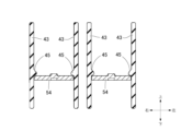
端子付き電線50は、電線51と、電線51の端末に接続される端子52と、により構成される(図2~図3参照)。電線51は、一端が端子52と接続され、他端が例えばバッテリやオルタネータ等と接続される。端子52は、図2~図3、図6、及び図8~図9に示すように、上下方向に延びて電線51と接続される電線側接続部53と、前方に延びてスタッドボルトSに接続・締結される相手側接続部54と、が一体に構成されて、略L字状に形成されている。なお、相手側接続部54には、上下方向に貫通し、スタッドボルトSが挿通される孔部が設けられている。以下、電気接続箱1を構成するフレーム10、ロアカバー20、アッパカバー30、及びサイドカバー40について順に説明する。
The terminal-attached
まず、フレーム10について説明する。図1に示すように、フレーム10は、上下方向に延びる略矩形筒状の側壁部11を備える。側壁部11は、電気接続箱1の側面の外観の大部分を構成する。
First, the
側壁部11の下端部における周方向の複数箇所(本例では、8箇所)の外面には、それぞれ、上下方向に延びる貫通孔を含む被係止部12が一体に設けられている。被係止部12は、ロアカバー20をフレーム10に組み付ける機能を有する。また、側壁部11の上端部における周方向の複数箇所(本例では、3箇所)の外面には、それぞれ、被係止部13が一体に設けられている。被係止部13は、アッパカバー30をフレーム10に組み付ける機能を有する。
The outer surface of the lower end of the side wall portion 11 is integrally provided with a plurality of engaging
側壁部11における後方左部の電線引出孔に対応する箇所には、下方に開口する半円筒状の樋状部14が、左下方向に斜めに延びるように設けられている。樋状部14は、後方左部の電線引出孔を画成する内壁の上側部分を構成する機能を有する。また、側壁部11における前方右部の電線引出孔に対応する箇所には、下方に開口する半円筒状の樋状部15が、右方に延びるように設けられている。樋状部15は、前方右部の電線引出孔を画成する内壁の上側部分を構成する機能を有する。
A
側壁部11の下端部における周方向の複数箇所の外面には、それぞれ、下方に延びるステー部16が一体に設けられている。ステー部16は、その先端部を車両の搭載箇所に組み付けることで、フレーム10(即ち、電気接続箱1)を車両の搭載箇所に固定する機能を有する。
Stay
スタッドボルトS近傍(本例では、後方)の側壁部11には、サイドカバー40が組み付けられる被組付部17が設けられている。被組付部17には、例えばサイドカバー40の係止部(図示省略)が係止される被係止部(図示省略)が設けられる。
The side wall portion 11 near the stud bolt S (in this example, the rear) is provided with an
次いで、ロアカバー20について説明する。図1に示すように、ロアカバー20は、電気接続箱1の下側側面の外観の大部分を構成する環状の側壁部21と、側壁部21の環状の下端開口を塞ぐとともに電気接続箱1の底面の外観の大部分を構成する底壁部22と、を一体に備える。側壁部21の環状の上端縁部は、フレーム10の側壁部11の環状の下端縁部に対応する形状を有し、側壁部11の環状の下端縁部と嵌合可能となっている。
Next, the
側壁部21の上端部における周方向の複数箇所(本例では、8箇所)の外面には、それぞれ、フレーム10の複数の被係止部12に対応して、上方に延びる係止片23が一体に設けられている。
The upper end of the
側壁部21における後方左部の電線引出孔に対応する箇所には、上方に開口する半円筒状の樋状部24が、左下方向に斜めに延びるように設けられている。樋状部24は、後方左部の電線引出孔を画成する内壁の下側部分を構成する機能を有する。また、側壁部21における前方右部の電線引出孔に対応する箇所には、上方に開口する半円筒状の樋状部25が、右方に延びるように設けられている。樋状部24は、前方右部の電線引出孔を画成する内壁の下側部分を構成する機能を有する。
A
次いで、アッパカバー30について説明する。図1に示すように、アッパカバー30は、電気接続箱1の上側側面の外観の大部分を構成する環状の側壁部31と、側壁部31の環状の上端開口を塞ぐと共に電気接続箱1の上面の外観の大部分を構成する上壁部32と、を一体に備える。側壁部31の環状の下端縁部は、フレーム10の側壁部11の環状の上端縁部に対応する形状を有し、側壁部11の環状の上端縁部と嵌合可能となっている。側壁部31における周方向の複数箇所(本例では、3箇所)の外面には、それぞれ、フレーム10の複数の被係止部13に対応して、係止部33が一体に設けられている。
Next, the
次いで、サイドカバー40について説明する。図2~図5に示すように、サイドカバー40は、上下方向に延びる第1壁部41と、左右方向において離間して配置される一対の第2壁部43と、が一体に構成されている。これにより、サイドカバー40は、前方及び上下方向に開口する端子付き電線50の収容部42が画成されている。
Next, the
本実施形態では、第2壁部43は、第1壁部41の左右両端及び左右方向略中央領域にそれぞれ設けられている。これにより、一対の収容部42が左右方向に隣接して配置されている。なお、左右方向略中央領域の第2壁部43については、上下方向下側領域が一体に構成されている。
In this embodiment, the
つまり、第1壁部41はいわゆる底壁としての機能を有し、左右方向両端の第2壁部43はいわゆる側壁としての機能を有し、左右方向略中央領域の第2壁部は、いわゆる隣接する収容部42の仕切壁としての機能を有する。また、第2壁部43は、端子付き電線50の保持状態において、端子52(特に、相手側接続部54)の左右方向の変位を規制する機能を有する(図7参照)。
In other words, the
なお、第1壁部41は、上下方向下側領域に位置する第1部分41aと、上下方向上側領域に位置する第2部分41bと、第1部分41a及び第2部分41bの間に位置する第3部分と、から構成されている。そして、第1部分41aは、第2部分41bよりも後方に位置している。これにより、後述するように、端子52のがたつきを抑制しつつ、サイドカバー40への端子付き電線50の組み付け作業に必要なスペースが確保される。
The
各第2壁部43には、それぞれ、端子付き電線50の相手側接続部54が載置される載置部44が、対応する収容部42の内方に向けて突出するように設けられている(図4~図5参照)。また、各第2壁部43には、それぞれ、載置部44よりも上方且つ前方に配置される第1規制部45が、対応する収容部42の内方に向けて突出するように設けられている。第1規制部45は、端子付き電線50の保持状態において、載置部44とともに相手側接続部54を上下方向に挟み込むことで、端子52(特に、相手側接続部54)の上下方向の変位を規制する機能を有する(図6参照)。
Each
第1壁部41(具体的には、第3部分41c)における各収容部42に対応する箇所には、それぞれ、収容部42の左右方向に離間して配置される一対の第2規制部46が、前方に向けて突出するように設けられている(図4参照)。第2規制部46は、端子付き電線50の保持状態において、載置部44とともに相手側接続部54を前後方向に挟み込むことで、端子52(特に、相手側接続部54)の前後方向の変位を規制する機能を有する(図6参照)。
A pair of second restricting
以上、電気接続箱1を構成するフレーム10、ロアカバー20、アッパカバー30、及びサイドカバー40について説明した。フレーム10、ロアカバー20、アッパカバー30、及びサイドカバー40からなる電気接続箱1を組み付けるためには、フレーム10にロアカバー20、アッパカバー30、及びサイドカバー40をそれぞれ組み付ける必要がある。
The
まず、フレーム10にロアカバー20を組み付ける。フレーム10にロアカバー20を組み付けるためには、ロアカバー20の複数の係止片23(図1参照)を、下方からフレーム10の被係止部12(図1参照)の複数の貫通孔にそれぞれ挿入し、この状態から、ロアカバー20の側壁部21の環状の上端縁部をフレーム10の側壁部11の環状の下端縁部に嵌合させ、且つ、複数の係止片23を複数の被係止部12に係止させる。これにより、フレーム10へのロアカバー20の組み付けが完了する。
First, the
その後、サイドカバー40に端子付き電線50を組み付ける(詳細は後述する)。その後、フレーム10にサイドカバー40を組み付ける。フレーム10にサイドカバー40を組み付けるためには、端子付き電線50をスタッドボルトSに接続・締結させ、且つ、フレーム10の被組付部17にサイドカバー40を組み付ける。
Then, the electric wires with
具体的には、端子付き電線50における端子52の孔部55をスタッドボルトSに挿通させ、そしてナットNを締めることで、端子付き電線50がスタッドボルトSに接続・締結される。その後、サイドカバー40の係止部(図示省略)をフレーム10の被係止部(図示省略)に係止させる。これにより、フレーム10へのサイドカバー40の組み付けが完了する。
Specifically, the
その後、フレーム10にアッパカバー30を組み付ける。フレーム10にアッパカバー30を組み付けるためには、アッパカバー30の側壁部31の環状の下端縁部をフレーム10の側壁部11の環状の上端縁部に嵌合させ、且つ、アッパカバー30の複数の係止部33をフレーム10の複数の被係止部12に係止させる。これにより、フレーム10へのアッパカバー30の組み付けが完了する。
Then, the
これにより、フレーム10にロアカバー20、アッパカバー30、及びサイドカバー40がそれぞれ組み付けられて、電気接続箱1が完成される。なお、フレーム10へのロアカバー20の組み付け工程と、フレーム10へのサイドカバー40の組み付け工程と、の順番の前後は問わない。
As a result, the
電気接続箱1の組付完了状態では、複数の係止片23と複数の被係止部12との係止により、ロアカバー20がフレーム10から下方へ分離することが防止される。同様に、複数の係止部33と複数の被係止部13との係止により、アッパカバー30がフレーム10から上方へ分離することが防止される。なお、サイドカバー40についても同様に、フレーム10の被係止部(図示省略)とサイドカバー40の複数の係止部(図示省略)との係止により、サイドカバー40がフレーム10から後方へ分離することが防止される。
When the
更に、フレーム10の被組付部17の外面とサイドカバー40の収容部42の内面とにより端子付き電線50が挿通される電線挿通路が画成される(図示省略)。同様に、フレーム10の樋状部14と、ロアカバー20の樋状部24とにより、電線(図示省略)が挿通される後方左部の電線引出孔が画成される。同様に、フレーム10の樋状部15と、ロアカバー20の樋状部25とにより、電線(図示省略)が挿通される前方右部の電線引出孔が画成される。
Furthermore, the outer surface of the mounting
次いで、サイドカバー40への端子付き電線50の組み付け方法について図8~図9を参照して説明する。まず、端子付き電線50の上端部を後方に倒すように傾けて、相手側接続部54を、載置部44と第2規制部46との間の隙間に挿入する(図8参照)。
Next, a method for assembling the terminal-attached
相手側接続部54を所定位置まで挿入後、相手側接続部54と載置部44とが上下方向に対向(換言すると略平行)となるように後方に倒した端子付き電線50の上端部を元の位置に戻し、相手側接続部54と載置部44とが相対的に近付くように端子付き電線50を下方へと移動させる(図9の矢印参照)。相手側接続部54は、下方への移動途中において上方から下方に向けて第1規制部45を乗り越え、そして、所定位置に到達する。これにより、端子付き電線50がサイドカバー40に組み付けられる。換言すると、端子付き電線50は、サイドカバー40に保持される(図2及び図6~図7参照)。
After the
端子付き電線50は、保持状態において、相手側接続部54が、一対の第2壁部43に左右方向に挟み込まれて、端子52の左右方向の変位が規制される(図7参照)。同様に、端子付き電線50は、保持状態において、相手側接続部54が、載置部44及び第1規に上下方向に挟み込まれて、端子52の上下方向の変位が規制される(図6参照)。同様に、端子付き電線50は、保持状態において、相手側接続部54が、載置部44及び第2規制部46に前後方向に挟み込まれて、端子52の前後方向の変位が規制される(図6参照)。
In the held state, the electric wire with
また、サイドカバー40は、前後方向に延びる相手側接続部54に対して、載置部44と第1規制部45とが前後方向に異なる位置に設けられることで、端子52のがたつき(特に、相手側接続部54の前端の浮き上がり)をより適正に抑制できる。
In addition, the
このように、サイドカバー40は、端子52のあらゆる方向への変位を規制することで、端子52のがたつきを抑制できる。これにより、端子付き電線50における端子52の孔部55の位置決め精度が向上し、例えば、フレーム10へのサイドカバー40の組み付け時において、端子付き電線50をスタッドボルトSに容易に接続・締結できる。また、電線51の引っ張りによる端子52のがたつきが抑制されるため、電線51を所望の方向へと引き出すことができる。
In this way, the
なお、サイドカバー40への端子付き電線50の組み付け作業は、いわゆるワンアクションで行うことができ、組み付け作業性に優れる。
The assembly of the terminal-attached
また、第1壁部41の第2部分41bに何も設けられていないことで、載置部44と第2規制部46との間の隙間に端子付き電線50を挿入する際、第2部分41bに突起等が設けられている場合に比べて、端子付き電線50の上端部を後方に倒さなくてもよいため、第1部分41aと第2部分41bとの前後方向の距離を近付けることができる。つまり、本実施形態に係るサイドカバー40においては、小型化を図ることができる。
In addition, since there is nothing provided on the
<他の形態>
なお、本発明は、上述した実施形態に限定されるものではなく、適宜、変形、改良、等が可能である。その他、上述した実施形態における各構成要素の材質、形状、寸法、数、配置箇所、等は本発明を達成できるものであれば任意であり、限定されない。
<Other forms>
The present invention is not limited to the above-described embodiment, and can be appropriately modified, improved, etc. In addition, the material, shape, size, number, arrangement location, etc. of each component in the above-described embodiment are arbitrary as long as the present invention can be achieved, and are not limited.
図10に示すように、第1規制部45における相手側接続部54と対向する面(本例では、下端面)を、突出先端から突出基端に向かうにつれて相手側接続部54に近付く傾斜状に形成してもよい。一般に、係止部と係止部に係止される被係止部材との間には、クリアランスを設ける必要がある。このため、被係止部材は、クリアランスの大きさだけがたつくおそれがある。しかしながら、上記構成により、第1規制部45と相手側接続部54との間に必要なクリアランスを設けつつも、第1規制部45の突出基端においては、クリアランスを小さくできるため、端子52のがたつきをより適正に抑制できる。
As shown in FIG. 10, the surface of the first restricting
ここで、上述した本発明に係る樹脂体、及び、電気接続箱の実施形態の特徴をそれぞれ以下[1]~[3]に簡潔に纏めて列記する。
[1]
電線側接続部(53)及び相手側接続部(54)からなるL字状の端子(52)を有する端子付き電線(50)を保持可能に構成され、電子部品(R)を内部に収容する筐体(フレーム10,ロアカバー20、アッパカバー30)に組み付けられることになる樹脂体(サイドカバー40)であって、
第1方向に延びる第1壁部(41)と、
前記第1方向と交差する第2方向において離間して配置され、前記端子(52)における前記第2方向の変位を規制可能な一対の第2壁部(43)と、が一体に構成され、
前記一対の第2壁部(43)の各々には、
前記相手側接続部(54)が載置可能な載置部(44)と、
前記端子(52)における前記第1方向の変位を規制するように、前記載置部(44)とともに前記相手側接続部(54)を前記第1方向に挟み込むことになる第1規制部(45)と、が設けられ、
前記第1壁部(41)には、
前記端子(52)における前記第1方向及び前記第2方向と交差する第3方向の変位を規制するように、前記載置部(44)とともに前記相手側接続部(54)を前記第3方向に挟み込むことになる第2規制部(46)が設けられる、
樹脂体(サイドカバー40)。
[2]
上記[1]に記載の樹脂体(サイドカバー40)において、
前記載置部(44)及び前記第1規制部(45)は、
前記相手側接続部(54)の延び方向となる前記第3方向において、異なる位置に設けられる、
樹脂体(サイドカバー40)。
[3]
上記[1]又は上記[2]に記載の樹脂体(サイドカバー40)と、端子付き電線(50)と、電子部品(R)を内部に収容する筐体(フレーム10,ロアカバー20,アッパカバー30)と、を備えた電気接続箱(1)であって、
前記端子付き電線(50)は、電線(51)と、L字状の端子(52)と、を有し、
前記端子(52)は、
前記第1方向に延びて、前記電線(51)と接続される電線側接続部(53)と、
前記第3方向に延びて、前記筐体に設けられたスタッドボルト(S)と接続される相手側接続部(54)と、が一体に構成される、
電気接続箱(1)。
Here, the features of the embodiments of the resin body and the electrical junction box according to the present invention described above will be briefly summarized and listed in the following [1] to [3].
[1]
A resin body (side cover 40) configured to be capable of holding a terminal-attached electric wire (50) having an L-shaped terminal (52) consisting of an electric wire-side connection portion (53) and a mating connection portion (54), and to be assembled to a housing (
A first wall portion (41) extending in a first direction;
a pair of second walls (43) that are spaced apart from each other in a second direction intersecting the first direction and that are capable of restricting displacement of the terminal (52) in the second direction,
Each of the pair of second walls (43) has
a mounting portion (44) on which the mating connection portion (54) can be mounted;
a first restricting portion (45) that, together with the placement portion (44), clamps the mating connection portion (54) in the first direction so as to restrict displacement of the terminal (52) in the first direction,
The first wall portion (41) has
a second restricting portion (46) is provided to sandwich the mating connection portion (54) together with the placement portion (44) in the third direction so as to restrict displacement of the terminal (52) in the third direction intersecting the first direction and the second direction;
Resin body (side cover 40).
[2]
In the resin body (side cover 40) described in [1] above,
The placement portion (44) and the first restriction portion (45) are
The mating connection portion (54) is provided at different positions in the third direction, which is the extension direction of the mating connection portion (54).
Resin body (side cover 40).
[3]
An electrical connection box (1) including the resin body (side cover 40) according to the above-mentioned [1] or [2], an electric wire with terminal (50), and a housing (
The terminal-attached electric wire (50) has an electric wire (51) and an L-shaped terminal (52),
The terminal (52) is
an electric wire side connection portion (53) extending in the first direction and connected to the electric wire (51);
and a mating connection portion (54) extending in the third direction and connected to a stud bolt (S) provided in the housing.
Electrical junction box (1).
上記[1]の構成の樹脂体によれば、一対の第2壁部が、相手側接続部を第2方向に挟み込むことで、端子の第2方向の変位を規制する。同様に、載置部及び第1規制部が、相手側接続部を第1方向に挟み込むことで、端子の第1方向の変位を規制する。同様に、載置部及び第2規制部が、相手側接続部を第3方向に挟み込むことで、端子の第3方向の変位を規制する。このように、本構成の樹脂体は、端子のあらゆる方向への変位を規制するため、端子のがたつきを抑制できる。 According to the resin body of the configuration [1] above, the pair of second walls sandwich the mating connection part in the second direction, thereby restricting the displacement of the terminal in the second direction. Similarly, the placement part and the first restriction part sandwich the mating connection part in the first direction, thereby restricting the displacement of the terminal in the first direction. Similarly, the placement part and the second restriction part sandwich the mating connection part in the third direction, thereby restricting the displacement of the terminal in the third direction. In this way, the resin body of this configuration restricts the displacement of the terminal in all directions, thereby suppressing rattling of the terminal.
上記[2]の構成の樹脂体によれば、第3方向に延びる相手側接続部に対して、載置部と第1規制部とが第3方向に異なる位置に設けられることで、端子のがたつきをより適正に抑制できる。 According to the resin body having the configuration of [2] above, the placement portion and the first restricting portion are provided at different positions in the third direction relative to the mating connection portion extending in the third direction, so that rattling of the terminal can be more appropriately suppressed.
上記[3]の構成の電気接続箱によれば、一対の第2壁部が、相手側接続部を第2方向に挟み込むことで、端子の第2方向の変位を規制する。同様に、載置部及び第1規制部が、相手側接続部を第1方向に挟み込むことで、端子の第1方向の変位を規制する。同様に、載置部及び第2規制部が、相手側接続部を第3方向に挟み込むことで、端子の第3方向の変位を規制する。このように、本構成の樹脂体は、端子のあらゆる方向への変位を規制するため、端子のがたつきを抑制できる。 According to the electrical connection box of the configuration [3] above, the pair of second walls clamp the mating connection part in the second direction, thereby restricting the displacement of the terminal in the second direction. Similarly, the placement part and the first restricting part clamp the mating connection part in the first direction, thereby restricting the displacement of the terminal in the first direction. Similarly, the placement part and the second restricting part clamp the mating connection part in the third direction, thereby restricting the displacement of the terminal in the third direction. In this way, the resin body of this configuration restricts the displacement of the terminal in all directions, thereby suppressing rattling of the terminal.
1 電気接続箱
10 フレーム
11,21,31 側壁部
12,13 被係止部
14,15,24,25 樋状部
16 ステー部
17 被組付部
20 ロアカバー
22 底壁部
23 係止片
30 アッパカバー
32 上壁部
33 係止部
40 サイドカバー(樹脂体)
41 第1壁部
41a 第1部分
41b 第2部分
41c 第3部分
42 収容部
43 第2壁部
44 載置部
45 第1規制部
46 第2規制部
50 端子付き電線
51 電線
52 端子
53 電線側接続部
54 相手側接続部
55 孔部
N ナット
R 電子部品
S スタッドボルト
REFERENCE SIGNS
41
Claims (3)
第1方向に延びる第1壁部と、
前記第1方向と交差する第2方向において離間して配置され、前記端子における前記第2方向の変位を規制可能な一対の第2壁部と、が一体に構成され、
前記一対の第2壁部の各々には、
前記相手側接続部が載置可能な載置部と、
前記端子における前記第1方向の変位を規制するように、前記載置部とともに前記相手側接続部を前記第1方向に挟み込むことになる第1規制部と、が設けられ、
前記第1壁部には、
前記端子における前記第1方向及び前記第2方向と交差する第3方向の変位を規制するように、前記載置部とともに前記相手側接続部を前記第3方向に挟み込むことになる第2規制部が設けられる、
樹脂体。 A resin body configured to be capable of holding a terminal-attached electric wire having an L-shaped terminal composed of an electric wire-side connection portion and a mating connection portion, the resin body being to be assembled into a housing that accommodates an electronic component therein,
A first wall portion extending in a first direction;
a pair of second wall portions that are spaced apart from each other in a second direction intersecting the first direction and that are capable of restricting displacement of the terminal in the second direction,
Each of the pair of second walls has
a mounting portion on which the mating connection portion can be mounted;
a first restricting portion configured to sandwich the mating connection portion together with the placement portion in the first direction so as to restrict displacement of the terminal in the first direction,
The first wall portion has
a second restricting portion is provided to sandwich the mating connection portion together with the placement portion in the third direction so as to restrict displacement of the terminal in the third direction intersecting the first direction and the second direction;
Resin body.
前記載置部及び前記第1規制部は、
前記相手側接続部の延び方向となる前記第3方向において、異なる位置に設けられる、
樹脂体。 The resin body according to claim 1 ,
The placement portion and the first restriction portion are
The mating connection portion is provided at different positions in the third direction, which is an extension direction of the mating connection portion.
Resin body.
前記端子付き電線は、電線と、L字状の端子と、を有し、
前記端子は、
前記第1方向に延びて、前記電線と接続される電線側接続部と、
前記第3方向に延びて、前記筐体に設けられたスタッドボルトと接続される相手側接続部と、が一体に構成される、
電気接続箱。 An electrical connection box comprising the resin body according to claim 1 or 2, an electric wire with a terminal, and a housing for accommodating an electronic component therein,
The electric wire with terminal has an electric wire and an L-shaped terminal,
The terminal is
a wire-side connection portion extending in the first direction and connected to the wire;
a mating connection portion extending in the third direction and connected to a stud bolt provided in the housing,
Electrical junction box.
Priority Applications (2)
| Application Number | Priority Date | Filing Date | Title |
|---|---|---|---|
| JP2022112713A JP7522158B2 (en) | 2022-07-13 | 2022-07-13 | Resin body and electrical junction box |
| CN202310696941.2A CN117410914A (en) | 2022-07-13 | 2023-06-13 | Resin body and electrical junction box |
Applications Claiming Priority (1)
| Application Number | Priority Date | Filing Date | Title |
|---|---|---|---|
| JP2022112713A JP7522158B2 (en) | 2022-07-13 | 2022-07-13 | Resin body and electrical junction box |
Publications (2)
| Publication Number | Publication Date |
|---|---|
| JP2024011039A JP2024011039A (en) | 2024-01-25 |
| JP7522158B2 true JP7522158B2 (en) | 2024-07-24 |
Family
ID=89495106
Family Applications (1)
| Application Number | Title | Priority Date | Filing Date |
|---|---|---|---|
| JP2022112713A Active JP7522158B2 (en) | 2022-07-13 | 2022-07-13 | Resin body and electrical junction box |
Country Status (2)
| Country | Link |
|---|---|
| JP (1) | JP7522158B2 (en) |
| CN (1) | CN117410914A (en) |
Citations (3)
| Publication number | Priority date | Publication date | Assignee | Title |
|---|---|---|---|---|
| JP2009189082A (en) | 2008-02-01 | 2009-08-20 | Sumitomo Wiring Syst Ltd | Electric connection box |
| JP2019088126A (en) | 2017-11-08 | 2019-06-06 | 矢崎総業株式会社 | Electric connection box |
| JP2019180230A (en) | 2019-05-15 | 2019-10-17 | 住友電装株式会社 | Electric connection box |
Family Cites Families (1)
| Publication number | Priority date | Publication date | Assignee | Title |
|---|---|---|---|---|
| US7361841B1 (en) * | 2005-06-23 | 2008-04-22 | Yazaki North America, Inc. | Terminal cover with hinge |
-
2022
- 2022-07-13 JP JP2022112713A patent/JP7522158B2/en active Active
-
2023
- 2023-06-13 CN CN202310696941.2A patent/CN117410914A/en active Pending
Patent Citations (3)
| Publication number | Priority date | Publication date | Assignee | Title |
|---|---|---|---|---|
| JP2009189082A (en) | 2008-02-01 | 2009-08-20 | Sumitomo Wiring Syst Ltd | Electric connection box |
| JP2019088126A (en) | 2017-11-08 | 2019-06-06 | 矢崎総業株式会社 | Electric connection box |
| JP2019180230A (en) | 2019-05-15 | 2019-10-17 | 住友電装株式会社 | Electric connection box |
Also Published As
| Publication number | Publication date |
|---|---|
| CN117410914A (en) | 2024-01-16 |
| JP2024011039A (en) | 2024-01-25 |
Similar Documents
| Publication | Publication Date | Title |
|---|---|---|
| JP6709817B2 (en) | connector | |
| CN111656633A (en) | Electrical connection box | |
| JP5299699B2 (en) | Electrical junction box | |
| JP7522158B2 (en) | Resin body and electrical junction box | |
| JP7568518B2 (en) | Fuse Unit | |
| JP7601841B2 (en) | Resin body and electrical junction box | |
| JP6351396B2 (en) | Electrical junction box | |
| JP6861690B2 (en) | Assembled structure of cover and housing, and fusible link unit | |
| JP7648576B2 (en) | Electrical Junction Box Unit | |
| WO2018105345A1 (en) | Structure for attaching, to vehicle, battery and electrical junction box directly connected to battery | |
| JP7651382B2 (en) | Electrical junction box and waterproof structure of electrical junction box | |
| JP2001218338A (en) | Assembly structure of electrical junction box and waterproof box | |
| JP3936444B2 (en) | Electrical junction box | |
| JP2023102652A (en) | electric junction box | |
| JP4448763B2 (en) | Electrical junction box | |
| JP7525545B2 (en) | Electrical Junction Box | |
| JP2024013065A (en) | Electrical junction box and mounting structure between electrical junction box and battery | |
| JP2024125893A (en) | Electrical Junction Box Unit | |
| JP7744209B2 (en) | terminal block | |
| JP2021044141A (en) | Terminal with cover and electric connection box | |
| JP7211995B2 (en) | Fixing structure of connector | |
| JP2024011026A (en) | electrical junction box unit | |
| JP2023125599A (en) | box-shaped body | |
| JP2024011028A (en) | electrical junction box unit | |
| JP2024011025A (en) | electrical junction box unit |
Legal Events
| Date | Code | Title | Description |
|---|---|---|---|
| A621 | Written request for application examination |
Free format text: JAPANESE INTERMEDIATE CODE: A621 Effective date: 20231115 |
|
| A977 | Report on retrieval |
Free format text: JAPANESE INTERMEDIATE CODE: A971007 Effective date: 20240628 |
|
| TRDD | Decision of grant or rejection written | ||
| A01 | Written decision to grant a patent or to grant a registration (utility model) |
Free format text: JAPANESE INTERMEDIATE CODE: A01 Effective date: 20240709 |
|
| A61 | First payment of annual fees (during grant procedure) |
Free format text: JAPANESE INTERMEDIATE CODE: A61 Effective date: 20240711 |
|
| R150 | Certificate of patent or registration of utility model |
Ref document number: 7522158 Country of ref document: JP Free format text: JAPANESE INTERMEDIATE CODE: R150 |