JP7521371B2 - Drive device for electric vehicle, drive unit and electric vehicle - Google Patents

Drive device for electric vehicle, drive unit and electric vehicle Download PDF

Info

Publication number
JP7521371B2
JP7521371B2 JP2020171683A JP2020171683A JP7521371B2 JP 7521371 B2 JP7521371 B2 JP 7521371B2 JP 2020171683 A JP2020171683 A JP 2020171683A JP 2020171683 A JP2020171683 A JP 2020171683A JP 7521371 B2 JP7521371 B2 JP 7521371B2
Authority
JP
Japan
Prior art keywords
pair
fixed
drive
supported
drive unit
Prior art date
Legal status (The legal status is an assumption and is not a legal conclusion. Google has not performed a legal analysis and makes no representation as to the accuracy of the status listed.)
Active
Application number
JP2020171683A
Other languages
Japanese (ja)
Other versions
JP2021175657A (en
JP2021175657A5 (en
Inventor
真史 疋田
靖之 松田
竜峰 森田
健二 関根
信博 轟木
洋輔 下村
Current Assignee (The listed assignees may be inaccurate. Google has not performed a legal analysis and makes no representation or warranty as to the accuracy of the list.)
NSK Ltd
Original Assignee
NSK Ltd
Priority date (The priority date is an assumption and is not a legal conclusion. Google has not performed a legal analysis and makes no representation as to the accuracy of the date listed.)
Filing date
Publication date
Application filed by NSK Ltd filed Critical NSK Ltd
Publication of JP2021175657A publication Critical patent/JP2021175657A/en
Publication of JP2021175657A5 publication Critical patent/JP2021175657A5/ja
Application granted granted Critical
Publication of JP7521371B2 publication Critical patent/JP7521371B2/en
Active legal-status Critical Current
Anticipated expiration legal-status Critical

Links

Images

Classifications

    • YGENERAL TAGGING OF NEW TECHNOLOGICAL DEVELOPMENTS; GENERAL TAGGING OF CROSS-SECTIONAL TECHNOLOGIES SPANNING OVER SEVERAL SECTIONS OF THE IPC; TECHNICAL SUBJECTS COVERED BY FORMER USPC CROSS-REFERENCE ART COLLECTIONS [XRACs] AND DIGESTS
    • Y02TECHNOLOGIES OR APPLICATIONS FOR MITIGATION OR ADAPTATION AGAINST CLIMATE CHANGE
    • Y02TCLIMATE CHANGE MITIGATION TECHNOLOGIES RELATED TO TRANSPORTATION
    • Y02T10/00Road transport of goods or passengers
    • Y02T10/60Other road transportation technologies with climate change mitigation effect
    • Y02T10/64Electric machine technologies in electromobility
    • YGENERAL TAGGING OF NEW TECHNOLOGICAL DEVELOPMENTS; GENERAL TAGGING OF CROSS-SECTIONAL TECHNOLOGIES SPANNING OVER SEVERAL SECTIONS OF THE IPC; TECHNICAL SUBJECTS COVERED BY FORMER USPC CROSS-REFERENCE ART COLLECTIONS [XRACs] AND DIGESTS
    • Y02TECHNOLOGIES OR APPLICATIONS FOR MITIGATION OR ADAPTATION AGAINST CLIMATE CHANGE
    • Y02TCLIMATE CHANGE MITIGATION TECHNOLOGIES RELATED TO TRANSPORTATION
    • Y02T10/00Road transport of goods or passengers
    • Y02T10/60Other road transportation technologies with climate change mitigation effect
    • Y02T10/72Electric energy management in electromobility

Landscapes

  • Gear Transmission (AREA)
  • Electric Propulsion And Braking For Vehicles (AREA)
  • Connection Of Motors, Electrical Generators, Mechanical Devices, And The Like (AREA)
  • Motor Power Transmission Devices (AREA)
  • Arrangement And Driving Of Transmission Devices (AREA)
  • Arrangement Or Mounting Of Propulsion Units For Vehicles (AREA)
  • Vehicle Body Suspensions (AREA)

Description

本発明は、電動モータを駆動源として車輪を回転駆動する、電気自動車用駆動装置と、前記電気自動車用駆動装置を備える駆動ユニットと、前記駆動ユニットを複数備える電気自動車とに関する。 The present invention relates to an electric vehicle drive device that uses an electric motor as a drive source to rotate and drive wheels, a drive unit that includes the electric vehicle drive device, and an electric vehicle that includes multiple drive units.

近年における化石燃料低減化の流れを受けて、電気自動車の研究が進み、一部で実施されている。特開2006-22879号公報(特許文献1)には、1個の電動モータの出力トルクを、2段変速機とデファレンシャルギヤとを介して、左右一対の駆動輪に伝達する、電気自動車用駆動装置が記載されている。 In response to the recent trend towards reducing the use of fossil fuels, research into electric vehicles has progressed and some have been implemented. JP 2006-22879 A (Patent Document 1) describes a drive unit for an electric vehicle that transmits the output torque of a single electric motor to a pair of left and right drive wheels via a two-speed transmission and a differential gear.

特開2006-22879号公報JP 2006-22879 A

特開2006-22879号公報に記載の電気自動車用駆動装置では、1個の電動モータにより、左右一対の駆動輪を駆動するように構成されている。このため、車両総重量に応じて、適切な仕様を有する電動モータ、2段変速機およびデファレンシャルギヤを使用する必要がある。換言すれば、電気自動車用駆動装置として、特開2006-22879号公報に記載の電気自動車用駆動装置を採用する場合には、車両総重量ごとに専用に設計する必要があり、電気自動車の製造コストを低減する面からは不利になる。 The electric vehicle drive device described in JP 2006-22879 A is configured to drive a pair of left and right drive wheels with a single electric motor. For this reason, it is necessary to use an electric motor, two-speed transmission, and differential gear with appropriate specifications according to the total vehicle weight. In other words, when using the electric vehicle drive device described in JP 2006-22879 A as an electric vehicle drive device, it is necessary to design it specifically for each total vehicle weight, which is disadvantageous in terms of reducing the manufacturing costs of electric vehicles.

特に、人間が運転操作を行わなくても走行することができる自動運転車は、多数の高価なセンサを備えており、コスト低減の要望が大きい。 In particular, self-driving cars, which can run without human intervention, are equipped with numerous expensive sensors, and there is a strong demand for cost reduction.

本発明は、上述のような事情を鑑みて、車両総重量にかかわらず、電気自動車用駆動装置を共通化して、電気自動車の製造コストを低減することを目的としている。 In view of the above circumstances, the present invention aims to standardize the drive unit for electric vehicles regardless of the total vehicle weight, thereby reducing the manufacturing costs of electric vehicles.

本発明の電気自動車用駆動装置は、
ハウジングと、
それぞれが出力軸を有し、前記ハウジングに対し支持された、一対の電動モータと、
互いに同軸に、かつ、車輪が支持されるそれぞれの先端部を互いに反対方向に向けた状態で、前記ハウジングに対し回転自在に支持された、一対の駆動軸と、
前記一対の電動モータのそれぞれの前記出力軸の回転トルクを、前記一対の駆動軸のそれぞれに伝達する、一対のトルク伝達装置と、
を備える。
The electric vehicle drive device of the present invention comprises:
Housing and
a pair of electric motors each having an output shaft and supported relative to the housing;
a pair of drive shafts that are coaxial with each other and rotatably supported on the housing with their respective tip ends, on which wheels are supported, facing in opposite directions;
a pair of torque transmission devices that transmit the rotational torque of each of the output shafts of the pair of electric motors to each of the pair of drive shafts;
Equipped with.

なお、本発明の電気自動車用駆動装置は、路面に直交する旋回軸を中心とする回動を可能に車体に対し支持される。
また、本発明の電気自動車用駆動装置を使用して電気自動車を構成する場合には、前記電気自動車用駆動装置は、1個または複数個、例えば4個以上車体に搭載される。
The electric vehicle drive device of the present invention is supported on the vehicle body so as to be rotatable about a pivot axis perpendicular to the road surface.
Furthermore, when an electric vehicle is constructed using the electric vehicle drive device of the present invention, one or more electric vehicle drive devices, for example, four or more, are mounted on the vehicle body.

本発明の電気自動車用駆動装置では、前記一対の電動モータのそれぞれの前記出力軸と、前記一対の駆動軸とを、平行に配置することができる。
この場合、前記一対の電動モータのそれぞれの前記出力軸は、互いに非同軸に、かつ、互いに平行に配置することができる。
さらに、この場合、前記一対の電動モータのそれぞれを、それぞれの前記出力軸に直交する方向に関して互いに重畳して配置することができる。
In the electric vehicle drive device of the present invention, the output shafts of the pair of electric motors and the pair of drive shafts can be disposed in parallel.
In this case, the output shafts of the pair of electric motors can be arranged non-coaxially and parallel to each other.
Furthermore, in this case, the pair of electric motors can be disposed so as to overlap each other in a direction perpendicular to the output shafts of the respective electric motors.

また、前記一対の電動モータのそれぞれを、前記車輪から径方向外側に外れた位置に配置することができる。あるいは、前記一対の電動モータのそれぞれを、前記車輪同士の間部分に配置することもできる。 Each of the pair of electric motors can be disposed radially outward from the wheels. Alternatively, each of the pair of electric motors can be disposed between the wheels.

前記一対のトルク伝達装置のそれぞれは、複数個の歯車を備える歯車式減速機により構成することができる。
あるいは、前記一対のトルク伝達装置のそれぞれは、ベルトやチェーンを使用した減速機により構成したり、ウォーム減速機により構成したりすることもできる。
あるいは、前記一対のトルク伝達装置のそれぞれは、前記一対の電動モータのそれぞれの前記出力軸と、前記一対の駆動軸のそれぞれとの間の減速比を調節可能な、無段変速機や有段変速機により構成することもできる。
Each of the pair of torque transmission devices can be configured by a gear-type reducer including a plurality of gears.
Alternatively, each of the pair of torque transmission devices may be configured by a reducer using a belt or chain, or by a worm reducer.
Alternatively, each of the pair of torque transmission devices can be configured as a continuously variable transmission or a stepped transmission capable of adjusting the reduction ratio between the output shaft of each of the pair of electric motors and each of the pair of drive shafts.

本発明の駆動ユニットは、
一対の駆動軸を有する電気自動車用駆動装置と、
前記一対の駆動軸のそれぞれに支持された、一対の車輪と、
前記電気自動車用駆動装置を、路面に直交する旋回軸を中心とする回動を可能に、車体に対し支持する、旋回装置と、
を備え、
前記電気自動車用駆動装置が、本発明の電気自動車用駆動装置により構成される。
The drive unit of the present invention comprises:
A drive device for an electric vehicle having a pair of drive shafts;
a pair of wheels supported on each of the pair of drive shafts;
a turning device that supports the electric vehicle drive device with respect to a vehicle body so as to enable the electric vehicle drive device to turn about a turning axis that is perpendicular to a road surface;
Equipped with
The electric vehicle drive device is configured by the electric vehicle drive device of the present invention.

前記旋回装置は、前記旋回軸を中心とする前記電気自動車用駆動装置の回動可能範囲を規制するストッパ機構を有することができる。 The swivel device may have a stopper mechanism that limits the range of rotation of the electric vehicle drive device around the swivel shaft.

前記旋回装置は、前記電気自動車用駆動装置に対して前記旋回軸を中心とする回転を不能に支持された回転部材と、前記回転部材と同軸に、該回転部材に対する回転を可能に配置され、かつ、前記車体に対して支持固定される固定部材と、を有することができる。
この場合、前記ストッパ機構は、前記旋回軸を中心とする円周方向を向き、前記回転部材に備えられた回転側ストッパ面と、前記旋回軸を中心とする円周方向を向き、かつ、前記回転側ストッパ面に対向し、前記固定部材に備えられた固定側ストッパ面と、を有することができる。
The turning device may have a rotating member supported relative to the electric vehicle drive device so as not to rotate around the turning axis, and a fixed member arranged coaxially with the rotating member so as to be rotatable relative to the rotating member, and supported and fixed to the vehicle body.
In this case, the stopper mechanism may have a rotating side stopper surface provided on the rotating member, facing in a circumferential direction around the rotating axis, and a fixed side stopper surface provided on the fixed member, facing in a circumferential direction around the rotating axis and facing the rotating side stopper surface.

前記回転部材は、
前記旋回軸を中心とする円周方向を向いた本体側対向面を有し、前記電気自動車用駆動装置に対して前記旋回軸を中心とする回転を不能に支持された回転部材本体と、
前記旋回軸を中心とする円周方向を向き、かつ、前記本体側対向面に当接または近接対向するストッパ部材側対向面と、前記回転側ストッパ面とを有し、前記回転部材本体に支持固定された回転側ストッパ部材と、
を備えることができる。
The rotating member is
a rotating member main body having a main body-side facing surface facing a circumferential direction centered on the pivot shaft and supported in such a manner that the rotating member main body cannot rotate about the pivot shaft relative to the electric vehicle drive device;
a rotation side stopper member that faces a circumferential direction about the pivot axis and has a stopper member side opposing surface that abuts or closely faces the main body side opposing surface and the rotation side stopper surface, and is supported and fixed to the rotation member main body;
It can be provided with:

前記固定部材は、
前記車体に対して支持固定される固定部材本体と、
前記固定側ストッパ面を有し、前記固定部材本体に対し、前記旋回軸を中心とする円周方向に関する取付位置を調節可能に支持固定された固定側ストッパ部材と、
を備えることができる。
The fixing member is
A fixing member main body that is supported and fixed to the vehicle body;
a fixed-side stopper member having the fixed-side stopper surface and supported and fixed to the fixed member body so that an attachment position thereof in a circumferential direction about the pivot shaft can be adjusted;
It can be provided with:

本発明の駆動ユニットは、前記車輪を構成するタイヤの外周面のそれぞれを前記路面に押し付けつつ、前記車輪のそれぞれを介して前記路面から前記車体に伝わる振動を緩和する、支持装置を備えることができる。 The drive unit of the present invention can include a support device that presses each of the outer circumferential surfaces of the tires that constitute the wheels against the road surface, while mitigating vibrations transmitted from the road surface to the vehicle body via each of the wheels.

本発明の駆動ユニットは、前記電気自動車用駆動装置のそれぞれと前記車体との間に配置され、前記路面に対する前記車体の高さを調整する、車高調整装置を備えることができる。 The drive unit of the present invention can include a vehicle height adjustment device that is disposed between each of the electric vehicle drive devices and the vehicle body and adjusts the height of the vehicle body relative to the road surface.

本発明の電気自動車は、
車体と、
少なくとも1個の駆動ユニットと、
を備え、
前記駆動ユニットのそれぞれが、本発明の駆動ユニットにより構成される。
なお、本発明の電気自動車では、前記駆動ユニットの搭載数は、車両総重量に応じて決定される。
The electric vehicle of the present invention is
The car body and
At least one drive unit;
Equipped with
Each of the drive units is constituted by the drive unit of the present invention.
In the electric vehicle of the present invention, the number of drive units mounted is determined according to the total vehicle weight.

本発明によれば、車両総重量にかかわらず、電気自動車用駆動装置を共通化して、電気自動車の製造コストを低減することができる。 According to the present invention, it is possible to standardize the drive unit for electric vehicles regardless of the total vehicle weight, thereby reducing the manufacturing costs of electric vehicles.

図1は、実施の形態の第1例に係る電気自動車用駆動装置を示す斜視図である。FIG. 1 is a perspective view showing an electric vehicle drive device according to a first embodiment. 図2は、実施の形態の第1例に係る電気自動車用駆動装置を、一部を分解して示す斜視図である。FIG. 2 is a perspective view showing a part of the electric vehicle drive device according to the first embodiment, in an exploded state. 図3は、実施の形態の第1例に係る電気自動車用駆動装置を、一対のハブユニット軸受を取り付けた状態で示す斜視図である。FIG. 3 is a perspective view showing the electric vehicle drive device according to the first embodiment with a pair of hub unit bearings attached. 図4は、実施の形態の第1例に係る電気自動車用駆動装置を、一対のハブユニット軸受を取り付けた状態で示す側面図である。FIG. 4 is a side view showing the electric vehicle drive device according to the first embodiment with a pair of hub unit bearings attached. 図5は、図4のX-O-O-O-X断面図である。FIG. 5 is a cross-sectional view taken along line X 1 -O 1 -O 2 -O 3 -X 2 of FIG. 図6は、図4のX-O-O -O -O -O-X断面図である。FIG. 6 is a cross-sectional view taken along line X 1 -O 1 -O 2 -O 3 -O 2 -O 4 -X 3 of FIG. 図7は、実施の形態の第1例に係る電気自動車用駆動装置を示す、模式図である。FIG. 7 is a schematic diagram showing an electric vehicle drive device according to a first embodiment. 図8は、実施の形態の第1例に係る電気自動車用駆動装置を含んで構成される駆動ユニットを示す斜視図である。FIG. 8 is a perspective view showing a drive unit including an electric vehicle drive device according to a first embodiment. 図9は、図8に示す駆動ユニットから車高調整装置を取り外して示す斜視図である。FIG. 9 is a perspective view showing the drive unit shown in FIG. 8 with the vehicle height control device removed. 図10は、図9に示す状態から一方の駆動輪を取り外して示す側面図である。FIG. 10 is a side view showing the state shown in FIG. 9 with one of the drive wheels removed. 図11(A)は、実施の形態の第1例に係る駆動ユニットを備える電気自動車の第1例を示す斜視図であり、図11(B)は、図11(A)の下側から見た側面図であり、図11(C)は、図11(B)の左側から見た端面図である。FIG. 11(A) is an oblique view showing a first example of an electric vehicle equipped with a drive unit relating to a first example of an embodiment, FIG. 11(B) is a side view seen from the lower left of FIG. 11(A), and FIG. 11(C) is an end view seen from the left side of FIG. 11(B). 図12(A)は、実施の形態の第1例に係る駆動ユニットを備える電気自動車の第2例を示す斜視図であり、図12(B)は、図12(A)の下側から見た側面図であり、図12(C)は、図12(B)の左側から見た端面図である。Figure 12(A) is an oblique view showing a second example of an electric vehicle equipped with a drive unit relating to the first example of the embodiment, Figure 12(B) is a side view seen from the lower left of Figure 12(A), and Figure 12(C) is an end view seen from the left side of Figure 12(B). 図13(A)は、実施の形態の第1例に係る駆動ユニットを備える電気自動車の第3例を示す斜視図であり、図13(B)は、図13(A)の下側から見た側面図であり、図13(C)は、図13(B)の左側から見た端面図である。Figure 13(A) is an oblique view showing a third example of an electric vehicle equipped with a drive unit relating to the first example of the embodiment, Figure 13(B) is a side view seen from the lower left of Figure 13(A), and Figure 13(C) is an end view seen from the left side of Figure 13(B). 図14(A)は、実施の形態の第2例に係る無人搬送車(電気自動車)を示す斜視図であり、図14(B)は、実施の形態の第2例に係る無人搬送車を示す側面図であり、図14(C)は、図14(B)の下側から見た底面図である。Figure 14(A) is an oblique view showing an unmanned guided vehicle (electric vehicle) according to a second example of an embodiment, Figure 14(B) is a side view showing the unmanned guided vehicle according to the second example of an embodiment, and Figure 14(C) is a bottom view seen from below of Figure 14(B). 図15は、実施の形態の第2例に係る駆動ユニットを取り出して示す斜視図である。FIG. 15 is a perspective view showing a drive unit according to the second example of the embodiment. 図16は、実施の形態の第2例に係る駆動ユニットを取り出して示す側面図である。FIG. 16 is a side view showing a drive unit according to the second example of the embodiment. 図17は、図16の左側から見た正面図である。FIG. 17 is a front view seen from the left side of FIG. 図18は、図16の上側から見た平面図である。FIG. 18 is a plan view seen from above in FIG. 図19は、実施の形態の第2例に係る駆動ユニットを、車輪を取り外して示す斜視図である。FIG. 19 is a perspective view showing a drive unit according to a second example of the embodiment with the wheels removed. 図20は、実施の形態の第2例に係る駆動ユニットを、車輪を取り外して示す側面図である。FIG. 20 is a side view showing a drive unit according to a second example of the embodiment with the wheels removed. 図21は、図20の左側から見た正面図である。FIG. 21 is a front view seen from the left side of FIG. 図22は、図20の上側から見た平面図である。FIG. 22 is a plan view seen from above in FIG. 図23は、図20のY-O-O-O-O-O-O10-Y断面図である。FIG. 23 is a cross-sectional view taken along line Y 1 -O 5 -O 6 -O 7 -O 8 -O 9 -O 10 -Y 2 of FIG. 図24は、図20のY-O-O-O-O10-Y断面図である。FIG. 24 is a cross-sectional view taken along line Y 3 -O 7 -O 8 -O 9 -O 10 -Y 2 of FIG. 図25は、図20のY-O-O-O-O11-Y断面図である。FIG. 25 is a cross-sectional view taken along line Y 4 -O 5 -O 6 -O 7 -O 11 -Y 5 of FIG. 図26は、実施の形態の第2例に係る電気自動車用駆動装置を示す、模式図である。FIG. 26 is a schematic diagram showing an electric vehicle driving device according to a second example of the embodiment. 図27(A)は、実施の形態の第3例に係る無人搬送車を示す斜視図であり、図27(B)は、実施の形態の第3例に係る無人搬送車を示す側面図であり、図27(C)は、図27(B)の下側から見た底面図である。Figure 27(A) is an oblique view showing an unmanned guided vehicle according to a third example of an embodiment, Figure 27(B) is a side view showing an unmanned guided vehicle according to the third example of an embodiment, and Figure 27(C) is a bottom view seen from below of Figure 27(B). 図28は、実施の形態の第4例に係る駆動ユニットを示す斜視図である。FIG. 28 is a perspective view showing a drive unit according to a fourth example of the embodiment. 図29(A)は、固定部材から円筒部を1個だけ取り出して、蓋体を取り付ける以前の状態で示す側面図であり、図29(B)は、図29(A)のZ-Z断面図である。29(A) is a side view showing a state in which only one cylindrical portion is removed from a fixing member and a lid is not yet attached, and FIG. 29(B) is a ZZ cross-sectional view of FIG. 29(A). 図30は、実施の形態の第5例に係る駆動ユニットを示す斜視図である。FIG. 30 is a perspective view showing a drive unit according to a fifth example of the embodiment. 図31は、実施の形態の第6例に係る無人搬送車により自動車を搬送する様子を示す模式図である。FIG. 31 is a schematic diagram showing a state in which an automobile is transported by an automatic guided vehicle according to a sixth embodiment. 図32は、実施の形態の第7例に係る駆動ユニットを示す斜視図である。FIG. 32 is a perspective view showing a drive unit according to a seventh example of the embodiment. 図33は、実施の形態の第7例に係る駆動ユニットを示す平面図である。FIG. 33 is a plan view showing a drive unit according to a seventh example of the embodiment. 図34は、実施の形態の第7例に係る駆動ユニットを、一方の回転側ストッパ面と一方の固定側ストッパ面とが当接した状態で示す平面図である。FIG. 34 is a plan view showing a drive unit according to a seventh example of an embodiment in a state in which one rotation-side stopper surface and one fixed-side stopper surface are in contact with each other. 図35は、実施の形態の第7例に係る駆動ユニットから旋回装置を取り出して、回転側ストッパ面と固定側ストッパ面とが当接した状態で示す斜視図である。FIG. 35 is a perspective view showing a state in which the rotation side stopper surface and the fixed side stopper surface are in contact with each other when the swivel device is removed from the drive unit according to the seventh example of the embodiment. 図36は、実施の形態の第7例に係る駆動ユニットから旋回装置を取り出し、かつ、回転側ストッパ部材を回転部材本体に対し支持固定する以前の状態で示す部分切断斜視図である。FIG. 36 is a partially cutaway perspective view showing a state in which the swivel device has been removed from the drive unit according to the seventh example of the embodiment and before the rotation-side stopper member is supported and fixed to the rotation member main body. 図37は、実施の形態の第7例に係る駆動ユニットから旋回装置を取り出し、かつ、回転側ストッパ部材を回転部材本体に対し支持固定する以前の状態を、図36とは別の方向から見た部分切断斜視図である。Figure 37 is a partially cut-away oblique view, seen from a different direction than Figure 36, showing the state before the rotating device is removed from the drive unit of the seventh example of the embodiment and the rotating side stopper member is supported and fixed to the rotating member main body. 図38は、実施の形態の第8例に係る駆動ユニットから旋回装置を取り出して示す斜視図である。FIG. 38 is a perspective view showing a turning device taken out of a drive unit according to an eighth example of the embodiment. 図39は、実施の形態の第8例に係る駆動ユニットから旋回装置を取り出し、一部を分解して示す斜視図である。FIG. 39 is a partially exploded perspective view of a swivel device taken out of a drive unit according to an eighth example of the embodiment. FIG. 図40は、実施の形態の第9例に係る駆動ユニットから旋回装置を取り出して示す斜視図である。FIG. 40 is a perspective view showing a turning device taken out of a drive unit according to a ninth example of the embodiment. 図41は、実施の形態の第9例に係る駆動ユニットから旋回装置を取り出し、一部を分解して示す斜視図である。FIG. 41 is a partially exploded perspective view of a swivel device taken out of a drive unit according to a ninth embodiment. FIG. 図42は、実施の形態の第10例に係る駆動ユニットから旋回装置を取り出して示す斜視図である。FIG. 42 is a perspective view showing a turning device taken out of a drive unit according to a tenth example of the embodiment. 図43は、実施の形態の第10例に係る駆動ユニットから旋回装置を取り出し、一部を分解して示す斜視図である。FIG. 43 is a partially exploded perspective view of a swivel device taken out of a drive unit according to a tenth example of the embodiment. FIG. 図44は、実施の形態の第10例に係る旋回装置から一部を取り出して示す、部分切断斜視図である。FIG. 44 is a partially cut-away perspective view showing a part of a turning device according to a tenth example of the embodiment. 図45は、実施の形態の第11例に係る駆動ユニットから旋回装置を取り出して示す斜視図である。FIG. 45 is a perspective view showing a turning device taken out of a drive unit according to an eleventh example of the embodiment. 図46は、実施の形態の第11例に係る駆動ユニットから旋回装置を取り出し、一部を分解して示す斜視図である。FIG. 46 is a partially exploded perspective view of a swivel device taken out of a drive unit according to an eleventh example of the embodiment. 図47は、実施の形態の第11例に係る旋回装置から一部を取り出して示す、部分切断斜視図である。FIG. 47 is a partially cut-away perspective view showing a part of a turning device according to an eleventh example of the embodiment.

[実施の形態の第1例]
本発明の実施の形態の第1例について、図1~図13(C)を用いて説明する。電気自動車用駆動装置1は、ハウジング2と、一対の電動モータ3a、3bと、一対の駆動軸4a、4bと、一対のトルク伝達装置5a、5bとを備える。
[First Example of the Embodiment]
1 to 13(C), a first embodiment of the present invention will be described. An electric vehicle drive device 1 includes a housing 2, a pair of electric motors 3a, 3b, a pair of drive shafts 4a, 4b, and a pair of torque transmission devices 5a, 5b.

ハウジング2は、アルミニウム合金などの軽合金、または、合成樹脂などにより構成され、かつ、複数の部品を組み合わせることにより構成されている。本例のハウジング2は、互いに平行に配置された3個の円筒部6a、6b、6cを備え、かつ、下側の端部から、進行方向に関して片側(図4および図10の左側)に向けて延出したアーム部37を備える。 The housing 2 is made of a light alloy such as an aluminum alloy, or synthetic resin, and is constructed by combining multiple parts. In this example, the housing 2 has three cylindrical parts 6a, 6b, and 6c arranged parallel to one another, and an arm part 37 that extends from the lower end toward one side in the traveling direction (the left side in Figures 4 and 10).

なお、進行方向とは、電気自動車用駆動装置1を含んで構成される駆動ユニット48を車体32a、32b、32c(図11(A)~図13(C)参照)に取り付け、かつ、車輪16a、16b(図8および図9参照)を直進方向に向けた状態での電気自動車50a、50b、50c(図11(A)~図13(C)参照)の進行方向(図4、図10、図11(B)、図12(B)および図13(B)の左右方向)をいう。また、幅方向とは、電気自動車用駆動装置1を含んで構成される駆動ユニット48を車体32a、32b、32cに取り付け、かつ、車輪16a、16bを直進方向に向けた状態での電気自動車50a、50b、50cの幅方向(図5、図7、図11(C)、図12(C)および図13(C)の左右方向)をいう。 The traveling direction refers to the traveling direction (left-right direction in Figs. 4, 10, 11B, 12B, and 13B) of electric vehicles 50a, 50b, and 50c (see Figs. 11A to 13C) when drive unit 48 including electric vehicle drive device 1 is attached to vehicle body 32a, 32b, and 32c (see Figs. 11A to 13C) and wheels 16a and 16b (see Figs. 8 and 9) are oriented in a straight-ahead direction. The width direction refers to the width direction (left-right direction in Figs. 5, 7, 11C, 12C, and 13C) of electric vehicles 50a, 50b, and 50c when drive unit 48 including electric vehicle drive device 1 is attached to vehicle body 32a, 32b, and 32c and wheels 16a and 16b are oriented in a straight-ahead direction.

また、ハウジング2は、上側部分に、コネクタ部54を備える。コネクタ部54は、電気自動車用駆動装置1を構成する一対の電動モータ3a、3bや各種センサとケーブルにより接続されている。さらに、コネクタ部54は、車体32a、32b、32cに搭載した電源や制御装置とハーネスにより接続されている。これにより、一対の電動モータ3a、3bに電源を供給し、かつ、各種センサの出力信号を制御装置に送信可能としている。 The housing 2 also has a connector section 54 on the upper part. The connector section 54 is connected by cables to the pair of electric motors 3a, 3b and various sensors that make up the electric vehicle drive device 1. The connector section 54 is also connected by harnesses to the power source and control device mounted on the vehicle bodies 32a, 32b, 32c. This allows power to be supplied to the pair of electric motors 3a, 3b, and output signals from the various sensors to be sent to the control device.

一対の電動モータ3a、3bのそれぞれは、出力軸7a、7bを有し、ハウジング2に対し支持されている。一対の電動モータ3a、3bのそれぞれの出力軸7a、7bは、それぞれの先端部を、互いに反対方向に向けた状態で、互いに非同軸に、かつ、互いに平行に配置されている。 Each of the pair of electric motors 3a, 3b has an output shaft 7a, 7b, and is supported by the housing 2. The output shafts 7a, 7b of the pair of electric motors 3a, 3b are arranged non-coaxially and parallel to each other with their respective tips facing in opposite directions.

このために、具体的には、一対の電動モータ3a、3bのうち、一方である第1の電動モータ3aの出力軸7aは、先端部を、幅方向に関して片側(図5および図7の左側)に向けた状態で、ハウジング2の3個の円筒部6a、6b、6cのうちの1個の円筒部6aの内側に回転自在に支持されている。すなわち、第1の電動モータ3aは、円筒部6aの内周面に支持固定されたステータ8aの内周面を、出力軸7aの中間部の周囲に支持固定されたロータ9aの外周面に近接対向させている。 To this end, specifically, the output shaft 7a of the first electric motor 3a, which is one of the pair of electric motors 3a, 3b, is rotatably supported inside one of the three cylindrical portions 6a, 6b, 6c of the housing 2 with its tip facing one side in the width direction (the left side in Figs. 5 and 7). That is, the first electric motor 3a has the inner peripheral surface of the stator 8a, which is supported and fixed to the inner peripheral surface of the cylindrical portion 6a, closely facing the outer peripheral surface of the rotor 9a, which is supported and fixed around the middle portion of the output shaft 7a.

これに対し、一対の電動モータ3a、3bのうち、他方である第2の電動モータ3bの出力軸7bは、先端部を、幅方向に関して他側(図7の右側)に向けた状態で、ハウジング2の3個の円筒部6a、6b、6cのうちの別の1個の円筒部6bの内側に回転自在に支持されている。すなわち、第2の電動モータ3bは、円筒部6bの内周面に支持固定されたステータ8bの内周面を、出力軸7bの中間部の周囲に支持固定されたロータ9bの外周面に近接対向させている。 In contrast, the output shaft 7b of the second electric motor 3b, which is the other of the pair of electric motors 3a, 3b, is supported rotatably inside another one of the three cylindrical portions 6a, 6b, 6c of the housing 2 with its tip facing the other side in the width direction (the right side in FIG. 7). That is, the second electric motor 3b has the inner peripheral surface of the stator 8b supported and fixed to the inner peripheral surface of the cylindrical portion 6b closely facing the outer peripheral surface of the rotor 9b supported and fixed around the middle portion of the output shaft 7b.

一対の電動モータ3a、3bのそれぞれは、ステータ8a、8bとロータ9a、9bとからなる駆動部53a、53bを、それぞれの出力軸7a、7bに直交する方向に関して重畳するように配置している。具体的には、本例では、駆動部53a、53bの幅方向に関する位置を、互いに同じとしている。 Each of the pair of electric motors 3a, 3b has a driving section 53a, 53b consisting of a stator 8a, 8b and a rotor 9a, 9b, which are arranged so as to overlap in a direction perpendicular to the output shafts 7a, 7b. Specifically, in this example, the positions of the driving sections 53a, 53b in the width direction are the same.

なお、一対の電動モータ3a、3bのそれぞれの出力軸7a、7bのうち、ハウジング2の側面から突出した基端部の周囲には、回転センサ10a、10bが装着されている。これにより、一対の電動モータ3a、3bのそれぞれの出力軸7a、7bの回転数(回転速度)を検出可能に構成されている。 In addition, rotation sensors 10a, 10b are attached to the periphery of the base end of each of the output shafts 7a, 7b of the pair of electric motors 3a, 3b that protrude from the side of the housing 2. This makes it possible to detect the number of rotations (rotation speed) of each of the output shafts 7a, 7b of the pair of electric motors 3a, 3b.

一対の電動モータ3a、3bのそれぞれは、互いに同じ定格出力および定格回転数(定格回転速度)を有し、かつ、それぞれの出力軸7a、7bの回転数(回転速度)および回転方向を独立して制御可能に構成されている。一対の電動モータ3a、3bのそれぞれの定格出力および定格回転数は、互いに同じであれば、特に限定されるものではないが、例えば、定格出力は5kW以上10kW以下とすることができ、定格回転数は2400rpm以上4500rpm以下とすることができる。 The pair of electric motors 3a, 3b have the same rated output and rated rotational speed, and are configured to be able to independently control the rotational speed and rotation direction of the output shafts 7a, 7b. The rated output and rated rotational speed of the pair of electric motors 3a, 3b are not particularly limited as long as they are the same, but for example, the rated output can be 5 kW or more and 10 kW or less , and the rated rotational speed can be 2400 rpm or more and 4500 rpm or less.

一対の駆動軸4a、4bは、互いに同軸に、かつ、それぞれの先端部を互いに反対方向に向けた状態で、ハウジング2に対し回転自在に支持されている。本例では、一対の駆動軸4a、4bは、一対の電動モータ3a、3bのそれぞれの出力軸7a、7bと非同軸に、かつ、平行に配置されている。 The pair of drive shafts 4a, 4b are supported coaxially with their respective tips facing in opposite directions and rotatably relative to the housing 2. In this example, the pair of drive shafts 4a, 4b are arranged non-coaxially and parallel to the respective output shafts 7a, 7b of the pair of electric motors 3a, 3b.

このために、具体的には、一対の駆動軸4a、4bのうち、一方である第1の駆動軸4aは、先端部を、幅方向に関して片側に向けた状態で、基端部を、ハウジング2の3個の円筒部6a、6b、6cのうちの残りの1個の円筒部6cの幅方向片側の端部に、回転自在に支持している。これに対し、一対の駆動軸4a、4bのうち、他方である第2の駆動軸4bは、先端部を、幅方向に関して他側に向けた状態で、基端部を、円筒部6cの幅方向他側の端部に、回転自在に支持している。 To this end, specifically, the first drive shaft 4a, which is one of the pair of drive shafts 4a, 4b, has its tip facing one side in the width direction, and its base end is rotatably supported on the end of one width direction side of the remaining one of the three cylindrical portions 6a, 6b, 6c of the housing 2. In contrast, the second drive shaft 4b, which is the other of the pair of drive shafts 4a, 4b, has its tip facing the other side in the width direction, and its base end is rotatably supported on the end of the other width direction side of the cylindrical portion 6c.

また、本例では、一対の駆動軸4a、4bのそれぞれは、先端部外周面に、スプライン軸部24を有する。 In this example, each of the pair of drive shafts 4a, 4b has a splined shaft portion 24 on the outer circumferential surface of the tip portion.

一対のトルク伝達装置5a、5bのそれぞれは、一対の電動モータ3a、3bのそれぞれの出力軸7a、7bの回転トルクを、一対の駆動軸4a、4bのそれぞれに伝達する。本例では、一対のトルク伝達装置5a、5bのそれぞれは、歯車式減速機により構成されている。すなわち、一対のトルク伝達装置5a、5bのうちの一方である第1のトルク伝達装置5aは、第1の電動モータ3aの出力軸7aの回転トルクを増大させつつ、第1の駆動軸4aに伝達する。これに対し、一対のトルク伝達装置5a、5bのうちの他方である第2のトルク伝達装置5bは、第2の電動モータ3bの出力軸7bの回転トルクを増大させつつ、第2の駆動軸4bに伝達する。 Each of the pair of torque transmission devices 5a, 5b transmits the rotational torque of the output shafts 7a, 7b of the pair of electric motors 3a, 3b to each of the pair of drive shafts 4a, 4b. In this example, each of the pair of torque transmission devices 5a, 5b is configured with a gear-type reducer. That is, the first torque transmission device 5a, which is one of the pair of torque transmission devices 5a, 5b, increases the rotational torque of the output shaft 7a of the first electric motor 3a while transmitting it to the first drive shaft 4a. In contrast, the second torque transmission device 5b, which is the other of the pair of torque transmission devices 5a, 5b, increases the rotational torque of the output shaft 7b of the second electric motor 3b while transmitting it to the second drive shaft 4b.

このために、一対のトルク伝達装置5a、5bのそれぞれは、1個の中間軸11と、4個の歯車12a、12b、12c、12dとを備える。 For this purpose, each of the pair of torque transmission devices 5a, 5b has one intermediate shaft 11 and four gears 12a, 12b, 12c, and 12d.

中間軸11は、出力軸7a、7bおよび駆動軸4a、4bと非同軸に、かつ、平行に、ハウジング2に対し回転自在に支持されている。 The intermediate shaft 11 is supported rotatably relative to the housing 2, non-coaxially and parallel to the output shafts 7a, 7b and the drive shafts 4a, 4b.

第1の歯車12aは、電動モータ3a、3bのそれぞれの出力軸7a、7bとともに回転する。本例では、第1の歯車12aは、電動モータ3a、3bのそれぞれの出力軸7a、7bの先端部に支持固定されている。 The first gear 12a rotates together with the output shafts 7a and 7b of the electric motors 3a and 3b. In this example, the first gear 12a is supported and fixed to the tip of the output shafts 7a and 7b of the electric motors 3a and 3b.

第2の歯車12bは、第1の歯車12aと噛合する。第2の歯車12bは、第1の歯車12aの歯数Nよりも多い歯数Nを有する(N>N)。本例では、第2の歯車12bは、中間軸11に支持固定されている。 The second gear 12b meshes with the first gear 12a. The second gear 12b has a number of teeth N2 that is greater than the number of teeth N1 of the first gear 12a ( N2 > N1 ). In this example, the second gear 12b is supported and fixed to the intermediate shaft 11.

第3の歯車12cは、第2の歯車12bと同期して回転する。第3の歯車12cは、第2の歯車12bの歯数Nよりも少ない歯数Nを有する(N<N)。本例では、第3の歯車12cは、中間軸11のうち、第2の歯車12bが支持固定された部分から軸方向に外れた部分に支持固定されている。 The third gear 12c rotates in synchronization with the second gear 12b. The third gear 12c has a number of teeth N3 that is smaller than the number of teeth N2 of the second gear 12b ( N3 < N2 ). In this example, the third gear 12c is supported and fixed to a portion of the intermediate shaft 11 that is axially displaced from the portion to which the second gear 12b is supported and fixed.

第4の歯車12dは、第3の歯車12cと噛合し、かつ、駆動軸4a、4bのそれぞれとともに回転する。第4の歯車12dは、第3の歯車12cの歯数Nよりも多い歯数Nを有する(N>N)。本例では、第4の歯車12dは、駆動軸4a、4bのそれぞれの基端部(互いに近い側の端部)に支持固定されている。 The fourth gear 12d meshes with the third gear 12c and rotates together with each of the drive shafts 4a and 4b. The fourth gear 12d has a number of teeth N4 that is greater than the number of teeth N3 of the third gear 12c ( N4 > N3 ). In this example, the fourth gear 12d is supported and fixed to the base ends (the ends closer to each other) of each of the drive shafts 4a and 4b.

電動モータ3a、3bのそれぞれに通電することで、出力軸7a、7bのそれぞれを回転駆動すると、出力軸7a、7bのそれぞれの回転は、第1の歯車12aと第2の歯車12bとの噛合部を介して、中間軸11に伝達される。さらに、中間軸11の回転は、第3の歯車12cと第4の歯車12dとの噛合部を介して、駆動軸4a、4bのそれぞれに伝達される。このようにして、一対の電動モータ3a、3bのそれぞれの出力軸7a、7bの回転トルクは、トルク伝達装置5a、5bのそれぞれにより増大されてから、一対の駆動軸4a、4bのそれぞれに伝達される。 When the output shafts 7a and 7b are rotated by energizing the electric motors 3a and 3b, the rotation of the output shafts 7a and 7b is transmitted to the intermediate shaft 11 through the meshing portion between the first gear 12a and the second gear 12b. Furthermore, the rotation of the intermediate shaft 11 is transmitted to the drive shafts 4a and 4b through the meshing portion between the third gear 12c and the fourth gear 12d. In this way, the rotational torque of the output shafts 7a and 7b of the pair of electric motors 3a and 3b is increased by the torque transmission devices 5a and 5b, respectively, and then transmitted to the pair of drive shafts 4a and 4b, respectively.

一対の電動モータのそれぞれの出力軸の回転トルクを、一対の駆動軸のそれぞれに伝達する、一対のトルク伝達装置のそれぞれは、本例のような歯車式減速機に限らず、ベルトやチェーンを使用した減速機により構成したり、ウォーム減速機により構成したりすることもできる。なお、一対のトルク伝達装置のそれぞれをウォーム減速機により構成する場合には、一対の電動モータのそれぞれの出力軸と、一対の駆動軸のそれぞれとを、互いにねじれの位置に配置することができる。あるいは、一対のトルク伝達装置のそれぞれを、一対の電動モータのそれぞれの出力軸と一対の駆動軸のそれぞれとの間の減速比を調節可能な、無段変速機や有段変速機により構成することもできる。 Each of the pair of torque transmission devices that transmit the rotational torque of the output shafts of the pair of electric motors to each of the pair of drive shafts is not limited to being a gear-type reducer as in this example, but can also be configured with a reducer using a belt or chain, or with a worm reducer. When each of the pair of torque transmission devices is configured with a worm reducer, the output shafts of the pair of electric motors and each of the pair of drive shafts can be positioned in a twisted position relative to each other. Alternatively, each of the pair of torque transmission devices can be configured with a continuously variable transmission or a stepped transmission that can adjust the reduction ratio between the output shafts of the pair of electric motors and each of the pair of drive shafts.

一対の電動モータ3a、3bのそれぞれの出力軸7a、7bと、一対の駆動軸4a、4bのそれぞれとの間の減速比は、特に限定されるものではないが、例えば、6.0以上8.0以下であることが好ましい。 The reduction ratio between the output shafts 7a, 7b of the pair of electric motors 3a, 3b and the pair of drive shafts 4a, 4b is not particularly limited, but is preferably, for example, 6.0 or more and 8.0 or less.

図8~図10に示すように、電気自動車用駆動装置1の一対の駆動軸4a、4bのそれぞれには、ハブユニット軸受13a、13bを介して、制動装置14を構成する制動用回転体15と、車輪16a、16bを構成するホイール17とが支持される。 As shown in Figures 8 to 10, a pair of drive shafts 4a, 4b of the electric vehicle drive unit 1 support a braking rotor 15 constituting the braking device 14 and wheels 17 constituting the wheels 16a, 16b via hub unit bearings 13a, 13b.

なお、本例では、一対の駆動軸4a、4bのそれぞれに車輪16a、16bを支持した状態で、電気自動車用駆動装置1全体が、車輪16a、16b同士の間に配置されている。したがって、本例では、一対の電動モータ3a、3bのそれぞれは、車輪16a、16b同士の間に配置されている。また、図10に示すように、駆動軸4a、4bの軸方向から見た場合に、電気自動車用駆動装置1は、車輪16a、16bを構成するタイヤ33の外周縁よりも径方向内側に収まっている(タイヤ33の外周縁よりも径方向外側に突出した部分を有していない)。 In this example, the entire electric vehicle drive device 1 is disposed between the wheels 16a, 16b with the wheels 16a, 16b supported on the pair of drive shafts 4a, 4b, respectively. Therefore, in this example, the pair of electric motors 3a, 3b are disposed between the wheels 16a, 16b, respectively. Also, as shown in FIG. 10, when viewed from the axial direction of the drive shafts 4a, 4b, the electric vehicle drive device 1 is located radially inward from the outer periphery of the tires 33 that constitute the wheels 16a, 16b (it does not have a portion that protrudes radially outward from the outer periphery of the tires 33).

ハブユニット軸受13a、13bのそれぞれは、外輪18と、ハブ19と、複数個の転動体20とを備える。 Each of the hub unit bearings 13a and 13b includes an outer ring 18, a hub 19, and a number of rolling elements 20.

外輪18は、内周面に複列の外輪軌道を有し、かつ、径方向外側に向けて突出した静止フランジ21を有する。外輪18は、静止フランジ21の周方向複数箇所に備えられた支持孔に挿通または螺合した支持部材49により、ハウジング2に対し支持固定されている。 The outer ring 18 has a double row outer ring raceway on its inner circumferential surface and a stationary flange 21 that protrudes radially outward. The outer ring 18 is supported and fixed to the housing 2 by support members 49 that are inserted or screwed into support holes provided at multiple locations around the circumference of the stationary flange 21.

ハブ19は、外輪18の内側に、外輪18と同軸に配置されている。ハブ19は、外周面に複列の内輪軌道を有する。また、ハブ19は、中心部に、軸方向に貫通するスプライン孔22を有し、かつ、径方向外側に向けて突出した回転フランジ23を有する。 The hub 19 is disposed inside the outer ring 18 and coaxially with the outer ring 18. The hub 19 has a double row inner ring raceway on its outer circumferential surface. The hub 19 also has a spline hole 22 that penetrates in the axial direction in the center, and a rotating flange 23 that protrudes radially outward.

スプライン孔22には、一対の駆動軸4a、4bのそれぞれの先端部に備えられたスプライン軸部24がスプライン係合されている。 The splined shaft portions 24 provided at the respective ends of the pair of drive shafts 4a, 4b are splined into the splined holes 22.

回転フランジ23は、周方向複数箇所に、軸方向に貫通する取付孔25を有する。制動用回転体15およびホイール17は、それぞれの周方向複数箇所に備えられた通孔を挿通したハブボルト26を、取付孔25のそれぞれに螺合することにより、回転フランジ23に対し支持されている。 The rotating flange 23 has mounting holes 25 that penetrate the axial direction at multiple locations around the circumference. The braking rotor 15 and the wheel 17 are supported on the rotating flange 23 by screwing hub bolts 26, which pass through holes provided at multiple locations around the circumference of each of them, into the mounting holes 25.

なお、本例では、制動装置14は、ディスクブレーキ装置により構成されている。すなわち、制動用回転体15は、円板状のブレーキロータにより構成されている。制動装置14を構成するブレーキキャリパ28は、ハウジング2に対し支持固定されている。ただし、制動装置を、ドラムブレーキにより構成することもできる。 In this example, the braking device 14 is configured as a disk brake device. That is, the braking rotor 15 is configured as a disk-shaped brake rotor. The brake caliper 28 that constitutes the braking device 14 is supported and fixed to the housing 2. However, the braking device can also be configured as a drum brake.

電気自動車用駆動装置1は、支持装置29と旋回装置30と車高調整装置31とを介して、電気自動車50a、50b、50cを構成する車体32a、32b、32cの下面に支持される。 The electric vehicle drive device 1 is supported on the underside of the vehicle bodies 32a, 32b, and 32c that constitute the electric vehicles 50a, 50b, and 50c via a support device 29, a turning device 30, and a vehicle height adjustment device 31.

支持装置29は、電気自動車用駆動装置1と車体32a、32b、32cとの間に配置されて、車輪16a、16bのそれぞれを構成するタイヤ33の外周面(トレッド)を路面に押し付けつつ、車輪16a、16bのそれぞれを介して路面から車体32a、32b、32cに伝わる振動を緩和する機能を有する。本例では、支持装置29は、マウント部材34と、ダンパ35と、連結部材36とを備える。 The support device 29 is disposed between the electric vehicle drive device 1 and the vehicle bodies 32a, 32b, and 32c, and has the function of pressing the outer peripheral surfaces (treads) of the tires 33 constituting each of the wheels 16a and 16b against the road surface while mitigating vibrations transmitted from the road surface to the vehicle bodies 32a, 32b, and 32c via each of the wheels 16a and 16b. In this example, the support device 29 includes a mount member 34, a damper 35, and a connecting member 36.

マウント部材34は、電気自動車用駆動装置1の上側に、路面とほぼ平行に配置されている。マウント部材34は、旋回装置30と車高調整装置31とを介して、車体32a、32b、32cの下面に支持される。 The mount member 34 is disposed on the upper side of the electric vehicle drive device 1 and is approximately parallel to the road surface. The mount member 34 is supported on the underside of the vehicle bodies 32a, 32b, and 32c via the turning device 30 and the vehicle height adjustment device 31.

ダンパ35は、全長を伸縮可能に構成されている。ダンパ35は、上側の端部を、マウント部材34の進行方向片側(図8~図10の左側)の端部に回動可能に支持(枢支)し、かつ、下側の端部を、ハウジング2のアーム部37に回動可能に支持している。 The damper 35 is configured so that its entire length can be expanded or contracted. The upper end of the damper 35 is rotatably supported (pivoted) on the end of the mount member 34 on one side in the direction of travel (the left side in Figures 8 to 10), and the lower end is rotatably supported on the arm portion 37 of the housing 2.

連結部材36は、略円弧形または略U字形の板ばねにより構成されている。連結部材36は、湾曲部分の曲率が大きくなる(曲率半径が小さくなる)ように弾性変形させた状態で、マウント部材34の進行方向他側(図8~図10の右側)の端部と、ハウジング2の下側の端部との間にかけ渡されている。すなわち、連結部材36は、上側の端部を、マウント部材34の進行方向他側(図8~図10の右側)の端部に結合固定し、下側の端部を、ハウジング2の下側の端部結合固定している。 The connecting member 36 is composed of a leaf spring having a substantially arc-like or substantially U-like shape. The connecting member 36 is stretched between the end of the mount member 34 on the other side in the traveling direction (the right side in FIGS. 8 to 10 ) and the lower end of the housing 2 in a state in which the connecting member 36 is elastically deformed so that the curvature of the curved portion becomes larger (the radius of curvature becomes smaller). That is, the connecting member 36 has an upper end connected and fixed to the end of the mount member 34 on the other side in the traveling direction (the right side in FIGS. 8 to 10 ), and a lower end connected and fixed to the lower end of the housing 2.

上述のように構成される支持装置29は、連結部材36が弾性的に復元しようとする力によって、タイヤ33の外周面を路面に押し付ける。また、支持装置29は、連結部材36が弾性変形し、かつ、ダンパ35が収縮して減衰力を発生させることで、路面から車体32a、32b、32cに伝わる振動を吸収して緩和する。 The support device 29 configured as described above presses the outer circumferential surface of the tire 33 against the road surface by the elastic force of the connecting member 36 attempting to return to its original position. In addition, the support device 29 absorbs and reduces vibrations transmitted from the road surface to the vehicle bodies 32a, 32b, and 32c by the elastic deformation of the connecting member 36 and the contraction of the damper 35 to generate a damping force.

旋回装置30は、電気自動車用駆動装置1を、路面に直交する旋回軸C(図10参照)を中心とする回動を可能に、車体32a、32b、32cに対し車高調整装置31を介して支持する。すなわち、一対の電動モータ3a、3bのそれぞれの出力軸7a、7bの回転数および/または回転方向を互いに異ならせることで、一対の車輪16a、16bのそれぞれの回転数および/または回転方向を互いに異ならせると、電気自動車用駆動装置1は、旋回軸Cを中心に、車体32a、32b、32cに対し旋回(回動)する。 The turning device 30 supports the electric vehicle drive device 1 on the vehicle bodies 32a, 32b, 32c via the vehicle height adjustment device 31, allowing the electric vehicle drive device 1 to rotate around a turning axis C (see FIG. 10) perpendicular to the road surface. In other words, by making the rotation speed and/or rotation direction of the output shafts 7a, 7b of the pair of electric motors 3a, 3b different from each other, the electric vehicle drive device 1 turns (rotates) around the turning axis C relative to the vehicle bodies 32a, 32b, 32c.

本例では、旋回装置30は、車高調整装置31を構成する下側支持部材40の下面に支持固定された固定部材38と、支持装置29のマウント部材34の上面に支持固定された回転部材39とを、互いに同軸に、かつ、旋回軸Cを中心とする相対回転を可能に組み合わせてなる。具体的には、旋回装置30は、固定部材38の径方向内側に回転部材39を、複数個の転動体を介して回転自在に支持してなる。 In this example, the swivel device 30 is configured by combining a fixed member 38 supported and fixed to the lower surface of a lower support member 40 constituting the vehicle height adjustment device 31, and a rotating member 39 supported and fixed to the upper surface of a mount member 34 of the support device 29, which are coaxial with each other and can rotate relative to each other around a swivel axis C. Specifically, the swivel device 30 supports the rotating member 39 on the radially inner side of the fixed member 38 via a plurality of rolling elements so that it can rotate freely.

固定部材38は、上側の端部または上下方向中間部に、旋回軸Cを中心とする径方向に関して外側に向けて突出した固定フランジ84を有する。固定フランジ84は、それぞれが上下方向に貫通する固定側支持孔85を有し、かつ、円周方向に離隔して配置された複数個(図示の例では4個)の固定フランジ片86を備える。具体的には、固定フランジ片86のそれぞれには、固定側支持孔85が1個ずつ備えられている。固定部材38は、固定側支持孔85に挿通または螺合されたボルト87により、下側支持部材40に支持固定されている(図8参照)。 The fixed member 38 has a fixed flange 84 at its upper end or vertical middle portion that protrudes outward in the radial direction about the pivot axis C. Each fixed flange 84 has a fixed side support hole 85 that penetrates in the vertical direction, and includes a plurality of fixed flange pieces 86 (four in the illustrated example) that are spaced apart in the circumferential direction. Specifically, each fixed flange piece 86 has one fixed side support hole 85. The fixed member 38 is supported and fixed to the lower support member 40 by bolts 87 that are inserted or screwed into the fixed side support holes 85 (see FIG. 8).

回転部材39は、下側の端部に、旋回軸Cを中心とする径方向に関して外側に向けて突出した回転フランジ88を有する。回転フランジ88は、それぞれが上下方向に貫通する回転側支持孔(図示省略)を有し、かつ、円周方向に離隔して配置された複数個(図示の例では4個)の回転フランジ片89を備える。具体的には、回転フランジ片89のそれぞれには、前記回転支持孔が1個ずつ備えられている。固定部材38は、前記回転側支持孔に挿通または螺合されたボルト90により、マウント部材34に支持固定されている。 The rotating member 39 has, at its lower end, a rotating flange 88 that protrudes outward in the radial direction about the pivot axis C. The rotating flange 88 has a plurality of rotating flange pieces 89 (four in the illustrated example) that are spaced apart in the circumferential direction, each of which has a rotating side support hole (not shown) that penetrates in the vertical direction. Specifically, each of the rotating flange pieces 89 has one of the rotating side support holes. The fixed member 38 is supported and fixed to the mount member 34 by bolts 90 that are inserted or screwed into the rotating side support holes.

なお、旋回装置は、回転部材の径方向内側に固定部材を回転自在に支持することにより構成することもできる。 The swivel device can also be constructed by supporting a fixed member rotatably on the radially inner side of the rotating member.

なお、本例では、旋回軸Cは、一対の駆動軸4a、4bのそれぞれに対しねじれの位置に配置されている。具体的には、図10に示すように、旋回軸Cは、一対の駆動軸4a、4bに対し、進行方向に関して他側にオフセットして配置されている。これにより、旋回軸Cを、路面に対するタイヤ33の接地点よりも、進行方向に関して他側に位置させて、キャスタトレールを確保している。 In this example, the pivot axis C is disposed in a twisted position relative to the pair of drive shafts 4a, 4b. Specifically, as shown in FIG. 10, the pivot axis C is disposed offset to the other side in the traveling direction relative to the pair of drive shafts 4a, 4b. This positions the pivot axis C on the other side in the traveling direction relative to the contact point of the tire 33 with the road surface, ensuring a caster trail.

車高調整装置31は、路面に対する車体32a、32b、32cの高さを調整する機能を有する。このために、車高調整装置31は、支持フレーム41と、調整機構42と、高さ調整用モータ43とを備える。 The vehicle height adjustment device 31 has the function of adjusting the height of the vehicle bodies 32a, 32b, and 32c relative to the road surface. To this end, the vehicle height adjustment device 31 includes a support frame 41, an adjustment mechanism 42, and a height adjustment motor 43.

支持フレーム41は、下側支持部材40と、上側支持部材44と、一対の下側リンク部材45と、一対の上側リンク部材46と、一対の枢軸47とを備える。下側支持部材40は、旋回装置30の固定部材38の上面に支持固定されている。上側支持部材44は、車体32a、32b、32cの下面に対し支持固定される。一対の下側リンク部材45のそれぞれは、下側の端部を、下側支持部材40のうち、進行方向両側の端部に対し揺動可能に支持している。一対の上側リンク部材46のそれぞれは、上側の端部を、上側支持部材44のうち、進行方向両側の端部に対し揺動可能に支持している。一対の枢軸47のそれぞれは、一対の下側リンク部材45のそれぞれの上側の端部と、一対の上側リンク部材46のそれぞれの下側の端部とを、互いに揺動可能に接続している。 The support frame 41 includes a lower support member 40, an upper support member 44, a pair of lower link members 45, a pair of upper link members 46, and a pair of pivots 47. The lower support member 40 is supported and fixed to the upper surface of the fixed member 38 of the swivel device 30. The upper support member 44 is supported and fixed to the lower surface of the vehicle bodies 32a, 32b, and 32c. Each of the pair of lower link members 45 supports a lower end of the lower support member 40 so as to be swingable relative to the ends of the lower support member 40 on both sides in the traveling direction. Each of the pair of upper link members 46 supports an upper end of the upper support member 44 so as to be swingable relative to the ends of the upper support member 44 on both sides in the traveling direction. Each of the pair of pivots 47 swingably connects the upper end of each of the pair of lower link members 45 and the lower end of each of the pair of upper link members 46 to each other.

調整機構42は、高さ調整用モータ43を駆動源として、一対の枢軸47同士の間の間隔を拡縮させ、下側支持部材40と上側支持部材44との間隔を拡縮することにより、路面に対する車体32a、32b、32cの高さを調整する。このために、調整機構42は、一対の軸部材を伸縮可能に組み合わせてなる伸縮軸と、直動機構とを備える。 The adjustment mechanism 42 adjusts the height of the vehicle bodies 32a, 32b, and 32c relative to the road surface by expanding and contracting the gap between the pair of pivots 47 and the gap between the lower support member 40 and the upper support member 44, using the height adjustment motor 43 as a drive source. For this purpose, the adjustment mechanism 42 is equipped with a telescopic shaft formed by combining a pair of shaft members in a telescopic manner, and a linear motion mechanism.

直動機構は、例えば、ボールねじ機構により構成される。すなわち、直動機構は、一対の軸部材のうちの一方であるボールねじ軸と、一対の軸部材のうちの他方の軸部材に支持固定されたボールナットとを備える。 The linear motion mechanism is, for example, a ball screw mechanism. That is, the linear motion mechanism includes a ball screw shaft, which is one of a pair of shaft members, and a ball nut supported and fixed to the other of the pair of shaft members.

調整機構42は、高さ調整用モータ43によりボールねじ軸を回転駆動し、ボールナットを軸方向に相対変位させる。これにより、他方の軸部材を軸方向に変位させ、伸縮軸を伸縮させることで、一対の枢軸47同士の間の間隔を拡縮させ、路面に対する車体32a、32b、32cの高さを調整する。 The adjustment mechanism 42 rotates the ball screw shaft using the height adjustment motor 43, displacing the ball nut relatively in the axial direction. This displaces the other shaft member in the axial direction and expands and contracts the telescopic shaft, expanding and contracting the gap between the pair of pivots 47, thereby adjusting the height of the vehicle bodies 32a, 32b, and 32c relative to the road surface.

本例の電気自動車用駆動装置1は、図8に示すように、ハブユニット軸受13a、13b、制動装置14および車輪16a、16bと、支持装置29と、旋回装置30と、車高調整装置31と組み合わされ、駆動ユニット48として一体に取り扱うことができる。なお、駆動ユニット48は、支承する重量を測定するための重量センサと、車輪16a、16bの舵角を測定するための角度センサとを備える。重量センサおよび角度センサの取付位置は特に限定されるものではなく、例えば、旋回装置30に取り付けることができる。 As shown in FIG. 8, the electric vehicle drive device 1 of this example is combined with the hub unit bearings 13a, 13b, the braking device 14, the wheels 16a, 16b, the support device 29, the turning device 30, and the vehicle height adjustment device 31, and can be handled as a single unit as the drive unit 48. The drive unit 48 is equipped with a weight sensor for measuring the weight to be supported, and an angle sensor for measuring the steering angle of the wheels 16a, 16b. The mounting positions of the weight sensor and the angle sensor are not particularly limited, and they can be mounted, for example, on the turning device 30.

本例の電気自動車用駆動装置1は、電気自動車の駆動源として使用される。具体的には、本例の電気自動車用駆動装置1を含む駆動ユニット48は、車両総重量に応じた適切な数だけ、電気自動車に搭載される。なお、駆動ユニット48の1台当たりが支承する重量については、特に限定されるものではないが、例えば、300kg以上650kg以下とすることができる。 The electric vehicle drive device 1 of this example is used as a drive source for the electric vehicle. Specifically, an appropriate number of drive units 48 including the electric vehicle drive device 1 of this example are mounted on the electric vehicle according to the total vehicle weight. The weight supported by each drive unit 48 is not particularly limited, but can be, for example, 300 kg to 650 kg.

電気自動車用駆動装置1を駆動源として使用した電気自動車の例について、図11(A)~図13(C)を用いて説明する。 An example of an electric vehicle that uses the electric vehicle drive device 1 as a drive source will be described with reference to Figures 11(A) to 13(C).

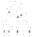
図11(A)~図11(C)は、電気自動車用駆動装置1を駆動源として使用した電気自動車の第1例を示している。電気自動車50aは、4人から5人程度の乗車定員を有する。電気自動車50aは、車体32aと、4個の駆動ユニット48とを備える。 Figures 11(A) to 11(C) show a first example of an electric vehicle that uses the electric vehicle drive device 1 as a drive source. The electric vehicle 50a has a passenger capacity of about four to five people. The electric vehicle 50a includes a vehicle body 32a and four drive units 48.

車体32aは、矩形箱状の車体本体51aと、車体本体51aの進行方向両側面のうち、下側部分から突出した庇状の一対の被支持部52a1、52a2とを備える。 The vehicle body 32a comprises a rectangular box-shaped vehicle body main body 51a and a pair of eaves-shaped supported parts 52a1, 52a2 that protrude from the lower parts of both sides of the vehicle body main body 51a in the traveling direction.

駆動ユニット48のそれぞれは、すべて同じ向きを向くように、一対の被支持部52a1、52a2のそれぞれの下面に2個ずつ支持されている。すなわち、駆動ユニット48のそれぞれを構成する車高調整装置31の上側支持部材44は、一対の被支持部52a1、52a2のそれぞれの下面の幅方向2箇所に支持固定されている。このため、車体本体51a内の空間(車室空間)を広く確保することができる。 Each of the drive units 48 is supported in pairs on the underside of each of the pair of supported parts 52a1, 52a2 so that they all face the same direction. That is, the upper support members 44 of the vehicle height adjustment device 31 constituting each of the drive units 48 are supported and fixed at two locations in the width direction on the underside of each of the pair of supported parts 52a1, 52a2. This makes it possible to ensure a large space (vehicle interior space) inside the vehicle body 51a.

電気自動車用駆動装置1は、車輪16a、16bのそれぞれをいずれの方向にも回転させることができる。ただし、駆動ユニット48の旋回軸Cは、一対の駆動軸4a、4bに対し、進行方向他側にオフセットして配置されている。このため、電気自動車50aは、駐車スペースへの駐車時や方向転換時などを除き、通常は、電気自動車用駆動装置1の進行方向他側(図11(B)の右側)が前方を向くように走行することが、直進走行の安定性を確保する面から好ましい。 The electric vehicle drive device 1 can rotate each of the wheels 16a, 16b in either direction. However, the pivot axis C of the drive unit 48 is offset to the other side of the traveling direction relative to the pair of drive shafts 4a, 4b. For this reason, except when parking in a parking space or changing direction, it is usually preferable for the electric vehicle 50a to run with the other side of the traveling direction of the electric vehicle drive device 1 (the right side in FIG. 11(B)) facing forward in order to ensure stability in straight-ahead driving.

また、電気自動車用駆動装置1の進行方向他側には、支持装置29の連結部材36が配置されている。したがって、進行方向他側を前方に向けて走行すれば、前方を走行する自動車のタイヤによって小石などが巻き上げられた場合でも、小石などが、電気自動車用駆動装置1に直接衝突するのを、連結部材36により防止することができる。 In addition, a connecting member 36 of the support device 29 is disposed on the other side of the electric vehicle drive device 1 in the direction of travel. Therefore, when the other side of the direction of travel is facing forward, even if pebbles or the like are kicked up by the tires of a vehicle traveling in front, the connecting member 36 can prevent the pebbles or the like from directly colliding with the electric vehicle drive device 1.

電気自動車50aは、図示しない制御装置により、4個の駆動ユニット48のそれぞれの車輪16a、16bの回転数および回転方向を制御することで、走行方向および走行速度を制御する。例えば、電気自動車50aは、すべての車輪16a、16bの回転数および回転方向を同じにすることで、直進走行することができる。一方、電気自動車50aは、それぞれの車輪16a、16bの回転数を適切な値に調節することで、旋回走行することができる。具体的には、旋回走行時には、車輪16a、16bの回転数を、旋回軌跡の径方向に関して内側に位置する車輪ほど小さくする。また、駆動ユニット48のそれぞれについて、一方の車輪16aの回転方向と他方の車輪16bの回転方向とを互いに反対方向とすれば、その場で、駆動ユニット48の向きのみを変更(転舵)することができる。 The electric vehicle 50a controls the running direction and running speed by controlling the rotation speed and direction of each of the wheels 16a, 16b of the four drive units 48 using a control device (not shown). For example, the electric vehicle 50a can run straight by making the rotation speed and direction of all the wheels 16a, 16b the same. On the other hand, the electric vehicle 50a can turn by adjusting the rotation speed of each of the wheels 16a, 16b to an appropriate value. Specifically, when turning, the rotation speed of the wheels 16a, 16b is made smaller for the wheels located radially inside the turning trajectory. Also, if the rotation direction of one wheel 16a and the rotation direction of the other wheel 16b are made opposite to each other for each of the drive units 48, only the direction of the drive unit 48 can be changed (steered) on the spot.

本例では、一対の駆動軸4a、4bを互いに同軸に配置しているため、一対の駆動軸4a、4bの回転方向および回転数を制御することにより、駆動ユニット48を、駆動軸4a、4bと平行な路面に対して直交する旋回軸Cを中心に回動させ、車両を転舵することができる。 In this example, the pair of drive shafts 4a, 4b are arranged coaxially with each other, so that by controlling the rotation direction and rotation speed of the pair of drive shafts 4a, 4b, the drive unit 48 can be rotated about a pivot axis C that is perpendicular to the road surface parallel to the drive shafts 4a, 4b, and the vehicle can be steered.

電気自動車50aは、停止する際には、制動装置14を駆動し、ブレーキキャリパ28に支持された一対のパッドを、制動用回転体15に押し付けて制動を行う。ただし、電気自動車用駆動装置1を構成する一対の電動モータ3a、3bのそれぞれを発電機として使用することで、回生制動を行うこともできる。 When the electric vehicle 50a stops, the braking device 14 is driven and a pair of pads supported by the brake caliper 28 are pressed against the braking rotor 15 to perform braking. However, regenerative braking can also be performed by using each of the pair of electric motors 3a, 3b that make up the electric vehicle drive device 1 as a generator.

駆動ユニット48のそれぞれは、車高調整装置31を備える。したがって、電気自動車50aは、駆動ユニット48のそれぞれの車高調整装置31の上下寸法を調節することにより、車高を調節することができる。特に、駆動ユニット48のそれぞれの重量センサによる測定値に基づいて、それぞれの車高調整装置31の上下寸法を調節すれば、車室空間の重量バランスにかかわらず、車体32aの重量を、4個の駆動ユニット48によりバランスよく支承できる。また、乗員の乗降や荷物の積み下ろしの際には、車体32aのうち、乗降口側を低くして、乗降動作や積み下ろし作業を容易化することができる。 Each drive unit 48 is equipped with a height adjustment device 31. Therefore, the electric vehicle 50a can adjust its height by adjusting the vertical dimensions of the height adjustment devices 31 of each drive unit 48. In particular, by adjusting the vertical dimensions of each height adjustment device 31 based on measurements by the weight sensors of each drive unit 48, the weight of the vehicle body 32a can be supported in a balanced manner by the four drive units 48 regardless of the weight balance in the vehicle interior space. In addition, when passengers get on and off the vehicle or when loading and unloading luggage, the entrance side of the vehicle body 32a can be lowered to facilitate boarding and alighting and loading and unloading operations.

図12(A)~図12(C)は、電気自動車用駆動装置1を駆動源として使用した電気自動車の第2例を示している。電気自動車50bは、8人から10人程度の乗車定員を有する。電気自動車50bは、車体32bと、8個の駆動ユニット48とを備える。 Figures 12(A) to 12(C) show a second example of an electric vehicle that uses the electric vehicle drive device 1 as a drive source. The electric vehicle 50b has a passenger capacity of about 8 to 10 people. The electric vehicle 50b includes a vehicle body 32b and eight drive units 48.

車体32bは、矩形箱状の車体本体51bと、車体本体51bの進行方向両側面のうち、下側部分から突出した庇状の一対の被支持部52b1、52b2とを備える。 The vehicle body 32b comprises a rectangular box-shaped vehicle body main body 51b and a pair of eaves-shaped supported parts 52b1, 52b2 that protrude from the lower parts of both sides of the vehicle body main body 51b in the traveling direction.

駆動ユニット48のそれぞれは、一対の被支持部52b1、52b2のそれぞれの下面に4個ずつ支持されている。すなわち、駆動ユニット48のそれぞれを構成する車高調整装置31の上側支持部材44は、一対の被支持部52b1、52b2のそれぞれの下面に、2列に分けて、両列ごとに幅方向2箇所ずつに支持固定されている。その他の部分の構成および作用効果は、図11(A)~図11(C)に示す第1例と同様である。 Each of the drive units 48 is supported by four units on the underside of each of the pair of supported parts 52b1, 52b2. That is, the upper support members 44 of the vehicle height adjustment device 31 constituting each of the drive units 48 are supported and fixed to the underside of each of the pair of supported parts 52b1, 52b2 in two rows, with two locations in each row in the width direction. The configuration and effects of the other parts are the same as those of the first example shown in Figures 11(A) to 11(C).

図13(A)~図13(C)は、電気自動車用駆動装置1を駆動源として使用した電気自動車の第3例を示している。電気自動車50cは、20人から30人程度の乗車定員を有する。電気自動車50cは、車体32cと、16個の駆動ユニット48とを備える。 Figures 13(A) to 13(C) show a third example of an electric vehicle that uses the electric vehicle drive device 1 as a drive source. The electric vehicle 50c has a passenger capacity of about 20 to 30 people. The electric vehicle 50c includes a vehicle body 32c and 16 drive units 48.

車体32cは、矩形箱状の車体本体51cと、車体本体51cの進行方向両側面のうち、下側部分から突出した庇状の一対の被支持部52c1、52c2とを備える。 The vehicle body 32c comprises a rectangular box-shaped vehicle body 51c and a pair of eaves-shaped supported parts 52c1, 52c2 that protrude from the lower parts of both sides of the vehicle body 51c in the traveling direction.

駆動ユニット48のそれぞれは、一対の被支持部52c1、52c2のそれぞれの下面に8個ずつ支持されている。すなわち、駆動ユニット48のそれぞれを構成する車高調整装置31の上側支持部材44は、一対の被支持部52c1、52c2のそれぞれの下面に、2列に分けて、両列ごとに幅方向4箇所ずつに支持固定されている。その他の部分の構成および作用効果は、図11(A)~図11(C)に示す第1例と同様である。 Each of the drive units 48 is supported by eight units on the underside of each of the pair of supported parts 52c1, 52c2. That is, the upper support members 44 of the vehicle height adjustment device 31 constituting each of the drive units 48 are supported and fixed to the underside of each of the pair of supported parts 52c1, 52c2 in two rows, with four locations in each row in the width direction. The configuration and effects of the other parts are the same as those of the first example shown in Figures 11(A) to 11(C).

上述のように、本例の電気自動車用駆動装置1は、車両総重量にかかわらず、電気自動車の駆動装置として、共通に使用することができる。したがって、電気自動車用駆動装置を車両総重量ごとに専用に設計する必要がなく、電気自動車の製造コストを低減することができる。特に、本例の電気自動車用駆動装置1を、多数の高価なセンサを備える自動運転車に適用した場合、電気自動車用駆動装置1の共通化によるコスト削減効果を顕著に得ることができる。 As described above, the electric vehicle drive device 1 of this example can be commonly used as a drive device for electric vehicles regardless of the total vehicle weight. Therefore, there is no need to design an electric vehicle drive device specifically for each total vehicle weight, and the manufacturing costs of electric vehicles can be reduced. In particular, when the electric vehicle drive device 1 of this example is applied to an autonomous vehicle equipped with a large number of expensive sensors, the cost reduction effect of sharing the electric vehicle drive device 1 can be obtained significantly.

本例では、一対の電動モータ3a、3bは、それぞれの出力軸7a、7bの回転数および回転方向を独立して制御可能に構成されている。したがって、一対の駆動軸4a、4bのそれぞれに支持された車輪16a、16bの回転数および回転方向を独立して調節することができる。このため、駆動ユニット48を転舵するためのアクチュエータを別に備えなくても、一方の車輪16aの回転方向と他方の車輪16bの回転方向とを互いに反対方向とすることで、駆動ユニット48の転舵を行うことができる。ただし、駆動ユニット48のそれぞれは、旋回軸Cを中心に転舵するためのアクチュエータを別に備えることもできる。 In this example, the pair of electric motors 3a, 3b are configured to be able to independently control the rotation speed and direction of each output shaft 7a, 7b. Therefore, the rotation speed and direction of the wheels 16a, 16b supported by each of the pair of drive shafts 4a, 4b can be independently adjusted. Therefore, even without a separate actuator for steering the drive unit 48, the drive unit 48 can be steered by rotating one wheel 16a in the opposite direction to the other wheel 16b. However, each drive unit 48 can also be provided with a separate actuator for steering about the pivot axis C.

また、本例の電気自動車用駆動装置1は、一対の電動モータ3a、3bのそれぞれを構成する駆動部53a、53bを、それぞれの出力軸7a、7bに直交する方向に関する位置を互いに同じとしている。このため、電気自動車用駆動装置1の幅方向に関する寸法を抑えることができる。 In addition, in the electric vehicle drive device 1 of this example, the drive units 53a, 53b constituting each of the pair of electric motors 3a, 3b are positioned in the same position in the direction perpendicular to the output shafts 7a, 7b. This allows the width dimension of the electric vehicle drive device 1 to be reduced.

なお、本例の電気自動車用駆動装置1は、一対の駆動軸4a、4bのそれぞれを、一対の電動モータ3a、3bのそれぞれにより、一対のトルク伝達装置5a、5bを介して駆動するように構成されているが、本発明を実施する場合、駆動軸のそれぞれを、2個以上ずつの電動モータにより駆動するように構成することもできる。 In this example, the electric vehicle drive device 1 is configured to drive each of the pair of drive shafts 4a, 4b by a pair of electric motors 3a, 3b via a pair of torque transmission devices 5a, 5b, but when implementing the present invention, each of the drive shafts can also be configured to be driven by two or more electric motors.

電気自動車用駆動装置1と、ハブユニット軸受13a、13b、制動装置14および車輪16a、16bと、支持装置29と、旋回装置30と、車高調整装置31とからなる駆動ユニット48は、電気自動車50a、50b、50cの走行、旋回および停止の機能を実現することができる。また、電気自動車50a、50b、50cは、このような駆動ユニット48を複数個備える。このため、電気自動車50a、50b、50cは、複数個の駆動ユニット48のうちの一部の駆動ユニット48が故障した場合でも、残りの駆動ユニット48を使用してある程度(例えば、路肩に退避する程度であれば)自走し続けることができる。また、電気自動車50a、50b、50cは、故障した駆動ユニット48ごと交換することで、容易に故障を修理することができ、メンテナンス性に優れる。 The electric vehicle drive device 1, the hub unit bearings 13a, 13b, the brake device 14, the wheels 16a, 16b, the support device 29, the turning device 30, and the vehicle height adjustment device 31 constitute a drive unit 48 that enables the electric vehicles 50a, 50b, and 50c to run, turn, and stop. The electric vehicles 50a, 50b, and 50c each have a plurality of such drive units 48. Therefore, even if one of the drive units 48 fails, the electric vehicles 50a, 50b, and 50c can continue to run to a certain extent (for example, to the extent of retreating to the roadside) using the remaining drive units 48. The electric vehicles 50a, 50b, and 50c also have excellent maintainability because the breakdown can be easily repaired by replacing the failed drive unit 48.

[実施の形態の第2例]
実施の形態の第2例について、図14(A)~図26を用いて説明する。本例は、電気自動車の一種である無人搬送車(AGV:Automated Guided Vehicle)の駆動装置に、本発明の電気自動車用駆動装置を適用した例である。無人搬送車は、自動車を所定の位置まで搬送する。以下では、まず、無人搬送車の全体構造について説明した後、本例の駆動ユニットの構造について説明する。
[Second Example of the Embodiment]
A second embodiment of the present invention will be described with reference to Fig. 14(A) to Fig. 26. In this embodiment, the electric vehicle drive device of the present invention is applied to a drive device of an automated guided vehicle (AGV), which is a type of electric vehicle. The automated guided vehicle transports an automobile to a predetermined position. In the following, the overall structure of the automated guided vehicle will be described first, and then the structure of the drive unit of this embodiment will be described.

無人搬送車55は、車体56と、一対の駆動ユニット48aと、一対の従動輪57とを備える。 The automated guided vehicle 55 includes a vehicle body 56, a pair of drive units 48a, and a pair of driven wheels 57.

車体56は、矩形箱状の牽引部58と、自動車を載置するための載置部59とを備える。載置部59は、上下方向から見て略U字形(コ字形)の平面形状を有する。すなわち、載置部59は、牽引部58の後側面の下側の端部から後側に向けて延出する矩形板状の基部60と、該基部60の後側の端部の幅方向に離隔した2箇所位置から後側に向けて延出する矩形板状の延出部61とを有する。延出部61のそれぞれには、自動車の前輪および後輪がそれぞれ載置される。 The vehicle body 56 includes a rectangular box-shaped towing section 58 and a mounting section 59 for mounting an automobile. The mounting section 59 has a generally U-shaped planar shape when viewed from the top-bottom direction. That is, the mounting section 59 has a rectangular plate-shaped base section 60 that extends rearward from the lower end of the rear side of the towing section 58, and rectangular plate-shaped extension sections 61 that extend rearward from two positions spaced apart in the width direction of the rear end section of the base 60. The front and rear wheels of the automobile are placed on each of the extension sections 61.

駆動ユニット48aのそれぞれは、牽引部58の下面のうち、幅方向に離隔した2箇所位置に、路面に直交する旋回軸C(図16参照)を中心とする回動を可能に支持されている。 Each of the drive units 48a is supported on the underside of the towing section 58 at two locations spaced apart in the width direction so as to be able to rotate about a pivot axis C (see FIG. 16) that is perpendicular to the road surface.

従動輪57のそれぞれは、延出部61の後側部分に支持された支持軸62と、該支持軸62に回転自在に支持された一対のタイヤ63とを有する。 Each of the driven wheels 57 has a support shaft 62 supported on the rear portion of the extension 61 and a pair of tires 63 supported rotatably on the support shaft 62.

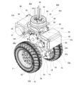
次に、本例の無人搬送車55に搭載される駆動ユニット48aの構造について説明する。本例の駆動ユニット48aは、一対の電動モータ3c、3dの設置箇所が、実施の形態の第1例の駆動ユニット48と異なる。すなわち、本例の駆動ユニット48aでは、一対の電動モータ3c、3dのそれぞれが、車輪16c、16dから径方向外側に外れた位置に配置されている。より具体的には、一対の電動モータ3c、3dのそれぞれは、車輪16c、16dから上方に外れた位置に配置されている。 Next, the structure of the drive unit 48a mounted on the automated guided vehicle 55 of this example will be described. The drive unit 48a of this example differs from the drive unit 48 of the first example of the embodiment in the location where the pair of electric motors 3c, 3d are installed. That is, in the drive unit 48a of this example, each of the pair of electric motors 3c, 3d is disposed at a position radially outwardly offset from the wheels 16c, 16d. More specifically, each of the pair of electric motors 3c, 3d is disposed at a position offset upward from the wheels 16c, 16d.

また、一対の電動モータ3c、3dのそれぞれは、駆動部53c、53dを、それぞれの出力軸7c、7dに直交する方向に関して重畳するように配置している。具体的には、本例では、駆動部53c、53dの幅方向に関する位置を、互いに同じとしている The pair of electric motors 3c, 3d are arranged so that the driving parts 53c, 53d are overlapped in a direction perpendicular to the output shafts 7c, 7d. Specifically, in this example, the positions of the driving parts 53c, 53d in the width direction are the same.

駆動ユニット48aは、電気自動車用駆動装置1aと、車輪16c、16dおよび制動装置14と、旋回装置30aとを備える。 The drive unit 48a includes an electric vehicle drive device 1a, wheels 16c, 16d, a braking device 14, and a turning device 30a.

電気自動車用駆動装置1aは、ハウジング2aと、一対の電動モータ3c、3dと、一対の駆動軸4c、4dと、一対のトルク伝達装置5c、5dとを備える。 The electric vehicle drive unit 1a includes a housing 2a, a pair of electric motors 3c, 3d, a pair of drive shafts 4c, 4d, and a pair of torque transmission devices 5c, 5d.

ハウジング2aは、円筒部6dと、円筒部6dよりも上側部分に備えられ、互いに平行に、かつ、進行方向および幅方向に離隔して配置された矩形板状の一対のモータ取付部64a、64bと、円筒部6dとモータ取付部64a、64bのそれぞれとの間に掛け渡された一対の伝達装置収容部65a、65bとを有する。 The housing 2a has a cylindrical portion 6d, a pair of rectangular plate-shaped motor mounting portions 64a, 64b that are provided above the cylindrical portion 6d and are arranged parallel to each other and spaced apart in the direction of travel and width, and a pair of transmission device accommodating portions 65a, 65b that are bridged between the cylindrical portion 6d and the motor mounting portions 64a, 64b, respectively.

一対の電動モータ3c、3dのそれぞれは、出力軸7c、7dを有し、ハウジング2aに対し支持固定されている。具体的には、一対の電動モータ3c、3dのそれぞれは、出力軸7c、7dの先端部を、互いに反対方向に向けた状態で、出力軸7c、7dが、互いに非同軸に、かつ、互いに平行となるように、ハウジング2aのモータ取付部64a、64bに支持固定されている。 The pair of electric motors 3c, 3d each have an output shaft 7c, 7d, and are supported and fixed to the housing 2a. Specifically, the pair of electric motors 3c, 3d each are supported and fixed to the motor mounting parts 64a, 64b of the housing 2a such that the output shafts 7c, 7d are non-coaxial and parallel to each other with the tips of the output shafts 7c, 7d facing in opposite directions.

このために、具体的には、一対の電動モータ3c、3dのうち、一方である第1の電動モータ3cは、出力軸7cの先端部を、幅方向に関して片側(図26の左側)に向けた状態で、ハウジング2aの一対のモータ取付部64a、64bのうち、幅方向片側のモータ取付部64aの幅方向他側面に支持固定されている。 To this end, specifically, the first electric motor 3c, which is one of the pair of electric motors 3c, 3d, is supported and fixed to the other side in the width direction of the motor mounting portion 64a on one side in the width direction of the pair of motor mounting portions 64a, 64b of the housing 2a, with the tip of the output shaft 7c facing one side in the width direction (the left side in FIG. 26).

これに対し、一対の電動モータ3c、3dのうち、他方である第2の電動モータ3dは、出力軸7dの先端部を、幅方向に関して他側(図26の右側)に向けた状態で、ハウジング2aの一対のモータ取付部64a、64bのうち、幅方向他側のモータ取付部64bの幅方向片側面に支持固定されている。 In contrast, the second electric motor 3d, which is the other of the pair of electric motors 3c, 3d, is supported and fixed to one side of the motor mounting portion 64b on the other side in the width direction of the pair of motor mounting portions 64a, 64b of the housing 2a, with the tip of the output shaft 7d facing the other side in the width direction (the right side in FIG. 26).

なお、本例では、一対の電動モータ3c、3dのそれぞれとして、実施の形態の第1例に係る電気自動車用駆動装置1の電動モータ3a、3bよりも定格電圧が低く、大型のモータが使用されている。具体的には、例えば、電動モータ3c、3dのそれぞれとして、定格電圧が48[V]のモータを使用している。 In this example, a pair of electric motors 3c, 3d are each a larger motor with a lower rated voltage than the electric motors 3a, 3b of the electric vehicle drive device 1 according to the first embodiment. Specifically, for example, a motor with a rated voltage of 48 V is used as each of the electric motors 3c, 3d.

一対の駆動軸4c、4dのそれぞれは、互いに同軸に、かつ、それぞれの先端部を互いに反対方向に向けた状態で、基端部(互いに近い側の端部)を、ハウジング2aの円筒部6dに対し回転自在に支持している。さらに、図23および図24に示すように、一対の駆動軸4c、4dのそれぞれは、中間部を、ハウジング2aに対し支持固定された筒状部材76の内側に、背面組み合わせ(DB)型の接触角を付与した一対の円すいころ軸受77を介して回転自在に支持している。本例では、一対の駆動軸4c、4dは、一対の電動モータ3c、3dのそれぞれの出力軸7c、7dと非同軸に、かつ、平行に配置されている。 The pair of drive shafts 4c, 4d are coaxial with each other, with their respective tips facing in opposite directions, and their base ends (the ends closest to each other) are rotatably supported by the cylindrical portion 6d of the housing 2a. Furthermore, as shown in Figures 23 and 24, the middle portion of each of the pair of drive shafts 4c, 4d is rotatably supported by a pair of tapered roller bearings 77 with a back-to-back (DB) type contact angle on the inside of a cylindrical member 76 supported and fixed to the housing 2a. In this example, the pair of drive shafts 4c, 4d are arranged non-coaxially and parallel to the output shafts 7c, 7d of the pair of electric motors 3c, 3d.

このために、具体的には、一対の駆動軸4c、4dのうち、一方である第1の駆動軸4cは、先端部を、幅方向に関して他側に向けた状態で、基端部を、ハウジング2aの円筒部6dの幅方向他側の端部に、回転自在に支持している。これに対し、一対の駆動軸4c、4dのうち、他方である第2の駆動軸4dは、先端部を、幅方向に関して片側に向けた状態で、基端部を、円筒部6dの幅方向片側の端部に、回転自在に支持している。 To this end, specifically, the first drive shaft 4c, which is one of the pair of drive shafts 4c, 4d, has its base end rotatably supported on the end of the cylindrical portion 6d of the housing 2a in the other width direction, with its tip end facing the other side in the width direction. In contrast, the second drive shaft 4d, which is the other of the pair of drive shafts 4c, 4d, has its base end rotatably supported on the end of the cylindrical portion 6d in the one width direction, with its tip end facing one side in the width direction.

本例では、図16に示すように、駆動軸4c、4dのそれぞれに車輪16c、16dを支持した状態で、幅方向(駆動軸4c、4dの軸方向)から見た場合に、電動モータ3c、3dのそれぞれが、車輪16c、16dを構成するタイヤ33よりも上方に位置するように、ハウジング2aを構成する円筒部6dとモータ取付部64a、64bの位置関係を規制している。すなわち、電動モータ3c、3dの大きさやタイヤ33の外径寸法に基づいて、円筒部6dとモータ取付部64a、64bの上下方向に関する位置関係を規制している。 In this example, as shown in Fig. 16, when wheels 16c, 16d are supported on drive shafts 4c, 4d, respectively, the positional relationship between cylindrical portion 6d and motor mounting portions 64a, 64b constituting housing 2a is regulated so that electric motors 3c, 3d are positioned above tires 33 constituting wheels 16c, 16d when viewed from the width direction (axial direction of drive shafts 4c, 4d). In other words, the positional relationship between cylindrical portion 6d and motor mounting portions 64a, 64b in the vertical direction is regulated based on the size of electric motors 3c, 3d and the outer diameter dimension of tires 33.

さらに、本例では、図18に示すように、駆動ユニット48aを構成するすべての部材が、一対の車輪16c、16dの旋回円(後述する旋回軸Cを中心とし、車輪16c、16dを構成するタイヤ33の外周面のうちの幅方向外側の端部を通る円)αの内側に位置するように、一対の電動モータ3c、3d同士の進行方向に関する間隔を規制している。すなわち、電動モータ3c、3dの大きさやタイヤ33の幅寸法に基づいて、モータ取付部64a、64bの進行方向に関する位置関係を規制している。 Furthermore, in this example, as shown in FIG. 18, the distance between the pair of electric motors 3c, 3d in the traveling direction is regulated so that all members constituting the drive unit 48a are located inside the turning circle α of the pair of wheels 16c, 16d (a circle centered on the turning axis C described below and passing through the outer end in the width direction of the outer peripheral surface of the tire 33 constituting the wheels 16c, 16d). In other words, the positional relationship of the motor mounting parts 64a, 64b in the traveling direction is regulated based on the size of the electric motors 3c, 3d and the width dimension of the tire 33.

一対のトルク伝達装置5c、5dのそれぞれは、一対の電動モータ3c、3dのそれぞれの出力軸7c、7dの回転トルクを、一対の駆動軸4c、4dのそれぞれに伝達する。本例では、一対のトルク伝達装置5c、5dのそれぞれは、歯車式減速機により構成されている。すなわち、一対のトルク伝達装置5c、5dのうちの一方である第1のトルク伝達装置5cは、第1の電動モータ3cの出力軸7cの回転トルクを増大させつつ、第1の駆動軸4cに伝達する。これに対し、一対のトルク伝達装置5c、5dのうちの他方である第2のトルク伝達装置5dは、第2の電動モータ3dの出力軸7dの回転トルクを増大させつつ、第2の駆動軸4dに伝達する。 Each of the pair of torque transmission devices 5c, 5d transmits the rotational torque of the output shaft 7c, 7d of the pair of electric motors 3c, 3d to each of the pair of drive shafts 4c, 4d. In this example, each of the pair of torque transmission devices 5c, 5d is configured with a gear-type reducer. That is, the first torque transmission device 5c, which is one of the pair of torque transmission devices 5c, 5d, increases the rotational torque of the output shaft 7c of the first electric motor 3c while transmitting it to the first drive shaft 4c. In contrast, the second torque transmission device 5d, which is the other of the pair of torque transmission devices 5c, 5d, increases the rotational torque of the output shaft 7d of the second electric motor 3d while transmitting it to the second drive shaft 4d.

このために、一対のトルク伝達装置5c、5dのそれぞれは、いずれも平歯車により構成される4個の中間軸66a~66dと、8個の歯車67a~67hとを備える。 For this reason, each of the pair of torque transmission devices 5c, 5d has four intermediate shafts 66a-66d, all of which are made up of spur gears, and eight gears 67a-67h.

中間軸66a~66dは、それぞれ非同軸に、かつ、平行に、ハウジング2aの伝達装置収容部65a、65bの内側に回転自在に支持されている。 The intermediate shafts 66a to 66d are supported non-coaxially and in parallel to each other so as to be freely rotatable inside the transmission device accommodating portions 65a and 65b of the housing 2a.

第1の中間軸66aは、伝達装置収容部65a、65bの内側部分のうち、進行方向に関して電動モータ3c、3dの出力軸7c、7dよりも駆動軸4c、4dに近い側の位置に回転自在に支持されている。第2の中間軸66bは、伝達装置収容部65a、65bの内側部分のうち、進行方向に関して第1の中間軸66aよりも駆動軸4c、4dに近い側で、かつ、第1の中間軸66aよりも上方に回転自在に支持されている。第3の中間軸66cは、伝達装置収容部65a、65bの内側部分のうち、第2の中間軸66bよりも下方、かつ、進行方向に関して第1の中間軸66aよりも駆動軸4c、4dに近い側の位置に回転自在に支持されている。第4の中間軸66dは、伝達装置収容部65a、65bの内側部分のうち、第3の中間軸66cよりも下方、かつ、進行方向に関して第3の中間軸66cよりも駆動軸4c、4dに近い側の位置に回転自在に支持されている。 The first intermediate shaft 66a is rotatably supported at a position on the inner side of the transmission device housing 65a, 65b closer to the drive shafts 4c, 4d than the output shafts 7c, 7d of the electric motors 3c, 3d in the direction of travel. The second intermediate shaft 66b is rotatably supported at a position on the inner side of the transmission device housing 65a, 65b closer to the drive shafts 4c, 4d than the first intermediate shaft 66a in the direction of travel and above the first intermediate shaft 66a. The third intermediate shaft 66c is rotatably supported at a position on the inner side of the transmission device housing 65a, 65b lower than the second intermediate shaft 66b and closer to the drive shafts 4c, 4d than the first intermediate shaft 66a in the direction of travel. The fourth intermediate shaft 66d is rotatably supported in the inner portion of the transmission device accommodating portion 65a, 65b, at a position lower than the third intermediate shaft 66c and closer to the drive shafts 4c, 4d than the third intermediate shaft 66c in the direction of travel.

第1の歯車67aは、電動モータ3c、3dのそれぞれの出力軸7c、7dとともに回転する。本例では、第1の歯車67aは、電動モータ3c、3dのそれぞれの出力軸7c、7dの先端部に外嵌固定されている。 The first gear 67a rotates together with the output shafts 7c and 7d of the electric motors 3c and 3d. In this example, the first gear 67a is fitted and fixed to the tip of the output shafts 7c and 7d of the electric motors 3c and 3d.

第2の歯車67bは、第1の歯車67aと噛合し、第1の中間軸66aの周囲に備えられている。本例では、第2の歯車67bは、第1の中間軸66aと一体に構成されている。第2の歯車67bは、第1の歯車67aの歯数よりも多い歯数を有する。 The second gear 67b meshes with the first gear 67a and is provided around the first intermediate shaft 66a. In this example, the second gear 67b is integrally formed with the first intermediate shaft 66a. The second gear 67b has a greater number of teeth than the first gear 67a.

第3の歯車67cは、第2の歯車67bと噛合し、第2の中間軸66bに支持固定されている。本例では、第3の歯車67cは、第2の歯車67bの歯数よりも多い歯数を有する。 The third gear 67c meshes with the second gear 67b and is supported and fixed to the second intermediate shaft 66b. In this example, the third gear 67c has a greater number of teeth than the second gear 67b.

第4の歯車67dは、第2の中間軸66bのうち、第3の歯車67cが支持固定された部分から軸方向に外れた部分の周囲に備えられ、第3の歯車67cと同期して回転する。本例では、第4の歯車67dは、第2の中間軸66bと一体に構成されている。第4の歯車67dは、第3の歯車67cの歯数よりも少ない歯数を有する。 The fourth gear 67d is provided around a portion of the second intermediate shaft 66b that is axially displaced from the portion where the third gear 67c is supported and fixed, and rotates in synchronization with the third gear 67c. In this example, the fourth gear 67d is integrally formed with the second intermediate shaft 66b. The fourth gear 67d has a smaller number of teeth than the third gear 67c.

第5の歯車67eは、第4の歯車67dと噛合し、第3の中間軸66cに支持固定されている。本例では、第5の歯車67eは、第4の歯車67dの歯数よりも多い歯数を有する。 The fifth gear 67e meshes with the fourth gear 67d and is supported and fixed to the third intermediate shaft 66c. In this example, the fifth gear 67e has a greater number of teeth than the fourth gear 67d.

第6の歯車67fは、第3の中間軸66cのうち、第5の歯車67eが支持固定された部分から軸方向に外れた部分の周囲に備えられ、第5の歯車67eと同期して回転する。本例では、第6の歯車67fは、第3の中間軸66cと一体に構成されている。第6の歯車67fは、第5の歯車67eの歯数よりも少ない歯数を有する。 The sixth gear 67f is provided around a portion of the third intermediate shaft 66c that is axially displaced from the portion where the fifth gear 67e is supported and fixed, and rotates in synchronization with the fifth gear 67e. In this example, the sixth gear 67f is integrally formed with the third intermediate shaft 66c. The sixth gear 67f has a smaller number of teeth than the fifth gear 67e.

第7の歯車67gは、第6の歯車67fと噛合し、第4の中間軸66dの周囲に備えられている。本例では、第7の歯車67gは、第4の中間軸66dと一体に構成されている。第7の歯車67gは、第6の歯車67fの歯数よりも多い歯数を有する。 The seventh gear 67g meshes with the sixth gear 67f and is provided around the fourth intermediate shaft 66d. In this example, the seventh gear 67g is integrally formed with the fourth intermediate shaft 66d. The seventh gear 67g has a greater number of teeth than the sixth gear 67f.

第8の歯車67hは、第7の歯車67gと噛合し、かつ、駆動軸4c、4dのそれぞれとともに回転する。第8の歯車67hは、第7の歯車67gの歯数よりも多い歯数を有する。本例では、第8の歯車67hは、駆動軸4c、4dのそれぞれの基端部(互いに近い側の端部)に支持固定されている。 The eighth gear 67h meshes with the seventh gear 67g and rotates with each of the drive shafts 4c and 4d. The eighth gear 67h has a greater number of teeth than the seventh gear 67g. In this example, the eighth gear 67h is supported and fixed to the base end (the end closest to each other) of each of the drive shafts 4c and 4d.

一対のトルク伝達装置5c、5dのそれぞれは、上記の構成に限らず、電動モータ3c、3dのそれぞれの出力軸7c、7dの回転トルクを、駆動軸4c、4dのそれぞれに増大させつつ伝達できる限り、適宜変更することができる。具体的には、例えば、歯車67a~67hの歯数の関係を上記関係から変更したり、歯車(および中間軸)の個数を変更したりすることができる。本例では、歯車67a~67hは、いずれも平歯車により構成されているが、歯車の一部または全部を、はずば歯車により構成することもできる。トルク伝達装置中に、互いに噛合するウォームの中心軸とウォームホイールの中心軸とがねじれの位置にあるウォーム減速機を組み込むこともできる。さらに、トルク伝達装置を、ベルトやチェーンを使用した減速機により構成することもできる。 The pair of torque transmission devices 5c, 5d are not limited to the above configuration, and can be modified as appropriate as long as the rotational torque of the output shafts 7c, 7d of the electric motors 3c, 3d can be increased and transmitted to the drive shafts 4c, 4d. Specifically, for example, the relationship between the number of teeth of the gears 67a to 67h can be changed from the above relationship, or the number of gears (and intermediate shafts) can be changed. In this example, the gears 67a to 67h are all spur gears, but some or all of the gears can be helical gears. A worm reducer in which the central axis of the worm and the central axis of the worm wheel that mesh with each other are in a twisted position can also be incorporated into the torque transmission device. Furthermore, the torque transmission device can be configured with a reducer that uses a belt or chain.

図23および図24に示すように、一対の駆動軸4c、4dのそれぞれには、取付部材78を介して、制動装置14を構成する制動用回転体15と、車輪16c、16dを構成するホイール17とが支持される。 As shown in Figures 23 and 24, a pair of drive shafts 4c, 4d are supported by mounting members 78 on each of which are a braking rotor 15 constituting the braking device 14 and wheels 17 constituting the wheels 16c, 16d.

取付部材78は、中心部に、軸方向に貫通するスプライン孔79を有し、かつ、径方向外側に向けて突出した回転フランジ80を有する。 The mounting member 78 has a spline hole 79 that penetrates axially in the center, and a rotating flange 80 that protrudes radially outward.

スプライン孔79には、一対の駆動軸4c、4dのそれぞれの先端部に備えられたスプライン軸部24がスプライン係合されている。 The splined shaft portions 24 provided at the respective ends of the pair of drive shafts 4c, 4d are splined into the splined holes 79.

回転フランジ80は、周方向複数箇所に取付孔81を有する。制動用回転体15およびホイール17は、それぞれの周方向複数箇所に備えられた通孔を挿通したハブボルト26を、取付孔81のそれぞれに螺合することにより、回転フランジ80に対し支持されている。 The rotating flange 80 has mounting holes 81 at multiple locations in the circumferential direction. The braking rotor 15 and the wheel 17 are supported on the rotating flange 80 by threading the hub bolts 26, which pass through holes provided at multiple locations in the circumferential direction of each of them, into the mounting holes 81.

なお、取付部材78は、一対の駆動軸4c、4dのそれぞれの先端部に螺合されたナット82により、駆動軸4c、4dのそれぞれからの脱落が防止されている。 The mounting member 78 is prevented from falling off the drive shafts 4c and 4d by nuts 82 that are screwed onto the ends of the pair of drive shafts 4c and 4d.

電気自動車用駆動装置1aは、旋回装置30aを介して、車体56の牽引部58の下面に支持される。 The electric vehicle drive unit 1a is supported on the underside of the towing section 58 of the vehicle body 56 via the turning device 30a.

旋回装置30aは、車体56の牽引部58の下面に支持固定された固定部材38aと、ハウジング2aの上側の端部に支持固定された回転部材39aとを、互いに同軸に、かつ、旋回軸Cを中心とする相対回転を可能に組み合わせてなる。具体的には、旋回装置30aは、固定部材38aの径方向内側に回転部材39aを、複数個の転動体91を介して回転自在に支持してなる。 The swivel device 30a is a combination of a fixed member 38a supported and fixed to the underside of the towing section 58 of the vehicle body 56 and a rotating member 39a supported and fixed to the upper end of the housing 2a, which are coaxial with each other and can rotate relative to each other around the swivel axis C. Specifically, the swivel device 30a supports the rotating member 39a on the radially inner side of the fixed member 38a via a plurality of rolling elements 91 so that it can rotate freely.

固定部材38aは、内周面に、複列の固定側軌道92を有し、かつ、上下方向中間部に、旋回軸Cを中心とする径方向に関して外側に向けて突出した固定フランジ84を有する。固定フランジ84は、それぞれが上下方向に貫通する固定側支持孔85を有し、かつ、円周方向に離隔して配置された複数個(図示の例では4個)の固定フランジ片86を備える。すなわち、固定フランジ片86のそれぞれは、固定側支持孔85を1個ずつ備えている。固定部材38は、固定側支持孔85に挿通または螺合されたボルトにより、牽引部58に支持固定されている。 The fixed member 38a has a double row of fixed side tracks 92 on its inner circumferential surface, and a fixed flange 84 at the vertical middle that protrudes outward in the radial direction centered on the pivot axis C. Each fixed flange 84 has a fixed side support hole 85 that penetrates in the vertical direction, and includes a plurality of fixed flange pieces 86 (four in the illustrated example) that are spaced apart in the circumferential direction. That is, each fixed flange piece 86 has one fixed side support hole 85. The fixed member 38 is supported and fixed to the towing section 58 by bolts that are inserted or screwed into the fixed side support holes 85.

回転部材39aは、外周面に、複列の回転側軌道93を有し、かつ、下側の端部に、旋回軸Cを中心とする径方向に関して外側に向けて突出した回転フランジ88を有する。回転フランジ88は、それぞれが上下方向に貫通する回転側支持孔(図示省略)を有し、かつ、円周方向に離隔して配置された複数個(図示の例では4個)の回転フランジ片89を備える。具体的には、回転フランジ片89のそれぞれは、前記回転側支持孔を1個ずつ備えている。回転部材39aは、回転側支持孔に挿通または螺合されたボルト90により、ハウジング2aの上側の端部に支持固定されている。 The rotating member 39a has a double row rotating side raceway 93 on its outer circumferential surface, and a rotating flange 88 at its lower end that protrudes outward in the radial direction centered on the rotation axis C. Each rotating flange 88 has a rotating side support hole (not shown) that penetrates in the vertical direction, and has a plurality of rotating flange pieces 89 (four in the illustrated example) that are spaced apart in the circumferential direction. Specifically, each rotating flange piece 89 has one of the rotating side support holes. The rotating member 39a is supported and fixed to the upper end of the housing 2a by bolts 90 that are inserted or screwed into the rotating side support holes.

転動体91のそれぞれは、複列の固定側軌道92と複列の回転側軌道93との間に、保持器により保持された状態で、転動自在に配置され、かつ、背面組み合わせ型の接触角が付与されている。本例では、転動体91として、玉を使用しているが、円すいころ使用することもできる。 Each of the rolling elements 91 is held by a cage between a double row fixed side raceway 92 and a double row rotating side raceway 93, and is arranged to roll freely, and is given a back-to-back combination type contact angle. In this example, balls are used as the rolling elements 91, but tapered rollers can also be used.

本例の駆動ユニット48aでは、駆動軸4c、4dの回転方向および回転数を制御することにより、車輪16c、16d(および電気自動車用駆動装置1a)を、旋回軸Cを中心に回動させることができる。 In this example, the drive unit 48a can rotate the wheels 16c, 16d (and the electric vehicle drive unit 1a) around the pivot axis C by controlling the direction and speed of rotation of the drive shafts 4c, 4d.

なお、本例では、図24に示すように、固定部材38aの内周面に複列の固定側軌道92を、外輪94を介して設け、かつ、回転部材39aの外周面に複列の回転側軌道93を、内輪95を介して設けている。換言すれば、固定部材38aの径方向内側に回転部材39aを、背面組み合わせ型の接触角が付与された一対のアンギュラ玉軸受を介して回転自在に支持している。ただし、本発明を実施する場合、固定部材の内周面に、複列の固定側軌道の一方若しくは両方を直接設ける、および/または、回転部材の外周面に、複列の回転側軌道の一方若しくは両方を直接設けることもできる。 In this example, as shown in FIG. 24, a double row fixed side raceway 92 is provided on the inner peripheral surface of the fixed member 38a via an outer ring 94, and a double row rotating side raceway 93 is provided on the outer peripheral surface of the rotating member 39a via an inner ring 95. In other words, the rotating member 39a is rotatably supported on the radially inner side of the fixed member 38a via a pair of angular ball bearings with a back-to-back contact angle. However, when implementing the present invention, one or both of the double row fixed side raceways can be provided directly on the inner peripheral surface of the fixed member, and/or one or both of the double row rotating side raceways can be provided directly on the outer peripheral surface of the rotating member.

なお、本例では、回転部材39aの中心軸である旋回軸Cを、一対の駆動軸4c、4dのそれぞれの中心軸と直交させている。ただし、旋回軸Cを、一対の駆動軸4c、4dのそれぞれの中心軸に対し、進行方向にオフセットさせる(ねじれの位置に配置する)ことにより、キャスタトレールを確保することもできる。 In this example, the pivot axis C, which is the central axis of the rotating member 39a, is perpendicular to the central axes of the pair of drive shafts 4c and 4d. However, the caster trail can also be ensured by offsetting the pivot axis C in the direction of travel with respect to the central axes of the pair of drive shafts 4c and 4d (positioning it in a twisted position).

本例の無人搬送車55は、各種センサなどからの信号に基づいて、牽引部58に搭載された制御装置により、一対の駆動ユニット48aのそれぞれを制御する。すなわち、前記制御装置により、一対の駆動ユニット48aのそれぞれの駆動軸4c、4dの回転方向および回転数(回転速度)を制御し、駆動軸4c、4dに支持された車輪16c、16dの回転方向および回転数を制御することで、無人搬送車55の走行方向および走行速度を制御することができる。 In this example, the automated guided vehicle 55 controls each of the pair of drive units 48a using a control device mounted on the towing unit 58 based on signals from various sensors, etc. In other words, the control device controls the rotation direction and number of rotations (rotational speed) of each of the drive shafts 4c, 4d of the pair of drive units 48a, and controls the rotation direction and number of rotations of the wheels 16c, 16d supported by the drive shafts 4c, 4d, thereby controlling the travel direction and travel speed of the automated guided vehicle 55.

例えば、すべての車輪16c、16dの回転数および回転方向を同じにすることで、無人搬送車55を直進走行させることができる。また、車輪16c、16dの回転数を、旋回軌跡の径方向に関して内側に位置する車輪ほど小さくすることで、無人搬送車55を旋回走行させることができる。さらに、駆動ユニット48aのそれぞれについて、一方の車輪16cの回転方向と他方の車輪16dの回転方向とを互いに反対方向とすれば、その場で、駆動ユニット48aの向きのみを変更(転舵)することができる。 For example, by making the rotation speed and direction of all the wheels 16c, 16d the same, the automated guided vehicle 55 can travel straight. Also, by making the rotation speed of the wheels 16c, 16d smaller for the wheels located radially inwards of the turning trajectory, the automated guided vehicle 55 can travel in turns. Furthermore, by making the rotation direction of one wheel 16c and the rotation direction of the other wheel 16d opposite each other for each of the drive units 48a, it is possible to change (steer) only the direction of the drive unit 48a on the spot.

本例では、一対の電動モータ3c、3dのそれぞれを、車輪16c、16d(を構成するタイヤ33)から径方向外側に外れた位置に配置している。このため、実施の形態の第1例のように、一対の電動モータ3a、3bが、一対の車輪16a、16b同士の間に配置されている構造と比較して、車輪16c、16d同士の間隔(車輪16c、16dの軸方向に関する間隔)を短くしやすい。換言すれば、駆動ユニット48a全体の幅方向寸法を小さく抑えやすい。要するに、電動モータ3c、3dとして、専用設計された小型のものを使用することなく、汎用かつ大型のものを使用した場合でも、タイヤ33の接地面(トレッド)の幅寸法を十分に確保しつつ、駆動ユニット48a全体の幅方向寸法の増大を抑えることができる。 In this example, the pair of electric motors 3c, 3d are arranged at a position radially outward from the wheels 16c, 16d (the tires 33 that constitute them). Therefore, compared to the structure in which the pair of electric motors 3a, 3b are arranged between the pair of wheels 16a, 16b as in the first example of the embodiment, it is easier to shorten the distance between the wheels 16c, 16d (the distance in the axial direction of the wheels 16c, 16d). In other words, it is easier to keep the width dimension of the entire drive unit 48a small. In short, even if general-purpose and large electric motors 3c, 3d are used instead of small ones specially designed for the electric motors 3c, 3d, the width dimension of the contact surface (tread) of the tire 33 can be sufficiently secured while suppressing an increase in the width dimension of the entire drive unit 48a.

したがって、本例の駆動ユニット48aは、幅方向に関する設置スペースが限られる車両にも組み込みやすい。あるいは、車輪16c、16d同士の間隔を抑えられる分、一対の電動モータ3c、3dを大型化(サイズアップ)することができるため、電動モータ3c、3dの定格出力を増大させて、電気自動車(無人搬送車55)への駆動ユニット48aの搭載数を抑えることができる。また、車輪16c、16d同士の間に配置される部品のレイアウト性の自由度を向上することができる。具体的には、例えば、大きな制動力を得るために、制動装置14を大型化したり、耐荷重を大きくするために、タイヤ33の幅寸法を大きくしたりするなどの変更を行いやすい。 Therefore, the drive unit 48a of this example can be easily installed in a vehicle with limited installation space in the width direction. Alternatively, since the distance between the wheels 16c, 16d can be reduced, the pair of electric motors 3c, 3d can be made larger (upsized), and the rated output of the electric motors 3c, 3d can be increased, thereby reducing the number of drive units 48a mounted on an electric vehicle (automated guided vehicle 55). In addition, the degree of freedom in the layout of the parts arranged between the wheels 16c, 16d can be improved. Specifically, for example, it is easy to make changes such as making the brake device 14 larger to obtain a large braking force, or increasing the width dimension of the tire 33 to increase the load capacity.

また、電動モータ3c、3dとして大型のもの使用した場合でも、駆動ユニット48aを構成するすべての部材を、一対の車輪16c、16dの旋回円αの内側に収めやすい。さらに、車輪16c、16dを取り外すことなく、電動モータ3c、3dの交換作業を行えるため、メンテナンス性を良好にすることができる。
その他の部分の構成および作用効果は、実施の形態の第1例と同じである。
Even if large electric motors 3c, 3d are used, all of the members constituting the drive unit 48a can be easily accommodated inside the turning circle α of the pair of wheels 16c, 16d. Furthermore, the electric motors 3c, 3d can be replaced without removing the wheels 16c, 16d, which improves maintainability.
The configuration and the effects of the other parts are the same as those of the first embodiment.

[実施の形態の第3例]
図27(A)~図27(C)は、実施の形態の第3例を示している。本例の無人搬送車55aは、駆動ユニット48aを1個のみ備える。具体的には、駆動ユニット48aは、車体56の牽引部58の下面のうち、幅方向中央位置に、路面に直交する旋回軸C(図16参照)を中心とする回動を可能に支持されている。
[Third Example of the Embodiment]
27(A) to 27(C) show a third embodiment. An automated guided vehicle 55a in this embodiment has only one drive unit 48a. Specifically, the drive unit 48a is supported at the center position in the width direction of the underside of a towing section 58 of a vehicle body 56 so as to be rotatable about a rotation axis C (see FIG. 16) perpendicular to the road surface.

本例の無人搬送車55aによれば、駆動ユニット48aの個数を必要最小限とすることで、コストを抑えることができる。その他の部分の構成および作用効果は、実施の形態の第1例および第2例と同様である。 In the present example of the automated guided vehicle 55a, the number of drive units 48a is kept to a minimum, thereby reducing costs. The configuration and effects of the other parts are the same as those of the first and second examples of the embodiment.

[実施の形態の第4例]
図28は、実施の形態の第4例を示している。本例の駆動ユニット48bは、車輪16c、16dのそれぞれを介して路面から車体56(図14(A)~図14(C)参照)に伝わる振動を緩和する機能を有する。
[Fourth Example of the Embodiment]
Fig. 28 shows a fourth example of the embodiment. A drive unit 48b in this example has a function of reducing vibrations transmitted from the road surface to a vehicle body 56 (see Figs. 14(A) to 14(C)) via each of the wheels 16c and 16d.

このために、旋回装置30bの固定部材38bは、進行方向反対側2箇所位置に円筒部68をそれぞれ有する。本例では、円筒部68の中心軸は、幅方向に配置されている。すなわち、円筒部68の中心軸は、電動モータ3c、3dの出力軸7c、7dおよび駆動軸4c、4d(図23、図24および図26参照)と平行に配置されている。さらに、固定部材38bは、円筒部68のそれぞれの内側に、ゴムのごときエラストマーなどにより構成される弾性部材69を介して支持されたスリーブ70を有し、かつ、円筒部68の内周面とスリーブ70の外周面との間の円筒状空間の軸方向片側(図29(A)および図29(B)の左側)の開口を塞ぐ中空円形板状の蓋体83を有する。 For this purpose, the fixed member 38b of the swivel device 30b has two cylindrical portions 68 at positions opposite to the traveling direction. In this example, the central axis of the cylindrical portion 68 is arranged in the width direction. That is, the central axis of the cylindrical portion 68 is arranged parallel to the output shafts 7c, 7d and drive shafts 4c, 4d of the electric motors 3c, 3d (see Figures 23, 24, and 26). Furthermore, the fixed member 38b has a sleeve 70 supported on the inside of each cylindrical portion 68 via an elastic member 69 made of an elastomer such as rubber, and has a hollow circular plate-shaped cover body 83 that closes the opening on one axial side (the left side in Figures 29(A) and 29(B)) of the cylindrical space between the inner peripheral surface of the cylindrical portion 68 and the outer peripheral surface of the sleeve 70.

固定部材38bは、例えば、スリーブ70と蓋体83とを軸方向他側から挿通したボルトにナットを螺合するなどにより、車体56の牽引部58の下面に設けられた被取付部に対して支持固定される。すなわち、固定部材38bを車体56に対し支持固定した状態では、蓋体83および前記被取付部により、円筒部68の内周面とスリーブ70の外周面との間の円筒状空間の軸方向両側の開口が塞がれる。 The fixing member 38b is supported and fixed to the mounting portion provided on the underside of the towing part 58 of the vehicle body 56, for example, by screwing a nut onto a bolt inserted through the sleeve 70 and the lid body 83 from the other axial side. In other words, when the fixing member 38b is supported and fixed to the vehicle body 56, the lid body 83 and the mounting portion close the openings on both axial sides of the cylindrical space between the inner circumferential surface of the cylindrical part 68 and the outer circumferential surface of the sleeve 70.

本例によれば、路面の凹凸などに起因して、車輪16c、16dが、該車輪16c、16dの軸方向(幅方向)や径方向(進行方向および/または上下方向)に振動した場合でも、この振動を、旋回装置30bの弾性部材69が弾性変形することで吸収することができる。すなわち、車輪16c、16dのそれぞれを介して路面から車体56に伝わる振動を緩和することができる。特に本例では、円筒部68の中心軸を幅方向に配置しているため、車輪16c、16dからの上下方向の振動の吸収性能を良好にできる。 According to this example, even if the wheels 16c, 16d vibrate in the axial direction (width direction) or radial direction (travel direction and/or up-down direction) of the wheels 16c, 16d due to unevenness of the road surface, the elastic member 69 of the turning device 30b can absorb this vibration by elastic deformation. In other words, the vibration transmitted from the road surface to the vehicle body 56 via each of the wheels 16c, 16d can be mitigated. In particular, in this example, the central axis of the cylindrical portion 68 is arranged in the width direction, so that the absorption performance of the vertical vibration from the wheels 16c, 16d can be improved.

さらに本例では、蓋体83および前記被取付部により、円筒部68の内周面とスリーブ70の外周面との間の円筒状空間の軸方向両側の開口を塞いでいるため、車輪16c、16dの振動に伴う弾性部材69の過度の変形を防止することができる。なお、一対の蓋体により、円筒部68の内周面とスリーブ70の外周面との間の円筒状空間の軸方向両側の開口を塞ぐこともできるし、円筒部68の軸方向片側の端部に、径方向内側に向けた鍔部を設け、該鍔部により、弾性部材69の軸方向片側への過度な変形を防止することもできる。 Furthermore, in this example, the lid 83 and the mounting portion close the openings on both axial sides of the cylindrical space between the inner circumferential surface of the cylindrical portion 68 and the outer circumferential surface of the sleeve 70, so that excessive deformation of the elastic member 69 due to vibration of the wheels 16c, 16d can be prevented. In addition, the pair of lids can close the openings on both axial sides of the cylindrical space between the inner circumferential surface of the cylindrical portion 68 and the outer circumferential surface of the sleeve 70, and a flange facing radially inward can be provided at one axial end of the cylindrical portion 68 to prevent excessive deformation of the elastic member 69 to one axial side.

なお、本発明を実施する場合、本例のように、駆動ユニット48bを、弾性部材69を介して車体56に支持する構成に代えて、または、駆動ユニット48bを、弾性部材69を介して車体56に支持する構成に加えて、駆動ユニットを、ガスダンパやエアスプリングなどの緩衝機構を介して車体に対し支持することもできる。
その他の構成および作用効果は、実施の形態の第1例および第2例と同様である。
In addition, when implementing the present invention, instead of or in addition to the configuration in which the drive unit 48b is supported on the vehicle body 56 via the elastic member 69 as in this example, the drive unit can also be supported on the vehicle body via a cushioning mechanism such as a gas damper or air spring.
The other configurations and effects are similar to those of the first and second embodiments.

[実施の形態の第5例]
図30は、実施の形態の第5例を示している。本例の駆動ユニット48cも、図29に示す実施の形態の第4例に係る駆動ユニット48bと同様に、車輪16c、16dのそれぞれを介して路面から車体56(図14(A)~図14(C)参照)に伝わる振動を緩和する機能を有する。
[Fifth Example of the Embodiment]
Fig. 30 shows a fifth example of the embodiment. Similar to the drive unit 48b according to the fourth example of the embodiment shown in Fig. 29, the drive unit 48c of this example also has a function of reducing vibrations transmitted from the road surface to the vehicle body 56 (see Figs. 14(A) to 14(C)) via each of the wheels 16c and 16d.

このために、旋回装置30cの固定部材38cは、周方向複数箇所に円筒部68aをそれぞれ有する。本例では、円筒部68aのそれぞれは、固定部材38cの周方向等間隔4箇所位置に備えられている。円筒部68aの中心軸は、上下方向に配置されている。固定部材38cは、円筒部68aのそれぞれの内側に、ゴムのごときエラストマーなどにより構成される弾性部材69aを介して支持されたスリーブ70aを有する。さらに、固定部材38cは、円筒部68aの内周面とスリーブ70aの外周面との間の円筒状空間の軸方向片側の開口(下側の開口)を塞ぐ中空円形板状の蓋体83(図29(A)および図29(B)参照)を有する。 For this purpose, the fixed member 38c of the swivel device 30c has cylindrical portions 68a at multiple locations in the circumferential direction. In this example, the cylindrical portions 68a are provided at four locations on the fixed member 38c at equal intervals in the circumferential direction. The central axes of the cylindrical portions 68a are arranged in the vertical direction. The fixed member 38c has a sleeve 70a supported on the inside of each cylindrical portion 68a via an elastic member 69a made of an elastomer such as rubber. Furthermore, the fixed member 38c has a hollow circular plate-shaped cover body 83 (see Figures 29(A) and 29(B)) that closes an opening on one axial side (lower opening) of the cylindrical space between the inner peripheral surface of the cylindrical portion 68a and the outer peripheral surface of the sleeve 70a.

固定部材38cは、例えば、スリーブ70aと蓋体83とを軸方向他側(上側)から挿通したボルトにナットを螺合するなどにより、車体56の牽引部58の下面に設けられた被取付部に対し支持固定される。すなわち、固定部材38cを車体56に対し支持固定した状態では、蓋体83および前記被取付部により、円筒部68aの内周面とスリーブ70aの外周面との間の円筒状空間の軸方向両側の開口(上下方向両側の開口)が塞がれる。 The fixing member 38c is supported and fixed to the mounting portion provided on the underside of the towing part 58 of the vehicle body 56, for example, by screwing a nut onto a bolt inserted from the other axial side (upper side) through the sleeve 70a and the lid body 83. In other words, when the fixing member 38c is supported and fixed to the vehicle body 56, the lid body 83 and the mounting portion close the openings on both axial sides (openings on both vertical sides) of the cylindrical space between the inner circumferential surface of the cylindrical part 68a and the outer circumferential surface of the sleeve 70a.

本例によれば、路面の凹凸などに起因して、車輪16c、16dが、該車輪16c、16dの軸方向(幅方向)や径方向(進行方向および/または幅方向)に振動した場合でも、この振動を、旋回装置30cの弾性部材69aが弾性変形することで吸収することができる。すなわち、車輪16c、16dのそれぞれを介して路面から車体56に伝わる振動を緩和することができる。特に本例では、円筒部68aの中心軸を上下方向に配置しているため、車輪16c、16dからの幅方向の振動吸収性能を良好にできる。 According to this example, even if the wheels 16c, 16d vibrate in the axial direction (width direction) or radial direction (travel direction and/or width direction) of the wheels 16c, 16d due to unevenness of the road surface, the elastic member 69a of the turning device 30c can absorb this vibration by elastic deformation. In other words, the vibration transmitted from the road surface to the vehicle body 56 via each of the wheels 16c, 16d can be mitigated. In particular, in this example, the central axis of the cylindrical portion 68a is arranged in the vertical direction, so that the vibration absorption performance in the width direction from the wheels 16c, 16d can be improved.

さらに本例では、蓋体83および前記被取付部により、円筒部68aの内周面とスリーブ70aの外周面との間の円筒状空間の軸方向両側の開口を塞いでいるため、車輪16c、16dの振動に伴う弾性部材69aの過度の変形を防止することができる。 Furthermore, in this example, the lid 83 and the mounting portion close the openings on both axial sides of the cylindrical space between the inner circumferential surface of the cylindrical portion 68a and the outer circumferential surface of the sleeve 70a, preventing excessive deformation of the elastic member 69a due to vibration of the wheels 16c, 16d.

なお、本例の場合も、駆動ユニットを、ガスダンパやエアスプリングなどの緩衝機構を介して車体に対し支持する構成を採用することができる。
その他の構成および作用効果は、実施の形態の第1例、第2例および第4例と同様である。
In this embodiment as well, the drive unit may be supported on the vehicle body via a shock-absorbing mechanism such as a gas damper or an air spring.
The other configurations and effects are similar to those of the first, second and fourth embodiments.

[実施の形態の第6例]
図31は、実施の形態の第6例を示している。本例の無人搬送車55bは、矩形箱状の車体71と、駆動ユニット48aと、複数個(図示の例では4個)の補助輪72と、フォーク73とを備える。
[Sixth Example of the Embodiment]
31 shows a sixth embodiment. An automated guided vehicle 55b of this embodiment includes a rectangular box-shaped vehicle body 71, a drive unit 48a, a plurality of auxiliary wheels 72 (four in the illustrated example), and a fork 73.

駆動ユニット48aは、車体71の下面の中央部に、路面に直交する旋回軸C(図16参照)を中心とする回動を可能に支持されている。 The drive unit 48a is supported in the center of the underside of the vehicle body 71 so as to be able to rotate about a pivot axis C (see FIG. 16) that is perpendicular to the road surface.

補助輪72は、車体71の下面のうちの隅部に、路面に直交する中心軸を中心とする回動を可能に支持されている。 The auxiliary wheels 72 are supported at corners of the underside of the vehicle body 71 so that they can rotate about a central axis perpendicular to the road surface.

フォーク73は、車体71の前面に、上下方向の変位を可能に支持されている。 The fork 73 is supported on the front of the vehicle body 71 so that it can move up and down.

本例の無人搬送車55bを用いて自動車74を搬送する場合、複数台の無人搬送車55bを1組として使用することにより、自動車74を搬送する。具体的には、自動車74の車輪75のそれぞれを、1台ずつの無人搬送車55bのフォーク73により持ち上げて搬送する。図示の例では、4個の車輪75のそれぞれを1台ずつ合計4台の無人搬送車55bにより搬送する。 When the automated guided vehicles 55b of this example are used to transport the automobile 74, the automobile 74 is transported by using multiple automated guided vehicles 55b as a group. Specifically, each wheel 75 of the automobile 74 is lifted by the fork 73 of each automated guided vehicle 55b and transported. In the example shown in the figure, each of the four wheels 75 is transported by one automated guided vehicle 55b in total, four in number.

本例の無人搬送車55bによれば、多くの車種の自動車74を搬送することができる。すなわち、実施の形態の第2例に係る無人搬送車55および実施の形態の第3例に係る無人搬送車55aでは、搬送する自動車の車幅や全長に応じて、載置部59の幅寸法や全長の変更が必要となる場合がある。これに対し、本例の無人搬送車55bでは、自動車74の車輪75のそれぞれを、1台ずつの無人搬送車55bのフォーク73により持ち上げて搬送するため、自動車74の車幅や全長にかかわらず、自動車74を搬送することができる。
その他の部分の構成および作用効果は、実施の形態の第2例と同様である。
The automated guided vehicle 55b of this example can transport many types of automobiles 74. That is, in the automated guided vehicle 55 according to the second example of the embodiment and the automated guided vehicle 55a according to the third example of the embodiment, it may be necessary to change the width dimension and overall length of the placement unit 59 depending on the width and overall length of the automobile to be transported. In contrast, the automated guided vehicle 55b of this example transports the automobile 74 by lifting each of the wheels 75 with the forks 73 of the automated guided vehicle 55b, so that the automobile 74 can be transported regardless of the width and overall length of the automobile 74.
The configuration and the effects of the other parts are similar to those of the second embodiment.

[実施の形態の第7例]
図32~図37は、実施の形態の第7例を示している。本例の駆動ユニット48dを構成する旋回装置30dは、旋回軸Cを中心とする電気自動車用駆動装置1aの回動可能範囲を規制するストッパ機構96を有する。すなわち、本例の旋回装置30dは、メカニカルストッパを有する。ストッパ機構96は、円周方向を向き、固定部材38dに備えられた一対の固定側ストッパ面97と、円周方向を向き、かつ、一対の固定側ストッパ面97に対向し、回転部材39aに備えられた一対の回転側ストッパ面98とを有する。なお、旋回装置30dに関して、円周方向、径方向および軸方向とは、旋回軸Cを中心とする円周方向、径方向および軸方向をいう。
[Seventh Example of the Embodiment]
32 to 37 show a seventh example of the embodiment. The turning device 30d constituting the drive unit 48d of this example has a stopper mechanism 96 that restricts the rotatable range of the electric vehicle drive device 1a around the turning axis C. That is, the turning device 30d of this example has a mechanical stopper. The stopper mechanism 96 has a pair of fixed side stopper surfaces 97 facing the circumferential direction and provided on the fixed member 38d, and a pair of rotating side stopper surfaces 98 facing the circumferential direction and facing the pair of fixed side stopper surfaces 97 and provided on the rotating member 39a. Note that, with respect to the turning device 30d, the circumferential direction, the radial direction, and the axial direction refer to the circumferential direction, the radial direction, and the axial direction around the turning axis C.

固定部材38dは、軸方向中間部に、径方向外側に向けて突出した固定フランジ84を有する。固定フランジ84は、円周方向に離隔した4箇所に、円周方向両側に隣接する部分よりも径方向外側に張り出した、略三角形状の固定フランジ片86を有する。固定部材38dは、固定フランジ84を構成する4個の固定フランジ片86のうち、円周方向に隣り合う一対の固定フランジ片86の、円周方向に関して互いに遠い側の端部から下方に折れ曲がった一対の折れ曲がり板部99を有する。換言すれば、円周方向に隣り合う2個の固定フランジ片86のそれぞれは、折れ曲がり板部99を有する。折れ曲がり板部99のそれぞれの径方向内側の端部は、固定部材38dの外周面のうち、固定フランジ84の下側に隣接する部分に接続されている。すなわち、固定部材38dは、4個の固定フランジ片86および一対の折れ曲がり板部99を有する固定フランジ84を含め、全体を一体に構成されている。一対の固定側ストッパ面97は、一対の折れ曲がり板部99のうち、円周方向に関して互いに遠い側の側面に備えられている。 The fixed member 38d has a fixed flange 84 protruding radially outward at the axial middle. The fixed flange 84 has four fixed flange pieces 86 in a substantially triangular shape that protrude radially outward from the adjacent parts on both sides in the circumferential direction at four circumferentially spaced locations. The fixed member 38d has a pair of bent plate portions 99 bent downward from the ends of a pair of fixed flange pieces 86 adjacent in the circumferential direction, which are far from each other in the circumferential direction, among the four fixed flange pieces 86 that constitute the fixed flange 84. In other words, each of the two fixed flange pieces 86 adjacent in the circumferential direction has a bent plate portion 99. The radially inner ends of each of the bent plate portions 99 are connected to the portion of the outer circumferential surface of the fixed member 38d that is adjacent to the lower side of the fixed flange 84. That is, the fixed member 38d is configured as a whole, including the four fixed flange pieces 86 and the fixed flange 84 having a pair of bent plate portions 99. The pair of fixed stopper surfaces 97 are provided on the side surfaces of the pair of bent plate portions 99 that are farther from each other in the circumferential direction.

回転部材39aは、回転部材本体100と回転側ストッパ部材101とをボルト102により結合固定してなる。 The rotating member 39a is made by connecting and fixing a rotating member main body 100 and a rotating side stopper member 101 with a bolt 102.

回転部材本体100は、外周面に、複列の回転側軌道93を有し、かつ、下側の端部に、径方向外側に向けて突出した、円輪状の回転フランジ88aを有する。回転フランジ88aは、円周方向1箇所位置に、矩形の切り欠き103を有する。切り欠き103は、底面に開口するねじ孔104を有し、かつ、円周方向両内側面に、互いに平行な一対の本体側対向面105を有する。 The rotating member body 100 has a double row rotating side track 93 on its outer circumferential surface, and a circular rotating flange 88a at its lower end that protrudes radially outward. The rotating flange 88a has a rectangular notch 103 at one circumferential position. The notch 103 has a screw hole 104 that opens to the bottom surface, and has a pair of main body-side opposing surfaces 105 that are parallel to each other on both inner circumferential surfaces.

回転側ストッパ部材101は、矩形板状の係合板部106と、係合板部106の上面から上方に突出する柱状部107とを有する。係合板部106は、径方向に貫通する通孔108を有し、かつ、円周方向両側面に、互いに平行な一対のストッパ部材側対向面109を有する。一対の回転側ストッパ面98は、柱状部107の円周方向両側面に備えられている。なお、一対の回転側ストッパ面98は、径方向内側に向かうほど互いに近づく方向に傾斜している。 The rotation side stopper member 101 has a rectangular plate-shaped engagement plate portion 106 and a columnar portion 107 that protrudes upward from the upper surface of the engagement plate portion 106. The engagement plate portion 106 has a through hole 108 that penetrates in the radial direction, and has a pair of stopper member side opposing surfaces 109 that are parallel to each other on both circumferential side surfaces. A pair of rotation side stopper surfaces 98 are provided on both circumferential side surfaces of the columnar portion 107. The pair of rotation side stopper surfaces 98 are inclined in a direction that approaches each other as they move radially inward.

回転部材39aは、係合板部106を切り欠き103に係合し、かつ、通孔108を挿通したボルト102をねじ孔104に螺合しさらに締め付けることで、回転部材本体100と回転側ストッパ部材101とを結合固定することにより構成されている。回転部材本体100と回転側ストッパ部材101とを結合固定した状態において、一対の本体側対向面105と一対のストッパ部材側対向面109とは、当接または近接対向している。 The rotating member 39a is constructed by engaging the engagement plate portion 106 with the notch 103, and by screwing the bolt 102, which has passed through the through hole 108, into the screw hole 104 and further tightening it, thereby connecting and fixing the rotating member main body 100 and the rotating side stopper member 101. When the rotating member main body 100 and the rotating side stopper member 101 are connected and fixed, the pair of main body side opposing surfaces 105 and the pair of stopper member side opposing surfaces 109 are in contact or close to each other.

図33に示すように、車輪16c、16dを直進方向に向けた中立状態で、回転側ストッパ部材101が、一対の固定側ストッパ面97同士の間の円周方向中央位置に位置するように、固定部材38dに対する回転部材39aの円周方向に関する位相が規制されている。前記中立状態において、円周方向に互いに対向する固定側ストッパ面97と回転側ストッパ面98とがなす角度である許容限界旋回角度θ(図33参照)は、駆動ユニット48dが取り付けられる電気自動車の用途に応じて適宜設定することができる。ただし、許容限界旋回角度θは、制御装置からの指示に従って、電気自動車用駆動装置1aが旋回軸Cを中心に車体32a、32b、32c(図11(A)~図13(C)参照)に対し旋回する際の旋回角度の最大値である管理限界角度以上とする。管理限界角度は、最大でも135度程度あれば十分である。したがって、例えば、許容限界旋回角度θは、90度以上180度未満、好ましくは90度よりも大きく、150度以下とすることができ、図示の例では、120度程度である。 As shown in FIG. 33, in a neutral state with the wheels 16c, 16d facing in a straight-ahead direction, the phase of the rotating member 39a in the circumferential direction relative to the fixed member 38d is regulated so that the rotating side stopper member 101 is located at the circumferential center position between a pair of fixed side stopper surfaces 97. In the neutral state, the allowable limit turning angle θ (see FIG. 33), which is the angle between the fixed side stopper surface 97 and the rotating side stopper surface 98 that face each other in the circumferential direction, can be set appropriately according to the application of the electric vehicle to which the drive unit 48d is attached. However, the allowable limit turning angle θ is equal to or greater than the control limit angle, which is the maximum value of the turning angle when the electric vehicle drive unit 1a turns around the turning axis C relative to the vehicle bodies 32a, 32b, 32c (see FIG. 11(A) to FIG. 13(C)) in accordance with instructions from the control device. A control limit angle of about 135 degrees at most is sufficient. Therefore, for example, the allowable limit turning angle θ can be greater than or equal to 90 degrees and less than 180 degrees, preferably greater than 90 degrees and less than or equal to 150 degrees, and in the illustrated example, is approximately 120 degrees.

本例の駆動ユニット48dによれば、電気自動車用駆動装置1aが、旋回軸Cを中心に、車体32a、32b、32cに対し過度に旋回することを防止できる。すなわち、電気自動車用駆動装置1aが管理限界角度の近傍まで旋回した状態で、悪路を走行したり縁石に乗り上げたりなどした場合、車輪16c、16dに加わる外力に基づいて、電気自動車用駆動装置1aに、管理限界角度を超えて旋回させようとする力が加わる可能性がある。 The drive unit 48d of this example can prevent the electric vehicle drive device 1a from turning excessively with respect to the vehicle bodies 32a, 32b, and 32c around the turning axis C. In other words, if the electric vehicle drive device 1a is turned close to the control limit angle and travels on a rough road or runs over a curb, a force that tries to turn the electric vehicle drive device 1a beyond the control limit angle may be applied based on the external force applied to the wheels 16c and 16d.

本例の駆動ユニット48dでは、電気自動車用駆動装置1aが管理限界角度を超えて旋回しようとすると、一対の回転側ストッパ面98のうち、一方の回転側ストッパ面98が、該一方の回転側ストッパ面98に対向する一方の固定側ストッパ面97に当接(衝突)する。これにより、固定部材38dに対する回転部材39aのそれ以上の回転を防止することができる。このため、旋回軸Cを中心とする電気自動車用駆動装置1aの過度の旋回を防止して、駆動ユニット48aが故障したり制御不良が発生したりすることを防止できる。 In the drive unit 48d of this example, when the electric vehicle drive device 1a attempts to rotate beyond the control limit angle, one of the pair of rotation side stopper surfaces 98 abuts (collides) against one of the fixed side stopper surfaces 97 that faces the one rotation side stopper surface 98. This makes it possible to prevent further rotation of the rotating member 39a relative to the fixed member 38d. This prevents excessive rotation of the electric vehicle drive device 1a around the rotation axis C, and prevents the drive unit 48a from breaking down or causing control problems.

また、本例では、回転部材本体100と回転側ストッパ部材101とを結合固定して回転部材39aを構成した状態において、回転部材本体100の一対の本体側対向面105と、回転側ストッパ部材101の一対のストッパ部材側対向面109とが、当接または近接対向している。このため、回転側ストッパ面98が固定側ストッパ面97に当接することに伴って回転側ストッパ部材101に反力が加わると、この反力は、ストッパ部材側対向面109から本体側対向面105に伝達される。したがって、固定側ストッパ面97と回転側ストッパ面98とが当接した場合でも、回転側ストッパ部材101を回転部材本体100に結合固定するためのボルト102に、大きな荷重が加わることを防止できる。このため、ボルト102として、過度に径が大きいものを使用する必要がない。 In addition, in this example, when the rotating member 39a is formed by connecting and fixing the rotating member main body 100 and the rotating side stopper member 101, the pair of main body side opposing surfaces 105 of the rotating member main body 100 and the pair of stopper member side opposing surfaces 109 of the rotating side stopper member 101 are in contact or in close contact with each other. Therefore, when a reaction force is applied to the rotating side stopper member 101 as the rotating side stopper surface 98 abuts against the fixed side stopper surface 97, this reaction force is transmitted from the stopper member side opposing surface 109 to the main body side opposing surface 105. Therefore, even when the fixed side stopper surface 97 and the rotating side stopper surface 98 abut, it is possible to prevent a large load from being applied to the bolt 102 for connecting and fixing the rotating side stopper member 101 to the rotating member main body 100. Therefore, it is not necessary to use a bolt 102 with an excessively large diameter.

また、本例によれば、係合板部106を切り欠き103に係合することにより、回転部材本体100に対し回転側ストッパ部材101を円周方向に位置決めすることができる。したがって、回転部材本体100に対し回転側ストッパ部材101を円周方向に位置決めするためにのみ、別部品を用意する必要がなく、部品点数の徒な増加を防止することができる。 In addition, according to this example, the rotation side stopper member 101 can be positioned in the circumferential direction relative to the rotation member main body 100 by engaging the engagement plate portion 106 with the notch 103. Therefore, there is no need to prepare a separate part just for positioning the rotation side stopper member 101 in the circumferential direction relative to the rotation member main body 100, and an unnecessary increase in the number of parts can be prevented.

さらに、回転側ストッパ部材101は、回転部材本体100の径方向外側に、通孔108を挿通したボルト102をねじ孔104に螺合しさらに締め付けることにより結合されている。したがって、一対の回転側ストッパ面98が摩耗するなどした場合でも、回転側ストッパ部材101のみを容易に交換できるため、メンテナンス性に優れる。 Furthermore, the rotating side stopper member 101 is attached to the radial outside of the rotating member body 100 by threading the bolt 102 inserted through the through hole 108 into the screw hole 104 and further tightening it. Therefore, even if the pair of rotating side stopper surfaces 98 wears, it is easy to replace only the rotating side stopper member 101, which provides excellent maintainability.

また、本例では、一対の固定側ストッパ面97は、一対の折れ曲がり板部99の円周方向側面に備えられている。折れ曲がり板部99は、固定フランジ片86の円周方向端部から下方に折れ曲がり、かつ、径方向内側の端部を、固定部材38dの外周面のうち、固定フランジ84の下側に隣接する部分に接続している。要するに、固定部材38dは、4個の固定フランジ片86および一対の折れ曲がり板部99を有する固定フランジ84を含め、全体を一体に構成されている。したがって、回転側ストッパ面98が固定側ストッパ面97に当接することに伴って折れ曲がり板部99に加わる力を、固定部材38dの径方向内側部分に効果的に分散させて支承することができる。 In this example, the pair of fixed side stopper surfaces 97 are provided on the circumferential side surfaces of the pair of bent plate portions 99. The bent plate portions 99 bend downward from the circumferential end portions of the fixed flange pieces 86, and the radially inner end portions are connected to the portion of the outer circumferential surface of the fixed member 38d adjacent to the lower side of the fixed flange 84. In short, the fixed member 38d is constructed as a whole, including the four fixed flange pieces 86 and the fixed flange 84 having the pair of bent plate portions 99. Therefore, the force applied to the bent plate portions 99 as the rotating side stopper surface 98 abuts against the fixed side stopper surface 97 can be effectively distributed and supported by the radially inner portion of the fixed member 38d.

また、本例では、一対の固定側ストッパ面97は、固定部材38dの径方向外側部分に設けられた一対の折れ曲がり板部99の円周方向側面に備えられている。したがって、一対の固定側ストッパ面97が摩耗するなどした場合でも、固定側ストッパ面97のメンテナンスを容易に行うことができる。その他の部分の構成および作用効果は、実施の形態の第1例および第2例と同様である。 In addition, in this example, the pair of fixed side stopper surfaces 97 are provided on the circumferential side surfaces of a pair of bent plate portions 99 provided on the radially outer portion of the fixed member 38d. Therefore, even if the pair of fixed side stopper surfaces 97 become worn, maintenance of the fixed side stopper surfaces 97 can be easily performed. The configuration and effects of the other parts are the same as those of the first and second examples of the embodiment.

[実施の形態の第8例]
図38および図39は、本発明の実施の形態の第8例を示している。本例では、ストッパ機構96aを構成する一対の固定側ストッパ面97aのそれぞれは、一対の折れ曲がり板部99aのそれぞれに支持固定された、ゴムのごときエラストマーなどの弾性材製の弾性部材110の先端面に備えられている。このために、折れ曲がり板部99aのそれぞれは、中央部に、板厚方向に貫通する通孔111を有する。弾性部材110は、円柱状に構成され、先端面に固定側ストッパ面97aを有し、かつ、基端面に開口するねじ孔を有する。弾性部材110は、図示しないボルトを、折れ曲がり板部99aの通孔111に挿通し、弾性部材110のねじ孔に螺合しさらに締め付けることにより、折れ曲がり板部99aに支持固定されている。
[Eighth Example of the Embodiment]
38 and 39 show an eighth embodiment of the present invention. In this example, a pair of fixed stopper surfaces 97a constituting the stopper mechanism 96a are provided on the tip surface of an elastic member 110 made of an elastic material such as an elastomer like rubber, which is supported and fixed to each of a pair of bent plate portions 99a. For this reason, each of the bent plate portions 99a has a through hole 111 penetrating in the plate thickness direction at the center. The elastic member 110 is formed in a cylindrical shape, has the fixed stopper surface 97a on the tip surface, and has a screw hole opening on the base end surface. The elastic member 110 is supported and fixed to the bent plate portion 99a by inserting a bolt (not shown) through the through hole 111 of the bent plate portion 99a, screwing it into the screw hole of the elastic member 110, and further tightening it.

本例では、回転側ストッパ面98に当接(衝突)する固定側ストッパ面97aが、弾性材製の弾性部材110の先端面に備えられている。このため、固定側ストッパ面97aと回転側ストッパ面98とが当接する際の衝撃を緩和できるとともに、異音を小さく抑えることができる。 In this example, the fixed-side stopper surface 97a that abuts (collides with) the rotating-side stopper surface 98 is provided on the tip surface of an elastic member 110 made of an elastic material. This makes it possible to reduce the impact when the fixed-side stopper surface 97a and the rotating-side stopper surface 98 abut, and to keep abnormal noise to a minimum.

なお、折れ曲がり板部99aと、弾性部材110の基端面との間に、シム板を挟持することで、中立状態における固定側ストッパ面97aと回転側ストッパ面98との間の間隔を調整するようにしても良い。その他の部分の構成および作用効果は、実施の形態の第1例、第2例および第7例と同様である。 The distance between the fixed stopper surface 97a and the rotating stopper surface 98 in the neutral state may be adjusted by sandwiching a shim plate between the bent plate portion 99a and the base end surface of the elastic member 110. The configuration and effects of the other parts are the same as those of the first, second and seventh examples of the embodiment.

[実施の形態の第9例]
図40および図41は、本発明の実施の形態の第9例を示している。本例の旋回装置30eを構成する固定部材38eは、車体に対し支持固定される固定部材本体112と、一対の固定側ストッパ部材113とを、固定側ストッパ部材113のそれぞれごとに複数本ずつ(図示の例では2本ずつ、合計4本)のボルト114により結合固定してなる。
[Ninth Example of the Embodiment]
40 and 41 show a ninth embodiment of the present invention. A fixed member 38e constituting a swivel device 30e of this example is formed by connecting and fixing a fixed member main body 112 supported and fixed to the vehicle body and a pair of fixed side stopper members 113 with a plurality of bolts 114 for each fixed side stopper member 113 (two for each, a total of four in the illustrated example).

固定部材本体112は、内周面に、複列の固定側軌道92(図36および図37参照)を有し、かつ、軸方向中間部に、径方向外側に向けて突出した固定フランジ84aを有する。固定フランジ84aは、円周方向に離隔して配置された複数個の固定フランジ片86を有し、かつ、径方向内側部分の円周方向等間隔複数箇所に上下方向に貫通するねじ孔115を有する。換言すれば固定フランジ84aは、円輪状のフランジ基部127と、該フランジ基部127の外周面の円周方向複数個所から径方向外側に張り出した略三角形状の固定フランジ片86とからなり、このうちのフランジ基部127の円周方向複数個所に、ねじ孔115を有する。 The fixed member main body 112 has a double row of fixed side raceways 92 (see Figures 36 and 37) on its inner peripheral surface, and has a fixed flange 84a protruding radially outward at an axially intermediate portion. The fixed flange 84a has a plurality of fixed flange pieces 86 spaced apart in the circumferential direction, and has screw holes 115 that penetrate vertically at a plurality of equally spaced circumferential positions on the radially inner portion. In other words , the fixed flange 84a is composed of a circular ring-shaped flange base 127 and substantially triangular fixed flange pieces 86 that protrude radially outward from a plurality of circumferential positions on the outer peripheral surface of the flange base 127, and the flange base 127 has screw holes 115 at a plurality of circumferential positions.

一対の固定側ストッパ部材113は、部分円筒形状を有する。また、固定側ストッパ部材113のそれぞれは、円周方向両側面のうちの一方の側面に固定側ストッパ面97を有し、かつ、上下方向に貫通する一対の通孔116を有する。 The pair of fixed side stopper members 113 have a partially cylindrical shape. Each of the fixed side stopper members 113 has a fixed side stopper surface 97 on one of the two circumferential side surfaces, and has a pair of through holes 116 that penetrate in the vertical direction.

固定部材38eは、固定側ストッパ部材113のそれぞれの一対の通孔116を挿通した一対のボルト114を、固定部材本体112のねじ孔115のうち、円周方向に隣り合ういずれか一対のねじ孔115に螺合しさらに締め付けることで、固定部材本体112と一対の固定側ストッパ部材113とを結合することにより構成されている。すなわち、本例の旋回装置30eでは、一対の固定側ストッパ部材113は、固定部材本体112に対し、旋回軸Cを中心とする円周方向に関する取付位置を、段階的に調節可能に支持固定されている。このため、本例の旋回装置30eによれば、中立状態において固定側ストッパ面97と回転側ストッパ面98とがなす角度である許容限界旋回角度を、電気自動車の用途などに応じて、段階的に調節することができる。 The fixed member 38e is configured by connecting the fixed member body 112 and the pair of fixed side stopper members 113 by screwing a pair of bolts 114, which are inserted through a pair of through holes 116 of the fixed side stopper member 113, into any pair of screw holes 115 of the fixed member body 112 that are adjacent in the circumferential direction and further tightening them. That is, in the swivel device 30e of this example, the pair of fixed side stopper members 113 are supported and fixed to the fixed member body 112 so that the mounting position in the circumferential direction around the swivel axis C can be adjusted in stages. Therefore, according to the swivel device 30e of this example, the allowable limit swivel angle, which is the angle between the fixed side stopper surface 97 and the rotating side stopper surface 98 in the neutral state, can be adjusted in stages according to the use of the electric vehicle.

なお、図示の例では、一対の固定側ストッパ部材113のそれぞれを、固定部材本体112に対し、一対ずつのボルト114により結合固定しているが、固定側ストッパ部材を固定部材本体に対し結合固定するためのボルトを、1本とすることもできるし、3本以上とすることもできる。その他の部分の構成および作用効果は、実施の形態の第1例、第2例および第7例と同様である。 In the illustrated example, each of the pair of fixed side stopper members 113 is connected and fixed to the fixed member body 112 by a pair of bolts 114, but the number of bolts for connecting and fixing the fixed side stopper members to the fixed member body can be one or three or more. The configuration and effects of the other parts are the same as those of the first, second, and seventh examples of the embodiment.

[実施の形態の第10例]
図42~図44は、本発明の実施の形態の第10例を示している。本例の旋回装置30fを構成する固定部材38fは、固定部材本体112aと一対の固定側ストッパ部材113aとを、一対ずつのナット124およびボルト125により結合固定してなる。
[Tenth Example of the Embodiment]
42 to 44 show a tenth embodiment of the present invention. A fixing member 38f constituting a swivel device 30f of this example is formed by connecting and fixing a fixing member main body 112a and a pair of fixed side stopper members 113a with each pair of nuts 124 and bolts 125.

固定部材本体112aは、マウント部117と、ガイドレール118とを備える。 The fixing member body 112a includes a mounting portion 117 and a guide rail 118.

マウント部117は、内周面に、複列の固定側軌道92(図36および図37参照)を有し、かつ、上下方向中間部に、径方向外側に向けて突出した固定フランジ84を有する。 The mount portion 117 has a double row fixed side track 92 (see Figures 36 and 37) on its inner circumferential surface, and a fixed flange 84 protruding radially outward at the middle portion in the vertical direction.

ガイドレール118は、外周面に、T字形の断面形状を有するレール溝119を全周にわたって備え、マウント部117の下側部分の周囲に相対回転不能に外嵌固定されている。 The guide rail 118 has a rail groove 119 with a T-shaped cross section on its outer periphery, and is fixed to the outside of the lower part of the mount portion 117 so that it cannot rotate relative to the mount portion 117.

一対の固定側ストッパ部材113aのそれぞれは、平板状または部分円筒状の基部120と、基部120の円周方向片側の端部から径方向外側に向けて折れ曲がった折れ曲がり板部121と、基部120の径方向内側面の上下方向中間部から径方向内側に向けて突出し、かつ、円周方向に伸長する係合凸部122と、基部120を径方向に貫通する通孔123とを備える。一対の固定側ストッパ面97のそれぞれは、折れ曲がり板部121の円周方向片側面に備えられている。 Each of the pair of fixed side stopper members 113a includes a flat or partially cylindrical base 120, a bent plate portion 121 that is bent radially outward from one circumferential end of the base 120, an engaging protrusion 122 that protrudes radially inward from a vertical middle portion of the radial inner surface of the base 120 and extends circumferentially, and a through hole 123 that penetrates the base 120 in the radial direction. Each of the pair of fixed side stopper surfaces 97 is provided on one circumferential side of the bent plate portion 121.

一対のナット124のそれぞれは、部分円筒状で、中央部に径方向に貫通するねじ孔126を有し、上下方向両側の端部を、ガイドレール118のレール溝119に、円周方向相対変位(摺動)を可能に係合させている。 Each of the pair of nuts 124 is partially cylindrical and has a screw hole 126 that penetrates radially through the center, and the ends on both the upper and lower sides are engaged with the rail groove 119 of the guide rail 118 to allow relative circumferential displacement (sliding).

固定部材38fは、一対の固定側ストッパ部材113aのそれぞれの係合凸部122を、ガイドレール118のレール溝119に係合し、かつ、一対の固定側ストッパ部材113aのそれぞれの通孔123を挿通したボルト125を、一対のナット124のそれぞれのねじ孔126に螺合しさらに締め付けることで、固定部材本体112aと一対の固定側ストッパ部材113aとを結合することにより構成されている。すなわち、本例の旋回装置30fでは、一対の固定側ストッパ部材113aは、固定部材本体112aに対し、円周方向に関する取付位置を、無段階に(連続的に)調節可能に支持固定されている。このため、本例の旋回装置30fによれば、中立状態において固定側ストッパ面97と回転側ストッパ面98とがなす角度である許容限界旋回角度を、無段階に調節することができる。その他の部分の構成および作用効果は、実施の形態の第1例、第2例、第7例および第9例と同様である。 The fixed member 38f is configured by engaging the respective engagement protrusions 122 of the pair of fixed side stopper members 113a with the rail grooves 119 of the guide rail 118, and by screwing the bolts 125 inserted through the respective through holes 123 of the pair of fixed side stopper members 113a into the respective screw holes 126 of the pair of nuts 124 and further tightening them, thereby connecting the fixed member main body 112a and the pair of fixed side stopper members 113a. That is, in the swivel device 30f of this example, the pair of fixed side stopper members 113a are supported and fixed to the fixed member main body 112a so that the mounting position in the circumferential direction can be adjusted steplessly (continuously). Therefore, according to the swivel device 30f of this example, the allowable limit swivel angle, which is the angle between the fixed side stopper surface 97 and the rotating side stopper surface 98 in the neutral state, can be adjusted steplessly. The configuration and effects of other parts are the same as those of the first, second, seventh, and ninth examples of the embodiment.

[実施の形態の第11例]
図45~図47は、本発明の実施の形態の第11例を示している。本例の旋回装置30gを構成する固定部材38gも、実施の形態の第10例に係る固定部材38fと同様に、固定部材本体112bと一対の固定側ストッパ部材113bとを、一対ずつのナット124およびボルト125により結合固定してなる。
[Eleventh Example of the Embodiment]
45 to 47 show an eleventh embodiment of the present invention. Similar to the fixing member 38f according to the tenth embodiment, the fixing member 38g constituting the swivel device 30g of this example is formed by connecting and fixing a fixing member main body 112b and a pair of fixed side stopper members 113b with a pair of nuts 124 and bolts 125.

固定部材本体112bは、マウント部117と、ガイドレール118aとを備える。 The fixing member body 112b includes a mounting portion 117 and a guide rail 118a.

ガイドレール118aは、外周面に、T字形の断面形状を有するレール溝119を全周にわたって備え、かつ、外周面の円周方向等間隔複数箇所に、レール溝119を横切るように軸方向に伸長するように形成された係合凹部128を有する。 The guide rail 118a has a rail groove 119 having a T-shaped cross-sectional shape on its entire outer surface, and has engagement recesses 128 formed at multiple equally spaced locations on the outer surface in the circumferential direction so as to extend axially across the rail groove 119.

一対の固定側ストッパ部材113bのそれぞれは、平板状または部分円筒状の基部120と、基部120の円周方向片側の端部から径方向外側に向けて折れ曲がった折れ曲がり板部121と、基部120の径方向内側面の円周方向片側の端部から径方向内側に向けて軸方向にわたり突出する係合凸部122aと、基部120を径方向に貫通する通孔123とを備える。固定側ストッパ面97のそれぞれは、折れ曲がり板部121の円周方向片側面に備えられている。 Each of the pair of fixed side stopper members 113b includes a flat or partially cylindrical base 120, a bent plate portion 121 bent radially outward from one circumferential end of the base 120, an engaging protrusion 122a protruding axially radially inward from one circumferential end of the radial inner surface of the base 120, and a through hole 123 that penetrates the base 120 in the radial direction. Each of the fixed side stopper surfaces 97 is provided on one circumferential side of the bent plate portion 121.

固定部材38gは、一対の固定側ストッパ部材113bのそれぞれの係合凸部122aを、ガイドレール118の複数個の係合凹部128のうちのいずれか1個の係合凹部128に係合し、かつ、一対の固定側ストッパ部材113bのそれぞれの通孔123を挿通したボルト125を、一対のナット124のそれぞれのねじ孔126に螺合しさらに締め付けることで、固定部材本体112bと一対の固定側ストッパ部材113bとを結合することにより構成されている。すなわち、本例の旋回装置30gでは、一対の固定側ストッパ部材113は、固定部材本体112に対し、円周方向に関する取付位置を、段階的に調節可能に支持固定されている。このため、本例の旋回装置30gによれば、中立状態において固定側ストッパ面97と回転側ストッパ面98とがなす角度である許容限界旋回角度を、段階的に調節することができる。 The fixed member 38g is configured by engaging the respective engagement protrusions 122a of the pair of fixed side stopper members 113b with any one of the multiple engagement recesses 128 of the guide rail 118, and screwing a bolt 125 inserted through each through hole 123 of the pair of fixed side stopper members 113b into each screw hole 126 of the pair of nuts 124 and further tightening the bolt 125 to connect the fixed member main body 112b and the pair of fixed side stopper members 113b. That is, in the swivel device 30g of this example, the pair of fixed side stopper members 113b are supported and fixed to the fixed member main body 112b so that the mounting position in the circumferential direction can be adjusted in stages. Therefore, according to the swivel device 30g of this example, the allowable limit swivel angle, which is the angle between the fixed side stopper surface 97 and the rotating side stopper surface 98 in the neutral state, can be adjusted in stages.

また、本例では、ガイドレール118aの外周面に軸方向に伸長するように形成された係合凹部128に、一対の固定側ストッパ部材113bのそれぞれの係合凸部122aを係合させている。このため、固定側ストッパ面97と回転側ストッパ面98との衝突時に、固定側ストッパ部材113bが固定部材本体112bに対し相対回転することを防止できる。その他の部分の構成および作用効果は、実施の形態の第1例、第2例、第7例、第9例および第10例と同様である。 In this example, the engaging protrusions 122a of the pair of fixed-side stopper members 113b are engaged with the engaging recesses 128 formed on the outer peripheral surface of the guide rail 118a so as to extend in the axial direction. This prevents the fixed-side stopper members 113b from rotating relative to the fixed member main body 112b when the fixed-side stopper surface 97 and the rotating-side stopper surface 98 collide. The configurations and effects of the other parts are similar to those of the first, second, seventh, ninth and tenth examples of the embodiment.

上述した実施の形態の第1例~第11例は、矛盾を生じない限り、適宜組み合わせて実施することができる。 The first to eleventh examples of the above-mentioned embodiment can be implemented in any suitable combination as long as no contradictions arise.

1、1a 電気自動車用駆動装置
2、2a ハウジング
3a、3c 第1の電動モータ
3b、3d 第2の電動モータ
4a、4c 第1の駆動軸
4b、4d 第2の駆動軸
5a、5c 第1のトルク伝達装置
5b、5d 第2のトルク伝達装置
6a、6b、6c、6d 円筒部
7a、7b、7c、7d 出力軸
8a、8b ステータ
9a、9b ロータ
10a、10b 回転センサ
11 中間軸
12a 第1の歯車
12b 第2の歯車
12c 第3の歯車
12d 第4の歯車
13a、13b、13c、13d ハブユニット軸受
14 制動装置
15 制動用回転体
16a、16b、16c、16d 車輪
17 ホイール
18 外輪
19 ハブ
20 転動体
21 静止フランジ
22 スプライン孔
23 回転フランジ
24 スプライン軸部
25 取付孔
26 ハブボルト
28 ブレーキキャリパ
29 支持装置
30、30a、30b、30c、30d、30e、30f、30g 旋回装置
31 車高調整装置
32a、32b、32c 車体
33 タイヤ
34 マウント部材
35 ダンパ
36 連結部材
37 アーム部
38、38a、38b、38c、38d、38e、38f、38g 固定部材
39、39a、39b 回転部材
40 下側支持部材
41 支持フレーム
42 調整機構
43 高さ調整用モータ
44 上側支持部材
45 下側リンク部材
46 上側リンク部材
47 枢軸
48、48a、48b、48c、48d 駆動ユニット
49 支持部材
50a、50b、50c 電気自動車
51a、51b、51c 車体本体
52a1、52a2、52b1、52b2、52c1、52c2 被支持部
53a、53b、53c、53d 駆動部
54 コネクタ部
55、55a、55b 無人搬送車
56 車体
57 従動輪
58 牽引部
59 載置部
60 基部
61 延出部
62 支持軸
63 タイヤ
64a、64b モータ取付部
65a、65b 伝達装置収容部
66a 第1の中間軸
66b 第2の中間軸
66c 第3の中間軸
66d 第4の中間軸
67a 第1の歯車
67b 第2の歯車
67c 第3の歯車
67d 第4の歯車
67e 第5の歯車
67f 第6の歯車
67g 第7の歯車
67h 第8の歯車
68、68a 円筒部
69、69a 弾性部材
70、70a スリーブ
71 車体
72 補助輪
73 フォーク
74 自動車
75 車輪
76 筒状部材
77 円すいころ軸受
78 取付部材
79 スプライン孔
80 回転フランジ
81 取付孔
82 ナット
83 蓋体
84 固定フランジ
85 固定側支持孔
86 固定フランジ片
87 ボルト
88 回転フランジ
89 回転フランジ片
90 ボルト
91 転動体
92 固定側軌道
93 回転側軌道
94 外輪
95 内輪
96 ストッパ機構
97 固定側ストッパ面
98 回転側ストッパ面
99 折れ曲がり板部
100 回転部材本体
101 回転側ストッパ部材
102 ボルト
103 切り欠き
104 ねじ孔
105 本体側対向面
106 係合板部
107 柱状部
108 通孔
109 ストッパ部材側対向面
110 弾性部材
111 通孔
112、112a、112b 固定部材本体
113、113a、113b 固定側ストッパ部材
114 ボルト
115 ねじ孔
116 通孔
117 マウント部
118 ガイドレール
119 レール溝
120 基部
121 折れ曲がり板部
122 係合凸部
123 通孔
124 ナット
125 ボルト
126 ねじ孔
127 フランジ基部
128 係合凹部
REFERENCE SIGNS LIST 1, 1a Electric vehicle drive device 2, 2a Housing 3a, 3c First electric motor 3b, 3d Second electric motor 4a, 4c First drive shaft 4b, 4d Second drive shaft 5a, 5c First torque transmission device 5b, 5d Second torque transmission device 6a, 6b, 6c, 6d Cylindrical portion 7a, 7b, 7c, 7d Output shaft 8a, 8b Stator 9a, 9b Rotor 10a, 10b Rotation sensor 11 Intermediate shaft 12a First gear 12b Second gear 12c Third gear 12d Fourth gear 13a, 13b, 13c, 13d Hub unit bearing 14 Brake device 15 Brake rotor 16a, 16b, 16c, 16d Wheel 17 Wheel 18 Description of the Reference Numerals 19 Outer ring 20 Rolling element 21 Stationary flange 22 Spline hole 23 Rotating flange 24 Spline shaft portion 25 Mounting hole 26 Hub bolt 28 Brake caliper 29 Support device 30, 30a, 30b, 30c, 30d, 30e, 30f, 30g Swivel device 31 Height adjustment device 32a, 32b, 32c Vehicle body 33 Tire 34 Mount member 35 Damper 36 Connecting member 37 Arm portion 38, 38a, 38b, 38c, 38d, 38e, 38f, 38g Fixed member 39, 39a, 39b Rotating member 40 Lower support member 41 Support frame 42 Adjustment mechanism 43 Height adjustment motor 44 Upper support member 45 Lower link member 46 Upper link member 47 Pivot 48, 48a, 48b, 48c, 48d Drive unit 49 Support member 50a, 50b, 50c Electric vehicle 51a, 51b, 51c Vehicle body 52a1, 52a2, 52b1, 52b2, 52c1, 52c2 Supported portion 53a, 53b, 53c, 53d Drive portion 54 Connector portion 55, 55a, 55b Automatic guided vehicle 56 Vehicle body 57 Driven wheel 58 Traction portion 59 Placement portion 60 Base portion 61 Extension portion 62 Support shaft 63 Tire 64a, 64b Motor attachment portion 65a, 65b Transmission device accommodating portion 66a First intermediate shaft 66b Second intermediate shaft [0033] 66c Third intermediate shaft 66d Fourth intermediate shaft 67a First gear 67b Second gear 67c Third gear 67d Fourth gear 67e Fifth gear 67f Sixth gear 67g Seventh gear 67h Eighth gear 68, 68a Cylindrical portion 69, 69a Elastic member 70, 70a Sleeve 71 Vehicle body 72 Auxiliary wheel 73 Fork 74 Automobile 75 Wheel 76 Cylindrical member 77 Tapered roller bearing 78 Mounting member 79 Spline hole 80 Rotating flange 81 Mounting hole 82 Nut 83 Cover 84 Fixed flange 85 Fixed side support hole 86 Fixed flange piece 87 Bolt 88 Rotating flange 89 Rotating flange piece 90 Bolt 91 Rolling element 92 Fixed side raceway 93 Rotating side raceway 94 Outer ring 95 Inner ring 96 Stopper mechanism 97 Fixed side stopper surface 98 Rotating side stopper surface 99 Bent plate portion 100 Rotating member main body 101 Rotating side stopper member 102 Bolt 103 Notch 104 Screw hole 105 Main body side facing surface 106 Engagement plate portion 107 Column-shaped portion 108 Through hole 109 Stopper member side facing surface 110 Elastic member 111 Through holes 112, 112a, 112b Fixed member main body 113, 113a, 113b Fixed side stopper member 114 Bolt 115 Screw hole 116 Through hole 117 Mount portion 118 Guide rail 119 Rail groove 120 Base portion 121 Bent plate portion 122 Engagement protrusion 123 Through hole 124 Nut 125 Bolt 126 Screw hole 127 Flange base
128 Engagement recess

Claims (10)

ハウジングと、それぞれが出力軸を有し、前記ハウジングに対し支持された、一対の電動モータと、互いに同軸に、かつ、車輪が支持されるそれぞれの先端部を互いに反対方向に向けた状態で、前記ハウジングに対し回転自在に支持された、一対の駆動軸と、前記一対の電動モータのそれぞれの前記出力軸の回転トルクを、前記一対の駆動軸のそれぞれに伝達する、一対のトルク伝達装置と、を備える、電気自動車用駆動装置と、
前記一対の駆動軸のそれぞれに支持された、一対の車輪と、
前記電気自動車用駆動装置を、路面に直交する旋回軸を中心とする回動を可能に、車体に対し支持する、旋回装置と、
を備え、
前記旋回装置が、前記旋回軸を中心とする前記電気自動車用駆動装置の回動可能範囲を規制するストッパ機構を有し、
前記旋回装置は、前記車体に対して支持固定される固定部材と、前記固定部材と同軸に、該固定部材に対する回転を可能に配置され、かつ、前記電気自動車用駆動装置に対して前記旋回軸を中心とする回転を不能に支持された回転部材と、を有し、
前記ストッパ機構は、前記旋回軸を中心とする円周方向を向き、前記固定部材に備えられた固定側ストッパ面と、前記旋回軸を中心とする円周方向を向き、かつ、前記固定側ストッパ面に対向し、前記回転部材に備えられた回転側ストッパ面と、を有し、
前記固定部材は、前記車体に対して支持固定される固定部材本体と、前記固定側ストッパ面を有し、前記固定部材本体に対し、前記旋回軸を中心とする円周方向に関する取付位置を調節可能に支持固定された固定側ストッパ部材と、を備える、
駆動ユニット。
a pair of electric motors each having an output shaft and supported by the housing; a pair of drive shafts coaxially supported by the housing with their respective tips, on which wheels are supported, facing in opposite directions; and a pair of torque transmission devices that transmit rotational torque of the output shafts of the pair of electric motors to each of the pair of drive shafts ;
a pair of wheels supported on each of the pair of drive shafts;
a turning device that supports the electric vehicle drive device with respect to a vehicle body so as to be capable of turning about a turning axis perpendicular to a road surface;
Equipped with
the turning device has a stopper mechanism that restricts a rotatable range of the electric vehicle drive device around the turning shaft,
the turning device includes a fixed member that is supported and fixed to the vehicle body, and a rotating member that is arranged coaxially with the fixed member and capable of rotating relative to the fixed member, and is supported in the electric vehicle drive device so as not to rotate about the turning axis,
the stopper mechanism has a fixed-side stopper surface that faces a circumferential direction about the pivot shaft and is provided on the fixed member, and a rotating-side stopper surface that faces a circumferential direction about the pivot shaft and faces the fixed-side stopper surface and is provided on the rotating member,
the fixed member includes a fixed member main body that is supported and fixed to the vehicle body, and a fixed side stopper member that has the fixed side stopper surface and is supported and fixed to the fixed member main body so that an attachment position in a circumferential direction around the pivot shaft can be adjusted.
Drive unit.
前記一対の電動モータのそれぞれの前記出力軸と、前記一対の駆動軸とが、平行に配置されている、
請求項1に記載の駆動ユニット
The output shafts of the pair of electric motors and the pair of drive shafts are arranged in parallel.
2. A drive unit according to claim 1.
前記一対の電動モータのそれぞれの前記出力軸は、互いに非同軸に、かつ、互いに平行に配置されている、
請求項2に記載の駆動ユニット
The output shafts of the pair of electric motors are arranged non-coaxially and parallel to each other.
A drive unit according to claim 2.
前記一対の電動モータのそれぞれが、それぞれの前記出力軸に直交する方向に関して互いに重畳して配置されている、
請求項3に記載の駆動ユニット
The pair of electric motors are arranged to overlap each other in a direction perpendicular to the output shafts of the pair of electric motors.
A drive unit according to claim 3.
前記一対の電動モータのそれぞれが、前記車輪から径方向外側に外れた位置に配置されている、
請求項1~4のいずれかに記載の駆動ユニット
Each of the pair of electric motors is disposed at a position radially outwardly offset from the wheel.
A drive unit according to any one of claims 1 to 4.
前記一対のトルク伝達装置のそれぞれは、複数個の歯車を備える歯車式減速機により構成されている、
請求項1~5のいずれかに記載の駆動ユニット
Each of the pair of torque transmission devices is constituted by a gear type reducer having a plurality of gears.
A drive unit according to any one of claims 1 to 5.
前記回転部材は、
前記旋回軸を中心とする円周方向を向いた本体側対向面を有し、前記電気自動車用駆動装置に対して前記旋回軸を中心とする回転を不能に支持された回転部材本体と、
前記旋回軸を中心とする円周方向を向き、かつ、前記本体側対向面に当接または近接対向するストッパ部材側対向面と、前記回転側ストッパ面とを有し、前記回転部材本体に支持固定された回転側ストッパ部材と、
を備える、
請求項1~6のいずれかに記載の駆動ユニット。
The rotating member is
a rotating member main body having a main body-side facing surface facing a circumferential direction centered on the pivot shaft and supported in such a manner that the rotating member main body cannot rotate about the pivot shaft relative to the electric vehicle drive device;
a rotation side stopper member that faces a circumferential direction about the pivot axis and has a stopper member side opposing surface that abuts or closely faces the main body side opposing surface and the rotation side stopper surface, and is supported and fixed to the rotation member main body;
Equipped with
A drive unit according to any one of claims 1 to 6 .
前記車輪を構成するタイヤの外周面のそれぞれを前記路面に押し付けつつ、前記車輪のそれぞれを介して前記路面から前記車体に伝わる振動を緩和する、支持装置を備える、
請求項1~7のいずれかに記載の駆動ユニット。
a support device that presses each of the outer circumferential surfaces of the tires constituting the wheels against the road surface and absorbs vibrations transmitted from the road surface to the vehicle body via each of the wheels;
A drive unit according to any one of claims 1 to 7 .
前記電気自動車用駆動装置のそれぞれと前記車体との間に配置され、前記路面に対する前記車体の高さを調整する、車高調整装置を備える、
請求項1~8のいずれかに記載の駆動ユニット。
a vehicle height adjustment device disposed between each of the electric vehicle drive devices and the vehicle body, the vehicle height adjustment device adjusting the height of the vehicle body relative to the road surface;
A drive unit according to any one of claims 1 to 8 .
車体と、
少なくとも1個の駆動ユニットと、
を備え、
前記駆動ユニットのそれぞれが、請求項1~9のいずれかに記載の駆動ユニットである、電気自動車。
The car body and
At least one drive unit;
Equipped with
An electric vehicle, wherein each of the drive units is a drive unit according to any one of claims 1 to 9 .
JP2020171683A 2019-10-10 2020-10-12 Drive device for electric vehicle, drive unit and electric vehicle Active JP7521371B2 (en)

Applications Claiming Priority (4)

Application Number Priority Date Filing Date Title
JP2019187145 2019-10-10
JP2020077360 2020-04-24

Publications (3)

Publication Number Publication Date
JP2021175657A JP2021175657A (en) 2021-11-04
JP2021175657A5 JP2021175657A5 (en) 2023-08-23
JP7521371B2 true JP7521371B2 (en) 2024-07-24

Family

ID=78300208

Family Applications (1)

Application Number Title Priority Date Filing Date
JP2020171683A Active JP7521371B2 (en) 2019-10-10 2020-10-12 Drive device for electric vehicle, drive unit and electric vehicle

Country Status (1)

Country Link
JP (1) JP7521371B2 (en)

Families Citing this family (1)

* Cited by examiner, † Cited by third party
Publication number Priority date Publication date Assignee Title
CN114835056A (en) * 2022-03-21 2022-08-02 天津工程机械研究院有限公司 Working method of differential driving unit for heavy-load AGV

Citations (6)

* Cited by examiner, † Cited by third party
Publication number Priority date Publication date Assignee Title
JP2002211392A (en) 2001-01-12 2002-07-31 Kawasaki Heavy Ind Ltd Single axle bogie for rolling stock
JP2005186832A (en) 2003-12-26 2005-07-14 Iseki & Co Ltd Crawler oscillation regulating device of working vehicle
US20140245862A1 (en) 2013-03-01 2014-09-04 Siemens Aktiengesellschaft Twin-wheel drive module
JP2015163494A (en) 2014-02-28 2015-09-10 住友重機械工業株式会社 self-propelled vehicle
US20160229289A1 (en) 2014-09-19 2016-08-11 Arcimoto, Inc. Vehicle powertrain with dual-independent transmissions
WO2019111581A1 (en) 2017-12-05 2019-06-13 日本電産株式会社 Mobile body and mobile device

Patent Citations (6)

* Cited by examiner, † Cited by third party
Publication number Priority date Publication date Assignee Title
JP2002211392A (en) 2001-01-12 2002-07-31 Kawasaki Heavy Ind Ltd Single axle bogie for rolling stock
JP2005186832A (en) 2003-12-26 2005-07-14 Iseki & Co Ltd Crawler oscillation regulating device of working vehicle
US20140245862A1 (en) 2013-03-01 2014-09-04 Siemens Aktiengesellschaft Twin-wheel drive module
JP2015163494A (en) 2014-02-28 2015-09-10 住友重機械工業株式会社 self-propelled vehicle
US20160229289A1 (en) 2014-09-19 2016-08-11 Arcimoto, Inc. Vehicle powertrain with dual-independent transmissions
WO2019111581A1 (en) 2017-12-05 2019-06-13 日本電産株式会社 Mobile body and mobile device

Also Published As

Publication number Publication date
JP2021175657A (en) 2021-11-04

Similar Documents

Publication Publication Date Title
US10414264B2 (en) In-wheel motor drive device assembly having an in-wheel motor drive device and a suspension device
EP3321529B1 (en) Wheel end assembly having a seal interface with a tone ring
US11731693B2 (en) Hub unit with steering function, steering system, and vehicle
CN107848402B (en) Connection structure of in-wheel motor drive device and strut-type suspension device
KR20210099558A (en) Wheel modules for automobiles and corresponding automobiles
EP3718860B1 (en) Hub unit having steering function, and vehicle provided with said hub unit
JP7521371B2 (en) Drive device for electric vehicle, drive unit and electric vehicle
US20210362770A1 (en) Hub unit having steering function, and vehicle equipped with same
EP3398834B1 (en) Wheel end assembly having a deflector
US11851123B2 (en) Hub unit having steering function, and vehicle equipped with same
JP7419893B2 (en) Electric vehicle drives, drive units and electric vehicles
CN112849261B (en) Hub unit with steering function
JP6970572B2 (en) Hub unit with steering function and vehicle equipped with it
JP2021175657A5 (en)
JP7060984B2 (en) Hub unit with steering function and vehicles equipped with it
WO2019189102A1 (en) Hub unit having steering function and vehicle equipped with same
JP4221831B2 (en) Rolling bearing unit for wheels
JP2021062671A (en) Swinging device
JP6720393B2 (en) Hub bearing with steering shaft and hub unit with steering function
JP2020097964A (en) Linear motion mechanism, hub unit with steering mechanism and vehicle having the same
WO2019054383A1 (en) Hub unit with auxiliary steering function and vehicle comprising said hub unit
JP2021062672A (en) Support device
US20230365191A1 (en) Hub unit with steering function, steering system, and vehicle
RU2743346C1 (en) Wheel unit with controlled suspension
WO2021193525A1 (en) Hub unit with steering function, and vehicle equipped with same

Legal Events

Date Code Title Description
A521 Request for written amendment filed

Free format text: JAPANESE INTERMEDIATE CODE: A523

Effective date: 20230814

A621 Written request for application examination

Free format text: JAPANESE INTERMEDIATE CODE: A621

Effective date: 20230814

A977 Report on retrieval

Free format text: JAPANESE INTERMEDIATE CODE: A971007

Effective date: 20240214

A131 Notification of reasons for refusal

Free format text: JAPANESE INTERMEDIATE CODE: A131

Effective date: 20240305

A521 Request for written amendment filed

Free format text: JAPANESE INTERMEDIATE CODE: A523

Effective date: 20240328

TRDD Decision of grant or rejection written
A01 Written decision to grant a patent or to grant a registration (utility model)

Free format text: JAPANESE INTERMEDIATE CODE: A01

Effective date: 20240611

A61 First payment of annual fees (during grant procedure)

Free format text: JAPANESE INTERMEDIATE CODE: A61

Effective date: 20240624

R150 Certificate of patent or registration of utility model

Ref document number: 7521371

Country of ref document: JP

Free format text: JAPANESE INTERMEDIATE CODE: R150