JP7520105B2 - Ultrasound imaging system having a tiltable secondary display - Patents.com - Google Patents
Ultrasound imaging system having a tiltable secondary display - Patents.com Download PDFInfo
- Publication number
- JP7520105B2 JP7520105B2 JP2022508502A JP2022508502A JP7520105B2 JP 7520105 B2 JP7520105 B2 JP 7520105B2 JP 2022508502 A JP2022508502 A JP 2022508502A JP 2022508502 A JP2022508502 A JP 2022508502A JP 7520105 B2 JP7520105 B2 JP 7520105B2
- Authority
- JP
- Japan
- Prior art keywords
- arm
- imaging system
- ultrasound imaging
- display panel
- display
- Prior art date
- Legal status (The legal status is an assumption and is not a legal conclusion. Google has not performed a legal analysis and makes no representation as to the accuracy of the status listed.)
- Active
Links
Images


Classifications
-
- A—HUMAN NECESSITIES
- A61—MEDICAL OR VETERINARY SCIENCE; HYGIENE
- A61B—DIAGNOSIS; SURGERY; IDENTIFICATION
- A61B8/00—Diagnosis using ultrasonic, sonic or infrasonic waves
- A61B8/44—Constructional features of the ultrasonic, sonic or infrasonic diagnostic device
- A61B8/4427—Device being portable or laptop-like
-
- A—HUMAN NECESSITIES
- A61—MEDICAL OR VETERINARY SCIENCE; HYGIENE
- A61B—DIAGNOSIS; SURGERY; IDENTIFICATION
- A61B8/00—Diagnosis using ultrasonic, sonic or infrasonic waves
- A61B8/44—Constructional features of the ultrasonic, sonic or infrasonic diagnostic device
- A61B8/4483—Constructional features of the ultrasonic, sonic or infrasonic diagnostic device characterised by features of the ultrasound transducer
- A61B8/4488—Constructional features of the ultrasonic, sonic or infrasonic diagnostic device characterised by features of the ultrasound transducer the transducer being a phased array
-
- A—HUMAN NECESSITIES
- A61—MEDICAL OR VETERINARY SCIENCE; HYGIENE
- A61B—DIAGNOSIS; SURGERY; IDENTIFICATION
- A61B8/00—Diagnosis using ultrasonic, sonic or infrasonic waves
- A61B8/46—Ultrasonic, sonic or infrasonic diagnostic devices with special arrangements for interfacing with the operator or the patient
- A61B8/461—Displaying means of special interest
- A61B8/462—Displaying means of special interest characterised by constructional features of the display
-
- A—HUMAN NECESSITIES
- A61—MEDICAL OR VETERINARY SCIENCE; HYGIENE
- A61B—DIAGNOSIS; SURGERY; IDENTIFICATION
- A61B8/00—Diagnosis using ultrasonic, sonic or infrasonic waves
- A61B8/46—Ultrasonic, sonic or infrasonic diagnostic devices with special arrangements for interfacing with the operator or the patient
- A61B8/467—Ultrasonic, sonic or infrasonic diagnostic devices with special arrangements for interfacing with the operator or the patient characterised by special input means
-
- F—MECHANICAL ENGINEERING; LIGHTING; HEATING; WEAPONS; BLASTING
- F16—ENGINEERING ELEMENTS AND UNITS; GENERAL MEASURES FOR PRODUCING AND MAINTAINING EFFECTIVE FUNCTIONING OF MACHINES OR INSTALLATIONS; THERMAL INSULATION IN GENERAL
- F16M—FRAMES, CASINGS OR BEDS OF ENGINES, MACHINES OR APPARATUS, NOT SPECIFIC TO ENGINES, MACHINES OR APPARATUS PROVIDED FOR ELSEWHERE; STANDS; SUPPORTS
- F16M11/00—Stands or trestles as supports for apparatus or articles placed thereon ; Stands for scientific apparatus such as gravitational force meters
- F16M11/02—Heads
- F16M11/04—Means for attachment of apparatus; Means allowing adjustment of the apparatus relatively to the stand
- F16M11/06—Means for attachment of apparatus; Means allowing adjustment of the apparatus relatively to the stand allowing pivoting
- F16M11/10—Means for attachment of apparatus; Means allowing adjustment of the apparatus relatively to the stand allowing pivoting around a horizontal axis
-
- F—MECHANICAL ENGINEERING; LIGHTING; HEATING; WEAPONS; BLASTING
- F16—ENGINEERING ELEMENTS AND UNITS; GENERAL MEASURES FOR PRODUCING AND MAINTAINING EFFECTIVE FUNCTIONING OF MACHINES OR INSTALLATIONS; THERMAL INSULATION IN GENERAL
- F16M—FRAMES, CASINGS OR BEDS OF ENGINES, MACHINES OR APPARATUS, NOT SPECIFIC TO ENGINES, MACHINES OR APPARATUS PROVIDED FOR ELSEWHERE; STANDS; SUPPORTS
- F16M11/00—Stands or trestles as supports for apparatus or articles placed thereon ; Stands for scientific apparatus such as gravitational force meters
- F16M11/42—Stands or trestles as supports for apparatus or articles placed thereon ; Stands for scientific apparatus such as gravitational force meters with arrangement for propelling the support stands on wheels
-
- A—HUMAN NECESSITIES
- A61—MEDICAL OR VETERINARY SCIENCE; HYGIENE
- A61B—DIAGNOSIS; SURGERY; IDENTIFICATION
- A61B8/00—Diagnosis using ultrasonic, sonic or infrasonic waves
- A61B8/44—Constructional features of the ultrasonic, sonic or infrasonic diagnostic device
- A61B8/4433—Constructional features of the ultrasonic, sonic or infrasonic diagnostic device involving a docking unit
-
- A—HUMAN NECESSITIES
- A61—MEDICAL OR VETERINARY SCIENCE; HYGIENE
- A61B—DIAGNOSIS; SURGERY; IDENTIFICATION
- A61B8/00—Diagnosis using ultrasonic, sonic or infrasonic waves
- A61B8/46—Ultrasonic, sonic or infrasonic diagnostic devices with special arrangements for interfacing with the operator or the patient
- A61B8/461—Displaying means of special interest
- A61B8/464—Displaying means of special interest involving a plurality of displays
-
- F—MECHANICAL ENGINEERING; LIGHTING; HEATING; WEAPONS; BLASTING
- F16—ENGINEERING ELEMENTS AND UNITS; GENERAL MEASURES FOR PRODUCING AND MAINTAINING EFFECTIVE FUNCTIONING OF MACHINES OR INSTALLATIONS; THERMAL INSULATION IN GENERAL
- F16M—FRAMES, CASINGS OR BEDS OF ENGINES, MACHINES OR APPARATUS, NOT SPECIFIC TO ENGINES, MACHINES OR APPARATUS PROVIDED FOR ELSEWHERE; STANDS; SUPPORTS
- F16M2200/00—Details of stands or supports
- F16M2200/02—Locking means
- F16M2200/021—Locking means for rotational movement
- F16M2200/024—Locking means for rotational movement by positive interaction, e.g. male-female connections
Landscapes
- Health & Medical Sciences (AREA)
- Life Sciences & Earth Sciences (AREA)
- Engineering & Computer Science (AREA)
- Biomedical Technology (AREA)
- Medical Informatics (AREA)
- Veterinary Medicine (AREA)
- Biophysics (AREA)
- Nuclear Medicine, Radiotherapy & Molecular Imaging (AREA)
- Pathology (AREA)
- Radiology & Medical Imaging (AREA)
- Public Health (AREA)
- Heart & Thoracic Surgery (AREA)
- Physics & Mathematics (AREA)
- Molecular Biology (AREA)
- Surgery (AREA)
- Animal Behavior & Ethology (AREA)
- General Health & Medical Sciences (AREA)
- General Engineering & Computer Science (AREA)
- Mechanical Engineering (AREA)
- Gynecology & Obstetrics (AREA)
- Ultra Sonic Daignosis Equipment (AREA)
Description
[0001] 本開示は、概して、超音波イメージングシステムなどの医用イメージングシステムに関する。 [0001] This disclosure relates generally to medical imaging systems, such as ultrasound imaging systems.
超音波イメージングシステムは、通常、ユーザインターフェースを含む。ユーザインターフェースは、通常、プローブ内に設けられているトランスデューサアレイを介して送受信される信号から医用画像を提供するために、ディスプレイと共に動作する。多くの場合、ユーザインターフェースは、1つ以上の手動コントロールを含む。また、最新の超音波イメージングシステムは、患者の検査中に、ユーザ又は臨床医にセカンダリメニュ及びコントロールを表示するための手段として、タッチ感応ディスプレイを含んでいることがよくある。タッチ感応ディスプレイのユーザインターフェース(例えばソフトユーザコントロール)は、所与の時間にアクティブである特定のアプリケーション又はイメージングプロトコルに応じて、超音波システムによって自動的に再構成できる。しかしながら、市販されているシステムのタッチコントロールパネルには、特に人間工学及び使い勝手に関する欠点がある。 Ultrasound imaging systems typically include a user interface that typically works in conjunction with a display to provide medical images from signals transmitted and received through a transducer array located within a probe. Often the user interface includes one or more manual controls. Modern ultrasound imaging systems also often include a touch-sensitive display as a means to present secondary menus and controls to a user or clinician during a patient examination. The user interface (e.g., soft user controls) of the touch-sensitive display can be automatically reconfigured by the ultrasound system depending on the particular application or imaging protocol that is active at a given time. However, touch control panels in commercially available systems have drawbacks, particularly with regard to ergonomics and usability.
したがって、超音波システムのタッチコントロールパネルの改良が望まれている。 Therefore, improvements in touch control panels for ultrasound systems are desirable.
[0002] トランスデューサアレイによって取得された超音波エコーから超音波画像を生成するように動作可能な超音波イメージングシステムは、特に、コントロールパネルと、揺動可能にコントロールパネルに結合されたディスプレイパネルとを含み得る。ディスプレイパネルは、ユーザに対面するその面にタッチ感応ディスプレイを含み得るため、特定のアプリケーションに合わせて簡単に(例えばシステムによって自動的に)、かつ頻繁に(例えばタイプ、検査、イメージングプロトコル、又は機能を切り替えるときに)再構成可能であるグラフィカルユーザインターフェースを提供できる。このディスプレイパネルは、セカンダリディスプレイパネルなど、複数のディスプレイパネルのうちの1つであり、通常は既存の超音波システムに存在し、通常は画像用のメインディスプレイとして機能するメインディスプレイパネルに追加されるディスプレイパネルである。ディスプレイパネルは、揺動可能にコントロールパネルに結合され、チルト調整メカニズムを使用して任意の傾斜位置でしっかりと保持され得る。例えば、システムには、タッチスクリーンの周りを揺動可能であるように、揺動可能にディスプレイパネルに結合された第1のアームが設けられる。第1のアームは、ディスプレイパネルのユーザに対面する面の反対の面(すなわち、背面)に配置され、ディスプレイパネルのユーザに対面する面から外方に向く(背を向ける方向に)複数の歯を含み得る。システムはまた、コントロールパネルに揺動可能に結合され、複数の歯に選択的に係合して、ディスプレイパネルを複数の傾斜位置のうちの任意の1つに支持する第2のアームを含み得る。 [0002] An ultrasound imaging system operable to generate ultrasound images from ultrasound echoes acquired by a transducer array may include, among other things, a control panel and a display panel pivotally coupled to the control panel. The display panel may include a touch-sensitive display on its user-facing side, thereby providing a graphical user interface that is easily (e.g., automatically by the system) and frequently (e.g., when switching between types, exams, imaging protocols, or functions) reconfigurable for a particular application. The display panel may be one of a number of display panels, such as a secondary display panel, that is typically present in an existing ultrasound system and is typically an additional display panel to a main display panel that functions as the main display for images. The display panel may be pivotally coupled to the control panel and may be held securely in any tilt position using a tilt adjustment mechanism. For example, the system may be provided with a first arm pivotally coupled to the display panel such that it can pivot around a touch screen. The first arm may be located on a side opposite (i.e., rear side) of the display panel that faces the user, and may include a number of tines that face outward (away from) the user-facing side of the display panel. The system may also include a second arm that is pivotally coupled to the control panel and selectively engages the plurality of tines to support the display panel in any one of the plurality of tilted positions.
[0003] イメージングシステムのさまざまな実施形態では、ディスプレイパネル及び第1のアームは、共通軸の周りを揺動可能であり得る。いくつかの実施形態では、ディスプレイパネルは、摩擦ヒンジを使用してコントロールパネルに揺動可能に結合され得る。いくつかの実施形態では、ディスプレイパネルは、コントロールパネルの方へ、より具体的には、ディスプレイパネルの格納位置の方へ付勢され得る。いくつかの実施形態では、第2のアームは、アーム揺動の反対側の端に爪を含み得る。これは、第1のアームの歯の間でかみ合って、第1のアームに選択的に係合する。さらなる例では、第1のアームは、第2のアームの方へ付勢され得る。いくつかの実施形態では、第1のアームは、一方の第1の端において揺動可能にディスプレイパネルに結合され、第1のアームの反対側の他方の第2の端は、ディスプレイパネルの縁の少なくとも一部分上に巻き付き、第2の端を、第1の端よりも、ユーザに対面する面に相対的により近くに位置付け得る。いくつかのこのような実施形態では、第1のアームの第2の端は、第1のアームを揺動させて、歯から爪を係合解除するための、ユーザによる第1のアームの操作を容易にするために、けん引特徴部を含み得る。いくつかの実施形態では、第2の端は、ディスプレイパネルの縁(例えば上縁)に巻き付き、けん引特徴部は、ディスプレイパネルの上縁から離れる方向に延在するレッジを含み得る。このレッジは、第1のアームを揺動させるためにユーザの力を加えるのに適した形状及び場所にある任意の構造を使用して実現できる。いくつかの実施形態では、第1のアームの複数の歯は、各々、第1のアームの第1の端に向いているリーディング面、及び、第1のアームの第2の端に向いているトレーリング面を有し得る。歯のトレーリング面は、第2のアームの爪が、第1のアームを手動で揺動させて爪を係合解除することなく、第1のアームの第1の端の方へ第1のアームに沿って移動又は前進することを可能にするように、リーディング側よりも浅い傾斜にされている。つまり、このような例では、第1及び第2のアームは、第1のアームを手動で揺動させることなく、チルト角を一方向において調整できるように(例えば、チルト角を直立又は90度の位置に向けて上げるように)構成される。(例えば第1のアームから第2のアームを係合解除することによってチルト調整メカニズムをロック解除するために)第1のアームを手動で揺動させずに(例えば、格納位置の方へ)チルト角を反対方向に調整することは、第1及び第2のアームの構成によって(例えば歯のリーディング面が比較的より急勾配に方向づけられていることによって)抵抗又は本質的に防止され得る。 [0003] In various embodiments of the imaging system, the display panel and the first arm may be pivotable about a common axis. In some embodiments, the display panel may be pivotally coupled to the control panel using a friction hinge. In some embodiments, the display panel may be biased toward the control panel, more specifically toward the storage position of the display panel. In some embodiments, the second arm may include a pawl at an end opposite the arm pivot, which interlocks between teeth of the first arm to selectively engage the first arm. In a further example, the first arm may be biased toward the second arm. In some embodiments, the first arm may be pivotally coupled to the display panel at one first end, and the other second end opposite the first arm may wrap over at least a portion of an edge of the display panel to position the second end relatively closer to a surface facing the user than the first end. In some such embodiments, the second end of the first arm may include a traction feature to facilitate manipulation of the first arm by a user to swing the first arm to disengage the pawl from the tines. In some embodiments, the second end may wrap around an edge (e.g., a top edge) of the display panel, and the traction feature may include a ledge extending away from the top edge of the display panel. The ledge may be implemented using any structure in a shape and location suitable for applying a user force to swing the first arm. In some embodiments, the tines of the first arm may each have a leading surface facing the first end of the first arm and a trailing surface facing the second end of the first arm. The trailing surface of the tine is sloped less steeply than the leading side to allow the pawl of the second arm to move or advance along the first arm toward the first end of the first arm without manually swinging the first arm to disengage the pawl. That is, in such examples, the first and second arms are configured to allow the tilt angle to be adjusted in one direction (e.g., to raise the tilt angle toward an upright or 90 degree position) without manually rocking the first arm. Adjusting the tilt angle in the opposite direction (e.g., toward a stored position) without manually rocking the first arm (e.g., to unlock the tilt adjustment mechanism by disengaging the second arm from the first arm) may be resisted or essentially prevented by the configuration of the first and second arms (e.g., by the leading surface of the tooth being oriented relatively steeper).
[0004] いくつかの実施形態では、チルト調整メカニズムは、ガイドを含み得る。このガイドは、第2のアームの上端(例えば爪)とディスプレイパネルの背面との間にスライド可能なジョイントの一部を提供し、これにより、第2のアームは、例えば、ディスプレイパネルのチルト調整中、及びディスプレイパネルが格納位置にある場合でも、移動可能ではあるが、常に取り付けられたままになる。ガイドは、ディスプレイパネルに固定された1つ以上の構造を含み得、第2のアームは、ディスプレイパネルの傾斜位置が変更されている間に、第2のアームがディスプレイパネルに結合したままであるように、ガイドに移動可能(例えばスライド可能)に結合され得る。いくつかの具体例では、ガイドは、1つのスロット又はスロットのペアを含み得る。これらのスロットは、第1のアームの長さに沿って方向付けられ得る。つまり、スロットの長さは通常、第1のアームの長さにほぼ整列され得る(例えば平行)。いくつかの具体例では、第1のアームの歯付き部分の長手方向の両側に沿って配設され得るスロットのペアが使用され得る。いくつかの実施形態では、第2のアームは、例えば爪の近くのその上端に、第2のアームの両側から横方向(すなわち、長さ方向に対して横に)に延在する1つ以上のピンが設けられていてもよい。第2のアームのピンは、ガイドのスロットのペアのうちの対応する1つにスライド可能に受容され、これにより、第2のアームをディスプレイパネルに、例えばディスプレイパネルの背面にスライド可能に結合できる。 [0004] In some embodiments, the tilt adjustment mechanism may include a guide that provides a portion of a slidable joint between the top end (e.g., a tab) of the second arm and the back of the display panel, such that the second arm remains attached at all times, albeit movably, during tilt adjustment of the display panel and even when the display panel is in a retracted position. The guide may include one or more structures that are fixed to the display panel, and the second arm may be movably (e.g., slidably) coupled to the guide such that the second arm remains coupled to the display panel while the tilt position of the display panel is being changed. In some implementations, the guide may include a slot or a pair of slots. The slots may be oriented along the length of the first arm. That is, the length of the slots may generally be approximately aligned (e.g., parallel) to the length of the first arm. In some implementations, a pair of slots may be used that may be disposed along both longitudinal sides of the toothed portion of the first arm. In some embodiments, the second arm may be provided with one or more pins extending laterally (i.e., transversely to the length) from either side of the second arm, e.g., at its upper end near the claw. The pins of the second arm may be slidably received in corresponding ones of the pair of slots of the guide, thereby slidably coupling the second arm to the display panel, e.g., to the back surface of the display panel.
[0005] いくつかの実施形態では、コントロールパネルは、格納時にコントロールパネルと実質的に同一平面になるように、セカンダリディスプレイパネルを収容し得る。例えば、コントロールパネルは、ディスプレイパネルを、場合によっては、実質的に完全に受容できるキャビティを含む又は画定し得る。いくつかの実施形態では、ディスプレイパネルがキャビティ内で実質的に平らになる格納位置に、ディスプレイパネルが提供されるときに、第2アームは、第1のアームとキャビティのベースとの間に位置付けられている。上記のように、超音波イメージングシステムは、いくつかの例では、タッチ感応ディスプレイとは別のプライマリ又はメインディスプレイを含み得る。パッシブ(すなわち、非タッチ感応)ディスプレイであり得るメインディスプレイは、例えば連結アームを使用して、コントロールパネルに移動可能に結合され得る。他の例では、超音波システムは、ポータブルシステムであってもよく、メインディスプレイ及びコントロールパネルの構成要素を各々収容し、ノートブック型フォームファクタになるようにヒンジで連結される第1及び第2のハウジング部分を含む。このような例では、セカンダリディスプレイパネルは、格納されるときは、第1の部分を第2の又はコントロールパネル部分上に閉じることを抑制又は妨害しないように、第2の部分のキャビティ内に位置付けられ得る。 [0005] In some embodiments, the control panel may accommodate a secondary display panel such that it is substantially flush with the control panel when stored. For example, the control panel may include or define a cavity that can receive the display panel, possibly substantially completely. In some embodiments, the second arm is positioned between the first arm and the base of the cavity when the display panel is provided in a stored position in which the display panel is substantially flat within the cavity. As noted above, the ultrasound imaging system may include a primary or main display that is separate from the touch-sensitive display in some examples. The main display, which may be a passive (i.e., non-touch-sensitive) display, may be movably coupled to the control panel, for example, using an articulating arm. In other examples, the ultrasound system may be a portable system and include first and second housing portions that each accommodate components of the main display and the control panel and are hinged to form a notebook-type form factor. In such examples, the secondary display panel may be positioned within the cavity of the second portion when stored so as not to inhibit or impede closing of the first portion onto the second or control panel portion.
[0013] 本開示を十分に理解するために、以下に特定の詳細を記載する。しかしながら、当業者には、これらのさまざまな特定の細部なしで本発明の実施形態を実施できることが明らかであろう。さらに、本明細書における実施形態の1つ以上の態様は、図において縮尺どおりに描かれておらず、本発明の原理を説明するために強調されている場合がある。 [0013] In order to provide a thorough understanding of the present disclosure, certain details are set forth below. However, it will be apparent to one skilled in the art that embodiments of the present invention may be practiced without these various specific details. Moreover, one or more aspects of the embodiments herein may not be drawn to scale in the figures, emphasis instead being placed on explaining the principles of the present invention.
[0014] 添付の図面を参照して、さまざまな実施形態について以下により詳細に説明する。さまざまな実施形態の説明では、同じ又は対応する要素を同じ参照指定子で示すことができる。簡潔にし、重複した説明を避けるために、1つの実施形態において記載されているものと同じ要素の説明は、後続の実施形態のそれぞれでは省略するか又は簡単にのみ説明する。 [0014] Various embodiments are described in more detail below with reference to the accompanying drawings. In the description of the various embodiments, the same or corresponding elements may be indicated with the same reference designators. For the sake of brevity and to avoid redundant description, the description of the same elements as those described in one embodiment will be omitted or only briefly described in each subsequent embodiment.
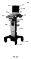
[0015] 図1は、超音波イメージングシステム100の例を示している。このシステムに、本開示のいくつかの実施形態によるチルト調整可能なディスプレイが含まれ得る。超音波イメージングシステム100を使用して、トランスデューサアレイによって取得された超音波エコーから超音波画像が生成される。超音波イメージングシステム100には、超音波画像の生成及び表示に適した信号及び画像処理構成要素(例えば図7を参照してさらに説明される)が含まれている。信号及び画像処理構成要素は、カートベースのシステム(図1に示す)に組み込まれていても、例えば、図2A及び図2Bに示すようなタブレット超音波システム又はノートブック型超音波システムなどのポータブル超音波システムに組み込まれていてもよい。超音波イメージングシステムに、本発明の原理によるタッチスクリーンインターフェースを提供するタッチ感応ディスプレイが含まれている。
[0015] FIG. 1 illustrates an example of an
[0016] 図1は、カートベースの超音波イメージングシステムの例を示している。このシステムに、本開示によるチルト調整可能なディスプレイが含まれ得る。図1の超音波イメージングシステム100は、ベース102(カートなど)を含む。ベース102は、患者と検査室、研究室、又は手術室との間など、超音波イメージングシステムを1つの場所から別の場所に簡単に移動できるようにするキャスタ又はホイール104を含む。超音波イメージングシステム100の電子構成要素のうちの1つ以上(1つ以上のプロセッサ、コントローラ、信号発生器/受信器、及び/又は入出力(I/O)デバイス106など)がベース102内に設けられている。1つ以上の超音波トランスデューサプローブ(図示せず)が、ベース102に、通常は、例えば、I/Oデバイス106又はワイヤレスなどを介して取り外し可能に結合される。
[0016] FIG. 1 illustrates an example of a cart-based ultrasound imaging system that may include a tilt-adjustable display according to the present disclosure. The
[0017] 超音波イメージングシステム100は、コントロールパネル110を支持するコントロールプラットフォーム108を含む。コントロールプラットフォーム108は、例えば、第1の連結アーム112を介して、ベース102に調整可能に接続できる。第1の連結アーム112は、ベース102に対するコントロールプラットフォーム108の位置を変更できる。コントロールパネル110は、第1のコントロールパネル114を含む。これには、1つ以上のダイヤル、ボタン、ノブ、スイッチ、キーボード、トラックボールなど、さまざまな物理的又は機械的入力デバイスのいずれかとして実装された複数の手動コントロール118が含まれる。また、コントロールパネル110は、追加のコントロールを提供するタッチコントロールパネル116を含む。したがって、これは、セカンダリコントロールパネル116と呼ばれる。タッチコントロールパネル116は、タッチ感応ディスプレイ124によって実現され、任意の現在知られている又は後に開発されるタッチ感応ディスプレイ技術(抵抗、容量性、圧力感応式容量、赤外線など)を使用して組み込まれている。本開示の原理によれば、タッチコントロールパネル116は、第1のコントロールパネル114に対して移動可能に結合される。例えば、セカンダリコントロールパネル116のチルト角を調整できるように、第1のコントロールパネル114に揺動可能に結合される。ユーザインターフェース(例えばセカンダリコントロールパネル116上に提供されるグラフィカルユーザインターフェースコントロール要素のセット)は、任意の所与の時間に、システム上でアクティブである特定のイメージングモード又はアプリケーションに基づいて、イメージングシステム100によって通常は自動的に再構成される。したがって、特定のアプリケーションに合わせて調整された多数の追加のユーザコントロール機能が、超音波イメージングシステム100のメインの物理的コントロールに簡単に追加される。タッチ感応コントロールの汎用性にもかかわらず、手動コントロールが依然として望ましい場合がある。例えば、オペレータがこのようなコントロールに慣れていることや、手動コントロールによって触覚フィードバック(位置の物理的な変化など)が得られることが理由であり、これにより、オペレータはコントロールを見なくても特定の機能を行うことができる。しかしながら、タッチ感応コントロール(例えばコントロールパネルアセンブリの1つ以上のコントロールパネルとして)のみを含む実施形態も想定され、本開示の範囲内である。あるいは又はさらに、いくつかの実施形態では、コントロールのうちの1つ以上(手動コントロールなど)をトランスデューサプローブに提供してもよい。いくつかの実施形態では、超音波イメージングシステム100の操作を制御するために、タッチスクリーンインターフェースのみを使用してもよい。
[0017] The
[0018] いくつかの実施形態では、コントロールパネル110又はその一部が、コントロールプラットフォーム108に取り外しできないように取り付けられる(つまり、統合されている)。例えば、コントロールパネル110の一部又はすべてがコントロールプラットフォーム108にされている。他の実施形態では、コントロールパネル110又はその一部、並びに超音波システムの特定の機能が、ベース102から分離できるポータブルユニットに組み込まれていてもよい。このような実施形態では、超音波イメージングシステム100にドッキング構造が含まれていてもよい。ドッキング構造は、コントロールプラットフォーム108の上又は近くに提供されて、ポータブルユニットをベース102に取り外し可能に取り付け、動作可能(例えば電気的)に結合することを可能にする。いくつかの実施形態では、システム100は、タッチ感応ディスプレイ124とは別の追加のモニタ120を含む。いくつかの例では、モニタ120は、メインディスプレイパネル又は単にメインディスプレイと呼ばれる。モニタ120は、例えば、第2の連結アーム122を介して、ベース102及び/又はコントロールプラットフォーム108に調整可能に接続される。いくつかの実施形態では、モニタ120は、パッシブディスプレイ(例えばタッチ感応部分を含まない)であり、超音波イメージングシステム100又は別のイメージングシステムで取得した画像の表示に使用される。いくつかの実施形態では、画像、患者情報若しくは関連する臨床測定値を含むグラフィックオーバーレイ、又は他のデータが表示される。いくつかの実施形態では、モニタ120に、タッチ感応ディスプレイ124のいずれかに表示されるデータの複製又はバリエーションが表示される。
[0018] In some embodiments, the
[0019] 図2A~2Bは、本開示の実施形態によるチルト調整可能なディスプレイが設けられ得るポータブル超音波イメージングシステム200の例を示している。図2Aでは、ポータブル超音波イメージングシステム200は、可動ベース202上に支えられているものとして示されている。この可動ベース202は、システム200のコントロール及びディスプレイを、ユーザにより適した(例えば人間工学的な)位置に位置付けて支持する。図2Bは、超音波イメージングシステム200を単独で(つまり、ベース202なしで)示している。ポータブル超音波イメージングシステム200は、図7を参照して以下にさらに説明する超音波イメージングシステム710の構成要素の一部又はすべてを含む。例えば、ポータブル超音波イメージングシステム200は、超音波画像の取得及び表示に必要なすべての電子構成要素を含む。
2A-2B show an example of a portable
[0020] この実施形態では、ポータブル超音波イメージングシステム200は、第1の部分220及び第2の部分209を含む。第1の部分220は、メインディスプレイ224を含むので、ディスプレイ部分220とも呼ばれる。第2の209は、少なくとも1つのコントロールパネル(例えばプライマリコントロールパネル210)を含むので、コントロールパネル部分209とも呼ばれる。ディスプレイ部分220及びコントロールパネル部分209は、超音波イメージングシステム200をよりコンパクトな(例えば折り畳み)構成で提供できるように、互いに折り畳み可能(例えばヒンジ式)に結合されている。よりコンパクトな構成では、メインディスプレイ224は、コントロールパネル210を向いて折り畳まれて向かい合う。
[0020] In this embodiment, the portable
[0021] 超音波イメージングシステム200は、可動ベース202に機械的及び/又は電子的に接続できる。いくつかのそのような実施形態では、追加のストレージ及び/又は追加の入出力デバイスなどの特定の機能が、ベース202によって提供される。ポータブル超音波イメージングシステム200は、単に超音波イメージングシステム200を支持プラットフォーム208に置くことによって、また、場合によっては、任意選択で1つ以上の停止突起に接して置くことによってなど、ベースに機械的に結合されるか又はベースによって支持される一方で、他の例では、超音波イメージングシステム200は、可動ベース202に追加的に機械的にロックされる、又は別の方法で固定されることで結合される。超音波イメージングシステム200が可動ベース202に固定されると、システム200は、本質的にカートベースのシステムに再構成される。可動ベース202は、患者と検査室、研究室、又は手術室との間など、超音波イメージングシステムを1つの場所から別の場所に簡単に移動できるようにするキャスタ又はホイール204といったホイールを含む。さらに又はあるいは、いくつかの実施形態では、超音波イメージングシステム200は、可動ベース202に(有線又はワイヤレス接続を介して)電子的に結合されてもよい。いくつかのこのような実施形態では、超音波イメージングシステムの電子構成要素のうちの1つ以上(1つ以上のプロセッサ、コントローラ、信号発生器/受信器、及び/又は入出力(I/O)デバイス206など)が、(図2Aに示されているように)ベース202内に設けられていても、コントロールパネル部分209内に設けられていてもよい。可動ベース202は、ホイール204を取り外すことで固定ベースにすることができる。
[0021] The
[0022] 超音波データ収集及び画像生成に不可欠なすべての信号及び画像処理構成要素は、ポータブルシステム(例えば超音波イメージングシステム200)内にある。一方、可動ベース202の任意の電子構成要素は、補助機能(例えば追加のストレージ、追加及び/又は処理、追加の周辺機器及び/又は入出力デバイス)を提供できる。いくつかの実施形態では、可動ベース202にドッキング構造が含まれていてもよい。ドッキング構造は、支持プラットフォーム208の上又は近くに提供されて、ポータブルシステム200を可動ベース202に取り外し可能に取り付け、動作可能(例えば電気的)に結合することを可能にする。また、可動ベース202は、例えばイメージングのために使用されていない間、1つ以上の超音波トランスデューサプローブを支持又は固定するための1つ以上の支持構造を含む。いくつかの実施形態では、超音波プローブは、超音波イメージングシステム200、ベース202、又はその両方に取り外し可能に結合される。
[0022] All signal and image processing components essential for ultrasound data collection and image generation are within the portable system (e.g., ultrasound imaging system 200), while any electronic components on the
[0023] 図2Bに示すように、ディスプレイ部分220及びコントロールパネル部分209は共に、ポータブル(例えば1人で簡単に運搬できる)フォームファクタを有する統合型ハウジング内に設けられている。例えば、ディスプレイ部分220及びコントロールパネル部分209は、第1のハウジング部分221及び第2のハウジング部分211内にそれぞれ設けられている。これらのハウジング部分は、揺動ジョイント又はヒンジジョイントによって互いに揺動可能に接続され、ノートブック型のポータブルイメージングシステムを形成する。他の実施形態では、コントロールパネル部分の構成要素(例えばコントロールパネル210又はその構成要素)が、メインディスプレイ224の横に設けられる。いくつかの実施形態では、メインディスプレイ224は、パッシブディスプレイ(例えば任意のタッチ感応部分を含まない)であり、超音波システム200又は別のイメージングシステムで取得した情報(例えば画像又は測定値)の表示のために主に使用される。他の実施形態では、メインディスプレイに少なくとも1つのタッチ感応部分が含まれていてもよい。これは、イメージングシステム200の任意の他のタッチ感応コントロールインターフェース(例えばセカンダリコントロールパネル)の代わりに又はそれに加えて提供されてもよい。
2B, both the
[0024] 本開示の原理によれば、PHILIPS社が販売するCX50超音波システムなどの既存のポータブル超音波システムのコントロールパネル部分209を、手動コントロールパネル214の横にタッチコントロールパネル216(例えばタッチスクリーン)を含むように変更できる。手動コントロールパネル214には、1つ以上のダイヤル、ボタン、ノブ、スイッチ、キーボード、トラックボールなど、システムの手動コントロール218が含まれる。タッチコントロールパネル216は、ヒンジジョイントの同じ側にあり、本開示の原理により、それ自体が下にある構造に揺動可能に接続される。このように、タッチコントロールパネル216は、以下にさらに説明するように、タッチコントロールパネル216がメインコントロールパネルと実質的に同一平面である格納位置から、さまざまなチルト角に調整可能になる。タッチコントロールパネル216は、システムのコントロールパネルのセカンダリディスプレイ及び/又は第2の(例えばシステムによって)再構成可能な部分を提供するため、セカンダリコントロールパネル又はセカンダリディスプレイとも呼ばれる。チルト調整可能なタッチコントロールパネル216(セカンダリコントロールパネル216とも呼ばれる)は、コントロールパネル部分209の任意の適切な場所(キーボードの下、上、又はその片側など)に設置される。いくつかの実施形態では、セカンダリコントロールパネル216は、手動コントロール(例えばキーボード、タッチパッド、トラックボール、時間ゲイン補正(TGC)スライダ、ゲインノブ、又は従来のコントロールパネルのノブ又はスライダのうちの任意の他の1つ若しくは組み合わせ)の一部、サブセット、又はすべてを置換することができ、プライマリコントロールパネル210の任意の残りの手動コントロールは、セカンダリコントロールパネル216に対応するようにコントロールパネル部分209に再配置される。いくつかの実施形態では、画像、患者情報若しくは関連する臨床測定値を含むグラフィックオーバーレイ、又は他のデータは、メインディスプレイ224、タッチコントロールパネル216のタッチ感応ディスプレイ、又はその両方のいずれかに表示される。
[0024] In accordance with the principles of the present disclosure, the
[0025] タッチディスプレイは、部分的にはさまざまな使用事例/イメージングモードでの再構成が可能であることから、超音波イメージングシステムにおいて普及しつつある。しかしながら、既存の超音波システムでは、通常、このようなタッチディスプレイは、コントロールパネルに対して固定された向きにあり、通常の向きは、タブレット型超音波システムではフラットであるか、又はカートベースのシステムでは固定角度で高くされている/傾斜している。これらの2つの構成のいずれも人間工学的な観点からは理想的ではない。発明者らは、超音波システムなどの医用イメージングシステムにチルト調整可能なコントロールパネルを設けることに関連する課題のうちの1つ以上に対処できるソリューションを想定し、本明細書で説明する。本開示によるチルト調整可能なタッチディスプレイは、従来のタッチディスプレイに伴うグレアを低減又は防止できるため、そのようなディスプレイの可読性/視認性を向上させ、ディスプレイの角度をさまざまなユーザサイズや位置(例えば着席や立位)に合わせて変更できるようにすることで、人間工学に基づいてディスプレイを調整できるため、反復使用損傷を軽減する可能性があり、概してユーザ体験を向上させることができる。 [0025] Touch displays are becoming popular in ultrasound imaging systems due in part to their reconfigurability for different use cases/imaging modes. However, in existing ultrasound systems, such touch displays are typically in a fixed orientation relative to the control panel, with the normal orientation being flat in tablet ultrasound systems or elevated/tilted at a fixed angle in cart-based systems. Neither of these two configurations is ideal from an ergonomic standpoint. The inventors envision and describe herein a solution that may address one or more of the challenges associated with providing a tilt-adjustable control panel for a medical imaging system, such as an ultrasound system. A tilt-adjustable touch display according to the present disclosure may reduce or prevent glare associated with conventional touch displays, thereby improving the readability/visibility of such displays, and may allow the display to be ergonomically adjusted by allowing the angle of the display to be changed to accommodate different user sizes and positions (e.g., seated vs. standing), potentially reducing repetitive use injuries, and generally improving the user experience.
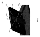
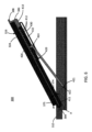
[0026] 図3~図6は、本開示による超音波イメージングシステムのセカンダリディスプレイ/コントロールパネル(例えばパネル124又は216)を実装するために使用できるチルト調整可能なディスプレイアセンブリ300の例を示している。図3は、例示的なディスプレイアセンブリ300の等角投影図を示し、図4~図6は、本発明の原理を例示するために、ディスプレイパネル316がさまざまな位置(例えばさまざまなチルト角)に示されているディスプレイアセンブリ300の断面図を示している。
[0026] Figures 3-6 show an example of a tilt-
[0027] チルト調整可能なディスプレイアセンブリ300は、ここではコントロールパネル310の一部として示されている支持構造に揺動可能に結合されたディスプレイパネル316を含む。ディスプレイパネル316は、超音波イメージングシステムに再構成可能なユーザインターフェースを提供するタッチ感応ディスプレイユニット又はタッチスクリーン324を含む。前述のように、タッチスクリーン324は、使用中、異なる時間に、例えばさまざまなイメージングモード又は臨床アプリケーション用の異なるユーザインターフェース要素を表示するようにシステムによって再構成される。タッチスクリーン324は、ディスプレイパネル316のユーザに対面する面362にある。ディスプレイパネル316、したがって、タッチスクリーン324は、超音波装置のコントロールパネル310に揺動可能に結合され、これにより、ディスプレイパネル316、したがって、タッチスクリーン324は、タッチスクリーン324がコントロールパネル310と実質的に平行にあり、コントロールパネル310から上方向又外方に向いている、図5に示す格納位置と、タッチスクリーン324がコントロールパネル310に対して角度が付けられている、図4に示す傾斜位置を含む複数の傾斜位置との間で揺動できる。
[0027] The tilt
[0028] ディスプレイパネル316は、複数の傾斜位置のうちのいずれかにディスプレイパネル316を位置付けて、しっかりと支持するチルト調整メカニズム400を介して、支持構造(例えばコントロールパネル310)に揺動可能に結合される。チルト調整メカニズム400は、ユーザに対面する面362の反対側のディスプレイパネル316の後面364に設けられた第1のアーム410を含む。チルト調整メカニズム400はまた、支持構造(例えばコントロールパネル310)に揺動可能に結合された第2のアーム420を含む。第2のアーム420は、第1のアーム410と係合して、以下にさらに説明するように、ディスプレイパネル316を傾斜位置でしっかりと支持する。
[0028] The
[0029] 図6に示すように、ディスプレイパネル316は、チルト軸Aの周りを揺動できる。これにより、コントロールパネル310に対するディスプレイパネル316の傾斜角374(チルト角とも呼ばれる)を変更できる。第1のアーム410は、ディスプレイパネル316が異なる位置(すなわち、異なるチルト角)に調整されるときに、ディスプレイパネル316とともに移動するように、揺動するディスプレイパネル316上に担持される。さらにかつ独立して、第2のアーム420との係合及び係合解除のために、第1のアーム410は、(動作矢印375で示すように)第1のアーム軸411の周りをタッチスクリーン324に対して揺動可能である。いくつかの例では、図6に示すように、第1のアーム軸411はチルト軸Aと一致する。つまり、ディスプレイパネル316及び第1のアーム410には共通のヒンジラインがある。他の例では、ディスプレイパネル316及び第1のアーム410は、異なる軸の周りを揺動する。例えば、第1のアーム410は、(例えばディスプレイパネルの下端付近で)ディスプレイパネル316を通過するが、軸Aからは離間している軸の周りを揺動する。第1のアーム410は、複数の歯412を含む。この例では、これらの歯は、ディスプレイパネル316の背面364から外方を向くように配置されている。
6, the
[0030] 第2のアーム420は、コントロールパネル310上で揺動可能に支持され、歯412と動作可能に係合する自由端(上端424)を含む。第1のアーム410及び第2のアーム420、より具体的には、歯412及び上端424は、1つの方向(すなわち、チルト角374を大きくする方向)におけるディスプレイパネル316の比較的妨げられない揺動移動を可能にする一方で、反対の方向(すなわち、チルト角374を小さくする方向)におけるディスプレイパネル316の揺動移動に抵抗する。いくつかの実施形態では、ディスプレイパネル316とコントロールパネル310との間の揺動ジョイントに、チルト調整メカニズム400の一部として、摩擦ヒンジを追加的にかつ任意選択で設けることができる。摩擦ヒンジは、揺動剛性を高め、したがって、(例えば、摩擦ヒンジの抵抗を追加することで、揺動ジョイントでのスプリングバック、遊動、又は任意の他の望ましくない動きをさらに低減又は排除することによって)揺動ジョイントの安定性を向上できる。
[0030] The
[0031] 図6にさらに示すように、第2のアーム420は、その下端422において、コントロールパネル310に揺動可能に結合され、これにより、第2のアーム420は、使用中、第1のアーム軸411から離間している第2のアーム軸421の周りを揺動する。この例における第2のアーム軸421は、ディスプレイパネル316を通過していない。第2のアーム軸421は、ディスプレイパネル316の所望の動作範囲(例えばチルト角度範囲)をもたらすために選択された距離だけ第1の軸411から離間されている。
6, the
[0032] チルト調整メカニズム400は、第1のアーム410及び第2のアーム420が常に結合された(必ずしも係合されているとは限らないが)ままであるように構成される。例えば、第2のアーム420の上端424は、ディスプレイパネル316の背面364に移動可能に(例えばスライド可能に)結合される。ここでは、スロット432のペアとして示されているガイド430が、ディスプレイパネル316の背面364に設けられ、第2のアーム420の協働構造をスライド可能に受容する又は捉える。スロット432は、例えば、ディスプレイパネルの背面364から(例えば垂直に)突き出た細長い構造内に形成されることにより、背面364に固定される。スルースロットでもブラインドスロットでもよいスロット432は、互いに向き合うように配置される。つまり、協働構造を受容するスロットの開口部が、互いに向き合う突起のそれぞれの側面に配置される。この例では、協働構造は、それぞれ、第2のアーム420の長さ方向に対して横方向に延在するピン434のペアによって提供される。
[0032] The
[0033] 例えば、図3に示すように、スロット434は、第2のアーム420の上端424から反対方向に延在し、これにより、各ピン434がスロット432のうちの対応する1つに受容される。使用中、ディスプレイパネル316のチルト角が調整されるときに、上端424が第1のアーム410の歯付き部分に対して移動すると、ピン434は、それぞれのスロット432内に残る。上端424をディスプレイパネルに移動可能に(例えばスライド可能に)結合するために、他の適切な配置を使用してもよい。例えば、ガイド430のスロット432は、背面の表面に形成され、協働構造は、背面の方へ(例えば背面に実質的に垂直に)延在するように配置できる。他の例では、本例のピン・イン・スロット配置ではなく、1つ以上のレール若しくはトラック及びローラ、又は他の適切なスライド構造を使用してもよい。ここでのピン及びスロットの配置は、スロットのペアと対応するピンを含むものとして示されているが、他の例では、異なる数の協働構造(例えばシングルスロット及びピン配置、又は3以上のスロット及びピンのカップリング)を使用してもよい。さらなる例では、スロット及びピンの位置を逆にしてもよく、例えば、アーム420に受容構造(例えばスロット)が設けられ、ディスプレイパネル316にスライド構造(例えばピン)が設けられる。ガイドスロット432の長さ、アーム420の長さ、及び/又はアーム軸411とアーム軸412との間隔は、例えば、前進の揺動移動を制限するために、所望の動作範囲、したがって、約90度まで、場合によっては、90度未満、例えば、75度、60度、又は他の適切な最大傾斜角までのディスプレイパネル316のチルト角を達成するために調整される。第2のアーム420は、サイズ決定され、チルト位置におけるディスプレイパネル316の重量を支えることができる任意の適切な剛性材料(例えば金属、プラスチック、複合材、又はその組み合わせ)から作られる。アーム420は、ディスプレイを使用するとき(例えばディスプレイ上のGUIを選択又は操作するために、タップされる又は他の方法でタッチされるとき)に、ディスプレイが著しく動くこと(例えばユーザが知覚できる動き)を防ぐために十分に硬く設計されている。
[0033] For example, as shown in FIG. 3, the
[0034] 第1のアーム410は、(例えばコイルばね、板ばね、又は別の適切な付勢部材などの任意の適切なばねを介して)、第2のアーム420の方へ付勢され、これにより、歯412は、第2のアーム420の上端424との係合の方へ付勢される。図示するように、上端424は、動作可能に歯412に係合する。例えば、上端424は、背面364、したがって、歯412の方へ延在して歯412と係合する(例えば隣接する歯間で受容される)任意の適切な構造(例えば1つ以上のフックや爪426)を成形するか、又は含めることができる。本例の成形された上端424は、1つのフック又は爪426を含み、これは、歯412と係合して(例えば歯間に受容され又は歯とかみ合って)、第1のアーム410に対する第2のアーム420の移動に機械的に抵抗するようにサイズ決定されている。各歯412は、アーム410の下端384の方へ向いているリーディング面と、アーム410の上端386の方へ向いているトレーリング面とを含む。トレーリング面がリーディング面よりもアーム410の長さ方向に対してより浅く傾いているため、歯412及び爪426は実質的にラチェットとして動作する。つまり、下端384の方への(つまり、歯412のリーディング面の上方への)爪426の前進は、反対方向への、つまり、アーム410の上端386の方への歯412のトレーリング面の上方への前進よりも低い程度に抵抗される。好ましい実施形態では、トレーリング面の傾斜は、十分に急勾配であり(例えばアーム410の長さ方向に実質的に垂直であり)、これにより、歯412から爪426が係合解除されることなく、後者が本質的に防止される。これに対し、リーディング面の傾斜は、十分に浅く(例えば、アーム410の長さ方向に対して90度未満、場合によっては、約60、約50、又は約45度未満)、アーム410を揺動させることなく爪を下端384の方へ前進させることができる。したがって、アーム410を揺動させることなくディスプレイパネル316のチルト角を大きくすることができるが、(例えばディスプレイパネルを下げるために)チルト角を小さくするには、第1のアーム410を作動させる必要がある。
[0034] The
[0035] いくつかの実施形態では、第1のアーム410には、第1のアーム410の上端386に結合されるか又は上端386と一体に形成され得る作動部材が設けられている。例えば、上端386は巻き付けられて、ディスプレイ316の周辺縁322を越えて延在して上端386(ここでは作動端とも呼ばれる)を、チルト調整可能なメカニズムを操作するために(例えばディスプレイ316のチルト角を調整するときに、歯412から第2のアームを一時的に係合解除するために)ユーザが簡単にアクセスできる場所に位置付ける。あるいは又はさらに、上端386には、ユーザが第1のアーム410を操作(例えば揺動)しやすくするために、1つ以上のけん引特徴部が設けられていてもよい。例えば、アームの上端386から延在するレッジが、けん引特徴部として機能してもよい。さらに又はあるいは、アームの上端には、第1のアームの他の部分よりも静摩擦係数の高い1つ以上の材料が設けられていてもよい(例えば上端にコーティングされる又は上端に接合される)。例えば、第1のアームは、ナイロン、ポリ塩化ビニル、又は他の硬質プラスチック材料などの適切なプラスチック製構成要素で実質的に作られ、一方、ゴムなどの高摩擦材料を、上端の少なくとも一部に塗布してけん引特徴部を提供できる。場合によっては、けん引特徴部は、突起などの構造的な強化と、ゴム製コーティングなどの摩擦的な強化との組み合わせである。
[0035] In some embodiments, the
[0036] 作動部材386は、歯付きアーム330の上端336を揺動させるためのレバー力を加えるためにユーザが掴めるように構成された任意の適切な構造によって提供できる。例えば、作動部材386は、ディスプレイパネル316の上端383の上面358を越えて延在して、ユーザが歯付きアーム330を掴み、作動させるのに便利な場所を提供するレッジ388を含む。いくつかの実施形態では、コントロールパネル310のキャビティ376は、ディスプレイパネル316とキャビティ376の端部との間に隙間があり、これにより、ユーザがレッジ388の下に届いて歯付きアーム330を掴み、作動させることができるようにサイズ決定される。いくつかの実施形態では、ディスプレイパネル316は、コントロールパネル310の上面378と同一平面又はそれよりも下にあり、レッジ388は上面378より上にあることで、ユーザが歯付きアーム330を掴み、作動させるのに便利な場所を提供する。いくつかの実施形態では、ユーザの掴みが滑らないように、作動部材386はテクスチャ(例えばバンプ、リッジ)を含む。いくつかの実施形態では、ユーザが掴みやすくするために、作動部材386はノンスリップコーティングを含む。
[0036] The
[0037] 爪426が歯412と動作可能に係合する(例えば隣接する2つの歯412間に着座する)と、ディスプレイパネル316の下向き回転(すなわち、格納位置の方へ)が抵抗又は防止されて、ディスプレイパネル316が傾斜位置にしっかりと固定される。第1のアーム410には十分な数の歯412が設けられ、アーム410の長さの一部に沿って適切に配置されて、例えば、3、4、又は5の増分、若しくはより大きな数の調整増分(例えば、最大10、最大12、又は最大15の異なる調整)の、所望の数の増分チルト調整を行うことができる。いくつかの実施形態では、ゼロ度(すなわち、格納位置)から約60度の傾斜まで複数の異なるチルト角が可能にされる。いくつかの例では、約5度若しくは約7度のチルト角増分、又は他の適切な増分を使用できる。イメージングシステムに提供される調整増分の数は、セカンダリコントロールパネルのサイズによって異なる。例えば、カートベースのシステムなどの大型のセカンダリコントロールパネルでは、増分調整可能なチルト角の数は多くなり(例えば最大10個のチルト角)、ポータブル(例えばノートブック又は他のハンドヘルドイメージングシステム)などの小型のセカンダリコントロールパネルでは、使用可能なチルト角の数は少ない(例えば最大6又は7個のチルト角)。本開示を考慮してわかるように、タッチ感応セカンダリコントロールパネルのチルト角374を調整できる能力により、(例えば、頭上の照明によるグレアを軽減したり、ユーザにとってより最適な向きのために角度を調整したりすることで)セカンダリディスプレイに示される情報の可読性が向上し、また、例えば、異なるサイズのユーザが座っているときと立っているときとの両方で、かつ、オペレータに対してメインコントロールパネルを動かした異なる位置のいずれにおいてもセカンダリコントロールパネルを快適かつ便利に操作できるようにすることによって、幅広いユーザ層の人間工学が向上する。
[0037] When the
[0038] いくつかの実施形態では、支持構造(例えばコントロールパネル310)は、ディスプレイパネル316を少なくとも部分的に、場合によっては実質的に完全に受容して、ディスプレイパネル316が格納位置にあるときに、タッチスクリーン324がコントロールパネル310の上面と実質的に同一平面になるようにキャビティ376を画定する。これは、例えば、メインディスプレイをコントロールパネルの上に置くとき(例えば、ノートブック型イメージングシステムを折り畳むとき)のイメージングシステムの保管に特に便利である。格納位置で提供される場合、第1のアーム410及び第2のアーム420は、実質的にディスプレイパネル316とキャビティ376の底部との間に設置されているため、例えば、図5に示すように、キャビティ376内に実質的に完全に入っている。
[0038] In some embodiments, the support structure (e.g., the control panel 310) defines a
[0039] 前述のように、使用中は、第1のアーム410は、第2のアーム420と係合及び係合解除するために、タッチスクリーン324に対して揺動する。図6の例では、第2のアーム420から係合解除するために作動される場合、第1のアーム410は、タッチスクリーン324に対して同じ軸Aの周りを揺動し、これにより、アーム410の上端386がタッチスクリーン324の近くになる。いくつかの実施形態では、アーム410の上端386は、ユーザによる操作のために構成される。例えば、上端386には、レッジ384又は他の適切な構造が設けられる。レッジ384は、ユーザがアーム410をより簡単に掴んで操作する(例えば、モーメントを加える)ことを可能にして、ユーザに対面する面362の方へアーム410を軸A周りに揺動させる。この動作は、アーム410の歯付き部分をアーム420の爪426から引き離すことで、第1のアーム410を第2のアーム420から係合解除し、ディスプレイパネル316のチルトを調整できるようにする。アーム410をこの揺動位置に保持している間、ユーザはディスプレイパネルを異なる(例えば傾斜角の低い)位置の方へ操作し、その後アーム410を解放してアーム420を再係合させることができる。再係合されると、アーム420の爪端と、付勢要素によって爪端の方へ付勢されているアーム410の歯412との間の連結は、チルト調整メカニズムが再びユーザによって操作される(例えば、アーム410がアーム420から係合解除するために前方に揺動される)まで、ディスプレイパネルの揺動移動を大幅に低減又は防止できる。
[0039] As previously discussed, in use, the
[0040] 例えば、図7に示すように、上記ディスプレイアセンブリ300などのチルト調整可能なセカンダリディスプレイを含み得る本開示による超音波イメージングシステムは、超音波画像データを取得及び表示するためのさまざまな電子構成要素を含む。例えば、図7に示すように、超音波イメージングシステム710は、超音波を送信してエコー情報を受け取るためのトランスデューサアレイ714を収容する超音波プローブ712を含むか、又は、超音波プローブ712と取り外し可能に結合される。例えば、リニアアレイ、コンベックスアレイ、又はフェーズドアレイである、さまざまなトランスデューサアレイが当技術分野においてよく知られている。例えば、トランスデューサアレイ714は、2D及び/又は3Dイメージングのために仰角寸法及び方位角寸法の両方でスキャン可能なトランスデューサ素子の2次元アレイ(図示する)を含む。トランスデューサアレイ714は、プローブ712内のマイクロビームフォーマ716に結合される。マイクロビームフォーマ716は、アレイのトランスデューサ素子による信号の送受信を制御する。この例では、マイクロビームフォーマは、プローブケーブルによって送受信(T/R)スイッチ718に結合されている。このスイッチは、送信と受信とを切り替え、メインビームフォーマ722を高エネルギー送信信号から保護する。いくつかの実施形態では、T/Rスイッチ718及びシステム内の他の素子を、別個の超音波システムベースではなくトランスデューサプローブに含めてもよい。マイクロビームフォーマ716の制御下のトランスデューサアレイ714からの超音波ビームの送信は、T/Rスイッチ718及びビームフォーマ722に結合された送信コントローラ720によって指示される。ビームフォーマ722は、ユーザインターフェース又はコントロールパネル724のユーザ操作から入力を受け取る。送信コントローラ720によって制御される機能の1つは、ビームがステアリングされる方向である。ビームは、トランスデューサアレイからまっすぐに前に(トランスデューサアレイに直交して)ステアリングすることも、より広い視野を得るために異なる角度でステアリングすることもできる。マイクロビームフォーマ716によって生成された部分的ビーム形成信号は、メインビームフォーマ722に結合される。ここでは、トランスデューサ素子の個々のパッチからの部分的ビーム形成信号が完全ビーム形成信号になるように結合される。
[0040] For example, as shown in FIG. 7, an ultrasound imaging system according to the present disclosure, which may include a tilt-adjustable secondary display such as the
[0041] ビーム形成された信号は、信号プロセッサ726に結合される。信号プロセッサ726は、バンドパスフィルタリング、デシメーション、I及びQ成分の分離、及び高調波信号の分離など、さまざまなやり方で、受け取ったエコー信号を処理できる。また、信号プロセッサ726は、スペックルの低減、信号複合、及びノイズ除去などの追加の信号強調を行うことができる。処理された信号は、Bモードプロセッサ728に結合され、体内の構造のイメージングに振幅検出を採用できる。Bモードプロセッサによって生成される信号は、スキャンコンバータ730及びマルチプラナーリフォーマッタ732に結合される。スキャンコンバータ730は、エコー信号を、それらを受け取った元の空間的関係で所望の画像フォーマットで配置する。例えば、スキャンコンバータ730は、エコー信号を2次元(2D)セクタ型フォーマット、又はピラミッド型3次元(3D)画像に配置できる。米国特許第6,443,896号(Detmer)に説明されているように、マルチプラナーリフォーマッタ732は、体のボリュメトリック領域内の共通平面内の点から受け取ったエコーをその平面の超音波画像に変換できる。ボリュームレンダラ734は、例えば、米国特許第6,530,885号(Entrekin他)に説明されているように、3Dデータセットのエコー信号を、所与の基準点から見た投影3D画像に変換する。2D又は3D画像は、スキャンコンバータ730、マルチプラナーリフォーマッタ732、及びボリュームレンダラ734から画像プロセッサ736に、画像ディスプレイ738に表示するためのさらなる強調、バッファリング、及び一時的な保存のために結合される。いくつかの実施形態では、画像プロセッサによって生成された画像のうちの1つ以上を、さらに、あるいは、コントロールパネル724に揺動可能に結合されたセカンダリディスプレイパネルに表示することもできる。このようなセカンダリディスプレイパネルは、本明細書における実施例のいずれかによるコントロールパネル724に実装及び結合できる。グラフィックプロセッサ740では、超音波画像とともに表示されるグラフィックオーバーレイが生成される。これらのグラフィックオーバーレイには、患者名、画像の日時、イメージングパラメータなどの標準的な識別情報を含めることができる。グラフィックプロセッサ、及び超音波システムの他の機能は、ユーザインターフェースから入力を受け取ることができる。これは、手動(例えば機械的)コントロール及びソフト(例えばGUI)コントロールを使用して実装できる。前述のように、ユーザインターフェースはまた、マルチプラナーリフォーマッタ732によって生成された画像平面の選択、さまざまな音響パラメータの選択又は設定など、システムの他のさまざまな機能を制御するために、動作可能に結合される。
[0041] The beamformed signals are coupled to a
[0042] このように、発明者は、本開示による超音波システム用のチルト調整可能なディスプレイが、現在の技術の問題のうちの1つ以上に対処できることを認識している。例えば、発明者は、本明細書に説明されている種類の剛性アームベースのチルト調整アセンブリは、場合によっては、ディスプレイ揺動ジョイントにおける摩擦ヒンジとの組み合わせで、揺動ジョイントのスプリングバック及び遊動(ともにユーザ体験を劣化させる可能性がある)を低減することで、チルト調整可能なディスプレイのソリューションを向上させ、ほとんどの場合、チルト調整可能なディスプレイアセンブリの耐久性を高めて、システムの耐用年数が長くする可能性があることを認識している。 [0042] Thus, the inventors have recognized that a tilt-adjustable display for an ultrasound system according to the present disclosure may address one or more of the problems of the current art. For example, the inventors have recognized that a rigid arm-based tilt adjustment assembly of the type described herein, in some cases in combination with a friction hinge at the display swing joint, may improve tilt-adjustable display solutions by reducing swing joint springback and free play (both of which can degrade the user experience), and in most cases may increase the durability of the tilt-adjustable display assembly, extending the useful life of the system.
[0043] 本システムは、特に超音波イメージングシステムを参照して説明されている場合もあるが、X線、CT、MRIなど、1つ以上の画像が体系的に取得される他の医用イメージングシステムにも拡張できることも想定されている。最後に、上記の議論は、本システムの例示に過ぎず、添付の特許請求の範囲を任意の特定の実施形態又は実施形態のグループに限定するものと解釈されるべきではない。このように、本システムは、例示的な実施形態を参照して、特に詳細に説明されているが、また、以下の特許請求の範囲に記載されているように、本システムのより広範で意図された精神や範囲から逸脱することなく、当業者が、数多くの修正及び代替実施形態を考案することができることも理解されたい。したがって、明細書及び図面は、例示的であると見なされ、添付の特許請求の範囲を限定することを意図していない。 [0043] Although the present system may be described with particular reference to an ultrasound imaging system, it is contemplated that the system may be extended to other medical imaging systems in which one or more images are systematically acquired, such as X-ray, CT, MRI, etc. Finally, the above discussion is merely illustrative of the present system, and should not be construed as limiting the appended claims to any particular embodiment or group of embodiments. Thus, while the present system has been described in particular detail with reference to exemplary embodiments, it should also be understood that those skilled in the art may devise numerous modifications and alternative embodiments without departing from the broader intended spirit and scope of the present system, as set forth in the following claims. Accordingly, the specification and drawings are to be regarded as illustrative, and are not intended to limit the scope of the appended claims.
Claims (19)
コントロールパネルと、
揺動可能に前記コントロールパネルに結合されたディスプレイパネルであって、前記ディスプレイパネルのユーザに対面する面にタッチ感応ディスプレイを含む、ディスプレイパネルと、
前記タッチ感応ディスプレイの周りを揺動可能であるように、揺動可能に前記ディスプレイパネルに結合された第1のアームであって、前記ディスプレイパネルの背面に複数の歯を含む、第1のアームと、
前記コントロールパネルに揺動可能に結合され、前記複数の歯に選択的に係合して、前記ディスプレイパネルを複数の傾斜位置のうちのいずれか1つにおいて支持する第2のアームと、
を含む、超音波イメージングシステム。 1. An ultrasound imaging system for generating an ultrasound image from ultrasound echoes acquired by a transducer array, comprising:
A control panel and
a display panel pivotally coupled to the control panel, the display panel including a touch-sensitive display on a user-facing surface of the display panel;
a first arm pivotally coupled to the display panel such that the first arm can pivot about the touch-sensitive display , the first arm including a plurality of teeth on a rear surface of the display panel ;
a second arm pivotally coupled to the control panel and selectively engaging the plurality of teeth to support the display panel in any one of a plurality of tilted positions;
1. An ultrasound imaging system comprising:
Applications Claiming Priority (3)
| Application Number | Priority Date | Filing Date | Title |
|---|---|---|---|
| US201962887003P | 2019-08-15 | 2019-08-15 | |
| US62/887,003 | 2019-08-15 | ||
| PCT/EP2020/072621 WO2021028470A1 (en) | 2019-08-15 | 2020-08-12 | Ultrasound imaging system with a tilt-adjustable secondary display |
Publications (3)
| Publication Number | Publication Date |
|---|---|
| JP2022544922A JP2022544922A (en) | 2022-10-24 |
| JPWO2021028470A5 JPWO2021028470A5 (en) | 2023-08-18 |
| JP7520105B2 true JP7520105B2 (en) | 2024-07-22 |
Family
ID=72088082
Family Applications (1)
| Application Number | Title | Priority Date | Filing Date |
|---|---|---|---|
| JP2022508502A Active JP7520105B2 (en) | 2019-08-15 | 2020-08-12 | Ultrasound imaging system having a tiltable secondary display - Patents.com |
Country Status (5)
| Country | Link |
|---|---|
| US (1) | US12433572B2 (en) |
| EP (1) | EP4013306B1 (en) |
| JP (1) | JP7520105B2 (en) |
| CN (1) | CN114269254A (en) |
| WO (1) | WO2021028470A1 (en) |
Families Citing this family (2)
| Publication number | Priority date | Publication date | Assignee | Title |
|---|---|---|---|---|
| US12088371B2 (en) * | 2022-02-14 | 2024-09-10 | Qualcomm Incorporated | Selection of beamforming configuration parameters for a multi-panel active antenna system (AAS) |
| KR20230168264A (en) * | 2022-06-06 | 2023-12-13 | 에이에스엠 아이피 홀딩 비.브이. | Diagnostic tool having human-machine interface, and method for diagnosis of programmable logic controller |
Citations (3)
| Publication number | Priority date | Publication date | Assignee | Title |
|---|---|---|---|---|
| US20040179332A1 (en) | 2003-03-12 | 2004-09-16 | Zonare Medical Systems. Inc. | Portable ultrasound unit and docking station |
| US20150351719A1 (en) | 2012-12-28 | 2015-12-10 | Hitachi Aloka Medical, Ltd. | Ultrasonic imaging device and cart for ultrasonic imaging device |
| US20160345935A1 (en) | 2015-05-29 | 2016-12-01 | Samsung Medison Co., Ltd. | Ultrasonic imaging device and moving unit applied to the same |
Family Cites Families (20)
| Publication number | Priority date | Publication date | Assignee | Title |
|---|---|---|---|---|
| JPH0527764A (en) * | 1991-07-25 | 1993-02-05 | Yamaha Corp | Surface operation input device for electronic musical instrument |
| US5520361A (en) * | 1993-04-20 | 1996-05-28 | Inkel Corporation | Monitor tilting device |
| US6530885B1 (en) | 2000-03-17 | 2003-03-11 | Atl Ultrasound, Inc. | Spatially compounded three dimensional ultrasonic images |
| JP2001274564A (en) * | 2000-03-27 | 2001-10-05 | Hitachi Telecom Technol Ltd | Electronic console |
| US6443896B1 (en) | 2000-08-17 | 2002-09-03 | Koninklijke Philips Electronics N.V. | Method for creating multiplanar ultrasonic images of a three dimensional object |
| TW562182U (en) * | 2003-01-30 | 2003-11-11 | Micro Star Int Co Ltd | Tablet computer accommodation device with a supporting design |
| TWM259501U (en) * | 2004-07-09 | 2005-03-21 | Tatung Co | Foldable computer cover |
| TWM288936U (en) * | 2005-08-08 | 2006-03-21 | Posiflex Inc | Mechanism for adjusting elevation angle of LCD device |
| WO2007121605A1 (en) * | 2006-04-21 | 2007-11-01 | Dreamcom Corporation | Laptop computer |
| JP5014245B2 (en) * | 2008-05-08 | 2012-08-29 | 沖電気工業株式会社 | Support device with tilt mechanism |
| US9277812B2 (en) * | 2010-07-08 | 2016-03-08 | Southco, Inc. | Display support with first and second arms and mechanism for maintaining constant orientation of the plane bisecting the range of rotation of the second arm relative to a support base |
| KR101365242B1 (en) * | 2012-01-27 | 2014-02-19 | 삼성전자주식회사 | Ultrasound diagnosis apparatus having pluraltiy of display units |
| CN104135942B (en) * | 2012-02-27 | 2017-04-05 | 株式会社日立制作所 | Portability ultrasonic equipment for medical diagnosis |
| WO2013145866A1 (en) * | 2012-03-30 | 2013-10-03 | 日立アロカメディカル株式会社 | Portable ultrasonic diagnostic device |
| US20140352125A1 (en) * | 2013-05-28 | 2014-12-04 | Oswaldo Duran | Method and apparatus for retaining tablet computer |
| WO2014192815A1 (en) | 2013-05-31 | 2014-12-04 | 日立アロカメディカル株式会社 | Ultrasound diagnostic device |
| US9310474B2 (en) * | 2013-06-04 | 2016-04-12 | Chison Medical Imaging, Inc. | Portable ultrasound imaging devices |
| WO2017114874A2 (en) * | 2015-12-29 | 2017-07-06 | Koninklijke Philips N.V. | Ultrasound imaging system with a multi-mode touch screen interface |
| CN107035944B (en) * | 2016-02-03 | 2023-08-01 | 泰州市创新电子有限公司 | Adjustable tilt monitor support device |
| KR102387628B1 (en) * | 2018-01-08 | 2022-04-18 | 삼성메디슨 주식회사 | Supporting device for display apparatus |
-
2020
- 2020-08-12 WO PCT/EP2020/072621 patent/WO2021028470A1/en not_active Ceased
- 2020-08-12 US US17/632,408 patent/US12433572B2/en active Active
- 2020-08-12 EP EP20757263.7A patent/EP4013306B1/en active Active
- 2020-08-12 JP JP2022508502A patent/JP7520105B2/en active Active
- 2020-08-12 CN CN202080057638.2A patent/CN114269254A/en active Pending
Patent Citations (3)
| Publication number | Priority date | Publication date | Assignee | Title |
|---|---|---|---|---|
| US20040179332A1 (en) | 2003-03-12 | 2004-09-16 | Zonare Medical Systems. Inc. | Portable ultrasound unit and docking station |
| US20150351719A1 (en) | 2012-12-28 | 2015-12-10 | Hitachi Aloka Medical, Ltd. | Ultrasonic imaging device and cart for ultrasonic imaging device |
| US20160345935A1 (en) | 2015-05-29 | 2016-12-01 | Samsung Medison Co., Ltd. | Ultrasonic imaging device and moving unit applied to the same |
Also Published As
| Publication number | Publication date |
|---|---|
| US20220287681A1 (en) | 2022-09-15 |
| US12433572B2 (en) | 2025-10-07 |
| WO2021028470A1 (en) | 2021-02-18 |
| EP4013306A1 (en) | 2022-06-22 |
| JP2022544922A (en) | 2022-10-24 |
| EP4013306B1 (en) | 2024-10-09 |
| CN114269254A (en) | 2022-04-01 |
Similar Documents
| Publication | Publication Date | Title |
|---|---|---|
| JP7407693B2 (en) | Ultrasound imaging system with multi-mode touch screen interface | |
| KR101313218B1 (en) | Handheld ultrasound system | |
| CN104519801B (en) | Portable supersonic filming apparatus | |
| JP4376776B2 (en) | Inspection ultrasound system cart with integrated cable support | |
| JP6027621B2 (en) | Portable ultrasound imaging device | |
| US20150216505A1 (en) | Ultrasound diagnosis apparatus having plurality of display units | |
| US20150320388A1 (en) | Portable ultrasonic diagnostic apparatus | |
| JP7520105B2 (en) | Ultrasound imaging system having a tiltable secondary display - Patents.com | |
| JPH03109620A (en) | Electronic equipment | |
| CN1802124A (en) | Ultrasound system for internal imaging including controls in the handle | |
| US8724884B2 (en) | Controller | |
| US20120083693A1 (en) | Handheld ultrasonic diagnostic apparatus with rack stand | |
| KR102589770B1 (en) | ultrasound imaging system | |
| JP2005161058A (en) | Method and system for using hand-held trackball for controlling imaging system | |
| JP2011142939A (en) | Ultrasonic diagnostic apparatus | |
| JP2014068820A (en) | Portable ultrasonic imaging apparatus |
Legal Events
| Date | Code | Title | Description |
|---|---|---|---|
| A521 | Request for written amendment filed |
Free format text: JAPANESE INTERMEDIATE CODE: A523 Effective date: 20230809 |
|
| A621 | Written request for application examination |
Free format text: JAPANESE INTERMEDIATE CODE: A621 Effective date: 20230809 |
|
| A977 | Report on retrieval |
Free format text: JAPANESE INTERMEDIATE CODE: A971007 Effective date: 20240124 |
|
| A131 | Notification of reasons for refusal |
Free format text: JAPANESE INTERMEDIATE CODE: A131 Effective date: 20240208 |
|
| A521 | Request for written amendment filed |
Free format text: JAPANESE INTERMEDIATE CODE: A523 Effective date: 20240318 |
|
| TRDD | Decision of grant or rejection written | ||
| A01 | Written decision to grant a patent or to grant a registration (utility model) |
Free format text: JAPANESE INTERMEDIATE CODE: A01 Effective date: 20240610 |
|
| A61 | First payment of annual fees (during grant procedure) |
Free format text: JAPANESE INTERMEDIATE CODE: A61 Effective date: 20240709 |
|
| R150 | Certificate of patent or registration of utility model |
Ref document number: 7520105 Country of ref document: JP Free format text: JAPANESE INTERMEDIATE CODE: R150 |