JP7519084B2 - Ophthalmic Equipment - Google Patents
Ophthalmic Equipment Download PDFInfo
- Publication number
- JP7519084B2 JP7519084B2 JP2020146124A JP2020146124A JP7519084B2 JP 7519084 B2 JP7519084 B2 JP 7519084B2 JP 2020146124 A JP2020146124 A JP 2020146124A JP 2020146124 A JP2020146124 A JP 2020146124A JP 7519084 B2 JP7519084 B2 JP 7519084B2
- Authority
- JP
- Japan
- Prior art keywords
- eye
- optical system
- alignment mode
- alignment
- light
- Prior art date
- Legal status (The legal status is an assumption and is not a legal conclusion. Google has not performed a legal analysis and makes no representation as to the accuracy of the status listed.)
- Active
Links
- 230000003287 optical effect Effects 0.000 claims description 73
- 238000001514 detection method Methods 0.000 claims description 21
- 238000005259 measurement Methods 0.000 claims description 19
- 238000007689 inspection Methods 0.000 claims 2
- 238000012360 testing method Methods 0.000 description 52
- 210000003128 head Anatomy 0.000 description 29
- 210000004087 cornea Anatomy 0.000 description 20
- 230000004410 intraocular pressure Effects 0.000 description 20
- 239000005357 flat glass Substances 0.000 description 12
- 238000010586 diagram Methods 0.000 description 11
- 238000000034 method Methods 0.000 description 10
- 210000001525 retina Anatomy 0.000 description 8
- 230000005856 abnormality Effects 0.000 description 4
- 238000006073 displacement reaction Methods 0.000 description 4
- 239000011521 glass Substances 0.000 description 4
- 230000005540 biological transmission Effects 0.000 description 2
- 230000001276 controlling effect Effects 0.000 description 2
- 210000000399 corneal endothelial cell Anatomy 0.000 description 1
- 230000002596 correlated effect Effects 0.000 description 1
- 230000005484 gravity Effects 0.000 description 1
- 238000003384 imaging method Methods 0.000 description 1
- 238000012986 modification Methods 0.000 description 1
- 230000004048 modification Effects 0.000 description 1
- 210000001747 pupil Anatomy 0.000 description 1
- 230000004044 response Effects 0.000 description 1
- 238000012876 topography Methods 0.000 description 1
Images


Landscapes
- Eye Examination Apparatus (AREA)
Description
本開示は、被検眼の眼特性を検査する眼科装置に関する。 This disclosure relates to an ophthalmic device that examines the ocular characteristics of a subject's eye.
被検眼に対しアライメントを行う際、角膜頂点に向かって光源からの光を照射し、角膜頂点からの反射光を受光することによってアライメントを行う技術が従来より知られている。 When aligning the subject's eye, a technique has been known in the past in which light from a light source is directed toward the corneal apex and the light reflected from the corneal apex is received to perform alignment.
例えば、特許文献1には、上下、左右、前後方向に測定手段を移動させてアライメントを行うオートアライメントモードと、アライメント検出手段で検出された前後方向の距離に基づいて測定手段を監視又は駆動手段により移動し、上下左右方向のアライメントには手動により駆動手段を手動で操作するマニュアル連続測定モードと、を備え、オートアライメントモード完了後に眼屈折力測定エラーが生じた際、オートアライメントモードからマニュアル連続測定モードに自動的に移行させる構成が開示されている。 For example, Patent Document 1 discloses a configuration that includes an auto-alignment mode in which alignment is performed by moving the measuring means in the up-down, left-right, and front-back directions, and a manual continuous measurement mode in which the measuring means is monitored or moved by the driving means based on the front-back distance detected by the alignment detection means, and the driving means is manually operated for alignment in the up-down, left-right directions, and that automatically switches from the auto-alignment mode to the manual continuous measurement mode when an error occurs in the eye refractive power measurement after the auto-alignment mode is completed.
しかしながら、従来装置は、角膜異常眼、IOL眼のようなアライメントが困難な場合を想定していない。IOL眼の場合、角膜頂点以外にIOLからも光が反射し、これがノイズとなってしまい、間違った位置でオートアライメントが行われてしまうという問題がある。また、角膜異常眼においても、角膜に対し照射した光の反射光から得られる受光信号が弱くなってしまい、結果としてオートアライメントが終わらなくなってしまい、アライメントに失敗する場合があり、被検者に負担がかかってしまうという問題がある。 However, conventional devices do not take into account cases where alignment is difficult, such as eyes with corneal abnormalities or eyes with IOLs. In the case of eyes with IOLs, light is reflected not only from the corneal apex but also from the IOL, which becomes noise and causes auto-alignment to be performed in the wrong position. Also, in eyes with corneal abnormalities, the light receiving signal obtained from the reflected light of light irradiated onto the cornea becomes weak, resulting in auto-alignment not completing and alignment failing, which places a burden on the subject.
本発明は、上記問題点を鑑み、その目的は眼特性を検査する眼科装置において、被検眼のアライメントをスムーズに行い、被検者への負担を軽減する眼科装置を提供することにある。 In consideration of the above problems, the present invention aims to provide an ophthalmic device that smoothly aligns the subject's eye and reduces the burden on the subject in an ophthalmic device that examines eye characteristics.
上記目的を達成するために、請求項1に記載の発明は、被検眼の前眼部画像を撮影する前眼部観察光学系と、前記前眼部画像をディスプレイに表示するよう構成される表示制御部と、前記前眼部観察光学系を含む前記被検眼の眼特性を検査する検査光学系と、を備える眼科装置において、前記検査光学系を所定の位置へ移動させる第1のアライメントモードと、前記被検眼に対し、前記検査光学系が前記所定の位置へ到達したか否かを判定する判定部と、前記判定部により前記検査光学系が前記所定の位置へ到達したと判定された後、前記第1のアライメントモードとは異なる第2のアライメントモードへ切り替える切り替え部と、を備えることを特徴とする。 In order to achieve the above object, the invention described in claim 1 provides an ophthalmic device comprising an anterior segment observation optical system that captures an anterior segment image of a test eye, a display control unit configured to display the anterior segment image on a display, and an examination optical system that examines the ocular characteristics of the test eye including the anterior segment observation optical system, the device comprising: a first alignment mode that moves the examination optical system to a predetermined position; a determination unit that determines whether the examination optical system has reached the predetermined position for the test eye; and a switching unit that switches to a second alignment mode different from the first alignment mode after the determination unit determines that the examination optical system has reached the predetermined position.
また、本発明の請求項2に記載の発明は、請求項1にかかる眼科装置において、前記切り替え部が、あらかじめ定められた前記第2のアライメントモードへ切り替えることを特徴とする。 Furthermore, the invention described in claim 2 of the present invention is characterized in that in the ophthalmic device according to claim 1, the switching unit switches to the second alignment mode that is predetermined.
また、本発明の請求項3に記載の発明は、請求項1にかかる眼科装置において、前記切り替え部が、前記第1のアライメントモードとは異なる複数のアライメントモードを前記ディスプレイに表示し、前記表示された複数のアライメントモードの中から前記第2のアライメントモードを選択し、前記選択された第2のアライメントモードに切り替えることを特徴とする。 Furthermore, the invention described in claim 3 of the present invention is characterized in that in the ophthalmic device of claim 1, the switching unit displays a plurality of alignment modes different from the first alignment mode on the display, selects the second alignment mode from the displayed plurality of alignment modes, and switches to the selected second alignment mode.
また、本発明の請求項4に記載の発明は、請求項2又は請求項3にかかる眼科装置において、前記第2のアライメントモードが、前記前眼部画像が表示されている前記ディスプレイ上で指定された任意の位置と前記検査光学系の光軸とが一致するように制御を行うことを特徴とする。 Furthermore, the invention described in claim 4 of the present invention is characterized in that in the ophthalmic device according to claim 2 or claim 3, the second alignment mode performs control so that any position specified on the display on which the anterior eye image is displayed coincides with the optical axis of the examination optical system.
また、本発明の請求項5に記載の発明は、請求項2又は請求項3にかかる眼科装置において、前記第2のアライメントモードが、前記前眼部画像が表示されている前記ディスプレイ上に前記検査光学系を移動する方向を指示するための画面を表示し、前記画面が押下されたことを検出する検出部を備え、前記検出部による検出結果に基づいて前記検査光学系を移動させることを特徴とする。 Furthermore, the invention described in claim 5 of the present invention is characterized in that, in the ophthalmic device according to claim 2 or claim 3, the second alignment mode displays a screen on the display on which the anterior eye image is displayed to instruct the direction in which the examination optical system is to be moved, the device is provided with a detection unit that detects that the screen has been pressed, and the examination optical system is moved based on the detection result by the detection unit.
上記のように、本発明にかかる眼科装置は、アライメントモードを切り替える構成をもつことにより、アライメントが困難な被検眼に対してスムーズな測定を行うことを可能とする。 As described above, the ophthalmic device of the present invention has a configuration for switching alignment modes, making it possible to perform smooth measurements on examinee's eyes that are difficult to align.
以下、本発明の一実施例にかかる眼科装置について図面を参照して説明する。
[一実施形態]
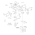
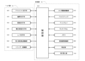
図1、2は本発明にかかる眼科装置1の光学系の詳細を説明した図である。図1は眼屈折力検査時における光学系を示す図であり、図2は眼圧力検査時における光学系を示す図である。そして、図3は制御部を含めた本発明の一実施例にかかる眼科装置1の全体構成を説明するブロック図である。これら図1~図3を用いて本発明の一実施例にかかる眼科装置の眼科装置1について以下に説明する。眼科装置1は図3に示すように、被検眼を測定するための光学系が配置されたヘッド部710と、ヘッド部710の中の光学系や切り替え部700の回転動作などを制御する制御部600を備えた本体部720によって構成される。
An ophthalmic apparatus according to an embodiment of the present invention will now be described with reference to the drawings.
[One embodiment]
1 and 2 are diagrams for explaining the details of the optical system of an ophthalmic apparatus 1 according to the present invention. FIG. 1 is a diagram showing the optical system during an eye refractive power test, and FIG. 2 is a diagram showing the optical system during an eye pressure test. And FIG. 3 is a block diagram for explaining the overall configuration of an ophthalmic apparatus 1 according to an embodiment of the present invention, including a control unit. The ophthalmic apparatus 1 according to an embodiment of the present invention will be explained below with reference to these FIGS. 1 to 3. As shown in FIG. 3, the ophthalmic apparatus 1 is composed of a head unit 710 in which an optical system for measuring the subject's eye is arranged, and a main body unit 720 including a
なお、本体部720は、ヘッド部710を本体部720に対してXYZ(左右、上下、前後)方向に移動させるXYZ駆動制御部630、ヘッド部710の空間位置の調整等を支持するジョイスティック640、撮影された被検眼の画像や、眼屈折力、眼圧等の測定結果を表示するディスプレイ650、測定項目等の指示を受け付けるタッチパネル660、制御部600の制御処理において利用されるメモリ670、固視標部(後述)を制御する固視標制御部680、アライメントが完了したか否かを判定する判定部690を備えている。
The main body 720 is equipped with an XYZ
(眼屈折力検査光学系)
図1には被検眼の眼屈折力検査時の全体光学系(眼屈折力検査光学系)を示す。
眼屈折力検査光学系は、光源101からの光を被検眼に向けて照射し、角膜からの反射光を受光するプロファイルセンサ108及び光源109からの光を被検眼に向けて照射し、角膜からの反射光を受光するラインセンサ112で構成されるアライメント光学系100、光源301、302から2次元撮像素子(CCD)307で構成される観察光学系300、固視標512から光源514及びリレーレンズ403、ミラー404で構成される固視光学系400及び光源501から平面ガラス511で構成される被検眼の眼屈折力を検出する眼屈折力光学系500から構成される。図1に示すように眼屈折力検査光学系を構成する各光学系はその一部が共有される構成になっている。そして、見口部は回転されて、眼屈折力検査のための平面ガラス510及び511が配置される。
(Ophthalmic refraction testing optical system)
FIG. 1 shows the entire optical system (optical system for eye refraction testing) used to test the eye of a patient.
The eye refraction test optical system is composed of an alignment
(アライメント光学系100)
アライメント光学系100は、光源101からの光がハーフミラー102、リレーレンズ103、ホットミラー104、リレーレンズ105を通り、ホットミラー106で反射された後、平面ガラス511、510を通り被検眼Eの角膜に照射する。本実施例では光源101は赤外光を出力するLEDが採用されている。
角膜で反射された光はホットミラー106で反射し、リレーレンズ105を通り、ホットミラー104で反射し、集光レンズ107を通してプロファイルセンサ108で受光される。プロファイルセンサ108で得られた信号は制御装置600で処理される。また、光源109からの光はリレーレンズ110を通り、角膜に照射する。本実施例では光源109は赤外光を出力するLEDが採用されている。角膜で反射された光はリレーレンズ111を通してラインセンサ112で受光される。ラインセンサ112で得られた信号は制御装置600で処理される。プロファイルセンサ108で得られた信号とラインセンサ112で得られた信号とに基づいてXYZ駆動制御部630によりヘッド部700を被検眼に対してXYZ方向にアライメントを実施する。
(Alignment Optical System 100)
In the alignment
The light reflected by the cornea is reflected by the
(観察光学系300)
観察光学系300は、ヘッド部710の被検眼側に配置された光源301及び光源302により被検眼の角膜部を含む前眼部領域を照射し、対物レンズ303、リレーレンズ305、結像レンズ306及び2次元撮像素子(CCD)307により、被検眼の前眼部画像を取得して、取得した被検眼の前眼部画像をディスプレイ650に表示する。光源301及び光源302は赤外光を出力するLEDが採用されるが、アライメント用の光源101より短波長の光を採用する。そのため、ホットミラー106は観察用の光(観察光)は透過し、アライメント用の光(アライメント光、光源101からの光)は反射する。また、ダイクロイックミラー304は、観察光は透過するように反射/透過の波長領域が設定されている。これにより、アライメント光と観察光は適切に分割され、各々の測定を可能にしている。
(Observation Optical System 300)
The observation
(固視光学系400:眼屈折力検査)
固視光学系400は、光源514からの光を拡散板513に通し、固視標512に照射する。そして、固視標からの光はホットミラー402、リレーレンズ403を透過した後、ミラー404で反射し、ホットミラー506を透過して、ダイクロイックミラー304で反射して主光軸O1を通り、対物レンズ303、ホットミラー106、平面ガラス511、510を透過して、被検眼の網膜上で結像する。そのため、固視標512と被検眼の網膜位置は略共役であることが望ましい。被検眼は固視標512に基づいて固視される。眼屈折力を検査する際は、一度、固視標と被検眼の網膜位置が略共役になるように固視標部(固視標512、拡散板513及び光源514)を移動制御して被検眼を固視させ、その後、所定距離移動して雲霧状態にしてから、眼屈折力を検査する。そのため、制御部600からの信号により固視標部は光軸に沿って前後に移動可能となっている。光源514は光源401より短波長である被検者が視認可能な可視光を出力するLEDが採用される。
(Fixation Optical System 400: Eye Refractive Index Test)
The fixation
(眼屈折力光学系500)
眼屈折力光学系500は光源501からの光(レフ光)がミラー502で集光し、集光レンズ503で反射して穴あきミラー504の中心にある穴を通り、光軸O2に対して斜めに配置し、図示しない駆動部により光軸O2を中心に回転する平行平面ガラス505を透過した後、ホットミラー506及びダイクロイックミラー304で反射して光軸O1を通り、対物レンズ303、ホットミラー106、平面ガラス511及び平面ガラス510を透過して被検眼Eの網膜に照射する。そして、被検眼Eの網膜からの反射光は、照射時とは逆の経路で、平面ガラス510、平面ガラス511、ホットミラー106及び対物レンズ303を透過し、ダイクロイックミラー304及びホットミラー506で反射して光軸O2を通り、平行平面ガラス505を透過した後、穴あきミラー504で反射し、レンズ507を透過後リングレンズ508により、2次元撮像素子(CCD)509でリング状に結像(リング像)する。光源501は、アライメント光(光源101)や観察光(光源301及び302)より長波長の赤外光が採用されている。
(Eye Refractive Power Optical System 500)
In the eye refractive
(眼圧検査光学系)
図2には被検眼の眼圧検査時における全体光学系(眼圧検査光学系)を示す。眼圧検査光学系は、光源101からの光を被検眼に向けて照射し、角膜からの反射光を受光するプロファイルセンサ108及び光源109からの光を被検眼に向けて照射し、角膜からの反射光を受光するラインセンサ112で構成されるアライメント光学系100、光源301、302から2次元撮像素子(CCD)307で構成される観察光学系300、光源401からミラー404で構成される固視光学系400及び光源101からノズル201、平面ガラス202で構成される被検眼の角膜の変形度合いを検出する変位変形検出受光光学系200から構成される。図2に示すように眼圧検査光学系を構成する各光学系はその一部が共有される構成になっている。そして、見口部は回転されて、眼圧検査のためのノズル201が配置される。
(Optics for Intraocular Pressure Testing)
2 shows the entire optical system (tonometry optical system) during tonometry of the subject's eye. The tonometry optical system includes an alignment
(固視光学系400:眼圧検査)
眼圧を検査する場合は、眼屈折力検査時に用いた光源514を消灯して、別の光源である光源401を点灯する。光源401からの光(固視光)をホットミラー402で反射し、リレーレンズ403を通り、反射ミラー404で反射した後、ホットミラー506を透過し、ダイクロイックミラー304で反射して主光軸O1を通り、対物レンズ303、ホットミラー106を通って、被検眼Eの網膜上で結像する。被検眼Eは固視光に基づいて固視され、眼圧検査などの眼特性の検査が可能になる。光源401は被検者が視認可能な可視光を出力するLEDが採用される。
(Fixation Optical System 400: Intraocular Pressure Test)
When testing intraocular pressure, the
(変位変形検出受光光学系200)
変位変形検出受光光学系200は、光源101からの光(変形検出光)の一部がハーフミラー102を透過後、リレーレンズ103、ホットミラー104、リレーレンズ105を透過し、ホットミラー106で反射して主光軸O1を通り、平面ガラス202、ノズル201の開口部を通って、被検眼の角膜に照射する。角膜に照射した光は角膜で反射し、逆の経路で、ノズル201の開口部、平面ガラス202を通過し、ホットミラー106で反射してリレーレンズ105、ホットミラー104、リレーレンズ103を通り、その一部がハーフミラー102で反射され、受光素子204で受光される。眼圧検査時は、ノズル201から圧縮された空気が被検眼の角膜に向けて噴射される。空気が噴射されると角膜は変位変形するため受光素子204で受光する光量が変化する。この光量の変化の度合いから被検眼の眼圧値を算出するのである。光源101も赤外光を出力するLEDが採用されるが、観察光より長波長で、かつ、アライメント光より短波長の光が選択され、採用される。このように、アライメント光、観察光、固視光、変形検出光(光源101からの光)の波長が設定され、ホットミラー104、106、506、402及びダイクロイックミラー304の反射/透過特性を適宜設定することにより、これら4つの光が適切な光路に沿って進むように構成されているのである。
(Displacement/deformation detection light receiving optical system 200)
In the displacement/deformation detection light receiving
(操作フロー)
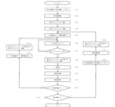
図4、図5は本実施例にかかる眼科装置の操作フローを説明する図である。尚、本実施例では、第1検査を眼屈折力検査、第2検査を眼圧検査として検査が実施される。
(Operation flow)
4 and 5 are diagrams for explaining the operation flow of the ophthalmic apparatus according to this embodiment. In this embodiment, the first examination is an eye refractive power examination, and the second examination is an intraocular pressure examination.
S10では、第1検査である眼屈折力検査を実施するため、見口部を回転して、図1に示すように、平面ガラス510及び511を配置する。既に、見口部が眼屈折力検査時の状態になっている場合は、S10は省略される。
In S10, to perform the first test, the eye refraction test, the sight aperture is rotated and the
S20では、第1検査である眼屈折力検査を開始する。操作フローに記載はないが、この時、観察用の光源301、302、アライメント用の光源101、固視標用の光源514が点灯する。
In S20, the first test, an eye refractive power test, is started. Although not described in the operation flow, at this time, the observation
S30では、第2のアライメントモードを選択するためのボタンがディスプレイ650に複数表示され、検者が選択したモードを第2のアライメントモードとして設定する。本実施例では第2のアライメントモードを精アライメントモードとする。
In S30, multiple buttons for selecting the second alignment mode are displayed on the
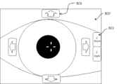
本発明における精アライメントモードは、以下のような動作を行うモードである。始めに、図6に示す前眼部画像800上に上下左右駆動ボタン801及び前後駆動ボタン802を重畳表示する。その後、検者が上下左右駆動ボタン801または前後駆動ボタン802を押下したことを検出すると、検出結果に基づいてヘッド部710の駆動操作を行う。これにより指示した方向に対し微動操作を行うことができ、アライメントが困難なIOL眼や角膜異常眼に対しても正確なアライメントが可能である。
The fine alignment mode in the present invention is a mode that performs the following operations. First, the up/down/left/
第2のアライメントモード選択後、S40で第1のアライメントモードを開始する。本実施例では、第1のアライメントモードはオートアライメントモードとする。オートアライメントモードは、ジョイスティック640やタッチパネル660を用いてヘッド部710を駆動操作し(S50)、所定位置を検出すると、自動で所定位置に向かってXYZ方向にアライメントを行うモードである(S60)。所定位置とは、例えば瞳孔中心でもよいし、角膜輪部の重心であってもよい。
After the second alignment mode is selected, the first alignment mode is started in S40. In this embodiment, the first alignment mode is the auto-alignment mode. In the auto-alignment mode, the head unit 710 is driven and operated using the
S50では、ジョイスティック640を用いて、患者の右眼がディスプレイ650に表示されるようにヘッド部710を移動する。操作フローに記載はないが、この時、観察用の光源301、302、アライメント用の光源101、固視標用光源514が点灯する。そして、ディスプレイ650に所定位置が所定の領域に入るようにヘッド部710をXYZ方向にアライメントする。
In S50, the
S60では、所定位置が上述した所定の領域に入ったことを検出すると、その検出結果から本体内部のXYZ駆動制御部630によりヘッド部710をXYZ方向に自動でアライメントを実施し、ヘッド部710が所定位置に到達するまでアライメントを続ける 。
In S60, when it is detected that the predetermined position has entered the above-mentioned predetermined area, the XYZ
S70で判定部690はヘッド部710が所定位置に到達しているか否かを判定する。到達していないと判定された場合、制御部はS60を繰り返す。
In S70, the
一方S70において、判定部690でヘッド部710が所定位置に到達したと判定された場合、S80で切り替え部700は、S30においてあらかじめ選択した第2のアライメントモードへ切り替え、続けて第2のアライメントモードを開始する。本実施例では上述の通り、第2のアライメントモードは精アライメントモードとする。
On the other hand, if the
精アライメントモードでは、被検眼前眼部の画像が表示されるディスプレイ650の画面上であって、図6で表すような上下左右駆動ボタン801及び前後駆動ボタン802を前眼部画像上に重畳表示させる。検者により上下左右駆動ボタン801または前後駆動ボタン802が押下されると、その検出結果に基づいてヘッド部710を移動させる。これにより、ノイズ等のアライメント不良の影響を受けることなく正確なアライメントを行うことが出来る。
In the fine alignment mode, on the screen of the
第2のアライメントモードによるアライメントが完了し、検者が図示しない撮影ボタンを押下すると、S90で仮測定として、眼屈折力を測定する。この時得られた眼屈折力の値に基づいて固視標512が被検眼Eの網膜と共役の位置になるように固視標部(512~514)を移動させる。
When alignment in the second alignment mode is complete and the examiner presses the capture button (not shown), the eye refractive power is measured provisionally in S90. Based on the value of the eye refractive power obtained at this time, the fixation target portion (512-514) is moved so that the
S100で本測定を開始する。眼屈折力検査の場合、眼屈折力測定用の光源501が点灯し、被検眼を開放状態にするため、固視標部(512~514)を所定の距離光軸に沿って移動させ、雲霧状態にしてから、眼屈折力の測定を実施する。撮影ボタンは画面上に表示されても良く、ジョイスティック640にも備えられていても良い。また、検者からの操作を受け付けた後、操作が一定時間行われなかったとき、自動的に測定を開始する構成にしても良い。
The measurement starts in S100. In the case of an eye refraction test, the
S110で、測定値をメモリ670に保存する。
At S110, the measurement value is stored in
S120では、判定部690は左右眼とも測定が完了したかどうかを判定する。右眼のみの場合は、S140で、ヘッド部710を左眼側に動かし、S150で第2のアライメントモードから第1のアライメントモードへ切り替え、右眼と同様S60からS110で左眼の眼屈折力を測定して測定値をメモリ670に保存する。
In S120, the
左右眼とも測定が完了したら、S130で判定部690は第2検査である眼圧検査が完了したかを判定する。
Once measurements have been completed for both the left and right eyes, in S130 the
第2検査の眼圧検査が完了していない場合は、S160で、見口部を回転して図2に示すようにノズル201及び平面ガラス202が配置されるようにする。そして、S170で第2検査である眼圧検査を開始する。ここで、操作フローに記載はないが、眼屈折力測定用の固視標用光源514は消灯し、代わりに固視光源401が点灯する。
If the second test, intraocular pressure testing, has not been completed, in S160, the viewing port is rotated so that the
S180で第2のアライメントモードから第1のアライメントモードへ切り替え、眼屈折力検査と同様、ジョイスティック640を用いて、患者の右眼がディスプレイ650に表示されるようにヘッド部を移動する。そして、所定位置が所定の領域に入るようにヘッド部をXYZ方向にアライメントを実施する。
In S180, the second alignment mode is switched to the first alignment mode, and the head is moved using the
S60で、眼屈折力検査と同様、所定位置が所定領域に到達したか否かを判定し、その判定結果から本体内部のXYZ駆動制御部630によりヘッド部をXYZ方向に自動でアライメントを実施し、ヘッド部710が所定位置に到達するまでアライメントを続ける。
In S60, as in the eye refraction test, it is determined whether or not the specified position has reached the specified area, and based on the result of this determination, the XYZ
S70において、判定部690でヘッド部710が所定位置に到達したと判定された場合、上述と同様、S80で切り替え部700はS30においてあらかじめ選択した第2のアライメントモードへ切り替え、続けて第2のアライメントモードを開始する。
If the
第2のアライメントモードによるアライメントが完了し、検者が図示しない撮影ボタンを押下すると、第1検査の眼屈折力検査の結果を用いて、光源401を被検眼Eの網膜位置と略共役位置となるように移動させる。なお、眼圧検査において仮測定(S90)は実施しない。
When alignment in the second alignment mode is completed and the examiner presses the capture button (not shown), the
S100で本測定を開始する。上述のように、光源101からの光を被検眼Eの角膜に照射し、その反射光を受光素子204で受光する。そして、図示しない見口部のシリンダー内のピストンが駆動して、シリンダー内で圧縮された空気が配管を介して見口部の空気路に流入し、ノズル201から被検眼Eの角膜に向けて噴出させる。噴出した空気により角膜は変位変形するため、受光素子204で受光する光量が変化(空気の噴出により角膜は平らになるため、受光素子204で受光する光量が増加)する。受光素子204で得られた受光信号が所定の値になるまでの時間を測定し、S110で、その測定値をメモリ670に保存する。眼圧値は、空気を噴出してから受光信号が所定の値になるまでの時間と相関があるため、保存された測定値(時間)から被検眼Eの眼圧値が算出できるのである。
The measurement starts in S100. As described above, light from the
そして、S120で眼屈折力検査と同様、左右眼とも測定が完了したかどうかを判定する。右眼のみの場合は、S140でヘッド部を左眼側に動かし、S150で第2のアライメントモードから第1のアライメントモードへ切り替え、右眼と同様S60からS100で左眼の眼圧検査を実施してその結果をメモリ670に保存する。
Then, in S120, it is determined whether measurements have been completed for both the left and right eyes, in the same way as for the eye refractive power test. If only the right eye is involved, the head unit is moved to the left eye side in S140, the second alignment mode is switched to the first alignment mode in S150, and an intraocular pressure test is performed on the left eye in the same way as for the right eye, from S60 to S100, and the results are stored in
左右眼とも測定が完了したら、S130で、第2検査である眼圧検査が完了したかを判定する。第2検査である眼圧検査が完了したら測定は終了する。 When measurements have been completed for both the left and right eyes, in S130 it is determined whether the second test, the intraocular pressure test, has been completed. When the second test, the intraocular pressure test, has been completed, the measurement ends.
尚、第1検査と第2検査は必ずしも両方実施する必要は無く、一方の検査のみ実施してもよい。眼屈折力検査の検査結果が予め判明している患者に対しては、第1検査である眼屈折力検査を実施せず、第2検査である眼圧検査時に眼屈折力値を入力することにより、光源401を移動させるようにしてもよい。さらに、本実施例では、右眼から検査を実施しているが、これも左眼から実施してもよいし、一方の眼のみ検査してもよい。
It should be noted that it is not necessary to carry out both the first and second tests, and only one of the tests may be carried out. For patients whose eye refraction test results are known in advance, the first test, eye refraction test, may not be carried out, and the
以上、本発明の実施形態について詳述してきたが、かかる実施形態における具体的な記載によって、本発明は限定されるものではなく、本発明の趣旨を逸脱しない範囲において種々の変更を加えることが可能である。 The above describes the embodiments of the present invention in detail, but the present invention is not limited to the specific descriptions in the embodiments, and various modifications can be made without departing from the spirit of the present invention.
上記実施例において第1のアライメントモードは、マニュアルアライメントモード等でも良い。マニュアルアライメントモードは、ジョイスティック640やタッチパネル660を用いてヘッド部710を駆動操作可能にし、所定領域内に入った後もジョイスティック640やタッチパネル660を用いてヘッド部710を駆動操作可能とするモードである。
In the above embodiment, the first alignment mode may be a manual alignment mode, etc. The manual alignment mode is a mode in which the head unit 710 can be driven and operated using the
また、上記実施例において、第2のアライメントモードは、アイトラッキングモード等でもよい。アイトラッキングモードは、以下のような動作を行うモードである。初めに、前眼部画像上の任意の位置を検者が指定すると、指定位置が検出され、指定位置が光軸O1上と一致するようヘッド部710の制御を行う。これにより、アライメントが困難なIOL眼や角膜異常眼に対しても正確なアライメントが可能であり、前眼部中心に混濁が見られる眼であっても、混濁を避けた位置を指定することで、指定位置を追従させて測定することができる。指定位置の指定方法としては、検者が指で前眼部画面上をタッチしてもよいし、マウス等を用いてもよい。マウスを用いた場合、指よりもより精密な押下が可能となる。上述のアイトラッキングモードにおける制御の方法としては、指定位置の特徴点を抽出し、パターンマッチング法等を用いて特徴点が光軸中心に位置するよう制御を行う方法でも良い。また、上述の方法に限定されず、トラッキング技術で用いられる種々の公知の方法を採用することが可能である。 In the above embodiment, the second alignment mode may be an eye tracking mode or the like. The eye tracking mode is a mode that performs the following operations. First, when the examiner specifies an arbitrary position on the anterior eye image, the specified position is detected, and the head unit 710 is controlled so that the specified position coincides with the optical axis O1. This allows accurate alignment even for IOL eyes and eyes with corneal abnormalities that are difficult to align, and even for eyes with opacity in the center of the anterior eye, the specified position can be tracked and measured by specifying a position that avoids the opacity. As a method for specifying the specified position, the examiner may touch the anterior eye screen with his/her finger, or a mouse or the like may be used. When a mouse is used, more precise pressing is possible than with a finger. As a method of control in the above-mentioned eye tracking mode, a method of extracting a feature point at the specified position and controlling the feature point to be located at the center of the optical axis using a pattern matching method or the like may be used. In addition, the method is not limited to the above-mentioned method, and various known methods used in tracking technology can be adopted.
また、上記実施例では第1のアライメントモードを開始する前に第2のアライメントモードを選択し、第1のアライメントモード完了後に自動で第2のアライメントモードへ切り替わる構成を開示したが、図5に示すように、S70で第1のアライメントモードによるアライメント完了後、S72、S74でディスプレイ650上に前述した精アライメントモード、アイトラッキングモード等の第2のアライメントモードを選択するためのボタン又はプルダウンメニューを表示させ、検者が選択すると、選択したモードへ切り替わる構成にしても良い。これにより、アライメント状況を確認した後に第2のアライメントモードを選択できるため、患者に適したアライメントモードへ切り替えることができる。
In the above embodiment, the second alignment mode is selected before starting the first alignment mode, and the configuration is disclosed in which the second alignment mode is automatically switched to after the first alignment mode is completed. However, as shown in FIG. 5, after the alignment using the first alignment mode is completed in S70, a button or pull-down menu for selecting a second alignment mode such as the fine alignment mode or eye tracking mode described above may be displayed on the
また、上記実施例における精アライメントモードにおいて、前眼部画像800上に表示される上下左右駆動ボタン801,前後駆動ボタン802を押下することでヘッド部710を駆動操作可能とする構成を開示したが、それだけでなく、上下左右駆動ボタン801または前後駆動ボタン802を長押しすることで連続的な駆動操作を可能としても良い。また、上下左右駆動ボタン801または前後駆動ボタン802を押下した時のヘッド部の移動幅を変更可能としても良い。また、その他の構成として、図6に示す例に表示される上下左右駆動ボタン801及び前後駆動ボタン802はディスプレイ650上の一か所にまとめて配置されても良く、またボタンである必要も無い。具体的には、検出エリアをディスプレイ650上に表示し、検出エリアを押下することにより、検出結果に基づいてヘッド部710を移動させる構成にしても良い。
In addition, in the fine alignment mode in the above embodiment, a configuration has been disclosed in which the head unit 710 can be driven by pressing the up/down/left/
また、上記実施例では第2検査に眼圧検査を実施する構成を開示したが、第2検査はこれに限定されるものではない。例えば、角膜形状検査であってもよいし、或いは、角膜内皮細胞検査であってもよい。
In the above embodiment, the second examination is an intraocular pressure examination, but the second examination is not limited to this. For example, the second examination may be a corneal topography examination or a corneal endothelial cell examination.
100・・アライメント光学系、200・・変位変形検出受光光学系、300・・観察光学系、400・・固視光学系、500・・眼屈折力光学系、600・・制御部、630・・XYZ駆動制御部、650・・ディスプレイ、690・・判定部、700・・切り替え部
100: alignment optical system, 200: displacement/deformation detection light receiving optical system, 300: observation optical system, 400: fixation optical system, 500: eye refractive power optical system, 600: control unit, 630: XYZ drive control unit, 650: display, 690: determination unit, 700: switching unit
Claims (1)
前記前眼部画像をディスプレイに表示するよう構成される表示制御部と、
前記前眼部観察光学系を含む前記被検眼の眼特性を検査する検査光学系と、を備える眼科装置において、
前記検査光学系を所定の位置へ移動させる第1のアライメントモードと、
前記被検眼に対し、前記検査光学系が前記所定の位置へ到達したか否かを判定する判定部と、
前記判定部により前記検査光学系が前記所定の位置へ到達したと判定された後、前記第1のアライメントモードとは異なる第2のアライメントモードへ切り替える切り替え部と、
撮影ボタンが押下されたか否かを検出する撮影指示検出部と、
前記第2のアライメントモードにおけるアライメント完了後、前記撮影指示検出部により前記撮影ボタンが押下されたことを検出すると測定を開始する測定開始処理部を備え、
前記切り替え部は、あらかじめ定められた前記第2のアライメントモードへ切り替えることを特徴とし、
前記第1のアライメントモードはオートアライメントモードであり、
前記第2のアライメントモードは、前記前眼部画像が表示されている前記ディスプレイ上に前記検査光学系を移動する方向を指示するための画面を表示し、前記画面が押下されたことを検出する移動方向検出部をさらに備え、前記移動方向検出部による検出結果に基づいて、前記検査光学系を移動させることを特徴とする精アライメントモードであり、
さらに、前記画面が押下されたときの前記検査光学系の移動幅を変更可能であることを特徴とする眼科装置。 an anterior segment observation optical system that captures an image of an anterior segment of a subject's eye;
a display control unit configured to display the anterior eye image on a display;
an examination optical system for examining ocular characteristics of the subject's eye including the anterior eye observation optical system,
a first alignment mode in which the inspection optical system is moved to a predetermined position;
a determination unit that determines whether or not the examination optical system has reached the predetermined position with respect to the subject's eye;
a switching unit that switches to a second alignment mode different from the first alignment mode after the determining unit determines that the inspection optical system has reached the predetermined position; and
a photographing instruction detection unit that detects whether a photographing button is pressed;
a measurement start processing unit that starts measurement when the photographing instruction detection unit detects that the photographing button has been pressed after the alignment in the second alignment mode is completed ,
The switching unit switches to the second alignment mode, which is determined in advance;
the first alignment mode is an auto-alignment mode,
the second alignment mode is a fine alignment mode further comprising a movement direction detection unit that displays a screen for instructing a direction in which to move the examination optical system on the display on which the anterior eye image is displayed and detects that the screen is pressed, and moves the examination optical system based on a detection result by the movement direction detection unit;
The ophthalmologic apparatus further comprises a means for changing a movement range of the examination optical system when the screen is pressed .
Priority Applications (1)
| Application Number | Priority Date | Filing Date | Title |
|---|---|---|---|
| JP2020146124A JP7519084B2 (en) | 2020-08-31 | 2020-08-31 | Ophthalmic Equipment |
Applications Claiming Priority (1)
| Application Number | Priority Date | Filing Date | Title |
|---|---|---|---|
| JP2020146124A JP7519084B2 (en) | 2020-08-31 | 2020-08-31 | Ophthalmic Equipment |
Publications (2)
| Publication Number | Publication Date |
|---|---|
| JP2022041093A JP2022041093A (en) | 2022-03-11 |
| JP7519084B2 true JP7519084B2 (en) | 2024-07-19 |
Family
ID=80499694
Family Applications (1)
| Application Number | Title | Priority Date | Filing Date |
|---|---|---|---|
| JP2020146124A Active JP7519084B2 (en) | 2020-08-31 | 2020-08-31 | Ophthalmic Equipment |
Country Status (1)
| Country | Link |
|---|---|
| JP (1) | JP7519084B2 (en) |
Citations (5)
| Publication number | Priority date | Publication date | Assignee | Title |
|---|---|---|---|---|
| US20080165322A1 (en) | 2007-01-10 | 2008-07-10 | Clarity Medical Systems, Inc. | Working distance and alignment sensor for a fundus camera |
| JP2011030689A (en) | 2009-07-31 | 2011-02-17 | Nidek Co Ltd | Fundus photographing system and method for processing three-dimensional fundus image |
| WO2012144075A1 (en) | 2011-04-22 | 2012-10-26 | 興和株式会社 | Opthalmologic measurement device |
| JP2014140482A (en) | 2013-01-23 | 2014-08-07 | Topcon Corp | Ophthalmologic apparatus |
| JP2016067795A (en) | 2014-09-30 | 2016-05-09 | 株式会社ニデック | Ophthalmologic device and ophthalmologic device control program |
-
2020
- 2020-08-31 JP JP2020146124A patent/JP7519084B2/en active Active
Patent Citations (5)
| Publication number | Priority date | Publication date | Assignee | Title |
|---|---|---|---|---|
| US20080165322A1 (en) | 2007-01-10 | 2008-07-10 | Clarity Medical Systems, Inc. | Working distance and alignment sensor for a fundus camera |
| JP2011030689A (en) | 2009-07-31 | 2011-02-17 | Nidek Co Ltd | Fundus photographing system and method for processing three-dimensional fundus image |
| WO2012144075A1 (en) | 2011-04-22 | 2012-10-26 | 興和株式会社 | Opthalmologic measurement device |
| JP2014140482A (en) | 2013-01-23 | 2014-08-07 | Topcon Corp | Ophthalmologic apparatus |
| JP2016067795A (en) | 2014-09-30 | 2016-05-09 | 株式会社ニデック | Ophthalmologic device and ophthalmologic device control program |
Also Published As
| Publication number | Publication date |
|---|---|
| JP2022041093A (en) | 2022-03-11 |
Similar Documents
| Publication | Publication Date | Title |
|---|---|---|
| JP6016445B2 (en) | Ophthalmic equipment | |
| JP6006519B2 (en) | Ophthalmic equipment | |
| JP5955193B2 (en) | Ophthalmic apparatus, control method for ophthalmic apparatus, and program | |
| JP2017051213A (en) | Ophthalmic equipment | |
| JP2023080218A (en) | ophthalmic equipment | |
| JP7265897B2 (en) | ophthalmic equipment | |
| JP7266375B2 (en) | Ophthalmic device and method of operation thereof | |
| JPH10216088A (en) | Opthalmonogy device | |
| US5844660A (en) | Objectives refraction measuring apparatus | |
| WO2003039357A1 (en) | Device for measuring optical characteristic of eye | |
| JPH06165758A (en) | Ophthalmic apparatus | |
| JP7519084B2 (en) | Ophthalmic Equipment | |
| JP4392006B2 (en) | Ophthalmic measuring device | |
| CN111568370A (en) | Ophthalmic Devices | |
| JP2018038517A (en) | Ophthalmic apparatus and method for controlling ophthalmic apparatus | |
| WO2010067764A1 (en) | Ophthalmic measurement device | |
| JP6680216B2 (en) | Eye refractive power measuring device | |
| JP7714189B2 (en) | ophthalmology equipment | |
| JP2021045263A (en) | Non-contact type tonometer and control method thereof | |
| JP7219312B2 (en) | ophthalmic equipment | |
| JP7154260B2 (en) | ophthalmic equipment | |
| JP3869335B2 (en) | Ophthalmic measuring device | |
| JP2005349237A (en) | Ophthalmic equipment | |
| JP6735963B2 (en) | Ophthalmic equipment | |
| JP3504362B2 (en) | Non-contact tonometer |
Legal Events
| Date | Code | Title | Description |
|---|---|---|---|
| A621 | Written request for application examination |
Free format text: JAPANESE INTERMEDIATE CODE: A621 Effective date: 20230801 |
|
| A977 | Report on retrieval |
Free format text: JAPANESE INTERMEDIATE CODE: A971007 Effective date: 20240131 |
|
| A131 | Notification of reasons for refusal |
Free format text: JAPANESE INTERMEDIATE CODE: A131 Effective date: 20240205 |
|
| A601 | Written request for extension of time |
Free format text: JAPANESE INTERMEDIATE CODE: A601 Effective date: 20240327 |
|
| A521 | Request for written amendment filed |
Free format text: JAPANESE INTERMEDIATE CODE: A523 Effective date: 20240527 |
|
| TRDD | Decision of grant or rejection written | ||
| A01 | Written decision to grant a patent or to grant a registration (utility model) |
Free format text: JAPANESE INTERMEDIATE CODE: A01 Effective date: 20240603 |
|
| A61 | First payment of annual fees (during grant procedure) |
Free format text: JAPANESE INTERMEDIATE CODE: A61 Effective date: 20240701 |
|
| R150 | Certificate of patent or registration of utility model |
Ref document number: 7519084 Country of ref document: JP Free format text: JAPANESE INTERMEDIATE CODE: R150 |