JP7516632B2 - Method and apparatus for transmitting and receiving a reference signal in a wireless communication system - Google Patents
Method and apparatus for transmitting and receiving a reference signal in a wireless communication system Download PDFInfo
- Publication number
- JP7516632B2 JP7516632B2 JP2023122431A JP2023122431A JP7516632B2 JP 7516632 B2 JP7516632 B2 JP 7516632B2 JP 2023122431 A JP2023122431 A JP 2023122431A JP 2023122431 A JP2023122431 A JP 2023122431A JP 7516632 B2 JP7516632 B2 JP 7516632B2
- Authority
- JP
- Japan
- Prior art keywords
- tci
- qcl
- terminal
- csi
- resource
- Prior art date
- Legal status (The legal status is an assumption and is not a legal conclusion. Google has not performed a legal analysis and makes no representation as to the accuracy of the status listed.)
- Active
Links
Images

Classifications
-
- H—ELECTRICITY
- H04—ELECTRIC COMMUNICATION TECHNIQUE
- H04L—TRANSMISSION OF DIGITAL INFORMATION, e.g. TELEGRAPHIC COMMUNICATION
- H04L5/00—Arrangements affording multiple use of the transmission path
- H04L5/003—Arrangements for allocating sub-channels of the transmission path
- H04L5/0048—Allocation of pilot signals, i.e. of signals known to the receiver
- H04L5/0051—Allocation of pilot signals, i.e. of signals known to the receiver of dedicated pilots, i.e. pilots destined for a single user or terminal
-
- H—ELECTRICITY
- H04—ELECTRIC COMMUNICATION TECHNIQUE
- H04J—MULTIPLEX COMMUNICATION
- H04J13/00—Code division multiplex systems
- H04J13/16—Code allocation
-
- H—ELECTRICITY
- H04—ELECTRIC COMMUNICATION TECHNIQUE
- H04L—TRANSMISSION OF DIGITAL INFORMATION, e.g. TELEGRAPHIC COMMUNICATION
- H04L5/00—Arrangements affording multiple use of the transmission path
- H04L5/0001—Arrangements for dividing the transmission path
- H04L5/0003—Two-dimensional division
- H04L5/0005—Time-frequency
- H04L5/0007—Time-frequency the frequencies being orthogonal, e.g. OFDM(A) or DMT
-
- H—ELECTRICITY
- H04—ELECTRIC COMMUNICATION TECHNIQUE
- H04L—TRANSMISSION OF DIGITAL INFORMATION, e.g. TELEGRAPHIC COMMUNICATION
- H04L5/00—Arrangements affording multiple use of the transmission path
- H04L5/003—Arrangements for allocating sub-channels of the transmission path
- H04L5/0078—Timing of allocation
- H04L5/008—Timing of allocation once only, on installation
-
- H—ELECTRICITY
- H04—ELECTRIC COMMUNICATION TECHNIQUE
- H04L—TRANSMISSION OF DIGITAL INFORMATION, e.g. TELEGRAPHIC COMMUNICATION
- H04L5/00—Arrangements affording multiple use of the transmission path
- H04L5/003—Arrangements for allocating sub-channels of the transmission path
- H04L5/0078—Timing of allocation
- H04L5/0082—Timing of allocation at predetermined intervals
-
- H—ELECTRICITY
- H04—ELECTRIC COMMUNICATION TECHNIQUE
- H04L—TRANSMISSION OF DIGITAL INFORMATION, e.g. TELEGRAPHIC COMMUNICATION
- H04L5/00—Arrangements affording multiple use of the transmission path
- H04L5/0091—Signalling for the administration of the divided path, e.g. signalling of configuration information
- H04L5/0094—Indication of how sub-channels of the path are allocated
-
- H—ELECTRICITY
- H04—ELECTRIC COMMUNICATION TECHNIQUE
- H04W—WIRELESS COMMUNICATION NETWORKS
- H04W72/00—Local resource management
- H04W72/04—Wireless resource allocation
- H04W72/044—Wireless resource allocation based on the type of the allocated resource
- H04W72/0453—Resources in frequency domain, e.g. a carrier in FDMA
-
- H—ELECTRICITY
- H04—ELECTRIC COMMUNICATION TECHNIQUE
- H04W—WIRELESS COMMUNICATION NETWORKS
- H04W72/00—Local resource management
- H04W72/20—Control channels or signalling for resource management
- H04W72/21—Control channels or signalling for resource management in the uplink direction of a wireless link, i.e. towards the network
-
- H—ELECTRICITY
- H04—ELECTRIC COMMUNICATION TECHNIQUE
- H04W—WIRELESS COMMUNICATION NETWORKS
- H04W72/00—Local resource management
- H04W72/20—Control channels or signalling for resource management
- H04W72/23—Control channels or signalling for resource management in the downlink direction of a wireless link, i.e. towards a terminal
- H04W72/231—Control channels or signalling for resource management in the downlink direction of a wireless link, i.e. towards a terminal the control data signalling from the layers above the physical layer, e.g. RRC or MAC-CE signalling
-
- H—ELECTRICITY
- H04—ELECTRIC COMMUNICATION TECHNIQUE
- H04W—WIRELESS COMMUNICATION NETWORKS
- H04W72/00—Local resource management
- H04W72/20—Control channels or signalling for resource management
- H04W72/23—Control channels or signalling for resource management in the downlink direction of a wireless link, i.e. towards a terminal
- H04W72/232—Control channels or signalling for resource management in the downlink direction of a wireless link, i.e. towards a terminal the control data signalling from the physical layer, e.g. DCI signalling
-
- H—ELECTRICITY
- H04—ELECTRIC COMMUNICATION TECHNIQUE
- H04W—WIRELESS COMMUNICATION NETWORKS
- H04W72/00—Local resource management
- H04W72/50—Allocation or scheduling criteria for wireless resources
- H04W72/51—Allocation or scheduling criteria for wireless resources based on terminal or device properties
-
- H—ELECTRICITY
- H04—ELECTRIC COMMUNICATION TECHNIQUE
- H04L—TRANSMISSION OF DIGITAL INFORMATION, e.g. TELEGRAPHIC COMMUNICATION
- H04L25/00—Baseband systems
- H04L25/02—Details ; arrangements for supplying electrical power along data transmission lines
- H04L25/0202—Channel estimation
- H04L25/0224—Channel estimation using sounding signals
- H04L25/0226—Channel estimation using sounding signals sounding signals per se
-
- H—ELECTRICITY
- H04—ELECTRIC COMMUNICATION TECHNIQUE
- H04L—TRANSMISSION OF DIGITAL INFORMATION, e.g. TELEGRAPHIC COMMUNICATION
- H04L27/00—Modulated-carrier systems
- H04L27/26—Systems using multi-frequency codes
- H04L27/2601—Multicarrier modulation systems
- H04L27/2602—Signal structure
- H04L27/261—Details of reference signals
- H04L27/2613—Structure of the reference signals
-
- H—ELECTRICITY
- H04—ELECTRIC COMMUNICATION TECHNIQUE
- H04L—TRANSMISSION OF DIGITAL INFORMATION, e.g. TELEGRAPHIC COMMUNICATION
- H04L5/00—Arrangements affording multiple use of the transmission path
- H04L5/0001—Arrangements for dividing the transmission path
- H04L5/0003—Two-dimensional division
- H04L5/0005—Time-frequency
- H04L5/0007—Time-frequency the frequencies being orthogonal, e.g. OFDM(A) or DMT
- H04L5/001—Time-frequency the frequencies being orthogonal, e.g. OFDM(A) or DMT the frequencies being arranged in component carriers
-
- H—ELECTRICITY
- H04—ELECTRIC COMMUNICATION TECHNIQUE
- H04L—TRANSMISSION OF DIGITAL INFORMATION, e.g. TELEGRAPHIC COMMUNICATION
- H04L5/00—Arrangements affording multiple use of the transmission path
- H04L5/0001—Arrangements for dividing the transmission path
- H04L5/0003—Two-dimensional division
- H04L5/0005—Time-frequency
- H04L5/0007—Time-frequency the frequencies being orthogonal, e.g. OFDM(A) or DMT
- H04L5/0012—Hopping in multicarrier systems
-
- H—ELECTRICITY
- H04—ELECTRIC COMMUNICATION TECHNIQUE
- H04L—TRANSMISSION OF DIGITAL INFORMATION, e.g. TELEGRAPHIC COMMUNICATION
- H04L5/00—Arrangements affording multiple use of the transmission path
- H04L5/0001—Arrangements for dividing the transmission path
- H04L5/0014—Three-dimensional division
- H04L5/0023—Time-frequency-space
-
- H—ELECTRICITY
- H04—ELECTRIC COMMUNICATION TECHNIQUE
- H04L—TRANSMISSION OF DIGITAL INFORMATION, e.g. TELEGRAPHIC COMMUNICATION
- H04L5/00—Arrangements affording multiple use of the transmission path
- H04L5/003—Arrangements for allocating sub-channels of the transmission path
- H04L5/0032—Distributed allocation, i.e. involving a plurality of allocating devices, each making partial allocation
- H04L5/0035—Resource allocation in a cooperative multipoint environment
-
- H—ELECTRICITY
- H04—ELECTRIC COMMUNICATION TECHNIQUE
- H04W—WIRELESS COMMUNICATION NETWORKS
- H04W8/00—Network data management
- H04W8/22—Processing or transfer of terminal data, e.g. status or physical capabilities
- H04W8/24—Transfer of terminal data
Landscapes
- Engineering & Computer Science (AREA)
- Signal Processing (AREA)
- Computer Networks & Wireless Communication (AREA)
- Mobile Radio Communication Systems (AREA)
- Computer Security & Cryptography (AREA)
Description
本発明は、無線通信システムで基準信号の送受信方法及び装置に関する。 The present invention relates to a method and device for transmitting and receiving a reference signal in a wireless communication system.
4G通信システム商用化以後の増加趨勢である無線データトラフィック需要を満たすために、改善された5G通信システム又はpre-5G通信システムを開発するための努力が行われている。
このような理由で、5G通信システム又はpre-5G通信システムは、4Gネットワーク以後(Beyond 4G Network)通信システム又はLTEシステム以後(Post LTE)システムと呼ばれている。
In order to meet the increasing demand for wireless data traffic since the commercialization of the 4G communication system, efforts are underway to develop improved 5G or pre-5G communication systems.
For this reason, 5G communication systems or pre-5G communication systems are called beyond 4G network communication systems or post-LTE systems.
高いデータ送信率を達成するために、5G通信システムは、超高周波(mmWave)帯域(例えば、60ギガ(60GHz)帯域のような)での具現が考慮されている。
超高周波の帯域での伝播の経路損失緩和及び伝達距離を増加させるために、5G通信システムではビームフォーミング(beamforming)、massive MIMO(Multiple-Input Multiple-Output)、FD-MIMO(Full Dimensional MIMO)、アレイアンテナ(array antenna)、アナログビームフォーミング(analog beam-forming)、及び大規模アンテナ(large scale antenna)技術が論議されている。
In order to achieve high data transmission rates, 5G communication systems are being considered for implementation in ultra-high frequency (mmWave) bands (such as the 60 giga (60 GHz) band).
In order to mitigate path loss and increase transmission distance in the ultra-high frequency band, beamforming, massive MIMO (Multiple-Input Multiple-Output), FD-MIMO (Full Dimensional MIMO), array antenna, analog beamforming, and large scale antenna technologies are being discussed in the 5G communication system.
さらに、システムのネットワーク改善のために、5G通信システムでは進化した小型セル、改善された小型セル(advanced small cell)、クラウド無線アクセスネットワーク(cloud radio access network:cloud RAN)、超高密度ネットワーク(ultra-dense network)、D2D通信(Device-to-Device communication)、無線バックホール(wireless backhaul)、移動ネットワーク(moving network)、協力通信(cooperative communication)、CoMP(Coordinated Multi-Points)、及び受信干渉除去(interference cancellation)などの技術開発が行われている。
その他にも、5Gシステムでは進歩したコーディング変調(Advanced Coding Modulation:ACM)方式であるFQAM(Hybrid FSK and QAM Modulation)及びSWSC(Sliding Window Superposition Coding)と、進歩した接続技術であるFBMC(Filter Bank Multi Carrier)、NOMA(non orthogonal multiple access)、及びSCMA(sparse code multiple access)などが開発されている。
In addition, to improve the system's network, the 5G communication system is undergoing technological developments such as advanced small cells, improved small cells, cloud radio access networks (cloud RANs), ultra-dense networks, device-to-device communication (D2D) communications, wireless backhaul, moving networks, cooperative communication, CoMP (Coordinated Multi-Points), and interference cancellation.
In addition, the 5G system has developed advanced coding modulation (ACM) methods such as FQAM (Hybrid FSK and QAM Modulation) and SWSC (Sliding Window Superposition Coding), as well as advanced connection technologies such as FBMC (Filter Bank Multi Carrier), NOMA (non orthogonal multiple access), and SCMA (sparse code multiple access).
一方、インターネットは、人間が情報を生成して消費する人間中心の接続網から、事物などの分散された構成要素の間に情報を交換して処理するIOT(Internet of Things、モノのインターネット)網へ進化しつつある。
クラウドサーバーなどとの接続を介してビッグデータ(Big data)処理技術などがIoT技術に結合されたIoE(Internet of Everything)技術も台頭している。
IoTを具現するには、センシング技術、有無線通信及びネットワークインフラ、サービスインタフェース技術、セキュリティ技術のような技術要素が要求され、近年には物事の間の接続のためのセンサネットワーク(sensor network)、M2M(Machine to Machine)、MTC(Machine Type Communication)などの技術が研究されている。
IoT環境は、接続された事物の間に生成されるデータを収集、分析して人間の生活に新しい価値を創出する知能型IT(Internet Technology)サービスを提供することができる。
IoTは、既存のIT(information technology)技術と多様な産業の間のコンバージェンス及び複合を介してスマートホーム、スマートビルディング、スマートシティ、スマートカー又はコネクテッドカー、スマートグリド、ヘルスケア、スマート家電、先端医療サービスなどの分野に応用され得る。
Meanwhile, the Internet is evolving from a human-centered connection network in which humans generate and consume information to an Internet of Things (IOT) network in which information is exchanged and processed among distributed components such as things.
IoE (Internet of Everything) technology, which combines big data processing technology with IoT technology through connections to cloud servers, is also on the rise.
To realize IoT, technological elements such as sensing technology, wired and wireless communication and network infrastructure, service interface technology, and security technology are required. In recent years, technologies such as sensor networks, M2M (Machine to Machine), and MTC (Machine Type Communication) for connecting things are being researched.
The IoT environment can provide intelligent IT (Internet Technology) services that collect and analyze data generated between connected things to create new value in human life.
Through convergence and integration between existing IT (information technology) technologies and various industries, IoT can be applied to fields such as smart homes, smart buildings, smart cities, smart cars or connected cars, smart grids, healthcare, smart home appliances, and advanced medical services.
これによって、5G通信システムをIoT網に適用するための多様な試みが行われている。
例えば、センサネットワーク(sensor network)、M2M(Machine to Machine)、MTC(Machine Type Communication)などの5G通信技術がビームフォーミング、MIMO、及びアレイアンテナなどの技法によって具現され得る。
前述のビッグデータ処理技術としてクラウド無線アクセスネットワーク(cloud RAN)が応用されることも5G技術とIoT技術のコンバージェンスの例と見なすことができる
As a result, various attempts are being made to apply 5G communication systems to IoT networks.
For example, 5G communication technologies such as sensor networks, M2M (Machine to Machine), and MTC (Machine Type Communication) can be implemented using techniques such as beamforming, MIMO, and array antennas.
The application of cloud radio access network (cloud RAN) as the big data processing technology mentioned above can also be seen as an example of the convergence of 5G technology and IoT technology.
本発明が達成しようとする技術的課題は、移動通信システムで多様なサービスのための効率的なアップリンク又はダウンリンク信号の送受信操作のための基準信号の送受信方法及び装置を提供することにある。 The technical objective of the present invention is to provide a method and device for transmitting and receiving a reference signal for efficient transmission and reception of uplink or downlink signals for various services in a mobile communication system.
上記課題を解決するための本発明の一実施形態による無線通信システムの端末の行う方法は、基地局からTCI(transmission configuration information)エミュレーションに関する情報を受信したかを確認する段階と、前記基地局からダウンリンク制御情報内のTCI情報のための2つのTCI状態を指示するMAC(medium access control)制御要素を受信する段階と、前記基地局からダウンリンクデータをスケジューリングする前記ダウンリンク制御情報を受信する段階と、ここで、前記ダウンリンク制御情報は、前記2つのTCI状態に対応する前記TCI情報、及び1つ以上のDMRS(demodulation reference signal)ポートを指示するDMRS設定情報を含み、前記1つ以上のDMRSポートに対応するDMRSと前記ダウンリンクデータを受信する段階と、を有し、前記TCIエミュレーションに関する情報が受信された場合、前記1つ以上のDMRSポートに対応する前記DMRSは、前記2つのTCI状態に関連する基準信号とQCL(quasi co-location)関係であると仮定され、第1TCIエミュレーション類型が設定された場合、前記QCL関係は、前記2つのTCI状態に関連するQCLパラメーターに基づくことを特徴とする。 A method for a terminal of a wireless communication system according to an embodiment of the present invention for solving the above problem includes: determining whether information on TCI (transmission configuration information) emulation has been received from a base station; receiving a MAC (medium access control) control element indicating two TCI states for TCI information in downlink control information from the base station; and receiving the downlink control information for scheduling downlink data from the base station, wherein the downlink control information includes the TCI information corresponding to the two TCI states and one or more DMRS (demodulation reference signals). and receiving the downlink data and a DMRS corresponding to the one or more DMRS ports, the DMRS corresponding to the one or more DMRS ports being assumed to be in a quasi co-location (QCL) relationship with a reference signal associated with the two TCI states when information regarding the TCI emulation is received, and when a first TCI emulation type is set, the QCL relationship is based on a QCL parameter associated with the two TCI states.
また、無線通信システムの基地局が行う方法は、端末にTCI(transmission configuration information)エミュレーションに関する情報を送信する段階と、前記端末にダウンリンク制御情報内のTCI情報のための2つのTCI状態を指示するMAC(medium access control )制御要素を送信する段階と、前記端末にダウンリンクデータをスケジューリングする前記ダウンリンク制御情報を送信する段階と、ここで、前記ダウンリンク制御情報は、前記2つのTCI状態に対応する前記TCI情報、及び1つ以上のDMRS(demodulation reference signal)ポートを指示するDMRS設定情報を含み、前記1つ以上のDMRSポートに対応するDMRSと前記ダウンリンクデータを送信する段階と、を有し、前記1つ以上のDMRSポートに対応する前記DMRSは、前記2つのTCI状態に関連する基準信号とQCL(quasi co-location)の関係であると仮定され、第1TCIエミュレーション類型が設定された場合、前記QCL関係は、前記2つのTCI状態に関連するQCLパラメーターに基づくことを特徴とする。 In addition, a method performed by a base station of a wireless communication system includes a step of transmitting information regarding TCI (transmission configuration information) emulation to a terminal, a step of transmitting a medium access control (MAC) control element indicating two TCI states for TCI information in downlink control information to the terminal, and a step of transmitting the downlink control information for scheduling downlink data to the terminal, where the downlink control information includes the TCI information corresponding to the two TCI states and DMRS setting information indicating one or more DMRS (demodulation reference signal) ports, and a step of transmitting a DMRS corresponding to the one or more DMRS ports and the downlink data, and the DMRS corresponding to the one or more DMRS ports includes a reference signal and a QCL (quasi reference line) associated with the two TCI states. When the first TCI emulation type is set, the QCL relationship is based on QCL parameters associated with the two TCI states.
また、無線通信システムの端末は、送受信部と、制御部と、を有し、前記制御部は、基地局からTCI(transmission configuration information)エミュレーションに関する情報を受信したかを確認し、前記基地局からダウンリンク制御情報内のTCI情報のための2つのTCI状態を指示するMAC(medium access control)制御要素を受信し、前記基地局からダウンリンクデータをスケジューリングする前記ダウンリンク制御情報を受信し、ここで、前記ダウンリンク制御情報は、前記2つのTCI状態に対応する前記TCI情報、及び1つ以上のDMRS(demodulation reference signal)ポートを指示するDMRS設定情報を含み、前記1つ以上のDMRSポートに対応するDMRSと前記ダウンリンクデータを受信するように制御し、前記TCIエミュレーションに関する情報が受信された場合、前記1つ以上のDMRSポートに対応する前記DMRSは、前記2つのTCI状態に関連する基準信号とQCL(quasi co-location)関係であると仮定され、第1TCIエミュレーション類型が設定された場合、前記QCL関係は、前記2つのTCI状態に関連するQCLパラメーターに基づくことを特徴とする。 In addition, a terminal of the wireless communication system includes a transceiver unit and a control unit, and the control unit checks whether information regarding TCI (transmission configuration information) emulation has been received from a base station, receives a MAC (medium access control) control element indicating two TCI states for the TCI information in the downlink control information from the base station, and receives the downlink control information for scheduling downlink data from the base station, where the downlink control information includes the TCI information corresponding to the two TCI states and one or more DMRS (demodulation reference The downlink data is controlled to receive the DMRS and the downlink data corresponding to the one or more DMRS ports, and when information regarding the TCI emulation is received, the DMRS corresponding to the one or more DMRS ports is assumed to be in a quasi co-location (QCL) relationship with a reference signal associated with the two TCI states, and when a first TCI emulation type is set, the QCL relationship is based on a QCL parameter associated with the two TCI states.
また、無線通信システムの基地局は、送受信部と、制御部と、を有し、前記制御部は、端末にTCI(transmission configuration information)エミュレーションに関する情報を送信し、前記端末にダウンリンク制御情報内のTCI情報のための2つのTCI状態を指示するMAC(medium access control)制御要素を送信し、前記端末にダウンリンクデータをスケジューリングする前記ダウンリンク制御情報を送信し、ここで、前記ダウンリンク制御情報は、前記2つのTCI状態に対応する前記TCI情報、及び1つ以上のDMRS(demodulation reference signal)ポートを指示するDMRS設定情報を含み、前記1つ以上のDMRSポートに対応するDMRSと前記ダウンリンクデータを送信するように制御し、前記1つ以上のDMRSポートに対応する前記DMRSは、前記2つのTCI状態に関連する基準信号とQCL(quasi co-location)関係であると仮定され、第1TCIエミュレーション類型が設定された場合、前記QCL関係は、前記2つのTCI状態に関連するQCLパラメーターに基づくことを特徴とする。 In addition, a base station of a wireless communication system includes a transceiver unit and a control unit, and the control unit transmits information regarding TCI (transmission configuration information) emulation to a terminal, transmits a MAC (medium access control) control element indicating two TCI states for TCI information in downlink control information to the terminal, and transmits the downlink control information for scheduling downlink data to the terminal, where the downlink control information includes the TCI information corresponding to the two TCI states and DMRS (demodulation reference signal) setting information indicating one or more DMRS ports, and controls to transmit a DMRS corresponding to the one or more DMRS ports and the downlink data, and the DMRS corresponding to the one or more DMRS ports includes a reference signal and a QCL (quasi reference line) associated with the two TCI states. When a first TCI emulation type is set, the QCL relationship is assumed to be a co-location relationship, and the QCL relationship is based on QCL parameters associated with the two TCI states.
本発明に係る無線通信システムで基準信号の送受信方法及び装置は、移動通信システムで効率的なアップリンク又はダウンリンクの信号送受信のための基準信号の送受信方法及び装置を提供する。 The method and device for transmitting and receiving a reference signal in a wireless communication system according to the present invention provides a method and device for transmitting and receiving a reference signal for efficient uplink or downlink signal transmission and reception in a mobile communication system.
以下、本発明の実施形態を添付した図面を参照して詳細に説明する。
実施形態を説明するに当り本発明が属する技術分野によく知られており、本発明と直接的に関連がない技術内容に対しては説明を省略する。
これは不必要な説明を省略することによって本発明の要旨を明瞭にしてより明確に伝達するためことである。
同一の理由で添付図面において一部構成要素は、誇張したり省略したり概略的に図示した。
また、各構成要素のサイズは、実際サイズを全的に反映するものではない。
各図面で同一又は対応する構成要素には同一の参照番号を付した。
DETAILED DESCRIPTION OF THE PREFERRED EMBODIMENTS Hereinafter, embodiments of the present invention will be described in detail with reference to the accompanying drawings.
In describing the embodiments, technical content that is well known in the technical field to which the present invention pertains and is not directly related to the present invention will not be described.
This is to clarify and more clearly convey the gist of the present invention by omitting unnecessary description.
For the same reason, some components are exaggerated, omitted, or illustrated diagrammatically in the accompanying drawings.
Additionally, the size of each component does not necessarily reflect the actual size.
In the various drawings, the same or corresponding components are designated by the same reference numbers.
本発明の利点及び特徴、及びそれらを達成する方法は、添付した図面と共に詳細に後述されている実施形態を参考すれば明確になるだろう。
しかし、本発明は以下で開示される実施形態に限定されるのではなく互いに異なる多様な形態で具現することができ、ただ本実施形態は本発明を完全にし、本発明が属する技術分野で通常の知識を有する者に開示の範囲を完全に知らせるために提供するものであり、本発明は請求項の範囲によって定義されるだけである。
明細書全体にかけて同一参照番号は同一構成要素を称する。
また、本発明を説明するにおいて関連する機能又は構成に対する具体的な説明が本発明の要旨を不明瞭にする可能性があると判断された場合、その詳細な説明を省略する。
そして、後述する用語は本発明での機能を考慮して定義された用語としてこれはユーザ、操作者の意図又は慣例などによって変えることができる。
したがって、その定義は、本明細書全般にわたった内容に基づいて下さればなければならないだろう。
The advantages and features of the present invention, and the methods for achieving them, will become more apparent from the following detailed description of the embodiments taken in conjunction with the accompanying drawings.
However, the present invention is not limited to the embodiments disclosed below, but may be embodied in various different forms, and the present embodiments are provided only to complete the present invention and to fully convey the scope of the disclosure to those skilled in the art to which the present invention pertains, and the present invention is defined only by the scope of the claims.
Like numbers refer to like elements throughout the specification.
In addition, when it is determined that detailed description of related functions or configurations in describing the present invention may obscure the gist of the present invention, the detailed description will be omitted.
The terms used below are defined in consideration of the functions of the present invention and may be changed according to the intentions or customs of a user or operator.
Therefore, the definition must be based on the overall content of this specification.
以下、基地局は、端末のリソース割り当てを行う主体として、gNode B、eNode B、Node B、BS(Base Station)、無線接続ユニット、基地局制御機、又はネットワーク上のノードの内の少なくとも一つであれば良い。
端末は、UE(User Equipment)、MS(Mobile Station)、セルラーフォン、スマートフォン、コンピュータ、又は通信機能を行うことができるマルチメディアシステムを含み得る。
本発明でダウンリンク(Downlink;DL)は、基地局が端末に送信する信号の無線送信経路で、アップリンクは(Uplink;UL)は、端末が基地局に送信する信号の無線送信経路を意味する。
また、以下でLTE又はLTE-Aシステムを一例として説明することもできるが、類似の技術的背景又はチャンネル形態を有するそのほかの通信システムにも本発明の実施形態を適用することができる。
例えば、LTE-A以後に開発される5世代移動通信技術(5Gシステム、これはnew radio、NRと混用されてもよい)がここに含まれることができ、以下の5Gシステムは、既存LTE、LTE-A及び類似の他のサービスを含む概念であってもよい。
また、本発明は熟練された技術的知識を有する者の判断として本発明の範囲を大きく逸脱せず範囲で一部変形を介して他の通信システムにも適用することができる。
Hereinafter, the base station may be an entity that allocates resources to a terminal and may be at least one of a gNode B, an eNode B, a Node B, a BS (Base Station), a radio access unit, a base station controller, or a node on a network.
A terminal may include a User Equipment (UE), a Mobile Station (MS), a cellular phone, a smartphone, a computer, or a multimedia system capable of performing communication functions.
In the present invention, downlink (DL) refers to a radio transmission path of a signal transmitted from a base station to a terminal, and uplink (UL) refers to a radio transmission path of a signal transmitted from a terminal to a base station.
Although the following description will be given using an LTE or LTE-A system as an example, the embodiments of the present invention may also be applied to other communication systems having similar technical backgrounds or channel configurations.
For example, the fifth generation mobile communication technology (5G system, which may be mixed with new radio, NR) developed after LTE-A may be included here, and the following 5G system may be a concept including existing LTE, LTE-A and other similar services.
Furthermore, the present invention can be applied to other communication systems through some modifications within the scope of the present invention, as determined by a person skilled in the art.
このとき、処理フローチャートの各ブロックとフローチャートの図面の組み合せは、コンピュータプログラムインストラクションによって行われることができることを理解することができるだろう。
これらコンピュータプログラムインストラクションは、汎用コンピュータ、特殊用コンピュータ又はその他のプログラム可能なデータプロセッシング装置のプロセッサに搭載することができるので、コンピュータ又はその他のプログラム可能なデータプロセッシング装置のプロセッサを介して行われるそのインストラクションが、フローチャートブロックで説明された機能を行う手段を生成するようになる。
これらコンピュータプログラムインストラクションは、特定方式で機能を具現するためにコンピュータ又はその他のプログラム可能なデータプロセッシング装置を志向することができるコンピュータ利用可能、又はコンピュータ可読メモリーに記憶されることも可能であるので、そのコンピュータ利用可能又はコンピュータ可読メモリーに記憶されたインストラクションは、フローチャートブロックで説明された機能を行うインストラクション手段を内包する製造品目を生産することも可能である。
コンピュータプログラムインストラクションは、コンピュータ又はその他のプログラム可能なデータプロセッシング装置上に搭載することも可能であるので、コンピュータ又はその他のプログラム可能なデータプロセッシング装置上で一連の動作段階が行われ、コンピュータで実行されるプロセスを生成してコンピュータ又はその他のプログラム可能なデータプロセッシング装置を行うインストラクションは、フローチャートブロックで説明された機能を行うための段階を提供することも可能である。
At this time, it will be understood that each block of the process flow chart and the combination of the figures in the flow chart can be implemented by computer program instructions.
These computer program instructions can be loaded into a processor of a general purpose computer, special purpose computer, or other programmable data processing device, such that the instructions, executed by the processor of the computer or other programmable data processing device, create means for performing the functions described in the flowchart blocks.
These computer program instructions may also be stored in a computer usable or computer readable memory that can direct a computer or other programmable data processing device to implement functions in a particular manner, such that the instructions stored in the computer usable or computer readable memory may produce an article of manufacture that includes instruction means that perform the functions described in the flowchart blocks.
Computer program instructions may be embodied on a computer or other programmable data processing device such that a sequence of operational steps are performed on the computer or other programmable data processing device, and the instructions may generate a computer implemented process that causes the computer or other programmable data processing device to provide steps for performing the functions described in the flowchart blocks.
また、各ブロックは、特定した論理的機能を行うための1つ以上の実行可能なインストラクションを含むモジュール、セグメント、又はコードの一部を示すことができる。
また、幾つか代替実行例ではブロックで言及された機能が順序を外れて発生することも可能であることを注目しなければならない。
例えば、接して示されている2つのブロックは、実は実質的に同時に行われることも可能で、又はそのブロックが時々該当する機能によって逆順に行われることも可能である。
Furthermore, each block may represent a module, a segment, or a portion of code that includes one or more executable instructions for performing a specified logical function.
It should also be noted that in some alternative implementations, the functions noted in the blocks may occur out of order.
For example, two blocks shown adjacent to each other may in fact be performed substantially concurrently or the blocks may sometimes be performed in reverse order depending on the functionality involved.
このとき、本実施形態に用いられる‘~部’という用語は、ソフトウェア又はFPGA(Field Programmable Gate Array)又はASIC(Application Specific Integrated Circuit)のようなハードウェア構成要素を意味し、‘~部’は特定の役目を行う。
しかし、‘~部’は、ソフトウェア又はハードウェアに限定される意味ではない。
‘~部’はアドレシングすることができる記憶媒体にあるように構成することもでき、1つ又はその以上のプロセッサを再生させるように構成することもできる。
したがって、一例として‘~部’は、ソフトウェア構成要素、客体志向ソフトウェア構成要素、クラス構成要素、及びタスク構成要素のような構成要素と、プロセス、関数、属性、プロシージャ、サブルーティン、プログラムコードのセグメント、ドライバー、ファームウエア、マイクロコード、回路、データ、データベース、データ構造、テーブル、アレイ、及び変数を含む。
構成要素と‘~部’の内で提供される機能は、より小さい数の構成要素及び‘~部’に結合したり追加的な構成要素と‘~部’でさらに分離することができる。
それだけでなく、構成要素及び‘~部’は、デバイス又はセキュリティマルチメディアカード内の1つ又はその以上のCPUを再生させるように具現されることもできる。
また、実施形態で‘部’は一つ以上のプロセッサを含むことができる。
In this embodiment, the term 'module' refers to software or hardware components such as a Field Programmable Gate Array (FPGA) or an Application Specific Integrated Circuit (ASIC), and the 'module' performs a specific function.
However, the term "part" is not intended to be limited to software or hardware.
A 'module' may be configured to reside on an addressable storage medium and may be configured to execute on one or more processors.
Thus, by way of example, 'part' includes components such as software components, object-oriented software components, class components, and task components, as well as processes, functions, attributes, procedures, subroutines, segments of program code, drivers, firmware, microcode, circuits, data, databases, data structures, tables, arrays, and variables.
The functionality provided within the components and units may be combined into fewer components and units or further separated into additional components and units.
Moreover, the components and 'units' may be embodied to execute one or more CPUs within a device or a secure multimedia card.
Additionally, in embodiments, a 'unit' may include one or more processors.
以下、本発明の実施形態を添付した図面と共に詳しく説明する。
以下、本発明の実施形態で提案する方法及び装置は、カバレッジ向上のためのサービスを一例として本発明の実施形態を説明するが、各実施形態に限って適用されず、本発明で提案する一つ以上の実施形態全体又は一部実施形態の組み合せを利用して他の追加的なサービスに該当するデータチャンネル、制御チャンネル、基準信号送受信方法に活用することも可能であろう。
したがって、本発明の実施形態は、熟練された技術的知識を有する者の判断として本発明の範囲を大きく逸脱せず範囲で一部変形を介して適用することができる。
DETAILED DESCRIPTION OF THE PREFERRED EMBODIMENTS Hereinafter, embodiments of the present invention will be described in detail with reference to the accompanying drawings.
Hereinafter, the method and apparatus proposed in the embodiments of the present invention will be described using a service for improving coverage as an example, but the application is not limited to each embodiment, and it may also be possible to use a combination of one or more embodiments proposed in the present invention in whole or in part for a data channel, control channel, and reference signal transmission/reception method corresponding to other additional services.
Therefore, the embodiments of the present invention may be applied with some modifications within the scope of the present invention as determined by a person skilled in the art without departing from the scope of the present invention.
また、本発明を説明するにおいて関連する機能又は構成に対する具体的な説明が本発明の要旨を不明瞭にする可能性があると判断された場合、その詳細な説明は省略する。
そして、後述する用語は、本発明での機能を考慮して定義された用語としてこれはユーザ、操作者の意図又は慣例などによって変わることができる。
したがって、その定義は、本明細書全般にわたった内容に基づいて下されなければならないだろう。
In addition, when it is determined that detailed description of related functions or configurations in describing the present invention may obscure the gist of the present invention, the detailed description will be omitted.
The terms used below are defined in consideration of the functions of the present invention and may be changed according to the intention or practice of a user or operator.
Therefore, the definition must be based on the overall content of this specification.
無線通信システムは、初期の音声中心のサービスを提供したものから外れて、例えば、3GPP(登録商標)のHSPA(High Speed Packet Access)、LTE(Long Term Evolution又はE-UTRA(Evolved Universal Terrestrial Radio Access))、LTE-Advanced(LTE-A)、LTE-Pro、3GPP2のHRPD(High Rate Packet Data)、UMB(Ultra Mobile Broadband)、及びIEEEの802.16eなどの通信標準のように高速、ハイクオリティのパケットデータサービスを提供する広帯域無線通信システムへ発展している。 Wireless communication systems have evolved from the early voice-centric services to broadband wireless communication systems providing high-speed, high-quality packet data services, such as 3GPP (registered trademark) High Speed Packet Access (HSPA), LTE (Long Term Evolution or E-UTRA (Evolved Universal Terrestrial Radio Access)), LTE-Advanced (LTE-A), LTE-Pro, 3GPP2 High Rate Packet Data (HRPD), UMB (Ultra Mobile Broadband), and IEEE 802.16e.
広帯域無線通信システムの代表的な例として、LTEシステムにおいてダウンリンク(downlink、DL)ではOFDM(Orthogonal Frequency Division Multiplexing)方式を採用し、アップリンク(uplink、UL)ではSC-FDMA(Single Carrier Frequency Division Multiple Access)方式を採用している。
アップリンクは、端末(user equipment(UE)又はmobile station(MS))が基地局(eNode B(eNB)又はbase station(BS))でデータ又は制御信号を送信する無線リンクを意味し、ダウンリンクは基地局が端末でデータ又は制御信号を送信する無線リンクを意味する。
また、前述の多重接続方式は、通常各ユーザ別でデータ又は制御情報を送信する時間-周波数リソースが互いにオーバーラップされないように、すなわち、直交性(orthogonality)が成立するように、割り当て及び操作することによって各ユーザのデータ又は制御情報が区分される。
As a representative example of a broadband wireless communication system, an LTE system employs an OFDM (Orthogonal Frequency Division Multiplexing) scheme in the downlink (DL) and an SC-FDMA (Single Carrier Frequency Division Multiple Access) scheme in the uplink (UL).
The uplink refers to a radio link through which a terminal (user equipment (UE) or mobile station (MS)) transmits data or control signals to a base station (eNode B (eNB) or base station (BS)), and the downlink refers to a radio link through which a base station transmits data or control signals to the terminal.
In addition, the above-mentioned multiple access method typically allocates and operates time-frequency resources for transmitting data or control information for each user so that they do not overlap with each other, i.e., so that orthogonality is established, thereby separating the data or control information of each user.
LTE以後の通信システムの5G通信システムは、ユーザ及びサービス提供者などの多様な要求事項を自由に反映するように多様な要求事項を同時に満足するサービスをサポートしなければならない。
5G通信システムのために考慮されるサービスとしては、向上したモバイル広帯域通信(enhanced mobile broadband:eMBB)、大規模機械型通信(massive machine type communication:mMTC)、超信頼低遅延通信(ultra reliability low latency communciation:URLLC)などがある。
The 5G communication system, which is the post-LTE communication system, must support services that simultaneously satisfy various requirements so as to freely reflect the various requirements of users and service providers.
Services being considered for 5G communication systems include enhanced mobile broadband (eMBB), massive machine type communication (mMTC), and ultra-reliability low latency communication (URLLC).
eMBBは、既存のLTE、LTE-A、又はLTE-Proがサポートするデータ送信速度より向上したデータ送信速度を提供することを目標とする。
例えば、5G通信システムで、eMBBは、一つの基地局観点でダウンリンクでは20Gbpsの最大送信速度(peak data rate)、アップリンクでは10Gbpsの最大送信速度を提供しなければならない。
また、5G通信システムは、最大送信速度を提供すると同時に、増加した端末の実際体感送信速度(User perceived data rate)を提供しなければならない。
このような要求事項を満足させるため、より向上した多重アンテナ(multi input multi output、MIMO)送信技術を含んで多様な送受信技術の向上が要求され得る。
また、LTEシステムでは2GHz帯域で最大20MHz送信帯域幅を用いて信号が送信される一方で、5G通信システムは、3~6GHz又は6GHz以上の周波数帯域で20MHzより広い周波数帯域幅を用いることによって5G通信システムで要求するデータ送信速度を満足させることができる。
eMBB aims to provide improved data transmission speeds than those supported by existing LTE, LTE-A, or LTE-Pro.
For example, in a 5G communication system, eMBB must provide a maximum transmission rate of 20 Gbps in the downlink (peak data rate) and a maximum transmission rate of 10 Gbps in the uplink from the perspective of one base station.
In addition, the 5G communication system must provide a maximum transmission speed while also providing an increased user perceived data rate.
To meet these requirements, various improvements in transmission and reception technologies may be required, including improved multi-antenna (multi-input multi-output (MIMO)) transmission technology.
In addition, while an LTE system transmits signals using a maximum transmission bandwidth of 20 MHz in the 2 GHz band, a 5G communication system can satisfy the data transmission speed required by the 5G communication system by using a frequency bandwidth wider than 20 MHz in the frequency band of 3 to 6 GHz or 6 GHz or higher.
また、基地局が広帯域幅の周波数をサポートする時の全体キャリア(carrier)周波数帯域内で基地局が各端末別でサポートされることができる複数の周波数帯域に分けるBWP(bandwidth part、帯域幅部分)技術が重要に目立っている。
すなわち、基地局がBWPをサポートすれば特定端末のBWケーパビリティー(capability)が小さい場合、BWPを介して端末に小さい周波数帯域をサポートすることができ、BWPの変更を介して周波数帯域を減らしながら端末のエネルギー消費を減らすことができる。
以外にも、複数のBWPそれぞれに他のフレーム構造をサポートしながら一つの端末にBWP変更を介して多様なサービスを遅延(latency)無しにサポートすることができる効果がある。
BWP技術は、所定の端末と基地局の間に一対一に対応される制御チャンネル又はデータチャンネルに適用することができる。
また、基地局がシステム内の複数の端末に送信する共通信号、例えば、「synchronization signal、physical broadcast channel」(PBCH)、「system information」を送信するための制御チャンネル及びデータチャンネルに対してもこのような制御チャンネル及びデータチャンネルを設定したBWPだけで送信することによってBWPが基地局のエネルギー減少のために適用することができる。
In addition, when a base station supports a wide bandwidth frequency, a BWP (bandwidth part) technology that divides the entire carrier frequency band into a plurality of frequency bands that the base station can support for each terminal is becoming increasingly important.
In other words, if a base station supports BWP, when the BW capability of a particular terminal is small, it can support a small frequency band to the terminal through BWP, and by changing the BWP, it can reduce the frequency band and reduce the energy consumption of the terminal.
In addition, since a plurality of BWPs each support a different frame structure, various services can be supported in one terminal through BWP change without latency.
The BWP technique can be applied to a control channel or a data channel that has one-to-one correspondence between a given terminal and a base station.
In addition, for common signals that a base station transmits to multiple terminals in the system, such as a "synchronization signal, physical broadcast channel" (PBCH), and a control channel and a data channel for transmitting "system information", the BWP can be applied to reduce the energy of the base station by transmitting only the BWP that sets such control channels and data channels.
同時に、5G通信システムでモノのインターネット(Internet of Thing:IoT)のような応用サービスをサポートするためにmMTCが考慮されている。
mMTCは、効率的にモノのインターネットを提供するためにセル内で大規模端末の接続サポート、端末のカバレッジ向上、向上したバッテリー時間、端末の費用減少などを要する。
モノのインターネットは、様々なセンサー及び多様な機器に付着して通信機能を提供するため、セル内で複数の端末(例えば、1,000,000端末/km2)をサポートしなければならない。
また、mMTCをサポートする端末は、サービスの特性上の建物の地下のようにセルがカバーすることができない陰影地域に位置する可能性が高いため、5G通信システムで提供する他のサービス対比より広いカバレッジを要求する。
mMTCをサポートする端末は、低価の端末で構成されなければなく、端末のバッテリーを頻繁に交換し難いため、10~15年のように非常に長いバッテリーライフタイム(battery life time)を要する。
At the same time, mMTC is being considered to support application services such as the Internet of Things (IoT) in 5G communication systems.
mMTC requires support for large numbers of device connections within a cell, improved device coverage, improved battery life, and reduced device costs to efficiently deliver the Internet of Things.
The Internet of Things must support a large number of terminals (eg, 1,000,000 terminals/km 2 ) within a cell in order to provide communication functions by attaching to various sensors and various devices.
In addition, terminals supporting mMTC are likely to be located in shadow areas that cannot be covered by cells, such as underground areas of buildings, due to the characteristics of the service, and therefore require wider coverage than other services provided by 5G communication systems.
A device that supports mMTC must be a low-cost device, and since it is difficult to frequently replace the battery of the device, it requires a very long battery life time, such as 10 to 15 years.
最後に、URLLCの場合、特定目的(mission-critical)で用いられるセルラー基盤無線通信サービスである。
例えば、ロボット(robot)又は機械装置(machinery)に対するリモートコントロール(remote control)、産業自動化(industrial automation)、無人飛行装置(unmaned aerial vehicle)、遠隔健康ケア(remote health care)、非常状況アラート(emergency alert)などに用いられるサービスなどを考慮することができる。
したがって、URLLCが提供する通信は、非常に低い低遅延及び非常に高い信頼度を提供しなければならない。
例えば、URLLCをサポートするサービスは、0.5ミリ秒より小さい無線接続遅延時間(Air interface latency)を満足しなければならなく、同時に10-5以下のパケットエラー率(Packet Error Rate)の要求事項を満足しなければならない。
したがって、URLLCをサポートするサービスのために5Gシステムは、他のサービスより小さい送信時間区間(transmit time interval:TTI)を提供しなければならなく、同時に通信リンクの信頼性を確保するために周波数帯域で広いリソースを割り当てなければならない。
Finally, URLLC is a cellular-based wireless communication service used for mission-critical purposes.
For example, services used for remote control of a robot or machinery, industrial automation, unmanned aerial vehicles, remote health care, emergency alerts, etc. may be considered.
Therefore, the communications provided by the URLLC must offer very low latency and very high reliability.
For example, a service that supports URLLC must meet the air interface latency requirement of less than 0.5 milliseconds, and at the same time, must meet the packet error rate requirement of 10 −5 or less.
Therefore, for services supporting URLLC, the 5G system must provide a smaller transmit time interval (TTI) than other services, and at the same time, allocate wide resources in the frequency band to ensure the reliability of the communication link.
5G通信システム(以下、5Gシステムと混用可能)の3つサービス、すなわち、eMBB、URLLC、mMTCは、一つのシステムで多重化されて送信することができる。
この時、それぞれのサービスを有する相違な要求事項を満足させるために、サービスの間に互いに異なる送受信技法及び送受信パラメーターが用いられ得る。
The three services of the 5G communication system (hereinafter, which can be used interchangeably with the 5G system), namely, eMBB, URLLC, and mMTC, can be multiplexed and transmitted in one system.
At this time, in order to satisfy different requirements of each service, different transmission/reception techniques and transmission/reception parameters may be used between the services.
以下、上位レイヤーシグナリングとは、無線リソース制御(radio resource control:RRC)シグナリング(RRCシグナリングにはシステム情報ブロック(system information block:SIB)、マスター情報ブロック(master information block:MIB)などが含まれることができる)、媒体接近制御(medium access control:MAC)制御要素(control element:CE)などを含むことができ、L1シグナリングとは、ダウンリンク制御情報(downlink control information)、アップリンク制御情報(uplink control information)などを含むことができる。 Hereinafter, the higher layer signaling may include radio resource control (RRC) signaling (RRC signaling may include system information block (SIB), master information block (MIB), etc.), medium access control (MAC) control element (CE), etc., and the L1 signaling may include downlink control information, uplink control information, etc.
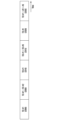
以下、5Gシステムのフレーム構造に対して図面を参照してより具体的に説明する。
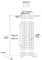
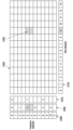
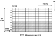
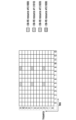
図1は、5Gシステムの無線リソース領域である時間-周波数領域の基本構造を示す図である。
Hereinafter, the frame structure of the 5G system will be described in more detail with reference to the drawings.
FIG. 1 is a diagram showing the basic structure of the time-frequency domain, which is the radio resource domain of a 5G system.
図1で、横軸は時間領域を表し、縦軸は周波数領域を表す。
時間及び周波数領域でリソースの基本単位は、リソース要素(resource element:RE)101として時間軸に1個のOFDM(Orthogonal Frequency Division Multiplexing)シンボル(又はDFT-s-OFDM(discrete Fourier transform spread OFDM)シンボル)102及び周波数軸に1個のサブキャリア(subcarrier)103と定義することができる。
周波数領域で
![]()
また、時間領域で
![]()
The basic unit of a resource in the time and frequency domain is a resource element (RE) 101, which can be defined as one Orthogonal Frequency Division Multiplexing (OFDM) symbol (or DFT-s-OFDM (discrete Fourier transform spread OFDM) symbol) 102 on the time axis and one
In the frequency domain
![]()
Also, in the time domain
![]()
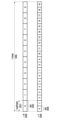
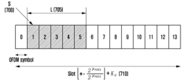
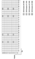
図2は、5Gシステムで考慮するスロット構造を示す図である。
図2にはフレーム(frame)200、サブフレーム201、スロット(slot)202構造の一例を図に示す。
1個のフレーム200は、10msと定義することができる。
1個のサブフレーム201は、1msと定義することができ、したがって、1個のフレーム200は、総数10個のサブフレーム201から構成される。
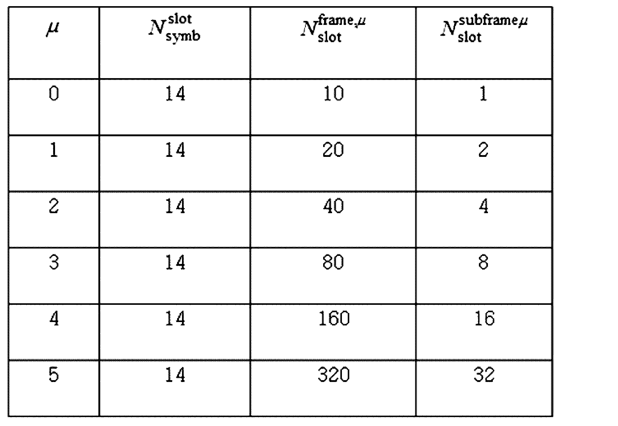
また、1個のスロット(202、203)は、14個のOFDMシンボルと定義することができる(すなわち、1個のスロット当りシンボル数(
![]()
1個のサブフレーム201は、1個又は複数個のスロット(202、203)から構成され、1個のサブフレーム201当りスロット(202、203)の個数は、サブキャリア間隔に対する設定値のμ(204、205)によって異なる。
FIG. 2 is a diagram showing a slot structure considered in a 5G system.
FIG. 2 shows an example of a
One
One
Also, one slot (202, 203) can be defined as 14 OFDM symbols (i.e., the number of symbols per slot (
![]()
One
図2の一例では、サブキャリア間隔設定値でμ=0(204)の場合とμ=1(205)の場合のスロット構造を示している。
μ=0(204)の場合、1個のサブフレーム201は、1個のスロット202から構成され、μ=1(205)の場合、1個のサブフレーム201は、2個のスロット203から構成される。
すなわち、サブキャリア間隔に対する設定値μによって1個のサブフレーム当りスロット数(
![]()
![]()
各サブキャリア間隔設定μによる
![]()
![]()
When μ=0 ( 204 ), one
That is, the number of slots per subframe (
![]()
![]()
By setting each subcarrier interval μ
![]()
![]()
5G無線通信システムでは初期接続のために同期化信号ブロック(synchronization signal block、SSB、SS ブロック(SS block)、SS/PBCHブロック(SS/PBCH block)などと混用されてもよい)を送信することができ、同期化信号ブロックは、PSS(primary synchronization signal)、SSS(secondary synchronization signal)、PBCH(physical broadcast channel)から構成され得る。
端末が最初でシステムに接続する初期接続(initial access)段階で、端末は、先ずセル探索(cell search)を介して同期化信号(synchronization signal)からダウンリンク時間及び周波数領域同期を取得してセルID(cell ID)を取得する。
同期化信号にはPSS及びSSSが含まれ得る。
In the 5G wireless communication system, a synchronization signal block (SSB, SS block, SS / PBCH block, etc.) may be transmitted for initial connection, and the synchronization signal block may be composed of a primary synchronization signal (PSS), a secondary synchronization signal (SSS), and a physical broadcast channel (PBCH).
In an initial access stage in which a terminal first connects to a system, the terminal first acquires downlink time and frequency domain synchronization from a synchronization signal through a cell search, and then acquires a cell ID.
The synchronization signals may include a PSS and a SSS.
そして、端末は、基地局からマスター情報ブロック(master information block:MIB)を送信するPBCHを受信してシステム帯域幅又は関連制御情報など送受信に関連するシステム情報及び基本的なパラメーター値を獲得することができる。
この情報に基づいて端末は、PDCCH(physical downlink control channel)及びPDSCH(physical downlink shared channel)に対するデコーディングを行ってシステム情報ブロック(system information block:SIB)を取得する。
その後、端末は、ランダムアクセス(random access)段階を介して基地局とアイデンティティーを交換して登録、認証などの段階を経てネットワークに初期接続する。
The terminal can receive a PBCH that transmits a master information block (MIB) from the base station to obtain system information related to transmission and reception, such as a system bandwidth or related control information, and basic parameter values.
Based on this information, the terminal performs decoding on a physical downlink control channel (PDCCH) and a physical downlink shared channel (PDSCH) to obtain a system information block (SIB).
Thereafter, the terminal exchanges an identity with the base station through a random access step, and performs registration, authentication, and other steps to initially connect to the network.
同期化信号は、セル探索の基準になる信号として、周波数バンド別で位相雑音(phase noise)などのチャンネル環境に適合したサブキャリア間隔が適用されて送信される。
5G基地局は、操作しようとするアナログビームの個数に従って同期化信号ブロックを複数個送信する。
PSSとSSSは、12RBにかけてマッピングされて送信されてPBCHは、24RBにかけてマッピングされて送信される。
The synchronization signal is a reference signal for cell search, and is transmitted with a subcarrier interval adapted to a channel environment such as phase noise for each frequency band.
The 5G base station transmits multiple synchronization signal blocks according to the number of analog beams to be steered.
The PSS and SSS are mapped across 12 RBs and transmitted, and the PBCH is mapped across 24 RBs and transmitted.
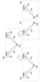
次に、5G通信システムで帯域幅部分(Bandwidth Part:BWP)設定に対して図面を参照して具体的に説明する。
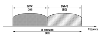
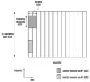
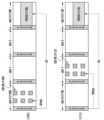
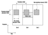
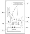
図3は、5G通信システムで帯域幅部分に対する設定の一例を示す図面である。
図3には端末帯域幅(UE bandwidth)300が2つの帯域幅部分、すなわち、帯域幅部分#1(BWP#1)305と帯域幅部分#2(BWP#2)310と設定された一例を示す。
基地局は、端末に1個又は複数個の帯域幅部分を設定することができ、各帯域幅部分に対して以下の情報を設定することができる。
Next, a bandwidth part (BWP) setting in a 5G communication system will be described in detail with reference to the drawings.
FIG. 3 is a diagram showing an example of a setting for a bandwidth portion in a 5G communication system.
FIG. 3 shows an example in which a
The base station can configure one or more bandwidth portions for the terminal, and can configure the following information for each bandwidth portion:
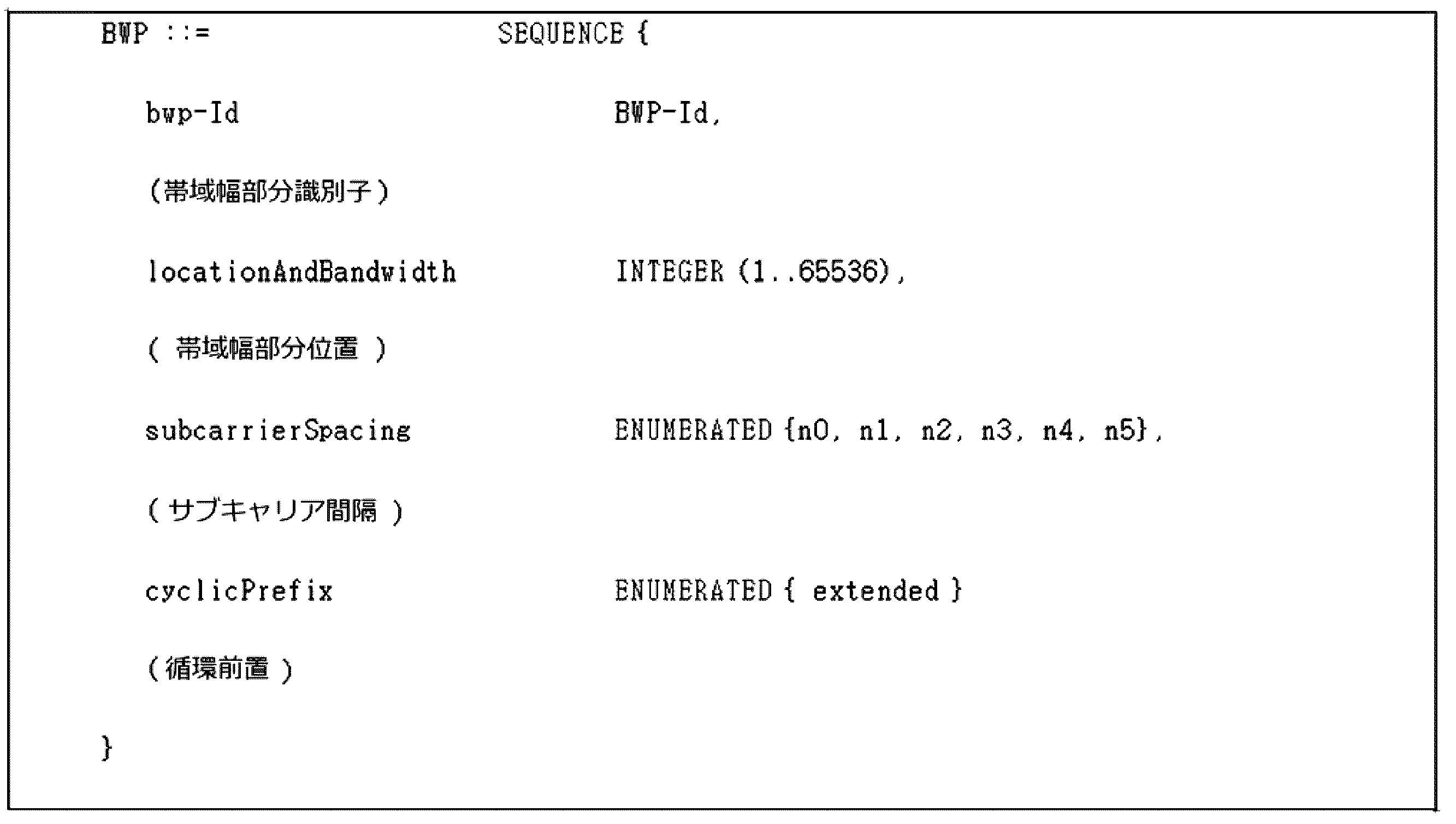
もちろん、本例示に制限されることではなく、上記設定情報外にも帯域幅部分に関連する多様なパラメーターが端末に設定され得る。
上記情報は、上位階層シグナリング、例えば、RRC(Radio Resource Control)シグナリングを介して基地局が端末に伝達する。
設定された一つ又は複数個の帯域幅部分の内の少なくとも一つの帯域幅部分が活性化(Activation)される。
設定された帯域幅部分に対し活性化するかどうかは、基地局から端末にRRCシグナリングを介して準静的に伝達されるか、DCI(Downlink Control Information)を介して動的に伝達される。
Of course, the present invention is not limited to this example, and various parameters related to the bandwidth portion other than the above setting information may be set in the terminal.
The information is transmitted from the base station to the terminal via higher layer signaling, for example, Radio Resource Control (RRC) signaling.
At least one of the set one or more bandwidth portions is activated.
Whether or not to activate the set bandwidth portion is semi-statically transmitted from the base station to the terminal via RRC signaling, or dynamically transmitted via Downlink Control Information (DCI).
一部実施形態によれば、RRC(Radio Resource Control)接続の前の端末は、初期接続のための初期帯域幅部分(Initial BWP)をMIB(Master Information Block)を介して基地局から設定される。
より具体的に説明すれば、端末は、初期接続段階でMIBを介して初期接続に必要なシステム情報(Remaining System Information:RMSI又はSystem Information Block 1:SIB1に該当することができる)受信のためのPDCCH(Physical Downlink Control Channel)が送信され得る制御領域(Control Resource Set:CORESET)と探索空間(Search Space)に対する設定情報を受信する。
MIBに設定される制御領域と探索空間は、それぞれ識別子(Identity:ID)0と見なされる。
基地局は、端末にMIBを介して制御領域#0に対する周波数割り当て情報、時間割り当て情報、ヌマララジ(Numerology)などの設定情報を通知することができる。
また、基地局は、端末にMIBを介して制御領域#0に対するモニタリング周期及び「occasion」に対する設定情報、すなわち、探索空間#0に対する設定情報を通知することができる。
端末は、MIBから取得した制御領域#0と設定された周波数領域を初期接続のための初期帯域幅部分と見なす。
この時、初期帯域幅部分の識別子(ID)は「0」と見なされる。
According to some embodiments, before a Radio Resource Control (RRC) connection, a terminal receives an initial bandwidth portion (Initial BWP) for an initial connection from a base station via a Master Information Block (MIB).
More specifically, in the initial access stage, the terminal receives system information (which may correspond to Remaining System Information (RMSI) or System Information Block 1 (SIB1)) required for initial access via the MIB. The terminal receives setting information for a control area (CORESET) and a search space (Search Space) in which a PDCCH (Physical Downlink Control Channel) can be transmitted.
The control region and search space configured in the MIB are each considered to have an identity (ID) of 0.
The base station can notify the terminal of setting information such as frequency allocation information, time allocation information, and numerology for
In addition, the base station can notify the terminal of the monitoring period for the
The terminal regards the
At this time, the identifier (ID) of the initial bandwidth portion is considered to be "0".
5Gシステムでサポートする帯域幅部分に対する設定は多様な目的として用いられる。
一部実施形態によれば、システム帯域幅より端末がサポートする帯域幅が小さい場合に帯域幅部分設定を介してこれをサポートする。
例えば、基地局は、帯域幅部分の周波数位置(設定情報2)を端末に設定することによって、システム帯域幅内の特定周波数位置で端末がデータを送受信する。
The settings for the bandwidth portion supported by the 5G system are used for various purposes.
According to some embodiments, when the bandwidth supported by the terminal is smaller than the system bandwidth, this is supported via bandwidth portion configuration.
For example, the base station sets a frequency position of a bandwidth portion (setting information 2) to the terminal, so that the terminal transmits and receives data at a specific frequency position within the system bandwidth.
また、一部実施形態によれば、互いに異なるヌマララジをサポートするための目的で基地局が端末に複数個の帯域幅部分を設定することができる。
例えば、ある端末に対して15kHzのサブキャリア間隔と30kHzのサブキャリア間隔を用いたデータ送受信をいずれもサポートするため、2つの帯域幅部分をそれぞれの15kHzと30kHzのサブキャリア間隔で設定する。
互いに異なる帯域幅部分は、周波数分割多重化(Frequency Division Multiplexing)することができ、特定サブキャリア間隔でデータを送受信しようとする場合、該当サブキャリア間隔に設定されている帯域幅部分が活性化される。
Also, according to some embodiments, a base station may configure multiple bandwidth portions to a terminal in order to support different numeral radios.
For example, to support data transmission and reception using both a subcarrier spacing of 15 kHz and a subcarrier spacing of 30 kHz for a certain terminal, two bandwidth portions are set with subcarrier spacings of 15 kHz and 30 kHz, respectively.
The different bandwidth portions can be frequency division multiplexed, and when data is to be transmitted or received at a specific subcarrier interval, the bandwidth portion set at the corresponding subcarrier interval is activated.
また、一部実施形態によれば、端末の電力消費減少のための目的に基地局が端末に互いに異なるサイズの帯域幅を持つ帯域幅部分を設定する。
例えば、端末が非常に大きい帯域幅、例えば、100MHzの帯域幅をサポートして該当帯域幅で常にデータを送受信する場合、非常に大きい電力消費が発生する可能性がある。
特に、トラフィック(Traffic)がない状況で100MHzの大きい帯域幅で不必要なダウンリンク制御チャンネルに対するモニタリングを行うことは、電力消費観点で非常に非効率的である。
端末の電力消費を減らすための目的に、基地局は、端末に相対的に小さな帯域幅の帯域幅部分、例えば、20MHzの帯域幅部分を設定する。
トラフィックがない状況で、端末は、20MHz帯域幅部分でモニタリング動作を行うことができ、データが発生した場合、基地局の指示に従って100MHzの帯域幅部分でデータを送受信することができる。
Also, according to some embodiments, the base station configures bandwidth portions having different bandwidth sizes to the terminal for the purpose of reducing power consumption of the terminal.
For example, if a terminal supports a very large bandwidth, for example, a bandwidth of 100 MHz, and constantly transmits and receives data through that bandwidth, very large power consumption may occur.
In particular, monitoring an unnecessary downlink control channel with a large bandwidth of 100 MHz in a situation where there is no traffic is very inefficient in terms of power consumption.
In order to reduce the power consumption of the terminal, the base station sets a bandwidth portion of a relatively small bandwidth, for example a bandwidth portion of 20 MHz, to the terminal.
In a situation where there is no traffic, the terminal can perform a monitoring operation in the 20 MHz bandwidth portion, and when data occurs, it can transmit and receive data in the 100 MHz bandwidth portion according to the instruction of the base station.
上記帯域幅部分を設定する方法において、RRC接続(Connected)前の端末は、初期接続段階でMIB(Master Information Block)を介して初期帯域幅部分(Initial Bandwidth Part)に対する設定情報を受信する。
より具体的に説明すれば、端末は、PBCH(Physical Broadcast Channel)のMIBからSIB(System Information Block)をスケジューリングするDCI(Downlink Control Information)が送信され得るダウンリンク制御チャンネルのための制御領域(Control Resource Set、CORESET、又は制御リソースセットと混用されてもよい)が設定される。
MIBに設定された制御領域の帯域幅が初期帯域幅部分と見なされ得、設定された初期帯域幅部分を介して、端末は、SIBが送信されるPDSCH(Physical Downlink Shared Channel)を受信する。
初期帯域幅部分は、SIBを受信する用途の外にも、他のシステム情報(Other System Information:OSI)、ページング(Paging)、ランダムアクセス(Random Access)用に活用することもできる。
In the method for setting the bandwidth part, a terminal before an RRC connection receives setting information for an initial bandwidth part via a master information block (MIB) in an initial connection stage.
More specifically, the terminal is configured with a control region (which may be referred to as a Control Resource Set, CORESET, or control resource set) for a downlink control channel in which Downlink Control Information (DCI) for scheduling a System Information Block (SIB) from an MIB of a Physical Broadcast Channel (PBCH) can be transmitted.
The bandwidth of the control region set in the MIB may be regarded as an initial bandwidth portion, and the terminal receives a Physical Downlink Shared Channel (PDSCH) through which the SIB is transmitted via the set initial bandwidth portion.
In addition to receiving SIBs, the initial bandwidth portion can also be utilized for other system information (OSI), paging, and random access.
端末に一つ以上の帯域幅部分が設定された場合、基地局は、端末にDCI内の帯域幅部分インジケーター(Bandwidth Part Indicator)フィールドを用い、帯域幅部分に対する変更を指示する。
例えば、図3で端末の現在活性化されて帯域幅部分が帯域幅部分#1(305)の場合、基地局は、端末にDCI内の帯域幅部分インジケーターで帯域幅部分#2(310)を指示し、端末は、受信したDCI内の帯域幅部分インジケーターに指示された帯域幅部分#2(310)で帯域幅部分変更を行う。
If one or more bandwidth parts are configured for the terminal, the base station instructs the terminal to change the bandwidth part using a Bandwidth Part Indicator field in the DCI.
For example, in FIG. 3, if the currently activated bandwidth portion of the terminal is bandwidth portion #1 (305), the base station indicates bandwidth portion #2 (310) to the terminal using a bandwidth portion indicator in the DCI, and the terminal performs a bandwidth portion change to bandwidth portion #2 (310) indicated by the bandwidth portion indicator in the received DCI.
前述のようにDCI基盤帯域幅部分変更は、PDSCH又はPUSCH(Physical Uplink Shared Channel)をスケジューリングするDCIによって指示することができるため、端末は帯域幅部分変更リクエストを受信した場合、該当DCIがスケジューリングするPDSCH又はPUSCHを変更された帯域幅部分で無理無しに受信又は送信を行わなければならない。
このために、標準では帯域幅部分変更時の要求される遅延時間(TBWP)に対する要求事項を規定し、例えば、以下のように定義される。
As described above, the DCI-based bandwidth portion change can be indicated by a DCI that schedules a PDSCH or a PUSCH (Physical Uplink Shared Channel). Therefore, when a terminal receives a bandwidth portion change request, the terminal must receive or transmit the PDSCH or PUSCH scheduled by the corresponding DCI in the changed bandwidth portion without difficulty.
For this purpose, the standard specifies requirements for the required delay time (T BWP ) when changing the bandwidth portion, and is defined, for example, as follows:
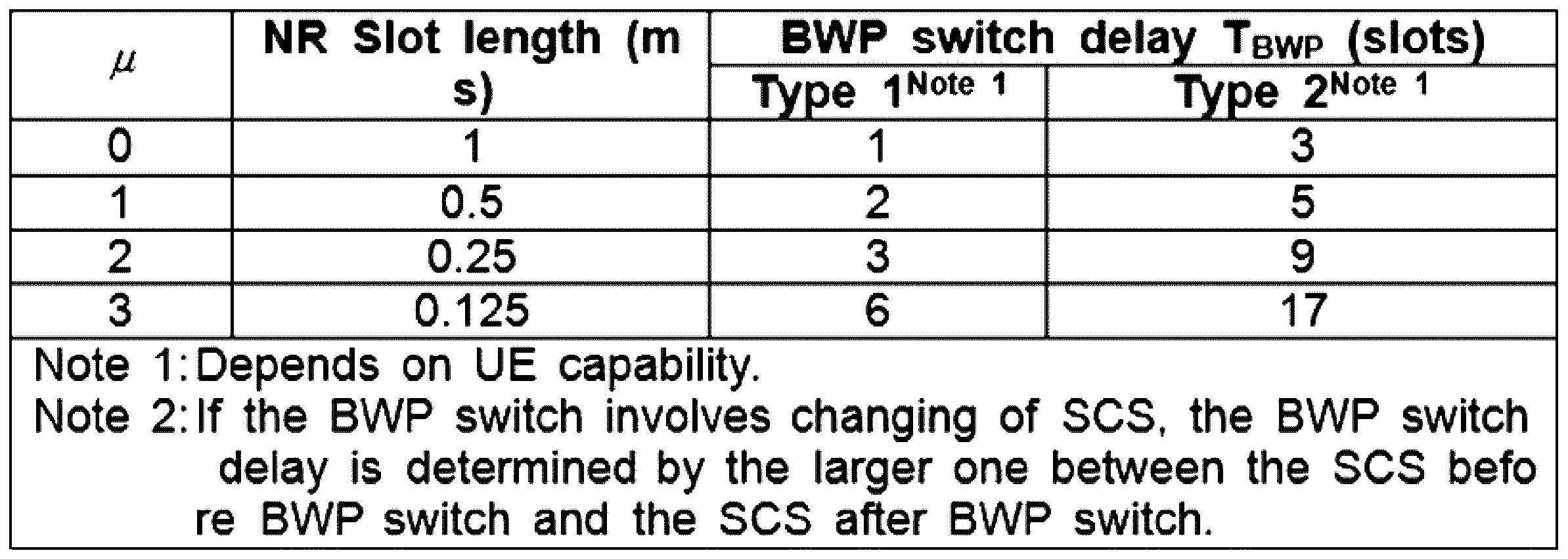
帯域幅部分変更遅延時間に対する要求事項は、端末の能力(Capability)によってタイプ1又はタイプ2をサポートする。
端末は、基地局にサポート可能な帯域幅部分遅延時間タイプを報告する。
The requirement for bandwidth portion change delay time supports
The terminal reports the bandwidth partial delay time type that it can support to the base station.
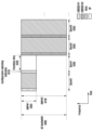
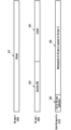
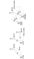
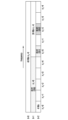
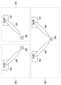
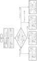
図4は、本発明の一実施形態による帯域幅変更方法の一例を示す図である。
図4を参照すると、前述の帯域幅部分変更遅延時間に対する要求事項に従い、端末が帯域幅部分変更インジケーターを含むDCIをスロット#1(430)で受信した場合(415)、端末は帯域幅部分変更インジケーターが指す新しい帯域幅部分への変更をスロット(n+TBWP)より遅れない時点で完了し、変更された新しい帯域幅部分(410)で該当DCIがスケジューリングするデータチャンネルに対する送受信を行う。
FIG. 4 illustrates an example of a method for changing bandwidth according to an embodiment of the present invention.
Referring to FIG. 4, in accordance with the requirements for the bandwidth portion change delay time described above, if a terminal receives a DCI including a bandwidth portion change indicator in slot #1 (430) (415), the terminal completes the change to the new bandwidth portion indicated by the bandwidth portion change indicator no later than slot (n+T BWP ) and transmits/receives the data channel scheduled by the corresponding DCI in the changed new bandwidth portion (410).
基地局は、新しい帯域幅部分でデータチャンネルをスケジューリングしようとする場合、端末の帯域幅部分変更遅延時間(TBWP)420を考慮し、データチャンネルに対する時間ドメインリソース割り当てを決定する。
すなわち、基地局は、新しい帯域幅部分でデータチャンネルをスケジューリングする時、データチャンネルに対する時間ドメインリソース割り当てを決定する方法において、帯域幅部分変更遅延時間の以後で(スロット#2、スロット#3)(435、440)該当データチャンネルをスケジューリングする。
これにより端末は、帯域幅部分変更を指示するDCIが、帯域幅部分変更遅延時間(TBWP)420より小さいスロットオフセット(K0又はK2)値を指示することを期待しないこともある。
When the base station attempts to schedule a data channel in a new bandwidth portion, it considers the bandwidth portion change delay (T BWP ) 420 of the terminal and determines the time domain resource allocation for the data channel.
That is, when the base station schedules a data channel in a new bandwidth portion, in a method for determining a time domain resource allocation for the data channel, the base station schedules the corresponding data channel (
As a result, the terminal may not expect the DCI indicating a bandwidth portion change to indicate a slot offset (K0 or K2) value smaller than the bandwidth portion change delay time (T BWP ) 420 .
もし、端末が帯域幅部分変更を指示するDCI(例えば、DCIフォーマット(1_1)又は(0_1))を受信する場合、端末は該当DCIを含むPDCCHを受信したスロットの第3のシンボルから、該当DCI内の時間ドメインリソース割り当てインジケーターフィールドに指示されたスロットオフセット(K0又はK2)値に指示されたスロットの開始地点までに該当する時間区間の間のどんな送信又は受信も行われないこともある。
例えば、端末がスロットnで帯域幅部分変更を指示するDCIを受信し、該当DCIに指示されたスロットオフセット値がKとすると、端末は、スロットnの第3のシンボルからスロット(n+K)以前シンボル(すなわち、スロット(n+K-1)の最後のシンボル)までどんな送信又は受信も行われないこともある。
If the terminal receives a DCI indicating a bandwidth portion change (e.g., DCI format (1_1) or (0_1)), the terminal may not perform any transmission or reception during the corresponding time interval from the third symbol of the slot in which the terminal receives the PDCCH containing the corresponding DCI to the start of the slot indicated by the slot offset (K0 or K2) value indicated in the time domain resource allocation indicator field in the corresponding DCI.
For example, if a terminal receives a DCI indicating a bandwidth portion change in slot n and the slot offset value indicated in the DCI is K, the terminal may not transmit or receive anything from the third symbol of slot n to the symbol before slot (n+K) (i.e., the last symbol of slot (n+K-1)).
次に、5Gシステムにおける帯域幅部分別で送受信関連パラメーターを設定する方法に対して説明する。
端末は、基地局から一つ又は複数個の帯域幅部分が設定することができ、設定された各帯域幅部分別で送受信に用いるパラメーター(例えば、アップリンクデータチャンネル及び制御チャンネル関連設定情報など)を追加で設定することができる。
Next, a method for setting transmission and reception related parameters for each bandwidth portion in a 5G system will be described.
The terminal can be configured with one or more bandwidth portions from the base station, and can additionally configure parameters (e.g., uplink data channel and control channel related configuration information, etc.) to be used for transmission and reception for each configured bandwidth portion.
例えば、図3で、端末が帯域幅部分#1(305)と帯域幅部分#2(310)を設定された場合、端末は、帯域幅部分#1(305)に対して送受信パラメーター#1が設定され、帯域幅部分#2(310)に対して送受信パラメーター#2が設定される。
端末は、帯域幅部分#1(305)が活性化されている場合、送受信パラメーター#1に基づいて基地局と送受信を行い、帯域幅部分#2(310)が活性化されている場合、送受信パラメーター#2に基づいて基地局と送受信を行う。
For example, in FIG. 3, when a terminal is configured with bandwidth portion #1 (305) and bandwidth portion #2 (310), the terminal is configured with transmission and
When bandwidth portion #1 (305) is activated, the terminal transmits and receives with the base station based on transmission and
より具体的には、以下のパラメーターが基地局から端末と設定される。
先ず、アップリンク帯域幅部分に対し、以下の情報が設定される。
More specifically, the following parameters are set from the base station to the terminal:
First, the following information is set for the uplink bandwidth portion:
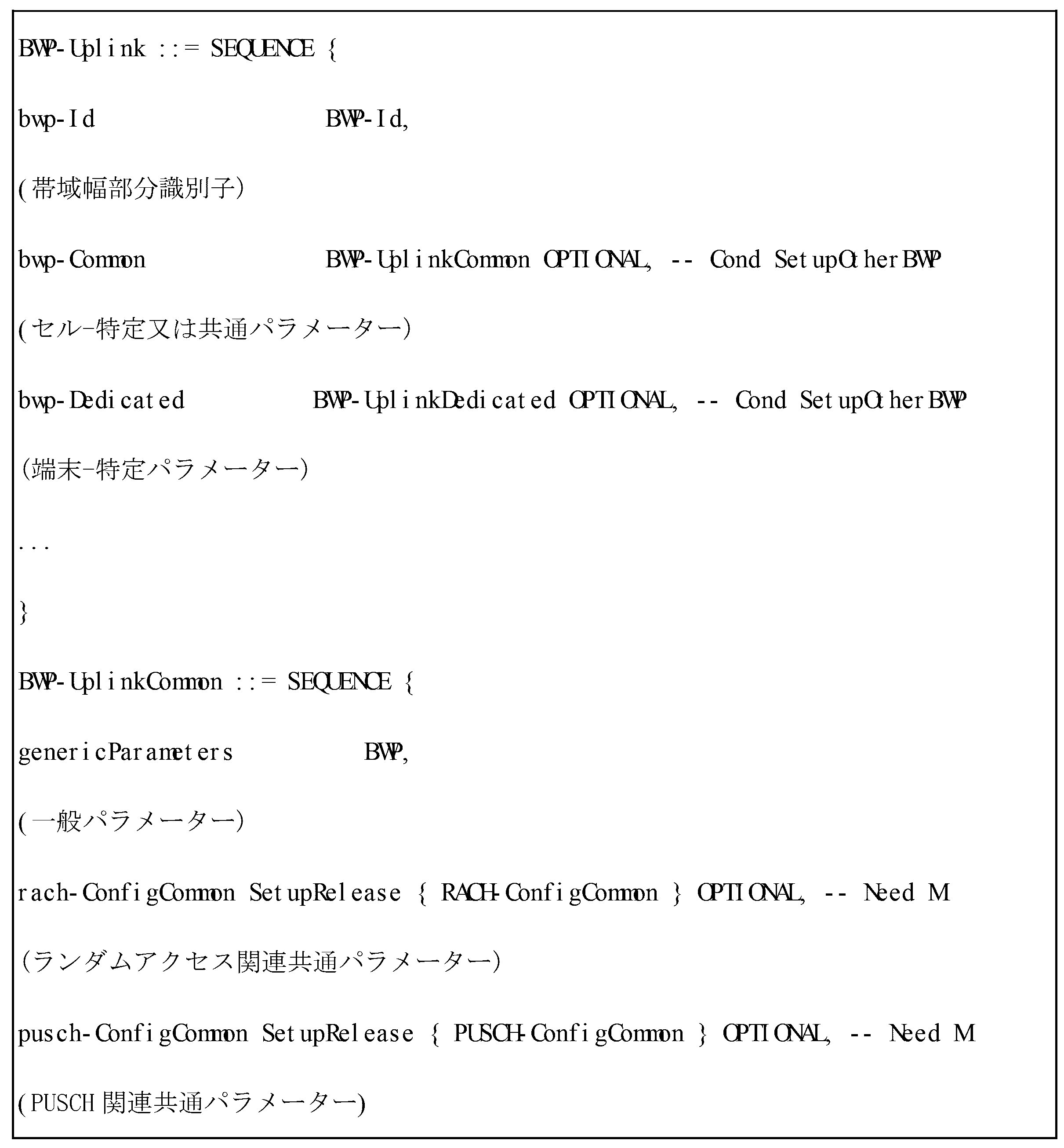
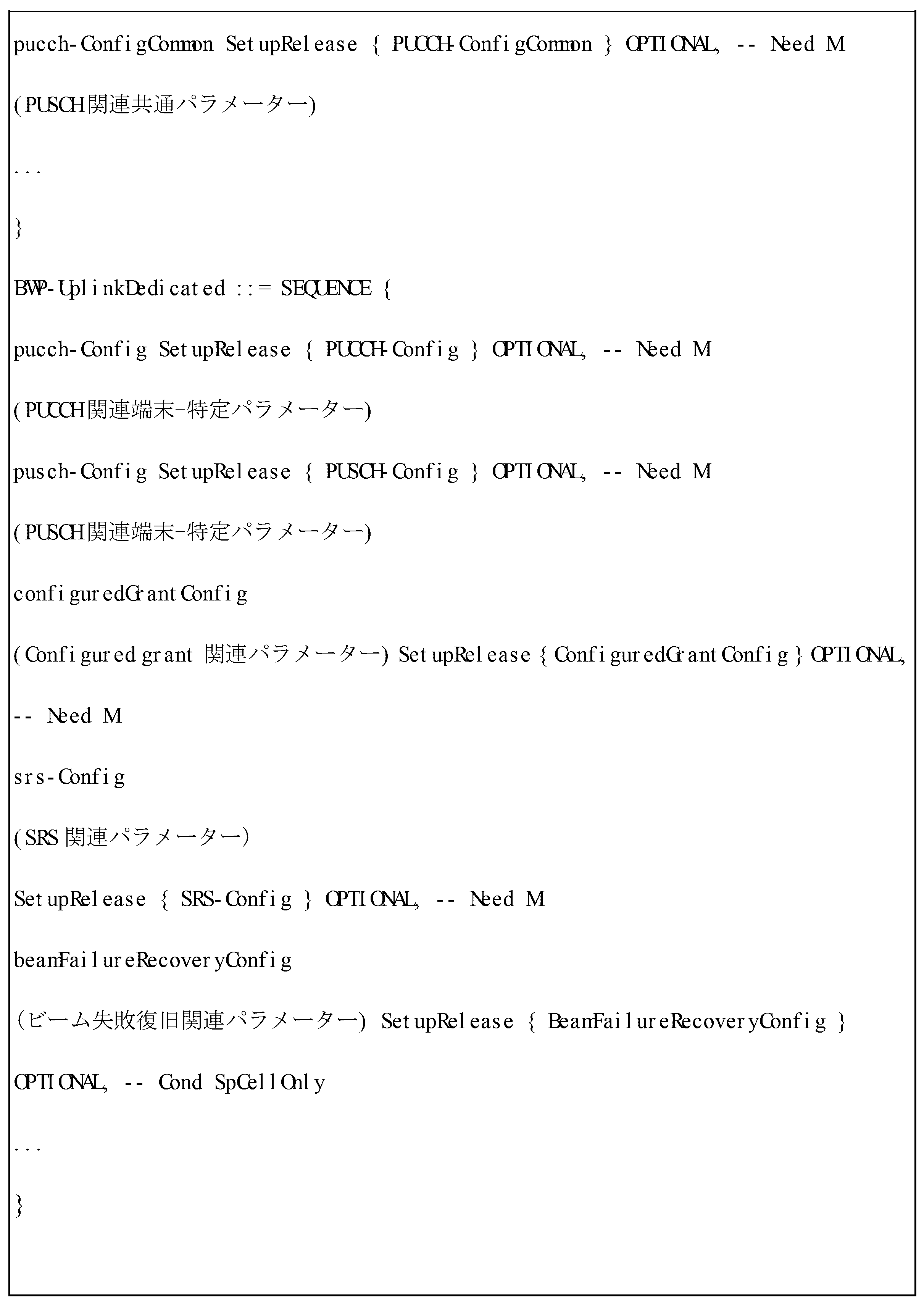
上述の表によれば、端末は、基地局からセル-特定的(又はセル共通又は共通)送信関連パラメーター(例えば、ランダムアクセスチャンネル(Random Access Channel:RACH)、アップリンク制御チャンネル(Physical Uplink Control Channel:PUCCH)、アップリンクデータチャンネル(Physical Uplink Shared Channel)関連パラメーター)が設定される(BWP-UplinkCommonに該当)。
また、端末は、基地局から端末-特定的(又はdedicated)送信関連パラメーター(例えば、PUCCH、PUSCH、非承認-基盤アップリンク送信(Configured Grant PUSCH)、サウンディング参照信号(Sounding Reference Signal:SRS)関連パラメーター)が設定される(BWP-UplinkDedicatedに該当)。
According to the above table, the terminal is configured with cell-specific (or cell-common or common) transmission related parameters (e.g., Random Access Channel (RACH), Physical Uplink Control Channel (PUCCH), and Physical Uplink Shared Channel related parameters) from the base station (corresponding to BWP-UplinkCommon).
In addition, the terminal is configured with terminal-specific (or dedicated) transmission related parameters (e.g., PUCCH, PUSCH, unacknowledged-based uplink transmission (Configured Grant PUSCH), and Sounding Reference Signal (SRS) related parameters) from the base station (corresponding to BWP-UplinkDedicated).
次に、ダウンリンク帯域幅部分に対し、以下の情報が設定される。 Then, the following information is set for the downlink bandwidth portion:
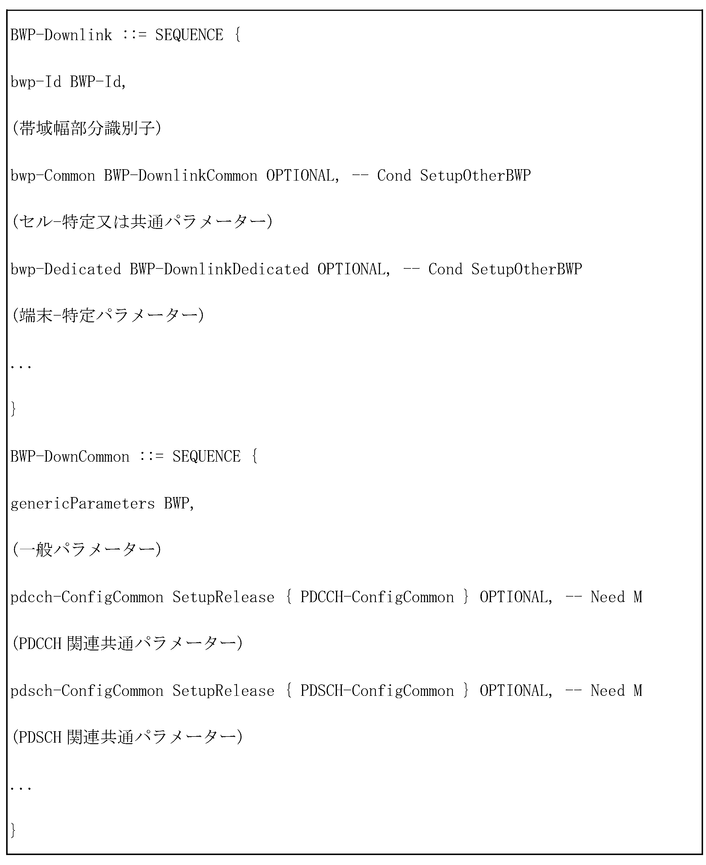
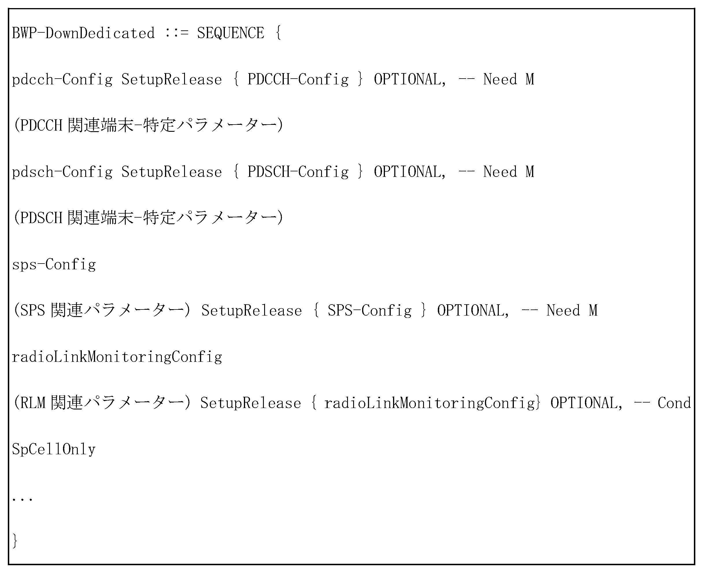
上述の表によれば、端末は、基地局からセル-特定的(又はセル共通又は共通)受信関連パラメーター(例えば、ダウンリンク制御チャンネル(Physical Downlink Control Channel:PDCCH)、ダウンリンクデータチャンネル(Physical Downlink Shared Channel)関連パラメーター)が設定される(BWP-DownlinkCommonに該当)。
また、端末は、基地局から端末-特定的(又はdedicated)受信関連パラメーター(例えば、PDCCH、PDSCH、非承認-基盤ダウンリンクデータ送信(Semi-persistent Scheduled PDSCH)、無線リンクモニタリング(Radio Link Monitoring:RLM)関連パラメーター)が設定される(BWP-UplinkDedicatedに該当)。
According to the above table, the terminal is configured with cell-specific (or cell-common or common) reception-related parameters (e.g., downlink control channel (Physical Downlink Control Channel: PDCCH), downlink data channel (Physical Downlink Shared Channel) related parameters) from the base station (corresponding to BWP-DownlinkCommon).
In addition, the terminal is configured with terminal-specific (or dedicated) reception-related parameters (e.g., PDCCH, PDSCH, unacknowledged-based downlink data transmission (Semi-persistent Scheduled PDSCH), and Radio Link Monitoring (RLM)-related parameters) from the base station (corresponding to BWP-UplinkDedicated).
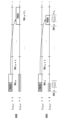
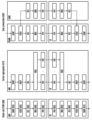
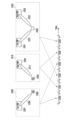
図5は、5G無線通信システムでダウンリンク制御チャンネルが送信される制御リソースセット(Control Resource Set:CORESET)に対する一例を示す図である。
図5は、周波数軸に端末の帯域幅部分(UE bandwidth part)510、時間軸で1スロット520内に2個の制御リソースセット(制御リソースセット#1(501)、制御リソースセット#2(502))が設定されている一例を示す図である。
制御リソースセット(501、502)は、周波数軸に全体端末帯域幅部分510内で特定周波数リソース503に設定される。
時間軸としては、1個又は複数個のOFDMシンボルと設定され、これを制御リソースセット長さ(Control Resource Set Duration)504として定義することができる。
図5に示した例を参照すると、制御リソースセット#1(501)は、2シンボルの制御リソースセット長さと設定され、制御リソースセット#2(502)は、1シンボルの制御リソースセット長さと設定される。
FIG. 5 is a diagram illustrating an example of a control resource set (CORESET) on which a downlink control channel is transmitted in a 5G wireless communication system.
FIG. 5 is a diagram showing an example in which a terminal bandwidth part (UE bandwidth part) 510 is set on the frequency axis, and two control resource sets (control resource set #1 (501) and control resource set #2 (502)) are set within one
The control resource set (501, 502) is set to a specific frequency resource 503 within the entire
The time axis is set to one or more OFDM symbols, which can be defined as a control resource set
Referring to the example shown in FIG. 5, control resource set #1 (501) is configured with a control resource set length of 2 symbols, and control resource set #2 (502) is configured with a control resource set length of 1 symbol.
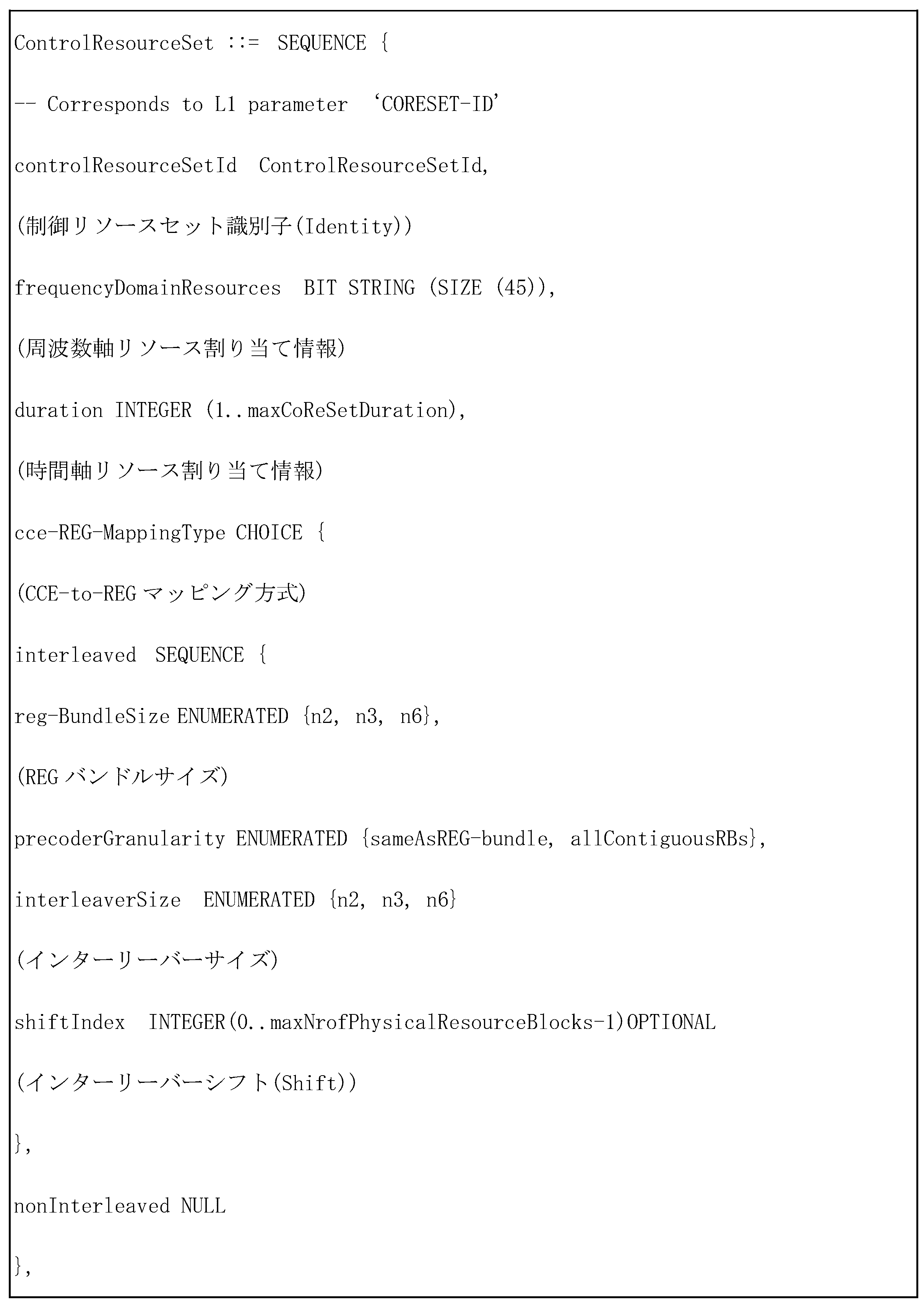
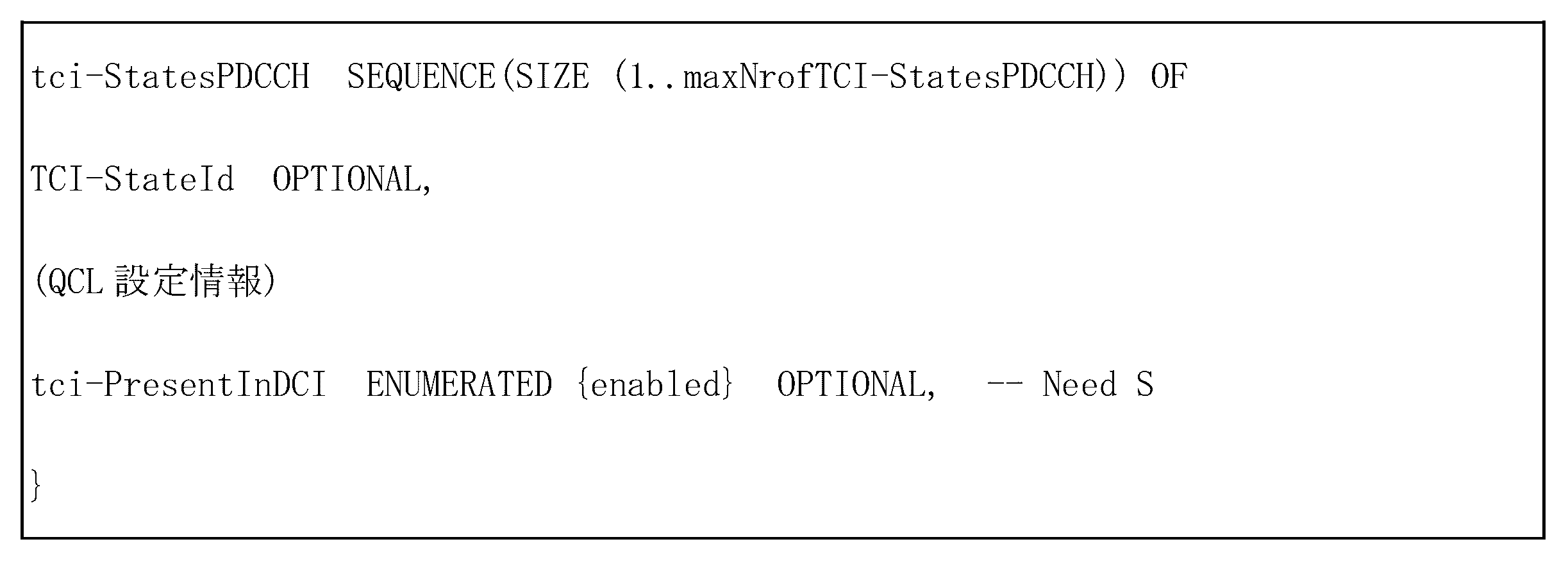
前述の5Gシステムでの制御リソースセットは、基地局が端末に上位階層シグナリング(例えば、システム情報(System Information)、MIB(Master Information Block)、RRC(Radio Resource Control)シグナリング)を介して設定することができる。
端末に制御リソースセットを設定するということは、制御リソースセット識別子(Identity)、制御リソースセットの周波数位置、制御リソースセットのシンボル長さなどの情報を提供することを意味する。
例えば、制御リソースセットを設定するために提供される情報は、以下の通りである。
In the above-mentioned 5G system, the control resource set can be set by the base station to the terminal through higher layer signaling (e.g., system information, master information block (MIB), radio resource control (RRC) signaling).
Configuring a control resource set in a terminal means providing information such as a control resource set identifier, a frequency location of the control resource set, and a symbol length of the control resource set.
For example, the information provided to configure the control resource set is as follows:
5Gシステムで制御リソースセットセットは、周波数ドメインで、NRB
CORESETRBから構成され、時間軸に、Nsymb
CORESET∈{1,2,3}シンボルから構成される。
一つのCCEは、6個のREGから構成され、REGは、1 OFDMシンボルの間の1RBと定義される。
一つの制御リソースセット内でREGは、制御リソースセットの第1OFDMシンボル、最も低いRBからREGインデックス0を始まりに時間-優先(Time-First)手順でインデックスが付けられる。
In the 5G system, the control resource set is composed of N RB CORESET RBs in the frequency domain and N symb CORESET ε{1, 2, 3} symbols in the time domain.
One CCE consists of six REGs, and a REG is defined as one RB during one OFDM symbol.
Within one control resource set, the REGs are indexed in a time-first order starting with
5Gシステムでは、PDCCHに対する送信方法でインターリビング(Interleaved)方式と非インターリビング(non-interleaved)方式をサポートする。
基地局は、端末に各制御リソースセット別でインターリビング又は非インターリビング送信するかどうかを、上位階層シグナリングを介して設定する。
インターリビングは、REGバンドル単位に行われる。
REGバンドルとは、一つ又は複数個のREGのセットと定義される。
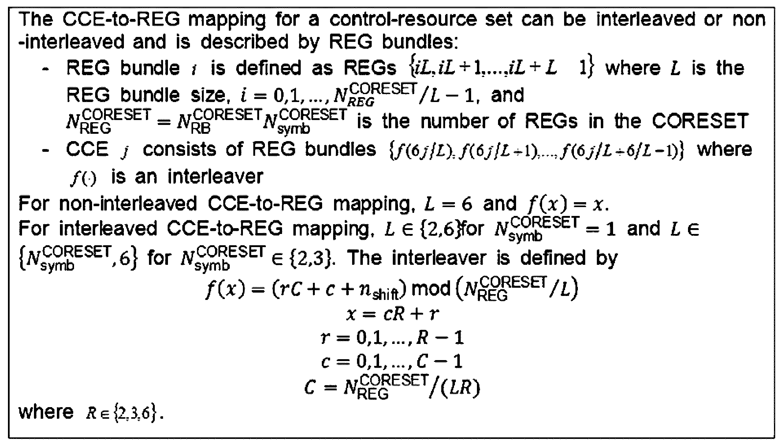
端末は、基地局から設定されたインターリビング又は非インターリビング送信するかどうかに基づいて、該当制御リソースセットでのCCE-to-REGマッピング方式を以下のような方式で決定する。
In the 5G system, the transmission method for PDCCH supports an interleaved scheme and a non-interleaved scheme.
The base station configures the terminal whether to perform interleaved or non-interleaved transmission for each control resource set through higher layer signaling.
Interleaving is performed on a REG bundle basis.
A REG bundle is defined as a set of one or more REGs.
Depending on whether interleaved or non-interleaved transmission is set by the base station, the terminal determines a CCE-to-REG mapping scheme for a corresponding control resource set in the following manner.
ダウンリンク制御チャンネルの基本単位、すなわち、REGにはDCIがマッピングされるREと、これをデコーディングするためのレファレンス信号(reference signal:RS、基準信号と混用可能)である復調基準信号(demodulation reference signal:DMRS)がマッピングされる領域がいずれも含まれる。
一つのREG内には3個のDMRS REが含まれる。
PDCCHを送信するのに必要なCCEの個数は、アグリゲーションレベル(Aggregation Level:AL)によって1、2、4、8、又は16個になることができ、互いに異なるCCE個数は、ダウンリンク制御チャンネルのリンク適応(link adaptation)を具現するために用いられる。
例えば、AL=Lの場合、一つのダウンリンク制御チャンネルがL個のCCEを介して送信される。
The basic unit of the downlink control channel, i.e., the REG, includes both the RE to which the DCI is mapped and an area to which a demodulation reference signal (DMRS), which is a reference signal (RS, which can be mixed with a reference signal) for decoding the DCI, is mapped.
One REG includes three DMRS REs.
The number of CCEs required to transmit the PDCCH can be 1, 2, 4, 8, or 16 depending on an aggregation level (AL), and different numbers of CCEs are used to implement link adaptation of the downlink control channel.
For example, if AL=L, one downlink control channel is transmitted over L CCEs.
端末は、ダウンリンク制御チャンネルに対する情報を知らない状態で信号を検出しなければならないが、ブラインドデコーディングのためにCCEのセットを示す探索空間(search space)を定義した。
探索空間は、与えられたアグリゲーションレベル上で端末がデコーディングを試みなければならないCCEからなるダウンリンク制御チャンネル候補群(Candidate)のセットであり、1、2、4、8、又は16個のCCEで一つの束ねを造る様々なアグリゲーションレベルがあるため、端末は複数個の探索空間を持つことができる。
探索空間セット(Set)は、設定されたすべてのアグリゲーションレベルでの探索空間のセットと定義される。
A terminal must detect a signal without knowing information about a downlink control channel, but a search space indicating a set of CCEs is defined for blind decoding.
A search space is a set of downlink control channel candidates consisting of CCEs that a terminal must attempt to decode at a given aggregation level. Since there are various aggregation levels that create a bundle of 1, 2, 4, 8, or 16 CCEs, a terminal can have multiple search spaces.
A search space set (Set) is defined as the set of search spaces at all configured aggregation levels.
探索空間は、共通(Common)探索空間と端末-特定(UE-specific)探索空間で分類される。
一定グループの端末又はすべての端末がシステム情報に対する動的なスケジューリングやページングメッセージのようなセル共通の制御情報を受信するためにPDCCHの共通探索空間を調査する。
例えば、端末は、セルの事業者情報などを含むSIBの送信のためのPDSCHスケジューリング割り当て情報はPDCCHの共通探索空間を調査して受信する。
共通探索空間の場合、一定グループの端末又はすべての端末がPDCCHを受信しなければならないため、既に約束されたCCEのセットとして定義される。
端末-特定的PDSCH又はPUSCHに対するスケジューリング割り当て情報は、PDCCHの端末-特定探索空間を調査することによって受信される。
端末-特定探索空間は、端末のアイデンティティー(Identity)及び多様なシステムパラメーターの関数で端末-特定的に定義される。
The search space is classified into a common search space and a UE-specific search space.
A certain group of terminals or all terminals search a common search space of the PDCCH to receive cell-common control information such as dynamic scheduling for system information and paging messages.
For example, the terminal receives PDSCH scheduling allocation information for transmitting SIBs including cell operator information, etc., by searching a common search space of the PDCCH.
In the case of a common search space, it is defined as a set of CCEs that have already been committed for which a certain group of terminals or all terminals must receive the PDCCH.
Scheduling assignment information for a terminal-specific PDSCH or PUSCH is received by searching a terminal-specific search space of the PDCCH.
The terminal-specific search space is terminal-specifically defined as a function of the terminal's identity and various system parameters.
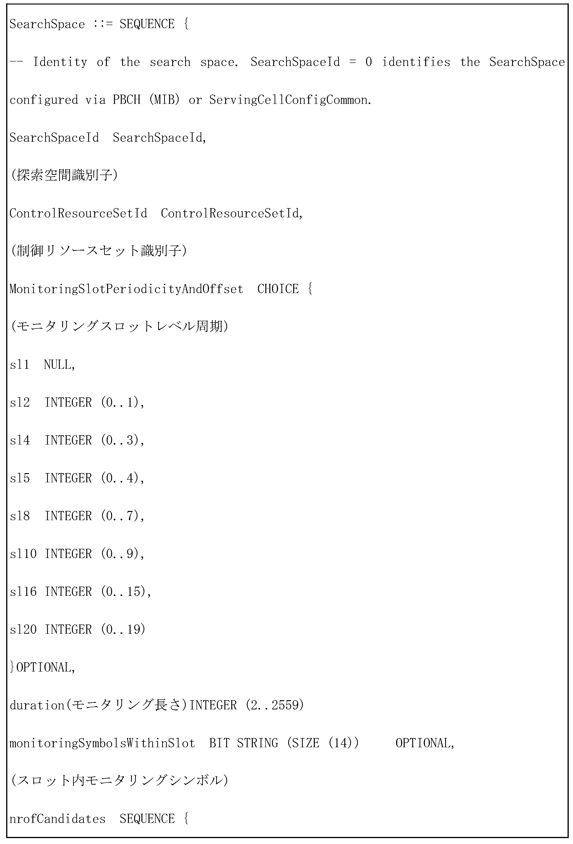
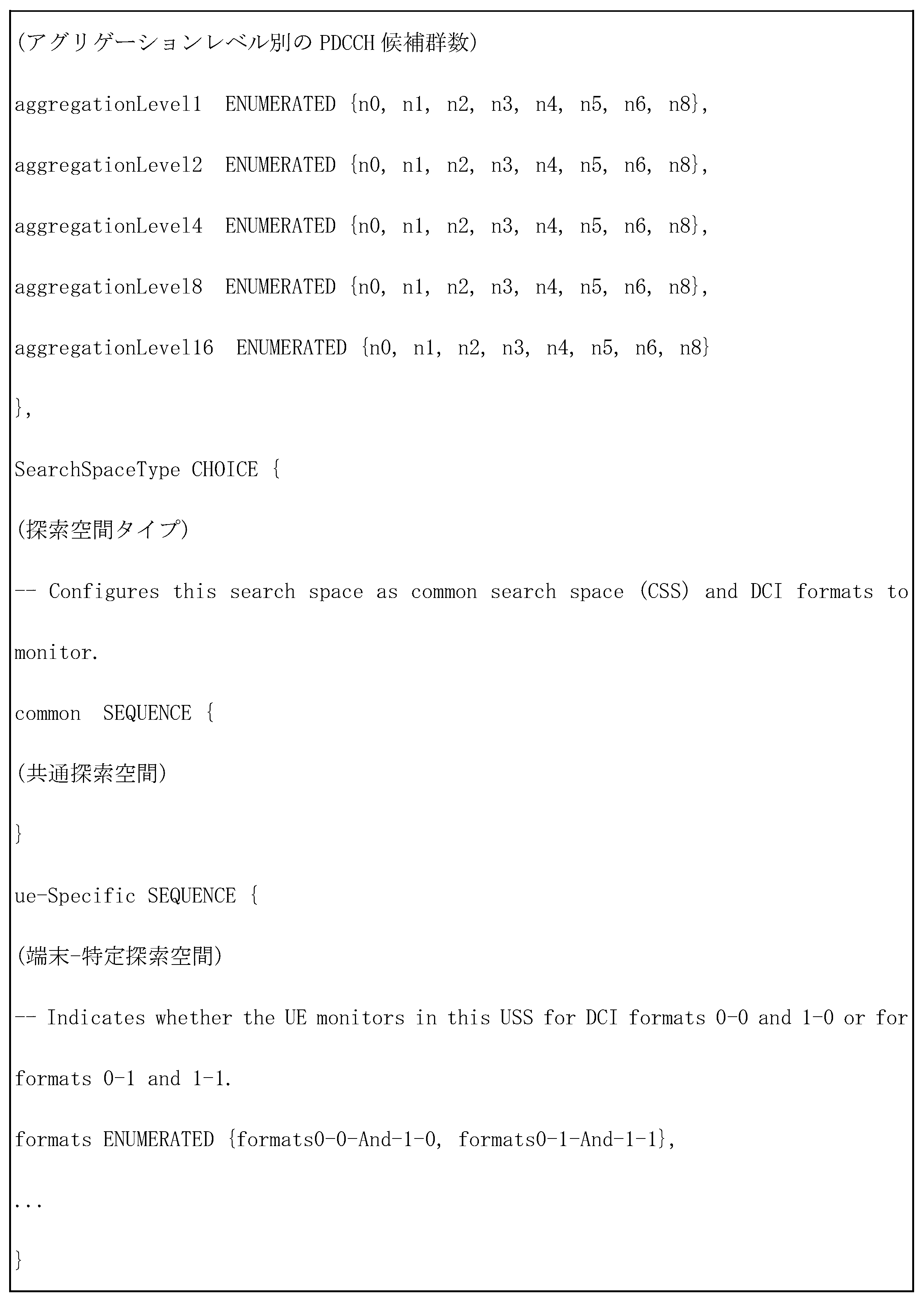
5Gシステムでは、PDCCHに対する探索空間に対するパラメーターは上位階層シグナリング(例えば、SIB、MIB、RRCシグナリング)を介して基地局から端末に設定される。
例えば、基地局は、各アグリゲーションレベルLでのPDCCH候補群数、探索空間に対するモニタリング周期、探索空間に対するスロット内のシンボル単位のモニタリングoccasion、探索空間タイプ(共通探索空間又は端末-特定探索空間)、該当探索空間でモニタリングしようとするDCIフォーマットとRNTIの組み合せ、探索空間をモニタリングしようとする制御リソースセットインデックスなどを端末に設定することができる。
例えば、PDCCHに対する探索空間に対するパラメーターは、以下の情報を含むことができる。
In a 5G system, parameters for the search space for the PDCCH are set from the base station to the terminal via higher layer signaling (e.g., SIB, MIB, RRC signaling).
For example, the base station can set to the terminal the number of PDCCH candidate groups at each aggregation level L, the monitoring period for the search space, the symbol-based monitoring occasion within a slot for the search space, the search space type (common search space or terminal-specific search space), the combination of DCI format and RNTI to be monitored in the corresponding search space, the control resource set index to be monitored in the search space, etc.
For example, the parameters for the search space for the PDCCH may include the following information:
設定情報によって、基地局は、端末に一つ又は複数個の探索空間セットを設定する。
一部実施形態によれば、基地局は、端末に探索空間セット1と探索空間セット2を設定する。
探索空間セット1では端末がX-RNTIでスクランブリングされたDCIフォーマットAを共通探索空間でモニタリングするように設定され、探索空間セット2では端末がY-RNTIでスクランブリングされるDCIフォーマットBを端末-特定探索空間でモニタリングするように設定される。
According to the configuration information, the base station configures one or more search space sets for the terminal.
According to some embodiments, the base station configures a
In
設定情報によれば、共通探索空間又は端末-特定探索空間に、一つ又は複数個の探索空間セットが存在し得る。
例えば、探索空間セット#1と探索空間セット#2が共通探索空間に設定され、探索空間セット#3と探索空間セット#4が端末-特定探索空間に設定され得る。
According to the configuration information, there may be one or more search space sets in a common search space or in a terminal-specific search space.
For example, search
共通探索空間では、以下のDCIフォーマットとRNTIの組み合せがモニタリングされ得る。
もちろん、以下の例示に制限されない。
In the common search space, the following DCI format and RNTI combinations may be monitored:
Of course, the following examples are not limiting.
・DCI format 0_0/1_0 with CRC scrambled by C-RNTI,CS-RNTI,SP-CSI-RNTI,RA-RNTI,TC-RNTI,P-RNTI,SI-RNTI
・DCI format 2_0 with CRC scrambled by SFI-RNTI
・DCI format 2_1 with CRC scrambled by INT-RNTI
・DCI format 2_2 with CRC scrambled by TPC-PUSCH-RNTI,TPC-PUCCH-RNTI
・DCI format 2_3 with CRC scrambled by TPC-SRS-RNTI
・DCI format 0_0/1_0 with CRC scrambled by C-RNTI, CS-RNTI, SP-CSI-RNTI, RA-RNTI, TC-RNTI, P-RNTI, SI-RNTI
・DCI format 2_0 with CRC scrambled by SFI-RNTI
・DCI format 2_1 with CRC scrambled by INT-RNTI
・DCI format 2_2 with CRC scrambled by TPC-PUSCH-RNTI, TPC-PUCCH-RNTI
・DCI format 2_3 with CRC scrambled by TPC-SRS-RNTI
端末-特定探索空間では、以下のDCIフォーマットとRNTIの組み合せがモニタリングされ得る。
もちろん、以下の例示に制限されない。
In the terminal-specific search space, the following DCI format and RNTI combinations may be monitored:
Of course, the following examples are not limiting.
・DCI format 0_0/1_0 with CRC scrambled by C-RNTI,CS-RNTI,TC-RNTI
・DCI format 1_0/1_1 with CRC scrambled by C-RNTI,CS-RNTI,TC-RNTI
・DCI format 0_0/1_0 with CRC scrambled by C-RNTI, CS-RNTI, TC-RNTI
・DCI format 1_0/1_1 with CRC scrambled by C-RNTI, CS-RNTI, TC-RNTI
明示されているRNTIは、以下の定義及び用途による。
・C-RNTI(Cell RNTI):端末-特定PDSCHスケジューリング用途
・TC-RNTI(Temporary Cell RNTI):端末-特定PDSCHスケジューリング用途
・CS-RNTI(Configured Scheduling RNTI):準静的に設定された端末-特定PDSCHスケジューリング用途
・RA-RNTI(Random Access RNTI):ランダムエックセス段階でPDSCHスケジューリング用途
・P-RNTI(Paging RNTI):ページングが送信されるPDSCHスケジューリング用途
・SI-RNTI(System Information RNTI):システム情報が送信されるPDSCHスケジューリング用途
・INT-RNTI(Interruption RNTI):PDSCHに対するpucturingするかどうかを通知するための用途
・TPC-PUSCH-RNTI(Transmit Power Control for PUSCH RNTI):PUSCHに対する電力調節命令指示用途
・TPC-PUCCH-RNTI(Transmit Power Control for PUCCH RNTI):PUCCHに対する電力調節命令指示用途
・TPC-SRS-RNTI(Transmit Power Control for SRS RNTI):SRSに対する電力調節命令指示用途
The RNTIs specified are according to the following definitions and uses:
C-RNTI (Cell RNTI): Used for terminal-specific PDSCH scheduling. TC-RNTI (Temporary Cell RNTI): Used for terminal-specific PDSCH scheduling. CS-RNTI (Configured Scheduling RNTI): Used for semi-statically configured terminal-specific PDSCH scheduling. RA-RNTI (Random Access RNTI): Used for PDSCH scheduling in the random access phase. P-RNTI (Paging RNTI): Used for PDSCH scheduling when paging is transmitted. SI-RNTI (System Information RNTI): Used for PDSCH scheduling when system information is transmitted. INT-RNTI (Interruption TPC-PUSCH-RNTI (Transmit Power Control for PUSCH RNTI): Used to notify whether or not to puncture for PDSCH. TPC-PUCCH-RNTI (Transmit Power Control for PUCCH RNTI): Used to indicate a power adjustment command for PUCCH. TPC-SRS-RNTI (Transmit Power Control for SRS RNTI): Used to indicate a power adjustment command for SRS.
上述の明示されたDCIフォーマットは、以下の定義に従う。 The DCI formats specified above follow the definitions below.
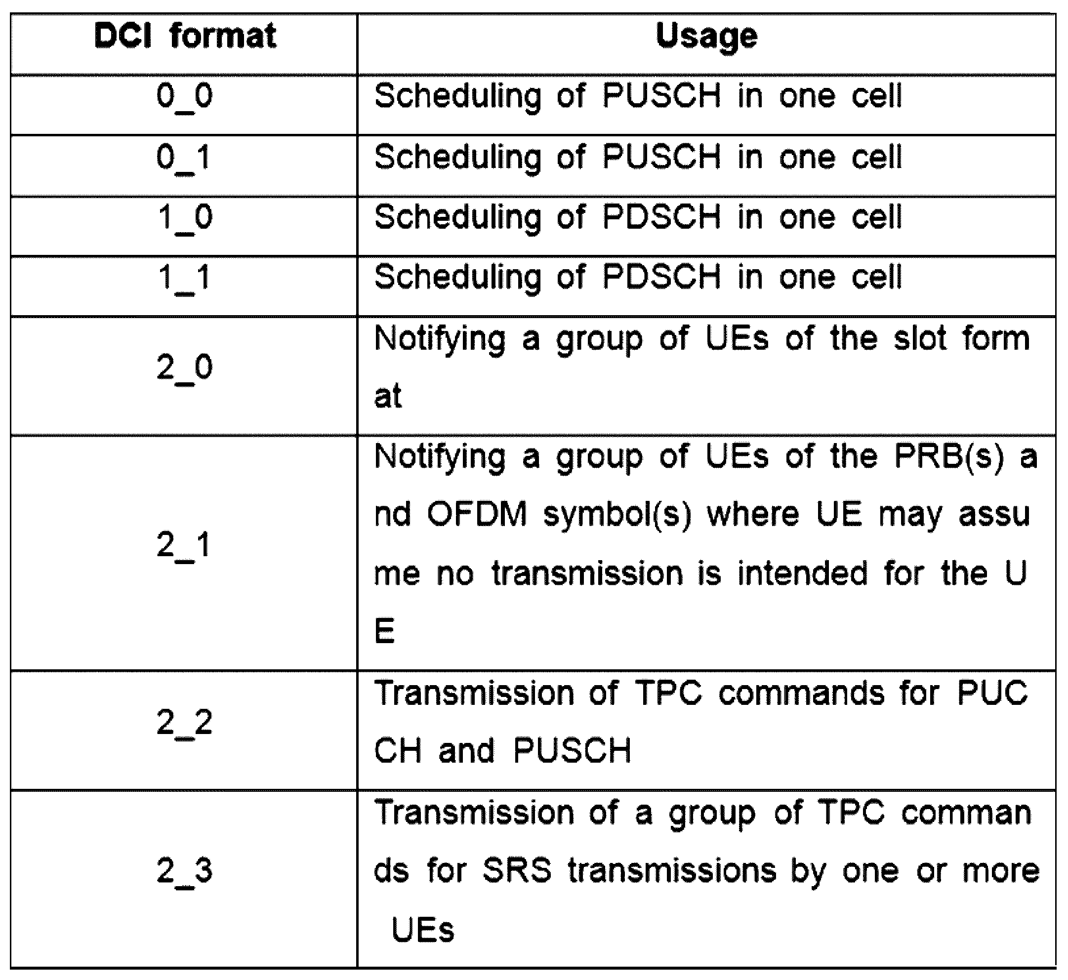
5Gシステムで、制御リソースセットp、探索空間セットsで、アグリゲーションレベルLの探索空間は、以下の数式1のように表される。
In a 5G system, with a control resource set p and a search space set s, the search space for aggregation level L is expressed as follows in
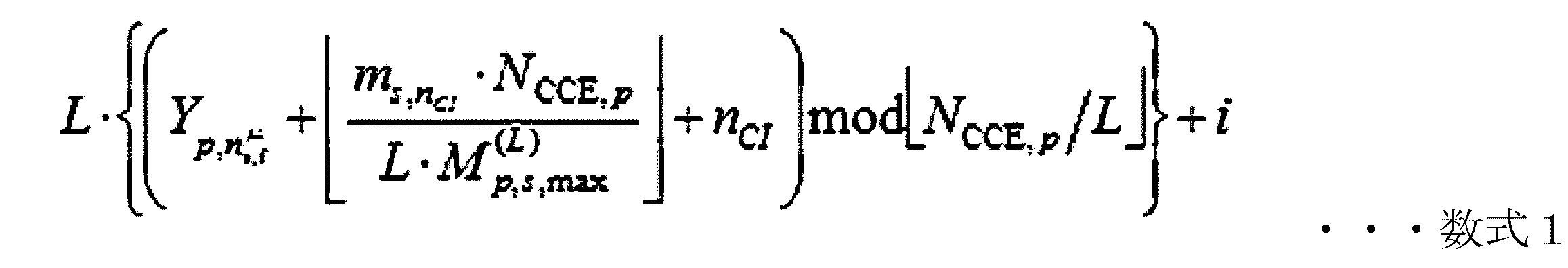
・L:アグリゲーションレベル
・nCI:キャリア(Carrier)インデックス
・NCCE,p:制御リソースセットp内に存在する総CCE個数
・nμ
s,f:スロットインデックス
・M(L)
p,s,max:アグリゲーションレベルLのPDCCH候補群数
・msnCI=0,..., M(L)
p,s,max-1:アグリゲーションレベルLのPDCCH候補群インデックス
・i=0,...,L-1
L: aggregation level n CI : carrier index N CCE,p : total number of CCEs present in control resource set p n μ s,f : slot index M (L) p,s,max : number of PDCCH candidates for aggregation level L m snCI = 0,..., M (L) p,s,max -1: PDCCH candidate index for aggregation level L i = 0,...,L-1
・
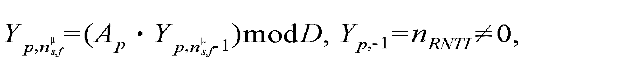
・nRNTI:端末識別子 n RNTI : Terminal Identifier
Y_(p,nμ
s,f)値は、共通探索空間の場合、0に該当する。
Y_(p,nμ
s,f)値は、端末-特定探索空間の場合、端末のアイデンティティー(C-RNTI又は基地局が端末に設定したID)と時間インデックスによって変わる値に該当する。
The Y_(p,n μ s,f ) value corresponds to 0 in the case of a common search space.
In the case of a terminal-specific search space, the Y_(p,n μ s,f ) value corresponds to a value that changes depending on the terminal's identity (C-RNTI or an ID set to the terminal by the base station) and a time index.
以下では、5G通信システムで、端末と基地局の間の「quasi co-location」(QCL)情報指示又は交換のための手段であるTCI(transmission configuration indication)stateを設定する方法に対して具体的に説明する。 The following describes in detail how to set the transmission configuration indication (TCI) state, which is a means for indicating or exchanging "quasi co-location" (QCL) information between a terminal and a base station in a 5G communication system.
基地局は、適切なシグナリングを介して互いに異なる2つのRS又はチャンネルの間の「TCI state」を設定及び指示して互いに異なるRS又はチャンネルの間のQCL関係を通知することが可能である。
互いに異なるRS又はチャンネルがQCLされている(QCLed)とは、QCL関係にある特定の基準RSアンテナポートA(reference RS #A)とまた他の目的RSアンテナポートB(target RS #B)を介してチャンネルを推定するにあたり、端末がアンテナポートAで推定された「large-scale」チャンネルパラメーターの内の一部又は全部をアンテナポートBからのチャンネル測定に適用することが許容されることを意味する。
QCLは、
1)「average delay」及び「delay spread」に影響を受ける「time tracking」、
2)「Doppler shift」及び「Doppler spread」に影響を受ける「frequency tracking」、
3)「average gain」に影響を受けるRRM(radio resource management)、
4)「spatial parameter」に影響を受けるBM(beam management)など状況によって互いに異なるパラメーターを関連させる必要があり得る。
これによってNRでは、以下の表10のような4つタイプのQCL関係をサポートする。
The base station can set and indicate the "TCI state" between two different RSs or channels through appropriate signaling to inform the QCL relationship between the different RSs or channels.
The fact that different RSs or channels are QCLed means that when estimating a channel via a specific reference RS antenna port A (reference RS #A) and another target RS antenna port B (target RS #B) that are in a QCL relationship, the terminal is allowed to apply some or all of the “large-scale” channel parameters estimated at antenna port A to the channel measurement from antenna port B.
QCL is,
1) "Time tracking" influenced by "average delay" and "delay spread";
2) "frequency tracking" influenced by "Doppler shift" and "Doppler spread";
3) RRM (radio resource management) influenced by "average gain";
4) It may be necessary to associate different parameters depending on the situation, such as beam management (BM) that is affected by spatial parameters.
This allows NR to support four types of QCL relationships, as shown in Table 10 below.

「spatial RX parameter」は、「Angle of arrival」(AoA)、「Power Angular Spectrum(PAS)of AoA」、「Angle of departure(AoD)」、「PAS of AoD」、「transmit/receive channel correlation」、「transmit/receive beamforming」、「spatial channel correlation」などの多様なパラメーターの内の一部又は全部を総称することができる。 The term "spatial RX parameter" can collectively refer to some or all of various parameters such as "Angle of arrival" (AoA), "Power Angular Spectrum (PAS) of AoA", "Angle of departure (AoD)", "PAS of AoD", "transmit/receive channel correlation", "transmit/receive beamforming", and "spatial channel correlation".
QCL関係は、以下の表11のように「RRC parameter TCI-State」及び「QCL-Info」を介して端末に設定されることが可能である。
表11を参照すると、基地局は、端末に一つ以上の「TCI state」を設定して「TCI state」のIDを参照するRS、すなわち、「target RS」に対する最大2つのQCL関係(qcl-Type1、qcl-Type2)を通知することができる。
この時、各「TCI state」が含む各QCL情報(QCL-Info)は、該当QCL情報が示す「reference RS」の「serving cell index」及び「BWP index」、及び「reference RS」の種類及びID、及び表10のようなQCL typeを含む。
The QCL relationship can be set in the terminal via "RRC parameter TCI-State" and "QCL-Info" as shown in Table 11 below.
Referring to Table 11, the base station can set one or more 'TCI state' to the terminal and notify up to two QCL relationships (qcl-Type1, qcl-Type2) for the RS that refers to the ID of the 'TCI state', i.e., the 'target RS'.
At this time, each QCL information (QCL-Info) included in each 'TCI state' includes the 'serving cell index' and 'BWP index' of the 'reference RS' indicated by the corresponding QCL information, the type and ID of the 'reference RS', and the QCL type as shown in Table 10.
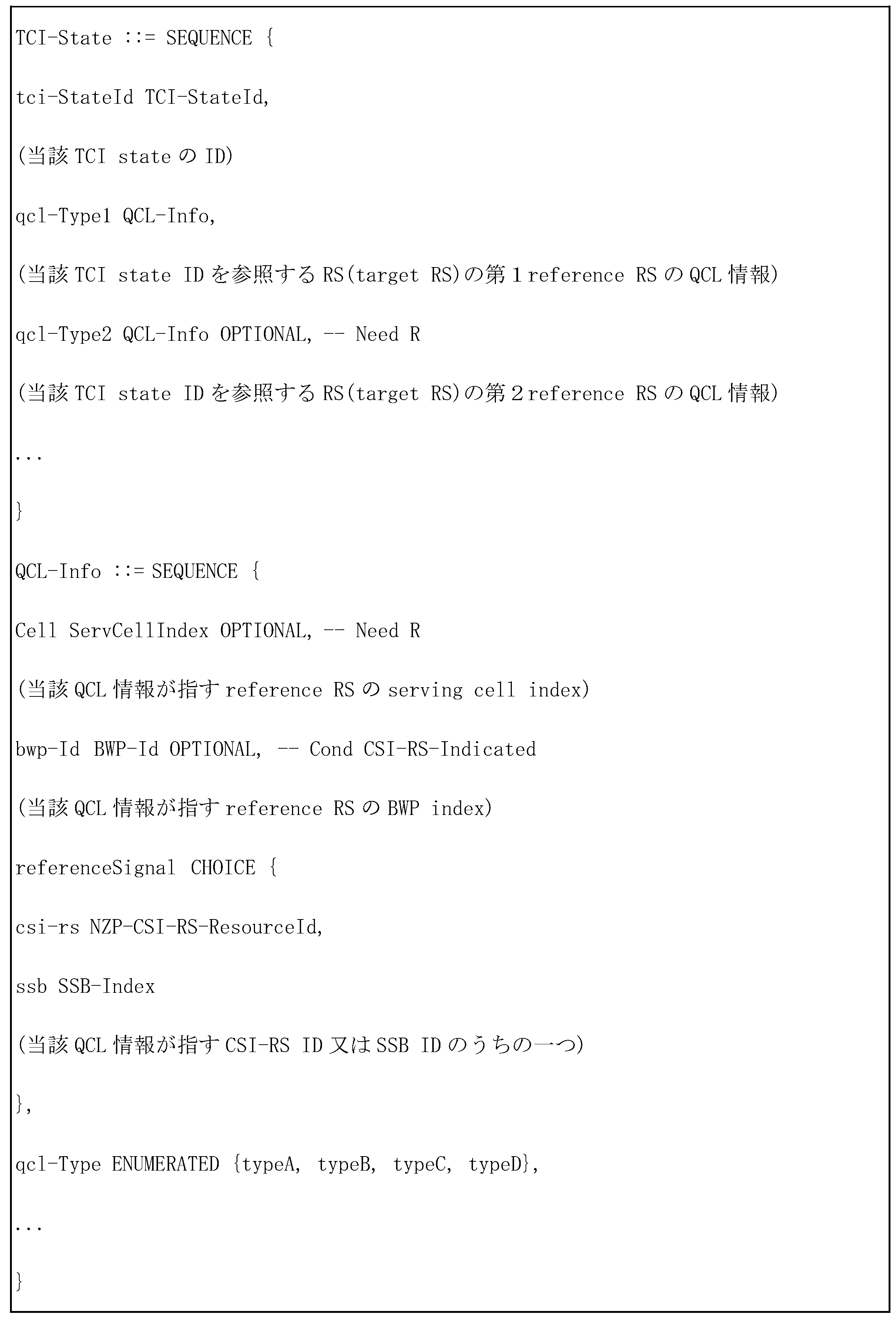
端末のチャンネル推定性能を保障するために、基地局がTCI及びQCLのために設定することができる「target RS」と「reference RS」の種類は、特定規則に従って決定することができる。 To ensure the channel estimation performance of the terminal, the types of 'target RS' and 'reference RS' that the base station can configure for TCI and QCL can be determined according to specific rules.
For a periodic CSI-RS resource in a NZP-CSI-RS-ResourceSet configured with higher layer parameter trs-Info、the UE shall expect that a TCI-State indicates one of the following quasi co-location type(s): For a periodic CSI-RS resource in a NZP-CSI-RS-ResourceSet configured with higher layer parameter rs-Info, the UE shall expect that a TCI-State indicates one of the following quasi co-location type(s):
・‘QCL-TypeC’ with an SS/PBCH block and、when applicable、‘QCL-TypeD’with the same SS/PBCH block, or
・‘QCL-TypeC’ with an SS/PBCH block and、when applicable,‘QCL-TypeD’ with a CSI-RS resource in an NZP-CSI-RS-ResourceSet configured with higher layer parameter repetition, or
・'QCL-TypeC' with an SS/PBCH block and, when applicable, 'QCL-TypeD' with the same SS/PBCH block, or
・'QCL-TypeC' with an SS/PBCH block and, when applicable, 'QCL-TypeD' with a CSI-RS resource in an NZP-CSI-RS-ResourceSet c configured with higher layer parameter repetition, or
For an aperiodic CSI-RS resource in a NZP-CSI-RS-ResourceSet configured with higher layer parameter trs-Info、the UE shall expect that a TCI-State indicates‘QCL-TypeA’with a periodic CSI-RS resource in a NZP-CSI-RS-ResourceSet configured with higher layer parameter trs-Info and,when applicabl,‘QCL-TypeD’with the same periodic CSI-RS resource. For an aperiodic CSI-RS resource in a NZP-CSI-RS-ResourceSet configured with higher layer parameter rs-Info, the UE shal I expect that a TCI-State indicates QCL-TypeA'with a periodic CSI-RS resource in a NZP -CSI-RS-ResourceSet configured with higher layer parameter trs-Info and, when applicable, 'QCL-TypeD' with the same periodic CSI-RS resource.
For a CSI-RS resource in a NZP-CSI-RS-ResourceSet configured without higher layer parameter trs-Info and without the higher layer parameter repetition、the UE shall expect that a TCI-State indicates one of the following quasi co-location type(s): For a CSI-RS resource in a NZP-CSI-RS-ResourceSet configured without higher layer parameter trs-Info and without the hig her layer parameter repetition, the UE shall expect that a TCI-State indicates one of the following quasi co-location type (s):
・‘QCL-TypeA’with a CSI-RS resource in a NZP-CSI-RS-ResourceSet configured with higher layer parameter trs-Info and、when applicable,‘QCL-TypeD’ with the same CSI-RS resource, or
・‘QCL-TypeA’with a CSI-RS resource in a NZP-CSI-RS-ResourceSet configured with higher layer parameter trs-Info and、when applicable,‘QCL-TypeD’ with an SS/PBCH block,or
・‘QCL-TypeA’with a CSI-RS resource in a NZP-CSI-RS-ResourceSet configured with higher layer parameter trs-Info and、when applicable,‘QCL-TypeD’ with a CSI-RS resource in a NZP-CSI-RS-ResourceSet configured with higher layer parameter repetition,or
・‘QCL-TypeB’ with a CSI-RS resource in a NZP-CSI-RS-ResourceSet configured with higher layer parameter trs-Info when‘QCL-TypeD’ is not applicable.
・'QCL-TypeA'with a CSI-RS resource in a NZP-CSI-RS-ResourceSet configured with higher layer parameter rs-Info and, when applicable, 'QCL-TypeD' with the same CSI-RS resource, or
・'QCL-TypeA'with a CSI-RS resource in a NZP-CSI-RS-ResourceSet configured with higher layer parameter rs-Info and, when applicable, 'QCL-TypeD' with an SS/PBCH block, or
・'QCL-TypeA'with a CSI-RS resource in a NZP-CSI-RS-ResourceSet configured with higher layer parameter rs-Info and, when applicable, 'QCL-TypeD' with a CSI-RS resource in a NZP-CSI -RS-ResourceSet configured with higher layer parameter repetition, or
・'QCL-TypeB' with a CSI-RS resource in a NZP-CSI-RS-ResourceSet configured with higher layer parameter rs-Info when'QCL -TypeD' is not applicable.
For a CSI-RS resource in a NZP-CSI-RS-ResourceSet configured with higher layer parameter repetition、the UE shall expect that a TCI-State indicates one of the following quasi co-location type(s): For a CSI-RS resource in a NZP-CSI-RS-ResourceSet configured with higher layer parameter repetition, the UE shall expect that a TCI-State indicates one of the following quasi co-location type(s):
・‘QCL-TypeA’ with a CSI-RS resource in a NZP-CSI-RS-ResourceSet configured with higher layer parameter trs-Info and、when applicable,‘QCL-TypeD’ with the same CSI-RS resource,or
・‘QCL-TypeA’with a CSI-RS resource in a NZP-CSI-RS-ResourceSet configured with higher layer parameter trs-Info and、when applicable,‘QCL-TypeD’ with a CSI-RS resource in a NZP-CSI-RS-ResourceSet configured with higher layer parameter repetition,or
・‘QCL-TypeC’ with an SS/PBCH block and、when applicable,‘QCL-TypeD’ with the same SS/PBCH block.
・'QCL-TypeA' with a CSI-RS resource in a NZP-CSI-RS-ResourceSet configured with higher layer parameter rs-Info and, when applicable, 'QCL-TypeD' with the same CSI-RS resource, or
・'QCL-TypeA'with a CSI-RS resource in a NZP-CSI-RS-ResourceSet configured with higher layer parameter rs-Info and, when applicable, 'QCL-TypeD' with a CSI-RS resource in a NZP-CSI -RS-ResourceSet configured with higher layer parameter repetition, or
・'QCL-TypeC' with an SS/PBCH block and, when applicable, 'QCL-TypeD' with the same SS/PBCH block.
For the DM-RS of PDCCH、the UE shall expect that a TCI-State indicates one of the following quasi co-location type(s): For the DM-RS of PDCCH, the UE shall expect that a TCI-State indicates one of the following quasi co-location type(s):
・‘QCL-TypeA’with a CSI-RS resource in a NZP-CSI-RS-ResourceSet configured with higher layer parameter trs-Info and、when applicable,‘QCL-TypeD’ with the same CSI-RS resource,or
・‘QCL-TypeA’with a CSI-RS resource in a NZP-CSI-RS-ResourceSet configured with higher layer parameter trs-Info and、when applicable,‘QCL-TypeD’ with a CSI-RS resource in an NZP-CSI-RS-ResourceSet configured with higher layer parameter repetition,or
・‘QCL-TypeA’with a CSI-RS resource in a NZP-CSI-RS-ResourceSet configured without higher layer parameter trs-Info and without higher layer parameter repetition and、when applicable,‘QCL-TypeD’ with the same CSI-RS resource.
・'QCL-TypeA'with a CSI-RS resource in a NZP-CSI-RS-ResourceSet configured with higher layer parameter rs-Info and, when applicable, 'QCL-TypeD' with the same CSI-RS resource, or
・'QCL-TypeA'with a CSI-RS resource in a NZP-CSI-RS-ResourceSet configured with higher layer parameter rs-Info and, when applicable, 'QCL-TypeD' with a CSI-RS resource in an NZP-CSI -RS-ResourceSet configured with higher layer parameter repetition, or
・'QCL-TypeA'with a CSI-RS resource in a NZP-CSI-RS-ResourceSet configured without higher layer parameter rs-Info and wi though higher layer parameter repetition and, when applicable, 'QCL-TypeD' with the same CSI- RS resource.
For the DM-RS of PDSCH、the UE shall expect that a TCI-State indicates one of the following quasi co-location type(s): For the DM-RS of PDSCH, the UE shall expect that a TCI-State indicates one of the following quasi co-location type(s):
・‘QCL-TypeA’with a CSI-RS resource in a NZP-CSI-RS-ResourceSet configured with higher layer parameter trs-Info and、when applicable,‘QCL-TypeD’ with the same CSI-RS resource,or
・‘QCL-TypeA’with a CSI-RS resource in a NZP-CSI-RS-ResourceSet configured with higher layer parameter trs-Info and、when applicable,‘QCL-TypeD’ with a CSI-RS resource in an NZP-CSI-RS-ResourceSet configured with higher layer parameter repetition,or
・‘QCL-TypeA’with a CSI-RS resource in a NZP-CSI-RS-ResourceSet configured without higher layer parameter trs-Info and without higher layer parameter repetition and、when applicable,‘QCL-TypeD’with the same CSI-RS resource.
・'QCL-TypeA'with a CSI-RS resource in a NZP-CSI-RS-ResourceSet configured with higher layer parameter rs-Info and, when applicable, 'QCL-TypeD' with the same CSI-RS resource, or
・'QCL-TypeA'with a CSI-RS resource in a NZP-CSI-RS-ResourceSet configured with higher layer parameter rs-Info and, when applicable, 'QCL-TypeD' with a CSI-RS resource in an NZP-CSI -RS-ResourceSet configured with higher layer parameter repetition, or
・'QCL-TypeA'with a CSI-RS resource in a NZP-CSI-RS-ResourceSet configured without higher layer parameter rs-Info and wi though higher layer parameter repetition and, when applicable,'QCL-TypeD'with the same CSI- RS resource.
以下では、NRでデータ送信のための時間及び周波数リソース割り当て方法を説明する。
NRでは、BWP指示(indication)を介して周波数軸リソース候補割り当てに加えて次のような詳細的な周波数軸リソース割り当て方法(frequency domain resource allocation:FD-RA)が提供される。
図6は、本発明の一実施形態による無線通信システムでPDSCH周波数軸リソース割り当て例題を示す図である。
The following describes a method for allocating time and frequency resources for data transmission in NR.
In NR, in addition to frequency domain resource candidate allocation through BWP indication, the following detailed frequency domain resource allocation method (FD-RA) is provided.
FIG. 6 is a diagram illustrating an example of PDSCH frequency axis resource allocation in a wireless communication system according to an embodiment of the present invention.
図6は、NRで上位レイヤーを介して設定可能な「type 0」(600)、「type 1」(605)、及び動的変更(dynamic switch)610の3つ周波数軸リソース割り当て方法を示す図である。
図6を参照すると、もし、上位レイヤーシグナリングを介して端末が「resource type0」だけを用いるように設定された場合(600)、該当端末にPDSCHを割り当てる一部ダウンリンク制御情報(downlink control information:DCI)は、「N RBG」個のビットから構成されるビットマップを持つ。
このため条件は以後にさらに説明する。
この時、NRBGは、BWPインジケーター(indicator)が割り当てるBWPサイズ(size)及び上位レイヤーパラメーター(又は上位レイヤーシグナリングパラメーター)「rbg-Size」によって以下の表12のように決定されるRBG(resource block group)の数を意味し、ビットマップによって「1」で表されるRBGでデータが送信されるようになる。
FIG. 6 shows three frequency axis resource allocation methods, "
Referring to FIG. 6, if a terminal is configured to use only 'resource type 0' through higher layer signaling (600), some downlink control information (DCI) for allocating a PDSCH to the terminal has a bitmap consisting of 'N RBG ' bits.
The conditions for this are explained further below.
In this case, N RBG means the number of RBGs (resource block groups) determined as shown in Table 12 below according to the BWP size assigned by the BWP indicator and the upper layer parameter (or upper layer signaling parameter) 'rbg-Size', and data is transmitted in the RBG represented by '1' according to the bitmap.
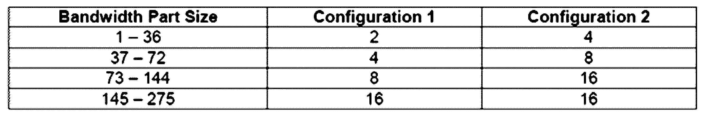
もし、上位レイヤーシグナリングを介して端末が「resource type 1」だけを用いるように設定された場合(605)、該当端末にPDSCHを割り当てる一部DCIは

このため条件は以後にさらに説明される。
基地局は、これを介して「starting VRB」620とこれから連続的に割り当てられる周波数軸リソースの長さ625を設定する。
The conditions for this are explained further below.
Through this, the base station sets a 'starting VRB' 620 and the
もし、上位レイヤーシグナリングを介して端末が「resource type0」と「resource type 1」をいずれも用いるように設定された場合(610)、該当端末にPDSCHを割り当てる一部DCIは、「resource type0」を設定するためのpayload615と、「resource type1」を設定するためのpayload(620、625)の内の大きい値635のビットで構成される周波数軸リソース割り当て情報を有する。
このため条件は以後にさらに説明される。
この時、DCI内の周波数軸リソース割り当て情報の最前方部分(MSB)に一つのビットが追加され得、該当ビットが「0」の場合、「resource type0」が用いられることを指示され、「1」の場合、「resource type1」が用いられることが指示される。
If a terminal is configured to use both "
The conditions for this are explained further below.
In this case, one bit may be added to the most significant bit (MSB) of the frequency axis resource allocation information in the DCI, and if the corresponding bit is '0', it indicates that 'resource type 0' is to be used, and if it is '1', it indicates that 'resource type 1' is to be used.
図7は、本発明の一実施形態による無線通信システムでPDSCH(physical downlink shared channel)時間軸リソース割り当ての例示を示す図である。
図7を参照すると、基地局は、上位レイヤーを用いて設定されるデータチャンネル(data channel)及び制御チャンネル(control channel)のサブキャリア間隔(subcarrier spacing:SCS)(μPDSCH、μPDCCH)、スケジューリングオフセット(scheduling offset)(K0)値、そしてDCIを介して動的に指示される、一つのslot710内の「OFDM symbol」開始位置700と長さ705によってPDSCHリソースの時間軸位置を指示することができる。
FIG. 7 is a diagram illustrating an example of a physical downlink shared channel (PDSCH) time axis resource allocation in a wireless communication system according to an embodiment of the present invention.
Referring to FIG. 7, the base station can indicate the time axis position of the PDSCH resource by the subcarrier spacing (SCS) (μ PDSCH , μ PDCCH ) of the data channel and control channel configured using a higher layer, the scheduling offset (K 0 ) value, and the starting
図8は、本発明の一実施形態による無線通信システムでデータチャンネル(data channel)及び制御チャンネル(control channel)のサブキャリア間隔による時間軸リソース割り当て例題を示す図である。
図8を参照すると、データチャンネル及び制御チャンネルのサブキャリア間隔が同じ場合(800、μPDSCH=μPDCCH)、データチャンネルと制御チャンネルのためのスロット番号(slot number)が同じであるため、基地局及び端末は、予め決定されたスロットオフセット(slot offset)K0に合わせて、スケジューリングオフセット(scheduling offset)を確認する。
FIG. 8 is a diagram illustrating an example of time axis resource allocation according to subcarrier spacing of a data channel and a control channel in a wireless communication system according to an embodiment of the present invention.
Referring to FIG. 8, when the subcarrier spacing of the data channel and the control channel is the same (800, μ PDSCH = μ PDCCH ), the slot numbers for the data channel and the control channel are the same, so the base station and the terminal check the scheduling offset according to a predetermined slot offset K0 .
一方、データチャンネル及び制御チャンネルのサブキャリア間隔が異なる場合(805、μPDSCH≠μPDCCH)、データチャンネルと制御チャンネルのためのスロット番号(slot number)が異なるため、基地局及び端末は、PDCCHのサブキャリア間隔を基準とし、予め決定されたスロットオフセット(slot offset)K0に合わせてスケジューリングオフセット(scheduling offset)を確認する。 On the other hand, when the subcarrier spacing of the data channel and the control channel is different (805, μ PDSCH ≠ μ PDCCH ), the slot numbers for the data channel and the control channel are different, so the base station and the terminal check the scheduling offset based on the subcarrier spacing of the PDCCH and a predetermined slot offset K0 .
図8で、データチャンネルと制御チャンネルとの間のサブキャリア間隔が同じ又は異なる場合に対するオフセット解釈方法を説明したが、上記方法はここに限ることではなく、同様にCSI-RSと制御チャンネルとの間のサブキャリア間隔、又はSRSと制御チャンネルとの間のサブキャリア間隔が他の場合など他のチャンネル又は基準信号のサブキャリア間隔が同じ又は異なる場合にも適用される。 In FIG. 8, a method of interpreting offsets for cases where the subcarrier spacing between the data channel and the control channel is the same or different has been described, but the above method is not limited thereto and can also be applied to cases where the subcarrier spacing of other channels or reference signals is the same or different, such as cases where the subcarrier spacing between the CSI-RS and the control channel, or the subcarrier spacing between the SRS and the control channel is different.
NRでは端末の効率的な制御チャンネル受信のために目的によって表9のような多様な形態の「DCI format」を提供する。
例えば、基地局は、一つのセル(cell)にPDSCHを割り当て(scheduling)するために「DCI format 0_0」又は「DCI format 0_1」を用いることができる。
「DCI format 0_1」は、C-RNTI(Cell Radio Network Temporary Identifier)又はCS-RNTI(Configured Scheduling RNTI)又はnew-RNTIによってスクランブリングされるCRC共に送信される場合、少なくとも次のような情報を含む:
In NR, various types of 'DCI formats' as shown in Table 9 are provided depending on the purpose for efficient control channel reception of the UE.
For example, a base station can use "DCI format 0_0" or "DCI format 0_1" to schedule a PDSCH to a cell.
When the "DCI format 0_1" is transmitted together with a CRC scrambled by a Cell Radio Network Temporary Identifier (C-RNTI) or a Configured Scheduling RNTI (CS-RNTI) or a new-RNTI, it includes at least the following information:
・「Identifier for DCI formats」(1 bits):「DCI format」インジケーターに常に「1」と設定 - "Identifier for DCI formats" (1 bit): Always set the "DCI format" indicator to "1"
・「Frequency domain resource assignment」(NRBG bits又は

:周波数軸リソース割り当てを指示し、「DCI format 1_0」が「UE specific search space」でモニターされる場合、


NRBGは、resource block groupの数字である。
詳細方法は、上記周波数軸リソース割り当てを参照する。
・“Frequency domain resource assignment” ( NRBG bits or
: When frequency axis resource allocation is indicated and "DCI format 1_0" is monitored in "UE specific search space",
NRBG is the number of resource block groups.
For details, refer to the frequency axis resource allocation section above.
・「Time domain resource assignment」(0~4bits):前記説明によって時間軸リソース割り当てを指示する。
・「VRB-to-PRB mapping」(1bit):「0」の場合、「Non-interleaved」、「1」の場合、「interleaved VRP-to-PRB mapping」を指示する。
・「Modulation and coding scheme」(5bits):PDSCH送信に用いられる「modulation order」及び「coding rate」を指示する。
・「New data indicator」(1bit):ToggleであるかどうかによってPDSCHが初期送信又は再送信するかどうかを指示する。
"Time domain resource assignment" (0 to 4 bits): indicates the time domain resource assignment as explained above.
"VRB-to-PRB mapping" (1 bit): "0" indicates "non-interleaved" and "1" indicates "interleaved VRP-to-PRB mapping".
"Modulation and coding scheme" (5 bits): indicates the "modulation order" and "coding rate" used for PDSCH transmission.
"New data indicator" (1 bit): indicates whether the PDSCH is to be initially transmitted or retransmitted depending on whether it is Toggle.
・「Redundancy version」(2bits):PDSCH送信に用いられたredundancy versionを指示する。
・「HARQ process number」(4bits):PDSCH送信に用いられた「HARQ process number」を指示する。
・「Downlink assignment index」(2bits):DAIインジケーター
・「TPC command for scheduled PUCCH」(2bits):「PUCCH power control」インジケーター
・「PUCCH resource indicator」(3bits):PUCCHリソースインジケーターで、上位レイヤーに設定された8つのリソースの内の一つを指示する。
・「PDSCH-to-HARQ_feedback timing indicator」(3bits):「HARQ feedback timing」インジケーターで、上位レイヤーに設定された8つの「feedback timing offset」の内の一つを指示する。
"Redundancy version" (2 bits): indicates the redundancy version used for PDSCH transmission.
"HARQ process number" (4 bits): indicates the "HARQ process number" used for PDSCH transmission.
"Downlink assignment index" (2 bits): DAI indicator "TPC command for scheduled PUCCH" (2 bits): "PUCCH power control" indicator "PUCCH resource indicator" (3 bits): PUCCH resource indicator indicating one of eight resources configured in a higher layer.
"PDSCH-to-HARQ_feedback timing indicator" (3 bits): This is a "HARQ feedback timing" indicator that indicates one of eight "feedback timing offsets" set in the higher layer.
「DCI format 1_1」は、C-RNTI(Cell Radio Network Temporary Identifier)又はCS-RNTI(Configured Scheduling RNTI)又はnew-RNTIによってスクランブリングされたCRCと共に送信される場合、少なくとも次のような情報を含む: When "DCI format 1_1" is sent with a CRC scrambled by the Cell Radio Network Temporary Identifier (C-RNTI) or Configured Scheduling RNTI (CS-RNTI) or new-RNTI, it contains at least the following information:
・「Identifier for DCI formats」(1bit):「DCI format」インジケーターに常に「1」と設定
・「Carrier indicator」(0又は3bits):該当DCIが割り当てるPDSCHが送信されるCC(又はcell)を指示する。
・「Bandwidth part indicator」(0又は1又は2bits):該当DCIが割り当てるPDSCHが送信されるBWPを指示する。
・「Frequency domain resource assignment」(周波数軸リソース割り当てによってpayload決定):周波数軸リソース割り当てを指示し、

詳細方法は、周波数軸リソース割り当てを参照する。
"Identifier for DCI formats" (1 bit): The "DCI format" indicator is always set to "1". "Carrier indicator" (0 or 3 bits): Indicates the CC (or cell) on which the PDSCH assigned by the corresponding DCI is transmitted.
"Bandwidth part indicator" (0, 1, or 2 bits): indicates the BWP in which the PDSCH allocated by the corresponding DCI is transmitted.
"Frequency domain resource assignment" (payload determined by frequency domain resource assignment): indicates frequency domain resource assignment,
For details, see Frequency axis resource allocation.
・「Time domain resource assignment」(0~4bits):上記説明によって時間軸リソース割り当てを指示する。
・「VRB-to-PRB mapping」(0 or 1bit):「0」の場合、「Non-interleaved」、「1」の場合、「interleaved VRP-to-PRB mapping」を指示する。
周波数軸リソース割り当てが「resource type0」と設定された場合、0bitである。
・「PRB bundling size indicator」(0 or 1bit):上位レイヤーパラメーター「prb-BundlingType」が設定されないか又は‘static’と設定された場合、0bitであり、‘dynamic’と設定された場合、1bitである。
・「Rate matching indicator」(0 or 1 or 2bits):「rate matching pattern」を指示する。
・「ZP CSI-RS trigger」(0 or 1 or 2bits):「aperiodic ZP CSI-RS」をトリガーするインジケーター。
"Time domain resource assignment" (0 to 4 bits): indicates the time domain resource assignment as described above.
"VRB-to-PRB mapping" (0 or 1 bit): "0" indicates "non-interleaved" and "1" indicates "interleaved VRP-to-PRB mapping".
When the frequency axis resource allocation is set to "
"PRB bundling size indicator" (0 or 1 bit): 0 bit if the upper layer parameter "prb-BundlingType" is not set or is set to 'static', and 1 bit if set to 'dynamic'.
"Rate matching indicator" (0 or 1 or 2 bits): Specifies the "rate matching pattern".
- "ZP CSI-RS trigger" (0 or 1 or 2 bits): Indicator that triggers "aperiodic ZP CSI-RS".
For transport block 1:
・「Modulation and coding scheme」(5bits):PDSCH送信に用いられる「modulation order」及び「coding rate」を指示する。
・「New data indicator」(1bit):ToggleであるかどうかによってPDSCHが初期送信又は再送信するかを指示する。
・「Redundancy version」(2bits):PDSCH送信に用いられた「redundancy version」を指示する。
For transport block 1:
"Modulation and coding scheme" (5 bits): indicates the "modulation order" and "coding rate" used for PDSCH transmission.
"New data indicator" (1 bit): indicates whether the PDSCH is to be initially transmitted or retransmitted depending on whether it is Toggle.
"Redundancy version" (2 bits): indicates the "redundancy version" used for PDSCH transmission.
For transport block 2:
・「Modulation and coding scheme」(5bits):PDSCH送信に用いられる「modulation order」及び「coding rate」を指示する。
・「New data indicator」(1 bit):ToggleであるかどうかによってPDSCHが初期送信又は再送信するかを指示する。
・「Redundancy version」(2bits):PDSCH送信に用いられたredundancy versionを指示する。
・「HARQ process number」(4bits):PDSCH送信に用いられた「HARQ process number」を指示する。
・「Downlink assignment index」(0 or 2 or 4bis):DAI(Downlink assignment index)インジケーター
・「TPC command for scheduled PUCCH」(2bits):「PUCCH power control」インジケーター
・「PUCCH resource indicator」(3bits):PUCCH リソースインジケーターで、上位レイヤーに設定された8つのリソースの内の一つを指示する。
For transport block 2:
"Modulation and coding scheme" (5 bits): indicates the "modulation order" and "coding rate" used for PDSCH transmission.
"New data indicator" (1 bit): indicates whether the PDSCH is to be initially transmitted or retransmitted depending on whether it is Toggle.
"Redundancy version" (2 bits): indicates the redundancy version used for PDSCH transmission.
"HARQ process number" (4 bits): indicates the "HARQ process number" used for PDSCH transmission.
"Downlink assignment index" (0 or 2 or 4 bis): DAI (Downlink assignment index) indicator "TPC command for scheduled PUCCH" (2 bits): "PUCCH power control" indicator "PUCCH resource indicator" (3 bits): PUCCH The resource indicator indicates one of eight resources set in the upper layer.
・「PDSCH-to-HARQ_feedback timing indicator」(3bits):「HARQ feedback timing」インジケーターで、上位レイヤーと設定された8つの「feedback timing offset」の内の一つを指示する。
・「Antenna port」(4 or 5 or 6bits):「DMRS port」及び「CDM group without data」を指示する。
・「Transmission configuration indication」(0 or 3bits):TCIインジケーター。
・「SRS request」(2 or 3bits):SRS送信リクエストインジケーター
・「CBG transmission information」(0 or 2 or 4 or 6 or 8bits):割り当てられたPDSCH内の「code block group」に対する送信するかどうかを通知するインジケーター。
「0」は該当CBGが送信されないことを意味し、「1」は送信されることを意味する。
・「CBG flushing out information」(0 or 1bit):以前CBGが汚染された否かを通知するインジケーターで、「0」であれば汚染されたことを意味し、「1」であれば再送信受信時の用いることができる(combinable)ことを意味する。
・「DMRS sequence initialization」(0 or 1bit):「DMRS scramblingID」選択インジケーター
"PDSCH-to-HARQ_feedback timing indicator" (3 bits): This is a "HARQ feedback timing" indicator that indicates one of eight "feedback timing offsets" configured with a higher layer.
"Antenna port" (4 or 5 or 6 bits): Indicates "DMRS port" and "CDM group without data".
"Transmission configuration indication" (0 or 3 bits): TCI indicator.
"SRS request" (2 or 3 bits): SRS transmission request indicator "CBG transmission information" (0 or 2 or 4 or 6 or 8 bits): indicator notifying whether or not to transmit for a "code block group" in an assigned PDSCH.
"0" means that the corresponding CBG is not transmitted, and "1" means that it is transmitted.
- "CBG flushing out information" (0 or 1 bit): An indicator that notifies whether the CBG was previously polluted or not. If it is "0", it means that it was polluted, and if it is "1", it means that it can be used (combinable) when receiving a retransmission.
"DMRS sequence initialization" (0 or 1 bit): "DMRS scrambling ID" selection indicator
端末が該当cellでslot当たり受信可能な互いに異なるサイズのDCI数は、最大4である。
端末が該当セルでslot当たり受信可能なC-RNTIでスクランブリングされた互いに異なるサイズのDCI数は、最大3である。
ここで「antenna port indication」を次の表13~表16を介して指示することができる。
The maximum number of DCIs of different sizes that a terminal can receive per slot in a corresponding cell is four.
The number of DCIs of different sizes scrambled with the C-RNTI that a terminal can receive per slot in a corresponding cell is up to three.
Here, the "antenna port indication" can be indicated via the following Tables 13 to 16.
・Antenna port(s)(1000+DMRS port),dmrs-Type=1,maxLength=1
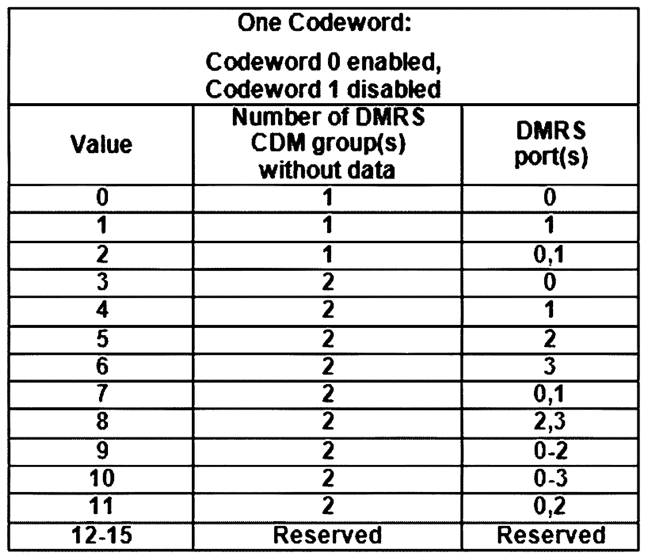
・Antenna port(s)(1000+DMRS port),dmrs-Type=1,maxLength=2
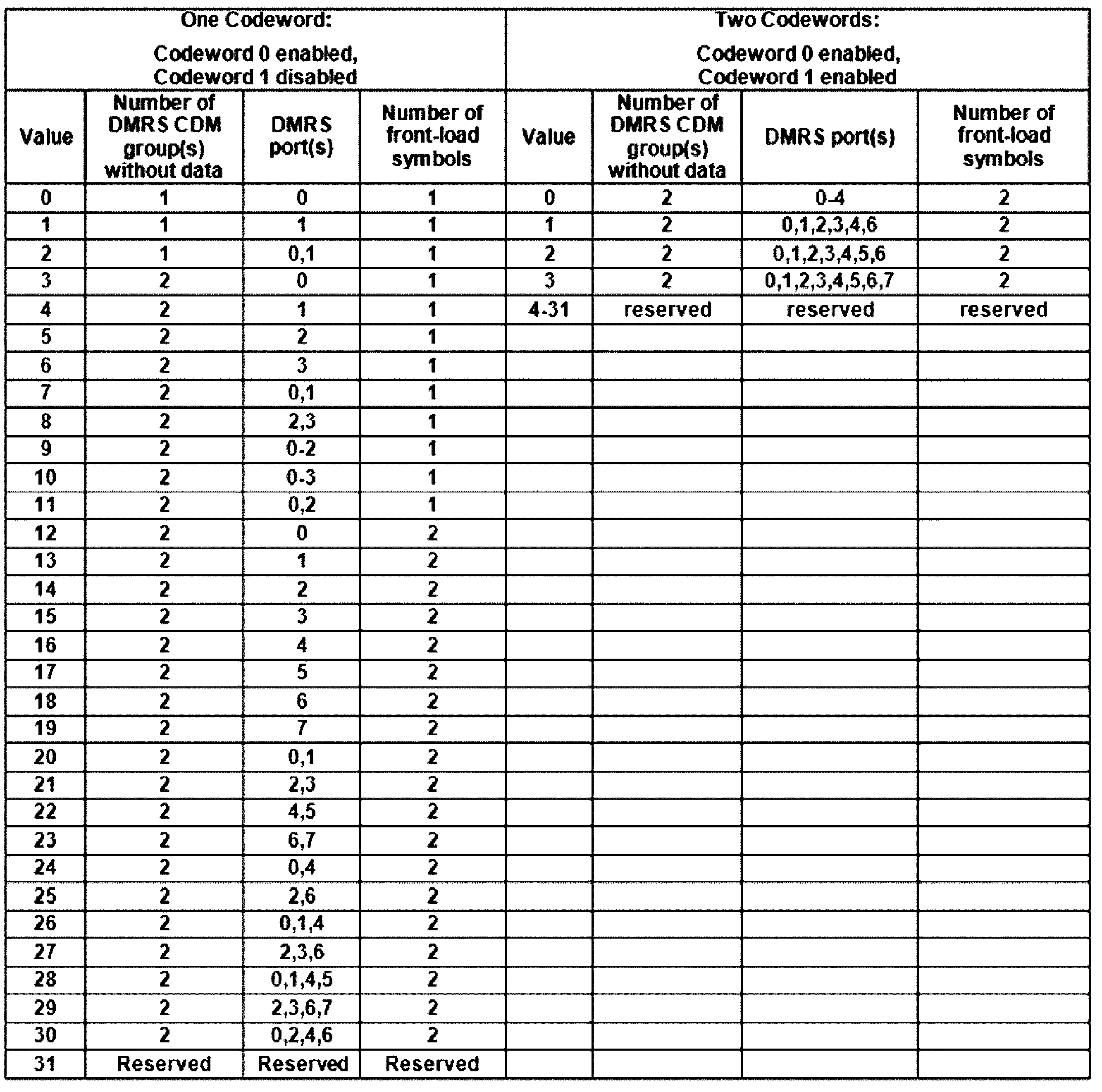
・Antenna port(s)(1000+DMRS port),dmrs-Type=2,maxLength=1

・Antenna port(s)(1000+DMRS port),dmrs-Type=2,maxLength=2
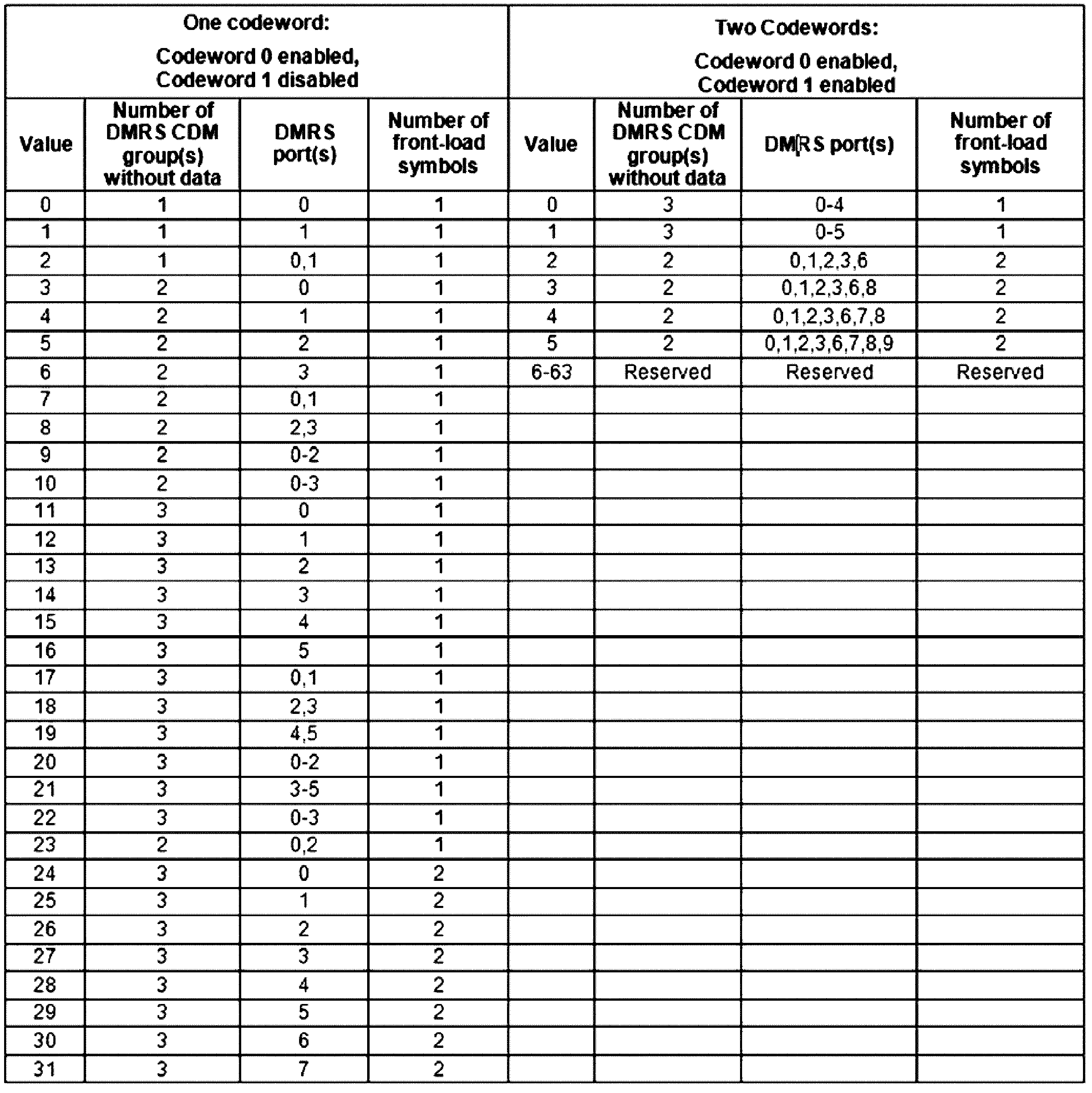
・Antenna port(s)(1000+DMRS port),dmrs-Type=2,maxLength=2
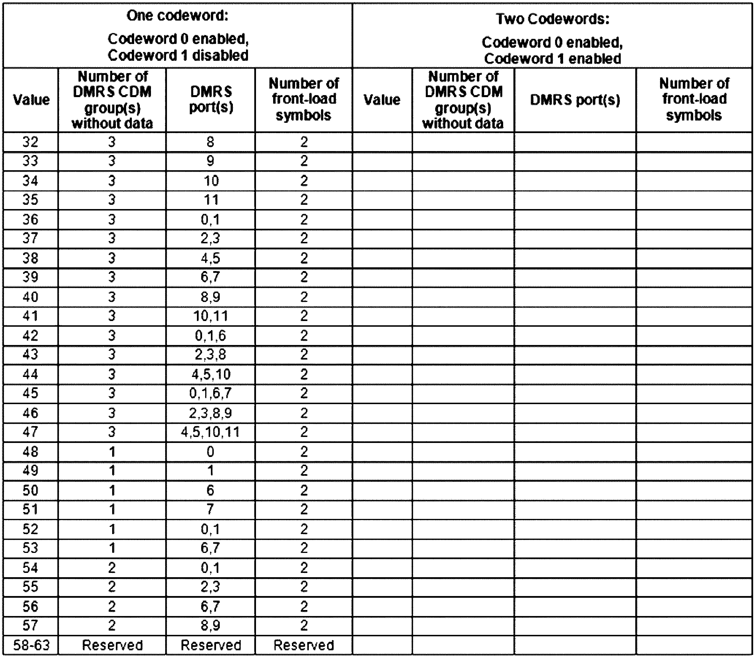
上記の表16-1及び表16-2は、互いに接続されたものと理解されることが好ましい。
表13は、「dmrs-type」が「1」で、maxLengthが「1」に指示された場合用いる表で、表14は、「dmrs-Type=1」、「maxLength=2」に指示された場合に用いる表である。
「dmrs-type=2」、「maxLength=1」の場合は、表15を、「drms-tpye」が「2」で、maxLengthが「2」の場合には、表16-1及び表16-2に基づいて用いられるDMRSのportが指示される。
It is preferable that the above Tables 16-1 and 16-2 are understood to be connected to each other.
Table 13 is a table to be used when "dmrs-type" is "1" and maxLength is designated as "1", and Table 14 is a table to be used when "dmrs-Type=1" and "maxLength=2" are designated.
When "dmrs-type=2" and "maxLength=1", the DMRS port to be used is indicated based on Table 15; when "drms-type" is "2" and maxLength is "2", the DMRS port to be used is indicated based on Tables 16-1 and 16-2.
表で、「Number of DMRS CDM group(s)without data」が指示する数字1、2、3は、それぞれ、CDM group{0}、{0、1}、{0、1、2}を意味する。
「DMRS port(s)」は、用いるportのindexを順に置くことである。
「Antenna port」は、「DMRS port」+1000に指示される。
DMRSのCDM groupは、表17と表18のようにDMRSシーケンスを発生する方法と「antenna port」と接続されている。
表17は、「dmrs-type=1を用いる場合のパラメーターで、表18は、「dmrs-type=2」を常用する場合のパラメーターである。
In the table, the
"DMRS port(s)" refers to placing the index of the port to be used in order.
The "Antenna port" is instructed to be "DMRS port" + 1000.
The DMRS CDM group is connected to the 'antenna port' and the method of generating the DMRS sequence as shown in Tables 17 and 18.
Table 17 shows the parameters when "dmrs-type=1" is used, and Table 18 shows the parameters when "dmrs-type=2" is commonly used.
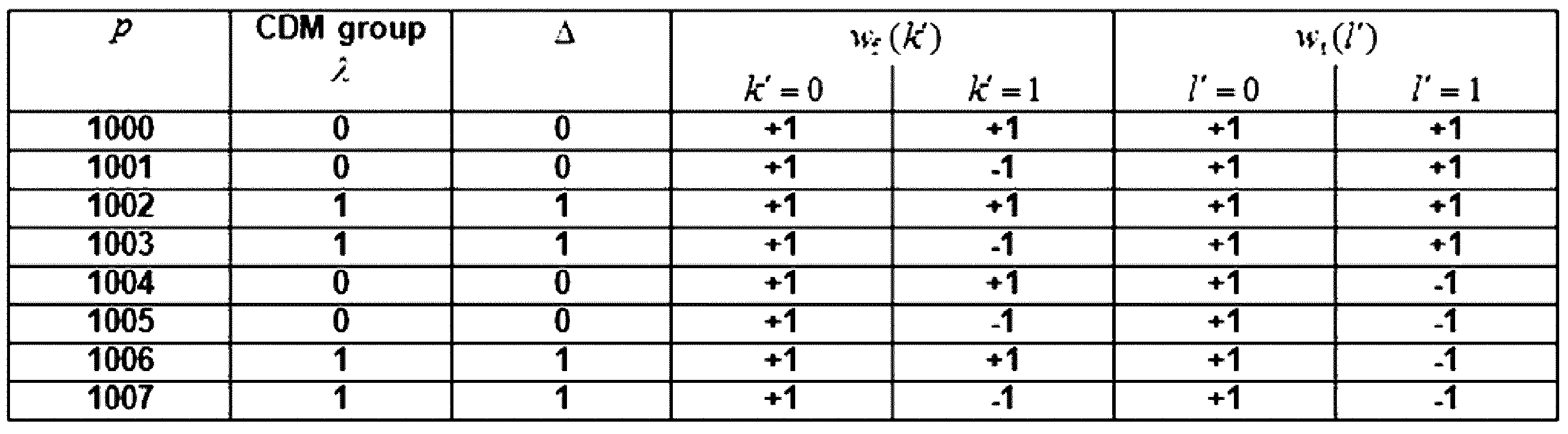
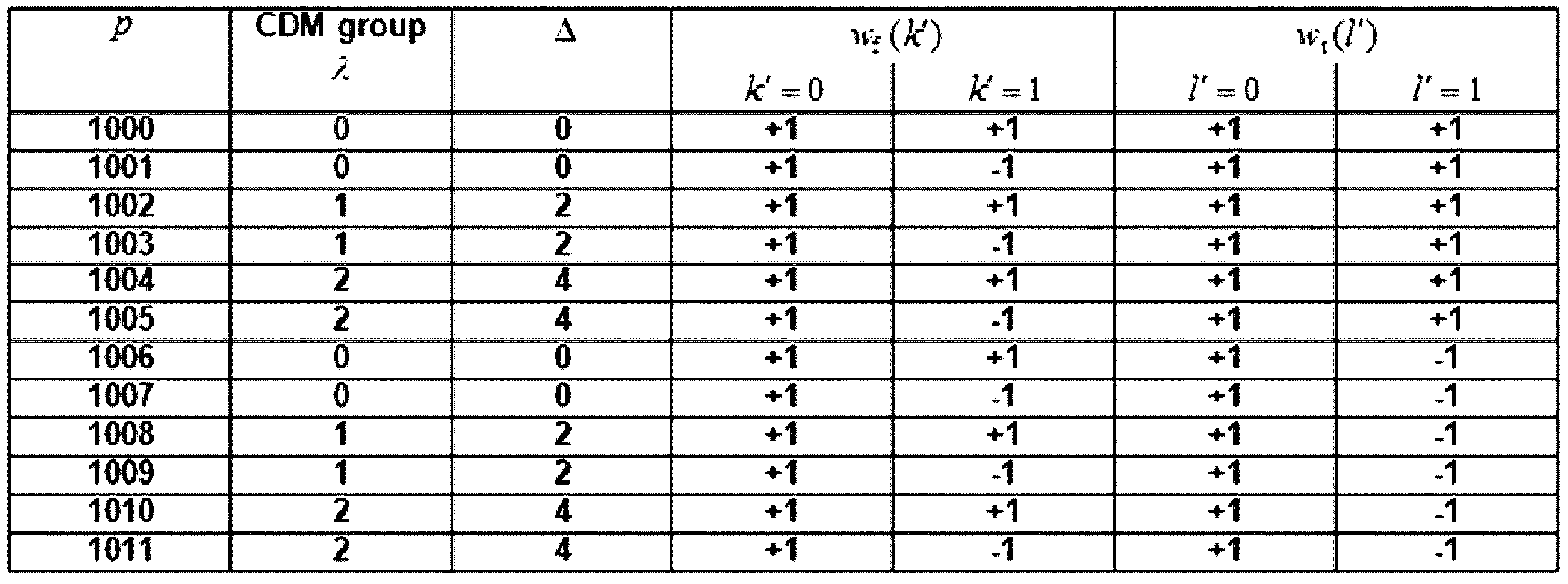
各パラメーターによるDMRSのシーケンスは、次の数式2によって決定される。
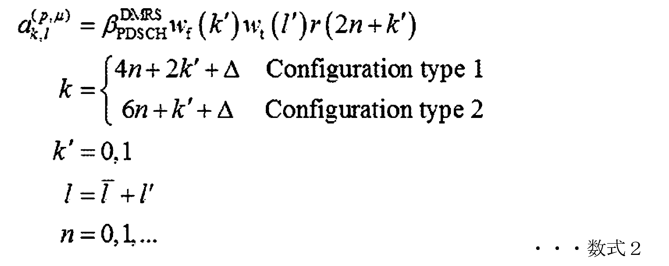
図9は、本発明の一実施形態による「single cell」、「carrier aggregation」、「dual connectivity」実行時の基地局及び端末無線プロトコル構造を示す図である。
図9を参照すると、次世代移動通信システムの無線プロトコルは、端末とNR基地局でそれぞれNR SDAP(Service Data Adaptation Protocol)(925、970)、NR PDCP(Packet Data Convergence Protocol)(930、965)、NR RLC(Radio Link Control)(935、960)、NR MAC(Medium Access Control)(940、955)からなる。
FIG. 9 is a diagram showing a radio protocol structure of a base station and a terminal when "single cell", "carrier aggregation", and "dual connectivity" are performed according to an embodiment of the present invention.
Referring to FIG. 9, the radio protocols of the next-generation mobile communication system consist of NR SDAP (Service Data Adaptation Protocol) (925, 970), NR PDCP (Packet Data Convergence Protocol) (930, 965), NR RLC (Radio Link Control) (935, 960), and NR MAC (Medium Access Control) (940, 955) in the terminal and NR base station, respectively.
NR SDAP(925、970)の主要機能は、次の機能の内の一部を含むことができる。
・ユーザデータの伝達機能(transfer of user plane data)
・アップリンクとダウンリンクに対して「QoS flow」とデータベアラーのマッピング機能(mapping between a QoS flow and a DRB for both DL and UL)
・アップリンクとダウンリンクに対して「QoS flow ID」のマーキング機能(marking QoS flowIDin both DL and UL packets)
・アップリンクSDAP PDUに対して「relective QoS flow」をデータベアラーにマッピングさせる機能(reflective QoS flow to DRB mapping for the UL SDAP PDUs)。
The main functions of the NR SDAP (925, 970) may include some of the following functions:
Transfer of user plane data
Mapping function of "QoS flow" and data bearer for uplink and downlink (mapping between a QoS flow and a DRB for both DL and UL)
- Marking function of "QoS flow ID" for uplink and downlink (marking QoS flow ID in both DL and UL packets)
- A function for mapping "relective QoS flow" to data bearers for uplink SDAP PDUs (reflective QoS flow to DRB mapping for the UL SDAP PDUs).
SDAP階層装置に対して、端末は、RRCメッセージで各PDCP階層装置別又はベアラー別又はロジカルチャンネル別のSDAP階層装置のヘッダーを用いるか否か又はSDAP階層装置の機能を用いるか否かが設定される。
基地局は、SDAPヘッダーが設定された場合、SDAPヘッダーのNASQoS反映設定1ビットインジケーター(NAS reflective QoS)とAS QoS反映設定1ビットインジケーター(AS reflective QoS)で端末がアップリンクとダウンリンクの「QoS flow」とデータベアラーに対するマッピング情報を更新又は再設定することができるように指示する。
SDAPヘッダーは、QoSを示す「QoS flowID」情報を含む。
QoS情報は、円滑なサービスをサポートするためのデータ処理優先順位、スケジューリング情報などで用いられる。
For the SDAP layer device, the terminal is configured in the RRC message to determine whether to use the header of the SDAP layer device for each PDCP layer device, bearer, or logical channel, or whether to use the function of the SDAP layer device.
When the SDAP header is set, the base station instructs the terminal to update or reconfigure the uplink and downlink 'QoS flow' and mapping information for the data bearer using the NAS QoS reflective setting 1-bit indicator (NAS reflective QoS) and AS QoS reflective setting 1-bit indicator (AS reflective QoS) of the SDAP header.
The SDAP header includes "QoS flowID" information that indicates the QoS.
The QoS information is used for data processing priorities, scheduling information, etc. to support smooth service.
NR PDCP(930、965)の主要機能は、次の機能の内の一部を含むことができる。
・ヘッダー圧縮及び圧縮解除機能(Header compression and decompression:ROHC only)
・ユーザデータ送信機能(Transfer of user data)
・順次的伝達機能(In-sequence delivery of upper layer PDUs)
・非順次的伝達機能(Out-of-sequence delivery of upper layer PDUs)
・順序再整列機能(PDCP PDU reordering for reception)
・重複探知機能(Duplicate detection of lower layer SDUs)
・再送信機能(Retransmission of PDCP SDUs)
・暗号化及び復号化機能(Ciphering and deciphering)
・タイマー基盤SDU削除機能(Timer-based SDU discard in uplink。)
The main functions of the NR PDCP (930, 965) may include some of the following functions:
Header compression and decompression function (ROHC only)
User data transmission function (Transfer of user data)
In-sequence delivery of upper layer PDUs
Out-of-sequence delivery of upper layer PDUs
・Order reordering function (PDCP PDU reordering for reception)
Duplicate detection of lower layer SDUs
Retransmission of PDCP SDUs
- Encryption and decryption functions (Ciphering and deciphering)
Timer-based SDU discard function (Timer-based SDU discard in uplink)
上記でNR PDCP装置の順序再整列機能(reordering)は、下位階層で受信した「PDCP PDU」を「PDCP SN」(sequence number)に基づいて順次に再整列する機能を言い、再整列された順にデータを上位階層に伝達する機能を含むか、又は手順を考慮せず、直ちに伝達する機能を含むことができ、手順を再整列して失われた「PDCP PDU」を記録する機能を含むことができ、失われた「PDCP PDU」に対する状態報告を送信側にする機能を含むことができ、失われた「PDCP PDU」に対する再送信をリクエストする機能を含むことができる。 The reordering function of the NR PDCP device refers to a function of sequentially reordering the PDCP PDUs received at a lower layer based on the PDCP SN (sequence number), and may include a function of transmitting data to a higher layer in the reordered order, or a function of immediately transmitting data without considering the procedure, a function of recording a lost PDCP PDU by reordering the procedure, a function of reporting the status of a lost PDCP PDU to the transmitting side, and a function of requesting retransmission of a lost PDCP PDU.
NR RLC(935、960)の主要機能は、次の機能の内の一部を含むことができる。
・データ送信機能(Transfer of upper layer PDUs)
・順次的伝達機能(In-sequence delivery of upper layer PDUs)
・非順次的伝達機能(Out-of-sequence delivery of upper layer PDUs)
・ARQ機能(Error Correction through ARQ)
・接合、分割、再組立て機能(Concatenation、segmentation and reassembly of RLC SDUs)
・再分割機能(Re-segmentation of RLC data PDUs)
・順序再整列機能(Reordering of RLC data PDUs)
・重複探知機能(Duplicate detection)
・エラー探知機能(Protocol error detection)
・RLC SDU削除機能(RLC SDU discard)
・RLC再確立機能(RLC re-establishment)
The main functions of the NR RLC (935, 960) may include some of the following functions:
Data transmission function (Transfer of upper layer PDUs)
In-sequence delivery of upper layer PDUs
Out-of-sequence delivery of upper layer PDUs
・ARQ function (Error Correction through ARQ)
Concatenation, segmentation and reassembly of RLC SDUs
・Re-segmentation of RLC data PDUs
・Reordering of RLC data PDUs
Duplicate detection function
・Error detection function (Protocol error detection)
RLC SDU discard function (RLC SDU discard)
・RLC re-establishment function
上記で、NR RLC装置の順次的伝達機能(In-sequence delivery)は、下位階層から受信した「RLC SDU」を順次に上位階層に伝達する機能を言い、元々一つの「RLC SDU」が複数の「RLC SDU」に分割されて受信された場合、これを再組立てて伝達する機能を含むことができ、受信した「RLC PDU」を「RLC SN」(sequence number)又は「PDCP SN」(sequence number)を基準に再整列する機能を含むことができ、手順を再整列して失われた「RLC PDU」を記録する機能を含むことができ、失われた「RLC PDU」に対する状態を送信側に報告する機能を含むことができ、失われた「RLC PDU」に対する再送信をリクエストする機能を含むことができ、失われた「RLC SDU」がある場合、失われた「RLC SDU」以前までの「RLC SDU」のみを順に上位階層に伝達する機能を含むことができ、若しくは失われた「RLC SDU」があっても所定のタイマーが満了されると、タイマーが開始される前に受信されたすべての「RLC SDU」を順に上位階層に伝達する機能を含むことができ、若しくは失われた「RLC SDU」があっても所定のタイマーが満了されると、現在まで受信されたすべての「RLC SDU」を順に上位階層に伝達する機能を含むことができる。 In the above, the in-sequence delivery function of the NR RLC device refers to a function of sequentially delivering the RLC SDUs received from a lower layer to a higher layer, and may include a function of reassembling and delivering an RLC SDU when one RLC SDU is originally divided into multiple RLC SDUs and received, a function of re-arranging the received RLC PDU based on the RLC SN (sequence number) or PDCP SN (sequence number), a function of recording a lost RLC PDU by rearranging the procedure, a function of reporting the status of a lost RLC PDU to the transmitting side, a function of requesting retransmission of a lost RLC PDU, and a function of, when a lost RLC SDU is present, a function of recording the RLC PDU up to the lost RLC SDU. It may include a function to sequentially transmit only "RLC SDUs" to the upper layer, or it may include a function to sequentially transmit all "RLC SDUs" received before the timer is started to the upper layer when a specified timer expires even if an "RLC SDU" is lost, or it may include a function to sequentially transmit all "RLC SDUs" received up to now to the upper layer when a specified timer expires even if an "RLC SDU" is lost.
また、上記で「RLC PDU」を受信する順に(シーケンス番号(Sequence number)の手順に関係なく、到着する順に)処理してPDCP装置で手順に関係なく(Out-of sequence delivery)伝達することもでき、segmentの場合には、バッファーに記憶されているか追後に受信されるsegmentを受信して完全な一つの「RLC PDU」で再構成した後、処理してPDCP装置で伝達することができる。
NR RLC階層は、接合(Concatenation)機能を含まないこともあり、上記機能をNR MAC階層で行うかNR MAC階層の多重化(multiplexing)機能で取り替えることができる。
In addition, the RLC PDUs can be processed in the order in which they are received (in the order in which they arrive, regardless of the sequence number order) and delivered to the PDCP device regardless of the order (out-of-sequence delivery). In the case of a segment, a segment stored in a buffer or received later can be received and reconstructed into a complete RLC PDU, and then processed and delivered to the PDCP device.
The NR RLC layer may not include a concatenation function, and the function may be performed in the NR MAC layer or replaced by the multiplexing function of the NR MAC layer.
上記で、NR RLC装置の非順次的伝達機能(Out-of-sequence delivery)は、下位階層から受信した「RLC SDU」を手順と関係なく直ちに上位階層で伝達する機能を言い、元々一つの「RLC SDU」が複数の「RLC SDU」で分割されて受信された場合、これを再組立てて伝達する機能を含むことができ、受信した「RLC PDU」の「RLC SN」又は「PDCP SN」を記憶して手順を整列して失われた「RLC PDU」を記録する機能を含むことができる。 The out-of-sequence delivery function of the NR RLC device refers to a function of immediately delivering an RLC SDU received from a lower layer to a higher layer regardless of the procedure, and may include a function of reassembling and delivering an RLC SDU that was originally split into multiple RLC SDUs and received, and a function of storing the RLC SN or PDCP SN of a received RLC PDU, aligning the procedure, and recording a lost RLC PDU.
NR MAC(940、955)は、一つの端末に構成された複数のNR RLC階層装置と接続されることができ、NR MACの主要機能は、次の機能の内の一部を含むことができる。
・マッピング機能(Mapping between logical channels and transport channels)
・多重化及び逆多重化機能(Multiplexing/demultiplexing of MAC SDUs)
・スケジューリング情報報告機能 Scheduling information reporting)
・HARQ機能(Error correction through HARQ)
・ロジカルチャンネルの間の優先順位調節機能 (Priority handling between logical channels of one UE)
・端末の間の優先順位調節機能 (Priority handling between UEs by means of dynamic scheduling)
・MBMSサービス確認機能(MBMS service identification)
・送信フォーマット選択機能(Transport format selection)
・パディング機能(Padding)
The NR MAC (940, 955) can be connected to multiple NR RLC layer devices configured in one terminal, and the main functions of the NR MAC can include some of the following functions.
Mapping function (Mapping between logical channels and transport channels)
・Multiplexing/demultiplexing of MAC SDUs
・Scheduling information reporting function
・HARQ function (Error correction through HARQ)
Priority handling between logical channels of one UE
Priority handling between UEs by means of dynamic scheduling
MBMS service identification function
・Transport format selection function
・Padding function
NR PHY階層(945、950)は、上位階層データをチャンネルコーディング及び変調し、OFDMシンボルで造って無線チャンネルに送信するか、無線チャンネルを介して受信したOFDMシンボルを復調してチャンネルデコーディングして上位階層に伝達する動作を行う。 The NR PHY layer (945, 950) performs channel coding and modulation of upper layer data, creates OFDM symbols and transmits them to a wireless channel, or demodulates and channel decodes the OFDM symbols received via the wireless channel and transmits them to a higher layer.
無線プロトコル構造は、キャリア(又はセル)操作方式に従って詳細構造を多様に変更することができる。
例えば、基地局が単一キャリア(又はセル)に基づいて端末にデータを送信する場合、基地局及び端末は、900のように各階層別に単一構造を有するプロトコル構造を用いる。
一方、基地局が単一TRPで多重キャリアを用いるCA(carrier aggregation)に基づいて端末にデータを送信する場合、基地局及び端末は、910のようにRLCまでは単一構造を有するが、「MAC layer」を介して「PHY layer」をmultiplexingするプロトコル構造を用いる。
また他の例示で基地局が多重TRPで多重キャリアを用いるDC(dual connectivity)に基づいて端末にデータを送信する場合、基地局及び端末は、920のようにRLCまでは単一構造を有するが、「MAC layer」を介して「PHY layer」をmultiplexingするプロトコル構造を用いる。
The details of the radio protocol structure may vary according to the carrier (or cell) operation method.
For example, when a base station transmits data to a terminal based on a single carrier (or cell), the base station and the terminal use a protocol architecture having a single architecture for each layer, such as 900 .
On the other hand, when the base station transmits data to the terminal based on carrier aggregation (CA) using multiple carriers in a single TRP, the base station and the terminal have a single structure up to the RLC as in 910, but use a protocol structure that multiplexes the 'PHY layer' through the 'MAC layer'.
In another example, when a base station transmits data to a terminal based on DC (dual connectivity) using multiple carriers in multiple TRPs, the base station and the terminal have a single structure up to the RLC as in 920, but use a protocol structure that multiplexes the 'PHY layer' through the 'MAC layer'.
LTE及びNRで、端末は、サービング基地局に接続した状態で該当基地局に端末がサポートするcapabilityを報告する手順を有する。
以下の説明でこれを「UE capability」(報告)と指称する。
基地局は、接続状態の端末にcapability報告をリクエストする「UE capability enquiry」メッセージを伝達する。
メッセージには基地局の「RAT type」別の端末capabilityリクエストを含む。
「RAT type」別のリクエストには端末のcapabilityをリクエストする周波数バンド情報が含まれる。
また、「UE capability enquiry」メッセージは、一つのRRCメッセージcontainerで複数の「RAT type」をリクエストすることができ、又は基地局は、「UE capability enquiry」メッセージを各「RAT type」別のリクエストに含ませて複数回端末に伝達することができる。
すなわち、「UE capability Enquiry」が複数回繰り返されて端末は、ここに該当する「UE capability information」メッセージを構成して複数回報告する。
次世代移動通信システムでは、NR、LTE、EN-DCを含めたMR-DCに対する端末capabilityリクエストが行われる。
参考までに、「UE capability Enquiry」メッセージは、一般的に端末が接続を確立した以後、初期に送信することが一般的であるが、基地局が必要な時にどんな条件でもリクエストすることができる。
In LTE and NR, a terminal has a procedure for reporting the capabilities supported by the terminal to a serving base station while connected to the serving base station.
In the following description, this is referred to as "UE capability" (reporting).
The base station transmits a "UE capability inquiry" message to the connected terminal requesting a capability report.
The message includes a terminal capability request for a different "RAT type" from the base station.
The request for each "RAT type" includes frequency band information for which the terminal's capability is requested.
In addition, the 'UE capability enquiry' message may request multiple 'RAT types' in one RRC message container, or the base station may transmit the 'UE capability enquiry' message to the terminal multiple times by including it in a separate request for each 'RAT type'.
That is, the 'UE capability inquiry' is repeated multiple times, and the UE constructs the corresponding 'UE capability information' message and reports it multiple times.
In the next-generation mobile communication system, a terminal capability request is made to MR-DC, including NR, LTE, and EN-DC.
For reference, the 'UE Capability Enquiry' message is generally transmitted initially after the terminal establishes a connection, but the base station can request it under any conditions when necessary.
上記段階で、基地局で「UE capability」報告リクエストを受けた端末は、基地局からリクエストされた「RAT type」及びバンド情報によって端末capabilityを構成する。
以下に、NRシステムで端末が「UE capability」を構成する方法を整理した。
In the above step, the terminal that has received the 'UE capability' report request from the base station configures the terminal capability according to the 'RAT type' and band information requested from the base station.
Below is a summary of how a terminal configures "UE capability" in the NR system.
1.もし、端末が基地局から「UE capability」リクエストでLTE及び/又はNRバンドに対するリストが提供されると、端末は、「EN-DC」と「NR stand alone」(SA)に対する「band combination」(BC)を構成する。
すなわち、基地局に、「FreqBandList」でリクエストしたバンドに基づいて「EN-DC」と「NR SA」に対するBCの候補リストを構成する。
また、バンドの優先順位は、「FreqBandList」に記載した順に優先順位を有する。
1. If the terminal is provided with a list of LTE and/or NR bands in the "UE capability" request from the base station, the terminal configures a "band combination" (BC) for "EN-DC" and "NR stand alone" (SA).
That is, the base station configures a candidate list of BCs for "EN-DC" and "NR SA" based on the bands requested in "FreqBandList".
The bands have a priority order according to the order in which they are listed in "FreqBandList".
2.もし、基地局が“eutra-nr-only”flag又は“eutra”flagをセッティングして「UE capability」報告をリクエストした場合、端末は、上記の構成されたBCの候補リストの内の「NR SA BC」に対することは完全に除去する。
このような動作は、LTE基地局(eNB)が“eutra” capabilityをリクエストする場合にだけ起きる。
2. If the base station requests a "UE capability" report by setting the "eutra-nr-only" flag or the "eutra" flag, the terminal completely removes the "NR SA BC" from the above configured BC candidate list.
Such an operation occurs only if the LTE base station (eNB) requests "eutra" capability.
3.以後の端末は、上記段階で構成されたBCの候補リストで「fallback BC」を除去する。
ここで、「fallback BC」は、特定の「super set BC」で最小一つのSCellに該当するバンドを除去した場合に該当し、「super set BC」が既に「fallback BC」をカバーすることができるため省略が可能である。
この段階は、MR-DC(multi-RAT dual connectivity)でも適用され、すなわち、LTEバンドも適用される。
この段階以後に残っているBCは、最終“候補BCリスト”である。
3. The subsequent terminal removes the "fallback BC" from the candidate list of BCs constructed in the above step.
Here, the "fallback BC" corresponds to a case where a band corresponding to at least one SCell is removed from a specific "super set BC", and can be omitted because the "super set BC" can already cover the "fallback BC".
This step also applies to multi-RAT dual connectivity (MR-DC), ie, to the LTE bands.
The BCs remaining after this stage are the final "Candidate BC List."
4.端末は、上記の最終“候補BCリスト”でリクエストされた「RAT type」に当たるBCを選択して報告するBCを選択する。
本段階では、定められた順序に端末が「supportedBandCombinationList」を構成する。
すなわち、端末は、予め設定された「rat-Type」の手順に合わせて報告するBC及び「UE capability」を構成する。(nr->eutra-nr->eutra)。
また、構成された「supportedBandCombinationList」に対する「featureSetCombination」を構成し、「fallback BC」(同一又は低い段階のcapabilityを含んでいる)に対するリストが除去された候補BCリストで“候補feature set combination”のリストを構成する。
上記の“候補feature set combination”は、NR及び「EUTRA-NR BC」に対する「feature set combination」をいずれも含み、「UE-NR-Capabilities」と「UE-MRDC-Capabilities」コンテナの「feature set combination」から得ることができる。
4. The terminal selects a BC that corresponds to the requested "RAT type" from the final "candidate BC list" and selects a BC to report.
At this stage, the terminals configure a "supportedBandCombinationList" in a predetermined order.
That is, the terminal configures the BC and "UE capability" to be reported in accordance with the procedure of the preset "rat-Type"(nr->eutra-nr->eutra).
Also, a 'featureSetCombination' is constructed for the constructed 'supportedBandCombinationList', and a list of 'candidate feature set combination' is constructed from the candidate BC list from which the list for 'fallback BC' (containing the same or lower level capability) is removed.
The above "candidate feature set combination" includes both "feature set combination" for NR and "EUTRA-NR BC", and can be obtained from the "feature set combination" of the "UE-NR-Capabilities" and "UE-MRDC-Capabilities" containers.
5.また、もしリクエストされた「rat Type」が「eutra-nr」であり、影響を与える場合、「featureSetCombinations」は、「UE-MRDC-Capabilities」と「UE-NR-Capabilities」の2つのコンテナに全部含まれる。
しかし、NRの「feature set」は、「UE-NR-Capabilities」だけに含まれる。
5. Also, if the requested 'rat type' is 'eutra-nr' and has an impact, 'featureSetCombinations' is included in both containers, 'UE-MRDC-Capabilities' and 'UE-NR-Capabilities'.
However, the NR "feature set" is included only in "UE-NR-Capabilities".
端末capabilityが構成されてから以後、端末は、「UE capability」が含まれた「UE capability information」メッセージを基地局に伝達する。
基地局は、端末から受信した「UE capability」に基づいて以後の該当端末に適当なスケジューリング及び送受信管理を行う。
After the terminal capability is configured, the terminal transmits a "UE capability information" message including the "UE capability" to the base station.
The base station performs appropriate scheduling and transmission/reception management for the corresponding terminal based on the "UE capability" received from the terminal.
NRでは、端末のチャンネル状態報告のための基準信号で、CSI-RS(channel state information reference signal)をサポートし、上位レイヤーによって設定される各「CSI-RS resource configuration」は、少なくとも次の詳細設定情報を含むことができる。
ただ、以下の例示に制限されることではない。
In NR, a channel state information reference signal (CSI-RS) is supported as a reference signal for reporting the channel state of a terminal, and each "CSI-RS resource configuration" configured by a higher layer can include at least the following detailed configuration information.
However, the present invention is not limited to the following examples.
*NZP-CSI-RS-Resource ConfigID:該当CSI-RS resource configurationのID
*NrofPorts:該当CSI-RS resourceが含むCSI-RSポート(port)数
*CSI-RS-timeConfig:該当CSI-RS resourceの送信周期及びスロットオフセット(slot offset)
*CSI-RS-ResourceMapping:該当CSI-RS resourceのslot内のOFDMシンボル(symbol)位置及びPRB内のサブキャリア(subcarrier)位置
*CSI-RS-Density:該当CSI-RSの周波数密度(frequency density)
*CDMType:該当CSI-RSのCDM 長さ(length)及びCDM RE パターン(pattern)
*CSI-RS-FreqBand:該当CSI-RSの送信帯域幅(bandwidth)及び開始位置
*Pc:PDSCH(physical downlink shared channel)EPRE(Energy Per RE)とNZP CSI-RS EPREの間の割合
*Pc-SS:SS/PBCH block EPREとNZP CSI-RS EPRE の間の割合
*CSI-RS-ResourceRep:一つの「resource set」内に属する「NZP CSI-RS resource」間の連動
* NZP-CSI-RS-Resource Config ID: ID of the corresponding CSI-RS resource configuration
*NrofPorts: Number of CSI-RS ports included in the corresponding CSI-RS resource *CSI-RS-timeConfig: Transmission period and slot offset of the corresponding CSI-RS resource
* CSI-RS-ResourceMapping: OFDM symbol position in the slot of the corresponding CSI-RS resource and subcarrier position in the PRB * CSI-RS-Density: frequency density of the corresponding CSI-RS
* CDMType: CDM length and CDM RE pattern of the corresponding CSI-RS
*CSI-RS-FreqBand: Transmission bandwidth and starting position of the corresponding CSI-RS *Pc: Ratio between PDSCH (physical downlink shared channel) EPRE (Energy Per RE) and NZP CSI-RS EPRE *Pc-SS: Ratio between SS/PBCH block EPRE and NZP CSI-RS EPRE *CSI-RS-ResourceRep: Interrelation between “NZP CSI-RS resource” belonging to one “resource set”
もし、「CSI-RS-ResourceRep」が‘ON’の場合、端末は、「resource set」内に属する「NZP CSI-RS resource」にいずれも同じ空間ドメイン送信フィルター(spatial domain transmission filter)が適用されて(すなわち、端末は基地局が同じ送信ビームを用いたと仮定することができる。
以下、送信ビーム(beam)は、方向性を有する送信信号を意味することができ、これは空間ドメイン送信フィルターの適用と混用されてもよい)、各「NZP CSI-RS resource」が同じ「CSI-RS」ポート数及び周期(periodicity)を持つことが分かる。
もし、「CSI-RS-ResourceRep」が‘OFF’の場合、端末は、「resource set」内に属する「NZP CSI-RS resource」にいずれも同じ空間ドメイン送信フィルター(spatial domain transmission filter)が適用されると仮定することができなく(すなわち、端末は基地局が同じ送信ビームを用いたと仮定することができない)、各「NZP CSI-RS resource」が同じ「CSI-RS」ポート数及び周期(periodicity)を有すると仮定することができない。
If 'CSI-RS-ResourceRep' is 'ON', the UE can assume that the same spatial domain transmission filter is applied to all 'NZP CSI-RS resources' belonging to the 'resource set' (i.e., the UE can assume that the base station used the same transmission beam).
Hereinafter, a transmit beam may refer to a transmit signal having a directionality, which may be mixed with the application of a spatial domain transmit filter. It can be seen that each “NZP CSI-RS resource” has the same number of “CSI-RS” ports and periodicity.
If 'CSI-RS-ResourceRep' is 'OFF', the UE cannot assume that the same spatial domain transmission filter is applied to all 'NZP CSI-RS resources' belonging to the 'resource set' (i.e., the UE cannot assume that the base station uses the same transmission beam), and cannot assume that each 'NZP CSI-RS resource' has the same number of 'CSI-RS' ports and periodicity.
一部実施形態によれば、NRでは、一つの「CSI-RS resource」に{1、2、4、8、12、16、24、32}の内の一つの「CSI-RS」ポート数が設定され、「CSI-RS resource」に設定される「CSI-RS」ポート数によって互いに異なる設定自由度をサポートする。
表19は、「NR CSI-RS」ポート数(X)によって設定可能な「CSI-RS density」、「CDM length及びtype」、「CSI-RS component RE pattern」の周波数軸、及び時間軸開示位置(

Table 19 shows the frequency axis and time axis start position (
一部実施形態によれば、「CSI-RS component RE pattern」は、「CSI-RS resource」を構成する基本単位として周波数軸で隣接した(Y=1+max(k’))個のREと、時間軸で隣接した(Z=1+max(l’))個のREで、総数YZ個のREから構成される。
表19を参照すると、NRでは、「CSI-RS resource」に設定される「CSI-RS」ポート数によって互いに異なる周波数軸設定自由度をサポートする。
According to some embodiments, the “CSI-RS component RE pattern” is a basic unit constituting a “CSI-RS resource”, and is composed of a total of YZ REs, which are (Y=1+max(k′)) REs adjacent on the frequency axis and (Z=1+max(l′)) REs adjacent on the time axis.
Referring to Table 19, NR supports different frequency axis setting freedoms depending on the number of "CSI-RS" ports set in the "CSI-RS resource".
図10は、一部実施形態による「CSI-RS」リソースマッピングによる「CSI-RS」リソースエレメントの指定を示す。
図10を参照すると、図10は、上位レイヤーによって設定される「CSI-RS-ResourceMapping」による「CSI-RS RE」指定例示を示す図である。
「CSI-RS」が1ポートの場合、「CSI-RS」がPRB内のサブキャリア制限無しに設定されることが可能であり、端末は、12ビットのビットマップによって「CSI-RS RE」位置が指定される(1000)。
{2、4、8、12、16、24、32}portで、Y=2の場合、「CSI-RS」がPRB内の2つサブキャリアごとに設定されることが可能であり、端末は、6ビットのビットマップによって「CSI-RS RE」位置が指定される(1005)。
4portで、Y=4の場合、「CSI-RS」がPRB内の4つサブキャリアごとに設定されることが可能であり、端末は、3ビットのビットマップによって「CSI-RS RE」位置が指定される(1010)。
これと同様に、時間軸R位置の場合、端末が「CSI-RS」を総数14ビットのビットマップによって指定されることが可能である。
この時、表19(CSI-RS locations within a slot)のZ値によって周波数位置指定のようにビットマップの長さが変わることが可能であるが、原理は前述の説明と同様であるため、詳しく説明は省略する。
FIG. 10 illustrates assignment of CSI-RS resource elements according to CSI-RS resource mapping according to some embodiments.
Referring to FIG. 10, FIG. 10 is a diagram illustrating an example of CSI-RS RE designation according to CSI-RS-Resource Mapping set by a higher layer.
When the "CSI-RS" has one port, the "CSI-RS" can be configured without subcarrier restrictions within the PRB, and the "CSI-RS RE" position is specified to the terminal by a 12-bit bitmap (1000).
In the case of {2, 4, 8, 12, 16, 24, 32} port and Y=2, the "CSI-RS" can be configured for every two subcarriers in the PRB, and the terminal is specified the "CSI-RS RE" position by a 6-bit bitmap (1005).
In the case of 4port and Y=4, a "CSI-RS" can be configured for every four subcarriers in a PRB, and the terminal is specified the "CSI-RS RE" position by a 3-bit bitmap (1010).
Similarly, in the case of the time axis R position, the terminal can specify the "CSI-RS" by a bitmap of a total of 14 bits.
At this time, the length of the bitmap can be changed like frequency location designation according to the Z value in Table 19 (CSI-RS locations within a slot), but since the principle is the same as described above, detailed description will be omitted.
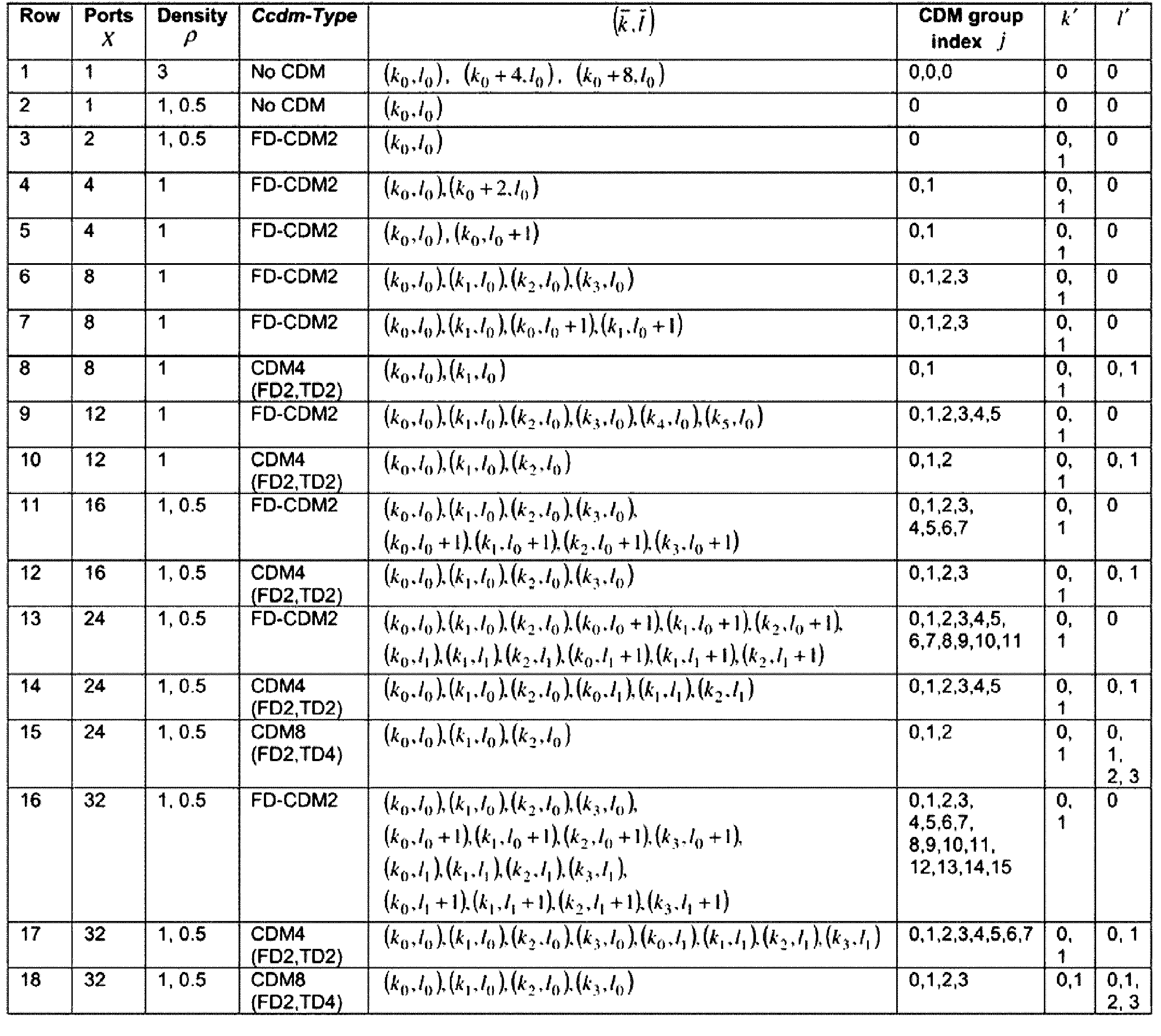
例えば、X=2ポートと設定された場合、基地局は、(1005)によって周波数軸RE位置を指定するようになり、もし、基地局が(1005)の「2」によって周波数軸サブキャリア位置を指定して(1015)の「9」によって時間軸「OFDM symbol」位置を指定するようになれば、これに基づいて端末は、該当PRB(1020)内の(1025)のRE位置で「CSI-RS」が送信されることが分かる。 For example, when X=2 ports is set, the base station specifies the frequency axis RE position by (1005). If the base station specifies the frequency axis subcarrier position by the "2" in (1005) and specifies the time axis "OFDM symbol" position by the "9" in (1015), the terminal knows that the "CSI-RS" will be transmitted at the RE position of (1025) in the corresponding PRB (1020).
上記説明のように、NRで、基地局は、CSI測定以外の「rate matching」又は「time/frequency tracking」など他の機能を提供するために端末に「CSI-RS」を設定する。
一方、「CSI-RS」測定以外他の機能のために設定される「CSI-RS」に「reporting setting」を設定する場合、不必要なCSI生成のために端末パワーを消費するようになるか、不必要なCSI報告のためにアップリンクリソースを浪費するようになる副作用があり得る。
As described above, in NR, the base station configures a "CSI-RS" to the terminal to provide other functions such as "rate matching" or "time/frequency tracking" other than CSI measurement.
On the other hand, if the 'reporting setting' is set to the 'CSI-RS' that is set for functions other than 'CSI-RS' measurement, there may be side effects such as consuming terminal power for unnecessary CSI generation or wasting uplink resources for unnecessary CSI reporting.
以下では、5G通信システムでのチャンネル状態測定及びチャンネル状態を報告する方法に対して具体的に記述する。 The following describes in detail how to measure and report channel conditions in a 5G communication system.
チャンネル状態情報(channel state information:CSI)には、チャンネル品質インジケーター(channel quality information:CQI)、プリコーディング行列インデックス(precoding matric indicator:PMI)、CSI-RSリソースインジケーター(CSI-RS resource indicator:CRI),SS/PBCHブロックリソースインジケーター(SS/PBCH block resource indicator:SSBRI)、レイヤインジケーター(layer indicator:LI)、ランクインジケーター(rank indicator:RI)、及び/又は「L1-RSRP」(Reference Signal Received Power)などが含まれ得る。
基地局は、端末の前述のCSI測定及び報告のための時間及び周波数リソースを制御する。
The channel state information (CSI) may include a channel quality information (CQI), a precoding matrix index (PMI), a CSI-RS resource indicator (CRI), a SS/PBCH block resource indicator (SSBRI), a layer indicator (LI), a rank indicator (RI), and/or a Reference Signal Received Power (L1-RSRP), etc.
The base station controls the time and frequency resources for the terminals' such CSI measurements and reporting.
前述のCSI測定及び報告のために、端末は、N(≧1)個のCSI報告のためのセッティング(Setting)情報(CSI-ReportConfig)、M(≧1)個のRS送信リソースに対するセッティング情報(CSI-ResourceConfig)、1つ又は2つのトリガー(Trigger)状態(「CSI-AperiodicTriggerStateList」、「CSI-SemiPersistentOnPUSCH-TriggerStateList」)リスト(List)情報を、上位階層シグナリングを介して設定する。 For the above-mentioned CSI measurement and reporting, the terminal configures setting information (CSI-ReportConfig) for N (≧1) CSI reports, setting information (CSI-ResourceConfig) for M (≧1) RS transmission resources, and list information for one or two trigger states ("CSI-AperiodicTriggerStateList", "CSI-SemiPersistentOnPUSCH-TriggerStateList") via higher layer signaling.
前述のCSI測定及び報告のための設定情報は、より具体的には、表20~表26に記載した以下の通りである。 More specifically, the configuration information for the above-mentioned CSI measurement and reporting is as follows, as shown in Tables 20 to 26.
・「CSI-ReportConfig」
The IE CSI-ReportConfig is used to configure a periodic or semi-persistent report sent on PUCCH on the cell in which the CSI-ReportConfig is included,or to configure a semi-persistent or aperiodic report sent on PUSCH triggered by DCI received on the cell in which the CSI-ReportConfig is included(in this case,the cell on which the report is sent is determined by the received DCI). See TS 38.214 [19],clause 5.2.1.
・"CSI-ReportConfig"
The IE CSI-ReportConfig is used to configure a periodic or semi-persistent report sent on PUCCH on the cell in which the C SI-ReportConfig is included, or to configure a semi-persistent or aperiodic report sent on PUSCH triggered by DCI received on the cell in which the CSI-ReportConfig is included(in this case, the cell on which the report is sent is determined by the received DCI). See TS 38.214 [19], clause 5.2.1.
・「CSI-ReportConfig information element」
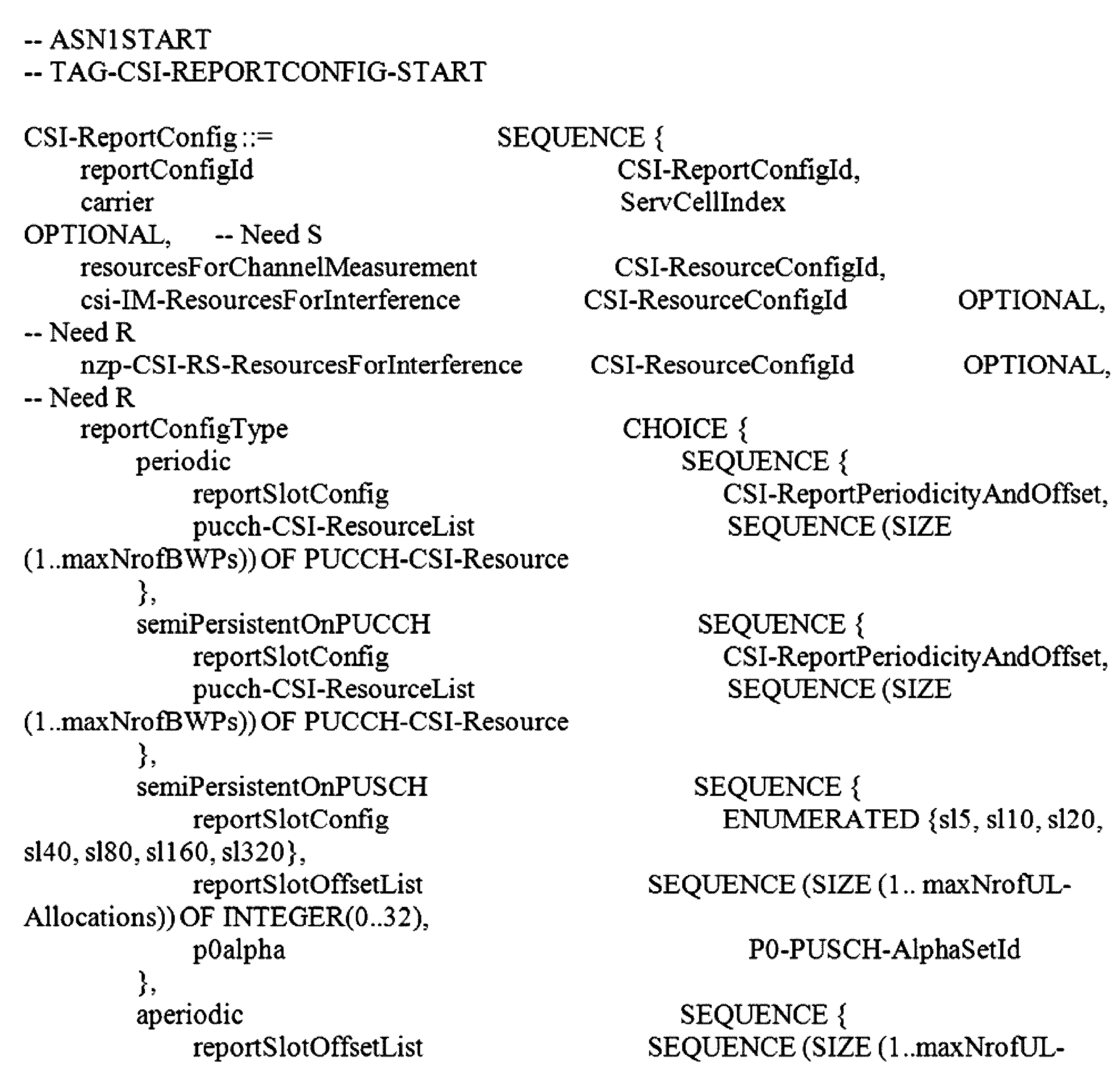
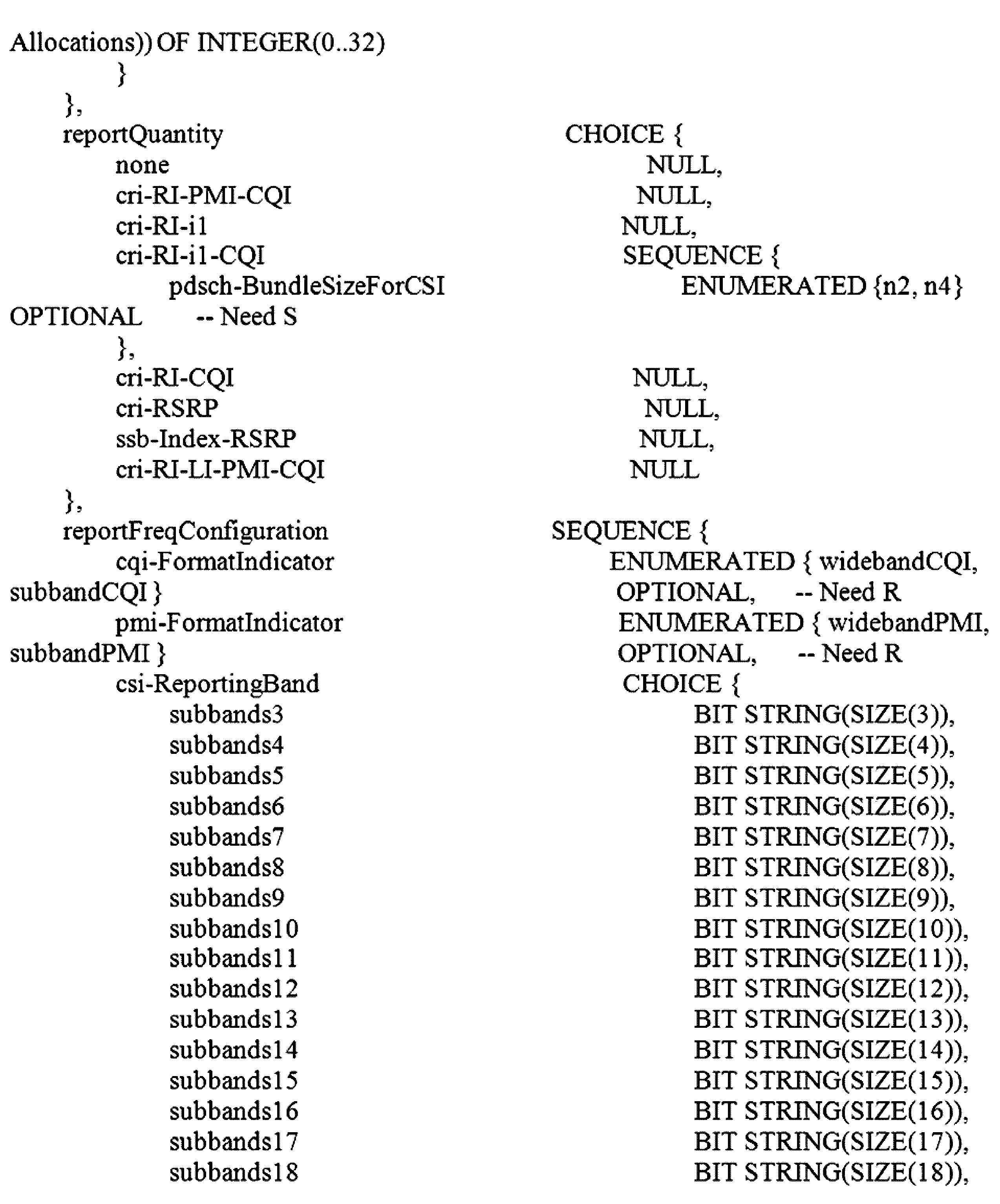

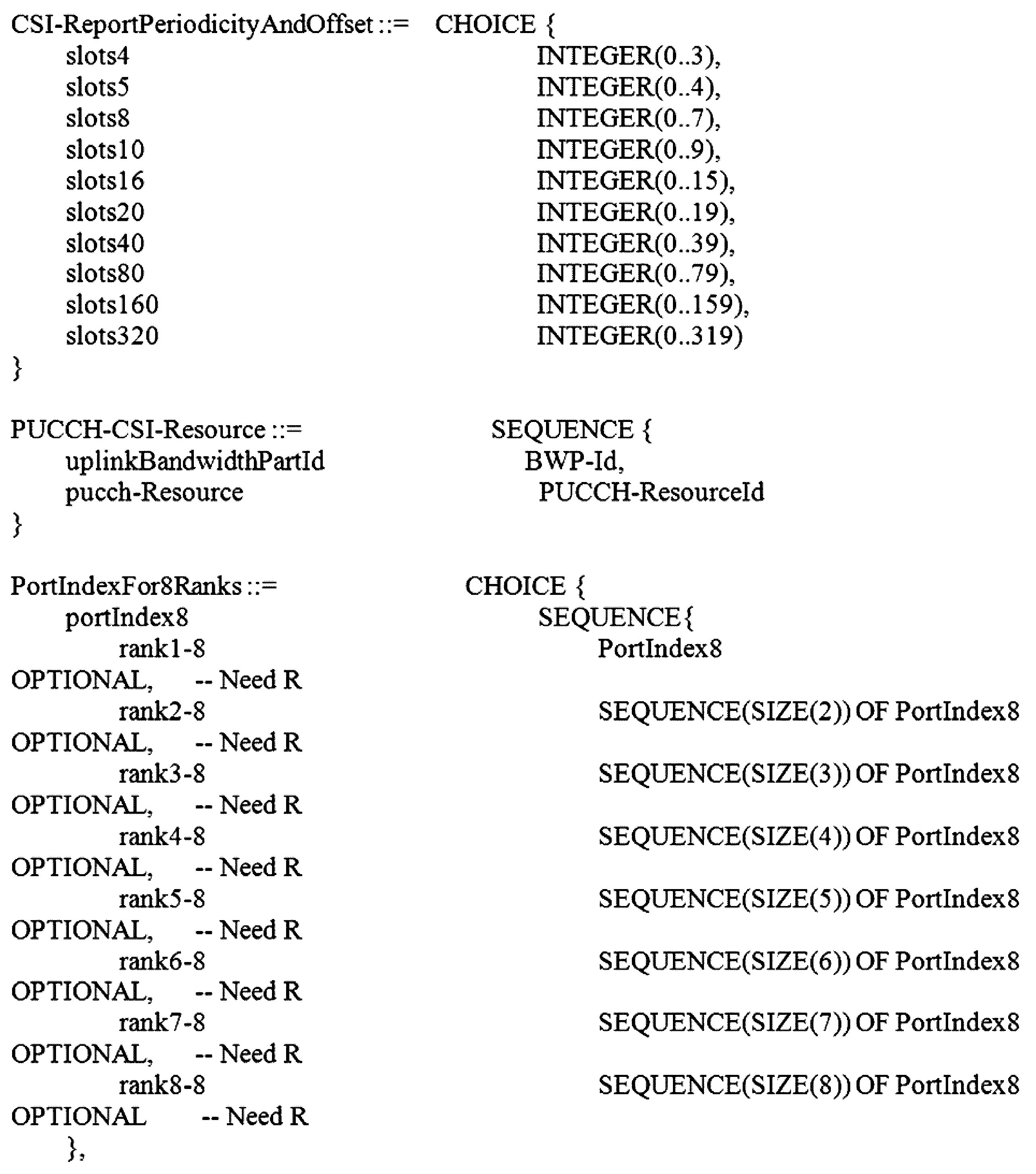
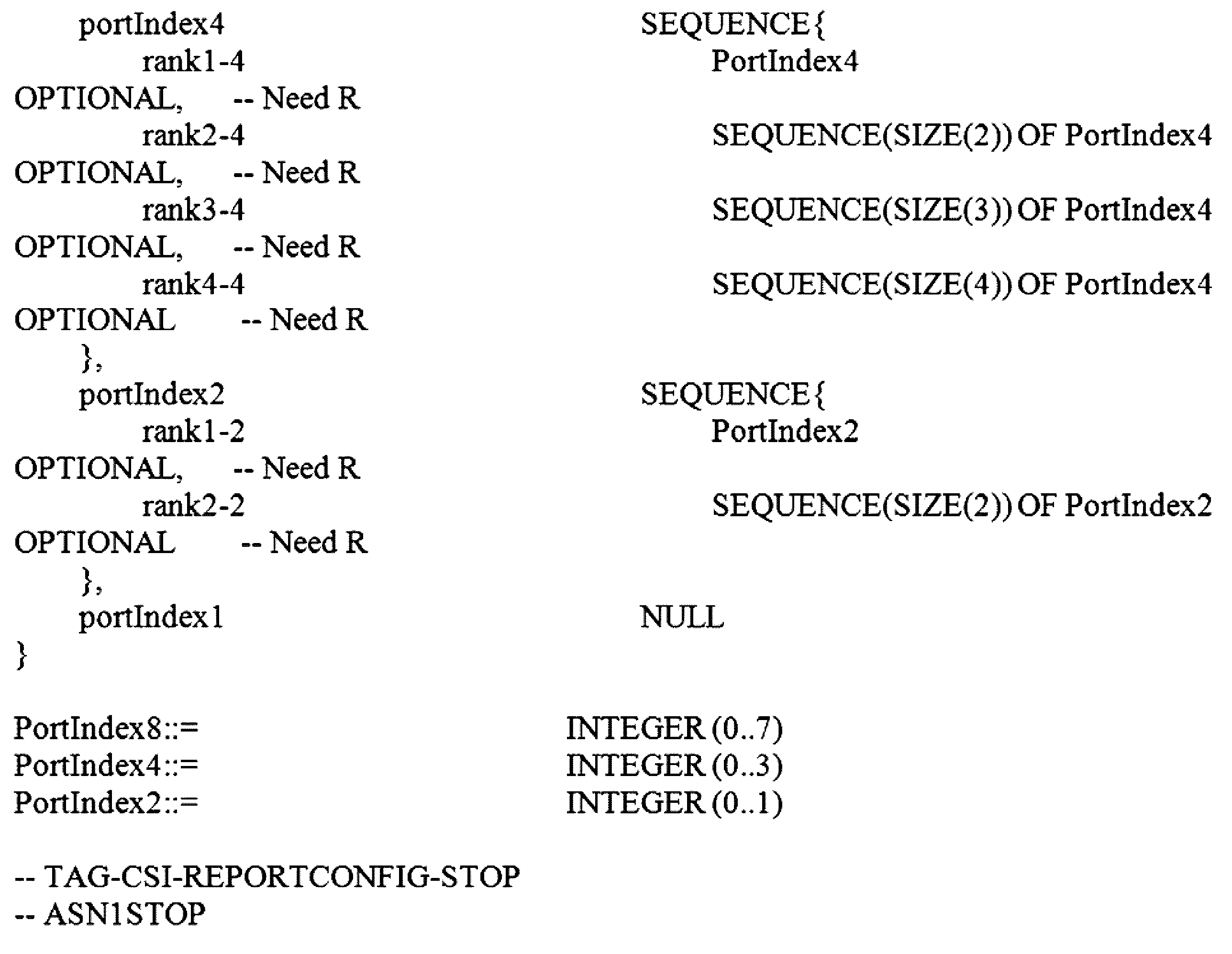
CSI-ReportConfig field descriptions
・「carrier」:Indicates in which serving cell the CSI-ResourceConfig indicated below are to be found. If the field is absent,the resources are on the same serving cell as this report configuration.
・「codebookConfig」:Codebook configuration for Type-1 or Type-II including codebook subset restriction.
・「cqi-FormatIndicator」:Indicates whether the UE shall report a single(wideband)or multiple(subband)CQI. (see TS 38.214 [19],clause 5.2.1.4).
・「cqi-Table」:Which CQI table to use for CQI calculation(see TS 38.214 [19],clause 5.2.2.1).
・「csi-IM-ResourcesForInterference」:CSI IM resources for interference measurement. csi-ResourceConfigId of a CSI-ResourceConfig included in the configuration of the serving cell indicated with the field “carrier” above.The CSI-ResourceConfig indicated here contains only CSI-IM resources.The bwp-Id in that CSI-ResourceConfig is the same value as the bwp-Id in the CSI-ResourceConfig indicated by resourcesForChannelMeasurement.
CSI-ReportConfig field descriptions
・“carrier”: Indicates in which serving cell the CSI-ResourceConfig indicated below are to be found. If the field is absent, the resources are on the same serving cell as this report configuration.
・"codebookConfig": Codebook configuration for Type-1 or Type-II including codebook subset restriction.
- "cqi-FormatIndicator": Indicates whether the UE shall report a single (wideband) or multiple (subband) CQI. (see TS 38.214 [19], clause 5.2.1.4).
- "cqi-Table": Which CQI table to use for CQI calculation (see TS 38.214 [19], clause 5.2.2.1).
・"CSI-IM-ResourcesForInterference": CSI IM resources for interference measurement. CSI-ResourceConfigId of a CSI-ResourceConfig included in the configuration of the serving cell indicated with the field “ca above. The CSI-ResourceConfig indicated here contains only CSI-IM resources. The bwp-Id in that CSI-ResourceConfig is the same value as the bwp-Id in the CSI-ResourceConfig indicated by resourcesForC hannelMeasurement.
・「csi-ReportingBand」:Indicates a contiguous or non-contiguous subset of subbands in the bandwidth part which CSI shall be reported for.Each bit in the bit-string represents one subband.The right-most bit in the bit string represents the lowest subband in the BWP.The choice determines the number of subbands(subbands3 for 3 subbands、subbands4 for 4 subbands、and so on)(see TS 38.214 [19],clause 5.2.1.4).This field is absent if there are less than 24 PRBs(no sub band)and present otherwise、the number of sub bands can be from 324 PRBs、sub band size 8)to 18(72 PRBs、sub band size 4).
・「dummy」:This field is not used in the specification. If received it shall be ignored by the UE.
・「groupBasedBeamReporting」:Turning on/off group beam based reporting(see TS 38.214 [19],clause 5.2.1.4)
・「non-PMI-PortIndication」:Port indication for RI/CQI calculation. For each CSI-RS resource in the linked ResourceConfig for channel measurement,a port indication for each rank R、indicating which R ports to use.Applicable only for non-PMI feedback(see TS 38.214 [19],clause 5.2.1.4.2.
・"CSI-ReportingBand": Indicates a contiguous or non-contiguous subset of subbands in the bandwidth part which CSI shall be reported for. Each bit in the bit-string representatives one subband. The right-most bit in the bit string representatives the lowest subband in the BWP. The choice determines the number of subbands (subbands3 for 3 subbands, subbands4 for 4 subbands, and so on) (see TS 38.214 9], clause 5.2.1.4). This field is absent if there are less than 24 PRBs (no sub band) and present otherwise, the number of sub bands can be from 324 PRBs, sub band size 8) to 18 (72 PRBs, sub band size 4).
・"dummy": This field is not used in the specification. If received it shall be ignored by the UE.
・“groupBasedBeamReporting”: Turning on/off group beam based reporting (see TS 38.214 [19], clause 5.2.1.4)
・“non-PMI-PortIndication”: Port indication for RI/CQI calculation. For each CSI-RS resource in the linked ResourceConfig for channel measurement, a port indication for each rank R,indicating which R ports to use. Applicable only for non-PMI feedback (see TS 38.214 [19], clause 5.2.1.4.2.
The first entry in non-PMI-PortIndication corresponds to the NZP-CSI-RS-Resource indicated by the first entry in nzp-CSI-RS-Resources in the NZP-CSI-RS-ResourceSet indicated in the first entry of nzp-CSI-RS-ResourceSetList of the CSI-ResourceConfig whose CSI-ResourceConfigId is indicated in a CSI-MeasId together with the above CSI-ReportConfigId;the second entry in non-PMI-PortIndication corresponds to the NZP-CSI-RS-Resource indicated by the second entry in nzp-CSI-RS-Resources in the NZP-CSI-RS-ResourceSet indicated in the first entry of nzp-CSI-RS-ResourceSetList of the same CSI-ResourceConfig、and so on until the NZP-CSI-RS-Resource indicated by the last entry in nzp-CSI-RS-Resources in the in the NZP-CSI-RS-ResourceSet indicated in the first entry of nzp-CSI-RS-ResourceSetList of the same CSI-ResourceConfig.Then the next entry corresponds to the NZP-CSI-RS-Resource indicated by the first entry in nzp-CSI-RS-Resources in the NZP-CSI-RS-ResourceSet indicated in the second entry of nzp-CSI-RS-ResourceSetList of the same CSI-ResourceConfig and so on. The first entry in non-PMI-PortIndication corresponds to the NZP-CSI-RS-Resource indicated by the first entry in nzp-C SI-RS-Resources in the NZP-CSI -RS-ResourceSetList of the CSI-ResourceConfig who CSI-ResourceConfigId is indicated in a CSI-MeasId together with the above CSI-ReportConfigId; the second entry in non-PMI-PortIndication corresponds to the N ZP-CSI-RS-Resources indicated by the second entry in nzp-CSI-RS-Resources in the NZP-CSI -RS-ResourceSet indicated in the first entry of nzp-CSI-RS-ResourceSetList of the same CSI-ResourceConfig, and so on until the NZP-CSI-RS-Resource indicated by the last entry in nzp-CSI-RS-Resources the in the NZP-CSI-RS-ResourceSet indicated in the first entry of nzp-CSI -RS-ResourceSetList of the same CSI-ResourceConfig. Then the next entry corresponds to the NZP-CSI-RS-Resources indicated by the first entry in nzp-CSI-RS-Resources in the NZP-CSI-RS-ResourceSet indicated in the second entry of nzp-CSI-RS-ResourceSetList of the same CSI-ResourceConfig and so on.
・「nrofReportedRS」:The number(N)of measured RS resources to be reported per report setting in a non-group-based report.N <=N_max、where N_max is either 2 or 4 depending on UE capability.
(see TS 38.214 [19],clause 5.2.1.4)When the field is absent the UE applies the value 1
・「nzp-CSI-RS-ResourcesForInterference」:NZP CSI RS resources for interference measurement. csi-ResourceConfigId of a CSI-ResourceConfig included in the configuration of the serving cell indicated with the field “carrier” above.The CSI-ResourceConfig indicated here contains only NZP-CSI-RS resources.The bwp-Id in that CSI-ResourceConfig is the same value as the bwp-Id in the CSI-ResourceConfig indicated by resourcesForChannelMeasurement.
・"nrofReportedRS": The number (N) of measured RS resources to be reported per report setting in a non-group-based report. N <= N_max, where N_max is either 2 or 4 depending on UE capability.
(see TS 38.214 [19], clause 5.2.1.4) When the field is absent the UE applications the
・"nzp-CSI-RS-ResourcesForInterference": NZP CSI RS resources for interference measurement. CSI-ResourceConfigId of a CSI-ResourceConfig included in the configuration of the serving cell indicated with the field “ca rrier” above. The CSI-ResourceConfig indicated here contains only NZP-CSI-RS resources. The bwp-Id in that CSI-ResourceConfig is the same value as the bwp-Id in the CSI-ResourceConfig indicated by resourcesForC hannelMeasurement.
・「p0alpha」:Index of the p0-alpha set determining the power control for this CSI report transmission(see TS 38.214 [19],clause 6.2.1.2).
・「pdsch-BundleSizeForCSI」:PRB bundling size to assume for CQI calculation when reportQuantity is CRI/RI/i1/CQI. If the field is absent、the UE assumes that no PRB bundling is applied(see TS 38.214 [19],clause 5.2.1.4.2).
・「pmi-FormatIndicator」:Indicates whether the UE shall report a single(wideband)or multiple(subband)PMI. (see TS 38.214 [19],clause 5.2.1.4).
・「pucch-CSI-ResourceList」:Indicates which PUCCH resource to use for reporting on PUCCH.
・"p0alpha": Index of the p0-alpha set determining the power control for this CSI report transmission (see TS 38.214 [19], use 6.2.1.2).
・"pdsch-BundleSizeForCSI": PRB bundling size to assume for CQI calculation when reportQuantity is CRI/RI/i1/CQI. If the field is absent, the UE assumes that no PRB bundling is applied (see TS 38.214 [19], clause 5.2.1.4.2).
- "pmi-FormatIndicator": Indicates whether the UE shall report a single (wideband) or multiple (subband) PMI. (see TS 38.214 [19], clause 5.2.1.4).
・“pucch-CSI-ResourceList”: Indicates which PUCCH resource to use for reporting on PUCCH.
・「reportConfigType」:Time domain behavior of reporting configuration.
・reportFreqConfiguration:Reporting configuration in the frequency domain.(see TS 38.214 [19],clause 5.2.1.4).
・「reportQuantity」:The CSI related quantities to report.Corresponds to L1 parameter‘eportQuantity’(see TS 38.214 [19],clause 5.2.1).
・「reportSlotConfig」:Periodicity and slot offset(see TS 38.214 [19],clause 5.2.1.4).
- "reportConfigType": Time domain behavior of reporting configuration.
・reportFreqConfiguration: Reporting configuration in the frequency domain. (see TS 38.214 [19], clause 5.2.1.4).
- "reportQuantity": The CSI related quantities to report. Corresponds to L1 parameter 'eportQuantity' (see TS 38.214 [19], clause 5.2.1).
- "reportSlotConfig": Periodicity and slot offset (see TS 38.214 [19], clause 5.2.1.4).
・「reportSlotConfig-v1530」:Extended value range for reportSlotConfig for semi-persistent CSI on PUSCH. If the field is present、the UE shall ignore the value provided in the legacy field(semiPersistentOnPUSCH.reportSlotConfig).
・「reportSlotOffsetList」:Timing offset Y for semi persistent reporting using PUSCH.This field lists the allowed offset values.This list must have the same number of entries as the pusch-TimeDomainAllocationList in PUSCH-Config. A particular value is indicated in DCI.The network indicates in the DCI field of the UL grant、which of the configured report slot offsets the UE shall apply.The DCI value 0 corresponds to the first report slot offset in this list、the DCI value 1 corresponds to the second report slot offset in this list、and so on.The first report is transmitted in slot n+Y、second report in n+Y+P,where P is the configured periodicity.
・“reportSlotConfig-v1530”: Extended value range for reportSlotConfig for semi-persistent CSI on PUSCH. If the field is present, the UE shall ignore the value provided in the legacy field (semiPersistentOnPUSCH.reportSlotConfig) ..
- "reportSlotOffsetList": Timing offset Y for semi persistent reporting using PUSCH. This field lists the allowed offset values. This list must have the same number of entries as the push-TimeDomainAllocationList in PUSCH-Config. A particular value is indicated in DCI. The network indicates in the DCI field of the UL grant, which of the configured report slot offsets the UE shall apply. The
Timing offset Y for aperiodic reporting using PUSCH. This field lists the allowed offset values.This list must have the same number of entries as the pusch-TimeDomainAllocationList in PUSCH-Config.A particular value is indicated in DCI.The network indicates in the DCI field of the UL grant、which of the configured report slot offsets the UE shall apply.The DCI value 0 corresponds to the first report slot offset in this list、the DCI value 1 corresponds to the second report slot offset in this list、and so on(see TS 38.214 [19],clause 5.2.3).
Timing offset Y for aperiodic reporting using PUSCH. This field lists the allowed offset values. This list must have the same number of entries as the push-TimeDomainAllocationList in PUSCH-Config. A particular value is indicated in DCI. The network indicates in the DCI field of the UL grant, which of the configured report slot offsets the UE shall apply. The
・「resourcesForChannelMeasurement」:Resources for channel measurement. csi-ResourceConfigId of a CSI-ResourceConfig included in the configuration of the serving cell indicated with the field “carrier” above. The CSI-ResourceConfig indicated here contains only NZP-CSI-RS resources and/or SSB resources.This CSI-ReportConfig is associated with the DL BWP indicated by bwp-Id in that CSI-ResourceConfig.
・「subbandSize」:Indicates one out of two possible BWP-dependent values for the subband size as indicated in TS 38.214 [19],table 5.2.1.4-2. If csi-ReportingBand is absent、the UE shall ignore this field.
・「timeRestrictionForChannelMeasurements」:Time domain measurement restriction for the channel(signal)measurements(see TS 38.214 [19],clause 5.2.1.1).
・「timeRestrictionForInterferenceMeasurements」:Time domain measurement restriction for interference measurements(see TS 38.214 [19],clause 5.2.1.1).
- "resourcesForChannelMeasurement": Resources for channel measurement. CSI-ResourceConfigId of a CSI-ResourceConfig included in the configuration of the serving cell indicated with the field “ca above. The CSI-ResourceConfig indicated here contains only NZP-CSI-RS resources and/or SSB resources. This CSI-ReportConfig is associated with the DL BWP indicated by bwp-Id in that CSI-ResourceConfig.
・"subbandSize": Indicates one out of two possible BWP-dependent values for the subband size as indicated in TS 38.214 19], table 5.2.1.4-2. If CSI-ReportingBand is absent, the UE shall ignore this field.
・“timeRestrictionForChannelMeasurements”: Time domain measurement restriction for the channel (signal) measurements (see TS 38 .214 [19], clause 5.2.1.1).
・“timeRestrictionForInterferenceMeasurements”: Time domain measurement restriction for interference measurements (see TS 38. 214 [19], clause 5.2.1.1).
CSI-ResourceConfig
The IE CSI-ResourceConfig defines a group of one or more NZP-CSI-RS-ResourceSet,CSI-IM-ResourceSet and/or CSI-SSB-ResourceSet.
CSI-ResourceConfig information element
CSI-ResourceConfig
The IE CSI-ResourceConfig defines a group of one or more NZP-CSI-RS-ResourceSet, CSI-IM-ResourceSet and/or CSI-SSB-Resour ceSet.
CSI-ResourceConfig information element
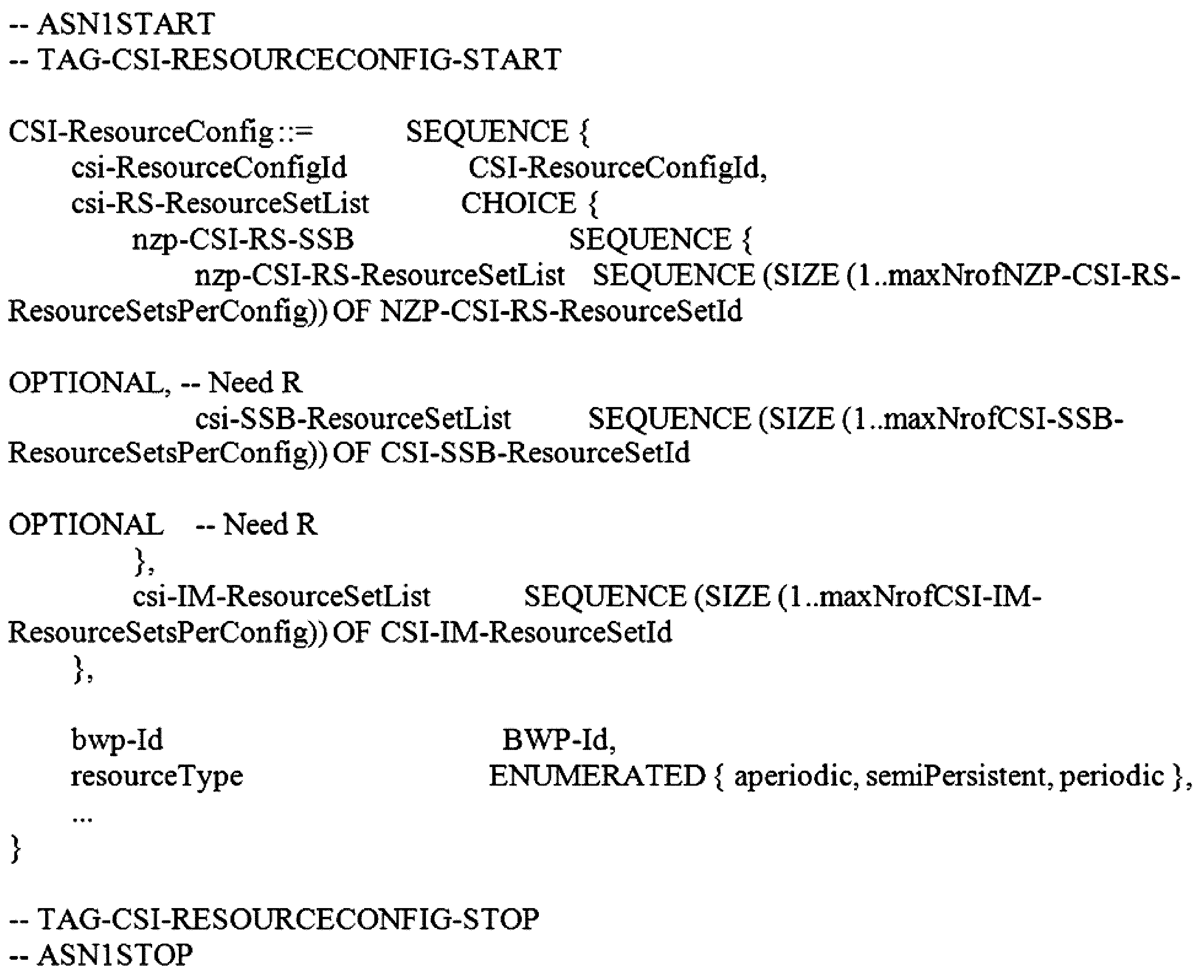
CSI-ResourceConfig field descriptions CSI-ResourceConfig field descriptions
・「bwp-Id」:The DL BWP which the CSI-RS associated with this CSI-ResourceConfig are located in(see TS 38.214 [19],clause 5.2.1.2 [374].
・「csi-ResourceConfigId」:Used in CSI-ReportConfig to refer to an instance of CSI-ResourceConfig.
・「csi-RS-ResourceSetList」:Contains up to maxNrofNZP-CSI-RS-ResourceSetsPerConfig resource sets if ResourceConfigType is ‘aperiodic’ and 1 otherwise(see TS 38.214 [19],clause 5.2.1.2).
・「csi-SSB-ResourceSetList」:List of SSB resources used for beam measurement and reporting in a resource set(see TS 38.214 [19],section FFS_Section).
・「resourceType」:Time domain behavior of resource configuration(see TS 38.214 [19],clause 5.2.1.2). It does not apply to resources provided in the csi-SSB-ResourceSetList.
・"bwp-Id": The DL BWP which the CSI-RS associated with this CSI-ResourceConfig are located in (see TS 38.214 [19], Clause 5.2 .1.2 [374].
- "CSI-ResourceConfigId": Used in CSI-ReportConfig to refer to an instance of CSI-ResourceConfig.
・"CSI-RS-ResourceSetList": Contains up to maxNrofNZP-CSI-RS-ResourceSetsPerConfig resource sets if ResourceConfigType is'aperiodic' and 1 otherwise (see TS 38.214 [19], clause 5.2.1.2).
・"CSI-SSB-ResourceSetList": List of SSB resources used for beam measurement and reporting in a resource set (see TS 38.214 19], section FFS_Section).
- "resourceType": Time domain behavior of resource configuration (see TS 38.214 [19], clause 5.2.1.2). It does not apply to resources provided in the CSI-SSB-ResourceSetList.
NZP-CSI-RS-ResourceSet
The IE NZP-CSI-RS-ResourceSet is a set of Non-Zero-Power(NZP)CSI-RS resources(their IDs)and set-specific parameters.
NZP-CSI-RS-ResourceSet information element
NZP-CSI-RS-ResourceSet
The IE NZP-CSI-RS-ResourceSet is a set of Non-Zero-Power(NZP)CSI-RS resources(their IDs)and set-specific parameters.
NZP-CSI-RS-ResourceSet information element
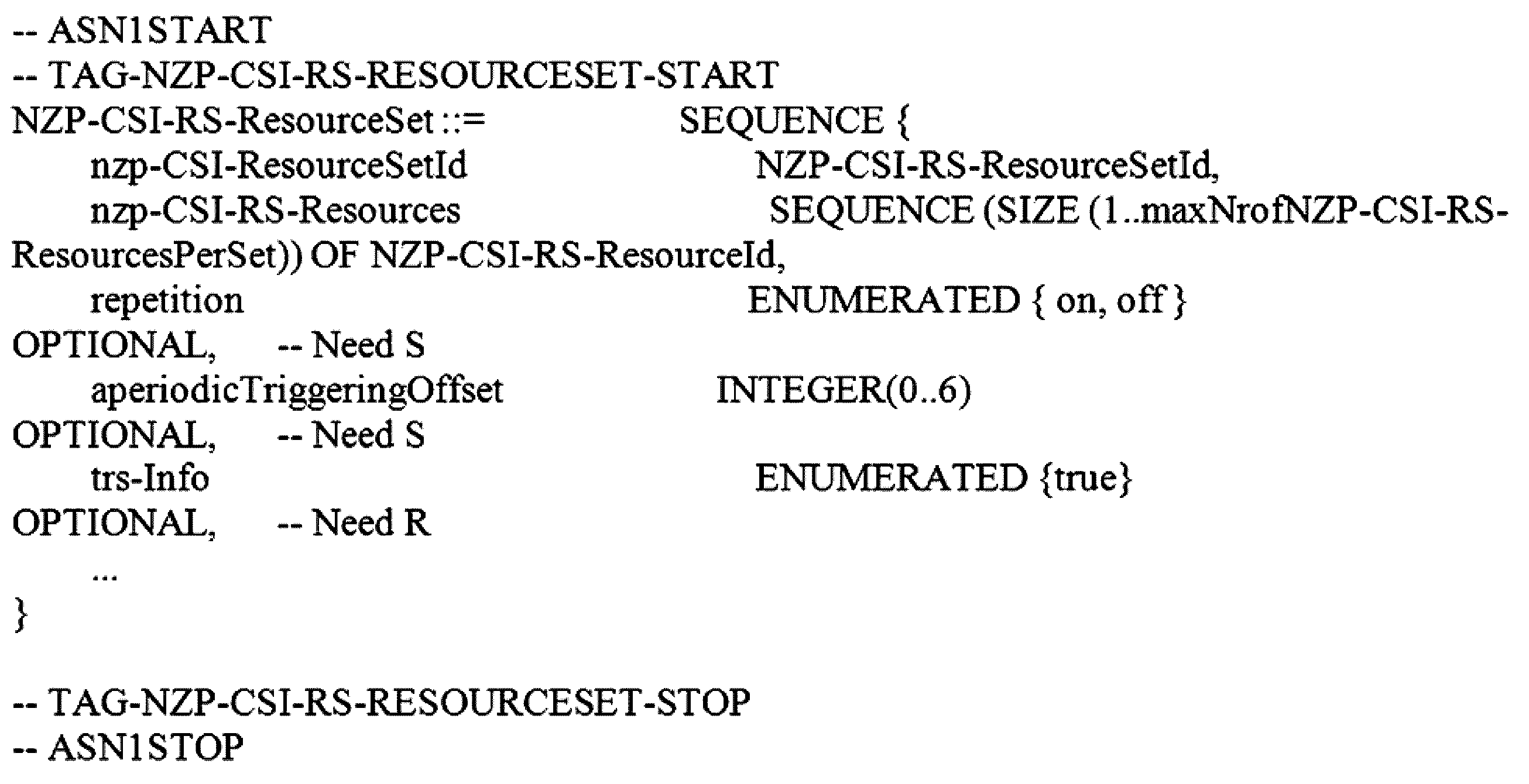
NZP-CSI-RS-ResourceSet field descriptions NZP-CSI-RS-ResourceSet field descriptions
・「aperiodicTriggeringOffset」:Offset X between the slot containing the DCI that triggers a set of aperiodic NZP CSI-RS resources and the slot in which the CSI-RS resource set is transmitted. The value 0 corresponds to 0 slots、value 1 corresponds to 1 slot,value 2 corresponds to 2 slots、value 3 corresponds to 3 slots,value 4 corresponds to 4 slots,value 5 corresponds to 16 slots、value 6 corresponds to 24 slots.When the field is absent the UE applies the value 0.
・「nzp-CSI-RS-Resources」:NZP-CSI-RS-Resources associated with this NZP-CSI-RS resource set(see TS 38.214 [19],clause 5.2). For CSI,there are at most 8 NZP CSI RS resources per resource set.
・「repetition」:Indicates whether repetition is on/off.If the field is set to ‘OFF’or if the field is absent,the UE may not assume that the NZP-CSI-RS resources within the resource set are transmitted with the same downlink spatial domain transmission filter and with same NrofPorts in every symbol(see TS 38.214 [19],clauses 5.2.2.3.1 and 5.1.6.1.2). Can only be configured for CSI-RS resource sets which are associated with CSI-ReportConfig with report of L1 RSRP or “no report”
・「trs-Info」:Indicates that the antenna port for all NZP-CSI-RS resources in the CSI-RS resource set is same.If the field is absent or released the UE applies the value “false”(see TS 38.214 [19],clause 5.2.2.3.1).
・"AperiodicTriggeringOffset": Offset X between the slot containing the DCI that triggers a set of aperiodic NZP CSI-RS re sources and the slot in which the CSI-RS resource set is transmitted. The
・"nzp-CSI-RS-Resources": NZP-CSI-RS-Resources associated with this NZP-CSI-RS resource set (see TS 38.214 [19], 5.2). For CSI, there are at most 8 NZP CSI RS resources per resource set.
・“repetition”: Indicates whether repetition is on/off. If the field is set to 'OFF'or if the field is absent, the UE may not assume that the NZP-CSI-RS resources with the reso source set are transmitted with the same downlink spatial domain transmission filter and with same NrofPorts in every symbol (see TS 38.214 [19], clauses 5.2.2.3.1 and 5.1.6.1.2). Can only be configured for CSI-RS resource sets which are associated with CSI-ReportConfig with report of L1 RSRP or “no re” "port"
・"trs-Info": Indicates that the antenna port for all NZP-CSI-RS resources in the CSI-RS resource set is the same. If the field is absent or released the UE applications the value “false” (see TS 38.214 [19], clause 5.2.2.3.1).
CSI-SSB-ResourceSet
The IE CSI-SSB-ResourceSet is used to configure one SS/PBCH block resource set which refers to SS/PBCH as indicated in ServingCellConfigCommon.
CSI-SSB-ResourceSet information element
CSI-SSB-ResourceSet
The IE CSI-SSB-ResourceSet is used to configure one SS/PBCH block resource set which refers to SS/PBCH as indicated in Ser vingCellConfigCommon.
CSI-SSB-ResourceSet information element
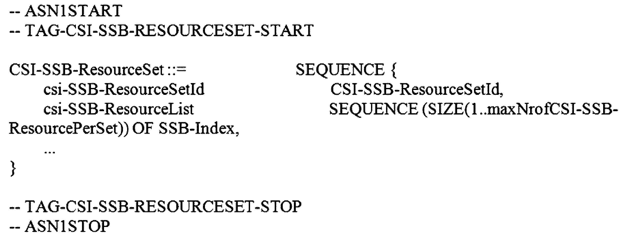
CSI-IM-ResourceSet
The IE CSI-IM-ResourceSet is used to configure a set of one or more CSI Interference Management(IM)resources(their IDs)and set-specific parameters.
CSI-IM-ResourceSet information element
CSI-IM-ResourceSet
The IE CSI-IM-ResourceSet is used to configure a set of one or more CSI Interference Management (IM) resources (their IDs) and set-specific parameters.
CSI-IM-ResourceSet information element
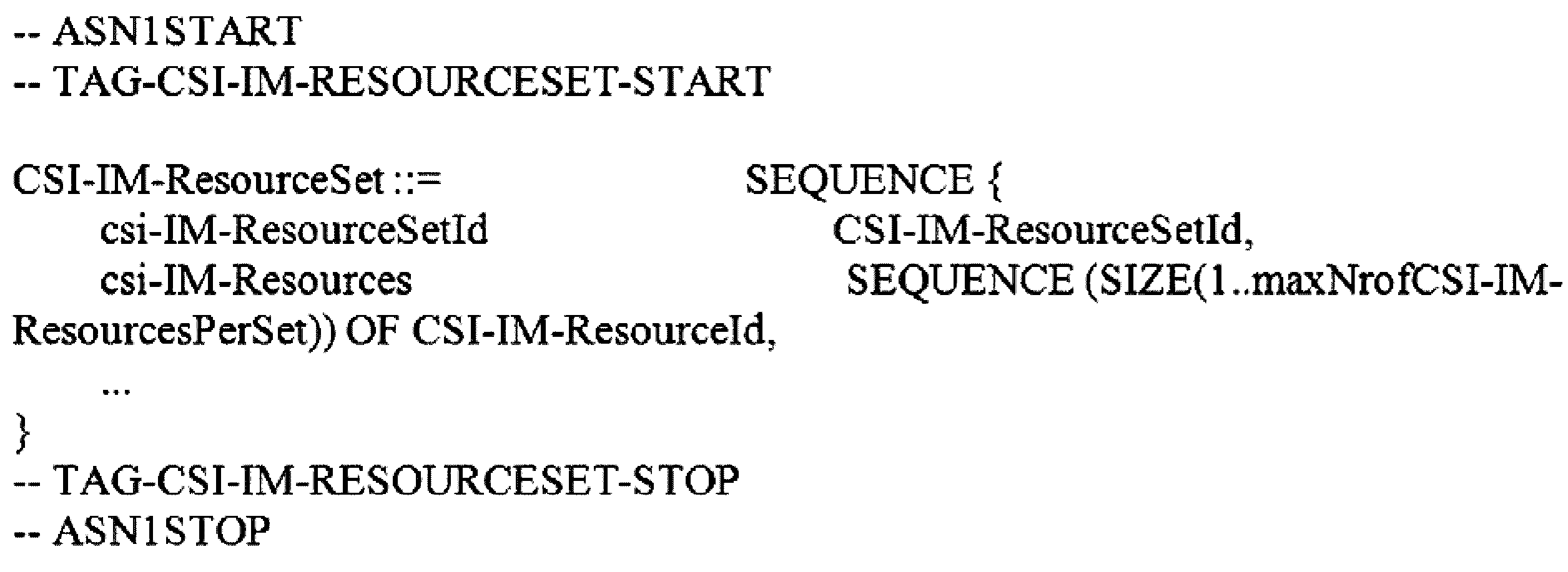
CSI-AperiodicTriggerStateList
The CSI-AperiodicTriggerStateList IE is used to configure the UE with a list of aperiodic trigger states. Each codepoint of the DCI field “CSI request” is associated with one trigger state.Upon reception of the value associated with a trigger state,the UE will perform measurement of CSI-RS(reference signals)and aperiodic reporting on L1 according to all entries in the associatedReportConfigInfoList for that trigger state.
CSI-AperiodicTriggerStateList information element
CSI-AperiodicTriggerStateList
The CSI-AperiodicTriggerStateList IE is used to configure the UE with a list of aperiodic trigger states. Each codepoint of the DCI field “CSI request” is associated with one trigger state. Upon reception of the value associated with a trigger state, the UE will perform measurement of CSI-RS (reference signals) d aperiodic reporting on L1 according to all entries in the associatedReportConfigInfoList for that trigger state.
CSI-AperiodicTriggerStateList information element
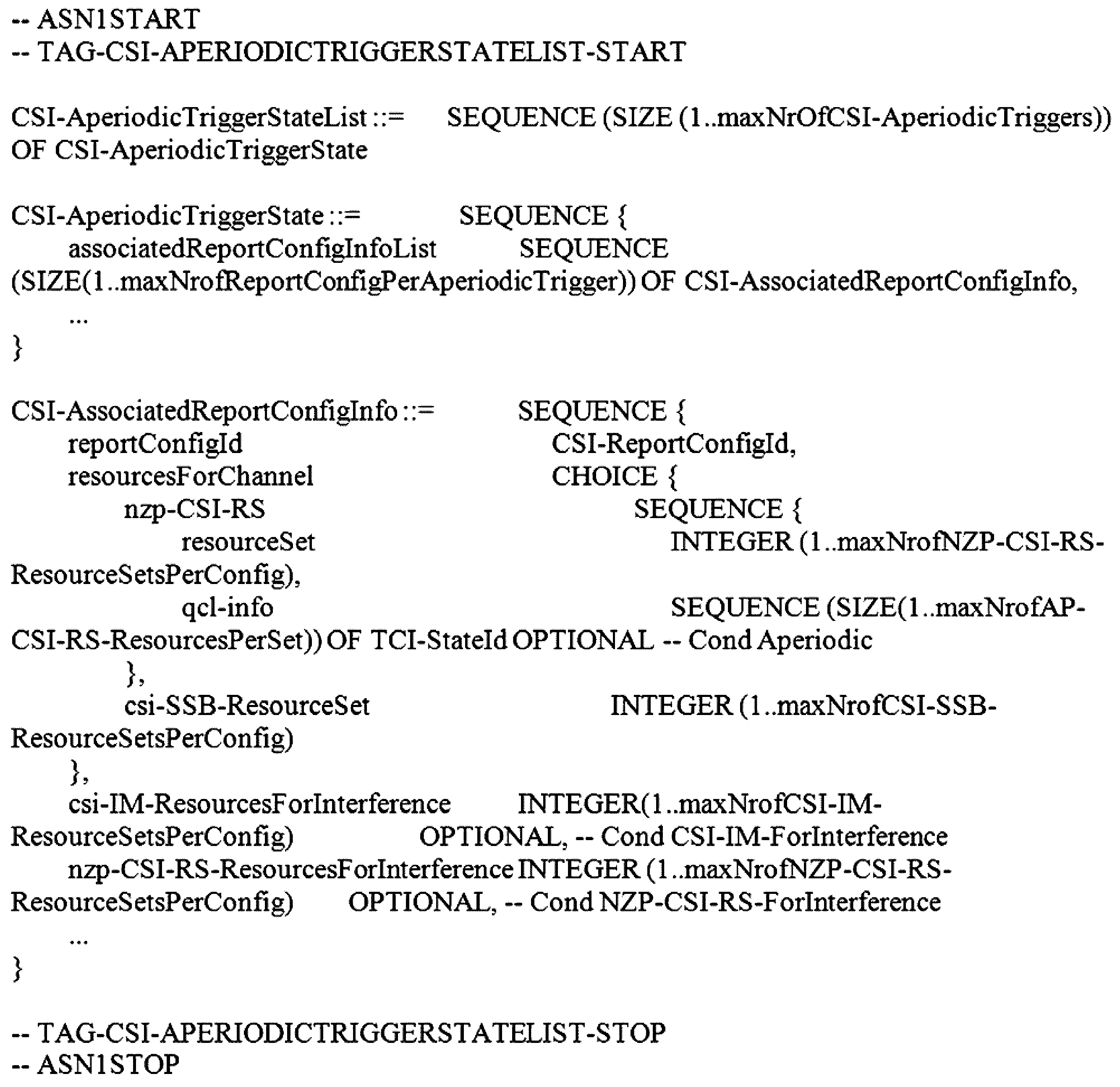
CSI-AssociatedReportConfigInfo field descriptions CSI-AssociatedReportConfigInfo field descriptions
・「csi-IM-ResourcesForInterference」:CSI-IM-ResourceSet for interference measurement. Entry number in csi-IM-ResourceSetList in the CSI-ResourceConfig indicated by csi-IM-ResourcesForInterference in the CSI-ReportConfig indicated by reportConfigId above(1 corresponds to the first entry、2 to the second entry、and so on).The indicated CSI-IM-ResourceSet should have exactly the same number of resources like the NZP-CSI-RS-ResourceSet indicated in nzp-CSI-RS-ResourcesforChannel.
・「csi-SSB-ResourceSet」:CSI-SSB-ResourceSet for channel measurements. Entry number in csi-SSB-ResourceSetList in the CSI-ResourceConfig indicated by resourcesForChannelMeasurement in the CSI-ReportConfig indicated by reportConfigId above(1 corresponds to the first entry,2 to the second entry,and so on).
・「nzp-CSI-RS-ResourcesForInterference」:NZP-CSI-RS-ResourceSet for interference measurement.Entry number in nzp-CSI-RS-ResourceSetList in the CSI-ResourceConfig indicated by nzp-CSI-RS-ResourcesForInterference in the CSI-ReportConfig indicated by reportConfigId above(1 corresponds to the first entry,2 to the second entry、and so on).
・"CSI-IM-ResourcesForInterference": CSI-IM-ResourceSet for interference measurement. Entry number in CSI-IM-ResourceSetList in the CSI-ResourceConfig indicated by CSI-IM-ResourcesForInterference in the CSI-R eportConfig indicated by reportConfigId above (1 corresponds to the first entry, 2 to the second entry, and so on). The indicated CSI-IM-ResourceSet should have exactly the same number of resources like the NZP-CSI-RS-ResourceSet indica ted in nzp-CSI-RS-ResourcesforChannel.
・"CSI-SSB-ResourceSet": CSI-SSB-ResourceSet for channel measurements. Entry number in CSI-SSB-ResourceSetList in the CSI-ResourceConfig indicated by resourcesForChannelMeasurement in the CSI-R eportConfig indicated by reportConfigId above (1 corresponds to the first entry, 2 to the second entry, and so on).
- "nzp-CSI-RS-ResourcesForInterference": NZP-CSI-RS-ResourceSet for interference measurement. Entry number in nzp-CSI-RS-ResourceSetList in the CSI-ResourceConfig indicated by nzp-CSI-RS-ResourcesForInterference in the CSI-ReportConfig indicated by reportConfigId above(1 corresponds to the first entry, 2 to the second entry, and so on ).
・「qcl-info」:List of references to TCI-States for providing the QCL source and QCL type for each NZP-CSI-RS-Resource listed in nzp-CSI-RS-Resources of the NZP-CSI-RS-ResourceSet indicated by nzp-CSI-RS-ResourcesforChannel.Each TCI-StateId refers to the TCI-State which has this value for tci-StateId and is defined in tci-StatesToAddModList in the PDSCH-Config included in the BWP-Downlink corresponding to the serving cell and to the DL BWP to which the resourcesForChannelMeasurement(in the CSI-ReportConfig indicated by reportConfigId above)belong to.First entry in qcl-info-forChannel corresponds to first entry in nzp-CSI-RS-Resources of that NZP-CSI-RS-ResourceSet、second entry in qcl-info-forChannel corresponds to second entry in nzp-CSI-RS-Resources,
and so on(see TS 38.214 [19],clause 5.2.1.5.1)
・「reportConfigId」:The reportConfigId of one of the CSI-ReportConfigToAddMod configured in CSI-MeasConfig.
・「resourceSet」:NZP-CSI-RS-ResourceSet for channel measurements.Entry number in nzp-CSI-RS-ResourceSetList in the CSI-ResourceConfig indicated by resourcesForChannelMeasurement in the CSI-ReportConfig indicated by reportConfigId above(1 corresponds to the first entry, 2 to thesecond entry、and so on).
・"qcl-info": List of references to TCI-States for providing the QCL source and QCL type for each NZP-CSI-RS-Resource li sted in nzp-CSI-RS-Resources of the NZP-CSI-RS-ResourceSet indicated by nzp-CSI-RS-ResourcesforChannel. Each TCI-StateId refers to the TCI-State which has this value for tci-StateId and is defined in tci-StatesToAddModList in the PDSCH-Config included in the BWP-Downlink corresponding to the serving cell and to the DL BWP to which the resourcesForC hannelMeasurement (in the CSI-ReportConfig indicated by reportConfigId above)belong to. First entry in qcl-info-forChannel corresponds to first entry in nzp-CSI-RS-Resources of that NZP-CSI-RS-ResourceSet , second entry in qcl-info-forChannel corresponds to second entry in nzp-CSI-RS-Resources ,
and so on (see TS 38.214 [19], clause 5.2.1.5.1)
- "reportConfigId": The reportConfigId of one of the CSI-ReportConfigToAddMod configured in CSI-MeasConfig.
・"resourceSet": NZP-CSI-RS-ResourceSet for channel measurements. Entry number in nzp-CSI-RS-ResourceSetList in the CSI-ResourceConfig indicated by resourcesForChannelMeasurement in the CSI-ReportConfig indicated by reportConfigId above (1 corresponds to the first entry, 2 to the second entry, and so on).
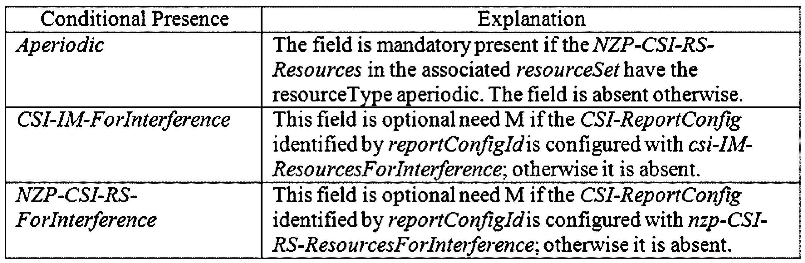
CSI-SemiPersistentOnPUSCH-TriggerStateList
The CSI-SemiPersistentOnPUSCH-TriggerStateList IE is used to configure the UE with list of trigger states for semi-persistent reporting of channel state information on L1.See also TS 38.214 [19],clause 5.2.
CSI-SemiPersistentOnPUSCH-TriggerStateList information element
CSI-SemiPersistentOnPUSCH-TriggerStateList
The CSI-SemiPersistentOnPUSCH-TriggerStateList IE is used to configure the UE with list of trigger states for semi-persist ent reporting of channel state information on L1. See also TS 38.214 [19], clause 5.2.
CSI-SemiPersistentOnPUSCH-TriggerStateList information element
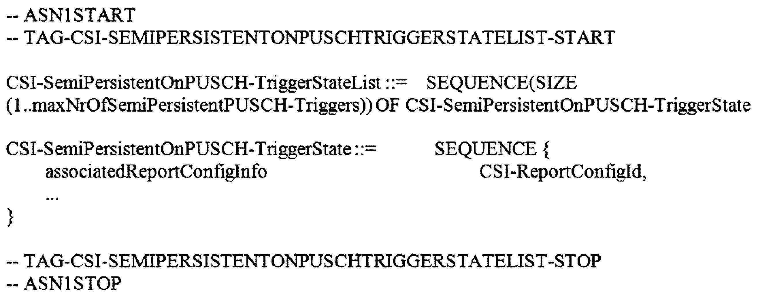
前述のCSI報告セッティング(CSI-ReportConfig)に対し、各報告セッティング「CSI-ReportConfig」は、該当報告セッティングと関連(Association)したCSIリソースセッティング、「CSI-ResourceConfig」で与えられる上位階層パラメーター帯域幅部分識別子(bwp-id)で識別される一つのダウンリンク(downlink:DL)帯域幅部分と関連される。 For the aforementioned CSI report settings (CSI-ReportConfig), each report setting "CSI-ReportConfig" is associated with one downlink (DL) bandwidth portion identified by the upper layer parameter bandwidth portion identifier (bwp-id) given in the CSI resource setting "CSI-ResourceConfig" associated with the corresponding report setting.
各報告セッティング「CSI-ReportConfig」に対する時間ドメイン報告動作で、‘非周期的(Aperiodic)’、‘半永久的(Semi-Persistent)’、‘周期的(Periodic)’方式がサポートされ、これは上位階層から設定された「reportConfigType」パラメーターによって基地局から端末に設定される。
半永久的CSI報告方法は、‘PUCCH基盤半永久的(semi-PersistentOnPUCCH)’、‘PUSCH基盤半永久的(semi-PersistentOnPUSCH)’をサポートする。
周期的又は半永久的CSI報告方法の場合、端末は、CSIを送信するPUCCH又はPUSCHリソースを基地局から上位階層シグナリングを介して設定される。
CSIを送信するPUCCH又はPUSCHリソースの周期とスロットオフセットは、CSI報告が送信されるように設定されたアップリンク(uplink:UL)帯域幅部分のヌマララジ(Numerology)に基づいて与えられる。
非周期的CSI報告方法の場合、端末は、CSIを送信するPUSCHリソースを基地局からL1シグナリング(DCI、例えば、前述のDCIフォーマット0_1)を介してスケジューリングされる。
In the time domain reporting operation for each reporting setting 'CSI-ReportConfig', 'Aperiodic', 'Semi-Persistent' and 'Periodic' methods are supported, which are set from the base station to the terminal according to the 'reportConfigType' parameter set from the upper layer.
The semi-persistent CSI reporting method supports 'PUCCH-based semi-persistent (semi-PersistentOnPUCCH)' and 'PUSCH-based semi-persistent (semi-PersistentOnPUSCH)'.
In the case of the periodic or semi-persistent CSI reporting method, the UE is configured with PUCCH or PUSCH resources for transmitting CSI from the base station via higher layer signaling.
The periodicity and slot offset of the PUCCH or PUSCH resources transmitting the CSI is given based on the numerology of the uplink (UL) bandwidth portion over which the CSI report is configured to be transmitted.
In the case of the aperiodic CSI reporting method, the terminal is scheduled for PUSCH resources for transmitting CSI from the base station via L1 signaling (DCI, for example, the above-mentioned DCI format 0_1).
前述のCSIリソースセッティング(CSI-ResourceConfig)に対し、各CSIリソースセッティング「CSI-ReportConfig」は、S(≧1)個のCSIリソースセット(上位階層パラメーター「csi-RS-ResourceSetList」に設定される)を含む。
CSIリソースセットリストは、ノン-ゼロパワー(non-zero power:NZP)「CSI-RS」リソースセットと「SS/PBCH」ブロックセットから構成されるか、又はCSI干渉測定(CSI-interference measurement:CSI-IM)リソースセットから構成される。
各CSIリソースセッティングは、上位階層パラメーター「bwp-id」で識別されるダウンリンク(downlink:DL)帯域幅部分に位置し、CSIリソースセッティングは、同じダウンリンク帯域幅部分のCSI報告セッティングと接続される。
CSIリソースセッティング内の「CSI-RS」リソースの時間ドメイン動作は、上位階層パラメーターresourceTypeから‘非周期的’、‘周期的’又は‘半永久的’の内の一つに設定される。
周期的又は半永久的CSIリソースセッティングに対し、「CSI-RS」リソースセットの数は、S=1で制限され、設定された周期とスロットオフセットは、「bwp-id」に識別されるダウンリンク帯域幅部分のヌマララジジに基づいて与えられる。
端末は、基地局から上位階層シグナリングを介してチャンネル又は干渉測定のための一つ又は一つ以上のCSIリソースセッティングが設定され、例えば、以下のCSIリソースを含むことができる。
For the above-mentioned CSI resource setting (CSI-ResourceConfig), each CSI resource setting "CSI-ReportConfig" includes S (≧1) CSI resource sets (set in the upper layer parameter "csi-RS-ResourceSetList").
The CSI resource set list is composed of a non-zero power (NZP) "CSI-RS" resource set and a "SS/PBCH" block set, or is composed of a CSI-interference measurement (CSI-IM) resource set.
Each CSI resource setting is located in a downlink (DL) bandwidth portion identified by an upper layer parameter "bwp-id", and a CSI resource setting is connected with a CSI reporting setting of the same downlink bandwidth portion.
The time domain behavior of the 'CSI-RS' resource in the CSI resource setting is set to one of 'aperiodic', 'periodic' or 'semi-permanent' by the higher layer parameter resourceType.
For periodic or semi-permanent CSI resource setting, the number of “CSI-RS” resource sets is limited by S=1, and the configured period and slot offset are given based on the numerical radius of the downlink bandwidth portion identified by “bwp-id”.
The terminal may be configured with one or more CSI resource settings for channel or interference measurement via higher layer signaling from the base station, which may include, for example, the following CSI resources:
・干渉測定のための「CSI-IM」リソース
・干渉測定のための「NZPCSI-RS」リソース
・チャンネル測定のための「NZP CSI-RS」リソース
"CSI-IM" resource for interference measurement "NZP CSI-RS" resource for interference measurement "NZP CSI-RS" resource for channel measurement
上位階層パラメーター「resourceType」が、‘非周期’、‘周期’、又は‘半永久的’と設定されたリソースセッティングと関連しているCSI-RSリソースセットに対し、「reportType」が‘非周期’と設定されているCSI報告セッティングに対するトリガー(Trigger)状態(State)と一つ又は複数個のコンポネントセル(Component Cell:CC)に対するチャンネル又は干渉測定に対するリソースセッティングが上位階層パラメーター「CSI-AperiodicTriggerStateList」と設定される。 For a CSI-RS resource set associated with a resource setting in which the upper layer parameter "resourceType" is set to 'aperiodic', 'periodic', or 'semi-permanent', the trigger state for the CSI report setting in which "reportType" is set to 'aperiodic' and the resource setting for channel or interference measurement for one or more component cells (CCs) are set as the upper layer parameter "CSI-AperiodicTriggerStateList".
端末の非周期的CSI報告は、PUSCHを利用して行われ、周期的CSI報告は、PUCCHを利用して行われ、半永久的CSI報告は、DCIでトリガリング(triggering)又は活性化(Activated)された場合、PUSCH、MAC制御要素(MAC control element:MAC CE)で活性化(Activated)された以後にはPUCCHを利用して行われる。
前述したようにCSIリソースセッティングも非周期的、周期的、半永久的と設定され得る。
CSI報告セッティングとCSIリソース設定間の組み合せは、以下の表27に基づいてサポートされる。
Aperiodic CSI reporting of the UE is performed using a PUSCH, periodic CSI reporting is performed using a PUCCH, and semi-permanent CSI reporting is performed using a PUSCH after being triggered or activated by a DCI or activated by a MAC control element (MAC CE).
As mentioned above, CSI resource setting can also be set to aperiodic, periodic, or semi-permanent.
Combinations between CSI reporting settings and CSI resource settings are supported based on Table 27 below.
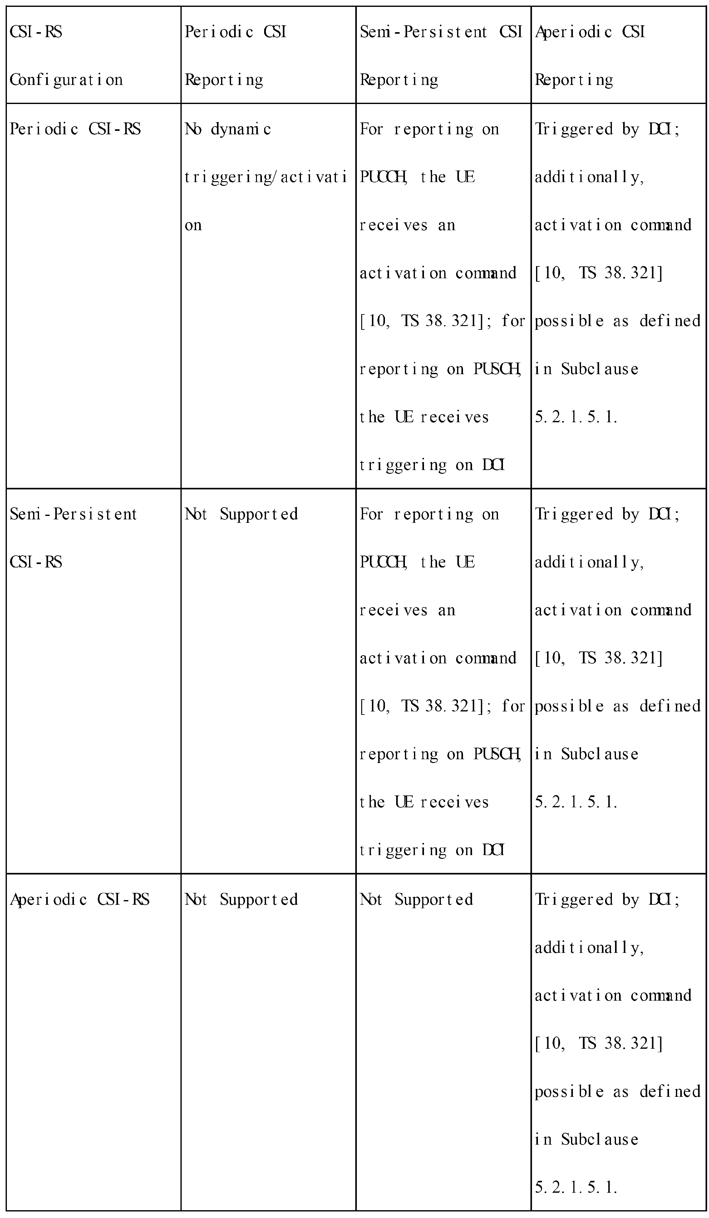
非周期的CSI報告は、PUSCHに対するスケジューリングDCIに該当する前述のDCIフォーマット(0_1)の“CSIリクエスト(request)”フィールドでトリガーされる。
端末は、PDCCHをモニタリングでき、DCIフォーマット(0_1)を取得し、PUSCHに対するスケジューリング情報及びCSIリクエストインジケーターを取得する。
CSIリクエストインジケーターは、NTS(=0、1、2、3、4、5、又は6)ビットと設定され、CSIリクエストインジケーターのビット数は、上位階層シグナリング(reportTriggerSize)によって決定される。
上位階層シグナリング(CSI-AperiodicTriggerStateList)と設定され得る一つ又は複数個の非周期的CSI報告トリガー状態の内の一つのトリガー状態がCSIリクエストインジケーターによってトリガーされる。
Aperiodic CSI reporting is triggered by the "CSI request" field of the aforementioned DCI format (0_1) corresponding to the scheduling DCI for PUSCH.
The terminal can monitor the PDCCH, obtain DCI format (0_1), and obtain scheduling information and a CSI request indicator for the PUSCH.
The CSI request indicator is set to N TS (=0, 1, 2, 3, 4, 5, or 6) bits, and the number of bits of the CSI request indicator is determined by higher layer signaling (reportTriggerSize).
One of one or more aperiodic CSI report trigger states, which may be configured as higher layer signaling (CSI-AperiodicTriggerStateList), is triggered by the CSI request indicator.
・CSIリクエストフィールドのすべてのビットが「0」の場合、これはCSI報告をリクエストしないことを意味する。
・もし、設定された「CSI-AperiodicTriggerStateLite」内のCSIトリガー状態の数(M)が、2NTs-1より大きい場合、先ず定義されているマッピング関係によって、M個のCSIトリガー状態が2NTs-1でマッピングされ、2NTs-1のトリガー状態の内の一つのトリガー状態がCSIリクエストフィールドに指示される。
・もし、設定された「CSI-AperiodicTriggerStateLite」内のCSIトリガー状態の数(M)が、2NTs-1と小さい又は同一の場合、M個のCSIトリガー状態の内の一つがCSIリクエストフィールドで指示される。
If all bits in the CSI request field are '0', this means that no CSI reporting is requested.
- If the number of CSI trigger states (M) in the configured "CSI-AperiodicTriggerStateLite" is greater than 2 NTs-1 , first, according to the defined mapping relationship, M CSI trigger states are mapped to 2 NTs-1 , and one of the 2 NTs-1 trigger states is indicated in the CSI request field.
- If the number of CSI trigger states (M) in the configured "CSI-AperiodicTriggerStateLite" is less than or equal to 2NTs-1 , one of the M CSI trigger states is indicated in the CSI request field.
以下の表28は、CSIリクエストインジケーターと該当インジケーターに指示され得るCSIトリガー状態の間の関係に対する一例を示す。 Table 28 below shows an example of the relationship between the CSI request indicator and the CSI trigger state that may be indicated by the corresponding indicator.
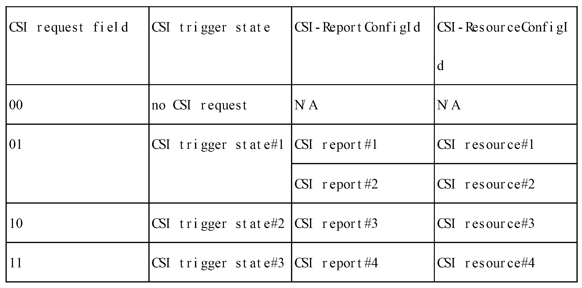
CSIリクエストフィールドにトリガーされたCSIトリガー状態内のCSIリソースに対して、端末は、測定を行い、これからCSI(前述のCQI、PMI、CRI、SSBRI、LI、RI、又は「L1-RSRP」などの内の少なくとも一つ以上を含み)を生成する。
端末は、取得したCSIを該当DCIフォーマット(0_1)がスケジューリングするPUSCHを用いて送信する。
DCIフォーマット(0_1)内のアップリンクデータインジケーター(UL-SCH indicator)に該当する1ビットが“1”を指示する場合、DCIフォーマット(0_1)がスケジューリングしたPUSCHリソースにアップリンクデータ(UL-SCH)と取得したCSIを多重化(Multiplexing)して送信する。
DCIフォーマット(0_1)内のアップリンクデータインジケーター(UL-SCH indicator)に該当する1ビットが“0”を指示する場合、DCIフォーマット(0_1)がスケジューリングしたPUSCHリソースにアップリンクデータ(UL-SCH)無しにCSIのみをマッピングして送信する。
For CSI resources in the CSI trigger state triggered by the CSI request field, the terminal performs measurements and generates CSI from them (including at least one of the above-mentioned CQI, PMI, CRI, SSBRI, LI, RI, or "L1-RSRP", etc.).
The terminal transmits the acquired CSI using a PUSCH scheduled by the corresponding DCI format (0_1).
When one bit corresponding to the uplink data indicator (UL-SCH indicator) in the DCI format (0_1) indicates “1”, the uplink data (UL-SCH) and the acquired CSI are multiplexed and transmitted on the PUSCH resource scheduled by the DCI format (0_1).
When a bit corresponding to the uplink data indicator (UL-SCH indicator) in the DCI format (0_1) indicates “0”, only CSI is mapped to the PUSCH resource scheduled by the DCI format (0_1) without uplink data (UL-SCH) and transmitted.
図11は、非周期的CSI報告方法の一例を示す図である。
図11の一例で、端末は、PDCCH1101をモニタリングしてDCIフォーマット(0_1)を取得し、これからPUSCH1105に対するスケジューリング情報及びCSIリクエスト情報を取得する。
端末は、受信したCSIリクエストインジケーターから測定する「CSI-RS」1102に対するリソース情報を取得する。
端末は、DCIフォーマット(0_1)を受信した時点とCSIリソースセット設定(例えば、「NZP CSI-RS」リソースセット設定(「NZP-CSI-RS-ResourceSet」)内のオフセットに対するパラメーター(前述の「aperiodicTriggeringOffset」)に基づいて、どの時点で送信される「CSI-RS」(1102)リソースに対する測定を行わなければならないか判断する。
より具体的に説明すれば、端末は、基地局から上位階層シグナリングで「NZP-CSI-RS」リソースセット設定内のパラメーター「aperiodicTriggeringOffset」のオフセット値Xが設定され、設定されたオフセット値Xは、非周期的CSI報告をトリガーするDCIを受信したスロットと「CSI-RS」リソースが送信されるスロットの間のオフセットを意味する。
例えば、「aperiodicTriggeringOffset」パラメーター値とオフセット値Xは、以下の表29に記載したマッピング関係を持つ。
FIG. 11 is a diagram illustrating an example of a method for aperiodic CSI reporting.
In the example of FIG. 11, the terminal monitors the
The terminal obtains resource information for the "CSI-RS" 1102 to be measured from the received CSI request indicator.
The terminal determines when it must perform measurements on the “CSI-RS” (1102) resources to be transmitted based on the time when it receives the DCI format (0_1) and the CSI resource set setting (e.g., the parameter for the offset (the above-mentioned “aperiodicTriggeringOffset”) in the “NZP CSI-RS” resource set setting (“NZP-CSI-RS-ResourceSet”)).
More specifically, the UE is configured with an offset value X of the parameter 'aperiodicTriggeringOffset' in the 'NZP-CSI-RS' resource set configuration by higher layer signaling from the base station, and the configured offset value X means an offset between a slot in which a DCI triggering an aperiodic CSI report is received and a slot in which the 'CSI-RS' resource is transmitted.
For example, the "aperiodicTriggeringOffset" parameter value and the offset value X have the mapping relationship shown in Table 29 below.
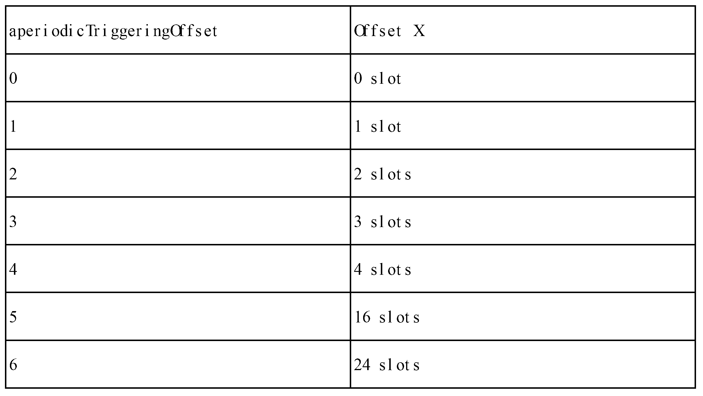
図11の一例では、前述のオフセット値がX=0と設定された一例を示している。
この場合、端末は、非周期的CSI報告をトリガーするDCIフォーマット(0_1)を受信したスロット(図11のスロット0に該当)で「CSI-RS」1102を受信し、受信した「CSI-RS」で測定したCSI情報を、PUSCH1105を介して基地局で報告する。
端末は、DCIフォーマット(0_1)からCSI報告のためのPUSCH1105に対するスケジューリング情報(前述のDCIフォーマット(0_1)の各フィールドに該当する情報)を取得する。
例えば、端末は、DCIフォーマット(0_1)は、PUSCH1105に対する前述の時間ドメインリソース割り当て情報からPUSCH1105を送信するスロットに対する情報を取得する。
図11の一例で、端末は、「PDCCH-to-PUSCH」対するスロットオフセット値に該当するK2値を「3」で取得し、これによってPUSCH1105がPDCCH1101を受信した時点、スロット0(1106)で3スロット離れたスロット3(1109)で送信される。
In the example of FIG. 11, the offset value is set to X=0.
In this case, the terminal receives a “CSI-RS” 1102 in the slot (corresponding to slot 0 in FIG. 11) in which it received a DCI format (0_1) that triggers aperiodic CSI reporting, and reports the CSI information measured by the received “CSI-RS” to the base station via a PUSCH 1105.
The terminal obtains scheduling information for PUSCH 1105 for CSI reporting from DCI format (0_1) (information corresponding to each field of the above-mentioned DCI format (0_1)).
For example, for DCI format (0_1), the terminal obtains information on the slot in which to transmit the PUSCH 1105 from the above-mentioned time domain resource allocation information for the PUSCH 1105.
In the example of Figure 11, the terminal acquires the K2 value corresponding to the slot offset value for "PDCCH-to-PUSCH" as "3", so that at the time when PUSCH 1105 receives
図11のまた他の例で、端末は、PDCCH1111をモニタリングしてDCIフォーマット(0_1)を取得し、これからPUSCH1115に対するスケジューリング情報及びCSIリクエスト情報を取得する。
端末は、受信したCSIリクエストインジケーターから測定する「CSI-RS」1112に対するリソース情報を取得する。
図11の一例では、前述の「CSI-RS」に対するオフセット値がX=1と設定された一例を示している。
この場合、端末は、非周期的CSI報告をトリガーするDCIフォーマット(0_1)を受信したスロット(図11のスロット0(1116)に該当)で、「CSI-RS」1112を受信し、受信した「CSI-RS」で測定したCSI情報をスロット3(1119)のPUSCH1115を介して基地局に報告する。
In another example of FIG. 11, the terminal monitors the
The terminal obtains resource information for the 'CSI-RS' 1112 to be measured from the received CSI request indicator.
In the example of FIG. 11, an example is shown in which the offset value for the above-mentioned "CSI-RS" is set to X=1.
In this case, the terminal receives the "CSI-RS" 1112 in the slot (corresponding to slot 0 (1116) in FIG. 11) in which it received the DCI format (0_1) that triggers aperiodic CSI reporting, and reports the CSI information measured by the received "CSI-RS" to the base station via the PUSH 1115 in slot 3 (1119).
図12は、SRSの多様な運営シナリオに対する例示を示す図である。
図12を参照すると、NRシステムで少なくとも次の3つSRS操作シナリオを考慮することが可能である。
FIG. 12 illustrates examples of various operation scenarios of the SRS.
Referring to FIG. 12, at least three SRS operation scenarios can be considered in the NR system:
1)基地局1205が端末1200に一方向のビームを設定して(本明細書で一方向のビーム/プリコーディングを設定することは、ビーム/プリコーディングを適用しないか「wide beam」(cell-coverage or sector coverage)を適用することを含み)、端末1200は、「periodic SRS」又は「semi-persistent SRS」の場合、SRSの送信周期及びオフセットに合わせて、「aperiodic SRS」の場合、基地局の「SRS request」に合わせて(「SRS request」以後の定められた時間で)SRSを送信する。
この時、SRSには、ビーム/プリコーディングのための追加情報を必要としない。
1) The
At this time, the SRS does not require additional information for beam/precoding.
2)基地局(1215、1220)は、端末1210に、一つ以上の方向にビームを設定し、端末1210は、一つ以上の方向にビームフォーミングされた複数のSRSを送信する。
例えば、図12の例のように「SRS resource」(又はport)#0は、基地局1215でビームフォーミングされて「SRS resource」(又はport)#1は、基地局1220でビームフォーミングされるように設定することが可能である。
この場合、基地局(1215、1220)は、上記1)番の方法とは異なるように「SRS request」だけでなくSRSビーム/プリコーディング情報を共に通知しなければならない必要がある。
2) The base stations (1215, 1220) set beams in one or more directions to the terminal 1210, and the terminal 1210 transmits a plurality of beamformed SRSs in one or more directions.
For example, as in the example of FIG. 12 , it is possible to set “SRS resource” (or port) #0 to be beamformed by the
In this case, unlike the above method 1), the base station (1215, 1220) needs to notify not only the 'SRS request' but also the SRS beam/precoding information.
3)基地局1230は、端末1225に一つ以上の方向にビームを設定し、端末1225は、一つ以上の方向にビームフォーミングされた複数のSRSを送信する。
例えば、図12の例のように基地局は、端末が「SRS resource」(又はport)#0、「SRS resource」(又はport)#1、「SRS resource」(又はport)#2にそれぞれ他のビーム/プリコーディングを適用してSRSを送信するように設定する。
これを介して端末の移動性が高い場合でもビーム/プリーコーダーダイバーシティーを介して安定的な通信を行う。
例えば、端末1225は、「time A」の時点ではSRS#2で基地局1230にチャンネル状態情報を提供し、「time A+alpha」の時点ではSRS#0で基地局1230にチャンネル状態情報を提供する。
この場合、基地局1230は、上記1)番の方法とは異なるように「SRS request」だけでなくSRSビーム/プリコーディング情報を共に通知しなければならない必要がある。
3) The
For example, as in the example of FIG. 12, the base station configures the terminal to transmit SRS by applying different beams/precoding to "SRS resource" (or port) #0, "SRS resource" (or port) #1, and "SRS resource" (or port) #2.
This enables stable communication through beam/precoder diversity even when the terminal is highly mobile.
For example, the terminal 1225 provides channel state information to the
In this case, unlike the above method 1), the
上記説明は、SRS送信を基づいたがこれと同様にPRACH、PUSCH、PUCCHなど他の「UL channel」又は/及びRS送信にも拡張することが可能で、本発明の要旨を不明瞭にしないためにすべての場合に対する詳しく説明は省略する。 The above description is based on SRS transmission, but can be extended to other "UL channels" such as PRACH, PUSCH, PUCCH, and/or RS transmission in the same manner, and detailed descriptions of all cases will be omitted in order to avoid obscuring the gist of the present invention.
図13は、5G又はNRシステムのアップリンク送信構造を示す図である。
図13を参照すると、5G又はNRシステムの送信基本単位は、スロット1300で、一般的なCP(Cyclic Prefix)長さを仮定する時、各スロットは、14個のシンボル1305から構成され、一つのシンボルは、一つの「UL waveform」(「CP-OFDM」又は「DFT-S-OFDM」)シンボルに対応する。
FIG. 13 is a diagram showing the uplink transmission structure of a 5G or NR system.
Referring to FIG. 13, the basic transmission unit of a 5G or NR system is a
リソースブロック(Resource Block:RB)1310は、時間領域を基準として一つのスロットに該当するリソース割り当て単位であり、周波数領域を基準として12個のサブキャリアから構成される。 A resource block (RB) 1310 is a resource allocation unit that corresponds to one slot in the time domain and is composed of 12 subcarriers in the frequency domain.
アップリンク構造は、大きくデータ領域と制御領域に区分される。
LTEシステムと異なり、5G又はNRシステムでは制御領域がアップリンクの任意の位置に設定されて送信される。
ここで、データ領域は、各端末に送信される音声、パケットなどのデータを含む一連の通信リソースを含み、サブフレーム内で制御領域を除いた残りリソースに該当する。
制御領域は、各端末からのダウンリンクチャンネル品質報告、ダウンリンク信号に対する受信ACK/NACK、アップリンクスケジューリングリクエストなどのための一連の通信リソースを含む。
The uplink structure is broadly divided into a data region and a control region.
Unlike an LTE system, in a 5G or NR system, a control region is set and transmitted at any position in the uplink.
Here, the data region includes a series of communication resources including data such as voice and packets transmitted to each terminal, and corresponds to the remaining resources in the subframe excluding the control region.
The control region includes a set of communication resources for downlink channel quality reports from each terminal, reception ACK/NACK for downlink signals, uplink scheduling requests, and so on.
端末は、データ領域と制御領域で自分のデータ及び制御情報を同時に送信する。
一つのスロット内で、端末が周期的にSRSを送信することができるシンボルは、最後の6個のシンボル区間1315であればよく、周波数領域を基準で「UL BWP」内で予め設定されたSRS送信帯域を介して送信される。
ただ、これは一例であり、SRSを送信することができるシンボルは、他の時間区間に拡張されるか、又は周波数帯域を介して送信される。
SRSを送信することができるRBは、周波数領域で送信される時、4RBの倍数で送信されて最大272RBで送信される。
A terminal simultaneously transmits its data and control information in the data and control fields.
Within one slot, the symbols by which the terminal can periodically transmit the SRS may be the last six
However, this is just one example, and the symbols capable of transmitting the SRS may be extended to other time intervals or transmitted over other frequency bands.
When transmitted in the frequency domain, the RBs on which the SRS can be transmitted are transmitted in multiples of 4 RBs, up to a maximum of 272 RBs.
また、5G又はNRシステムで、SRSのシンボル数Nは、1、2、又は4と設定され、連続したシンボルに送信される。
また、5G又はNRシステムではSRSシンボルの繰り返し送信を許容する。
具体的に、SRSシンボルの繰り返し送信因子(repetition factor、r)は、r∈{1,2,4}で、ここでr≦Nのように設定される。
例えば、一つのSRSアンテナが一つのシンボルにマッピングされて送信される場合、最大4シンボルまで繰り返されて送信される。
これと異なり、互いに異なる4個のアンテナポートが互いに異なる4個のシンボルに送信される。
この時は、各アンテナポートが一つのシンボルにマッピングされた場合であるため、SRSシンボルの繰り返し送信が許容されない。
In addition, in a 5G or NR system, the number of SRS symbols N is set to 1, 2, or 4 and is transmitted in consecutive symbols.
In addition, 5G or NR systems allow repeated transmission of SRS symbols.
Specifically, the repetition factor (r) of the SRS symbol is set such that r ∈ {1, 2, 4}, where r≦N.
For example, when one SRS antenna is mapped to one symbol for transmission, the symbol may be repeated and transmitted up to a maximum of four symbols.
Alternatively, four different antenna ports are transmitted on four different symbols.
In this case, since each antenna port is mapped to one symbol, repeated transmission of the SRS symbol is not permitted.
LTE及びNRの場合、SRSは、次のような上位レイヤーシグナリング情報(又はこれらの部分セット)に基づいて設定される。 For LTE and NR, the SRS is configured based on higher layer signaling information (or a subset of these) such as:
「BandwidthConfig」:「SRS bandwidth」情報を設定する。
アップリンクシステムBW値によって各コードポイントが意味する正確な値は変わる。
「SubframeConfig」(又はConfigIndex):SRS送信周期及び送信オフセット値を設定する。
FDDであるかTDDであるかどうかによって、各コードポイントが意味する正確な値は変わる。
「ackNackSRS-SimultaneousTransmission」:「ACK/NACK-SRS」同時送信するかどうかを通知する。
「MaxUpPts」:UpPTSでSRS送信の周波数位置初期化であるかどうかを通知する。
「Hopping」:2ビット情報で「SRS frequency hopping」であるかどうか及びhopping位置及び方法を通知する。
「Frequency domain position」:SRS送信の周波数ドメイン位置を通知する。
「Duration」:「Periodic SRS」の送信するかどうかを通知する。
「Transmission comb」:SRS送信時「comb offset」値を通知する。
「Cyclic shift」:SRS送信時「cyclic shift」値を通知する。
「Antenna port」:SRS送信時用いられるSRSアンテナポート数を通知する。
LTEの場合、1、2、又は4ポートをサポート可能である。
"BandwidthConfig": Sets "SRS bandwidth" information.
The exact value that each code point means varies depending on the uplink system BW value.
"SubframeConfig" (or ConfigIndex): Sets the SRS transmission period and transmission offset value.
Depending on whether it is FDD or TDD the exact value that each codepoint means changes.
"ackNackSRS-SimultaneousTransmission": Notifies whether or not to transmit "ACK/NACK-SRS" simultaneously.
"MaxUpPts": Notifies whether the frequency position of SRS transmission is initialized by UpPTS.
"Hopping": 2-bit information indicates whether or not "SRS frequency hopping" is performed and the hopping location and method.
"Frequency domain position": Notifies the frequency domain position of the SRS transmission.
"Duration": Notifies whether or not to transmit "Periodic SRS".
"Transmission comb": Notifies the "comb offset" value when transmitting SRS.
"Cyclic shift": Notify the "cyclic shift" value when transmitting SRS.
"Antenna port": Notifies the number of SRS antenna ports used when transmitting SRS.
For LTE, one, two or four ports can be supported.
LTE-Aシステムの場合、上述の設定情報に基づいてperiodic及びaperiodic SRS送信をサポートする。
NRシステムの場合、前述の設定情報以外のSRSリソースに対する「activation/deactivation」シグナリングなど追加情報を利用することが可能で、periodic、semi-persistent、及びaperiodic SRS送信をサポートする。
SRSの送信形態によって、例えば、periodic、semi-persistent、又はaperiodic SRS送信であるか否かによって設定情報の内の一部は省略され得る。
In the case of the LTE-A system, periodic and aperiodic SRS transmission is supported based on the above-mentioned configuration information.
In the case of an NR system, additional information such as "activation/deactivation" signaling for SRS resources other than the above-mentioned configuration information can be used, and periodic, semi-persistent, and aperiodic SRS transmissions are supported.
Depending on the transmission format of the SRS, for example, whether the SRS is periodic, semi-persistent, or aperiodic, some of the configuration information may be omitted.
SRSは、CAZAC(Constant Amplitude Zero Auto Correlation)シーケンスで構成される。
そして、複数の端末から送信されたそれぞれのSRSを構成するCAZACシーケンスは、互いに異なる循環遷移(Cyclic Shift)値を有する。
また、一つのCAZACシーケンスで循環遷移(Cyclic Shift)を介して発生したCAZACシーケンスは、各々自分と異なる循環遷移値を有するシーケンスと零の相関値を有する特性がある。
このような特性を利用して同時に同じ周波数領域に割り当てられたSRSは、基地局でSRS別で設定したCAZACシーケンス循環遷移値によって区分することができる。
The SRS is composed of a CAZAC (Constant Amplitude Zero Auto Correlation) sequence.
The CAZAC sequences constituting the SRSs transmitted from the multiple terminals each have a different cyclic shift value.
In addition, each CAZAC sequence generated through a cyclic shift has a characteristic of having zero correlation with a sequence having a different cyclic shift value from itself.
Using this characteristic, SRSs simultaneously allocated to the same frequency region can be distinguished according to the CAZAC sequence cyclic transition value set for each SRS by the base station.
複数の端末のSRSは、循環遷移値だけではなく、周波数位置によって区分される。
周波数位置は、SRSサブバンド単位割り当て又はCombに区分される。
5G又はNRシステムではComb2及びComb4をサポートする。
Comb2の場合、一つのSRSは、SRSサブバンド内で偶数番目又は奇数番目のサブキャリアにだけ割り当てられる。
この時、この偶数番目のサブキャリア及び奇数番目のサブキャリアそれぞれが一つのCombを構成する。
The SRSs of multiple terminals are distinguished according to frequency positions as well as cyclic transition values.
The frequency location is partitioned into SRS subband unit allocations or Combs.
5G or NR systems support Comb2 and Comb4.
In the case of Comb2, one SRS is assigned only to even-numbered or odd-numbered subcarriers within the SRS subband.
In this case, each of the even-numbered subcarriers and the odd-numbered subcarriers constitutes one Comb.
各端末は、ツリー構造に基づいてSRSサブバンドが割り当てられる。
そして、端末は、SRS送信時点ごとに各サブバンドに割り当てられたSRSにホッピングを行う。
これによって端末のすべての送信アンテナがアップリンクデータ送信帯域幅全体を利用してSRSを送信する。
Each terminal is assigned an SRS subband based on the tree structure.
The terminal then hops to the SRS assigned to each subband at each SRS transmission time.
This allows all transmit antennas of the terminal to transmit SRS using the entire uplink data transmission bandwidth.
図14は、サブバンド別でSRSが割り当てられた構造を示す図である。
図14を参照すると、周波数上に40RBに該当するデータ送信帯域を持つ時、基地局が設定したツリー構造によってSRSが各端末に割り当てられた例を示す。
FIG. 14 illustrates a structure in which SRS is allocated for each subband.
Referring to FIG. 14, an example is shown in which SRS is allocated to each terminal according to a tree structure set by a base station when a data transmission band corresponding to 40 RBs is present in frequency.
図14で、ツリー構造のレベルインデックスを「b」とする時、ツリー構造の第1上位レベル(b=0)は、40RB帯域幅のSRSサブバンド一つから構成される。
第2レベル(b=1)では、b=0、レベルのSRSサブバンドから20RB帯域幅のSRSサブバンド2つが発生する。
したがって、第2レベル(b=1)の全体データ送信帯域に2個のSRSサブバンドが存在する。
第3レベル(b=2)では真上のレベル(b=1)の「20RB SRS」サブバンド一つから「4 RB SRS」サブバンド5個が発生され、一つのレベル内に10個の「4RB SRS」サブバンドが存在する構造を有する。
In FIG. 14, when the level index of the tree structure is 'b', the first upper level (b=0) of the tree structure is composed of one SRS subband with a bandwidth of 40 RBs.
At the second level (b=1), two SRS subbands with a bandwidth of 20 RBs are generated from the SRS subbands at the b=0 level.
Therefore, there are two SRS subbands in the entire data transmission band of the second level (b=1).
In the third level (b=2), five “4 RB SRS” subbands are generated from one “20 RB SRS” subband in the level immediately above (b=1), resulting in a structure in which there are ten “4 RB SRS” subbands within one level.
このようなツリー構造の構成は、基地局の設定によって多様なレベル数、SRSサブバンドサイズ及び一レベル当たりSRSサブバンド数を有する。
ここで、上位レベルのSRSサブバンド一つから発生されるレベルbでのSRSサブバンド個数をNb、及びこのNb個のSRSサブバンドに対するインデックスをnb={0,...,Nb-1}と定義する。
このようにレベル当りサブバンドが変わることによって、図14に示したようにレベルごとに各サブバンドに端末が割り当てられる。
例えば、端末1(14-00)がb=1レベルで「20 RB」帯域幅を有する2つのSRSサブバンドの内の第1SRSサブバンド(n1=0)に割り当てられ、端末2(14-01)と端末3(14-02)はそれぞれ第2の「20 RB SRS」サブバンド下の第1SRSサブバンド(n2=0)と第3SRSサブバンド(n2=2)位置に割り当てられる。
このような過程を介して端末は、複数のCC(Component Carrier)を介してSRS同時送信が可能であり、一CC内で同時に複数のSRSサブバンドでSRSを送信することができる。
The tree structure may have various numbers of levels, SRS subband sizes, and numbers of SRS subbands per level depending on the settings of the base station.
Here, the number of SRS subbands at level b generated from one upper level SRS subband is defined as N b , and the index for the N b SRS subbands is defined as n b ={0, . . . , N b-1 }.
As the subbands per level are changed in this manner, terminals are assigned to each subband for each level as shown in FIG.
For example, terminal 1 (14-00) is assigned to the first SRS subband (n 1 =0) of two SRS subbands having a “20 RB” bandwidth at the b=1 level, and terminal 2 (14-01) and terminal 3 (14-02) are assigned to the first SRS subband (n 2 =0) and third SRS subband (n 2 =2) positions under the second “20 RB SRS” subband, respectively.
Through this process, the terminal can simultaneously transmit SRS via multiple component carriers (CCs) and can simultaneously transmit SRS in multiple SRS subbands within one CC.
具体的に前述のSRSサブバンド設定のためにNRでは以下の表30のような「SRS bandwidth configuration」をサポートする。 Specifically, for the above-mentioned SRS subband setting, NR supports the "SRS bandwidth configuration" as shown in Table 30 below.
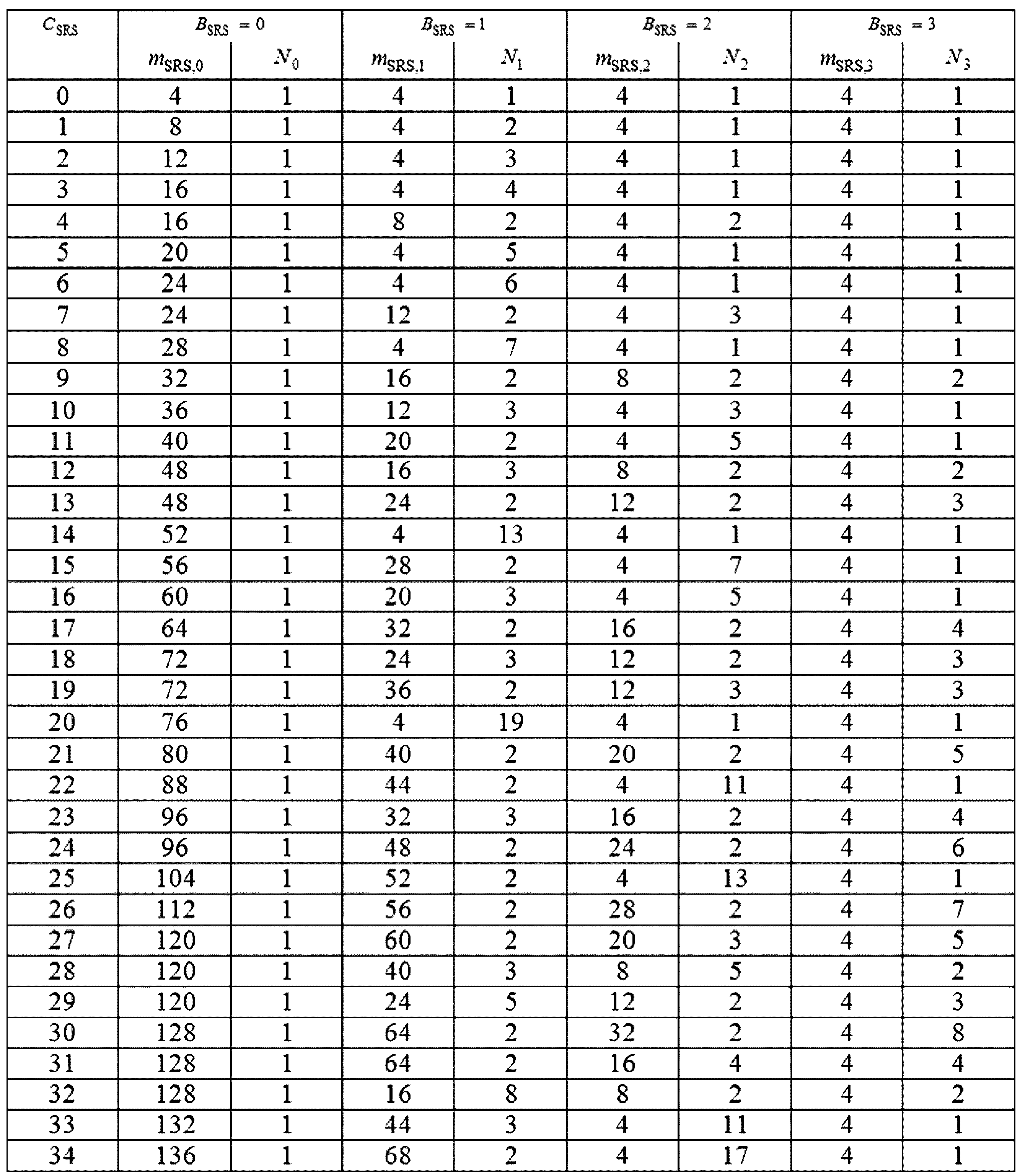
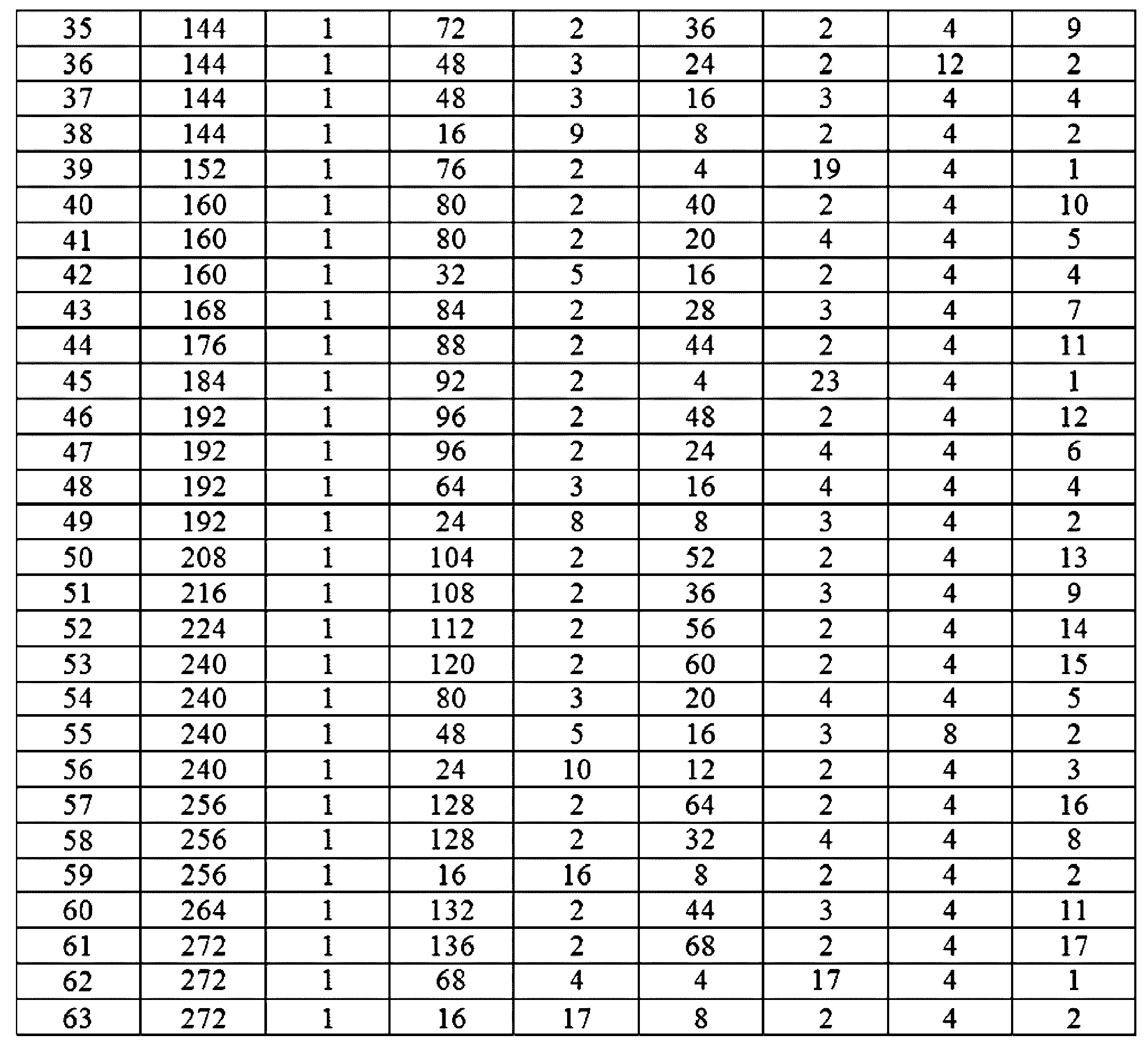
またNRでは、表30の値に基づいて「SRS frequency hopping」をサポートして詳しい手順は、以下の表31による。 NR also supports "SRS frequency hopping" based on the values in Table 30, and the detailed procedure is shown in Table 31 below.
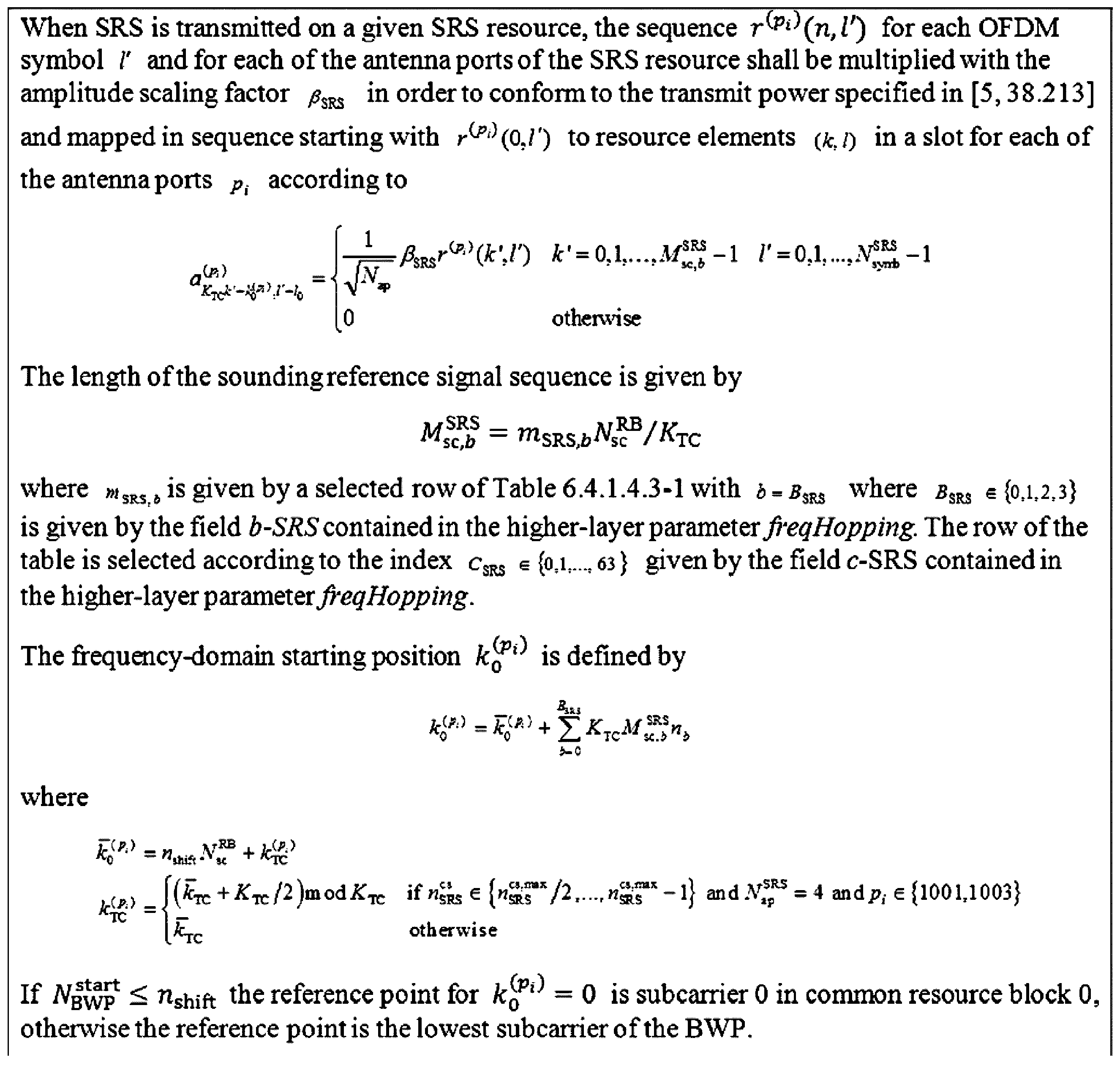
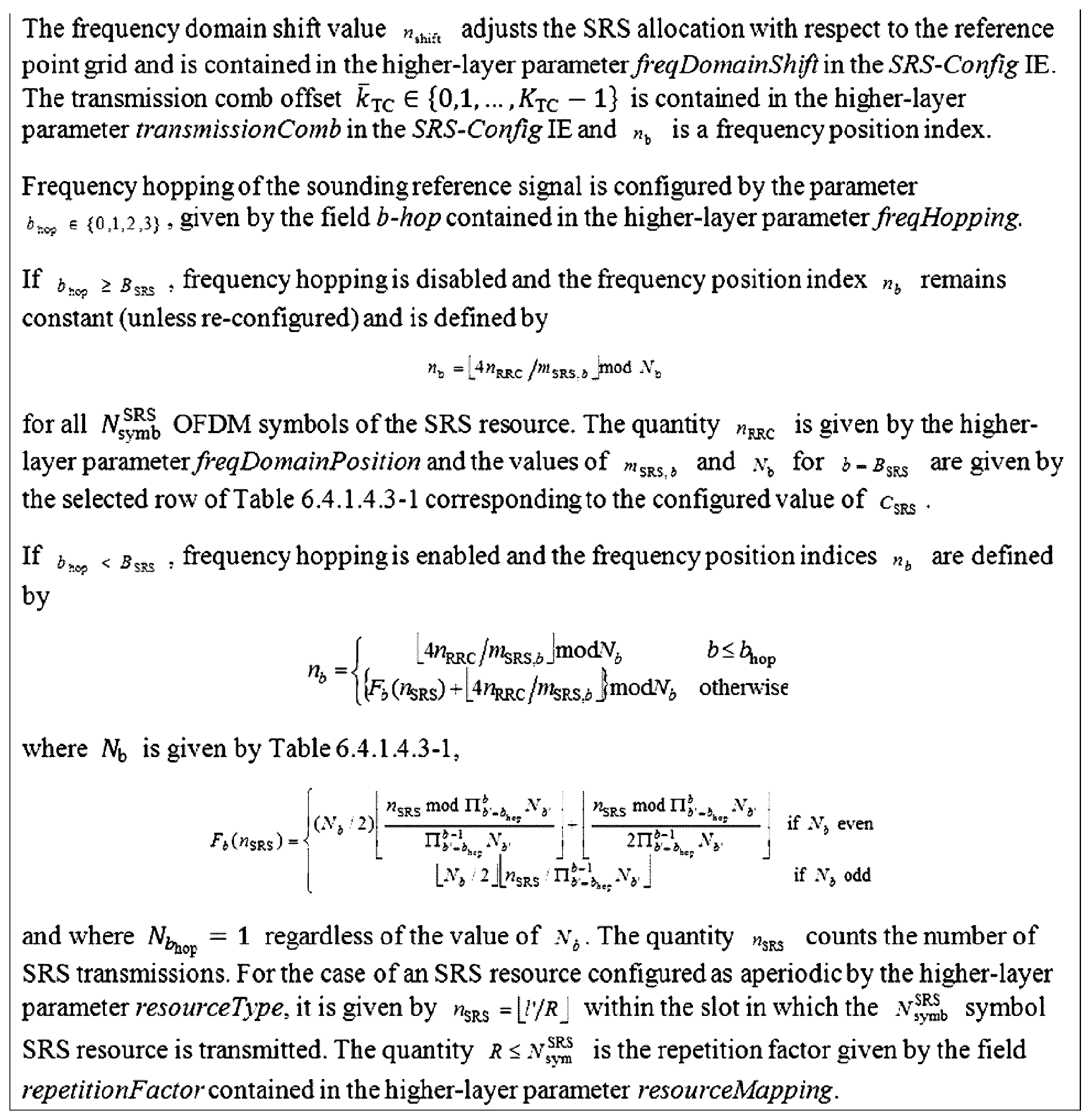
前述のように5G又はNR端末は、SU-MIMO(Single User)技法をサポートして最大4個の送信アンテナを有する。
また、NR端末は、SRSを複数のCC、又はCC内の複数のSRSサブバンドで同時に送信することができる。
5G又はNRシステムの場合、LTEシステムと異なる多様なnumerologyがサポートされ、SRS送信シンボルが複数個で多様に設定することができ、繰り返し送信因子(repetition factor)を介してSRS送信に対する繰り返し送信も許容される。
As mentioned above, a 5G or NR terminal supports SU-MIMO (Single User) technique and has up to four transmit antennas.
In addition, an NR terminal can simultaneously transmit SRS on multiple CCs or multiple SRS subbands within a CC.
In the case of a 5G or NR system, various numerologies different from those in an LTE system are supported, and multiple SRS transmission symbols can be set in various ways, and repetitive transmission of SRS transmission is also allowed via a repetition factor.
したがって、これを考慮したSRS送信をカウンティング(counting)する必要がある。
SRS送信をカウンティングすることは、多様に活用することができる。
例えば、SRS送信をカウンティングすることは、SRS送信によるアンテナスイッチングをサポートすることに活用することができる。
具体的に、どんなSRS送信時点にどんなアンテナに該当するSRSをどんな帯域で送信するかは、SRS送信カウンティングによって決定することができる。
Therefore, it is necessary to count SRS transmissions taking this into consideration.
Counting SRS transmissions can be utilized in a variety of ways.
For example, counting SRS transmissions can be utilized to support antenna switching due to SRS transmissions.
Specifically, which SRS to transmit at which SRS transmission time, which antenna, and in which band is used can be determined by SRS transmission counting.
以下では、レートマッチング(Rate Matching)動作及びパンクチャリング(Puncturing)動作に対して具体的に記述する。 The rate matching and puncturing operations are described in detail below.
任意のシンボルシーケンスAを送信しようとする時間及び周波数リソースAが任意の時間及び周波数リソースBとオーバーラップされた場合、リソースAとリソースBがオーバーラップされた領域リソースCを考慮したチャンネルAの送受信動作でレートマッチング又はパンクチャリング動作が考慮されることができる。
具体的な動作は、以下の内容による。
When a time and frequency resource A on which a given symbol sequence A is to be transmitted overlaps with a given time and frequency resource B, rate matching or puncturing operations can be taken into account in the transmission and reception operations of channel A taking into account the area resource C where resource A and resource B overlap.
The specific operation is as follows:
レートマッチング(Rate Matching)動作に対して記述する。
基地局は、端末でシンボルシーケンスAを送信しようとする全体リソースAの内のリソースBとオーバーラップされた領域に該当するリソースCを除いた残りリソース領域に対してだけチャンネルAをマッピングして送信する。
例えば、シンボルシーケンスAが{シンボル#1、シンボル#2、シンボル#3、シンボル4}から構成され、リソースAが{リソース#1、リソース#2、リソース#3、リソース#4}で、リソースBが{リソース#3、リソース#5}の場合、基地局は、リソースAの内のリソースCに該当する{リソース#3}を除いた残りリソースである{リソース#1、リソース#2、リソース#4}にシンボルシーケンスAを順次にマッピングして送信する。
結果的に基地局は、シンボルシーケンス{シンボル#1、シンボル#2、シンボル#3}をそれぞれ{リソース#1、リソース#2、リソース#4}にマッピングして送信する。
A rate matching operation will now be described.
The base station maps and transmits channel A only to the remaining resource area excluding resource C corresponding to an overlapping area with resource B among all resources A from which the terminal intends to transmit symbol sequence A.
For example, if symbol sequence A is composed of {
As a result, the base station maps the symbol sequence {
端末は、基地局からシンボルシーケンスAに対するスケジューリング情報からリソースA及びリソースBを判断することができ、これを介してリソースAとリソースBがオーバーラップした領域であるリソースCを判断することができる。
端末は、シンボルシーケンスAが全体リソースAの内のリソースCを除いた残り領域でマッピングされて送信されたと仮定してシンボルシーケンスAを受信する。
例えば、シンボルシーケンスAが{シンボル#1、シンボル#2、シンボル#3、シンボル4}から構成され、リソースAが{リソース#1、リソース#2、リソース#3、リソース#4}で、リソースBが{リソース#3、リソース#5}の場合、端末は、リソースAの内のリソースCに該当する{リソース#3}を除いた残りリソースである{リソース#1、リソース#2、リソース#4}にシンボルシーケンスAが順次にマッピングされたと仮定して受信する。
結果的に端末は、シンボルシーケンス{シンボル#1、シンボル#2、シンボル#3}がそれぞれ{リソース#1、リソース#2、リソース#4}にマッピングされて送信されたと仮定して以後の一連の受信動作を行う。
The terminal can determine resource A and resource B from scheduling information for symbol sequence A from the base station, and can thereby determine resource C, which is an overlapping area of resource A and resource B.
The terminal receives the symbol sequence A on the assumption that the symbol sequence A is mapped to and transmitted from the remaining area of the entire resource A excluding the resource C.
For example, if symbol sequence A is composed of {
As a result, the terminal performs a series of subsequent receiving operations assuming that the symbol sequence {
次に、パンクチャリング(Puncturing)動作に対して記述する。
基地局は、端末でシンボルシーケンスAを送信しようとする全体リソースAの内のリソースBとオーバーラップされた領域に該当するリソースCが存在する場合、シンボルシーケンスAをリソースA全体にマッピングするが、リソースCに該当するリソース領域では送信を行わず、リソースAの内のリソースCを除いた残りリソース領域に対してだけ送信を行う。
例えば、シンボルシーケンスAが{シンボル#1、シンボル#2、シンボル#3、シンボル4}から構成され、リソースAが{リソース#1、リソース#2、リソース#3、リソース#4}で、リソースBが{リソース#3、リソース#5}の場合、基地局は、シンボルシーケンスA{シンボル#1、シンボル#2、シンボル#3、シンボル#4}をリソースA{リソース#1、リソース#2、リソース#3、リソース#4}にそれぞれマッピングし、リソースAの内のリソースCに該当する{リソース#3}を除いた残りリソースである{リソース#1、リソース#2、リソース#4}に該当するシンボルシーケンス{シンボル#1、シンボル#2、シンボル#4}だけ送信し、リソースCに該当する{リソース#3}にマッピングされた{シンボル#3}は送信しないこともある。
結果的に基地局は、シンボルシーケンス{シンボル#1、シンボル#2、シンボル#4}をそれぞれ{リソース#1、リソース#2、リソース#4}にマッピングして送信する。
Next, a puncturing operation will be described.
If there is a resource C that corresponds to an area that overlaps with resource B among the total resources A from which the terminal intends to transmit symbol sequence A, the base station maps the symbol sequence A to the entire resource A, but does not transmit in the resource area corresponding to resource C, and only transmits in the remaining resource areas of resource A excluding resource C.
For example, if symbol sequence A is composed of {
As a result, the base station maps the symbol sequence {
端末は、基地局からシンボルシーケンスAに対するスケジューリング情報からリソースA及びリソースBを判断することができ、これを介してリソースAとリソースBがオーバーラップされた領域であるリソースCを判断する。
端末は、シンボルシーケンスAが全体リソースAにマッピングされるがリソース領域Aの内のリソースCを除いた残り領域にだけ送信されたと仮定してシンボルシーケンスAを受信する。
例えば、シンボルシーケンスAが{シンボル#1、シンボル#2、シンボル#3、シンボル4}から構成され、リソースAが{リソース#1、リソース#2、リソース#3、リソース#4}で、リソースBが{リソース#3、リソース#5}の場合、端末は、シンボルシーケンスA{シンボル#1、シンボル#2、シンボル#3、シンボル#4}がリソースA{リソース#1、リソース#2、リソース#3、リソース#4}にそれぞれマッピングされるが、リソースCに該当する{リソース#3}にマッピングされた{シンボル#3}は送信されないと仮定することができ、リソースAの内のリソースCに該当する{リソース#3}を除いた残りリソースである{リソース#1、リソース#2、リソース#4}に該当するシンボルシーケンス{シンボル#1、シンボル#2、シンボル#4}がマッピングされて送信されたと仮定して受信する。
結果的に、端末は、シンボルシーケンス{シンボル#1、シンボル#2、シンボル#4}がそれぞれ{リソース#1、リソース#2、リソース#4}にマッピングされて送信されたと仮定して以後の一連の受信動作を行う。
The terminal can determine resource A and resource B from scheduling information for symbol sequence A from the base station, and thereby determine resource C, which is an overlapping area of resource A and resource B.
The terminal receives symbol sequence A assuming that symbol sequence A is mapped to the entire resource A but is transmitted only to the remaining area of resource area A excluding resource C.
For example, if symbol sequence A is composed of {
As a result, the terminal performs a series of subsequent receiving operations assuming that the symbol sequence {
次に、レートマッチングリソース(rate matching resource)に対して記述する。
図15は、基地局及び端末がダウンリンクデータチャンネル及びレートマッチングリソースを考慮してデータを送受信する方法を説明するための図である。
Next, a rate matching resource will be described.
FIG. 15 is a diagram illustrating a method in which a base station and a terminal transmit and receive data in consideration of a downlink data channel and a rate matching resource.
図15にはダウンリンクデータチャンネル(PDSCH、1501)とレートマッチングリソース1502を図に示している。
基地局は、端末に上位階層シグナリング(例えば、RRCシグナリング)を介して一つ又は複数個のレートマッチングリソース502を設定する。
レートマッチングリソース1502設定情報には時間軸リソース割り当て情報1503、周波数軸リソース割り当て情報1504、周期情報1505が含まれる。
以下では周波数軸リソース割り当て情報1504に該当するビットマップを“第1ビットマップ”、時間軸リソース割り当て情1503に該当するビットマップを“第2ビットマップ”、周期情報1505に該当するビットマップを“第3ビットマップ”で名付ける。
スケジューリングされたデータチャンネル1501の時間及び周波数リソースの全体又は、一部が設定されたレートマッチングリソース1502とオーバーラップする場合、基地局は、レートマッチングリソース1502部分でデータチャンネル1501をレートマッチングして送信し、端末は、レートマッチングリソース1502部分でデータチャンネル1501がレートマッチングされたと仮定した後に受信及びデコーディングを行う。
FIG. 15 illustrates a downlink data channel (PDSCH, 1501) and
The base station configures one or more
The
Hereinafter, the bitmap corresponding to the frequency axis
When all or part of the time and frequency resources of the scheduled
基地局は、追加的な設定を介して設定されたレートマッチングリソース部分でデータチャンネルをレートマッチングするかどうかを、DCIを介して動的(Dynamic)で端末に通知する(前述のDCIフォーマット内の“レートマッチングインジケーター”に相当する)。
具体的に、基地局は、設定されたレートマッチングリソースの内の一部を選択してレートマッチングリソースグループにグループ化し、各レートマッチングリソースグループに対するデータチャンネルがレートマッチングするかどうかを、ビットマップ方式を利用してDCIで端末に指示する。
例えば、4個のレートマッチングリソース、RMR#1、RMR#2、RMR#3、RMR#4が設定されている場合、基地局は、レートマッチンググループでRMG#1={RMR#1、RMR#2}、RMG#2={RMR#3、RMR#4}を設定することができ、基地局は、DCIフィールド内の2ビットを用い、それぞれRMG#1とRMG#2がレートマッチングするかどうかをビットマップで端末に指示する。
例えば、基地局は、レートマッチングをしなければならない場合には各ビットを“1”でレートマッチングをしなくなければならない場合には“0”と設定する。
The base station dynamically notifies the terminal via DCI whether or not to rate match the data channel in the rate matching resource portion set through additional configuration (corresponding to the “rate matching indicator” in the aforementioned DCI format).
Specifically, the base station selects a portion of the configured rate matching resources and groups them into rate matching resource groups, and indicates to the terminal via DCI whether the data channel for each rate matching resource group is rate matched using a bitmap scheme.
For example, if four rate matching resources,
For example, the base station sets each bit to "1" if rate matching is required, and sets each bit to "0" if rate matching is not required.
5Gシステムでは前述のレートマッチングリソースを端末に設定する方法で“RBシンボルレベル”及び“REレベル”のgranularityをサポートする。
より具体的には以下の設定方法によることができる。
In the 5G system, the above-mentioned rate matching resources are configured in the terminal to support "RB symbol level" and "RE level" granularity.
More specifically, the following setting method can be used.
以下、RBシンボルレベルの設定方法を記述する。
端末は、帯域幅部分別で最大4個の「RateMatchPattern」を上位階層シグナリングで設定され、一つの「RateMatchPattern」は、以下の内容を含むことができる。
The method for setting the RB symbol level will be described below.
The UE may be configured with up to four 'RateMatchPattern' for each bandwidth portion through higher layer signaling, and one 'RateMatchPattern' may include the following content.
・帯域幅部分内の予備リソース(Reserved Resource)として、周波数軸にRBレベルのビットマップとシンボルレベルのビットマップで組み合せで該当予備リソースの時間及び周波数リソース領域が設定されたリソースが含まれる。
予備リソースは、一つ又は2つのスロットにかけてspanされる。
各RBレベル及びシンボルレベルビットマップpairから構成された時間及び周波数領域が繰り返される時間ドメインパターン(periodicityAndPattern)が追加に設定される。
Reserved resources within the bandwidth portion include resources in which the time and frequency resource regions of the corresponding reserved resources are set by combining an RB level bitmap and a symbol level bitmap on the frequency axis.
The spare resources are spanned across one or two slots.
A time domain pattern (periodicityAndPattern) in which the time and frequency domains composed of each RB level and symbol level bitmap pair are repeated is additionally set.
・帯域幅部分内の制御リソースセットに設定された時間及び周波数ドメインリソース領域と該当リソース領域が繰り返される探索空間設定に設定された時間ドメインパターンに該当するリソース領域が含まれる。 - It includes time and frequency domain resource regions set in the control resource set within the bandwidth portion and resource regions corresponding to the time domain pattern set in the search space setting in which the corresponding resource regions are repeated.
次に、REレベルの設定方法を記述する。
端末は、以下の内容を、上位階層シグナリングを介して設定する。
Next, a method for setting the RE level will be described.
The terminal sets the following contents via higher layer signaling.
・「LTE CRS」(「Cell-specific Reference Signal」又は「Common Reference Signal」)パターンに該当するREに対する設定情報(lte-CRS-ToMatchAround)として「LTE CRS」のポート数(nrofCRS-Ports)及び「LTE-CRS-vshift(s)」値(v-shift)、基準になる周波数地点(例えば、「reference point A」)からLTEキャリアのセンターサブキャリア(Subcarrier)位置情報(carrierFreqDL)、LTEキャリアの帯域幅サイズ(carrierBandwidthDL)情報、MBSFN(Multicast-broadcast single-frequency network)に該当するサブフレーム設定情報(mbsfn-SubframConfigList)などを含む。
端末は、前述の情報に基づいてLTEサブフレームに該当するNRスロット内でのCRSの位置を判断する。
The number of ports (nrofCRS-Ports) of the LTE CRS and the value (v-shift) of the LTE CRS-vshift(s) as the configuration information (lte-CRS-ToMatchAround) for the RE corresponding to the LTE CRS (Cell-specific Reference Signal or Common Reference Signal) pattern, the center subcarrier (Subcarrier) position information (carrierFreqDL) of the LTE carrier from the reference frequency point (e.g., 'reference point A'), the bandwidth size (carrierBandwidthDL) information of the LTE carrier, the MBSFN (Multicast-broadcast) The configurable subframe information includes subframe configuration information (mbsfn-SubframeConfigList) corresponding to a single-frequency network.
Based on the above information, the terminal determines the position of the CRS within the NR slot corresponding to the LTE subframe.
・帯域幅部分内の一つ又は複数個の「ZP(Zero Power)CSI-RS」に該当するリソースセットに対する設定情報を含む。 - Includes configuration information for a resource set corresponding to one or more "ZP (Zero Power) CSI-RS" within the bandwidth portion.
図16は、5G通信システムで考慮されるアップリンク-ダウンリンク設定を一例に示す図である。
5G通信システムで、シンボル/スロットのアップリンク-ダウンリンク設定は、3段階で構成される。
第1に、半静的(semi-static)で、シンボル単位でシステム情報を介してセル特定設定情報1610を介してシンボル/スロットのアップリンク-ダウンリンクが設定される。
具体的には、システム情報を介してセル特定アップリンク-ダウンリンク設定情報にはアップリンク-ダウンリンクパターン情報と基準となるサブキャリア情報が含まれる。
アップリンク-ダウンリンクパターン情報を介してパターン周期1603と各パターンの開始点から連続的なダウンリンクスロット個数1611とその次のスロットのシンボル個数1612、及びパターンの端から連続的なアップリンクスロット個数1613とその次のスロットのシンボル個数1614が指示される。
この時、端末は、アップリンクとダウンリンクに指示されないスロットとシンボルをフレキシブル(flexible)スロット/シンボルとして判断する。
FIG. 16 is a diagram showing an example of an uplink-downlink configuration considered in a 5G communication system.
In a 5G communication system, the uplink-downlink setting of symbols/slots consists of three stages.
First, semi-statically, the uplink-downlink of a symbol/slot is configured via cell-specific configuration information 1610 via system information on a symbol-by-symbol basis.
Specifically, the cell-specific uplink-downlink configuration information provided through the system information includes uplink-downlink pattern information and reference subcarrier information.
The uplink-downlink pattern information indicates the
At this time, the terminal determines the slots and symbols not specified for the uplink and downlink as flexible slots/symbols.
第2で、専用上位階層シグナリングを介し、ユーザー特定構成情報1620を介してフレキシブル(flexible)スロット又はフレキシブル(flexible)シンボルを含んでいるスロット(1621、1622)をそれぞれスロットの開始シンボルから連続的なダウンリンクシンボル個数(1623、1625)とスロットの端から連続的なアップリンクシンボル個数(1624、1626)を指示するか、又はスロット全体ダウンリンク又はスロット全体アップリンクで指示する。 Second, via dedicated upper layer signaling, flexible slots or slots (1621, 1622) containing flexible symbols are indicated via user-specific configuration information 1620 by indicating the number of consecutive downlink symbols (1623, 1625) from the start symbol of the slot and the number of consecutive uplink symbols (1624, 1626) from the end of the slot, respectively, or by indicating the entire slot as downlink or the entire slot as uplink.
最後に、さらに、ダウンリンク信号送信とアップリンク信号送信区間を動的に変更するため、DCIフォーマット(2_0)を介して端末グループにUL/DL設定を指示する(1330)。
基地局は、それぞれのスロットでフレキシブル(flexible)シンボルに指示されたシンボル(すなわち、ダウンリンク及びアップリンクに指示されないシンボル)をそれぞれがダウンリンクシンボル、又はアップリンクシンボル又はフレキシブル(flexible)シンボルであるかをダウンリンク制御チャンネルに含まれたスロットフォーマットインジケーター(Slot Format Indicator:SFI)(1631、1632)を介して指示する。
スロットフォーマットインジケーターは、以下の表32のように一つのスロット内の14個シンボルのアップリンク-ダウンリンク構成が予め設定された表で一つのインデックスとして選択される。
Finally, in order to dynamically change the downlink signal transmission and uplink signal transmission periods, the UL/DL configuration is instructed to the terminal group via the DCI format (2_0) (1330).
The base station indicates whether a symbol designated as a flexible symbol in each slot (i.e., a symbol not designated for downlink or uplink) is a downlink symbol, an uplink symbol, or a flexible symbol via a slot format indicator (SFI) (1631, 1632) included in the downlink control channel.
The slot format indicator is selected as an index in a table in which the uplink-downlink configuration of 14 symbols in one slot is preset, as shown in Table 32 below.
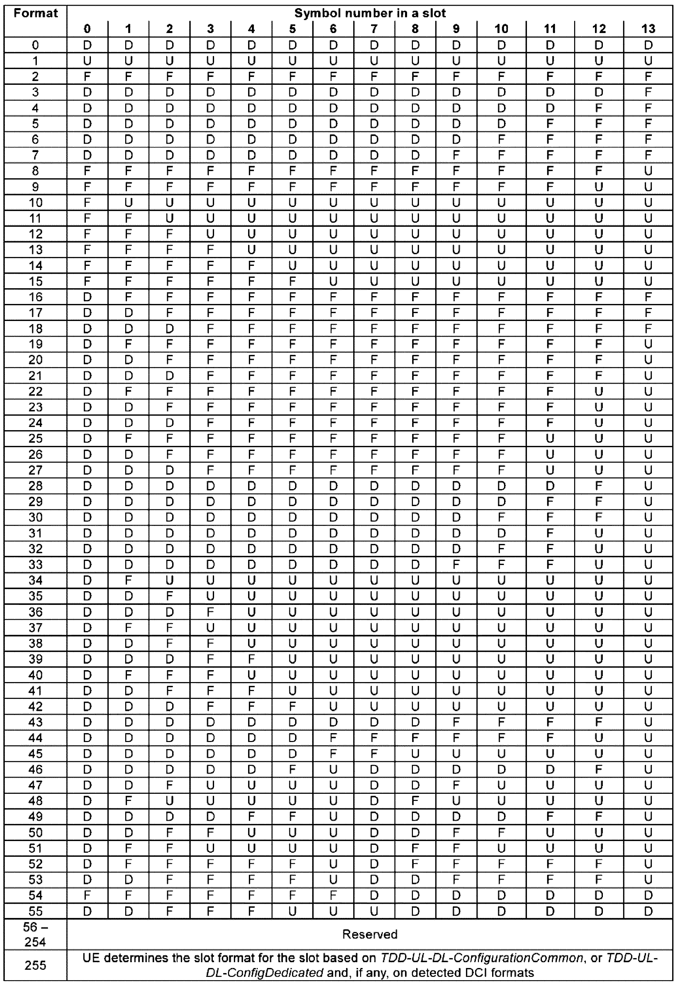
NRシステムでは基地局の「fine time/frequency tracking」のために「tracking RS」(すなわち、TRS)を設定する。
TRSは、規格で「CSI-RS for tracking」など他の用語と指称されるが本明細書では説明の便宜のためにTRSと指称する。
TRSは、10ms、20msなど特定周期を持って、1つ(X=1)又は2つ(X=2)の連続されたslotで送信され、これを「TRS burst」と名付ける。
In the NR system, a "tracking RS" (i.e., TRS) is configured for "fine time/frequency tracking" of the base station.
Although the TRS is referred to by other terms such as "CSI-RS for tracking" in the standard, it will be referred to as TRS in this specification for the sake of convenience.
The TRS is transmitted in one (X=1) or two (X=2) consecutive slots with a specific period such as 10 ms or 20 ms, and is called a "TRS burst."
図17は、一部実施形態によるTRSのREパターンを示す。
図17を参照すると、一つのslot内で可能なTRSパターン例示を示している。
図17に示したように、TRSは、3RE/RB/portの「frequency RE density」を持って4個サブキャリアごとに「TRS RE」が繰り返される(すなわち、一つの「TRS port」は、図17の「TRS OFDM symbol RE」に表記した、0、1、2、3 REの内の一つREで送信される)。
また、一部実施形態によれば、TRSは、「frequency range 1」(FR1)と指称される6GHz以下の周波数帯域では[{5番目、9番目}、{6番目、10番目}、{7番目、11番目}]の3つの「OFDM symbol pair」の内の一つで送信され、「frequency range 2」(FR2)に指称される6GHz以上の周波数帯域で[{1番目、5番目}、{2番目、6番目}、{3番目、7番目}、{4番目、8番目}、{5番目、9番目}、{6番目、10番目}、{7番目、11番目}、{8番目、12番目}、{9番目、13番目}、{10番目、14番目}]の10つの「OFDM symbol pair」の内の一つで送信される。
図17で、「OFDM symbol」位置は、TRS設定の例示で実際送信位置は、基地局送信によって変更することができることに留意しなければならない。
FIG. 17 shows the RE pattern of a TRS according to some embodiments.
Referring to FIG. 17, examples of possible TRS patterns within one slot are shown.
As shown in FIG. 17, the TRS has a “frequency RE density” of 3 RE/RB/port, and “TRS RE” is repeated every four subcarriers (i.e., one “TRS port” is transmitted in one of
Also, according to some embodiments, the TRS is transmitted in one of three "OFDM symbol pairs" [{fifth, ninth}, {sixth, tenth}, {seventh, eleventh}] in a frequency band below 6 GHz designated as "
It should be noted that the "OFDM symbol" position in FIG. 17 is an example of TRS setting, and the actual transmission position may be changed depending on the base station transmission.
図18Aは、一部実施形態による「1-Port CSI-RS」設定を示す図である。
図18Aを参照すると、図17の「TRS RE pattern」をカバーするための「1-port CSI-RS」設定の一例示を図に示した。
表20によれば、基地局は、一つの「resource setting」に一つの「resource set」を設定し、その中に最大4つの「CSI-RS resource」(1800、1810、1820、1830)を設定する。
この時、「CSI-RS」の「frequency density」は、「3RE/RB/port」と設定される。
もし、X=1 「TRS burst」を用いる場合、基地局は、「CSI-RS resource」#0と#1を設定する。
FIG. 18A is a diagram illustrating a "1-Port CSI-RS" configuration according to some embodiments.
Referring to FIG. 18A, an example of a "1-port CSI-RS" setting for covering the "TRS RE pattern" of FIG. 17 is shown in the figure.
According to Table 20, the base station sets one "resource set" in one "resource setting", and sets up to four "CSI-RS resources" (1800, 1810, 1820, 1830) therein.
At this time, the "frequency density" of the "CSI-RS" is set to "3RE/RB/port".
If X=1 "TRS burst" is used, the base station sets "CSI-RS resource"#0 and #1.
図18Bは、一部実施形態によるまた一つの「1-Port CSI-RS」設定を示す図である。
X=2 「TRS burst」の場合、基地局は、「CSI-RS resource」#0、#1、#2、#3(1800、1810、1820、1830)をいずれも設定する。
X=1又はX=2 「TRS burst」の場合、一つの「resource set」内に設定される「CSI-RS resource」に対して端末は、同じポートインデックスを持つ同じアンテナポートを仮定することができ、これに基づいて連続的な「time/frequency tracking」を行うようにする。
また、基地局は、「CSI-RS resource」がTRSと設定される場合、対応する報告セッティング(CSI-ReportConfig)を設定しないか(すなわち、該当「CSI-RS resource」を参照する報告セッティングがないか)、報告セッティングの設定値が‘none’になるようにして端末が該当「CSI-RS resource」を「time/frequency tracking」用途で用いて「CSI report」生成をしなくてもよいことを保障する。
FIG. 18B illustrates another "1-Port CSI-RS" configuration according to some embodiments.
In the case of X=2 "TRS burst", the base station sets all of "CSI-RS resource"#0,#1,#2, and #3 (1800, 1810, 1820, and 1830).
In the case of X=1 or X=2 'TRS burst', for 'CSI-RS resource' set in one 'resource set', the UE can assume the same antenna port having the same port index, and performs continuous 'time/frequency tracking' based on this.
In addition, when the 'CSI-RS resource' is set as a TRS, the base station does not set a corresponding report setting (CSI-ReportConfig) (i.e., there is no report setting referring to the corresponding 'CSI-RS resource'), and sets the report setting value to 'none' to ensure that the terminal does not need to use the corresponding 'CSI-RS resource' for 'time/frequency tracking' purposes and generate a 'CSI report'.
図18A及び図18Bで、「1-port CSI-RS resource」のサブキャリア位置及び「OFDM symbol」位置は、図17のTRSサブキャリア位置によって適当に変更することができる。 In Figures 18A and 18B, the subcarrier positions of the "1-port CSI-RS resource" and the "OFDM symbol" positions can be appropriately changed according to the TRS subcarrier positions in Figure 17.
TRSは、periodic、semi-persistent、aperiodicなどの多様な形態で送信されることが可能である。
「periodic TRS(P-TRS)」の場合、RRC設定される周期及び「slot offset」値によって「RRC reconfiguration」前まで周期的に送信され、「semi-persistent TRS(SP-TRS)」の場合、RRC設定される周期及び「slot offset」に基づいて「MAC CE」又はDCIによってactivationされた以後のdeactivationされる前まで送信され、「aperiodic TRS(A-TRS)」の場合、周期又は「slot offset」値設定無しに「MAC CE」又はDCIによってtriggerされて送信される。
この時、「A-TRS triggering」及び「A-TRS」送信タイミングは上位レイヤーと設定されたoffsetを有するか、又は予め約束された値(例えば、「A-TRS triggering」のようなslotに「A-TRS」が送信されるように)によることが可能である。
The TRS can be transmitted in various forms such as periodic, semi-persistent, and aperiodic.
In the case of a "periodic TRS (P-TRS)", the TRS is periodically transmitted until "RRC reconfiguration" according to the period and "slot offset" value set by RRC. In the case of a "semi-persistent TRS (SP-TRS)", the TRS is transmitted until deactivation after activation by "MAC CE" or DCI based on the period and "slot offset" set by RRC. In the case of an "aperiodic TRS (A-TRS)", the TRS is triggered by "MAC CE" or DCI and transmitted without setting the period or "slot offset" value.
In this case, the "A-TRS triggering" and "A-TRS" transmission timing may have an offset set with the upper layer, or may be based on a pre-agreed value (e.g., "A-TRS" is transmitted in a slot such as "A-TRS triggering").
「Aperiodic TRS(A-TRS)」の場合、時間軸RE数が不足でチャンネルの統計的特性を測定し難い場合があるため、「periodic TRS」又は「semi-persistent TRS」と接続(association)される。
「A-TRSとSP-TRS」又は「P-TRS」の間接続は、「quasi co-location(QCL)」などの多様な方法を介してサポートされることが可能である。
例えば、基地局は、「A-TRS」に少なくとも一つの「SP-TRS」又は「P-TRS」を「QCL reference RS」と設定して「delay spread」、「average delay」、「Doppler spread」、「Doppler shift」などのチャンネル統計値を抽出することができるか(「QCL type A」)、又は「TX beam」、「RX beam」などの「spatial parameter」を抽出すること(「QCL type D」)ができる。
In the case of an "Aperiodic TRS (A-TRS)", since it may be difficult to measure the statistical characteristics of a channel due to an insufficient number of time-axis REs, the "A-TRS" is associated with a "periodic TRS" or a "semi-persistent TRS".
The connection between the "A-TRS and the SP-TRS" or the "P-TRS" can be supported via various methods such as "quasi co-location (QCL)".
For example, the base station can set at least one "SP-TRS" or "P-TRS" in the "A-TRS" as a "QCL reference RS" to extract channel statistics such as "delay spread", "average delay", "Doppler spread", and "Doppler shift"("QCL type A"), or can extract "spatial parameters" such as "TX beam" and "RX beam"("QCL type D").
また、TRSは、上位レイヤーパラメーター「freqBand」によって帯域幅情報を割り当てられ、該当TRSが送信されるBWPの帯域幅が52RBより小さい場合、TRSの帯域幅はBWPの帯域幅と同じで、該当TRSが送信されるBWPの帯域幅が52RBより大きい又は同じの場合、TRSの帯域幅は52RBと設定される。 The TRS is also assigned bandwidth information by the upper layer parameter "freqBand". If the bandwidth of the BWP through which the TRS is transmitted is smaller than 52RB, the bandwidth of the TRS is the same as the bandwidth of the BWP, and if the bandwidth of the BWP through which the TRS is transmitted is larger than or equal to 52RB, the bandwidth of the TRS is set to 52RB.
図19は、本発明の一実施形態による端末の信号処理装置構造を示す図である。
信号処理装置の構造は、端末のアンテナポート、アンテナパネル、ベースバンドプロセッサの内の少なくとも一つを含む。
FIG. 19 is a diagram showing a signal processing device structure of a terminal according to an embodiment of the present invention.
The signal processing device structure includes at least one of an antenna port, an antenna panel, and a baseband processor of a terminal.
図19を参照すると、端末1900は、複数のアンテナポート又はパネル(1905、1910、1915)から構成される。
図19で、端末が3個のアンテナポート又はパネル構造を有するものとして図に示しているが、これは実際適用時のこのような一例に制限される必要はなく、より多い又はより小さい数のアンテナポート又はパネル構造が用いられることが可能である。
Referring to FIG. 19, a terminal 1900 is configured with multiple antenna ports or panels (1905, 1910, 1915).
In FIG. 19, the terminal is illustrated as having three antenna ports or panel structures, however, this need not be limited to such an example in actual application, and a greater or lesser number of antenna ports or panel structures may be used.
複数のアンテナポート又はパネルは、端末の製造コスト、目標性能、FR1又はFR2などの動作周波数帯域などの多様な環境及び条件によってアンテナポート/パネル選択部(antenna selection module、1920)と接続されるか、又はアンテナポート/パネル利得結合部(antenna combining module/MIMO module)1925などを介して信号処理部(baseband processing module)1930で接続される。
説明の便宜のために今後の説明でアンテナポート/パネル選択部(antenna selection module)1920、アンテナポート/パネル利得結合部(antenna combining module/MIMO module)1925などのモジュールを“アンテナ信号処理部”と通称する。
信号処理部(baseband processing module)1930は、アンテナ信号処理部を通過したRF信号又はデジタル信号を受信して前述の手順によって基準信号を測定してTCI/QCL手順を行うか、データシンボルを測定してデータを復調する。
現状の大部分の端末は、消費電力節減や複雑度/費用減少を目的としてアンテナポート/パネル選択部(antenna selection module)1920を用いるか、又は無線通信カバレッジ拡大や又は容量増大を目的としてアンテナポート/パネル利得結合部(antenna combining module/MIMO module)1925を用いるなど1920又は1925の内の一つを選んで使用している。
A plurality of antenna ports or panels are connected to an antenna port/panel selection module (1920) according to various environments and conditions such as the manufacturing cost of the terminal, target performance, and operating frequency band such as FR1 or FR2, or are connected to a signal processing unit (baseband processing module) 1930 via an antenna port/panel gain combining module (antenna combining module/MIMO module) 1925, etc.
For ease of explanation, in the following description, modules such as the
A signal processing module (baseband processing module) 1930 receives an RF signal or a digital signal that has passed through the antenna signal processing module, measures a reference signal according to the above-mentioned procedure, and performs a TCI/QCL procedure, or measures a data symbol and demodulates the data.
Most current terminals use either an
一方、将来の端末の場合、アンテナ選択、結合又は/及び組み合せによる多様な利得を状況によって適切に取得するために複数のアンテナ信号処理部を同時具現するか、又は多様な機能を行うことができる複合アンテナ信号処理部を導入することが可能である。
このような傾向は、無線通信の周波数動作帯域が増加することによって(例えば、6GHz以上のFR2帯域又は52.6GHz以上のFR4帯域など)アンテナポート/パネルのモジュールサイズ及び各モジュールの間の最小要求間隔は周波数に反比例して(波長に比例して)短くなることによって、一つの端末が有するアンテナポート/パネルの数が次第に増加するようになるため、段々加速化されるだろう。
Meanwhile, in the case of future terminals, it may be possible to simultaneously implement multiple antenna signal processors or introduce a composite antenna signal processor capable of performing various functions in order to appropriately obtain various gains through antenna selection, combining and/or combination depending on the situation.
This trend will accelerate as the number of antenna ports/panels per terminal gradually increases as the frequency operating band of wireless communication increases (e.g., FR2 band above 6 GHz or FR4 band above 52.6 GHz, etc.), and the module size of the antenna port/panel and the minimum required spacing between each module become shorter inversely proportional to the frequency (proportional to the wavelength).
前述のように複数のアンテナポート/パネルを操作する端末が複数の機能を有するアンテナ信号処理部を有している場合、理論的に優れた環境適応力を介して高い性能を得ることが可能であるが、優れた適応力を実体化してこれをカバレッジ利得又は通信容量の利得に換算するためには各場合に対する個別的な基準信号送信及び測定が伴わなければならなく、端末のTCI及びQCL測定及び適用も各場合別で個別に処理される必要がある。
これはフレキシブルのアンテナ信号処理を介して無線通信性能利得を得るために、単一アンテナ信号処理方法を仮定した従来システムに対比して、多くの量の基準信号送信及び測定負担、端末のTCI及びQCL測定及び適用能力向上のような追加的なコストが必要となるということを意味する。
As described above, when a terminal operating multiple antenna ports/panels has an antenna signal processing unit with multiple functions, it is theoretically possible to obtain high performance through excellent environmental adaptability; however, in order to realize the excellent adaptability and convert it into a coverage gain or communication capacity gain, individual reference signal transmission and measurement for each case is required, and the terminal's TCI and QCL measurement and application also need to be processed separately for each case.
This means that in order to obtain wireless communication performance gains through flexible antenna signal processing, additional costs such as a large amount of reference signal transmission and measurement burden, terminal TCI and QCL measurement, and improved application capabilities are required compared to conventional systems that assume a single antenna signal processing method.
本発明では端末の多様なアンテナポート及びパネル構造を考慮した「TCI emulation」方法を提供して基準信号送信負担を減らすことによって無線通信効率を高める。
以下、具体的な実施形態を介して本発明の主要要旨を説明する。
The present invention provides a "TCI emulation" method that takes into account various antenna ports and panel structures of a terminal, thereby reducing the burden of transmitting a reference signal and improving wireless communication efficiency.
The main gist of the present invention will be described below with reference to specific embodiments.
<第1実施形態>
第1実施形態では、「TCI又は/及びQCL(以下、TCI/QCL)emulation」を介して基準信号送信負担を軽減させる方法を提供する。
本実施形態によれば、「TCI/QCL emulation」は、
1)互いに異なる2つ以上の「TCI state」又は互いに異なる2つ以上の「QCL assumption」を適切に合成して一つの「TCI state」又は一つの「QCL assumption」で造る方法、
2)一つの「TCI state」又は一つの「QCL assumption」を適切に分割して互いに異なる2つ以上の「TCI state」又は互いに異なる2つ以上の「QCL assumption」で造る方法などの一つ以上の組み合せで、多様な詳細的な方法が存在する。
First Embodiment
In the first embodiment, a method for reducing the burden of transmitting a reference signal via "TCI and/or QCL (hereinafter, TCI/QCL) emulation" is provided.
According to this embodiment, the "TCI/QCL emulation" is
1) A method of appropriately synthesizing two or more different "TCI states" or two or more different "QCL assumptions" to create one "TCI state" or one "QCL assumption";
2) There are various detailed methods, such as one or more combinations of a method of appropriately dividing one "TCI state" or one "QCL assumption" into two or more different "TCI states" or two or more different "QCL assumptions".
図20は、本発明の一実施形態による「TCI emulation」の一例を示す図である。
図20は、2つの「TCI emulation」方法の内の第1方法である互いに異なる2つ以上の「TCI state」又は互いに異なる2つ以上のQCL仮定を適切に合成して一つの「TCI state」又は一つのQCL仮定で造る方法の具体的な例示を示す図である。
FIG. 20 is a diagram showing an example of "TCI emulation" according to an embodiment of the present invention.
FIG. 20 is a diagram showing a specific example of the first of two “TCI emulation” methods, which is a method of appropriately combining two or more different “TCI states” or two or more different QCL assumptions to create one “TCI state” or one QCL assumption.
図20を参照すると、端末2002は、一つ以上の送信地点(transmission and reception point:TRP)又はパネル(panel)又はアンテナポート(2001、2011)とアップ又はダウン無線通信リンクを形成する。
この時、SFN(single-frequency network)、NC-JT(non-coherent joint transmission)などの多様な「multi-TRP」操作方法を考慮すれば、送信地点、パネル、及び/又はアンテナポートは、その一部又は全部が同じ基地局から送信される(又は含まれる)ことが可能である。
送信地点、パネル、及び/又はアンテナポートは、説明の便宜のためにこれから“送信地点”と通称する。
すなわち、図20の場合、説明の便宜上送信地点(2001、2011)の物理的位置が異なるものとして表したが実際適用時のここに限る必要はなく、一部送信地点はその物理的位置が同じになることが可能である(例えば、端末は各2つのパネルで構成される2つの互いに異なる送信地点を介して信号を送受信することができ、この時、総数4つのパネルの内の一部は、互いに同じ水平又は垂直物理位置を共有しても良い。)。
Referring to FIG. 20, a terminal 2002 forms an up or down wireless communication link with one or more transmission and reception points (TRPs) or panels or antenna ports (2001, 2011).
In this case, taking into consideration various "multi-TRP" operation methods such as SFN (single-frequency network) and NC-JT (non-coherent joint transmission), some or all of the transmission points, panels, and/or antenna ports may be transmitted from (or included in) the same base station.
The transmission points, panels, and/or antenna ports are hereinafter referred to as "transmission points" for ease of discussion.
That is, in the case of FIG. 20, for convenience of explanation, the physical locations of the transmission points (2001, 2011) are shown to be different, but this is not limited to this in actual application, and some transmission points may have the same physical location (for example, a terminal may transmit and receive signals through two different transmission points each consisting of two panels, and in this case, some of the total four panels may share the same horizontal or vertical physical location).
本明細書内で、QCL仮定を生成するか、又はQCL/TCIプロセスを開始又は行うと言うことは、端末が基地局からQCL設定情報を受信して該当設定情報内の「QCL reference RS」に設定された基準信号又はチャンネルを受信して表10の「QCL type」によるチャンネルの統計的情報の内の全部又は一部を生成して該当QCL設定情報内の設定された「QCL target RS」の受信を介してチャンネル推定に用いることを意味する。 In this specification, generating a QCL hypothesis or initiating or performing a QCL/TCI process means that the terminal receives QCL configuration information from the base station, receives a reference signal or channel set in the "QCL reference RS" in the corresponding configuration information, generates all or part of the channel statistical information according to the "QCL type" in Table 10, and uses it for channel estimation through reception of the "QCL target RS" set in the corresponding QCL configuration information.
本明細書内で、ある基準信号チャンネルを送信する送信地点が異なるということは、端末2002が受信する互いに異なる2つの基準信号が互いに異なるQCL仮定を有するか又は互いに異なる「TCI state」を有するように一つ以上の上位レイヤーシグナリングを介して設定されるか、又は一つ以上の上位レイヤーシグナリング又はL1シグナリングを介して活性化されるか又はL1シグナリングを介して指示される場合を意味する。
これと同様に、ある基準信号又はチャンネルを受信する送信地点が異なるということは、端末2002が送信する互いに異なる2つの基準信号が互いに異なるQCL仮定(「UL QCL」又は「DL-UL joint QCL」又は「spatial relation information」などを含むことができる)を有するか又は互いに異なる「UL-TCI state」を有するように一つ以上の上位レイヤーシグナリングを介して設定されるか、又は一つ以上の上位レイヤーシグナリング又はL1シグナリングを介して活性化されるか、又はL1シグナリングを介して指示される場合を意味する。
また、実際適用時の送信地点が異なるということを端末が容易に判断するのを助けるための目的で、独立的上位レイヤーパラメーターが定義され、これを明示的に公知することが可能である。
前述のようにダウンリンクを記述する場合とアップリンクを記述する場合、必要な用語に差があり得るが、説明の要旨を不明瞭にしないために今後の説明ではダウンリンクを主として言及する。
しかし、上記のような発明の全般的内容は、アップリンクにも同様の方法で適用することができることに留意しなければならない。
In this specification, the term "different transmission points transmitting a reference signal channel" means that two different reference signals received by the terminal 2002 have different QCL assumptions or different "TCI states" and are configured via one or more higher layer signaling, or are activated via one or more higher layer signaling or L1 signaling, or are indicated via L1 signaling.
Similarly, the fact that the transmission points receiving a certain reference signal or channel are different means that two different reference signals transmitted by the terminal 2002 have different QCL assumptions (which may include “UL QCL” or “DL-UL joint QCL” or “spatial relation information”, etc.) or are configured to have different “UL-TCI states” via one or more higher layer signaling, or are activated via one or more higher layer signaling or L1 signaling, or are indicated via L1 signaling.
In addition, in order to help the terminal easily determine that the transmission point is different in actual application, an independent upper layer parameter can be defined and explicitly announced.
As mentioned above, there may be differences in the terminology required when describing the downlink and when describing the uplink, but to avoid obscuring the gist of the description, the following description will primarily refer to the downlink.
However, it should be noted that the general teachings of the invention as described above can also be applied in a similar manner to the uplink.
どの基準信号又はチャンネルを送信する送信地点が異なるということを基地局が端末に公知する方法(すなわち、互いに異なる2つの基準信号が互いに異なるQCL仮定又は互いに異なる「TCI state」を有するように一つ以上の上位レイヤーシグナリングを介して設定されるか、又は一つ以上の上位レイヤーシグナリング又はL1シグナリングを介して活性化されるか又はL1シグナリングを介して指示されるなどの方法)に対する一例として、基地局は、各CORESET設定に追加的インジケーター、例えば、「CORESET pool index」、を設定して追加的インジケーターの値が同じCORESETで送信されるDCIによって割り当てられる、又はDCIと連携される制御チャンネル(PDCCH、PUCCH)、データチャンネル(PDSCH、PUSCHなど)又はRS(DMRS、CSI-RS、SRSなど)が同じ送信地点で送信されたことと仮定するように約束する。
例えば、端末は、「CORESET pool index」が設定されないCORESET又は「CORSET pool index」の値が「0」と設定されたCORESETで送信されるPDCCH及び該当PDCCHの含むDCIが割り当てるPDSCHは、第1送信地点で送信され、「CORSET pool index」の値が「1」と設定されたCORESETで送信されるPDCCH及び該当PDCCHの含むDCIが割り当てるPDSCHは、第2送信地点で送信されることと仮定することができる。
As an example of a method in which a base station informs a terminal that the transmission points from which reference signals or channels are transmitted are different (i.e., two different reference signals are configured via one or more higher layer signaling to have different QCL assumptions or different "TCI states", or are activated via one or more higher layer signaling or L1 signaling, or are indicated via L1 signaling), the base station sets an additional indicator, for example, a "CORESET pool index", in each CORESET setting, and promises to assume that the value of the additional indicator is assigned by DCI transmitted in the same CORESET or that control channels (PDCCH, PUCCH), data channels (PDSCH, PUSCH, etc.), or RSs (DMRS, CSI-RS, SRS, etc.) associated with DCI are transmitted from the same transmission point.
For example, the terminal may assume that a PDCCH transmitted in a CORESET in which the "CORESET pool index" is not set or in which the "CORSET pool index" value is set to "0" and a PDSCH allocated by a DCI included in the corresponding PDCCH are transmitted at a first transmission point, and a PDCCH transmitted in a CORESET in which the "CORSET pool index" value is set to "1" and a PDSCH allocated by a DCI included in the corresponding PDCCH are transmitted at a second transmission point.
送信地点区分に対する例示は、CORESET内のインジケーターに従うことに集中したが、これは説明の便宜のためのことで実際適用時にここに限らずPUCCH、「PUCCH group」、cell、「cell group」、BWP、「BWP group」などの多様な設定内部に追加的なインジケーターを導入して同様に拡張することが可能である。 The examples of transmission point classification have focused on following indicators in CORESET, but this is for convenience of explanation, and in actual application, it is possible to similarly extend by introducing additional indicators into various settings such as PUCCH, "PUCCH group", cell, "cell group", BWP, and "BWP group".
端末は、上記方法を利用して「QCL reference RS」と「target RS」が同じ送信地点と関連されたこと、又は一つの「QCL reference RS」が複数の「target RS」に関連されたこと、又は一つの「target RS」が複数の「QCL reference RS」に関連されたことであるか、などの多様な状況を判断する。 The terminal uses the above method to determine various situations, such as whether a "QCL reference RS" and a "target RS" are associated with the same transmission point, or whether one "QCL reference RS" is associated with multiple "target RSs," or whether one "target RS" is associated with multiple "QCL reference RSs."
以下の記述で発明の要旨を不明瞭にしないためにQCL又は「TCI state」が設定されるということは、前述した“基地局が端末に特定QCL又は「TCI state」を、上位レイヤーシグナリングを介して設定するか”又は“上位レイヤーシグナリング又はL1シグナリングを介して特定QCL又は「TCI state」が活性化されるか”又は“L1シグナリングを介して特定QCL又は「TCI state」が指示される場合”を通称して用いる場合があることに留意しなければならない。 In the following description, in order to avoid obscuring the gist of the invention, it should be noted that the term "setting a QCL or "TCI state"" may be used in common to mean "when a base station sets a specific QCL or "TCI state" in a terminal via higher layer signaling," "when a specific QCL or "TCI state" is activated via higher layer signaling or L1 signaling," or "when a specific QCL or "TCI state" is indicated via L1 signaling."
以下の説明で2つの送信地点を仮定するがこれは説明の便宜のためのことで同様の方法で3つ以上の送信地点が存在する場合もサポートすることが可能である。 The following explanation assumes two transmission points, but this is for ease of explanation; it is possible to support cases where there are three or more transmission points using a similar method.
図20を参照すると、端末2002は、第1送信地点2001からどんな特定時点又は特定時間/周波数リソース2000で「QCL reference RS」が(例えば 「SS/PBCH block」、TRS、「CSI-RS for BM」(「CSI-RS」の内の「repetition parameter」がon又はoffに設定された「CSI-RS」2003)などが設定され、これを受信してQCL仮定を生成するか又はTCIプロセスを開始する。
また、端末2002は、第2送信地点2011からまた他の特定時点又は特定時間/周波数リソース2010で「QCL reference RS」が(例えば「SS/PBCH block」、TRS、「CSI-RS for BM」(「CSI-RS」の内の「repetition parameter」がon又はoffに設定された「CSI-RS」2013)などが設定され、これを受信してQCL仮定を生成するか又はTCIプロセスを開始する。
Referring to FIG. 20, a terminal 2002 receives a “QCL reference RS” (e.g., “SS/PBCH block”, TRS, “CSI-RS for BM” (a “CSI-RS” 2003 in which the “repetition parameter” of the “CSI-RS” is set to on or off) from a
In addition, the terminal 2002 receives a “QCL reference RS” (e.g., “SS/PBCH block”, TRS, “CSI-RS for BM” (a “CSI-RS” 2013 in which the “repetition parameter” of the “CSI-RS” is set to on or off) from the
一方、端末2002と第1及び第2送信地点(2001、2011)のいずれもからまた他の特定時点又は特定時間/周波数リソース2020で送信される「QCL target RS」が(例えば、「PDCCH DMRS」、「PDSCH DMRS」、「CSI-RS」2024、2025)などが設定され、これを受信する場合、最適の受信性能のために「QCL reference RS」は、「QCL target RS」のような方法で送信されなければならない。
すなわち、「QCL target RS」(2024、2025)の最適受信性能のためには「QCL reference RS」も第1及び第2送信地点(2001、2011)のいずれもから同時に受信されることが必要である。
しかし、これは、第1及び第2送信地点の個別送信シナリオのための「QCL reference RS」(2002、2013)とはまた他の「QCL reference RS」を送信することを要求するため、多くの量の(場合によって50%以上の追加的な)基準信号送信負担を追加で要求するようになる。
また、多い場合、セル共通又はグループ共通で用いられる「QCL reference RS」に対する同時送信が要求される問題が発生するようになる。
Meanwhile, when a 'QCL target RS' (e.g., 'PDCCH DMRS', 'PDSCH DMRS', 'CSI-RS' 2024, 2025) is configured and received from the terminal 2002 and the first and second transmission points (2001, 2011) at another specific time point or specific time/
That is, for optimal reception performance of the 'QCL target RS' (2024, 2025), the 'QCL reference RS' also needs to be received simultaneously from both the first and second transmission points (2001, 2011).
However, this requires transmitting a "QCL reference RS" other than the "QCL reference RS" (2002, 2013) for the individual transmission scenarios of the first and second transmission points, which requires a large amount of additional reference signal transmission burden (in some cases, an additional 50% or more).
In addition, if the number of QCL reference RSs is large, a problem occurs in that simultaneous transmission of a QCL reference RS that is used commonly by a cell or a group is required.
このような問題を解決するために以下のような方法の内の一つ又はそれらの組み合せによって「TCI emulation」(QCL合成又はTCI合成、「TCI emulation mode」#1)が行われることが可能である。
図20で示したように2つの互いに異なる「reference RS」で測定されたQCL情報を一つの「target RS」に適用させるために基地局は、「reference RS」と「target RS」の間の多対一の関係(N:1 association)を端末に適切に通知しなければならない。
基地局及び端末は、これを介して多くの場合、セル共通又はグループ共通で用いられる「QCL reference RS」に対する同時送受信を行わなくでも協力送信される「QCL target RS」に対するQCL又は/及びTCI情報を適切に交換する。
In order to solve such problems, "TCI emulation" (QCL synthesis or TCI synthesis, "TCI emulation mode"#1) can be performed by one of the following methods or a combination thereof.
As shown in FIG. 20, in order to apply QCL information measured at two different “reference RSs” to one “target RS”, the base station must properly notify the terminal of the many-to-one relationship (N:1 association) between the “reference RS” and the “target RS”.
Through this, the base station and the terminal appropriately exchange QCL and/or TCI information for the "QCL target RS" that is cooperatively transmitted without simultaneous transmission and reception for the "QCL reference RS" that is commonly used in cells or groups.
現在のNRシステムでは、「multi-TRP」送信をサポートするために「MAC CE」など上位レイヤーシグナリングを利用してDCI内の一つの「TCI field code point」に複数の「TCI state」を接続(活性化)する機能をサポートする。
しかし、このような機能は、該当DCIの「DMRS port indication field」が指示するDMRSポートを「DMRS CDM group」を基準に分けて「DMRS CDM group」別の互いに異なる「TCI state」を適用するためのことで(すなわち、従来の場合、相変らず一つの「DMRS port」には一つの独立的QCL仮定だけが適用される)、一つの「DMRS port」(すなわち、一つの「QCL target RS」ポート)に互いに異なる「TCI state」又は互いに異なるQCL仮定を統合(複数の「QCL reference RS」を統合適用)してサポートしようとする本発明の趣旨及び機能とは区別されるべきである。
In the current NR system, in order to support 'multi-TRP' transmission, the function of connecting (activating) multiple 'TCI states' to one 'TCI field code point' in DCI using higher layer signaling such as 'MAC CE' is supported.
However, this function is to divide the DMRS port indicated by the 'DMRS port indication field' of the corresponding DCI based on 'DMRS CDM group' and apply different 'TCI states' to each 'DMRS CDM group' (i.e., in the conventional case, only one independent QCL assumption is applied to one 'DMRS port'), and should be distinguished from the purpose and function of the present invention, which aims to support different 'TCI states' or different QCL assumptions by integrating (integrating and applying multiple 'QCL reference RSs') to one 'DMRS port' (i.e., one 'QCL target RS' port).
本発明の意図に従い、一つの「QCL target RS」ポートに互いに異なる「TCI state」又は互いに異なるQCL仮定を統合(複数の「QCL reference RS」を統合)適用するために、以下の3つ方法の内の一つを適用することが可能である。 In accordance with the intent of the present invention, one of the following three methods can be applied to integrate different "TCI states" or different QCL assumptions (integrating multiple "QCL reference RSs") to one "QCL target RS" port.
・方法1:第1方法は、「Rel-16 PDSCH DMRS TCI activation MAC CE」又はその拡張に基づいて、DCIが指示する「DMRS port」に同時に適用する複数の「TCI state」又はQCL仮定が接続されることである。
この時、別途の上位レイヤーパラメーターが定義され、端末は、上位レイヤーパラメーターに基づいて接続が「Rel-16 multi-TRP」動作によって解釈されるか(すなわち、第1「TCI state」は、第1「DMRS CDM group」に属するDMRSに適用し、第2「TCI state」は、第2「DMRS CDM group」に属するDMRSに適用)、それとも本発明の内容によって「TCI emulation」を行うか(すなわち、第1「TCI state」と第2「TCI state」を合成して新規「TCI state」を導出してこれを指示されたすべての「DMRS port」に適用)を決定する。
別途の上位レイヤーパラメーターは、独立的RRCパラメーターと定義されるか、又は「Rel-16 multi-TRP」のための上位レイヤーパラメーターが前述された内容の指示のために活用されることも可能である。
方法1によれば、表11の「TCI state」及びQCL設定を再使用することが可能であるため最小限の規格変更で「TCI emulation」サポートが可能であるが、「Rel-16 multi-TRP」動作と「TCI emulation」動作を同時に行うことができない欠点がある。
Method 1: In the first method, multiple “TCI states” or QCL assumptions that are simultaneously applied to the “DMRS port” indicated by the DCI are connected based on the “Rel-16 PDSCH DMRS TCI activation MAC CE” or its extension.
At this time, a separate upper layer parameter is defined, and the terminal determines whether the connection is interpreted according to the "Rel-16 multi-TRP" operation based on the upper layer parameter (i.e., the first "TCI state" is applied to the DMRS belonging to the first "DMRS CDM group" and the second "TCI state" is applied to the DMRS belonging to the second "DMRS CDM group"), or whether "TCI emulation" is performed according to the contents of the present invention (i.e., the first "TCI state" and the second "TCI state" are combined to derive a new "TCI state" and apply it to all indicated "DMRS ports").
Separate upper layer parameters may be defined as independent RRC parameters, or upper layer parameters for 'Rel-16 multi-TRP' may be utilized to indicate the above-mentioned contents.
According to
・方法2:第2方法は、表11の「TCI state」設定を以下の表33のように修正して一つの「TCI state」内に総数4個の「QCL type」を設定するように許容する方法である。
これを介して該当「TCI state」を参照する「QCL target RS」が互いに異なる2つの送信地点で送信される互いに異なる2つの「QCL reference RS」を参照することができる。
この時、「qcl-Type1」が示すQCLパラメーターは、「qcl-Type1-r17」が示すQCLパラメーターと合成されて新しい第1QCL情報が生成され、「qcl-Type2」が示すQCLパラメーターは、「qcl-Type1-r17」が示すQCLパラメーターと合成されて新しい第2QCL情報が生成される。
表33は、2個の「QCL reference RS」が参照される一例に対するものであるが、3以上の「QCL reference RS」に対して同じ方法で拡張することができるだろう。
方法2の場合にも独立的な上位レイヤーシグナリングパラメーターが定義されてパラメーターが以下の新規パラメーター「qcl-Type1-r17」及び「qcl-Type2-r17」を使用するかどうかを通知するか、又は{qcl-Type1、qcl-Type2}と{qcl-Type1-r17、qcl-Type2-r17}の内のどんなパラメーター対を用いるか又は2つの対を合成して生成される新しいパラメーター対を用いるかなどを直接的に指示することが可能である。
Method 2: The second method is a method in which the 'TCI state' setting in Table 11 is modified as shown in Table 33 below to allow a total of four 'QCL types' to be set within one 'TCI state'.
Thereby, a 'QCL target RS' referring to a corresponding 'TCI state' can refer to two different 'QCL reference RS' transmitted from two different transmission points.
At this time, the QCL parameters indicated by "qcl-Type1" are combined with the QCL parameters indicated by "qcl-Type1-r17" to generate new first QCL information, and the QCL parameters indicated by "qcl-Type2" are combined with the QCL parameters indicated by "qcl-Type1-r17" to generate new second QCL information.
Table 33 is for an example where two "QCL reference RS" are referenced, but could be extended in the same manner for three or more "QCL reference RS".
In the case of
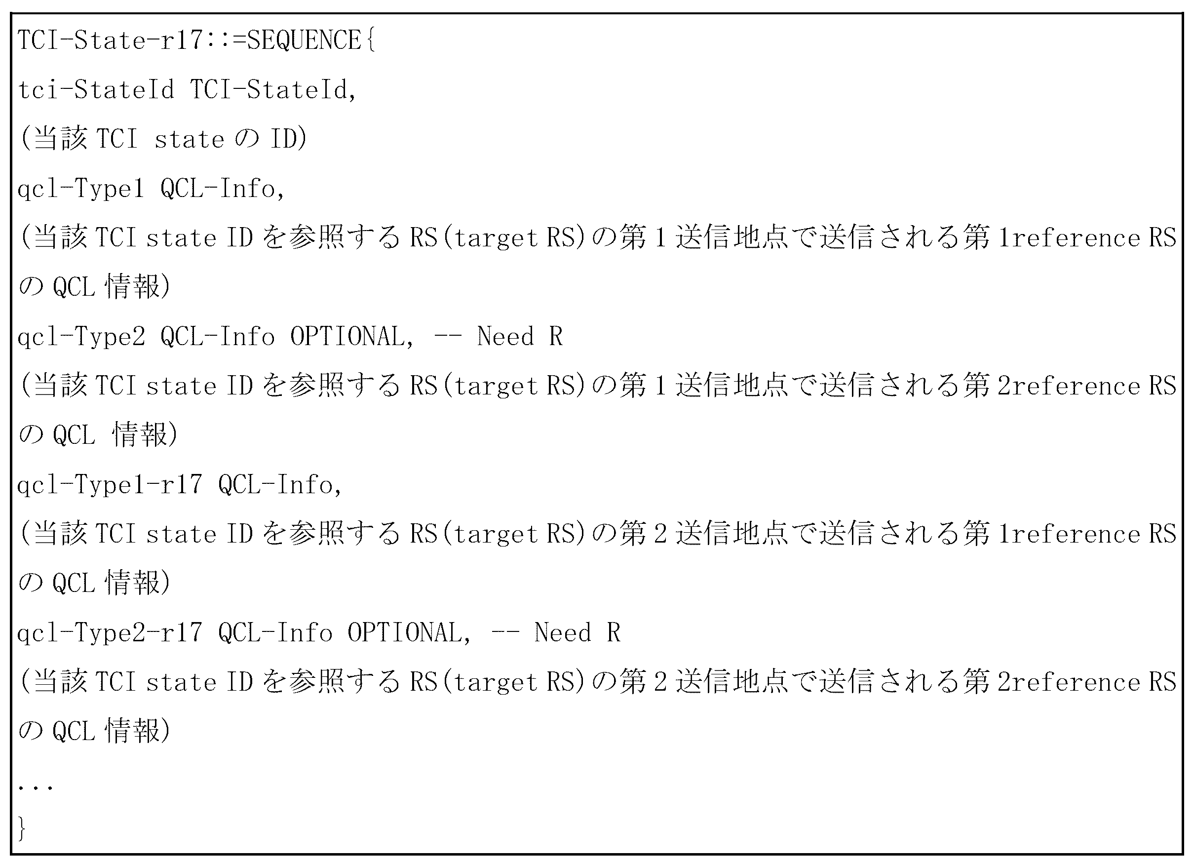
・方法3:第3方法は、表11のQCL設定を以下の表34のように修正して一つのQCL設定内に総数2個の「QCL reference RS」が含まれるように許容する方法である。
これを介して端末が該当「TCI state」を参照する「QCL target RS」基盤チャンネル推定の時に互いに異なる2つの送信地点で送信される互いに異なる2つの「QCL reference RS」のチャンネルパラメーターを参照する。
この時、端末は、該当QCL設定内の「QCL reference RS」の測定値を直接合成するか、又は該当QCL設定内の「QCL reference RS」から独立的に測定されたQCLパラメーター値を合成して新しいQCL情報を生成する。
表34は、2個の「QCL reference RS」が参照される一例に対するものであるが、3以上の「QCL reference RS」に対しても同じ方法で拡張することができるだろう。
方法3の場合にも新しく定義された独立的な上位レイヤーシグナリングパラメーターが以下の新規パラメーター「referenceSignal-r17」及び「qcl-Type-r17」を使用するかどうかを通知することが可能である。
この時、「qcl-Type-r17」は、従来「QCL type A、B、C、D」以外新しいタイプを追加で指示することができ、例えば、「type E」が追加されて従来「QCL type」の内の一つに加えて「average gain」などの新規チャンネル統計特性を「TCI emulation」に用いるようにサポートすることができる。
「Average gain」などチャンネル統計特性に基づいた「TCI emulation」の詳細方法は、以下に別に詳しく提供される。
Method 3: The third method is to modify the QCL setting in Table 11 as shown in Table 34 below, allowing a total of two "QCL reference RS" to be included in one QCL setting.
Through this, when the terminal performs channel estimation based on the 'QCL target RS' referring to the corresponding 'TCI state', it refers to the channel parameters of two different 'QCL reference RS' transmitted from two different transmission points.
At this time, the terminal directly synthesizes the measurement values of the 'QCL reference RS' in the corresponding QCL setting, or synthesizes QCL parameter values measured independently from the 'QCL reference RS' in the corresponding QCL setting to generate new QCL information.
Table 34 is for an example where two "QCL reference RS" are referenced, but it could be extended in the same way to three or more "QCL reference RS".
In the case of
At this time, 'qcl-Type-r17' can indicate new types other than the conventional 'QCL type A, B, C, D'. For example, 'type E' can be added to support the use of new channel statistical characteristics such as 'average gain' in 'TCI emulation' in addition to one of the conventional 'QCL types'.
A detailed method of "TCI emulation" based on channel statistical characteristics such as "average gain" will be provided in detail below.
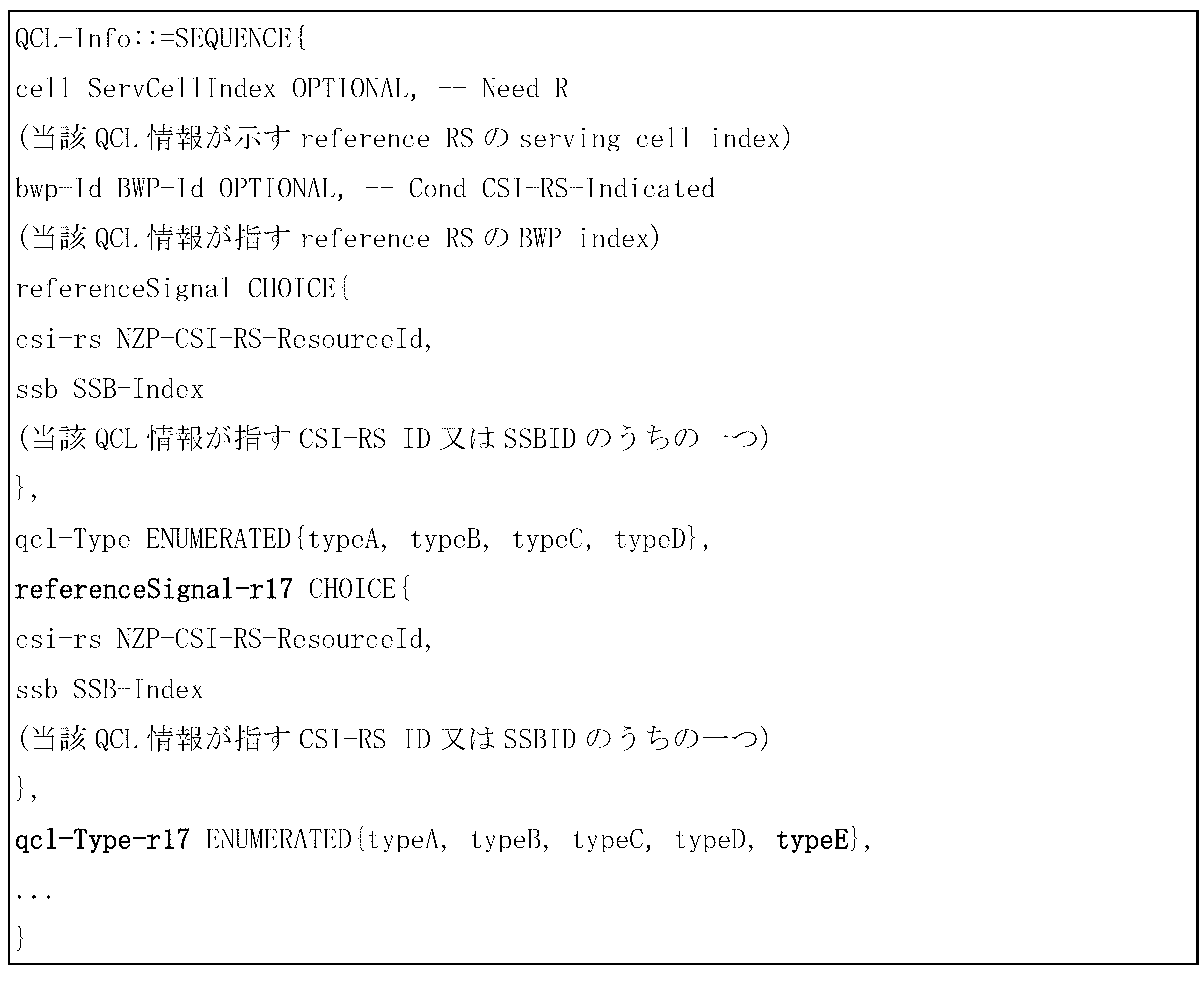
表33及び表34は、一つの「target RS」と複数の「reference RS」間の接続関係(association)を提供するための例題であり、実際適用時、多様な応用が可能で「reference RS」の個数など詳細事項も適切に変更が可能である。 Tables 33 and 34 are examples for providing an association between one "target RS" and multiple "reference RSs". Various applications are possible in actual applications, and details such as the number of "reference RSs" can be changed appropriately.
端末は、前述の方法の内の一つによって「QCL target RS」ポートと複数の「TCI state」又は互いに異なるQCL仮定間の接続関係情報を基地局から受信してこれによって以下のTCI/QCL合成方法の内の一つを行うことができる。 The terminal receives connection relationship information between a "QCL target RS" port and multiple "TCI states" or different QCL assumptions from the base station by one of the above-mentioned methods, and can perform one of the following TCI/QCL synthesis methods.
・方法1:複数の「QCL reference RS」で測定又は抽出した「QCL parameter」値(個別QCL仮定)を合成して新しい「QCL parameter」値(合成されたQCL仮定)を生成する第1方法は、個別QCL仮定の加重値の合計(weighted sum)を合成されたQCL仮定として用いる方法である。
加重値の合計で個別QCL仮定に掛けられる係数の例示で同じ値の整数があり得る。
端末は、個別QCL仮定を独立確率変数で仮定していずれも同じ値の整数(例えば、「1」)を掛けて加えることで合成されたQCL仮定を生成することが可能である。
本例示によれば、どんな「target RS」が「average delay=A」の値を有する第1「reference RS」と接続されてこれと同時に「average delay=B」の値を有する第2「reference RS」と接続される場合、合成された「average delay」値は、「A+B」と仮定される。
Method 1: The first method for synthesizing “QCL parameter” values (individual QCL assumptions) measured or extracted from multiple “QCL reference RSs” to generate a new “QCL parameter” value (synthesized QCL assumption) is to use the weighted sum of the individual QCL assumptions as the synthesized QCL assumption.
There may be integers of the same value in the example of coefficients by which the individual QCL assumptions are multiplied in total by the weighting value.
The terminal can generate a combined QCL hypothesis by making individual QCL hypotheses on independent random variables, multiplying them all by an integer of the same value (eg, "1"), and adding them.
According to this example, if any "target RS" is connected to a first "reference RS" having a value of "average delay=A" and at the same time to a second "reference RS" having a value of "average delay=B", the combined "average delay" value is assumed to be "A+B".
また他の例示で、「delay spread」又は「Doppler spread」のようにチャンネルの2次統計的特性値が継続増加する方向に合成されることを調節するために、全ての同じ値の実数(例えば、N個の個別QCL仮定が存在する場合、1/N)を掛けて加えることで合成されたQCL仮定を生成することが可能である。
本例示によれば、どんな「target RS」が「average delay=A」の値を有する第1「reference RS」と接続されて、これと同時に「average delay=B」の値を有する第2「reference RS」と接続される場合、合成された「average delay」値は「(A+B)/2」と仮定される。
In another example, in order to adjust the second-order statistical characteristic values of the channel, such as “delay spread” or “Doppler spread”, to be combined in a direction that continuously increases, it is possible to generate a combined QCL hypothesis by multiplying and adding all the same values by a real number (e.g., 1/N if there are N individual QCL hypotheses).
According to this example, if any “target RS” is connected to a first “reference RS” having a value of “average delay=A” and at the same time to a second “reference RS” having a value of “average delay=B”, the combined “average delay” value is assumed to be “(A+B)/2”.
本方法によれば、「average delay」、「delay spread」、「Doppler shift」、「Doppler spread」、「spatial RX parameter」など基地局から設定された「QCL parameter」全体に前述した例示の内の一つ方法が一括適用されることも可能であるが、これに基づいた応用でQCL仮定内の「QCL parameter」種類によって互いに異なる方法が適用されるように約束されることも可能である。
例えば、「average delay」又は「Doppler shift」又は「spatial RX parameter」のようなチャンネルの1次特性(平均又は与えられた測定区間を基準にする瞬時値)に該当する変数は、第1例示によっていずれも同じ値の整数(例えば、「1」)を係数に用いる加重値の合計によって決定され、「delay spread」又は「Doppler spread」のようなチャンネルの2次特性(与えられた測定区間を基準にする分散値)に該当する変数は、第2例示によっていずれも同じ値のエラー(例えば、1/N)を係数に用いる加重値の合計によって決定されるように約束するか、又はこれを設定する独立的な上位レイヤーシグナリングパラメーターを導入することができる。
上位レイヤーシグナリングパラメーターは、各QCLパラメーターに適用される係数(又は上記例示の内の一つの方法)を指示するか又は予め設定された特定一つ以上のQCLパラメーターのセットに上記例示の内の一つの方法が適用されるのを指示するものであれば良い。
According to this method, one of the above-mentioned exemplary methods may be applied to all the "QCL parameters" set by the base station, such as "average delay", "delay spread", "Doppler shift", "Doppler spread", and "spatial RX parameter", at once. However, in an application based on this, it is also possible to provide that different methods are applied depending on the type of "QCL parameter" in the QCL assumption.
For example, variables corresponding to primary characteristics of a channel (average or instantaneous value based on a given measurement interval) such as 'average delay', 'Doppler shift', or 'spatial RX parameter' are all determined by the sum of weighted values using the same integer value (e.g., '1') as a coefficient according to the first example, and variables corresponding to secondary characteristics of a channel such as 'delay spread' or 'Doppler spread' (variance value based on a given measurement interval) are all determined by the sum of weighted values using the same error value (e.g., 1/N) as a coefficient according to the second example, or an independent upper layer signaling parameter that sets this can be introduced.
The upper layer signaling parameters may indicate the coefficients (or one of the methods listed above) to be applied to each QCL parameter, or may indicate that one of the methods listed above is to be applied to a specific set of one or more pre-defined QCL parameters.
・方法2:複数の「QCL reference RS」で測定又は抽出した「QCL parameter」値(個別QCL仮定)を合成して新しい「QCL parameter」値(合成されたQCL仮定)を生成する第2方法は、個別QCL仮定のQCL設定以外の独立的な値を係数として用いてQCL加重値の合計(weighted sum)を合成されたQCL仮定で用いる方法である。
加重値の合計で、個別QCL仮定に掛けられる係数の例示で「average gain」があり得る。
個別QCL仮定が合成されたQCL仮定に及ぶ寄与度は、該当個別QCL仮定を推定する「reference RS」の受信強度に比例するようになることを反映して端末は独立的な値で各「reference RS」の「average gain」を用いることが可能である。
本例示によれば、どんな「target RS」が「average delay=A」、及び「average gain=C」の値を有する第1「reference RS」と接続されて、これと同時に「average delay=B」、及び「average gain=D」の値を有する第2「reference RS」と接続される場合、合成された「average delay」値は「(C×A+D×B)」と仮定される。
Method 2: The second method of generating a new “QCL parameter” value (synthesized QCL hypothesis) by synthesizing “QCL parameter” values (individual QCL assumptions) measured or extracted from multiple “QCL reference RSs” is to use an independent value other than the QCL setting of the individual QCL assumptions as a coefficient and use the weighted sum of the QCL values in the synthesized QCL assumption.
The sum of the weightings may be an example of a coefficient by which the individual QCL assumptions are multiplied.
Reflecting that the contribution of individual QCL assumptions to a combined QCL assumption is proportional to the reception strength of the “reference RS” that estimates the corresponding individual QCL assumption, the terminal can use the “average gain” of each “reference RS” as an independent value.
According to this example, when any "target RS" is connected to a first "reference RS" having values of "average delay=A" and "average gain=C" and at the same time connected to a second "reference RS" having values of "average delay=B" and "average gain=D", the combined "average delay" value is assumed to be "(C×A+D×B)."
また他の例示で、「delay spread」又は「Doppler spread」のようにチャンネルの2次統計的特性値が継続増加する方向に合成されることを調節するために「reference RS」間の「average gain」の相対的サイズを掛けて加えることで合成されたQCL仮定を生成することが可能である。
本例示によれば、どんな「target RS」が「average delay=A」、及び「average gain=C」の値を有する第1「reference RS」と接続され、これと同時に「average delay=B」、及び「average gain=D」の値を有する第2「reference RS」と接続される場合、合成された「average delay」値は「(C×A+D×B)/(C+D)」と仮定される。
In another example, it is possible to generate a combined QCL hypothesis by multiplying and adding the relative sizes of the “average gains” between the “reference RSs” to adjust the combination of the second-order statistical characteristics of the channel, such as “delay spread” or “Doppler spread”, in a direction that continuously increases.
According to this example, when any "target RS" is connected to a first "reference RS" having values of "average delay=A" and "average gain=C" and at the same time connected to a second "reference RS" having values of "average delay=B" and "average gain=D", the combined "average delay" value is assumed to be "(C×A+D×B)/(C+D)".
本方法によれば、「average delay」、「delay spread」、「Doppler shift」、「Doppler spread」、「spatial RX parameter」など基地局から設定された「QCL parameter」全体に一つ方法が一括適用されることも可能であるが、これに基づいた応用でQCL仮定内の「QCL parameter」種類によって互いに異なる方法が適用されるように約束することが可能である。
例えば、「average delay」又は「Doppler shift」又は「spatial RX parameter」のようなチャンネルの1次特性(平均又は与えられた測定区間を基準にする瞬時値)に該当する変数は、方法1の第1例示によって全て同じ値の整数(例えば、「1」)を係数に用いる加重値の合計によって決定され、「delay spread」又は「Doppler spread」のようなチャンネルの2次特性(与えられた測定区間を基準にする分散値)に該当する変数は、方法2の第2例示によって「reference RS」間の「average gain」の相対的サイズを係数に用いる加重値の合計によって決まるように約束するか、又はこれを設定する独立的上位レイヤーシグナリングパラメーターを導入することができる。
上位レイヤーシグナリングパラメーターは、特定QCLパラメーターの合成のための方法を直接指示するか、又は予め設定された特定一つ以上のQCLパラメーターのセットに上記例示の内の一つの方法が適用されることを指示するものであれば良い。
According to this method, it is possible to apply one method to all the "QCL parameters" set by the base station, such as "average delay", "delay spread", "Doppler shift", "Doppler spread", and "spatial RX parameter", at once, but it is also possible to apply different methods depending on the type of "QCL parameter" in the QCL assumption in the application based on this.
For example, a variable corresponding to a primary characteristic of a channel (average or instantaneous value based on a given measurement interval) such as an 'average delay', 'Doppler shift', or 'spatial RX parameter' is determined by the sum of weighted values using the same integer value (e.g., '1') as a coefficient according to the first example of
The upper layer signaling parameters may directly indicate a method for synthesis of specific QCL parameters, or may indicate that one of the above exemplary methods is to be applied to a specific pre-defined set of one or more QCL parameters.
・方法3:複数の「QCL reference RS」で測定又は抽出した「QCL parameter」値(個別QCL仮定)を合成して新しい「QCL parameter」値(合成されたQCL仮定)を生成する第3方法は、個別QCL仮定の「QCL parameter」値を比べてその中の支配的な値を選択して合成されたQCL仮定で用いる方法である。
例えば、「delay spread」又は「Doppler spread」のようにチャンネルの2次統計的特性値は、合成されたパラメーター値が個別値の内の大きい値に多い影響を受けるようになるため、端末の具現複雑度を考慮して正確な合成値を生成せず個別「QCL parameter」測定値の内の最大の値を選択するか、又は個別「QCL parameter」測定値の内の上位N個だけが選択されて合成されるように限定することが可能である。
本例示によれば、どんな「target RS」が「average delay=A」の値を有する第1「reference RS」と接続されて、これと同時に「average delay=B」の値を有する第2「reference RS」と接続されて「A>B」の条件を満足する場合、合成された「average delay」値は、「A」と仮定される。
Method 3: The third method of generating a new “QCL parameter” value (synthesized QCL hypothesis) by synthesizing “QCL parameter” values (individual QCL hypotheses) measured or extracted from multiple “QCL reference RSs” is to compare the “QCL parameter” values of the individual QCL hypotheses, select the dominant value among them, and use it in the synthesized QCL hypothesis.
For example, since the secondary statistical characteristic value of a channel such as 'delay spread' or 'Doppler spread' is such that the combined parameter value is heavily influenced by the larger value among the individual values, it is possible to select the maximum value among the individual 'QCL parameter' measurement values without generating an accurate combined value in consideration of the implementation complexity of the terminal, or to limit the selection to only the top N of the individual 'QCL parameter' measurement values to be selected and combined.
According to this example, when any "target RS" is connected to a first "reference RS" having a value of "average delay=A" and at the same time to a second "reference RS" having a value of "average delay=B" to satisfy the condition "A>B", the combined "average delay" value is assumed to be "A".
上記支配的な値を選択して合成されたQCL仮定を生成するまた他の例示で、基地局の直接指示に従って決定する方法がある。
例えば、基地局は、表33又は表34に加えて、複数の「reference RS」の内のどんなRSで測定した「QCL parameter」を合成されたQCL仮定に用いるかどうかに対する情報を上位レイヤーシグナリング又はL1シグナリングを介して端末に指示することが可能である。
上記支配的な値を選択して合成されたQCL仮定を生成するまた他の例示で、独立的パラメーター値によってどんな「reference RS」で測定されたQCLパラメーターを合成に用いるか決定する方法がある。
例えば、独立的パラメーターを各「reference RS」で測定した「average gain」で約束することが可能である。
本例示によれば、どんな「target RS」が「average delay=A」、及び「average gain=C」の値を有する第1「reference RS」と接続され、これと同時に「average delay=B」、及び「average gain=D」の値を有する第2「reference RS」と接続され、「C>D」の場合、合成された「average delay」値は、「A」と仮定される。
Another example of selecting the dominant value to generate the combined QCL hypothesis is to determine it under direct instruction of the base station.
For example, in addition to Table 33 or Table 34, the base station can instruct the terminal via higher layer signaling or L1 signaling information regarding whether to use the "QCL parameter" measured at any one of multiple "reference RSs" in the combined QCL hypothesis.
Another example of selecting the dominant values to generate a synthesized QCL hypothesis is to determine which QCL parameters measured in a "reference RS" are used for synthesis based on the independent parameter values.
For example, independent parameters can be determined by the "average gain" measured with each "reference RS."
According to this example, any "target RS" is connected to a first "reference RS" having values of "average delay=A" and "average gain=C", and at the same time, is connected to a second "reference RS" having values of "average delay=B" and "average gain=D", and if "C>D", the combined "average delay" value is assumed to be "A".
本方法によれば、「average delay」、「delay spread」、「Doppler shift」、「Doppler spread、spatial RX parameter」など基地局から設定された「QCL parameter」全体に一つ方法が一括適用されることも可能であるが、これに基づいた応用でQCL仮定内の「QCL parameter」種類によって互いに異なる方法が適用されるように約束することが可能である。
例えば、「average delay」又は「Doppler shift」又は「spatial RX parameter」のようなチャンネルの1次特性(平均又は与えられた測定区間を基準にする瞬時値)に該当する変数に対しては、方法3の第2例示によって「average gain」値による選択による値を用い、「delay spread」又は「Doppler spread」のようなチャンネルの2次特性(与えられた測定区間を基準にする分散値)に該当する変数に対しては、方法3の第1例示によって個別「reference RS」の「QCL parameter」値サイズによって合成されたQCL仮定が用いられるように約束するか、又はこれを設定する独立的な上位レイヤーシグナリングパラメーターが導入することができる。
上位レイヤーシグナリングパラメーターは、特定QCLパラメーターの合成のための方法を直接指示するか、又は予め設定された特定一つ以上のQCLパラメーターのセットに上記例示の内の一つの方法が適用されることを指示するものであれば良い。
According to this method, it is possible to apply one method to all the "QCL parameters" set by the base station, such as "average delay", "delay spread", "Doppler shift", "Doppler spread, spatial RX parameter", etc., at once, but it is also possible to apply different methods depending on the type of "QCL parameter" in the QCL assumption in the application based on this.
For example, for variables corresponding to primary characteristics of a channel (average or instantaneous value based on a given measurement interval) such as “average delay”, “Doppler shift”, or “spatial RX parameter”, a value selected according to the “average gain” value is used according to the second example of
The upper layer signaling parameters may directly indicate a method for synthesis of specific QCL parameters, or may indicate that one of the above exemplary methods is to be applied to a specific pre-defined set of one or more QCL parameters.
・方法4:上記方法1、2、3に対する説明で一部方法及び例示間の組み合せに対して言及したが、実際適用時、上記例示に制限される必要はなく、これと同様の多様な組み合せを考慮することができることは自明である。
- Method 4: In the explanation of
図21は、本発明の一実施形態による「TCI emulation」のまた他の例示を示す図である。
図21は、上記2つの「TCI emulation」方法の内の第2方法の一つの「TCI state」又は一つの「QCL assumption」を適切に分割して互いに異なる2つ以上の「TCI state」又は互いに異なる2つ以上の「QCL assumption」で造る方法の具体的な一例を示す図である。
FIG. 21 is a diagram showing yet another example of "TCI emulation" according to an embodiment of the present invention.
FIG. 21 is a diagram showing a specific example of a method of appropriately dividing one “TCI state” or one “QCL assumption” of the second method of the above two “TCI emulation” methods into two or more different “TCI states” or two or more different “QCL assumptions”.
図21を参照すると、端末2103は、一つ以上の送信地点(transmission and reception point:TRP)又はパネル(panel)又はアンテナポート(2101、2102)とアップ又はダウン無線通信リンクを形成する。
この時、SFN(single-frequency network)、「NC-JT」(non-coherent joint transmission)などの多様な「multi-TRP」操作方法を考慮すれば、送信地点、パネル、又はアンテナポートは、その一部又は全部が同じ基地局から送信される(又は含まれる)ことが可能である。
送信地点、パネル、又はアンテナポートは、説明の便宜のために今後“送信地点”と通称する。
すなわち、図21の場合、説明の便宜上、送信地点(2101、2102)の物理的位置が異なるものとして表示したが実際適用時、これに限る必要はなく、一部送信地点は、その物理的位置が同じであることも可能である(例えば、端末は各2つのパネルで構成される2つの互いに異なる送信地点を介して信号を送受信することができ、この時、総数4つのパネルの内の一部は、互いに同じ水平又は垂直物理位置を共有しても良い。)。
Referring to FIG. 21, a terminal 2103 forms an up or down wireless communication link with one or more transmission and reception points (TRPs) or panels or antenna ports (2101, 2102).
In this case, taking into consideration various "multi-TRP" operation methods such as SFN (single-frequency network) and "NC-JT" (non-coherent joint transmission), it is possible that some or all of the transmission points, panels, or antenna ports are transmitted from (or included in) the same base station.
For ease of explanation, the transmitting points, panels, or antenna ports will hereinafter be referred to as "transmitting points."
That is, in the case of FIG. 21, for convenience of explanation, the physical locations of the transmission points (2101, 2102) are shown as different, but in actual application, this is not limited to this, and some transmission points may have the same physical location (for example, a terminal may transmit and receive signals through two different transmission points each consisting of two panels, and in this case, some of the total four panels may share the same horizontal or vertical physical location).
本明細書内で、QCL仮定を生成するか、又はQCL/TCIプロセスを開始又は行うということは、端末が基地局からQCL設定情報を受信して該当設定情報内の「QCL reference RS」と設定された基準信号又はチャンネルを受信して表10の「QCL type」によるチャンネルの統計的情報の内の全部又は一部を生成して該当QCL設定情報内の設定された「QCL target RS」の受信を介してチャンネル推定に利用することを意味する。 In this specification, generating a QCL hypothesis or initiating or performing a QCL/TCI process means that the terminal receives QCL setting information from the base station, receives a reference signal or channel set as "QCL reference RS" in the corresponding setting information, generates all or part of the channel statistical information according to "QCL type" in Table 10, and uses it for channel estimation through receiving the "QCL target RS" set in the corresponding QCL setting information.
本明細書内で、ある基準信号又はチャンネルを送信する送信地点が異なるということは、端末2103が受信する互いに異なる2つの基準信号が互いに異なるQCL仮定を有するか、又は互いに異なる「TCI state」を有するように一つ以上の上位レイヤーシグナリングを介して設定されるか、又は一つ以上の上位レイヤーシグナリング又はL1シグナリングを介して活性化されるか、又はL1シグナリングを介して指示される場合を意味する。
これと同様に、ある基準信号又はチャンネルを受信する送信地点が異なるということは、端末2103が送信する互いに異なる2つの基準信号が互いに異なるQCL仮定(「UL QCL」又は「DL-UL joint QCL」又は「spatial relation information」などを含むことができる)を有するか、又は互いに異なる「UL-TCI state」を有するように一つ以上の上位レイヤーシグナリングを介して設定されるか、又は一つ以上の上位レイヤーシグナリング又はL1シグナリングを介して活性化されるか、又はL1シグナリングを介して指示される場合を意味する。
また、実際適用時、送信地点が異なると言うことを端末が容易に判断するように助けるための目的に独立的上位レイヤーパラメーターが定義され、これを明示的に公知するようにすることが可能である。
前述のようにダウンリンクを記述する場合とアップリンクを記述する場合、必要な用語に差があり得るが、説明の要旨を不明瞭にしないために今後の説明ではダウンリンクを主として言及する。
しかし、前記のような発明の全般的な内容は、アップリンクにも同様の方法を適用することができることに留意しなければならない。
In this specification, different transmission points transmitting a certain reference signal or channel means that two different reference signals received by the terminal 2103 have different QCL assumptions or are configured to have different "TCI states" via one or more higher layer signaling, or are activated via one or more higher layer signaling or L1 signaling, or are indicated via L1 signaling.
Similarly, the fact that the transmission points receiving a certain reference signal or channel are different means that two different reference signals transmitted by the terminal 2103 have different QCL assumptions (which may include “UL QCL” or “DL-UL joint QCL” or “spatial relation information”, etc.) or are configured to have different “UL-TCI states” via one or more higher layer signaling, or are activated via one or more higher layer signaling or L1 signaling, or are indicated via L1 signaling.
In addition, in order to help the terminal easily determine that the transmission points are different in actual application, an independent upper layer parameter may be defined and made explicitly known.
As mentioned above, there may be differences in the terminology required when describing the downlink and when describing the uplink, but to avoid obscuring the gist of the description, the following description will primarily refer to the downlink.
However, it should be noted that the general concept of the invention as described above can be applied in a similar manner to the uplink.
以下の記述で、発明の要旨を不明瞭にしないために、QCL又は「TCI state」が設定されるということは、前述した“基地局が端末に特定QCL又は「TCI state」を、上位レイヤーシグナリングを介して設定するか”又は“上位レイヤーシグナリング又はL1シグナリングを介して特定QCL又はTCI stateが活性化されるか”又は“L1シグナリングを介して特定QCL又はTCI stateが指示される場合”を通称して用いる場合があることに留意しなければならない。 In the following description, in order to avoid obscuring the gist of the invention, it should be noted that the term "setting a QCL or "TCI state"" may be used in common to mean "when a base station sets a specific QCL or "TCI state" in a terminal via higher layer signaling," "when a specific QCL or TCI state is activated via higher layer signaling or L1 signaling," or "when a specific QCL or TCI state is indicated via L1 signaling."
以下の説明で2つの送信地点を仮定するがこれは説明の便宜のためのもので同様の方法で3つ以上の送信地点が存在する場合もサポートすることが可能である。 In the following explanation, we assume two transmission points, but this is for convenience of explanation, and it is possible to support cases where there are three or more transmission points using a similar method.
図21を参照すると、端末2103は、第1送信地点2101と第2送信地点2102からどんな特定時点又は特定時間/周波数リソース2100で同時に送信される「QCL reference RS」が(例えば、「SS/PBCH block」、TRS、「CSI-RS for BM」(「CSI-RS」の内の「repetition parameter」がon又はoffに設定された「CSI-RS」)など(2104、2105)設定され、これを受信してQCL仮定を生成するか又はTCIプロセスを開始する。
この時、端末は、図21に示したように3つの場合の「target RS」受信シナリオを考慮する。
第1シナリオは、端末2103が第1及び第2送信地点(2101、2102)のいずれもから特定時点又は特定時間/周波数リソース2110で送信される「QCL target RS」が(例えば、「PDCCH DMRS」、「PDSCH DMRS」、「CSI-RS」など(2114、2115))設定され、これを受信する場合で、この時の端末は、特定時点又は特定時間/周波数リソース2100で「QCL reference RS」から測定したQCL仮定をそのまま適用して「target RS」を受信する。
第2シナリオは、端末2103が第1送信地点2101から特定時点又は特定時間/周波数リソース2120で送信される「QCL target RS」が(例えば、「PDCCH DMRS」、「PDSCH DMRS」、「CSI-RS」など、2121)設定され、これを受信する場合で、この時の端末は、最適の受信性能のために特定時点又は特定時間/周波数リソース2100で「QCL reference RS」から測定したQCL仮定を変更して適用する必要がある。
第3シナリオは、第2シナリオと同様に端末2103が第2送信地点2102から特定時点又は特定時間/周波数リソース2130で送信される「QCL target RS」が(例えば、「PDCCH DMRS」、「PDSCH DMRS」、「CSI-RS」など、2131)設定され、これを受信する場合で、この時の端末は、最適の受信性能のために特定時点又は特定時間/周波数リソース2100で「QCL reference RS」から測定したQCL仮定を変更して適用する必要がある。
Referring to FIG. 21, a terminal 2103 receives a "QCL reference RS" (e.g., "SS/PBCH block", TRS, "CSI-RS for BM"("CSI-RS" with the "repetition parameter" in "CSI-RS" set to on or off) transmitted simultaneously from a
At this time, the terminal considers three "target RS" reception scenarios as shown in FIG.
The first scenario is when the terminal 2103 is configured with and receives a “QCL target RS” (e.g., “PDCCH DMRS”, “PDSCH DMRS”, “CSI-RS”, etc. (2114, 2115)) transmitted at a specific time or specific time/
In the second scenario, a terminal 2103 is configured with and receives a “QCL target RS” (e.g., “PDCCH DMRS”, “PDSCH DMRS”, “CSI-RS”, etc., 2121) transmitted from a
In the third scenario, similar to the second scenario, a "QCL target RS" (e.g., "PDCCH DMRS", "PDSCH DMRS", "CSI-RS", etc., 2131) is set and received by the terminal 2103 from the
しかし、これは第1又は第2送信地点の同時送信シナリオのための「QCL reference RS」(2104、2105)は、また他の「QCL reference RS」を送信することを要求するため、多くの量の(場合によって50%以上の追加的な)基準信号送信負担を追加で要求するようになる。
また、多くの場合、セル共通又はグループ共通で用いられる「QCL reference RS」に対する同時送信が要求される問題が発生する。
However, this requires a large amount of additional reference signal transmission burden (possibly more than 50%) since the "QCL reference RS" (2104, 2105) for the simultaneous transmission scenario of the first or second transmission point also requires transmitting another "QCL reference RS".
Furthermore, in many cases, a problem occurs in which simultaneous transmission of a "QCL reference RS" that is used commonly among cells or groups is required.
このような問題を解決するために以下のような方法の内の一つ又はその組み合せによって「TCI emulation」(QCL分割又はTC分割、「TCI emulation mode#2」)が行われることが可能である。
図21で示したように、一つの「reference RS」で測定されたQCL情報を複数の「target RS」に分けて適用させるために、基地局は、「reference RS」と「target RS」間の一対多の関係(1:N association)を端末に適切に通知しなければならない。
基地局及び端末は、これを介して多くの場合、セル共通又はグループ共通で用いられる「QCL reference RS」に対する同時送受信を行わなくても協力送信される「QCL target RS」に対する「QCL/TCI」情報を適切に交換することができる。
In order to solve such a problem, "TCI emulation" (QCL division or TC division, "TCI
As shown in FIG. 21, in order to apply QCL information measured in one “reference RS” to multiple “target RSs” separately, the base station must properly notify the terminal of the one-to-many relationship (1:N association) between the “reference RS” and the “target RS”.
Through this, the base station and the terminal can properly exchange “QCL/TCI” information for the “QCL target RS” that is cooperatively transmitted without performing simultaneous transmission and reception for the “QCL reference RS” that is commonly used in cells or groups in many cases.
端末は、基地局の指示に従って一つの「QCL reference RS」で2対以上の「QCL parameter」値(例えば、「average delay」、「delay spread」、「Doppler shift」、「Doppler spread」、「spatial RX parameter」、「average gain」、など)を一度(同時)に測定することが可能である。
例えば、測定結果、「average delay」値で(「average delay 1」、「average delay 2」)の2つの値が測定され、2個以上の値が測定されることも可能である。
この時、基地局は、端末の「QCL parameter」測定複雑度を減らすための目的として、端末にこれに関連する特定情報(例えば、複数の対のパラメーターが同時に測定されるか、又は複数の送信地点が同時に信号を送信するかなど)を通知する。
特定情報は、RRC又は「MAC CE」など、及び上位レイヤーシグナリングによって基づくか、又はL1シグナリングに基づいて端末に伝達することが可能である。
図21によれば、例えば、一つの「QCL reference RS」は、特定時点又は特定時間/周波数リソース2100の第1送信地点2101から送信されるRS2104及び第2送信地点2102から送信されるRS2105を含むことで、端末は、2対のQCLパラメーター値(RS2104に基づく特定QCLパラメーター値、RS2105に基づく特定QCLパラメーター値)で測定する。
The terminal can measure two or more pairs of “QCL parameter” values (e.g., “average delay”, “delay spread”, “Doppler shift”, “Doppler spread”, “spatial RX parameter”, “average gain”, etc.) at once (simultaneously) using one “QCL reference RS” according to instructions from the base station.
For example, two values ("
At this time, the base station notifies the terminal of specific information related thereto (e.g., whether multiple pairs of parameters are measured simultaneously or whether multiple transmission points transmit signals simultaneously) in order to reduce the terminal's "QCL parameter" measurement complexity.
The specific information may be based on RRC or "MAC CE" etc. and higher layer signaling, or may be conveyed to the terminal based on L1 signaling.
According to FIG. 21, for example, one "QCL reference RS" includes
また他の例示で、端末は、明示的シグナリング以外の特定条件によって暗示的に「TCI emulation」(QCL分割又はTCI分割、「TCI emulation mode#2」)実行するかどうかを判断することが可能である。
例えば、端末は、端末速度、TRS送信周期、測定された「Doppler shift」のmaximum又はmiminum値などの多様な条件の内の一つ又は条件の組み合せが定められたthresholdを越すかどうかなどによって「TCI emulation」実行するかどうかを判断するように設定される。
In yet another example, the terminal may determine whether to perform "TCI emulation" (QCL division or TCI division, "TCI
For example, the terminal is configured to determine whether to perform "TCI emulation" based on whether one or a combination of various conditions, such as the terminal speed, the TRS transmission period, and the maximum or minimum value of the measured "Doppler shift", exceeds a specified threshold.
基地局は、端末が上記「TCI emulation」を行うにあたり、以下の動作の内の一つを選択的に適用するように指示することが可能である。 When the terminal performs the above-mentioned "TCI emulation", the base station can instruct the terminal to selectively apply one of the following operations:
・emulation mode#動作#1:端末は、「target RS」受信時の一つの「QCL reference RS」で同時測定されたQCLパラメーターカップルをいずれも適用する。
これは「target RS」が「reference RS」と同様に複数の送信地点で同時送信された状況を仮定する動作である。
これは、端末が本動作を行うように指示される場合、一つのQCLパラメーターに同時測定された複数のQCLパラメーター値が存在すると仮定せず、各QCLパラメーター別で一つのQCLパラメーター値が存在すると仮定してQCL仮定を生成するか、又はQCL/TCIプロセスを開始又は行うということを意味する。
図21を参考すると、「target RS」が特定時点又は特定時間/周波数リソース2110のRS2114及びRS2115のような場合、端末は、「QCL reference」RS2104及びRS2105から測定された一つのQCLパラメーター値を用いる。
Emulation mode # operation #1: The terminal applies all QCL parameter couples simultaneously measured with one "QCL reference RS" when receiving a "target RS".
This is an operation assuming a situation in which the "target RS" is simultaneously transmitted from a plurality of transmission points, similar to the "reference RS".
This means that when the terminal is instructed to perform this operation, it does not assume that there are multiple QCL parameter values measured simultaneously for one QCL parameter, but assumes that there is one QCL parameter value for each QCL parameter, and generates a QCL hypothesis or initiates or performs a QCL/TCI process.
Referring to FIG. 21, when the 'target RS' is
・emulation mode#動作#2:端末は、「target RS」受信時の同時測定されたQCLパラメーター対の内の第1グループを適用する。
これは「target RS」が「reference RS」を送信した送信地点の内の一部だけ(第1送信地点だけ)送信された状況を仮定する動作である。
図21を参考すると、「target RS」が第1送信地点2101で送信された上記符号2121の場合、端末は、RS2104に基づいて測定されたQCLパラメーターを適用してQCL仮定を生成するか又はQCL/TCIプロセスを開始又は行う。
Emulation mode # action #2: The terminal applies the first group of simultaneously measured QCL parameter pairs upon receiving the "target RS".
This is an operation assuming a situation in which the "target RS" is transmitted from only a portion (only the first transmission point) of the transmission points that transmitted the "reference RS".
Referring to FIG. 21, when the 'target RS' is the
・emulation mode#動作#3:端末は、「target RS」受信時の同時測定されたQCLパラメーター対の内の第2グループを適用する。
これは「target RS」が「reference RS」を送信したた送信地点の内の一部だけ(第2送信地点だけ)送信された状況を仮定する動作である。
図21を参考すると、「target RS」が第2送信地点2102で送信される上記符号2131の場合、端末は、RS2105に基づいて測定されたQCLパラメーターを適用してQCL仮定を生成するか又はQCL/TCIプロセスを開始又は行うことができる。
Emulation mode # action #3: The terminal applies the second group of simultaneously measured QCL parameter pairs upon receiving the "target RS".
This is an operation assuming a situation in which the "target RS" is transmitted from only a portion (only the second transmission point) of the transmission points that transmitted the "reference RS".
Referring to FIG. 21, in the case of the
<第2実施形態>
第2実施形態では、「TCI/QCL emulation」を介して基準信号送信負担を軽減させる方法を提供する。
本実施形態によれば、「TCI/QCL emulation」は、
1)同じ設定の「target RS」に対する測定区間(monitoring occasion)を時間軸で定義される複数の区間によって多くのグループに分けて各グループ別で互いに異なるQCL仮定を適用するようにする方法、
2)時間リソースを複数のpoolに分けて各poolに対して互いに異なる「TCI indication」又は「TCI configuration」を許容する方法などの一つ以上の組み合せで、多様な詳細的な方法が存在し得る。
Second Embodiment
In the second embodiment, a method for reducing the reference signal transmission burden via "TCI/QCL emulation" is provided.
According to this embodiment, the "TCI/QCL emulation" is
1) A method of dividing a monitoring occasion for the same “target RS” into multiple groups according to multiple intervals defined on a time axis and applying different QCL assumptions to each group;
2) A method of dividing time resources into a plurality of pools and allowing a different "TCI indication" or "TCI configuration" for each pool, etc., may exist in various detailed methods, including one or more combinations thereof.
図22は、本発明の一実施形態による「measurement restriction」を介して「TCI emulation」の一例を示す図である。
図22を参照すると、端末2203は、2つ以上の送信地点、パネル、又はアンテナポート(2201、2202)とアップ又はダウン無線通信リンクを形成する。
この時、SFN(single-frequency network)、「NC-JT」(non-coherent joint transmission)などの多様な「multi-TRP」操作方法を考慮すれば、送信地点、パネル、又はアンテナポートは、その一部又は全部が同じ基地局から送信される(又は含まれる)ことが可能である。
送信地点、パネル、又はアンテナポートは、説明の便宜のためにこれから“送信地点”と通称する。
すなわち、図22の場合、説明の便宜上、送信地点(2201、2202)の物理的位置が異なるものとして表示したが、実際適用時、これに限る必要はなく、一部送信地点は、その物理的位置が同一のことも可能である(例えば、端末は各2つのパネルで構成される2つの互いに異なる送信地点を介して信号を送受信することができ、この時、総数4つのパネルの内の一部は、互いに同じ水平又は垂直物理位置を共有しても良い。)。
FIG. 22 is a diagram illustrating an example of "TCI emulation" via "measurement restriction" according to an embodiment of the present invention.
Referring to FIG. 22, a terminal 2203 forms an up or down wireless communication link with two or more transmission points, panels, or antenna ports (2201, 2202).
In this case, taking into consideration various "multi-TRP" operation methods such as SFN (single-frequency network) and "NC-JT" (non-coherent joint transmission), it is possible that some or all of the transmission points, panels, or antenna ports are transmitted from (or included in) the same base station.
The transmitting points, panels, or antenna ports are hereinafter referred to as "transmitting points" for ease of explanation.
That is, in the case of FIG. 22, for convenience of explanation, the physical locations of the transmission points (2201, 2202) are shown as different, but in actual application, this is not limited to this, and some of the transmission points may have the same physical location (for example, a terminal may transmit and receive signals through two different transmission points each consisting of two panels, and in this case, some of the total of four panels may share the same horizontal or vertical physical location).
本明細書内で、QCL仮定を生成したり、又はQCL/TCIプロセスを開始又は行うということは、端末が基地局からQCL設定情報を受信して該当設定情報内の「QCL reference RS」に設定された基準信号又はチャンネルを受信して表10の「QCL type」によるチャンネルの統計的情報の内の全部又は一部を生成して該当QCL設定情報内の設定された「QCL target RS」の受信を介してチャンネル推定に利用することを意味する。 In this specification, generating a QCL hypothesis or initiating or performing a QCL/TCI process means that the terminal receives QCL setting information from the base station, receives a reference signal or channel set in the "QCL reference RS" in the corresponding setting information, generates all or part of the channel statistical information according to the "QCL type" in Table 10, and uses it for channel estimation through receiving the "QCL target RS" set in the corresponding QCL setting information.
本明細書内で、ある基準信号又はチャンネルを送信する送信地点が異なるということは、端末2203が受信する互いに異なる2つの基準信号が互いに異なるQCL仮定を有するか、又は互いに異なる「TCI state」を有するように一つ以上の上位レイヤーシグナリングを介して設定されるか、又は一つ以上の上位レイヤーシグナリング又はL1シグナリングを介して活性化されるか、又はL1シグナリングを介して指示される場合を意味する。
これと同様に、ある基準信号又はチャンネルを受信する送信地点が異なるということは、端末2203が送信する互いに異なる2つの基準信号が互いに異なるQCL仮定(「UL QCL」又は「DL-UL joint QCL」又は「spatial relation information」などを含むことができる)を有するか、又は互いに異なる「UL-TCI state」を有するように一つ以上の上位レイヤーシグナリングを介して設定されるか、又は一つ以上の上位レイヤーシグナリング又はL1シグナリングを介して活性化されるか、又はL1シグナリングを介して指示される場合を意味する。
また、実際適用時、送信地点が異なるということを端末が容易に判断するように助けるための目的で、独立的な上位レイヤーパラメーターが定義され、これを明示的に公知するようにすることが可能である。
前述のようにダウンリンクを記述する場合とアップリンクを記述する場合、必要な用語に差があり得るが、説明の要旨を不明瞭にしないために今後の説明ではダウンリンクを主として言及する。
しかし、本発明の全般的な内容は、アップリンクにも同様の方法を適用することができることに留意しなければならない。
In this specification, different transmission points transmitting a certain reference signal or channel means that two different reference signals received by the terminal 2203 have different QCL assumptions or are configured to have different "TCI states" via one or more higher layer signaling, or are activated via one or more higher layer signaling or L1 signaling, or are indicated via L1 signaling.
Similarly, the fact that the transmission points receiving a certain reference signal or channel are different means that two different reference signals transmitted by the terminal 2203 have different QCL assumptions (which may include “UL QCL” or “DL-UL joint QCL” or “spatial relation information”, etc.) or are configured to have different “UL-TCI states” via one or more higher layer signaling, or are activated via one or more higher layer signaling or L1 signaling, or are indicated via L1 signaling.
In addition, in order to help the terminal easily determine that the transmission points are different in actual application, an independent upper layer parameter may be defined and made explicitly known.
As mentioned above, there may be differences in the terminology required when describing the downlink and when describing the uplink, but to avoid obscuring the gist of the description, the following description will primarily refer to the downlink.
However, it should be noted that the general teachings of the present invention can be applied in a similar manner to the uplink.
以下の記述で、発明の要旨を不明瞭にしないために、QCL又は「TCI state」が設定されると言うことは、前述した“基地局が端末に特定QCL又は「TCI state」を、上位レイヤーシグナリングを介して設定するか”又は“上位レイヤーシグナリング又はL1シグナリングを介して特定QCL又は「TCI state」が活性化されるか”又は“L1シグナリングを介して特定QCL又は「TCI state」が指示される場合”を通称して用いる場合があることに留意しなければならない。 In the following description, in order to avoid obscuring the gist of the invention, it should be noted that the term "a QCL or "TCI state" being set" may be used in common to mean "a base station sets a specific QCL or "TCI state" in a terminal via higher layer signaling," "a specific QCL or "TCI state" is activated via higher layer signaling or L1 signaling," or "a specific QCL or "TCI state" is indicated via L1 signaling."
以下の説明で、2つの送信地点を仮定するがこれは説明の便宜のためのもので同様の方法で3つ以上の送信地点が存在する場合もサポートすることが可能である。 In the following explanation, we will assume two transmission points, but this is for convenience of explanation, and it is possible to support cases where there are three or more transmission points using a similar method.
図22を参照すれば、基地局は、端末2203が特定の時間周波数リソースで基準信号を測定するように設定したり、指示する。
この時、基準信号測定のための時間リソースは、スロット又はサブフレーム単位で周期とオフセットを示す情報とスロット内の基準信号が送信される「OFDM symbol」の位置情報などから構成することが可能である。
もし、端末が多様な場合のQCL仮定を用いる必要がある場合、(例えば、
1)端末2203が第1送信地点2201から送信される「reference RS」2204を受信してQCL仮定を生成する場合(2200)、
2)端末2203が第2送信地点2202から送信される「reference RS」2211を受信してQCL仮定を生成する場合(2210)、
3)端末2203)が第1及び第2送信地点(2201、2202)で送信される「reference RS」(2221、2222)を同時受信してQCL仮定を生成する場合(2220など)、
基地局は、前述の一つの基準信号設定によって定義される基準信号測定のための時間リソースを複数の時間区間に分けて、端末が各時間区間別の互いに異なるQCL仮定を生成するように指示することが可能であり、これを説明の便宜のために“time domain measurement restriction基盤QCL仮定方法”と名付ける。
Referring to FIG. 22, a base station configures or instructs a terminal 2203 to measure a reference signal on a specific time-frequency resource.
At this time, the time resource for measuring the reference signal can be composed of information indicating the period and offset in slot or subframe units, and position information of the "OFDM symbol" where the reference signal is transmitted within the slot.
If it is necessary to use QCL assumptions for terminal diversity (e.g.,
1) When a terminal 2203 receives a “reference RS” 2204 transmitted from a
2) When the terminal 2203 receives the “reference RS” 2211 transmitted from the
3) When the terminal 2203) simultaneously receives “reference RSs” (2221, 2222) transmitted from the first and second transmission points (2201, 2202) and generates a QCL hypothesis (2220, etc.),
The base station may divide the time resource for reference signal measurement defined by the above-mentioned one reference signal setting into multiple time intervals and instruct the terminal to generate different QCL hypotheses for each time interval. For convenience of explanation, this method is called a "time domain measurement restriction based QCL hypothesis method."
上記“一つの基準信号設定によって定義される基準信号測定のための時間リソース”は、例えば、periodic又は「semi-persistent CSI-RS resource configuration」内の設定されるperiodicity及びoffsetによる時間リソースであるか(又は一つのperiodic又は「semi-persistent CSI-RS resource」内に複数の時間リソースを指示する情報が含まれ、それぞれの情報によって指示される時間リソースが各時間区間に該当することも可能)又は「aperiodic CSI-RS」の「triggering DCI」の送信タイミング及び送信offsetによる時間リソースであるか(又は一つの「aperiodic CSI-RS resource」内に複数の送信offsetが設定されることも可能であり、それぞれのoffsetによる時間リソースが各時間区間に該当することも可能)又は基準信号設定と関係なくsubframe又はframe内のslot別に、若しくは「OFDM symbol」別で定義される時間リソースを意味するなどの多様な応用が可能である。
図22では、説明の便宜のために上記“一つの基準信号設定によって定義される基準信号測定のための時間リソース”が総数6個の区間(2230、2231、2232、2233、2234、2235)に分けられる場合を仮定した。
上記区間は“基準信号測定のための時間リソース内の毎N番目リソース”のように予め決定された規則によって分けられるか、又はビットマップ、リソースインデックスなどの明示的シグナリングによって区分されることも可能である。
The "time resource for reference signal measurement defined by one reference signal configuration" may be, for example, a time resource according to a periodicity and offset configured in a periodic or "semi-persistent CSI-RS resource configuration" (or information indicating a plurality of time resources may be included in one periodic or "semi-persistent CSI-RS resource", and the time resource indicated by each piece of information may correspond to each time interval), or a time resource according to a transmission timing and a transmission offset of "triggering DCI" of "aperiodic CSI-RS" (or a time resource according to one "aperiodic CSI-RS It is also possible for multiple transmission offsets to be set in the OFDM resource, and the time resource according to each offset may correspond to each time interval), or it may refer to a time resource defined by a slot within a subframe or frame, or by an OFDM symbol, regardless of the reference signal setting.
For ease of explanation, it is assumed in FIG. 22 that the "time resource for measuring a reference signal defined by one reference signal setting" is divided into a total of six sections (2230, 2231, 2232, 2233, 2234, and 2235).
The intervals may be divided according to a predetermined rule such as "every Nth resource within a time resource for measuring a reference signal" or may be divided by explicit signaling such as a bitmap, a resource index, or the like.
図22の場合、3つQCL仮定算出方法(2200、2210、2220)のために6個の区間が2個ずつ各QCL仮定算出方法にマッピング(association)される場合を仮定した。
例えば、端末2203は、一つの基準信号設定によってQCL仮定を生成する場合、基地局の指示に従って、一つの基準信号設定による基準信号測定区間を3つのサブグループに分け、第1サブグループ(2230、2233)で第1QCL仮定2200を生成し、第2サブグループ(2231、2234)で第2QCL仮定2210を生成し、第3サブグループ(2232、2235)で第3QCL仮定2220を生成する。
この時、端末は、各サブグループが複数の送信地点に基づいたQCL仮定を生成するのに用いられるかに対する明確な情報は知らないことがあるが、端末具現による基準信号受信結果を処理(例えば、ノイズ除去のためのaverageなど)実行時の互いに異なるサブグループに属する基準信号受信結果を交ぜて使用しないように制限することができる。
In the case of FIG. 22, it is assumed that six sections are mapped (associated) to each of three QCL assumption calculation methods (2200, 2210, 2220) two at a time.
For example, when the terminal 2203 generates a QCL hypothesis based on one reference signal setting, it divides the reference signal measurement period based on one reference signal setting into three subgroups according to the instructions of the base station, generates a
In this case, the terminal may not know the exact information as to which subgroup is used to generate a QCL hypothesis based on multiple transmission points, but may be restricted from mixing and using reference signal reception results belonging to different subgroups when processing (e.g., averaging for noise removal) the reference signal reception results according to the terminal implementation.
図23は、本発明の一実施形態による「resource pool」を介して「TCI emulation」の一例を示す図である。
図23を参照すると、端末は、全体時間/周波数リソースの内のQCL仮定を生成するための基準信号を測定可能な部分(例えば、F(flexible)やU(uplink)で設定又は指示されないD(downlink)slotに含まれる時間周波数リソース、これは時間リソースを設定する上位レイヤーシグナリングに基づいて判断されることができる)を例えば、複数の区間(2300、2305、2310、2315、2320、2325)に分けることができ、これをQCL仮定のための「resource pool」として名付けることができる。
基地局は、この時の一部「resource pool」で従来の一対一「reference RS-target RS」関係を仮定してQCL仮定を生成するか、又は「TCI process」を行うように設定することができるが(例えば、区間(2300、2310、2320)ではTCI#1に対する「TCI process」が行われる)、以外の「resource pool」(例えば、区間(2305、2315、2325)では本発明で提案する多対一又は一対多の「reference RS-target RS」関係を仮定してQCL仮定を生成するか、又は「TCI process」を行うように設定することが可能である。
「resource pool」設定情報は、上位階層シグナリングに送信され、この場合、周期及びオフセットを指示する情報、ビットマップ、一つ以上のリソースインデックスなどの明示的パラメーターによって設定され得、又は暗黙的に「resource pool」を設定することも可能である。
FIG. 23 is a diagram illustrating an example of "TCI emulation" via a "resource pool" according to an embodiment of the present invention.
Referring to FIG. 23, the terminal can divide a portion of the entire time/frequency resource in which a reference signal for generating a QCL hypothesis can be measured (e.g., a time-frequency resource included in a D (downlink) slot that is not configured or indicated by F (flexible) or U (uplink), which can be determined based on higher layer signaling that configures the time resource), for example, into a number of sections (2300, 2305, 2310, 2315, 2320, 2325), which can be named as a "resource pool" for QCL hypotheses.
The base station can be configured to generate a QCL hypothesis by assuming a conventional one-to-one “reference RS-target RS” relationship or to perform a “TCI process” in some of the “resource pools” at this time (e.g., in intervals (2300, 2310, 2320) the “TCI process” for
The "resource pool" configuration information is transmitted in higher layer signaling, in which case it may be configured by explicit parameters such as information indicating a periodicity and offset, a bitmap, one or more resource indexes, etc., or it is also possible to configure the "resource pool" implicitly.
この時、端末は、「resource pool」(2305、2315、2325)で「TCI emulation」を行うように指示されたこととして理解することができる。
上記過程は、端末が図22の例のように端末が“従来のQCL又は「TCI framework」のための測定を(又はその後、TCIプロセスの内の一部又は全部を含み)行う「resource pool」(2300、2310、2320)”と“「TCI emulation」のための測定を(又はその後のTCIプロセスの内の一部又は全部を含み)行う「resource pool」(2305、2315、2325)”間のQCL仮定が互いに異なることを認知すること対し行われる。
すなわち、この場合、端末は、「resource pool」(2300、2310、2320)間の測定結果は、互いに同じ統計的特性を有するものとして判断して「joint processing」することが可能であるが、以外の「resource pool」(2305、2315、2325)の場合、互いに異なる統計的特性を有するということを認知するため「resource pool」間の「joint processing」を行うことができない。
又は、端末は、基地局から「resource pool」(2305、2315、2325)の例のように各「resource pool」でどんなQCL仮定又は「TCI state」が合成されるべきかを直接的な上位レイヤーシグナリング又は/及びL1シグナリングを介して指示されることも可能である。
このような場合、上位レイヤーシグナリング又は/及びL1シグナリングは、前述した上位レイヤーシグナリングパラメーター又はダウンリンク制御情報フィールドを含む。
At this time, the terminal can understand that it has been instructed to perform "TCI emulation" in the "resource pool" (2305, 2315, 2325).
The above process is performed when the terminal recognizes that the QCL assumptions between the "resource pool" (2300, 2310, 2320) in which the terminal performs measurements for "conventional QCL or 'TCI framework' (or some or all of the subsequent TCI processes)" and the "resource pool" (2305, 2315, 2325) in which the terminal performs measurements for "TCI emulation" (or some or all of the subsequent TCI processes) are different from each other, as in the example of FIG.
That is, in this case, the terminal can determine that the measurement results between the "resource pools" (2300, 2310, 2320) have the same statistical characteristics and perform "join processing", but in the case of "resource pools" other than (2305, 2315, 2325), the terminal cannot perform "join processing" between the "resource pools" because it recognizes that the measurement results have different statistical characteristics.
Alternatively, the terminal may be instructed by the base station via direct higher layer signaling and/or L1 signaling what QCL assumptions or "TCI states" should be combined in each "resource pool", as in the example of "resource pool" (2305, 2315, 2325).
In such a case, the higher layer signaling or/and the L1 signaling includes the higher layer signaling parameters or the downlink control information field as described above.
<第3実施形態>
第3実施形態では本発明による基地局及び端末動作手順を提供する。
図24は、本発明の一実施形態による基地局及び端末動作手順を説明するためのフローチャートである。
Third Embodiment
In the third embodiment, a base station and a terminal operation procedure according to the present invention are provided.
FIG. 24 is a flowchart illustrating a base station and terminal operation procedure according to one embodiment of the present invention.
図24を参照すると、端末は、基地局に前述の「TCI emulation」方法の内の全部又は一部に対するサポートするかどうかを通知する端末能力報告を行う(2400)。
基地局は、端末能力報告を受信する。
以後、基地局は、端末能力報告に基づいて端末がサポートする「TCI emulation」方法の内の一部に対するTCI設定又はQCL設定を上位レイヤーシグナリングを介して行い、必要な場合、この中の一部に対する活性化を「MAC CE」又はL1シグナリングを介して行う(2405)。
端末は、上位レイヤーシグナリングを受信し、基地局が送信した場合、「MAC CE」又はL1シグナリングを介して活性化情報を受信する。
以後、端末は、上記情報と前述の「TCI emulation」動作条件の内の一部によって「TCI emulation」を実行するかどうか、及び「TCI emulation」動作方法(又はモード)を判断する(2410)。
Referring to FIG. 24, the terminal performs a terminal capability report to inform the base station whether it supports all or some of the above-mentioned "TCI emulation" methods (2400).
The base station receives the terminal capability report.
Thereafter, the base station performs TCI configuration or QCL configuration for some of the "TCI emulation" methods supported by the terminal based on the terminal capability report via higher layer signaling, and, if necessary, activates some of them via "MAC CE" or L1 signaling (2405).
The terminal receives higher layer signaling and, if sent by the base station, receives activation information via "MAC CE" or L1 signaling.
Thereafter, the terminal determines whether to perform "TCI emulation" and the "TCI emulation" operation method (or mode) according to the above information and some of the above-mentioned "TCI emulation" operation conditions (2410).
端末は、もし、「TCI emulation」を実行しないように設定されるか、どんな「TCI emulation」実行条件も満足されない場合、「target RS」と「reference RS」間の1:1関係を仮定してTCI/QCLプロセスを行う(すなわち、「NR Rel-15」又は「Rel-16」動作を行う(2415)。
一方、端末は、もし、「TCI emulation」を行うように設定され、実施形態1の「TCI emulation mode#1」の実行条件が満足される場合、「target RS」と「reference RS」間の1:N関係を仮定して、前述した方法によってTCI/QCLプロセスを行う(2420)。
一方、端末は、もし、「TCI emulation」を行うように設定され、実施形態1の「TCI emulation mode#2」の実行条件が満足される場合、「target RS」と「reference RS」間のN:1関係を仮定して、前述した方法によってTCI/QCLプロセスを行う(2425)。
一方、端末は、もし、「TCI emulation」を行うように設定され、実施形態2の「TCI emulation mode #3又は#4」の実行条件が満足される場合、端末は、前述した方法によって「measurement restriction」又は「resource pool」による「QCL parameter」測定を仮定してTCI/QCLプロセスを行う(2430)。
If the UE is configured not to perform "TCI emulation" or if any "TCI emulation" execution condition is not satisfied, the UE performs the TCI/QCL process assuming a 1:1 relationship between the "target RS" and the "reference RS" (i.e., performs "NR Rel-15" or "Rel-16" operation (2415)).
On the other hand, if the terminal is configured to perform "TCI emulation" and the execution conditions of "TCI
On the other hand, if the terminal is configured to perform "TCI emulation" and the execution conditions of "TCI
On the other hand, if the UE is configured to perform "TCI emulation" and the execution conditions of "TCI
前述の実施形態及び方法は、排他的なものではなく、状況によって互いに組み合せて操作することができる。
例えば、端末は、FR1では第1実施形態の「TCI emulation mode #1又は#2」を用い、FR2では第2実施形態の「TCI emulation mode#3又は#4」を適用するように設定され得る。
以外の多様な応用が可能であるが、本発明の要旨を不明瞭にしないためにすべての可能な場合の数を並べない。
The above-described embodiments and methods are not exclusive and may operate in combination with each other where appropriate.
For example, the terminal may be configured to use "TCI
A variety of other applications are possible, but not all possible cases will be enumerated in order not to obscure the gist of the invention.
図25は、本発明の一実施形態による端末の概略構成を示すブロック図である。
図25を参照すると、
端末2500は、送受信部2510、制御部2520、及び記憶部2530を含む。
前述の実施形態に該当する5G通信システムで効率的なチャンネル及び信号送受信方法によって、端末2500の送受信部2510、制御部2520、及び記憶部2530が動作する。
ただ、一実施形態による端末2500の構成要素が前述の例に限定されることではない。
他の実施形態によって、端末2500は、前述の構成要素より多い構成要素を含むか、より少ない構成要素を含むこともできる。
それだけでなく、特定の場合、送受信部2510、制御部2520、及び記憶部2530が一つのチップ(chip)形態で具現することもできる。
FIG. 25 is a block diagram showing a schematic configuration of a terminal according to an embodiment of the present invention.
Referring to FIG.
The terminal 2500 includes a transmission/
The
However, the components of the terminal 2500 according to an embodiment are not limited to the above examples.
According to other embodiments, terminal 2500 may include more or less components than those listed above.
In addition, in a particular case, the
送受信部2510は、他の実施形態によって、送信部及び受信部から構成することもできる。
送受信部2510は、基地局と信号を送受信する。
信号は、制御情報と、データと、を含み得る。
このために、送受信部2510は、送信する信号の周波数を上昇変換及び増幅するRF送信機と、受信する信号を低雑音増幅して周波数を下降変換するRF受信機などから構成され得る。
また、送受信部2510は、無線チャンネルを介して信号を受信してこれを制御部2520に出力し、制御部2520から出力された信号を、無線チャンネルを介して送信する。
In other embodiments, the
The
The signals may include control information and data.
To this end, the
In addition, the
制御部2520は、上述した本発明の実施形態によって端末2500が動作することができる一連の過程を制御する。
例えば、制御部2520は、本開示の実施形態による「TCI emulation」実行方法の内の少なくとも一つを行う。
記憶部2530は、端末2500で取得される信号に含まれたTCI又はQCL設定情報などの制御情報又はデータを記憶し、制御部2520の制御に必要なデータ及び制御部2520で制御時に発生されるデータなどを記憶するための領域を持つ。
The controller 2520 controls a series of processes by which the terminal 2500 can operate according to the above-described embodiment of the present invention.
For example, the control unit 2520 performs at least one of the "TCI emulation" methods according to an embodiment of the present disclosure.
The memory unit 2530 stores control information or data such as TCI or QCL setting information contained in a signal acquired by the terminal 2500, and has an area for storing data necessary for the control of the control unit 2520 and data generated during control by the control unit 2520.
図26は、本発明の一実施形態による基地局の概略構成を示すブロック図である。
図26を参照すると、基地局2600は、送受信部2610、制御部2620、及び記憶部2630を含む。
FIG. 26 is a block diagram showing a schematic configuration of a base station according to one embodiment of the present invention.
Referring to FIG. 26, a
前述の実施形態に該当する5G通信システムで効率的チャンネル及び信号送受信方法によって、基地局2600の送受信部2610、制御部2620、及び記憶部2630が動作する。
ただ、一実施形態による基地局2600の構成要素が前述の例に限定されるものではない。
他の実施形態によって、基地局2600は、前述の構成要素より多い構成要素を含むか、より少ない構成要素を含むこともできる。
それだけでなく、特定の場合、送受信部2610、制御部2620、及び記憶部2630を一つのチップ(chip)形態で具現することもできる。
送受信部2610は、他の実施形態によって、送信部及び受信部から構成することもできる。
送受信部2610は、端末と信号を送受信する。
信号は、制御情報と、データと、を含み得る。
このために、送受信部2610は、送信する信号の周波数を上昇変換及び増幅するRF送信機と、受信する信号を低雑音増幅して周波数を下降変換するRF受信機などから構成することができる。
また、送受信部2610は、無線チャンネルを介して信号を受信してこれを制御部2620に出力し、制御部2620から出力された信号を、無線チャンネルを介して送信する。
The
However, the components of the
According to other embodiments,
In addition, in a particular case, the
In other embodiments, the
The
The signals may include control information and data.
To this end, the
In addition, the
制御部2620は、上述した本発明の実施形態によって基地局2600が動作するように一連の過程を制御する。
例えば、制御部2620は、本発明の実施形態による「TCI emulation」方法の内の少なくとも一つを行う。
The controller 2620 controls a series of processes to operate the
For example, the controller 2620 performs at least one of the "TCI emulation" methods according to an embodiment of the present invention.
記憶部2630は、基地局2600で決定されたTCI又はQCL設定情報などの制御情報、データ又は端末から受信した制御情報、データを記憶し、制御部2620の制御に必要なデータ及び制御部2620で制御時に発生されるデータなどを記憶するための領域を持つ。
The memory unit 2630 stores control information and data such as TCI or QCL setting information determined by the
一方、本明細書及び図面に開示された実施形態は本発明の記述内容を容易に説明して本発明の理解を助けるために特定例を提示したことで、本発明の範囲を限定しようとするものではない。
すなわち、本発明の技術的思想に基づいた他の変形例が実施可能であるということは本発明が属する技術分野で通常の知識を有する者に自明なことである。
また、上記それぞれの実施形態は、必要によって互いに組み合せて操作することができる。
However, the embodiments disclosed in this specification and the drawings are presented as specific examples to easily explain the description of the present invention and to aid in understanding the present invention, and are not intended to limit the scope of the present invention.
In other words, it is obvious to a person having ordinary skill in the art to which the present invention pertains that other modified examples based on the technical concept of the present invention can be implemented.
Moreover, the above-mentioned embodiments can be operated in combination with each other as necessary.
1900,2002、2103、2203 端末
1910、1915 アンテナポート又はパネル
1920 アンテナポート/パネル選択部
1925 アンテナポート/パネル利得結合部
1930 信号処理部
2500、2510 (端末)送受信部(受信部及び送信部)
2505 (端末)制御部
2600、2610 (基地局)送受信部(受信部及び送信部)
2605 (基地局)制御部
1900, 2002, 2103, 2203
2505 (terminal)
2605 (base station) control unit
Claims (20)
基地局からTCI(transmission configuration information)エミュレーションに関する情報を受信したかを確認する段階と、
前記基地局からダウンリンク制御情報内のTCI情報のための2つのTCI状態を指示するMAC(medium access control)制御要素を受信する段階と、
前記基地局からダウンリンクデータをスケジューリングする前記ダウンリンク制御情報を受信する段階と、
ここで、前記ダウンリンク制御情報は、前記2つのTCI状態に対応する前記TCI情報、及び1つ以上のDMRS(demodulation reference signal)ポートを指示するDMRS設定情報を含み、
前記1つ以上のDMRSポートに対応するDMRSと前記ダウンリンクデータを受信する段階と、を有し、
前記TCIエミュレーションに関する情報が受信された場合、前記1つ以上のDMRSポートに対応する前記DMRSは、前記2つのTCI状態に関連する基準信号とQCL(quasi co-location)関係であると仮定され、
第1TCIエミュレーション類型が設定された場合、前記QCL関係は、前記2つのTCI状態に関連するQCLパラメーターに基づくことを特徴とする無線通信システムの端末が行う方法。 A method performed by a terminal of a wireless communication system, comprising:
determining whether information regarding transmission configuration information (TCI) emulation has been received from the base station;
receiving a medium access control (MAC) control element indicating two TCI states for TCI information in downlink control information from the base station;
receiving the downlink control information from the base station for scheduling downlink data;
Here, the downlink control information includes the TCI information corresponding to the two TCI states and DMRS configuration information indicating one or more demodulation reference signal (DMRS) ports;
receiving a DMRS corresponding to the one or more DMRS ports and the downlink data;
If the information regarding the TCI emulation is received, the DMRS corresponding to the one or more DMRS ports is assumed to be in a quasi co-location (QCL) relationship with reference signals associated with the two TCI states;
A method performed by a terminal of a wireless communication system, wherein, when a first TCI emulation type is set, the QCL relationship is based on QCL parameters associated with the two TCI states.
端末にTCI(transmission configuration information)エミュレーションに関する情報を送信する段階と、
前記端末にダウンリンク制御情報内のTCI情報のための2つのTCI状態を指示するMAC(medium access control )制御要素を送信する段階と、
前記端末にダウンリンクデータをスケジューリングする前記ダウンリンク制御情報を送信する段階と、
ここで、前記ダウンリンク制御情報は、前記2つのTCI状態に対応する前記TCI情報、及び1つ以上のDMRS(demodulation reference signal)ポートを指示するDMRS設定情報を含み、
前記1つ以上のDMRSポートに対応するDMRSと前記ダウンリンクデータを送信する段階と、を有し、
前記1つ以上のDMRSポートに対応する前記DMRSは、前記2つのTCI状態に関連する基準信号とQCL(quasi co-location)の関係であると仮定され、
第1TCIエミュレーション類型が設定された場合、前記QCL関係は、前記2つのTCI状態に関連するQCLパラメーターに基づくことを特徴とする無線通信システムの基地局が行う方法。 1. A method performed by a base station of a wireless communication system, comprising:
transmitting information regarding transmission configuration information (TCI) emulation to the terminal;
transmitting a medium access control (MAC) control element indicating two TCI states for TCI information in downlink control information to the terminal;
transmitting the downlink control information to the terminal for scheduling downlink data;
Here, the downlink control information includes the TCI information corresponding to the two TCI states and DMRS configuration information indicating one or more demodulation reference signal (DMRS) ports;
transmitting the downlink data and a DMRS corresponding to the one or more DMRS ports;
The DMRS corresponding to the one or more DMRS ports is assumed to be in a quasi co-location (QCL) relationship with a reference signal associated with the two TCI states;
A method performed by a base station in a wireless communication system, wherein, when a first TCI emulation type is set, the QCL relationship is based on QCL parameters associated with the two TCI states.
送受信部と、
制御部と、を有し、
前記制御部は、
基地局からTCI(transmission configuration information)エミュレーションに関する情報を受信したかを確認し、
前記基地局からダウンリンク制御情報内のTCI情報のための2つのTCI状態を指示するMAC(medium access control)制御要素を受信し、
前記基地局からダウンリンクデータをスケジューリングする前記ダウンリンク制御情報を受信し、
ここで、前記ダウンリンク制御情報は、前記2つのTCI状態に対応する前記TCI情報、及び1つ以上のDMRS(demodulation reference signal)ポートを指示するDMRS設定情報を含み、
前記1つ以上のDMRSポートに対応するDMRSと前記ダウンリンクデータを受信するように制御し、
前記TCIエミュレーションに関する情報が受信された場合、前記1つ以上のDMRSポートに対応する前記DMRSは、前記2つのTCI状態に関連する基準信号とQCL(quasi co-location)関係であると仮定され、
第1TCIエミュレーション類型が設定された場合、前記QCL関係は、前記2つのTCI状態に関連するQCLパラメーターに基づくことを特徴とする無線通信システムの端末。 A terminal of a wireless communication system,
A transmitter/receiver unit;
A control unit,
The control unit is
Check whether information regarding TCI (transmission configuration information) emulation has been received from the base station;
receiving a medium access control (MAC) control element indicating two TCI states for TCI information in downlink control information from the base station;
receiving the downlink control information from the base station for scheduling downlink data;
Here, the downlink control information includes the TCI information corresponding to the two TCI states and DMRS configuration information indicating one or more demodulation reference signal (DMRS) ports;
Controlling the downlink data and a DMRS corresponding to the one or more DMRS ports to be received;
If the information regarding the TCI emulation is received, the DMRS corresponding to the one or more DMRS ports is assumed to be in a quasi co-location (QCL) relationship with reference signals associated with the two TCI states;
2. A terminal of a wireless communication system, comprising: a first TCI emulation type; a second TCI state emulation type; a second TCI state emulation type; a third TCI state emulation type; a fourth TCI state emulation type;
送受信部と、
制御部と、を有し、
前記制御部は、
端末にTCI(transmission configuration information)エミュレーションに関する情報を送信し、
前記端末にダウンリンク制御情報内のTCI情報のための2つのTCI状態を指示するMAC(medium access control)制御要素を送信し、
前記端末にダウンリンクデータをスケジューリングする前記ダウンリンク制御情報を送信し、
ここで、前記ダウンリンク制御情報は、前記2つのTCI状態に対応する前記TCI情報、及び1つ以上のDMRS(demodulation reference signal)ポートを指示するDMRS設定情報を含み、
前記1つ以上のDMRSポートに対応するDMRSと前記ダウンリンクデータを送信するように制御し、
前記1つ以上のDMRSポートに対応する前記DMRSは、前記2つのTCI状態に関連する基準信号とQCL(quasi co-location)関係であると仮定され、
第1TCIエミュレーション類型が設定された場合、前記QCL関係は、前記2つのTCI状態に関連するQCLパラメーターに基づくことを特徴とする無線通信システムの基地局。 A base station of a wireless communication system, comprising:
A transmitter/receiver unit;
A control unit,
The control unit is
Sending information regarding TCI (transmission configuration information) emulation to the terminal;
transmitting a medium access control (MAC) control element indicating two TCI states for TCI information in downlink control information to the terminal;
transmitting the downlink control information to the terminal for scheduling downlink data;
Here, the downlink control information includes the TCI information corresponding to the two TCI states and DMRS configuration information indicating one or more demodulation reference signal (DMRS) ports;
Controlling the downlink data and a DMRS corresponding to the one or more DMRS ports to be transmitted;
The DMRS corresponding to the one or more DMRS ports is assumed to be in a quasi co-location (QCL) relationship with reference signals associated with the two TCI states;
A base station for a wireless communication system, wherein when a first TCI emulation type is set, the QCL relationship is based on QCL parameters associated with the two TCI states.
The base station of claim 16, wherein the controller controls to receive capability information indicating whether the TCI emulation is supported from the terminal.
Applications Claiming Priority (4)
| Application Number | Priority Date | Filing Date | Title |
|---|---|---|---|
| KR1020200038511A KR20210121579A (en) | 2020-03-30 | 2020-03-30 | Method and apparatus for reference signal transmission and reception in wireless communication systems |
| KR10-2020-0038511 | 2020-03-30 | ||
| PCT/KR2021/003902 WO2021201554A1 (en) | 2020-03-30 | 2021-03-30 | Method and device for transmitting and receiving reference signal in wireless communication system |
| JP2022559958A JP7323721B2 (en) | 2020-03-30 | 2021-03-30 | Method and apparatus for transmitting/receiving reference signal in wireless communication system |
Related Parent Applications (1)
| Application Number | Title | Priority Date | Filing Date |
|---|---|---|---|
| JP2022559958A Division JP7323721B2 (en) | 2020-03-30 | 2021-03-30 | Method and apparatus for transmitting/receiving reference signal in wireless communication system |
Publications (2)
| Publication Number | Publication Date |
|---|---|
| JP2023159100A JP2023159100A (en) | 2023-10-31 |
| JP7516632B2 true JP7516632B2 (en) | 2024-07-16 |
Family
ID=77928689
Family Applications (2)
| Application Number | Title | Priority Date | Filing Date |
|---|---|---|---|
| JP2022559958A Active JP7323721B2 (en) | 2020-03-30 | 2021-03-30 | Method and apparatus for transmitting/receiving reference signal in wireless communication system |
| JP2023122431A Active JP7516632B2 (en) | 2020-03-30 | 2023-07-27 | Method and apparatus for transmitting and receiving a reference signal in a wireless communication system |
Family Applications Before (1)
| Application Number | Title | Priority Date | Filing Date |
|---|---|---|---|
| JP2022559958A Active JP7323721B2 (en) | 2020-03-30 | 2021-03-30 | Method and apparatus for transmitting/receiving reference signal in wireless communication system |
Country Status (6)
| Country | Link |
|---|---|
| US (2) | US12309096B2 (en) |
| EP (1) | EP4113881A4 (en) |
| JP (2) | JP7323721B2 (en) |
| KR (1) | KR20210121579A (en) |
| CN (2) | CN115362651B (en) |
| WO (1) | WO2021201554A1 (en) |
Families Citing this family (8)
| Publication number | Priority date | Publication date | Assignee | Title |
|---|---|---|---|---|
| US11038557B2 (en) | 2016-03-31 | 2021-06-15 | Samsung Electronics Co., Ltd. | Method and apparatus for transmitting and receiving reference signals in wireless communication |
| CN111901086B (en) * | 2020-04-29 | 2024-11-29 | 中兴通讯股份有限公司 | Information indication, determination, carrier frequency information determination method, communication node and medium |
| US12452008B2 (en) | 2020-05-15 | 2025-10-21 | Samsung Electronics Co., Ltd. | Method and apparatus transmitting signal for high speed mobile terminal in wireless communication system |
| CN116436582B (en) * | 2020-08-07 | 2025-01-07 | Oppo广东移动通信有限公司 | SSB determination method, device, equipment and storage medium |
| WO2022115012A1 (en) * | 2020-11-27 | 2022-06-02 | Telefonaktiebolaget Lm Ericsson (Publ) | Method and network node for signalling tci states to user equipment |
| US12279271B2 (en) * | 2021-05-11 | 2025-04-15 | Qualcomm Incorporated | Indication of scheduling delays for a shared channel with BWP switching in higher frequency bands |
| US12445175B2 (en) * | 2022-11-10 | 2025-10-14 | Qualcomm Incorporated | Quasi co-location parameter weighting for coherent joint transmissions |
| WO2025091253A1 (en) * | 2023-10-31 | 2025-05-08 | Zte Corporation | Wireless power control techniques |
Citations (4)
| Publication number | Priority date | Publication date | Assignee | Title |
|---|---|---|---|---|
| WO2019233334A1 (en) | 2018-06-07 | 2019-12-12 | 展讯通信(上海)有限公司 | Method and apparatus for sending transmission configuration indicator, method and apparatus for receiving transmission configuration indicator, storage medium, base station, and terminal |
| US20200007194A1 (en) | 2018-07-02 | 2020-01-02 | Qualcomm Incorporated | Method and apparatus for expanding quasi-colocation (qcl) signaling to cover varied scenarios |
| US20200374931A1 (en) | 2018-02-14 | 2020-11-26 | Guangdong Oppo Mobile Telecommunications Corp., Ltd. | Signal transmission method and device |
| US20210136773A1 (en) | 2018-07-13 | 2021-05-06 | Vivo Mobile Communication Co.,Ltd. | Method for determining search space parameter, and terminal device |
Family Cites Families (12)
| Publication number | Priority date | Publication date | Assignee | Title |
|---|---|---|---|---|
| CN109587793B (en) | 2017-09-29 | 2021-08-31 | 维沃移动通信有限公司 | TCI state update method, base station and terminal |
| WO2019066618A1 (en) | 2017-09-29 | 2019-04-04 | 엘지전자 주식회사 | Method for transmitting and receiving data on basis of qcl in wireless communication system, and device therefor |
| US20200389883A1 (en) * | 2017-11-16 | 2020-12-10 | Telefonaktiebolaget Lm Ericsson (Publ) | Configuring spatial qcl reference in a tci state |
| KR102439425B1 (en) | 2017-12-21 | 2022-09-05 | 삼성전자 주식회사 | Method and apparatus for antenna beam tracking in wirelss cellular communication system |
| US11343037B2 (en) * | 2018-02-16 | 2022-05-24 | Qualcomm Incorporated | Transmission configuration indication states with quasi-collocation groups |
| WO2020032569A1 (en) | 2018-08-10 | 2020-02-13 | 엘지전자 주식회사 | Method for transmitting and receiving downlink signal and device for same |
| JP2020072371A (en) * | 2018-10-31 | 2020-05-07 | シャープ株式会社 | Terminal device and communication method |
| US12238025B2 (en) * | 2019-01-08 | 2025-02-25 | Apple Inc. | Systems and methods for mapping transmission configuration indication (TCI) state and demodulation reference signal (DMRS) ports groups |
| CN113785502B (en) * | 2019-02-14 | 2024-03-12 | 株式会社Ntt都科摩 | User terminal and wireless communication method |
| CN113748633A (en) * | 2019-07-25 | 2021-12-03 | Oppo广东移动通信有限公司 | Method and terminal device for transmitting data |
| US11627601B2 (en) * | 2020-01-29 | 2023-04-11 | Qualcomm Incorporated | Non-transparent single frequency network scheme |
| CN115152174B (en) * | 2020-02-21 | 2024-07-16 | 华为技术有限公司 | A communication method and device |
-
2020
- 2020-03-30 KR KR1020200038511A patent/KR20210121579A/en active Pending
-
2021
- 2021-03-30 US US17/915,331 patent/US12309096B2/en active Active
- 2021-03-30 EP EP21780498.8A patent/EP4113881A4/en active Pending
- 2021-03-30 JP JP2022559958A patent/JP7323721B2/en active Active
- 2021-03-30 CN CN202180025655.2A patent/CN115362651B/en active Active
- 2021-03-30 CN CN202510727696.6A patent/CN120602060A/en active Pending
- 2021-03-30 WO PCT/KR2021/003902 patent/WO2021201554A1/en not_active Ceased
-
2023
- 2023-07-27 JP JP2023122431A patent/JP7516632B2/en active Active
-
2025
- 2025-04-23 US US19/187,234 patent/US20250254004A1/en active Pending
Patent Citations (5)
| Publication number | Priority date | Publication date | Assignee | Title |
|---|---|---|---|---|
| US20200374931A1 (en) | 2018-02-14 | 2020-11-26 | Guangdong Oppo Mobile Telecommunications Corp., Ltd. | Signal transmission method and device |
| WO2019233334A1 (en) | 2018-06-07 | 2019-12-12 | 展讯通信(上海)有限公司 | Method and apparatus for sending transmission configuration indicator, method and apparatus for receiving transmission configuration indicator, storage medium, base station, and terminal |
| US20210235452A1 (en) | 2018-06-07 | 2021-07-29 | Spreadtrum Communications (Shanghai) Co., Ltd. | Method and Apparatus for Sending Transmission Configuration Indicator, Method and Apparatus for Receiving Transmission Configuration Indicator, Storage Medium, Base Station, and Terminal |
| US20200007194A1 (en) | 2018-07-02 | 2020-01-02 | Qualcomm Incorporated | Method and apparatus for expanding quasi-colocation (qcl) signaling to cover varied scenarios |
| US20210136773A1 (en) | 2018-07-13 | 2021-05-06 | Vivo Mobile Communication Co.,Ltd. | Method for determining search space parameter, and terminal device |
Non-Patent Citations (2)
| Title |
|---|
| 3GPP TS 38.214 V16.0.0,2020年01月14日,P.1-5,34 5.1.5,[検索日 2024.05.30] |
| 3GPP TS 38.331 V15.8.0,2020年01月08日,P.1,216-219,276,[検索日 2024.05.30] |
Also Published As
| Publication number | Publication date |
|---|---|
| JP2023159100A (en) | 2023-10-31 |
| JP7323721B2 (en) | 2023-08-08 |
| EP4113881A1 (en) | 2023-01-04 |
| EP4113881A4 (en) | 2023-09-06 |
| CN115362651B (en) | 2025-06-20 |
| US20250254004A1 (en) | 2025-08-07 |
| KR20210121579A (en) | 2021-10-08 |
| JP2023520470A (en) | 2023-05-17 |
| CN120602060A (en) | 2025-09-05 |
| US12309096B2 (en) | 2025-05-20 |
| CN115362651A (en) | 2022-11-18 |
| WO2021201554A1 (en) | 2021-10-07 |
| US20230239103A1 (en) | 2023-07-27 |
Similar Documents
| Publication | Publication Date | Title |
|---|---|---|
| EP4072057B1 (en) | Method and apparatus for transmitting or receiving reference signal in wireless communication system | |
| US12519590B2 (en) | Method and apparatus for transmitting or receiving reference signal in wireless communication system | |
| EP4145724B1 (en) | Method and device for controlling measuring and reporting of adjacent channel interference in wireless communication system | |
| US12231362B2 (en) | Method and apparatus for signal transmission to high speed mobile UE in a wireless communication system | |
| US12058718B2 (en) | Method and apparatus for reporting channel state information for network cooperative communication | |
| JP7516632B2 (en) | Method and apparatus for transmitting and receiving a reference signal in a wireless communication system | |
| CN116018865A (en) | Method and device for allocating frequency resources in wireless communication system | |
| CN115516801B (en) | Detection method and device in wireless communication system | |
| CN118511633A (en) | Method and apparatus for dynamic switching between downlink data channel transmission or reception schemes in a wireless communication system | |
| CN119678624A (en) | Method and apparatus for supporting precoding indication of multiple panels in a wireless communication system | |
| KR20220167157A (en) | Method and apparatus for transmitting and receiving downlink control information and data in a wirelss communication system | |
| CN118176687A (en) | Method and apparatus for HARQ-ACK transmission in a wireless communication system | |
| KR102952990B1 (en) | Method and apparatus for controlling measurement and reporting of adjacent channel interference in radio communication systems | |
| KR20210043378A (en) | Method and apparatus for transmission of uplink phase tracking reference signal in wireless communication system | |
| KR102961829B1 (en) | Method and apparatus for signal transmission to high speed mobile terminal in a wireless communication system | |
| KR20250142069A (en) | Method and apparatus for transmission and reception of data information within measurement gap in wireless communication system | |
| KR20250037171A (en) | Method and apparatus for transmission and reception of multicast and broadcast in satellite communication system | |
| KR20250142707A (en) | Method and apparatus for transmission and reception of data information in satellite communication system | |
| CN118525474A (en) | HARQ-ACK transmission method and device for multiple PDSCH scheduling and PDSCH repetition in wireless communication system | |
| CN122003831A (en) | Methods and apparatus for transmitting and receiving signals in a communication system |
Legal Events
| Date | Code | Title | Description |
|---|---|---|---|
| A621 | Written request for application examination |
Free format text: JAPANESE INTERMEDIATE CODE: A621 Effective date: 20230727 |
|
| TRDD | Decision of grant or rejection written | ||
| A01 | Written decision to grant a patent or to grant a registration (utility model) |
Free format text: JAPANESE INTERMEDIATE CODE: A01 Effective date: 20240604 |
|
| A61 | First payment of annual fees (during grant procedure) |
Free format text: JAPANESE INTERMEDIATE CODE: A61 Effective date: 20240703 |
|
| R150 | Certificate of patent or registration of utility model |
Ref document number: 7516632 Country of ref document: JP Free format text: JAPANESE INTERMEDIATE CODE: R150 |