JP7484635B2 - Lighting Control Device - Google Patents
Lighting Control Device Download PDFInfo
- Publication number
- JP7484635B2 JP7484635B2 JP2020165564A JP2020165564A JP7484635B2 JP 7484635 B2 JP7484635 B2 JP 7484635B2 JP 2020165564 A JP2020165564 A JP 2020165564A JP 2020165564 A JP2020165564 A JP 2020165564A JP 7484635 B2 JP7484635 B2 JP 7484635B2
- Authority
- JP
- Japan
- Prior art keywords
- lighting
- baton
- control device
- lighting control
- setting information
- Prior art date
- Legal status (The legal status is an assumption and is not a legal conclusion. Google has not performed a legal analysis and makes no representation as to the accuracy of the status listed.)
- Active
Links
Images


Landscapes
- Circuit Arrangement For Electric Light Sources In General (AREA)
Description
本開示は、照明制御装置に関する。 This disclosure relates to a lighting control device.
従来、スタジオや劇場等では、複数の照明機器により照明演出がなされている。そして、各照明機器側に設定される制御アドレスを用いて、照明制御装置が各照明機器の照度や照明する光の色彩等を遠隔制御する照明制御システムが導入されている。 Traditionally, lighting effects are produced in studios, theaters, etc. using multiple lighting devices. A lighting control system has been introduced in which a lighting control device remotely controls the illuminance and color of the light emitted by each lighting device using a control address set on the side of each lighting device.
このような照明制御システムでは、照明演出の変更等に応じて、複数のポートに接続される複数の照明機器の種類や配置などの対応関係を変更する仕込み作業が行われる。仕込み作業において、ユーザは、各照明機器に対して照度や光の色彩ごとに制御アドレスを設定し、照明制御装置と照明機器との通信を制御する伝送装置に照明機器を接続する。照明機器の接続後、ユーザは、照明制御装置が有する調光用フェーダなどの操作部と各照明機器に設定した制御アドレスとの対応を設定する。 In such a lighting control system, setup work is performed to change the correspondence between the types and arrangements of multiple lighting devices connected to multiple ports in response to changes in the lighting performance, etc. In the setup work, the user sets a control address for each lighting device for each illuminance and light color, and connects the lighting devices to a transmission device that controls communication between the lighting control device and the lighting devices. After connecting the lighting devices, the user sets the correspondence between the operation units such as dimming faders on the lighting control device and the control addresses set for each lighting device.
しかしながら、照明制御装置に保存された制御アドレスなどの仕込みデータを、種類が異なる照明制御装置間で相互に利用することが難しいという問題がある。これは、照明制御装置に保存されるデータが、機種に依存したデータ形式で保存される点に主たる原因がある。 However, there is a problem in that it is difficult to share control addresses and other stored data between different types of lighting control devices. This is mainly because the data stored in the lighting control device is saved in a data format that is dependent on the model.
そこで、本開示では、照明制御装置の保存データを異なる機種間での相互に利用可能とする照明制御装置を提案する。 Therefore, this disclosure proposes a lighting control device that allows the stored data of the lighting control device to be used interchangeably between different models.
実施形態の一例に係る照明制御装置は、取得部と、設定部とを具備する。取得部は、照明機器が接続されるバトンの機器接続位置を示す第1の識別情報と、所定の対象を基準としたバトンの位置を示す第2の識別情報と、を含み、他の装置において保存された設定情報を取得する。設定部は、取得部により取得された第1の識別情報及び第2の識別情報、及び自装置と通信可能に接続された照明機器から取得する第2の設定情報を用いて、バトンに接続される照明機器の設定を行う。 A lighting control device according to an example embodiment includes an acquisition unit and a setting unit. The acquisition unit acquires setting information stored in another device, including first identification information indicating the device connection position of the baton to which the lighting device is connected and second identification information indicating the position of the baton relative to a predetermined target. The setting unit configures the lighting device connected to the baton using the first identification information and second identification information acquired by the acquisition unit, and second setting information acquired from the lighting device connected to the device so as to be able to communicate with the device itself.
以下に説明する実施形態及び変形例に係る照明制御装置100は、取得部151と、設定部152とを具備する。取得部151は、照明機器が接続されるバトンの機器接続位置を示す第1の識別情報と、所定の対象を基準としたバトンの位置を示す第2の識別情報と、を含み、他の装置において保存された第1の設定情報を取得する。設定部152は、取得部151により取得された第1の識別情報及び第2の識別情報、及び自装置と通信可能に接続された照明機器から取得する第2の設定情報を用いて、バトンに接続される照明機器の設定を行う。
The
また、以下に説明する実施形態及び変形例に係る照明制御装置100において、所定の対象は、照明機器の設置が行われる施設内に設けられた物体である。
In addition, in the
また、以下に説明する実施形態及び変形例に係る照明制御装置100において、所定の対象は、照明機器により照明演出が行われる領域である。
In addition, in the
また、以下に説明する実施形態及び変形例に係る照明制御装置100において、第1及び第2の設定情報は、機種が異なる他の照明制御装置でも利用可能な共通のデータ形式で保存される。
In addition, in the
また、以下に説明する実施形態及び変形例に係る照明制御装置100において、設定情報は、データ形式の変更の有無を示すバージョン情報を含む。設定部152は、自装置が保存する設定情報のバージョン情報よりも、取得部151が取得した他の装置の設定情報のバージョン情報が新しい場合、他の装置の設定情報を利用しない。
In addition, in the
また、以下に説明する実施形態及び変形例に係る照明制御装置100において、設定部152は、自装置が保存する第1の設定情報のバージョン情報よりも、取得部151により取得された他の装置の第1の設定情報のバージョン情報が古い場合、自装置が保存する第1の設定情報と他の装置が保存する第1の設定情報との差分を読み込んで利用する。
In addition, in the
<<実施形態>>
以下、図面を参照して、実施形態に係る照明制御装置について説明する。以下に説明する実施形態において、実質的に同一の部位である複数の部位を、同一の符号の後に異なる数字を付して区別する場合がある。例えば、実質的に同一部位である複数のバトン10やバトン20を、必要に応じてバトン101やバトン102、バトン201やバトン202などのように区別して説明する。また、バトン101やバトン102、バトン201やバトン202を特に区別する必要がない場合、単にバトン10やバトン20と総称する。
<<Embodiments>>
Hereinafter, a lighting control device according to an embodiment will be described with reference to the drawings. In the embodiment described below, multiple parts that are substantially the same part may be distinguished by adding different numbers after the same reference symbol. For example,
以下に説明する実施形態において、実質的に同一の機能構成を有する複数の構成要素を、同一の符号の後に異なる数字を付して区別する場合もある。例えば、実質的に同一の機能構成を有する複数の照明機器50を、必要に応じて照明機器501や照明機器502、照明制御装置100-1や照明制御装置100-2などのように区別して説明する。また、実質的に同一の機能構成を有する照明機器501や照明機器502の各々を特に区別する必要がない場合、単に照明機器50として総称する。また、実質的に同一の機能構成を有する複数の照明制御装置100-1や照明制御装置100-2の各々を特に区別する必要がない場合、単に照明制御装置100として総称する。
In the embodiment described below, multiple components having substantially the same functional configuration may be distinguished by adding different numbers after the same reference numeral. For example,
<照明システムの概要>
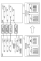
図1は、実施形態に係る照明システムを示す図である。実施形態に係る照明システム1は、A会場に設置される照明システム1Aと、B会場に設置される照明システム1Bとで構成される。A会場及びB会場は、スタジオや劇場などの照明演出が行われるステージ等を備えた場所である。
<Lighting system overview>
1 is a diagram showing a lighting system according to an embodiment. The lighting system 1 according to the embodiment is composed of a
A会場に設置される照明システム1Aは、複数のバトン10と、ノード30と、照明制御装置100-1とを備える。照明システム1Aにおいて、ノード30と照明制御装置100-1とは、例えば、LAN(Local Area Network)などの所定のネットワークに接続される。ノード30と照明制御装置100-1とは、所定のネットワークを介して、相互に通信できる。
The
B会場に設置される照明システム1Bは、複数のバトン20と、ノード40と、照明制御装置100-2とを備える。照明システム1Bにおいて、ノード40と照明制御装置100-2とは、例えば、LAN(Local Area Network)などの所定のネットワークに接続される。ノード30と照明制御装置100-2とは、所定のネットワークを介して、相互に通信できる。
The
ノード30やノード40は、例えばDMXノードやRDMノードと称され、照明機器と照明制御装置100との間の通信を中継する装置である。すなわち、ノード30は、所定の通信プロトコル、例えばDMX規格に従った通信プロトコルや、DMXを拡張したRDM規格に沿った通信方式により、照明機器と双方向通信が可能である。ノード30は、バトン10に備えられたポート11を介して照明機器と接続される。また、ノード40は、バトン20に備えられたポート21を介して照明機器と接続される。
照明制御装置100は、各照明機器に対して制御を行う操作者による操作を受付ける。例えば、照明制御装置100は、調光操作卓あるいは調光卓と称される装置である。照明制御装置100-1は、操作者による操作等に応じて、各照明機器の調光等を制御する情報(信号)をノード30に送信する。また、照明制御装置100-2は、操作者による操作等に応じて、各照明機器の調光等を制御する情報(信号)をノード40に送信する。
The
<照明制御装置の処理例>
照明制御装置100は、各照明機器の調光等を制御する情報(信号)に基づいて、照明演出等を行うための設定情報を保存する。設定情報の作成は、照明制御装置100の操作者により手動で実施される。照明制御装置100の操作者は、例えば、照明空間となるスタジオや劇場等の見取り図に対して、どのバトンのどの位置に、どの照明機器を設置するかといったことが記載された、いわゆる仕込み図面を参照しながら設定情報を作成する。
<Example of processing by lighting control device>
The
設定情報には、パッチデータやシーンデータ、エフェクトデータなどが含まれる。また、設定情報には、各照明機器に対して割り付けたDMXアドレス(以下、「制御アドレス」と称する。)と、照明制御装置100に備えられた各フェーダとの対応関係が含まれる。また、設定情報には、同一のフェーダの操作により制御される照明機器のグループを示すCH(Channel)番号が含まれる。これにより、照明制御装置100の操作者は、各フェーダを操作することにより、各照明機器の調光等を制御する情報を送信できる。
The setting information includes patch data, scene data, effect data, etc. The setting information also includes the correspondence between the DMX address (hereinafter referred to as the "control address") assigned to each lighting device and each fader provided in the
また、設定情報には、照明機器が接続されるバトンの機器接続位置を示す第1の識別情報(後述する「機器レイアウトデータ」)と、所定の対象を基準としたバトンの位置を示す第2の識別情報(後述する「バトンレイアウトデータ」)とが含まれている。 The setting information also includes first identification information ("equipment layout data" described below) indicating the device connection position of the baton to which the lighting device is connected, and second identification information ("baton layout data" described below) indicating the position of the baton relative to a specified target.
第1の識別情報は、例えば、照明機器を接続するために、バトンが備えているポートの情報に該当する。また、第2の識別情報は、スタジオや劇場等の照明空間におけるバトンの位置を示す情報である。所定の基準として、例えば、照明機器が接続される照明機器の設置が行われる施設内に設けられた物体を採用でき、スタジオや劇場等に備えられている客席の位置や通路の位置などが例示される。また、所定の基準は、照明機器により照明演出が行われる領域であってもよく、照明演出が行われるステージの領域等が例示される。 The first identification information corresponds to, for example, information about a port that the baton has for connecting lighting equipment. The second identification information is information indicating the position of the baton in a lighting space such as a studio or theater. As the predetermined criterion, for example, an object provided in the facility where the lighting equipment to be connected is installed can be used, and examples thereof include the positions of the audience seats and the aisles provided in a studio or theater. The predetermined criterion may also be the area where the lighting performance is performed by the lighting equipment, and examples thereof include the area of the stage where the lighting performance is performed.
前述の設定情報は、機種が異なる他の照明制御装置100(以下、「他の装置」と称する。)でも利用可能な共通のデータ形式で保存される。これにより、照明制御装置間での設定情報の相互利用が容易となる。 The above-mentioned setting information is saved in a common data format that can be used by other lighting control devices 100 (hereinafter referred to as "other devices") of different models. This makes it easy to share setting information between lighting control devices.
以下、図2を用いて、照明制御装置における設定情報の相互利用例について説明する。図2は、実施形態に係る設定情報の相互利用例を示す図である。以下では、A会場で利用された照明機器をB会場に持ち込んで利用する場合、B会場に設置されている照明制御装置100-2において、A会場に設置されている照明制御装置100-1の設定情報を利用する例について説明する。 An example of mutual use of setting information in lighting control devices will be described below with reference to FIG. 2. FIG. 2 is a diagram showing an example of mutual use of setting information according to an embodiment. Below, an example will be described in which, when lighting equipment used in venue A is brought to venue B for use, the lighting control device 100-2 installed in venue B uses the setting information of the lighting control device 100-1 installed in venue A.
図2に示すように、A会場には計4台のバトン10が設けられている。そして、A会場における照明演出に合計3台の照明機器50が利用されている。
As shown in FIG. 2, a total of four batons 10 are installed in venue A. A total of three
また、照明制御装置100-1は、照明制御装置100-1の操作者により、A会場の照明演出のために作成された設定情報を保存する。図2に示すように、照明制御装置1001-が保存する設定情報は、バトンレイアウトデータと機器レイアウトデータとを含んでいる。 The lighting control device 100-1 also stores setting information created by the operator of the lighting control device 100-1 for the lighting performance in venue A. As shown in FIG. 2, the setting information stored by the lighting control device 1001- includes baton layout data and equipment layout data.
バトンレイアウトデータは、A会場に設置されているバトン10に対して個別に割り振られている各バトンに固有のバトンIDと、バトン情報とを対応付けて構成されている。バトン情報は、所定の対象を基準としたバトンの位置を示す情報である。図2では、バトン10の位置を示す位置情報として、A会場の客席を基準とした情報が割り振られている例を示している。すなわち、A会場の客席から1列目のバトン101に対して位置情報:「0-1」が割り振られ、2列目~4列目のバトン102~104に対して、位置情報:「0-2」、位置情報:「0-3」、位置情報:「0-4」がそれぞれ割り振られている。 The baton layout data is configured by associating baton information with a unique baton ID that is individually assigned to each baton 10 installed in venue A. The baton information is information that indicates the position of the baton with a specified target as a reference. FIG. 2 shows an example in which information based on the audience seats in venue A is assigned as the position information indicating the position of the baton 10. That is, from the audience seats in venue A, position information: "0-1" is assigned to baton 10-1 in the first row, and position information: "0-2", "0-3", and "0-4" are assigned to batons 10-2 to 10-4 in the second to fourth rows, respectively.
バトンの位置を示す位置情報は、B会場に設置されているバトン20に対しても、A会場と同一の対象を所定の基準として割り振られている。すなわち、B会場の客席から1列目のバトン201に対して位置情報:「0-1」が割り振られ、2列目~4列目のバトン202~204に対して、位置情報:「0-2」、位置情報:「0-3」、位置情報:「0-4」がそれぞれ割り振られている。このように、所定の対象を基準としたバトンの位置を示す位置情報を利用することにより、会場がどこであっても、照明機器が設置されているバトンの位置を簡易に特定できる。なお、バトン情報が含むバトンの位置を示す情報は、各会場に設けられる物体などを所定の基準とする情報であるので、所定の基準には、各会場に共通に設けられる物体等を採用することが望ましい。
The position information indicating the position of the baton is also assigned to the
また、図2に示すように、照明制御装置100-1が保存する設定情報に含まれる機器レイアウトデータは、照明機器に対して個別に割り振られている各照明機器に固有の機器IDと、バトンIDとを対応付けて構成されている。なお、バトンレイアウトデータは、バトンが有するポートに対して個別に割り振られている各ポートに固有のポートIDを含んでもよい。図2に示す例では、バトン101が有するポートP111(ポートID:PT111)に照明機器501が接続され、バトン101が有するポートP113(ポートID:PT113)に照明機器502が接続され、バトン102が有するポートP122(ポートID:PT122)に照明機器503が接続されている。 As shown in Fig. 2, the device layout data included in the setting information stored by the lighting control device 100-1 is configured by associating a device ID unique to each lighting device, which is individually assigned to each lighting device, with a baton ID. The baton layout data may also include a port ID unique to each port, which is individually assigned to the port of the baton. In the example shown in Fig. 2, a lighting device 50-1 is connected to a port P11-1 (port ID: PT111) of the baton 10-1 , a lighting device 50-2 is connected to a port P11-3 (port ID: PT113) of the baton 10-1 , and a lighting device 50-3 is connected to a port P12-2 ( port ID: PT122) of the baton 10-2 .
図2に示すバトンレイアウトデータ及び機器レイアウトデータにより、客席から1列目に位置するバトン101(バトンID:AB01)に照明機器501(機器ID:SK51)及び照明機器502(機器ID:SK52)が接続されていることや、客席から2列目に位置するバトン102(バトンID:AB02)に照明機器503(機器ID:SK53)が接続されていることが把握される。 The baton layout data and equipment layout data shown in FIG. 2 show that lighting equipment 50 1 (equipment ID: SK51) and lighting equipment 50 2 (equipment ID: SK52) are connected to baton 10 1 (baton ID: AB01), which is located in the first row from the audience seats, and that lighting equipment 50 3 (equipment ID: SK53) is connected to baton 10 2 (baton ID: AB02), which is located in the second row from the audience seats.
そして、A会場で利用した3台の照明機器50をB会場に持ち込んで利用する場合、照明制御装置100-2は、照明制御装置100―1において設定情報として保存されているバトンレイアウトデータ及び機器レイアウトデータを取得する。バトンレイアウトデータ及び機器レイアウトデータは、任意の方法で取得でき、例えば、照明制御装置100-1の設定情報が保存されるクラウドサーバや可搬型の補助記憶装置から取得できる。可搬型の補助記憶装置としては、USB(Universal Serial Bus)フラッシュドライブやメモリカード、ハードディスクドライブなどを利用できる。
When the three
照明制御装置100-2は、照明制御装置100-1から取得したバトンレイアウトデータ及び機器レイアウトデータを用いて、機器レイアウトデータを設定する。例えば、照明制御装置100-2は、A会場において照明機器50の設置されているときの位置関係を利用して、機器レイアウトデータを設定する。すなわち、照明制御装置100-2は、図2に示すように、照明機器501(SK51)及び照明機器502(SK52)の位置情報をB会場の客席から1列目のバトン201(バトンID:BB01)に設定し、照明機器503(SK53)の設置位置をB会場の客席から2列目のバトン202(バトンID:BB02)に設定する。
The lighting control device 100-2 sets the equipment layout data using the baton layout data and the equipment layout data acquired from the lighting control device 100-1. For example, the lighting control device 100-2 sets the equipment layout data using the positional relationship when the
機器レイアウトデータの設定後、B会場に持ち込まれた照明機器50は、照明制御装置100-1から取得したバトンレイアウトデータ及び機器レイアウトデータに基づいて設置される。すなわち、照明機器50は、A会場と同様の位置関係で設置される。
After the equipment layout data is set, the
照明機器の接続後、照明制御装置100-2は、バトン20に接続されることで自装置と通信可能に接続された照明機器50から設定情報を取得し、取得した設定情報を用いて、照明機器50の設定を行う。ここで、照明機器50に保存された設定情報を第2の設定情報といい、例えば、照明制御装置100-2は、照明機器50から取得する制御アドレスやCH番号を、バトン20に接続された照明機器50の制御アドレスやCH番号としてそのまま利用する。
After the lighting devices are connected, the lighting control device 100-2 acquires setting information from the
実施形態に係る照明制御装置100は、照明機器が接続されるバトンの機器接続位置を示す機器レイアウトデータと、所定の対象を基準としたバトンの位置を示すバトンレイアウトデータとを含む設定情報を取得する。また、照明制御装置100は、取得した設定情報を用いて、バトン(バトン10又はバトン20)に接続される照明機器の設定を実行する。このようにして、照明制御装置100は、照明制御装置の保存データを異なる機種間での相互に利用できる。
The
<照明制御装置の構成例>
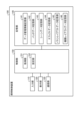
以下、図3を用いて、実施形態に係る照明制御装置100の構成例について説明する。図3は、実施形態に係る照明制御装置の構成例を示すブロック図である。
<Example of lighting control device configuration>
An example of the configuration of the
図3に示すように、照明制御装置100は、入力部110と、表示部120と、通信部130と、記憶部140と、制御部150とを有する。
As shown in FIG. 3, the
入力部110は、照明制御装置100の操作者の操作入力を受け付ける。入力部110は、例えば、キーボードやマウス、タッチパネル等の入力装置により実現される。入力部110が受け付ける操作入力には、他の装置から設定情報を取得するための操作入力や、照明機器の制御アドレス及びCH番号を設定するための操作入力などがある。
The input unit 110 accepts operational inputs from the operator of the
表示部120は、照明制御装置100により実行される照明機器の制御に関する各種情報等を表示する。表示部120は、例えば、液晶モニタや液晶ディスプレイ等の表示装置により実現される。
The display unit 120 displays various information related to the control of the lighting devices executed by the
通信部130は、ノード30等との間で情報を送受信する。通信部130は、ノード30等との間の通信を制御する機能を有し、例えば、NIC(Network Interface Card)等の通信装置により実現される。また、通信部130は、設定情報を保存するクラウドサーバと通信できる。
The
記憶部140は、制御部150により実現される制御を実現するためのプログラム等を記憶する。記憶部140は、例えば、RAM(Random Access Memory)、フラッシュメモリ(Flash Memory)等の半導体メモリ素子、または、ハードディスク、光ディスク等の記憶装置によって実現される。
The
図3に示すように、記憶部140は、データ管理情報記憶部141と、パッチデータ記憶部142と、シーンデータ記憶部143と、エフェクトデータ記憶部144と、バトンレイアウトデータ記憶部145と、機器レイアウトデータ記憶部146とを有し、第1の設定情報としての設定情報を記憶する。上述したように、第1の設定情報は照明制御装置100に記憶された設定情報であり、第2の設定情報は照明機器に記憶された設定情報となる。つまり、第1の設定情報には第2の設定情報が含まれていてもよい。
As shown in FIG. 3, the
図4は、実施形態に係るデータ管理情報の概要を示す図である。図4に示すように、データ管理情報は、照明演出のための設定情報に含まれる各データのバージョン番号と、保存先相対パスとを対応付けて構成される。バージョン番号は、照明制御装置100の機能追加や不具合修正などに伴う、各データのデータ形式の変更に伴って更新される。保存先相対パスは、各データのファイルの保存先を示す情報である。
Figure 4 is a diagram showing an overview of data management information according to an embodiment. As shown in Figure 4, the data management information is configured by associating the version number of each piece of data included in the setting information for lighting performance with the relative storage path. The version number is updated when the data format of each piece of data is changed due to the addition of functions to the
パッチデータ記憶部142は、パッチデータのファイルを記憶する。シーンデータ記憶部143と、シーンデータのファイルを記憶する。エフェクトデータ記憶部144は、エフェクトデータのファイルを記憶する。パッチデータや、シーンデータや、エフェクトデータは、照明機器ごとの照度や色彩、照明機器を移動させるムービングなどの照明演出に対応した調光を実行するための制御データであり、照明機器に対して個別に割り振られている各照明機器に固有の制御アドレスに対応付けられる。 The patch data storage unit 142 stores patch data files. The scene data storage unit 143 stores scene data files. The effect data storage unit 144 stores effect data files. Patch data, scene data, and effect data are control data for performing dimming corresponding to lighting effects such as the illuminance and color of each lighting device, and moving the lighting device, and are associated with a control address unique to each lighting device that is individually assigned to the lighting device.
バトンレイアウトデータ記憶部145は、所定の対象を基準としたバトンの位置を示す第2の識別情報として機能するバトンレイアウトデータを記憶する。図5は、実施形態に係るバトンレイアウトデータの概要を示す図である。図5は、例えば、図2に対応するバトンレイアウトデータを示している。
The baton layout
図5に示すように、バトンレイアウトデータは、バトン20に対して個別に割り振られている各バトンに固有のバトンIDと、バトン情報とを対応付けて構成される。バトン情報には、位置情報と保有ポート数の情報とが含まれる。位置情報は、所定の対象を基準としたバトンの位置を示す情報であり、バトンの位置ごとに固有の識別情報(例えば、「0-1」など)が個別に割り振られている。所定の対象として、例えば、照明機器の設置が行われる施設内に設けられた物体を採用できる。採用される物体として、スタジオや劇場等に備えられている客席の位置や通路の位置などが例示される。また、所定の対象は、照明機器により照明演出が行われる領域であってもよく、照明演出が行われるステージの領域等が例示される。保有ポート数は、各バトンが照明機器の機器接続位置として備えるポートの数に対応する。
As shown in FIG. 5, the baton layout data is configured by associating a baton ID, which is unique to each baton and is individually assigned to the
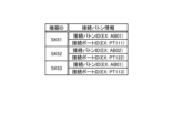
機器レイアウトデータ記憶部146は、照明機器が接続されるバトンの機器接続位置を示す第1の識別情報として機能する機器レイアウトデータを記憶する。図6は、実施形態に係る機器レイアウトデータの概要を示す図である。図6は、例えば、図2に対応する機器レイアウトデータを示している。 The device layout data storage unit 146 stores device layout data that functions as first identification information indicating the device connection position of the baton to which the lighting device is connected. FIG. 6 is a diagram showing an overview of the device layout data according to the embodiment. FIG. 6 shows, for example, the device layout data corresponding to FIG. 2.
図6に示すように、機器レイアウトデータは、照明機器に対して個別に割り振られている各照明機器に固有の識別情報である機器IDと、接続バトン情報とを対応付けて構成される。接続バトン情報は、照明機器が接続されるバトンに割り振られたバトンID(例えば、「AB01」など)に対応する。接続ポートIDは、照明機器が接続されるポートに対して個別に割り振られている各ポートに固有のポートID(例えば、「PT101」など)に対応する。 As shown in FIG. 6, the device layout data is configured by associating device IDs, which are identification information unique to each lighting device that is individually assigned to the lighting device, with connection baton information. The connection baton information corresponds to the baton ID (e.g., "AB01") assigned to the baton to which the lighting device is connected. The connection port ID corresponds to a port ID (e.g., "PT101") unique to each port that is individually assigned to the port to which the lighting device is connected.
図3に戻り、制御部150は、照明制御装置100の各種処理を実行する。制御部150は、プロセッサやメモリを備えた制御回路により実現できる。制御部150が有する各機能部は、例えば、プロセッサによって内部メモリから読み込まれたプログラムに記述された命令が、内部メモリを作業領域として実行されることにより実現される。プロセッサが内部メモリから読み込むプログラムには、OS(Operating System)やアプリケーションプログラムが含まれる。また、制御部150が有する各機能部は、例えば、ASIC(Application Specific Integrated Circuit)やFPGA(Field-Programmable Gate Array)等の集積回路により実現されてもよい。
Returning to FIG. 3, the control unit 150 executes various processes of the
図3に示すように、制御部150は、取得部151と、設定部152とを有する。なお、図3は、制御部150が有する機能部を例示するものであり、図3に示す例には特に限定される必要はない。
As shown in FIG. 3, the control unit 150 has an
取得部151は、照明機器が接続されるバトンの機器接続位置を示す第1の識別情報として機能する機器レイアウトデータと、所定の対象を基準としたバトンの位置を示す第2の識別情報として機能するバトンレイアウトデータと、を含み、他の装置において保存された設定情報を取得する。設定情報には、前述のバトンレイアウトデータ及び機器レイアウトデータの他、データ管理情報や、パッチデータや、シーンデータや、エフェクトデータが含まれる。設定情報は、任意の方法で取得でき、例えば、他の装置の設定情報が保存されるクラウドサーバや可搬型の補助記憶装置から取得できる。可搬型の補助記憶装置としては、USBフラッシュドライブやメモリカード、ハードディスクドライブなどを利用できる。
The
設定部152は、取得部151により取得された第1の識別情報及び第2の識別情報、及び自装置と通信可能に接続された照明機器から取得する第2の設定情報を用いて、バトンに接続される照明機器の設定を行う。
The
具体的には、設定部152は、照明制御装置100-1から取得したバトンレイアウトデータ及び機器レイアウトデータを用いて、機器レイアウトデータを設定する。具体的には、設定部152は、設定情報の取得元である他の装置が設置されている他の会場において照明機器50の設置されているときの位置関係を利用して、自装置の機器レイアウトデータを設定する。
Specifically, the
また、設定部152は、照明機器が持ち出された会場(以下、「前会場」と称する。)と、照明機器が持ち込まれた会場(以下、「今会場」と称する。)とで、対応するバトンが保有するポート数が異なる場合がある。このような場合の機器レイアウトデータの設定方法の一例について説明する。前会場よりも、今会場において対応バトンの保有するポート数が多い場合、例えば、対応バトンに照明機器が接続されるように、自装置の機器レイアウトデータを設定する。一方、前会場よりも、今会場において対応バトンの保有するポート数が少ない場合、対応バトンに隣接するバトンに渡って照明機器が接続されるように、自装置の機器レイアウトデータを設定する。
In addition, the
照明機器の接続後、設定部152は、バトンに接続された照明機器から設定情報を取得し、取得した設定情報を用いて、照明機器の設定を行う。例えば、設定部152は、照明機器から取得する制御アドレスやCH番号を、照明機器が持ち込まれた会場のバトンに接続された照明機器の制御アドレスやCH番号としてそのまま設定する。また、設定部152は、設定した制御アドレスやCH番号と、自装置が備える各フェーダとの対応関係を設定する。
After the lighting devices are connected, the
<照明制御装置における処理手順>
図7を用いて、照明制御装置100による処理手順について説明する。図7は、実施形態に係る照明制御装置100の処理手順例を示すフローチャートである。図7に示す処理手順は、制御部150により実行される。
<Processing procedure in lighting control device>
A process performed by the
図7に示すように、取得部151は、他の装置において保存された設定情報を取得する(ステップS101)。
As shown in FIG. 7, the
設定部152は、ステップS101で取得された設定情報に含まれるレイアウトデータ(バトンレイアウトデータ及び機器レイアウトデータ)に基づいて、レイアウトデータを設定する(ステップS102)。
The
設定部152は、ステップS102おいて設定された機器レイアウトデータに基づいて設置された照明機器から取得する設定情報(制御アドレスやCH番号など)を用いて、バトンに接続された照明機器の設定を実行する(ステップS103)。
The
<<変形例>>
<機器レイアウトデータの変形例>
以下、機器レイアウトデータ記憶部146に記憶される機器レイアウトデータの変形例について説明する。図8は、変形例に係る機器レイアウトデータの概要を示す図である。
<<Modifications>>
<Modifications of Device Layout Data>
The following describes modified examples of the device layout data stored in the device layout data storage unit 146. Fig. 8 is a diagram showing an overview of the device layout data according to the modified examples.
上記の実施形態では、機器レイアウトデータ記憶部146が記憶する機器レイアウトデータは、各照明機器に対して個別に割り振られている機器IDと、接続バトン情報とを対応付けて構成される例を説明したが、この例には特に限定される必要はない。例えば、図8に示すように、接続バトン情報として、接続ポート位置情報を記憶してもよい。 In the above embodiment, an example was described in which the device layout data stored in the device layout data storage unit 146 is configured by associating device IDs individually assigned to each lighting device with connection baton information, but this example does not need to be limited to this. For example, as shown in FIG. 8, connection port position information may be stored as connection baton information.
接続ポート位置情報は、バトンが備えるポートの位置を示す情報である。接続ポート位置情報は、バトンレイアウトデータと同様に、所定の対象を基準とした接続ポートの位置を示す情報を採用できる。具体的には、照明機器が設置される会場の客席を基準とした情報を個別に割り振ることができる。例えば、上述した図2に示す例を用いて説明すると、客席から見て一番左にあるポート111に対して「L1」、左から2番目にあるポートに対して「L2」、左から3番目にあるポートに「L3」を割り振ることができる。これにより、照明機器が接続されたバトンの位置だけではなく、ポートの相対的な位置までを把握できる。 The connection port position information is information indicating the position of the port equipped with the baton. As with the baton layout data, the connection port position information can adopt information indicating the position of the connection port based on a specific target. Specifically, information based on the audience seats of the venue where the lighting equipment is installed can be individually assigned. For example, using the example shown in FIG. 2 described above, it is possible to assign "L1" to the port 111 located at the far left as seen from the audience seats, "L2" to the second port from the left, and "L3" to the third port from the left. This allows not only the position of the baton to which the lighting equipment is connected, but also the relative positions of the ports to be grasped.
<バージョン情報に基づく設定情報の利用(1)>
上記の実施形態において、設定部152は、自装置が保存する設定情報のデータ管理情報に記録されたバージョン情報よりも、取得部151により取得された他の装置の設定情報のデータ管理情報に記録されているバージョン情報が新しい場合、他の装置の設定情報を利用しないようにしてもよい。例えば、設定部152は、他の装置から取得した設定情報を使用しないように、データ管理情報に記録されている保存先相対パスを無効にする。
<Use of setting information based on version information (1)>
In the above embodiment, the
これにより、他の装置から取得した設定情報により、不自然な照明演出が行われるなどの不都合を防止できる。 This prevents problems such as unnatural lighting effects caused by setting information obtained from other devices.
<バージョン情報に基づく設定情報の利用(2)>
上記の実施形態において、設定部152は、自装置が保存する第1の設定情報のバージョン情報よりも、取得部151により取得された他の装置の設定情報のバージョン情報が古い場合、自装置が保存する設定情報と他の装置が保存する設定情報との差分を読み込んで利用してもよい。例えば、設定部152は、自装置が保存する設定情報と、他の装置から取得した設定情報との差分を抽出し、抽出した差分のデータファイルに対して、保存先相対パスを設定する。
<Use of setting information based on version information (2)>
In the above embodiment, when the version information of the setting information of the other device acquired by the
これにより、他の装置から取得した設定情報のうち、利用可能な情報を設定することにより、不自然な照明演出が行われるなどの不都合を防止しつつ、照明演出のための設定作業の負担をできるだけ軽減できる。 This allows you to set available setting information obtained from other devices, preventing inconveniences such as unnatural lighting effects, while reducing the burden of setting up lighting effects as much as possible.
<<その他>>
上記の実施形態及び変形例に係る照明制御装置100の処理機能を実現するための情報処理プログラムを、光ディスク、半導体メモリ、磁気テープ、フレキシブルディスク等のコンピュータ読み取り可能な記録媒体に格納して配布してもよい。このとき、例えば、照明制御装置100は、情報処理プログラムをコンピュータにインストールし、上述の処理を実行する。
<<Others>>
An information processing program for implementing the processing functions of the
また、前述の情報処理プログラムをインターネット等のネットワーク上に配置されたクラウドストレージに格納しておき、コンピュータにダウンロード等できるようにしてもよい。また、上述の機能を、OS(Operating System)とアプリケーションソフトとの協働により実現してもよい。この場合には、OS以外の部分を媒体に格納して配布してもよいし、OS以外の部分をクラウドストレージに格納しておき、コンピュータにダウンロード等できるようにしてもよい。 The information processing program may also be stored in cloud storage located on a network such as the Internet, and may be made available for downloading to a computer. The above-mentioned functions may also be realized by cooperation between an operating system (OS) and application software. In this case, parts other than the OS may be stored on a medium and distributed, or parts other than the OS may be stored in cloud storage, and may be made available for downloading to a computer.
また、上記実施形態において説明した各処理のうち、自動的に行われるものとして説明した処理の全部又は一部を手動的に行うこともでき、あるいは、手動的に行われるものとして説明した処理の全部又は一部を公知の方法で自動的に行うこともできる。この他、上記文書中や図面中で示した処理手順、具体的名称、各種のデータやパラメータを含む情報については、特記する場合を除いて任意に変更することができる。例えば、各図に示した各種情報は、図示した情報に限られない。 Furthermore, among the processes described in the above embodiments, all or part of the processes described as being performed automatically can be performed manually, or all or part of the processes described as being performed manually can be performed automatically using known methods. In addition, the information including the processing procedures, specific names, various data, and parameters shown in the above documents and drawings can be changed as desired unless otherwise specified. For example, the various information shown in each drawing is not limited to the information shown in the drawings.
以上、本発明の実施形態を説明したが、この実施形態は、例として提示したものであり、発明の範囲を限定することは意図していない。この実施形態は、その他の様々な形態で実施されることが可能であり、発明の要旨を逸脱しない範囲で、種々の省略、置き換え、変更を行うことができる。この実施形態は、発明の範囲や要旨に含まれると同様に、特許請求の範囲に記載された発明とその均等の範囲に含まれるものである。また、この実施形態は、処理内容を矛盾させない範囲で適宜組み合わせることが可能である。 Although an embodiment of the present invention has been described above, this embodiment is presented as an example and is not intended to limit the scope of the invention. This embodiment can be implemented in various other forms, and various omissions, substitutions, and modifications can be made without departing from the gist of the invention. This embodiment is included within the scope of the invention and its equivalents as described in the claims, as well as within the scope and gist of the invention. Furthermore, this embodiment can be combined as appropriate as long as it does not cause contradictions in the processing contents.
また、本明細書に記載された効果はあくまで例示であって限定されるものでは無く、また他の効果があってもよい。 Furthermore, the effects described in this specification are merely examples and are not limiting, and other effects may also exist.
1A、1B 照明システム
10、20 バトン
30、40 ノード
50 照明機器
100 照明制御装置
110 入力部
120 表示部
130 通信部
140 記憶部
141 データ管理情報記憶部
142 パッチデータ記憶部
143 シーンデータ記憶部
144 エフェクトデータ記憶部
145 バトンレイアウトデータ記憶部
146 機器レイアウトデータ記憶部
150 制御部
151 取得部
152 設定部
Claims (6)
前記取得部により取得された前記第1の設定情報に含まれている前記第1の識別情報及び前記第2の識別情報を用いて、前記第1の会場とは異なる第2の会場の前記バトンの位置を示す前記第2の識別情報の設定を行い、前記第1の識別情報および前記第2の識別情報に基づいて前記第2の会場のバトンに接続されることにより、自装置と通信可能に接続された照明機器から取得する情報であって、当該照明機器に記憶されている制御アドレス情報である第2の設定情報を用いて、前記第2の会場のバトンに接続される照明機器の設定を行う設定部と;
を具備することを特徴とする照明制御装置。 an acquisition unit that acquires first setting information stored in another lighting control device installed in the first venue, the first setting information including first identification information indicating an equipment connection position of a baton to which a lighting device is connected and second identification information indicating a position of the baton relative to a predetermined target;
a setting unit that sets the second identification information indicating the position of the baton of a second venue different from the first venue, using the first identification information and the second identification information included in the first setting information acquired by the acquisition unit, and sets the lighting devices connected to the baton of the second venue using second setting information that is acquired from lighting devices connected to the baton of the second venue so as to be communicable with the device itself , the second setting information being control address information stored in the lighting devices , based on the first identification information and the second identification information;
A lighting control device comprising:
ことを特徴とする請求項1に記載の照明制御装置。 The lighting control device according to claim 1 , wherein the predetermined target is an object provided within the facility of the first venue where the lighting device is to be installed.
ことを特徴とする請求項1に記載の照明制御装置。 The lighting control device according to claim 1 , wherein the predetermined target is an area in which a lighting effect is performed by the lighting device.
ことを特徴とする請求項1~3のいずれか1つに記載の照明制御装置。 The lighting control device according to any one of claims 1 to 3, characterized in that the first and second setting information are saved in a common data format that can be used by other lighting control devices of different models.
前記設定部は、
自装置が保存する前記第1の設定情報の前記バージョン情報よりも、前記取得部により取得された前記第1の設定情報の前記バージョン情報が新しい場合、前記取得部により取得された前記第1の設定情報を利用しない
ことを特徴とする請求項4に記載の照明制御装置。 the first setting information includes version information that is updated in accordance with a change in the data format,
The setting unit is
The lighting control device according to claim 4, characterized in that if the version information of the first setting information acquired by the acquisition unit is newer than the version information of the first setting information stored in the lighting control device, the lighting control device does not use the first setting information acquired by the acquisition unit .
自装置が保存する前記第1の設定情報のバージョン情報よりも、前記取得部により取得された前記第1の設定情報の前記バージョン情報が古い場合、自装置が保存する前記第1の設定情報と前記取得部により取得された前記第1の設定情報との差分を読み込んで利用する
ことを特徴とする請求項5に記載の照明制御装置。 The setting unit is
The lighting control device according to claim 5, characterized in that, when the version information of the first setting information acquired by the acquisition unit is older than the version information of the first setting information stored in the lighting control device itself, a difference between the first setting information stored in the lighting control device itself and the first setting information acquired by the acquisition unit is read and used.
Priority Applications (1)
| Application Number | Priority Date | Filing Date | Title |
|---|---|---|---|
| JP2020165564A JP7484635B2 (en) | 2020-09-30 | 2020-09-30 | Lighting Control Device |
Applications Claiming Priority (1)
| Application Number | Priority Date | Filing Date | Title |
|---|---|---|---|
| JP2020165564A JP7484635B2 (en) | 2020-09-30 | 2020-09-30 | Lighting Control Device |
Publications (2)
| Publication Number | Publication Date |
|---|---|
| JP2022057353A JP2022057353A (en) | 2022-04-11 |
| JP7484635B2 true JP7484635B2 (en) | 2024-05-16 |
Family
ID=81110632
Family Applications (1)
| Application Number | Title | Priority Date | Filing Date |
|---|---|---|---|
| JP2020165564A Active JP7484635B2 (en) | 2020-09-30 | 2020-09-30 | Lighting Control Device |
Country Status (1)
| Country | Link |
|---|---|
| JP (1) | JP7484635B2 (en) |
Families Citing this family (1)
| Publication number | Priority date | Publication date | Assignee | Title |
|---|---|---|---|---|
| JP2024048768A (en) * | 2022-09-28 | 2024-04-09 | 東芝ライテック株式会社 | Lighting Control System |
Citations (4)
| Publication number | Priority date | Publication date | Assignee | Title |
|---|---|---|---|---|
| JP2004336169A (en) | 2003-04-30 | 2004-11-25 | Matsushita Electric Works Ltd | Dimming control system |
| JP2014120351A (en) | 2012-12-17 | 2014-06-30 | Toshiba Lighting & Technology Corp | Illumination baton and illumination system |
| JP2019175582A (en) | 2018-03-27 | 2019-10-10 | 東芝ライテック株式会社 | Illumination control device, illumination control system and illumination control method |
| US20200187335A1 (en) | 2018-12-10 | 2020-06-11 | Electronic Theatre Controls, Inc. | Systems and methods for determining lighting fixture arrangement information |
-
2020
- 2020-09-30 JP JP2020165564A patent/JP7484635B2/en active Active
Patent Citations (4)
| Publication number | Priority date | Publication date | Assignee | Title |
|---|---|---|---|---|
| JP2004336169A (en) | 2003-04-30 | 2004-11-25 | Matsushita Electric Works Ltd | Dimming control system |
| JP2014120351A (en) | 2012-12-17 | 2014-06-30 | Toshiba Lighting & Technology Corp | Illumination baton and illumination system |
| JP2019175582A (en) | 2018-03-27 | 2019-10-10 | 東芝ライテック株式会社 | Illumination control device, illumination control system and illumination control method |
| US20200187335A1 (en) | 2018-12-10 | 2020-06-11 | Electronic Theatre Controls, Inc. | Systems and methods for determining lighting fixture arrangement information |
Also Published As
| Publication number | Publication date |
|---|---|
| JP2022057353A (en) | 2022-04-11 |
Similar Documents
| Publication | Publication Date | Title |
|---|---|---|
| US20070276897A1 (en) | Method of deploying a production environment using a development environment | |
| JP2013097394A (en) | Network system management method, network system, and management server | |
| EP3861833B1 (en) | A method and a controller for configuring a replacement lighting device in a lighting system | |
| JP7484635B2 (en) | Lighting Control Device | |
| JP6017289B2 (en) | Management server, tenant pattern verification method, and computer system | |
| JP2017224406A (en) | Lighting control device and lighting control system | |
| JP2020047508A (en) | Illumination system and illumination system setting method | |
| JP6443111B2 (en) | Lighting control system, lighting control method, and lighting control program | |
| US20170346963A1 (en) | Managing system, intermediate apparatus, and managing method | |
| JP2016149326A (en) | Illumination control system, illumination control method and illumination control program | |
| JP5333115B2 (en) | Firmware update device and program | |
| JP6497155B2 (en) | Lighting control system, lighting control method, and lighting control program | |
| JP7428106B2 (en) | Information processing equipment and information processing system | |
| JP2016181330A (en) | Illumination control system, illumination control method, and illumination control program | |
| JP7405257B2 (en) | Communication device, communication device control system, communication device control method and program | |
| JP2010181930A (en) | Field-equipment engineering apparatus | |
| JP2004215164A (en) | External device control device, external device control method, and external device control program | |
| US11188291B2 (en) | Audio signal processing apparatus, method for processing audio signal, and storage medium storing program | |
| JP7423960B2 (en) | lighting control system | |
| JP5927846B2 (en) | Information processing apparatus, authentication system, and authentication program | |
| JP2017204432A (en) | Control device | |
| JP6984518B2 (en) | Lighting control device, lighting control system and lighting control method | |
| JP7154004B2 (en) | LIGHTING CONTROL DEVICE, LIGHTING CONTROL METHOD AND LIGHTING CONTROL PROGRAM | |
| JP5263103B2 (en) | Firmware update device and program | |
| JP4862545B2 (en) | Parameter management apparatus and parameter management program for audio equipment |
Legal Events
| Date | Code | Title | Description |
|---|---|---|---|
| A621 | Written request for application examination |
Free format text: JAPANESE INTERMEDIATE CODE: A621 Effective date: 20230518 |
|
| A977 | Report on retrieval |
Free format text: JAPANESE INTERMEDIATE CODE: A971007 Effective date: 20231213 |
|
| A131 | Notification of reasons for refusal |
Free format text: JAPANESE INTERMEDIATE CODE: A131 Effective date: 20231226 |
|
| A521 | Request for written amendment filed |
Free format text: JAPANESE INTERMEDIATE CODE: A523 Effective date: 20240222 |
|
| TRDD | Decision of grant or rejection written | ||
| A01 | Written decision to grant a patent or to grant a registration (utility model) |
Free format text: JAPANESE INTERMEDIATE CODE: A01 Effective date: 20240402 |
|
| A61 | First payment of annual fees (during grant procedure) |
Free format text: JAPANESE INTERMEDIATE CODE: A61 Effective date: 20240415 |
|
| R150 | Certificate of patent or registration of utility model |
Ref document number: 7484635 Country of ref document: JP Free format text: JAPANESE INTERMEDIATE CODE: R150 |