JP7483860B2 - Hierarchical reporting of location assistance information for positioning reference signal (PRS) resources in multi-beam user equipment based positioning scenarios - Patents.com - Google Patents
Hierarchical reporting of location assistance information for positioning reference signal (PRS) resources in multi-beam user equipment based positioning scenarios - Patents.com Download PDFInfo
- Publication number
- JP7483860B2 JP7483860B2 JP2022507380A JP2022507380A JP7483860B2 JP 7483860 B2 JP7483860 B2 JP 7483860B2 JP 2022507380 A JP2022507380 A JP 2022507380A JP 2022507380 A JP2022507380 A JP 2022507380A JP 7483860 B2 JP7483860 B2 JP 7483860B2
- Authority
- JP
- Japan
- Prior art keywords
- location
- description
- level
- relative
- base station
- Prior art date
- Legal status (The legal status is an assumption and is not a legal conclusion. Google has not performed a legal analysis and makes no representation as to the accuracy of the status listed.)
- Active
Links
- 230000005540 biological transmission Effects 0.000 claims description 213
- 238000000034 method Methods 0.000 claims description 72
- 239000013598 vector Substances 0.000 claims description 69
- 238000004891 communication Methods 0.000 claims description 59
- 238000005259 measurement Methods 0.000 claims description 11
- 238000012545 processing Methods 0.000 description 46
- 230000006870 function Effects 0.000 description 35
- 239000002609 medium Substances 0.000 description 19
- 230000008859 change Effects 0.000 description 16
- 238000007726 management method Methods 0.000 description 14
- 235000019580 granularity Nutrition 0.000 description 11
- 238000001228 spectrum Methods 0.000 description 11
- 238000005516 engineering process Methods 0.000 description 9
- 239000000969 carrier Substances 0.000 description 7
- 230000001413 cellular effect Effects 0.000 description 7
- 238000010586 diagram Methods 0.000 description 6
- 238000012937 correction Methods 0.000 description 5
- 238000001514 detection method Methods 0.000 description 5
- 238000013507 mapping Methods 0.000 description 5
- 125000004122 cyclic group Chemical group 0.000 description 4
- 230000006837 decompression Effects 0.000 description 4
- 230000003287 optical effect Effects 0.000 description 4
- 239000002245 particle Substances 0.000 description 4
- 230000002441 reversible effect Effects 0.000 description 4
- 238000003491 array Methods 0.000 description 3
- 230000008901 benefit Effects 0.000 description 3
- 238000004422 calculation algorithm Methods 0.000 description 3
- 230000006835 compression Effects 0.000 description 3
- 238000007906 compression Methods 0.000 description 3
- 238000013461 design Methods 0.000 description 3
- 230000011664 signaling Effects 0.000 description 3
- 238000013459 approach Methods 0.000 description 2
- 230000009286 beneficial effect Effects 0.000 description 2
- 239000000835 fiber Substances 0.000 description 2
- 230000007246 mechanism Effects 0.000 description 2
- 238000012986 modification Methods 0.000 description 2
- 230000004048 modification Effects 0.000 description 2
- 230000010363 phase shift Effects 0.000 description 2
- 238000012913 prioritisation Methods 0.000 description 2
- 230000005855 radiation Effects 0.000 description 2
- 230000011218 segmentation Effects 0.000 description 2
- 238000012384 transportation and delivery Methods 0.000 description 2
- 238000012795 verification Methods 0.000 description 2
- 230000027311 M phase Effects 0.000 description 1
- 241000700159 Rattus Species 0.000 description 1
- 230000002776 aggregation Effects 0.000 description 1
- 238000004220 aggregation Methods 0.000 description 1
- 230000003190 augmentative effect Effects 0.000 description 1
- 230000003139 buffering effect Effects 0.000 description 1
- 238000004364 calculation method Methods 0.000 description 1
- 230000015556 catabolic process Effects 0.000 description 1
- 238000004590 computer program Methods 0.000 description 1
- 230000003247 decreasing effect Effects 0.000 description 1
- 238000006731 degradation reaction Methods 0.000 description 1
- 230000009977 dual effect Effects 0.000 description 1
- 239000011521 glass Substances 0.000 description 1
- 238000007689 inspection Methods 0.000 description 1
- 230000000670 limiting effect Effects 0.000 description 1
- 230000007774 longterm Effects 0.000 description 1
- 239000000463 material Substances 0.000 description 1
- 238000010295 mobile communication Methods 0.000 description 1
- 238000005192 partition Methods 0.000 description 1
- 230000008569 process Effects 0.000 description 1
- 238000013139 quantization Methods 0.000 description 1
- 230000002829 reductive effect Effects 0.000 description 1
- 238000013468 resource allocation Methods 0.000 description 1
- 230000009131 signaling function Effects 0.000 description 1
- 230000003595 spectral effect Effects 0.000 description 1
- 230000003068 static effect Effects 0.000 description 1
- 238000012546 transfer Methods 0.000 description 1
- 239000006163 transport media Substances 0.000 description 1
- 238000010200 validation analysis Methods 0.000 description 1
- 230000000007 visual effect Effects 0.000 description 1
Images


Classifications
-
- G—PHYSICS
- G01—MEASURING; TESTING
- G01S—RADIO DIRECTION-FINDING; RADIO NAVIGATION; DETERMINING DISTANCE OR VELOCITY BY USE OF RADIO WAVES; LOCATING OR PRESENCE-DETECTING BY USE OF THE REFLECTION OR RERADIATION OF RADIO WAVES; ANALOGOUS ARRANGEMENTS USING OTHER WAVES
- G01S1/00—Beacons or beacon systems transmitting signals having a characteristic or characteristics capable of being detected by non-directional receivers and defining directions, positions, or position lines fixed relatively to the beacon transmitters; Receivers co-operating therewith
- G01S1/02—Beacons or beacon systems transmitting signals having a characteristic or characteristics capable of being detected by non-directional receivers and defining directions, positions, or position lines fixed relatively to the beacon transmitters; Receivers co-operating therewith using radio waves
- G01S1/04—Details
- G01S1/042—Transmitters
- G01S1/0428—Signal details
-
- H—ELECTRICITY
- H04—ELECTRIC COMMUNICATION TECHNIQUE
- H04W—WIRELESS COMMUNICATION NETWORKS
- H04W4/00—Services specially adapted for wireless communication networks; Facilities therefor
- H04W4/02—Services making use of location information
- H04W4/029—Location-based management or tracking services
-
- G—PHYSICS
- G01—MEASURING; TESTING
- G01S—RADIO DIRECTION-FINDING; RADIO NAVIGATION; DETERMINING DISTANCE OR VELOCITY BY USE OF RADIO WAVES; LOCATING OR PRESENCE-DETECTING BY USE OF THE REFLECTION OR RERADIATION OF RADIO WAVES; ANALOGOUS ARRANGEMENTS USING OTHER WAVES
- G01S5/00—Position-fixing by co-ordinating two or more direction or position line determinations; Position-fixing by co-ordinating two or more distance determinations
- G01S5/02—Position-fixing by co-ordinating two or more direction or position line determinations; Position-fixing by co-ordinating two or more distance determinations using radio waves
- G01S5/0205—Details
- G01S5/0236—Assistance data, e.g. base station almanac
-
- G—PHYSICS
- G01—MEASURING; TESTING
- G01S—RADIO DIRECTION-FINDING; RADIO NAVIGATION; DETERMINING DISTANCE OR VELOCITY BY USE OF RADIO WAVES; LOCATING OR PRESENCE-DETECTING BY USE OF THE REFLECTION OR RERADIATION OF RADIO WAVES; ANALOGOUS ARRANGEMENTS USING OTHER WAVES
- G01S5/00—Position-fixing by co-ordinating two or more direction or position line determinations; Position-fixing by co-ordinating two or more distance determinations
- G01S5/02—Position-fixing by co-ordinating two or more direction or position line determinations; Position-fixing by co-ordinating two or more distance determinations using radio waves
- G01S5/0284—Relative positioning
- G01S5/0289—Relative positioning of multiple transceivers, e.g. in ad hoc networks
-
- G—PHYSICS
- G01—MEASURING; TESTING
- G01S—RADIO DIRECTION-FINDING; RADIO NAVIGATION; DETERMINING DISTANCE OR VELOCITY BY USE OF RADIO WAVES; LOCATING OR PRESENCE-DETECTING BY USE OF THE REFLECTION OR RERADIATION OF RADIO WAVES; ANALOGOUS ARRANGEMENTS USING OTHER WAVES
- G01S5/00—Position-fixing by co-ordinating two or more direction or position line determinations; Position-fixing by co-ordinating two or more distance determinations
- G01S5/02—Position-fixing by co-ordinating two or more direction or position line determinations; Position-fixing by co-ordinating two or more distance determinations using radio waves
- G01S5/14—Determining absolute distances from a plurality of spaced points of known location
-
- H—ELECTRICITY
- H04—ELECTRIC COMMUNICATION TECHNIQUE
- H04W—WIRELESS COMMUNICATION NETWORKS
- H04W64/00—Locating users or terminals or network equipment for network management purposes, e.g. mobility management
-
- G—PHYSICS
- G01—MEASURING; TESTING
- G01S—RADIO DIRECTION-FINDING; RADIO NAVIGATION; DETERMINING DISTANCE OR VELOCITY BY USE OF RADIO WAVES; LOCATING OR PRESENCE-DETECTING BY USE OF THE REFLECTION OR RERADIATION OF RADIO WAVES; ANALOGOUS ARRANGEMENTS USING OTHER WAVES
- G01S2205/00—Position-fixing by co-ordinating two or more direction or position line determinations; Position-fixing by co-ordinating two or more distance determinations
- G01S2205/001—Transmission of position information to remote stations
- G01S2205/008—Transmission of position information to remote stations using a mobile telephone network
-
- G—PHYSICS
- G01—MEASURING; TESTING
- G01S—RADIO DIRECTION-FINDING; RADIO NAVIGATION; DETERMINING DISTANCE OR VELOCITY BY USE OF RADIO WAVES; LOCATING OR PRESENCE-DETECTING BY USE OF THE REFLECTION OR RERADIATION OF RADIO WAVES; ANALOGOUS ARRANGEMENTS USING OTHER WAVES
- G01S2205/00—Position-fixing by co-ordinating two or more direction or position line determinations; Position-fixing by co-ordinating two or more distance determinations
- G01S2205/01—Position-fixing by co-ordinating two or more direction or position line determinations; Position-fixing by co-ordinating two or more distance determinations specially adapted for specific applications
-
- H—ELECTRICITY
- H04—ELECTRIC COMMUNICATION TECHNIQUE
- H04W—WIRELESS COMMUNICATION NETWORKS
- H04W4/00—Services specially adapted for wireless communication networks; Facilities therefor
- H04W4/02—Services making use of location information
-
- H—ELECTRICITY
- H04—ELECTRIC COMMUNICATION TECHNIQUE
- H04W—WIRELESS COMMUNICATION NETWORKS
- H04W48/00—Access restriction; Network selection; Access point selection
- H04W48/08—Access restriction or access information delivery, e.g. discovery data delivery
- H04W48/12—Access restriction or access information delivery, e.g. discovery data delivery using downlink control channel
-
- H—ELECTRICITY
- H04—ELECTRIC COMMUNICATION TECHNIQUE
- H04W—WIRELESS COMMUNICATION NETWORKS
- H04W48/00—Access restriction; Network selection; Access point selection
- H04W48/16—Discovering, processing access restriction or access information
Landscapes
- Engineering & Computer Science (AREA)
- Physics & Mathematics (AREA)
- General Physics & Mathematics (AREA)
- Radar, Positioning & Navigation (AREA)
- Remote Sensing (AREA)
- Computer Networks & Wireless Communication (AREA)
- Signal Processing (AREA)
- Computer Security & Cryptography (AREA)
- Mobile Radio Communication Systems (AREA)
- Radar Systems Or Details Thereof (AREA)
- Position Fixing By Use Of Radio Waves (AREA)
Description
関連出願の相互参照
[0001] 本特許出願は、2019年8月14日に出願された「HIERARCHICAL REPORTING OF LOCATION ASSISTANCE INFORMATION FOR POSITIONING REFERENCE SIGNAL (PRS) RESOURCES IN A MULTI-BEAM USER EQUIPMENT-BASED POSITIONING SCENARIO」という名称のギリシャ特許出願第20190100360号と、2020年7月13日に出願された「HIERARCHICAL REPORTING OF LOCATION ASSISTANCE INFORMATION FOR POSITIONING REFERENCE SIGNAL (PRS) RESOURCES IN A MULTI-BEAM USER EQUIPMENT-BASED POSITIONING SCENARIO」という名称の米国非仮特許出願第16/927,401号とに対して米国特許法第119条に基づき優先権を主張するものであり、これらの特許出願の両方は本明細書の譲受人に譲渡され、その全体が参照により明確に本明細書に組み込まれる。
CROSS-REFERENCE TO RELATED APPLICATIONS
[0001] This patent application is a continuation of Greek patent application no. 20190100360, filed on August 14, 2019, entitled "HIERARCHICAL REPORTING OF LOCATION ASSISTION INFORMATION FOR POSITIONING REFERENCE SIGNAL (PRS) RESOURCES IN A MULTI-BEAM USER EQUIPMENT-BASED POSITIONING SCENARIO" and no. 20190100360, filed on July 13, 2020, entitled "HIERARCHICAL REPORTING OF LOCATION ASSISTION INFORMATION FOR POSITIONING REFERENCE SIGNAL (PRS) RESOURCES IN A MULTI-BEAM USER EQUIPMENT-BASED POSITIONING SCENARIO." No. 16/927,401, entitled "INFORMATION FOR POSITIONING REFERENCE SIGNAL (PRS) RESOURCES IN A MULTI-BEAM USER EQUIPMENT-BASED POSITIONING SCENARIO," both of which are assigned to the assignee hereof and are expressly incorporated by reference in their entireties.
[0002] 本開示の態様は、一般に、ワイヤレス通信(wireless communication)等に関する。 [0002] Aspects of the present disclosure generally relate to wireless communication and the like.
[0003] ワイヤレス通信システムは、第1世代アナログワイヤレス電話サービス(1G)、第2世代(2G)デジタルワイヤレス電話サービス(暫定2.5Gネットワークを含む)、第3世代(3G)高速データインターネット対応ワイヤレスサービス、ならびに第4世代(4G)サービス(たとえば、ロングタームエボリューション(LTE(登録商標))、WiMax(登録商標))を含む様々な世代を通して発展してきた。現在、セルラーおよびパーソナル通信サービス(PCS)システムを含む多くの異なるタイプのワイヤレス通信システムが使用されている。知られているセルラーシステムの例は、セルラーアナログアドバンストモバイルフォンシステム(AMPS:cellular Analog Advanced Mobile Phone System)と、符号分割多元接続(CDMA)、周波数分割多元接続(FDMA)、時分割多元接続(TDMA)、TDMAのグローバルシステムフォーモバイルアクセス(GSM(登録商標):Global System for Mobile access)変形などに基づくデジタルセルラーシステムとを含む。 [0003] Wireless communication systems have evolved through various generations, including first generation analog wireless telephone service (1G), second generation (2G) digital wireless telephone service (including interim 2.5G networks), third generation (3G) high-speed data Internet-enabled wireless service, and fourth generation (4G) services (e.g., Long Term Evolution (LTE), WiMax). Currently, many different types of wireless communication systems are in use, including cellular and personal communication service (PCS) systems. Examples of known cellular systems include the cellular Analog Advanced Mobile Phone System (AMPS) and digital cellular systems based on code division multiple access (CDMA), frequency division multiple access (FDMA), time division multiple access (TDMA), the Global System for Mobile access (GSM) variant of TDMA, and the like.
[0004] 第5世代(5G)モバイル標準は、改善の中でもとりわけ、より速いデータ転送速度、より多数の接続、およびより良いカバレッジを必要とする。5G標準(「New Radio」または「NR」とも呼ばれる)は、次世代モバイルネットワークアライアンスによれば、毎秒数十メガビットのデータレートを何万人ものユーザの各々に提供するように設計され、毎秒1ギガビットをオフィスフロアの何十人もの労働者に提供する。大規模なセンサ配置をサポートするには、数十万個の同時接続がサポートされるべきである。したがって、5Gモバイル通信のスペクトル効率は、現在の4G/LTE標準と比較して著しく向上されるべきである。さらに、現在の標準と比較して、シグナリング効率が向上されるべきであり、レイテンシがかなり低減されるべきである。 [0004] The fifth generation (5G) mobile standard calls for faster data rates, a larger number of connections, and better coverage, among other improvements. The 5G standard (also called "New Radio" or "NR") is designed to provide data rates of tens of megabits per second to each of tens of thousands of users, and one gigabit per second to dozens of workers on an office floor, according to the Next Generation Mobile Network Alliance. To support large-scale sensor deployments, hundreds of thousands of simultaneous connections should be supported. Thus, the spectral efficiency of 5G mobile communications should be significantly improved compared to the current 4G/LTE standards. Furthermore, signaling efficiency should be improved and latency should be significantly reduced compared to current standards.
[0005] 以下に、本明細書で開示される1つまたは複数の態様に関する簡略化された概要を提示する。したがって、後続の概要は、企図されるすべての態様に関する広範な概観と見なされるべきではなく、また、企図されるすべての態様に関する重要なもしくはクリティカルな要素を識別するもの、またはいずれか特定の態様に関連する範囲を示すものと見なされるべきでもない。したがって、後続の概要は、本明細書で開示されるメカニズムに関する1つまたは複数の態様に関するいくつかの概念を、後で提示される詳細な記述に先行して簡略化された形で提示することのみを目的とする。 [0005] The following presents a simplified summary of one or more aspects disclosed herein. As such, the following summary is not intended to be an extensive overview of all contemplated aspects, nor is it intended to identify key or critical elements of all contemplated aspects or to indicate the scope associated with any particular aspect. As such, the following summary is intended only to present some concepts of one or more aspects of the mechanisms disclosed herein in a simplified form prior to the more detailed description presented later.
[0006] 一態様では、ユーザ機器(UE:user equipment)は、メモリ(memory)と、少なくとも1つの送受信機(transceiver)と、メモリおよび少なくとも1つの送受信機に通信可能に結合された少なくとも1つのプロセッサ(processor)とを含み、少なくとも1つのプロセッサは、UEのロケーション(location)をUEが推定できるようにするための支援データ(assistance data)を、測位エンティティ(positioning entity)から少なくとも1つの送受信機を介して受信することと、支援データが複数の送信ポイント(transmission point)の各々の相対的ロケーション(relative location)を含み、ここにおいて、複数の送信ポイントの各々の相対的ロケーションが2つ以上の記述レベル(level of description)の階層(hierarchy)として表され、ここにおいて、より低い記述レベル(lower level of description)がより高い記述レベル(higher level of description)に対して相対的であり、およびここにおいて、最も高い記述レベル(highest level of description)が固定参照ポイント(fixed reference point)に対して相対的である、複数の送信ポイントの少なくともサブセット(subset)の各々から少なくとも1つの送受信機を介して少なくとも1つの測位参照信号(positioning reference signal)を受信することと、複数の送信ポイントのサブセットの各々からの少なくとも1つの測位参照信号の受信の特性(characteristics of reception)と複数の送信ポイントのサブセットの各々についての2つ以上の記述レベルおよび固定参照ポイントとに基づいて、UEのロケーションを推定(estimate)することとを行うように構成される。 [0006] In one aspect, a user equipment (UE) includes a memory, at least one transceiver, and at least one processor communicatively coupled to the memory and the at least one transceiver, the at least one processor receiving assistance data from a positioning entity via the at least one transceiver to enable the UE to estimate a location of the UE, the assistance data including a relative location of each of a plurality of transmission points, wherein the relative location of each of the plurality of transmission points is represented as a hierarchy of two or more levels of description, wherein a lower level of description is relative to a higher level of description, and wherein the highest level of description is a fixed reference point. and receiving at least one positioning reference signal via at least one transceiver from each of at least a subset of the plurality of transmission points relative to the fixed reference point; and estimating a location of the UE based on characteristics of reception of the at least one positioning reference signal from each of the subset of the plurality of transmission points and two or more description levels and a fixed reference point for each of the subset of the plurality of transmission points.
[0007] 一態様では、測位エンティティは、メモリと、少なくとも1つの送受信機と、メモリおよび少なくとも1つの送受信機に通信可能に結合された少なくとも1つのプロセッサとを含み、少なくとも1つのプロセッサは、UEのロケーションをUEが推定できるようにするための支援データを少なくとも1つの送受信機から送信させるように構成され、支援データは複数の送信ポイントの各々の相対的ロケーションを含み、ここにおいて、複数の送信ポイントの各々の相対的ロケーションは2つ以上の記述レベルの階層として表され、ここにおいて、より低い記述レベルはより高い記述レベルに対して相対的であり、およびここにおいて、最も高い記述レベルは固定参照ポイントに対して相対的である。 [0007] In one aspect, a positioning entity includes a memory, at least one transceiver, and at least one processor communicatively coupled to the memory and the at least one transceiver, the at least one processor configured to cause the at least one transceiver to transmit assistance data to enable a UE to estimate a location of the UE, the assistance data including a relative location of each of a plurality of transmission points, where the relative location of each of the plurality of transmission points is represented as a hierarchy of two or more descriptive levels, where a lower descriptive level is relative to a higher descriptive level, and where the highest descriptive level is relative to a fixed reference point.
[0008] 一態様では、UEによって実施されるワイヤレス通信の方法は、UEのロケーションをUEが推定できるようにするための支援データを測位エンティティから受信することと、支援データが複数の送信ポイントの各々の相対的ロケーションを含み、ここにおいて、複数の送信ポイントの各々の相対的ロケーションが2つ以上の記述レベルの階層として表され、ここにおいて、より低い記述レベルがより高い記述レベルに対して相対的であり、およびここにおいて、最も高い記述レベルが固定参照ポイントに対して相対的である、複数の送信ポイントの少なくともサブセットの各々から少なくとも1つの測位参照信号を受信することと、複数の送信ポイントのサブセットの各々からの少なくとも1つの測位参照信号の受信の特性と複数の送信ポイントのサブセットの各々についての2つ以上の記述レベルおよび固定参照ポイントとに基づいて、UEのロケーションを推定することとを含む。 [0008] In one aspect, a method of wireless communications implemented by a UE includes receiving assistance data from a positioning entity to enable the UE to estimate a location of the UE, the assistance data including a relative location of each of a plurality of transmission points, where the relative location of each of the plurality of transmission points is represented as a hierarchy of two or more description levels, where a lower description level is relative to a higher description level, and where the highest description level is relative to a fixed reference point, and estimating a location of the UE based on characteristics of the reception of the at least one positioning reference signal from each of the subset of the plurality of transmission points and the two or more description levels for each of the subset of the plurality of transmission points and the fixed reference point.
[0009] 一態様では、測位エンティティによって実施されるワイヤレス通信の方法は、UEのロケーションをUEが推定できるようにするための支援データを送信することを含み、支援データは複数の送信ポイントの各々の相対的ロケーションを含み、ここにおいて、複数の送信ポイントの各々の相対的ロケーションは2つ以上の記述レベルの階層として表され、ここにおいて、より低い記述レベルはより高い記述レベルに対して相対的であり、およびここにおいて、最も高い記述レベルは固定参照ポイントに対して相対的である。一態様では、UEは、UEのロケーションをUEが推定できるようにするための支援データを測位エンティティから受信するための手段と、支援データが複数の送信ポイントの各々の相対的ロケーションを含み、ここにおいて、複数の送信ポイントの各々の相対的ロケーションが2つ以上の記述レベルの階層として表され、ここにおいて、より低い記述レベルがより高い記述レベルに対して相対的であり、およびここにおいて、最も高い記述レベルが固定参照ポイントに対して相対的である、複数の送信ポイントの少なくともサブセットの各々から少なくとも1つの測位参照信号を受信するための手段と、複数の送信ポイントのサブセットの各々からの少なくとも1つの測位参照信号の受信の特性と複数の送信ポイントのサブセットの各々についての2つ以上の記述レベルおよび固定参照ポイントとに基づいて、UEのロケーションを推定するための手段とを含む。 [0009] In one aspect, a method of wireless communication implemented by a positioning entity includes transmitting assistance data to enable a UE to estimate a location of the UE, the assistance data including a relative location of each of a plurality of transmission points, where the relative location of each of the plurality of transmission points is represented as a hierarchy of two or more description levels, where a lower description level is relative to a higher description level, and where the highest description level is relative to a fixed reference point. In one aspect, the UE includes means for receiving assistance data from a positioning entity to enable the UE to estimate a location of the UE, the assistance data including a relative location of each of a plurality of transmission points, where the relative location of each of the plurality of transmission points is represented as a hierarchy of two or more description levels, where a lower description level is relative to a higher description level, and where the highest description level is relative to a fixed reference point, and means for estimating a location of the UE based on characteristics of the reception of the at least one positioning reference signal from each of the subset of the plurality of transmission points and the two or more description levels and the fixed reference point for each of the subset of the plurality of transmission points.
[0010] 一態様では、測位エンティティは、UEのロケーションをUEが推定できるようにするための支援データを送信するための手段を含み、支援データは複数の送信ポイントの各々の相対的ロケーションを含み、ここにおいて、複数の送信ポイントの各々の相対的ロケーションは2つ以上の記述レベルの階層として表され、ここにおいて、より低い記述レベルはより高い記述レベルに対して相対的であり、およびここにおいて、最も高い記述レベルは固定参照ポイントに対して相対的である。 [0010] In one aspect, the positioning entity includes means for transmitting assistance data to enable the UE to estimate a location of the UE, the assistance data including a relative location of each of a plurality of transmission points, where the relative location of each of the plurality of transmission points is represented as a hierarchy of two or more descriptive levels, where a lower descriptive level is relative to a higher descriptive level, and where the highest descriptive level is relative to a fixed reference point.
[0011] 一態様では、コンピュータ実行可能命令を記憶した非一時的コンピュータ可読媒体は、UEのロケーションをUEが推定できるようにするための支援データを測位エンティティから受信するようUEに命令する少なくとも1つの命令と、支援データが複数の送信ポイントの各々の相対的ロケーションを含み、ここにおいて、複数の送信ポイントの各々の相対的ロケーションが2つ以上の記述レベルの階層として表され、ここにおいて、より低い記述レベルがより高い記述レベルに対して相対的であり、およびここにおいて、最も高い記述レベルが固定参照ポイントに対して相対的である、複数の送信ポイントの少なくともサブセットの各々から少なくとも1つの測位参照信号を受信するようUEに命令する少なくとも1つの命令と、複数の送信ポイントのサブセットの各々からの少なくとも1つの測位参照信号の受信の特性と複数の送信ポイントのサブセットの各々についての2つ以上の記述レベルおよび固定参照ポイントとに基づいて、UEのロケーションを推定するようUEに命令する少なくとも1つの命令とを備えるコンピュータ実行可能命令を含む。 [0011] In one aspect, a non-transitory computer-readable medium having computer-executable instructions stored thereon includes computer-executable instructions comprising at least one instruction to instruct a UE to receive assistance data from a positioning entity to enable the UE to estimate a location of the UE, the assistance data including a relative location of each of a plurality of transmission points, where the relative location of each of the plurality of transmission points is represented as a hierarchy of two or more description levels, where a lower description level is relative to a higher description level, and where a highest description level is relative to a fixed reference point, and at least one instruction to instruct the UE to estimate a location of the UE based on characteristics of reception of the at least one positioning reference signal from each of the subset of the plurality of transmission points and the two or more description levels and the fixed reference point for each of the subset of the plurality of transmission points.
[0012] 一態様では、コンピュータ実行可能命令を記憶した非一時的コンピュータ可読媒体は、ユーザ機器(UE)のロケーションをUEが推定できるようにするための支援データを送信するよう測位エンティティに命令する少なくとも1つの命令を備えるコンピュータ実行可能命令を含み、支援データは複数の送信ポイントの各々の相対的ロケーションを含み、ここにおいて、複数の送信ポイントの各々の相対的ロケーションは2つ以上の記述レベルの階層として表され、ここにおいて、より低い記述レベルはより高い記述レベルに対して相対的であり、およびここにおいて、最も高い記述レベルは固定参照ポイントに対して相対的である。 [0012] In one aspect, a non-transitory computer-readable medium having computer-executable instructions stored thereon includes computer-executable instructions comprising at least one instruction to instruct a positioning entity to transmit assistance data to enable a user equipment (UE) to estimate a location of the UE, the assistance data including a relative location of each of a plurality of transmission points, where the relative location of each of the plurality of transmission points is represented as a hierarchy of two or more descriptive levels, where a lower descriptive level is relative to a higher descriptive level, and where the highest descriptive level is relative to a fixed reference point.
[0013] 本明細書で開示される態様に関連する他の目的および利点は、添付図面および詳細な記述に基づいて当業者には明らかであろう。 [0013] Other objects and advantages associated with the embodiments disclosed herein will be apparent to one of ordinary skill in the art based on the accompanying drawings and detailed description.
[0014] 添付図面は、本開示の様々な態様についての記述を助けるために提示されるものであり、態様を限定するのではなく例証するためのみに提供される。 [0014] The accompanying drawings are presented to aid in the description of various aspects of the present disclosure and are provided only to illustrate, not limit, the aspects.
[0024] 例証の目的で提供される様々な例に向けられた後続の記述および関連する図面において、本開示の態様が提供される。本開示の範囲を逸脱することなく、代替の態様が考案されてもよい。加えて、本開示の関連性のある詳細を曖昧にしないために、本開示の周知の要素は、詳細に記述されないかまたは省略されることになる。 [0024] Aspects of the present disclosure are provided in the following description and associated drawings directed to various examples provided for purposes of illustration. Alternate aspects may be devised without departing from the scope of the present disclosure. Additionally, well-known elements of the present disclosure will not be described in detail or will be omitted so as not to obscure the relevant details of the present disclosure.
[0025] 「例示的」および/または「例」という言葉は、本明細書では、「例、事例、または例証としての働きをする」ことを意味するのに使用される。本明細書で「例示的」および/または「例」として記述されるどんな態様も、他の態様よりも好適または有利であると解釈されることには必ずしもならない。同様に、「本開示の態様」という用語は、論じられる特徴、利点、または動作モードを本開示のすべての態様が含むことを必要としない。 [0025] The words "exemplary" and/or "example" are used herein to mean "serving as an example, instance, or illustration." Any aspect described herein as "exemplary" and/or "example" is not necessarily to be construed as preferred or advantageous over other aspects. Likewise, the term "aspects of the disclosure" does not require that all aspects of the disclosure include the discussed feature, advantage or mode of operation.
[0026] 後述される情報および信号が、様々な異なる技術および技法のいずれかを使用して表され得ることを、当業者なら理解するであろう。たとえば、以下の記述の全体を通して参照されることのあるデータ、命令、コマンド、情報、信号、ビット、シンボル、およびチップは、特定の適用例、所望の設計、対応する技術などに部分的に応じて、電圧、電流、電磁波、磁場もしくは磁性粒子、光場もしくは光学粒子、またはこれらの任意の組合せによって表されることがある。 [0026] Those skilled in the art will appreciate that the information and signals described below may be represented using any of a variety of different technologies and techniques. For example, data, instructions, commands, information, signals, bits, symbols, and chips that may be referenced throughout the following description may be represented by voltages, currents, electromagnetic waves, magnetic fields or particles, optical fields or particles, or any combination thereof, depending in part on the particular application, desired design, corresponding technology, etc.
[0027] さらに、多くの態様は、コンピューティングデバイスの要素によってたとえば実施されることになるアクションのシーケンスの点から記述される。本明細書で記述される様々なアクションが、特定の回路(たとえば、特定用途向け集積回路(ASIC))によって、またはプログラム命令が1つもしくは複数のプロセッサにより実行されることによって、またはこれらの組合せによって実施されることが可能であることは、認識されるであろう。加えて、本明細書で記述されるアクションのシーケンスは、対応するコンピュータ命令のセットが記憶された任意の形の非一時的コンピュータ可読記憶媒体内に完全に組み入れられると見なされることが可能であり、コンピュータ命令のセットは、実行されたとき、デバイスの関連するプロセッサに、本明細書で記述される機能性を実施させることになるかまたは実施するよう命令することになる。したがって、本発明の様々な態様は、いくつかの異なる形で具体化されることがあり、これらはすべて、特許請求される主題の範囲内にあることが企図されている。加えて、本明細書で記述される態様の各々につき、任意のそのような態様の対応する形は、本明細書では、たとえば、記述されるアクションを実施する「ように構成されたロジック」として記述されることがある。 [0027] Furthermore, many aspects are described in terms of sequences of actions to be performed, for example, by elements of a computing device. It will be appreciated that various actions described herein can be performed by specific circuitry (e.g., an application specific integrated circuit (ASIC)), or by program instructions executed by one or more processors, or by a combination thereof. In addition, the sequences of actions described herein can be considered to be fully embodied in any form of non-transitory computer-readable storage medium having stored thereon a corresponding set of computer instructions that, when executed, will cause or instruct the associated processors of the device to perform the functionality described herein. Thus, various aspects of the present invention may be embodied in a number of different forms, all of which are contemplated to be within the scope of the claimed subject matter. In addition, for each of the aspects described herein, the corresponding form of any such aspect may be described herein, for example, as "logic configured to" perform the described actions.
[0028] 本明細書において、「ユーザ機器」(UE)および「基地局」という用語は、別段の記載がない限り、いずれか特定の無線アクセス技術(RAT)に固有のものまたは他の方法で限定されるものとは意図されない。一般に、UEは、ワイヤレス通信ネットワークを介して通信するためにユーザによって使用される任意のワイヤレス通信デバイス(たとえば、モバイルフォン、ルータ、タブレットコンピュータ、ラップトップコンピュータ、トラッキングデバイス、ウェアラブル(たとえば、スマートウォッチ、眼鏡、拡張現実(AR)/仮想現実(VR)ヘッドセットなど)、車両(たとえば、自動車、オートバイ、自転車など)、モノのインターネット(IoT)デバイスなど)であってよい。UEは、モバイルであるかまたは(たとえばいくつかの時点では)静的であることがあり、無線アクセスネットワーク(RAN)と通信することがある。本明細書において、「UE」という用語は、「アクセス端末」もしくは「AT」、「クライアントデバイス」、「ワイヤレスデバイス」「加入者デバイス」、「加入者端末」、「加入者局」、「ユーザ端末」もしくは「UT」、「モバイル端末」、「移動局」、またはこれらの変形と交換可能に呼ばれることがある。一般に、UEは、RANを介してコアネットワークと通信することができ、コアネットワークを介して、UEは、インターネットなどの外部ネットワーク、および他のUEと接続されることが可能である。当然、有線アクセスネットワーク、ワイヤレスローカルエリアネットワーク(WLAN)ネットワーク(たとえば、IEEE802.11などに基づく)を介するものなど、コアネットワークおよび/またはインターネットに接続する他のメカニズムもまたUEにとって可能である。 [0028] In this specification, the terms "user equipment" (UE) and "base station" are not intended to be specific or otherwise limited to any particular radio access technology (RAT) unless otherwise specified. In general, a UE may be any wireless communication device (e.g., a mobile phone, a router, a tablet computer, a laptop computer, a tracking device, a wearable (e.g., a smart watch, glasses, an augmented reality (AR)/virtual reality (VR) headset, etc.), a vehicle (e.g., a car, a motorcycle, a bicycle, etc.), an Internet of Things (IoT) device, etc.) used by a user to communicate over a wireless communication network. A UE may be mobile or (e.g., at some points in time) static and may communicate with a radio access network (RAN). In this specification, the term "UE" may be referred to interchangeably as "access terminal" or "AT", "client device", "wireless device", "subscriber device", "subscriber terminal", "subscriber station", "user terminal" or "UT", "mobile terminal", "mobile station", or variations thereof. In general, a UE can communicate with a core network via a RAN, through which the UE can be connected to external networks, such as the Internet, and to other UEs. Of course, other mechanisms for connecting to the core network and/or the Internet are also possible for a UE, such as via a wired access network, a wireless local area network (WLAN) network (e.g., based on IEEE 802.11, etc.).
[0029] 基地局は、基地局が配置されているネットワークに応じて、UEと通信する際にいくつかのRATのうちの1つに従って動作してよく、基地局は、アクセスポイント(AP)、ネットワークノード、NodeB、進化型(evolved)NodeB(eNB)、New Radio(NR)NodeB(gNBまたはgNodeBとも呼ばれる)などと代替的に呼ばれることがある。加えて、いくつかのシステムでは、基地局は、純粋にエッジノードシグナリング機能を提供することがあり、他のシステムでは、基地局は、追加の制御および/またはネットワーク管理機能を提供することがある。UEが基地局に信号を送る際に経由することができる通信リンクは、アップリンク(UL)チャネル(たとえば、逆方向トラフィックチャネル、逆方向制御チャネル、アクセスチャネルなど)と呼ばれる。基地局がUEに信号を送る際に経由することができる通信リンクは、ダウンリンク(DL)または順方向リンクチャネル(たとえば、ページングチャネル、制御チャネル、ブロードキャストチャネル、順方向トラフィックチャネルなど)と呼ばれる。本明細書において、トラフィックチャネル(TCH)という用語は、アップリンク/逆方向またはダウンリンク/順方向トラフィックチャネルのいずれかを指すことができる。 [0029] Depending on the network in which the base station is located, the base station may operate according to one of several RATs when communicating with the UE, and the base station may alternatively be referred to as an access point (AP), a network node, a NodeB, an evolved NodeB (eNB), a New Radio (NR) NodeB (also referred to as gNB or gNodeB), etc. In addition, in some systems, the base station may provide purely edge node signaling functions, while in other systems, the base station may provide additional control and/or network management functions. The communication links over which the UE may signal to the base station are referred to as uplink (UL) channels (e.g., reverse traffic channel, reverse control channel, access channel, etc.). The communication links over which the base station may signal to the UE are referred to as downlink (DL) or forward link channels (e.g., paging channel, control channel, broadcast channel, forward traffic channel, etc.). As used herein, the term traffic channel (TCH) can refer to either an uplink/reverse or downlink/forward traffic channel.
[0030] 「基地局」という用語は、単一の物理送受信ポイント(TRP:transmission-reception point)、または、コロケートされているかもしくはそうでない場合のある複数の物理TRPを指すことがある。たとえば、「基地局」という用語が単一の物理TRPを指す場合、物理TRPは、基地局のセル(cell)に対応する基地局のアンテナであってよい。「基地局」という用語が、コロケートされている複数の物理TRPを指す場合、物理TRPは、基地局のアンテナのアレイ(たとえば、他入力多出力(MIMO)システムにおけるような、または、基地局がビームフォーミングを採用する場合の)であってよい。「基地局」という用語が、コロケートされていない複数の物理TRPを指す場合、物理TRPは、分散型アンテナシステム(DAS)(トランスポート媒体を介して共通ソースに接続された、空間的に分離されたアンテナのネットワーク)、またはリモート無線ヘッド(RRH)(サービング基地局に接続されたリモート基地局)であってよい。別法として、コロケートされていない物理TRPは、UEから測定報告を受信するサービング基地局、および、その参照RF信号をUEが測定している近隣基地局であってよい。TRPは基地局がワイヤレス信号を送受信するポイントなので、本明細書では、基地局からの送信または基地局における受信への言及は、基地局の特定のTRPへの言及と理解されたい。 [0030] The term "base station" may refer to a single physical transmission-reception point (TRP) or multiple physical TRPs that may or may not be collocated. For example, when the term "base station" refers to a single physical TRP, the physical TRP may be an antenna of the base station corresponding to a cell of the base station. When the term "base station" refers to multiple physical TRPs that are collocated, the physical TRP may be an array of antennas of the base station (e.g., as in a multiple-input multiple-output (MIMO) system or when the base station employs beamforming). When the term "base station" refers to multiple physical TRPs that are not collocated, the physical TRP may be a distributed antenna system (DAS) (a network of spatially separated antennas connected to a common source via a transport medium) or a remote radio head (RRH) (a remote base station connected to a serving base station). Alternatively, the non-co-located physical TRPs may be the serving base station that receives the measurement report from the UE and the neighboring base station whose reference RF signal the UE is measuring. Since a TRP is a point at which a base station transmits and receives wireless signals, in this specification, references to transmission from or reception at a base station should be understood as references to a particular TRP of the base station.
[0031] 「RF信号」は、送信機と受信機との間の空間を介して情報を搬送する所与の周波数の電磁波を備える。本明細書において、送信機は、単一の「RF信号」または複数の「RF信号」を受信機に送信することがある。しかし、受信機は、マルチパスチャネルを介したRF信号の伝搬特性のせいで、各送信RF信号に対応する複数の「RF信号」を受信することがある。送信機と受信機との間の異なる経路上の同じ送信RF信号は、「マルチパス」RF信号と呼ばれることがある。 [0031] An "RF signal" comprises an electromagnetic wave of a given frequency that carries information through space between a transmitter and a receiver. As used herein, a transmitter may transmit a single "RF signal" or multiple "RF signals" to a receiver. However, the receiver may receive multiple "RF signals" corresponding to each transmitted RF signal due to the propagation characteristics of RF signals through a multipath channel. The same transmitted RF signal on different paths between a transmitter and a receiver may be referred to as a "multipath" RF signal.
[0032] 様々な態様によれば、図1は、例示的なワイヤレス通信システム100を示す。ワイヤレス通信システム100(ワイヤレスワイドエリアネットワーク(WWAN)と呼ばれることもある)は、様々な基地局102(「BS」とラベル付けされている)および様々なUE104を含んでよい。基地局102は、マクロセル基地局(高出力セルラー基地局)および/またはスモールセル基地局(低出力セルラー基地局)を含んでよい。一態様では、マクロセル基地局102は、ワイヤレス通信システム100がLTEネットワークに対応する場合のeNB、またはワイヤレス通信システム100がNRネットワークに対応する場合のgNB、または両方の組合せを含んでよく、スモールセル基地局は、フェムトセル、ピコセル、マイクロセルなどを含んでよい。
[0032] According to various aspects, FIG. 1 illustrates an exemplary
[0033] 基地局102は、集合的にRANを形成してよく、バックホールリンク122を介してコアネットワーク170(たとえば、進化型パケットコア(EPC)または次世代コア(NGC))とインターフェースしてよく、コアネットワーク170を介して1つまたは複数のロケーションサーバ172にインターフェースしてよい。他の機能に加えて、基地局102は、ユーザデータの転送、無線チャネル暗号化および暗号化解除、保全性保護、ヘッダ圧縮、モビリティ制御機能(たとえば、ハンドオーバ、デュアルコネクティビティ)、セル間干渉協調、接続セットアップおよび解放、負荷平衡化、非アクセス層(NAS)メッセージのための配信、NASノード選択、同期、RAN共有、マルチメディアブロードキャストマルチキャストサービス(MBMS)、加入者および機器トレース、RAN情報管理(RIM)、ページング、測位、ならびに警告メッセージの送達、のうちの1つまたは複数に関係する機能を実施してよい。基地局102は、有線またはワイヤレスであり得るバックホールリンク134を介して、相互と直接にまたは間接的に(たとえばEPC/NGCを介して)通信してよい。
[0033] The
[0034] 基地局102は、UE104とワイヤレス通信してよい。基地局102の各々は、それぞれの地理的カバレッジエリア110についての通信カバレッジを提供してよい。一態様では、各地理的カバレッジエリア110中で、1つまたは複数のセルが基地局102によってサポートされてよい。「セル(cell)」は、基地局との(たとえば、キャリア周波数、コンポーネントキャリア、キャリア、帯域などと呼ばれる何らかの周波数リソースを介した)通信に使用される論理通信エンティティであり、同じまたは異なるキャリア周波数を介して動作するセルを区別するために識別子(たとえば、物理セル識別子(PCI)、仮想セル識別子(VCI))に関連付けられてよい。場合によっては、異なるセルが、異なるタイプのUEのためのアクセスを提供し得る異なるプロトコルタイプ(たとえば、マシンタイプ通信(MTC)、ナローバンドIoT(NB-IoT)、エンハンストモバイルブロードバンド(eMBB)、またはその他)に従って構成されることがある。セルは特定の基地局によってサポートされるので、「セル」という用語は、文脈に応じて、論理通信エンティティとそれをサポートする基地局とのいずれかまたは両方を指すことがある。場合によっては、「セル」という用語はまた、地理的カバレッジエリア110の何らかの部分内でキャリア周波数が検出され通信に使用されることが可能である限り、基地局の地理的カバレッジエリア(たとえばセクタ)を指すこともある。
[0034] The
[0035] 近隣マクロセル基地局102の地理的カバレッジエリア110は部分的に重なることがある(たとえばハンドオーバ領域で)が、地理的カバレッジエリア110のいくつかには、より大きい地理的カバレッジエリア110が実質的に重なることがある。たとえば、スモールセル基地局102’(「スモールセル」を表す「SC」とラベル付けされている)は、1つまたは複数のマクロセル基地局102の地理的カバレッジエリア110と実質的に重なる地理的カバレッジエリア110’を有することがある。スモールセル基地局とマクロセル基地局の両方を含むネットワークは、ヘテロジニアスネットワークとして知られることがある。ヘテロジニアスネットワークはまた、ホームeNB(HeNB)も含むことがあり、HeNBは、クローズド加入者グループ(CSG)として知られる制限されたグループにサービスを提供してよい。
[0035] The
[0036] 基地局102とUE104との間の通信リンク120は、UE104から基地局102へのアップリンク(逆方向リンクとも呼ばれる)送信、および/または、基地局102からUE104へのダウンリンク(DL)(順方向リンクとも呼ばれる)送信を含んでよい。通信リンク120は、空間多重化、ビームフォーミング、および/または送信ダイバーシティを含めた、MIMOアンテナ技術を使用してよい。通信リンク120は、1つまたは複数のキャリア周波数を介してよい。キャリアの割振りは、ダウンリンクとアップリンクとで非対称であってよい(たとえば、キャリアがアップリンクよりもダウンリンクに多くまたは少なく割り振られてよい)。
[0036] The
[0037] ワイヤレス通信システム100はさらに、免許不要周波数スペクトル(たとえば5GHz)中で通信リンク154を介してWLAN局(STA)152と通信するワイヤレスローカルエリアネットワーク(WLAN)アクセスポイント(AP)150を含んでよい。免許不要周波数スペクトル中で通信するとき、WLAN STA152および/またはWLAN AP150は、チャネルが利用可能かどうか決定するために、通信前にクリアチャネルアセスメント(CCA)またはリッスンビフォアトーク(LBT)プロシージャを実施してよい。
[0037] The
[0038] スモールセル基地局102’は、免許および/または免許不要周波数スペクトル中で動作してよい。免許不要周波数スペクトル中で動作するとき、スモールセル基地局102’は、LTEまたはNR技術を採用してよく、WLAN AP150によって使用されるのと同じ5GHz免許不要周波数スペクトルを使用してよい。免許不要周波数スペクトル中でLTE/5Gを採用するスモールセル基地局102’は、アクセスネットワークに対するカバレッジを増強すること、および/またはアクセスネットワークの容量を増大させることができる。免許不要スペクトルにおけるNRは、NR-Uと呼ばれることがある。免許不要スペクトルにおけるLTEは、LTE-U、ライセンストアシステッドアクセス(LAA:licensed assisted access)、またはMulteFireと呼ばれることがある。
[0038] The small cell base station 102' may operate in a licensed and/or unlicensed frequency spectrum. When operating in an unlicensed frequency spectrum, the small cell base station 102' may employ LTE or NR technology and may use the same 5 GHz unlicensed frequency spectrum used by the
[0039] ワイヤレス通信システム100はさらに、UE182との通信においてミリメートル(mm)波(mmW)周波数および/または近mmW周波数で動作し得るmmW基地局180を含んでよい。極高周波(EHF)は、電磁スペクトル中のRFの一部である。EHFは、30GHz~300GHzのレンジ、および1mmと10mmとの間の波長を有する。この帯域中の電波は、ミリメートル波と呼ばれることがある。近mmWは、100mmの波長を伴う3GHzの周波数まで下方に及ぶことがある。超高周波(SHF)帯域は、3GHzと30GHzとの間に及び、センチメートル波とも呼ばれる。mmW/近mmW無線周波数帯域を使用する通信は、高い経路損失および比較的短いレンジを有する。mmW基地局180およびUE182は、mmW通信リンク184を介したビームフォーミング(送信および/または受信)を利用して、非常に高い経路損失および短いレンジを補償してよい。さらに、代替構成では、1つまたは複数の基地局102もまた、mmWまたは近mmWおよびビームフォーミングを使用して送信してよいことは、理解されるであろう。したがって、前述の例証が例にすぎず、本明細書で開示される様々な態様を限定するものと解釈されるべきでないことは、理解されるであろう。
[0039] The
[0040] 送信ビームフォーミングは、RF信号の焦点を特定の方向に合わせるための技法である。従来、ネットワークノード(たとえば基地局)がRF信号をブロードキャストするとき、ネットワークノードは、信号をすべての方向に(全方向に)ブロードキャストする。送信ビームフォーミングを用いて、ネットワークノードは、所与のターゲットデバイス(たとえばUE)がどこに位置するか(送信側ネットワークノードに対して相対的に)を決定して、その特定の方向により強いダウンリンクRF信号を発射し、それにより、より高速な(データレートの点からみて)、より強いRF信号を受信側デバイスに提供する。送信時にRF信号の方向性を変更するために、ネットワークノードは、RF信号をブロードキャストしている1つまたは複数の送信機の各々において、RF信号の位相および相対振幅を制御することができる。たとえば、ネットワークノードは、アンテナのアレイ(「フェーズドアレイ」または「アンテナアレイ」と呼ばれる)を使用してよく、このアンテナのアレイは、アンテナを実際に動かすことなく、種々の方向を指すように「ステアリング」されることが可能なRF波のビームを生み出す。具体的には、送信機からのRF電流が、正しい位相関係で個々のアンテナに供給され、それにより、別々のアンテナからの電波が、合わさって望ましい方向の放射を増大させ、相殺して望ましくない方向の放射を抑制する。 [0040] Transmit beamforming is a technique for focusing an RF signal in a particular direction. Traditionally, when a network node (e.g., a base station) broadcasts an RF signal, the network node broadcasts the signal in all directions (omni-directional). With transmit beamforming, the network node determines where a given target device (e.g., a UE) is located (relative to the transmitting network node) and launches a stronger downlink RF signal in that particular direction, thereby providing a faster (in terms of data rate) and stronger RF signal to the receiving device. To change the directionality of the RF signal when transmitting, the network node can control the phase and relative amplitude of the RF signal at each of one or more transmitters broadcasting the RF signal. For example, the network node may use an array of antennas (called a "phased array" or "antenna array") that produces beams of RF waves that can be "steered" to point in different directions without actually moving the antennas. Specifically, RF current from a transmitter is fed to each antenna in the correct phase relationship so that the radio waves from the separate antennas combine to enhance radiation in desired directions and cancel each other out to suppress radiation in undesired directions.
[0041] 送信ビームは疑似コロケートされてよく、これは、ネットワークノードの送信アンテナ自体が物理的にコロケートされているか否かにかかわらず、受信側(たとえばUE)には送信ビームが同じパラメータを有するように見えることを意味する。NRでは、4つのタイプの疑似コロケーション(QCL)関係がある。具体的には、所与のタイプのQCL関係は、ソースビーム上のソース参照RF信号に関する情報から、第2のビーム上の第2の参照RF信号に関するいくつかのパラメータが導出されることが可能であることを意味する。したがって、ソース参照RF信号がQCLタイプAである場合、受信側は、ソース参照RF信号を使用して、同じチャネル上で送信される第2の参照RF信号のドップラーシフト、ドップラー拡散、平均遅延、および遅延拡散を推定することができる。ソース参照RF信号がQCLタイプBである場合、受信側は、ソース参照RF信号を使用して、同じチャネル上で送信される第2の参照RF信号のドップラーシフトおよびドップラー拡散を推定することができる。ソース参照RF信号がQCLタイプCである場合、受信側は、ソース参照RF信号を使用して、同じチャネル上で送信される第2の参照RF信号のドップラーシフトおよび平均遅延を推定することができる。ソース参照RF信号がQCLタイプDである場合、受信側は、ソース参照RF信号を使用して、同じチャネル上で送信される第2の参照RF信号の空間受信パラメータを推定することができる。 [0041] A transmit beam may be quasi-collocated, meaning that the transmit beam appears to the receiver (e.g., UE) to have the same parameters, regardless of whether the network node's transmit antennas themselves are physically collocated. In NR, there are four types of quasi-collocation (QCL) relationships. Specifically, a given type of QCL relationship means that some parameters for a second reference RF signal on a second beam can be derived from information about the source reference RF signal on the source beam. Thus, if the source reference RF signal is QCL type A, the receiver can use the source reference RF signal to estimate the Doppler shift, Doppler spread, average delay, and delay spread of the second reference RF signal transmitted on the same channel. If the source reference RF signal is QCL type B, the receiver can use the source reference RF signal to estimate the Doppler shift and Doppler spread of the second reference RF signal transmitted on the same channel. If the source reference RF signal is QCL type C, the receiver can use the source reference RF signal to estimate the Doppler shift and average delay of a second reference RF signal transmitted on the same channel. If the source reference RF signal is QCL type D, the receiver can use the source reference RF signal to estimate the spatial reception parameters of a second reference RF signal transmitted on the same channel.
[0042] 受信ビームフォーミングでは、受信側ユーザは、受信ビームを使用して、所与のチャネル上で検出されたRF信号を増幅する。たとえば、受信側は、特定の方向でアンテナのアレイの利得設定を増大させることおよび/または位相設定を調整することで、その方向から受信されたRF信号を増幅する(たとえば、その利得レベルを引き上げる)ことができる。したがって、受信側が、ある方向にビームフォーミングすると言われる場合、これは、その方向のビーム利得が、他の方向に沿ったビーム利得に対して相対的に高いこと、または、その方向のビーム利得が、受信側に利用可能な他のすべての受信ビームのその方向のビーム利得と比較して最も高いことを意味する。この結果、その方向から受信されるRF信号の受信信号強度(たとえば、参照信号受信電力(RSRP)、参照信号受信品質(RSRQ)、信号対干渉プラス雑音比(SINR)など)は、より強い。 [0042] In receive beamforming, a receiving user uses a receive beam to amplify the RF signals detected on a given channel. For example, the receiver can increase the gain setting and/or adjust the phase setting of an array of antennas in a particular direction to amplify (e.g., raise its gain level) the RF signals received from that direction. Thus, when a receiver is said to beamform in a direction, this means that the beam gain in that direction is relatively high with respect to the beam gains along other directions, or that the beam gain in that direction is the highest compared to the beam gains in that direction of all other receive beams available to the receiver. As a result, the received signal strength (e.g., reference signal received power (RSRP), reference signal received quality (RSRQ), signal-to-interference-plus-noise ratio (SINR), etc.) of the RF signals received from that direction is stronger.
[0043] 送信ビームと受信ビームは、空間的に関係し得る。空間的関係は、第1の参照信号についての第1のビーム(たとえば、受信ビームまたは送信ビーム)に関する情報から、第2の参照信号についての第2のビーム(たとえば、送信または受信ビーム)のパラメータが導出されることが可能であることを意味する。たとえば、UEは、特定の受信ビームを使用して、基地局から参照ダウンリンク参照信号(たとえば同期信号ブロック(SSB))を受信してよい。次いでUEは、受信ビームのパラメータに基づいて、この基地局にアップリンク参照信号(たとえばサウンディング参照信号(SRS))を送るための送信ビームを形成することができる。 [0043] The transmit beam and the receive beam may be spatially related. The spatial relationship means that the parameters of the second beam (e.g., transmit or receive beam) for the second reference signal can be derived from information about the first beam (e.g., receive or transmit beam) for the first reference signal. For example, the UE may use a particular receive beam to receive a reference downlink reference signal (e.g., Synchronization Signal Block (SSB)) from a base station. The UE can then form a transmit beam for sending an uplink reference signal (e.g., Sounding Reference Signal (SRS)) to this base station based on the parameters of the receive beam.
[0044] 「ダウンリンク」ビームは、それを形成するエンティティに応じて、送信ビームまたは受信ビームのいずれかであり得ることに留意されたい。たとえば、基地局が、UEに参照信号を送信するためにダウンリンクビームを形成している場合は、ダウンリンクビームは送信ビームである。しかし、UEがダウンリンクビームを形成している場合は、これはダウンリンク参照信号を受信するための受信ビームである。同様に、「アップリンク」ビームは、それを形成するエンティティに応じて、送信ビームまたは受信ビームのいずれかであり得る。たとえば、基地局がアップリンクビームを形成している場合は、それはアップリンク受信ビームであり、UEがアップリンクビームを形成している場合は、それはアップリンク送信ビームである。 [0044] Note that a "downlink" beam can be either a transmit beam or a receive beam, depending on the entity that forms it. For example, if the base station forms a downlink beam to transmit a reference signal to the UE, then the downlink beam is a transmit beam. However, if the UE forms a downlink beam, then it is a receive beam to receive the downlink reference signal. Similarly, an "uplink" beam can be either a transmit beam or a receive beam, depending on the entity that forms it. For example, if the base station forms an uplink beam, then it is an uplink receive beam, and if the UE forms an uplink beam, then it is an uplink transmit beam.
[0045] 5Gでは、ワイヤレスノード(たとえば、基地局102/180、UE104/182)が動作する周波数スペクトルは、複数の周波数レンジFR1(450~6000MHz)、FR2(24250~52600MHz)、FR3(52600MHzよりも上)、およびFR4(RF1とFR2との間)に分割される。5Gなどのマルチキャリアシステムでは、キャリア周波数のうちの1つは、「プライマリキャリア」または「アンカーキャリア」または「プライマリサービングセル」または「PCell」と呼ばれ、残りのキャリア周波数は、「セカンダリキャリア」または「セカンダリサービングセル」または「SCell」と呼ばれる。キャリアアグリゲーションでは、アンカーキャリアは、UE104/182によって利用されるプライマリ周波数(たとえばFR1)上で動作するキャリアであり、UE104/182が初期無線リソース制御(RRC)接続確立プロシージャの実施またはRRC接続再確立プロシージャの開始のいずれかを行うセルである。プライマリキャリアは、すべての共通およびUE固有の制御チャネルを担持し、免許周波数中のキャリアであってよい(しかし常にそうとは限らない)。セカンダリキャリアは、UE104とアンカーキャリアとの間でRRC接続が確立された後で構成されて追加の無線リソースの提供に使用され得る、第2の周波数(たとえばFR2)上で動作するキャリアである。場合によっては、セカンダリキャリアは、免許不要周波数中のキャリアであることがある。セカンダリキャリアは、必要なシグナリング情報のみを含むことがあり、信号、たとえばUE固有の信号は、セカンダリキャリア中にないことがある。というのは、プライマリアップリンクキャリアとダウンリンクキャリアの両方が通常はUE固有だからである。このことは、セル中の異なるUE104/182が、異なるダウンリンクプライマリキャリアを有し得ることを意味する。同じことが、アップリンクプライマリキャリアについても当てはまる。ネットワークは、いつでも任意のUE104/182のプライマリキャリアを変更することができる。これはたとえば、異なるキャリア上の負荷を平衡化するために行われる。「サービングセル」(PCellであろうとSCellであろうと)は、何らかの基地局が通信しているキャリア周波数/コンポーネントキャリアに対応するので、「セル」、「サービングセル」、「コンポーネントキャリア」、「キャリア周波数」などの用語は、交換可能に使用されることが可能である。
[0045] In 5G, the frequency spectrum in which wireless nodes (e.g.,
[0046] たとえば、引き続き図1を参照すると、マクロセル基地局102によって利用される周波数のうちの1つは、アンカーキャリア(または「PCell」)であってよく、マクロセル基地局102および/またはmmW基地局180によって利用される他の周波数は、セカンダリキャリア(「SCell」)であってよい。複数のキャリアの同時送信および/または受信により、UE104/182は、そのデータ送信および/または受信レートを著しく増加させることができる。たとえば、マルチキャリアシステム中のアグリゲートされた2つの20MHzキャリアは、理論的には、単一の20MHzキャリアによって達成されるデータレートと比較して、データレートが2倍(すなわち40MHz)になることになる。
[0046] For example, with continued reference to FIG. 1, one of the frequencies utilized by the
[0047] ワイヤレス通信システム100はさらに、1つまたは複数のデバイスツーデバイス(D2D)ピアツーピア(P2P)リンクを介して1つまたは複数の通信ネットワークに間接的に接続する、UE190などの1つまたは複数のUEを含んでよい。図1の例では、UE190は、基地局102のうちの1つに接続されるUE104のうちの1つとのD2D P2Pリンク192(たとえば、それを介してUE190はセルラー接続性を間接的に得てよい)と、WLAN AP150に接続されるWLAN STA152とのD2D P2Pリンク194(それを介してUE190はWLANベースのインターネット接続性を間接的に得てよい)とを有する。一例では、D2D P2Pリンク192および194は、LTE Direct(LTE-D)、WiFi Direct(登録商標)(WiFi(登録商標)-D)、Bluetooth(登録商標)など、いずれかの周知のD2D RATを用いてサポートされてよい。
[0047] The
[0048] ワイヤレス通信システム100はさらに、通信リンク120を介したマクロセル基地局102との通信、および/またはmmW通信リンク184を介したmmW基地局180との通信を行い得るUE164を含んでよい。たとえば、マクロセル基地局102は、UE164のためにPCellおよび1つまたは複数のSCellをサポートしてよく、mmW基地局180は、UE164のために1つまたは複数のSCellをサポートしてよい。
[0048] The
[0049] 様々な態様によれば、図2Aは、例示的なワイヤレスネットワーク構造200を示す。たとえば、NGC210(「5GC」とも呼ばれる)は、機能的に、制御プレーン機能(Cプレーン)214(たとえば、UE登録、認証、ネットワークアクセス、ゲートウェイ選択など)、およびユーザプレーン機能(Uプレーン)212(たとえば、UEゲートウェイ機能、データネットワークへのアクセス、IPルーティングなど)として見られることが可能であり、これらは、コアネットワークを形成するために協同的に動作する。ユーザプレーンインターフェース(NG-U)213および制御プレーンインターフェース(NG-C)215が、gNB222をNGC210に、具体的にはユーザプレーン機能212および制御プレーン機能214にそれぞれ接続する。追加の構成では、eNB224がまた、制御プレーン機能214へのNG-C215とユーザプレーン機能212へのNG-U213とを介して、NGC210に接続されてよい。さらに、eNB224は、バックホール接続223を介してgNB222と直接に通信してよい。いくつかの構成では、New RAN220は、1つまたは複数のgNB222のみを有してよく、他の構成は、eNB224とgNB222の両方のうちの1つまたは複数を含む。gNB222またはeNB224のいずれかが、UE204(たとえば、図1に描かれるUEのいずれか)と通信してよい。別の任意選択の態様は、ロケーションサーバ230を含んでよく、ロケーションサーバ230は、UE204のためのロケーション支援を提供するためにNGC210と通信してよい。ロケーションサーバ230は、複数の別々のサーバ(たとえば、物理的に別々のサーバ、単一のサーバ上の異なるソフトウェアモジュール、複数の物理サーバに散在する異なるソフトウェアモジュールなど)として実装されることが可能であり、または別法として、各々が単一のサーバに対応してよい。ロケーションサーバ230は、コアネットワーク、NGC210、および/またはインターネット(図示せず)を介してロケーションサーバ230に接続できるUE204のために、1つまたは複数のロケーションサービスをサポートするように構成されることが可能である。さらに、ロケーションサーバ230は、コアネットワークのコンポーネントに統合されてもよく、または別法として、コアネットワークの外部にあってもよい。
[0049] According to various aspects, FIG. 2A illustrates an exemplary
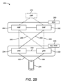
[0050] 様々な態様によれば、図2Bは、別の例示的なワイヤレスネットワーク構造250を示す。たとえば、NGC260(「5GC」とも呼ばれる)は、機能的に、アクセスおよびモビリティ管理機能(AMF)/ユーザプレーン機能(UPF)264によって提供される制御プレーン機能、ならびに、セッション管理機能(SMF)262によって提供されるユーザプレーン機能として見られることが可能であり、これらは、コアネットワーク(すなわちNGC260)を形成するために協同的に動作する。ユーザプレーンインターフェース263および制御プレーンインターフェース265が、eNB224をNGC260に、具体的にはSMF262およびAMF/UPF264にそれぞれ接続する。追加の構成では、gNB222がまた、AMF/UPF264への制御プレーンインターフェース265とSMF262へのユーザプレーンインターフェース263とを介して、NGC260に接続されてよい。さらに、eNB224は、NGC260へのgNB直接接続性ありまたはなしで、バックホール接続223を介してgNB222と直接に通信してよい。いくつかの構成では、New RAN220は、1つまたは複数のgNB222のみを有してよく、他の構成は、eNB224とgNB222の両方のうちの1つまたは複数を含む。gNB222またはeNB224のいずれかが、UE204(たとえば、図1に描かれるUEのいずれか)と通信してよい。New RAN220の基地局は、N2インターフェースを介してAMF/UPF264のAMF側と通信し、N3インターフェースを介してAMF/UPF264のUPF側と通信する。
[0050] According to various aspects, FIG. 2B illustrates another exemplary
[0051] AMFの機能は、登録管理、接続管理、到達可能性管理、モビリティ管理、合法的傍受、UE204とSMF262との間のセッション管理(SM)メッセージのための搬送、SMメッセージをルーティングするためのトランスペアレントプロキシサービス、アクセス認証およびアクセス許可、UE204とショートメッセージサービス機能(SMSF)(図示せず)との間のショートメッセージサービス(SMS)メッセージのための搬送、ならびにセキュリティアンカー機能性(SEAF)を含む。AMFはまた、認証サーバ機能(AUSF)(図示せず)およびUE204と対話し、UE204認証プロセスの結果として確立された中間キーを受け取る。UMTS(ユニバーサルモバイル遠隔通信システム)加入者識別モジュール(USIM)に基づく認証の場合、AMFは、AUSFからセキュリティ材料を取り出す。AMFの機能はまた、セキュリティコンテキスト管理(SCM)も含む。SCMは、アクセスネットワーク固有のキーを導出するのに使用するキーをSEAFから受け取る。AMFの機能性はまた、規制サービスのためのロケーションサービス管理、UE204とロケーション管理機能(LMF)270との間の、またNew RAN220とLMF270との間のロケーションサービスメッセージのための搬送、進化型パケットシステム(EPS)とのインターワーキングのためのEPSベアラ識別子割振り、およびUE204モビリティイベント通知を含む。加えて、AMFはまた、非3GPP(登録商標)アクセスネットワークのための機能性もサポートする。
[0051] The functions of the AMF include registration management, connection management, reachability management, mobility management, lawful interception, transport for session management (SM) messages between the
[0052] UPFの機能は、RAT内/RAT間モビリティのためのアンカーポイントとしての働きをすること(適用可能なとき)、データネットワーク(図示せず)への相互接続の外部プロトコルデータユニット(PDU)セッションポイントとしての働きをすること、パケットルーティングおよび転送を提供すること、パケット検査、ユーザプレーンポリシ規則施行(たとえば、ゲーティング、リダイレクション、トラフィックステアリング)、合法的傍受(ユーザプレーン収集)、トラフィック使用報告、ユーザプレーンのためのサービス品質(QoS)の扱い(たとえば、UL/DLレート施行、DLにおけるリフレクティブQoSマーキング)、アップリンクトラフィック検証(サービスデータフロー(SDF)とQoSフローとのマッピング)、アップリンクおよびダウンリンクにおけるトランスポートレベルパケットマーキング、ダウンリンクパケットバッファリングおよびダウンリンクデータ通知トリガリング、ならびに、1つまたは複数の「エンドマーカ」をソースRANノードに送出および転送することを含む。 [0052] The functions of the UPF include acting as an anchor point for intra-RAT/inter-RAT mobility (when applicable), acting as an outer protocol data unit (PDU) session point for interconnection to a data network (not shown), providing packet routing and forwarding, packet inspection, user plane policy rule enforcement (e.g., gating, redirection, traffic steering), lawful interception (user plane collection), traffic usage reporting, quality of service (QoS) handling for the user plane (e.g., UL/DL rate enforcement, reflective QoS marking in DL), uplink traffic validation (service data flow (SDF) to QoS flow mapping), transport level packet marking in uplink and downlink, downlink packet buffering and downlink data notification triggering, and sending and forwarding one or more "end markers" to the source RAN node.
[0053] SMF262の機能は、セッション管理、UEインターネットプロトコル(IP)アドレス割振りおよび管理、ユーザプレーン機能の選択および制御、トラフィックを適正な宛先にルーティングするためのUPFにおけるトラフィックステアリングの構成、ポリシ施行およびQoSの一部の制御、ならびにダウンリンクデータ通知を含む。SMF262がAMF/UPF264のAMF側と通信する際に経由するインターフェースは、N11インターフェースと呼ばれる。
[0053] The functions of the
[0054] 別の任意選択の態様はLMF270を含んでよく、LMF270は、UE204のためのロケーション支援を提供するためにNGC260と通信してよい。LMF270は、複数の別々のサーバ(たとえば、物理的に別々のサーバ、単一のサーバ上の異なるソフトウェアモジュール、複数の物理サーバに散在する異なるソフトウェアモジュールなど)として実装されることが可能であり、または別法として、各々が単一のサーバに対応してよい。LMF270は、コアネットワーク、NGC260、および/またはインターネット(図示せず)を介してLMF270に接続できるUE204のために、1つまたは複数のロケーションサービスをサポートするように構成されることが可能である。
[0054] Another optional aspect may include an
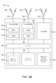
[0055] 図3A、図3B、および図3Cは、いくつかの例示的なコンポーネント(対応するブロックによって表される)を示し、これらのコンポーネントは、本明細書で教示されるファイル送信動作をサポートするために、UE302(本明細書で記述されるUEのいずれかに対応し得る)、基地局304(本明細書で記述される基地局のいずれかに対応し得る)、ならびにネットワークエンティティ306(ロケーションサーバ230およびLMF270を含めた、本明細書で記述されるネットワーク機能のいずれかに対応し得るかまたはそれを具体化し得る)に組み込まれてよい。これらのコンポーネントが、異なる実装形態では異なるタイプの装置中で(たとえば、ASIC中で、システムオンチップ(SoC)中で、など)実装されてよいことは、理解されるであろう。図示のコンポーネントはまた、通信システム中の他の装置に組み込まれてもよい。たとえば、システム中の他の装置は、記述されるコンポーネントと同様のコンポーネントを含んで同様の機能を提供し得る。また、所与の装置が、コンポーネントのうちの1つまたは複数を含んでよい。たとえば、装置は、装置が複数のキャリア上で動作することおよび/または異なる複数の技術を介して通信することを可能にする、複数の送受信機コンポーネントを含んでよい。
3A, 3B, and 3C illustrate several example components (represented by corresponding blocks) that may be incorporated in a UE 302 (which may correspond to any of the UEs described herein), a base station 304 (which may correspond to any of the base stations described herein), and a network entity 306 (which may correspond to or embody any of the network functions described herein, including
[0056] UE302および基地局304は各々、NRネットワーク、LTEネットワーク、GSMネットワーク、および/またはその他など1つまたは複数のワイヤレス通信ネットワーク(図示せず)を介して通信するように構成された、ワイヤレスワイドエリアネットワーク(WWAN)送受信機310および350をそれぞれ含む。WWAN送受信機310および350は、対象のワイヤレス通信媒体(たとえば、特定の周波数スペクトル中の時間/周波数リソースの何らかのセット)を介して少なくとも1つの指定されたRAT(たとえば、NR、LTE、GSMなど)により他のUE、アクセスポイント、基地局(たとえば、eNB、gNB)など他のネットワークノードと通信するために、1つまたは複数のアンテナ316および356にそれぞれ接続されてよい。WWAN送受信機310および350は、指定されたRATに従って、信号318および358(たとえば、メッセージ、インジケーション、情報など)をそれぞれ送信および符号化するために、また反対に、信号318および358(たとえば、メッセージ、インジケーション、情報、パイロットなど)をそれぞれ受信および復号するために、様々に構成されてよい。具体的には、WWAN送受信機310および350は、信号318および358をそれぞれ送信および符号化するための1つまたは複数の送信機314および354をそれぞれ含み、信号318および358をそれぞれ受信および復号するための1つまたは複数の受信機312および352をそれぞれ含む。
[0056] The
[0057] UE302および基地局304はまた、少なくともいくつかの場合には、ワイヤレスローカルエリアネットワーク(WLAN)送受信機320および360をそれぞれ含む。WLAN送受信機320および360は、対象のワイヤレス通信媒体を介して少なくとも1つの指定されたRAT(たとえば、WiFi、LTE-D、Bluetoothなど)により他のUE、アクセスポイント、基地局など他のネットワークノードと通信するために、1つまたは複数のアンテナ326および366にそれぞれ接続されてよい。WLAN送受信機320および360は、指定されたRATに従って、信号328および368(たとえば、メッセージ、インジケーション、情報など)をそれぞれ送信および符号化するために、また反対に、信号328および368(たとえば、メッセージ、インジケーション、情報、パイロットなど)をそれぞれ受信および復号するために、様々に構成されてよい。具体的には、送受信機320および360は、信号328および368をそれぞれ送信および符号化するための1つまたは複数の送信機324および364をそれぞれ含み、信号328および368をそれぞれ受信および復号するための1つまたは複数の受信機322および362をそれぞれ含む。
[0057] The
[0058] 少なくとも1つの送信機と少なくとも1つの受信機とを含む送受信機回路は、いくつかの実装形態では、一体型デバイス(たとえば、単一の通信デバイスの送信機回路および受信機回路として具体化される)を備えてよく、いくつかの実装形態では、別個の送信機デバイスおよび別個の受信機デバイスを備えてよく、または、他の実装形態では、他の方法で具体化されてよい。一態様では、送信機は、アンテナアレイなど、本明細書で記述されるような送信「ビームフォーミング」をそれぞれの装置が実施するのを可能にする複数のアンテナ(たとえば、アンテナ316、326、356、366)を含むかまたはそれらに結合されてよい。同様に、受信機は、アンテナアレイなど、本明細書で記述されるような受信ビームフォーミングをそれぞれの装置が実施するのを可能にする複数のアンテナ(たとえば、アンテナ316、326、356、366)を含むかまたはそれらに結合されてよい。一態様では、送信機と受信機は、同じ複数のアンテナ(たとえば、アンテナ316、326、356、366)を共有してよく、それにより、それぞれの装置は、受信と送信の両方を同時に行うことはできず、所与の時点で受信または送信のみを行うことができる。UE302および/または基地局304のワイヤレス通信デバイス(たとえば、送受信機310および320ならびに/または350および360の一方または両方)はまた、様々な測定を実施するために、ネットワークリッスンモジュール(NLM)などを備えてもよい。
[0058] The transceiver circuitry including at least one transmitter and at least one receiver may comprise an integrated device (e.g., embodied as the transmitter and receiver circuits of a single communications device) in some implementations, may comprise separate transmitter and receiver devices in some implementations, or may be embodied in other ways in other implementations. In one aspect, the transmitter may include or be coupled to multiple antennas (e.g.,
[0059] UE302および基地局304はまた、少なくともいくつかの場合には、衛星測位システム(SPS)受信機330および370を含む。SPS受信機330および370は、全地球測位システム(GPS)信号、全地球航法衛星システム(GLONASS)信号、ガリレオ信号、北斗信号、インド地域航法衛星システム(NAVIC)、準天頂衛星システム(QZSS)などのSPS信号338および378をそれぞれ受信するために、1つまたは複数のアンテナ336および376にそれぞれ接続されてよい。SPS受信機330および370は、SPS信号338および378をそれぞれ受信および処理するための、任意の適切なハードウェアおよび/またはソフトウェアを備えてよい。SPS受信機330および370は、他のシステムに情報および動作を適宜要求し、任意の適切なSPSアルゴリズムによって得られた測定値を使用して、UE302および基地局304の位置を決定するのに必要な計算を実施する。
[0059] The
[0060] 基地局304およびネットワークエンティティ306は各々、他のネットワークエンティティと通信するために、少なくとも1つのネットワークインターフェース380および390を含む。たとえば、ネットワークインターフェース380および390(たとえば、1つまたは複数のネットワークアクセスポート)は、ワイヤベースのまたはワイヤレスのバックホール接続を介して1つまたは複数のネットワークエンティティと通信するように構成されてよい。いくつかの態様では、ネットワークインターフェース380および390は、ワイヤベースのまたはワイヤレスの信号通信をサポートするように構成された送受信機として実装されてよい。この通信は、たとえば、メッセージ、パラメータ、および/または他のタイプの情報を送出および受信することを含み得る。
[0060] The
[0061] UE302、基地局304、およびネットワークエンティティ306はまた、本明細書で開示される動作に関連して使用され得る他のコンポーネントを含んでもよい。UE302は、階層型支援データ受信および復号にたとえば関係する機能を提供するためならびに他の処理機能を提供するための処理システム332を実装するプロセッサ回路を含む。基地局304は、本明細書で記述される階層型支援データを提供することにたとえば関係する機能性を提供するためおよび他の処理機能性を提供するための処理システム384を含む。ネットワークエンティティ306は、本明細書で記述される階層型支援データを提供することにたとえば関係する機能性を提供するためおよび他の処理機能性を提供するための処理システム394を含む。一態様では、処理システム332、384、および394は、たとえば、1つまたは複数の汎用プロセッサ、マルチコアプロセッサ、ASIC、デジタル信号プロセッサ(DSP)、フィールドプログラマブルゲートアレイ(FPGA)、または他のプログラマブルロジックデバイスもしくは処理回路を含んでよい。
[0061] The
[0062] UE302、基地局304、およびネットワークエンティティ306は、情報(たとえば、予約済みリソース、しきい値、パラメータなどを示す情報)を維持するために、メモリコンポーネント340、386、および396(たとえば、各々がメモリデバイスを含む)をそれぞれ実装するメモリ回路を含む。場合によっては、UE302、基地局304、およびネットワークエンティティ306は、支援データコンポーネント342、388、および398をそれぞれ含んでよい。支援データコンポーネント342、388、および398は、それぞれ処理システム332、384、および394の一部であるかまたはそれに結合された、ハードウェア回路であってよく、このハードウェア回路は、実行されたとき、本明細書で記述される機能性をUE302、基地局304、およびネットワークエンティティ306に実施させる。他の態様では、支援データコンポーネント342、388、および398は、処理システム332、384、および394の外部にあってよい(たとえば、モデム処理システムの一部であるか、別の処理システムと統合されるなど)。別法として、支援データコンポーネント342、388、および398は、メモリコンポーネント340、386、および396にそれぞれ記憶されたメモリモジュール(図3A~図3Cに示されるように)であってよく、このメモリモジュールは、処理システム332、384、および394(またはモデム処理システム、別の処理システムなど)によって実行されたとき、本明細書で記述される機能性をUE302、基地局304、およびネットワークエンティティ306に実施させる。
[0062] The
[0063] UE302は、WWAN送受信機310、WLAN送受信機320、および/またはSPS受信機330によって受信された信号から導出されるモーションデータから独立した動きおよび/または配向情報を提供するために、処理システム332に結合された1つまたは複数のセンサ344を含んでよい。例として、センサ344は、加速度計(たとえば、マイクロエレクトリカルメカニカルシステムズ(MEMS)デバイス)、ジャイロスコープ、地磁気センサ(たとえばコンパス)、高度計(たとえば気圧高度計)、および/またはいずれか他のタイプの動き検出センサを含んでよい。その上、センサ344は、複数の異なるタイプのデバイスを含んでよく、モーション情報を提供するためにそれらの出力を結合してよい。たとえば、センサ344は、2Dおよび/または3D座標系における位置を計算する能力を提供するために、多軸加速度計と配向センサの組合せを使用してよい。
[0063] The
[0064] 加えて、UE302は、インジケーション(たとえば、可聴および/もしくは視覚的インジケーション)をユーザに提供するため、ならびに/またはユーザ入力を(たとえば、キーパッド、タッチ画面、マイクロフォンなどの感知デバイスのユーザ作動時に)受け取るために、ユーザインターフェース346を含む。図示されていないが、基地局304およびネットワークエンティティ306もまた、ユーザインターフェースを含んでよい。
[0064] Additionally, the
[0065] 処理システム384をより詳細に参照すると、ダウンリンクでは、ネットワークエンティティ306からのIPパケットが処理システム384に提供されてよい。処理システム384は、RRCレイヤ、パケットデータ収束プロトコル(PDCP)レイヤ、無線リンク制御(RLC)レイヤ、および媒体アクセス制御(MAC)レイヤのための機能性を実装してよい。処理システム384は、システム情報(たとえば、マスタ情報ブロック(MIB)、システム情報ブロック(SIB))のブロードキャスト、RRC接続制御(たとえば、RRC接続ページング、RRC接続確立、RRC接続修正、およびRRC接続解放)、RAT間モビリティ、およびUE測定報告のための測定構成に関連する、RRCレイヤ機能性;ヘッダ圧縮/圧縮解除、セキュリティ(暗号化、暗号化解除、保全性保護、保全性検証)、およびハンドオーバサポート機能に関連する、PDCPレイヤ機能性;上位レイヤパケットデータユニット(PDU)の転送、自動再送要求(ARQ)を介した誤り訂正、RLCサービスデータユニット(SDU)のコンカチネーションとセグメンテーションと再アセンブリ、RLCデータPDUの再セグメンテーション、およびRLCデータPDUの並べ替えに関連する、RLCレイヤ機能性;ならびに、論理チャネルとトランスポートチャネルとの間のマッピング、スケジューリング情報報告、誤り訂正、優先順位の扱い、および論理チャネル優先順位付けに関連する、MACレイヤ機能性を提供してよい。
[0065] Referring more particularly to the
[0066] 送信機354および受信機352は、様々な信号処理機能に関連するレイヤ1機能性を実装してよい。レイヤ1は物理(PHY)レイヤを含み、トランスポートチャネル上での誤り検出、トランスポートチャネルの順方向誤り訂正(FEC)コーディング/復号、インタリービング、レートマッチング、物理チャネル上へのマッピング、物理チャネルの変調/復調、およびMIMOアンテナ処理を含んでよい。送信機354は、様々な変調方式(たとえば、バイナリ位相シフトキーイング(BPSK)、直角位相シフトキーイング(QPSK)、M位相シフトキーイング(M-PSK)、M直交振幅変調(M-QAM))に基づく信号コンステレーションへのマッピングを扱う。コーディングされ変調されたシンボルは、次いで、並列ストリームに分離されてよい。次いで各ストリームは、直交周波数分割多重化(OFDM)サブキャリアにマッピングされ、時間および/または周波数領域で参照信号(たとえばパイロット)と多重化され、次いで逆高速フーリエ変換(IFFT)を使用して結合されて、時間領域OFDMシンボルストリームを担持する物理チャネルが生成されてよい。OFDMシンボルストリームは、空間的にプリコーディングされて、複数の空間ストリームが生成される。コーディング変調方式を決定するため、ならびに空間処理のために、チャネル推定器からのチャネル推定値が使用されてよい。チャネル推定値は、UE302によって送信された、参照信号および/またはチャネル条件フィードバックから導出されてよい。次いで、各空間ストリームは、1つまたは複数の異なるアンテナ356に提供されてよい。送信機354は、送信のためにそれぞれの空間ストリームを用いてRFキャリアを変調してよい。
[0066] The
[0067] UE302において、受信機312は、そのそれぞれのアンテナ316を介して信号を受信する。受信機312は、RFキャリア上に変調された情報を回復し、情報を処理システム332に提供する。送信機314および受信機312は、様々な信号処理機能に関連するレイヤ1機能性を実装する。受信機312は、情報に対して空間処理を実施して、UE302に宛てられたどんな空間ストリームも回復してよい。複数の空間ストリームがUE302に宛てられている場合、これらは、受信機312によって単一のOFDMシンボルストリームに結合されてよい。次いで受信機312は、高速フーリエ変換(FFT)を使用して、OFDMシンボルストリームを時間領域から周波数領域に変換する。周波数領域信号は、OFDM信号の各サブキャリアにつき別々のOFDMシンボルストリームを備える。各サブキャリア上のシンボル、および参照信号は、基地局304によって送信された最も可能性の高い信号コンステレーションポイントを決定することによって、回復および復調される。これらの軟判定は、チャネル推定器によって計算されたチャネル推定値に基づいてよい。次いで、軟判定は復号されデインタリーブされて、元々基地局304によって物理チャネル上で送信されたデータおよび制御信号が回復される。次いで、データおよび制御信号は処理システム332に提供され、処理システム332は、レイヤ3およびレイヤ2機能性を実装する。
[0067] At the
[0068] ULでは、処理システム332は、コアネットワークからのIPパケットを回復するために、トランスポートチャネルと論理チャネルとの間の多重化解除、パケット再アセンブリ、暗号化解除、ヘッダ圧縮解除、および制御信号処理を提供する。処理システム332はまた、誤り検出も担う。
[0068] In the UL, the
[0069] 基地局304によるダウンリンク送信に関連して記述された機能性と同様、処理システム332は、システム情報(たとえば、MIB、SIB)獲得、RRC接続、および測定報告に関連する、RRCレイヤ機能性;ヘッダ圧縮/圧縮解除、およびセキュリティ(暗号化、暗号化解除、保全性保護、保全性検証)に関連する、PDCPレイヤ機能性;上位レイヤPDUの転送、ARQを介した誤り訂正、RLC SDUのコンカチネーションとセグメンテーションと再アセンブリ、RLCデータPDUの再セグメンテーション、およびRLCデータPDUの並べ替えに関連する、RLCレイヤ機能性;ならびに、論理チャネルとトランスポートチャネルとの間のマッピング、トランスポートブロック(TB)上へのMAC SDUの多重化、TBからのMAC SDUの多重化解除、スケジューリング情報報告、ハイブリッド自動再送要求(HARQ)を介した誤り訂正、優先順位の扱い、および論理チャネル優先順位付けに関連する、MACレイヤ機能性を提供する。
[0069] Similar to the functionality described in connection with downlink transmissions by
[0070] 基地局304によって送信された参照信号またはフィードバックからチャネル推定器によって導出されたチャネル推定値が、送信機314によって使用されて、適切なコーディング変調方式が選択され、空間処理が容易にされてよい。送信機314によって生成された空間ストリームは、異なる複数のアンテナ316に提供されてよい。送信機314は、送信のためにそれぞれの空間ストリームを用いてRFキャリアを変調してよい。
[0070] Channel estimates derived by the channel estimator from a reference signal or feedback transmitted by the
[0071] アップリンク送信は、UE302における受信機機能に関連して記述されたのと同様にして、基地局304において処理される。受信機352は、そのそれぞれのアンテナ356を介して信号を受信する。受信機352は、RFキャリア上に変調された情報を回復し、情報を処理システム384に提供する。
[0071] Uplink transmissions are processed at
[0072] ULでは、処理システム384は、UE302からのIPパケットを回復するために、トランスポートチャネルと論理チャネルとの間の多重化解除、パケット再アセンブリ、暗号化解除、ヘッダ圧縮解除、制御信号処理を提供する。処理システム384からのIPパケットは、コアネットワークに提供されてよい。処理システム384はまた、誤り検出も担う。
[0072] In the UL, the
[0073] 便宜上、UE302、基地局304、および/またはネットワークエンティティ306は、図3A~図3Cでは、本明細書で記述される様々な例に従って構成され得る様々なコンポーネントを含むものとして示されている。しかし、図示されるブロックが、異なる設計では異なる機能性を有してよいことは、理解されるであろう。
[0073] For convenience, the
[0074] UE302、基地局304、およびネットワークエンティティ306の様々なコンポーネントは、それぞれデータバス334、382、および392を介して相互と通信してよい。図3A~図3Cのコンポーネントは、様々な方法で実装されてよい。いくつかの実装形態では、図3A~図3Cのコンポーネントは、たとえば1つもしくは複数のプロセッサおよび/または1つもしくは複数のASIC(1つもしくは複数のプロセッサを含み得る)など、1つまたは複数の回路中で実装されてよい。ここで、各回路は、この機能性を提供するために回路によって使用される情報または実行可能コードを記憶するための、少なくとも1つのメモリコンポーネントを使用してよく、および/または組み込んでよい。たとえば、ブロック310~346によって表される機能性のいくつかまたはすべては、UE302のプロセッサおよびメモリコンポーネントによって(たとえば、適切なコードの実行、および/またはプロセッサコンポーネントの適切な構成によって)実装されてよい。同様に、ブロック350~388によって表される機能性のいくつかまたはすべては、基地局304のプロセッサおよびメモリコンポーネントによって(たとえば、適切なコードの実行、および/またはプロセッサコンポーネントの適切な構成によって)実装されてよい。また、ブロック390~398によって表される機能性のいくつかまたはすべては、ネットワークエンティティ306のプロセッサおよびメモリコンポーネントによって(たとえば、適切なコードの実行、および/またはプロセッサコンポーネントの適切な構成によって)実装されてよい。簡単にするために、本明細書では、様々な動作、行為、および/または機能が、「UEによって」、「基地局によって」、「測位エンティティによって」実施されるなどと記述される。しかし、理解されるであろうが、そのような動作、行為、および/または機能は、実際には、処理システム332、384、394、送受信機310、320、350、および360、メモリコンポーネント340、386、および396、支援データコンポーネント342、388、および398など、UEや基地局や測位エンティティなどの具体的なコンポーネント、またはコンポーネントの組合せによって実施されてよい。
[0074] The various components of the
[0075] 様々なフレーム構造は、ネットワークノード(たとえば、基地局およびUE)間のダウンリンク送信およびアップリンク送信をサポートするために使用され得る。図4は、本開示の態様による、ダウンリンクフレーム構造の例を示す図400である。他のワイヤレス通信技術は、異なるフレーム構造および/または異なるチャネルを有し得る。 [0075] Various frame structures may be used to support downlink and uplink transmissions between network nodes (e.g., base stations and UEs). FIG. 4 is a diagram 400 illustrating an example of a downlink frame structure according to aspects of the present disclosure. Other wireless communication technologies may have different frame structures and/or different channels.
[0076] LTE、およびいくつかの場合においてNRは、ダウンリンク上ではOFDMを、アップリンク上ではシングルキャリア周波数分割多重(SC-FDM)を利用する。しかし、LTEと異なり、NRは、アップリンク上でもOFDMを使用するためのオプションを有する。OFDMおよびSC-FDMは、システム帯域幅を複数(K)の直交サブキャリアへパーティション化し、これらは一般にトーン、ビン等とも呼ばれる。各サブキャリアは、データにより変調され得る。一般に、変調シンボルは、OFDMでは周波数ドメインにおいて、SC-FDMでは時間ドメインにおいて送られる。隣接するサブキャリア間の間隔は、固定されてもよく、サブキャリアの総数(K)は、システム帯域幅に依存し得る。たとえば、サブキャリアの間隔は、15kHzであってもよく、最小リソース割振り(リソースブロック)は、12個のサブキャリア(または180kHz)であってもよい。結果的に、公称FFTサイズは、1.25メガヘルツ(MHz)、2.5MHz、5MHz、10MHz、または20MHzのシステム帯域幅について、それぞれ128、256、512、1024、または2048に等しくなり得る。システム帯域幅も、サブバンドへパーティション化され得る。たとえば、サブバンドは1.08MHz(すなわち、6個のリソースブロック)をカバーしてもよく、1.25MHz、2.5MHz、5MHz、10MHz、または20MHzのシステム帯域幅について、それぞれ1個、2個、4個、8個、または16個のサブバンドがあってもよい。 [0076] LTE, and in some cases NR, utilizes OFDM on the downlink and single-carrier frequency division multiplexing (SC-FDM) on the uplink. However, unlike LTE, NR has the option to use OFDM on the uplink as well. OFDM and SC-FDM partition the system bandwidth into multiple (K) orthogonal subcarriers, which are also commonly referred to as tones, bins, etc. Each subcarrier may be modulated with data. Generally, modulation symbols are sent in the frequency domain for OFDM and in the time domain for SC-FDM. The spacing between adjacent subcarriers may be fixed, and the total number of subcarriers (K) may depend on the system bandwidth. For example, the subcarrier spacing may be 15 kHz, and the minimum resource allocation (resource block) may be 12 subcarriers (or 180 kHz). As a result, the nominal FFT size may be equal to 128, 256, 512, 1024, or 2048 for a system bandwidth of 1.25 megahertz (MHz), 2.5 MHz, 5 MHz, 10 MHz, or 20 MHz, respectively. The system bandwidth may also be partitioned into subbands. For example, a subband may cover 1.08 MHz (i.e., 6 resource blocks), and there may be 1, 2, 4, 8, or 16 subbands for a system bandwidth of 1.25 MHz, 2.5 MHz, 5 MHz, 10 MHz, or 20 MHz, respectively.
[0077] LTEは、単一のヌメロロジー(numerology)(サブキャリア間隔(SCS:subcarrier spacing)、シンボル長等)をサポートする。対照的に、NRは、複数のヌメロロジー(μ)をサポートしてよく、たとえば、15kHz、30kHz、60kHz、120kHz、および240kHz以上のサブキャリア間隔が利用可能であり得る。下記に提供される表1は、異なるNRヌメロロジーについてのいくつかの様々なパラメータを列挙する。 [0077] LTE supports a single numerology (subcarrier spacing (SCS), symbol length, etc.). In contrast, NR may support multiple numerologies (μ), e.g., subcarrier spacings of 15 kHz, 30 kHz, 60 kHz, 120 kHz, and 240 kHz or more may be available. Table 1 provided below lists some various parameters for the different NR numerologies.
[0078] 図4の例では、15kHzのヌメロロジーが使用される。したがって、時間ドメインにおいて、フレーム(たとえば、10ms)は、各々が1msの10個の等しいサイズのサブフレームへ分割され、各サブフレームは、1つの時間スロットを含む。図4において、時間は、水平に(たとえば、X軸上で)表され、時間は左から右へ増加し、一方で、周波数は、垂直に(たとえば、Y軸上で)表され、周波数は下から上へ増加(または減少)する。 [0078] In the example of FIG. 4, a numerology of 15 kHz is used. Thus, in the time domain, a frame (e.g., 10 ms) is divided into 10 equally sized subframes of 1 ms each, with each subframe containing one time slot. In FIG. 4, time is represented horizontally (e.g., on the X-axis), with time increasing from left to right, while frequency is represented vertically (e.g., on the Y-axis), with frequency increasing (or decreasing) from bottom to top.
[0079] リソースグリッドが、時間スロットを表すために使用されてもよく、各時間スロットは、周波数ドメインにおいて1つまたは複数の時間並列リソースブロック(RB)(物理RB(PRB)とも呼ばれる)を含む。リソースグリッドは、複数のリソースエレメント(RE)へさらに分割される。REは、時間ドメインにおいて1つのシンボル長に対応し、周波数ドメインにおいて1つのサブキャリアに対応し得る。図4のヌメロロジーにおいて、通常の巡回プレフィックスの場合、RBは、周波数ドメインにおいて12個の連続するサブキャリア、および時間ドメインにおいて7個の連続するシンボル、合計で84個のREを含有し得る。拡張巡回プレフィックスの場合、RBは、周波数ドメインにおいて12個の連続するサブキャリア、および時間ドメインにおいて6個の連続するシンボル、合計で72個のREを含有し得る。各REによって担持されるビットの数は、変調方式に依存する。 [0079] A resource grid may be used to represent time slots, with each time slot including one or more time parallel resource blocks (RBs) (also called physical RBs (PRBs)) in the frequency domain. The resource grid is further divided into multiple resource elements (REs). An RE may correspond to one symbol length in the time domain and one subcarrier in the frequency domain. In the numerology of FIG. 4, for a normal cyclic prefix, an RB may contain 12 consecutive subcarriers in the frequency domain and 7 consecutive symbols in the time domain, for a total of 84 REs. For an extended cyclic prefix, an RB may contain 12 consecutive subcarriers in the frequency domain and 6 consecutive symbols in the time domain, for a total of 72 REs. The number of bits carried by each RE depends on the modulation scheme.
[0080] 図4に例示されるように、REのうちのいくつかは、UEにおけるチャネル推定のためにダウンリンク参照(パイロット)信号(DL-RS)を担持する。DL-RSは、復調参照信号(DMRS)、チャネル状態情報参照信号(CSI-RS)、セル固有参照信号(CRS)、測位参照信号(PRS:positioning reference signal)、ナビゲーション参照信号(NRS)、追跡参照信号(TRS)等を含んでもよく、これらの例示的なロケーションは、図4において「R」とラベル付けされる。 [0080] As illustrated in FIG. 4, some of the REs carry downlink reference (pilot) signals (DL-RS) for channel estimation at the UE. The DL-RS may include demodulation reference signals (DMRS), channel state information reference signals (CSI-RS), cell-specific reference signals (CRS), positioning reference signals (PRS), navigation reference signals (NRS), tracking reference signals (TRS), etc., and their exemplary locations are labeled "R" in FIG. 4.
[0081] PRSの送信のために使用されるリソースエレメントの集合は、「PRSリソース」と呼ばれ、パラメータDL-PRS-ResourceIdによって識別され得る。リソースエレメント(RE)の集合は、周波数ドメインにおいては複数のPRB、時間ドメインにおいてはスロット内のN個の(たとえば、1つまたは複数の)連続するシンボルに及び得る。時間ドメインにおける所与のOFDMシンボルにおいて、PRSリソースは、周波数ドメインにおいて連続するPRBを占有する。 [0081] The set of resource elements used for the transmission of a PRS is called a "PRS resource" and may be identified by the parameter DL-PRS-ResourceId. A set of resource elements (REs) may span multiple PRBs in the frequency domain and N (e.g., one or more) consecutive symbols within a slot in the time domain. For a given OFDM symbol in the time domain, the PRS resource occupies consecutive PRBs in the frequency domain.
[0082] 「PRSリソースセット(resource set)」は、PRS信号の送信のために使用されるPRSリソースのセットであり、ただし、各PRSリソースは、PRSリソースID(DL-PRS-ResourceId)を有する。また、PRSリソースセット内のPRSリソースは、同じTRPに関連付けられる。PRSリソースセットは、PRSリソースセットID(DL-PRS-ResourceSetId)によって識別され、特定のTRP(セルIDによって識別される)に関連付けられる。また、PRSリソースセット内のPRSリソースは、同じ周期性、共通のミューティングパターン構成、およびスロットにまたがる同じ反復係数を有する。周期性は、2m・{4,5,8,10,16,20,32,40,64,80,160,320,640,1280,2560,5120,10240}スロットから選択された長さを有してよく、μ=0、1、2、3(ヌメロロジーの識別子)である。反復係数は、{1,2,4,6,8,16,32}スロットから選択された長さを有してよい。 [0082] A "PRS resource set" is a set of PRS resources used for the transmission of PRS signals, where each PRS resource has a PRS resource ID (DL-PRS-ResourceId). Also, the PRS resources in a PRS resource set are associated with the same TRP. A PRS resource set is identified by a PRS resource set ID (DL-PRS-ResourceSetId) and is associated with a specific TRP (identified by a cell ID). Also, the PRS resources in a PRS resource set have the same periodicity, a common muting pattern configuration, and the same repetition factor across slots. The periodicity may have a length selected from 2 m ·{4, 5, 8, 10, 16, 20, 32, 40, 64, 80, 160, 320, 640, 1280, 2560, 5120, 10240} slots, μ=0, 1, 2, 3 (numerology identifiers). The repetition factor may have a length selected from {1, 2, 4, 6, 8, 16, 32} slots.
[0083] PRSリソースセット内のPRSリソースIDは、単一のTRP(ただし、TRPは1つまたは複数のビームを送信し得る)から送信される単一のビーム(および/またはビームID)に関連付けられる。つまり、PRSリソースセットの各PRSリソースは、異なるビーム上で送信され得、そのため、「PRSリソース」、または単純に「リソース」も、「ビーム」と呼ばれることがある。これは、TRP、およびPRSが送信されるビームが、UEに知られているかどうかに関する暗示を有しないことに留意されたい。 [0083] A PRS resource ID in a PRS resource set is associated with a single beam (and/or beam ID) transmitted from a single TRP (although a TRP may transmit one or more beams). That is, each PRS resource in a PRS resource set may be transmitted on a different beam, and thus a "PRS resource", or simply a "resource", may also be referred to as a "beam". Note that this has no implication as to whether the TRP and the beam on which the PRS is transmitted are known to the UE.
[0084] 「PRSインスタンス(instance)」または「PRSオケージョン(occasion)」は、PRSが送信されると予想される、周期的に繰り返されるタイムウィンドウ(たとえば、1つまたは複数の連続するスロットのグループ)の1つのインスタンスである。PRSオケージョンは、「PRS測位オケージョン」、「PRS測位インスタンス、「測位オケージョン」、「測位インスタンス」、または単純に「オケージョン」もしくは「インスタンス」とも呼ばれ得る。 [0084] A "PRS instance" or "PRS occasion" is one instance of a periodically repeating time window (e.g., a group of one or more contiguous slots) during which a PRS is expected to be transmitted. A PRS occasion may also be called a "PRS positioning occasion", a "PRS positioning instance", a "positioning occasion", a "positioning instance", or simply an "occasion" or "instance".
[0085] 「測位周波数レイヤ」は、同じサブキャリア間隔(SCS)および巡回プレフィックス(CP:cyclic prefix)タイプ(PDSCHのためにサポートされるすべてのヌメロロジーが、PRSのためにもサポートされることを意味する)、同じポイントA、同じ値のダウンリンクPRS帯域幅、同じ開始PRB(および中心周波数)、ならびに同じ値のコームサイズ(comb-size)を有する、1つまたは複数のTRPにまたがる、1つまたは複数のPRSリソースセットの集合である。ポイントAパラメータは、パラメータARFCN-ValueNRの値を取り、ただし、「ARFCN」は、「絶対無線周波数チャネル番号(absolute radio-frequency channel number)」を表し、送信および受信のために使用される物理無線通信路のペアを特定する識別子/コードである。ダウンリンクPRS帯域幅は、最低で24個のPRB、最高で272個のPRBを有する、4つのPRBの粒度(granularity)を有し得る。コームサイズは、PRSを担持する各シンボル内のサブキャリアの数を示す。たとえば、コーム-4というコームサイズは、所与のシンボルの4番目のサブキャリアごとにPRSを担持することを意味する。現在、最大で4つの周波数レイヤが定義されており、最大で2つのPRSリソースセットが、周波数レイヤごとのTRPごとに構成され得る。 [0085] A "positioning frequency layer" is a collection of one or more PRS resource sets across one or more TRPs with the same subcarrier spacing (SCS) and cyclic prefix (CP) type (meaning that all numerologies supported for PDSCH are also supported for PRS), the same point A, the same value of downlink PRS bandwidth, the same starting PRB (and center frequency), and the same value of comb-size. The point A parameter takes the value of the parameter ARFCN-ValueNR, where "ARFCN" stands for "absolute radio-frequency channel number" and is an identifier/code that identifies the pair of physical radio channels used for transmission and reception. The downlink PRS bandwidth may have a granularity of 4 PRBs, with a minimum of 24 PRBs and a maximum of 272 PRBs. The comb size indicates the number of subcarriers in each symbol that carry the PRS. For example, a comb size of comb-4 means that every fourth subcarrier of a given symbol carries a PRS. Currently, up to four frequency layers are defined, and up to two PRS resource sets can be configured per TRP per frequency layer.
[0086] ダウンリンクPRSリソースIDは、ダウンリンクPRSリソースセット内で局所的に定義され、ダウンリンクPRSリソースセットIDは、TRP内で局所的に定義される。TRPにまたがってDL-PRSリソースを一意に識別するために、単一のTRPに関連付けられた複数のダウンリンクPRSリソースセットに関連付けられ得るIDが定義されている。このIDは、単一のダウンリンクPRSリソースを一意に識別するために、ダウンリンクPRSリソースセットIDおよびダウンリンクPRSリソースIDと共に使用され得る。このIDは、本明細書においてDL-PRS-TRP-ResourceSetIdと呼ばれる。各TRPは、1つのDL-PRS-TRP-ResourceSetIdのみに関連付けられるべきである。たとえば、DL-PRS-TRP-ResourceSetIdは、セルID(たとえば、PCI、VCI)、もしくはTRP ID、または、PRSリソースの一意の識別に参加する測位目的のために使用される、セルIDもしくはTRP IDと異なる別の識別子であってよい。 [0086] Downlink PRS resource IDs are defined locally within a downlink PRS resource set, and downlink PRS resource set IDs are defined locally within a TRP. To uniquely identify DL-PRS resources across TRPs, an ID is defined that can be associated with multiple downlink PRS resource sets associated with a single TRP. This ID can be used together with the downlink PRS resource set ID and the downlink PRS resource ID to uniquely identify a single downlink PRS resource. This ID is referred to herein as DL-PRS-TRP-ResourceSetId. Each TRP should be associated with only one DL-PRS-TRP-ResourceSetId. For example, the DL-PRS-TRP-ResourceSetId may be a cell ID (e.g., PCI, VCI), or a TRP ID, or another identifier different from the cell ID or TRP ID that is used for positioning purposes to participate in the unique identification of PRS resources.
[0087] 「測位参照信号(positioning reference signal)」および「PRS」という用語は、LTEシステムにおいて測位のために使用される特定の参照信号を時には指すことがあることに留意されたい。しかし、本明細書において使用されるように、別段の指示がない限り、「測位参照信号」および「PRS」という用語は、測位のために使用され得る任意のタイプの参照信号、たとえば、LTE、NRS、TRS、CRS、CSI-RS、DMRSにおけるPRS信号、PSS、SSS等などを指すが、これらに限定されない。 [0087] It should be noted that the terms "positioning reference signal" and "PRS" sometimes refer to specific reference signals used for positioning in LTE systems. However, as used herein, unless otherwise indicated, the terms "positioning reference signal" and "PRS" refer to any type of reference signal that may be used for positioning, such as, but not limited to, PRS signals in LTE, NRS, TRS, CRS, CSI-RS, DMRS, PSS, SSS, etc.
[0088] 図5は、本開示の態様による、所与の基地局のPRS送信のための例示的なPRS構成500の図である。図5において、時間は、水平に表され、左から右に増加する。長い各矩形はスロットを表し、短い(陰付きの)各矩形はOFDMシンボルを表す。PRS構成500は、PRSリソースセット510のPRSリソース512および514を識別し、基地局はこれらを介してPRSを送信する。PRSリソースセット510は、2つの(2)スロットのオケージョン長NPRSと、TPRS(たとえば、160サブフレームまたは160ms)の周期性とを有する。したがって、PRSリソース512と514の両方は、各々、長さが連続する2つのスロット(slot)であり、TPRSサブフレームごとに繰り返し、それぞれのPRSリソースの第1のシンボルが発生するスロットから開始する。
FIG. 5 is a diagram of an
[0089] 図5の例では、PRSリソースセット510は、第1のPRSリソース512(図5では「PRSリソース1」とラベル付けされている)と第2のPRSリソース514(図5では「PRSリソース2」とラベル付けされている)の、2つのPRSリソースを含む。PRSリソース512およびPRSリソース514は、同じ基地局の別々のビーム上で送信され得る。PRSリソース512は、2つの(2)シンボルのシンボル長Nsymbを有し、PRSリソース514は、4つの(4)シンボルのシンボル長Nsymbを有する。
In the example of FIG. 5, PRS resource set 510 includes two PRS resources: a first PRS resource 512 (labeled as “
[0090] インスタンス530a、530b、および530cとして示されるPRSリソースセット510の各インスタンスは、PRSリソースセットの各PRSリソース512、514につき、長さ「2」(すなわち、NPRS=2)のオケージョンを含む。PRSリソース512および514は、ミューティングシーケンス周期性TREPまで、TPRSサブフレームごとに繰り返される。したがって、インスタンス530a、530b、および530cのどのオケージョンがミュートされるのかを示すために、長さTREPのビットマップが必要とされることになる。
Each instance of the PRS resource set 510, denoted as instances 530a, 530b, and 530c, includes occasions of length "2" (i.e., N PRS =2) for each
[0091] 一態様では、図5に示されるPRS構成500などのPRS構成に対して、追加の制約があり得る。たとえば、PRSリソースセット(たとえば、PRSリソースセット510)のすべてのPRSリソース(たとえば、PRSリソース512、514)について、基地局(またはロケーションサーバ)は、以下のパラメータを同じに構成することができる。すなわち、(a)オケージョン長(たとえばTPRS)、(b)シンボル数(たとえばNsymb)、(c)コームタイプ(comb type)、および/または(d)帯域幅である。加えて、すべてのPRSリソースセットのすべてのPRSリソースについて、サブキャリア間隔および巡回プレフィックスは、1つの基地局またはすべての基地局に対して同じに構成されることが可能である。これが1つの基地局に対してであるかすべての基地局に対してであるかは、第1および/または第2のオプションをサポートするUEの能力に依存し得る。
In one aspect, there may be additional constraints for a PRS configuration such as the
[0092] 前述のようなPRS構成は、PRS測位測定をUEが実施できるようにするためにUEにシグナリングされることに留意されたい。UEは、PRS構成の検出をブラインドに実施することは予期されない。さらに、ダウンリンクPRSについてのヌメロロジー(たとえば、CP長およびサブキャリア間隔)のサポートは、データ送信の場合と同じである。 [0092] Note that the PRS configuration as described above is signaled to the UE to enable the UE to perform PRS positioning measurements. The UE is not expected to perform PRS configuration detection blindly. Furthermore, the numerology (e.g., CP length and subcarrier spacing) support for downlink PRS is the same as for data transmission.
[0093] いくつかの場合では、UEが測定値を測位エンティティ(たとえば、ロケーションサーバ230、LMF270)に報告して測位エンティティがUEの位置を推定するのではなく、UEが推定値それ自体の位置を計算できることがある。これは、UEベースの測位と呼ばれる。UEベースの測位は、いくつかの利点を有する。すなわち、新しい使用事例を可能にし、既存の使用事例の改善された性能を可能にし、改善されたスケーラビリティ、改善された動作範囲、低いアップリンクオーバーヘッド、低いレイテンシ、非常に低い仕様影響、およびRAT独立のUEベースの特徴によるパリティを有する。
[0093] In some cases, rather than the UE reporting measurements to a positioning entity (e.g.,
[0094] UEベースの測位の場合、UEは、各ビーム(PRSリソース)の送信元となっている送信ポイント(たとえばアンテナアレイ)の物理的ロケーションを知る必要がある。次いで、UEは、それ自体と少なくとも3つの送信ポイントとの間のラウンドトリップ時間(RTT:round-trip-time)、または、送信ポイントの対(pair)から受信された参照信号(たとえばPRS)の観測到着時間差(OTDOA:observed time difference of arrival)/参照信号時間差(RSTD:reference signal time difference)に基づいて、それ自体と当該送信ポイントとの間の距離を決定することができ、それにより、それらの既知の位置に対して相対的なUEの位置を推定することができる。しかし、UEが基地局のロケーションしか知らず、ビームを送信している送信ポイントのロケーションは知らない場合、得られる位置推定値は正しくないことになる。たとえば、基地局の中心とビームを送信しているアンテナアレイとの間に0.5メートル(m)以上の差があることがあるが、これは、UEのロケーションの相応の誤差をもたらすことになる。 [0094] For UE-based positioning, the UE needs to know the physical location of the transmission points (e.g., antenna arrays) from which each beam (PRS resource) is transmitted. The UE can then determine the distance between itself and at least three transmission points based on the round-trip-time (RTT) between itself and the transmission points, or the observed time difference of arrival (OTDOA)/reference signal time difference (RSTD) of the reference signals (e.g., PRS) received from a pair of transmission points, and can estimate the UE's location relative to their known location. However, if the UE only knows the location of the base station, but not the location of the transmission points transmitting the beams, the resulting position estimate will be incorrect. For example, there may be a difference of 0.5 meters (m) or more between the center of the base station and the antenna array transmitting the beam, which will result in a corresponding error in the UE's location.
[0095] 図6は、本開示の態様による、例示的な基地局602の上面図600である。図6の例では、基地局602は3つの側面を有し、各側面は3つのアンテナパネル(antenna panel)612を有する。各アンテナパネル612は2つのサブパネル(subpanel)614からなる。基地局602の側面上の3つのアンテナパネル612は、基地局602のセル610に対応する。基地局602の中心に、中心ポイント(center point)620で印が付けられている。しかし、サブパネル614が、UEにビームを送信する送信ポイント(たとえばアンテナアレイ)である。わかるように、中心ポイント620と各パネル612の中心との間にはいくらかの距離があり、また、各パネル612の中心と各サブパネル614の中心との間にもやはりいくらかの距離がある。したがって、基地局602の中心ポイント620のロケーションしかわからない場合、UEの位置推定値は不正確になる。
[0095] FIG. 6 is a
[0096] 現在、UEにはセルレベルのロケーション粒度しか利用可能でない。具体的には、セル610のロケーションを識別するためには、各セル610のロケーションが、参照ポイント(たとえば参照ポイント630)および相対的ロケーション(たとえば、参照ポイントからセルの中心までのベクトル(vector))として記憶され得る。これは、セル610ごとの、参照ポイントの座標と参照ポイントからセル610までのベクトルの値とのフォーマットの測位支援データとして、UEに提供されることが可能である。現在、複数のセル610が、異なる参照ポイントに対して同じ相対的ロケーションを有するかまたは同じ参照ポイントに対して差分相対的ロケーションを有する場合であっても、依然として、各セル610ごとの参照ポイントおよび相対的ロケーションがUEに提供されることに留意されたい。
[0096] Currently, only cell-level location granularity is available to the UE. Specifically, to identify the location of the
[0097] さらに現在、セル610と、PRSリソース、PRSリソースセット、ビーム、またはパネル612の概念との間には関連がない。すなわち、セル610のロケーションが、現在達成可能な最も細かいレベルのロケーション粒度である。したがって、基地局602のロケーションとセル610のロケーションという2つのレベルのロケーション粒度しかない。したがって、より高レベルのロケーション精度を達成するには、送信ビームの送信ポイントのロケーション(たとえば、パネル612および/またはサブパネル614のロケーション)を識別する必要がある。
[0097] Furthermore, currently there is no association between a
[0098] 一態様では、送信ポイント(たとえばサブパネル614)のロケーションは、グローバル座標系(GCS:global coordinate system)における座標によって与えられることが可能である。たとえば、ロケーションは、高度(altitude)と不確定性楕円体(uncertainty ellipsoid)とを有する楕円体ポイント(ellipsoid point)(これは、NR測位プロトコルA(NRPPa)において使用される)として提供されることが可能である。この場合、緯度解像度(すなわち精度)は、実際の緯度の約1メートル以内となり、経度解像度は、実際の経度の約2.5メートル以内となり、高度解像度は、実際のロケーションの約1メートル以内となる。別の例として、送信ポイントのロケーションは、高度と不確定性楕円体とを有する高精度楕円体ポイントとして提供されることが可能である。これは、緯度についてはおよそ5mmの解像度、経度については10mm未満の解像度を提供することができる。これはまた、高度については2-7メートルの解像度を提供する。 In one aspect, the location of the transmission point (e.g., sub-panel 614) can be given by coordinates in a global coordinate system (GCS). For example, the location can be provided as an ellipsoid point with an altitude and an uncertainty ellipsoid (as used in NR Positioning Protocol A (NRPPa)). In this case, the latitude resolution (i.e., accuracy) is within about 1 meter of the actual latitude, the longitude resolution is within about 2.5 meters of the actual longitude, and the altitude resolution is within about 1 meter of the actual location. As another example, the location of the transmission point can be provided as a high-precision ellipsoid point with an altitude and an uncertainty ellipsoid. This can provide approximately 5 mm resolution for latitude and less than 10 mm resolution for longitude. This also provides 2-7 meter resolution for altitude.
[0099] 参照送信ポイントロケーションの報告には、異なる複数のレベルがある可能性がある。理解されるであろうが、高精度楕円体アプローチ(high-accuracy ellipsoid approach)は、極めてより多くのビットを使用することになり、そのため、支援データ中でブロードキャストするのが難しくなる。したがって、精度を犠牲にすることなく、送信ポイントロケーション支援データのオーバーヘッド(overhead)を低減するのが有益であろう。 [0099] There may be different levels of reporting of the reference transmission point location. As will be appreciated, a high-accuracy ellipsoid approach would use significantly more bits and therefore be difficult to broadcast in the assistance data. It would therefore be beneficial to reduce the overhead of the transmission point location assistance data without sacrificing accuracy.
[00100] 本開示の技法の目標は、予期されるエンドツーエンド位置精度要件よりも1桁良い精密度レベルで、DL-PRSについての一意の各送信ポイントのロケーションを記述することである。このようにすれば、精密度は、エンドツーエンド位置精度に対してわずかな影響しか有さないはずである。 [00100] The goal of the techniques of this disclosure is to describe the location of each unique transmission point for the DL-PRS with a precision level that is an order of magnitude better than the expected end-to-end location accuracy requirements. In this way, precision should have only a small impact on the end-to-end location accuracy.
[00101] 最も単純なアプローチでは、各送信ポイント(たとえばサブパネル614)のロケーションは、絶対的な参照ポイント(たとえば参照ポイント630)に対する単一のベクトルとして表されることが可能である。しかし、非常に多くの基地局を同じ参照ポイント(たとえば参照ポイント630)に関連付けるのが望ましいことがあり、そのため、参照ポイントはいくつかの基地局から遠いことがある。また、各サブパネルの相対的ロケーションを高い精密度で表すのが望ましいこともある。したがって、単一の参照ポイントが複数の基地局に関連付けられる場合、支援データは、(サブパネルのロケーションを十分な精度で表すために)小さい量子化で大きい地理範囲をカバーする必要があることになり、これは多数のビットを必要とすることになる。 [00101] In the simplest approach, the location of each transmission point (e.g., sub-panel 614) can be represented as a single vector relative to an absolute reference point (e.g., reference point 630). However, it may be desirable to associate a large number of base stations with the same reference point (e.g., reference point 630), so that the reference point may be far from some base stations. It may also be desirable to represent the relative location of each sub-panel with a high degree of precision. Thus, if a single reference point is associated with multiple base stations, the assistance data will need to cover a large geographical area with a small quantization (to represent the sub-panel locations with sufficient precision), which will require a large number of bits.
[00102] したがって、本開示は、送信ポイントのロケーションを支援データ中でUEに提供するための多層階層構造(multi-layer hierarchical structure)を提供する。たとえば、より詳細に後述されるように、高いレベルでは、各セル識別子(ID)が、基地局のロケーションに対する相対的ロケーションに関連付けられることが可能であり、セルIDの各PRSリソースセット(たとえば、コロケートされていない異なる複数のパネル612または異なる複数のリピータ)が、セルIDのロケーションに対する相対的ロケーションに関連付けられることが可能であり、PRSリソースセット中の各PRSリソースが、PRSリソースセットのロケーションに対する相対的ロケーションに関連付けられることが可能である(可能性としては、パネルからサブパネルへの分割、および、サブパネルのアンテナ素子のサブセットからのビームの作成)。
[00102] Thus, the present disclosure provides a multi-layer hierarchical structure for providing the locations of transmission points to UEs in assistance data. For example, at a high level, as described in more detail below, each cell identifier (ID) can be associated with a relative location to the base station location, each PRS resource set of the cell ID (e.g., different
[00103] 再び図6を参照すると、基地局602の中心ポイント620は、参照ポイント(reference point)630からのベクトルAとして与えられ、セル610の中心ロケーションは、基地局の相対的ロケーション(すなわち中心ポイント620)からのベクトルBとして与えられ、パネル612の中心ロケーションは、セル610の相対的ロケーションからのベクトルCとして与えられ、サブパネル614(またはアンテナ素子のアレイ)の中心ロケーションは、パネル612の相対的ロケーションからのベクトルDとして与えられる。したがって、UEには、参照ポイント630の座標とベクトルA、B、C、およびDとが提供されることによってサブパネル614のロケーションが提供され得る。このレベルの測位精度が必要とされない場合、UEには、参照ポイント630の座標とベクトルA、B、およびCとが提供されることによってパネル612のロケーションが提供されることが可能である。各ベクトルは、「レイヤ」(または「レベル」)と考えられ、したがってこの例では、前述のような2つのレイヤ(基地局に1つとセルに1つ)とは対照的に、3つまたは4つのロケーション粒度レイヤがある。
[00103] Referring again to FIG. 6, the
[00104] より詳細には、第1の記述レベル(first level of description)は、任意の基地局(たとえばgNB)のロケーションを経度と緯度で記述できるべきである。たとえば、基地局のロケーションは、参照ポイント(たとえば参照ポイント630)の座標と、この参照ポイントからの相対的な距離(distance)および方向(direction)(たとえば、図6のベクトルA)として表され得る。別法として、基地局のロケーションは、基地局の中心(たとえば中心ポイント620)の座標として表されてもよい。このレベルでは、所望の追加精密度があればそれは第2のレベルや第3のレベルなどが提供することになるので、高い精密度は必要ない。たとえば、第1のレベルの精度は、基地局の実際の中心の周囲の半径9.25mとすることができる。 [00104] More specifically, the first level of description should be able to describe the location of any base station (e.g., gNB) in longitude and latitude. For example, the location of the base station can be represented as the coordinates of a reference point (e.g., reference point 630) and the relative distance and direction from this reference point (e.g., vector A in FIG. 6). Alternatively, the location of the base station can be represented as the coordinates of the center of the base station (e.g., center point 620). At this level, high precision is not required, since any desired additional precision would be provided by the second level, third level, etc. For example, the precision of the first level can be a radius of 9.25 m around the actual center of the base station.
[00105] 第2の記述レベル(second level of description)は、たとえば、セル(たとえばセル610)に対応し得る。第2の記述レベルは、第1の記述レベルから計算される参照ポイントからセルの中心までの距離および方向を表すベクトル(たとえば、図6のベクトルB)であり得る。例として、第2の記述レベルは、セルの実際の中心の周囲0.92mの精度を提供し得る。 [00105] A second level of description may, for example, correspond to a cell (e.g., cell 610). The second level of description may be a vector (e.g., vector B in FIG. 6) representing the distance and direction from a reference point to the center of the cell calculated from the first level of description. As an example, the second level of description may provide an accuracy of 0.92 m around the actual center of the cell.
[00106] 第3の記述レベル(third level of description)は、たとえばPRSリソースセットに対応し得る。第3の記述レベルは、第2の記述レベルから計算される参照ポイントからPRSリソースセット(たとえばアンテナパネル612)の送信ポイントの中心までの距離および方向を表すベクトル(たとえば、図6のベクトルC)であり得る。例として、第3の記述レベルは、PRSリソースセットの送信ポイントの実際の中心の周囲0.092mの精度を提供し得る。 [00106] A third level of description may correspond, for example, to a PRS resource set. The third level of description may be a vector (e.g., vector C in FIG. 6) representing the distance and direction from a reference point calculated from the second level of description to the center of a transmission point of the PRS resource set (e.g., antenna panel 612). As an example, the third level of description may provide an accuracy of 0.092 m around the actual center of a transmission point of the PRS resource set.
[00107] 第4の記述レベル(fourth level of description)は、たとえば、PRSリソースセット内部のPRSリソースに対応し得る。第4の記述レベルは、第3の記述レベルから計算される参照ポイントからPRSリソース(たとえばサブパネル614)の送信ポイントの中心までの距離および方向を表すベクトル(たとえば、図6のベクトルD)であり得る。第4の記述レベルは、各パネル内の異なるアンテナ素子グループのロケーションの違いを捕捉するために、1メートル未満(たとえば10センチメートル(cm))の精度範囲および非常に高い精密度(たとえばmmレベルのステップ)を有するべきである。例として、第4の記述レベルは、PRSリソースの送信ポイントの実際の中心の周囲0.0092mの精度を提供し得る。 [00107] The fourth level of description may, for example, correspond to a PRS resource within a PRS resource set. The fourth level of description may be a vector (e.g., vector D in FIG. 6) representing the distance and direction from a reference point calculated from the third level of description to the center of the transmission point of the PRS resource (e.g., sub-panel 614). The fourth level of description should have an accuracy range of less than 1 meter (e.g., 10 centimeters (cm)) and a very high precision (e.g., mm-level steps) to capture the differences in the locations of different antenna element groups within each panel. As an example, the fourth level of description may provide an accuracy of 0.0092 m around the actual center of the transmission point of the PRS resource.
[00108] 一態様では、汎用の「RelativeLocation」情報要素(IE:information element)が定義されることが可能であり、このIEは、参照ポイントに対して相対的な様々な粒度の測地ロケーションを、それぞれの不確定性と共に可能にする。上の例示的な値9.25m、0.92m、0.092m、および0.0092mは、提案されている標準化に基づく。具体的には、0.0003、0.003、0.03、および0.3秒角の粒度が提案されている。これらの粒度は、およそ以下に対応する。 [00108] In one aspect, a generic "RelativeLocation" information element (IE) can be defined that allows for various granularities of geodetic location relative to a reference point, along with their respective uncertainties. The above example values 9.25m, 0.92m, 0.092m, and 0.0092m are based on the proposed standardization. Specifically, granularities of 0.0003, 0.003, 0.03, and 0.3 arc seconds are proposed. These granularities correspond approximately to the following:
同様に、高さ解像度については、メートル、センチメートル、およびミリメートルの単位が提案されている。 Similarly, units of meters, centimeters, and millimeters have been proposed for height resolution.
[00109] 一態様では、送信ポイントについてのより低い記述レベルが支援データ中でUEに提供されない場合、UEは、前の(より高い)レベルから送信ポイントまでの相対的距離が0であると仮定することができる。すなわち、UEは、このレベルについてのベクトルが「0」であると仮定することができる。たとえば、第2のレベルが提供されない場合は、UEは、第1のレベルに対する相対的な差が「0」であると仮定することになる。同様に、第3のレベルが提供されない場合は、UEは、第2のレベルに対する相対的な差が「0」であると仮定することになる。 [00109] In one aspect, if a lower description level for a transmission point is not provided to the UE in the assistance data, the UE may assume that the relative distance from the previous (higher) level to the transmission point is 0. That is, the UE may assume that the vector for this level is "0". For example, if a second level is not provided, the UE will assume that the relative difference to the first level is "0". Similarly, if a third level is not provided, the UE will assume that the relative difference to the second level is "0".
[00110] 具体例として、図6を参照すると、第1のステップは、絶対的な参照ポイント630に対する基地局602の相対的ロケーションを示すこととなる。ベクトルAがこのステップを示し、範囲(range)(すなわち、ベクトルAの長さ)は大きいと予期されることになり、精度は粗い可能性がある(さらに後のステップが解像度を改善することになる)。例として、範囲20,480mおよびステップサイズ10mの場合、ベクトルAを表すのに11ビットを必要とすることになる(すなわち、ceil(log2(20480m/10m))=11)。基地局602のロケーションは、参照ポイント630の既知のロケーションとベクトルAとに基づいて計算されることが可能である。
[00110] As a concrete example, referring to FIG. 6, the first step would indicate the relative location of
[00111] 図6のベクトルBによって表される第2のステップは、第1のステップで計算された基地局602のロケーションに対するセル610の相対的ロケーションを提供する。すなわち、セル610のロケーションは、参照ポイント630の既知のロケーションとベクトルAおよびBとに基づいて計算されることが可能である。いくつかのセル610はタワー上に搭載されることがあるが、セル610が建物および他の構造物の側面に搭載される例もあり、その結果、構造物の中心と構造物に搭載されたセルとの間の距離がより長くなる。したがって、ベクトルBは256mまでの範囲を表せることが望ましいことがある。例示的な範囲256mおよびステップサイズ1mの場合、ベクトルBを表すのに8ビットを必要とすることになる(すなわち、ceil(log2(256/1))=8)。ベクトルAとBの合計(19ビット)は、およそ10kmの結合範囲と1メートルの精密度とを有することになることに留意されたい。
[00111] The second step, represented by vector B in FIG. 6, provides the relative location of
[00112] 図6のベクトルCによって表される第3のステップは、セル610のロケーションに対するパネル612の相対的ロケーションを提供する。すなわち、パネル612のロケーションは、参照ポイント630の既知のロケーションとベクトルA、B、およびCとに基づいて計算されることが可能である。異なる複数のパネル612が共に比較的近くに配置されることがあり、そのため、ベクトルCは、10cmのステップサイズで12.8mまでの例示的な範囲を表すことが望ましいことがある。したがって、ベクトルCは、7ビットで表されることが可能である(すなわち、ceil(log2(12.8/0.1))=7)。ベクトルAとBとCの合計は、およそ10kmを超える総範囲と10cmの精密度とを有することになる。
[00112] The third step, represented by vector C in FIG. 6, provides the relative location of
[00113] 図6のベクトルDとして示される第4のステップは、パネル612のロケーションに対してサブパネル614の位置を関係付けることである。すなわち、サブパネル614のロケーションは、参照ポイント630の既知のロケーションとベクトルA、B、C、およびDとに基づいて計算されることが可能である。サブパネル614はパネル612に近接しているので、ベクトルDは、1cmのステップサイズで1.28mまでの例示的な範囲を表すのが望ましいことがある。したがって、ベクトルDは、7ビットで表されることが可能である(すなわち、ceil(log2(1.28/.01))=7)。このステップの後には、ベクトルAとBとCとDの合計は、1cmの精密度でおよそ10kmを超える範囲を有することになる。
[00113] The fourth step, shown as vector D in FIG. 6, is to relate the position of sub-panel 614 to the location of
[00114] 図6では、総計18個のサブパネル614があり、前述のベクトルの階層を使用すると、これらのサブパネル614すべてのロケーションは、総計224ビットに当たる1個のベクトルA、3個のベクトルB、9個のベクトルC、および18個のベクトルDによって表されることが可能である(すなわち、1×11+3×8+9×7+18×7=224)。すなわち、18個のサブパネル614すべてのロケーションは、224ビットで表されることが可能である。対照的に、各サブパネル614のロケーションが参照ポイント630からのベクトルとして与えられる場合は、開示される技法と同レベルの精密度を達成するには、18個のサブパネル614のロケーションが378ビットで表されることになり(すなわち、18×ceil(log2(20480/0.01))=18×21=378)、これは、開示される技法から68.75%の増加である。このように、本技法は、非常に正確な支援データを提供しながらも、シグナリングオーバーヘッド(signaling overhead)の著しい低減をもたらす。
[00114] In FIG. 6, there are a total of 18
[00115] 一態様では、上の例のように、固定された範囲およびステップサイズが使用されることが可能である。別法として、これらは可変とすることもでき、これらの定義は支援データ中で報告されることが可能である。 [00115] In one aspect, fixed ranges and step sizes may be used, as in the example above. Alternatively, these may be variable, and these definitions may be reported in the assistance data.
[00116] 一態様では、開示される、パネル/サブパネルのロケーションを報告する方法は、複数のUEにブロードキャストされる支援データのみに使用され、単一のUEにユニキャストされる支援データには使用されないものであってよい。別法として、この方法は、ブロードキャストされる支援データのサイズがしきい値よりも大きい場合、または何らかのしきい値数よりも多い送信ポイントがUEに報告される必要がある場合にのみ、使用されることも可能である。 [00116] In one aspect, the disclosed method of reporting panel/sub-panel locations may be used only for assistance data broadcast to multiple UEs and not for assistance data unicast to a single UE. Alternatively, the method may be used only when the size of the broadcast assistance data is larger than a threshold or when more than some threshold number of transmission points need to be reported to the UE.
[00117] 一態様では、ロケーションサーバ(たとえば、ロケーションサーバ230、LMF270)が、TRPのセットについてのアンテナ参照ポイント(ARP:antenna reference point)の座標を「TRP-LocationInfo」IE中で提供し得る。各TRPにつき、PRSリソースセットごとの各関連PRSリソースIDについてARPロケーションが提供されることが可能である。「ReferencePoint」IEが定義されてよく、このIEは、高度と不確定性楕円体とを有する楕円体ポイント、または、高度と不確定性楕円体とを有する高精度楕円体ポイントであり得る。汎用の「RelativeLocation」IEが定義されてよく、このIEは、参照ポイントに対して相対的な様々な粒度の測地ロケーションを、関連する不確定性と共に可能にする。0.0003、0.003、0.03、および0.3秒角の粒度が提案されている。前述のように、これらの粒度は、およそ以下に対応する。
[00117] In one aspect, a location server (e.g.,
同様に、高さ解像度については、メートル、センチメートル、およびミリメートルの単位が提案されている。 Similarly, units of meters, centimeters, and millimeters have been proposed for height resolution.
[00118] 図7は、本開示の態様による、基地局702上の送信ポイントとUEとの間の距離を表すことの別の例を示す。図7の例では、基地局702は、何らかの数のアンテナパネル712のアレイを有する。アンテナパネル712のアレイは、図6のセル610など、基地局702の単一のセルに対応し得る。アンテナパネル712のアレイの中心は、中心ポイント720として表される。図7は、アンテナパネル712のアレイの中心ポイント720と様々なアンテナパネル712の中心ポイント730との間の距離を表す、「C」でラベル付けされたいくつかのベクトルを示す。これらのベクトルは、図6に示されるベクトルCに対応し得る。
[00118] FIG. 7 illustrates another example of representing distances between a transmission point on a
[00119] 図7はさらに、アンテナパネル712のうちの1つのより詳細な図を示す。各アンテナパネル712は、何らかの数のアンテナ素子714のアレイを備える。アンテナ素子714の垂直グループまたは列は、特定の送信ビームに対応し得、各送信ビーム上のPRSリソースは、PRS ID(「PRS ID1」、「PRS ID2」、および「PRS ID N」として示される)でラベル付けされ得る。アンテナパネル712の中心ポイント730とアンテナ素子714の特定の列の中心との間の距離は、「D」としてラベル付けされており、図6のベクトルDに対応し得る。したがって、わかるように、同じアンテナパネル712から送信されるビームであっても、アンテナパネル712のx軸上の同じ物理的ロケーションから送信されるとは限らない。高い精密度(たとえば、センチメートルレベルの精度)を必要とする場合、ビームの送信ポイント(たとえば、アンテナ素子714の列)の実際のロケーションの間にセンチメートルオーダーの不一致がある結果、ロケーション精度が目立って低下し、さらには著しく低下する可能性がある。したがって、本明細書に記載のようにアンテナ素子714の列のロケーションを表す支援データをUEに提供できることは、精密な測位シナリオのために非常に有益であろう。
7 further illustrates a more detailed view of one of the
[00120] 図8は、本開示の態様による、相対的ロケーションの階層800を示す。図8で、階層800は第1のレベル810を含み、第1のレベル810は、ノード(たとえば、基地局など、RSTD測位プロシージャのための参照ノード)についての絶対的な参照ポイントである。階層800の第2のレベル820は、ノードのTRP(たとえばセル)のロケーションを、第1のレベル810における参照ポイントに対して相対的なデルタロケーション(delta location)として定義する。第3のレベル830は、PRSリソースセットのロケーションを、第2のレベル820におけるTRP IDのロケーションに対して相対的なデルタロケーションとして定義する。第4のレベル840は、PRSリソースのロケーションを、第3のレベル830におけるPRSリソースセットのロケーションに対して相対的なデルタロケーションとして定義する。
[00120] FIG. 8 illustrates a
[00121] 一態様では、基地局(またはロケーションサーバ)は、PRSリソースについてのロケーション情報(たとえば、サブパネル614のロケーション、アンテナ素子714の列、第4のレベル840)のサブセットを部分的に更新する必要があることがある。これは、基地局が、時間において間隔が空けられたオケージョンにわたるPRSリソース中で実際のビームを更新する場合に起こり得る。たとえば、PRSリソースIDが、1つの測位オケージョン中で特定のパネル/サブパネルに関連付けられ、数秒後に同じPRSリソースIDが別の1つに関連付けられることがある。支援データを含む測位プロトコルメッセージ全体を更新する必要なしにPRSリソースについてのロケーション情報を更新するには、PRSリソースIDとセルIDおよびロケーションとの関連を記憶したデータベースが、残りのフィールド/値を更新する必要なしに更新され得る。すなわち、たとえば、PRSリソースについてのベクトルA、B、C、およびDのすべてではなく、ベクトルD(および、パネルも変化した場合にはおそらくベクトルC)のみがUEに提供されれば済むことになる。
[00121] In one aspect, the base station (or location server) may need to partially update a subset of the location information for a PRS resource (e.g., location of sub-panel 614, row of
[00122] PRSリソースセット全体のロケーション(たとえば、第3のレベル830)を更新することもまた可能であるべきであり、この結果、PRSリソースについての支援情報を再度送る必要なしに、PRSリソースセット内部のPRSリソースのすべてのロケーションが変化することになる。たとえば、PRSリソースセット/パネルの新しいロケーションについての新しいベクトルCがUEに提供されることが可能だが、PRSリソースセット/パネルのPRSリソース/サブパネルについてのベクトルDは、同じのままとなる。というのは、新しいパネルの構造は前のパネルの構造と同じであり、そのため、PRSリソースセット/パネルの中心に対して相対的なPRSリソース/サブパネルのロケーションは同じだからである。同様に、セルIDのロケーション(たとえば、第2のレベル820)を、関係するどんなPRSリソースセットのロケーションについての支援データ中での変更も必要とすることなく更新することが可能であるべきである(この場合もやはり、新しいセルの構造が前のセルと同じであり、そのためPRSリソースセット/パネルの相対的位置が同じであると仮定する)。 [00122] It should also be possible to update the location of the entire PRS resource set (e.g., third level 830), which would result in a change in the location of all of the PRS resources within the PRS resource set, without the need to send assistance information for the PRS resources again. For example, a new vector C for the new location of the PRS resource set/panel can be provided to the UE, but the vector D for the PRS resources/sub-panels of the PRS resource set/panel will remain the same, since the structure of the new panel is the same as that of the previous panel, and therefore the location of the PRS resources/sub-panels relative to the center of the PRS resource set/panel is the same. Similarly, it should be possible to update the location of the cell ID (e.g., second level 820) without requiring a change in the assistance data for the location of any PRS resource set involved (again, assuming that the structure of the new cell is the same as the previous cell, and therefore the relative positions of the PRS resource sets/panels are the same).
[00123] 一態様では、階層800の1つまたは複数のレベルを他のレベルから独立して更新するために、階層800の各レイヤに専用に確保されたIEがあってよく、したがって、ロケーションサーバ(または基地局)は、レイヤのうちの1つについてのIEを更新する別個のメッセージを、当該レイヤよりも上または下のレイヤについての更新されたIEを送る必要なしに送ることができる。
[00123] In one aspect, there may be an IE reserved specifically for each layer of the
[00124] 一態様では、複数のセル(たとえば、第2のレベル820)にわたって使用されることが可能な(PRSリソースセットについての)相対的ロケーションの第3のレベル(たとえば、第3のレベル830)を構成することが可能であるべきである。たとえば、特定のPRSリソースセットの相対的ロケーションが、いくつかの複数のセルIDについて同じであり得る。より具体的には、図6を参照すると、セル610の何らかのセットが、パネル612(PRSリソースセットに対応する)の同じ物理的レイアウトを有し得る。したがって、特定のパネル612/PRSリソースセットについてのベクトルCは、セル610のこのセットにわたって同じであることになる。このようにすれば、同じ物理的構造を有するセル610について同じ第2レイヤ相対的ロケーションを繰り返す必要はない。
[00124] In one aspect, it should be possible to configure a third level (e.g., third level 830) of relative locations (for PRS resource sets) that can be used across multiple cells (e.g., second level 820). For example, the relative location of a particular PRS resource set may be the same for several cell IDs. More specifically, with reference to FIG. 6, any set of
[00125] 同様に、相対的ロケーションの第4のレベル840(PRSリソースレベル)は、複数のPRSリソースセットまたは複数のセルIDにわたって適用されることが可能である。たとえば、特定のPRSリソースの相対的ロケーションが、いくつかの複数のパネル612(PRSリソースセット)およびセル610(セルID)に対して同じであり得る。より具体的には、パネル612の何らかのセットが、サブパネル614(PRSリソースに対応する)の同じ物理的レイアウトを有し得る。したがって、特定のサブパネル614についてのベクトルDは、パネル612/セル610のこのセットにわたって同じであることになる。このようにすれば、PRSリソースの相対的位置が同じであるときにPRSリソースセットにわたって同じ情報を繰り返す必要はない。
[00125] Similarly, the
[00126] 一態様では、オンデマンドPRSリソースまたはPRSリソースセットについて、送信ポイントの物理的ロケーションのみを、他のどんな関係する構成パラメータも更新する必要なしに別個に更新することが可能であるべきである。たとえばこれは、ビームスイープ中に、同じPRSリソースが、あるサブパネル614から別のサブパネル614に切り替えられる場合に対応することになる。このシナリオでは、UEには、ベクトルA、B、およびCが提供され、次いで、PRSリソースがあるサブパネル614から次のサブパネル614に切り替えられるたびに新しいベクトルDが提供されることが可能である。PRSリソースが新しいサブパネルに切り替わるたびにベクトルA、B、およびCを提供する必要はないことになり、それにより、UEに提供される支援データの量がさらに削減される。
[00126] In one aspect, it should be possible to separately update only the physical location of the transmission point for an on-demand PRS resource or PRS resource set without the need to update any other related configuration parameters. For example, this would correspond to the case where the same PRS resource is switched from one
[00127] 一態様では、パネル(またはサブパネル)の相対的ロケーションがGCSフレームワーク中で指定される(たとえば、{x’,y’,z’}として与えられるパネルの中心ロケーションに対して相対的な、{x,y,z}軸における変化(change))場合は、パネル(たとえばパネル612)の相対的ロケーションは、パネル配向(panel orientation)が異なるせいで同じではないことがある。すなわち、ベクトルCによって表されるパネルの中心までの範囲および方向(range and direction)はパネルごとに同じであり得るが、パネルが傾いている場合、ビーム方向はパネルによって異なることになる。この問題に対処するために、(a)パネル配向および相対的ロケーションがローカル座標系(LCS:local coordinate system)中で指定されることが可能であり、または、(b)パネルの相対的ロケーションについてGCSが依然として使用されることが可能だが極座標(polar coordinates){dr,theta,phi}が提供されることが可能である。この場合、「dr」は同じであり得、パネルがどの方向を向いているかに応じてthetaおよびphiのみが異なることになる。この情報は、追加のベクトル(たとえばベクトルE)として支援データ中でUEに提供されることが可能である。 [00127] In one aspect, if the relative locations of the panels (or sub-panels) are specified in a GCS framework (e.g., changes in the {x, y, z} axes relative to the panel's center location given as {x', y', z'}), the relative locations of the panels (e.g., panel 612) may not be the same due to different panel orientations. That is, the range and direction to the center of the panel, represented by vector C, may be the same for each panel, but if the panels are tilted, the beam direction will be different for each panel. To address this issue, (a) the panel orientation and relative locations can be specified in a local coordinate system (LCS), or (b) the GCS can still be used for the relative locations of the panels, but polar coordinates {dr, theta, phi} can be provided. In this case, "dr" can be the same, and only theta and phi will be different depending on which way the panels are oriented. This information can be provided to the UE in the assistance data as an additional vector (e.g., vector E).
[00128] 一態様では、UEは、提案される階層のすべてのレベルをサポートするとは限らない。たとえば、UEは、第1のレベル(すなわち、基地局レベルのロケーション)のみをサポートすることがあり、これは、基地局内部の各PRSリソースが同じロケーションを有すると考えられることになることを意味する。しかし、UEが追加のレベルをサポートする場合、またはUEが追加のレベルをサポートするようにアップグレードされるのに伴って、すでに展開された基地局アルマナック(BSA:base station almanac)を更新する必要はないことになり、そうではなく単に、第1のレベルに対する第2および後続のレベルの差分ロケーションがUEに提供されれば済むことになる。このように、UE能力に応じて、いくつかのUEは、BSAの第1のレベルを読み取り、それをUEのPRSリソースにマッピングするのみであることがあり、他のいくつかのUEは、第1のレベルを読み取り、それを第2のレベルで調整し、それをPRSリソースのロケーションにマッピングすることがあり、次いで、他のいくつかのUEは、さらに良いBSAロケーション情報(たとえば、第3および第4のレベル)を有することがある。 [00128] In one aspect, a UE may not support all levels of the proposed hierarchy. For example, a UE may only support the first level (i.e., base station level location), which means that each PRS resource inside the base station will be considered to have the same location. However, if a UE supports additional levels, or as a UE is upgraded to support additional levels, there will be no need to update the already deployed base station almanac (BSA), but rather the UE will simply be provided with the differential locations of the second and subsequent levels relative to the first level. Thus, depending on the UE capabilities, some UEs may only read the first level of the BSA and map it to the UE's PRS resources, some other UEs may read the first level, adjust it at the second level and map it to the location of the PRS resources, and then some other UEs may have even better BSA location information (e.g., the third and fourth levels).
[00129] 図9は、本開示の態様による、ワイヤレス通信の例示的な方法900を示す。一態様では、方法900は、本明細書に記載のUEのいずれかなど、UEによって実施され得る。
[00129] FIG. 9 illustrates an
[00130] 910で、UEは、UEのロケーションをUEが推定できるようにするための支援データを、測位エンティティ(たとえば、ロケーションサーバ230、LMF270)から受信する。支援データは、複数の送信ポイント(たとえば、サブパネル614、パネル612など)の各々の相対的ロケーションを含み、複数の送信ポイントの各々の相対的ロケーションは、2つ以上の記述レベル(たとえば、ベクトルA、B、C、D;レベル810~840)の階層として表され、より低い記述レベルは、より高い記述レベルに対して相対的であり、最も高い記述レベル(たとえば、ベクトルA、第1のレベル810)は、固定参照ポイント(たとえば参照ポイント630)に対して相対的である。一態様では、動作910は、WWAN送受信機310、処理システム332、メモリコンポーネント340、および/または支援データコンポーネント342によって実施されてよく、これらのいずれかまたはすべては、この動作を実施するための「手段」と見なされ得る。
[00130] At 910, the UE receives assistance data from a positioning entity (e.g.,
[00131] 920で、UEは、複数の送信ポイントの少なくともサブセットの各々から、少なくとも1つの測位参照信号を受信する。一態様では、動作920は、WWAN送受信機310、処理システム332、メモリコンポーネント340、および/または支援データコンポーネント342によって実施されてよく、これらのいずれかまたはすべては、この動作を実施するための「手段」と見なされ得る。
[00131] At 920, the UE receives at least one positioning reference signal from each of at least a subset of the plurality of transmission points. In one aspect,
[00132] 930で、UEは、複数の送信ポイントのサブセットの各々からの少なくとも1つの測位参照信号の受信の特性と、複数の送信ポイントのサブセットの各々についての2つ以上の記述レベルおよび固定参照ポイントとに基づいて、UEのロケーションを推定する。一態様では、動作940は、WWAN送受信機310、処理システム332、メモリコンポーネント340、および/または支援データコンポーネント342によって実施されてよく、これらのいずれかまたはすべては、この動作を実施するための「手段」と見なされ得る。
[00132] At 930, the UE estimates a location of the UE based on characteristics of the reception of at least one positioning reference signal from each of the subset of the plurality of transmission points and the two or more description levels and fixed reference points for each of the subset of the plurality of transmission points. In one aspect, operation 940 may be performed by the
[00133] 図10は、本開示の態様による、ワイヤレス通信の例示的な方法1000を示す。一態様では、方法1000は、ロケーションサーバ(たとえば、ロケーションサーバ230、LMF270)またはサービング基地局(たとえば、本明細書に記載の基地局のいずれか)などの測位エンティティによって実施され得る。
[00133] FIG. 10 illustrates an
[00134] 1010で、測位エンティティは、任意選択で、UE(たとえば、本明細書に記載のUEのいずれか)から、支援データを求める要求を受信する。一態様では、測位エンティティが基地局である場合、動作1010は、WWAN送受信機350、処理システム384、メモリコンポーネント386、および/または支援データコンポーネント388によって実施されてよく、これらのいずれかまたはすべては、この動作を実施するための「手段」と見なされ得る。一態様では、測位エンティティがロケーションサーバである場合、動作1010は、ネットワークインターフェース390、処理システム394、メモリ396、および/または支援データコンポーネント398によって実施されてよく、これらのいずれかまたはすべては、この動作を実施するための「手段」と見なされ得る。
[00134] At 1010, the positioning entity optionally receives a request for assistance data from a UE (e.g., any of the UEs described herein). In one aspect, if the positioning entity is a base station,
[00135] 1020で、測位エンティティは、UEのロケーションをUEが推定できるようにするための支援データを送信する。支援データは、複数の送信ポイント(たとえば、サブパネル614、パネル612など)の各々の相対的ロケーションを含み、複数の送信ポイントの各々の相対的ロケーションは、2つ以上の記述レベル(たとえば、ベクトルA、B、C、D;レベル810~840)の階層として表され、より低い記述レベルは、より高い記述レベルに対して相対的であり、最も高い記述レベル(たとえば、ベクトルA、第1のレベル810)は、固定参照ポイント(たとえば参照ポイント630)に対して相対的である。一態様では、測位エンティティが基地局である場合、動作1010は、WWAN送受信機350、処理システム384、メモリコンポーネント386、および/または支援データコンポーネント388によって実施されてよく、これらのいずれかまたはすべては、この動作を実施するための「手段」と見なされ得る。一態様では、測位エンティティがロケーションサーバである場合、動作1010は、ネットワークインターフェース390、処理システム394、メモリ396、および/または支援データコンポーネント398によって実施されてよく、これらのいずれかまたはすべては、この動作を実施するための「手段」と見なされ得る。
[00135] At 1020, the positioning entity transmits assistance data to enable the UE to estimate its location. The assistance data includes a relative location of each of a plurality of transmission points (e.g., sub-panel 614,
[00136] 当業者は、多様な異なる技術および技法のいずれかを使用して情報および信号が表され得ることを理解するであろう。たとえば、上記説明の全体にわたって参照され得るデータ、命令、コマンド、情報、信号、ビット、シンボル、およびチップは、電圧、電流、電磁波、磁界もしくは磁性粒子、光場もしくは光粒子、または、これらの任意の組合せによって表されてよい。 [00136] Those skilled in the art will appreciate that information and signals may be represented using any of a variety of different technologies and techniques. For example, the data, instructions, commands, information, signals, bits, symbols, and chips that may be referenced throughout the above description may be represented by voltages, currents, electromagnetic waves, magnetic fields or particles, optical fields or particles, or any combination thereof.
[00137] さらに、当業者は、本明細書において開示されている態様に関連して説明される、様々な例示的な論理ブロック、モジュール、回路、およびアルゴリズムステップが、電子ハードウェア、コンピュータソフトウェア、または、両方の組合せとして実装されてよいことを理解するであろう。ハードウェアとソフトウェアとのこの互換性を明確に示すために、様々な例示的なコンポーネント、ブロック、モジュール、回路、およびステップは、一般にそれらの機能性の観点から上述されている。そのような機能性がハードウェアとして実装されるか、またはソフトウェアとして実装されるかは、特定の用途およびシステム全体に課される設計制約条件に依存する。熟練した職人は、説明された機能性を特定の用途ごとに様々な手法で実装し得るが、そのような実装決定は、本開示の範囲からの逸脱を引き起こすものとして解釈されるべきでない。 [00137] Furthermore, those skilled in the art will appreciate that the various illustrative logic blocks, modules, circuits, and algorithm steps described in connection with the aspects disclosed herein may be implemented as electronic hardware, computer software, or a combination of both. To clearly illustrate this interchangeability of hardware and software, the various illustrative components, blocks, modules, circuits, and steps have been described above generally in terms of their functionality. Whether such functionality is implemented as hardware or software depends on the particular application and design constraints imposed on the overall system. Skilled artisans may implement the described functionality in varying ways for each particular application, but such implementation decisions should not be interpreted as causing a departure from the scope of the present disclosure.
[00138] 本明細書において開示されている態様に関連して説明される、様々な例示的な論理ブロック、モジュール、および回路は、汎用プロセッサ、DSP、ASIC、FPGA、もしくは他のプログラマブル論理デバイス、ディスクリートゲートもしくはトランジスタロジック、ディスクリートハードウェアコンポーネント、または、本明細書において説明される機能を実施するように設計された、これらの任意の組合せを用いて、実装または実施されてもよい。汎用プロセッサは、マイクロプロセッサであってもよいが、代替案において、プロセッサは、任意の従来のプロセッサ、コントローラ、マイクロコントローラ、または状態機械であってもよい。プロセッサは、コンピューティングデバイスの組合せ、たとえば、DSPとマイクロプロセッサとの組合せ、複数のマイクロプロセッサ、DSPコアを併用する1つまたは複数のマイクロプロセッサ、または、任意の他のそのような構成としても実装され得る。 [00138] The various example logic blocks, modules, and circuits described in connection with the aspects disclosed herein may be implemented or performed using a general purpose processor, a DSP, an ASIC, an FPGA, or other programmable logic device, discrete gate or transistor logic, discrete hardware components, or any combination thereof designed to perform the functions described herein. A general purpose processor may be a microprocessor, but in the alternative, the processor may be any conventional processor, controller, microcontroller, or state machine. A processor may also be implemented as a combination of computing devices, e.g., a combination of a DSP and a microprocessor, multiple microprocessors, one or more microprocessors in conjunction with a DSP core, or any other such configuration.
[00139] 本明細書において開示されている態様に関連して説明される方法、シーケンスおよび/またはアルゴリズムは、直接ハードウェアにおいて、プロセッサによって実行されるソフトウェアモジュールにおいて、または、この2つの組合せにおいて、具体化され得る。ソフトウェアモジュールは、ランダムアクセスメモリ(RAM)、フラッシュメモリ、読み出し専用メモリ(ROM)、消去可能なプログラマブルROM(EPROM)、電気的消去可能プログラマブルROM(EEPROM(登録商標))、レジスタ、ハードディスク、リムーバブルディスク、CD-ROM、または、本技術分野において知られている任意の他の形式の記憶媒体に存在してもよい。例示的な記憶媒体は、プロセッサが記憶媒体から情報を読み出し、記憶媒体に情報を書き込むことができるように、プロセッサに結合される。代替案において、記憶媒体は、プロセッサと一体であってもよい。プロセッサおよび記憶媒体は、ASICに存在してよい。ASICは、ユーザ端末(たとえば、UE)に存在してよい。代替案において、プロセッサおよび記憶媒体は、ユーザ端末においてディスクリート部品として存在してもよい。 [00139] The methods, sequences and/or algorithms described in connection with the aspects disclosed herein may be embodied directly in hardware, in a software module executed by a processor, or in a combination of the two. The software module may reside in a random access memory (RAM), a flash memory, a read only memory (ROM), an erasable programmable ROM (EPROM), an electrically erasable programmable ROM (EEPROM), a register, a hard disk, a removable disk, a CD-ROM, or any other form of storage medium known in the art. An exemplary storage medium is coupled to the processor such that the processor can read information from the storage medium and write information to the storage medium. In the alternative, the storage medium may be integral to the processor. The processor and the storage medium may reside in an ASIC. The ASIC may reside in a user terminal (e.g., a UE). In the alternative, the processor and the storage medium may reside as discrete components in the user terminal.
[00140] 1つまたは複数の例示的な態様において、説明される機能は、ハードウェア、ソフトウェア、ファームウェア、または、これらの任意の組合せにおいて実装され得る。ソフトウェアにおいて実装される場合、機能は、コンピュータ可読媒体上の1つまたは複数の命令またはコードとして記憶されてもよく、または送信されてもよい。コンピュータ可読媒体は、コンピュータ記憶媒体と、ある場所から別の場所へのコンピュータプログラムの転送を容易にする任意の媒体を含む通信媒体の両方を含む。記憶媒体は、コンピュータによってアクセスされ得る任意の利用可能な媒体であってよい。限定ではなく、例として、そのようなコンピュータ可読媒体は、RAM、ROM、EEPROM、CD-ROMもしくは他の光学ディスクストレージ、磁気ディスクストレージもしくは他の磁気ストレージデバイス、または、命令もしくはデータ構造の形式で所望のプログラムコードを担持もしくは記憶するために使用され得、コンピュータによってアクセスされ得る、任意の他の媒体を備えることができる。また、任意の接続は、コンピュータ可読媒体と適切に名付けられる。たとえば、ソフトウェアが、同軸ケーブル、光ファイバーケーブル、撚線対、デジタル加入者線(DSL)、または無線技術、たとえば、赤外線、無線、およびマイクロ波などを使用して、ウェブサイト、サーバ、または他の遠隔源から送信される場合、同軸ケーブル、光ファイバーケーブル、撚線対、DSL、または無線技術、たとえば、赤外線、無線、およびマイクロ波は、媒体の定義に含まれる。ディスク(disk)およびディスク(disc)は、本明細書において使用されるように、コンパクトディスク(CD)、レーザーディスク(登録商標)、光ディスク、デジタル多用途ディスク(DVD)、フロッピー(登録商標)ディスクおよびブルーレイ(登録商標)ディスクを含み、ただし、ディスク(disk)は、通常は、データを磁気的に再生し、一方で、ディスク(disc)は、レーザを用いてデータを光学的に再生する。上記の組合せも、コンピュータ可読媒体の範囲内に含まれるべきものである。 [00140] In one or more exemplary aspects, the functions described may be implemented in hardware, software, firmware, or any combination thereof. If implemented in software, the functions may be stored on or transmitted as one or more instructions or code on a computer-readable medium. Computer-readable media includes both computer storage media and communication media including any medium that facilitates transfer of a computer program from one place to another. Storage media may be any available medium that can be accessed by a computer. By way of example, and not limitation, such computer-readable media may comprise RAM, ROM, EEPROM, CD-ROM or other optical disk storage, magnetic disk storage or other magnetic storage devices, or any other medium that can be used to carry or store desired program code in the form of instructions or data structures and that can be accessed by a computer. Also, any connection is properly termed a computer-readable medium. For example, if the software is transmitted from a website, server, or other remote source using coaxial cable, fiber optic cable, twisted pair, digital subscriber line (DSL), or wireless technology such as infrared, radio, and microwave, the coaxial cable, fiber optic cable, twisted pair, DSL, or wireless technology such as infrared, radio, and microwave are included in the definition of the medium. Disk and disc, as used herein, include compact discs (CDs), laser discs, optical discs, digital versatile discs (DVDs), floppy discs, and Blu-ray discs, although disks typically reproduce data magnetically, while discs reproduce data optically using lasers. Combinations of the above are also intended to be included within the scope of computer-readable media.
[00141] 前述の開示は、本開示の例示的な態様を示すが、添付の特許請求の範囲によって定義されるような、本開示の範囲から逸脱せずに、様々な変更および変形が本明細書において行われ得ることが留意されるべきである。本明細書において説明される本開示の態様による方法請求項の機能、ステップおよび/またはアクションは、いかなる特定の順序においても実施される必要はない。さらに、本開示の要素は、単数で説明または特許請求され得るが、単数に対する限定が明示的に述べられない限り、複数が想定される。
以下に本願の出願当初の特許請求の範囲に記載された発明を付記する。
[C1]
メモリと、
少なくとも1つの送受信機と、
前記メモリおよび前記少なくとも1つの送受信機に通信可能に結合された少なくとも1つのプロセッサとを備えるユーザ機器(UE)であって、
前記少なくとも1つのプロセッサが、
前記UEのロケーションを前記UEが推定できるようにするための支援データを、測位エンティティから前記少なくとも1つの送受信機を介して受信することと、前記支援データが複数の送信ポイントの各々の相対的ロケーションを含み、ここにおいて、前記複数の送信ポイントの各々の前記相対的ロケーションが2つ以上の記述レベルの階層として表され、ここにおいて、より低い記述レベルがより高い記述レベルに対して相対的であり、およびここにおいて、最も高い記述レベルが固定参照ポイントに対して相対的である、
前記複数の送信ポイントの少なくともサブセットの各々から前記少なくとも1つの送受信機を介して少なくとも1つの測位参照信号を受信することと、
前記複数の送信ポイントの前記サブセットの各々からの前記少なくとも1つの測位参照信号の受信の特性と、前記複数の送信ポイントの前記サブセットの各々についての前記2つ以上の記述レベルおよび前記固定参照ポイントとに基づいて、前記UEの前記ロケーションを推定することとを行うように構成された、UE。
[C2]
前記2つ以上の記述レベルの各々が、より高い記述レベルに基づいて計算されるロケーションからの範囲および方向を表すベクトルを備える、C1に記載のUE。
[C3]
前記範囲および方向が極座標で表現される、C2に記載のUE。
[C4]
前記範囲および方向がデカルト座標(Cartesian coordinates)で表現される、C2に記載のUE。
[C5]
各送信ポイントにつき、
前記送信ポイントの前記相対的ロケーションを表す前記2つ以上の記述レベルの前記階層のうちの第1の記述レベルが、前記固定参照ポイントに対して相対的な送受信ポイント(TRP)のロケーションを表し、
前記送信ポイントの前記相対的ロケーションを表す前記2つ以上の記述レベルの前記階層のうちの第2の記述レベルが、前記TRPに対応する前記ロケーションに対して相対的な測位参照信号(PRS)リソースセットに対応するロケーションを表す、C1に記載のUE。
[C6]
前記複数の送信ポイントが複数のPRSリソースセットに対応する、C5に記載のUE。
[C7]
前記少なくとも1つのプロセッサが計算するように構成されたことが、前記少なくとも1つのプロセッサが、
各送信ポイントにつき、前記送信ポイントの絶対的ロケーション(absolute location)を計算するために前記第1および第2の記述レベルを前記固定参照ポイントと結合するように構成されたことを備える、C5に記載のUE。
[C8]
各送信ポイントにつき、
前記送信ポイントの前記相対的ロケーションを表す前記2つ以上の記述レベルの前記階層のうちの第3の記述レベルが、前記PRSリソースセットに対応する前記ロケーションに対して相対的なPRSリソースに対応するロケーションを表す、C5に記載のUE。
[C9]
前記複数の送信ポイントが複数のPRSリソースに対応する、C8に記載のUE。
[C10]
前記少なくとも1つのプロセッサが計算するように構成されたことが、前記少なくとも1つのプロセッサが、
各送信ポイントにつき、前記送信ポイントの絶対的ロケーションを計算するために前記第1、第2、および第3の記述レベルを前記固定参照ポイントと結合するように構成されたことを備える、C9に記載のUE。
[C11]
各PRSリソースが基地局のセルのアンテナパネルのアンテナサブパネルに対応し、
各PRSリソースセットが基地局のセルのアンテナパネルに対応し、
各TRPが基地局のセルに対応する、C8に記載のUE。
[C12]
各送信ポイントにつき、
前記送信ポイントの前記相対的ロケーションを表す前記2つ以上の記述レベルの前記階層のうちの第4の記述レベルが、PRSリソースに対応する前記ロケーションに対して相対的な、前記PRSリソースに対応する配向を表す、C8に記載のUE。
[C13]
前記第4の記述レベルが極座標で表現される、C12に記載のUE。
[C14]
前記第4の記述レベルがローカル座標系(LCS)で表現される、C12に記載のUE。
[C15]
前記固定参照ポイントが、前記複数の送信ポイントのうちの少なくとも1つに関連付けられる基地局の外部にあり、複数の基地局によって共有される、C1に記載のUE。
[C16]
前記固定参照ポイントが、前記複数の送信ポイントのうちの少なくとも1つに関連付けられる基地局の中心ポイントである、C1に記載のUE。
[C17]
前記複数の送信ポイントのうちの送信ポイントのロケーションの変化に基づいて、前記少なくとも1つのプロセッサが、
前記送信ポイントについての2つ以上の記述レベルの前記階層のうちの更新された最も低い記述レベル(updated lowest level of description)を、前記少なくとも1つの送受信機を介して受信するように構成された、C1に記載のUE。
[C18]
2つ以上の記述レベルの前記階層のうちの、最も低い記述レベルでない記述レベル(non-lowest level of description)に対する変化に基づいて、前記少なくとも1つのプロセッサが、
前記最も低い記述レベルでない記述レベルに対する更新された記述レベル(updated level of description)を、前記少なくとも1つの送受信機を介して受信するように構成され、ここにおいて、前記最も低い記述レベルでない記述レベルよりも低い、2つ以上の記述レベルの前記階層のうちの記述レベルが、前記更新された記述レベルの受信に基づいて変化しない、C1に記載のUE。
[C19]
2つ以上の記述レベルの前記階層のうちの単一のより低い記述レベル(single lower level of description)が、2つ以上の記述レベルの前記階層のうちの次に高い記述レベル(next higher level of description)のセットの各々に関連付けられる、C1に記載のUE。
[C20]
前記支援データが、前記次に高い記述レベルの前記セットに対する前記単一のより低い記述レベルの表現を1つのみ含み、前記次に高い記述レベルの前記セットの各々につき前記単一のより低い記述レベルの表現を1つ含むのではない、C19に記載のUE。
[C21]
2つ以上の記述レベルの前記階層のうちのより低いレベルが前記支援データ中で提供されないことに基づいて、前記UEが前記より低いレベルを0に等しいものとして扱う、C1に記載のUE。
[C22]
前記支援データが、2つ以上の記述レベルの前記階層のうちの2つの記述レベルのみを含み、後続の支援データが追加の記述レベルを含む、C1に記載のUE。
[C23]
受信の前記特性が、ラウンドトリップ時間(RTT)推定値、もしくは送信ポイントの対から受信された参照信号間の参照信号時間差(RSTD)測定値、角度情報(angle information)、またはこれらの任意の組合せを備える、C1に記載のUE。
[C24]
前記少なくとも1つのプロセッサが、
前記複数の送信ポイントの前記サブセットの各送信ポイントにつき、前記2つ以上の記述レベルおよび前記固定参照ポイントに基づいて前記送信ポイントの絶対的ロケーションを計算するようにさらに構成され、
ここにおいて、前記少なくとも1つのプロセッサが前記複数の送信ポイントの前記サブセットの各々についての前記2つ以上の記述レベルおよび前記固定参照ポイントに基づいて前記UEの前記ロケーションを推定するように構成されたことが、前記少なくとも1つのプロセッサが前記複数の送信ポイントの前記サブセットの各送信ポイントの前記絶対的ロケーションに基づいて前記UEの前記ロケーションを推定するように構成されたことを備える、C1に記載のUE。
[C25]
メモリと、
少なくとも1つの送受信機と、
前記メモリおよび前記少なくとも1つの送受信機に通信可能に結合された少なくとも1つのプロセッサとを備える測位エンティティであって、
前記少なくとも1つのプロセッサが、
ユーザ機器(UE)のロケーションを前記UEが推定できるようにするための支援データを前記少なくとも1つの送受信機から送信させるように構成され、前記支援データが複数の送信ポイントの各々の相対的ロケーションを含み、ここにおいて、前記複数の送信ポイントの各々の前記相対的ロケーションが2つ以上の記述レベルの階層として表され、ここにおいて、より低い記述レベルがより高い記述レベルに対して相対的であり、およびここにおいて、最も高い記述レベルが固定参照ポイントに対して相対的である、測位エンティティ。
[C26]
前記2つ以上の記述レベルの各々が、より高い記述レベルに基づいて計算されるロケーションからの範囲および方向を表すベクトルを備える、C25に記載の測位エンティティ。
[C27]
前記範囲および方向が極座標で表現される、C26に記載の測位エンティティ。
[C28]
前記範囲および方向がデカルト座標で表現される、C26に記載の測位エンティティ。
[C29]
各送信ポイントにつき、
前記送信ポイントの前記相対的ロケーションを表す前記2つ以上の記述レベルの前記階層のうちの第1の記述レベルが、前記固定参照ポイントに対して相対的な送受信ポイント(TRP)のロケーションを表し、
前記送信ポイントの前記相対的ロケーションを表す前記2つ以上の記述レベルの前記階層のうちの第2の記述レベルが、前記TRPに対応する前記ロケーションに対して相対的な測位参照信号(PRS)リソースセットに対応するロケーションを表す、C25に記載の測位エンティティ。
[C30]
前記複数の送信ポイントが複数のPRSリソースセットに対応する、C29に記載の測位エンティティ。
[C31]
各送信ポイントにつき、
前記送信ポイントの前記相対的ロケーションを表す前記2つ以上の記述レベルの前記階層のうちの第3の記述レベルが、前記PRSリソースセットに対応する前記ロケーションに対して相対的なPRSリソースに対応するロケーションを表す、C29に記載の測位エンティティ。
[C32]
前記複数の送信ポイントが複数のPRSリソースに対応する、C31に記載の測位エンティティ。
[C33]
各PRSリソースが基地局のセルのアンテナパネルのアンテナサブパネルに対応し、
各PRSリソースセットが基地局のセルのアンテナパネルに対応し、
各TRPが基地局のセルに対応する、C31に記載の測位エンティティ。
[C34]
各送信ポイントにつき、
前記送信ポイントの前記相対的ロケーションを表す前記2つ以上の記述レベルの前記階層のうちの第4の記述レベルが、PRSリソースに対応する前記ロケーションに対して相対的な、前記PRSリソースに対応する配向を表す、C31に記載の測位エンティティ。
[C35]
前記第4の記述レベルが極座標で表現される、C34に記載の測位エンティティ。
[C36]
前記第4の記述レベルがローカル座標系(LCS)で表現される、C34に記載の測位エンティティ。
[C37]
前記固定参照ポイントが、前記複数の送信ポイントのうちの少なくとも1つに関連付けられる基地局の外部にあり、複数の基地局によって共有される、C25に記載の測位エンティティ。
[C38]
前記固定参照ポイントが、前記複数の送信ポイントのうちの少なくとも1つに関連付けられる基地局の中心ポイントである、C25に記載の測位エンティティ。
[C39]
前記複数の送信ポイントのうちの送信ポイントのロケーションの変化に基づいて、前記少なくとも1つのプロセッサが、
前記送信ポイントについての2つ以上の記述レベルの前記階層のうちの更新された最も低い記述レベルを、前記少なくとも1つの送受信機から送信させるように構成された、C25に記載の測位エンティティ。
[C40]
2つ以上の記述レベルの前記階層のうちの、最も低い記述レベルでない記述レベルに対する変化に基づいて、前記少なくとも1つのプロセッサが、
前記最も低い記述レベルでない記述レベルに対する更新された記述レベルを前記少なくとも1つの送受信機から送信させるように構成され、ここにおいて、前記最も低い記述レベルでない記述レベルよりも低い、2つ以上の記述レベルの前記階層のうちの記述レベルが、前記更新された記述レベルの受信に基づいて変化しない、C25に記載の測位エンティティ。
[C41]
2つ以上の記述レベルの前記階層のうちの単一のより低い記述レベルが、2つ以上の記述レベルの前記階層のうちの次に高い記述レベルのセットの各々に関連付けられる、C25に記載の測位エンティティ。
[C42]
前記支援データが、前記次に高い記述レベルの前記セットに対する前記単一のより低い記述レベルの表現を1つのみ含み、前記次に高い記述レベルの前記セットの各々につき前記単一のより低い記述レベルの表現を1つ含むのではない、C41に記載の測位エンティティ。
[C43]
前記支援データが、2つ以上の記述レベルの前記階層のうちの2つの記述レベルのみを含み、後続の支援データが追加の記述レベルを含む、C25に記載の測位エンティティ。
[C44]
ユーザ機器(UE)によって実施されるワイヤレス通信の方法であって、
前記UEのロケーションを前記UEが推定できるようにするための支援データを測位エンティティから受信することと、前記支援データが複数の送信ポイントの各々の相対的ロケーションを含み、ここにおいて、前記複数の送信ポイントの各々の前記相対的ロケーションが2つ以上の記述レベルの階層として表され、ここにおいて、より低い記述レベルがより高い記述レベルに対して相対的であり、およびここにおいて、最も高い記述レベルが固定参照ポイントに対して相対的である、
前記複数の送信ポイントの少なくともサブセットの各々から少なくとも1つの測位参照信号を受信することと、
前記複数の送信ポイントの前記サブセットの各々からの前記少なくとも1つの測位参照信号の受信の特性と、前記複数の送信ポイントの前記サブセットの各々についての前記2つ以上の記述レベルおよび前記固定参照ポイントとに基づいて、前記UEの前記ロケーションを推定することとを備える方法。
[C45]
前記2つ以上の記述レベルの各々が、より高い記述レベルに基づいて計算されるロケーションからの範囲および方向を表すベクトルを備える、C44に記載の方法。
[C46]
前記範囲および方向が極座標で表現される、C45に記載の方法。
[C47]
前記範囲および方向がデカルト座標で表現される、C45に記載の方法。
[C48]
各送信ポイントにつき、
前記送信ポイントの前記相対的ロケーションを表す前記2つ以上の記述レベルの前記階層のうちの第1の記述レベルが、前記固定参照ポイントに対して相対的な送受信ポイント(TRP)のロケーションを表し、
前記送信ポイントの前記相対的ロケーションを表す前記2つ以上の記述レベルの前記階層のうちの第2の記述レベルが、前記TRPに対応する前記ロケーションに対して相対的な測位参照信号(PRS)リソースセットに対応するロケーションを表す、C44に記載の方法。
[C49]
前記複数の送信ポイントが複数のPRSリソースセットに対応する、C48に記載の方法。
[C50]
前記計算することが、
各送信ポイントにつき、前記送信ポイントの絶対的ロケーションを計算するために前記第1および第2の記述レベルを前記固定参照ポイントと結合することを備える、C48に記載の方法。
[C51]
各送信ポイントにつき、
前記送信ポイントの前記相対的ロケーションを表す前記2つ以上の記述レベルの前記階層のうちの第3の記述レベルが、前記PRSリソースセットに対応する前記ロケーションに対して相対的なPRSリソースに対応するロケーションを表す、C48に記載の方法。
[C52]
前記複数の送信ポイントが複数のPRSリソースに対応する、C51に記載の方法。
[C53]
前記計算することが、
各送信ポイントにつき、前記送信ポイントの絶対的ロケーションを計算するために前記第1、第2、および第3の記述レベルを前記固定参照ポイントと結合することを備える、C52に記載の方法。
[C54]
各PRSリソースが基地局のセルのアンテナパネルのアンテナサブパネルに対応し、
各PRSリソースセットが基地局のセルのアンテナパネルに対応し、
各TRPが基地局のセルに対応する、C51に記載の方法。
[C55]
各送信ポイントにつき、
前記送信ポイントの前記相対的ロケーションを表す前記2つ以上の記述レベルの前記階層のうちの第4の記述レベルが、PRSリソースに対応する前記ロケーションに対して相対的な、前記PRSリソースに対応する配向を表す、C51に記載の方法。
[C56]
前記第4の記述レベルが極座標で表現される、C55に記載の方法。
[C57]
前記第4の記述レベルがローカル座標系(LCS)で表現される、C55に記載の方法。
[C58]
前記固定参照ポイントが、前記複数の送信ポイントのうちの少なくとも1つに関連付けられる基地局の外部にあり、複数の基地局によって共有される、C44に記載の方法。
[C59]
前記固定参照ポイントが、前記複数の送信ポイントのうちの少なくとも1つに関連付けられる基地局の中心ポイントである、C44に記載の方法。
[C60]
前記複数の送信ポイントのうちの送信ポイントのロケーションの変化に基づいて、前記送信ポイントについての2つ以上の記述レベルの前記階層のうちの更新された最も低い記述レベルを受信することをさらに備える、C44に記載の方法。
[C61]
2つ以上の記述レベルの前記階層のうちの、最も低い記述レベルでない記述レベルに対する変化に基づいて、前記最も低い記述レベルでない記述レベルに対する更新された記述レベルを受信することをさらに備え、ここにおいて、前記最も低い記述レベルでない記述レベルよりも低い、2つ以上の記述レベルの前記階層のうちの記述レベルが、前記更新された記述レベルの受信に基づいて変化しない、C44に記載の方法。
[C62]
2つ以上の記述レベルの前記階層のうちの単一のより低い記述レベルが、2つ以上の記述レベルの前記階層のうちの次に高い記述レベルのセットの各々に関連付けられる、C44に記載の方法。
[C63]
前記支援データが、前記次に高い記述レベルの前記セットに対する前記単一のより低い記述レベルの表現を1つのみ含み、前記次に高い記述レベルの前記セットの各々につき前記単一のより低い記述レベルの表現を1つ含むのではない、C62に記載の方法。
[C64]
2つ以上の記述レベルの前記階層のうちのより低いレベルが前記支援データ中で提供されないことに基づいて、前記UEが前記より低いレベルを0に等しいものとして扱う、C44に記載の方法。
[C65]
前記支援データが、2つ以上の記述レベルの前記階層のうちの2つの記述レベルのみを含み、後続の支援データが追加の記述レベルを含む、C44に記載の方法。
[C66]
受信の前記特性が、ラウンドトリップ時間(RTT)推定値、もしくは送信ポイントの対から受信された参照信号間の参照信号時間差(RSTD)測定値、角度情報、またはこれらの任意の組合せを備える、C44に記載の方法。
[C67]
前記複数の送信ポイントの前記サブセットの各送信ポイントにつき、前記2つ以上の記述レベルおよび前記固定参照ポイントに基づいて前記送信ポイントの絶対的ロケーションを計算することをさらに備え、
ここにおいて、前記複数の送信ポイントの前記サブセットの各々についての前記2つ以上の記述レベルおよび前記固定参照ポイントに基づいて前記UEの前記ロケーションを推定することが、前記複数の送信ポイントの前記サブセットの各送信ポイントの前記絶対的ロケーションに基づいて前記UEの前記ロケーションを推定することを備える、C44に記載の方法。
[C68]
測位エンティティによって実施されるワイヤレス通信の方法であって、
ユーザ機器(UE)のロケーションを前記UEが推定できるようにするための支援データを送信することを備え、前記支援データが複数の送信ポイントの各々の相対的ロケーションを含み、ここにおいて、前記複数の送信ポイントの各々の前記相対的ロケーションが2つ以上の記述レベルの階層として表され、ここにおいて、より低い記述レベルがより高い記述レベルに対して相対的であり、およびここにおいて、最も高い記述レベルが固定参照ポイントに対して相対的である、方法。
[C69]
前記2つ以上の記述レベルの各々が、より高い記述レベルに基づいて計算されるロケーションからの範囲および方向を表すベクトルを備える、C68に記載の方法。
[C70]
前記範囲および方向が極座標で表現される、C69に記載の方法。
[C71]
前記範囲および方向がデカルト座標で表現される、C69に記載の方法。
[C72]
各送信ポイントにつき、
前記送信ポイントの前記相対的ロケーションを表す前記2つ以上の記述レベルの前記階層のうちの第1の記述レベルが、前記固定参照ポイントに対して相対的な送受信ポイント(TRP)のロケーションを表し、
前記送信ポイントの前記相対的ロケーションを表す前記2つ以上の記述レベルの前記階層のうちの第2の記述レベルが、前記TRPに対応する前記ロケーションに対して相対的な測位参照信号(PRS)リソースセットに対応するロケーションを表す、C68に記載の方法。
[C73]
前記複数の送信ポイントが複数のPRSリソースセットに対応する、C72に記載の方法。
[C74]
各送信ポイントにつき、
前記送信ポイントの前記相対的ロケーションを表す前記2つ以上の記述レベルの前記階層のうちの第3の記述レベルが、前記PRSリソースセットに対応する前記ロケーションに対して相対的なPRSリソースに対応するロケーションを表す、C72に記載の方法。
[C75]
前記複数の送信ポイントが複数のPRSリソースに対応する、C74に記載の方法。
[C76]
各PRSリソースが基地局のセルのアンテナパネルのアンテナサブパネルに対応し、
各PRSリソースセットが基地局のセルのアンテナパネルに対応し、
各TRPが基地局のセルに対応する、C74に記載の方法。
[C77]
各送信ポイントにつき、
前記送信ポイントの前記相対的ロケーションを表す前記2つ以上の記述レベルの前記階層のうちの第4の記述レベルが、PRSリソースに対応する前記ロケーションに対して相対的な、前記PRSリソースに対応する配向を表す、C74に記載の方法。
[C78]
前記第4の記述レベルが極座標で表現される、C77に記載の方法。
[C79]
前記第4の記述レベルがローカル座標系(LCS)で表現される、C77に記載の方法。
[C80]
前記固定参照ポイントが、前記複数の送信ポイントのうちの少なくとも1つに関連付けられる基地局の外部にあり、複数の基地局によって共有される、C68に記載の方法。
[C81]
前記固定参照ポイントが、前記複数の送信ポイントのうちの少なくとも1つに関連付けられる基地局の中心ポイントである、C68に記載の方法。
[C82]
前記複数の送信ポイントのうちの送信ポイントのロケーションの変化に基づいて、前記送信ポイントについての2つ以上の記述レベルの前記階層のうちの更新された最も低い記述レベルを送信することをさらに備える、C68に記載の方法。
[C83]
2つ以上の記述レベルの前記階層のうちの、最も低い記述レベルでない記述レベルに対する変化に基づいて、前記最も低い記述レベルでない記述レベルに対する更新された記述レベルを送信することをさらに備え、ここにおいて、前記最も低い記述レベルでない記述レベルよりも低い、2つ以上の記述レベルの前記階層のうちの記述レベルが、前記更新された記述レベルの受信に基づいて変化しない、C68に記載の方法。
[C84]
2つ以上の記述レベルの前記階層のうちの単一のより低い記述レベルが、2つ以上の記述レベルの前記階層のうちの次に高い記述レベルのセットの各々に関連付けられる、C68に記載の方法。
[C85]
前記支援データが、前記次に高い記述レベルの前記セットに対する前記単一のより低い記述レベルの表現を1つのみ含み、前記次に高い記述レベルの前記セットの各々につき前記単一のより低い記述レベルの表現を1つ含むのではない、C84に記載の方法。
[C86]
前記支援データが、2つ以上の記述レベルの前記階層のうちの2つの記述レベルのみを含み、後続の支援データが追加の記述レベルを含む、C68に記載の方法。
[C87]
ユーザ機器(UE)のロケーションを前記UEが推定できるようにするための支援データを測位エンティティから受信するための手段と、前記支援データが複数の送信ポイントの各々の相対的ロケーションを含み、ここにおいて、前記複数の送信ポイントの各々の前記相対的ロケーションが2つ以上の記述レベルの階層として表され、ここにおいて、より低い記述レベルがより高い記述レベルに対して相対的であり、およびここにおいて、最も高い記述レベルが固定参照ポイントに対して相対的である、
前記複数の送信ポイントの少なくともサブセットの各々から少なくとも1つの測位参照信号を受信するための手段と、
前記複数の送信ポイントの前記サブセットの各々からの前記少なくとも1つの測位参照信号の受信の特性と、前記複数の送信ポイントの前記サブセットの各々についての前記2つ以上の記述レベルおよび前記固定参照ポイントとに基づいて、前記UEの前記ロケーションを推定するための手段とを備えるUE。
[C88]
ユーザ機器(UE)のロケーションを前記UEが推定できるようにするための支援データを送信するための手段を備える測位エンティティであって、前記支援データが複数の送信ポイントの各々の相対的ロケーションを含み、ここにおいて、前記複数の送信ポイントの各々の前記相対的ロケーションが2つ以上の記述レベルの階層として表され、ここにおいて、より低い記述レベルがより高い記述レベルに対して相対的であり、およびここにおいて、最も高い記述レベルが固定参照ポイントに対して相対的である、測位エンティティ。
[00141] Although the foregoing disclosure illustrates exemplary aspects of the disclosure, it should be noted that various modifications and variations may be made herein without departing from the scope of the disclosure, as defined by the appended claims. The functions, steps and/or actions of the method claims in accordance with the aspects of the disclosure described herein need not be performed in any particular order. Further, although elements of the disclosure may be described or claimed in the singular, the plural is contemplated unless limitation to the singular is explicitly stated.
The invention as described in the claims of the original application is set forth below.
[C1]
Memory,
At least one transceiver;
and at least one processor communicatively coupled to the memory and to the at least one transceiver,
The at least one processor:
receiving, via the at least one transceiver, assistance data from a positioning entity to enable the UE to estimate a location of the UE, the assistance data including a relative location of each of a plurality of transmission points, wherein the relative location of each of the plurality of transmission points is represented as a hierarchy of two or more descriptive levels, wherein a lower descriptive level is relative to a higher descriptive level, and wherein a highest descriptive level is relative to a fixed reference point;
receiving at least one positioning reference signal via the at least one transceiver from each of at least a subset of the plurality of transmission points;
and estimating the location of the UE based on characteristics of reception of the at least one positioning reference signal from each of the subset of the plurality of transmission points and the two or more description levels and the fixed reference point for each of the subset of the plurality of transmission points.
[C2]
The UE of C1, wherein each of the two or more description levels comprises a vector representing a range and direction from a location calculated based on a higher description level.
[C3]
The UE of C2, wherein the range and direction are expressed in polar coordinates.
[C4]
The UE of C2, wherein the range and direction are expressed in Cartesian coordinates.
[C5]
For each transmission point,
a first description level of the hierarchy of two or more description levels representing the relative locations of the transmission points represents a location of a transmission/reception point (TRP) relative to the fixed reference point;
The UE of C1, wherein a second description level of the hierarchy of the two or more description levels representing the relative location of the transmission point represents a location corresponding to a positioning reference signal (PRS) resource set relative to the location corresponding to the TRP.
[C6]
The UE of C5, wherein the multiple transmission points correspond to multiple PRS resource sets.
[C7]
The at least one processor is configured to calculate:
6. The UE of
[C8]
For each transmission point,
The UE of C5, wherein a third description level of the hierarchy of the two or more description levels representing the relative location of the transmission point represents a location corresponding to a PRS resource relative to the location corresponding to the PRS resource set.
[C9]
The UE of C8, wherein the multiple transmission points correspond to multiple PRS resources.
[C10]
The at least one processor is configured to calculate:
10. The UE of
[C11]
Each PRS resource corresponds to an antenna sub-panel of an antenna panel of a cell of the base station;
Each PRS resource set corresponds to an antenna panel of a cell of the base station;
A UE as described in C8, wherein each TRP corresponds to a cell of a base station.
[C12]
For each transmission point,
A UE as described in C8, wherein a fourth description level of the hierarchy of the two or more description levels representing the relative location of the transmission point represents an orientation corresponding to the PRS resource relative to the location corresponding to the PRS resource.
[C13]
The UE of C12, wherein the fourth description level is expressed in polar coordinates.
[C14]
The UE of C12, wherein the fourth description level is expressed in a local coordinate system (LCS).
[C15]
3. The UE of
[C16]
The UE of C1, wherein the fixed reference point is a center point of a base station associated with at least one of the plurality of transmission points.
[C17]
based on a change in location of a transmission point among the plurality of transmission points, the at least one processor:
2. The UE of
[C18]
based on a change to a non-lowest level of description of the hierarchy of two or more description levels, the at least one processor:
A UE as described in C1, configured to receive, via the at least one transceiver, an updated level of description for a description level other than the lowest description level, wherein a description level of the hierarchy of two or more description levels lower than the description level other than the lowest description level does not change based on receipt of the updated description level.
[C19]
13. The UE of
[C20]
The UE described in C19, wherein the assistance data includes only one representation of a single lower description level for the set of the next higher description levels, and not one representation of a single lower description level for each of the set of the next higher description levels.
[C21]
The UE of C1, wherein the UE treats a lower level of the hierarchy of two or more description levels as equal to 0 based on the lower level not being provided in the assistance data.
[C22]
3. The UE of
[C23]
The UE of C1, wherein the characteristics of reception comprise a round trip time (RTT) estimate or a reference signal time difference (RSTD) measurement between reference signals received from a pair of transmission points, angle information, or any combination thereof.
[C24]
The at least one processor:
further configured, for each transmission point of the subset of the plurality of transmission points, to calculate an absolute location of the transmission point based on the two or more description levels and the fixed reference point;
5. The UE of
[C25]
Memory,
At least one transceiver;
a positioning entity comprising: at least one processor communicatively coupled to the memory and to the at least one transceiver;
the at least one processor:
11. A positioning entity configured to cause the at least one transceiver to transmit assistance data to enable a user equipment (UE) to estimate a location of the UE, the assistance data including a relative location of each of a plurality of transmission points, wherein the relative location of each of the plurality of transmission points is represented as a hierarchy of two or more descriptive levels, wherein a lower descriptive level is relative to a higher descriptive level, and wherein the highest descriptive level is relative to a fixed reference point.
[C26]
The positioning entity of C25, wherein each of the two or more description levels comprises a vector representing a range and direction from a location calculated based on a higher description level.
[C27]
The positioning entity of C26, wherein the range and direction are expressed in polar coordinates.
[C28]
The positioning entity of C26, wherein the range and direction are expressed in Cartesian coordinates.
[C29]
For each transmission point,
a first description level of the hierarchy of two or more description levels representing the relative locations of the transmission points represents a location of a transmission/reception point (TRP) relative to the fixed reference point;
A positioning entity as described in C25, wherein a second description level of the hierarchy of the two or more description levels representing the relative location of the transmission point represents a location corresponding to a positioning reference signal (PRS) resource set relative to the location corresponding to the TRP.
[C30]
The positioning entity of C29, wherein the multiple transmission points correspond to multiple PRS resource sets.
[C31]
For each transmission point,
A positioning entity as described in C29, wherein a third description level of the hierarchy of the two or more description levels representing the relative location of the transmission point represents a location corresponding to a PRS resource relative to the location corresponding to the PRS resource set.
[C32]
The positioning entity of C31, wherein the multiple transmission points correspond to multiple PRS resources.
[C33]
Each PRS resource corresponds to an antenna sub-panel of an antenna panel of a cell of the base station;
Each PRS resource set corresponds to an antenna panel of a cell of the base station;
The positioning entity of C31, wherein each TRP corresponds to a cell of a base station.
[C34]
For each transmission point,
A positioning entity as described in C31, wherein a fourth description level of the hierarchy of the two or more description levels representing the relative location of the transmission point represents an orientation corresponding to the PRS resource relative to the location corresponding to the PRS resource.
[C35]
The positioning entity of C34, wherein the fourth description level is expressed in polar coordinates.
[C36]
The positioning entity of C34, wherein the fourth description level is expressed in a local coordinate system (LCS).
[C37]
The positioning entity of C25, wherein the fixed reference point is external to a base station associated with at least one of the plurality of transmission points and is shared by a plurality of base stations.
[C38]
The positioning entity of C25, wherein the fixed reference point is a center point of a base station associated with at least one of the plurality of transmission points.
[C39]
based on a change in location of a transmission point among the plurality of transmission points, the at least one processor:
The positioning entity of C25, configured to cause an updated lowest description level of the hierarchy of two or more description levels for the transmission point to be transmitted from the at least one transceiver.
[C40]
based on a change to a description level of the hierarchy of two or more description levels that is not the lowest description level, the at least one processor:
The positioning entity of C25, configured to cause an updated description level for a description level other than the lowest description level to be transmitted from the at least one transceiver, wherein a description level in the hierarchy of two or more description levels lower than the description level other than the lowest description level does not change based on receipt of the updated description level.
[C41]
The positioning entity of C25, wherein a single lower description level of the hierarchy of two or more description levels is associated with each of a set of next higher description levels of the hierarchy of two or more description levels.
[C42]
The positioning entity of C41, wherein the assistance data includes only one representation of a single lower description level for the set of the next higher description levels, and not one representation of a single lower description level for each of the set of the next higher description levels.
[C43]
The positioning entity of C25, wherein the assistance data includes only two description levels of the hierarchy of two or more description levels, and subsequent assistance data includes additional description levels.
[C44]
1. A method of wireless communication implemented by a user equipment (UE), comprising:
receiving assistance data from a positioning entity to enable the UE to estimate a location of the UE, the assistance data including a relative location of each of a plurality of transmission points, wherein the relative location of each of the plurality of transmission points is represented as a hierarchy of two or more descriptive levels, wherein a lower descriptive level is relative to a higher descriptive level, and wherein the highest descriptive level is relative to a fixed reference point;
receiving at least one positioning reference signal from each of at least a subset of the plurality of transmission points;
and estimating the location of the UE based on characteristics of reception of the at least one positioning reference signal from each of the subset of the plurality of transmission points and the two or more description levels and the fixed reference point for each of the subset of the plurality of transmission points.
[C45]
The method of C44, wherein each of the two or more description levels comprises a vector representing a range and direction from a location calculated based on a higher description level.
[C46]
The method of C45, wherein the range and direction are expressed in polar coordinates.
[C47]
The method of C45, wherein the range and direction are expressed in Cartesian coordinates.
[C48]
For each transmission point,
a first description level of the hierarchy of two or more description levels representing the relative locations of the transmission points represents a location of a transmission/reception point (TRP) relative to the fixed reference point;
The method of claim 44, wherein a second description level of the hierarchy of two or more description levels representing the relative location of the transmission point represents a location corresponding to a positioning reference signal (PRS) resource set relative to the location corresponding to the TRP.
[C49]
The method of C48, wherein the multiple transmission points correspond to multiple PRS resource sets.
[C50]
The calculating step comprises:
The method of C48, comprising, for each transmission point, combining the first and second description levels with the fixed reference point to calculate an absolute location of the transmission point.
[C51]
For each transmission point,
The method of claim 48, wherein a third description level of the hierarchy of the two or more description levels representing the relative location of the transmission point represents a location corresponding to a PRS resource relative to the location corresponding to the PRS resource set.
[C52]
The method of claim 51, wherein the multiple transmission points correspond to multiple PRS resources.
[C53]
The calculating step comprises:
The method of C52, comprising, for each transmission point, combining the first, second and third description levels with the fixed reference point to calculate an absolute location of the transmission point.
[C54]
Each PRS resource corresponds to an antenna sub-panel of an antenna panel of a cell of the base station;
Each PRS resource set corresponds to an antenna panel of a cell of the base station;
The method according to C51, wherein each TRP corresponds to a cell of a base station.
[C55]
For each transmission point,
The method of claim 51, wherein a fourth description level of the hierarchy of the two or more description levels representing the relative location of the transmission point represents an orientation corresponding to a PRS resource relative to the location corresponding to the PRS resource.
[C56]
The method of C55, wherein the fourth description level is expressed in polar coordinates.
[C57]
The method of C55, wherein the fourth description level is expressed in a local coordinate system (LCS).
[C58]
The method of C44, wherein the fixed reference point is external to a base station associated with at least one of the plurality of transmission points and is shared by a plurality of base stations.
[C59]
The method of C44, wherein the fixed reference point is a center point of a base station associated with at least one of the plurality of transmission points.
[C60]
5. The method of claim 44, further comprising receiving an updated lowest description level of the hierarchy of two or more description levels for the transmission point based on a change in a location of a transmission point of the plurality of transmission points.
[C61]
The method of C44, further comprising receiving an updated description level for a non-lowest description level based on a change to a description level of the hierarchy of two or more description levels that is not the lowest description level, wherein a description level of the hierarchy of two or more description levels that is lower than the non-lowest description level does not change based on receiving the updated description level.
[C62]
The method of C44, wherein a single lower description level of said hierarchy of two or more description levels is associated with each of a set of next higher description levels of said hierarchy of two or more description levels.
[C63]
The method of claim 62, wherein the support data includes only one representation of the single lower description level for the set of the next higher description levels, rather than one representation of the single lower description level for each of the sets of the next higher description levels.
[C64]
The method of claim 44, wherein the UE treats a lower level of the hierarchy of two or more description levels as equal to 0 based on the lower level being not provided in the assistance data.
[C65]
The method of C44, wherein the assistance data includes only two descriptive levels of the hierarchy of two or more descriptive levels, and subsequent assistance data includes additional descriptive levels.
[C66]
The method of C44, wherein the characteristics of reception comprise a round trip time (RTT) estimate or a reference signal time difference (RSTD) measurement between reference signals received from a pair of transmission points, angle information, or any combination thereof.
[C67]
and for each transmission point of the subset of the plurality of transmission points, calculating an absolute location of the transmission point based on the two or more description levels and the fixed reference point;
estimating the location of the UE based on the two or more description levels for each of the subset of the plurality of transmission points and the fixed reference point comprises estimating the location of the UE based on the absolute location of each transmission point of the subset of the plurality of transmission points.
[C68]
1. A method of wireless communication implemented by a positioning entity, comprising:
1. A method comprising: transmitting assistance data to enable a user equipment (UE) to estimate a location of the UE, the assistance data including a relative location of each of a plurality of transmission points, where the relative location of each of the plurality of transmission points is represented as a hierarchy of two or more description levels, where a lower description level is relative to a higher description level, and where the highest description level is relative to a fixed reference point.
[C69]
The method of C68, wherein each of the two or more description levels comprises a vector representing a range and direction from a location calculated based on a higher description level.
[C70]
The method of C69, wherein the range and direction are expressed in polar coordinates.
[C71]
The method of C69, wherein the range and direction are expressed in Cartesian coordinates.
[C72]
For each transmission point,
a first description level of the hierarchy of two or more description levels representing the relative locations of the transmission points represents a location of a transmission/reception point (TRP) relative to the fixed reference point;
The method of claim 68, wherein a second description level of the hierarchy of two or more description levels representing the relative location of the transmission point represents a location corresponding to a positioning reference signal (PRS) resource set relative to the location corresponding to the TRP.
[C73]
The method of C72, wherein the multiple transmission points correspond to multiple PRS resource sets.
[C74]
For each transmission point,
The method of claim 72, wherein a third description level of the hierarchy of the two or more description levels representing the relative location of the transmission point represents a location corresponding to a PRS resource relative to the location corresponding to the PRS resource set.
[C75]
The method of C74, wherein the multiple transmission points correspond to multiple PRS resources.
[C76]
Each PRS resource corresponds to an antenna sub-panel of an antenna panel of a cell of the base station;
Each PRS resource set corresponds to an antenna panel of a cell of the base station;
The method according to C74, wherein each TRP corresponds to a cell of a base station.
[C77]
For each transmission point,
The method of claim 74, wherein a fourth description level of the hierarchy of two or more description levels representing the relative location of the transmission point represents an orientation corresponding to a PRS resource relative to the location corresponding to the PRS resource.
[C78]
The method according to C77, wherein the fourth description level is expressed in polar coordinates.
[C79]
The method according to C77, wherein the fourth description level is expressed in a local coordinate system (LCS).
[C80]
The method of C68, wherein the fixed reference point is external to a base station associated with at least one of the plurality of transmission points and is shared by a plurality of base stations.
[C81]
The method of C68, wherein the fixed reference point is a center point of a base station associated with at least one of the plurality of transmission points.
[C82]
66. The method of claim 68, further comprising transmitting an updated lowest description level of the hierarchy of two or more description levels for the transmission point based on a change in a location of a transmission point of the plurality of transmission points.
[C83]
The method of C68, further comprising sending an updated description level for a non-lowest description level of the hierarchy of two or more description levels based on a change to the non-lowest description level, wherein a description level of the hierarchy of two or more description levels lower than the non-lowest description level does not change based on receiving the updated description level.
[C84]
The method of C68, wherein a single lower description level of said hierarchy of two or more description levels is associated with each of a set of next higher description levels of said hierarchy of two or more description levels.
[C85]
The method of claim 84, wherein the support data includes only one representation of the single lower description level for the set of the next higher description levels, rather than one representation of the single lower description level for each of the sets of the next higher description levels.
[C86]
The method of C68, wherein the assistance data includes only two descriptive levels of the hierarchy of two or more descriptive levels, and subsequent assistance data includes additional descriptive levels.
[C87]
means for receiving assistance data from a positioning entity to enable a user equipment (UE) to estimate a location of the UE, the assistance data including a relative location of each of a plurality of transmission points, wherein the relative location of each of the plurality of transmission points is represented as a hierarchy of two or more descriptive levels, wherein a lower descriptive level is relative to a higher descriptive level, and wherein the highest descriptive level is relative to a fixed reference point;
means for receiving at least one positioning reference signal from each of at least a subset of the plurality of transmission points;
means for estimating a location of the UE based on characteristics of reception of the at least one positioning reference signal from each of the subset of the plurality of transmission points and the two or more description levels and the fixed reference point for each of the subset of the plurality of transmission points.
[C88]
1. A positioning entity comprising: means for transmitting assistance data to enable a user equipment (UE) to estimate a location of the UE, the assistance data including a relative location of each of a plurality of transmission points, wherein the relative location of each of the plurality of transmission points is represented as a hierarchy of two or more descriptive levels, wherein a lower descriptive level is relative to a higher descriptive level, and wherein the highest descriptive level is relative to a fixed reference point.
Claims (15)
少なくとも1つの送受信機と、
前記メモリおよび前記少なくとも1つの送受信機に通信可能に結合された少なくとも1つのプロセッサとを備えるユーザ機器(UE)であって、
前記少なくとも1つのプロセッサが、
前記UEのロケーションを前記UEが推定できるようにするための支援データを、測位エンティティから前記少なくとも1つの送受信機を介して受信することと、前記支援データが複数の送信ポイントの各々の相対的ロケーションを含み、ここにおいて、前記複数の送信ポイントの各々の前記相対的ロケーションが複数の記述レベルの階層として表され、ここにおいて、より低い記述レベルがより高い記述レベルに対して相対的であり、およびここにおいて、最も高い記述レベルが固定参照ポイントに対して相対的であり、ここにおいて、各送信ポイントにつき、
前記階層のうちの第1の記述レベルが、前記固定参照ポイントに対して相対的な基地局のセルのロケーションを表し、
前記階層のうちの第2の記述レベルが、前記基地局に対応する前記ロケーションに対して相対的な基地局のセルのアンテナパネルに対応するロケーションを表し、
前記階層のうちの第3の記述レベルが、基地局のセルの前記アンテナパネルに対応する前記ロケーションに対して相対的な基地局のセルのアンテナパネルのアンテナサブパネルに対応するロケーションを表す、
前記複数の送信ポイントの少なくともサブセットの各々から前記少なくとも1つの送受信機を介して少なくとも1つの測位参照信号を受信することと、
前記複数の送信ポイントの前記サブセットの各々からの前記少なくとも1つの測位参照信号の受信の特性と、前記複数の送信ポイントの前記サブセットの各々についての前記複数の記述レベルおよび前記固定参照ポイントとに基づいて、前記UEの前記ロケーションを推定することとを行うように構成された、UE。 Memory,
At least one transceiver;
and at least one processor communicatively coupled to the memory and to the at least one transceiver,
The at least one processor:
receiving, via the at least one transceiver, assistance data from a positioning entity to enable the UE to estimate a location of the UE, the assistance data including a relative location of each of a plurality of transmission points, wherein the relative location of each of the plurality of transmission points is represented as a hierarchy of a plurality of description levels, wherein a lower description level is relative to a higher description level, and wherein a highest description level is relative to a fixed reference point, wherein for each transmission point:
a first description level of said hierarchy representing the location of a cell of a base station relative to said fixed reference point;
a second description level of said hierarchy representing locations corresponding to antenna panels of cells of said base stations relative to said locations corresponding to said base stations;
a third description level of the hierarchy representing locations corresponding to antenna sub-panels of an antenna panel of a base station cell relative to said locations corresponding to said antenna panel of a base station cell;
receiving at least one positioning reference signal from each of at least a subset of the plurality of transmission points via the at least one transceiver;
and estimating the location of the UE based on characteristics of reception of the at least one positioning reference signal from each of the subset of the plurality of transmission points and the plurality of description levels and the fixed reference point for each of the subset of the plurality of transmission points.
前記複数の送信ポイントが複数のアンテナパネルに対応する場合、各送信ポイントにつき、前記送信ポイントの絶対的ロケーション(absolute location)を計算するために前記第1および第2の記述レベルを前記固定参照ポイントと結合することと、または、
前記複数の送信ポイントが複数のアンテナサブパネルに対応する場合、各送信ポイントにつき、前記送信ポイントの絶対的ロケーションを計算するために前記第1、第2、および第3の記述レベルを前記固定参照ポイントと結合することと、
を行うようにさらに構成された、請求項3または4に記載のUE。 the at least one processor:
combining, for each transmission point, the first and second description levels with the fixed reference point to calculate an absolute location of the transmission point, if the transmission points correspond to a plurality of antenna panels ; or
combining, for each transmission point, the first, second, and third description levels with the fixed reference point to calculate an absolute location of the transmission point, where the plurality of transmission points correspond to a plurality of antenna sub-panels;
The UE of claim 3 or 4, further configured to :
前記送信ポイントの前記相対的ロケーションを表す前記複数の記述レベルの前記階層のうちの第4の記述レベルが、前記アンテナパネルに対応する前記ロケーションに対して相対的な、アンテナのサブパネルに対応する配向を表す、請求項1に記載のUE。 For each transmission point,
2. The UE of claim 1, wherein a fourth description level of the hierarchy of the plurality of description levels representing the relative location of the transmission point represents an orientation corresponding to a sub-panel of an antenna relative to the location corresponding to the antenna panel .
前記複数の送信ポイントの前記サブセットの各送信ポイントにつき、前記複数の記述レベルおよび前記固定参照ポイントに基づいて前記送信ポイントの絶対的ロケーションを計算するようにさらに構成され、
ここにおいて、前記少なくとも1つのプロセッサが前記複数の送信ポイントの前記サブセットの各々についての前記複数の記述レベルおよび前記固定参照ポイントに基づいて前記UEの前記ロケーションを推定するように構成されたことが、前記少なくとも1つのプロセッサが前記複数の送信ポイントの前記サブセットの各送信ポイントの前記絶対的ロケーションに基づいて前記UEの前記ロケーションを推定するように構成されたことを備える、請求項1に記載のUE。 The at least one processor:
further configured, for each transmission point of the subset of the plurality of transmission points, to calculate an absolute location of the transmission point based on the plurality of description levels and the fixed reference point;
2. The UE of claim 1, wherein the at least one processor is configured to estimate the location of the UE based on the multiple description levels for each of the subset of the multiple transmission points and the fixed reference point, wherein the at least one processor is configured to estimate the location of the UE based on the absolute location of each transmission point of the subset of the multiple transmission points.
少なくとも1つの送受信機と、
前記メモリおよび前記少なくとも1つの送受信機に通信可能に結合された少なくとも1つのプロセッサとを備える測位エンティティであって、
前記少なくとも1つのプロセッサが、
ユーザ機器(UE)のロケーションを前記UEが推定できるようにするための支援データを前記少なくとも1つの送受信機から送信させるように構成され、前記支援データが複数の送信ポイントの各々の相対的ロケーションを含み、ここにおいて、前記複数の送信ポイントの各々の前記相対的ロケーションが複数の記述レベルの階層として表され、ここにおいて、より低い記述レベルがより高い記述レベルに対して相対的であり、およびここにおいて、最も高い記述レベルが固定参照ポイントに対して相対的であり、ここにおいて、各送信ポイントにつき、
前記階層のうちの第1の記述レベルが、前記固定参照ポイントに対して相対的な基地局のセルのロケーションを表し、
前記階層のうちの第2の記述レベルが、基地局のセルのアンテナパネルに対応するロケーションを表し、
前記階層のうちの第3の記述レベルが、基地局のセルの前記アンテナパネルに対応する前記ロケーションに対して相対的な基地局のセルのアンテナパネルのアンテナサブパネルに対するロケーションを表す、測位エンティティ。 Memory,
At least one transceiver;
a positioning entity comprising: at least one processor communicatively coupled to the memory and to the at least one transceiver;
the at least one processor:
and configured to cause the at least one transceiver to transmit assistance data to enable a user equipment (UE) to estimate a location of the UE, the assistance data including a relative location of each of a plurality of transmission points, wherein the relative location of each of the plurality of transmission points is represented as a hierarchy of a plurality of description levels, wherein a lower description level is relative to a higher description level, and wherein the highest description level is relative to a fixed reference point, and wherein for each transmission point:
a first description level of said hierarchy representing the location of a cell of a base station relative to said fixed reference point;
a second description level of said hierarchy represents locations corresponding to antenna panels of cells of the base station;
A positioning entity , wherein a third description level of said hierarchy represents a location for an antenna sub-panel of an antenna panel of a base station cell relative to said location corresponding to said antenna panel of a base station cell.
前記UEのロケーションを前記UEが推定できるようにするための支援データを測位エンティティから受信することと、前記支援データが複数の送信ポイントの各々の相対的ロケーションを含み、ここにおいて、前記複数の送信ポイントの各々の前記相対的ロケーションが複数の記述レベルの階層として表され、ここにおいて、より低い記述レベルがより高い記述レベルに対して相対的であり、およびここにおいて、最も高い記述レベルが固定参照ポイントに対して相対的である、
前記複数の送信ポイントの少なくともサブセットの各々から少なくとも1つの測位参照信号を受信することと、
前記複数の送信ポイントの前記サブセットの各々からの前記少なくとも1つの測位参照信号の受信の特性と、前記複数の送信ポイントの前記サブセットの各々についての前記2つ以上の記述レベルおよび前記固定参照ポイントとに基づいて、前記UEの前記ロケーションを推定することと、ここにおいて、各送信ポイントにつき、
前記階層のうちの第1の記述レベルが、前記固定参照ポイントに対して相対的な基地局のセルのロケーションを表し、
前記階層のうちの第2の記述レベルが、前記基地局に対応する前記ロケーションに対して相対的な基地局のセルのアンテナパネルに対応するロケーションを表し、
前記階層のうちの第3の記述レベルが、基地局のセルの前記アンテナパネルに対応する前記ロケーションに対して相対的な基地局のセルのアンテナパネルのアンテナサブパネルに対応するロケーションを表す、
を備える方法。 1. A method of wireless communication implemented by a user equipment (UE), comprising:
receiving assistance data from a positioning entity to enable the UE to estimate a location of the UE, the assistance data including a relative location of each of a plurality of transmission points, wherein the relative location of each of the plurality of transmission points is represented as a hierarchy of a plurality of description levels, wherein a lower description level is relative to a higher description level, and wherein the highest description level is relative to a fixed reference point;
receiving at least one positioning reference signal from each of at least a subset of the plurality of transmission points;
estimating the location of the UE based on characteristics of reception of the at least one positioning reference signal from each of the subset of the plurality of transmission points and the two or more description levels and the fixed reference point for each of the subset of the plurality of transmission points , wherein for each transmission point:
a first description level of said hierarchy representing the location of a cell of a base station relative to said fixed reference point;
a second description level of said hierarchy representing locations corresponding to antenna panels of cells of said base stations relative to said locations corresponding to said base stations;
a third description level of the hierarchy representing locations corresponding to antenna sub-panels of an antenna panel of a base station cell relative to said locations corresponding to said antenna panel of a base station cell;
A method for providing the above.
ユーザ機器(UE)のロケーションを前記UEが推定できるようにするための支援データを送信することを備え、前記支援データが複数の送信ポイントの各々の相対的ロケーションを含み、ここにおいて、前記複数の送信ポイントの各々の前記相対的ロケーションが複数の記述レベルの階層として表され、ここにおいて、より低い記述レベルがより高い記述レベルに対して相対的であり、およびここにおいて、最も高い記述レベルが固定参照ポイントに対して相対的であり、
前記階層のうちの第1の記述レベルが、前記固定参照ポイントに対して相対的な基地局のセルのロケーションを表し、
前記階層のうちの第2の記述レベルが、前記基地局に対応する前記ロケーションに対して相対的な基地局のセルのアンテナパネルに対応するロケーションを表し、
前記階層のうちの第3の記述レベルが、基地局のセルの前記アンテナパネルに対応する前記ロケーションに対して相対的な基地局のセルのアンテナパネルのアンテナサブパネルに対応するロケーションを表す、方法。 1. A method of wireless communication implemented by a positioning entity, comprising:
transmitting assistance data to enable a user equipment (UE) to estimate a location of the UE, the assistance data including a relative location of each of a plurality of transmission points, where the relative location of each of the plurality of transmission points is represented as a hierarchy of a plurality of description levels, where a lower description level is relative to a higher description level, and where a highest description level is relative to a fixed reference point;
a first description level of said hierarchy representing the location of a cell of a base station relative to said fixed reference point;
a second description level of said hierarchy representing locations corresponding to antenna panels of cells of said base stations relative to said locations corresponding to said base stations;
A method according to claim 1, wherein a third description level of said hierarchy represents locations corresponding to antenna sub-panels of an antenna panel of a base station cell relative to said locations corresponding to said antenna panel of a base station cell.
Applications Claiming Priority (5)
| Application Number | Priority Date | Filing Date | Title |
|---|---|---|---|
| GR20190100360 | 2019-08-14 | ||
| GR20190100360 | 2019-08-14 | ||
| US16/927,401 US11451928B2 (en) | 2019-08-14 | 2020-07-13 | Hierarchical reporting of location assistance information for positioning reference signal (PRS) resources in a multi-beam user equipment-based positioning scenario |
| US16/927,401 | 2020-07-13 | ||
| PCT/US2020/041975 WO2021029997A1 (en) | 2019-08-14 | 2020-07-14 | Hierarchical reporting of location assistance information for positioning reference signal (prs) resources in a multi-beam user equipment-based positioning scenario |
Publications (3)
| Publication Number | Publication Date |
|---|---|
| JP2022544469A JP2022544469A (en) | 2022-10-19 |
| JPWO2021029997A5 JPWO2021029997A5 (en) | 2023-06-23 |
| JP7483860B2 true JP7483860B2 (en) | 2024-05-15 |
Family
ID=74566770
Family Applications (1)
| Application Number | Title | Priority Date | Filing Date |
|---|---|---|---|
| JP2022507380A Active JP7483860B2 (en) | 2019-08-14 | 2020-07-14 | Hierarchical reporting of location assistance information for positioning reference signal (PRS) resources in multi-beam user equipment based positioning scenarios - Patents.com |
Country Status (8)
| Country | Link |
|---|---|
| US (2) | US11451928B2 (en) |
| EP (2) | EP4231038A1 (en) |
| JP (1) | JP7483860B2 (en) |
| KR (1) | KR20220045153A (en) |
| CN (1) | CN114223223B (en) |
| BR (1) | BR112022002119A2 (en) |
| TW (1) | TW202110210A (en) |
| WO (1) | WO2021029997A1 (en) |
Families Citing this family (7)
| Publication number | Priority date | Publication date | Assignee | Title |
|---|---|---|---|---|
| US11451928B2 (en) | 2019-08-14 | 2022-09-20 | Qualcomm Incorporated | Hierarchical reporting of location assistance information for positioning reference signal (PRS) resources in a multi-beam user equipment-based positioning scenario |
| WO2022216351A1 (en) * | 2021-04-08 | 2022-10-13 | Qualcomm Incorporated | Configuration framework and positioning reference signal (prs) association mechanisms and triggering for reconfigurable intelligent surface (ris)-aided positioning and object sensing |
| GB2606003A (en) * | 2021-04-22 | 2022-10-26 | Nokia Solutions & Networks Oy | Device management |
| WO2023081058A1 (en) * | 2021-11-05 | 2023-05-11 | Intel Corporation | Ao a measurement and reference point location information association |
| WO2023146695A1 (en) * | 2022-01-27 | 2023-08-03 | Qualcomm Incorporated | Grouping of antennas for positioning of a user equipment |
| CN115037366B (en) * | 2022-06-20 | 2023-09-19 | 电子科技大学 | Laser arbitrary multi-user full duplex wireless optical communication system and method |
| US20240073644A1 (en) * | 2022-08-24 | 2024-02-29 | Qualcomm Incorporated | Location indication for uplink resources for positioning |
Citations (5)
| Publication number | Priority date | Publication date | Assignee | Title |
|---|---|---|---|---|
| JP2011523046A (en) | 2008-05-12 | 2011-08-04 | クゥアルコム・インコーポレイテッド | Providing base station almanac to mobile stations |
| US20140176366A1 (en) | 2012-12-24 | 2014-06-26 | Qualcomm Incorporated | Positioning reference signal (prs) generation for multiple transmit antenna systems |
| US20150004997A1 (en) | 2013-06-27 | 2015-01-01 | Qualcomm Incorporated | WWAN Almanac Integrity Monitoring System |
| JP2015033098A (en) | 2013-08-06 | 2015-02-16 | 株式会社Nttドコモ | Radio base station device and scheduling method |
| WO2016098635A1 (en) | 2014-12-16 | 2016-06-23 | 株式会社村田製作所 | Wireless base station |
Family Cites Families (34)
| Publication number | Priority date | Publication date | Assignee | Title |
|---|---|---|---|---|
| US6728522B1 (en) * | 1999-09-07 | 2004-04-27 | Delphi Technologies, Inc. | Weather band radio and method of tuning same |
| MY163773A (en) | 2005-09-13 | 2017-10-31 | Taiwan Semiconductor Mfg Co Ltd | Position determination of mobile stations in a wireless network |
| US8619140B2 (en) * | 2007-07-30 | 2013-12-31 | International Business Machines Corporation | Automatic adjustment of area monitoring based on camera motion |
| WO2012008816A2 (en) | 2010-07-16 | 2012-01-19 | 엘지전자 주식회사 | Method and apparatus for transmitting location estimation message in wireless communication system |
| US9344248B2 (en) | 2010-11-12 | 2016-05-17 | Google Technology Holdings LLC | Positioning reference signal assistance data signaling for enhanced interference coordination in a wireless communication network |
| GB2487347A (en) * | 2011-01-05 | 2012-07-25 | Cambridge Silicon Radio Ltd | Reference satellite |
| GB201100114D0 (en) * | 2011-01-05 | 2011-02-16 | Cambridge Silicon Radio Ltd | Determing positiion |
| US9877299B2 (en) | 2011-08-18 | 2018-01-23 | Rivada Research, Llc | Method and system for performing trilateration for fixed infrastructure nodes (FIN) based on enhanced location based information |
| US9702963B2 (en) * | 2012-05-30 | 2017-07-11 | Nokia Technologies Oy | Method, apparatus, and computer program product for high accuracy location determination |
| EP2865214A4 (en) | 2012-06-20 | 2015-07-08 | Ericsson Telefon Ab L M | Method and network node for enabling position determination of a user equipment measurement |
| CA2906232C (en) * | 2013-03-15 | 2023-09-19 | Locus Analytics, Llc | Domain-specific syntax tagging in a functional information system |
| US11151096B2 (en) * | 2013-03-15 | 2021-10-19 | Locus Lp | Dynamic syntactic affinity group formation in a high-dimensional functional information system |
| US10349371B2 (en) * | 2014-06-23 | 2019-07-09 | Lg Electronics Inc. | Method for performing positioning in wireless communication system, and apparatus therefor |
| EP3165938A4 (en) | 2014-07-04 | 2018-06-20 | LG Electronics Inc. | Method for receiving reference signal in wireless communication system and apparatus therefor |
| US10237687B2 (en) * | 2014-09-02 | 2019-03-19 | Qualcomm Incorporated | Techniques for allocating positioning signal acquisition tasks among a plurality of co-located mobile devices |
| US20220138280A1 (en) * | 2015-01-23 | 2022-05-05 | Locus Lp | Digital Platform for Trading and Management of Investment Securities |
| WO2016135021A1 (en) * | 2015-02-23 | 2016-09-01 | Philips Lighting Holding B.V. | Localization of a mobile device |
| US10291419B2 (en) * | 2015-03-16 | 2019-05-14 | Qualcomm Incorporated | Location and range determination using broadcast messages |
| US11122535B2 (en) | 2016-07-15 | 2021-09-14 | Qualcomm Incorporated | Techniques for locating devices using narrowband positioning reference signals |
| US10831945B2 (en) * | 2017-02-22 | 2020-11-10 | Middle Chart, LLC | Apparatus for operation of connected infrastructure |
| US10627479B2 (en) * | 2017-05-17 | 2020-04-21 | Zerokey Inc. | Method for determining the position of an object and system employing same |
| US10605889B2 (en) * | 2017-08-23 | 2020-03-31 | Locix, Inc. | Systems and methods for precise radio frequency localization using time sweep time difference of arrival |
| WO2019099390A1 (en) * | 2017-11-14 | 2019-05-23 | Atc Technologies, Llc | Localized content delivery platform |
| US11019487B2 (en) * | 2017-12-11 | 2021-05-25 | Qualcomm Incorporated | Systems and methods for uplink high efficiency location in a wireless network |
| US10578747B2 (en) * | 2017-12-14 | 2020-03-03 | Swift Navigation, Inc. | Systems and methods for reduced-outlier satellite positioning |
| EP3743736A1 (en) * | 2018-01-26 | 2020-12-02 | Sonitor Technologies AS | Location-based functionality using acoustic location determination techniques |
| US20210049630A1 (en) * | 2018-04-24 | 2021-02-18 | Ntt Docomo, Inc. | Area popularity calculation device |
| US11244509B2 (en) * | 2018-08-20 | 2022-02-08 | Fisher-Rosemount Systems, Inc. | Drift correction for industrial augmented reality applications |
| US11740320B2 (en) * | 2018-10-05 | 2023-08-29 | Qualcomm Incorporated | Simplified cell location information sharing for positioning purposes |
| US11321910B2 (en) * | 2019-04-04 | 2022-05-03 | Intel Corporation | Apparatus and method for reduced precision bounding volume hierarchy construction |
| US20210001981A1 (en) | 2019-07-02 | 2021-01-07 | Nokia Solutions And Networks Oy | Position determination of mobile objects |
| JP2022544571A (en) * | 2019-08-14 | 2022-10-19 | エルジー エレクトロニクス インコーポレイティド | A point cloud data transmission device, a point cloud data transmission method, a point cloud data reception device, and a point cloud data reception method. |
| US11451928B2 (en) | 2019-08-14 | 2022-09-20 | Qualcomm Incorporated | Hierarchical reporting of location assistance information for positioning reference signal (PRS) resources in a multi-beam user equipment-based positioning scenario |
| US11617152B2 (en) * | 2020-06-29 | 2023-03-28 | Qualcomm Incorporated | Passive positioning with sidelink assistance |
-
2020
- 2020-07-13 US US16/927,401 patent/US11451928B2/en active Active
- 2020-07-14 WO PCT/US2020/041975 patent/WO2021029997A1/en unknown
- 2020-07-14 EP EP23171714.1A patent/EP4231038A1/en active Pending
- 2020-07-14 EP EP20747314.1A patent/EP4014059A1/en active Pending
- 2020-07-14 CN CN202080057012.1A patent/CN114223223B/en active Active
- 2020-07-14 TW TW109123774A patent/TW202110210A/en unknown
- 2020-07-14 KR KR1020227003970A patent/KR20220045153A/en unknown
- 2020-07-14 JP JP2022507380A patent/JP7483860B2/en active Active
- 2020-07-14 BR BR112022002119A patent/BR112022002119A2/en unknown
-
2022
- 2022-08-16 US US17/820,195 patent/US11917492B2/en active Active
Patent Citations (5)
| Publication number | Priority date | Publication date | Assignee | Title |
|---|---|---|---|---|
| JP2011523046A (en) | 2008-05-12 | 2011-08-04 | クゥアルコム・インコーポレイテッド | Providing base station almanac to mobile stations |
| US20140176366A1 (en) | 2012-12-24 | 2014-06-26 | Qualcomm Incorporated | Positioning reference signal (prs) generation for multiple transmit antenna systems |
| US20150004997A1 (en) | 2013-06-27 | 2015-01-01 | Qualcomm Incorporated | WWAN Almanac Integrity Monitoring System |
| JP2015033098A (en) | 2013-08-06 | 2015-02-16 | 株式会社Nttドコモ | Radio base station device and scheduling method |
| WO2016098635A1 (en) | 2014-12-16 | 2016-06-23 | 株式会社村田製作所 | Wireless base station |
Also Published As
| Publication number | Publication date |
|---|---|
| US11451928B2 (en) | 2022-09-20 |
| EP4014059A1 (en) | 2022-06-22 |
| WO2021029997A1 (en) | 2021-02-18 |
| US20210051442A1 (en) | 2021-02-18 |
| CN114223223A (en) | 2022-03-22 |
| US11917492B2 (en) | 2024-02-27 |
| CN114223223B (en) | 2024-04-16 |
| KR20220045153A (en) | 2022-04-12 |
| TW202110210A (en) | 2021-03-01 |
| JP2022544469A (en) | 2022-10-19 |
| BR112022002119A2 (en) | 2022-04-12 |
| EP4231038A1 (en) | 2023-08-23 |
| US20220394432A1 (en) | 2022-12-08 |
Similar Documents
| Publication | Publication Date | Title |
|---|---|---|
| JP7439133B2 (en) | Method and apparatus for maximum number of path loss or uplink spatial transmit beam reference signals for downlink or uplink positioning reference signals | |
| JP7483860B2 (en) | Hierarchical reporting of location assistance information for positioning reference signal (PRS) resources in multi-beam user equipment based positioning scenarios - Patents.com | |
| JP2022519545A (en) | Sounding reference signal (SRS) resource and resource set configuration for positioning | |
| JP2022550079A (en) | Low Tier User Device Positioning with Premium User Device Assistance | |
| US11044581B2 (en) | Signaling for round trip time (RTT) based positioning using stronger path tracking | |
| JP2023541783A (en) | Sidelink round trip time measurement | |
| US11770875B2 (en) | Integrated access and backhaul (IAB) timing handling for positioning | |
| JP2022546723A (en) | Group Delay Lookup Table Signaling per Beam Eigenfrequency for Accurate Multi-Round Trip Times | |
| KR20230134493A (en) | Bistatic detection-tracking reference signal | |
| KR20230021661A (en) | Radio-based radar reference signals by use case | |
| KR20230044185A (en) | Single Sided Beam Management for Bistatic Air Interface-based Radio Frequency Sensing in Millimeter Wave Systems | |
| JP2022552639A (en) | Real Time Difference (RTD) Reporting for Mobile Device Based Positioning | |
| CN114503734A (en) | Joint consideration of maximum number of channel state information reference signal and positioning reference signal resources | |
| TW202306414A (en) | Dilution of precision (dop)-based selection of reconfigurable intelligent surface (ris) | |
| JP2024513378A (en) | Configuration Framework and Positioning Reference Signal (PRS) Association and Triggering for Reconfigurable Intelligent Surface (RIS)-aided Positioning and Object Detection | |
| KR20230087460A (en) | Time-angle probability distributions for positioning | |
| JP2023545997A (en) | Arrival and departure angle system optimization by using antenna information | |
| KR20230029677A (en) | Resolving Sounding Reference Signal Conflicts | |
| US20220240292A1 (en) | Uplink power change capability indication | |
| WO2022126305A1 (en) | Tearing down a packet data session after a transition to a different subscription of a dual subscriber identity module dual standby user equipment | |
| TW202243427A (en) | Dynamic accuracy requirements and preferred subarray indication for positioning | |
| KR20230134478A (en) | Optimization of signaling for beam shape auxiliary data for mobile device location | |
| KR20230051174A (en) | Round-trip time measurement procedure on mutual cross-link interference measurement resources |
Legal Events
| Date | Code | Title | Description |
|---|---|---|---|
| RD02 | Notification of acceptance of power of attorney |
Free format text: JAPANESE INTERMEDIATE CODE: A7422 Effective date: 20230104 |
|
| A521 | Request for written amendment filed |
Free format text: JAPANESE INTERMEDIATE CODE: A523 Effective date: 20230614 |
|
| A621 | Written request for application examination |
Free format text: JAPANESE INTERMEDIATE CODE: A621 Effective date: 20230614 |
|
| A977 | Report on retrieval |
Free format text: JAPANESE INTERMEDIATE CODE: A971007 Effective date: 20240325 |
|
| TRDD | Decision of grant or rejection written | ||
| A01 | Written decision to grant a patent or to grant a registration (utility model) |
Free format text: JAPANESE INTERMEDIATE CODE: A01 Effective date: 20240402 |
|
| A61 | First payment of annual fees (during grant procedure) |
Free format text: JAPANESE INTERMEDIATE CODE: A61 Effective date: 20240501 |
|
| R150 | Certificate of patent or registration of utility model |
Ref document number: 7483860 Country of ref document: JP Free format text: JAPANESE INTERMEDIATE CODE: R150 |