JP7481237B2 - Target detection device - Google Patents
Target detection device Download PDFInfo
- Publication number
- JP7481237B2 JP7481237B2 JP2020194708A JP2020194708A JP7481237B2 JP 7481237 B2 JP7481237 B2 JP 7481237B2 JP 2020194708 A JP2020194708 A JP 2020194708A JP 2020194708 A JP2020194708 A JP 2020194708A JP 7481237 B2 JP7481237 B2 JP 7481237B2
- Authority
- JP
- Japan
- Prior art keywords
- detection
- target
- fusion
- false
- reliability
- Prior art date
- Legal status (The legal status is an assumption and is not a legal conclusion. Google has not performed a legal analysis and makes no representation as to the accuracy of the status listed.)
- Active
Links
- 238000001514 detection method Methods 0.000 title claims description 284
- 230000004927 fusion Effects 0.000 claims description 94
- 238000000034 method Methods 0.000 claims description 38
- 238000012937 correction Methods 0.000 claims description 31
- 238000007499 fusion processing Methods 0.000 claims description 30
- 238000004364 calculation method Methods 0.000 claims description 21
- 238000012545 processing Methods 0.000 claims description 18
- 230000008569 process Effects 0.000 claims description 15
- 230000005856 abnormality Effects 0.000 claims description 4
- 239000011159 matrix material Substances 0.000 claims description 4
- 230000006870 function Effects 0.000 description 19
- 238000010586 diagram Methods 0.000 description 14
- 238000004458 analytical method Methods 0.000 description 6
- 238000000605 extraction Methods 0.000 description 5
- 238000007500 overflow downdraw method Methods 0.000 description 5
- 230000015572 biosynthetic process Effects 0.000 description 4
- 230000008859 change Effects 0.000 description 4
- 230000006866 deterioration Effects 0.000 description 4
- 238000003786 synthesis reaction Methods 0.000 description 4
- 230000015556 catabolic process Effects 0.000 description 2
- 238000006731 degradation reaction Methods 0.000 description 2
- 230000000694 effects Effects 0.000 description 2
- 238000012935 Averaging Methods 0.000 description 1
- 238000007476 Maximum Likelihood Methods 0.000 description 1
- 230000002411 adverse Effects 0.000 description 1
- 239000002131 composite material Substances 0.000 description 1
- 238000013480 data collection Methods 0.000 description 1
- 238000005516 engineering process Methods 0.000 description 1
- 238000012986 modification Methods 0.000 description 1
- 230000004048 modification Effects 0.000 description 1
- 238000002310 reflectometry Methods 0.000 description 1
- 239000007787 solid Substances 0.000 description 1
- 230000002194 synthesizing effect Effects 0.000 description 1
- 230000009466 transformation Effects 0.000 description 1
- 238000004148 unit process Methods 0.000 description 1
Images


Classifications
-
- G—PHYSICS
- G08—SIGNALLING
- G08G—TRAFFIC CONTROL SYSTEMS
- G08G1/00—Traffic control systems for road vehicles
- G08G1/16—Anti-collision systems
- G08G1/166—Anti-collision systems for active traffic, e.g. moving vehicles, pedestrians, bikes
-
- G—PHYSICS
- G08—SIGNALLING
- G08G—TRAFFIC CONTROL SYSTEMS
- G08G1/00—Traffic control systems for road vehicles
- G08G1/16—Anti-collision systems
- G08G1/165—Anti-collision systems for passive traffic, e.g. including static obstacles, trees
-
- G—PHYSICS
- G01—MEASURING; TESTING
- G01S—RADIO DIRECTION-FINDING; RADIO NAVIGATION; DETERMINING DISTANCE OR VELOCITY BY USE OF RADIO WAVES; LOCATING OR PRESENCE-DETECTING BY USE OF THE REFLECTION OR RERADIATION OF RADIO WAVES; ANALOGOUS ARRANGEMENTS USING OTHER WAVES
- G01S13/00—Systems using the reflection or reradiation of radio waves, e.g. radar systems; Analogous systems using reflection or reradiation of waves whose nature or wavelength is irrelevant or unspecified
- G01S13/86—Combinations of radar systems with non-radar systems, e.g. sonar, direction finder
-
- G—PHYSICS
- G01—MEASURING; TESTING
- G01S—RADIO DIRECTION-FINDING; RADIO NAVIGATION; DETERMINING DISTANCE OR VELOCITY BY USE OF RADIO WAVES; LOCATING OR PRESENCE-DETECTING BY USE OF THE REFLECTION OR RERADIATION OF RADIO WAVES; ANALOGOUS ARRANGEMENTS USING OTHER WAVES
- G01S13/00—Systems using the reflection or reradiation of radio waves, e.g. radar systems; Analogous systems using reflection or reradiation of waves whose nature or wavelength is irrelevant or unspecified
- G01S13/88—Radar or analogous systems specially adapted for specific applications
- G01S13/93—Radar or analogous systems specially adapted for specific applications for anti-collision purposes
- G01S13/931—Radar or analogous systems specially adapted for specific applications for anti-collision purposes of land vehicles
-
- G—PHYSICS
- G01—MEASURING; TESTING
- G01S—RADIO DIRECTION-FINDING; RADIO NAVIGATION; DETERMINING DISTANCE OR VELOCITY BY USE OF RADIO WAVES; LOCATING OR PRESENCE-DETECTING BY USE OF THE REFLECTION OR RERADIATION OF RADIO WAVES; ANALOGOUS ARRANGEMENTS USING OTHER WAVES
- G01S17/00—Systems using the reflection or reradiation of electromagnetic waves other than radio waves, e.g. lidar systems
- G01S17/86—Combinations of lidar systems with systems other than lidar, radar or sonar, e.g. with direction finders
-
- G—PHYSICS
- G01—MEASURING; TESTING
- G01S—RADIO DIRECTION-FINDING; RADIO NAVIGATION; DETERMINING DISTANCE OR VELOCITY BY USE OF RADIO WAVES; LOCATING OR PRESENCE-DETECTING BY USE OF THE REFLECTION OR RERADIATION OF RADIO WAVES; ANALOGOUS ARRANGEMENTS USING OTHER WAVES
- G01S17/00—Systems using the reflection or reradiation of electromagnetic waves other than radio waves, e.g. lidar systems
- G01S17/88—Lidar systems specially adapted for specific applications
- G01S17/93—Lidar systems specially adapted for specific applications for anti-collision purposes
- G01S17/931—Lidar systems specially adapted for specific applications for anti-collision purposes of land vehicles
-
- G—PHYSICS
- G08—SIGNALLING
- G08G—TRAFFIC CONTROL SYSTEMS
- G08G1/00—Traffic control systems for road vehicles
- G08G1/16—Anti-collision systems
- G08G1/167—Driving aids for lane monitoring, lane changing, e.g. blind spot detection
Landscapes
- Physics & Mathematics (AREA)
- Engineering & Computer Science (AREA)
- Radar, Positioning & Navigation (AREA)
- Remote Sensing (AREA)
- General Physics & Mathematics (AREA)
- Computer Networks & Wireless Communication (AREA)
- Electromagnetism (AREA)
- Radar Systems Or Details Thereof (AREA)
- Traffic Control Systems (AREA)
Description
本発明は、物標検出装置及び物標検出方法に関する。 The present invention relates to a target detection device and a target detection method.
物標検出装置は、センサからの出力データを受け付けて物標を検出する。このような物標検出装置として、複数の観測値と予測値を確率的に合成し、現時刻の状態推定を更新するトラッキング手法であるProbabilistic data association (PDA)と呼ばれる手法が提案されている(非特許文献1参照b)。 Target detection devices receive output data from sensors and detect targets. As such a target detection device, a method called probabilistic data association (PDA) has been proposed, which is a tracking method that probabilistically combines multiple observed values and predicted values to update the current state estimate (see Non-Patent Document 1b).
また、PDAの状態推定を拡張し、同時に、追跡物標の存在確率を求める手法として、Integrated probabilistic data association (IPDA)が知られている(非特許文献2参照)。 In addition, integrated probabilistic data association (IPDA) is known as a method for extending the state estimation of PDA and simultaneously determining the probability of the presence of a tracked target (see non-patent document 2).
また、自動車向けのセンサフュージョン手法として、ファジィ理論に基づくDempster-Shafer理論を用いた手法が知られている(非特許文献3参照)。 In addition, a method that uses the Dempster-Shafer theory, which is based on fuzzy theory, is known as a sensor fusion method for automobiles (see non-patent document 3).
一方、近年は、より元データに近い状態でフュージョンを行って推定結果を高度化し、運転支援システムや自動運転技術に求められる物標検出機能を実現する方法が注目されている。 On the other hand, in recent years, attention has been focused on methods that perform fusion on data closer to the original data to improve estimation results and realize the target detection functions required for driving assistance systems and autonomous driving technology.
従来の物標検出装置では、複数種類のセンサを用いた場合、各センサで得手不得手があるため、特性が劣化する利用シーンが多数発生する。特定の利用シーンに対しては、センサの信頼度を事前に設定してシーンを検出することで、特性劣化を防ぐことは可能である。しかし、比較的短期間に発生するセンサ特性の劣化やシーン検出が困難な状況では、特性劣化を防ぐことは難しい。 In conventional target detection devices, when multiple types of sensors are used, each sensor has its strengths and weaknesses, resulting in many usage scenarios in which the characteristics deteriorate. For specific usage scenarios, it is possible to prevent characteristic deterioration by detecting the scene after setting the reliability of the sensor in advance. However, it is difficult to prevent characteristic deterioration when the deterioration of sensor characteristics occurs over a relatively short period of time or in situations where scene detection is difficult.
また、非常に多くの利用シーンに対して、事前にパラメータを設定することは、設定するためのデータ収集や実装コストの面からも現実的ではない。
このため、利用シーンに応じて適切にセンサの信頼度を設定して複数センサのフュージョン結果を改善する方法が求められている。
In addition, setting parameters in advance for a large number of usage scenarios is not realistic in terms of data collection and implementation costs required for setting the parameters.
For this reason, there is a need for a method to improve the results of fusion of multiple sensors by appropriately setting the reliability of sensors according to the usage scenario.
本発明の目的は、物標検出装置において、利用シーンに応じて適切にセンサの信頼度を設定して複数センサのフュージョン結果を改善することにある。 The object of the present invention is to improve the fusion results of multiple sensors in a target detection device by appropriately setting the reliability of sensors according to the usage scene.
本発明の一態様の物標検出装置は、複数種類のセンサから出力された複数の観測値に基づいて物標を検出する物標検出装置であって、フュージョンを処理してフュージョン後の前記物標の予測値を出力するフュージョン処理部と、前記観測値と前記予測値に基づいて、前記物標ごとの誤検知を推定して誤検知推定結果を出力する誤検知推定部と、前記誤検知推定結果に基づいて、前記センサ毎の誤検知率を算出する誤検知確率算出部と、前記誤検知率に基づいて、予め定められた前記センサの信頼度を補正して補正後の信頼度を出力する信頼度補正部と、を有し、前記フュージョン処理部は、前記予測値、前記誤検知推定結果及び前記補正後の信頼度に基づいて、前記フュージョンを処理することを特徴とする。 The target detection device according to one aspect of the present invention is a target detection device that detects targets based on multiple observation values output from multiple types of sensors, and includes a fusion processing unit that processes fusion and outputs a predicted value of the target after fusion, a false detection estimation unit that estimates a false detection for each target based on the observation value and the predicted value and outputs a false detection estimation result, a false detection probability calculation unit that calculates a false detection rate for each sensor based on the false detection estimation result, and a reliability correction unit that corrects a predetermined reliability of the sensor based on the false detection rate and outputs a corrected reliability, and the fusion processing unit processes the fusion based on the predicted value, the false detection estimation result, and the corrected reliability.
本発明の一態様の物標検出装置は、複数種類のセンサから複数の出力データを受け付け、前記複数の出力データに基づいて、物標を検出するフュージョン物体認識部を備える物標検出装置であって、時間的に前のステップのフュージョン後の前記物標の検出結果に基づいて、前記物標の誤検知の推定を行う誤検知推定部と、前記誤検知の推定結果に基づいて、前記複数種類のセンサ単位の所定のシーンにおけるセンサの信頼度を推定するセンサ信頼度検出部と、を有し、前記センサの信頼度に基づく補正後の信頼度、前記誤検知の推定結果及び前記出力データに基づいて前記物標の検出を行うことを特徴とする。 The target detection device of one aspect of the present invention is a target detection device that includes a fusion object recognition unit that receives multiple output data from multiple types of sensors and detects targets based on the multiple output data, and includes an erroneous detection estimation unit that estimates erroneous detection of the target based on the target detection result after fusion in a temporally previous step, and a sensor reliability detection unit that estimates the reliability of the sensor in a given scene for each of the multiple types of sensors based on the erroneous detection estimation result, and detects the target based on the corrected reliability based on the sensor reliability, the erroneous detection estimation result, and the output data.
本発明の一態様の物標検出方法は、複数種類のセンサから出力された複数の観測値に基づいて物標を検出する物標検出方法であって、フュージョンを処理してフュージョン後の前記物標の予測値を出力するフュージョン処理ステップと、前記観測値と前記予測値に基づいて、前記物標ごとの誤検知を推定して誤検知推定結果を出力する誤検知推定ステップと、前記誤検知推定結果に基づいて、前記センサ毎の誤検知率を算出する誤検知確率算出ステップと、前記誤検知率に基づいて、予め定められた前記センサの信頼度を補正して補正後の信頼度を出力する信頼度補正ステップと、を有し、前記フュージョン処理ステップは、前記予測値、前記誤検知推定結果及び前記補正後の信頼度に基づいて、前記フュージョンを処理することを特徴とする。 The target detection method according to one aspect of the present invention is a method for detecting a target based on a plurality of observation values output from a plurality of types of sensors, and includes a fusion processing step for processing the fusion and outputting a predicted value of the target after fusion, a false detection estimation step for estimating a false detection for each target based on the observation value and the predicted value and outputting a false detection estimation result, a false detection probability calculation step for calculating a false detection rate for each sensor based on the false detection estimation result, and a reliability correction step for correcting a predetermined reliability of the sensor based on the false detection rate and outputting the corrected reliability, and the fusion processing step processes the fusion based on the predicted value, the false detection estimation result, and the corrected reliability.
本発明の一態様によれば、物標検出装置において、利用シーンに応じて適切にセンサの信頼度を設定して複数センサのフュージョン結果を改善することができる。 According to one aspect of the present invention, in a target detection device, the reliability of sensors can be appropriately set according to the usage scene, thereby improving the fusion results of multiple sensors.
以下、図面を用いて実施例について説明する。 The following describes the examples using the drawings.
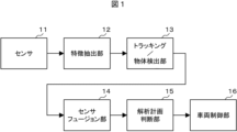
図1を参照して、物標検出装置の構成について説明する。
物体検出装置は、センサ11、特徴抽出部11、トラッキング/物体検出部13、センサフュージョン部14、解析計画判断部15及び車両制御部16を有する。センサ11で取得されたデータは特徴抽出部12でクレンジングされ、トラッキング/物体検出部13でトラッキング処理及び物体検出処理が行われて物標データとなる。
The configuration of the target detection device will be described with reference to FIG.
The object detection device includes a
物標データは、解析計画判断部15での走行経路や制御の計画判断に用いられ、その結果に基づいて車両制御部16で車両制御が行われる。本発明は、上記物体検出システムの中のトラッキング及び物体検出部13とセンサフュージョン部14に関わる。
The target data is used by the analysis and planning
図1において、センサフュージョンは物標データに対して行われる。この場合、物標データを物理的モデルを含まない単純な確率で合成する手法や、センサの不完全性をファジィ理論に基づいて表現したD-S理論を用いた手法がフュージョンとしてよく用いられる。 In Figure 1, sensor fusion is performed on target data. In this case, methods that often are used for fusion include synthesizing target data using simple probabilities that do not involve physical models, and methods that use D-S theory, which represents sensor imperfections based on fuzzy theory.
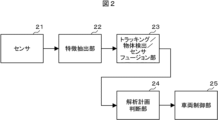
図2を参照して、物標検出装置の他の構成について説明する。
物体検出装置は、センサ21、特徴抽出部22、トラッキング/物体検出/センサフュージョン部23、解析計画判断部24及び車両制御部25を有する。図1に示す物標検出システムと異なる点は、図2に示す物標検出システムでは、トラッキング、物体検出及びセンサフュージョン23が統合されておりセンサ21からの観測値に対して直接合成を行う点である。この場合、(minimum-mean-squred error)MMSE、(Maximum Liklehood estimation)ML、(Maximum A-Posteriori Estimation)MAPといった規範に基づき、ベイズの定理を用いて観測値が得られた際の物標の確率分布を演算する手法が用いられる。図2の手法では、演算量は増加するものの、図1の物標に対してフュージョンを行う場合より一般的に良い特性が得られる。
Another configuration of the target detection device will be described with reference to FIG.
The object detection device includes a
本発明の物体検出装置は、確率的な合成を用いるセンサフュージョン方式に、利用シーンに応じて信頼度を適用的に変化させる機能を加えたものであり、図3~図6を用いて、前提となる確率的な合成を用いるセンサフュージョン方式に関して説明する。 The object detection device of the present invention adds a function to adaptively change the reliability depending on the usage scene to the sensor fusion method using probabilistic synthesis. The sensor fusion method using probabilistic synthesis, which is the premise of the method, will be explained using Figures 3 to 6.
図3を参照して、図1のトラッキング/物体検出部13とセンサフュージョン部14の機能について説明する。
各センサの観測値は、それぞれトラッキング処理31により、各センサの予測更新値32と合成される。トラッキングの出力の状態ベクトルや共分散行列、物標情報、存在確率等は、一度センサ毎に算出され、算出されたオブジェクトデータに対してセンサフュージョン33を行う。現在の自動運転向けセンサーフュージョンシステムでは、演算量とパフォーマンスのバランスの良い、D-S理論を用いた検討がよく行われており、本発明の物体検出装置で利用できる。
The functions of the tracking/
The observed values of each sensor are combined with the predicted
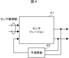
図4を参照して、図2のトラッキング/物体検出/センサフュージョン部23の機能について説明する。
各センサからの観測値に対して直接センサフュージョン41を行う際には、シングルセンサで複数の観測値と物標を合成するトラッキング手法をマルチセンサに拡張することで、トラッキングとセンサフュージョンを統合できる。この場合、ベイズ推定に基づき、フュージョン結果を用いた予測更新42の出力と、複数センサの観測値を確率的に統合する。
The function of the tracking/object detection/
When performing
例えば、カルマンフィルタを用いたMMSE規範のフュージョン手法として、Probabilistic Data Association(PDA)が知られている。また、PDAを拡張し、物標の存在確率を同時に算出する手法としてIntegrated PDA (IPDA)が知られており、これをマルチセンサに拡張することにより、フュージョン出力が得られる。本発明の物体検出部では、図3、図4のいずれの場合でも、確率的な合成に基づいてフュージョン処理を行う。 For example, Probabilistic Data Association (PDA) is known as an MMSE-based fusion method using a Kalman filter. Integrated PDA (IPDA) is also known as a method of extending PDA to simultaneously calculate the probability of a target's presence, and fusion output can be obtained by extending this to multiple sensors. In the object detection unit of the present invention, fusion processing is performed based on probabilistic synthesis in both cases of Figures 3 and 4.
図5を参照して、観測値の確率的な合成で狙う効果について説明する。図5は、センサ1とセンサ2のそれぞれの確率が距離とともに変化するモデルで確率的な合成をセンサフュージョンで行った場合の信頼度の例を示している。
The effect that is aimed for by the probabilistic combination of observed values will be explained with reference to Figure 5. Figure 5 shows an example of the reliability when probabilistic combination is performed by sensor fusion in a model in which the respective probabilities of
ここで、検知閾値以上の物標データが後段に繋がる場合、センサ1、センサ2でそれぞれ判定を行った場合、130m以上の領域は検知不可能となる。一方、センサ出力を確率として合成し、フュージョン後に判定する構成の場合、140m付近まで検知領域を拡大できる。
If target data above the detection threshold is connected to the subsequent stage, and a judgment is made by
図6は、フュージョンによる状態推定の改善の原理を説明する図である。図6(a)は、シングルセンサでPDAの手法を用いて、複数の観測値62、63と予測値61を合成する様子を示している。PDAはカルマンフィルタによるトラッキングを前提としたMMSE規範のフュージョン方法であり、推定する状態ベクトルxは、観測値Zの条件付き状態ベクトルである。MMSE規範を用いて、観測値と予測値の組み合わせイベントθに対して期待値を取る形となる。
Figure 6 is a diagram explaining the principle of improving state estimation through fusion. Figure 6(a) shows how multiple observed
ここで、数式βi=P{θ|Z}は、それぞれのイベントθのアソシエーション確率である。今、図6(a)において、予測値61に観測値62、63を結びつけることを考える。
Here, the formula β i =P{θ|Z} is the association probability of each event θ. Now, consider linking observed
今、各物標に1タイムステップでアソシエーションされる正しい観測値を1以下と仮定すると(Point target想定)、正しいアソシエーションの観測値は62か63、若しくは「正しいアソシエーションなし」である。観測値62が正しいアソシエーションとすると、観測値63は誤検出となる。一方、反対に63が正しく、62が誤検出のイベント仮説も考えられ、両者を尤度に基づく重みで平均し、フュージョン出力を算出する。
Now, assuming that the number of correct observations associated with each target in one time step is 1 or less (Point target assumption), the correct association observations are 62 or 63, or "no correct association." If
ここで、マルチセンサに拡張した場合、図6(b)のように、センサ2に基づく観測値の予測範囲66とセンサ2の観測値66が追加され、同じく、全ての起こり得るイベント仮説について期待値を取ると、センサ2の観測値66が正しい観測値であったときに、合成利得が発生し状態推定の精度が上昇する。
When expanded to multiple sensors, as shown in FIG. 6(b), a
一方、このような手法を用いる場合、それぞれ異なるセンサの確からしさを適切に設定しない場合、間違った仮説の尤度が高くなるため、センサの信頼度を適応的に調整する手法が重要となる。 However, when using such a method, if the reliability of each different sensor is not set appropriately, the likelihood of an incorrect hypothesis will be high, so a method for adaptively adjusting the reliability of the sensors is important.
そこで、本発明では、上記フュージョン機能に、センサ毎の誤検知率を推定する機能を追加し、様々な利用シーンでフュージョン後の推定精度を高める。
以下、図7~図13を用いて、本発明の実施例について説明する。
Therefore, in the present invention, a function for estimating the false detection rate for each sensor is added to the above-mentioned fusion function, thereby improving the estimation accuracy after fusion in various usage scenarios.
Hereinafter, an embodiment of the present invention will be described with reference to FIGS.
図7を参照して、実施例1の物標検出装置の構成について説明する。図7は、実施例1の適応的にセンサの信頼度を推定するセンサフュージョンを用いた物標検出部の機能ブロックを示す。以下、誤検知は、誤検出と未検出の両方を含む。 The configuration of the target detection device of the first embodiment will be described with reference to FIG. 7. FIG. 7 shows the functional blocks of the target detection unit of the first embodiment that uses sensor fusion to adaptively estimate the reliability of the sensor. Hereinafter, false detection includes both false detection and non-detection.
実施例1の物標検出装置は、フュージョン後の物標の予測値(フュージョン結果の予測更新の結果)を用いて予測値と観測値のグルーピングを行うグルーピング部71と、確率に基づくフュージョン処理部73と、観測値とフュージョン後の予測値を用いて、物標ごとの誤検知を推定する誤検知推定部72と、誤検知推定部72の誤検知結果からセンサ単位の誤検知率を推定する誤検知確率算出部75と、誤検知算出のセンサ毎の誤検知率を元にセンサの既定の信頼度を補正する信頼度補正部76を有する。
The target detection device of Example 1 includes a
グルーピング部71は、フュージョン後の予測値とセンサの観測値から、物標の予測値と観測値の対応状況を表すグループ情報を作成する。誤検知推定部72は、グルーピング部71からのグループ情報、観測値及びフュージョン後の予測値を用いて、物標ごと(予測値毎)の誤検知推定を行う。
The
誤検知確率算出部75は、誤検知推定結果から、センサ単位の誤検知確率を推定する。信頼度補正部76は、既定のセンサの信頼度を誤検知確率算出部75からのセンサ単位の誤検知確率に基づいて補正する。フュージョン処理部73は、グループ情報、観測値、誤検知推定結果、補正後のセンサ信頼度及び予測値に基づいてフュージョン処理を行い、状態ベクトルや共分散行列、存在確率等を出力する。
The false detection
ここで、センサの信頼度として用いるパラメータの一例を図8に示す。
オブジェクトの存在の有無と、検出結果の関係を図8で表すと、誤検出はクラッタ密度λ、未検出検知確率Pdと結びつけることができる。検知確率やクラッタの密度は、前記PDAの手法のアソシエーション確率βに利用できるので、これらをセンサの信頼度として用いることで、検知結果から適応的にセンサ単位の信頼度を推定できる。
An example of parameters used as the reliability of the sensor is shown in FIG.
The relationship between the presence or absence of an object and the detection result is shown in Figure 8. False detection can be linked to the clutter density λ and the undetected detection probability Pd . The detection probability and clutter density can be used for the association probability β in the PDA method, so by using these as the reliability of the sensor, the reliability of each sensor can be adaptively estimated from the detection result.
実施例1では、PDAの手法を用いた場合を示すが、オブジェクトデータに対するフュージョンに関しても、D-S方に基づいた合成で用いるセンサの不確実性のパラメータを上記誤検出及び未検出に応じて変更することで、利用シーンに応じて適応的にセンサの信頼度を変化させる方式を適用できる。 In Example 1, a case where the PDA method is used is shown, but for fusion of object data, a method of adaptively changing the reliability of the sensor according to the usage scene can also be applied by changing the parameter of the sensor uncertainty used in synthesis based on the D-S method according to the above-mentioned false detection and non-detection.
図9を参照して、誤検知推定部72の機能について説明する。
誤検知推定部72では、フュージョン結果の予測値94を用いて、物標毎の未検出率、誤検出頻度を推定する。ここで、91~93は観測値の予測範囲であり、94、96、97は物標の予測値であり、98は観測値である。
The function of the erroneous
The false
まず、補足した物標に対応する真の観測値は最大1点とすると、図9(a)は通常の場合であり、観測値95が予測値94の物標に起因するか否かを判定する。図9(b)は、観測値が予測範囲92内に存在しない場合で、未検出と判定し未検出の推定値として用いる。図9(c)は、予測値97に対して観測値98が多数の場合で、誤検出率が増加したと判定し、誤検出の数をカウントし誤検出の推定値として用いる。
First, assuming that the true observed value corresponding to the captured target is a maximum of one point, FIG. 9(a) shows the normal case, in which it is determined whether or not the observed
ここで、予測値としてフュージョン後の値を用いているため、複数センサのどれかが観測できなかった場合に、他のセンサの尤度が高ければトラックは維持され、未検出数をカウントできる。 Here, the value after fusion is used as the predicted value, so if one of the multiple sensors misses an observation, the track is maintained if the likelihood of the other sensors is high, and the number of undetected events can be counted.
図10を参照して、誤検知確率算出部75の機能について説明する。
誤検出確率算出部75は、複数の物標の誤検出数の平均値や未検出の頻度をセンサ毎に算出して、センサ単位の誤検知推定として出力する。図10において、補足している物標の数分の未検出数の推定値、誤検出数の推定値が前段ブロックから入力され、センサ単位でまとめて平均処理や検知率への変換を行う。
The function of the false detection
The false detection
図11を参照して、信頼度補正部76の機能について説明する。
図11(a)に示すように、信頼度補正部76は、センサ単位の誤検知確率に基づき、既定のセンサ毎の信頼度を補正し、補正後の信頼度を出力する。補正の方法はテーブルルックアップを用いた係数選択や、誤検知確率を指揮変換し補正係数として乗算することで実行される。
図11(b)には、誤検知率が増加した際の補正によるセンサ信頼度の変化を示す。既定の信頼度として距離に応じたセンサ信頼度が設定されたものに対して、センサの誤検出確率が高くなった場合に信頼度を減少させる。これにより、利用シーンで信頼度の低いセンサから受ける影響を抑えることができる。
The function of the
11A, the
Fig. 11(b) shows the change in sensor reliability due to correction when the false detection rate increases. The sensor reliability according to distance is set as the default reliability, but the reliability is reduced when the sensor false detection rate increases. This makes it possible to reduce the impact of low-reliability sensors in the usage scenario.
上述のように、実施例1の物標検出装置は、複数種類のセンサから出力された複数の観測値に基づいて物標を検出する。物標検出装置は、フュージョンを処理してフュージョン後の物標の予測値を出力するフュージョン処理部73と、観測値と予測値に基づいて、物標ごとの誤検知を推定して誤検知推定結果を出力する誤検知推定部72と、誤検知推定結果に基づいて、センサ毎の誤検知率を算出する誤検知確率算出部75と、誤検知率に基づいて、予め定められたセンサの信頼度を補正して補正後の信頼度を出力する信頼度補正部76を有する。フュージョン処理部73は、予測値、誤検知推定結果及び補正後の信頼度に基づいて、フュージョンを処理する。フュージョン処理部73は、フュージョンを処理して、状態ベクトル、共分散行列又は存在確率を出力する。
As described above, the target detection device of Example 1 detects a target based on multiple observation values output from multiple types of sensors. The target detection device has a
誤検知推定部72は、予測値を用いて、物標毎の未検出率及び誤検出率を推定する。また、誤検知推定部72は、センサ毎の未検出の頻度を観測値の推定範囲内に存在する観測値の有無に基づいて算出し、センサ毎の誤検出の頻度を観測値の推定範囲内に存在する観測値の数に基づいて算出し、未検出の頻度及び誤検出の頻度を用いて、物標ごとの誤検知を推定する。
The false
また、誤検知推定部72は、観測値が推定範囲内に存在しない場合に、未検出と判定して未検出率の推定値として用い、観測値が推定範囲内に少なくとも一つ存在する場合に、誤検出数をカウントして誤検出率の推定値として用いる。
In addition, if an observed value does not exist within the estimated range, the false
また、誤検知推定部72は複数のタイムステップに渡る誤検知推定結果の平均又は統計処理を用いて、物標ごとの誤検知を推定する。また、誤検知推定部72は、時間的に前のステップのフュージョン後の予測値を用いて、物標ごとの誤検知を推定する。
The false
また、誤検出確率算出部75は、誤検知推定結果として未検出の推定値及び誤検出の推定値を用いて、複数の物標の誤検出数の平均値及び未検出の頻度をセンサ毎に算出して、センサ毎の誤検知率を算出する。
The false detection
信頼度補正部76は、誤検知率を指揮変換して係数を算出し、補正係数として予め定められたセンサの信頼度に乗算することにより、センサの信頼度を補正する。また、信頼度補正部76は、センサの信頼度として距離に応じたセンサ信頼度が予め設定されている場合、誤検出率が高くなった場合にセンサ信頼度を減少させるようにセンサの信頼度を補正する。
The
上記実施例1によれば、センサの信頼度が変化するシーンにおいても、良好なフュージョン結果が得られる。このように、利用シーンに応じて適切にセンサの信頼度を設定して複数センサのフュージョン結果を改善することができる。 According to the above-mentioned Example 1, good fusion results can be obtained even in scenes where the reliability of the sensors changes. In this way, the reliability of the sensors can be appropriately set according to the usage scene, and the fusion results of multiple sensors can be improved.
図12を参照して、実施例2の物標検出装置の構成について説明する。図12は、センサの異常検知機能を有するセンサフュージョンを用いた物標検出装置の機能ブロックを示す。
図12では、センサ単位の誤検知確率からセンサの異常を検知する異常検知部121が新たに追加されている。その他の構成は図7に示す実施例1の物標検出装置の構成と同じなのでその説明は省略する。
The configuration of the target detection device of the second embodiment will be described with reference to Fig. 12. Fig. 12 shows functional blocks of the target detection device using sensor fusion having a sensor anomaly detection function.
12, an
センサの誤検知率の増加が定常的になった場合には、劣化要因は外部環境ではなくセンサそのものとみなすことができる。異常検知部121は、一定時間以上誤検知の高い状況が続いた場合にアラートを上げることによりセンサの異常を検知する。
When the increase in the sensor's false positive rate becomes steady, the cause of degradation can be considered to be the sensor itself, rather than the external environment. The
図13を参照して、実施例3の物標検出装置の構成について説明する。図13は、センサのシーン検出機能を有するセンサフュージョンを用いた物標検出装置の機能ブロックを示す。
図13では、センサ単位の誤検知確率を入力としてシーンの検出を行うシーン検出部131が新たに追加されている。その他の構成は図7に示す実施例1の物標検出装置の構成と同じなのでその説明は省略する。
The configuration of a target object detection device according to the third embodiment will be described with reference to Fig. 13. Fig. 13 shows functional blocks of a target object detection device using sensor fusion having a sensor scene detection function.
13, a
上記実施例3では、センサ単位の誤検知率の変化により、どのセンサが苦手なのかを推定することが可能である。シーン検出部131は、センサ単位の誤検知確率を入力としてシーン検出を行い、検出したシーンを図1の解析計画判断部15へ入力する。
In the above-mentioned third embodiment, it is possible to estimate which sensor is weak based on the change in the false detection rate per sensor. The
例えば、トンネル内では、ミリ波の誤検知率が反射波により増加する。このため、他のセンサで大きな変化がない中で、ミリ波の誤検知が急増すれば、反射率の高い物体に囲まれているか、反射率の高い物体が周辺に存在することが推定できる。 For example, in a tunnel, the rate of false positives for millimeter waves increases due to reflected waves. Therefore, if there is a sudden increase in false positives for millimeter waves while there are no significant changes in other sensors, it can be inferred that the vehicle is surrounded by highly reflective objects or that highly reflective objects are present in the vicinity.
また、カメラでの検知率が低下した際は、逆境による白飛びや降雨、泥はねによるオクルージョン、比較的近い距離での車両横切りや突発的な障害物の発生等が推定できる。Lidarに関しては、反射率の高い物体での未検知が発生する。 In addition, when the detection rate of the camera drops, it can be assumed that adverse conditions such as whiteout, rainfall, occlusion due to mud splashes, vehicles crossing at a relatively close distance, or the sudden appearance of an obstacle are the cause. With Lidar, objects with high reflectivity go undetected.
実施例3では、センサフュージョンにおいて、利用シーンでのセンサの得手不得手に起因する特性劣化を改善することができる。 In the third embodiment, in sensor fusion, it is possible to improve the degradation of characteristics caused by the strengths and weaknesses of sensors in a given usage scenario.
上記実施例では、複数種類のセンサから複数の出力データを受け付け、前記複数の出力データに基づいて、物標を検出するフュージョン物体認識部を備える物標検出装置において、時間的に前のステップのフュージョン後の前記物標の検出結果に基づいて前記物標の誤検知の推定を行う誤検知推定部と、前記誤検知の推定結果に基づいて前記複数種類のセンサ単位の現在のシーンにおけるセンサの信頼度を推定するセンサ信頼度検出部とを備える。そして、前記センサの信頼度に基づく補正後の信頼度、前記誤検知の推定結果及び前記出力データに基づいて前記物標の検出を行う。 In the above embodiment, the target detection device includes a fusion object recognition unit that receives multiple output data from multiple types of sensors and detects targets based on the multiple output data. The device includes a false detection estimation unit that estimates a false detection of the target based on the target detection result after fusion in a previous step, and a sensor reliability detection unit that estimates the reliability of the sensor in the current scene for each of the multiple types of sensors based on the false detection estimation result. The target is then detected based on the corrected reliability based on the sensor reliability, the false detection estimation result, and the output data.
また、前記センサの信頼度として、センサ毎の未検出、誤検出の頻度を用いる。前記センサ毎の未検出の頻度は、前記フュージョン後の予測値から、観測値の推定範囲内に存在する観測値の有無を基にして算出する。前記センサ毎の未検出の頻度は、前記フュージョン後の予測値から、観測値の推定範囲内に存在する観測値の数を基にして算出する。 The frequency of non-detection and false detection for each sensor is used as the reliability of the sensor. The frequency of non-detection for each sensor is calculated based on the presence or absence of observed values that exist within the estimated range of observed values from the predicted value after the fusion. The frequency of non-detection for each sensor is calculated based on the number of observed values that exist within the estimated range of observed values from the predicted value after the fusion.
また、前記センサの信頼度に基づく補正は、前記センサ信頼度検出部で算出したセンサの信頼度によるテーブルルックアップによる係数参照、若しくは、信頼度検出部で算出したセンサの信頼度と既定のセンサの信頼度の両方を入力とするルックアップテーブルで算出された係数を用いて行われる。前記センサの信頼度に基づく補正は、前記センサ信頼度検出部で算出したセンサの信頼度を入力とした指揮変換で係数を算出し、既存のセンサ信頼度に乗算することで行われる。また、前記誤検知の推定結果の推定は、複数タイムステップに渡る誤検知指定結果の平均や統計処理を基に行われる。 The correction based on the reliability of the sensor is performed by referencing a coefficient by table lookup based on the reliability of the sensor calculated by the sensor reliability detection unit, or by using a coefficient calculated in a lookup table that inputs both the reliability of the sensor calculated by the reliability detection unit and the reliability of a default sensor. The correction based on the reliability of the sensor is performed by calculating a coefficient through command transformation that inputs the reliability of the sensor calculated by the sensor reliability detection unit, and multiplying the coefficient by the existing sensor reliability. The estimation of the false detection estimation result is performed based on the average or statistical processing of the false detection designation results over multiple time steps.
また、前記複数種類のセンサ単位の現在のシーンにおけるセンサの信頼度を推定するセンサ信頼度検出部からのセンサ単位の信頼を入力として現在のシーンを推定するシーン検出機能を有する。 It also has a scene detection function that estimates the current scene using the reliability of each sensor as input from a sensor reliability detection unit that estimates the reliability of the sensors in the current scene for each of the multiple types of sensors.
また、前記複数種類のセンサ単位の現在のシーンにおけるセンサの信頼度を推定するセンサ信頼度検出部からのセンサ単位の信頼を入力として、センサの経年劣化や故障等の異常検知を行う異常検知機能を有する。 The system also has an anomaly detection function that detects anomalies such as deterioration or failure of the sensor by using the reliability of each sensor as input from a sensor reliability detection unit that estimates the reliability of the sensors in the current scene for each of the multiple types of sensors.
上記実施例によれば、センサの信頼度が変化するシーンにおいても、良好なフュージョン結果が得られる物標検出装置を実現できる。 The above embodiment makes it possible to realize a target detection device that can obtain good fusion results even in scenes where the reliability of the sensor changes.
なお、本発明は前述した実施例に限定されるものではなく、添付した特許請求の範囲の趣旨内における様々な変形例及び同等の構成が含まれる。例えば、前述した実施例は本発明を分かりやすく説明するために詳細に説明したものであり、必ずしも説明した全ての構成を備えるものに本発明は限定されない。 The present invention is not limited to the above-described embodiments, but includes various modifications and equivalent configurations within the spirit of the appended claims. For example, the above-described embodiments have been described in detail to clearly explain the present invention, and the present invention is not necessarily limited to those having all of the configurations described.
例えば、図7に示す実施例1の物標検出装置では、既定の信頼度は外部から信頼度補正部76に入力されているが、本発明はこれに限定されず、信頼度補正部76のレジスタ等に既定の信頼度を保持しても良い。
For example, in the target detection device of Example 1 shown in FIG. 7, the default reliability is input to the
また、ある実施例の構成の一部を他の実施例の構成に置き換えてもよい。また、ある実施例の構成に他の実施例の構成を加えてもよい。また、各実施例の構成の一部について、他の構成の追加・削除・置換をしてもよい。 In addition, part of the configuration of one embodiment may be replaced with the configuration of another embodiment. In addition, the configuration of one embodiment may be added to the configuration of another embodiment. In addition, part of the configuration of each embodiment may be added to, deleted from, or replaced with another configuration.
また、前述した各構成、機能、処理部、処理手段等は、それらの一部又は全部を、例えば集積回路で設計する等により、ハードウェアで実現してもよく、プロセッサがそれぞれの機能を実現するプログラムを解釈し実行することにより、ソフトウェアで実現してもよい。 Furthermore, each of the configurations, functions, processing units, processing means, etc. described above may be realized in part or in whole in hardware, for example by designing them as integrated circuits, or may be realized in software by a processor interpreting and executing a program that realizes each function.
各機能を実現するプログラム、テーブル、ファイル等の情報は、メモリ、ハードディスク、SSD(Solid State Drive)等の記憶装置、又は、ICカード、SDカード、DVD等の記録媒体に格納することができる。 Information such as programs, tables, and files that realize each function can be stored in a storage device such as a memory, hard disk, or SSD (Solid State Drive), or in a recording medium such as an IC card, SD card, or DVD.
また、制御線や情報線は説明上必要と考えられるものを示しており、実装上必要な全ての制御線や情報線を示しているとは限らない。実際には、ほとんど全ての構成が相互に接続されていると考えてよい。 In addition, the control lines and information lines shown are those considered necessary for explanation, and do not necessarily represent all control lines and information lines necessary for implementation. In reality, it is safe to assume that almost all components are interconnected.
11 センサ
12 特徴抽出部
13 トラッキング/物体検出部、
14 センサフュージョン部
15 解析計画判断部
16 車両制御部
21 センサ
22 特徴抽出部
23 トラッキング/物体検出/センサフュージョン部
24 解析計画判断部
25 車両制御部
31 トラッキング
32 予測更新
33 センサフュージョン
41 センサフュージョン
42 予測更新
71 グルーピング部
72 誤検知推定部
73 フュージョン処理部
74 予測値
75 誤検知確率算出部
76 信頼度補正部
121 異常検知部
131 シーン検出部
11
14
Claims (12)
フュージョンを処理してフュージョン後の前記物標の予測値を出力するフュージョン処理部と、
前記観測値と前記予測値に基づいて、前記物標ごとの誤検知を推定して誤検知推定結果を出力する誤検知推定部と、
前記誤検知推定結果に基づいて、前記センサ毎の誤検知率を算出する誤検知確率算出部と、
前記誤検知率に基づいて、予め定められた前記センサの信頼度を補正して補正後の信頼度を出力する信頼度補正部と、を有し、
前記フュージョン処理部は、
前記予測値、前記誤検知推定結果及び前記補正後の信頼度に基づいて、前記フュージョンを処理し、
前記誤検知推定部は、
前記予測値を用いて、前記物標毎の未検出率及び誤検出率を推定することを特徴とする物標検出装置。 A target detection device that detects a target based on a plurality of observation values output from a plurality of types of sensors,
a fusion processing unit that processes the fusion and outputs a predicted value of the target after the fusion;
an erroneous detection estimation unit that estimates an erroneous detection for each target based on the observed value and the predicted value and outputs an erroneous detection estimation result;
a false detection probability calculation unit that calculates a false detection rate for each of the sensors based on the false detection estimation result;
a reliability correction unit that corrects a predetermined reliability of the sensor based on the false detection rate and outputs the corrected reliability,
The fusion processing unit includes:
processing the fusion based on the predicted value, the false positive estimation result, and the corrected confidence level;
The erroneous detection estimation unit is
A target detection device comprising: a detection unit for detecting a target object, the detection unit being configured to estimate a non-detection rate and a false detection rate for each target object by using the predicted value.
前記フュージョンを処理して、状態ベクトル、共分散行列又は存在確率を出力することを特徴とする請求項1に記載の物標検出装置。 The fusion processing unit includes:
The target detection device according to claim 1 , further comprising: processing the fusion to output a state vector, a covariance matrix, or an existence probability.
前記センサ毎の未検出の頻度を前記観測値の推定範囲内に存在する前記観測値の有無に基づいて算出し、
前記センサ毎の誤検出の頻度を前記観測値の前記推定範囲内に存在する前記観測値の数に基づいて算出し、
前記未検出の頻度及び前記誤検出の頻度を用いて、前記物標ごとの誤検知を推定することを特徴とする請求項1に記載の物標検出装置。 The erroneous detection estimation unit is
Calculating a frequency of non-detection for each of the sensors based on the presence or absence of the observed value within an estimated range of the observed value;
Calculating a frequency of false positives for each sensor based on the number of observed values that are within the estimated range of the observed values;
2. The target detection device according to claim 1, wherein the frequency of non-detection and the frequency of erroneous detection are used to estimate a erroneous detection rate for each target.
前記観測値が前記推定範囲内に存在しない場合に、前記未検出と判定して前記未検出率の推定値として用い、
前記観測値が前記推定範囲内に少なくとも一つ存在する場合に、誤検出数をカウントして前記誤検出率の推定値として用いることを特徴とする請求項3に記載の物標検出装置。 The erroneous detection estimation unit is
When the observed value is not within the estimated range, the observed value is determined to be undetected and used as an estimate of the undetected rate;
4. The target detection device according to claim 3, wherein when at least one of the observed values is within the estimation range, the number of false positives is counted and used as the estimated value of the false positive rate.
前記誤検知推定結果として前記未検出率の推定値及び前記誤検出率の推定値を用いて、複数の前記物標の前記誤検出の数の平均値及び前記未検出の頻度を前記センサ毎に算出して、前記センサ毎の前記誤検知率を算出することを特徴とする請求項4に記載の物標検出装置。 The false positive probability calculation unit
5. The target detection device according to claim 4, characterized in that an average value of the number of false detections of a plurality of targets and a frequency of the false detection are calculated for each sensor using the estimated value of the non -detection rate and the estimated value of the false detection rate as the false detection estimation result, thereby calculating the false detection rate for each sensor.
フュージョンを処理してフュージョン後の前記物標の予測値を出力するフュージョン処理部と、
前記観測値と前記予測値に基づいて、前記物標ごとの誤検知を推定して誤検知推定結果を出力する誤検知推定部と、
前記誤検知推定結果に基づいて、前記センサ毎の誤検知率を算出する誤検知確率算出部と、
前記誤検知率に基づいて、予め定められた前記センサの信頼度を補正して補正後の信頼度を出力する信頼度補正部と、を有し、
前記フュージョン処理部は、
前記予測値、前記誤検知推定結果及び前記補正後の信頼度に基づいて、前記フュージョンを処理し、
前記誤検知推定部は、
複数のタイムステップに渡る前記誤検知推定結果の平均又は統計処理を用いて、前記物標ごとの前記誤検知を推定することを特徴とする物標検出装置。 A target detection device that detects a target based on a plurality of observation values output from a plurality of types of sensors,
a fusion processing unit that processes the fusion and outputs a predicted value of the target after the fusion;
an erroneous detection estimation unit that estimates an erroneous detection for each target based on the observed value and the predicted value and outputs an erroneous detection estimation result;
a false detection probability calculation unit that calculates a false detection rate for each of the sensors based on the false detection estimation result;
a reliability correction unit that corrects a predetermined reliability of the sensor based on the false detection rate and outputs the corrected reliability,
The fusion processing unit includes:
processing the fusion based on the predicted value, the false positive estimation result, and the corrected confidence level;
The erroneous detection estimation unit is
A target detection device comprising: an apparatus for estimating the false positives for each target by using an average or statistical processing of the false positive estimation results over a plurality of time steps.
フュージョンを処理してフュージョン後の前記物標の予測値を出力するフュージョン処理部と、
前記観測値と前記予測値に基づいて、前記物標ごとの誤検知を推定して誤検知推定結果を出力する誤検知推定部と、
前記誤検知推定結果に基づいて、前記センサ毎の誤検知率を算出する誤検知確率算出部と、
前記誤検知率に基づいて、予め定められた前記センサの信頼度を補正して補正後の信頼度を出力する信頼度補正部と、を有し、
前記フュージョン処理部は、
前記予測値、前記誤検知推定結果及び前記補正後の信頼度に基づいて、前記フュージョンを処理し、
前記誤検知推定部は、
時間的に前のステップの前記フュージョン後の前記予測値を用いて、前記物標ごとの前記誤検知を推定することを特徴とする物標検出装置。 A target detection device that detects a target based on a plurality of observation values output from a plurality of types of sensors,
a fusion processing unit that processes the fusion and outputs a predicted value of the target after the fusion;
an erroneous detection estimation unit that estimates an erroneous detection for each target based on the observed value and the predicted value and outputs an erroneous detection estimation result;
a false detection probability calculation unit that calculates a false detection rate for each of the sensors based on the false detection estimation result;
a reliability correction unit that corrects a predetermined reliability of the sensor based on the false detection rate and outputs the corrected reliability,
The fusion processing unit includes:
processing the fusion based on the predicted value, the false positive estimation result, and the corrected confidence level;
The erroneous detection estimation unit is
A target detection device comprising: a step of estimating the erroneous detection for each target by using the predicted value after the fusion in a temporally previous step.
フュージョンを処理してフュージョン後の前記物標の予測値を出力するフュージョン処理部と、
前記観測値と前記予測値に基づいて、前記物標ごとの誤検知を推定して誤検知推定結果を出力する誤検知推定部と、
前記誤検知推定結果に基づいて、前記センサ毎の誤検知率を算出する誤検知確率算出部と、
前記誤検知率に基づいて、予め定められた前記センサの信頼度を補正して補正後の信頼度を出力する信頼度補正部と、を有し、
前記フュージョン処理部は、
前記予測値、前記誤検知推定結果及び前記補正後の信頼度に基づいて、前記フュージョンを処理し、
前記信頼度補正部は、
前記誤検知率から算出した補正係数を予め定められた前記センサの信頼度に乗算することにより、前記センサの信頼度を補正することを特徴とする物標検出装置。 A target detection device that detects a target based on a plurality of observation values output from a plurality of types of sensors,
a fusion processing unit that processes the fusion and outputs a predicted value of the target after the fusion;
an erroneous detection estimation unit that estimates an erroneous detection for each target based on the observed value and the predicted value and outputs an erroneous detection estimation result;
a false detection probability calculation unit that calculates a false detection rate for each of the sensors based on the false detection estimation result;
a reliability correction unit that corrects a predetermined reliability of the sensor based on the false detection rate and outputs the corrected reliability,
The fusion processing unit includes:
processing the fusion based on the predicted value, the false positive estimation result, and the corrected confidence level;
The reliability correction unit is
a correction coefficient calculated from the rate of false detection , thereby correcting a predetermined reliability of the sensor, the correction coefficient being calculated from the rate of false detection, the correction coefficient being calculated from the rate of false detection, and the like.
フュージョンを処理してフュージョン後の前記物標の予測値を出力するフュージョン処理部と、
前記観測値と前記予測値に基づいて、前記物標ごとの誤検知を推定して誤検知推定結果を出力する誤検知推定部と、
前記誤検知推定結果に基づいて、前記センサ毎の誤検知率を算出する誤検知確率算出部と、
前記誤検知率に基づいて、予め定められた前記センサの信頼度を補正して補正後の信頼度を出力する信頼度補正部と、を有し、
前記フュージョン処理部は、
前記予測値、前記誤検知推定結果及び前記補正後の信頼度に基づいて、前記フュージョンを処理し、
前記信頼度補正部は、
前記センサの前記信頼度として距離に応じたセンサ信頼度が予め設定されている場合、前記誤検知率が高くなった場合に前記センサ信頼度を減少させるように前記センサの信頼度を補正することを特徴とする物標検出装置。 A target detection device that detects a target based on a plurality of observation values output from a plurality of types of sensors,
a fusion processing unit that processes the fusion and outputs a predicted value of the target after the fusion;
an erroneous detection estimation unit that estimates an erroneous detection for each target based on the observed value and the predicted value and outputs an erroneous detection estimation result;
a false detection probability calculation unit that calculates a false detection rate for each of the sensors based on the false detection estimation result;
a reliability correction unit that corrects a predetermined reliability of the sensor based on the false detection rate and outputs the corrected reliability,
The fusion processing unit includes:
processing the fusion based on the predicted value, the false positive estimation result, and the corrected confidence level;
The reliability correction unit is
A target detection device characterized in that, when the reliability of the sensor is preset as a sensor reliability corresponding to distance, the reliability of the sensor is corrected so as to decrease the sensor reliability when the false detection rate becomes high.
フュージョンを処理してフュージョン後の前記物標の予測値を出力するフュージョン処理部と、
前記観測値と前記予測値に基づいて、前記物標ごとの誤検知を推定して誤検知推定結果を出力する誤検知推定部と、
前記誤検知推定結果に基づいて、前記センサ毎の誤検知率を算出する誤検知確率算出部と、
前記誤検知率に基づいて、予め定められた前記センサの信頼度を補正して補正後の信頼度を出力する信頼度補正部と、を有し、
前記フュージョン処理部は、
前記予測値、前記誤検知推定結果及び前記補正後の信頼度に基づいて、前記フュージョンを処理し、
前記センサ毎の前記誤検知率に基づいて、前記センサの異常を検知するセンサ異常検知部を更に有することを特徴とする物標検出装置。 A target detection device that detects a target based on a plurality of observation values output from a plurality of types of sensors,
a fusion processing unit that processes the fusion and outputs a predicted value of the target after the fusion;
an erroneous detection estimation unit that estimates an erroneous detection for each target based on the observed value and the predicted value and outputs an erroneous detection estimation result;
a false detection probability calculation unit that calculates a false detection rate for each of the sensors based on the false detection estimation result;
a reliability correction unit that corrects a predetermined reliability of the sensor based on the false detection rate and outputs the corrected reliability,
The fusion processing unit includes:
processing the fusion based on the predicted value, the false positive estimation result, and the corrected confidence level;
The target detection device further comprises a sensor abnormality detection unit that detects an abnormality in the sensor based on the false detection rate for each of the sensors.
フュージョンを処理してフュージョン後の前記物標の予測値を出力するフュージョン処理部と、
前記観測値と前記予測値に基づいて、前記物標ごとの誤検知を推定して誤検知推定結果を出力する誤検知推定部と、
前記誤検知推定結果に基づいて、前記センサ毎の誤検知率を算出する誤検知確率算出部と、
前記誤検知率に基づいて、予め定められた前記センサの信頼度を補正して補正後の信頼度を出力する信頼度補正部と、を有し、
前記フュージョン処理部は、
前記予測値、前記誤検知推定結果及び前記補正後の信頼度に基づいて、前記フュージョンを処理し、
前記センサ毎の前記誤検知率に基づいて、前記センサのシーンを検出するシーン検出部を更に有することを特徴とする物標検出装置。 A target detection device that detects a target based on a plurality of observation values output from a plurality of types of sensors,
a fusion processing unit that processes the fusion and outputs a predicted value of the target after the fusion;
an erroneous detection estimation unit that estimates an erroneous detection for each target based on the observed value and the predicted value and outputs an erroneous detection estimation result;
a false detection probability calculation unit that calculates a false detection rate for each of the sensors based on the false detection estimation result;
a reliability correction unit that corrects a predetermined reliability of the sensor based on the false detection rate and outputs the corrected reliability,
The fusion processing unit includes:
processing the fusion based on the predicted value, the false positive estimation result, and the corrected confidence level;
The target detection device further comprises a scene detection unit that detects a scene of the sensor based on the false detection rate for each of the sensors.
フュージョンを処理してフュージョン後の前記物標の予測値を出力するフュージョン処理部と、
前記観測値と前記予測値に基づいて、前記物標ごとの誤検知を推定して誤検知推定結果を出力する誤検知推定部と、
前記誤検知推定結果に基づいて、前記センサ毎の誤検知率を算出する誤検知確率算出部と、
前記誤検知率に基づいて、予め定められた前記センサの信頼度を補正して補正後の信頼度を出力する信頼度補正部と、を有し、
前記フュージョン処理部は、
前記予測値、前記誤検知推定結果及び前記補正後の信頼度に基づいて、前記フュージョンを処理し、
前記予測値と前記観測値のグルーピングを行うグルーピング部を更に有し、
前記グルーピング部は、
前記予測値と前記観測値の対応状況を表すグループ情報を生成し、
前記誤検知推定部は、
前記グループ情報を参照して、前記物標ごとの前記誤検知を推定し、
前記フュージョン処理部は、
前記グループ情報を参照して、前記フュージョンを処理することを特徴とする物標検出装置。 A target detection device that detects a target based on a plurality of observation values output from a plurality of types of sensors,
a fusion processing unit that processes the fusion and outputs a predicted value of the target after the fusion;
an erroneous detection estimation unit that estimates an erroneous detection for each target based on the observed value and the predicted value and outputs an erroneous detection estimation result;
a false detection probability calculation unit that calculates a false detection rate for each of the sensors based on the false detection estimation result;
a reliability correction unit that corrects a predetermined reliability of the sensor based on the false detection rate and outputs the corrected reliability,
The fusion processing unit includes:
processing the fusion based on the predicted value, the false positive estimation result, and the corrected confidence level;
A grouping unit that groups the predicted values and the observed values,
The grouping unit includes:
generating group information representing a correspondence state between the predicted value and the observed value;
The erroneous detection estimation unit is
estimating the false positive rate for each of the targets by referring to the group information;
The fusion processing unit includes:
A target detection device, comprising: a processing unit that processes the fusion by referring to the group information.
Priority Applications (4)
| Application Number | Priority Date | Filing Date | Title |
|---|---|---|---|
| JP2020194708A JP7481237B2 (en) | 2020-11-24 | 2020-11-24 | Target detection device |
| PCT/JP2021/033549 WO2022113478A1 (en) | 2020-11-24 | 2021-09-13 | Object detection device and object detection method |
| DE112021004904.6T DE112021004904T5 (en) | 2020-11-24 | 2021-09-13 | OBJECT DETECTION DEVICE AND OBJECT DETECTION METHOD |
| US18/035,727 US20230410657A1 (en) | 2020-11-24 | 2021-09-13 | Object detection device and object detection method |
Applications Claiming Priority (1)
| Application Number | Priority Date | Filing Date | Title |
|---|---|---|---|
| JP2020194708A JP7481237B2 (en) | 2020-11-24 | 2020-11-24 | Target detection device |
Publications (2)
| Publication Number | Publication Date |
|---|---|
| JP2022083331A JP2022083331A (en) | 2022-06-03 |
| JP7481237B2 true JP7481237B2 (en) | 2024-05-10 |
Family
ID=81755464
Family Applications (1)
| Application Number | Title | Priority Date | Filing Date |
|---|---|---|---|
| JP2020194708A Active JP7481237B2 (en) | 2020-11-24 | 2020-11-24 | Target detection device |
Country Status (4)
| Country | Link |
|---|---|
| US (1) | US20230410657A1 (en) |
| JP (1) | JP7481237B2 (en) |
| DE (1) | DE112021004904T5 (en) |
| WO (1) | WO2022113478A1 (en) |
Families Citing this family (2)
| Publication number | Priority date | Publication date | Assignee | Title |
|---|---|---|---|---|
| JP7796686B2 (en) * | 2023-02-24 | 2026-01-09 | 三菱電機株式会社 | OBJECT DETECTION DEVICE, OBJECT DETECTION METHOD, AND OBJECT DETECTION PROGRAM |
| CN116956216A (en) * | 2023-07-17 | 2023-10-27 | 中国电子科技集团公司第五十四研究所 | Offshore target identification method based on fuzzy theory and D-S evidence theory |
Citations (3)
| Publication number | Priority date | Publication date | Assignee | Title |
|---|---|---|---|---|
| JP2010185824A (en) | 2009-02-13 | 2010-08-26 | Fujitsu Ltd | Vehicle detection device, and method and program of the same |
| JP2018173816A (en) | 2017-03-31 | 2018-11-08 | パナソニックIpマネジメント株式会社 | Driving support method, and driving support device, automatic driving control device, vehicle, program, driving support system using the same |
| WO2020230645A1 (en) | 2019-05-13 | 2020-11-19 | 日本電気株式会社 | Position estimation system, position estimation method, program, and recording medium |
Family Cites Families (5)
| Publication number | Priority date | Publication date | Assignee | Title |
|---|---|---|---|---|
| US6085151A (en) * | 1998-01-20 | 2000-07-04 | Automotive Systems Laboratory, Inc. | Predictive collision sensing system |
| US7522091B2 (en) * | 2002-07-15 | 2009-04-21 | Automotive Systems Laboratory, Inc. | Road curvature estimation system |
| US20090292468A1 (en) * | 2008-03-25 | 2009-11-26 | Shunguang Wu | Collision avoidance method and system using stereo vision and radar sensor fusion |
| EP2306433A1 (en) * | 2009-10-05 | 2011-04-06 | Nederlandse Organisatie voor toegepast -natuurwetenschappelijk onderzoek TNO | Collision avoidance system and method for a road vehicle and respective computer program product |
| US12164058B2 (en) * | 2021-07-23 | 2024-12-10 | Zoox, Inc. | Radar data analysis and concealed object detection |
-
2020
- 2020-11-24 JP JP2020194708A patent/JP7481237B2/en active Active
-
2021
- 2021-09-13 US US18/035,727 patent/US20230410657A1/en active Pending
- 2021-09-13 WO PCT/JP2021/033549 patent/WO2022113478A1/en not_active Ceased
- 2021-09-13 DE DE112021004904.6T patent/DE112021004904T5/en active Pending
Patent Citations (3)
| Publication number | Priority date | Publication date | Assignee | Title |
|---|---|---|---|---|
| JP2010185824A (en) | 2009-02-13 | 2010-08-26 | Fujitsu Ltd | Vehicle detection device, and method and program of the same |
| JP2018173816A (en) | 2017-03-31 | 2018-11-08 | パナソニックIpマネジメント株式会社 | Driving support method, and driving support device, automatic driving control device, vehicle, program, driving support system using the same |
| WO2020230645A1 (en) | 2019-05-13 | 2020-11-19 | 日本電気株式会社 | Position estimation system, position estimation method, program, and recording medium |
Also Published As
| Publication number | Publication date |
|---|---|
| JP2022083331A (en) | 2022-06-03 |
| US20230410657A1 (en) | 2023-12-21 |
| WO2022113478A1 (en) | 2022-06-02 |
| DE112021004904T5 (en) | 2023-07-27 |
Similar Documents
| Publication | Publication Date | Title |
|---|---|---|
| EP1835463A2 (en) | Obstacle tracking apparatus and method | |
| US20050001759A1 (en) | Method and apparatus for joint kinematic and feature tracking using probabilistic argumentation | |
| KR20180080004A (en) | Target tracking method using feature information in target occlusion condition | |
| AU2007327875B2 (en) | A multiple target tracking system incorporating merge, split and reacquisition hypotheses | |
| Pulford | OTHR multipath tracking with uncertain coordinate registration | |
| EP3851870A1 (en) | Method for determining position data and/or motion data of a vehicle | |
| KR101885839B1 (en) | System and Method for Key point Selecting for Object Tracking | |
| JP7481237B2 (en) | Target detection device | |
| CN111007880B (en) | Extended target tracking method based on automobile radar | |
| KR102589987B1 (en) | Method and Apparatus for Tracking of Online Multi-Object with Visual and Radar Features | |
| Pollard et al. | Hybrid algorithms for multitarget tracking using MHT and GM-CPHD | |
| CN117788514A (en) | A visible light video multi-target tracking method and system based on DeepSORT | |
| KR20120048958A (en) | Method for tracking object and for estimating | |
| CN119027450A (en) | A multi-target tracking method and device for complex scenes | |
| CN115561795A (en) | Data recovery method, terminal device and storage medium based on automatic driving | |
| CN118196138A (en) | A quadratic correlation multi-target tracking method with occlusion resistance | |
| CN108010066B (en) | A Multi-hypothesis Tracking Method Based on Infrared Target Grayscale Cross-correlation and Angle Information | |
| CN115236651A (en) | Obstacle detection method and electronic device | |
| IL181820A (en) | Method for detecting and tracking punctual targets in an optoelectronic surveillance system | |
| CN117433538A (en) | A multi-source heterogeneous sensor track fusion method | |
| Munz et al. | A sensor independent probabilistic fusion system for driver assistance systems | |
| US11555913B2 (en) | Object recognition device and object recognition method | |
| CN115494494A (en) | Multi-sensor target fusion method and device, electronic equipment and storage medium | |
| Mobus et al. | Multi-target multi-object radar tracking | |
| CN111985379A (en) | Target tracking method, device and equipment based on vehicle-mounted radar and vehicle |
Legal Events
| Date | Code | Title | Description |
|---|---|---|---|
| A621 | Written request for application examination |
Free format text: JAPANESE INTERMEDIATE CODE: A621 Effective date: 20230209 |
|
| A131 | Notification of reasons for refusal |
Free format text: JAPANESE INTERMEDIATE CODE: A131 Effective date: 20230912 |
|
| A521 | Request for written amendment filed |
Free format text: JAPANESE INTERMEDIATE CODE: A523 Effective date: 20231107 |
|
| A131 | Notification of reasons for refusal |
Free format text: JAPANESE INTERMEDIATE CODE: A131 Effective date: 20240116 |
|
| A521 | Request for written amendment filed |
Free format text: JAPANESE INTERMEDIATE CODE: A523 Effective date: 20240227 |
|
| TRDD | Decision of grant or rejection written | ||
| A01 | Written decision to grant a patent or to grant a registration (utility model) |
Free format text: JAPANESE INTERMEDIATE CODE: A01 Effective date: 20240409 |
|
| A61 | First payment of annual fees (during grant procedure) |
Free format text: JAPANESE INTERMEDIATE CODE: A61 Effective date: 20240425 |
|
| R150 | Certificate of patent or registration of utility model |
Ref document number: 7481237 Country of ref document: JP Free format text: JAPANESE INTERMEDIATE CODE: R150 |