JP7478150B2 - Urinary catheters, bladder catheters, systems, kits and methods for inducing negative pressure and increasing renal function - Patents.com - Google Patents
Urinary catheters, bladder catheters, systems, kits and methods for inducing negative pressure and increasing renal function - Patents.com Download PDFInfo
- Publication number
- JP7478150B2 JP7478150B2 JP2021530130A JP2021530130A JP7478150B2 JP 7478150 B2 JP7478150 B2 JP 7478150B2 JP 2021530130 A JP2021530130 A JP 2021530130A JP 2021530130 A JP2021530130 A JP 2021530130A JP 7478150 B2 JP7478150 B2 JP 7478150B2
- Authority
- JP
- Japan
- Prior art keywords
- catheter
- negative pressure
- retention portion
- bladder
- protected
- Prior art date
- Legal status (The legal status is an assumption and is not a legal conclusion. Google has not performed a legal analysis and makes no representation as to the accuracy of the status listed.)
- Active
Links
- 230000001939 inductive effect Effects 0.000 title claims description 38
- 230000002485 urinary effect Effects 0.000 title claims description 22
- 238000000034 method Methods 0.000 title description 71
- 230000001965 increasing effect Effects 0.000 title description 33
- 230000003907 kidney function Effects 0.000 title description 14
- 210000003932 urinary bladder Anatomy 0.000 claims description 609
- 230000014759 maintenance of location Effects 0.000 claims description 490
- 239000012530 fluid Substances 0.000 claims description 307
- 210000003734 kidney Anatomy 0.000 claims description 267
- 210000002700 urine Anatomy 0.000 claims description 165
- 210000000244 kidney pelvis Anatomy 0.000 claims description 142
- 210000000626 ureter Anatomy 0.000 claims description 140
- 230000004044 response Effects 0.000 claims description 100
- DDRJAANPRJIHGJ-UHFFFAOYSA-N creatinine Chemical compound CN1CC(=O)NC1=N DDRJAANPRJIHGJ-UHFFFAOYSA-N 0.000 claims description 94
- 210000004400 mucous membrane Anatomy 0.000 claims description 85
- 210000001635 urinary tract Anatomy 0.000 claims description 84
- 230000001681 protective effect Effects 0.000 claims description 70
- 238000003780 insertion Methods 0.000 claims description 56
- 230000037431 insertion Effects 0.000 claims description 56
- 210000004369 blood Anatomy 0.000 claims description 55
- 239000008280 blood Substances 0.000 claims description 55
- 229940109239 creatinine Drugs 0.000 claims description 47
- 238000005534 hematocrit Methods 0.000 claims description 34
- 102000004169 proteins and genes Human genes 0.000 claims description 29
- 108090000623 proteins and genes Proteins 0.000 claims description 29
- 230000017531 blood circulation Effects 0.000 claims description 24
- 239000000203 mixture Substances 0.000 claims description 23
- 239000012491 analyte Substances 0.000 claims description 21
- 238000004891 communication Methods 0.000 claims description 21
- 230000036772 blood pressure Effects 0.000 claims description 19
- 230000002401 inhibitory effect Effects 0.000 claims description 14
- 210000002216 heart Anatomy 0.000 claims description 10
- 230000003287 optical effect Effects 0.000 claims description 9
- WQZGKKKJIJFFOK-GASJEMHNSA-N Glucose Natural products OC[C@H]1OC(O)[C@H](O)[C@@H](O)[C@@H]1O WQZGKKKJIJFFOK-GASJEMHNSA-N 0.000 claims description 8
- 239000008103 glucose Substances 0.000 claims description 8
- 230000029058 respiratory gaseous exchange Effects 0.000 claims description 8
- 238000004611 spectroscopical analysis Methods 0.000 claims description 8
- 102000001554 Hemoglobins Human genes 0.000 claims description 7
- 108010054147 Hemoglobins Proteins 0.000 claims description 7
- 238000002106 pulse oximetry Methods 0.000 claims description 7
- 210000001519 tissue Anatomy 0.000 description 60
- 239000000463 material Substances 0.000 description 41
- 238000010586 diagram Methods 0.000 description 36
- 241001465754 Metazoa Species 0.000 description 33
- 210000005239 tubule Anatomy 0.000 description 33
- 210000003708 urethra Anatomy 0.000 description 33
- 230000027939 micturition Effects 0.000 description 30
- 238000002560 therapeutic procedure Methods 0.000 description 26
- 238000009826 distribution Methods 0.000 description 25
- 208000009304 Acute Kidney Injury Diseases 0.000 description 21
- 208000033626 Renal failure acute Diseases 0.000 description 21
- 201000011040 acute kidney failure Diseases 0.000 description 21
- 210000005068 bladder tissue Anatomy 0.000 description 21
- 239000011148 porous material Substances 0.000 description 21
- 238000011282 treatment Methods 0.000 description 21
- DGAQECJNVWCQMB-PUAWFVPOSA-M Ilexoside XXIX Chemical compound C[C@@H]1CC[C@@]2(CC[C@@]3(C(=CC[C@H]4[C@]3(CC[C@@H]5[C@@]4(CC[C@@H](C5(C)C)OS(=O)(=O)[O-])C)C)[C@@H]2[C@]1(C)O)C)C(=O)O[C@H]6[C@@H]([C@H]([C@@H]([C@H](O6)CO)O)O)O.[Na+] DGAQECJNVWCQMB-PUAWFVPOSA-M 0.000 description 20
- 239000011734 sodium Substances 0.000 description 20
- 229910052708 sodium Inorganic materials 0.000 description 20
- 210000005084 renal tissue Anatomy 0.000 description 19
- 230000009467 reduction Effects 0.000 description 18
- 230000006378 damage Effects 0.000 description 17
- 238000001914 filtration Methods 0.000 description 17
- 230000002829 reductive effect Effects 0.000 description 17
- 210000001631 vena cava inferior Anatomy 0.000 description 17
- 201000002282 venous insufficiency Diseases 0.000 description 17
- 241000282887 Suidae Species 0.000 description 15
- 229920001296 polysiloxane Polymers 0.000 description 15
- 238000005259 measurement Methods 0.000 description 14
- XLYOFNOQVPJJNP-UHFFFAOYSA-N water Substances O XLYOFNOQVPJJNP-UHFFFAOYSA-N 0.000 description 14
- 210000001736 capillary Anatomy 0.000 description 13
- 230000007423 decrease Effects 0.000 description 13
- 230000000694 effects Effects 0.000 description 13
- 208000014674 injury Diseases 0.000 description 13
- 238000012544 monitoring process Methods 0.000 description 13
- 208000020832 chronic kidney disease Diseases 0.000 description 12
- -1 polytetrafluoroethylene Polymers 0.000 description 12
- 230000008569 process Effects 0.000 description 12
- FAPWRFPIFSIZLT-UHFFFAOYSA-M Sodium chloride Chemical compound [Na+].[Cl-] FAPWRFPIFSIZLT-UHFFFAOYSA-M 0.000 description 11
- 208000027418 Wounds and injury Diseases 0.000 description 11
- 229910001000 nickel titanium Inorganic materials 0.000 description 11
- 238000001356 surgical procedure Methods 0.000 description 11
- 238000004364 calculation method Methods 0.000 description 10
- 238000004519 manufacturing process Methods 0.000 description 10
- 206010019280 Heart failures Diseases 0.000 description 9
- 241000282414 Homo sapiens Species 0.000 description 9
- 238000011156 evaluation Methods 0.000 description 9
- 230000002706 hydrostatic effect Effects 0.000 description 9
- 210000002966 serum Anatomy 0.000 description 9
- 210000003484 anatomy Anatomy 0.000 description 8
- 230000008901 benefit Effects 0.000 description 8
- 238000002474 experimental method Methods 0.000 description 8
- 230000006870 function Effects 0.000 description 8
- 210000004276 hyalin Anatomy 0.000 description 8
- 210000000056 organ Anatomy 0.000 description 8
- 230000009103 reabsorption Effects 0.000 description 8
- 239000012781 shape memory material Substances 0.000 description 8
- 230000007704 transition Effects 0.000 description 8
- 206010021143 Hypoxia Diseases 0.000 description 7
- 238000004458 analytical method Methods 0.000 description 7
- 230000000903 blocking effect Effects 0.000 description 7
- 230000006698 induction Effects 0.000 description 7
- 210000003360 nephrocyte Anatomy 0.000 description 7
- HLXZNVUGXRDIFK-UHFFFAOYSA-N nickel titanium Chemical compound [Ti].[Ti].[Ti].[Ti].[Ti].[Ti].[Ti].[Ti].[Ti].[Ti].[Ti].[Ni].[Ni].[Ni].[Ni].[Ni].[Ni].[Ni].[Ni].[Ni].[Ni].[Ni].[Ni].[Ni].[Ni] HLXZNVUGXRDIFK-UHFFFAOYSA-N 0.000 description 7
- 230000008855 peristalsis Effects 0.000 description 7
- 239000011780 sodium chloride Substances 0.000 description 7
- 210000003741 urothelium Anatomy 0.000 description 7
- 206010016803 Fluid overload Diseases 0.000 description 6
- 206010016807 Fluid retention Diseases 0.000 description 6
- 102000013519 Lipocalin-2 Human genes 0.000 description 6
- 108010051335 Lipocalin-2 Proteins 0.000 description 6
- 229920000954 Polyglycolide Polymers 0.000 description 6
- 210000002565 arteriole Anatomy 0.000 description 6
- 230000008859 change Effects 0.000 description 6
- 239000011248 coating agent Substances 0.000 description 6
- 238000000576 coating method Methods 0.000 description 6
- 230000007850 degeneration Effects 0.000 description 6
- 201000000523 end stage renal failure Diseases 0.000 description 6
- 210000003743 erythrocyte Anatomy 0.000 description 6
- 230000005484 gravity Effects 0.000 description 6
- 230000000670 limiting effect Effects 0.000 description 6
- 238000001000 micrograph Methods 0.000 description 6
- 230000002572 peristaltic effect Effects 0.000 description 6
- 229920001343 polytetrafluoroethylene Polymers 0.000 description 6
- 239000004810 polytetrafluoroethylene Substances 0.000 description 6
- 230000000717 retained effect Effects 0.000 description 6
- 230000000638 stimulation Effects 0.000 description 6
- 230000001225 therapeutic effect Effects 0.000 description 6
- 239000002699 waste material Substances 0.000 description 6
- 206010059484 Haemodilution Diseases 0.000 description 5
- 102100034459 Hepatitis A virus cellular receptor 1 Human genes 0.000 description 5
- 101710185991 Hepatitis A virus cellular receptor 1 homolog Proteins 0.000 description 5
- 241000282412 Homo Species 0.000 description 5
- 206010020565 Hyperaemia Diseases 0.000 description 5
- 241000243142 Porifera Species 0.000 description 5
- 230000005779 cell damage Effects 0.000 description 5
- 230000008602 contraction Effects 0.000 description 5
- 238000002637 fluid replacement therapy Methods 0.000 description 5
- 230000000004 hemodynamic effect Effects 0.000 description 5
- 230000007954 hypoxia Effects 0.000 description 5
- 229920000126 latex Polymers 0.000 description 5
- 239000004816 latex Substances 0.000 description 5
- 210000004197 pelvis Anatomy 0.000 description 5
- 230000010412 perfusion Effects 0.000 description 5
- 230000035479 physiological effects, processes and functions Effects 0.000 description 5
- 239000000243 solution Substances 0.000 description 5
- 230000009724 venous congestion Effects 0.000 description 5
- 241001164374 Calyx Species 0.000 description 4
- 241000282472 Canis lupus familiaris Species 0.000 description 4
- 206010007556 Cardiac failure acute Diseases 0.000 description 4
- 230000009056 active transport Effects 0.000 description 4
- 210000004351 coronary vessel Anatomy 0.000 description 4
- 230000003247 decreasing effect Effects 0.000 description 4
- 238000013461 design Methods 0.000 description 4
- 238000000502 dialysis Methods 0.000 description 4
- 239000010432 diamond Substances 0.000 description 4
- 201000010099 disease Diseases 0.000 description 4
- 208000037265 diseases, disorders, signs and symptoms Diseases 0.000 description 4
- 239000000706 filtrate Substances 0.000 description 4
- 239000007789 gas Substances 0.000 description 4
- 238000010562 histological examination Methods 0.000 description 4
- 238000003384 imaging method Methods 0.000 description 4
- 230000033001 locomotion Effects 0.000 description 4
- 238000007726 management method Methods 0.000 description 4
- 230000007246 mechanism Effects 0.000 description 4
- 210000004877 mucosa Anatomy 0.000 description 4
- 210000003205 muscle Anatomy 0.000 description 4
- RVTZCBVAJQQJTK-UHFFFAOYSA-N oxygen(2-);zirconium(4+) Chemical compound [O-2].[O-2].[Zr+4] RVTZCBVAJQQJTK-UHFFFAOYSA-N 0.000 description 4
- 230000036961 partial effect Effects 0.000 description 4
- 229920000642 polymer Polymers 0.000 description 4
- 229920002635 polyurethane Polymers 0.000 description 4
- 239000004814 polyurethane Substances 0.000 description 4
- 239000000047 product Substances 0.000 description 4
- 210000002796 renal vein Anatomy 0.000 description 4
- 230000008093 supporting effect Effects 0.000 description 4
- 238000012360 testing method Methods 0.000 description 4
- 238000012800 visualization Methods 0.000 description 4
- 208000004990 Cardiorenal syndrome Diseases 0.000 description 3
- 206010020772 Hypertension Diseases 0.000 description 3
- 208000004880 Polyuria Diseases 0.000 description 3
- 102000007562 Serum Albumin Human genes 0.000 description 3
- 108010071390 Serum Albumin Proteins 0.000 description 3
- 229920006362 Teflon® Polymers 0.000 description 3
- 238000013459 approach Methods 0.000 description 3
- 230000004872 arterial blood pressure Effects 0.000 description 3
- 229920000249 biocompatible polymer Polymers 0.000 description 3
- 230000000747 cardiac effect Effects 0.000 description 3
- 210000002808 connective tissue Anatomy 0.000 description 3
- 229910003460 diamond Inorganic materials 0.000 description 3
- 230000035619 diuresis Effects 0.000 description 3
- 238000002594 fluoroscopy Methods 0.000 description 3
- 230000001434 glomerular Effects 0.000 description 3
- 238000007912 intraperitoneal administration Methods 0.000 description 3
- 238000001990 intravenous administration Methods 0.000 description 3
- 210000000210 loop of henle Anatomy 0.000 description 3
- 230000001926 lymphatic effect Effects 0.000 description 3
- 210000001087 myotubule Anatomy 0.000 description 3
- 230000003204 osmotic effect Effects 0.000 description 3
- SONNWYBIRXJNDC-VIFPVBQESA-N phenylephrine Chemical compound CNC[C@H](O)C1=CC=CC(O)=C1 SONNWYBIRXJNDC-VIFPVBQESA-N 0.000 description 3
- 229960001802 phenylephrine Drugs 0.000 description 3
- 229920000915 polyvinyl chloride Polymers 0.000 description 3
- 239000004800 polyvinyl chloride Substances 0.000 description 3
- 238000012545 processing Methods 0.000 description 3
- 230000000750 progressive effect Effects 0.000 description 3
- 238000012552 review Methods 0.000 description 3
- 229910052709 silver Inorganic materials 0.000 description 3
- 239000004332 silver Substances 0.000 description 3
- 208000024891 symptom Diseases 0.000 description 3
- 238000012546 transfer Methods 0.000 description 3
- 230000032258 transport Effects 0.000 description 3
- 238000012384 transportation and delivery Methods 0.000 description 3
- 239000011800 void material Substances 0.000 description 3
- 230000002407 ATP formation Effects 0.000 description 2
- 102000009027 Albumins Human genes 0.000 description 2
- 108010088751 Albumins Proteins 0.000 description 2
- 102000004506 Blood Proteins Human genes 0.000 description 2
- 108010017384 Blood Proteins Proteins 0.000 description 2
- RYGMFSIKBFXOCR-UHFFFAOYSA-N Copper Chemical compound [Cu] RYGMFSIKBFXOCR-UHFFFAOYSA-N 0.000 description 2
- RTZKZFJDLAIYFH-UHFFFAOYSA-N Diethyl ether Chemical compound CCOCC RTZKZFJDLAIYFH-UHFFFAOYSA-N 0.000 description 2
- WSFSSNUMVMOOMR-UHFFFAOYSA-N Formaldehyde Chemical compound O=C WSFSSNUMVMOOMR-UHFFFAOYSA-N 0.000 description 2
- AEMRFAOFKBGASW-UHFFFAOYSA-N Glycolic acid Polymers OCC(O)=O AEMRFAOFKBGASW-UHFFFAOYSA-N 0.000 description 2
- 206010058558 Hypoperfusion Diseases 0.000 description 2
- 206010061218 Inflammation Diseases 0.000 description 2
- 208000001647 Renal Insufficiency Diseases 0.000 description 2
- 206010040047 Sepsis Diseases 0.000 description 2
- BQCADISMDOOEFD-UHFFFAOYSA-N Silver Chemical compound [Ag] BQCADISMDOOEFD-UHFFFAOYSA-N 0.000 description 2
- 206010041277 Sodium retention Diseases 0.000 description 2
- 239000004433 Thermoplastic polyurethane Substances 0.000 description 2
- RTAQQCXQSZGOHL-UHFFFAOYSA-N Titanium Chemical compound [Ti] RTAQQCXQSZGOHL-UHFFFAOYSA-N 0.000 description 2
- HZEWFHLRYVTOIW-UHFFFAOYSA-N [Ti].[Ni] Chemical compound [Ti].[Ni] HZEWFHLRYVTOIW-UHFFFAOYSA-N 0.000 description 2
- 230000009102 absorption Effects 0.000 description 2
- 238000010521 absorption reaction Methods 0.000 description 2
- 239000002253 acid Substances 0.000 description 2
- 239000000654 additive Substances 0.000 description 2
- 230000001668 ameliorated effect Effects 0.000 description 2
- TZCXTZWJZNENPQ-UHFFFAOYSA-L barium sulfate Chemical compound [Ba+2].[O-]S([O-])(=O)=O TZCXTZWJZNENPQ-UHFFFAOYSA-L 0.000 description 2
- 230000033228 biological regulation Effects 0.000 description 2
- 230000005540 biological transmission Effects 0.000 description 2
- 239000000090 biomarker Substances 0.000 description 2
- 210000004204 blood vessel Anatomy 0.000 description 2
- 230000036760 body temperature Effects 0.000 description 2
- 210000002665 bowman capsule Anatomy 0.000 description 2
- 239000002775 capsule Substances 0.000 description 2
- 230000000052 comparative effect Effects 0.000 description 2
- 150000001875 compounds Chemical class 0.000 description 2
- 229910052802 copper Inorganic materials 0.000 description 2
- 239000010949 copper Substances 0.000 description 2
- 230000001054 cortical effect Effects 0.000 description 2
- 230000006866 deterioration Effects 0.000 description 2
- 238000011863 diuretic therapy Methods 0.000 description 2
- 210000003038 endothelium Anatomy 0.000 description 2
- 230000029142 excretion Effects 0.000 description 2
- 210000003722 extracellular fluid Anatomy 0.000 description 2
- 210000003414 extremity Anatomy 0.000 description 2
- 239000004744 fabric Substances 0.000 description 2
- 210000005086 glomerual capillary Anatomy 0.000 description 2
- 230000024924 glomerular filtration Effects 0.000 description 2
- PCHJSUWPFVWCPO-UHFFFAOYSA-N gold Chemical compound [Au] PCHJSUWPFVWCPO-UHFFFAOYSA-N 0.000 description 2
- 229910052737 gold Inorganic materials 0.000 description 2
- 239000010931 gold Substances 0.000 description 2
- 208000018875 hypoxemia Diseases 0.000 description 2
- 230000001976 improved effect Effects 0.000 description 2
- 230000006872 improvement Effects 0.000 description 2
- 230000004054 inflammatory process Effects 0.000 description 2
- 230000001788 irregular Effects 0.000 description 2
- 230000007794 irritation Effects 0.000 description 2
- 238000005304 joining Methods 0.000 description 2
- 201000006370 kidney failure Diseases 0.000 description 2
- 230000007774 longterm Effects 0.000 description 2
- 238000013507 mapping Methods 0.000 description 2
- 230000001404 mediated effect Effects 0.000 description 2
- 210000004379 membrane Anatomy 0.000 description 2
- 239000012528 membrane Substances 0.000 description 2
- 230000004048 modification Effects 0.000 description 2
- 238000012986 modification Methods 0.000 description 2
- 238000012806 monitoring device Methods 0.000 description 2
- 210000005036 nerve Anatomy 0.000 description 2
- 210000000557 podocyte Anatomy 0.000 description 2
- 229920001606 poly(lactic acid-co-glycolic acid) Polymers 0.000 description 2
- 229920001610 polycaprolactone Polymers 0.000 description 2
- 239000004632 polycaprolactone Substances 0.000 description 2
- 239000004626 polylactic acid Substances 0.000 description 2
- 229920001299 polypropylene fumarate Polymers 0.000 description 2
- 230000001737 promoting effect Effects 0.000 description 2
- 210000001147 pulmonary artery Anatomy 0.000 description 2
- 230000003938 response to stress Effects 0.000 description 2
- 230000028327 secretion Effects 0.000 description 2
- 210000002460 smooth muscle Anatomy 0.000 description 2
- 210000000329 smooth muscle myocyte Anatomy 0.000 description 2
- 239000011343 solid material Substances 0.000 description 2
- 210000005070 sphincter Anatomy 0.000 description 2
- 229910001220 stainless steel Inorganic materials 0.000 description 2
- 239000010935 stainless steel Substances 0.000 description 2
- 230000002459 sustained effect Effects 0.000 description 2
- 230000009885 systemic effect Effects 0.000 description 2
- 229920002803 thermoplastic polyurethane Polymers 0.000 description 2
- 229910052719 titanium Inorganic materials 0.000 description 2
- 239000010936 titanium Substances 0.000 description 2
- 230000008733 trauma Effects 0.000 description 2
- 230000010024 tubular injury Effects 0.000 description 2
- 208000037978 tubular injury Diseases 0.000 description 2
- 230000000007 visual effect Effects 0.000 description 2
- ZHVLGOLHHYJSBZ-QRPNPIFTSA-N (2s)-1-phenylpropan-2-amine;phosphoric acid Chemical compound OP(O)(O)=O.C[C@H](N)CC1=CC=CC=C1 ZHVLGOLHHYJSBZ-QRPNPIFTSA-N 0.000 description 1
- 206010058808 Abdominal compartment syndrome Diseases 0.000 description 1
- 206010000060 Abdominal distension Diseases 0.000 description 1
- 206010002091 Anaesthesia Diseases 0.000 description 1
- 102000008873 Angiotensin II receptor Human genes 0.000 description 1
- 108050000824 Angiotensin II receptor Proteins 0.000 description 1
- 208000037157 Azotemia Diseases 0.000 description 1
- OYPRJOBELJOOCE-UHFFFAOYSA-N Calcium Chemical compound [Ca] OYPRJOBELJOOCE-UHFFFAOYSA-N 0.000 description 1
- 241000282465 Canis Species 0.000 description 1
- 241000282461 Canis lupus Species 0.000 description 1
- 206010007559 Cardiac failure congestive Diseases 0.000 description 1
- 208000017667 Chronic Disease Diseases 0.000 description 1
- 206010009192 Circulatory collapse Diseases 0.000 description 1
- 229920000742 Cotton Polymers 0.000 description 1
- 208000028399 Critical Illness Diseases 0.000 description 1
- 206010061818 Disease progression Diseases 0.000 description 1
- 208000000059 Dyspnea Diseases 0.000 description 1
- 206010013975 Dyspnoeas Diseases 0.000 description 1
- 206010016654 Fibrosis Diseases 0.000 description 1
- 206010020524 Hydronephrosis Diseases 0.000 description 1
- 206010020919 Hypervolaemia Diseases 0.000 description 1
- 206010021137 Hypovolaemia Diseases 0.000 description 1
- 208000002623 Intra-Abdominal Hypertension Diseases 0.000 description 1
- PIWKPBJCKXDKJR-UHFFFAOYSA-N Isoflurane Chemical compound FC(F)OC(Cl)C(F)(F)F PIWKPBJCKXDKJR-UHFFFAOYSA-N 0.000 description 1
- YQEZLKZALYSWHR-UHFFFAOYSA-N Ketamine Chemical compound C=1C=CC=C(Cl)C=1C1(NC)CCCCC1=O YQEZLKZALYSWHR-UHFFFAOYSA-N 0.000 description 1
- 208000000913 Kidney Calculi Diseases 0.000 description 1
- 241000124008 Mammalia Species 0.000 description 1
- 208000007101 Muscle Cramp Diseases 0.000 description 1
- 206010029148 Nephrolithiasis Diseases 0.000 description 1
- 206010030113 Oedema Diseases 0.000 description 1
- 206010033645 Pancreatitis Diseases 0.000 description 1
- 241000237503 Pectinidae Species 0.000 description 1
- 229920005830 Polyurethane Foam Polymers 0.000 description 1
- 239000004372 Polyvinyl alcohol Substances 0.000 description 1
- ZLMJMSJWJFRBEC-UHFFFAOYSA-N Potassium Chemical compound [K] ZLMJMSJWJFRBEC-UHFFFAOYSA-N 0.000 description 1
- 206010037423 Pulmonary oedema Diseases 0.000 description 1
- 206010041349 Somnolence Diseases 0.000 description 1
- 229920002472 Starch Polymers 0.000 description 1
- 206010042674 Swelling Diseases 0.000 description 1
- 208000001871 Tachycardia Diseases 0.000 description 1
- XSQUKJJJFZCRTK-UHFFFAOYSA-N Urea Chemical compound NC(N)=O XSQUKJJJFZCRTK-UHFFFAOYSA-N 0.000 description 1
- 240000008042 Zea mays Species 0.000 description 1
- 235000005824 Zea mays ssp. parviglumis Nutrition 0.000 description 1
- 235000002017 Zea mays subsp mays Nutrition 0.000 description 1
- 210000000683 abdominal cavity Anatomy 0.000 description 1
- 230000002159 abnormal effect Effects 0.000 description 1
- 238000009825 accumulation Methods 0.000 description 1
- 229920006397 acrylic thermoplastic Polymers 0.000 description 1
- 230000009471 action Effects 0.000 description 1
- 230000003213 activating effect Effects 0.000 description 1
- 230000004913 activation Effects 0.000 description 1
- 208000012998 acute renal failure Diseases 0.000 description 1
- 230000004075 alteration Effects 0.000 description 1
- 150000001413 amino acids Chemical class 0.000 description 1
- 230000037005 anaesthesia Effects 0.000 description 1
- 238000004873 anchoring Methods 0.000 description 1
- 238000010171 animal model Methods 0.000 description 1
- 230000000845 anti-microbial effect Effects 0.000 description 1
- 230000001174 ascending effect Effects 0.000 description 1
- 230000000712 assembly Effects 0.000 description 1
- 238000000429 assembly Methods 0.000 description 1
- QVGXLLKOCUKJST-UHFFFAOYSA-N atomic oxygen Chemical compound [O] QVGXLLKOCUKJST-UHFFFAOYSA-N 0.000 description 1
- 230000010455 autoregulation Effects 0.000 description 1
- 230000004888 barrier function Effects 0.000 description 1
- 210000002469 basement membrane Anatomy 0.000 description 1
- 238000005452 bending Methods 0.000 description 1
- WQZGKKKJIJFFOK-VFUOTHLCSA-N beta-D-glucose Chemical compound OC[C@H]1O[C@@H](O)[C@H](O)[C@@H](O)[C@@H]1O WQZGKKKJIJFFOK-VFUOTHLCSA-N 0.000 description 1
- 238000012742 biochemical analysis Methods 0.000 description 1
- 239000000560 biocompatible material Substances 0.000 description 1
- 230000000740 bleeding effect Effects 0.000 description 1
- 210000001124 body fluid Anatomy 0.000 description 1
- 239000010839 body fluid Substances 0.000 description 1
- 230000037396 body weight Effects 0.000 description 1
- 230000004097 bone metabolism Effects 0.000 description 1
- 238000013276 bronchoscopy Methods 0.000 description 1
- 239000011575 calcium Substances 0.000 description 1
- 229910052791 calcium Inorganic materials 0.000 description 1
- 239000004202 carbamide Substances 0.000 description 1
- 229910052799 carbon Inorganic materials 0.000 description 1
- 206010007625 cardiogenic shock Diseases 0.000 description 1
- 238000013130 cardiovascular surgery Methods 0.000 description 1
- 208000037887 cell injury Diseases 0.000 description 1
- 230000001413 cellular effect Effects 0.000 description 1
- 238000006243 chemical reaction Methods 0.000 description 1
- 239000003153 chemical reaction reagent Substances 0.000 description 1
- 230000001684 chronic effect Effects 0.000 description 1
- 230000004087 circulation Effects 0.000 description 1
- 230000007882 cirrhosis Effects 0.000 description 1
- 208000019425 cirrhosis of liver Diseases 0.000 description 1
- 238000004040 coloring Methods 0.000 description 1
- 206010010121 compartment syndrome Diseases 0.000 description 1
- 230000000295 complement effect Effects 0.000 description 1
- 239000012141 concentrate Substances 0.000 description 1
- 238000011109 contamination Methods 0.000 description 1
- 239000007799 cork Substances 0.000 description 1
- 235000005822 corn Nutrition 0.000 description 1
- 230000001186 cumulative effect Effects 0.000 description 1
- 238000013480 data collection Methods 0.000 description 1
- 230000018044 dehydration Effects 0.000 description 1
- 238000006297 dehydration reaction Methods 0.000 description 1
- 238000003745 diagnosis Methods 0.000 description 1
- 230000005750 disease progression Effects 0.000 description 1
- 239000013013 elastic material Substances 0.000 description 1
- 239000003792 electrolyte Substances 0.000 description 1
- 230000008030 elimination Effects 0.000 description 1
- 238000003379 elimination reaction Methods 0.000 description 1
- 238000013156 embolectomy Methods 0.000 description 1
- 208000028208 end stage renal disease Diseases 0.000 description 1
- 210000003989 endothelium vascular Anatomy 0.000 description 1
- 230000002708 enhancing effect Effects 0.000 description 1
- 210000000981 epithelium Anatomy 0.000 description 1
- 238000007667 floating Methods 0.000 description 1
- 239000000499 gel Substances 0.000 description 1
- 238000002682 general surgery Methods 0.000 description 1
- 210000000585 glomerular basement membrane Anatomy 0.000 description 1
- 230000036541 health Effects 0.000 description 1
- 239000010903 husk Substances 0.000 description 1
- 239000000416 hydrocolloid Substances 0.000 description 1
- 239000000017 hydrogel Substances 0.000 description 1
- 230000002209 hydrophobic effect Effects 0.000 description 1
- 238000001802 infusion Methods 0.000 description 1
- 239000003978 infusion fluid Substances 0.000 description 1
- 239000004615 ingredient Substances 0.000 description 1
- 230000000977 initiatory effect Effects 0.000 description 1
- 238000002347 injection Methods 0.000 description 1
- 239000007924 injection Substances 0.000 description 1
- 230000003993 interaction Effects 0.000 description 1
- 229960002725 isoflurane Drugs 0.000 description 1
- 229960003299 ketamine Drugs 0.000 description 1
- 208000017169 kidney disease Diseases 0.000 description 1
- 230000002045 lasting effect Effects 0.000 description 1
- 238000012423 maintenance Methods 0.000 description 1
- 239000002207 metabolite Substances 0.000 description 1
- DDLIGBOFAVUZHB-UHFFFAOYSA-N midazolam Chemical compound C12=CC(Cl)=CC=C2N2C(C)=NC=C2CN=C1C1=CC=CC=C1F DDLIGBOFAVUZHB-UHFFFAOYSA-N 0.000 description 1
- 229960003793 midazolam Drugs 0.000 description 1
- 230000003278 mimic effect Effects 0.000 description 1
- 230000003387 muscular Effects 0.000 description 1
- 210000000885 nephron Anatomy 0.000 description 1
- 210000004126 nerve fiber Anatomy 0.000 description 1
- 230000007935 neutral effect Effects 0.000 description 1
- 239000004745 nonwoven fabric Substances 0.000 description 1
- 238000010606 normalization Methods 0.000 description 1
- 230000010627 oxidative phosphorylation Effects 0.000 description 1
- 239000001301 oxygen Substances 0.000 description 1
- 229910052760 oxygen Inorganic materials 0.000 description 1
- 239000013618 particulate matter Substances 0.000 description 1
- 230000009057 passive transport Effects 0.000 description 1
- 210000003899 penis Anatomy 0.000 description 1
- 230000002085 persistent effect Effects 0.000 description 1
- RGCLLPNLLBQHPF-HJWRWDBZSA-N phosphamidon Chemical compound CCN(CC)C(=O)C(\Cl)=C(/C)OP(=O)(OC)OC RGCLLPNLLBQHPF-HJWRWDBZSA-N 0.000 description 1
- 230000000704 physical effect Effects 0.000 description 1
- 230000004962 physiological condition Effects 0.000 description 1
- 229920003229 poly(methyl methacrylate) Polymers 0.000 description 1
- 229920000867 polyelectrolyte Polymers 0.000 description 1
- 229920000728 polyester Polymers 0.000 description 1
- 239000011496 polyurethane foam Substances 0.000 description 1
- 229920002451 polyvinyl alcohol Polymers 0.000 description 1
- 238000011176 pooling Methods 0.000 description 1
- 230000012495 positive regulation of renal sodium excretion Effects 0.000 description 1
- 230000002980 postoperative effect Effects 0.000 description 1
- 239000011591 potassium Substances 0.000 description 1
- 229910052700 potassium Inorganic materials 0.000 description 1
- 230000002028 premature Effects 0.000 description 1
- 230000002250 progressing effect Effects 0.000 description 1
- 230000007425 progressive decline Effects 0.000 description 1
- 230000002035 prolonged effect Effects 0.000 description 1
- 229960004134 propofol Drugs 0.000 description 1
- OLBCVFGFOZPWHH-UHFFFAOYSA-N propofol Chemical compound CC(C)C1=CC=CC(C(C)C)=C1O OLBCVFGFOZPWHH-UHFFFAOYSA-N 0.000 description 1
- 210000000512 proximal kidney tubule Anatomy 0.000 description 1
- 208000005333 pulmonary edema Diseases 0.000 description 1
- 239000003087 receptor blocking agent Substances 0.000 description 1
- 230000001105 regulatory effect Effects 0.000 description 1
- 230000008085 renal dysfunction Effects 0.000 description 1
- 238000012959 renal replacement therapy Methods 0.000 description 1
- 230000008663 renal system process Effects 0.000 description 1
- 238000011160 research Methods 0.000 description 1
- 239000012858 resilient material Substances 0.000 description 1
- 230000036387 respiratory rate Effects 0.000 description 1
- 230000000284 resting effect Effects 0.000 description 1
- 235000020637 scallop Nutrition 0.000 description 1
- 230000035945 sensitivity Effects 0.000 description 1
- 229910052710 silicon Inorganic materials 0.000 description 1
- 239000010703 silicon Substances 0.000 description 1
- 235000021023 sodium intake Nutrition 0.000 description 1
- 210000004872 soft tissue Anatomy 0.000 description 1
- 239000007787 solid Substances 0.000 description 1
- 241000894007 species Species 0.000 description 1
- 239000008107 starch Substances 0.000 description 1
- 235000019698 starch Nutrition 0.000 description 1
- 230000004936 stimulating effect Effects 0.000 description 1
- 238000003860 storage Methods 0.000 description 1
- 230000035900 sweating Effects 0.000 description 1
- 230000008961 swelling Effects 0.000 description 1
- 230000009897 systematic effect Effects 0.000 description 1
- 230000006794 tachycardia Effects 0.000 description 1
- ISXSCDLOGDJUNJ-UHFFFAOYSA-N tert-butyl prop-2-enoate Chemical compound CC(C)(C)OC(=O)C=C ISXSCDLOGDJUNJ-UHFFFAOYSA-N 0.000 description 1
- 208000037816 tissue injury Diseases 0.000 description 1
- 238000000108 ultra-filtration Methods 0.000 description 1
- 238000002604 ultrasonography Methods 0.000 description 1
- 238000004148 unit process Methods 0.000 description 1
- 230000003202 urodynamic effect Effects 0.000 description 1
- 210000005166 vasculature Anatomy 0.000 description 1
- 238000010792 warming Methods 0.000 description 1
- 230000003442 weekly effect Effects 0.000 description 1
- 239000002759 woven fabric Substances 0.000 description 1
Images


Classifications
-
- A—HUMAN NECESSITIES
- A61—MEDICAL OR VETERINARY SCIENCE; HYGIENE
- A61M—DEVICES FOR INTRODUCING MEDIA INTO, OR ONTO, THE BODY; DEVICES FOR TRANSDUCING BODY MEDIA OR FOR TAKING MEDIA FROM THE BODY; DEVICES FOR PRODUCING OR ENDING SLEEP OR STUPOR
- A61M27/00—Drainage appliance for wounds or the like, i.e. wound drains, implanted drains
- A61M27/002—Implant devices for drainage of body fluids from one part of the body to another
- A61M27/008—Implant devices for drainage of body fluids from one part of the body to another pre-shaped, for use in the urethral or ureteral tract
-
- A—HUMAN NECESSITIES
- A61—MEDICAL OR VETERINARY SCIENCE; HYGIENE
- A61M—DEVICES FOR INTRODUCING MEDIA INTO, OR ONTO, THE BODY; DEVICES FOR TRANSDUCING BODY MEDIA OR FOR TAKING MEDIA FROM THE BODY; DEVICES FOR PRODUCING OR ENDING SLEEP OR STUPOR
- A61M25/00—Catheters; Hollow probes
- A61M25/0017—Catheters; Hollow probes specially adapted for long-term hygiene care, e.g. urethral or indwelling catheters to prevent infections
-
- A—HUMAN NECESSITIES
- A61—MEDICAL OR VETERINARY SCIENCE; HYGIENE
- A61M—DEVICES FOR INTRODUCING MEDIA INTO, OR ONTO, THE BODY; DEVICES FOR TRANSDUCING BODY MEDIA OR FOR TAKING MEDIA FROM THE BODY; DEVICES FOR PRODUCING OR ENDING SLEEP OR STUPOR
- A61M25/00—Catheters; Hollow probes
- A61M25/0067—Catheters; Hollow probes characterised by the distal end, e.g. tips
- A61M25/0068—Static characteristics of the catheter tip, e.g. shape, atraumatic tip, curved tip or tip structure
- A61M25/007—Side holes, e.g. their profiles or arrangements; Provisions to keep side holes unblocked
-
- A—HUMAN NECESSITIES
- A61—MEDICAL OR VETERINARY SCIENCE; HYGIENE
- A61M—DEVICES FOR INTRODUCING MEDIA INTO, OR ONTO, THE BODY; DEVICES FOR TRANSDUCING BODY MEDIA OR FOR TAKING MEDIA FROM THE BODY; DEVICES FOR PRODUCING OR ENDING SLEEP OR STUPOR
- A61M25/00—Catheters; Hollow probes
- A61M25/01—Introducing, guiding, advancing, emplacing or holding catheters
- A61M25/02—Holding devices, e.g. on the body
- A61M25/04—Holding devices, e.g. on the body in the body, e.g. expansible
-
- A—HUMAN NECESSITIES
- A61—MEDICAL OR VETERINARY SCIENCE; HYGIENE
- A61M—DEVICES FOR INTRODUCING MEDIA INTO, OR ONTO, THE BODY; DEVICES FOR TRANSDUCING BODY MEDIA OR FOR TAKING MEDIA FROM THE BODY; DEVICES FOR PRODUCING OR ENDING SLEEP OR STUPOR
- A61M27/00—Drainage appliance for wounds or the like, i.e. wound drains, implanted drains
- A61M27/002—Implant devices for drainage of body fluids from one part of the body to another
- A61M2027/004—Implant devices for drainage of body fluids from one part of the body to another with at least a part of the circuit outside the body
-
- A—HUMAN NECESSITIES
- A61—MEDICAL OR VETERINARY SCIENCE; HYGIENE
- A61M—DEVICES FOR INTRODUCING MEDIA INTO, OR ONTO, THE BODY; DEVICES FOR TRANSDUCING BODY MEDIA OR FOR TAKING MEDIA FROM THE BODY; DEVICES FOR PRODUCING OR ENDING SLEEP OR STUPOR
- A61M2210/00—Anatomical parts of the body
- A61M2210/10—Trunk
- A61M2210/1078—Urinary tract
- A61M2210/1082—Kidney
-
- A—HUMAN NECESSITIES
- A61—MEDICAL OR VETERINARY SCIENCE; HYGIENE
- A61M—DEVICES FOR INTRODUCING MEDIA INTO, OR ONTO, THE BODY; DEVICES FOR TRANSDUCING BODY MEDIA OR FOR TAKING MEDIA FROM THE BODY; DEVICES FOR PRODUCING OR ENDING SLEEP OR STUPOR
- A61M2210/00—Anatomical parts of the body
- A61M2210/10—Trunk
- A61M2210/1078—Urinary tract
- A61M2210/1085—Bladder
-
- A—HUMAN NECESSITIES
- A61—MEDICAL OR VETERINARY SCIENCE; HYGIENE
- A61M—DEVICES FOR INTRODUCING MEDIA INTO, OR ONTO, THE BODY; DEVICES FOR TRANSDUCING BODY MEDIA OR FOR TAKING MEDIA FROM THE BODY; DEVICES FOR PRODUCING OR ENDING SLEEP OR STUPOR
- A61M2210/00—Anatomical parts of the body
- A61M2210/10—Trunk
- A61M2210/1078—Urinary tract
- A61M2210/1089—Urethra
Description
(関連出願の相互参照)
本願は、それぞれが参照することによってそれらの全体として本明細書に組み込まれる、2016年2月25日に出願された米国仮出願第62/300,025号、2016年1月14日に出願された米国仮出願第62/278,721号、2015年11月30日に出願された米国仮出願第62/260,966号、および2015年7月20日に出願された米国仮出願第62/194,585号の利益を主張する、2016年7月20日に出願された米国特許出願第15/214,955号の一部継続である、2017年1月20日に出願された米国特許出願第15/411,884号の一部継続である、2017年8月25日に出願された米国特許出願第15/687,064号の一部継続である、2018年1月25日に出願された米国特許出願第15/879,770号の一部継続である、2018年11月30日に出願された米国特許出願第16/205,987号からの優先権を主張する。
CROSS-REFERENCE TO RELATED APPLICATIONS
This application claims the benefit of U.S. Provisional Application No. 62/300,025, filed February 25, 2016, U.S. Provisional Application No. 62/278,721, filed January 14, 2016, U.S. Provisional Application No. 62/260,966, filed November 30, 2015, and U.S. Provisional Application No. 62/194,585, filed July 20, 2015, each of which is incorporated herein by reference in its entirety. This application claims priority from U.S. patent application Ser. No. 16/205,987, filed Nov. 30, 2018, which is a continuation-in-part of U.S. patent application Ser. No. 15/411,884, filed Jan. 20, 2017, which is a continuation-in-part of U.S. patent application Ser. No. 15/687,064, filed Aug. 25, 2017, which is a continuation-in-part of U.S. patent application Ser. No. 15/879,770, filed Jan. 25, 2018.
また、2018年1月25日に出願された米国特許出願第15/879,770号は、それぞれが参照することによってその全体として本明細書に組み込まれる、2016年2月25日に出願された米国仮出願第62/300,025号、2016年1月14日に出願された米国仮出願第62/278,721号、2015年11月30日に出願された米国仮出願第62/260,966号、および2015年7月20日に出願された米国仮出願第62/194,585号の利益を主張する、2016年7月20日に出願された米国特許出願第15/214,955号の一部継続である、2017年1月20日に出願された米国特許出願第15/411,884号の一部継続である、2017年8月25日に出願された米国特許出願第15/687,083号の一部継続である。 Also, U.S. Provisional Application No. 62/300,025, filed February 25, 2016, U.S. Provisional Application No. 62/278,721, filed January 14, 2016, and U.S. Provisional Application No. 62/260,966, filed November 30, 2015, each of which is incorporated herein by reference in its entirety, U.S. Patent Application No. 15/879,770, filed January 25, 2018. , which claims the benefit of U.S. Provisional Application No. 62/194,585, filed July 20, 2015, which is a continuation-in-part of U.S. Patent Application No. 15/214,955, filed July 20, 2016, which is a continuation-in-part of U.S. Patent Application No. 15/411,884, filed January 20, 2017, which is a continuation-in-part of U.S. Patent Application No. 15/687,083, filed August 25, 2017.
また、2018年1月25日に出願された米国特許出願第15/879,770号は、それぞれが参照することによってその全体として本明細書に組み込まれる、
2016年2月25日に出願された米国仮出願第62/300,025号、2016年1月14日に出願された米国仮出願第62/278,721号、2015年11月30日に出願された米国仮出願第62/260,966号、および2015年7月20日に出願された米国仮出願第62/194,585号の利益を主張する、2016年7月20日に出願された第PCT/US2016/043101号の米国内段階である、2018年1月18日に出願された米国特許出願第15/745,823号の一部継続である。
Also, U.S. Patent Application No. 15/879,770, filed January 25, 2018, each of which is incorporated herein by reference in its entirety.
This is a continuation-in-part of U.S. Provisional Application No. 15/745,823, filed January 18, 2018, which is the U.S. national stage of PCT/US2016/043101, filed July 20, 2016, which claims the benefit of U.S. Provisional Application No. 62/300,025, filed February 25, 2016, U.S. Provisional Application No. 62/278,721, filed January 14, 2016, U.S. Provisional Application No. 62/260,966, filed November 30, 2015, and U.S. Provisional Application No. 62/194,585, filed July 20, 2015.
また、2018年1月25日に出願された米国特許出願第15/879,770号は、2017年4月25日に出願された米国仮出願第62/489,789号、および2017年4月25日に出願された米国仮出願第62/489,831号の利益を主張する。 U.S. Patent Application No. 15/879,770, filed January 25, 2018, also claims the benefit of U.S. Provisional Application No. 62/489,789, filed April 25, 2017, and U.S. Provisional Application No. 62/489,831, filed April 25, 2017.
本開示は、種々の病状を横断して腎機能障害を治療するための方法およびデバイスに関し、特に、尿管カテーテル、尿管ステント、および/または膀胱カテーテルを通して負圧を印加することによって、例えば、尿管ステント、尿管カテーテル、および/または膀胱カテーテル、または尿管ステントおよび/または尿管カテーテルならびに膀胱カテーテルの組み合わせを使用することによって、患者から流体(例えば、尿)を除去するための方法に関する。 The present disclosure relates to methods and devices for treating renal dysfunction across a variety of medical conditions, and in particular to methods for removing fluid (e.g., urine) from a patient by applying negative pressure through a ureteral catheter, a ureteral stent, and/or a bladder catheter, for example, by using a ureteral stent, a ureteral catheter, and/or a bladder catheter, or a combination of a ureteral stent and/or a ureteral catheter and a bladder catheter.
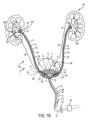
腎臓または泌尿系は、一対の腎臓を含み、各腎臓は、尿管によって膀胱に接続され、膀胱から腎臓によって産生される流体または尿を排出するための尿道に接続される。腎臓は、例えば、血液を濾過し、尿の形態で廃棄物を排除することを含め、人体にとっていくつかの重要な機能を実施する。腎臓はまた、電解質(例えば、ナトリウム、カリウム、およびカルシウム)ならびに代謝物、血液量、血圧、血液pH、体液量、赤血球の産生、および骨代謝を調整する。腎臓の生体構造および生理学の適正な理解は、改変された血行動態および他の体液量過剰状態がその機能に及ぼす影響を理解するために有用である。 The renal or urinary system includes a pair of kidneys, each connected by a ureter to the bladder and a urethra for draining fluid or urine produced by the kidney from the bladder. The kidneys perform several important functions for the human body, including, for example, filtering blood and eliminating waste products in the form of urine. The kidneys also regulate electrolytes (e.g., sodium, potassium, and calcium) and metabolites, blood volume, blood pressure, blood pH, body fluid volume, red blood cell production, and bone metabolism. A proper understanding of renal anatomy and physiology is useful for understanding the effects of altered hemodynamics and other volume overload conditions on its function.
正常な生体構造では、2つの腎臓は、腹腔内の腹膜後に位置する。腎臓は、豆形状の被包された器官である。尿は、腎臓の機能単位である腎単位によって形成され、次いで、集合管と呼ばれる収束尿細管系を通して流動する。集合管は、ともに継合し、小腎杯、次いで、大腎杯を形成し、最終的には、腎臓の凹状部分(腎盂)の近傍で継合する。腎盂の主要機能は、尿流を尿管に指向することである。尿は、腎盂から、尿を腎臓から膀胱の中に搬送する管状構造である、尿管の中に流動する。腎臓の外側層は、外皮と呼ばれ、剛性線維状被包である。腎臓の内部は、髄質と呼ばれる。髄質構造は、錐体状に配列される。 In normal anatomy, the two kidneys are located retroperitoneally within the abdominal cavity. The kidneys are bean-shaped encapsulated organs. Urine is formed by the nephron, the functional unit of the kidney, and then flows through a system of converging tubules called collecting ducts. The collecting ducts join together to form the minor and then major calyces, and finally join near the concave part of the kidney (the renal pelvis). The main function of the renal pelvis is to direct urine flow to the ureters. From the renal pelvis, urine flows into the ureters, which are tubular structures that carry urine from the kidneys into the bladder. The outer layer of the kidney is called the cortex, a rigid fibrous capsule. The interior of the kidney is called the medulla. The medullary structures are arranged in a pyramidal shape.
各腎臓は、約百万腎単位から成る。各腎単位は、糸球体と、ボーマン嚢と、尿細管とを含む。尿細管は、近位曲尿細管と、ヘンレのループと、遠位曲尿細管と、集合管とを含む。腎臓の外皮層内に含有される腎単位は、髄質内に含有されるものの生体構造と明確に異なる。主な差異は、ヘンレのループの長さである。髄質腎単位は、より長いヘンレのループを含有し、これは、正常状況下、外皮腎単位より優れた水分およびナトリウム再吸収の調整を可能にする。 Each kidney consists of approximately one million nephrocytes. Each nephrocyte contains a glomerulus, a Bowman's capsule, and a tubule. The tubule contains a proximal convoluted tubule, a loop of Henle, a distal convoluted tubule, and a collecting duct. The nephrocytes contained within the outer cortical layer of the kidney have a distinctly different anatomy from those contained within the medulla. The main difference is the length of the loop of Henle. Medullary nephrocytes contain longer loops of Henle, which allows for better regulation of water and sodium reabsorption than outer cortical nephrocytes under normal circumstances.
糸球体は、腎単位の起始部であって、血液の初期濾過に関与する。輸入細動脈は、血液を糸球体毛細血管の中に通過させ、そこで静水圧が、水および溶質をボーマン嚢の中に押動させる。正味濾過圧力は、輸入細動脈内の静水圧から、ボーマン隙内の静水圧を差し引き、そこから輸出細動脈内の浸透圧を差し引いたものとして表される。
正味濾過圧力=静水圧(輸入細動脈)-静水圧(ボーマン隙)-浸透圧(輸出細動脈)(方程式1)
The glomerulus is the origin of the renal unit and is responsible for the initial filtration of blood. The afferent arteriole passes blood into the glomerular capillaries, where hydrostatic pressure pushes water and solutes into Bowman's capsule. Net filtration pressure is expressed as the hydrostatic pressure in the afferent arteriole minus the hydrostatic pressure in Bowman's space minus the osmotic pressure in the efferent arteriole.
Net filtration pressure = hydrostatic pressure (afferent arteriole) - hydrostatic pressure (Bowman's space) - osmotic pressure (efferent arteriole) (Equation 1)
方程式1によって定義された本正味濾過圧力の大きさは、ボーマン隙内に形成され、尿細管に送達される限外濾過液の量を決定する。残りの血液は、輸出細動脈を介して、糸球体から退出する。正常糸球体濾過、すなわち、限外濾過液の尿細管の中への送達は、約90ml/分/1.73m2である。 The magnitude of this net filtration pressure, defined by Equation 1, determines the amount of ultrafiltrate that is formed in the Bowman's space and delivered to the renal tubule. The remaining blood leaves the glomerulus via the efferent arteriole. Normal glomerular filtration, i.e., delivery of ultrafiltrate into the renal tubule, is approximately 90 ml/min/1.73 m2 .
糸球体は、3層濾過構造を有し、血管内皮と、糸球体基底膜と、有足細胞とを含む。通常、アルブミンおよび赤血球等の巨大タンパク質は、ボーマン隙の中に濾過されない。しかしながら、上昇糸球体圧力および糸球体間質拡張が、表面積変化を基底膜上にもたらし、有足細胞間のより大きい開窓が、より巨大なタンパク質がボーマン隙の中に通過することを可能にする。 The glomerulus has a three-layer filtration structure, including the vascular endothelium, the glomerular basement membrane, and the podocytes. Normally, large proteins such as albumin and red blood cells are not filtered into Bowman's space. However, elevated glomerular pressure and mesangial expansion result in surface area changes on the basement membrane, and larger fenestrations between podocytes allow larger proteins to pass into Bowman's space.
ボーマン隙内に収集される限外濾過液は、最初に、近位曲尿細管に送達される。尿細管内での水分および溶質の再吸収ならびに分泌が、能動輸送チャネルおよび受動圧力勾配の混合によって実施される。近位曲尿細管は、通常、塩化ナトリウムおよび水分の大部分と、糸球体によって濾過されたほぼ全てのグルコースおよびアミノ酸とを再吸収する。ヘンレのループは、尿中の廃棄物を濃縮するように設計される、2つの構成要素を有する。下行脚は、高度に水浸透性であって、残りの水分の大部分を再吸収する。上行脚は、残りの塩化ナトリウムの25%を再吸収し、例えば、尿素およびクレアチニンの観点から、濃縮された尿を生成する。遠位曲尿細管は、通常、小割合の塩化ナトリウムを再吸収し、浸透勾配が、水分が追従する状態をもたらす。 The ultrafiltrate collected in the Bowman's space is first delivered to the proximal convoluted tubule. Reabsorption and secretion of water and solutes within the tubule is carried out by a mixture of active transport channels and passive pressure gradients. The proximal convoluted tubule normally reabsorbs most of the sodium chloride and water, and nearly all of the glucose and amino acids filtered by the glomerulus. The loop of Henle has two components designed to concentrate waste products in urine. The descending limb is highly water permeable and reabsorbs most of the remaining water. The ascending limb reabsorbs 25% of the remaining sodium chloride, producing a concentrated urine, e.g., in terms of urea and creatinine. The distal convoluted tubule normally reabsorbs a small percentage of sodium chloride, and the osmotic gradient results in a state where water follows.
正常状態下では、正味濾過は、約14mmHgである。静脈鬱滞の影響は、約4mmHgまでの正味濾過の有意な減少であり得る。Jessup M., The cardiorenal syndrome:Do we need a change of strategy or a change of tactics?, JACC 53(7):597-600,2009(以降、「Jessup」)を参照されたい。第2の濾過段階は、近位尿細管で生じる。尿からの分泌および吸収の大部分は、髄質腎単位内の尿細管で生じる。尿細管から間質空間の中へのナトリウムの能動輸送が、本プロセスを開始する。しかしながら、静水力が、溶質および水分の正味交換を左右する。正常状況下では、ナトリウムの75%がリンパまたは静脈循環の中に再吸収されると考えられる。しかしながら、腎臓は、被包されているため、静脈およびリンパ鬱滞の両方からの静水圧の変化に敏感である。静脈鬱滞の間、ナトリウムおよび水分の貯留は、85%を超え、腎鬱滞をさらに長引かせ得る。Verbrugge et al., The kidney in congestive heart failure:Are natriuresis, sodium, and diruetucs really the good, the bad and the ugly?European Journal of Heart Failure 2014:16,133-42(以降、「Verbrugge」)を参照されたい。 Under normal conditions, net filtration is about 14 mmHg. The effects of venous stasis can result in a significant decrease in net filtration to about 4 mmHg. See Jessup M., The cardiorenal syndrome: Do we need a change of strategy or a change of tactics?, JACC 53(7):597-600, 2009 (hereafter "Jessup"). The second filtration step occurs in the proximal tubule. The majority of secretion and absorption from urine occurs in tubules within the medullary renal unit. Active transport of sodium from the tubule into the interstitial space begins the process. However, hydrostatic forces govern the net exchange of solutes and water. Under normal circumstances, it is believed that 75% of sodium is reabsorbed into the lymphatic or venous circulation. However, because the kidneys are encapsulated, they are sensitive to changes in hydrostatic pressure from both venous and lymphatic congestion. During venous congestion, sodium and water retention can exceed 85%, further prolonging renal congestion. Verbrugge et al., The kidney in congestive heart failure: Are natriuresis, sodium, and diruetucs really the good, the bad and the ugly? See European Journal of Heart Failure 2014:16,133-42 (hereafter "Verbrugge").
静脈鬱滞は、急性腎傷害(AKI)の腎前性形態につながり得る。腎前性AKIは、腎臓を通した潅流の損失(または血流の損失)に起因する。多くの臨床医は、急性循環不全状態に起因する腎臓の中への流動の欠如に焦点を当てる。しかしながら、また、静脈鬱滞に起因する器官からの血流の欠如も、臨床上重要な持続的傷害であり得るという証拠が存在する。Damman K, Importance of venous congestion for worsening renal function in advanced decompensated heart failure, JACC 17:589-96,2009(以降、「Damman」)を参照されたい。 Venous congestion can lead to prerenal forms of acute kidney injury (AKI). Prerenal AKI results from loss of perfusion (or loss of blood flow) through the kidney. Many clinicians focus on the lack of flow into the kidney due to the acute circulatory failure state. However, there is evidence that lack of blood flow from the organ due to venous congestion can also be a clinically significant lasting injury. See Damman K, Importance of venous congestion for worsening renal function in advanced decompensated heart failure, JACC 17:589-96,2009 (hereafter "Damman").
腎前性AKIは、様々な診断を横断して生じ、救命救急入院を要求する。最も顕著な入院は、敗血症および急性非代償性心不全(ADHF)に関するものである。付加的入院は、心血管外科、一般外科、肝硬変、外傷、熱傷、および膵炎を含む。これらの疾患状態の症状には、広範な臨床上のばらつきがあるが、共通点は、中心静脈圧の上昇である。ADHFの場合、心不全によって生じる中心静脈圧の上昇は、肺浮腫、続いて、呼吸困難につながり、ひいては、入院が促される。敗血症の場合、中心静脈圧の上昇は、主に、大量の急速輸液の結果である。一次侵襲が、血液量減少またはナトリウムおよび流体貯留に起因する低潅流であるかどうかにかかわらず、持続的傷害は、静脈鬱滞であって、不適正な潅流をもたらす。 Prerenal AKI occurs across a variety of diagnoses and requires critical care hospitalization. The most prominent hospitalizations are for sepsis and acute decompensated heart failure (ADHF). Additional hospitalizations include cardiovascular surgery, general surgery, cirrhosis, trauma, burns, and pancreatitis. The symptoms of these disease states have wide clinical variation, but a common denominator is elevated central venous pressure. In ADHF, elevated central venous pressure caused by heart failure leads to pulmonary edema and subsequent dyspnea, which in turn prompts hospitalization. In sepsis, elevated central venous pressure is primarily the result of massive fluid resuscitation. Whether the primary insult is hypovolemia or hypoperfusion due to sodium and fluid retention, the persistent insult is venous stasis resulting in inadequate perfusion.
高血圧症は、腎臓の能動および受動輸送系内に摂動をもたらす、別の広く認識される状態である。高血圧症は、直接、輸入細動脈圧に影響を及ぼし、糸球体内の正味濾過圧の比例増加をもたらす。増加される濾過割合はまた、尿細管周囲毛細血管圧を上昇させ、これは、ナトリウムおよび水分再吸収を刺激する。Verbruggeを参照されたい。 Hypertension is another widely recognized condition that results in perturbations within the active and passive transport systems of the kidney. Hypertension directly affects afferent arteriolar pressure, resulting in a proportional increase in net filtration pressure within the glomerulus. The increased filtration rate also elevates peritubular capillary pressure, which stimulates sodium and water reabsorption. See Verbrugge.
腎臓は、被包された器官であるため、髄質錐体内の圧力変化に敏感である。腎静脈圧の上昇は、間質圧の上昇につながる鬱滞をもたらす。間質圧の上昇は、糸球体および尿細管の両方に力を付与する。Verbruggeを参照されたい。糸球体では、間質圧の上昇は、直接、濾過に対抗する。圧力の増加は、間質流体を増加させ、それによって、腎臓の髄質内の間質流体および尿細管周囲毛細血管中の静水圧を増加させる。両事例において、低酸素は、細胞傷害および潅流のさらなる損失につながることを確実にし得る。正味結果は、ナトリウムおよび水分再吸収のさらなる悪化であって、負のフィードバックをもたらす。Verbrugge(133-42)を参照されたい。特に、腹腔内の体液量過剰は、腹腔内圧上昇、腹部コンパートメント症候群、および急性腎不全を含む、多くの疾患ならびに状態と関連付けられる。体液量過剰は、腎置換療法を通して対処されることができる。Peters, C.D., Short and Long-Term Effects of the Angiotensin II Receptor Blocker Irbesartanon Intradialytic Central Hemodynamics:A Randomized Double-Blind Placebo-Controlled One-Year Intervention Trial(SAFIR Study), PLoS ONE (2015)10(6):e0126882.doi:10.1371/journal.pone.0126882(以降、「Peters」)を参照されたい。しかしながら、そのような臨床方略は、心腎症候群を伴う患者の腎機能に改善を提供しない。Bart B, Ultrafiltration in decompensated heart failure with cardiorenal syndrome, NEJM 2012;367:2296-2304(以降、「Bart」)を参照されたい。 Because the kidney is an encapsulated organ, it is sensitive to pressure changes within the medullary pyramids. Increased renal venous pressure results in stasis leading to increased interstitial pressure. Increased interstitial pressure exerts forces on both the glomerulus and tubule. See Verbrugge. In the glomerulus, increased interstitial pressure directly opposes filtration. Increased pressure increases interstitial fluid, thereby increasing hydrostatic pressure in the interstitial fluid and peritubular capillaries within the renal medulla. In both cases, hypoxia can ensure cell injury and further loss of perfusion. The net result is further deterioration of sodium and water reabsorption, resulting in negative feedback. See Verbrugge (133-42). In particular, intraperitoneal fluid volume overload is associated with many diseases and conditions, including elevated intraperitoneal pressure, abdominal compartment syndrome, and acute renal failure. Fluid volume overload can be addressed through renal replacement therapy. Peters, C. D. , Short and Long-Term Effects of the Angiotensin II Receptor Blocker Irbesartanon Intradialytic Central Hemodynamics: A Randomized Double-Blind Placebo-Controlled One-Year Intervention Trial (SAFIR Study), PLoS ONE (2015) 10 (6): e0126882. doi:10.1371/journal. Pone. See Peters, J. Neurosci. 2012; 367:2296-2304 (hereinafter "Bart"). However, such clinical strategies do not provide improvement in renal function in patients with cardiorenal syndrome. See Bart B, Ultrafiltration in decompensated heart failure with cardiorenal syndrome, NEJM 2012; 367:2296-2304 (hereinafter "Bart").
流体貯留のそのような問題となる影響に照らして、患者からの尿等の流体の除去を改良するための、具体的には、腎臓からの流体出力の量および品質を増加させるためのシステムならびに方法が、必要とされる。 In light of such problematic effects of fluid retention, systems and methods are needed to improve the removal of fluids, such as urine, from a patient, and specifically, to increase the quantity and quality of fluid output from the kidneys.
いくつかの実施例では、尿管または膀胱カテーテルが、提供され、カテーテルは、(a)近位部分と、(b)遠位部分であって、1つ以上の保護された排出孔、ポート、または穿孔を備え、カテーテルを通した負圧の印加に応じて、粘膜組織が1つ以上の保護された排出孔、ポート、または穿孔を閉塞することを阻止する、外側周縁または保護表面積を確立するように構成される、保定部分を備える、遠位部分とを備える。 In some embodiments, a ureteral or bladder catheter is provided, the catheter comprising: (a) a proximal portion; and (b) a distal portion, the distal portion comprising a retention portion having one or more protected drainage holes, ports, or perforations, the retention portion configured to establish an outer perimeter or protective surface area that inhibits mucosal tissue from occluding the one or more protected drainage holes, ports, or perforations in response to application of negative pressure through the catheter.
いくつかの実施例では、負圧を患者の尿路の一部内に誘発するためのシステムが、提供され、本システムは、(a)患者の腎臓内の挿入のための遠位部分と、近位部分とを備える、尿管カテーテルと、(b)患者の膀胱内の挿入のための遠位部分と、負圧の印加のための近位部分であって、患者の身体の外側に延在する近位部分とを備える、膀胱カテーテルと、(c)膀胱カテーテルおよび尿管カテーテルの両方を通した負圧の印加のために患者の身体の外部にあり、ひいては、腎臓からの流体を、尿管カテーテルの中に、尿管カテーテルおよび膀胱カテーテルの両方を通して、次いで、患者の身体の外側に引き出させる、ポンプとを備える。 In some embodiments, a system for inducing negative pressure within a portion of a patient's urinary tract is provided, the system comprising: (a) a ureteral catheter having a distal portion for insertion within the patient's kidney and a proximal portion; (b) a bladder catheter having a distal portion for insertion within the patient's bladder and a proximal portion for application of negative pressure, the proximal portion extending outside the patient's body; and (c) a pump that is external to the patient's body for application of negative pressure through both the bladder catheter and the ureteral catheter, thus drawing fluid from the kidney into the ureteral catheter, through both the ureteral catheter and the bladder catheter, and then outside the patient's body.
いくつかの実施例では、負圧を患者の尿路の一部内に誘発するためのキットが、提供され、キットは、1つまたは2つの尿管カテーテルであって、各尿管カテーテルは、(a)近位部分と、(b)遠位部分であって、1つ以上の保護された排出孔、ポート、または穿孔を備え、カテーテルを通した負圧の印加に応じて、粘膜組織が1つ以上の保護された排出孔、ポート、または穿孔を閉塞することを阻止する、外側周縁または保護表面積を確立するように構成される、保定部分を備える、遠位部分とを備える、尿管カテーテルと、膀胱カテーテルおよび尿管カテーテルの両方を通した負圧の印加のために患者の身体の外部にあり、ひいては、腎臓からの流体を、尿管カテーテルの中に、尿管カテーテルおよび膀胱カテーテルの両方を通して、次いで、患者の身体の外側に引き出させる、ポンプとを備える。 In some embodiments, a kit for inducing negative pressure within a portion of a patient's urinary tract is provided, the kit comprising one or two ureteral catheters, each ureteral catheter comprising (a) a proximal portion and (b) a distal portion, the distal portion comprising one or more protected drains, ports, or perforations, the distal portion comprising a retention portion configured to establish an outer perimeter or protective surface area that inhibits mucosal tissue from occluding the one or more protected drains, ports, or perforations in response to application of negative pressure through the catheter, and a pump that is external to the patient's body for application of negative pressure through both the bladder catheter and the ureteral catheter, thus drawing fluid from the kidney into the ureteral catheter, through both the ureteral catheter and the bladder catheter, and then outside the patient's body.
いくつかの実施例では、キットが、提供され、キットは、複数の使い捨て膀胱カテーテルであって、各膀胱カテーテルは、(a)近位部分と、(b)遠位部分であって、1つ以上の保護された排出孔、ポート、または穿孔を備え、カテーテルを通した負圧の印加に応じて、粘膜組織が1つ以上の保護された排出孔、ポート、または穿孔を閉塞することを阻止する、外側周縁または保護表面積を確立するように構成される、保定部分を備える、遠位部分とを備える、膀胱カテーテルと、膀胱カテーテルを展開するための命令と、膀胱カテーテルの近位端をポンプに接続するために、およびポンプを動作させ、尿を膀胱カテーテルの排出管腔を通して引き出すための命令とを備える。 In some embodiments, a kit is provided that includes a plurality of disposable bladder catheters, each having (a) a proximal portion and (b) a distal portion, the distal portion including one or more protected drains, ports, or perforations, the distal portion including a retention portion configured to establish an outer perimeter or protective surface area that inhibits mucosal tissue from occluding the one or more protected drains, ports, or perforations in response to application of negative pressure through the catheter; instructions for deploying the bladder catheter; and instructions for connecting the proximal end of the bladder catheter to a pump and for operating the pump to draw urine through the drainage lumen of the bladder catheter.
いくつかの実施例では、負圧を患者の尿路の一部内に誘発するための方法が、提供され、本方法は、尿管カテーテルを患者の尿管の中に展開し、患者の腎臓と膀胱との間の流体流の開存性を維持するステップであって、尿管カテーテルは、患者の腎臓内の挿入のための遠位部分と、近位部分とを備える、ステップと、膀胱カテーテルを患者の膀胱の中に展開するステップであって、膀胱カテーテルは、患者の膀胱内の挿入のための遠位部分と、負圧の印加のための近位部分であって、患者の身体の外側に延在する近位部分とを備える、ステップと、負圧を膀胱カテーテルの近位端に印加し、負圧を患者の尿路の一部内に誘発し、流体を患者から除去するステップとを含む。 In some embodiments, a method is provided for inducing negative pressure within a portion of a patient's urinary tract, the method including the steps of: deploying a ureteral catheter within the patient's ureter to maintain patency of fluid flow between the patient's kidney and bladder, the ureteral catheter having a distal portion for insertion within the patient's kidney and a proximal portion; deploying a bladder catheter within the patient's bladder, the bladder catheter having a distal portion for insertion within the patient's bladder and a proximal portion for application of negative pressure, the proximal portion extending outside the patient's body; and applying negative pressure to a proximal end of the bladder catheter to induce negative pressure within the portion of the patient's urinary tract and remove fluid from the patient.
本発明の非限定的実施例、側面、または実施形態が、ここで、以下に付番された付記に説明されるであろう。 Non-limiting examples, aspects, or embodiments of the present invention will now be described in the appended claims numbered below.
付記1.尿管カテーテルであって、(a)近位部分と、(b)遠位部分であって、1つ以上の保護された排出孔、ポート、または穿孔を備え、カテーテルを通した負圧の印加に応じて、粘膜組織が1つ以上の保護された排出孔、ポート、または穿孔を閉塞することを阻止する、外側周縁または保護表面積を確立するように構成される、保定部分を備える、遠位部分とを備える、尿管カテーテル。 Appendix 1. A ureteral catheter comprising: (a) a proximal portion; and (b) a distal portion comprising one or more protected drainage holes, ports, or perforations, the distal portion comprising a retention portion configured to establish an outer perimeter or protective surface area that inhibits mucosal tissue from occluding the one or more protected drainage holes, ports, or perforations in response to application of negative pressure through the catheter.
付記2.1つ以上の保護された排出孔、ポート、または穿孔は、保定部分の保護された表面積または内側表面積上に配置され、カテーテルの保定部分の外側周縁または保護表面積は、粘膜組織を支持し、それによって、尿管カテーテルを通した負圧の印加に応じて、保護された排出孔、ポート、または穿孔のうちの1つ以上のものの閉塞を防止するように構成される、付記1に記載の尿管カテーテル。 Appendix 2. The ureteral catheter of appendix 1, wherein one or more protected drainage holes, ports, or perforations are disposed on a protected or inner surface area of the retention portion, and an outer periphery or protected surface area of the retention portion of the catheter is configured to support mucosal tissue, thereby preventing occlusion of one or more of the protected drainage holes, ports, or perforations in response to application of negative pressure through the ureteral catheter.
付記3.保定部分は、1つ以上の螺旋コイルを備え、各コイルは、外向きに面した側と、内向きに面した側とを有し、外側周縁または保護表面積は、1つ以上の螺旋コイルの外向きに面した側を備え、1つ以上の保護された排出孔、ポート、または穿孔は、1つ以上の螺旋コイルの内向きに面した側に配置される、付記1または2のいずれかに記載の尿管カテーテル。
付記4.保定部分は、外側表面および内側表面を有する、漏斗状支持体に構成され、外側周縁または保護表面積は、漏斗状支持体の外側表面を備え、1つ以上の排出孔、ポート、または穿孔は、漏斗状支持体の内側表面上に配置される、付記1-3のいずれかに記載の尿管カテーテル。
付記5.保定部分は、保定部分の直径が排出管腔部分の直径を上回る、展開位置まで延在されるように構成される、付記1-4のいずれかに記載の尿管カテーテル。 Appendix 5. A ureteral catheter according to any one of appendices 1-4, wherein the retention portion is configured to extend to a deployed position in which the diameter of the retention portion exceeds the diameter of the drainage lumen portion.
付記6.保定部分の遠位端に向かった排出孔、ポート、または穿孔の数は、保定部分の近位端に向かった排出孔、ポート、または穿孔の数を上回る、付記1-5のいずれかに記載の尿管カテーテル。
付記7.保定部分の遠位端に向かった排出孔、ポート、または穿孔のうちの1つ以上のもののサイズは、保定部分の近位端に向かった排出孔、ポート、または穿孔のうちの1つ以上のもののサイズを上回る、付記1-6のいずれかに記載の尿管カテーテル。
付記8.保定部分の遠位端に向かった排出孔、ポート、または穿孔の総面積は、保定部分の近位端に向かった排出孔、ポート、または穿孔の総面積を上回る、付記1-7のいずれかに記載の尿管カテーテル。
付記9.尿管カテーテルの近位部分の側壁は、排出開口部が本質的にない、またはない、付記1-8のいずれかに記載の尿管カテーテル。 Appendix 9. A ureteral catheter according to any one of appendices 1-8, wherein the sidewall of the proximal portion of the ureteral catheter is essentially free of or has no drainage openings.
付記10.膀胱カテーテルであって、(a)近位部分と、(b)遠位部分であって、1つ以上の保護された排出孔、ポート、または穿孔を備え、カテーテルを通した負圧の印加に応じて、粘膜組織が1つ以上の保護された排出孔、ポート、または穿孔を閉塞することを阻止する、外側周縁または保護表面積を確立するように構成される、保定部分を備える、遠位部分とを備える、膀胱カテーテル。
付記11.1つ以上の保護された排出孔、ポート、または穿孔は、保定部分の保護された表面積または内側表面積上に配置され、カテーテルの保定部分の外側周縁または保護表面積は、粘膜組織を支持し、それによって、膀胱カテーテルを通した負圧の印加に応じて、保護された排出孔、ポート、または穿孔のうちの1つ以上のものの閉塞を防止するように構成される、付記10に記載の膀胱カテーテル。
Appendix 11. The bladder catheter of
付記12.保定部分は、1つ以上の螺旋コイルを備え、各コイルは、外向きに面した側と、内向きに面した側とを有し、外側周縁または保護表面積は、1つ以上の螺旋コイルの外向きに面した側を備え、1つ以上の保護された排出孔、ポート、または穿孔は、1つ以上の螺旋コイルの内向きに面した側に配置される、付記10または11に記載の膀胱カテーテル。
付記13.保定部分は、外側表面および内側表面を有する、漏斗状支持体に構成され、外側周縁または保護表面積は、漏斗状支持体の外側表面を備え、1つ以上の排出孔、ポート、または穿孔は、漏斗状支持体の内側表面上に配置される、付記10-12のいずれかに記載の膀胱カテーテル。 Appendix 13. A bladder catheter according to any of appendices 10-12, wherein the retention portion is configured as a funnel-shaped support having an outer surface and an inner surface, the outer periphery or protective surface area comprises the outer surface of the funnel-shaped support, and one or more drainage holes, ports, or perforations are disposed on the inner surface of the funnel-shaped support.
付記14.保定部分は、保定部分の直径が排出管腔部分の直径を上回る、展開位置まで延在されるように構成される、付記10-13のいずれかに記載の膀胱カテーテル。
付記15.保定部分の遠位端に向かった排出孔、ポート、または穿孔の数は、保定部分の近位端に向かった排出孔、ポート、または穿孔の数を上回る、付記10-14のいずれかに記載の膀胱カテーテル。 Appendix 15. A bladder catheter according to any of appendices 10-14, in which the number of drainage holes, ports, or perforations toward the distal end of the retention portion exceeds the number of drainage holes, ports, or perforations toward the proximal end of the retention portion.
付記16.保定部分の遠位端に向かった排出孔、ポート、または穿孔のうちの1つ以上のもののサイズは、保定部分の近位端に向かった排出孔、ポート、または穿孔のうちの1つ以上のもののサイズを上回る、付記10-15のいずれかに記載の膀胱カテーテル。
付記17.保定部分の遠位端に向かった排出孔、ポート、または穿孔の総面積は、保定部分の近位端に向かった排出孔、ポート、または穿孔の総面積を上回る、付記10-16のいずれかに記載の膀胱カテーテル。 Appendix 17. A bladder catheter according to any of appendices 10-16, in which the total area of the drainage holes, ports, or perforations toward the distal end of the retention portion is greater than the total area of the drainage holes, ports, or perforations toward the proximal end of the retention portion.
付記18.尿管カテーテルの近位部分の側壁は、排出開口部が本質的にない、またはない、付記10-17のいずれかに記載の膀胱カテーテル。
付記19.負圧を患者の尿路の一部内に誘発するためのシステムであって、(a)少なくとも1つの尿管カテーテルであって、患者の腎臓内の挿入のために構成される遠位部分と、近位部分とを備える、少なくとも1つの尿管カテーテルと、(b)患者の膀胱内の挿入のために構成される遠位部分と、負圧を腎臓の中に伝送するように構成され、ひいては、腎臓からの流体を、尿管カテーテルの中に、かつそれを通して、次いで、膀胱カテーテルを通して、次いで、患者の身体の外側に引き出させる、近位部分とを備える、膀胱カテーテルとを備える、システム。 Appendix 19. A system for inducing negative pressure within a portion of a patient's urinary tract, comprising: (a) at least one ureteral catheter having a distal portion configured for insertion within the patient's kidney and a proximal portion; and (b) a bladder catheter having a distal portion configured for insertion within the patient's bladder and a proximal portion configured to transmit negative pressure into the kidney, thus causing fluid from the kidney to be drawn into and through the ureteral catheter, then through the bladder catheter, and then outside the patient's body.
付記20.尿管カテーテルの遠位部分は、1つ以上の保護された排出孔、ポート、または穿孔を備え、負圧の印加に応じて、粘膜組織が1つ以上の保護された排出孔、ポート、または穿孔を閉塞することを阻止する、外側周縁または保護表面積を確立するように構成される、保定部分を備える、付記19に記載のシステム。
付記21.1つ以上の保護された排出孔、ポート、または穿孔は、尿管カテーテルの保定部分の保護された表面積または内側表面積上に配置され、負圧の印加に応じて、粘膜組織は、尿管カテーテルの保定部分の外側周縁または保護表面積上に共形化または圧潰し、それによって、保護された排出孔、ポート、または穿孔のうちの1つ以上のものを閉塞することを防止または阻止される、付記20に記載のシステム。
付記22.尿管カテーテルの近位部分は、膀胱カテーテルの遠位部分と流体連通する、付記19-21のいずれかに記載のシステム。
付記23.膀胱カテーテルの遠位部分は、1つ以上の保護された排出孔、ポート、または穿孔を備え、負圧の印加に応じて、粘膜組織が1つ以上の保護された排出孔、ポート、または穿孔を閉塞することを阻止する、外側周縁または保護表面積を確立するように構成される、保定部分を備える、付記19-22のいずれかに記載のシステム。 Appendix 23. The system of any of Appendices 19-22, wherein the distal portion of the bladder catheter includes one or more protected drainage holes, ports, or perforations, and includes a retention portion configured to establish an outer perimeter or protective surface area that inhibits mucosal tissue from occluding the one or more protected drainage holes, ports, or perforations in response to application of negative pressure.
付記24.1つ以上の保護された排出孔、ポート、または穿孔は、膀胱カテーテルの保定部分の保護された表面積または内側表面積上に配置され、負圧の印加に応じて、粘膜組織は、膀胱カテーテルの保定部分の外側周縁または保護表面積上に共形化または圧潰し、それによって、保護された排出孔、ポート、または穿孔のうちの1つ以上のものを閉塞することを防止または阻止される、付記23に記載のシステム。 Appendix 24. The system of appendix 23, wherein one or more protected drain holes, ports, or perforations are disposed on a protected or inner surface area of the retention portion of the bladder catheter, and in response to application of negative pressure, the mucosal tissue conforms or collapses onto the outer periphery or protected surface area of the retention portion of the bladder catheter, thereby preventing or inhibiting occlusion of one or more of the protected drain holes, ports, or perforations.
付記25.システムはさらに、膀胱カテーテルおよび尿管カテーテルの両方を通した負圧の印加のための負圧源を備え、これは、ひいては、腎臓からの流体を、尿管カテーテルの中に、かつそれを通して、次いで、膀胱カテーテルを通して、次いで、患者の身体の外側に引き出させる、付記19-24のいずれかに記載のシステム。
付記26.負圧源は、膀胱カテーテルおよび尿管カテーテルの両方を通した負圧の印加および調整のために患者の身体の外部に真空源を備え、これは、ひいては、腎臓からの流体を、尿管カテーテルの中に、かつそれを通して、次いで、膀胱カテーテルを通して、次いで、患者の身体の外側に引き出させる、付記25に記載のシステム。
Appendix 26. The system of
付記27.負圧源から受容される負圧は、手動で、自動的に、またはそれらの組み合わせで制御される、付記25または26に記載のシステム。
Appendix 27. The system of
付記28.コントローラが、負圧源からの負圧を調整するために使用される、付記25-27のいずれかに記載のシステム。
付記29.コントローラは、約10mmHgまたはそれ未満の正確度を提供する、付記28に記載のシステム。
Appendix 29. The system of
付記30.負圧は、約2mmHg~約150mmHgの範囲内で提供される、付記25-29のいずれかに記載のシステム。
付記31.患者の少なくとも1つの物理的パラメータを検出するように構成される、1つ以上の生理学的センサをさらに備える、付記19-30のいずれかに記載のシステム。 Appendix 31. The system of any of Appendices 19-30, further comprising one or more physiological sensors configured to detect at least one physical parameter of the patient.
付記32.少なくとも1つの物理的パラメータは、収集される尿の体積、尿組成、尿タンパク質濃度、血液組成、または血流のうちの1つ以上のものを備える、付記31に記載のシステム。
付記33.血液組成の少なくとも1つの物理的パラメータは、ヘマトクリット比、検体濃度、タンパク質濃度、またはクレアチニン濃度のうちの1つ以上のものを備える、付記32に記載のシステム。
Appendix 33. The system of
付記34.血流の少なくとも1つの物理的パラメータは、血圧または血流速のうちの1つ以上のものを備える、付記32に記載のシステム。
付記35.1つ以上の生理学的センサは、パルスオキシメトリセンサ、血圧センサ、心拍数センサ、呼吸センサ、カプノグラフィセンサ、グルコースセンサ、血液速度センサ、ヘモグロビンセンサ、ヘマトクリットセンサ、タンパク質センサ、クレアチニンセンサ、検体センサ、静電容量センサ、光学分光法センサ、またはそれらの組み合わせのうちの1つ以上のものを備える、付記31に記載のシステム。 Additional Note 35. The system of Additional Note 31, wherein the one or more physiological sensors include one or more of a pulse oximetry sensor, a blood pressure sensor, a heart rate sensor, a respiration sensor, a capnography sensor, a glucose sensor, a blood rate sensor, a hemoglobin sensor, a hematocrit sensor, a protein sensor, a creatinine sensor, an analyte sensor, a capacitance sensor, an optical spectroscopy sensor, or a combination thereof.
付記36.負圧を患者の尿路の一部内に誘発するためのシステムであって、(a)患者の腎臓内の挿入のために構成される遠位部分と、近位部分とを備える、尿管カテーテルと、(b)患者の膀胱内の挿入のために構成される遠位部分と、負圧の印加のための近位部分であって、患者の身体の外側に延在する近位部分とを備える、膀胱カテーテルと、(c)膀胱カテーテルおよび尿管カテーテルの両方を通した負圧の印加のために患者の身体の外部にあり、ひいては、腎臓からの流体を、尿管カテーテルの中に、尿管カテーテルおよび膀胱カテーテルの両方を通して、次いで、患者の身体の外側に引き出させる、ポンプとを備える、システム。 Appendix 36. A system for inducing negative pressure within a portion of a patient's urinary tract, comprising: (a) a ureteral catheter having a distal portion configured for insertion within the patient's kidney and a proximal portion; (b) a bladder catheter having a distal portion configured for insertion within the patient's bladder and a proximal portion for application of negative pressure, the proximal portion extending outside the patient's body; and (c) a pump that is external to the patient's body for application of negative pressure through both the bladder catheter and the ureteral catheter, thus drawing fluid from the kidney into the ureteral catheter, through both the ureteral catheter and the bladder catheter, and then outside the patient's body.
付記37.尿管カテーテルの近位部分は、膀胱カテーテルの遠位部分と流体連通する、付記36に記載のシステム。 Appendix 37. The system of appendix 36, wherein the proximal portion of the ureteral catheter is in fluid communication with the distal portion of the bladder catheter.
付記38.尿管カテーテルの遠位部分は、1つ以上の保護された排出孔、ポート、または穿孔を備え、ポンプによる負圧の印加に応じて、粘膜組織が1つ以上の保護された排出孔、ポート、または穿孔を閉塞することを阻止する、外側周縁または保護表面積を確立するように構成される、保定部分を備える、付記36または37に記載のシステム。 Note 38. The system of any one of notes 36 and 37, wherein the distal portion of the ureteral catheter includes one or more protected drainage holes, ports, or perforations, and includes a retention portion configured to establish an outer perimeter or protective surface area that inhibits mucosal tissue from occluding the one or more protected drainage holes, ports, or perforations in response to application of negative pressure by the pump.
付記39.1つ以上の保護された排出孔、ポート、または穿孔は、尿管カテーテルの保定部分の保護された表面積または内側表面積上に配置され、負圧の印加に応じて、粘膜組織は、カテーテルの保定部分の外側周縁または保護表面積上に共形化または圧潰し、それによって、保護された排出孔、ポート、または穿孔のうちの1つ以上のものを閉塞することを防止または阻止される、付記38に記載のシステム。 Appendix 39. The system of appendix 38, wherein one or more protected drainage holes, ports, or perforations are disposed on a protected or inner surface area of the retained portion of the ureteral catheter, and in response to application of negative pressure, the mucosal tissue conforms or collapses onto the outer periphery or protected surface area of the retained portion of the catheter, thereby preventing or inhibiting occlusion of one or more of the protected drainage holes, ports, or perforations.
付記40.膀胱カテーテルの遠位部分は、1つ以上の保護された排出孔、ポート、または穿孔を備え、ポンプによる負圧の印加に応じて、粘膜組織が1つ以上の保護された排出孔、ポート、または穿孔を閉塞することを阻止する、外側周縁または保護表面積を確立するように構成される、保定部分を備える、付記36-39のいずれかに記載のシステム。
付記41.1つ以上の保護された排出孔、ポート、または穿孔は、保定部分の保護された表面積または内側表面積上に配置され、負圧の印加に応じて、粘膜組織は、カテーテルの保定部分の外側周縁または保護表面積上に共形化または圧潰し、それによって、保護された排出孔、ポート、または穿孔のうちの1つ以上のものを閉塞することを防止または阻止される、付記40に記載のシステム。
Appendix 41. The system of
付記42.患者の少なくとも1つの物理的パラメータを検出するように構成される、1つ以上の生理学的センサをさらに備える、付記36-41のいずれかに記載のシステム。 Appendix 42. The system of any of Appendices 36-41, further comprising one or more physiological sensors configured to detect at least one physical parameter of the patient.
付記43.少なくとも1つの物理的パラメータは、収集される尿の体積、尿組成、尿タンパク質濃度、血液組成、または血流のうちの1つ以上のものを備える、付記42に記載のシステム。 Appendix 43. The system of appendix 42, wherein the at least one physical parameter comprises one or more of collected urine volume, urine composition, urine protein concentration, blood composition, or blood flow.
付記44.血液組成の少なくとも1つの物理的パラメータは、ヘマトクリット比、検体濃度、タンパク質濃度、またはクレアチニン濃度のうちの1つ以上のものを備える、付記43に記載のシステム。 Appendix 44. The system of appendix 43, wherein at least one physical parameter of blood composition comprises one or more of a hematocrit ratio, an analyte concentration, a protein concentration, or a creatinine concentration.
付記45.血流の少なくとも1つの物理的パラメータは、血圧または血流速のうちの1つ以上のものを備える、付記43に記載のシステム。 Appendix 45. The system of appendix 43, wherein at least one physical parameter of blood flow comprises one or more of blood pressure or blood flow velocity.
付記46.1つ以上の生理学的センサは、パルスオキシメトリセンサ、血圧センサ、心拍数センサ、呼吸センサ、カプノグラフィセンサ、グルコースセンサ、血液速度センサ、ヘモグロビンセンサ、ヘマトクリットセンサ、タンパク質センサ、クレアチニンセンサ、検体センサ、静電容量センサ、光学分光法センサ、またはそれらの組み合わせのうちの1つ以上のものを備える、付記42に記載のシステム。 Additional Note 46. The system of Additional Note 42, wherein the one or more physiological sensors include one or more of a pulse oximetry sensor, a blood pressure sensor, a heart rate sensor, a respiration sensor, a capnography sensor, a glucose sensor, a blood rate sensor, a hemoglobin sensor, a hematocrit sensor, a protein sensor, a creatinine sensor, an analyte sensor, a capacitance sensor, an optical spectroscopy sensor, or a combination thereof.
付記47.ポンプは、約10mmHgまたはそれ未満の正確度を提供する、付記36-46のいずれかに記載のシステム。 Appendix 47. The system of any of Appendices 36-46, wherein the pump provides an accuracy of about 10 mmHg or less.
付記48.負圧は、約2mmHg~約150mmHgの範囲内で提供される、付記36-47のいずれかに記載のシステム。 Appendix 48. A system according to any one of appendices 36-47, wherein the negative pressure is provided within a range of about 2 mmHg to about 150 mmHg.
付記49.負圧を患者の尿路の一部内に誘発するためのシステムであって、(a)少なくとも1つの尿管カテーテルであって、患者の腎臓内の挿入のための遠位部分と、近位部分とを備える、少なくとも1つの尿管カテーテルと、(b)患者の膀胱内の挿入のための遠位部分と、負圧源から負圧を受容するための近位部分とを備える、膀胱カテーテルであって、少なくとも1つの尿管カテーテルまたは膀胱カテーテルのうちの少なくとも1つは、(a)近位部分と、(b)遠位部分であって、1つ以上の保護された排出孔、ポート、または穿孔を備え、カテーテルを通した負圧の印加に応じて、粘膜組織が1つ以上の保護された排出孔、ポート、または穿孔を閉塞することを阻止する、外側周縁または保護表面積を確立するように構成される、保定部分を備える、遠位部分とを備える、膀胱カテーテルと、(c)膀胱カテーテルおよび尿管カテーテルの両方を通した負圧の印加のための負圧源であって、ひいては、腎臓からの流体を、尿管カテーテルの中に、次いで、膀胱カテーテルを通して、次いで、患者の身体の外側に引き出させる、負圧源とを備える、システム。 Appendix 49. A system for inducing negative pressure within a portion of a patient's urinary tract, comprising: (a) at least one ureteral catheter, the at least one ureteral catheter comprising a distal portion for insertion within the patient's kidney and a proximal portion; (b) a bladder catheter comprising a distal portion for insertion within the patient's bladder and a proximal portion for receiving negative pressure from a negative pressure source, at least one of the at least one ureteral catheter or bladder catheter comprising: (a) a proximal portion; (b) a distal portion comprising one or more protected drains, ports, or perforations, the distal portion comprising a retention portion configured to establish an outer perimeter or protective surface area that inhibits mucosal tissue from occluding the one or more protected drains, ports, or perforations in response to application of negative pressure through the catheter; and (c) a negative pressure source for application of negative pressure through both the bladder catheter and the ureteral catheter, thus drawing fluid from the kidney into the ureteral catheter, then through the bladder catheter, and then outside the patient's body.
付記50.少なくとも1つの尿管カテーテルの近位部分は、膀胱カテーテルの遠位部分と流体連通する、付記49に記載のシステム。
付記51.少なくとも1つの尿管カテーテルの遠位部分は、1つ以上の保護された排出孔、ポート、または穿孔を備え、負圧源からの負圧の印加に応じて、粘膜組織が1つ以上の保護された排出孔、ポート、または穿孔を閉塞することを阻止する、外側周縁または保護表面積を確立するように構成される、保定部分を備える、付記49に記載のシステム。 Note 51. The system of note 49, wherein the distal portion of at least one ureteral catheter includes one or more protected drainage holes, ports, or perforations, and includes a retention portion configured to establish an outer perimeter or protective surface area that inhibits mucosal tissue from occluding the one or more protected drainage holes, ports, or perforations in response to application of negative pressure from a negative pressure source.
付記52.1つ以上の保護された排出孔、ポート、または穿孔は、尿管カテーテルの保定部分の保護された表面積または内側表面積上に配置され、尿管カテーテルの保定部分の外側周縁または保護表面積は、粘膜組織を支持し、それによって、尿管カテーテルを通した負圧の印加に応じて、保護された排出孔、ポート、または穿孔のうちの1つ以上のものの閉塞を防止するように構成される、付記51に記載のシステム。 Appendix 52. The system of appendix 51, wherein one or more protected drainage holes, ports, or perforations are disposed on a protected or inner surface area of the retention portion of the ureteral catheter, and an outer periphery or protected surface area of the retention portion of the ureteral catheter is configured to support mucosal tissue, thereby preventing occlusion of one or more of the protected drainage holes, ports, or perforations in response to application of negative pressure through the ureteral catheter.
付記53.膀胱カテーテルの遠位部分は、1つ以上の保護された排出孔、ポート、または穿孔を備え、負圧源からの負圧の印加に応じて、粘膜組織が1つ以上の保護された排出孔、ポート、または穿孔を閉塞することを阻止する、外側周縁または保護表面積を確立するように構成される、保定部分を備える、付記49に記載のシステム。 Note 53. The system of note 49, wherein the distal portion of the bladder catheter includes a retention portion that includes one or more protected drainage holes, ports, or perforations and is configured to establish an outer perimeter or protective surface area that inhibits mucosal tissue from occluding the one or more protected drainage holes, ports, or perforations in response to application of negative pressure from a negative pressure source.
付記54.1つ以上の保護された排出孔、ポート、または穿孔は、膀胱カテーテルの保定部分の保護された表面積または内側表面積上に配置され、膀胱カテーテルの保定部分の外側周縁または保護表面積は、粘膜組織を支持し、それによって、膀胱カテーテルを通した負圧の印加に応じて、保護された排出孔、ポート、または穿孔のうちの1つ以上のものの閉塞を防止するように構成される、付記53に記載のシステム。 Appendix 54. The system of appendix 53, wherein one or more protected drain holes, ports, or perforations are disposed on a protected or inner surface area of the retention portion of the bladder catheter, and an outer periphery or protected surface area of the retention portion of the bladder catheter is configured to support mucosal tissue, thereby preventing occlusion of one or more of the protected drain holes, ports, or perforations in response to application of negative pressure through the bladder catheter.
付記55.患者と関連付けられる1つ以上の生理学的センサをさらに備え、生理学的センサは、少なくとも1つの物理的パラメータを表す情報をコントローラに提供するように構成される、付記49に記載のシステム。 Appendix 55. The system of appendix 49, further comprising one or more physiological sensors associated with the patient, the physiological sensors configured to provide information representative of at least one physical parameter to the controller.
付記56.負圧源は、膀胱カテーテルおよび尿管カテーテルの両方を通した負圧の印加のために患者の身体の外部にポンプを備え、これは、ひいては、腎臓からの流体を、尿管カテーテルの中に、かつそれを通して、次いで、膀胱カテーテルを通して、次いで、患者の身体の外側に引き出させる、付記49に記載のシステム。
付記57.負圧源は、膀胱カテーテルおよび尿管カテーテルの両方を通した負圧の印加および調整のために患者の身体の外部に真空源を備え、これは、ひいては、腎臓からの流体を、尿管カテーテルの中に、かつそれを通して、次いで、膀胱カテーテルを通して、次いで、患者の身体の外側に引き出させる、付記49に記載のシステム。 Appendix 57. The system of appendix 49, wherein the negative pressure source comprises a vacuum source external to the patient's body for application and adjustment of negative pressure through both the bladder catheter and the ureteral catheter, which in turn causes fluid from the kidney to be drawn into and through the ureteral catheter, then through the bladder catheter, and then outside the patient's body.
付記58.真空源は、壁吸引源、真空ボトル、および手動真空源から成る群から選択される、付記57に記載のシステム。
付記59.真空源は、圧力差によって提供される、付記57に記載のシステム。 Appendix 59. The system of appendix 57, wherein the vacuum source is provided by a pressure differential.
付記60.負圧源から受容される負圧は、手動で、自動的に、またはそれらの組み合わせで制御される、付記49-59のいずれかに記載のシステム。 Appendix 60. A system as described in any of appendices 49-59, wherein the negative pressure received from the negative pressure source is controlled manually, automatically, or a combination thereof.
付記61.コントローラが、負圧源からの負圧を調整するために使用される、付記49-60のいずれかに記載のシステム。 Appendix 61. A system according to any of appendices 49-60, wherein the controller is used to regulate the negative pressure from the negative pressure source.
付記62.ポンプは、約10mmHgまたはそれ未満の正確度を提供する、付記56に記載のシステム。
Appendix 62. The system of
付記63.負圧は、約2mmHg~約150mmHgの範囲内で提供される、付記49-62のいずれかに記載のシステム。 Appendix 63. The system of any of Appendices 49-62, wherein the negative pressure is provided within a range of about 2 mmHg to about 150 mmHg.
付記64.負圧を患者の尿路の一部内に誘発するためのシステムであって、(a)少なくとも1つの尿管カテーテルであって、患者の腎臓内の挿入のための遠位部分と、近位部分とを備える、少なくとも1つの尿管カテーテルと、(b)患者の膀胱内の挿入のための遠位部分と、負圧を受容するための近位部分とを備える、膀胱カテーテルであって、負圧は、腎臓からの流体を、尿管カテーテルの中に、尿管カテーテルを通して、次いで、膀胱カテーテルを通して、次いで、患者の身体の外側に引き出させる、膀胱カテーテルとを備え、少なくとも1つの尿管カテーテルまたは膀胱カテーテルのうちの少なくとも1つは、(a)近位部分と、(b)遠位部分であって、1つ以上の保護された排出孔、ポート、または穿孔を備え、少なくとも1つの尿管カテーテルまたは膀胱カテーテルを通した負圧の印加に応じて、粘膜組織が1つ以上の保護された排出孔、ポート、または穿孔を閉塞することを阻止する、外側周縁または保護表面積を確立するように構成される、保定部分を備える、遠位部分とを備える、システム。 Appendix 64. A system for inducing negative pressure within a portion of a patient's urinary tract, comprising: (a) at least one ureteral catheter, the at least one ureteral catheter comprising a distal portion for insertion within the patient's kidney and a proximal portion; and (b) a bladder catheter comprising a distal portion for insertion within the patient's bladder and a proximal portion for receiving negative pressure, the negative pressure causing fluid from the kidney to be drawn into the ureteral catheter, through the bladder catheter, and then outside the patient's body, at least one of the at least one ureteral or bladder catheter comprising: (a) a proximal portion; and (b) a distal portion comprising one or more protected drains, ports, or perforations, the distal portion comprising a retaining portion configured to establish an outer perimeter or protective surface area that inhibits mucosal tissue from occluding the one or more protected drains, ports, or perforations in response to application of negative pressure through the at least one ureteral or bladder catheter.
付記65.少なくとも1つの尿管カテーテルの近位部分は、膀胱カテーテルの遠位部分と流体連通する、付記64に記載のシステム。 Appendix 65. The system of appendix 64, wherein the proximal portion of at least one ureteral catheter is in fluid communication with the distal portion of the bladder catheter.
付記66.少なくとも1つの尿管カテーテルの遠位部分は、1つ以上の保護された排出孔、ポート、または穿孔を備え、圧力差の印加に応じて、粘膜組織が1つ以上の保護された排出孔、ポート、または穿孔を閉塞することを阻止する、外側周縁または保護表面積を確立するように構成される、保定部分を備える、付記64に記載のシステム。 Note 66. The system of note 64, wherein the distal portion of at least one ureteral catheter includes one or more protected drainage holes, ports, or perforations and includes a retention portion configured to establish an outer perimeter or protective surface area that inhibits mucosal tissue from occluding the one or more protected drainage holes, ports, or perforations in response to application of a pressure differential.
付記67.1つ以上の保護された排出孔、ポート、または穿孔は、尿管カテーテルの保定部分の保護された表面積または内側表面積上に配置され、尿管カテーテルの保定部分の外側周縁または保護表面積は、粘膜組織を支持し、それによって、尿管カテーテルを通した負圧の印加に応じて、保護された排出孔、ポート、または穿孔のうちの1つ以上のものの閉塞を防止するように構成される、付記66に記載のシステム。 A system according to claim 66, wherein one or more protected drainage holes, ports, or perforations are disposed on a protected or inner surface area of the retention portion of the ureteral catheter, and an outer periphery or protected surface area of the retention portion of the ureteral catheter is configured to support mucosal tissue, thereby preventing occlusion of one or more of the protected drainage holes, ports, or perforations in response to application of negative pressure through the ureteral catheter.
付記68.膀胱カテーテルの遠位部分は、1つ以上の保護された排出孔、ポート、または穿孔を備え、負圧の印加に応じて、粘膜組織が1つ以上の保護された排出孔、ポート、または穿孔を閉塞することを阻止する、外側周縁または保護表面積を確立するように構成される、保定部分を備える、付記64に記載のシステム。 Note 68. The system of note 64, wherein the distal portion of the bladder catheter includes one or more protected drains, ports, or perforations, and includes a retention portion configured to establish an outer perimeter or protective surface area that inhibits mucosal tissue from occluding the one or more protected drains, ports, or perforations in response to application of negative pressure.
付記69.1つ以上の保護された排出孔、ポート、または穿孔は、膀胱カテーテルの保定部分の保護された表面積または内側表面積上に配置され、膀胱カテーテルの保定部分の外側周縁または保護表面積は、粘膜組織を支持し、それによって、膀胱カテーテルを通した負圧の印加に応じて、保護された排出孔、ポート、または穿孔のうちの1つ以上のものの閉塞を防止するように構成される、付記68に記載のシステム。 A system as described in claim 68, wherein one or more protected drain holes, ports, or perforations are disposed on a protected or inner surface area of the retention portion of the bladder catheter, and an outer periphery or protected surface area of the retention portion of the bladder catheter is configured to support mucosal tissue, thereby preventing occlusion of one or more of the protected drain holes, ports, or perforations in response to application of negative pressure through the bladder catheter.
付記70.患者と関連付けられる1つ以上の生理学的センサをさらに備え、生理学的センサは、少なくとも1つの物理的パラメータを表す情報をコントローラに提供するように構成される、付記64に記載のシステム。
付記71.負圧を患者の尿路の一部内に誘発するためのキットであって、付記1に記載の1つまたは2つの尿管カテーテルと、膀胱カテーテルおよび尿管カテーテルの両方を通した負圧の印加のために患者の身体の外部にあり、ひいては、腎臓からの流体を、尿管カテーテルの中に、尿管カテーテルおよび膀胱カテーテルの両方を通して、次いで、患者の身体の外側に引き出させる、ポンプとを備える、キット。 Appendix 71. A kit for inducing negative pressure in a portion of a patient's urinary tract, comprising one or two ureteral catheters as described in appendix 1, and a pump that is external to the patient's body for application of negative pressure through both the bladder catheter and the ureteral catheter, thus drawing fluid from the kidney into the ureteral catheter, through both the ureteral catheter and the bladder catheter, and then outside the patient's body.
付記72.膀胱カテーテルをさらに備える、付記71に記載のキット。
付記73.膀胱カテーテルを挿入し、ポンプを動作させ、患者の膀胱内で展開されるカテーテルの排出管腔を通して尿を引き出すための命令をさらに備える、付記71に記載のキット。 Claim 73. The kit of claim 71, further comprising instructions for inserting a bladder catheter and operating the pump to withdraw urine through a drainage lumen of the catheter deployed within the patient's bladder.
付記74.キットであって、付記6に記載の複数の使い捨て膀胱カテーテルと、膀胱カテーテルを展開するための命令と、膀胱カテーテルの近位端をポンプに接続するために、およびポンプを動作させ、尿を膀胱カテーテルの排出管腔を通して引き出すための命令とを備える、キット。
Appendix 74. A kit comprising a plurality of disposable bladder catheters according to
付記75.負圧を患者の尿路の一部内に誘発するための方法であって、尿管カテーテルを患者の尿管の中に展開し、患者の腎臓と膀胱との間の流体流の開存性を維持するステップであって、尿管カテーテルは、患者の腎臓内の挿入のための遠位部分と、近位部分とを備える、ステップと、膀胱カテーテルを患者の膀胱の中に展開するステップであって、膀胱カテーテルは、患者の膀胱内の挿入のための遠位部分と、負圧の印加のための近位部分であって、患者の身体の外側に延在する近位部分とを備える、ステップと、負圧を膀胱カテーテルの近位端に印加し、負圧を患者の尿路の一部内に誘発し、流体を患者から除去するステップとを含む、方法。 Appendix 75. A method for inducing negative pressure in a portion of a patient's urinary tract, comprising the steps of: deploying a ureteral catheter in the patient's ureter to maintain patency of fluid flow between the patient's kidney and bladder, the ureteral catheter having a distal portion for insertion into the patient's kidney and a proximal portion; deploying a bladder catheter in the patient's bladder, the bladder catheter having a distal portion for insertion into the patient's bladder and a proximal portion for application of negative pressure, the proximal portion extending outside the patient's body; and applying negative pressure to a proximal end of the bladder catheter to induce negative pressure in a portion of the patient's urinary tract and remove fluid from the patient.
付記76.尿管カテーテルまたは膀胱カテーテルのうちの少なくとも1つは、(a)近位部分と、(b)遠位部分であって、1つ以上の保護された排出孔、ポート、または穿孔を備え、カテーテルを通した負圧の印加に応じて、粘膜組織が1つ以上の保護された排出孔、ポート、または穿孔を閉塞することを阻止する、外側周縁または保護表面積を確立するように構成される、保定部分を備える、遠位部分とを備える、付記75に記載の方法。 Note 76. The method of note 75, wherein at least one of the ureteral or bladder catheters comprises: (a) a proximal portion; and (b) a distal portion, the distal portion comprising a retention portion having one or more protected drainage holes, ports, or perforations, and configured to establish an outer perimeter or protective surface area that inhibits mucosal tissue from occluding the one or more protected drainage holes, ports, or perforations in response to application of negative pressure through the catheter.
付記77.尿管カテーテルは、展開され、少なくとも24時間にわたって患者の身体内に留まる、付記75に記載の方法。 Appendix 77. The method of appendix 75, wherein the ureteral catheter is deployed and remains within the patient's body for at least 24 hours.
付記78.尿管カテーテルは、展開され、少なくとも30日またはより長く患者の身体内に留まる、付記75に記載の方法。 Appendix 78. The method of appendix 75, wherein the ureteral catheter is deployed and remains within the patient's body for at least 30 days or longer.
付記79.膀胱カテーテルは、尿管カテーテルよりも頻繁に交換される、付記75に記載の方法。 Appendix 79. The method of appendix 75, wherein the bladder catheter is replaced more frequently than the ureteral catheter.
付記80.複数の膀胱カテーテルが、尿管カテーテルの単一セットに関して留置時間の間に設置および除去される、付記75に記載の方法。
本発明は、例えば、以下の項目を提供する。
(項目1)
尿管カテーテルであって、前記尿管カテーテルは、(a)近位部分と、(b)遠位部分とを備え、前記遠位部分は、保定部分を備え、前記保定部分は、1つ以上の保護された排出孔、ポート、または穿孔を備え、前記カテーテルを通した負圧の印加に応じて、粘膜組織が前記1つ以上の保護された排出孔、ポート、または穿孔を閉塞することを阻止する外側周縁または保護表面積を確立するように構成される、尿管カテーテル。
(項目2)
前記1つ以上の保護された排出孔、ポート、または穿孔は、前記保定部分の保護された表面積または内側表面積上に配置され、前記カテーテルの保定部分の外側周縁または保護表面積は、前記粘膜組織を支持し、それによって、前記尿管カテーテルを通した負圧の印加に応じて、前記保護された排出孔、ポート、または穿孔のうちの1つ以上のものの閉塞を防止するように構成される、項目1に記載の尿管カテーテル。
(項目3)
前記保定部分は、1つ以上の螺旋コイルを備え、各コイルは、外向きに面した側と、内向きに面した側とを有し、前記外側周縁または保護表面積は、前記1つ以上の螺旋コイルの外向きに面した側を備え、前記1つ以上の保護された排出孔、ポート、または穿孔は、前記1つ以上の螺旋コイルの内向きに面した側に配置される、項目1に記載の尿管カテーテル。
(項目4)
前記保定部分は、外側表面および内側表面を有する漏斗状支持体に構成され、前記外側周縁または保護表面積は、前記漏斗状支持体の外側表面を備え、前記1つ以上の排出孔、ポート、または穿孔は、前記漏斗状支持体の内側表面上に配置される、項目1に記載の尿管カテーテル。
(項目5)
前記保定部分は、前記保定部分の直径が前記排出管腔部分の直径を上回る展開位置まで延在されるように構成される、項目1に記載の尿管カテーテル。
(項目6)
前記保定部分の遠位端に向かった前記排出孔、ポート、または穿孔の数は、前記保定部分の近位端に向かった前記排出孔、ポート、または穿孔の数を上回る、項目1に記載の尿管カテーテル。
(項目7)
前記保定部分の遠位端に向かった前記排出孔、ポート、または穿孔のうちの1つ以上のもののサイズは、前記保定部分の近位端に向かった前記排出孔、ポート、または穿孔のうちの1つ以上のもののサイズを上回る、項目1に記載の尿管カテーテル。
(項目8)
前記保定部分の遠位端に向かった前記排出孔、ポート、または穿孔の総面積は、前記保定部分の近位端に向かった前記排出孔、ポート、または穿孔の総面積を上回る、項目1に記載の尿管カテーテル。
(項目9)
前記尿管カテーテルの近位部分の側壁は、排出開口部が本質的にない、またはない、項目1に記載の尿管カテーテル。
(項目10)
膀胱カテーテルであって、前記膀胱カテーテルは、(a)近位部分と、(b)遠位部分とを備え、前記遠位部分は、保定部分を備え、前記保定部分は、1つ以上の保護された排出孔、ポート、または穿孔を備え、前記カテーテルを通した負圧の印加に応じて、粘膜組織が前記1つ以上の保護された排出孔、ポート、または穿孔を閉塞することを阻止する外側周縁または保護表面積を確立するように構成される、膀胱カテーテル。
(項目11)
前記1つ以上の保護された排出孔、ポート、または穿孔は、前記保定部分の保護された表面積または内側表面積上に配置され、前記カテーテルの保定部分の外側周縁または保護表面積は、前記粘膜組織を支持し、それによって、前記膀胱カテーテルを通した負圧の印加に応じて、前記保護された排出孔、ポート、または穿孔のうちの1つ以上のものの閉塞を防止するように構成される、項目10に記載の膀胱カテーテル。
(項目12)
前記保定部分は、1つ以上の螺旋コイルを備え、各コイルは、外向きに面した側と、内向きに面した側とを有し、前記外側周縁または保護表面積は、前記1つ以上の螺旋コイルの外向きに面した側を備え、前記1つ以上の保護された排出孔、ポート、または穿孔は、前記1つ以上の螺旋コイルの内向きに面した側に配置される、項目10に記載の膀胱カテーテル。
(項目13)
前記保定部分は、外側表面および内側表面を有する漏斗状支持体に構成され、前記外側周縁または保護表面積は、前記漏斗状支持体の外側表面を備え、前記1つ以上の排出孔、ポート、または穿孔は、前記漏斗状支持体の内側表面上に配置される、項目10に記載の膀胱カテーテル。
(項目14)
前記保定部分は、前記保定部分の直径が前記排出管腔部分の直径を上回る展開位置まで延在されるように構成される、項目10に記載の膀胱カテーテル。
(項目15)
前記保定部分の遠位端に向かった前記排出孔、ポート、または穿孔の数は、前記保定部分の近位端に向かった前記排出孔、ポート、または穿孔の数を上回る、項目10に記載の膀胱カテーテル。
(項目16)
前記保定部分の遠位端に向かった前記排出孔、ポート、または穿孔のうちの1つ以上のもののサイズは、前記保定部分の近位端に向かった前記排出孔、ポート、または穿孔のうちの1つ以上のもののサイズを上回る、項目10に記載の膀胱カテーテル。
(項目17)
前記保定部分の遠位端に向かった前記排出孔、ポート、または穿孔の総面積は、前記保定部分の近位端に向かった前記排出孔、ポート、または穿孔の総面積を上回る、項目10に記載の膀胱カテーテル。
(項目18)
前記尿管カテーテルの近位部分の側壁は、排出開口部が本質的にない、またはない、項目10に記載の膀胱カテーテル。
(項目19)
負圧を患者の尿路の一部内に誘発するためのシステムであって、前記システムは、
(a)少なくとも1つの尿管カテーテルであって、前記少なくとも1つの尿管カテーテルは、前記患者の腎臓、腎盂、および/または尿管内の挿入のために構成される遠位部分と、近位部分とを備える、少なくとも1つの尿管カテーテルと、
(b)膀胱カテーテルであって、前記膀胱カテーテルは、患者の膀胱内の挿入のために構成される遠位部分と、近位部分とを備え、前記近位部分は、負圧を前記腎臓の中に伝送するように構成され、ひいては、前記腎臓からの流体を、前記尿管カテーテルの中に、かつそれを通して、次いで、膀胱カテーテルを通して、次いで、前記患者の身体の外側に引き出させる、膀胱カテーテルと
を備える、システム。
(項目20)
前記尿管カテーテルの遠位部分は、保定部分を備え、前記保定部分は、1つ以上の保護された排出孔、ポート、または穿孔を備え、負圧の印加に応じて、粘膜組織が前記1つ以上の保護された排出孔、ポート、または穿孔を閉塞することを阻止する外側周縁または保護表面積を確立するように構成される、項目19に記載のシステム。
(項目21)
前記1つ以上の保護された排出孔、ポート、または穿孔は、前記尿管カテーテルの保定部分の保護された表面積または内側表面積上に配置され、負圧の印加に応じて、前記粘膜組織は、前記尿管カテーテルの保定部分の外側周縁または保護表面積上に共形化または圧潰し、それによって、前記保護された排出孔、ポート、または穿孔のうちの1つ以上のものを閉塞することを防止または阻止される、項目20に記載のシステム。
(項目22)
前記尿管カテーテルの近位部分は、前記膀胱カテーテルの遠位部分と流体連通する、項目19に記載のシステム。
(項目23)
前記膀胱カテーテルの遠位部分は、保定部分を備え、前記保定部分は、1つ以上の保護された排出孔、ポート、または穿孔を備え、負圧の印加に応じて、粘膜組織が前記1つ以上の保護された排出孔、ポート、または穿孔を閉塞することを阻止する外側周縁または保護表面積を確立するように構成される、項目19に記載のシステム。
(項目24)
前記1つ以上の保護された排出孔、ポート、または穿孔は、前記膀胱カテーテルの保定部分の保護された表面積または内側表面積上に配置され、負圧の印加に応じて、前記粘膜組織は、前記膀胱カテーテルの保定部分の外側周縁または保護表面積上に共形化または圧潰し、それによって、前記保護された排出孔、ポート、または穿孔のうちの1つ以上のものを閉塞することを防止または阻止される、項目23に記載のシステム。
(項目25)
前記システムはさらに、前記膀胱カテーテルおよび前記尿管カテーテルの両方を通した負圧の印加のための負圧源を備え、これは、ひいては、前記腎臓からの流体を、前記尿管カテーテルの中に、かつそれを通して、次いで、前記膀胱カテーテルを通して、次いで、前記患者の身体の外側に引き出させる、項目19に記載のシステム。
(項目26)
前記負圧源は、前記膀胱カテーテルおよび前記尿管カテーテルの両方を通した負圧の印加および調整のために前記患者の身体の外部に真空源を備え、これは、ひいては、前記腎臓からの流体を、前記尿管カテーテルの中に、かつそれを通して、次いで、前記膀胱カテーテルを通して、次いで、前記患者の身体の外側に引き出させる、項目25に記載のシステム。
(項目27)
前記負圧源から受容される負圧は、手動で、自動的に、またはそれらの組み合わせで制御される、項目25に記載のシステム。
(項目28)
コントローラが、前記負圧源からの負圧を調整するために使用される、項目25に記載のシステム。
(項目29)
前記コントローラは、約10mmHgまたはそれ未満の正確度を提供する、項目28に記載のシステム。
(項目30)
前記負圧は、約2mmHg~約150mmHgの範囲内で提供される、項目25に記載のシステム。
(項目31)
前記患者の少なくとも1つの物理的パラメータを検出するように構成される1つ以上の生理学的センサをさらに備える、項目19に記載のシステム。
(項目32)
前記少なくとも1つの物理的パラメータは、収集される尿の体積、尿組成、尿タンパク質濃度、血液組成、または血流のうちの1つ以上のものを備える、項目31に記載のシステム。
(項目33)
前記血液組成の少なくとも1つの物理的パラメータは、ヘマトクリット比、検体濃度、タンパク質濃度、またはクレアチニン濃度のうちの1つ以上のものを備える、項目32に記載のシステム。
(項目34)
前記血流の少なくとも1つの物理的パラメータは、血圧または血流速のうちの1つ以上のものを備える、項目32に記載のシステム。
(項目35)
前記1つ以上の生理学的センサは、パルスオキシメトリセンサ、血圧センサ、心拍数センサ、呼吸センサ、カプノグラフィセンサ、グルコースセンサ、血液速度センサ、ヘモグロビンセンサ、ヘマトクリットセンサ、タンパク質センサ、クレアチニンセンサ、検体センサ、静電容量センサ、光学分光法センサ、またはそれらの組み合わせのうちの1つ以上のものを備える、項目31に記載のシステム。
(項目36)
負圧を患者の尿路の一部内に誘発するためのシステムであって、前記システムは、
(a)尿管カテーテルであって、前記尿管カテーテルは、前記患者の腎臓、腎盂、および/または尿管内の挿入のために構成される遠位部分と、近位部分とを備える、尿管カテーテルと、
(b)膀胱カテーテルであって、前記膀胱カテーテルは、患者の膀胱内の挿入のために構成される遠位部分と、負圧の印加のための近位部分とを備え、前記近位部分は、前記患者の身体の外側に延在するように構成される、膀胱カテーテルと、
(c)ポンプであって、前記ポンプは、前記膀胱カテーテルおよび前記尿管カテーテルの両方を通した負圧の印加のために前記患者の身体の外部にあり、ひいては、前記腎臓からの流体を、前記尿管カテーテルの中に、前記尿管カテーテルおよび前記膀胱カテーテルの両方を通して、次いで、前記患者の身体の外側に引き出させる、ポンプと
を備える、システム。
(項目37)
前記尿管カテーテルの近位部分は、前記膀胱カテーテルの遠位部分と流体連通する、項目36に記載のシステム。
(項目38)
前記尿管カテーテルの遠位部分は、保定部分を備え、前記保定部分は、1つ以上の保護された排出孔、ポート、または穿孔を備え、前記ポンプによる負圧の印加に応じて、粘膜組織が前記1つ以上の保護された排出孔、ポート、または穿孔を閉塞することを阻止する外側周縁または保護表面積を確立するように構成される、項目36に記載のシステム。
(項目39)
前記1つ以上の保護された排出孔、ポート、または穿孔は、前記尿管カテーテルの保定部分の保護された表面積または内側表面積上に配置され、負圧の印加に応じて、前記粘膜組織は、前記カテーテルの保定部分の外側周縁または保護表面積上に共形化または圧潰し、それによって、前記保護された排出孔、ポート、または穿孔のうちの1つ以上のものを閉塞することを防止または阻止される、項目38に記載のシステム。
(項目40)
前記膀胱カテーテルの遠位部分は、保定部分を備え、前記保定部分は、1つ以上の保護された排出孔、ポート、または穿孔を備え、前記ポンプによる負圧の印加に応じて、粘膜組織が前記1つ以上の保護された排出孔、ポート、または穿孔を閉塞することを阻止する外側周縁または保護表面積を確立するように構成される、項目36に記載のシステム。
(項目41)
前記1つ以上の保護された排出孔、ポート、または穿孔は、前記保定部分の保護された表面積または内側表面積上に配置され、負圧の印加に応じて、前記粘膜組織は、前記カテーテルの保定部分の外側周縁または保護表面積上に共形化または圧潰し、それによって、前記保護された排出孔、ポート、または穿孔のうちの1つ以上のものを閉塞することを防止または阻止される、項目40に記載のシステム。
(項目42)
前記患者の少なくとも1つの物理的パラメータを検出するように構成される1つ以上の生理学的センサをさらに備える、項目36に記載のシステム。
(項目43)
前記少なくとも1つの物理的パラメータは、収集される尿の体積、尿組成、尿タンパク質濃度、血液組成、または血流のうちの1つ以上のものを備える、項目42に記載のシステム。
(項目44)
前記血液組成の少なくとも1つの物理的パラメータは、ヘマトクリット比、検体濃度、タンパク質濃度、またはクレアチニン濃度のうちの1つ以上のものを備える、項目43に記載のシステム。
(項目45)
前記血流の少なくとも1つの物理的パラメータは、血圧または血流速のうちの1つ以上のものを備える、項目43に記載のシステム。
(項目46)
前記1つ以上の生理学的センサは、パルスオキシメトリセンサ、血圧センサ、心拍数センサ、呼吸センサ、カプノグラフィセンサ、グルコースセンサ、血液速度センサ、ヘモグロビンセンサ、ヘマトクリットセンサ、タンパク質センサ、クレアチニンセンサ、検体センサ、静電容量センサ、光学分光法センサ、またはそれらの組み合わせのうちの1つ以上のものを備える、項目42に記載のシステム。
(項目47)
前記ポンプは、約10mmHgまたはそれ未満の正確度を提供する、項目36に記載のシステム。
(項目48)
前記負圧は、約2mmHg~約150mmHgの範囲内で提供される、項目36に記載のシステム。
(項目49)
負圧を患者の尿路の一部内に誘発するためのシステムであって、前記システムは、
(a)少なくとも1つの尿管カテーテルであって、前記少なくとも1つの尿管カテーテルは、前記患者の腎臓、腎盂、および/または尿管内の挿入のための遠位部分と、近位部分とを備える、少なくとも1つの尿管カテーテルと、
(b)膀胱カテーテルであって、前記膀胱カテーテルは、前記患者の膀胱内の挿入のための遠位部分と、負圧源から負圧を受容するための近位部分とを備え、前記少なくとも1つの尿管カテーテルまたは前記膀胱カテーテルのうちの少なくとも1つは、(a)近位部分と、(b)遠位部分とを備え、前記遠位部分は、保定部分を備え、前記保定部分は、1つ以上の保護された排出孔、ポート、または穿孔を備え、前記カテーテルを通した負圧の印加に応じて、粘膜組織が前記1つ以上の保護された排出孔、ポート、または穿孔を閉塞することを阻止する、外側周縁または保護表面積を確立するように構成される、膀胱カテーテルと、
(c)前記膀胱カテーテルおよび前記尿管カテーテルの両方を通した負圧の印加のための負圧源であって、ひいては、前記腎臓からの流体を、前記尿管カテーテルの中に、次いで、前記膀胱カテーテルを通して、次いで、前記患者の身体の外側に引き出させる、負圧源と
を備える、システム。
(項目50)
前記少なくとも1つの尿管カテーテルの近位部分は、前記膀胱カテーテルの遠位部分と流体連通する、項目49に記載のシステム。
(項目51)
前記少なくとも1つの尿管カテーテルの遠位部分は、保定部分を備え、前記保定部分は、1つ以上の保護された排出孔、ポート、または穿孔を備え、前記負圧源からの負圧の印加に応じて、粘膜組織が前記1つ以上の保護された排出孔、ポート、または穿孔を閉塞することを阻止する外側周縁または保護表面積を確立するように構成される、項目49に記載のシステム。
(項目52)
前記1つ以上の保護された排出孔、ポート、または穿孔は、前記尿管カテーテルの保定部分の保護された表面積または内側表面積上に配置され、前記尿管カテーテルの保定部分の外側周縁または保護表面積は、前記粘膜組織を支持し、それによって、前記尿管カテーテルを通した負圧の印加に応じて、前記保護された排出孔、ポート、または穿孔のうちの1つ以上のものの閉塞を防止するように構成される、項目51に記載のシステム。
(項目53)
前記膀胱カテーテルの遠位部分は、保定部分を備え、前記保定部分は、1つ以上の保護された排出孔、ポート、または穿孔を備え、前記負圧源からの負圧の印加に応じて、粘膜組織が前記1つ以上の保護された排出孔、ポート、または穿孔を閉塞することを阻止する外側周縁または保護表面積を確立するように構成される、項目49に記載のシステム。
(項目54)
前記1つ以上の保護された排出孔、ポート、または穿孔は、前記膀胱カテーテルの保定部分の保護された表面積または内側表面積上に配置され、前記膀胱カテーテルの保定部分の外側周縁または保護表面積は、前記粘膜組織を支持し、それによって、前記膀胱カテーテルを通した負圧の印加に応じて、前記保護された排出孔、ポート、または穿孔のうちの1つ以上のものの閉塞を防止するように構成される、項目53に記載のシステム。
(項目55)
前記患者と関連付けられる1つ以上の生理学的センサをさらに備え、前記生理学的センサは、少なくとも1つの物理的パラメータを表す情報をコントローラに提供するように構成される、項目49に記載のシステム。
(項目56)
前記負圧源は、前記膀胱カテーテルおよび前記尿管カテーテルの両方を通した負圧の印加のために前記患者の身体の外部にポンプを備え、これは、ひいては、前記腎臓からの流体を、前記尿管カテーテルの中に、かつそれを通して、次いで、前記膀胱カテーテルを通して、次いで、前記患者の身体の外側に引き出させる、項目49に記載のシステム。
(項目57)
前記負圧源は、前記膀胱カテーテルおよび前記尿管カテーテルの両方を通した負圧の印加および調整のために前記患者の身体の外部に真空源を備え、これは、ひいては、前記腎臓からの流体を、前記尿管カテーテルの中に、かつそれを通して、次いで、前記膀胱カテーテルを通して、次いで、前記患者の身体の外側に引き出させる、項目49に記載のシステム。
(項目58)
前記真空源は、壁吸引源、真空ボトル、および手動真空源から成る群から選択される、項目57に記載のシステム。
(項目59)
前記真空源は、圧力差によって提供される、項目57に記載のシステム。
(項目60)
前記負圧源から受容される負圧は、手動で、自動的に、またはそれらの組み合わせで制御される、項目49に記載のシステム。
(項目61)
コントローラが、前記負圧源からの負圧を調整するために使用される、項目49に記載のシステム。
(項目62)
前記ポンプは、約10mmHgまたはそれ未満の正確度を提供する、項目56に記載のシステム。
(項目63)
前記負圧は、約2mmHg~約150mmHgの範囲内で提供される、項目49に記載のシステム。
(項目64)
負圧を患者の尿路の一部内に誘発するためのシステムであって、前記システムは、
(a)少なくとも1つの尿管カテーテルであって、前記少なくとも1つの尿管カテーテルは、前記患者の腎臓、腎盂、および/または尿管内の挿入のための遠位部分と、近位部分とを備える、少なくとも1つの尿管カテーテルと、
(b)膀胱カテーテルであって、前記膀胱カテーテルは、前記患者の膀胱内の挿入のための遠位部分と、負圧を受容するための近位部分とを備え、前記負圧は、前記腎臓からの流体を、前記尿管カテーテルの中に、前記尿管カテーテルを通して、次いで、前記膀胱カテーテルを通して、次いで、前記患者の身体の外側に引き出させる、膀胱カテーテルと
を備え、
前記少なくとも1つの尿管カテーテルまたは前記膀胱カテーテルのうちの少なくとも1つは、(a)近位部分と、(b)遠位部分とを備え、前記遠位部分は、保定部分を備え、前記保定部分は、1つ以上の保護された排出孔、ポート、または穿孔を備え、前記少なくとも1つの尿管カテーテルまたは前記膀胱カテーテルを通した前記負圧の印加に応じて、粘膜組織が前記1つ以上の保護された排出孔、ポート、または穿孔を閉塞することを阻止する外側周縁または保護表面積を確立するように構成される、システム。
(項目65)
前記少なくとも1つの尿管カテーテルの近位部分は、前記膀胱カテーテルの遠位部分と流体連通する、項目64に記載のシステム。
(項目66)
前記少なくとも1つの尿管カテーテルの遠位部分は、保定部分を備え、前記保定部分は、1つ以上の保護された排出孔、ポート、または穿孔を備え、前記圧力差の印加に応じて、粘膜組織が前記1つ以上の保護された排出孔、ポート、または穿孔を閉塞することを阻止する外側周縁または保護表面積を確立するように構成される、項目64に記載のシステム。
(項目67)
前記1つ以上の保護された排出孔、ポート、または穿孔は、前記尿管カテーテルの保定部分の保護された表面積または内側表面積上に配置され、前記尿管カテーテルの保定部分の外側周縁または保護表面積は、前記粘膜組織を支持し、それによって、前記尿管カテーテルを通した負圧の印加に応じて、前記保護された排出孔、ポート、または穿孔のうちの1つ以上のものの閉塞を防止するように構成される、項目66に記載のシステム。
(項目68)
前記膀胱カテーテルの遠位部分は、保定部分を備え、前記保定部分は、1つ以上の保護された排出孔、ポート、または穿孔を備え、前記負圧の印加に応じて、粘膜組織が前記1つ以上の保護された排出孔、ポート、または穿孔を閉塞することを阻止する外側周縁または保護表面積を確立するように構成される、項目64に記載のシステム。
(項目69)
前記1つ以上の保護された排出孔、ポート、または穿孔は、前記膀胱カテーテルの保定部分の保護された表面積または内側表面積上に配置され、前記膀胱カテーテルの保定部分の外側周縁または保護表面積は、前記粘膜組織を支持し、それによって、前記膀胱カテーテルを通した負圧の印加に応じて、前記保護された排出孔、ポート、または穿孔のうちの1つ以上のものの閉塞を防止するように構成される、項目68に記載のシステム。
(項目70)
前記患者と関連付けられる1つ以上の生理学的センサをさらに備え、前記生理学的センサは、少なくとも1つの物理的パラメータを表す情報をコントローラに提供するように構成される、項目64に記載のシステム。
(項目71)
負圧を患者の尿路の一部内に誘発するためのキットであって、前記キットは、
項目1に記載の1つまたは2つの尿管カテーテルと、
ポンプであって、前記ポンプは、前記膀胱カテーテルおよび前記尿管カテーテルの両方を通した負圧の印加のために前記患者の身体の外部にあり、ひいては、前記腎臓からの流体を、前記尿管カテーテルの中に、前記尿管カテーテルおよび前記膀胱カテーテルの両方を通して、次いで、前記患者の身体の外側に引き出させる、ポンプと
を備える、キット。
(項目72)
膀胱カテーテルをさらに備える、項目71に記載のキット。
(項目73)
膀胱カテーテルを挿入し、前記ポンプを動作させ、前記患者の膀胱内で展開されるカテーテルの排出管腔を通して尿を引き出すための命令をさらに備える、項目71に記載のキット。
(項目74)
キットであって、
項目6に記載の複数の使い捨て膀胱カテーテルと、
前記膀胱カテーテルを展開するための命令と、
前記膀胱カテーテルの近位端をポンプに接続するための、および、前記ポンプを動作させ、尿を前記膀胱カテーテルの排出管腔を通して引き出すための命令と
を備える、キット。
(項目75)
負圧を患者の尿路の一部内に誘発するための方法であって、前記方法は、
尿管カテーテルを患者の腎臓、腎盂、および/または尿管の中に展開し、前記患者の腎臓と膀胱との間の流体流の開存性を維持することであって、前記尿管カテーテルは、前記患者の腎臓または腎盂内の挿入のための遠位部分と、近位部分とを備える、ことと、
膀胱カテーテルを前記患者の膀胱の中に展開することであって、前記膀胱カテーテルは、前記患者の膀胱内の挿入のための遠位部分と、負圧の印加のための近位部分とを備え、前記近位部分は、前記患者の身体の外側に延在する、ことと、
負圧を前記膀胱カテーテルの近位端に印加し、負圧を前記患者の尿路の一部内に誘発し、流体を前記患者から除去することと
を含む、方法。
(項目76)
前記尿管カテーテルまたは前記膀胱カテーテルのうちの少なくとも1つは、(a)近位部分と、(b)遠位部分とを備え、前記遠位部分は、保定部分を備え、前記保定部分は、1つ以上の保護された排出孔、ポート、または穿孔を備え、前記カテーテルを通した負圧の印加に応じて、粘膜組織が前記1つ以上の保護された排出孔、ポート、または穿孔を閉塞することを阻止する外側周縁または保護表面積を確立するように構成される、項目75に記載の方法。
(項目77)
前記尿管カテーテルは、展開され、少なくとも24時間にわたって前記患者の身体内に留まる、項目75に記載の方法。
(項目78)
前記尿管カテーテルは、展開され、少なくとも30日またはより長く前記患者の身体内に留まる、項目75に記載の方法。
(項目79)
前記膀胱カテーテルは、前記尿管カテーテルよりも頻繁に交換される、項目75に記載の方法。
(項目80)
複数の膀胱カテーテルが、尿管カテーテルの単一セットに関して留置時間の間に設置および除去される、項目75に記載の方法。
Clause 80. The method of clause 75, wherein multiple bladder catheters are placed and removed during the indwelling time for a single set of ureteral catheters.
The present invention provides, for example, the following items.
(Item 1)
1. A ureteral catheter comprising: (a) a proximal portion; and (b) a distal portion, the distal portion comprising a retention portion, the retention portion comprising one or more protected drainage holes, ports, or perforations, and configured to establish an outer perimeter or protective surface area that inhibits mucosal tissue from occluding the one or more protected drainage holes, ports, or perforations in response to application of negative pressure through the catheter.
(Item 2)
2. The ureteral catheter of claim 1, wherein the one or more protected drainage holes, ports, or perforations are disposed on a protected or inner surface area of the retention portion, and an outer periphery or protected surface area of the retention portion of the catheter is configured to support the mucosal tissue, thereby preventing occlusion of one or more of the protected drainage holes, ports, or perforations in response to application of negative pressure through the ureteral catheter.
(Item 3)
2. The ureteral catheter of claim 1, wherein the retention portion comprises one or more helical coils, each coil having an outwardly facing side and an inwardly facing side, the outer periphery or protected surface area comprises the outwardly facing side of the one or more helical coils, and the one or more protected drain holes, ports, or perforations are disposed on the inwardly facing side of the one or more helical coils.
(Item 4)
2. The ureteral catheter of claim 1, wherein the retention portion is configured as a funnel-shaped support having an outer surface and an inner surface, the outer periphery or protective surface area comprises the outer surface of the funnel-shaped support, and the one or more drainage holes, ports, or perforations are disposed on the inner surface of the funnel-shaped support.
(Item 5)
2. The ureteral catheter of claim 1, wherein the retention portion is configured to extend to a deployed position in which a diameter of the retention portion exceeds a diameter of the drainage lumen portion.
(Item 6)
2. The ureteral catheter of claim 1, wherein the number of drainage holes, ports, or perforations toward the distal end of the retention portion exceeds the number of drainage holes, ports, or perforations toward the proximal end of the retention portion.
(Item 7)
2. The ureteral catheter of claim 1, wherein a size of one or more of the drainage holes, ports, or perforations toward a distal end of the retention portion is greater than a size of one or more of the drainage holes, ports, or perforations toward a proximal end of the retention portion.
(Item 8)
2. The ureteral catheter of claim 1, wherein a total area of the drainage holes, ports, or perforations toward a distal end of the retention portion is greater than a total area of the drainage holes, ports, or perforations toward a proximal end of the retention portion.
(Item 9)
2. The ureteral catheter of claim 1, wherein the sidewall of the proximal portion of the ureteral catheter is essentially devoid of or devoid of drainage openings.
(Item 10)
1. A bladder catheter comprising: (a) a proximal portion; and (b) a distal portion, the distal portion comprising a retention portion, the retention portion comprising one or more protected drains, ports, or perforations, and configured to establish an outer perimeter or protective surface area that inhibits mucosal tissue from occluding the one or more protected drains, ports, or perforations in response to application of negative pressure through the catheter.
(Item 11)
11. The bladder catheter of
(Item 12)
11. The bladder catheter of
(Item 13)
Item 11. The bladder catheter of
(Item 14)
11. The bladder catheter of
(Item 15)
11. The bladder catheter of
(Item 16)
11. The bladder catheter of
(Item 17)
11. The bladder catheter of
(Item 18)
11. The bladder catheter of
(Item 19)
1. A system for inducing negative pressure within a portion of a patient's urinary tract, the system comprising:
(a) at least one ureteral catheter, the at least one ureteral catheter comprising a distal portion configured for insertion within the patient's kidney, renal pelvis, and/or ureter, and a proximal portion;
(b) a bladder catheter, the bladder catheter comprising a distal portion configured for insertion into a patient's bladder and a proximal portion, the proximal portion configured to transmit negative pressure into the kidney, thus causing fluid from the kidney to be drawn into and through the ureteral catheter, then through the bladder catheter and then outside the patient's body; and
A system comprising:
(Item 20)
20. The system of claim 19, wherein the distal portion of the ureteral catheter comprises a retention portion, the retention portion comprising one or more protected drainage holes, ports, or perforations, and configured to establish an outer perimeter or protective surface area that prevents mucosal tissue from occluding the one or more protected drainage holes, ports, or perforations in response to application of negative pressure.
(Item 21)
21. The system of
(Item 22)
20. The system of claim 19, wherein a proximal portion of the ureteral catheter is in fluid communication with a distal portion of the bladder catheter.
(Item 23)
20. The system of claim 19, wherein the distal portion of the bladder catheter comprises a retention portion, the retention portion comprising one or more protected drainage holes, ports, or perforations, and configured to establish an outer perimeter or protective surface area that prevents mucosal tissue from occluding the one or more protected drainage holes, ports, or perforations in response to application of negative pressure.
(Item 24)
24. The system of claim 23, wherein the one or more protected drainage holes, ports, or perforations are disposed on a protected or inner surface area of the retention portion of the bladder catheter, and in response to application of negative pressure, the mucosal tissue conforms or collapses onto the outer periphery or protected surface area of the retention portion of the bladder catheter, thereby preventing or inhibiting occlusion of one or more of the protected drainage holes, ports, or perforations.
(Item 25)
20. The system of claim 19, further comprising a negative pressure source for application of negative pressure through both the bladder catheter and the ureteral catheter, which in turn causes fluid from the kidney to be drawn into and through the ureteral catheter, then through the bladder catheter, and then outside the patient's body.
(Item 26)
26. The system of
(Item 27)
26. The system of
(Item 28)
26. The system of
(Item 29)
30. The system of
(Item 30)
26. The system of
(Item 31)
20. The system of claim 19, further comprising one or more physiological sensors configured to detect at least one physical parameter of the patient.
(Item 32)
32. The system of claim 31, wherein the at least one physical parameter comprises one or more of collected urine volume, urine composition, urine protein concentration, blood composition, or blood flow.
(Item 33)
33. The system of
(Item 34)
33. The system of
(Item 35)
32. The system of claim 31, wherein the one or more physiological sensors comprise one or more of a pulse oximetry sensor, a blood pressure sensor, a heart rate sensor, a respiration sensor, a capnography sensor, a glucose sensor, a blood rate sensor, a hemoglobin sensor, a hematocrit sensor, a protein sensor, a creatinine sensor, an analyte sensor, a capacitance sensor, an optical spectroscopy sensor, or a combination thereof.
(Item 36)
1. A system for inducing negative pressure within a portion of a patient's urinary tract, the system comprising:
(a) a ureteral catheter, the ureteral catheter comprising a distal portion configured for insertion within the patient's kidney, renal pelvis, and/or ureter, and a proximal portion;
(b) a bladder catheter, the bladder catheter comprising a distal portion configured for insertion within a patient's bladder and a proximal portion for application of negative pressure, the proximal portion configured to extend outside the patient's body;
(c) a pump, the pump being external to the patient's body due to the application of negative pressure through both the bladder catheter and the ureteral catheter, thus causing fluid from the kidney to be drawn into the ureteral catheter, through both the ureteral catheter and the bladder catheter, and then outside the patient's body;
A system comprising:
(Item 37)
37. The system of claim 36, wherein a proximal portion of the ureteral catheter is in fluid communication with a distal portion of the bladder catheter.
(Item 38)
37. The system of claim 36, wherein the distal portion of the ureteral catheter comprises a retention portion, the retention portion comprising one or more protected drainage holes, ports, or perforations, and configured to establish an outer perimeter or protective surface area that prevents mucosal tissue from occluding the one or more protected drainage holes, ports, or perforations in response to application of negative pressure by the pump.
(Item 39)
39. The system of claim 38, wherein the one or more protected drainage holes, ports, or perforations are disposed on a protected or inner surface area of the retention portion of the ureteral catheter, and in response to application of negative pressure, the mucosal tissue conforms or collapses onto the outer periphery or protected surface area of the retention portion of the catheter, thereby preventing or inhibiting occlusion of one or more of the protected drainage holes, ports, or perforations.
(Item 40)
37. The system of claim 36, wherein the distal portion of the bladder catheter comprises a retention portion, the retention portion comprising one or more protected drainage holes, ports, or perforations, and configured to establish an outer perimeter or protective surface area that prevents mucosal tissue from occluding the one or more protected drainage holes, ports, or perforations in response to application of negative pressure by the pump.
(Item 41)
41. The system of
(Item 42)
40. The system of claim 36, further comprising one or more physiological sensors configured to detect at least one physical parameter of the patient.
(Item 43)
43. The system of claim 42, wherein the at least one physical parameter comprises one or more of collected urine volume, urine composition, urine protein concentration, blood composition, or blood flow.
(Item 44)
44. The system of claim 43, wherein the at least one physical parameter of blood composition comprises one or more of a hematocrit ratio, an analyte concentration, a protein concentration, or a creatinine concentration.
(Item 45)
44. The system of claim 43, wherein the at least one physical parameter of blood flow comprises one or more of blood pressure or blood flow velocity.
(Item 46)
43. The system of claim 42, wherein the one or more physiological sensors comprise one or more of a pulse oximetry sensor, a blood pressure sensor, a heart rate sensor, a respiration sensor, a capnography sensor, a glucose sensor, a blood rate sensor, a hemoglobin sensor, a hematocrit sensor, a protein sensor, a creatinine sensor, an analyte sensor, a capacitance sensor, an optical spectroscopy sensor, or a combination thereof.
(Item 47)
37. The system of claim 36, wherein the pump provides an accuracy of about 10 mmHg or less.
(Item 48)
Item 37. The system of item 36, wherein the negative pressure is provided in a range of about 2 mmHg to about 150 mmHg.
(Item 49)
1. A system for inducing negative pressure within a portion of a patient's urinary tract, the system comprising:
(a) at least one ureteral catheter, the at least one ureteral catheter comprising a distal portion for insertion into the patient's kidney, renal pelvis, and/or ureter, and a proximal portion;
(b) a bladder catheter comprising a distal portion for insertion into the patient's bladder and a proximal portion for receiving negative pressure from a negative pressure source, at least one of the at least one ureteral catheter or the bladder catheter comprising (a) a proximal portion and (b) a distal portion, the distal portion comprising a retention portion comprising one or more protected drains, ports, or perforations, and configured to establish an outer perimeter or protective surface area that inhibits mucosal tissue from occluding the one or more protected drains, ports, or perforations in response to application of negative pressure through the catheter;
(c) a negative pressure source for application of negative pressure through both the bladder catheter and the ureteral catheter, thus causing fluid from the kidney to be drawn into the ureteral catheter, then through the bladder catheter, and then outside the patient's body;
A system comprising:
(Item 50)
50. The system of claim 49, wherein a proximal portion of the at least one ureteral catheter is in fluid communication with a distal portion of the bladder catheter.
(Item 51)
50. The system of claim 49, wherein a distal portion of the at least one ureteral catheter comprises a retention portion, the retention portion comprising one or more protected drainage holes, ports, or perforations, and configured to establish an outer perimeter or protective surface area that prevents mucosal tissue from occluding the one or more protected drainage holes, ports, or perforations in response to application of negative pressure from the negative pressure source.
(Item 52)
52. The system of claim 51, wherein the one or more protected drainage holes, ports, or perforations are disposed on a protected or inner surface area of the retention portion of the ureteral catheter, and an outer periphery or protected surface area of the retention portion of the ureteral catheter is configured to support the mucosal tissue, thereby preventing blockage of one or more of the protected drainage holes, ports, or perforations in response to application of negative pressure through the ureteral catheter.
(Item 53)
50. The system of claim 49, wherein the distal portion of the bladder catheter comprises a retention portion, the retention portion comprising one or more protected drainage holes, ports, or perforations, and configured to establish an outer perimeter or protective surface area that prevents mucosal tissue from occluding the one or more protected drainage holes, ports, or perforations in response to application of negative pressure from the negative pressure source.
(Item 54)
54. The system of claim 53, wherein the one or more protected drain holes, ports, or perforations are disposed on a protected or inner surface area of the retention portion of the bladder catheter, and an outer periphery or protected surface area of the retention portion of the bladder catheter is configured to support the mucosal tissue, thereby preventing occlusion of one or more of the protected drain holes, ports, or perforations in response to application of negative pressure through the bladder catheter.
(Item 55)
50. The system of claim 49, further comprising one or more physiological sensors associated with the patient, the physiological sensors configured to provide information representative of at least one physical parameter to the controller.
(Item 56)
50. The system of claim 49, wherein the negative pressure source comprises a pump external to the patient's body for application of negative pressure through both the bladder catheter and the ureteral catheter, which in turn causes fluid from the kidney to be drawn into and through the ureteral catheter, then through the bladder catheter, and then outside the patient's body.
(Item 57)
50. The system of claim 49, wherein the negative pressure source comprises a vacuum source external to the patient's body for application and adjustment of negative pressure through both the bladder catheter and the ureteral catheter, which in turn causes fluid from the kidney to be drawn into and through the ureteral catheter, then through the bladder catheter, and then outside the patient's body.
(Item 58)
58. The system of claim 57, wherein the vacuum source is selected from the group consisting of a wall suction source, a vacuum bottle, and a manual vacuum source.
(Item 59)
(Item 60)
50. The system of claim 49, wherein the negative pressure received from the negative pressure source is controlled manually, automatically, or a combination thereof.
(Item 61)
50. The system of claim 49, wherein a controller is used to regulate the negative pressure from the negative pressure source.
(Item 62)
57. The system of
(Item 63)
50. The system of claim 49, wherein the negative pressure is provided in a range of about 2 mmHg to about 150 mmHg.
(Item 64)
1. A system for inducing negative pressure within a portion of a patient's urinary tract, the system comprising:
(a) at least one ureteral catheter, the at least one ureteral catheter comprising a distal portion for insertion into the patient's kidney, renal pelvis, and/or ureter, and a proximal portion;
(b) a bladder catheter, the bladder catheter comprising a distal portion for insertion into the patient's bladder and a proximal portion for receiving negative pressure, the negative pressure causing fluid from the kidney to be drawn into the ureteral catheter, through the bladder catheter, and then outside the patient's body; and
Equipped with
At least one of the at least one ureteral catheter or the bladder catheter comprises (a) a proximal portion and (b) a distal portion, the distal portion comprising a retention portion, the retention portion comprising one or more protected drainage holes, ports, or perforations, and configured to establish an outer perimeter or protective surface area that prevents mucosal tissue from obstructing the one or more protected drainage holes, ports, or perforations in response to application of the negative pressure through the at least one ureteral catheter or the bladder catheter.
(Item 65)
65. The system of claim 64, wherein a proximal portion of the at least one ureteral catheter is in fluid communication with a distal portion of the bladder catheter.
(Item 66)
65. The system of claim 64, wherein the distal portion of the at least one ureteral catheter comprises a retention portion, the retention portion comprising one or more protected drainage holes, ports, or perforations, and configured to establish an outer perimeter or protective surface area that prevents mucosal tissue from occluding the one or more protected drainage holes, ports, or perforations in response to application of the pressure differential.
(Item 67)
67. The system of claim 66, wherein the one or more protected drainage holes, ports, or perforations are disposed on a protected or inner surface area of the retention portion of the ureteral catheter, and an outer periphery or protected surface area of the retention portion of the ureteral catheter is configured to support the mucosal tissue, thereby preventing blockage of one or more of the protected drainage holes, ports, or perforations in response to application of negative pressure through the ureteral catheter.
(Item 68)
65. The system of claim 64, wherein the distal portion of the bladder catheter comprises a retention portion, the retention portion comprising one or more protected drainage holes, ports, or perforations, and configured to establish an outer perimeter or protective surface area that prevents mucosal tissue from occluding the one or more protected drainage holes, ports, or perforations in response to application of the negative pressure.
(Item 69)
70. The system of claim 68, wherein the one or more protected drain holes, ports, or perforations are disposed on a protected or inner surface area of the retention portion of the bladder catheter, and an outer periphery or protected surface area of the retention portion of the bladder catheter is configured to support the mucosal tissue, thereby preventing blockage of one or more of the protected drain holes, ports, or perforations in response to application of negative pressure through the bladder catheter.
(Item 70)
65. The system of claim 64, further comprising one or more physiological sensors associated with the patient, the physiological sensors configured to provide information representative of at least one physical parameter to the controller.
(Item 71)
1. A kit for inducing negative pressure in a portion of a patient's urinary tract, said kit comprising:
One or two ureteral catheters according to item 1;
a pump, the pump being external to the patient's body due to the application of negative pressure through both the bladder catheter and the ureteral catheter, thus causing fluid from the kidney to be drawn into the ureteral catheter, through both the ureteral catheter and the bladder catheter, and then outside the patient's body;
A kit comprising:
(Item 72)
72. The kit of claim 71, further comprising a bladder catheter.
(Item 73)
72. The kit of claim 71, further comprising instructions for inserting a bladder catheter and operating the pump to withdraw urine through a drainage lumen of a catheter deployed within the patient's bladder.
(Item 74)
A kit comprising:
A plurality of disposable bladder catheters according to
instructions to deploy the bladder catheter;
instructions for connecting a proximal end of the bladder catheter to a pump and for operating the pump to draw urine through a drainage lumen of the bladder catheter;
A kit comprising:
(Item 75)
1. A method for inducing negative pressure within a portion of a patient's urinary tract, the method comprising:
deploying a ureteral catheter into a kidney, renal pelvis, and/or ureter of a patient to maintain patency of fluid flow between the kidney and bladder of the patient, the ureteral catheter comprising a distal portion for insertion within the kidney or renal pelvis of the patient and a proximal portion;
deploying a bladder catheter into the patient's bladder, the bladder catheter comprising a distal portion for insertion into the patient's bladder and a proximal portion for application of negative pressure, the proximal portion extending outside the patient's body;
applying a negative pressure to a proximal end of the bladder catheter to induce negative pressure within a portion of the patient's urinary tract to remove fluid from the patient;
A method comprising:
(Item 76)
76. The method of claim 75, wherein at least one of the ureteral catheter or the bladder catheter comprises (a) a proximal portion and (b) a distal portion, the distal portion comprising a retention portion, the retention portion comprising one or more protected drainage holes, ports, or perforations, and configured to establish an outer perimeter or protective surface area that inhibits mucosal tissue from occluding the one or more protected drainage holes, ports, or perforations in response to application of negative pressure through the catheter.
(Item 77)
76. The method of claim 75, wherein the urinary catheter is deployed and remains within the patient's body for at least 24 hours.
(Item 78)
76. The method of claim 75, wherein the urinary catheter is deployed and remains within the patient's body for at least 30 days or longer.
(Item 79)
76. The method of claim 75, wherein the bladder catheter is changed more frequently than the ureteral catheter.
(Item 80)
76. The method of claim 75, wherein multiple bladder catheters are placed and removed during the residence time for a single set of ureteral catheters.
本開示のこれらおよび他の特徴ならびに特性だけではなく、構造の関連要素の動作および機能の方法ならびに部品および製造の経済性の組み合わせが、その全てが本明細書の一部を形成し、同様の参照番号は、種々の図における対応する部品を指定する、付随の図面を参照して、以下の説明および添付の付記の検討からより明白となるであろう。しかしながら、図面は、例証および説明の目的のためだけのものであって、本発明の限定の定義として意図されるものではないことを明示的に理解されたい。 These and other features and characteristics of the present disclosure, as well as the method of operation and function of the associated elements of structure and combination of parts and economies of manufacture, will become more apparent from a consideration of the following description and the accompanying appendix, with reference to the accompanying drawings, all of which form a part of this specification and in which like reference numerals designate corresponding parts in the various views. It is to be expressly understood, however, that the drawings are for purposes of illustration and description only and are not intended as a definition of the limits of the invention.
さらなる特徴ならびに他の実施例および利点も、図面を参照して検討される以下の発明を実施するための形態から明白となるであろう。 Further features and other embodiments and advantages will become apparent from the following detailed description of the invention considered in conjunction with the drawings.
本明細書で使用されるように、「a」、「an」、および「the」の単数形は、文脈によって明確に別様に示されない限り、複数参照も含む。 As used herein, the singular forms "a," "an," and "the" include plural references unless the context clearly indicates otherwise.
本明細書で使用されるように、用語「右」、「左」、「上部」、およびその派生形は、図面において配向されるように本発明に関連するものとする。用語「近位」は、ユーザおよび/または尿路アクセス部位の最近傍留置カテーテルの一部によって操作または接触される、カテーテルデバイスの部分を指す。用語「遠位」は、患者の中に挿入されるように構成されるカテーテルデバイスの反対端および/または患者の尿路の最遠位に挿入されるデバイスの一部を指す。しかしながら、本発明は、種々の代替配向をとることができ、故に、そのような用語は、限定として見なされるものではないことを理解されたい。また、本発明は、反対のことが明示的に規定されない限り、種々の代替変形例および段階シーケンスをとることができることを理解されたい。また、添付の図面に図示され、以下の明細書に説明される、具体的デバイスおよびプロセスは、実施例であることを理解されたい。故に、本明細書に開示される実施形態に関連する具体的寸法および他の物理的特性は、限定として見なされるものではない。 As used herein, the terms "right", "left", "top" and derivatives thereof shall refer to the present invention as oriented in the drawings. The term "proximal" refers to the portion of the catheter device that is manipulated or contacted by the user and/or the portion of the indwelling catheter closest to the urinary access site. The term "distal" refers to the opposite end of the catheter device that is configured to be inserted into the patient and/or the portion of the device that is inserted most distally of the patient's urinary tract. However, it should be understood that the present invention can assume various alternative orientations and therefore such terms are not to be considered as limiting. It should also be understood that the present invention can assume various alternative modifications and step sequences unless expressly specified to the contrary. It should also be understood that the specific devices and processes illustrated in the accompanying drawings and described in the following specification are examples. Therefore, specific dimensions and other physical characteristics associated with the embodiments disclosed herein are not to be considered as limiting.
本明細書の目的のために、別様に示されない限り、明細書および請求項において使用される成分、反応状態、寸法、物理的特性等の数量を表す全ての数字は、全事例において用語「約」によって修飾されるものとして理解されたい。反対のことが示されない限り、以下の明細書および添付の請求項に記載される数値パラメータは、本発明によって得られることが模索される所望の特性に応じて変動し得る、近似である。 For purposes of this specification, unless otherwise indicated, all numbers expressing quantities of ingredients, reaction conditions, dimensions, physical properties, and the like used in the specification and claims are to be understood as being modified in all instances by the term "about." Unless indicated to the contrary, the numerical parameters set forth in the following specification and appended claims are approximations that may vary depending upon the desired properties sought to be obtained by the present invention.
本発明の広義の範囲を記載する数値範囲およびパラメータは、近似であるが、具体的実施例に記載される数値は、可能な限り精密に報告される。しかしながら、任意の数値は、本質的に、その個別の試験測定に見出される標準偏差から必然的に生じる、ある誤差を含有する。 Notwithstanding that the numerical ranges and parameters setting forth the broad scope of the invention are approximations, the numerical values set forth in the specific examples are reported as precisely as possible. Any numerical value, however, inherently contains certain errors necessarily resulting from the standard deviation found in their respective testing measurements.
また、本明細書に列挙される任意の数値範囲は、その中に含められる全ての下位範囲を含むことが意図されることを理解されたい。例えば、「1~10」の範囲は、1の列挙された最小値と、10の列挙された最大値とを含む、その間のあらゆる範囲、すなわち、1に等しい以上の最小値から開始し、10に等しいまたはそれ未満の最大値で終了する全ての下位範囲と、その間の全ての下位範囲、例えば、1~6.3、または5.5~10、もしくは2.7~6.1を含むものと意図される。 It should also be understood that any numerical range recited herein is intended to include all subranges subsumed therein. For example, a range of "1 to 10" is intended to include the minimum recited value of 1 and the maximum recited value of 10, including all ranges therebetween, i.e., all subranges starting with a minimum value equal to or greater than 1 and ending with a maximum value equal to or less than 10, and all subranges therebetween, e.g., 1 to 6.3, or 5.5 to 10, or 2.7 to 6.1.
本明細書で使用されるように、用語「通信」および「通信する」は、1つ以上の信号、メッセージ、コマンド、もしくは他のタイプのデータの受信または転送を指す。1つのユニットまたは構成要素が別のユニットもしくは構成要素と通信することは、1つのユニットまたは構成要素が、直接もしくは間接的に、データを他のユニットまたは構成要素から受信する、および/またはそこにデータを伝送することが可能であることを意味する。これは、性質上、有線および/または無線であり得る、直接もしくは間接接続を指し得る。加えて、2つのユニットまたは構成要素は、伝送されるデータが、第1および第2のユニットまたは構成要素間で修正される、処理される、ルーティングされる、および同等物である場合でも、相互に通信することができる。例えば、第1のユニットは、第1のユニットがデータを受動的に受信し、データを第2のユニットに能動的に伝送しない場合でも、第2のユニットと通信することができる。別の実施例として、第1のユニットは、中間ユニットが、1つのユニットからのデータを処理し、処理されたデータを第2のユニットに伝送する場合も、第2のユニットと通信することができる。多数の他の配列も可能性として考えられることを理解されたい。 As used herein, the terms "communication" and "communicating" refer to the receipt or transfer of one or more signals, messages, commands, or other types of data. For one unit or component to communicate with another unit or component means that the one unit or component is able to receive data from and/or transmit data to the other unit or component, directly or indirectly. This may refer to a direct or indirect connection, which may be wired and/or wireless in nature. In addition, two units or components may communicate with each other even if the data transmitted is modified, processed, routed, and the like between the first and second units or components. For example, a first unit may communicate with a second unit even if the first unit passively receives data and does not actively transmit data to the second unit. As another example, a first unit may communicate with a second unit even if an intermediate unit processes data from the one unit and transmits the processed data to the second unit. It should be understood that numerous other arrangements are also possible.
本明細書で使用されるように、「患者の腎臓と膀胱との間の流体流の開存性を維持する」は、腎臓から、尿管、尿管ステント、および/または尿管カテーテルを通して、膀胱ならびに身体の外側への尿等の流体の流動を確立、増加、または維持することを意味する。いくつかの実施例では、流体流は、上部尿路および/または膀胱内に保護表面積1001を提供し、尿路内皮が流体柱または流れの中に収縮もしくは圧潰しないように防止することによって、促進または維持される。本明細書で使用されるように、「流体」は、尿路からの尿および任意の他の流体を意味する。
As used herein, "maintaining patency of fluid flow between a patient's kidney and bladder" means establishing, increasing, or maintaining the flow of fluid, such as urine, from the kidney through the ureter, ureteral stent, and/or ureteral catheter to the bladder and outside the body. In some examples, fluid flow is promoted or maintained by providing a
本明細書で使用されるように、「負圧」は、それぞれ、膀胱カテーテルの近位端または尿管カテーテルの近位端に印加される圧力が、負圧の印加に先立った、それぞれ、膀胱カテーテルの近位端または尿管カテーテルの近位端における既存の圧力を下回ること、例えば、それぞれ、膀胱カテーテルの近位端または尿管カテーテルの近位端と、負圧の印加に先立った、それぞれ、膀胱カテーテルの近位端または尿管カテーテルの近位端における既存の圧力との間に、圧力差が存在することを意味する。本圧力差は、腎臓からの流体を、それぞれ、尿管カテーテルまたは膀胱カテーテルの中に、もしくは尿管カテーテルおよび膀胱カテーテルの両方を通して、次いで、患者の身体の外側に引き出させる。例えば、膀胱カテーテルの近位端または尿管カテーテルの近位端に印加される負圧は、流体が腎臓および/または膀胱から引き出されるように、大気圧未満(約760mmHgまたは約1気圧未満)、または負圧の印加に先立った膀胱カテーテルの近位端もしくは尿管カテーテルの近位端において測定される圧力未満であり得る。いくつかの実施例では、膀胱カテーテルの近位端または尿管カテーテルの近位端に印加される負圧は、約0.1mmHg~約150mmHg、または約0.1mmHg~約50mmHg、もしくは約0.1mmHg~約10mmHg、または約5mmHg~約20mmHg、もしくは約45mmHg(ポンプ710におけるゲージ圧または負圧源におけるゲージ圧)に及ぶことができる。いくつかの実施例では、負圧源は、膀胱カテーテルおよび尿管カテーテルの両方を通した負圧の印加のために患者の身体の外部にポンプを備え、これは、ひいては、腎臓からの流体を尿管カテーテルの中に、尿管カテーテルおよび膀胱カテーテルの両方を通して、次いで、患者の身体の外側に引き出させる。いくつかの実施例では、負圧源は、膀胱カテーテルおよび尿管カテーテルの両方を通した負圧の印加および調整のために患者の身体の外部に真空源を備え、これは、ひいては、腎臓からの流体を尿管カテーテルの中に、尿管カテーテルおよび膀胱カテーテルの両方を通して、次いで、患者の身体の外側に引き出させる。いくつかの実施例では、真空源は、壁吸引源、真空ボトル、および手動真空源から成る群から選択される、または真空源は、圧力差によって提供される。いくつかの実施例では、負圧源から受容される負圧は、手動で、自動的に、またはそれらの組み合わせで制御されることができる。いくつかの実施例では、コントローラが、負圧源からの負圧を調整するために使用される。負および正圧源の非限定的実施例が、下記に詳細に議論される。
As used herein, "negative pressure" means that the pressure applied to the proximal end of the bladder catheter or the proximal end of the ureteral catheter, respectively, is less than the pre-existing pressure at the proximal end of the bladder catheter or the proximal end of the ureteral catheter, respectively, prior to application of the negative pressure, e.g., there is a pressure difference between the proximal end of the bladder catheter or the proximal end of the ureteral catheter, respectively, and the pre-existing pressure at the proximal end of the bladder catheter or the proximal end of the ureteral catheter, respectively, prior to application of the negative pressure. This pressure difference causes fluid from the kidney to be drawn into the ureteral catheter or the bladder catheter, respectively, or through both the ureteral catheter and the bladder catheter, and then outside the patient's body. For example, the negative pressure applied to the proximal end of the bladder catheter or the proximal end of the ureteral catheter may be less than atmospheric pressure (less than about 760 mmHg or about 1 atmosphere) or less than the pressure measured at the proximal end of the bladder catheter or the proximal end of the ureteral catheter prior to application of the negative pressure, such that fluid is drawn from the kidney and/or bladder. In some embodiments, the negative pressure applied to the proximal end of the bladder catheter or the proximal end of the ureteral catheter can range from about 0.1 mmHg to about 150 mmHg, or about 0.1 mmHg to about 50 mmHg, or about 0.1 mmHg to about 10 mmHg, or about 5 mmHg to about 20 mmHg, or about 45 mmHg (gauge pressure at the
本明細書で使用されるように、「正圧」は、それぞれ、膀胱カテーテルの近位端または尿管カテーテルの近位端に印加される圧力が、負圧の印加に先立った、それぞれ、膀胱カテーテルの近位端または尿管カテーテルの近位端における既存の圧力を上回り、それぞれ、尿管カテーテルまたは膀胱カテーテル内に、もしくは尿管カテーテルおよび膀胱カテーテルの両方を通して存在する流体を、膀胱または腎臓に向かって戻るように流動させることを意味する。いくつかの実施例では、膀胱カテーテルの近位端または尿管カテーテルの近位端に印加される正圧は、約0.1mmHg~約150mmHg、または約0.1mmHg~約50mmHg、もしくは約0.1mmHg~約10mmHg、または約5mmHg~約20mmHg、もしくは約45mmHg(ポンプ710におけるゲージ圧または正圧源におけるゲージ圧)に及ぶことができる。正圧源は、例えば、ポンプまたは壁圧力源、もしくは加圧されたボトルによって提供されることができ、手動で、自動的に、またはそれらの組み合わせで制御されることができる。いくつかの実施例では、コントローラが、正圧源からの正圧を調整するために使用される。
As used herein, "positive pressure" means that the pressure applied to the proximal end of the bladder catheter or the proximal end of the ureteral catheter, respectively, exceeds the existing pressure at the proximal end of the bladder catheter or the proximal end of the ureteral catheter, respectively, prior to the application of the negative pressure, causing fluid present in the ureteral catheter or bladder catheter, or through both the ureteral catheter and the bladder catheter, respectively, to flow back toward the bladder or kidney. In some examples, the positive pressure applied to the proximal end of the bladder catheter or the proximal end of the ureteral catheter can range from about 0.1 mmHg to about 150 mmHg, or about 0.1 mmHg to about 50 mmHg, or about 0.1 mmHg to about 10 mmHg, or about 5 mmHg to about 20 mmHg, or about 45 mmHg (gauge pressure at the
流体貯留および静脈鬱滞は、進行性腎疾患の進行における主要な問題である。排泄における相対的減少と結び付けられる過剰ナトリウム摂取は、等張体積膨張および二次コンパートメント症候群の併発につながる。いくつかの実施例では、本発明は、概して、患者の膀胱、尿管、および/または腎臓からの尿もしくは廃棄物の排出を促進するためのデバイスおよび方法を対象とする。いくつかの実施例では、本発明は、概して、患者の膀胱、尿管、および/または腎臓、例えば、泌尿系の少なくとも一部内で負圧を誘発するためのシステムおよび方法を対象とする。任意の理論によって拘束されることを意図するわけではないが、負圧を膀胱、尿管、および/または腎臓、例えば、泌尿系の少なくとも一部に印加することは、いくつかの状況において、ナトリウムおよび水分の髄質腎単位尿細管再吸収を補償し得ると考えられる。ナトリウムおよび水分の再吸収の補償は、尿産生を増加させ、総体内ナトリウムを減少させ、赤血球産生を改良することができる。髄質内圧が、ナトリウム、したがって、体液量過剰によって促されるため、過剰ナトリウムの標的除去は、体液量損失の維持を可能にする。体液量の除去は、髄質鬱滞を回復させる。正常尿産生は、1.48~1.96L/日(または1~1.4ml/分)である。 Fluid retention and venous stasis are major problems in the progression of progressive renal disease. Excessive sodium intake coupled with a relative decrease in excretion leads to isotonic volume expansion and secondary compartment syndrome complications. In some embodiments, the present invention is generally directed to devices and methods for facilitating the evacuation of urine or waste products from a patient's bladder, ureters, and/or kidneys. In some embodiments, the present invention is generally directed to systems and methods for inducing negative pressure within a patient's bladder, ureters, and/or kidneys, e.g., at least a portion of the urinary system. Without intending to be bound by any theory, it is believed that applying negative pressure to the bladder, ureters, and/or kidneys, e.g., at least a portion of the urinary system, may compensate for medullary renal unitary tubule reabsorption of sodium and water in some circumstances. Compensating sodium and water reabsorption can increase urine production, reduce total body sodium, and improve red blood cell production. Because intramedullary pressure is driven by sodium, and therefore by volume excess, targeted removal of excess sodium allows for the maintenance of volume loss. Removal of fluid volume reverses medullary congestion. Normal urine production is 1.48-1.96 L/day (or 1-1.4 ml/min).
流体貯留および静脈鬱滞はまた、腎前性急性腎傷害(AKI)の進行における主要な問題である。具体的には、AKIは、腎臓を通した潅流または血流の損失に関連し得る。故に、いくつかの実施例では、本発明は、静脈鬱滞を緩和または低減させる目的のために、改良された腎血行動態を促進し、排尿を増加させる。さらに、AKIの治療および/または阻止は、他の状態の発生にも良い影響を及ぼす、ならびに/もしくはそれを低減させることが予期され、例えば、NYHA分類III度および/または分類IV度心不全を伴う患者における腎機能の悪化の低減または阻止が挙げられる。異なるレベルの心不全の分類は、The Criteria Committee of the New York Heart Association, (1994), Nomenclature and Criteria for Diagnosis of Diseases of the Heart and Great Vessels, (9th ed.),Boston:Little, Brown and Co. pp.253-256(その開示は、参照することによってその全体として本明細書に組み込まれる)に説明されている。AKIおよび/または慢性的潅流減少のエピソードの低減または阻止はまた、第4期ならびに/もしくは第5期慢性腎臓疾患のための治療であり得る。慢性腎臓疾患の進行は、National Kidney Foundation, K/DOQI Clinical Practice Guidelines for Chronic Kidney Disease: Evaluation, Classification and Stratification. Am. J. Kidney Dis. 39:S1-S266,2002(Suppl. 1)(その開示は、参照することによってその全体として本明細書に組み込まれる)に説明されている。
Fluid retention and venous stasis are also major problems in the progression of prerenal acute kidney injury (AKI). Specifically, AKI can be associated with loss of perfusion or blood flow through the kidney. Thus, in some embodiments, the present invention promotes improved renal hemodynamics and increases urination for the purpose of alleviating or reducing venous stasis. Furthermore, treating and/or preventing AKI is expected to positively affect and/or reduce the occurrence of other conditions, such as reducing or preventing the deterioration of renal function in patients with NYHA Class III and/or Class IV heart failure. Classification of different levels of heart failure is explained in The Criteria Committee of the New York Heart Association, (1994), Nomenclature and Criteria for Diagnosis of Diseases of the Heart and Great Vessels, (9th ed.), Boston: Little, Brown and Co. pp. 253-256, the disclosure of which is incorporated herein by reference in its entirety. Reducing or preventing episodes of AKI and/or chronic hypoperfusion may also be a treatment for
また、本明細書に開示される尿管カテーテル、尿管ステント、および/または膀胱カテーテルは、末期腎疾患(「ESRD」)を予防する、その発症を遅延させる、および/または治療するために有用であり得る。平均的透析患者は、339億ドルの米国政府の総コストに関して医療利用において1年に約90,000ドルを消費する。現在、ESRD患者は、メディケアの全受益者の2.9%のみを含むが、総支出の13%超を占める。発生率および患者あたりのコストが、近年は安定しているが、活発な患者の量は、上昇し続けている。 The ureteral catheters, ureteral stents, and/or bladder catheters disclosed herein may also be useful for preventing, delaying the onset of, and/or treating end-stage renal disease ("ESRD"). The average dialysis patient consumes approximately $90,000 per year in healthcare utilization for a total cost to the U.S. government of $33.9 billion. Currently, ESRD patients comprise only 2.9% of all Medicare beneficiaries but account for over 13% of total expenditures. While incidence and cost per patient have stabilized in recent years, active patient volume continues to rise.
進行性慢性腎疾患(「CKD」)の5つの段階は、糸球体濾過率(GFR)に基づく。段階1(GFR>90)の患者が、正常な濾過を有する一方、段階5(GFR<15)は、腎不全を有する。多くの慢性疾患のように、診断捕捉は、増加する症状および疾患重症度とともに改良する。 Five stages of progressive chronic kidney disease ("CKD") are based on glomerular filtration rate (GFR). Stage 1 (GFR>90) patients have normal filtration, while stage 5 (GFR<15) have renal failure. As with many chronic diseases, diagnostic coverage improves with increasing symptoms and disease severity.
CKD3b/4部分群は、疾患進行、医療システム関与、およびESRDへの遷移における重要な変化を反映する、より小さい部分群である。救急科への診療は、CKDの重症度とともに上昇する。米国復員軍人援護局の集団の中で、付帯的透析患者のほぼ86%が、入院に先行する5年以内に入院していた。それらのうち、63%が、透析の開始時に入院させられた。これは、透析に先立って介入する非常に大きな機会を示唆する。 The CKD3b/4 subgroup is a smaller subgroup that reflects important changes in disease progression, health care system involvement, and transition to ESRD. Emergency department visits increase with CKD severity. Among the US Veterans Affairs population, nearly 86% of incident dialysis patients were hospitalized within the 5 years preceding hospitalization. Of those, 63% were hospitalized at the initiation of dialysis. This suggests a tremendous opportunity to intervene prior to dialysis.
他の器官よりも動脈樹をさらに下に辿るにもかかわらず、腎臓は、安静時に不均衡な量の心拍出量を受容する。糸球体膜は、尿細管の中への濾過液の最小抵抗の経路を表す。健康な状態では、腎単位は、動脈圧の正常な範囲内の自己調整の複数の複雑で冗長な手段を有する。 Despite being further down the arterial tree than other organs, the kidneys receive a disproportionate amount of cardiac output at rest. The glomerular membrane represents the path of least resistance for the filtrate into the renal tubule. In the healthy state, the renal unit has multiple complex and redundant means of autoregulation within the normal range of arterial pressure.
静脈鬱滞は、低減した腎機能に関与しており、後期のCKDで見出される全身性循環血液量過多症と関連付けられる。腎臓が、半剛性の被膜で被覆されるため、静脈圧のわずかな変化が、尿細管内圧の直接変化に変換される。尿細管内圧の本偏移は、ナトリウムおよび水分の再吸収を上方調整し、悪循環を永続させることが示されている。 Venous congestion is responsible for reduced renal function and is associated with the systemic hypervolemia seen in late-stage CKD. Because the kidneys are covered by a semi-rigid capsule, small changes in venous pressure are translated into direct changes in intratubular pressure. This shift in intratubular pressure has been shown to upregulate sodium and water reabsorption, perpetuating a vicious cycle.
初期侵襲および早期進行にかかわらず、より進行性のCKDは、(定義による)濾過の減少およびさらなる高窒素血症と関連付けられる。残りの腎単位が水分を過剰吸収しているか、または単に十分に濾過することができないかどうかにかかわらず、本腎単位損失は、流体貯留および腎機能の進行性低下と関連付けられる。 Regardless of initial insult and early progression, more progressive CKD is associated with decreased filtration (by definition) and further azotemia. Whether the remaining renal units are overabsorbing fluid or simply unable to filter adequately, this renal unit loss is associated with fluid retention and progressive decline in renal function.
腎臓は、体積の微妙な偏移に敏感である。尿細管または毛細血管床のいずれかの中の圧力が上昇するにつれて、他方の中の圧力が続く。毛細血管床圧が上昇するにつれて、濾過液の産生および尿の排除は、劇的に減少し得る。任意の理論によって拘束されることを意図するわけではないが、腎盂に送達される軽微かつ調整された負圧は、機能している腎単位のそれぞれの間で圧力を減少させると考えられる。健康な生体構造では、腎盂は、腎杯および集合管網を介して約100万の個々の腎単位に接続される。これらの腎単位はそれぞれ、本質的にボーマン隙を腎盂に接続する流体柱である。腎盂に伝送される圧力は、全体を通して平行移動する。負圧が腎盂に印加されるにつれて、糸球体毛細管圧は、糸球体膜を横断してより多くの濾過液を押進させ、排尿の増加につながると考えられる。 The kidneys are sensitive to subtle shifts in volume. As pressure rises in either the tubule or capillary bed, pressure in the other follows. As capillary bed pressure rises, filtrate production and urine elimination can decrease dramatically. Without intending to be bound by any theory, it is believed that a slight and regulated negative pressure delivered to the renal pelvis reduces pressure between each of the functioning renal units. In healthy anatomy, the renal pelvis is connected to approximately one million individual renal units via the calyces and collecting duct network. Each of these renal units is essentially a column of fluid connecting the Bowman's space to the renal pelvis. Pressure transmitted to the renal pelvis translates throughout. It is believed that as negative pressure is applied to the renal pelvis, glomerular capillary pressure forces more filtrate across the glomerular membrane, leading to increased urination.
尿路の組織が、移行上皮の一種である、尿路上皮で覆われることに注目することが重要である。尿路の内側の組織内層はまた、尿管および/または腎臓ならびに膀胱組織1004の粘膜組織1003等の尿路内皮または尿路上皮組織とも称される。尿路上皮は、非常に高い弾性を有し、顕著な範囲の圧潰性および伸展性を可能にする。尿管管腔を覆う尿路上皮は、ともに尿路上皮粘膜を含む、疎性結合組織の薄い層である、固有層によって最初に囲繞される。本粘膜は、次いで、縦筋線維の層によって囲繞される。尿路上皮粘膜を囲繞するこれらの縦筋線維および尿路上皮粘膜自体の弾性は、尿管が圧潰星状断面に弛緩し、次いで、利尿の間に完全膨張まで拡張することを可能にする。任意の正常な尿管断面の組織構造は、概して、橋渡し医学研究で使用される、ヒトおよび他の哺乳類で本星形管腔を明らかにする。Wolf et al., “Comparative Ureteral Microanatomy”, JEU 10: 527-31 (1996)。
It is important to note that the tissues of the urinary tract are lined with urothelium, a type of transitional epithelium. The inner tissue lining of the urinary tract is also referred to as urinary tract endothelium or urothelial tissue, such as the
腎臓から膀胱に尿を輸送するプロセスは、腎盂を通した収縮および尿管の残りの部分を遠位に通した蠕動によって促される。腎盂は、尿管が腎臓に進入する、漏斗形状への近位尿管の拡大である。腎盂は、実際に、同一の組織から成るが、それが収縮することを可能にする1つの付加的筋肉層を伴う、尿管の継続であることが示されている。Dixon and Gosling, “The Musculature of the Human Renal Calyces, Pelvis and Upper Ureter”, J. Anat. 135: 129-37 (1982)。これらの収縮は、腎盂漏斗を通して尿を押動し、蠕動波が尿管を通して膀胱まで流体を伝搬することを可能にする。 The process of transporting urine from the kidney to the bladder is driven by contractions through the renal pelvis and peristalsis distally through the remainder of the ureter. The renal pelvis is the enlargement of the proximal ureter into a funnel shape where the ureter enters the kidney. It has been shown that the renal pelvis is in fact a continuation of the ureter, composed of the same tissue but with one additional layer of muscle that allows it to contract. Dixon and Gosling, "The Musculature of the Human Renal Calyces, Pelvis and Upper Ureter", J. Anat. 135: 129-37 (1982). These contractions push urine through the renal pelvis funnel, allowing peristaltic waves to propagate fluid through the ureter to the bladder.
画像研究は、イヌの尿管がその安静時断面積の最大17倍まで容易に増加し、利尿の間に大量の尿を収容し得ることを示している。Woodburne and Lapides, “The Ureteral Lumen During Peristalsis”, AJA 133: 255-8 (1972)。ヒト上部尿路のための最も近い動物モデルと考えられるブタの中でも、腎盂および最近位尿管は、実際に、全ての尿管区分のうちで最も柔軟であることが示されている。Gregersen, et al., “Regional Differences Exist in Elastic Wall Properties in the Ureter”, SJUN 30: 343-8 (1996)。ヒトの尿管微細生体構造との種々の研究動物のもののWolfの比較研究は、イヌにおける尿管直径全体に対する固有層の匹敵する厚さ(ヒトでは29.5%およびイヌでは34%)、ならびにブタにおける総筋肉断面積に対する平滑筋の匹敵する割合(ヒトでは54%およびブタでは45%)を明らかにした。確実に、種の間の比較に限界が存在するが、イヌおよびブタは、ヒト尿管生体構造および生理学を研究および理解する際の強力な焦点となっており、これらの参照値は、本高レベルの翻訳可能性を支持する。 Imaging studies have shown that the dog ureter can easily increase up to 17 times its resting cross-sectional area and accommodate large volumes of urine during diuresis. Woodburne and Lapides, "The Ureteral Lumen During Peristalsis", AJA 133: 255-8 (1972). In the pig, which is considered the closest animal model for the human upper urinary tract, the renal pelvis and most proximal ureter have been shown to be, in fact, the most flexible of all ureteral segments. Gregersen, et al., "Regional Differences Exist in Elastic Wall Properties in the Ureter", SJUN 30: 343-8 (1996). Wolf's comparative studies of human ureteral microanatomy with that of various study animals revealed comparable thickness of lamina propria to total ureteral diameter in dogs (29.5% in humans and 34% in dogs), and comparable proportions of smooth muscle to total muscle cross-sectional area in pigs (54% in humans and 45% in pigs). Although limitations to comparisons between species certainly exist, dogs and pigs have been strong focuses in studying and understanding human ureteral anatomy and physiology, and these reference values support this high level of translational potential.
ヒト尿管よりもブタおよびイヌ尿管ならびに腎盂の構造および力学で利用可能である、はるかに多くのデータが存在する。これは、部分的に、そのような詳細な分析のために要求される侵襲性、ならびにそのような小さい可撓性の動的構造のサイズおよび組成を臨床的に正確に識別しようとするための種々の画像診断法(MRI、CT、超音波等)の固有の限界に起因する。それにもかかわらず、腎盂がヒトにおいて膨張または完全に圧潰するための本能力は、尿流を改良しようとする腎臓専門医および泌尿器科医にとって障害である。 There is much more data available on the structure and mechanics of the porcine and canine ureter and renal pelvis than the human ureter. This is due, in part, to the invasiveness required for such detailed analysis, as well as the inherent limitations of various imaging modalities (MRI, CT, ultrasound, etc.) to attempt to clinically accurately identify the size and composition of such small, flexible, dynamic structures. Nonetheless, the ability of the renal pelvis to expand or completely collapse in humans is an obstacle for nephrologists and urologists seeking to improve urinary flow.
任意の理論によって拘束されることを意図するわけではないが、本発明者らは、負圧の印加が、腎臓からの流体流を促進することに役立ち得、周辺組織が負圧下で流体柱に収縮または圧潰しないように阻止しながら、開放する、または腎盂の内部の開放を維持するために、保護表面積を展開するように設計される、非常に特定のツールが、腎盂内の負圧の印加を促進するために必要とされることを理論化した。本明細書に開示される本発明のカテーテル設計は、保護表面積を提供し、周辺尿路上皮組織が負圧下で流体柱に収縮または圧潰しないように阻止する。本明細書に開示される本発明のカテーテル設計は、カテーテル排出管腔の中心軸および保護された孔から離れた尿管壁の星状縦方向折畳を正常に維持し得、蠕動波による、尿管管腔の星状断面積を辿るカテーテルの自然摺動および/または下向き移動を阻止し得ると考えられる。 While not intending to be bound by any theory, the inventors theorize that application of negative pressure may help facilitate fluid flow from the kidney, and that a very specific tool designed to deploy a protective surface area to open or maintain the interior of the renal pelvis open while preventing the surrounding tissue from contracting or collapsing into a fluid column under negative pressure is required to facilitate application of negative pressure within the renal pelvis. The inventive catheter design disclosed herein provides a protective surface area to prevent the surrounding urothelial tissue from contracting or collapsing into a fluid column under negative pressure. It is believed that the inventive catheter design disclosed herein may normally maintain the stellate longitudinal folding of the ureteral wall away from the central axis of the catheter drainage lumen and the protected holes, preventing natural sliding and/or downward movement of the catheter following the stellate cross-sectional area of the ureteral lumen by peristaltic waves.
また、本明細書に開示される本発明のカテーテル設計は、吸引の間に周辺組織を保護することができない、排出管腔の遠位端における保護されていない開放孔を回避することができる。尿管を直線管と考えることが便宜的であるが、真の尿管および腎盂は、種々の角度において腎臓に進入し得る。Lippincott Williams & Wilkins, Annals of Surgery, 58, Figs 3 & 9 (1913)。したがって、腎盂内にそのようなカテーテルを展開するときに、排出管腔の遠位端における保護されていない開放孔の配向を制御することは困難であろう。本単一孔は、組織壁からの確実である、または一貫した、いずれかの距離の確保の手段を有しておらず、それによって、組織が保護されていない開放孔を閉塞することを許容し、組織への損傷のリスクがある、局所的吸引点を提示し得る。また、本明細書に開示される本発明のカテーテル設計は、腎杯に対する吸引および/または腎杯の閉塞をもたらし得る、腎臓の近くの排出管腔の遠位端に保護されていない開放孔を有する、バルーンの設置を回避することができる。尿管・腎盂移行部の基底部における排出管腔の遠位端に保護されていない開放孔を有する、バルーンの設置は、腎盂組織に対する吸引および腎盂組織による閉塞をもたらし得る。また、丸みを帯びたバルーンは、バルーン上の付帯的牽引力からの尿管剥離または他の損傷のリスクを示し得る。 The inventive catheter design disclosed herein also avoids an unprotected open hole at the distal end of the drainage lumen that cannot protect the surrounding tissue during aspiration. Although it is convenient to consider the ureter as a straight tube, the true ureter and renal pelvis may enter the kidney at various angles. Lippincott Williams & Wilkins, Annals of Surgery, 58, Figs 3 & 9 (1913). Thus, it would be difficult to control the orientation of the unprotected open hole at the distal end of the drainage lumen when deploying such a catheter within the renal pelvis. The single hole does not have any means of ensuring a reliable or consistent distance from the tissue wall, thereby allowing tissue to occlude the unprotected open hole and presenting a localized aspiration point with risk of injury to the tissue. Additionally, the inventive catheter designs disclosed herein can avoid placement of a balloon with an unprotected open hole at the distal end of the draining lumen near the kidney, which can result in suction against and/or obstruction of the calyx. Placement of a balloon with an unprotected open hole at the distal end of the draining lumen at the base of the ureteropelvic junction can result in suction against and obstruction by the renal pelvic tissue. Also, rounded balloons can present a risk of ureteral avulsion or other injury from incidental traction on the balloon.
負圧を患者の腎臓面積の中に送達するステップは、少なくとも3つの理由から、いくつかの解剖学的課題を有する。第1に、泌尿系は、容易に変形される、高度に柔軟性組織から成る。医学書は、多くの場合、膀胱内に含有される尿の体積にかかわらず、固定形状のままであり得る、厚い筋肉構造として、膀胱を描写している。しかしながら、現実では、膀胱は、軟質変形可能構造である。膀胱は、収縮し、膀胱内に含有される尿の体積に共形化する。空膀胱は、ボールよりも、収縮されたラテックスバルーンに近似する。加えて、膀胱の内部の粘膜内層は、軟質であって、炎症および損傷を受けやすい。泌尿系組織をカテーテルのオリフィスの中に引き込むことを回避し、それを通して適正な流体流を維持し、周囲組織への傷害を回避することが望ましい。 Delivering negative pressure into the renal area of a patient poses several anatomical challenges for at least three reasons. First, the urinary system is composed of highly flexible tissue that is easily deformed. Medical texts often depict the bladder as a thick muscular structure that can remain in a fixed shape regardless of the volume of urine contained within the bladder. In reality, however, the bladder is a soft, deformable structure. It contracts and conforms to the volume of urine contained within the bladder. An empty bladder resembles a deflated latex balloon more than a ball. In addition, the mucosal lining inside the bladder is soft and prone to inflammation and injury. It is desirable to avoid drawing urinary system tissue into the orifice of the catheter, maintaining proper fluid flow therethrough and avoiding injury to the surrounding tissue.
第2に、尿管は、拡張および収縮し、尿を腎盂から膀胱に輸送し得る、小管状構造である。本輸送は、2つの方法、すなわち、蠕動活動と、開放システム内の圧力勾配とにおいて生じる。蠕動活動では、尿部分は、収縮性波より先に押動され、これは、管腔をほぼ完全に塞ぐ。波パターンは、腎盂面積内で開始し、尿管に沿って伝搬し、膀胱で終端する。そのような完全な閉塞は、流体流を中断し、膀胱内で送達される負圧が補助なしで腎盂に到達することを阻み得る。広開放尿管を通した圧力勾配による、第2のタイプの輸送は、大量の尿流の間に存在し得る。大量尿産生のそのような期間の間に、腎盂内の圧力頭は、上部尿路の平滑筋の収縮によって引き起こされる必要はないであろうが、むしろ、尿の前方流によって発生され、したがって、動脈血圧を反映する。Kiil F.,“Urinary Flow and Ureteral Peristalsis” in:Lutzeyer W., Melchior H.(eds)Urodynamics.Springer, Berlin, Heidelberg(pp.57-70)(1973)。 Second, the ureter is a small tubular structure that can expand and contract to transport urine from the renal pelvis to the bladder. This transport occurs in two ways: peristaltic action and pressure gradients in an open system. In peristaltic action, urine portions are pushed ahead of a contractile wave that almost completely occludes the lumen. The wave pattern starts in the renal pelvic area, propagates along the ureter, and terminates at the bladder. Such a complete obstruction would interrupt the fluid flow and prevent the negative pressure delivered in the bladder from reaching the renal pelvis unassisted. A second type of transport, due to a pressure gradient through a wide open ureter, may exist during large volumes of urine flow. During such periods of large volume urine production, the pressure head in the renal pelvis would not necessarily be caused by contraction of the smooth muscle of the upper urinary tract, but rather would be generated by the forward flow of urine and would thus reflect arterial blood pressure. Kiil F. "Urinary Flow and Urethral Peristalsis" in: Lutzeyer W. , Melchior H. (eds) Urodynamics. Springer, Berlin, Heidelberg (pp.57-70) (1973).
第3に、腎盂は、少なくとも、膀胱と同様に柔軟性である。腎盂の薄壁は、例えば、水腎症を有する患者において生じるように、拡張し、複数回、正常体積を収容することができる。 Third, the renal pelvis is at least as flexible as the bladder. The thin walls of the renal pelvis can expand and accommodate multiple times its normal volume, as occurs, for example, in patients with hydronephrosis.
より近年では、吸引の使用によって腎盂から血栓を除去するための腎盂内の負圧の使用は、腎盂の必然的圧潰により、警告されており、したがって、腎盂領域内の負圧の使用を妨げる。Webb, Percutaneous Renal Surgery: A Practical Clinical Handbook. p 92. Springer (2016)。 More recently, the use of negative pressure within the renal pelvis to remove thrombi from the renal pelvis by use of suction has been cautioned against due to the inevitable collapse of the renal pelvis, thus precluding the use of negative pressure within the renal pelvic region. Webb, Percutaneous Renal Surgery: A Practical Clinical Handbook. p 92. Springer (2016).
任意の理論によって拘束されることを意図するわけではないが、腎盂および膀胱の組織は、負圧の送達の間、内向きに引き出されるために十分に可撓性であって、負圧を送達するために使用されているツールの形状および体積に共形化する。殻付きのトウモロコシの穂の真空シールと同様に、尿路上皮組織は、負圧源の周囲で圧潰し、それに共形化するであろう。組織が管腔を閉塞し、尿の流動を妨げないように防止するために、本発明者らは、軽微な負圧が印加されるときに流体柱を維持するために十分な保護表面積が閉塞を防止または阻止するであろうことを理論化した。 While not intending to be bound by any theory, the renal pelvis and bladder tissues are flexible enough to be drawn inward during delivery of negative pressure, conforming to the shape and volume of the tool being used to deliver the negative pressure. Similar to the vacuum seal of an ear of corn with a husk, the urothelial tissue will collapse around and conform to the negative pressure source. To prevent the tissue from occluding the lumen and impeding urine flow, the inventors theorize that sufficient protective surface area to maintain a fluid column when minor negative pressure is applied will prevent or discourage occlusion.
本発明者らは、カテーテルツールが、前述に説明されていない泌尿器領域内で正常に展開され、それを通して負圧を送達することを可能にする、具体的特徴が存在することを決定した。これらは、治療ゾーンおよび隣接組織の生体構造および生理学の深い理解を要求する。カテーテルは、尿路上皮を支持し、カテーテル管腔を通した負圧の印加の間に尿路上皮組織がカテーテル内の開口部を閉塞しないように阻止することによって、腎盂内に保護表面積を備えなければならない。例えば、尿路上皮組織がない、または本質的にない、3次元形状もしくは空隙体積を確立することは、100万の腎単位のそれぞれからカテーテルの排出管腔の中への流体柱または流の開存性を確実にする。 The inventors have determined that there are specific features that allow catheter tools to be successfully deployed in and deliver negative pressure through urological regions not previously described. These require a deep understanding of the anatomy and physiology of the treatment zone and adjacent tissues. The catheter must provide a protective surface area within the renal pelvis by supporting the urothelium and preventing the urothelial tissue from occluding the openings within the catheter during application of negative pressure through the catheter lumen. For example, establishing a three-dimensional shape or void volume that is free or essentially free of urothelial tissue ensures patency of the fluid column or flow from each of the one million renal units into the drainage lumen of the catheter.
腎盂が、縦方向に配向された平滑筋細胞から成るため、保護表面積は、理想的には、保護された表面積を確立することへの多平面アプローチを組み込むであろう。生体構造は、多くの場合、3つの平面、すなわち、矢状(身体を右および左部分に分割する垂直の前から後)、冠状(身体を背部および腹部に分割する垂直の左右)、ならびに横断(身体を上および下部に分割し、矢状および冠状面と垂直である、水平または軸方向)面で説明される。腎盂内の平滑筋細胞は、垂直に配向される。カテーテルが、腎臓と尿管との間の多くの横断面を横断して半径方向表面積も維持することが望ましい。これは、カテーテルが保護表面積1001の確立において腎盂の縦方向および水平部分の両方を占めることを可能にする。加えて、組織の可撓性を前提として、カテーテルツールの管腔につながる開口部またはオリフィスからのこれらの組織の保護が、望ましい。本明細書に議論されるカテーテルは、負圧、正圧を送達するために有用であり得る、または周囲圧力で使用され得る、もしくはそれらの任意の組み合わせであり得る。
Because the renal pelvis is composed of longitudinally oriented smooth muscle cells, the protective surface area would ideally incorporate a multiplanar approach to establishing the protected surface area. The anatomy is often described in three planes: sagittal (vertical anterior-posterior dividing the body into right and left portions), coronal (vertical left-right dividing the body into dorsal and ventral portions), and transverse (horizontal or axial dividing the body into superior and inferior portions and perpendicular to the sagittal and coronal planes). The smooth muscle cells within the renal pelvis are vertically oriented. It is desirable for the catheter to also maintain radial surface area across the many transverse planes between the kidney and the ureter. This allows the catheter to account for both the longitudinal and horizontal portions of the renal pelvis in establishing the
いくつかの実施例では、展開されると、腎臓とカテーテル排出管腔との間の開存している流体柱または流を生成および/または維持する、展開可能/後退可能拡張機構が、利用される。本展開可能/後退可能機構は、展開されると、尿路上皮を支持し、カテーテル管腔を通した負圧の印加の間に尿路上皮組織がカテーテル内の開口部を閉塞しないように阻止することによって、腎盂内に保護表面積1001を生成する。いくつかの実施例では、保定部分は、保定部分の直径が排出管腔部分の直径を上回る、展開位置まで延在されるように構成される。
In some embodiments, a deployable/retractable expansion mechanism is utilized that, when deployed, creates and/or maintains a patent fluid column or flow between the kidney and the catheter drainage lumen. When deployed, the deployable/retractable mechanism creates a
図1A-1C、1F、1P、1U、2A、2B、7A、7B、17、および44を参照すると、概して、1において示される尿路は、患者の右腎2および左腎4を備える。上記に議論されるように、腎臓2、4は、血液濾過および尿を通した身体からの廃棄化合物のクリアランスに関与する。右腎2および左腎4によって産生される尿は、尿細管、すなわち、右尿管6および左尿管8を通して、患者の膀胱10の中に排出される。例えば、尿は、尿管壁の蠕動によって、ならびに重力によって、尿管6、8を通して伝導され得る。尿管6、8は、尿管口または開口部16を通して膀胱10に進入する。膀胱10は、尿が身体から排泄されるまで尿を収集するように適合される、可撓性かつ実質的に中空の構造である。膀胱10は、空位置(参照線Eによって示される)から満杯位置(参照線Fによって示される)に遷移可能である。膀胱が、空位置Eにあるとき、膀胱上壁70は、例えば、図1Aおよび1Bではメッシュ57として、図1C、1U、および7Aではコイル1210として、図1Fでは膀胱上壁支持体210のバスケット形構造または支持キャップ212として、図1Pでは環状バルーン310として、図17では漏斗116として示される、膀胱カテーテル56、116の遠位端136の外側周縁72、1002または保護表面積1001に隣接して位置付けられる、および/またはそれに共形化することができる。通常、膀胱10が、実質的に満杯状態に到達すると、尿は、膀胱10から尿道12に、膀胱10の下側部分に位置する尿道括約筋または開口部18を通して排出することが可能にされる。膀胱10の収縮は、尿管開口部16と尿道開口部18との間に延在する三角形領域である、膀胱10の三角部領域14に付与される応力および圧力に応答し得る。三角部領域14は、膀胱10が充填し始めるにつれて、三角部領域14上の圧力が増加するように、応力および圧力に敏感である。三角部領域14上の閾値圧力を超えると、膀胱10は、収縮し始め、収集された尿を尿道12を通して排出する。
1A-1C, 1F, 1P, 1U, 2A, 2B, 7A, 7B, 17, and 44, the urinary tract generally shown at 1 comprises a right kidney 2 and a
同様に、図1A、1B、1C、1F、1P、1U、2A、および2Bに示されるように、例えば、本発明の尿管カテーテル112、114の外側周縁72、1002または保護表面積1001は、尿管および/または腎臓の組織1003を支持し、患者の腎臓と膀胱との間の流体流の開存性を維持することができる。
Similarly, as shown in Figures 1A, 1B, 1C, 1F, 1P, 1U, 2A, and 2B, for example, the
いくつかの実施例では、例えば、図1A、1B、1C、1F、1P、1U、2A、2B、7、17、および44に示されるような方法およびシステム50、100は、患者から流体(尿等)を除去するために提供され、本方法は、尿管ステント52、54(図1Aに示される)または尿管カテーテル112、114(図1B、1C、1F、1P、1U、2A、2B、7、17、および44に示される)を患者の尿管6、8の中に展開し、患者の腎臓2、4と膀胱10との間の流体流の開存性を維持するステップ、および/または膀胱カテーテル56、116を患者の膀胱10の中に展開するステップであって、膀胱カテーテル56、116は、患者の膀胱10内に位置付けられるように構成される遠位端136と、近位端117を有する排出管腔部分140と、それらの間に延在する側壁119とを備える、ステップと、負圧を膀胱カテーテル56、116ならびに/もしくは尿管カテーテル112、114の近位端117に印加し、患者の尿路の一部内に負圧を誘発し、患者から流体を除去するステップとを含む。いくつかの実施例では、本方法はさらに、第2の尿管ステントまたは第2の尿管カテーテルを患者の第2の尿管または腎臓の中に展開し、図1A、1B、1C、1F、1P、1U、2A、2B、7、17、および44に示されるように、患者の第2の腎臓と膀胱との間の流体流の開存性を維持するステップを含む。本発明の例示的尿管ステントまたは尿管カテーテルの具体的特性が、下記に詳細に説明される。
In some embodiments, a method and
いくつかの非限定的実施例では、尿管または膀胱カテーテル56、112、114、116、312、412、512、812、1212、5000、5001は、(a)近位部分117、128、1228、5006、5007、5017と、(b)遠位部分118、318、1218、5004、5005とを備え、遠位部分は、1つ以上の保護された排出孔、ポート、または穿孔133、533、1233を備え、カテーテルを通した負圧の印加に応じて、尿管および/または腎臓ならびに膀胱組織1004の粘膜組織1003等の尿路上皮組織が、1つ以上の保護された排出孔、ポート、または穿孔133、533、1233を閉塞することを阻止する、外側周縁1002または保護表面積1001を確立するように構成される、保定部分130、330、410、500、1230、1330、2230、3230、4230、5012、5013を備える。
例示的尿管カテーテル:
In some non-limiting examples, a ureteral or
Exemplary ureteral catheters:
図2A、7、17、および44に示されるように、患者の尿路内に位置付けられるように構成される、尿管カテーテル112、114を含む、システム100の実施例が、図示される。例えば、尿管カテーテル112、114の遠位端120、121、1220、5019、5021は、患者の尿管2、4、腎臓6、8の腎盂20、21面積、または腎臓6、8のうちの少なくとも1つ内で展開されるように構成されることができる。
2A, 7, 17, and 44, an embodiment of the
いくつかの実施例では、好適な尿管カテーテルは、米国特許第9,744,331号、米国特許出願第公開第US2017/0021128A1号、米国特許出願第15/687,064号、および米国特許出願第15/687,083号(それぞれ、参照することによって本明細書に組み込まれる)に開示される。 In some embodiments, suitable ureteral catheters are disclosed in U.S. Pat. No. 9,744,331, U.S. Patent Application Publication No. US2017/0021128A1, U.S. Patent Application No. 15/687,064, and U.S. Patent Application No. 15/687,083, each of which is incorporated herein by reference.
いくつかの実施例では、システム100は、右腎2の腎盂20内またはそれに隣接して配置される第1のカテーテル112、および左腎4の腎盂21内またはそれに隣接して配置される第2のカテーテル114等の2つの別個の尿管カテーテルを備えることができる。カテーテル112、114は、その全長に対して別個であることができる、またはクリップ、リング、クランプ、もしくは他のタイプの接続機構(例えば、コネクタ)によって相互に近接して保持され、カテーテル112、114の配置もしくは除去を促進することができる。図2A、7、17、27、および44に示されるように、各カテーテル112、114の近位端113、115は、流体または尿を膀胱の中に排出するように、膀胱10内または膀胱10の近傍の尿管の近位端に位置付けられる。いくつかの実施例では、各カテーテル112、114の近位端113、115は、膀胱カテーテル56、116の遠位部分または端136と流体連通することができる。いくつかの実施例では、カテーテル112、114は、膀胱内でとともに融合または接続され、膀胱10の中に排出する、単一排出管腔を形成することができる。
In some embodiments, the
図2Aに示されるように、いくつかの実施例では、カテーテル112、114の一方または両方の近位端113、115は、尿道12内に位置付けられ、随意に、流体を患者の身体の外側に排出するための付加的排出管類に接続されることができる。図2Bに示されるように、いくつかの実施例では、カテーテル112、114の一方または両方の近位端113、115は、尿道12から患者の身体の外側まで延在するように位置付けられることができる。
As shown in FIG. 2A, in some embodiments, the proximal ends 113, 115 of one or both of the
他の実施例では、カテーテル112、114は、その一部または区画に沿って別のカテーテル、管、もしくはシースを通して挿入され、またはその中に封入され、カテーテル112、114の患者の身体への挿入およびそこからの後退を促進することができる。例えば、膀胱カテーテル116は、尿管カテーテル112、114と同一のガイドワイヤにわたって、および/またはそれに沿って、もしくは尿管カテーテル112、114を挿入するために使用される同一の管類内に、挿入されることができる。
In other embodiments, the
図1B、1C、1F、1P、1U、2A、2B、7、8A、および8Bを参照すると、例示的尿管カテーテル112、1212、5000は、少なくとも1つの伸長本体または管122、1222、5009を備えることができ、その内部は、排出管腔124、1224、5002等の1つ以上の排出チャネルもしくは管腔を画定する、または備える。管122、1222、5009サイズは、約1Fr~約9Fr(フレンチカテーテルスケール)に及ぶことができる。いくつかの実施例では、管122、1222、5009は、約0.33~約3mmに及ぶ外径と、約0.165~約2.39mmに及ぶ内径とを有することができる。一実施例では、管122は、6Frであって、2.0±0.1mmの外径を有する。管122、1222、5009の長さは、患者の年齢(例えば、小児または成人)および性別に応じて、約30cm~約120cmに及ぶことができる。
1B, 1C, 1F, 1P, 1U, 2A, 2B, 7, 8A, and 8B, an exemplary
管122、1222、5009は、可撓性および/または変形可能材料から形成され、膀胱10および尿管6、8(図2および7に示される)内での管122、1222、5009の前進ならびに/または位置付けを促進することができる。カテーテル材料は、腎盂および尿管の炎症を回避または低減させるために十分に可撓性かつ軟質であるべきであるが、腎盂または尿路の他の部分が圧力を管122、1222、5009の外部に付与するとき、または腎盂および/または尿管が負圧の誘発の間に管122、1222、5009に対して牽引されるとき、管122、1222、5009が圧潰しないように十分に剛性であるべきである。例えば、管122、1222、5009または排出管腔は、少なくとも部分的に、銅、銀、金、ニッケル-チタン合金、ステンレス鋼、チタン、および/または生体適合性ポリマー、ポリウレタン、ポリ塩化ビニル、ポリテトラフルオロエチレン(PTFE)、ラテックス、シリコンコーティングされたラテックス、シリコン、シリコーン、ポリグリコリドまたはポリ(グリコール酸)(PGA)、ポリ乳酸(PLA)、ポリ(乳酸-co-グリコール酸)、ポリヒドロキシアルカン酸、ポリカプロラクトン、ならびに/またはポリ(プロピレンフマラート)等のポリマーを含む、1つ以上の材料から形成されることができる。一実施例では、管122、1222、5009は、熱可塑性ポリウレタンから形成される。管122、1222、5009はまた、銅、銀、金、ニッケル-チタン合金、ステンレス鋼、およびチタンのうちの1つ以上のものを含む、またはそれを含浸されることができる。いくつかの実施例では、管122、1222、5009は、蛍光透視撮像によって視認可能な材料を含浸される、またはそれから形成される。例えば、管122、1222、5009を形成する、生体適合性ポリマーは、硫酸バリウムまたは類似放射線不透過性材料を含浸されることができる。したがって、管122、1222、5009の構造および位置は、蛍光透視法に対して可視である。
The
カテーテル112、1212、5000、例えば、管122、1222、5009の内部または外部の少なくとも一部または全ては、挿入および/または除去を促進するように、ならびに/または快適性を向上させるように、親水性コーティングでコーティングされることができる。いくつかの実施例では、コーティングは、疎水性および/または潤滑性コーティングである。例えば、好適なコーティングは、Koninklijke DSM N.V.から入手可能である、ComfortCoat(登録商標)親水性コーティング、または米国特許第8,512,795号(参照することによって本明細書に組み込まれる)に開示されるような高分子電解質から成る親水性コーティングを備えることができる。
At least a portion or all of the interior or exterior of the
いくつかの実施例では、例えば、図8Bに示されるように、管122は、遠位部分118(例えば、尿管6、8および腎盂20、21内に位置付けられるように構成される管122の一部)と、中央部分126(例えば、遠位部分118から尿管開口部16を通して患者の膀胱10および尿道12の中に延在するように構成される管122の一部)と、近位部分128(例えば、膀胱10または尿道12の中に延在する、もしくは尿道12から患者の身体の外側に延在する、管122の一部)とを備えることができる。一実施例では、管122の近位部分128および中央部分126の組み合わせられた長さは、約54±2cmである。いくつかの実施例では、管122は、膀胱10内で終端する。その場合、流体は、尿管カテーテル112、114の近位端から排出され、身体から付加的留置膀胱カテーテルを通して指向される。他の実施例では、管122は、尿道12内で終端し、例えば、膀胱カテーテルが、要求されない。他の実施例では、管は、尿道12から患者の身体の外側に延在し、例えば、膀胱カテーテルが、要求されない。
例示的尿管保定部分:
In some embodiments, for example, as shown in FIG. 8B , the
Exemplary ureteral retention segments:
本明細書に開示される保定部分のいずれかは、上記に議論される排出管腔と同一材料から形成されることができ、排出管腔と一体型である、もしくはそれに接続されることができる、または保定部分は、排出管腔に関して上記に議論されるもの等と異なる材料から形成され、そこに接続されることができる。例えば、保定部分は、前述の材料、例えば、ポリウレタン、可撓性ポリ塩化ビニル、ポリテトラフルオロエチレン(PTFE)、ラテックス、シリコーン、シリコン、ポリグリコリドまたはポリ(グリコール酸)(PGA)、ポリ乳酸(PLA)、ポリ(乳酸-co-グリコール酸)、ポリヒドロキシアルカン酸、ポリカプロラクトン、および/またはポリ(プロピレンフマラート)等のポリマーのいずれかから形成されることができる。 Any of the retention portions disclosed herein can be formed from the same materials as the drainage lumen discussed above and can be integral with or connected to the drainage lumen, or the retention portion can be formed from a different material and connected thereto, such as those discussed above with respect to the drainage lumen. For example, the retention portion can be formed from any of the aforementioned materials, such as polyurethane, flexible polyvinyl chloride, polytetrafluoroethylene (PTFE), latex, silicone, silicon, polyglycolide or polymers such as poly(glycolic acid) (PGA), polylactic acid (PLA), poly(lactic-co-glycolic acid), polyhydroxyalkanoic acid, polycaprolactone, and/or poly(propylene fumarate).
概して、例えば、図2A-C、8A、および8Bに示されるように、尿管カテーテル112の遠位部分118は、カテーテル112の遠位端120を腎臓2、4の腎盂20、21に近接して、またはその中の所望の流体収集位置に維持するための保定部分130を備える。いくつかの実施例では、保定部分130は、保定部分130を尿管および/または腎盂内に位置付けることを可能にするために可撓性かつ屈曲可能であるように構成される。保定部分130は、望ましくは、カテーテル112上に付与される力を吸収するため、かつそのような力が尿管に伝達されないように防止するために十分に屈曲可能である。例えば、保定部分130が近位方向P(図9Aに示される)に患者の膀胱に向かって引動される場合、保定部分130は、尿管を通して牽引され得るように、解巻または直線化され始めるために十分に可撓性であり得る。同様に、保定部分130が腎盂または尿管内の他の好適な領域の中に再挿入され得るとき、その展開構成に戻るように付勢されることができる。
Generally, as shown, for example, in FIGS. 2A-C, 8A, and 8B, the
いくつかの実施例では、保定部分130は、管122と一体型である。その場合、保定部分130は、カテーテルを所望の流体収集場所に保定するように定寸および成形される、屈曲または変曲をカテーテル本体122に付与することによって形成されることができる。好適な屈曲またはコイルは、図1、2A、7A、および8A-10Gに示されるようなピグテールコイル、コルクスクリュコイル、および/または螺旋コイルを含むことができる。例えば、保定部分130は、例えば、図2A、7A、および8A-10Gに示されるように、尿管6、8内のカテーテル112を腎盂20、21に近接して、またはその中に接触させ、受動的に保定するように構成される、1つ以上の半径方向および縦方向に延在する螺旋コイルを備えることができる。他の実施例では、保定部分130は、カテーテル本体122の半径方向にフレア状またはテーパ状の部分から形成される。例えば、保定部分130はさらに、テーパ状または漏斗形状の内側表面186等の図17-41Cに示されるような流体収集部分を備えることができる。他の実施例では、保定部分130は、カテーテル本体または管122に接続され、そこから延在する、別個の要素を備えることができる。
In some embodiments, the
いくつかの実施例では、保定部分130はさらに、排出孔、穿孔、またはポート132、1232(例えば、図9A-9E、10A、10E、11-14、27、32A、32B、33、34、および39-41A-Cに示される)等の1つ以上の穿孔区分を備えることができる。排出ポート132は、例えば、図10Dに示されるように、管122の開放遠位端120、121に位置することができる。他の実施例では、穿孔区分および/または排出ポート132、1232は、図9A-9E、10A、10E、11-14、27、32A、32B、33、34、および41A-Cに示されるように、カテーテル管122の遠位部分118の側壁109に沿って、または図39および40のスポンジ材料等の保定部分の材料内に配置される。排出ポートまたは孔132、1232は、流体収集を補助するために使用されることができ、それによって、流体が患者の身体からの除去のために排出管腔の中に流入することができる。他の実施例では、保定部分130は、貯留構造および流体収集専用であって、および/または負圧の付与は、カテーテル管122上の他の場所における構造によって提供される。
In some embodiments, the
図9B-E、10D-G、18B、18C-E、20、22A-35、37B、38A、39B、40A-41Cに示されるようないくつかの実施例では、排出孔、ポート、または穿孔132、1232の少なくとも一部、大部分、もしくは全ては、膀胱または腎臓からの組織1004、1003が、保護された排出孔、ポート、または穿孔133に直接接触しない、もしくはそれを部分的または完全に閉塞しないように、保護された表面積または内側表面積1000内の尿管カテーテル112、114または膀胱カテーテル116内に位置付けられる。例えば、図2A-2C、7A、7B、10F、17、18D、24B、29C、39B、40B、および41Bに示されるように、負圧が、尿管および/または腎盂内で誘発されるとき、尿管ならびに/もしくは腎臓の粘膜組織1003の一部が、保定部分130の外側周縁72、1002または保護表面積1001もしくは外側領域に対して牽引され得、保定部分130の外側周縁72、1002または保護表面積1001上に位置付けられる、いくつかの排出孔、ポート、または穿孔134を部分的または完全に閉塞し得る。同様に、図2A-2C、7A、7B、10G、17、18E、24C、39C、40C、および41Cに示されるように、負圧が、膀胱内で誘発されるとき、移行上皮組織内層、固有層結合組織、筋固有層、および/または脂肪性結合組織等の膀胱組織1004の一部が、保定部分130の外側周縁72、1002または保護表面積1001もしくは外側領域に対して牽引され得、保定部分130の外側周縁1002または保護表面積1001もしくは外側領域上に位置付けられる、いくつかの排出孔、ポート、または穿孔134を部分的または完全に閉塞し得る。
In some embodiments, such as those shown in Figures 9B-E, 10D-G, 18B, 18C-E, 20, 22A-35, 37B, 38A, 39B, 40A-41C, at least a portion, most, or all of the drainage hole, port, or
保定部分130の保護された表面積または内側表面積1000上に位置する保護された排出ポート133の少なくとも一部は、そのような組織1003、1004が保定部分130の外側周縁72、1002または保護表面積1001もしくは外側領域に接触するときに、部分的または完全に閉塞されないであろう。さらに、排出ポート133との噛込または接触からの組織1003、1004への傷害のリスクは、低減または改善されることができる。保定部分130の外側周縁72、1002または保護表面積1001もしくは外側領域の構成は、保定部分130の全体的構成に依存する。概して、保定部分130の外側周縁72、1002または保護表面積1001もしくは外側領域は、膀胱1004または腎臓組織1003に接触してそれを支持し、それによって、保護された排出孔、ポート、または穿孔133の閉塞または妨害を阻止する。
At least a portion of the protected
例えば、図10E-Gに示されるように、複数の螺旋コイル1280、1282、1284を備える、例示的保定部分1230が示されている。螺旋コイル1280、1282、1284の外側周縁1002または保護表面積1001もしくは外側領域は、膀胱組織1004または腎臓組織1003に接触してそれを支持し、螺旋コイル1280、1282、1284の保護された表面積または内側表面積1000内に位置付けられる、保護された排出孔、ポート、または穿孔1233の閉塞もしくは妨害を阻止する。螺旋コイル1280、1282、1284の外側周縁1002または保護表面積1001もしくは外側領域は、保護された排出孔、ポート、または穿孔1233のための保護を提供する。図10Fでは、腎臓組織1003は、螺旋コイル1280、1282、1284の外側周縁1002または保護表面積1001もしくは外側領域の少なくとも一部を囲繞し、それに接触して示され、これは、螺旋コイル1280、1282、1284の保護された表面積または内側表面積1000との腎臓組織1003の接触を阻止し、それによって、腎臓組織1003による、保護された排出孔、ポート、または穿孔1233の部分または完全妨害を阻止する。図10Gでは、膀胱組織1004は、螺旋コイル1280、1282、1284の外側周縁1002または保護表面積1001もしくは外側領域の少なくとも一部を囲繞し、それに接触して示され、これは、螺旋コイル1280、1282、1284の保護された表面積または内側表面積1000との膀胱組織1004の接触を阻止し、それによって、膀胱組織1004による、保護された排出孔、ポート、または穿孔1233の部分または完全妨害を阻止する。
10E-G, an
同様に、図1、2A、7A、17、18A、18B、18C、19、20、21、22A、22B、23A、23B、24、25、26、27、28A、28B、29A、29B、30、31、32A、32B、33、34、35A、35B、36、37A、37B、38A、38B、39、40、および41に示される、膀胱および/または尿管保定部分の構成の他の実施例も、膀胱組織1004または腎臓組織1003に接触してそれを支持し、保定部分の保護された表面積または内側表面積1000内に位置付けられる、保護された排出孔、ポート、もしくは穿孔133、1233の閉塞または妨害を阻止し得る、外側周縁1002または保護表面積1001または外側領域を提供する。これらの実施例はそれぞれ、下記にさらに議論されるであろう。
Similarly, other examples of bladder and/or ureter retention portion configurations shown in Figures 1, 2A, 7A, 17, 18A, 18B, 18C, 19, 20, 21, 22A, 22B, 23A, 23B, 24, 25, 26, 27, 28A, 28B, 29A, 29B, 30, 31, 32A, 32B, 33, 34, 35A, 35B, 36, 37A, 37B, 38A, 38B, 39, 40, and 41 also provide an
ここで図8A、8B、および9A-9Eを参照すると、1つ以上の完全コイル184および1つ以上の半もしくは部分コイル183等の複数の螺旋コイルを備える、尿管カテーテルまたは膀胱カテーテルのための例示的保定部分130が、図示される。保定部分130は、複数の螺旋コイルとともに、収縮位置と展開位置との間で移動可能である。例えば、略直線ガイドワイヤが、保定部分130を通して挿入され、保定部分130を略直線収縮位置に維持することができる。ガイドワイヤが除去されると、保定部分130は、そのコイル状構成に遷移することができる。いくつかの実施例では、コイル183、184は、管122の遠位部分118から半径方向および縦方向に延在する。図8Aおよび8Bを具体的に参照すると、例示的実施形態では、保定部分130は、2つの完全コイル184と、1つの半コイル183とを備える。例えば、図8Aおよび8Bに示されるように、線D1によって示される完全コイル184の外径は、約18±2mmであることができ、半コイル183の直径D2は、約14mm±2mmであることができ、コイル状保定部分130は、約16±2mmの高さHを有することができる。
8A, 8B, and 9A-9E, an
保定部分130はさらに、流体をカテーテル管122の内部の中に引き出すように構成される、1つ以上の排出孔132、1232(例えば、図9A-9E、10A、および10Eに示される)を備えることができる。いくつかの実施例では、保定部分130は、2つ、3つ、4つ、5つ、6つ、7つ、8つ、またはそれを上回る排出孔132、1232に加え、付加的孔110を保定部分の遠位先端または端120に備えることができる。いくつかの実施例では、排出孔132、1232(例えば、図9A-9E、10A、および10Eに示される)のそれぞれの直径は、約0.7mm~0.9mmに及ぶことができ、好ましくは、約0.83±0.01mmである。いくつかの実施例では、保定部分130の遠位先端または端における付加的孔110(例えば、図9A-9E、10A、および10Eに示される)の直径は、約0.165mm~約2.39mm、または約0.7~約0.97mmに及ぶことができる。隣接する排出孔132間の距離、具体的には、コイルが直線化されたときの排出孔132、1232の最も近い外縁間の線形距離は、約15mm±2.5mm、または約22.5±2.5mmもしくはそれを上回り得る。
The
図9A-9Eに示されるように、別の例示的実施形態では、保定部分130の近位の排出管腔124の遠位部分118は、直線または曲線中心軸Lを画定する。いくつかの実施例では、保定部分130の少なくとも半または第1のコイル183および完全もしくは第2のコイル184は、保定部分130の軸Aを中心として延在する。第1のコイル183は、管122が、角度αによって示されるように、中心軸Lから約15度~約75度に及ぶ、好ましくは、約45度の角度αで屈曲する点から開始または起始する。図9Aおよび9Bに示されるように、身体内への挿入に先立って、軸Aは、縦方向中心軸Lと同延であることができる。他の実施例では、図9C-9Eに示されるように、身体内への挿入に先立って、軸Aは、中心縦軸Lから延在し、例えば、それに対して角度βで湾曲または角度付けられる。
9A-9E, in another exemplary embodiment, the
いくつかの実施例では、複数のコイル184は、隣接するコイル184の間に同一もしくは異なる内および/または外径Dならびに高さH2を有することができる。その場合、コイル184のそれぞれの外径D1は、約10mm~約30mmに及んでもよい。隣接するコイル184のそれぞれの間の高さH2は、約3mm~約10mmに及んでもよい。
In some embodiments, the
他の実施例では、保定部分130は、腎盂のテーパ状部分内に挿入されるように構成される。例えば、コイル184の外径D1は、管122の遠位端120に向かって増加し、テーパ状または部分的テーパ状構成を有する螺旋構造をもたらすことができる。例えば、テーパ状螺旋部分の遠位または最大外径D1は、腎盂の寸法に対応する、約10mm~約30mmに及び、各隣接するコイルの外径D1は、保定部分130の近位端128のより近くで減少し得る。保定部分130の全体的高さHは、約10mm~約30mmに及ぶことができる。
In other embodiments, the retaining
いくつかの実施例では、各コイル184の外径D1および/またはコイル184のそれぞれの間の高さH2は、規則的または不規則的方式で変動することができる。例えば、コイルの外径D1または隣接するコイル間の高さH2は、規則的量(例えば、隣接するコイル184間で約10%~約25%)ずつ増加または減少することができる。例えば、3つのコイルを有する保定部分130(例えば、図9Aおよび9Bに示されるように)に関して、最近位コイルまたは第1のコイル183の外径D2は、約6mm~18mmであることができ、中央コイルまたは第2のコイル185の外径D3は、約8mm~約24mmであることができ、最遠位または第3のコイル187の外径D13は、約10mm~約30mmであることができる。
In some embodiments, the outer diameter D1 of each
保定部分130はさらに、保定部分130上またはそれに隣接して、カテーテル管122の側壁109上に、またはそれを通して配置される、排出穿孔、孔、もしくはポート132を備え、尿廃棄物がカテーテル管122の外側からカテーテル管122の内側排出管腔124まで流動することを可能にすることができる。排出ポート132の位置およびサイズは、保定部分130の所望の流率ならびに構成に応じて変動することができる。排出ポート132のそれぞれの直径D11は、独立して約0.005mm~約1.0mmに及ぶことができる。排出ポート132のそれぞれの最も近い縁の間の間隔D12は、独立して約1.5mm~約5mmに及ぶことができる。排出ポート132は、任意の配列、例えば、無作為、線形、またはオフセット配列で離間されることができる。いくつかの実施例では、排出ポート132は、非円形であることができ、約0.00002~0.79mm2の表面積を有することができる。
The
いくつかの実施例では、図9Aに示されるように、排出ポート132は、カテーテル管122の側壁109の外側周縁72、1002または保護表面積1001全体の周囲に位置し、排出管腔124の中に引き出され得る流体の量を増加させる(図2、9A、および9Bに示される)。他の実施例では、図9B-9Eおよび10-10Eに示されるように、排出孔、ポート、または穿孔132は、本質的にコイル184の保護された表面積または内側表面積1000もしくは半径方向内向きに面した側1286のみに、またはその側のみに配置され、排出ポート132、1232の閉塞または妨害を防止することができ、コイルの外向きに面した側1288は、本質的に排出ポート132、1232がない、または排出ポート132、1232がなくてもよい。螺旋コイル183、184、1280、1282、1284の外側周縁72、189、1002または保護表面積1001もしくは外側領域192は、膀胱組織1004または腎臓組織1003に接触してそれを支持し、螺旋コイル183、184、1280、1282、1284の保護された表面積または内側表面積1000内に位置付けられる、保護された排出孔、ポート、または穿孔133、1233の閉塞または妨害を阻止することができる。例えば、負圧が尿管および/または腎盂内で誘発されると、尿管ならびに/もしくは腎臓の粘膜組織は、保定部分130に対して牽引され得、保定部分130の外側周縁72、189、1002上のいくつかの排出ポート134を閉塞し得る。貯留構造の半径方向内向き側1286または保護された表面積もしくは内側表面積1000上に位置する排出ポート133、1233は、そのような組織1003、1004が保定部分130の外側周縁72、189、1002または保護表面積1001もしくは外側領域に接触するとき、著しく閉塞されないであろう。さらに、排出ポート132、133、1233、または保護された排出孔、ポート、もしくは穿孔133、1233との噛込または接触からの組織への傷害のリスクは、低減または改善されることができる。
In some embodiments, as shown in FIG. 9A, the
図9Cおよび9Dを参照すると、複数のコイル184を備える保定部分130を有する、尿管カテーテル112の他の実施例が、図示される。図9Cに示されるように、保定部分130は、軸Aを中心として延在する3つのコイル184を備える。軸Aは、湾曲弧であって、保定部分130の近位の排出管腔181の一部の中心縦軸Lから延在する。保定部分130に付与される曲率は、円錐形の容器形状の空洞を備える、腎盂の曲率に対応するように選択されることができる。
9C and 9D, another embodiment of a
図9Dに示されるように、別の例示的実施形態では、保定部分130は、角度付けられた軸Aを中心として延在する2つのコイル184を備えることができる。角度付けられた軸Aは、中心縦軸Lからある角度で延在し、角度βによって示されるように、排出管腔の一部の中心軸Lと略垂直な軸に対して角度付けられる。角度βは、約15~約75度(例えば、カテーテル112の排出管腔部分の中心縦軸Lに対して約105~約165度)に及ぶことができる。
9D, in another exemplary embodiment, the
図9Eは、尿管カテーテル112の別の実施例を示す。保定部分は、軸Aを中心として延在する3つの螺旋コイル184を備える。軸Aは、角度βによって示されるように、水平に対して角度付けられる。前述の実施例におけるように、角度βは、約15~約75度(例えば、カテーテル112の排出管腔部分の中心縦軸Lに対して約105~約165度)に及ぶことができる。
Figure 9E shows another embodiment of a
図10-10Eに示されるいくつかの実施例では、保定部分1230は、管1222と一体型である。他の実施例では、保定部分1230は、管または排出管腔1224に接続され、そこから延在する、別個の管状部材を備えることができる。
In some embodiments shown in FIGS. 10-10E, the
いくつかの実施例では、保定部分は、複数の半径方向に延在するコイル184を備える。コイル184は、漏斗の形状で構成され、それによって、漏斗状支持体を形成する。コイル漏斗状支持体のいくつかの実施例は、図2A-C、7A、7B、8A、および8A-10Eに示される。
In some embodiments, the retention portion comprises a plurality of radially extending
いくつかの実施例では、漏斗状支持体の少なくとも1つの側壁119は、第1の直径を有する、少なくとも第1のコイル183と、第2の直径を有する、第2のコイル184とを備え、第1の直径は、第2の直径未満であって、第1のコイルの側壁の一部と第2のコイルの隣接する側壁の一部との間の最大距離は、約0mm~約10mmに及ぶ。いくつかの実施例では、第1のコイル183の第1の直径は、約1mm~約10mmに及び、第2のコイル184の第2の直径は、約5mm~約25mmに及ぶ。いくつかの実施例では、コイルの直径は、排出管腔の遠位端に向かって増加し、テーパ状または部分的にテーパ状の構成を有する、螺旋構造をもたらす。いくつかの実施形態では、第2のコイル184は、第1のコイル183より排出管腔124の遠位部分118の端部に近い。いくつかの実施形態では、第2のコイル184は、第1のコイル183より排出管腔124の近位部分128の端部に近い。
In some examples, at least one
いくつかの実施例では、漏斗状支持体の少なくとも1つの側壁119は、下記に議論されるように、内向きに面した側1286と、外向きに面した側1288とを備え、内向きに面した側1286は、排出管腔の中への流体流を可能にするための少なくとも1つの開口部133、1233を備え、外向きに面した側1288は、開口部が本質的にない、またはない。いくつかの実施例では、少なくとも1つの開口部133、1233は、約0.002mm2~約100mm2に及ぶ面積を有する。
In some embodiments, at least one
いくつかの実施例では、第1のコイル1280は、半径方向内向きに面した側1286と、半径方向外向きに面した側1288とを備える、側壁119を備え、第1のコイル1280の半径方向内向きに面した側1286は、排出管腔の中への流体流を可能にするための少なくとも1つの開口部1233を備える。
In some embodiments, the
いくつかの実施例では、第1のコイル1280は、半径方向内向きに面した側1286と、半径方向外向きに面した側1288とを備える、側壁119を備え、第1のコイル1280の半径方向内向きに面した側1286は、排出管腔1224の中への流体流を可能にするための少なくとも2つの開口部1233を備える。
In some embodiments, the
いくつかの実施例では、第1のコイル1280は、半径方向内向きに面した側1286と、半径方向外向きに面した側1288とを備える、側壁119を備え、第1のコイル1280の半径方向外向きに面した側1288は、1つ以上の開口部1232が本質的にない、またはない。
In some embodiments, the
いくつかの実施例では、第1のコイル1280は、半径方向内向きに面した側1286と、半径方向外向きに面した側1288とを備える、側壁119を備え、第1のコイル1280の半径方向内向きに面した側1286は、排出管腔1224の中への流体流を可能にするための少なくとも1つの開口部1233を備え、半径方向外向きに面した側1288は、1つ以上の開口部1232が本質的にない、またはない。
In some embodiments, the
ここで図10-10Eを参照すると、いくつかの実施例では、遠位部分1218は、流体を排出管腔1224の中に引き出すための開放遠位端1220を備える。尿管カテーテル1212の遠位部分1218はさらに、排出管腔または管1222の遠位部分1218を尿管および/または腎臓内に維持するための保定部分1230を備える。いくつかの実施例では、保定部分1230は、複数の半径方向に延在するコイル1280、1282、1284を備える。保定部分1230は、可撓性かつ屈曲可能であって、尿管、腎盂、および/または腎臓内への保定部分1230の位置付けを可能にすることができる。例えば、保定部分1230は、望ましくは、カテーテル1212上に付与される力を吸収し、そのような力が尿管に伝達されないように防止するために十分に屈曲可能である。さらに、保定部分1230が、近位方向P(図9A-9Eに示される)に患者の膀胱10に向かって引動される場合、保定部分1230は、尿管6、8を通して牽引され得るように、解巻または直線化され始めるために十分に可撓性であることができる。いくつかの実施例では、保定部分1230は、管1222と一体型である。他の実施例では、保定部分1230は、管または排出管腔1224に接続され、そこから延在する、別個の管状部材を備えることができる。いくつかの実施例では、カテーテル1212は、保定部分1230の近位端において管1222上に位置付けられる、放射線不透過性バンド1234(図29に示される)を備える。放射線不透過性バンド1234は、カテーテル1212の展開の間、蛍光透視撮像によって可視である。特に、ユーザは、蛍光透視法によって、尿路を通したバンド1234の前進を監視し、保定部分1230が腎盂内にあって、展開の準備ができた状態になるときを決定することができる。
10-10E, in some embodiments, the
いくつかの実施例では、保定部分1230は、穿孔、排出ポート、または開口部1232を管1222の側壁内に備える。本明細書に説明されるように、開口部1232の位置およびサイズは、開口部毎の所望の体積流率および保定部分1230のサイズ制約に応じて変動し得る。いくつかの実施例では、開口部1232のそれぞれの直径D11は、独立して約0.05mm~約2.5mmに及び、約0.002mm2~約5mm2の面積を有することができる。開口部1232は、縦方向および/または軸方向等の所望される任意の方向に管1222の側壁119に沿って延在するように位置付けられることができる。いくつかの実施例では、開口部1232のそれぞれの最も近い隣接する縁の間の間隔は、約1.5mm~約15mmに及ぶことができる。流体は、穿孔、排出ポート、または開口部1232のうちの1つ以上のものを通して、排出管腔1234の中に通過する。望ましくは、開口部1232は、負圧が排出管腔1224に印加されるとき、それらが尿管6、8または腎臓1003の組織によって閉塞されないように位置付けられる。例えば、本明細書に説明されるように、開口部1233は、保定部分1230のコイルまたは他の構造の内部部分もしくは保護された表面面積1000上に位置付けられ、開口部1232、1233の閉塞を回避することができる。いくつかの実施例では、管1222の中央部分1226および近位部分1228は、穿孔、ポート、開口、または開口部が本質的になく、もしくはなく、管1222のそれらの部分に沿って開口部の閉塞を回避することができる。いくつかの実施例では、穿孔または開口部が本質的にない、部分1226、1228は、管1222の遠位部分1218等の他の部分より実質的に少ない開口部1232を含む。例えば、遠位部分1218の開口部1232の総面積は、管1222の中央部分1226および/または近位部分1228の開口部の総面積を上回る、もしくは実質的に上回ってもよい。
In some examples, the
いくつかの実施例では、開口部1232は、保定部分1230を通した流体流を改良するように定寸および離間される。特に、本発明者らは、負圧がカテーテル1212の排出管腔1224に印加されると、流体の大部分が排出管腔1224の中に最近位穿孔または開口部1232を通して引き出されることを発見した。流体がまた、より遠位の開口部を通して、および/または管1222の開放遠位端1220を通して受容されるように、流動動態を改良するために、より大きいサイズまたはより多くの数の開口部1232が、保定部分1230の遠位端1220に向かって提供されることができる。例えば、保定部分1230の近位端1228の近傍の管1222の長さ上の開口部1232の総面積は、管1222の開放遠位端1220の近傍に位置する管1222の類似サイズの長さの開口部1232の総面積未満であってもよい。特に、流体流の90%未満、好ましくは、70%未満、より好ましくは、55%未満が、排出管腔1224の中に保定部分1230の近位端1228の近傍に位置付けられる単一開口部1232または少数の開口部1232を通して引き出される、排出管腔1224を通した流動分布を生産することが望ましくあり得る。
In some embodiments, the
多くの実施例では、開口部1232は、概して、円形形状であるが、三角形、楕円形、正方形、菱形、および任意の他の開口部形状もまた、使用されてもよい。さらに、当業者によって理解されるように、開口部1232の形状は、管1222が非コイル状または伸長位置とコイル状または展開位置との間で遷移するにつれて変化してもよい。開口部1232の形状は、変化してもよい(例えば、オリフィスは、ある位置では、円形であって、他の位置では、若干伸長されてもよい)が、開口部1232の面積は、展開またはコイル状位置と比較して、伸長または非コイル状位置において実質的に類似することに留意されたい。
In many embodiments, the
いくつかの実施例では、管1222によって画定された排出管腔1224は、遠位部分1218(例えば、尿管6、8および腎盂20、21内に位置付けられるように構成される、管1222の一部(例えば、図7Aおよび10に示される))と、中央部分1226(例えば、遠位部分から尿管開口部16を通して患者の膀胱10および尿道12の中に延在するように構成される、管1222の一部(図7Aおよび10に示される))と、近位部分1228(例えば、尿道12から外部流体収集容器および/またはポンプ2000まで延在する、管1222の一部)とを備える。一実施例では、管1222の近位部分1228および中央部分1226の組み合わせられた長さは、約54±2cmである。いくつかの実施例では、管1222の中央部分1226および近位部分1228は、距離マーキング1236(図10に示される)を管1222の側壁上に含み、これは、カテーテル1212の展開の間、管1222が患者の尿路の中に挿入された距離を決定するために使用されることができる。
In some embodiments, the
図7Aおよび10-14に示されるように、例示的尿管カテーテル1212は、少なくとも1つの伸長本体または管1222を備え、その内部は、排出管腔1224等の1つ以上の排出チャネルもしくは管腔を画定する、または備える。管1222サイズは、約1Fr~約9Fr(フレンチカテーテルスケール)に及ぶことができる。いくつかの実施例では、管1222は、約0.33~約3.0mmに及ぶ外径と、約0.165~約2.39mmに及ぶ内径とを有することができる。一実施例では、管1222は、6Frであって、2.0±0.1mmの外側または外径を有する。管1222の全長は、患者の年齢(例えば、小児または成人)および性別に応じて、約30cm~約120cmに及ぶことができる。
管1222は、上記に議論される材料のうちのいずれか等の膀胱10および尿管6、8(図7に示される)内における管1222の前進および/または位置付けを促進するための可撓性ならびに/または変形可能材料から形成されることができる。例えば、管1222は、生体適合性ポリマー、ポリ塩化ビニル、Teflon(登録商標)等のポリテトラフルオロエチレン(PTFE)、シリコンコーティングされたラテックス、またはシリコン等の1つ以上の材料から形成されることができる。一実施例では、管1222は、熱可塑性ポリウレタンから形成される。
螺旋コイル保定部分
As shown in Figures 7A and 10-14, the exemplary
The
Spiral coil retention part
ここで図10A-10Eを参照すると、例示的保定部分1230は、螺旋コイル1280、1282、1284を備える。いくつかの実施例では、保定部分1230は、第1または半コイル1280と、第2のコイル1282および第3のコイル1284等の2つの完全コイルとを備える。図10A-10Dに示されるように、いくつかの実施例では、第1のコイル1280は、保定部分1230の曲線中心軸Aの周囲の0度~180度に延在する、半コイルを備える。いくつかの実施例では、示されるように、曲線中心軸Aは、略直線であって、管1222の曲線中心軸と同延である。他の実施例では、保定部分1230の曲線中心軸Aは、湾曲され、保定部分1230に、例えば、円錐形の容器形状を当てることができる。第1のコイル1280は、約1mm~20mm、好ましくは、約8mm~10mmの直径D1を有することができる。第2のコイル1282は、約5mm~50mm、好ましくは、約10mm~20mm、より好ましくは、約14mm±2mmの直径D2を有する、保定部分1230に沿って180度~540度延在する、完全コイルであることができる。第3のコイル1284は、540度~900度延在し、5mmおよび60mm、好ましくは、約10mm~30mm、より好ましくは、約18mm±2mmの直径D3を有する、完全コイルであることができる。他の実施例では、複数のコイル1282、1284は、同一内径および/または外径を有することができる。例えば、完全コイル1282、1284の外径はそれぞれ、約18±2mmであることができる。
10A-10E, an
いくつかの実施例では、保定部分1230の全高Hは、約10mm~約30mm、好ましくは、約18±2mmに及ぶ。隣接するコイル1284間、すなわち、第1のコイル1280の管1222の側壁1219と第2のコイル1282の管122の隣接する側壁1221との間の間隙の高さH2は、3.0mm未満、好ましくは、約0.25mm~2.5mm、より好ましくは、約0.5mm~2.0mmである。
In some embodiments, the overall height H of the
保定部分1230はさらに、最遠位湾曲部分1290を備えることができる。例えば、管1222の開放遠位端1220を含む、保定部分1230の最遠位部分1290は、第3のコイル1284の曲率に対して内向きに屈曲されることができる。例えば、最遠位部分1290の曲線中心軸X1(図10Dに示される)は、管1222の遠位端1220から保定部分1230の曲線中心軸Aに向かって延在することができる。
The retaining
保定部分1230は、保定部分1230が患者の尿路の中への挿入のために直線である、収縮位置と、保定部分1230が螺旋コイル1280、1282、1284を備える、展開位置との間で移動することが可能である。概して、管1222は、コイル状構成に向かって必然的に付勢される。例えば、非コイル状または略直線ガイドワイヤは、保定部分1230を通して挿入され、保定部分1230を、例えば、図11-14に示されるように、その直線収縮位置に維持することができる。ガイドワイヤが除去されると、保定部分1230は、そのコイル状位置に必然的に遷移する。
The
いくつかの実施例では、開口部1232、1233は、本質的にコイル1280、1282、1284の半径方向内向きに面した側1286または保護された表面積もしくは内側表面積1000のみ、またはその側のみに配置され、開口部1232、1233の閉塞または妨害を防止する。コイル1280、1282、1284の半径方向外向きに面した側1288は、開口部1232が本質的になくてもよい。類似実施例では、保定部分1230の内向きに面した側1286上の開口部1232、1233の総面積は、保定部分1230の半径方向外向きに面した側1288上の開口部1232の総面積を実質的に上回ることができる。故に、負圧が尿管および/または腎盂内で誘発されると、尿管ならびに/もしくは腎臓の粘膜組織は、保定部分1230に対して牽引され得、保定部分1230の外側周縁1002または保護表面積1001上のいくつかの開口部1232を閉塞し得る。しかしながら、保定部分1230の半径方向内向きに面した側1286または保護された表面積もしくは内側表面積1000上に位置する開口部1232は、そのような組織が保定部分1230の外側周縁1002または保護表面積1001に接触するとき、著しく閉塞されない。したがって、排出開口部1232との噛込または接触からの組織の傷害のリスクは、低減または排除されることができる。
孔または開口部分布実施例
In some embodiments, the
Hole or opening distribution example
いくつかの実施例では、第1のコイル1280は、開口部1232がない、または本質的にないことができる。例えば、第1のコイル1280上の開口部1232の総面積は、完全コイル1282、1284の開口部1232の総面積未満または実質的に未満であることができる。コイル状保定部分(図10A-10Eに示されるコイル状保定部分1230等)のために使用され得る、開口または開口部1232の種々の配列の実施例は、図11-14に図示される。図11-14に示されるように、保定部分1330は、ガイドワイヤが排出管腔を通して挿入されると生じるような、その非コイル状または直線位置に描写される。
In some embodiments, the
例示的保定部分1330は、図11に図示される。保定部分1330の開口部の位置付けをより明確に説明するために、保定部分1330は、本明細書では、最近位または第1の区分1310、第2の区分1312、第3の区分1314、第4の区分1316、第5の区分1318、および最遠位または第6の区分1320等の複数の区分または穿孔区分に分割されるように参照される。当業者は、所望に応じて、より少ないまたは付加的区分が含まれることができることを理解するであろう。本明細書で使用されるように、「区分」は、保定部分1330内の管1322の離散長を指す。いくつかの実施例では、区分は、長さが等しい。他の実施例では、いくつかの区分は、同一長さを有することができ、他の区分は、異なる長さを有することができる。他の実施例では、各区分は、異なる長さを有する。例えば、区分1310、1312、1314、1316、1318、および1320はそれぞれ、それぞれ、約5mm~約35mm、好ましくは、約5mm~15mmに及ぶ、長さL1-L6を有することができる。
An
いくつかの実施例では、各区分1310、1312、1314、1316、1318、および1320は、1つ以上の開口部1332を備える。いくつかの実施例では、各区分はそれぞれ、単一開口部1332を備える。他の実施例では、第1の区分1310は、単一開口部1332を含み、他の区分は、複数の開口部1332を備える。他の実施例では、異なる区分は、1つ以上の開口部1332を備え、開口部はそれぞれ、異なる形状または異なる総面積を有する。
In some examples, each of the
図10A-10Eに示される保定部分1230等のいくつかの実施例では、保定部分1230の0~約180度に延在する、第1または半コイル1280は、開口部がない、または本質的にないことができる。第2のコイル1282は、約180~360度延在する、第1の区分1310を含むことができる。第2のコイル1282はまた、保定部分1230の約360度~540度に位置付けられる、第2および第3の区分1312、1314を含むことができる。第3のコイル1284は、保定部分1230の約540度~900度に位置付けられる、第4および第5の区分1316、1318を含むことができる。
In some embodiments, such as the
いくつかの実施例では、開口部1332は、第1の区分1310の開口部の総面積が、隣接する第2の区分1312の開口部の総面積未満であるように、定寸されることができる。同様に、保定部分1330がさらに、第3の区分1314を備える場合、第3の区分1314の開口部は、第1の区分1310または第2の区分1312の開口部の総面積を上回る、総面積を有することができる。第4の区分1316、第5の区分1318、および第6の区分1320の開口部はまた、徐々に増加する総面積および/または数の開口部を有し、管1222を通した流体流を改良してもよい。
In some embodiments, the
図11に示されるように、管の保定部分1230は、5つの区分1310、1312、1314、1316、1318を含み、それぞれ、単一開口部1332、1334、1336、1338、1340を含む。保定部分1330はまた、第6の区分1320を含み、これは、管1222の開放遠位端1220を含む。本実施例では、第1の区分1310の開口部1232は、最小総面積を有する。例えば、第1の区分の開口部1332の総面積は、約0.002mm2~約2.5mm2、または約0.01mm2~1.0mm2、もしくは約0.1mm2~0.5mm2に及ぶことができる。一実施例では、開口部1332は、カテーテルの遠位端1220から約55mmであって、0.48mmの直径と、0.18mm2の面積とを有する。本実施例では、第2の区分1312の開口部1334の総面積は、第1の区分1310の開口部1232の総面積を上回り、約0.01mm2~約1.0mm2のサイズに及ぶことができる。第3の開口部1336、第4の開口部1338、および第5の開口部1350もまた、約0.01mm2~約1.0mm2のサイズに及ぶことができる。一実施例では、第2の開口部1334は、カテーテル1220の遠位端から約45mmであって、約0.58mmの直径と、約0.27mm2の面積とを有する。第3の開口部1336は、カテーテル1220の遠位端から約35mmであって、約0.66mmの直径を有することができる。第4の開口部1338は、遠位端1220から約25mmであって、約0.76mmの直径を有することができる。第5の開口部1340は、カテーテルの遠位端1220から約15mmであって、約0.889mmの直径を有することができる。いくつかの実施例では、管1222の開放遠位端1220は、約0.5mm2~約5.0mm2に及ぶ、またはそれを上回る面積を有する、最大開口部を有する。一実施例では、開放遠位端1220は、約0.97mmの直径と、約0.74mm2の面積とを有する。
11, the
本明細書に説明されるように、開口部1332、1334、1336、1338、1340は、負圧が、例えば、排出管腔1224の近位部分1228から、カテーテル1212の排出管腔1224に印加されるとき、第1の開口部1332を通して通過する流体の体積流率が、より遠位区分の開口部の体積流率により近似対応するように、位置付けられ、定寸されることができる。上記に説明されるように、各開口部が同一面積である場合、負圧が排出管腔1224に印加されると、第1の開口部1332の最近位を通して通過する流体の体積流率は、保定部分1330の遠位端1220により近い開口部1334を通して通過する流体の体積流率を実質的に上回るであろう。任意の理論によって拘束されることを意図するわけではないが、負圧が印加されると、排出管腔1224の内部と排出管腔1224の外部との間の圧力差が、最近位開口部の領域内でより大きくなり、管の遠位端に向かって移動する各開口部において減少すると考えられる。例えば、開口部1332、1334、1336、1338、1340のサイズおよび位置は、第2の区分1312の開口部1334の中に流動する流体に関する体積流率が、第1の区分1310の開口部1332の中に流動する流体の体積流率の少なくとも約30%であるように選択されることができる。他の実施例では、最近位または第1の区分1310の中に流動する流体に関する体積流率は、排出管腔1224の近位部分を通して流動する流体に関する総体積流率の約60%未満である。他の実施例では、2つの最近位区分(例えば、第1の区分1310および第2の区分1312)の開口部1332、1334の中に流動する流体に関する体積流率は、負圧、例えば、約-45mmHgの負圧が、排出管腔の近位端に印加されるとき、排出管腔1224の近位部分を通して流動する流体の体積流率の約90%未満であることができる。
As described herein, the
当業者によって理解されるであろうように、複数の開口部または穿孔を備える、カテーテルまたは管に関する体積流率および分布は、種々の異なる方法において直接測定または計算されることができる。本明細書で使用されるように、「体積流率」は、各開口部の下流およびそれに隣接する体積流率の実際の測定または下記に説明される「計算される体積流率」のための方法の使用を意味する。 As will be appreciated by those skilled in the art, the volumetric flow rate and distribution for a catheter or tube with multiple openings or perforations can be directly measured or calculated in a variety of different ways. As used herein, "volume flow rate" refers to the actual measurement of the volumetric flow rate downstream and adjacent to each opening or the use of the methods for "calculated volumetric flow rate" described below.
例えば、経時的に分散される流体体積の実際の測定は、各開口部1332、1334、1336、1338、1340を通した体積流率を決定するために使用されることができる。1つの例示的実験配列では、保定部分1330の区分1310、1312、1314、1316、1318、1320を受容するように定寸される個々のチャンバを備える、マルチチャンバ容器が、保定部分1330の周囲でシールされ、それを封入し得る。各開口部1332、1334、1336、1338、1340は、チャンバのうちの1つ内にシールされ得る。個別のチャンバから管3222の中に各開口部1332、1334、1336、1338、1340を通して引き出される流体体積の量が、測定され、負圧が印加されるときに各開口部の中に経時的に引き出される流体体積の量を決定し得る。負圧ポンプシステムによって管3222内で収集される流体体積の累積量は、各開口部1332、1334、1336、1338、1340の中に引き出される流体の和に匹敵するであろう。
For example, actual measurements of fluid volume dispersed over time can be used to determine the volumetric flow rate through each
代替として、異なる開口部1332、1334、1336、1338、1340を通した体積流体流率は、管状本体を通した流体流をモデル化するための方程式を使用して、数学的に計算されることができる。例えば、開口部1332、1334、1336、1338、1340を通して排出管腔1224の中に通過する流体の体積流率は、数学的実施例および図15A-15Cに関連して下記に詳細に説明されるように、物質移動シェルバランス評価に基づいて計算されることができる。物質収支方程式を導出し、開口部1332、1334、1336、1338、1340間の流動分布またはそれに関する体積流率を計算するためのステップもまた、図15A-15Cに関連して下記に詳細に説明される。
Alternatively, the volumetric fluid flow rates through the
開口部2332、2334、2336、2338、2340を伴う、別の例示的保定部分2230は、図12に図示される。図12に示されるように、保定部分2230は、多数のより小さい穿孔または開口部2332、2334、2336、2338、2340を備える。開口部2332、2334、2336、2338、2340はそれぞれ、実質的に同じ断面積を有することができる、もしくは1つ以上の開口部2332、2334、2336、2338、2340は、異なる断面積を有することができる。図12に示されるように、保定部分2330は、上記に説明されるような6つの区分2310、2312、2314、2316、2318、2320を備え、各区分は、複数の開口部2332、2334、2336、2338、2340を備える。図12に示される実施例では、区分あたりの開口部2332、2334、2336、2338、2340の数は、各区分内の開口部1332の総面積が、近位に隣接する区分と比較して増加するように、管2222の遠位端2220に向かって増加する。
Another
図12に示されるように、第1の区分2310の開口部2332は、保定部分2230の曲線中心軸X1と略平行な第1の仮想線V1に沿って配列される。第2の区分2312、第3の区分2314、第4の区分2316、および第5の区分2318の開口部2334、2336、2338、2340は、それぞれ、これらの区分の開口部2334、2336、2338、2340もまた、管2222の円周の周囲に整列するように、徐々に増加する数の列において、管2222の側壁上に位置付けられる。例えば、第2の区分2312の開口部2334のいくつかは、管2222の側壁の円周の周囲に延在する第2の仮想線V2が複数の開口部2334の少なくとも一部に接触するように位置付けられる。例えば、第2の区分2312は、各開口部2334が等しいまたは異なる断面積を有する、2つ以上の列の穿孔または開口部2334を備えることができる。さらに、いくつかの実施例では、第2の区分2312の列のうちの少なくとも1つは、管2222の曲線中心軸X1と平行であるが、第1の仮想線V1と同延ではない、第3の仮想線V3に沿って整合されることができる。同様に、第3の区分2314は、各開口部2336が等しいまたは異なる断面積を有する、5列の穿孔または開口部2336を備えることができ、第4の区分2316は、7列の穿孔または開口部2338を備えることができ、第5の区分2318は、9列の穿孔または開口部2340を備えることができる。前の実施例におけるように、第6の区分2320は、単一開口部、すなわち、管2222の開放遠位端2220を備える。図12の実施例では、開口部はそれぞれ、同一面積を有するが、1つ以上の開口部の面積は、所望に応じて、異なり得る。
12, the
開口部3332、3334、3336、3338、3340を伴う、別の例示的保定部分3230は、図13に図示される。図13の保定部分3230は、複数の同様に定寸された穿孔または開口部3332、3334、3336、3338、3340を含む。前の実施例におけるように、保定部分3230は、6つの区分3310、3312、3314、3316、3318、3320に分割されることができ、それぞれ、少なくとも1つの開口部を備える。最近位または第1の区分3310は、1つの開口部3332を含む。第2の区分3312は、管3222の側壁の円周の周囲に延在する仮想線V2に沿って整合される、2つの開口部3334を含む。第3の区分3314は、仮想三角形の頂点に位置付けられる、3つの開口部3336の群を備える。第4の区分3316は、仮想正方形の角に位置付けられる、4つの開口部3338の群を備える。第5の区分3318は、菱形を管3222の側壁上に形成するように位置付けられる、10の開口部3340を備える。前の実施例におけるように、第6の区分3320は、単一開口部、すなわち、管3222の開放遠位端3220を備える。各開口部の面積は、約0.001mm2~約2.5mm2に及ぶことができる。図13の実施例では、開口部はそれぞれ、同一面積を有するが、1つ以上の開口部の面積は、所望に応じて、異なり得る。
Another
開口部4332、4334、4336、4338、4340を伴う、別の例示的保定部分4230は、図14に図示される。保定部分4330の開口部4332、4334、4336、4338、4340は、異なる形状およびサイズを有する。例えば、第1の区分4310は、単一円形開口部4332を含む。第2の区分4312は、第1の区分4310の開口部4332より大きい断面積を伴う、円形開口部4334を有する。第3の区分4314は、3つの三角形の開口部4336を備える。第4の区分4316は、大円形開口部4338を備える。第5の区分4318は、菱形の開口部4340を備える。前の実施例におけるように、第6の区分4320は、管4222の開放遠位端4220を備える。図14は、各区分内の異なる形状の開口部の配列の一実施例を図示する。各区分内の各開口部の形状は、独立して選択されることができ、例えば、第1の区分4310は、1つ以上の菱形の開口部もしくは他の形状を有することができることを理解されたい。各開口部の面積は、同一または異なり得、約0.001mm2~約2.5mm2に及ぶことができる。
Another
体積流率の計算および流動分布のパーセンテージ
尿管カテーテル1212の保定部分のための開口部の種々の配列を説明したので、流動分布の計算されるパーセンテージおよびカテーテルを通した計算される体積流率を決定するための方法が、ここで、詳細に説明されるであろう。以下の計算において使用される管または排出管腔の部分の位置を示す側壁開口部を伴う、例示的カテーテルの概略図が、図16に示される。流動分布の計算されるパーセンテージは、保定部分の異なる開口部または区分を通して排出管腔に進入する、排出管腔の近位部分を通して流動する総流体のパーセンテージを指す。計算される体積流率は、保定部分の排出管腔または開口部の異なる部分を通した単位時間あたりの流体流量を指す。例えば、排出管腔の近位部分に関する体積流率は、カテーテルを通して通過する総流体量に関する流率を説明する。開口部に関する体積流率は、単位時間あたり開口部を通して排出管腔の中に通過する、流体の体積を指す。下記の表3-5では、流動は、排出管腔の近位部分に関する総流体流量または総体積流率のパーセンテージとして説明される。例えば、100%の流動分布を有する開口部は、排出管腔に進入する全ての流体が開口部を通して通過したことを意味する。0%の分布を有する開口部は、排出管腔内の流体がその開口部を通して排出管腔に進入しなかったことを示すであろう。
Calculation of Volume Flow Rate and Percentage of Flow Distribution Having described the various arrangements of openings for the retention portion of the
これらの体積流率計算は、図7Aおよび10-10Eに示される尿管カテーテル1212の保定部分1230を通した流体流量を決定およびモデル化するために使用された。さらに、これらの計算は、開口部の面積および保定部分に沿った開口部の線形分布を調節することが、異なる開口部を通した流体流の分布をもたらすことを示す。例えば、最近位開口部の面積を低減させることは、カテーテルの中に最近位開口部を通して引き出される流体の割合を減少させ、保定部分のより遠位開口部の中に引き出される流体の割合を増加させる。
These volumetric flow rate calculations were used to determine and model the fluid flow rate through the
以下の計算に関して、0.97mmの内径および0.97mmの端部孔内径を有する、86cmの管長が、使用された。尿の密度は、1.03g/mLであって、37℃で8.02×10-3Pa・S(8.02×10-3kg/s・m)の摩擦係数μを有していた。カテーテルを通して通過する尿体積流率は、実験測定によって決定されるように、2.7ml/分(QTotal)であった。 For the following calculations, a tubing length of 86 cm was used with an inner diameter of 0.97 mm and an end hole inner diameter of 0.97 mm. The density of urine was 1.03 g/mL with a friction coefficient μ of 8.02×10⁻³ Pa·S (8.02×10⁻³ kg/s·m) at 37° C. The volumetric flow rate of urine passing through the catheter was 2.7 ml/min (Q Total ), as determined by experimental measurements.
計算される体積流率は、保定部分の5つの区分の全ての穿孔または開口部1232を通り(本明細書では、体積流量Q2-Q6と称される)、開放遠位端1220を通る(本明細書では、体積流量Q1と称される)、体積流量の総和が、方程式2に示されるように、最後の近位開口部から10cm~60cm距離が離れた管1222の近位端から退出する総体積流量(QTotal)と等しくなる、体積物質収支方程式によって決定される。
QTotal=Q1+Q2+Q3+Q4+Q5+Q6(方程式2)
The calculated volumetric flow rate is determined by a volumetric mass balance equation in which the sum of the volumetric flows through all perforations or
Q Total = Q 1 + Q 2 + Q 3 + Q 4 + Q 5 + Q 6 (Equation 2)
区分毎の修正損失係数(K’)は、カテーテルモデル内の3つのタイプの損失係数、すなわち、パイプ入口(例えば、管1222の開口部および開放遠位端)における結果として生じる圧力損失を考慮した入口損失係数と、流体とパイプ壁との間の摩擦から生じる圧力損失を考慮した摩擦損失係数と、2つの流動が一体となる相互作用から生じる圧力損失を考慮した流動合流損失係数とに基づく。 The modified loss coefficients (K') for each section are based on three types of loss coefficients in the catheter model: an inlet loss coefficient that accounts for the resulting pressure loss at the pipe inlet (e.g., the opening and open distal end of tube 1222), a friction loss coefficient that accounts for the pressure loss resulting from friction between the fluid and the pipe wall, and a flow merging loss coefficient that accounts for the pressure loss resulting from the interaction of the two flows together.
入口損失係数は、オリフィスまたは開口部の形状に依存する。例えば、テーパ状またはノズル形状のオリフィスは、排出管腔1224の中への流率を増加させるであろう。同様に、鋭縁オリフィスは、明確に画定されていない縁を伴うオリフィスと異なる流動性質を有するであろう。以下の計算の目的のために、開口部1232は、側面オリフィス開口部であって、管1222の開放遠位端1220は、鋭縁開口部であると仮定される。各開口部の断面積は、管側壁を通して一定であると見なされる。
The entrance loss coefficient depends on the shape of the orifice or opening. For example, a tapered or nozzle-shaped orifice will increase the flow rate into the
摩擦損失係数は、流体と管1222の隣接する内壁との間の摩擦から生じる圧力損失に近似する。摩擦損失は、以下の方程式に従って定義される。
流動合流損失係数は、90度の分岐角度において流動を組み合わせるための損失係数から導出される。損失係数に関する値は、Miller DS, Internal Flow Systems, 1990(参照することによって本明細書に組み込まれる)のチャート13.10および13.11から求められた。チャートは、入口オリフィス面積(チャートではA1と称される)とパイプ断面積(チャートではA3と称される)の比率と、入口オリフィス体積流率(チャートではQ1)と結果として生じる組み合わせられたパイプ体積流率(チャートではQ3)の比率とを使用する。例えば、開口部の面積と排出管腔の面積との間の0.6の面積比率に関して、以下の流動合流損失係数(K13およびK23)が、使用されるであろう。
総マニホールド損失係数(K)を計算するために、モデルをいわゆる「基準ステーション」に分離し、2つの経路(例えば、開口部を通した流動および管の排出管腔を通した流動)の圧力および流動分布を徐々に処理し、平衡化し、最近位「ステーション」の遠位先端から開始して各ステーションに到達することが必要である。本計算のために使用される異なるステーションのグラフィカル表現は、図16に示される。例えば、最遠位「ステーション」Aは、管122の遠位開放端部1220である。第2のステーションA’は、管122の側壁上の最遠位開口部(例えば、図11-14における第5の区分1318の開口部)である。次のステーションBは、A’開口部のすぐ近位の排出管腔1224を通した流動のためのものである。
To calculate the total manifold loss factor (K), it is necessary to separate the model into so-called "reference stations" and gradually process and equilibrate the pressure and flow distribution of the two paths (e.g., flow through the opening and flow through the exhaust lumen of the tube), starting from the distal tip of the most proximal "station" and reaching each station. A graphical representation of the different stations used for this calculation is shown in FIG. 16. For example, the most distal "station" A is the distal
管1222の開放遠位端(経路1)を通して進入する流体に関するステーションA(遠位開口部)とステーションBとの間の損失を計算するために、修正損失係数(K’)は、以下と等しくなる。
同様に、ステーションBへの第2の経路は、保定部分1330の第5の区分1318(図11-14に示される)の開口部1334を通したものである。経路2に関する修正損失計算は、以下のように計算される。
経路1および経路2の両方の修正損失係数は、体積流率(Q1およびQ2)がステーションBにおけるマニホールド内の平衡分布を反映することを確実にするように等化されなければならない。体積流率は、両方の経路に関する等しい修正損失係数が達成されるまで調節される。体積流率は、本段階的解法の目的のために1であると仮定される、総体積流率(Q’Total)のある分画部分を表すため、調節されることができる。2つの修正損失係数を等化することに応じて、次いで、2つの経路の等化に進み、ステーションC(図11-14における第4の区分1316)に到達することができる。
The modified loss coefficients for both paths 1 and 2 must be equalized to ensure that the volumetric flow rates ( Q1 and Q2 ) reflect the equilibrium distribution in the manifold at station B. The volumetric flow rates are adjusted until equal modified loss coefficients for both paths are achieved. The volumetric flow rates can be adjusted to represent some fractional portion of the total volumetric flow rate (Q' Total ), which is assumed to be unity for purposes of this stepwise solution. Upon equalizing the two modified loss coefficients, one can then proceed to equalize the two paths to reach station C (
ステーションB(第5の区分1318における排出管腔を通した流動)とステーションC(第4の区分1316における管腔を通した流動)との間の損失係数は、方程式5.1および5.2によって示されるように、類似様式において計算される。例えば、経路1(ステーションBからステーションC)に関して、第4の区分1316の開口部に関する修正損失係数(K’)は、以下のように定義される。
経路2(ステーションBからC)に関して、第4の区分1316の開口部の流動面積に基づく修正損失係数(K’)は、以下のように定義される。
前のステーションと同様に、経路1および経路2の両方の修正損失係数は、体積流率(Q1、Q2、およびQ3)がステーションCまでのマニホールド内の平衡分布を反映することを確実にするように等化されなければならない。2つの修正損失係数の等化に応じて、次いで、2つの経路の等化に進み、ステーションD、ステーションE、およびステーションFに到達することができる。段階的解法プロセスは、最終ステーション、この場合、ステーションFに関する修正損失係数を計算するまで、実証されるように、各ステーションを通して進められる。マニホールドに関する総損失係数(K)が、次いで、実験測定を通して決定された実際のQTotal(排出管腔の近位部分を通した体積流率)を使用して計算されることができる。
段階的実行を通して計算される分画体積流率は、次いで、実際の総体積流率(QTotal)によって乗算され、各開口部1232(図10-10Eに示される)および開放遠位端1220を通した流量を決定することができる。
The fractional volumetric flow rate calculated through the stepwise run can then be multiplied by the actual total volumetric flow rate (Q Total ) to determine the flow rate through each opening 1232 (shown in FIGS. 10-10E) and the open
実施例が、計算される体積流率に関して、下記に提供され、表3-5および図15A-15Cに示される。 Examples of calculated volumetric flow rates are provided below and shown in Tables 3-5 and Figures 15A-15C.
(実施例1)
実施例1は、図11に示される保定部材1330の実施形態に対応する、異なるサイズの開口部を伴う保定部材管の流体流の分布を図示する。表3に示されるように、最近位開口部(Q6)は、0.48mmの直径を有し、管の側壁上の最遠位開口部(Q5)は、0.88mmの直径を有し、管の開放遠位端(Q6)は、0.97mmの直径を有していた。開口部はそれぞれ、円形であった。
Example 1
Example 1 illustrates the fluid flow distribution of retention member tubes with different sized openings, corresponding to the embodiment of
流動分布および計算される体積流率のパーセンテージは、以下のように決定された。
「ステーション」または開口部毎に流動分布を計算するために、計算されるK’値が、実際の総体積流率(QTotal)によって乗算され、各穿孔および遠位端孔を通した流量を決定した。代替として、計算された結果は、表3に示されるように、総流量または流動分布のパーセンテージとして提示され得る。表3および図15Cに示されるように、最近位開口部(Q6)を通した流動分布のパーセンテージ(%流動分布)は、56.1%であった。2つの最近位開口部(Q6およびQ5)を通した流量は、84.6%であった。
実施例1に実証されたように、管の保定部分の近位領域から遠位領域に進む穿孔の直径を増加させることは、保定部分全体を横断してより均一に分散された流動をもたらす。 As demonstrated in Example 1, increasing the diameter of the perforations progressing from the proximal to the distal region of the retention portion of the tube results in more evenly distributed flow across the entire retention portion.
(実施例2)
実施例2では、各開口部は、同一直径および面積を有する。表4および図15Aに示されるように、その場合、最近位開口部を通した流動分布は、管を通した総流量の86.2%である。第2の開口部を通した流動分布は、11.9%である。したがって、本実施例では、排出管腔を通して通過する流体の98.1%が2つの最近位開口部を通して管腔に進入したと計算された。実施例1と比較して、実施例2は、管の近位端を通して流量を増加させた。したがって、実施例1は、流体のより大きいパーセンテージが最近位開口部以外の開口部を通して排出管腔に進入する、より広い流動分布を提供する。したがって、流体は、複数の開口部を通してより効率的に収集され、流体鬱滞を低減させ、腎盂および/または腎臓を通した負圧の分布を改良することができる。
In Example 2, each opening has the same diameter and area. As shown in Table 4 and FIG. 15A, the flow distribution through the most proximal opening is then 86.2% of the total flow through the tube. The flow distribution through the second opening is 11.9%. Therefore, in this example, it was calculated that 98.1% of the fluid passing through the drainage lumen entered the lumen through the two most proximal openings. Compared to Example 1, Example 2 increased the flow rate through the proximal end of the tube. Thus, Example 1 provides a wider flow distribution in which a larger percentage of the fluid enters the drainage lumen through openings other than the most proximal opening. Thus, fluid is more efficiently collected through multiple openings, which can reduce fluid stagnation and improve the distribution of negative pressure through the renal pelvis and/or kidney.
(実施例3)
実施例2はまた、同一直径を有する開口部に関する流動分布を図示する。しかしながら、表5に示されるように、開口部は、ともにより近い(10mm対22mm)。表5および図15Bに示されるように、排出管腔を通して通過する流体の80.9%が、最近位開口部(Q6)を通して排出管腔に進入した。排出管腔内の流体の96.3%が、2つの最近位開口部(Q5およびQ6)を通して排出管腔に進入した。
Example 2 also illustrates the flow distribution for orifices having the same diameter. However, as shown in Table 5, the orifices are closer together (10 mm vs. 22 mm). As shown in Table 5 and FIG. 15B, 80.9% of the fluid passing through the exhaust lumen entered the exhaust lumen through the most proximal orifice (Q6). 96.3% of the fluid in the exhaust lumen entered the exhaust lumen through the two most proximal orifices (Q5 and Q6).
ここで、概して、図17-41C、より具体的には、図17を参照すると、患者の尿路内に位置付けられる2つの例示的尿管カテーテル5000、5001、および膀胱カテーテル116が、示されている。尿管カテーテル5000、5001は、患者の腎臓2、4、腎盂20、21、または腎盂20、21に隣接する尿管6、8のうちの少なくとも1つから尿等の流体を排出するための排出管腔5002、5003を備える。排出管腔5002、5003は、患者の腎臓2、4、腎盂20、21、および/または腎盂20、21に隣接する尿管6、8内に位置付けられるように構成される、遠位部分5004、5005と、図2Bおよび2Cに示されるように、それを通して流体5008が患者の膀胱10または体外に排出される、近位部分5006、5007とを備える。
17-41C, and more specifically, FIG. 17, two exemplary
いくつかの実施例では、遠位部分5004、5005は、流体を排出管腔5002、5003の中に引き出すための開放遠位端5010、5011を備える。尿管カテーテル5000、5001の遠位部分5004、5005はさらに、排出管腔または管5002、5003の遠位部分5004、5005を尿管および/または腎臓内に維持するための保定部分5012、5013を備える。保定部分5012、5013は、可撓性および/または屈曲可能であって、尿管、腎盂、ならびに/もしくは腎臓内への保定部分5012、5013の位置付けを可能にすることができる。例えば、保定部分5012、5013は、望ましくは、カテーテル5000、5001上に付与される力を吸収し、そのような力が尿管に伝達されないように防止するために十分に屈曲可能である。さらに、保定部分5012、5013が、近位方向P(図17に示される)に患者の膀胱10に向かって引動される場合、保定部分5012、5013は、尿管6、8を通して引き出され得るように、解巻、直線化、または圧潰され始めるように十分に可撓性であることができる。
In some embodiments, the
いくつかの実施例では、保定部分は、漏斗状支持体を備える。漏斗状支持体の異なる形状の非限定的実施例が、下記に詳細に議論される、図7A、7B、17、および18A-41Cに示される。概して、漏斗状支持体は、少なくとも1つの側壁を備える。漏斗状支持体の少なくとも1つの側壁は、第1の直径と、第2の直径とを備え、第1の直径は、第2の直径未満である。漏斗状支持体の第2の直径は、第1の直径より排出管腔の遠位部分の端部に近い。 In some embodiments, the retention portion comprises a funnel-shaped support. Non-limiting examples of different shapes of funnel-shaped supports are shown in Figures 7A, 7B, 17, and 18A-41C, which are discussed in detail below. Generally, the funnel-shaped support comprises at least one sidewall. The at least one sidewall of the funnel-shaped support comprises a first diameter and a second diameter, the first diameter being less than the second diameter. The second diameter of the funnel-shaped support is closer to the end of the distal portion of the drainage lumen than the first diameter.
排出管腔または排出管の近位部分は、開口部が本質的にない、もしくはない。任意の理論によって拘束されることを意図するわけではないが、負圧が排出管腔の近位部分の近位端に印加されると、排出管腔または排出管の近位部分内の開口部は、尿管カテーテルの遠位部分における負圧を減少させ、それによって、腎臓および腎臓の腎盂からの流体または尿の引き出しもしくは流動を減少させ得るため、そのような開口部は、望ましくあり得ないと考えられる。尿管および/または腎臓からの流体の流動は、カテーテルによる尿管および/または腎臓の閉塞によって妨げられないことが望ましい。また、任意の理論によって拘束されることを意図するわけではないが、負圧が排出管腔の近位部分の近位端に印加されると、尿管組織は、排出管腔の近位部分に沿って開口部に対してまたはその中に引き込まれ得、これは、組織を炎症させ得ると考えられる。 The proximal portion of the drain lumen or drain tube is essentially free or devoid of openings. While not intending to be bound by any theory, it is believed that openings in the drain lumen or drain tube may be undesirable because when negative pressure is applied to the proximal end of the proximal portion of the drain lumen, such openings may reduce the negative pressure at the distal portion of the ureteral catheter, thereby reducing the withdrawal or flow of fluid or urine from the kidney and renal pelvis of the kidney. It is desirable that the flow of fluid from the ureter and/or kidney is not impeded by the obstruction of the ureter and/or kidney by the catheter. Also, while not intending to be bound by any theory, it is believed that when negative pressure is applied to the proximal end of the proximal portion of the drain lumen, the ureteral tissue may be drawn against or into the openings along the proximal portion of the drain lumen, which may inflame the tissue.
本発明による、漏斗状支持体を備える保定部分を備える、尿管カテーテルのいくつかの実施例は、図7A、7B、17、および18A-41Cに示される。図7A-10Eでは、漏斗状支持体は、管類のコイルによって形成される。図17-41Cでは、漏斗状支持体の他の実施例が、示される。本発明によるこれらの漏斗状支持体はそれぞれ、下記に詳細に議論されるであろう。 Some examples of ureteral catheters with retention portions that include funnel-shaped supports according to the present invention are shown in Figures 7A, 7B, 17, and 18A-41C. In Figures 7A-10E, the funnel-shaped supports are formed by coils of tubing. In Figures 17-41C, other examples of funnel-shaped supports are shown. Each of these funnel-shaped supports according to the present invention will be discussed in detail below.
ここで図18A-Dを参照すると、いくつかの実施例では、尿管カテーテルの遠位部分5004が、示され、概して、5000として示される。遠位部分5004は、漏斗状支持体5014を構成する、保定部分5012を備える。漏斗状支持体5014は、少なくとも1つの側壁5016を備える。図18Cおよび18Dに示されるように、外側周縁1002または保護表面積1001は、漏斗状支持体5014の外側表面または外壁5022を備える。1つ以上の排出孔、ポート、もしくは穿孔、または内部開口部5030は、漏斗状支持体5014の保護された表面積もしくは内側表面積1000上に配置される。図18Cおよび18Dに示されるように、漏斗状支持体の基部部分5024に単一排出孔5030があるが、複数の孔が存在し得る。
18A-D, in some embodiments, a
漏斗状支持体5014の少なくとも1つの側壁5016は、第1の(外側)直径D4と、第2の(外側)直径D5とを備え、第1の外径D4は、第2の外径D5未満である。漏斗状支持体5014の第2の外径D5は、第1の外径D4より排出管腔5002の遠位部分5004の遠位端5010に近い。いくつかの実施例では、第1の外径D4は、約0.33mm~4mm(約1Fr~約12Fr(フレンチカテーテルスケール))または約2.0±0.1mmに及ぶことができる。いくつかの実施例では、第2の外径D5は、第1の外径D4を上回り、約1mm~約60mm、または約10mm~30mm、もしくは約18mm±2mmに及ぶことができる。
At least one
いくつかの実施例では、漏斗状支持体5014の少なくとも1つの側壁5016はさらに、第3の直径D7(図18Bに示される)を備えることができ、第3の直径D7は、第2の外径D5未満である。漏斗状支持体5014の第3の直径D7は、第2の直径D5より排出管腔5002の遠位部分5004の遠位端5010に近い。第3の直径D7は、辺縁に関して下記により詳細に議論される。いくつかの実施例では、第3の直径D7は、約0.99mm~約59mmまたは約5mm~約25mmに及ぶことができる。
In some embodiments, at least one
漏斗状支持体5014の少なくとも1つの側壁5016は、第1の(内側)直径D6を備える。第1の内径D6は、第3の直径D7より漏斗状支持体5014の近位端5017に近い。第1の内径D6は、第3の直径D7未満である。いくつかの実施例では、第1の内径D6は、約0.05mm~3.9mmまたは約1.25±0.75mmに及ぶことができる。
At least one
いくつかの実施例では、保定部分5012の中心軸5018に沿った側壁5016の全高H5は、約1mm~約25mmに及ぶことができる。いくつかの実施例では、側壁の高さH5は、例えば、側壁が図24に示されるように波状縁または丸みを帯びた縁を有する場合、側壁の異なる部分で変動し得る。いくつかの実施例では、波状部は、所望に応じて、約0.01mm~約5mmに及ぶ、またはそれを上回り得る。
In some embodiments, the overall height H5 of the
いくつかの実施例では、図7A-10Eおよび17-41Cに示されるように、漏斗状支持体5014は、略円錐形形状を有することができる。いくつかの実施例では、漏斗状支持体5014の近位端5017の近傍の外壁5022と漏斗状支持体5014の基部部分5024に隣接する排出管腔5002との間の角度5020は、約100度~約180度、または約100度~約160度、もしくは約120度~約130度に及ぶことができる。角度5020は、角度5020が約140度~約180度に及ぶ、図22Aに示されるように、漏斗状支持体5014の円周を中心として異なる位置で変動してもよい。
In some embodiments, the funnel-shaped
いくつかの実施例では、少なくとも1つの側壁5016の遠位端5010の縁または辺縁5026は、丸みを帯びた、正方形、または所望の任意の形状であることができる。縁5026によって画定される形状は、例えば、円形(図18Cおよび23Bに示されるように)、楕円形(図22Bに示されるように)、葉状(図28B、29B、および31に示されるように)、正方形、長方形、または所望の任意の形状であることができる。
In some embodiments, the edge or
ここで図28A-31を参照すると、漏斗状支持体5300が、示され、少なくとも1つの側壁5302は、側壁5302の長さL7に沿って複数の葉状形状の縦方向折畳部5304を備える。外側周縁1002または保護表面積1001は、漏斗状支持体5300の外側表面または外壁5032を備える。1つ以上の排出孔、ポート、もしくは穿孔、または内部開口部は、漏斗状支持体5300の保護された表面積もしくは内側表面積1000上に配置される。図28Bに示されるように、漏斗状支持体の基部部分に単一排出孔があるが、複数の孔が存在し得る。
28A-31, a funnel-shaped
折畳部5304の数は、示されるように、2~約20または約6に及ぶことができる。本実施例では、折畳部5304は、シリコーン、ポリマー、固体材料、布地、または浸透性メッシュ等の1つ以上の可撓性材料から形成され、所望の葉状形状を提供することができる。折畳部5304は、断面図51Bに示されるように、略丸みを帯びた形状を有することができる。漏斗状支持体5300の遠位端5306における各折畳部5304の深度D100は、同一または変動することができ、約0.5mm~約5mmに及ぶことができる。
The number of
ここで図29Aおよび29Bを参照すると、1つ以上の折畳部5304は、少なくとも1つの縦方向支持部材5308を備えることができる。縦方向支持部材5308は、漏斗状支持体5300の長さL7の全長L7または一部に跨架することができる。縦方向支持部材5308は、感温形状記憶材料、例えば、ニチノール等の可撓性であるが、部分的に剛性の材料から形成されることができる。縦方向支持部材5308の厚さは、所望に応じて、約0.01mm~約1mmに及ぶことができる。いくつかの実施例では、ニチノールフレームは、シリコン等の好適な防水材料で被覆され、テーパ状部分または漏斗を形成することができる。その場合、流体は、漏斗状支持体5300の内側表面5310を辿って、排出管腔5312の中に流動することが可能にされる。他の実施例では、折畳部5304は、漏斗形状の保定部分を形成するように屈曲または成型される、種々の剛性または部分的に剛性のシートもしくは材料から形成される。
29A and 29B, the one or
ここで図30および31を参照すると、折畳部5402の遠位端または縁5400は、少なくとも1つの縁支持部材5404を備えることができる。縁支持部材5404は、漏斗状支持体5408の遠位縁5400の円周5406の全体もしくは円周5406の1つ以上の部分に跨架することができる。縁支持部材5404は、感温形状記憶材料、例えば、ニチノール等の可撓性であるが、部分的に剛性の材料から形成されることができる。縁支持部材5404の厚さは、所望に応じて、約0.01mm~約1mmに及ぶことができる。
30 and 31, the distal end or
図18A-Cに示されるようないくつかの実施例では、排出管腔5002(または漏斗状支持体5014)の遠位端5010は、例えば、約0.01mm~約1mmの漏斗状支持体5014の中心に向かって配向される内向きに面した辺縁5026を有し、腎臓組織の炎症を阻止することができる。したがって、漏斗状支持体5014は、第2の直径D5未満である、第3の直径D7を備えることができ、第3の直径D7は、第2の直径D5より排出管腔5002の遠位部分5004の端部5010に近い。辺縁5026の外側表面5028は、丸みを帯びた、正方形縁、または所望の任意の形状であることができる。辺縁5026は、付加的支持を腎盂および内部腎臓組織に提供することを補助し得る。
18A-C, the
ここで図24A-Cを参照すると、いくつかの実施例では、少なくとも1つの側壁5204の遠位端5202の縁5200が、成形されることができる。例えば、縁5200は、複数の略丸みを帯びた縁5206または扇形、例えば、約4~約20以上の丸みを帯びた縁を備えることができる。丸みを帯びた縁5206は、直線縁より大きい表面積を提供し、腎盂または腎臓の組織を支持し、閉塞を阻止することに役立つことができる。縁5200は、所望の任意の形状を有することができるが、好ましくは、鋭縁が本質的にないまたはなく、傷害組織を回避する。
24A-C, in some embodiments, the
図18A-Cおよび22A-23Bに示されるようないくつかの実施例では、漏斗状支持体5014は、排出管腔5002の遠位部分5004に隣接する、基部部分5024を備える。基部部分5024は、排出管腔5002の近位部分5006の内部管腔5032の中への流体流を可能にするための排出管腔5002の近位部分5006の排出管腔5002の内部管腔5032と整合される、少なくとも1つの内部開口部5030を備える。いくつかの実施例では、開口部5030の断面は、円形であるが、形状は、楕円形、三角形、正方形等、変動してもよい。
18A-C and 22A-23B, the funnel-shaped
図22A-23Bに示されるようないくつかの実施例では、漏斗状支持体5014の中心軸5018は、排出管腔5002の近位部分5006の中心軸5034に対してオフセットされる。近位部分5006の中心軸5034に対する漏斗状支持体5014の中心軸5018からのオフセット距離Xは、約0.1mm~約5mmに及ぶことができる。
In some embodiments, such as those shown in FIGS. 22A-23B, the
基部部分5024の少なくとも1つの内部開口部5030は、約0.05mm~約4mmに及ぶ、直径D8を有する(例えば、図18Cおよび23Bに示される)。いくつかの実施例では、基部部分5024の内部開口部5030の直径D8は、排出管腔の隣接する近位部分5006の第1の内径D6とほぼ等しい。
At least one
いくつかの実施例では、漏斗状支持体5014の少なくとも1つの側壁5016の高さH5と漏斗状支持体5014の少なくとも1つの側壁5016の第2の外径D5の比率は、約1:25~約5:1に及ぶ。
In some embodiments, the ratio of the height H5 of the at least one
いくつかの実施例では、基部部分5024の少なくとも1つの内部開口部5030は、約0.05mm~約4mmに及ぶ直径D8を有し、漏斗状支持体5014の少なくとも1つの側壁5016の高さH5は、約1mm~約25mmに及び、漏斗状支持体5014の第2の外径D5は、約5mm~約25mmに及ぶ。
In some embodiments, at least one
いくつかの実施形態では、漏斗状支持体5014の少なくとも1つの側壁5016の厚さT1(例えば、図18Bに示される)は、約0.01mm~約1.9mmまたは約0.5mm~約1mmに及ぶことができる。厚さT1は、概して、少なくとも1つの側壁5016の全体を通して均一であることができる、または所望に応じて変動してもよい。例えば、少なくとも1つの側壁5016の厚さT1は、漏斗状支持体5014の基部部分5024より排出管腔5002の遠位部分5004の遠位端5010の近傍においてより薄いまたは厚くあることができる。
In some embodiments, the thickness T1 (e.g., as shown in FIG. 18B) of at least one
ここで図18A-21を参照すると、少なくとも1つの側壁5016の長さに沿って、側壁5016は、直線(図18Aおよび20に示されるように)、凸面(図19に示されるように)、凹面(図21に示されるように)、または任意のそれらの組み合わせであることができる。図19および21に示されるように、側壁5016の曲率は、Qにおいて心合される円形が曲線に衝合し、曲線と同一傾きおよび曲率を有するように、点Qからの曲率半径Rから近似されることができる。いくつかの実施例では、曲率半径は、約2mm~約12mmに及ぶ。いくつかの実施例では、漏斗状支持体5014は、図19に示されるように、略半球形状を有する。
18A-21, along the length of at least one
いくつかの実施例では、漏斗状支持体5014の少なくとも1つの側壁5016は、例えば、図35A、35B、38A、および38Bに示されるように、バルーン5100から形成される。バルーン5100は、漏斗状支持体を提供し、尿管、腎盂、および/または腎臓の残りの閉塞を阻止する、任意の形状を有することができる。図35Aおよび35Bに示されるように、バルーン5100は、漏斗の形状を有する。バルーンは、ガスまたは空気をガスポート5102を通して追加もしくは除去することによって、挿入後に膨張される、または除去前に収縮されることができる。ガスポート5102は、単に、バルーン5100の内部5104と連続的であることができ、例えば、バルーン5100は、内部5106に隣接する、または排出管腔5002の近位部分5006の隣接する部分の外部5108を包囲することができる。バルーン5100の側壁5110の直径D9は、約1mm~約3mmに及ぶことができ、側壁が、均一直径を有する、漏斗状支持体5116の遠位端5112に向かってテーパ状になる、または近位端5114に向かってテーパ状になるように、その長さに沿って変動することができる。漏斗状支持体5116の遠位端5112の外径D10は、約5mm~約25mmに及ぶことができる。
In some embodiments, at least one
いくつかの実施例では、漏斗状支持体5014の少なくとも1つの側壁5016は、例えば、図18A、19、20、および21に示されるように、少なくとも1つの側壁5016の高さH5に沿って連続する。いくつかの実施例では、漏斗状支持体5014の少なくとも1つの側壁5016は、固体壁を備え、例えば、側壁5016は、片側上における尿等の流体との接触から24時間後も、側壁を通して非浸透性である。
In some embodiments, at least one
いくつかの実施例では、漏斗状支持体の少なくとも1つの側壁は、少なくとも1つの側壁の高さまたは本体に沿って断続である。本明細書で使用されるように、「断続」は、少なくとも1つの側壁が、例えば、重力または負圧によって、それを通して排出管腔の中への流体または尿の流動を可能にするための少なくとも1つの開口部を備えることを意味する。いくつかの実施例では、開口部は、側壁を通した従来の開口部、またはメッシュ材料内の開口部、もしくは浸透性布地内の開口部であることができる。開口部の断面形状は、所望に応じて、円形、または長方形、正方形、三角形、多角形、楕円形等の非円形であることができる。いくつかの実施例では、「開口部」は、コイル状管または導管を備える、カテーテルの保定部分内の隣接するコイル間の間隙である。 In some embodiments, at least one sidewall of the funnel-shaped support is interrupted along the height or body of the at least one sidewall. As used herein, "intermittent" means that at least one sidewall comprises at least one opening for permitting the flow of fluid or urine therethrough into the drainage lumen, e.g., by gravity or negative pressure. In some embodiments, the opening can be a conventional opening through the sidewall, or an opening in a mesh material, or an opening in a permeable fabric. The cross-sectional shape of the opening can be circular or non-circular, such as rectangular, square, triangular, polygonal, elliptical, etc., as desired. In some embodiments, the "opening" is a gap between adjacent coils in a retention portion of a catheter that comprises a coiled tube or conduit.
本明細書で使用されるように、「開口部」または「孔」は、側壁の外側から内側もしくはその逆に側壁を通した連続空隙空間またはチャネルを意味する。いくつかの実施例では、少なくとも1つの開口部はそれぞれ、同一または異なり得、約0.002mm2~約100mm2または約0.002mm2~約10mm2に及び得る、面積を有することができる。本明細書で使用されるように、開口部の「面積」または「表面積」もしくは「断面積」は、開口部の周界によって画定された最小または極小平面面積を意味する。例えば、開口部が、円形であって、約0.36mmの直径(0.1mm2の面積)を側壁の外側に有するが、わずか0.05mmの直径(0.002mm2の面積)を側壁内または側壁の反対側上のある点に有する場合、「面積」は、側壁内の開口部を通した流動のための最小または極小平面面積であるため、0.002mm2となるであろう。開口部が、正方形または長方形である場合、「面積」は、長さ×平面面積の幅となるであろう。任意の他の形状に関して、「面積」は、当業者に周知の従来の数学的計算によって決定されることができる。例えば、不規則形状の開口部の「面積」は、形状を開口部の平面面積を充填するように適合し、各形状の面積を計算し、各形状の面積をともに加算することによって見出される。 As used herein, an "opening" or "hole" refers to a continuous void space or channel through a sidewall from the outside to the inside of the sidewall or vice versa. In some examples, each of the at least one opening can have an area, which can be the same or different, and can range from about 0.002 mm 2 to about 100 mm 2 or from about 0.002 mm 2 to about 10 mm 2. As used herein, the "area" or "surface area" or "cross-sectional area" of an opening refers to the minimum or smallest planar area defined by the perimeter of the opening. For example, if an opening is circular and has a diameter of about 0.36 mm (area of 0.1 mm 2 ) on the outside of the sidewall, but only a diameter of 0.05 mm (area of 0.002 mm 2 ) at some point within the sidewall or on the opposite side of the sidewall, then the "area" would be 0.002 mm 2 , since this is the minimum or smallest planar area for flow through the opening in the sidewall. If the opening is a square or rectangle, the "area" would be the length times the width of the planar area. For any other shape, the "area" can be determined by conventional mathematical calculations well known to those skilled in the art. For example, the "area" of an irregularly shaped opening is found by fitting shapes to fill the planar area of the opening, calculating the area of each shape, and adding the areas of each shape together.
いくつかの実施例では、側壁の少なくとも一部は、少なくとも1つの(1つ以上の)開口部を備える。概して、開口部の中心軸は、側壁の平面外側表面と略垂直であることができる、または開口部は、側壁の平面外側表面に対して角度付けられることができる。開口部のボアの寸法は、その深度全体を通して均一であってもよい、または幅は、側壁の外部表面から側壁の内部表面への開口部を通して、幅を増加させる、減少させる、または交互させることのいずれかによって、深度に沿って変動してもよい。 In some embodiments, at least a portion of the sidewall comprises at least one opening. Generally, the central axis of the opening can be approximately perpendicular to the planar outer surface of the sidewall, or the opening can be angled relative to the planar outer surface of the sidewall. The bore dimensions of the opening can be uniform throughout its depth, or the width can vary along the depth by either increasing, decreasing, or alternating in width through the opening from the exterior surface of the sidewall to the interior surface of the sidewall.
ここで図9A-9E、10A、10E、11-14、27、32A、32B、33、および34を参照すると、いくつかの実施例では、側壁の少なくとも一部は、少なくとも1つの(1つ以上の)開口部を備える。開口部は、側壁に沿って任意の場所に位置付けられることができる。例えば、開口部は、側壁全体を通して均一に位置付けられる、または側壁の遠位端により近い、もしくは側壁の近位端により近い等の側壁の規定された領域内に、もしくは側壁の長さまたは円周に沿って垂直または水平もしくはランダム群内に位置付けられることができる。任意の理論によって拘束されることを意図するわけではないが、負圧が排出管腔の近位部分の近位端に印加されるとき、尿管、腎盂、および/または他の腎臓組織に直接隣接する、漏斗状支持体の近位部分内の開口部は、尿管カテーテルの遠位部分における負圧を減少させ、それによって、腎臓および腎臓の腎盂からの流体または尿の引き出しまたは流動を減少させ、おそらく、組織を炎症させ得るため、そのような開口部は、望ましくあり得ないと考えられる。 9A-9E, 10A, 10E, 11-14, 27, 32A, 32B, 33, and 34, in some embodiments, at least a portion of the sidewall comprises at least one opening (one or more). The openings can be positioned anywhere along the sidewall. For example, the openings can be positioned uniformly throughout the entire sidewall, or within a defined region of the sidewall, such as closer to the distal end of the sidewall, or closer to the proximal end of the sidewall, or vertically or horizontally or in random groups along the length or circumference of the sidewall. Without intending to be bound by any theory, it is believed that openings in the proximal portion of the funnel-shaped support directly adjacent to the ureter, renal pelvis, and/or other renal tissues when negative pressure is applied to the proximal end of the proximal portion of the drainage lumen may be undesirable because such openings would reduce the negative pressure at the distal portion of the ureteral catheter, thereby reducing the withdrawal or flow of fluid or urine from the kidney and renal pelvis, possibly causing tissue irritation.
開口部の数は、所望に応じて、1~1000またはそれを上回って変動することができる。例えば、図27では、6つの開口部(各側上に3つ)が、示される。上記に議論されるように、いくつかの実施例では、少なくとも1つの開口部はそれぞれ、同一または異なり得、約0.002mm2~約50mm2または約0.002mm2~約10mm2に及び得る、面積を有することができる。 The number of openings can vary from 1 to 1000 or more, as desired. For example, in Figure 27, six openings (three on each side) are shown. As discussed above, in some embodiments, each of the at least one opening can have an area that can be the same or different and can range from about 0.002 mm2 to about 50 mm2 or from about 0.002 mm2 to about 10 mm2.
いくつかの実施例では、図27に示されるように、開口部5500は、側壁5504の遠位端5502のより近くに位置付けられることができる。いくつかの実施例では、開口部は、遠位端5502に向かって側壁の遠位半分5506内に位置付けられる。いくつかの実施例では、開口部5500は、遠位半分5506の円周の周囲に、またはさらに側壁5504の遠位端5502のより近くに均一に分散される。
27, the
対照的に、図32Bでは、開口部5600は、内側側壁5604の近位端5602の近傍に位置付けられ、外側側壁5606が開口部5600と組織との間に存在するため、組織に直接接触しない。代替として、または加えて、1つ以上の開口部5600は、所望に応じて、内側側壁の遠位端の近傍に位置付けられることができる。内側側壁5604および外側側壁5606は、内側側壁5604の外側5610を外側側壁5606の内側5612に接続する、1つ以上の支持体5608もしくは隆起によって、接続されることができる。
In contrast, in FIG. 32B, the opening 5600 is positioned near the
図9A-9E、10A、10D-10G、18B、18D、18E、20、22A、22B、23A、23B、24A-24C、25、26、27、28A、28B、29A-29C、30、31、32A、32B、33、34、35A、35B、37B、38A、39B、39C、40A-40C、および41A-41Cに示されるような、いくつかの非限定的実施例では、保護された表面積または内側表面積1000が、種々の異なる形状または材料によって確立されることができる。保護された表面積または内側表面積1000の非限定的実施例は、例えば、漏斗150、5014、5116、5300、5408、5508、5614、5702、5802、6000の内部部分152、5028、5118、5310、5410、5510、5616、5710、5814、6004、コイル183、184、185、187、334、1280、1282、1284の内部部分164、166、168、170、338、1281、1283、1285、多孔性材料5900、6002の内部部分5902、6003、メッシュ57、5704、5804の内部部分162、5710、5814、または保護された排出孔533を伴うケージ530の内部部分536を備えることができる。
In some non-limiting examples, such as those shown in Figures 9A-9E, 10A, 10D-10G, 18B, 18D, 18E, 20, 22A, 22B, 23A, 23B, 24A-24C, 25, 26, 27, 28A, 28B, 29A-29C, 30, 31, 32A, 32B, 33, 34, 35A, 35B, 37B, 38A, 39B, 39C, 40A-40C, and 41A-41C, the protected surface area or
いくつかの非限定的実施例では、1つ以上の保護された排出孔、ポート、または穿孔133、1233が、保護された表面積1000上に配置される。カテーテルを通した負圧療法の印加に応じて、尿路上皮または粘膜組織1003、1004は、カテーテルの保定部分130、330、410、500、1230、1330、2230、3230、4230、5012、5013の外側周縁189、1002または保護表面積1001上に共形化または圧潰し、それによって、保護された表面積または内側表面積1000上に配置される、保護された排出孔、ポート、または穿孔133、1233のうちの1つ以上のものを閉塞することを防止または阻止され、それによって、開存している流体柱または流が、腎盂および腎杯と排出管腔124、324、424、524、1224、5002、5003、5312、5708、5808との間で確立、維持、または向上される。
In some non-limiting examples, one or more protected drain holes, ports, or
いくつかの実施例では、保定部分130、330、410、500、1230、1330、2230、3230、4230、5012、5013は、外向きに面した側1288と、内向きに面した側1286とを有する、1つ以上の螺旋コイルを備え、外側周縁1002または保護表面積1001は、1つ以上の螺旋コイルの外向きに面した側1288を備え、1つ以上の保護された排出孔、ポート、または穿孔133、1233は、1つ以上の螺旋コイルの内向きに面した側1286(保護された表面積または内側表面積1000)上に配置される。
In some embodiments, the
例えば、図25に示されるような漏斗形状は、腎盂の自然な解剖学的形状に共形化し、尿路上皮が流体柱を収縮させないように防止する、側壁5700を生成することができる。漏斗状支持体5702の内部5710は、それを通して流体柱が腎杯から排出管腔5708の中に流動し得る、通路を提供する開口部5706を、それを通して有する、保護された表面積1000を提供する。同様に、図26のメッシュ形態もまた、腎杯とカテーテルの排出管腔5808との間に、メッシュ5804の内部5814等の保護された表面積1000を生成することができる。メッシュ5704、5804は、それを通して排出管腔5708、5808の中への流体流を可能にするための複数の開口部5706、5806を備える。いくつかの実施例では、開口部の最大面積は、約100mm2未満、または約1mm2未満、もしくは約0.002mm2~約1mm2、または約0.002mm2~約0.05mm2であることができる。メッシュ5704、5804は、上記に議論されるような任意の好適な金属またはポリマー材料から形成されることができる。
For example, a funnel shape as shown in Fig. 25 can create a
いくつかの実施例では、漏斗状支持体はさらに、漏斗状支持体の遠位端にわたってカバー部分を備える。本カバー部分は、漏斗状支持体の一体部分として形成される、または漏斗状支持体の遠位端に接続されることができる。例えば、図26に示されるように、漏斗状支持体5802は、漏斗状支持体5802の遠位端5812を横断して、漏斗状支持体5802の遠位端5812から突出する、カバー部分5810を備える。カバー部分5810は、平坦、凸面、凹面、波状、およびそれらの組み合わせ等の所望の任意の形状を有することができる。カバー部分5810は、上記に議論されるように、メッシュまたは任意のポリマー固体材料から形成されることができる。カバー部分5810は、外側周縁1002または保護表面積1001を提供し、腎臓領域内の柔軟組織を支持し、尿産生を促進することを補助することができる。
In some embodiments, the funnel-shaped support further comprises a cover portion over the distal end of the funnel-shaped support. The cover portion can be formed as an integral part of the funnel-shaped support or can be connected to the distal end of the funnel-shaped support. For example, as shown in FIG. 26, the funnel-shaped
いくつかの実施例では、漏斗状支持体は、例えば、図39A-40Cに示されるように、多孔性材料を含む。図39A-40Cおよび好適な多孔性材料は、下記に詳細に議論される。簡潔に、図39および40では、多孔性材料自体が、漏斗状支持体である。図39では、漏斗状支持体は、多孔性材料の楔である。図40では、多孔性材料は、漏斗の形状である。図33等のいくつかの実施例では、多孔性材料5900は、側壁5904の内部5902内に位置付けられる。図34等のいくつかの実施例では、漏斗状支持体6000は、側壁6006の内部6004に隣接して位置付けられる、多孔性ライナ6002を備える。多孔性ライナ6002の厚さT2は、例えば、約0.5mm~約12.5mmに及ぶことができる。多孔性材料内の開口部の面積は、約0.002mm2~約100mm2またはそれ未満であることができる。
In some embodiments, the funnel-shaped support comprises a porous material, as shown, for example, in Figures 39A-40C. Figures 39A-40C and suitable porous materials are discussed in detail below. Briefly, in Figures 39 and 40, the porous material itself is the funnel-shaped support. In Figure 39, the funnel-shaped support is a wedge of porous material. In Figure 40, the porous material is in the shape of a funnel. In some embodiments, such as Figure 33, the
ここで図37Aおよび37Bを参照すると、例えば、尿管カテーテル112の保定部分130は、いくつかの実施例では、患者の腎盂および/または腎臓内に位置付けられるように構成される、拡開ならびに/もしくはテーパ状遠位端部分を有する、カテーテル管122を備える。例えば、保定部分130は、尿管および/または腎臓壁に対して位置付けられるように構成される外側表面185を備え、流体をカテーテル112の排出管腔124に向かって指向するように構成される内側表面186を備える、漏斗形状の構造であることができる。保定部分は、外側表面185と、内側表面186とを有する、漏斗状支持体に構成されることができ、外側周縁189または保護表面積1001は、漏斗状支持体の外側表面185を備え、1つ以上の排出孔、ポート、もしくは穿孔133、1233は、漏斗状支持体の基部において内側表面186上に配置される。図32Aおよび32Bに示される別の実施例では、保定部分は、外側表面185と、内側表面5616とを有する、漏斗状支持体5614に構成されることができ、外側周縁1002または保護表面積1001は、外側側壁5606の外側表面を備える。保護された表面積1000は、内側漏斗の内側側壁5604を備えることができ、1つ以上の排出孔、ポート、もしくは穿孔5600は、漏斗状支持体の内側側壁5604上に配置されることができる。
37A and 37B, for example, the
図37Aおよび37Bを参照すると、保定部分130は、排出管腔124の遠位端に隣接し、第1の直径D1を有する、近位端188と、保定部分130がその展開位置にあるとき、第1の直径D1を上回る第2の直径D2を有する、遠位端190とを備えることができる。いくつかの実施例では、保定部分130は、圧潰または圧縮位置から展開位置に遷移可能である。例えば、保定部分130は、保定部分130がその流体収集位置に前進されると、保定部分130(例えば、漏斗部分)が半径方向外向きに展開状態に拡張するように、半径方向外向きに付勢されることができる。
37A and 37B, the
尿管カテーテル112の保定部分130は、圧潰状態から展開状態に遷移可能な種々の好適な材料から作製されることができる。一実施例では、保定部分130は、ニチノール等の感温形状記憶材料から形成される、尖叉または伸長部材のフレームワークを備える。いくつかの実施例では、ニチノールフレームは、シリコン等の好適な防水材料で被覆され、テーパ状部分または漏斗を形成することができる。その場合、流体は、保定部分130の内側表面186を辿って排出管腔124の中に流動することが可能にされる。他の実施例では、保定部分130は、図37Aおよび37Bに図示されるように、漏斗形状の保定部分を形成するように屈曲または成形される、種々の剛性または部分的剛性シートもしくは材料から形成される。
The
いくつかの実施例では、尿管カテーテル112の保定部分は、刺激を尿管および腎盂の隣接する組織内の神経ならびに筋線維に提供するための1つ以上の機械的刺激デバイス191を含むことができる。例えば、機械的刺激デバイス191は、カテーテル管122の側壁の一部内に埋設され、またはそれに隣接して搭載され、低レベルの振動を発するように構成される、線形または環状アクチュエータを含むことができる。いくつかの実施例では、機械的刺激は、尿管および/または腎盂の一部に提供され、負圧の印加によって取得される治療上の効果を補完または修正することができる。理論によって拘束されることを意図するわけではないが、そのような刺激は、例えば、尿管および/または腎盂と関連付けられた神経を刺激すること、ならびに/もしくは蠕動筋肉を作動させることによって、隣接する組織に影響を及ぼすと考えられる。神経の刺激および筋肉の活性化は、周囲組織ならびに器官内の圧力勾配または圧力レベルの変化をもたらし得、これは、負圧療法の治療上の利点に寄与する、またはある場合には、それを向上させ得る。
In some examples, the retention portion of the
図38Aおよび38Bを参照すると、別の実施例によると、尿管カテーテル312の保定部分330は、螺旋構造332および螺旋構造332の近位に位置付けられる膨張可能要素またはバルーン350内に形成され、腎盂および/または流体収集場所内に付加的保定度を提供するための遠位部分318を有する、カテーテル管322を備える。バルーン350は、バルーンを腎盂または尿管内に保定するために十分であるが、これらの構造の膨張または損傷を回避するために十分に低い圧力まで膨張されることができる。好適な膨張圧力は、当業者に公知であって、試行錯誤によって容易に判別可能である。前述の実施例におけるように、螺旋構造332は、カテーテル管322を屈曲させ、1つ以上のコイル334を形成することによって付与されることができる。コイル334は、上記に説明されるように、一定または可変直径および高さを有することができる。カテーテル管322はさらに、カテーテル管322の側壁上に配置され、尿がカテーテル管322の排出管腔324の中に引き出され、例えば、コイル334の内向きに面した側および/または外向きに面した側上の排出管腔324を通して身体から指向されることを可能にする、複数の排出ポート336を備える。
38A and 38B, according to another embodiment, the
図38Bに示されるように、膨張可能要素またはバルーン350は、例えば、略ハート形状の断面を有し、空洞353を画定する表面またはカバー352を備える、環状バルーン状構造を備えることができる。空洞353は、カテーテル管322によって画定された排出管腔324と平行に延在する膨張管腔354と流体連通する。バルーン350は、腎盂のテーパ状部分内に挿入され、その外側表面356が尿管および/または腎盂の内側表面に対して接触および静置するように、膨張されるように構成されることができる。膨張可能要素またはバルーン350は、縦方向および半径方向内向きにカテーテル管322に向かって延在するテーパ状内側表面358を備えることができる。内側表面358は、尿をカテーテル管322に向かって排出管腔の324中に引き出されるように指向するように構成されることができる。内側表面358はまた、膨張可能要素またはバルーン350の周縁の周囲等、流体が尿管内に滞留しないように防止するように位置付けられることができる。膨張可能保定部分またはバルーン350は、望ましくは、腎盂内に嵌合するように定寸され、約10mm~約30mmに及ぶ直径を有することができる。
As shown in FIG. 38B, the expandable element or
図39A-40Cを参照すると、いくつかの実施例では、保定部分410を備える尿管カテーテル412を含む、アセンブリ400が、図示される。保定部分410は、カテーテル管422の遠位端421に取り付けられる、多孔性および/またはスポンジ状材料から形成される。多孔性材料は、尿を運び、および/または吸収し、尿をカテーテル管422の排出管腔424に向かって指向するように構成されることができる。保定部分410は、外側表面と、内側表面とを有する、漏斗状支持体に構成されることができ、外側周縁1002または保護表面積1001は、漏斗状支持体の外側表面を備え、多孔性材料内の1つ以上の排出孔、ポート、もしくは穿孔は、多孔性材料内に、または漏斗状支持体の内側表面426上に配置されることができる。
39A-40C, an
図40に示されるように、保定部分410は、患者の腎盂内への挿入および保定のために構成される、多孔性楔形状の構造であることができる。多孔性材料は、複数の孔および/またはチャネルを含む。流体は、例えば、重力によって、またはカテーテル412を通した負圧の誘発に応じて、チャネルおよび孔を通して引き出されることができる。例えば、流体は、孔および/またはチャネルを通して楔形状の保定部分410に進入することができ、例えば、毛細管作用、蠕動によって、もしくは孔および/またはチャネル内での負圧の誘発の結果として、排出管腔424の遠位開口部420に向かって引き出される。他の実施例では、図40に示されるように、保定部分410は、多孔性スポンジ状材料から形成される中空漏斗構造を備える。矢印Aによって示されるように、流体は、漏斗構造の内側表面426を辿ってカテーテル管422によって画定された排出管腔424の中に指向される。また、流体は、側壁428の多孔性スポンジ状材料内の孔およびチャネルを通して保定部分410の漏斗構造に進入することができる。例えば、好適な多孔性材料は、ポリウレタンエーテル等の連続気泡ポリウレタン発泡体を含むことができる。好適な多孔性材料はまた、銀等の抗菌性添加剤の有無を問わず、かつヒドロゲル、親水コロイド、アクリル、またはシリコーン等の材料特性を修正するための添加剤の有無を問わず、例えば、ポリウレタン、シリコーン、ポリビニルアルコール、綿、またはポリエステルを含む、織布または不織布の層の積層を含むことができる。
As shown in FIG. 40, the
図41を参照すると、別の実施例によると、尿管カテーテル512の保定部分500は、拡張可能ケージ530を備える。拡張可能ケージ530は、1つ以上の縦方向および半径方向に延在する中空管522を備える。例えば、管522は、ニチノール等の弾性形状記憶材料から形成されることができる。ケージ530は、患者の尿路を通した挿入のための収縮状態から、患者の尿管および/または腎臓内に位置付けるための展開状態に遷移するように構成される。中空管522は、管、例えば、その半径方向内向きに面した側上に位置付けられ得る、複数の排出ポート534を備える。ポート534は、流体がポート534を通して個別の管522の中に流動する、または引き出されることを可能にするように構成される。流体は、中空管522を通して尿管カテーテル512のカテーテル本体526によって画定された排出管腔524の中に排出される。例えば、流体は、図41における矢印532によって示される経路に沿って流動することができる。いくつかの実施例では、負圧が腎盂、腎臓、および/または尿管内で誘発されると、尿管壁ならびに/もしくは腎盂の一部は、中空管522の外向きに面した表面に対して牽引され得る。排出ポート534は、尿管および/または腎臓への負圧の印加に応じて、尿管構造によって著しく閉塞されないように位置付けられ、構成される。
41, according to another embodiment, the
いくつかの実施例では、漏斗状支持体を備える、尿管カテーテルは、尿道を通して膀胱の中へと導管を使用して、患者の尿路の中に、より具体的には、腎盂領域/腎臓内に展開されることができる。漏斗状支持体6100は、圧潰状態(図36に示される)にあって、尿管シース6102内に納置される。尿管カテーテルを展開するために、医療従事者は、膀胱鏡を尿道の中に挿入し、ツールが膀胱に進入するためのチャネルを提供するであろう。尿管口は、可視化され、ガイドワイヤは、ガイドワイヤの先端が腎盂に到達するまで、膀胱鏡および尿管を通して挿入されるであろう。膀胱鏡は、可能性として、除去され、「プッシャ管」が、ガイドワイヤにわたって腎盂まで送られるであろう。ガイドワイヤは、「プッシャ管」が定位置に留まり、展開シースとして作用する間、除去されるであろう。尿管カテーテルは、プッシャ管/シースを通して挿入され、カテーテル先端は、いったんプッシャ管/シースの端部を越えて延在すると、作動されるであろう。漏斗状支持体は、半径方向に拡張し、展開位置をとるであろう。
例示的尿管ステント:
In some embodiments, a ureteral catheter comprising a funnel-shaped support can be deployed into the patient's urinary tract, more specifically into the renal pelvis region/kidney, using a conduit through the urethra into the bladder. The funnel-shaped
Exemplary ureteral stents:
ここで図1Aを参照すると、いくつかの実施例では、尿管ステント52、54は、近位端62と、遠位端58と、縦軸と、近位端から遠位端までの縦軸に沿って延在し、患者の腎臓と膀胱との間の流体流の開存性を維持する、少なくとも1つの排出チャネルとを備える、伸長本体を備える。いくつかの実施例では、尿管ステントはさらに、ピグテールコイルまたはループを近位端または遠位端のうちの少なくとも1つの上に備える。いくつかの実施例では、尿管ステントの本体はさらに、少なくとも1つの穿孔をその側壁上に備える。他の実施例では、尿管ステントの本体は、穿孔がその側壁上に本質的にない、またはない。
1A, in some embodiments, the ureteral stent 52, 54 comprises an elongate body having a proximal end 62, a
本システムおよび方法において有用であり得る、尿管ステント52、54のいくつかの実施例は、CONTOURTM尿管ステント、CONTOUR VLTM尿管ステント、POLARISTMループ尿管ステント、POLARISTMウルトラ尿管ステント、PERCUFLEXTM尿管ステント、PERCUFLEXTMプラス尿管ステント、STRETCHTMVLフレキシマ尿管ステントを含み、それぞれ、Boston Scientific Corporation(Natick, Massachusetts)から市販されている。Boston Scientific Corp.の出版物(2010年7月)である、“Ureteral Stent Portfolio”(参照することによって本明細書に組み込まれる)を参照されたい。CONTOURTMおよびCONTOUR VLTM尿管ステントは、体温で軟化し、365日の留置時間用に設計された、軟質PercuflexTM材料で構築される。遠位および近位端上の可変長コイルは、1つのステントが種々の尿管長に適合することを可能にする。固定長ステントは、20cm~30cmに及ぶ長さを伴う6F~8Fであることができ、可変長ステントは、22~30cmの長さを伴う4.8F~7Fであることができる。好適な尿管ステントの他の実施例は、INLAY(登録商標)尿管ステント、INLAY(登録商標)OPTIMA(登録商標)尿管ステント、BARDEX(登録商標)二重ピグテール尿管ステント、およびFLUORO-4TMシリコーン尿管ステントを含み、それぞれ、C.R. Bard, Inc.(Murray Hill, NJ)から市販されている。“Ureteral Stents”,http://www.bardmedical.com/products/kidney-stone-management/ureteral-stents/(2018年1月21日)(参照することによって本明細書に組み込まれる)を参照されたい。 Some examples of ureteral stents 52, 54 that may be useful in the present systems and methods include the CONTOUR ™ ureteral stent, CONTOUR VL ™ ureteral stent, POLARIS ™ Loop ureteral stent, POLARIS ™ Ultra ureteral stent, PERCUFLEX ™ ureteral stent, PERCUFLEX ™ Plus ureteral stent, and STRETCH ™ VL Flexima ureteral stent, each of which are commercially available from Boston Scientific Corporation, Natick, Massachusetts. See "Ureteral Stent Portfolio," a Boston Scientific Corp. publication (July 2010), which is incorporated herein by reference. CONTOUR TM and CONTOUR VL TM ureteral stents are constructed of soft Percuflex TM material that softens at body temperature and is designed for a 365 day placement time. Variable length coils on the distal and proximal ends allow one stent to fit a variety of ureteral lengths. Fixed length stents can be 6F-8F with lengths ranging from 20cm-30cm, and variable length stents can be 4.8F-7F with lengths ranging from 22-30cm. Other examples of suitable ureteral stents include the INLAY® ureteral stent, INLAY® OPTIMA® ureteral stent, BARDEX® double pigtail ureteral stent, and FLUORO-4 TM silicone ureteral stent, each commercially available from C. R. Bard, Inc. (Murray Hill, NJ). See "Uretral Stents", http://www.bardmedical.com/products/kidney-stone-management/ureteral-stents/ (January 21, 2018) (incorporated herein by reference).
ステント52、54は、所望に応じて、患者の一方または両方の腎臓もしくは腎臓面積(腎盂または腎盂に隣接する尿管)内に展開されることができる。典型的には、これらのステントは、それを通してニチノールワイヤを有するステントを、尿道および膀胱を通して腎臓まで挿入し、次いで、ニチノールワイヤをステントから抜去し、ステントが展開構成をとることを可能にすることによって展開される。上記のステントの多くは、平面ループ58、60を遠位端上に有し(腎臓内で展開されるために)、いくつかのものはまた、平面ループ62、64をステントの近位端上に有し、これは、膀胱内で展開される。ニチノールワイヤが、除去されると、ステントは、事前に応力がかけられた平面ループ形状を遠位および/または近位端においてとる。ステントを除去するために、ニチノールワイヤは、ステントを直線化するために挿入され、ステントは、尿管および尿道から抜去される。
The stents 52, 54 can be deployed in one or both kidneys or renal areas (renal pelvis or ureter adjacent to the renal pelvis) of a patient as desired. Typically, these stents are deployed by inserting the stent with the Nitinol wire through it through the urethra and bladder to the kidney, then removing the Nitinol wire from the stent and allowing the stent to assume a deployed configuration. Many of the above stents have
好適な尿管ステント52、54の他の実施例は、PCT特許出願公開第WO2017/019974号(参照することによって本明細書に組み込まれる)に開示される。いくつかの実施例では、例えば、第WO2017/019974号の図1-7および本明細書の図3(第WO2017/019974号の図1と同一である)に示されるように、尿管ステント100は、近位端102と、遠位端104と、縦軸106と、外側表面108と、内側表面110であって、近位端102から遠位端104までの縦軸106に沿って延在する、変形可能ボア111を画定する、内側表面110とを備える、伸長本体101と、本体101の外側表面108から離れるように半径方向に突出する、少なくとも2つのフィン112とを備えることができ、変形可能ボア111は、(a)縦方向に開放したチャネル116を画定する開放ボア114を備える、デフォルト配向113A(図59の左に示される)と、(b)縦方向に本質的に閉鎖された排出チャネル120を伸長本体101の縦軸106に沿って画定する、少なくとも本質的に閉鎖されたボア118または閉鎖されたボアを備える、第2の配向113B(図59の右に示される)とを備え、変形可能ボア111は、本体101の外側表面108の少なくとも一部に印加されている半径方向圧縮力122に応じて、デフォルト配向113Aから第2の配向113Bに移動可能である。
Other examples of suitable ureteral stents 52, 54 are disclosed in PCT Patent Application Publication No. WO2017/019974, which is incorporated herein by reference. In some examples, as shown, for example, in Figures 1-7 of WO2017/019974 and Figure 3 herein (which is identical to Figure 1 of WO2017/019974), a
いくつかの実施例では、図3に示されるように、尿管ステント100の排出チャネル120は、直径Dを有し、これは、変形可能ボア111がデフォルト配向113Aから第2の配向113Bに移動することに応じて低減され、直径は、変形可能ボア111を通した尿流が低減されるであろう点を上回る点まで低減可能である。いくつかの実施例では、直径Dは、変形可能ボア111がデフォルト配向113Aから第2の配向113Bに移動することに応じて、最大約40%低減される。いくつかの実施例では、デフォルト配向113Aにおける直径Dは、約0.75~約5.5mm、または約1.3mm、もしくは約1.4mmに及ぶことができる。いくつかの実施例では、第2の配向113Bにおける直径Dは、約0.4~約4mmまたは約0.9mmに及ぶことができる。
3, the
いくつかの実施例では、1つ以上のフィン112は、Shore硬度スケールに基づいて軟質~中軟質である、可撓性材料を含む。いくつかの実施例では、本体101は、Shore硬度スケールに基づいて中硬質~硬質である、可撓性材料を含む。いくつかの実施例では、1つ以上のフィンは、硬度約15A~約40Aを有する。いくつかの実施例では、本体101は、硬度約80A~約90Aを有する。いくつかの実施例では、1つ以上のフィン112および本体101は、例えば、硬度約40A~約70Aを有する、Shore硬度スケールに基づいて中軟質~中硬質である、可撓性材料を含む。
In some embodiments, the one or
いくつかの実施例では、1つ以上のフィン112および本体101は、例えば、硬度約85A~約90Aを有する、Shore硬度スケールに基づいて中硬質~硬質である、可撓性材料を含む。
In some embodiments, one or
いくつかの実施例では、デフォルト配向113Aおよび第2の配向113Bは、変形可能ボア111を通してに加え、ステント100の外側表面108の周囲でも流体または尿流を支持する。
In some embodiments, the default orientation 113A and the second orientation 113B support fluid or urine flow through the deformable bore 111 as well as around the outer surface 108 of the
いくつかの実施例では、1つ以上のフィン112は、近位端102から遠位端104まで縦方向に延在する。いくつかの実施例では、ステントは、2つ、3つ、または4つのフィンを有する。
In some embodiments, one or
いくつかの実施例では、本体の外側表面108は、デフォルト配向113Aでは、約0.8mm~約6mmまたは約3mmに及ぶ外径を有する。いくつかの実施例では、本体の外側表面108は、第2の配向113Bでは、約0.5mm~約4.5mmまたは約1mmに及ぶ外径を有する。いくつかの実施例では、1つ以上のフィンは、約0.25mm~約1.5mmまたは約1mmに及ぶ幅もしくは先端を有し、本体の外側表面108から縦軸と略垂直方向に突出する。 In some embodiments, the body outer surface 108 has an outer diameter in the default orientation 113A ranging from about 0.8 mm to about 6 mm or about 3 mm. In some embodiments, the body outer surface 108 has an outer diameter in the second orientation 113B ranging from about 0.5 mm to about 4.5 mm or about 1 mm. In some embodiments, the one or more fins have a width or tip ranging from about 0.25 mm to about 1.5 mm or about 1 mm and protrude from the body outer surface 108 in a direction generally perpendicular to the longitudinal axis.
いくつかの実施例では、半径方向圧縮力が、正常尿管生理学、異常尿管生理学、または任意の外力の印加のうちの少なくとも1つによって提供される。いくつかの実施例では、尿管ステント100は、意図的に、動的尿管環境に適合し、尿管ステント100は、近位端102と、遠位端104と、縦軸106と、外側表面108と、内側表面110であって、近位端102から遠位端104までの縦軸106に沿って延在する変形可能ボア111を画定する、内側表面110とを備える、伸長本体101を備え、変形可能ボア111は、(a)縦方向に開放したチャネル116を画定する開放ボア114を備える、デフォルト配向113Aと、(b)縦方向に本質的に閉鎖されたチャネル120を画定する少なくとも本質的に閉鎖されたボア118を備える、第2の配向113Bとを備え、変形可能ボアは、半径方向圧縮力122が本体101の外側表面108の少なくとも一部に印加されていることに応じて、デフォルト配向113Aから第2の配向113Bに移動可能であって、本体101の内側表面110は、直径Dを有し、これは、変形可能ボア111がデフォルト配向113Aから第2の配向113Bに移動することに応じて低減され、直径は、変形可能ボア111を通した流体流が低減されるであろう点を上回る点まで低減可能である。いくつかの実施例では、直径Dは、変形可能ボア111がデフォルト配向113Aから第2の配向113Bに移動することに応じて、最大約40%低減される。
In some embodiments, the radial compressive force is provided by at least one of normal ureteral physiology, abnormal ureteral physiology, or the application of any external force. In some embodiments, the
好適な尿管ステントの他の実施例は、米国特許出願公開第US2002/0183853A1号(参照することによって本明細書に組み込まれる)に開示される。いくつかの実施例では、例えば、第US2002/0183853A1号の図4、5、および7、ならびに本明細書の図4-6(第US2002/0183853A1号の図1、4、5、および7と同一である)に示されるように、尿管ステントは、近位端12と、遠位端14(図示せず)と、縦軸15と、近位端12から遠位端14までの縦軸15に沿って延在し、患者の腎臓と膀胱との間の流体流の開存性を維持する、少なくとも1つの排出チャネル(例えば、図4では26、28、30、図5では32、34、36、および38、図6では48)とを備える、伸長本体10を備える。いくつかの実施例では、少なくとも1つの排出チャネルは、その少なくとも縦方向部分に沿って部分的に開放される。いくつかの実施例では、少なくとも1つの排出チャネルは、その少なくとも縦方向部分に沿って閉鎖される。いくつかの実施例では、少なくとも1つの排出チャネルは、その縦方向長に沿って閉鎖される。いくつかの実施例では、尿管ステントは、半径方向に圧縮性である。いくつかの実施例では、尿管ステントは、半径方向に圧縮性であって、少なくとも1つの排出チャネルを狭小化させる。いくつかの実施例では、伸長本体10は、伸長本体10の縦軸15に沿って、少なくとも1つの外部フィン40を備える。いくつかの実施例では、伸長本体は、1~4つの排出チャネルを備える。排出チャネルの直径は、上記に説明されるものと同一であることができる。
負圧を誘発するためのシステム
Other examples of suitable ureteral stents are disclosed in U.S. Patent Application Publication No.
System for inducing negative pressure
いくつかの実施例では、患者の尿路の一部内に負圧を誘発するため、または流体を患者の尿路から除去するためのシステムが、提供され、患者の腎臓のうちの少なくとも1つと膀胱との間の流体流の開存性を維持するための尿管ステントまたは尿管カテーテルと、流体を患者の膀胱から排出するための排出管腔を備える、膀胱カテーテルと、排出管腔の遠位端と流体連通する、ポンプであって、ポンプを作動させ、負圧をカテーテルの近位端に印加し、負圧を患者の尿路の一部内に誘発し、流体を患者の尿路から除去するように構成される、コントローラを備える、ポンプとを備える。 In some embodiments, a system for inducing negative pressure within a portion of a patient's urinary tract or removing fluid from the patient's urinary tract is provided, comprising a ureteral stent or ureteral catheter for maintaining patency of fluid flow between at least one of the patient's kidneys and the bladder, a bladder catheter having a drainage lumen for draining fluid from the patient's bladder, and a pump in fluid communication with a distal end of the drainage lumen, the pump comprising a controller configured to actuate the pump to apply negative pressure to a proximal end of the catheter to induce negative pressure within a portion of the patient's urinary tract and remove fluid from the patient's urinary tract.
いくつかの実施例では、患者の尿路の一部内に負圧を誘発するためのシステムが、提供され、本システムは、(a)患者の腎臓内の挿入のための遠位部分と、近位部分とを備える、尿管カテーテルと、(b)患者の膀胱内の挿入のための遠位部分と、負圧の印加のための近位部分であって、患者の身体の外側に延在する近位部分とを備える、膀胱カテーテルと、(c)膀胱カテーテルおよび尿管カテーテルの両方を通した負圧の印加のために患者の身体の外部にあり、ひいては、腎臓からの流体を、尿管カテーテルの中に、尿管カテーテルおよび膀胱カテーテルの両方を通して、次いで、患者の身体の外側に引き出させる、ポンプとを備える。 In some embodiments, a system for inducing negative pressure within a portion of a patient's urinary tract is provided, the system comprising: (a) a ureteral catheter having a distal portion for insertion within the patient's kidney and a proximal portion; (b) a bladder catheter having a distal portion for insertion within the patient's bladder and a proximal portion for application of negative pressure, the proximal portion extending outside the patient's body; and (c) a pump that is external to the patient's body for application of negative pressure through both the bladder catheter and the ureteral catheter, thus drawing fluid from the kidney into the ureteral catheter, through both the ureteral catheter and the bladder catheter, and then outside the patient's body.
いくつかの実施例では、患者の尿路の一部内に負圧を誘発するためのシステムが、提供され、本システムは、(a)少なくとも1つの尿管カテーテルであって、患者の腎臓内の挿入のための遠位部分と、近位部分とを備える、少なくとも1つの尿管カテーテルと、(b)患者の膀胱内の挿入のための遠位部分と、負圧源から負圧を受容するための近位部分とを備える、膀胱カテーテルであって、少なくとも1つの尿管カテーテルまたは膀胱カテーテルのうちの少なくとも1つは、(a)近位部分と、(b)遠位部分であって、1つ以上の保護された排出孔、ポート、または穿孔を備え、カテーテルを通した負圧の印加に応じて、粘膜組織が1つ以上の保護された排出孔、ポート、または穿孔を閉塞することを阻止する、外側周縁または保護表面積を確立するように構成される、保定部分を備える、遠位部分とを備える、膀胱カテーテルと、(c)膀胱カテーテルおよび尿管カテーテルの両方を通した負圧の印加のための負圧源であって、ひいては、腎臓からの流体を、尿管カテーテルの中に、尿管カテーテルおよび膀胱カテーテルの両方を通して、次いで、患者の身体の外側に引き出させる、負圧源とを備える。 In some embodiments, a system for inducing negative pressure within a portion of a patient's urinary tract is provided, the system comprising: (a) at least one ureteral catheter having a distal portion for insertion within the patient's kidney and a proximal portion; and (b) a bladder catheter having a distal portion for insertion within the patient's bladder and a proximal portion for receiving negative pressure from a negative pressure source, wherein at least one of the at least one ureteral catheter or bladder catheter has (a) a proximal portion and (b) a distal portion having one or more protected drain holes, (c) a bladder catheter having a distal portion with a retention portion configured to establish an outer perimeter or protective surface area that prevents mucosal tissue from blocking one or more protected drains, ports, or perforations in response to application of negative pressure through the catheter; and (b) a negative pressure source for application of negative pressure through both the bladder catheter and the ureteral catheter, thereby drawing fluid from the kidney into the ureteral catheter, through both the ureteral catheter and the bladder catheter, and then outside the patient's body.
いくつかの実施例では、患者の尿路の一部内に負圧を誘発するためのシステムであって、本システムは、(a)少なくとも1つの尿管カテーテルであって、患者の腎臓内の挿入のための遠位部分と、近位部分とを備える、少なくとも1つの尿管カテーテルと、(b)患者の膀胱内の挿入のための遠位部分と、圧力差を受容するための近位部分とを備える、膀胱カテーテルとを備え、圧力差は、腎臓からの流体を、尿管カテーテルの中に、尿管カテーテルおよび膀胱カテーテルの両方を通して、次いで、患者の身体の外側に引き出させ、圧力差は、それを通した流体流を増加させる、減少させる、および/または維持するように印加され、少なくとも1つの尿管カテーテルまたは膀胱カテーテルのうちの少なくとも1つは、(a)近位部分と、(b)遠位部分であって、1つ以上の保護された排出孔、ポート、または穿孔を備え、カテーテルを通した圧力差の印加に応じて、粘膜組織が1つ以上の保護された排出孔、ポート、または穿孔を閉塞することを阻止する、外側周縁または保護表面積を確立するように構成される、保定部分を備える、遠位部分とを備える。 In some embodiments, a system for inducing negative pressure within a portion of a patient's urinary tract comprises: (a) at least one ureteral catheter, the at least one ureteral catheter comprising a distal portion for insertion within the patient's kidney and a proximal portion; and (b) a bladder catheter comprising a distal portion for insertion within the patient's bladder and a proximal portion for receiving a pressure differential, the pressure differential being applied to draw fluid from the kidney into the ureteral catheter, through both the ureteral catheter and the bladder catheter, and then outside the patient's body, the pressure differential being applied to increase, decrease, and/or maintain fluid flow therethrough, at least one of the at least one ureteral or bladder catheter comprising: (a) a proximal portion; and (b) a distal portion comprising one or more protected drains, ports, or perforations, the distal portion comprising a retaining portion configured to establish an outer perimeter or protective surface area that inhibits mucosal tissue from occluding the one or more protected drains, ports, or perforations in response to application of a pressure differential through the catheter.
図1A、1B、1C、1F、1P、1U、2A、2B、7A、および7Bを参照すると、腎臓潅流を増加させるために負圧を患者の尿路内に誘発するための例示的システム1100が、図示される。システム1100は、負圧を発生させるために流体ポンプ2000に接続される、1つまたは2つの尿管カテーテル1212(または代替として、図1Aに示される尿管ステント)を備える。より具体的には、患者の尿路は、患者の右腎2および左腎4を備える。腎臓2、4は、血液濾過および尿を通した身体からの廃棄化合物のクリアランスに関与する。右腎2および左腎4によって産生された尿または流体は、患者の膀胱10の中に、尿細管、すなわち、腎盂20、21において腎臓に接続される、右尿管6および左尿管8を通して排出される。尿は、尿管壁の蠕動ならびに重力によって、尿管6、8を通して伝導され得る。尿管6、8は、尿管口または開口部16を通して、膀胱10に進入する。膀胱10は、尿が身体から排泄されるまで尿を収集するように適合される、可撓性かつ実質的に中空の構造である。膀胱10は、空位置(参照線Eによって示される)から満杯位置(参照線Fによって示される)まで遷移可能である。通常、膀胱10が実質的に満杯状態に到達すると、流体または尿は、膀胱10から尿道12に膀胱10の下側部分に位置する尿道括約筋または開口部18を通して排出することが可能にされる。膀胱10の収縮は、尿管開口部16と尿道開口部18の間に延在する三角形領域である、膀胱10の三角部領域14上に付与される応力および圧力に応答し得る。三角部領域14は、膀胱10が充填し始めるにつれて、三角部領域14上にかかる圧力が増加するように、応力および圧力に敏感である。三角部領域14上の閾値圧力を超えると、膀胱10は、収縮し始め、収集された尿を尿道12を通して排出する。
1A, 1B, 1C, 1F, 1P, 1U, 2A, 2B, 7A, and 7B, an
図1、2A、7A、および7Bに示されるように、尿管カテーテルの遠位部分は、腎臓2、4の近傍の腎盂20、21内で展開される。カテーテル1212のうちの1つ以上のものの近位部分は、膀胱の中に、尿道の中に入り込む、または身体の外側に出る。いくつかの実施例では、尿管カテーテル1212の近位部分1216は、膀胱カテーテル56、116の遠位部分または端136と流体連通する。膀胱カテーテル56、116の近位部分1216は、流体ポンプ2000等の負圧源に接続される。コネクタの形状およびサイズは、使用されているポンプ2000のタイプに基づいて選択されることができる。いくつかの実施例では、コネクタは、特定のポンプタイプのみに接続され得るように、明確に異なる構成を伴って製造されることができ、これは、負圧を患者の膀胱、尿管、または腎臓内に誘発するために安全であると見なされる。他の実施例では、本明細書に説明されるように、コネクタは、種々の異なるタイプの流体ポンプへの取付のために適合される、より汎用構成であることができる。システム1100は、本明細書に開示される膀胱カテーテルと併用され得る、負圧を誘発するための負圧システムの一実施例にすぎない。
As shown in FIGS. 1, 2A, 7A, and 7B, the distal portion of the ureteral catheter is deployed within the
ここで図1A、1B、1C、1F、1P、1U、2A、2B、7A、7B、17を参照すると、いくつかの実施例では、システム50、100は、膀胱カテーテル116を備える。尿管カテーテル112、114の遠位端120、121は、直接、膀胱の中に排出することができ、流体は、膀胱カテーテル116を通して、随意に、膀胱カテーテル管の側面に沿って、排出されることができる。
例示的膀胱カテーテル
1A, 1B, 1C, 1F, 1P, 1U, 2A, 2B, 7A, 7B, 17, in some embodiments, the
Exemplary Bladder Catheter
本明細書に開示される尿管カテーテルのいずれかは、本方法およびシステムにおいて有用な膀胱カテーテルとして使用されることができる。いくつかの実施例では、膀胱カテーテル116は、尿収集アセンブリ100の留置部分を係留し、保定し、および/またはそのための受動固定を提供し、いくつかの実施例では、使用の間、アセンブリ構成要素の早期ならびに/もしくは意図されない除去を防止するための保定部分123もしくは展開可能シールおよび/またはアンカ136を備える。保定部分123またはアンカ136は、患者の膀胱10(図1A、1B、1C、1F、1P、1U、2A、2B、7A、7B、17に示される)の下壁に隣接して位置し、患者運動および/または留置カテーテル112、114、116に印加される力が尿管に伝達されないように防止するように構成される。膀胱カテーテル116は、尿を膀胱10から外部尿収集容器712(図44に示される)に伝導させるように構成される排出管腔140を画定する、内部を備える。いくつかの実施例では、膀胱カテーテル116の管サイズは、約8Fr~約24Frに及ぶことができる。いくつかの実施例では、膀胱カテーテル116は、約2.7~約8mmに及ぶ管外径を有することができる。いくつかの実施例では、膀胱カテーテル116は、約2.16~約10mmに及ぶ内径を有することができる。膀胱カテーテル116は、性別および/または患者サイズのための解剖学的差異に適応するために異なる長さで利用可能であり得る。例えば、平均女性尿道長は、わずか数インチであって、したがって、管138の長さは、かなり短くあり得る。男性の平均尿道長は、陰茎に起因してより長く、ばらつきがあり得る。女性が、過剰管類がカテーテル116の操作および/またはその滅菌部分の汚染の防止における困難を増加させないことを前提として、より長い長さの管138を伴う膀胱カテーテル116を使用し得ることも可能性として考えられる。いくつかの実施例では、膀胱カテーテル116の滅菌および留置部分は、約1インチ~3インチ(女性)~約20インチ(男性)に及ぶことができる。滅菌および非滅菌部分を含む、膀胱カテーテル116の全長は、1~数フィートであることができる。
Any of the ureteral catheters disclosed herein can be used as bladder catheters useful in the present methods and systems. In some embodiments, the
図1A、1B、1C、1F、1P、1U、2A、2B、7A、および7Bに示されるようないくつかの実施例では、膀胱カテーテル56、116の遠位部分136は、1つ以上の排出孔、ポート、もしくは穿孔142を含み、ポンプ710、2000による負圧の印加に応じて、粘膜組織が1つ以上の排出孔、ポート、もしくは穿孔142を閉塞しないように阻止する、外側周縁1002または保護表面積1001を確立するように構成される、保定部分123を備える。
In some embodiments, such as those shown in Figures 1A, 1B, 1C, 1F, 1P, 1U, 2A, 2B, 7A, and 7B, the
保定部分123が管138を備える、いくつかの実施例では、管138は、尿を排出管腔140の中に引き出すために膀胱10内に位置付けられるように構成される、1つ以上の排出孔、ポート、もしくは穿孔142を備えることができる。例えば、尿管カテーテル112、114から患者の膀胱10の中に流動する流体または尿は、膀胱10からポート142および排出管腔140を通して放出される。排出管腔140は、負圧に加圧され、流体収集を補助してもよい。
In some embodiments where the
図1A、1B、1C、1F、1P、1U、2A、2B、7A、および7Bに示されるようないくつかの実施例では、上記に議論される尿管カテーテルのような膀胱カテーテル56、116の1つ以上の排出孔、ポート、もしくは穿孔142、172は、保定部分123の保護された表面積または内側表面積1000上に配置され、負圧の印加に応じて、粘膜組織1003、1004は、膀胱カテーテル56、116の保定部分173の外側周縁1002または保護表面積1001上に共形化もしくは圧潰し、それによって、膀胱カテーテル56、116の保護された排出孔、ポート、または穿孔172のうちの1つ以上のものを閉塞しないように防止または阻止される。
In some embodiments, such as those shown in Figures 1A, 1B, 1C, 1F, 1P, 1U, 2A, 2B, 7A, and 7B, one or more drainage holes, ports, or
図1A、1B、1C、1F、1P、1U、2A、2B、7A、および7Bを具体的に参照すると、保定部分123もしくは展開可能シールおよび/またはアンカ136が、膀胱カテーテル116の遠位端148に、またはそれに隣接して配置される。保定部分123または展開可能アンカ136は、膀胱10の中への尿道12および尿道開口部18を通した挿入のための収縮状態と、展開状態との間を遷移するように構成される。保定部分123または展開可能アンカ136は、膀胱10の下側部分内に展開され、かつそれに隣接して、および/または尿道開口部18に対して着座されるように構成される。例えば、保定部分123または展開可能アンカ136は、尿道開口部18に隣接して位置付けられ、膀胱10に印加される負圧の吸引を向上させ、または膀胱10を部分的に、実質的に、もしくは完全にシールし、膀胱10内の尿が排出管腔140を通して指向されることを確実にし、尿道12への漏出を防止することができる。8Fr~24Frの伸長管138を含む、膀胱カテーテル116に関して、保定部分123または展開可能アンカ136は、展開状態では、約10mm~約100mmの直径を有することができる。
例示的膀胱アンカ構造
1A, 1B, 1C, 1F, 1P, 1U, 2A, 2B, 7A, and 7B, the
Exemplary Bladder Anchor Structures
本明細書に開示される尿管カテーテルのいずれかは、本方法およびシステムにおいて有用な膀胱カテーテルとして使用されることができる。例えば、膀胱カテーテルは、図1A、1B、および7Bに示されるような膀胱アンカとしてメッシュを備えることができる。別の実施例では、膀胱カテーテル116は、図1C-1Wおよび7Aに示されるような膀胱アンカとしてコイル36、38、40、183、184、185、334、1210を備えることができる。別の実施例では、膀胱カテーテル116は、図7Bに示されるような膀胱アンカとしてメッシュ漏斗57を備えることができる。別の実施例では、膀胱カテーテル116は、図17に示されるような膀胱アンカとして漏斗150を備えることができる。選択される実施形態にかかわらず、保定部分123は、外側周縁1002または保護表面積1001を生成し、組織1003、1004が負圧下で流体柱に収縮または圧潰しないように防止する。
Any of the ureteral catheters disclosed herein can be used as a bladder catheter useful in the present methods and systems. For example, the bladder catheter can include a mesh as a bladder anchor as shown in Figures 1A, 1B, and 7B. In another example, the
いくつかの実施例では、保定部分123は、図2Aおよび7A-14に関連して説明される尿管カテーテルの保定部分に類似するコイル状保定部分を備える。図1C-1E、1U-1Wに示されるようないくつかの実施例では、コイル状保定部分123は、螺旋コイル36、38、40、または438、436、432の外側周縁1002もしくは外側領域が、膀胱組織1004に接触してそれを支持し、螺旋コイル36、38、40、または438、436、432の保護された表面積もしくは内側表面積内に位置付けられる、保護された排出孔、ポート、または穿孔172の閉塞または妨害を阻止するように配列される、複数の螺旋コイル36、38、40、または438、436、432を備えることができる。
In some embodiments, the
コイル状保定部分123は、外径D1(図1E参照)を有する、少なくとも第1のコイル36、438と、外径D2を有する、少なくとも第2のコイル38、436と、外径D3を有する、少なくとも第3のコイル40、432とを備えることができる。最遠位または第3のコイル40、432の直径D3は、第1のコイル36、438または第2のコイル38、436のいずれかの直径より小さくあり得る。故に、コイル36、38、40、または438、436、432の直径、および/または隣接するコイル36、38、40、もしくは438、436、432の間の段階距離または高さは、規則的もしくは不規則的な様式で変動し得る。いくつかの実施例では、複数のコイル36、38、40、または438、436、432は、D1>D2>D3である、テーパ状または逆角錐形状を形成することができる。いくつかの実施例では、コイル状保定部分123は、複数の同様に定寸されたコイルを備えることができる、または、例えば、複数の近位の同様に定寸されたコイルと、複数のコイルのうちの他のコイルより小さい直径を有する最遠位コイルとを含むことができる。コイル36、38、40、または438、436、432の直径、および隣接するコイルの間の距離もしくは高さは、保定部分123が、数時間、数日、または最大約6ヶ月等の所望の期間にわたって膀胱内に留まるように選択される。コイル状保定部分123は、膀胱10内に留まり、カテーテルが膀胱10から除去される準備ができるまで尿道の中へ通過しないように、十分に大型であり得る。例えば、最近位または第1のコイル36、438の外径D1は、約2mm~80mmに及ぶことができる。第2のコイル38、436の外径D2は、約2mm~60mmに及ぶことができる。最遠位または第3のコイル40、432は、約1mm~45mmに及ぶ外径D3を有することができる。コイル管の直径は、約0.33mm~9.24mm(約1Fr~約28Fr(フレンチカテーテルスケール)に及ぶことができる。
The coiled
孔、ポート、または穿孔142、172の構成、サイズ、および位置は、尿管または他のカテーテルに関して上記に議論される構成、サイズ、および位置のうちのいずれかであり得る。いくつかの実施例では、孔、ポート、または穿孔142は、外側周縁1002または保護表面積1001上に存在し、保護された孔、ポート、もしくは穿孔172は、保護された表面積または内側表面積1000上に存在する。いくつかの実施例では、外側周縁1002または保護表面積1001は、孔、ポート、または穿孔142が本質的になく、もしくはなく、保護された孔、ポート、または穿孔172は、保護された表面積もしくは内側表面積1000上に存在する。
The configurations, sizes, and locations of the holes, ports, or
図1U-1Wに示される保定部分416は、伸長管418の略線形または直線部分430に巻着される複数のコイルを備える、コイル状保定部分である。いくつかの実施例では、コイル状保定部分416は、直線部分430と、伸長管418内の約90度~180度の屈曲部434から形成される最遠位コイル432とを備える。保定部分416はさらに、直線部分430に巻着される、第2または中央コイル436および第3または最近位コイル438等の1つ以上の付加的コイルを備える。伸長管418はさらに、最近位コイル438の後に遠位端440を備えることができる。遠位端440は、閉鎖されることができる、または膀胱10から尿もしくは流体を受容するように開放することができる。
1U-1W is a coiled retention portion comprising multiple coils wrapped around a generally linear or
拡張可能保定部分16の中心軸Aを横断する平面内の展開された拡張可能保定部分123によって画定される3次元形状32の2次元スライス34(図1Eに示される)の面積は、拡張または展開された保定部分123の遠位端22に向かって減少し、保定部分123に角錐または逆円錐形状を与えることができる。いくつかの実施例では、展開または拡張された保定部分132の中心軸Aを横断する平面内の展開または拡張された保定部分123によって画定される3次元形状32の最大断面積は、約100mm2~1,500mm2、または約750mm2に及ぶことができる。
The area of a two-dimensional slice 34 (shown in FIG. 1E ) of the three-
カテーテルデバイス10の他の実施例が、図1F-1Jに示される。カテーテルデバイス10の保定部分123は、後退位置では管12の遠位部分内に配置されるように、かつ展開位置では管12の遠位端から延在するように構成される、膀胱上壁支持体210または外側周縁1002のバスケット形構造または支持キャップ212を備える。膀胱上壁支持体210は、上壁または膀胱組織1004を支持するように構成される支持キャップ212と、支持キャップ212の近位表面に接続される脚部214等の複数の支持部材とを備える。脚部214は、キャップ212が排出管12の開放遠位端から離間するように位置付けられることができる。例えば、脚部214は、管12の開放遠位端30と支持キャップ212との間で距離D1の間隙、空洞、または空間を維持するように構成されることができる。距離D1は、約1mm~約40mmまたは約5mm~約40mmに及ぶことができる。膀胱上壁支持体210または保定部分の高さD2は、約25mm~約75mm、もしくは約40mmに及ぶことができる。支持キャップ212の最大直径は、展開状態では約25mm~約60mmに及び、好ましくは、約35mm~45mmに及ぶことができる。
Another embodiment of the
いくつかの実施例では、脚部214は、ニッケルチタン等の可撓性または形状記憶材料から形成され得る、可撓性尖叉を備える。脚部の数は、約3~約8に及ぶことができる。各脚部の長さは、約25mm~約100mmに及ぶ、または展開機構が患者の身体の外部にある場合、より長くあり得る。各脚部の幅および/または厚さ、例えば、直径は、約0.003インチ~約0.035インチに及ぶことができる。
In some embodiments, the
いくつかの実施例では、支持キャップ212は、脚部214に搭載され、それによって支持される、可撓性カバー216であり得る。可撓性カバー216は、流体がカバー216を通して通過しないように防止するためのシリコーンまたはTeflon(登録商標)等の可撓性、軟質、および/または弾性材料、多孔性材料、もしくはそれらの組み合わせから形成されることができる。いくつかの実施例では、可撓性材料は、シリコーンまたはTeflon(登録商標)材料もしくは多孔性材料等の、粘膜内層に隣接して位置付けられたときに、膀胱壁または尿道の粘膜内層を著しく摩耗、刺激、または損傷しない材料から形成される。カバー216の厚さは、約0.05mm~約0.5mmに及ぶことができる。いくつかの実施例では、可撓性カバー216および脚部214は、カバー216および脚部214が、上壁または膀胱組織1004によって接触されたときにそれらの形態を維持するように、十分に構造的に剛性である。故に、脚部214および可撓性カバー216は、膀胱が圧潰し、保定部分6上の穿孔および/または管12の開放遠位端30を閉塞しないように防止する。また、脚部214および可撓性カバー216は、負圧が尿を膀胱ならびに排出管12の中に引き込み得るように、効果的に三角部領域および尿管口を開放した状態に保つ。本明細書に議論されるように、膀胱が過剰に圧潰することを可能にされた場合、組織弁が、尿管開口部にわたって延在し、それによって、負圧が尿管カテーテル、尿管ステント、および/または尿管に伝達されないように防止し、それによって、膀胱の中への尿の引き込みを阻止するであろう。
In some examples, the
いくつかの実施例では、カテーテルデバイス10はさらに、排出管218を備える。図1G-1Jに示されるように、排出管218は、管12の開放遠位端30に隣接して位置付けられる、またはそこから延在する、開放遠位端220を備えることができる。いくつかの実施例では、排出管218の開放遠位端220は、膀胱から排出管218の内部の中に尿を引き込むための唯一の開口部である。他の実施例では、排出管218の遠位部分は、図1Jに示されるように、その上の側壁222上に穿孔(図1G-1Iに示されていない)または孔、ポート、もしくは穿孔174を備えてもよい。孔、ポート、または穿孔174は、尿を排出管218の内部の中に引き込むための付加的空間を提供し、それによって、排出管218の開放遠位端220が閉塞された場合でさえも、流体収集が継続し得ることを確実にすることができる。また、孔、ポート、または穿孔174は、流体を排出管218の中に引き込むために利用可能な表面積を増加させ、それによって、効率および/または流体収集収率を増加させることができる。
In some embodiments, the
いくつかの実施例では、支持キャップ212の最遠位部分は、ゲルパッド等のスポンジまたはパッド224を備えることができる。パッド224は、負圧治療の間に、排出、吸引、または膀胱10への他の外傷を防止する目的のために、上部膀胱壁または膀胱組織1004に接触し、それに対して押圧するように位置付けられることができる。
In some embodiments, the distal-most portion of the
図1Jを参照すると、膀胱上壁支持体210は、支持キャップ212と、複数の脚部214とを備える。前述で説明された実施例におけるように、膀胱上壁支持体210は、支持体210が導管または管12内で少なくとも部分的に後退される後退位置と、膀胱の上壁を支持するための展開位置との間で移動されることが可能である。いくつかの実施例では、カテーテルデバイス10はまた、導管または管12の開放遠位端30から延在する、排出管218も含む。前述で説明された実施例と異なり、図4に示される支持キャップ212は、膨張可能バルーン226を備える。膨張可能バルーン226は、略半球形であり得、展開されたときに上部膀胱壁または膀胱組織1004の少なくとも一部に接触し、それを支持するように構成される、湾曲遠位表面228を備えることができる。
1J, the bladder
いくつかの実施例では、排出管218は、管12の開放遠位端30と支持構造212との間に延在する、穿孔部分230を備える。穿孔部分230は、流体が膀胱100から除去され得るように、それを排出管218の内部の中に引き込むように位置付けられる。望ましくは、穿孔部分230は、負圧がそこに印加されるときに、展開された支持キャップ212または膀胱壁のいずれかによって閉塞されないように位置付けられる。排出管218は、バルーン226をその収縮位置から展開位置まで膨張させるために、流体またはガスをバルーン226の内部234に提供するための膨張管腔232を備える、またはそれに隣接して位置付けられることができる。例えば、図1Jに示されるように、膨張管腔232は、排出管218内に配置されることができる。
In some embodiments, the
図1Kを参照すると、概して、管腔218として表される、複数のコイル状排出管腔を含む、尿収集カテーテルデバイス10の例示的保定部分6、123が、図示される。保定部分6は、遠位開放端30を有する、管12を備える。排出管腔218は、部分的に管12内に位置付けられる。展開位置では、排出管腔218は、管12の開放遠位端30から延在するように、かつコイル状配向に共形化するように構成される。排出管腔218は、カテーテルデバイス10の全長にわたって別個であり得る、または管12によって画定される単一排出管腔の中に入り込んでもよい。いくつかの実施例では、図6に示されるように、排出管腔218は、1つ以上のコイル244を有する、ピグテールコイルであり得る。前述で説明された実施例と異なり、ピグテールコイル244は、管の非コイル状部分の軸Cと同延ではない軸を中心としてコイル状である。代わりに、図6に示されるように、ピグテールコイルは、管12の軸Cと略垂直である軸Dを中心としてコイル状であり得る。いくつかの実施例では、排出管腔218は、流体を膀胱から排出管腔218の内部の中に引き込むために、図9Aまたは9Bの穿孔132、133に類似する、孔、ポート、もしくは穿孔(図1Kに示されない)を備えることができる。いくつかの実施例では、穿孔は、排出管腔のコイル状部分の半径方向内向きに面した側240および/または外向きに面した側に位置付けられることができる。前述で説明されたように、排出管腔218または管12の半径方向内向きに面した側に位置付けられる穿孔は、膀胱への負圧の印加の間に膀胱壁によって閉塞される可能性が低い。尿はまた、管12によって画定される1つ以上の排出管腔の中に直接引き込まれることもできる。例えば、穿孔230を通して排出管腔218の中に引き込まれるのではなく、尿は、直接、開放遠位端30を通して、管12によって画定される排出管腔の中に引き込まれることができる。
1K, an
図1Lおよび1Mを参照すると、保定部分123の別の実施例が、示される。カテーテルデバイス10aの流体受容部分または遠位端部分30aが、図1Lでは収縮位置に、図1Mでは展開位置に示される。遠位端30aは、上部または下部膀胱壁1004を支持するための対向する膀胱壁支持体19a、19bを含む。例えば、遠位端部分30aは、近位シース20aと、遠位シース22aとを備えることができる。各シース20a、22aは、摺動可能リングまたはカラー24aと定常もしくは搭載リングまたはカラー28aとの間に延在する。シース20a、22aは、シリコンまたは本明細書に議論される材料のうちのいずれか等の可撓性の非多孔性材料から形成される。シース20a、22aは、1つ以上の可撓性ワイヤもしくはケーブル26aによってともに保持される。シース20a、22aはまた、支持体32a等の1つ以上の剛性部材によって接続されることもできる。いくつかの実施例では、支持体32aは、ニッケルチタン等の可撓性形状記憶材料から形成される尖叉であり得る。支持体32aは、近位シース20aのための支持を提供するように、かつ遠位端30aが展開位置にあるときに圧潰しないように防止するように、位置付けられる。収縮位置では、カラー24a、28aは、シース20a、22aがケーブル26aおよび支持体32aに対して伸張または折畳されるように、相互から離れて位置付けられる。展開位置では、摺動可能カラー24aは、定常カラー28aに向かって移動され、シース20a、22aが、中心ケーブル26aから折畳解除されること、および略平坦な円盤形状構造を形成することを可能にする。
1L and 1M, another embodiment of the
使用時、カテーテルデバイス10aの遠位端30aは、収縮位置で患者の膀胱の中に挿入される。いったん膀胱内に挿入されると、遠位シース22aは、定常カラー28aに向かって遠位方向に摺動可能カラー24aを摺動させることによって解放される。いったん遠位シース22aが展開されると、近位シース20aは、個別の定常カラー28aに向かって近位方向に摺動可能カラー24aを摺動させることによって、類似様式で解放または展開される。本時点で、近位シース20aは、膀胱内で浮動しており、膀胱の下壁に対して位置付けられない、またはシールされない。膀胱の圧潰によって引き起こされる、遠位シース22aに対する圧力は、支持体32aを通して近位シース20aに伝達され、近位シース20aを尿道の開口部に隣接する所望の位置に向かって移動させる。いったん近位シース20aが定位置に来ると、尿道開口部にわたるシールが、生成されてもよい。近位シース20aは、膀胱内で負圧を維持することを補助し、空気および/または尿が尿道を通して膀胱から退出しないように防止する。
In use, the
図1N-1Tを参照すると、保定部分123は、膀胱10の上壁に接触し、膀胱10がカテーテルデバイス10の流体ポート312または膀胱の尿管開口部のいずれかを収縮させ、閉塞しないように防止するように位置付けられる、環状バルーン310等の膨張可能支持キャップを備える。いくつかの実施例では、管12の遠位端部分30は、バルーン310の中心開口部314を通して延在する。管12の遠位端部分30はまた、上部膀胱壁に接触することもできる。
Referring to Figures 1N-1T, the
ここで1Nおよび1Oを参照すると、いくつかの実施例では、管12は、バルーン310の近位に位置付けられ、管12の側壁を通して延在する、流体アクセス部分316を備える。流体アクセス部分316は、管12の中心管腔を中心として配置されるフィルタ318(図1Oに示される)を備えることができる。いくつかの実施例では、スポンジ材料320が、膀胱内の流体の増加した吸収度のために、フィルタ318にわたって位置付けられることができる。例えば、スポンジ材料320は、フィルタ318にわたって射出成型されることができる。使用時、尿は、スポンジ材料320によって吸収され、管12を通した負圧の印加に応じて、フィルタ318を通して管12の中心管腔の中に通過する。
Now referring to 1N and 1O, in some embodiments, the
ここで図1P-1Rを参照すると、別の実施例では、環状バルーン310等の支持キャップは、上部膀胱壁に接触し、それを支持するように構成される、略球状遠位部分322を備える。バルーン310はさらに、複数の近位に延在する葉状部324を備える。例えば、バルーン310は、バルーン310の近位の管12の一部の周囲に等距離で離間される、3つの葉状部324を備えることができる。図1Rに示されるように、流体ポート312は、隣接する葉状部324の間に位置付けられることができる。本構成では、葉状部324および球状遠位部分322は、膀胱壁に接触し、これは、膀胱壁が流体ポート312を妨害または閉塞しないように防止する。
Now referring to Figures 1P-1R, in another embodiment, a support cap, such as an
ここで図1Sおよび1Tを参照すると、別の実施例では、環状バルーン310は、扁平または伸長形状を具備する。例えば、環状バルーン310は、管12に隣接して位置付けられる、そのより狭い部分326と、その半径方向外向きに面した側に位置付けられる、拡大または球状部分328とを伴って、図1Tに示されるような略涙滴形の半径方向断面を有することができる。平坦な環状バルーン310は、膀胱内に展開されると、バルーン310の外周が尿管開口部を越えて半径方向に延在するように、膀胱の三角部領域の周縁に跨架し、随意に、それをシールするように構成される。例えば、患者の膀胱内に位置付けられると、バルーン310の中心開口部314は、三角部領域の上方に位置付けられるように構成されることができる。流体ポート312は、図1Tに示されるように、中心部分バルーン310の近位に位置付けられることができる。望ましくは、流体ポート312は、バルーンの中心開口部314と三角部領域との間に位置付けられる。膀胱が、負圧の印加から収縮するとき、膀胱壁は、尿管開口部を妨害することを回避するように、バルーン310の外周によって支持される。故に、本構成では、バルーン310は、膀胱壁に接触し、それが流体ポート312を妨害または閉塞しないように防止する。同様に、本明細書に議論されるように、バルーン310は、尿が尿管から尿管開口部を通して膀胱の中に引き込まれ得るように、三角部領域を開放した状態で保つ。
1S and 1T, in another embodiment, the
図41を参照すると、膀胱カテーテルの別の実施例では、拡張可能ケージ530は、膀胱カテーテルを膀胱内に係留することができる。拡張可能ケージ530は、膀胱カテーテルのカテーテル本体から縦方向および半径方向外向きに延在する複数の可撓性部材または尖叉を備え、これは、いくつかの実施例では、図41の尿管カテーテルの保定部分に関して上記に議論されるものに類似することができる。部材は、ニチノール等の好適な弾性かつ形状記憶材料から形成されることができる。展開位置では、部材または尖叉は、球体または楕円体中心空洞を画定するように十分な曲率が付与される。ケージは、カテーテル管または本体の開放遠位開放端に取り付けられ、管または本体によって画定された排出管腔へのアクセスを可能にする。ケージは、膀胱の下側部分内に位置付けるために定寸され、1.0cm~2.3cm、好ましくは、約1.9cm(0.75インチ)に及ぶ直径および長さを画定することができる。
Referring to FIG. 41, in another embodiment of the bladder catheter, an
いくつかの実施例では、ケージはさらに、ケージの遠位部分にわたって遮蔽体またはカバーを備え、組織、すなわち、膀胱の遠位壁が、ケージまたは部材との接触の結果として捕捉もしくは噛込されるであろう可能性を防止または低減させる。より具体的には、膀胱が収縮するにつれて、膀胱の内側遠位壁は、ケージの遠位側と接触する。カバーは、組織が噛込または捕捉されないように防止し、使用の間、患者不快感を低減させ、デバイスを保護し得る。カバーは、少なくとも部分的に、織布ポリマーメッシュ等の多孔性および/または浸透性生体適合性材料から形成されることができる。いくつかの実施例では、カバーは、空洞の全てまたは実質的に全てを封入する。いくつかの実施例では、カバーは、ケージ210の遠位約2/3、遠位約半分、または遠位約1/3部分、もしくは任意の量のみを被覆する。
In some embodiments, the cage further comprises a shield or cover over a distal portion of the cage to prevent or reduce the likelihood that tissue, i.e., the distal wall of the bladder, will be trapped or bitten as a result of contact with the cage or member. More specifically, as the bladder contracts, the inner distal wall of the bladder contacts the distal side of the cage. The cover may prevent tissue from being bitten or trapped, reduce patient discomfort during use, and protect the device. The cover may be formed, at least in part, from a porous and/or permeable biocompatible material, such as a woven polymer mesh. In some embodiments, the cover encapsulates all or substantially all of the cavity. In some embodiments, the cover covers only about the distal ⅔, about the distal half, or about the distal ⅓ portion of the
ケージおよびカバーは、部材が中心部分の周囲および/または膀胱カテーテル116の周囲でともに緊密に収縮され、カテーテルまたはシースを通した挿入を可能にする、収縮位置から、展開位置に遷移可能である。例えば、形状記憶材料から構築されるケージの場合、ケージは、体温(例えば、37℃)等の十分な温度まで加温されると、展開位置に遷移するように構成されることができる。展開位置では、ケージは、好ましくは、尿道開口部より広い、直径Dを有し、患者運動が尿管カテーテル112、114を通して尿管に伝達しないように防止する。部材212または尖叉の開放配列は、膀胱カテーテル216の遠位開口部248および/または排出ポートを妨害もしくは閉塞せず、カテーテル112、114の操作を実施することをより容易にする。
The cage and cover are transitionable from a contracted position, in which the members are tightly contracted together around the central portion and/or the
上記に説明される膀胱カテーテルのうちのいずれかはまた、尿管カテーテルとしても有用であり得ることを理解されたい。 It should be understood that any of the bladder catheters described above may also be useful as ureteral catheters.
膀胱カテーテルは、例えば、流体流路を画定する可撓性管類166によって、ポンプアセンブリ710等の真空源に接続される。
例示的流体センサ:
The bladder catheter is connected to a vacuum source, such as a
Exemplary Fluid Sensors:
再び図1A、1B、1C、1F、1P、1U、2A、2Bを参照すると、いくつかの実施例では、システムまたはアセンブリ100、700、1100はさらに、尿管6、8および/または膀胱10から収集されている流体もしくは尿の物理的パラメータまたは流体特性を監視するための1つ以上のセンサ174を備える。患者と関連付けられる1つ以上の生理学的センサ174は、少なくとも1つの物理的パラメータを表す情報をコントローラに提供するように構成されることができる。図44に関連して本明細書に議論されるように、センサ174から取得される情報は、中央データ収集モジュールまたはプロセッサに伝送され、例えば、ポンプ710(図44に示される)等の外部デバイスの動作を制御するために使用されることができる。センサ174は、例えば、カテーテル本体または管の壁内に埋設され、排出管腔124、140と流体連通する等、カテーテル112、114、116のうちの1つ以上のものと一体的に形成されることができる。他の実施例では、センサ174のうちの1つ以上のものは、流体収集容器712(図44に示される)またはポンプ710等の外部デバイスの内部回路内に位置付けられることができる。
1A, 1B, 1C, 1F, 1P, 1U, 2A, 2B, in some embodiments, the system or
尿収集アセンブリ100と併用され得る例示的センサ174は、以下のセンサタイプのうちの1つ以上のものを備えることができる。例えば、カテーテルアセンブリ100は、尿の伝導性をサンプリングする、伝導率センサまたは電極を備えることができる。人尿の正常伝導率は、約5~10mS/mである。予期される範囲外の伝導率を有する尿は、患者が生理学的問題を被っており、さらなる治療または分析を要求することを示し得る。カテーテルアセンブリ100はまた、カテーテル112、114、116を通る尿の流率を測定するための流量計を備えることができる。流率は、身体から排泄される流体の総体積を決定するために使用されることができる。カテーテル112、114、116はまた、尿温度を測定するための温度計を備えることができる。尿温度は、伝導率センサと協働するために使用されることができる。尿温度はまた、生理学的正常範囲外の尿温度がある生理学的状態を示し得るため、監視目的のために使用されることができる。いくつかの実施例では、センサ174は、尿中のクレアチニンおよび/またはタンパク質の濃度を測定するように構成される、尿検体センサであることができる。例えば、種々の伝導性センサおよび光学分光法センサが、尿中の検体濃度を決定するために使用されてもよい。色変化試薬試験細片に基づくセンサもまた、本目的のために使用されてもよい。
システムの挿入方法:
To insert the system:
尿管カテーテルおよび/または尿管ステントと、膀胱カテーテルとを備える、システム100を説明したので、尿管ステントまたは尿管カテーテルおよび膀胱カテーテルの挿入および展開のための方法のいくつかの実施例が、ここで、詳細に議論されるであろう。
Having described the
いくつかの実施例では、患者の尿路の一部内に負圧を誘発するための方法が、提供され、本方法は、尿管カテーテルを患者の尿管の中に展開し、患者の腎臓と膀胱との間の流体流の開存性を維持するステップであって、尿管カテーテルは、患者の腎臓内の挿入のための遠位部分と、近位部分とを備える、ステップと、膀胱カテーテルを患者の膀胱の中に展開するステップであって、膀胱カテーテルは、患者の膀胱内の挿入のための遠位部分と、負圧の印加のための近位部分であって、患者の身体の外側に延在する近位部分とを備える、ステップと、負圧を膀胱カテーテルの近位端に印加し、患者の尿路の一部内に負圧を誘発し、患者から流体を除去するステップとを含む。いくつかの実施例では、尿管カテーテルまたは膀胱カテーテルのうちの少なくとも1つは、(a)近位部分と、(b)遠位部分であって、1つ以上の保護された排出孔、ポート、または穿孔を備え、カテーテルを通した負圧の印加に応じて、粘膜組織が1つ以上の保護された排出孔、ポート、または穿孔を閉塞することを阻止する、外側周縁または保護表面積を確立するように構成される、保定部分を備える、遠位部分とを備える。 In some embodiments, a method is provided for inducing negative pressure within a portion of a patient's urinary tract, the method including the steps of deploying a ureteral catheter within the patient's ureter to maintain patency of fluid flow between the patient's kidney and bladder, the ureteral catheter having a distal portion for insertion within the patient's kidney and a proximal portion; deploying a bladder catheter within the patient's bladder, the bladder catheter having a distal portion for insertion within the patient's bladder and a proximal portion for application of negative pressure, the proximal portion extending outside the patient's body; and applying negative pressure to a proximal end of the bladder catheter to induce negative pressure within a portion of the patient's urinary tract and remove fluid from the patient. In some embodiments, at least one of the ureteral or bladder catheters comprises (a) a proximal portion and (b) a distal portion comprising one or more protected drains, ports, or perforations and a retention portion configured to establish an outer perimeter or protective surface area that inhibits mucosal tissue from occluding the one or more protected drains, ports, or perforations in response to application of negative pressure through the catheter.
図42Aを参照すると、システムを患者の身体内に位置付け、随意に、負圧を膀胱、尿管、および/または腎臓等の患者の尿路内に誘発するためのステップの実施例が、図示される。ボックス610に示されるように、医療従事者または介護者が、可撓性もしくは剛性膀胱鏡を患者の尿道を通して膀胱の中に挿入し、尿管口または開口部の可視化を取得する。いったん好適な可視化が取得されると、ボックス612に示されるように、ガイドワイヤが、尿道、膀胱、尿管開口部、尿管を通して、腎臓の腎盂等の所望の流体収集位置に前進される。いったんガイドワイヤが所望の流体収集位置に前進されると、本発明の尿管ステントまたは尿管カテーテル(その実施例は、上記に詳細に議論される)は、ボックス614に示されるように、ガイドワイヤにわたって流体収集位置に挿入される。いくつかの実施例では、尿管ステントまたは尿管カテーテルの場所は、ボックス616に示されるように、蛍光透視法によって確認されることができる。いったん尿管ステントまたは尿管カテーテルの遠位端の位置が確認されると、ボックス618に示されるように、尿管カテーテルの保定部分が、展開されることができる。例えば、ガイドワイヤは、カテーテルから除去され、それによって、遠位端および/または保定部分が展開位置に遷移することを可能にすることができる。いくつかの実施例では、カテーテルの展開された遠位端部分は、尿がカテーテルの外側から尿管を通して膀胱の中に通過することを可能にされるように、尿管および/または腎盂を完全に閉塞しない。カテーテルを移動させることは、尿路組織に対して力を付与し得るため、尿管の完全妨害を回避し、傷害を生じさせ得る、尿管側壁への力の印加を回避する。 42A, an example of steps for positioning the system within a patient's body and optionally inducing negative pressure within the patient's urinary tract, such as the bladder, ureter, and/or kidney, is illustrated. As shown in box 610, a medical professional or caregiver inserts a flexible or rigid cystoscope through the patient's urethra and into the bladder to obtain visualization of the ureteral orifice or opening. Once suitable visualization is obtained, a guidewire is advanced through the urethra, bladder, ureteral orifice, ureter, to a desired fluid collection location, such as the renal pelvis of the kidney, as shown in box 612. Once the guidewire is advanced to the desired fluid collection location, a ureteral stent or catheter of the present invention (examples of which are discussed in detail above) is inserted over the guidewire to the fluid collection location, as shown in box 614. In some examples, the location of the ureteral stent or catheter can be confirmed by fluoroscopy, as shown in box 616. Once the position of the ureteral stent or distal end of the ureteral catheter has been confirmed, the retention portion of the ureteral catheter can be deployed, as shown in box 618. For example, the guidewire can be removed from the catheter, thereby allowing the distal end and/or retention portion to transition to the deployed position. In some embodiments, the deployed distal end portion of the catheter does not completely occlude the ureter and/or renal pelvis, such that urine is permitted to pass from outside the catheter through the ureter and into the bladder. Moving the catheter avoids complete obstruction of the ureter, which may impart forces against urinary tract tissue, and avoids application of forces to the ureteral sidewall, which may cause injury.
尿管ステントまたは尿管カテーテルが、定位置に来て展開された後、同一ガイドワイヤが、本明細書に説明される同一挿入および位置付け方法を使用して、第2の尿管ステントまたは第2の尿管カテーテルを他の尿管および/または腎臓内に位置付けるために使用されることができる。例えば、膀胱鏡が、膀胱内の他の尿管開口部の可視化を取得するために使用されることができ、ガイドワイヤは、可視化された尿管開口部を通して他の尿管内の流体収集位置に前進されることができる。第2の尿管ステントまたは第2の尿管カテーテルは、ガイドワイヤとともに牽引され、本明細書に説明される様式で展開されることができる。代替として、膀胱鏡およびガイドワイヤは、身体から除去されることができる。膀胱鏡は、第1の尿管カテーテルにわたって膀胱の中に再挿入されることができる。膀胱鏡は、第2の尿管ステントまたは第2の尿管カテーテルを位置付けるために、尿管開口部の可視化を取得し、第2のガイドワイヤを第2の尿管および/または腎臓に前進させることを補助するように、上記に説明される様式で使用される。いったん尿管ステントまたはカテーテルが定位置に来ると、いくつかの実施例では、ガイドワイヤおよび膀胱鏡は、除去される。他の実施例では、膀胱鏡および/またはガイドワイヤは、膀胱内に留まり、膀胱カテーテルの設置を補助することができる。 After the ureteral stent or catheter is in place and deployed, the same guidewire can be used to position a second ureteral stent or catheter in the other ureter and/or kidney using the same insertion and positioning methods described herein. For example, a cystoscope can be used to obtain visualization of the other ureteral opening in the bladder, and a guidewire can be advanced through the visualized ureteral opening to a fluid collection location in the other ureter. The second ureteral stent or catheter can be pulled along with the guidewire and deployed in the manner described herein. Alternatively, the cystoscope and guidewire can be removed from the body. The cystoscope can be reinserted into the bladder over the first ureteral catheter. The cystoscope is used in the manner described above to obtain visualization of the ureteral opening and to assist in advancing a second guidewire into the second ureter and/or kidney to position the second ureteral stent or catheter. Once the ureteral stent or catheter is in place, in some embodiments the guidewire and cystoscope are removed. In other embodiments, the cystoscope and/or guidewire can remain in the bladder to aid in the placement of the bladder catheter.
いくつかの実施例では、いったん尿管カテーテルが定位置に来ると、ボックス620に示されるように、医療従事者、介護者、または患者は、圧潰もしくは収縮状態における膀胱カテーテルの遠位端を患者の尿道を通して膀胱の中に挿入することができる。膀胱カテーテルは、上記で詳細に議論されるような本発明の膀胱カテーテルであることができる。いったん膀胱内に挿入されると、ボックス622に示されるように、膀胱カテーテルに接続されたおよび/またはそれと関連付けられたアンカは、展開位置に拡張される。いくつかの実施例では、膀胱カテーテルは、ガイドワイヤおよび/または膀胱鏡を使用せずに、尿道を通して膀胱の中に挿入される。他の実施例では、膀胱カテーテルは、尿管ステントまたはカテーテルを位置付けるために使用される同一ガイドワイヤにわたって挿入される。 In some embodiments, once the ureteral catheter is in place, the healthcare professional, caregiver, or patient can insert the distal end of the bladder catheter in a collapsed or contracted state through the patient's urethra and into the bladder, as shown in box 620. The bladder catheter can be a bladder catheter of the present invention as discussed in detail above. Once inserted into the bladder, the anchors connected to and/or associated with the bladder catheter are expanded to a deployed position, as shown in box 622. In some embodiments, the bladder catheter is inserted through the urethra into the bladder without the use of a guidewire and/or cystoscope. In other embodiments, the bladder catheter is inserted over the same guidewire used to position the ureteral stent or catheter.
いくつかの実施例では、尿管ステントまたは尿管カテーテルは、展開され、少なくとも24時間またはより長く、患者の身体内に留まる。いくつかの実施例では、尿管ステントまたは尿管カテーテルは、展開され、少なくとも30日またはそれより長く、患者の身体内に留まる。いくつかの実施例では、尿管ステントまたは尿管カテーテルは、周期的に、例えば、毎週または毎月交換され、療法の期間を延長させることができる。 In some embodiments, the ureteral stent or ureteral catheter is deployed and remains within the patient's body for at least 24 hours or longer. In some embodiments, the ureteral stent or ureteral catheter is deployed and remains within the patient's body for at least 30 days or longer. In some embodiments, the ureteral stent or ureteral catheter is replaced periodically, for example, weekly or monthly, to extend the duration of therapy.
いくつかの実施例では、膀胱カテーテルは、尿管ステントまたは尿管カテーテルより頻繁に交換される。いくつかの実施例では、複数の膀胱カテーテルが、単一尿管ステントまたは尿管カテーテルのために、留置時間の間、連続して、設置され、除去される。例えば、医師、看護士、介護者、または患者は、自宅もしくは任意の保健医療設定において、膀胱カテーテルを患者内に設置することができる。複数の膀胱カテーテルが、キット内に、随意に、必要に応じて、設置、交換、および膀胱カテーテルと負圧源の随意の接続または容器への排出のための命令とともに、医療従事者、患者、または介護者に提供されることができる。いくつかの実施例では、負圧は、所定の晩数(1~30晩以上の晩数等)にわたって、毎晩印加される。随意に、膀胱カテーテルは、負圧の印加の前に、毎晩交換されることができる。 In some embodiments, the bladder catheter is replaced more frequently than the ureteral stent or ureteral catheter. In some embodiments, multiple bladder catheters are placed and removed consecutively during the indwelling time for a single ureteral stent or ureteral catheter. For example, a physician, nurse, caregiver, or patient can place a bladder catheter in a patient at home or in any healthcare setting. Multiple bladder catheters can be provided to a healthcare professional, patient, or caregiver in a kit, optionally with instructions for placement, replacement, and optional connection of the bladder catheter to a negative pressure source or drainage into a container, as needed. In some embodiments, negative pressure is applied nightly for a predetermined number of nights (e.g., 1-30 or more nights). Optionally, the bladder catheter can be replaced nightly before application of negative pressure.
いくつかの実施例では、尿は、尿道からの重力または蠕動によって排出することが可能にされる。他の実施例では、負圧が、膀胱カテーテル内で誘発され、尿の排出を促進する。任意の理論によって拘束されることを意図するわけではないが、膀胱カテーテルの近位端に印加される負圧の一部は、尿管、腎盂、または腎臓の他の部分に伝送され、腎臓からの流体または尿の排出を促進すると考えられる。 In some embodiments, urine is allowed to drain by gravity or peristalsis from the urethra. In other embodiments, negative pressure is induced in the bladder catheter to facilitate drainage of urine. Without intending to be bound by any theory, it is believed that a portion of the negative pressure applied to the proximal end of the bladder catheter is transmitted to the ureter, renal pelvis, or other portions of the kidney, facilitating drainage of fluid or urine from the kidney.
図42Bを参照すると、尿管および/または腎臓内の負圧の誘発のためのシステムを使用するためのステップが、図示される。ボックス624に示されるように、尿管ステントまたは尿管カテーテルおよび膀胱カテーテルの留置部分が、正しく位置付けられ、任意の係留/保定構造が、存在する場合、展開された後、膀胱カテーテルの外部近位端が、流体収集またはポンプアセンブリに接続される。例えば、膀胱カテーテルは、負圧を患者の膀胱、腎盂、および/または腎臓において誘発するためのポンプに接続されることができる。 Referring to FIG. 42B, steps for using the system for induction of negative pressure in the ureter and/or kidney are illustrated. As shown in box 624, after the ureteral stent or ureteral catheter and the indwelling portion of the bladder catheter are properly positioned and any anchoring/retention structures, if present, are deployed, the external proximal end of the bladder catheter is connected to a fluid collection or pump assembly. For example, the bladder catheter can be connected to a pump to induce negative pressure in the patient's bladder, renal pelvis, and/or kidney.
いったん膀胱カテーテルおよびポンプアセンブリが接続されると、負圧が、ボックス626に示されるように、膀胱カテーテルの排出管腔を通して、腎盂および/または腎臓ならびに/もしくは膀胱に印加される。負圧は、腹腔内圧上昇および結果として生じるまたは上昇した腎静脈圧もしくは腎リンパ圧に起因する、鬱滞媒介間質静水圧に対抗するように意図される。印加される負圧は、したがって、髄質尿細管を通した濾過液の流動を増加させ、水分およびナトリウム再吸収を減少させることが可能である。 Once the bladder catheter and pump assembly are connected, negative pressure is applied to the renal pelvis and/or kidney and/or bladder through the drainage lumen of the bladder catheter, as shown in box 626. The negative pressure is intended to counteract the stasis-mediated interstitial hydrostatic pressure resulting from elevated intraperitoneal pressure and resulting or elevated renal venous or lymphatic pressure. The applied negative pressure can thus increase the flow of filtrate through the medullary tubules and decrease water and sodium reabsorption.
印加される負圧の結果、ボックス628に示されるように、尿が、その遠位端の排出ポートにおける膀胱カテーテルの中に、膀胱カテーテルの排出管腔を通して、廃棄のための流体収集容器に引き出される。尿が収集容器に引き出されるにつれて、ボックス630において、流体収集システム内に配置される随意のセンサは、収集される尿の体積等の物理的パラメータを査定するために使用され得る尿についてのいくつかの測定ならびに患者の物理的状態および産生される尿の組成物についての情報を提供することができる。いくつかの実施例では、センサによって取得される情報は、ボックス632に示されるように、ポンプおよび/または別の患者監視デバイスと関連付けられたプロセッサによって処理され、ボックス634において、関連付けられたフィードバックデバイスの視覚的ディスプレイを介してユーザに表示される。
例示的流体収集システム:
As a result of the applied negative pressure, urine is drawn into the bladder catheter at the drain port at its distal end, through the drain lumen of the bladder catheter, and into a fluid collection container for disposal, as shown in box 628. As urine is drawn into the collection container, optional sensors located within the fluid collection system, in box 630, can provide several measurements about the urine that can be used to assess physical parameters such as the volume of urine collected, as well as information about the patient's physical condition and the composition of the urine produced. In some examples, the information obtained by the sensors is processed by a processor associated with the pump and/or another patient monitoring device, as shown in box 632, and displayed to the user via a visual display of an associated feedback device, in box 634.
Exemplary Fluid Collection Systems:
そのようなシステムを患者の身体内に位置付ける例示的システムおよび方法が説明されたので、ここで、図44を参照して、負圧を患者の膀胱、尿管、腎盂、および/または腎臓に誘発するためのシステム700が、説明されるであろう。システム700は、本明細書に上記で説明される、尿管ステントおよび/または尿管カテーテル、膀胱カテーテル、もしくはシステム100を備えることができる。図44に示されるように、システム100の膀胱カテーテル116は、膀胱から引き出される尿を収集するために1つ以上の流体収集容器712に接続される。膀胱カテーテル116に接続される流体収集容器712は、負圧を膀胱カテーテル116および/または尿管カテーテル112、114を通して膀胱、尿管、ならびに/もしくは腎臓内に発生させるために外部流体ポンプ710と流体連通することができる。本明細書に議論されるように、そのような負圧は、間質圧を克服し、尿を腎臓または腎単位内で形成するために提供されることができる。いくつかの実施例では、流体収集容器712とポンプ710との間の接続は、流体ロックまたは流体障壁を備え、偶発的な療法的または非療法的圧力変化の場合、空気が膀胱、腎盂、または腎臓に進入しないように防止することができる。例えば、流体容器の流入および流出ポートは、容器内に流体レベルを下回って位置付けられることができる。故に、空気は、流体容器712の流入または流出ポートのいずれかを通して医療管類またはカテーテルに進入しないように防止される。前述で議論されたように、流体収集容器712とポンプ710との間に延在する管類の外部部分は、1つ以上のフィルタを含み、尿および/または粒子状物質がポンプ710に進入しないように防止することができる。
Having described exemplary systems and methods for positioning such systems within a patient's body, a system 700 for inducing negative pressure in a patient's bladder, ureter, renal pelvis, and/or kidney will now be described with reference to FIG. 44. System 700 may comprise a ureteral stent and/or ureteral catheter, bladder catheter, or
図44に示されるように、システム700はさらに、ポンプ710に電子的に結合され、コンピュータ可読メモリ716を有する、またはそれと関連付けられたマイクロプロセッサ等のコントローラ714を備える。いくつかの実施例では、メモリ716は、実行されると、コントローラ714に、情報をアセンブリ100の一部上に位置する、またはそれと関連付けられたセンサ174から受信させる命令を備える。患者の状態についての情報は、センサ174からの情報に基づいて決定されることができる。センサ174からの情報はまた、ポンプ710のための動作パラメータを決定および実装するために使用されることができる。
As shown in FIG. 44, the system 700 further includes a
いくつかの実施例では、コントローラ714は、専用電子デバイス、コンピュータ、タブレットPC、またはスマートフォン等のポンプ710と通信する別個かつ遠隔の電子デバイス内に組み込まれる。代替として、コントローラ714は、ポンプ710内に含まれることができ、例えば、ポンプ710を手動で動作させるためのユーザインターフェースと、情報をセンサ174から受信し、処理する等のシステム機能との両方を制御することができる。
In some examples, the
コントローラ714は、情報を1つ以上のセンサ174から受信し、情報を関連付けられたコンピュータ可読メモリ716内に記憶するように構成される。例えば、コントローラ714は、1秒に1回等の所定の率でセンサ174から情報を受信し、受信された情報に基づいて、伝導率を決定するように構成されることができる。いくつかの実施例では、伝導率を計算するためのアルゴリズムはまた、尿温度等の他のセンサ測定を含み、伝導率のよりロバストな決定を取得することができる。
The
コントローラ714はまた、患者の状態の変化を経時的に例証する、患者物理統計または診断インジケータを計算するように構成されることができる。例えば、システム700は、排泄される総ナトリウム量を識別するように構成されることができる。排泄される総ナトリウム量は、例えば、ある期間にわたる流率および伝導率の組み合わせに基づき得る。
The
図44を継続して参照すると、システム700はさらに、情報をユーザに提供するために、視覚的ディスプレイまたはオーディオシステム等のフィードバックデバイス720を備えることができる。いくつかの実施例では、フィードバックデバイス720は、ポンプ710と一体的に形成されることができる。代替として、フィードバックデバイス720は、コンピュータ、ラップトップコンピュータ、タブレットPC、スマートフォン、または他のハンドヘルド電子デバイス等の別個の専用もしくは多目的電子デバイスであることができる。フィードバックデバイス720は、計算または決定された測定をコントローラ714から受信し、受信された情報をフィードバックデバイス720を介してユーザに提示するように構成される。例えば、フィードバックデバイス720は、尿路に印加されている現在の負圧(mmHg単位)を表示するように構成されてもよい。他の実施例では、フィードバックデバイス720は、尿の現在の流率、温度、尿のmS/m単位における現在の伝導率、セッションの間に産生された総尿量、セッションの間に排泄される総ナトリウム量、他の物理的パラメータ、または任意のそれらの組み合わせを表示するように構成される。
Continuing with reference to FIG. 44, the system 700 can further include a feedback device 720, such as a visual display or audio system, to provide information to the user. In some examples, the feedback device 720 can be formed integrally with the
いくつかの実施例では、フィードバックデバイス720はさらに、ユーザがポンプ710の動作を制御することを可能にする、ユーザインターフェースモジュールまたは構成要素を備える。例えば、ユーザは、ユーザインターフェースを介して、ポンプ710をオンまたはオフにすることができる。ユーザはまた、ポンプ710によって印加される圧力を調節し、より大きな大きさまたは率のナトリウム排泄および流体除去を達成することができる。
In some examples, the feedback device 720 further comprises a user interface module or component that allows a user to control the operation of the
随意に、フィードバックデバイス720および/またはポンプ710はさらに、情報をデバイス720および/またはポンプ710から他の電子デバイスもしくはコンピュータネットワークに送信するためのデータ送信機722を備える。データ送信機722は、短距離または長距離データ通信プロトコルを利用することができる。短距離データ伝送プロトコルの実施例は、Bluetooth(登録商標)である。長距離データ伝送ネットワークは、例えば、Wi-Fiまたはセルラーネットワークを含む。データ送信機722は、情報を患者の医師または介護者に送信し、医師または介護者に患者の現在の状態について知らせることができる。代替として、または加えて、情報は、例えば、患者の電子医療記録(EHR)内に記録される情報を含むように、データ送信機722から既存のデータベースまたは情報記憶場所に送信されることができる。 Optionally, the feedback device 720 and/or pump 710 further comprises a data transmitter 722 for transmitting information from the device 720 and/or pump 710 to other electronic devices or computer networks. The data transmitter 722 can utilize short-range or long-range data communication protocols. An example of a short-range data transmission protocol is Bluetooth. Long-range data transmission networks include, for example, Wi-Fi or cellular networks. The data transmitter 722 can transmit information to the patient's physician or caregiver to inform the physician or caregiver of the patient's current condition. Alternatively or in addition, the information can be transmitted from the data transmitter 722 to an existing database or information storage location, for example, to include information to be recorded in the patient's electronic medical record (EHR).
図44を継続して参照すると、尿センサ174に加え、いくつかの実施例では、システム700はさらに、1つ以上の患者監視センサ724を備えることができる。患者監視センサ724は、上記に詳細に議論されるような尿組成、血液組成(例えば、ヘマトクリット率、検体濃度、タンパク質濃度、クレアチニン濃度)、および/または血流(例えば、血圧、血流速)等の患者の物理的パラメータについての情報を測定するために、侵襲性および非侵襲性センサを含むことができる。ヘマトクリットは、赤血球の体積と血液の総体積の比率である。正常ヘマトクリットは、約25%~40%、好ましくは、約35%および40%(例えば、体積比35%~40%赤血球および60%~65%血漿)である。
Continuing with reference to FIG. 44, in addition to the
非侵襲性患者監視センサ724は、パルスオキシメトリセンサ、血圧センサ、心拍数センサ、および呼吸センサ(例えば、カプノグラフィセンサ)を含むことができる。侵襲性患者監視センサ724は、侵襲性血圧センサ、グルコースセンサ、血液速度センサ、ヘモグロビンセンサ、ヘマトクリットセンサ、タンパク質センサ、クレアチニンセンサ、およびその他を含むことができる。さらに他の実施例では、センサは、体外血液システムまたは回路と関連付けられ、体外システムの管類を通して通過する血液のパラメータを測定するように構成されてもよい。例えば、静電容量センサまたは光学分光法センサ等の検体センサは、体外血液システムの管類と関連付けられ、管類を通して通過するにつれて、患者の血液のパラメータ値を測定してもよい。患者監視センサ724は、ポンプ710および/またはコントローラ714と有線もしくは無線通信することができる。
The non-invasive patient monitoring sensors 724 may include pulse oximetry sensors, blood pressure sensors, heart rate sensors, and respiration sensors (e.g., capnography sensors). The invasive patient monitoring sensors 724 may include invasive blood pressure sensors, glucose sensors, blood velocity sensors, hemoglobin sensors, hematocrit sensors, protein sensors, creatinine sensors, and others. In yet other examples, the sensors may be associated with an extracorporeal blood system or circuit and configured to measure parameters of blood passing through tubing of the extracorporeal system. For example, an analyte sensor, such as a capacitance sensor or an optical spectroscopy sensor, may be associated with tubing of the extracorporeal blood system and measure parameter values of the patient's blood as it passes through the tubing. The patient monitoring sensors 724 may communicate wired or wirelessly with the
いくつかの実施例では、コントローラ714は、ポンプ710に、血液監視センサ等の尿検体センサ174および/または患者監視センサ724から取得される患者ベースの情報のための治療を提供させるように構成される。例えば、ポンプ710の動作パラメータは、患者の血液ヘマトクリット率、血液タンパク質濃度、クレアチニン濃度、排尿体積、尿タンパク質濃度(例えば、アルブミン)、および他のパラメータの変化に基づいて調節されることができる。例えば、コントローラ714は、患者の血液ヘマトクリット率またはクレアチニン濃度についての情報を患者監視センサ724および/または検体センサ174から受信するように構成されることができる。コントローラ714は、血液および/または尿測定に基づいて、ポンプ710の動作パラメータを調節するように構成されることができる。他の実施例では、ヘマトクリット率は、患者から周期的に取得される血液サンプルから測定されてもよい。試験の結果は、処理および分析のために、手動でまたは自動的に、コントローラ714に提供されることができる。
In some examples, the
本明細書に議論されるように、患者に関する測定されたヘマトクリット値は、一般的母集団に関する所定の閾値または臨床上容認可能値と比較されることができる。概して、女性に関するヘマトクリットレベルは、男性に関するものより低い。他の実施例では、測定されたヘマトクリット値は、外科手術手技に先立って取得される、患者ベースライン値と比較されることができる。測定されたヘマトクリット値が、容認可能範囲内で増加されると、ポンプ710は、オフにされ、尿管または腎臓への負圧の印加を停止してもよい。同様に、負圧の強度も、測定されたパラメータ値に基づいて調節されることができる。例えば、患者の測定されたパラメータが、容認可能範囲に近づき始めるにつれて、尿管および腎臓に印加されている負圧の強度は、低減されることができる。対照的に、望ましくない傾向(例えば、ヘマトクリット値、排尿率、および/またはクレアチニンクリアランスの減少)が、識別される場合、負圧の強度は、正の生理学的結果を産生するために、増加されることができる。例えば、ポンプ710は、低レベルの負圧(例えば、約0.1mmHg~10mmHg)を提供することによって、開始するように構成されてもよい。負圧は、患者クレアチニンレベルの正の傾向が観察されるまで、徐々に増加されてもよい。しかしながら、概して、ポンプ710によって提供される負圧は、約50mmHgを超えないであろう。
As discussed herein, the measured hematocrit value for the patient can be compared to a predetermined threshold or clinically acceptable value for the general population. Generally, hematocrit levels for women are lower than those for men. In other examples, the measured hematocrit value can be compared to a patient baseline value obtained prior to the surgical procedure. Once the measured hematocrit value has increased within an acceptable range, the
図45Aおよび45Bを参照すると、システムと併用するための例示的ポンプ710が、図示される。いくつかの実施例では、ポンプ710は、流体をカテーテル112、114(例えば、図1A、1B、1C、1F、1P、1U、2A、2Bに示される)から引き出すように構成され、約10mmHgまたはそれ未満の感度または正確度を有する、マイクロポンプである。望ましくは、ポンプ710は、長期間、例えば、約8時間~約24時間/日、1~約30日、またはより長い期間にわたって0.05ml/分~3ml/分の尿の流動範囲を提供可能である。0.2ml/分では、約300mLの尿/日がシステム700によって収集されることが予期される。ポンプ710は、負圧を患者の膀胱に提供するように構成されることができ、負圧は、約0.1mmHg~約150mmHg、または約0.1mmHg~約50mmHg、もしくは約5mmHg~20mmHg(ポンプ710におけるゲージ圧)に及ぶ。例えば、Langer Inc.(モデルBT100-2J)によって製造されたマイクロポンプが、本開示のシステム700と併用されることができる。ダイヤフラム吸引器ポンプならびに他のタイプの市販のポンプもまた、本目的のために使用されることができる。蠕動ポンプもまた、システム700と併用されることができる。他の実施例では、ピストンポンプ、真空ボトル、または手動真空源が、負圧を提供するために使用されることができる。他の実施例では、システムは、負圧を療法的に適切なレベルまで低減させるための真空調整器を通して、病院において利用可能であるような壁吸引源に接続されることができる。
45A and 45B, an
いくつかの実施例では、ポンプアセンブリの少なくとも一部は、患者の尿路内、例えば、膀胱内に位置付けられることができる。例えば、ポンプアセンブリは、ポンプモジュールと、ポンプモジュールに結合される、制御モジュールとを備えることができ、制御モジュールは、ポンプモジュールの運動を指図するように構成される。ポンプモジュール、制御モジュール、または電力供給源のうちの少なくとも1つ(1つ以上のもの)が、患者の尿路内に位置付けられてもよい。ポンプモジュールは、流体流チャネル内に位置付けられ、流体をチャネルを通して引き込む、少なくとも1つのポンプ要素を備えることができる。好適なポンプアセンブリ、システム、および使用方法のいくつかの実施例は、「Indwelling Pump for Facilitating Removal of Urine from the Urinary Tract」と題され、2017年8月25日に出願された米国特許出願第62/550,259号(参照することによってその全体として本明細書に組み込まれる)に開示される。 In some examples, at least a portion of the pump assembly can be positioned within the patient's urinary tract, e.g., within the bladder. For example, the pump assembly can include a pump module and a control module coupled to the pump module, the control module configured to direct movement of the pump module. At least one (or more) of the pump module, the control module, or the power source may be positioned within the patient's urinary tract. The pump module can include at least one pump element positioned within the fluid flow channel and drawing fluid through the channel. Some examples of suitable pump assemblies, systems, and methods of use are disclosed in U.S. Patent Application No. 62/550,259, entitled "Indwelling Pump for Facilitating Removal of Urine from the Urinary Tract," filed August 25, 2017, which is incorporated herein by reference in its entirety.
いくつかの実施例では、ポンプ710は、長期使用のために構成され、したがって、膀胱カテーテルの交換時間を除き、例えば、約8時間~約24時間/日、または1~約30日、もしくはより長い期間にわたって、精密な吸引を維持することが可能である。さらに、いくつかの実施例では、ポンプ710は、手動で動作され、その場合、ユーザが所望の吸引値を設定することを可能にする、制御パネル718を含むように構成される。ポンプ710はまた、システム700を動作させる同一コントローラであり得る、またはポンプ710の動作のための専用の別個のプロセッサであり得る、コントローラまたはプロセッサを含むことができる。いずれの場合も、プロセッサは、ポンプの手動動作のためと、所定の動作パラメータに従ってポンプ710を自動的に動作させるためとの命令の両方を受信するために構成される。代替として、または加えて、ポンプ710の動作は、カテーテルと関連付けられた複数のセンサから受信されたフィードバックに基づいて、プロセッサによって制御されることができる。
In some embodiments, the
いくつかの実施例では、プロセッサは、ポンプ710を断続的に動作させるように構成される。例えば、ポンプ710は、負圧のパルスを発し、負圧が提供されない期間が続くように構成されてもよい。他の実施例では、ポンプ710は、負圧および正圧の提供間を交互し、交互フラッシュおよびポンプ効果をもたらすように構成されることができる。例えば、約0.1mmHg~20mmHg、好ましくは、約5mmHg~20mmHgの正圧が、提供された後、約0.1mmHg~50mmHgに及ぶ負圧が続くことができる。
In some embodiments, the processor is configured to operate the
本明細書に説明されるデバイスおよびシステムを使用して過剰流体を患者から除去するためのステップは、図49に図示される。図49に示されるように、治療方法は、ボックス910に示されるように、尿が尿管および/または腎臓から流動するように、尿管ステントもしくは尿管カテーテル等の尿路カテーテルを患者の尿管および/または腎臓内で展開するステップを含む。カテーテルは、尿管および/または腎臓を閉塞することを回避するように設置されてもよい。いくつかの実施例では、ステントまたはカテーテルの流体収集部分は、患者の腎臓の腎盂内に位置付けられてもよい。いくつかの実施例では、尿管ステントまたは尿管カテーテルは、患者の腎臓のそれぞれ内に位置付けられてもよい。他の実施例では、尿収集カテーテルは、ボックス911に示されるように、膀胱または尿管内で展開されてもよい。いくつかの実施例では、尿管カテーテルは、本明細書に説明される保定部分のいずれかのうちの1つ以上のものを備える。例えば、尿管カテーテルは、螺旋保定部分および複数の排出ポートを備える排出管腔を画定する、管を備えることができる。他の実施例では、カテーテルは、漏斗形状の流体収集および保定部分またはピグテールコイルを含むことができる。代替として、例えば、ピグテールコイルを有する、尿管ステントが、展開されることができる。 Steps for removing excess fluid from a patient using the devices and systems described herein are illustrated in FIG. 49. As shown in FIG. 49, a method of treatment includes deploying a urinary catheter, such as a ureteral stent or ureteral catheter, within the patient's ureter and/or kidney so that urine flows from the ureter and/or kidney, as shown in box 910. The catheter may be positioned to avoid blocking the ureter and/or kidney. In some examples, the fluid collection portion of the stent or catheter may be positioned within the renal pelvis of the patient's kidney. In some examples, the ureteral stent or ureteral catheter may be positioned within each of the patient's kidneys. In other examples, the urine collection catheter may be deployed within the bladder or ureter, as shown in box 911. In some examples, the ureteral catheter comprises one or more of any of the retention portions described herein. For example, the ureteral catheter can comprise a tube defining a drainage lumen with a spiral retention portion and multiple drainage ports. In other examples, the catheter can comprise a funnel-shaped fluid collection and retention portion or a pigtail coil. Alternatively, a ureteral stent, for example with a pigtail coil, can be deployed.
ボックス912に示されるように、本方法はさらに、膀胱カテーテルを通して、負圧を膀胱、尿管、および/または腎臓のうちの少なくとも1つに印加し、流体または尿の産生を腎臓内で誘発もしくは促進し、流体または尿を患者から抽出するステップを含む。望ましくは、負圧は、患者の血液クレアチニンレベルを臨床上有意な量だけ低減させるために十分なある期間にわたって印加される。 As shown in box 912, the method further includes applying negative pressure through the bladder catheter to at least one of the bladder, ureters, and/or kidneys to induce or promote fluid or urine production in the kidneys and extract the fluid or urine from the patient. Desirably, the negative pressure is applied for a period of time sufficient to reduce the patient's blood creatinine level by a clinically significant amount.
負圧は、所定の期間にわたって、印加され続けてもよい。例えば、ユーザは、外科手術手技の持続時間または患者の生理学的特性に基づいて選択されたある期間にわたって、ポンプを動作させるように命令されてもよい。他の実施例では、患者状態が、監視され、十分な治療が提供されたときを決定してもよい。例えば、ボックス914に示されるように、本方法はさらに、患者を監視し、患者の膀胱、尿管、および/または腎臓への負圧の印加を停止すべきときを決定するステップを含んでもよい。いくつかの実施例では、患者のヘマトクリットレベルが、測定される。例えば、患者監視デバイスが、ヘマトクリット値を周期的に取得するために使用されてもよい。他の実施例では、血液サンプルは、周期的に採取され、直接、ヘマトクリットを測定してもよい。いくつかの実施例では、膀胱カテーテルを通して身体から排出される尿の濃度および/または体積もまた、監視され、尿が腎臓によって産生されている率を決定してもよい。同様に、排出された排尿も、監視され、患者に関するタンパク質濃度および/またはクレアチニンクリアランス率を決定してもよい。尿中の低減されたクレアチニンおよびタンパク質濃度は、過希釈および/または腎機能低下を示し得る。測定された値は、所定の閾値と比較され、負圧療法が患者状態を改良するかどうかと、修正または中断されるべきかどうかとを査定することができる。例えば、本明細書に議論されるように、患者ヘマトクリットに関する望ましい範囲は、25%~40%であってもよい。他の実施例では、本明細書に説明されるように、患者体重が、測定され、ドライ体重と比較されてもよい。測定された患者体重の変化は、流体が身体から除去されていることを実証する。したがって、ドライ体重への戻りは、血液希釈が、適切に管理されており、患者が、過希釈されていないことを表す。 The negative pressure may continue to be applied for a predetermined period of time. For example, the user may be instructed to operate the pump for a period of time selected based on the duration of the surgical procedure or the physiological characteristics of the patient. In other examples, the patient condition may be monitored to determine when sufficient therapy has been provided. For example, as shown in box 914, the method may further include monitoring the patient and determining when to stop applying negative pressure to the patient's bladder, ureters, and/or kidneys. In some examples, the patient's hematocrit level is measured. For example, a patient monitoring device may be used to periodically obtain a hematocrit value. In other examples, blood samples may be taken periodically to directly measure the hematocrit. In some examples, the concentration and/or volume of urine that is drained from the body through the bladder catheter may also be monitored to determine the rate at which urine is being produced by the kidneys. Similarly, drained urine may also be monitored to determine the protein concentration and/or creatinine clearance rate for the patient. Reduced creatinine and protein concentrations in the urine may indicate hyperdilution and/or reduced renal function. The measured value can be compared to a predetermined threshold to assess whether negative pressure therapy improves the patient's condition and whether it should be modified or discontinued. For example, as discussed herein, a desirable range for patient hematocrit may be 25%-40%. In another example, patient weight may be measured and compared to dry weight, as described herein. A change in the measured patient weight demonstrates that fluid is being removed from the body. Thus, a return to dry weight indicates that hemodilution is being properly managed and the patient is not overdiluted.
ボックス916に示されるように、ユーザは、正の結果が識別されると、ポンプに、負圧療法の提供を停止させてもよい。同様に、患者血液パラメータが、監視され、患者の腎臓に印加されている負圧の有効性を査定してもよい。例えば、静電容量または検体センサが、体外血液管理システムの管類と流体連通するように設置されてもよい。センサは、血液タンパク質、酸素、クレアチニン、および/またはヘマトクリットレベルを表す情報を測定するために使用されてもよい。測定された血液パラメータ値は、持続的または周期的に、測定され、種々の閾値または臨床上容認可能値と比較されてもよい。負圧は、測定されたパラメータ値が臨床上容認可能範囲内になるまで、患者の膀胱、腎臓、または尿管に印加され続けてもよい。いったん測定された値が、閾値または臨床上容認可能範囲内になると、ボックス916に示されるように、負圧の印加は、停止してもよい。 As shown in box 916, the user may cause the pump to stop providing negative pressure therapy once a positive result is identified. Similarly, patient blood parameters may be monitored to assess the effectiveness of the negative pressure being applied to the patient's kidneys. For example, capacitance or analyte sensors may be placed in fluid communication with the tubing of the extracorporeal blood management system. The sensors may be used to measure information representative of blood protein, oxygen, creatinine, and/or hematocrit levels. The measured blood parameter values may be measured continuously or periodically and compared to various thresholds or clinically acceptable values. Negative pressure may continue to be applied to the patient's bladder, kidneys, or ureters until the measured parameter values are within a clinically acceptable range. Once the measured values are within the thresholds or clinically acceptable range, application of negative pressure may be stopped, as shown in box 916.
いくつかの実施例では、慢性浮腫症、高血圧症、慢性腎臓疾患、および/または急性心不全と関連付けられた全身流体体積管理のために、過剰流体を患者から除去する方法が、提供される。本開示の別の側面によると、過剰流体を患者から除去することによって冠動脈移植バイパス外科手術等の蘇生輸液手技を受ける患者のための過剰流体を除去するための方法が、提供される。蘇生輸液の間、生理食塩水溶液および/または澱粉溶液等の溶液が、静脈内点滴等の好適な流体送達プロセスによって、患者の血流に導入される。例えば、いくつかの外科手術手技では、患者は、5~10回、正常な流体の1日摂取量を供給され得る。補液または蘇生輸液は、発汗、出血、脱水、および類似プロセスを通して喪失された体液を補給するために提供され得る。冠動脈移植バイパス等の外科手術手技の場合、蘇生輸液は、患者の体液平衡および血圧を適切な率内に維持することを支援するために提供される。急性腎障害(AKI)は、冠動脈移植バイパス外科手術の公知の合併症である。AKIは、腎不全に進行しない患者でさえ、長期入院ならびに罹患率および死亡率の上昇と関連付けられる。Kim, et al., Relationship between a perioperative intravenous fluid administration strategy and acute kidney injury following off-pump coronary artery bypass surgery: an observational study, Critical Care 19:350 (1995)を参照されたい。流体を血液に導入することはまた、死亡率および罹患率をさらに増加させることが示されている、ヘマトクリットレベルを低減させる。研究はまた、生理食塩水溶液を患者に導入することが、腎機能を低下させ、および/または自然流体管理プロセスを阻止し得ることを実証している。したがって、腎機能の適切な監視および制御は、改良された転帰を産生し得、特に、AKIの術後症例を低減させ得る。 In some examples, a method is provided for removing excess fluid from a patient for systemic fluid volume management associated with chronic edema, hypertension, chronic kidney disease, and/or acute heart failure. According to another aspect of the present disclosure, a method is provided for removing excess fluid for a patient undergoing a resuscitation procedure, such as coronary artery graft bypass surgery, by removing excess fluid from the patient. During resuscitation, a solution, such as a saline solution and/or a starch solution, is introduced into the patient's bloodstream by a suitable fluid delivery process, such as an intravenous drip. For example, in some surgical procedures, a patient may be provided with a normal daily intake of fluid 5-10 times. Fluid replacement or resuscitation fluids may be provided to replenish fluids lost through sweating, bleeding, dehydration, and similar processes. In the case of surgical procedures such as coronary artery graft bypass, resuscitation fluids are provided to help maintain the patient's fluid balance and blood pressure within the proper rate. Acute kidney injury (AKI) is a known complication of coronary artery graft bypass surgery. AKI is associated with prolonged hospital stays and increased morbidity and mortality, even in patients who do not progress to renal failure. See Kim, et al., Relationship between a perioperative intravenous fluid administration strategy and acute kidney injury following off-pump coronary artery bypass surgery: an observational study, Critical Care 19:350 (1995). Introducing fluid into the blood also reduces hematocrit levels, which has been shown to further increase mortality and morbidity. Studies have also demonstrated that introducing saline solutions into patients can reduce renal function and/or thwart the natural fluid management process. Therefore, proper monitoring and control of renal function can produce improved outcomes, particularly reducing postoperative cases of AKI.
過剰な流体を除去するために患者を治療する方法は、図50に図示される。ボックス1010に示されるように、本方法は、尿管および/または腎臓からの尿の流動が尿管ならびに/もしくは腎臓の閉塞によって阻まれないように、尿管ステントまたは尿管カテーテルを患者の尿管および/または腎臓内で展開するステップを含む。例えば、カテーテルの尿管ステントまたは流体収集部分の遠位端は、腎盂内に位置付けられてもよい。他の実施例では、カテーテルは、腎臓または尿管内で展開されてもよい。カテーテルは、本明細書に説明される尿管カテーテルのうちの1つ以上のものを備えることができる。例えば、カテーテルは、排出管腔を画定し、螺旋保定部分および複数の排出ポートを備える、管を備えることができる。他の実施例では、カテーテルは、ピグテールコイルを含むことができる。 A method of treating a patient to remove excess fluid is illustrated in FIG. 50. As shown in box 1010, the method includes deploying a ureteral stent or ureteral catheter within the patient's ureter and/or kidney such that urine flow from the ureter and/or kidney is not impeded by an obstruction in the ureter and/or kidney. For example, the distal end of the ureteral stent or fluid collection portion of the catheter may be positioned within the renal pelvis. In other examples, the catheter may be deployed within the kidney or ureter. The catheter may comprise one or more of the ureteral catheters described herein. For example, the catheter may comprise a tube defining a drainage lumen and including a helical retention portion and multiple drainage ports. In other examples, the catheter may include a pigtail coil.
ボックス1012に示されるように、膀胱カテーテルは、患者の膀胱内で展開されることができる。例えば、膀胱カテーテルは、尿道開口部を少なくとも部分的にシールし、身体から尿道を通した尿の通過を防止するように位置付けられてもよい。膀胱カテーテルは、例えば、カテーテルの遠位端を膀胱内に維持するために、アンカを含むことができる。本明細書に説明されるように、コイルおよび螺旋、漏斗等の他の配列が、膀胱カテーテルの適切な位置付けを取得するために使用されてもよい。膀胱カテーテルは、尿管カテーテルの設置に先立って、患者の膀胱に進入した流体だけではなく、治療の間、尿管、尿管ステント、および/または尿管カテーテルから収集される流体を収集するように構成されることができる。膀胱カテーテルはまた、尿管カテーテルの流体収集部分を越えて流動し、膀胱に進入する、尿を収集してもよい。いくつかの実施例では、尿管カテーテルの近位部分は、膀胱カテーテルの排出管腔内に位置付けられてもよい。同様に、膀胱カテーテルは、尿管カテーテルを位置付けるために使用される同一ガイドワイヤを使用して、膀胱の中に前進されてもよい。いくつかの実施例では、負圧が、膀胱カテーテルの排出管腔を通して、膀胱に提供されてもよい。他の実施例では、負圧は、膀胱カテーテルのみに印加されてもよい。その場合、尿管カテーテルは、重力によって膀胱の中に排出する。 As shown in box 1012, a bladder catheter can be deployed within the patient's bladder. For example, the bladder catheter may be positioned to at least partially seal the urethral opening and prevent the passage of urine through the urethra from the body. The bladder catheter can include an anchor, for example, to maintain the distal end of the catheter within the bladder. As described herein, coils and other arrangements such as helices, funnels, etc., may be used to obtain proper positioning of the bladder catheter. The bladder catheter can be configured to collect fluids that have entered the patient's bladder prior to placement of the ureteral catheter, as well as fluids that are collected from the ureter, ureteral stent, and/or ureteral catheter during treatment. The bladder catheter may also collect urine that flows past the fluid collection portion of the ureteral catheter and enters the bladder. In some examples, a proximal portion of the ureteral catheter may be positioned within the drainage lumen of the bladder catheter. Similarly, the bladder catheter may be advanced into the bladder using the same guidewire used to position the ureteral catheter. In some embodiments, negative pressure may be provided to the bladder through the drainage lumen of the bladder catheter. In other embodiments, negative pressure may be applied to the bladder catheter only, in which case the ureteral catheter drains into the bladder by gravity.
ボックス1014に示されるように、尿管ステントおよび/または尿管カテーテルならびに膀胱カテーテルの展開に続いて、負圧が、膀胱カテーテルを通して、膀胱、尿管、ならびに/もしくは腎臓に印加される。例えば、負圧は、蘇生輸液手技の間に患者に提供される流体の一部を含む尿を抽出するために十分な期間にわたって、印加されることができる。本明細書に説明されるように、負圧は、膀胱カテーテルの近位端またはポートに接続される、外部ポンプによって提供されることができる。ポンプは、患者の療法要件に応じて、継続的または周期的に、動作されることができる。ある場合には、ポンプは、負圧の印加と正圧の印加との間で交互してもよい。 As shown in box 1014, following deployment of the ureteral stent and/or ureteral catheter and bladder catheter, negative pressure is applied to the bladder, ureters, and/or kidneys through the bladder catheter. For example, negative pressure can be applied for a period of time sufficient to extract urine, including some of the fluid provided to the patient during a resuscitation procedure. As described herein, the negative pressure can be provided by an external pump connected to a proximal end or port of the bladder catheter. The pump can be operated continuously or periodically, depending on the patient's therapy requirements. In some cases, the pump may alternate between applying negative and positive pressure.
負圧は、所定の期間にわたって印加され続けてもよい。例えば、ユーザは、外科手術手技の持続時間または患者の生理学的特性に基づいて選択された期間にわたって、ポンプを動作させるように命令されてもよい。他の実施例では、患者状態が、監視され、十分な量の流体が患者から引き出されたときを決定してもよい。例えば、ボックス1016に示されるように、身体から排出される流体は、収集されてもよく、取得された流体の総体積が、監視されてもよい。その場合、ポンプは、所定の流体体積が尿管および/または膀胱カテーテルから収集されるまで動作し続けることができる。所定の流体体積は、例えば、外科手術手技に先立っておよびその間、患者に提供される流体の体積に基づいてもよい。ボックス1018に示されるように、膀胱、尿管、および/または腎臓への負圧の印加は、収集された流体の総体積が所定の流体体積を超えると停止される。 The negative pressure may continue to be applied for a predetermined period of time. For example, the user may be instructed to operate the pump for a period of time selected based on the duration of the surgical procedure or the physiological characteristics of the patient. In other examples, the patient condition may be monitored to determine when a sufficient amount of fluid has been withdrawn from the patient. For example, as shown in box 1016, fluid draining from the body may be collected and the total volume of fluid obtained may be monitored. The pump may then continue to operate until a predetermined volume of fluid has been collected from the ureteral and/or bladder catheter. The predetermined volume of fluid may be based, for example, on the volume of fluid provided to the patient prior to and during the surgical procedure. As shown in box 1018, application of negative pressure to the bladder, ureters, and/or kidneys is stopped when the total volume of fluid collected exceeds a predetermined volume of fluid.
他の実施例では、ポンプの動作は、測定されたクレアチニンクリアランス、血液クレアチニンレベル、またはヘマトクリット率等の患者の測定された生理学的パラメータに基づいて決定されることができる。例えば、ボックス1020に示されるように、患者から収集される尿は、カテーテルおよび/またはポンプと関連付けられた1つ以上のセンサによって分析されてもよい。センサは、静電容量センサ、検体センサ、光学センサ、または尿検体濃度を測定するように構成される類似デバイスであることができる。同様に、ボックス1022に示されるように、患者の血液クレアチニンまたはヘマトクリットレベルは、本明細書に上記で議論される患者監視センサから取得された情報に基づいて分析され得る。例えば、静電容量センサは、既存の体外血液システムに設置されてもよい。静電容量センサによって取得される情報は、分析され、患者のヘマトクリット率を決定してもよい。測定されたヘマトクリット率は、ある予期されるまたは療法上容認可能な値と比較されてもよい。ポンプは、療法上容認可能範囲内の測定された値が取得されるまで、負圧を患者の尿管および/または腎臓に印加し続けてもよい。いったん療法上容認可能な値が、取得されると、負圧の印加は、ボックス1018に示されるように、停止されてもよい。 In other examples, the operation of the pump can be determined based on a measured physiological parameter of the patient, such as a measured creatinine clearance, blood creatinine level, or hematocrit rate. For example, as shown in box 1020, urine collected from the patient may be analyzed by one or more sensors associated with the catheter and/or pump. The sensor can be a capacitance sensor, an analyte sensor, an optical sensor, or a similar device configured to measure urine analyte concentration. Similarly, as shown in box 1022, the patient's blood creatinine or hematocrit level may be analyzed based on information obtained from the patient monitoring sensors discussed herein above. For example, a capacitance sensor may be installed in an existing extracorporeal blood system. The information obtained by the capacitance sensor may be analyzed to determine the patient's hematocrit rate. The measured hematocrit rate may be compared to some expected or therapeutically acceptable value. The pump may continue to apply negative pressure to the patient's ureter and/or kidney until a measured value within the therapeutically acceptable range is obtained. Once a therapeutically acceptable value has been obtained, the application of negative pressure may be stopped, as shown in box 1018.
他の実施例では、ボックス2024に示されるように、患者体重が、測定され、流体が印加される負圧療法によって患者から除去されているかどうかを査定してもよい。例えば、患者の測定された身体重量(蘇生輸液手技の間に導入される流体を含む)は、患者のドライ体重と比較されることができる。本明細書で使用されるように、ドライ体重は、患者が過希釈されていないときに測定される正常体重として定義される。例えば、血圧上昇、意識朦朧または筋痙攣、脚、足、腕、手、もしくは眼の周囲の腫脹のうちの1つ以上のものを被っておらず、快適に呼吸を行なっている患者は、過剰流体を有していない可能性が高い。患者がそのような症状を被っていないときに測定された体重は、ドライ体重であり得る。患者体重は、測定された体重がドライ体重に接近するまで、周期的に測定されることができる。ボックス1018に示されるように、測定された体重に接近すると(例えば、ドライ体重の5%~10%以内)、負圧の印加は、停止されることができる。 In other examples, the patient weight may be measured to assess whether fluid is being removed from the patient by the negative pressure therapy being applied, as shown in box 2024. For example, the patient's measured body weight (including fluids introduced during resuscitation procedures) can be compared to the patient's dry weight. As used herein, dry weight is defined as a normal weight measured when the patient is not overdiluted. For example, a patient who is not suffering from one or more of elevated blood pressure, drowsiness or muscle cramps, swelling around the legs, feet, arms, hands, or eyes, and who is breathing comfortably, is likely not to have excess fluid. The weight measured when the patient is not suffering from such symptoms may be the dry weight. The patient weight can be measured periodically until the measured weight approaches the dry weight. Once the measured weight is approached (e.g., within 5% to 10% of the dry weight), the application of negative pressure can be stopped, as shown in box 1018.
本発明のシステムを使用した治療の前述の詳細は、増加された尿または流体出力もしくは除去から利益を享受し得る、種々の病状を治療するために使用されることができる。例えば、負圧の印加によって腎機能を保存し、髄質領域の尿細管内の間質圧を減少させ、排尿を促進し、腎臓の髄質内の静脈鬱滞誘発腎単位低酸素症を防止するための方法が、提供される。本方法は、尿管ステントまたは尿管カテーテルを患者の尿管もしくは腎臓の中に展開し、患者の腎臓と膀胱との間の流体流の開存性を維持するステップと、膀胱カテーテルを患者の膀胱の中に展開するステップであって、膀胱カテーテルは、患者の膀胱内に位置付けられるように構成される、遠位端と、近位端を有する、排出管腔部分と、その間に延在する、側壁とを備える、ステップと、負圧をカテーテルの近位端に印加し、所定の期間にわたって、負圧を患者の尿路の一部内に誘発し、流体を患者の尿路から除去するステップとを含む。 The foregoing details of treatment using the system of the present invention can be used to treat a variety of medical conditions that may benefit from increased urine or fluid output or removal. For example, a method is provided for preserving renal function by application of negative pressure, reducing interstitial pressure within the tubules of the medullary region, promoting urination, and preventing venous stasis-induced renal unit hypoxia within the medulla of the kidney. The method includes deploying a ureteral stent or catheter within the patient's ureter or kidney to maintain patency of fluid flow between the patient's kidney and bladder, deploying a bladder catheter within the patient's bladder, the bladder catheter comprising a drainage lumen portion having a distal end and a proximal end configured to be positioned within the patient's bladder, and a sidewall extending therebetween, and applying negative pressure to the proximal end of the catheter to induce negative pressure within a portion of the patient's urinary tract for a predetermined period of time and removing fluid from the patient's urinary tract.
別の実施例では、静脈鬱滞に起因する急性腎傷害の治療のための方法が、提供される。本方法は、尿管ステントまたは尿管カテーテルを患者の尿管または腎臓の中に展開し、患者の腎臓と膀胱との間の流体流の開存性を維持するステップと、膀胱カテーテルを患者の膀胱の中に展開するステップであって、膀胱カテーテルは、患者の膀胱内に位置付けられるように構成される、遠位端と、近位端を有する、排出管腔部分と、その間に延在する、側壁とを備える、ステップと、負圧をカテーテルの近位端に印加し、所定の期間にわたって、負圧を患者の尿路の一部内に誘発し、流体を患者の尿路から除去し、それによって、腎臓内の静脈鬱滞を低減させ、急性腎傷害を治療するステップとを含む。 In another embodiment, a method for treating acute kidney injury due to venous stasis is provided. The method includes deploying a ureteral stent or ureteral catheter in a patient's ureter or kidney to maintain patency of fluid flow between the patient's kidney and bladder; deploying a bladder catheter in the patient's bladder, the bladder catheter having a distal end configured to be positioned within the patient's bladder, a drainage lumen portion having a proximal end and a sidewall extending therebetween; and applying a negative pressure to the proximal end of the catheter to induce a negative pressure within a portion of the patient's urinary tract for a predetermined period of time and remove fluid from the patient's urinary tract, thereby reducing venous stasis in the kidney and treating the acute kidney injury.
別の実施例では、腎臓内の静脈鬱滞の低減を通したNew York心臓協会(NYHA)分類IIIおよび/または分類IV心不全の治療のための方法が、提供される。本方法は、尿管ステントまたは尿管カテーテルを患者の尿管もしくは腎臓の中に展開し、患者の腎臓と膀胱との間の流体流の開存性を維持するステップと、膀胱カテーテルを患者の膀胱の中に展開するステップであって、膀胱カテーテルは、患者の膀胱内に位置付けられるように構成される、遠位端と、近位端を有する、排出管腔部分と、その間に延在する、側壁とを備える、ステップと、負圧をカテーテルの近位端に印加し、所定の期間にわたって、負圧を患者の尿路の一部内に誘発し、流体を患者の尿路から除去し、NYHA分類IIIおよび/または分類IV心不全における体液量過剰を治療するステップとを含む。 In another embodiment, a method is provided for the treatment of New York Heart Association (NYHA) Class III and/or Class IV heart failure through reduction of venous stasis in the kidney. The method includes deploying a ureteral stent or catheter in the patient's ureter or kidney to maintain patency of fluid flow between the patient's kidney and bladder, deploying a bladder catheter in the patient's bladder, the bladder catheter having a distal end configured to be positioned in the patient's bladder, a drainage lumen portion having a proximal end and a sidewall extending therebetween, and applying a negative pressure to the proximal end of the catheter to induce a negative pressure in a portion of the patient's urinary tract for a predetermined period of time to remove fluid from the patient's urinary tract and treat volume overload in NYHA Class III and/or Class IV heart failure.
別の実施例では、腎臓内の静脈鬱滞の低減を通した段階4および/または段階5の慢性腎臓疾患の治療のための方法が、提供される。本方法は、尿管ステントまたは尿管カテーテルを患者の尿管もしくは腎臓の中に展開し、患者の腎臓と膀胱との間の流体流の開存性を維持するステップと、膀胱カテーテルを患者の膀胱の中に展開するステップであって、膀胱カテーテルは、患者の膀胱内に位置付けられるように構成される、遠位端と、近位端を有する、排出管腔部分と、その間に延在する、側壁とを備える、ステップと、負圧をカテーテルの近位端に印加し、負圧を患者の尿路の一部内に誘発し、流体を患者の尿路から除去し、腎臓内の静脈鬱滞を低減させるステップとを含む。
In another embodiment, a method is provided for the treatment of
いくつかの実施例では、キットが、流体を患者の尿路から除去する、および/または患者の尿路の一部内に負圧を誘発するために提供される。キットは、尿管および/または腎臓からの流体流を尿管ステントもしくは尿管カテーテルの排出チャネルを通して患者の膀胱に向かって促進するための排出チャネルを備える、尿管ステントまたは尿管カテーテルと、負圧を患者の尿管、腎臓、もしくは膀胱のうちの少なくとも1つ内で誘発し、尿を患者の膀胱内で展開されるカテーテルの排出管腔を通して引き出すように構成される、コントローラを備える、ポンプとを備える。いくつかの実施例では、キットはさらに、少なくとも1つの膀胱カテーテルを備える。いくつかの実施例では、キットはさらに、以下のうちの1つ以上のもの、すなわち、尿管ステントおよび/または尿管カテーテルを挿入/展開する、膀胱カテーテルを挿入/展開する、ならびにポンプを動作させ、尿を患者の膀胱内で展開された膀胱カテーテルの排出管腔を通して引き出すための命令を備える。 In some embodiments, a kit is provided for removing fluid from a patient's urinary tract and/or inducing negative pressure within a portion of the patient's urinary tract. The kit includes a ureteral stent or ureteral catheter with a drainage channel for promoting fluid flow from the ureter and/or kidney through the drainage channel of the ureteral stent or catheter toward the patient's bladder, and a pump with a controller configured to induce negative pressure in at least one of the patient's ureter, kidney, or bladder and draw urine through the drainage lumen of the catheter deployed in the patient's bladder. In some embodiments, the kit further includes at least one bladder catheter. In some embodiments, the kit further includes instructions for one or more of the following: inserting/deploying the ureteral stent and/or ureteral catheter, inserting/deploying the bladder catheter, and operating the pump to draw urine through the drainage lumen of the bladder catheter deployed in the patient's bladder.
いくつかの実施例では、別のキットは、複数の使い捨て膀胱カテーテルであって、各膀胱カテーテルは、近位端と、患者の膀胱内に位置付けられるように構成される、遠位端と、その間に延在する、側壁とを有する、排出管腔部分と、排出管腔部分の遠位端の一部から半径方向外向きに延在し、保定部分の直径が排出管腔部分の直径を上回る、展開位置の中に延在されるように構成される、保定部分とを備える、複数の使い捨て膀胱カテーテルと、膀胱カテーテルを挿入/展開するための命令と、膀胱カテーテルの近位端をポンプに接続するため、および、例えば、負圧を膀胱カテーテルの近位端に印加することによって、ポンプを動作させ、尿を膀胱カテーテルの排出管腔を通して引き出すための命令とを備える。 In some embodiments, another kit includes a plurality of disposable bladder catheters, each including a drain lumen portion having a proximal end, a distal end configured to be positioned within a patient's bladder and a sidewall extending therebetween, and a retention portion extending radially outward from a portion of the distal end of the drain lumen portion and configured to extend into a deployed position in which the diameter of the retention portion exceeds the diameter of the drain lumen portion, instructions for inserting/deploying the bladder catheter, and instructions for connecting the proximal end of the bladder catheter to a pump and for operating the pump, e.g., by applying negative pressure to the proximal end of the bladder catheter, to draw urine through the drain lumen of the bladder catheter.
いくつかの実施例では、キットが、提供され、キットは、複数の使い捨て膀胱カテーテルであって、各膀胱カテーテルは、(a)近位部分と、(b)遠位部分であって、1つ以上の保護された排出孔、ポート、または穿孔を備え、カテーテルを通した負圧の印加に応じて、粘膜組織が1つ以上の保護された排出孔、ポート、または穿孔を閉塞することを阻止する、外側周縁または保護表面積を確立するように構成される、保定部分を備える、遠位部分とを備える、複数の使い捨て膀胱カテーテルと、膀胱カテーテルを展開するための命令と、膀胱カテーテルの近位端をポンプに接続するため、およびポンプを動作させ、尿を膀胱カテーテルの排出管腔を通して引き出すための命令とを備える。
尿管カテーテルを使用して負圧を誘発する実験実施例:
In some examples, a kit is provided comprising a plurality of disposable bladder catheters, each bladder catheter comprising: (a) a proximal portion; and (b) a distal portion comprising one or more protected drainage holes, ports, or perforations, the distal portion comprising a retention portion configured to establish an outer perimeter or protective surface area that prevents mucosal tissue from occluding the one or more protected drainage holes, ports, or perforations in response to application of negative pressure through the catheter; instructions for deploying the bladder catheter; and instructions for connecting the proximal end of the bladder catheter to a pump and for operating the pump to draw urine through the drainage lumen of the bladder catheter.
Experimental Example of Inducing Negative Pressure Using a Ureteral Catheter:
家畜用ブタの腎盂内における負圧の誘発が、腎臓内の腎鬱滞に及ぼす負圧療法の効果を評価する目的のために実施された。これらの研究の目的は、腎盂の中に送達される負圧が腎鬱滞のブタモデルにおいて排尿を有意に増加させるかどうかを実証するものであった。実施例1では、通常、塞栓除去術または気管支鏡検査法用途において使用される、小児用Fogartyカテーテルが、腎盂における負圧の誘発の原理の証拠のためだけにブタモデルにおいて使用された。Fogartyカテーテルが、尿路組織の傷害を回避するために、臨床設定においてヒトに使用されることは示唆されない。実施例2では、図2Aおよび2Bに示され、カテーテルの遠位部分を腎盂または腎臓内に搭載もしくは維持するための螺旋保定部分を含む、尿管カテーテル112が、使用された。
Induction of negative pressure in the renal pelvis of domestic pigs was performed for the purpose of evaluating the effect of negative pressure therapy on renal congestion in the kidney. The purpose of these studies was to demonstrate whether negative pressure delivered into the renal pelvis significantly increases urination in a porcine model of renal congestion. In Example 1, a pediatric Fogarty catheter, typically used in embolectomy or bronchoscopy applications, was used in the porcine model only for proof of principle of induction of negative pressure in the renal pelvis. It is not suggested that the Fogarty catheter be used in humans in a clinical setting to avoid injury to urinary tract tissue. In Example 2, a
(実施例1)
方法
4匹の家畜用ブタ800が、腎臓内の腎鬱滞に及ぼす負圧療法の効果を評価する目的のために使用された。図21に示されるように、小児用Fogartyカテーテル812、814が、4匹のブタ800の各腎臓802、804の腎盂領域820、821に挿入された。カテーテル812、814が、拡張可能バルーンを、腎盂をシールし、バルーンの位置を腎盂内に維持するために十分なサイズに膨張させることによって、腎盂領域内に展開された。カテーテル812、814は、腎盂802、804から、膀胱810および尿道816を通して、ブタの外部の流体収集容器に延在する。
Example 1
Methods Four domestic pigs 800 were used for the purpose of evaluating the effect of negative pressure therapy on renal congestion within the kidney. As shown in FIG. 21, pediatric Fogarty catheters 812, 814 were inserted into the renal pelvic region 820, 821 of each kidney 802, 804 of the four pigs 800. The catheters 812, 814 were deployed within the renal pelvic region by inflating an expandable balloon to a size sufficient to seal the renal pelvis and maintain the position of the balloon within the renal pelvis. The catheters 812, 814 extend from the renal pelvis 802, 804 through the bladder 810 and urethra 816 to a fluid collection container outside the pig.
2匹の動物の排尿が、排尿体積および率に関するベースラインを確立するために15分期間にわたって収集された。右腎802および左腎804の排尿が、個々に測定され、著しく変動することが見出された。クレアチニンクリアランス値もまた、決定された。 Urine output from two animals was collected over a 15 minute period to establish a baseline for urination volume and rate. Right kidney 802 and left kidney 804 output were measured individually and found to vary significantly. Creatinine clearance values were also determined.
腎鬱滞(例えば、腎臓の静脈内の鬱滞または血流低減)が、下大静脈(IVC)を腎静脈流出口の直上の膨張可能バルーンカテーテル850で部分的に閉塞することによって、動物800の右腎802および左腎804内で誘発された。圧力センサが、IVC圧力を測定するために使用された。正常IVC圧力は、1~4mmHgであった。カテーテル850のバルーンをIVC直径の約3/4まで膨張させることによって、IVC圧力は、15~25mmHgまで上昇された。IVC直径の約3/4までのバルーンの膨張は、排尿における50~85%低減をもたらした。完全閉塞は、28mmHgを上回るIVC圧力を発生させ、排尿における少なくとも95%低減と関連付けられた。 Renal congestion (e.g., stagnation or reduced blood flow in the renal veins) was induced in the right kidney 802 and left kidney 804 of the animal 800 by partially occluding the inferior vena cava (IVC) with an inflatable balloon catheter 850 just above the renal vein outflow. A pressure sensor was used to measure the IVC pressure. Normal IVC pressure was 1-4 mmHg. By inflating the balloon of the catheter 850 to approximately 3/4 of the IVC diameter, the IVC pressure was raised to 15-25 mmHg. Inflation of the balloon to approximately 3/4 of the IVC diameter resulted in a 50-85% reduction in urination. Complete occlusion produced an IVC pressure of greater than 28 mmHg and was associated with at least a 95% reduction in urination.
各動物800の一方の腎臓が、治療されず、対照(「対照腎臓802」)として供与された。対照腎臓から延在する尿管カテーテル812は、流体レベルを決定するために流体収集容器819に接続された。各動物の一方の腎臓(「治療腎臓804」)が、尿管カテーテル814に接続される負圧源(例えば、小さい大きさの負圧をより正確に制御するように設計される調整器と組み合わせた療法ポンプ818)からの負圧で治療された。ポンプ818は、Cole-Parmer Instrument Company(モデル番号EW-07530-85)製Air Cadet Vacuum Pumpであった。ポンプ818は、調整器に直列に接続された。調整器は、Airtrol Components Inc.製V-800 Series Miniature Precision Vacuum Regulator-1/8 NPT Ports(モデル番号V-800-10-W/K)であった。 One kidney of each animal 800 was not treated and served as a control ("control kidney 802"). A ureteral catheter 812 extending from the control kidney was connected to a fluid collection container 819 to determine fluid levels. One kidney of each animal ("treatment kidney 804") was treated with negative pressure from a negative pressure source (e.g., a therapy pump 818 combined with a regulator designed to more precisely control small magnitudes of negative pressure) connected to the ureteral catheter 814. The pump 818 was an Air Cadet Vacuum Pump manufactured by Cole-Parmer Instrument Company (model number EW-07530-85). The pump 818 was connected in series to a regulator. The regulator was manufactured by Airtrol Components Inc. It was a V-800 Series Miniature Precision Vacuum Regulator-1/8 NPT Ports (model number V-800-10-W/K).
ポンプ818は、以下のプロトコルに従って、負圧を治療腎臓の腎盂820、821内で誘発するように作動された。最初に、負圧の効果が、正常状態で(例えば、IVCバルーンを膨張させずに)調査された。4つの異なる圧力レベル(-2、-10、-15、および-20mmHg)が、15分ずつ印加され、産生された尿およびクレアチニンクリアランスの率が、決定された。圧力レベルは、調整器において制御および決定された。-20mmHg療法に続いて、IVCバルーンが、膨張され、圧力を15~20mmHg増加させた。同一の4つの負圧レベルが、印加された。鬱滞対照腎臓802および治療腎臓804に関する排尿量およびクレアチニンクリアランス率が、取得された。動物800は、90分にわたるIVCの部分的閉塞によって鬱滞させられた。治療が、90分鬱滞期間のうち60分にわたって提供された。 The pump 818 was operated to induce negative pressure in the renal pelvis 820, 821 of the treatment kidney according to the following protocol. First, the effect of negative pressure was investigated under normal conditions (e.g., without inflating the IVC balloon). Four different pressure levels (-2, -10, -15, and -20 mmHg) were applied for 15 minutes each, and the urine produced and the rate of creatinine clearance were determined. The pressure levels were controlled and determined in a regulator. Following the -20 mmHg therapy, the IVC balloon was inflated, increasing the pressure by 15 to 20 mmHg. The same four negative pressure levels were applied. The urine output and creatinine clearance rates for the congested control kidney 802 and the treatment kidney 804 were obtained. The animal 800 was congested by partial occlusion of the IVC for 90 minutes. Treatment was provided for 60 minutes of the 90 minute congestive period.
排尿およびクレアチニンクリアランスデータの収集に続いて、1匹の動物からの腎臓が、肉眼的検査を受け、次いで、10%中性緩衝ホルマリン内に固定された。肉眼的検査に続いて、組織切片が、取得され、検査され、切片の拡大画像が、捕捉された。切片は、直立型Olympus BX41光顕微鏡を使用して検査され、画像が、Olympus DP25デジタルカメラを使用して捕捉された。具体的には、サンプリングされた組織の光顕微鏡写真画像は、低拡大率(20倍オリジナル拡大率)および高拡大率(100倍オリジナル拡大率)で取得された。取得された画像は、組織学的評価を受けた。評価の目的は、組織を組織学的に検査し、取得されたサンプルに関する鬱滞および尿細管変性を定質的に特性評価することであった。 Following collection of urination and creatinine clearance data, kidneys from one animal underwent macroscopic examination and were then fixed in 10% neutral buffered formalin. Following macroscopic examination, tissue sections were obtained and examined, and magnified images of the sections were captured. Sections were examined using an upright Olympus BX41 light microscope, and images were captured using an Olympus DP25 digital camera. Specifically, light photomicrograph images of sampled tissues were obtained at low magnification (20x original magnification) and high magnification (100x original magnification). The images obtained underwent histological evaluation. The purpose of the evaluation was to histologically examine the tissues and qualitatively characterize congestion and tubular degeneration for the obtained samples.
表面マッピング分析もまた、腎臓組織の取得されたスライド上で実施された。具体的には、サンプルは、染色および分析され、治療ならびに未治療腎臓に関する尿細管のサイズの差異を評価した。画像処理技法によって、染色された画像内の異なる着色を伴うピクセルの数および/または相対的パーセンテージを計算した。計算された測定データは、異なる解剖学的構造の体積を決定するために使用された。
結果
排尿およびクレアチニンクリアランス
Surface mapping analysis was also performed on the acquired slides of kidney tissue. Specifically, samples were stained and analyzed to evaluate the difference in tubule size for treated and untreated kidneys. Image processing techniques were used to calculate the number and/or relative percentage of pixels with different coloring in the stained images. The calculated measurement data was used to determine the volume of different anatomical structures.
Outcomes Urinary output and creatinine clearance
排尿量は、著しくばらつきがあった。排尿量における3つの変動の原因が、研究の間に観察された。個体間および血行動態の変動が、当技術分野において公知の変動の予期される原因であった。排尿における変動の第3の原因は、以前は未知であったと考えられる情報および考えに基づいて、本明細書に議論される実験において識別された、すなわち、排尿における対側性個体内変動である。 Void volume was highly variable. Three sources of variability in voided volume were observed during the study. Inter-individual and hemodynamic variability were expected sources of variability known in the art. A third source of variability in voiding was identified in the experiments discussed herein based on information and ideas previously believed to be unknown, namely, contralateral intra-individual variability in voiding.
ベースライン排尿量は、一方の腎臓に関しては0.79ml/分であって、他方の腎臓に関しては1.07ml/分であった(例えば、26%差異)。排尿量は、動物毎の排尿量から計算された平均率である。 Baseline urination volume was 0.79 ml/min for one kidney and 1.07 ml/min for the other kidney (e.g., 26% difference). Urine volume is the average rate calculated from the urination volume per animal.
鬱滞がIVCバルーンを膨張させることによって提供されたとき、治療腎臓排尿は、0.79ml/分から0.12ml/分(ベースラインの15.2%)まで降下した。比較では、鬱滞の間の対照腎臓排尿量は、1.07ml/分から0.09ml/分(ベースラインの8.4%)まで降下した。排尿量に基づいて、対照腎臓排尿と比較した治療腎臓排尿における相対的増加が、以下の方程式に従って計算された。
(療法治療/ベースライン治療)/(療法対照/ベースライン対照)=相対的増加
(0.12ml/分/0.79ml/分)/(0.09ml/分/1.07ml/分)=180.6%
When stasis was provided by inflating the IVC balloon, therapeutic renal output dropped from 0.79 ml/min to 0.12 ml/min (15.2% of baseline). In comparison, control renal output during stasis dropped from 1.07 ml/min to 0.09 ml/min (8.4% of baseline). Based on the voided volume, the relative increase in therapeutic renal output compared to control renal output was calculated according to the following equation:
(Therapy Treatment/Baseline Treatment)/(Therapy Control/Baseline Control) = Relative Increase (0.12 ml/min/0.79 ml/min)/(0.09 ml/min/1.07 ml/min) = 180.6%
したがって、治療腎臓排尿量における相対的増加は、対照と比較して180.6%であった。本結果は、治療側と比較して、対照側における鬱滞によって生じた尿産生のより大きい減少を示す。排尿における相対的パーセンテージ差として結果を提示することは、腎臓間の排尿における差異を調節する。 Thus, the relative increase in treated kidney urination volume was 180.6% compared to the control. The results indicate a greater decrease in urine production caused by stasis in the control side compared to the treated side. Presenting the results as a relative percentage difference in urination adjusts for differences in urination between the kidneys.
動物のうちの1匹に対するベースライン、鬱滞、および治療部分に関するクレアチニンクリアランス測定が、図22に示される。
肉眼的検査および組織学的評価
Creatinine clearance measurements for the baseline, stasis, and treatment portions for one of the animals are shown in FIG.
Gross examination and histological evaluation
対照腎臓(右腎)および治療腎臓(左腎)の肉眼的検査に基づいて、対照腎臓が均一に暗褐色を有することが決定され、これは、治療腎臓と比較した対照腎臓におけるより多くの鬱滞に対応する。拡大切片画像の定質的評価もまた、治療腎臓と比較した対照腎臓における鬱滞増加に着目した。具体的には、表1に示されるように、治療腎臓は、対照腎臓と比較してより低いレベルの鬱滞および尿細管変性を呈した。以下の定質的スケールが、取得されたスライドの評価のために使用された。
表1に示されるように、治療腎臓(左腎)は、低度の鬱滞および尿細管変性のみを呈した。対照的に、対照腎臓(右腎)は、中程度の鬱滞および尿細管変性を呈した。これらの結果は、以下に議論されるスライドの分析によって取得された。 As shown in Table 1, the treated kidney (left kidney) exhibited only low levels of congestion and tubular degeneration. In contrast, the control kidney (right kidney) exhibited moderate levels of congestion and tubular degeneration. These results were obtained by analysis of the slides discussed below.
図48Aおよび48Bは、動物の左腎(負圧で治療された)の低および高拡大率光顕微鏡写真である。組織学的精査に基づいて、皮髄境界部における血管内の低度の鬱滞が、矢印によって示されるように識別された。図48Bに示されるように、硝子様円柱を伴う単一尿細管(アスタリスクによって識別されるように)が、識別された。 Figures 48A and 48B are low and high magnification light micrographs of the left kidney of an animal (treated with negative pressure). Based on histological review, low-grade congestion within the blood vessels at the corticomedullary junction was identified as indicated by the arrow. As shown in Figure 48B, a single tubule with a hyaline cast (as identified by the asterisk) was identified.
図48Cおよび48Dは、対照腎臓(右腎)の低および高分解能光顕微鏡写真である。組織学的精査に基づいて、皮髄境界部における血管内の中程度の鬱滞が、図48Cにおける矢印によって示されるように識別された。図48Dに示されるように、硝子様円柱を伴ういくつかの尿細管が、組織サンプル中に存在した(画像内のアスタリスクによって識別されるように)。硝子様円柱の実質的数の存在は、低酸素の証拠である。 Figures 48C and 48D are low and high resolution light micrographs of a control kidney (right kidney). Based on histological review, moderate congestion within the blood vessels at the corticomedullary junction was identified as indicated by the arrow in Figure 48C. As shown in Figure 48D, several tubules with hyaline casts were present in the tissue sample (as identified by the asterisk in the image). The presence of a substantial number of hyaline casts is evidence of hypoxia.
表面マッピング分析は、以下の結果を提供した。治療腎臓は、ボーマン隙内において1.5倍上回る流体体積を有し、尿細管管腔内において2倍上回る流体体積を有することが決定された。ボーマン隙および尿細管管腔内の増加された流体体積は、増加された排尿に対応する。加えて、治療腎臓は、対照腎臓と比較して、毛細管内に5倍少ない血液体積を有することが決定された。治療腎臓内の増加された体積は、(1)対照と比較した個々の毛細管サイズの減少と、(2)対照腎臓と比較した治療腎臓内に可視赤血球を伴わない毛細管の数の増加、すなわち、治療器官におけるより少ない鬱滞のインジケータの結果となって現れる。
まとめ
Surface mapping analysis provided the following results: Treated kidneys were determined to have 1.5 times more fluid volume in Bowman's space and 2 times more fluid volume in the tubule lumen. The increased fluid volume in Bowman's space and tubule lumen corresponds to increased urine output. In addition, treated kidneys were determined to have 5 times less blood volume in the capillaries compared to control kidneys. The increased volume in treated kidneys is a result of (1) a decrease in individual capillary size compared to controls and (2) an increase in the number of capillaries without visible red blood cells in treated kidneys compared to control kidneys, an indicator of less congestion in the treated organ.
summary
これらの結果は、対照腎臓が、治療腎臓と比較してタンパク質が豊富な管腔内物質を表す、より多くの鬱滞および管腔内硝子様円柱を伴うより多くの尿細管を有していたことを示す。故に、治療腎臓は、より低い腎機能の損失の程度を呈する。理論によって拘束されることを意図するわけではないが、重度の鬱滞が腎臓内に発症するにつれて、器官の低酸素血症が続くと考えられる。低酸素血症は、器官内の酸化的リン酸化(例えば、ATP産生)に干渉する。ATPの損失および/またはATP産生の減少は、タンパク質の能動的輸送を阻止し、管腔内タンパク質含有量を増加させ、これは、硝子様円柱として発現する。管腔内硝子様円柱を伴う腎尿細管の数は、腎機能の損失の程度と相関する。故に、治療された左腎内の尿細管の低減された数は、生理学的に有意であると考えられる。理論によって拘束されることを意図するわけではないが、これらの結果は、腎臓への損傷が、負圧を腎盂の中に挿入される尿管カテーテルに印加し、排尿を促進することによって防止または阻止され得ることを示すと考えられる。 These results show that the control kidney had more tubules with more congestion and intraluminal hyaline casts, representing protein-rich intraluminal material, compared to the treated kidney. Thus, the treated kidney exhibits a lower degree of loss of renal function. Without intending to be bound by theory, it is believed that as severe congestion develops in the kidney, organ hypoxemia follows. Hypoxemia interferes with oxidative phosphorylation (e.g., ATP production) in the organ. Loss of ATP and/or reduced ATP production blocks active transport of proteins and increases intraluminal protein content, which is expressed as hyaline casts. The number of renal tubules with intraluminal hyaline casts correlates with the degree of loss of renal function. Thus, the reduced number of tubules in the treated left kidney is believed to be physiologically significant. Without intending to be bound by theory, these results are believed to indicate that damage to the kidney can be prevented or inhibited by applying negative pressure to a ureteral catheter inserted into the renal pelvis to promote urination.
(実施例2)
方法
4匹の家畜用ブタ(A、B、C、D)が、鎮静および麻酔された。ブタ毎のバイタルが、実験全体を通して監視され、心拍出量が、研究の各30分相の終了時に測定された。図2Aおよび2Bに示される尿管カテーテル112等の尿管カテーテルが、ブタのそれぞれの腎臓の腎盂領域内で展開された。展開されるカテーテルは、2.0±0.1mmの外径を有する6フレンチカテーテルであった。カテーテルは、54±2cmの長さであって、遠位保定部分を含まない。保定部分は、16±2mmの長さであった。図2Aおよび2Bにおけるカテーテル112に示されるように、保定部分は、2つの完全コイルと、1つの近位半コイルとを含んだ。図2Aおよび2Bにおける線D1によって示される完全コイルの外径は、18±2mmであった。半コイル直径D2は、約14mmであった。展開された尿管カテーテルの保定部分は、6つの排出開口部に加え、カテーテル管の遠位端における付加的開口部を含んだ。排出開口部のそれぞれの直径は、0.83±0.01mmであった。隣接する排出開口部132間の距離、具体的には、コイルが直線化されたときの排出開口部間の線形距離は、22.5±2.5mmであった。
Example 2
Methods Four domestic pigs (A, B, C, D) were sedated and anesthetized. Vitals for each pig were monitored throughout the experiment, and cardiac output was measured at the end of each 30-minute phase of the study. A ureteral catheter, such as the
尿管カテーテルは、ブタの腎盂から、膀胱および尿道を通して、各ブタの外部の流体収集容器に延在するように位置付けられた。尿管カテーテルの設置に続いて、IVC圧力を測定するための圧力センサが、腎静脈の遠位の位置においてIVC内に設置された。膨張可能バルーンカテーテル、具体的には、NuMED Inc.(Hopkinton, NY)製PTS(登録商標)経皮的バルーンカテーテル(30mm直径×5cm長さ)が、腎静脈の近位の位置においてIVC内で拡張された。熱希釈カテーテル、具体的には、Edwards Lifesciences Corp.(Irvine, CA)製Swan-Ganz熱希釈肺動脈カテーテルが、次いで、心拍出量を測定する目的のために肺動脈内に設置された。 A ureteral catheter was positioned to extend from the pig's renal pelvis, through the bladder and urethra, and into a fluid collection container external to each pig. Following placement of the ureteral catheter, a pressure sensor was placed in the IVC distal to the renal vein to measure IVC pressure. An inflatable balloon catheter, specifically a PTS® percutaneous balloon catheter (30 mm diameter x 5 cm length) from NuMED Inc. (Hopkinton, NY), was expanded in the IVC proximal to the renal vein. A thermodilution catheter, specifically a Swan-Ganz thermodilution pulmonary artery catheter from Edwards Lifesciences Corp. (Irvine, CA), was then placed in the pulmonary artery for the purpose of measuring cardiac output.
最初に、ベースライン排尿が、30分にわたって測定され、血液および尿サンプルが、生化学分析のために収集された。30分のベースライン期間に続いて、バルーンカテーテルが、IVC圧力を1~4mmHgのベースライン圧力から約20mmHg(+/-5mmHg)の上昇鬱滞圧力に増加させるために膨張された。鬱滞ベースラインが、次いで、30分にわたって対応する血液および尿分析とともに収集された。 First, baseline urination was measured over 30 minutes and blood and urine samples were collected for biochemical analysis. Following the 30 minute baseline period, the balloon catheter was inflated to increase the IVC pressure from a baseline pressure of 1-4 mmHg to an elevated stasis pressure of approximately 20 mmHg (+/- 5 mmHg). A stasis baseline was then collected over 30 minutes along with corresponding blood and urine analyses.
鬱滞期間の終了時、上昇鬱滞IVC圧力が、維持され、負圧利尿治療が、ブタAおよびブタCに対して提供された。具体的には、ブタ(A、C)は、ポンプを用いて尿管カテーテルを通して-25mmHgの負圧を印加することによって治療された。前述で議論された実施例におけるように、ポンプは、Cole-Parmer Instrument Company(モデル番号EW-07530-85)製Air Cadet Vacuum Pumpであった。ポンプは、調整器に直列に接続された。調整器は、Airtrol Components Inc.製V-800 Series Miniature Precision Vacuum Regulator-1/8NPT Ports(モデル番号V-800-10-W/K)であった。ブタは、120分にわたって、治療が提供されるにつれて観察された。血液および尿収集が、治療期間の間、30分毎に実施された。ブタのうちの2匹(B、D)が、鬱滞対照として治療され(例えば、負圧が尿管カテーテルを通して腎盂に印加されなかった)、2匹のブタ(B、D)が負圧利尿療法を受けなかったことを意味する。 At the end of the stasis period, elevated stasis IVC pressure was maintained and negative pressure diuretic therapy was provided to pigs A and C. Specifically, pigs (A, C) were treated by applying a negative pressure of -25 mmHg through the ureteral catheter using a pump. As in the examples discussed above, the pump was an Air Cadet Vacuum Pump manufactured by Cole-Parmer Instrument Company (Model No. EW-07530-85). The pump was connected in series to a regulator. The regulator was a V-800 Series Miniature Precision Vacuum Regulator-1/8 NPT Ports (Model No. V-800-10-W/K) manufactured by Airtrol Components Inc. The pigs were observed as treatment was provided over a 120-minute period. Blood and urine collections were performed every 30 minutes during the treatment period. Two of the pigs (B, D) were treated as stasis controls (e.g., no negative pressure was applied to the renal pelvis through the ureteral catheter), meaning that two pigs (B, D) did not receive negative pressure diuretic therapy.
120分の治療期間にわたる排尿およびクレアチニンクリアランスデータの収集に続いて、動物は、屠殺され、各動物からの腎臓は、肉眼的検査を受けた。肉眼的検査に続いて、組織切片が、取得および検査され、切片の拡大画像が、捕捉された。
結果
Following collection of urination and creatinine clearance data over the 120 minute treatment period, animals were sacrificed and kidneys from each animal underwent macroscopic examination. Following macroscopic examination, tissue sections were obtained and examined, and magnified images of the sections were captured.
result
ベースライン、鬱滞、および治療期間の間に収集された測定は、表2に提供される。具体的には、排尿、血清中クレアチニン、および尿中クレアチニン測定が、期間毎に取得された。これらの値は、以下のように、測定されたクレアチニンクリアランスの計算を可能にする。
動物A:動物は、重さ50.6kgであって、3.01ml/分のベースライン排尿量、0.8mg/dlのベースライン血清中クレアチニンを有し、261ml/分のCrClが測定された。これらの測定は、血清中クレアチニンに加えて、研究された他の動物と比較して非特徴的に高かったことに留意されたい。鬱滞は、排尿量における98%低減(0.06ml/分)およびCrClにおける>99%低減(1.0ml/分)と関連付けられた。尿管カテーテルを通して印加される負圧を用いた治療は、それぞれ、ベースライン値の17%および12%の排尿ならびにCrClと、それぞれ、鬱滞値の9倍および>10倍と関連付けられた。NGALのレベルは、実験全体を通して変化し、鬱滞の間のベースラインの68%から90分の療法後のベースラインの258%まで及んだ。最終値は、ベースラインの130%であった。KIM-1のレベルは、それぞれ、最後の3回の収集期間にわたって、ベースライン値の68倍、52倍、および63倍まで増加する前に、ベースライン査定後、最初の2回の30分の時間枠にわたってベースラインの6倍および4倍であった。2時間の血清中クレアチニンは、1.3mg/dlであった。組織学的検査は、毛細管空間内の血液体積によって測定された2.4%の全体的鬱滞レベルを明らかにした。組織学的検査はまた、管腔内硝子様円柱およびある程度の尿細管上皮性変性を伴ういくつかの尿細管に着目し、細胞損傷と一貫することを見出した。 Animal A: The animal weighed 50.6 kg, had a baseline urinary output of 3.01 ml/min, baseline serum creatinine of 0.8 mg/dl, and measured CrCl of 261 ml/min. Note that these measurements, in addition to serum creatinine, were uncharacteristically high compared to other animals studied. Stasis was associated with a 98% reduction in urinary output (0.06 ml/min) and a >99% reduction in CrCl (1.0 ml/min). Treatment with negative pressure applied through the ureteral catheter was associated with voiding of 17% and 12% of baseline values, respectively, and CrCl of 9-fold and >10-fold of stasis values, respectively. NGAL levels varied throughout the experiment, ranging from 68% of baseline during stasis to 258% of baseline after 90 minutes of therapy. Final values were 130% of baseline. KIM-1 levels were 6 and 4 times baseline over the first two 30-minute time frames after baseline assessment before increasing to 68, 52, and 63 times baseline values over the final three collection periods, respectively. Serum creatinine at 2 hours was 1.3 mg/dl. Histological examination revealed an overall congestion level of 2.4% as measured by blood volume in the capillary space. Histological examination also noted some tubules with intraluminal hyaline casts and some degree of tubular epithelial degeneration, consistent with cellular injury.
動物B:動物は、重さ50.2kgであって、2.62ml/分のベースライン排尿量を有し、172ml/分(これはまた、予想よりも高い)のCrClが測定された。鬱滞は、排尿量における80%低減(0.5ml/分)およびCrClにおける83%低減(30ml/分)と関連付けられた。鬱滞状態になってから50分時点において(鬱滞ベースライン期間から20分後)、動物は、平均動脈圧および呼吸数に急降下を被り、頻脈が続いた。麻酔科医が、ある用量のフェニレフリン(75mg)を投与し、心原性ショックを防いだ。フェニレフリンは、血圧が麻酔の間に安全レベルを下回って降下するときの静脈内投与のために適応される。しかしながら、実験は、腎生理学に及ぼす鬱滞の影響を試験しているため、フェニレフリンの投与は、実験の残りを判別不能なものにした。 Animal B: The animal weighed 50.2 kg and had a baseline urinary output of 2.62 ml/min with a measured CrCl of 172 ml/min (also higher than expected). Stasis was associated with an 80% reduction in urinary output (0.5 ml/min) and an 83% reduction in CrCl (30 ml/min). At 50 minutes into the stasis state (20 minutes after the stasis baseline period), the animal experienced a sudden drop in mean arterial pressure and respiratory rate, followed by tachycardia. The anesthesiologist administered a dose of phenylephrine (75 mg) to prevent cardiogenic shock. Phenylephrine is indicated for intravenous administration when blood pressure drops below a safe level during anesthesia. However, since the experiment was testing the effects of stasis on renal physiology, administration of phenylephrine rendered the remainder of the experiment unintelligible.
動物C:動物は、重さ39.8kgであって、0.47ml/分のベースライン排尿量、3.2mg/dlのベースライン血清中クレアチニンを有し、5.4ml/分のCrClが測定された。鬱滞は、排尿における75%低減(0.12ml/分)およびCrClにおける79%低減(1.6ml/分)と関連付けられた。ベースラインNGALレベルは、正常値上限(ULN)の>5倍であったことが決定された。尿管カテーテルを通して腎盂に印加された負圧を用いた治療は、排尿の正常化(ベースラインの101%)およびCrClにおける341%改良(18.2ml/分)と関連付けられた。NGALのレベルは、実験全体を通して変化し、鬱滞の間のベースラインの84%から30と90分との間のベースラインの47%~84%まで及んだ。最終値は、ベースラインの115%であった。KIM-1のレベルは、それぞれ、残りの30分時間枠にわたって、ベースライン値の8.7倍、6.7倍、6.6倍、および8倍まで増加する前に、鬱滞の最初の30分以内にベースラインから40%減少した。2時間の時点における血清中クレアチニンレベルは、3.1mg/dlであった。組織学的検査は、毛細管空間内の血液体積によって測定された0.9%の全体的鬱滞レベルを明らかにした。尿細管は、組織学的に正常であることが着目された。 Animal C: The animal weighed 39.8 kg, had a baseline urinary output of 0.47 ml/min, baseline serum creatinine of 3.2 mg/dl, and measured CrCl of 5.4 ml/min. Stasis was associated with a 75% reduction in micturition (0.12 ml/min) and a 79% reduction in CrCl (1.6 ml/min). Baseline NGAL levels were determined to be >5-fold the upper limit of normal (ULN). Treatment with negative pressure applied to the renal pelvis through the ureteral catheter was associated with normalization of micturition (101% of baseline) and a 341% improvement in CrCl (18.2 ml/min). NGAL levels varied throughout the experiment, ranging from 84% of baseline during stasis to 47%-84% of baseline between 30 and 90 minutes. Final value was 115% of baseline. KIM-1 levels decreased 40% from baseline within the first 30 minutes of congestion before increasing to 8.7-, 6.7-, 6.6-, and 8-fold baseline values, respectively, over the remaining 30-minute time frame. Serum creatinine levels at the 2-hour time point were 3.1 mg/dl. Histological examination revealed an overall congestion level of 0.9%, as measured by blood volume in the capillary space. Renal tubules were noted to be histologically normal.
動物D:動物は、重さ38.2kgであって、0.98ml/分のベースライン排尿、1.0mg/dlのベースライン血清中クレアチニンを有し、46.8ml/分のCrClが測定された。鬱滞は、排尿量における75%低減(0.24ml/分)およびCrClにおける65%低減(16.2ml/分)と関連付けられた。持続的鬱滞は、排尿の66%~91%低減およびCrClにおける89%~71%低減と関連付けられた。NGALのレベルは、実験全体を通して変化し、鬱滞の間のベースラインの127%からベースラインの209%の最終値まで及んだ。KIM-1のレベルは、最後の3回の30分期間にわたってベースライン値の190倍、219倍、および201倍まで増加する前に、ベースライン査定後の最初の2回の30分の時間枠にわたってベースラインの1倍~2倍のままであった。2時間血清中クレアチニンレベルは、1.7mg/dlであった。組織学的検査は、全体的鬱滞レベルが治療された動物(A、C)に関して組織サンプル内で観察されたものを2.44倍上回り、平均毛細管サイズが治療された動物のいずれかにおいて観察されたものを2.33倍上回ることを明らかにした。組織学的評価はまた、実質的細胞損傷を示す、管腔内硝子様円柱ならびに尿細管上皮性変性を伴ういくつかの尿細管に着目した。
まとめ
Animal D: The animal weighed 38.2 kg, had a baseline voiding rate of 0.98 ml/min, a baseline serum creatinine of 1.0 mg/dl, and a measured CrCl of 46.8 ml/min. Stasis was associated with a 75% reduction in voiding volume (0.24 ml/min) and a 65% reduction in CrCl (16.2 ml/min). Sustained stasis was associated with a 66%-91% reduction in voiding and an 89%-71% reduction in CrCl. NGAL levels varied throughout the experiment, ranging from 127% of baseline during stasis to a final value of 209% of baseline. KIM-1 levels remained 1-2x baseline over the first two 30-minute time frames after baseline assessment before increasing to 190-, 219-, and 201-fold baseline values over the final three 30-minute periods. The 2-hour serum creatinine level was 1.7 mg/dl. Histological examination revealed that the overall congestion level was 2.44-fold greater than that observed in tissue samples for treated animals (A, C) and the average capillary size was 2.33-fold greater than that observed in any of the treated animals. Histological evaluation also noted several tubules with intraluminal hyaline casts as well as tubular epithelial degeneration, indicative of substantial cellular damage.
summary
理論によって拘束されることを意図するわけではないが、収集されたデータは、静脈鬱滞が生理学的に有意な影響を腎機能に及ぼすという仮説を支持すると考えられる。特に、腎静脈圧の上昇は、排尿を数秒以内に75%~98%低減させることが観察された。尿細管傷害および組織学的損傷のバイオマーカ内の上昇間の関連付けは、傷害の大きさおよび持続時間の両方の観点から、静脈鬱滞が発生する程度と一貫する。 Without intending to be bound by theory, the data collected are believed to support the hypothesis that venous stasis has a physiologically significant effect on renal function. In particular, it has been observed that an increase in renal venous pressure reduces urination by 75%-98% within seconds. The association between increases in biomarkers of tubular injury and histological damage is consistent with the extent to which venous stasis occurs, both in terms of the magnitude and duration of injury.
データはまた、間質圧を改変することによって、静脈鬱滞が髄質腎単位内の濾過勾配を減少させるという仮説を支持することが分かる。変化は、髄質腎単位内の低酸素および細胞傷害に直接寄与することが分かる。本モデルは、AKIの臨床状態を模倣していないが、機械的持続傷害に対する洞察を確実に提供する。 The data are also found to support the hypothesis that venous stasis, by altering interstitial pressure, reduces the filtration gradient within the medullary nephrocyte unit. Changes are found to directly contribute to hypoxia and cellular injury within the medullary nephrocyte unit. While this model does not mimic the clinical state of AKI, it certainly provides insight into the mechanical injury sustained.
データはまた、負圧を尿管カテーテルを通して腎盂に印加することが、静脈鬱滞モデルにおける排尿を増加させ得るという仮説を支持することが分かる。特に、負圧治療は、臨床上有意となるであろう、排尿およびクレアチニンクリアランスの増加と関連付けられた。髄質毛細管体積における生理学的に有意義な減少および尿細管傷害のバイオマーカにおけるよりわずかな上昇もまた、観察された。したがって、排尿量を増加させ、髄質腎単位内の間質圧を減少させることによって、負圧療法は、鬱滞を直接減少させ得ることが分かる。理論によって拘束されることを意図するわけではないが、鬱滞を減少させることによって、負圧療法は、静脈鬱滞媒介AKIにおいて腎臓内の低酸素およびその下流影響を低減させると結論付けられ得る。 The data are also seen to support the hypothesis that application of negative pressure to the renal pelvis through a ureteral catheter can increase urination in a venous stasis model. In particular, negative pressure therapy was associated with increases in urination and creatinine clearance that would be clinically significant. Physiologically meaningful decreases in medullary capillary volume and more modest increases in biomarkers of tubular injury were also observed. Thus, it can be seen that by increasing urination volume and decreasing interstitial pressure within the medullary renal unit, negative pressure therapy can directly reduce stasis. Without intending to be bound by theory, it can be concluded that by reducing stasis, negative pressure therapy reduces intrarenal hypoxia and its downstream effects in venous stasis-mediated AKI.
実験結果は、鬱滞の程度が、圧力の大きさおよび持続時間の両方の観点から、観察される細胞傷害の程度と関連付けられるという仮説を支持することが分かる。具体的には、排尿低減および組織学的損傷の程度間の関連付けが、観察された。例えば、排尿における98%低減を有した治療されたブタAは、排尿における75%低減を有した治療されたブタCより多く損傷を被った。予期されるであろうように、2時間半にわたる療法の利点を伴わない、排尿における75%低減を被った対照ブタDは、最も組織学的損傷を呈した。これらの見解は、より多くの静脈鬱滞に伴うAKI発症のリスク増加を実証するヒトデータと広く一貫する。例えば、Legrand, M. et al., Association between systemic hemodynamics and septic acute kidney injury in critically ill patients: a retrospective observational study. Critical Care 17:R278-86, 2013を参照されたい。 The experimental results are found to support the hypothesis that the degree of stasis, both in terms of the magnitude and duration of pressure, is associated with the degree of cellular injury observed. Specifically, an association between the degree of urination reduction and histological damage was observed. For example, treated pig A, which had a 98% reduction in urination, suffered more damage than treated pig C, which had a 75% reduction in urination. As would be expected, control pig D, which suffered a 75% reduction in urination without the benefit of therapy over two and a half hours, exhibited the most histological damage. These findings are broadly consistent with human data demonstrating an increased risk of developing AKI with more venous stasis. See, for example, Legrand, M. et al. , Association between systematic hemodynamics and septic acute kidney injury in critically ill patients: a retrospective observational study. Critical Care 17:R278-86, 2013.
(実施例3)
方法
尿管カテーテルを使用した家畜用ブタの腎盂内での負圧の誘発が、血液の血液希釈に及ぼす負圧療法の効果を評価する目的のために実施された。これらの研究の目的は、腎盂の中に送達される負圧が蘇生輸液のブタモデルにおいて排尿を有意に増加させるかどうかを実証することであった。
Example 3
Methods: Induction of negative pressure in the renal pelvis of domestic pigs using a ureteral catheter was performed for the purpose of evaluating the effect of negative pressure therapy on hemodilution of blood. The aim of these studies was to demonstrate whether negative pressure delivered into the renal pelvis significantly increases urination in a porcine model of fluid resuscitation.
2匹のブタが、ケタミン、ミダゾラム、イソフルラン、およびプロポフォールを使用して、鎮静および麻酔された。1匹の動物(#6543)が、本明細書に説明されるように、尿管カテーテルおよび負圧療法を用いて治療された。他方は、Foleyタイプ膀胱カテーテルを受容し、対照(#6566)としての役割を果たした。尿管カテーテルの設置に続いて、動物は、寝台に移され、24時間にわたって監視された。 Two pigs were sedated and anesthetized using ketamine, midazolam, isoflurane, and propofol. One animal (#6543) was treated with a ureteral catheter and negative pressure therapy as described herein. The other received a Foley-type bladder catheter and served as the control (#6566). Following placement of the ureteral catheter, the animals were transferred to a sleeping platform and monitored for 24 hours.
体液量過剰が、24時間経過観察の間、生理食塩水(125mL/時間)の一定注入を用いて、両動物において誘発された。排尿体積が、24時間にわたって15分毎に測定された。血液および尿サンプルが、4時間毎に収集された。図21に示されるように、療法ポンプ818は、-45mmHg(+/-2mmHg)の圧力を使用して、負圧を両腎臓の腎盂820、821(図21に示される)内で誘発するように設定された。
結果
Volume overload was induced in both animals using a constant infusion of saline (125 mL/hr) for a 24 hour follow-up. Voided volumes were measured every 15 minutes for 24 hours. Blood and urine samples were collected every 4 hours. As shown in Figure 21, the therapy pump 818 was set to induce negative pressure in the renal pelvis 820, 821 of both kidneys (shown in Figure 21) using a pressure of -45 mmHg (+/- 2 mmHg).
result
両動物は、24時間期間にわたって、7Lの生理食塩水を受けた。治療動物は、4.22Lの尿を産生した一方、対照は、2.11Lを産生した。24時間の終了時、対照は、投与された7Lのうち4.94Lを貯留していた一方、治療動物は、投与された7Lのうち2.81Lを貯留していた。図26は、血清アルブミンの変化を図示する。治療動物は、24時間にわたって、血清アルブミン濃度の6%降下を認めた一方、対照動物は、29%降下を認めた。
まとめ
Both animals received 7 L of saline over a 24 hour period. The treated animals produced 4.22 L of urine while the controls produced 2.11 L. At the end of the 24 hour period, the controls had retained 4.94 L of the 7 L administered while the treated animals had retained 2.81 L of the 7 L administered. Figure 26 illustrates the changes in serum albumin. The treated animals experienced a 6% drop in serum albumin concentration over the 24 hour period while the control animals experienced a 29% drop.
summary
理論によって拘束されることを意図するわけではないが、収集されたデータは、体液量過剰が臨床上有意な影響を腎機能に誘発し、その結果、血液希釈を誘発するという仮説を支持すると考えられる。特に、大量の静脈内生理食塩水の投与は、健康な腎臓によってさえ、効果的に除去されることができないことが観察された。結果として生じる流体蓄積は、血液希釈につながる。データはまた、尿管カテーテルを使用して負圧利尿療法を体液量過剰動物に適用することが、排尿を増加させ、正味体液平衡を改良し、血液希釈の発現に及ぼす蘇生輸液の影響を減少させることができるという仮説を支持すると考えらえる。 Without intending to be bound by theory, the collected data are believed to support the hypothesis that volume overload induces clinically significant effects on renal function and, as a consequence, hemodilution. In particular, it was observed that the administration of large volumes of intravenous saline cannot be effectively removed, even by healthy kidneys. The resulting fluid accumulation leads to hemodilution. The data are also believed to support the hypothesis that the application of negative pressure diuresis using a ureteral catheter to volume-overloaded animals can increase urination, improve net fluid balance, and reduce the effect of resuscitative fluid administration on the manifestations of hemodilution.
本発明の前述の実施例および実施形態が、種々の実施例を参照して説明された。修正および改変が、前述の実施例の熟読ならびに理解に応じて当業者に想起されるであろう。故に、前述の実施例は、本開示を限定するものとして解釈されるべきではない。 The foregoing examples and embodiments of the present invention have been described with reference to various examples. Modifications and alterations will occur to those skilled in the art upon perusal and understanding of the foregoing examples. Therefore, the foregoing examples should not be construed as limiting the present disclosure.
Claims (66)
(a)少なくとも1つの尿管カテーテルであって、前記少なくとも1つの尿管カテーテルは、前記患者の腎臓、腎盂、および/または尿管内の挿入のために構成される遠位部分と、近位部分とを備え、前記尿管カテーテルの前記遠位部分は、コイル状保定部分を備え、前記コイル状保定部分は、複数の螺旋コイルを備え、前記コイル状保定部分の遠位コイルの直径は、前記コイル状保定部分の近位コイルの直径よりも小さい、少なくとも1つの尿管カテーテルと、
(b)膀胱カテーテルであって、前記膀胱カテーテルは、前記患者の膀胱内の挿入のために構成される遠位部分と、近位部分とを備え、前記近位部分は、負圧を前記腎臓の中に伝送するように構成され、これは、ひいては、前記腎臓からの流体が、前記尿管カテーテルの中に、かつ前記尿管カテーテルを通して、次いで、前記膀胱カテーテルを通して、次いで、前記患者の身体の外側に引き出されることをもたらす、膀胱カテーテルと
を備える、システム。 1. A system for inducing negative pressure within a portion of a patient's urinary tract, the system comprising:
(a) at least one ureteral catheter comprising a distal portion configured for insertion into a kidney, renal pelvis, and/or ureter of the patient and a proximal portion , the distal portion of the ureteral catheter comprising a coiled retention portion comprising a plurality of helical coils, the distal coil of the coiled retention portion having a diameter smaller than a diameter of a proximal coil of the coiled retention portion;
(b) a bladder catheter comprising a distal portion configured for insertion into the patient 's bladder and a proximal portion configured to transmit negative pressure into the kidney which in turn causes fluid from the kidney to be drawn into and through the ureteral catheter, then through the bladder catheter and then outside the patient's body.
(a)尿管カテーテルであって、前記尿管カテーテルは、前記患者の腎臓、腎盂、および/または尿管内の挿入のために構成される遠位部分と、近位部分とを備え、前記尿管カテーテルの前記遠位部分は、コイル状保定部分を備え、前記コイル状保定部分は、複数の螺旋コイルを備え、前記コイル状保定部分の遠位コイルの直径は、前記コイル状保定部分の近位コイルの直径より小さい、尿管カテーテルと、
(b)膀胱カテーテルであって、前記膀胱カテーテルは、前記患者の膀胱内の挿入のために構成される遠位部分と、負圧の印加のための近位部分とを備え、前記近位部分は、前記患者の身体の外側に延在するように構成される、膀胱カテーテルと、
(c)ポンプであって、前記ポンプは、前記膀胱カテーテルおよび前記尿管カテーテルの両方を通した負圧の印加のために前記患者の身体の外部にあり、これは、ひいては、前記腎臓からの流体が、前記尿管カテーテルの中に、前記尿管カテーテルおよび前記膀胱カテーテルの両方を通して、次いで、前記患者の身体の外側に引き出されることをもたらす、ポンプと
を備える、システム。 1. A system for inducing negative pressure within a portion of a patient's urinary tract, the system comprising:
(a) a ureteral catheter comprising: a distal portion configured for insertion into the patient's kidney, renal pelvis, and/or ureter; and a proximal portion, the distal portion of the ureteral catheter comprising a coiled retention portion, the coiled retention portion comprising a plurality of helical coils, a diameter of a distal coil of the coiled retention portion being smaller than a diameter of a proximal coil of the coiled retention portion;
(b) a bladder catheter, the bladder catheter comprising a distal portion configured for insertion within the patient's bladder and a proximal portion for application of negative pressure, the proximal portion configured to extend outside the patient's body;
(c) a pump, the pump being external to the patient's body due to application of negative pressure through both the bladder catheter and the ureteral catheter, which in turn causes fluid from the kidney to be drawn into the ureteral catheter, through both the ureteral catheter and the bladder catheter, and then outside the patient's body.
(a)少なくとも1つの尿管カテーテルであって、前記少なくとも1つの尿管カテーテルは、前記患者の腎臓、腎盂、および/または尿管内の挿入のための遠位部分と、近位部分とを備える、少なくとも1つの尿管カテーテルと、
(b)膀胱カテーテルであって、前記膀胱カテーテルは、前記患者の膀胱内の挿入のための遠位部分と、負圧源から負圧を受容するための近位部分とを備える、膀胱カテーテルと、
(c)前記膀胱カテーテルおよび前記尿管カテーテルの両方を通した負圧の印加のための負圧源であって、これは、ひいては、前記腎臓からの流体が、前記尿管カテーテルの中に、次いで、前記膀胱カテーテルを通して、次いで、前記患者の身体の外側に引き出されることをもたらす、負圧源と
を備え、前記少なくとも1つの尿管カテーテルまたは前記膀胱カテーテルのうちの少なくとも1つは、(a)近位部分と、(b)遠位部分とを備え、前記遠位部分は、コイル状保定部分を備え、前記コイル状保定部分は、1つ以上の保護された排出孔、ポート、または穿孔を備え、前記コイル状保定部分は、複数の螺旋コイルを備え、前記複数の螺旋コイルは、外側周縁または保護表面積が、前記少なくとも1つの尿管カテーテルまたは前記膀胱カテーテルのうちの前記少なくとも1つを通した負圧の印加に応じて、粘膜組織が前記1つ以上の保護された排出孔、ポート、または穿孔を閉塞することを阻止するように配列され、前記コイル状保定部分の遠位コイルの直径は、前記コイル状保定部分の近位コイルの直径よりも小さい、システム。 1. A system for inducing negative pressure within a portion of a patient's urinary tract, the system comprising:
(a) at least one ureteral catheter, the at least one ureteral catheter comprising a distal portion for insertion into the patient's kidney, renal pelvis, and/or ureter, and a proximal portion;
(b) a bladder catheter, the bladder catheter comprising a distal portion for insertion into the patient's bladder and a proximal portion for receiving negative pressure from a negative pressure source;
(c) a negative pressure source for application of negative pressure through both the bladder catheter and the ureteral catheter, which in turn causes fluid from the kidney to be drawn into the ureteral catheter, through the bladder catheter, and then outside the patient's body, wherein at least one of the at least one ureteral catheter or bladder catheter comprises (a) a proximal portion and (b) a distal portion, the distal portion comprising a coiled retention portion, the coiled retention portion comprising one or more protected drainage holes, ports, or perforations, the coiled retention portion comprising a plurality of helical coils arranged such that an outer perimeter or protected surface area prevents mucosal tissue from obstructing the one or more protected drainage holes, ports, or perforations in response to application of negative pressure through the at least one of the at least one ureteral catheter or the at least one bladder catheter, and a diameter of the distal coil of the coiled retention portion is smaller than a diameter of a proximal coil of the coiled retention portion .
(a)少なくとも1つの尿管カテーテルであって、前記少なくとも1つの尿管カテーテルは、前記患者の腎臓、腎盂、および/または尿管内の挿入のための遠位部分と、近位部分とを備える、少なくとも1つの尿管カテーテルと、
(b)膀胱カテーテルであって、前記膀胱カテーテルは、前記患者の膀胱内の挿入のための遠位部分と、負圧を受容するための近位部分とを備え、前記負圧は、前記腎臓からの流体が、前記尿管カテーテルの中に、前記尿管カテーテルを通して、次いで、前記膀胱カテーテルを通して、次いで、前記患者の身体の外側に引き出されることをもたらす、膀胱カテーテルと
を備え、
前記少なくとも1つの尿管カテーテルまたは前記膀胱カテーテルのうちの少なくとも1つは、(a)近位部分と、(b)遠位部分とを備え、前記遠位部分は、コイル状保定部分を備え、前記コイル状保定部分は、1つ以上の保護された排出孔、ポート、または穿孔を備え、前記コイル状保定部分は、複数の螺旋コイルを備え、前記複数の螺旋コイルは、外側周縁または保護表面積が、前記少なくとも1つの尿管カテーテルまたは前記膀胱カテーテルを通した前記負圧の印加に応じて、粘膜組織が前記1つ以上の保護された排出孔、ポート、または穿孔を閉塞することを阻止するように配列され、前記コイル状保定部分の遠位コイルの直径は、前記コイル状保定部分の近位コイルの直径よりも小さい、システム。 1. A system for inducing negative pressure within a portion of a patient's urinary tract, the system comprising:
(a) at least one ureteral catheter, the at least one ureteral catheter comprising a distal portion for insertion into the patient's kidney, renal pelvis, and/or ureter, and a proximal portion;
(b) a bladder catheter comprising a distal portion for insertion into the patient's bladder and a proximal portion for receiving negative pressure, the negative pressure causing fluid from the kidney to be drawn into the ureteral catheter, through the bladder catheter, and then outside the patient's body;
11. A system comprising: at least one of the at least one ureteral catheter or the bladder catheter comprising: (a) a proximal portion; and (b) a distal portion, the distal portion comprising a coiled retention portion, the coiled retention portion comprising one or more protected drainage holes, ports, or perforations, the coiled retention portion comprising a plurality of helical coils arranged such that an outer periphery or protective surface area prevents mucosal tissue from occluding the one or more protected drainage holes, ports, or perforations in response to application of the negative pressure through the at least one ureteral catheter or the bladder catheter, and a diameter of the distal coil of the coiled retention portion is smaller than a diameter of a proximal coil of the coiled retention portion .
請求項1に記載の1つまたは2つの尿管カテーテルと、
膀胱カテーテルと、
ポンプであって、前記ポンプは、前記膀胱カテーテルおよび前記尿管カテーテルの両方を通した負圧の印加のために前記患者の身体の外部にあり、これは、ひいては、前記患者の腎臓からの流体が、前記尿管カテーテルの中に、前記尿管カテーテルおよび前記膀胱カテーテルの両方を通して、次いで、前記患者の身体の外側に引き出されることをもたらす、ポンプと
を備える、キット。 1. A kit for inducing negative pressure in a portion of a patient's urinary tract, said kit comprising:
One or two ureteral catheters according to claim 1;
A bladder catheter,
a pump, the pump being external to the patient's body for application of negative pressure through both the bladder catheter and the ureteral catheter, which in turn causes fluid from the patient's kidneys to be drawn into the ureteral catheter, through both the ureteral catheter and the bladder catheter, and then outside the patient's body.
患者の腎臓、腎盂、および/または尿管の中に展開されることにより、前記患者の腎臓と膀胱との間の流体流の開存性を維持するように構成される尿管カテーテルであって、前記尿管カテーテルは、前記患者の腎臓または腎盂内の挿入のための遠位部分と、近位部分とを備える、尿管カテーテルと、
前記患者の膀胱の中に展開されるように構成される膀胱カテーテルであって、前記膀胱カテーテルは、前記患者の膀胱内の挿入のための遠位部分と、負圧の印加のための近位部分とを備え、前記近位部分は、前記患者の身体の外側に延在する、膀胱カテーテルと、
負圧を前記膀胱カテーテルの近位端に印加することにより、負圧を前記患者の尿路の一部内に誘発し、流体を前記患者から除去するように構成された負圧源と
を備え、前記尿管カテーテルまたは前記膀胱カテーテルのうちの少なくとも1つは、(a)近位部分と、(b)遠位部分とを備え、前記遠位部分は、コイル状保定部分を備え、前記コイル状保定部分は、1つ以上の保護された排出孔、ポート、または穿孔を備え、前記コイル状保定部分は、複数の螺旋コイルを備え、前記複数の螺旋コイルは、外側周縁または保護表面積が、前記尿管カテーテルまたは前記膀胱カテーテルのうちの前記少なくとも1つを通した負圧の印加に応じて、粘膜組織が前記1つ以上の保護された排出孔、ポート、または穿孔を閉塞することを阻止するように配列され、前記コイル状保定部分の遠位コイルの直径は、前記コイル状保定部分の近位コイルの直径よりも小さい、システム。 1. A system for inducing negative pressure within a portion of a patient's urinary tract, the system comprising:
a ureteral catheter configured to be deployed within a kidney, renal pelvis, and/or ureter of a patient to maintain patency of fluid flow between the kidney and bladder of the patient, the ureteral catheter comprising a distal portion for insertion within the kidney or renal pelvis of the patient and a proximal portion;
a bladder catheter configured to be deployed within the patient's bladder, the bladder catheter comprising a distal portion for insertion within the patient's bladder and a proximal portion for application of negative pressure, the proximal portion extending outside the patient's body;
and a negative pressure source configured to apply negative pressure to a proximal end of the bladder catheter to induce negative pressure within a portion of the patient's urinary tract to remove fluid from the patient , wherein at least one of the ureteral catheter or the bladder catheter comprises (a) a proximal portion and (b) a distal portion, the distal portion comprising a coiled retention portion, the coiled retention portion comprising one or more protected drains, ports, or perforations, the coiled retention portion comprising a plurality of helical coils arranged such that an outer perimeter or protected surface area prevents mucosal tissue from obstructing the one or more protected drains, ports, or perforations in response to application of negative pressure through the at least one of the ureteral catheter or the bladder catheter, and a diameter of the distal coil of the coiled retention portion is smaller than a diameter of a proximal coil of the coiled retention portion .
Priority Applications (1)
| Application Number | Priority Date | Filing Date | Title |
|---|---|---|---|
| JP2022187997A JP2023010996A (en) | 2018-11-30 | 2022-11-25 | Ureteral and bladder catheters, systems, kits, and methods for inducing negative pressure to increase renal function |
Applications Claiming Priority (3)
| Application Number | Priority Date | Filing Date | Title |
|---|---|---|---|
| US16/205,987 US10493232B2 (en) | 2015-07-20 | 2018-11-30 | Ureteral catheters, bladder catheters, systems, kits and methods for inducing negative pressure to increase renal function |
| US16/205,987 | 2018-11-30 | ||
| PCT/IB2019/060260 WO2020110051A1 (en) | 2018-11-30 | 2019-11-27 | Ureteral catheters, bladder catheters, systems, kits and methods for inducing negative pressure to increase renal function |
Related Child Applications (1)
| Application Number | Title | Priority Date | Filing Date |
|---|---|---|---|
| JP2022187997A Division JP2023010996A (en) | 2018-11-30 | 2022-11-25 | Ureteral and bladder catheters, systems, kits, and methods for inducing negative pressure to increase renal function |
Publications (3)
| Publication Number | Publication Date |
|---|---|
| JP2022514455A JP2022514455A (en) | 2022-02-14 |
| JPWO2020110051A5 JPWO2020110051A5 (en) | 2023-01-06 |
| JP7478150B2 true JP7478150B2 (en) | 2024-05-02 |
Family
ID=68848331
Family Applications (2)
| Application Number | Title | Priority Date | Filing Date |
|---|---|---|---|
| JP2021530130A Active JP7478150B2 (en) | 2018-11-30 | 2019-11-27 | Urinary catheters, bladder catheters, systems, kits and methods for inducing negative pressure and increasing renal function - Patents.com |
| JP2022187997A Pending JP2023010996A (en) | 2018-11-30 | 2022-11-25 | Ureteral and bladder catheters, systems, kits, and methods for inducing negative pressure to increase renal function |
Family Applications After (1)
| Application Number | Title | Priority Date | Filing Date |
|---|---|---|---|
| JP2022187997A Pending JP2023010996A (en) | 2018-11-30 | 2022-11-25 | Ureteral and bladder catheters, systems, kits, and methods for inducing negative pressure to increase renal function |
Country Status (6)
| Country | Link |
|---|---|
| EP (1) | EP3886961A1 (en) |
| JP (2) | JP7478150B2 (en) |
| IL (1) | IL283562A (en) |
| MX (1) | MX2021006304A (en) |
| TW (1) | TW202034863A (en) |
| WO (1) | WO2020110051A1 (en) |
Families Citing this family (6)
| Publication number | Priority date | Publication date | Assignee | Title |
|---|---|---|---|---|
| MX348673B (en) | 2008-05-01 | 2017-06-23 | Convatec Tech Inc * | Rectal drain appliance. |
| CA2918607C (en) | 2013-08-01 | 2024-02-20 | Convatec Technologies Inc. | Self-closing bag connector |
| CN110382822B (en) | 2017-03-06 | 2022-04-12 | 马瑟斯液压技术有限公司 | Hydraulic machine with stepped roller blades and fluid power system comprising a hydraulic machine with a starting motor function |
| GB201721956D0 (en) | 2017-12-27 | 2018-02-07 | Convatec Ltd | Female catheter locator tip |
| GB201721955D0 (en) | 2017-12-27 | 2018-02-07 | Convatec Ltd | Catheter wetting devices |
| JP2022536671A (en) | 2019-06-11 | 2022-08-18 | コンバテック・テクノロジーズ・インコーポレイテッド | Urine collection bag for use with catheter products and method of making urine collection bag |
Citations (5)
| Publication number | Priority date | Publication date | Assignee | Title |
|---|---|---|---|---|
| US4531933A (en) | 1982-12-07 | 1985-07-30 | C. R. Bard, Inc. | Helical ureteral stent |
| US20150094696A1 (en) | 2013-05-07 | 2015-04-02 | John D. Adams, JR. | Retention drainage catheter |
| US20170128639A1 (en) | 2015-07-20 | 2017-05-11 | Strataca Systems, LLC | "Method of Removing Excess Fluid From A Patient With Hemodilution" |
| US20180193618A1 (en) | 2015-07-20 | 2018-07-12 | Strataca Systems, LLC | Systems, Kits and Methods for Inducing Negative Pressure to Increase Renal Function |
| JP2018110903A (en) | 2015-07-20 | 2018-07-19 | ストラタカ システムズ, エルエルシー | Ureteral and bladder catheters and methods for inducing negative pressure to increase renal perfusion |
Family Cites Families (4)
| Publication number | Priority date | Publication date | Assignee | Title |
|---|---|---|---|---|
| US6709465B2 (en) | 1999-03-18 | 2004-03-23 | Fossa Medical, Inc. | Radially expanding ureteral device |
| WO2007065720A2 (en) | 2005-12-09 | 2007-06-14 | Dsm Ip Assets B.V. | Hydrophilic coating composition for urinary catheter |
| WO2017019974A1 (en) | 2015-07-29 | 2017-02-02 | Renastent Llc | Transformable ureteral stent |
| SE1750414A1 (en) * | 2017-04-04 | 2018-04-10 | Madeleine Ramstedt | Indwelling urethral device |
-
2019
- 2019-11-20 TW TW108142085A patent/TW202034863A/en unknown
- 2019-11-27 MX MX2021006304A patent/MX2021006304A/en unknown
- 2019-11-27 WO PCT/IB2019/060260 patent/WO2020110051A1/en active Application Filing
- 2019-11-27 EP EP19818264.4A patent/EP3886961A1/en active Pending
- 2019-11-27 JP JP2021530130A patent/JP7478150B2/en active Active
-
2021
- 2021-05-30 IL IL283562A patent/IL283562A/en unknown
-
2022
- 2022-11-25 JP JP2022187997A patent/JP2023010996A/en active Pending
Patent Citations (6)
| Publication number | Priority date | Publication date | Assignee | Title |
|---|---|---|---|---|
| US4531933A (en) | 1982-12-07 | 1985-07-30 | C. R. Bard, Inc. | Helical ureteral stent |
| US20150094696A1 (en) | 2013-05-07 | 2015-04-02 | John D. Adams, JR. | Retention drainage catheter |
| US20170128639A1 (en) | 2015-07-20 | 2017-05-11 | Strataca Systems, LLC | "Method of Removing Excess Fluid From A Patient With Hemodilution" |
| US20180193618A1 (en) | 2015-07-20 | 2018-07-12 | Strataca Systems, LLC | Systems, Kits and Methods for Inducing Negative Pressure to Increase Renal Function |
| JP2018110903A (en) | 2015-07-20 | 2018-07-19 | ストラタカ システムズ, エルエルシー | Ureteral and bladder catheters and methods for inducing negative pressure to increase renal perfusion |
| JP2018527061A (en) | 2015-07-20 | 2018-09-20 | ストラタカ システムズ, エルエルシー | Ureteral and bladder catheters and methods for inducing negative pressure to increase renal perfusion |
Also Published As
| Publication number | Publication date |
|---|---|
| EP3886961A1 (en) | 2021-10-06 |
| MX2021006304A (en) | 2021-10-22 |
| WO2020110051A1 (en) | 2020-06-04 |
| TW202034863A (en) | 2020-10-01 |
| IL283562A (en) | 2021-07-29 |
| JP2022514455A (en) | 2022-02-14 |
| JP2023010996A (en) | 2023-01-20 |
Similar Documents
| Publication | Publication Date | Title |
|---|---|---|
| US10799668B2 (en) | Ureteral catheters, bladder catheters, systems, kits and methods for inducing negative pressure to increase renal function | |
| US20210170149A1 (en) | Systems, Kits and Methods for Inducing Negative Pressure to Increase Renal Function | |
| US11229771B2 (en) | Percutaneous ureteral catheter | |
| US20200330723A1 (en) | Ureteral and Bladder Catheters and Methods of Inducing Negative Pressure to Increase Renal Perfusion | |
| US11541205B2 (en) | Coated urinary catheter or ureteral stent and method | |
| JP7478150B2 (en) | Urinary catheters, bladder catheters, systems, kits and methods for inducing negative pressure and increasing renal function - Patents.com | |
| US20200094017A1 (en) | "Coated and/or Impregnated Ureteral Catheter or Stent and Method" | |
| JP2020517359A (en) | Systems, kits and methods for inducing negative pressure to increase renal function | |
| CN113329782B (en) | Percutaneous catheter | |
| EP3672656A1 (en) | Ureteral and bladder catheters and methods of inducing negative pressure to increase renal perfusion | |
| US20220054798A1 (en) | Percutaneous Urinary Catheter | |
| WO2019038734A1 (en) | Ureteral and bladder catheters and methods of inducing negative pressure to increase renal perfusion | |
| US20220184342A1 (en) | Coated Urinary Catheter or Ureteral Stent and Method | |
| EP3886931A1 (en) | Coated and/or impregnated ureteral catheter or stent and method |
Legal Events
| Date | Code | Title | Description |
|---|---|---|---|
| A711 | Notification of change in applicant |
Free format text: JAPANESE INTERMEDIATE CODE: A711 Effective date: 20211125 |
|
| A521 | Request for written amendment filed |
Free format text: JAPANESE INTERMEDIATE CODE: A523 Effective date: 20221125 |
|
| A621 | Written request for application examination |
Free format text: JAPANESE INTERMEDIATE CODE: A621 Effective date: 20221125 |
|
| A521 | Request for written amendment filed |
Free format text: JAPANESE INTERMEDIATE CODE: A523 Effective date: 20221223 |
|
| A131 | Notification of reasons for refusal |
Free format text: JAPANESE INTERMEDIATE CODE: A131 Effective date: 20230907 |
|
| A977 | Report on retrieval |
Free format text: JAPANESE INTERMEDIATE CODE: A971007 Effective date: 20230915 |
|
| A521 | Request for written amendment filed |
Free format text: JAPANESE INTERMEDIATE CODE: A523 Effective date: 20231207 |
|
| TRDD | Decision of grant or rejection written | ||
| A01 | Written decision to grant a patent or to grant a registration (utility model) |
Free format text: JAPANESE INTERMEDIATE CODE: A01 Effective date: 20240322 |
|
| A61 | First payment of annual fees (during grant procedure) |
Free format text: JAPANESE INTERMEDIATE CODE: A61 Effective date: 20240419 |
|
| R150 | Certificate of patent or registration of utility model |
Ref document number: 7478150 Country of ref document: JP Free format text: JAPANESE INTERMEDIATE CODE: R150 |