JP7477657B2 - NETWORK SERVICE MANAGEMENT SYSTEM AND NETWORK SERVICE MANAGEMENT METHOD - Google Patents
NETWORK SERVICE MANAGEMENT SYSTEM AND NETWORK SERVICE MANAGEMENT METHOD Download PDFInfo
- Publication number
- JP7477657B2 JP7477657B2 JP2022579150A JP2022579150A JP7477657B2 JP 7477657 B2 JP7477657 B2 JP 7477657B2 JP 2022579150 A JP2022579150 A JP 2022579150A JP 2022579150 A JP2022579150 A JP 2022579150A JP 7477657 B2 JP7477657 B2 JP 7477657B2
- Authority
- JP
- Japan
- Prior art keywords
- data
- unit
- network service
- network
- customer
- Prior art date
- Legal status (The legal status is an assumption and is not a legal conclusion. Google has not performed a legal analysis and makes no representation as to the accuracy of the status listed.)
- Active
Links
- 238000007726 management method Methods 0.000 title claims description 169
- 238000000034 method Methods 0.000 claims description 78
- 230000008859 change Effects 0.000 claims description 31
- 238000013499 data model Methods 0.000 claims description 2
- 230000008569 process Effects 0.000 description 67
- 238000010586 diagram Methods 0.000 description 56
- 238000004891 communication Methods 0.000 description 48
- 238000012544 monitoring process Methods 0.000 description 46
- 230000006870 function Effects 0.000 description 33
- 238000005516 engineering process Methods 0.000 description 30
- 238000013439 planning Methods 0.000 description 22
- 230000004044 response Effects 0.000 description 17
- 238000012545 processing Methods 0.000 description 13
- 241000380131 Ammophila arenaria Species 0.000 description 12
- 238000012790 confirmation Methods 0.000 description 12
- 238000010276 construction Methods 0.000 description 10
- 238000012384 transportation and delivery Methods 0.000 description 8
- 230000005540 biological transmission Effects 0.000 description 4
- 239000002134 carbon nanofiber Substances 0.000 description 4
- 230000010365 information processing Effects 0.000 description 4
- 238000010295 mobile communication Methods 0.000 description 4
- 238000012986 modification Methods 0.000 description 4
- 230000004048 modification Effects 0.000 description 4
- 238000004590 computer program Methods 0.000 description 3
- 230000001960 triggered effect Effects 0.000 description 3
- 230000006837 decompression Effects 0.000 description 2
- 238000001152 differential interference contrast microscopy Methods 0.000 description 2
- 239000000796 flavoring agent Substances 0.000 description 2
- 235000019634 flavors Nutrition 0.000 description 2
- 238000009434 installation Methods 0.000 description 2
- 230000003287 optical effect Effects 0.000 description 2
- 244000287680 Garcinia dulcis Species 0.000 description 1
- 238000004458 analytical method Methods 0.000 description 1
- 238000006243 chemical reaction Methods 0.000 description 1
- 238000011161 development Methods 0.000 description 1
- 230000000694 effects Effects 0.000 description 1
- 230000014509 gene expression Effects 0.000 description 1
- 230000010354 integration Effects 0.000 description 1
- 238000001871 ion mobility spectroscopy Methods 0.000 description 1
- 238000002955 isolation Methods 0.000 description 1
- 239000002184 metal Substances 0.000 description 1
- 238000012360 testing method Methods 0.000 description 1
- 238000012546 transfer Methods 0.000 description 1
- 238000012795 verification Methods 0.000 description 1
- 239000002699 waste material Substances 0.000 description 1
Images


Classifications
-
- H—ELECTRICITY
- H04—ELECTRIC COMMUNICATION TECHNIQUE
- H04L—TRANSMISSION OF DIGITAL INFORMATION, e.g. TELEGRAPHIC COMMUNICATION
- H04L41/00—Arrangements for maintenance, administration or management of data switching networks, e.g. of packet switching networks
- H04L41/08—Configuration management of networks or network elements
- H04L41/0894—Policy-based network configuration management
-
- H—ELECTRICITY
- H04—ELECTRIC COMMUNICATION TECHNIQUE
- H04L—TRANSMISSION OF DIGITAL INFORMATION, e.g. TELEGRAPHIC COMMUNICATION
- H04L41/00—Arrangements for maintenance, administration or management of data switching networks, e.g. of packet switching networks
- H04L41/50—Network service management, e.g. ensuring proper service fulfilment according to agreements
- H04L41/5041—Network service management, e.g. ensuring proper service fulfilment according to agreements characterised by the time relationship between creation and deployment of a service
- H04L41/5051—Service on demand, e.g. definition and deployment of services in real time
-
- H—ELECTRICITY
- H04—ELECTRIC COMMUNICATION TECHNIQUE
- H04L—TRANSMISSION OF DIGITAL INFORMATION, e.g. TELEGRAPHIC COMMUNICATION
- H04L41/00—Arrangements for maintenance, administration or management of data switching networks, e.g. of packet switching networks
- H04L41/08—Configuration management of networks or network elements
- H04L41/0803—Configuration setting
- H04L41/0806—Configuration setting for initial configuration or provisioning, e.g. plug-and-play
-
- H—ELECTRICITY
- H04—ELECTRIC COMMUNICATION TECHNIQUE
- H04L—TRANSMISSION OF DIGITAL INFORMATION, e.g. TELEGRAPHIC COMMUNICATION
- H04L41/00—Arrangements for maintenance, administration or management of data switching networks, e.g. of packet switching networks
- H04L41/50—Network service management, e.g. ensuring proper service fulfilment according to agreements
- H04L41/5041—Network service management, e.g. ensuring proper service fulfilment according to agreements characterised by the time relationship between creation and deployment of a service
- H04L41/5048—Automatic or semi-automatic definitions, e.g. definition templates
-
- H—ELECTRICITY
- H04—ELECTRIC COMMUNICATION TECHNIQUE
- H04L—TRANSMISSION OF DIGITAL INFORMATION, e.g. TELEGRAPHIC COMMUNICATION
- H04L41/00—Arrangements for maintenance, administration or management of data switching networks, e.g. of packet switching networks
- H04L41/14—Network analysis or design
- H04L41/145—Network analysis or design involving simulating, designing, planning or modelling of a network
-
- H—ELECTRICITY
- H04—ELECTRIC COMMUNICATION TECHNIQUE
- H04L—TRANSMISSION OF DIGITAL INFORMATION, e.g. TELEGRAPHIC COMMUNICATION
- H04L41/00—Arrangements for maintenance, administration or management of data switching networks, e.g. of packet switching networks
- H04L41/22—Arrangements for maintenance, administration or management of data switching networks, e.g. of packet switching networks comprising specially adapted graphical user interfaces [GUI]
-
- H—ELECTRICITY
- H04—ELECTRIC COMMUNICATION TECHNIQUE
- H04L—TRANSMISSION OF DIGITAL INFORMATION, e.g. TELEGRAPHIC COMMUNICATION
- H04L41/00—Arrangements for maintenance, administration or management of data switching networks, e.g. of packet switching networks
- H04L41/40—Arrangements for maintenance, administration or management of data switching networks, e.g. of packet switching networks using virtualisation of network functions or resources, e.g. SDN or NFV entities
Landscapes
- Engineering & Computer Science (AREA)
- Computer Networks & Wireless Communication (AREA)
- Signal Processing (AREA)
- Human Computer Interaction (AREA)
- Management, Administration, Business Operations System, And Electronic Commerce (AREA)
Description
本開示は、データ処理技術に関し、特にネットワークサービス管理システムおよびネットワークサービス管理方法に関する。The present disclosure relates to data processing technology, and in particular to a network service management system and a network service management method.
ネットワークサービスの購入に応じた機能ユニットのデプロイに関する技術の一例として、特許文献1には、顧客が購入した製品のオーダを、VNF(Virtualized Network Function)単位に分解し、NFVI(Network Functions Virtualization Infrastructure)上にデプロイする技術が記載されている。As an example of a technology related to the deployment of functional units in response to the purchase of a network service, Patent Literature 1 describes a technology in which an order of a product purchased by a customer is broken down into VNF (Virtualized Network Function) units and deployed on a Network Functions Virtualization Infrastructure (NFVI).
特許文献2には、非共有に関する要件であるアイソレーション要件を満たすよう、配備要求に応じたネットワーク機能部を利用可能な計算装置に配備する技術が記載されている。Patent Document 2 describes a technique for distributing network function units in available computing devices according to a distribution request so as to satisfy an isolation requirement, which is a requirement regarding non-sharing.
特許文献3には、上位の事業者において管理している複数のネットワークスライスの全部又は一部を、複数の事業者に対して独自性をもって利用させることができる技術が記載されている。
ネットワークサービスの構成、規模、対象地域などといったネットワークサービスに対するニーズは様々である。しかし、特許文献1~3に記載の技術を用いても、様々なニーズに応じたネットワークサービスを柔軟に構築することができなかった。There are various needs for network services, such as the configuration, scale, target area, etc. However, even if the techniques described in
本開示は上記課題に鑑みてなされたものであり、1つの目的は、様々なニーズに応じたネットワークサービスを柔軟に構築する技術を提供することにある。The present disclosure has been made in consideration of the above problems, and one object of the present disclosure is to provide a technique for flexibly constructing network services that meet various needs.
上記課題を解決するために、本開示のある態様のネットワークサービス管理システムは、顧客が購入可能なネットワークサービスと関連付けて、当該ネットワークサービスを実現するためのネットワーク機器の設定内容を定めたファイルを記憶する記憶部と、ネットワークサービスに関する顧客の要求を受け付ける受付部と、ファイルに定められた内容に基づくネットワーク機器の設定画面を顧客の端末に提供する設定画面提供部と、設定画面に顧客が入力したネットワーク機器の設定値に基づいて、ネットワーク機器に設定を投入する機器設定部とを備える。In order to solve the above problems, a network service management system according to one embodiment of the present disclosure includes a memory unit that stores a file that defines the configuration contents of a network device for realizing a network service, associated with the network service that a customer can purchase, a reception unit that receives customer requests for network services, a setting screen providing unit that provides a setting screen for the network device based on the contents defined in the file to the customer's terminal, and a device setting unit that inputs settings to the network device based on the network device setting values entered by the customer on the setting screen.
本開示の別の態様は、ネットワークサービス管理方法である。この方法は、顧客が購入可能なネットワークサービスと関連付けて、当該ネットワークサービスを実現するためのネットワーク機器の設定内容を定めたファイルを記憶する記憶部を備えるコンピュータが、ネットワークサービスに関する顧客の要求を受け付けるステップと、ファイルに定められた内容に基づくネットワーク機器の設定画面を顧客の端末に提供するステップと、設定画面に顧客が入力したネットワーク機器の設定値に基づいて、ネットワーク機器に設定を投入するステップとを実行する。Another aspect of the present disclosure is a network service management method, in which a computer having a storage unit that stores a file that defines configuration contents of a network device for realizing a network service that can be purchased by a customer executes the steps of accepting a customer's request for the network service, providing a configuration screen of the network device based on the contents defined in the file to a customer's terminal, and inputting settings into the network device based on the configuration values of the network device input by the customer on the configuration screen.
なお、以上の構成要素の任意の組合せ、本開示の表現を、装置、コンピュータプログラム、コンピュータプログラムを読み取り可能に記録した記録媒体などの間で変換したものもまた、本開示の態様として有効である。In addition, any combination of the above components, and any conversion of the expressions of the present disclosure between an apparatus, a computer program, a recording medium on which a computer program is readably recorded, etc. are also valid as aspects of the present disclosure.
本開示によれば、様々なニーズに応じたネットワークサービスを柔軟に構築することを支援できる。According to the present disclosure, it is possible to assist in flexibly constructing network services that meet various needs.
<前提技術>
実施例の前提となる技術について、図1から図22Gに基づき詳細に説明する。<Based Technology>
The technology underlying the embodiments will be described in detail with reference to FIGS. 1 to 22G.
図1は、本発明の一実施形態に係るコンピュータネットワーク24の一例を示す図である。図1に示すように、本実施形態では、インターネット等のコンピュータネットワーク24に、マーケットプレイスシステム(MPS)10、ネットワークオペレーティングシステム(NOS)12、購入者端末14、ベンダ端末16、複数のコアネットワークシステム20、及び、複数の基地局装置22、が接続されている。Fig. 1 is a diagram showing an example of a
コアネットワークシステム20は、第4世代移動通信システム(以下、4Gと呼ぶ。)におけるEPC(Evolved Packet Core)や、第5世代移動通信システム(以下、5Gと呼ぶ。)における、AMF(Access and Mobility Management Function)、SMF(Session Management Function)、UPF(User Plane Function)等を含む5GC(5G CoreNetwork)に相当するシステムである。本実施形態に係るコアネットワークシステム20は、様々なロケーションに設けられた複数のデータセンタに配置されたサーバ群によって実装されている。各データセンタには、複数のサーバが配置されている。なお、図1には2つのコアネットワークシステム20が示されているが、本実施形態に係るコアネットワークシステム20の数は2つには限定されず、1つであってもよいし3つ以上であってもよい。The
基地局装置22は、4GにおけるeNB(eNodeB)や、5GにおけるgNB(NR基地局)に相当する、アンテナ22aを備えたコンピュータシステムである。本実施形態に係る基地局装置22には、1又は複数のサーバが含まれる。なお、基地局装置22がデータセンタに配置されたサーバ群によって実装されていても構わない。The
また、4GにおけるRAN(Radio Access Network)の構成要素であるvDU(virtual DU)やvCU(virtual CU)は、基地局装置22に配置されてもよいしコアネットワークシステム20の一部に組み込まれていてもよい。また、5GにおけるRANの構成要素であるDUやCUについても同様に、基地局装置22に配置されてもよいしコアネットワークシステム20の一部に組み込まれていてもよい。Furthermore, a vDU (virtual DU) and a vCU (virtual CU), which are components of a RAN (Radio Access Network) in 4G, may be disposed in a
本実施形態に係るMPS10は、例えば、クラウド基盤上に構成されており、図1に示すように、プロセッサ10a、記憶部10b、通信部10c、が含まれる。プロセッサ10aは、MPS10にインストールされるプログラムに従って動作するマイクロプロセッサ等のプログラム制御デバイスである。記憶部10bは、例えばROMやRAM等の記憶素子や、ソリッドステートドライブ(SSD)、ハードディスクドライブ(HDD)などである。記憶部10bには、プロセッサ10aによって実行されるプログラムなどが記憶される。通信部10cは、例えば、NIC(Network Interface Card)や無線LANモジュールなどといった通信インタフェースである。通信部10cは、コンピュータネットワーク24を介して、NOS12や購入者端末14との間でデータを授受する。The
本実施形態に係るNOS12は、例えば、クラウド基盤上に構成されており、図1に示すように、プロセッサ12a、記憶部12b、通信部12c、が含まれる。プロセッサ12aは、NOS12にインストールされるプログラムに従って動作するマイクロプロセッサ等のプログラム制御デバイスである。記憶部12bは、例えばROMやRAM等の記憶素子や、ソリッドステートドライブ(SSD)、ハードディスクドライブ(HDD)などである。記憶部12bには、プロセッサ12aによって実行されるプログラムなどが記憶される。通信部12cは、例えば、NICや無線LANモジュールなどといった通信インタフェースである。通信部12cは、コンピュータネットワーク24を介して、MPS10、購入者端末14、ベンダ端末16、コアネットワークシステム20、基地局装置22との間でデータを授受する。The
本実施形態では、購入者によるネットワークサービスの購入要求に応じて、購入要求がされたネットワークサービスがコアネットワークシステム20や基地局装置22に構築される。そして、構築されたネットワークサービスが購入者に提供される。In this embodiment, in response to a purchase request for a network service by a purchaser, the requested network service is established in the
例えば、MVNO(Mobile Virtual Network Operator)である購入者に、音声通信サービスやデータ通信サービス等のネットワークサービスが提供される。本実施形態によって提供される音声通信サービスやデータ通信サービスは、図1に示すUE(User Equipment)26を利用する、購入者(上述の例ではMVNO)にとっての顧客(エンドユーザ)に対して最終的に提供されることとなる。当該エンドユーザは、コアネットワークシステム20や基地局装置22を介して他のユーザとの間で音声通信やデータ通信を行うことが
可能である。For example, a purchaser, which is a Mobile Virtual Network Operator (MVNO), is provided with network services such as voice communication services and data communication services. The voice communication services and data communication services provided by this embodiment are ultimately provided to customers (end users) of the purchaser (MVNO in the above example) who use UE (User Equipment) 26 shown in FIG. 1. The end users can perform voice communication and data communication with other users via the
また、本実施形態において提供されるネットワークサービスは音声通信サービスやデータ通信サービスには限定されない。本実施形態において提供されるネットワークサービスは、例えば、IoTサービスであっても構わない。そして、例えば、ロボットアームやコネクテッドカーなどを利用するエンドユーザが本実施形態に係るネットワークサービスの購入者となっても構わない。In addition, the network service provided in this embodiment is not limited to a voice communication service or a data communication service. The network service provided in this embodiment may be, for example, an IoT service. And, for example, an end user who uses a robot arm or a connected car may be a purchaser of the network service according to this embodiment.
また、本実施形態では、コアネットワークシステム20や基地局装置22に配置されているサーバには、ドッカー(Docker)などのコンテナ型のアプリケーション実行環境がインストールされており、これらのサーバにコンテナをデプロイして稼働させることができるようになっている。そして本実施形態において購入者に提供されるネットワークサービスは、コンテナベースの機能ユニットであるCNF(Cloud-native Network Function)によって実装される。In this embodiment, a container-type application execution environment such as Docker is installed on the servers arranged in the
本実施形態に係る購入者端末14は、例えば、上述の購入者が利用する、スマートフォン、タブレット端末、パーソナルコンピュータ、などの一般的なコンピュータである。The
図2は、本実施形態に係る購入者端末14に表示される購入画面の一例を示す図である。図2に示す購入画面では、ラジオボタンによって購入者が購入するネットワークサービスの種類が選択できるようになっている。ここで、購入者が音声通信サービスを指定して、次へボタン30をクリックすると、購入者端末14には、図3に示すサービス要件入力画面が表示される。Fig. 2 is a diagram showing an example of a purchase screen displayed on the
サービス要件入力画面では、購入者は、購入するネットワークサービスについてのサービス要件を入力できるようになっている。図3の例では、加入者数、対向IP、監視対象、監視間隔、対象地域、及び、パスワードが設定できるようになっている。なお、対向IPとは、購入者が既に保有しているネットワークシステムに対するアクセスポイントとなるIPアドレスを指す。In the service requirement input screen, the purchaser can input the service requirements for the network service to be purchased. In the example of Fig. 3, the number of subscribers, the opposing IP, the monitoring target, the monitoring interval, the target area, and the password can be set. The opposing IP refers to the IP address that is the access point to the network system that the purchaser already owns.
購入者がこれらのサービス要件を入力して、次へボタン32をクリックすると、サービス要件入力画面への入力に対応付けられるサービス要件データが、MPS10に送信される。When the purchaser inputs these service requirements and clicks the
サービス要件データには、例えば、加入者数を示す加入者数データ、対向IPを示す対向IPデータ、監視対象を示す監視対象データ、当該監視対象の監視間隔を示す監視間隔データ、購入されるネットワークサービスの対象地域を示す対象地域データ、及び、パスワードを示すパスワードデータが含まれる。なお、サービス要件データにこれらのデータのすべてが含まれている必要はなく、また、これら以外の要件を示すデータが含まれていてもよい。The service requirement data includes, for example, subscriber number data indicating the number of subscribers, opposing IP data indicating opposing IPs, monitoring target data indicating monitoring targets, monitoring interval data indicating monitoring intervals of the monitoring targets, target area data indicating target areas of the network service to be purchased, and password data indicating passwords. Note that the service requirement data does not need to include all of these data, and may also include data indicating requirements other than these.
そして、MPS10が、NOS12と連携して、サービス要件データに基づいて、当該サービス要件データが示すサービス要件を満たすサーバの確保が可能であるか否かを確認する。ここでは例えば、(1)サービス要件を満たすサーバの確保が可能である、(2)空きサーバのセットアップを行うことでサービス要件を満たすサーバの確保が可能である、(3)サービス要件を満たすサーバの確保が不可能である、のいずれであるかが判定される。Then, the
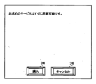
そして、当該判定の結果が(1)又は(2)である場合には、購入者端末14には、図4に示す、即時の提供が可能であることを示す購入確認画面が表示される。当該判定の結果が(3)である場合には、購入者端末14には、図5に示す、所定の納期が必要である(例えば、2週間の納期が必要である)ことを示す購入確認画面が表示される。If the result of the determination is (1) or (2), the
ここで、購入者によって、図4又は図5に示す購入ボタン34がクリックされると、購入要求がされたネットワークサービスが構築され、購入者に提供される。When the purchaser clicks on the
一方、購入者によって、図4又は図5に示すキャンセルボタン36がクリックされると、購入はキャンセルされる。On the other hand, if the purchaser clicks the cancel
以上のように本実施形態によれば、購入者の様々なニーズに応じたネットワークサービスが柔軟に構築される。購入者は、ネットワークサービスの細かい実装について意識することなく、いくつかのサービス要件を指定するだけで、所望のネットワークサービスの提供を受けることができる。As described above, according to this embodiment, network services that meet various needs of purchasers can be flexibly constructed. Purchasers can receive desired network services by simply specifying some service requirements, without being aware of the detailed implementation of the network service.
本実施形態に係るベンダ端末16は、ネットワークサービスに関するサービスプロバイダ等のベンダが利用する、スマートフォン、タブレット端末、パーソナルコンピュータ、などの一般的なコンピュータである。The
本実施形態では、ベンダに、開発環境、検証環境、試験環境を含むCI(Continuous Integration)/CD(Continuous Delivery)パイプラインが提供される。そして、本実施形態では、当該CI/CDパイプラインを活用したオンボーディングプロセスによって、ベンダによって作成された、購入者への提供対象であるネットワークサービスに対応する検証済のバンドルファイルがオンボーディングされる。In this embodiment, a CI (Continuous Integration)/CD (Continuous Delivery) pipeline including a development environment, a verification environment, and a test environment is provided to the vendor. In this embodiment, a verified bundle file corresponding to a network service to be provided to a purchaser, which is created by the vendor, is onboarded by an onboarding process using the CI/CD pipeline.
本実施形態に係るバンドルファイルは、例えば、所定のディレクトリ構成のファイル群を圧縮したファイル(例えばtargz形式のファイル)である。The bundle file according to this embodiment is, for example, a file (for example, a targz format file) obtained by compressing a group of files in a predetermined directory structure.
図6は、本実施形態に係るバンドルファイルのデータ構造の一例を示す図である。図6に示すように、本実施形態に係るバンドルファイルには、ビジネスセクションデータ、テクノロジーセクションデータ、セキュリティセクションデータ、及び、オペレーションセクションデータが含まれる。6 is a diagram showing an example of a data structure of a bundle file according to this embodiment. As shown in FIG. 6, the bundle file according to this embodiment includes business section data, technology section data, security section data, and operation section data.
ビジネスセクションデータには、例えば、ネットワークサービスの名称、ライセンス要件、サービスレベルアグリーメント(SLA)の定義など、ネットワークサービスのビジネス要件が示されている。また、本実施形態に係るビジネスセクションデータには、ネットワークサービスのサービス要件についての必須の入力項目やオプションの入力項目を示すデータが含まれている。The business section data indicates business requirements of the network service, such as the name of the network service, license requirements, definition of a service level agreement (SLA), etc. The business section data according to the present embodiment also includes data indicating required input items and optional input items for the service requirements of the network service.
テクノロジーセクションデータには、例えば、ネットワークサービスを実現する機能ユニット群の構成が示されている。テクノロジーセクションデータには、例えば、ネットワークサービスを構成するアプリケーションやCNFの構成が示されている。The technology section data indicates, for example, the configuration of a group of functional units that realize a network service, and the configuration of applications and CNFs that constitute the network service.
セキュリティセクションデータには、例えば、インストール資格情報などといった、当該ネットワークサービスのセキュリティ定義が示されている。The security section data indicates the security definitions for the network service, such as installation credentials.
オペレーションセクションデータには、例えば、監視対象のメトリックや監視間隔などのネットワークサービスに関する監視ポリシーが示されている。The operation section data indicates a monitoring policy for the network service, such as the metrics to be monitored and the monitoring interval.
図7は、本実施形態に係るベンダ端末16に表示されるオンボーディング画面の一例を示す図である。本実施形態では、ベンダが、バンドルファイルが配置されているパスを指定した上で、オンボーディングボタン40をクリックすると、当該バンドルファイルがオンボーディングされる。7 is a diagram showing an example of an onboarding screen displayed on the
以上のようにして本実施形態では、ベンダは、開発したファイル群がオンボーディングされる実際のロケーションを意識することなく、ネットワークサービスのオンボーディングを簡単に行うことができる。As described above, in this embodiment, the vendor can easily onboard a network service without being aware of the actual location where the developed files are onboarded.
以下、本実施形態に係るMPS10及びNOS12の機能、及び、MPS10及びNOS12で実行される処理について、さらに説明する。The functions of the
図8は、本実施形態に係るMPS10及びNOS12で実装される機能の一例を示す機能ブロック図である。なお、本実施形態に係るMPS10及びNOS12で、図8に示す機能のすべてが実装される必要はなく、また、図8に示す機能以外の機能が実装されていても構わない。Fig. 8 is a functional block diagram showing an example of functions implemented in the
図8に示すように、MPS10には、機能的には例えば、バンドル管理部50、プロダクトカタログ記憶部52、購入管理部54、が含まれる。As shown in FIG. 8, the
バンドル管理部50、購入管理部54は、プロセッサ10a及び通信部10cを主として実装される。プロダクトカタログ記憶部52は、記憶部10bを主として実装される。The
以上の機能は、コンピュータであるMPS10にインストールされた、以上の機能に対応する指令を含むプログラムをプロセッサ10aで実行することにより実装されてもよい。このプログラムは、例えば、光ディスク、磁気ディスク、磁気テープ、光磁気ディスク、フラッシュメモリ等のコンピュータ読み取り可能な情報記憶媒体を介して、あるいは、インターネットなどを介してMPS10に供給されてもよい。The above functions may be implemented by executing a program including instructions corresponding to the above functions on the processor 10a, which is installed in the computer,
また、図8に示すように、NOS12には、機能的には例えば、バンドル展開部60、オーケストレーション(E2EO:End-to-End-Orchestration)部62、サービスカタログ記憶部64、インベントリ管理部66、CMaaS(Configuration Management as a Service)部68、サービスマネージャ部70、スライスマネージャ部72、監視管理部74、セキュリティ設定部76、複数のコンテナ管理部78、リポジトリ部80、インベントリデータベース82、BMaaS(Bare Metal as a Service)部84、が含まれる。As shown in FIG. 8, the
バンドル展開部60、E2EO部62は、プロセッサ12a及び通信部12cを主として実装される。サービスカタログ記憶部64、リポジトリ部80、インベントリデータベース82は、記憶部12bを主として実装される。インベントリ管理部66、CMaaS部68、サービスマネージャ部70、スライスマネージャ部72、監視管理部74、セキュリティ設定部76、コンテナ管理部78は、プロセッサ12a及び記憶部12bを主として実装される。BMaaS部84は、プロセッサ12aを主として実装される。The
以上の機能は、コンピュータであるNOS12にインストールされた、以上の機能に対応する指令を含むプログラムをプロセッサ12aで実行することにより実装されてもよい。このプログラムは、例えば、光ディスク、磁気ディスク、磁気テープ、光磁気ディスク、フラッシュメモリ等のコンピュータ読み取り可能な情報記憶媒体を介して、あるいは、インターネットなどを介してNOS12に供給されてもよい。The above functions may be implemented by executing a program including instructions corresponding to the above functions on the processor 12a, which is installed in the
また、図8には、図1に示す、コアネットワークシステム20、及び、基地局装置22に含まれる、様々なロケーションに分散配置された複数のサーバ90についても示されている。そして、本実施形態に係る複数のコンテナ管理部78は、それぞれ、これら複数のサーバ90のうちの一部であるサーバ群に対応付けられている。Fig. 8 also shows a plurality of
本実施形態に係る複数のコンテナ管理部78のそれぞれには、例えば、クバネテス(Kubernetes)等のコンテナ管理ツール、及び、ヘルム(Helm)等のパッケージマネージャがインストールされている。そして、コンテナ管理部78は、当該コンテナ管理部78に対応付けられているサーバ群(複数のサーバ90)に対してコンテナのデプロイや設定などといったコンテナの構築を含む、コンテナのライフサイクル管理を実行する。A container management tool such as Kubernetes and a package manager such as Helm are installed in each of the multiple
なお、コンテナ管理部78は、NOS12に含まれている必要はない。コンテナ管理部78は、例えば、当該コンテナ管理部78によって管理されるサーバ90(すなわち、コアネットワークシステム20や基地局装置22)、あるいは、当該サーバ90に併設されているサーバに設けられていてもよい。It should be noted that the
バンドル展開部60は、本実施形態では例えば、バンドルファイルをベンダ端末16から受け付ける。そして、バンドル展開部60は、本実施形態では例えば、受け付けたバンドルファイルに基づいて、図9にデータ構造が示されているデータ群を生成する。図9に示すデータ群は、バンドル展開部60が受け付けたバンドルファイルの内容を再構成したものとなっている。In this embodiment, for example, the
図9に示すように、バンドル展開部60によって生成されるデータ群には、プロダクトカタログデータ、サービスカタログデータ、インベントリテンプレートデータ、CMテンプレートデータ、サービステンプレートデータ、スライステンプレートデータ、監視スクリプトデータ、セキュリティスクリプトデータ、ヘルムチャートデータ、及び、コンテナイメージデータが含まれる。As shown in FIG. 9, the data group generated by the
プロダクトカタログデータは、例えば、バンドルファイルに含まれるビジネスセクションデータに対応するデータである。プロダクトカタログデータには、上述したように、図2に示す購入画面に表示されるネットワークサービスの名称、ライセンス要件、サービスレベルアグリーメント(SLA)の定義など、ネットワークサービスのビジネス要件に関する情報が示されている。The product catalog data is, for example, data corresponding to the business section data included in the bundle file. As described above, the product catalog data indicates information on the business requirements of the network service, such as the name of the network service displayed on the purchase screen shown in FIG. 2, the license requirements, and the definition of the service level agreement (SLA).
また、本実施形態に係るプロダクトカタログデータには、ネットワークサービスのサービス要件についての必須の入力項目やオプションの入力項目を示すデータが含まれている。本実施形態では、例えば、プロダクトカタログデータに基づいて、図2に示す購入画面、及び、図3に示すサービス要件入力画面が生成される。Furthermore, the product catalog data according to this embodiment includes data indicating required input items and optional input items for the service requirements of the network service. In this embodiment, for example, a purchase screen shown in Fig. 2 and a service requirements input screen shown in Fig. 3 are generated based on the product catalog data.
サービスカタログデータは、例えば、バンドルファイルに含まれるテクノロジーセクションデータの一部に対応するデータである。サービスカタログデータには、ネットワークサービスを構築するためのワークフローのスクリプトが含まれている。The service catalog data corresponds to, for example, a part of the technology section data included in the bundle file, and includes a workflow script for constructing a network service.
また、サービスカタログデータに、上述のサービス要件データの値と、購入要求に応じて構築される機能ユニット群(例えば、CNF群)の構成との対応を示す要件構成対応データが含まれていてもよい。The service catalog data may also include requirement configuration correspondence data indicating the correspondence between the values of the above-mentioned service requirement data and the configuration of a group of functional units (e.g., a group of CNFs) constructed in response to a purchase request.
例えば、サービスカタログデータに、サービス要件データの値と、機能ユニット群の種類並びに各種類についての機能ユニットの数との対応を示す要件構成対応データが含まれていてもよい。例えば、要件構成対応データに、「加入者数20000と1つのP-GW(Packet Data Network Gateway)」、「加入者数20000と1つのIMS(IP Multimedia System)」、「加入者数20000と1つのHSS(Home Subscriber Server)」が対応することが示されていてもよい。なお、サービス要件データと対応付けられるのは4Gの構成要素の種類や数には限定されず、サービス要件データと5Gの構成要素の種類や数とが対応付けられていてもよい。For example, the service catalog data may include requirement configuration correspondence data indicating the correspondence between the value of the service requirement data, the type of functional unit group, and the number of functional units for each type. For example, the requirement configuration correspondence data may indicate that "20,000 subscribers and one P-GW (Packet Data Network Gateway)", "20,000 subscribers and one IMS (IP Multimedia System)", and "20,000 subscribers and one HSS (Home Subscriber Server)" correspond to each other. Note that the correspondence between the service requirement data and the type and number of 4G components is not limited, and the service requirement data and the type and number of 5G components may be associated with each other.
また、例えば、要件構成対応データに、サービス要件データの値と、購入要求に応じて構築される機能ユニット群に含まれる各機能ユニットが構築されるロケーションとの対応が示されていてもよい。この場合、要件構成対応データにおいてサービス要件データの値と対応付けられているロケーションは、構築される機能ユニット群に含まれる機能ユニットによって異なっていてもよい。Also, for example, the requirement configuration correspondence data may indicate the correspondence between the value of the service requirement data and the location where each functional unit included in the functional unit group to be constructed in response to the purchase request is constructed. In this case, the location associated with the value of the service requirement data in the requirement configuration correspondence data may be different depending on the functional unit included in the functional unit group to be constructed.
インベントリテンプレートデータは、例えば、バンドルファイルに含まれるテクノロジーセクションデータの一部及びセキュリティセクションデータの一部に対応するデータである。インベントリテンプレートデータは、例えば、インベントリ管理部66によって利用されるロジックを示すテンプレートデータである。The inventory template data is, for example, data corresponding to a part of the technology section data and a part of the security section data included in the bundle file. The inventory template data is, for example, template data indicating logic used by the
CMテンプレートデータは、例えば、バンドルファイルに含まれるテクノロジーセクションデータの一部及びオペレーションセクションデータの一部に対応するデータであり、例えば、CMaaS部68によって利用されるロジックを示すテンプレートデータである。The CM template data is, for example, data corresponding to a part of the technology section data and a part of the operation section data included in the bundle file, and is, for example, template data indicating the logic used by the
サービステンプレートデータは、例えば、バンドルファイルに含まれるテクノロジーセクションデータの一部に対応するデータであり、例えば、サービスマネージャ部70によって利用されるロジックを示すテンプレートデータである。The service template data is, for example, data corresponding to a part of the technology section data included in the bundle file, and is, for example, template data indicating the logic used by the
スライステンプレートデータは、例えば、バンドルファイルに含まれるテクノロジーセクションデータの一部に対応するデータであり、例えば、スライスマネージャ部72によって利用されるロジックを示すテンプレートデータである。The slice template data is, for example, data corresponding to a part of the technology section data included in the bundle file, and is, for example, template data indicating the logic used by the
監視スクリプトデータは、例えば、バンドルファイルに含まれるオペレーションセクションデータの一部に対応するデータであり、例えば、監視管理部74によって実行される監視スクリプトを示すデータである。The monitoring script data is, for example, data corresponding to a part of the operation section data included in the bundle file, and is, for example, data indicating a monitoring script to be executed by the
セキュリティスクリプトデータは、例えば、バンドルファイルに含まれるセキュリティセクションデータの一部に対応するデータであり、例えば、セキュリティ設定部76によって実行されるセキュリティに関するスクリプトを示すデータである。The security script data is, for example, data corresponding to a part of the security section data included in the bundle file, and is, for example, data indicating a script relating to security executed by the
ヘルムチャートデータは、例えば、バンドルファイルに含まれるオペレーションセクションデータの一部に対応するデータであり、コンテナ管理部78によって利用されるスクリプトテンプレート(ヘルムチャート)を示すデータである。The Helm chart data is, for example, data corresponding to a part of the operation section data included in the bundle file, and is data indicating a script template (Helm chart) used by the
コンテナイメージデータは、例えば、バンドルファイルに含まれるオペレーションセクションデータの一部に対応するデータであり、例えば、ネットワークサービスを実現する機能ユニット群に含まれるコンテナについてのコンテナイメージのデータである。コンテナイメージデータには、1又は複数のコンテナイメージが含まれる。これら1又は複数のコンテナイメージのそれぞれには、当該コンテナイメージの識別子であるコンテナイメージIDが関連付けられている。The container image data is, for example, data corresponding to a part of the operation section data included in the bundle file, and is, for example, data of a container image for a container included in a group of functional units that realize a network service. The container image data includes one or more container images. Each of the one or more container images is associated with a container image ID that is an identifier of the container image.
本実施形態では、バンドル展開部60は、バンドルファイルの受付に応じて、当該バンドルファイルに基づいて生成されるデータ群に対応するバンドルIDを決定する。バンドルIDは、生成されるデータ群ごとに一意に割り当てられる。In this embodiment, in response to receiving a bundle file, the
そして、バンドル展開部60は、当該バンドルIDに対応するデータ群に含まれるプロダクトカタログデータを、決定されるバンドルIDに関連付けた上で、MPS10に送信する。Then, the
また、バンドル展開部60は、当該データ群に含まれるサービスカタログデータを、決定されるバンドルIDに関連付けた上で、E2EO部62に出力する。すると、E2EO部62は、当該サービスカタログデータをサービスカタログ記憶部64に記憶させる。Furthermore, the
また、バンドル展開部60は、インベントリテンプレートデータ、CMテンプレートデータ、サービステンプレートデータ、スライステンプレートデータ、監視スクリプトデータ、セキュリティスクリプトデータ、ヘルムチャートデータ、及び、コンテナイメージデータを、当該データ群に対応するバンドルIDに関連付けた上で、それぞれ、インベントリ管理部66、CMaaS部68、サービスマネージャ部70、スライスマネージャ部72、監視管理部74、セキュリティ設定部76、コンテナ管理部78、及び、リポジトリ部80に記憶させる。In addition, the
このようにして、本実施形態ではバンドルIDによって、プロダクトカタログデータ、サービスカタログデータ、インベントリテンプレートデータ、CMテンプレートデータ、サービステンプレートデータ、スライステンプレートデータ、監視スクリプトデータ、セキュリティスクリプトデータ、ヘルムチャートデータ、及び、コンテナイメージデータが互いに関連付けられることとなる。In this way, in this embodiment, the product catalog data, service catalog data, inventory template data, CM template data, service template data, slice template data, monitoring script data, security script data, Helm chart data, and container image data are associated with each other by the bundle ID.
また、本実施形態では、ベンダは、バンドルファイルのパスの指定などの簡単な操作によって簡単にネットワークサービスを提供することが可能である。Furthermore, in this embodiment, the vendor can easily provide a network service by performing a simple operation such as specifying the path of a bundle file.
バンドル管理部50は、本実施形態では例えば、バンドル展開部60から送信される、バンドルIDに関連付けられたプロダクトカタログデータを受信する。そして、バンドル管理部50は、受信したプロダクトカタログデータをプロダクトカタログ記憶部52に記憶させる。In this embodiment, for example, the
プロダクトカタログ記憶部52は、本実施形態では例えば、上述のように、バンドルIDに関連付けられたプロダクトカタログデータを記憶する。In this embodiment, the product
購入管理部54は、本実施形態では例えば、購入者端末14から、バンドルID、及び、サービス要件データに関連付けられた、ネットワークサービスの購入要求などといったネットワークサービスの構築要求を受け付ける。以下、購入要求に関連付けられているバンドルIDを購入バンドルIDと呼び、購入要求に関連付けられているサービス要件データを購入サービス要件データと呼ぶこととする。In this embodiment, for example, the
そして、購入管理部54は、上述の購入要求の受付に応じて、当該購入バンドルIDに関連付けられた当該購入サービス要件データをE2EO部62に送信する。Then, in response to receiving the above-mentioned purchase request, the
また、購入管理部54は、E2EO部62及びインベントリ管理部66と連携して、購入者が購入するネットワークサービスの納期を特定する。そして、購入管理部54は、特定される納期を購入者に通知する。購入管理部54は、例えば、特定される納期が示された購入確認画面を生成して、生成される購入確認画面を購入者端末14に送信する。Furthermore, the
インベントリデータベース82は、本実施形態では例えば、NOS12で管理されている、コアネットワークシステム20や基地局装置22に配置されている複数のサーバ90についてのインベントリ情報が格納されたデータベースである。In this embodiment, the inventory database 82 is, for example, a database that stores inventory information about a plurality of
本実施形態では例えば、インベントリデータベース82には、図10に示す物理インベントリデータ、及び、図11に示す論理インベントリデータを含む、インベントリデータが記憶されている。インベントリデータには、NOS12で管理されているリソースの状況(例えば、リソースの使用状況)が示されている。In this embodiment, for example, the inventory database 82 stores inventory data including the physical inventory data shown in Fig. 10 and the logical inventory data shown in Fig. 11. The inventory data indicates the status of resources managed by the NOS 12 (e.g., the usage status of the resources).
図10は、物理インベントリデータのデータ構造の一例を示す図である。図10に示す物理インベントリデータは、1つのサーバ90に対応付けられる。図10に示す物理インベントリデータには、例えば、サーバID、ロケーションデータ、建物データ、階数データ、ラックデータ、割り当てリソースプール群ID、割り当てリソースプールID、スペックデータ、ネットワークデータ、稼働コンテナIDリスト、などが含まれる。Fig. 10 is a diagram showing an example of a data structure of physical inventory data. The physical inventory data shown in Fig. 10 is associated with one
物理インベントリデータに含まれるサーバIDは、例えば、当該物理インベントリデータに対応付けられるサーバ90の識別子である。The server ID included in the physical inventory data is, for example, an identifier of the
物理インベントリデータに含まれるロケーションデータは、例えば、当該物理インベントリデータに対応付けられるサーバ90のロケーション(例えばロケーションの住所)を示すデータである。The location data included in the physical inventory data is, for example, data indicating the location (for example, the address of the location) of the
物理インベントリデータに含まれる建物データは、例えば、当該物理インベントリデータに対応付けられるサーバ90が配置されている建物(例えば建物名)を示すデータである。The building data included in the physical inventory data is, for example, data indicating the building (for example, the building name) in which the
物理インベントリデータに含まれる階数データは、例えば、当該物理インベントリデータに対応付けられるサーバ90が配置されている階数を示すデータである。The floor data included in the physical inventory data is, for example, data indicating the floor on which the
物理インベントリデータに含まれるラックデータは、例えば、当該物理インベントリデータに対応付けられるサーバ90が配置されているラックの識別子である。The rack data included in the physical inventory data is, for example, an identifier of the rack in which the
物理インベントリデータに含まれる割り当てリソースプール群IDは、例えば、当該物理インベントリデータに対応付けられるサーバ90が割り当てられているリソースプール群の識別子である。The allocated resource pool group ID included in the physical inventory data is, for example, an identifier of a resource pool group to which the
物理インベントリデータに含まれる割り当てリソースプールIDは、例えば、当該物理インベントリデータに対応付けられるサーバ90が割り当てられているリソースプールの識別子である。割り当てリソースプールIDが示すリソースプールは、割り当てリソースプール群IDに対応するリソースプール群に含まれるいずれかのリソースプールである。なお、本実施形態では、空きサーバは、いずれかのリソースプール群に割り当てられるが、当該空きサーバが当該リソースプール群に含まれるどのリソースプールに割り当てられるかは未決定である。このような空きサーバについては、対応する物理インベントリデータに含まれる割り当てリソースプールIDの値としてNullが設定される。The assigned resource pool ID included in the physical inventory data is, for example, an identifier of a resource pool to which a
物理インベントリデータに含まれるスペックデータは、例えば、当該物理インベントリデータに対応付けられるサーバ90のコア数、メモリ容量、ハードディスク容量、などといった、当該サーバ90のスペックを示すデータである。The specification data included in the physical inventory data is data indicating the specifications of the
物理インベントリデータに含まれるネットワークデータは、例えば、当該物理インベントリデータに対応付けられるサーバ90が備えるNICや当該NICが備えるポート数などを示すデータである。The network data included in the physical inventory data is, for example, data indicating the NICs provided in the
物理インベントリデータに含まれる稼働コンテナIDリストは、例えば、当該物理インベントリデータに対応付けられるサーバ90で稼働する1又は複数のコンテナのインスタンスの識別子(コンテナID)のリストを示すデータである。The operating container ID list included in the physical inventory data is data indicating, for example, a list of identifiers (container IDs) of one or more container instances operating on the
図11は、論理インベントリデータのデータ構造の一例を模式的に示す図である。図11に示すように、論理インベントリデータには、NS(Network Service)データ、NF(Network Function)データ、CNFデータ、podデータ、及び、コンテナデータが含まれている。Fig. 11 is a diagram illustrating an example of a data structure of logical inventory data. As illustrated in Fig. 11, the logical inventory data includes network service (NS) data, network function (NF) data, CNF data, pod data, and container data.
NSデータは、例えばvRAN(virtual RAN)などに相当するネットワークサービスのインスタンスの識別子や当該ネットワークサービスの種類等の属性を示すデータである。NFデータは、例えばeNodeBなどに相当するネットワークファンクションのインスタンスの識別子や当該ネットワークファンクション種類等の属性を示すデータである。CNFデータは、例えばvCUやvDUなどに相当する、CNFのインスタンスの識別子や当該CNFの種類等の属性を示すデータである。podデータは、CNFに含まれるpodのインスタンスの識別子や当該podの種類等の属性を示すデータである。ここで、podとは、クバネテスでドッカーコンテナを管理するための最小単位を指す。コンテナデータは、podに含まれるコンテナのインスタンスのコンテナIDや当該コンテナの種類等の属性を示すデータである。The NS data is data indicating attributes such as an identifier of an instance of a network service corresponding to a virtual RAN (vRAN) or the type of the network service. The NF data is data indicating attributes such as an identifier of an instance of a network function corresponding to an eNodeB or the type of the network function. The CNF data is data indicating attributes such as an identifier of an instance of a CNF corresponding to a vCU or vDU or the type of the CNF. The pod data is data indicating attributes such as an identifier of an instance of a pod included in a CNF or the type of the pod. Here, a pod refers to the smallest unit for managing a Docker container in Kubernetes. The container data is data indicating attributes such as a container ID of an instance of a container included in a pod or the type of the container.
なお、ホスト名やIPアドレスなどの属性を示すデータが論理インベントリデータに含まれる上述のデータに設定されていても構わない。例えば、コンテナデータに、当該コンテナデータに対応するコンテナのIPアドレスを示すデータが含まれていてもよい。また、例えば、CNFデータに、当該CNFデータが示すCNFのIPアドレス及びホスト名を示すデータが含まれていてもよい。In addition, data indicating attributes such as a host name and an IP address may be set in the above data included in the logical inventory data. For example, the container data may include data indicating an IP address of a container corresponding to the container data. Also, for example, the CNF data may include data indicating an IP address and a host name of a CNF indicated by the CNF data.
上述のデータは階層構造になっており、NSデータは、当該NSデータに対応するネットワークサービスに含まれる1又は複数のネットワークファンクションのそれぞれに対応する1又は複数のNFデータと関連付けられている。また、NFデータは、当該NFデータに対応するネットワークファンクションに含まれる1又は複数のCNFのそれぞれに対応する1又は複数のCNFデータと関連付けられている。また、CNFデータは、当該CNFデータに対応するCNFに含まれる1又は複数のpodのそれぞれに対応する1又は複数のpodデータと関連付けられている。また、podデータは、当該podデータに対応するpodに含まれる1又は複数のコンテナのそれぞれに対応する1又は複数のコンテナデータと関連付けられている。The above data has a hierarchical structure, and the NS data is associated with one or more NF data corresponding to one or more network functions included in the network service corresponding to the NS data. The NF data is associated with one or more CNF data corresponding to one or more CNFs included in the network function corresponding to the NF data. The CNF data is associated with one or more pod data corresponding to one or more pods included in the CNF corresponding to the CNF data. The pod data is associated with one or more container data corresponding to one or more containers included in the pod corresponding to the pod data.
論理インベントリデータに含まれるコンテナデータのコンテナIDと、物理インベントリデータに含まれる稼働コンテナIDリストに含まれるコンテナIDと、によって、コンテナのインスタンスと、当該コンテナのインスタンスが稼働しているサーバ90とが関連付けられることとなる。The container instance is associated with the
なお、本実施形態において購入者が購入するネットワークサービス(プロダクトカタログデータに対応付けられるネットワークサービス)は、NSデータに対応付けられるネットワークサービスに相当するものである必要はない。例えば、購入者が購入するネットワークサービスが、1又は複数のNFデータに対応付けられるネットワークファンクションに相当する機能ユニット群によって実現されるものであっても構わないし、1又は複数のCNFデータに対応付けられる機能ユニット群によって実現されるものであっても構わない。また、購入者に購入されるネットワークサービスが、1又は複数のpodに対応付けられる機能ユニット群によって実現されるものであっても構わないし、1又は複数のコンテナに対応付けられる機能ユニット群によって実現されるものであっても構わない。In this embodiment, the network service purchased by the purchaser (the network service associated with the product catalog data) does not have to correspond to the network service associated with the NS data. For example, the network service purchased by the purchaser may be realized by a functional unit group corresponding to a network function associated with one or more NF data, or may be realized by a functional unit group associated with one or more CNF data. In addition, the network service purchased by the purchaser may be realized by a functional unit group associated with one or more pods, or may be realized by a functional unit group associated with one or more containers.
また、図11に示すように、本実施形態に係る論理インベントリデータには、それぞれリソースプール群に対応付けられる複数のリソースプール管理データが含まれる。As shown in FIG. 11, the logical inventory data according to this embodiment includes a plurality of resource pool management data each associated with a resource pool group.
図12は、本実施形態に係るリソースプール管理データの一例を示す図である。リソースプール管理データは、当該リソースプール管理データに対応付けられるリソースプール群に含まれる複数のリソースプールの状況が示されている。12 is a diagram showing an example of resource pool management data according to this embodiment. The resource pool management data indicates the status of a plurality of resource pools included in a resource pool group associated with the resource pool management data.
図12に示すリソースプール管理データには、リソースプール群ID、複数のリソースプールデータ、及び、空きサーバ数データが含まれる。The resource pool management data illustrated in FIG. 12 includes a resource pool group ID, a plurality of resource pool data, and data on the number of available servers.
リソースプール管理データに含まれるリソースプール群IDは、当該リソースプール管理データに対応付けられるリソースプール群の識別子である。The resource pool group ID included in the resource pool management data is an identifier of a resource pool group associated with the resource pool management data.
リソースプール管理データに含まれる空きサーバ数データは、当該リソースプール管理データに対応付けられるリソースプール群に割り当てられた空きサーバ数を示すデータである。The number of available servers data included in the resource pool management data is data indicating the number of available servers allocated to the resource pool group associated with the resource pool management data.
リソースプールデータは、リソースプール管理データに対応付けられるリソースプール群に含まれるリソースプールの状況を示すデータである。The resource pool data is data that indicates the status of a resource pool included in a resource pool group associated with the resource pool management data.
図12に示すように、リソースプールデータには、リソースプールID、総コア数データ、残りコア数データ、CNF種類データが含まれる。As shown in FIG. 12, the resource pool data includes a resource pool ID, data on the total number of cores, data on the number of remaining cores, and CNF type data.
リソースプールIDは、リソースプールの識別子である。The resource pool ID is an identifier of a resource pool.
総コア数データは、当該リソースプールに割り当てられたサーバ90の総コア数を示すデータである。総コア数データは、当該リソースプールに含まれるハードウェアリソースの総量を示すリソース総量データの一具体例である。The total core count data is data indicating the total number of cores of the
残りコア数データは、当該リソースプールに割り当てられたサーバ90の残りコア数を示すデータである。残りコア数データは、当該リソースプールに含まれるハードウェアリソースの残量を示すリソース残量データの一具体例である。The remaining core number data is data indicating the number of remaining cores of the
また、CNF種類データは、当該リソースプールに関連付けられた1種類以上のCNFの種類を示すデータである。CNF種類データは、当該リソースプールに関連付けられた1種類以上の種類の機能ユニットを示す機能ユニット種類データの一具体例である。The CNF type data is data indicating one or more types of CNFs associated with the resource pool. The CNF type data is a specific example of functional unit type data indicating one or more types of functional units associated with the resource pool.
本実施形態では、複数のロケーションにまたがるリソースプール群が予め設定されてもよいし、1つのロケーションだけに対応付けられるリソースプール群が予め設定されていてもよい。いずれの場合も、リソースプール群は、物理インベントリデータに示されている1又は複数のロケーションに対応付けられることとなる。In this embodiment, a resource pool group that spans multiple locations may be predefined, or a resource pool group that is associated with only one location may be predefined. In either case, the resource pool group is associated with one or more locations indicated in the physical inventory data.
また、インベントリ管理部66は、コンテナ管理部78と連携して、リソースの状況を適宜把握できるようになっている。そして、インベントリ管理部66は、リソースの最新の状況に基づいて、インベントリデータベース82に記憶されているインベントリデータを適宜更新する。The
E2EO部62及びインベントリ管理部66は、本実施形態では例えば、購入管理部54から受信するサービス要件データに基づいて、購入されるネットワークサービスを実現する機能ユニット群の構成を特定する。In this embodiment, the
ここで、E2EO部62は、例えば、購入管理部54から受信する購入サービス要件データに関連付けられている購入バンドルIDに対応するサービスカタログデータをサービスカタログ記憶部64から取得する。そして、E2EO部62は、当該サービスカタログデータが示すワークフローのスクリプトを実行する。Here, the
E2EO部62及びインベントリ管理部66は、購入管理部54から受信する購入サービス要件データ、購入バンドルIDに関連付けられているサービスカタログデータ、購入バンドルIDに関連付けられているインベントリテンプレートデータ、及び、インベントリデータに基づいて、図13及び図14に例示する計画データ(planned data)を生成する。計画データは例えば、購入されるネットワークサービスを実現する機能ユニット群の構成を示すデータである。この処理は、例えば、E2EO部62によるワークフローのスクリプトの実行をトリガとして実行される。The
図13は、本実施形態に係る計画データのデータ構造の一例を示す図である。図14は、本実施形態に係る計画データの一例を模式的に示す図である。本実施形態に係る計画データには、計画データの識別子であるインベントリキーが含まれる。インベントリキーは、計画データが生成される際に、当該計画データに一意に割り当てられる。また、計画データには、購入バンドルIDが含まれる(図14の例では「0010」)。また、計画データには、購入要求を行った購入者(ユーザ)の識別子であるユーザIDが含まれる。Fig. 13 is a diagram showing an example of a data structure of planning data according to this embodiment. Fig. 14 is a diagram showing an example of planning data according to this embodiment. Planning data according to this embodiment includes an inventory key that is an identifier of the planning data. The inventory key is uniquely assigned to the planning data when the planning data is generated. The planning data also includes a purchase bundle ID ("0010" in the example of Fig. 14). The planning data also includes a user ID that is an identifier of the purchaser (user) who made the purchase request.
また、計画データに、購入サービス要件データに設定されている値が含まれていてもよい。図13及び図14に示す計画データには、購入サービス要件データに含まれる、対向IPデータの値、監視対象データの値、監視間隔データの値、及び、パスワードデータの値が含まれている。The plan data may also include values set in the purchased service requirement data. The plan data shown in Fig. 13 and Fig. 14 includes values of opposing IP data, monitoring target data, monitoring interval data, and password data, which are included in the purchased service requirement data.
そして、本実施形態では、計画データには、購入されるネットワークサービスを実現する機能ユニット群に含まれる機能ユニットのそれぞれについての機能ユニット構成データが含まれる。機能ユニット構成データには、例えば、当該機能ユニットの種類を示すCNF種類データ、ホスト名を示すホスト名データ、IPアドレスを示すIPアドレスデータ、当該機能ユニットを構成するコンテナにそれぞれ対応付けられる複数のコンテナ構成データ、が含まれる。In this embodiment, the plan data includes functional unit configuration data for each of the functional units included in the functional unit group that realizes the purchased network service. The functional unit configuration data includes, for example, CNF type data indicating the type of the functional unit, host name data indicating the host name, IP address data indicating the IP address, and multiple container configuration data respectively associated with the containers that configure the functional unit.
ここで例えば、E2EO部62が、購入サービス要件データに基づいて、構築される機能ユニット群の数を特定してもよい。例えば、E2EO部62が、購入サービス要件データとサービスカタログデータに含まれる要件構成対応データとに基づいて、購入されるネットワークサービスを実現する機能ユニット群の種類並びに各種類についての機能ユニットの数を特定してもよい。例えば、サービス要件データが示す加入者数が50000である場合に、上述の要件構成対応データに基づいて、構築される機能ユニット群が、3個のP-GW、3個のIMS、及び、3個のHSSであると特定されてもよい。Here, for example, the
そして、E2EO部62が、サービス要件データとともに、機能ユニット群の種類並びに各種類についての機能ユニットの数を示すデータをインベントリ管理部66に出力してもよい。そして、インベントリ管理部66が、当該データと、インベントリデータと、に基づいて、各機能ユニットに割り当てられるホスト名およびIPアドレスを決定してもよい。ここで例えば、既に使用されているホスト名やIPアドレスと重複しないようホスト名やIPアドレスが決定されてもよい。そして、このようにして決定されるホスト名を示すホスト名データ、及び、決定されるIPアドレスを示すIPアドレスデータを含む計画データが生成されてもよい。The
また、上述のように、E2EO部62が、購入サービス要件データに基づいて、構築される機能ユニット群に含まれる機能ユニットのそれぞれが構築されるロケーションを特定してもよい。例えば、E2EO部62が、購入サービス要件データに含まれる対象地域データとサービスカタログデータに含まれる要件構成対応データとに基づいて、構築される機能ユニット群に含まれる各機能ユニットのロケーションを決定してもよい。ここで各機能ユニットについて異なるロケーションが決定されてもよい。そして、各機能ユニットについて、当該機能ユニットについて決定されるロケーションにおいて利用可能なホスト名やIPアドレスが、当該機能ユニットのホスト名及びIPアドレスとして決定されてもよい。そして、このようにして決定されるホスト名を示すホスト名データ、及び、決定されるIPアドレスを示すIPアドレスデータを含む計画データが生成されてもよい。Also, as described above, the
また、E2EO部62が、購入サービス要件データに基づいて、複数のロケーションのそれぞれについて、当該ロケーションに構築される機能ユニットの種類及び数を特定してもよい。この場合、E2EO部62が、購入サービス要件データに基づいて特定されるロケーションに応じて、当該ロケーションに構築される、それぞれの種類の機能ユニットの数を決定してもよい。また、E2EO部62が、購入サービス要件データに基づいて特定されるロケーション毎に設定されている重みに基づいて、ロケーション毎に構築される、それぞれの種類の機能ユニットの数を決定してもよい。The
例えば、E2EO部62に、図15に示す想定ビジーレベルデータが記憶されていてもよい。図15に示す想定ビジーレベルデータには、例えば、当該想定ビジーレベルデータに関連付けられているデータセンタの配下の1又は複数のセルがカバーするエリアの人口が示されている。想定ビジーレベルデータの値は、上述したロケーション毎に設定されている重みの一例である。For example, the
ここで、コアネットワークシステム20のデータセンタについての想定ビジーレベルデータには、例えば、当該コアネットワークシステム20と通信する1又は複数の基地局装置22のセルがカバーするエリアの人口が示される。Here, the expected busy level data for a data center of the
そして、例えば、想定ビジーレベルデータが示す人口が高いロケーションであるほど多くの機能ユニットがデプロイされるようにしてもよい。例えば、購入サービス要件データに含まれる加入者数データに基づいて、デプロイされるvDUの総数nが特定されるとする。そして、購入サービス要件データに含まれる対象地域データに基づいて、当該対象地域データが示す対象地域内にある、vDUのデプロイ先である複数のデータセンタが特定されるとする。この場合、特定された各データセンタについての想定ビジーレベルデータの値に基づいて、特定されたvDUの総数nを按分した数のvDUが各データセンタにデプロイされるようにしてもよい。For example, the more functional units may be deployed in a location with a higher population indicated by the expected busy level data. For example, a total number n of vDUs to be deployed is specified based on subscriber count data included in the purchased service requirement data. Then, a plurality of data centers to which the vDUs are to be deployed are specified in a target region indicated by the target region data included in the purchased service requirement data. In this case, a pro rata number of vDUs of the specified total number n of vDUs may be deployed in each data center based on the value of expected busy level data for each specified data center.
図13に示すように、コンテナ構成データには、例えば、コンテナID、コンテナイメージID、必要リソースデータ、リソースプール群ID、リソースプールID、及び、接続コンテナIDリストが含まれる。As shown in FIG. 13, the container configuration data includes, for example, a container ID, a container image ID, necessary resource data, a resource pool group ID, a resource pool ID, and a connected container ID list.
コンテナIDは、例えば、上述したように、当該コンテナ構成データに対応するコンテナのインスタンスに一意に割り当てられる識別子である。The container ID is, for example, as described above, an identifier that is uniquely assigned to an instance of a container corresponding to the container configuration data.
コンテナ構成データに含まれるコンテナイメージIDには、例えば、当該コンテナ構成データに対応するコンテナのコンテナイメージに割り当てられているコンテナイメージIDが設定される。The container image ID included in the container configuration data is set to, for example, the container image ID assigned to the container image of the container corresponding to the container configuration data.
必要リソースデータは、例えば、当該コンテナの稼働に必要なリソースを示すデータである。本実施形態では例えば、インベントリテンプレートデータに、各コンテナについて、当該コンテナの稼働に必要なリソースが示されている。インベントリ管理部66は、インベントリテンプレートデータに基づいて、必要リソースデータの値を設定する。The required resource data is, for example, data indicating resources required for the operation of the container. In this embodiment, for example, the inventory template data indicates, for each container, the resources required for the operation of the container. The
コンテナ構成データに含まれるリソースプール群IDには、例えば、当該コンテナ構成データに対応するコンテナが割り当てられるリソースプール群のリソースプール群IDの値が設定される。インベントリ管理部66は、例えば、上述のようにして決定されるロケーションと、インベントリデータと、に基づいて、当該コンテナが構築されるリソースプール群IDを決定してもよい。The resource pool group ID included in the container configuration data is set to, for example, the value of the resource pool group ID of the resource pool group to which the container corresponding to the container configuration data is assigned. The
コンテナ構成データに含まれるリソースプールIDには、例えば、当該コンテナ構成データに対応するコンテナが割り当てられるリソースプールのリソースプールIDの値が設定される。インベントリ管理部66は、例えば、当該コンテナの種類と、リソースプール管理データと、に基づいて、リソースプールIDを決定してもよい。The resource pool ID included in the container configuration data is set to, for example, the value of the resource pool ID of the resource pool to which the container corresponding to the container configuration data is assigned. The
接続コンテナIDリストは、当該コンテナと接続されるコンテナのコンテナIDのリストである。本実施形態では例えば、インベントリテンプレートデータに、各コンテナについて、当該コンテナと接続されるコンテナの種類が示されている。インベントリ管理部66は、例えば、インベントリテンプレートデータと、インベントリデータと、に基づいて、接続コンテナIDリストの値を決定する。The connected container ID list is a list of container IDs of containers connected to the container. In this embodiment, for example, the inventory template data indicates, for each container, the type of container connected to the container. The
計画データを生成する際には、E2EO部62は、インベントリ管理部66と連携して、新規の機能ユニット群がデプロイされるリソースプール、及び、必要なリソースを特定する。ここで、E2EO部62は、購入要求の受付などといった、ネットワークサービスの構築要求の受付に応じて特定される機能ユニットに関連付けられているリソースプールを特定してもよい。また、E2EO部62は、購入されるネットワークサービスの対象地域に基づいて、リソースプール群を特定してもよい。例えば、購入サービス要件データに含まれる対象地域データが示す対象地域に基づいて、リソースプール群が特定されてもよい。そして、E2EO部62は、特定されたリソースプール群に含まれるリソースプールのうちから、新規の機能ユニット群がデプロイされるリソースプールを特定してもよい。When generating the planning data, the
また、E2EO部62は、新規の機能ユニット群がデプロイされるハードウェアリソース(ここでは例えばサーバ90)を確保可能であるか否かを判定する。ここでは例えば、(1)サーバ90の確保が可能である、(2)いずれのリソースプールにも含まれていない未使用ハードウェアリソース(ここでは例えば空きサーバ)のセットアップを行うことでサーバ90の確保が可能である、(3)サーバ90の確保が不可能である、のいずれであるかかが判定される。The
ここで、(2)である場合は、E2EO部62は、未使用ハードウェアリソース(ここでは例えば空きサーバ)に、予め定められた特定種類の機能ユニットがデプロイされるか否かを判定する。Here, in the case of (2), the
そして、特定種類の機能ユニットがデプロイされる場合は、E2EO部62は、当該特定種類の機能ユニットに関連付けられているリソースプールを特定する。ここで例えば、リソースプール管理データに基づいて、当該リソースプールが特定される。When a specific type of functional unit is deployed, the
本実施形態では例えば、以上のようにして特定されるリソースプール群のリソースプール群ID、及び、特定されるリソースプールのリソースプールIDが、コンテナ構成データに設定される。In this embodiment, for example, the resource pool group ID of the resource pool group identified as above and the resource pool ID of the identified resource pool are set in the container configuration data.
CMaaS部68、サービスマネージャ部70、及び、スライスマネージャ部72は、本実施形態では例えば、上述のようにして特定される機能ユニット群の構成と、当該構成をパラメータとして受け入れ可能なテンプレートデータと、に基づいて、当該機能ユニット群の構築手順を特定する。当該構築手順には、例えば、コンテナのデプロイ、及び、デプロイされたコンテナ及び当該コンテナに関係するコンテナの設定等のコンテナの構成管理の手順が含まれる。この処理は、例えば、E2EO部62によるワークフローのスクリプトの実行をトリガとして実行される。In this embodiment, the
そして、CMaaS部68、サービスマネージャ部70、スライスマネージャ部72、及び、コンテナ管理部78は、特定される構築手順を実行することで、機能ユニット群を構築する。この処理も、例えば、E2EO部62によるワークフローのスクリプトの実行をトリガとして実行される。Then, the
なお、機能ユニット群に含まれる機能ユニットのそれぞれが、当該機能ユニットについて特定されるロケーションに構築されてもよい。Each of the functional units included in the functional unit group may be constructed in a location specified for that functional unit.
また例えば、購入サービス要件データに基づいて特定される数の機能ユニット群が構築されてもよい。Also for example, a specified number of functional units may be constructed based on purchased service requirement data.
また例えば、複数のロケーションのそれぞれについて、当該ロケーションについて特定される種類の機能ユニットが、特定される数だけ構築されるようにしてもよい。Also, for example, for each of a plurality of locations, a specified number of functional units of a type specified for that location may be constructed.
ここで、CMaaS部68及びBMaaS部84は、例えば、新規の機能ユニット群がデプロイされるハードウェアリソース(ここでは例えばサーバ90)を確保する。Here, the
また、CMaaS部68及びBMaaS部84は、特定種類の機能ユニットに応じたシステムソフトウェアのセットアップを、未使用ハードウェアリソースに施す。本実施形態では例えば、CMaaS部68又はBMaaS部84に上述の特定種類の機能ユニットについてのセットアップを行うためのスクリプト(例えば、Ansibleスクリプト)が記憶されている。当該スクリプトには、例えば、特定種類あるいは特定バージョンである、コンテナ実行環境の基盤であるホストOSのインストール手順、ホストOSのカーネルの設定手順、BIOS(Basic Input Output System)の設定手順、などが記述されている。そして、BMaaS部84が、当該スクリプトを実行することにより、特定種類の機能ユニットに応じたシステムソフトウェアのセットアップが、空きサーバに施される。例えば、コンテナ実行環境のホストOSやBIOSのセットアップが、空きサーバに施される。In addition, the
そして、CMaaS部68及びBMaaS部84は、リソースプール管理データを更新して、システムソフトウェアのセットアップが施された未使用ハードウェアリソースを、特定されるリソースプールに追加する。このようなリソースプールへのハードウェアリソースの追加は当該ハードウェアリソースを管理するコンテナ管理部78によって検出される。そして、インベントリ管理部66が、追加されたハードウェアリソース(サーバ90)に対応するインベントリデータを更新される。このようにして、当該リソースプールには、特定種類の機能ユニットに応じたシステムソフトウェアのセットアップが施されたハードウェアリソースが含まれることとなる。Then, the
ここでは例えば、vDUが特定種類の機能ユニットであることとする。また、vDUに必要なコア数が5つであり、空きサーバのコア数が50であるとする。For example, it is assumed here that a vDU is a specific type of functional unit, that the number of cores required for the vDU is 5, and that the number of available cores in the server is 50.
この場合において、vDUを含むネットワークサービスが購入される際に、vDUに関連付けられたリソースプールが特定される。図12の例では、リソースプールIDがCであるリソースプールが特定される。そして、このリソースプールの残りハードウェアリソースが充分であるか否かが確認される。そして、残りハードウェアリソースが不足している場合は、1つの空きサーバに対して、vDUに応じたシステムソフトウェアのセットアップが施される。そして、システムソフトウェアのセットアップがされたサーバ90が、リソースプールCに追加され、リソースプール管理データは、図16に示すものに更新される。In this case, when a network service including a vDU is purchased, a resource pool associated with the vDU is identified. In the example of Fig. 12, a resource pool with a resource pool ID of C is identified. Then, it is confirmed whether the remaining hardware resources of this resource pool are sufficient. Then, if the remaining hardware resources are insufficient, system software corresponding to the vDU is set up for one free server. Then, the
このようにして、本実施形態では、リソースプールデータに対応するリソースプールに含まれるハードウェアリソースには、当該リソースプールに関連付けられている1種類以上の種類の機能ユニットに応じたシステムソフトウェアのセットアップが施されることとなる。In this manner, in this embodiment, the hardware resources included in the resource pool corresponding to the resource pool data are subjected to system software setup according to one or more types of functional units associated with the resource pool.
機能ユニットの種類によっては一般的な構成の汎用サーバでは充分な性能が発揮できないことがある。そこで、このような特定種類の機能ユニットのために、ホストOSやBIOS等のシステムソフトウェアについて、専用のセットアップをサーバ等のハードウェアリソースに施すことが望ましい。この場合、そうした専用のシステムソフトウェアのセットアップが施されたハードウェアリソースをネットワークサービスの提供開始前に所要数だけ予め準備しておき、必要時には、準備されたハードウェアリソースに当該機能ユニットをデプロイすることが考えられる。Depending on the type of functional unit, a general-purpose server with a general configuration may not be able to provide sufficient performance. Therefore, for such a specific type of functional unit, it is desirable to perform dedicated setup of system software such as a host OS and BIOS on hardware resources such as a server. In this case, it is possible to prepare a required number of hardware resources with such dedicated system software setup before the start of the network service, and deploy the functional unit to the prepared hardware resources when necessary.
ところが、特定種類の機能ユニットに応じたシステムソフトウェアのセットアップを事前に施すべきハードウェアリソースの最適量をネットワークサービスの提供開始前に見積もることは困難である。また、余裕をもって多くのハードウェアリソースに対して特定種類の機能ユニットに応じたシステムソフトウェアのセットアップを施してしまうと、このようなハードウェアリソースは他の機能ユニットのデプロイには適さないため、リソースの無駄が発生する。However, it is difficult to estimate the optimal amount of hardware resources for which system software corresponding to a specific type of functional unit should be set up in advance before the provision of a network service is started. Also, if system software corresponding to a specific type of functional unit is set up for many hardware resources with a margin, such hardware resources will be inappropriate for deploying other functional units, resulting in resource waste.
本実施形態では、上述のようにして、特定種類の機能ユニットを、未使用ハードウェアリソースにデプロイする場合に、当該特定種類の機能ユニットに応じたシステムソフトウェアのセットアップが未使用ハードウェアリソースに施される。そして、システムソフトウェアのセットアップが施された未使用ハードウェアリソースが、当該特定種類の機能ユニットに関連付けられているリソースプールに追加される。In the present embodiment, when a specific type of functional unit is deployed to an unused hardware resource as described above, the setup of system software corresponding to the specific type of functional unit is applied to the unused hardware resource, and the unused hardware resource to which the setup of the system software has been applied is added to a resource pool associated with the specific type of functional unit.
このようにして本実施形態によれば、ネットワークサービスを実現する各種の機能ユニットがデプロイされるハードウェアリソースを有効活用できることとなる。In this manner, according to this embodiment, it becomes possible to effectively utilize the hardware resources in which various functional units that realize network services are deployed.
なお、本実施形態において、需要予測の結果に基づいて機能ユニットが特定されてもよい。例えば、需要予測の結果に基づいて、近い将来に不足することが予測される機能ユニットが特定されてもよい。そして、このようにして特定される機能ユニットに関連付けられているリソースプールが特定されてもよい。そして、当該リソースプールに、当該機能ユニットに応じたシステムソフトウェアのセットアップが施された未使用ハードウェアリソースが追加されてもよい。In the present embodiment, functional units may be identified based on the results of demand forecasting. For example, functional units that are predicted to be in short supply in the near future may be identified based on the results of demand forecasting. Then, a resource pool associated with the functional units identified in this manner may be identified. Then, unused hardware resources to which system software corresponding to the functional units has been set up may be added to the resource pool.
新規の機能ユニット群がデプロイされるハードウェアリソースが確保されると、サービスマネージャ部70は、例えば、上述の計画データと、サービスマネージャ部70に記憶されている、購入バンドルIDに関連付けられたサービステンプレートデータと、に基づいて、新規の機能ユニット群のデプロイをコンテナ管理部78に指示する。当該サービステンプレートデータは、当該計画データの一部又は全部をパラメータとして受け入れ可能なものとなっている。When the hardware resources for deploying the new functional units are secured, the
上述のサービステンプレートデータの一例として、CNFD(CNF Descriptor)が挙げられる。図17は、CNFDの一例を示す図である。サービスマネージャ部70は、例えば、計画データと当該CNFDとに基づいて、図18に示すday0パラメータ(CNFインスタンス)を生成する。例えば、図17に示すCNFDのホスト名とIPアドレスの値が設定された、図18に示すday0パラメータが生成される。An example of the above-mentioned service template data is CNFD (CNF Descriptor). Fig. 17 is a diagram showing an example of CNFD. The
ここでCNFDに複数のデプロイメントフレーバーのそれぞれに対応付けられたテンプレートが含まれていてもよい。そして例えば、サービスマネージャ部70は、購入サービス要件データに応じたデプロイメントフレーバーに対応するテンプレートに基づいて、day0パラメータを生成してもよい。Here, the CNFD may include templates corresponding to each of a plurality of deployment flavors. For example, the
ここで、サービスマネージャ部70は、day0パラメータの出力先のロケーションを特定してもよい。例えば、day0パラメータの出力先となる1又は複数のコンテナ管理部78が特定されてもよい。例えば、計画データのコンテナ構成データに示されているリソースプールのロケーションに配置されているサーバ90に対応付けられているコンテナ管理部78が特定されてもよい。そして、特定されるロケーションのそれぞれに出力されるday0パラメータが生成されてもよい。例えば、出力先となる1又は複数のコンテナ管理部78のそれぞれに出力されるday0パラメータが生成されてもよい。Here, the
そして、サービスマネージャ部70は、生成された1又は複数のday0パラメータのそれぞれを、当該day0パラメータの出力先のロケーションであるコンテナ管理部78に出力する。当該day0パラメータには購入バンドルIDが関連付けられている。Then, the
そして、コンテナ管理部78は、受け付けたday0パラメータに基づいて、新規の機能ユニット群をデプロイする。コンテナ管理部78は、例えば、購入バンドルIDに対応付けられるヘルムチャートデータと、受け付けたday0パラメータとに基づいて、デプロイされるコンテナイメージ、及び、コンテナがデプロイされるリソースプールを特定する。そして、コンテナ管理部78は、当該コンテナイメージをリポジトリ部80から取得して、当該コンテナイメージに対応するコンテナを、特定されたリソースプールにデプロイする。ここでは例えば、購入バンドルIDに対応付けられるヘルムチャートデータと、受信したday0パラメータとに基づいて、マニフェストファイルが生成される。そして、当該マニフェストファイルを用いたコンテナのデプロイが実行される。Then, the
また、CMaaS部68は、例えば、上述の計画データと、CMaaS部68に記憶されている、購入バンドルIDに関連付けられたCMテンプレートデータと、に基づいて、day1パラメータを含む計画CMデータを生成する。当該CMテンプレートデータは、当該計画データの一部又は全部をパラメータとして受け入れ可能なものとなっている。Furthermore, the
day1パラメータには、例えば、デプロイされた機能ユニット群及び当該機能ユニット群に関係する少なくとも1つの機能ユニット(例えば、デプロイされた機能ユニット群と通信する機能ユニット)についての設定等の構成管理手順が示されている。基地局装置22に係るday1パラメータには、例えば、電波強度、アンテナ22aの向きや角度、シリアルナンバー、などが示されている。S-GW(Serving-Gateway)に係るday1パラメータには、例えば、対向ノードを示す情報(通信相手のMME(Mobility Management Entity)を示す情報やAPN(Access Point Name)等)、RADIUS(Remote Authentication Dial In User Service)サーバのホスト名あるいはFQDN、などが示されている。The day1 parameter indicates, for example, configuration management procedures such as settings for the deployed functional unit group and at least one functional unit related to the functional unit group (for example, a functional unit that communicates with the deployed functional unit group). The day1 parameter related to the
そして、CMaaS部68は、生成される計画CMデータに含まれるday1パラメータに基づいて、機能ユニットの設定等の構成管理を実行する。これらの処理は、例えば、E2EO部62によるワークフローのスクリプトの実行をトリガとして実行される。Then, the
そして、スライスマネージャ部72は、例えば、上述の計画データと、スライスマネージャ部72に記憶されている、購入バンドルIDに関連付けられたスライステンプレートデータと、に基づいて、購入されるネットワークサービスに係るネットワークスライスのインスタンス化を実行する。当該スライステンプレートデータは、当該計画データの一部又は全部をパラメータとして受け入れ可能なものとなっている。この処理は、例えば、E2EO部62によるワークフローのスクリプトの実行をトリガとして実行される。Then, the
ここで、スライスマネージャ部72が、ネットワークスライスのインスタンス化に関係する構成管理指示をCMaaS部68に出力してもよい。そして、CMaaS部68が、当該構成管理指示に従った設定等の構成管理を実行してもよい。Here, the
ここで例えば、CMaaS部68が、新規の機能ユニット群のデプロイが終了した際にこれらの新規の機能ユニット群に関する構成管理を実行して、その後に、ネットワークスライスのインスタンス化に関係する構成管理を実行してもよい。Here, for example, the
あるいは、CMaaS部68が、一旦生成されるday1パラメータを、スライスマネージャ部72から受け付ける構成管理指示に基づいて更新してもよい。そして、CMaaS部68が、新規の機能ユニット群及びネットワークスライスのインスタンス化に関係する構成管理をまとめて実行してもよい。Alternatively, the
監視管理部74は、本実施形態では例えば、上述の計画データと、監視管理部74に記憶されている、購入バンドルIDに関連付けられた監視スクリプトデータと、に基づいて、購入サービス要件データが示す監視ポリシーを特定する。そして、監視管理部74は、特定される監視ポリシーに従った監視設定を実行する。そして、監視管理部74は、構築される機能ユニット群を、特定される監視ポリシーに従って監視する。ここでは例えば、購入サービス要件データが示す監視対象に対する、購入サービス要件データが示す監視間隔での監視が実行されてもよい。この処理は、例えば、E2EO部62によるワークフローのスクリプトの実行をトリガとして実行される。In this embodiment, for example, the
監視管理部74は、例えば、監視対象のコンテナに関連付けられた、監視対象のメトリックの値を上述の監視間隔でログとして出力するサイドカーをデプロイしてもよい。そして、当該サイドカーが上述の監視設定に従ってログを監視管理部74に出力してもよい。そして、監視管理部74は、当該ログを蓄積してもよい。そして、監視管理部74は、例えば、購入者端末14からの要求に応じて当該ログを購入者端末14に送信してもよい。The
セキュリティ設定部76は、例えば、本実施形態では例えば、上述の計画データと、セキュリティ設定部76に記憶されている、購入バンドルIDに関連付けられたセキュリティスクリプトデータと、に基づいて、購入サービス要件データの値に従った、パスワードの設定等のセキュリティ設定を実行する。In this embodiment, the
ここで、図7に示すオンボーディング画面においてベンダによってオンボーディングボタン40がクリックされた際にベンダ端末16、MPS10、及び、NOS12で実行される処理の流れを、図19A及び図19Bに示すフロー図を参照しながら説明する。Here, the flow of processing executed by the
まず、ベンダ端末16が、オンボーディング画面において指定されたパスに配置されたバンドルデータをNOS12のバンドル展開部60に送信する(S101)。First, the
そして、バンドル展開部60は、S101に示す処理で受信したバンドルデータを展開して、図9に示すデータ群を生成する(S102)。Then, the
そして、バンドル展開部60は、S102に示すデータ群に対応するバンドルIDを決定する(S103)。Then, the
そして、バンドル展開部60は、S103に示す処理で決定されたバンドルIDに関連付けられた、S102に示すデータ群に含まれるプロダクトカタログデータをMPS10のバンドル管理部50に送信する。そして、MPS10のバンドル管理部50が、受信したプロダクトカタログデータをプロダクトカタログ記憶部52に記憶させる(S104)。Then, the
そして、バンドル展開部60は、S103に示す処理で決定されたバンドルIDに関連付けられた、S102に示すデータ群に含まれるサービスカタログデータをE2EO部62に出力する。そして、E2EO部62が、受信したサービスカタログデータをサービスカタログ記憶部64に記憶させる(S105)。Then, the
そして、バンドル展開部60が、S103に示す処理で決定されたバンドルIDに関連付けられた、S102に示すデータ群に含まれるインベントリテンプレートデータをインベントリ管理部66に記憶させる(S106)。Then, the
そして、バンドル展開部60が、S103に示す処理で決定されたバンドルIDに関連付けられた、S102に示すデータ群に含まれるCMテンプレートデータをCMaaS部68に記憶させる(S107)。Then, the
そして、バンドル展開部60が、S103に示す処理で決定されたバンドルIDに関連付けられた、S102に示すデータ群に含まれるサービステンプレートデータをサービスマネージャ部70に記憶させる(S108)。Then, the
そして、バンドル展開部60が、S103に示す処理で決定されたバンドルIDに関連付けられた、S102に示すデータ群に含まれるスライステンプレートデータをスライスマネージャ部72に記憶させる(S109)。Then, the
そして、バンドル展開部60が、S103に示す処理で決定されたバンドルIDに関連付けられた、S102に示すデータ群に含まれる監視スクリプトデータを監視管理部74に記憶させる(S110)。Then, the
そして、バンドル展開部60が、S103に示す処理で決定されたバンドルIDに関連付けられた、S102に示すデータ群に含まれるセキュリティスクリプトデータをセキュリティ設定部76に記憶させる(S111)。Then, the
そして、バンドル展開部60が、S103に示す処理で決定されたバンドルIDに関連付けられた、S102に示すデータ群に含まれるヘルムチャートデータをコンテナ管理部78に記憶させる(S112)。ここで例えば、バンドル展開部60は、S102に示すデータ群に含まれるヘルムチャートを複数のコンテナ管理部78に記憶させてもよい。また、コンテナ管理部78に対応付けられるヘルムチャートデータが当該コンテナ管理部78に記憶されるようにしてもよい。Then, the
そして、バンドル展開部60が、S103に示す処理で決定されたバンドルIDに関連付けられた、S102に示すデータ群に含まれるコンテナイメージデータをリポジトリ部80に記憶させて(S113)、本処理例に示す処理は終了される。Then, the
次に、図3に示すサービス要件入力画面において購入者によって次へボタン32がクリックされた際に、購入者端末14、MPS10、及び、NOS12で実行される処理の流れを、図20に示すフロー図を参照しながら説明する。Next, the flow of processing executed by the
まず、購入者端末14は、購入バンドルIDに関連付けられた購入サービス要件データをMPS10の購入管理部54に送信する(S201)。当該購入バンドルIDは、図2に示す購入画面において購入者によって選択されたネットワークサービスのバンドルIDである。当該購入サービス要件データは、図3に示すサービス要件入力画面における入力内容を示すサービス要件データである。First, the
すると、MPS10の購入管理部54は、S201に示す処理で受信した、購入バンドルIDに関連付けられた購入サービス要件データを、NOS12のE2EO部62に送信する(S202)。Then, the
すると、NOS12のE2EO部62が、当該購入バンドルIDに関連付けられているサービスカタログデータに基づいて、空き状況問合せデータを生成する(S203)。ここでは例えば、購入されるネットワークサービスを実現する機能ユニット群の種類並びに各種類についての機能ユニットの数を示す空き状況問合せデータが生成される。Then, the
そして、E2EO部62が、S203に示す処理で生成された空き状況問合せデータをインベントリ管理部66に出力する(S204)。Then, the
すると、インベントリ管理部66が、受け付けた空き状況問合せデータ、インベントリデータ、及び、インベントリテンプレートデータに基づいて、空き状況データを生成する(S205)。ここでは例えば、受け付けた空き状況問合せデータに示されている機能ユニット群がデプロイされるハードウェアリソースについて(1)確保可能であること、(2)空きサーバをリソースプールに追加することで確保可能であること、又は、(3)確保が不可能であることのいずれかを示す空き状況データが生成される。Then, the
そして、インベントリ管理部66は、S205に示す処理で生成された空き状況データをE2EO部62に送信する(S206)。Then, the
すると、E2EO部62は、S206に示す処理で受信した空き状況データに基づいて、回答データを生成する(S207)。ここでは例えば、空き状況データが上述の(1)又は(2)を示す場合は、OKを示す回答データが生成され、空き状況データが上述の(3)を示す場合は、NGを示す回答データが生成される。Then, the
そして、E2EO部62は、S207に示す処理で生成された回答データを、MPS10の購入管理部54に送信する(S208)。Then, the
そして、購入管理部54は、S208に示す処理で受信した回答データに基づいて、購入確認画面を生成する(S209)。ここでは例えば、受信した回答データがOKを示す場合は、図4に示す、即時の提供が可能であることを示す購入確認画面が生成される。一方、受信した回答データがNGを示す場合は、図5に示す、所定の納期が必要である(例えば、2週間の納期が必要である)ことを示す購入確認画面が生成される。Then, the
そして、購入管理部54は、S209に示す処理で生成された購入確認画面を購入者端末14に送信する(S210)。Then, the
そして、購入者端末14が、S210に示す処理で受信した購入確認画面を購入者端末14のディスプレイに表示させて(S211)、本処理例に示す処理は終了される。Then, the
次に、購入者によって、図4又は図5に示す購入確認画面において購入ボタン34がクリックされた際に、購入者端末14、MPS10、及び、NOS12で実行される処理の流れを、図21に示すフロー図を参照しながら説明する。Next, the flow of processing executed by the
まず、購入者端末14が、ネットワークサービスの購入要求をMPS10の購入管理部54に送信する(S301)。当該購入要求には、S201に示す処理で送信された購入バンドルID及び購入サービス要件データが関連付けられていることとする。First, the
そして、購入管理部54は、S301に示す処理で受信した、購入バンドルID及び購入サービス要件データに関連付けられた購入要求をE2EO部62に送信する(S302)。Then, the
そして、E2EO部62が、受信した購入要求に関連付けられている購入バンドルIDに対応するサービスカタログデータを特定する(S303)。Then, the
そして、E2EO部62が、S303に示す処理で特定されたサービスカタログデータをサービスカタログ記憶部64から取得して、当該サービスカタログデータが示すワークフローのスクリプトを実行して(S304)、本処理例に示す処理は終了される。Then, the
ここで、S304に示す処理の詳細について、図22A~図22Gに示すフロー図を参照しながら説明する。Here, the details of the process shown in S304 will be described with reference to the flow charts shown in FIGS. 22A to 22G.
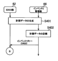
まず、E2EO部62及びインベントリ管理部66が、購入要求に関連付けられている購入サービス要件データ、サービスカタログデータ、インベントリテンプレートデータ、及び、インベントリデータに基づいて、計画データを生成する(S401)。S401で実行される処理には、例えば、機能ユニット群がデプロイされるリソースプール、及び、必要なリソースを特定する処理が含まれる。First, the
そして、インベントリ管理部66は、生成された計画データをインベントリデータベース82に記憶させる(S402)。Then, the
そして、インベントリ管理部66は、生成された計画データに含まれるインベントリキーをE2EO部62に出力する(S403)。Then, the
すると、E2EO部62は、受け付けたインベントリキーをCMaaS部68に出力する(S404)。Then, the
すると、CMaaS部68は、受け付けたインベントリキーを含む計画データをインベントリデータベース82から取得する(S405)。Then, the
そして、CMaaS部68は、S405に示す処理で取得された計画データに基づいて、day1パラメータを含む計画CMデータを生成して、保持する(S406)。Then, the
そして、CMaaS部68は、必要なハードウェアリソースの確保などのセットアップの指示をBMaaS部84に出力して(S407)、BMaaS部84が、当該指示に応じたハードウェアリソースの確保などのセットアップを実行する(S408)。この際に、特定種類の機能ユニットに応じたシステムソフトウェアのセットアップや、リソースプールへの空きサーバの追加が、必要に応じて実行される。Then, the
なお、本実施形態において、リソースプールへの空きサーバの追加は余裕(バッファ)をもって行われるようにしてもよい。例えば、複数台のサーバ90がまとめてリソースプールに追加されてもよい。In this embodiment, the addition of free servers to the resource pool may be performed with a buffer. For example, a plurality of
そして、BMaaS部84が、終了通知をCMaaS部68に出力すると(S409)、CMaaS部68は、リソースプール管理データを更新する(S410)。ここでは例えば、ハードウェアリソースが確保されたリソースプールの残りコア数データの値が減算されてもよい。また、空きサーバ数や総コア数データの値が更新されてもよい。なお、S410に示す処理において、CMaaS部68ではなく、BMaaS部84がリソースプール管理データを更新してもよい。また、CMaaS部68からの指示に従って、インベントリ管理部66がリソースプール管理データを更新してもよい。Then, when the
そして、CMaaS部68は、終了通知をE2EO部62に出力する(S411)。Then, the
すると、E2EO部62は、S403に示す処理で受け付けたインベントリキーをサービスマネージャ部70に出力する(S412)。Then, the
すると、サービスマネージャ部70は、受け付けたインベントリキーを含む計画データをインベントリデータベース82から取得する(S413)。The
そして、サービスマネージャ部70は、S418に示す処理で取得された計画データに基づいて、機能ユニット群がデプロイされるロケーションを特定する(S414)。Then, the
そして、サービスマネージャ部70は、S414に示す処理で特定されたロケーション毎のday0パラメータ(CNFインスタンス)を生成する(S415)。Then, the
そして、サービスマネージャ部70は、S414に示す処理で特定されたそれぞれのロケーションに対応するコンテナ管理部78に、当該コンテナ管理部78に対応するday0パラメータを出力する(S416)。Then, the
そして、コンテナ管理部78は、受け付けたday0パラメータに基づいて、コンテナのデプロイを実行する(S417)。Then, the
そして、コンテナ管理部78は、終了通知をサービスマネージャ部70に出力する(S418)。Then, the
すると、サービスマネージャ部70は、終了通知をE2EO部62に出力する(S419)。Then, the
そして、E2EO部62は、day1パラメータに基づく構成管理指示をCMaaS部68に出力する(S420)。Then, the
すると、CMaaS部68は、保持している計画CMデータに含まれるday1パラメータに基づく、コンテナ群の構成管理を実行する(S421)。Then, the
そして、CMaaS部68は、終了通知をE2EO部62に出力する(S422)。Then, the
すると、E2EO部62は、S403に示す処理で受け付けたインベントリキーをスライスマネージャ部72に出力する(S423)。Then, the
すると、スライスマネージャ部72は、受け付けたインベントリキーを含む計画データをインベントリデータベース82から取得する(S424)。The
そして、スライスマネージャ部72は、S429に示す処理で取得された計画データに基づいて、ネットワークスライスのインスタンス化を実行する(S425)。S425に示す処理では、例えば上述のように、スライスマネージャ部72が、ネットワークスライスのインスタンス化に関係する構成管理指示をCMaaS部68に出力してもよい。そして、CMaaS部68が、当該構成管理指示に従った設定等の構成管理を実行してもよい。Then, the
また、上述のように、S420~S422に示す処理が実行されずに、S425に示す処理で、CMaaS部68が、day1パラメータを、スライスマネージャ部72から受け付ける構成管理指示に基づいて更新してもよい。そして、CMaaS部68が、当該構成管理指示に従った設定等の構成管理を実行してもよい。Alternatively, as described above, the processes shown in S420 to S422 may not be executed, and in the process shown in S425, the
そして、スライスマネージャ部72は、終了通知をE2EO部62に出力する(S426)。Then, the
すると、E2EO部62は、S403に示す処理で受け付けたインベントリキーを監視管理部74に出力する(S427)。Then, the
すると、監視管理部74は、受け付けたインベントリキーを含む計画データをインベントリデータベース82から取得する(S428)。The
そして、監視管理部74は、S428に示す処理で取得された計画データに基づいて、購入サービス要件データが示す監視ポリシーに従った監視設定を実行する(S429)。Then, the
そして、監視管理部74は、終了通知をE2EO部62に出力する(S430)。Then, the
すると、E2EO部62は、S403に示す処理で受け付けたインベントリキーをセキュリティ設定部76に出力する(S431)。Then, the
すると、セキュリティ設定部76は、受け付けたインベントリキーを含む計画データをインベントリデータベース82から取得する(S432)。The
そして、セキュリティ設定部76は、S432に示す処理で取得された計画データに基づいて、セキュリティ設定を実行する(S433)。Then, the
そして、セキュリティ設定部76は、終了通知をE2EO部62に出力して(S434)、本処理例に示す処理は終了される。Then, the
なお、本発明は上述の実施形態に限定されるものではない。It should be noted that the present invention is not limited to the above-described embodiment.
例えば、購入者に提供されるネットワークサービスが、コンテナベースの機能ユニットであるCNFではなく、ハイパーバイザ型やホスト型の仮想化技術を用いた、VM(Virtual Machine)ベースの機能ユニットであるVNF(Virtualized Network Function)によって実装されても構わない。ここで、未使用ハードウェアリソース(ここでは例えば空きサーバ)に、特定種類の機能ユニットがデプロイされる場合は、仮想マシン環境の基盤であるホストOSに、当該特定種類の機能ユニットに応じたシステムソフトウェアのセットアップが施されてもよい。For example, a network service provided to a purchaser may be implemented by a VNF (Virtualized Network Function), which is a VM (Virtual Machine)-based functional unit using a hypervisor-type or host-type virtualization technology, instead of a CNF, which is a container-based functional unit. Here, when a specific type of functional unit is deployed in an unused hardware resource (here, for example, a free server), system software corresponding to the specific type of functional unit may be set up in a host OS, which is the foundation of a virtual machine environment.
また、例えば、図8に示されている各機能についての役割分担は、図8に示すものに限定されない。例えば、E2EO部62で実行される処理の一部がインベントリ管理部66で実行されてもよい。また例えば、インベントリ管理部66で実行される処理の一部がE2EO部62で実行されてもよい。Also, for example, the division of roles among the functions shown in Fig. 8 is not limited to that shown in Fig. 8. For example, a part of the processing executed by the
また、本実施形態において、NOS12にリポジトリ部80が含まれていなくてもよい。そして、バンドル展開部60が、ヘルムチャートデータ、及び、コンテナイメージデータをコンテナ管理部78に記憶させてもよい。そして、コンテナ管理部78が、当該コンテナ管理部78に記憶されているコンテナイメージをデプロイしてもよい。In this embodiment, the
また、本実施形態において、NOS12にバンドル展開部60が含まれていなくてもよい。例えば、外部のファイル転送サーバからバンドルファイルがオンボーディングされるようにしてもよい。In this embodiment, the
<実施例>
上記の前提技術を踏まえ、本開示の実施例を説明する。以下、前提技術で説明済みの内容は適宜省略し、前提技術と異なる内容を主に説明する。また、前提技術の構成要素と同一または対応する構成要素には同一の符号を付して説明する。<Example>
Based on the above-mentioned base technology, an embodiment of the present disclosure will be described. Below, the contents already explained in the base technology will be omitted as appropriate, and the contents different from the base technology will be mainly explained. In addition, the same reference numerals will be used to denote components that are the same as or correspond to those in the base technology.
実施例の概要を説明する。ネットワーク機器の管理プロトコル「NETCONF」で使用される、設定項目等の記述言語としてYANG(Yet Another Next Generation)が知られている。ネットワーク機器の設定内容がYANGにより記述されたファイルを以下「YANGモデル」と呼ぶ。YANGモデルは、YANGを用いてネットワーク機器の構造や設定項目、設定値等を抽象化したデータと言える。An overview of the embodiment will be described. YANG (Yet Another Next Generation) is known as a description language for configuration items and the like used in the network device management protocol "NETCONF." A file in which the configuration contents of a network device are described in YANG is hereinafter referred to as a "YANG model." The YANG model can be said to be data that abstracts the structure, configuration items, setting values, and the like of a network device using YANG.
実施例では、ネットワーク機器の設定内容を定めたYangモデルと、ネットワークサービスを購入または利用する顧客(以下「ユーザ」とも呼ぶ。)により入力されたデータとをもとに、ネットワーク機器を設定するためのユーザインタフェースを生成して、ユーザに提供する。このユーザインタフェースは、例えば、新規設定用の画面と設定変更用の画面を含む。これにより、ネットワーク機器に対する最新の設定内容(設定項目や設定値等)に整合する設定用の画面を効率よく生成して、ユーザに提供できる。In the embodiment, a user interface for configuring a network device is generated based on a Yang model that defines the configuration contents of the network device and data input by a customer (hereinafter also referred to as a "user") who purchases or uses a network service, and is provided to the user. This user interface includes, for example, a screen for new configuration and a screen for changing settings. This makes it possible to efficiently generate a configuration screen that matches the latest configuration contents (setting items, setting values, etc.) for the network device and provide it to the user.
図23は、YANGモデルのデータの例を示す。同図のYANGモデル100は、ネットワーク機器に対する設定項目として、最大送信電力(項目102)と、ダウンリンク用ベースステーションの帯域幅(項目104)を含む。各設定項目では、設定値の型・単位・範囲、設定が必須であることを示す必須オプション、デフォルトの設定値、選択可能な設定値の候補等が指定され得る。デフォルトの設定値は、デフォルトステートメントとも言え、例えば、推奨値であってもよい。Fig. 23 shows an example of data of the YANG model. The
実施例の詳細を説明する。図24は、実施例の通信プラットフォーム110の構成を示す。実施例の通信プラットフォーム110は、移動体通信事業者が提供する通信インフラ上にネットワークサービスを構築し、また、移動体通信事業者が提供する通信インフラ上に構築されたネットワークサービスを管理する情報処理システム(言い換えればコンピュータシステム)である。通信プラットフォーム110は、ネットワークサービス管理システムとも言える。Details of the embodiment will be described. Fig. 24 shows the configuration of a
通信プラットフォーム110の物理的な構成に制約はない。例えば、通信プラットフォーム110の機能は、1台の装置により実現されてもよい。または、通信プラットフォーム110の機能は、複数台の装置に分散配置され、これら複数台の装置が連携することにより実現されてもよい。通信プラットフォーム110は、LAN・WAN・インターネット等の通信網を介して、ユーザ端末120およびベンダ端末16と接続される。ユーザ端末120は、前提技術の購入者端末14に対応するものであり、ネットワークサービスの利用者(例えばMVNO)により操作される情報処理装置である。There are no restrictions on the physical configuration of the
図24は、通信プラットフォーム110の機能ブロックを示すブロック図を含む。本明細書のブロック図で示す各ブロックは、ハードウェア的には、コンピュータのプロセッサ、CPU、メモリをはじめとする素子や電子回路、機械装置で実現でき、ソフトウェア的にはコンピュータプログラム等によって実現されるが、ここでは、それらの連携によって実現される機能ブロックを描いている。したがって、これらの機能ブロックはハードウェア、ソフトウェアの組合せによっていろいろなかたちで実現できることは、当業者には理解されるところである。24 includes a block diagram showing the functional blocks of the
通信プラットフォーム110は、フロントエンドシステム112、ネットワークオペレーティングシステム(NOS12)、サーバ90を備える。フロントエンドシステム112は、ウェブページ等のユーザインタフェースをユーザ端末120へ提供し、ネットワークサービスに関するユーザの要求を受け付ける情報処理システムである。フロントエンドシステム112は、前提技術のマーケットプレイスシステム(MPS10)が備える機能のうち少なくとも一部の機能を備えてもよい。The
サーバ90は、各種ネットワーク機器の機能(例えば図1のコアネットワークシステム20や基地局装置22の機能)を提供するコンテナベースの機能ユニットであるCNFインスタンス(CNF116)がデプロイされる情報処理装置である。前提技術で説明したように、NOS12のCMaaS部68は、ネットワーク機器の機能を規定する値(以下「設定値」とも呼ぶ。)をday1パラメータとしてCNF116に設定する。なお、実際の通信プラットフォーム110は、複数のサーバ90を備える。The
NOS12は、マーケットプレイスシステム(MPS10)、E2EO部62、インベントリ管理部66、CMaaS部68、サービスマネージャ部70を備える。インベントリ管理部66は、前提技術のインベントリデータベース82を含み、複数のサーバ90についてのインベントリ情報を管理する。The
ネットワークサービスの新規構築、言い換えれば、ネットワーク機器の新規設定に関する構成を説明する。CMaaS部68は、記憶部として、ユーザが購入可能なネットワークサービスと関連付けて、当該ネットワークサービスを実現するためのネットワーク機器の設定内容を定めたファイルを記憶する。このファイルは、ネットワーク機器の設定内容が所定のデータモデル言語で記述されたファイルであり、実施例では、ネットワーク機器の設定内容がYANG(Yet Another Next Generation)により記述されたYANGモデルを含む。A configuration relating to the new construction of a network service, in other words, the new setting of a network device, will be described. The
フロントエンドシステム112は、受付部として、ネットワークサービスを購入しようとするユーザにより指定されたネットワークサービスの構成を受け付ける。CMaaS部68とフロントエンドシステム112は、設定画面提供部として、上記ファイルに定められた内容と、ユーザにより指定されたネットワークサービスの構成とに基づくネットワーク機器の設定画面をユーザ端末120に提供する。CMaaS部68は、機器設定部として、設定画面にユーザが入力したネットワーク機器の設定値に基づいて、ネットワーク機器に設定を投入する。The front-
ネットワークサービスの設定変更、言い換えれば、ネットワーク機器の設定変更に関する構成を説明する。CMaaS部68は、第1記憶部として、ユーザが購入可能なネットワークサービスと関連付けて、当該ネットワークサービスを実現するためのネットワーク機器の設定内容を定めたファイル(実施例ではYANGモデルを含むファイル)を記憶する。また、CMaaS部68は、第2記憶部として、ネットワーク機器の現在の設定値を記憶する。The configuration for changing the settings of a network service, in other words, changing the settings of a network device, will be described. The
フロントエンドシステム112は、受付部として、ネットワークサービスの設定変更要求をユーザ端末120から受け付ける。CMaaS部68とフロントエンドシステム112は、設定変更画面提供部として、上記ファイルに定められた内容と、ネットワーク機器の現在の設定値とに基づくネットワーク機器の設定変更画面をユーザ端末120に提供する。CMaaS部68は、機器設定部として、設定変更画面にユーザが入力したネットワーク機器の設定値に基づいて、ネットワーク機器の設定を変更する。The front-
以上の構成による実施例の通信プラットフォーム110の動作を説明する。図25は、通信プラットフォーム110の動作を示すシーケンス図である。同図は、ネットワークサービスの新規構築、言い換えれば、ネットワーク機器の新規設定に関する動作を示している。The operation of the
ベンダ端末16は、ベンダの担当者の操作に応じて、バンドルデータをNOS12(E2EO部62)にアップロードする(S500)。E2EO部62(バンドル展開部60)は、バンドルデータをもとに生成された機器設定テンプレート(前提技術のCMテンプレートデータ)をCMaaS部68へ送信する(S502)。The
機器設定テンプレートは、ネットワークサービスのIDと、当該ネットワークサービスを実現するためのネットワーク機器の設定内容を定めた1つ以上のYANGモデルとを含む。CMaaS部68は、機器設定テンプレートを受け付けると、機器設定テンプレートが示すネットワークサービスIDと、1つ以上のYANGモデルとを対応付けたサービスデータを記憶する。図26は、CMaaS部68に記憶されるサービスデータを模式的に示す。同図は、ネットワークサービスIDとYANGモデルとの対応関係を示している。ネットワークサービスIDとYANGモデルとの対応関係は、1対N(Nは1以上の整数)である。The device setting template includes a network service ID and one or more YANG models that define the setting contents of the network device to realize the network service. When the
図25に戻り、E2EO部62(バンドル展開部60)は、バンドルデータをもとに生成されたプロダクトカタログデータをフロントエンドシステム112へ送信する(S504)。フロントエンドシステム112は、ユーザ端末120からの要求に応じて、ユーザが選択可能(言い換えれば購入可能)なネットワークサービスを示す購入画面(例えば図2の購入画面や、図3のサービス要件入力画面)をユーザ端末120に表示させる(S506)。25, the E2EO unit 62 (bundle expansion unit 60) transmits product catalog data generated based on the bundle data to the front-end system 112 (S504). In response to a request from the
図2および図3に関連して既述したように、ユーザは、ネットワークサービスを選択して、購入するネットワークサービスの種類やサービス要件を含む購入情報を購入画面に入力する。ユーザ端末120は、購入画面に入力された購入情報をフロントエンドシステム112へ送信する(S508)。購入情報は、購入対象のネットワークサービスのIDを含む。また、購入情報は、購入対象のネットワークサービスの構成に関する情報を含み、例えば、購入対象のネットワークサービスの規模に関する情報を含む。ネットワークサービスの規模に関する情報は、例えば、図3の加入者数や対象地域等を含んでもよい。また、購入情報は、購入対象のネットワークサービスの種類に関する情報を含む。ネットワークサービスの種類に関する情報は、例えば、図2の音声通信サービス、データ通信サービス、IoTサービスのいずれかを含んでもよい。As described above with reference to Figures 2 and 3, the user selects a network service and inputs purchase information including the type of network service to be purchased and service requirements into the purchase screen. The
フロントエンドシステム112は、ユーザ端末120から受信した購入情報(ネットワークサービスの規模、種類を含む)をE2EO部62へ送信する(S510)。それとともに、フロントエンドシステム112は、「処理中」を示すテキストデータや画像データをユーザ端末120へ送信し、ユーザ端末120に「処理中」を表示させる(S512)。The front-
前提技術にて既述したように、E2EO部62は、バンドルデータ(サービスカタログデータ)で指定されたワークフローにしたがって、ネットワーク構築処理を進める。ネットワーク構築処理において、E2EO部62は、計画データの作成指示(購入情報を含む)をインベントリ管理部66へ送信する(S514)。インベントリ管理部66は、購入情報に基づいて計画データを作成し、作成した計画データをE2EO部62へ送信する(S516)。E2EO部62は、計画データをCMaaS部68へ送信する(S518)。変形例として、インベントリ管理部66は、作成した計画データを自らCMaaS部68へ送信してもよい。CMaaS部68は、計画データが示すネットワークサービスに対応する1つ以上のYANGモデルのデータをE2EO部62へ送信する(S520)。As described in the prerequisite technology, the
前提技術において一部記載したように、計画データは、ユーザにより指定された規模や種類のネットワークサービスを実現するためのリソースの情報を含み、例えば、設定すべきネットワーク機器の個数や種類を示す情報を含む。実施例の通信プラットフォーム110は、計画データが、複数台のネットワーク機器Aを設定すべきことを示す場合、ネットワーク機器Aに対応するYANGモデルを用いて、設定すべきネットワーク機器Aの個数分だけユーザ用の画面(設定画面および設定変更画面)を生成する。また、実施例の通信プラットフォーム110は、計画データが、複数種類のネットワーク機器(ネットワーク機器A、ネットワーク機器B)を設定すべきことを示す場合、ネットワーク機器Aに対応するYANGモデルを用いて、ネットワーク機器A用の設定画面または設定変更画面を生成する。それとともに、ネットワーク機器Bに対応するYANGモデルを用いて、ネットワーク機器B用の設定画面または設定変更画面を生成する。As described in part in the base technology, the planning data includes information on resources for realizing a network service of a scale and type designated by a user, and includes, for example, information indicating the number and type of network devices to be configured. When the planning data indicates that multiple network devices A should be configured, the
例えば、計画データが3台のネットワーク機器A(ネットワーク機器A-1、A-2、A-3)を設定すべきことを示す場合、CMaaS部68は、ネットワーク機器A-1に対応するYANGモデルとしてネットワーク機器A用のYANGモデルをE2EO部62へ送信し、ネットワーク機器A-2に対応するYANGモデルとして同じネットワーク機器A用のYANGモデルをE2EO部62へ送信し、ネットワーク機器A-3に対応するYANGモデルとして同じネットワーク機器A用のYANGモデルをE2EO部62へ送信する。既述したように、各YANGモデルのデータには、ネットワーク機器に対するデフォルトの設定値が含まれうる。E2EO部62は、CMaaS部68から受け付けた1つ以上のYANGモデルのデータをフロントエンドシステム112へ送信する(S522)。For example, when the planning data indicates that three network devices A (network devices A-1, A-2, A-3) should be configured, the
フロントエンドシステム112は、YANGモデルの内容を解析するパーサーを含む。フロントエンドシステム112は、パーサーによる解析結果に基づいて、購入されたネットワークサービスを実現するためのネットワーク機器の設定画面のデータを生成する(S524)。例えば、フロントエンドシステム112は、YANGモデルで定められた複数の設定項目について、各設定項目の型や単位等に予め対応付けられた画面要素を配置することにより設定画面のデータを生成してもよい。ネットワーク機器に対するデフォルトの設定値がYANGモデルに含まれる場合、フロントエンドシステム112は、そのデフォルトの設定値を含む設定画面のデータを生成する。The front-
また、フロントエンドシステム112は、購入されるネットワークサービスの規模や種類に応じた内容の設定画面を生成する。例えば、フロントエンドシステム112が、CMaaS部68から、計画データに基づく4つのYANGモデル(例えば、ネットワーク機器A-1に対応するYANGモデル、ネットワーク機器A-2に対応するYANGモデル、ネットワーク機器A-3に対応するYANGモデル、ネットワーク機器Bに対応するYANGモデル)を受け付けたとする。この場合、フロントエンドシステム112は、これら4つのYANGモデルに基づいて、4つのネットワーク機器(A-1、A-2、A-3、B)に対応する4つの設定値入力エリアを含む設定画面を生成してもよい。第1の設定値入力エリアは、ネットワーク機器A-1への設定値が入力されるものであり、第2の設定値入力エリアは、ネットワーク機器A-2への設定値が入力されるものであり、第3の設定値入力エリアは、ネットワーク機器A-3への設定値が入力されるものであり、第4の設定値入力エリアは、ネットワーク機器Bへの設定値が入力されるものであってもよい。The front-
このように、実施例の通信プラットフォーム110は、ユーザが購入画面で指定したネットワークサービスの規模や種類に応じた内容の設定画面をユーザに提供する。これにより、ユーザが指定した規模および種類のネットワークサービスを実現するための複数のネットワーク機器を漏れなくかつ効率的に設定することができる。In this way, the
フロントエンドシステム112は、生成した設定画面のデータをユーザ端末120へ送信して、設定画面をユーザ端末120に表示させる(S526)。設定画面のデータは、HTMLデータであってもよく、ユーザ端末120のウェブブラウザは、フロントエンドシステム112から提供されたHTMLデータをもとに、設定画面を所定の表示装置に表示させてもよい。The front-
図27は、設定画面の例を示す。設定画面122は、設定対象の複数のネットワーク機器(例えばeNodeB「AAA」、eNodeB「BBB」)に対する2つの設定項目を含む。1つ目の設定項目は、最大送信電力(MaxTxPower)であり、2つ目の設定項目は、アンテナチルト角(Antenna tilt)である。最大送信電力の設定値入力エリアには、YANGモデルに設定されたデフォルト値「200」が予め設定されている。図27には不図示だが、図23の項目104で示したように、YANGモデルにおいて設定値の複数の候補が定められている場合、設定画面122には、それら複数の候補の中から特定の設定値を選択可能なプルダウンメニューが配置されてもよい。FIG. 27 shows an example of a setting screen. The
図25に戻り、ユーザ端末120は、設定画面にユーザが入力した設定値(以下「ユーザ設定値」とも呼ぶ。)をフロントエンドシステム112へ送信する(S528)。フロントエンドシステム112は、ユーザ設定値をCMaaS部68へ送信する(S530)。ユーザ設定値は、前提技術におけるday1パラメータに対応する。25, the
前提技術で既述したように、E2EO部62は、計画データをサービスマネージャ部70へ送信し、サービスマネージャ部70は、その計画データにしたがって、ネットワーク機器(例えばeNodeB)の機能を提供するCNF116をサーバ90にデプロイする。サービスマネージャ部70は、デプロイしたCNF116のID(すなわちネットワーク機器のID)をインベントリ管理部66へ通知する。S518で、E2EO部62からCMaaS部68へ送信される計画データには、上記CNF116のID(すなわち設定対象となるネットワーク機器のID)が含まれる。CMaaS部68は、フロントエンドシステム112から送信されたユーザ設定値を受け付けると、公知のNETCONFにしたがって、計画データで指定されたサーバ90のCNF116(すなわち設定対象のネットワーク機器)にユーザ設定値を投入する(S532)。As described in the prerequisite technology, the
CMaaS部68は、ユーザ設定値を受け付けると、購入者であるユーザのID、購入対象のネットワークサービスのIDと、当該ネットワークサービスに対応するYANGモデルのID、YANGモデルを用いて設定されるネットワーク機器(CNF116)のID、ユーザ設定値とを対応付けたユーザデータを記憶する。図28は、CMaaS部68に記憶されるユーザデータを模式的に示す。ユーザIDとネットワークサービスIDとの対応関係は、1対N(Nは1以上の整数)である。ネットワークサービスIDとYANGモデルとの対応関係は、1対Nである。YANGモデルとネットワーク機器IDとの対応関係は、1対Nである。ネットワーク機器IDとユーザ設定値との対応関係は、1対Nである。ユーザ設定値の活用に係る処理については図29に関連して後述する。When the
実施例の通信プラットフォーム110は、ベンダからアップロードされたバンドルファイルに含まれるYANGモデルを用いてネットワーク機器の設定画面を生成し、その設定画面に入力された設定値をネットワーク機器(実施例ではCNF116)に設定する。機器設定用のYANGモデルには、ユーザ用の画面を生成するために必要な情報が含まれており、YANGモデルよりネットワーク機器の設定画面を生成すれば、設定画面生成のためのみの情報を別途保持する必要はなく、必要な情報量を少なくすることができる。The
また、バンドルファイルを提供するベンダがネットワーク機器の構成をバージョンアップする場合には、そのネットワーク機器に対応するYANGモデルも更新されることになる。YANGモデルとは別に設定画面用の情報を保持する構成では、YANGモデルと設定画面用の情報の両方を更新する必要があるが、実施例の通信プラットフォーム110では、YANGモデルから設定画面を生成するため、設定画面用の情報を別途更新する必要はなく、YANGモデルのみ更新すればよい。これにより、バージョンアップされたネットワーク機器に必要なパラメータの設定画面を簡便に、また、必要なパラメータの漏れがないよう生成することが可能になる。In addition, when a vendor providing a bundle file upgrades the configuration of a network device, the YANG model corresponding to the network device is also updated. In a configuration in which information for a setting screen is stored separately from the YANG model, it is necessary to update both the YANG model and the information for the setting screen. However, in the
また、実施例の通信プラットフォーム110は、YANGモデルに設定されたデフォルトの設定値(例えば推奨値)を含む設定画面をユーザに提供する。これにより、ユーザによる設定値の決定と入力を支援することができる。In addition, the
図29は、通信プラットフォーム110の動作を示すシーケンス図である。同図は、ネットワークサービスの設定変更に関する動作を示している。具体的には、同図は、CMaaS部68に記憶されたユーザ設定値の活用と、ネットワーク機器の設定変更に関する動作を示している。29 is a sequence diagram showing the operation of the
ユーザ端末120は、設定変更画面をフロントエンドシステム112に要求する(S540)。フロントエンドシステム112は、現在の設定情報をCMaaS部68に要求する(S542)。S540とS542における要求は、ユーザIDと、変更対象のネットワークサービスIDとを含むこととする。CMaaS部68は、予め記憶するユーザデータを参照して、設定情報要求に含まれるユーザIDとネットワークサービスIDとに対応付けられたYANGモデルおよびユーザ設定値(すなわち現在の設定値)を読み出す。CMaaS部68は、読み出したYANGモデルおよびユーザ設定値を現在の設定情報としてフロントエンドシステム112へ送信する(S544)。The
フロントエンドシステム112は、CMaaS部68から送信されたYANGモデルおよびユーザ設定値とに基づいて、設定変更画面のデータを生成する(S546)。具体的には、フロントエンドシステム112は、ネットワーク機器に対するユーザ設定値(すなわち現在の設定値)を含む設定変更画面のデータを生成する。フロントエンドシステム112は、生成した設定変更画面のデータをユーザ端末120へ送信して、設定変更画面をユーザ端末120に表示させる(S548)。例えば、設定変更画面は、図27で示した設定画面122の最大送信電力の設定値入力エリアとアンテナチルト角の設定値入力エリアのそれぞれに、現在の設定値が埋め込まれたものであってもよい。The front-
ユーザ端末120は、ユーザが設定変更画面に入力したユーザ設定値(変更された設定値を含む)をフロントエンドシステム112へ送信する(S550)。フロントエンドシステム112は、ユーザ設定値をE2EO部62へ送信する(S552)。E2EO部62は、予め定められた設定変更用のワークフローにしたがって、ユーザ設定値をCMaaS部68へ送信する(S554)。CMaaS部68は、フロントエンドシステム112から送信されたユーザ設定値を受け付けると、公知のNETCONFにしたがって、サーバ90のCNF116にユーザ設定値を投入する(S556)。すなわち、CMaaS部68は、ユーザが設定変更画面に入力した変更内容を、サーバ90のCNF116に反映する。それとともに、CMaaS部68は、フロントエンドシステム112から送信されたユーザ設定値により予め記憶している既存のユーザ設定値を更新する。The
実施例の通信プラットフォーム110は、ベンダからアップロードされたバンドルデータに含まれるYANGモデルと、ネットワーク機器の現在の設定値を用いて設定変更画面を生成し、ユーザに提供する。これにより、ネットワーク機器に対する最新の設定内容(設定値等)に整合する設定変更画面を効率よく生成でき、また、ユーザによる設定変更作業を支援することができる。The
以上、本発明を実施例をもとに説明した。この実施例は例示であり、各構成要素あるいは各処理プロセスの組合せにいろいろな変形例が可能なこと、またそうした変形例も本発明の範囲にあることは当業者に理解されるところである。The present invention has been described above based on the embodiments. These embodiments are merely illustrative, and it will be understood by those skilled in the art that various modifications are possible in the combination of each component or each treatment process, and that such modifications are also within the scope of the present invention.
上記実施例では言及していないが、フロントエンドシステム112は、YANGモデルに規定されたデフォルトの設定値より、ネットワーク機器の現在の設定値を優先して設定変更画面の設定値入力エリアに設定してもよい。また、フロントエンドシステム112は、ネットワーク機器の一部の設定項目の設定値が未設定であり、かつ、YANGモデルにおいて当該一部の設定項目に対するデフォルトの設定値が規定されている場合、YANGモデルに規定されたデフォルトの設定値を設定変更画面の設定値入力エリアに設定してもよい。Although not mentioned in the above embodiment, the front-
上記実施例では言及していないが、フロントエンドシステム112は、ネットワークサービスの規模をユーザが変更するための画面要素を設定変更画面に配置してもよい。ネットワークサービスの規模の変更は、ここでは規模の拡大とするが、規模の縮小でもよい。ネットワークサービスの規模の変更内容は、フロントエンドシステム112からCMaaS部68へ通知されてもよく、CMaaS部68は、ネットワークサービスの規模の変更内容と、記憶部に記憶する現在のネットワークサービスの規模(例えば設定済のネットワーク機器の個数)とに応じて、新たに設定すべきネットワーク機器の個数を導出してもよい。Although not mentioned in the above embodiment, the front-
または、ネットワークサービスの規模の変更内容は、フロントエンドシステム112からE2EO部62(インベントリ管理部66)へ通知されてもよく、E2EO部62(インベントリ管理部66)は、ネットワークサービスの規模の変更内容に応じて新たな計画データ(例えば変更後の規模に応じたネットワーク機器の個数)を生成し、CMaaS部68へ送信してもよい。CMaaS部68は、新たな計画データと、記憶部に記憶する現在のネットワークサービスの規模(例えば設定済のネットワーク機器の個数)とに応じて、新たに設定すべきネットワーク機器の個数を導出してもよい。Alternatively, the change in the scale of the network service may be notified from the front-
新たに設定すべき1つ以上のネットワーク機器に対応する1つ以上のYANGモデルは、図25のS520、S522で示したように、CMaaS部68からE2EO部62へ送信され、E2EO部62からフロントエンドシステム112へ送信されてもよい。フロントエンドシステム112は、新たに設定すべき1つ以上のネットワーク機器に対応する1つ以上のYANGモデルをもとに、それらのネットワーク機器に対する設定値を入力するための設定画面を生成し、設定画面をユーザ端末120に表示させてもよい。以降、図25のS528、S530、S532と同様に、設定画面に入力された設定値が、新たに設定すべき各ネットワーク機器に投入されてもよい。One or more YANG models corresponding to one or more network devices to be newly configured may be transmitted from the
上述した前提技術、実施例および変形例の任意の組み合わせもまた本開示の実施の形態として有用である。組み合わせによって生じる新たな実施の形態は、組み合わされる構成要素それぞれの効果をあわせもつ。また、請求項に記載の各構成要件が果たすべき機能は、前提技術、実施例および変形例において示された各構成要素の単体もしくはそれらの連携によって実現されることも当業者には理解されるところである。Any combination of the above-mentioned base technology, examples, and modifications is also useful as an embodiment of the present disclosure. A new embodiment resulting from the combination has the effects of each of the combined components. In addition, it is understood by those skilled in the art that the functions to be performed by each component described in the claims can be realized by each component shown in the base technology, examples, and modifications alone or in cooperation with each other.
本開示の技術は、ネットワークサービスを管理するシステムに適用することができる。The technology of the present disclosure can be applied to a system for managing network services.
12 NOS、 68 CMaaS部、 90 サーバ、 100 YANGモデル、 110 通信プラットフォーム、 112 フロントエンドシステム、 116 CNF、 120 ユーザ端末、 122 設定画面。12 NOS, 68 CMaaS section, 90 Server, 100 YANG model, 110 Communication platform, 112 Front-end system, 116 CNF, 120 User terminal, 122 Setting screen.
Claims (11)
前記ネットワークサービスに関する前記顧客の要求を受け付ける受付部と、
前記ファイルに定められた内容に基づく前記ネットワーク機器の設定画面を前記顧客の端末に提供する設定画面提供部と、
前記設定画面に前記顧客が入力した前記ネットワーク機器の設定値に基づいて、前記ネットワーク機器に設定を投入する機器設定部と、
を備え、
前記受付部は、前記要求として、前記ネットワークサービスを購入しようとする顧客により指定された前記ネットワークサービスの構成を受け付け、
前記設定画面提供部は、前記ファイルに定められた内容と、前記顧客により指定された前記ネットワークサービスの構成とに基づく前記ネットワーク機器の設定画面を前記顧客の端末に提供する、
ネットワークサービス管理システム。 a storage unit for storing a file that defines the settings of a network device for implementing a network service that can be purchased by a customer, in association with the network service;
a reception unit for receiving a request from the customer regarding the network service;
a setting screen providing unit that provides a setting screen for the network device to the customer's terminal based on the contents defined in the file;
a device setting unit that inputs settings to the network device based on the setting values of the network device input by the customer on the setting screen;
Equipped with
the reception unit receives, as the request, a configuration of the network service designated by a customer who is about to purchase the network service;
the setting screen providing unit provides, to the customer's terminal, a setting screen of the network device based on the contents defined in the file and the configuration of the network service designated by the customer.
Network Service Management System.
前記設定画面提供部は、前記ネットワーク機器に対するデフォルトの設定値を含む設定画面を前記顧客の端末に提供する、
請求項1に記載のネットワークサービス管理システム。 the file includes default settings for the network device;
the setting screen providing unit provides a setting screen including default setting values for the network device to the customer's terminal;
2. The network service management system according to claim 1 .
前記ネットワークサービスに関する前記顧客の要求を受け付ける受付部と、
前記ファイルに定められた内容に基づく前記ネットワーク機器の設定画面を前記顧客の端末に提供する設定画面提供部と、
前記設定画面に前記顧客が入力した前記ネットワーク機器の設定値に基づいて、前記ネットワーク機器に設定を投入する機器設定部と、
を備え、
前記受付部は、前記要求として、前記ネットワークサービスの規模に関する情報を受け付け、
前記設定画面提供部は、前記ネットワークサービスの規模に応じた内容の設定画面を前記顧客の端末に提供する、
ネットワークサービス管理システム。 a storage unit for storing a file that defines the settings of a network device for implementing a network service that can be purchased by a customer, in association with the network service;
a reception unit for receiving a request from the customer regarding the network service;
a setting screen providing unit that provides a setting screen for the network device to the client terminal based on the contents defined in the file;
a device setting unit that inputs settings to the network device based on the setting values of the network device input by the customer on the setting screen;
Equipped with
the receiving unit receives, as the request, information regarding a scale of the network service;
the setting screen providing unit provides a setting screen having contents corresponding to the scale of the network service to the customer's terminal;
Network Service Management System.
前記設定画面提供部は、前記設定すべきネットワーク機器の個数に対応する個数の前記ファイルに基づいて生成された設定画面を前記顧客の端末に提供する、
請求項3に記載のネットワークサービス管理システム。 the information on the scale of the network service includes information indicating the number of network devices to be configured;
the setting screen providing unit provides the setting screen generated based on the files, the number of which corresponds to the number of the network devices to be configured, to the customer's terminal.
4. The network service management system according to claim 3 .
請求項4に記載のネットワークサービス管理システム。 the setting screen includes a plurality of setting value input areas corresponding to a plurality of network devices based on a plurality of the files;
5. The network service management system according to claim 4 .
前記受付部は、前記要求として、前記ネットワークサービスの設定変更要求を前記顧客の端末から受け付け、
前記設定画面提供部は、前記設定画面として、前記ファイルに定められた内容と、前記ネットワーク機器の現在の設定値とに基づく前記ネットワーク機器の設定変更画面を前記顧客の端末に提供し、
前記機器設定部は、前記設定変更画面に顧客が入力した前記ネットワーク機器の設定値に基づいて、前記ネットワーク機器の設定を変更する、
請求項1から5のいずれかに記載のネットワークサービス管理システム。 The storage unit further stores a current setting value of the network device;
the reception unit receives, as the request, a request for changing settings of the network service from the customer's terminal;
the setting screen providing unit provides, as the setting screen, a setting change screen for the network device based on the contents defined in the file and the current setting values of the network device to the customer's terminal;
the device setting unit changes settings of the network device based on setting values of the network device input by the customer on the setting change screen;
6. The network service management system according to claim 1.
請求項6に記載のネットワークサービス管理システム。 the setting screen providing unit provides a setting change screen including current setting values of the network device to the customer's terminal;
The network service management system according to claim 6 .
請求項1から7のいずれかに記載のネットワークサービス管理システム。 The file is a file in which the configuration contents of the network device are described in a predetermined data model language.
8. The network service management system according to claim 1.
請求項1から8のいずれかに記載のネットワークサービス管理システム。 The file includes a YANG model in which the configuration contents of the network device are described in YANG (Yet Another Next Generation),
9. The network service management system according to claim 1.
前記ネットワークサービスに関する前記顧客の要求を受け付けるステップと、
前記ファイルに定められた内容に基づく前記ネットワーク機器の設定画面を前記顧客の端末に提供するステップと、
前記設定画面に前記顧客が入力した前記ネットワーク機器の設定値に基づいて、前記ネットワーク機器に設定を投入するステップと、
を実行し、
前記受け付けるステップは、前記要求として、前記ネットワークサービスを購入しようとする顧客により指定された前記ネットワークサービスの構成を受け付け、
前記提供するステップは、前記ファイルに定められた内容と、前記顧客により指定された前記ネットワークサービスの構成とに基づく前記ネットワーク機器の設定画面を前記顧客の端末に提供する、
ネットワークサービス管理方法。 a computer having a storage unit for storing a file that defines configuration contents of a network device for realizing a network service that can be purchased by a customer, the file being associated with the network service,
accepting a request from the customer for the network service;
providing a setting screen for the network device based on the contents defined in the file to the customer's terminal;
inputting settings into the network device based on the setting values of the network device input by the customer on the setting screen;
Run
The receiving step includes receiving, as the request, a configuration of the network service specified by a customer who is to purchase the network service;
The providing step provides, to the customer's terminal, a setting screen of the network device based on the contents defined in the file and the configuration of the network service designated by the customer.
A network service management methodology.
前記ネットワークサービスに関する前記顧客の要求を受け付けるステップと、
前記ファイルに定められた内容に基づく前記ネットワーク機器の設定画面を前記顧客の端末に提供するステップと、
前記設定画面に前記顧客が入力した前記ネットワーク機器の設定値に基づいて、前記ネットワーク機器に設定を投入するステップと、
を実行し、
前記受け付けるステップは、前記要求として、前記ネットワークサービスの規模に関する情報を受け付け、
前記提供するステップは、前記ネットワークサービスの規模に応じた内容の設定画面を前記顧客の端末に提供する、
ネットワークサービス管理方法。 a computer having a storage unit for storing a file that defines configuration contents of a network device for realizing a network service that can be purchased by a customer, the file being associated with the network service,
accepting a request from the customer for the network service;
providing a setting screen for the network device based on the contents defined in the file to the customer's terminal;
inputting settings into the network device based on the setting values of the network device input by the customer on the setting screen;
Run
The receiving step receives, as the request, information regarding a scale of the network service;
The providing step provides a setting screen having contents corresponding to the scale of the network service to the customer's terminal.
A network service management method.
Applications Claiming Priority (1)
| Application Number | Priority Date | Filing Date | Title |
|---|---|---|---|
| PCT/IB2021/050887 WO2022167837A1 (en) | 2021-02-04 | 2021-02-04 | Network service management system and network service management method |
Publications (2)
| Publication Number | Publication Date |
|---|---|
| JPWO2022167837A1 JPWO2022167837A1 (en) | 2022-08-11 |
| JP7477657B2 true JP7477657B2 (en) | 2024-05-01 |
Family
ID=82742031
Family Applications (1)
| Application Number | Title | Priority Date | Filing Date |
|---|---|---|---|
| JP2022579150A Active JP7477657B2 (en) | 2021-02-04 | 2021-02-04 | NETWORK SERVICE MANAGEMENT SYSTEM AND NETWORK SERVICE MANAGEMENT METHOD |
Country Status (4)
| Country | Link |
|---|---|
| US (1) | US20230396502A1 (en) |
| EP (1) | EP4290388A1 (en) |
| JP (1) | JP7477657B2 (en) |
| WO (1) | WO2022167837A1 (en) |
Citations (4)
| Publication number | Priority date | Publication date | Assignee | Title |
|---|---|---|---|---|
| WO2004071044A1 (en) | 2003-02-06 | 2004-08-19 | Fujitsu Limited | Communication parameters setting method, setting server and setting program |
| JP2010004426A (en) | 2008-06-23 | 2010-01-07 | Hitachi Ltd | Communication system and server device |
| US20190052526A1 (en) | 2016-04-15 | 2019-02-14 | Huawei Technologies Co., Ltd. | Device Configuration Method and Apparatus that are Based on Network Configuration Protocol |
| US20190245743A1 (en) | 2016-04-20 | 2019-08-08 | Juniper Networks, Inc. | Generating network service models |
Family Cites Families (3)
| Publication number | Priority date | Publication date | Assignee | Title |
|---|---|---|---|---|
| US11516881B2 (en) | 2016-08-17 | 2022-11-29 | Ntt Docomo, Inc. | Slice management system and slice management method |
| WO2018181826A1 (en) | 2017-03-30 | 2018-10-04 | 日本電気株式会社 | Recommendation system, method, device and program |
| JP2021010042A (en) | 2017-09-26 | 2021-01-28 | 株式会社Nttドコモ | Management device and network configuration control method |
-
2021
- 2021-02-04 EP EP21924510.7A patent/EP4290388A1/en active Pending
- 2021-02-04 US US18/032,268 patent/US20230396502A1/en active Pending
- 2021-02-04 WO PCT/IB2021/050887 patent/WO2022167837A1/en active Application Filing
- 2021-02-04 JP JP2022579150A patent/JP7477657B2/en active Active
Patent Citations (4)
| Publication number | Priority date | Publication date | Assignee | Title |
|---|---|---|---|---|
| WO2004071044A1 (en) | 2003-02-06 | 2004-08-19 | Fujitsu Limited | Communication parameters setting method, setting server and setting program |
| JP2010004426A (en) | 2008-06-23 | 2010-01-07 | Hitachi Ltd | Communication system and server device |
| US20190052526A1 (en) | 2016-04-15 | 2019-02-14 | Huawei Technologies Co., Ltd. | Device Configuration Method and Apparatus that are Based on Network Configuration Protocol |
| US20190245743A1 (en) | 2016-04-20 | 2019-08-08 | Juniper Networks, Inc. | Generating network service models |
Also Published As
| Publication number | Publication date |
|---|---|
| US20230396502A1 (en) | 2023-12-07 |
| JPWO2022167837A1 (en) | 2022-08-11 |
| EP4290388A1 (en) | 2023-12-13 |
| WO2022167837A1 (en) | 2022-08-11 |
Similar Documents
| Publication | Publication Date | Title |
|---|---|---|
| WO2021171071A1 (en) | Network service construction system and network service construction method | |
| EP3512233B1 (en) | Method for managing network slice and management unit | |
| JP6549787B2 (en) | Method and apparatus for deploying network services | |
| WO2021171211A1 (en) | Resource pool management system, resource pool management method and program | |
| WO2022074435A1 (en) | Network service management system and network service management method | |
| WO2016015558A1 (en) | Method and apparatus for applying for license | |
| JPWO2016121882A1 (en) | Data file registration management system, method, management apparatus and program | |
| US20180004563A1 (en) | Orchestrator apparatus, system, virtual machine creation method, and computer-readable recording medium | |
| WO2022074436A1 (en) | Network service management system and network service management method | |
| US20220300296A1 (en) | Method and apparatus for constructing a network service | |
| US10735937B2 (en) | Management apparatus, mobile terminal, and methods thereof | |
| WO2021171210A1 (en) | Network service construction system and network service construction method | |
| JP7477657B2 (en) | NETWORK SERVICE MANAGEMENT SYSTEM AND NETWORK SERVICE MANAGEMENT METHOD | |
| US20230067168A1 (en) | Network service construction graphical user interface, apparatus and method | |
| TWI797399B (en) | ICT resource management device, ICT resource management method, and ICT resource management program | |
| WO2022157912A1 (en) | Computer system and user management method | |
| WO2023058135A1 (en) | Location determination system and location determination method | |
| WO2023058137A1 (en) | Action execution system and method for controlling same | |
| JP6750929B2 (en) | Method and apparatus for deploying network services | |
| CN113098705B (en) | Authorization method and device for life cycle management of network service | |
| WO2021166644A1 (en) | Communication device and communication method | |
| JP2017058734A (en) | Virtual machine management method, virtual machine management device and virtual machine management program |
Legal Events
| Date | Code | Title | Description |
|---|---|---|---|
| A621 | Written request for application examination |
Free format text: JAPANESE INTERMEDIATE CODE: A621 Effective date: 20230314 |
|
| A131 | Notification of reasons for refusal |
Free format text: JAPANESE INTERMEDIATE CODE: A131 Effective date: 20231024 |
|
| A521 | Request for written amendment filed |
Free format text: JAPANESE INTERMEDIATE CODE: A523 Effective date: 20240116 |
|
| TRDD | Decision of grant or rejection written | ||
| A01 | Written decision to grant a patent or to grant a registration (utility model) |
Free format text: JAPANESE INTERMEDIATE CODE: A01 Effective date: 20240402 |
|
| A61 | First payment of annual fees (during grant procedure) |
Free format text: JAPANESE INTERMEDIATE CODE: A61 Effective date: 20240418 |