JP7475729B2 - Gaming Machines - Google Patents

Gaming Machines Download PDF

Info

Publication number
JP7475729B2
JP7475729B2 JP2022210239A JP2022210239A JP7475729B2 JP 7475729 B2 JP7475729 B2 JP 7475729B2 JP 2022210239 A JP2022210239 A JP 2022210239A JP 2022210239 A JP2022210239 A JP 2022210239A JP 7475729 B2 JP7475729 B2 JP 7475729B2
Authority
JP
Japan
Prior art keywords
pattern
performance
opening
jackpot
game
Prior art date
Legal status (The legal status is an assumption and is not a legal conclusion. Google has not performed a legal analysis and makes no representation as to the accuracy of the status listed.)
Active
Application number
JP2022210239A
Other languages
Japanese (ja)
Other versions
JP2023024814A (en
Inventor
智久 川添
覚 中山
智宣 牧
諒 下田
浩司 梶野
浩志 柏木
Original Assignee
株式会社サンセイアールアンドディ
Priority date (The priority date is an assumption and is not a legal conclusion. Google has not performed a legal analysis and makes no representation as to the accuracy of the date listed.)
Filing date
Publication date
Application filed by 株式会社サンセイアールアンドディ filed Critical 株式会社サンセイアールアンドディ
Priority to JP2022210239A priority Critical patent/JP7475729B2/en
Publication of JP2023024814A publication Critical patent/JP2023024814A/en
Application granted granted Critical
Publication of JP7475729B2 publication Critical patent/JP7475729B2/en
Active legal-status Critical Current
Anticipated expiration legal-status Critical

Links

Images

Landscapes

  • Display Devices Of Pinball Game Machines (AREA)

Description

本発明は、パチンコ遊技機などの遊技機に関する。 The present invention relates to gaming machines such as pachinko machines.

従来、始動口への遊技球の入賞を契機に表示装置を用いた表示演出を実行可能な遊技機が知られている(例えば、特許文献1参照)。 Conventionally, gaming machines are known that can execute a display effect using a display device when a gaming ball enters a starting hole (see, for example, Patent Document 1).

このような遊技機では、キャラクタ画像や図柄などを用いた表示演出をおこなうことができる。 In these types of gaming machines, it is possible to create display effects using character images, patterns, etc.

特開2016-202930号公報JP 2016-202930 A 特開2016-198339号公報JP 2016-198339 A 特開2016-182376号公報JP 2016-182376 A

しかしながら、上記の遊技機によっても、遊技の興趣を向上させるための技術については、なお改善の余地があった。 However, even with the gaming machines described above, there was still room for improvement in terms of technology to enhance the enjoyment of the game.

本発明は、上述した課題を解決するためになされたものであり、遊技の興趣の向上を図ることを目的とする。 The present invention was made to solve the above-mentioned problems, and aims to improve the entertainment value of the game.

本発明は、上述の課題の少なくとも一部を解決するためになされたものであり、以下の適用例として実現することが可能である。なお、本欄における括弧内の参照符号や補足説明等は、本発明の理解を助けるために、後述する実施形態との対応関係を示したものであって、本発明を何ら限定するものではない。 The present invention has been made to solve at least some of the problems described above, and can be realized as the following application examples. Note that the reference symbols and supplementary explanations in parentheses in this section indicate the correspondence with the embodiments described below in order to aid in understanding the present invention, and do not limit the present invention in any way.

[適用例1]
保留数を示す保留アイコン画像を表示画面に表示可能な表示制御手段を備える遊技機であって、
前記表示制御手段は、
前記保留アイコン画像と同様の輪郭を持つ特定領域の内部で特定の表示を行い、
前記特定領域によって現在の変動を示す変動アイコンを覆うとともに前記特定の表示の表示色によって当たりへの期待度を示唆可能であり、さらに、前記特定の表示に伴い前記特定領域の大きさを変更することなく前記特定領域を移動可能である、
ことを特徴とする遊技機。
[Application Example 1]
A gaming machine having a display control means capable of displaying a reserved icon image indicating a reserved number on a display screen,
The display control means
A specific display is made within a specific area having a contour similar to that of the hold icon image,
The specific area can cover a fluctuation icon showing a current fluctuation , and the display color of the specific display can suggest the expectation of a win, and further, the specific area can be moved without changing the size of the specific area in accordance with the specific display.
A gaming machine characterized by:

本発明によれば、遊技の興趣を向上させることができる。 The present invention can increase the enjoyment of games.

遊技機の正面図である。FIG. 表示器類の拡大図である。FIG. 遊技機の主制御基板側の電気的な構成を示すブロック図である。A block diagram showing the electrical configuration of the main control board of the gaming machine. 遊技機のサブ制御基板側の電気的な構成を示すブロック図である。A block diagram showing the electrical configuration of the sub-control board of the gaming machine. メインROMおよびメインRAMを説明するための図である。FIG. 2 is a diagram for explaining a main ROM and a main RAM. サブROMおよびサブRAMを説明するための図である。FIG. 2 is a diagram for explaining a sub-ROM and a sub-RAM. 遊技機において使用される各種の乱数を説明するための図である。1 is a diagram for explaining various random numbers used in gaming machines. 判定テーブルT1~T4を説明するための図である。FIG. 11 is a diagram for explaining judgment tables T1 to T4. 大当たり種別判定テーブルT5の説明図である。An explanatory diagram of the jackpot type determination table T5. 非時短状態時の変動パターン判定テーブルT6の説明図である。An explanatory diagram of the fluctuation pattern determination table T6 during non-time-saving mode. 時短状態時の変動パターン判定テーブルT6の説明図である。An explanatory diagram of the fluctuation pattern determination table T6 during time-saving mode. 電チュー開放パターン判定テーブルT7の説明図である。This is an explanatory diagram of the electric chute opening pattern determination table T7. 大入賞口開放パターン判定テーブルT8の説明図である。13 is an explanatory diagram of the large prize opening pattern determination table T8. V開閉部材開放パターン判定テーブルT9の説明図である。FIG. 13 is an explanatory diagram of a V opening/closing member opening pattern determination table T9. 主制御メイン処理のフローチャートである。13 is a flowchart of a main control process. メイン側タイマ割り込み処理のフローチャートである。13 is a flowchart of a main-side timer interrupt process. 始動口センサ検出処理のフローチャートである。13 is a flowchart of a start port sensor detection process. 特図2事前判定処理のフローチャートである。This is a flowchart of the special chart 2 pre-judgment processing. 特図1事前判定処理のフローチャートである。This is a flowchart of the special diagram 1 pre-judgment processing. 普通動作処理のフローチャートである。13 is a flowchart of a normal operation process. 特別動作処理のフローチャートである。13 is a flowchart of a special action process. 特別図柄待機処理のフローチャートである。13 is a flowchart of a special symbol waiting process. 大当たり判定処理のフローチャートである。13 is a flowchart of a jackpot determination process. 変動パターン選択処理の第1のフローチャートである。This is a first flowchart of the variation pattern selection process. 変動パターン選択処理の第2のフローチャートである。This is a second flowchart of the variation pattern selection process. 特別図柄変動中処理のフローチャートである。This is a flowchart of processing during special pattern change. 特別図柄確定処理のフローチャートである。13 is a flowchart of a special symbol determination process. 遊技状態管理処理のフローチャートである。13 is a flowchart of a game status management process. 遊技状態リセット処理のフローチャートである。13 is a flowchart of a game status reset process. 特別電動役物処理のフローチャートである。13 is a flowchart of special electric device processing. V開閉部材動作処理のフローチャートである。13 is a flowchart of a V-type opening/closing member operation process. 遊技状態設定処理のフローチャートである。13 is a flowchart of a game status setting process. V領域センサ検出処理のフローチャートである。13 is a flowchart of a V-area sensor detection process. 保留球数処理のフローチャートである。This is a flowchart for processing the number of reserved balls. サブ制御メイン処理を示すフローチャートである。13 is a flowchart showing a sub-control main process. サブ側タイマ割り込み処理のフローチャートである。13 is a flowchart of a sub-side timer interrupt process. 受信コマンド解析処理のフローチャートである。13 is a flowchart of a received command analysis process. 先読み演出決定処理のフローチャートである。13 is a flowchart of a pre-reading performance determination process. 事前判定情報記憶領域の構成を説明するための図である。10 is a diagram for explaining a configuration of a pre-determination information storage area; FIG. 先読み演出パターン決定テーブルT51の説明図である。FIG. 13 is an explanatory diagram of a pre-reading performance pattern determination table T51. 変動演出開始処理のフローチャートである。13 is a flowchart of the variable performance start processing. 基幹演出パターン決定テーブルT52の説明図である。An explanatory diagram of the core performance pattern determination table T52. チャンスアップ演出パターン決定テーブルT53の説明図である。13 is an explanatory diagram of a chance-up effect pattern determination table T53. 変動演出中処理のフローチャートである。This is a flowchart of processing during variable performance. 表示制御処理のフローチャートである。13 is a flowchart of a display control process. 第1可動役物14の移動態様を例示した説明図である。An explanatory diagram illustrating the movement pattern of the first movable part 14. 第1可動役物14の第2態様を例示した説明図である。An explanatory diagram illustrating the second state of the first movable part 14. 第2可動役物15の第2態様を例示した説明図である。An explanatory diagram illustrating the second state of the second movable part 15. 枠可動役物69の第2態様を例示した説明図である。An explanatory diagram illustrating the second state of the frame movable part 69. サブ表示画面64の表示演出を例示した説明図である。13 is an explanatory diagram illustrating an example of the display presentation of a sub-display screen 64. FIG. 装飾図柄横並び演出Aを説明するための図である。A diagram to explain the decorative pattern horizontal arrangement performance A. 装飾図柄横並び演出Bを説明するための図である。A diagram to explain the decorative pattern horizontal arrangement performance B. 装飾図柄横並び演出Cを説明するための図である。A diagram to explain the decorative pattern horizontal arrangement performance C. 装飾図柄逆移動演出Aを説明するための図である。A diagram to explain the decorative pattern reverse movement performance A. 装飾図柄逆移動演出Bを説明するための図である。A diagram to explain the decorative pattern reverse movement performance B. 装飾図柄逆移動演出Cを説明するための図である。A diagram to explain the decorative pattern reverse movement performance C. 装飾図柄ワープ演出Aを説明するための図である。A diagram to explain decorative pattern warp performance A. 装飾図柄ワープ演出Bを説明するための図である。A diagram to explain decorative pattern warp performance B. 装飾図柄ワープ演出Cを説明するための図である。A diagram to explain decorative pattern warp performance C. 装飾図柄移動演出Aを説明するための図である。A diagram to explain decorative pattern moving performance A. 装飾図柄移動演出Bを説明するための図である。A diagram to explain decorative pattern moving performance B. 装飾図柄移動演出Cを説明するための図である。A diagram to explain decorative pattern moving performance C. 態様変化変動演出Aを説明するための図である。A diagram to explain the aspect change variation presentation A. 態様変化変動演出Bを説明するための図である。A diagram to explain the aspect change variation presentation B. 態様変化変動演出Cを説明するための図である。A diagram to explain the aspect change variation presentation C. 装飾図柄変化演出A、Bを説明するための図である。A diagram to explain decorative pattern change performances A and B. 装飾図柄変化演出C、Dを説明するための図である。A diagram to explain decorative pattern change performances C and D. 装飾図柄変化演出Eを説明するための図である。A diagram to explain the decorative pattern change performance E. キャラクタ飛び出し演出1を説明するための図である。FIG. 13 is a diagram for explaining character pop-out effect 1. キャラクタ飛び出し演出2を説明するための図である。FIG. 13 is a diagram for explaining character pop-out effect 2. 数字図柄変化演出を説明するための図である。13 is a diagram for explaining the number pattern change presentation. FIG. 保留アイコン遮蔽演出A、Bを説明するための図である。A diagram to explain pending icon blocking effects A and B. 保留アイコン遮蔽演出Cを説明するための図である。A diagram to explain the pending icon blocking effect C. 保留アイコン遮蔽演出D、Eを説明するための図である。A diagram to explain the pending icon blocking effects D and E. アイコン画像表示演出Aを説明するための図である。A diagram for explaining icon image display effect A. アイコン画像表示演出Bを説明するための図である。13 is a diagram for explaining icon image display effect B. FIG. アイコン画像表示演出Cを説明するための図である。A diagram for explaining icon image display effect C. アイコン形状領域演出Aを説明するための図である。13 is a diagram for explaining icon shape area effect A. FIG. アイコン形状領域演出Bを説明するための図である。FIG. 13 is a diagram for explaining icon shape area effect B. アイコン形状領域演出Cを説明するための図である。FIG. 13 is a diagram for explaining icon shape area presentation C. 保留アイコン連続変化演出Aを説明するための図である。A diagram to explain the pending icon continuous change presentation A. 保留アイコン連続変化演出Bを説明するための図である。A diagram to explain the pending icon continuous change presentation B. 保留アイコン連続変化演出Cを説明するための図である。A diagram to explain the pending icon continuous change presentation C. 図柄変動更新演出Aを説明するための図である。A diagram to explain the pattern change update performance A. 図柄変動更新演出Bを説明するための図である。A diagram to explain the pattern change update performance B. 図柄変動更新演出Cを説明するための図である。A diagram to explain the pattern change update performance C. 当たり期待度示唆演出1を説明するための図である。This is a diagram to explain the winning probability indication effect 1. 当たり期待度示唆演出2を説明するための図である。This is a diagram to explain the winning probability indication effect 2. 当たり期待度示唆演出3を説明するための図である。This is a diagram to explain the winning probability indication effect 3. 保留アイコン変化演出Aを説明するための図である。A diagram to explain the pending icon change presentation A. 保留アイコン変化演出Bを説明するための図である。A diagram to explain the pending icon change presentation B. 保留アイコン変化演出Cを説明するための図である。A diagram to explain the pending icon change presentation C. 演出ボタン操作演出Aを説明するための図である。A diagram to explain performance button operation performance A. 演出ボタン操作演出Bを説明するための図である。A diagram to explain performance button operation performance B. 演出ボタン操作演出Cを説明するための図である。A figure to explain the effect button operation effect C. バトルキャラクタ選択演出Aを説明するための図である。13 is a diagram for explaining a battle character selection presentation A. FIG. バトルキャラクタ選択演出Bを説明するための図である。FIG. 13 is a diagram for explaining a battle character selection presentation B. バトルキャラクタ選択演出Cを説明するための図である。FIG. 13 is a diagram illustrating a battle character selection presentation C. 予定獲得球数関連情報表示演出を説明する第1の図である。This is the first figure explaining the display of information related to the expected number of balls to be acquired. 予定獲得球数関連情報表示演出を説明する第2の図である。This is the second figure explaining the display of information related to the expected number of balls to be acquired. 予定獲得球数関連情報表示演出を説明する第3の図である。This is the third figure explaining the display of information related to the expected number of balls to be acquired. 期待度アップアイテム演出1を説明するための図である。A diagram to explain expectation level increasing item presentation 1. 期待度アップアイテム演出2を説明するための図である。A diagram to explain expectation level increasing item presentation 2. 期待度アップアイテム演出3を説明するための図である。A diagram to explain expectation level increasing item presentation 3. 数値合計演出1を説明するための図である。FIG. 13 is a diagram for explaining numerical sum presentation 1. 数値合計演出2、3、4を説明するための図である。A diagram to explain numerical sum performances 2, 3, and 4. 数値合計演出5を説明するための図である。A diagram to explain numerical sum presentation 5. 保留先読み演出1を説明するための図である。A diagram to explain reserved reading ahead performance 1. 保留先読み演出2を説明するための図である。A diagram to explain the reserved reading ahead performance 2. 保留先読み演出3を説明するための図である。A diagram to explain reserved reading ahead performance 3. センター装飾部の右下部に配置される装飾部の概要図である。An outline diagram of the decorative part located in the lower right corner of the center decorative part. 第1可動役物14の概要図である。1 is a schematic diagram of the first movable part 14. 固定入賞装置19の概要図である。1 is a schematic diagram of a fixed winning device 19. FIG. 入球示唆演出1を説明するための図である。FIG. 13 is a diagram for explaining a goal suggestion effect 1. 入球示唆演出2、3、4を説明するための図である。This is a diagram to explain the goal suggestion effects 2, 3, and 4. 入球示唆演出5、6、7を説明するための図である。A diagram to explain the goal suggestion effects 5, 6, and 7.

<第1実施形態>
1.遊技機の構造
図1は、本発明の一実施形態としての遊技機1の正面図である。以下では、遊技機1の左右方向を、遊技機1に対面する遊技者から見た左右方向に一致させて説明する。また、遊技機1の前方向は、遊技機1から遊技者に向かう方向として説明し、遊技機1の後方向は、遊技者から遊技機1に向かう方向として説明する。
First Embodiment
1. Structure of the gaming machine Fig. 1 is a front view of a gaming machine 1 according to one embodiment of the present invention. In the following description, the left-right direction of the gaming machine 1 will be described as coinciding with the left-right direction as seen by a player facing the gaming machine 1. The front direction of the gaming machine 1 will be described as the direction from the gaming machine 1 toward the player, and the rear direction of the gaming machine 1 will be described as the direction from the player toward the gaming machine 1.

遊技機1は、遊技者の発射操作に基づいて遊技球を発射させ、特定の入賞装置に遊技球が入賞すると、その入賞に基づいて所定数の遊技球を遊技者に払い出すパチンコ遊技機である。遊技機1は、遊技機枠50と、遊技盤2とを備え、遊技機枠50の内側に遊技盤2が取り付けられている。遊技機枠50は、前枠(前枠部)53のほか、遊技機の外郭部を形成する外枠(基枠部)と、外枠の内側において遊技盤2が取り付けられる内枠と、を備えている。前枠(前枠部)53は、外枠および内枠の前方側に配置される縦長方形状のユニットであり、ハンドル60と、打球供給皿(上皿)61と、余剰球受皿(下皿)62と、演出ボタン63と、サブ表示画面64(右サブ表示画面64R、左サブ表示画面64L、および、上サブ表示画面64U)と、剣部材65と、枠ランプ66と、スピーカ67と、セレクトボタン68と、枠可動体69と、音声ボタン55と、輝度ボタン56と、を備えている。前枠53の中央には開口部が形成されており、開口部を介して、遊技盤2の遊技領域3を視認することができる。 The gaming machine 1 is a pachinko gaming machine that shoots gaming balls based on the player's shooting operation, and when a gaming ball wins a specific winning device, pays out a predetermined number of gaming balls to the player based on the winning. The gaming machine 1 comprises a gaming machine frame 50 and a gaming board 2, and the gaming board 2 is attached to the inside of the gaming machine frame 50. In addition to a front frame (front frame portion) 53, the gaming machine frame 50 comprises an outer frame (base frame portion) that forms the outer hull of the gaming machine, and an inner frame to which the gaming board 2 is attached inside the outer frame. The front frame (front frame portion) 53 is a vertically rectangular unit located on the front side of the outer frame and inner frame, and includes a handle 60, a ball supply tray (upper tray) 61, a surplus ball receiving tray (lower tray) 62, a performance button 63, a sub-display screen 64 (right sub-display screen 64R, left sub-display screen 64L, and upper sub-display screen 64U), a sword member 65, a frame lamp 66, a speaker 67, a select button 68, a frame movable body 69, a sound button 55, and a brightness button 56. An opening is formed in the center of the front frame 53, and the play area 3 of the play board 2 can be seen through the opening.

ハンドル60は、前枠53の右側の下端に配置され、回転角度に応じた発射強度で遊技球を発射させる。ハンドル60の右側と左側には、可動式のいわゆるギミックである枠可動体69(枠可動役物69とも呼ぶ)が設けられている。枠可動体69は、ハンドル60の左右のそれぞれに配置された2つの部材が左右方向に移動可能に構成されている。2つの部材のそれぞれは、柔軟性のある平板状の部材で形成されており、主面がハンドル60に近づいたり遠ざかったりするように構成されている。枠可動体69は、通常時はハンドル60の左側と右側においてそれぞれハンドル60から遠ざかった退避位置(図1)で静止しており、退避位置からハンドル60に向かって互いに近接するように移動(進出)してハンドル60に触れる位置で静止することができる。枠可動体69は、進出位置のとき、ハンドル60またはハンドル60を操作中の遊技者の右手に触れる。 The handle 60 is located at the lower end of the right side of the front frame 53, and launches the game ball with a launch strength according to the rotation angle. On the right and left sides of the handle 60, a movable frame movable body 69 (also called a frame movable gadget 69), which is a movable so-called gimmick, is provided. The frame movable body 69 is configured so that two members arranged on the left and right sides of the handle 60 can move left and right in the left and right directions. Each of the two members is formed of a flexible flat plate-like member, and is configured so that the main surface approaches and moves away from the handle 60. The frame movable body 69 is normally stationary at a retreat position (FIG. 1) away from the handle 60 on the left and right sides of the handle 60, and can move (advance) from the retreat position toward the handle 60 so as to approach each other and stop at a position where it touches the handle 60. When in the advance position, the frame movable body 69 touches the handle 60 or the right hand of the player operating the handle 60.

打球供給皿(上皿)61は、前枠53の下方に設けられ、遊技球を貯留する。余剰球受皿(下皿)62は、打球供給皿(上皿)61の下方に配置され、打球供給皿61に収容しきれない遊技球を貯留する。演出ボタン63は、打球供給皿(上皿)61の近傍に配置された操作部であり、遊技の進行に伴って実行される演出時などに遊技者によって操作(押圧)される。演出ボタン63の内側には振動モータが配置されており、演出等に応じてボタン自体が上下左右に振動するように構成されている。剣部材65は、剣の形を模した操作部であり、遊技の進行に伴って実行される演出時等に遊技者が下方向に押し込むことができる。剣部材65は、剣部材65全体を下方に押し込む第1の操作と、剣部材65全体を上方に押し上げる第2の操作を実行可能に構成されている。サブ表示画面64は、液晶表示装置の画面であり、右サブ表示画面64Rと、左サブ表示画面64Lと、上サブ表示画面64Uとを含んでいる。右サブ表示画面64Rは、前枠53の右側に設けられ、左サブ表示画面64Lは、前枠53の左側に設けられ、上サブ表示画面64Uは、前枠53の上側に設けられている。右サブ表示画面64Rと、左サブ表示画面64Lは、遊技盤2を介して対となる位置に配置されている。上サブ表示画面64Uは、遊技盤2の上方に配置されている。右サブ表示画面64Rと、左サブ表示画面64Lと、上サブ表示画面64Uは、前枠53の開口部を囲むように配置されている。サブ表示画面64は、液晶表示装置であってもよいし、有機EL表示装置、プラズマディスプレイ、プロジェクター、ドットマトリクスなどの他の画像表示装置であってもよい。枠ランプ66は、右枠ランプと、左枠ランプとを含んでおり、前枠53の上方に配置され、遊技中などに発光演出をおこなう。右枠ランプは、上サブ表示画面64Uと右サブ表示画面64Rとの間に配置された斜め線状の発光部である。左枠ランプは、上サブ表示画面64Uと左サブ表示画面64Lとの間に配置された斜め線状の発光部である。スピーカ67は、前枠53の左上方と右上方に配置され、遊技中などに音演出をおこなう。セレクトボタン68は、打球供給皿(上皿)61の近傍であって演出ボタン63の左方に配置され、上ボタン、右ボタン、下ボタン、左ボタンから構成された操作部であり、演出モードの変更時や演出に関する各種パラメータの変更時によって遊技者によって操作(押圧)される。音量ボタン55は、打球供給皿(上皿)61の近傍であってセレクトボタン68と演出ボタン63との間に配置され、音量ダウンボタンと音量アップボタンとから構成された操作部であり、音量レベルを上げたり下げたりする時に遊技者によって操作(押圧)される。輝度ボタン56は、セレクトボタン68と演出ボタン63との間であって音量ボタン55の手前側に配置され、輝度ダウンボタンと輝度アップボタンとから構成された操作部であり、輝度レベルを上げたり下げたりする時に遊技者によって操作(押圧)される。 The ball supply tray (upper tray) 61 is provided below the front frame 53 and stores game balls. The surplus ball receiving tray (lower tray) 62 is located below the ball supply tray (upper tray) 61 and stores game balls that cannot be accommodated in the ball supply tray 61. The performance button 63 is an operation unit located near the ball supply tray (upper tray) 61 and is operated (pressed) by the player during performances that are performed as the game progresses. A vibration motor is located inside the performance button 63, and the button itself is configured to vibrate up, down, left, and right depending on the performance. The sword member 65 is an operation unit that imitates the shape of a sword and can be pushed downward by the player during performances that are performed as the game progresses. The sword member 65 is configured to be able to perform a first operation of pushing the entire sword member 65 downward and a second operation of pushing the entire sword member 65 upward. The sub-display screen 64 is a screen of a liquid crystal display device, and includes a right sub-display screen 64R, a left sub-display screen 64L, and an upper sub-display screen 64U. The right sub-display screen 64R is provided on the right side of the front frame 53, the left sub-display screen 64L is provided on the left side of the front frame 53, and the upper sub-display screen 64U is provided on the upper side of the front frame 53. The right sub-display screen 64R and the left sub-display screen 64L are arranged in a pair via the game board 2. The upper sub-display screen 64U is arranged above the game board 2. The right sub-display screen 64R, the left sub-display screen 64L, and the upper sub-display screen 64U are arranged to surround the opening of the front frame 53. The sub-display screen 64 may be a liquid crystal display device, or may be another image display device such as an organic EL display device, a plasma display, a projector, or a dot matrix. The frame lamp 66 includes a right frame lamp and a left frame lamp, and is arranged above the front frame 53 to perform light-emitting effects during play. The right frame lamp is a diagonal light-emitting part arranged between the upper sub-display screen 64U and the right sub-display screen 64R. The left frame lamp is a diagonal light-emitting part arranged between the upper sub-display screen 64U and the left sub-display screen 64L. The speakers 67 are arranged in the upper left and upper right of the front frame 53, and perform sound effects during play. The select button 68 is arranged near the ball supply tray (upper tray) 61 and to the left of the effect button 63, and is an operation part consisting of an up button, a right button, a down button, and a left button, and is operated (pressed) by the player when changing the effect mode or when changing various parameters related to the effect. The volume button 55 is arranged near the ball supply tray (upper tray) 61 between the select button 68 and the effect button 63, and is an operation part consisting of a volume down button and a volume up button, and is operated (pressed) by the player when increasing or decreasing the volume level. The brightness button 56 is located between the select button 68 and the effect button 63, in front of the volume button 55, and is an operation unit consisting of a brightness down button and a brightness up button, and is operated (pressed) by the player to raise or lower the brightness level.

遊技盤2は、遊技領域3と、レール部材4と、盤ランプ5と、画像表示装置7と、センター装飾体10と、第1盤可動体14と、第2盤可動体15と、固定入賞装置(ヘソ)19と、普通可変入賞装置(電チュー)22と、ゲート(スルーチャッカー)28と、第1大入賞装置(第1アタッカー)31と、第2大入賞装置(第2アタッカー)36と、大入賞口開放始動口17と、一般入賞口27(普通入賞口27)と、アウト口16と、表示器類40と、を備えている。 The game board 2 includes a game area 3, a rail member 4, a board lamp 5, an image display device 7, a center decoration 10, a first board movable body 14, a second board movable body 15, a fixed winning device (center) 19, a normal variable winning device (electric chute) 22, a gate (through chucker) 28, a first large winning device (first attacker) 31, a second large winning device (second attacker) 36, a large winning opening start port 17, a normal winning opening 27 (normal winning opening 27), an outlet 16, and displays 40.

遊技領域3は、ハンドル60の操作によって発射された遊技球が流下する領域であり、遊技球を誘導する複数の遊技釘が突設されている。レール部材4は、遊技領域3の左側端部に配置され、ハンドル60の操作によって発射された遊技球を遊技領域3の上方に向けて誘導する。盤ランプ5は、遊技領域3の背面側に配置され、遊技領域3の背面側から光を照射する。ここでは、盤ランプ5のうちの一部は、右枠ランプ、および、左枠ランプと接続され、形態や発光が連続するように構成されている。 The game area 3 is an area where game balls launched by operating the handle 60 flow down, and has multiple game nails protruding therein to guide the game balls. The rail member 4 is disposed at the left end of the game area 3, and guides the game balls launched by operating the handle 60 toward the top of the game area 3. The board lamp 5 is disposed on the rear side of the game area 3, and irradiates light from the rear side of the game area 3. Here, some of the board lamps 5 are connected to the right frame lamp and the left frame lamp, and are configured to have a continuous shape and light emission.

画像表示装置7は、遊技領域3の中央付近に設けられ、表示画面7aを備えている。画像表示装置7は、液晶表示装置であってもよいし、有機EL表示装置、プラズマディスプレイ、プロジェクター、ドットマトリクスなどの他の画像表示装置であってもよい。画像表示装置7の表示画面7aは、演出図柄(装飾図柄)8L、8C、8Rが可変表示(変動表示ともいう)される演出図柄表示領域と、保留画像9A、9Bが表示される保留画像表示領域と、保留消化画像9Cが表示される保留消化画像表示領域(当該保留表示領域)と、を有している。保留画像9A、9Bは、保留を表す画像であり、保留アイコン9A,9Bとも呼ぶ。保留消化画像9Cは、当該保留を表す画像であり、当該保留画像9C、当該保留アイコン9C、当該変動アイコン9C、変動アイコン9Cとも呼ぶ。当該保留アイコン9Cも単に保留アイコンと呼ぶ場合がある。 The image display device 7 is provided near the center of the play area 3 and has a display screen 7a. The image display device 7 may be a liquid crystal display device, or may be another image display device such as an organic EL display device, a plasma display, a projector, or a dot matrix. The display screen 7a of the image display device 7 has a performance pattern display area in which performance patterns (decorative patterns) 8L, 8C, and 8R are variably displayed (also called variable display), a reserved image display area in which reserved images 9A and 9B are displayed, and a reserved digestion image display area (respective reserved display area) in which a reserved digestion image 9C is displayed. The reserved images 9A and 9B are images that represent a reserved play, and are also called reserved icons 9A and 9B. The reserved digestion image 9C is an image that represents the reserved play, and is also called the reserved image 9C, the reserved icon 9C, the variable icon 9C, or the variable icon 9C. The reserved icon 9C may also be simply called a reserved icon.

演出図柄表示領域は、「左」「中」「右」の3つの図柄表示エリアを含んでいる。左の図柄表示エリアには左演出図柄(左装飾図柄)8Lが表示される。中の図柄表示エリアには中演出図柄(中装飾図柄)8Cが表示される。右の図柄表示エリアには右演出図柄(右装飾図柄)8Rが表示される。演出図柄8L、8C、8Rは、例えば「1」~「9」までの数字を表した複数の図柄によって構成されている。演出図柄8L、8C、8Rの変動表示は、後述する第1特別図柄および第2特別図柄の変動表示と同期している。画像表示装置7は、左、中、右の図柄表示エリアに表示する演出図柄の組み合わせによって、後述の第1特別図柄表示器41aおよび第2特別図柄表示器41bによって表示される第1特別図柄および第2特別図柄の可変表示の結果(大当たり抽選結果)を、遊技者にわかりやすく表示することができる。 The effect symbol display area includes three symbol display areas, "left", "center", and "right". The left symbol display area displays a left effect symbol (left decorative symbol) 8L. The center symbol display area displays a center effect symbol (center decorative symbol) 8C. The right symbol display area displays a right effect symbol (right decorative symbol) 8R. The effect symbols 8L, 8C, and 8R are composed of a plurality of symbols representing numbers, for example, from "1" to "9". The variable display of the effect symbols 8L, 8C, and 8R is synchronized with the variable display of the first special symbol and the second special symbol, which will be described later. The image display device 7 can display the results of the variable display of the first special symbol and the second special symbol displayed by the first special symbol display device 41a and the second special symbol display device 41b, which will be described later, (the result of the big win lottery) in an easy-to-understand manner to the player, by the combination of the effect symbols displayed in the left, center, and right symbol display areas.

例えば、大当たりに当選した場合には「777」などのゾロ目で演出図柄を停止表示する。はずれであった場合には「637」などのバラケ目で演出図柄を停止表示する。これにより、遊技者による遊技の進行状況の把握が容易となる。遊技者は、大当たり抽選結果を第1特別図柄表示器41aや第2特別図柄表示器41bのほか、画像表示装置7によって把握することができる。なお、図柄表示エリアの位置は固定的でなくてもよい。また、演出図柄の変動表示の態様としては、上下方向にスクロールする態様であってもよいしそれ以外の態様であってもよい。各抽選結果に応じてどのような演出図柄の組み合わせを停止表示するかは上記に限定されず任意に設定することができる。以後、演出図柄8L、8C、8Rを表示する演出を「演出図柄の変動演出」、「装飾図柄の変動演出」または、単に「変動演出」「変動表示」とも呼ぶ。なお、この装飾図柄の変動演出は、特別図柄が変動開始してから停止するまでの期間(特別図柄変動期間とも呼ぶ)における演出を1回の変動演出(1サイクルの変動演出)としてカウントする。従って、特別図柄が変動開始してから停止するまでの期間に、装飾図柄を仮停止させる場合があったとしても、当該仮停止の演出は、装飾図柄の変動演出に含まれる。 For example, if a jackpot is won, the display will stop with a repeat number such as "777". If a loss occurs, the display will stop with a random number such as "637". This makes it easier for the player to grasp the progress of the game. The player can grasp the jackpot lottery result from the first special symbol display 41a and the second special symbol display 41b, as well as the image display device 7. The position of the symbol display area does not have to be fixed. In addition, the variable display of the variable symbols may be a vertical scroll or may be other than that. The combination of the variable symbols to be displayed according to each lottery result is not limited to the above and can be set arbitrarily. Hereinafter, the display of the variable symbols 8L, 8C, and 8R will be referred to as "variable symbol display", "variable decorative symbol display", or simply "variable display" or "variable display". In addition, this decorative pattern change performance counts the performance during the period from when the special pattern starts changing to when it stops (also called the special pattern change period) as one change performance (one cycle of change performance). Therefore, even if the decorative pattern is temporarily stopped during the period from when the special pattern starts changing to when it stops, the temporary stop performance is included in the decorative pattern change performance.

画像表示装置7は、演出図柄変動演出のほか、大当たり遊技(特別遊技の一例)に並行しておこなわれる大当たり演出や、客待ち用のデモ演出などを表示画面7aに表示することができる。演出図柄変動演出では、演出図柄のほか、背景画像やキャラクタ画像などの演出画像も表示されてもよい。また、画像表示装置7は、演出図柄に加え、特別図柄が変動中であることを示唆したり、特別図柄の抽選結果を示唆したりすることが可能な識別表示(第四図柄、図示省略)を、表示画面7aに表示してもよい。なお、識別表示(第四図柄)は、遊技領域3に設けられたLEDなどの発光器によって表示させてもよい。 The image display device 7 can display on the display screen 7a not only the performance symbol changing performance, but also a jackpot performance performed in parallel with a jackpot game (an example of a special game), a demo performance for waiting for customers, and the like. In the performance symbol changing performance, in addition to the performance symbol, performance images such as background images and character images may also be displayed. Furthermore, the image display device 7 may display on the display screen 7a, in addition to the performance symbol, an identification display (fourth symbol, not shown) that can suggest that a special symbol is changing or the result of a lottery for a special symbol. The identification display (fourth symbol) may be displayed by a light-emitting device such as an LED provided in the game area 3.

保留画像表示領域は、後述の第1特図保留の記憶数に応じて保留画像9Aを表示する第1保留表示エリアと、後述の第2特図保留の記憶数に応じて保留画像9Bを表示する第2保留表示エリアとを含んでいる。保留画像9A、9Bの表示によって、後述の第1特図保留表示器43aに表示される第1特図保留の記憶数と、第2特図保留表示器43bに表示される第2特図保留の記憶数を、遊技者にわかりやすく表示することができる。保留消化画像表示領域は、保留消化画像9Cを表示する保留消化表示エリアを含んでいる。保留消化画像9Cは、表示画面7aまたは表示画面7bで現在変動中の演出図柄(演出図柄8L、8C、8R)に対応しており、保留消化画像9Cの表示によって、第1特図保留または第2特図保留が消化(後述の「特図保留の消化」)されることを、遊技者にわかりやすく表示することができる。 The reserved image display area includes a first reserved display area that displays reserved images 9A according to the number of reserved first special symbols, which will be described later, and a second reserved display area that displays reserved images 9B according to the number of reserved second special symbols, which will be described later. By displaying the reserved images 9A and 9B, the number of reserved first special symbols displayed on the reserved first special symbol display 43a, which will be described later, and the number of reserved second special symbols displayed on the reserved second special symbol display 43b, which will be described later, can be displayed in an easy-to-understand manner to the player. The reserved consumption image display area includes a reserved consumption display area that displays reserved consumption image 9C. The reserved consumption image 9C corresponds to the currently changing performance pattern (performance pattern 8L, 8C, 8R) on the display screen 7a or the display screen 7b, and by displaying the reserved consumption image 9C, it can be displayed in an easy-to-understand manner to the player that the reserved first special symbol or reserved second special symbol is consumed ("reserved special symbol consumption" described later).

画像表示装置7の左側には、可動式のいわゆるギミックである第1盤可動体14(第1可動役物14とも呼ぶ)が設けられている。第1可動役物14は、縦長の棒状の部材が画像表示装置7の前方(前面)において左右方向に移動可能に構成されている。第1可動役物14は、通常時は画像表示装置7の左側の退避位置(図1)で静止しており、退避位置から表示画面7aの右端に向かって移動(進出)して表示画面7aの前方の任意の進出位置で静止することができる。第1可動役物14は、画像表示装置7の縦方向とほぼ同じ長さに形成されており、進出位置で画像表示装置7の一部を上方から下方まで覆う。 On the left side of the image display device 7, a first movable board 14 (also called the first movable gadget 14), which is a movable so-called gimmick, is provided. The first movable gadget 14 is configured as a vertically long rod-shaped member that can move left and right in front of the image display device 7. The first movable gadget 14 is normally stationary in a retracted position (Figure 1) on the left side of the image display device 7, and can move (advance) from the retracted position toward the right end of the display screen 7a to stop at any advanced position in front of the display screen 7a. The first movable gadget 14 is formed to be approximately the same length as the vertical direction of the image display device 7, and in the advanced position, it covers a part of the image display device 7 from top to bottom.

画像表示装置7の上方側には、可動式のいわゆるギミックである第2盤可動体15(第2可動役物15とも呼ぶ)が設けられている。第2可動役物15は、「OARO」と記載された矩形形状の部材(装飾部)が上下方向に移動可能に構成されている。第2可動役物15は、通常時は画像表示装置7の上方の退避位置(図1)で静止しており、退避位置から表示画面7aの中央に向かって下方に移動(進出)して表示画面7aの前方の進出位置で静止することができる。第2可動役物15は、進出位置で停止したとき画像表示装置7の一部を覆う。 A second movable board 15 (also called the second movable gadget 15), which is a movable so-called gimmick, is provided above the image display device 7. The second movable gadget 15 is configured so that a rectangular member (decorative part) marked "OARO" can move up and down. The second movable gadget 15 is normally stationary in a retracted position (Fig. 1) above the image display device 7, and can move (advance) downward from the retracted position toward the center of the display screen 7a and come to rest at an advanced position in front of the display screen 7a. The second movable gadget 15 covers a part of the image display device 7 when stopped at the advanced position.

センター装飾体10は、遊技領域3の中央付近であって、画像表示装置7の前方に配置されている。画像表示装置7の下部と対応するセンター装飾体10の下部には、ステージ部11が形成されている。ステージ部11は、ステージ部11の上面を転動する遊技球を後述の第1始動口20へと誘導可能な形状を有している。画像表示装置7の左下方と対応するセンター装飾体10の左下方には、ワープ部12が設けられている。ワープ部12は、遊技球が流入する入口部と遊技球が流出する出口部とを備え、入口部から流入した遊技球を出口部からステージ部11に流出させる。 The center decorative body 10 is located near the center of the game area 3, in front of the image display device 7. A stage section 11 is formed at the bottom of the center decorative body 10, which corresponds to the bottom of the image display device 7. The stage section 11 has a shape that can guide game balls rolling on the top surface of the stage section 11 to the first starting hole 20, which will be described later. A warp section 12 is provided at the bottom left of the center decorative body 10, which corresponds to the bottom left of the image display device 7. The warp section 12 has an entrance section through which game balls flow in and an exit section through which game balls flow out, and causes the game balls that flow in from the entrance section to flow out from the exit section to the stage section 11.

固定入賞装置(ヘソ)19は、遊技領域3における画像表示装置7の下方に配置され、遊技球の入球し易さが常に変わらない第1始動口(第1始動入賞口、第1入球口、固定始動口)20を備えている。第1始動口20への遊技球の入賞は、第1特別図柄の抽選(大当たり抽選)の契機となっている。言い換えれば、第1始動口20への遊技球の入賞は、大当たり乱数等の取得および大当たり判定等の契機となっている。 The fixed winning device (center) 19 is disposed below the image display device 7 in the game area 3, and is equipped with a first starting hole (first starting winning hole, first ball hole, fixed starting hole) 20, which always allows the game ball to enter with a constant ease. The entry of a game ball into the first starting hole 20 triggers the drawing of a lottery for a first special symbol (jackpot lottery). In other words, the entry of a game ball into the first starting hole 20 triggers the acquisition of a jackpot random number and the like, as well as the determination of a jackpot.

普通可変入賞装置(電チュー)22は、遊技領域3における第1始動口20の下方に配置され、第2始動口(第2始動入賞口、第2入球口、可変始動口)21を備えている。第2始動口21への遊技球の入賞は、第2特別図柄の抽選(大当たり抽選)の契機となっている。電チュー22は、第2始動口21の前方に可動部材23を備えており、可動部材23の作動によって第2始動口21を開閉する。可動部材23は、電チューソレノイド24(図3)によって駆動される。第2始動口21は、可動部材23が開状態のとき遊技球が入球可能である。なお、電チュー22は、可動部材23が開状態のときの方が閉状態のときよりも第2始動口21への入球が容易であればよく、閉状態のときに第2始動口21への入球が可能であってもよい。 The normal variable winning device (electric chute) 22 is disposed below the first starting hole 20 in the game area 3, and includes a second starting hole (second starting winning hole, second ball entry hole, variable starting hole) 21. The entry of a game ball into the second starting hole 21 triggers the drawing of a lottery for a second special symbol (a big win lottery). The electric chute 22 includes a movable member 23 in front of the second starting hole 21, and the second starting hole 21 is opened and closed by the operation of the movable member 23. The movable member 23 is driven by an electric chute solenoid 24 (FIG. 3). The second starting hole 21 is capable of receiving a game ball when the movable member 23 is in an open state. It is sufficient that the electric chute 22 allows a ball to enter the second starting hole 21 more easily when the movable member 23 is in an open state than when it is in a closed state, and may allow a ball to enter the second starting hole 21 when the movable member 23 is in a closed state.

ゲート(スルーチャッカー)28は、遊技領域3における第1大入賞装置(第1アタッカー)31の上方に配置されており、遊技球が通過可能に構成されている。ゲート28への遊技球の通過は、電チュー22を開放するか否かを決定する普通図柄抽選の契機となっている。言い換えれば、ゲート28への遊技球の通過は、普通図柄乱数(当たり乱数)の取得および当たり判定等の契機となっている。 The gate (through chucker) 28 is located above the first big prize device (first attacker) 31 in the game area 3, and is configured to allow the game ball to pass through. The passage of the game ball through the gate 28 triggers a normal pattern lottery that determines whether or not the electric chute 22 will open. In other words, the passage of the game ball through the gate 28 triggers the acquisition of a normal pattern random number (winning random number) and a win determination, etc.

ここで、「特別図柄の抽選」とは、第1始動口20または第2始動口21に遊技球が入賞したときに、特別図柄判定用の乱数を取得し、この取得した乱数を予め定められた「大当たり」に対応する値と比較することにより、大当たりか否かを判定する処理をいう。この「大当たり」の抽選結果は即座に遊技者に報知されるわけではなく、後述の第1特別図柄表示器41aまたは第2特別図柄表示器41bにおいて特別図柄の変動表示がおこなわれ、所定の変動時間を経過したところで、抽選結果に対応する特別図柄が停止表示(確定表示)され、遊技者に抽選結果が報知される。画像表示装置7では、特別図柄の変動表示と同期して演出図柄を変動表示する図柄合わせゲームが行われ、この図柄合わせゲームによって、より効果的に大当りの抽選結果が遊技者に報知される。 Here, "special symbol lottery" refers to a process in which, when a game ball enters the first starting hole 20 or the second starting hole 21, a random number for determining the special symbol is obtained, and this obtained random number is compared with a value corresponding to a predetermined "jackpot" to determine whether or not there is a jackpot. The lottery result of this "jackpot" is not immediately notified to the player, but the first special symbol display device 41a or the second special symbol display device 41b described below displays a variable special symbol, and after a predetermined variable time has elapsed, the special symbol corresponding to the lottery result is displayed stationary (determined display), and the lottery result is notified to the player. The image display device 7 plays a pattern matching game in which the performance symbols are displayed in a variable manner in synchronization with the variable display of the special symbols, and this pattern matching game more effectively notifies the player of the lottery result of the jackpot.

また、「普通図柄の抽選」とは、ゲート28を遊技球が通過したときに、普通図柄判定用の乱数を取得し、この取得した乱数を予め定められた「当り」に対応する値と比較することにより、当りか否かを判定する処理をいう。この普通図柄の抽選結果についても、ゲート28を遊技球が通過して即座に抽選結果が報知されるわけではなく、後述の普通図柄表示器42において普通図柄の変動表示がおこなわれ、所定の変動時間を経過したところで、抽選結果に対応する普通図柄が確定表示(点灯または消灯)され、遊技者に抽選結果が報知される。 "Drawing a normal pattern" refers to a process in which, when a gaming ball passes through gate 28, a random number for determining the normal pattern is acquired, and this acquired random number is compared with a value corresponding to a predetermined "win" to determine whether or not there is a win. The result of the drawing for the normal pattern is also not immediately announced when the gaming ball passes through gate 28; rather, a fluctuating display of the normal pattern is performed on normal pattern display 42 (described below), and after a predetermined fluctuating time has elapsed, the normal pattern corresponding to the lottery result is displayed as a confirmed one (lit or unlit), and the player is notified of the lottery result.

第1大入賞装置(第1アタッカー、第1特別可変入賞装置)31は、遊技領域3における第1始動口20の右上方に配置され、第1大入賞口(第1特別入賞口)30と、V領域39と、非V領域70と、V開閉部材71とを備えている。第1大入賞口30は、スイング式の開閉動作により遊技球の受け入れを許容または阻害する開閉部材(第1特別入賞口開閉部材)32を備えている。開閉部材32は、第1大入賞口ソレノイド33(図3)によって駆動される。第1大入賞口30は、開閉部材32が開状態のとき遊技球が入球可能となる。 The first large prize winning device (first attacker, first special variable prize winning device) 31 is located above and to the right of the first starting hole 20 in the game area 3, and includes a first large prize winning hole (first special prize winning hole) 30, a V area 39, a non-V area 70, and a V opening and closing member 71. The first large prize winning hole 30 includes an opening and closing member (first special prize winning hole opening and closing member) 32 that allows or prevents the reception of game balls by a swing-type opening and closing action. The opening and closing member 32 is driven by a first large prize winning hole solenoid 33 (Figure 3). Game balls can enter the first large prize winning hole 30 when the opening and closing member 32 is in the open state.

第1大入賞装置31は内部に、V領域(特定領域)39と、V領域センサ39a(図3)と、非V領域(非特定領域)70と、非V領域センサ70a(図3)と、第1大入賞口センサ30a(図3)と、V開閉部材71と、V開閉部材ソレノイド73(図3)と、を備えている。V領域(特定領域)39および非V領域(非特定領域)70は、第1大入賞装置31の内部において、第1大入賞口30を通過した遊技球が通過可能な領域として構成されている。第1大入賞口センサ30aは、V領域39および非V領域70の上流に配置され、第1大入賞口30への遊技球の入賞を検知する。V領域センサ39aは、V領域39に配置され、V領域39への遊技球の通過を検知する。非V領域センサ70aは、非V領域70に配置され、非V領域70への遊技球の通過を検知する。V開閉部材71は、第1大入賞口30を通過した遊技球をV領域39または非V領域70のいずれかに振り分ける。V開閉部材ソレノイド73は、V開閉部材71を駆動する。V開閉部材71は、回転移動(遊技盤2に対して時計回りおよび反時計回り)するように構成され、V開閉部材ソレノイド73の通電時には、原点位置から反時計回りに回転して遊技球をV領域39に振り分ける第1の状態(回動状態)となり、V開閉部材ソレノイド73の非通電時には、原点に位置して遊技球を非V領域70に振り分ける第2の状態(停止状態)となる。なお、V開閉部材71は、回転移動に限らず、第1大入賞口30を通過した遊技球をV領域39または非V領域70のいずれかに振り分ける機能を有しておればよく、例えば、遊技盤2に対して左右方向に移動するように構成してもよい。すなわち、V開閉部材ソレノイド73の通電時には、遊技球をV領域39に振り分ける退避状態(第1の状態)となり、V開閉部材ソレノイド73の非通電時には、遊技球を非V領域70に振り分ける進出状態(第2の状態)となるように構成してもよい。なお、遊技機1では、V領域39への遊技球の通過が後述の高確率状態への移行の契機となっている。つまり、V領域39は、確変作動口となっている。一方、非V領域70は、確変作動口となっていない。本実施形態の第1大入賞装置31は、さらに、第1大入賞装置31から排出される遊技球数を計数する第1大入賞装置排出センサ(図示しない)を備えている。第1大入賞装置排出センサは、V領域39と非V領域70が下流で合流した地点に設けられており、V領域センサ39aまたは非V領域センサ70aを通過した遊技球数を計数する。 The first large prize winning device 31 is equipped with a V area (specific area) 39, a V area sensor 39a (Figure 3), a non-V area (non-specific area) 70, a non-V area sensor 70a (Figure 3), a first large prize winning port sensor 30a (Figure 3), a V opening/closing member 71, and a V opening/closing member solenoid 73 (Figure 3). The V area (specific area) 39 and the non-V area (non-specific area) 70 are configured inside the first large prize winning device 31 as areas through which a game ball that has passed through the first large prize winning port 30 can pass. The first large prize winning port sensor 30a is disposed upstream of the V area 39 and the non-V area 70, and detects the entry of a game ball into the first large prize winning port 30. The V area sensor 39a is disposed in the V area 39, and detects the passage of a game ball into the V area 39. The non-V area sensor 70a is disposed in the non-V area 70 and detects the passage of the game ball into the non-V area 70. The V opening/closing member 71 distributes the game ball that has passed through the first large winning opening 30 to either the V area 39 or the non-V area 70. The V opening/closing member solenoid 73 drives the V opening/closing member 71. The V opening/closing member 71 is configured to rotate (clockwise and counterclockwise with respect to the game board 2), and when the V opening/closing member solenoid 73 is energized, it rotates counterclockwise from the origin position to distribute the game ball to the V area 39 in a first state (rotating state), and when the V opening/closing member solenoid 73 is not energized, it is located at the origin and distributes the game ball to the non-V area 70 in a second state (stopped state). In addition, the V-opening member 71 may be configured to move in a left-right direction with respect to the game board 2, as long as it has a function of distributing the game ball that has passed through the first large winning opening 30 to either the V area 39 or the non-V area 70, without being limited to rotational movement. That is, when the V-opening member solenoid 73 is energized, it is in a retreat state (first state) in which the game ball is distributed to the V area 39, and when the V-opening member solenoid 73 is not energized, it is in an advance state (second state) in which the game ball is distributed to the non-V area 70. In addition, in the gaming machine 1, the passage of the game ball into the V area 39 is a trigger for transition to a high probability state described later. In other words, the V area 39 is a probability variable operation port. On the other hand, the non-V area 70 is not a probability variable operation port. The first large winning device 31 of this embodiment further includes a first large winning device discharge sensor (not shown) that counts the number of game balls discharged from the first large winning device 31. The first big prize device discharge sensor is installed at the point where the V area 39 and the non-V area 70 join downstream, and counts the number of game balls that pass through the V area sensor 39a or the non-V area sensor 70a.

第2大入賞装置(第2アタッカー、第2特別可変入賞装置)36は、遊技領域3における第1大入賞口30の右上方に配置され、第2大入賞口(第2特別入賞口)35を備えている。第2大入賞口35は、スイング式の開閉動作により遊技球の受け入れを阻害または許容する開閉部材(第2特別入賞口開閉部材、可動部材)37を備えている。開閉部材37は、第2大入賞口ソレノイド38(図3)によって駆動される。第2大入賞口35は、開閉部材37が開状態のとき遊技球が入球可能となる。 The second large prize winning device (second attacker, second special variable prize winning device) 36 is located above and to the right of the first large prize winning opening 30 in the game area 3, and is equipped with a second large prize winning opening (second special prize winning opening) 35. The second large prize winning opening 35 is equipped with an opening/closing member (second special prize winning opening opening/closing member, movable member) 37 that inhibits or allows the reception of game balls by swinging open and closed. The opening/closing member 37 is driven by a second large prize winning opening solenoid 38 (Figure 3). Game balls can enter the second large prize winning opening 35 when the opening/closing member 37 is in the open state.

大入賞口開放始動口17は、遊技領域3における第1大入賞口30の上方に配置され、遊技球の通過時に、第1大入賞口30が開放される。ただし、遊技機1は、大入賞口開放始動口17を備えていなくてもよい。 The large prize opening start port 17 is located above the first large prize opening 30 in the game area 3, and the first large prize opening 30 opens when the game ball passes through. However, the game machine 1 does not have to be equipped with the large prize opening start port 17.

一般入賞口27は、遊技領域3の下部に設けられている。アウト口16は、遊技領域3の下部に設けられており、いずれの入賞口にも入賞しなかった遊技球を遊技領域3の外へ排出する。表示器類40は、遊技盤2の右側中央付近に配置されている。表示器類40の詳細については後述する。一般入賞口29は、遊技領域3の右下部であって、第1大入賞口30の右側に隣接して配置されている。 The general winning opening 27 is provided at the bottom of the play area 3. The outlet 16 is provided at the bottom of the play area 3, and ejects game balls that do not win at any of the winning openings out of the play area 3. The indicators 40 are located near the center of the right side of the play board 2. Details of the indicators 40 will be described later. The general winning opening 29 is located at the bottom right of the play area 3, adjacent to the right side of the first large winning opening 30.

遊技領域3には、左右方向の中央より左側の左遊技領域3Aと、右側の右遊技領域3Bとがある。左遊技領域3Aを遊技球が流下するように遊技球を発射する打ち方を「左打ち」と呼ぶ。一方、右遊技領域3Bを遊技球が流下するように遊技球を発射する打ち方を「右打ち」と呼ぶ。遊技機1では、左打ちにて第1始動口20への入賞を狙うことができる。一方、右打ちにてゲート28への通過、第2始動口21、第1大入賞口30、および、第2大入賞口35への入賞が狙うことができるように構成されている。 The game area 3 has a left game area 3A on the left side of the center in the left-right direction, and a right game area 3B on the right side. A hitting style in which the game ball is shot so that it flows down the left game area 3A is called a "left hit". On the other hand, a hitting style in which the game ball is shot so that it flows down the right game area 3B is called a "right hit". The game machine 1 is configured so that a left hit can aim for winning at the first starting hole 20. On the other hand, a right hit can aim for passing through the gate 28 and winning at the second starting hole 21, the first large winning hole 30, and the second large winning hole 35.

図2は、表示器類40の拡大図である。表示器類40は、第1特別図柄表示器41aと、第2特別図柄表示器41bと、普通図柄表示器42と、第1特図保留表示器43aと、第2特図保留表示器43bと、普図保留表示器44と、を含んでいる。第1特別図柄表示器41aは、第1特別図柄を可変表示する。第2特別図柄表示器41bは、第2特別図柄を可変表示する。普通図柄表示器42は、普通図柄を可変表示する。第1特図保留表示器43aは、第1特別図柄表示器41aの作動保留(第1特図保留)の記憶数を表示する。第2特図保留表示器43bは、第2特別図柄表示器41bの作動保留(第2特図保留)の記憶数を表示する。普図保留表示器44は、普通図柄表示器42の作動保留(普図保留)の記憶数を表示する。第1特別図柄の可変表示は、第1始動口20への遊技球の入賞を契機としておこなわれる。第2特別図柄の可変表示は、第2始動口21への遊技球の入賞を契機としておこなわれる。以下では、第1特別図柄および第2特別図柄を総称して「特別図柄」とも呼ぶ。また、第1特別図柄表示器41aおよび第2特別図柄表示器41bを総称して「特別図柄表示器41」とも呼ぶ。また、第1特図保留表示器43aおよび第2特図保留表示器43bを総称して「特図保留表示器43」とも呼ぶ。 Figure 2 is an enlarged view of the display devices 40. The display devices 40 include a first special symbol display 41a, a second special symbol display 41b, a normal symbol display 42, a first special symbol reserved display 43a, a second special symbol reserved display 43b, and a normal symbol reserved display 44. The first special symbol display 41a variably displays the first special symbol. The second special symbol display 41b variably displays the second special symbol. The normal symbol display 42 variably displays the normal symbol. The first special symbol reserved display 43a displays the number of reserved activations (first special symbol reserved) of the first special symbol display 41a. The second special symbol reserved display 43b displays the number of reserved activations (second special symbol reserved) of the second special symbol display 41b. The regular symbol reserve display 44 displays the number of reserved activations (regular symbol reserves) stored in the regular symbol display 42. The variable display of the first special symbol is triggered by the entry of a game ball into the first starting hole 20. The variable display of the second special symbol is triggered by the entry of a game ball into the second starting hole 21. Hereinafter, the first special symbol and the second special symbol are collectively referred to as "special symbols." The first special symbol display 41a and the second special symbol display 41b are collectively referred to as "special symbol display 41." The first special symbol reserve display 43a and the second special symbol reserve display 43b are collectively referred to as "special symbol reserve display 43."

特別図柄表示器41は、特別図柄(識別情報)を可変表示(変動表示)した後、停止表示することによって第1始動口20または第2始動口21への入賞に基づく抽選(特別図柄当たり抽選、大当たり抽選)の結果を報知する。停止表示される特別図柄(停止図柄、可変表示の表示結果として導出表示される特別図柄)は、特別図柄抽選によって複数種類の特別図柄の中から選択された一つの特別図柄である。停止図柄が予め定めた大当たり停止態様の特別図柄(大当たり図柄)である場合には、停止表示された大当たり図柄の種類(当選した大当たりの種類)に応じた開放パターンにて第1大入賞口30または第2大入賞口35を開放させる特別遊技(大当たり遊技)がおこなわれる。なお、特別遊技における大入賞口(第1大入賞口30および第2大入賞口35)の開放パターンについては後述する。 The special symbol display 41 notifies the result of a lottery (special symbol winning lottery, jackpot lottery) based on winning at the first start port 20 or the second start port 21 by displaying a special symbol (identification information) in a variable manner (variable display) and then displaying it in a stopped state. The special symbol (stopped symbol, special symbol derived and displayed as a display result of the variable display) that is stopped is one special symbol selected from a plurality of types of special symbols by the special symbol lottery. If the stopped symbol is a special symbol (jackpot symbol) of a predetermined jackpot stopping mode, a special game (jackpot game) is played in which the first jackpot opening 30 or the second jackpot opening 35 is opened in an opening pattern according to the type of jackpot symbol that is stopped and displayed (the type of jackpot that has been won). The opening patterns of the jackpot openings (first jackpot opening 30 and second jackpot opening 35) in the special game will be described later.

特別図柄表示器41は、横並びに配された8個のLEDから構成されており、その点灯態様によって特別図柄当たり抽選の結果に応じた特別図柄を表示する。例えば、大当たり(後述の複数種類の大当たりのうちの一つ)に当選した場合には、「○○●●○○●●」(○:点灯、●:消灯)というように左から1,2,5,6番目にあるLEDが点灯した大当たり図柄を表示する。ハズレである場合には、「●●●●●●●○」というように一番右にあるLEDのみが点灯したハズレ図柄を表示する。ハズレ図柄として全てのLEDを消灯させる態様を採用してもよい。特別図柄が停止表示される前には、所定の変動時間にわたって特別図柄の変動表示(可変表示)がなされる。変動表示の態様は、例えば、左から右へ光が繰り返し流れるように各LEDが点灯してもよい。変動表示の態様は、各LEDが停止表示(特定の態様での点灯表示)されていなければ、上記態様に限定されず、任意の点灯態様とすることができる。例えば、変動表示の態様は、全LEDが一斉に点滅してもよい。 The special symbol display 41 is composed of eight LEDs arranged side by side, and displays a special symbol according to the result of the special symbol winning lottery depending on the lighting state of the LEDs. For example, if a big win (one of the multiple types of big wins described below) is won, the big win symbol is displayed with the first, second, fifth, and sixth LEDs from the left lit, as in "○○●●○○●●" (○: lit, ●: off). If it is a loss, a losing symbol is displayed with only the rightmost LED lit, as in "●●●●●●●○". A mode in which all LEDs are turned off as a losing symbol may be adopted. Before the special symbol is displayed in a stopped state, the special symbol is displayed in a variable display (variable display) for a predetermined variable time. The variable display mode may be, for example, each LED is lit so that light flows repeatedly from left to right. The variable display mode is not limited to the above mode, and can be any lighting mode as long as each LED is not displayed in a stopped state (light display in a specific mode). For example, the variable display mode may be all LEDs flashing at once.

遊技機1では、第1始動口20または第2始動口21への遊技球の入賞(入球)があると、その入賞に対して取得した大当たり乱数等の各種乱数の値(数値情報)は、特図保留記憶領域85(図5)に一旦記憶される。具体的には、第1始動口20への入賞であれば、第1特図保留として第1特図保留記憶領域85a(図5)に記憶され、第2始動口21への入賞であれば、第2特図保留として第2特図保留記憶領域85b(図5)に記憶される。各々の特図保留記憶領域85に記憶可能な特図保留の数には上限があり、本実施形態における上限値は、第1特図保留記憶領域85a、第2特図保留記憶領域85bともにそれぞれ4個となっている。特図保留記憶領域85に記憶された特図保留は、その特図保留に基づく特別図柄の可変表示が可能となったときに消化される。「特図保留の消化」とは、その特図保留に対応する大当たり乱数等を判定して、その判定結果を示すための特別図柄の可変表示を実行することをいう。従って、遊技機1では、第1始動口20または第2始動口21への遊技球の入賞に基づく特別図柄の可変表示がその入賞後にすぐにおこなえない場合、すなわち、特別図柄の可変表示の実行中や特別遊技の実行中に入賞があった場合であっても、所定個数を上限として、その入賞に対する大当たり抽選の権利を留保することができる。特図保留の数は、特図保留表示器43に表示される。第1特図保留表示器43aと第2特図保留表示器43bは、例えばそれぞれ4個のLEDで構成されている。各特図保留表示器43は、特図保留の数だけLEDを点灯させることによって特図保留の数を表示する。 In the gaming machine 1, when a game ball enters the first start hole 20 or the second start hole 21, the values (numerical information) of various random numbers such as the jackpot random number obtained for that entry are temporarily stored in the special pattern reservation memory area 85 (Fig. 5). Specifically, if the game ball enters the first start hole 20, it is stored in the first special pattern reservation memory area 85a (Fig. 5) as the first special pattern reservation, and if the game ball enters the second start hole 21, it is stored in the second special pattern reservation memory area 85b (Fig. 5) as the second special pattern reservation. There is an upper limit to the number of special pattern reservations that can be stored in each special pattern reservation memory area 85, and in this embodiment, the upper limit is four for both the first special pattern reservation memory area 85a and the second special pattern reservation memory area 85b. The special pattern reservation stored in the special pattern reservation memory area 85 is consumed when it becomes possible to variably display the special pattern based on the special pattern reservation. "Consuming the reserved special symbols" refers to determining the jackpot random number or the like corresponding to the reserved special symbols, and executing the variable display of the special symbols to show the result of the determination. Therefore, in the gaming machine 1, even if the variable display of the special symbols based on the winning of the game ball into the first starting hole 20 or the second starting hole 21 cannot be performed immediately after the winning, that is, even if a winning occurs during the variable display of the special symbols or during the execution of the special game, the right to the jackpot lottery for the winning can be reserved up to a predetermined number. The number of reserved special symbols is displayed on the reserved special symbol display 43. The first reserved special symbol display 43a and the second reserved special symbol display 43b are each composed of, for example, four LEDs. Each reserved special symbol display 43 displays the number of reserved special symbols by lighting the LEDs for the number of reserved special symbols.

普通図柄の可変表示は、ゲート28への遊技球の通過を契機としておこなわれる。普通図柄表示器42は、普通図柄を可変表示(変動表示)した後、停止表示することによってゲート28への遊技球の通過に基づく普通図柄抽選の結果を報知する。停止表示される普通図柄(普図停止図柄、可変表示の表示結果として導出表示される普通図柄)は、普通図柄抽選によって複数種類の普通図柄の中から選択された一つの普通図柄である。普図停止図柄が予め定めた特定普通図柄(所定の停止態様の普通図柄すなわち普通当たり図柄)である場合には、現在の遊技状態に応じた開放パターンに第2始動口21を開放させる補助遊技が行われる。なお、第2始動口21の開放パターンについては後述する。 The variable display of the normal symbol is triggered by the passage of the game ball through the gate 28. The normal symbol display 42 variably displays (varies) the normal symbol, and then displays it still to notify the result of the normal symbol lottery based on the passage of the game ball through the gate 28. The normal symbol that is displayed still (normal symbol stop symbol, normal symbol derived and displayed as the display result of the variable display) is one normal symbol selected from a plurality of normal symbols by the normal symbol lottery. If the normal symbol stop symbol is a specific normal symbol that has been determined in advance (a normal symbol in a predetermined stop mode, i.e., a normal winning symbol), an auxiliary game is played in which the second start hole 21 is opened in an opening pattern that corresponds to the current game state. The opening pattern of the second start hole 21 will be described later.

普通図柄表示器42は、2個のLEDから構成されており、その点灯態様によって普通図柄抽選の結果に応じた普通図柄を表示するものである。例えば、抽選結果が当たりである場合には、「○○」(○:点灯、●:消灯)というように両LEDが点灯した普通当たり図柄を表示する。抽選結果がハズレである場合には、「●○」というように右のLEDのみが点灯した普通ハズレ図柄を表示する。普通ハズレ図柄として全てのLEDを消灯させる態様を採用してもよい。普通図柄が停止表示される前には、所定の変動時間にわたって普通図柄の変動表示がなされる。変動表示の態様は、例えば、両LEDが交互に点灯してもよい。変動表示の態様は、各LEDが停止表示(特定の態様での点灯表示)されていなければ、上記態様に限定されず、任意の点灯態様とすることができる。例えば、変動表示の態様は、全LEDが一斉に点滅してもよい。 The normal pattern display 42 is composed of two LEDs, and displays a normal pattern according to the result of the normal pattern lottery depending on the lighting state of the LEDs. For example, if the lottery result is a win, a normal winning pattern with both LEDs lit is displayed as "○○" (○: lit, ●: off). If the lottery result is a loss, a normal loss pattern with only the right LED lit is displayed as "●○". A mode in which all LEDs are turned off as a normal loss pattern may be adopted. Before the normal pattern is displayed in a stopped state, the normal pattern is displayed in a predetermined change time. The mode of the change display may be, for example, both LEDs are turned on alternately. The mode of the change display is not limited to the above mode and can be any lighting mode as long as each LED is not displayed in a stopped state (lighting display in a specific mode). For example, the mode of the change display may be all LEDs flashing at once.

遊技機1では、ゲート28への遊技球の通過があると、その通過に対して取得した普通図柄乱数(当たり乱数)の値は、普図保留記憶領域86(図5)に普図保留として一旦記憶される。普図保留記憶領域86に記憶可能な普図保留の数には上限があり、本形態における上限値は4個となっている。普図保留記憶領域86に記憶された普図保留は、その普図保留に基づく普通図柄の可変表示が可能となったときに消化される。普図保留の消化とは、その普図保留に対応する普通図柄乱数(当たり乱数)を判定して、その判定結果を示すための普通図柄の可変表示を実行することをいう。従って、遊技機1では、ゲート28への遊技球の通過に基づく普通図柄の可変表示がその通過後にすぐにおこなえない場合、すなわち、普通図柄の可変表示の実行中や補助遊技の実行中に入賞があった場合であっても、所定個数を上限として、その通過に対する普通図柄抽選の権利を留保することができる。普図保留の数は、普図保留表示器44に表示される。普図保留表示器44は、例えば、4個のLEDで構成されており、普図保留の数だけLEDを点灯させることによって普図保留の数を表示する。 In the gaming machine 1, when a game ball passes through the gate 28, the value of the normal pattern random number (winning random number) acquired for that passage is temporarily stored as a normal pattern reserve in the normal pattern reserve memory area 86 (Figure 5). There is an upper limit to the number of normal pattern reserves that can be stored in the normal pattern reserve memory area 86, and the upper limit in this embodiment is four. The normal pattern reserve stored in the normal pattern reserve memory area 86 is consumed when it becomes possible to variable display the normal pattern based on that normal pattern reserve. The consumption of the normal pattern reserve means determining the normal pattern random number (winning random number) corresponding to that normal pattern reserve and executing variable display of the normal pattern to show the result of the determination. Therefore, in the gaming machine 1, even if the variable display of the normal pattern based on the passage of the game ball through the gate 28 cannot be performed immediately after the passage, that is, even if a prize is won during the variable display of the normal pattern or during the execution of the auxiliary game, the right to draw the normal pattern for that passage can be reserved up to a predetermined number. The number of normal pattern reserves is displayed on the normal pattern reserve display 44. The regular map reservation indicator 44 is, for example, composed of four LEDs, and displays the number of regular map reservations by lighting up the LEDs according to the number of regular map reservations.

2.遊技機の電気的構成
図3、図4に基づいて、遊技機1の電気的構成について説明する。図3は、遊技機1の主制御基板側の電気的な構成を示すブロック図である。図4は、遊技機1のサブ制御基板側の電気的な構成を示すブロック図である。遊技機1は、主制御基板80(図3)と、サブ制御基板90(図4)と、画像制御基板100(図4)と、ランプ制御基板107(図4)と、音声制御基板106(図4)と、払出制御基板110(図3)と、を備えている。主制御基板80は、大当たり抽選や遊技状態の移行などの遊技利益に関する制御をおこなう遊技制御基板であり、メイン制御部を構成する。サブ制御基板90は、遊技の進行に伴って実行する演出に関する制御をおこなう演出制御基板であり、画像制御基板100、ランプ制御基板107、音声制御基板106とともにサブ制御部を構成する。なお、サブ制御部は、少なくともサブ制御基板90を備えていれば構成可能である。
2. Electrical Configuration of the Gaming Machine The electrical configuration of the gaming machine 1 will be described with reference to FIG. 3 and FIG. 4. FIG. 3 is a block diagram showing the electrical configuration of the main control board side of the gaming machine 1. FIG. 4 is a block diagram showing the electrical configuration of the sub-control board side of the gaming machine 1. The gaming machine 1 includes a main control board 80 (FIG. 3), a sub-control board 90 (FIG. 4), an image control board 100 (FIG. 4), a lamp control board 107 (FIG. 4), a sound control board 106 (FIG. 4), and a payout control board 110 (FIG. 3). The main control board 80 is a game control board that controls game profits such as big win lottery and transition of game state, and constitutes a main control unit. The sub-control board 90 is a performance control board that controls performances executed as the game progresses, and constitutes a sub-control unit together with the image control board 100, the lamp control board 107, and the sound control board 106. The sub-control unit can be configured as long as it includes at least the sub-control board 90.

主制御基板80は、遊技制御用マイコン81と、入出力回路87と、を備えている。遊技制御用マイコン81は、主制御基板80に実装されているワンチップマイコンであり、プログラムに従って遊技機1の遊技の進行を制御する。遊技制御用マイコン81は、遊技の進行を制御するためのプログラムなどを記憶するメインROM83と、ワークメモリとして使用されるメインRAM84と、メインROM83に記憶されているプログラムを実行するメインCPU82と、を含んでいる。メインROM83に記憶されているデータの詳細、および、メインRAM84に設けられている記憶領域の詳細については後述する。メインROM83は外付けROMとして構成されていてもよい。遊技制御用マイコン81は、入出力回路(I/Oポート部)87を介して他の基板等とデータの送受信をおこなう。入出力回路87は、遊技制御用マイコン81に内蔵されていてもよい。 The main control board 80 includes a game control microcomputer 81 and an input/output circuit 87. The game control microcomputer 81 is a one-chip microcomputer mounted on the main control board 80, and controls the progress of the game on the gaming machine 1 according to a program. The game control microcomputer 81 includes a main ROM 83 that stores programs for controlling the progress of the game, a main RAM 84 used as a work memory, and a main CPU 82 that executes the programs stored in the main ROM 83. Details of the data stored in the main ROM 83 and details of the storage area provided in the main RAM 84 will be described later. The main ROM 83 may be configured as an external ROM. The game control microcomputer 81 transmits and receives data to and from other boards, etc. via an input/output circuit (I/O port section) 87. The input/output circuit 87 may be built into the game control microcomputer 81.

主制御基板80には、入出力回路87および中継基板88を介して各種センサやソレノイドが接続されている。主制御基板80は、各センサから出力された信号が入力するとともに、各ソレノイドに対して信号を出力する。中継基板88を介して接続されるセンサ類としては、大入賞口開放始動口センサ17a、第1始動口センサ20a、第2始動口センサ21a、ゲートセンサ28a、第1大入賞口センサ30a、第2大入賞口センサ35a、V領域センサ39a、非V領域センサ70a、および、普通入賞口センサ27a、29aが例示される。中継基板88を介して接続されるソレノイド類としては、電チューソレノイド24、第1大入賞口ソレノイド33、第2大入賞口ソレノイド38、および、V開閉部材ソレノイド73が例示される。大入賞口開放始動口センサ17aは、大入賞口開放始動口17の内部に設けられ、大入賞口開放始動口17に入球した遊技球を検出する。第1始動口センサ20aは、第1始動口20の内部に設けられ、第1始動口20に入賞した遊技球を検出する。第2始動口センサ21aは、第2始動口21の内部に設けられ、第2始動口21に入賞した遊技球を検出する。ゲートセンサ28aは、ゲート28の内部に設けられ、ゲート28を通過した遊技球を検出する。第1大入賞口センサ30aは、第1大入賞口30の内部に設けられ、第1大入賞口30に入賞した遊技球を検出する。第2大入賞口センサ35aは、第2大入賞口35の内部に設けられ、第2大入賞口35に入賞した遊技球を検出する。V領域センサ39aは、第1大入賞口30の内部のV領域39に設けられ、V領域39を通過した遊技球を検出する。非V領域センサ70aは、第1大入賞口30の内部の非V領域70に設けられ、非V領域70を通過した遊技球を検出する。普通入賞口センサ27aは、普通入賞口27の内部に設けられ、普通入賞口27に入賞した遊技球を検出する。普通入賞口センサ29aは、普通入賞口29の内部に通過した遊技球を検出する。電チューソレノイド24は、電チュー22の可動部材23を駆動する。第1大入賞口ソレノイド33は、第1大入賞装置31の開閉部材32を駆動する。第2大入賞口ソレノイド38は、第2大入賞装置36の開閉部材37を駆動する。V開閉部材ソレノイド73は、第1大入賞装置31のV開閉部材71を駆動する。 Various sensors and solenoids are connected to the main control board 80 via an input/output circuit 87 and a relay board 88. The main control board 80 receives signals output from each sensor and outputs signals to each solenoid. Examples of sensors connected via the relay board 88 include the large prize opening start port sensor 17a, the first start port sensor 20a, the second start port sensor 21a, the gate sensor 28a, the first large prize port sensor 30a, the second large prize port sensor 35a, the V area sensor 39a, the non-V area sensor 70a, and the normal prize port sensors 27a and 29a. Examples of solenoids connected via the relay board 88 include the electric chute solenoid 24, the first large prize port solenoid 33, the second large prize port solenoid 38, and the V opening and closing member solenoid 73. The large prize opening start opening sensor 17a is provided inside the large prize opening start opening 17 and detects a game ball that has entered the large prize opening start opening 17. The first start opening sensor 20a is provided inside the first start opening 20 and detects a game ball that has entered the first start opening 20. The second start opening sensor 21a is provided inside the second start opening 21 and detects a game ball that has entered the second start opening 21. The gate sensor 28a is provided inside the gate 28 and detects a game ball that has passed through the gate 28. The first large prize opening sensor 30a is provided inside the first large prize opening 30 and detects a game ball that has entered the first large prize opening 30. The second large prize opening sensor 35a is provided inside the second large prize opening 35 and detects a game ball that has entered the second large prize opening 35. The V-area sensor 39a is provided in the V-area 39 inside the first large prize opening 30, and detects game balls that have passed through the V-area 39. The non-V-area sensor 70a is provided in the non-V-area 70 inside the first large prize opening 30, and detects game balls that have passed through the non-V-area 70. The regular prize opening sensor 27a is provided inside the regular prize opening 27, and detects game balls that have won in the regular prize opening 27. The regular prize opening sensor 29a detects game balls that have passed through the regular prize opening 29. The electric chute solenoid 24 drives the movable member 23 of the electric chute 22. The first large prize opening solenoid 33 drives the opening/closing member 32 of the first large prize device 31. The second large prize opening solenoid 38 drives the opening/closing member 37 of the second large prize device 36. The V-shaped opening/closing member solenoid 73 drives the V-shaped opening/closing member 71 of the first big prize device 31.

主制御基板80には、入出力回路87を介して表示器類40が接続されている。遊技制御用マイコン81は、第1特別図柄表示器41a、第2特別図柄表示器41b、普通図柄表示器42、第1特図保留表示器43a、第2特図保留表示器43b、普図保留表示器44についての表示制御をおこなう。 The main control board 80 is connected to the displays 40 via an input/output circuit 87. The game control microcomputer 81 controls the display of the first special symbol display 41a, the second special symbol display 41b, the normal symbol display 42, the first special symbol reserved display 43a, the second special symbol reserved display 43b, and the normal symbol reserved display 44.

主制御基板80には、入出力回路87を介して払出制御基板110が接続されている。主制御基板80は、払出制御基板110に各種コマンドを送信するとともに、払い出し監視のために払出制御基板110から信号を受信する。払出制御基板110には、賞球払出装置120と、貸球払出装置130と、カードユニット135と、が接続され、発射制御回路111を介して発射装置112が接続されている。賞球払出装置120は、賞球の払い出しをおこなう。払出制御基板110は、遊技制御用マイコン81からの信号に基づいて、賞球払出装置120の賞球モータ121を駆動して賞球の払い出しをおこなう。払い出される賞球は、計数のために賞球センサ122によって検知される。貸球払出装置130は、貸球の払い出しをおこなう。払出制御基板110は、遊技機1に接続されたカードユニット135からの信号に基づいて、貸球払出装置130の貸球モータ131を駆動して貸球の払い出しをおこなう。払い出される貸球は、計数のために貸球センサ132によって検知される。カードユニット135は、遊技機1に隣接して配置され、挿入されたプリペイドカードなどの情報に基づいて球貸に関する情報を出力する。発射装置112は、ハンドル60(図1)と、発射モータ113と、タッチスイッチ114と、発射ボリューム115と、を備えている。発射装置112は、遊技者によるハンドル60の操作があった場合に、タッチスイッチ114によってハンドル60の接触を検知し、発射ボリューム115によってハンドル60の回転量を検知する。そして、発射ボリューム115の検知信号の大きさに応じた強さで遊技球が発射されるように発射モータ113を駆動する。 The payout control board 110 is connected to the main control board 80 via the input/output circuit 87. The main control board 80 transmits various commands to the payout control board 110 and receives signals from the payout control board 110 to monitor payouts. The payout control board 110 is connected to the prize ball payout device 120, the loan ball payout device 130, and the card unit 135, and is connected to the launch device 112 via the launch control circuit 111. The prize ball payout device 120 pays out prize balls. The payout control board 110 drives the prize ball motor 121 of the prize ball payout device 120 based on a signal from the game control microcomputer 81 to pay out prize balls. The paid out prize balls are detected by the prize ball sensor 122 for counting. The loan ball payout device 130 pays out loan balls. The payout control board 110 drives the ball-lending motor 131 of the ball-lending device 130 to dispense balls based on a signal from a card unit 135 connected to the gaming machine 1. The dispensed balls are detected by a ball-lending sensor 132 for counting. The card unit 135 is disposed adjacent to the gaming machine 1 and outputs information about ball lending based on information such as an inserted prepaid card. The launching device 112 includes a handle 60 (FIG. 1), a launching motor 113, a touch switch 114, and a launching volume 115. When the player operates the handle 60, the launching device 112 detects the contact of the handle 60 by the touch switch 114 and detects the amount of rotation of the handle 60 by the launching volume 115. Then, the launching motor 113 is driven so that the game balls are launched with a strength corresponding to the magnitude of the detection signal of the launching volume 115.

主制御基板80には、入出力回路87を介してサブ制御基板90(図4)が接続されている。主制御基板80は、サブ制御基板90に対して各種コマンドを送信する。主制御基板80とサブ制御基板90との接続は、主制御基板80からサブ制御基板90への信号の送信のみが可能な単方向通信接続となっている。すなわち、主制御基板80とサブ制御基板90との間には、通信方向規制手段としての図示しない単方向性回路(例えばダイオードを用いた回路)が介在している。 The sub-control board 90 (Figure 4) is connected to the main control board 80 via an input/output circuit 87. The main control board 80 transmits various commands to the sub-control board 90. The connection between the main control board 80 and the sub-control board 90 is a one-way communication connection that only allows signals to be transmitted from the main control board 80 to the sub-control board 90. In other words, a unidirectional circuit (not shown, for example, a circuit using a diode) is interposed between the main control board 80 and the sub-control board 90 as a means for restricting the direction of communication.

サブ制御基板90は、演出制御用マイコン91と、入出力回路95と、を備えている。演出制御用マイコン91は、サブ制御基板90に実装されているワンチップマイコンであり、プログラムに従って遊技機1の遊技の演出を制御する。演出制御用マイコン91は、遊技の進行に伴って演出を制御するためのプログラム等を記憶するサブROM93と、ワークメモリとして使用されるサブRAM94と、サブROM93に記憶されているプログラムを実行するサブCPU92と、を含んでいる。サブROM93に記憶されているデータの詳細、および、サブRAM94に設けられている記憶領域の詳細については後述する。サブROM93は外付けROMとして構成されていてもよい。演出制御用マイコン91は、入出力回路(I/Oポート部)95を介して他の基板等とデータの送受信をおこなう。入出力回路95は、演出制御用マイコン91に内蔵されていてもよい。サブ制御基板90には、入出力回路95を介して、画像制御基板100と、音声制御基板106と、ランプ制御基板107と、中継基板108と、が接続されている。 The sub-control board 90 includes a performance control microcomputer 91 and an input/output circuit 95. The performance control microcomputer 91 is a one-chip microcomputer mounted on the sub-control board 90, and controls the performance of the game of the gaming machine 1 according to a program. The performance control microcomputer 91 includes a sub-ROM 93 that stores programs for controlling the performance as the game progresses, a sub-RAM 94 used as a work memory, and a sub-CPU 92 that executes the programs stored in the sub-ROM 93. Details of the data stored in the sub-ROM 93 and details of the storage area provided in the sub-RAM 94 will be described later. The sub-ROM 93 may be configured as an external ROM. The performance control microcomputer 91 transmits and receives data to and from other boards, etc. via an input/output circuit (I/O port section) 95. The input/output circuit 95 may be built into the performance control microcomputer 91. The sub-control board 90 is connected to an image control board 100, an audio control board 106, a lamp control board 107, and a relay board 108 via an input/output circuit 95.

画像制御基板100は、画像制御用マイコン101と、入力回路105aと、出力回路105bとを備えている。画像制御用マイコン101は、画像制御基板100に実装されているワンチップマイコンであり、プログラムに従って画像表示装置7やサブ表示画面64の表示制御をおこなう。画像制御用マイコン101は、CPU102と、ROM103と、RAM104とを含んでいる。ROM103には、表示制御をおこなうためのプログラムのほか、画像表示装置7やサブ表示画面64に表示される静止画データや動画データ、具体的には、キャラクタ、アイテム、図形、文字、数字および記号等(演出図柄を含む)や背景画像等の画像データが格納されている。RAM104は、画像データを展開するためのメモリとして使用される。CPU102は、ROM103に記憶されているプログラムを実行する。演出制御用マイコン91は、主制御基板80から受信したコマンドに基づいて、画像制御用マイコン101に画像表示装置7やサブ表示画面64の表示制御をおこなわせる。画像制御用マイコン101は、演出制御用マイコン91からの指令に基づいてROM103から画像データを読み出し、読み出した画像データに基づいて表示制御をおこなう。 The image control board 100 includes an image control microcomputer 101, an input circuit 105a, and an output circuit 105b. The image control microcomputer 101 is a one-chip microcomputer mounted on the image control board 100, and controls the display of the image display device 7 and the sub-display screen 64 according to a program. The image control microcomputer 101 includes a CPU 102, a ROM 103, and a RAM 104. In addition to a program for controlling the display, the ROM 103 stores still image data and video data to be displayed on the image display device 7 and the sub-display screen 64, specifically image data such as characters, items, figures, letters, numbers, and symbols (including performance patterns) and background images. The RAM 104 is used as a memory for expanding the image data. The CPU 102 executes the program stored in the ROM 103. Based on commands received from the main control board 80, the performance control microcomputer 91 causes the image control microcomputer 101 to control the display of the image display device 7 and the sub-display screen 64. Based on instructions from the performance control microcomputer 91, the image control microcomputer 101 reads image data from the ROM 103 and controls the display based on the read image data.

音声制御基板106には、スピーカ67が接続されており、演出制御用マイコン91は、主制御基板80から受信したコマンドに基づいて、音声制御基板106を介してスピーカ67から音声、楽曲、効果音等を出力させる。スピーカ67から出力する音声等の音響データは、サブ制御基板90のサブROM93に格納されている。なお、音声制御基板106は、CPUを実装していてもよく、そのCPUにコマンドに基づく音声制御を実行させてもよい。さらに、音声制御基板106は、ROMを実装してもよく、そのROMに音響データを格納してもよい。また、スピーカ67を画像制御基板100に接続し、画像制御基板100のCPU102に音声制御を実行させてもよい。さらに、画像制御基板100のROM103に音響データを格納してもよい。 The speaker 67 is connected to the audio control board 106, and the performance control microcomputer 91 outputs voice, music, sound effects, etc. from the speaker 67 via the audio control board 106 based on commands received from the main control board 80. Sound data such as voice output from the speaker 67 is stored in the sub-ROM 93 of the sub-control board 90. The audio control board 106 may be equipped with a CPU, and the CPU may execute audio control based on commands. Furthermore, the audio control board 106 may be equipped with a ROM, and audio data may be stored in the ROM. The speaker 67 may also be connected to the image control board 100, and the CPU 102 of the image control board 100 may execute audio control. Furthermore, audio data may be stored in the ROM 103 of the image control board 100.

ランプ制御基板107には、枠ランプ66と、盤ランプ5と、第1可動役物14と、第2可動役物15と、枠可動役物69と、が接続されており、これらを制御する。演出制御用マイコン91は、主制御基板80から受信したコマンドに基づいて、ランプ制御基板107を介して枠ランプ66や盤ランプ5等のランプの点灯制御をおこなう。つまり、演出制御用マイコン91は、枠ランプ66や盤ランプ5等のランプの発光態様を決める発光パターンデータ(点灯/消灯や発光色等を決めるデータ、ランプデータともいう)を作成し、発光パターンデータに従って枠ランプ66や盤ランプ5などのランプの発光を制御する。発光パターンデータの作成にはサブ制御基板90のサブROM93に格納されているデータが用いられる。演出制御用マイコン91は、主制御基板80から受信したコマンドに基づいて、第1可動役物14、第2可動役物15、および、枠可動役物69を動作させる。演出制御用マイコン91は、第1可動役物14、第2可動役物15、および、枠可動役物69のそれぞれの動作態様を決める動作パターンデータ(駆動データ)を作成し、動作パターンデータに従って第1可動役物14、第2可動役物15、および、枠可動役物69の動作を制御する。動作パターンデータの作成にはサブROM93に格納されているデータを用いる。なお、ランプ制御基板107は、CPUを実装していてもよく、そのCPUにコマンドに基づくランプの点灯制御や可動役物14、15の動作制御を実行させてもよい。この場合、ランプ制御基板107はROMを実装してもよく、そのROMに発光パターンや動作パターンに関するデータを格納してもよい。 The lamp control board 107 is connected to the frame lamp 66, the board lamp 5, the first movable role 14, the second movable role 15, and the frame movable role 69, and controls them. The performance control microcomputer 91 controls the lighting of lamps such as the frame lamp 66 and the board lamp 5 through the lamp control board 107 based on commands received from the main control board 80. In other words, the performance control microcomputer 91 creates light pattern data (data that determines the on/off and light color, etc., also called lamp data) that determines the light emission mode of lamps such as the frame lamp 66 and the board lamp 5, and controls the light emission of lamps such as the frame lamp 66 and the board lamp 5 according to the light emission pattern data. The data stored in the sub-ROM 93 of the sub-control board 90 is used to create the light emission pattern data. The performance control microcomputer 91 operates the first movable role 14, the second movable role 15, and the frame movable role 69 based on commands received from the main control board 80. The performance control microcomputer 91 creates operation pattern data (drive data) that determines the operation modes of the first movable role 14, the second movable role 15, and the frame movable role 69, and controls the operation of the first movable role 14, the second movable role 15, and the frame movable role 69 according to the operation pattern data. Data stored in the sub-ROM 93 is used to create the operation pattern data. The lamp control board 107 may be equipped with a CPU, and the CPU may be made to control the lighting of the lamps and the operation of the movable roles 14 and 15 based on commands. In this case, the lamp control board 107 may be equipped with a ROM, and data regarding the light emission pattern and operation pattern may be stored in the ROM.

中継基板108には、演出ボタン検出スイッチ63aと、セレクトボタン検出スイッチ68aと、が接続されている。音量ボタン検出スイッチ55aは、音量ボタン55(図1)が押圧操作されたことを検出する。音量ボタン55が押下されると、音量ボタン検出スイッチ55aから、中継基板108を介してサブ制御基板90にスイッチ信号が出力される。輝度ボタン検出スイッチ56aは、輝度ボタン56(図1)が押圧操作されたことを検出する。輝度ボタン56が押下されると、輝度ボタン検出スイッチ56aから、中継基板108を介してサブ制御基板90にスイッチ信号が出力される。演出ボタン検出スイッチ63aは、演出ボタン63(図1)が押下操作されたことを検出する。演出ボタン63が押下されると、演出ボタン検出スイッチ63aから、中継基板108を介してサブ制御基板90にスイッチ信号が出力される。また、演出ボタン検出スイッチ63aには振動モータが取り付けられており、中継基板108からの信号に応じて駆動し、演出ボタン63を振動させることができる。セレクトボタン検出スイッチ68aは、セレクトボタン68が押下操作されたことを検出する。セレクトボタン68が押下されると、セレクトボタン検出スイッチ68aから、中継基板108を介してサブ制御基板90にスイッチ信号が出力される。なお、中継基板108には、ほかに、剣部材65が捜査されたことを検出する剣部材検出スイッチも接続されている。 The relay board 108 is connected to a performance button detection switch 63a and a select button detection switch 68a. The volume button detection switch 55a detects that the volume button 55 (Figure 1) has been pressed. When the volume button 55 is pressed, a switch signal is output from the volume button detection switch 55a to the sub-control board 90 via the relay board 108. The brightness button detection switch 56a detects that the brightness button 56 (Figure 1) has been pressed. When the brightness button 56 is pressed, a switch signal is output from the brightness button detection switch 56a to the sub-control board 90 via the relay board 108. The performance button detection switch 63a detects that the performance button 63 (Figure 1) has been pressed. When the performance button 63 is pressed, a switch signal is output from the performance button detection switch 63a to the sub-control board 90 via the relay board 108. In addition, a vibration motor is attached to the effect button detection switch 63a, which can be driven in response to a signal from the relay board 108 to vibrate the effect button 63. The select button detection switch 68a detects that the select button 68 has been pressed. When the select button 68 is pressed, a switch signal is output from the select button detection switch 68a to the sub-control board 90 via the relay board 108. In addition, a sword component detection switch that detects when the sword component 65 has been pressed is also connected to the relay board 108.

3.遊技機のデータ構成
図5、図6に基づいて、遊技機1のデータ構成について説明する。図5(A)は、メインROM83に記憶されているテーブルを説明するための図である。図5(B)は、メインRAM84に設けられている記憶領域を説明するための図である。図6(A)は、サブROM93に記憶されているテーブルを説明するための図である。図6(B)は、サブRAM94に設けられている記憶領域を説明するための図である。
3. Data Structure of the Gaming Machine The data structure of the gaming machine 1 will be described with reference to Figures 5 and 6. Figure 5 (A) is a diagram for explaining a table stored in the main ROM 83. Figure 5 (B) is a diagram for explaining a storage area provided in the main RAM 84. Figure 6 (A) is a diagram for explaining a table stored in the sub ROM 93. Figure 6 (B) is a diagram for explaining a storage area provided in the sub RAM 94.

メインROM83(図5(A))には、大当たり判定テーブルT1と、リーチ判定テーブルT2と、普通図柄当たり判定テーブルT3と、普通図柄変動パターン判定テーブルT4と、大当たり種別判定テーブルT5と、変動パターン判定テーブルT6と、電チュー開放パターン判定テーブルT7と、大入賞口開放パターン判定テーブルT8と、V開閉部材開放パターン判定テーブルT9と、が格納されている。これらの判定テーブルは、遊技制御用マイコン81が実行する主制御メイン処理(後述)において、遊技制御用マイコン81によって参照される。各判定テーブルの具体的な内容については後述する。 The main ROM 83 (FIG. 5(A)) stores a jackpot determination table T1, a reach determination table T2, a normal symbol hit determination table T3, a normal symbol change pattern determination table T4, a jackpot type determination table T5, a change pattern determination table T6, an electric chute opening pattern determination table T7, a large prize opening pattern determination table T8, and a V-shaped opening member opening pattern determination table T9. These determination tables are referenced by the game control microcomputer 81 in the main control main process (described later) executed by the game control microcomputer 81. The specific contents of each determination table will be described later.

メインRAM84(図5(B))には、コマンドセット領域84aと、フラグセット領域84bと、カウンタセット領域84cと、特別動作ステータスセット領域84dと、特図保留記憶領域85と、普図保留記憶領域86とが設けられている。コマンドセット領域84aは、主制御メイン処理(後述)において、メイン制御部側からサブ制御部側に出力されるコマンドがセットされる領域(出力バッファ)であり、事前判定コマンド、保留球数コマンド、変動開始コマンド、変動停止コマンド、オープニングコマンド、ラウンド指定コマンド、エンディングコマンド、遊技状態指定コマンド、V通過コマンド、客待ち待機コマンドなどがセットされる。フラグセット領域84bは、主制御メイン処理(後述)において、遊技機の状態や遊技状態を示すフラグがセットされる領域であり、大当たりフラグ、大当たり終了フラグ、第1入賞フラグ、第2入賞フラグ、天井フラグ、Vフラグ、確変フラグ、時短フラグなどがセットされる。カウンタセット領域84cは、主制御メイン処理(後述)において使用されるカウンタがセットされる領域であり、乱数カウンタ、ラウンドカウンタ、天井カウンタ、確変カウンタ、時短カウンタなどがセットされる。特別動作ステータスセット領域84dは、後述する特別動作処理におけるステータスがセットされる領域である。特図保留記憶領域85は、第1特図保留が記憶される第1特図保留記憶領域85aと、第2特図保留が記憶される第2特図保留記憶領域85bとを含んでいる。第1特図保留記憶領域85aには、第1特図保留の1個目、2個目、3個目、4個目にそれぞれ対応する特別図柄当たり乱数等の乱数値群(保留情報)を記憶するための第1記憶領域、第2記憶領域、第3記憶領域、第4記憶領域が設けられている。第2特図保留記憶領域85bには、第2特図保留の1個目、2個目、3個目、4個目にそれぞれ対応する乱数値群(保留情報)を記憶するための第1記憶領域、第2記憶領域、第3記憶領域、第4記憶領域が設けられている。普図保留記憶領域86は、普図保留の1個目、2個目、3個目、4個目にそれぞれ対応する普通図柄乱数(あたり乱数)等の乱数値群(保留情報)を記憶するための第1記憶領域、第2記憶領域、第3記憶領域、第4記憶領域が設けられている。なお、メインRAM84には、上記の領域の他に、特図停止図柄データがセットされる当たり種別セットバッファや、可動役物14、15や枠可動体600を駆動させるための駆動データがセットされる駆動データバッファ等が設けられている。メインRAM84に記憶されている情報は、遊技機1の電源のOFF、ONによってもクリアされずそのまま維持される。すなわち、上記のコマンド、フラグ、カウンタ、ステータス情報、保留情報については、電源のOFF、ONによっても状態が変わらず、情報が維持される。一方、メインRAM84に記憶されている情報は、遊技機1のラムクリアによってリセットされる。リセットされると、フラグの初期状態として、天井フラグは「ON」にセットされ、その他のフラグは「OFF」にセットされる。また、カウンタの初期状態として、天井カウンタには「500」がセットされ、その他のカウンタには「0」がセットされる。 The main RAM 84 (FIG. 5B) includes a command set area 84a, a flag set area 84b, a counter set area 84c, a special action status set area 84d, a special chart reserved memory area 85, and a normal chart reserved memory area 86. The command set area 84a is an area (output buffer) in which commands output from the main control unit to the sub-control unit in the main control main process (described later) are set, and a pre-determination command, a reserved ball number command, a fluctuation start command, a fluctuation stop command, an opening command, a round designation command, an ending command, a game state designation command, a V pass command, a customer waiting standby command, and the like are set. The flag set area 84b is an area in which flags indicating the state of the gaming machine and the game state are set in the main control main process (described later), and a jackpot flag, a jackpot end flag, a first winning flag, a second winning flag, a ceiling flag, a V flag, a probability change flag, a time reduction flag, and the like are set. The counter set area 84c is an area where counters used in the main control main process (described later) are set, and a random number counter, a round counter, a ceiling counter, a probability change counter, a time reduction counter, etc. are set. The special operation status set area 84d is an area where a status in the special operation process described later is set. The special pattern reserved memory area 85 includes a first special pattern reserved memory area 85a in which the first special pattern reserved is stored, and a second special pattern reserved memory area 85b in which the second special pattern reserved is stored. The first special pattern reserved memory area 85a is provided with a first memory area, a second memory area, a third memory area, and a fourth memory area for storing random number groups (reserved information) such as random numbers for special patterns corresponding to the first, second, third, and fourth pieces of the first special pattern reserved, respectively. The second special symbol reserved memory area 85b is provided with a first memory area, a second memory area, a third memory area, and a fourth memory area for storing random number groups (reserved information) corresponding to the first, second, third, and fourth pieces of the second special symbol reserved. The normal symbol reserved memory area 86 is provided with a first memory area, a second memory area, a third memory area, and a fourth memory area for storing random number groups (reserved information) such as normal symbol random numbers (winning random numbers) corresponding to the first, second, third, and fourth pieces of the normal symbol reserved. In addition to the above areas, the main RAM 84 is provided with a winning type set buffer in which special symbol stop symbol data is set, and a drive data buffer in which drive data for driving the movable parts 14, 15 and the frame movable body 600 is set. The information stored in the main RAM 84 is not cleared even when the power of the gaming machine 1 is turned off or on, and is maintained as it is. That is, the above commands, flags, counters, status information, and pending information do not change state even when the power is turned OFF and ON, and the information is maintained. Meanwhile, the information stored in the main RAM 84 is reset by clearing the RAM of the gaming machine 1. When reset, the ceiling flag is set to "ON" as the initial state of the flags, and the other flags are set to "OFF". Also, the ceiling counter is set to "500" as the initial state of the counters, and the other counters are set to "0".

サブROM93(図6(A))には、先読み演出パターン決定テーブルT51と、基幹演出パターン決定テーブルT52と、チャンスアップ演出パターン決定テーブルT53と、停止図柄パターン決定テーブルT54と、が格納されている。これらの決定テーブルは、演出制御用マイコン91が実行するサブ制御メイン処理(後述)において、演出制御用マイコン91によって参照される。各決定テーブルの具体的な内容については後述する。 The sub-ROM 93 (FIG. 6(A)) stores a look-ahead performance pattern determination table T51, a core performance pattern determination table T52, a chance-up performance pattern determination table T53, and a stop symbol pattern determination table T54. These determination tables are referenced by the performance control microcomputer 91 in the sub-control main process (described later) executed by the performance control microcomputer 91. The specific contents of each determination table will be described later.

サブRAM94(図6(B))には、コマンド記憶領域94aと、演出コマンドセット領域94bと、事前判定情報記憶領域94cと、カウンタセット領域94dと、が設けられている。コマンド記憶領域94aは、サブ制御メイン処理(後述)において、メイン制御部側から入力されたコマンドが記憶される領域(入力バッファ)であり、事前判定コマンド、保留球数コマンド、変動開始コマンド、変動停止コマンド、オープニングコマンド、ラウンド指定コマンド、エンディングコマンド、遊技状態指定コマンド、V通過コマンド、客待ち待機コマンドなどが格納される。演出コマンドセット領域94bは、サブ制御メイン処理(後述)において、サブ制御基板90から画像制御基板100、音声制御基板106、ランプ制御基板107、中継基板108に出力されるコマンドがセットされる領域(出力バッファ)であり、変動演出開始コマンド、変動終了前コマンド、変動演出終了コマンド、オープニング演出開始コマンド、ラウンド演出開始コマンド、エンディング演出開始コマンドなどがセットされる。事前判定情報記憶領域94cは、サブ制御メイン処理(後述)において、事前判定情報が記憶される。カウンタセット領域94dは、サブ制御メイン処理(後述)において使用されるカウンタがセットされる領域であり、乱数カウンタ、第1特図保留演出カウンタ、第2特図保留演出カウンタ、普図保留演出カウンタ、天井演出カウンタ、宵越し演出カウンタ、確変演出カウンタ、時短演出カウンタなどがセットされる。サブRAM94に記憶されている情報のうち、宵越し演出カウンタ以外は、遊技機1の電源のOFF、ONによってもクリアされずそのまま維持される。すなわち、上記のコマンド、宵越し演出カウンタ以外のカウンタ、事前判定情報については、電源のOFF、ONによっても状態が変わらず、情報が維持される。宵越し演出カウンタは、遊技機1の電源のOFF、ONによってリセットされ、初期状態として0がセットされる。サブRAM94に記憶されている情報は、遊技機1のラムクリアによってリセットされる。リセットされると、カウンタの初期状態として、天井演出カウンタには500がセットされ、その他のカウンタには0がセットされる。 The sub-RAM 94 (FIG. 6B) is provided with a command memory area 94a, a performance command set area 94b, a pre-judgment information memory area 94c, and a counter set area 94d. The command memory area 94a is an area (input buffer) in which commands input from the main control unit side in the sub-control main processing (described later) are stored, and pre-judgment commands, reserved ball number commands, fluctuation start commands, fluctuation stop commands, opening commands, round designation commands, ending commands, game state designation commands, V pass commands, customer waiting standby commands, etc. are stored. The performance command set area 94b is an area (output buffer) in which commands output from the sub-control board 90 to the image control board 100, the sound control board 106, the lamp control board 107, and the relay board 108 in the sub-control main processing (described later) are set, and a fluctuation performance start command, a pre-fluctuation end command, a fluctuation performance end command, an opening performance start command, a round performance start command, an ending performance start command, etc. are set. The pre-judgment information storage area 94c stores pre-judgment information in the sub-control main process (described later). The counter set area 94d is an area in which counters used in the sub-control main process (described later) are set, and a random number counter, a first special reserved effect counter, a second special reserved effect counter, a normal reserved effect counter, a ceiling effect counter, an overnight effect counter, a probability change effect counter, a time-saving effect counter, and the like are set. Of the information stored in the sub-RAM 94, the information other than the overnight effect counter is not cleared even when the power supply of the gaming machine 1 is turned OFF or ON, and is maintained as it is. In other words, the above-mentioned commands, counters other than the overnight effect counter, and pre-judgment information are not changed even when the power supply is turned OFF or ON, and the information is maintained. The overnight effect counter is reset by turning the power supply of the gaming machine 1 OFF or ON, and 0 is set as the initial state. The information stored in the sub-RAM 94 is reset by the RAM clear of the gaming machine 1. When reset, the ceiling effect counter is set to 500 as the initial state of the counters, and the other counters are set to 0.

図7は、遊技機1において使用される各種の乱数を説明するための図である。図7(A)は、メイン制御部側の遊技制御用マイコン81が取得する乱数を示しており、図7(B)は、サブ制御部側の演出制御用マイコン91が取得する乱数を示している。遊技制御用マイコン81は、「大当たり乱数」と、「大当たり種別乱数」と、「リーチ乱数」と、「変動パターン乱数」と、「普通図柄乱数(当たり乱数)」とを後述するタイミングにおいて取得するように構成されている。「大当たり乱数」は、大当たりか否かの抽選(大当たり判定)に用いられる乱数であり、0~65535までの範囲の値をとる。「大当たり種別乱数」は、当選した大当たりの種別の抽選(大当たり種別判定)に用いられる乱数であり、0~127までの範囲の値をとる。「リーチ乱数」は、大当たり判定がハズレである場合に、その結果を示す演出図柄変動演出においてリーチを発生させるか否かを決定するために用いられる乱数であり、0~127までの範囲の値をとる。リーチとは、複数の演出図柄(装飾図柄)のうち変動表示されている演出図柄が残り1つとなっている状態であって、変動表示されている演出図柄がどの図柄で停止表示されるか次第で大当たり当選を示す演出図柄の組み合わせとなる状態(例えば、「7↓7」の状態)のことである。なお、リーチ状態において停止表示されている演出図柄は、表示画面7a内で揺れているように表示されてもよい。「変動パターン乱数」は、変動時間を含む変動パターンを決定するために用いられる乱数であり、0~127までの範囲の値をとる。「普通図柄乱数(当たり乱数)」は、電チュー22を開放させる補助遊技をおこなうか否かの抽選(普通図柄抽選)に用いられる。普通図柄乱数は、0~255までの範囲の値をとる。「大当たり乱数」、「大当たり種別乱数」、「リーチ乱数」、「変動パターン乱数」は、始動口(第1始動口20または第2始動口21)への入球に基づいて取得される。第1始動口20への入球に基づいて取得された乱数値群は第1特図保留記憶領域85aに記憶され、第2始動口21への入球に基づいて取得された乱数値群は第2特図保留記憶領域85bに記憶される。「普通図柄乱数(当たり乱数)」は、ゲート28の通過に基づいて取得される。取得された普通図柄乱数値は、普図保留記憶領域86に記憶される。 Figure 7 is a diagram for explaining various random numbers used in the gaming machine 1. Figure 7 (A) shows the random numbers acquired by the gaming control microcomputer 81 on the main control unit side, and Figure 7 (B) shows the random numbers acquired by the performance control microcomputer 91 on the sub-control unit side. The gaming control microcomputer 81 is configured to acquire a "jackpot random number", a "jackpot type random number", a "reach random number", a "variable pattern random number", and a "normal pattern random number (win random number)" at the timing described below. The "jackpot random number" is a random number used in the lottery to determine whether or not there is a jackpot (jackpot determination), and takes a value in the range of 0 to 65535. The "jackpot type random number" is a random number used in the lottery to determine the type of jackpot that has been won (jackpot type determination), and takes a value in the range of 0 to 127. The "reach random number" is a random number used to determine whether or not a reach occurs in the performance pattern change performance that indicates the result when the jackpot judgment is a miss, and takes a value in the range of 0 to 127. The reach is a state in which there is only one performance pattern remaining among multiple performance patterns (decorative patterns) that is displayed in a changing manner, and depending on which of the performance patterns that are displayed in a changing manner are displayed as stopped, a combination of performance patterns that indicates a jackpot win (for example, a "7↓7" state). Note that the performance pattern that is displayed in a stopped state in the reach state may be displayed as if it is flickering on the display screen 7a. The "change pattern random number" is a random number used to determine a change pattern including a change time, and takes a value in the range of 0 to 127. The "normal pattern random number (win random number)" is used in a lottery (normal pattern lottery) to determine whether or not to play an auxiliary game that opens the electric chute 22. The normal pattern random number takes a value in the range of 0 to 255. The "jackpot random number", "jackpot type random number", "reach random number", and "variation pattern random number" are obtained based on the ball entering the start port (first start port 20 or second start port 21). The random number group obtained based on the ball entering the first start port 20 is stored in the first special pattern reserve memory area 85a, and the random number group obtained based on the ball entering the second start port 21 is stored in the second special pattern reserve memory area 85b. The "normal pattern random number (winning random number)" is obtained based on the passage through the gate 28. The obtained normal pattern random number value is stored in the normal pattern reserve memory area 86.

演出制御用マイコン91は、「先読み演出乱数」と、「チャンスアップ乱数」と、を後述するタイミングにおいて取得するように構成されている。「先読み演出乱数」は、変動演出時の先読み演出を決定するために用いられる乱数であり、0~127までの範囲の値をとる。「チャンスアップ乱数」は、変動演出時のチャンスアップ演出を決定するために用いられる乱数であり、0~127までの範囲の値をとる。「先読み演出乱数」は、メイン制御部側からサブ制御部側に事前判定コマンドが出力されたことに基づいて取得される。取得された乱数値群はサブRAM94に記憶される。「チャンスアップ乱数」は、メイン制御部側からサブ制御部側に変動開始コマンドが出力されたことに基づいて取得される。取得された乱数値はサブRAM94に記憶される。 The performance control microcomputer 91 is configured to acquire a "look-ahead performance random number" and a "chance up random number" at the timing described below. The "look-ahead performance random number" is a random number used to determine the look-ahead performance during a variable performance, and takes a value in the range of 0 to 127. The "chance up random number" is a random number used to determine the chance up performance during a variable performance, and takes a value in the range of 0 to 127. The "look-ahead performance random number" is acquired based on a pre-determination command being output from the main control unit to the sub-control unit. The acquired random value group is stored in the sub-RAM 94. The "chance up random number" is acquired based on a variation start command being output from the main control unit to the sub-control unit. The acquired random value group is stored in the sub-RAM 94.

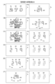
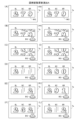
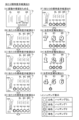
図8は、判定テーブルT1~T4を説明するための図である。図8(A)には、大当たり判定テーブルT1を説明するための図が示され、図8(B)には、リーチ判定テーブルT2を説明するための図が示され、図8(C)には、普通図柄当たり判定テーブルT3を説明するための図が示され、図8(D)には、普通図柄変動パターン判定テーブルT4を説明するための図が示されている。 Figure 8 is a diagram for explaining the judgment tables T1 to T4. Figure 8 (A) shows a diagram for explaining the big win judgment table T1, Figure 8 (B) shows a diagram for explaining the reach judgment table T2, Figure 8 (C) shows a diagram for explaining the normal pattern hit judgment table T3, and Figure 8 (D) shows a diagram for explaining the normal pattern change pattern judgment table T4.

大当たり判定テーブルT1は、遊技制御用マイコン81が主制御メイン処理(後述)において、取得した大当たり乱数値(0~65535のいずれか)が「大当たり」に該当するか「ハズレ」に該当するかを判定するために参照されるテーブルである。図8(A)では、「通常確率状態」において、大当たり乱数値が「0~164」の場合には、「大当たり」と判定され、大当たり乱数値が「0~164以外の数値(165~65535)」の場合には、「ハズレ」と判定されることが示されている。また、「高確率状態」において、大当たり乱数値が「0~649」の場合には、「大当たり」と判定され、大当たり乱数値が「0~649以外の数値(650~65535)」の場合には、「ハズレ」と判定されることが示されている。「通常確率状態」および「高確率状態」の内容については後述する。 The jackpot determination table T1 is a table that the game control microcomputer 81 refers to in the main control main process (described later) to determine whether the acquired jackpot random number (any of 0 to 65535) corresponds to a "jackpot" or a "miss." In FIG. 8(A), it is shown that in the "normal probability state," if the jackpot random number is "0 to 164," it is determined to be a "jackpot," and if the jackpot random number is "a number other than 0 to 164 (165 to 65535)," it is determined to be a "miss." Also, in the "high probability state," if the jackpot random number is "0 to 649," it is determined to be a "jackpot," and if the jackpot random number is "a number other than 0 to 649 (650 to 65535)," it is determined to be a "miss." The contents of the "normal probability state" and "high probability state" will be described later.

リーチ判定テーブルT2は、遊技制御用マイコン81が主制御メイン処理(後述)において、取得したリーチ乱数値(0~127のいずれか)が「リーチ有り」に該当するか「リーチ無し」に該当するかを判定するために参照されるテーブルである。図8(B)では、「非時短状態」において、リーチ乱数値が「0~13」の場合には、「リーチ有り」と判定され、リーチ乱数値が「0~13以外の数値(14~127)」の場合には、「リーチ無し」と判定されることが示されている。また、「時短状態」において、リーチ乱数値が「0~5」の場合には、「リーチ有り」と判定され、リーチ乱数値が「0~5以外の数値(6~127)」の場合には、「リーチ無し」と判定されることが示されている。「時短状態」および「非時短状態」の内容については後述する。リーチ判定テーブルT2では、時短状態の方が非時短状態よりもハズレ時のリーチがかかりにくくなっている。これは、時短状態において変動時間の短いリーチ無しハズレがより多く選択されることで、特図保留の消化スピードを速めるためである。 The reach judgment table T2 is a table that the game control microcomputer 81 refers to in the main control main process (described later) to judge whether the acquired reach random number value (any of 0 to 127) corresponds to "reach" or "no reach". In FIG. 8 (B), it is shown that in the "non-time-saving state", when the reach random number value is "0 to 13", it is judged as "reach", and when the reach random number value is "a number other than 0 to 13 (14 to 127)", it is judged as "no reach". Also, in the "time-saving state", when the reach random number value is "0 to 5", it is judged as "reach", and when the reach random number value is "a number other than 0 to 5 (6 to 127)", it is judged as "no reach". The contents of the "time-saving state" and "non-time-saving state" will be described later. In the reach judgment table T2, it is more difficult to reach when losing in the time-saving state than in the non-time-saving state. This is because when in the time-saving mode, more no-reach misses with short fluctuation times are selected, speeding up the consumption of reserved special charts.

普通図柄当たり判定テーブルT3は、遊技制御用マイコン81が主制御メイン処理(後述)において、取得した普通図柄乱数値(0~255のいずれか)が「当たり」に該当するか「ハズレ」に該当するかを判定するために参照されるテーブルである。図8(C)では、「非時短状態」において、普通図柄乱数値が「0~2」の場合には、「当たり」と判定され、普通図柄乱数値が「0~2以外の数値(3~255)」の場合には、「ハズレ」と判定されることが示されている。また、「時短状態」において、普通図柄乱数値が「0~254」の場合には、「当たり」と判定され、普通図柄乱数値が「0~254以外の数値(255)」の場合には、「ハズレ」と判定されることが示されている。 The normal symbol hit determination table T3 is a table that is referenced by the game control microcomputer 81 in the main control main process (described later) to determine whether the acquired normal symbol random number value (any of 0 to 255) corresponds to a "hit" or a "miss." FIG. 8(C) shows that in the "non-time-saving state," if the normal symbol random number value is "0 to 2," it is determined to be a "hit," and if the normal symbol random number value is "a number other than 0 to 2 (3 to 255)," it is determined to be a "miss." It also shows that in the "time-saving state," if the normal symbol random number value is "0 to 254," it is determined to be a "hit," and if the normal symbol random number value is "a number other than 0 to 254 (255)," it is determined to be a "miss."

普通図柄変動パターン判定テーブルT4は、遊技制御用マイコン81が主制御メイン処理(後述)において、遊技状態(非時短状態か時短状態か)に応じて、普通図柄の変動時間が何秒かを判定するために参照されるテーブルである。図8(D)では、「非時短状態」のとき、普通図柄の変動時間は「30秒」と判定され、「時短状態」のとき、普通図柄の変動時間が「1秒」と判定されることが示されている。 The normal symbol change pattern determination table T4 is a table that is referenced by the game control microcomputer 81 in the main control main process (described later) to determine how many seconds the normal symbol change time is depending on the game state (non-time-saving state or time-saving state). Figure 8 (D) shows that in the "non-time-saving state", the normal symbol change time is determined to be "30 seconds", and in the "time-saving state", the normal symbol change time is determined to be "1 second".

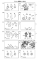
図9は、大当たり種別判定テーブルT5を説明するための図である。大当たり種別判定テーブルT5は、遊技制御用マイコン81が主制御メイン処理(後述)において、取得した大当たり種別乱数値(0~127のいずれか)に応じて、「大当たりの種別」と「特別図柄の種類」を判定するために参照されるテーブルである。図9では、第1特別図柄(特図1)の抽選において当選したとき、大当たり種別乱数値が「0~24」の場合には、大当たり種別が「16RV通過予定大当たり」と判定され、特図1の停止図柄(特図停止図柄)が「大当たり図柄1」と判定される。大当たり種別乱数値が「25~49」の場合には、大当たり種別が「16RV通過予定大当たり」と判定され、特図停止図柄が「大当たり図柄2」と判定される。大当たり種別乱数値が「50~55」の場合には、大当たり種別が「16R(実質15R)V通過予定大当たり」と判定され、特図停止図柄が「大当たり図柄3」と判定される。大当たり種別乱数値が「56~67」の場合には、大当たり種別が「16R(実質13R)V通過予定大当たり」と判定され、特図停止図柄が「大当たり図柄4」と判定される。大当たり種別乱数値が「68~127」の場合には、大当たり種別が「16R(実質13R)V非通過予定大当たり」と判定され、特図停止図柄が「大当たり図柄5」と判定される。一方、第2特別図柄(特図2)の抽選において当選したとき、大当たり種別乱数値が「0~82」の場合には、大当たり種別が「16RV通過予定大当たり」と判定され、特図2の停止図柄(特図停止図柄)が「大当たり図柄1」と判定される。大当たり種別乱数値が「83~127」の場合には、大当たり種別が「16R(実質13R)V非通過予定大当たり」と判定され、特図停止図柄が「大当たり図柄5」と判定される。なお、大当たり種別判定テーブルT5を参照することによって、特図停止図柄に対応する「特図停止図柄データ」、特別遊技の「オープニング(OP)コマンド」、「ラウンド指定コマンド」、「エンディング(ED)コマンド」も特定することができる。「16RV通過予定大当たり」、「16R(実質15R)V通過予定大当たり」、「16R(実質13R)V通過予定大当たり」および「16R(実質13R)V非通過予定大当たり」の具体的な内容については後述する。 Figure 9 is a diagram for explaining the jackpot type determination table T5. The jackpot type determination table T5 is a table that the game control microcomputer 81 refers to in the main control main process (described later) to determine the "jackpot type" and the "type of special symbol" according to the acquired jackpot type random number value (any of 0 to 127). In Figure 9, when the first special symbol (special symbol 1) is selected in the lottery, if the jackpot type random number value is "0 to 24", the jackpot type is determined to be "16RV passing jackpot" and the special symbol 1 stopping symbol (special symbol stopping symbol) is determined to be "jackpot symbol 1". If the jackpot type random number value is "25 to 49", the jackpot type is determined to be "16RV passing jackpot" and the special symbol stopping symbol is determined to be "jackpot symbol 2". When the jackpot type random number value is "50-55", the jackpot type is determined to be "16R (actually 15R) V-passing jackpot" and the special symbol stop pattern is determined to be "jackpot pattern 3". When the jackpot type random number value is "56-67", the jackpot type is determined to be "16R (actually 13R) V-passing jackpot" and the special symbol stop pattern is determined to be "jackpot pattern 4". When the jackpot type random number value is "68-127", the jackpot type is determined to be "16R (actually 13R) V-non-passing jackpot" and the special symbol stop pattern is determined to be "jackpot pattern 5". On the other hand, when the second special symbol (special symbol 2) is selected in the lottery, when the jackpot type random number value is "0-82", the jackpot type is determined to be "16RV-passing jackpot" and the special symbol 2 stop pattern (special symbol stop pattern) is determined to be "jackpot pattern 1". When the jackpot type random number value is "83 to 127", the jackpot type is determined to be "16R (actual 13R) V non-passing jackpot" and the special symbol stop pattern is determined to be "jackpot pattern 5". By referring to the jackpot type determination table T5, the "special symbol stop pattern data" corresponding to the special symbol stop pattern, the "opening (OP) command", "round designation command", and "ending (ED) command" of the special game can also be specified. The specific contents of "16RV passing jackpot", "16R (actual 15R) V passing jackpot", "16R (actual 13R) V passing jackpot", and "16R (actual 13R) V non-passing jackpot" will be described later.

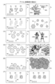
図10は、非時短状態時の変動パターン判定テーブルT6を説明するための図である。図11は、時短状態時の変動パターン判定テーブルT6を説明するための図である。変動パターン判定テーブルT6は、遊技制御用マイコン81が主制御メイン処理(後述)において、取得した変動パターン乱数値(0~127)に応じて、変動パターンを判定するために参照されるテーブルである。図10では、例えば、非時短状態において第1始動口20に入賞し、大当たり判定テーブルT1において「ハズレ」と判定され、リーチ判定テーブルT2において「リーチ有り」と判定され、保留球数が「1~2」であり、変動パターン乱数値が「0~60」の場合には、変動パターンが「P7」と判定されることが示されている。図11では、例えば、時短状態において第2始動口21に入賞し、大当たり判定テーブルT1において「大当たり」と判定され、大当たり種別判定テーブルT5において「16RV通過予定大当たり」と判定され、変動パターン乱数値が「0~10」の場合には、変動パターンが「P61」と判定されることが示されている。図10,11に示されるように、変動パターンが決定されれば、変動時間も決定される。また、リーチになる場合に、そのリーチがノーマルリーチとなるのかスーパーリーチ(SPリーチ)となるのかも決定される。スーパーリーチとは、ノーマルリーチよりもリーチ後の変動時間が長いリーチ演出である。ここでは、変動時間の異なる5種類のスーパーリーチ(SP1、SP2、SP3,SP4,SP5)が設定されている。SP1~3では、ノーマルリーチを経て発展的に実行される。SP1~5の違いは、例えば、疑似連の有無であってもよい。 Figure 10 is a diagram for explaining the fluctuation pattern determination table T6 in the non-time-saving state. Figure 11 is a diagram for explaining the fluctuation pattern determination table T6 in the time-saving state. The fluctuation pattern determination table T6 is a table that is referenced by the game control microcomputer 81 in the main control main process (described later) to determine the fluctuation pattern according to the acquired fluctuation pattern random number value (0 to 127). Figure 10 shows, for example, that in the non-time-saving state, when a ball enters the first starting hole 20, the jackpot determination table T1 determines it as a "miss," the reach determination table T2 determines it as a "reach," the number of reserved balls is "1 to 2," and the fluctuation pattern random number value is "0 to 60," the fluctuation pattern is determined to be "P7." In FIG. 11, for example, when the second starting hole 21 is won in the time-saving state, the jackpot determination table T1 determines it as a "jackpot", the jackpot type determination table T5 determines it as a "jackpot expected to pass 16RV", and the fluctuation pattern random number value is "0 to 10", the fluctuation pattern is determined as "P61". As shown in FIG. 10 and FIG. 11, when the fluctuation pattern is determined, the fluctuation time is also determined. In addition, when a reach occurs, it is also determined whether the reach will be a normal reach or a super reach (SP reach). A super reach is a reach performance in which the fluctuation time after the reach is longer than that of a normal reach. Here, five types of super reaches (SP1, SP2, SP3, SP4, SP5) with different fluctuation times are set. In SP1 to SP3, it is executed in a developed manner after a normal reach. The difference between SP1 to SP5 may be, for example, the presence or absence of a pseudo consecutive.

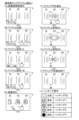
図12は、電チュー開放パターン判定テーブルT7を説明するための図である。電チュー開放パターン判定テーブルT7は、遊技制御用マイコン81が主制御メイン処理(後述)において、遊技状態(非時短状態か時短状態か)に応じて、電チュー22の開放パターンを判定するために参照されるテーブルである。図12(A)では、「非時短状態」のとき、電チュー22の開放パターンは「開放パターン11」と判定され、「時短状態」のとき、開放パターンは「開放パターン12」と判定されることが示されている。図12(B)には、開放パターン11と開放パターン12の内容が示されている。開放パターン11では、開放回数1回、開放時間0.2秒の電チュー22の開放をおこなう。開放パターン12では、開放回数が3回、1回あたりの開放時間2.0秒、インターバル(開放間隔)1.0秒の電チュー22の開放をおこなう。ただし、この電チュー22の開放は、予め定められた数の遊技球の入賞(規定入賞数、最大10個)があった場合、開放時間が残っていても閉鎖される。 Figure 12 is a diagram for explaining the electric chute opening pattern determination table T7. The electric chute opening pattern determination table T7 is a table that the game control microcomputer 81 refers to in the main control main process (described later) to determine the opening pattern of the electric chute 22 depending on the game state (non-time-saving state or time-saving state). In Figure 12 (A), it is shown that in the "non-time-saving state", the opening pattern of the electric chute 22 is determined to be "opening pattern 11", and in the "time-saving state", the opening pattern is determined to be "opening pattern 12". Figure 12 (B) shows the contents of opening pattern 11 and opening pattern 12. In opening pattern 11, the electric chute 22 is opened once and for an opening time of 0.2 seconds. In opening pattern 12, the electric chute 22 is opened three times, with an opening time of 2.0 seconds per time, and an interval (opening interval) of 1.0 seconds. However, if a predetermined number of game balls are won (a maximum of 10 balls), the electric chute 22 will close even if there is still time left to open it.

図13は、大入賞口開放パターン判定テーブルT8を説明するための図である。大入賞口開放パターン判定テーブルT8は、遊技制御用マイコン81が主制御メイン処理(後述)において、特図停止図柄データ(図9)に応じて、第1大入賞口30および第2大入賞口35の開放パターンを判定するために参照されるテーブルである。図13(A)では、特図停止図柄データが「11H」、「12H」、または、「21H」のとき、第1大入賞口30および第2大入賞口35の開放パターンは「開放パターン21」と判定され、特図停止図柄データが「14H」、「15H」、「22H」のとき、開放パターンは「開放パターン22」と判定され、特図停止図柄データが「13H」のとき、開放パターンは「開放パターン23」と判定されることが示されている。図13(B)には、開放パターン21、開放パターン22および開放パターン23の内容が示されている。開放パターン21では1~13、15R目において、開放回数1回、開放時間29.5秒の第1大入賞口30の開放(ロング開放)をおこない、14、16R目において、開放回数1回、開放時間29.5秒の第2大入賞口35の開放(ロング開放)をおこなう。開放パターン22では1~13R目において、開放回数1回、開放時間29.5秒の第1大入賞口30の開放(ロング開放)をおこない、14、16R目において、開放回数1回、開放時間0.1秒の第2大入賞口35の開放(ショート開放)をおこない、15R目において、開放回数1回、開放時間0.1秒の第1大入賞口30の開放(ショート開放)をおこなう。開放パターン23では1~13、15R目において、開放回数1回、開放時間29.5秒の第1大入賞口30の開放(ロング開放)をおこない、14R目において、開放回数1回、開放時間0.1秒の第2大入賞口35の開放(ショート開放)をおこない、16R目において、開放回数1回、開放時間29.5秒の第2大入賞口35の開放(ロング開放)をおこなう。ただし、第1大入賞口30および第2大入賞口35の開放は、予め定められた数の遊技球の入賞(規定入賞数、最大9個)があった場合、開放時間が残っていても閉鎖される。 Figure 13 is a diagram for explaining the large prize opening pattern determination table T8. The large prize opening pattern determination table T8 is a table that is referred to by the game control microcomputer 81 in the main control main process (described later) to determine the opening pattern of the first large prize opening 30 and the second large prize opening 35 according to the special symbol stop pattern data (Figure 9). In Figure 13 (A), when the special symbol stop pattern data is "11H", "12H", or "21H", the opening pattern of the first large prize opening 30 and the second large prize opening 35 is determined to be "opening pattern 21", when the special symbol stop pattern data is "14H", "15H", or "22H", the opening pattern is determined to be "opening pattern 22", and when the special symbol stop pattern data is "13H", the opening pattern is determined to be "opening pattern 23". In Figure 13 (B), the contents of the opening pattern 21, the opening pattern 22, and the opening pattern 23 are shown. In the opening pattern 21, the first large prize opening 30 is opened once and for an opening time of 29.5 seconds (long opening) in the 1st to 13th and 15th rounds, and the second large prize opening 35 is opened once and for an opening time of 29.5 seconds (long opening) in the 14th and 16th rounds. In the opening pattern 22, the first large prize opening 30 is opened once and for an opening time of 29.5 seconds (long opening) in the 1st to 13th rounds, the second large prize opening 35 is opened once and for an opening time of 0.1 seconds (short opening) in the 14th and 16th rounds, and the first large prize opening 30 is opened once and for an opening time of 0.1 seconds (short opening) in the 15th round. In opening pattern 23, the first large prize opening 30 is opened once and for an opening time of 29.5 seconds (long opening) in rounds 1 to 13 and 15, the second large prize opening 35 is opened once and for an opening time of 0.1 seconds (short opening) in round 14, and the second large prize opening 35 is opened once and for an opening time of 29.5 seconds (long opening) in round 16. However, if a predetermined number of game balls have won (prescribed number of winnings, up to 9 balls), the first large prize opening 30 and the second large prize opening 35 are closed even if there is still opening time remaining.

図14は、V開閉部材開放パターン判定テーブルT9を説明するための図である。V開閉部材開放パターン判定テーブルT9は、遊技制御用マイコン81が主制御メイン処理(後述)において、特図停止図柄データ(図9)に応じて、V開閉部材71の開放パターンを判定するために参照されるテーブルである。図14(A)では、特図停止図柄データが「11H」、「12H」、または、「21H」のとき、V開閉部材71の開放パターンは「開放パターン31」と判定され、特図停止図柄データが「13H」のとき、開放パターンは「開放パターン32」と判定され、特図停止図柄データが「14H」のとき、開放パターンは「開放パターン33」と判定され、特図停止図柄データが「15H」または「22H」のとき、開放パターンは「開放パターン34」と判定されることが示されている。図14(B)には、開放パターン31、開放パターン32、開放パターン33、および、開放パターン34の内容が示されている。開放パターン31では2、4、6、8R目において、第1大入賞口30に1個目の入賞があったとき開放時間0.1秒のV開閉部材71のショート開放をおこなう。10、12R目において、第1大入賞口30に1個目の入賞があったとき開放時間0.1秒のV開閉部材71のショート開放をおこない、2個目の入賞があったとき開放時間最大31.5秒のV開閉部材71のロング開放をおこなう。開放パターン32では2、4、6、12R目において、第1大入賞口30に1個目の入賞があったとき開放時間0.1秒のV開閉部材71のショート開放をおこなう。8、10R目において、第1大入賞口30に1個目の入賞があったとき開放時間0.1秒のV開閉部材71のショート開放をおこない、2個目の入賞があったとき開放時間最大31.5秒のV開閉部材71のロング開放をおこなう。開放パターン33では2、6R目において、第1大入賞口30に1個目の入賞があったとき開放時間0.1秒のV開閉部材71のショート開放をおこない、2個目の入賞があったとき開放時間最大31.5秒のV開閉部材71のロング開放をおこなう。4、8、10、12R目において、第1大入賞口30に1個目の入賞があったとき開放時間0.1秒のV開閉部材71のショート開放をおこなう。開放パターン34では2、4、6、8、10、12R目において、第1大入賞口30に1個目の入賞があったとき開放時間0.1秒のV開閉部材71のショート開放をおこなう。 Figure 14 is a diagram for explaining the V-opening/closing member opening pattern determination table T9. The V-opening/closing member opening pattern determination table T9 is a table that is referenced by the game control microcomputer 81 in the main control main process (described later) to determine the opening pattern of the V-opening/closing member 71 according to the special symbol stop pattern data (Figure 9). In Figure 14 (A), when the special symbol stop pattern data is "11H", "12H", or "21H", the opening pattern of the V-opening/closing member 71 is determined to be "opening pattern 31", when the special symbol stop pattern data is "13H", the opening pattern is determined to be "opening pattern 32", when the special symbol stop pattern data is "14H", the opening pattern is determined to be "opening pattern 33", and when the special symbol stop pattern data is "15H" or "22H", the opening pattern is determined to be "opening pattern 34". 14B shows the contents of the opening pattern 31, the opening pattern 32, the opening pattern 33, and the opening pattern 34. In the opening pattern 31, when the first prize is won in the first large prize opening 30 in the 2nd, 4th, 6th, and 8th rounds, the V-shaped opening/closing member 71 is opened in a short time of 0.1 seconds. In the 10th and 12th rounds, when the first prize is won in the first large prize opening 30, the V-shaped opening/closing member 71 is opened in a short time of 0.1 seconds, and when the second prize is won, the V-shaped opening/closing member 71 is opened in a long time of up to 31.5 seconds. In the opening pattern 32, when the first prize is won in the first large prize opening 30 in the 2nd, 4th, 6th, and 12th rounds, the V-shaped opening/closing member 71 is opened in a short time of 0.1 seconds. In the 8th and 10th races, when the first prize is won in the first large prize opening 30, the V-shaped opening/closing member 71 is opened in a short time of 0.1 seconds, and when the second prize is won, the V-shaped opening/closing member 71 is opened in a long time of up to 31.5 seconds. In the opening pattern 33, in the 2nd and 6th races, when the first prize is won in the first large prize opening 30, the V-shaped opening/closing member 71 is opened in a short time of 0.1 seconds, and when the second prize is won, the V-shaped opening/closing member 71 is opened in a long time of up to 31.5 seconds. In the 4th, 8th, 10th, and 12th races, when the first prize is won in the first large prize opening 30, the V-shaped opening/closing member 71 is opened in a short time of 0.1 seconds. In opening pattern 34, when the first prize is won in the first large prize opening 30 in the 2nd, 4th, 6th, 8th, 10th, and 12th rounds, the V-shaped opening/closing member 71 is short-opened with an opening time of 0.1 seconds.

4.大当たり等の説明
遊技機1では、大当たり抽選(特別図柄抽選)の結果としての「大当たり」と「ハズレ」がある。「大当たり」の場合には、特別図柄表示器41に「大当たり図柄」が停止表示される。「ハズレ」のときには、特別図柄表示器41に「ハズレ図柄」が停止表示される。大当たりに当選すると、停止表示された特別図柄の種類(大当たりの種類)に応じた開放パターンにて、大入賞口(第1大入賞口30および第2大入賞口35)を開放させる「大当たり遊技」が実行される。大当たり遊技は、特別遊技の一例である。大当たり遊技は、複数回のラウンド遊技(単位開放遊技)と、初回のラウンド遊技が開始される前のオープニング(OP)と、最終回のラウンド遊技が終了した後のエンディング(ED)とを含んでいる。各ラウンド遊技は、オープニングの終了、または、前のラウンド遊技の終了によって開始し、次のラウンド遊技の開始によって終了する。ラウンド遊技間の大入賞口の閉鎖の時間(インターバル時間)は、その閉鎖前の開放ラウンド遊技に含まれる。
4. Description of jackpots, etc. In the gaming machine 1, there are "jackpots" and "losses" as a result of the jackpot lottery (special symbol lottery). In the case of a "jackpot", a "jackpot symbol" is displayed on the special symbol display 41. In the case of a "loss", a "loss symbol" is displayed on the special symbol display 41. When a jackpot is won, a "jackpot game" is executed in which the jackpot winning holes (the first jackpot winning hole 30 and the second jackpot winning hole 35) are opened in an opening pattern according to the type of the special symbol (type of jackpot) that is displayed on the screen. The jackpot game is an example of a special game. The jackpot game includes a plurality of round games (unit opening games), an opening (OP) before the first round game starts, and an ending (ED) after the last round game ends. Each round game starts with the end of the opening or the end of the previous round game, and ends with the start of the next round game. The time (interval time) for closing the big prize opening between rounds of play is included in the open round of play before that closure.

大当たりには複数の種別がある。大当たりの種別については、図9に示すとおりである。ここでは、大当たりの種別としては、大きく分けて「V通過予定大当たり」と「V非通過予定大当たり」の2つある。「V通過予定大当たり」は、その大当たり遊技中にV領域39への遊技球の通過が可能な開放パターン(V通過予定開放パターン)で開閉部材32、開閉部材37およびV開閉部材71を作動させる大当たりである。ここでは、特図停止図柄データが11H~14H,21Hの大当たりが「V通過予定大当たり(確変大当たり)」に該当する。図13に示す開閉部材32および開閉部材37の開放パターンと、図14に示すV開閉部材71の開放パターンとの組み合わせが、(開放パターン21:開放パターン31)、(開放パターン22:開放パターン33)、または(開放パターン23:開放パターン32)のとき、その大当たり遊技中にV領域39への遊技球の通過が可能となる。「V非通過予定大当たり(通常大当たり)」は、その大当たり遊技中にV領域39への遊技球の通過が不可能な開放パターン(V非通過予定開放パターン)で開閉部材32、開閉部材37およびV開閉部材71を作動させる大当たりである。ここでは、特図停止図柄データが15H、22Hの大当たりが「V非通過予定大当たり」に該当する。図13に示す開閉部材32および開閉部材37の開放パターンと、図14に示すV開閉部材71の開放パターンとの組み合わせが(開放パターン22:開放パターン34)のとき、その大当たり遊技中にV領域39への遊技球の通過が不可能となる。上記のように、開閉部材32および開閉部材37の開放パターン22は、V通過予定開放パターンとV非通過予定開放パターンとを兼ねている。 There are several types of jackpots. The types of jackpots are as shown in FIG. 9. Here, the types of jackpots are roughly divided into two types: "V-passing jackpot" and "V-non-passing jackpot". A "V-passing jackpot" is a jackpot that operates the opening/closing member 32, the opening/closing member 37, and the V-opening/closing member 71 in an opening pattern (V-passing opening pattern) that allows the game ball to pass through to the V area 39 during the jackpot game. Here, a jackpot with special stop pattern data of 11H to 14H, 21H corresponds to a "V-passing jackpot (probable jackpot)". When the combination of the opening pattern of the opening/closing member 32 and the opening/closing member 37 shown in FIG. 13 and the opening pattern of the V-opening/closing member 71 shown in FIG. 14 is (opening pattern 21: opening pattern 31), (opening pattern 22: opening pattern 33), or (opening pattern 23: opening pattern 32), the game ball can pass through to the V area 39 during the jackpot game. A "V non-passing scheduled jackpot (normal jackpot)" is a jackpot that activates the opening/closing members 32, 37, and 71 in an opening pattern (V non-passing scheduled opening pattern) that makes it impossible for the game ball to pass through to the V area 39 during the jackpot game. Here, a jackpot with special stop pattern data of 15H and 22H corresponds to a "V non-passing scheduled jackpot". When the combination of the opening pattern of the opening/closing members 32 and 37 shown in FIG. 13 and the opening pattern of the V opening/closing member 71 shown in FIG. 14 is (opening pattern 22: opening pattern 34), it becomes impossible for the game ball to pass through to the V area 39 during the jackpot game. As described above, the opening pattern 22 of the opening/closing members 32 and 37 serves as both the V passing scheduled opening pattern and the V non-passing scheduled opening pattern.

「V通過予定大当たり」は、「16RV通過予定大当たり」と、「16R(実質13R)V通過予定大当たり」と、「16R(実質15R)V通過予定大当たり」と、を含んでいる。「16RV通過予定大当たり」は、実質的な総ラウンド数が16Rである。1Rから13Rまでと15Rは第1大入賞口30を1R当たり最大29.5秒にわたって開放する。14Rと16Rは第2大入賞口35を1R当たり最大29.5秒にわたって開放する(図13:開放パターン21)。10Rおよび12Rでは、V開閉部材71がロング開放され(図14:開放パターン31)、第1大入賞口30内のV領域39への通過が容易に可能である。 The "V passing jackpot" includes the "16RV passing jackpot", the "16R (actually 13R) V passing jackpot", and the "16R (actually 15R) V passing jackpot". The "16RV passing jackpot" has a total of 16Rs. The first large prize opening 30 is opened for a maximum of 29.5 seconds per R in Rs 1 to 13 and R 15. The second large prize opening 35 is opened for a maximum of 29.5 seconds per R in Rs 14 and 16 (Figure 13: opening pattern 21). In Rs 10 and 12, the V opening/closing member 71 is opened for a long time (Figure 14: opening pattern 31), and it is easy to pass through to the V area 39 in the first large prize opening 30.

「16R(実質13R)V通過予定大当たり」は、総ラウンド数は16Rであるものの、実質的な総ラウンド数は13Rである。つまり、1Rから13Rまでは第1大入賞口30を1R当たり最大29.5秒にわたって開放するが、15Rでは第1大入賞口30を1R当たり0.1秒しか開放せず、また、14Rと16Rでも第2大入賞口35を1R当たり0.1秒しか開放しない(図13:開放パターン22)。従って、この「16R(実質13R)V通過予定大当たり」では14Rから16Rまでは、大入賞口の開放時間が極めて短く、賞球の見込めないラウンドとなっている。つまり、「16R(実質13R)V通過予定大当たり」は、実質13Rの大当たりとなっている。2Rおよび6Rでは、V開閉部材71がロング開放され(図14:開放パターン33)、第1大入賞口30内のV領域39への通過が容易に可能である。 In the "16R (actually 13R) V-pass scheduled jackpot", the total number of rounds is 16R, but the actual total number of rounds is 13R. In other words, from 1R to 13R, the first large prize opening 30 is opened for a maximum of 29.5 seconds per R, but in 15R, the first large prize opening 30 is opened for only 0.1 seconds per R, and in 14R and 16R, the second large prize opening 35 is opened for only 0.1 seconds per R (Figure 13: Opening pattern 22). Therefore, in this "16R (actually 13R) V-pass scheduled jackpot", the opening time of the large prize opening is extremely short from 14R to 16R, making it a round in which no prize balls are expected. In other words, the "16R (actually 13R) V-pass scheduled jackpot" is a jackpot of 13R in effect. In rounds 2 and 6, the V-shaped opening/closing member 71 is opened long (Figure 14: opening pattern 33), making it easy to pass through to the V-shaped area 39 inside the first large winning opening 30.

「16R(実質15R)V通過予定大当たり」は、総ラウンド数は16Rであるものの、実質的な総ラウンド数は15Rである。つまり、1Rから13Rまでと15Rは第1大入賞口30を1R当たり最大29.5秒にわたって開放し、16Rでは第2大入賞口35を1R当たり最大29.5秒にわたって開放するが、14Rでは第2大入賞口35を1R当たり0.1秒しか開放しない(図13:開放パターン23)。従って、この「16R(実質15R)V通過予定大当たり」では14Rは、大入賞口の開放時間が極めて短く、賞球の見込めないラウンドとなっている。つまり、「16R(実質15R)V通過予定大当たり」は、実質15Rの大当たりとなっている。8Rおよび10Rでは、V開閉部材71がロング開放され(図14:開放パターン32)、第1大入賞口30内のV領域39への通過が容易に可能である。 In the "16R (actually 15R) V-pass scheduled jackpot", the total number of rounds is 16R, but the actual total number of rounds is 15R. In other words, from 1R to 13R and 15R, the first large prize opening 30 is opened for a maximum of 29.5 seconds per R, and in 16R, the second large prize opening 35 is opened for a maximum of 29.5 seconds per R, but in 14R, the second large prize opening 35 is opened for only 0.1 seconds per R (Figure 13: Opening pattern 23). Therefore, in this "16R (actually 15R) V-pass scheduled jackpot", the opening time of the large prize opening is extremely short in 14R, making it a round in which no prize balls are expected to be won. In other words, the "16R (actually 15R) V-pass scheduled jackpot" is a jackpot of 15R in effect. In rounds 8 and 10, the V-shaped opening and closing member 71 is opened long (Figure 14: opening pattern 32), making it easy to pass through to the V-shaped area 39 inside the first large prize opening 30.

「V非通過予定大当たり」は、総ラウンド数は16Rであるものの、実質的な総ラウンド数は13となる開放パターン22の「16R(実質13R)V非通過予定大当たり」である。つまり、1Rから13Rまでは第1大入賞口30を1R当たり最大29.5秒にわたって開放するが、15Rでは第1大入賞口30を1R当たり0.1秒しか開放せず、また、14Rと16Rでも第2大入賞口35を1R当たり0.1秒しか開放しない(図13:開放パターン22)。従って、この「16R(実質13R)V非通過予定大当たり」では14Rから16Rまでは、大入賞口の開放時間が極めて短く、賞球の見込めないラウンドとなっている。つまり、「16R(実質13R)V非通過予定大当たり」は実質13Rの大当たりとなっている。2R,4R,6R,8R,10Rおよび12Rでは、V開閉部材71は開放されるもののその開放はショート開放であり(図14:開放パターン34)、第1大入賞口30内のV領域39に遊技球が通過することはほぼ不可能となっている。 The "V non-passing scheduled jackpot" is a "16R (actually 13R) V non-passing scheduled jackpot" of opening pattern 22, in which the total number of rounds is 16R, but the actual total number of rounds is 13. In other words, from 1R to 13R, the first large prize winning hole 30 is opened for a maximum of 29.5 seconds per round, but in 15R, the first large prize winning hole 30 is opened for only 0.1 seconds per round, and in 14R and 16R, the second large prize winning hole 35 is opened for only 0.1 seconds per round (Figure 13: opening pattern 22). Therefore, in this "16R (actually 13R) V non-passing scheduled jackpot", the opening time of the large prize winning hole is extremely short from 14R to 16R, making it a round in which no prize balls are expected. In other words, the "16R (actually 13R) V non-passing scheduled jackpot" is a jackpot of essentially 13R. At 2R, 4R, 6R, 8R, 10R and 12R, the V-shaped opening/closing member 71 is opened, but the opening is a short opening (Figure 14: opening pattern 34), making it almost impossible for the game ball to pass through the V-shaped area 39 inside the first large winning opening 30.

上記の説明から明らかなように、「16R(実質13R)V非通過予定大当たり」と「16R(実質13R)V通過予定大当たり」とは、第1大入賞口30と第2大入賞口35(開閉部材32と開閉部材37)との開放パターンが同一(開放パターン22)であり、V開閉部材71の開放パターンのみが異なっている(開放パターン34と開放パターン33)。なお、後述するが、「16R(実質13R)V非通過予定大当たり」と「16R(実質13R)V通過予定大当たり」は、大当たり遊技終了後に時短遊技(本例では100回)がおこなわれるようになっている。すなわち、「16R(実質13R)V非通過予定大当たり」は、第1大入賞口30内のV領域39に遊技球が通過することはほぼ不可能になっており、当該大当たり後の遊技状態は低確時短状態(低確高ベース状態)となる。一方、「16R(実質13R)V通過予定大当たり」は、第1大入賞口30内のV領域39への遊技球の通過が容易に可能になっており、当該大当たり後の遊技状態は高確時短状態(高確高ベース状態)となる。このことから、遊技者は、「16R(実質13R)V非通過予定大当たり」と「16R(実質13R)V通過予定大当たり」とを見分けることが困難になり、当該大当たり後の遊技状態が低確時短状態(低確高ベース状態)になるか高確時短状態(高確高ベース状態)になるかが判別し難くなる。また、時短遊技終了後は、「16R(実質13R)V非通過予定大当たり」では遊技状態が低確低ベース状態(通常状態)になり、「16R(実質13R)V通過予定大当たり」では遊技状態が見かけ上は通常状態の高確低ベース状態になる。すなわち、「16R(実質13R)V通過予定大当たり」では、第1大入賞口30内のV領域39に遊技球が通過した場合には、大当たり遊技後の時短状態が終了すると、遊技状態は、高確低ベース状態でありながら高確率になっていることが潜伏した状態(潜伏確変状態)となり、この潜伏確変状態は、遊技者が判別し難くなっている。すなわち「16R(実質13R)V非通過予定大当たり」と「16R(実質13R)V通過予定大当たり」、「16R(実質13R)V非通過予定大当たり」の大当たり遊技後の低確時短状態(低確高ベース状態)と「16R(実質13R)V通過予定大当たり」の大当たり遊技後の高確時短状態(高確高ベース状態)、および、「16R(実質13R)V非通過予定大当たり」の時短終了後の低確低ベース状態と「16R(実質13R)V通過予定大当たり」の時短終了後の高確低ベース状態は、遊技者が判別し難い態様でおこなわれる。 As is clear from the above explanation, the "16R (actual 13R) V non-passing scheduled jackpot" and the "16R (actual 13R) V passing scheduled jackpot" have the same opening pattern (opening pattern 22) between the first large prize winning opening 30 and the second large prize winning opening 35 (opening member 32 and opening member 37), and only the opening pattern of the V opening and closing member 71 is different (opening pattern 34 and opening pattern 33). As will be described later, the "16R (actual 13R) V non-passing scheduled jackpot" and the "16R (actual 13R) V passing scheduled jackpot" are designed to play a time-saving game (100 times in this example) after the jackpot game ends. In other words, in the "16R (actual 13R) V non-passing scheduled jackpot", it is almost impossible for the game ball to pass through the V area 39 in the first large prize winning opening 30, and the game state after the jackpot becomes a low-probability time-saving state (low-probability high base state). On the other hand, in the "16R (actual 13R) V-passing scheduled jackpot", the game ball can easily pass through the V area 39 in the first big winning port 30, and the game state after the jackpot becomes a high-probability time-saving state (high-probability high-base state). For this reason, it becomes difficult for the player to distinguish between the "16R (actual 13R) V-non-passing scheduled jackpot" and the "16R (actual 13R) V-passing scheduled jackpot", and it becomes difficult to determine whether the game state after the jackpot becomes a low-probability time-saving state (low-probability high-base state) or a high-probability time-saving state (high-probability high-base state). In addition, after the time-saving game ends, the game state becomes a low-probability low-base state (normal state) in the "16R (actual 13R) V-non-passing scheduled jackpot", and the game state becomes a high-probability low-base state that appears to be the normal state in the "16R (actual 13R) V-passing scheduled jackpot". That is, in the "16R (actually 13R) V passing scheduled jackpot", when the game ball passes through the V area 39 in the first large winning port 30, when the time-saving state after the jackpot game ends, the game state becomes a high probability low base state but a latent state in which a high probability is hidden (latent high probability state), and this latent high probability state is difficult for the player to distinguish. That is, the low-probability time-saving state (low-probability high base state) after the jackpot play of "16R (actual 13R) V non-passing jackpot" and "16R (actual 13R) V passing jackpot", the high-probability time-saving state (high-probability high base state) after the jackpot play of "16R (actual 13R) V passing jackpot", and the low-probability low base state after the time-saving end of "16R (actual 13R) V non-passing jackpot" and the high-probability low base state after the time-saving end of "16R (actual 13R) V passing jackpot" are performed in a manner that is difficult for the player to distinguish.

また、図9に示すように、第1特別図柄(特図1)の抽選における大当たりの振分率は、V通過予定大当たりが68/128(約53%)、V非通過予定大当たりが60/128(約47%)となっている。これに対して、第2特別図柄(特図2)の抽選における大当たりの振り分け率は、V通過予定大当たりが83/128(約64.8%)、V非通過予定大当たりが45/128(約35.2%)となっている。このように遊技機1では、第1始動口20に遊技球が入賞して行われる大当たり抽選(第1特別図柄の抽選)よりも、第2始動口21に遊技球が入賞して行われる大当たり抽選(第2特別図柄の抽選)の方が、遊技者にとって有利となるように設定されている。 As shown in FIG. 9, the distribution rate of the jackpot in the drawing for the first special symbol (special symbol 1) is 68/128 (about 53%) for the V-passing jackpot and 60/128 (about 47%) for the V-non-passing jackpot. In contrast, the distribution rate of the jackpot in the drawing for the second special symbol (special symbol 2) is 83/128 (about 64.8%) for the V-passing jackpot and 45/128 (about 35.2%) for the V-non-passing jackpot. In this way, the gaming machine 1 is set up so that the jackpot lottery (lottery for the second special symbol) held when the gaming ball enters the second starting hole 21 is more advantageous to the player than the jackpot lottery (lottery for the first special symbol) held when the gaming ball enters the first starting hole 20.

5.遊技状態の説明
遊技機1の遊技状態について説明する。遊技制御用マイコン81は、特別図柄表示器41に表示する特別図柄および普通図柄表示器42に表示する普通図柄に対して、それぞれ、「確率変動制御」と「変動時間短縮制御」とを実行可能である。ここでは、遊技制御用マイコン81が特別図柄表示器41の特別図柄に対して確率変動制御している状態を「高確率状態(高確状態、確率変動状態、確変状態)」と呼び、確率変動制御していない状態を単に「通常確率状態(非高確率状態、低確率状態、通常状態)」と呼ぶ。遊技制御用マイコン81は、特別図柄の確率変動制御として、大当たりと判定される大当たり乱数値の数が通常確率状態よりも高確率状態の方が多い大当たり判定テーブル(図8(A))を用いた大当たり判定をおこなうことにより、高確率状態を実現する。従って、高確率状態は、通常確率状態よりも大当たりの確率が高くなる。つまり、遊技制御用マイコン81が特別図柄表示器41の特別図柄に対して確率変動制御を実行している場合には、確率変動制御を実行していない場合と比べて、特別図柄表示器41による特別図柄の可変表示の表示結果(停止図柄)が大当たり図柄となる確率が高くなる。
5. Description of the gaming state The gaming state of the gaming machine 1 will be described. The gaming control microcomputer 81 can execute "probability variation control" and "variation time reduction control" for the special symbols displayed on the special symbol display 41 and the normal symbols displayed on the normal symbol display 42, respectively. Here, the state in which the gaming control microcomputer 81 performs probability variation control on the special symbols of the special symbol display 41 is called a "high probability state (high probability state, probability variation state, probability change state)," and the state in which the probability variation control is not performed is simply called a "normal probability state (non-high probability state, low probability state, normal state)." The gaming control microcomputer 81 realizes the high probability state by performing a jackpot determination using a jackpot determination table (FIG. 8(A)) in which the number of jackpot random numbers determined to be a jackpot is greater in the high probability state than in the normal probability state, as the probability variation control of the special symbols. Therefore, the high probability state has a higher probability of jackpot than the normal probability state. In other words, when the game control microcomputer 81 is executing probability fluctuation control on the special pattern of the special pattern display device 41, the probability that the display result (stop pattern) of the variable display of the special pattern by the special pattern display device 41 will be a jackpot pattern is higher than when the probability fluctuation control is not being executed.

また、遊技制御用マイコン81が特別図柄表示器41の特別図柄に対して変動時間短縮制御している状態を「時短状態」といい、変動時間短縮制御していない状態を単に「非時短状態」という。時短状態は、特別図柄の変動時間(変動表示開始時から表示結果の導出表示時までの時間)が、非時短状態よりも短くなっている。遊技制御用マイコン81は、時短状態のときに、変動時間の短い変動パターンが選択されることが非時短状態よりも多くなるように定められた変動パターン判定テーブルT6(図10、図11)を用いた変動パターンの判定をおこなう。つまり、遊技制御用マイコン81が特別図柄表示器41の特別図柄に対して変動時間短縮制御を実行している場合には、変動時間短縮制御を実行していない場合と比べて、特別図柄の可変表示の変動時間として短い変動時間が選択されやすくなる。その結果、時短状態では、特図保留の消化のペースが速くなり、始動口への有効な入賞(特図保留として記憶され得る入賞)が発生しやすくなる。これにより、スムーズな遊技の進行のもとで大当たりを狙うことができる。なお、遊技制御用マイコン81は、特別図柄表示器41の特別図柄に対して、確率変動制御と変動時間短縮制御とを同時に実行することもあるし、片方のみ実行することもある。 In addition, the state in which the game control microcomputer 81 controls the time-shortening of the special symbol of the special symbol display 41 is called the "time-shortening state", and the state in which the time-shortening of the special symbol is not controlled is simply called the "non-time-shortening state". In the time-shortening state, the time-shortening of the special symbol (the time from the start of the display of the special symbol to the derivation of the display result) is shorter than in the non-time-shortening state. The game control microcomputer 81 judges the variation pattern using the variation pattern judgment table T6 (FIGS. 10 and 11) that is determined so that a variation pattern with a short variation time is selected more often than in the non-time-shortening state in the time-shortening state. In other words, when the game control microcomputer 81 is executing the variation time-shortening control for the special symbol of the special symbol display 41, a short variation time is more likely to be selected as the variation time of the variable display of the special symbol compared to when the variation time-shortening control is not executed. As a result, in the time-shortening state, the pace of consumption of the special symbol reservation is faster, and effective winning (winning that can be stored as the special symbol reservation) at the starting port is more likely to occur. This allows players to aim for a big win while playing smoothly. The game control microcomputer 81 may simultaneously execute probability fluctuation control and fluctuation time reduction control for the special symbols on the special symbol display 41, or may execute only one of them.

遊技制御用マイコン81は、普通図柄表示器42の普通図柄に対する確率変動制御および変動時間短縮制御を、特別図柄表示器41の特別図柄に対する変動時間短縮制御に同期して実行する。すなわち、遊技制御用マイコン81は、普通図柄に対する確率変動制御および変動時間短縮制御を、時短状態の場合は実行し、非時短状態の場合には実行しない。遊技制御用マイコン81は、普通図柄の確率変動制御として、当たりと判定される普通図柄乱数値(当たり乱数値)の数が非時短状態よりも時短状態の方が多い普通図柄当たり判定テーブルT3(図8(C))を用いて、当たり判定(普通図柄の判定)をおこなう。従って、時短状態では、普通図柄通常確率状態よりも当たり確率が高くなる。つまり、遊技制御用マイコン81が普通図柄表示器42の普通図柄に対して確率変動制御を実行している場合には、確率変動制御を実行していない場合と比べて、普通図柄表示器42による普通図柄の可変表示の表示結果(停止図柄)が当たり図柄となる確率が高くなる。時短状態では、普通図柄の変動時間が非時短状態よりも短くなっている。ここでは、普通図柄の変動時間は非時短状態では30秒であるが、時短状態では1秒である(図8(D))。さらに時短状態では、補助遊技における電チュー22の開放時間が、非時短状態よりも長くなっている(図12)。すなわち、遊技制御用マイコン81は、電チュー22に対して開放時間延長制御を実行している。加えて、時短状態では、補助遊技における電チュー22の開放回数が非時短状態よりも多くなっている(図12)。すなわち、遊技制御用マイコン81は、電チュー22に対して開放回数増加制御を実行している。遊技制御用マイコン81が、普通図柄表示器42の普通図柄に対する確率変動制御と変動時間短縮制御、および、電チュー22に対する開放時間延長制御と開放回数増加制御とを実行している状況下では、これらの制御を実行していない場合と比べて、電チュー22が頻繁に開放され、第2始動口21へ遊技球が頻繁に入賞することとなる。その結果、発射球数に対する賞球数の割合であるベースが高くなる。従って、これらの制御が実行されている状態を「高ベース状態」といい、実行されていない状態を「低ベース状態」という。高ベース状態では、手持ちの遊技球を大きく減らすことなく大当たりを狙うことができる。なお、高ベース状態とは、いわゆる電サポ制御(電チュー22により第2始動口21への入賞をサポートする制御)が実行されている状態である。高ベース状態(電サポ制御状態)は、上記の全ての制御を実行するものでなくてもよい。すなわち、普通図柄表示器42の普通図柄に対する確率変動制御、普通図柄表示器42の普通図柄に対する変動時間短縮制御、電チュー22に対する開放時間延長制御、および、電チュー22に対する開放回数増加制御のうち一つ以上の制御を実行することによって、その制御が実行されていないときよりも電チュー22が開放され易くなっていればよい。また、高ベース状態(電サポ制御状態)は、時短状態に付随せずに独立して制御されるようにしてもよい。 The game control microcomputer 81 executes the probability fluctuation control and the fluctuation time shortening control for the normal pattern of the normal pattern display 42 in synchronization with the fluctuation time shortening control for the special pattern of the special pattern display 41. That is, the game control microcomputer 81 executes the probability fluctuation control and the fluctuation time shortening control for the normal pattern in the time-shortening state, but does not execute them in the non-time-shortening state. The game control microcomputer 81 performs the hit judgment (judgment of the normal pattern) using the normal pattern hit judgment table T3 (FIG. 8(C)) in which the number of normal pattern random number values (hit random number values) judged as a hit is higher in the time-shortening state than in the non-time-shortening state, as the probability fluctuation control for the normal pattern. Therefore, in the time-shortening state, the hit probability is higher than in the normal pattern normal probability state. In other words, when the game control microcomputer 81 is executing probability fluctuation control on the normal pattern of the normal pattern display 42, the probability that the display result (stop pattern) of the variable display of the normal pattern by the normal pattern display 42 will be a winning pattern is higher than when the probability fluctuation control is not executed. In the time-saving state, the fluctuation time of the normal pattern is shorter than that in the non-time-saving state. Here, the fluctuation time of the normal pattern is 30 seconds in the non-time-saving state, but is 1 second in the time-saving state (FIG. 8 (D)). Furthermore, in the time-saving state, the opening time of the electric chute 22 in the auxiliary game is longer than that in the non-time-saving state (FIG. 12). That is, the game control microcomputer 81 is executing the opening time extension control on the electric chute 22. In addition, in the time-saving state, the number of times the electric chute 22 is opened in the auxiliary game is greater than that in the non-time-saving state (FIG. 12). That is, the game control microcomputer 81 is executing the opening number increase control on the electric chute 22. In a situation where the game control microcomputer 81 is executing the probability fluctuation control and the fluctuation time shortening control for the normal symbol of the normal symbol display 42, and the opening time extension control and the opening number increase control for the electric chute 22, the electric chute 22 is opened more frequently and the game balls enter the second start hole 21 more frequently than when these controls are not executed. As a result, the base, which is the ratio of the number of winning balls to the number of shot balls, becomes higher. Therefore, the state in which these controls are executed is called a "high base state", and the state in which they are not executed is called a "low base state". In the high base state, it is possible to aim for a jackpot without significantly reducing the number of game balls in hand. The high base state is a state in which the so-called electric support control (control that supports the entry into the second start hole 21 by the electric chute 22) is executed. The high base state (electric support control state) does not have to execute all of the above controls. That is, by executing one or more of the following controls, it is sufficient that the electric chute 22 is more likely to open than when the control is not executed: probability fluctuation control for the normal symbol on the normal symbol display 42, fluctuation time reduction control for the normal symbol on the normal symbol display 42, opening time extension control for the electric chute 22, and opening count increase control for the electric chute 22. Also, the high base state (electric support control state) may be controlled independently without being associated with the time-saving state.

遊技機1では、V通過予定大当たりへの当選による大当たり遊技後の遊技状態は、その大当たり遊技中にV領域39への通過がなされていれば、高確率状態かつ時短状態かつ高ベース状態である。この遊技状態を特に、「高確高ベース状態」、または、「高確時短状態」という。具体的に、大当たり遊技後の遊技状態が高確高ベース状態になる大当たりは、図9に示す大当たり種別のうち、「16RV通過予定大当たり」、「16R(実質15R)V通過予定大当たり」、「16R(実質13R)V通過予定大当たり」である。「16RV通過予定大当たり」と「16R(実質15R)V通過予定大当たり」は、高確高ベース状態は、大当たり遊技後、次の大当たり(次回大当たり)に当選してその大当たり遊技が実行されることにより終了する。「16R(実質13R)V通過予定大当たり」は、高確高ベース状態は、大当たり遊技後、所定回数(ここでは100回)の特別図柄の可変表示が実行されて高確低ベース状態(潜伏確変状態)になるか、あるいは、次の大当たり(次回大当たり)に当選してその大当たり遊技が実行されることにより終了する。また、V非通過予定大当たりへの当選による大当たり遊技後の遊技状態は、その大当たり遊技中にV領域39の通過がなされていなければ(なされることはほぼない)、通常確率状態(非高確率状態すなわち低確率の状態)かつ時短状態かつ高ベース状態である。この遊技状態を特に、「低確高ベース状態」、「低確時短状態」という。具体的に、大当たり遊技後の遊技状態が低確高ベース状態になる大当たりは、図9に示す大当たり種別のうち、「16R(実質13R)V非通過予定大当たり」である。この大当たりでは、低確高ベース状態は、大当たり遊技後、所定回数(ここでは100回)の特別図柄の可変表示が実行されるか、または、次の大当たり(次回大当たり)に当選してその大当たり遊技が実行されることにより終了する。遊技機1を初めて遊技する場合において電源投入後の遊技状態は、通常確率状態かつ非時短状態かつ低ベース状態(非電サポ制御状態)である。この遊技状態を特に、「低確低ベース状態」という。低確低ベース状態を「通常遊技状態」、または、「低確非時短状態(単に、非時短状態とも呼ぶ)」、と称することもある。また、特別遊技(大当たり遊技)の実行中の状態を「特別遊技状態(大当たり遊技状態)」と称することもある。さらに、高確率状態および高ベース状態のうち少なくとも一方の状態に制御されている状態を、「特定遊技状態」と称することもある。 In the gaming machine 1, the game state after a jackpot game due to winning a V-passing jackpot is a high probability state, a time-saving state, and a high base state if the game passes through the V area 39 during the jackpot game. This game state is particularly called a "high probability high base state" or a "high probability time-saving state." Specifically, the jackpots that result in a high probability high base state after a jackpot game are the "16RV-passing jackpot," the "16R (effectively 15R) V-passing jackpot," and the "16R (effectively 13R) V-passing jackpot" among the jackpot types shown in FIG. 9. For the "16RV-passing jackpot" and the "16R (effectively 15R) V-passing jackpot," the high probability high base state ends when the next jackpot (next jackpot) is won after the jackpot game and the jackpot game is executed. In the "16R (actually 13R) V-passing jackpot", the high probability high base state ends when the special pattern is displayed a predetermined number of times (here, 100 times) after the jackpot game, resulting in a high probability low base state (latent probability change state), or when the next jackpot (next jackpot) is won and the jackpot game is played. In addition, the game state after the jackpot game due to the winning of the V non-passing jackpot is a normal probability state (non-high probability state, i.e., low probability state), time-saving state, and high base state if the V area 39 is not passed during the jackpot game (almost never). This game state is particularly called the "low probability high base state" and the "low probability time-saving state". Specifically, the jackpot in which the game state after the jackpot game becomes a low probability high base state is the "16R (actually 13R) V non-passing jackpot" among the jackpot types shown in FIG. 9. In this jackpot, the low probability high base state ends when the special symbol is displayed a predetermined number of times (here, 100 times) after the jackpot game, or when the next jackpot (next jackpot) is won and the jackpot game is played. When playing the gaming machine 1 for the first time, the game state after the power is turned on is a normal probability state, a non-time-saving state, and a low base state (non-electric support control state). This game state is particularly called a "low probability low base state." The low probability low base state is sometimes called a "normal game state" or a "low probability non-time-saving state (also simply called a non-time-saving state)." In addition, the state during which a special game (jackpot game) is being played is sometimes called a "special game state (jackpot game state)." Furthermore, the state controlled to at least one of the high probability state and the high base state is sometimes called a "specific game state."

高確高ベース状態や低確高ベース状態といった高ベース状態では、右打ちによって右遊技領域3B(図1)へ遊技球を進入させた方が有利に遊技を進行させることができる。電サポ制御によって、低ベース状態と比べて電チュー22が開放されやすくなっており、第1始動口20への入賞よりも第2始動口21への入賞の方が容易となっているためである。このことから、高ベース状態では、普通図柄抽選の契機となるゲート28へ遊技球を通過させつつ、第2始動口21へ遊技球を入賞させるべく右打ちをおこなう。これにより左打ちをするよりも、多数の始動入賞(始動口への入賞)を得ることができる。なお、遊技機1では、大当たり遊技中も右打ちにて遊技をおこなう。一方、低ベース状態では、左打ちによって左遊技領域3A(図1)へ遊技球を進入させた方が有利に遊技を進行させることができる。電サポ制御が実行されていないため、高ベース状態と比べて電チュー22が開放されにくくなっており、第2始動口21への入賞よりも第1始動口20への入賞の方が容易となっているためである。このことから、低ベース状態では、第1始動口20へ遊技球を入賞させるべく左打ちをおこなう。これにより右打ちするよりも、多数の始動入賞を得ることができる。 In a high base state such as a high probability high base state or a low probability high base state, it is more advantageous to advance the game by hitting the ball to the right game area 3B (Fig. 1). This is because the electric support control makes it easier to open the electric chute 22 than in the low base state, and it is easier to enter the second start hole 21 than the first start hole 20. For this reason, in a high base state, the ball is hit to the right to enter the second start hole 21 while passing through the gate 28, which is the trigger for the normal pattern lottery. This allows more start wins (entry into the start hole) to be obtained than by hitting to the left. In addition, in the gaming machine 1, the game is played by hitting to the right even during a jackpot game. On the other hand, in a low base state, it is more advantageous to advance the game by hitting the ball to the left game area 3A (Fig. 1) by hitting to the left. Because electric support control is not being executed, the electric chute 22 is less likely to open than in the high base state, making it easier to win in the first starting hole 20 than in the second starting hole 21. For this reason, in the low base state, the ball is hit from the left in order to get the game ball to win in the first starting hole 20. This allows more start wins to be obtained than if the ball was hit from the right.

6.遊技制御用マイコン81の動作
図15~図34に基づいて主制御基板80(図3)に設けられた遊技制御用マイコン81の動作について説明する。遊技制御用マイコン81の動作説明にて登場するカウンタ、フラグ、ステータス、バッファ等はメインRAM84に設けられている。遊技制御用マイコン81は、当否判定手段(図23)、当否事前判定手段(図18、図19)に該当する。
6. Operation of the game control microcomputer 81 The operation of the game control microcomputer 81 provided on the main control board 80 (Fig. 3) will be described with reference to Figs. 15 to 34. Counters, flags, status, buffers, etc. that appear in the description of the operation of the game control microcomputer 81 are provided in the main RAM 84. The game control microcomputer 81 corresponds to the win/lose determination means (Fig. 23) and the win/lose advance determination means (Figs. 18 and 19).

[主制御メイン処理]
図15は、主制御メイン処理のフローチャートである。遊技制御用マイコン81は、遊技機1の電源がオンされると、メインROM83から主制御メイン処理を実行するためのプログラムを読み出す。主制御メイン処理では、遊技制御用マイコン81は、まず、初期設定をおこなう(ステップS001)。初期設定では、例えば、メインCPU82の設定、各種のフラグ、ステータスおよびカウンタなどのリセット等をおこなう。フラグの初期値は天井フラグが「1」つまり「ON」であり、それ以外のフラグの初期値は「0」つまり「OFF」である。ステータスの初期値は「1」である。カウンタの初期値は天井カウンタが「500」であり、その他のカウンタは「0」である。なお、初期設定は、電源投入後に一度だけ実行され、それ以降は実行されない。
[Main control main processing]
FIG. 15 is a flow chart of the main control process. When the power supply of the gaming machine 1 is turned on, the gaming control microcomputer 81 reads out a program for executing the main control process from the main ROM 83. In the main control process, the gaming control microcomputer 81 first performs an initial setting (step S001). In the initial setting, for example, the main CPU 82 is set, and various flags, statuses, counters, etc. are reset. The initial value of the flag is the ceiling flag, i.e., "1", i.e., "ON", and the initial value of the other flags is "0", i.e., "OFF". The initial value of the status is "1". The initial value of the counter is the ceiling counter, i.e., "500", and the other counters are "0". The initial setting is performed only once after the power supply is turned on, and is not performed thereafter.

初期設定の後、遊技制御用マイコン81は、割り込み処理の割り込みを禁止し(ステップS002)、普通図柄・特別図柄主要乱数更新処理(ステップS003)をおこなう。この普通図柄・特別図柄主要乱数更新処理では、遊技制御用マイコン81は、図7(A)で示した種々の乱数カウンタ値(大当たり乱数値、大当たり種別乱数値、リーチ乱数値、変動パターン乱数値、普通図柄乱数値)を1加算して更新する。各乱数カウンタ値は設定された上限値に達すると「0」に戻って再び加算される。なお、各乱数カウンタの初期値は「0」以外の値であってもよく、ランダムに変更されるものであってもよい。また、各乱数は、カウンタIC等からなる公知の乱数生成回路を利用して生成されるいわゆるハードウェア乱数であってもよい。 After the initial setting, the game control microcomputer 81 prohibits interrupts from the interrupt process (step S002) and performs the normal and special symbol main random number update process (step S003). In this normal and special symbol main random number update process, the game control microcomputer 81 updates the various random number counter values (jackpot random number, jackpot type random number, reach random number, variable pattern random number, normal symbol random number) shown in FIG. 7(A) by adding 1. When each random number counter value reaches the set upper limit value, it returns to "0" and is added again. Note that the initial value of each random number counter may be a value other than "0" and may be changed randomly. Also, each random number may be a so-called hardware random number generated using a known random number generation circuit consisting of a counter IC or the like.

普通図柄・特別図柄主要乱数更新処理の後、遊技制御用マイコン81は、割り込み処理の割り込みを許可する(ステップS004)。割り込み許可中は、メイン側タイマ割り込み処理(ステップS005)の実行が可能となる。メイン側タイマ割り込み処理は、所定の周期(例えば、4msec周期)でメインCPU82に繰り返し入力される割り込みパルスに基づいて実行される。すなわち、メイン側タイマ割り込み処理は、所定周期(例えば4msec周期)ごとに実行される。そして、メイン側タイマ割り込み処理が終了してから、次にメイン側タイマ割り込み処理が開始されるまでの間に、普通図柄・特別図柄主要乱数更新処理による各種カウンタ値の更新処理が繰り返し実行される。なお、割り込み禁止状態のときに、メインCPU82に割り込みパルスが入力された場合は、メイン側タイマ割り込み処理はすぐには開始されず、割り込み許可がされてから開始される。 After the normal and special symbol main random number update process, the game control microcomputer 81 allows the interrupt process to be interrupted (step S004). While the interrupt is allowed, the main timer interrupt process (step S005) can be executed. The main timer interrupt process is executed based on an interrupt pulse repeatedly input to the main CPU 82 at a predetermined cycle (e.g., 4 msec cycle). That is, the main timer interrupt process is executed at a predetermined cycle (e.g., 4 msec cycle). Then, from the end of the main timer interrupt process to the start of the next main timer interrupt process, the update process of various counter values by the normal and special symbol main random number update process is repeatedly executed. Note that if an interrupt pulse is input to the main CPU 82 when the interrupt is prohibited, the main timer interrupt process does not start immediately, but starts after the interrupt is allowed.

[メイン側タイマ割り込み処理]
図16は、メイン側タイマ割り込み処理(図15:ステップS005)のフローチャートである。メイン側タイマ割り込み処理では、遊技制御用マイコン81は、まず、乱数更新処理をおこなう(ステップS101)。具体的には、遊技制御用マイコン81は、図7(A)で示した種々の乱数カウンタ値を更新する。この乱数更新処理は、上述した主制御メイン処理(図15)でおこなう普通図柄・特別図柄主要乱数更新処理と同じである。すなわち、各種乱数カウンタ値の更新処理は、メイン側タイマ割り込み処理の実行期間と、それ以外の期間(メイン側タイマ割り込み処理の終了後、次のメイン側タイマ割り込み処理が開始されるまでの期間)との両方でおこなわれる。
[Main timer interrupt processing]
FIG. 16 is a flow chart of the main timer interrupt process (FIG. 15: step S005). In the main timer interrupt process, the game control microcomputer 81 first performs a random number update process (step S101). Specifically, the game control microcomputer 81 updates various random number counter values shown in FIG. 7 (A). This random number update process is the same as the normal and special pattern main random number update process performed in the main control main process (FIG. 15) described above. That is, the update process of various random number counter values is performed both during the execution period of the main timer interrupt process and during other periods (the period from the end of the main timer interrupt process to the start of the next main timer interrupt process).

乱数更新処理の後、遊技制御用マイコン81は、入力処理をおこなう(ステップS102)。入力処理では、遊技制御用マイコン81は、遊技機1に取り付けられている各種センサが検出した検出信号を読み込み、入賞口の種類に応じた賞球を払い出すための払い出しデータをメインRAM84の出力バッファにセットする。各種センサとは、例えば、第1始動口センサ20a、第2始動口センサ21a、第1大入賞口センサ30a、第2大入賞口センサ35a、普通入賞口センサ27a、普通入賞口センサ29a(図3)である。 After the random number update process, the game control microcomputer 81 performs input processing (step S102). In the input process, the game control microcomputer 81 reads the detection signals detected by the various sensors attached to the gaming machine 1, and sets payout data for paying out prize balls according to the type of winning hole in the output buffer of the main RAM 84. The various sensors are, for example, the first start hole sensor 20a, the second start hole sensor 21a, the first large winning hole sensor 30a, the second large winning hole sensor 35a, the normal winning hole sensor 27a, and the normal winning hole sensor 29a (Figure 3).

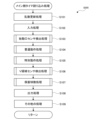
入力処理の後、遊技制御用マイコン81は、始動口センサ検出処理(ステップS103)、普通動作処理(ステップS104)、特別動作処理(ステップS105)、V領域センサ検出処理(ステップS106)、保留球数処理(ステップS107)を順に実行する。これらの処理の詳細については後述する。保留球数処理の後、遊技制御用マイコン81は、出力処理をおこなう(ステップS108)。出力処理では、遊技制御用マイコン81は、上述の各処理においてメインRAM84のコマンドセット領域84aにセットしたコマンド等をサブ制御基板90に出力する。出力処理の後、遊技制御用マイコン81は、その他の処理をおこなう(ステップS109)。その他の処理では、例えば、後述の特図2保留球数に基づいて第2特図保留表示器43bをその数を示す表示態様に制御し、特図1保留球数に基づいて第1特図保留表示器43aをその数を示す表示態様に制御する。 After the input process, the game control microcomputer 81 executes the start hole sensor detection process (step S103), the normal operation process (step S104), the special operation process (step S105), the V-area sensor detection process (step S106), and the reserved ball number process (step S107) in that order. Details of these processes will be described later. After the reserved ball number process, the game control microcomputer 81 executes the output process (step S108). In the output process, the game control microcomputer 81 outputs the commands and the like set in the command set area 84a of the main RAM 84 in each of the above processes to the sub-control board 90. After the output process, the game control microcomputer 81 executes other processes (step S109). In the other processes, for example, the second special chart reserved display 43b is controlled to a display mode showing the number based on the reserved ball number of the special chart 2 described later, and the first special chart reserved display 43a is controlled to a display mode showing the number based on the reserved ball number of the special chart 1.

[始動口センサ検出処理]
図17は、始動口センサ検出処理(図16:ステップS103)のフローチャートである。遊技制御用マイコン81は、まず、ゲート28に遊技球が通過したか否かの判定をおこなう(ステップS201)。この判定は、ゲートセンサ28aによって遊技球が検出されたか否かによっておこなわれる。ゲート28に遊技球が通過していない場合(ステップS201:NO)、処理はステップS205にスキップする。ゲート28に遊技球が通過した場合(ステップS201:YES)、遊技制御用マイコン81は、普通図柄保留球数が「4(上限値)」であるか否かの判定をおこなう(ステップS202)。普通図柄保留球数とは、普図保留の数であり、より具体的には、メインRAM84に設けられた普図保留の数をカウントするカウンタの値である。普通図柄保留球数が「4」であれば(ステップS202:YES)、処理はステップS205にスキップする。普通図柄保留球数が「3」以下の場合(ステップS202:NO)、普通図柄保留球数に「1」を加算した後(ステップS203)、普通図柄乱数取得処理をおこなう(ステップS204)。ここでは、遊技制御用マイコン81は、普通図柄乱数カウンタの値(図7:ラベル-TRND-Hの値)を取得し、取得した乱数値をメインRAM84の普図保留記憶領域86の第1~第4記憶領域うち、現在の普通図柄保留球数に応じた記憶領域に格納する。
[Starting port sensor detection process]
FIG. 17 is a flow chart of the start hole sensor detection process (FIG. 16: step S103). The game control microcomputer 81 first judges whether or not a game ball has passed through the gate 28 (step S201). This judgment is made based on whether or not a game ball has been detected by the gate sensor 28a. If the game ball has not passed through the gate 28 (step S201: NO), the process skips to step S205. If the game ball has passed through the gate 28 (step S201: YES), the game control microcomputer 81 judges whether or not the number of reserved balls for normal symbols is "4 (upper limit value)" (step S202). The number of reserved balls for normal symbols is the number of reserved normal symbols, and more specifically, is the value of a counter that counts the number of reserved normal symbols provided in the main RAM 84. If the number of reserved balls for normal symbols is "4" (step S202: YES), the process skips to step S205. If the number of reserved normal symbol balls is "3" or less (step S202: NO), "1" is added to the number of reserved normal symbol balls (step S203), and then a normal symbol random number acquisition process is performed (step S204). Here, the game control microcomputer 81 acquires the value of the normal symbol random number counter (FIG. 7: value of label-TRND-H), and stores the acquired random number value in the first to fourth memory areas of the normal symbol reserved memory area 86 of the main RAM 84 according to the current number of reserved normal symbol balls.

ステップS205では、遊技制御用マイコン81は、第2始動口21に遊技球が入賞したか否かの判定をおこなう。この判定は、第2始動口センサ21aによって遊技球が検出されたか否かによっておこなわれる。第2始動口21に遊技球が入賞していない場合(ステップS205:NO)、処理はステップS210にスキップする。遊技球が入賞した場合(ステップS205:YES)、遊技制御用マイコン81は、特図2保留球数が「4(上限値)」であるか否かの判定をおこなう(ステップS206)。特図2保留球数とは、第2特図保留の数であり、より具体的には、メインRAM84に設けられた第2特図保留の数をカウントするカウンタの値である。特図2保留球数が「4」であれば(ステップS206:YES)、処理はステップS210にスキップする。特図2保留球数が「3」以下の場合(ステップS206:NO)、特図2保留球数に「1」を加算した後(ステップS207)、特図2関係乱数取得処理をおこなう(ステップS208)。ここでは、大当たり乱数カウンタの値(図7:ラベル-TRND-Aの値)、大当たり種別乱数カウンタの値(図7:ラベル-TRND-ASの値)、リーチ乱数カウンタの値(図7:ラベル-TRND-RCの値)、変動パターン乱数カウンタの値(図7:ラベル-TRND-T1の値)を取得する。遊技制御用マイコン81は、取得した乱数値群を第2特図保留記憶領域85bの第1~第4記憶領域うち、現在の特図2保留球数に応じた記憶領域に格納する。遊技制御用マイコン81は、後述の特図2事前判定処理(図18)のために、取得した乱数値群を第2特図保留記憶領域85bとは異なるバッファ(事前判定用バッファ)にも一時的に記憶(保持)させる。特図2関係乱数取得処理の後、遊技制御用マイコン81は、特図2事前判定処理をおこなう(ステップS209)。特図2事前判定処理の詳細については後述する。 In step S205, the game control microcomputer 81 judges whether or not a game ball has entered the second start hole 21. This judgment is made based on whether or not a game ball has been detected by the second start hole sensor 21a. If a game ball has not entered the second start hole 21 (step S205: NO), the process skips to step S210. If a game ball has entered (step S205: YES), the game control microcomputer 81 judges whether or not the number of reserved balls in the special chart 2 is "4 (upper limit value)" (step S206). The number of reserved balls in the special chart 2 is the number of reserved second special charts, and more specifically, is the value of a counter that counts the number of reserved second special charts provided in the main RAM 84. If the number of reserved balls in the special chart 2 is "4" (step S206: YES), the process skips to step S210. If the number of reserved balls for the special chart 2 is "3" or less (step S206: NO), "1" is added to the number of reserved balls for the special chart 2 (step S207), and then a special chart 2 related random number acquisition process is performed (step S208). Here, the value of the jackpot random number counter (Figure 7: value of label-TRND-A), the value of the jackpot type random number counter (Figure 7: value of label-TRND-AS), the value of the reach random number counter (Figure 7: value of label-TRND-RC), and the value of the variation pattern random number counter (Figure 7: value of label-TRND-T1) are acquired. The game control microcomputer 81 stores the acquired random number group in the storage area corresponding to the current number of reserved balls for the special chart 2 among the first to fourth storage areas of the second special chart reservation storage area 85b. The game control microcomputer 81 temporarily stores (holds) the acquired random number group in a buffer (pre-determination buffer) different from the second special chart reserved memory area 85b for the special chart 2 pre-determination process (FIG. 18) described later. After the special chart 2 related random number acquisition process, the game control microcomputer 81 performs the special chart 2 pre-determination process (step S209). The details of the special chart 2 pre-determination process will be described later.

ステップS210では、遊技制御用マイコン81は、第1始動口20に遊技球が入賞したか否かの判定をおこなう。この判定は、第1始動口センサ20aによって遊技球が検出されたか否かによっておこなわれる。第1始動口20に遊技球が入賞していない場合(ステップS210:NO)、本処理を終了する。第1始動口20に遊技球が入賞した場合(ステップS210:YES)、遊技制御用マイコン81は、特図1保留球数が「4(上限値)」であるか否かの判定をおこなう(ステップS211)。特図1保留球数とは、第1特図保留の数であり、より具体的には、メインRAM84に設けられた第1特図保留の数をカウントするカウンタの値である。特図1保留球数が「4」であれば(ステップS211:YES)、本処理を終了する。特図1保留球数が「3」以下の場合(ステップS211:NO)、特図1保留球数に「1」を加算した後(ステップS212)、特図1関係乱数取得処理をおこなう(ステップS213)。ここでは、上述の特図2関係乱数取得処理(ステップS208)と同様に、大当たり乱数カウンタの値、大当たり種別乱数カウンタの値、リーチ乱数カウンタの値、変動パターン乱数カウンタの値を取得する。遊技制御用マイコン81は、取得した乱数値群を第1特図保留記憶領域85aの第1~第4記憶領域うち、現在の特図1保留球数に応じた記憶領域に格納する。遊技制御用マイコン81は、後述の特図1事前判定処理(図19)のために、取得した乱数値群を第1特図保留記憶領域85aとは異なるバッファ(事前判定用バッファ)にも一時的に記憶(保持)させる。特図1関係乱数取得処理の後、遊技制御用マイコン81は、特図1事前判定処理をおこなう(ステップS214)。特図1事前判定処理の詳細については後述する。 In step S210, the game control microcomputer 81 judges whether or not a game ball has entered the first starting hole 20. This judgment is made based on whether or not a game ball has been detected by the first starting hole sensor 20a. If a game ball has not entered the first starting hole 20 (step S210: NO), this process is terminated. If a game ball has entered the first starting hole 20 (step S210: YES), the game control microcomputer 81 judges whether or not the number of reserved balls in the special chart 1 is "4 (upper limit value)" (step S211). The number of reserved balls in the special chart 1 is the number of reserved first special charts, and more specifically, is the value of a counter that counts the number of reserved first special charts provided in the main RAM 84. If the number of reserved balls in the special chart 1 is "4" (step S211: YES), this process is terminated. If the number of reserved balls for special chart 1 is "3" or less (step S211: NO), "1" is added to the number of reserved balls for special chart 1 (step S212), and then a random number acquisition process related to special chart 1 is performed (step S213). Here, as in the above-mentioned special chart 2 related random number acquisition process (step S208), the value of the jackpot random number counter, the value of the jackpot type random number counter, the value of the reach random number counter, and the value of the variation pattern random number counter are acquired. The game control microcomputer 81 stores the acquired random number group in a storage area corresponding to the current number of reserved balls for special chart 1 among the first to fourth storage areas of the first special chart reservation storage area 85a. The game control microcomputer 81 also temporarily stores (holds) the acquired random number group in a buffer (pre-determination buffer) different from the first special chart reservation storage area 85a for the special chart 1 pre-determination process (FIG. 19) described later. After the special chart 1 related random number acquisition process, the game control microcomputer 81 performs special chart 1 pre-determination process (step S214). The details of the special chart 1 pre-determination process will be described later.

[特図2事前判定処理]
図18は、特図2事前判定処理(図17:ステップS209)のフローチャートである。遊技制御用マイコン81は、まず、確変フラグがONであるか否かの判定をおこなう(ステップS301)。確変フラグがOFFの場合(ステップS301:NO)、本処理を終える。すなわち、確変フラグがOFFの場合には、事前判定はおこなわれない。一方、確変フラグがONの場合、遊技制御用マイコン81は、大当たり判定テーブルT1(図8)のうちの高確率状態用テーブルを参照して大当たり事前判定をおこなう(ステップS302)。具体的には、遊技制御用マイコン81は、まず、特図2関係乱数取得処理(図17:ステップS208)によって事前判定用バッファに一時的に記憶されている判定値としての大当たり乱数値を取得する。次に、遊技制御用マイコン81は、参照する大当たり判定テーブルT1(図8)と大当たり乱数値とを用いて大当たりか否かの事前判定をおこなう。ここでは、高確率状態(確変フラグがON)であるため、遊技制御用マイコン81は、大当たり判定テーブルT1のうち、高確率状態用のテーブル(大当たり判定値が「0」~「649」)を参照して大当たりか否かを事前判定する。すなわち、大当たり乱数値が「0」~「649」のとき「大当たり」と事前判定し、それ以外の値のとき「ハズレ」と事前判定する。なお、本実施形態では、後述する大当たり判定処理(図23)で用いられる大当たり判定テーブルT1を用いて事前判定をおこなっているが、他の実施形態として、大当たり判定テーブルT1とは異なる事前判定用の大当たり判定テーブルを用いて事前判定をおこなってもよい。
[Special Drawing 2 Pre-Decision Processing]
FIG. 18 is a flow chart of the special chart 2 pre-judgment process (FIG. 17: step S209). The game control microcomputer 81 first judges whether the probability of winning is ON or not (step S301). If the probability of winning is OFF (step S301: NO), this process is terminated. That is, if the probability of winning is OFF, no pre-judgment is performed. On the other hand, if the probability of winning is ON, the game control microcomputer 81 performs a pre-judgment of a jackpot by referring to the high probability state table in the jackpot judgment table T1 (FIG. 8) (step S302). Specifically, the game control microcomputer 81 first acquires a jackpot random number value as a judgment value temporarily stored in the pre-judgment buffer by the special chart 2 related random number acquisition process (FIG. 17: step S208). Next, the game control microcomputer 81 performs a pre-judgment of whether or not a jackpot has been won by using the jackpot judgment table T1 (FIG. 8) and the jackpot random number value to be referred to. Here, since the probability state is high (the probability flag is ON), the game control microcomputer 81 refers to the high probability state table (the jackpot determination value is "0" to "649") in the jackpot determination table T1 to determine in advance whether or not there is a jackpot. That is, when the jackpot random number value is "0" to "649", it is determined in advance as a "jackpot", and when it is any other value, it is determined in advance as a "miss". In this embodiment, the jackpot determination table T1 used in the jackpot determination process (FIG. 23) described later is used to perform the pre-determination, but in other embodiments, a jackpot determination table for pre-determination different from the jackpot determination table T1 may be used to perform the pre-determination.

大当たり事前判定の結果が「ハズレ」の場合(ステップS304:NO)、処理はステップS306にスキップする。一方、大当たり事前判定の結果が「大当たり」の場合(ステップS304:YES)、遊技制御用マイコン81は、大当たり種別事前判定をおこなう(ステップS305)。大当たり種別事前判定では、遊技制御用マイコン81は、まず、特図2関係乱数取得処理(図17:ステップS208)によって事前判定用バッファに一時的に記憶されている判定値としての大当たり種別乱数値を取得する。次に、遊技制御用マイコン81は、取得した大当たり種別乱数値と大当たり種別判定テーブルT5(図9)に基づいて、大当たり種別の事前判定をおこなう。ここでは、大当たり種別乱数値が「0」~「127」のいずれであっても「16RV通過予定大当たり」と事前判定する。なお、本実施形態では、後述する大当たり判定処理(図23)で用いられる大当たり種別判定テーブルT5を用いて事前判定をおこなっているが、他の実施形態として、大当たり種別判定テーブルT5とは異なる事前判定用の大当たり種別判定テーブルを用いて事前判定をおこなってもよい。 If the result of the jackpot pre-determination is "miss" (step S304: NO), the process skips to step S306. On the other hand, if the result of the jackpot pre-determination is "jackpot" (step S304: YES), the game control microcomputer 81 performs a jackpot type pre-determination (step S305). In the jackpot type pre-determination, the game control microcomputer 81 first acquires a jackpot type random number value as a determination value temporarily stored in the pre-determination buffer by the special chart 2 related random number acquisition process (FIG. 17: step S208). Next, the game control microcomputer 81 performs a pre-determination of the jackpot type based on the acquired jackpot type random number value and the jackpot type determination table T5 (FIG. 9). Here, regardless of whether the jackpot type random number value is "0" to "127", the pre-determination is "16RV passing scheduled jackpot". In this embodiment, the pre-determination is performed using the jackpot type determination table T5 used in the jackpot determination process (FIG. 23) described later, but in other embodiments, the pre-determination may be performed using a jackpot type determination table for pre-determination that is different from the jackpot type determination table T5.

ステップS306では、遊技制御用マイコン81は、変動パターン事前判定をおこなう。具体的には、遊技制御用マイコン81は、まず、特図2関係乱数取得処理(図17:ステップS208)によって事前判定用バッファに一時的に記憶されている判定値としての変動パターン乱数値、および、リーチ乱数値を取得する。次に、ここでは、時短状態(時短フラグがON)であるため、遊技制御用マイコン81は、時短状態用の変動パターン判定テーブルT6(図11)を参照し、ステップS304の大当たり事前判定結果、リーチ乱数値から得られるリーチの有無事前判定結果、および、変動パターン乱数値から変動パターンを特定する。なお、図11の変動パターン判定テーブルT6では、保留球数の違いによって選択される変動パターンが異なる場合がある。ここでは、保留球数の違いによって選択される可能性のあるすべての変動パターンが選択されるものとする。例えば、大当たり事前判定結果、および、リーチ有無事前判定結果から、リーチ有りハズレが事前判定され、変動パターン乱数値が「60」の場合、遊技制御用マイコン81は、保留球数が「1~2」であれば選択される変動パターン「P64」と、保留球数が「3~4」であれば選択される変動パターン「P68」の2つを選択する。なお、本実施形態では、後述する変動パターン選択処理(図24、図25)で用いられる変動パターン判定テーブルT6を用いて事前判定をおこなっているが、他の実施形態として、変動パターン判定テーブルT6とは異なる事前判定用の変動パターン判定テーブルを用いて事前判定をおこなってもよい。 In step S306, the game control microcomputer 81 performs a pre-determination of the fluctuation pattern. Specifically, the game control microcomputer 81 first obtains the fluctuation pattern random number value and the reach random number value as the judgment value temporarily stored in the pre-determination buffer by the special chart 2 related random number acquisition process (FIG. 17: step S208). Next, since the time-saving state (time-saving flag is ON) is in effect here, the game control microcomputer 81 refers to the fluctuation pattern determination table T6 for the time-saving state (FIG. 11) and specifies the fluctuation pattern from the jackpot pre-determination result of step S304, the reach pre-determination result obtained from the reach random number value, and the fluctuation pattern random number value. In addition, in the fluctuation pattern determination table T6 in FIG. 11, the fluctuation pattern selected may differ depending on the number of reserved balls. Here, it is assumed that all fluctuation patterns that may be selected depending on the number of reserved balls are selected. For example, if a reach or miss is determined in advance based on the jackpot advance determination result and the reach/no reach advance determination result, and the fluctuation pattern random number value is "60", the game control microcomputer 81 selects two patterns: fluctuation pattern "P64" which is selected if the number of reserved balls is "1 to 2", and fluctuation pattern "P68" which is selected if the number of reserved balls is "3 to 4". In this embodiment, the advance determination is performed using the fluctuation pattern determination table T6 used in the fluctuation pattern selection process (FIGS. 24 and 25) described later, but in other embodiments, the advance determination may be performed using a fluctuation pattern determination table for advance determination that is different from the fluctuation pattern determination table T6.

ステップS307では、遊技制御用マイコン81は、事前判定コマンドの作成をおこなう。事前判定コマンドには、大当たり事前判定結果、(当たりの場合には大当たり種別事前判定結果)、および、変動パターン事前判定結果が含まれる。遊技制御用マイコン81は、作成した事前判定コマンドをメインRAM84のコマンドセット領域84aにセットして(ステップS308)、本処理を終える。 In step S307, the game control microcomputer 81 creates a pre-determination command. The pre-determination command includes the jackpot pre-determination result (in the case of a win, the jackpot type pre-determination result) and the fluctuation pattern pre-determination result. The game control microcomputer 81 sets the created pre-determination command in the command set area 84a of the main RAM 84 (step S308), and ends this process.

[特図1事前判定処理]
図19は、特図1事前判定処理(図17:ステップS214)のフローチャートである。遊技制御用マイコン81は、まず、確変フラグがONであるか否かの判定をおこなう(ステップS401)。上述の特図2事前判定処理とは反対に、確変フラグがONの場合(ステップS401:YES)、本処理を終える。すなわち、確変フラグがONの場合には、事前判定はおこなわれない。一方、確変フラグがOFFの場合(ステップS401:NO)、遊技制御用マイコン81は、大当たり判定テーブルT1(図8)のうちの通常確率状態用のテーブルを参照して大当たり事前判定をおこなう(ステップS402)。具体的には、遊技制御用マイコン81は、まず、特図1関係乱数取得処理(図17:ステップS213)によって事前判定用バッファに一時的に記憶されている判定値としての大当たり乱数値を取得する。次に、ここでは、通常確率状態(確変フラグがOFF)であるため、遊技制御用マイコン81は、大当たり判定テーブルT1のうち、通常確率状態用のテーブル(大当たり判定値が「0」~「164」)に基づいて大当たりか否かを事前判定する。すなわち、大当たり乱数値が「0」~「164」のとき「大当たり」と事前判定し、それ以外の値のとき「ハズレ」と事前判定する。なお、大当たり事前判定は、大当たり判定テーブルT1とは異なる事前判定用の大当たり判定テーブルを用いてもよい。以降、ステップS404~S408の処理は、上述の特図2事前判定処理(図18)のステップS304~S308と同様であるため説明を省略する。
[Special Figure 1 Pre-judgment Processing]
FIG. 19 is a flow chart of the special chart 1 pre-judgment process (FIG. 17: step S214). The game control microcomputer 81 first judges whether the probability variable flag is ON or not (step S401). Contrary to the above-mentioned special chart 2 pre-judgment process, if the probability variable flag is ON (step S401: YES), this process is terminated. That is, if the probability variable flag is ON, pre-judgment is not performed. On the other hand, if the probability variable flag is OFF (step S401: NO), the game control microcomputer 81 performs a jackpot pre-judgment by referring to the table for the normal probability state in the jackpot judgment table T1 (FIG. 8) (step S402). Specifically, the game control microcomputer 81 first acquires a jackpot random number value as a judgment value temporarily stored in the pre-judgment buffer by the special chart 1 related random number acquisition process (FIG. 17: step S213). Next, since the state is normal probability (the probability flag is OFF), the game control microcomputer 81 pre-determines whether or not there is a jackpot based on the table for normal probability (the jackpot determination value is "0" to "164") in the jackpot determination table T1. That is, when the jackpot random number value is "0" to "164", it is pre-determined as a "jackpot", and when it is any other value, it is pre-determined as a "miss". Note that the jackpot pre-determination may use a jackpot determination table for pre-determination that is different from the jackpot determination table T1. The process of steps S404 to S408 is the same as steps S304 to S308 of the special chart 2 pre-determination process (FIG. 18) described above, so the description will be omitted.

[普通動作処理]
図20は、普通動作処理(図16:ステップS104)のフローチャートである。遊技制御用マイコン81は、まず、電チュー22が作動中か否かの判定をおこなう(ステップS501)。電チュー22が作動中の場合(ステップS501:YES)、処理はステップS520に移行する。電チュー22が作動中ではない場合(ステップS501:NO)、遊技制御用マイコン81は、普通図柄の変動中か否かの判定をおこなう(ステップS502)。普通図柄の変動中の場合(ステップS502:YES)、処理はステップS508にスキップする。普通図柄の変動中ではない場合(ステップS502:NO)、遊技制御用マイコン81は、普通図柄の保留球数が「0」か否かの判定をおこなう(ステップS503)。保留球数が「0」の場合(ステップS503:YES)、本処理を終了する。保留球数が1以上ある場合(ステップS503:NO)、普通図柄保留球数を1ディクリメントする(ステップS504)。従って、普通図柄の保留球数が「0」の状態でゲート28を遊技球が通過した場合、始動口センサ検出処理(図17)のステップS203において、一旦、普通図柄の保留球数が「1」になり、その後、本ステップS504において保留が消化され即座に普通図柄の保留球数が「0」になる。これは、特別図柄の保留球数についても同様である。すなわち、始動口センサ検出処理(図17)のステップS207およびステップS212において、一旦、特別図柄の保留数が「1」になり、その後、後述の特別図柄待機処理(図22)におけるステップS1404およびステップS1410において保留が消化され特別図柄の保留球数が「0」になる。次に、遊技制御用マイコン81は、普通図柄当たり判定テーブルT3(図8(C))を参照して当たり判定をおこなう(ステップS505)。具体的には、遊技制御用マイコン81は、まず、普図保留記憶領域86の第1記憶領域(普図保留の1個目に対応)に記憶されている判定値としての普通図柄乱数値(当たり乱数値)を読み出す。そして、普通図柄乱数値と、遊技状態(時短状態か否か)と、普通図柄当たり判定テーブルT3とを用いて当たりか否かを判定する。例えば、非時短状態において、普通図柄乱数値が「0」~「2」の場合には、「当たり」と判定され、普通図柄乱数値がそれ以外の場合には、「ハズレ」と判定される(図8(C)参照)。
[Normal operation processing]
FIG. 20 is a flow chart of the normal operation process (FIG. 16: step S104). The game control microcomputer 81 first judges whether the electric chute 22 is in operation (step S501). If the electric chute 22 is in operation (step S501: YES), the process proceeds to step S520. If the electric chute 22 is not in operation (step S501: NO), the game control microcomputer 81 judges whether the normal pattern is changing (step S502). If the normal pattern is changing (step S502: YES), the process skips to step S508. If the normal pattern is not changing (step S502: NO), the game control microcomputer 81 judges whether the number of reserved balls of the normal pattern is "0" (step S503). If the number of reserved balls is "0" (step S503: YES), the process ends. If the number of reserved balls is 1 or more (step S503: NO), the number of reserved balls of normal symbols is decremented by 1 (step S504). Therefore, when the game ball passes through the gate 28 with the number of reserved balls of normal symbols being "0", the number of reserved balls of normal symbols becomes "1" once in step S203 of the start hole sensor detection process (FIG. 17), and then the reserved balls are consumed in this step S504, and the reserved balls of normal symbols immediately become "0". This is the same for the number of reserved balls of special symbols. That is, in steps S207 and S212 of the start hole sensor detection process (FIG. 17), the reserved balls of special symbols become "1" once, and then the reserved balls are consumed in steps S1404 and S1410 of the special symbol waiting process (FIG. 22) described later, and the reserved balls of special symbols become "0". Next, the game control microcomputer 81 performs a win judgment by referring to the normal symbol win judgment table T3 (FIG. 8(C)) (step S505). Specifically, the game control microcomputer 81 first reads out the normal symbol random number value (win random number value) stored as a judgment value in the first memory area (corresponding to the first normal symbol reserved) of the normal symbol reserved memory area 86. Then, it judges whether or not there is a win by using the normal symbol random number value, the game state (whether or not there is a time-saving state), and the normal symbol win judgment table T3. For example, in the non-time-saving state, if the normal symbol random number value is "0" to "2", it is judged as a "win", and if the normal symbol random number value is other than that, it is judged as a "lose" (see FIG. 8(C)).

次に、遊技制御用マイコン81は、普通図柄変動パターン判定テーブルT4(図8(D))を参照して変動パターンの選択をおこなう(ステップS506)。具体的には、遊技制御用マイコン81は、まず、遊技状態(時短状態か否か)の判定をおこない、遊技状態の判定結果と、普通図柄変動パターン判定テーブルT4とを用いて、普通図柄変動パターンとしての普通図柄の変動時間を選択する。ここでは、非時短状態のとき、普通図柄の変動時間は「30秒」と判定され、時短状態のとき、普通図柄の変動時間が「1秒」と判定される(図8(D)参照)。遊技制御用マイコン81は、選択した普通図柄変動パターンをセットすることで、普通図柄の変動表示を開始させる(ステップS507)。 Next, the game control microcomputer 81 refers to the normal symbol fluctuation pattern judgment table T4 (FIG. 8 (D)) to select a fluctuation pattern (step S506). Specifically, the game control microcomputer 81 first judges the game state (whether or not it is in a time-saving state), and selects the normal symbol fluctuation time as a normal symbol fluctuation pattern using the game state judgment result and the normal symbol fluctuation pattern judgment table T4. Here, in the non-time-saving state, the normal symbol fluctuation time is judged to be "30 seconds", and in the time-saving state, the normal symbol fluctuation time is judged to be "1 second" (see FIG. 8 (D)). The game control microcomputer 81 sets the selected normal symbol fluctuation pattern to start displaying the normal symbol fluctuation (step S507).

ステップS508では、遊技制御用マイコン81は、普通図柄の変動時間が経過して終了したか否かの判定をおこなう。普通図柄の変動時間とは、ステップS506で選択された変動時間である(図8(D)参照)。変動時間が終了していない場合(ステップS508:NO)、遊技制御用マイコン81は、本処理を終える。すなわち、普通図柄の変動表示が継続される。一方、変動時間が終了している場合(ステップS508:YES)、遊技制御用マイコン81は、変動表示を停止させ(ステップS509)、上述の当たり判定(ステップS505)において「ハズレ」の場合には(ステップS510:NO)、本処理を終える。一方、上述の当たり判定で「当たり」の場合には(ステップS510:YES)、遊技制御用マイコン81は、電チュー開放パターンのセットをおこなう(ステップS511)。電チュー22の開放パターンは、電チュー開放パターン判定テーブルT7(図12(A))を参照して選択される。具体的には、遊技制御用マイコン81は、遊技状態(時短状態か否か)の判定をおこない、遊技状態の判定結果と、電チュー開放パターン判定テーブルT7とを用いて電チュー22の開放パターンを選択する。ここでは、非時短状態のとき、「開放パターン11」が選択され、時短状態のとき、「開放パターン12」が選択される。開放パターンの選択後、遊技制御用マイコン81は、選択した開放パターンに従うように電チュー作動を開始させ(ステップS512)、本処理を終える。 In step S508, the game control microcomputer 81 determines whether the normal symbol fluctuation time has elapsed and ended. The normal symbol fluctuation time is the fluctuation time selected in step S506 (see FIG. 8 (D)). If the fluctuation time has not ended (step S508: NO), the game control microcomputer 81 ends this process. That is, the normal symbol fluctuation display continues. On the other hand, if the fluctuation time has ended (step S508: YES), the game control microcomputer 81 stops the fluctuation display (step S509), and if the above-mentioned hit determination (step S505) is a "miss" (step S510: NO), this process ends. On the other hand, if the above-mentioned hit determination is a "win" (step S510: YES), the game control microcomputer 81 sets the electric chute opening pattern (step S511). The opening pattern of the electric chute 22 is selected by referring to the electric chute opening pattern determination table T7 (Figure 12 (A)). Specifically, the game control microcomputer 81 determines the game state (whether or not it is in a time-saving state), and selects the opening pattern of the electric chute 22 using the game state determination result and the electric chute opening pattern determination table T7. Here, when it is in a non-time-saving state, "opening pattern 11" is selected, and when it is in a time-saving state, "opening pattern 12" is selected. After selecting the opening pattern, the game control microcomputer 81 starts the operation of the electric chute in accordance with the selected opening pattern (step S512), and ends this process.

上述のステップS501において、電チュー22が作動中の場合(ステップS501:YES)、遊技制御用マイコン81は、電チュー22の閉鎖条件が成立しているか否かの判定をおこなう(ステップS520)。ここでの閉鎖条件は、電チュー22への入賞個数が規定の最大入賞個数(例えば6個)に達したこと、または、電チュー22の作動時間が経過して電チュー22を閉鎖させる時間に至ったことのいずれかが満たされていることである。電チュー22の作動時間とは、ステップS511で選択された開放パターンに対応する作動時間である。電チュー22の閉鎖条件が成立していない場合(ステップS520:NO)、遊技制御用マイコン81は、本処理を終える。一方、電チュー22の閉鎖条件が成立している場合(ステップS520:YES)、遊技制御用マイコン81は、電チュー22を閉鎖(閉塞)してその作動を停止し(ステップS521)、本処理を終える。 In the above-mentioned step S501, if the electric chute 22 is in operation (step S501: YES), the game control microcomputer 81 judges whether the closing condition of the electric chute 22 is satisfied (step S520). The closing condition here is that either the number of winning balls in the electric chute 22 has reached a specified maximum number of winning balls (for example, 6 balls) or the operation time of the electric chute 22 has elapsed and it has become time to close the electric chute 22. The operation time of the electric chute 22 is the operation time corresponding to the opening pattern selected in step S511. If the closing condition of the electric chute 22 is not satisfied (step S520: NO), the game control microcomputer 81 ends this process. On the other hand, if the closing condition of the electric chute 22 is satisfied (step S520: YES), the game control microcomputer 81 closes (blocks) the electric chute 22 and stops its operation (step S521), and ends this process.

[特別動作処理]
図21は、特別動作処理(図16:ステップS105)のフローチャートである。ここでは、特別図柄表示器41および大入賞装置(第1大入賞装置31および第2大入賞装置36)に関する処理を4つの段階に分け、各段階をそれぞれ「特別動作ステータス」の「1」、「2」、「3」、「4」と呼ぶ。遊技制御用マイコン81は、「特別動作ステータス」が「1」のとき(ステップS1301:YES)、特別図柄待機処理をおこなう(ステップS1302)。特別図柄待機処理では、大当たり判定や変動パターン選択等が実行される。「特別動作ステータス」が「2」のときには(ステップS1301:NO、ステップS1303:YES)、特別図柄変動中処理をおこなう(ステップS1304)。特別図柄変動中処理では、変動時間経過後に変動停止コマンドの出力等が実行される。「特別動作ステータス」が「3」のときには(ステップS1301、S1303:NO、ステップS1305:YES)、特別図柄確定処理をおこなう(ステップS1306)。特別図柄確定処理では、大当たり時にオープニングコマンドの出力等が実行される。「特別動作ステータス」が「4」のときには(ステップS1301、S1303、S1305:NO)、特別電動役物処理をおこなう(ステップS1308)。特別電動役物処理では、大当たり遊技が実行される。上記の各処理の詳細については後述する。なお、特別動作ステータスは、初期設定では「1」である。
[Special Action Processing]
FIG. 21 is a flow chart of the special operation process (FIG. 16: step S105). Here, the process related to the special symbol display 41 and the big prize device (first big prize device 31 and second big prize device 36) is divided into four stages, and each stage is called "1", "2", "3", and "4" of the "special operation status". When the "special operation status" is "1" (step S1301: YES), the game control microcomputer 81 performs a special symbol standby process (step S1302). In the special symbol standby process, a big win determination, a change pattern selection, and the like are executed. When the "special operation status" is "2" (step S1301: NO, step S1303: YES), a special symbol change process is executed (step S1304). In the special symbol change process, a change stop command is output after the change time has elapsed. When the "special operation status" is "3" (steps S1301, S1303: NO, step S1305: YES), a special symbol determination process is performed (step S1306). In the special symbol determination process, an opening command is output when a jackpot occurs. When the "special operation status" is "4" (steps S1301, S1303, S1305: NO), a special electric device process is performed (step S1308). In the special electric device process, a jackpot game is executed. Details of each of the above processes will be described later. The initial setting of the special operation status is "1".

[特別図柄待機処理]
図22は、特別図柄待機処理(図21:ステップS1302)のフローチャートである。特別図柄待機処理では、遊技制御用マイコン81は、まず、特図2保留球数が「0」であるか否かの判定をおこなう(ステップS1401)。特図2保留球数が「0」である場合(ステップS1401:YES)、すなわち、第2特図保留記憶領域85bに、第2始動口21への入賞に起因して取得した乱数値群の記憶がない場合には、処理はステップS1407に移行する。特図2保留球数が「1」以上である場合(ステップS1401:NO)、遊技制御用マイコン81は、大当たり判定処理(ステップS1402)、および、変動パターン選択処理(ステップS1403)を実行する。これらの処理の詳細については後述する。変動パターン選択処理の後、特図2保留球数を1つディクリメントする(ステップS1404)。次に、遊技制御用マイコン81は、第2特図保留記憶領域85bの第1~第4記憶領域に格納されている保留情報(各種乱数値)の格納場所を現在の位置から読み出される側に1つシフトするとともに、第2特図保留記憶領域85bにおいて読み出される側から最も遠い場所に格納されている保留情報をクリアする(ステップS1405)。例えば、第1~第3記憶領域に保留情報が格納されている場合には、第3記憶領域に格納されている保留情報をクリアし、第1~第4記憶領域に保留情報が格納されている場合には、第4記憶領域に格納されている保留情報をクリアする。上記ステップによって、第2特図保留が保留された順に消化される。この場合、画像表示装置7の表示画面7aでは、第2特図保留記憶領域85bの第1記憶領域に対応する保留画像9B(4つの保留画像9Bのうち、一番左端の保留画像9B)が保留消化画像表示領域側にシフトし、保留消化画像9Cとして表示される。また、第2特図保留記憶領域85bの第2~第4記憶領域に対応する保留画像9B(4つの保留画像9Bのうち、左から2、3、4番目の保留画像9B)がそれぞれ左側に1つシフトする(図1)。これにより、遊技者は、第2特図保留が1つ消化されたことを認識することができる。次に、遊技制御用マイコン81は、特図2変動開始処理をおこなう(ステップS1406)。特図2変動開始処理では、変動開始コマンドをメインRAM84のコマンドセット領域84aにセットし、第2特別図柄の変動表示を開始させるとともに、変動時間タイマのセットをおこなう。変動時間タイマには、変動パターン選択処理で選択された変動パターンに応じて決定される変動時間がセットされる。また、遊技制御用マイコン81は、特別動作ステータスを「2」にセットする。なお、特図2変動開始処理でセットされる変動開始コマンド(特図2変動開始コマンド)には、大当たり判定処理(ステップS1402)でセットされた特図停止図柄データに関する情報や変動パターン選択処理(ステップS1403)でセットされた変動パターンに関する情報(変動時間に関する情報を含む)が含まれている。
[Special symbol standby process]
FIG. 22 is a flowchart of the special symbol waiting process (FIG. 21: step S1302). In the special symbol waiting process, the game control microcomputer 81 first judges whether the number of reserved balls of the special symbol 2 is "0" or not (step S1401). If the number of reserved balls of the special symbol 2 is "0" (step S1401: YES), that is, if the second special symbol reserved memory area 85b does not store a random number group acquired due to winning the second starting hole 21, the process proceeds to step S1407. If the number of reserved balls of the special symbol 2 is "1" or more (step S1401: NO), the game control microcomputer 81 executes a jackpot determination process (step S1402) and a variable pattern selection process (step S1403). Details of these processes will be described later. After the variable pattern selection process, the number of reserved balls of the special symbol 2 is decremented by one (step S1404). Next, the game control microcomputer 81 shifts the storage location of reserved information (various random numbers) stored in the first to fourth storage areas of the second special chart reserved storage area 85b from the current position to the side to be read, and clears the reserved information stored in the farthest location from the side to be read in the second special chart reserved storage area 85b (step S1405). For example, when reserved information is stored in the first to third storage areas, the reserved information stored in the third storage area is cleared, and when reserved information is stored in the first to fourth storage areas, the reserved information stored in the fourth storage area is cleared. By the above steps, the reserved second special charts are consumed in the order in which they were reserved. In this case, on the display screen 7a of the image display device 7, the reserved image 9B (the leftmost reserved image 9B among the four reserved images 9B) corresponding to the first storage area of the second special chart reserved storage area 85b is shifted to the reserved consumption image display area side and is displayed as the reserved consumption image 9C. Also, the reserved images 9B (the second, third, and fourth reserved images 9B from the left out of the four reserved images 9B) corresponding to the second to fourth storage areas of the second special symbol reserved storage area 85b are shifted one to the left (FIG. 1). This allows the player to recognize that one second special symbol reservation has been consumed. Next, the game control microcomputer 81 performs special symbol 2 variation start processing (step S1406). In the special symbol 2 variation start processing, a variation start command is set in the command set area 84a of the main RAM 84, the variation display of the second special symbol is started, and the variation time timer is set. The variation time timer is set to a variation time determined according to the variation pattern selected in the variation pattern selection processing. Also, the game control microcomputer 81 sets the special operation status to "2". In addition, the fluctuation start command (special chart 2 fluctuation start command) set in the special chart 2 fluctuation start process includes information regarding the special chart stop pattern data set in the jackpot determination process (step S1402) and information regarding the fluctuation pattern set in the fluctuation pattern selection process (step S1403) (including information regarding the fluctuation time).

ステップS1401において、特図2保留球数が「0」の場合(ステップS1401:YES)、遊技制御用マイコン81は、特図1保留球数が「0」であるか否かの判定をおこなう(ステップS1407)。特図1保留球数が「0」である場合(ステップS1407:YES)、すなわち、第1特図保留記憶領域85aに、第1始動口20への入賞に起因して取得した乱数値群の記憶がない場合には、処理はステップS1413に移行する。特図1保留球数が「1」以上である場合(ステップS1407:NO)、遊技制御用マイコン81は、大当たり判定処理(ステップS1408)、および、変動パターン選択処理(ステップS1409)を実行する。これらの処理の詳細については後述する。変動パターン選択処理の後、特図1保留球数を1つディクリメントする(ステップS1410)。次に、遊技制御用マイコン81は、第1特図保留記憶領域85aの第1~第4記憶領域に格納されている各種乱数値の格納場所を現在の位置から読み出される側に1つシフトするとともに、第1特図保留記憶領域85aにおいて読み出される側から最も遠い場所に格納されている保留情報をクリアする(ステップS1411)。上記ステップによって、第1特図保留が保留された順に消化される。この場合、画像表示装置7の表示画面7aでは、第1特図保留記憶領域85aの第1記憶領域に対応する保留画像9A(4つの保留画像9Aのうち、一番右端の保留画像9A)が保留消化画像表示領域側にシフトし、保留消化画像9Cとして表示される。また、第1特図保留記憶領域85aの第2~第4記憶領域に対応する保留画像9A(4つの保留画像9Aのうち、左から2、3、4番目の保留画像9A)がそれぞれ右側に1つシフトする(図1)。これにより、遊技者は、第1特図保留が1つ消化されたことを認識することができる。次に、遊技制御用マイコン81は、特図1変動開始処理をおこなう(ステップS1412)。特図1変動開始処理では、変動開始コマンドをメインRAM84のコマンドセット領域84aにセットし、第1特別図柄の変動表示を開始させるとともに、変動時間タイマのセットをおこなう。変動時間タイマには、変動パターン選択処理で選択された変動パターンに応じて決定される変動時間がセットされる。また、遊技制御用マイコン81は、特別動作ステータスを「2」にセットする(ステップS1406)。なお、特図1変動開始処理でセットされる変動開始コマンド(特図1変動開始コマンド)には、大当たり判定処理(ステップS1408)でセットされた特図停止図柄データに関する情報や変動パターン選択処理(ステップS1409)でセットされた変動パターンに関する情報(変動時間に関する情報を含む)が含まれている。 In step S1401, if the number of reserved balls in the special chart 2 is "0" (step S1401: YES), the game control microcomputer 81 judges whether the number of reserved balls in the special chart 1 is "0" or not (step S1407). If the number of reserved balls in the special chart 1 is "0" (step S1407: YES), that is, if the first special chart reserved memory area 85a does not store a random number group obtained due to winning the first starting hole 20, the process proceeds to step S1413. If the number of reserved balls in the special chart 1 is "1" or more (step S1407: NO), the game control microcomputer 81 executes a jackpot determination process (step S1408) and a variation pattern selection process (step S1409). Details of these processes will be described later. After the variation pattern selection process, the number of reserved balls in the special chart 1 is decremented by one (step S1410). Next, the game control microcomputer 81 shifts the storage location of various random numbers stored in the first to fourth storage areas of the first special chart reserved storage area 85a from the current position to the side to be read, and clears the reserved information stored in the farthest location from the side to be read in the first special chart reserved storage area 85a (step S1411). Through the above steps, the first special chart reserved is consumed in the order in which it was reserved. In this case, on the display screen 7a of the image display device 7, the reserved image 9A (the reserved image 9A at the right end of the four reserved images 9A) corresponding to the first storage area of the first special chart reserved storage area 85a is shifted to the reserved consumption image display area side and is displayed as a reserved consumption image 9C. In addition, the reserved images 9A (the second, third, and fourth reserved images 9A from the left of the four reserved images 9A) corresponding to the second to fourth storage areas of the first special chart reserved storage area 85a are each shifted one position to the right (FIG. 1). This allows the player to recognize that one first special chart reserved has been consumed. Next, the game control microcomputer 81 performs special symbol 1 variation start processing (step S1412). In the special symbol 1 variation start processing, a variation start command is set in the command set area 84a of the main RAM 84, the variation display of the first special symbol is started, and the variation time timer is set. The variation time timer is set to a variation time determined according to the variation pattern selected in the variation pattern selection processing. In addition, the game control microcomputer 81 sets the special operation status to "2" (step S1406). Note that the variation start command (special symbol 1 variation start command) set in the special symbol 1 variation start processing includes information on the special symbol stop pattern data set in the big win determination processing (step S1408) and information on the variation pattern set in the variation pattern selection processing (step S1409) (including information on the variation time).

ステップS1407において、特図1保留球数が「0」の場合(ステップS1407:YES)、遊技制御用マイコン81は、画像表示装置7の表示画面7aが待機画面か否かの判定をおこなう(ステップS1413)。待機画面とは、客待ち用のデモ画面のことである。遊技制御用マイコン81は、例えば、客待ち用のデモ画面表示フラグのON/OFFによって判定してもよい。待機画面である場合(ステップS1413:YES)、本処理を終了する。待機画面でない場合(ステップS1413:NO)、遊技制御用マイコン81は、所定の待機時間の経過をまって、待機場面を表示させるための客待ち待機コマンドをメインRAM84のコマンドセット領域84aにセットし(ステップS1414)、本処理を終える。上記のように、本実施形態の特別図柄待機処理によれば、第1特図保留に基づく特別図柄の変動表示は、第2特図保留が「0」の場合に限って実行される。すなわち、第2特図保留の消化は、第1特図保留の消化に優先して実行される。また、本実施形態の大当たり種別判定テーブルT5によれば、第2特図保留に基づく抽選の方が、第1特図保留に基づく抽選よりも遊技者にとって利益の大きい大当たり(V通過予定大当たり)に当選しやすくなっている。 In step S1407, if the number of reserved balls for special symbol 1 is "0" (step S1407: YES), the game control microcomputer 81 judges whether the display screen 7a of the image display device 7 is a waiting screen or not (step S1413). The waiting screen is a demo screen for waiting for customers. The game control microcomputer 81 may judge, for example, by the ON/OFF of the demo screen display flag for waiting for customers. If it is a waiting screen (step S1413: YES), this process ends. If it is not a waiting screen (step S1413: NO), the game control microcomputer 81 waits for a predetermined waiting time to elapse, sets a customer waiting waiting command for displaying a waiting scene in the command set area 84a of the main RAM 84 (step S1414), and ends this process. As described above, according to the special symbol waiting process of this embodiment, the variable display of the special symbol based on the first special symbol reservation is executed only when the second special symbol reservation is "0". That is, the consumption of the second reserved special chart is executed with priority over the consumption of the first reserved special chart. Also, according to the jackpot type determination table T5 of this embodiment, the lottery based on the second reserved special chart makes it easier for the player to win a jackpot (a jackpot scheduled to pass V) that is more profitable for the player than the lottery based on the first reserved special chart.

[大当たり判定処理]
図23は、大当たり判定処理(図22:ステップS1402、S1408)のフローチャートである。特図2の大当たり判定処理(ステップS1402)と特図1の大当たり判定処理(ステップS1408)は処理の流れが同様であるため、まとめて説明する。大当たり判定処理では、まず、遊技制御用マイコン81は、確変フラグがONであるか否かの判定をおこなう(ステップS1501)。確変フラグがONの場合(ステップS1501:YES)、大当たり判定テーブルT1(図8)のうちの高確率状態用テーブルを参照して大当たり判定をおこなう(ステップS1502)。具体的には、遊技制御用マイコン81は、まず、判定値としての大当たり乱数値の読み出しをおこなう。例えば、特図2の大当たり判定処理では、第2特図保留記憶領域85bの第1記憶領域(第2特図保留の1個目に対応)に記憶されている大当たり乱数値を読み出す。特図1の大当たり判定処理では、第1特図保留記憶領域85aの第1記憶領域(第1特図保留の1個目に対応)に記憶されている大当たり乱数値を読み出す。次に、遊技制御用マイコン81は、参照する大当たり判定テーブルT1と大当たり乱数値とを用いて大当たりか否かを判定する。ここでは、高確率状態(確変フラグがON)であるため、大当たり判定テーブルT1のうち、高確率状態用のテーブル(大当たり判定値が「0」~「649」)に基づいて大当たりか否かを判定する。
[Jackpot determination process]
FIG. 23 is a flow chart of the jackpot determination process (FIG. 22: steps S1402, S1408). The jackpot determination process for special chart 2 (step S1402) and the jackpot determination process for special chart 1 (step S1408) are similar in process flow, so they will be described together. In the jackpot determination process, the game control microcomputer 81 first determines whether the probability variable flag is ON (step S1501). If the probability variable flag is ON (step S1501: YES), the game control microcomputer 81 performs the jackpot determination by referring to the high probability state table in the jackpot determination table T1 (FIG. 8) (step S1502). Specifically, the game control microcomputer 81 first reads out the jackpot random number value as the determination value. For example, in the jackpot determination process for special chart 2, the jackpot random number value stored in the first storage area (corresponding to the first one of the second special chart reserved) of the second special chart reserved storage area 85b is read out. In the jackpot determination process for special chart 1, the jackpot random number stored in the first storage area (corresponding to the first reserved first special chart) of the first special chart reserved storage area 85a is read. Next, the game control microcomputer 81 determines whether or not a jackpot has occurred by using the jackpot determination table T1 and the jackpot random number value to which it refers. Here, since the probability of a jackpot is high (the probability flag is ON), the jackpot determination is determined based on the table for the high probability state (the jackpot determination value is "0" to "649") in the jackpot determination table T1.

ステップS1501において、確変フラグがOFFの場合(ステップS1501:NO)、遊技制御用マイコン81は、大当たり判定テーブルT1(図8)のうちの通常確率状態用のテーブルを参照して大当たり判定をおこなう(ステップS1504)。具体的には、遊技制御用マイコン81は、まず、ステップS1502と同様の方法によって大当たり乱数値の読み出しをおこなう。次に、ここでは、通常確率状態(確変フラグがOFF)であるため、大当たり判定テーブルT1のうち、通常確率状態用のテーブル(大当たり判定値が「0」~「164」)に基づいて大当たりか否かを判定する。 In step S1501, if the probability change flag is OFF (step S1501: NO), the game control microcomputer 81 performs a jackpot determination by referring to the table for the normal probability state in the jackpot determination table T1 (FIG. 8) (step S1504). Specifically, the game control microcomputer 81 first reads out the jackpot random number value in the same manner as in step S1502. Next, since the normal probability state (probability change flag is OFF) is being used here, it determines whether or not a jackpot has occurred based on the table for the normal probability state (the jackpot determination value is "0" to "164") in the jackpot determination table T1.

大当たり判定の結果が「大当たり」の場合(ステップS1503、S1505:YES)、遊技制御用マイコン81は、大当たりフラグをONにするとともに(ステップS1506)、大当たり種別の判定をおこなう(ステップS1507)。具体的には、遊技制御用マイコン81は、まず、判定値としての大当たり種別乱数値の読み出しをおこなう。例えば、特図2の大当たり判定処理では、第2特図保留記憶領域85bの第1記憶領域に記憶されている大当たり種別乱数値を読み出す。特図1の大当たり判定処理では、第1特図保留記憶領域85aの第1記憶領域に記憶されている大当たり種別乱数値を読み出す。次に、遊技制御用マイコン81は、読み出した大当たり種別乱数値と大当たり種別判定テーブルT5(図9)に基づいて、大当たり種別の判定をおこなう。大当たり種別の判定後、特定された大当たり種別に応じた特図停止図柄データ(図9)をメインRAM84に設けた大当たり種別バッファにセットして(ステップS1520)、本処理を終了する。一方、ステップS1503またはステップS1505において、大当たり判定の結果が「ハズレ」の場合、ハズレ図柄に応じた特図停止図柄データ(01H)をメインRAM84に設けた大当たり種別バッファにセットして(ステップS1520)、本処理を終了する。 If the result of the jackpot determination is "jackpot" (steps S1503, S1505: YES), the game control microcomputer 81 turns on the jackpot flag (step S1506) and determines the type of jackpot (step S1507). Specifically, the game control microcomputer 81 first reads out the jackpot type random number value as a determination value. For example, in the jackpot determination process for special chart 2, the jackpot type random number value stored in the first storage area of the second special chart reserved storage area 85b is read out. In the jackpot determination process for special chart 1, the jackpot type random number value stored in the first storage area of the first special chart reserved storage area 85a is read out. Next, the game control microcomputer 81 determines the type of jackpot based on the read out jackpot type random number value and the jackpot type determination table T5 (FIG. 9). After determining the type of jackpot, the special stop pattern data (FIG. 9) corresponding to the identified jackpot type is set in the jackpot type buffer provided in the main RAM 84 (step S1520), and this process ends. On the other hand, in step S1503 or step S1505, if the result of the jackpot determination is "miss," the special stop pattern data (01H) corresponding to the miss pattern is set in the jackpot type buffer provided in the main RAM 84 (step S1520), and this process ends.

[変動パターン選択処理]
図24および図25は、変動パターン選択処理(図22:ステップS1403、S1409)のフローチャートである。特図2の変動パターン選択処理(ステップS1403)と特図1の変動パターン選択処理(ステップS1409)は処理の流れが同様であるため、まとめて説明する。変動パターン選択処理では、まず、遊技制御用マイコン81は、遊技状態が時短状態であるか否かの判定をおこなう(ステップS1600)。時短状態であるか否かの判定は、時短フラグがONか否かによっておこなわれる。時短状態である場合(ステップS1600:YES)、処理はステップS1612に移行する。時短状態でない場合(ステップS1600:NO)、遊技制御用マイコン81は、大当たりフラグがONか否かの判定をおこなう(ステップS1602)。大当たりフラグがOFFの場合(ステップS1602:NO)、処理はステップS1607に移行する。大当たりフラグがONの場合(ステップS1602:YES)、遊技制御用マイコン81は、大当たりが特図2か否かの判定をおこなう(ステップS1603)。大当たりが特図2の場合(ステップS1603:YES)、大当たり種別が必ずV通過予定大当たりとなるため、処理はステップS1605にスキップする。大当たりが特図1の場合(ステップS1603:NO)、遊技制御用マイコン81は、大当たり種別がV通過予定大当たりか否かの判定をおこなう(ステップS1604)、大当たり種別の判定は、メインRAM84にセットされている特図停止図柄データに基づいておこなわれる。
[Variation pattern selection process]
24 and 25 are flow charts of the variation pattern selection process (FIG. 22: steps S1403, S1409). The variation pattern selection process of the special chart 2 (step S1403) and the variation pattern selection process of the special chart 1 (step S1409) are similar in flow of processing, so they will be described together. In the variation pattern selection process, first, the game control microcomputer 81 judges whether the game state is in a time-saving state or not (step S1600). The judgment of whether the game state is in a time-saving state or not is made by whether the time-saving flag is ON or not. If the game state is in a time-saving state (step S1600: YES), the process proceeds to step S1612. If the game state is not in a time-saving state (step S1600: NO), the game control microcomputer 81 judges whether the jackpot flag is ON or not (step S1602). If the jackpot flag is OFF (step S1602: NO), the process proceeds to step S1607. When the jackpot flag is ON (step S1602: YES), the game control microcomputer 81 judges whether the jackpot is a special symbol 2 or not (step S1603). When the jackpot is a special symbol 2 (step S1603: YES), the jackpot type is always a V-passing jackpot, so the process skips to step S1605. When the jackpot is a special symbol 1 (step S1603: NO), the game control microcomputer 81 judges whether the jackpot type is a V-passing jackpot or not (step S1604). The jackpot type is judged based on the special symbol stop pattern data set in the main RAM 84.

大当たり種別がV通過予定大当たりの場合(ステップS1604:YES)、遊技制御用マイコン81は、変動パターン判定テーブルT6(図10)のうち、非時短状態V通過予定大当たり用のテーブルを参照して変動パターンの選択をおこなう(ステップS1605)。具体的には、遊技制御用マイコン81は、まず、判定値としての変動パターン乱数値の読み出しをおこなう。例えば、特図2の変動パターン選択処理では、第2特図保留記憶領域85bの第1記憶領域(第2特図保留の1個目に対応)に記憶されている変動パターン乱数値を読み出す。特図1の変動パターン選択処理では、第1特図保留記憶領域85aの第1記憶領域(第1特図保留の1個目に対応)に記憶されている変動パターン乱数値を読み出す。次に、遊技制御用マイコン81は、変動パターン判定テーブルT6と変動パターン乱数値とを用いて変動パターンを選択する。ここでは、非時短状態V通過予定大当たり用のテーブルとして、図10に示す非時短状態用の変動パターン判定テーブルT6のうち、V通過予定大当たりに該当する部分(特図1では変動パターンが「P1」~「P3」の部分、特図2では変動パターンが「P21」~「P23」の部分)が参照される(アドレスがセットされる)。読み出した変動パターン乱数値から、特図1では変動パターンとして「P1」~「P3」のいずれか、特図2では「P21」~「P23」のいずれかが選択される。 When the jackpot type is a V-passing jackpot (step S1604: YES), the game control microcomputer 81 selects a fluctuation pattern by referring to the table for non-time-saving state V-passing jackpots in the fluctuation pattern determination table T6 (FIG. 10) (step S1605). Specifically, the game control microcomputer 81 first reads out a fluctuation pattern random number value as a judgment value. For example, in the fluctuation pattern selection process for special chart 2, the fluctuation pattern random number value stored in the first storage area (corresponding to the first of the second special chart reserved) of the second special chart reserved storage area 85b is read out. In the fluctuation pattern selection process for special chart 1, the fluctuation pattern random number value stored in the first storage area (corresponding to the first of the first special chart reserved) of the first special chart reserved storage area 85a is read out. Next, the game control microcomputer 81 selects a fluctuation pattern using the fluctuation pattern determination table T6 and the fluctuation pattern random number value. Here, as a table for a non-time-saving state V-passing jackpot, the portion of the non-time-saving state fluctuation pattern determination table T6 shown in FIG. 10 that corresponds to a V-passing jackpot (the portion with fluctuation patterns "P1" to "P3" in special chart 1, and the portion with fluctuation patterns "P21" to "P23" in special chart 2) is referenced (the address is set). From the read fluctuation pattern random number value, one of "P1" to "P3" is selected as the fluctuation pattern in special chart 1, and one of "P21" to "P23" is selected in special chart 2.

大当たり種別がV非通過予定大当たりの場合(ステップS1604:NO)、遊技制御用マイコン81は、変動パターン判定テーブルT6(図10)のうち、非時短状態V非通過予定大当たり用のテーブルを参照して変動パターンの選択をおこなう(ステップS1606)。ここでは、非時短状態V非通過予定大当たり用のテーブルとして、図10に示す非時短状態用の変動パターン判定テーブルT6のうち、V非通過予定大当たりに該当する部分(「P4」~「P6」の部分)が参照される。読み出した変動パターン乱数値から、変動パターンとして「P4」~「P6」のいずれかが選択される。 If the jackpot type is a V non-passing scheduled jackpot (step S1604: NO), the game control microcomputer 81 refers to the table for a non-time-saving state V non-passing scheduled jackpot in the fluctuation pattern determination table T6 (Figure 10) to select a fluctuation pattern (step S1606). Here, as the table for a non-time-saving state V non-passing scheduled jackpot, the portion of the fluctuation pattern determination table T6 for the non-time-saving state shown in Figure 10 that corresponds to a V non-passing scheduled jackpot (the portion "P4" to "P6"). From the read fluctuation pattern random number value, one of "P4" to "P6" is selected as the fluctuation pattern.

ステップS1602において、大当たりフラグがOFFの場合(ステップS1602:NO)、遊技制御用マイコン81は、リーチ乱数値がリーチ成立乱数値か否かの判定をおこなう(ステップS1607)。具体的には、遊技制御用マイコン81は、まず、判定値としてのリーチ乱数値の読み出しをおこなう。特図2の変動パターン選択処理では、第2特図保留記憶領域85bの第1記憶領域(第2特図保留の1個目に対応)に記憶されているリーチ乱数値を読み出す。特図1の変動パターン選択処理では、第1特図保留記憶領域85aの第1記憶領域(第1特図保留の1個目に対応)に記憶されているリーチ乱数値を読み出す。次に、遊技制御用マイコン81は、リーチ判定テーブルT2(図8(B))と、リーチ乱数値とを用いてリーチの有無を判定する。ここでは、非時短状態であるため、リーチ判定テーブルT2のうち、非時短状態用のテーブル(リーチ有り判定値(リーチ成立乱数値)が「0」~「13」の部分)に基づいてリーチの有無を判定する。 In step S1602, if the jackpot flag is OFF (step S1602: NO), the game control microcomputer 81 judges whether the reach random number value is a reach establishment random number value or not (step S1607). Specifically, the game control microcomputer 81 first reads the reach random number value as a judgment value. In the variation pattern selection process of the special chart 2, the reach random number value stored in the first memory area (corresponding to the first of the second special chart reserved) of the second special chart reserved memory area 85b is read. In the variation pattern selection process of the special chart 1, the reach random number value stored in the first memory area (corresponding to the first of the first special chart reserved) of the first special chart reserved memory area 85a is read. Next, the game control microcomputer 81 judges whether or not there is a reach using the reach judgment table T2 (FIG. 8(B)) and the reach random number value. In this case, since the time-saving state is not in effect, the presence or absence of a reach is determined based on the table for the non-time-saving state (the portion of the reach determination value (reach establishment random number value) between "0" and "13") in the reach determination table T2.

リーチ乱数値がリーチ成立乱数値である場合(ステップS1607:YES)、すなわち、リーチ有りハズレの場合には、遊技制御用マイコン81は、変動パターン判定テーブルT6(図10)のうち、非時短状態リーチ有りハズレ用のテーブルを参照して変動パターンの選択をおこなう(ステップS1608)。ここでは、非時短状態リーチ有りハズレ用のテーブルとして、図10に示す非時短状態用の変動パターン判定テーブルT6のうち、リーチ有りハズレに該当する部分(特図1では変動パターンが「P7」~「P14」の部分、特図2では変動パターンが「P24」~「P31」の部分)が参照される。特図1では、読み出した変動パターン乱数値と、現在の特図1保留球数(1~4)から、変動パターンとして「P7」~「P14」のいずれかが選択される。特図2では、読み出した変動パターン乱数値と、現在の特図2保留球数(1~4)から、変動パターンとして「P24」~「P31」のいずれかが選択される。保留球数によって選択される変動パターンが変わるため、保留球数に応じた短縮変動の機能が働くようになっている。すなわち、特図1および特図2のいずれにおいても、保留球数が「3」~「4」であるときは、保留球数が「1」~「2」であるときに比べて変動時間の短い変動パターンがより多く選択されるようになっている。これにより、保留球数が多いときに特図保留の消化スピードを速めることができる。 If the reach random number is a reach establishment random number (step S1607: YES), that is, in the case of a reach with miss, the game control microcomputer 81 refers to the table for reach with miss in the non-time-saving state in the fluctuation pattern determination table T6 (Fig. 10) and selects the fluctuation pattern (step S1608). Here, as the table for reach with miss in the non-time-saving state, the part corresponding to reach with miss (the part with the fluctuation pattern "P7" to "P14" in the special chart 1, and the part with the fluctuation pattern "P24" to "P31" in the special chart 2) in the fluctuation pattern determination table T6 for the non-time-saving state shown in Fig. 10 is referred to. In the special chart 1, one of the fluctuation patterns "P7" to "P14" is selected as the fluctuation pattern from the read fluctuation pattern random number value and the current number of reserved balls in the special chart 1 (1 to 4). In Special Chart 2, one of the patterns "P24" to "P31" is selected as the pattern from the read-out random number value for the pattern and the current number of reserved balls for Special Chart 2 (1 to 4). Since the pattern selected changes depending on the number of reserved balls, a shortened pattern function is activated according to the number of reserved balls. In other words, in both Special Chart 1 and Special Chart 2, when the number of reserved balls is "3" to "4", more patterns with shorter change times are selected than when the number of reserved balls is "1" to "2". This makes it possible to speed up the consumption of reserved special charts when there are a large number of reserved balls.

リーチ乱数値がリーチ成立乱数値ではない場合(ステップS1607:NO)、すなわち、リーチ無しハズレの場合には、遊技制御用マイコン81は、変動パターン判定テーブルT6(図10)のうち、非時短状態リーチ無しハズレ用のテーブルを参照して変動パターンの選択をおこなう(ステップS1609)。ここでは、非時短状態リーチ無しハズレ用のテーブルとして、図10に示す非時短状態用の変動パターン判定テーブルT6のうち、リーチ無しハズレに該当する部分(特図1では変動パターンが「P15」~「P16」の部分、特図2では変動パターンが「P32」~「P33」の部分)が参照される。特図1では、読み出した変動パターン乱数値と、現在の特図1保留球数(1~4)から、変動パターンとして「P15」、「P16」のいずれかが選択される。特図2では、読み出した変動パターン乱数値と、現在の特図2保留球数(1~4)から、変動パターンとして「P32」、「P33」のいずれかが選択される。ここでも、保留球数によって選択される変動パターンが変わるため、保留球数に応じた短縮変動の機能が働くようになっている。 If the reach random number is not a reach establishment random number (step S1607: NO), that is, in the case of a miss without a reach, the game control microcomputer 81 refers to the table for a miss without a reach in the non-time-saving state in the fluctuation pattern determination table T6 (Fig. 10) and selects a fluctuation pattern (step S1609). Here, as the table for a miss without a reach in the non-time-saving state, the part corresponding to a miss without a reach (the part with the fluctuation pattern "P15" to "P16" in the special chart 1, and the part with the fluctuation pattern "P32" to "P33" in the special chart 2) in the fluctuation pattern determination table T6 for the non-time-saving state shown in Fig. 10 is referred to. In the special chart 1, either "P15" or "P16" is selected as the fluctuation pattern from the read fluctuation pattern random number value and the current number of reserved balls in the special chart 1 (1 to 4). In the special chart 2, either "P32" or "P33" is selected as the variation pattern based on the read variation pattern random number value and the current number of reserved balls in the special chart 2 (1 to 4). Here too, the variation pattern selected changes depending on the number of reserved balls, so the shortened variation function according to the number of reserved balls is activated.

ステップS1600において、遊技状態が時短状態であると判定した場合には、遊技制御用マイコン81は、大当たりフラグがONか否かの判定をおこなう(図25:ステップS1612)。以後、ステップS1613~S1619の処理は、以下の点を除いては上述のステップS1603~S1609の処理と同様であるため説明を省略する。ステップS1613~S1619の処理とステップS1603~S1609の処理との違いは、ステップS1615、S1616、S1618、S1619において、参照される変動パターン判定テーブルT6の部分が既述のステップS1605、S1606、S1608、S1609と異なる。具体的には、S1605、S1606、S1608、S1609では、非時短状態用の変動パターン判定テーブルT6(図10)が参照されるのに対して、ステップS1615、S1616、S1618、S1619では、時短状態用の変動パターン判定テーブルT6(図11)が参照される。例えば、ステップS1615の場合、すなわち、大当たり種別がV通過予定大当たりの場合、図11に示す時短状態用の変動パターン判定テーブルT6のうち、V通過予定大当たりに該当する部分(特図1では変動パターンが「P41」~「P43」の部分、特図2では変動パターンが「P61」~「P63」の部分)が参照される。読み出した変動パターン乱数値から、特図1では変動パターンとして「P41」~「P43」のいずれか、特図2では「P61」~「P63」のいずれかが選択される。また、例えば、ステップS1616の場合、すなわち、大当たり種別がV非通過予定大当たりの場合、図11に示す時短状態用の変動パターン判定テーブルT6のうち、V非通過予定大当たりに該当する部分(「P44」~「P46」の部分)が参照される。読み出した変動パターン乱数値から、変動パターンとして「P44」~「P46」のいずれかが選択される。 If it is determined in step S1600 that the game state is in the time-saving state, the game control microcomputer 81 determines whether the jackpot flag is ON or not (FIG. 25: step S1612). Thereafter, the processing of steps S1613 to S1619 is the same as the processing of steps S1603 to S1609 described above, except for the following points, so explanations will be omitted. The difference between the processing of steps S1613 to S1619 and the processing of steps S1603 to S1609 is that the part of the fluctuation pattern determination table T6 referenced in steps S1615, S1616, S1618, and S1619 is different from that of the already-described steps S1605, S1606, S1608, and S1609. Specifically, in S1605, S1606, S1608, and S1609, the fluctuation pattern determination table T6 (FIG. 10) for the non-time-saving state is referenced, whereas in steps S1615, S1616, S1618, and S1619, the fluctuation pattern determination table T6 (FIG. 11) for the time-saving state is referenced. For example, in the case of step S1615, that is, when the jackpot type is a V-passing jackpot, the part corresponding to the V-passing jackpot (the part with the fluctuation pattern "P41" to "P43" in the special chart 1, and the part with the fluctuation pattern "P61" to "P63" in the special chart 2) of the fluctuation pattern determination table T6 for the time-saving state shown in FIG. 11 is referenced. From the read fluctuation pattern random number value, one of "P41" to "P43" is selected as the fluctuation pattern in the special chart 1, and one of "P61" to "P63" is selected as the fluctuation pattern in the special chart 2. Also, for example, in the case of step S1616, that is, when the jackpot type is a V non-passing scheduled jackpot, the portion of the fluctuation pattern determination table T6 for the time-saving state shown in FIG. 11 that corresponds to the V non-passing scheduled jackpot (the portion "P44" to "P46") is referenced. From the read fluctuation pattern random number value, one of "P44" to "P46" is selected as the fluctuation pattern.

上記のように変動パターンの選択をおこなった後、遊技制御用マイコン81は、選択した変動パターンをセットして(ステップS1630)本処理を終える。セットされた変動パターンの情報は変動開始コマンドに含められて、出力処理(図16:ステップS108)においてサブ制御基板90に送信される。これにより特別図柄の変動表示が開始される。 After selecting the variation pattern as described above, the game control microcomputer 81 sets the selected variation pattern (step S1630) and ends this process. Information on the set variation pattern is included in a variation start command and is sent to the sub-control board 90 in the output process (Figure 16: step S108). This starts the variation display of the special symbol.

[特別図柄変動中処理]
図26は、特別図柄変動中処理(図21:ステップS1304)のフローチャートである。遊技制御用マイコン81は、まず、特別図柄の変動時間が経過して終了したか否かの判定をおこなう(ステップS1701)。特別図柄の変動時間とは、上述の変動パターン選択処理(図24、図25)で選択された変動パターンに応じて決定される変動時間である。変動時間が終了していない場合(ステップS1701:NO)、本処理を終える。すなわち、特別図柄待機処理(図22)のステップS1406またはS1412において開始された特別図柄の変動表示が継続される。一方、変動時間が終了している場合(ステップS1701:YES)、変動停止コマンドをセットし(ステップS1702)、特別動作ステータスを「3」にセットする(ステップS1703)。また、遊技制御用マイコン81は、変動停止にともなうその他の処理をおこなう(ステップS1704)。例えば、遊技制御用マイコン81は、特別図柄の変動表示を、セットされている特図停止図柄データに応じた図柄で停止させる処理等をおこなう。その後、遊技制御用マイコン81は、本処理を終える。
[Special pattern change processing]
FIG. 26 is a flow chart of the special symbol variation process (FIG. 21: step S1304). The game control microcomputer 81 first judges whether the variation time of the special symbol has elapsed and ended (step S1701). The variation time of the special symbol is a variation time determined according to the variation pattern selected in the variation pattern selection process (FIG. 24, FIG. 25) described above. If the variation time has not ended (step S1701: NO), this process is terminated. That is, the variation display of the special symbol started in step S1406 or S1412 of the special symbol standby process (FIG. 22) is continued. On the other hand, if the variation time has ended (step S1701: YES), a variation stop command is set (step S1702), and the special operation status is set to "3" (step S1703). In addition, the game control microcomputer 81 performs other processes associated with the variation stop (step S1704). For example, the game control microcomputer 81 performs a process of stopping the variable display of the special symbol at a symbol corresponding to the set special symbol stop symbol data, etc. After that, the game control microcomputer 81 ends this process.

[特別図柄確定処理]
図27は、特別図柄確定処理(図21:ステップS1306)のフローチャートである。遊技制御用マイコン81は、まず、遊技状態管理処理をおこなう(ステップS1801)。遊技状態管理処理とは、ST回数や時短回数を管理するための処理であり内容について後述する。遊技状態管理処理の後、大当たりフラグがONであるか否かの判定をおこなう(ステップS1802)。大当たりフラグがOFFである場合(ステップS1802:NO)、遊技制御用マイコン81は、特別動作ステータスを「1」にセットして(ステップS1808)、本処理を終了する。これにより、大当たり遊技は開始されず、再度、特別図柄待機処理(図22)に移行し、次の保留に対する大当たり判定等が実行される。
[Special design confirmation process]
FIG. 27 is a flow chart of the special symbol determination process (FIG. 21: step S1306). The game control microcomputer 81 first performs a game status management process (step S1801). The game status management process is a process for managing the number of STs and the number of time-saving times, and the details of which will be described later. After the game status management process, it is determined whether the jackpot flag is ON (step S1802). If the jackpot flag is OFF (step S1802: NO), the game control microcomputer 81 sets the special operation status to "1" (step S1808) and ends this process. As a result, the jackpot game is not started, and the process moves to the special symbol waiting process (FIG. 22) again, and the jackpot determination for the next reserved game is executed.

大当たりフラグがONの場合(ステップS1802:YES)、遊技制御用マイコン81は、当選した大当たりの種別に応じた大入賞口およびV開閉部材の開放パターンのセットをおこなう(ステップS1803)。具体的には、遊技制御用マイコン81は、大入賞口開放パターン判定テーブルT8(図13)を参照して、特図停止図柄データから大入賞口の開放パターンを決定し、決定した開放パターンをセットする。例えば、特図停止図柄データが「11H」の場合には、大入賞口の開放パターンとして「開放パターン21」がセットされる。また、遊技制御用マイコン81は、V開閉部材開放パターン判定テーブルT9(図14)を参照して、特図停止図柄データからV開閉部材71の開放パターンを決定し、決定した開放パターンをセットする。例えば、特図停止図柄データが「11H」の場合には、V開閉部材71の開放パターンとして「開放パターン31」がセットされる。大入賞口およびV開閉部材の開放パターンのセットとあわせてラウンドカウンタの値を、当選した大当たりの種類に応じたラウンド数にセットする。ラウンドカウンタとは、大当たり遊技中に実行した単位開放遊技(ラウンド遊技)の回数をカウントするものである。ここでは、ラウンドカウンタには「16」がセットされる(図13(B))。 If the jackpot flag is ON (step S1802: YES), the game control microcomputer 81 sets the opening pattern of the large prize opening and the V-shaped opening member according to the type of the jackpot that has been won (step S1803). Specifically, the game control microcomputer 81 refers to the large prize opening opening pattern determination table T8 (FIG. 13), determines the opening pattern of the large prize opening from the special symbol stop pattern data, and sets the determined opening pattern. For example, when the special symbol stop pattern data is "11H", "opening pattern 21" is set as the opening pattern of the large prize opening. In addition, the game control microcomputer 81 refers to the V-shaped opening and closing member opening pattern determination table T9 (FIG. 14), determines the opening pattern of the V-shaped opening and closing member 71 from the special symbol stop pattern data, and sets the determined opening pattern. For example, when the special symbol stop pattern data is "11H", "opening pattern 31" is set as the opening pattern of the V-shaped opening and closing member 71. Along with setting the opening pattern of the big prize opening and the V-shaped opening/closing member, the round counter value is set to the number of rounds according to the type of big win that was won. The round counter counts the number of unit opening games (round games) that were executed during the big win game. In this case, the round counter is set to "16" (Figure 13 (B)).

開放パターンのセット後、遊技制御用マイコン81は、遊技状態リセット処理をおこなう(ステップS1804)。遊技状態リセット処理とは、確変フラグや時短フラグをリセットする(OFFに戻す)ための処理であり内容について後述する。遊技状態リセット処理の後、大当たり遊技を開始するために、大当たりのオープニングコマンドをセットし(ステップS1805)、オープニングを開始する(ステップS1806)。その後、特別動作ステータスを「4」にセットして(ステップS1807)、本処理を終える。 After setting the opening pattern, the game control microcomputer 81 performs a game state reset process (step S1804). The game state reset process is a process for resetting (returning to OFF) the probability bonus flag and time-saving flag, and will be described later. After the game state reset process, in order to start a jackpot game, a jackpot opening command is set (step S1805), and opening is started (step S1806). Thereafter, the special operation status is set to "4" (step S1807), and this process ends.

[遊技状態管理処理]
図28は、遊技状態管理処理(図27:ステップS1801)のフローチャートである。遊技制御用マイコン81は、まず、確変フラグがONか否かの判定をおこなう(ステップS2001)。確変フラグがOFFの場合(ステップS2001:NO)、処理はステップS2010にスキップする。確変フラグがONの場合(ステップS2001:YES)、確変カウンタの値を1ディクリメントする(ステップS2002)。確変カウンタとは、高確率状態中に実行した特別図柄の変動回数をカウントするものである。ここでは、高確率状態への移行時に確変カウンタに「100」がセットされる。遊技制御用マイコン81は、確変カウンタを1ディクリメントした結果、カウンタの値が「0」になったか否かの判定をおこなう(ステップS2003)。確変カウンタの値が「0」ではない場合(ステップS2003:NO)、処理はステップS2005にスキップする。確変カウンタの値が「0」の場合(ステップS2003:YES)、確変フラグをOFFに切り替える(ステップS2004)。
[Game Status Management Processing]
FIG. 28 is a flow chart of the game state management process (FIG. 27: step S1801). The game control microcomputer 81 first judges whether the probability variable flag is ON or not (step S2001). If the probability variable flag is OFF (step S2001: NO), the process skips to step S2010. If the probability variable flag is ON (step S2001: YES), the value of the probability variable counter is decremented by 1 (step S2002). The probability variable counter counts the number of times the special pattern is changed during the high probability state. Here, the probability variable counter is set to "100" when the state transitions to the high probability state. The game control microcomputer 81 judges whether the counter value becomes "0" as a result of decrementing the probability variable counter by 1 (step S2003). If the value of the probability variable counter is not "0" (step S2003: NO), the process skips to step S2005. If the value of the high probability counter is "0" (step S2003: YES), the high probability flag is switched to OFF (step S2004).

ステップS2005では、遊技制御用マイコン81は、時短フラグがONか否かの判定をおこなう。時短フラグがOFFの場合(ステップS2005:NO)、処理はステップS2009にスキップする。時短フラグがONの場合(ステップS2005:YES)、時短カウンタの値を1ディクリメントする(ステップS2006)。時短カウンタとは、時短状態中に実行した特別図柄の変動回数をカウントするものである。ここでは、時短状態への移行時に、時短カウンタに「100」がセットされる。遊技制御用マイコン81は、時短カウンタを1ディクリメントした結果、カウンタの値が「0」になったか否かの判定をおこなう(ステップS2007)。時短カウンタの値が「0」ではない場合(ステップS2007:NO)、処理はステップS2009にスキップする。時短カウンタの値が「0」の場合(ステップS2007:YES)、時短フラグをOFFに切り替える(ステップS2008)。 In step S2005, the game control microcomputer 81 determines whether the time-saving flag is ON or not. If the time-saving flag is OFF (step S2005: NO), the process skips to step S2009. If the time-saving flag is ON (step S2005: YES), the value of the time-saving counter is decremented by 1 (step S2006). The time-saving counter counts the number of times the special pattern changes during the time-saving state. Here, the time-saving counter is set to "100" when the time-saving state is entered. The game control microcomputer 81 determines whether the counter value has become "0" as a result of decrementing the time-saving counter by 1 (step S2007). If the value of the time-saving counter is not "0" (step S2007: NO), the process skips to step S2009. If the time-saving counter value is "0" (step S2007: YES), the time-saving flag is switched to OFF (step S2008).

ステップS2009では、遊技制御用マイコン81は、遊技状態指定コマンドをメインRAM84のコマンドセット領域(出力バッファ)84aにセットして、本処理を終える。遊技状態指定コマンドには、設定した現在の遊技状態に関する情報(天井フラグがONか否か、天井カウンタ値、確変状態か否か、確変カウンタ値、時短状態か否か、時短カウンタ値など)が含まれている。 In step S2009, the game control microcomputer 81 sets the game state designation command in the command set area (output buffer) 84a of the main RAM 84, and ends this process. The game state designation command includes information about the set current game state (whether the ceiling flag is ON or not, the ceiling counter value, whether or not the game is in a special state, the special state counter value, whether or not the game is in a time-saving state, the time-saving counter value, etc.).

ステップS2010では、遊技制御用マイコン81は、天井フラグがONか否かの判定をおこなう。天井フラグがOFFの場合(ステップS2010:NO)、処理はステップS2005にスキップする。天井フラグがONの場合(ステップS2010:YES)、天井カウンタの値を1ディクリメントする(ステップS2011)。天井カウンタとは、b時短(遊タイム)に達するまでの規定回転数をカウントするためのものであり、天井フラグがONのとき(低確率状態中)に実行した特別図柄の変動回数をカウントする。ここでは、天井フラグがONにセットされたときに天井カウンタに規定回転数としての「500」がセットされる。遊技制御用マイコン81は、天井カウンタを1ディクリメントした結果、カウンタの値が「0」になったか否かの判定をおこなう(ステップS2012)。すなわち、b時短(遊タイム)に達するまでの規定回転数を経過したか否かの判定をおこなう。天井カウンタの値が「0」ではない場合(ステップS2012:NO)、処理はステップS2005にスキップする。天井カウンタの値が「0」の場合(ステップS2012:YES)、時短フラグをONに切り替え(ステップS2013)、時短カウンタに時短回数(付与回数)として「700」をセットする。そして、天井フラグをOFFに切り替える(ステップS2015)。その後、ステップS2009の処理が実行される。 In step S2010, the game control microcomputer 81 judges whether the ceiling flag is ON or not. If the ceiling flag is OFF (step S2010: NO), the process skips to step S2005. If the ceiling flag is ON (step S2010: YES), the value of the ceiling counter is decremented by 1 (step S2011). The ceiling counter is for counting the specified number of rotations until the b time reduction (play time) is reached, and counts the number of times the special pattern changes when the ceiling flag is ON (during the low probability state). Here, when the ceiling flag is set to ON, the ceiling counter is set to "500" as the specified number of rotations. The game control microcomputer 81 judges whether the counter value becomes "0" as a result of decrementing the ceiling counter by 1 (step S2012). In other words, it judges whether the specified number of rotations until the b time reduction (play time) is reached has elapsed. If the value of the ceiling counter is not "0" (step S2012: NO), the process skips to step S2005. If the value of the ceiling counter is "0" (step S2012: YES), the time-saving flag is switched ON (step S2013), and the time-saving counter is set to "700" as the number of time-saving times (number of times awarded). Then, the ceiling flag is switched OFF (step S2015). After that, the process of step S2009 is executed.

[遊技状態リセット処理]
図29は、遊技状態リセット処理(図27:ステップS1804)のフローチャートである。遊技制御用マイコン81は、まず、確変フラグがONか否かの判定をおこなう(ステップS2101)。確変フラグがOFFの場合(ステップS2101:NO)、処理はステップS2103にスキップする。確変フラグがONの場合(ステップS2101:YES)、確変フラグをOFFに切り替える(ステップS2102)。ステップS2103において、遊技制御用マイコン81は、時短フラグがONか否かの判定をおこなう。時短フラグがOFFの場合(ステップS2103:NO)、処理は2105にスキップする。時短フラグがONの場合(ステップS2103:YES)、時短フラグをOFFに切り替える(ステップS2104)。ステップS2105において、遊技制御用マイコン81は、天井フラグがONか否かの判定をおこなう。天井フラグがOFFの場合(ステップS2105:NO)、本処理を終了する。天井フラグがONの場合(ステップS2105:YES)、天井フラグをOFFに切り替える(ステップS2106)。つまり、大当たり遊技の実行中は、非高確率状態かつ非時短状態で天井フラグはOFFとなる。遊技機1では、非時短状態時は常に低ベース状態となるため、大当たり遊技の実行中は低ベース状態となる。
[Game Status Reset Processing]
FIG. 29 is a flow chart of the game state reset process (FIG. 27: step S1804). The game control microcomputer 81 first judges whether the high probability flag is ON or not (step S2101). If the high probability flag is OFF (step S2101: NO), the process skips to step S2103. If the high probability flag is ON (step S2101: YES), the high probability flag is switched OFF (step S2102). In step S2103, the game control microcomputer 81 judges whether the time-saving flag is ON or not. If the time-saving flag is OFF (step S2103: NO), the process skips to 2105. If the time-saving flag is ON (step S2103: YES), the time-saving flag is switched OFF (step S2104). In step S2105, the game control microcomputer 81 judges whether the ceiling flag is ON or not. If the ceiling flag is OFF (step S2105: NO), this process is terminated. If the ceiling flag is ON (step S2105: YES), the ceiling flag is switched to OFF (step S2106). In other words, during the execution of a jackpot game, the ceiling flag is OFF in a non-high probability state and a non-time-saving state. In the gaming machine 1, since the non-time-saving state is always in a low base state, the low base state is maintained during the execution of a jackpot game.

[特別電動役物処理]
図30は、特別電動役物処理(図21:ステップS1308)のフローチャートである。遊技制御用マイコン81は、まず、大当たり終了フラグがONか否かの判定をおこなう(ステップS2200)。「大当たり終了フラグ」とは、実行中の大当たり遊技において、開放パターンに基づく大入賞装置(第1大入賞装置31および第2大入賞装置36)の開放がすべて終了したことを示すフラグである。大当たり終了フラグがONの場合(ステップS2200:YES)、処理はステップS2230に移行する。大当たり終了フラグがOFFの場合(ステップS2200:NO)、V開閉部材71を作動させるためのV開閉部材動作処理をおこなう(ステップS2201)。本実施形態のV開閉部材71は、第1大入賞口30に所定個数の遊技球が入賞した時に作動するように構成されており、V開閉部材動作処理では、V開閉部材開放パターンT9に応じて所定番目の遊技球の入賞時にV開閉部材71を所定期間開放させる。V開閉部材動作処理の詳細については後述する。V開閉部材動作処理の後、遊技制御用マイコン81は、大入賞口(第1大入賞口30および第2大入賞口35)が開放中か否かの判定をおこなう(ステップS2202)。開放中の場合(ステップS2202:YES)、処理はステップS2210に移行する。
[Special electric accessory processing]
FIG. 30 is a flow chart of the special electric device processing (FIG. 21: step S1308). The game control microcomputer 81 first judges whether the big win end flag is ON or not (step S2200). The "big win end flag" is a flag indicating that the opening of all the big win devices (first big win device 31 and second big win device 36) based on the opening pattern in the ongoing big win game has ended. If the big win end flag is ON (step S2200: YES), the process proceeds to step S2230. If the big win end flag is OFF (step S2200: NO), the V opening and closing member operation process is performed to operate the V opening and closing member 71 (step S2201). The V-shaped opening/closing member 71 of this embodiment is configured to operate when a predetermined number of game balls enter the first large winning opening 30, and in the V-shaped opening/closing member operation process, the V-shaped opening/closing member 71 is opened for a predetermined period of time when a predetermined number of game balls enter according to the V-shaped opening/closing member opening pattern T9. Details of the V-shaped opening/closing member operation process will be described later. After the V-shaped opening/closing member operation process, the game control microcomputer 81 determines whether the large winning openings (the first large winning opening 30 and the second large winning opening 35) are open or not (step S2202). If they are open (step S2202: YES), the process proceeds to step S2210.

大入賞口が開放中ではない場合(ステップS2202:NO)、遊技制御用マイコン81は、大入賞口を開放する時間(タイミング)か否かの判定をおこなう(ステップS2203)。大入賞口を開放する時間には、例えば、大当たりのオープニングの時間が経過して初回のラウンド遊技における開放開始の時期に至ったときや、開放後に一時的に閉鎖した大入賞口を再び開放させるまでのインターバル時間(閉鎖時間)が経過して、再度の開放開始の時期に至ったときが含まれる。大入賞口を開放する時間ではない場合(ステップS2203:NO)、処理はステップS2220に移行する。 If the large prize opening is not open (step S2202: NO), the game control microcomputer 81 determines whether it is time (timing) to open the large prize opening (step S2203). The time to open the large prize opening includes, for example, when the opening time for the large prize opening has elapsed and it is time to start opening for the first round of play, and when the interval time (closing time) until the large prize opening is temporarily closed after opening has elapsed and it is time to start opening again. If it is not time to open the large prize opening (step S2203: NO), the process proceeds to step S2220.

大入賞口を開放する時間(タイミング)である場合(ステップS2203:YES)、遊技制御用マイコン81は、大入賞口開放処理をおこなう(ステップS2207)。具体的には、遊技制御用マイコン81は、大当たりの種類に応じた開放パターン(図13)に従って大入賞口(第1大入賞口30または第2大入賞口35)を開放させる。大入賞口開放処理の後、遊技制御用マイコン81は、ラウンド指定コマンドのセットをおこなう(ステップS2208)。ラウンド指定コマンドには、実行中の大当たり遊技のラウンド数に関する情報が含まれており、遊技制御用マイコン81は、ラウンド指定コマンドをメインRAM84の出力バッファにセットする。なお、本実施形態では、1回のラウンド遊技中に複数回の大入賞口の開放がなされることがない。しかし、他の実施形態として、1回のラウンド遊技中に複数回の大入賞口の開放がなされる場合には、遊技制御用マイコン81は、大入賞口の開放が1回のラウンド中での初めての開放か否かを判定し、初めての開放の場合のみ、ラウンド指定コマンドをセットするようにしてもよい。ラウンド指定コマンドをセットした後、本処理を終える。 If it is time (timing) to open the big prize opening (step S2203: YES), the game control microcomputer 81 performs the big prize opening opening process (step S2207). Specifically, the game control microcomputer 81 opens the big prize opening (first big prize opening 30 or second big prize opening 35) according to the opening pattern (FIG. 13) according to the type of big prize. After the big prize opening opening process, the game control microcomputer 81 sets a round designation command (step S2208). The round designation command includes information regarding the number of rounds of the big prize game being executed, and the game control microcomputer 81 sets the round designation command in the output buffer of the main RAM 84. In this embodiment, the big prize opening is not opened multiple times during one round of game. However, in another embodiment, when the large prize opening is opened multiple times during one round of play, the game control microcomputer 81 may determine whether the large prize opening is the first opening during one round, and set the round designation command only if it is the first opening. After setting the round designation command, this process ends.

上述のステップS2202において、大入賞口の開放中の場合(ステップS2202:YES)、遊技制御用マイコン81は、大入賞口の閉鎖条件が成立しているか否かの判定をおこなう(ステップS2210)。ここでの閉鎖条件は、そのラウンド遊技における大入賞口への入賞個数が規定の最大入賞個数(例えば、1ラウンドあたり9個)に達したこと、または、大入賞口を閉鎖させる時間に至ったこと(すなわち、大入賞口を開放してから所定の開放時間(図13)が経過したこと)のいずれかが満たされていることである。そして、大入賞口の閉鎖条件が成立していなければ(ステップS2210:NO)、遊技制御用マイコン81は、本処理を終える。一方、大入賞口の閉鎖条件が成立している場合には(ステップS2210:YES)、遊技制御用マイコン81は、大入賞口を閉鎖(閉塞)する(ステップS2211)。 In the above-mentioned step S2202, if the large prize opening is open (step S2202: YES), the game control microcomputer 81 judges whether the closing condition of the large prize opening is satisfied (step S2210). The closing condition here is that either the number of winnings in the large prize opening in that round of play has reached a specified maximum number of winnings (e.g., 9 winnings per round), or the time to close the large prize opening has arrived (i.e., a predetermined opening time (FIG. 13) has elapsed since the large prize opening was opened) is satisfied. If the closing condition of the large prize opening is not satisfied (step S2210: NO), the game control microcomputer 81 ends this process. On the other hand, if the closing condition of the large prize opening is satisfied (step S2210: YES), the game control microcomputer 81 closes (blocks) the large prize opening (step S2211).

上述のステップS2203において、大入賞口を開放する時間(タイミング)ではない場合、遊技制御用マイコン81は、当該ラウンド遊技が終了しているか否かの判定をおこなう(ステップS2220)。ここでは1回のラウンドは、大入賞口が閉鎖してから所定の時間(ここでは2秒)経過後に終了する。上述のように、ラウンド遊技間の大入賞口の閉鎖の時間(インターバル時間)は、その閉鎖前の開放ラウンド遊技に含まれるためである。遊技制御用マイコン81は、大入賞口を閉鎖してから所定のインターバル時間が経過したか否かによって、当該ラウンド遊技が終了しているか否かの判定をおこなう。当該ラウンド遊技が終了していない場合(ステップS2220:NO)、遊技制御用マイコン81は本処理を終了する。 If it is not the time (timing) to open the large prize opening in step S2203 described above, the game control microcomputer 81 judges whether the round of play has ended (step S2220). Here, one round ends after a predetermined time (here, 2 seconds) has elapsed since the large prize opening was closed. As described above, this is because the time (interval time) for the large prize opening to be closed between rounds of play is included in the open round of play before the closure. The game control microcomputer 81 judges whether the round of play has ended based on whether a predetermined interval time has elapsed since the large prize opening was closed. If the round of play has not ended (step S2220: NO), the game control microcomputer 81 ends this process.

当該ラウンド遊技が終了している場合(ステップS2220:YES)、遊技制御用マイコン81は、ラウンドカウンタの値を1ディクリメンとし(ステップS2221)、ラウンドカウンタの値が「0」であるか否かの判定をおこなう(ステップS2226)。ラウンドカウンタの値が「0」でなはい場合(ステップS2226:NO)、すなわち、規定のラウンド遊技回数をまだ消化していない場合、次のラウンド遊技を開始するために本処理を終える。一方、ラウンドカウンタの値が「0」の場合、大当たり遊技を終了させる大当たり終了処理として、大当たりのエンディングコマンドをセットするとともに(ステップS2227)、大当たりのエンディングを開始する(ステップS2228)。本実施形態では、「16R(実質13R)V通過予定大当たり」でV領域39への遊技球の通過があった場合のエンディング時間(例えば18秒)は、「16R(実質13R)V非通過予定大当たり」でV領域39への遊技球の通過が無かった場合のエンディング時間と同じ長さになっている。これにより、遊技者に対して、「16R(実質13R)V通過予定大当たり」でV領域39への遊技球の通過があった場合であっても、「16R(実質13R)V非通過予定大当たり」でV領域39への遊技球の通過が無かったと認識させることができる。なお、「16R(実質13R)V通過予定大当たり」でV領域39への遊技球の通過が無かった場合のエンディング時間もこれらと同じ長さになっている。大当たりのエンディングの開始後、大当たり終了フラグをONにセットして(ステップS2229)、本処理を終える。 If the round play has ended (step S2220: YES), the game control microcomputer 81 decrements the round counter by 1 (step S2221) and determines whether the round counter value is "0" or not (step S2226). If the round counter value is not "0" (step S2226: NO), that is, if the specified number of rounds has not yet been played, this process ends in order to start the next round play. On the other hand, if the round counter value is "0", a jackpot ending command is set (step S2227) as a jackpot ending process that ends the jackpot play, and the jackpot ending is started (step S2228). In this embodiment, the ending time (e.g., 18 seconds) when the game ball passes through the V region 39 in the "16R (actual 13R) V-passing scheduled jackpot" is the same length as the ending time when the game ball does not pass through the V region 39 in the "16R (actual 13R) V-non-passing scheduled jackpot". This allows the player to recognize that the game ball did not pass through the V region 39 in the "16R (actual 13R) V-non-passing scheduled jackpot" even if the game ball passed through the V region 39 in the "16R (actual 13R) V-passing scheduled jackpot". Note that the ending time when the game ball did not pass through the V region 39 in the "16R (actual 13R) V-passing scheduled jackpot" is also the same length. After the jackpot ending starts, the jackpot end flag is set to ON (step S2229), and this process ends.

上述のステップS2200において、大当たり終了フラグがONの場合(ステップS2200:YES)、最終ラウンドが終了しているので、遊技制御用マイコン81は、大当たりのエンディングの時間が経過したか否かを判定する(ステップS2230)。エンディング時間が経過していない場合(ステップS2230:NO)、遊技制御用マイコン81は、本処理を終える。一方、エンディング時間が経過している場合(ステップS2230:YES)、遊技制御用マイコン81は、大当たり終了フラグをOFFにするとともに(ステップS2231)、大当たりフラグをOFFにし(ステップS2232)、特別動作ステータスを「1」にセットする(ステップS2233)。これにより、次回の特別動作処理において、再び特別図柄待機処理(ステップS1302)が実行される。その後、後述の遊技状態設定処理(ステップS2234)を実行し本処理を終える。 In the above-mentioned step S2200, if the jackpot end flag is ON (step S2200: YES), the final round has ended, so the game control microcomputer 81 determines whether the jackpot ending time has elapsed (step S2230). If the ending time has not elapsed (step S2230: NO), the game control microcomputer 81 ends this process. On the other hand, if the ending time has elapsed (step S2230: YES), the game control microcomputer 81 turns off the jackpot end flag (step S2231), turns off the jackpot flag (step S2232), and sets the special operation status to "1" (step S2233). As a result, in the next special operation process, the special symbol waiting process (step S1302) is executed again. After that, the game state setting process (step S2234) described later is executed, and this process ends.

[V開閉部材動作処理]
図31は、V開閉部材動作処理(図30:ステップS2201)のフローチャートである。遊技制御用マイコン81は、まず、現在のラウンド遊技(当該ラウンド)がV開閉部材71の開放ラウンドであるか否かの判定をおこなう(ステップS2501)。ここでは、第2ラウンド,第4ラウンド,第6ラウンド,第8ラウンド,第10ラウンド,第12ラウンドがV開閉部材71の開放ラウンドに該当する。遊技制御用マイコン81は、ラウンドカウンタの値が「15」,「13」,「11」,「9」,「7」,「5」のとき、開放ラウンドであると判定することができる。V開閉部材71の開放ラウンドではない場合(ステップS2501:NO)、本処理を終える。当該ラウンドにおいてV開閉部材71を作動させる必要がないためである。
[V opening/closing member operation process]
FIG. 31 is a flow chart of the V opening/closing member operation process (FIG. 30: step S2201). The game control microcomputer 81 first judges whether the current round game (the relevant round) is the opening round of the V opening/closing member 71 (step S2501). Here, the second round, the fourth round, the sixth round, the eighth round, the tenth round, and the twelfth round correspond to the opening round of the V opening/closing member 71. The game control microcomputer 81 can judge that it is an opening round when the round counter value is "15", "13", "11", "9", "7", or "5". If it is not the opening round of the V opening/closing member 71 (step S2501: NO), this process is terminated. This is because there is no need to operate the V opening/closing member 71 in the relevant round.

V開閉部材71の開放ラウンドである場合(ステップS2501:YES)、遊技制御用マイコン81は、第1入賞フラグがONか否かの判定をおこなう(ステップS2502)。「第1入賞フラグ」とは、当該ラウンドにおいて、第1大入賞口30に1球目の入賞があったことを示すフラグである。第1入賞フラグがONの場合(ステップS2502:YES)、処理はステップS2520に移行する。第1入賞フラグがOFFの場合(ステップS2502:NO)、1球目の入賞を検出したか否かの判定をおこなう(ステップS2503)。1球目の入賞を検出していない場合(ステップS2503:NO)、本処理を終える。当該ラウンドにおいて第1大入賞口30への入賞がまだなく、V開閉部材71を作動させる必要がないためである。 If it is the round in which the V-shaped opening/closing member 71 is opened (step S2501: YES), the game control microcomputer 81 judges whether the first winning flag is ON or not (step S2502). The "first winning flag" is a flag indicating that the first ball has won in the first large winning port 30 in the round. If the first winning flag is ON (step S2502: YES), the process proceeds to step S2520. If the first winning flag is OFF (step S2502: NO), the process judges whether the first ball has won (step S2503). If the first ball has not won (step S2503: NO), the process ends. This is because there has been no winning in the first large winning port 30 in the round, and there is no need to operate the V-shaped opening/closing member 71.

1球目の入賞を検出した場合(ステップS2503:YES)、遊技制御用マイコン81は、V開閉部材71をショート開放させるとともに、V有効期間設定処理をおこなう(ステップS2504)。V開閉部材71をショート開放させるのは、V開閉部材71の開放パターン(図14(B))では、「ショート開放」、「ロング開放」のいずれの場合であっても、1球目の入賞時にショート開放(ここでは0.1秒)を実行させるためである。なお、V開閉部材71のショート開放では、V開閉部材71の開放時間が非常に短いため、第1大入賞口30に入賞した1球目の遊技球は、V領域39を通過せずに非V領域70を通過するように構成されている。V有効期間設定処理では、V開閉部材71の開放中、および、V開閉部材71の閉鎖後の数秒間を、V領域センサ39aによる遊技球の検知を有効とするV有効期間に設定する。ここでは、遊技制御用マイコン81は、V開閉部材71の開放パターン(図14(B))に従って、V開閉部材71をショート開放(ここでは0.1秒)させ、V開閉部材71の開放中および閉鎖後1秒間をV有効期間に設定する。遊技制御用マイコン81は、V有効期間以外の期間(大当たり遊技を実行していないときも含む)を、V領域センサ39aによる遊技球の検知を無効と判定するV無効期間に設定している。ここで「V領域センサ39aによる遊技球の検知を有効と判定する」とは、V領域センサ39aによる遊技球の検知に基づいてVフラグをONにすることを意味する(後述のV領域センサ検出処理(図33)参照)。また、「V領域センサ39aによる遊技球の検知を無効と判定する」とは、V領域センサ39aによる遊技球の検知があってもVフラグをONにしないことを意味する。なお、V有効期間にV開閉部材71の閉鎖後の数秒間(球ハケ期間)を含めているのは、V開閉部材71とV領域センサ39aとの間には物理的な距離があるため、V開閉部材71の閉鎖直前にV領域39側に入球した遊技球がV領域センサ39aによって検知されるまでの期間を考慮したものである。すなわち、ここでは、V有効期間中のV通過(V領域39への遊技球の通過)の検知時のみVフラグをONし、V有効期間外(V無効期間)のV通過検知時にはVフラグをONしないこととしている。なお、VフラグがONである場合には、確変フラグがONされる、すなわち、大当たり遊技後の遊技状態が高確率状態に設定される(後述の遊技状態設定処理(図32)参照)。このようにすることで、不正行為によるV通過に基づいてVフラグがONされ、高確率状態に設定されることのないようにしている。V開閉部材71のショート開放およびV有効期間設定処理の後、遊技制御用マイコン81は、第1入賞フラグをONに切り替え(ステップS2505)、ステップS2540に移行する。 When the winning of the first ball is detected (step S2503: YES), the game control microcomputer 81 short-opens the V opening/closing member 71 and performs the V effective period setting process (step S2504). The reason for short-opening the V opening/closing member 71 is to execute a short opening (here, 0.1 seconds) when the first ball wins, regardless of whether the opening pattern of the V opening/closing member 71 (FIG. 14(B)) is "short opening" or "long opening". In addition, in the short opening of the V opening/closing member 71, the opening time of the V opening/closing member 71 is very short, so that the first game ball that wins the first large winning hole 30 passes through the non-V area 70 without passing through the V area 39. In the V effective period setting process, the V effective period during which the V opening/closing member 71 is open and for several seconds after the V opening/closing member 71 is closed is set to be the V effective period during which the detection of the game ball by the V area sensor 39a is valid. Here, the game control microcomputer 81 short-opens the V opening/closing member 71 (here, 0.1 seconds) according to the opening pattern of the V opening/closing member 71 (FIG. 14(B)), and sets the V effective period during the opening of the V opening/closing member 71 and 1 second after closing. The game control microcomputer 81 sets the period other than the V effective period (including when a jackpot game is not being executed) as the V invalid period in which the detection of the game ball by the V area sensor 39a is judged to be invalid. Here, "judging the detection of the game ball by the V area sensor 39a to be valid" means that the V flag is turned ON based on the detection of the game ball by the V area sensor 39a (see the V area sensor detection process (FIG. 33) described later). Also, "judging the detection of the game ball by the V area sensor 39a to be invalid" means that the V flag is not turned ON even if the game ball is detected by the V area sensor 39a. The reason why the V effective period includes several seconds (ball brushing period) after the V opening/closing member 71 is closed is that, since there is a physical distance between the V opening/closing member 71 and the V area sensor 39a, the period until the game ball that entered the V area 39 side just before the V opening/closing member 71 is closed is taken into consideration until it is detected by the V area sensor 39a. That is, here, the V flag is turned ON only when the V passage (passage of the game ball into the V area 39) is detected during the V effective period, and the V flag is not turned ON when the V passage is detected outside the V effective period (V invalid period). When the V flag is ON, the probability variable flag is turned ON, that is, the game state after the big win game is set to a high probability state (see the game state setting process (FIG. 32) described later). By doing so, the V flag is not turned ON based on the V passage due to fraudulent acts and is not set to a high probability state. After the V opening/closing member 71 is short-circuited and the V valid period is set, the game control microcomputer 81 switches the first winning flag to ON (step S2505) and proceeds to step S2540.

ステップS2502において、第1入賞フラグがONの場合、すなわち、既に1球目の入賞があった場合(ステップS2502:YES)、遊技制御用マイコン81は、第2入賞フラグがONか否かの判定をおこなう(ステップS2520)。「第2入賞フラグ」とは、当該ラウンドのV開閉部材71の開放パターンがロング開放の場合には、第1大入賞口30に2球目の入賞があったことを示すフラグである。第2入賞フラグがONの場合(ステップS2520:YES)、処理はステップS2540に移行する。第2入賞フラグがOFFの場合(ステップS2520:NO)、遊技制御用マイコン81は、当該ラウンドにおけるV開閉部材71の開放パターンがロング開放か否かの判定をおこなう(ステップS2521)。ロング開放ではない場合(ステップS2521:NO)、すなわち、ショート開放である場合、処理はステップS2540に移行する。一方、ロング開放である場合(ステップS2521:YES)、遊技制御用マイコン81は、2球目の入賞を検出したか否かの判定をおこなう(ステップS2522)。2球目の入賞を検出していない場合(ステップS2522:NO)、処理はステップS2540に移行する。 In step S2502, if the first winning flag is ON, that is, if the first ball has already won (step S2502: YES), the game control microcomputer 81 judges whether the second winning flag is ON or not (step S2520). The "second winning flag" is a flag indicating that the second ball has won in the first large winning port 30 when the opening pattern of the V opening and closing member 71 in the round is a long opening. If the second winning flag is ON (step S2520: YES), the process proceeds to step S2540. If the second winning flag is OFF (step S2520: NO), the game control microcomputer 81 judges whether the opening pattern of the V opening and closing member 71 in the round is a long opening or not (step S2521). If it is not a long opening (step S2521: NO), that is, if it is a short opening, the process proceeds to step S2540. On the other hand, if the opening is long (step S2521: YES), the game control microcomputer 81 determines whether or not the winning of the second ball has been detected (step S2522). If the winning of the second ball has not been detected (step S2522: NO), the process proceeds to step S2540.

2球目の入賞を検出した場合(ステップS2522:YES)、遊技制御用マイコン81は、V開閉部材71をロング開放させるとともに、V有効期間設定処理をおこなう(ステップS2523)。V開閉部材71をロング開放させるのは、V開閉部材71の開放パターン(図14(B))では、「ロング開放」の場合、2球目の入賞時にロング開放(ここでは最大31.5秒)を実行させるためである。なお、ここでは、1回のラウンド遊技時間は最長で31.5秒(大入賞口最大開放時間29.5秒+インターバル閉鎖時間2秒)となるため、一般的には、2球目の入賞時からラウンドの終了時までの時間は31.5秒よりも短くなる。後述のように、V開閉部材71は、当該ラウンドの終了時に強制的に閉鎖されるため、V開閉部材71のロング開放の開放時間は、31.5秒よりも短くなる。しかし、V開閉部材71のロング開放は、V開閉部材71の開放時間が比較的長いため、第1大入賞口30に入賞した2球目以降の遊技球の少なくとも一部は、V領域39を通過するように構成されている。V有効期間設定処理では、遊技制御用マイコン81は、V開閉部材71の開放中をV有効期間に設定し、当該ラウンドの終了時にV開閉部材71の閉鎖とともにV無効期間を設定する。V開閉部材71のロング開放およびV有効期間設定処理の後、遊技制御用マイコン81は、第2入賞フラグをONに切り替え(ステップS2524)、ステップS2540に移行する。 When the winning of the second ball is detected (step S2522: YES), the game control microcomputer 81 opens the V opening/closing member 71 long and performs the V effective period setting process (step S2523). The reason for opening the V opening/closing member 71 long is to execute the long opening (here, maximum 31.5 seconds) when the second ball wins in the case of "long opening" in the opening pattern of the V opening/closing member 71 (FIG. 14 (B)). Note that here, the maximum play time for one round is 31.5 seconds (maximum opening time of the large winning port 29.5 seconds + interval closing time 2 seconds), so generally, the time from the winning of the second ball to the end of the round is shorter than 31.5 seconds. As described later, the V opening/closing member 71 is forcibly closed at the end of the round, so the opening time of the long opening of the V opening/closing member 71 is shorter than 31.5 seconds. However, the long opening of the V opening/closing member 71 is configured such that at least a portion of the second and subsequent game balls that enter the first large winning port 30 pass through the V area 39 because the opening time of the V opening/closing member 71 is relatively long. In the V valid period setting process, the game control microcomputer 81 sets the V valid period while the V opening/closing member 71 is open, and sets the V invalid period together with the closing of the V opening/closing member 71 at the end of the round. After the long opening of the V opening/closing member 71 and the V valid period setting process, the game control microcomputer 81 switches the second winning flag to ON (step S2524) and proceeds to step S2540.

ステップS2540では、遊技制御用マイコン81は、V開閉部材71が開放中か否かの判定をおこなう。V開閉部材71が開放中の場合(ステップS2540:YES)、遊技制御用マイコン81は、当該ラウンド遊技が終了しているか否かの判定をおこなう(ステップS2550)。既述のように、遊技制御用マイコン81は、大入賞口を閉鎖してから所定のインターバル時間(ここでは2秒)が経過したか否かによって、当該ラウンド遊技が終了しているか否かの判定をおこなう。 In step S2540, the game control microcomputer 81 determines whether the V-shaped opening/closing member 71 is open or not. If the V-shaped opening/closing member 71 is open (step S2540: YES), the game control microcomputer 81 determines whether the round of play has ended or not (step S2550). As described above, the game control microcomputer 81 determines whether the round of play has ended or not based on whether a predetermined interval time (here, 2 seconds) has elapsed since the big prize opening was closed.

当該ラウンド遊技が終了している場合(ステップS2550:YES)、遊技制御用マイコン81は、第1入賞フラグおよび第2入賞フラグをOFFに切り替え(ステップS2551)、V開閉部材閉鎖処理およびV無効期間設定処理をおこなう(ステップS2552)。ここでは、当該ラウンド遊技の終了時に遊技制御用マイコン81は、V開閉部材71を強制的に閉鎖させ、V開閉部材71の閉鎖後数秒間(ここでは1秒間)経過後から、V無効期間に設定し、本処理を終える。 If the round of play has ended (step S2550: YES), the game control microcomputer 81 switches the first winning flag and the second winning flag to OFF (step S2551), and performs V opening/closing member closing processing and V invalid period setting processing (step S2552). Here, at the end of the round of play, the game control microcomputer 81 forcibly closes the V opening/closing member 71, and sets the V invalid period several seconds (here, 1 second) after the V opening/closing member 71 is closed, and ends this processing.

当該ラウンド遊技が終了していない場合(ステップS2550:NO)、遊技制御用マイコン81は、V開閉部材71の閉鎖条件が成立しているか否かの判定をおこなう(ステップS2560)。V開閉部材71の閉鎖条件とは、例えば、ショート開放であれば、V開閉部材71の開放後に所定期間(例えば0.1秒)が経過していること等が例示できる。閉鎖条件が成立している場合(ステップS2560:YES)、V開閉部材閉鎖処理およびV無効期間設定処理をおこない(ステップS2552)、本処理を終える。閉鎖条件が成立していない場合(ステップS2560:NO)、V開閉部材71を開放状態、V有効期間を継続したまま本処理を終える。 If the round of play has not ended (step S2550: NO), the game control microcomputer 81 determines whether the closing condition of the V opening/closing member 71 is met (step S2560). For example, the closing condition of the V opening/closing member 71 may be that a predetermined period (e.g., 0.1 seconds) has elapsed since the V opening/closing member 71 was opened in the case of a short opening. If the closing condition is met (step S2560: YES), the V opening/closing member closing process and the V invalid period setting process are performed (step S2552), and the process ends. If the closing condition is not met (step S2560: NO), the V opening/closing member 71 is left open and the V valid period is continued, and the process ends.

ステップS2540において、遊技制御用マイコン81は、V開閉部材71が閉鎖中と判定した場合(ステップS2540:NO)、当該ラウンド遊技が終了しているか否かの判定をおこなう(ステップS2571)。当該ラウンドが終了している場合(ステップS2571:YES)、遊技制御用マイコン81は、第1入賞フラグおよび第2入賞フラグをOFFに切り替えて(ステップS2572)、本処理を終える。ラウンドが終了していない場合には(ステップS2571:NO)、そのまま本処理を終える。 If the game control microcomputer 81 determines in step S2540 that the V-shaped opening/closing member 71 is closed (step S2540: NO), it determines whether the round of play has ended (step S2571). If the round has ended (step S2571: YES), the game control microcomputer 81 switches the first winning flag and the second winning flag to OFF (step S2572) and ends this process. If the round has not ended (step S2571: NO), it ends this process.

[遊技状態設定処理]
図32は、遊技状態設定処理(図30:ステップS2234)のフローチャートである。遊技制御用マイコン81は、まず、VフラグがONか否かの判定をおこなう(ステップS2301)。VフラグがOFFの場合(ステップS2301:NO)、時短フラグをONにし(ステップS2302)、時短カウンタに「100」をセットする(ステップS2303)。これにより、今回の大当たり遊技後の遊技状態が「非高確率状態」かつ「時短状態」かつ「高ベース状態」(すなわち、低確高ベース)になる。この低確高ベース状態は、特別図柄の可変表示が100回おこなわれること、または、次の大当たりに当選すること、のいずれかの条件の成立によって終了する。
[Game Status Setting Process]
FIG. 32 is a flow chart of the game state setting process (FIG. 30: step S2234). The game control microcomputer 81 first judges whether the V flag is ON or not (step S2301). If the V flag is OFF (step S2301: NO), the time-saving flag is turned ON (step S2302), and the time-saving counter is set to "100" (step S2303). As a result, the game state after the current big win game becomes "non-high probability state", "time-saving state", and "high base state" (i.e., low probability high base). This low probability high base state ends when either of the following conditions is met: the variable display of the special pattern is performed 100 times, or the next big win is won.

一方、ステップS2301において、VフラグがONの場合(ステップS2301:YES)、遊技制御用マイコン81は、確変フラグをONにし(ステップS2304)、確変カウンタに「100」をセットし(ステップS2305)、VフラグをOFFにする(ステップS2306)。また、遊技制御用マイコン81は、時短フラグをONにし(ステップS2307)、時短カウンタに「100」をセットする(ステップS2308)。これにより、今回の大当たり遊技後の遊技状態が「高確率状態」かつ「時短状態」かつ「高ベース状態」(すなわち、高確高ベース)になる。この高確高ベース状態は、特別図柄の可変表示が100回おこなわれること、または、次の大当たりに当選すること、のいずれかの条件の成立によって終了する。 On the other hand, in step S2301, if the V flag is ON (step S2301: YES), the game control microcomputer 81 turns the high probability flag ON (step S2304), sets the high probability counter to "100" (step S2305), and turns the V flag OFF (step S2306). The game control microcomputer 81 also turns the time-saving flag ON (step S2307), and sets the time-saving counter to "100" (step S2308). As a result, the game state after the current jackpot game becomes a "high probability state", a "time-saving state", and a "high base state" (i.e., high probability, high base). This high probability, high base state ends when either of the following conditions is met: the variable display of the special pattern is performed 100 times, or the next jackpot is won.

ステップS2310では、遊技制御用マイコン81は、天井フラグをONにし、天井カウンタに、b時短(遊タイム)に達するまでの規定回転数としての「500」がセットされる(ステップS2311)。これにより、大当たり遊技後、確変フラグがOFFとなっているとき、500回はまるとb時短(遊タイム)に突入する。ステップS2309では、遊技制御用マイコン81は、遊技状態指定コマンドをメインRAM84のコマンドセット領域(出力バッファ)84aにセットして、本処理を終える。遊技状態指定コマンドには、設定した遊技状態(時短フラグ、時短カウンタ、確変フラグ、確変カウンタ、天井フラグ、天井カウンタ)に関する情報が含まれている。 In step S2310, the game control microcomputer 81 turns the ceiling flag ON, and the ceiling counter is set to "500" as the specified number of spins until the b time reduction (play time) is reached (step S2311). As a result, when the probability change flag is OFF after a jackpot game, the game will enter the b time reduction (play time) after 500 spins. In step S2309, the game control microcomputer 81 sets a game state designation command in the command set area (output buffer) 84a of the main RAM 84, and ends this process. The game state designation command contains information regarding the set game state (time reduction flag, time reduction counter, probability change flag, probability change counter, ceiling flag, ceiling counter).

[V領域センサ検出処理]
図33は、V領域センサ検出処理(図16:ステップS106)のフローチャートである。遊技制御用マイコン81は、まず、V領域センサ39aによる遊技球の検知があったか否かの判定をおこなう(ステップS2601)。V領域センサ39aによる遊技球の検知がない場合には(ステップS2601:NO)、本処理を終える。一方、検知がある場合には(ステップS2601:YES)、遊技制御用マイコン81は、V有効期間中か否かの判定をおこなう(ステップS2602)。V有効期間は、V開閉部材動作処理(図31)のV有効期間設定処理(ステップS2504,S2523)によって設定される期間である。V有効期間は、第2ラウンド,第4ラウンド,第6ラウンド,第8ラウンド,第10ラウンド,第12ラウンド中のV開閉部材71の開放時や閉鎖後の数秒間(球ハケ期間)に設定される。V有効期間中ではない場合には(ステップS2602:NO)、本処理を終える。一方、V有効期間中である場合(ステップS2602:YES)、遊技制御用マイコン81は、VフラグをONするとともに(ステップS2603)、V通過コマンドをセットして(ステップS2604)、本処理を終える。
[V-area sensor detection process]
FIG. 33 is a flow chart of the V-area sensor detection process (FIG. 16: step S106). The game control microcomputer 81 first judges whether or not a game ball has been detected by the V-area sensor 39a (step S2601). If the game ball has not been detected by the V-area sensor 39a (step S2601: NO), this process is terminated. On the other hand, if a game ball has been detected (step S2601: YES), the game control microcomputer 81 judges whether or not the V-effective period is in progress (step S2602). The V-effective period is a period set by the V-effective period setting process (steps S2504, S2523) of the V-opening/closing member operation process (FIG. 31). The V-effective period is set during the second, fourth, sixth, eighth, tenth, and twelfth rounds, during which the V-opening/closing member 71 is opened or closed for several seconds (ball brushing period). If the V valid period is not in progress (step S2602: NO), this process ends. On the other hand, if the V valid period is in progress (step S2602: YES), the game control microcomputer 81 turns on the V flag (step S2603), sets the V pass command (step S2604), and ends this process.

[保留球数処理]
図34は、保留球数処理(図16:ステップS107)のフローチャートである。遊技制御用マイコン81は、まず、メインRAM84に記憶されている特図1保留球数、特図2保留球数、および、普通図柄保留球数の読み出しをおこなう(ステップS2701)。次に、遊技制御用マイコン81は、保留球数コマンドをメインRAM84のコマンドセット領域(出力バッファ)84aにセットする(ステップS2702)。保留球数コマンドは、保留球数をサブ制御基板90に通知するためのコマンドであり、特図1保留球数、特図2保留球数、および、普通図柄保留球数に関する情報を含んでいる。保留球数コマンドのセット後、遊技制御用マイコン81は、本処理を終了する。
[Reserved ball count processing]
34 is a flowchart of the reserved ball number processing (FIG. 16: step S107). The game control microcomputer 81 first reads the reserved ball number of special pattern 1, the reserved ball number of special pattern 2, and the reserved ball number of normal pattern stored in the main RAM 84 (step S2701). Next, the game control microcomputer 81 sets the reserved ball number command in the command set area (output buffer) 84a of the main RAM 84 (step S2702). The reserved ball number command is a command for notifying the sub-control board 90 of the reserved ball number, and includes information on the reserved ball number of special pattern 1, the reserved ball number of special pattern 2, and the reserved ball number of normal pattern. After setting the reserved ball number command, the game control microcomputer 81 ends this process.

7.演出制御用マイコン91の動作
図35~図45に基づいてサブ制御基板90(図4)に設けられた演出制御用マイコン91の動作について説明する。演出制御用マイコン91の動作説明にて登場するカウンタ、フラグ、ステータス、バッファ等はサブRAM94に設けられている。
7. Operation of the performance control microcomputer 91 The operation of the performance control microcomputer 91 provided on the sub-control board 90 (FIG. 4) will be described with reference to Figures 35 to 45. Counters, flags, status, buffers, etc. that appear in the description of the operation of the performance control microcomputer 91 are provided in the sub-RAM 94.

[サブ制御メイン処理]
図35は、サブ制御メイン処理を示すフローチャートである。演出制御用マイコン91は、遊技機1の電源がオンされると、サブROM93からサブ制御メイン処理を実行するためのプログラムを読み出す。サブ制御メイン処理では、演出制御用マイコン91は、まず、CPU初期化処理をおこなう(ステップS4000)。CPU初期化処理では、例えば、サブCPU92の設定、各種のフラグ、ステータスおよびカウンタなどのリセット等をおこなう。フラグの初期値は「0」つまり「OFF」であり、ステータスの初期値は「1」であり、カウンタの初期値は「0」である。なお、CPU初期化処理は、電源投入後に一度だけ実行され、それ以降は実行されない。
[Sub-control main processing]
35 is a flow chart showing the sub-control main process. When the power supply of the gaming machine 1 is turned on, the performance control microcomputer 91 reads out a program for executing the sub-control main process from the sub ROM 93. In the sub-control main process, the performance control microcomputer 91 first performs a CPU initialization process (step S4000). In the CPU initialization process, for example, the sub-CPU 92 is set, and various flags, statuses, counters, etc. are reset. The initial value of the flag is "0" or "OFF", the initial value of the status is "1", and the initial value of the counter is "0". The CPU initialization process is executed only once after the power supply is turned on, and is not executed thereafter.

CPU初期化処理の後、演出制御用マイコン91は、割り込み処理の割り込みを禁止し(ステップS4015)、乱数更新処理(ステップS4020)をおこなう。この乱数更新処理では、演出制御用マイコン91は、図7(B)で示した乱数カウンタ値を1加算して更新する。各乱数カウンタ値は設定された上限値に達すると「0」に戻って再び加算される。なお、各乱数カウンタの初期値は「0」以外の値であってもよく、ランダムに変更されるものであってもよい。また、乱数値は、1ずつ加算する以外に、2以上を加算するようにしてもよい。各乱数はいわゆるハードウェア乱数であってもよい。 After the CPU initialization process, the performance control microcomputer 91 prohibits interrupts from the interrupt process (step S4015) and performs a random number update process (step S4020). In this random number update process, the performance control microcomputer 91 updates the random number counter value shown in FIG. 7(B) by adding 1. When each random number counter value reaches a set upper limit value, it returns to "0" and is incremented again. Note that the initial value of each random number counter may be a value other than "0" and may be changed randomly. In addition to incrementing the random number value by 1, it may also be configured to increment by 2 or more. Each random number may be a so-called hardware random number.

乱数更新処理の後、演出制御用マイコン91は、割り込み処理の割り込みを許可する(ステップS4025)。割り込み許可中は、サブ側タイマ割り込み処理(ステップS4035)の実行が可能となる。サブ側タイマ割り込み処理は、所定の周期でサブCPU92に繰り返し入力される割り込みパルスに基づいて実行される。すなわち、サブ側タイマ割り込み処理は、所定周期ごとに実行される。そして、サブ側タイマ割り込み処理が終了してから、次にサブ側タイマ割り込み処理が開始されるまでの間に、乱数更新処理が繰り返し実行される。 After the random number update process, the performance control microcomputer 91 allows the interrupt process to be interrupted (step S4025). While the interrupt is allowed, the sub-side timer interrupt process (step S4035) can be executed. The sub-side timer interrupt process is executed based on an interrupt pulse that is repeatedly input to the sub-CPU 92 at a predetermined cycle. In other words, the sub-side timer interrupt process is executed at each predetermined cycle. Then, the random number update process is executed repeatedly between the end of the sub-side timer interrupt process and the start of the next sub-side timer interrupt process.

[サブ側タイマ割り込み処理]
図36は、サブ側タイマ割り込み処理(図35:ステップS4035)のフローチャートである。演出制御用マイコン91は、まず、受信コマンド解析処理をおこなう(ステップS4300)。受信コマンド解析処理の詳細については後述する。受信コマンド解析処理の後、演出制御用マイコン91は、変動演出中処理をおこなう(ステップS4305)。変動演出中処理は、変動演出中に特定のタイミングで変動終了前コマンドをセットして、表示画面7aに特定の表示演出を実行させるための処理であり、詳細については後述する。変動演出中処理の後、演出制御用マイコン91は、スイッチ処理をおこなう(ステップS4310)。スイッチ処理では、演出制御用マイコン91は、演出ボタン検出スイッチ63aからの検知信号に基づいて出力されたスイッチデータ(エッジデータおよびレベルデータ)に基づいて、表示画面7aの表示内容の設定等をおこなう。スイッチ処理の後、演出制御用マイコン91は、コマンド送信処理をおこなう(ステップS4315)。コマンド送信処理では、演出制御用マイコン91は、受信コマンド解析処理等でサブRAM94の演出コマンドセット領域94b(出力バッファ)にセットした各種コマンドを画像制御基板100、音声制御基板106、ランプ制御基板107、中継基板108に送信する。各種コマンドを受信した画像制御基板100は、画像表示装置7を用いて、受信したコマンドに応じた表示演出を実行する。また、各種コマンドを受信した音声制御基板106は、受信したコマンドに応じて、スピーカ67から音声を出力する音声演出を実行する。各種コマンドを受信したランプ制御基板107は、受信したコマンドに応じて盤ランプ5や枠ランプ66の発光制御を行うランプ演出を実行する。コマンド送信処理の後、演出制御用マイコン91は、その他の処理をおこない(ステップS4320)、本処理を終える。その他の処理では、例えば、乱数更新処理等がおこなわれる。
[Sub-side timer interrupt processing]
FIG. 36 is a flow chart of the sub-side timer interrupt process (FIG. 35: step S4035). The performance control microcomputer 91 first performs a received command analysis process (step S4300). The received command analysis process will be described later in detail. After the received command analysis process, the performance control microcomputer 91 performs a variable performance process (step S4305). The variable performance process is a process for setting a pre-variation end command at a specific timing during the variable performance to execute a specific display performance on the display screen 7a, and the details will be described later. After the variable performance process, the performance control microcomputer 91 performs a switch process (step S4310). In the switch process, the performance control microcomputer 91 sets the display contents of the display screen 7a based on the switch data (edge data and level data) output based on the detection signal from the performance button detection switch 63a. After the switch process, the performance control microcomputer 91 performs a command transmission process (step S4315). In the command transmission process, the performance control microcomputer 91 transmits various commands set in the performance command set area 94b (output buffer) of the sub-RAM 94 in the received command analysis process, etc., to the image control board 100, the voice control board 106, the lamp control board 107, and the relay board 108. The image control board 100 that has received various commands executes a display performance according to the received command using the image display device 7. In addition, the voice control board 106 that has received various commands executes a sound performance that outputs sound from the speaker 67 according to the received command. The lamp control board 107 that has received various commands executes a lamp performance that controls the light emission of the board lamp 5 and the frame lamp 66 according to the received command. After the command transmission process, the performance control microcomputer 91 performs other processes (step S4320) and ends this process. In the other processes, for example, a random number update process is performed.

[受信コマンド解析処理]
図37は、受信コマンド解析処理(図36:ステップS4300)のフローチャートである。演出制御用マイコン91は、まず、主制御基板80から事前判定コマンドを受信したか否かの判定をおこなう(ステップS4415)。受信している場合(ステップS4415:YES)、先読み演出決定処理をおこなう(ステップS4420)。「先読み演出決定処理」は、先読み演出を実行するか否か、および実行する場合の先読み演出パターンを決定する処理である。先読み演出決定処理の詳細については後述する。一方、受信していない場合(ステップS4415:NO)、上述の先読み演出決定処理をスキップする。先読み演出とは、特図保留記憶領域85に新たに記憶された保留情報に大当たりが含まれている可能性が高いことを示唆する演出であり、変動演出中に実行される。
[Received command analysis process]
FIG. 37 is a flowchart of the received command analysis process (FIG. 36: step S4300). The performance control microcomputer 91 first judges whether or not a pre-judgment command has been received from the main control board 80 (step S4415). If it has been received (step S4415: YES), a pre-reading performance determination process is performed (step S4420). The "pre-reading performance determination process" is a process for determining whether or not to execute a pre-reading performance, and a pre-reading performance pattern if executed. Details of the pre-reading performance determination process will be described later. On the other hand, if it has not been received (step S4415: NO), the above-mentioned pre-reading performance determination process is skipped. The pre-reading performance is a performance that suggests that the reserved information newly stored in the special chart reserved memory area 85 is highly likely to contain a jackpot, and is performed during a variable performance.

続いて、演出制御用マイコン91は、主制御基板80から保留球数コマンドを受信したか否かの判定をおこなう(ステップS4445)。受信している場合(ステップS4445:YES)、保留表示処理をおこなう(ステップS4450)。保留表示処理では、保留球数コマンドに含まれている特図1保留球数、特図2保留球数、および、普通図柄保留球数に関する情報に基づいて、サブRAM94のカウンタセット領域94dに設けられた、第1特図保留演出カウンタ、第2特図保留演出カウンタ、および、普図保留演出カウンタの値を更新する。これにより、主制御基板80側だけでなく、サブ制御基板90側でも各保留球数の情報を保持することができる。また、演出制御用マイコン91は、第1特図保留演出カウンタ、第2特図保留演出カウンタ、および、普図保留演出カウンタの値に基づいて、表示画面7aに表示されている保留画像9A、9Bの更新をおこなう。一方、保留球数コマンドを受信していない場合(ステップS4445:NO)、上述の保留表示処理をスキップする。 Next, the performance control microcomputer 91 judges whether or not a reserved ball number command has been received from the main control board 80 (step S4445). If it has been received (step S4445: YES), a reserved display process is performed (step S4450). In the reserved display process, the values of the first special reserved performance counter, the second special reserved performance counter, and the normal reserved performance counter provided in the counter set area 94d of the sub-RAM 94 are updated based on the information on the reserved ball number of the special pattern 1, the reserved ball number of the special pattern 2, and the reserved ball number of the normal pattern included in the reserved ball number command. This allows the information on the number of reserved balls to be held not only on the main control board 80 side but also on the sub-control board 90 side. In addition, the performance control microcomputer 91 updates the reserved images 9A and 9B displayed on the display screen 7a based on the values of the first special reserved performance counter, the second special reserved performance counter, and the normal reserved performance counter. On the other hand, if the reserved ball count command has not been received (step S4445: NO), the reserved ball display process described above is skipped.

続いて、演出制御用マイコン91は、主制御基板80から変動開始コマンドを受信したか否かの判定をおこなう(ステップS4455)。受信している場合(ステップS4455:YES)、変動演出開始処理をおこなう(ステップS4460)。「変動演出開始処理」は、特別図柄変動中に実行する変動演出パターン(内容)を選択する処理である。変動演出開始処理の詳細については後述する。一方、受信していない場合(ステップS4455:NO)、上述の変動演出開始処理をスキップする。 Then, the performance control microcomputer 91 determines whether or not a fluctuation start command has been received from the main control board 80 (step S4455). If a fluctuation start command has been received (step S4455: YES), a fluctuation performance start process is performed (step S4460). The "fluctuation performance start process" is a process for selecting the fluctuation performance pattern (contents) to be executed during the special pattern fluctuation. The details of the fluctuation performance start process will be described later. On the other hand, if a fluctuation start command has not been received (step S4455: NO), the above-mentioned fluctuation performance start process is skipped.

続いて、演出制御用マイコン91は、主制御基板80から変動停止コマンドを受信したか否かの判定をおこなう(ステップS4465)。受信している場合(ステップS4465:YES)、変動演出終了処理をおこなう(ステップS4470)。「変動演出終了処理」は、特別図柄変動中に実行される変動演出を停止させるための処理である。変動演出終了処理では、演出制御用マイコン91は、変動停止コマンドの解析結果に基づいてカウンタのセット等をおこなうとともに、変動演出を終了させるための変動演出終了コマンドをセットする。これにより変動中の特図1または特図2に対応する装飾図柄が停止表示される。また、演出制御用マイコン91は、後述する事前判定情報シフト処理(図39)をおこなう。なお、変動停止コマンドを受信していない場合(ステップS4465:NO)、上述の変動演出終了処理をスキップする。 Then, the performance control microcomputer 91 judges whether or not a change stop command has been received from the main control board 80 (step S4465). If it has been received (step S4465: YES), a change performance end process is performed (step S4470). The "change performance end process" is a process for stopping the change performance executed during the special pattern change. In the change performance end process, the performance control microcomputer 91 sets a counter based on the analysis result of the change stop command, and sets a change performance end command for ending the change performance. As a result, the decorative pattern corresponding to the special pattern 1 or special pattern 2 that is changing is stopped and displayed. In addition, the performance control microcomputer 91 performs a pre-determination information shift process (FIG. 39) described later. Note that if the change stop command has not been received (step S4465: NO), the change performance end process described above is skipped.

続いて、演出制御用マイコン91は、主制御基板80からオープニングコマンドを受信したか否かの判定をおこなう(ステップS4475)。受信している場合(ステップS4475:YES)、オープニング演出パターン決定処理をおこなう(ステップS4480)。「オープニング演出パターン決定処理」は、特別遊技(大当たり遊技)開始時に実行するオープニング演出パターン(内容)を選択する処理である。オープニング演出パターン決定処理では、演出制御用マイコン91は、まず、オープニングコマンドの解析をおこない、オープニングコマンドに含まれる、大当たり当選判定時にセットされた特図停止図柄データに関する情報をサブRAM94にセットする。そして、特図停止図柄データが示す当たり種別に対応して予め設定されているオープニング演出の演出パターンを選択し、選択したオープニング演出を開始するためのオープニング演出開始コマンドをサブRAM94の演出コマンドセット領域94bにセットする。演出コマンドセット領域94bにセットされたオープニング演出開始コマンドがコマンド送信処理(図36:ステップS4315)において画像制御基板100に送信されると、画像制御基板100のCPU102は、所定のオープニング演出画像をROM103から読み出して、画像表示装置7の表示画面7aに表示させる。なお、ステップS4475において、オープニングコマンドを受信していない場合(ステップS4475:NO)、上述のオープニング演出パターン決定処理をスキップする。 Next, the performance control microcomputer 91 judges whether an opening command has been received from the main control board 80 (step S4475). If an opening command has been received (step S4475: YES), an opening performance pattern determination process is performed (step S4480). The "opening performance pattern determination process" is a process for selecting an opening performance pattern (content) to be executed at the start of a special game (jackpot game). In the opening performance pattern determination process, the performance control microcomputer 91 first analyzes the opening command and sets information about the special symbol stop pattern data set at the time of the jackpot winning determination, which is included in the opening command, in the sub-RAM 94. Then, the performance pattern of the opening performance that is preset in accordance with the winning type indicated by the special symbol stop pattern data is selected, and an opening performance start command for starting the selected opening performance is set in the performance command set area 94b of the sub-RAM 94. When the opening effect start command set in the effect command set area 94b is sent to the image control board 100 in the command sending process (FIG. 36: step S4315), the CPU 102 of the image control board 100 reads out a predetermined opening effect image from the ROM 103 and displays it on the display screen 7a of the image display device 7. Note that if an opening command has not been received in step S4475 (step S4475: NO), the above-mentioned opening effect pattern determination process is skipped.

続いて、演出制御用マイコン91は、主制御基板80からラウンド指定コマンドを受信したか否かの判定をおこなう(ステップS4485)。受信している場合(ステップS4485:YES)、ラウンド演出パターン決定処理をおこなう(ステップS4490)。「ラウンド演出パターン決定処理」は、特別遊技(大当たり遊技)において、大入賞口の開放中や開放間のインターバル中に実行する開放遊技演出パターン(内容)を選択する処理である。ラウンド演出パターン決定処理では、演出制御用マイコン91は、まず、ラウンド指定コマンドの解析をおこない、ラウンド指定コマンドに含まれる、特図停止図柄データに関する情報、および、ラウンド数に関する情報をサブRAM94にセットする。そして、特図停止図柄データが示す当たり種別およびラウンド数に対応して予め設定されているラウンド演出の演出パターンを選択し、選択したラウンド演出を開始するためのラウンド演出開始コマンドをサブRAM94の演出コマンドセット領域94bにセットする。演出コマンドセット領域94bにセットされたラウンド演出開始コマンドが画像制御基板100に送信されると、CPU102は、所定のラウンド演出画像をROM103から読み出して、表示画面7aに表示させる。なお、ステップS4485において、ラウンド指定コマンドを受信していない場合(ステップS4485:NO)、上述のラウンド演出パターン決定処理をスキップする。 Next, the performance control microcomputer 91 judges whether or not a round designation command has been received from the main control board 80 (step S4485). If a round designation command has been received (step S4485: YES), a round designation pattern determination process is performed (step S4490). The "round designation pattern determination process" is a process for selecting an open game designation pattern (content) to be executed during the opening of the big prize opening or during the interval between openings in a special game (big prize game). In the round designation pattern determination process, the performance control microcomputer 91 first analyzes the round designation command, and sets information on the special stop pattern data and information on the number of rounds included in the round designation command in the sub-RAM 94. Then, a performance pattern of the round designation that is preset in accordance with the winning type and the number of rounds indicated by the special stop pattern data is selected, and a round designation start command for starting the selected round designation is set in the performance command set area 94b of the sub-RAM 94. When the round effect start command set in the effect command set area 94b is sent to the image control board 100, the CPU 102 reads out a predetermined round effect image from the ROM 103 and displays it on the display screen 7a. Note that if a round designation command has not been received in step S4485 (step S4485: NO), the above-mentioned round effect pattern determination process is skipped.

続いて、演出制御用マイコン91は、主制御基板80からエンディングコマンドを受信したか否かの判定をおこなう(ステップS4495)。受信している場合(ステップS4495:YES)、エンディング演出パターン決定処理をおこなう(ステップS4500)。「エンディング演出パターン決定処理」は、特別遊技(大当たり遊技または小当たり遊技)のエンディング中に実行するエンディング演出パターン(内容)を選択する処理である。エンディング演出パターン決定処理では、演出制御用マイコン91は、まず、エンディングコマンドの解析をおこない、エンディングコマンドに含まれる特図停止図柄データに関する情報をサブRAM94にセットする。そして、特図停止図柄データが示す当たり種別に応じたエンディング演出パターンを選択し、選択したエンディング演出を開始するためのエンディング演出開始コマンドをサブRAM94の出力バッファにセットする。演出コマンドセット領域94bにセットされたエンディング演出開始コマンドが画像制御基板100に送信されると、CPU102は、所定のエンディング演出画像をROM103から読み出して、表示画面7aに表示させる。なお、エンディングコマンドを受信していない場合(ステップS4495:NO)、上述のエンディング演出パターン決定処理をスキップする。 Next, the performance control microcomputer 91 determines whether an ending command has been received from the main control board 80 (step S4495). If an ending command has been received (step S4495: YES), an ending performance pattern determination process is performed (step S4500). The "ending performance pattern determination process" is a process for selecting an ending performance pattern (content) to be executed during the ending of a special game (big win game or small win game). In the ending performance pattern determination process, the performance control microcomputer 91 first analyzes the ending command and sets information regarding the special chart stop pattern data included in the ending command in the sub-RAM 94. Then, the microcomputer 91 selects an ending performance pattern according to the type of win indicated by the special chart stop pattern data, and sets an ending performance start command to start the selected ending performance in the output buffer of the sub-RAM 94. When the ending performance start command set in the performance command set area 94b is sent to the image control board 100, the CPU 102 reads a specific ending performance image from the ROM 103 and displays it on the display screen 7a. If no ending command has been received (step S4495: NO), the above-mentioned ending performance pattern determination process is skipped.

続いて、演出制御用マイコン91は、その他の処理をおこなう(ステップS4535)。その他の処理では、例えば、演出制御用マイコン91は、遊技状態指定コマンドを受信したときに、遊技状態指定コマンドに含まれる遊技状態に関する情報(時短フラグ、時短カウンタ、確変フラグ、確変カウンタ、天井フラグ、天井カウンタなど)をサブRAM94に保持させる。具体的には、遊技状態指定コマンドに含まれる情報に基づいて、サブRAM94のカウンタセット領域94dに設けられた、時短演出カウンタ、確変演出カウンタ、天井演出カウンタの値が更新される。例えば、時短時の残り変動回数(ゲーム回数)が時短演出カウンタにセットされ、確変時の残り変動回数が確変演出カウンタにセットされ、天井到達までの残り変動回数が天井演出カウンタにセットされる。これにより、主制御基板80側だけでなく、サブ制御基板90側でも時短回数、確変回数、天井回数の情報を保持することができる。また、演出制御用マイコン91は、V通過コマンドを受信したときに、V通過した情報をサブRAM94に保持させる。また、演出制御用マイコン91は、上記以外のコマンド(客待ち待機コマンド、RAMクリア報知コマンドなど)に基づく処理をおこなって、本処理を終了する。 Next, the performance control microcomputer 91 performs other processing (step S4535). In other processing, for example, when the performance control microcomputer 91 receives a game state designation command, it stores information about the game state included in the game state designation command (such as time-saving flag, time-saving counter, probability flag, probability counter, ceiling flag, and ceiling counter) in the sub-RAM 94. Specifically, based on the information included in the game state designation command, the values of the time-saving performance counter, probability-changing performance counter, and ceiling performance counter provided in the counter set area 94d of the sub-RAM 94 are updated. For example, the remaining number of fluctuations (number of games) during time-saving is set in the time-saving performance counter, the remaining number of fluctuations during probability-changing is set in the probability-changing performance counter, and the remaining number of fluctuations until the ceiling is reached is set in the ceiling performance counter. This allows the information on the time-saving number of times, the probability-changing number of times, and the ceiling number of times to be stored not only on the main control board 80 side but also on the sub-control board 90 side. In addition, when the performance control microcomputer 91 receives a V-pass command, it stores the V-passed information in the sub-RAM 94. In addition, the performance control microcomputer 91 performs processing based on commands other than those mentioned above (such as a customer waiting command or a RAM clear notification command) and then ends this processing.

[先読み演出決定処理]
図38は、先読み演出決定処理(図37:ステップS4420)のフローチャートである。演出制御用マイコン91は、まず、事前判定情報書換処理をおこなう(ステップS4601)。具体的には、演出制御用マイコン91は、主制御基板80から受信した事前判定コマンドに含まれる、大当たり事前判定結果(大当たり判定情報)、大当たり種別事前判定結果(大当たり種別情報)、および、変動パターン事前判定結果(変動パターン情報)を事前判定情報記憶領域94cに記憶させる。
[Pre-reading performance decision processing]
38 is a flowchart of the pre-reading performance determination process (FIG. 37: step S4420). The performance control microcomputer 91 first performs a pre-judgment information rewrite process (step S4601). Specifically, the performance control microcomputer 91 stores the jackpot pre-judgment result (jackpot judgment information), the jackpot type pre-judgment result (jackpot type information), and the fluctuation pattern pre-judgment result (fluctuation pattern information) contained in the pre-judgment command received from the main control board 80 in the pre-judgment information storage area 94c.

図39は、事前判定情報記憶領域94cの構成を説明するための図である。事前判定情報記憶領域94cには、上述した、大当たり判定情報、大当たり種別情報、および、変動パターン情報のほか、先読み演出パターン情報が記憶される。先読み演出パターン情報とは、変動演出中に実行される先読み演出の内容を示す情報であり、後述するステップS4604において選択される。図39(A)は、特図2保留の1個目~3個目にそれぞれ対応する事前判定結果として、大当たり判定情報「ハズレ」と、変動パターン情報「P72」「P73」が第1~3格納領域に記憶され、また、当該変動に対応する事前判定結果が当該領域に記憶された状態が示されている。図39(B)は、図39(A)の状態から特図2の入賞があり、主制御基板80から受信した事前判定コマンドに含まれる事前判定情報を、特図2保留の4個目に対応する第4格納領域に記憶させた状態が示されている。ここでは、事前判定情報として、大当たり判定情報「大当たり」と、大当たり種別情報「21H」と、変動パターン情報「P61」が記憶されている。また、あわせて、特図2保留の1個目~4個目に対応する第1~4格納領域と、当該変動に対応する当該領域とのそれぞれに先読み演出パターン情報として「パターンA」がセットされている。図39(C)は、図39(B)の状態から当該変動が終了して事前判定情報シフト処理が実行された状態が示されている。具体的には、第1格納領域に格納されていた事前判定情報が当該領域にシフトし、第2~4格納領域に格納されていた事前判定情報が第1~3格納領域にシフトし、第4記憶領域の事前判定情報がクリアされる。事前判定情報シフト処理は、変動演出終了処理(図37:ステップS4470)において実行される。 Figure 39 is a diagram for explaining the configuration of the pre-judgment information storage area 94c. In addition to the jackpot judgment information, jackpot type information, and fluctuation pattern information described above, the pre-judgment information storage area 94c stores pre-reading performance pattern information. The pre-reading performance pattern information is information indicating the contents of the pre-reading performance executed during the fluctuation performance, and is selected in step S4604 described later. Figure 39 (A) shows a state in which the jackpot judgment information "miss" and the fluctuation pattern information "P72" and "P73" are stored in the first to third storage areas as pre-judgment results corresponding to the first to third reserved special charts 2, respectively, and the pre-judgment results corresponding to the fluctuations are stored in the corresponding areas. Figure 39 (B) shows a state in which the special chart 2 wins from the state of Figure 39 (A), and the pre-judgment information included in the pre-judgment command received from the main control board 80 is stored in the fourth storage area corresponding to the fourth reserved special chart 2. Here, the jackpot determination information "jackpot", the jackpot type information "21H", and the variation pattern information "P61" are stored as the pre-determination information. In addition, "Pattern A" is set as the pre-reading performance pattern information in each of the first to fourth storage areas corresponding to the first to fourth reserved special chart 2 pieces and the area corresponding to the variation. FIG. 39(C) shows the state in which the variation has ended from the state in FIG. 39(B) and the pre-determination information shift process has been executed. Specifically, the pre-determination information stored in the first storage area is shifted to the area, the pre-determination information stored in the second to fourth storage areas is shifted to the first to third storage areas, and the pre-determination information in the fourth storage area is cleared. The pre-determination information shift process is executed in the variation performance end process (FIG. 37: step S4470).

図38に戻り、続いて、演出制御用マイコン91は、事前判定情報記憶領域94cに先読み演出パターン情報が記憶されているか否かの判定をおこなう(ステップS4602)。具体的には、演出制御用マイコン91は、事前判定情報記憶領域94cの当該領域、第1~4格納領域のいずれかに先読み演出パターン情報が記憶されていないか否かの判定をおこなう。先読み演出パターン情報が記憶されている場合(ステップS4602:YES)には、本処理を終了する。すなわち、事前判定情報記憶領域94cの当該領域、第1~4格納領域のいずれかに先読み演出パターン情報が記憶されている場合には、新たに先読み演出パターン情報を選択して記憶させない。一方、事前判定情報記憶領域94cに先読み演出パターン情報が記憶されていない場合(ステップS4602:NO)には、演出制御用マイコン91は、受信した事前判定コマンドに含まれる事前判定結果が「大当たり」または「リーチ有りハズレ」か否かの判定をおこなう(ステップS4603)。「大当たり」または「リーチ有りハズレ」か否かは、例えば、変動パターン事前判定結果(変動パターン情報)によって判別することができる。演出制御用マイコン91は、受信した事前判定コマンドに含まれる事前判定結果が「リーチ無しハズレ」の場合には(ステップS4603:NO)、本処理を終了する。先読み演出をおこなう必要が無いためである。一方、受信した事前判定コマンドに含まれる事前判定結果が「大当たり」または「リーチ有りハズレ」の場合(ステップS4603:YES)には、先読み演出を実行するか否かを判定する先読み演出実行判定、および、先読み演出パターン選択をおこなう(ステップS4604)。具体的には、演出制御用マイコン91は、先読み演出乱数のカウンタの値を取得し、取得した乱数値と、サブROM93に記憶されている先読み演出パターン決定テーブルT51を参照して先読み演出をおこなうか否か、および、先読み演出をおこなう場合の先読み演出パターンを決定する。 Returning to FIG. 38, the performance control microcomputer 91 then determines whether or not the pre-reading performance pattern information is stored in the pre-judgment information storage area 94c (step S4602). Specifically, the performance control microcomputer 91 determines whether or not the pre-reading performance pattern information is stored in the relevant area or any of the first to fourth storage areas of the pre-judgment information storage area 94c. If the pre-reading performance pattern information is stored (step S4602: YES), this process is terminated. That is, if the pre-reading performance pattern information is stored in the relevant area or any of the first to fourth storage areas of the pre-judgment information storage area 94c, the pre-reading performance pattern information is not newly selected and stored. On the other hand, if the pre-judgment information is not stored in the pre-judgment information storage area 94c (step S4602: NO), the performance control microcomputer 91 determines whether or not the pre-judgment result included in the received pre-judgment command is a "jackpot" or a "miss with reach" (step S4603). Whether or not the result is a "jackpot" or a "miss with reach" can be determined, for example, by the result of the preliminary determination of the variation pattern (variation pattern information). When the result of the preliminary determination included in the received preliminary determination command is "miss without reach" (step S4603: NO), the performance control microcomputer 91 ends this process. This is because there is no need to perform a look-ahead performance. On the other hand, when the result of the preliminary determination included in the received preliminary determination command is "jackpot" or "miss with reach" (step S4603: YES), a look-ahead performance execution determination is performed to determine whether or not to perform a look-ahead performance, and a look-ahead performance pattern selection is performed (step S4604). Specifically, the performance control microcomputer 91 acquires the value of the counter of the look-ahead performance random number, and determines whether or not to perform a look-ahead performance and the look-ahead performance pattern selection table T51 stored in the sub-ROM 93 by referring to the acquired random number value and the look-ahead performance pattern selection table T51 stored in the sub-ROM 93.

図40は、先読み演出パターン決定テーブルT51を説明するための図である。図40では、事前判定結果が「大当たり」で、先読み演出乱数値が「0~55」の場合、先読み演出は「無し」となり、先読み演出乱数値が「56~67」の場合、先読み演出として「パターンA」が選択され、先読み演出乱数値が「68~127」の場合、先読み演出として「パターンB」が選択される。また、事前判定結果が「リーチ有りハズレ」で、先読み演出乱数値が「0~107」の場合、先読み演出は「無し」となり、先読み演出乱数値が「108~114」の場合、先読み演出として「パターンA」が選択され、先読み演出乱数値が「115~127」の場合、先読み演出として「パターンB」が選択される。なお、先読み演出パターンの種類、内容、選択される乱数値の範囲は任意に設定することができる。 Figure 40 is a diagram for explaining the look-ahead performance pattern determination table T51. In Figure 40, if the pre-determination result is "big win" and the look-ahead performance random number value is "0-55", the look-ahead performance is "none", if the look-ahead performance random number value is "56-67", "pattern A" is selected as the look-ahead performance, and if the look-ahead performance random number value is "68-127", "pattern B" is selected as the look-ahead performance. Also, if the pre-determination result is "reach with miss" and the look-ahead performance random number value is "0-107", the look-ahead performance is "none", if the look-ahead performance random number value is "108-114", "pattern A" is selected as the look-ahead performance, and if the look-ahead performance random number value is "115-127", "pattern B" is selected as the look-ahead performance. Note that the type, content, and range of the random number value to be selected of the look-ahead performance pattern can be set arbitrarily.

図38に戻り、ステップS4604において、先読み演出が実行されることが決定した場合(ステップS4605:YES)、選択された先読み演出パターンを事前判定情報記憶領域94cに記憶する(ステップS4606)。ここでは、先読み演出パターンを事前判定情報記憶領域94cに記憶するとき、第1~4格納領域のうち、受信した事前判定コマンドに対応する格納領域のみでなく、対応する格納領域よりも前の格納領域および当該領域にも先読み演出パターンを格納する。具体的には、図39(B)に示すように、受信した事前判定コマンドに対応する第4格納領域に「パターンA」をセットするだけでなく、第1~3格納領域、および、当該領域にも「パターンA」をセットする。これにより、第4格納領域に対応する変動演出が実行される前に実行される変動演出(当該領域および第1~3格納領域に対応する変動演出)においても、先読み演出パターンAが実行される。なお、当該領域に対応する変動演出で先読み演出が実行されるか否かは、当該変動演出の進捗状況による。すなわち、当該変動演出において、先読み演出を実行するタイミングをもう過ぎている場合には、先読み演出が実行されないが、先読み演出を実行するタイミング前であれば、そのタイミングにおいて実行される。これについては後述する。ステップS4604において、先読み演出が実行されないことが決定した場合(ステップS4605:NO)、処理を終了する。 Returning to FIG. 38, if it is determined in step S4604 that a look-ahead performance is to be executed (step S4605: YES), the selected look-ahead performance pattern is stored in the pre-determination information storage area 94c (step S4606). Here, when the look-ahead performance pattern is stored in the pre-determination information storage area 94c, the look-ahead performance pattern is stored not only in the storage area corresponding to the received pre-determination command among the first to fourth storage areas, but also in the storage area before the corresponding storage area and in the area. Specifically, as shown in FIG. 39 (B), not only is "Pattern A" set in the fourth storage area corresponding to the received pre-determination command, but "Pattern A" is also set in the first to third storage areas and the area. As a result, the look-ahead performance pattern A is also executed in the variable performance executed before the variable performance corresponding to the fourth storage area is executed (the variable performance corresponding to the area and the first to third storage areas). Note that whether or not the look-ahead performance is executed in the variable performance corresponding to the area depends on the progress of the variable performance. That is, in the variable performance, if the timing for executing the look-ahead performance has already passed, the look-ahead performance will not be executed, but if it is before the timing for executing the look-ahead performance, it will be executed at that timing. This will be described later. If it is determined in step S4604 that the look-ahead performance will not be executed (step S4605: NO), the processing ends.

[変動演出開始処理]
図41は、変動演出開始処理(図37:ステップS4460)のフローチャートである。演出制御用マイコン91は、まず、変動開始コマンドの解析をおこなう(ステップS5000)。ここでは、演出制御用マイコン91は、変動開始コマンドに含まれる特図停止図柄データに関する情報、および、変動パターンに関する情報をサブRAM94にセットする。セットされた情報には、現在の遊技状態を示す遊技状態情報や、特図1または特図2の当たり判定処理の判定結果としての図柄を示す図柄情報等が含まれている。ここで取得された遊技状態情報や図柄情報は、演出制御用マイコン91によって適宜参照され得る。
[Variable performance start processing]
41 is a flow chart of the variable performance start process (FIG. 37: step S4460). The performance control microcomputer 91 first analyzes the variable start command (step S5000). Here, the performance control microcomputer 91 sets information on the special symbol stop pattern data included in the variable start command and information on the variable pattern in the sub-RAM 94. The set information includes game status information indicating the current game status, and pattern information indicating the pattern as the judgment result of the hit judgment process of the special symbol 1 or the special symbol 2. The game status information and pattern information acquired here can be appropriately referred to by the performance control microcomputer 91.

続いて、演出制御用マイコン91は、基幹演出パターン決定処理をおこなう(ステップS5010)。基幹演出パターン決定処理は、変動演出の基本的な構成(例えば、画像表示装置7における背景画像の表示およびその切り換え、所定のキャラクタの表示およびその動作、スピーカ67を用いたメロディや効果音の出力、ランプ類の点灯制御など)を決定するための処理である。変動演出は、この基幹演出にチャンスアップ演出や先読み演出などの付加的な演出が重畳されて完成する。演出制御用マイコン91は、サブROM93に記憶されている基幹演出パターン決定テーブルT52を参照して基幹演出パターンを決定する。 Then, the performance control microcomputer 91 performs a core performance pattern determination process (step S5010). The core performance pattern determination process is a process for determining the basic configuration of the variable performance (for example, the display and switching of background images on the image display device 7, the display and movement of predetermined characters, the output of melodies and sound effects using the speaker 67, the lighting control of lamps, etc.). The variable performance is completed by superimposing additional performances such as chance-up performances and pre-reading performances on this core performance. The performance control microcomputer 91 determines the core performance pattern by referring to the core performance pattern determination table T52 stored in the sub-ROM 93.

図42は、基幹演出パターン決定テーブルT52を説明するための図である。図42では、ノーマルリーチ演出をおこなう複数種類の基幹演出パターンと、SP1演出をおこなう複数種類の基幹演出パターン、SP2演出をおこなう複数種類の基幹演出パターン、SP3演出をおこなう複数種類の基幹演出パターンと、リーチ無しハズレ演出をおこなう複数種類の基幹演出パターンが設定されている。基幹演出パターンの種類は任意に設定することができる。ここでは、例えば、変動開始コマンドに含まれていた変動パターンが「P1」の場合、SP1演出をおこなう基幹演出パターンが選択される。また、変動開始コマンドに含まれていた変動パターンが「P72」の場合、リーチ無しハズレ演出をおこなう基幹演出パターンが選択される。 Figure 42 is a diagram for explaining the core performance pattern determination table T52. In Figure 42, multiple types of core performance patterns that perform normal reach performance, multiple types of core performance patterns that perform SP1 performance, multiple types of core performance patterns that perform SP2 performance, multiple types of core performance patterns that perform SP3 performance, and multiple types of core performance patterns that perform no reach miss performance are set. The type of core performance pattern can be set arbitrarily. Here, for example, if the fluctuation pattern included in the fluctuation start command is "P1", a core performance pattern that performs an SP1 performance is selected. Also, if the fluctuation pattern included in the fluctuation start command is "P72", a core performance pattern that performs a no reach miss performance is selected.

図41に戻り、基幹演出パターンを決定した後、演出制御用マイコン91は、チャンスアップ演出パターン決定処理をおこなう(ステップS5015)。チャンスアップ演出パターン決定処理は、変動演出に重畳させる付加的な演出を決定するための処理である。演出制御用マイコン91は、チャンスアップ乱数のカウンタの値を取得し、取得した乱数値と、サブROM93に記憶されているチャンスアップ演出パターン決定テーブルT53を参照してチャンスアップ演出パターンを決定する。 Returning to FIG. 41, after determining the core performance pattern, the performance control microcomputer 91 performs chance-up performance pattern determination processing (step S5015). The chance-up performance pattern determination processing is processing for determining additional performance to be superimposed on the variable performance. The performance control microcomputer 91 obtains the value of the chance-up random number counter, and determines the chance-up performance pattern by referring to the obtained random number value and the chance-up performance pattern determination table T53 stored in the sub-ROM 93.

図43は、チャンスアップ演出パターン決定テーブルT53を説明するための図である。ここでは、チャンスアップ演出パターン決定テーブルT53のうち、非時短状態時における特図1の変動演出パターンを決定する部分のみを示している。すなわち、図43は、変動開始コマンドに含まれていた変動パターンが「P1」~「P16」の場合において実行されるチャンスアップ演出パターンを示している。なお、チャンスアップ演出パターン決定テーブルT53は、変動パターンが「P21」~「P33」「P41」~「P56」「61」~「73」の場合において実行されるチャンスアップ演出パターンを決定する部分を備えていてもよいし備えていなくてもよい。 Figure 43 is a diagram for explaining the chance-up performance pattern determination table T53. Here, only the portion of the chance-up performance pattern determination table T53 that determines the variation performance pattern of special chart 1 in the non-time-saving state is shown. That is, Figure 43 shows the chance-up performance pattern that is executed when the variation pattern included in the variation start command is "P1" to "P16". Note that the chance-up performance pattern determination table T53 may or may not include a portion that determines the chance-up performance pattern that is executed when the variation pattern is "P21" to "P33", "P41" to "P56", or "61" to "73".

図43では、チャンスアップ演出パターンとして「2-NO」「2-SP1」「2-SP2」「2-SP3」「3-NO」「3-SP1」「3-SP2」「3-SP3」「4-NO」「4-SP1」「4-SP2」「4-SP3」「ANO」が設定されている。これらのチャンス演出パターンは、後述の種々のチャンスアップ演出に対応する。 In FIG. 43, the chance-up effect patterns are set as "2-NO", "2-SP1", "2-SP2", "2-SP3", "3-NO", "3-SP1", "3-SP2", "3-SP3", "4-NO", "4-SP1", "4-SP2", "4-SP3", and "ANO". These chance-up effect patterns correspond to the various chance-up effects described below.

図41に戻り、チャンスアップ演出パターンを決定した後、演出制御用マイコン91は、カウント演出パターン決定処理をおこなう(ステップS5016)。ここでは、カウント演出パターン決定処理は、確変時の残り変動回数(ゲーム回数)や、時短時の残り変動回数、天井到達までの残り変動回数、電源投入時からの変動回数、大当たり遊技後からの変動回数等を表示画面7aに表示するための処理である。演出制御用マイコン91は、確変時に、確変演出カウンタの値に基づいて、表示画面7aに確変残り回数を表示させる。また、演出制御用マイコン91は、時短時に、時短演出カウンタの値に基づいて、確変残り回数を表示させる。 Returning to FIG. 41, after determining the chance-up presentation pattern, the presentation control microcomputer 91 performs a count presentation pattern determination process (step S5016). Here, the count presentation pattern determination process is a process for displaying on the display screen 7a the remaining number of fluctuations (number of games) during the special bonus period, the remaining number of fluctuations during the time-saving period, the remaining number of fluctuations until the ceiling is reached, the number of fluctuations since the power was turned on, the number of fluctuations since the big win was played, etc. During the special bonus period, the presentation control microcomputer 91 displays the remaining number of times in the special bonus period on the display screen 7a based on the value of the special bonus presentation counter. Also, during the time-saving period, the presentation control microcomputer 91 displays the remaining number of times in the special bonus period based on the value of the time-saving presentation counter.

また、演出制御用マイコン91は、天井演出カウンタの値と、宵越し演出カウンタの値から、種々の演出を実行することができる。天井演出カウンタには、天井到達までの残り変動回数が記憶され、宵越し演出カウンタには、電源投入時からの変動回数が記録されている。演出制御用マイコン91は、例えば、主制御基板80から変動演出終了コマンドを受信するたびに、宵越し演出カウンタをインクリメントすることによって、電源投入時からの変動回数をセットすることができる。演出制御用マイコン91は、宵越し演出カウンタの値がTH1(例えば、TH1=10)のときの天井演出カウンタの値がTH2(例えば、TH2=200)以下か否かの判定をおこなう。天井演出カウンタの値がTH2以下の場合には、所定のチャンス画像を表示させる。天井演出カウンタの値がTH2より大きい場合には、チャンス画像を表示させない。これにより、チャンス画像を見た遊技者は、遊技機1が前日のゲーム回数を引き継いでおり、ラムクリアがなされていないことを認識することができる。また、演出制御用マイコン91は、宵越し演出カウンタの値がTH3(例えば、TH3=50)のときの天井演出カウンタの値を表示させてもよい。また、演出制御用マイコン91は、宵越し演出カウンタの値がTH4(例えば、TH4=100)のときの天井演出カウンタの値を表す表示やチャンス画像を再度消してもよい。また、演出制御用マイコン91は、宵越し演出カウンタの値がTH5(例えば、TH5=200)のときの天井演出カウンタの値を再度表示してもよい。演出制御用マイコン91は、天井演出カウンタの値を表示するか否かを上述のように、宵越し演出カウンタの値に基づいて決定してもよいし、天井演出カウンタの値に基づいて決定してもよい。例えば、演出制御用マイコン91は、天井演出カウンタの値がTH6(例えば、TH6=100)のときに、天井演出カウンタの値を表示させ、天井演出カウンタの値がTH7(例えば、TH7=70)のときに、天井演出カウンタの値の表示を消し、天井演出カウンタの値がTH8(例えば、TH8=50)のときに、再び、天井演出カウンタの値を表示させてもよい。 The performance control microcomputer 91 can execute various performances based on the value of the ceiling performance counter and the value of the overnight performance counter. The ceiling performance counter stores the number of remaining variations until the ceiling is reached, and the overnight performance counter records the number of variations since the power is turned on. For example, the performance control microcomputer 91 can set the number of variations since the power is turned on by incrementing the overnight performance counter every time it receives a variable performance end command from the main control board 80. The performance control microcomputer 91 determines whether the value of the ceiling performance counter is equal to or less than TH2 (for example, TH2 = 200) when the value of the overnight performance counter is TH1 (for example, TH1 = 10). If the value of the ceiling performance counter is equal to or less than TH2, a predetermined chance image is displayed. If the value of the ceiling performance counter is greater than TH2, the chance image is not displayed. This allows a player who sees the chance image to recognize that the gaming machine 1 has inherited the number of games from the previous day and that RAM clearing has not been performed. The performance control microcomputer 91 may also display the value of the ceiling performance counter when the value of the overnight performance counter is TH3 (e.g., TH3=50). The performance control microcomputer 91 may also erase the display or chance image showing the value of the ceiling performance counter when the value of the overnight performance counter is TH4 (e.g., TH4=100). The performance control microcomputer 91 may also display the value of the ceiling performance counter when the value of the overnight performance counter is TH5 (e.g., TH5=200) again. The performance control microcomputer 91 may determine whether or not to display the value of the ceiling performance counter based on the value of the overnight performance counter as described above, or may also determine based on the value of the ceiling performance counter. For example, the performance control microcomputer 91 may display the value of the ceiling performance counter when the value of the ceiling performance counter is TH6 (e.g., TH6 = 100), may turn off the display of the value of the ceiling performance counter when the value of the ceiling performance counter is TH7 (e.g., TH7 = 70), and may display the value of the ceiling performance counter again when the value of the ceiling performance counter is TH8 (e.g., TH8 = 50).

カウント演出パターン決定処理の後、演出制御用マイコン91、乱数値と停止図柄パターン決定テーブルT54を参照して、停止表示する演出図柄8L、8C、8Rの組み合わせなどを決定してもよい。これらにより、変動演出としてどのような演出をおこなうかが決定される。 After the count effect pattern determination process, the effect control microcomputer 91 may refer to the random number value and the stop pattern pattern determination table T54 to determine the combination of effect patterns 8L, 8C, and 8R to be displayed. This determines what type of effect will be performed as the variable effect.

演出制御用マイコン91は、上記ステップS5010~S5016にて決定された変動演出パターンに基づく変動演出が実現されるよう変動演出開始コマンドをサブRAM94の演出コマンドセット領域94b(出力バッファ)にセットする(ステップS5020)。サブRAM94の演出コマンドセット領域94bにセットされた変動演出開始コマンドがコマンド送信処理(図36:ステップS4315)において画像制御基板100に送信されると、画像制御基板100のCPU102は、変動演出画像をROM103から読み出して、画像表示装置7の表示画面7aに表示させる。 The performance control microcomputer 91 sets a variable performance start command in the performance command set area 94b (output buffer) of the sub-RAM 94 so that a variable performance based on the variable performance pattern determined in steps S5010 to S5016 above is realized (step S5020). When the variable performance start command set in the performance command set area 94b of the sub-RAM 94 is sent to the image control board 100 in the command sending process (FIG. 36: step S4315), the CPU 102 of the image control board 100 reads the variable performance image from the ROM 103 and displays it on the display screen 7a of the image display device 7.

続いて、演出制御用マイコン91は、変動演出タイマをセットして(ステップS5030)、本処理を終了する。変動演出タイマには、変動開始コマンドに含まれる変動パターン変動パターンに応じた変動時間(図42)がセットされる。例えば、変動パターンが「P1」のとき、変動演出タイマには「40秒」がセットされる。 Then, the performance control microcomputer 91 sets the variable performance timer (step S5030) and ends this process. The variable performance timer is set to a variable time (Figure 42) that corresponds to the variable pattern included in the variable start command. For example, when the variable pattern is "P1", the variable performance timer is set to "40 seconds".

[変動演出中処理]
図44は、変動演出中処理(図36:ステップS4305)のフローチャートである。演出制御用マイコン91は、変動演出中か否かの判定をおこなう(ステップS4701)。変動演出中か否かは、例えば、変動演出タイマがゼロになっているか否かによって判定することができる。変動演出中ではない場合(ステップSS4701:NO)、本処理を終了する。一方、変動演出中の場合(ステップSS4701:YES)、演出制御用マイコン91は、変動終了前コマンドをサブRAM94の演出コマンドセット領域94bにセットするタイミングか否かの判定をおこなう(ステップS4702)。変動終了前コマンドは、演出制御用マイコン91が画像制御基板100などに対して、変動演出中の特定のタイミングであることを知らせるコマンドであり、画像制御基板100は、変動終了前コマンドを受信すると、変動終了前コマンドに含まれる情報にしたがって演出内容の切り替えや、特定の画像の表示等をおこなう。
[Processing during variable performance]
FIG. 44 is a flow chart of the process during the variable performance (FIG. 36: step S4305). The performance control microcomputer 91 judges whether or not the variable performance is in progress (step S4701). Whether or not the variable performance is in progress can be judged, for example, by whether or not the variable performance timer is set to zero. If the variable performance is not in progress (step SS4701: NO), this process is terminated. On the other hand, if the variable performance is in progress (step SS4701: YES), the performance control microcomputer 91 judges whether or not it is time to set the pre-variation end command in the performance command set area 94b of the sub-RAM 94 (step S4702). The pre-variation end command is a command that the performance control microcomputer 91 notifies the image control board 100 and the like that it is a specific timing during the variable performance, and when the image control board 100 receives the pre-variation end command, it switches the performance content or displays a specific image according to the information contained in the pre-variation end command.

変動終了前コマンドをセットするタイミングではない場合(ステップS4702:NO)、本処理を終える。一方、変動終了前コマンドをセットするタイミングである場合(ステップS4702:YES)、事前判定情報記憶領域94cの当該領域に先読み演出パターン情報があるか否かの判定をおこなう(ステップS4703)。当該領域に先読み演出パターン情報がある場合(ステップS4703:YES)、先読み演出パターン情報を含んだ変動終了前コマンドをサブRAM94の演出コマンドセット領域94bにセットする(ステップS4704)。一方、当該領域に先読み演出パターン情報が無い場合(ステップS4703:NO)には、先読み演出パターン情報を含まない変動終了前コマンドをサブRAM94の演出コマンドセット領域94bにセットする(ステップS4705)。これにより、当該領域に先読み演出パターン情報がある場合には、当該変動演出の終了2秒前に先読み演出パターン情報を含んだ変動終了前コマンドが画像制御基板100に送信される。そして、画像制御用マイコン101は、画像表示装置7の表示画面7aに先読み演出画像を表示させる先読み演出を開始させる。一方、当該領域に先読み演出パターン情報が無い場合にも当該変動の終了2秒前に変動終了前コマンドが画像制御基板100に送信される。ここでは、画像制御用マイコン101は、画像表示装置7の表示画面7aに既に予告画像が表示されている場合、その予告画像をフェードさせる予告フェード演出を開始させる。 If it is not the time to set the pre-change end command (step S4702: NO), this process is terminated. On the other hand, if it is the time to set the pre-change end command (step S4702: YES), a determination is made as to whether or not there is pre-reading performance pattern information in the area of the advance judgment information storage area 94c (step S4703). If there is pre-reading performance pattern information in the area (step S4703: YES), a pre-change end command including the pre-reading performance pattern information is set in the performance command set area 94b of the sub-RAM 94 (step S4704). On the other hand, if there is no pre-reading performance pattern information in the area (step S4703: NO), a pre-change end command not including the pre-reading performance pattern information is set in the performance command set area 94b of the sub-RAM 94 (step S4705). As a result, if there is pre-reading performance pattern information in the area, a pre-change end command including the pre-reading performance pattern information is sent to the image control board 100 two seconds before the end of the change performance. Then, the image control microcomputer 101 starts a look-ahead performance in which a look-ahead performance image is displayed on the display screen 7a of the image display device 7. On the other hand, even if there is no look-ahead performance pattern information in the area, a pre-variation end command is sent to the image control board 100 two seconds before the end of the variation. Here, if a preview image is already displayed on the display screen 7a of the image display device 7, the image control microcomputer 101 starts a preview fade performance in which the preview image fades.

8.画像制御用マイコン101の動作
図45に基づいて画像制御基板100(図4)に設けられた画像制御用マイコン101の動作について説明する。画像制御用マイコン101の動作説明にて登場するバッファ等はRAM104に設けられている。図45は、表示制御処理のフローチャートである。画像制御用マイコン101は、遊技機1の電源がオンされると、ROM103からプログラムを読み出し、CPU初期化処理の後、表示制御処理が繰り返し実行される。表示制御処理では、まず、画像制御用マイコン101は、サブ制御基板90から変動演出開始コマンドを受信したか否かの判定をおこなう(ステップS5001)。受信している場合(ステップS5001:YES)、画像制御用マイコン101は、変動演出表示を開始させる(ステップS5002)。具体的には、画像制御用マイコン101は、受信した変動演出開始コマンドを解析し、変動演出開始コマンドにおいて指示された所定の変動演出画像をROM103から読み出して、画像表示装置7に表示させる。一方、受信していない場合(ステップS5001:NO)、上述の処理をスキップする。
8. Operation of the image control microcomputer 101 The operation of the image control microcomputer 101 provided in the image control board 100 (FIG. 4) will be described based on FIG. 45. The buffers and the like that appear in the description of the operation of the image control microcomputer 101 are provided in the RAM 104. FIG. 45 is a flow chart of the display control process. When the power supply of the gaming machine 1 is turned on, the image control microcomputer 101 reads a program from the ROM 103, and after the CPU initialization process, the display control process is repeatedly executed. In the display control process, first, the image control microcomputer 101 judges whether or not a variable performance start command has been received from the sub-control board 90 (step S5001). If it has been received (step S5001: YES), the image control microcomputer 101 starts the variable performance display (step S5002). Specifically, the image control microcomputer 101 analyzes the received variable performance start command, reads out a predetermined variable performance image designated in the variable performance start command from the ROM 103, and displays it on the image display device 7. On the other hand, if the command has not been received (step S5001: NO), the above-mentioned process is skipped.

続いて、画像制御用マイコン101は、サブ制御基板90から変動終了前コマンドを受信したか否かの判定をおこなう(ステップS5003)。受信している場合(ステップ5003:YES)、画像制御用マイコン101は、先読み演出表示を開始させる(ステップS5004)。一方、受信していない場合(ステップS5003:NO)、画像制御用マイコン101は、上述の処理をスキップする。 Next, the image control microcontroller 101 determines whether or not a pre-variation end command has been received from the sub-control board 90 (step S5003). If a pre-variation end command has been received (step 5003: YES), the image control microcontroller 101 starts the pre-reading performance display (step S5004). On the other hand, if a pre-variation end command has not been received (step S5003: NO), the image control microcontroller 101 skips the above-mentioned process.

続いて、画像制御用マイコン101は、サブ制御基板90から変動演出終了コマンドを受信したか否かの判定をおこなう(ステップS5005)。受信している場合(ステップ5005:YES)、画像制御用マイコン101は、変動演出を停止表示させた画像をROM103から読み出して、画像表示装置7に表示させる変動演出停止表示をおこなう(ステップS5006)。一方、受信していない場合(ステップS5005:NO)、画像制御用マイコン101は、上述の処理をスキップする。 Then, the image control microcomputer 101 determines whether or not a variable performance end command has been received from the sub-control board 90 (step S5005). If so (step 5005: YES), the image control microcomputer 101 reads out from the ROM 103 an image that displays the variable performance as stopped, and displays the variable performance stopped on the image display device 7 (step S5006). On the other hand, if the command has not been received (step S5005: NO), the image control microcomputer 101 skips the above-mentioned process.

続いて、画像制御用マイコン101は、その他の処理をおこなう(ステップS5007)。その他の処理では、画像制御用マイコン101は、上記したコマンドの他に、各種コマンドにおいて指示された所定の画像をROM103から読み出して、画像表示装置7に表示させる。例えば、画像制御用マイコン101は、オープニング演出開始コマンドを受信したときに、オープニング演出開始コマンドにおいて指示された所定のオープニング演出画像をROM103から読み出して、画像表示装置7に表示させる。また、ラウンド演出開始コマンドを受信したときに、ラウンド演出開始コマンドにおいて指示された所定のラウンド演出画像をROM103から読み出して、画像表示装置7に表示させる。また、エンディング演出開始コマンドを受信したときに、エンディング演出開始コマンドにおいて指示された所定のエンディング演出画像をROM103から読み出して、画像表示装置7に表示させて、本処理を終了する。 Then, the image control microcomputer 101 performs other processing (step S5007). In other processing, the image control microcomputer 101 reads out from the ROM 103 predetermined images instructed in various commands in addition to the above-mentioned commands, and displays them on the image display device 7. For example, when the image control microcomputer 101 receives an opening performance start command, it reads out from the ROM 103 a predetermined opening performance image instructed in the opening performance start command, and displays it on the image display device 7. When the image control microcomputer 101 receives a round performance start command, it reads out from the ROM 103 a predetermined round performance image instructed in the round performance start command, and displays it on the image display device 7. When the image control microcomputer 101 receives an ending performance start command, it reads out from the ROM 103 a predetermined ending performance image instructed in the ending performance start command, and displays it on the image display device 7, and then this processing ends.

9.可動体の動作およびサブ表示画面64の表示演出
図46~図50を用いて、盤可動体(第1可動役物14、第2可動役物15)の動作、枠可動体(枠可動役物69)の動作、および、サブ表示画面64(右サブ表示画面64R、左サブ表示画面64L、および、上サブ表示画面64U)の表示演出について説明する。演出制御用マイコン91は、遊技演出(表示演出)中や電源投入時の初期動作等において、第1可動役物14、第2可動役物15、および、枠可動役物69を動作させる駆動制御をおこなう。また、演出制御用マイコン91は、遊技演出(表示演出)中や電源投入時の初期動作等においてサブ表示画面64に特定の画像を表示させる表示演出をおこなう。
9. Operation of movable body and display performance of sub display screen 64 Using Figures 46 to 50, the operation of the board movable body (first movable role 14, second movable role 15), the operation of the frame movable body (frame movable role 69), and the display performance of the sub display screen 64 (right sub display screen 64R, left sub display screen 64L, and upper sub display screen 64U) will be described. The performance control microcomputer 91 performs drive control to operate the first movable role 14, the second movable role 15, and the frame movable role 69 during the game performance (display performance) or in the initial operation when the power is turned on. In addition, the performance control microcomputer 91 performs a display performance to display a specific image on the sub display screen 64 during the game performance (display performance) or in the initial operation when the power is turned on.

図46は、第1可動役物14の移動態様を例示した説明図である。図47は、第1可動役物14の第2態様を例示した説明図である。第1可動役物14は、縦長の棒状部材であり、上端が画像表示装置7の上端付近に位置し、下端が像表示装置7の下端付近に位置している。第1可動役物14は、上端と下端が視認困難になっており、中央部付近が画像表示装置7の前方(前面)において視認可能になっている。図1に示すように、第1可動役物14は、画像表示装置7の左側の退避位置(ホームポジション)で静止することができる(第1態様)。第1可動役物14は、退避位置において、一部のみが格納されて残部が視認可能になっていてもよいし、全体が格納されて視認困難になっていてもよい。図46に示すように、第1可動役物14は、画像表示装置7の前方において左右方向に移動可能に構成されている。退避位置から表示画面7aの右端に向かって移動(進出)して表示画面7aの前面において左右方向に移動可能に構成されている。また、表示画面7aの前方の任意の進出位置で静止することができる。第1可動役物14の移動態様は任意に設定できる。また、図47に示すように、第1可動役物14は、表示画面7aの右端まで移動して、その位置で静止することができる(第2態様)。第1可動役物14は、少なくとも一部に装飾部が形成されていてもよいし、透過性を有していてもよい。 Figure 46 is an explanatory diagram illustrating the movement mode of the first movable role 14. Figure 47 is an explanatory diagram illustrating the second mode of the first movable role 14. The first movable role 14 is a vertically long rod-shaped member, with its upper end located near the upper end of the image display device 7 and its lower end located near the lower end of the image display device 7. The first movable role 14 is difficult to see at its upper and lower ends, and the center area is visible in front of the image display device 7. As shown in Figure 1, the first movable role 14 can be stationary at a retracted position (home position) on the left side of the image display device 7 (first mode). In the retracted position, only a portion of the first movable role 14 may be stored and the remaining portion may be visible, or the entirety of the first movable role 14 may be stored and difficult to see. As shown in Figure 46, the first movable role 14 is configured to be movable in the left and right directions in front of the image display device 7. It is configured to move (advance) from the retracted position toward the right end of the display screen 7a and to be movable in the left and right directions in front of the display screen 7a. It can also stop at any advanced position in front of the display screen 7a. The movement mode of the first movable part 14 can be set arbitrarily. As shown in FIG. 47, the first movable part 14 can move to the right edge of the display screen 7a and stop at that position (second mode). At least a part of the first movable part 14 may be formed with a decorative part, or may be transparent.

図48は、第2可動役物15の第2態様を例示した説明図である。第2可動役物15は、「OARO」と記載された矩形形状の装飾部を備え、上下移動が可能に構成されている。第2可動役物15は、図1に示すように、表示画面7aの上方側の退避位置(ホームポジション)で静止することができる(第1態様)。このとき、第2可動役物15は、一部が視認困難な状態となる。第2可動役物15は、図1の状態から、表示画面7aの中央に向かって下方向に移動し、図48に示す進出位置(展開ポジション)において、静止することができる(第2態様)。この第2態様では、装飾部は、画像表示装置7の前方(前面)において、表示画面7aの中央付近を覆うように停止する。第2可動役物15は、図48の進出位置から上方に移動(退避)することによって、図1に示す退避位置まで移動することができ、そこで静止することができる。 Figure 48 is an explanatory diagram illustrating the second mode of the second movable role 15. The second movable role 15 has a rectangular decorative part marked "OARO" and is configured to be able to move up and down. As shown in Figure 1, the second movable role 15 can stop at a retreat position (home position) on the upper side of the display screen 7a (first mode). At this time, a part of the second movable role 15 becomes difficult to see. The second movable role 15 can move downward from the state shown in Figure 1 toward the center of the display screen 7a and stop at the advanced position (deployed position) shown in Figure 48 (second mode). In this second mode, the decorative part stops in front of the image display device 7 so as to cover the vicinity of the center of the display screen 7a. The second movable role 15 can move upward (retreat) from the advanced position of Figure 48 to the retreat position shown in Figure 1 and can stop there.

図49は、枠可動役物69の第2態様を例示した説明図である。枠可動役物69は、ハンドル60の左右両側に配置された一対の平板状の部材によって構成され、それぞれ、左右方向に移動可能に構成されている。2つの部材は、柔軟性のある部材で形成されており、それぞれの部材の一方の主面がハンドル60に近づいたり遠ざかったりするように構成されている。図1に示すように、枠可動役物69の2つの部材は、通常時はハンドル60の左側と右側においてそれぞれハンドル60から遠ざかった退避位置(ホームポジション)で静止している(第1態様)。図49に示すように、枠可動役物69の2つの部材は、退避位置からそれぞれハンドル60に近づく方向に向かって移動(進出)し、すなわち、互いに近接するように移動し、それぞれハンドル60に触れる位置で静止することができる(第2態様)。枠可動役物69は、進出位置のとき、ハンドル60またはハンドル60を操作中の遊技者の右手に触れる。枠可動役物69は、第2態様から第1態様になるように、2つの部材が互いに離れる方向に移動することができる。 Figure 49 is an explanatory diagram illustrating the second mode of the frame movable role 69. The frame movable role 69 is composed of a pair of flat plate-shaped members arranged on the left and right sides of the handle 60, and each is configured to be movable in the left and right directions. The two members are formed of flexible materials, and one main surface of each member is configured to approach and move away from the handle 60. As shown in Figure 1, the two members of the frame movable role 69 are normally stationary at retreat positions (home positions) away from the handle 60 on the left and right sides of the handle 60 (first mode). As shown in Figure 49, the two members of the frame movable role 69 can move (advance) from the retreat position toward the handle 60, that is, move toward each other, and stop at a position where they touch the handle 60 (second mode). When in the advanced position, the frame movable role 69 touches the handle 60 or the right hand of the player operating the handle 60. The movable frame part 69 can move in a direction in which the two components move away from each other so that the frame moves from the second position to the first position.

図50は、サブ表示画面64(右サブ表示画面64R、左サブ表示画面64L、および、上サブ表示画面64U)の表示演出を例示した説明図である。右サブ表示画面64R、左サブ表示画面64L、および、上サブ表示画面64Uは、それぞれ、独立して画像を表示することができる。また、表示画面7aの画像と連動した演出をおこなうことができる。 Figure 50 is an explanatory diagram illustrating the display effects of the sub-display screens 64 (right sub-display screen 64R, left sub-display screen 64L, and upper sub-display screen 64U). The right sub-display screen 64R, left sub-display screen 64L, and upper sub-display screen 64U can each display images independently. They can also display effects linked to the images on the display screen 7a.

10.本実施形態の演出例、効果例、変形例、態様例
以下に、本実施形態の各演出例(表示演出例、役物可動演出例)を説明する。また、その演出例に対する効果例、変形例、および、態様例も合わせて説明する。これから説明する演出は、上述したように、遊技制御用マイコン81から送信される種々の情報(大当たり判定情報、大当たり種別情報、変動パターン情報、事前判定情報など)に基づき、演出制御用マイコン91(画像制御用マイコン101)によって実現される演出である。なお、以下の表示演出例は、画像表示装置7の表示画面7aなどで実行される。また、表示演出例において保留表示(保留アイコン)が省略されている場合がある。
10. Examples of the performance, effects, modifications, and aspects of the present embodiment The following describes each of the performance examples (display performance examples, role-moving performance examples) of the present embodiment. In addition, effects, modifications, and aspects of the performance examples are also described. The performances described below are, as described above, performances realized by the performance control microcomputer 91 (image control microcomputer 101) based on various information (jackpot determination information, jackpot type information, variation pattern information, advance determination information, etc.) transmitted from the game control microcomputer 81. The following display performance examples are executed on the display screen 7a of the image display device 7, etc. In addition, the hold display (hold icon) may be omitted in the display performance examples.

以下に図51~53を用いて装飾図柄横並び演出A~Cについて説明する。この装飾図柄横並び演出は、装飾図柄の変動演出中などに実行される。すなわち、画像制御用マイコン101がサブ制御基板90から受信したコマンドを解析し、装飾図柄横並び演出を実行する指示が含まれていると、ROM103から対応する画像データを読み出して画像表示装置7の表示画面7aや、サブ表示画面64に画像を表示させる。 The decorative pattern side-by-side effects A to C are explained below using Figures 51 to 53. These decorative pattern side-by-side effects are executed during the decorative pattern changing effect, etc. In other words, the image control microcomputer 101 analyzes the command received from the sub-control board 90, and if an instruction to execute the decorative pattern side-by-side effect is included, it reads out the corresponding image data from the ROM 103 and displays the image on the display screen 7a of the image display device 7 and the sub-display screen 64.

[装飾図柄横並び演出A]
図51は、装飾図柄横並び演出Aを説明するための図である。装飾図柄横並び演出は、表示画面7aに表示されている3つの装飾図柄8L、8C、8Rのうち、横方向(水平方向)に並ぶ2つの装飾図柄の組み合わせが変化する演出である。図51(A)~(F)では、特図変動の1変動の例を示し、図51(G)~(L)では、他の1変動の例を示している。
[Decorative design side-by-side presentation A]
Fig. 51 is a diagram for explaining the decorative pattern side-by-side performance A. The decorative pattern side-by-side performance is a performance in which the combination of two decorative patterns arranged horizontally (horizontally) among the three decorative patterns 8L, 8C, and 8R displayed on the display screen 7a changes. Fig. 51 (A) to (F) show an example of one variation of the special pattern variation, and Fig. 51 (G) to (L) show an example of another variation.

装飾図柄横並び演出Aでは、まず、図51(A)に示すように、表示画面7aに、装飾図柄8L、8C、8Rが高速変動表示される。ここでは、保留アイコン9Aと、変動アイコン(当該保留アイコン)9Cが表示されていないが、表示されていてもよい。 In decorative pattern horizontal display A, first, as shown in FIG. 51(A), decorative patterns 8L, 8C, and 8R are displayed in a rapidly changing manner on the display screen 7a. Here, the reserved icon 9A and the changing icon (relevant reserved icon) 9C are not displayed, but they may be displayed.

装飾図柄8L、8C、8Rは、左装飾図柄8Lと、中装飾図柄8Cと、右装飾図柄8Rと、を含む一組の図柄であり、一組の図柄の変動表示によって特別図柄の可変表示(特図変動)を表し、一組の図柄の停止表示によって特図抽選結果を報知する。ここでの特別図柄とは、第1特別図柄と第2特別図柄のいずれであってもよい。左装飾図柄8Lと、中装飾図柄8Cと、右装飾図柄8Rは、それぞれ、表示画面7aの上方から下方にわたって表示され、低速の変動表示時には、複数の数字図柄が縦に並んで表示される。ここでは、左装飾図柄8L、中装飾図柄8C、および右装飾図柄8Rの各図柄配列は表示画面7aの上から下に向かって「123456789」の順番に並んでいる。左装飾図柄8Lと、中装飾図柄8Cと、右装飾図柄8Rは、変動表示時に、表示画面7aの上から下に向かって移動する。よって、左装飾図柄8Lと、中装飾図柄8Cと、右装飾図柄8Rの3つの図柄配列は、それぞれ、「123456789」を表す装飾図柄が変動方向(上下方向)に沿って並んでいる。左装飾図柄8Lと、中装飾図柄8Cと、右装飾図柄8Rは、図51(A)に示す高速の変動表示時には、各図柄が視認困難になり、高速で移動していることを表す縦線が視認可能になる。一方、低速の変動表示時には、図51(B)の中装飾図柄8Cのように、各図柄配列において複数の数字図柄が縦に並んで視認可能に表示され表示画面7aの上端からフレームインして下方に移動し、表示画面7aの下端からフレームアウトする。 The decorative patterns 8L, 8C, and 8R are a set of patterns including the left decorative pattern 8L, the middle decorative pattern 8C, and the right decorative pattern 8R, and the variable display of the set of patterns represents the variable display of the special pattern (special pattern variation), and the stationary display of the set of patterns notifies the result of the special pattern lottery. The special pattern here may be either the first special pattern or the second special pattern. The left decorative pattern 8L, the middle decorative pattern 8C, and the right decorative pattern 8R are each displayed from the top to the bottom of the display screen 7a, and multiple number patterns are displayed vertically when the variable display is performed at a slow speed. Here, the pattern arrangement of the left decorative pattern 8L, the middle decorative pattern 8C, and the right decorative pattern 8R is arranged in the order of "123456789" from the top to the bottom of the display screen 7a. The left decorative pattern 8L, the middle decorative pattern 8C, and the right decorative pattern 8R move from the top to the bottom of the display screen 7a during the variable display. Therefore, in the three pattern arrangements of the left decorative pattern 8L, the middle decorative pattern 8C, and the right decorative pattern 8R, the decorative patterns representing "123456789" are arranged along the variable direction (up and down direction). In the left decorative pattern 8L, the middle decorative pattern 8C, and the right decorative pattern 8R, when the variable display is performed at high speed as shown in FIG. 51(A), each pattern becomes difficult to see, and the vertical lines indicating that they are moving at high speed become visible. On the other hand, when the variable display is performed at low speed, multiple number patterns are displayed vertically in each pattern arrangement so as to be visible, as in the middle decorative pattern 8C in FIG. 51(B), and they frame in from the top end of the display screen 7a, move downward, and frame out from the bottom end of the display screen 7a.

図51(B)に示すように、左装飾図柄8Lと右装飾図柄8Rは、順番に減速して高速変動表示から低速の変動表示になり、その後、それぞれ「3」で停止表示される。このとき、左装飾図柄8Lの「3」は、表示画面7aの上段で停止表示され、右装飾図柄8Rの「3」は、表示画面7aの下段で停止表示される。ここでは、装飾図柄は、表示画面7aの上段、中段、下段の3つの位置のいずれかにおいて停止表示される。変動中の各図柄配列において、「123456789」のうちの一つの装飾図柄が表示画面7aの上段、中段、下段のいずれかで停止すると、他の装飾図柄の表示が消える。中装飾図柄8Cは、減速して高速変動表示から低速の変動表示になり、各図柄列において、縦に並んだ複数の数字図柄が視認可能になる。 As shown in FIG. 51(B), the left decorative pattern 8L and the right decorative pattern 8R decelerate in turn from a high-speed change display to a low-speed change display, and then each is displayed as a stopped "3". At this time, the "3" of the left decorative pattern 8L is displayed as a stopped display in the upper row of the display screen 7a, and the "3" of the right decorative pattern 8R is displayed as a stopped display in the lower row of the display screen 7a. Here, the decorative patterns are displayed as stopped display in one of three positions, the upper row, the middle row, or the lower row of the display screen 7a. In each pattern arrangement that is changing, when one of the decorative patterns "123456789" stops in the upper row, the middle row, or the lower row of the display screen 7a, the display of the other decorative patterns disappears. The middle decorative pattern 8C decelerates from a high-speed change display to a low-speed change display, and multiple number patterns lined up vertically become visible in each pattern row.

その後、図51(C)に示すように、中装飾図柄8Cが表示画面7aの上段で停止表示(仮停止表示以後同じ)される。ここでは「3」で停止表示される。これにより、表示画面7aの上段において、左装飾図柄8Lの「3」と中装飾図柄8Cの「3」が横方向(水平方向)に並んだ状態になり、表示画面7aの下段の右装飾図柄8Rの「3」は、他の2つの装飾図柄(左装飾図柄8Lの「3」および中装飾図柄8Cの「3」)と横方向に並んでいない状態となる。 After that, as shown in FIG. 51(C), the middle decorative pattern 8C is displayed as stopped (the same as after the temporary stop display) in the upper row of the display screen 7a. Here, it is displayed as stopped at "3". As a result, in the upper row of the display screen 7a, the "3" of the left decorative pattern 8L and the "3" of the middle decorative pattern 8C are lined up horizontally, and the "3" of the right decorative pattern 8R in the lower row of the display screen 7a is not lined up horizontally with the other two decorative patterns (the "3" of the left decorative pattern 8L and the "3" of the middle decorative pattern 8C).

その後、図51(D)に示すように、表示画面7aの上段で停止表示していた中装飾図柄8Cの「3」が再び下方向に移動し、表示画面7aの下段で再び停止表示される。これにより、表示画面7aの下段において、中装飾図柄8Cの「3」と右装飾図柄8Rの「3」が横方向(水平方向)に並んだ状態になり、表示画面7aの上段の左装飾図柄8Lの「3」は、他の2つの装飾図柄(中装飾図柄8Cの「3」および右装飾図柄8Rの「3」)と横方向に並んでいない状態となる。このように、3つの装飾図柄8L、8C、8Rのうち、横方向(水平方向)に並ぶ2つの装飾図柄の組み合わせが変化する演出(図51(C)が1回目、図51(D)が2回目)が実行されると、大当たりの期待度が高いことを示唆している。 After that, as shown in FIG. 51(D), the "3" of the middle decorative pattern 8C, which was displayed in a stopped state in the upper part of the display screen 7a, moves downward again and is displayed in a stopped state again in the lower part of the display screen 7a. As a result, the "3" of the middle decorative pattern 8C and the "3" of the right decorative pattern 8R are aligned horizontally in the lower part of the display screen 7a, and the "3" of the left decorative pattern 8L in the upper part of the display screen 7a is not aligned horizontally with the other two decorative patterns (the "3" of the middle decorative pattern 8C and the "3" of the right decorative pattern 8R). In this way, when a performance in which the combination of two decorative patterns aligned horizontally among the three decorative patterns 8L, 8C, and 8R changes (FIG. 51(C) is the first time, and FIG. 51(D) is the second time) is executed, it suggests that there is a high expectation of a big win.

その後、図51(E)に示すように、表示画面7aの下段で停止表示していた中装飾図柄8Cの「3」が再変動(再び下方向に移動)する。その後、図51(F)に示すように、中装飾図柄8Cが表示画面7aの中段で停止表示される。ここでは「3」で停止表示される。これにより、表示画面7aの上段の左装飾図柄8Lの「3」と、表示画面7aの中段の中装飾図柄8Cの「3」と、表示画面7aの下段の右装飾図柄8Rの「3」は、斜め方向に一列に並び「333」の当たりとなる。 After that, as shown in FIG. 51(E), the "3" of the middle decorative pattern 8C that was displayed as a stop in the lower row of the display screen 7a changes again (moves downward again). After that, as shown in FIG. 51(F), the middle decorative pattern 8C is displayed as a stop in the middle row of the display screen 7a. Here, it is displayed as a stop at "3". As a result, the "3" of the left decorative pattern 8L in the upper row of the display screen 7a, the "3" of the middle decorative pattern 8C in the middle row of the display screen 7a, and the "3" of the right decorative pattern 8R in the lower row of the display screen 7a line up in a diagonal direction, resulting in a winning number of "333".

図51(G)~(L)では、図51(A)~(F)とは別の1変動の例を示している。別の1変動では、まず、図51(A)に示すように、表示画面7aに、装飾図柄8L、8C、8Rが高速変動表示される。その後、図51(G)に示すように、左装飾図柄8Lと右装飾図柄8Rは、順番に減速して高速変動表示から低速の変動表示になり、その後、それぞれ「3」で停止表示される。このとき、左装飾図柄8Lの「3」は、表示画面7aの中段で停止表示され、右装飾図柄8Rの「3」は、表示画面7aの上段で停止表示される。ここでも、装飾図柄は、表示画面7aの上段、中段、下段の3つの位置のいずれかにおいて停止表示される。変動中の各図柄配列において、「123456789」のうちの一つの装飾図柄が表示画面7aの上段、中段、下段のいずれかで停止すると、他の装飾図柄の表示が消える。中装飾図柄8Cは、減速して高速変動表示から低速の変動表示になり、各図柄列において、縦に並んだ複数の数字図柄が視認可能になる。 Figures 51 (G) to (L) show an example of one variation different from Figures 51 (A) to (F). In another variation, first, as shown in Figure 51 (A), the decorative patterns 8L, 8C, and 8R are displayed in a high-speed variation on the display screen 7a. Then, as shown in Figure 51 (G), the left decorative pattern 8L and the right decorative pattern 8R decelerate in turn from a high-speed variation display to a low-speed variation display, and then each is displayed as a "3". At this time, the "3" of the left decorative pattern 8L is displayed as a static display in the middle section of the display screen 7a, and the "3" of the right decorative pattern 8R is displayed as a static display in the upper section of the display screen 7a. Here, too, the decorative patterns are displayed as static displays in one of the three positions of the upper, middle, and lower sections of the display screen 7a. In each pattern arrangement during the variation, when one of the decorative patterns "123456789" stops in one of the upper, middle, or lower sections of the display screen 7a, the display of the other decorative patterns disappears. The middle decorative pattern 8C slows down and changes from a fast-changing display to a slow-changing display, and multiple number patterns lined up vertically become visible in each pattern row.

その後、図51(H)に示すように、中装飾図柄8Cが表示画面7aの中段で停止表示される。ここでは「3」で停止表示される。これにより、表示画面7aの中段において、左装飾図柄8Lの「3」と中装飾図柄8Cの「3」が横方向(水平方向)に並んだ状態になり、表示画面7aの上段の右装飾図柄8Rの「3」は、他の2つの装飾図柄(左装飾図柄8Lの「3」および中装飾図柄8Cの「3」)と横方向に並んでいない状態となる。 After that, as shown in FIG. 51(H), the middle decorative pattern 8C is stopped and displayed in the middle of the display screen 7a. Here, it is stopped and displayed as a "3". As a result, in the middle of the display screen 7a, the "3" of the left decorative pattern 8L and the "3" of the middle decorative pattern 8C are lined up horizontally, and the "3" of the right decorative pattern 8R in the top row of the display screen 7a is not lined up horizontally with the other two decorative patterns (the "3" of the left decorative pattern 8L and the "3" of the middle decorative pattern 8C).

その後、図51(I)に示すように、表示画面7aの中段で停止表示していた中装飾図柄8Cの「3」と、表示画面7aの上段で停止表示していた右装飾図柄8Rの「3」がともに再び下方向に移動し、それぞれ、表示画面7aの下段で再び停止表示される。これにより、表示画面7aの下段において、中装飾図柄8Cの「3」と右装飾図柄8Rの「3」が横方向(水平方向)に並んだ状態になり、表示画面7aの中段の左装飾図柄8Lの「3」は、他の2つの装飾図柄(中装飾図柄8Cの「3」および右装飾図柄8Rの「3」)と横方向に並んでいない状態となる。このように、3つの装飾図柄8L、8C、8Rのうち、横方向(水平方向)に並ぶ2つの装飾図柄の組み合わせが変化する演出(図51(H)が1回目、図51(I)が2回目)が実行されると、大当たりの期待度が高いことを示唆している。 After that, as shown in FIG. 51(I), the "3" of the middle decorative pattern 8C, which was displayed in a stopped state in the middle of the display screen 7a, and the "3" of the right decorative pattern 8R, which was displayed in a stopped state in the upper part of the display screen 7a, both move downward again, and are displayed in a stopped state again in the lower part of the display screen 7a. As a result, the "3" of the middle decorative pattern 8C and the "3" of the right decorative pattern 8R are aligned horizontally in the lower part of the display screen 7a, and the "3" of the left decorative pattern 8L in the middle part of the display screen 7a is not aligned horizontally with the other two decorative patterns (the "3" of the middle decorative pattern 8C and the "3" of the right decorative pattern 8R). In this way, when a performance in which the combination of two decorative patterns aligned horizontally among the three decorative patterns 8L, 8C, and 8R changes (FIG. 51(H) is the first time, and FIG. 51(I) is the second time) is executed, it suggests that there is a high expectation of a big win.

その後、図51(J)に示すように、表示画面7aの下段で停止表示していた中装飾図柄8Cの「3」が再変動(再び下方向に移動)する。その後、図51(L)に示すように、中装飾図柄8Cが表示画面7aの下段で停止表示される。ここでは「3」で停止表示される。装飾図柄8Cが表示画面7aの下段で停止表示した後、左装飾図柄8Lの「3」が再び下方向に移動し、表示画面7aの下段で再び停止表示される。これにより、表示画面7aの下段の左装飾図柄8Lの「3」と、中装飾図柄8Cの「3」と、右装飾図柄8Rの「3」は、横一列に並び「333」の当たりとなる。 After that, as shown in FIG. 51(J), the "3" of the middle decorative pattern 8C that was displayed as a stopped symbol on the lower row of the display screen 7a changes again (moves downward again). After that, as shown in FIG. 51(L), the middle decorative pattern 8C is displayed as a stopped symbol on the lower row of the display screen 7a. Here, it is displayed as a stopped symbol of "3". After the decorative pattern 8C is displayed as a stopped symbol on the lower row of the display screen 7a, the "3" of the left decorative pattern 8L moves downward again and is displayed as a stopped symbol on the lower row of the display screen 7a again. As a result, the "3" of the left decorative pattern 8L, the "3" of the middle decorative pattern 8C, and the "3" of the right decorative pattern 8R on the lower row of the display screen 7a line up in a horizontal row, resulting in a winning number of "333".

[装飾図柄横並び演出B]
図52は、装飾図柄横並び演出Bを説明するための図である。装飾図柄横並び演出は、表示画面7aに表示されている3つの装飾図柄8L、8C、8Rのうち、横方向(水平方向)に並ぶ2つの装飾図柄の組み合わせが変化する演出である。
[Decorative design side-by-side presentation B]
52 is a diagram for explaining the decorative pattern side-by-side effect B. The decorative pattern side-by-side effect is an effect in which the combination of two decorative patterns arranged in a horizontal direction (horizontal direction) among the three decorative patterns 8L, 8C, and 8R displayed on the display screen 7a is changed.

装飾図柄横並び演出Bでは、まず、図52(A)に示すように、表示画面7aに、装飾図柄8L、8C、8Rが高速変動表示される。ここでは、保留アイコン9Aと、変動アイコン(当該保留アイコン)9Cが表示されていないが、表示されていてもよい。 In decorative pattern horizontal display B, first, as shown in FIG. 52(A), decorative patterns 8L, 8C, and 8R are displayed in a rapidly changing manner on the display screen 7a. Here, the reserved icon 9A and the changing icon (relevant reserved icon) 9C are not displayed, but may be displayed.

装飾図柄8L、8C、8Rは、左装飾図柄8Lと、中装飾図柄8Cと、右装飾図柄8Rと、を含む一組の図柄であり、一組の図柄の変動表示によって特別図柄の可変表示(特図変動)を表し、一組の図柄の停止表示によって特図抽選結果を報知する。ここでの特別図柄とは、第1特別図柄と第2特別図柄のいずれであってもよい。左装飾図柄8Lと、中装飾図柄8Cと、右装飾図柄8Rは、それぞれ、表示画面7aの上方から下方にわたって表示され、低速の変動表示時には、複数の数字図柄が縦に並んで表示される。ここでは、左装飾図柄8L、中装飾図柄8C、および右装飾図柄8Rの各図柄配列は表示画面7aの上から下に向かって「123456789」の順番に並んでいる。左装飾図柄8Lと、中装飾図柄8Cと、右装飾図柄8Rは、変動表示時に、表示画面7aの上から下に向かって移動する。よって、左装飾図柄8Lと、中装飾図柄8Cと、右装飾図柄8Rの3つの図柄配列は、それぞれ、「123456789」を表す装飾図柄が変動方向(上下方向)に沿って並んでいる。左装飾図柄8Lと、中装飾図柄8Cと、右装飾図柄8Rは、図52(A)に示す高速の変動表示時には、各図柄が視認困難になり、高速で移動していることを表す縦線が視認可能になる。一方、低速の変動表示時には、図52(B)の中装飾図柄8Cのように、各図柄配列において複数の数字図柄が縦に並んで視認可能に表示され表示画面7aの上端からフレームインして下方に移動し、表示画面7aの下端からフレームアウトする。 The decorative patterns 8L, 8C, and 8R are a set of patterns including the left decorative pattern 8L, the middle decorative pattern 8C, and the right decorative pattern 8R, and the variable display of the set of patterns represents the variable display of the special pattern (special pattern variation), and the stationary display of the set of patterns notifies the result of the special pattern lottery. The special pattern here may be either the first special pattern or the second special pattern. The left decorative pattern 8L, the middle decorative pattern 8C, and the right decorative pattern 8R are each displayed from the top to the bottom of the display screen 7a, and multiple number patterns are displayed vertically when the variable display is performed at a slow speed. Here, the pattern arrangement of the left decorative pattern 8L, the middle decorative pattern 8C, and the right decorative pattern 8R is arranged in the order of "123456789" from the top to the bottom of the display screen 7a. The left decorative pattern 8L, the middle decorative pattern 8C, and the right decorative pattern 8R move from the top to the bottom of the display screen 7a during the variable display. Therefore, in the three pattern arrangements of the left decorative pattern 8L, the middle decorative pattern 8C, and the right decorative pattern 8R, the decorative patterns representing "123456789" are arranged along the variable direction (up and down direction). In the left decorative pattern 8L, the middle decorative pattern 8C, and the right decorative pattern 8R, when the variable display is performed at high speed as shown in FIG. 52(A), each pattern becomes difficult to see, and the vertical lines indicating that they are moving at high speed become visible. On the other hand, when the variable display is performed at low speed, multiple number patterns are displayed vertically in each pattern arrangement so as to be visible, as in the middle decorative pattern 8C in FIG. 52(B), and they frame in from the top end of the display screen 7a, move downward, and frame out from the bottom end of the display screen 7a.

図52(B)に示すように、左装飾図柄8Lと右装飾図柄8Rは、順番に減速して高速変動表示から低速の変動表示になり、その後、それぞれ「3」で停止表示(仮停止表示以後同じ)される。このとき、左装飾図柄8Lの「3」は、表示画面7aの上段で停止表示され、右装飾図柄8Rの「3」は、表示画面7aの下段で停止表示される。ここでは、装飾図柄は、表示画面7aの上段、中段、下段の3つの位置のいずれかにおいて停止表示される。変動中の各図柄配列において、「123456789」のうちの一つの装飾図柄が表示画面7aの上段、中段、下段のいずれかで停止すると、他の装飾図柄の表示が消える。中装飾図柄8Cは、減速して高速変動表示から低速の変動表示になり、各図柄列において、縦に並んだ複数の数字図柄が視認可能になる。 As shown in FIG. 52(B), the left decorative pattern 8L and the right decorative pattern 8R decelerate in turn from a high-speed change display to a low-speed change display, and then each is displayed as a stopped "3" (the same as after the temporary stop display). At this time, the "3" of the left decorative pattern 8L is displayed as a stopped display in the upper row of the display screen 7a, and the "3" of the right decorative pattern 8R is displayed as a stopped display in the lower row of the display screen 7a. Here, the decorative patterns are displayed as stopped in one of the three positions of the upper row, middle row, and lower row of the display screen 7a. In each pattern arrangement during the change, when one of the decorative patterns "123456789" stops in the upper row, middle row, or lower row of the display screen 7a, the display of the other decorative patterns disappears. The middle decorative pattern 8C decelerates from a high-speed change display to a low-speed change display, and multiple number patterns lined up vertically become visible in each pattern row.

その後、図52(C)に示すように、中装飾図柄8Cが表示画面7aの上段で停止表示される。ここでは「3」で停止表示される。これにより、表示画面7aの上段において、左装飾図柄8Lの「3」と中装飾図柄8Cの「3」が横方向(水平方向)に並んだ状態になり、表示画面7aの下段の右装飾図柄8Rの「3」は、他の2つの装飾図柄(左装飾図柄8Lの「3」および中装飾図柄8Cの「3」)と横方向に並んでいない状態となる。 After that, as shown in FIG. 52(C), the middle decorative pattern 8C is stopped and displayed in the upper row of the display screen 7a. Here, it is stopped and displayed as a "3." As a result, in the upper row of the display screen 7a, the "3" of the left decorative pattern 8L and the "3" of the middle decorative pattern 8C are lined up horizontally, and the "3" of the right decorative pattern 8R in the lower row of the display screen 7a is not lined up horizontally with the other two decorative patterns (the "3" of the left decorative pattern 8L and the "3" of the middle decorative pattern 8C).

なお、中装飾図柄8Cは、図52(C)とは異なる態様で、停止表示する場合がある。すなわち、中装飾図柄8Cは、表示画面7aの上段のほか、中段や下段で停止する場合がある。また、中装飾図柄8Cは、左装飾図柄8Lおよび右装飾図柄8Rと異なる数字で停止表示する場合がある。一例として、中装飾図柄8Cは中段で「3」が停止表示した場合には、斜めのラインで「333」の大当たりになる。一方、中装飾図柄8Cは「3」以外の数字で、上段、中段、下段のいずれかに停止表示した場合(例えば、図52(I))、はずれで確定停止する。そして、図52(C)のように、左装飾図柄8Lおよび右装飾図柄8Rと同じ数字「3」であり、かつ、左装飾図柄8Lと右装飾図柄8Rのうちの一方と同じ横ライン(水平ライン)に停止表示する場合には、チャンス演出として中装飾図柄8Cと水平ラインが揃っていない他方の装飾図柄(ここでは右装飾図柄8R)の再変動演出が実行される。 Note that the central decorative pattern 8C may be displayed in a manner different from that shown in FIG. 52(C). That is, the central decorative pattern 8C may be displayed in the upper row of the display screen 7a, as well as in the middle or lower row. The central decorative pattern 8C may be displayed as a number different from the left decorative pattern 8L and the right decorative pattern 8R. As an example, when the central decorative pattern 8C displays a "3" in the middle row, it will result in a jackpot of "333" in a diagonal line. On the other hand, when the central decorative pattern 8C displays a number other than "3" in the upper, middle, or lower row (for example, FIG. 52(I)), it will stop as a miss. Then, as shown in FIG. 52(C), if the number "3" is the same as the left decorative pattern 8L and the right decorative pattern 8R, and is stopped and displayed on the same horizontal line as one of the left decorative pattern 8L and the right decorative pattern 8R, a re-changing effect of the other decorative pattern (here, the right decorative pattern 8R) that does not align with the horizontal line as the center decorative pattern 8C is executed as a chance effect.

すなわち、図52(C)に示すように、中装飾図柄8Cの停止表示によって、3つの装飾図柄8L、8C、8Rのうちの2つの装飾図柄(左装飾図柄8Lと中装飾図柄8C)が同じ数字で横方向に並んだため、図52(D)に示すように、並んでいない残りの装飾図柄(右装飾図柄8R)について、再変動が実行される。 In other words, as shown in Figure 52 (C), due to the stopped display of the middle decorative pattern 8C, two of the three decorative patterns 8L, 8C, and 8R (left decorative pattern 8L and middle decorative pattern 8C) are lined up horizontally with the same numbers, so as shown in Figure 52 (D), a re-change is performed on the remaining decorative pattern (right decorative pattern 8R) that is not lined up.

図52(D)の右装飾図柄8Rの再変動の後、図52(E)に示すように、右装飾図柄8Rが表示画面7aの下段で停止表示される。ここでは「3」で停止表示される。なお、右装飾図柄8Rは、図52(E)とは異なる態様で、停止表示する場合がある。すなわち、右装飾図柄8Rは、表示画面7aの下段のほか、上段や中段で停止する場合がある。また、右装飾図柄8Rは、左装飾図柄8Lおよび中装飾図柄8Cと異なる数字で停止表示する場合がある。一例として、右装飾図柄8Rは上段で「3」が停止表示した場合には、水平ラインで「333」の大当たりになる(図52(J))。一方、右装飾図柄8Rは「3」以外の数字で、上段、中段、下段のいずれかに停止表示した場合(例えば、図52(K))、はずれで確定停止する。そして、図52(E)のように、左装飾図柄8Lおよび中装飾図柄8Cと同じ数字「3」であり、かつ、左装飾図柄8Lと中装飾図柄8Cと異なるライン(水平ライン)に停止表示する場合には、チャンス演出として、左装飾図柄8Lと中装飾図柄8Cの一方が再び下方に移動し、右装飾図柄8Rと並び、他方が再変動する。 After the right decorative pattern 8R in FIG. 52(D) changes again, the right decorative pattern 8R is displayed stopped at the lower row of the display screen 7a as shown in FIG. 52(E). Here, it is displayed stopped at "3". The right decorative pattern 8R may be displayed stopped in a manner different from that shown in FIG. 52(E). That is, the right decorative pattern 8R may be displayed stopped at the upper row or middle row of the display screen 7a in addition to the lower row. The right decorative pattern 8R may be displayed stopped at a number different from the left decorative pattern 8L and the middle decorative pattern 8C. As an example, when the right decorative pattern 8R is displayed stopped at "3" at the upper row, it becomes a big win of "333" on a horizontal line (FIG. 52(J)). On the other hand, when the right decorative pattern 8R is displayed stopped at any of the upper row, middle row, or lower row with a number other than "3" (for example, FIG. 52(K)), it is stopped at a loss. Then, as shown in FIG. 52(E), if the number "3" is the same as the left decorative pattern 8L and the center decorative pattern 8C, and the left decorative pattern 8L and the center decorative pattern 8C are stopped and displayed on a different line (horizontal line), one of the left decorative pattern 8L and the center decorative pattern 8C will move downward again and line up with the right decorative pattern 8R, while the other will move again, creating a chance effect.

すなわち、図52(E)に示すように、右装飾図柄8Rの「3」が下段で停止表示した場合、その後、図52(F)に示すように、中装飾図柄8Cが再び下方に移動し、下段で停止表示される。これにより、3つの装飾図柄8L、8C、8Rのうちの2つの装飾図柄(中装飾図柄8Cと右装飾図柄8R)が同じ数字で横方向に並んだため、図52(G)に示すように、並んでいない残りの装飾図柄(左装飾図柄8L)について、再変動が実行される。 That is, when the "3" of the right decorative pattern 8R is stopped and displayed in the lower row as shown in Fig. 52(E), the middle decorative pattern 8C moves downward again and is stopped and displayed in the lower row as shown in Fig. 52(F). As a result, two of the three decorative patterns 8L, 8C, and 8R (middle decorative pattern 8C and right decorative pattern 8R) are lined up horizontally with the same number, so as shown in Fig. 52(G), the remaining decorative pattern that is not lined up (left decorative pattern 8L) is changed again.

図52(G)の左装飾図柄8Lの再変動の後、図52(H)に示すように、右装飾図柄8Rが表示画面7aの下段で停止表示される。ここでは「3」で停止表示される。これにより、「333」の大当たりが報知される。なお、左装飾図柄8Lは、図52(H)とは異なる態様で、停止表示する場合がある。すなわち、左装飾図柄8Lは、表示画面7aの下段のほか、上段や中段で停止する場合がある。また、左装飾図柄8Lは、中装飾図柄8Cおよび右装飾図柄8Rと異なる数字で停止表示する場合がある。一例として、左装飾図柄8Lは下段で「4」が停止表示した場合には、水平ラインで「433」のはずれで確定停止する(図52(L))。 After the left decorative pattern 8L in FIG. 52(G) changes again, the right decorative pattern 8R is displayed as stopped in the lower row of the display screen 7a as shown in FIG. 52(H). Here, it is displayed as "3". This notifies the jackpot of "333". The left decorative pattern 8L may be displayed as stopped in a manner different from that shown in FIG. 52(H). That is, the left decorative pattern 8L may be displayed as stopped in the upper row or middle row of the display screen 7a in addition to the lower row. The left decorative pattern 8L may be displayed as stopped with a number different from the middle decorative pattern 8C and the right decorative pattern 8R. As an example, when the left decorative pattern 8L is displayed as "4" in the lower row, it is confirmed to stop at the edge of "433" on the horizontal line (FIG. 52(L)).

図52(I)は、図52(B)の後、中装飾図柄8Cが表示画面7aの中段で「4」で停止表示された状態を示している。この場合、3つの装飾図柄8L、8C、8Rのうちの2つの装飾図柄が同じ数字で横方向に並んでいないため、はずれで確定停止となる。 Figure 52 (I) shows the state after Figure 52 (B) where the middle decorative pattern 8C is displayed as a "4" in the middle of the display screen 7a. In this case, two of the three decorative patterns 8L, 8C, and 8R are not lined up horizontally with the same number, so the game stops as a miss.

図52(J)は、図52(D)の後、右装飾図柄8Rが表示画面7aの上段で「3」で停止表示された状態を示している。この場合、水平ラインで「333」の大当たりになる。 Figure 52 (J) shows the state after Figure 52 (D) where the right decorative pattern 8R is displayed as "3" on the upper row of the display screen 7a. In this case, the horizontal line shows "333" as a jackpot.

図52(K)は、図52(D)の後、右装飾図柄8Rが表示画面7aの上段で「4」で停止表示された状態を示している。この場合、水平ラインで「334」のはずれで確定停止となる。 Figure 52 (K) shows the state after Figure 52 (D) where the right decorative pattern 8R is displayed as "4" on the upper part of the display screen 7a. In this case, the horizontal line stops at the "334" offset, and the reel is confirmed.

図52(L)は、図52(G)の後、左装飾図柄8Lが表示画面7aの下段で「3」で停止表示された状態を示している。この場合、水平ラインで「433」のはずれで確定停止となる。 Figure 52 (L) shows the state after Figure 52 (G) where the left decorative pattern 8L is displayed as "3" on the lower part of the display screen 7a. In this case, the horizontal line stops at the "433" offset.

[装飾図柄横並び演出C]
図53は、装飾図柄横並び演出Cを説明するための図である。装飾図柄横並び演出は、表示画面7aに表示されている3つの装飾図柄8L、8C、8Rのうち、横方向(水平方向)に並ぶ2つの装飾図柄の組み合わせが変化する演出である。図53(A)~(F)では、特図変動の1変動の例を示し、図53(G)~(L)では、他の1変動の例を示している。
[Decorative design side-by-side presentation C]
Fig. 53 is a diagram for explaining the decorative pattern side-by-side performance C. The decorative pattern side-by-side performance is a performance in which the combination of two decorative patterns arranged horizontally (horizontally) among the three decorative patterns 8L, 8C, and 8R displayed on the display screen 7a changes. Fig. 53 (A) to (F) show an example of one variation of the special pattern variation, and Fig. 53 (G) to (L) show an example of another variation.

装飾図柄横並び演出Cでは、まず、図53(A)に示すように、表示画面7aに、装飾図柄8L、8C、8Rが高速変動表示される。ここでは、保留アイコン9Aと、変動アイコン(当該保留アイコン)9Cが表示されていないが、表示されていてもよい。 In decorative pattern horizontal display C, first, as shown in FIG. 53(A), decorative patterns 8L, 8C, and 8R are displayed in a rapidly changing manner on the display screen 7a. Here, the reserved icon 9A and the changing icon (relevant reserved icon) 9C are not displayed, but may be displayed.

装飾図柄8L、8C、8Rは、左装飾図柄8Lと、中装飾図柄8Cと、右装飾図柄8Rと、を含む一組の図柄であり、一組の図柄の変動表示によって特別図柄の可変表示(特図変動)を表し、一組の図柄の停止表示によって特図抽選結果を報知する。ここでの特別図柄とは、第1特別図柄と第2特別図柄のいずれであってもよい。左装飾図柄8Lと、中装飾図柄8Cと、右装飾図柄8Rは、それぞれ、表示画面7aの上方から下方にわたって表示され、低速の変動表示時には、複数の数字図柄が縦に並んで表示される。ここでは、左装飾図柄8L、中装飾図柄8C、および右装飾図柄8Rの各図柄配列は表示画面7aの上から下に向かって「123456789」の順番に並んでいる。左装飾図柄8Lと、中装飾図柄8Cと、右装飾図柄8Rは、変動表示時に、表示画面7aの上から下に向かって移動する。よって、左装飾図柄8Lと、中装飾図柄8Cと、右装飾図柄8Rの3つの図柄配列は、それぞれ、「123456789」を表す装飾図柄が変動方向(上下方向)に沿って並んでいる。左装飾図柄8Lと、中装飾図柄8Cと、右装飾図柄8Rは、図53(A)に示す高速の変動表示時には、各図柄が視認困難になり、高速で移動していることを表す縦線が視認可能になる。一方、低速の変動表示時には、図53(B)の中装飾図柄8Cのように、各図柄配列において複数の数字図柄が縦に並んで視認可能に表示され表示画面7aの上端からフレームインして下方に移動し、表示画面7aの下端からフレームアウトする。ここでは、装飾図柄は、表示画面7aの上段、中段、下段の3つの位置のいずれかにおいて停止表示される。変動中の各図柄配列において、「123456789」のうちの一つの装飾図柄が表示画面7aの上段、中段、下段のいずれかで停止すると、他の装飾図柄の表示が消える。 The decorative patterns 8L, 8C, and 8R are a set of patterns including the left decorative pattern 8L, the middle decorative pattern 8C, and the right decorative pattern 8R, and the variable display of the set of patterns represents the variable display of the special pattern (special pattern variation), and the stationary display of the set of patterns notifies the result of the special pattern lottery. The special pattern here may be either the first special pattern or the second special pattern. The left decorative pattern 8L, the middle decorative pattern 8C, and the right decorative pattern 8R are each displayed from the top to the bottom of the display screen 7a, and multiple number patterns are displayed vertically when the variable display is performed at a slow speed. Here, the pattern arrangement of the left decorative pattern 8L, the middle decorative pattern 8C, and the right decorative pattern 8R is arranged in the order of "123456789" from the top to the bottom of the display screen 7a. The left decorative pattern 8L, the middle decorative pattern 8C, and the right decorative pattern 8R move from the top to the bottom of the display screen 7a during the variable display. Therefore, in the three pattern arrangements of the left decorative pattern 8L, the middle decorative pattern 8C, and the right decorative pattern 8R, the decorative patterns representing "123456789" are arranged along the variable direction (up and down direction). In the left decorative pattern 8L, the middle decorative pattern 8C, and the right decorative pattern 8R, when the variable display is performed at high speed as shown in FIG. 53(A), each pattern becomes difficult to see, and the vertical lines representing the high speed movement become visible. On the other hand, when the variable display is performed at low speed, a plurality of number patterns are displayed vertically in each pattern arrangement so as to be visible, as in the middle decorative pattern 8C in FIG. 53(B), and the pattern moves downward from the upper end of the display screen 7a, and then frames out from the lower end of the display screen 7a. Here, the decorative pattern is displayed stopped at one of the three positions of the upper, middle, and lower stages of the display screen 7a. In each of the changing pattern arrangements, when one of the decorative patterns "123456789" stops on the top, middle, or bottom row of the display screen 7a, the display of the other decorative patterns disappears.

図53(B)に示すように、左装飾図柄8Lと右装飾図柄8Rは、順番に減速して高速変動表示から低速の変動表示になり、その後、それぞれ「3」で停止表示(仮停止表示以後同じ)される。このとき、左装飾図柄8Lの「3」と右装飾図柄8Rの「3」は、いずれも、表示画面7aの上段で停止表示される。これにより、表示画面7aの上段において、左装飾図柄8Lの「3」と右装飾図柄8Rの「3」が横方向(水平方向)に並んだ状態になり、変動表示中の中装飾図柄8Cは、他の2つの装飾図柄(左装飾図柄8Lの「3」および右装飾図柄8Rの「3」)と横方向に並んでいない状態となる。中装飾図柄8Cは、減速して高速変動表示から低速の変動表示になり、各図柄列において、縦に並んだ複数の数字図柄が視認可能になる。 As shown in FIG. 53(B), the left decorative pattern 8L and the right decorative pattern 8R decelerate in turn from a high-speed change display to a low-speed change display, and then each is displayed as a stopped "3" (the same as after the temporary stop display). At this time, the "3" of the left decorative pattern 8L and the "3" of the right decorative pattern 8R are both displayed as stopped in the upper part of the display screen 7a. As a result, the "3" of the left decorative pattern 8L and the "3" of the right decorative pattern 8R are lined up horizontally in the upper part of the display screen 7a, and the middle decorative pattern 8C, which is being displayed as a change, is not lined up horizontally with the other two decorative patterns (the "3" of the left decorative pattern 8L and the "3" of the right decorative pattern 8R). The middle decorative pattern 8C decelerates from a high-speed change display to a low-speed change display, and multiple number patterns lined up vertically in each pattern row become visible.

その後、図53(C)に示すように、中装飾図柄8Cが表示画面7aの中段で停止表示される。ここでは「3」で停止表示される。なお、中装飾図柄8Cは、図53(C)とは異なる態様で、停止表示する場合がある。すなわち、中装飾図柄8Cは、表示画面7aの中段のほか、上段や下段で停止する場合がある。また、中装飾図柄8Cは、左装飾図柄8Lおよび右装飾図柄8Rと異なる数字で停止表示する場合がある。一例として、中装飾図柄8Cは上段で「3」が停止表示した場合には、上段の水平ラインで「333」の大当たりになる。一方、中装飾図柄8Cは「3」以外の数字で、上段、中段、下段のいずれかに停止表示した場合、はずれで確定停止する。そして、図53(C)のように、左装飾図柄8Lおよび右装飾図柄8Rと同じ数字「3」であり、かつ、左装飾図柄8Lと右装飾図柄8Rと異なる横ライン(水平ライン)、すなわち、中段または下段に停止表示する場合には、チャンス演出として、左装飾図柄8Lと右装飾図柄8Rの一方が再び下方に移動し、中装飾図柄8Cと並び、他方が再変動する。 After that, as shown in FIG. 53(C), the middle decorative pattern 8C is stopped and displayed in the middle of the display screen 7a. Here, it is stopped and displayed as "3". Note that the middle decorative pattern 8C may be stopped and displayed in a manner different from that shown in FIG. 53(C). That is, the middle decorative pattern 8C may be stopped in the middle of the display screen 7a, as well as in the upper or lower rows. Also, the middle decorative pattern 8C may be stopped and displayed as a number different from the left decorative pattern 8L and the right decorative pattern 8R. As an example, when the middle decorative pattern 8C is stopped and displayed as "3" in the upper row, the horizontal line in the upper row will be a big win of "333". On the other hand, when the middle decorative pattern 8C is stopped and displayed as a number other than "3" in either the upper row, middle row, or lower row, it will be stopped and confirmed as a miss. Then, as shown in FIG. 53(C), if the left decorative pattern 8L and the right decorative pattern 8R have the same number "3" and are stopped on a different horizontal line (i.e., the middle or bottom line) than the left decorative pattern 8L and the right decorative pattern 8R, then as a chance presentation, one of the left decorative pattern 8L and the right decorative pattern 8R will move downward again and line up with the middle decorative pattern 8C, while the other will move again.

すなわち、図53(C)に示すように、中装飾図柄8Cの「3」が中段で停止表示した場合、その後、図53(D)に示すように、左装飾図柄8L(または右装飾図柄9R)が再び下方に移動し、中段で停止表示される。これにより、3つの装飾図柄8L、8C、8Rのうちの2つの装飾図柄(左装飾図柄8Lと中装飾図柄8C)が同じ数字で横方向に並んだため、図53(E)に示すように、並んでいない残りの装飾図柄(右装飾図柄8R)について、再変動が実行される。 That is, when the "3" of the center decorative pattern 8C is stopped and displayed in the middle row as shown in FIG. 53(C), the left decorative pattern 8L (or the right decorative pattern 9R) then moves downward again and is stopped and displayed in the middle row as shown in FIG. 53(D). As a result, two of the three decorative patterns 8L, 8C, and 8R (left decorative pattern 8L and center decorative pattern 8C) are lined up horizontally with the same number, so the remaining decorative pattern that is not lined up (right decorative pattern 8R) is re-varied as shown in FIG. 53(E).

図53(E)の右装飾図柄8Rの再変動の後、図53(F)に示すように、右装飾図柄8Rが表示画面7aの中段で停止表示される。ここでは「3」で停止表示される。これにより、水平ラインで「333」の大当たりになる。なお、右装飾図柄8Rは、図53(F)とは異なる態様で、停止表示する場合がある。すなわち、右装飾図柄8Rは、表示画面7aの中段のほか、上段や下段で停止する場合がある。また、右装飾図柄8Rは、左装飾図柄8Lおよび中装飾図柄8Cと異なる数字で停止表示する場合がある。例えば、右装飾図柄8Rは「3」以外の数字で、上段、中段、下段のいずれかに停止表示した場合、はずれで確定停止する。一方、左装飾図柄8Lおよび中装飾図柄8Cと同じ数字「3」であり、かつ、左装飾図柄8Lと中装飾図柄8Cと異なるライン(水平ライン)に停止表示する場合には、チャンス演出として、左装飾図柄8Lと中装飾図柄8Cの一方が再び移動し、右装飾図柄8Rと並び、他方が再変動する。 After the right decorative pattern 8R in FIG. 53(E) changes again, the right decorative pattern 8R is displayed stopped in the middle of the display screen 7a as shown in FIG. 53(F). Here, it is displayed stopped at "3". This results in a big win of "333" on a horizontal line. The right decorative pattern 8R may be displayed stopped in a manner different from that shown in FIG. 53(F). That is, the right decorative pattern 8R may be displayed stopped in the upper or lower row as well as the middle row of the display screen 7a. The right decorative pattern 8R may also be displayed stopped with a number different from the left decorative pattern 8L and the center decorative pattern 8C. For example, if the right decorative pattern 8R is displayed stopped with a number other than "3" in the upper, middle, or lower row, it will stop as a miss. On the other hand, if the number "3" is the same as the left decorative pattern 8L and the center decorative pattern 8C, and the left decorative pattern 8L and the center decorative pattern 8C are stopped and displayed on a different line (horizontal line), one of the left decorative pattern 8L and the center decorative pattern 8C will move again to line up with the right decorative pattern 8R, and the other will change again, creating a chance presentation.

図53(G)~(L)では、図53(A)~(F)とは別の1変動の例を示している。別の1変動では、まず、図53(A)に示すように、表示画面7aに、装飾図柄8L、8C、8Rが高速変動表示される。その後、図53(G)に示すように、3つの装飾図柄8L、8C、8Rのうちの2つの装飾図柄(ここでは、左装飾図柄8Lと中装飾図柄8C)は、同時に減速して高速変動表示から低速の変動表示になり、その後、それぞれ表示画面7aの上段で「3」で停止表示される。ここでも、装飾図柄は、表示画面7aの上段、中段、下段の3つの位置のいずれかにおいて停止表示される。変動中の各図柄配列において、「123456789」のうちの一つの装飾図柄が表示画面7aの上段、中段、下段のいずれかで停止すると、他の装飾図柄の表示が消える。図53(G)では、表示画面7aの上段において、左装飾図柄8Lの「3」と中装飾図柄8Cの「3」が横方向(水平方向)に並んだ状態になり、変動中の右装飾図柄8Rは、他の2つの装飾図柄(左装飾図柄8Lの「3」および中装飾図柄8Cの「3」)と横方向に並んでいない状態となる。 Figures 53 (G) to (L) show an example of one variation different from Figures 53 (A) to (F). In another variation, first, as shown in Figure 53 (A), decorative patterns 8L, 8C, and 8R are displayed on the display screen 7a in a high-speed variation manner. Then, as shown in Figure 53 (G), two decorative patterns (here, the left decorative pattern 8L and the center decorative pattern 8C) out of the three decorative patterns 8L, 8C, and 8R simultaneously decelerate from the high-speed variation display to the low-speed variation display, and then each is displayed as "3" in the upper row of the display screen 7a. Here, too, the decorative patterns are displayed as stopped at one of the three positions of the upper row, middle row, and lower row of the display screen 7a. In each pattern arrangement during the variation, when one of the decorative patterns "123456789" stops in the upper row, middle row, or lower row of the display screen 7a, the display of the other decorative patterns disappears. In FIG. 53(G), in the upper row of the display screen 7a, the "3" in the left decorative pattern 8L and the "3" in the center decorative pattern 8C are lined up horizontally, while the changing right decorative pattern 8R is not lined up horizontally with the other two decorative patterns (the "3" in the left decorative pattern 8L and the "3" in the center decorative pattern 8C).

なお、3つの装飾図柄8L、8C、8Rのうちの2つの装飾図柄(ここでは、左装飾図柄8Lと中装飾図柄8C)は、図53(G)とは異なる態様で、停止表示する場合がある。すなわち、左装飾図柄8Lと中装飾図柄8Cは、表示画面7aの上段のほか、中段や下段で停止する場合がある。また、左装飾図柄8Lと中装飾図柄8Cは、互いに異なる数字で停止表示する場合があり、また、互いに異なる上下方向の位置で停止表示する場合がある。左装飾図柄8Lと中装飾図柄8Cは互いに異なる数字で停止表示した場合、はずれで確定停止する。そして、図53(G)のように、左装飾図柄8Lと中装飾図柄8Cが同じ数字であり、かつ、同じ横ライン(水平ライン)に停止表示する場合には、チャンス演出として3つの装飾図柄8L、8C、8Rが再変動し、当たりの期待度が高いこと(例えば30%)であることが示唆される。3つの装飾図柄8L、8C、8Rのうちの2つの装飾図柄として、左装飾図柄8Lと中装飾図柄8Cの組み合わせ以外の組み合わせが停止表示する場合もある。 In addition, two of the three decorative patterns 8L, 8C, and 8R (here, the left decorative pattern 8L and the center decorative pattern 8C) may be displayed in a manner different from that shown in FIG. 53(G). That is, the left decorative pattern 8L and the center decorative pattern 8C may be displayed in the upper row of the display screen 7a, as well as in the middle or lower row. The left decorative pattern 8L and the center decorative pattern 8C may be displayed with different numbers, and may be displayed at different vertical positions. When the left decorative pattern 8L and the center decorative pattern 8C are displayed with different numbers, they are determined to be a miss. And, as shown in FIG. 53(G), when the left decorative pattern 8L and the center decorative pattern 8C are the same number and are displayed on the same horizontal line, the three decorative patterns 8L, 8C, and 8R are re-varied as a chance performance, suggesting that the expectation of a win is high (for example, 30%). There are also cases where two of the three decorative patterns 8L, 8C, and 8R are displayed in a stopped combination other than the combination of the left decorative pattern 8L and the center decorative pattern 8C.

すなわち、図53(G)に示すように、3つの装飾図柄8L、8C、8Rのうちの2つの装飾図柄(ここでは、左装飾図柄8Lと中装飾図柄8C)の停止表示によって、2つの装飾図柄(左装飾図柄8Lと中装飾図柄8C)が同じ数字で横方向に並んだため、図53(H)に示すように、3つの装飾図柄8L、8C、8Rの再変動が実行される。これにより、当たりの期待度が高いこと(例えば30%)であることが示唆される。 That is, as shown in FIG. 53(G), when two of the three decorative patterns 8L, 8C, and 8R (here, the left decorative pattern 8L and the center decorative pattern 8C) are stopped, the two decorative patterns (left decorative pattern 8L and center decorative pattern 8C) are lined up horizontally with the same numbers, and as shown in FIG. 53(H), the three decorative patterns 8L, 8C, and 8R are re-varied. This suggests that there is a high probability of winning (for example, 30%).

その後、図53(I)に示すように、3つの装飾図柄8L、8C、8Rのうちの2つの装飾図柄(ここでは、中装飾図柄8Cと右装飾図柄8R)は、同時に減速して高速変動表示から低速の変動表示になり、その後、それぞれ表示画面7aの中段で「3」で停止表示される。図53(I)では、表示画面7aの中段において、中装飾図柄8Cの「3」と右装飾図柄8Rの「3」が横方向(水平方向)に並んだ状態になり、変動中の左装飾図柄8Lは、他の2つの装飾図柄(中装飾図柄8Cの「3」および右装飾図柄8Rの「3」)と横方向に並んでいない状態となる。 After that, as shown in FIG. 53(I), two of the three decorative patterns 8L, 8C, and 8R (here, the middle decorative pattern 8C and the right decorative pattern 8R) simultaneously decelerate from a high-speed changing display to a low-speed changing display, and then each is displayed as a stopped "3" in the middle of the display screen 7a. In FIG. 53(I), the "3" of the middle decorative pattern 8C and the "3" of the right decorative pattern 8R are lined up horizontally in the middle of the display screen 7a, and the changing left decorative pattern 8L is not lined up horizontally with the other two decorative patterns (the "3" of the middle decorative pattern 8C and the "3" of the right decorative pattern 8R).

なお、3つの装飾図柄8L、8C、8Rのうちの2つの装飾図柄(ここでは、中装飾図柄8Cと右装飾図柄8R)は、図53(I)とは異なる態様で、停止表示する場合がある。すなわち、中装飾図柄8Cと右装飾図柄8Rは、表示画面7aの中段のほか、上段や下段で停止する場合がある。また、中装飾図柄8Cと右装飾図柄8Rは、互いに異なる数字で停止表示する場合があり、また、互いに異なる上下方向の位置で停止表示する場合がある。中装飾図柄8Cと右装飾図柄8Rは互いに異なる数字で停止表示した場合、はずれで確定停止する。そして、図53(I)のように、中装飾図柄8Cと右装飾図柄8Rが同じ数字であり、かつ、同じ横ライン(水平ライン)に停止表示する場合には、チャンス演出(2回目)として3つの装飾図柄8L、8C、8Rが再変動し、当たりの期待度が高いこと(例えば60%)であることが示唆される。3つの装飾図柄8L、8C、8Rのうちの2つの装飾図柄として、中装飾図柄8Cと右装飾図柄8Rの組み合わせ以外の組み合わせが停止表示する場合もある。 In addition, two of the three decorative patterns 8L, 8C, and 8R (here, the middle decorative pattern 8C and the right decorative pattern 8R) may be displayed as stopped in a manner different from that shown in FIG. 53(I). That is, the middle decorative pattern 8C and the right decorative pattern 8R may be displayed as stopped in the middle, upper, or lower rows of the display screen 7a. The middle decorative pattern 8C and the right decorative pattern 8R may be displayed as stopped with different numbers, and may be displayed as stopped at different vertical positions. When the middle decorative pattern 8C and the right decorative pattern 8R are displayed as stopped with different numbers, they are determined to be a miss. And, as shown in FIG. 53(I), when the middle decorative pattern 8C and the right decorative pattern 8R are the same number and are displayed as stopped on the same horizontal line, the three decorative patterns 8L, 8C, and 8R are re-varied as a chance performance (second time), suggesting that the expectation of a win is high (for example, 60%). There are also cases where two of the three decorative patterns 8L, 8C, and 8R are displayed in a stopped combination other than the combination of the center decorative pattern 8C and the right decorative pattern 8R.

すなわち、図53(I)に示すように、3つの装飾図柄8L、8C、8Rのうちの2つの装飾図柄(ここでは、中装飾図柄8Cと右装飾図柄8R)の停止表示によって、2つの装飾図柄(中装飾図柄8Cと右装飾図柄8R)が同じ数字で横方向に並んだため、図53(J)に示すように、3つの装飾図柄8L、8C、8Rの再変動が実行される。2回目のこの演出により、当たりの期待度がさらに高いこと(例えば60)であることが示唆される。 That is, as shown in FIG. 53(I), when two of the three decorative patterns 8L, 8C, and 8R (here, the middle decorative pattern 8C and the right decorative pattern 8R) are displayed stopped, the two decorative patterns (the middle decorative pattern 8C and the right decorative pattern 8R) are lined up horizontally with the same numbers, and so, as shown in FIG. 53(J), the three decorative patterns 8L, 8C, and 8R are changed again. This second performance suggests that the probability of winning is even higher (for example, 60).

その後、図53(K)に示すように、3つの装飾図柄8L、8C、8Rのうちの2つの装飾図柄(ここでは、左装飾図柄8Lと右装飾図柄8R)は、同時に減速して高速変動表示から低速の変動表示になり、その後、それぞれ表示画面7aの下段で「3」で停止表示される。図53(K)では、表示画面7aの下段において、左装飾図柄8Lの「3」と右装飾図柄8Rの「3」が横方向(水平方向)に並んだ状態になり、変動中の中装飾図柄8Cは、他の2つの装飾図柄(左装飾図柄8Lの「3」および右装飾図柄8Rの「3」)と横方向に並んでいない状態となる。 After that, as shown in FIG. 53(K), two of the three decorative patterns 8L, 8C, 8R (here, the left decorative pattern 8L and the right decorative pattern 8R) simultaneously decelerate from a high-speed changing display to a low-speed changing display, and then each is displayed as a stopped "3" in the lower part of the display screen 7a. In FIG. 53(K), the "3" of the left decorative pattern 8L and the "3" of the right decorative pattern 8R are lined up horizontally in the lower part of the display screen 7a, and the changing center decorative pattern 8C is not lined up horizontally with the other two decorative patterns (the "3" of the left decorative pattern 8L and the "3" of the right decorative pattern 8R).

なお、3つの装飾図柄8L、8C、8Rのうちの2つの装飾図柄(ここでは、左装飾図柄8Lと右装飾図柄8R)は、図53(K)とは異なる態様で、停止表示する場合がある。すなわち、左装飾図柄8Lと右装飾図柄8Rは、表示画面7aの下段のほか、中段や上段で停止する場合がある。また、左装飾図柄8Lと右装飾図柄8Rは、互いに異なる数字で停止表示する場合があり、また、互いに異なる上下方向の位置で停止表示する場合がある。左装飾図柄8Lと右装飾図柄8Rは互いに異なる数字で停止表示した場合、はずれで確定停止する。そして、図53(K)のように、左装飾図柄8Lと右装飾図柄8Rが同じ数字であり、かつ、同じ横ライン(水平ライン)に停止表示する場合には、チャンス演出(3回目)として再変動していない残りの1つの装飾図柄(ここでは中装飾図柄8C)が左装飾図柄8Lおよび右装飾図柄8Rと同じ数字図柄(ここでは「3」)で停止表示され、大当たりとなる。3つの装飾図柄8L、8C、8Rのうちの2つの装飾図柄として、左装飾図柄8Lと右装飾図柄8Rの組み合わせ以外の組み合わせが停止表示する場合もある。 Note that two of the three decorative patterns 8L, 8C, 8R (here, the left decorative pattern 8L and the right decorative pattern 8R) may be displayed stopped in a manner different from that shown in FIG. 53 (K). That is, the left decorative pattern 8L and the right decorative pattern 8R may stop in the middle or upper row, as well as the lower row, of the display screen 7a. Also, the left decorative pattern 8L and the right decorative pattern 8R may be displayed stopped with different numbers, and may be displayed stopped in different vertical positions. If the left decorative pattern 8L and the right decorative pattern 8R are displayed stopped with different numbers, they are confirmed as a miss. Then, as shown in FIG. 53(K), when the left decorative pattern 8L and the right decorative pattern 8R have the same number and are stopped and displayed on the same horizontal line, the remaining decorative pattern that has not changed again (here, the middle decorative pattern 8C) is stopped and displayed as the same number pattern (here, "3") as the left decorative pattern 8L and the right decorative pattern 8R as a chance performance (third time), resulting in a big win. As two of the three decorative patterns 8L, 8C, and 8R, a combination other than the combination of the left decorative pattern 8L and the right decorative pattern 8R may also be stopped and displayed.

すなわち、図53(K)に示すように、3つの装飾図柄8L、8C、8Rのうちの2つの装飾図柄(ここでは、左装飾図柄8Lと右装飾図柄8R)の停止表示によって、2つの装飾図柄(左装飾図柄8Lと右装飾図柄8R)が同じ数字で横方向に並んだため、3回目のチャンス演出により、図53(L)に示すように、「333」の大当たりの態様で停止表示される。 In other words, as shown in FIG. 53(K), when two of the three decorative patterns 8L, 8C, and 8R (here, the left decorative pattern 8L and the right decorative pattern 8R) are displayed in a stopped state, the two decorative patterns (the left decorative pattern 8L and the right decorative pattern 8R) are lined up horizontally with the same number, and therefore, due to the third chance presentation, the number "333" is displayed in a jackpot manner, as shown in FIG. 53(L).

[効果例]
以下に、装飾図柄横並び演出の効果例を示す。
[効果1]
上記実施形態の遊技機1では、図51(C)に示すように、表示画面7aに中装飾図柄8Cと左装飾図柄8Lが水平方向に沿って並び、かつ、右装飾図柄8Rが中装飾図柄8Cと水平方向に沿って並んでいない状態の第1の演出と、図51(D)に示すように、第1の演出の後、中装飾図柄8Cと右装飾図柄8Rが水平方向に沿って並び、かつ、左装飾図柄8Lが中装飾図柄8Cと水平方向に沿って並んでいない状態の第2の演出と、を実行することができる。この構成によれば、従来にない斬新な演出によって、遊技者を視覚的に楽しませることができ、興趣の向上を図ることができる。図52(C)、(F)、図53(C)、(D)についても同様である。
[効果2]
上記実施形態の遊技機1では、図51(C)に示すように、第1の演出では、中装飾図柄8Cは、表示画面7aの上段において仮停止して左装飾図柄8Lと水平方向に並び、図51(D)に示すように、第2の演出では、仮停止の後、変動方向(下方向)に移動して、表示画面7aの下段において再び仮停止して右装飾図柄8Rと水平方向に並ぶ。この構成によれば、従来にない斬新な演出によって、遊技者を視覚的に楽しませることができ、興趣の向上を図ることができる。図52(C)、(F)、図53(C)、(D)についても同様である。
[効果3]
上記実施形態の遊技機1では、図52(D)に示すように、第1の演出では、右装飾図柄8Rは変動しており、図52(F)に示すように、第2の演出では、右装飾図柄Rは仮停止している。この構成によれば、従来にない斬新な演出によって、遊技者を視覚的に楽しませることができ、興趣の向上を図ることができる。図53(B)、(D)についても同様である。
[効果4]
上記実施形態の遊技機1では、図51~53に示すように、仮停止している中装飾図柄8Cと、左装飾図柄8Lと、右装飾図柄8Rは、互いに同じ数字「3」を表している。この構成によれば、従来にない斬新な演出によって、遊技者を視覚的に楽しませることができ、興趣の向上を図ることができる。
[Example of effect]
Below is an example of the effect of the decorative patterns arranged side by side.
[Effect 1]
In the gaming machine 1 of the above embodiment, as shown in Fig. 51(C), a first effect is executed in which the center decorative pattern 8C and the left decorative pattern 8L are aligned horizontally on the display screen 7a, and the right decorative pattern 8R is not aligned horizontally with the center decorative pattern 8C, and as shown in Fig. 51(D), after the first effect, a second effect is executed in which the center decorative pattern 8C and the right decorative pattern 8R are aligned horizontally, and the left decorative pattern 8L is not aligned horizontally with the center decorative pattern 8C. According to this configuration, the player can be visually entertained by the unprecedented novel effect, and the interest can be improved. The same applies to Figs. 52(C), (F), 53(C), and (D).
[Effect 2]
In the gaming machine 1 of the above embodiment, as shown in Fig. 51(C), in the first performance, the middle decorative pattern 8C temporarily stops at the upper part of the display screen 7a and aligns horizontally with the left decorative pattern 8L, and as shown in Fig. 51(D), in the second performance, after the temporary stop, it moves in the moving direction (downward) and temporarily stops again at the lower part of the display screen 7a and aligns horizontally with the right decorative pattern 8R. According to this configuration, the player can be visually entertained by the unprecedented novel performance, and the interest can be improved. The same applies to Figs. 52(C), (F), 53(C), and (D).
[Effect 3]
In the gaming machine 1 of the above embodiment, as shown in Fig. 52(D), in the first performance, the right decorative symbol 8R fluctuates, and as shown in Fig. 52(F), in the second performance, the right decorative symbol R is temporarily stopped. With this configuration, the player can be visually entertained by the unprecedented novel performance, and the interest can be increased. The same applies to Figs. 53(B) and (D).
[Effect 4]
In the gaming machine 1 of the above embodiment, as shown in Figures 51 to 53, the temporarily stopped center decorative pattern 8C, the left decorative pattern 8L, and the right decorative pattern 8R each represent the same number "3." According to this configuration, a novel presentation that has never been seen before can be visually entertaining to the player, and the player's interest can be enhanced.

[変形例]
以下に、装飾図柄横並び演出の変形例を示す。
[変形例1]
装飾図柄横並び演出A~Cの構成は、適宜組み合わせてもよい。また、装飾図柄横並び演出A~Cの構成は、例示であり、一部の演出を備えていなくてもよい。
[Modification]
Below, a modified example of the decorative pattern side-by-side presentation is shown.
[Modification 1]
The configurations of the decorative pattern side-by-side effects A to C may be appropriately combined. In addition, the configurations of the decorative pattern side-by-side effects A to C are examples, and some of the effects may not be included.

[変形例2]
装飾図柄横並び演出A~Cでは、中装飾図柄8Cと、左装飾図柄8Lと、右装飾図柄8Rは、互いに同じ数字「3」が仮停止するものとした。しかし、装飾図柄横並び演出A~Cでは、中装飾図柄8Cと、左装飾図柄8Lと、右装飾図柄8Rは、少なくとも1つが異なる数字で仮停止してもよい。
[Modification 2]
In the decorative pattern side-by-side performances A to C, the center decorative pattern 8C, the left decorative pattern 8L, and the right decorative pattern 8R are temporarily stopped at the same number "3". However, in the decorative pattern side-by-side performances A to C, at least one of the center decorative pattern 8C, the left decorative pattern 8L, and the right decorative pattern 8R may be temporarily stopped at a different number.

[変形例3]
装飾図柄横並び演出A~Cにおいて、中装飾図柄8Cの移動や仮停止タイミングと、左装飾図柄8Lの移動や仮停止タイミングと入れ替えてもよい。また、中装飾図柄8Cの移動や仮停止タイミングと、右装飾図柄8Rの移動や仮停止タイミングと入れ替えてもよい。また、左装飾図柄8Lの移動や仮停止タイミングと、右装飾図柄8Rの移動や仮停止タイミングと入れ替えてもよい。
[Modification 3]
In the decorative pattern side-by-side performances A to C, the timing of movement or temporary stop of the center decorative pattern 8C may be replaced with the timing of movement or temporary stop of the left decorative pattern 8L. Also, the timing of movement or temporary stop of the center decorative pattern 8C may be replaced with the timing of movement or temporary stop of the right decorative pattern 8R. Also, the timing of movement or temporary stop of the left decorative pattern 8L may be replaced with the timing of movement or temporary stop of the right decorative pattern 8R.

[態様例]
本実施形態の遊技機では、以下の態様を実現可能である。
◇[態様A1-1]
複数種類の画像を表示可能な表示手段を備える遊技機であって、
前記複数種類の画像のうちの一つは、一つの数字が表された第1の装飾図柄であり、
前記複数種類の画像のうちの一つは、一つの数字が表された第2の装飾図柄であり、
前記複数種類の画像のうちの一つは、一つの数字が表された第3の装飾図柄であり、
前記表示手段に、前記第1の装飾図柄と前記第2の装飾図柄が第1の方向に沿って並び、かつ、前記第3の装飾図が前記第1の装飾図柄と前記第1の方向に沿って並んでいない状態の第1の演出と、
前記第1の演出の後、前記第1の装飾図柄と前記第3の装飾図が前記第1の方向に沿って並び、かつ、前記第2の装飾図柄が前記第1の装飾図柄と前記第1の方向に沿って並んでいない状態の第2の演出と、を実行可能な、
ことを特徴とする遊技機。
◇[態様A1-2]
態様A1-1に記載の遊技機であって、
前記第1の演出では、前記第1の装飾図柄は、前記表示手段の第1の位置において仮停止して前記第2の装飾図柄と水平方向に並び、
前記第2の演出では、前記仮停止の後、変動方向に移動して、前記表示手段の第2の位置において再び仮停止して前記第3の装飾図柄と水平方向に並ぶ、
ことを特徴とする遊技機。
◇[態様A1-3]
態様A1-1に記載の遊技機であって、
前記第1の演出では、前記第3の装飾図柄は変動しており、
前記第2の演出では、前記第3の装飾図柄は仮停止している、
ことを特徴とする遊技機。
◇[態様A1-4]
態様A1-1に記載の遊技機であって、
前記第1の装飾図柄と、前記第2の装飾図柄と、前記第3の装飾図柄は、互いに同じ数字を表している、
ことを特徴とする遊技機。
[Example of embodiment]
In the gaming machine of this embodiment, the following aspects can be realized.
◇[Aspect A1-1]
A gaming machine having a display means capable of displaying a plurality of types of images,
one of the plurality of types of images is a first decorative pattern representing a number;
one of the plurality of types of images is a second decorative pattern in which a number is represented;
one of the plurality of types of images is a third decorative pattern in which a number is represented;
A first effect in which the first decorative pattern and the second decorative pattern are aligned along a first direction, and the third decorative pattern is not aligned along the first direction with the first decorative pattern on the display means;
After the first performance, a second performance in which the first decorative pattern and the third decorative pattern are aligned along the first direction, and the second decorative pattern is not aligned along the first direction with the first decorative pattern;
A gaming machine characterized by:
◇[Aspect A1-2]
The gaming machine according to Aspect A1-1,
In the first performance, the first decorative pattern is temporarily stopped at a first position of the display means and aligned horizontally with the second decorative pattern,
In the second performance, after the provisional stop, the symbol moves in a variable direction, provisionally stops again at a second position of the display means, and is aligned horizontally with the third decorative symbol.
A gaming machine characterized by:
◇[Aspect A1-3]
The gaming machine according to aspect A1-1,
In the first performance, the third decorative pattern is variable,
In the second performance, the third decorative pattern is temporarily stopped.
A gaming machine characterized by:
◇[Aspect A1-4]
The gaming machine according to aspect A1-1,
The first decorative pattern, the second decorative pattern, and the third decorative pattern each represent the same number.
A gaming machine characterized by:

以下に図54~56を用いて装飾図柄逆移動演出A~Cについて説明する。この装飾図柄逆移動演出は、装飾図柄の変動演出中などに実行される。すなわち、画像制御用マイコン101がサブ制御基板90から受信したコマンドを解析し、装飾図柄逆移動演出を実行する指示が含まれていると、ROM103から対応する画像データを読み出して画像表示装置7の表示画面7aや、サブ表示画面64に画像を表示させる。 The decorative pattern reverse movement performances A to C are explained below using Figures 54 to 56. This decorative pattern reverse movement performance is executed during the decorative pattern change performance, etc. In other words, the image control microcomputer 101 analyzes the command received from the sub-control board 90, and if it contains an instruction to execute the decorative pattern reverse movement performance, it reads out the corresponding image data from the ROM 103 and displays the image on the display screen 7a of the image display device 7 and the sub-display screen 64.

[装飾図柄逆移動演出A]
図54は、装飾図柄逆移動演出Aを説明するための図である。装飾図柄逆移動演出は、表示画面7aに表示されている3つの装飾図柄8L、8C、8Rのうち、2以上の装飾図柄が仮停止し、その中の1以上の装飾図柄が表示を維持しながら変動方向(下方向)とは逆方向(上方向)に移動した後、最初に仮停止した位置とは異なる位置で停止する演出である。図54(A)~(D)では、特図変動の1変動の例を示し、図54(E)~(H)では、他の1変動の例を示している。図54(I)~(L)では、さらに他の1変動の例を示している。
[Decorative pattern reverse movement performance A]
FIG. 54 is a diagram for explaining the decorative pattern reverse movement performance A. The decorative pattern reverse movement performance is a performance in which two or more of the three decorative patterns 8L, 8C, and 8R displayed on the display screen 7a are temporarily stopped, and one or more of the decorative patterns move in the opposite direction (upward) to the moving direction (downward) while maintaining the display, and then stop at a position different from the position where they were temporarily stopped initially. FIG. 54 (A) to (D) show an example of one variation of the special pattern variation, and FIG. 54 (E) to (H) show an example of another variation. FIG. 54 (I) to (L) show an example of yet another variation.

装飾図柄逆移動演出Aでは、まず、図54(A)に示すように、表示画面7aに、装飾図柄8L、8C、8Rが高速変動表示される。ここでは、保留アイコン9Aと、変動アイコン(当該保留アイコン)9Cが表示されていないが、表示されていてもよい。 In decorative pattern reverse movement performance A, first, as shown in FIG. 54(A), decorative patterns 8L, 8C, and 8R are displayed in a rapidly changing manner on display screen 7a. Here, reserved icon 9A and changing icon (relevant reserved icon) 9C are not displayed, but may be displayed.

装飾図柄8L、8C、8Rは、左装飾図柄8Lと、中装飾図柄8Cと、右装飾図柄8Rと、を含む一組の図柄であり、一組の図柄の変動表示によって特別図柄の可変表示(特図変動)を表し、一組の図柄の停止表示によって特図抽選結果を報知する。ここでの特別図柄とは、第1特別図柄と第2特別図柄のいずれであってもよい。左装飾図柄8Lと、中装飾図柄8Cと、右装飾図柄8Rは、それぞれ、表示画面7aの上方から下方にわたって表示され、低速の変動表示時には、複数の数字図柄が縦に並んで表示される。ここでは、左装飾図柄8L、中装飾図柄8C、および右装飾図柄8Rの各図柄配列は表示画面7aの上から下に向かって「123456789」の順番に並んでいる。左装飾図柄8Lと、中装飾図柄8Cと、右装飾図柄8Rは、変動表示時に、表示画面7aの上から下に向かって移動する。よって、左装飾図柄8Lと、中装飾図柄8Cと、右装飾図柄8Rの3つの図柄配列は、それぞれ、「123456789」を表す装飾図柄が変動方向(上下方向)に沿って並んでいる。左装飾図柄8Lと、中装飾図柄8Cと、右装飾図柄8Rは、図54(A)に示す高速の変動表示時には、各図柄が視認困難になり、高速で移動していることを表す縦線が視認可能になる。一方、低速の変動表示時には、図55(D)の中装飾図柄8Cのように、各図柄配列において複数の数字図柄が縦に並んで視認可能に表示され表示画面7aの上端からフレームインして下方に移動し、表示画面7aの下端からフレームアウトする。 The decorative patterns 8L, 8C, and 8R are a set of patterns including the left decorative pattern 8L, the middle decorative pattern 8C, and the right decorative pattern 8R, and the variable display of the set of patterns represents the variable display of the special pattern (special pattern variation), and the stationary display of the set of patterns notifies the result of the special pattern lottery. The special pattern here may be either the first special pattern or the second special pattern. The left decorative pattern 8L, the middle decorative pattern 8C, and the right decorative pattern 8R are each displayed from the top to the bottom of the display screen 7a, and multiple number patterns are displayed vertically when the variable display is performed at a slow speed. Here, the pattern arrangement of the left decorative pattern 8L, the middle decorative pattern 8C, and the right decorative pattern 8R is arranged in the order of "123456789" from the top to the bottom of the display screen 7a. The left decorative pattern 8L, the middle decorative pattern 8C, and the right decorative pattern 8R move from the top to the bottom of the display screen 7a during the variable display. Therefore, in the three pattern arrangements of the left decorative pattern 8L, the middle decorative pattern 8C, and the right decorative pattern 8R, the decorative patterns representing "123456789" are arranged along the variable direction (up and down direction). In the left decorative pattern 8L, the middle decorative pattern 8C, and the right decorative pattern 8R, when the variable display is performed at high speed as shown in FIG. 54(A), each pattern becomes difficult to see, and the vertical lines indicating that they are moving at high speed become visible. On the other hand, when the variable display is performed at low speed, a plurality of number patterns are displayed vertically in each pattern arrangement so as to be visible, as in the middle decorative pattern 8C in FIG. 55(D), and they frame in from the top end of the display screen 7a, move downward, and frame out from the bottom end of the display screen 7a.

図54(B)に示すように、3つの装飾図柄8L、8C、8Rのうちの2つの装飾図柄(ここでは、左装飾図柄8Lと中装飾図柄8C)は、同時に減速して高速変動表示から低速の変動表示になり、その後、それぞれ表示画面7aの下段で「3」で停止表示(仮停止表示)される。ここでは、装飾図柄は、表示画面7aの上段、中段、下段の3つの位置のいずれかにおいて停止表示される。変動中の各図柄配列において、「123456789」のうちの一つの装飾図柄が表示画面7aの上段、中段、下段のいずれかで停止すると、他の装飾図柄の表示が消える。右装飾図柄8Rは、高速変動表示の状態を維持している。これにより、表示画面7aの下段において、左装飾図柄8Lの「3」と中装飾図柄8Cの「3」が横方向(水平方向)に並んだ状態になり、変動表示中の。右装飾図柄8Rは、他の2つの装飾図柄(左装飾図柄8Lの「3」および中装飾図柄8Cの「3」)と横方向に並んでいない状態となる。 As shown in FIG. 54(B), two of the three decorative patterns 8L, 8C, and 8R (here, the left decorative pattern 8L and the center decorative pattern 8C) simultaneously decelerate from the high-speed change display to the low-speed change display, and then are displayed as "3" (temporarily stopped) in the lower part of the display screen 7a. Here, the decorative patterns are displayed as stopped in one of three positions, the upper, middle, or lower part of the display screen 7a. In each pattern arrangement during the change, when one of the decorative patterns "123456789" stops in the upper, middle, or lower part of the display screen 7a, the display of the other decorative patterns disappears. The right decorative pattern 8R maintains the state of high-speed change display. As a result, in the lower part of the display screen 7a, the "3" of the left decorative pattern 8L and the "3" of the center decorative pattern 8C are lined up horizontally, and the display of the "3" during the change is displayed. The right decorative pattern 8R is not horizontally aligned with the other two decorative patterns (the "3" in the left decorative pattern 8L and the "3" in the center decorative pattern 8C).

図54(B)に示すように、3つの装飾図柄8L、8C、8Rのうちの2つの装飾図柄(ここでは、左装飾図柄8Lと中装飾図柄8C)が同時に停止表示することで後述する期待度示唆演出が実行されることが示唆される。期待度示唆演出は、仮停止後に変動方向とは逆方向に移動する装飾図柄の数、移動量によって当該変動における大当たり期待度が示唆される演出である。 As shown in FIG. 54(B), when two of the three decorative patterns 8L, 8C, and 8R (here, the left decorative pattern 8L and the center decorative pattern 8C) are displayed stopped at the same time, it is suggested that the expectation suggestion effect described below will be executed. The expectation suggestion effect is an effect in which the number and amount of movement of decorative patterns that move in the opposite direction to the movement direction after a temporary stop suggests the expectation of a jackpot in the corresponding movement.

図54(C)には期待度示唆演出の一例が示されている。期待度示唆演出では、表示画面7aの下段または中段で停止表示(仮停止表示)している2つの装飾図柄のうちの1以上の装飾図柄が表示を維持しながら変動方向(下方向)とは反対の方向(上方向)に移動すると、当たりの期待度が高いことが示唆される。上方向に移動する装飾図柄の数、移動量によって、示唆される当たりの期待度が異なる。上方向に移動する装飾図柄の数が0のとき、当たりの期待度は示唆されない。上方向に移動する装飾図柄の数が1で、移動量が一段分(例えば、下段→中段)のとき、当たりの期待度は20%であることが示唆される。上方向に移動する装飾図柄の数が1で、移動量が二段分(下段→上段)のとき、当たりの期待度は30%であることが示唆される。上方向に移動する装飾図柄の数が2で、移動量が一段分(例えば、下段→中段)のとき、当たりの期待度は40%であることが示唆される。上方向に移動する装飾図柄の数が2で、移動量が二段分(下段→上段)のとき、当たりの期待度は50%であることが示唆される。 Figure 54 (C) shows an example of the expectation suggestion performance. In the expectation suggestion performance, when one or more of the two decorative patterns displayed in a stopped state (temporarily stopped state) in the lower or middle section of the display screen 7a move in the opposite direction (upward) to the moving direction (downward) while maintaining the display, it is suggested that the expectation of a win is high. The expected degree of a win suggested varies depending on the number of decorative patterns moving upward and the amount of movement. When the number of decorative patterns moving upward is 0, the expected degree of a win is not suggested. When the number of decorative patterns moving upward is 1 and the amount of movement is one step (for example, from the lower row to the middle row), it is suggested that the expected degree of a win is 20%. When the number of decorative patterns moving upward is 1 and the amount of movement is two steps (from the lower row to the upper row), it is suggested that the expected degree of a win is 30%. When the number of decorative patterns moving upward is 2 and the amount of movement is one step (for example, from the lower row to the middle row), it is suggested that the expected degree of a win is 40%. When the number of decorative symbols moving upwards is two and the amount of movement is two rows (from bottom row to top row), it suggests that the expected probability of winning is 50%.

図54(C)では、表示画面7aの下段で停止表示(仮停止表示)している2つの装飾図柄(左装飾図柄8Lと中装飾図柄8C)のうちの2つの装飾図柄が表示を維持しながら変動方向(下方向)とは反対の方向(上方向)に移動する。そして、2つの装飾図柄(左装飾図柄8Lと中装飾図柄8C)は表示画面7aの上段で停止表示される。これにより、当該変動における当たりの期待度が50%であることが示唆される(上方向に移動する装飾図柄の数が2、移動量が二段分(下段→上段)のため)。 In FIG. 54(C), of the two decorative symbols (left decorative symbol 8L and center decorative symbol 8C) displayed as stopped (temporarily stopped) in the lower row of the display screen 7a, two of them move in the opposite direction (upward) to the direction of change (downward) while remaining displayed. The two decorative symbols (left decorative symbol 8L and center decorative symbol 8C) are then displayed as stopped in the upper row of the display screen 7a. This suggests that the expected probability of a win in this change is 50% (because there are two decorative symbols moving upward, and the amount of movement is two rows (lower row → upper row)).

その後、図54(D)に示すように、右装飾図柄8Rが減速して高速変動表示から低速の変動表示になり、その後、表示画面7aの上段で「3」で停止表示(仮停止表示)される。これにより、表示画面7aの上段において「333」の大当たりの態様で確定停止し、大当たりが報知される。 After that, as shown in FIG. 54(D), the right decorative pattern 8R decelerates and changes from a high-speed change display to a low-speed change display, and then the upper part of the display screen 7a stops at "3" (temporary stop display). As a result, the upper part of the display screen 7a stops at "333", which is a confirmed jackpot, and a jackpot is announced.

なお、右装飾図柄8Rは、図54(D)とは異なる態様で、停止表示する場合がある。すなわち、右装飾図柄8Rは、表示画面7aの上段のほか、中段や下段で停止する場合がある。また、右装飾図柄8Rは、左装飾図柄8Lおよび中装飾図柄8Cと異なる数字で停止表示する場合がある。一例として、右装飾図柄8Rは「3」以外の数字で、上段、中段、下段のいずれかに停止表示した場合、はずれで確定停止する。そして、左装飾図柄8Lおよび中装飾図柄8Cと同じ数字「3」であり、かつ、左装飾図柄8Lおよび中装飾図柄8Cと上下方向が異なる位置(ここでは、中段および下段)で停止表示する場合には、チャンス演出として3つの装飾図柄のうち、水平ラインが揃っていない1つの装飾図柄(ここでは右装飾図柄8R)の再変動演出が実行される。 The right decorative pattern 8R may be displayed stopped in a manner different from that shown in FIG. 54(D). That is, the right decorative pattern 8R may be displayed stopped in the upper row, middle row, or lower row of the display screen 7a. The right decorative pattern 8R may be displayed stopped with a number different from the left decorative pattern 8L and the middle decorative pattern 8C. As an example, if the right decorative pattern 8R is displayed stopped with a number other than "3" in the upper row, middle row, or lower row, it will be stopped as a miss. And if the right decorative pattern 8R is displayed with the same number "3" as the left decorative pattern 8L and the middle decorative pattern 8C and is displayed at a position different in the vertical direction from the left decorative pattern 8L and the middle decorative pattern 8C (here, the middle row and the lower row), a re-changing performance of one of the three decorative patterns (here, the right decorative pattern 8R) whose horizontal lines are not aligned is executed as a chance performance.

図54(E)~(H)では、図54(A)~(D)とは別の1変動の例を示している。別の1変動では、まず、図54(A)に示すように、表示画面7aに、装飾図柄8L、8C、8Rが高速変動表示される。その後、図54(B)に示すように、3つの装飾図柄8L、8C、8Rのうちの2つの装飾図柄(ここでは、左装飾図柄8Lと中装飾図柄8C)は、同時に減速して高速変動表示から低速の変動表示になり、その後、それぞれ表示画面7aの下段で「3」で停止表示(仮停止表示)される。中装飾図柄8Cは、高速変動表示の状態を維持している。3つの装飾図柄8L、8C、8Rのうちの2つの装飾図柄(ここでは、左装飾図柄8Lと中装飾図柄8C)が同時に停止表示することで期待度示唆演出が実行されることが示唆される。期待度示唆演出は、仮停止後に変動方向とは逆方向に移動する装飾図柄の数、移動量によって当該変動における大当たり期待度が示唆される演出である。期待度示唆演出では、表示画面7aの下段または中段で停止表示(仮停止表示)している2つの装飾図柄のうちの1以上の装飾図柄が表示を維持しながら変動方向(下方向)とは反対の方向(上方向)に移動すると、当たりの期待度が高いことが示唆される。上方向に移動する装飾図柄の数、移動量によって、示唆される当たりの期待度が異なる。上方向に移動する装飾図柄の数が0のとき、当たりの期待度は示唆されない。上方向に移動する装飾図柄の数が1で、移動量が一段分(例えば、下段→中段)のとき、当たりの期待度は20%であることが示唆される。上方向に移動する装飾図柄の数が1で、移動量が二段分(下段→上段)のとき、当たりの期待度は30%であることが示唆される。上方向に移動する装飾図柄の数が2で、移動量が一段分(例えば、下段→中段)のとき、当たりの期待度は40%であることが示唆される。上方向に移動する装飾図柄の数が2で、移動量が二段分(下段→上段)のとき、当たりの期待度は50%であることが示唆される。 Figures 54 (E) to (H) show an example of one variation different from Figures 54 (A) to (D). In another variation, first, as shown in Figure 54 (A), the decorative patterns 8L, 8C, and 8R are displayed on the display screen 7a in a high-speed variation manner. Then, as shown in Figure 54 (B), two decorative patterns (here, the left decorative pattern 8L and the middle decorative pattern 8C) among the three decorative patterns 8L, 8C, and 8R decelerate simultaneously to change from a high-speed variation display to a low-speed variation display, and then are displayed as "3" (temporarily stopped) in the lower part of the display screen 7a. The middle decorative pattern 8C maintains the state of high-speed variation display. The simultaneous display of two decorative patterns (here, the left decorative pattern 8L and the middle decorative pattern 8C) among the three decorative patterns 8L, 8C, and 8R suggests that an expectation suggestion performance will be executed. The expectation suggestion performance is a performance in which the expectation of a big win in the corresponding change is suggested by the number of decorative patterns that move in the opposite direction to the movement direction after the temporary stop and the amount of movement. In the expectation suggestion performance, when one or more of the two decorative patterns that are stopped (temporarily stopped) in the lower or middle section of the display screen 7a move in the opposite direction (upward) to the movement direction (downward) while maintaining the display, it is suggested that the expectation of a win is high. The expected degree of a win suggested varies depending on the number of decorative patterns that move upward and the amount of movement. When the number of decorative patterns that move upward is 0, the expected degree of a win is not suggested. When the number of decorative patterns that move upward is 1 and the amount of movement is one step (for example, from the lower row to the middle row), it is suggested that the expected degree of a win is 20%. When the number of decorative patterns that move upward is 1 and the amount of movement is two steps (from the lower row to the upper row), it is suggested that the expected degree of a win is 30%. When the number of decorative symbols moving upwards is 2 and the movement is one row (e.g., from bottom row to middle row), it is suggested that the expected probability of winning is 40%. When the number of decorative symbols moving upwards is 2 and the movement is two rows (from bottom row to top row), it is suggested that the expected probability of winning is 50%.

図54(B)の後、図54(E)では、表示画面7aの下段で停止表示(仮停止表示)している2つの装飾図柄(左装飾図柄8Lと中装飾図柄8C)のうちの1つの装飾図柄(中装飾図柄8C)が表示を維持しながら変動方向(下方向)とは反対の方向(上方向)に移動する。そして、1つの装飾図柄(中装飾図柄8C)は表示画面7aの中段で停止表示される。これにより、当該変動における当たりの期待度が20%であることが示唆される(上方向に移動する装飾図柄の数が1、移動量が一段分(下段→中段)のため)。 After FIG. 54(B), in FIG. 54(E), one of the two decorative symbols (left decorative symbol 8L and middle decorative symbol 8C) displayed as stopped (temporarily stopped) in the lower row of the display screen 7a (middle decorative symbol 8C) moves in the opposite direction (upward) to the direction of movement (downward) while remaining displayed. Then, one decorative symbol (middle decorative symbol 8C) is displayed as stopped in the middle row of the display screen 7a. This suggests that the expected probability of a win in that movement is 20% (because there is one decorative symbol moving upward, and the amount of movement is one row (lower row → middle row)).

その後、図54(F)に示すように、右装飾図柄8Rが減速して高速変動表示から低速の変動表示になり、その後、表示画面7aの中段で「3」で停止表示(仮停止表示)される。これにより、表示画面7aの中段において2つの「3」の装飾図柄(中装飾図柄8Cと右装飾図柄8R)が水平方向に並んだ状態になる。 After that, as shown in FIG. 54(F), the right decorative pattern 8R decelerates and changes from a high-speed fluctuation display to a low-speed fluctuation display, and then is displayed as a stopped "3" (temporarily stopped) in the middle of the display screen 7a. As a result, the two "3" decorative patterns (middle decorative pattern 8C and right decorative pattern 8R) are lined up horizontally in the middle of the display screen 7a.

なお、右装飾図柄8Rは、図54(F)とは異なる態様で、停止表示する場合がある。すなわち、右装飾図柄8Rは、表示画面7aの中段のほか、上段や下段で停止する場合がある。また、右装飾図柄8Rは、左装飾図柄8Lおよび中装飾図柄8Cと異なる数字で停止表示する場合がある。一例として、右装飾図柄8Rは「3」以外の数字で、上段、中段、下段のいずれかに停止表示した場合、はずれで確定停止する。そして、左装飾図柄8Lおよび中装飾図柄8Cと同じ数字「3」であり、かつ、左装飾図柄8Lおよび中装飾図柄8Cの一方と上下方向が同じ位置(ここでは、中段または下段)で停止表示する場合には、チャンス演出として3つの装飾図柄のうち、水平ラインが揃っていない1つの装飾図柄(ここでは左装飾図柄8L)の再変動演出が実行される。 The right decorative pattern 8R may be displayed in a different manner from that shown in FIG. 54(F). That is, the right decorative pattern 8R may be displayed in the upper or lower row, as well as in the middle row of the display screen 7a. The right decorative pattern 8R may be displayed with a number different from the left decorative pattern 8L and the middle decorative pattern 8C. As an example, if the right decorative pattern 8R is displayed with a number other than "3" in the upper, middle, or lower row, it will be stopped as a miss. And if the right decorative pattern 8R is displayed with the same number "3" as the left decorative pattern 8L and the middle decorative pattern 8C and is displayed in the same vertical position as either the left decorative pattern 8L or the middle decorative pattern 8C (here, the middle or lower row), a re-changing performance of one of the three decorative patterns whose horizontal lines are not aligned (here, the left decorative pattern 8L) is executed as a chance performance.

すなわち、図54(F)に示すように、右装飾図柄8Rの「3」が中段で停止表示した場合、3つの装飾図柄8L、8C、8Rのうちの2つの装飾図柄(中装飾図柄8Cと右装飾図柄8R)が同じ数字で横方向に並んだため、図54(G)に示すように、並んでいない残りの装飾図柄(左装飾図柄8L)について、再変動が実行される。 In other words, as shown in Figure 54 (F), when the "3" of the right decorative pattern 8R is displayed stopped in the middle row, two of the three decorative patterns 8L, 8C, and 8R (middle decorative pattern 8C and right decorative pattern 8R) are lined up horizontally with the same number, so as shown in Figure 54 (G), a re-change is performed on the remaining decorative pattern that is not lined up (left decorative pattern 8L).

図54(G)の左装飾図柄8Lの再変動の後、図54(H)に示すように、左装飾図柄8Lが表示画面7aの中段で停止表示される。ここでは「4」で停止表示される。これにより、「433」のはずれが報知される。なお、左装飾図柄8Lは、図54(H)とは異なる態様で、停止表示する場合がある。すなわち、左装飾図柄8Lは、表示画面7aの中段のほか、上段や下段で停止する場合がある。また、左装飾図柄8Lは、中装飾図柄8Cおよび右装飾図柄8Rと同じ数字で停止表示する場合がある。一例として、左装飾図柄8Lは中段で「3」が停止表示した場合には、水平ラインで「333」の大当たりで確定停止する。 After the left decorative pattern 8L in FIG. 54(G) changes again, the left decorative pattern 8L is displayed stopped in the middle of the display screen 7a as shown in FIG. 54(H). Here, it is displayed stopped at "4". This notifies the player that "433" is a miss. The left decorative pattern 8L may be displayed stopped in a manner different from that shown in FIG. 54(H). That is, the left decorative pattern 8L may be displayed stopped in the upper or lower row of the display screen 7a in addition to the middle row. The left decorative pattern 8L may also be displayed stopped with the same number as the center decorative pattern 8C and the right decorative pattern 8R. As an example, when the left decorative pattern 8L is displayed stopped at "3" in the middle row, it stops at the horizontal line to confirm the big win of "333".

図54(I)~(L)では、図54(A)~(D)とは別の1変動の例を示している。別の1変動では、まず、図54(A)に示すように、表示画面7aに、装飾図柄8L、8C、8Rが高速変動表示される。その後、図54(B)に示すように、3つの装飾図柄8L、8C、8Rのうちの2つの装飾図柄(ここでは、左装飾図柄8Lと中装飾図柄8C)は、同時に減速して高速変動表示から低速の変動表示になり、その後、それぞれ表示画面7aの下段で「3」で停止表示(仮停止表示)される。中装飾図柄8Cは、高速変動表示の状態を維持している。3つの装飾図柄8L、8C、8Rのうちの2つの装飾図柄(ここでは、左装飾図柄8Lと中装飾図柄8C)が同時に停止表示することで期待度示唆演出が実行されることが示唆される。期待度示唆演出は、仮停止後に変動方向とは逆方向に移動する装飾図柄の数、移動量によって当該変動における大当たり期待度が示唆される演出である。期待度示唆演出では、表示画面7aの下段または中段で停止表示(仮停止表示)している2つの装飾図柄のうちの1以上の装飾図柄が表示を維持しながら変動方向(下方向)とは反対の方向(上方向)に移動すると、当たりの期待度が高いことが示唆される。上方向に移動する装飾図柄の数、移動量によって、示唆される当たりの期待度が異なる。上方向に移動する装飾図柄の数が0のとき、当たりの期待度は示唆されない。上方向に移動する装飾図柄の数が1で、移動量が一段分(例えば、下段→中段)のとき、当たりの期待度は20%であることが示唆される。上方向に移動する装飾図柄の数が1で、移動量が二段分(下段→上段)のとき、当たりの期待度は30%であることが示唆される。上方向に移動する装飾図柄の数が2で、移動量が一段分(例えば、下段→中段)のとき、当たりの期待度は40%であることが示唆される。上方向に移動する装飾図柄の数が2で、移動量が二段分(下段→上段)のとき、当たりの期待度は50%であることが示唆される。 Figures 54 (I) to (L) show an example of one variation different from Figures 54 (A) to (D). In another variation, first, as shown in Figure 54 (A), the decorative patterns 8L, 8C, and 8R are displayed on the display screen 7a in a high-speed variation manner. Then, as shown in Figure 54 (B), two decorative patterns (here, the left decorative pattern 8L and the middle decorative pattern 8C) among the three decorative patterns 8L, 8C, and 8R decelerate simultaneously to change from a high-speed variation display to a low-speed variation display, and then are displayed as "3" (temporarily stopped) in the lower part of the display screen 7a. The middle decorative pattern 8C maintains the state of high-speed variation display. The simultaneous display of two decorative patterns (here, the left decorative pattern 8L and the middle decorative pattern 8C) among the three decorative patterns 8L, 8C, and 8R suggests that an expectation suggestion performance will be executed. The expectation suggestion performance is a performance in which the expectation of a big win in the corresponding change is suggested by the number of decorative patterns that move in the opposite direction to the movement direction after the temporary stop and the amount of movement. In the expectation suggestion performance, when one or more of the two decorative patterns that are stopped (temporarily stopped) in the lower or middle section of the display screen 7a move in the opposite direction (upward) to the movement direction (downward) while maintaining the display, it is suggested that the expectation of a win is high. The expected degree of a win suggested varies depending on the number of decorative patterns that move upward and the amount of movement. When the number of decorative patterns that move upward is 0, the expected degree of a win is not suggested. When the number of decorative patterns that move upward is 1 and the amount of movement is one step (for example, from the lower row to the middle row), it is suggested that the expected degree of a win is 20%. When the number of decorative patterns that move upward is 1 and the amount of movement is two steps (from the lower row to the upper row), it is suggested that the expected degree of a win is 30%. When the number of decorative symbols moving upwards is 2 and the movement is one row (e.g., from bottom row to middle row), it is suggested that the expected probability of winning is 40%. When the number of decorative symbols moving upwards is 2 and the movement is two rows (from bottom row to top row), it is suggested that the expected probability of winning is 50%.

図54(B)の後、図54(I)では、表示画面7aの下段で停止表示(仮停止表示)している2つの装飾図柄(左装飾図柄8Lと中装飾図柄8C)のうちの1つの装飾図柄(左装飾図柄8L)が表示を維持しながら変動方向(下方向)とは反対の方向(上方向)に移動する。そして、1つの装飾図柄(左装飾図柄8L)は表示画面7aの上段で停止表示される。これにより、当該変動における当たりの期待度が30%であることが示唆される(上方向に移動する装飾図柄の数が1、移動量が二段分(下段→上段)のため)。 After FIG. 54(B), in FIG. 54(I), one of the two decorative symbols (left decorative symbol 8L and center decorative symbol 8C) displayed as stopped (temporarily stopped) in the lower row of the display screen 7a (left decorative symbol 8L) moves in the opposite direction (upward) to the direction of change (downward) while remaining displayed. Then, one decorative symbol (left decorative symbol 8L) is displayed as stopped in the upper row of the display screen 7a. This suggests that the expected probability of a win in that change is 30% (because the number of decorative symbols moving upward is 1, and the amount of movement is two rows (lower row → upper row)).

その後、図54(J)に示すように、右装飾図柄8Rが減速して高速変動表示から低速の変動表示になり、その後、表示画面7aの上段で「3」で停止表示(仮停止表示)される。これにより、表示画面7aの上段において2つの「3」の装飾図柄(左装飾図柄8Lと右装飾図柄8R)が水平方向に並んだ状態になる。 After that, as shown in FIG. 54(J), the right decorative pattern 8R decelerates and changes from a high-speed fluctuation display to a low-speed fluctuation display, and then the "3" is displayed as a stopped (temporary stopped) display in the upper row of the display screen 7a. As a result, the two "3" decorative patterns (left decorative pattern 8L and right decorative pattern 8R) are lined up horizontally in the upper row of the display screen 7a.

なお、右装飾図柄8Rは、図54(J)とは異なる態様で、停止表示する場合がある。すなわち、右装飾図柄8Rは、表示画面7aの上段のほか、中段や下段で停止する場合がある。また、右装飾図柄8Rは、左装飾図柄8Lおよび中装飾図柄8Cと異なる数字で停止表示する場合がある。一例として、右装飾図柄8Rは「3」以外の数字で、上段、中段、下段のいずれかに停止表示した場合、はずれで確定停止する。そして、左装飾図柄8Lおよび中装飾図柄8Cと同じ数字「3」であり、かつ、左装飾図柄8Lおよび中装飾図柄8Cの一方と上下方向が同じ位置(ここでは、上段または下段)で停止表示する場合には、チャンス演出として3つの装飾図柄のうち、水平ラインが揃っていない1つの装飾図柄(ここでは中装飾図柄8C)の再変動演出が実行される。 The right decorative pattern 8R may be displayed in a different manner from that shown in FIG. 54(J). That is, the right decorative pattern 8R may be displayed in the upper row, middle row, or lower row of the display screen 7a. The right decorative pattern 8R may be displayed with a number different from the left decorative pattern 8L and the center decorative pattern 8C. As an example, if the right decorative pattern 8R is displayed with a number other than "3" in the upper, middle, or lower row, it will be stopped as a miss. If the right decorative pattern 8R is displayed with the same number "3" as the left decorative pattern 8L and the center decorative pattern 8C and is displayed in the same vertical position as either the left decorative pattern 8L or the center decorative pattern 8C (here, the upper row or lower row), a re-variation performance of one of the three decorative patterns whose horizontal lines are not aligned (here, the center decorative pattern 8C) is executed as a chance performance.

すなわち、図54(J)に示すように、右装飾図柄8Rの「3」が上段で停止表示した場合、3つの装飾図柄8L、8C、8Rのうちの2つの装飾図柄(左装飾図柄8Lと右装飾図柄8R)が同じ数字で横方向に並んだため、図54(K)に示すように、並んでいない残りの装飾図柄(中装飾図柄8C)について、再変動が実行される。 In other words, as shown in Figure 54 (J), when the "3" of the right decorative pattern 8R is stopped and displayed in the upper row, two of the three decorative patterns 8L, 8C, and 8R (left decorative pattern 8L and right decorative pattern 8R) are lined up horizontally with the same number, so as shown in Figure 54 (K), a re-change is performed on the remaining decorative pattern that is not lined up (middle decorative pattern 8C).

図54(K)の中装飾図柄8Cの再変動の後、図54(L)に示すように、中装飾図柄8Cが表示画面7aの上段で停止表示される。ここでは「4」で停止表示される。これにより、「343」のはずれが報知される。なお、中装飾図柄8Cは、図54(L)とは異なる態様で、停止表示する場合がある。すなわち、中装飾図柄8Cは、表示画面7aの上段のほか、中段や下段で停止する場合がある。また、中装飾図柄8Cは、左装飾図柄8Lおよび右装飾図柄8Rと同じ数字で停止表示する場合がある。一例として、中装飾図柄8Cは上段で「3」が停止表示した場合には、水平ラインで「333」の大当たりで確定停止する。 After the middle decorative pattern 8C in FIG. 54(K) changes again, the middle decorative pattern 8C is displayed as stopped in the upper row of the display screen 7a as shown in FIG. 54(L). Here, it is displayed as "4". This notifies the miss of "343". Note that the middle decorative pattern 8C may be displayed as stopped in a manner different from that shown in FIG. 54(L). That is, the middle decorative pattern 8C may be displayed as stopped in the middle row or lower row of the display screen 7a in addition to the upper row. Also, the middle decorative pattern 8C may be displayed as stopped with the same number as the left decorative pattern 8L and the right decorative pattern 8R. As an example, when the middle decorative pattern 8C is displayed as "3" in the upper row, it stops as a fixed jackpot of "333" on a horizontal line.

[装飾図柄逆移動演出B]
図55は、装飾図柄逆移動演出Bを説明するための図である。装飾図柄逆移動演出は、表示画面7aに表示されている3つの装飾図柄8L、8C、8Rのうち、2以上の装飾図柄が仮停止し、その中の1以上の装飾図柄が表示を維持しながら変動方向(下方向)とは逆方向(上方向)に移動した後、最初に仮停止した位置とは異なる位置で停止する演出である。図55(A)~(G)では、特図変動の1変動の例を示し、図55(H)~(J)では、他の1変動の例を示している。図55(K)~(L)では、さらに他の1変動の例を示している。
[Decorative pattern reverse movement performance B]
FIG. 55 is a diagram for explaining the decorative pattern reverse movement performance B. The decorative pattern reverse movement performance is a performance in which two or more of the three decorative patterns 8L, 8C, and 8R displayed on the display screen 7a are temporarily stopped, and one or more of the decorative patterns move in the opposite direction (upward) to the moving direction (downward) while maintaining the display, and then stop at a position different from the position where they were temporarily stopped initially. FIG. 55 (A) to (G) show an example of one variation of the special pattern variation, and FIG. 55 (H) to (J) show an example of another variation. FIG. 55 (K) to (L) show an example of yet another variation.

装飾図柄逆移動演出Bでは、まず、図55(A)に示すように、表示画面7aに、装飾図柄8L、8C、8Rが高速変動表示される。ここでは、保留アイコン9Aと、変動アイコン(当該保留アイコン)9Cが表示されていないが、表示されていてもよい。 In decorative pattern reverse movement performance B, first, as shown in FIG. 55(A), decorative patterns 8L, 8C, and 8R are displayed in a rapidly changing manner on display screen 7a. Here, reserved icon 9A and changing icon (relevant reserved icon) 9C are not displayed, but may be displayed.

装飾図柄8L、8C、8Rは、左装飾図柄8Lと、中装飾図柄8Cと、右装飾図柄8Rと、を含む一組の図柄であり、一組の図柄の変動表示によって特別図柄の可変表示(特図変動)を表し、一組の図柄の停止表示によって特図抽選結果を報知する。ここでの特別図柄とは、第1特別図柄と第2特別図柄のいずれであってもよい。左装飾図柄8Lと、中装飾図柄8Cと、右装飾図柄8Rは、それぞれ、表示画面7aの上方から下方にわたって表示され、低速の変動表示時には、複数の数字図柄が縦に並んで表示される。ここでは、左装飾図柄8L、中装飾図柄8C、および右装飾図柄8Rの各図柄配列は表示画面7aの上から下に向かって「123456789」の順番に並んでいる。左装飾図柄8Lと、中装飾図柄8Cと、右装飾図柄8Rは、変動表示時に、表示画面7aの上から下に向かって移動する。よって、左装飾図柄8Lと、中装飾図柄8Cと、右装飾図柄8Rの3つの図柄配列は、それぞれ、「123456789」を表す装飾図柄が変動方向(上下方向)に沿って並んでいる。左装飾図柄8Lと、中装飾図柄8Cと、右装飾図柄8Rは、図55(A)に示す高速の変動表示時には、各図柄が視認困難になり、高速で移動していることを表す縦線が視認可能になる。一方、低速の変動表示時には、図55(D)の中装飾図柄8Cのように、各図柄配列において複数の数字図柄が縦に並んで視認可能に表示され表示画面7aの上端からフレームインして下方に移動し、表示画面7aの下端からフレームアウトする。 The decorative patterns 8L, 8C, and 8R are a set of patterns including the left decorative pattern 8L, the middle decorative pattern 8C, and the right decorative pattern 8R, and the variable display of the set of patterns represents the variable display of the special pattern (special pattern variation), and the stationary display of the set of patterns notifies the result of the special pattern lottery. The special pattern here may be either the first special pattern or the second special pattern. The left decorative pattern 8L, the middle decorative pattern 8C, and the right decorative pattern 8R are each displayed from the top to the bottom of the display screen 7a, and multiple number patterns are displayed vertically when the variable display is performed at a slow speed. Here, the pattern arrangement of the left decorative pattern 8L, the middle decorative pattern 8C, and the right decorative pattern 8R is arranged in the order of "123456789" from the top to the bottom of the display screen 7a. The left decorative pattern 8L, the middle decorative pattern 8C, and the right decorative pattern 8R move from the top to the bottom of the display screen 7a during the variable display. Therefore, in the three pattern arrangements of the left decorative pattern 8L, the middle decorative pattern 8C, and the right decorative pattern 8R, the decorative patterns representing "123456789" are arranged along the variable direction (up and down direction). In the left decorative pattern 8L, the middle decorative pattern 8C, and the right decorative pattern 8R, when the variable display is performed at high speed as shown in FIG. 55(A), each pattern becomes difficult to see, and the vertical lines indicating that they are moving at high speed become visible. On the other hand, when the variable display is performed at low speed, multiple number patterns are displayed vertically in each pattern arrangement so as to be visible, as in the middle decorative pattern 8C in FIG. 55(D), and they frame in from the top end of the display screen 7a, move downward, and frame out from the bottom end of the display screen 7a.

図55(B)に示すように、3つの装飾図柄8L、8C、8Rのうちの2つの装飾図柄(ここでは、左装飾図柄8Lと右装飾図柄8R)は、同時に減速して高速変動表示から低速の変動表示になり、その後、それぞれ表示画面7aの上段で「3」で停止表示(仮停止表示)される。ここでは、装飾図柄は、表示画面7aの上段、中段、下段の3つの位置のいずれかにおいて停止表示される。変動中の各図柄配列において、「123456789」のうちの一つの装飾図柄が表示画面7aの上段、中段、下段のいずれかで停止すると、他の装飾図柄の表示が消える。中装飾図柄8Cは、高速変動表示の状態を維持している。これにより、表示画面7aの上段において、左装飾図柄8Lの「3」と右装飾図柄8Rの「3」が横方向(水平方向)に並んだ状態になり、変動表示中の中装飾図柄8Cは、他の2つの装飾図柄(左装飾図柄8Lの「3」および右装飾図柄8Rの「3」)と横方向に並んでいない状態となる。 As shown in FIG. 55(B), two of the three decorative patterns 8L, 8C, and 8R (here, the left decorative pattern 8L and the right decorative pattern 8R) simultaneously decelerate from a high-speed changing display to a low-speed changing display, and then are displayed as "3" (temporarily stopped) in the upper row of the display screen 7a. Here, the decorative patterns are displayed as stopped in one of three positions: the upper, middle, or lower row of the display screen 7a. In each pattern arrangement that is changing, when one of the decorative patterns "123456789" stops in the upper, middle, or lower row of the display screen 7a, the display of the other decorative patterns disappears. The middle decorative pattern 8C maintains its high-speed changing display state. As a result, in the upper row of the display screen 7a, the "3" in the left decorative pattern 8L and the "3" in the right decorative pattern 8R are lined up horizontally, and the middle decorative pattern 8C, which is being displayed in a changing state, is not lined up horizontally with the other two decorative patterns (the "3" in the left decorative pattern 8L and the "3" in the right decorative pattern 8R).

図55(B)に示すように、3つの装飾図柄8L、8C、8Rのうちの2つの装飾図柄(ここでは、左装飾図柄8Lと右装飾図柄8R)が同時に停止表示することで後述する期待度示唆演出が実行されることが示唆される。期待度示唆演出は、仮停止後に変動方向とは逆方向に移動する装飾図柄の数、移動量によって当該変動における大当たり期待度が示唆される演出である。 As shown in FIG. 55(B), when two of the three decorative patterns 8L, 8C, and 8R (here, the left decorative pattern 8L and the right decorative pattern 8R) are displayed stopped at the same time, it is suggested that the expectation suggestion effect described below will be executed. The expectation suggestion effect is an effect in which the number and amount of movement of decorative patterns that move in the opposite direction to the movement direction after a temporary stop suggests the expectation of a jackpot in the corresponding movement.

図55(C)(D)には期待度示唆演出の一例が示されている。期待度示唆演出では、表示画面7aの下段または中段で停止表示(仮停止表示)している2つの装飾図柄のうちの1以上の装飾図柄が表示を維持しながら変動方向(下方向)とは反対の方向(上方向)に移動すると、当たりの期待度が高いことが示唆される。上方向に移動する装飾図柄の数、移動量によって、示唆される当たりの期待度が異なる。上方向に移動する装飾図柄の数が0のとき、当たりの期待度は示唆されない。上方向に移動する装飾図柄の数が1で、移動量が一段分(例えば、下段→中段)のとき、当たりの期待度は20%であることが示唆される。上方向に移動する装飾図柄の数が1で、移動量が二段分(下段→上段)のとき、当たりの期待度は30%であることが示唆される。上方向に移動する装飾図柄の数が2で、移動量が一段分(例えば、下段→中段)のとき、当たりの期待度は40%であることが示唆される。上方向に移動する装飾図柄の数が2で、移動量が二段分(下段→上段)のとき、当たりの期待度は50%であることが示唆される。 Figure 55 (C) (D) shows an example of the expectation suggestion performance. In the expectation suggestion performance, when one or more of the two decorative patterns displayed (temporarily displayed) in the lower or middle row of the display screen 7a move in the opposite direction (upward) to the moving direction (downward) while maintaining the display, it is suggested that the expectation of a win is high. The expected degree of a win suggested varies depending on the number of decorative patterns moving upward and the amount of movement. When the number of decorative patterns moving upward is 0, the expected degree of a win is not suggested. When the number of decorative patterns moving upward is 1 and the amount of movement is one step (for example, from the lower row to the middle row), it is suggested that the expected degree of a win is 20%. When the number of decorative patterns moving upward is 1 and the amount of movement is two steps (from the lower row to the upper row), it is suggested that the expected degree of a win is 30%. When the number of decorative patterns moving upward is 2 and the amount of movement is one step (for example, from the lower row to the middle row), it is suggested that the expected degree of a win is 40%. When the number of decorative symbols moving upwards is two and the amount of movement is two rows (from bottom row to top row), it suggests that the expected probability of winning is 50%.

期待度示唆演出が開始されると、図55(C)に示すように、まず、表示画面7aの上段で停止表示(仮停止表示)している2つの装飾図柄(左装飾図柄8Lと右装飾図柄8R)が表示を維持しながら変動方向(下方向)に移動し、下段で停止する。ここでは、期待度示唆演出が開始されると、2つの装飾図柄(左装飾図柄8Lと右装飾図柄8R)が下方に二段移動するものとしたが、異なる態様となる場合もある。すなわち、下方に移動する装飾図柄が1つの場合もあるし、下方に一段だけ移動する場合もある。下方に移動する装飾図柄が1つで一段の場合、その後、上方向に移動する装飾図柄の数が0か1であり、2ではないことが示唆され、また、上方に移動する装飾図柄の数が1の場合、移動量が一段になることが示唆される。すなわち、大当たりの期待度が示唆されないか、20%のいずれかであることが示唆される。図55(C)では、2つの装飾図柄が二段下方に移動したため、大当たりの期待度は示唆されないか、20%、30%、40%、50%のいずれかであることが示唆される。 When the expectation suggestion effect starts, as shown in FIG. 55(C), first, the two decorative symbols (left decorative symbol 8L and right decorative symbol 8R) displayed as stopped (temporarily stopped) in the upper row of the display screen 7a move in the moving direction (downward) while maintaining their display, and stop in the lower row. Here, when the expectation suggestion effect starts, the two decorative symbols (left decorative symbol 8L and right decorative symbol 8R) move downward in two steps, but there are also cases where the embodiment is different. That is, there may be one decorative symbol moving downward, or there may be one step downward. When there is one decorative symbol moving downward in one step, it is suggested that the number of decorative symbols moving upward thereafter is 0 or 1, not 2, and when the number of decorative symbols moving upward is 1, it is suggested that the amount of movement will be one step. In other words, it is suggested that the expectation of a jackpot is either not suggested or 20%. In Figure 55(C), the two decorative symbols have moved two levels downward, suggesting that the likelihood of a jackpot is either not present or is 20%, 30%, 40%, or 50%.

図55(D)では、表示画面7aの下段で停止表示(仮停止表示)している2つの装飾図柄(左装飾図柄8Lと右装飾図柄8R)のうちの1つの装飾図柄(右装飾図柄8R)が表示を維持しながら変動方向(下方向)とは反対の方向(上方向)に移動する。そして、1つの装飾図柄(右装飾図柄8R)は表示画面7aの中段で停止表示される。1つの装飾図柄(右装飾図柄8R)が移動するタイミングは、低速変動中の中装飾図柄8Cにおいて「3」がフレームインしたタイミングと同じであり、中段に到着するタイミングも同じとなっている。この演出により、当該変動における当たりの期待度が20%であることが示唆される(上方向に移動する装飾図柄の数が1、移動量が一段分(下段→中段)のため)。 In FIG. 55(D), one of the two decorative symbols (left decorative symbol 8L and right decorative symbol 8R) displayed stationary (temporarily stopped) in the lower section of the display screen 7a (right decorative symbol 8R) moves in the opposite direction (upward) to the direction of fluctuation (downward) while remaining displayed. Then, one decorative symbol (right decorative symbol 8R) is displayed stationary in the middle section of the display screen 7a. The timing at which one decorative symbol (right decorative symbol 8R) moves is the same as the timing at which the "3" enters the frame in the middle decorative symbol 8C during slow fluctuation, and the timing at which it arrives at the middle section is also the same. This effect suggests that the expected probability of a win in that fluctuation is 20% (because there is one decorative symbol moving upward, and the amount of movement is one section (lower section → middle section)).

その後、図55(E)に示すように、低速変動中の中装飾図柄8Cの「3」と、上方に移動した右装飾図柄8Rの「3」とが同じタイミングで表示画面7aの中段に停止表示される。これにより、表示画面7aの中段において2つの「3」の装飾図柄(中装飾図柄8Cと右装飾図柄8R)が水平方向に並んだ状態になる。このように、3つの装飾図柄が同じ数字「3」であり、かつ、そのうちの2つの装飾図柄が水平方向に並び、1つの装飾図柄が他の2つの装飾図柄と水平方向に並んでいない状態になる場合には、チャンス演出として3つの装飾図柄のうち、水平ラインが揃っていない1つの装飾図柄(ここでは左装飾図柄8L)の再変動演出が実行される。 After that, as shown in FIG. 55(E), the "3" of the middle decorative pattern 8C, which is fluctuating at a slow speed, and the "3" of the right decorative pattern 8R, which has moved upward, are stopped and displayed at the same timing in the middle of the display screen 7a. As a result, the two "3" decorative patterns (middle decorative pattern 8C and right decorative pattern 8R) are lined up horizontally in the middle of the display screen 7a. In this way, when three decorative patterns are the same number "3", two of the decorative patterns are lined up horizontally, and one decorative pattern is not lined up horizontally with the other two decorative patterns, a re-variation effect of one of the three decorative patterns (here, left decorative pattern 8L) whose horizontal lines are not aligned is executed as a chance effect.

すなわち、図55(E)に示すように、3つの装飾図柄8L、8C、8Rのうちの2つの装飾図柄(中装飾図柄8Cと右装飾図柄8R)が同じ数字で横方向に並んだため、図55(F)に示すように、並んでいない残りの装飾図柄(左装飾図柄8L)について、再変動が実行される。 That is, as shown in FIG. 55(E), two of the three decorative patterns 8L, 8C, and 8R (middle decorative pattern 8C and right decorative pattern 8R) are lined up horizontally with the same numbers, so as shown in FIG. 55(F), a re-change is performed on the remaining decorative pattern (left decorative pattern 8L) that is not lined up.

図55(F)の左装飾図柄8Lの再変動の後、図55(G)に示すように、左装飾図柄8Lが表示画面7aの中段で停止表示される。ここでは「4」で停止表示される。これにより、「433」のはずれが報知される。なお、左装飾図柄8Lは、図55(G)とは異なる態様で、停止表示する場合がある。すなわち、左装飾図柄8Lは、表示画面7aの中段のほか、上段や下段で停止する場合がある。また、左装飾図柄8Lは、中装飾図柄8Cおよび右装飾図柄8Rと同じ数字で停止表示する場合がある。一例として、左装飾図柄8Lは中段で「3」が停止表示した場合には、水平ラインで「333」の大当たりで確定停止する。 After the left decorative pattern 8L in FIG. 55(F) changes again, the left decorative pattern 8L is displayed stopped in the middle of the display screen 7a as shown in FIG. 55(G). Here, it is displayed stopped at "4". This notifies the player that "433" is a miss. The left decorative pattern 8L may be displayed stopped in a manner different from that shown in FIG. 55(G). That is, the left decorative pattern 8L may be displayed stopped in the upper or lower row of the display screen 7a in addition to the middle row. The left decorative pattern 8L may also be displayed stopped with the same number as the center decorative pattern 8C and the right decorative pattern 8R. As an example, when the left decorative pattern 8L is displayed stopped at "3" in the middle row, it stops at the horizontal line to confirm the big win of "333".

図55(H)~(J)では、図55(A)~(G)とは別の1変動の例を示している。別の1変動では、まず、図55(A)に示すように、表示画面7aに、装飾図柄8L、8C、8Rが高速変動表示される。その後、図55(B)に示すように、3つの装飾図柄8L、8C、8Rのうちの2つの装飾図柄(ここでは、左装飾図柄8Lと右装飾図柄8R)は、同時に減速して高速変動表示から低速の変動表示になり、その後、それぞれ表示画面7aの上段で「3」で停止表示(仮停止表示)される。中装飾図柄8Cは、高速変動表示の状態を維持している。これにより、表示画面7aの上段において、左装飾図柄8Lの「3」と右装飾図柄8Rの「3」が横方向(水平方向)に並んだ状態になり、変動表示中の中装飾図柄8Cは、他の2つの装飾図柄(左装飾図柄8Lの「3」および右装飾図柄8Rの「3」)と横方向に並んでいない状態となる。3つの装飾図柄8L、8C、8Rのうちの2つの装飾図柄(ここでは、左装飾図柄8Lと右装飾図柄8R)が同時に停止表示することで期待度示唆演出が実行されることが示唆される。期待度示唆演出は、仮停止後に変動方向とは逆方向に移動する装飾図柄の数、移動量によって当該変動における大当たり期待度が示唆される演出である。期待度示唆演出では、表示画面7aの下段または中段で停止表示(仮停止表示)している2つの装飾図柄のうちの1以上の装飾図柄が表示を維持しながら変動方向(下方向)とは反対の方向(上方向)に移動すると、当たりの期待度が高いことが示唆される。上方向に移動する装飾図柄の数、移動量によって、示唆される当たりの期待度が異なる。上方向に移動する装飾図柄の数が0のとき、当たりの期待度は示唆されない。上方向に移動する装飾図柄の数が1で、移動量が一段分(例えば、下段→中段)のとき、当たりの期待度は20%であることが示唆される。上方向に移動する装飾図柄の数が1で、移動量が二段分(下段→上段)のとき、当たりの期待度は30%であることが示唆される。上方向に移動する装飾図柄の数が2で、移動量が一段分(例えば、下段→中段)のとき、当たりの期待度は40%であることが示唆される。上方向に移動する装飾図柄の数が2で、移動量が二段分(下段→上段)のとき、当たりの期待度は50%であることが示唆される。 Figures 55 (H) to (J) show an example of one variation different from Figures 55 (A) to (G). In this other variation, first, as shown in Figure 55 (A), decorative patterns 8L, 8C, and 8R are displayed on the display screen 7a in a high-speed variation manner. Then, as shown in Figure 55 (B), two of the three decorative patterns 8L, 8C, and 8R (here, the left decorative pattern 8L and the right decorative pattern 8R) simultaneously decelerate from a high-speed variation display to a low-speed variation display, and then each is displayed as a stopped "3" (temporary stop display) in the upper row of the display screen 7a. The middle decorative pattern 8C maintains its high-speed variation display state. As a result, in the upper part of the display screen 7a, the "3" of the left decorative pattern 8L and the "3" of the right decorative pattern 8R are arranged horizontally, and the middle decorative pattern 8C, which is being displayed in a variable manner, is not horizontally arranged with the other two decorative patterns (the "3" of the left decorative pattern 8L and the "3" of the right decorative pattern 8R). When two decorative patterns (here, the left decorative pattern 8L and the right decorative pattern 8R) out of the three decorative patterns 8L, 8C, and 8R are displayed in a stopped state at the same time, it is suggested that an expectation suggestion effect will be executed. The expectation suggestion effect is an effect in which the number and amount of decorative patterns that move in the opposite direction to the variable direction after a temporary stop suggest the expectation of a big win in the variable direction. In the expectation suggestion effect, when one or more decorative patterns out of two decorative patterns displayed in a stopped state (temporarily displayed) in the lower or middle part of the display screen 7a move in the opposite direction (upward) to the variable direction (downward) while maintaining their display, it is suggested that the expectation of a win is high. The expected probability of winning varies depending on the number of decorative symbols moving upward and the amount of movement. When the number of decorative symbols moving upward is 0, no expected probability of winning is suggested. When the number of decorative symbols moving upward is 1 and the amount of movement is one row (e.g., from the bottom row to the middle row), the expected probability of winning is 20%. When the number of decorative symbols moving upward is 1 and the amount of movement is two rows (from the bottom row to the top row), the expected probability of winning is 30%. When the number of decorative symbols moving upward is 2 and the amount of movement is one row (e.g., from the bottom row to the middle row), the expected probability of winning is 40%. When the number of decorative symbols moving upward is 2 and the amount of movement is two rows (from the bottom row to the top row), the expected probability of winning is 50%.

期待度示唆演出が開始されると、図55(H)に示すように、まず、表示画面7aの上段で停止表示(仮停止表示)している2つの装飾図柄(左装飾図柄8Lと右装飾図柄8R)のうちの1つの装飾図柄(右装飾図柄8R)が表示を維持しながら変動方向(下方向)に移動し、下段で停止する。ここでは、期待度示唆演出が開始されると、1つの装飾図柄(右装飾図柄8R)が下方に二段移動するものとしたが、異なる態様となる場合もある。すなわち、下方に移動する装飾図柄が2つの場合もあるし、下方に一段だけ移動する場合もある。下方に移動する装飾図柄が1つで一段の場合、その後、上方向に移動する装飾図柄の数が0か1であり、2ではないことが示唆され、また、上方に移動する装飾図柄の数が1の場合、移動量が一段になることが示唆される。すなわち、大当たりの期待度が示唆されないか、20%のいずれかであることが示唆される。図55(H)では、1つの装飾図柄が二段下方に移動したため、大当たりの期待度は示唆されないか、20%、30%のいずれかであることが示唆される。 When the expectation suggestion effect starts, as shown in FIG. 55(H), first, one of the two decorative patterns (left decorative pattern 8L and right decorative pattern 8R) displayed in a stopped state (temporarily stopped state) in the upper row of the display screen 7a (right decorative pattern 8R) moves in the moving direction (downward) while maintaining its display, and stops in the lower row. Here, when the expectation suggestion effect starts, one decorative pattern (right decorative pattern 8R) moves downward two steps, but there are also cases where it is different. That is, there are cases where there are two decorative patterns moving downward, and cases where it moves downward only one step. When there is one decorative pattern moving downward and one step, it is suggested that the number of decorative patterns moving upward afterwards is 0 or 1, not 2, and when the number of decorative patterns moving upward is 1, it is suggested that the amount of movement will be one step. In other words, it is suggested that the expectation of a jackpot is either not suggested or 20%. In Figure 55 (H), one decorative symbol has moved two levels downward, suggesting that the likelihood of a jackpot is either not present or is 20% or 30%.

図55(I)では、表示画面7aの下段で停止表示(仮停止表示)している1つの装飾図柄(右装飾図柄8R)が表示を維持しながら変動方向(下方向)とは反対の方向(上方向)に移動する。そして、1つの装飾図柄(右装飾図柄8R)は表示画面7aの上段で停止表示される。この演出により、当該変動における当たりの期待度が30%であることが示唆される(上方向に移動する装飾図柄の数が1、移動量が二段分(下段→上段)のため)。 In Figure 55 (I), one decorative pattern (right decorative pattern 8R) that is displayed as stopped (temporarily stopped) in the lower row of the display screen 7a moves in the opposite direction (upward) to the direction of fluctuation (downward) while remaining displayed. Then, one decorative pattern (right decorative pattern 8R) is displayed as stopped in the upper row of the display screen 7a. This effect suggests that the expected probability of a win in that fluctuation is 30% (because the number of decorative patterns moving upward is 1, and the amount of movement is two rows (lower row → upper row)).

その後、図55(J)に示すように、低速変動中の中装飾図柄8Cの「4」と、上方に移動した右装飾図柄8Rの「3」とが同じタイミングで表示画面7aの上段に停止表示される。これにより、表示画面7aの上段において3つの装飾図柄8L、8C、8Rが「343」のはずれ態様で水平方向に並び確定停止する。 After that, as shown in Figure 55 (J), the "4" of the middle decorative pattern 8C, which is fluctuating at a slow speed, and the "3" of the right decorative pattern 8R, which has moved upward, are stopped and displayed at the same time on the upper row of the display screen 7a. As a result, the three decorative patterns 8L, 8C, and 8R are lined up horizontally in the "343" mismatch pattern on the upper row of the display screen 7a and are fixed and stopped.

図55(K)~(L)では、図55(A)~(G)とは別の1変動の例を示している。別の1変動では、まず、図55(A)に示すように、表示画面7aに、装飾図柄8L、8C、8Rが高速変動表示される。その後、図55(B)に示すように、3つの装飾図柄8L、8C、8Rのうちの2つの装飾図柄(ここでは、左装飾図柄8Lと右装飾図柄8R)は、同時に減速して高速変動表示から低速の変動表示になり、その後、それぞれ表示画面7aの上段で「3」で停止表示(仮停止表示)される。中装飾図柄8Cは、高速変動表示の状態を維持している。これにより、表示画面7aの上段において、左装飾図柄8Lの「3」と右装飾図柄8Rの「3」が横方向(水平方向)に並んだ状態になり、変動表示中の中装飾図柄8Cは、他の2つの装飾図柄(左装飾図柄8Lの「3」および右装飾図柄8Rの「3」)と横方向に並んでいない状態となる。3つの装飾図柄8L、8C、8Rのうちの2つの装飾図柄(ここでは、左装飾図柄8Lと右装飾図柄8R)が同時に停止表示することで期待度示唆演出が実行されることが示唆される。期待度示唆演出は、仮停止後に変動方向とは逆方向に移動する装飾図柄の数、移動量によって当該変動における大当たり期待度が示唆される演出である。期待度示唆演出では、表示画面7aの下段または中段で停止表示(仮停止表示)している2つの装飾図柄のうちの1以上の装飾図柄が表示を維持しながら変動方向(下方向)とは反対の方向(上方向)に移動すると、当たりの期待度が高いことが示唆される。上方向に移動する装飾図柄の数、移動量によって、示唆される当たりの期待度が異なる。上方向に移動する装飾図柄の数が0のとき、当たりの期待度は示唆されない。上方向に移動する装飾図柄の数が1で、移動量が一段分(例えば、下段→中段)のとき、当たりの期待度は20%であることが示唆される。上方向に移動する装飾図柄の数が1で、移動量が二段分(下段→上段)のとき、当たりの期待度は30%であることが示唆される。上方向に移動する装飾図柄の数が2で、移動量が一段分(例えば、下段→中段)のとき、当たりの期待度は40%であることが示唆される。上方向に移動する装飾図柄の数が2で、移動量が二段分(下段→上段)のとき、当たりの期待度は50%であることが示唆される。 Figures 55 (K) to (L) show an example of one variation different from Figures 55 (A) to (G). In this other variation, first, as shown in Figure 55 (A), decorative patterns 8L, 8C, and 8R are displayed on the display screen 7a in a high-speed variation manner. Then, as shown in Figure 55 (B), two of the three decorative patterns 8L, 8C, and 8R (here, the left decorative pattern 8L and the right decorative pattern 8R) simultaneously decelerate from a high-speed variation display to a low-speed variation display, and then each is displayed as a stopped "3" (temporary stop display) in the upper row of the display screen 7a. The middle decorative pattern 8C maintains its high-speed variation display state. As a result, in the upper part of the display screen 7a, the "3" of the left decorative pattern 8L and the "3" of the right decorative pattern 8R are arranged horizontally, and the middle decorative pattern 8C, which is being displayed in a variable manner, is not horizontally arranged with the other two decorative patterns (the "3" of the left decorative pattern 8L and the "3" of the right decorative pattern 8R). When two decorative patterns (here, the left decorative pattern 8L and the right decorative pattern 8R) out of the three decorative patterns 8L, 8C, and 8R are displayed in a stopped state at the same time, it is suggested that an expectation suggestion effect will be executed. The expectation suggestion effect is an effect in which the number and amount of decorative patterns that move in the opposite direction to the variable direction after a temporary stop suggest the expectation of a big win in the variable direction. In the expectation suggestion effect, when one or more decorative patterns out of two decorative patterns displayed in a stopped state (temporarily displayed) in the lower or middle part of the display screen 7a move in the opposite direction (upward) to the variable direction (downward) while maintaining their display, it is suggested that the expectation of a win is high. The expected probability of winning varies depending on the number of decorative symbols moving upward and the amount of movement. When the number of decorative symbols moving upward is 0, no expected probability of winning is suggested. When the number of decorative symbols moving upward is 1 and the amount of movement is one row (e.g., from the bottom row to the middle row), the expected probability of winning is 20%. When the number of decorative symbols moving upward is 1 and the amount of movement is two rows (from the bottom row to the top row), the expected probability of winning is 30%. When the number of decorative symbols moving upward is 2 and the amount of movement is one row (e.g., from the bottom row to the middle row), the expected probability of winning is 40%. When the number of decorative symbols moving upward is 2 and the amount of movement is two rows (from the bottom row to the top row), the expected probability of winning is 50%.

期待度示唆演出が開始されると、図55(C)に示すように、まず、表示画面7aの上段で停止表示(仮停止表示)している2つの装飾図柄(左装飾図柄8Lと右装飾図柄8R)が表示を維持しながら変動方向(下方向)に移動し、下段で停止する。ここでは、期待度示唆演出が開始されると、2つの装飾図柄(左装飾図柄8Lと右装飾図柄8R)が下方に二段移動するものとしたが、異なる態様となる場合もある。すなわち、下方に移動する装飾図柄が1つの場合もあるし、下方に一段だけ移動する場合もある。下方に移動する装飾図柄が1つで一段の場合、その後、上方向に移動する装飾図柄の数が0か1であり、2ではないことが示唆され、また、上方に移動する装飾図柄の数が1の場合、移動量が一段になることが示唆される。すなわち、大当たりの期待度が示唆されないか、20%のいずれかであることが示唆される。図55(C)では、2つの装飾図柄が二段下方に移動したため、大当たりの期待度は示唆されないか、20%、30%、40%、50%のいずれかであることが示唆される。 When the expectation suggestion effect starts, as shown in FIG. 55(C), first, the two decorative symbols (left decorative symbol 8L and right decorative symbol 8R) displayed as stopped (temporarily stopped) in the upper row of the display screen 7a move in the moving direction (downward) while maintaining their display, and stop in the lower row. Here, when the expectation suggestion effect starts, the two decorative symbols (left decorative symbol 8L and right decorative symbol 8R) move downward in two steps, but there are also cases where the embodiment is different. That is, there may be one decorative symbol moving downward, or there may be one step downward. When there is one decorative symbol moving downward in one step, it is suggested that the number of decorative symbols moving upward thereafter is 0 or 1, not 2, and when the number of decorative symbols moving upward is 1, it is suggested that the amount of movement will be one step. In other words, it is suggested that the expectation of a jackpot is either not suggested or 20%. In Figure 55(C), the two decorative symbols have moved two levels downward, suggesting that the likelihood of a jackpot is either not present or is 20%, 30%, 40%, or 50%.

図55(C)の後、図55(K)では、表示画面7aの下段で停止表示(仮停止表示)している2つの装飾図柄(左装飾図柄8Lと右装飾図柄8R)のうちの2つの装飾図柄が表示を維持しながら変動方向(下方向)とは反対の方向(上方向)に移動する。そして、2つの装飾図柄(左装飾図柄8Lと右装飾図柄8R)は表示画面7aの上段で停止表示される。これにより、当該変動における当たりの期待度が50%であることが示唆される(上方向に移動する装飾図柄の数が2、移動量が二段分(下段→上段)のため)。 After FIG. 55(C), in FIG. 55(K), of the two decorative symbols (left decorative symbol 8L and right decorative symbol 8R) displayed as stopped (temporarily stopped) in the lower row of the display screen 7a, two of them move in the opposite direction (upward) to the direction of change (downward) while maintaining their display. Then, the two decorative symbols (left decorative symbol 8L and right decorative symbol 8R) are displayed as stopped in the upper row of the display screen 7a. This suggests that the expected probability of a win in that change is 50% (because there are two decorative symbols moving upward, and the amount of movement is two rows (lower row → upper row)).

その後、図55(L)に示すように、低速変動中の中装飾図柄8Cの「3」と、上方に移動した2つの装飾図柄(左装飾図柄8Lと右装飾図柄8R)の「3」とが同じタイミングで表示画面7aの上段に停止表示される。これにより、表示画面7aの上段において3つの装飾図柄8L、8C、8Rが「333」の当たり態様で水平方向に並び確定停止する。 After that, as shown in FIG. 55(L), the "3" of the middle decorative pattern 8C, which is fluctuating at a slow speed, and the "3"s of the two decorative patterns (left decorative pattern 8L and right decorative pattern 8R) that have moved upward are displayed stopped at the same time on the upper row of the display screen 7a. As a result, the three decorative patterns 8L, 8C, and 8R are lined up horizontally on the upper row of the display screen 7a in a "333" winning pattern and are fixed and stopped.

[装飾図柄逆移動演出C]
図56は、装飾図柄逆移動演出Cを説明するための図である。装飾図柄逆移動演出は、表示画面7aに表示されている3つの装飾図柄8L、8C、8Rのうち、2以上の装飾図柄が仮停止し、その中の1以上の装飾図柄が表示を維持しながら変動方向(下方向)とは逆方向(上方向)に移動した後、最初に仮停止した位置とは異なる位置で停止する演出である。図56(A)~(F)では、特図変動の1変動の例を示し、図56(G)~(L)では、他の1変動の例を示している。
[Decorative pattern reverse movement effect C]
Fig. 56 is a diagram for explaining the decorative pattern reverse movement performance C. The decorative pattern reverse movement performance is a performance in which two or more of the three decorative patterns 8L, 8C, and 8R displayed on the display screen 7a are temporarily stopped, and one or more of the decorative patterns move in the opposite direction (upward) to the moving direction (downward) while maintaining the display, and then stop at a position different from the position where they were temporarily stopped initially. Figs. 56(A) to (F) show an example of one variation of the special pattern variation, and Figs. 56(G) to (L) show an example of another variation.

装飾図柄逆移動演出Cでは、まず、図56(A)に示すように、表示画面7aに、装飾図柄8L、8C、8Rが高速変動表示される。ここでは、保留アイコン9Aと、変動アイコン(当該保留アイコン)9Cが表示されていないが、表示されていてもよい。 In decorative pattern reverse movement performance C, first, as shown in FIG. 56(A), decorative patterns 8L, 8C, and 8R are displayed on the display screen 7a in a rapidly changing manner. Here, the reserved icon 9A and the changing icon (relevant reserved icon) 9C are not displayed, but they may be displayed.

装飾図柄8L、8C、8Rは、左装飾図柄8Lと、中装飾図柄8Cと、右装飾図柄8Rと、を含む一組の図柄であり、一組の図柄の変動表示によって特別図柄の可変表示(特図変動)を表し、一組の図柄の停止表示によって特図抽選結果を報知する。ここでの特別図柄とは、第1特別図柄と第2特別図柄のいずれであってもよい。左装飾図柄8Lと、中装飾図柄8Cと、右装飾図柄8Rは、それぞれ、表示画面7aの上方から下方にわたって表示され、低速の変動表示時には、複数の数字図柄が縦に並んで表示される。ここでは、左装飾図柄8L、中装飾図柄8C、および右装飾図柄8Rの各図柄配列は表示画面7aの上から下に向かって「123456789」の順番に並んでいる。左装飾図柄8Lと、中装飾図柄8Cと、右装飾図柄8Rは、変動表示時に、表示画面7aの上から下に向かって移動する。よって、左装飾図柄8Lと、中装飾図柄8Cと、右装飾図柄8Rの3つの図柄配列は、それぞれ、「123456789」を表す装飾図柄が変動方向(上下方向)に沿って並んでいる。左装飾図柄8Lと、中装飾図柄8Cと、右装飾図柄8Rは、図56(A)に示す高速の変動表示時には、各図柄が視認困難になり、高速で移動していることを表す縦線が視認可能になる。一方、低速の変動表示時には、図56(D)の中装飾図柄8Cのように、各図柄配列において複数の数字図柄が縦に並んで視認可能に表示され表示画面7aの上端からフレームインして下方に移動し、表示画面7aの下端からフレームアウトする。 The decorative patterns 8L, 8C, and 8R are a set of patterns including the left decorative pattern 8L, the middle decorative pattern 8C, and the right decorative pattern 8R, and the variable display of the set of patterns represents the variable display of the special pattern (special pattern variation), and the stationary display of the set of patterns notifies the result of the special pattern lottery. The special pattern here may be either the first special pattern or the second special pattern. The left decorative pattern 8L, the middle decorative pattern 8C, and the right decorative pattern 8R are each displayed from the top to the bottom of the display screen 7a, and multiple number patterns are displayed vertically when the variable display is performed at a slow speed. Here, the pattern arrangement of the left decorative pattern 8L, the middle decorative pattern 8C, and the right decorative pattern 8R is arranged in the order of "123456789" from the top to the bottom of the display screen 7a. The left decorative pattern 8L, the middle decorative pattern 8C, and the right decorative pattern 8R move from the top to the bottom of the display screen 7a during the variable display. Therefore, in the three pattern arrangements of the left decorative pattern 8L, the middle decorative pattern 8C, and the right decorative pattern 8R, the decorative patterns representing "123456789" are arranged along the variable direction (up and down direction). In the left decorative pattern 8L, the middle decorative pattern 8C, and the right decorative pattern 8R, when the variable display is performed at high speed as shown in FIG. 56(A), each pattern becomes difficult to see, and the vertical lines indicating that they are moving at high speed become visible. On the other hand, when the variable display is performed at low speed, multiple number patterns are displayed vertically in each pattern arrangement so as to be visible, as in the middle decorative pattern 8C in FIG. 56(D), and they frame in from the top end of the display screen 7a, move downward, and frame out from the bottom end of the display screen 7a.

図56(B)に示すように、3つの装飾図柄8L、8C、8Rのうちの2つの装飾図柄(ここでは、左装飾図柄8Lと右装飾図柄8R)は、同時に減速して高速変動表示から低速の変動表示になり、その後、左装飾図柄8Lは表示画面7aの上段で「3」で停止表示(仮停止表示)され、右装飾図柄8Rは表示画面7aの下段で「3」で停止表示(仮停止表示)される。ここでは、装飾図柄は、表示画面7aの上段、中段、下段の3つの位置のいずれかにおいて停止表示される。変動中の各図柄配列において、「123456789」のうちの一つの装飾図柄が表示画面7aの上段、中段、下段のいずれかで停止すると、他の装飾図柄の表示が消える。中装飾図柄8Cは、高速変動表示の状態を維持している。これにより、左装飾図柄8Lの「3」と右装飾図柄8Rの「3」が斜め方向に並んだ状態になり、変動表示中の中装飾図柄8Cは、他の2つの装飾図柄(左装飾図柄8Lの「3」および右装飾図柄8Rの「3」)の斜め方向に並んでいない状態となる。 As shown in FIG. 56(B), two of the three decorative patterns 8L, 8C, and 8R (here, the left decorative pattern 8L and the right decorative pattern 8R) simultaneously decelerate from the high-speed change display to the low-speed change display, and then the left decorative pattern 8L is displayed as a "3" (temporarily stopped) in the upper row of the display screen 7a, and the right decorative pattern 8R is displayed as a "3" (temporarily stopped) in the lower row of the display screen 7a. Here, the decorative patterns are displayed as stopped in one of the three positions of the upper row, middle row, and lower row of the display screen 7a. In each pattern arrangement during the change, when one of the decorative patterns "123456789" stops in the upper row, middle row, or lower row of the display screen 7a, the display of the other decorative patterns disappears. The middle decorative pattern 8C maintains the state of high-speed change display. As a result, the "3" in the left decorative pattern 8L and the "3" in the right decorative pattern 8R are lined up diagonally, and the middle decorative pattern 8C, which is being displayed in a variable manner, is not lined up diagonally with the other two decorative patterns (the "3" in the left decorative pattern 8L and the "3" in the right decorative pattern 8R).

図56(B)に示すように、3つの装飾図柄8L、8C、8Rのうちの2つの装飾図柄(ここでは、左装飾図柄8Lと右装飾図柄8R)が同時に停止表示することで後述する期待度示唆演出が実行されることが示唆される。期待度示唆演出は、仮停止後に変動方向とは逆方向に移動する装飾図柄の数、移動量によって当該変動における大当たり期待度が示唆される演出である。 As shown in FIG. 56(B), when two of the three decorative patterns 8L, 8C, and 8R (here, the left decorative pattern 8L and the right decorative pattern 8R) are displayed stopped at the same time, it is suggested that the expectation suggestion effect described below will be executed. The expectation suggestion effect is an effect in which the number and amount of movement of decorative patterns that move in the opposite direction to the movement direction after a temporary stop suggests the expectation of a jackpot in the corresponding movement.

図56(C)には期待度示唆演出の一例が示されている。期待度示唆演出では、1以上の装飾図柄が表示を維持しながら変動方向(下方向)とは反対の方向(上方向)に移動すると、当たりの期待度が高いことが示唆される。上方向に移動する装飾図柄の数、移動量によって、示唆される当たりの期待度が異なる。上方向に移動する装飾図柄の数が0のとき、当たりの期待度は示唆されない。上方向に移動する装飾図柄の数が1で、移動量が一段分(例えば、下段→中段)のとき、当たりの期待度は20%であることが示唆される。上方向に移動する装飾図柄の数が1で、移動量が二段分(下段→上段)のとき、当たりの期待度は30%であることが示唆される。上方向に移動する装飾図柄の数が2で、移動量が一段分(例えば、下段→中段)のとき、当たりの期待度は40%であることが示唆される。上方向に移動する装飾図柄の数が2で、移動量が二段分(下段→上段)のとき、当たりの期待度は50%であることが示唆される。 Figure 56 (C) shows an example of an expectation suggestion effect. In the expectation suggestion effect, when one or more decorative patterns move in the opposite direction (upward) to the moving direction (downward) while maintaining their display, it is suggested that the expectation of a win is high. The number of decorative patterns moving upward and the amount of movement vary the expected degree of a win suggested. When the number of decorative patterns moving upward is 0, no expectation of a win is suggested. When the number of decorative patterns moving upward is 1 and the amount of movement is one step (e.g., from the lower step to the middle step), it is suggested that the expectation of a win is 20%. When the number of decorative patterns moving upward is 1 and the amount of movement is two steps (from the lower step to the upper step), it is suggested that the expectation of a win is 30%. When the number of decorative patterns moving upward is 2 and the amount of movement is one step (e.g., from the lower step to the middle step), it is suggested that the expectation of a win is 40%. When the number of decorative symbols moving upwards is two and the amount of movement is two rows (from bottom row to top row), it suggests that the expected probability of winning is 50%.

期待度示唆演出が開始されると、図56(C)に示すように、表示画面7aの下段で停止表示(仮停止表示)している1つの装飾図柄(右装飾図柄8R)が表示を維持しながら変動方向(下方向)とは反対の方向(上方向)に移動する。そして、1つの装飾図柄(右装飾図柄8R)は表示画面7aの上段で停止表示される。この演出により、当該変動における当たりの期待度が30%であることが示唆される(上方向に移動する装飾図柄の数が1、移動量が二段分(下段→上段)のため)。 When the expectation indication effect starts, as shown in FIG. 56(C), one decorative pattern (right decorative pattern 8R) displayed as stopped (temporarily stopped) in the lower row of the display screen 7a moves in the opposite direction (upward) to the direction of fluctuation (downward) while remaining displayed. Then, one decorative pattern (right decorative pattern 8R) is displayed as stopped in the upper row of the display screen 7a. This effect suggests that the expectation of a win in that fluctuation is 30% (because there is one decorative pattern moving upward, and the amount of movement is two rows (lower row → upper row)).

その後、図56(D)(E)に示すように、低速変動中の中装飾図柄8Cでフレームインしてきた「3」と、上段に停止表示(仮停止表示)されていた2つの装飾図柄(左装飾図柄8Lと右装飾図柄8R)が水平に並んだ状態で下方に移動する。そして、図56(F)に示すように、3つの装飾図柄8L、8C、8Rが表示画面7aの中段に停止表示される。これにより、水平ラインで「333」の大当たりで確定停止する。 After that, as shown in Figures 56(D) and (E), the "3" comes into frame as the middle decorative pattern 8C during the slow fluctuation, and the two decorative patterns (left decorative pattern 8L and right decorative pattern 8R) that were displayed as stopped (temporarily stopped) in the upper row move downward while lined up horizontally. Then, as shown in Figure 56(F), the three decorative patterns 8L, 8C, and 8R are displayed as stopped in the middle row of the display screen 7a. This causes the horizontal line to stop as a confirmed jackpot of "333."

図56(G)~(L)では、図56(A)~(F)とは別の1変動の例を示している。別の1変動では、まず、図56(A)に示すように、表示画面7aに、装飾図柄8L、8C、8Rが高速変動表示される。その後、図56(G)に示すように、3つの装飾図柄8L、8C、8Rのうちの2つの装飾図柄(ここでは、左装飾図柄8Lと中装飾図柄8C)は、同時に減速して高速変動表示から低速の変動表示になり、その後、左装飾図柄8Lは表示画面7aの中段で「4」で停止表示(仮停止表示)され、中装飾図柄8Cは表示画面7aの中段で「6」で停止表示(仮停止表示)される。右装飾図柄8Rは、高速変動表示の状態を維持している。これにより、表示画面7aの中段において、左装飾図柄8Lの「4」と中装飾図柄8Cの「6」が横方向(水平方向)に並んだ状態になり、変動表示中の右装飾図柄8Rは、他の2つの装飾図柄(左装飾図柄8Lの「4」と中装飾図柄8Cの「6」)と横方向に並んでいない状態となる。 Figures 56 (G) to (L) show an example of one variation different from Figures 56 (A) to (F). In another variation, first, as shown in Figure 56 (A), the decorative patterns 8L, 8C, and 8R are displayed on the display screen 7a in a high-speed variation manner. Then, as shown in Figure 56 (G), two of the three decorative patterns 8L, 8C, and 8R (here, the left decorative pattern 8L and the center decorative pattern 8C) simultaneously decelerate from the high-speed variation display to the low-speed variation display, and then the left decorative pattern 8L is displayed as a "4" (temporary stop display) in the middle of the display screen 7a, and the center decorative pattern 8C is displayed as a "6" (temporary stop display) in the middle of the display screen 7a. The right decorative pattern 8R maintains the state of high-speed variation display. As a result, in the middle row of the display screen 7a, the "4" in the left decorative pattern 8L and the "6" in the center decorative pattern 8C are lined up horizontally, and the right decorative pattern 8R, which is being displayed in a changing state, is not lined up horizontally with the other two decorative patterns (the "4" in the left decorative pattern 8L and the "6" in the center decorative pattern 8C).

図56(G)に示すように、3つの装飾図柄8L、8C、8Rのうちの2つの装飾図柄(ここでは、左装飾図柄8Lと中装飾図柄8C)が同時に停止表示することで期待度示唆演出が実行されることが示唆される。期待度示唆演出は、仮停止後に変動方向とは逆方向に移動する装飾図柄の数、移動量によって当該変動における大当たり期待度が示唆される演出である。 As shown in FIG. 56(G), the execution of an expectation suggestion effect is indicated by two of the three decorative patterns 8L, 8C, and 8R (here, the left decorative pattern 8L and the center decorative pattern 8C) being stopped at the same time. The expectation suggestion effect is an effect in which the number and amount of movement of decorative patterns that move in the opposite direction to the direction of movement after a temporary stop suggests the likelihood of a jackpot in the corresponding movement.

図56(H)には期待度示唆演出の一例が示されている。期待度示唆演出では、1以上の装飾図柄が表示を維持しながら変動方向(下方向)とは反対の方向(上方向)に移動すると、当たりの期待度が高いことが示唆される。上方向に移動する装飾図柄の数、移動量によって、示唆される当たりの期待度が異なる。上方向に移動する装飾図柄の数が0のとき、当たりの期待度は示唆されない。上方向に移動する装飾図柄の数が1で、移動量が一段分(例えば、下段→中段)のとき、当たりの期待度は20%であることが示唆される。上方向に移動する装飾図柄の数が1で、移動量が二段分(下段→上段)のとき、当たりの期待度は30%であることが示唆される。上方向に移動する装飾図柄の数が2で、移動量が一段分(例えば、下段→中段)のとき、当たりの期待度は40%であることが示唆される。上方向に移動する装飾図柄の数が2で、移動量が二段分(下段→上段)のとき、当たりの期待度は50%であることが示唆される。 Figure 56 (H) shows an example of an expectation suggestion effect. In the expectation suggestion effect, when one or more decorative patterns move in the opposite direction (upward) to the moving direction (downward) while maintaining their display, it is suggested that the expectation of a win is high. The number of decorative patterns moving upward and the amount of movement vary the expected degree of a win suggested. When the number of decorative patterns moving upward is 0, no expectation of a win is suggested. When the number of decorative patterns moving upward is 1 and the amount of movement is one step (e.g., from the lower step to the middle step), it is suggested that the expectation of a win is 20%. When the number of decorative patterns moving upward is 1 and the amount of movement is two steps (from the lower step to the upper step), it is suggested that the expectation of a win is 30%. When the number of decorative patterns moving upward is 2 and the amount of movement is one step (e.g., from the lower step to the middle step), it is suggested that the expectation of a win is 40%. When the number of decorative symbols moving upwards is two and the amount of movement is two rows (from bottom row to top row), it suggests that the expected probability of winning is 50%.

期待度示唆演出が開始されると、図56(H)に示すように、表示画面7aの中段で停止表示(仮停止表示)している2つの装飾図柄(左装飾図柄8Lと中装飾図柄8C)が表示を維持しながら変動方向(下方向)とは反対の方向(上方向)に移動する。そして、2つの装飾図柄(左装飾図柄8Lと中装飾図柄8C)は表示画面7aの上段で停止表示される。この演出により、当該変動における当たりの期待度が40%であることが示唆される(上方向に移動する装飾図柄の数が2、移動量が一段分(中段→上段)のため)。 When the expectation indication effect starts, as shown in FIG. 56 (H), the two decorative symbols (left decorative symbol 8L and middle decorative symbol 8C) that are displayed as stopped (temporarily stopped) in the middle row of the display screen 7a move in the opposite direction (upward) to the direction of movement (downward) while remaining displayed. Then, the two decorative symbols (left decorative symbol 8L and middle decorative symbol 8C) are displayed as stopped in the upper row of the display screen 7a. This effect suggests that the expectation of a win in that movement is 40% (because there are two decorative symbols moving upward, and the amount of movement is one row (middle row → upper row)).

その後、図56(I)に示すように、低速変動中の右装飾図柄8Rでフレームインしてきた「4」と、上段に停止表示(仮停止表示)されていた2つの装飾図柄(左装飾図柄8Lの「4」と中装飾図柄8Cの「6」)が水平に並んだ状態で下方に移動する。そして、3つの装飾図柄8L、8C、8Rが「464」で表示画面7aの中段に停止表示される。これにより、中装飾図柄8Cだけが他の2つの装飾図柄と数字が異なる状態となるため、中装飾図柄8Cが再変動される。 After that, as shown in FIG. 56(I), the "4" that has entered the frame in the slowly fluctuating right decorative pattern 8R, and the two decorative patterns (the "4" in the left decorative pattern 8L and the "6" in the center decorative pattern 8C) that were displayed stationary (temporarily stopped) in the upper row move downward while lined up horizontally. Then, the three decorative patterns 8L, 8C, and 8R are displayed stationary in the middle row of the display screen 7a as "464." As a result, only the center decorative pattern 8C has a different number from the other two decorative patterns, so the center decorative pattern 8C is fluctuated again.

その後、図56(J)に示すように、中装飾図柄8Cが再変動されると、2回目の期待度示唆演出が開始される。具体的には、表示画面7aの下段で停止表示(仮停止表示)している2つの装飾図柄(左装飾図柄8Lと右装飾図柄8R)の「4」が表示を維持しながら変動方向(下方向)とは反対の方向(上方向)に移動する。そして、2つの装飾図柄(左装飾図柄8Lと右装飾図柄8R)は表示画面7aの上段で停止表示される。この演出により、当該変動における当たりの期待度が50%であることが示唆される(上方向に移動する装飾図柄の数が2、移動量が二段分(中段→上段)のため)。 After that, as shown in FIG. 56(J), when the middle decorative pattern 8C changes again, a second expectation suggestion effect is started. Specifically, the "4"s of the two decorative patterns (left decorative pattern 8L and right decorative pattern 8R) that are displayed as stopped (temporarily stopped) in the lower section of the display screen 7a move in the opposite direction (upward) to the change direction (downward) while remaining displayed. Then, the two decorative patterns (left decorative pattern 8L and right decorative pattern 8R) are displayed as stopped in the upper section of the display screen 7a. This effect suggests that the expectation of a win in that change is 50% (because there are two decorative patterns that move upward, and the amount of movement is two stages (middle row → upper row)).

その後、図56(K)に示すように、低速変動中の中装飾図柄8Cでフレームインしてきた「4」と、上段に停止表示(仮停止表示)されていた2つの装飾図柄(左装飾図柄8Lの「4」と中装飾図柄8Cの「4」)が水平に並んだ状態で下方に移動する。その後、図56(L)に示すように、3つの装飾図柄8L、8C、8Rが「444」で表示画面7aの下段に停止表示される。これにより、大当たりが確定表示される。 After that, as shown in Figure 56 (K), the "4" that has entered the frame in the slowly fluctuating middle decorative pattern 8C, and the two decorative patterns (the "4" in the left decorative pattern 8L and the "4" in the middle decorative pattern 8C) that were displayed stationary (temporarily displayed) in the upper row move downward while lined up horizontally. After that, as shown in Figure 56 (L), the three decorative patterns 8L, 8C, and 8R are displayed stationary in the lower row of the display screen 7a as "444". This confirms and indicates that a jackpot has been won.

[効果例]
以下に、装飾図柄逆移動演出の効果例を示す。
[効果1]
上記実施形態の遊技機1では、図54(B)に示すように、表示画面7aに、一組の装飾図柄8L、8C、8Rのうちの2つの装飾図柄(左装飾図柄8Lと中装飾図柄8C)が表示画面7aの下段で仮停止する第1の演出と、図54(C)に示すように、第1の演出の後、表示画面7aの下段で仮停止している2つの装飾図柄(左装飾図柄8Lと中装飾図柄8C)のうちの1以上の装飾図柄(左装飾図柄8Lと中装飾図柄8C)が表示を維持しながら変動方向(下方向)と反対の方向(上方向)に移動した後、表示画面7aの下段とは異なる位置(表示画面7aの上段)で停止する第2の演出と、を実行できる。この構成によれば、従来にない斬新な演出によって、遊技者を視覚的に楽しませることができ、興趣の向上を図ることができる。図54(E)、(I)、図55(D)、(I)、(K)、図56(C)、(H)、(J)も同様である。
[効果2]
上記実施形態の遊技機1では、図54(B)に示すように、前記第1の演出では、一組の装飾図柄8L、8C、8Rのうち、表示画面7aの下段で仮停止していない右装飾図柄8Rは変動方向(下方向)に移動しており、図54(B)(C)に示すように、第2の演出では、第1の演出において変動方向に移動している右装飾図柄8Rは継続して変動方向(下方向)に移動した後、仮停止する。この構成によれば、従来にない斬新な演出によって、遊技者を視覚的に楽しませることができ、興趣の向上を図ることができる。図54(B)(E)、(B)(I)、図55(B)~(D)、(B)(H)(I)、(B)(C)(K)、図56(B)(C)、(G)(H)、(I)(J)も同様である。
[効果3]
上記実施形態の遊技機1では、図55(B)に示すように、第1の演出では、表示画面7aの上段で仮停止している装飾図柄(左装飾図柄8Lと右装飾図柄8R)はリーチ態様になっている。この構成によれば、従来にない斬新な演出によって、遊技者を視覚的に楽しませることができ、興趣の向上を図ることができる。図56(I)(J)も同様である。
[Example of effect]
An example of the effect of the decorative pattern reverse movement presentation is shown below.
[Effect 1]
In the gaming machine 1 of the above embodiment, as shown in Fig. 54(B), a first effect is performed in which two decorative symbols (left decorative symbol 8L and center decorative symbol 8C) of a set of decorative symbols 8L, 8C, and 8R are temporarily stopped on the lower part of the display screen 7a, and as shown in Fig. 54(C), after the first effect, one or more decorative symbols (left decorative symbol 8L and center decorative symbol 8C) of the two decorative symbols (left decorative symbol 8L and center decorative symbol 8C) temporarily stopped on the lower part of the display screen 7a move in the opposite direction (upward) to the moving direction (downward) while maintaining their display, and then stop at a position (upper part of the display screen 7a) different from the lower part of the display screen 7a. According to this configuration, a novel effect that has never been seen before can be visually entertaining to the player, and can increase the interest. The same is true for Figures 54 (E), (I), 55 (D), (I), (K), 56 (C), (H), and (J).
[Effect 2]
In the gaming machine 1 of the above embodiment, as shown in FIG. 54(B), in the first performance, the right decorative pattern 8R, which is not temporarily stopped at the lower part of the display screen 7a, moves in the moving direction (downward), and as shown in FIG. 54(B)(C), in the second performance, the right decorative pattern 8R, which is moving in the moving direction in the first performance, continues to move in the moving direction (downward) and then temporarily stops. According to this configuration, the player can be visually entertained by the unprecedented novel performance, and the interest can be improved. The same is true for FIG. 54(B)(E), (B)(I), FIG. 55(B)-(D), (B)(H)(I), (B)(C)(K), FIG. 56(B)(C), (G)(H), (I)(J).
[Effect 3]
In the gaming machine 1 of the above embodiment, as shown in Fig. 55(B), in the first performance, the decorative symbols (left decorative symbol 8L and right decorative symbol 8R) temporarily stopped on the upper part of the display screen 7a are in a reach state. With this configuration, the player can be visually entertained by a novel performance that has never been seen before, and the interest can be increased. The same is true for Fig. 56(I)(J).

[変形例]
以下に、装飾図柄逆移動演出の変形例を示す。
[変形例1]
装飾図柄逆移動演出A~Cの構成は、適宜組み合わせてもよい。また、装飾図柄逆移動演出A~Cの構成は、例示であり、一部の演出を備えていなくてもよい。
[Modification]
Below, a modified example of the decorative pattern reverse movement performance is shown.
[Modification 1]
The configurations of the decorative symbol reverse movement effects A to C may be appropriately combined. In addition, the configurations of the decorative symbol reverse movement effects A to C are examples, and some of the effects may not be included.

[変形例2]
装飾図柄逆移動演出A~Cでは、中装飾図柄8Cと、左装飾図柄8Lと、右装飾図柄8Rは、互いに同じ数字「3」が仮停止するものとした。しかし、装飾図柄逆移動演出A~Cでは、中装飾図柄8Cと、左装飾図柄8Lと、右装飾図柄8Rは、少なくとも1つが異なる数字で仮停止してもよい。
[Modification 2]
In the decorative pattern reverse movement performances A to C, the center decorative pattern 8C, the left decorative pattern 8L, and the right decorative pattern 8R are temporarily stopped at the same number "3". However, in the decorative pattern reverse movement performances A to C, at least one of the center decorative pattern 8C, the left decorative pattern 8L, and the right decorative pattern 8R may be temporarily stopped at a different number.

[変形例3]
装飾図柄逆移動演出A~Cにおいて、変動方向とは反対の方向に移動する装飾図柄は、図柄の態様を変化させてもよい。例えば、変動方向とは反対の方向に移動する装飾図柄は色が変化してもよいし、大きさが変化してもよい。
[Modification 3]
In the decorative pattern reverse movement performances A to C, the decorative pattern moving in the opposite direction to the moving direction may change its pattern. For example, the decorative pattern moving in the opposite direction to the moving direction may change color or size.

[態様例]
本実施形態の遊技機では、以下の態様を実現可能である。
◇[態様A2-1]
複数種類の画像を表示可能な表示手段を備える遊技機であって、
前記複数種類の画像のうちの一つは、当たりを報知可能な一組の装飾図柄であり、
前記表示手段に、前記一組の装飾図柄のうちの複数の装飾図柄が特定位置で仮停止する第1の演出と、
前記第1の演出の後、前記特定位置で仮停止している前記複数の装飾図柄のうちの1以上の装飾図柄が表示を維持しながら変動方向と反対の方向に移動した後、前記特定位置とは異なる位置で停止する第2の演出と、を実行可能な、
ことを特徴とする遊技機。
◇[態様A2-2]
態様A2-1に記載の遊技機であって、
前記第1の演出では、前記一組の装飾図柄のうち、前記特定位置で仮停止していない装飾図柄は変動方向に移動しており、
前記第2の演出では、前記第1の演出において変動方向に移動している装飾図柄は継続して変動方向に移動した後、仮停止する、
ことを特徴とする遊技機。
◇[態様A2-3]
態様A2-1に記載の遊技機であって、
前記第1の演出では、前記特定位置で停止している装飾図柄はリーチ態様になっている、
ことを特徴とする遊技機。
[Example of embodiment]
In the gaming machine of this embodiment, the following aspects can be realized.
◇[Aspect A2-1]
A gaming machine having a display means capable of displaying a plurality of types of images,
One of the plurality of types of images is a set of decorative patterns capable of informing a win,
A first effect in which a plurality of decorative symbols among the set of decorative symbols are temporarily stopped at a specific position on the display means;
After the first performance, one or more of the decorative patterns temporarily stopped at the specific position move in a direction opposite to the moving direction while maintaining the display, and then stop at a position different from the specific position.
A gaming machine characterized by:
◇[Aspect A2-2]
The gaming machine according to Aspect A2-1,
In the first performance, among the set of decorative symbols, the decorative symbols that are not temporarily stopped at the specific position are moving in a variable direction,
In the second performance, the decorative pattern moving in the variable direction in the first performance continues to move in the variable direction and then temporarily stops.
A gaming machine characterized by:
◇[Aspect A2-3]
The gaming machine according to Aspect A2-1,
In the first performance, the decorative pattern stopped at the specific position is in a reach mode.
A gaming machine characterized by:

以下に図57~59を用いて装飾図柄ワープ演出A~Cについて説明する。この装飾図柄ワープ演出は、装飾図柄の変動演出中などに実行される。すなわち、画像制御用マイコン101がサブ制御基板90から受信したコマンドを解析し、装飾図柄ワープ演出を実行する指示が含まれていると、ROM103から対応する画像データを読み出して画像表示装置7の表示画面7aや、サブ表示画面64に画像を表示させる。 The decorative pattern warp effects A to C are explained below using Figures 57 to 59. These decorative pattern warp effects are executed during decorative pattern variation effects, etc. In other words, the image control microcomputer 101 analyzes the command received from the sub-control board 90, and if an instruction to execute a decorative pattern warp effect is included, it reads out the corresponding image data from the ROM 103 and displays the image on the display screen 7a of the image display device 7 and the sub-display screen 64.

[装飾図柄ワープ演出A]
図57は、装飾図柄ワープ演出Aを説明するための図である。装飾図柄ワープ演出は、変動方向(下方向)に移動中の縦の図柄列に含まれる装飾図柄が表示画面7aの第1の領域に達すると、達した部分から順に表示が消え、表示画面7aの第2の領域から、装飾図柄のうち第1の領域に達して消えた部分が順に出現する演出である。図57(A)~(I)では、特図変動の1変動の例を示し、図57(J)~(L)では、他の1変動の例を示している。
[Decorative Pattern Warp A]
Fig. 57 is a diagram for explaining the decorative pattern warp performance A. The decorative pattern warp performance is a performance in which, when the decorative patterns included in the vertical pattern row moving in the change direction (downward) reach the first area of the display screen 7a, the display disappears from the reached part in order, and the part of the decorative pattern that has reached the first area and disappeared appears in order from the second area of the display screen 7a. Fig. 57 (A) to (I) show an example of one change of the special pattern change, and Fig. 57 (J) to (L) show an example of another change.

装飾図柄ワープ演出Aでは、まず、図57(A)に示すように、特図変動中に、表示画面7aの上部に矩形形状の上部領域UEが表示され、表示画面7aの下部に矩形形状の下部領域LEが表示される。そのため、上部領域UEと下部領域LEは、水平方向の位置が異なっている(互いにずれている)。上部領域UEと下部領域LEは、色等によって領域全体が他の部分に対して識別可能な態様となっていてもよいし、領域の外形が識別できない態様であってもよい。ここでは、上部領域UEと下部領域LEは、領域全体が色と模様によって識別可能になっている。なお、保留アイコン9Aと、変動アイコン(当該保留アイコン)9Cが表示されていないが、表示されていてもよい。 In decorative pattern warp performance A, first, as shown in FIG. 57(A), during the special pattern change, a rectangular upper area UE is displayed at the top of the display screen 7a, and a rectangular lower area LE is displayed at the bottom of the display screen 7a. Therefore, the upper area UE and the lower area LE are in different horizontal positions (shifted from each other). The upper area UE and the lower area LE may be in a form in which the entire area can be distinguished from other parts by color, etc., or the outline of the area cannot be distinguished. Here, the upper area UE and the lower area LE are in a form in which the entire area can be distinguished by color and pattern. Note that the reserved icon 9A and the change icon (the reserved icon in question) 9C are not displayed, but they may be displayed.

その後、図57(B)に示すように、上部領域UEから装飾図柄8L、8C、8Rのうちの中装飾図柄8Cが変動方向(下方向)に移動しつつフレームインする。ここでは、装飾図柄8L、8C、8Rは、左装飾図柄8Lと、中装飾図柄8Cと、右装飾図柄8Rと、を含む一組の図柄であり、一組の図柄の変動表示によって特別図柄の可変表示(特図変動)を表し、一組の図柄の停止表示によって特図抽選結果を報知する。ここでの特別図柄とは、第1特別図柄と第2特別図柄のいずれであってもよい。左装飾図柄8Lと、中装飾図柄8Cと、右装飾図柄8Rは、それぞれ、表示画面7aの上方から下方にわたって表示され、低速の変動表示時には、複数の数字図柄が縦に並んで表示される。ここでは、左装飾図柄8L、中装飾図柄8C、および右装飾図柄8Rの各図柄配列は表示画面7aの上から下に向かって「123456789」の順番に並んでいる。左装飾図柄8Lと、中装飾図柄8Cと、右装飾図柄8Rは、変動表示時に、表示画面7aの上から下に向かって移動する。よって、左装飾図柄8Lと、中装飾図柄8Cと、右装飾図柄8Rの3つの図柄配列は、それぞれ、「123456789」を表す装飾図柄が変動方向(上下方向)に沿って並んでいる。左装飾図柄8Lと、中装飾図柄8Cと、右装飾図柄8Rは、変動表示時には、各図柄配列において複数の数字図柄が縦に並んで視認可能に表示され表示画面7aの上方側からフレームインして下方に移動し、表示画面7aの下方側からフレームアウトする。 After that, as shown in FIG. 57(B), the middle decorative pattern 8C of the decorative patterns 8L, 8C, and 8R moves from the upper area UE to the frame while moving in the changing direction (downward). Here, the decorative patterns 8L, 8C, and 8R are a set of patterns including the left decorative pattern 8L, the middle decorative pattern 8C, and the right decorative pattern 8R, and the variable display of the set of patterns represents the variable display of the special pattern (special pattern change), and the stationary display of the set of patterns notifies the result of the special pattern lottery. The special pattern here may be either the first special pattern or the second special pattern. The left decorative pattern 8L, the middle decorative pattern 8C, and the right decorative pattern 8R are each displayed from the top to the bottom of the display screen 7a, and during the slow changing display, multiple number patterns are displayed vertically lined up. Here, the left decorative pattern 8L, the middle decorative pattern 8C, and the right decorative pattern 8R are arranged in the order of "123456789" from top to bottom of the display screen 7a. The left decorative pattern 8L, the middle decorative pattern 8C, and the right decorative pattern 8R move from top to bottom of the display screen 7a during variable display. Therefore, the three pattern arrangements of the left decorative pattern 8L, the middle decorative pattern 8C, and the right decorative pattern 8R each have decorative patterns representing "123456789" arranged along the variable direction (up and down direction). During variable display, the left decorative pattern 8L, the middle decorative pattern 8C, and the right decorative pattern 8R are displayed such that multiple number patterns are arranged vertically and can be seen, framed in from the upper side of the display screen 7a, moved downward, and framed out from the lower side of the display screen 7a.

図57(C)に示すように、中装飾図柄8Cの図柄列(図柄配列)の最も下に位置する数字図柄「7」が表示画面7aの下部の下部領域LEに到達すると、到達した部分から順に表示が消える(視認困難になる)。そして、下部領域LEに到達して消えた部分(視認困難になった部分)が上部領域UEから順に出現する。ここでは、下部領域LEに到達して消えた部分(視認困難になった部分)が上部領域UEから2つ出現する。2つのうちの一つは左装飾図柄8Lとなり、他方は右装飾図柄8Rとなる。図57(C)では、中装飾図柄8Cの「7」の下半分が下部領域LEに到達して表示が順に消え(順に視認困難になり)、下部領域LEに到達して表示が消えた中装飾図柄8Cの「7」の下半分が上部領域UEから順に出現する。消えた中装飾図柄8Cの「7」の下半分に対応する部分が上部領域UEから2つ出現し、一方が左装飾図柄8Lとなり、他方が右装飾図柄8Rとなる。左装飾図柄8Lと右装飾図柄8Rは同じ数字図柄が横に並んだ状態で下方に移動する。 As shown in FIG. 57(C), when the number pattern "7" located at the bottom of the pattern row (pattern arrangement) of the middle decorative pattern 8C reaches the lower area LE at the bottom of the display screen 7a, the display disappears (becomes difficult to see) from the part that reached it. Then, the part that has disappeared after reaching the lower area LE (becomes difficult to see) appears in order from the upper area UE. Here, two parts that have disappeared after reaching the lower area LE (becomes difficult to see) appear from the upper area UE. One of the two becomes the left decorative pattern 8L, and the other becomes the right decorative pattern 8R. In FIG. 57(C), the lower half of the "7" of the middle decorative pattern 8C reaches the lower area LE and disappears in order (becomes difficult to see), and the lower half of the "7" of the middle decorative pattern 8C that has disappeared after reaching the lower area LE appears in order from the upper area UE. Two parts corresponding to the lower half of the "7" in the disappeared middle decorative pattern 8C appear from the upper area UE, one of which becomes the left decorative pattern 8L and the other becomes the right decorative pattern 8R. The left decorative pattern 8L and the right decorative pattern 8R move downward with the same number pattern lined up side by side.

図57(D)では、中装飾図柄8Cの図柄列が引き続き下方に移動し、中装飾図柄8Cの「4」の下半分が下部領域LEに到達して表示が順に消え(順に視認困難になり)、下部領域LEに到達して表示が消えた中装飾図柄8Cの「4」の下半分が左装飾図柄8Lと右装飾図柄8Rとしてそれぞれ上部領域UEから順に出現する。左装飾図柄8Lと右装飾図柄8Rは図柄列が引き続き下方に移動し、数字図柄が表示画面7aの下部の下部領域LEに到達すると表示が消える(視認困難になる)。視認困難になった部分は、改めて上部領域UEからは出現しない。左装飾図柄8Lと右装飾図柄8Rは同じ数字図柄が横に並んだ状態で下方に移動する。 In FIG. 57(D), the pattern row of the middle decorative pattern 8C continues to move downward, and the lower half of the "4" of the middle decorative pattern 8C reaches the lower area LE and disappears in sequence (becomes difficult to see in sequence), and the lower halves of the "4" of the middle decorative pattern 8C that reached the lower area LE and disappeared appear in sequence from the upper area UE as the left decorative pattern 8L and the right decorative pattern 8R. The pattern row of the left decorative pattern 8L and the right decorative pattern 8R continues to move downward, and when the number pattern reaches the lower area LE at the bottom of the display screen 7a, it disappears (becomes difficult to see). The part that has become difficult to see does not reappear from the upper area UE. The left decorative pattern 8L and the right decorative pattern 8R move downward with the same number pattern lined up side by side.

図57(E)では、中装飾図柄8Cの図柄列が引き続き下方に移動し、中装飾図柄8Cの「2」の下半分が下部領域LEに到達して表示が順に消え(順に視認困難になり)、下部領域LEに到達して表示が消えた中装飾図柄8Cの「2」の下半分が左装飾図柄8Lと右装飾図柄8Rとしてそれぞれ上部領域UEから順に出現する。左装飾図柄8Lと右装飾図柄8Rは図柄列が引き続き下方に移動し、数字図柄が表示画面7aの下部の下部領域LEに到達すると表示が消える(視認困難になる)。視認困難になった部分は、改めて上部領域UEからは出現しない。左装飾図柄8Lと右装飾図柄8Rは同じ数字図柄が横に並んだ状態で下方に移動する。 In FIG. 57(E), the pattern row of the middle decorative pattern 8C continues to move downward, and the lower half of the "2" of the middle decorative pattern 8C reaches the lower area LE and disappears in sequence (becomes difficult to see in sequence), and the lower halves of the "2" of the middle decorative pattern 8C that reached the lower area LE and disappeared appear in sequence from the upper area UE as the left decorative pattern 8L and the right decorative pattern 8R. The pattern row of the left decorative pattern 8L and the right decorative pattern 8R continues to move downward, and when the number pattern reaches the lower area LE at the bottom of the display screen 7a, it disappears (becomes difficult to see). The part that has become difficult to see does not reappear from the upper area UE. The left decorative pattern 8L and the right decorative pattern 8R move downward with the same number pattern lined up side by side.

図57(F)では、中装飾図柄8Cの図柄列が引き続き下方に移動し、中装飾図柄8Cの「1」の下半分が下部領域LEに到達して表示が順に消え(順に視認困難になり)、下部領域LEに到達して表示が消えた中装飾図柄8Cの「1」の下半分が左装飾図柄8Lと右装飾図柄8Rとしてそれぞれ上部領域UEから順に出現する。左装飾図柄8Lと右装飾図柄8Rは図柄列が引き続き下方に移動し、数字図柄が表示画面7aの下部の下部領域LEに到達すると表示が消える(視認困難になる)。視認困難になった部分は、改めて上部領域UEからは出現しない。左装飾図柄8Lと右装飾図柄8Rは同じ数字図柄が横に並んだ状態で下方に移動する。 In FIG. 57(F), the pattern row of the middle decorative pattern 8C continues to move downward, and the lower half of the "1" of the middle decorative pattern 8C reaches the lower area LE and disappears in sequence (becomes difficult to see in sequence), and the lower half of the "1" of the middle decorative pattern 8C that has disappeared after reaching the lower area LE appears in sequence from the upper area UE as the left decorative pattern 8L and the right decorative pattern 8R. The pattern row of the left decorative pattern 8L and the right decorative pattern 8R continues to move downward, and when the number pattern reaches the lower area LE at the bottom of the display screen 7a, it disappears (becomes difficult to see). The part that has become difficult to see does not reappear from the upper area UE. The left decorative pattern 8L and the right decorative pattern 8R move downward with the same number pattern lined up side by side.

図57(F)では、中装飾図柄8Cは「76543219」の順に表示され、中装飾図柄8Cの「9」の続きの数字が表示されておらず、図柄列において「9」がいちばん最後の数字図柄になっている。中装飾図柄8Cの図柄列が引き続き下方に移動すると、中装飾図柄8Cの「9」が下部領域LEに到達して表示が順に消え(順に視認困難になり)、図57(G)に示すように、中装飾図柄8Cが表示されない状態となる。左装飾図柄8Lと右装飾図柄8Rは「76543219」の順に移動表示される。中装飾図柄8Cが表示されない状態になった後、左装飾図柄8Lと右装飾図柄8Rは「1」で仮停止する。ここでは、図57(H)に示すように、各図柄配列において、「76543219」のうちの一つの数字図柄が表示画面7aで仮停止すると、図柄配列における他の数字図柄の表示が消える。これにより「1 1」のリーチ態様になる。 In FIG. 57(F), the middle decorative pattern 8C is displayed in the order of "76543219", and the number following the "9" of the middle decorative pattern 8C is not displayed, and "9" is the last number pattern in the pattern row. When the pattern row of the middle decorative pattern 8C continues to move downward, the "9" of the middle decorative pattern 8C reaches the lower area LE and disappears in order (becomes difficult to see in order), and as shown in FIG. 57(G), the middle decorative pattern 8C is not displayed. The left decorative pattern 8L and the right decorative pattern 8R are moved and displayed in the order of "76543219". After the middle decorative pattern 8C is not displayed, the left decorative pattern 8L and the right decorative pattern 8R temporarily stop at "1". Here, as shown in FIG. 57(H), in each pattern arrangement, when one number pattern of "76543219" temporarily stops on the display screen 7a, the display of the other number patterns in the pattern arrangement disappears. This will result in a "1 1" reach.

その後、図57(H)では、左装飾図柄8Lと右装飾図柄8Rが「1」のリーチ状態において、中装飾図柄8Cが変動した状態で再び表示される。その後、図57(I)に示すように、中装飾図柄8Cが「1」で停止表示(仮停止表示)し、「111」の大当たり態様となり、確定停止する。 After that, in FIG. 57(H), the left decorative pattern 8L and the right decorative pattern 8R are in a "1" reach state, and the center decorative pattern 8C is displayed again in a changed state. After that, as shown in FIG. 57(I), the center decorative pattern 8C stops at "1" (provisional stop display), and the jackpot state of "111" is reached, and the jackpot is confirmed.

図57(J)~(L)では、図57(A)~(I)とは別の1変動の例を示している。別の1変動では、まず、上述した図57(A)~(E)がおこなわれる。図57(E)の後、図57(J)~(L)が実行される。図57(J)では、中装飾図柄8Cは「7654321987」の順に表示され、中装飾図柄8Cの「7」の続きの数字が表示されておらず、図柄列において「7」がいちばん最後の数字図柄になっている。装飾図柄8Cの図柄列が引き続き下方に移動すると、中装飾図柄8Cの「7」が下部領域LEに到達して表示が順に消え(順に視認困難になり)、中装飾図柄8Cが表示されない状態となる。中装飾図柄8Cが表示されない状態になった後、左装飾図柄8Lと右装飾図柄8Rは「8」で仮停止する。ここでは、図57(K)に示すように、各図柄配列において、「123456789」のうちの一つの数字図柄が表示画面7aで仮停止すると、図柄配列における他の数字図柄の表示が消える。これにより「8 8」のリーチ態様になる。 Figure 57 (J) to (L) show an example of one variation different from Figure 57 (A) to (I). In another variation, first, the above-mentioned Figure 57 (A) to (E) are performed. After Figure 57 (E), Figure 57 (J) to (L) are executed. In Figure 57 (J), the middle decorative pattern 8C is displayed in the order of "7654321987", and the number following the "7" of the middle decorative pattern 8C is not displayed, and "7" is the last number pattern in the pattern row. When the pattern row of the decorative pattern 8C continues to move downward, the "7" of the middle decorative pattern 8C reaches the lower area LE and disappears in order (becoming harder to see in order), and the middle decorative pattern 8C is not displayed. After the middle decorative pattern 8C is not displayed, the left decorative pattern 8L and the right decorative pattern 8R are temporarily stopped at "8". Here, as shown in FIG. 57(K), when one of the number symbols "123456789" in each symbol arrangement temporarily stops on the display screen 7a, the display of the other number symbols in the symbol arrangement disappears. This results in a "8 8" reach mode.

その後、図57(K)では、左装飾図柄8Lと右装飾図柄8Rが「8」のリーチ状態において、中装飾図柄8Cが変動した状態で再び表示される。その後、図57(L)に示すように、中装飾図柄8Cが「8」で停止表示(仮停止表示)し、「888」の大当たり態様となり、確定停止する。
[装飾図柄ワープ演出B]
図58は、装飾図柄ワープ演出Bを説明するための図である。装飾図柄ワープ演出は、変動方向(下方向)に移動中の縦の図柄列に含まれる装飾図柄が表示画面7aの第1の領域に達すると、達した部分から順に表示が消え、表示画面7aの第2の領域から、装飾図柄のうち第1の領域に達して消えた部分が順に出現する演出である。
After that, in Fig. 57(K), the left decorative pattern 8L and the right decorative pattern 8R are in a ready state of "8", and the center decorative pattern 8C is displayed again in a changed state. After that, as shown in Fig. 57(L), the center decorative pattern 8C is displayed as stopped at "8" (provisional stop display), and the jackpot state of "888" is reached, and the jackpot is confirmed and stopped.
[Decorative Pattern Warp Feature B]
58 is a diagram for explaining the decorative symbol warp effect B. The decorative symbol warp effect is an effect in which, when the decorative symbols included in the vertical pattern row moving in the moving direction (downward) reach the first area of the display screen 7a, the display disappears from the reached part in order, and the parts of the decorative symbols that have reached the first area and disappeared appear in order from the second area of the display screen 7a.

装飾図柄ワープ演出Bでは、まず、図58(A)に示すように、特図変動中に、表示画面7aの上部に矩形形状の上部領域UEが表示され、表示画面7aの下部に矩形形状の下部領域LEが表示される。そのため、上部領域UEと下部領域LEは、水平方向の位置が異なっている(互いにずれている)。上部領域UEと下部領域LEは、色等によって領域全体が他の部分に対して識別可能な態様となっていてもよいし、領域の外形が識別できない態様であってもよい。ここでは、上部領域UEと下部領域LEは、領域全体が色と模様によって識別可能になっている。なお、保留アイコン9Aと、変動アイコン(当該保留アイコン)9Cが表示されていないが、表示されていてもよい。上部領域UEから装飾図柄8L、8C、8Rのうちの左装飾図柄8Lが変動方向(下方向)に移動しつつフレームインする。 In the decorative pattern warp performance B, first, as shown in FIG. 58(A), during the special pattern change, a rectangular upper area UE is displayed at the top of the display screen 7a, and a rectangular lower area LE is displayed at the bottom of the display screen 7a. Therefore, the upper area UE and the lower area LE are different in horizontal position (shifted from each other). The upper area UE and the lower area LE may be in a form in which the entire area can be distinguished from other parts by color, etc., or the outer shape of the area cannot be distinguished. Here, the upper area UE and the lower area LE are in a form in which the entire area can be distinguished by color and pattern. Note that the reserved icon 9A and the change icon (the reserved icon) 9C are not displayed, but may be displayed. Of the decorative patterns 8L, 8C, and 8R, the left decorative pattern 8L moves in the change direction (downward) from the upper area UE and frames in.

ここでは、装飾図柄8L、8C、8Rは、左装飾図柄8Lと、中装飾図柄8Cと、右装飾図柄8Rと、を含む一組の図柄であり、一組の図柄の変動表示によって特別図柄の可変表示(特図変動)を表し、一組の図柄の停止表示によって特図抽選結果を報知する。ここでの特別図柄とは、第1特別図柄と第2特別図柄のいずれであってもよい。左装飾図柄8Lと、中装飾図柄8Cと、右装飾図柄8Rは、それぞれ、表示画面7aの上方から下方にわたって表示され、低速の変動表示時には、複数の数字図柄が縦に並んで表示される。ここでは、左装飾図柄8L、中装飾図柄8C、および右装飾図柄8Rの各図柄配列は表示画面7aの上から下に向かって「123456789」の順番に並んでいる。左装飾図柄8Lと、中装飾図柄8Cと、右装飾図柄8Rは、変動表示時に、表示画面7aの上から下に向かって移動する。よって、左装飾図柄8Lと、中装飾図柄8Cと、右装飾図柄8Rの3つの図柄配列は、それぞれ、「123456789」を表す装飾図柄が変動方向(上下方向)に沿って並んでいる。左装飾図柄8Lと、中装飾図柄8Cと、右装飾図柄8Rは、変動表示時には、各図柄配列において複数の数字図柄が縦に並んで視認可能に表示され表示画面7aの上方側からフレームインして下方に移動し、表示画面7aの下方側からフレームアウトする。 Here, the decorative patterns 8L, 8C, and 8R are a set of patterns including the left decorative pattern 8L, the middle decorative pattern 8C, and the right decorative pattern 8R, and the variable display of the set of patterns represents the variable display of the special pattern (special pattern variation), and the stationary display of the set of patterns notifies the result of the special pattern lottery. The special pattern here may be either the first special pattern or the second special pattern. The left decorative pattern 8L, the middle decorative pattern 8C, and the right decorative pattern 8R are each displayed from the top to the bottom of the display screen 7a, and multiple number patterns are displayed vertically when the variable display is performed at a slow speed. Here, the arrangement of the left decorative pattern 8L, the middle decorative pattern 8C, and the right decorative pattern 8R is arranged in the order of "123456789" from the top to the bottom of the display screen 7a. The left decorative pattern 8L, the middle decorative pattern 8C, and the right decorative pattern 8R move from the top to the bottom of the display screen 7a when they are displayed in a variable manner. Therefore, in the three pattern arrangements of the left decorative pattern 8L, the middle decorative pattern 8C, and the right decorative pattern 8R, the decorative patterns representing "123456789" are lined up along the variable direction (up and down direction). In the left decorative pattern 8L, the middle decorative pattern 8C, and the right decorative pattern 8R, when they are displayed in a variable manner, multiple number patterns are lined up vertically in each pattern arrangement and are displayed visibly, framing in from the upper side of the display screen 7a, moving downward, and framing out from the lower side of the display screen 7a.

図58(B)に示すように、左装飾図柄8Lの図柄列(図柄配列)の最も下に位置する数字図柄「7」が表示画面7aの下部の下部領域LEに到達すると、到達した部分から順に表示が消える(視認困難になる)。そして、下部領域LEに到達して消えた部分(視認困難になった部分)が上部領域UEから順に出現する。ここでは、下部領域LEに到達して消えた部分(視認困難になった部分)が上部領域UEの中央付近から1つ出現する。これが中装飾図柄8Cとなる。図57(B)では、左装飾図柄8Lの「7」の下半分が下部領域LEに到達して表示が順に消え(順に視認困難になり)、下部領域LEに到達して表示が消えた左装飾図柄8Lの「7」の下半分が上部領域UEから順に出現する。消えた左装飾図柄8Lの「7」の下半分に対応する部分が上部領域UEの中央付近から1つ出現し中装飾図柄8Cとなる。 As shown in FIG. 58(B), when the number pattern "7" located at the bottom of the pattern row (pattern arrangement) of the left decorative pattern 8L reaches the lower area LE at the bottom of the display screen 7a, the display disappears (becomes difficult to see) from the part that has reached it. Then, the part that has disappeared after reaching the lower area LE (becomes difficult to see) appears in order from the upper area UE. Here, the part that has disappeared after reaching the lower area LE (becomes difficult to see) appears one by one from near the center of the upper area UE. This becomes the middle decorative pattern 8C. In FIG. 57(B), the lower half of the "7" of the left decorative pattern 8L reaches the lower area LE and disappears in order (becomes difficult to see in order), and the lower half of the "7" of the left decorative pattern 8L that has disappeared after reaching the lower area LE appears in order from the upper area UE. The part corresponding to the lower half of the "7" of the disappeared left decorative pattern 8L appears one by one from near the center of the upper area UE, becoming the middle decorative pattern 8C.

図58(C)では、左装飾図柄8Lの図柄列が引き続き下方に移動し、左装飾図柄8Lの「4」の下半分が下部領域LEに到達して表示が順に消え(順に視認困難になり)、下部領域LEに到達して表示が消えた左装飾図柄8Lの「4」の下半分が中装飾図柄8Cとして上部領域UEから順に出現する。中装飾図柄8Cの図柄列が引き続き下方に移動し、表示画面7aの下部の下部領域LEに到達すると、到達した部分から順に表示が消える(視認困難になる)。そして、下部領域LEに到達して消えた部分(視認困難になった部分)が上部領域UEから順に出現する。ここでは、下部領域LEに到達して消えた部分(視認困難になった部分)が上部領域UEの右側付近から1つ出現する。これが右装飾図柄8Rとなる。図58(C)では、中装飾図柄8Cの「6」の下端が下部領域LEに到達して表示が消え(順に視認困難になり)、下部領域LEに到達して表示が消えた中装飾図柄8Cの「6」の下端が上部領域UEから出現する。消えた中装飾図柄8Cの「6」の下端に対応する部分が上部領域UEの右側付近から1つ出現し右装飾図柄8Rとなる。右装飾図柄8Rは図柄列が下方に移動する。 In FIG. 58(C), the pattern row of the left decorative pattern 8L continues to move downward, and the lower half of the "4" of the left decorative pattern 8L reaches the lower area LE and disappears in sequence (becomes difficult to see in sequence), and the lower half of the "4" of the left decorative pattern 8L that has disappeared after reaching the lower area LE appears in sequence from the upper area UE as the middle decorative pattern 8C. When the pattern row of the middle decorative pattern 8C continues to move downward and reaches the lower area LE at the bottom of the display screen 7a, the display disappears in sequence from the part that has reached it (becomes difficult to see). Then, the part that has disappeared after reaching the lower area LE (the part that has become difficult to see) appears in sequence from the upper area UE. Here, one part that has disappeared after reaching the lower area LE (the part that has become difficult to see) appears near the right side of the upper area UE. This becomes the right decorative pattern 8R. In FIG. 58(C), the bottom end of the "6" in the middle decorative pattern 8C reaches the lower area LE and disappears (becoming harder to see), and the bottom end of the "6" in the middle decorative pattern 8C that has disappeared after reaching the lower area LE appears from the upper area UE. A part corresponding to the bottom end of the "6" in the disappeared middle decorative pattern 8C appears near the right side of the upper area UE, becoming the right decorative pattern 8R. The pattern row of the right decorative pattern 8R moves downward.

図58(D)では、左装飾図柄8Lの図柄列が引き続き下方に移動し、左装飾図柄8Lの「2」の下半分が下部領域LEに到達して表示が順に消え(順に視認困難になり)、下部領域LEに到達して表示が消えた左装飾図柄8Lの「2」の下半分が中装飾図柄8Cとして上部領域UEから順に出現する。中装飾図柄8Cの図柄列が引き続き下方に移動し、表示画面7aの下部の下部領域LEに到達すると、到達した部分から順に表示が消える(視認困難になる)。そして、下部領域LEに到達して消えた部分(視認困難になった部分)が上部領域UEから順に出現する。ここでは、下部領域LEに到達して消えた部分(視認困難になった部分)が上部領域UEの右側付近から1つ出現する。これが右装飾図柄8Rとなる。図58(D)では、中装飾図柄8Cの「4」が下部領域LEに到達して表示が消え(順に視認困難になり)、下部領域LEに到達して表示が消えた中装飾図柄8Cの「4」が上部領域UEから出現する。消えた中装飾図柄8Cの「4」が上部領域UEの右側付近から1つ出現し右装飾図柄8Rとなる。右装飾図柄8Rは図柄列が引き続き下方に移動し、数字図柄が表示画面7aの下部の下部領域LEに到達すると表示が消える(視認困難になる)。視認困難になった部分は、改めて上部領域UEからは出現しない。 In FIG. 58(D), the pattern row of the left decorative pattern 8L continues to move downward, and the lower half of the "2" of the left decorative pattern 8L reaches the lower area LE and disappears in sequence (becomes difficult to see in sequence), and the lower half of the "2" of the left decorative pattern 8L that has disappeared after reaching the lower area LE appears in sequence from the upper area UE as the middle decorative pattern 8C. When the pattern row of the middle decorative pattern 8C continues to move downward and reaches the lower area LE at the bottom of the display screen 7a, the display disappears in sequence from the part that has reached it (becomes difficult to see). Then, the part that has disappeared after reaching the lower area LE (the part that has become difficult to see) appears in sequence from the upper area UE. Here, one part that has disappeared after reaching the lower area LE (the part that has become difficult to see) appears near the right side of the upper area UE. This becomes the right decorative pattern 8R. In FIG. 58(D), the "4" of the middle decorative pattern 8C reaches the lower area LE and disappears (becoming difficult to see), and the "4" of the middle decorative pattern 8C that disappeared when it reached the lower area LE appears from the upper area UE. One of the "4"s of the middle decorative pattern 8C that disappeared appears from near the right side of the upper area UE and becomes the right decorative pattern 8R. The pattern row of the right decorative pattern 8R continues to move downward, and when the number pattern reaches the lower area LE at the bottom of the display screen 7a, it disappears (becoming difficult to see). The part that became difficult to see does not reappear from the upper area UE.

図58(E)では、左装飾図柄8Lは「76543219」の順に表示され、左装飾図柄8Lの「9」の続きの数字が表示されておらず、図柄列において「9」がいちばん最後の数字図柄になっている。左装飾図柄8Lの図柄列が引き続き下方に移動すると、左装飾図柄8Lの「9」が下部領域LEに到達して表示が順に消え(順に視認困難になり)、図58(F)に示すように、左装飾図柄8Lが表示されない状態となる。 In Figure 58 (E), the left decorative pattern 8L is displayed in the order "76543219," with no numbers following the "9" in the left decorative pattern 8L, making the "9" the last number in the pattern row. As the pattern row of the left decorative pattern 8L continues to move downward, the "9"s in the left decorative pattern 8L reach the lower area LE and disappear one by one (becoming harder to see one by one), until the left decorative pattern 8L is no longer displayed, as shown in Figure 58 (F).

その後、図58(F)では、中装飾図柄8Cは左装飾図柄8Lと同様に「76543219」の順に表示され、中装飾図柄8Cの「9」の続きの数字が表示されておらず、図柄列において「9」がいちばん最後の数字図柄になっている。中装飾図柄8Cの図柄列が引き続き下方に移動すると、図58(G)に示すように、中装飾図柄8Cの「9」が下部領域LEに到達して表示が順に消え(順に視認困難になり)、図58(H)に示すように、中装飾図柄8Cが表示されない状態となる。 After that, in Fig. 58(F), the middle decorative pattern 8C is displayed in the order of "76543219" like the left decorative pattern 8L, and the numbers following the "9" of the middle decorative pattern 8C are not displayed, and the "9" is the last number pattern in the pattern row. When the pattern row of the middle decorative pattern 8C continues to move downward, as shown in Fig. 58(G), the "9" of the middle decorative pattern 8C reaches the lower area LE and disappears in sequence (becoming increasingly difficult to see), and as shown in Fig. 58(H), the middle decorative pattern 8C is no longer displayed.

図58(I)では、右装飾図柄8Rは他の2つの装飾図柄8L、8Cと同様に「76543219」の順に表示され、右装飾図柄8Rの「9」の続きの数字が表示されておらず、図柄列において「9」がいちばん最後の数字図柄になっている。右装飾図柄8Rの図柄列が引き続き下方に移動すると、図58(J)に示すように、右装飾図柄8Rの「9」が下部領域LEに到達して表示が順に消え(順に視認困難になり)、図58(K)に示すように、中装飾図柄8Cが表示されない状態となる。これにより、装飾図柄8L、8C、8Rがいずれも表示されていない状態となる。 In Figure 58 (I), the right decorative pattern 8R is displayed in the order "76543219" like the other two decorative patterns 8L and 8C, and no numbers are displayed following the "9" in the right decorative pattern 8R, making the "9" the last number pattern in the pattern row. As the pattern row of the right decorative pattern 8R continues to move downward, as shown in Figure 58 (J), the "9" in the right decorative pattern 8R reaches the lower area LE and disappears in sequence (becoming increasingly difficult to see), and as shown in Figure 58 (K), the middle decorative pattern 8C is no longer displayed. This results in a state in which none of the decorative patterns 8L, 8C, and 8R are displayed.

その後、図58(L)に示すように、装飾図柄8L、8C、8Rが表示されていない状体から新たに「888」の大当たりの態様で表示される。 After that, as shown in Figure 58 (L), the decorative symbols 8L, 8C, and 8R are displayed in a new jackpot pattern of "888" in a state where they are not displayed.

[装飾図柄ワープ演出C]
図59は、装飾図柄ワープ演出Cを説明するための図である。装飾図柄ワープ演出は、変動方向(下方向)に移動中の縦の図柄列に含まれる装飾図柄が表示画面7aの第1の領域に達すると、達した部分から順に表示が消え、表示画面7aの第2の領域から、装飾図柄のうち第1の領域に達して消えた部分が順に出現する演出である。図59(A)~(I)では、装飾図柄ワープ演出Cの一例を示し、図59(J)~(L)は、他の態様例を示している。
[Decorative Pattern Warp Feature C]
Fig. 59 is a diagram for explaining the decorative pattern warp effect C. The decorative pattern warp effect is an effect in which, when the decorative patterns included in the vertical pattern row moving in the moving direction (downward) reach the first area of the display screen 7a, the display disappears from the reached part in order, and the part of the decorative pattern that has reached the first area and disappeared appears in order from the second area of the display screen 7a. Fig. 59 (A) to (I) show an example of the decorative pattern warp effect C, and Fig. 59 (J) to (L) show other examples.

装飾図柄ワープ演出Cでは、装飾図柄ワープ演出A(図57)おおび装飾図柄ワープ演出B(図58)と異なり、視認可能な上部領域UEと下部領域LEが表示されない。代わりに、領域全体が他の部分に対して識別困難な左下領域EL1、左上領域EL2、右下領域ER1、右上領域ER2、中下領域EC1、中上領域EC2が設定される。以後、左上領域EL2、右上領域ER2、中上領域EC2をまとめて「上領域EL2、EC2、ER2」とも呼び、左下領域EL1、右下領域ER1、中下領域EC1をまとめて「下領域EL1、EC1、ER1」とも呼ぶ。これらの領域には、表示画面7aの他の領域と区別無く背景画像等が表示されるため、遊技者は領域の内外を識別することができない。これらの領域はここでは矩形として説明しているが、領域の形状は任意の形状とすることができる。上領域EL2、EC2、ER2と下領域EL1、EC1、ER1は、水平方向の位置が異なっている(互いにずれている)。図59(A)に示すように、特図変動中に、表示画面7aの上端から装飾図柄8L、8C、8Rのうちの左装飾図柄8Lが変動方向(下方向)に移動しつつフレームインする。 In the decorative pattern warp performance C, unlike the decorative pattern warp performance A (Fig. 57) and the decorative pattern warp performance B (Fig. 58), the visible upper area UE and lower area LE are not displayed. Instead, the lower left area EL1, the upper left area EL2, the lower right area ER1, the upper right area ER2, the lower middle area EC1, and the upper middle area EC2 are set, which are difficult to distinguish from other areas. Hereinafter, the upper left area EL2, the upper right area ER2, and the upper middle area EC2 are collectively referred to as the "upper area EL2, EC2, ER2", and the lower left area EL1, the lower right area ER1, and the lower middle area EC1 are collectively referred to as the "lower area EL1, EC1, ER1". In these areas, background images and the like are displayed without distinction from other areas of the display screen 7a, so the player cannot distinguish between the inside and the outside of the area. Although these areas are described here as rectangular, the shape of the area can be any shape. The upper regions EL2, EC2, ER2 and the lower regions EL1, EC1, ER1 are in different horizontal positions (shifted from each other). As shown in FIG. 59(A), during the special pattern change, the left decorative pattern 8L of the decorative patterns 8L, 8C, and 8R moves in the change direction (downward) from the top edge of the display screen 7a and enters the frame.

ここでは、装飾図柄8L、8C、8Rは、左装飾図柄8Lと、中装飾図柄8Cと、右装飾図柄8Rと、を含む一組の図柄であり、一組の図柄の変動表示によって特別図柄の可変表示(特図変動)を表し、一組の図柄の停止表示によって特図抽選結果を報知する。ここでの特別図柄とは、第1特別図柄と第2特別図柄のいずれであってもよい。左装飾図柄8Lと、中装飾図柄8Cと、右装飾図柄8Rは、それぞれ、表示画面7aの上方から下方にわたって表示され、低速の変動表示時には、複数の数字図柄が縦に並んで表示される。ここでは、左装飾図柄8L、中装飾図柄8C、および右装飾図柄8Rの各図柄配列は表示画面7aの上から下に向かって「123456789」の順番に並んでいる。左装飾図柄8Lと、中装飾図柄8Cと、右装飾図柄8Rは、変動表示時に、表示画面7aの上から下に向かって移動する。よって、左装飾図柄8Lと、中装飾図柄8Cと、右装飾図柄8Rの3つの図柄配列は、それぞれ、「123456789」を表す装飾図柄が変動方向(上下方向)に沿って並んでいる。左装飾図柄8Lと、中装飾図柄8Cと、右装飾図柄8Rは、変動表示時には、各図柄配列において複数の数字図柄が縦に並んで視認可能に表示され表示画面7aの上方側からフレームインして下方に移動し、表示画面7aの下方側からフレームアウトする。 Here, the decorative patterns 8L, 8C, and 8R are a set of patterns including the left decorative pattern 8L, the middle decorative pattern 8C, and the right decorative pattern 8R, and the variable display of the set of patterns represents the variable display of the special pattern (special pattern variation), and the stationary display of the set of patterns notifies the result of the special pattern lottery. The special pattern here may be either the first special pattern or the second special pattern. The left decorative pattern 8L, the middle decorative pattern 8C, and the right decorative pattern 8R are each displayed from the top to the bottom of the display screen 7a, and multiple number patterns are displayed vertically when the variable display is performed at a slow speed. Here, the arrangement of the left decorative pattern 8L, the middle decorative pattern 8C, and the right decorative pattern 8R is arranged in the order of "123456789" from the top to the bottom of the display screen 7a. The left decorative pattern 8L, the middle decorative pattern 8C, and the right decorative pattern 8R move from the top to the bottom of the display screen 7a when they are displayed in a variable manner. Therefore, in the three pattern arrangements of the left decorative pattern 8L, the middle decorative pattern 8C, and the right decorative pattern 8R, the decorative patterns representing "123456789" are lined up along the variable direction (up and down direction). In the left decorative pattern 8L, the middle decorative pattern 8C, and the right decorative pattern 8R, when they are displayed in a variable manner, multiple number patterns are lined up vertically in each pattern arrangement and are displayed visibly, framing in from the upper side of the display screen 7a, moving downward, and framing out from the lower side of the display screen 7a.

図59(B)に示すように、左装飾図柄8Lの図柄列(図柄配列)の最も下に位置する数字図柄「7」が表示画面7aの下部の左下領域EL1に到達すると、到達した部分から順に表示が消える(視認困難になる)。そして、左下領域EL1に到達して消えた部分(視認困難になった部分)が左上領域EL2から順に出現し下方に移動する。左上領域EL2から出現した数字図柄も左装飾図柄8Lである。すなわち、左装飾図柄8Lが2列になって表示される。図59(B)では、左装飾図柄8Lの「7」の下半分が左下領域EL1に到達して表示が順に消え(順に視認困難になり)、左下領域EL1に到達して表示が消えた左装飾図柄8Lの「7」の下半分が左上領域EL2から順に出現する。消えた左装飾図柄8Lの「7」の下半分に対応する部分が左上領域EL2から出現して左装飾図柄8Lの2列目となる。 As shown in FIG. 59(B), when the numeral pattern "7" located at the bottom of the pattern row (pattern arrangement) of the left decorative pattern 8L reaches the lower left area EL1 at the bottom of the display screen 7a, the display disappears (becomes difficult to see) from the part that has reached it. Then, the part that has disappeared after reaching the lower left area EL1 (becomes difficult to see) appears in order from the upper left area EL2 and moves downward. The numeral pattern that appears from the upper left area EL2 is also the left decorative pattern 8L. That is, the left decorative pattern 8L is displayed in two rows. In FIG. 59(B), the lower half of the "7" of the left decorative pattern 8L reaches the lower left area EL1 and disappears in order (becomes difficult to see in order), and the lower half of the "7" of the left decorative pattern 8L that has disappeared after reaching the lower left area EL1 appears in order from the upper left area EL2. The part corresponding to the lower half of the "7" of the disappeared left decorative pattern 8L appears from the upper left area EL2 to become the second row of the left decorative pattern 8L.

図59(C)では、左装飾図柄8Lの図柄列が引き続き下方に移動し、左装飾図柄8Lの「4」の下半分が左下領域EL1に到達して表示が順に消え(順に視認困難になり)、左下領域EL1に到達して表示が消えた左装飾図柄8Lの「4」の下半分が左上領域EL2から順に出現する。表示画面7aの上端から右装飾図柄8Rが変動方向(下方向)に移動しつつフレームインする。 In FIG. 59(C), the row of symbols in the left decorative pattern 8L continues to move downward, and the lower half of the "4" in the left decorative pattern 8L reaches the lower left region EL1 and disappears in sequence (becoming increasingly difficult to see), and the lower half of the "4" in the left decorative pattern 8L that disappeared in the lower left region EL1 appears in sequence from the upper left region EL2. The right decorative pattern 8R moves in the moving direction (downward) from the top edge of the display screen 7a and frames in.

図59(D)に示すように、右装飾図柄8Rの図柄列(図柄配列)の最も下に位置する数字図柄「7」が表示画面7aの下部の右下領域ER1に到達すると、到達した部分から順に表示が消える(視認困難になる)。そして、右下領域ER1に到達して消えた部分(視認困難になった部分)が右上領域ER2から順に出現し下方に移動する。右上領域ER2から出現した数字図柄も右装飾図柄8Rである。すなわち、右装飾図柄8Rが2列になって表示される。図59(D)では、右装飾図柄8Rの「7」の下半分が右下領域ER1に到達して表示が順に消え(順に視認困難になり)、右下領域ER1に到達して表示が消えた右装飾図柄8Rの「7」の下半分が右上領域ER2から順に出現する。消えた右装飾図柄8Rの「7」の下半分に対応する部分が右上領域ER2から出現して右装飾図柄8Rの2列目となる。表示画面7aの上端から中装飾図柄8Cが変動方向(下方向)に移動しつつフレームインする。左装飾図柄8Lの図柄列が引き続き下方に移動し、左装飾図柄8Lの「2」の下半分が左下領域EL1に到達して表示が順に消え(順に視認困難になり)、左下領域EL1に到達して表示が消えた左装飾図柄8Lの「2」の下半分が左上領域EL2から順に出現する。 As shown in FIG. 59(D), when the number pattern "7" located at the bottom of the pattern row (pattern arrangement) of the right decorative pattern 8R reaches the lower right region ER1 at the bottom of the display screen 7a, the display disappears (becomes difficult to see) from the part that reached it. Then, the part that has disappeared after reaching the lower right region ER1 (the part that has become difficult to see) appears in order from the upper right region ER2 and moves downward. The number pattern that appears from the upper right region ER2 is also the right decorative pattern 8R. That is, the right decorative pattern 8R is displayed in two rows. In FIG. 59(D), the lower half of the "7" of the right decorative pattern 8R reaches the lower right region ER1 and disappears in order (becomes difficult to see in order), and the lower half of the "7" of the right decorative pattern 8R that has disappeared after reaching the lower right region ER1 appears in order from the upper right region ER2. The part corresponding to the lower half of the "7" of the disappeared right decorative pattern 8R appears from the upper right region ER2 to become the second row of the right decorative pattern 8R. The middle decorative pattern 8C moves in the moving direction (downward) from the top of the display screen 7a and frames in. The row of left decorative pattern 8L continues to move downward, and the lower half of the "2" of the left decorative pattern 8L reaches the lower left area EL1 and disappears in sequence (becoming increasingly difficult to see), and the lower half of the "2" of the left decorative pattern 8L that disappeared when it reached the lower left area EL1 appears in sequence from the upper left area EL2.

図59(E)に示すように、中装飾図柄8Cの図柄列(図柄配列)の最も下に位置する数字図柄「7」が表示画面7aの下部の中下領域EC1に到達すると、到達した部分から順に表示が消える(視認困難になる)。そして、中下領域EC1に到達して消えた部分(視認困難になった部分)が中上領域EC2から順に出現し下方に移動する。中上領域EC2から出現した数字図柄も中装飾図柄8Cである。すなわち、中装飾図柄8Cが2列になって表示される。図59(E)では、中装飾図柄8Cの「7」の下半分が中下領域EC1に到達して表示が順に消え(順に視認困難になり)、中下領域EC1に到達して表示が消えた中装飾図柄8Cの「7」の下半分が中上領域EC2から順に出現する。消えた中装飾図柄8Cの「7」の下半分に対応する部分が中上領域EC2から出現して中装飾図柄8Cの2列目となる。右装飾図柄8Rの図柄列が引き続き下方に移動し、右装飾図柄8Rの「4」の下半分が右下領域ER1に到達して表示が順に消え(順に視認困難になり)、右下領域ER1に到達して表示が消えた右装飾図柄8Rの「4」の下半分が右上領域ER2から順に出現する。左装飾図柄8Lは「76543219」の順に表示され、左装飾図柄8Lの「9」の続きの数字が表示されておらず、図柄列において「9」がいちばん最後の数字図柄になっている。左装飾図柄8Lの図柄列が引き続き下方に移動すると、左装飾図柄8Lの「9」が左下領域EL1に到達して表示が順に消え(順に視認困難になり)、左上領域EL2から順に出現した後の左装飾図柄8Lだけになる。 As shown in FIG. 59(E), when the number pattern "7" located at the bottom of the pattern row (pattern arrangement) of the middle decorative pattern 8C reaches the lower middle area EC1 at the bottom of the display screen 7a, the display disappears (becomes difficult to see) from the part that has reached it. Then, the part that has disappeared after reaching the lower middle area EC1 (becomes difficult to see) appears in order from the upper middle area EC2 and moves downward. The number pattern that appears from the upper middle area EC2 is also a middle decorative pattern 8C. That is, the middle decorative pattern 8C is displayed in two rows. In FIG. 59(E), the lower half of the "7" of the middle decorative pattern 8C reaches the lower middle area EC1 and disappears in order (becomes difficult to see in order), and the lower half of the "7" of the middle decorative pattern 8C that has disappeared after reaching the lower middle area EC1 appears in order from the upper middle area EC2. The part corresponding to the lower half of the "7" of the disappeared middle decorative pattern 8C appears from the upper middle area EC2 to become the second row of the middle decorative pattern 8C. The pattern row of the right decorative pattern 8R continues to move downward, and the lower half of the "4" of the right decorative pattern 8R reaches the lower right region ER1 and disappears in sequence (becoming difficult to see in sequence), and the lower half of the "4" of the right decorative pattern 8R that disappeared when it reached the lower right region ER1 appears in sequence from the upper right region ER2. The left decorative pattern 8L is displayed in the order "76543219", and the number following the "9" of the left decorative pattern 8L is not displayed, and the "9" is the last number pattern in the pattern row. As the pattern row of the left decorative pattern 8L continues to move downward, the "9" of the left decorative pattern 8L reaches the lower left region EL1 and disappears in sequence (becoming difficult to see in sequence), and only the left decorative pattern 8L remains after appearing in sequence from the upper left region EL2.

図59(F)に示すように、左装飾図柄8Lは「1」で仮停止する。ここでは、左装飾図柄8Lに含まれる図柄配列において、「76543219」のうちの一つの数字図柄が表示画面7aで仮停止すると、図柄配列における他の数字図柄の表示が消える。ここでは、一つ前の図59(E)に示すように、左装飾図柄8Lの「1」の下半分が左下領域EL1に到達して表示が消え(順に視認困難になり)、左上領域EL2から「1」の下半分が出現した状態になっているときに、表示が切り替わり、「1」が仮停止表示される。すなわち、ここでは、左下領域EL1に到達して下側の一部の表示が消え、左上領域EL2から下側の一部が出現した状態となっている数字図柄が停止表示される数字図柄となる。右装飾図柄8Rの図柄列は引き続き下方に移動し、右装飾図柄8Rの「2」の下半分が右下領域ER1に到達して表示が順に消え(順に視認困難になり)、右下領域ER1に到達して表示が消えた右装飾図柄8Rの「2」の下半分が右上領域ER2から順に出現する。中装飾図柄8Cの図柄列も引き続き下方に移動し、中装飾図柄8Cの「4」の下半分が中下領域EC1に到達して表示が順に消え(順に視認困難になり)、中下領域EC1に到達して表示が消えた中装飾図柄8Cの「4」の下半分が中上領域EC2から順に出現する。 As shown in FIG. 59(F), the left decorative pattern 8L is temporarily stopped at "1". Here, when one of the number patterns of "76543219" in the pattern arrangement included in the left decorative pattern 8L is temporarily stopped on the display screen 7a, the display of the other number patterns in the pattern arrangement disappears. Here, as shown in the previous FIG. 59(E), when the lower half of the "1" of the left decorative pattern 8L reaches the lower left area EL1 and disappears (becoming difficult to see in turn), and the lower half of the "1" appears from the upper left area EL2, the display switches and "1" is temporarily stopped and displayed. That is, here, the number pattern that has reached the lower left area EL1 and the display of the lower part disappears, and the lower part appears from the upper left area EL2 becomes the number pattern that is stopped and displayed. The pattern row of the right decorative pattern 8R continues to move downward, and the lower half of the "2" of the right decorative pattern 8R reaches the lower right region ER1 and disappears in sequence (becoming difficult to see in sequence), and the lower half of the "2" of the right decorative pattern 8R that has disappeared after reaching the lower right region ER1 appears in sequence from the upper right region ER2. The pattern row of the middle decorative pattern 8C also continues to move downward, and the lower half of the "4" of the middle decorative pattern 8C reaches the lower middle region EC1 and disappears in sequence (becoming difficult to see in sequence), and the lower half of the "4" of the middle decorative pattern 8C that has disappeared after reaching the lower middle region EC1 appears in sequence from the upper middle region EC2.

図59(G)に示すように、右装飾図柄8Rは「76543219」の順に表示され、右装飾図柄8Rの「9」の続きの数字が表示されておらず、図柄列において「9」がいちばん最後の数字図柄になっている。右装飾図柄8Rの図柄列が引き続き下方に移動すると、右装飾図柄8Rの「9」が右下領域ER1に到達して表示が順に消え(順に視認困難になり)、右上領域ER2から順に出現した後の右装飾図柄8Rだけになる。中装飾図柄8Cの図柄列は引き続き下方に移動し、中装飾図柄8Cの「2」の下半分が中下領域EC1に到達して表示が順に消え(順に視認困難になり)、中下領域EC1に到達して表示が消えた中装飾図柄8Cの「2」の下半分が中上領域EC2から順に出現する。左装飾図柄8Lは「1」で仮停止した状態が継続している。 As shown in FIG. 59(G), the right decorative pattern 8R is displayed in the order of "76543219", and the numbers following the "9" of the right decorative pattern 8R are not displayed, and "9" is the last number pattern in the pattern row. As the pattern row of the right decorative pattern 8R continues to move downward, the "9" of the right decorative pattern 8R reaches the lower right region ER1 and disappears in sequence (becomes difficult to see in sequence), and only the right decorative pattern 8R appears in sequence from the upper right region ER2. The pattern row of the middle decorative pattern 8C continues to move downward, and the lower half of the "2" of the middle decorative pattern 8C reaches the lower middle region EC1 and disappears in sequence (becomes difficult to see in sequence), and the lower half of the "2" of the middle decorative pattern 8C that has disappeared after reaching the lower middle region EC1 appears in sequence from the upper middle region EC2. The left decorative pattern 8L continues to be temporarily stopped at "1".

図59(H)に示すように、右装飾図柄8Rは「9」で仮停止する。ここでは、右装飾図柄8Rに含まれる図柄配列において、「76543219」のうちの一つの数字図柄が表示画面7aで仮停止すると、図柄配列における他の数字図柄の表示が消える。ここでは、一つ前の図59(G)に示すように、右装飾図柄8Rの「9」の下端部が右下領域ER1に到達して表示が消え(順に視認困難になり)、右上領域ER2から「9」の下端部が出現した状態になっているときに、表示が切り替わり、「9」が仮停止表示される。すなわち、ここでは、右下領域ER1に到達して下側の一部の表示が消え、右上領域ER2から下側の一部が出現した状態となっている数字図柄が停止表示される数字図柄となる。その後、中装飾図柄8Cは「2」で仮停止する。ここでは、中装飾図柄8Cに含まれる図柄配列において、「76543219」のうちの一つの数字図柄が表示画面7aで仮停止すると、図柄配列における他の数字図柄の表示が消える。ここでは、一つ前の図59(G)に示すように、中装飾図柄8Cの「2」の下端部が中下領域EC1に到達して表示が消え(順に視認困難になり)、中上領域EC2から「2」の下端部が出現した状態になっているときに、表示が切り替わり、「2」が仮停止表示される。すなわち、ここでは、中下領域EC1に到達して下側の一部の表示が消え、中上領域EC2から下側の一部が出現した状態となっている数字図柄が停止表示される数字図柄となる。これにより、装飾図柄8L、8C、8Rは、「129」のはずれ態様で確定停止する。 As shown in FIG. 59(H), the right decorative pattern 8R is temporarily stopped at "9". Here, when one of the number patterns of "76543219" in the pattern arrangement included in the right decorative pattern 8R is temporarily stopped on the display screen 7a, the display of the other number patterns in the pattern arrangement disappears. Here, as shown in the previous FIG. 59(G), when the lower end of the "9" of the right decorative pattern 8R reaches the lower right region ER1 and the display disappears (becoming difficult to see in turn), and the lower end of the "9" appears from the upper right region ER2, the display switches and the "9" is temporarily stopped and displayed. That is, here, the number pattern that has reached the lower right region ER1 and the display of the lower part disappears, and the lower part appears from the upper right region ER2 becomes the number pattern that is stopped and displayed. After that, the middle decorative pattern 8C is temporarily stopped at "2". Here, when one of the number patterns "76543219" in the pattern arrangement included in the middle decorative pattern 8C is temporarily stopped on the display screen 7a, the display of the other number patterns in the pattern arrangement disappears. Here, as shown in the previous FIG. 59(G), when the bottom end of the "2" in the middle decorative pattern 8C reaches the middle lower region EC1 and the display disappears (becoming harder to see in turn), and the bottom end of the "2" appears from the middle upper region EC2, the display switches and the "2" is temporarily stopped and displayed. That is, here, the number pattern that has reached the middle lower region EC1 and the display of the lower part disappears, and the lower part appears from the middle upper region EC2 becomes the number pattern that is stopped and displayed. As a result, the decorative patterns 8L, 8C, and 8R are fixed and stopped in a losing state of "129".

図59(I)は、装飾図柄ワープ演出Cの他の態様例を示している。図59(A)~(I)では、左下領域EL1の上端は左上領域EL2の下端よりも下側に位置しているものとした。同様に、右下領域ER1の上端は右上領域ER2の下端よりも下側に位置し、中下領域EC1の上端は中上領域EC2の下端よりも下側に位置しているものとした。しかし、図59(I)のように、左下領域EL1の上端は左上領域EL2の下端と水平位置が揃っていてもよい。同様に、右下領域ER1の上端は右上領域ER2の下端と水平位置が揃っていてもよく、中下領域EC1の上端は中上領域EC2の下端と水平位置が揃っていてもよい。 Figure 59 (I) shows another example of the decorative pattern warp performance C. In Figures 59 (A) to (I), the upper end of the lower left region EL1 is located lower than the lower end of the upper left region EL2. Similarly, the upper end of the lower right region ER1 is located lower than the lower end of the upper right region ER2, and the upper end of the lower middle region EC1 is located lower than the lower end of the upper middle region EC2. However, as in Figure 59 (I), the upper end of the lower left region EL1 may be horizontally aligned with the lower end of the upper left region EL2. Similarly, the upper end of the lower right region ER1 may be horizontally aligned with the lower end of the upper right region ER2, and the upper end of the lower middle region EC1 may be horizontally aligned with the lower end of the upper middle region EC2.

図59(J)~(L)は、装飾図柄ワープ演出Cの他の態様例を示している。図59(A)~(I)では、装飾図柄8L、8C、8Rの図柄列(図柄配列)の数字図柄が表示画面7aの下部の下領域EL1、EC1、ER1に到達すると、到達した部分から順に表示が消え、消えた部分が上領域EL2、EC2、ER2から順に出現するものとした。しかし、図59(J)~(L)のように、装飾図柄8L、8C、8Rの図柄列(図柄配列)の数字図柄が表示画面7aの下部の下領域EL1、EC1、ER1に到達して表示が消えた部分が、上領域EL2、EC2、ER2から出現までにタイムラグがあってもよい。また、下領域EL1、EC1、ER1や上領域EL2、EC2、ER2は、鉛直方向における位置が互いに異なっていてもよい。また、上領域EL2、EC2、ER2に到達するときの移動速度と、下領域EL1、EC1、ER1から出現して下方に移動するときの移動速度とが異なっていてもよい。 Figures 59 (J) to (L) show other examples of the decorative pattern warp performance C. In Figures 59 (A) to (I), when the number patterns of the pattern row (pattern arrangement) of decorative patterns 8L, 8C, and 8R reach the lower area EL1, EC1, and ER1 at the bottom of the display screen 7a, the display disappears in order from the reached part, and the disappeared part appears in order from the upper area EL2, EC2, and ER2. However, as shown in Figures 59 (J) to (L), there may be a time lag until the part where the number patterns of the pattern row (pattern arrangement) of decorative patterns 8L, 8C, and 8R reach the lower area EL1, EC1, and ER1 at the bottom of the display screen 7a and disappears from the upper area EL2, EC2, and ER2 appears. In addition, the lower area EL1, EC1, and ER1 and the upper area EL2, EC2, and ER2 may be located at different positions in the vertical direction. Additionally, the moving speed when it reaches the upper region EL2, EC2, ER2 may be different from the moving speed when it emerges from the lower region EL1, EC1, ER1 and moves downward.

[効果例]
以下に、装飾図柄ワープ演出の効果例を示す。
[効果1]
上記実施形態の遊技機1では、図57(C)に示すように、表示画面7aに、複数の中装飾図柄8Cが変動方向に沿って並んだ図柄列を表示する演出を実行可能であり、変動方向に移動中の図柄列に含まれる中装飾図柄8Cのうちの一つが表示画面7aの下部領域LEに達すると、達した部分から順に表示が消える第1の演出と、表示画面7aの上部領域UEから、中装飾図柄8Cのうち下部領域LEに達して消えた部分が順に出現する第2の演出と、を実行できる。この構成によれば、従来にない斬新な演出によって、遊技者を視覚的に楽しませることができ、興趣の向上を図ることができる。図58(B)、図59(B)も同様である。
[効果2]
上記実施形態の遊技機1では、図59(A)に示すように、上領域EL2、EC2、ER2と下領域EL1、EC1、ER1は、水平方向の位置が互いにずれている。この構成によれば、従来にない斬新な演出によって、遊技者を視覚的に楽しませることができ、興趣の向上を図ることができる。図57(A)、図58(A)の下部領域LEと上部領域UEにおいても、下部領域LEのうち、装飾図柄の表示が消える部分と、上部領域UEのうち装飾図柄が出現する部分とは水平方向の位置が互いにずれている。よって、これらの部分を下部領域LEと上部領域UEとすれば、下部領域LEと上部領域UEは、水平方向の位置が互いにずれているといえる。
[効果3]
上記実施形態の遊技機1では、図57(A)に示すように、鉛直方向において、下部領域LEは、上部領域UEよりも下方側に位置している。この構成によれば、従来にない斬新な演出によって、遊技者を視覚的に楽しませることができ、興趣の向上を図ることができる。図58(A)、図59(A)も同様である。
[Example of effect]
Below are examples of the decorative pattern warp effects.
[Effect 1]
In the gaming machine 1 of the above embodiment, as shown in Fig. 57(C), it is possible to execute a performance in which a pattern row in which a plurality of middle decorative patterns 8C are arranged along the moving direction is displayed on the display screen 7a, and when one of the middle decorative patterns 8C included in the pattern row moving in the moving direction reaches the lower area LE of the display screen 7a, a first performance in which the display disappears from the part that has reached it, and a second performance in which the part of the middle decorative pattern 8C that has reached the lower area LE and disappeared appears in order from the upper area UE of the display screen 7a. According to this configuration, it is possible to visually entertain the player with an unprecedented and novel performance, and to improve the interest. The same is true for Fig. 58(B) and Fig. 59(B).
[Effect 2]
In the gaming machine 1 of the above embodiment, as shown in Fig. 59(A), the upper area EL2, EC2, ER2 and the lower area EL1, EC1, ER1 are shifted from each other in the horizontal direction. This configuration allows the player to be visually entertained by a novel presentation that has never been seen before, and improves the interest. In the lower area LE and the upper area UE of Fig. 57(A) and Fig. 58(A), the part of the lower area LE where the display of the decorative pattern disappears and the part of the upper area UE where the decorative pattern appears are shifted from each other in the horizontal direction. Therefore, if these parts are the lower area LE and the upper area UE, it can be said that the lower area LE and the upper area UE are shifted from each other in the horizontal direction.
[Effect 3]
In the gaming machine 1 of the above embodiment, as shown in Fig. 57(A), the lower area LE is located lower than the upper area UE in the vertical direction. This configuration allows the player to visually enjoy the game with a novel presentation that has never been seen before, and increases the player's interest. The same is true for Fig. 58(A) and Fig. 59(A).

[変形例]
以下に、装飾図柄ワープ演出の変形例を示す。
[変形例1]
装飾図柄ワープ演出A、Bにおいて、上部領域UEと下部領域LEは、領域全体が色と模様によって識別可能であるものとした。しかし、上部領域UEと下部領域LEは、領域の内外が識別できない態様であってもよい。また、上部領域UEと下部領域LEは、領域の輪郭線だけが識別可能であり、領域内部が領域外部と同じ背景画像が表されていてもよい。装飾図柄ワープ演出Cの上領域EL2、EC2、ER2および下領域EL1、EC1、ER1についても同様である。
[Modification]
Below, modified examples of decorative pattern warp effects are shown.
[Modification 1]
In the decorative pattern warp performances A and B, the upper area UE and the lower area LE are made identifiable by color and pattern throughout the entire area. However, the upper area UE and the lower area LE may be in a form in which the inside and outside of the area cannot be distinguished. Also, the upper area UE and the lower area LE may be made identifiable only by the outline of the area, and the inside of the area may be displayed with the same background image as the outside of the area. The same applies to the upper area EL2, EC2, ER2 and the lower area EL1, EC1, ER1 of the decorative pattern warp performance C.

[変形例2]
装飾図柄ワープ演出A、Bにおいて、下部領域LEのうちの装飾図柄が消える端辺と、上部領域UEのうちの装飾図柄が出現する端辺は、水平方向に伸びているものとした。しかし、これらの端辺は、水平方向に交差する方向に伸びていてもよい。装飾図柄ワープ演出Cの上領域EL2、EC2、ER2および下領域EL1、EC1、ER1についても同様である。
[Modification 2]
In the decorative pattern warp effects A and B, the edge of the lower area LE where the decorative pattern disappears and the edge of the upper area UE where the decorative pattern appears extend horizontally. However, these edges may extend in a direction intersecting the horizontal direction. The same applies to the upper areas EL2, EC2, and ER2 and the lower areas EL1, EC1, and ER1 of the decorative pattern warp effect C.

[変形例3]
装飾図柄ワープ演出A、Bにおいて、下部領域LEと上部領域UEは、表示画面7aの一部の固定された領域として説明した。しかし、下部領域LEと上部領域UEは、表示画面7aにおける位置を変更させてもよいし、領域の大きさを変化させてもよい。装飾図柄ワープ演出Cの上領域EL2、EC2、ER2および下領域EL1、EC1、ER1についても同様である。
[Modification 3]
In the decorative pattern warp effects A and B, the lower area LE and the upper area UE have been described as fixed areas that are part of the display screen 7a. However, the positions of the lower area LE and the upper area UE on the display screen 7a may be changed, and the size of the areas may be changed. The same applies to the upper areas EL2, EC2, ER2 and the lower areas EL1, EC1, ER1 of the decorative pattern warp effect C.

[態様例]
本実施形態の遊技機では、以下の態様を実現可能である。
◇[態様A3-1]
複数種類の画像を表示可能な表示手段を備える遊技機であって、
前記複数種類の画像のうちの一つは、装飾図柄であり、
前記表示手段に、複数の前記装飾図柄が変動方向に沿って並んだ図柄列を表示する演出を実行可能であり、
変動方向に移動中の前記図柄列に含まれる前記装飾図柄が前記表示手段の第1の領域に達すると、達した部分から順に表示が消える第1の演出と、
前記表示手段の第2の領域から、前記装飾図柄のうち前記第1の領域に達して消えた部分が順に出現する第2の演出と、を実行可能な、
ことを特徴とする遊技機。
◇[態様A3-2]
態様A3-1に記載の遊技機であって、
前記第1の領域と前記第2の領域は、水平方向の位置が互いにずれている、
ことを特徴とする遊技機。
◇[態様A3-3]
態様A3-1に記載の遊技機であって、
鉛直方向において、前記第1の領域は、前記第2の領域よりも下方側に位置している、
ことを特徴とする遊技機。
[Example of embodiment]
In the gaming machine of this embodiment, the following aspects can be realized.
◇[Aspect A3-1]
A gaming machine having a display means capable of displaying a plurality of types of images,
One of the plurality of types of images is a decorative pattern;
The display means can execute an effect of displaying a pattern row in which the plurality of decorative patterns are arranged along a moving direction,
a first effect in which, when the decorative pattern included in the pattern row moving in the moving direction reaches a first area of the display means, the display disappears in order from the part that has reached the first area;
A second performance in which the decorative pattern that has disappeared after reaching the first area appears in sequence from the second area of the display means.
A gaming machine characterized by:
◇[Aspect A3-2]
The gaming machine according to Aspect A3-1,
The first region and the second region are offset from each other in the horizontal direction.
A gaming machine characterized by:
◇[Aspect A3-3]
The gaming machine according to Aspect A3-1,
In the vertical direction, the first region is located below the second region.
A gaming machine characterized by:

以下に図60~図62を用いて装飾図柄移動演出A~Cについて説明する。この装飾図柄移動演出は、装飾図柄の変動中に実行される。すなわち、画像制御用マイコン101がサブ制御基板90から受信したコマンドを解析し、装飾図柄移動演出を実行する指示が含まれていると、ROM103から対応する画像データを読み出して画像表示装置7の表示画面7aや、サブ表示画面64(右サブ表示画面64R、左サブ表示画面64L、および、上サブ表示画面64U)に画像を表示させる。 The decorative pattern movement performances A to C are explained below using Figures 60 to 62. These decorative pattern movement performances are executed while the decorative patterns are changing. That is, the image control microcomputer 101 analyzes the command received from the sub-control board 90, and if it contains an instruction to execute a decorative pattern movement performance, it reads out the corresponding image data from the ROM 103 and displays the image on the display screen 7a of the image display device 7 and the sub-display screen 64 (right sub-display screen 64R, left sub-display screen 64L, and upper sub-display screen 64U).

[装飾図柄移動演出A]
図60は、装飾図柄移動演出Aを説明するための図である。装飾図柄移動演出は、表示画面7aに表示されている装飾図柄の第1部位が第1方向へ移動し、第2部位が第2方向へ移動する演出である。図60(A)~(F)では、装飾図柄移動演出Aの第1の例を示し、図60(G)~(L)では、装飾図柄移動演出Aの第2の例を示している。
[Decorative pattern movement performance A]
Fig. 60 is a diagram for explaining the decorative pattern movement performance A. The decorative pattern movement performance is a performance in which the first part of the decorative pattern displayed on the display screen 7a moves in a first direction, and the second part moves in a second direction. Fig. 60 (A) to (F) show a first example of the decorative pattern movement performance A, and Fig. 60 (G) to (L) show a second example of the decorative pattern movement performance A.

装飾図柄移動演出Aの第1の例では、まず、図60(A)に示すように、変動開始演出を経て、左図柄停止演出が実行される。左図柄停止演出は、左装飾図柄の移動速度(変動速度)が遅くなって左装飾図柄が停止する演出である。ここでは、左装飾図柄8Lとして「4」図柄が停止している。中装飾図柄8C、右装飾図柄8Rは、高速変動している。中装飾図柄8C、右装飾図柄8Rは、透明または半透明で表示されている。なお、保留アイコンや当該変動アイコンは表示されていないが、表示するようにしてもよい(以下、同様)。 In the first example of decorative pattern movement performance A, first, as shown in FIG. 60 (A), a left pattern stop performance is executed after a change start performance. The left pattern stop performance is a performance in which the movement speed (changing speed) of the left decorative pattern slows down and the left decorative pattern stops. Here, a "4" pattern is stopped as the left decorative pattern 8L. The middle decorative pattern 8C and the right decorative pattern 8R are changing at high speed. The middle decorative pattern 8C and the right decorative pattern 8R are displayed transparently or semi-transparently. Note that the pending icon and the changing icon are not displayed, but they may be displayed (same below).

次に、図60(B)に示すように、右図柄停止演出が実行される。右図柄停止演出は、右装飾図柄の移動速度(変動速度)が遅くなって右装飾図柄が停止する演出である。ここでは、右装飾図柄8Rとして「8」図柄が停止している。「8」図柄の停止に伴い、「8」図柄の中心を通り左上から右下へ延びるラインLが表示される。ラインLによって右装飾図柄8Rの第1部位B1と第2部位B2とが区分される。 Next, as shown in FIG. 60(B), a right pattern stop effect is executed. The right pattern stop effect is an effect in which the movement speed (variation speed) of the right decorative pattern slows down and the right decorative pattern stops. Here, an "8" pattern is stopped as the right decorative pattern 8R. As the "8" pattern stops, a line L is displayed that passes through the center of the "8" pattern and extends from the upper left to the lower right. The line L separates the first portion B1 and the second portion B2 of the right decorative pattern 8R.

次に、図60(C)~(E)に示すように、図柄部位移動演出が実行される。図柄部位移動演出は、装飾図柄の第1部位が第1方向へ移動し、装飾図柄の第2部位が第2方向へ移動する演出である。ここでは、第1部位B1がラインLから離れるように右上方向(第1方向)へ移動し、第2部位B2がラインLから離れるように左下方向(第2方向)へ移動する。 Next, as shown in Figures 60 (C) to (E), a pattern part moving performance is executed. The pattern part moving performance is a performance in which a first part of the decorative pattern moves in a first direction, and a second part of the decorative pattern moves in a second direction. Here, the first part B1 moves in the upper right direction (first direction) so as to move away from line L, and the second part B2 moves in the lower left direction (second direction) so as to move away from line L.

図60(C)は、図柄部位移動演出の序盤を示している。このとき、第1部位B1および第2部位B2の移動速度が徐々に速くなるような表示が行われる。第1部位B1および第2部位B2の移動速度を微分した加速度の大きさは同じになっている。 Figure 60 (C) shows the beginning of the pattern part movement presentation. At this time, the display shows that the movement speed of the first part B1 and the second part B2 gradually increases. The magnitude of the acceleration obtained by differentiating the movement speed of the first part B1 and the second part B2 is the same.

図60(D)は、図柄部位移動演出の中盤を示している。このとき、第1部位B1および第2部位B2の移動速度が最大となるような表示が行われる。第1部位B1および第2部位B2の移動速度を微分した加速度の大きさは同じになっている。 Figure 60 (D) shows the middle of the pattern part movement presentation. At this time, the display is such that the movement speed of the first part B1 and the second part B2 is at its maximum. The magnitude of the acceleration obtained by differentiating the movement speed of the first part B1 and the second part B2 is the same.

図60(E)は、図柄部位移動演出の終盤を示している。このとき、第1部位B1および第2部位B2の移動速度が徐々に遅くなるような表示が行われる。第1部位B1および第2部位B2の移動速度を微分した加速度の大きさは同じになっている。 Figure 60 (E) shows the final stage of the symbol part movement presentation. At this time, the display shows that the movement speed of the first part B1 and the second part B2 gradually slows down. The magnitude of the acceleration obtained by differentiating the movement speed of the first part B1 and the second part B2 is the same.

次に、図60(F)に示すように、図柄更新演出が実行される。図柄更新演出は、図柄部位移動演出の対象となった装飾図柄に代えて別の図柄が表示される演出である。ここでは、分断された「8」図柄に代えて「4」図柄が表示されている。これにより、左装飾図柄8Lの「4」図柄とともに、リーチ態様が形成されている。 Next, as shown in FIG. 60(F), a symbol update effect is executed. The symbol update effect is an effect in which a different symbol is displayed in place of the decorative symbol that was the subject of the symbol portion movement effect. Here, a "4" symbol is displayed in place of the divided "8" symbol. This creates a reach state together with the "4" symbol of the left decorative symbol 8L.

装飾図柄移動演出Aの第2の例では、まず、図60(G)に示すように、変動開始演出を経て、左図柄停止演出が実行される。左図柄停止演出は、左装飾図柄の移動速度(変動速度)が遅くなって左装飾図柄が停止する演出である。ここでは、左装飾図柄8Lとして「4」図柄が停止している。中装飾図柄8C、右装飾図柄8Rは、高速変動している。中装飾図柄8C、右装飾図柄8Rは、透明または半透明で表示されている。なお、保留アイコンや当該変動アイコンは表示されていないが、表示するようにしてもよい(以下、同様)。 In the second example of decorative pattern movement performance A, first, as shown in FIG. 60 (G), a left pattern stop performance is executed after a change start performance. The left pattern stop performance is a performance in which the movement speed (changing speed) of the left decorative pattern slows down and the left decorative pattern stops. Here, a "4" pattern is stopped as the left decorative pattern 8L. The middle decorative pattern 8C and the right decorative pattern 8R are changing at high speed. The middle decorative pattern 8C and the right decorative pattern 8R are displayed transparently or semi-transparently. Note that the pending icon and the changing icon are not displayed, but they may be displayed (same below).

次に、図60(H)に示すように、右図柄停止演出が実行される。右図柄停止演出は、右装飾図柄の移動速度(変動速度)が遅くなって右装飾図柄が停止する演出である。ここでは、右装飾図柄8Rとして「8」図柄が停止している。「8」図柄の停止に伴い、「8」図柄の中心を通り左上から右下へ延びるラインLが表示される。ラインLによって右装飾図柄8Rの第1部位B1と第2部位B2とが区分される。 Next, as shown in FIG. 60 (H), a right pattern stop effect is executed. The right pattern stop effect is an effect in which the movement speed (variation speed) of the right decorative pattern slows down and the right decorative pattern stops. Here, an "8" pattern is stopped as the right decorative pattern 8R. As the "8" pattern stops, a line L is displayed that passes through the center of the "8" pattern and extends from the upper left to the lower right. The line L separates the first portion B1 and the second portion B2 of the right decorative pattern 8R.

次に、図60(I)~(K)に示すように、図柄部位移動演出が実行される。図柄部位移動演出は、装飾図柄の第1部位が第1方向へ移動し、装飾図柄の第2部位が第2方向へ移動する演出である。ここでは、右装飾図柄8Rの第1部位B1がラインLに沿って右下方向(第1方向)へ移動し、右装飾図柄8Rの第2部位B2がラインLに沿って左上方向(第2方向)へ移動する。 Next, as shown in Figures 60 (I) to (K), a pattern part moving performance is executed. The pattern part moving performance is a performance in which a first part of the decorative pattern moves in a first direction, and a second part of the decorative pattern moves in a second direction. Here, the first part B1 of the right decorative pattern 8R moves in a lower right direction (first direction) along line L, and the second part B2 of the right decorative pattern 8R moves in an upper left direction (second direction) along line L.

図60(I)は、図柄部位移動演出の序盤を示している。このとき、第1部位B1および第2部位B2の移動速度が徐々に速くなるような表示が行われる。第1部位B1および第2部位B2の移動速度を微分した加速度の大きさは同じになっている。 Figure 60 (I) shows the beginning of the pattern part movement presentation. At this time, the display shows that the movement speed of the first part B1 and the second part B2 gradually increases. The magnitude of the acceleration obtained by differentiating the movement speed of the first part B1 and the second part B2 is the same.

図60(J)は、図柄部位移動演出の中盤を示している。このとき、第1部位B1および第2部位B2の移動速度が最大となるような表示が行われる。第1部位B1および第2部位B2の移動速度を微分した加速度の大きさは同じになっている。 Figure 60 (J) shows the middle of the pattern part movement presentation. At this time, the display is such that the movement speed of the first part B1 and the second part B2 is at its maximum. The magnitude of the acceleration obtained by differentiating the movement speed of the first part B1 and the second part B2 is the same.

図60(K)は、図柄部位移動演出の終盤を示している。このとき、第1部位B1および第2部位B2の移動速度が徐々に遅くなるような表示が行われる。第1部位B1および第2部位B2の移動速度を微分した加速度の大きさは同じになっている。 Figure 60 (K) shows the final stage of the symbol part movement presentation. At this time, the movement speed of the first part B1 and the second part B2 is displayed to gradually slow down. The magnitude of the acceleration obtained by differentiating the movement speed of the first part B1 and the second part B2 is the same.

次に、図60(L)に示すように、図柄更新演出が実行される。図柄更新演出は、図柄部位移動演出の対象となった装飾図柄に代えて別の図柄が表示される演出である。ここでは、分断された「8」図柄に代えて「4」図柄が表示されている。これにより、左装飾図柄8Lの「4」図柄とともに、リーチ態様が形成されている。 Next, as shown in FIG. 60(L), a symbol update effect is executed. The symbol update effect is an effect in which a different symbol is displayed in place of the decorative symbol that was the subject of the symbol portion movement effect. Here, a "4" symbol is displayed in place of the divided "8" symbol. This creates a reach state together with the "4" symbol of the left decorative symbol 8L.

[装飾図柄移動演出B]
図61は、装飾図柄移動演出Bを説明するための図である。装飾図柄移動演出は、表示画面7aに表示されている装飾図柄の第1部位が第1方向へ移動し、第2部位が第2方向へ移動する演出である。図61(A)~(F)では、装飾図柄移動演出Bの第1の例を示し、図61(G)~(L)では、装飾図柄移動演出Bの第2の例を示している。
[Decorative pattern movement production B]
Fig. 61 is a diagram for explaining the decorative pattern movement performance B. The decorative pattern movement performance is a performance in which a first part of the decorative pattern displayed on the display screen 7a moves in a first direction, and a second part moves in a second direction. Fig. 61 (A) to (F) show a first example of the decorative pattern movement performance B, and Fig. 61 (G) to (L) show a second example of the decorative pattern movement performance B.

装飾図柄移動演出Bの第1の例では、まず、図61(A)に示すように、変動開始演出を経て、左図柄停止演出が実行される。左図柄停止演出は、左装飾図柄の移動速度(変動速度)が遅くなって左装飾図柄が停止する演出である。ここでは、左装飾図柄8Lとして「4」図柄が停止している。中装飾図柄8C、右装飾図柄8Rは、高速変動している。中装飾図柄8C、右装飾図柄8Rは、透明または半透明で表示されている。なお、保留アイコンや当該変動アイコンは表示されていないが、表示するようにしてもよい(以下、同様)。 In the first example of decorative pattern movement performance B, first, as shown in FIG. 61 (A), a left pattern stop performance is executed after a change start performance. The left pattern stop performance is a performance in which the movement speed (changing speed) of the left decorative pattern slows down and the left decorative pattern stops. Here, a "4" pattern is stopped as the left decorative pattern 8L. The middle decorative pattern 8C and the right decorative pattern 8R are changing at high speed. The middle decorative pattern 8C and the right decorative pattern 8R are displayed transparently or semi-transparently. Note that the pending icon and the changing icon are not displayed, but they may be displayed (same below).

次に、図61(B)に示すように、右図柄停止演出が実行される。右図柄停止演出は、右装飾図柄の移動速度(変動速度)が遅くなって右装飾図柄が停止する演出である。ここでは、右装飾図柄8Rとして「4」図柄が停止している。これにより、「4」図柄で停止した左装飾図柄8Lとともに、リーチ態様が形成されている。右装飾図柄8Rとしての「4」図柄の停止に伴い、左装飾図柄8Lとしての「4」図柄および右装飾図柄8Rとしての「4」図柄のそれぞれに対し、「4」図柄の中心を通る水平なラインLが表示される。ラインLによって左装飾図柄8Lおよび右装飾図柄8Rの第1部位B1と第2部位B2とが区分される。 Next, as shown in FIG. 61(B), a right symbol stop effect is executed. The right symbol stop effect is an effect in which the movement speed (variation speed) of the right decorative symbol slows down and the right decorative symbol stops. Here, a "4" symbol is stopped as the right decorative symbol 8R. This forms a reach state together with the left decorative symbol 8L that has stopped at the "4" symbol. As the "4" symbol stops as the right decorative symbol 8R, a horizontal line L passing through the center of the "4" symbol is displayed for each of the "4" symbol as the left decorative symbol 8L and the "4" symbol as the right decorative symbol 8R. The line L separates the first portion B1 and the second portion B2 of the left decorative symbol 8L and the right decorative symbol 8R.

次に、図61(C)~(E)に示すように、図柄部位移動演出が実行される。図柄部位移動演出は、装飾図柄の第1部位が第1方向へ移動し、装飾図柄の第2部位が第2方向へ移動する演出である。ここでは、左装飾図柄8Lおよび右装飾図柄8Rのそれぞれについて、第1部位B1がラインLに沿って右方向(第1方向)へ移動し、第2部位B2がラインLに沿って左方向(第2方向)へ移動する。 Next, as shown in Figures 61 (C) to (E), a pattern part moving performance is executed. The pattern part moving performance is a performance in which a first part of the decorative pattern moves in a first direction, and a second part of the decorative pattern moves in a second direction. Here, for each of the left decorative pattern 8L and the right decorative pattern 8R, the first part B1 moves to the right (first direction) along line L, and the second part B2 moves to the left (second direction) along line L.

図61(C)は、図柄部位移動演出の序盤を示している。このとき、第1部位B1および第2部位B2の移動速度が徐々に速くなるような表示が行われる。第1部位B1および第2部位B2の移動速度を微分した加速度の大きさは同じになっている。 Figure 61 (C) shows the beginning of the pattern part movement presentation. At this time, the display shows the movement speed of the first part B1 and the second part B2 gradually increasing. The magnitude of the acceleration obtained by differentiating the movement speed of the first part B1 and the second part B2 is the same.

図61(D)は、図柄部位移動演出の中盤を示している。このとき、第1部位B1および第2部位B2の移動速度が最大となるような表示が行われる。第1部位B1および第2部位B2の移動速度を微分した加速度の大きさは同じになっている。 Figure 61 (D) shows the middle of the symbol part movement presentation. At this time, the display is such that the movement speed of the first part B1 and the second part B2 is at its maximum. The magnitude of the acceleration obtained by differentiating the movement speed of the first part B1 and the second part B2 is the same.

図61(E)は、図柄部位移動演出の終盤を示している。このとき、第1部位B1および第2部位B2の移動速度が徐々に遅くなるような表示が行われる。第1部位B1および第2部位B2の移動速度を微分した加速度の大きさは同じになっている。 Figure 61 (E) shows the final stage of the symbol part movement presentation. At this time, the display shows that the movement speed of the first part B1 and the second part B2 gradually slows down. The magnitude of the acceleration obtained by differentiating the movement speed of the first part B1 and the second part B2 is the same.

次に、図61(F)に示すように、図柄更新演出が実行される。図柄更新演出は、図柄部位移動演出の対象となった装飾図柄に代えて別の図柄が表示される演出である。ここでは、分断された「4」図柄に代えて「5」図柄が表示されている。これにより、「4」図柄でのリーチ態様に代えて「5」図柄のリーチ態様が形成されている。 Next, as shown in FIG. 61 (F), a symbol update effect is executed. The symbol update effect is an effect in which a different symbol is displayed in place of the decorative symbol that was the target of the symbol part movement effect. Here, a "5" symbol is displayed in place of the divided "4" symbol. This creates a "5" symbol reach state in place of the "4" symbol reach state.

装飾図柄移動演出Cの第2の例では、まず、図61(G)に示すように、変動開始演出を経て、左図柄停止演出が実行される。左図柄停止演出は、左装飾図柄の移動速度(変動速度)が遅くなって左装飾図柄が停止する演出である。ここでは、左装飾図柄8Lとして「4」図柄が停止している。中装飾図柄8C、右装飾図柄8Rは、高速変動している。中装飾図柄8C、右装飾図柄8Rは、透明または半透明で表示されている。なお、保留アイコンや当該変動アイコンは表示されていないが、表示するようにしてもよい(以下、同様)。 In the second example of decorative pattern movement performance C, first, as shown in FIG. 61 (G), a left pattern stop performance is executed after a change start performance. The left pattern stop performance is a performance in which the movement speed (changing speed) of the left decorative pattern slows down and the left decorative pattern stops. Here, a "4" pattern is stopped as the left decorative pattern 8L. The middle decorative pattern 8C and the right decorative pattern 8R are changing at high speed. The middle decorative pattern 8C and the right decorative pattern 8R are displayed transparently or semi-transparently. Note that the pending icon and the changing icon are not displayed, but they may be displayed (same below).

次に、図61(H)に示すように、右図柄停止演出が実行される。右図柄停止演出は、右装飾図柄の移動速度(変動速度)が遅くなって右装飾図柄が停止する演出である。ここでは、右装飾図柄8Rとして「4」図柄が停止している。これにより、「4」図柄で停止した左装飾図柄8Lとともに、リーチ態様が形成されている。右装飾図柄8Rとしての「4」図柄の停止に伴い、左装飾図柄8Lとしての「4」図柄および右装飾図柄8Rとしての「4」図柄のそれぞれに対し、「4」図柄の中心を通る水平なラインL1と、「4」図柄の中心を通る垂直なラインL2とが表示される。ラインL1、L2によって左装飾図柄8Lおよび右装飾図柄8Rの第1部位B1、第2部位B2、第3部位B3、および、第4部位B4が区分される。 Next, as shown in FIG. 61(H), a right symbol stop effect is executed. The right symbol stop effect is an effect in which the movement speed (variation speed) of the right decorative symbol slows down and the right decorative symbol stops. Here, a "4" symbol is stopped as the right decorative symbol 8R. This forms a reach state together with the left decorative symbol 8L that stops at the "4" symbol. With the "4" symbol stopping as the right decorative symbol 8R, a horizontal line L1 passing through the center of the "4" symbol and a vertical line L2 passing through the center of the "4" symbol are displayed for each of the "4" symbol as the left decorative symbol 8L and the "4" symbol as the right decorative symbol 8R. The lines L1 and L2 separate the first portion B1, second portion B2, third portion B3, and fourth portion B4 of the left decorative symbol 8L and the right decorative symbol 8R.

次に、図61(I)~(K)に示すように、図柄部位移動演出が実行される。図柄部位移動演出は、装飾図柄の第1部位が第1方向へ移動し、装飾図柄の第2部位が第2方向へ移動し、装飾図柄の第3部位が第3方向へ移動し、装飾図柄の第4部位が第4方向へ移動する演出である。ここでは、左装飾図柄8Lおよび右装飾図柄8Rのそれぞれについて、第1部位B1がラインL1、L2の交点から遠ざかるように左上方向(第1方向)へ移動し、第2部位B2がラインL1、L2の交点から遠ざかるように右下方向(第2方向)へ移動し、第3部位B3がラインL1、L2の交点から遠ざかるように右上方向(第3方向)へ移動し、第4部位B4がラインL1、L2の交点から遠ざかるように左下方向(第4方向)へ移動する。 Next, as shown in FIG. 61 (I) to (K), a pattern part movement performance is executed. The pattern part movement performance is a performance in which the first part of the decorative pattern moves in the first direction, the second part of the decorative pattern moves in the second direction, the third part of the decorative pattern moves in the third direction, and the fourth part of the decorative pattern moves in the fourth direction. Here, for each of the left decorative pattern 8L and the right decorative pattern 8R, the first part B1 moves in the upper left direction (first direction) so as to move away from the intersection of the lines L1 and L2, the second part B2 moves in the lower right direction (second direction) so as to move away from the intersection of the lines L1 and L2, the third part B3 moves in the upper right direction (third direction) so as to move away from the intersection of the lines L1 and L2, and the fourth part B4 moves in the lower left direction (fourth direction) so as to move away from the intersection of the lines L1 and L2.

図61(I)は、図柄部位移動演出の序盤を示している。このとき、第1部位B1、第2部位B2、第3部位B3、および、第4部位B4の移動速度が徐々に速くなるような表示が行われる。第1部位B1、第2部位B2、第3部位B3、および、第4部位B4の移動速度を微分した加速度の大きさは同じになっている。 Figure 61 (I) shows the beginning of the pattern part movement presentation. At this time, the first part B1, the second part B2, the third part B3, and the fourth part B4 are displayed so that their movement speeds gradually increase. The magnitude of the acceleration obtained by differentiating the movement speeds of the first part B1, the second part B2, the third part B3, and the fourth part B4 is the same.

図61(J)は、図柄部位移動演出の中盤を示している。このとき、第1部位B1、第2部位B2、第3部位B3、および、第4部位B4の移動速度が最大となるような表示が行われる。第1部位B1、第2部位B2、第3部位B3、および、第4部位B4の移動速度を微分した加速度の大きさは同じになっている。 Figure 61 (J) shows the middle of the symbol part movement presentation. At this time, the first part B1, the second part B2, the third part B3, and the fourth part B4 are displayed so that their movement speeds are at their maximum. The magnitude of the acceleration obtained by differentiating the movement speeds of the first part B1, the second part B2, the third part B3, and the fourth part B4 is the same.

図61(K)は、図柄部位移動演出の終盤を示している。このとき、第1部位B1、第2部位B2、第3部位B3、および、第4部位B4の移動速度が徐々に遅くなるような表示が行われる。第1部位B1、第2部位B2、第3部位B3、および、第4部位B4の移動速度を微分した加速度の大きさは同じになっている。 Figure 61 (K) shows the final stage of the symbol part movement presentation. At this time, the movement speed of the first part B1, the second part B2, the third part B3, and the fourth part B4 is displayed to gradually slow down. The magnitude of the acceleration obtained by differentiating the movement speed of the first part B1, the second part B2, the third part B3, and the fourth part B4 is the same.

次に、図61(L)に示すように、図柄更新演出が実行される。図柄更新演出は、図柄部位移動演出の対象となった装飾図柄に代えて別の図柄が表示される演出である。ここでは、分断された「4」図柄に代えて「5」図柄が表示されている。これにより、「4」図柄でのリーチ態様に代えて「5」図柄のリーチ態様が形成されている。 Next, as shown in FIG. 61 (L), a symbol update effect is executed. The symbol update effect is an effect in which a different symbol is displayed in place of the decorative symbol that was the target of the symbol part movement effect. Here, a "5" symbol is displayed in place of the divided "4" symbol. This creates a "5" symbol reach state in place of the "4" symbol reach state.

[装飾図柄移動演出C]
図62は、装飾図柄移動演出Cを説明するための図である。装飾図柄移動演出は、表示画面7aに表示されている装飾図柄の第1部位が第1方向へ移動し、第2部位が第2方向へ移動する演出である。図62(A)~(F)では、装飾図柄移動演出Cの第1の例を示し、図62(G)~(L)では、装飾図柄移動演出Cの第2の例を示している。
[Decorative pattern movement production C]
Fig. 62 is a diagram for explaining the decorative pattern movement performance C. The decorative pattern movement performance is a performance in which the first part of the decorative pattern displayed on the display screen 7a moves in a first direction, and the second part moves in a second direction. Fig. 62 (A) to (F) show a first example of the decorative pattern movement performance C, and Fig. 62 (G) to (L) show a second example of the decorative pattern movement performance C.

装飾図柄移動演出Cの第1の例では、まず、図62(A)に示すように、変動開始演出を経て、左図柄停止演出が実行される。左図柄停止演出は、左装飾図柄の移動速度(変動速度)が遅くなって左装飾図柄が停止する演出である。ここでは、左装飾図柄8Lとして「4」図柄が停止している。中装飾図柄8C、右装飾図柄8Rは、高速変動している。中装飾図柄8C、右装飾図柄8Rは、透明または半透明で表示されている。なお、保留アイコンや当該変動アイコンは表示されていないが、表示するようにしてもよい(以下、同様)。 In the first example of decorative pattern movement performance C, first, as shown in FIG. 62 (A), a left pattern stop performance is executed after a change start performance. The left pattern stop performance is a performance in which the movement speed (changing speed) of the left decorative pattern slows down and the left decorative pattern stops. Here, a "4" pattern is stopped as the left decorative pattern 8L. The middle decorative pattern 8C and the right decorative pattern 8R are changing at high speed. The middle decorative pattern 8C and the right decorative pattern 8R are displayed transparently or semi-transparently. Note that the pending icon and the changing icon are not displayed, but they may be displayed (same below).

次に、図62(B)に示すように、右図柄停止演出が実行される。右図柄停止演出は、右装飾図柄の移動速度(変動速度)が遅くなって右装飾図柄が停止する演出である。ここでは、右装飾図柄8Rとして「4」図柄が停止している。これにより、「4」図柄で停止した左装飾図柄8Lとともに、リーチ態様が形成されている。右装飾図柄8Rとしての「4」図柄の停止に伴い、左装飾図柄8Lとしての「4」図柄および右装飾図柄8Rとしての「4」図柄のそれぞれに対し、「4」図柄の中心を通る水平なラインLが表示される。左装飾図柄8Lおよび右装飾図柄8Rの第1部位Pと第2部位QとがラインLに対して対称の位置にある。 Next, as shown in FIG. 62(B), a right symbol stop effect is executed. The right symbol stop effect is an effect in which the movement speed (variation speed) of the right decorative symbol slows down and the right decorative symbol stops. Here, a "4" symbol is stopped as the right decorative symbol 8R. This forms a reach state together with the left decorative symbol 8L that has stopped at the "4" symbol. As the "4" symbol stops as the right decorative symbol 8R, a horizontal line L passing through the center of the "4" symbol is displayed for each of the "4" symbol as the left decorative symbol 8L and the "4" symbol as the right decorative symbol 8R. The first portion P and second portion Q of the left decorative symbol 8L and the right decorative symbol 8R are symmetrically positioned with respect to the line L.

次に、図62(C)~(E)に示すように、図柄部位移動演出が実行される。図柄部位移動演出は、装飾図柄の第1部位が第1方向へ移動し、装飾図柄の第2部位が第2方向へ移動する演出である。ここでは、左装飾図柄8Lおよび右装飾図柄8Rのそれぞれについて、点P(第1部位)がラインLに沿って右方向(第1方向)へ移動し、点Q(第2部位)がラインLに沿って左方向(第2方向)へ移動する。 Next, as shown in Figures 62 (C) to (E), a pattern part moving performance is executed. The pattern part moving performance is a performance in which a first part of the decorative pattern moves in a first direction, and a second part of the decorative pattern moves in a second direction. Here, for each of the left decorative pattern 8L and the right decorative pattern 8R, point P (first part) moves to the right (first direction) along line L, and point Q (second part) moves to the left (second direction) along line L.

図62(C)は、図柄部位移動演出の序盤を示している。このとき、点Pおよび点Qの移動速度が徐々に速くなるような表示が行われる。点Pおよび点Qの移動速度を微分した加速度の大きさは同じになっている。 Figure 62 (C) shows the beginning of the symbol part movement presentation. At this time, the movement speed of points P and Q is displayed to gradually increase. The magnitude of the acceleration obtained by differentiating the movement speed of points P and Q is the same.

図62(D)は、図柄部位移動演出の中盤を示している。このとき、点Pおよび点Qの移動速度が最大となるような表示が行われる。点Pおよび点Qの移動速度を微分した加速度の大きさは同じになっている。 Figure 62 (D) shows the middle of the symbol part movement presentation. At this time, the display is such that the movement speed of points P and Q is at its maximum. The magnitude of the acceleration obtained by differentiating the movement speed of points P and Q is the same.

図62(E)は、図柄部位移動演出の終盤を示している。このとき、点Pおよび点Qの移動速度が徐々に遅くなるような表示が行われる。点Pおよび点Qの移動速度を微分した加速度の大きさは同じになっている。 Figure 62 (E) shows the final stage of the symbol part movement presentation. At this time, the movement speed of points P and Q is displayed to gradually slow down. The magnitude of the acceleration obtained by differentiating the movement speed of points P and Q is the same.

次に、図62(F)に示すように、図柄更新演出が実行される。図柄更新演出は、図柄部位移動演出の対象となった装飾図柄に代えて別の図柄が表示される演出である。ここでは、分断された「4」図柄に代えて「5」図柄が表示されている。これにより、「4」図柄でのリーチ態様に代えて「5」図柄のリーチ態様が形成されている。 Next, as shown in FIG. 62 (F), a symbol update effect is executed. The symbol update effect is an effect in which a different symbol is displayed in place of the decorative symbol that was the target of the symbol part movement effect. Here, a "5" symbol is displayed in place of the divided "4" symbol. This creates a "5" symbol reach state in place of the "4" symbol reach state.

装飾図柄移動演出Cの第2の例では、まず、図62(G)に示すように、変動開始演出を経て、左図柄停止演出が実行される。左図柄停止演出は、左装飾図柄の移動速度(変動速度)が遅くなって左装飾図柄が停止する演出である。ここでは、左装飾図柄8Lとして「4」図柄が停止している。中装飾図柄8C、右装飾図柄8Rは、高速変動している。中装飾図柄8C、右装飾図柄8Rは、透明または半透明で表示されている。なお、保留アイコンや当該変動アイコンは表示されていないが、表示するようにしてもよい(以下、同様)。 In the second example of decorative pattern movement performance C, first, as shown in FIG. 62 (G), a left pattern stop performance is executed after a change start performance. The left pattern stop performance is a performance in which the movement speed (changing speed) of the left decorative pattern slows down and the left decorative pattern stops. Here, a "4" pattern is stopped as the left decorative pattern 8L. The middle decorative pattern 8C and the right decorative pattern 8R are changing at high speed. The middle decorative pattern 8C and the right decorative pattern 8R are displayed transparently or semi-transparently. Note that the pending icon and the changing icon are not displayed, but they may be displayed (same below).

次に、図62(H)に示すように、右図柄停止演出が実行される。右図柄停止演出は、右装飾図柄の移動速度(変動速度)が遅くなって右装飾図柄が停止する演出である。ここでは、右装飾図柄8Rとして「4」図柄が停止している。これにより、「4」図柄で停止した左装飾図柄8Lとともに、リーチ態様が形成されている。右装飾図柄8Rとしての「4」図柄の停止に伴い、左装飾図柄8Lとしての「4」図柄および右装飾図柄8Rとしての「4」図柄のそれぞれに対し、「4」図柄の中心を通る水平なラインL1と、「4」図柄の中心を通る鉛直なラインL2とが表示される。左装飾図柄8Lおよび右装飾図柄8Rの点P(第1部位)、点Q(第2部位)、点R(第3部位)、および、点S(第4部位)はラインL1、L2に対し対称の位置にある。 Next, as shown in FIG. 62(H), a right symbol stop effect is executed. The right symbol stop effect is an effect in which the movement speed (variation speed) of the right decorative symbol slows down and the right decorative symbol stops. Here, a "4" symbol is stopped as the right decorative symbol 8R. This forms a reach state together with the left decorative symbol 8L that stops at the "4" symbol. With the "4" symbol stopping as the right decorative symbol 8R, a horizontal line L1 passing through the center of the "4" symbol and a vertical line L2 passing through the center of the "4" symbol are displayed for each of the "4" symbol as the left decorative symbol 8L and the "4" symbol as the right decorative symbol 8R. The points P (first portion), Q (second portion), R (third portion), and S (fourth portion) of the left decorative symbol 8L and the right decorative symbol 8R are symmetrically positioned with respect to the lines L1 and L2.

次に、図62(I)~(K)に示すように、図柄部位移動演出が実行される。図柄部位移動演出は、装飾図柄の第1部位が第1方向へ移動し、装飾図柄の第2部位が第2方向へ移動し、装飾図柄の第3部位が第3方向へ移動し、装飾図柄の第4部位が第4方向へ移動する演出である。ここでは、左装飾図柄8Lおよび右装飾図柄8Rのそれぞれについて、点P(第1部位)がラインL1、L2の交点から遠ざかるように左上方向(第1方向)へ移動し、点Q(第2部位)がラインL1、L2の交点から遠ざかるように右下方向(第2方向)へ移動し、点R(第3部位)がラインL1、L2の交点から遠ざかるように右上方向(第3方向)へ移動し、点S(第4部位)がラインL1、L2の交点から遠ざかるように左下方向(第4方向)へ移動する。 Next, as shown in Fig. 62 (I) to (K), a pattern part movement performance is executed. The pattern part movement performance is a performance in which the first part of the decorative pattern moves in the first direction, the second part of the decorative pattern moves in the second direction, the third part of the decorative pattern moves in the third direction, and the fourth part of the decorative pattern moves in the fourth direction. Here, for each of the left decorative pattern 8L and the right decorative pattern 8R, point P (first part) moves in the upper left direction (first direction) so as to move away from the intersection of lines L1 and L2, point Q (second part) moves in the lower right direction (second direction) so as to move away from the intersection of lines L1 and L2, point R (third part) moves in the upper right direction (third direction) so as to move away from the intersection of lines L1 and L2, and point S (fourth part) moves in the lower left direction (fourth direction) so as to move away from the intersection of lines L1 and L2.

図62(I)は、図柄部位移動演出の序盤を示している。このとき、点P、点Q、点R、点Sの移動速度が徐々に速くなるような表示が行われる。点P、点Q、点R、点Sの移動速度を微分した加速度の大きさは同じになっている。 Figure 62 (I) shows the beginning of the pattern part movement presentation. At this time, the movement speed of points P, Q, R, and S is displayed to gradually increase. The magnitude of the acceleration obtained by differentiating the movement speed of points P, Q, R, and S is the same.

図62(J)は、図柄部位移動演出の中盤を示している。このとき、点P、点Q、点R、点Sの移動速度が最大となるような表示が行われる。点P、点Q、点R、点Sの移動速度を微分した加速度の大きさは同じになっている。 Figure 62 (J) shows the middle of the symbol part movement presentation. At this time, the display is such that the movement speeds of points P, Q, R, and S are at their maximum. The magnitude of the acceleration obtained by differentiating the movement speeds of points P, Q, R, and S is the same.

図62(K)は、図柄部位移動演出の終盤を示している。このとき、点P、点Q、点R、点Sの移動速度が徐々に遅くなるような表示が行われる。点P、点Q、点R、点Sの移動速度を微分した加速度の大きさは同じになっている。 Figure 62 (K) shows the final stage of the symbol part movement presentation. At this time, the movement speed of points P, Q, R, and S is displayed to gradually slow down. The magnitude of the acceleration obtained by differentiating the movement speed of points P, Q, R, and S is the same.

次に、図62(L)に示すように、図柄更新演出が実行される。図柄更新演出は、図柄部位移動演出の対象となった装飾図柄に代えて別の図柄が表示される演出である。ここでは、分断された「4」図柄に代えて「5」図柄が表示されている。これにより、「4」図柄でのリーチ態様に代えて「5」図柄のリーチ態様が形成されている。 Next, as shown in FIG. 62 (L), a symbol update effect is executed. The symbol update effect is an effect in which a different symbol is displayed in place of the decorative symbol that was the target of the symbol part movement effect. Here, a "5" symbol is displayed in place of the divided "4" symbol. This creates a "5" symbol reach state in place of the "4" symbol reach state.

[効果例]
以下に、装飾図柄移動演出の効果例を示す。
[効果1]
上記実施形態の遊技機1では、表示画面7aに停止表示された装飾図柄の第1部位B1(点P)と、当該装飾図柄の前記第1部位以外の第2部位B1(点Q)とが別の方向へ移動する図柄部位移動演出(移動演出)を実行可能である(図60(C)~(E)、図60(I)~(K)、図61(C)~(E)、図61(I)~(K)、図62(C)~(E)、図62(I)~(K))。この構成によれば、装飾図柄を用いた従来にない斬新な演出を提供でき、遊技の興趣を向上させることができる。なお、演出制御用マイコン91が「演出実行手段」に相当する。
[Example of effect]
Below are some examples of the effects of moving decorative patterns.
[Effect 1]
In the gaming machine 1 of the above embodiment, it is possible to execute a pattern part movement effect (movement effect) in which the first part B1 (point P) of the decorative pattern stopped and displayed on the display screen 7a and the second part B1 (point Q) other than the first part of the decorative pattern move in different directions (FIGS. 60(C)-(E), 60(I)-(K), 61(C)-(E), 61(I)-(K), 62(C)-(E), 62(I)-(K)). According to this configuration, it is possible to provide an unprecedented and novel effect using the decorative pattern, and to increase the interest of the game. The effect control microcomputer 91 corresponds to the "effect execution means".

[効果2]
上記実施形態の遊技機1では、第1部位B1(点P)は装飾図柄の中心を通るラインL(ラインL1、L2)に対して一方の側にあり、第2部位B2(点Q)はラインL(ラインL1、L2)に対して他方の側にある(図60(C)~(E)、図60(I)~(K)、図61(C)~(E)、図61(I)~(K)、図62(C)~(E)、図62(I)~(K))。この構成によれば、装飾図柄を用いた従来にない斬新な演出を提供でき、遊技の興趣を向上させることができる。
[Effect 2]
In the gaming machine 1 of the above embodiment, the first portion B1 (point P) is on one side of the line L (lines L1, L2) that passes through the center of the decorative pattern, and the second portion B2 (point Q) is on the other side of the line L (lines L1, L2) (FIGS. 60(C)-(E), 60(I)-(K), 61(C)-(E), 61(I)-(K), 62(C)-(E), 62(I)-(K)). With this configuration, it is possible to provide a novel presentation that has never been seen before using the decorative pattern, and to increase the interest of the game.

[効果3]
上記実施形態の遊技機1では、第1方向へ第1部位B1(点P)を移動するとともに、第1部位B1(点P)の移動距離と同じ距離だけ第1方向とは反対の方向へ第2部位B2(点Q)を移動する図柄部位移動演出(対移動演出)を実行可能である(図60(C)~(E)、図60(I)~(K)、図61(C)~(E)、図61(I)~(K)、図62(C)~(E)、図62(I)~(K))。この構成によれば、装飾図柄を用いた従来にない斬新な演出を提供でき、遊技の興趣を向上させることができる。
[Effect 3]
In the gaming machine 1 of the above embodiment, it is possible to execute a symbol part movement effect (opposite movement effect) in which the first part B1 (point P) is moved in the first direction and the second part B2 (point Q) is moved in the opposite direction to the first direction by the same distance as the movement distance of the first part B1 (point P) (FIGS. 60(C)-(E), 60(I)-(K), 61(C)-(E), 61(I)-(K), 62(C)-(E), 62(I)-(K)). With this configuration, it is possible to provide an unprecedented and novel effect using decorative symbols, and to increase the interest of the game.

[効果4]
上記実施形態の遊技機1では、図柄部位移動演出(対移動演出)における第1部位B1(点P)および第2部位B2(点Q)の移動速度の微分である加速度の大きさが同じになるように第1部位B1(点P)および第2部位B2(点Q)を移動させる。この構成によれば、装飾図柄を用いた従来にない斬新な演出を提供でき、遊技の興趣を向上させることができる。
[Effect 4]
In the gaming machine 1 of the above embodiment, the first part B1 (point P) and the second part B2 (point Q) are moved so that the magnitude of the acceleration, which is the derivative of the moving speed of the first part B1 (point P) and the second part B2 (point Q) in the symbol part moving effect (pair moving effect), becomes the same. With this configuration, it is possible to provide a novel effect that has not been seen before using decorative symbols, and to increase the interest of the game.

[変形例]
以下に、装飾図柄移動演出の変形例を示す。
[変形例1]
上記実施形態では、図柄部位移動演出の対象となる装飾図柄8R(8Lおよび8R)が分断されていた。これに対し、図62に示した例では、装飾図柄を分断することなく点P、点Q(点P、点Q、点R、点S)を移動させる構成としてもよい。分断しないために、例えば、点P、点Q(点P、点Q、点R、点S)の移動に合わせ、装飾図柄を伸縮させたり、拡大縮小したりすることが考えられる。
[Modification]
Below, modified examples of decorative pattern movement are shown.
[Modification 1]
In the above embodiment, the decorative pattern 8R (8L and 8R) that is the target of the pattern part movement performance is divided. In contrast, in the example shown in FIG. 62, the points P and Q (points P, Q, R, and S) may be moved without dividing the decorative pattern. In order to avoid division, for example, it is possible to expand and contract the decorative pattern or to enlarge and reduce it according to the movement of points P and Q (points P, Q, R, and S).

[変形例2]
上記実施形態の図柄部位移動演出では、第1部位B1(点P)および第2部位(点Q)が表示画面7aの面内方向へ移動する構成であった。これに対し、第1部位、第2部位を、面外方向(例えば表示画面7aに垂直な方向)へ移動させる演出としてもよい。例えば、点P、点Q(点P、点Q、点R、点S)の前後の移動に合わせ、装飾図柄の一部を拡大および縮小することが考えられる。
[Modification 2]
In the above embodiment, the first part B1 (point P) and the second part (point Q) are configured to move in the in-plane direction of the display screen 7a. In contrast, the first part and the second part may be moved in the out-of-plane direction (for example, in a direction perpendicular to the display screen 7a). For example, it is possible to enlarge and reduce a part of the decorative pattern in accordance with the forward and backward movement of points P and Q (points P, Q, R, and S).

[変形例3]
上記実施形態では、装飾図柄8R(8Lおよび8R)が分断された様子を示すようにラインL1(ラインL1、L2)を表示していた。これに対し、所定のラインを表示しないようにしてもよい。あるいは、図柄部位移動演出の特定期間にだけ表示するようにしてもよい。
[Modification 3]
In the above embodiment, the line L1 (lines L1, L2) is displayed to show that the decorative pattern 8R (8L and 8R) is divided. In contrast, a specific line may not be displayed. Alternatively, the line may be displayed only during a specific period of the pattern portion movement performance.

[変形例4]
上記実施形態では、装飾図柄8R(8Lおよび8R)の第1部位B1(点P)及び第2部位B2(点Q)が互いに離れるように移動し(図60(C)~(E)、図60(I)~(K)、図61(C)~(E)、図61(I)~(K)、図62(C)~(E)、図62(I)~(K))、その後、図柄部位移動演出の対象となった装飾図柄8R(8Lおよび8R)に代えて別の図柄が表示されていた(図60(F)、図60(L)、図61(F)、図61(L)、図62(F)、図62(L))。これに対し、装飾図柄8R(8Lおよび8R)の第1部位B1(点P)及び第2部位B2(点Q)が互いに離れるように移動した後、互いに近づくように移動し、その後、互いに離れるように移動するというように、離れたり近づいたりという演出を行ってもよい。例えば、装飾図柄移動演出Aの第1の例でいえば、図60(C)→(D)→(E)→(D)→(C)→(D)→(E)→・・・というような演出を実行してもよい。このとき、互いに離れた後に「4」図柄が表示される上記構成(図60(E)→(F))の他、互いに近づいた後に、分断された装飾図柄8Rがふたたび「8」図柄を構成して終了する構成(図60(C)→(B))としてもよい。後者の場合、リーチ態様が形成されずにバラハズレとなることとしてもよい。
[Modification 4]
In the above embodiment, the first part B1 (point P) and the second part B2 (point Q) of the decorative pattern 8R (8L and 8R) move away from each other (FIGS. 60(C)-(E), 60(I)-(K), 61(C)-(E), 61(I)-(K), 62(C)-(E), 62(I)-(K)), and then, another pattern is displayed in place of the decorative pattern 8R (8L and 8R) that was the target of the pattern part movement performance (FIGS. 60(F), 60(L), 61(F), 61(L), 62(F), 62(L)). In contrast, the first part B1 (point P) and the second part B2 (point Q) of the decorative pattern 8R (8L and 8R) may move away from each other, then move closer to each other, and then move away from each other, so that a performance of moving away and approaching each other may be performed. For example, in the first example of the decorative pattern movement performance A, a performance such as Fig. 60(C)→(D)→(E)→(D)→(C)→(D)→(E)→... may be executed. In this case, in addition to the above configuration (Fig. 60(E)→(F)) in which the "4" pattern is displayed after moving away from each other, a configuration (Fig. 60(C)→(B)) in which the divided decorative patterns 8R form an "8" pattern again after approaching each other may be used to end the game. In the latter case, the reach mode may not be formed and the game may end in a miss.

[態様例]
本実施形態の遊技機では、以下の態様を実現可能である。
◇[態様A4-1]
表示画面において装飾図柄の変動演出を実行可能な演出実行手段を備える遊技機であって、
前記演出実行手段は、前記表示画面に停止表示された装飾図柄の第1部位と、当該装飾図柄の前記第1部位以外の第2部位とが別の方向へ移動する移動演出を実行可能である、
ことを特徴とする遊技機。
◇[態様A4-2]
態様A4-1に記載の遊技機であって、
前記第1部位は装飾図柄の中心を通るラインに対して一方の側にあり、前記第2部位は前記ラインに対して他方の側にある、
ことを特徴とする遊技機。
◇[態様A4-3]
態様A4-1または態様A4-2に記載の遊技機であって、
前記演出実行手段は、第1方向へ前記第1部位を移動するとともに、前記第1部位の移動距離と同じ距離だけ前記第1方向とは反対の方向へ前記第2部位を移動する対移動演出を実行可能である、
ことを特徴とする遊技機。
◇[態様A4-4]
態様A4-3に記載の遊技機であって、
前記演出実行手段は、前記対移動演出における前記第1部位および前記第2部位の移動速度の微分である加速度の大きさが同じになるように前記第1部位および前記第2部位を移動させる、
ことを特徴とする遊技機。
◇[態様A4-5]
態様A4-1に記載の遊技機であって、
前記演出実行手段は、複数の装飾図柄を対象にし、当該複数の装飾図柄において前記移動演出を同期させて実行する、
ことを特徴とする遊技機。
◇[態様A4-6]
態様A4-3に記載の遊技機であって、
前記演出実行手段は、前記対移動演出の後、前記第1方向へ移動した前記第1部位を前記第2方向へ移動するとともに、前記第1部位の移動距離と同じ距離だけ前記第2方向へ移動した前記第2部位を前記第1方向へ移動させる続対移動演出を実行可能である、
ことを特徴とする遊技機。
[Example of embodiment]
In the gaming machine of this embodiment, the following aspects can be realized.
◇[Aspect A4-1]
A gaming machine having a presentation execution means capable of executing a variation presentation of a decorative pattern on a display screen,
The effect execution means is capable of executing a moving effect in which a first portion of a decorative pattern stopped and displayed on the display screen and a second portion of the decorative pattern other than the first portion move in different directions.
A gaming machine characterized by:
◇ [Aspect A4-2]
The gaming machine according to Aspect A4-1,
The first portion is on one side of a line passing through the center of the decorative pattern, and the second portion is on the other side of the line.
A gaming machine characterized by:
◇[Aspect A4-3]
A gaming machine according to Aspect A4-1 or A4-2,
The performance execution means is capable of executing a paired movement performance in which the first part is moved in a first direction and the second part is moved in a direction opposite to the first direction by a distance equal to the moving distance of the first part.
A gaming machine characterized by:
◇[Aspect A4-4]
The gaming machine according to aspect A4-3,
The performance execution means moves the first part and the second part so that the magnitude of acceleration, which is a derivative of the moving speed of the first part and the second part in the pair movement performance, becomes equal to each other.
A gaming machine characterized by:
◇[Aspect A4-5]
The gaming machine according to Aspect A4-1,
The performance execution means targets a plurality of decorative patterns and executes the movement performance in synchronization with the plurality of decorative patterns.
A gaming machine characterized by:
◇[Aspect A4-6]
The gaming machine according to aspect A4-3,
The performance execution means is capable of executing a subsequent pair movement performance in which, after the pair movement performance, the first part that has moved in the first direction is moved in the second direction, and the second part that has moved in the second direction by a distance equal to the moving distance of the first part is moved in the first direction.
A gaming machine characterized by:

以下に図63~図65を用いて態様変化変動演出A~Cについて説明する。この態様変化変動演出は、装飾図柄の変動開始演出に伴って実行される。すなわち、画像制御用マイコン101がサブ制御基板90から受信したコマンドを解析し、態様変化変動演出を実行する指示が含まれていると、ROM103から対応する画像データを読み出して画像表示装置7の表示画面7aや、サブ表示画面64(右サブ表示画面64R、左サブ表示画面64L、および、上サブ表示画面64U)に画像を表示させる。 Below, the aspect change variation effects A to C will be explained using Figures 63 to 65. These aspect change variation effects are executed in conjunction with the decorative pattern variation start effect. That is, the image control microcomputer 101 analyzes the command received from the sub-control board 90, and if it contains an instruction to execute the aspect change variation effect, it reads out the corresponding image data from the ROM 103 and displays the image on the display screen 7a of the image display device 7 and the sub-display screen 64 (right sub-display screen 64R, left sub-display screen 64L, and upper sub-display screen 64U).

[態様変化変動演出A]
図63は、態様変化変動演出Aを説明するための図である。態様変化変動演出は、表示画面7aに停止表示されている装飾図柄のすべてが第1態様から第2態様へ変化し、その後、複数列の装飾図柄のうちの所定列の装飾図柄が第2態様から第3態様へ変化して変動を開始する演出である。
[Aspect change variation performance A]
63 is a diagram for explaining the mode change variation performance A. The mode change variation performance is a performance in which all of the decorative symbols displayed in a stopped state on the display screen 7a change from the first mode to the second mode, and then the decorative symbols in a predetermined row among the multiple rows of decorative symbols change from the second mode to the third mode and start to vary.

態様変化変動演出Aでは、まず、図63(A)に示すように、停止表示演出が実行される。停止表示演出は、複数列の装飾図柄を停止表示させる演出である。ここでは、左装飾図柄8Lが「2」図柄で確定停止し、中装飾図柄8Cが「7」図柄で確定停止し、右装飾図柄8Rが「9」図柄で確定停止している。なお、確定停止でなく、仮停止であってもよい。 In the mode change variation performance A, first, a stop display performance is executed as shown in FIG. 63 (A). The stop display performance is a performance in which multiple rows of decorative symbols are stopped and displayed. Here, the left decorative symbol 8L is fixed and stopped at a "2" symbol, the middle decorative symbol 8C is fixed and stopped at a "7" symbol, and the right decorative symbol 8R is fixed and stopped at a "9" symbol. Note that the stops do not have to be fixed and may be temporary stops.

次に、図63(B)に示すように、キャラ表示演出が実行される。キャラ表示演出は、味方キャラクタを画面に表示する演出である。ここでは、表示画面7aの中央部に、装飾図柄8L、8C、8Rに重なる味方キャラクタCRAが表示されている。中装飾図柄8Cが見えない状態(視認不能)となっている。左装飾図柄8L、右装飾図柄8Rは、一部が味方キャラクタCRAで覆われている。 Next, as shown in FIG. 63 (B), a character display effect is executed. The character display effect is an effect in which an ally character is displayed on the screen. Here, the ally character CRA is displayed in the center of the display screen 7a, overlapping with the decorative patterns 8L, 8C, and 8R. The middle decorative pattern 8C is invisible (not visible). The left decorative pattern 8L and the right decorative pattern 8R are partially covered by the ally character CRA.

次に、図63(C)に示すように、態様変化演出(第1変化演出)が実行される。態様変化演出は、複数列の装飾図柄のすべてを第1態様から第2態様へ変化させる演出である。ここでは、左中右の装飾図柄8L、8C、8Rの態様が、通常表示態様(第1態様)から7セグ表示態様(第2態様)へ変化している。中装飾図柄8Cは、味方キャラクタCRAによって視認不能となっている。左装飾図柄8L、右装飾図柄8Rは、一部が味方キャラクタCRAで覆われている。 Next, as shown in FIG. 63(C), a mode change effect (first change effect) is executed. The mode change effect is an effect in which all of the decorative patterns in multiple columns change from the first mode to the second mode. Here, the modes of the left, center, and right decorative patterns 8L, 8C, and 8R change from the normal display mode (first mode) to the 7-segment display mode (second mode). The center decorative pattern 8C is made invisible by the ally character CRA. The left decorative pattern 8L and the right decorative pattern 8R are partially covered by the ally character CRA.

次に、図63(D)に示すように、キャラクタ非表示演出が実行される。キャラクタ非表示演出は、味方キャラクタを非表示にする演出である。ここでは、味方キャラクタCRAが非表示になり、左中右の装飾図柄8L、8C、8Rが表示されている。装飾図柄8L、8C、8Rの態様は、7セグ表示態様(第2態様)となっている。 Next, as shown in FIG. 63 (D), a character non-display effect is executed. The character non-display effect is an effect in which an ally character is not displayed. Here, the ally character CRA is not displayed, and the decorative patterns 8L, 8C, and 8R on the left, center, and right are displayed. The appearance of the decorative patterns 8L, 8C, and 8R is the 7-segment display appearance (second appearance).

次に、図63(E)(F)に示すように、装飾図柄移動演出が実行される。装飾図柄移動演出は、所定列の装飾図柄が左右方向へ移動する演出である。ここでは、左装飾図柄8Lが矢印Y1で示すように右方向へ移動し、右装飾図柄8Rが矢印Y2で示すように左方向へ移動している。 Next, as shown in Figures 63 (E) and (F), a decorative pattern movement effect is executed. The decorative pattern movement effect is an effect in which the decorative patterns in a specified row move left and right. Here, the left decorative pattern 8L moves rightward as indicated by the arrow Y1, and the right decorative pattern 8R moves leftward as indicated by the arrow Y2.

図63(E)では、左装飾図柄8Lおよび右装飾図柄8Rがそれぞれ矢印Y1、Y2の方向へ移動し、中装飾図柄8Cとしての「7」図柄に近づいている。図63(F)では、左装飾図柄8Lおよび右装飾図柄8Rがそれぞれ矢印Y1、Y2の方向へさらに移動し、中装飾図柄8Cとしての「7」図柄に重なっている。 In Figure 63(E), the left decorative pattern 8L and the right decorative pattern 8R move in the directions of the arrows Y1 and Y2, respectively, and approach the "7" pattern as the central decorative pattern 8C. In Figure 63(F), the left decorative pattern 8L and the right decorative pattern 8R move further in the directions of the arrows Y1 and Y2, respectively, and overlap with the "7" pattern as the central decorative pattern 8C.

次に、図63(G)に示すように、中図柄変化演出(第2変化演出)が実行される。中図柄変化演出は、中装飾図柄の態様を変化させる演出である。ここでは、中装飾図柄8Cが7セグ表示態様(第2態様)からシンプル表示態様(第3態様)へ変化している。中装飾図柄8Cは、左装飾図柄8Lおよび右装飾図柄8Rと重なり、もっとも手前側に表示されている。 Next, as shown in FIG. 63 (G), a center pattern change effect (second change effect) is executed. The center pattern change effect is an effect that changes the state of the center decorative pattern. Here, the center decorative pattern 8C changes from the 7-segment display state (second state) to the simple display state (third state). The center decorative pattern 8C overlaps with the left decorative pattern 8L and the right decorative pattern 8R, and is displayed at the front.

次に、図63(H)(I)に示すように、装飾図柄移動演出が実行される。装飾図柄移動演出は、所定列の装飾図柄が左右方向へ移動する演出である。ここでは、左装飾図柄8Lが矢印Y1で示すように左方向へ移動し、右装飾図柄8Rが矢印Y2で示すように右方向へ移動している。 Next, as shown in Figures 63 (H) and (I), a decorative pattern movement effect is executed. The decorative pattern movement effect is an effect in which the decorative patterns in a specified row move left and right. Here, the left decorative pattern 8L moves left as indicated by the arrow Y1, and the right decorative pattern 8R moves right as indicated by the arrow Y2.

図63(H)では、左装飾図柄8Lおよび右装飾図柄8Rがそれぞれ矢印Y1、Y2の方向へ移動し、中装飾図柄8Cとしての「7」図柄から離れている。図63(I)では、左装飾図柄8Lおよび右装飾図柄8Rがそれぞれ矢印Y1、Y2の方向へさらに移動し、中装飾図柄8Cとしての「7」図柄からさらに離れて通常の表示位置(図63(D))まで移動している。 In Figure 63 (H), the left decorative pattern 8L and the right decorative pattern 8R have moved in the directions of the arrows Y1 and Y2, respectively, and are now away from the "7" pattern as the central decorative pattern 8C. In Figure 63 (I), the left decorative pattern 8L and the right decorative pattern 8R have moved further in the directions of the arrows Y1 and Y2, respectively, and are now further away from the "7" pattern as the central decorative pattern 8C, and have moved to their normal display position (Figure 63 (D)).

次に、図63(J)~(L)に示すように、変動開始演出が実行される。変動開始演出は複数列の装飾図柄が変動を開始する演出である。
図63(J)では、左装飾図柄8Lが変動を開始している。左装飾図柄8Lは変動開始後、透明または半透明の表示になる。図63(K)では、右装飾図柄8Rが変動を開始している。右装飾図柄8Rは変動開始後、透明または半透明の表示になる。図63(L)では、中装飾図柄8Cが変動を開始している。中装飾図柄8Cは変動開始後、透明または半透明の表示になる。
Next, as shown in Figure 63 (J) to (L), the change start effect is executed. The change start effect is an effect in which multiple rows of decorative symbols start changing.
In Fig. 63(J), the left decorative pattern 8L starts to change. After the left decorative pattern 8L starts to change, it becomes transparent or semi-transparent. In Fig. 63(K), the right decorative pattern 8R starts to change. After the right decorative pattern 8R starts to change, it becomes transparent or semi-transparent. In Fig. 63(L), the middle decorative pattern 8C starts to change. After the middle decorative pattern 8C starts to change, it becomes transparent or semi-transparent.

図63(J)~(L)では、左装飾図柄8L→右装飾図柄8R→中装飾図柄8Cの順に変動を開始していたが、どのような順序で変動を開始してもよい。例えば、左装飾図柄8L→中装飾図柄8C→右装飾図柄8Rの順に変動を開始してもよい。また例えば、右装飾図柄8R→中装飾図柄8C→左装飾図柄8Lの順に変動を開始してもよい。また、左中右の装飾図柄8L、8C、8Rが並行して変動を開始してもよい。並行してとしたのは、同時に変動を開始する場合の他、少しずつずれて変動を開始する場合を含む趣旨である。 In Figures 63 (J) to (L), the change started in the order of left decorative pattern 8L → right decorative pattern 8R → center decorative pattern 8C, but the change may start in any order. For example, the change may start in the order of left decorative pattern 8L → center decorative pattern 8C → right decorative pattern 8R. Also, the change may start in the order of right decorative pattern 8R → center decorative pattern 8C → left decorative pattern 8L. The left, center, and right decorative patterns 8L, 8C, and 8R may also start changing in parallel. The word "in parallel" is intended to include cases where the change starts at the same time, as well as cases where the change starts with a slight lag.

[態様変化変動演出B]
図64は、態様変化変動演出Bを説明するための図である。態様変化変動演出は、表示画面7aに停止表示されている装飾図柄のすべてが第1態様から第2態様へ変化し、その後、複数列の装飾図柄のうちの所定列の装飾図柄が第2態様から第3態様へ変化して変動を開始する演出である。
[Aspect change variation performance B]
64 is a diagram for explaining the mode change variation performance B. The mode change variation performance is a performance in which all of the decorative symbols stopped and displayed on the display screen 7a change from the first mode to the second mode, and then the decorative symbols in a predetermined row among the multiple rows of decorative symbols change from the second mode to the third mode and start to vary.

態様変化変動演出Bでは、まず、図64(A)に示すように、停止表示演出が実行される。停止表示演出は、複数列の装飾図柄を停止表示させる演出である。ここでは、左装飾図柄8Lが「2」図柄で確定停止し、中装飾図柄8Cが「7」図柄で確定停止し、右装飾図柄8Rが「9」図柄で確定停止している。なお、確定停止でなく、仮停止であってもよい。 In the mode change variation performance B, first, as shown in FIG. 64 (A), a stop display performance is executed. The stop display performance is a performance in which multiple rows of decorative patterns are stopped and displayed. Here, the left decorative pattern 8L is fixed and stopped at a "2" pattern, the middle decorative pattern 8C is fixed and stopped at a "7" pattern, and the right decorative pattern 8R is fixed and stopped at a "9" pattern. Note that the stops do not have to be fixed and may be temporary stops.

次に、図64(B)(C)に示すように、キャラ移動演出が実行される。キャラ移動演出は、味方キャラクタが画面上を移動する演出である。アニメーションを利用した演出としてもよい。図64(B)では、表示画面7aの左側に味方キャラクタCRAが表示されている。この後、味方キャラクタCRAは、矢印Yで示すように表示画面7aを右上方向へ移動し、徐々に拡大される。図64(C)では、表示画面7aの右側に味方キャラクタCRAが表示されている。「激アツだ」のセリフ画像SGが味方キャラクタCRAの左方に表示されている。 Next, as shown in Figures 64 (B) and (C), a character movement effect is executed. The character movement effect is an effect in which an ally character moves on the screen. It may be an effect that utilizes animation. In Figure 64 (B), the ally character CRA is displayed on the left side of the display screen 7a. After this, the ally character CRA moves in the upper right direction on the display screen 7a as shown by the arrow Y, and is gradually enlarged. In Figure 64 (C), the ally character CRA is displayed on the right side of the display screen 7a. A dialogue image SG saying "It's super hot" is displayed to the left of the ally character CRA.

なお、キャラ移動演出では、左中右の装飾図柄8L、8C、8Rのすべてが非表示となっている。つまり、キャラ移動演出中は、装飾図柄8L、8C、8Rが視認困難な状態となっている。 Note that during character movement performance, all of the decorative patterns 8L, 8C, and 8R on the left, center, and right are hidden. In other words, during character movement performance, the decorative patterns 8L, 8C, and 8R are difficult to see.

次に、図64(D)に示すように、態様変化演出(第1変化演出)が実行される。態様変化演出は、複数列の装飾図柄のすべてを第1態様から第2態様へ変化させる演出である。ここでは、左中右の装飾図柄8L、8C、8Rの態様が、通常表示態様(第1態様)から7セグ表示態様(第2態様)へ変化している。中装飾図柄8Cは、左右の装飾図柄8L、8Rと比較して拡大表示されており、中装飾図柄8Cが右装飾図柄8Rの一部を覆っている。左右の装飾図柄8L、8Rは、通常の表示位置(図64(H))よりもやや内側に表示されている。 Next, as shown in FIG. 64 (D), a mode change effect (first change effect) is executed. The mode change effect is an effect in which all of the decorative patterns in multiple columns change from the first mode to the second mode. Here, the modes of the left, center, and right decorative patterns 8L, 8C, and 8R change from the normal display mode (first mode) to the 7-segment display mode (second mode). The center decorative pattern 8C is displayed enlarged compared to the left and right decorative patterns 8L and 8R, and the center decorative pattern 8C covers part of the right decorative pattern 8R. The left and right decorative patterns 8L and 8R are displayed slightly inward from their normal display positions (FIG. 64 (H)).

次に、図64(E)に示すように、中図柄縮小演出が実行される。中図柄縮小演出は、中装飾図柄を徐々に縮小して表示する演出である。ここでは、7セグ表示態様(第2態様)の中装飾図柄8Cとして「7」図柄が縮小されている。この段階では、中装飾図柄8Cは、左右の装飾図柄8L、8Rよりも大きなサイズとなっている。 Next, as shown in FIG. 64 (E), a center symbol shrinking effect is executed. The center symbol shrinking effect is an effect in which the center decorative symbol is gradually reduced in size. Here, the "7" symbol is reduced in size as the center decorative symbol 8C in the 7-segment display mode (second mode). At this stage, the center decorative symbol 8C is larger than the decorative symbols 8L and 8R on the left and right.

次に、図64(F)に示すように、中図柄変化演出(第2変化演出)が実行される。中図柄変化演出は、中装飾図柄の態様を変化させる演出である。ここでは、中装飾図柄8Cが7セグ表示態様(第2態様)からシンプル表示態様(第3態様)へ変化している。中装飾図柄8Cは、左右の装飾図柄8L、8Rよりも大きなサイズとなっている。 Next, as shown in FIG. 64 (F), a center pattern change effect (second change effect) is executed. The center pattern change effect is an effect that changes the state of the center decorative pattern. Here, the center decorative pattern 8C changes from the 7-segment display state (second state) to the simple display state (third state). The center decorative pattern 8C is larger in size than the decorative patterns 8L and 8R on the left and right.

次に、図64(G)に示すように、中図柄縮小演出が実行される。中図柄縮小演出は、中装飾図柄を徐々に縮小して表示する演出である。ここでは、シンプル表示態様(第3態様)の中装飾図柄8Cとして「7」図柄が縮小されている。この段階では、中装飾図柄8Cは、左右の装飾図柄8L、8Rと同等のサイズとなっている。 Next, as shown in FIG. 64 (G), a center symbol shrinking effect is executed. The center symbol shrinking effect is an effect in which the center decorative symbol is gradually reduced in size. Here, the "7" symbol is reduced in size as the center decorative symbol 8C in the simple display mode (third mode). At this stage, the center decorative symbol 8C is the same size as the decorative symbols 8L and 8R on the left and right.

次に、図64(H)に示すように、装飾図柄移動演出が実行される。装飾図柄移動演出は、所定列の装飾図柄が左右方向へ移動する演出である。ここでは、左装飾図柄8Lが矢印Y1で示すように左方向へ移動し、右装飾図柄8Rが矢印Y2で示すように右方向へ移動している。 Next, as shown in FIG. 64 (H), a decorative pattern movement effect is executed. The decorative pattern movement effect is an effect in which the decorative patterns in a specified row move left and right. Here, the left decorative pattern 8L moves leftward as indicated by the arrow Y1, and the right decorative pattern 8R moves rightward as indicated by the arrow Y2.

次に、図64(I)~(K)に示すように、変動開始演出が実行される。変動開始演出は複数列の装飾図柄が変動を開始する演出である。
図64(I)では、左装飾図柄8Lが変動を開始している。左装飾図柄8Lは変動開始後、透明または半透明の表示になる。図64(J)では、右装飾図柄8Rが変動を開始している。右装飾図柄8Rは変動開始後、透明または半透明の表示になる。図64(K)では、中装飾図柄8Cが変動を開始している。中装飾図柄8Cは変動開始後、透明または半透明の表示になる。
Next, as shown in Figure 64 (I) to (K), the change start effect is executed. The change start effect is an effect in which multiple rows of decorative symbols start changing.
In Fig. 64(I), the left decorative pattern 8L starts to change. After the left decorative pattern 8L starts to change, it becomes transparent or semi-transparent. In Fig. 64(J), the right decorative pattern 8R starts to change. After the right decorative pattern 8R starts to change, it becomes transparent or semi-transparent. In Fig. 64(K), the middle decorative pattern 8C starts to change. After the middle decorative pattern 8C starts to change, it becomes transparent or semi-transparent.

図64(I)~(K)では、左装飾図柄8L→右装飾図柄8R→中装飾図柄8Cの順に変動を開始していたが、どのような順序で変動を開始してもよい。例えば、左装飾図柄8L→中装飾図柄8C→右装飾図柄8Rの順に変動を開始してもよい。また例えば、右装飾図柄8R→中装飾図柄8C→左装飾図柄8Lの順に変動を開始してもよい。また、左中右の装飾図柄8L、8C、8Rが並行して変動を開始してもよい。並行してとしたのは、同時に変動を開始する場合の他、少しずつずれて変動を開始する場合を含む趣旨である。 In Figures 64 (I) to (K), the change started in the order of left decorative pattern 8L → right decorative pattern 8R → center decorative pattern 8C, but the change may start in any order. For example, the change may start in the order of left decorative pattern 8L → center decorative pattern 8C → right decorative pattern 8R. Also, the change may start in the order of right decorative pattern 8R → center decorative pattern 8C → left decorative pattern 8L. The left, center, and right decorative patterns 8L, 8C, and 8R may also start changing in parallel. The word "in parallel" is intended to include cases where the change starts at the same time, as well as cases where the change starts with a slight lag.

[態様変化変動演出C]
図65は、態様変化変動演出Cを説明するための図である。態様変化変動演出は、表示画面7aに停止表示されている装飾図柄のすべてが第1態様から第2態様へ変化し、その後、複数列の装飾図柄のうちの所定列の装飾図柄が第2態様から第3態様へ変化して変動を開始する演出である。
[Aspect change variation performance C]
65 is a diagram for explaining the mode change variation performance C. The mode change variation performance is a performance in which all of the decorative symbols displayed in a stopped state on the display screen 7a change from the first mode to the second mode, and then the decorative symbols in a predetermined row among the multiple rows of decorative symbols change from the second mode to the third mode and start to vary.

態様変化変動演出Cでは、まず、図65(A)に示すように、停止表示演出が実行される。停止表示演出は、複数列の装飾図柄を停止表示させる演出である。ここでは、左装飾図柄8Lが「2」図柄で確定停止し、中装飾図柄8Cが「7」図柄で確定停止し、右装飾図柄8Rが「9」図柄で確定停止している。なお、確定停止でなく、仮停止であってもよい。 In the mode change variation performance C, first, as shown in FIG. 65 (A), a stop display performance is executed. The stop display performance is a performance in which multiple rows of decorative symbols are stopped and displayed. Here, the left decorative symbol 8L is fixed and stopped at a "2" symbol, the middle decorative symbol 8C is fixed and stopped at a "7" symbol, and the right decorative symbol 8R is fixed and stopped at a "9" symbol. Note that the stops do not have to be fixed and may be temporary stops.

次に、図65(B)(C)に示すように、キャラ移動演出が実行される。キャラ移動演出は、味方キャラクタが画面上を移動する演出である。アニメーションを利用した演出としてもよい。図65(B)では、表示画面7aの左側に味方キャラクタCRAが表示されている。この後、味方キャラクタCRAは、矢印Yで示すように表示画面7aを右上方向へ移動し、徐々に拡大される。図65(C)では、表示画面7aの右側に味方キャラクタCRAが表示されている。「激アツだ」のセリフ画像SGが味方キャラクタCRAの左方に表示されている。 Next, as shown in Figures 65(B) and (C), a character movement effect is executed. The character movement effect is an effect in which an ally character moves on the screen. It may be an effect that utilizes animation. In Figure 65(B), the ally character CRA is displayed on the left side of the display screen 7a. After this, the ally character CRA moves in the upper right direction on the display screen 7a as indicated by the arrow Y, and is gradually enlarged. In Figure 65(C), the ally character CRA is displayed on the right side of the display screen 7a. A dialogue image SG saying "It's super hot" is displayed to the left of the ally character CRA.

なお、キャラ移動演出では、左中右の装飾図柄8L、8C、8Rのすべてが非表示となっている。つまり、キャラ移動演出中は、装飾図柄8L、8C、8Rが視認困難な状態となっている。 Note that during character movement performance, all of the decorative patterns 8L, 8C, and 8R on the left, center, and right are hidden. In other words, during character movement performance, the decorative patterns 8L, 8C, and 8R are difficult to see.

次に、図65(D)に示すように、態様変化演出(第1変化演出)が実行される。態様変化演出は、複数列の装飾図柄のすべてを第1態様から第2態様へ変化させる演出である。ここでは、左中右の装飾図柄8L、8C、8Rの態様が、通常表示態様(第1態様)から7セグ表示態様(第2態様)へ変化している。中装飾図柄8Cは、左右の装飾図柄8L、8Rと比較して拡大表示されており、中装飾図柄8Cが右装飾図柄8Rの一部を覆っている。左右の装飾図柄8L、8Rは、通常の表示位置(図64(H))よりもやや内側に表示されている。 Next, as shown in FIG. 65(D), a mode change effect (first change effect) is executed. The mode change effect is an effect in which all of the decorative patterns in multiple columns change from the first mode to the second mode. Here, the modes of the left, center, and right decorative patterns 8L, 8C, and 8R change from the normal display mode (first mode) to the 7-segment display mode (second mode). The center decorative pattern 8C is displayed enlarged compared to the left and right decorative patterns 8L and 8R, and the center decorative pattern 8C covers part of the right decorative pattern 8R. The left and right decorative patterns 8L and 8R are displayed slightly inward from their normal display positions (FIG. 64(H)).

次に、図65(E)(F)に示すように、中図柄縮小演出が実行される。中図柄縮小演出は、中装飾図柄を徐々に縮小して表示する演出である。図65(E)では、7セグ表示態様(第2態様)の中装飾図柄8Cとして「7」図柄が縮小されている。この段階では、中装飾図柄8Cは、左右の装飾図柄8L、8Rよりも大きなサイズとなっている。図65(F)では、7セグ表示態様(第2態様)の中装飾図柄8Cとして「7」図柄がさらに縮小されている。この段階では、中装飾図柄8Cは、左右の装飾図柄8L、8Rと同等のサイズとなっている。 Next, as shown in Figures 65 (E) and (F), a center symbol shrinking effect is executed. The center symbol shrinking effect is an effect in which the center decorative symbol is gradually reduced in size. In Figure 65 (E), the "7" symbol is reduced as the center decorative symbol 8C in the 7-segment display mode (second mode). At this stage, the center decorative symbol 8C is larger in size than the left and right decorative symbols 8L and 8R. In Figure 65 (F), the "7" symbol is further reduced as the center decorative symbol 8C in the 7-segment display mode (second mode). At this stage, the center decorative symbol 8C is the same size as the left and right decorative symbols 8L and 8R.

次に、図65(G)に示すように、中図柄変化演出(第2変化演出)が実行される。中図柄変化演出は、中装飾図柄の態様を変化させる演出である。ここでは、中装飾図柄8Cが7セグ表示態様(第2態様)からシンプル表示態様(第3態様)へ変化している。 Next, as shown in FIG. 65(G), a middle pattern change effect (second change effect) is executed. The middle pattern change effect is an effect that changes the state of the middle decorative pattern. Here, the middle decorative pattern 8C changes from the 7-segment display state (second state) to the simple display state (third state).

次に、図65(H)に示すように、装飾図柄移動演出が実行される。装飾図柄移動演出は、所定列の装飾図柄が左右方向へ移動する演出である。ここでは、左装飾図柄8Lが矢印Y1で示すように左方向へ移動し、右装飾図柄8Rが矢印Y2で示すように右方向へ移動している。 Next, as shown in FIG. 65 (H), a decorative pattern movement effect is executed. The decorative pattern movement effect is an effect in which the decorative patterns in a predetermined row move left and right. Here, the left decorative pattern 8L moves leftward as indicated by the arrow Y1, and the right decorative pattern 8R moves rightward as indicated by the arrow Y2.

次に、図65(I)に示すように、中図柄変化演出が実行される。中図柄変化演出は、中装飾図柄の態様を変化させる演出である。ここでは、中装飾図柄8Cがシンプル表示態様(第3態様)から7セグ表示態様(第2態様)へ変化している。 Next, as shown in FIG. 65(I), a middle pattern change effect is executed. The middle pattern change effect is an effect that changes the state of the middle decorative pattern. Here, the middle decorative pattern 8C changes from the simple display state (third state) to the 7-segment display state (second state).

次に、図65(J)~(L)に示すように、変動開始演出が実行される。変動開始演出は複数列の装飾図柄が変動を開始する演出である。
図65(J)では、左装飾図柄8Lが変動を開始している。左装飾図柄8Lは変動開始後、透明または半透明の表示になる。図65(K)では、右装飾図柄8Rが変動を開始している。右装飾図柄8Rは変動開始後、透明または半透明の表示になる。図65(L)では、中装飾図柄8Cが変動を開始している。中装飾図柄8Cは変動開始後、透明または半透明の表示になる。
Next, as shown in Figure 65 (J) to (L), the change start effect is executed. The change start effect is an effect in which multiple rows of decorative symbols start changing.
In FIG. 65(J), the left decorative pattern 8L starts to change. After the left decorative pattern 8L starts to change, it becomes transparent or semi-transparent. In FIG. 65(K), the right decorative pattern 8R starts to change. After the right decorative pattern 8R starts to change, it becomes transparent or semi-transparent. In FIG. 65(L), the center decorative pattern 8C starts to change. After the center decorative pattern 8C starts to change, it becomes transparent or semi-transparent.

図65(J)~(L)では、左装飾図柄8L→右装飾図柄8R→中装飾図柄8Cの順に変動を開始していたが、どのような順序で変動を開始してもよい。例えば、左装飾図柄8L→中装飾図柄8C→右装飾図柄8Rの順に変動を開始してもよい。また例えば、右装飾図柄8R→中装飾図柄8C→左装飾図柄8Lの順に変動を開始してもよい。また、左中右の装飾図柄8L、8C、8Rが並行して変動を開始してもよい。並行してとしたのは、同時に変動を開始する場合の他、少しずつずれて変動を開始する場合を含む趣旨である。 In Figures 65 (J) to (L), the change started in the order of left decorative pattern 8L → right decorative pattern 8R → center decorative pattern 8C, but the change may start in any order. For example, the change may start in the order of left decorative pattern 8L → center decorative pattern 8C → right decorative pattern 8R. Also, the change may start in the order of right decorative pattern 8R → center decorative pattern 8C → left decorative pattern 8L. The left, center, and right decorative patterns 8L, 8C, and 8R may also start changing in parallel. The word "in parallel" is intended to include cases where the change starts at the same time, as well as cases where the change starts with a slight lag.

[効果例]
以下に、態様変化変動演出の効果例を示す。
[効果1]
上記実施形態の遊技機1では、停止表示された複数列の装飾図柄8L、8C、8Rのすべてを通常表示態様(第1態様)から7セグ表示態様(第2態様)へ変化させる態様変化演出(第1変化演出)を実行し(図63(C)、図64(D)、図65(D))、その後、複数列の装飾図柄8L、8C、8Rの変動演出を開始する(図63(J)~(L)、図64(I)~(K)、図65(J)~(L))。この構成によれば、装飾図柄の変動演出の開始が斬新なものとなり、遊技の興趣を向上させることができる。なお、演出制御用マイコン91が「演出実行手段」に相当する。
[Example of effect]
Below are some examples of the effects of the change in appearance.
[Effect 1]
In the gaming machine 1 of the above embodiment, a mode change performance (first change performance) is executed to change all of the multiple rows of decorative patterns 8L, 8C, and 8R displayed in a stopped state from a normal display mode (first mode) to a 7-segment display mode (second mode) (FIG. 63(C), FIG. 64(D), FIG. 65(D)), and then a variation performance of the multiple rows of decorative patterns 8L, 8C, and 8R is started (FIG. 63(J)-(L), FIG. 64(I)-(K), FIG. 65(J)-(L)). According to this configuration, the start of the variation performance of the decorative patterns becomes novel, and the interest of the game can be improved. The performance control microcomputer 91 corresponds to the "performance execution means".

[効果2]
上記実施形態の遊技機1では、態様変化演出(第1変化演出)の実行後、複数列の装飾図柄8L、8C、8Rの変動演出を開始する前に、複数列の装飾図柄のうちの中装飾図柄8Cを7セグ表示態様(第2態様)からシンプル表示態様(第3態様)へ変化させる中図柄変化演出(第2変化演出)を実行する(図63(G)、図64(F)、図65(G))。この構成によれば、装飾図柄の変動演出の開始が斬新なものとなり、遊技の興趣を向上させることができる。
[Effect 2]
In the gaming machine 1 of the above embodiment, after the execution of the mode change performance (first change performance), before starting the change performance of the decorative patterns 8L, 8C, and 8R in the multiple rows, a middle pattern change performance (second change performance) is executed to change the middle decorative pattern 8C among the multiple rows of decorative patterns from the 7-segment display mode (second mode) to the simple display mode (third mode) (FIG. 63(G), FIG. 64(F), FIG. 65(G)). According to this configuration, the start of the change performance of the decorative patterns becomes novel, and the interest of the game can be improved.

[効果3]
上記実施形態の遊技機1では、中装飾図柄8Cは、7セグ表示態様(第2態様)およびシンプル表示態様(第3態様)の少なくとも一方の態様において、隣接する列の装飾図柄8L、8Rにその一部が重なって表示される(図63(G)、図64(D)、図65(D))。この構成によれば、装飾図柄の変動演出の開始が斬新なものとなり、遊技の興趣を向上させることができる。
[Effect 3]
In the gaming machine 1 of the above embodiment, the middle decorative pattern 8C is displayed in at least one of the 7-segment display mode (second mode) and the simple display mode (third mode) so that a part of the middle decorative pattern 8C overlaps with the decorative patterns 8L and 8R in the adjacent rows (FIGS. 63(G), 64(D), and 65(D)). According to this configuration, the start of the decorative pattern variation presentation becomes novel, and the interest of the game can be improved.

[効果4]
上記実施形態の遊技機1では、態様変化演出(第1変化演出)に伴う装飾図柄8L、8C、8Rの態様の変化に合わせ、装飾図柄8L、8C、8Rを視認困難にするキャラクタ表示演出(図63(B)(C))、キャラクタ移動演出(図64(B)(C)、図65(B)(C))を行う。この構成によれば、装飾図柄の変動演出の開始が斬新なものとなり、遊技の興趣を向上させることができる。
[Effect 4]
In the gaming machine 1 of the above embodiment, in accordance with the change in appearance of the decorative symbols 8L, 8C, and 8R accompanying the appearance change appearance (first change appearance), character display appearances (FIGS. 63(B)(C)) and character movement appearances (FIGS. 64(B)(C), 65(B)(C)) are performed to make the decorative symbols 8L, 8C, and 8R less visible. With this configuration, the start of the decorative symbol variation appearance becomes innovative, and the interest of the game can be increased.

[変形例]
以下に、態様変化変動演出の変形例を示す。
[変形例1]
上記実施形態では、キャラクタ移動演出にて「激アツだ」というセリフ画像SGを表示して大当りへの期待度を示していたが、大当たりへの期待度を示す情報を表示しなくてもよい。
[Modification]
Below, modified examples of the aspect change variation presentation are shown.
[Modification 1]
In the above embodiment, the character movement effect displays the dialogue image SG saying "It's super hot" to indicate the degree of expectation of a jackpot, but it is not necessary to display information indicating the degree of expectation of a jackpot.

[変形例2]
上記実施形態では、中装飾図柄8Cが変化していた(図63(G)、図64(F)、図65(G))。中装飾図柄8Cに代え、左装飾図柄8L、または、右装飾図柄8Rを変化させるようにしてもよい。さらに、左中右の装飾図柄8L、8C、8Rの中の2つの装飾図柄を変化させたり、3つの装飾図柄を変化させたりするようにしてもよい。
[Modification 2]
In the above embodiment, the center decorative pattern 8C is changed (FIG. 63(G), FIG. 64(F), FIG. 65(G)). Instead of the center decorative pattern 8C, the left decorative pattern 8L or the right decorative pattern 8R may be changed. Furthermore, two of the left, center, and right decorative patterns 8L, 8C, and 8R may be changed, or three decorative patterns may be changed.

[変形例3]
上記実施形態では、キャラクタ表示演出(図63(B)(C))、キャラクタ移動演出(図64(B)(C)、図65(B)(C))を行っていた。このとき、味方キャラクタCRAの画像を1枚だけ表示している。これに対し、複数枚の特定画像を表示するような演出としてもよい。このとき、特定画像の枚数が徐々に増えていくような演出としてもよい。
[Modification 3]
In the above embodiment, character display effects (FIGS. 63(B)(C)) and character movement effects (FIGS. 64(B)(C), 65(B)(C)) were performed. At this time, only one image of the ally character CRA was displayed. In contrast, an effect may be used in which multiple specific images are displayed. At this time, an effect may be used in which the number of specific images gradually increases.

[態様例]
本実施形態の遊技機では、以下の態様を実現可能である。
◇[態様A5-1]
表示画面において装飾図柄の変動演出を実行可能な演出実行手段を備える遊技機であって、
前記演出実行手段は、停止表示された複数列の装飾図柄のすべてを第1態様から第2態様へ変化させる第1変化演出を実行し、その後、前記複数列の装飾図柄の変動演出を開始する、
ことを特徴とする遊技機。
◇[態様A5-2]
態様A5-1に記載の遊技機であって、
前記演出実行手段は、前記第1変化演出の実行後、前記複数列の装飾図柄の変動演出を開始する前に、複数列の装飾図柄のうちの所定列の装飾図柄を前記第2態様から第3態様へ変化させる第2変化演出を実行する、
ことを特徴とする遊技機。
◇[態様A5-3]
態様A5-2に記載の遊技機であって、
前記所定列の装飾図柄は、前記第2態様および前記第3態様の少なくとも一方の態様において、隣接する列の装飾図柄にその一部が重なって表示される、
ことを特徴とする遊技機。
◇[態様A5-4]
態様A5-1から態様A5-3までのいずれか一項に記載の遊技機であって、
前記演出実行手段は、前記第1変化演出または前記第2変化演出に伴う装飾図柄の態様の変化に合わせ、装飾図柄を視認困難な状態にする視認困難演出を実行可能である、
ことを特徴とする遊技機。
[Example of embodiment]
In the gaming machine of this embodiment, the following aspects can be realized.
◇[Aspect A5-1]
A gaming machine having a presentation execution means capable of executing a variation presentation of a decorative pattern on a display screen,
The performance execution means executes a first change performance in which all of the plurality of columns of decorative patterns stopped and displayed are changed from a first state to a second state, and then starts a change performance of the plurality of columns of decorative patterns.
A gaming machine characterized by:
◇[Aspect A5-2]
The gaming machine according to aspect A5-1,
The performance execution means executes a second change performance in which the decorative pattern of a predetermined row among the plurality of rows of decorative patterns is changed from the second aspect to a third aspect before starting a variation performance of the decorative patterns of the plurality of rows after executing the first change performance.
A gaming machine characterized by:
◇[Aspect A5-3]
The gaming machine according to aspect A5-2,
In at least one of the second and third aspects, the decorative symbols in the predetermined row are displayed so as to overlap a part of the decorative symbols in an adjacent row.
A gaming machine characterized by:
◇[Aspect A5-4]
A gaming machine according to any one of Aspects A5-1 to A5-3,
The performance execution means is capable of executing a visually difficult performance that makes the decorative pattern difficult to see in accordance with a change in the state of the decorative pattern associated with the first change performance or the second change performance.
A gaming machine characterized by:

以下に図66~図68を用いて装飾図柄変化演出について説明する。この装飾図柄変化演出は、変動演出中に実行される。すなわち、画像制御用マイコン101がサブ制御基板90から受信したコマンドを解析し、装飾図柄変化演出を実行する指示が含まれていると、ROM103から対応する画像データを読み出して画像表示装置7の表示画面7aや、サブ表示画面64(右サブ表示画面64R、左サブ表示画面64L、および、上サブ表示画面64U)に画像を表示させる。 The decorative pattern change presentation will be explained below with reference to Figures 66 to 68. This decorative pattern change presentation is executed during the variable presentation. That is, the image control microcomputer 101 analyzes the command received from the sub-control board 90, and if the command contains an instruction to execute the decorative pattern change presentation, it reads out the corresponding image data from the ROM 103 and displays the image on the display screen 7a of the image display device 7 and the sub-display screen 64 (right sub-display screen 64R, left sub-display screen 64L, and upper sub-display screen 64U).

[装飾図柄変化演出A]
図66(A)~(F)は、装飾図柄変化演出Aを説明するための図である。装飾図柄変化演出Aは、変動演出中において、装飾図柄が変化し、変動表示及び停止表示される演出である。なお、この例では、画像の表示は表示画面7aによって実行されるが、サブ表示画面64において実行されてもよい。
[Decorative pattern change performance A]
66(A) to (F) are diagrams for explaining the decorative pattern change performance A. The decorative pattern change performance A is a performance in which the decorative pattern changes during the change performance, and the decorative pattern is displayed changeably and stationarily. In this example, the image display is performed by the display screen 7a, but may be performed by the sub-display screen 64.

装飾図柄8L、8C、8Rは、左装飾図柄8Lと、中装飾図柄8Cと、右装飾図柄8Rと、を含む一組の図柄であり、一組の図柄の変動表示によって特別図柄の可変表示(特図変動)を表し、一組の図柄の停止表示によって特図抽選結果を報知する。ここでの特別図柄とは、第1特別図柄と第2特別図柄のいずれであってもよい。左装飾図柄8Lと、中装飾図柄8Cと、右装飾図柄8Rは、それぞれ、表示画面7aの上方から下方にわたって表示され、減速変動時には、表示画面7aに同時に2つ以上の図柄が視認可能となるように縦に並んで移動表示される。また、高速変動時には、図柄の内容は視認困難となるように表示される。また、停止表示時には、表示画面7aに1つの図柄が視認可能となるように表示されるが、同時に複数の図柄が視認可能となるようにしてもよい。また、特図抽選の結果が当たりである場合は、一直線上に並んだ3つの図柄の組が当たり態様となるように停止する。なお、ここでの一直線上に並んだ3つの図柄とは、概ね一直線上に並んだものも含む。ここでは、左装飾図柄8Lと、中装飾図柄8Cと、右装飾図柄8Rの図柄配列は表示画面7aの下から上に向かって「123456789」の順番に並んでいる。 The decorative patterns 8L, 8C, and 8R are a set of patterns including a left decorative pattern 8L, a middle decorative pattern 8C, and a right decorative pattern 8R, and the variable display of the set of patterns represents the variable display of the special pattern (special pattern variation), and the stop display of the set of patterns notifies the result of the special pattern lottery. The special pattern here may be either the first special pattern or the second special pattern. The left decorative pattern 8L, the middle decorative pattern 8C, and the right decorative pattern 8R are displayed from the top to the bottom of the display screen 7a, respectively, and during deceleration variation, they are displayed vertically side by side so that two or more patterns are visible at the same time on the display screen 7a. During high-speed variation, the contents of the patterns are displayed so that they are difficult to see. During stop display, one pattern is displayed so that it is visible on the display screen 7a, but multiple patterns may be visible at the same time. Also, if the result of the special drawing is a winning combination, the three symbols lined up in a straight line will stop in a winning configuration. Note that the three symbols lined up in a straight line here include those lined up in a roughly straight line. Here, the left decorative pattern 8L, the middle decorative pattern 8C, and the right decorative pattern 8R are arranged in the order of "123456789" from the bottom to the top of the display screen 7a.

装飾図柄変化演出Aを実行するにあたって、装飾図柄8L、8C、8Rを、3種類の表示態様で表示することが可能である。具体的には、各装飾図柄の内容を表す数字画像の数字をアラビア数字で表す態様(以降、アラビア態様と呼ぶ)と、ローマ数字で表す態様(以降、ローマ態様と呼ぶ)と、漢数字の大字で表す態様(以降、大字態様と呼ぶ)と、の3種類の表示態様に、それぞれ、変更可能である。 When executing decorative pattern change performance A, decorative patterns 8L, 8C, and 8R can be displayed in three different display modes. Specifically, the numbers in the number images that represent the content of each decorative pattern can be changed to three different display modes: a mode in which the numbers are displayed in Arabic numerals (hereafter referred to as the Arabic mode), a mode in which they are displayed in Roman numerals (hereafter referred to as the Roman mode), and a mode in which they are displayed in large Chinese numerals (hereafter referred to as the large character mode).

また、変動演出の開始時における装飾図柄の表示態様は、直前に実行されていた変動演出の終了後に確定停止表示された装飾図柄の表示態様を引き継ぐものとする。例えば、変動演出の終了後において、左装飾図柄8Lがアラビア態様で、中装飾図柄8Cが大字態様で、右装飾図柄8Rがローマ態様で、それぞれ確定停止した場合、次に実行される変動演出の開始時における各装飾図柄の表示態様は、左装飾図柄8Lがアラビア態様、中装飾図柄8Cが大字態様、右装飾図柄8Rがローマ態様となる、という具合である。 The display mode of the decorative pattern at the start of the variable performance will be the same as the display mode of the decorative pattern that was fixed and stopped after the end of the variable performance that was executed immediately before. For example, if the left decorative pattern 8L is fixed and stopped in an Arabic style, the middle decorative pattern 8C is fixed and stopped in a large font style, and the right decorative pattern 8R is fixed and stopped in a Roman style after the end of the variable performance, the display mode of each decorative pattern at the start of the next variable performance executed will be the Arabic style for the left decorative pattern 8L, the large font style for the middle decorative pattern 8C, and the Roman style for the right decorative pattern 8R.

加えて、装飾図柄の表示態様の変更は、変動演出中における任意のタイミングで実行可能である。例えば、減速変動表示中において、ある数を表す装飾図柄移行にフレームインする装飾図柄から、表示態様がローマ態様から大字態様への変化が可能である。この場合、各装飾図柄8L、8C、8Rにおいて、それぞれの装飾図柄が表す内容が表示画面7aの下から上に向かって「123456789」と並ぶ図柄配列は変化しない。例えば、アラビア数字態様で表示されていた装飾図柄において、「4」を表す装飾図柄以降の装飾図柄の表示態様が大字態様となった場合、図柄配列は「123肆伍陸漆捌玖」となり、次の周回以降は「壱弐参肆伍陸漆捌玖」となるという具合である。また、例えば、装飾図柄が仮停止表示されている場合において、仮停止表示されている装飾図柄の表示態様が大字態様からアラビア態様への変化も可能である。前述のとおり、変動演出の開始時における装飾図柄の表示態様は、前回の変動演出の終了後に確定停止した際の表示態様が引き継がれるため、例えば、ある装飾図柄において、「7」を表すアラビア態様の装飾図柄が仮停止した後、大字態様へ変化し確定停止した場合、次の変動演出において変動表示される図柄配列は「漆捌玖」と続き、次の周回から「壱弐参肆伍陸漆捌玖」となる。 In addition, the display mode of the decorative pattern can be changed at any timing during the variation performance. For example, during the deceleration variation display, the display mode can be changed from the Roman mode to the large character mode from the decorative pattern that frames in the decorative pattern transition representing a certain number. In this case, the pattern arrangement in which the contents represented by each decorative pattern 8L, 8C, and 8R are arranged from bottom to top of the display screen 7a as "123456789" does not change in each decorative pattern 8L, 8C, and 8R. For example, in a decorative pattern displayed in an Arabic numerals mode, if the display mode of the decorative pattern after the decorative pattern representing "4" becomes the large character mode, the pattern arrangement becomes "123456789", and from the next lap onwards it becomes "123456789". Also, for example, when a decorative pattern is displayed in a temporary stop mode, the display mode of the decorative pattern displayed in a temporary stop mode can be changed from the large character mode to the Arabic mode. As mentioned above, the display mode of the decorative pattern at the start of the variable performance is inherited from the display mode when it stopped after the previous variable performance ended. For example, if a decorative pattern in an Arabic form representing "7" temporarily stops, then changes to a large character form and stops, the pattern arrangement displayed in the next variable performance will continue with "Urushi Sakku", and from the next lap it will be "Ichi Ni San Shi Go Roku Urushi Sakku".

さらに、装飾図柄は、その装飾図柄の内容を表す数字画像と、キャラクタ画像と、を組み合わせた構成されていてもよい。この場合における表示態様の変化では、数字画像の表示態様の変化に加え、または、代え、キャラクタ画像の表示態様が変化するようにしてもよい。例えば、キャラクタ画像の表示態様として、キャラクタ画像が正面を向いた態様である正対表示態様と、右を向いた態様である右向き表示態様と、左を向いた態様である左向き表示態様と、を設け、上述したタイミングにおいて、任意に表示態様を変化させるという具合である。 Furthermore, the decorative pattern may be configured by combining a number image that represents the content of the decorative pattern with a character image. In this case, the change in the display mode may be such that in addition to or instead of the change in the display mode of the number image, the display mode of the character image is changed. For example, the display modes of the character image may be a front-facing display mode in which the character image faces forward, a right-facing display mode in which the character image faces to the right, and a left-facing display mode in which the character image faces to the left, and the display mode may be changed arbitrarily at the timing described above.

まず、図66(A)に示すように、変動演出が開始され、装飾図柄8L、8C、8Rが高速変動し、それぞれの内容が視認困難となる。ここでは、保留アイコン9A、9B、当該変動アイコン9Cは表示されていないが、表示されていてもよい。なお、この変動演出の前に実行されていた変動演出の終了後、装飾図柄8L、8C、8Rは、すべてアラビア態様で確定停止表示されたものとし、さらに、この変動演出の契機となった特図抽選の結果はハズレであったものとして説明を続ける。 First, as shown in FIG. 66(A), the change performance begins, and the decorative symbols 8L, 8C, and 8R change at high speed, making it difficult to see their respective contents. Here, the reserved icons 9A and 9B and the change icon 9C are not displayed, but they may be displayed. After the change performance that was being performed prior to this change performance ends, the decorative symbols 8L, 8C, and 8R are all displayed as fixed and stopped in an Arabic style, and the explanation will continue assuming that the result of the special symbol lottery that triggered this change performance was a miss.

次に、図66(B)に示すように、左装飾図柄8L、中装飾図柄8C、右装飾図柄8Rが減速変動となる。なお、高速変動から減速変動となる順序は、任意に設定してよいものとする。例えば、左装飾図柄8L、右装飾図柄8R、中装飾図柄8Cの順に、高速変動表示から減速変動表示に切り替えられるという具合である。 Next, as shown in FIG. 66(B), the left decorative pattern 8L, the center decorative pattern 8C, and the right decorative pattern 8R undergo deceleration fluctuations. The order in which the high-speed fluctuations are followed by the deceleration fluctuations may be set arbitrarily. For example, the high-speed fluctuation display may be switched to the deceleration fluctuation display in the order of the left decorative pattern 8L, the right decorative pattern 8R, and the center decorative pattern 8C.

次に、図66(C)に示すように、減速変動表示されている左装飾図柄8L、中装飾図柄8C、右装飾図柄8Rのうち、左装飾図柄8L及び右装飾図柄8Rの表示態様が、アラビア態様からローマ態様へ変化する。ここでは、左装飾図柄8Lにおいて、「7」を表す装飾図柄の表示態様がアラビア態様からローマ態様へ変化し、これ以降にフレームインする装飾図柄はすべてローマ態様となる。また、右装飾図柄8Rにおいて、「4」を表す装飾図柄の表示態様がアラビア態様からローマ態様へ変化し、これ以降にフレームインする装飾図柄はすべてローマ態様となる。なお、左装飾図柄8Lにおける「7」を表す装飾図柄、および、右装飾図柄8Rにおける「4」を表す装飾図柄、の表示態様は、フレームイン時においてローマ態様となっていてもよいし、アラビア態様でフレームイン後にローマ態様へ変化するようにしてもよい。フレームイン後に変化する場合は、アニメーションを伴って変化するようにしてもよい。 Next, as shown in FIG. 66(C), the display mode of the left decorative pattern 8L, the center decorative pattern 8C, and the right decorative pattern 8R, which are displayed in a decelerating manner, changes from an Arabic mode to a Roman mode. Here, in the left decorative pattern 8L, the display mode of the decorative pattern representing "7" changes from an Arabic mode to a Roman mode, and all decorative patterns that frame in thereafter become Roman mode. In addition, in the right decorative pattern 8R, the display mode of the decorative pattern representing "4" changes from an Arabic mode to a Roman mode, and all decorative patterns that frame in thereafter become Roman mode. Note that the display mode of the decorative pattern representing "7" in the left decorative pattern 8L and the decorative pattern representing "4" in the right decorative pattern 8R may be in the Roman mode at the time of frame in, or may change from the Arabic mode to the Roman mode after frame in. If the change occurs after frame in, the change may be accompanied by animation.

次に、図66(D)に示すように、減速変動表示されている左装飾図柄8L、中装飾図柄8C、右装飾図柄8Rのうち、左装飾図柄8Lの表示態様が、ローマ態様から大字態様へ変化する。ここでは、左装飾図柄8Lにおいて、「1」を表す装飾図柄の表示態様がローマ態様から大字態様へ変化し、これ以降にフレームインする装飾図柄はすべて大字態様となる。なお、左装飾図柄8Lにおける「1」を表す装飾図柄の表示態様は、フレームイン時において大字態様となっていてもよいし、ローマ態様でフレームイン後に大字態様へ変化するようにしてもよい。フレームイン後に変化する場合は、アニメーションを伴って変化するようにしてもよい。 Next, as shown in FIG. 66(D), of the left decorative pattern 8L, center decorative pattern 8C, and right decorative pattern 8R that are displayed with decelerating fluctuations, the display mode of the left decorative pattern 8L changes from the Roman mode to the large character mode. Here, in the left decorative pattern 8L, the display mode of the decorative pattern representing "1" changes from the Roman mode to the large character mode, and all decorative patterns that frame in thereafter will be in the large character mode. Note that the display mode of the decorative pattern representing "1" in the left decorative pattern 8L may be in the large character mode when framing in, or may change from the Roman mode to the large character mode after framing in. If it changes after framing in, it may change with animation.

次に、図66(E)に示すように、減速変動表示されていた左装飾図柄8L、中装飾図柄8C、右装飾図柄8Rが仮停止表示される。ここでは、左装飾図柄8L、中装飾図柄8C、右装飾図柄8Rが、それぞれ、大字態様の「3」、アラビア態様の「5」、ローマ態様の「9」を表して仮停止表示されている。なお、各装飾図柄が仮停止表示となる順序は、任意に設定してよいものとする。例えば、左装飾図柄8L、右装飾図柄8R、中装飾図柄8Cの順に、減速変動表示が終了し仮停止表示されるという具合である。 Next, as shown in FIG. 66(E), the left decorative pattern 8L, the middle decorative pattern 8C, and the right decorative pattern 8R, which were displayed in a decelerating and varying manner, are displayed as temporarily stopped. Here, the left decorative pattern 8L, the middle decorative pattern 8C, and the right decorative pattern 8R are displayed as temporarily stopped, respectively, representing a large character "3", an Arabic "5", and a Roman "9". Note that the order in which the decorative patterns are displayed as temporarily stopped may be set arbitrarily. For example, the decelerating and varying manner display ends and the temporary stop display is displayed in the order of the left decorative pattern 8L, the right decorative pattern 8R, and the middle decorative pattern 8C.

次に、図66(F)に示すように、左装飾図柄8L、中装飾図柄8C、右装飾図柄8Rにおいて仮停止表示されていた各装飾図柄のうち、左装飾図柄8L及び右装飾図柄8Rの表示態様が、それぞれ変化する。ここでは、左装飾図柄8Lにおいて仮停止表示されていた「3」を表す装飾図柄の表示態様が大字態様からアラビア態様へ変化し、右装飾図柄8Rにおいて仮停止表示されている「9」を表す装飾図柄の表示態様がローマ態様からアラビア態様へ変化する。なお、この後、変動演出が終了し、各装飾図柄8L、8C、8Rが確定停止する。 Next, as shown in FIG. 66(F), of the decorative patterns that were temporarily stopped in the left decorative pattern 8L, the middle decorative pattern 8C, and the right decorative pattern 8R, the display modes of the left decorative pattern 8L and the right decorative pattern 8R each change. Here, the display mode of the decorative pattern representing a "3" that was temporarily stopped in the left decorative pattern 8L changes from a large font mode to an Arabic mode, and the display mode of the decorative pattern representing a "9" that was temporarily stopped in the right decorative pattern 8R changes from a Roman mode to an Arabic mode. After this, the variable performance ends, and the decorative patterns 8L, 8C, and 8R each stop for a certainty.

以上が、装飾図柄変化演出Aの表示例である。装飾図柄変化演出Aを実行できる構成とすることで、左装飾図柄8L、中装飾図柄8C、右装飾図柄8Rのそれぞれについて、減速変動表示中、あるいは、仮停止表示中において、表示態様が変化することにより、変動演出における装飾図柄の表示で遊技者を楽しませることが可能となり、遊技の興趣を向上させることができる。 The above is a display example of decorative pattern change presentation A. By configuring the device to be able to execute decorative pattern change presentation A, the display state of each of the left decorative pattern 8L, center decorative pattern 8C, and right decorative pattern 8R changes during the deceleration change display or temporary stop display, making it possible to entertain the player with the display of the decorative patterns in the change presentation, thereby increasing the interest of the game.

[装飾図柄変化演出B]
図66(G)~(L)は、装飾図柄変化演出Bを説明するための図である。装飾図柄変化演出Bは、変動演出中において、装飾図柄が変化し、変動表示及び停止表示される演出である。なお、この例では、画像の表示は表示画面7aによって実行されるが、サブ表示画面64において実行されてもよい。
[Decorative pattern change performance B]
66(G) to (L) are diagrams for explaining the decorative pattern change performance B. The decorative pattern change performance B is a performance in which the decorative pattern changes during the change performance, and the decorative pattern is displayed changeably and stationarily. In this example, the image display is performed by the display screen 7a, but may be performed by the sub-display screen 64.

装飾図柄8L、8C、8Rは、左装飾図柄8Lと、中装飾図柄8Cと、右装飾図柄8Rと、を含む一組の図柄であり、一組の図柄の変動表示によって特別図柄の可変表示(特図変動)を表し、一組の図柄の停止表示によって特図抽選結果を報知する。ここでの特別図柄とは、第1特別図柄と第2特別図柄のいずれであってもよい。左装飾図柄8Lと、中装飾図柄8Cと、右装飾図柄8Rは、それぞれ、表示画面7aの上方から下方にわたって表示され、減速変動時には、表示画面7aに同時に2つ以上の図柄が視認可能となるように縦に並んで移動表示される。また、高速変動時には、図柄の内容は視認困難となるように表示される。また、停止表示時には、表示画面7aに1つの図柄が視認可能となるように表示されるが、同時に複数の図柄が視認可能となるようにしてもよい。また、特図抽選の結果が当たりである場合は、一直線上に並んだ3つの図柄の組が当たり態様となるように停止する。なお、ここでの一直線上に並んだ3つの図柄とは、概ね一直線上に並んだものも含む。ここでは、左装飾図柄8Lと、中装飾図柄8Cと、右装飾図柄8Rの図柄配列は表示画面7aの下から上に向かって「123456789」の順番に並んでいる。 The decorative patterns 8L, 8C, and 8R are a set of patterns including a left decorative pattern 8L, a middle decorative pattern 8C, and a right decorative pattern 8R, and the variable display of the set of patterns represents the variable display of the special pattern (special pattern variation), and the stop display of the set of patterns notifies the result of the special pattern lottery. The special pattern here may be either the first special pattern or the second special pattern. The left decorative pattern 8L, the middle decorative pattern 8C, and the right decorative pattern 8R are displayed from the top to the bottom of the display screen 7a, respectively, and during deceleration variation, they are displayed vertically side by side so that two or more patterns are visible at the same time on the display screen 7a. During high-speed variation, the contents of the patterns are displayed so that they are difficult to see. During stop display, one pattern is displayed so that it is visible on the display screen 7a, but multiple patterns may be visible at the same time. Also, if the result of the special drawing is a winning combination, the three symbols lined up in a straight line will stop in a winning configuration. Note that the three symbols lined up in a straight line here include those lined up in a roughly straight line. Here, the left decorative pattern 8L, the middle decorative pattern 8C, and the right decorative pattern 8R are arranged in the order of "123456789" from the bottom to the top of the display screen 7a.

装飾図柄変化演出Bを実行するにあたって、装飾図柄8L、8C、8Rを、3種類の表示態様で表示することが可能である。具体的には、それぞれ前述した、アラビア態様と、ローマ態様と、大字態様と、の3種類の表示態様に、それぞれ、変更可能である。 When executing decorative pattern change performance B, decorative patterns 8L, 8C, and 8R can be displayed in three different display modes. Specifically, each can be changed to the three display modes described above: Arabic mode, Roman mode, and large font mode.

また、変動演出の開始時における装飾図柄の表示態様は、直前に実行されていた変動演出の終了後に確定停止表示された装飾図柄の表示態様を引き継ぐものとする。例えば、変動演出の終了後において、左装飾図柄8Lがアラビア態様で、中装飾図柄8Cが大字態様で、右装飾図柄8Rがローマ態様で、それぞれ確定停止した場合、次に実行される変動演出の開始時における各装飾図柄の表示態様は、左装飾図柄8Lがアラビア態様、中装飾図柄8Cが大字態様、右装飾図柄8Rがローマ態様となる、という具合である。 The display mode of the decorative pattern at the start of the variable performance will be the same as the display mode of the decorative pattern that was fixed and stopped after the end of the variable performance that was executed immediately before. For example, if the left decorative pattern 8L is fixed and stopped in an Arabic style, the middle decorative pattern 8C is fixed and stopped in a large font style, and the right decorative pattern 8R is fixed and stopped in a Roman style after the end of the variable performance, the display mode of each decorative pattern at the start of the next variable performance executed will be the Arabic style for the left decorative pattern 8L, the large font style for the middle decorative pattern 8C, and the Roman style for the right decorative pattern 8R.

加えて、装飾図柄の表示態様の変更は、変動演出中における任意のタイミングで実行可能である。例えば、減速変動表示中において、ある数を表す装飾図柄から、表示態様がローマ態様から大字態様への変化が可能である。この場合、各装飾図柄8L、8C、8Rにおいて、それぞれの装飾図柄が表す内容が表示画面7aの下から上に向かって「123456789」と並ぶ図柄配列は変化しない。例えば、アラビア数字態様で表示されていた装飾図柄において、「4」を表す装飾図柄以降の装飾図柄の表示態様が大字態様となった場合、図柄配列は「123肆伍陸漆捌玖」となり、次の周回以降は「壱弐参肆伍陸漆捌玖」となるという具合である。また、例えば、装飾図柄が仮停止表示されている場合において、仮停止表示されている装飾図柄の表示態様が大字態様からアラビア態様への変化も可能である。前述のとおり、変動演出の開始時における装飾図柄の表示態様は、前回の変動演出の終了後に確定停止した際の表示態様が引き継がれるため、例えば、ある装飾図柄において、「7」を表すアラビア態様の装飾図柄が仮停止した後、大字態様へ変化し確定停止した場合、次の変動演出において変動表示される図柄配列は「漆捌玖」と続き、次の周回から「壱弐参肆伍陸漆捌玖」となる。 In addition, the display mode of the decorative pattern can be changed at any timing during the variation performance. For example, during the deceleration variation display, the display mode of the decorative pattern representing a certain number can be changed from the Roman mode to the large character mode. In this case, the pattern arrangement in which the contents represented by each decorative pattern 8L, 8C, and 8R are arranged from bottom to top of the display screen 7a as "123456789" does not change in each decorative pattern 8L, 8C, and 8R. For example, in a decorative pattern displayed in an Arabic numerals mode, if the display mode of the decorative pattern after the decorative pattern representing "4" becomes the large character mode, the pattern arrangement becomes "123456789", and from the next lap onwards it becomes "123456789". Also, for example, when a decorative pattern is displayed in a temporary stop mode, the display mode of the decorative pattern displayed in a temporary stop mode can be changed from the large character mode to the Arabic mode. As mentioned above, the display mode of the decorative pattern at the start of the variable performance is inherited from the display mode when it stopped after the previous variable performance ended. For example, if a decorative pattern in an Arabic form representing "7" temporarily stops, then changes to a large character form and stops, the pattern arrangement displayed in the next variable performance will continue with "Urushi Sakku", and from the next lap it will be "Ichi Ni San Shi Go Roku Urushi Sakku".

さらに、装飾図柄は、その装飾図柄の内容を表す数字画像と、キャラクタ画像と、を組み合わせた構成されていてもよい。この場合における表示態様の変化では、数字画像の表示態様の変化に加え、または、代え、キャラクタ画像の表示態様が変化するようにしてもよい。例えば、キャラクタ画像の表示態様として、キャラクタ画像が正面を向いた態様である正対表示態様と、右を向いた態様である右向き表示態様と、左を向いた態様である左向き表示態様と、を設け、上述したタイミングにおいて、任意に表示態様を変化させるという具合である。 Furthermore, the decorative pattern may be configured by combining a number image that represents the content of the decorative pattern with a character image. In this case, the change in the display mode may be such that in addition to or instead of the change in the display mode of the number image, the display mode of the character image is changed. For example, the display modes of the character image may be a front-facing display mode in which the character image faces forward, a right-facing display mode in which the character image faces to the right, and a left-facing display mode in which the character image faces to the left, and the display mode may be changed arbitrarily at the timing described above.

まず、図66(G)に示すように、変動演出が開始され、装飾図柄8L、8C、8Rが高速変動し、それぞれの内容が視認困難となる。ここでは、保留アイコン9A、9B、当該変動アイコン9Cは表示されていないが、表示されていてもよい。なお、この変動演出の前に実行されていた変動演出の終了後、装飾図柄8L、8C、8Rは、すべてアラビア態様で確定停止表示されたものとし、さらに、この変動演出の契機となった特図抽選の結果はハズレであったものとして説明を続ける。 First, as shown in FIG. 66(G), the change performance begins, and the decorative symbols 8L, 8C, and 8R change at high speed, making it difficult to see their respective contents. Here, the reserved icons 9A and 9B and the change icon 9C are not displayed, but they may be displayed. After the change performance that was being performed prior to this change performance ends, the decorative symbols 8L, 8C, and 8R are all displayed as fixed and stopped in an Arabic style, and the explanation will continue assuming that the result of the special symbol lottery that triggered this change performance was a miss.

次に、図66(H)に示すように、変動表示されていた装飾図柄8L、8C、8Rのうち、左装飾図柄8L、右装飾図柄8Rが仮停止表示される。ここでは、左装飾図柄8L、右装飾図柄8Rにおいて、「4」を表す装飾図柄がアラビア態様で仮停止表示され、リーチを形成している。なお、仮停止表示となる順序は、任意に設定してよいものとする。例えば、左装飾図柄8L、右装飾図柄8Rの順に変動表示から仮停止表示に切り替えられてもよいし、右装飾図柄8R、左装飾図柄8Lの順に変動表示から仮停止表示に切り替えられてもよい。また、この表示態様の変化は、アニメーションを伴って実行されるようにしてもよい。これは、以下における表示態様の変化についても同様である。 Next, as shown in FIG. 66(H), of the decorative symbols 8L, 8C, and 8R that were displayed in a variable manner, the left decorative symbol 8L and the right decorative symbol 8R are displayed as temporarily stopped. Here, the decorative symbols representing "4" are displayed as temporarily stopped in an Arabic style in the left decorative symbol 8L and the right decorative symbol 8R, forming a reach. The order in which the temporary stops are displayed may be set arbitrarily. For example, the left decorative symbol 8L and the right decorative symbol 8R may be switched from the variable display to the temporary stop display in this order, or the right decorative symbol 8R and the left decorative symbol 8L may be switched from the variable display to the temporary stop display in this order. Also, this change in display mode may be performed with animation. This also applies to the changes in display mode described below.

次に、図66(I)に示すように、仮停止表示されている左装飾図柄8L、右装飾図柄8Rの表示態様が、アラビア態様から大字態様へ変化する。ここでは、左装飾図柄8L及び右装飾図柄8Rにおいて、「4」を表す装飾図柄の表示態様がアラビア態様から大字態様へ変化する。なお、左装飾図柄8Lにおける「4」を表す装飾図柄、および、右装飾図柄8Rにおける「4」を表す装飾図柄、の表示態様は、アニメーションを伴って変化するようにしてもよい。これは、以下における表示態様の変化についても同様である。また、表示態様が変化する順序は任意に設定してもよい。例えば、左装飾図柄8L及び右装飾図柄8Rにおいて仮停止表示されている「4」を表す装飾図柄の表示態様が同時に大字態様へ変化するようにしてもよいし、左装飾図柄8L、右装飾図柄8Rの順に変化するようにしてもよいし、右装飾図柄8R、左装飾図柄8Lの順に変化するようにしてもよい。 Next, as shown in FIG. 66(I), the display mode of the left decorative pattern 8L and the right decorative pattern 8R that are temporarily stopped changes from an Arabic mode to a large character mode. Here, the display mode of the decorative pattern that represents "4" in the left decorative pattern 8L and the right decorative pattern 8R changes from an Arabic mode to a large character mode. The display mode of the decorative pattern that represents "4" in the left decorative pattern 8L and the decorative pattern that represents "4" in the right decorative pattern 8R may change with animation. This also applies to the changes in the display mode below. The order in which the display mode changes may be set arbitrarily. For example, the display mode of the decorative pattern that represents "4" that is temporarily stopped in the left decorative pattern 8L and the right decorative pattern 8R may change to a large character mode at the same time, or may change in the order of the left decorative pattern 8L and the right decorative pattern 8R, or may change in the order of the right decorative pattern 8R and the left decorative pattern 8L.

次に、図66(J)に示すように、変動表示されていた中装飾図柄8Cが仮停止表示される。ここでは、中装飾図柄8Cにおいて、「5」を表す装飾図柄の表示態様がアラビア態様で仮停止表示されている。 Next, as shown in FIG. 66(J), the center decorative pattern 8C, which was being displayed in a variable manner, is temporarily stopped. Here, the display mode of the decorative pattern representing "5" in the center decorative pattern 8C is temporarily stopped in an Arabic mode.

次に、図66(K)に示すように、仮停止表示されていた左装飾図柄8L、中装飾図柄8C、右装飾図柄8Rの表示態様が、すべて、変化する。ここでは、左装飾図柄8L、右装飾図柄8Rにおいて、「4」を表す装飾図柄の表示態様が、大字態様からローマ態様へ変化し、中装飾図柄8Cにおいて、「5」を表す装飾図柄の表示態様がローマ態様から大字態様へ変化する。各装飾図柄の表示態様が変化する順序は、任意に設定してよいものとする。すなわち、表示態様が変化する順は、左装飾図柄8L、右装飾図柄8R、中装飾図柄8Cの順でもよいし、左装飾図柄8L、中装飾図柄8C、右装飾図柄8Rの順でもよいし、右装飾図柄8R、左装飾図柄8L、中装飾図柄8Cの順でもよいし、右装飾図柄8R、中装飾図柄8C、左装飾図柄8Lの順でもよいし、中装飾図柄8C、左装飾図柄8L、右装飾図柄8Rの順でもよいし、中装飾図柄8C、右装飾図柄8R、左装飾図柄8Lの順でもよい。また、2つの装飾図柄が同時に変化した後に残りの1つの装飾図柄が変化してもよいし、1つの装飾図柄が変化した後に2つの装飾図柄が同時に変化してもよい。さらに、3つの装飾図柄8L、8C、8Rがすべて同時に変化するようにしてもよい。 Next, as shown in Figure 66 (K), the display modes of the left decorative pattern 8L, the middle decorative pattern 8C, and the right decorative pattern 8R, which were temporarily stopped, all change. Here, the display mode of the decorative pattern representing "4" in the left decorative pattern 8L and the right decorative pattern 8R changes from a large character mode to a Roman mode, and the display mode of the decorative pattern representing "5" in the middle decorative pattern 8C changes from a Roman mode to a large character mode. The order in which the display mode of each decorative pattern changes may be set arbitrarily. That is, the order in which the display mode changes may be the left decorative pattern 8L, the right decorative pattern 8R, and the middle decorative pattern 8C, or the left decorative pattern 8L, the middle decorative pattern 8C, and the right decorative pattern 8R, or the right decorative pattern 8R, the left decorative pattern 8L, and the middle decorative pattern 8C, or the right decorative pattern 8R, the middle decorative pattern 8C, and the left decorative pattern 8L, or the middle decorative pattern 8C, the left decorative pattern 8L, and the right decorative pattern 8R, or the middle decorative pattern 8C, the right decorative pattern 8R, and the left decorative pattern 8L. In addition, two decorative patterns may change simultaneously, and then the remaining one decorative pattern may change, or one decorative pattern may change, and then two decorative patterns may change simultaneously. Furthermore, all three decorative patterns 8L, 8C, and 8R may change simultaneously.

次に、図66(L)に示すように、仮停止表示されていた左装飾図柄8L、中装飾図柄8C、右装飾図柄8Rにおいて仮停止表示されていた各装飾図柄のうち、左装飾図柄8L、右装飾図柄8Rの表示態様が、それぞれ、再度変化する。ここでは、左右装飾図柄8L、8Rにおいて仮停止表示されていた「4」を表す装飾図柄の表示態様がローマ態様から大字態様へ変化する。なお、表示態様が変化する順序は任意に設定してもよい。例えば、左装飾図柄8L、右装飾図柄8Rの順に変化するようにしてもよいし、右装飾図柄8R、左装飾図柄8Lの順に変化するようにしてもよいし、2つが同時に変化するようにしてもよい。なお、この後、変動演出が終了し、各装飾図柄8L、8C、8Rが確定停止する。 Next, as shown in FIG. 66(L), of the decorative patterns that were temporarily displayed in the left decorative pattern 8L, the center decorative pattern 8C, and the right decorative pattern 8R, the display modes of the left decorative pattern 8L and the right decorative pattern 8R change again. Here, the display mode of the decorative pattern representing "4" that was temporarily displayed in the left and right decorative patterns 8L and 8R changes from the Roman mode to the large font mode. The order in which the display modes change may be set arbitrarily. For example, the left decorative pattern 8L may change in the order of the right decorative pattern 8R, the right decorative pattern 8R, and the left decorative pattern 8L, or the two may change simultaneously. After this, the variable performance ends, and the decorative patterns 8L, 8C, and 8R are fixed and stopped.

以上が、装飾図柄変化演出Bの表示例である。装飾図柄変化演出Bを実行できる構成とすることで、左装飾図柄8L、中装飾図柄8C、右装飾図柄8Rのそれぞれについて、リーチとなっている仮停止表示中において、表示態様が変化することにより、変動演出における装飾図柄の表示で遊技者を楽しませることが可能となり、遊技の興趣を向上させることができる。 The above is a display example of decorative pattern change presentation B. By configuring the device to be able to execute decorative pattern change presentation B, the display state of each of the left decorative pattern 8L, center decorative pattern 8C, and right decorative pattern 8R changes during the provisional stop display that indicates a reach, making it possible to entertain the player with the display of decorative patterns in the variable presentation, thereby increasing the interest of the game.

[装飾図柄変化演出C]
図67(A)~(F)は、装飾図柄変化演出Cを説明するための図である。装飾図柄変化演出Cは、変動演出中において、装飾図柄が変化し、変動表示及び停止表示される演出である。なお、この例では、画像の表示は表示画面7aによって実行されるが、サブ表示画面64において実行されてもよい。
[Decorative pattern change performance C]
67(A) to (F) are diagrams for explaining the decorative pattern change performance C. The decorative pattern change performance C is a performance in which the decorative pattern changes during the change performance, and the decorative pattern is displayed changeably and stationarily. In this example, the image display is performed by the display screen 7a, but may be performed on the sub-display screen 64.

装飾図柄8L、8C、8Rは、左装飾図柄8Lと、中装飾図柄8Cと、右装飾図柄8Rと、を含む一組の図柄であり、一組の図柄の変動表示によって特別図柄の可変表示(特図変動)を表し、一組の図柄の停止表示によって特図抽選結果を報知する。ここでの特別図柄とは、第1特別図柄と第2特別図柄のいずれであってもよい。左装飾図柄8Lと、中装飾図柄8Cと、右装飾図柄8Rは、それぞれ、表示画面7aの上方から下方にわたって表示され、減速変動時には、表示画面7aに同時に2つ以上の図柄が視認可能となるように縦に並んで移動表示される。また、高速変動時には、図柄の内容は視認困難となるように表示される。また、停止表示時には、表示画面7aに1つの図柄が視認可能となるように表示されるが、同時に複数の図柄が視認可能となるようにしてもよい。また、特図抽選の結果が当たりである場合は、一直線上に並んだ3つの図柄の組が当たり態様となるように停止する。なお、ここでの一直線上に並んだ3つの図柄とは、概ね一直線上に並んだものも含む。ここでは、左装飾図柄8Lと、中装飾図柄8Cと、右装飾図柄8Rの図柄配列は表示画面7aの下から上に向かって「123456789」の順番に並んでいる。 The decorative patterns 8L, 8C, and 8R are a set of patterns including a left decorative pattern 8L, a middle decorative pattern 8C, and a right decorative pattern 8R, and the variable display of the set of patterns represents the variable display of the special pattern (special pattern variation), and the stop display of the set of patterns notifies the result of the special pattern lottery. The special pattern here may be either the first special pattern or the second special pattern. The left decorative pattern 8L, the middle decorative pattern 8C, and the right decorative pattern 8R are displayed from the top to the bottom of the display screen 7a, respectively, and during deceleration variation, they are displayed vertically side by side so that two or more patterns are visible at the same time on the display screen 7a. During high-speed variation, the contents of the patterns are displayed so that they are difficult to see. During stop display, one pattern is displayed so that it is visible on the display screen 7a, but multiple patterns may be visible at the same time. Also, if the result of the special drawing is a winning combination, the three symbols lined up in a straight line will stop in a winning configuration. Note that the three symbols lined up in a straight line here include those lined up in a roughly straight line. Here, the left decorative pattern 8L, the middle decorative pattern 8C, and the right decorative pattern 8R are arranged in the order of "123456789" from the bottom to the top of the display screen 7a.

装飾図柄変化演出Cを実行するにあたって、装飾図柄8L、8C、8Rを、3種類の表示態様で表示することが可能である。具体的には、それぞれ前述した、アラビア態様と、ローマ態様と、大字態様と、の3種類の表示態様に、それぞれ、変更可能である。 When executing decorative pattern change performance C, decorative patterns 8L, 8C, and 8R can be displayed in three different display modes. Specifically, each can be changed to the three display modes described above: Arabic mode, Roman mode, and large font mode.

また、変動演出の開始時における装飾図柄の表示態様は、直前に実行されていた変動演出の終了後に確定停止表示された装飾図柄の表示態様を引き継ぐものとする。例えば、変動演出の終了後において、左装飾図柄8Lがアラビア態様で、中装飾図柄8Cが大字態様で、右装飾図柄8Rがローマ態様で、それぞれ確定停止した場合、次に実行される変動演出の開始時における各装飾図柄の表示態様は、左装飾図柄8Lがアラビア態様、中装飾図柄8Cが大字態様、右装飾図柄8Rがローマ態様となる、という具合である。 The display mode of the decorative pattern at the start of the variable performance will be the same as the display mode of the decorative pattern that was fixed and stopped after the end of the variable performance that was executed immediately before. For example, if the left decorative pattern 8L is fixed and stopped in an Arabic style, the middle decorative pattern 8C is fixed and stopped in a large font style, and the right decorative pattern 8R is fixed and stopped in a Roman style after the end of the variable performance, the display mode of each decorative pattern at the start of the next variable performance executed will be the Arabic style for the left decorative pattern 8L, the large font style for the middle decorative pattern 8C, and the Roman style for the right decorative pattern 8R.

加えて、装飾図柄の表示態様の変更は、変動演出中における任意のタイミングで実行可能である。例えば、減速変動表示中において、ある数を表す装飾図柄から、表示態様がローマ態様から大字態様への変化が可能である。この場合、各装飾図柄8L、8C、8Rにおいて、それぞれの装飾図柄が表す内容が表示画面7aの下から上に向かって「123456789」と並ぶ図柄配列は変化しない。例えば、アラビア数字態様で表示されていた装飾図柄において、「4」を表す装飾図柄以降の装飾図柄の表示態様が大字態様となった場合、図柄配列は「123肆伍陸漆捌玖」となり、次の周回以降は「壱弐参肆伍陸漆捌玖」となるという具合である。また、例えば、装飾図柄が仮停止表示されている場合において、仮停止表示されている装飾図柄の表示態様が大字態様からアラビア態様への変化も可能である。前述のとおり、変動演出の開始時における装飾図柄の表示態様は、前回の変動演出の終了後に確定停止した際の表示態様が引き継がれるため、例えば、ある装飾図柄において、「7」を表すアラビア態様の装飾図柄が仮停止した後、大字態様へ変化し確定停止した場合、次の変動演出において変動表示される図柄配列は「漆捌玖」と続き、次の周回から「壱弐参肆伍陸漆捌玖」となる。 In addition, the display mode of the decorative pattern can be changed at any timing during the variation performance. For example, during the deceleration variation display, the display mode of the decorative pattern representing a certain number can be changed from the Roman mode to the large character mode. In this case, the pattern arrangement in which the contents represented by each decorative pattern 8L, 8C, and 8R are arranged from bottom to top of the display screen 7a as "123456789" does not change in each decorative pattern 8L, 8C, and 8R. For example, in a decorative pattern displayed in an Arabic numerals mode, if the display mode of the decorative pattern after the decorative pattern representing "4" becomes the large character mode, the pattern arrangement becomes "123456789", and from the next lap onwards it becomes "123456789". Also, for example, when a decorative pattern is displayed in a temporary stop mode, the display mode of the decorative pattern displayed in a temporary stop mode can be changed from the large character mode to the Arabic mode. As mentioned above, the display mode of the decorative pattern at the start of the variable performance is inherited from the display mode when it stopped after the previous variable performance ended. For example, if a decorative pattern in an Arabic form representing "7" temporarily stops, then changes to a large character form and stops, the pattern arrangement displayed in the next variable performance will continue with "Urushi Sakku", and from the next lap it will be "Ichi Ni San Shi Go Roku Urushi Sakku".

さらに、装飾図柄は、その装飾図柄の内容を表す数字画像と、キャラクタ画像と、を組み合わせた構成されていてもよい。この場合における表示態様の変化では、数字画像の表示態様の変化に加え、または、代え、キャラクタ画像の表示態様が変化するようにしてもよい。例えば、キャラクタ画像の表示態様として、キャラクタ画像が正面を向いた態様である正対表示態様と、右を向いた態様である右向き表示態様と、左を向いた態様である左向き表示態様と、を設け、上述したタイミングにおいて、任意に表示態様を変化させるという具合である。 Furthermore, the decorative pattern may be configured by combining a number image that represents the content of the decorative pattern with a character image. In this case, the change in the display mode may be such that in addition to or instead of the change in the display mode of the number image, the display mode of the character image is changed. For example, the display modes of the character image may be a front-facing display mode in which the character image faces forward, a right-facing display mode in which the character image faces to the right, and a left-facing display mode in which the character image faces to the left, and the display mode may be changed arbitrarily at the timing described above.

まず、図67(A)に示すように、左装飾図柄8Lにおいて「7」を表す装飾図柄がアラビア態様で仮停止表示され、その他の装飾図柄は高速変動表示され視認困難となっている。これは、変動演出が開始され、装飾図柄8L、8C、8Rが高速変動し、それぞれの内容が視認困難となった後、左装飾図柄8Lのみが仮停止表示された状態である。ここでは、保留アイコン9A、9B、当該変動アイコン9Cは表示されていないが、表示されていてもよい。なお、この変動演出の前に実行されていた変動演出の終了後、装飾図柄8L、8C、8Rは、すべてアラビア態様で確定停止表示されたものとし、さらに、この変動演出の契機となった特図抽選の結果はハズレであったものとして説明を続ける。 First, as shown in FIG. 67(A), the decorative pattern representing "7" in the left decorative pattern 8L is displayed temporarily stopped in an Arabic style, and the other decorative patterns are displayed changing rapidly and are difficult to see. This is the state in which only the left decorative pattern 8L is displayed temporarily stopped after the changing performance has started and the decorative patterns 8L, 8C, and 8R change rapidly and their respective contents become difficult to see. Here, the reserved icons 9A and 9B and the changing icon 9C are not displayed, but they may be displayed. Note that, after the changing performance that was executed before this changing performance has ended, the decorative patterns 8L, 8C, and 8R are all displayed as fixedly stopped in an Arabic style, and the explanation will continue assuming that the result of the special drawing that triggered this changing performance was a miss.

次に、図67(B)に示すように、仮停止表示されていた左装飾図柄8Lの表示態様がアラビア態様から大字態様へ変化する。この表示態様の変化は、アニメーションを伴って実行されるようにしてもよい。これは、以下における表示態様の変化についても同様である。なお、中装飾図柄8C、右装飾図柄8Rは高速変動しており、視認困難なままとなっている。 Next, as shown in FIG. 67(B), the display mode of the left decorative pattern 8L, which was temporarily stopped, changes from an Arabic mode to a large font mode. This change in display mode may be accompanied by animation. This also applies to the following changes in display mode. Note that the middle decorative pattern 8C and the right decorative pattern 8R are fluctuating at high speed and remain difficult to see.

次に、図67(C)に示すように、変動表示されていた右装飾図柄8Rにおいて、「8」を表すアラビア態様の装飾図柄が仮停止する。なお、中装飾図柄8Cは高速変動しており、視認困難なままとなっている。 Next, as shown in FIG. 67(C), the Arabic-style decorative pattern representing the number "8" temporarily stops in the right decorative pattern 8R, which was being displayed in a changing manner. Meanwhile, the center decorative pattern 8C is changing at high speed and remains difficult to see.

次に、図67(D)に示すように、仮停止表示されていた右装飾図柄8Rの表示態様がアラビア態様から大字態様へ変化する。なお、中装飾図柄8Cは高速変動しており、視認困難なままとなっている。 Next, as shown in FIG. 67(D), the display mode of the right decorative pattern 8R, which was temporarily stopped, changes from an Arabic mode to a large font mode. Meanwhile, the center decorative pattern 8C is fluctuating at high speed and remains difficult to see.

次に、図67(E)に示すように、変動表示されていた中装飾図柄8Cにおいて、「5」を表すアラビア態様の装飾図柄が仮停止する。 Next, as shown in FIG. 67(E), the Arabic-style decorative pattern representing the number "5" temporarily stops in the middle decorative pattern 8C that was being displayed in a variable manner.

次に、図67(F)に示すように、仮停止表示されていた左装飾図柄8L、中装飾図柄8C、右装飾図柄8Rにおいて仮停止表示されていたすべての装飾図柄の表示態様が変化する。具体的には、左装飾図柄8L及び右装飾図柄8Rの表示態様は大字態様からアラビア態様へ変化し、中装飾図柄8Cの表示態様はアラビア態様から大字態様へ変化する。各装飾図柄の表示態様が変化する順序は、任意に設定してよいものとする。すなわち、表示態様が変化する順は、左装飾図柄8L、右装飾図柄8R、中装飾図柄8Cの順でもよいし、左装飾図柄8L、中装飾図柄8C、右装飾図柄8Rの順でもよいし、右装飾図柄8R、左装飾図柄8L、中装飾図柄8Cの順でもよいし、右装飾図柄8R、中装飾図柄8C、左装飾図柄8Lの順でもよいし、中装飾図柄8C、左装飾図柄8L、右装飾図柄8Rの順でもよいし、中装飾図柄8C、右装飾図柄8R、左装飾図柄8Lの順でもよい。また、2つの装飾図柄が同時に変化した後に残りの1つの装飾図柄が変化してもよいし、1つの装飾図柄が変化した後に2つの装飾図柄が同時に変化してもよい。さらに、3つの装飾図柄8L、8C、8Rがすべて同時に変化するようにしてもよい。なお、この後、変動演出が終了し、各装飾図柄8L、8C、8Rが確定停止する。 Next, as shown in Figure 67 (F), the display modes of all the decorative patterns that were temporarily stopped in the left decorative pattern 8L, the middle decorative pattern 8C, and the right decorative pattern 8R change. Specifically, the display modes of the left decorative pattern 8L and the right decorative pattern 8R change from the large character mode to the Arabic mode, and the display mode of the middle decorative pattern 8C changes from the Arabic mode to the large character mode. The order in which the display modes of the decorative patterns change may be set arbitrarily. That is, the order of the change of the display mode may be the left decorative pattern 8L, the right decorative pattern 8R, and the middle decorative pattern 8C, or the left decorative pattern 8L, the middle decorative pattern 8C, and the right decorative pattern 8R, or the right decorative pattern 8R, the left decorative pattern 8L, and the middle decorative pattern 8C, or the right decorative pattern 8R, the middle decorative pattern 8C, and the left decorative pattern 8L, or the middle decorative pattern 8C, the left decorative pattern 8L, and the right decorative pattern 8R, or the middle decorative pattern 8C, the right decorative pattern 8R, and the left decorative pattern 8L. In addition, the remaining one decorative pattern may change after two decorative patterns change at the same time, or two decorative patterns may change at the same time after one decorative pattern changes. Furthermore, all three decorative patterns 8L, 8C, and 8R may change at the same time. After this, the variable performance ends and the decorative patterns 8L, 8C, and 8R are fixed and stopped.

以上が、装飾図柄変化演出Cの表示例である。装飾図柄変化演出Cを実行できる構成とすることで、左装飾図柄8L、中装飾図柄8C、右装飾図柄8Rのそれぞれについて、仮停止表示中において、表示態様が変化することにより、変動演出における装飾図柄の表示で遊技者を楽しませることが可能となり、遊技の興趣を向上させることができる。 The above is a display example of the decorative pattern change presentation C. By configuring the device to be able to execute the decorative pattern change presentation C, the display state of each of the left decorative pattern 8L, center decorative pattern 8C, and right decorative pattern 8R changes during the temporary stop display, making it possible to entertain the player with the display of the decorative patterns in the variable presentation, thereby increasing the interest of the game.

[装飾図柄変化演出D]
図67(G)~(L)は、装飾図柄変化演出Dを説明するための図である。装飾図柄変化演出Dは、変動演出中において、装飾図柄が変化し、変動表示及び停止表示される演出である。なお、この例では、画像の表示は表示画面7aによって実行されるが、サブ表示画面64において実行されてもよい。
[Decorative pattern change performance D]
67(G) to (L) are diagrams for explaining the decorative pattern change performance D. The decorative pattern change performance D is a performance in which the decorative pattern changes during the change performance, and the decorative pattern is displayed changeably and stationarily. In this example, the image display is performed by the display screen 7a, but may be performed by the sub-display screen 64.

装飾図柄8L、8C、8Rは、左装飾図柄8Lと、中装飾図柄8Cと、右装飾図柄8Rと、を含む一組の図柄であり、一組の図柄の変動表示によって特別図柄の可変表示(特図変動)を表し、一組の図柄の停止表示によって特図抽選結果を報知する。ここでの特別図柄とは、第1特別図柄と第2特別図柄のいずれであってもよい。左装飾図柄8Lと、中装飾図柄8Cと、右装飾図柄8Rは、それぞれ、表示画面7aの上方から下方にわたって表示され、減速変動時には、表示画面7aに同時に2つ以上の図柄が視認可能となるように縦に並んで移動表示される。また、高速変動時には、図柄の内容は視認困難となるように表示される。また、停止表示時には、表示画面7aに1つの図柄が視認可能となるように表示されるが、同時に複数の図柄が視認可能となるようにしてもよい。また、特図抽選の結果が当たりである場合は、一直線上に並んだ3つの図柄の組が当たり態様となるように停止する。なお、ここでの一直線上に並んだ3つの図柄とは、概ね一直線上に並んだものも含む。ここでは、左装飾図柄8Lと、中装飾図柄8Cと、右装飾図柄8Rの図柄配列は表示画面7aの下から上に向かって「123456789」の順番に並んでいる。 The decorative patterns 8L, 8C, and 8R are a set of patterns including a left decorative pattern 8L, a middle decorative pattern 8C, and a right decorative pattern 8R, and the variable display of the set of patterns represents the variable display of the special pattern (special pattern variation), and the stop display of the set of patterns notifies the result of the special pattern lottery. The special pattern here may be either the first special pattern or the second special pattern. The left decorative pattern 8L, the middle decorative pattern 8C, and the right decorative pattern 8R are displayed from the top to the bottom of the display screen 7a, respectively, and during deceleration variation, they are displayed vertically side by side so that two or more patterns are visible at the same time on the display screen 7a. During high-speed variation, the contents of the patterns are displayed so that they are difficult to see. During stop display, one pattern is displayed so that it is visible on the display screen 7a, but multiple patterns may be visible at the same time. Also, if the result of the special drawing is a winning combination, the three symbols lined up in a straight line will stop in a winning configuration. Note that the three symbols lined up in a straight line here include those lined up in a roughly straight line. Here, the left decorative pattern 8L, the middle decorative pattern 8C, and the right decorative pattern 8R are arranged in the order of "123456789" from the bottom to the top of the display screen 7a.

装飾図柄変化演出Dを実行するにあたって、装飾図柄8L、8C、8Rを、3種類の表示態様で表示することが可能である。具体的には、装飾図柄に含まれる数字画像が図柄枠画像で囲われていない無枠態様、装飾図柄に含まれる数字画像が六角形の図柄枠で囲まれている六角枠態様と、装飾図柄に含まれる数字画像が円形の図柄枠で囲まれている円枠態様と、の3種類の表示態様に、それぞれ、変更可能である。以降において、装飾図柄の表記に関して、単に「4」など、装飾図柄の内容に則って表記する場合と、「4(無)」や、「6(円)」など、表示態様も含めた表記とすることもある。 When executing decorative pattern change performance D, decorative patterns 8L, 8C, and 8R can be displayed in three different display modes. Specifically, each of the three display modes can be changed to a frameless mode in which the number image included in the decorative pattern is not surrounded by a pattern frame image, a hexagonal frame mode in which the number image included in the decorative pattern is surrounded by a hexagonal pattern frame, and a circular frame mode in which the number image included in the decorative pattern is surrounded by a circular pattern frame. Hereinafter, the notation of the decorative pattern may be expressed in accordance with the content of the decorative pattern, such as simply "4," or may be expressed including the display mode, such as "4 (no)" or "6 (circle)."

また、変動演出の開始時における装飾図柄の表示態様は、直前に実行されていた変動演出の終了後に確定停止表示された装飾図柄の表示態様を引き継ぐものとする。例えば、変動演出の終了後において、左装飾図柄8Lが無枠態様で、中装飾図柄8Cが六角枠態様で、右装飾図柄8Rが円枠態様で、それぞれ確定停止した場合、次に実行される変動演出の開始時における各装飾図柄の表示態様は、左装飾図柄8Lが無枠態様、中装飾図柄8Cが六角枠態様、右装飾図柄8Rが円枠態様となる、という具合である。 The display mode of the decorative pattern at the start of the variable performance will be the same as the display mode of the decorative pattern that was fixed and stopped after the end of the variable performance that was executed immediately before. For example, if the left decorative pattern 8L is fixed and stopped in a frameless mode, the middle decorative pattern 8C is fixed and stopped in a hexagonal frame mode, and the right decorative pattern 8R is fixed and stopped in a circular frame mode after the variable performance ends, the display mode of each decorative pattern at the start of the next variable performance executed will be the left decorative pattern 8L in a frameless mode, the middle decorative pattern 8C in a hexagonal frame mode, and the right decorative pattern 8R in a circular frame mode.

加えて、装飾図柄の表示態様の変更は、変動演出中における任意のタイミングで実行可能である。例えば、減速変動表示中において、ある数を表す装飾図柄から、表示態様が六角枠態様から無枠態様への変化が可能である。この場合、各装飾図柄8L、8C、8Rにおいて、それぞれの装飾図柄が表す内容が表示画面7aの下から上に向かって「123456789」と並ぶ図柄配列は変化しない。例えば、無枠数字態様で表示されていた装飾図柄において、「4」を表す装飾図柄以降の装飾図柄の表示態様が六角枠態様となった場合、図柄配列は「1(無)2(無)3(無)4(六角)5(六角)6(六角)7(六角)8(六角)9(六角)」となり、次の周回以降は「1(六角)2(六角)3(六角)4(六角)5(六角)6(六角)7(六角)8(六角)9(六角)」となるという具合である。また、例えば、装飾図柄が仮停止表示されている場合において、仮停止表示されている装飾図柄の表示態様が円枠態様から六角枠態様への変化も可能である。前述のとおり、変動演出の開始時における装飾図柄の表示態様は、前回の変動演出の終了後に確定停止した際の表示態様が引き継がれるため、例えば、ある装飾図柄において、「7」を表す円枠態様の装飾図柄が仮停止した後、六角枠態様へ変化し確定停止した場合、次の変動演出において変動表示される図柄配列は「7(六角)8(六角)9(六角)」と続き、次の周回から「1(六角)2(六角)3(六角)4(六角)5(六角)6(六角)7(六角)8(六角)9(六角)」となる。 In addition, the display mode of the decorative pattern can be changed at any timing during the variation performance. For example, during the deceleration variation display, the display mode can be changed from a hexagonal frame mode to a frameless mode from a decorative pattern representing a certain number. In this case, the pattern arrangement in which the contents represented by each decorative pattern 8L, 8C, and 8R are arranged from bottom to top of the display screen 7a as "123456789" does not change for each decorative pattern 8L, 8C, and 8R. For example, in a decorative pattern displayed in a frameless number mode, if the display mode of the decorative pattern after the decorative pattern representing "4" becomes a hexagonal frame mode, the pattern arrangement becomes "1 (no) 2 (no) 3 (no) 4 (hexagon) 5 (hexagon) 6 (hexagon) 7 (hexagon) 8 (hexagon) 9 (hexagon)", and from the next lap onwards it becomes "1 (hexagon) 2 (hexagon) 3 (hexagon) 4 (hexagon) 5 (hexagon) 6 (hexagon) 7 (hexagon) 8 (hexagon) 9 (hexagon)". Also, for example, when a decorative pattern is temporarily stopped, the display mode of the temporarily stopped decorative pattern can change from a circular frame mode to a hexagonal frame mode. As described above, the display mode of the decorative pattern at the start of the variable performance is inherited from the display mode when it was fixedly stopped after the previous variable performance ended. For example, in a certain decorative pattern, if a decorative pattern of a circular frame mode representing "7" temporarily stops, then changes to a hexagonal frame mode and is fixedly stopped, the pattern arrangement displayed in the next variable performance will be "7 (hexagon) 8 (hexagon) 9 (hexagon)" and will continue, and from the next lap, it will be "1 (hexagon) 2 (hexagon) 3 (hexagon) 4 (hexagon) 5 (hexagon) 6 (hexagon) 7 (hexagon) 8 (hexagon) 9 (hexagon)".

さらに、装飾図柄は、その装飾図柄の内容を表す数字画像と、キャラクタ画像と、を組み合わせた構成されていてもよい。この場合における表示態様の変化では、図柄枠の表示態様の変化に加え、または、代え、キャラクタ画像の表示態様が変化するようにしてもよい。例えば、キャラクタ画像の表示態様として、キャラクタ画像が正面を向いた態様である正対表示態様と、右を向いた態様である右向き表示態様と、左を向いた態様である左向き表示態様と、を設け、上述したタイミングにおいて、任意に表示態様を変化させるという具合である。 Furthermore, the decorative pattern may be configured by combining a number image that represents the content of the decorative pattern with a character image. In this case, the change in the display mode may be such that the display mode of the character image changes in addition to or instead of the change in the display mode of the pattern frame. For example, the display modes of the character image may be a front-facing display mode in which the character image faces forward, a right-facing display mode in which the character image faces to the right, and a left-facing display mode in which the character image faces to the left, and the display mode may be changed arbitrarily at the timing described above.

まず、図67(G)に示すように、左装飾図柄8Lにおいて「7」を表す装飾図柄が無枠態様で仮停止表示され、その他の装飾図柄は高速変動表示され視認困難となっている。これは、変動演出が開始され、装飾図柄8L、8C、8Rが高速変動し、それぞれの内容が視認困難となった後、左装飾図柄8Lのみが仮停止表示された状態である。ここでは、保留アイコン9A、9B、当該変動アイコン9Cは表示されていないが、表示されていてもよい。なお、この変動演出の前に実行されていた変動演出の終了後、装飾図柄8L、8C、8Rは、すべて無枠態様で確定停止表示されたものとし、さらに、この変動演出の契機となった特図抽選の結果はハズレであったものとして説明を続ける。 First, as shown in FIG. 67(G), the decorative pattern representing "7" in the left decorative pattern 8L is displayed temporarily stopped in a frameless manner, and the other decorative patterns are displayed changing rapidly and are difficult to see. This is a state in which only the left decorative pattern 8L is displayed temporarily stopped after the changing performance has started and the decorative patterns 8L, 8C, and 8R change rapidly and their respective contents become difficult to see. Here, the reserved icons 9A and 9B and the changing icon 9C are not displayed, but they may be displayed. Note that, after the changing performance that was executed before this changing performance has ended, the decorative patterns 8L, 8C, and 8R are all displayed as fixedly stopped in a frameless manner, and the explanation will continue assuming that the result of the special drawing that triggered this changing performance was a miss.

次に、図67(H)に示すように、仮停止表示されていた左装飾図柄8Lの表示態様が無枠態様から六角枠態様へ変化する。この表示態様の変化は、アニメーションを伴って実行されるようにしてもよい。これは、以下における表示態様の変化についても同様である。なお、中装飾図柄8C、右装飾図柄8Rは高速変動しており、視認困難なままとなっている。 Next, as shown in FIG. 67(H), the display mode of the left decorative pattern 8L, which has been temporarily stopped, changes from a frameless mode to a hexagonal frame mode. This change in display mode may be accompanied by animation. This also applies to the following changes in display mode. Note that the middle decorative pattern 8C and the right decorative pattern 8R are fluctuating at high speed and remain difficult to see.

次に、図67(I)に示すように、変動表示されていた右装飾図柄8Rにおいて、「6」を表す無枠態様の装飾図柄が仮停止し、リーチを形成する。なお、中装飾図柄8Cは高速変動しており、視認困難なままとなっている。 Next, as shown in FIG. 67(I), the frameless decorative pattern representing "6" in the right decorative pattern 8R that was being displayed changes temporarily stops, forming a reach. Note that the center decorative pattern 8C is changing at high speed and remains difficult to see.

次に、図67(J)に示すように、仮停止表示されていた右装飾図柄8Rの表示態様が無枠態様から六角枠態様へ変化する。なお、中装飾図柄8Cは高速変動しており、視認困難なままとなっている。 Next, as shown in FIG. 67(J), the display mode of the right decorative pattern 8R, which was temporarily stopped, changes from a frameless mode to a hexagonal frame mode. Note that the center decorative pattern 8C is fluctuating at high speed and remains difficult to see.

次に、図67(K)に示すように、仮停止表示されていた左装飾図柄8L及び右装飾図柄8Rの表示態様が、六角枠態様から円枠態様へ変化する。左装飾図柄8L及び右装飾図柄8Rの表示態様が変化する順序は、任意に設定してよいものとする。すなわち、左装飾図柄8L及び右装飾図柄8Rの表示態様が同時に変化するようにしてもよいし、左装飾図柄8L、右装飾図柄8Rの順に変化するようにしてもよいし、右装飾図柄8R、左装飾図柄8Lの順に変化するようにしてもよい。 Next, as shown in FIG. 67(K), the display mode of the left decorative pattern 8L and the right decorative pattern 8R that were temporarily stopped changes from a hexagonal frame mode to a circular frame mode. The order in which the display modes of the left decorative pattern 8L and the right decorative pattern 8R change may be set arbitrarily. That is, the display modes of the left decorative pattern 8L and the right decorative pattern 8R may change simultaneously, or may change in the order of the left decorative pattern 8L and the right decorative pattern 8R, or may change in the order of the right decorative pattern 8R and the left decorative pattern 8L.

次に、図67(L)に示すように、変動表示されていた中装飾図柄8Cにおいて、「7」を表す無枠態様の装飾図柄が仮停止するとともに、仮停止表示されていた左装飾図柄8L、右装飾図柄8Rの表示態様が変化する。具体的には、左装飾図柄8L及び右装飾図柄8Rの表示態様は円枠態様から六角枠態様へ変化する。中装飾図柄8Cの仮停止、及び、左右装飾図柄8L、8Rの表示態様の変化の順序は、任意に設定してよいものとする。すなわち、左装飾図柄8Lの表示態様の変化、右装飾図柄8Rの表示態様の変化、中装飾図柄8Cの仮停止、の順でもよいし、左装飾図柄8Lの表示態様の変化、中装飾図柄8Cの仮停止、右装飾図柄8Rの表示態様の変化、の順でもよいし、右装飾図柄8Rの表示態様の変化、左装飾図柄8Lの表示態様の変化、中装飾図柄8Cの仮停止、の順でもよいし、右装飾図柄8Rの表示態様の変化、中装飾図柄8Cの仮停止、左装飾図柄8Lの表示態様の変化、の順でもよいし、中装飾図柄8Cの仮停止、左装飾図柄8Lの表示態様の変化、右装飾図柄8Rの表示態様の変化、の順でもよいし、中装飾図柄8Cの仮停止、右装飾図柄8Rの表示態様の変化、左装飾図柄8Lの表示態様の変化、の順でもよい。また、左右装飾図柄8L、8Rの表示態様が同時に変化した後に中装飾図柄8Cが仮停止してもよいし、中装飾図柄8Cが仮停止した後に左右装飾図柄8L、8Rの表示態様が同時に変化してもよい。さらに、左右装飾図柄8L、8Rの幼児態様の変化と、中装飾図柄8Cの仮停止がすべて同時に実行されるようにしてもよい。なお、この後、変動演出が終了し、各装飾図柄8L、8C、8Rが確定停止する。 Next, as shown in FIG. 67(L), in the center decorative pattern 8C that was being displayed in a variable manner, the frameless decorative pattern representing "7" temporarily stops, and the display modes of the left decorative pattern 8L and the right decorative pattern 8R that were temporarily stopped change. Specifically, the display modes of the left decorative pattern 8L and the right decorative pattern 8R change from a circular frame mode to a hexagonal frame mode. The order of the temporary stop of the center decorative pattern 8C and the change in the display modes of the left and right decorative patterns 8L and 8R may be set arbitrarily. That is, the order may be a change in the display mode of the left decorative pattern 8L, a change in the display mode of the right decorative pattern 8R, and a temporary stop of the middle decorative pattern 8C; or the order may be a change in the display mode of the left decorative pattern 8L, a temporary stop of the middle decorative pattern 8C, and a change in the display mode of the right decorative pattern 8R, a change in the display mode of the left decorative pattern 8L, and a temporary stop of the middle decorative pattern 8C; or the order may be a change in the display mode of the right decorative pattern 8R, a temporary stop of the middle decorative pattern 8C, and a change in the display mode of the left decorative pattern 8L, or the order may be a temporary stop of the middle decorative pattern 8C, a change in the display mode of the left decorative pattern 8L, and a change in the display mode of the right decorative pattern 8R, or the order may be a temporary stop of the middle decorative pattern 8C, a change in the display mode of the right decorative pattern 8R, and a change in the display mode of the left decorative pattern 8L. Also, the display modes of the left and right decorative patterns 8L and 8R may change simultaneously and then the center decorative pattern 8C may temporarily stop, or the display modes of the left and right decorative patterns 8L and 8R may change simultaneously after the center decorative pattern 8C is temporarily stopped. Furthermore, the change in the child modes of the left and right decorative patterns 8L and 8R and the temporary stop of the center decorative pattern 8C may all be executed simultaneously. After this, the variable performance ends and each of the decorative patterns 8L, 8C, and 8R is fixed and stopped.

以上が、装飾図柄変化演出Dの表示例である。装飾図柄変化演出Dを実行できる構成とすることで、左装飾図柄8L、中装飾図柄8C、右装飾図柄8Rのそれぞれについて、リーチとなっている仮停止表示中において、表示態様が変化することにより、変動演出における装飾図柄の表示で遊技者を楽しませることが可能となり、遊技の興趣を向上させることができる。 The above is a display example of the decorative pattern change performance D. By configuring the device to be able to execute the decorative pattern change performance D, the display state of each of the left decorative pattern 8L, the middle decorative pattern 8C, and the right decorative pattern 8R changes during the provisional stop display that indicates a reach, making it possible to entertain the player with the display of the decorative patterns in the variable performance, and thus increasing the interest of the game.

[装飾図柄変化演出E]
図68(A)~(L)は、装飾図柄変化演出Eを説明するための図である。装飾図柄変化演出Eは、変動演出中において、装飾図柄が変化し、変動表示及び停止表示される演出である。なお、この例では、画像の表示は表示画面7aによって実行されるが、サブ表示画面64において実行されてもよい。
[Decorative pattern change effect E]
68(A) to (L) are diagrams for explaining the decorative pattern change performance E. The decorative pattern change performance E is a performance in which the decorative pattern changes during the change performance, and the decorative pattern is displayed changeably and stationarily. In this example, the image display is performed by the display screen 7a, but may be performed on the sub-display screen 64.

装飾図柄8L、8C、8Rは、左装飾図柄8Lと、中装飾図柄8Cと、右装飾図柄8Rと、を含む一組の図柄であり、一組の図柄の変動表示によって特別図柄の可変表示(特図変動)を表し、一組の図柄の停止表示によって特図抽選結果を報知する。ここでの特別図柄とは、第1特別図柄と第2特別図柄のいずれであってもよい。左装飾図柄8Lと、中装飾図柄8Cと、右装飾図柄8Rは、それぞれ、表示画面7aの上方から下方にわたって表示され、減速変動時には、表示画面7aに同時に2つ以上の図柄が視認可能となるように縦に並んで移動表示される。また、高速変動時には、図柄の内容は視認困難となるように表示される。また、停止表示時には、表示画面7aに1つの図柄が視認可能となるように表示されるが、同時に複数の図柄が視認可能となるようにしてもよい。また、特図抽選の結果が当たりである場合は、一直線上に並んだ3つの図柄の組が当たり態様となるように停止する。なお、ここでの一直線上に並んだ3つの図柄とは、概ね一直線上に並んだものも含む。ここでは、左装飾図柄8Lと、中装飾図柄8Cと、右装飾図柄8Rの図柄配列は表示画面7aの下から上に向かって「123456789」の順番に並んでいる。 The decorative patterns 8L, 8C, and 8R are a set of patterns including a left decorative pattern 8L, a middle decorative pattern 8C, and a right decorative pattern 8R, and the variable display of the set of patterns represents the variable display of the special pattern (special pattern variation), and the stop display of the set of patterns notifies the result of the special pattern lottery. The special pattern here may be either the first special pattern or the second special pattern. The left decorative pattern 8L, the middle decorative pattern 8C, and the right decorative pattern 8R are displayed from the top to the bottom of the display screen 7a, respectively, and during deceleration variation, they are displayed vertically side by side so that two or more patterns are visible at the same time on the display screen 7a. During high-speed variation, the contents of the patterns are displayed so that they are difficult to see. During stop display, one pattern is displayed so that it is visible on the display screen 7a, but multiple patterns may be visible at the same time. Also, if the result of the special drawing is a winning combination, the three symbols lined up in a straight line will stop in a winning configuration. Note that the three symbols lined up in a straight line here include those lined up in a roughly straight line. Here, the left decorative pattern 8L, the middle decorative pattern 8C, and the right decorative pattern 8R are arranged in the order of "123456789" from the bottom to the top of the display screen 7a.

装飾図柄変化演出Eを実行するにあたって、装飾図柄8L、8C、8Rを、3種類の表示態様で表示することが可能である。具体的には、それぞれ前述した、アラビア態様と、ローマ態様と、大字態様と、の3種類の表示態様に、それぞれ、変更可能である。 When executing the decorative pattern change performance E, the decorative patterns 8L, 8C, and 8R can be displayed in three different display modes. Specifically, each can be changed to the three display modes described above: the Arabic mode, the Roman mode, and the large font mode.

また、変動演出の開始時における装飾図柄の表示態様は、直前に実行されていた変動演出の終了後に確定停止表示された装飾図柄の表示態様を引き継ぐものとする。例えば、変動演出の終了後において、左装飾図柄8Lがアラビア態様で、中装飾図柄8Cが大字態様で、右装飾図柄8Rがローマ態様で、それぞれ確定停止した場合、次に実行される変動演出の開始時における各装飾図柄の表示態様は、左装飾図柄8Lがアラビア態様、中装飾図柄8Cが大字態様、右装飾図柄8Rがローマ態様となる、という具合である。 The display mode of the decorative pattern at the start of the variable performance will be the same as the display mode of the decorative pattern that was fixed and stopped after the end of the variable performance that was executed immediately before. For example, if the left decorative pattern 8L is fixed and stopped in an Arabic style, the middle decorative pattern 8C is fixed and stopped in a large font style, and the right decorative pattern 8R is fixed and stopped in a Roman style after the end of the variable performance, the display mode of each decorative pattern at the start of the next variable performance executed will be the Arabic style for the left decorative pattern 8L, the large font style for the middle decorative pattern 8C, and the Roman style for the right decorative pattern 8R.

加えて、装飾図柄の表示態様の変更は、変動演出中における任意のタイミングで実行可能である。例えば、減速変動表示中において、ある数を表す装飾図柄から、表示態様がローマ態様から大字態様への変化が可能である。この場合、各装飾図柄8L、8C、8Rにおいて、それぞれの装飾図柄が表す内容が表示画面7aの下から上に向かって「123456789」と並ぶ図柄配列は変化しない。例えば、アラビア数字態様で表示されていた装飾図柄において、「4」を表す装飾図柄以降の装飾図柄の表示態様が大字態様となった場合、図柄配列は「123肆伍陸漆捌玖」となり、次の周回以降は「壱弐参肆伍陸漆捌玖」となるという具合である。また、例えば、装飾図柄が仮停止表示されている場合において、仮停止表示されている装飾図柄の表示態様が大字態様からアラビア態様への変化も可能である。前述のとおり、変動演出の開始時における装飾図柄の表示態様は、前回の変動演出の終了後に確定停止した際の表示態様が引き継がれるため、例えば、ある装飾図柄において、「7」を表すアラビア態様の装飾図柄が仮停止した後、大字態様へ変化し確定停止した場合、次の変動演出において変動表示される図柄配列は「漆捌玖」と続き、次の周回から「壱弐参肆伍陸漆捌玖」となる。 In addition, the display mode of the decorative pattern can be changed at any timing during the variation performance. For example, during the deceleration variation display, the display mode of the decorative pattern representing a certain number can be changed from the Roman mode to the large character mode. In this case, the pattern arrangement in which the contents represented by each decorative pattern 8L, 8C, and 8R are arranged from bottom to top of the display screen 7a as "123456789" does not change in each decorative pattern 8L, 8C, and 8R. For example, in a decorative pattern displayed in an Arabic numerals mode, if the display mode of the decorative pattern after the decorative pattern representing "4" becomes the large character mode, the pattern arrangement becomes "123456789", and from the next lap onwards it becomes "123456789". Also, for example, when a decorative pattern is displayed in a temporary stop mode, the display mode of the decorative pattern displayed in a temporary stop mode can be changed from the large character mode to the Arabic mode. As mentioned above, the display mode of the decorative pattern at the start of the variable performance is inherited from the display mode when it stopped after the previous variable performance ended. For example, if a decorative pattern in an Arabic form representing "7" temporarily stops, then changes to a large character form and stops, the pattern arrangement displayed in the next variable performance will continue with "Urushi Sakku", and from the next lap it will be "Ichi Ni San Shi Go Roku Urushi Sakku".

さらに、装飾図柄は、その装飾図柄の内容を表す数字画像と、キャラクタ画像と、を組み合わせた構成されていてもよい。この場合における表示態様の変化では、数字画像の表示態様の変化に加え、または、代え、キャラクタ画像の表示態様が変化するようにしてもよい。例えば、キャラクタ画像の表示態様として、キャラクタ画像が正面を向いた態様である正対表示態様と、右を向いた態様である右向き表示態様と、左を向いた態様である左向き表示態様と、を設け、上述したタイミングにおいて、任意に表示態様を変化させるという具合である。 Furthermore, the decorative pattern may be configured by combining a number image that represents the content of the decorative pattern with a character image. In this case, the change in the display mode may be such that in addition to or instead of the change in the display mode of the number image, the display mode of the character image is changed. For example, the display modes of the character image may be a front-facing display mode in which the character image faces forward, a right-facing display mode in which the character image faces to the right, and a left-facing display mode in which the character image faces to the left, and the display mode may be changed arbitrarily at the timing described above.

まず、図68(A)に示すように、変動演出が開始され、装飾図柄8L、8C、8Rが高速変動し、それぞれの内容が視認困難となる。ここでは、保留アイコン9A、9B、当該変動アイコン9Cは表示されていないが、表示されていてもよい。なお、この変動演出の前に実行されていた変動演出の終了後、装飾図柄8L、8C、8Rは、すべてアラビア態様で確定停止表示されたものとし、さらに、この変動演出の契機となった特図抽選の結果はハズレであったものとして説明を続ける。 First, as shown in FIG. 68(A), the change performance begins, and the decorative symbols 8L, 8C, and 8R change at high speed, making it difficult to see their respective contents. Here, the reserved icons 9A and 9B and the change icon 9C are not displayed, but they may be displayed. After the change performance that was being performed prior to this change performance ends, the decorative symbols 8L, 8C, and 8R are all displayed as fixed and stopped in an Arabic style, and the explanation will continue assuming that the result of the special symbol lottery that triggered this change performance was a miss.

次に、図68(B)に示すように、高速変動表示されていた左装飾図柄8L、中装飾図柄8C、右装飾図柄8Rのうち、左装飾図柄8Lが減速変動表示となる。このとき、左装飾図柄8Lでは、表示画面7aにおいて左装飾図柄8Lにおける図柄配列に含まれる装飾図柄のうちの少なくとも2つが視認可能となるように、減速表示されている。なお、中装飾図柄8C、右装飾図柄8Rは、高速変動表示を維持している。 Next, as shown in FIG. 68(B), of the left decorative pattern 8L, middle decorative pattern 8C, and right decorative pattern 8R that were displayed at high speed, the left decorative pattern 8L is displayed at a decelerated speed. At this time, the left decorative pattern 8L is displayed at a decelerated speed so that at least two of the decorative patterns included in the pattern arrangement of the left decorative pattern 8L are visible on the display screen 7a. Note that the middle decorative pattern 8C and right decorative pattern 8R maintain their high speed display.

次に、図68(C)に示すように、減速変動表示されている左装飾図柄8Lの表示態様が、アラビア態様から大字態様へ変化する。ここでは、左装飾図柄8Lにおいて、「3」を表す装飾図柄の表示態様がアラビア態様から大字態様へ変化し、これ以降にフレームインする装飾図柄はすべて大字態様となる。左装飾図柄8Lにおける「3」を表す装飾図柄の表示態様は、フレームイン時において大字態様となっていてもよいし、アラビア態様でフレームイン後にローマ態様へ変化するようにしてもよい。フレームイン後に変化する場合は、アニメーションを伴って変化するようにしてもよい。なお、中装飾図柄8C、右装飾図柄8Rは、高速変動表示を維持している。 Next, as shown in FIG. 68(C), the display mode of the left decorative pattern 8L, which is displayed in a decelerating manner, changes from an Arabic mode to a large character mode. Here, in the left decorative pattern 8L, the display mode of the decorative pattern representing "3" changes from an Arabic mode to a large character mode, and all decorative patterns which frame in thereafter will be in the large character mode. The display mode of the decorative pattern representing "3" in the left decorative pattern 8L may be in the large character mode when framed in, or may change from the Arabic mode to the Roman mode after framing in. If it changes after framing in, it may change with an animation. Note that the middle decorative pattern 8C and the right decorative pattern 8R maintain their high-speed variable display.

次に、図68(D)に示すように、減速変動表示されていた左装飾図柄8Lにおいて、「6」を表す大字態様の装飾図柄が仮停止する。なお、中装飾図柄8C、右装飾図柄8Rは、高速変動表示を維持している。 Next, as shown in FIG. 68(D), the large-font decorative pattern representing the number "6" in the left decorative pattern 8L, which had been displayed in a decelerating manner, temporarily stops. Note that the middle decorative pattern 8C and the right decorative pattern 8R maintain their high-speed display.

次に、図68(E)に示すように、左装飾図柄8Lにおいて仮停止していた「6」を表す装飾図柄の表示態様が、大字態様からローマ態様に変化する。この変化は、アニメーションを伴って実行されてもよい。なお、中装飾図柄8C、右装飾図柄8Rは、高速変動表示を維持している。 Next, as shown in FIG. 68(E), the display mode of the decorative pattern representing the "6" that was temporarily stopped in the left decorative pattern 8L changes from a large font mode to a Roman font mode. This change may be accompanied by animation. Note that the middle decorative pattern 8C and the right decorative pattern 8R maintain the high-speed changing display.

次に、図68(F)に示すように、高速変動表示されていた右装飾図柄8Rが減速変動表示となる。このとき、右装飾図柄8Rでは、表示画面7aにおいて右装飾図柄8Rにおける図柄配列に含まれる装飾図柄のうちの少なくとも2つが視認可能となるように、減速表示されている。なお、左装飾図柄8Lでは「6」を表すローマ態様の装飾図柄の仮停止、中装飾図柄8Cでは高速変動表示が、それぞれ維持されている。 Next, as shown in FIG. 68(F), the right decorative pattern 8R, which had been displayed as fluctuating at high speed, is displayed as fluctuating at a reduced speed. At this time, the right decorative pattern 8R is displayed at a reduced speed so that at least two of the decorative patterns included in the pattern arrangement of the right decorative pattern 8R are visible on the display screen 7a. Note that the left decorative pattern 8L maintains a temporary stop of the Roman-shaped decorative pattern representing "6," and the center decorative pattern 8C maintains a fluctuating display at high speed.

次に、図68(G)に示すように、減速変動表示されている右装飾図柄8Rの表示態様が、アラビア態様から大字態様へ変化する。ここでは、右装飾図柄8Rにおいて、「7」を表す装飾図柄の表示態様がアラビア態様から大字態様へ変化し、これ以降にフレームインする装飾図柄はすべて大字態様となる。左装飾図柄8Lにおける「7」を表す装飾図柄の表示態様は、フレームイン時において大字態様となっていてもよいし、アラビア態様でフレームイン後にローマ態様へ変化するようにしてもよい。フレームイン後に変化する場合は、アニメーションを伴って変化するようにしてもよい。なお、左装飾図柄8Lでは「6」を表すローマ態様の装飾図柄の仮停止、中装飾図柄8Cでは高速変動表示が、それぞれ維持されている。 Next, as shown in FIG. 68(G), the display mode of the right decorative pattern 8R, which is displayed with a decelerating fluctuation, changes from an Arabic mode to a large character mode. Here, in the right decorative pattern 8R, the display mode of the decorative pattern representing "7" changes from an Arabic mode to a large character mode, and all decorative patterns that frame in thereafter will be in the large character mode. The display mode of the decorative pattern representing "7" in the left decorative pattern 8L may be in the large character mode when framed in, or may change from the Arabic mode to the Roman mode after framing in. If it changes after framing in, it may change with animation. Note that the temporary stop of the Roman mode decorative pattern representing "6" is maintained in the left decorative pattern 8L, and the high-speed fluctuation display is maintained in the middle decorative pattern 8C.

次に、図68(H)に示すように、減速変動表示されていた右装飾図柄8Rにおいて、「9」を表す大字態様の装飾図柄が仮停止する。なお、左装飾図柄8Lでは「6」を表すローマ態様の装飾図柄の仮停止、中装飾図柄8Cでは高速変動表示が、それぞれ維持されている。 Next, as shown in FIG. 68(H), the large-lettered decorative pattern representing the number "9" temporarily stops in the right decorative pattern 8R, which had been displayed with a decelerating fluctuation. Note that the Roman-lettered decorative pattern representing the number "6" temporarily stops in the left decorative pattern 8L, and the high-speed fluctuation display is maintained in the center decorative pattern 8C.

次に、図68(I)に示すように、右装飾図柄8Rにおいて仮停止していた「9」を表す装飾図柄の表示態様が、大字態様からローマ態様に変化する。この変化は、アニメーションを伴って実行されてもよい。なお、左装飾図柄8Lでは「6」を表すローマ態様の装飾図柄の仮停止、中装飾図柄8Cでは高速変動表示が、それぞれ維持されている。 Next, as shown in FIG. 68(I), the display mode of the decorative pattern representing "9" that was temporarily stopped in the right decorative pattern 8R changes from a large font mode to a Roman font mode. This change may be accompanied by animation. Note that the temporarily stopped Roman font mode decorative pattern representing "6" is maintained in the left decorative pattern 8L, and the high-speed changing display is maintained in the center decorative pattern 8C.

次に、図68(J)に示すように、高速変動表示されていた中装飾図柄8Cが、減速変動表示を経て、「3」を表すアラビア態様の装飾図柄が仮停止する。なお、左装飾図柄8Lでは「6」を表すローマ態様の装飾図柄の仮停止、右装飾図柄8Rでは「9」を表すローマ態様の装飾図柄の仮停止が、それぞれ維持されている。 Next, as shown in FIG. 68(J), the center decorative pattern 8C, which had been displayed changing at high speed, changes at a reduced speed, and the Arabic-style decorative pattern representing the number "3" is temporarily stopped. Note that the temporarily stopped Roman-style decorative pattern representing the number "6" is maintained in the left decorative pattern 8L, and the temporarily stopped Roman-style decorative pattern representing the number "9" is maintained in the right decorative pattern 8R.

次に、図68(K)に示すように、中装飾図柄8Cにおいて仮停止していた「3」を表す装飾図柄の表示態様が、アラビア態様から大字態様に変化する。この変化は、アニメーションを伴って実行されてもよい。なお、左装飾図柄8Lでは「6」を表すローマ態様の装飾図柄の仮停止、右装飾図柄8Rでは「9」を表すローマ態様の装飾図柄の仮停止が、それぞれ維持されている。 Next, as shown in FIG. 68(K), the display mode of the decorative pattern representing "3" that was temporarily stopped in the middle decorative pattern 8C changes from an Arabic mode to a large font mode. This change may be accompanied by animation. Note that the temporarily stopped Roman-style decorative pattern representing "6" is maintained in the left decorative pattern 8L, and the temporarily stopped Roman-style decorative pattern representing "9" is maintained in the right decorative pattern 8R.

次に、図68(L)に示すように、左装飾図柄8Lにおいて仮停止していた「6」を表す装飾図柄、及び、右装飾図柄8Rにおいて仮停止していた「9」を表す装飾図柄、の表示態様が、ともに、ローマ態様から大字態様へ変化する。この表示態様の変化の順序は、任意に設定してよいものとする。例えば、左装飾図柄8L及び右装飾図柄8Rの表示態様が同時に変化するようにしてもよいし、左装飾図柄8L、右装飾図柄8Rの順に表示態様が変化してもよいし、右装飾図柄8R、左装飾図柄8Lの順に表示態様が変化するようにしてもよい。なお、この後、変動演出が終了し、各装飾図柄8L、8C、8Rが確定停止する。 Next, as shown in FIG. 68(L), the display mode of the decorative pattern representing "6" that was temporarily stopped in the left decorative pattern 8L and the decorative pattern representing "9" that was temporarily stopped in the right decorative pattern 8R both change from the Roman mode to the large font mode. The order in which the display modes change may be set arbitrarily. For example, the display modes of the left decorative pattern 8L and the right decorative pattern 8R may change simultaneously, or the display modes may change in the order of the left decorative pattern 8L and the right decorative pattern 8R, or the display modes may change in the order of the right decorative pattern 8R and the left decorative pattern 8L. After this, the variable performance ends, and the decorative patterns 8L, 8C, and 8R are fixed and stopped.

以上が、装飾図柄変化演出Eの表示例である。装飾図柄変化演出Eを実行できる構成とすることで、左装飾図柄8L、中装飾図柄8C、右装飾図柄8Rのそれぞれについて、減速変動表示中、あるいは、仮停止表示中において、表示態様が変化することにより、変動演出における装飾図柄の表示で遊技者を楽しませることが可能となり、遊技の興趣を向上させることができる。 The above is a display example of the decorative pattern change performance E. By configuring the device to be able to execute the decorative pattern change performance E, the display state of each of the left decorative pattern 8L, the middle decorative pattern 8C, and the right decorative pattern 8R changes during the deceleration change display or the temporary stop display, making it possible to entertain the player with the display of the decorative patterns in the change performance and increasing the interest of the game.

[効果例]
以下に、本実施形態の効果例を示す。
[効果1]
上記実施形態の遊技機1では、図66~68によれば、変動演出が開始されてから終了するまでの間に、装飾図柄8L、8C、8Rの表示態様が変化する回数が、装飾図柄によって異なる演出を実行可能である。例えば、装飾図柄変化演出Aにおける表示態様の変化回数は、左装飾図柄8Lが3回、中装飾図柄8Cが0回、右装飾図柄8Rが2回、となっている。また、装飾図柄変化演出Bにおける表示態様の変化回数は、左装飾図柄8L及び右装飾図柄8Rが3回、中装飾図柄8Cが1回、となっている。装飾図柄変化演出Cにおける表示態様の変化回数は、左装飾図柄8L及び右装飾図柄8Rが2回、中装飾図柄8Cが1回、となっている。装飾図柄変化演出Dにおける表示態様の変化回数は、左装飾図柄8L及び右装飾図柄8Rが3回、中装飾図柄8Cが0回、となっている。装飾図柄変化演出Eにおける表示態様の変化回数は、左装飾図柄8L及び右装飾図柄8Rが3回、中装飾図柄8Cが1回、となっている。この構成によれば、従来にない斬新な演出によって、遊技者を視覚的に楽しませることができ、興趣の向上を図ることができる。
[Example of effect]
The following are examples of the effects of this embodiment.
[Effect 1]
According to Figs. 66 to 68, the gaming machine 1 of the above embodiment can execute a performance in which the number of times the display mode of the decorative patterns 8L, 8C, and 8R changes varies depending on the decorative pattern from the start to the end of the variable performance. For example, the number of times the display mode changes in the decorative pattern change performance A is 3 times for the left decorative pattern 8L, 0 times for the center decorative pattern 8C, and 2 times for the right decorative pattern 8R. Also, the number of times the display mode changes in the decorative pattern change performance B is 3 times for the left decorative pattern 8L and the right decorative pattern 8R, and 1 time for the center decorative pattern 8C. The number of times the display mode changes in the decorative pattern change performance C is 2 times for the left decorative pattern 8L and the right decorative pattern 8R, and 1 time for the center decorative pattern 8C. The number of times the display mode changes in the decorative pattern change performance D is 3 times for the left decorative pattern 8L and the right decorative pattern 8R, and 0 times for the center decorative pattern 8C. The number of times the display mode changes in the decorative symbol change presentation E is three times for the left decorative symbol 8L and the right decorative symbol 8R, and one time for the center decorative symbol 8C. With this configuration, the player can be visually entertained by the unprecedented novel presentation, and the interest can be increased.

なお、画像表示装置7の表示画面7aが、請求項1における「表示手段」に相当する。 The display screen 7a of the image display device 7 corresponds to the "display means" in claim 1.

[効果2]
上記実施形態の遊技機1では、図66(G)~(K)に示すように、装飾図柄8L、8C、8Rが変動表示される第1の演出と、第1の演出の後、左装飾図柄8Lの表示態様がアラビア態様から大字態様へ変化する第2の演出と、第2の演出の後、左装飾図柄8Lの表示態様が大字態様からローマ態様へ変化する第3の演出と、第2の演出の後、中装飾図柄8Cの表示態様がアラビア態様から大字態様へ変化する第4の演出と、を実行可能な構成となっていた。この構成によれば、従来にない斬新な演出によって、遊技者を視覚的に楽しませることができ、興趣の向上を図ることができる。
[Effect 2]
In the gaming machine 1 of the above embodiment, as shown in Figures 66(G) to (K), the first effect in which the decorative symbols 8L, 8C, and 8R are displayed in a variable manner, the second effect in which the display mode of the left decorative symbol 8L changes from an Arabic mode to a large character mode after the first effect, the third effect in which the display mode of the left decorative symbol 8L changes from a large character mode to a Roman mode after the second effect, and the fourth effect in which the display mode of the center decorative symbol 8C changes from an Arabic mode to a large character mode after the second effect can be executed. With this configuration, the player can be visually entertained by the unprecedented novel effects, and the interest can be improved.

[効果3]
上記実施形態の遊技機1では、図66(G)~(K)に示すように、第1の演出の後、かつ、第2の演出の前に、左装飾図柄8Lが仮停止表示される第5の演出と、第2の演出の後、かつ、第4の演出の前に、中装飾図柄8Cが仮停止表示される第6の演出と、を実行可能な構成となっていた。この構成によれば、従来にない斬新な演出によって、遊技者を視覚的に楽しませることができ、興趣の向上を図ることができる。
[Effect 3]
As shown in Figures 66(G) to 66(K), the gaming machine 1 of the above embodiment is configured to be able to execute a fifth effect in which the left decorative symbol 8L is temporarily stopped after the first effect and before the second effect, and a sixth effect in which the center decorative symbol 8C is temporarily stopped after the second effect and before the fourth effect. With this configuration, the player can be visually entertained by the unprecedented and novel effects, and the interest can be increased.

[効果4]
上記実施形態の遊技機1では、図66(K)~(L)に示すように、第3の演出の後、左装飾図柄8Lの表示態様がローマ態様から大字態様へ変化する第7の演出を実行可能な構成となっている。ここの構成によれば、従来にない斬新な演出によって、遊技者を視覚的に楽しませることができ、興趣の向上を図ることができる。
[Effect 4]
In the gaming machine 1 of the above embodiment, as shown in Figures 66(K) to 66(L), after the third effect, a seventh effect can be executed in which the display mode of the left decorative pattern 8L changes from a Roman form to a large character form. This configuration allows the player to be visually entertained by an unprecedented and novel effect, and can increase the player's interest.

[変形例]
本実施形態の変形例を示す。
[変形例1]
装飾図柄変化演出において、当該変動演出の契機となった特図抽選の結果が当たりとなる期待度に応じて、確定停止時の各装飾図柄の表示態様が変化するようにしてもよい。例えば、確定停止時の装飾図柄が、アラビア態様、大字態様、ローマ態様の順に、当該変動演出の契機となった特図抽選の結果が当たりとなる期待度が高くなるという具合である。
[Modification]
A modified example of this embodiment is shown.
[Modification 1]
In the decorative pattern change performance, the display mode of each decorative pattern at the time of the fixed stop may be changed according to the expectation that the result of the special pattern lottery that triggered the variable performance will be a hit. For example, the expectation that the result of the special pattern lottery that triggered the variable performance will be a hit increases as the decorative pattern at the time of the fixed stop is in the order of Arabic mode, large character mode, and Roman mode.

[変形例2]
装飾図柄変化演出において、キャラクタ画像、数字画像、図柄枠を組み合わせて構成される装飾図柄を用いてもよい。この場合、装飾図柄の表示態様の変化として、キャラクタ画像、数字画像、図柄枠のそれぞれの位置関係を変化させてもよい。また、この場合、表示態様の変化として、キャラクタ画像のポーズや表情などを変化させてもよい。これに加え、キャラクタの声や音を出力するようにしてもよいし、表示されるキャラクタが他のキャラクタに変化してもよい。さらに、この場合、装飾図柄の表示態様の変化として、図柄枠の大きさを変化させてもよい。
[Modification 2]
In the decorative pattern change performance, a decorative pattern may be used that is configured by combining a character image, a number image, and a pattern frame. In this case, the display mode of the decorative pattern may be changed by changing the positional relationship between the character image, the number image, and the pattern frame. In addition, in this case, the display mode may be changed by changing the pose or expression of the character image. In addition, the voice or sound of the character may be output, or the displayed character may be changed to another character. Furthermore, in this case, the size of the pattern frame may be changed to change the display mode of the decorative pattern.

[変形例3]
装飾図柄変化演出において、装飾図柄の表示態様が変化することにより、装飾図柄の内容を表す数字画像が視認困難となってもよい。これに加え、他の文字列が表示されるようにしてもよい。
[Modification 3]
In the decorative pattern change performance, the display mode of the decorative pattern may change so that the number image representing the content of the decorative pattern becomes difficult to see. In addition, other character strings may be displayed.

[変形例4]
装飾図柄変化演出において装飾図柄の表示態様が変化した場合、次の変動演出の開始時において、さらに他の表示態様に切り替えられてもよい。例えば、変動演出の開始時には常にアラビア態様であるものとして、ある変動演出の終了後に大字態様で確定停止した場合、次の変動演出の開始時において、表示態様がアラビア態様に変化するという具合である。
[Modification 4]
When the display mode of the decorative pattern changes during the decorative pattern change performance, the display mode may be switched to another display mode at the start of the next change performance. For example, if the display mode is always Arabic at the start of the change performance, and the display mode is fixed and stopped in the large font mode after the end of a certain change performance, the display mode will change to Arabic at the start of the next change performance.

[変形例5]
装飾図柄変化演出A~Eにおいて説明した演出は適宜組み合わせてもよい。
[Modification 5]
The decorative pattern change effects A to E described above may be combined as appropriate.

[態様例]
本実施形態の遊技機では、以下の態様を実現可能である。
[態様A6-1]
複数種類の画像を表示可能な表示手段を備えた遊技機であって、
前記複数種類の画像のうちの一つは複数の装飾図柄であり、
前記複数の装飾図柄は、表示態様が変化することがあり、
変動演出が開始されてから終了するまでの間に前記表示態様が変化する回数が、装飾図柄によって異なる、
ことを特徴とする遊技機。
[Example of embodiment]
In the gaming machine of this embodiment, the following aspects can be realized.
[Aspect A6-1]
A gaming machine having a display means capable of displaying a plurality of types of images,
one of the plurality of types of images is a plurality of decorative patterns;
The display mode of the plurality of decorative patterns may change,
The number of times the display mode changes between the start and end of the variable performance varies depending on the decorative pattern.
A gaming machine characterized by:

[態様A6-2]
態様A6-1に記載の遊技機であって、
前記装飾図柄が変動表示される第1の演出と、
前記第1の演出の後、第1の装飾図柄の表示態様が前記第1態様から前記第2態様へ変化する第2の演出と、
前記第2の演出の後、第1の装飾図柄の表示態様が前記第2態様から前記第3態様へ変化する第3の演出と、
前記第2の演出の後、第2の装飾図柄の表示態様が前記第1態様から前記第2態様へ変化する第4の演出と、を実行可能な、
ことを特徴とする遊技機。
[Aspect A6-2]
The gaming machine according to A6-1,
A first effect in which the decorative pattern is displayed in a variable manner;
A second effect in which the display mode of the first decorative pattern changes from the first effect to the second effect after the first effect;
After the second effect, a third effect in which the display mode of the first decorative pattern changes from the second mode to the third mode;
After the second performance, a fourth performance in which the display mode of the second decorative pattern changes from the first mode to the second mode;
A gaming machine characterized by:

[態様A6-3]
態様A6-2に記載の遊技機であって、
前記第1の演出の後、かつ、前記第2の演出の前に、前記第1の装飾図柄が停止表示される第5の演出と、
前記第2の演出の後、かつ、前記第4の演出の前に、前記第2の装飾図柄が停止表示される第6の演出と、を実行可能な、
ことを特徴とする遊技機。
[Aspect A6-3]
The gaming machine according to aspect A6-2,
A fifth effect in which the first decorative pattern is stopped and displayed after the first effect and before the second effect;
A sixth effect in which the second decorative pattern is stopped and displayed after the second effect and before the fourth effect.
A gaming machine characterized by:

[態様A6-4]
態様A6-2に記載の遊技機であって、
前記第3の演出の後、前記第1の装飾図柄の表示態様が前記第3態様から前記第2態様へ変化する第7の演出を実行可能な、
ことを特徴とする遊技機。
[Aspect A6-4]
The gaming machine according to aspect A6-2,
After the third performance, a seventh performance can be executed in which the display mode of the first decorative pattern changes from the third mode to the second mode.
A gaming machine characterized by:

以下に図69~図71を用いてキャラクタ飛び出し演出1、キャラクタ飛び出し演出2、数字図柄変化演出について説明する。これらのキャラクタ飛び出し演出1、キャラクタ飛び出し演出2、数字図柄変化演出は、装飾図柄の変動演出において実行される。すなわち、画像制御用マイコン101がサブ制御基板90から受信したコマンドを解析し、変動演出を実行する指示が含まれていると、ROM103から対応する画像データを読み出して画像表示装置7の表示画面7aに画像を表示させる。 The character pop-out effect 1, character pop-out effect 2, and number pattern change effect are explained below with reference to Figures 69 to 71. These character pop-out effect 1, character pop-out effect 2, and number pattern change effects are executed in the decorative pattern change effect. That is, the image control microcomputer 101 analyzes the command received from the sub-control board 90, and if an instruction to execute a change effect is included, it reads the corresponding image data from the ROM 103 and displays the image on the display screen 7a of the image display device 7.

[キャラクタ飛び出し演出1]
図69は、キャラクタ飛び出し演出1を説明するための図である。キャラクタ飛び出し演出1は、表示画面7aにおいて装飾図柄8L、8C、8Rの図柄枠8LW、8CW、8RWの内側に表示されているキャラクタ8LK、8CK、8RKが、図柄枠8LW、8CW、8RWの前面に表示され、その後、図柄枠8LW、8CW、8RWの前面に表示されているキャラクタ8LK、8CK、8RKが図柄枠8LW、8CW、8RWの内側に表示される演出である。
[Character pop-out effect 1]
69 is a diagram for explaining the character pop-out performance 1. The character pop-out performance 1 is a performance in which the characters 8LK, 8CK, and 8RK displayed inside the pattern frames 8LW, 8CW, and 8RW of the decorative patterns 8L, 8C, and 8R on the display screen 7a are displayed in front of the pattern frames 8LW, 8CW, and 8RW, and then the characters 8LK, 8CK, and 8RK displayed in front of the pattern frames 8LW, 8CW, and 8RW are displayed inside the pattern frames 8LW, 8CW, and 8RW.

まず、図69(A)に示すように、装飾図柄8L、8C、8Rが高速変動し、装飾図柄変動中となる。ここでは、保留アイコン9A、9Cが表示されている。なお、保留アイコン9Bを表示してもよいし、すべての保留アイコンを表示しなくてもよい(以下でも同様)。 First, as shown in FIG. 69(A), decorative patterns 8L, 8C, and 8R change at high speed, and the decorative patterns are changing. Here, reserved icons 9A and 9C are displayed. Note that reserved icon 9B may be displayed, or not all reserved icons may be displayed (the same applies below).

次に、図69(B)に示すように、左装飾図柄8Lが停止する。ここでは、左装飾図柄のキャラクタ8LKは、左装飾図柄の枠8LWの内側に表示されている。中装飾図柄8C、右装飾図柄8Rは、高速変動している。 Next, as shown in FIG. 69(B), the left decorative pattern 8L stops. Here, the character 8LK of the left decorative pattern is displayed inside the frame 8LW of the left decorative pattern. The center decorative pattern 8C and the right decorative pattern 8R are fluctuating at high speed.

次に、図69(C)に示すように、左装飾図柄8Lが停止してから所定期間経過後に、右装飾図柄8Rが停止する。本実施例では、停止した右装飾図柄8Rの数字は、左装飾図柄8Lの数字と同じであるとする。つまり、リーチが成立する。右装飾図柄8Rが停止した直後は、右装飾図柄のキャラクタ8RKは、右装飾図柄の枠8RWの内側に表示されている。中装飾図柄8Cは、高速変動している。 Next, as shown in FIG. 69(C), a predetermined period of time has passed since the left decorative pattern 8L stopped, and then the right decorative pattern 8R stops. In this embodiment, the number of the stopped right decorative pattern 8R is the same as the number of the left decorative pattern 8L. In other words, a reach is achieved. Immediately after the right decorative pattern 8R stops, the character 8RK of the right decorative pattern is displayed inside the frame 8RW of the right decorative pattern. The center decorative pattern 8C is fluctuating at high speed.

次に、図69(D)、(E)に示すように、左装飾図柄の内側のキャラクタ8LKは、アニメーションを伴い変化する。このアニメーションを開始するタイミングは、右装飾図柄8Rの停止直後、つまり、リーチ成立直後である。変化後の左装飾図柄のキャラクタ8LKは、左装飾図柄の枠8LWの前面に表示される。魚であるキャラクタ8LKの頭の部分としっぽの部分は、左装飾図柄の枠8LWの一部分を覆っている。左装飾図柄のキャラクタ8LKは、左装飾図柄の枠8LWから飛び出すように演出される。また、右装飾図柄8Rについても左装飾図柄8Lと同様にアニメーションを伴い変化し、変化後の右装飾図柄のキャラクタ8RKは、右装飾図柄の枠8RWの前面に表示され、右装飾図柄の枠8RWの一部分を覆っている。中装飾図柄8Cは、高速変動している。 Next, as shown in Fig. 69 (D) and (E), the character 8LK inside the left decorative pattern changes with animation. The timing for starting this animation is immediately after the right decorative pattern 8R stops, that is, immediately after the reach is established. The character 8LK of the left decorative pattern after the change is displayed in front of the frame 8LW of the left decorative pattern. The head and tail of the fish character 8LK cover part of the frame 8LW of the left decorative pattern. The character 8LK of the left decorative pattern is presented as if it is jumping out of the frame 8LW of the left decorative pattern. The right decorative pattern 8R also changes with animation in the same way as the left decorative pattern 8L, and the character 8RK of the right decorative pattern after the change is displayed in front of the frame 8RW of the right decorative pattern and covers part of the frame 8RW of the right decorative pattern. The middle decorative pattern 8C is fluctuating at high speed.

次に、図69(F)に示すように、左装飾図柄のキャラクタ8LKと右装飾図柄のキャラクタ8RKが変化したあと、中装飾図柄8Cが低速になる。この低速とは遊技者がどの装飾図柄が変動しているかわかる程度の速度である。この低速になるタイミングは、本実施例では、左装飾図柄のキャラクタ8LKと右装飾図柄のキャラクタ8RKがアニメーションを伴い変化した後としたが、リーチ成立直後であってもよい。 Next, as shown in FIG. 69(F), after the character 8LK of the left decorative pattern and the character 8RK of the right decorative pattern change, the center decorative pattern 8C slows down. This slow speed is a speed at which the player can tell which decorative pattern is changing. In this embodiment, the timing of this slow speed is after the character 8LK of the left decorative pattern and the character 8RK of the right decorative pattern change with animation, but it may also be immediately after a reach is established.

次に、図69(G)に示すように、リーチが成立してから所定期間経過後、中装飾図柄8Cが停止する。本実施例では、停止した中装飾図柄8Cの数字は、左装飾図柄8Lまた右装飾図柄8Rの数字と異なる。つまり、停止した左装飾図柄8L、中装飾図柄8C、右装飾図柄8Rにより、はずれたことを表している。 Next, as shown in FIG. 69(G), after a predetermined period of time has elapsed since the reach was achieved, the center decorative pattern 8C stops. In this embodiment, the number on the stopped center decorative pattern 8C is different from the numbers on the left decorative pattern 8L and the right decorative pattern 8R. In other words, the stopped left decorative pattern 8L, center decorative pattern 8C, and right decorative pattern 8R indicate that the reach has been missed.

次に、図69(H)、(I)に示すように、左装飾図柄8Lについては、左装飾図柄のキャラクタ8LKは、中装飾図柄8Cが停止した直後に、アニメーションを伴いながら左装飾図柄の枠8LWの内側に表示される。左装飾図柄のキャラクタ8LKは、左装飾図柄の枠8LWに飛び込むように演出される。右装飾図柄8Rについても左装飾図柄8Lと同様に演出される。中装飾図柄8Cについては、中装飾図柄の内側のキャラクタ8CKは、中装飾図柄8Cが停止した直後に、左装飾図柄のキャラクタ8LKと右装飾図柄のキャラクタ8RKの変化と並行して、アニメーションを伴い変化する。変化後の中装飾図柄のキャラクタ8CKは、中装飾図柄の枠8CWの前面に表示される。変化後の中装飾図柄のキャラクタ8CKは、中装飾図柄の枠8CWの一部分を覆っている。中装飾図柄のキャラクタ8CKは、中装飾図柄の枠8CWから飛び出すように演出される。 Next, as shown in FIG. 69(H) and (I), for the left decorative pattern 8L, the character 8LK of the left decorative pattern is displayed inside the frame 8LW of the left decorative pattern with animation immediately after the middle decorative pattern 8C stops. The character 8LK of the left decorative pattern is presented as if it jumps into the frame 8LW of the left decorative pattern. The right decorative pattern 8R is presented in the same manner as the left decorative pattern 8L. For the middle decorative pattern 8C, the character 8CK inside the middle decorative pattern changes with animation in parallel with the change of the character 8LK of the left decorative pattern and the character 8RK of the right decorative pattern immediately after the middle decorative pattern 8C stops. The character 8CK of the middle decorative pattern after the change is displayed in front of the frame 8CW of the middle decorative pattern. The character 8CK of the middle decorative pattern after the change covers a part of the frame 8CW of the middle decorative pattern. The character 8CK of the middle decorative pattern is presented as if it is jumping out from the frame 8CW of the middle decorative pattern.

次に、図69(J)に示すように、中装飾図柄のキャラクタ8CKが中装飾図柄の枠8CWの前面に表示されてから所定期間経過後に、中装飾図柄の枠の前面のキャラクタ8CKは、アニメーションを伴いながら中装飾図柄の枠8CWの内側に表示される。中装飾図柄のキャラクタ8CKは、中装飾図柄の枠8CWに飛び込むように演出される。ここでは、左装飾図柄8Lと右装飾図柄8Rは、変化しない。 Next, as shown in FIG. 69(J), after a predetermined period of time has elapsed since the character 8CK of the middle decorative pattern is displayed in front of the middle decorative pattern frame 8CW, the character 8CK in front of the middle decorative pattern frame is displayed inside the middle decorative pattern frame 8CW accompanied by animation. The character 8CK of the middle decorative pattern is presented as if it is jumping into the middle decorative pattern frame 8CW. Here, the left decorative pattern 8L and the right decorative pattern 8R do not change.

なお、本実施例では、左装飾図柄の内側のキャラクタ8LKがアニメーションをおこなうタイミングを右装飾図柄8Rの停止直後としたが、左装飾図柄の内側のキャラクタ8LKがアニメーションをおこなうタイミングを左装飾図柄8Lの停止直後としてもよい。この場合、左装飾図柄の内側のキャラクタ8LKと右装飾図柄の内側のキャラクタ8RKがアニメーションをおこなうタイミングは、異なる。 In this embodiment, the timing at which the character 8LK inside the left decorative pattern performs the animation is immediately after the right decorative pattern 8R stops, but the timing at which the character 8LK inside the left decorative pattern performs the animation may also be immediately after the left decorative pattern 8L stops. In this case, the timing at which the character 8LK inside the left decorative pattern and the character 8RK inside the right decorative pattern perform the animation is different.

[キャラクタ飛び出し演出2]
図70は、キャラクタ飛び出し演出2を説明するための図である。キャラクタ飛び出し演出2は、表示画面7aにおいて装飾図柄8L、8C、8Rの図柄枠8LW、8CW、8RWの内側に表示されているキャラクタ8LK、8CK、8RKが、図柄枠8LW、8CW、8RWの前面に表示され、さらに、キャラクタ8LK、8CK、8RKの態様が変化し、その後、図柄枠8LW、8CW、8RWの前面に表示されているキャラクタ8LK、8CK、8RKが図柄枠8LW、8CW、8RWの内側に表示される演出である。
[Character pop-out effect 2]
70 is a diagram for explaining the character pop-out performance 2. The character pop-out performance 2 is a performance in which the characters 8LK, 8CK, and 8RK displayed inside the pattern frames 8LW, 8CW, and 8RW of the decorative patterns 8L, 8C, and 8R on the display screen 7a are displayed in front of the pattern frames 8LW, 8CW, and 8RW, and the appearance of the characters 8LK, 8CK, and 8RK changes, and then the characters 8LK, 8CK, and 8RK displayed in front of the pattern frames 8LW, 8CW, and 8RW are displayed inside the pattern frames 8LW, 8CW, and 8RW.

キャラクタ飛び出し演出2においても、キャラクタ飛び出し演出1と同様に装飾図柄変動中におこなわれる。省略するが、キャラクタ飛び出し演出2においても、図69(A)、(B)、(C)、(D)、(E)と同様の動作がおこなわれ、その後、図69(F)と同様の演出である図70(A)に示す動作がおこなわれる。 In character pop-out performance 2, the same operations as in character pop-out performance 1 are performed during the change of decorative patterns. Although not detailed here, in character pop-out performance 2, the same operations as those in Figures 69(A), (B), (C), (D), and (E) are performed, and then the operation shown in Figure 70(A), which is the same as the operation in Figure 69(F), is performed.

図69(A)、(B)、(C)、(D)、(E)と同様の動作がおこなわれた後、図70(A)に示すように、左装飾図柄のキャラクタ8LKと右装飾図柄のキャラクタ8RKが変化したあと、中装飾図柄8Cが低速になる。この低速になるタイミングは、本実施例では、左装飾図柄のキャラクタ8LKと右装飾図柄のキャラクタ8RKがアニメーションを伴い変化した後としたが、リーチ成立直後であってもよい。ここでは、保留アイコン9A、9Cが表示されている。なお、保留アイコン9Bを表示してもよいし、すべての保留アイコンを表示しなくてもよい(以下でも同様)。 After the same operations as those shown in Figures 69 (A), (B), (C), (D), and (E) are performed, as shown in Figure 70 (A), the character 8LK of the left decorative pattern and the character 8RK of the right decorative pattern change, and then the middle decorative pattern 8C slows down. In this embodiment, the timing of this slowing down is after the character 8LK of the left decorative pattern and the character 8RK of the right decorative pattern change with animation, but it may also be immediately after a reach is established. Here, the reserved icons 9A and 9C are displayed. Note that the reserved icon 9B may be displayed, or all reserved icons may not be displayed (same below).

次に、図70(B)に示すように、リーチが成立してから所定期間経過後、左装飾図柄のキャラクタ8LKがアニメーションを伴い変化する。具体的には、魚を表す左装飾図柄のキャラクタ8LKが口を広げるアニメーションをおこない、口を閉じた状態から口を開けた状態になる。また、左装飾図柄のキャラクタ8LKは左装飾図柄の枠8LWの前面に表示されたままであり、左装飾図柄の枠8LWの一部分を覆っている。右装飾図柄のキャラクタ8RKも左装飾図柄のキャラクタ8LKと同様に変化する。ここでは、中装飾図柄8Cは、低速で変動しているままである。 Next, as shown in FIG. 70(B), after a predetermined period of time has elapsed since the reach was achieved, the character 8LK of the left decorative pattern changes with animation. Specifically, the character 8LK of the left decorative pattern, which represents a fish, performs an animation of opening its mouth, changing from a closed mouth state to an open mouth state. Also, the character 8LK of the left decorative pattern remains displayed in front of the frame 8LW of the left decorative pattern, covering a part of the frame 8LW of the left decorative pattern. The character 8RK of the right decorative pattern also changes in the same way as the character 8LK of the left decorative pattern. Here, the middle decorative pattern 8C continues to fluctuate at a slow speed.

次に、図70(C)に示すように、左装飾図柄のキャラクタ8LKと右装飾図柄のキャラクタ8RKが変化してからもさらに、中装飾図柄8Cが低速で変動する。 Next, as shown in FIG. 70(C), even after the character 8LK of the left decorative pattern and the character 8RK of the right decorative pattern change, the center decorative pattern 8C continues to fluctuate at a slow speed.

次に、図70(D)に示すように、リーチが成立してから所定期間経過後、中装飾図柄8Cが停止する。本実施例では、停止した中装飾図柄8Cの数字は、左装飾図柄8Lまた右装飾図柄8Rの数字と異なる。つまり、停止した左装飾図柄8L、中装飾図柄8C、右装飾図柄8Rにより、はずれたことを表している。 Next, as shown in FIG. 70(D), after a predetermined period of time has elapsed since the reach was achieved, the center decorative pattern 8C stops. In this embodiment, the number on the stopped center decorative pattern 8C is different from the numbers on the left decorative pattern 8L and the right decorative pattern 8R. In other words, the stopped left decorative pattern 8L, center decorative pattern 8C, and right decorative pattern 8R indicate that the reach has been missed.

次に、図70(E)に示すように、左装飾図柄8Lについては、中装飾図柄8Cが停止した直後に、魚を表す左装飾図柄のキャラクタ8LKは、アニメーションを伴い、口を開けた状態から口を閉じた状態になる。右装飾図柄のキャラクタ8RKも左装飾図柄のキャラクタ8LKと同様に変化する。ここでは、中装飾図柄は、変化しない。 Next, as shown in FIG. 70(E), for the left decorative pattern 8L, immediately after the center decorative pattern 8C stops, the character 8LK of the left decorative pattern, which represents a fish, changes from an open-mouthed state to a closed-mouthed state, accompanied by animation. The character 8RK of the right decorative pattern also changes in the same way as the character 8LK of the left decorative pattern. Here, the center decorative pattern does not change.

次に、図70(F)、(G)に示すように、左装飾図柄8Lについては、左装飾図柄のキャラクタ8LKは、図70(E)の動作の直後に、アニメーションを伴いながら左装飾図柄の枠8LWの内側に表示される。左装飾図柄のキャラクタ8LKは、左装飾図柄の枠8LWに飛び込むように演出される。右装飾図柄8Rについても左装飾図柄8Lと同様に演出される。中装飾図柄8Cについては、中装飾図柄の内側のキャラクタ8CKは、図70(E)の動作の直後に、左装飾図柄のキャラクタ8LKと右装飾図柄のキャラクタ8RKの変化と並行して、アニメーションを伴い変化する。変化後の中装飾図柄のキャラクタ8CKは、中装飾図柄の枠8CWの前面に表示される。変化後の中装飾図柄のキャラクタ8CKは、中装飾図柄の枠8CWの一部分を覆っている。中装飾図柄のキャラクタ8CKは、中装飾図柄の枠8CWから飛び出すように演出される。 Next, as shown in Fig. 70(F) and (G), for the left decorative pattern 8L, the character 8LK of the left decorative pattern is displayed inside the frame 8LW of the left decorative pattern with animation immediately after the action of Fig. 70(E). The character 8LK of the left decorative pattern is presented as if jumping into the frame 8LW of the left decorative pattern. The right decorative pattern 8R is also presented in the same manner as the left decorative pattern 8L. For the middle decorative pattern 8C, the character 8CK inside the middle decorative pattern changes with animation in parallel with the change of the character 8LK of the left decorative pattern and the character 8RK of the right decorative pattern immediately after the action of Fig. 70(E). The character 8CK of the middle decorative pattern after the change is displayed in front of the frame 8CW of the middle decorative pattern. The character 8CK of the middle decorative pattern after the change covers a part of the frame 8CW of the middle decorative pattern. The character 8CK of the middle decorative pattern is presented as if it is jumping out from the frame 8CW of the middle decorative pattern.

次に、図70(H)に示すように、中装飾図柄のキャラクタ8CKが中装飾図柄の枠8CWの前面に表示されてから一定期間経過後に、中装飾図柄のキャラクタ8CKは、アニメーションを伴いながら中装飾図柄の枠8CWの内側に表示される。中装飾図柄のキャラクタ8CKは、中装飾図柄の枠8CWに飛び込むように演出される。ここでは、左装飾図柄8Lと右装飾図柄8Rは、変化しない。 Next, as shown in FIG. 70(H), after a certain period of time has elapsed since the character 8CK of the middle decorative pattern is displayed in front of the frame 8CW of the middle decorative pattern, the character 8CK of the middle decorative pattern is displayed inside the frame 8CW of the middle decorative pattern accompanied by animation. The character 8CK of the middle decorative pattern is presented as if it is jumping into the frame 8CW of the middle decorative pattern. Here, the left decorative pattern 8L and the right decorative pattern 8R do not change.

[数字図柄変化演出]
図71は、数字図柄変化演出を説明するための図である。数字図柄変化演出は、表示画面7aにおいて数字を表した装飾図柄8L、8C、8Rが、リーチ成立時、リーチ中、中図柄停止時のタイミングで変化する演出である。
[Number and pattern change effect]
71 is a diagram for explaining the number symbol change effect. The number symbol change effect is an effect in which the decorative symbols 8L, 8C, and 8R representing numbers on the display screen 7a change at the timing of reaching a winning state, reaching a winning state, and when the middle symbol stops.

図71(A)に示すように、右装飾図柄8Rが停止する。左装飾図柄8Lは右装飾図柄8Rが停止する前から停止している状態である。右装飾図柄8Rが停止する。このときの左装飾図柄8L、中装飾図柄8C、右装飾図柄8Rは、平面的デザインの装飾図柄である。本実施例では、停止した右装飾図柄8Rの数字は、左装飾図柄8Lの数字と同じであるとする。つまり、リーチが成立する。中装飾図柄8Cは、高速変動している。ここでは、保留アイコン9A、9Cが表示されている。なお、保留アイコン9Bを表示してもよいし、すべての保留アイコンを表示しなくてもよい(以下でも同様)。 As shown in FIG. 71(A), the right decorative pattern 8R stops. The left decorative pattern 8L has been stopped before the right decorative pattern 8R stops. The right decorative pattern 8R stops. At this time, the left decorative pattern 8L, the middle decorative pattern 8C, and the right decorative pattern 8R are decorative patterns with a flat design. In this embodiment, the number of the stopped right decorative pattern 8R is the same as the number of the left decorative pattern 8L. In other words, a reach is achieved. The middle decorative pattern 8C is fluctuating at high speed. Here, the reserved icons 9A and 9C are displayed. Note that the reserved icon 9B may be displayed, or not all reserved icons may be displayed (same below).

次に、図71(B)に示すように、リーチが成立した直後に、左装飾図柄8Lと右装飾図柄8Rが、平面的デザインから立体的デザインの装飾図柄に変化する。この変化はアニメーションを伴う。中装飾図柄8Cは、高速変動している。 Next, as shown in FIG. 71(B), immediately after the reach is achieved, the left decorative pattern 8L and the right decorative pattern 8R change from a two-dimensional design to a three-dimensional design. This change is accompanied by animation. The center decorative pattern 8C is fluctuating at high speed.

次に、図71(C)に示すように、左装飾図柄8Lと右装飾図柄8Rが変化してから一定期間経過後に、中装飾図柄8Cは、低速変動となる。この低速になるタイミングは、本実施例では、左装飾図柄8Lと右装飾図柄8Rがアニメーションを伴い立体的デザインの装飾図柄に変化した後としたが、リーチ成立直後であってもよい。このときの中装飾図柄8Cは、平面的デザインの装飾図柄である。 Next, as shown in FIG. 71(C), after a certain period of time has passed since the left decorative pattern 8L and the right decorative pattern 8R changed, the middle decorative pattern 8C will change at a slower speed. In this embodiment, the timing of this slowing down is after the left decorative pattern 8L and the right decorative pattern 8R have changed to decorative patterns with a three-dimensional design accompanied by animation, but it may also be immediately after a reach is achieved. At this time, the middle decorative pattern 8C is a decorative pattern with a two-dimensional design.

次に、図71(D)、(E)に示すように、左装飾図柄8Lと右装飾図柄8Rが、立体的デザインの装飾図柄に変化してから一定期間経過後に、左装飾図柄8Lが変化する前に比べ大きな図柄に変化する。この変化はアニメーションを伴う。
右装飾図柄8Rについても左装飾図柄8Lと同様に変化する。
Next, as shown in Figures 71(D) and (E), after a certain period of time has passed since the left decorative pattern 8L and the right decorative pattern 8R changed to decorative patterns with a three-dimensional design, the left decorative pattern 8L changes to a larger pattern than before the change. This change is accompanied by animation.
The right decorative pattern 8R changes in the same manner as the left decorative pattern 8L.

次に、図71(F)に示すように、左装飾図柄8Lと右装飾図柄8Rが大きな図柄に変化してからもさらに、中装飾図柄8Cが低速で変動する。 Next, as shown in FIG. 71(F), even after the left decorative pattern 8L and the right decorative pattern 8R change into larger patterns, the middle decorative pattern 8C continues to fluctuate at a slow speed.

次に、図71(G)に示すように、リーチが成立してから所定期間経過後、中装飾図柄8Cが停止する。本実施例では、停止した中装飾図柄8Cの数字は、左装飾図柄8Lまた右装飾図柄8Rの数字と異なる。つまり、停止した左装飾図柄8L、中装飾図柄8C、右装飾図柄8Rにより、はずれたことを表している。 Next, as shown in FIG. 71(G), after a predetermined period of time has elapsed since the reach was achieved, the center decorative pattern 8C stops. In this embodiment, the number on the stopped center decorative pattern 8C is different from the numbers on the left decorative pattern 8L and the right decorative pattern 8R. In other words, the stopped left decorative pattern 8L, center decorative pattern 8C, and right decorative pattern 8R indicate that the reach has been missed.

次に、図71(H)に示すように、左装飾図柄8Lについては、中装飾図柄8Cが停止した直後に、左装飾図柄8Lは、アニメーションを伴い立体的デザインの装飾図柄に変化する。右装飾図柄8Rも左装飾図柄8Lと同様に変化する。ここでは、中装飾図柄は、変化しない。 Next, as shown in FIG. 71(H), immediately after the center decorative pattern 8C stops, the left decorative pattern 8L changes to a decorative pattern with a three-dimensional design accompanied by animation. The right decorative pattern 8R also changes in the same way as the left decorative pattern 8L. Here, the center decorative pattern does not change.

次に、図71(I)に示すように、左装飾図柄8Lと右装飾図柄8Rが立体的デザインの装飾図柄に変化した直後に、左装飾図柄8Lについては、アニメーションを伴いながら平面的デザインの装飾図柄に変化する。右装飾図柄8Rについても左装飾図柄8Lと同様に変化する。中装飾図柄8Cについては、左装飾図柄8Lと右装飾図柄8Rの変化と並行して、アニメーションを伴い立体的デザインの装飾図柄に変化する。 Next, as shown in FIG. 71 (I), immediately after the left decorative pattern 8L and the right decorative pattern 8R change into decorative patterns with a three-dimensional design, the left decorative pattern 8L changes into a decorative pattern with a two-dimensional design accompanied by animation. The right decorative pattern 8R also changes in the same way as the left decorative pattern 8L. The center decorative pattern 8C changes into a decorative pattern with a three-dimensional design accompanied by animation in parallel with the changes in the left decorative pattern 8L and the right decorative pattern 8R.

次に、図71(J)に示すように、中装飾図柄8Cが立体的デザインの装飾図柄に変化してから一定期間経過後に、中装飾図柄8Cは、アニメーションを伴いながら立体的デザインから平面的デザインの装飾図柄に変化する。ここでは、左装飾図柄8Lと右装飾図柄8Rは、変化しない。 Next, as shown in FIG. 71(J), after a certain period of time has passed since the middle decorative pattern 8C changed into a decorative pattern with a three-dimensional design, the middle decorative pattern 8C changes from a three-dimensional design to a decorative pattern with a two-dimensional design accompanied by animation. Here, the left decorative pattern 8L and the right decorative pattern 8R do not change.

[効果例]
以下に、キャラクタ飛び出し演出1、キャラクタ飛び出し演出2、数字図柄変化演出の効果例を示す。
[Example of effect]
Below are examples of the effects of character pop-out effect 1, character pop-out effect 2, and number and pattern change effect.

[効果1]
上記実施形態の遊技機1では、「キャラクタ飛び出し演出1」に示すように、複数種類の画像を表示可能な表示画面7aを備え、複数種類の画像のうちの一つは左装飾図柄8Lであり、左装飾図柄8Lは、図柄の枠を表す枠画像8LWと、キャラクタを表すキャラクタ画像8LKとを含んでおり、表示画面7aに、枠画像8LWの内側にキャラクタの一部分を表す画像8LKが表示された第1の態様の左装飾図柄8Lが表示される第1の演出(図69(B)、(C))と、第1の演出の後、表示画面7aに、枠画像8LWの内側からキャラクタが飛び出し、枠画像8LWの前面側にキャラクタ画像8LKが表示され、枠画像8LWの少なくとも一部分がキャラクタ画像8LKによって覆われた第2態様の装飾図柄が表示される第2の演出(図69(D)、(E))と、を実行可能である。この構成によれば、従来にない斬新な演出によって、遊技者を視覚的に楽しませることができ、興趣の向上を図ることができる。
[Effect 1]
In the gaming machine 1 of the above embodiment, as shown in "character pop-out performance 1", the display screen 7a is provided with a display screen capable of displaying a plurality of types of images, one of which is a left decorative pattern 8L, which includes a frame image 8LW representing a pattern frame and a character image 8LK representing a character, and the display screen 7a is capable of executing a first performance (FIGS. 69(B), (C)) in which the left decorative pattern 8L of a first mode in which an image 8LK representing a part of a character is displayed inside the frame image 8LW, and a second performance (FIGS. 69(D), (E)) in which a character pops out from inside the frame image 8LW, the character image 8LK is displayed on the front side of the frame image 8LW, and at least a part of the frame image 8LW is covered by the character image 8LK is displayed on the display screen 7a. According to this configuration, the player can be visually entertained by the unprecedented novel performance, and the interest can be improved.

[効果2]
上記実施形態の遊技機1では、「キャラクタ飛び出し演出1」に示すように、第2の演出(図69(D)、(E))の後、表示画面7aに、枠画像8LWの前面側に表示されたキャラクタが、枠画像8LWが表す枠の内側に飛び込み、枠画像8LWの内側にキャラクタの一部分を表す画像8LKが表示された第1の態様の左装飾図柄8Lが表示される第3の演出(図69(H)、(I))を実行可能である。この構成によれば、従来にない斬新な演出によって、遊技者を視覚的に楽しませることができ、興趣の向上を図ることができる。
[Effect 2]
In the gaming machine 1 of the above embodiment, as shown in "character jump-out effect 1", after the second effect (Fig. 69 (D), (E)), the character displayed on the front side of the frame image 8LW on the display screen 7a jumps into the frame represented by the frame image 8LW, and the left decorative pattern 8L of the first aspect is displayed with an image 8LK representing a part of the character displayed inside the frame image 8LW. This configuration allows the player to be visually entertained by an unprecedented novel effect, and can increase the player's interest.

[効果3]
上記実施形態の遊技機1では、「キャラクタ飛び出し演出1」に示すように、複数種類の画像のうちの一つは左装飾図柄8Lとは異なる2つ目の中装飾図柄8Cであり、2つ目の中装飾図柄8Cは、図柄の枠を表す枠画像8CWと、キャラクタを表すキャラクタ画像8CKとを含んでおり、第2の演出(図69(D)、(E))の後であって、第3の演出(図69(H)、(I))の前に、表示画面7aに、枠画像8CWの内側にキャラクタの一部分を表す画像8CKが表示された第1の態様の2つ目の中装飾図柄8Cが表示される第4の演出(図69(F)、(G))と、第3の演出(図69(H)、(I))と並行して、表示画面7aに、枠画像8CWの内側からキャラクタが飛び出し、枠画像8CWの前面側にキャラクタ画像8CKが表示され、枠画像8CWの少なくとも一部分がキャラクタ画像8CKによって覆われた第2態様の前記2つ目の中装飾図柄8Cが表示される第5の演出(図69(H)、(I))と、を実行可能である。この構成によれば、従来にない斬新な演出によって、遊技者を視覚的に楽しませることができ、興趣の向上を図ることができる。
[Effect 3]
In the gaming machine 1 of the above embodiment, as shown in "character pop-out effect 1", one of the multiple types of images is a second middle decorative pattern 8C different from the left decorative pattern 8L, and the second middle decorative pattern 8C includes a frame image 8CW representing the frame of the pattern and a character image 8CK representing a character, and after the second effect (FIGS. 69(D), (E)) and before the third effect (FIGS. 69(H), (I)), an image 8CK representing a part of the character is displayed inside the frame image 8CW on the display screen 7a. In parallel with the fourth effect (FIGS. 69(F), (G)) in which the second central decorative pattern 8C of the first mode shown is displayed, and the third effect (FIGS. 69(H), (I)), a fifth effect (FIGS. 69(H), (I)) in which a character jumps out from inside the frame image 8CW on the display screen 7a, a character image 8CK is displayed on the front side of the frame image 8CW, and the second central decorative pattern 8C of the second mode in which at least a part of the frame image 8CW is covered by the character image 8CK is displayed can be executed. According to this configuration, the player can be visually entertained by the unprecedented novel effect, and the interest can be increased.

[効果4]
上記実施形態の遊技機1では、「キャラクタ飛び出し演出1」に示すように、第2の演出(図69(D)、(E))は、リーチ成立(図69(C))後に、おこなわれる。この構成によれば、従来にない斬新な演出によって、遊技者を視覚的に楽しませることができ、興趣の向上を図ることができる。
[Effect 4]
In the gaming machine 1 of the above embodiment, as shown in "Character Pop-out Presentation 1," the second presentation (FIGS. 69(D), (E)) is performed after a reach is achieved (FIG. 69(C)). With this configuration, a novel presentation that has never been seen before can be visually entertaining for the player, and can increase the player's interest.

[変形例]
以下に、キャラクタ飛び出し演出1、キャラクタ飛び出し演出2、数字図柄変化演出の変形例を示す。
[Modification]
Below, modified examples of character pop-out effect 1, character pop-out effect 2, and number and pattern change effect are shown.

[変形例1]
上記実施形態では、第1の演出(図69(B)、(C))と第2の演出(図69(D)、(E))と第3の演出(図69(H)、(I))と第4の演出(図69(F)、(G))と第5の演出(図69(H)、(I))がおこなわれるとしたが、第1の演出(図69(B)、(C))と第2の演出(図69(D)、(E))までおこなうものであってもよい。
[Modification 1]
In the above embodiment, the first effect (Figures 69 (B) and (C)), the second effect (Figures 69 (D) and (E)), the third effect (Figures 69 (H) and (I)), the fourth effect (Figures 69 (F) and (G)), and the fifth effect (Figures 69 (H) and (I)) are performed, but it is also possible to perform up to the first effect (Figures 69 (B) and (C)) and the second effect (Figures 69 (D) and (E)).

[変形例2]
上記実施形態では、左装飾図柄8Lが演出するだけでなく右装飾図柄8Rも演出するとしたが、左装飾図柄8Lが演出するだけであってもよい。つまり、上述した第1の演出(図69(B)、(C))と第2の演出(図69(D)、(E))と第3の演出(図69(H)、(I))だけであってもよい。
[Modification 2]
In the above embodiment, not only the left decorative pattern 8L but also the right decorative pattern 8R are produced, but only the left decorative pattern 8L may be produced. In other words, only the first production (FIGS. 69(B), (C)), the second production (FIGS. 69(D), (E)), and the third production (FIGS. 69(H), (I)) may be produced.

[変形例3]
上記実施形態では、第2の演出(図69(D)、(E))はリーチが成立した後におこなわれるとしたが、リーチが成立する前におこなわれてもよい。
[Modification 3]
In the above embodiment, the second effect (FIGS. 69(D) and (E)) is performed after a reach is achieved, but it may be performed before the reach is achieved.

[態様例]
本実施形態の遊技機では、以下の態様を実現可能である。
◇[態様A7-1]
複数種類の画像を表示可能な表示手段を備える遊技機であって、
前記複数種類の画像のうちの一つは装飾図柄であり、
前記装飾図柄は、図柄の枠を表す枠画像と、キャラクタを表すキャラクタ画像とを含んでおり、
前記表示手段に、前記枠画像の内側に前記キャラクタの一部分を表す画像が表示された第1の態様の前記装飾図柄が表示される第1の演出と、
前記第1の演出の後、前記表示手段に、前記枠画像の内側から前記キャラクタが飛び出し、前記枠画像の前面側に前記キャラクタ画像が表示され、前記枠画像の少なくとも一部分が前記キャラクタ画像によって覆われた第2態様の前記装飾図柄が表示される第2の演出と、を実行可能な、
ことを特徴とする遊技機。
◇[態様A7-2]
態様A7-1に記載の遊技機であって、
前記第2の演出の後、前記表示手段に、前記枠画像の前面側に表示された前記キャラクタが、前記枠画像が表す枠の内側に飛び込み、前記枠画像の内側に前記キャラクタの一部分を表す画像が表示された前記第1の態様の前記装飾図柄が表示される第3の演出を実行可能な、
ことを特徴とする遊技機。
◇[態様A7-3]
態様A7-2に記載の遊技機であって、
前記複数種類の画像のうちの一つは前記装飾図柄とは異なる2つ目の装飾図柄であり、
前記2つ目の装飾図柄は、図柄の枠を表す枠画像と、キャラクタを表すキャラクタ画像とを含んでおり、
前記第2の演出の後であって、前記第3の演出の前に、前記表示手段に、前記枠画像の内側に前記キャラクタの一部分を表す画像が表示された第1の態様の前記2つ目の装飾図柄が表示される第4の演出と、
前記第3の演出と並行して、前記表示手段に、前記枠画像の内側から前記キャラクタが飛び出し、前記枠画像の前面側に前記キャラクタ画像が表示され、前記枠画像の少なくとも一部分が前記キャラクタ画像によって覆われた第2態様の前記2つ目の装飾図柄が表示される第5の演出と、を実行可能な、
ことを特徴とする遊技機。
◇[態様A7-4]
態様A7-3に記載の遊技機であって、
前記第2の演出は、リーチ成立後に、おこなわれる、
ことを特徴とする遊技機。
[Example of embodiment]
In the gaming machine of this embodiment, the following aspects can be realized.
◇[Aspect A7-1]
A gaming machine having a display means capable of displaying a plurality of types of images,
one of the plurality of types of images is a decorative design;
The decorative pattern includes a frame image representing a frame of the pattern and a character image representing a character,
A first effect is displayed on the display means, the decorative pattern being a first aspect in which an image representing a part of the character is displayed inside the frame image;
and a second effect is displayed on the display means after the first effect, in which the character pops out from inside the frame image, the character image is displayed on the front side of the frame image, and the decorative pattern in a second mode in which at least a part of the frame image is covered by the character image is displayed.
A gaming machine characterized by:
◇[Aspect A7-2]
The gaming machine according to Aspect A7-1,
After the second performance, the display means is capable of executing a third performance in which the character displayed on the front side of the frame image jumps into the inside of the frame represented by the frame image, and the decorative pattern of the first aspect in which an image representing a part of the character is displayed inside the frame image is displayed.
A gaming machine characterized by:
◇[Aspect A7-3]
The gaming machine according to aspect A7-2,
one of the plurality of types of images is a second decorative pattern different from the decorative pattern;
The second decorative pattern includes a frame image representing a frame of the pattern and a character image representing a character,
a fourth effect in which, after the second effect and before the third effect, the display means displays the second decorative pattern of the first aspect in which an image representing a part of the character is displayed inside the frame image;
A fifth effect is executed in which, in parallel with the third effect, the display means displays the second decorative pattern in a second mode in which the character pops out from inside the frame image, the character image is displayed on the front side of the frame image, and at least a part of the frame image is covered with the character image.
A gaming machine characterized by:
◇[Aspect A7-4]
The gaming machine according to Aspect A7-3,
The second performance is performed after a reach is established.
A gaming machine characterized by:

以下に図72~図74を用いて保留アイコン遮蔽演出について説明する。この保留アイコン遮蔽演出は、変動演出中に実行される。すなわち、画像制御用マイコン101がサブ制御基板90から受信したコマンドを解析し、保留アイコン遮蔽演出を実行する指示が含まれていると、ROM103から対応する画像データを読み出して画像表示装置7の表示画面7aや、サブ表示画面64(右サブ表示画面64R、左サブ表示画面64L、および、上サブ表示画面64U)に画像を表示させる。 The pending icon blocking effect will be explained below with reference to Figures 72 to 74. This pending icon blocking effect is executed during the variable effect. That is, the image control microcomputer 101 analyzes the command received from the sub-control board 90, and if the command contains an instruction to execute the pending icon blocking effect, it reads out the corresponding image data from the ROM 103 and displays the image on the display screen 7a of the image display device 7 and the sub-display screen 64 (right sub-display screen 64R, left sub-display screen 64L, and upper sub-display screen 64U).

[保留アイコン遮蔽演出A]
図72(A)~(F)は、保留アイコン遮蔽演出Aを説明するための図である。保留アイコン遮蔽演出Aは、変動演出中において、キャラクタ画像を含むカバー画像が、表示画面7aの下部からフレームインし、保留アイコン及び装飾図柄の一部を覆い隠した後、フレームアウトする演出であって、保留変化を示唆するための演出である。なお、この例では、画像の表示は表示画面7aによって実行されるが、サブ表示画面64において実行されてもよい。
[Pending icon cover-up effect A]
72(A) to (F) are diagrams for explaining the reserved icon shielding effect A. The reserved icon shielding effect A is an effect in which a cover image including a character image frames in from the bottom of the display screen 7a during a change effect, covers a part of the reserved icon and the decorative pattern, and then frames out, which is an effect to suggest a change in reserved status. In this example, the image display is performed by the display screen 7a, but may also be performed on the sub-display screen 64.

装飾図柄8L、8C、8Rは、左装飾図柄8Lと、中装飾図柄8Cと、右装飾図柄8Rと、を含む一組の図柄であり、一組の図柄の変動表示によって特別図柄の可変表示(特図変動)を表し、一組の図柄の停止表示によって特図抽選結果を報知する。ここでの特別図柄とは、第1特別図柄と第2特別図柄のいずれであってもよい。左装飾図柄8Lと、中装飾図柄8Cと、右装飾図柄8Rは、それぞれ、表示画面7aの上方から下方にわたって表示され、減速変動時には、表示画面7aに同時に2つ以上の図柄が視認可能となるように縦に並んで移動表示される。また、高速変動時には、図柄の内容は視認困難となるように表示される。また、停止表示時には、表示画面7aに1つの図柄が視認可能となるように表示されるが、同時に複数の図柄が視認可能となるようにしてもよい。また、特図抽選の結果が当たりである場合は、一直線上に並んだ3つの図柄の組が当たり態様となるように停止する。なお、ここでの一直線上に並んだ3つの図柄とは、概ね一直線上に並んだものも含む。ここでは、左装飾図柄8Lと、中装飾図柄8Cと、右装飾図柄8Rの図柄配列は表示画面7aの下から上に向かって「123456789」の順番に並んでいる。 The decorative patterns 8L, 8C, and 8R are a set of patterns including a left decorative pattern 8L, a middle decorative pattern 8C, and a right decorative pattern 8R, and the variable display of the set of patterns represents the variable display of the special pattern (special pattern variation), and the stop display of the set of patterns notifies the result of the special pattern lottery. The special pattern here may be either the first special pattern or the second special pattern. The left decorative pattern 8L, the middle decorative pattern 8C, and the right decorative pattern 8R are displayed from the top to the bottom of the display screen 7a, respectively, and during deceleration variation, they are displayed vertically side by side so that two or more patterns are visible at the same time on the display screen 7a. During high-speed variation, the contents of the patterns are displayed so that they are difficult to see. During stop display, one pattern is displayed so that it is visible on the display screen 7a, but multiple patterns may be visible at the same time. Also, if the result of the special drawing is a winning combination, the three symbols lined up in a straight line will stop in a winning configuration. Note that the three symbols lined up in a straight line here include those lined up in a roughly straight line. Here, the left decorative pattern 8L, the middle decorative pattern 8C, and the right decorative pattern 8R are arranged in the order of "123456789" from the bottom to the top of the display screen 7a.

まず、図72(A)に示すように、変動演出が開始され、装飾図柄8L、8C、8Rが高速変動し、それぞれの内容が視認困難となる。ここでは、保留アイコン9A、当該変動アイコン9Cが表示画面7aの左下部(左装飾図柄8Lの下部)において表示されている。なお、この変動演出中において保留変化演出はなされないものとし、さらに、この変動演出の契機となった特図抽選の結果はハズレであったものとして説明を続ける。 First, as shown in FIG. 72(A), the change performance begins, and the decorative patterns 8L, 8C, and 8R change at high speed, making it difficult to see their respective contents. Here, the reserved icon 9A and the change performance icon 9C are displayed in the lower left corner of the display screen 7a (below the left decorative pattern 8L). Note that no reserved change performance is performed during this change performance, and furthermore, the explanation will continue assuming that the result of the special pattern lottery that triggered this change performance was a miss.

次に、図72(B)に示すように、キャラクタ画像を含むカバー画像CI1が、表示画面7aにおける保留アイコン9A及び当該変動アイコン9Cが表示されている位置の下部から、鉛直上方に向かって移動表示され、フレームインする。これにより、第1特図保留記憶領域85aの第1~3記憶領域に対応する保留アイコン9Aの一部分と、当該変動アイコン9Cの一部分とが、カバー画像CI1に覆い隠されている。この後、第1記憶領域に対応する保留アイコン9Aが視認困難となり、さらにその後、第2記憶領域に対応する保留アイコン9A、第3記憶領域に対応する保留アイコン9A、第4記憶領域に対応する保留アイコン9Aの順に、1つずつが視認困難となる。すなわち、視認困難となる保留アイコン9Aの数が徐々に増加するようになっている。また、カバー画像CI1に含まれるキャラクタ画像は、アニメーションを実行しながら表示されていてもよいし、カバー画像CI1がキャラクタ画像のみで構成されていてもよいし、保留アイコン9A及び当該変動アイコン9Cのみを視認困難にし左装飾図柄8Lは視認困難としない大きさであってもよいものとする。これ以降の場合においても同様である。なお、装飾図柄8L、8C、8Rは高速変動しており、内容は視認困難な状態を維持している。 Next, as shown in FIG. 72(B), the cover image CI1 including the character image is moved vertically upward from the lower part of the position where the reserved icon 9A and the variable icon 9C are displayed on the display screen 7a, and is framed in. As a result, a part of the reserved icon 9A corresponding to the first to third storage areas of the first special chart reserved storage area 85a and a part of the variable icon 9C are covered by the cover image CI1. After this, the reserved icon 9A corresponding to the first storage area becomes difficult to see, and then the reserved icon 9A corresponding to the second storage area, the reserved icon 9A corresponding to the third storage area, and the reserved icon 9A corresponding to the fourth storage area become difficult to see one by one in that order. That is, the number of reserved icons 9A that become difficult to see gradually increases. In addition, the character image included in the cover image CI1 may be displayed while performing animation, or the cover image CI1 may be composed of only the character image, or may be of a size that makes only the reserved icon 9A and the variable icon 9C difficult to see and does not make the left decorative pattern 8L difficult to see. The same applies to the subsequent cases. Note that the decorative patterns 8L, 8C, and 8R are changing at high speed, and their contents remain difficult to see.

次に、図72(C)に示すように、表示画面7aにおける保留アイコン9A及び当該変動アイコン9Cが表示されている位置の下部からフレームインしたカバー画像CI1の全体がフレームインした後停止表示され、表示されているすべての保留アイコン9A、当該変動アイコン9C、左装飾図柄8Lが視認困難となる。また、このとき、左装飾図柄8Lは、減速変動表示を経て、「3」を表す装飾図柄が仮停止したものとする。この場合、左装飾図柄8Lが仮停止した時刻と、左装飾図柄8Lが視認困難となった時刻は、任意に設定してよいものとする。すなわち、左装飾図柄8Lについて、カバー画像CI1によって視認困難となると同時に仮停止してもよいし、視認困難となった後に仮停止してもよいし、仮停止した後に視認困難となってもよい。なお、中装飾図柄8C、右装飾図柄8Rは高速変動しており、内容が視認困難な状態を維持している。 Next, as shown in FIG. 72(C), the cover image CI1, which has been framed in from the lower part of the position where the reserved icon 9A and the variable icon 9C are displayed on the display screen 7a, is framed in entirely and then stopped, and all the displayed reserved icons 9A, the variable icon 9C, and the left decorative pattern 8L become difficult to see. At this time, the left decorative pattern 8L undergoes a deceleration variable display and the decorative pattern representing "3" is temporarily stopped. In this case, the time when the left decorative pattern 8L is temporarily stopped and the time when the left decorative pattern 8L becomes difficult to see may be set arbitrarily. That is, the left decorative pattern 8L may be temporarily stopped at the same time as it becomes difficult to see due to the cover image CI1, or it may be temporarily stopped after it becomes difficult to see, or it may become difficult to see after it is temporarily stopped. Note that the middle decorative pattern 8C and the right decorative pattern 8R are rapidly fluctuating and maintain a state in which the contents are difficult to see.

次に、図72(D)に示すように、高速変動表示されていた右装飾図柄8Rにおいて、減速変動表示を経て、「6」を表す装飾図柄が仮停止表示される。なお、中装飾図柄8Cは高速変動表示を維持している。またこのとき、カバー画像CI1は停止表示を維持しているが、これによって左装飾図柄8Lは視認困難となっているため、再変動しているか仮停止表示を維持しているか不明となるが、ここでは、仮停止表示を維持しているものとする。なお、左装飾図柄8Lが再度変動した後、リーチを形成するなどしてもよい。 Next, as shown in FIG. 72(D), the right decorative pattern 8R, which had been displayed as changing at high speed, undergoes a deceleration change display and the decorative pattern representing "6" is displayed as temporarily stopped. The middle decorative pattern 8C maintains its display of changing at high speed. At this time, the cover image CI1 maintains its stopped display, which makes the left decorative pattern 8L difficult to see, so it is unclear whether it is changing again or maintaining its temporary stop display, but here it is assumed that it is maintaining its temporary stop display. After the left decorative pattern 8L changes again, a reach may be formed, etc.

次に、図72(E)に示すように、停止表示されていたカバー画像CI1が、表示画面7aの鉛直上方に向かって移動表示され、フレームアウトしていく。また、これに伴い、それぞれ視認困難となっていた、第1特図保留記憶領域85aの第1~3記憶領域に対応する保留アイコン9Aの一部分と、当該変動アイコン9Cの一部分とが、視認可能となる。この後、第1記憶領域に対応する保留アイコン9Aが視認可能となり、さらにその後、第2記憶領域に対応する保留アイコン9A、第3記憶領域に対応する保留アイコン9A、第4記憶領域に対応する保留アイコン9Aの順に、1つずつ視認可能となる。すなわち、視認可能となる保留アイコン9Aの数が徐々に増加するようになっている。図72(E)に示すシーンは、すべての保留アイコン9Aが視認可能となった後の場合における表示例である。なお、中装飾図柄8Cは高速変動表示を、右装飾図柄8Rは仮停止表示を、それぞれ維持している。またこのとき、カバー画像CI1は移動表示を維持しているが、依然として左装飾図柄8Lは視認困難となっているため、再変動しているか仮停止表示を維持しているか不明となるが、ここでは、仮停止表示を維持しているものとする。また、保留アイコン遮蔽演出Aは、保留アイコン9Aあるいは当該変動アイコン9Cの表示態様が、より大当たり期待度の高い態様へ変化することを示唆する演出であるが、この場合においては、保留変化はしなかったものとする。 Next, as shown in FIG. 72(E), the cover image CI1, which was displayed as stopped, moves vertically upward on the display screen 7a and frames out. In addition, along with this, a part of the reserved icon 9A corresponding to the first to third storage areas of the first special chart reserved storage area 85a and a part of the variable icon 9C, which were each difficult to see, become visible. After this, the reserved icon 9A corresponding to the first storage area becomes visible, and then the reserved icon 9A corresponding to the second storage area, the reserved icon 9A corresponding to the third storage area, and the reserved icon 9A corresponding to the fourth storage area become visible one by one in that order. That is, the number of the reserved icons 9A that become visible gradually increases. The scene shown in FIG. 72(E) is a display example after all the reserved icons 9A become visible. Note that the middle decorative pattern 8C maintains the high-speed variable display, and the right decorative pattern 8R maintains the temporary stop display. At this time, the cover image CI1 maintains the moving display, but the left decorative pattern 8L is still difficult to see, so it is unclear whether it is changing again or maintaining the temporary stop display, but here we will assume that it is maintaining the temporary stop display. Also, the reserved icon obscuring effect A is an effect that suggests that the display mode of the reserved icon 9A or the changing icon 9C will change to a mode with a higher probability of a jackpot, but in this case, we will assume that the reserved has not changed.

次に、図72(F)に示すように、表示画面7aの上方に向かって移動表示されていたカバー画像CI1の下端部がフレームアウトする。また、これに伴って、視認困難となっていた左装飾図柄8Lが視認可能となる。この後、中装飾図柄8Cが仮停止後、変動演出が終了し、各装飾図柄8L、8C、8Rが確定停止する。 Next, as shown in FIG. 72(F), the bottom end of the cover image CI1, which had been moving upward on the display screen 7a, frames out. As a result, the left decorative pattern 8L, which had been difficult to see, becomes visible. After this, the center decorative pattern 8C temporarily stops, the variable performance ends, and the decorative patterns 8L, 8C, and 8R are fixed and stopped.

以上が、保留アイコン遮蔽演出Aの表示例である。保留アイコン遮蔽演出Aを実行できる構成とすることで、保留アイコン9A及び当該変動アイコン9Cを視認困難とし、視認困難となっている間に保留変化が起こることを遊技者に期待させることが可能となり、変動演出における保留アイコンの演出で遊技者を楽しませることが可能となり、遊技の興趣を向上させることができる。 The above is an example of the display of reserved icon obscuring effect A. By configuring the device to be able to execute reserved icon obscuring effect A, it is possible to make the reserved icon 9A and the corresponding variable icon 9C difficult to see, leading the player to anticipate that a reserved change will occur while they are difficult to see. This makes it possible to entertain the player with the presentation of the reserved icon in the variable effect, thereby increasing the interest of the game.

[保留アイコン遮蔽演出B]
図72(G)~(L)は、保留アイコン遮蔽演出Bを説明するための図である。保留アイコン遮蔽演出Aは、変動演出中において、キャラクタ画像を含むカバー画像が、表示画面7aの左部からフレームインし、保留アイコン及び装飾図柄の一部を覆い隠した後、フレームアウトする演出であって、保留変化を示唆するための演出である。なお、この例では、画像の表示は表示画面7aによって実行されるが、サブ表示画面64において実行されてもよい。
[Pending icon cover-up effect B]
72(G)-(L) are diagrams for explaining the reserved icon shielding effect B. The reserved icon shielding effect A is an effect in which a cover image including a character image frames in from the left part of the display screen 7a during a change effect, covers a part of the reserved icon and the decorative pattern, and then frames out, which is an effect to suggest a change in reserved status. In this example, the image display is performed by the display screen 7a, but may also be performed on the sub-display screen 64.

装飾図柄8L、8C、8Rは、左装飾図柄8Lと、中装飾図柄8Cと、右装飾図柄8Rと、を含む一組の図柄であり、一組の図柄の変動表示によって特別図柄の可変表示(特図変動)を表し、一組の図柄の停止表示によって特図抽選結果を報知する。ここでの特別図柄とは、第1特別図柄と第2特別図柄のいずれであってもよい。左装飾図柄8Lと、中装飾図柄8Cと、右装飾図柄8Rは、それぞれ、表示画面7aの上方から下方にわたって表示され、減速変動時には、表示画面7aに同時に2つ以上の図柄が視認可能となるように縦に並んで移動表示される。また、高速変動時には、図柄の内容は視認困難となるように表示される。また、停止表示時には、表示画面7aに1つの図柄が視認可能となるように表示されるが、同時に複数の図柄が視認可能となるようにしてもよい。また、特図抽選の結果が当たりである場合は、一直線上に並んだ3つの図柄の組が当たり態様となるように停止する。なお、ここでの一直線上に並んだ3つの図柄とは、概ね一直線上に並んだものも含む。ここでは、左装飾図柄8Lと、中装飾図柄8Cと、右装飾図柄8Rの図柄配列は表示画面7aの下から上に向かって「123456789」の順番に並んでいる。 The decorative patterns 8L, 8C, and 8R are a set of patterns including a left decorative pattern 8L, a middle decorative pattern 8C, and a right decorative pattern 8R, and the variable display of the set of patterns represents the variable display of the special pattern (special pattern variation), and the stop display of the set of patterns notifies the result of the special pattern lottery. The special pattern here may be either the first special pattern or the second special pattern. The left decorative pattern 8L, the middle decorative pattern 8C, and the right decorative pattern 8R are displayed from the top to the bottom of the display screen 7a, respectively, and during deceleration variation, they are displayed vertically side by side so that two or more patterns are visible at the same time on the display screen 7a. During high-speed variation, the contents of the patterns are displayed so that they are difficult to see. During stop display, one pattern is displayed so that it is visible on the display screen 7a, but multiple patterns may be visible at the same time. Also, if the result of the special drawing is a winning combination, the three symbols lined up in a straight line will stop in a winning configuration. Note that the three symbols lined up in a straight line here include those lined up in a roughly straight line. Here, the left decorative pattern 8L, the middle decorative pattern 8C, and the right decorative pattern 8R are arranged in the order of "123456789" from the bottom to the top of the display screen 7a.

まず、図72(G)に示すように、変動演出が開始され、装飾図柄8L、8C、8Rが高速変動し、それぞれの内容が視認困難となる。ここでは、保留アイコン9A、当該変動アイコン9Cが表示画面7aの左下部(左装飾図柄8Lの下部)において表示されている。なお、この変動演出中において保留変化演出はなされないものとし、さらに、この変動演出の契機となった特図抽選の結果はハズレであったものとして説明を続ける。 First, as shown in FIG. 72(G), the change performance begins, and the decorative patterns 8L, 8C, and 8R change at high speed, making it difficult to see their respective contents. Here, the reserved icon 9A and the change performance icon 9C are displayed in the lower left corner of the display screen 7a (below the left decorative pattern 8L). Note that no reserved change performance is performed during this change performance, and furthermore, the explanation will continue assuming that the result of the special pattern lottery that triggered this change performance was a miss.

次に、図72(H)に示すように、キャラクタ画像を含むカバー画像CI2が、表示画面7aの左端部から、水平右方向に向かって移動表示され、フレームインする。これにより、第1特図保留記憶領域85aの第1~4記憶領域に対応する保留アイコン9Aと、当該変動アイコン9Cと、左装飾図柄8Lとが、カバー画像CI2に覆い隠されている。具体的には、まず、第4記憶領域に対応する保留アイコン9Aが視認困難となり、その後、第3記憶領域に対応する保留アイコン9A、第2記憶領域に対応する保留アイコン9A、第1記憶領域に対応する保留アイコン9A、当該変動アイコン9Cの順に、1つずつが視認困難となる。すなわち、視認困難となる保留アイコンの数が徐々に増加するようになっている。また、カバー画像CI2に含まれるキャラクタ画像は、アニメーションを実行しながら表示されていてもよいし、カバー画像CI2がキャラクタ画像のみで構成されていてもよいし、保留アイコン9A及び当該変動アイコン9Cのみを視認困難にし左装飾図柄8Lは視認困難としない大きさであってもよいものとする。これ以降の場合においても同様である。なお、装飾図柄8L、8C、8Rは高速変動しており、内容は視認困難な状態を維持している。 Next, as shown in FIG. 72(H), the cover image CI2 including the character image is displayed moving horizontally from the left end of the display screen 7a toward the right and framed in. As a result, the reserved icon 9A corresponding to the first to fourth memory areas of the first special chart reserved memory area 85a, the variable icon 9C, and the left decorative pattern 8L are covered by the cover image CI2. Specifically, first, the reserved icon 9A corresponding to the fourth memory area becomes difficult to see, and then the reserved icon 9A corresponding to the third memory area, the reserved icon 9A corresponding to the second memory area, the reserved icon 9A corresponding to the first memory area, and the variable icon 9C become difficult to see one by one in this order. That is, the number of reserved icons that become difficult to see gradually increases. In addition, the character image included in the cover image CI2 may be displayed while performing animation, or the cover image CI2 may be composed of only the character image, or may be a size that makes only the reserved icon 9A and the variable icon 9C difficult to see and does not make the left decorative pattern 8L difficult to see. The same applies to the subsequent cases. Furthermore, decorative patterns 8L, 8C, and 8R are changing rapidly, making it difficult to see the content.

次に、図72(I)に示すように、表示画面7aの左端部からフレームインしたカバー画像CI2の全体がフレームインした後停止表示され、表示されているすべての保留アイコン9A、当該変動アイコン9C、左装飾図柄8Lが視認困難となる。また、このとき、左装飾図柄8Lは、減速変動表示を経て、「3」を表す装飾図柄が仮停止したものとする。この場合、左装飾図柄8Lが仮停止した時刻と、左装飾図柄8Lが視認困難となった時刻は、任意に設定してよいものとする。すなわち、左装飾図柄8Lについて、カバー画像CI2によって視認困難となると同時に仮停止してもよいし、視認困難となった後に仮停止してもよいし、仮停止した後に視認困難となってもよい。なお、中装飾図柄8C、右装飾図柄8Rは高速変動しており、内容が視認困難な状態を維持している。 Next, as shown in FIG. 72(I), the entire cover image CI2 that has been framed in from the left end of the display screen 7a is stopped and displayed, and all the displayed reserved icons 9A, the variable icon 9C, and the left decorative pattern 8L become difficult to see. At this time, the left decorative pattern 8L undergoes a deceleration variable display, and the decorative pattern representing "3" is temporarily stopped. In this case, the time when the left decorative pattern 8L is temporarily stopped and the time when the left decorative pattern 8L becomes difficult to see may be set arbitrarily. That is, the left decorative pattern 8L may be temporarily stopped at the same time as it becomes difficult to see due to the cover image CI2, or it may be temporarily stopped after it becomes difficult to see, or it may become difficult to see after it is temporarily stopped. Note that the middle decorative pattern 8C and the right decorative pattern 8R are rapidly fluctuating, and the content remains in a state where it is difficult to see.

次に、図72(J)に示すように、高速変動表示されていた右装飾図柄8Rにおいて、減速変動表示を経て、「6」を表す装飾図柄が仮停止表示される。なお、中装飾図柄8Cは高速変動表示を維持している。またこのとき、カバー画像CI2は停止表示を維持しているが、これによって左装飾図柄8Lは視認困難となっているため、再変動しているか仮停止表示を維持しているか不明となるが、ここでは、仮停止表示を維持しているものとする。なお、左装飾図柄8Lが再度変動した後、リーチを形成するなどしてもよい。 Next, as shown in FIG. 72(J), the right decorative pattern 8R, which had been displayed as changing at high speed, undergoes a deceleration change display and the decorative pattern representing "6" is displayed as temporarily stopped. The middle decorative pattern 8C maintains its display of changing at high speed. At this time, the cover image CI2 maintains its stopped display, which makes the left decorative pattern 8L difficult to see, so it is unclear whether it is changing again or maintaining its temporary stop display, but here it is assumed that it is maintaining its temporary stop display. After the left decorative pattern 8L changes again, a reach may be formed, etc.

次に、図72(K)に示すように、停止表示されていたカバー画像CI2が、表示画面7aの水平右方向に向かって移動表示され、フレームアウトしていく。また、これに伴い、それぞれ視認困難となっていた、第1特図保留記憶領域85aの第1~4記憶領域に対応する保留アイコン9Aと、当該変動アイコン9Cとが、視認可能となる。具体的には、まず、第4記憶領域に対応する保留アイコン9Aが視認可能となり、その後、第3記憶領域に対応する保留アイコン9A、第2記憶領域に対応する保留アイコン9A、第1記憶領域に対応する保留アイコン9A、当該変動アイコン9Cの順に、1つずつ視認可能となる。すなわち、視認可能となる保留アイコンの数が徐々に増加するようになっている。また、左装飾図柄8Lは、左端部から徐々に視認可能となる。なお、カバー画像CI2は、保留アイコン9A、当該変動アイコン9C、左装飾図柄8Lよりも前面側に表示されていたため、これらを視認困難としていたが、中装飾図柄8C及び右装飾図柄8Rが表示有れる円形領域の背面側において表示されているため、カバー画像CI2が移動表示されても、中装飾図柄8C及び右装飾図柄8Rは視認困難とならないようになっている。しかし、これに限らず、カバー画像CI2が、中装飾図柄8C及び右装飾図柄8Rの少なくとも一方の前面側に表示され、カバー画像CI2の移動表示に伴って、カバー画像CI2の背面側に表示されている一方の装飾図柄を視認困難としてもよい。図72(K)に示すシーンは、すべての保留アイコン9Aが視認可能となった後の場合における表示例である。なお、中装飾図柄8Cは高速変動表示を、左装飾図柄8L及び右装飾図柄8Rは仮停止表示を、それぞれ維持している。しかしこのとき、カバー画像CI2によって視認困難となっていた左装飾図柄8Lが、再度視認可能な状態となったので、これを契機として、再変動してもよい。例えば、カバー画像CI2の移動表示に伴って、左装飾図柄8Lが視認可能となった時点において、すでに再変動を開始しており、その後、右装飾図柄8Rにおいて仮停止表示されている装飾図柄と同一の内容の装飾図柄が仮停止表示され、リーチを形成するという具合である。また、保留アイコン遮蔽演出Bは、保留アイコン9Aあるいは当該変動アイコン9Cの表示態様が、より大当たり期待度の高い態様へ変化することを示唆する演出であるが、この場合においては、保留変化はしなかったものとする。 Next, as shown in FIG. 72(K), the cover image CI2 that was displayed in a stopped state is moved horizontally to the right on the display screen 7a and frames out. In addition, the reserved icons 9A corresponding to the first to fourth storage areas of the first special chart reserved storage area 85a and the variable icon 9C, which were previously difficult to see, become visible. Specifically, the reserved icon 9A corresponding to the fourth storage area becomes visible first, and then the reserved icon 9A corresponding to the third storage area, the reserved icon 9A corresponding to the second storage area, the reserved icon 9A corresponding to the first storage area, and the variable icon 9C become visible one by one in this order. That is, the number of reserved icons that become visible gradually increases. In addition, the left decorative pattern 8L gradually becomes visible from the left end. In addition, the cover image CI2 was displayed in front of the reserved icon 9A, the variable icon 9C, and the left decorative pattern 8L, making them difficult to see, but since it is displayed on the back side of the circular area in which the middle decorative pattern 8C and the right decorative pattern 8R are displayed, even if the cover image CI2 is moved, the middle decorative pattern 8C and the right decorative pattern 8R are not difficult to see. However, this is not limited to this, and the cover image CI2 may be displayed in front of at least one of the middle decorative pattern 8C and the right decorative pattern 8R, and one of the decorative patterns displayed on the back side of the cover image CI2 may be difficult to see with the moving display of the cover image CI2. The scene shown in FIG. 72(K) is an example of a display after all the reserved icons 9A have become visible. In addition, the middle decorative pattern 8C maintains a high-speed variable display, and the left decorative pattern 8L and the right decorative pattern 8R maintain a temporary stop display. However, at this time, the left decorative pattern 8L, which had been difficult to see due to the cover image CI2, becomes visible again, so this may be used as an opportunity to change again. For example, when the left decorative pattern 8L becomes visible with the moving display of the cover image CI2, it has already started to change again, and then a decorative pattern with the same content as the decorative pattern temporarily displayed in the right decorative pattern 8R is temporarily displayed, forming a reach. In addition, the reserved icon obscuring effect B is an effect that suggests that the display mode of the reserved icon 9A or the variable icon 9C will change to a mode with a higher probability of a jackpot, but in this case, it is considered that the reserved icon has not changed.

次に、図72(L)に示すように、表示画面7aの水平右方向に向かって移動表示されていたカバー画像CI2の左端部がフレームアウトする。この後、中装飾図柄8Cが仮停止後、変動演出が終了し、装飾図柄8L、8C、8Rが確定停止する。 Next, as shown in FIG. 72(L), the left edge of the cover image CI2, which was moving horizontally to the right on the display screen 7a, goes out of the frame. After this, the middle decorative pattern 8C temporarily stops, the variable performance ends, and the decorative patterns 8L, 8C, and 8R are fixed and stopped.

以上が、保留アイコン遮蔽演出Bの表示例である。保留アイコン遮蔽演出Bを実行できる構成とすることで、保留アイコン9A及び当該変動アイコン9Cを視認困難とし、視認困難となっている間に保留変化が起こることを遊技者に期待させることが可能となり、変動演出における保留アイコンの演出で遊技者を楽しませることが可能となり、遊技の興趣を向上させることができる。 The above is an example of the display of reserved icon obscuring effect B. By configuring the device to be able to execute reserved icon obscuring effect B, it is possible to make the reserved icon 9A and the corresponding variable icon 9C difficult to see, leading the player to anticipate that a reserved change will occur while they are difficult to see. This makes it possible to entertain the player with the presentation of the reserved icon in the variable effect, thereby increasing the interest of the game.

[保留アイコン遮蔽演出C]
図73は、保留アイコン遮蔽演出Cを説明するための図である。保留アイコン遮蔽演出Cは、変動演出中において、キャラクタ画像を含むカバー画像が、表示画面7aの下部からフレームインし、保留アイコン及び装飾図柄の一部を覆い隠した後、フレームアウトする演出であって、保留変化を示唆するための演出である。なお、この例では、画像の表示は表示画面7aによって実行されるが、サブ表示画面64において実行されてもよい。
[Pending icon cover-up effect C]
73 is a diagram for explaining the reserved icon shielding effect C. The reserved icon shielding effect C is an effect in which a cover image including a character image frames in from the bottom of the display screen 7a during a change effect, covers a part of the reserved icon and the decorative pattern, and then frames out, which is an effect to suggest a change in reserved status. In this example, the display of the image is performed by the display screen 7a, but may also be performed on the sub-display screen 64.

装飾図柄8L、8C、8Rは、左装飾図柄8Lと、中装飾図柄8Cと、右装飾図柄8Rと、を含む一組の図柄であり、一組の図柄の変動表示によって特別図柄の可変表示(特図変動)を表し、一組の図柄の停止表示によって特図抽選結果を報知する。ここでの特別図柄とは、第1特別図柄と第2特別図柄のいずれであってもよい。左装飾図柄8Lと、中装飾図柄8Cと、右装飾図柄8Rは、それぞれ、表示画面7aの上方から下方にわたって表示され、減速変動時には、表示画面7aに同時に2つ以上の図柄が視認可能となるように縦に並んで移動表示される。また、高速変動時には、図柄の内容は視認困難となるように表示される。また、停止表示時には、表示画面7aに1つの図柄が視認可能となるように表示されるが、同時に複数の図柄が視認可能となるようにしてもよい。また、特図抽選の結果が当たりである場合は、一直線上に並んだ3つの図柄の組が当たり態様となるように停止する。なお、ここでの一直線上に並んだ3つの図柄とは、概ね一直線上に並んだものも含む。ここでは、左装飾図柄8Lと、中装飾図柄8Cと、右装飾図柄8Rの図柄配列は表示画面7aの下から上に向かって「123456789」の順番に並んでいる。 The decorative patterns 8L, 8C, and 8R are a set of patterns including a left decorative pattern 8L, a middle decorative pattern 8C, and a right decorative pattern 8R, and the variable display of the set of patterns represents the variable display of the special pattern (special pattern variation), and the stop display of the set of patterns notifies the result of the special pattern lottery. The special pattern here may be either the first special pattern or the second special pattern. The left decorative pattern 8L, the middle decorative pattern 8C, and the right decorative pattern 8R are displayed from the top to the bottom of the display screen 7a, respectively, and during deceleration variation, they are displayed vertically side by side so that two or more patterns are visible at the same time on the display screen 7a. During high-speed variation, the contents of the patterns are displayed so that they are difficult to see. During stop display, one pattern is displayed so that it is visible on the display screen 7a, but multiple patterns may be visible at the same time. Also, if the result of the special drawing is a winning combination, the three symbols lined up in a straight line will stop in a winning configuration. Note that the three symbols lined up in a straight line here include those lined up in a roughly straight line. Here, the left decorative pattern 8L, the middle decorative pattern 8C, and the right decorative pattern 8R are arranged in the order of "123456789" from the bottom to the top of the display screen 7a.

保留アイコン遮蔽演出Cでは、表示画面7aの下部からカバー画像CI3がフレームインし、保留アイコン9A及び当該変動アイコン9Cが視認困難となった後、カバー画像CI3がフレームアウトし保留アイコン9A及び当該変動アイコン9Cが再度視認可能となる演出である。保留アイコン9A及び当該変動アイコン9Cは、カバー画像CI3によって視認困難となっている間に、各保留アイコンの表示態様が、通常態様から、対応づけられた特図抽選の結果が当たりとなる期待度が相対的に高い態様へ変化する保留変化を実行する場合がある。この例では、保留アイコンは、通常態様では白い丸形アイコンであり、網掛けの正方形アイコン、模様入り六角形アイコンのいずれかに変化可能であるものとする。 In reserved icon obscuring performance C, a cover image CI3 frames in from the bottom of the display screen 7a, making the reserved icon 9A and the variable icon 9C difficult to see, and then the cover image CI3 frames out and the reserved icon 9A and the variable icon 9C become visible again. While the reserved icon 9A and the variable icon 9C are difficult to see due to the cover image CI3, a reserved change may be performed in which the display state of each reserved icon changes from a normal state to a state in which the corresponding special drawing result has a relatively high expectation of winning. In this example, the reserved icon is a white round icon in the normal state, and can be changed to either a shaded square icon or a patterned hexagon icon.

さらに、カバー画像CI3は、保留アイコン9A及び当該変動アイコン9Cのうちのいずれかが保留変化を実行する期待度が相対的に高い態様のカバー画像CI4に変化する場合がある。これを発展と呼ぶこととする。なお、カバー画像CI3には「乾坤」という文字列画像が含まれ、カバー画像CI4には「一擲」という文字列画像が含まれており、発展することで、「乾坤一擲」という四字熟語が完成し、遊技者に保留変化への期待感を与えられるように構成されている。 Furthermore, cover image CI3 may change to cover image CI4, which indicates a relatively high likelihood that either the reserved icon 9A or the variable icon 9C will execute a reserved change. This is referred to as development. Cover image CI3 includes a character string image of "天坤" ("Win"), and cover image CI4 includes a character string image of "一擲" ("One move"), and by developing, the four-character idiom "天坤一擲" ("Win") is completed, giving the player a sense of anticipation for a reserved change.

図73(A)~(F)では保留変化なしかつ発展なしのパターン、図73(A)~(E)、(G)では保留変化ありかつ発展なしのパターン、図73(A)~(D)、(H)~(J)では保留変化なしかつ発展ありのパターン、図73(A)~(D)、(H)~(I)、(K)では保留変化ありかつ発展ありのパターン、図73(A)~(D)、(H)~(I)、(L)では保留変化複数ありかつ発展ありのパターン、についてそれぞれ説明する。最初に、保留変化なしかつ発展なしのパターンについて説明する。 In Fig. 73 (A)-(F) we explain the pattern with no pending changes and no development, in Fig. 73 (A)-(E) and (G) we explain the pattern with a pending change and no development, in Fig. 73 (A)-(D) and (H)-(J) we explain the pattern with no pending change and development, in Fig. 73 (A)-(D), (H)-(I) and (K) we explain the pattern with a pending change and development, and in Fig. 73 (A)-(D), (H)-(I) and (L) we explain the pattern with multiple pending changes and development. First, we will explain the pattern with no pending changes and no development.

まず、図73(A)に示すように、変動演出が開始され、装飾図柄8L、8C、8Rが高速変動し、それぞれの内容が視認困難となる。ここでは、保留アイコン9A、当該変動アイコン9Cが表示画面7aの左下部(左装飾図柄8Lの下部)において表示されている。 First, as shown in FIG. 73(A), the change performance starts, and the decorative patterns 8L, 8C, and 8R change at high speed, making it difficult to see their contents. Here, the reserved icon 9A and the change icon 9C are displayed in the lower left corner of the display screen 7a (below the left decorative pattern 8L).

次に、図73(B)に示すように、キャラクタ画像を含むカバー画像CI3が、表示画面7aにおける保留アイコン9A及び当該変動アイコン9Cが表示されている位置の下部から、鉛直上方に向かって移動表示され、フレームインする。これにより、第1特図保留記憶領域85aの第1~3記憶領域に対応する保留アイコン9Aの一部分と、当該変動アイコン9Cの一部分とが、カバー画像CI1に覆い隠されている。この後、第1記憶領域に対応する保留アイコン9Aが視認困難となり、さらにその後、第2記憶領域に対応する保留アイコン9A、第3記憶領域に対応する保留アイコン9A、第4記憶領域に対応する保留アイコン9Aの順に、1つずつが視認困難となる。すなわち、視認困難となる保留アイコン9Aの数が徐々に増加するようになっている。また、カバー画像CI3は、アニメーションを実行しながら表示されていてもよいし、カバー画像CI3が文字列画像のみで構成されていてもよいし、保留アイコン9A及び当該変動アイコン9Cのみを視認困難にし左装飾図柄8Lは視認困難としない大きさであってもよいものとする。これ以降の場合においても同様である。なお、装飾図柄8L、8C、8Rは高速変動しており、内容は視認困難な状態を維持している。 Next, as shown in FIG. 73(B), the cover image CI3 including the character image is moved vertically upward from the lower part of the position where the reserved icon 9A and the variable icon 9C are displayed on the display screen 7a, and is framed in. As a result, a part of the reserved icon 9A corresponding to the first to third storage areas of the first special chart reserved storage area 85a and a part of the variable icon 9C are covered by the cover image CI1. After this, the reserved icon 9A corresponding to the first storage area becomes difficult to see, and then the reserved icon 9A corresponding to the second storage area, the reserved icon 9A corresponding to the third storage area, and the reserved icon 9A corresponding to the fourth storage area become difficult to see one by one in this order. That is, the number of reserved icons 9A that become difficult to see gradually increases. In addition, the cover image CI3 may be displayed while performing animation, or may be composed of only a character string image, or may be of a size that makes only the reserved icon 9A and the variable icon 9C difficult to see and does not make the left decorative pattern 8L difficult to see. The same applies to the subsequent cases. Furthermore, decorative patterns 8L, 8C, and 8R are changing rapidly, making it difficult to see the content.

次に、図73(C)に示すように、表示画面7aにおける保留アイコン9A及び当該変動アイコン9Cが表示されている位置の下部からフレームインしたカバー画像CI3の全体がフレームインした後停止表示され、表示されているすべての保留アイコン9A、当該変動アイコン9C、左装飾図柄8Lが視認困難となる。また、このとき、左装飾図柄8Lは、減速変動表示を経て、「3」を表す装飾図柄が仮停止したものとする。この場合、左装飾図柄8Lが仮停止した時刻と、左装飾図柄8Lが視認困難となった時刻は、任意に設定してよいものとする。すなわち、左装飾図柄8Lについて、カバー画像CI3によって視認困難となると同時に仮停止してもよいし、視認困難となった後に仮停止してもよいし、仮停止した後に視認困難となってもよい。なお、中装飾図柄8C、右装飾図柄8Rは高速変動しており、内容が視認困難な状態を維持している。 Next, as shown in FIG. 73(C), the cover image CI3, which has been framed in from below the position where the reserved icon 9A and the variable icon 9C are displayed on the display screen 7a, is stopped and displayed in its entirety, and all the displayed reserved icons 9A, the variable icon 9C, and the left decorative pattern 8L become difficult to see. At this time, the left decorative pattern 8L undergoes a deceleration variable display and the decorative pattern representing "3" is temporarily stopped. In this case, the time when the left decorative pattern 8L is temporarily stopped and the time when the left decorative pattern 8L becomes difficult to see may be set arbitrarily. That is, the left decorative pattern 8L may be temporarily stopped at the same time as it becomes difficult to see due to the cover image CI3, or it may be temporarily stopped after it becomes difficult to see, or it may become difficult to see after it is temporarily stopped. Note that the middle decorative pattern 8C and the right decorative pattern 8R are rapidly fluctuating and maintain a state in which the contents are difficult to see.

次に、図73(D)に示すように、高速変動表示されていた右装飾図柄8Rにおいて、減速変動表示を経て、「6」を表す装飾図柄が仮停止表示される。なお、中装飾図柄8Cは高速変動表示を維持している。またこのとき、カバー画像CI3は停止表示を維持しているが、これによって左装飾図柄8Lは視認困難となっているため、再変動しているか仮停止表示を維持しているか不明となるが、ここでは、仮停止表示を維持しているものとする。なお、左装飾図柄8Lが再度変動した後、リーチを形成する構成などとしてもよい。 Next, as shown in FIG. 73(D), the right decorative pattern 8R, which had been displayed as changing at high speed, undergoes a deceleration change display and the decorative pattern representing "6" is displayed as temporarily stopped. The middle decorative pattern 8C maintains its display of changing at high speed. At this time, the cover image CI3 maintains its stopped display, which makes the left decorative pattern 8L difficult to see, so it is unclear whether it is changing again or maintaining its temporary stop display, but here it is assumed that it is maintaining its temporary stop display. Note that a configuration in which a reach is formed after the left decorative pattern 8L changes again may also be used.

次に、図73(E)に示すように、停止表示されていたカバー画像CI3が、表示画面7aの鉛直下方に向かって移動表示され、フレームアウトしていく。また、これに伴い、それぞれ視認困難となっていた、左装飾図柄8L、第1特図保留記憶領域85aの第1~3記憶領域に対応する保留アイコン9A、当該変動アイコン9C、が視認可能となる。具体的には、まず、第4記憶領域に対応する保留アイコン9Aが視認可能となり、その後、第3記憶領域に対応する保留アイコン9A、第2記憶領域に対応する保留アイコン9A、第1記憶領域に対応する保留アイコン9Aの順に、1つずつ視認可能となる。すなわち、視認可能となる保留アイコン9Aの数が徐々に増加するようになっている。なお、中装飾図柄8Cは高速変動表示を、右装飾図柄8Rは仮停止表示を、それぞれ維持している。またこのとき、カバー画像CI3は移動表示されているが、左装飾図柄8Lは視認困難な状態から視認可能な状態へと遷移するが、視認可能となるまでに、再変動しているか仮停止表示を維持しているか不明となるが、ここでは、仮停止表示を維持しているものとする。左装飾図柄8Lが再度変動した後、リーチを形成する構成などとしてもよい。 Next, as shown in FIG. 73(E), the cover image CI3, which was displayed as stopped, moves vertically downward on the display screen 7a and frames out. In addition, the left decorative pattern 8L, the reserved icon 9A corresponding to the first to third storage areas of the first special pattern reserved storage area 85a, and the variable icon 9C, which were each difficult to see, become visible. Specifically, the reserved icon 9A corresponding to the fourth storage area becomes visible first, and then the reserved icon 9A corresponding to the third storage area, the reserved icon 9A corresponding to the second storage area, and the reserved icon 9A corresponding to the first storage area become visible one by one in that order. That is, the number of the reserved icons 9A that become visible gradually increases. Note that the middle decorative pattern 8C maintains a high-speed variable display, and the right decorative pattern 8R maintains a temporary stop display. At this time, the cover image CI3 is displayed moving, but the left decorative pattern 8L transitions from a difficult to see state to a visible state. By the time it becomes visible, it is unclear whether it will change again or maintain the temporary stop display, but here it is assumed that the temporary stop display is maintained. After the left decorative pattern 8L changes again, a reach may be formed.

次に、図73(F)に示すように、表示画面7aの鉛直下方に向かって移動表示されていたカバー画像CI3の下端部がフレームアウトする。また、これに伴って、視認困難となっていた保留アイコン9Aや当該変動アイコン9Cの全体が視認可能となる。この後、中装飾図柄8Cが仮停止後、変動演出が終了し、各装飾図柄8L、8C、8Rが確定停止する。以上が、保留変化なしかつ発展なしのパターンにおける保留アイコン遮蔽演出Cの表示例である。 Next, as shown in FIG. 73(F), the bottom end of cover image CI3, which had been displayed moving vertically downward on display screen 7a, frames out. As a result, reserved icon 9A and variable icon 9C, which had been difficult to see, become visible in their entirety. After this, middle decorative pattern 8C temporarily stops, the variable performance ends, and each decorative pattern 8L, 8C, 8R stops for a definite period. The above is an example of the display of reserved icon obscuring performance C in a pattern with no reserved change and no development.

次に、保留変化ありかつ発展なしのパターンについて説明する。図73(A)~(E)までの流れは、前述した保留変化なしかつ発展なしのパターンと同様であるため、説明は省略する。
図73(E)に示すシーンの後、カバー画像CI3が完全にフレームアウトすると、図73(G)に示すように、第2記憶領域に対応する保留アイコン9Aの表示態様が、白い丸形アイコンから、網掛けの正方形アイコンに変化している。この保留アイコン9Aの表示態様の変化は、カバー画像CI3による視認困難な期間において実行されていてもよいし、カバー画像CI3が移動し視認可能となった後に実行されてもよい。また、視認可能となった後に保留変化する場合、アニメーションを伴って変化してもよい。さらに、保留変化は、当該変動アイコン9Cに対して実行されてもよい。以上が、保留変化ありかつ発展なしのパターンにおける保留アイコン遮蔽演出Cの表示例である。
Next, a pattern with a reservation change and no development will be described. The flow from (A) to (E) in Figure 73 is the same as the pattern without a reservation change and no development described above, so the description will be omitted.
After the scene shown in FIG. 73(E), when the cover image CI3 completely goes out of the frame, the display mode of the reserved icon 9A corresponding to the second storage area changes from a white round icon to a shaded square icon as shown in FIG. 73(G). This change in the display mode of the reserved icon 9A may be performed during a period when it is difficult to see due to the cover image CI3, or may be performed after the cover image CI3 moves and becomes visible. In addition, when the reserved icon changes after it becomes visible, it may change with animation. Furthermore, the reserved icon change may be performed on the variable icon 9C. The above is a display example of the reserved icon shielding performance C in a pattern with a reserved change and no development.

次に、保留変化なしかつ発展ありのパターンについて説明する。図73(A)~(D)の流れは、前述した保留変化なしかつ発展なしのパターンと同様であるため、説明は省略する。 Next, we will explain the pattern with no pending changes and development. The flow of Figures 73 (A) to (D) is the same as the pattern with no pending changes and no development described above, so the explanation will be omitted.

図73(D)に示すシーンの後、図73(E)に示すように、カバー画像CI3の表示態様が変化し、カバー画像CI4となる。なお、この変化に際してアニメーションを行ってもよいが、依然として、左装飾図柄8L、保留アイコン9A、当該変動アイコン9Cはカバー画像によって視認困難なままであるものとする。 After the scene shown in FIG. 73(D), the display mode of cover image CI3 changes to cover image CI4 as shown in FIG. 73(E). Note that animation may be performed when this change occurs, but the left decorative pattern 8L, the reserved icon 9A, and the variable icon 9C will still remain difficult to see due to the cover image.

次に、図73(I)に示すように、停止表示されていたカバー画像CI4が、表示画面7aの鉛直下方に向かって移動表示され、フレームアウトしていく。また、これに伴い、それぞれ視認困難となっていた、左装飾図柄8L、第1特図保留記憶領域85aの第1~3記憶領域に対応する保留アイコン9A、当該変動アイコン9C、が視認可能となる。具体的には、まず、第4記憶領域に対応する保留アイコン9Aが視認可能となり、その後、第3記憶領域に対応する保留アイコン9A、第2記憶領域に対応する保留アイコン9A、第1記憶領域に対応する保留アイコン9Aの順に、1つずつ視認可能となる。すなわち、視認可能となる保留アイコン9Aの数が徐々に増加するようになっている。なお、中装飾図柄8Cは高速変動表示を、右装飾図柄8Rは仮停止表示を、それぞれ維持している。またこのとき、カバー画像CI4は移動表示されているが、左装飾図柄8Lは視認困難な状態から視認可能な状態へと遷移するが、視認可能となるまでに、再変動しているか仮停止表示を維持しているか不明となるが、ここでは、仮停止表示を維持しているものとする。左装飾図柄8Lが再度変動した後、リーチを形成する構成などとしてもよい。 Next, as shown in FIG. 73(I), the cover image CI4, which was displayed as stopped, moves vertically downward on the display screen 7a and frames out. In addition, the left decorative pattern 8L, the reserved icon 9A corresponding to the first to third memory areas of the first special pattern reserved memory area 85a, and the variable icon 9C, which were each difficult to see, become visible. Specifically, the reserved icon 9A corresponding to the fourth memory area becomes visible first, and then the reserved icon 9A corresponding to the third memory area, the reserved icon 9A corresponding to the second memory area, and the reserved icon 9A corresponding to the first memory area become visible one by one in that order. That is, the number of the reserved icons 9A that become visible gradually increases. Note that the middle decorative pattern 8C maintains a high-speed variable display, and the right decorative pattern 8R maintains a temporary stop display. At this time, the cover image CI4 is displayed moving, but the left decorative pattern 8L transitions from a difficult to see state to a visible state. By the time it becomes visible, it is unclear whether it will change again or maintain the temporary stop display, but here it is assumed that the temporary stop display is maintained. After the left decorative pattern 8L changes again, a reach may be formed.

次に、図73(J)に示すように、表示画面7aの鉛直下方に向かって移動表示されていたカバー画像CI4の下端部がフレームアウトする。また、これに伴って、視認困難となっていた保留アイコン9Aや当該変動アイコン9Cの全体が視認可能となる。この後、中装飾図柄8Cが仮停止後、変動演出が終了し、各装飾図柄8L、8C、8Rが確定停止する。以上が、保留変化なしかつ発展ありのパターンにおける保留アイコン遮蔽演出Cの表示例である。 Next, as shown in FIG. 73(J), the bottom end of cover image CI4, which was displayed moving vertically downward on display screen 7a, frames out. As a result, reserved icon 9A and variable icon 9C, which had been difficult to see, become visible in their entirety. After this, middle decorative pattern 8C temporarily stops, the variable performance ends, and each decorative pattern 8L, 8C, 8R stops for a certainty. The above is an example of the display of reserved icon obscuring performance C in a pattern with no reserved change and development.

次に、保留変化ありかつ発展ありのパターンについて説明する。図73(A)~(D)の流れは、前述した保留変化なしかつ発展なしのパターンと同様であり、その後の流れのうちの図73(H)~(I)の流れは保留変化なしかつ発展ありのパターンと同様であるため、それぞれ説明は省略する。 Next, we will explain the pattern with pending changes and development. The flow in Figure 73 (A) to (D) is similar to the pattern with no pending changes and no development described above, and the flow after that in Figure 73 (H) to (I) is similar to the pattern with no pending changes and development, so we will not explain each one.

図73(I)に示すシーンの後、カバー画像CI4が完全にフレームアウトすると、図73(K)に示すように、第3記憶領域に対応する保留アイコン9Aの表示態様が、白い丸形アイコンから、網掛けの正方形アイコンに変化している。この保留アイコン9Aの表示態様の変化は、カバー画像CI4が表示されていたことによる視認困難な期間において実行されていてもよいし、カバー画像CI4が移動し視認可能となった後に実行されてもよい。また、視認可能となった後に保留変化する場合、アニメーションを伴って変化してもよい。さらに、保留変化は、当該変動アイコン9Cに対して実行されてもよい。以上が、保留変化ありかつ発展ありのパターンにおける保留アイコン遮蔽演出Cの表示例である。 After the scene shown in FIG. 73(I), when the cover image CI4 completely frames out, the display mode of the reserved icon 9A corresponding to the third memory area changes from a white round icon to a shaded square icon as shown in FIG. 73(K). This change in the display mode of the reserved icon 9A may be performed during the period when it is difficult to see because the cover image CI4 was displayed, or it may be performed after the cover image CI4 moves and becomes visible. In addition, if the reserved icon changes after it becomes visible, the change may be accompanied by an animation. Furthermore, the reserved icon change may be performed on the variable icon 9C. The above is an example of the display of the reserved icon obscuring effect C in a pattern with a reserved change and development.

最後に、保留変化複数ありかつ発展ありのパターンについて説明する。図73(A)~(D)の流れは、前述した保留変化なしかつ発展なしのパターンと同様であり、その後の流れのうちの図73(H)~(I)の流れは保留変化なしかつ発展ありのパターンと同様であるため、それぞれ説明は省略する。 Finally, we will explain the pattern with multiple pending changes and development. The flow in Figure 73 (A) to (D) is similar to the pattern with no pending changes and no development described above, and the subsequent flow in Figure 73 (H) to (I) is similar to the pattern with no pending changes and development, so we will not explain each one.

図73(I)に示すシーンの後、カバー画像CI4が完全にフレームアウトすると、図73(L)に示すように、第2記憶領域に対応する保留アイコン9Aの表示態様が、白い丸形アイコンから、模様入り六角形アイコンに変化し、さらに、第3記憶領域に対応する保留アイコン9Aの表示態様が、白い丸形アイコンから、網掛けの正方形アイコンに変化している。これらの保留アイコン9Aの表示態様の変化は、カバー画像CI4が表示されていたことによる視認困難な期間において実行されていてもよいし、カバー画像CI4が移動し視認可能となった後に実行されてもよい。また、視認可能となった後に保留変化する場合、アニメーションを伴って変化してもよい。さらに、保留変化は、当該変動アイコン9Cに対して実行されてもよい。加えて、保留変化の順序は任意に設定してもよい。すなわち、第2記憶領域に対応する保留アイコン9Aと第3記憶領域に対応する保留アイコン9Aが同時に保留変化してもよいし、第2記憶領域に対応する保留アイコン9A、第3記憶領域に対応する保留アイコン9Aの順に保留変化してもよいし、第3記憶領域に対応する保留アイコン9A、第2記憶領域に対応する保留アイコン9Aの順に保留変化してもよい。以上が、保留変化複数ありかつ発展ありのパターンにおける保留アイコン遮蔽演出Cの表示例である。 After the scene shown in FIG. 73(I), when the cover image CI4 is completely framed out, the display mode of the reserved icon 9A corresponding to the second storage area changes from a white round icon to a patterned hexagonal icon, and the display mode of the reserved icon 9A corresponding to the third storage area changes from a white round icon to a shaded square icon, as shown in FIG. 73(L). These changes in the display mode of the reserved icon 9A may be performed during the period when it is difficult to see because the cover image CI4 was displayed, or may be performed after the cover image CI4 moves and becomes visible. In addition, when the reserved icon changes after becoming visible, the change may be accompanied by an animation. Furthermore, the reserved icon 9C may be subjected to the reserved icon change. In addition, the order of the reserved icon change may be set arbitrarily. That is, the pending icon 9A corresponding to the second storage area and the pending icon 9A corresponding to the third storage area may change to pending at the same time, or the pending icon 9A corresponding to the second storage area may change to pending before the pending icon 9A corresponding to the third storage area, or the pending icon 9A corresponding to the third storage area may change to pending before the pending icon 9A corresponding to the second storage area. The above is an example of the display of the pending icon obscuring effect C in a pattern with multiple pending changes and development.

以上が、種々のパターンにおける保留アイコン遮蔽演出Cの表示例である。保留アイコン遮蔽演出Cを実行できる構成とすることで、保留アイコン9A及び当該変動アイコン9Cを視認困難とし、視認困難となっている間に保留変化が起こること、及び、それを期待させるためのカバー画像の表示態様の変化などによって、遊技者に保留変化を期待させることが可能となり、変動演出における保留アイコンの演出で遊技者を楽しませることが可能となり、遊技の興趣を向上させることができる。 The above are examples of the display of the reserved icon obscuring effect C in various patterns. By configuring the system to be able to execute the reserved icon obscuring effect C, it is possible to make the reserved icon 9A and the corresponding variable icon 9C difficult to see, and by having a reserved change occur while they are difficult to see, and by changing the display mode of the cover image to create anticipation of this, it is possible to make the player look forward to a reserved change, and it is possible to entertain the player with the presentation of the reserved icon in the variable effect, thereby increasing the enjoyment of the game.

[保留アイコン遮蔽演出D]
図74(A)~(F)は、保留アイコン遮蔽演出Dを説明するための図である。保留アイコン遮蔽演出Dは、変動演出中において、複数個の示唆画像CI5及び複数個の示唆画像CI6が、表示画面7aの左部から連続的にフレームインし、保留アイコン及び装飾図柄の一部を覆い隠した後、フレームアウトする演出であって、仮停止した装飾図柄の再変動、及び、当該変動アイコン9Cの保留変化を示唆するための演出である。なお、この例では、画像の表示は表示画面7aによって実行されるが、サブ表示画面64において実行されてもよい。
[Pending icon occlusion effect D]
74(A)-(F) are diagrams for explaining the reserved icon shielding effect D. The reserved icon shielding effect D is an effect in which a plurality of suggestive images CI5 and a plurality of suggestive images CI6 are continuously framed in from the left part of the display screen 7a during the change effect, cover a part of the reserved icon and the decorative pattern, and then framed out, which is an effect for suggesting the re-change of the temporarily stopped decorative pattern and the reserved change of the variable icon 9C. In this example, the display of the image is performed by the display screen 7a, but may be performed on the sub-display screen 64.

装飾図柄8L、8C、8Rは、左装飾図柄8Lと、中装飾図柄8Cと、右装飾図柄8Rと、を含む一組の図柄であり、一組の図柄の変動表示によって特別図柄の可変表示(特図変動)を表し、一組の図柄の停止表示によって特図抽選結果を報知する。ここでの特別図柄とは、第1特別図柄と第2特別図柄のいずれであってもよい。左装飾図柄8Lと、中装飾図柄8Cと、右装飾図柄8Rは、それぞれ、表示画面7aの上方から下方にわたって表示され、減速変動時には、表示画面7aに同時に2つ以上の図柄が視認可能となるように縦に並んで移動表示される。また、高速変動時には、図柄の内容は視認困難となるように表示される。また、停止表示時には、表示画面7aに1つの図柄が視認可能となるように表示されるが、同時に複数の図柄が視認可能となるようにしてもよい。また、特図抽選の結果が当たりである場合は、一直線上に並んだ3つの図柄の組が当たり態様となるように停止する。なお、ここでの一直線上に並んだ3つの図柄とは、概ね一直線上に並んだものも含む。ここでは、左装飾図柄8Lと、中装飾図柄8Cと、右装飾図柄8Rの図柄配列は表示画面7aの下から上に向かって「123456789」の順番に並んでいる。 The decorative patterns 8L, 8C, and 8R are a set of patterns including a left decorative pattern 8L, a middle decorative pattern 8C, and a right decorative pattern 8R, and the variable display of the set of patterns represents the variable display of the special pattern (special pattern variation), and the stop display of the set of patterns notifies the result of the special pattern lottery. The special pattern here may be either the first special pattern or the second special pattern. The left decorative pattern 8L, the middle decorative pattern 8C, and the right decorative pattern 8R are displayed from the top to the bottom of the display screen 7a, respectively, and during deceleration variation, they are displayed vertically side by side so that two or more patterns are visible at the same time on the display screen 7a. During high-speed variation, the contents of the patterns are displayed so that they are difficult to see. During stop display, one pattern is displayed so that it is visible on the display screen 7a, but multiple patterns may be visible at the same time. Also, if the result of the special drawing is a winning combination, the three symbols lined up in a straight line will stop in a winning configuration. Note that the three symbols lined up in a straight line here include those lined up in a roughly straight line. Here, the left decorative pattern 8L, the middle decorative pattern 8C, and the right decorative pattern 8R are arranged in the order of "123456789" from the bottom to the top of the display screen 7a.

まず、図74(A)に示すように、変動演出が開始され、装飾図柄8L、8C、8Rが高速変動し、それぞれの内容が視認困難となる。ここでは、保留アイコン9A、当該変動アイコン9Cが表示画面7aの左下部(左装飾図柄8Lの下部)において表示されている。なお、この変動演出の契機となった特図抽選の結果は当たりであったものとして説明を続ける。 First, as shown in FIG. 74(A), the change performance starts, and the decorative patterns 8L, 8C, and 8R change at high speed, making it difficult to see their contents. Here, the reserved icon 9A and the change icon 9C are displayed in the lower left corner of the display screen 7a (below the left decorative pattern 8L). The explanation will continue assuming that the result of the special drawing that triggered this change performance was a win.

次に、図74(B)に示すように、複数個の示唆画像CI5及び複数個の示唆画像CI6が、表示画面7aの左端部から、水平右方向に向かって移動表示され、続々とフレームインする。これにより、第1特図保留記憶領域85aの第1~4記憶領域に対応する保留アイコン9Aと、当該変動アイコン9Cと、左装飾図柄8Lとが、複数個の示唆画像CI5及び複数個の示唆画像CI6に覆い隠されている。具体的には、まず、第4記憶領域に対応する保留アイコン9Aが視認困難となり、その後、第3記憶領域に対応する保留アイコン9A、第2記憶領域に対応する保留アイコン9A、第1記憶領域に対応する保留アイコン9A、当該変動アイコン9Cの順に、1つずつが視認困難となる。すなわち、視認困難となる保留アイコンの数が徐々に増加するようになっている。また、示唆画像CI5及び示唆画像CI6は、アニメーションを実行しながら表示されていてもよいし、示唆画像CI5及び示唆画像CI6のうちの少なくとも一方がキャラクタ画像で構成されていてもよいし、保留アイコン9A及び当該変動アイコン9Cのみを視認困難にし左装飾図柄8Lは視認困難としない大きさであってもよいものとする。これ以降の場合においても同様である。また、このとき、高速変動表示されていた左装飾図柄8Lは、減速変動表示を経て、「3」を表す装飾図柄が仮停止表示される。仮停止表示のタイミングは、複数個の示唆画像CI5及び複数個の示唆画像CI6によって視認困難となる前が好ましいが、視認困難となった後でもよい。この場合は、仮停止後に視認困難となったこととする。さらに、移動表示されることで、左装飾図柄8L、保留アイコン9A、当該変動アイコン9Cを視認困難とする複数個の画像は、示唆画像CI5のみであってもよい。なお、中装飾図柄8C、右装飾図柄8Rは高速変動表示を維持しており、内容は視認困難な状態である。 Next, as shown in FIG. 74(B), a plurality of suggestion images CI5 and a plurality of suggestion images CI6 are displayed moving horizontally to the right from the left end of the display screen 7a, and are framed in one after another. As a result, the reserved icons 9A corresponding to the first to fourth memory areas of the first special pattern reserved memory area 85a, the variable icon 9C, and the left decorative pattern 8L are covered by the plurality of suggestion images CI5 and the plurality of suggestion images CI6. Specifically, first, the reserved icon 9A corresponding to the fourth memory area becomes difficult to see, and then the reserved icon 9A corresponding to the third memory area, the reserved icon 9A corresponding to the second memory area, the reserved icon 9A corresponding to the first memory area, and the variable icon 9C become difficult to see one by one in that order. In other words, the number of reserved icons that become difficult to see gradually increases. In addition, the suggestion image CI5 and the suggestion image CI6 may be displayed while performing animation, or at least one of the suggestion image CI5 and the suggestion image CI6 may be composed of a character image, or may be a size that makes only the reserved icon 9A and the variable icon 9C difficult to see and does not make the left decorative pattern 8L difficult to see. The same applies to the subsequent cases. At this time, the left decorative pattern 8L that was displayed in a high-speed variable state is temporarily stopped and displayed as a decorative pattern representing "3" after a deceleration variable display. The timing of the temporary stop display is preferably before it becomes difficult to see due to the multiple suggestion images CI5 and the multiple suggestion images CI6, but it may also be after it becomes difficult to see. In this case, it is assumed that it becomes difficult to see after the temporary stop. Furthermore, the multiple images that make the left decorative pattern 8L, the reserved icon 9A, and the variable icon 9C difficult to see by being displayed in a moving manner may be only the suggestion image CI5. Note that the middle decorative pattern 8C and the right decorative pattern 8R maintain the high-speed variable display, and the contents are in a state where they are difficult to see.

次に、図74(C)に示すように、表示画面7aの左端部からフレームインした複数個の示唆画像CI5及び複数個の示唆画像CI6によって、表示されているすべての保留アイコン9A、当該変動アイコン9C、左装飾図柄8Lが視認困難となる。なお、中装飾図柄8C、右装飾図柄8Rは高速変動しており、内容が視認困難な状態を維持している。加えて、中装飾図柄8C、右装飾図柄8Rは、すべての示唆画像CI5及び示唆画像CI6の前面側において表示されており、示唆画像CI5及び示唆画像CI6と重なったとしても、視認困難とはならない構成となっているものとする。しかし、これに限らず、カバー画像CI2が、中装飾図柄8C及び右装飾図柄8Rの少なくとも一方の前面側に表示され、カバー画像CI2の移動表示に伴って、カバー画像CI2の背面側に表示されている一方の装飾図柄を視認困難としてもよい。 Next, as shown in FIG. 74(C), all the displayed reserved icons 9A, the variable icons 9C, and the left decorative pattern 8L are difficult to see due to the multiple suggestive images CI5 and multiple suggestive images CI6 framed in from the left end of the display screen 7a. The middle decorative pattern 8C and the right decorative pattern 8R are rapidly fluctuating, and the contents are maintained in a state in which they are difficult to see. In addition, the middle decorative pattern 8C and the right decorative pattern 8R are displayed in front of all the suggestive images CI5 and CI6, and are configured so that they are not difficult to see even if they overlap with the suggestive images CI5 and CI6. However, this is not limited to this, and the cover image CI2 may be displayed in front of at least one of the middle decorative pattern 8C and the right decorative pattern 8R, and one of the decorative patterns displayed on the back side of the cover image CI2 may be difficult to see as the cover image CI2 moves.

次に、図74(D)に示すように、表示画面7aの左端部から新たな示唆画像CI5及び示唆画像CI6がフレームインしなくなり、かつ、すでにフレームインした示唆画像CI5及び示唆画像CI6が、引き続き、表示画面7aにおいて水平右方向に移動表示されている。また、これに伴い、それぞれ視認困難となっていた、第1特図保留記憶領域85aの第1~4記憶領域に対応する保留アイコン9Aと、当該変動アイコン9Cと、左装飾図柄8Lとが、視認可能となる。具体的には、まず、第4記憶領域に対応する保留アイコン9Aが視認可能となり、その後、第3記憶領域に対応する保留アイコン9A、第2記憶領域に対応する保留アイコン9A、第1記憶領域に対応する保留アイコン9A、当該変動アイコン9Cの順に、1つずつ視認可能となる。すなわち、視認可能となる保留アイコンの数が徐々に増加するようになっている。また、左装飾図柄8Lは、左端部から徐々に視認可能となる。高速変動表示されていた右装飾図柄8Rは、減速変動表示を経て、「6」を表す装飾図柄が仮停止表示される。なお、中装飾図柄8Cは高速変動表示を維持している。 Next, as shown in FIG. 74(D), the new suggestion image CI5 and suggestion image CI6 are no longer framed in from the left end of the display screen 7a, and the suggestion image CI5 and suggestion image CI6 that have already framed in are continuously displayed by moving horizontally to the right on the display screen 7a. In addition, the reserved icon 9A corresponding to the first to fourth memory areas of the first special pattern reserved memory area 85a, the variable icon 9C, and the left decorative pattern 8L, which were each difficult to see, become visible. Specifically, first, the reserved icon 9A corresponding to the fourth memory area becomes visible, and then the reserved icon 9A corresponding to the third memory area, the reserved icon 9A corresponding to the second memory area, the reserved icon 9A corresponding to the first memory area, and the variable icon 9C become visible one by one in this order. That is, the number of reserved icons that become visible gradually increases. In addition, the left decorative pattern 8L gradually becomes visible from the left end. The right decorative pattern 8R, which had been changing at high speed, changes to a decelerated change display, and the decorative pattern representing the number "6" is temporarily stopped and displayed. The center decorative pattern 8C continues to change at high speed.

さらに、視認可能となった当該変動アイコン9Cの表示態様が、白い丸形アイコンから、網掛けの正方形アイコンに変化している。この当該変動アイコン9Cの表示態様の変化は、示唆画像CI5及び示唆画像CI6が表示されていたことによる視認困難な期間において実行されていてもよいし、示唆画像CI5及び示唆画像CI6が移動し視認可能となった後に実行されてもよい。また、視認可能となった後に保留変化する場合、アニメーションを伴って変化してもよい。さらに、保留変化は、保留アイコン9Aに対して実行されてもよい。 Furthermore, the display mode of the variable icon 9C that has become visible changes from a white round icon to a shaded square icon. This change in the display mode of the variable icon 9C may be performed during the period when it is difficult to see because the suggestion image CI5 and the suggestion image CI6 are displayed, or it may be performed after the suggestion image CI5 and the suggestion image CI6 have moved and become visible. Furthermore, if the pending change occurs after it becomes visible, the change may be accompanied by an animation. Furthermore, the pending change may be performed on the pending icon 9A.

加えて、視認可能となった左装飾図柄8Lにおいて仮停止表示されていた装飾図柄の内容が、「3」から「6」に変化している。これによって、左装飾図柄8Lにおいて仮停止している装飾図柄の内容と、右装飾図柄8Rにおいて仮停止している装飾図柄の内容とが一致し、リーチを形成したこととなる。この装飾図柄の内容の変化は、示唆画像CI5及び示唆画像CI6が表示されていたことによる視認困難な期間において実行されていてもよいし、示唆画像CI5及び示唆画像CI6が移動し視認可能となった後に実行されてもよい。また、視認可能となった後に内容が変化する場合、アニメーションを伴って変化してもよい。 In addition, the content of the decorative pattern that was temporarily stopped in the left decorative pattern 8L, which has become visible, changes from "3" to "6". As a result, the content of the decorative pattern that is temporarily stopped in the left decorative pattern 8L matches the content of the decorative pattern that is temporarily stopped in the right decorative pattern 8R, forming a reach. This change in the content of the decorative pattern may be performed during the period when it is difficult to see because suggestive image CI5 and suggestive image CI6 are displayed, or it may be performed after suggestive image CI5 and suggestive image CI6 have moved and become visible. Furthermore, if the content changes after it becomes visible, it may change accompanied by an animation.

次に、図74(E)に示すように、表示画面7aの水平右方向に向かって移動表示されていた示唆画像CI5及び示唆画像CI6が続々とフレームアウトする。 Next, as shown in FIG. 74(E), suggested image CI5 and suggested image CI6, which had been displayed moving horizontally to the right on the display screen 7a, are framed out one after another.

次に、図74(F)に示すように、中装飾図柄8Cが減速変動表示を経て、「6」を表す装飾図柄が仮停止表示される。これにより、装飾図柄8L、8C、8Rにおいて乖離停止表示されている装飾図柄の内容が「6」で一致し、この変動演出の契機となった特図抽選の結果が当たりであってことを示唆している。この後、装飾図柄8L、8C、8Rがすべて確定停止し、当たりが確定する。 Next, as shown in Figure 74 (F), the middle decorative pattern 8C undergoes a deceleration change display, and the decorative pattern representing "6" is temporarily stopped and displayed. As a result, the contents of the decorative patterns displayed as divergent stops in the decorative patterns 8L, 8C, and 8R match with "6," suggesting that the result of the special drawing that triggered this change performance was a win. After this, the decorative patterns 8L, 8C, and 8R all stop and the win is confirmed.

以上が、保留アイコン遮蔽演出Dの表示例である。保留アイコン遮蔽演出Dを実行できる構成とすることで、左装飾図柄8L、保留アイコン9A、当該変動アイコン9Cを視認困難とし、視認困難となっている間に仮停止している左装飾図柄8Lの内容の変化や、保留変化が起こることを遊技者に期待させることが可能となり、変動演出における保留アイコンの演出で遊技者を楽しませることが可能となり、遊技の興趣を向上させることができる。 The above is an example of the display of the reserved icon shielding effect D. By configuring the device to be able to execute the reserved icon shielding effect D, it is possible to make the left decorative pattern 8L, the reserved icon 9A, and the variable icon 9C difficult to see, and while they are difficult to see, it is possible to make the player look forward to a change in the contents of the left decorative pattern 8L that is temporarily stopped, or a change in the reserved icon, which makes it possible to entertain the player with the presentation of the reserved icon in the variable effect, thereby increasing the interest of the game.

[保留アイコン遮蔽演出E]
図74(G)~(L)は、保留アイコン遮蔽演出Eを説明するための図である。保留アイコン遮蔽演出Eは、変動演出中において、複数個の示唆画像CI5及び複数個の示唆画像CI6が、表示画面7aの左部から連続的にフレームインし、保留アイコン及び装飾図柄の一部を覆い隠した後、フレームアウトする演出であって、保留変化を示唆するための演出である。なお、この例では、画像の表示は表示画面7aによって実行されるが、サブ表示画面64において実行されてもよい。
[Pending icon occlusion effect E]
74(G)-(L) are diagrams for explaining the reserved icon shielding effect E. The reserved icon shielding effect E is an effect in which a plurality of suggestive images CI5 and a plurality of suggestive images CI6 are successively framed in from the left part of the display screen 7a during a change effect, cover a part of the reserved icon and the decorative pattern, and then framed out, which is an effect for suggesting a change in reserved status. In this example, the display of the images is performed by the display screen 7a, but may be performed on the sub-display screen 64.

装飾図柄8L、8C、8Rは、左装飾図柄8Lと、中装飾図柄8Cと、右装飾図柄8Rと、を含む一組の図柄であり、一組の図柄の変動表示によって特別図柄の可変表示(特図変動)を表し、一組の図柄の停止表示によって特図抽選結果を報知する。ここでの特別図柄とは、第1特別図柄と第2特別図柄のいずれであってもよい。左装飾図柄8Lと、中装飾図柄8Cと、右装飾図柄8Rは、それぞれ、表示画面7aの上方から下方にわたって表示され、減速変動時には、表示画面7aに同時に2つ以上の図柄が視認可能となるように縦に並んで移動表示される。また、高速変動時には、図柄の内容は視認困難となるように表示される。また、停止表示時には、表示画面7aに1つの図柄が視認可能となるように表示されるが、同時に複数の図柄が視認可能となるようにしてもよい。また、特図抽選の結果が当たりである場合は、一直線上に並んだ3つの図柄の組が当たり態様となるように停止する。なお、ここでの一直線上に並んだ3つの図柄とは、概ね一直線上に並んだものも含む。ここでは、左装飾図柄8Lと、中装飾図柄8Cと、右装飾図柄8Rの図柄配列は表示画面7aの下から上に向かって「123456789」の順番に並んでいる。 The decorative patterns 8L, 8C, and 8R are a set of patterns including a left decorative pattern 8L, a middle decorative pattern 8C, and a right decorative pattern 8R, and the variable display of the set of patterns represents the variable display of the special pattern (special pattern variation), and the stop display of the set of patterns notifies the result of the special pattern lottery. The special pattern here may be either the first special pattern or the second special pattern. The left decorative pattern 8L, the middle decorative pattern 8C, and the right decorative pattern 8R are displayed from the top to the bottom of the display screen 7a, respectively, and during deceleration variation, they are displayed vertically side by side so that two or more patterns are visible at the same time on the display screen 7a. During high-speed variation, the contents of the patterns are displayed so that they are difficult to see. During stop display, one pattern is displayed so that it is visible on the display screen 7a, but multiple patterns may be visible at the same time. Also, if the result of the special drawing is a winning combination, the three symbols lined up in a straight line will stop in a winning combination. Note that the three symbols lined up in a straight line here include symbols lined up in a roughly straight line. Here, the left decorative pattern 8L, the middle decorative pattern 8C, and the right decorative pattern 8R are arranged in the order of "123456789" from the bottom to the top of the display screen 7a.

まず、図74(G)に示すように、変動演出が開始され、装飾図柄8L、8C、8Rが高速変動し、それぞれの内容が視認困難となる。ここでは、保留アイコン9A、当該変動アイコン9Cが表示画面7aの左下部(左装飾図柄8Lの下部)において表示されている。なお、この変動演出中において保留変化演出はなされないものとし、さらに、この変動演出の契機となった特図抽選の結果はハズレであったものとして説明を続ける。 First, as shown in Figure 74 (G), the change performance begins, and the decorative patterns 8L, 8C, and 8R change at high speed, making it difficult to see their respective contents. Here, the hold icon 9A and the change icon 9C are displayed in the lower left corner of the display screen 7a (below the left decorative pattern 8L). Note that the hold change performance is not performed during this change performance, and furthermore, the explanation will continue assuming that the result of the special pattern lottery that triggered this change performance was a miss.

次に、図74(H)に示すように、示唆画像CI5及び示唆画像CI6が、表示画面7aの左端部から、水平右方向に向かって移動表示され、連続的に複数個ずつフレームインする。これにより、第1特図保留記憶領域85aの第1~4記憶領域に対応する保留アイコン9Aと、当該変動アイコン9Cと、左装飾図柄8Lとが、示唆画像CI5及び示唆画像CI6に覆い隠されている。具体的には、まず、第4記憶領域に対応する保留アイコン9Aが視認困難となり、その後、第3記憶領域に対応する保留アイコン9A、第2記憶領域に対応する保留アイコン9A、第1記憶領域に対応する保留アイコン9A、当該変動アイコン9Cの順に、1つずつが視認困難となる。すなわち、視認困難となる保留アイコンの数が徐々に増加するようになっている。また、示唆画像CI5及び示唆画像CI6は、キャラクタ画像で構成されていてもよいし、アニメーションを実行しながら表示されていてもよいし、保留アイコン9A及び当該変動アイコン9Cのみを視認困難にし左装飾図柄8Lは視認困難としない大きさであってもよいものとする。さらに、移動表示されることで、左装飾図柄8L、保留アイコン9A、当該変動アイコン9Cを視認困難とする複数個の画像は、示唆画像CI5のみであってもよい。これ以降の場合においても同様である。なお、装飾図柄8L、8C、8Rは高速変動しており、内容は視認困難な状態を維持している。 Next, as shown in FIG. 74(H), the suggestion image CI5 and the suggestion image CI6 are displayed moving horizontally to the right from the left end of the display screen 7a, and are framed in succession in multiples. As a result, the reserved icons 9A corresponding to the first to fourth memory areas of the first special pattern reserved memory area 85a, the variable icon 9C, and the left decorative pattern 8L are covered by the suggestion image CI5 and the suggestion image CI6. Specifically, first, the reserved icon 9A corresponding to the fourth memory area becomes difficult to see, and then the reserved icon 9A corresponding to the third memory area, the reserved icon 9A corresponding to the second memory area, the reserved icon 9A corresponding to the first memory area, and the variable icon 9C become difficult to see one by one in that order. In other words, the number of reserved icons that become difficult to see gradually increases. Furthermore, the suggestion image CI5 and the suggestion image CI6 may be composed of a character image, may be displayed while an animation is running, and may be of a size that makes only the reserved icon 9A and the variable icon 9C difficult to see, but does not make the left decorative pattern 8L difficult to see. Furthermore, the multiple images that are displayed in a moving manner to make the left decorative pattern 8L, the reserved icon 9A, and the variable icon 9C difficult to see may be only the suggestion image CI5. The same applies to the subsequent cases. Note that the decorative patterns 8L, 8C, and 8R are rapidly changing, and the contents remain difficult to see.

次に、図74(I)に示すように、表示画面7aの左端部からフレームインした示唆画像CI5及び示唆画像CI6が停止表示され、かつ、新たな示唆画像CI5及び示唆画像CI6がフレームインしなくなる。示唆画像CI5及び示唆画像CI6によって、表示されているすべての保留アイコン9A、当該変動アイコン9C、左装飾図柄8Lが視認困難となる。また、このとき、左装飾図柄8Lは、減速変動表示を経て、「3」を表す装飾図柄が仮停止したものとする。この場合、左装飾図柄8Lが仮停止した時刻と、左装飾図柄8Lが視認困難となった時刻は、任意に設定してよいものとする。すなわち、左装飾図柄8Lについて、示唆画像CI5及び示唆画像CI6によって視認困難となると同時に仮停止してもよいし、視認困難となった後に仮停止してもよいし、仮停止した後に視認困難となってもよい。なお、中装飾図柄8C、右装飾図柄8Rは高速変動しており、内容が視認困難な状態を維持している。 Next, as shown in FIG. 74(I), the suggestive image CI5 and the suggestive image CI6 that have framed in from the left end of the display screen 7a are stopped and displayed, and new suggestive images CI5 and CI6 are no longer framed in. The suggestive image CI5 and the suggestive image CI6 make all the displayed reserved icons 9A, the variable icon 9C, and the left decorative pattern 8L difficult to see. Also, at this time, the left decorative pattern 8L undergoes a deceleration variable display, and the decorative pattern representing "3" is temporarily stopped. In this case, the time when the left decorative pattern 8L is temporarily stopped and the time when the left decorative pattern 8L becomes difficult to see may be set arbitrarily. That is, the left decorative pattern 8L may be temporarily stopped at the same time as it becomes difficult to see due to the suggestive image CI5 and the suggestive image CI6, or it may be temporarily stopped after it becomes difficult to see, or it may become difficult to see after it is temporarily stopped. Note that the middle decorative pattern 8C and the right decorative pattern 8R are rapidly fluctuating, and the content remains in a state where it is difficult to see.

次に、図74(J)に示すように、高速変動表示されていた右装飾図柄8Rにおいて、減速変動表示を経て、「6」を表す装飾図柄が仮停止表示される。なお、中装飾図柄8Cは高速変動表示を維持している。またこのとき、示唆画像CI5及び示唆画像CI6は停止表示を維持しているが、これによって左装飾図柄8Lは視認困難となっているため、再変動しているか仮停止表示を維持しているか不明となるが、ここでは、仮停止表示を維持しているものとする。なお、左装飾図柄8Lが再度変動した後、リーチを形成するなどしてもよい。 Next, as shown in FIG. 74 (J), the right decorative pattern 8R, which had been displayed as changing at high speed, undergoes a deceleration change display and the decorative pattern representing "6" is displayed as temporarily stopped. The middle decorative pattern 8C maintains its display of changing at high speed. At this time, suggestive image CI5 and suggestive image CI6 maintain their stopped display, which makes the left decorative pattern 8L difficult to see, so it is unclear whether it is changing again or maintaining its temporary stop display, but here it is assumed that it is maintaining its temporary stop display. After the left decorative pattern 8L changes again, a reach may be formed, etc.

次に、図74(K)に示すように、停止表示されていた示唆画像CI5及び示唆画像CI6が、表示画面7aの水平左方向に向かって移動表示され、フレームアウトしていく。また、これに伴い、それぞれ視認困難となっていた、第1特図保留記憶領域85aの第1~4記憶領域に対応する保留アイコン9Aと、当該変動アイコン9Cとが、視認可能となる。具体的には、まず、当該変動アイコン9Cが視認可能となり、その後、第1記憶領域に対応する保留アイコン9A、第2記憶領域に対応する保留アイコン9A、第3記憶領域に対応する保留アイコン9A、第4記憶領域に対応する保留アイコン9Aの順に、1つずつ視認可能となる。すなわち、視認可能となる保留アイコンの数が徐々に増加するようになっている。また、左装飾図柄8Lは、右端部から徐々に視認可能となる。なお、中装飾図柄8Cは高速変動表示を維持している。しかしこのとき、示唆画像CI5及び示唆画像CI6によって視認困難となっていた左装飾図柄8Lが、再度視認可能な状態となったので、これを契機として、再変動してもよい。例えば、示唆画像CI5及び示唆画像CI6の移動表示に伴って、左装飾図柄8Lが視認可能となった時点において、すでに再変動を開始しており、その後、右装飾図柄8Rにおいて仮停止表示されている装飾図柄と同一の内容の装飾図柄が仮停止表示され、リーチを形成するという具合である。さらに、視認可能となった第1記憶領域に対応する保留アイコン9Aの表示態様が、白い丸形アイコンから、網掛けの正方形アイコンに変化している。この第1記憶領域に対応する保留アイコン9Aの表示態様の変化は、示唆画像CI5及び示唆画像CI6が表示されていたことによる視認困難な期間において実行されていてもよいし、示唆画像CI5及び示唆画像CI6が移動し視認可能となった後に実行されてもよい。また、視認可能となった後に保留変化する場合、アニメーションを伴って変化してもよい。さらに、保留変化は、当該変動アイコン9Cに対して実行されてもよい。 Next, as shown in FIG. 74(K), the suggestion image CI5 and the suggestion image CI6, which were displayed in a stopped state, are displayed moving horizontally to the left of the display screen 7a and frame out. In addition, the reserved icon 9A corresponding to the first to fourth memory areas of the first special pattern reserved memory area 85a and the variable icon 9C, which were difficult to see, become visible. Specifically, the variable icon 9C becomes visible first, and then the reserved icon 9A corresponding to the first memory area, the reserved icon 9A corresponding to the second memory area, the reserved icon 9A corresponding to the third memory area, and the reserved icon 9A corresponding to the fourth memory area become visible one by one in this order. That is, the number of the reserved icons that become visible gradually increases. In addition, the left decorative pattern 8L gradually becomes visible from the right end. In addition, the middle decorative pattern 8C maintains the high-speed variable display. However, at this time, the left decorative pattern 8L, which was difficult to see due to the suggestion image CI5 and the suggestion image CI6, becomes visible again, so this may be used as a trigger to change again. For example, when the left decorative pattern 8L becomes visible with the movement of the suggestion image CI5 and the suggestion image CI6, the re-change has already started, and then, a decorative pattern with the same content as the decorative pattern temporarily stopped in the right decorative pattern 8R is temporarily stopped and displayed, forming a reach. Furthermore, the display mode of the reserved icon 9A corresponding to the first storage area that has become visible has changed from a white round icon to a shaded square icon. This change in the display mode of the reserved icon 9A corresponding to the first storage area may be performed during the period when it is difficult to see due to the display of the suggestion image CI5 and the suggestion image CI6, or may be performed after the suggestion image CI5 and the suggestion image CI6 have moved and become visible. In addition, when the reserved changes after becoming visible, it may change with animation. Furthermore, the reserved change may be performed on the variable icon 9C.

次に、図74(L)に示すように、表示画面7aの水平右方向に向かって移動表示されていた示唆画像CI5及び示唆画像CI6がすべてフレームアウトする。この後、中装飾図柄8Cが仮停止後、変動演出が終了し、装飾図柄8L、8C、8Rが確定停止する。 Next, as shown in FIG. 74(L), the suggestive image CI5 and the suggestive image CI6, which had been displayed moving horizontally to the right on the display screen 7a, all frame out. After this, the middle decorative pattern 8C temporarily stops, the variable performance ends, and the decorative patterns 8L, 8C, and 8R are fixed and stopped.

以上が、保留アイコン遮蔽演出Eの表示例である。保留アイコン遮蔽演出Eを実行できる構成とすることで、保留アイコン9A及び当該変動アイコン9Cを視認困難とし、視認困難となっている間に保留変化が起こることを遊技者に期待させることが可能となり、変動演出における保留アイコンの演出で遊技者を楽しませることが可能となり、遊技の興趣を向上させることができる。 The above is an example of the display of the reserved icon obscuring effect E. By configuring the device to be able to execute the reserved icon obscuring effect E, it is possible to make the reserved icon 9A and the corresponding variable icon 9C difficult to see, leading the player to anticipate that a reserved change will occur while they are difficult to see. This makes it possible to entertain the player with the presentation of the reserved icon in the variable effect, thereby increasing the interest of the game.

[効果例]
以下に、本実施形態の効果例を示す。
[効果1]
上記実施形態の遊技機1では、図72~74によれば、装飾図柄8L、8C、8Rが変動表示される第1の演出と、第1の演出の後、カバー画像CI1、CI2、CI3、CI4、CI5、CI6のうちの少なくとも一つが移動表示される第2の演出と、第2の演出の後、カバー画像CI1、CI2、CI3、CI4、CI5、CI6のうちの少なくとも一つが、保留アイコン9Aと重なり、かつ、保留アイコン9Aよりも前面側に停止表示され、保留アイコン9Aが視認困難になる第3の演出と、を実行可能な構成となっている。例えば、保留アイコン遮蔽演出Aでは、図72(C)に示すように、カバー画像CI1が保留アイコン9Aを視認困難としている。この構成によれば、従来にない斬新な演出によって、遊技者を視覚的に楽しませることができ、興趣の向上を図ることができる。
[Example of effect]
The following are examples of the effects of this embodiment.
[Effect 1]
In the gaming machine 1 of the above embodiment, according to Figs. 72 to 74, the first effect in which the decorative symbols 8L, 8C, and 8R are displayed in a variable manner, the second effect in which at least one of the cover images CI1, CI2, CI3, CI4, CI5, and CI6 is displayed in a moving manner after the first effect, and the third effect in which at least one of the cover images CI1, CI2, CI3, CI4, CI5, and CI6 overlaps with the reserved icon 9A and is displayed stationary in front of the reserved icon 9A, making the reserved icon 9A difficult to see. For example, in the reserved icon shielding effect A, as shown in Fig. 72(C), the cover image CI1 makes the reserved icon 9A difficult to see. According to this configuration, the player can be visually entertained by the unprecedented and novel effect, and the interest can be improved.

なお、画像表示装置7の表示画面7aが請求項1における「表示画面」に、装飾図柄8L、8C、8Rが「複数の装飾図柄」に、保留アイコン9Aが「保留画像」に、いずれかのカバー画像が「所定画像」に、それぞれ相当する。 The display screen 7a of the image display device 7 corresponds to the "display screen" in claim 1, the decorative patterns 8L, 8C, and 8R correspond to the "plurality of decorative patterns", the hold icon 9A corresponds to the "hold image", and one of the cover images corresponds to the "predetermined image".

[効果2]
上記実施形態の遊技機1では、例えば、図72(C)~(F)に示すように、第3の演出では、カバー画像CI1は、左装飾図柄8Lと重なり、かつ、左装飾図柄8Lよりも前面側に表示され、左装飾図柄8Lを視認困難にし、第3の演出の後、左装飾図柄8Lが停止表示される第4の演出と、第4の演出の後、カバー画像CI1が移動表示され、保留アイコン9A及び左装飾図柄8Lが視認可能になる第5の演出と、を実行可能な構成となっていた。この構成によれば、従来にない斬新な演出によって、遊技者を視覚的に楽しませることができ、興趣の向上を図ることができる。
[Effect 2]
In the gaming machine 1 of the above embodiment, for example, as shown in Figures 72(C) to (F), in the third performance, the cover image CI1 overlaps with the left decorative pattern 8L and is displayed in front of the left decorative pattern 8L, making the left decorative pattern 8L difficult to see, and after the third performance, a fourth performance in which the left decorative pattern 8L is displayed stationary, and after the fourth performance, the cover image CI1 is displayed moving, making the reserved icon 9A and the left decorative pattern 8L visible, are executed. According to this configuration, the player can be visually entertained by the unprecedented novel performance, and the interest can be increased.

[効果3]
上記実施形態の遊技機1では、例えば、図73に示すように、保留アイコン9Aは、対応づけられた特図抽選の結果が当たりとなる期待度が比較的低い白い丸形アイコンで表示される場合と、期待度が比較的高い網掛けの正方形アイコンで表示される場合と、があり、第2の演出の後、保留アイコン9Aが白い丸形アイコンから網掛けの正方形アイコンへ変化する第6の演出を実行可能な構成となっていた。この構成によれば、従来にない斬新な演出によって、遊技者を視覚的に楽しませることができ、興趣の向上を図ることができる。
[Effect 3]
In the gaming machine 1 of the above embodiment, for example, as shown in Fig. 73, the reserved icon 9A may be displayed as a white round icon with a relatively low expectation that the result of the corresponding special drawing will be a win, or may be displayed as a shaded square icon with a relatively high expectation, and after the second performance, the reserved icon 9A is configured to be able to execute a sixth performance in which the white round icon changes to a shaded square icon. With this configuration, the player can be visually entertained by the unprecedented novel performance, and the interest can be improved.

[効果4]
上記実施形態の遊技機1では、例えば、図73に示すように、第2の演出の後、かつ、第6の演出の前に、カバー画像CI3からカバー画像CI4へ変化することで、第6の演出が実行されることを示唆する第7の演出を実行可能な構成となっている。ここの構成によれば、従来にない斬新な演出によって、遊技者を視覚的に楽しませることができ、興趣の向上を図ることができる。
[Effect 4]
In the gaming machine 1 of the above embodiment, for example, as shown in Fig. 73, after the second effect and before the sixth effect, the cover image CI3 changes to a cover image CI4, thereby making it possible to execute a seventh effect that suggests that the sixth effect will be executed. With this configuration, a novel effect that has never been seen before can be visually entertaining to the player, thereby increasing the interest of the player.

[効果5]
上記実施形態の遊技機1では、例えば、図72(G)~(L)に示すように、第1の演出では、保留アイコン9Aは複数個同時に表示されている状態であり、第2の演出では、カバー画像CI2の移動によって、視認可能な状態から視認困難な状態となる保留アイコン9Aの数は徐々に増加し、第3の演出では、すべての保留アイコン9Aは視認困難な状態となる構成となっている。ここの構成によれば、従来にない斬新な演出によって、遊技者を視覚的に楽しませることができ、興趣の向上を図ることができる。
[Effect 5]
In the gaming machine 1 of the above embodiment, for example, as shown in Figures 72(G) to (L), in the first performance, multiple reserved icons 9A are displayed at the same time, in the second performance, the number of reserved icons 9A that are changed from visible to difficult to see by the movement of the cover image CI2 gradually increases, and in the third performance, all reserved icons 9A are changed to difficult to see. According to this configuration, the player can be visually entertained by the unprecedented novel performance, and the interest can be increased.

[変形例]
本実施形態の変形例を示す。
[変形例1]
保留アイコン遮蔽演出において、左装飾図柄8Lがカバー画像によって視認困難とならないように、カバー画像が構成されていてもよい。一方、左装飾図柄8L以外の装飾図柄も視認困難とするように構成されていてもよい。
[Modification]
A modified example of this embodiment is shown.
[Modification 1]
In the reserved icon shielding performance, the cover image may be configured so that the left decorative pattern 8L is not difficult to see due to the cover image. On the other hand, the decorative patterns other than the left decorative pattern 8L may also be configured to be difficult to see.

[変形例2]
保留アイコン遮蔽演出Cにおいて、カバー画像CI3は、キャラクタ画像を含んだ構成となっていてもよい。また、この場合、カバー画像CI4は、カバー画像CI3と表示態様が異なる同一のキャラクタ画像を含んだ構成としてよく、カバー画像CI3からカバー画像CI4に変化するとき、キャラクタ画像がアニメーションを実行するようにしてもよい。
[Modification 2]
In the reserved icon shielding performance C, the cover image CI3 may be configured to include a character image. In this case, the cover image CI4 may be configured to include the same character image as the cover image CI3 but in a different display mode, and when the cover image CI3 changes to the cover image CI4, the character image may perform an animation.

[変形例3]
保留アイコン遮蔽演出D、Eにおいて、保留アイコン9A等を視認困難とする複数個のカバー画像は、1種類の画像で構成されていてもよい。この場合、1種類のカバー画像は、キャラクタ画像を含む構成としてもよいし、カバー画像が移動表示されるとき、当該キャラクタ画像がアニメーションを行うように構成してもよい。
[Modification 3]
In the reserved icon shielding performances D and E, the cover images that make the reserved icons 9A and the like difficult to see may be composed of one type of image. In this case, the one type of cover image may be configured to include a character image, or may be configured so that the character image performs an animation when the cover image is moved.

[変形例4]
保留アイコン遮蔽演出A、Bにおいて、保留アイコン9A及び当該変動アイコン9Cがカバー画像CI1、CI2によって視認困難となった後、保留変化を実行するようにしてもよい。
[Modification 4]
In the pending icon obscuring performances A and B, the pending change may be executed after the pending icon 9A and the variable icon 9C become difficult to see due to the cover images CI1 and CI2.

[変形例5]
保留アイコン遮蔽演出において、カバー画像は、保留アイコン9A及び当該変動アイコン9Cのすべてを視認困難とせず、所定の数の保留アイコン9A及び当該変動アイコン9Cのみを視認困難とする構成としてもよい。
[Modification 5]
In the pending icon obscuring performance, the cover image does not have to make all of the pending icons 9A and the floating icons 9C difficult to see, but may be configured to make only a predetermined number of the pending icons 9A and the floating icons 9C difficult to see.

[変形例6]
装飾図柄変化演出A~Eにおいて説明した演出は適宜組み合わせてもよい。
[Modification 6]
The decorative pattern change effects A to E described above may be combined as appropriate.

[態様例]
本実施形態の遊技機では、以下の態様を実現可能である。
[態様B1-1]
複数種類の画像を表示可能な表示画面を備えた遊技機であって、
前記複数種類の画像のうちの一つは、複数の装飾図柄であり、
前記複数種類の画像のうちの一つは、保留を表す保留画像であり、
前記複数種類の画像のうちの一つは、所定画像であり、
前記複数の装飾図柄が変動表示される第1の演出と、
前記第1の演出の後、前記所定画像が移動表示される第2の演出と、
前記第2の演出の後、前記所定画像が、前記保留画像と重なり、かつ、前記保留画像よりも前面側に停止表示され、前記保留画像が視認困難になる第3の演出と、を実行可能な、
ことを特徴とする遊技機。
[Example of embodiment]
In the gaming machine of this embodiment, the following aspects can be realized.
[Aspect B1-1]
A gaming machine having a display screen capable of displaying a plurality of types of images,
one of the plurality of types of images is a plurality of decorative patterns;
One of the plurality of types of images is a hold image representing a hold;
one of the plurality of types of images is a predetermined image;
A first effect in which the plurality of decorative patterns are displayed in a variable manner;
a second effect in which the predetermined image is displayed in a moving manner after the first effect;
After the second performance, the predetermined image overlaps with the reserved image and is stopped and displayed in front of the reserved image, making the reserved image difficult to see.
A gaming machine characterized by:

[態様B1-2]
態様B1-1に記載の遊技機であって、
前記第3の演出では、前記所定画像は、第1の装飾図柄と重なり、かつ、前記第1の装飾図柄よりも前面側に表示され、第1の装飾図柄を視認困難にし、
前記第3の演出の後、前記第1の装飾図柄が停止表示される第4の演出と、
前記第4の演出の後、前記所定画像が移動表示され、前記保留画像及び前記第1の装飾図柄が視認可能になる第5の演出と、を実行可能な、
ことを特徴とする遊技機。
[Aspect B1-2]
The gaming machine according to aspect B1-1,
In the third performance, the predetermined image overlaps with the first decorative pattern and is displayed in front of the first decorative pattern, making the first decorative pattern difficult to see;
After the third effect, a fourth effect in which the first decorative pattern is stopped and displayed;
After the fourth performance, the predetermined image is moved and the reserved image and the first decorative pattern are made visible.
A gaming machine characterized by:

[態様B1-3]
態様B1-1に記載の遊技機であって、
前記保留画像は、対応づけられた特図抽選の結果が大当たりとなる期待度が比較的低い第1保留態様で表示される場合と、前記期待度が比較的高い第2保留態様で表示される場合と、があり、
前記第2の演出の後、前記保留画像が前記第1保留態様から前記第2保留態様へ変化する第6の演出を実行可能な、
ことを特徴とする遊技機。
[Aspect B1-3]
The gaming machine according to aspect B1-1,
The reserved image may be displayed in a first reserved state in which the corresponding special drawing result has a relatively low expectation of a jackpot, or in a second reserved state in which the expectation is relatively high,
After the second performance, a sixth performance in which the reserved image changes from the first reserved state to the second reserved state can be executed.
A gaming machine characterized by:

[態様B1-4]
態様B1-3に記載の遊技機であって、
前記第2の演出の後、かつ、前記第6の演出の前に、前記所定画像が第1態様から第2態様へ変化することで、前記第6の演出が実行されることを示唆する第7の演出を実行可能な、
ことを特徴とする遊技機。
[Aspect B1-4]
The gaming machine according to aspect B1-3,
After the second performance and before the sixth performance, the predetermined image changes from the first state to the second state, thereby executing a seventh performance that suggests that the sixth performance will be executed.
A gaming machine characterized by:

[態様B1-5]
態様B1-1に記載の遊技機であって、
前記第1の演出では、前記保留画像は複数個同時に表示されている状態であり、
前記第2の演出では、前記所定画像の移動によって、視認可能な状態から視認困難な状態となる前記保留画像の数は徐々に増加し、
前記第3の演出では、すべての前記保留画像は視認困難な状態となる、
ことを特徴とする遊技機。
[Aspect B1-5]
The gaming machine according to aspect B1-1,
In the first performance, a plurality of the reserved images are displayed simultaneously,
In the second performance, the number of reserved images that change from a visible state to a difficult-to-visible state due to the movement of the predetermined image gradually increases,
In the third performance, all the reserved images are difficult to see.
A gaming machine characterized by:

以下に図75~図77を用いてアイコン画像表示演出A~Cについて説明する。アイコン画像表示演出は、装飾図柄の変動中に実行される。すなわち、画像制御用マイコン101がサブ制御基板90から受信したコマンドを解析し、アイコン画像表示演出を実行する指示が含まれていると、ROM103から対応する画像データを読み出して画像表示装置7の表示画面7aや、サブ表示画面64(右サブ表示画面64R、左サブ表示画面64L、および、上サブ表示画面64U)に画像を表示させる。 Below, icon image display effects A to C are explained using Figures 75 to 77. The icon image display effects are executed while the decorative patterns are changing. That is, the image control microcomputer 101 analyzes the command received from the sub-control board 90, and if it contains an instruction to execute an icon image display effect, it reads out the corresponding image data from the ROM 103 and displays the image on the display screen 7a of the image display device 7 and the sub-display screen 64 (right sub-display screen 64R, left sub-display screen 64L, and upper sub-display screen 64U).

[アイコン画像表示演出A]
図75は、アイコン画像表示演出Aを説明するための図である。アイコン画像表示演出Aでは、まず、図75(A)に示すように、停止表示演出が実行される。停止表示演出は、複数列の装飾図柄を停止表示させる演出である。ここでは、左装飾図柄8Lが「2」図柄で確定停止し、中装飾図柄8Cが「7」図柄で確定停止し、右装飾図柄8Rが「9」図柄で確定停止している。なお、確定停止でなく、仮停止であってもよい。表示画面7aの下部には、4つの保留アイコン9Aおよび当該変動アイコン9Cが表示されている。保留アイコン9Aおよび当該変動アイコン9Cは正六角形の画像となっている。保留アイコン9Aは、右側(中央寄り)から順に、第1特図保留記憶領域85aの第1記憶領域、第2記憶領域、第3記憶領域、第4記憶領域に対応している。これらをそれぞれ、第1保留、第2保留、第3保留、第4保留とも呼ぶ。
[Icon image display effect A]
FIG. 75 is a diagram for explaining the icon image display performance A. In the icon image display performance A, first, as shown in FIG. 75(A), a stop display performance is executed. The stop display performance is a performance in which a plurality of rows of decorative patterns are stopped and displayed. Here, the left decorative pattern 8L is fixed and stopped at the "2" pattern, the middle decorative pattern 8C is fixed and stopped at the "7" pattern, and the right decorative pattern 8R is fixed and stopped at the "9" pattern. It should be noted that the fixed stop may be a temporary stop. Four reserved icons 9A and the corresponding variable icons 9C are displayed at the bottom of the display screen 7a. The reserved icons 9A and the corresponding variable icons 9C are regular hexagonal images. The reserved icons 9A correspond to the first storage area, the second storage area, the third storage area, and the fourth storage area of the first special pattern reserved storage area 85a, in order from the right side (closer to the center). These are also called the first reserved, the second reserved, the third reserved, and the fourth reserved, respectively.

次に、図75(B)に示すように、変動開始演出が実行される。変動開始演出は、複数列の装飾図柄が変動を開始する演出である。ここでは、左中右の装飾図柄8L、8C、8Rが高速変動している。装飾図柄8L、8C、8Rの変動開始に伴い、保留アイコン9Aのシフト表示が行われる。具体的には、第1保留の保留アイコン9Aを当該変動アイコン9Cとし、第2保留の保留アイコン9Aを第1保留の保留アイコン9Aとし、第3保留の保留アイコン9Aを第2保留の保留アイコン9Aとし、第4保留の保留アイコン9Aを第3保留の保留アイコン9Aとするように移動させる。 Next, as shown in FIG. 75(B), a change start effect is executed. The change start effect is an effect in which multiple rows of decorative patterns start changing. Here, the decorative patterns 8L, 8C, and 8R on the left, center, and right are changing at high speed. As the decorative patterns 8L, 8C, and 8R start to change, the hold icon 9A is shifted. Specifically, the hold icon 9A for the first hold is moved to the corresponding change icon 9C, the hold icon 9A for the second hold is moved to the hold icon 9A for the first hold, the hold icon 9A for the third hold is moved to the hold icon 9A for the second hold, and the hold icon 9A for the fourth hold is moved to the hold icon 9A for the third hold.

次に、図75(C)~(E)に示すように、アイコン表示演出が実行される。アイコン表示演出は、保留アイコン画像の表す対象と同じ対象のアイコン画像を表示する演出である。ここでは、保留アイコン9Aの表す対象である六角形と同じ六角形のアイコン画像IGを表示している。アイコン画像IGは、保留数とは関係なく複数表示されている。アイコン画像IGは、保留アイコン9Aの画像サイズ以上となっている。アイコン画像IGは、表示画面7aの上端からフレームインし、徐々に拡大されながら下端からフレームアウトする。したがって、表示画面の奥側から手前側へ向かって飛来するように表示される。 Next, as shown in Figures 75 (C) to (E), an icon display effect is executed. The icon display effect is an effect in which an icon image of the same object as the object represented by the hold icon image is displayed. Here, a hexagonal icon image IG is displayed, the same as the hexagon that is the object represented by the hold icon 9A. Multiple icon images IG are displayed regardless of the number of holds. The icon image IG is equal to or larger than the image size of the hold icon 9A. The icon image IG frames in from the top edge of the display screen 7a, and gradually expands as it frames out from the bottom edge. Therefore, it is displayed as if it is flying from the back of the display screen to the front.

図75(C)では、アイコン画像IGが表示画面7aにフレームインした直後であり、アイコン画像IGが、中央よりも上方に表示されている。図75(D)では、アイコン画像IGが徐々に拡大されつつ下方へ移動している。図75(E)では、アイコン画像IGがさらに拡大されて下方へ移動し表示画面7aからフレームアウトしている。 In Figure 75(C), the icon image IG has just been framed into the display screen 7a, and is displayed above the center. In Figure 75(D), the icon image IG is gradually enlarged and moving downward. In Figure 75(E), the icon image IG is further enlarged and moves downward, framing out of the display screen 7a.

次に、図75(F)に示すように、リーチ形成演出が実行される。リーチ形成演出は、装飾図柄が所定のリーチ態様を形成する演出である。ここでは、左右の装飾図柄8L、8Rがともに「3」図柄で停止してリーチ態様を形成している。中装飾図柄8Cは、高速変動を続けている。 Next, as shown in FIG. 75(F), a reach formation effect is executed. A reach formation effect is an effect in which decorative symbols form a predetermined reach state. Here, the left and right decorative symbols 8L and 8R both stop at the "3" symbol to form a reach state. The center decorative symbol 8C continues to fluctuate at high speed.

次に、図75(G)に示すように、バトルリーチ発展演出が実行される。バトルリーチ発展演出は、バトル演出へ発展することを示唆する演出である。ここでは、表示画面7aの左側に味方キャラクタCRAが表示されている。表示画面7aの右側に「バトルリーチに発展だ」のメッセージ画像MGが表示されている。 Next, as shown in FIG. 75 (G), a battle reach development presentation is executed. The battle reach development presentation is a presentation that suggests development into a battle presentation. Here, an ally character CRA is displayed on the left side of the display screen 7a. A message image MG saying "Develop into battle reach" is displayed on the right side of the display screen 7a.

次に、図75(H)(I)に示すように、アイコン表示演出が再度実行される。アイコン表示演出は、保留アイコン画像の表す対象と同じ対象のアイコン画像を表示する演出である。ここでは、保留アイコン9Aの表す対象である六角形と同じ六角形のアイコン画像IGを表示している。アイコン画像IGは、保留数とは関係なく複数表示されている。このとき、保留アイコン9Aの画像は非表示になっている。図75(H)では、複数のアイコン画像IGが表示画面7aに表示されている。アイコン画像IGの表示後、アイコン画像IGは、下方へ移動していき、図75(I)に示すように、表示画面7aの下端からフレームアウトする。 Next, as shown in Figures 75 (H) and (I), the icon display effect is executed again. The icon display effect is an effect in which an icon image of the same object as the object represented by the hold icon image is displayed. Here, a hexagonal icon image IG is displayed that is the same as the hexagonal object represented by the hold icon 9A. Multiple icon images IG are displayed regardless of the number of holds. At this time, the image of the hold icon 9A is not displayed. In Figure 75 (H), multiple icon images IG are displayed on the display screen 7a. After the icon image IG is displayed, the icon image IG moves downward and frames out from the bottom edge of the display screen 7a as shown in Figure 75 (I).

次に、図75(J)(K)に示すように、バトル演出が実行される。バトル演出は、味方キャラクタと敵キャラクタとが戦いを繰り広げる演出である。図75(J)では、味方キャラクタCRAと敵キャラクタCRBとが表示画面7aの中央部で対峙している。図75(K)では、味方キャラクタCRAと敵キャラクタCRBとが激突している。味方キャラクタCRAが敵キャラクタCRBに勝利することで当たりが確定する。 Next, as shown in Figures 75 (J) and (K), a battle presentation is executed. A battle presentation is one in which a battle unfolds between an ally character and an enemy character. In Figure 75 (J), an ally character CRA and an enemy character CRB face off in the center of the display screen 7a. In Figure 75 (K), an ally character CRA and an enemy character CRB collide. A hit is confirmed when an ally character CRA defeats an enemy character CRB.

次に、図75(L)に示すように、当落報知演出が実行される。当落報知演出は、当たりであるか否かを報知する演出である。ここでは、左中右の装飾図柄8L、8C、8Rがすべて「3」図柄となっており、当たりであることが報知されている。なお、ハズレの場合は、図示していないが、例えば、左右の装飾図柄が「3」図柄となり、中装飾図柄が「4」図柄となる。 Next, as shown in FIG. 75 (L), a win/loss notification effect is executed. The win/loss notification effect is an effect that notifies whether or not there is a win. Here, the left, center, and right decorative patterns 8L, 8C, and 8R are all "3" patterns, notifying that there is a win. Note that in the case of a loss, although not shown in the figure, for example, the left and right decorative patterns will be "3" patterns and the center decorative pattern will be a "4" pattern.

[アイコン画像表示演出B]
図76は、アイコン画像表示演出Bを説明するための図である。アイコン画像表示演出Bでは、まず、図76(A)に示すように、停止表示演出が実行される。停止表示演出は、複数列の装飾図柄を停止表示させる演出である。ここでは、左装飾図柄8Lが「2」図柄で確定停止し、中装飾図柄8Cが「7」図柄で確定停止し、右装飾図柄8Rが「9」図柄で確定停止している。なお、確定停止でなく、仮停止であってもよい。表示画面7aの下部には、4つの保留アイコン9Aおよび当該変動アイコン9Cが表示されている。保留アイコン9Aおよび当該変動アイコン9Cは正六角形の画像となっている。保留アイコン9Aは、右側(中央寄り)から順に、第1特図保留記憶領域85aの第1記憶領域、第2記憶領域、第3記憶領域、第4記憶領域に対応している。これらをそれぞれ、第1保留、第2保留、第3保留、第4保留とも呼ぶ。
[Icon image display effect B]
FIG. 76 is a diagram for explaining the icon image display performance B. In the icon image display performance B, first, as shown in FIG. 76(A), a stop display performance is executed. The stop display performance is a performance in which a plurality of rows of decorative patterns are stopped and displayed. Here, the left decorative pattern 8L is fixed and stopped at the "2" pattern, the middle decorative pattern 8C is fixed and stopped at the "7" pattern, and the right decorative pattern 8R is fixed and stopped at the "9" pattern. It should be noted that the fixed stop may be a temporary stop. Four reserved icons 9A and the corresponding variable icons 9C are displayed at the bottom of the display screen 7a. The reserved icons 9A and the corresponding variable icons 9C are regular hexagonal images. The reserved icons 9A correspond to the first storage area, the second storage area, the third storage area, and the fourth storage area of the first special pattern reserved storage area 85a, in order from the right side (closer to the center). These are also called the first reserved, the second reserved, the third reserved, and the fourth reserved, respectively.

次に、図76(B)に示すように、変動開始演出が実行される。変動開始演出は、複数列の装飾図柄が変動を開始する演出である。ここでは、左中右の装飾図柄8L、8C、8Rが高速変動している。装飾図柄8L、8C、8Rの変動開始に伴い、保留アイコン9Aのシフト表示が行われる。具体的には、第1保留の保留アイコン9Aを当該変動アイコン9Cとし、第2保留の保留アイコン9Aを第1保留の保留アイコン9Aとし、第3保留の保留アイコン9Aを第2保留の保留アイコン9Aとし、第4保留の保留アイコン9Aを第3保留の保留アイコン9Aとするように移動させる。 Next, as shown in FIG. 76(B), a change start effect is executed. The change start effect is an effect in which multiple rows of decorative patterns start changing. Here, the decorative patterns 8L, 8C, and 8R on the left, center, and right are changing at high speed. As the decorative patterns 8L, 8C, and 8R start to change, the hold icon 9A is shifted. Specifically, the hold icon 9A for the first hold is moved to the change icon 9C, the hold icon 9A for the second hold is moved to the hold icon 9A for the first hold, the hold icon 9A for the third hold is moved to the hold icon 9A for the second hold, and the hold icon 9A for the fourth hold is moved to the hold icon 9A for the third hold.

次に、図76(C)~(E)に示すように、アイコン表示演出が実行される。アイコン表示演出は、保留アイコン画像の表す対象と同じ対象のアイコン画像を表示する演出である。ここでは、保留アイコン9Aの表す対象である六角形と同じ六角形のアイコン画像IGを表示している。アイコン画像IGは、保留数とは関係なく複数表示されている。アイコン画像IGは、保留アイコン9Aの画像サイズ以上となっている。アイコン画像IGの表示色は青色であるものとする(ハッチングを施して示した)。アイコン画像IGの表示色は当たりへの期待度を示唆している。表示色における当たりへの期待度は、例えば、白色→青色→緑色→赤色→金色の順序で設定されている。アイコン画像IGは、表示画面7aの上端からフレームインし、徐々に拡大されながら下端からフレームアウトする。したがって、表示画面の奥側から手前側へ向かって飛来するように表示される。 Next, as shown in Fig. 76 (C) to (E), an icon display effect is executed. The icon display effect is an effect in which an icon image of the same object as the reserved icon image is displayed. Here, a hexagonal icon image IG is displayed, the same as the hexagonal object represented by the reserved icon 9A. A plurality of icon images IG are displayed regardless of the number of reserved items. The icon image IG is equal to or larger than the image size of the reserved icon 9A. The display color of the icon image IG is blue (shown with hatching). The display color of the icon image IG indicates the expectation of a win. The expectation of a win in the display color is set in the following order, for example: white → blue → green → red → gold. The icon image IG frames in from the top of the display screen 7a, and gradually expands as it frames out from the bottom. Therefore, it is displayed as if it is flying from the back of the display screen to the front.

図76(C)では、アイコン画像IGが表示画面7aにフレームインした直後であり、アイコン画像IGが、中央よりも上方に表示されている。図76(D)では、アイコン画像IGが徐々に拡大されつつ下方へ移動している。図76(E)では、アイコン画像IGがさらに拡大されて下方へ移動し表示画面7aからフレームアウトしている。 In Figure 76 (C), the icon image IG has just been framed into the display screen 7a, and is displayed above the center. In Figure 76 (D), the icon image IG is gradually enlarged and moving downward. In Figure 76 (E), the icon image IG is further enlarged and moves downward, framing out of the display screen 7a.

次に、図76(F)に示すように、リーチ形成演出が実行される。リーチ形成演出は、装飾図柄が所定のリーチ態様を形成する演出である。ここでは、左右の装飾図柄8L、8Rがともに「3」図柄で停止してリーチ態様を形成している。中装飾図柄8Cは、高速変動を続けている。 Next, as shown in FIG. 76 (F), a reach formation effect is executed. A reach formation effect is an effect in which decorative symbols form a predetermined reach state. Here, the left and right decorative symbols 8L and 8R both stop at the "3" symbol to form a reach state. The center decorative symbol 8C continues to fluctuate at high speed.

次に、図76(G)に示すように、バトルリーチ発展演出が実行される。バトルリーチ発展演出は、バトル演出へ発展することを示唆する演出である。ここでは、表示画面7aの左側に味方キャラクタCRAが表示されている。表示画面7aの右側に「バトルリーチに発展だ」のメッセージ画像MGが表示されている。 Next, as shown in FIG. 76 (G), a battle reach development presentation is executed. The battle reach development presentation is a presentation that suggests development into a battle presentation. Here, an ally character CRA is displayed on the left side of the display screen 7a. A message image MG saying "Develop into battle reach" is displayed on the right side of the display screen 7a.

次に、図76(H)(I)に示すように、アイコン表示演出が再度実行される。アイコン表示演出は、保留アイコン画像の表す対象と同じ対象のアイコン画像を表示する演出である。ここでは、保留アイコン9Aの表す対象である六角形と同じ六角形のアイコン画像IGを表示している。アイコン画像IGは、保留数とは関係なく複数表示されている。アイコン画像IGは、保留アイコン9Aの画像サイズ以上となっている。アイコン画像IGの表示色は緑色となっている(ハッチングを施して示した)。これにより、当たりへの期待度の上昇を示唆している。このとき、保留アイコン9Aの画像は非表示になっている。図76(H)では、複数のアイコン画像IGが表示画面7aに表示されている。ここでは、表示画面7aの下部に、3つの保留アイコン9Aおよび当該変動アイコン9Cが表示されている。アイコン画像IGの表示後、アイコン画像IGは、下方へ移動していき、図76(I)に示すように、表示画面7aの下端からフレームアウトする。ここでは、3つの保留アイコン9Aが非表示になり、表示画面7aの下部には当該変動アイコン9Cが表示されている。 Next, as shown in FIG. 76(H)(I), the icon display effect is executed again. The icon display effect is an effect in which an icon image of the same object as the reserved icon image is displayed. Here, a hexagonal icon image IG is displayed, which is the same as the hexagonal object represented by the reserved icon 9A. A plurality of icon images IG are displayed regardless of the number of reserved items. The icon image IG is equal to or larger than the image size of the reserved icon 9A. The display color of the icon image IG is green (shown with hatching). This suggests an increase in the expectation of a win. At this time, the image of the reserved icon 9A is not displayed. In FIG. 76(H), a plurality of icon images IG are displayed on the display screen 7a. Here, three reserved icons 9A and the variable icon 9C are displayed at the bottom of the display screen 7a. After the icon image IG is displayed, the icon image IG moves downward and frames out from the bottom edge of the display screen 7a, as shown in FIG. 76(I). Here, the three reserved icons 9A are not displayed, and the variable icon 9C is displayed at the bottom of the display screen 7a.

次に、図76(J)(K)に示すように、バトル演出が実行される。バトル演出は、味方キャラクタと敵キャラクタとが戦いを繰り広げる演出である。図76(J)では、味方キャラクタCRAと敵キャラクタCRBとが表示画面7aの中央部で対峙している。図76(K)では、味方キャラクタCRAと敵キャラクタCRBとが激突している。味方キャラクタCRAが敵キャラクタCRBに勝利することで当たりが確定する。 Next, as shown in Figures 76 (J) and (K), a battle presentation is executed. A battle presentation is one in which a battle unfolds between an ally character and an enemy character. In Figure 76 (J), an ally character CRA and an enemy character CRB face off in the center of the display screen 7a. In Figure 76 (K), an ally character CRA and an enemy character CRB collide. A hit is confirmed when an ally character CRA defeats an enemy character CRB.

次に、図76(L)に示すように、当落報知演出が実行される。当落報知演出は、当たりであるか否かを報知する演出である。ここでは、左中右の装飾図柄8L、8C、8Rがすべて「3」図柄となっており、当たりであることが報知されている。なお、ハズレの場合は、図示していないが、例えば、左右の装飾図柄が「3」図柄となり、中装飾図柄が「4」図柄となる。 Next, as shown in FIG. 76 (L), a win/loss notification effect is executed. The win/loss notification effect is an effect that notifies whether or not there is a win. Here, the left, center, and right decorative patterns 8L, 8C, and 8R are all "3" patterns, indicating a win. Note that in the case of a loss, although not shown, for example, the left and right decorative patterns will be "3" patterns and the center decorative pattern will be a "4" pattern.

[アイコン画像表示演出C]
図77は、アイコン画像表示演出Cを説明するための図である。アイコン画像表示演出Cでは、まず、図77(A)に示すように、停止表示演出が実行される。停止表示演出は、複数列の装飾図柄を停止表示させる演出である。ここでは、左装飾図柄8Lが「2」図柄で確定停止し、中装飾図柄8Cが「7」図柄で確定停止し、右装飾図柄8Rが「9」図柄で確定停止している。なお、確定停止でなく、仮停止であってもよい。表示画面7aの下部には、4つの保留アイコン9Aおよび当該変動アイコン9Cが表示されている。保留アイコン9Aおよび当該変動アイコン9Cは正六角形の画像となっている。保留アイコン9Aは、右側(中央寄り)から順に、第1特図保留記憶領域85aの第1記憶領域、第2記憶領域、第3記憶領域、第4記憶領域に対応している。これらをそれぞれ、第1保留、第2保留、第3保留、第4保留とも呼ぶ。
[Icon image display effect C]
FIG. 77 is a diagram for explaining the icon image display performance C. In the icon image display performance C, first, as shown in FIG. 77(A), a stop display performance is executed. The stop display performance is a performance in which a plurality of rows of decorative patterns are stopped and displayed. Here, the left decorative pattern 8L is fixed and stopped at the "2" pattern, the middle decorative pattern 8C is fixed and stopped at the "7" pattern, and the right decorative pattern 8R is fixed and stopped at the "9" pattern. It should be noted that the fixed stop may be a temporary stop. Four reserved icons 9A and the corresponding variable icons 9C are displayed at the bottom of the display screen 7a. The reserved icons 9A and the corresponding variable icons 9C are regular hexagonal images. The reserved icons 9A correspond to the first storage area, the second storage area, the third storage area, and the fourth storage area of the first special pattern reserved storage area 85a, in order from the right side (closer to the center). These are also called the first reserved, the second reserved, the third reserved, and the fourth reserved, respectively.

次に、図77(B)に示すように、変動開始演出が実行される。変動開始演出は、複数列の装飾図柄が変動を開始する演出である。ここでは、左中右の装飾図柄8L、8C、8Rが高速変動している。装飾図柄8L、8C、8Rの変動開始に伴い、保留アイコン9Aのシフト表示が行われる。具体的には、第1保留の保留アイコン9Aを当該変動アイコン9Cとし、第2保留の保留アイコン9Aを第1保留の保留アイコン9Aとし、第3保留の保留アイコン9Aを第2保留の保留アイコン9Aとし、第4保留の保留アイコン9Aを第3保留の保留アイコン9Aとするように移動させる。 Next, as shown in FIG. 77(B), a change start effect is executed. The change start effect is an effect in which multiple rows of decorative patterns start changing. Here, the decorative patterns 8L, 8C, and 8R on the left, center, and right are changing at high speed. As the decorative patterns 8L, 8C, and 8R start to change, the hold icon 9A is shifted. Specifically, the hold icon 9A for the first hold is moved to the corresponding change icon 9C, the hold icon 9A for the second hold is moved to the hold icon 9A for the first hold, the hold icon 9A for the third hold is moved to the hold icon 9A for the second hold, and the hold icon 9A for the fourth hold is moved to the hold icon 9A for the third hold.

次に、図77(C)~(E)に示すように、アイコン表示演出が実行される。アイコン表示演出は、保留アイコン画像の表す対象と同じ対象のアイコン画像を表示する演出である。ここでは、保留アイコン9Aの表す対象である六角形と同じ六角形のアイコン画像IGを表示している。アイコン画像IGは、保留数とは関係なく複数表示されている。アイコン画像IGは、保留アイコン9Aの画像サイズ以上となっている。アイコン画像IGの表示色は青色であるものとする(ハッチングを施して示した)。アイコン画像IGの表示色は当たりへの期待度を示唆している。表示色における当たりへの期待度は、例えば、白色→青色→緑色→赤色→金色の順序で設定されている。アイコン画像IGは、表示画面7aの上端からフレームインし、徐々に拡大されながら下端からフレームアウトする。したがって、表示画面の奥側から手前側へ向かって飛来するように表示される。 Next, as shown in Fig. 77 (C) to (E), an icon display effect is executed. The icon display effect is an effect in which an icon image of the same object as the reserved icon image is displayed. Here, a hexagonal icon image IG is displayed, the same as the hexagonal object represented by the reserved icon 9A. A plurality of icon images IG are displayed regardless of the number of reserved items. The icon image IG is equal to or larger than the image size of the reserved icon 9A. The display color of the icon image IG is blue (shown with hatching). The display color of the icon image IG indicates the expectation of a win. The expectation of a win in the display color is set in the following order, for example: white → blue → green → red → gold. The icon image IG frames in from the top of the display screen 7a, and gradually expands as it frames out from the bottom. Therefore, it is displayed as if it is flying from the back of the display screen to the front.

図77(C)では、アイコン画像IGが表示画面7aにフレームインした直後であり、アイコン画像IGが、中央よりも上方に表示されている。図77(D)では、アイコン画像IGが徐々に拡大されつつ下方へ移動している。図77(E)では、アイコン画像IGがさらに拡大されて下方へ移動し表示画面7aからフレームアウトしている。 In Figure 77(C), the icon image IG has just been framed into the display screen 7a, and is displayed above the center. In Figure 77(D), the icon image IG is gradually enlarged and moves downward. In Figure 77(E), the icon image IG is further enlarged and moves downward, framing out of the display screen 7a.

次に、図77(F)に示すように、リーチ形成演出が実行される。リーチ形成演出は、装飾図柄が所定のリーチ態様を形成する演出である。ここでは、左右の装飾図柄8L、8Rがともに「3」図柄で停止してリーチ態様を形成している。中装飾図柄8Cは、高速変動を続けている。 Next, as shown in FIG. 77(F), a reach formation effect is executed. A reach formation effect is an effect in which decorative symbols form a predetermined reach state. Here, the left and right decorative symbols 8L and 8R both stop at the "3" symbol to form a reach state. The center decorative symbol 8C continues to fluctuate at high speed.

次に、図77(G)に示すように、バトルリーチ発展演出が実行される。バトルリーチ発展演出は、バトル演出へ発展することを示唆する演出である。ここでは、表示画面7aの左側に味方キャラクタCRAが表示されている。表示画面7aの右側に「バトルリーチに発展だ」のメッセージ画像MGが表示されている。 Next, as shown in FIG. 77 (G), a battle reach development presentation is executed. The battle reach development presentation is a presentation that suggests development into a battle presentation. Here, an ally character CRA is displayed on the left side of the display screen 7a. A message image MG saying "Develop into battle reach" is displayed on the right side of the display screen 7a.

次に、図77(H)に示すように、アイコン表示演出が再度実行される。アイコン表示演出は、保留アイコン画像の表す対象と同じ対象のアイコン画像を表示する演出である。ここでは、保留アイコン9Aの表す対象である六角形と同じ六角形のアイコン画像IGを表示している。アイコン画像IGは、保留数とは関係なく複数表示されている。アイコン画像IGの表示色は緑色となっている(ハッチングを施して示した)。これにより、当たりへの期待度の上昇を示唆する。このとき、保留アイコン9Aの画像は非表示になっている。 Next, as shown in FIG. 77 (H), the icon display effect is executed again. The icon display effect is an effect in which an icon image of the same object as that represented by the reserved icon image is displayed. Here, a hexagonal icon image IG is displayed, the same as the hexagonal object represented by the reserved icon 9A. Multiple icon images IG are displayed regardless of the number of reserved items. The display color of the icon image IG is green (shown with hatching). This suggests an increase in the expectation of a win. At this time, the image of the reserved icon 9A is hidden.

次に、図77(I)(J)に示すように、バトル演出が実行される。バトル演出は、味方キャラクタと敵キャラクタとが戦いを繰り広げる演出である。図77(I)では、味方キャラクタCRAと敵キャラクタCRBとが表示画面7aの中央部で対峙している。図77(J)では、味方キャラクタCRAと敵キャラクタCRBとが激突している。味方キャラクタCRAが敵キャラクタCRBに勝利することで当たりが確定する。 Next, as shown in Figures 77(I) and (J), a battle presentation is executed. A battle presentation is one in which a battle unfolds between an ally character and an enemy character. In Figure 77(I), an ally character CRA and an enemy character CRB face off in the center of the display screen 7a. In Figure 77(J), an ally character CRA and an enemy character CRB collide. A hit is confirmed when the ally character CRA defeats the enemy character CRB.

次に、図77(K)に示すように、3回目のアイコン表示演出が実行される。アイコン表示演出は、保留アイコン画像の表す対象と同じ対象のアイコン画像を表示する演出である。ここでは、保留アイコン9Aの表す対象である六角形と同じ六角形のアイコン画像IGを表示している。アイコン画像IGは、保留数とは関係なく複数表示されている。しかも、表示画面7aを埋め尽くすようにアイコン画像IGが表示されている。アイコン画像IGの表示色は赤色となっている(ハッチングを施して示した)。これにより、当たりへの期待度のさらなる上昇を示唆する。このとき、保留アイコン9Aの画像は非表示になっている。 Next, as shown in FIG. 77 (K), a third icon display effect is executed. The icon display effect is an effect in which an icon image of the same object as that represented by the reserved icon image is displayed. Here, a hexagonal icon image IG is displayed, the same as the hexagonal object represented by the reserved icon 9A. Multiple icon images IG are displayed regardless of the number of reserved items. Moreover, the icon images IG are displayed so as to fill the display screen 7a. The display color of the icon image IG is red (shown with hatching). This suggests a further increase in the expectation of a win. At this time, the image of the reserved icon 9A is hidden.

次に、図77(L)に示すように、当落報知演出が実行される。当落報知演出は、当たりであるか否かを報知する演出である。ここでは、左中右の装飾図柄8L、8C、8Rがすべて「3」図柄となっており、当たりであることが報知されている。なお、ハズレの場合は、図示していないが、例えば、左右の装飾図柄が「3」図柄となり、中装飾図柄が「4」図柄となる。 Next, as shown in FIG. 77 (L), a win/loss notification effect is executed. The win/loss notification effect is an effect that notifies whether or not there is a win. Here, the left, center, and right decorative patterns 8L, 8C, and 8R are all "3" patterns, indicating a win. Note that in the case of a loss, although not shown, for example, the left and right decorative patterns will be "3" patterns and the center decorative pattern will be a "4" pattern.

[効果例]
以下に、アイコン画像表示演出の効果例を示す。
[効果1]
上記実施形態の遊技機1では、保留アイコン9Aが表す正六角形(対象)と同じ正六角形(対象)を表すアイコン画像IGを、保留数に関係なく所定数だけ表示画面7aに表示するアイコン表示演出を実行可能である。この構成によれば、従来にない斬新な演出を提供でき、遊技の興趣を向上させることができる。なお、演出制御用マイコン91が「表示制御手段」に相当する。
[Example of effect]
Below are some examples of the icon image display effects.
[Effect 1]
In the gaming machine 1 of the above embodiment, it is possible to execute an icon display effect in which a predetermined number of icon images IG representing a regular hexagon (target) the same as the regular hexagon (target) represented by the reserved icon 9A are displayed on the display screen 7a regardless of the number of reserved balls. With this configuration, it is possible to provide a novel effect that has never been seen before, and to increase the interest of the game. The effect control microcomputer 91 corresponds to the "display control means."

[効果2]
上記実施形態の遊技機1では、一変動中に複数回に亘ってアイコン表示演出を実行可能である(図75(C)~(E)(H)(I)、図76(C)~(E)(H)(I)、図77(C)~(E)(H)(K))。この構成によれば、従来にない斬新な演出を提供でき、遊技の興趣を向上させることができる。
[Effect 2]
In the gaming machine 1 of the above embodiment, it is possible to execute icon display effects multiple times during one variation (FIGS. 75(C)-(E)(H)(I), 76(C)-(E)(H)(I), 77(C)-(E)(H)(K)). With this configuration, it is possible to provide novel effects that have not been seen before, and to increase the interest of the game.

[効果3]
上記実施形態の遊技機1では、一変動中に複数回に亘ってアイコン表示演出にて表示されるアイコン画像IGの表示色を変化させる(図77(C)~(E)(H)(K))。この構成によれば、従来にない斬新な演出を提供でき、遊技の興趣を向上させることができる。
[Effect 3]
In the gaming machine 1 of the above embodiment, the display color of the icon image IG displayed in the icon display effect is changed multiple times during one variation (FIGS. 77(C)-(E)(H)(K)). With this configuration, a novel effect not seen in the past can be provided, and the interest of the game can be improved.

[効果4]
上記実施形態の遊技機1では、アイコン表示演出の実行中に、保留アイコン9Aが表示された表示状態から保留アイコン9Aが表示されない非表示状態へ切り替える(図76(H)(I))。この構成によれば、従来にない斬新な演出を提供でき、遊技の興趣を向上させることができる。
[Effect 4]
In the gaming machine 1 of the above embodiment, during the icon display effect, the display state in which the reserved icon 9A is displayed is switched to a non-display state in which the reserved icon 9A is not displayed (FIG. 76 (H) (I)). With this configuration, a novel effect that has never been seen before can be provided, and the interest of the game can be improved.

[効果5]
上記実施形態の遊技機1では、アイコン表示演出にて表示される所定数のアイコン画像IGのうちの少なくとも一つのアイコン画像IGは、保留アイコン9Aの画像サイズ以上である。この構成によれば、従来にない斬新な演出を提供でき、遊技の興趣を向上させることができる。
[Effect 5]
In the gaming machine 1 of the above embodiment, at least one of the predetermined number of icon images IG displayed in the icon display effect is equal to or larger than the image size of the reserved icon 9 A. This configuration makes it possible to provide an unprecedented and novel effect, thereby increasing the interest of the game.

[変形例]
以下に、アイコン画像表示演出の変形例を示す。
[変形例1]
上記実施形態では、アイコン表示演出の実行中に保留アイコン9Aを表示状態から非表示状態に切り替えていた(図76(H)(I))。これに対し、アイコン表示演出の開始時から保留アイコン9Aを非表示に切り替える構成としてもよい。
[Modification]
The following describes modified examples of icon image display presentation.
[Modification 1]
In the above embodiment, the reserved icon 9A is switched from a display state to a non-display state during the icon display performance (FIG. 76 (H) (I)). In contrast, the reserved icon 9A may be configured to be switched to a non-display state from the start of the icon display performance.

[変形例2]
上記実施形態では、アイコン表示演出の実行中に保留アイコン9Aを表示状態から非表示状態に切り替え、当該変動アイコン9Cは表示していた(図76(H)(I))。当該変動アイコン9Cも、保留アイコン9Aとともに、表示状態から非表示状態に切り替えてもよい。
[Modification 2]
In the above embodiment, the reserved icon 9A is switched from a display state to a non-display state during the icon display performance, and the variable icon 9C is displayed (FIG. 76 (H) (I)). The variable icon 9C may also be switched from a display state to a non-display state together with the reserved icon 9A.

[変形例3]
上記実施形態では保留アイコン9Aが表す対象と同じ対象を表すアイコン画像を表示していたが、保留アイコン9Bが表す対象と同じ対象を表すアイコン画像を表示するようにしてもよい。
[Modification 3]
In the above embodiment, an icon image representing the same target as the hold icon 9A was displayed, but it is also possible to display an icon image representing the same target as the hold icon 9B.

[態様例]
本実施形態の遊技機では、以下の態様を実現可能である。
◇[態様B2-1]
保留数を示す保留アイコン画像を表示画面に表示可能な表示制御手段を備える遊技機であって、
前記表示制御手段は、前記保留アイコン画像が表す対象と同じ対象を表すアイコン画像を保留数に関係なく所定数だけ表示画面に表示するアイコン表示演出を実行可能である、
ことを特徴とする遊技機。
◇[態様B2-2]
態様B2-1に記載の遊技機であって、
前記表示制御手段は、一変動中に複数回に亘って前記アイコン表示演出を実行可能である、
ことを特徴とする遊技機。
◇[態様B2-3]
態様B2-1に記載の遊技機であって、
前記表示制御手段は、一変動中に複数回に亘って前記アイコン表示演出にて表示される前記アイコン画像の表示色を変化させる、
ことを特徴とする遊技機。
◇[態様B2-4]
態様B2-1に記載の遊技機であって、
前記表示制御手段は、前記アイコン表示演出の実行中に、前記保留アイコン画像が表示された表示状態から前記保留アイコン画像が表示されない非表示状態へ切り替える、
ことを特徴とする遊技機。
◇[態様B2-5]
態様B2-1から態様B2-4までのいずれか一項に記載の遊技機であって、
前記表示制御手段は、前記アイコン表示演出にて表示される所定数のアイコン画像のうちの少なくとも一つのアイコン画像は、前記保留アイコン画像の画像サイズ以上である、
ことを特徴する遊技機。
[Example of embodiment]
In the gaming machine of this embodiment, the following aspects can be realized.
◇ [Aspect B2-1]
A gaming machine having a display control means capable of displaying a reserved icon image indicating a reserved number on a display screen,
The display control means is capable of executing an icon display effect in which a predetermined number of icon images representing the same object as the reserved icon image are displayed on the display screen regardless of the number of reserved objects.
A gaming machine characterized by:
◇ [Aspect B2-2]
The gaming machine according to aspect B2-1,
The display control means is capable of executing the icon display performance a plurality of times during one change.
A gaming machine characterized by:
◇ [Aspect B2-3]
The gaming machine according to aspect B2-1,
The display control means changes a display color of the icon image displayed in the icon display performance a plurality of times during one change.
A gaming machine characterized by:
◇ [Aspect B2-4]
The gaming machine according to aspect B2-1,
The display control means switches the display state in which the hold icon image is displayed to a non-display state in which the hold icon image is not displayed during execution of the icon display performance.
A gaming machine characterized by:
◇[Aspect B2-5]
A gaming machine according to any one of Aspects B2-1 to B2-4,
The display control means is configured such that at least one icon image among the predetermined number of icon images displayed in the icon display performance is equal to or larger than the image size of the reserved icon image.
The gaming machine is characterized by the above.

以下に図78~図80を用いてアイコン形状領域演出A~Cについて説明する。アイコン形状領域演出は、装飾図柄の変動中に実行される。すなわち、画像制御用マイコン101がサブ制御基板90から受信したコマンドを解析し、アイコン形状領域演出を実行する指示が含まれていると、ROM103から対応する画像データを読み出して画像表示装置7の表示画面7aや、サブ表示画面64(右サブ表示画面64R、左サブ表示画面64L、および、上サブ表示画面64U)に画像を表示させる。 Below, icon shape area effects A to C are explained using Figures 78 to 80. The icon shape area effects are executed while the decorative patterns are changing. That is, the image control microcomputer 101 analyzes the command received from the sub-control board 90, and if it contains an instruction to execute an icon shape area effect, it reads out the corresponding image data from the ROM 103 and displays the image on the display screen 7a of the image display device 7 and the sub-display screen 64 (right sub-display screen 64R, left sub-display screen 64L, and upper sub-display screen 64U).

[アイコン形状領域演出A]
図78は、アイコン形状領域演出Aを説明するための図である。アイコン形状領域演出Aでは、まず、図78(A)に示すように、停止表示演出が実行される。停止表示演出は、複数列の装飾図柄を停止表示させる演出である。ここでは、左装飾図柄8Lが「2」図柄で確定停止し、中装飾図柄8Cが「7」図柄で確定停止し、右装飾図柄8Rが「9」図柄で確定停止している。なお、確定停止でなく、仮停止であってもよい。表示画面7aの下部には、4つの保留アイコン9Aおよび当該変動アイコン9Cが表示されている。保留アイコン9Aおよび当該変動アイコン9Cは正六角形の画像となっている。保留アイコン9Aは、右側(中央寄り)から順に、第1特図保留記憶領域85aの第1記憶領域、第2記憶領域、第3記憶領域、第4記憶領域に対応している。これらをそれぞれ、第1保留、第2保留、第3保留、第4保留とも呼ぶ。
[Icon Shape Area Presentation A]
FIG. 78 is a diagram for explaining the icon shape area performance A. In the icon shape area performance A, first, as shown in FIG. 78(A), a stop display performance is executed. The stop display performance is a performance in which a plurality of rows of decorative patterns are stopped and displayed. Here, the left decorative pattern 8L is fixed and stopped at the "2" pattern, the middle decorative pattern 8C is fixed and stopped at the "7" pattern, and the right decorative pattern 8R is fixed and stopped at the "9" pattern. It should be noted that the fixed stop may be a temporary stop. Four reserved icons 9A and the corresponding variable icons 9C are displayed at the bottom of the display screen 7a. The reserved icons 9A and the corresponding variable icons 9C are regular hexagonal images. The reserved icons 9A correspond to the first storage area, the second storage area, the third storage area, and the fourth storage area of the first special pattern reserved storage area 85a, in order from the right side (closer to the center). These are also called the first reserved, the second reserved, the third reserved, and the fourth reserved, respectively.

次に、図78(B)に示すように、変動開始演出が実行される。変動開始演出は、複数列の装飾図柄が変動を開始する演出である。ここでは、左中右の装飾図柄8L、8C、8Rが高速変動している。装飾図柄8L、8C、8Rの変動開始に伴い、保留アイコン9Aのシフト表示が行われる。具体的には、第1保留の保留アイコン9Aを当該変動アイコン9Cとし、第2保留の保留アイコン9Aを第1保留の保留アイコン9Aとし、第3保留の保留アイコン9Aを第2保留の保留アイコン9Aとし、第4保留の保留アイコン9Aを第3保留の保留アイコン9Aとするように移動させる。 Next, as shown in FIG. 78(B), a change start effect is executed. The change start effect is an effect in which multiple rows of decorative patterns start changing. Here, the decorative patterns 8L, 8C, and 8R on the left, center, and right are changing at high speed. As the decorative patterns 8L, 8C, and 8R start to change, the hold icon 9A is shifted. Specifically, the hold icon 9A for the first hold is moved to the change icon 9C, the hold icon 9A for the second hold is moved to the hold icon 9A for the first hold, the hold icon 9A for the third hold is moved to the hold icon 9A for the second hold, and the hold icon 9A for the fourth hold is moved to the hold icon 9A for the third hold.

次に、図78(C)~(E)に示すように、特定領域演出が実行される。特定領域演出は、保留アイコン画像と同様の輪郭を持つ特定領域の内部で特定の表示を行う演出である。図78(C)では、正六角形の特定領域TAが表示画面7aの上端からフレームインしている。特定領域TAは拡大しつつ、図78(D)に示すように、表示画面7aの中央部へ移動して停止する。このとき、特定領域TAの一部に当該変動アイコン9Cが重なって表示される。当該変動アイコン9Cは、特定領域TAの前面側に表示されている。図78(E)では、特定領域TAの内部に「バトルに発展?」というメッセージ画像MGが表示される。メッセージ画像MGによってメッセージ画像MGの表示後に実行される演出が示唆されている。 Next, as shown in Fig. 78(C) to (E), a specific area effect is executed. A specific area effect is an effect in which a specific display is made inside a specific area having the same outline as the reserved icon image. In Fig. 78(C), a regular hexagonal specific area TA is framed in from the top edge of the display screen 7a. The specific area TA expands and moves to the center of the display screen 7a, as shown in Fig. 78(D), where it stops. At this time, the variable icon 9C is displayed overlapping a part of the specific area TA. The variable icon 9C is displayed on the front side of the specific area TA. In Fig. 78(E), a message image MG saying "Develop into a battle?" is displayed inside the specific area TA. The message image MG suggests an effect that will be executed after the message image MG is displayed.

次に、図78(F)に示すように、リーチ形成演出が実行される。リーチ形成演出は、装飾図柄が所定のリーチ態様を形成する演出である。ここでは、左右の装飾図柄8L、8Rがともに「3」図柄で停止してリーチ態様を形成している。中装飾図柄8Cは、高速変動を続けている。表示画面7aの下部には、3つの保留アイコン9Aおよび当該変動アイコン9Cが表示されている。 Next, as shown in FIG. 78 (F), a reach formation effect is executed. The reach formation effect is an effect in which decorative symbols form a specified reach state. Here, the left and right decorative symbols 8L and 8R both stop at the "3" symbol to form a reach state. The center decorative symbol 8C continues to fluctuate at high speed. Three reserved icons 9A and the fluctuating icon 9C are displayed at the bottom of the display screen 7a.

次に、図78(G)に示すように、バトルリーチ発展演出が実行される。バトルリーチ発展演出は、バトル演出への発展を示唆する演出である。ここでは、表示画面7aの左側に味方キャラクタCRAが表示されている。表示画面7aの右側に「バトルリーチに発展だ」のメッセージ画像MGが表示されている。 Next, as shown in FIG. 78 (G), a battle reach development presentation is executed. The battle reach development presentation is a presentation that suggests development to a battle presentation. Here, an ally character CRA is displayed on the left side of the display screen 7a. A message image MG saying "Develop to battle reach" is displayed on the right side of the display screen 7a.

次に、図78(H)~(J)に示すように、特定領域演出が再度実行される。特定領域演出は、保留アイコン画像と同様の輪郭を持つ特定領域の内部で特定の表示を行う演出である。図78(H)では、正六角形の特定領域TAが表示画面7aの上端からフレームインしている。特定領域TAは拡大しつつ、図78(I)に示すように、表示画面7aの中央部へ移動して停止する。特定領域TAは、図78(D)(E)に示した特定領域TAよりも大きく拡大されている。このとき、特定領域TAの一部に当該変動アイコン9Cおよび第1保留の保留アイコン9Aが重なって表示される。当該変動アイコン9Cおよび保留アイコン9Aは、特定領域TAの前面側に表示されている。図78(J)では、特定領域TAの内部でバトル演出が実行されている。ここでは、特定領域TAの内部で味方キャラクタCRAと敵キャラクタCRBとの戦いがアニメーション表示される。 Next, as shown in Fig. 78 (H) to (J), the specific area presentation is executed again. The specific area presentation is a presentation in which a specific display is made inside a specific area having the same outline as the reserved icon image. In Fig. 78 (H), a regular hexagonal specific area TA is framed in from the top edge of the display screen 7a. The specific area TA expands and moves to the center of the display screen 7a and stops there, as shown in Fig. 78 (I). The specific area TA is enlarged larger than the specific area TA shown in Fig. 78 (D) (E). At this time, the variable icon 9C and the reserved icon 9A of the first reservation are displayed overlapping on a part of the specific area TA. The variable icon 9C and the reserved icon 9A are displayed on the front side of the specific area TA. In Fig. 78 (J), a battle presentation is executed inside the specific area TA. Here, an animation of a battle between an ally character CRA and an enemy character CRB is displayed inside the specific area TA.

次に、図78(K)に示すように、特定領域TAが非表示となり、表示画面7aの全体で、最終決戦演出が実行される。最終決戦演出は、バトルの勝敗を決める演出である。ここでは、味方キャラクタCRAと敵キャラクタCRBとが激突している。味方キャラクタCRAが敵キャラクタCRBに勝利することで当たりが確定する。 Next, as shown in FIG. 78 (K), the specific area TA is hidden, and the final battle performance is executed on the entire display screen 7a. The final battle performance is a performance that decides the outcome of the battle. Here, the ally character CRA and the enemy character CRB clash. A win is confirmed when the ally character CRA defeats the enemy character CRB.

次に、図78(L)に示すように、当落報知演出が実行される。当落報知演出は、当たりであるか否かを報知する演出である。ここでは、左中右の装飾図柄8L、8C、8Rがすべて「3」図柄となっており、当たりであることが報知されている。なお、ハズレの場合は、図示していないが、例えば、左右の装飾図柄が「3」図柄となり、中装飾図柄が「4」図柄となる。 Next, as shown in FIG. 78 (L), a win/loss notification effect is executed. The win/loss notification effect is an effect that notifies whether or not there is a win. Here, the left, center, and right decorative patterns 8L, 8C, and 8R are all "3" patterns, indicating a win. Note that in the case of a loss, although not shown, for example, the left and right decorative patterns will be "3" patterns and the center decorative pattern will be a "4" pattern.

[アイコン形状領域演出B]
図79は、アイコン形状領域演出Bを説明するための図である。アイコン形状領域演出Bでは、まず、図79(A)に示すように、停止表示演出が実行される。停止表示演出は、複数列の装飾図柄を停止表示させる演出である。ここでは、左装飾図柄8Lが「2」図柄で確定停止し、中装飾図柄8Cが「7」図柄で確定停止し、右装飾図柄8Rが「9」図柄で確定停止している。なお、確定停止でなく、仮停止であってもよい。表示画面7aの下部には、4つの保留アイコン9Aおよび当該変動アイコン9Cが表示されている。保留アイコン9Aおよび当該変動アイコン9Cは正六角形の画像となっている。保留アイコン9Aは、右側(中央寄り)から順に、第1特図保留記憶領域85aの第1記憶領域、第2記憶領域、第3記憶領域、第4記憶領域に対応している。これらをそれぞれ、第1保留、第2保留、第3保留、第4保留とも呼ぶ。
[Icon Shape Area Presentation B]
FIG. 79 is a diagram for explaining the icon shape area performance B. In the icon shape area performance B, first, as shown in FIG. 79(A), a stop display performance is executed. The stop display performance is a performance in which a plurality of rows of decorative patterns are stopped and displayed. Here, the left decorative pattern 8L is fixed and stopped at the "2" pattern, the middle decorative pattern 8C is fixed and stopped at the "7" pattern, and the right decorative pattern 8R is fixed and stopped at the "9" pattern. It should be noted that the fixed stop may be a temporary stop. Four reserved icons 9A and the corresponding variable icons 9C are displayed at the bottom of the display screen 7a. The reserved icons 9A and the corresponding variable icons 9C are regular hexagonal images. The reserved icons 9A correspond to the first storage area, the second storage area, the third storage area, and the fourth storage area of the first special pattern reserved storage area 85a, in order from the right side (closer to the center). These are also called the first reserved, the second reserved, the third reserved, and the fourth reserved, respectively.

次に、図79(B)に示すように、変動開始演出が実行される。変動開始演出は、複数列の装飾図柄が変動を開始する演出である。ここでは、左中右の装飾図柄8L、8C、8Rが高速変動している。装飾図柄8L、8C、8Rの変動開始に伴い、保留アイコン9Aのシフト表示が行われる。具体的には、第1保留の保留アイコン9Aを当該変動アイコン9Cとし、第2保留の保留アイコン9Aを第1保留の保留アイコン9Aとし、第3保留の保留アイコン9Aを第2保留の保留アイコン9Aとし、第4保留の保留アイコン9Aを第3保留の保留アイコン9Aとするように移動させる。 Next, as shown in FIG. 79(B), a change start effect is executed. The change start effect is an effect in which multiple rows of decorative patterns start changing. Here, the decorative patterns 8L, 8C, and 8R on the left, center, and right are changing at high speed. As the decorative patterns 8L, 8C, and 8R start to change, the hold icon 9A is shifted. Specifically, the hold icon 9A for the first hold is moved to the corresponding change icon 9C, the hold icon 9A for the second hold is moved to the hold icon 9A for the first hold, the hold icon 9A for the third hold is moved to the hold icon 9A for the second hold, and the hold icon 9A for the fourth hold is moved to the hold icon 9A for the third hold.

次に、図79(C)~(E)に示すように、特定領域演出が実行される。特定領域演出は、保留アイコン画像と同様の輪郭を持つ特定領域の内部で特定の表示を行う演出である。図79(C)では、正六角形の特定領域TAが表示画面7aの上端からフレームインしている。特定領域TAは拡大しつつ、図79(D)に示すように、表示画面7aの中央部へ移動して停止する。このとき、特定領域TAの一部に当該変動アイコン9Cが重なって表示される。当該変動アイコン9Cは、特定領域TAの背面側に隠れている。当該変動アイコン9Cを特定領域TAの背面側に表示することで、遊技者に驚きを与えることができる。当該変動アイコン9Cを非表示にしてもよい。特定領域TAが当該変動アイコン9Cの代わりの表示となってもよい。図79(E)では、特定領域TAの内部が赤色で塗りつぶされている。これにより、当たりへの期待度が示唆されている。 Next, as shown in Fig. 79(C) to (E), a specific area presentation is executed. The specific area presentation is a presentation in which a specific display is made inside a specific area having the same outline as the reserved icon image. In Fig. 79(C), a regular hexagonal specific area TA is framed in from the top edge of the display screen 7a. The specific area TA expands and moves to the center of the display screen 7a and stops there, as shown in Fig. 79(D). At this time, the variable icon 9C is displayed overlapping a part of the specific area TA. The variable icon 9C is hidden behind the specific area TA. By displaying the variable icon 9C behind the specific area TA, the player can be surprised. The variable icon 9C may be hidden. The specific area TA may be displayed in place of the variable icon 9C. In Fig. 79(E), the inside of the specific area TA is filled in red. This suggests the expectation of a win.

次に、図79(F)に示すように、リーチ形成演出が実行される。リーチ形成演出は、装飾図柄が所定のリーチ態様を形成する演出である。ここでは、左右の装飾図柄8L、8Rがともに「3」図柄で停止してリーチ態様を形成している。中装飾図柄8Cは、高速変動を続けている。表示画面7aの下部には、3つの保留アイコン9Aおよび当該変動アイコン9Cが表示されている。 Next, as shown in FIG. 79 (F), a reach formation effect is executed. The reach formation effect is an effect in which decorative symbols form a specified reach state. Here, the left and right decorative symbols 8L and 8R both stop at the "3" symbol to form a reach state. The center decorative symbol 8C continues to fluctuate at high speed. Three reserved icons 9A and the fluctuating icon 9C are displayed at the bottom of the display screen 7a.

次に、図79(G)に示すように、バトルリーチ発展演出が実行される。バトルリーチ発展演出は、バトル演出への発展を示唆する演出である。ここでは、表示画面7aの左側に味方キャラクタCRAが表示されている。表示画面7aの右側に「バトルリーチに発展だ」のメッセージ画像MGが表示されている。 Next, as shown in FIG. 79 (G), a battle reach development presentation is executed. The battle reach development presentation is a presentation that suggests development to a battle presentation. Here, an ally character CRA is displayed on the left side of the display screen 7a. A message image MG saying "Develop to battle reach" is displayed on the right side of the display screen 7a.

次に、図79(H)~(J)に示すように、特定領域演出が再度実行される。特定領域演出は、保留アイコン画像と同様の輪郭を持つ特定領域の内部で特定の表示を行う演出である。特定領域TAは、図79(D)(E)に示した特定領域TAよりも大きな領域となっている。また、特定領域TAは、当該変動アイコン9Cおよび保留アイコン9Aの一部に重なっている。当該変動アイコン9Cおよび保留アイコン9Aは、特定領域TAよりも前面側に表示されている。図79(H)では、正六角形の特定領域TAが表示画面7aの右側に表示され、特定領域TAの内部でバトル演出が実行されている。ここでは、敵キャラクタCRBによって味方キャラクタCRAが表示画面7aの右側に押しやられており、味方キャラクタCRAが劣勢となっているアニメーション表示がされている。図79(I)では、正六角形の特定領域TAが表示画面7aの左側に表示され、特定領域TAの内部でバトル演出が実行されている。ここでは、味方キャラクタが表示画面7aの左側に敵キャラクタCRBを押しやっており、味方キャラクタCRAが優勢となっているアニメーション表示がされている。図79(J)では、正六角形の特定領域TAが表示画面7aの中央に表示され、特定領域TAの内部でバトル演出が実行されている。ここでは、味方キャラクタCRAと敵キャラクタCRBとの戦いが均衡しているアニメーション表示がされている。 Next, as shown in Fig. 79 (H) to (J), the specific area presentation is executed again. The specific area presentation is a presentation in which a specific display is performed inside a specific area having the same outline as the reserved icon image. The specific area TA is larger than the specific area TA shown in Fig. 79 (D) (E). The specific area TA also overlaps with a part of the variable icon 9C and the reserved icon 9A. The variable icon 9C and the reserved icon 9A are displayed on the front side of the specific area TA. In Fig. 79 (H), a regular hexagonal specific area TA is displayed on the right side of the display screen 7a, and a battle presentation is performed inside the specific area TA. Here, the enemy character CRB pushes the ally character CRA to the right side of the display screen 7a, and an animation display is performed in which the ally character CRA is at a disadvantage. In Fig. 79 (I), a regular hexagonal specific area TA is displayed on the left side of the display screen 7a, and a battle presentation is performed inside the specific area TA. Here, an animation is displayed in which the ally character CRA is pushing the enemy character CRB to the left side of the display screen 7a, with the ally character CRA having the upper hand. In FIG. 79(J), a regular hexagonal specific area TA is displayed in the center of the display screen 7a, and a battle performance is taking place within the specific area TA. Here, an animation is displayed in which the battle between the ally character CRA and the enemy character CRB is balanced.

次に、図79(K)に示すように、特定領域TAが非表示となり、表示画面7aの全体で、最終決戦演出が実行される。最終決戦演出は、バトルの勝敗を決める演出である。ここでは、味方キャラクタCRAと敵キャラクタCRBとが激突している。味方キャラクタCRAが敵キャラクタCRBに勝利することで当たりが確定する。 Next, as shown in FIG. 79 (K), the specific area TA is hidden, and the final battle performance is executed on the entire display screen 7a. The final battle performance is a performance that decides the outcome of the battle. Here, the ally character CRA and the enemy character CRB clash. A win is confirmed when the ally character CRA defeats the enemy character CRB.

次に、図79(L)に示すように、当落報知演出が実行される。当落報知演出は、当たりであるか否かを報知する演出である。ここでは、左中右の装飾図柄8L、8C、8Rがすべて「3」図柄となっており、当たりであることが報知されている。なお、ハズレの場合は、図示していないが、例えば、左右の装飾図柄が「3」図柄となり、中装飾図柄が「4」図柄となる。 Next, as shown in FIG. 79 (L), a win/loss notification effect is executed. The win/loss notification effect is an effect that notifies whether or not there is a win. Here, the left, center, and right decorative patterns 8L, 8C, and 8R are all "3" patterns, indicating a win. Note that in the case of a loss, although not shown in the figure, for example, the left and right decorative patterns will be "3" patterns and the center decorative pattern will be a "4" pattern.

[アイコン形状領域演出C]
図80は、アイコン形状領域演出Cを説明するための図である。アイコン形状領域演出Cでは、まず、図80(A)に示すように、停止表示演出が実行される。停止表示演出は、複数列の装飾図柄を停止表示させる演出である。ここでは、左装飾図柄8Lが「2」図柄で確定停止し、中装飾図柄8Cが「7」図柄で確定停止し、右装飾図柄8Rが「9」図柄で確定停止している。なお、確定停止でなく、仮停止であってもよい。表示画面7aの下部には、4つの保留アイコン9Aおよび当該変動アイコン9Cが表示されている。保留アイコン9Aおよび当該変動アイコン9Cは正六角形の画像となっている。保留アイコン9Aは、右側(中央寄り)から順に、第1特図保留記憶領域85aの第1記憶領域、第2記憶領域、第3記憶領域、第4記憶領域に対応している。これらをそれぞれ、第1保留、第2保留、第3保留、第4保留とも呼ぶ。
[Icon Shape Area Presentation C]
FIG. 80 is a diagram for explaining the icon shape area performance C. In the icon shape area performance C, first, as shown in FIG. 80(A), a stop display performance is executed. The stop display performance is a performance in which a plurality of rows of decorative patterns are stopped and displayed. Here, the left decorative pattern 8L is fixed and stopped at the "2" pattern, the middle decorative pattern 8C is fixed and stopped at the "7" pattern, and the right decorative pattern 8R is fixed and stopped at the "9" pattern. It should be noted that the fixed stop may be a temporary stop. Four reserved icons 9A and the corresponding variable icons 9C are displayed at the bottom of the display screen 7a. The reserved icons 9A and the corresponding variable icons 9C are regular hexagonal images. The reserved icons 9A correspond to the first storage area, the second storage area, the third storage area, and the fourth storage area of the first special pattern reserved storage area 85a, in order from the right side (closer to the center). These are also called the first reserved, the second reserved, the third reserved, and the fourth reserved, respectively.

次に、図80(B)に示すように、変動開始演出が実行される。変動開始演出は、複数列の装飾図柄が変動を開始する演出である。ここでは、左中右の装飾図柄8L、8C、8Rが高速変動している。装飾図柄8L、8C、8Rの変動開始に伴い、保留アイコン9Aのシフト表示が行われる。具体的には、第1保留の保留アイコン9Aを当該変動アイコン9Cとし、第2保留の保留アイコン9Aを第1保留の保留アイコン9Aとし、第3保留の保留アイコン9Aを第2保留の保留アイコン9Aとし、第4保留の保留アイコン9Aを第3保留の保留アイコン9Aとするように移動させる。 Next, as shown in FIG. 80(B), a change start effect is executed. The change start effect is an effect in which multiple rows of decorative patterns start changing. Here, the decorative patterns 8L, 8C, and 8R on the left, center, and right are changing at high speed. As the decorative patterns 8L, 8C, and 8R start to change, the hold icon 9A is shifted. Specifically, the hold icon 9A for the first hold is moved to the corresponding change icon 9C, the hold icon 9A for the second hold is moved to the hold icon 9A for the first hold, the hold icon 9A for the third hold is moved to the hold icon 9A for the second hold, and the hold icon 9A for the fourth hold is moved to the hold icon 9A for the third hold.

次に、図80(C)~(E)に示すように、特定領域演出が実行される。特定領域演出は、保留アイコン画像と同様の輪郭を持つ特定領域の内部で特定の表示を行う演出である。図80(C)では、正六角形の特定領域TAが表示画面7aの上端からフレームインしている。特定領域TAは拡大しつつ、図80(D)に示すように、表示画面7aの中央部へ移動して停止する。このとき、特定領域TAの一部に当該変動アイコン9Cが重なって表示される。当該変動アイコン9Cは、特定領域TAの背面側に隠れている。当該変動アイコン9Cを特定領域TAの背面側に表示することで、遊技者に驚きを与えることができる。当該変動アイコン9Cを非表示にしてもよい。特定領域TAが当該変動アイコン9Cの代わりの表示となってもよい。図80(E)では、特定領域TAの内部に「激アツ」というメッセージ画像MGが表示されている。メッセージ画像MGにより、当たりへの期待度が示唆されている。 Next, as shown in Fig. 80(C) to (E), a specific area presentation is executed. The specific area presentation is a presentation in which a specific display is made inside a specific area having the same outline as the reserved icon image. In Fig. 80(C), a regular hexagonal specific area TA is framed in from the top edge of the display screen 7a. The specific area TA expands and moves to the center of the display screen 7a and stops there, as shown in Fig. 80(D). At this time, the variable icon 9C is displayed overlapping a part of the specific area TA. The variable icon 9C is hidden behind the specific area TA. By displaying the variable icon 9C behind the specific area TA, the player can be surprised. The variable icon 9C may be hidden. The specific area TA may be displayed in place of the variable icon 9C. In Fig. 80(E), a message image MG saying "Super Hot" is displayed inside the specific area TA. The message image MG suggests the expectation of a win.

次に、図80(F)に示すように、リーチ形成演出が実行される。リーチ形成演出は、装飾図柄が所定のリーチ態様を形成する演出である。ここでは、左右の装飾図柄8L、8Rがともに「3」図柄で停止してリーチ態様を形成している。中装飾図柄8Cは、高速変動を続けている。表示画面7aの下部には、3つの保留アイコン9Aおよび当該変動アイコン9Cが表示されている。 Next, as shown in FIG. 80(F), a reach formation effect is executed. The reach formation effect is an effect in which decorative symbols form a specified reach state. Here, the left and right decorative symbols 8L and 8R both stop at the "3" symbol to form a reach state. The center decorative symbol 8C continues to fluctuate at high speed. Three reserved icons 9A and the fluctuating icon 9C are displayed at the bottom of the display screen 7a.

次に、図80(G)に示すように、バトルリーチ発展演出が実行される。バトルリーチ発展演出は、バトル演出への発展を示唆する演出である。ここでは、表示画面7aの左側に味方キャラクタCRAが表示されている。表示画面7aの右側に「バトルリーチに発展だ」のメッセージ画像MGが表示されている。 Next, as shown in Figure 80 (G), a battle reach development presentation is executed. The battle reach development presentation is a presentation that suggests development to a battle presentation. Here, an ally character CRA is displayed on the left side of the display screen 7a. A message image MG saying "Develop to battle reach" is displayed on the right side of the display screen 7a.

次に、図80(H)(I)に示すように、バトル演出が実行される。バトル演出は、味方キャラクタと敵キャラクタとが戦いを繰り広げる演出である。図80(H)では、敵キャラクタCRBによって味方キャラクタCRAが表示画面7aの右側に押しやられており、味方キャラクタCRAが劣勢となっているアニメーション表示がされている。図80(I)では、味方キャラクタが表示画面7aの左側に敵キャラクタCRBを押しやっており、味方キャラクタCRAが優勢となっているアニメーション表示がされている。 Next, as shown in Figures 80(H) and (I), a battle presentation is executed. A battle presentation is a presentation in which a battle unfolds between an ally character and an enemy character. In Figure 80(H), an animation is displayed in which the ally character CRA is being pushed to the right side of the display screen 7a by the enemy character CRB, and the ally character CRA is at a disadvantage. In Figure 80(I), an animation is displayed in which the ally character is pushing the enemy character CRB to the left side of the display screen 7a, and the ally character CRA is at a disadvantage.

次に、図80(J)に示すように、表示画面7aの全体で、最終決戦演出が実行される。最終決戦演出は、バトルの勝敗を決める演出である。ここでは、味方キャラクタCRAと敵キャラクタCRBとが激突している。味方キャラクタCRAが敵キャラクタCRBに勝利することで当たりが確定する。 Next, as shown in FIG. 80(J), a final battle performance is executed across the entire display screen 7a. The final battle performance is a performance that determines the outcome of the battle. Here, the ally character CRA and the enemy character CRB collide. A win is confirmed when the ally character CRA defeats the enemy character CRB.

次に、図80(K)に示すように、特定領域演出が再度実行される。特定領域演出は、保留アイコン画像と同様の輪郭を持つ特定領域の内部で特定の表示を行う演出である。ここでは、表示画面7aの中央に特定領域TAが表示されており、特定領域TAの内部に味方キャラクタCRAが表示されている。また、特定領域TAの内部に「おめでとう」というメッセージ画像MGが表示されている。特定領域TAは、図80(D)(E)に示した特定領域TAよりも大きな領域となっている。また、特定領域TAは、当該変動アイコン9Cおよび保留アイコン9Aの一部に重なっている。当該変動アイコン9Cおよび保留アイコン9Aは、特定領域TAよりも前面側に表示されている。 Next, as shown in FIG. 80 (K), the specific area presentation is executed again. The specific area presentation is a presentation in which a specific display is made inside a specific area having the same contour as the reserved icon image. Here, the specific area TA is displayed in the center of the display screen 7a, and the ally character CRA is displayed inside the specific area TA. In addition, a message image MG saying "Congratulations" is displayed inside the specific area TA. The specific area TA is larger than the specific area TA shown in FIG. 80 (D) (E). In addition, the specific area TA overlaps with a portion of the variable icon 9C and the reserved icon 9A. The variable icon 9C and the reserved icon 9A are displayed closer to the front than the specific area TA.

次に、図80(L)に示すように、当落報知演出が実行される。当落報知演出は、当たりであるか否かを報知する演出である。ここでは、左中右の装飾図柄8L、8C、8Rがすべて「3」図柄となっており、当たりであることが報知されている。 Next, as shown in FIG. 80 (L), a win/loss notification effect is executed. The win/loss notification effect is an effect that notifies the player whether or not there is a win. Here, the decorative patterns 8L, 8C, and 8R on the left, center, and right are all "3" patterns, notifying the player that there is a win.

[効果例]
以下に、アイコン形状領域演出の効果例を示す。
[効果1]
上記実施形態の遊技機1では、保留アイコン画像9Aと同様の輪郭を持つ特定領域TAの内部で特定の表示を行う(図87(E)(J)、図79(E)(H)~(J)、図80(E)(K))。この構成によれば、従来にない斬新な演出を提供でき、遊技の興趣を向上させることができる。なお、演出制御用マイコン91が「表示制御手段」に相当する。
[Example of effect]
Examples of the icon shape area effects are shown below.
[Effect 1]
In the gaming machine 1 of the above embodiment, a specific display is made within a specific area TA having the same contour as the reserved icon image 9A (Fig. 87(E)(J), Fig. 79(E)(H)-(J), Fig. 80(E)(K)). With this configuration, a novel presentation that has never been seen before can be provided, and the interest in the game can be increased. The presentation control microcomputer 91 corresponds to the "display control means."

[効果2]
上記実施形態の遊技機1では、特定の表示として、当たりへの期待度を示唆する画像を表示する場合がある(図79(E)、図80(E))。この構成によれば、従来にない斬新な演出を提供でき、遊技の興趣を向上させることができる。
[Effect 2]
In the gaming machine 1 of the above embodiment, an image suggesting the expectation of a win may be displayed as a specific display (FIG. 79(E), FIG. 80(E)). With this configuration, a novel presentation not seen before can be provided, and the interest of the game can be increased.

[効果3]
上記実施形態の遊技機1では、特定の表示として、特定の表示が行われた後に実行される演出を示唆する画像を表示する場合がある(図78(E)、図80(K))。この構成によれば、従来にない斬新な演出を提供でき、遊技の興趣を向上させることができる。
[Effect 3]
In the gaming machine 1 of the above embodiment, an image suggesting an effect to be executed after the specific display is displayed may be displayed as the specific display (FIG. 78(E), FIG. 80(K)). With this configuration, an unprecedented and novel effect can be provided, and the interest of the game can be increased.

[効果4]
上記実施形態の遊技機1では、特定領域TAの少なくとも一部に保留アイコン画像9Aを重ねて表示することが可能である(図78(I)(J)、図79(H)~(J)、図80(K))。この構成によれば、従来にない斬新な演出を提供でき、遊技の興趣を向上させることができる。
[Effect 4]
In the gaming machine 1 of the above embodiment, it is possible to display the reserved icon image 9A superimposed on at least a part of the specific area TA (FIGS. 78(I)(J), 79(H)-(J), and 80(K)). This configuration makes it possible to provide a novel presentation that has not been seen before, and to increase the interest of the game.

[変形例]
以下に、アイコン形状領域演出の変形例を示す。
[変形例1]
上記実施形態では、一変動中に特定領域演出を2回実行していた。これに対し、特定領域演出の実行回数は特に限定されず、1回だけ実行する構成としてもよいし、3回以上実行する構成としてもよい。
[Modification]
The following describes modified examples of the icon shape area presentation.
[Modification 1]
In the above embodiment, the specific area effect is executed twice during one change. However, the number of times the specific area effect is executed is not particularly limited, and the specific area effect may be executed once or may be executed three or more times.

[変形例2]
上記実施形態における特定領域TAと保留アイコン9A(当該変動アイコン9C)との前後関係については、特定領域TAが保留アイコン9A(当該変動アイコン9C)に対して前面側であっても背面側であってもよい。
[Modification 2]
Regarding the anteroposterior relationship between the specific area TA and the hold icon 9A (the variable icon 9C) in the above embodiment, the specific area TA may be on the front side or the back side of the hold icon 9A (the variable icon 9C).

[変形例3]
上記実施形態では、特定の表示として、当たりへの期待度を示唆する画像を表示したり、特定の表示が行われた後に実行される演出を示唆する画像を表示したり、アニメーション表示を行ったりしていた。これに対し、特定の表示として、これらのうち2つ以上の表示を行うようにしてもよい。
[Modification 3]
In the above embodiment, the specific display may be an image suggesting the probability of winning, an image suggesting the effect to be executed after the specific display is performed, or an animation display. However, the specific display may be two or more of these.

[態様例]
本実施形態の遊技機では、以下の態様を実現可能である。
◇[態様B3-1]
保留数を示す保留アイコン画像を表示画面に表示可能な表示制御手段を備える遊技機であって、
前記表示制御手段は、前記保留アイコン画像と同様の輪郭を持つ特定領域の内部で特定の表示を行う、
ことを特徴とする遊技機。
◇[態様B3-2]
態様B3-1に記載の遊技機であって、
前記表示制御手段は、前記特定の表示として、当たりへの期待度を示唆する画像を表示する場合がある、
ことを特徴とする遊技機。
◇[態様B3-3]
態様B3-1に記載の遊技機であって、
前記表示制御手段は、前記特定の表示として、当該特定の表示が行われた後に実行される演出を示唆する画像を表示する場合がある、
ことを特徴とする遊技機。
◇[態様B3-4]
態様B3-1から態様B3-3までのいずれか一項に記載の遊技機であって、
前記表示制御手段は、前記特定領域の少なくとも一部に前記保留アイコン画像を重ねて表示することが可能である、
ことを特徴とする遊技機。
[Example of embodiment]
In the gaming machine of this embodiment, the following aspects can be realized.
◇ [Aspect B3-1]
A gaming machine having a display control means capable of displaying a reserved icon image indicating a reserved number on a display screen,
The display control means performs a specific display within a specific area having a contour similar to that of the hold icon image.
A gaming machine characterized by:
◇ [Aspect B3-2]
The gaming machine according to aspect B3-1,
The display control means may display, as the specific display, an image suggesting an expectation of a win.
A gaming machine characterized by:
◇ [Aspect B3-3]
The gaming machine according to aspect B3-1,
The display control means may display, as the specific display, an image suggesting a performance to be executed after the specific display is performed.
A gaming machine characterized by:
◇ [Aspect B3-4]
A gaming machine according to any one of Aspects B3-1 to B3-3,
The display control means is capable of displaying the hold icon image superimposed on at least a part of the specific area,
A gaming machine characterized by:

以下に図81~図83を用いて保留アイコン連続変化演出について説明する。この保留アイコン連続変化演出は、変動演出中に実行される。すなわち、画像制御用マイコン101がサブ制御基板90から受信したコマンドを解析し、保留アイコン連続変化演出を実行する指示が含まれていると、ROM103から対応する画像データを読み出して画像表示装置7の表示画面7aや、サブ表示画面64(右サブ表示画面64R、左サブ表示画面64L、および、上サブ表示画面64U)に画像を表示させる。 The pending icon continuous change presentation will be explained below with reference to Figures 81 to 83. This pending icon continuous change presentation is executed during the variation presentation. That is, the image control microcomputer 101 analyzes the command received from the sub-control board 90, and if the command contains an instruction to execute the pending icon continuous change presentation, it reads out the corresponding image data from the ROM 103 and displays the image on the display screen 7a of the image display device 7 and the sub-display screen 64 (right sub-display screen 64R, left sub-display screen 64L, and upper sub-display screen 64U).

[保留アイコン連続変化演出A]
図81は、保留アイコン連続変化演出Aを説明するための図である。保留アイコン連続変化演出Aは、変動演出中において、当該変動アイコン9Cと保留アイコン9Aとについて、変動演出が消化される順に、表示態様がより当たり期待度が高い態様へ変化する保留変化を実行する予告演出である。なお、この例では、画像の表示は表示画面7aによって実行されるが、サブ表示画面64において実行されてもよい。
[Continuous change of reserved icon A]
81 is a diagram for explaining the reserved icon continuous change performance A. The reserved icon continuous change performance A is a notice performance in which the display state of the reserved icon 9C and the reserved icon 9A changes to a state with a higher expectation of winning in the order in which the change performance is consumed during the change performance. In this example, the image display is performed by the display screen 7a, but may be performed on the sub-display screen 64.

装飾図柄8L、8C、8Rは、左装飾図柄8Lと、中装飾図柄8Cと、右装飾図柄8Rと、を含む一組の図柄であり、一組の図柄の変動表示によって特別図柄の可変表示(特図変動)を表し、一組の図柄の停止表示によって特図抽選結果を報知する。ここでの特別図柄とは、第1特別図柄と第2特別図柄のいずれであってもよい。左装飾図柄8Lと、中装飾図柄8Cと、右装飾図柄8Rは、それぞれ、表示画面7aの上方から下方にわたって表示され、減速変動時には、表示画面7aに同時に2つ以上の図柄が視認可能となるように縦に並んで移動表示される。また、高速変動時には、図柄の内容は視認困難となるように表示される。また、停止表示時には、表示画面7aに1つの図柄が視認可能となるように表示されるが、同時に複数の図柄が視認可能となるようにしてもよい。また、特図抽選の結果が当たりである場合は、一直線上に並んだ3つの図柄の組が当たり態様となるように停止する。なお、ここでの一直線上に並んだ3つの図柄とは、概ね一直線上に並んだものも含む。ここでは、左装飾図柄8Lと、中装飾図柄8Cと、右装飾図柄8Rの図柄配列は表示画面7aの下から上に向かって「123456789」の順番に並んでいる。 The decorative patterns 8L, 8C, and 8R are a set of patterns including a left decorative pattern 8L, a middle decorative pattern 8C, and a right decorative pattern 8R, and the variable display of the set of patterns represents the variable display of the special pattern (special pattern variation), and the stop display of the set of patterns notifies the result of the special pattern lottery. The special pattern here may be either the first special pattern or the second special pattern. The left decorative pattern 8L, the middle decorative pattern 8C, and the right decorative pattern 8R are displayed from the top to the bottom of the display screen 7a, respectively, and during deceleration variation, they are displayed vertically side by side so that two or more patterns are visible at the same time on the display screen 7a. During high-speed variation, the contents of the patterns are displayed so that they are difficult to see. During stop display, one pattern is displayed so that it is visible on the display screen 7a, but multiple patterns may be visible at the same time. Also, if the result of the special drawing is a winning combination, the three symbols lined up in a straight line will stop in a winning combination. Note that the three symbols lined up in a straight line here include symbols lined up in a roughly straight line. Here, the left decorative pattern 8L, the middle decorative pattern 8C, and the right decorative pattern 8R are arranged in the order of "123456789" from the bottom to the top of the display screen 7a.

保留アイコン9A及び当該変動アイコン9Cにおいて表示されるアイコンは、保留アイコン連続変化演出Aを実行するにあたって、対応づけられた特図抽選の結果が当たりとなる期待度がそれぞれ異なる、複数種類の形状及び複数種類の色(図81の例では、色の違いを模様で表現している。実際に模様が異なるようにしてもよい。)の組み合わせで表示態様が決定されるものとする。なお、各保留アイコン(当該変動アイコン9Cも含む)において、対応づけられた特図抽選の結果が当たりとなる期待度に応じて複数種類のキャラクタのうちの1種が割り当てられ、当該キャラクタ画像が各保留アイコンとして表示されてもよいものとする。保留アイコン連続変化演出Aでは、形状には、円形、正方形、六芒星、五芒星の4種があり、色(模様)には、白(白抜き)、緑(斜線)、赤(網掛け)の3種があるものとする。対応づけられた特図抽選の結果が当たりとなる期待度は、円形、正方形、六芒星、五芒星の順に高くなり、白(白抜き)、緑(斜線)、赤(網掛け)の順に高くなるものとする。 When executing the reserved icon continuous change performance A, the icons displayed in the reserved icon 9A and the variable icon 9C are determined to have a display mode that is determined by a combination of multiple types of shapes and multiple types of colors (in the example of FIG. 81, the difference in color is expressed by a pattern. The patterns may be different.) that have different expectations of winning the corresponding special drawing result. In addition, in each reserved icon (including the variable icon 9C), one of multiple types of characters may be assigned according to the expectation of winning the corresponding special drawing result, and the character image may be displayed as each reserved icon. In the reserved icon continuous change performance A, there are four types of shapes: circle, square, hexagram, and pentagram, and three types of colors (patterns): white (white-out), green (diagonal lines), and red (shaded). The expectation of winning the corresponding special drawing result increases in the order of circle, square, hexagram, and pentagram, and increases in the order of white (white-out), green (diagonal lines), and red (shaded).

ここで、各保留アイコン(当該変動アイコン9Cも含む)について、形状が異なる場合の当たり期待度の差と、色が異なる場合の当たり期待度の差とは、任意に設定してよいものとする。例えば、白円形アイコン、緑円形アイコン、赤円形アイコン、白正方形アイコン、緑正方形アイコン、赤正方形アイコン、白六芒星アイコン、緑六芒星アイコン、赤六芒星アイコン、白五芒星アイコン、緑五芒星アイコン、赤五芒星アイコンの順に当たり期待度が高くなるようにしてもよい。また、例えば、白円形アイコン、緑円形アイコン、白正方形アイコン、緑正方形アイコン、白六芒星アイコン、緑六芒星アイコン、白五芒星アイコン、緑五芒星アイコン、赤円形アイコン、赤正方形アイコン、赤六芒星アイコン、赤五芒星アイコンの順に当たり期待度が高くなるようにしてもよい。また、例えば、白円形アイコン、白正方形アイコン、白六芒星アイコン、白五芒星アイコン、緑円形アイコン、緑正方形アイコン、緑六芒星アイコン、緑五芒星アイコン、赤円形アイコン、赤正方形アイコン、赤六芒星アイコン、赤五芒星アイコンの順に当たり期待度が高くなるようにしてもよい。また例えば、白円形アイコン、白正方形アイコン、白六芒星アイコン、白五芒星アイコン、緑円形アイコン、赤円形アイコン、緑正方形アイコン、赤正方形アイコン、緑六芒星アイコン、赤六芒星アイコン、緑五芒星アイコン、赤五芒星アイコンの順に当たり期待度が高くなるようにしてもよい。これら以外の序列でもよい。 Here, for each reserved icon (including the variable icon 9C), the difference in the probability of winning when the shape is different and the difference in the probability of winning when the color is different may be set arbitrarily. For example, the probability of winning may be set to increase in the following order: white circular icon, green circular icon, red circular icon, white square icon, green square icon, red square icon, white hexagonal star icon, green hexagonal star icon, red hexagonal star icon, white pentagram icon, green pentagram icon, red pentagram icon. Also, the probability of winning may be set to increase in the following order: white circular icon, green circular icon, white square icon, green square icon, white hexagonal star icon, green hexagonal star icon, white pentagram icon, green pentagram icon, red circular icon, red square icon, red hexagonal star icon, red pentagram icon. Also, for example, the order of the expectation of winning may be set to be higher in the following order: white circle icon, white square icon, white hexagonal star icon, white pentagram icon, green circle icon, green square icon, green hexagonal star icon, green pentagram icon, red circle icon, red square icon, red hexagonal star icon, red pentagram icon. Also, for example, the order of the expectation of winning may be set to be higher in the following order: white circle icon, white square icon, white hexagonal star icon, white pentagram icon, green circle icon, red circle icon, green square icon, red square icon, green hexagonal star icon, red hexagonal star icon, green pentagram icon, red pentagram icon. Other orders are also possible.

さらに、最終表示形態が緑六芒星アイコンとなったとき、当該保留アイコンの表示が開始された時点から緑六芒星アイコンであった場合と、当該保留アイコンの表示開始時に白六芒星アイコンであり、かつ、保留アイコン連続変化演出Aの実行中において緑六芒星アイコンに変化した場合とで、当たり期待度は同等であってもよいし、異なるようにしてもよい。すなわち、最終表示形態に至るまでの変化経路に応じて、当たり期待度が異なるようにしてもよいし、差異がないようにしてもよい。
なお、以下の例では、各色に置き換えて、当該色に対応づけられた各模様を用いて説明する。
Furthermore, when the final display form becomes a green hexagram icon, the winning expectation may be the same or different between the case where the reserved icon was a green hexagram icon from the time when the display of the reserved icon started and the case where the reserved icon was a white hexagram icon when the display of the reserved icon started and changed to a green hexagram icon during the execution of the reserved icon continuous change performance A. In other words, the winning expectation may be different or may be the same depending on the change path leading to the final display form.
In the following examples, the patterns will be used in place of the respective colors and associated with the respective colors.

まず、図81(A)に示すように、変動演出が開始され、装飾図柄8L、8C、8Rが高速変動し、それぞれの内容が視認困難となった後、当該変動アイコン9Cの表示態様が変化することを示唆するエフェクト画像EGが表示される。エフェクト画像EGは、アニメーションを伴って表示されてもよいし、エフェクト画像EG自体がアニメーションを行っている画像であってもよい。また、このとき、第1特図保留記憶領域85aの第1~3記憶領域に対応する保留アイコン9Aが表示されており、この変動演出の終了時まで、新たに第1始動口20及び第2始動口21への入球はなかったものとする。保留アイコン9A、当該変動アイコン9Cが表示画面7aの下部(装飾図柄8L、8C、8Rの下部)において表示されている。なお、各保留アイコンの入球時における表示態様は、当該変動アイコン9Cが白抜き六芒星アイコン、第1記憶領域に対応する保留アイコン9Aが白抜き正方形アイコン、第2記憶領域に対応する保留アイコン9Aが白抜き五芒星アイコン、第3記憶領域に対応する保留アイコン9Aが白抜き円形アイコンであったものとする。ここで、例えば、各保留アイコンの入球時における表示態様が、すべて、最も当たり期待度の低い白い円形アイコンであってもよい。この変動演出の契機となった特図抽選の結果はハズレであったものとして説明を続ける。 First, as shown in FIG. 81(A), the change performance starts, the decorative patterns 8L, 8C, and 8R change at high speed, and after each of the contents becomes difficult to see, an effect image EG is displayed, which suggests that the display mode of the change icon 9C will change. The effect image EG may be displayed with animation, or the effect image EG itself may be an image that is performing animation. At this time, the reserved icon 9A corresponding to the first to third memory areas of the first special pattern reserved memory area 85a is displayed, and no new balls have entered the first start hole 20 and the second start hole 21 until the end of this change performance. The reserved icon 9A and the change icon 9C are displayed at the bottom of the display screen 7a (below the decorative patterns 8L, 8C, and 8R). The display mode of each reserved icon when the ball is entered is assumed to be a white hexagram icon for the variable icon 9C, a white square icon for the reserved icon 9A corresponding to the first memory area, a white pentagram icon for the reserved icon 9A corresponding to the second memory area, and a white circular icon for the reserved icon 9A corresponding to the third memory area. Here, for example, the display mode of each reserved icon when the ball is entered may all be a white circular icon, which has the lowest probability of winning. The explanation will continue assuming that the result of the special drawing that triggered this variable performance was a loss.

次に、図81(B)に示すように、当該変動アイコン9Cの表示態様が白抜き六芒星アイコンから斜線六芒星アイコンへ変化する。この表示態様の変化は、アニメーションを伴って実行されてもよい。この場合、当該変動アイコン9Cは、形状は変化せず、模様のみが変化したこととなる。しかし、これに限らず、例えば、斜線五芒星アイコンに変化するというように、模様と形状とが変化するようにしてもよい。また例えば、白抜き五芒星アイコンに変化するというように、形状のみが変化するようにしてもよい。また、エフェクト画像EGが視認困難となるタイミングと、当該変動アイコン9Cの表示態様が変化するタイミングは、任意に設定してよいものとする。例えば、エフェクト画像EGが視認困難となった後、当該変動アイコン9Cの表示態様が変化するようにしてもよい。また、例えば、当該変動アイコン9Cの表示態様が変化した後、エフェクト画像EGが視認困難となってもよい。さらに例えば、エフェクト画像EGが視認困難となると同時に、当該変動アイコン9Cの表示態様が変化してもよい。なお、装飾図柄8L、8C、8Rは高速変動しており、内容は視認困難な状態を維持している。 Next, as shown in FIG. 81(B), the display mode of the variable icon 9C changes from a white six-pointed star icon to a diagonal six-pointed star icon. This change in display mode may be performed with animation. In this case, the shape of the variable icon 9C does not change, and only the pattern changes. However, this is not limited to this, and the pattern and shape may change, for example, to a diagonal five-pointed star icon. Also, for example, only the shape may change, for example, to a white five-pointed star icon. Also, the timing at which the effect image EG becomes difficult to see and the timing at which the display mode of the variable icon 9C changes may be set arbitrarily. For example, the display mode of the variable icon 9C may change after the effect image EG becomes difficult to see. Also, for example, the effect image EG may become difficult to see after the display mode of the variable icon 9C changes. Furthermore, for example, the display mode of the variable icon 9C may change at the same time as the effect image EG becomes difficult to see. Furthermore, decorative patterns 8L, 8C, and 8R are changing rapidly, making it difficult to see their contents.

次に、図81(C)に示すように、当該変動アイコン9Cの表示態様が変化することを示唆するエフェクト画像EGが再び表示される。エフェクト画像EGは、アニメーションを伴って表示されてもよいし、エフェクト画像EG自体がアニメーションを行っている画像であってもよい。なお、装飾図柄8L、8C、8Rは高速変動しており、内容は視認困難な状態を維持している。 Next, as shown in FIG. 81(C), the effect image EG is displayed again, suggesting that the display mode of the variable icon 9C will change. The effect image EG may be displayed with animation, or the effect image EG itself may be an animated image. Note that the decorative patterns 8L, 8C, and 8R are fluctuating at high speed, and the contents remain in a state that is difficult to see.

次に、図81(D)に示すように、エフェクト画像EGが視認困難となり、当該変動アイコン9Cの表示態様が斜線六芒星アイコンから網掛け六芒星アイコンへ変化する。すなわち、当該保留アイコン9Cの表示態様が2度にわたって変化したこととなる。この表示態様の変化は、アニメーションを伴って実行されてもよいし、2度目の表示態様の変化はエフェクト画像EGが表示されずに実行されてもよい。また、エフェクト画像EGが視認困難となるタイミングと、当該変動アイコン9Cの表示態様が変化するタイミングは、任意に設定してよいものとする。例えば、エフェクト画像EGが視認困難となった後、当該変動アイコン9Cの表示態様が変化するようにしてもよい。また、例えば、当該変動アイコン9Cの表示態様が変化した後、エフェクト画像EGが視認困難となってもよい。さらに例えば、エフェクト画像EGが視認困難となると同時に、当該変動アイコン9Cの表示態様が変化してもよい。なお、装飾図柄8L、8C、8Rは高速変動しており、内容は視認困難な状態を維持している。 Next, as shown in FIG. 81(D), the effect image EG becomes difficult to see, and the display mode of the variable icon 9C changes from a diagonal hexagram icon to a shaded hexagram icon. That is, the display mode of the reserved icon 9C has changed twice. This change in display mode may be accompanied by animation, or the second change in display mode may be performed without displaying the effect image EG. In addition, the timing at which the effect image EG becomes difficult to see and the timing at which the display mode of the variable icon 9C changes may be set arbitrarily. For example, the display mode of the variable icon 9C may change after the effect image EG becomes difficult to see. In addition, for example, the effect image EG may become difficult to see after the display mode of the variable icon 9C changes. Furthermore, for example, the display mode of the variable icon 9C may change at the same time as the effect image EG becomes difficult to see. In addition, the decorative patterns 8L, 8C, and 8R are changing at high speed, and the contents remain difficult to see.

ここで、当該変動アイコン9Cについて、図81(A)~(B)において当該変動アイコンが白抜き六芒星アイコンから斜線六芒星アイコンへ変化し、図81(C)~(D)において斜線六芒星アイコンから網掛け六芒星アイコンへ変化した。すなわち、1度目の変化、2度目の変化は、ともに、当たり期待度が1段階高くなる変化であった。これに対し、例えば、1度目の変化で白抜き六芒星アイコンから網掛け六芒星アイコンへ変化するというように、当たり期待度が複数段階高くなる変化を1度の変化で実行してもよいものとする。また、エフェクト画像EGが表示された後に当該変動アイコン9Cの変化が実行される演出を通所の演出パターンとして、エフェクト画像EGが表示されることなく、突然該変動アイコン9Cが変化するというような特殊な演出パターンを設けてもよい。これらは、いかにおいて説明する保留アイコン9Aの変化においても同様に実行可能であるものとする。 Here, for the variable icon 9C, in Fig. 81 (A)-(B), the variable icon changes from a white hexagram icon to a diagonal hexagram icon, and in Fig. 81 (C)-(D), the diagonal hexagram icon changes to a shaded hexagram icon. That is, the first and second changes are both changes that increase the winning expectancy by one level. In contrast, a change that increases the winning expectancy by several levels may be executed in a single change, for example, changing from a white hexagram icon to a shaded hexagram icon in the first change. In addition, a special performance pattern may be set in which the variable icon 9C changes suddenly without displaying the effect image EG, with the performance in which the effect image EG is displayed and then the change in the variable icon 9C being executed as the usual performance pattern. These may also be executed in the change in the reserved icon 9A described below.

次に、図81(E)に示すように、第1記憶領域に対応する保留アイコン9Aの表示態様が変化することを示唆するエフェクト画像EGが表示される。エフェクト画像EGは、アニメーションを伴って表示されてもよいし、エフェクト画像EG自体がアニメーションを行っている画像であってもよい。なお、装飾図柄8L、8C、8Rは高速変動しており、内容は視認困難な状態を維持している。 Next, as shown in FIG. 81(E), an effect image EG is displayed, which suggests that the display mode of the hold icon 9A corresponding to the first memory area will change. The effect image EG may be displayed with animation, or the effect image EG itself may be an animated image. Note that the decorative patterns 8L, 8C, and 8R are rapidly changing, and the contents remain difficult to see.

次に、図81(F)に示すように、第1記憶領域に対応する保留アイコン9Aの表示態様が白抜き正方形アイコンから斜線正方形アイコンへ変化する。この表示態様の変化は、アニメーションを伴って実行されてもよい。この場合、第1記憶領域に対応する保留アイコン9Aは、形状は変化せず、模様のみが変化したこととなる。しかし、これに限らず、例えば、斜線六芒星アイコンに変化するというように、模様と形状とが変化するようにしてもよい。また例えば、白抜き五芒星アイコンに変化するというように、形状のみが変化するようにしてもよい。また、エフェクト画像EGが視認困難となるタイミングと、第1記憶領域に対応する保留アイコン9Aの表示態様が変化するタイミングは、任意に設定してよいものとする。例えば、エフェクト画像EGが視認困難となった後、第1記憶領域に対応する保留アイコン9Aの表示態様が変化するようにしてもよい。また、例えば、第1記憶領域に対応する保留アイコン9Aの表示態様が変化した後、エフェクト画像EGが視認困難となってもよい。さらに例えば、エフェクト画像EGが視認困難となると同時に、第1記憶領域に対応する保留アイコン9Aの表示態様が変化してもよい。なお、装飾図柄8L、8C、8Rは高速変動しており、内容は視認困難な状態を維持している。 Next, as shown in FIG. 81(F), the display mode of the hold icon 9A corresponding to the first storage area changes from a white square icon to a diagonal square icon. This change in display mode may be performed with animation. In this case, the shape of the hold icon 9A corresponding to the first storage area does not change, and only the pattern changes. However, this is not limited to this, and the pattern and shape may change, for example, to a diagonal hexagram icon. Also, for example, only the shape may change, for example, to a white pentagram icon. Also, the timing at which the effect image EG becomes difficult to see and the timing at which the display mode of the hold icon 9A corresponding to the first storage area changes may be set arbitrarily. For example, the display mode of the hold icon 9A corresponding to the first storage area may change after the effect image EG becomes difficult to see. Also, for example, the effect image EG may become difficult to see after the display mode of the hold icon 9A corresponding to the first storage area changes. Furthermore, for example, the display mode of the hold icon 9A corresponding to the first storage area may change at the same time as the effect image EG becomes difficult to see. Furthermore, decorative patterns 8L, 8C, and 8R are changing rapidly, making it difficult to see the content.

次に、図81(G)に示すように、第2記憶領域に対応する保留アイコン9Aの表示態様が変化することを示唆するエフェクト画像EGが表示される。エフェクト画像EGは、アニメーションを伴って表示されてもよいし、エフェクト画像EG自体がアニメーションを行っている画像であってもよい。なお、装飾図柄8L、8C、8Rは高速変動しており、内容は視認困難な状態を維持している。 Next, as shown in FIG. 81 (G), an effect image EG is displayed, suggesting that the display mode of the hold icon 9A corresponding to the second storage area will change. The effect image EG may be displayed with animation, or the effect image EG itself may be an animated image. Note that the decorative patterns 8L, 8C, and 8R are fluctuating at high speed, and the contents remain in a state that is difficult to see.

次に、図81(H)に示すように、第2記憶領域に対応する保留アイコン9Aの表示態様が白抜き五芒星アイコンから斜線五芒星アイコンへ変化する。この表示態様の変化は、アニメーションを伴って実行されてもよい。この場合、第2記憶領域に対応する保留アイコン9Aは、形状は変化せず、模様のみが変化したこととなる。しかし、これに限らず、例えば、斜線六芒星アイコンに変化するというように、模様と形状とが変化するようにしてもよい。また例えば、白抜き六芒星アイコンに変化するというように、形状のみが変化するようにしてもよい。また、エフェクト画像EGが視認困難となるタイミングと、第2記憶領域に対応する保留アイコン9Aの表示態様が変化するタイミングは、任意に設定してよいものとする。例えば、エフェクト画像EGが視認困難となった後、第2記憶領域に対応する保留アイコン9Aの表示態様が変化するようにしてもよい。また、例えば、第2記憶領域に対応する保留アイコン9Aの表示態様が変化した後、エフェクト画像EGが視認困難となってもよい。さらに例えば、エフェクト画像EGが視認困難となると同時に、第2記憶領域に対応する保留アイコン9Aの表示態様が変化してもよい。なお、装飾図柄8L、8C、8Rは高速変動しており、内容は視認困難な状態を維持している。 Next, as shown in FIG. 81 (H), the display mode of the hold icon 9A corresponding to the second storage area changes from a white pentagram icon to a diagonal pentagram icon. This change in display mode may be performed with animation. In this case, the shape of the hold icon 9A corresponding to the second storage area does not change, and only the pattern changes. However, this is not limited to this, and the pattern and shape may change, for example, to a diagonal six-pointed star icon. Also, for example, only the shape may change, for example, to a white six-pointed star icon. Also, the timing at which the effect image EG becomes difficult to see and the timing at which the display mode of the hold icon 9A corresponding to the second storage area changes may be set arbitrarily. For example, after the effect image EG becomes difficult to see, the display mode of the hold icon 9A corresponding to the second storage area may change. Also, for example, after the display mode of the hold icon 9A corresponding to the second storage area changes, the effect image EG may become difficult to see. Furthermore, for example, the display mode of the reserved icon 9A corresponding to the second storage area may change at the same time that the effect image EG becomes difficult to see. Note that the decorative patterns 8L, 8C, and 8R are rapidly changing, and the contents remain difficult to see.

次に、図81(I)に示すように、第3記憶領域に対応する保留アイコン9Aの表示態様が変化することを示唆するエフェクト画像EGが表示される。エフェクト画像EGは、アニメーションを伴って表示されてもよいし、エフェクト画像EG自体がアニメーションを行っている画像であってもよい。なお、装飾図柄8L、8C、8Rは高速変動しており、内容は視認困難な状態を維持している。 Next, as shown in FIG. 81(I), an effect image EG is displayed, which suggests that the display mode of the hold icon 9A corresponding to the third memory area will change. The effect image EG may be displayed with animation, or the effect image EG itself may be an animated image. Note that the decorative patterns 8L, 8C, and 8R are fluctuating at high speed, and the contents remain in a state that is difficult to see.

次に、図81(J)に示すように、表示態様が変化することを示唆するエフェクト画像EGは表示されたが、第3記憶領域に対応する保留アイコン9Aの表示態様は変化しない。すなわち、第3記憶領域に対応する保留アイコン9Aの表示態様が変化することを示唆する演出が実行されたにもかかわらず、第3記憶領域に対応する保留アイコン9Aの表示態様は変化しなかったということとなる。この場合、アニメーションを伴って表示態様が変化するかのような示唆演出を実行してもよい。なお、装飾図柄8L、8C、8Rは高速変動しており、内容は視認困難な状態を維持している。 Next, as shown in FIG. 81 (J), an effect image EG is displayed suggesting that the display mode will change, but the display mode of the reserved icon 9A corresponding to the third memory area does not change. In other words, even though a performance suggesting that the display mode of the reserved icon 9A corresponding to the third memory area will change has been executed, the display mode of the reserved icon 9A corresponding to the third memory area has not changed. In this case, a suggestion performance may be executed in which the display mode changes with animation. Note that the decorative patterns 8L, 8C, and 8R are fluctuating at high speed, and the contents remain difficult to see.

次に、図81(K)に示すように、高速変動表示されていた装飾図柄8L、8C、8Rが減速変動表示を経て、それぞれ「3」、「2」、「6」を表す装飾図柄が仮停止表示される。この後、装飾図柄8L、8C、8Rが確定停止し、図81(L)に示すように、次の変動演出が開始される。 Next, as shown in FIG. 81(K), the decorative symbols 8L, 8C, and 8R, which had been displayed changing at high speed, change to a decelerated changing display, and the decorative symbols representing "3", "2", and "6" are displayed temporarily frozen. After this, the decorative symbols 8L, 8C, and 8R are fixed and stopped, and the next changing performance begins, as shown in FIG. 81(L).

以上が、保留アイコン連続変化演出Aの表示例である。保留アイコン連続変化演出Aを実行できる構成とすることで、1度の変動演出中において、当該変動アイコン9Cだけでなく、保留アイコン9Aの保留変化が起こることを遊技者に期待させることが可能となる。したがって、変動演出における保留アイコンの演出で遊技者を楽しませることが可能となり、遊技の興趣を向上させることができる。 The above is an example of the display of the reserved icon continuous change presentation A. By configuring the device to be able to execute the reserved icon continuous change presentation A, it is possible to make the player expect that during one change presentation, not only the change presentation of the reserved icon 9C, but also the reserved icon 9A will change. Therefore, it is possible to entertain the player with the presentation of the reserved icon in the change presentation, and the interest of the game can be increased.

[保留アイコン連続変化演出B]
図82は、保留アイコン連続変化演出Bを説明するための図である。保留アイコン連続変化演出Bは、変動演出中において、当該変動アイコン9Cと保留アイコン9Aとについて、変動演出が消化される順に、表示態様がより当たり期待度が高い態様へ変化する保留変化を実行する予告演出である。なお、この例では、画像の表示は表示画面7aによって実行されるが、サブ表示画面64において実行されてもよい。
[Continuous change of reserved icon B]
82 is a diagram for explaining the reserved icon continuous change performance B. The reserved icon continuous change performance B is a notice performance in which the display state of the reserved icon 9C and the reserved icon 9A changes to a state with a higher expectation of winning in the order in which the change performance is consumed during the change performance. In this example, the image display is performed by the display screen 7a, but may be performed on the sub-display screen 64.

装飾図柄8L、8C、8Rは、左装飾図柄8Lと、中装飾図柄8Cと、右装飾図柄8Rと、を含む一組の図柄であり、一組の図柄の変動表示によって特別図柄の可変表示(特図変動)を表し、一組の図柄の停止表示によって特図抽選結果を報知する。ここでの特別図柄とは、第1特別図柄と第2特別図柄のいずれであってもよい。左装飾図柄8Lと、中装飾図柄8Cと、右装飾図柄8Rは、それぞれ、表示画面7aの上方から下方にわたって表示され、減速変動時には、表示画面7aに同時に2つ以上の図柄が視認可能となるように縦に並んで移動表示される。また、高速変動時には、図柄の内容は視認困難となるように表示される。また、停止表示時には、表示画面7aに1つの図柄が視認可能となるように表示されるが、同時に複数の図柄が視認可能となるようにしてもよい。また、特図抽選の結果が当たりである場合は、一直線上に並んだ3つの図柄の組が当たり態様となるように停止する。なお、ここでの一直線上に並んだ3つの図柄とは、概ね一直線上に並んだものも含む。ここでは、左装飾図柄8Lと、中装飾図柄8Cと、右装飾図柄8Rの図柄配列は表示画面7aの下から上に向かって「123456789」の順番に並んでいる。 The decorative patterns 8L, 8C, and 8R are a set of patterns including a left decorative pattern 8L, a middle decorative pattern 8C, and a right decorative pattern 8R, and the variable display of the set of patterns represents the variable display of the special pattern (special pattern variation), and the stop display of the set of patterns notifies the result of the special pattern lottery. The special pattern here may be either the first special pattern or the second special pattern. The left decorative pattern 8L, the middle decorative pattern 8C, and the right decorative pattern 8R are displayed from the top to the bottom of the display screen 7a, respectively, and during deceleration variation, they are displayed vertically side by side so that two or more patterns are visible at the same time on the display screen 7a. During high-speed variation, the contents of the patterns are displayed so that they are difficult to see. During stop display, one pattern is displayed so that it is visible on the display screen 7a, but multiple patterns may be visible at the same time. Also, if the result of the special drawing is a winning combination, the three symbols lined up in a straight line will stop in a winning combination. Note that the three symbols lined up in a straight line here include symbols lined up in a roughly straight line. Here, the left decorative pattern 8L, the middle decorative pattern 8C, and the right decorative pattern 8R are arranged in the order of "123456789" from the bottom to the top of the display screen 7a.

保留アイコン9A及び当該変動アイコン9Cにおいて表示されるアイコンは、保留アイコン連続変化演出Bを実行するにあたって、対応づけられた特図抽選の結果が当たりとなる期待度がそれぞれ異なる、複数種類の形状及び複数種類の色(図82の例では、色の違いを模様で表現している。実際に模様が異なるようにしてもよい。)の組み合わせで表示態様が決定されるものとする。なお、各保留アイコン(当該変動アイコン9Cも含む)において、対応づけられた特図抽選の結果が当たりとなる期待度に応じて複数種類のキャラクタのうちの1種が割り当てられ、当該キャラクタ画像が各保留アイコンとして表示されてもよいものとする。保留アイコン連続変化演出Bでは、形状には、円形、正方形、六芒星、五芒星の4種があり、色(模様)には、白(白抜き)、緑(斜線)、赤(網掛け)、金(ハニカム)の4種があるものとする。対応づけられた特図抽選の結果が当たりとなる期待度は、円形、正方形、六芒星、五芒星の順に高くなり、白(白抜き)、緑(斜線)、赤(網掛け)、金(ハニカム)の順に高くなるものとする。 When executing the reserved icon continuous change performance B, the icons displayed in the reserved icon 9A and the variable icon 9C are determined to have a display mode that is determined by a combination of multiple types of shapes and multiple types of colors (in the example of FIG. 82, the difference in color is expressed by a pattern. The patterns may actually be different.) that have different expectations of winning the corresponding special drawing result. In addition, in each reserved icon (including the variable icon 9C), one of multiple types of characters may be assigned according to the expectation of winning the corresponding special drawing result, and the character image may be displayed as each reserved icon. In the reserved icon continuous change performance B, there are four types of shapes: circle, square, hexagram, and pentagram, and four types of colors (patterns): white (white-out), green (diagonal lines), red (shaded), and gold (honeycomb). The likelihood of winning the associated special drawing increases in the order of circle, square, hexagram, and pentagram, followed by white (outlined), green (diagonal lines), red (shaded), and gold (honeycomb).

ここで、各保留アイコン(当該変動アイコン9Cも含む)について、形状が異なる場合の当たり期待度の差と、色が異なる場合の当たり期待度の差とは、任意に設定してよいものとする。例えば、白円形アイコン、緑円形アイコン、赤円形アイコン、金円形アイコン、白正方形アイコン、緑正方形アイコン、赤正方形アイコン、金正方形アイコン、白六芒星アイコン、緑六芒星アイコン、赤六芒星アイコン、金六芒星アイコン、白五芒星アイコン、緑五芒星アイコン、赤五芒星アイコン、金五芒星アイコンの順に当たり期待度が高くなるようにしてもよい。また、例えば、白円形アイコン、緑円形アイコン、白正方形アイコン、緑正方形アイコン、白六芒星アイコン、緑六芒星アイコン、白五芒星アイコン、緑五芒星アイコン、赤円形アイコン、金円形アイコン、赤正方形アイコン、金正方形アイコン、赤六芒星アイコン、金六芒星アイコン、赤五芒星アイコン、金五芒星アイコンの順に当たり期待度が高くなるようにしてもよい。また、例えば、白円形アイコン、白正方形アイコン、白六芒星アイコン、白五芒星アイコン、緑円形アイコン、緑正方形アイコン、緑六芒星アイコン、緑五芒星アイコン、赤円形アイコン、赤正方形アイコン、赤六芒星アイコン、赤五芒星アイコン、金円形アイコン、金正方形アイコン、金六芒星アイコン、金五芒星アイコンの順に当たり期待度が高くなるようにしてもよい。また例えば、白円形アイコン、白正方形アイコン、白六芒星アイコン、白五芒星アイコン、緑円形アイコン、赤円形アイコン、緑正方形アイコン、赤正方形アイコン、緑六芒星アイコン、赤六芒星アイコン、緑五芒星アイコン、赤五芒星アイコン、金円形アイコン、金正方形アイコン、金六芒星アイコン、金五芒星アイコンの順に当たり期待度が高くなるようにしてもよい。これら以外の序列でもよい。 Here, for each reserved icon (including the variable icon 9C), the difference in the probability of winning when the shape is different and the difference in the probability of winning when the color is different may be set arbitrarily. For example, the probability of winning may be set to increase in the following order: white circle icon, green circle icon, red circle icon, gold circle icon, white square icon, green square icon, red square icon, gold square icon, white hexagonal star icon, green hexagonal star icon, red hexagonal star icon, gold hexagonal star icon, white pentagram icon, green pentagram icon, red pentagram icon, gold pentagram icon. Also, for example, the order of the expectation of winning may be set to be higher in the order of white circle icon, green circle icon, white square icon, green square icon, white hexagonal star icon, green hexagonal star icon, white pentagram icon, green pentagram icon, red circle icon, gold circle icon, red square icon, gold square icon, red hexagonal star icon, gold hexagonal star icon, red pentagram icon, and gold pentagram icon. Also, for example, the order of the expectation of winning may be set to be higher in the order of white circle icon, white square icon, white hexagonal star icon, white pentagram icon, green circle icon, green square icon, green hexagonal star icon, green pentagram icon, red circle icon, red square icon, red hexagonal star icon, red pentagram icon, gold circle icon, gold square icon, gold hexagonal star icon, and gold pentagram icon. Also, for example, the likelihood of winning may be increased in the following order: white circle icon, white square icon, white hexagonal star icon, white pentagram icon, green circle icon, red circle icon, green square icon, red square icon, green hexagonal star icon, red hexagonal star icon, green pentagram icon, red pentagram icon, gold circle icon, gold square icon, gold hexagonal star icon, gold pentagram icon. Other orders may also be used.

さらに、ある保留アイコンの最終表示形態が緑六芒星アイコンとなったとき、当該保留アイコンの表示が開始された時点から緑六芒星アイコンであった場合と、当該保留アイコンの表示開始時に白六芒星アイコンであり、かつ、保留アイコン連続変化演出Aの実行中において緑六芒星アイコンに変化した場合とで、当たり期待度は同等であってもよいし、異なるようにしてもよい。すなわち、最終表示形態に至るまでの変化経路に応じて、当たり期待度が異なるようにしてもよいし、差異がないようにしてもよい。
なお、以下の例では、各色(白、緑、赤、金)に置き換えて、当該色に対応づけられた各模様(白抜き、斜線、網掛け、ハニカム)を用いて説明する。
Furthermore, when the final display form of a certain reserved icon becomes a green hexagram icon, the winning expectation may be the same or different between the case where the reserved icon was a green hexagram icon from the time when the display of the reserved icon started and the case where the reserved icon was a white hexagram icon when the display of the reserved icon started and changed to a green hexagram icon during the execution of the reserved icon continuous change performance A. In other words, the winning expectation may be different or may be the same depending on the change path leading to the final display form.
In the following examples, the colors (white, green, red, gold) are substituted with the patterns (white outline, diagonal lines, hatching, honeycomb) associated with the colors.

まず、図82(A)に示すように、変動演出が開始され、装飾図柄8L、8C、8Rが高速変動し、それぞれの内容が視認困難となる。このとき、第1特図保留記憶領域85aの第1~3記憶領域に対応する保留アイコン9Aが表示されており、この変動演出の終了時まで、新たに第1始動口20及び第2始動口21への入球はなかったものとする。保留アイコン9A、当該変動アイコン9Cが表示画面7aの下部(装飾図柄8L、8C、8Rの下部)において表示されている。なお、各保留アイコンの入球時における表示態様は、すべて、白抜き円形アイコンであったものとする。ここで、各保留アイコンの入球時における表示態様が、それぞれ異なるようにしてもよい。 First, as shown in FIG. 82(A), the variable performance starts, and the decorative patterns 8L, 8C, and 8R change at high speed, making it difficult to see their contents. At this time, the reserved icon 9A corresponding to the first to third memory areas of the first special pattern reserved memory area 85a is displayed, and it is assumed that no new balls have entered the first starting hole 20 and the second starting hole 21 until the end of this variable performance. The reserved icon 9A and the variable icon 9C are displayed at the bottom of the display screen 7a (below the decorative patterns 8L, 8C, and 8R). It is assumed that the display form of each reserved icon when a ball enters is all a white circular icon. Here, the display form of each reserved icon when a ball enters may be different from each other.

次に、図82(B)に示すように、当該変動アイコン9Cの表示態様が変化することを示唆する演出が実行される。ここでは、拡大表示された当該変動アイコン9Cである拡大アイコン9CKに、当該変動アイコン9Cの表示態様が変化した後の候補アイコンHK1がぶつかる演出が表示されている。また、このとき、図82(A)において表示画面7aの下部に表示されていた保留アイコン9A及び当該変動アイコン9Cに代わって、それぞれのアイコンが縮小されたアイコン画像であるミニ保留アイコン9AM及びミニ当該変動アイコン9CMが表示されている。この表示は、保留アイコン連続変化演出Bが終了するまで継続するものとする。ここで、候補アイコンHK1は、網掛け六芒星アイコンである。したがって、変化が成功した場合、白抜き円形アイコンから網掛け六芒星アイコンへ変化することとなり、この変化では、当該変動アイコン9Cの形状と模様とがいずれも変化することとなる。しかし、これに限らず、例えば、白抜き五芒星アイコンに変化するというように、形状のみが変化するようにしてもよいし、例えば、網掛け円形アイコンに変化するというように、模様のみが変化するようにしてもよい。なお、装飾図柄8L、8C、8Rは、一時的に表示画面7aにおいて表示されていない状態となるが、変動は継続しているものとする。また、装飾図柄8L、8C、8Rは、サブ表示画面64に表示されるようにしてもよい。 Next, as shown in FIG. 82(B), a performance is executed that suggests that the display mode of the variable icon 9C will change. Here, a performance is displayed in which the candidate icon HK1 after the display mode of the variable icon 9C changes hits the enlarged icon 9CK, which is the enlarged variable icon 9C. Also, at this time, instead of the reserved icon 9A and the variable icon 9C displayed at the bottom of the display screen 7a in FIG. 82(A), a mini reserved icon 9AM and a mini variable icon 9CM, which are icon images in which the respective icons are reduced, are displayed. This display is to be continued until the reserved icon continuous change performance B ends. Here, the candidate icon HK1 is a shaded hexagram icon. Therefore, if the change is successful, the icon will change from a white circular icon to a shaded hexagram icon, and in this change, both the shape and the pattern of the variable icon 9C will change. However, this is not limited to this, and for example, the icon may change only in shape, such as changing to a white pentagram icon, or the icon may change only in pattern, such as changing to a shaded circular icon. The decorative patterns 8L, 8C, and 8R are temporarily not displayed on the display screen 7a, but the changes continue. The decorative patterns 8L, 8C, and 8R may also be displayed on the sub-display screen 64.

次に、図82(C)に示すように、表示態様が変化した当該変動アイコン9Cの拡大アイコン9CKが表示されている。すなわち、当該変動アイコン9Cの表示態様は、白抜き円形アイコンから網掛け六芒星アイコンへ変化したこととなる。しかし、これに限らず、例えば、網掛け五芒星アイコンに変化するというように、図82(D)で示した示唆演出における候補アイコンHK2と異なる表示態様に変化するようにしてもよい。この場合、当該変動アイコン9Cの表示態様は、形状においても模様においても変化したこととなる。また、拡大アイコン9CKの表示は、アニメーションを伴って実行されてもよい。装飾図柄8L、8C、8Rは、一時的に表示画面7aにおいて表示されていない状態であるが、変動は継続しているものとする。また、装飾図柄8L、8C、8Rは、サブ表示画面64に表示されるようにしてもよい。 Next, as shown in FIG. 82(C), an enlarged icon 9CK of the variable icon 9C whose display mode has changed is displayed. That is, the display mode of the variable icon 9C has changed from a white circle icon to a shaded hexagram icon. However, this is not limited to this, and the variable icon 9C may change to a display mode different from the candidate icon HK2 in the suggestion performance shown in FIG. 82(D), such as changing to a shaded pentagram icon. In this case, the display mode of the variable icon 9C has changed in both shape and pattern. In addition, the display of the enlarged icon 9CK may be performed with animation. The decorative patterns 8L, 8C, and 8R are temporarily not displayed on the display screen 7a, but the change continues. In addition, the decorative patterns 8L, 8C, and 8R may be displayed on the sub-display screen 64.

次に、図82(D)に示すように、第1記憶領域に対応する保留アイコン9Aの表示態様が変化することを示唆する演出が実行される。ここでは、拡大表示された第1記憶領域に対応する保留アイコン9Aである拡大アイコン9AKに、第1記憶領域に対応する保留アイコン9Aの表示態様が変化した後の候補アイコンHK2がぶつかる演出が表示されている。候補アイコンHK2は、白抜き五芒星アイコンである。したがって、変化が成功した場合、白抜き円形アイコンから白抜き五芒星アイコンへ変化することとなり、この変化では、第1記憶領域に対応する保留アイコン9Aの形状が変化することとなる。しかし、これに限らず、例えば、斜線五芒星アイコンに変化するというように、形状と模様とがいずれも変化するようにしてもよいし、例えば、網掛け円形アイコンに変化するというように、模様のみが変化するようにしてもよい。装飾図柄8L、8C、8Rは、一時的に表示画面7aにおいて表示されていない状態であるが、変動は継続しているものとする。また、装飾図柄8L、8C、8Rは、サブ表示画面64に表示されるようにしてもよい。 Next, as shown in FIG. 82(D), an effect is executed that suggests that the display mode of the reserved icon 9A corresponding to the first storage area will change. Here, an effect is displayed in which the candidate icon HK2 after the display mode of the reserved icon 9A corresponding to the first storage area changes hits the enlarged icon 9AK, which is the reserved icon 9A corresponding to the enlarged first storage area. The candidate icon HK2 is a white five-pointed star icon. Therefore, if the change is successful, the white circular icon will change to a white five-pointed star icon, and this change will change the shape of the reserved icon 9A corresponding to the first storage area. However, this is not limited to this, and both the shape and the pattern may change, for example, to a diagonal five-pointed star icon, or only the pattern may change, for example, to a shaded circular icon. The decorative patterns 8L, 8C, and 8R are temporarily not displayed on the display screen 7a, but the change continues. The decorative patterns 8L, 8C, and 8R may also be displayed on the sub-display screen 64.

次に、図82(E)に示すように、表示態様が変化した第1記憶領域に対応する保留アイコン9Aの拡大アイコン9AKが表示されている。すなわち、第1記憶領域に対応する保留アイコン9Aの表示態様は、白抜き円形アイコンから白抜き五芒星アイコンへ変化したこととなる。しかし、これに限らず、例えば、網掛け五芒星アイコンに変化するというように、図82(D)で示した示唆演出における候補アイコンHK2と異なる表示態様に変化するようにしてもよい。また、拡大アイコン9AKの表示は、アニメーションを伴って実行されてもよい。装飾図柄8L、8C、8Rは、一時的に表示画面7aにおいて表示されていない状態であるが、変動は継続しているものとする。また、装飾図柄8L、8C、8Rは、サブ表示画面64に表示されるようにしてもよい。 Next, as shown in FIG. 82(E), an enlarged icon 9AK of the reserved icon 9A corresponding to the first storage area whose display mode has changed is displayed. That is, the display mode of the reserved icon 9A corresponding to the first storage area has changed from a white circle icon to a white five-pointed star icon. However, this is not limited to this, and the display mode may change to a different display mode from the candidate icon HK2 in the suggestion performance shown in FIG. 82(D), such as changing to a shaded five-pointed star icon. In addition, the display of the enlarged icon 9AK may be performed with animation. The decorative patterns 8L, 8C, and 8R are temporarily not displayed on the display screen 7a, but the change continues. In addition, the decorative patterns 8L, 8C, and 8R may be displayed on the sub-display screen 64.

次に、図82(F)に示すように、再度、第1記憶領域に対応する保留アイコン9Aの表示態様が変化することを示唆する演出が実行され。図82(D)と同様に、拡大表示された第1記憶領域に対応する保留アイコン9Aである拡大アイコン9AKに、第1記憶領域に対応する保留アイコン9Aの表示態様が変化した後の候補アイコンHK3がぶつかる演出が表示されている。図82(D)~(E)において、第1記憶領域に対応する保留アイコン9Aはすでに1度表示態様が変化しているため、拡大アイコン9AKは白抜き五芒星アイコンである。候補アイコンHK3は、ハニカム五芒星アイコンである。したがって、変化が成功した場合、白抜き五芒星アイコンからハニカム五芒星アイコンへ変化することとなり、この変化では、第1記憶領域に対応する保留アイコン9Aの模様のみが変化することとなる。しかし、これに限らず、例えば、斜線六芒星アイコンに変化するというように、形状と模様とがいずれも変化するようにしてもよいし、例えば、白抜き六芒星アイコンに変化するというように、形状のみが変化するようにしてもよい。装飾図柄8L、8C、8Rは、一時的に表示画面7aにおいて表示されていない状態であるが、変動は継続しているものとする。また、装飾図柄8L、8C、8Rは、サブ表示画面64に表示されるようにしてもよい。 Next, as shown in FIG. 82(F), an effect is executed again suggesting that the display mode of the reserved icon 9A corresponding to the first storage area will change. As in FIG. 82(D), an effect is displayed in which the candidate icon HK3 after the display mode of the reserved icon 9A corresponding to the first storage area changes hits the enlarged icon 9AK, which is the reserved icon 9A corresponding to the enlarged first storage area. In FIG. 82(D)-(E), since the display mode of the reserved icon 9A corresponding to the first storage area has already changed once, the enlarged icon 9AK is a white five-pointed star icon. The candidate icon HK3 is a honeycomb five-pointed star icon. Therefore, if the change is successful, the white five-pointed star icon will change to a honeycomb five-pointed star icon, and in this change, only the pattern of the reserved icon 9A corresponding to the first storage area will change. However, this is not limiting, and both the shape and the pattern may be changed, for example, to a diagonal hexagram icon, or only the shape may be changed, for example, to a hollow hexagram icon. The decorative patterns 8L, 8C, and 8R are temporarily not displayed on the display screen 7a, but the change continues. The decorative patterns 8L, 8C, and 8R may also be displayed on the sub-display screen 64.

次に、図82(G)に示すように、2度目の表示態様変化後の第1記憶領域に対応する保留アイコン9Aの拡大アイコン9AKが表示されている。すなわち、第1記憶領域に対応する保留アイコン9Aの表示態様は、白抜き五芒星アイコンからハニカム五芒星アイコンへ変化したこととなる。しかし、これに限らず、例えば、網掛け五芒星アイコンに変化するというように、図82(F)で示した示唆演出における候補アイコンHK3と異なる表示態様に変化するようにしてもよい。また、拡大アイコン9AKの表示は、アニメーションを伴って実行されてもよい。装飾図柄8L、8C、8Rは、一時的に表示画面7aにおいて表示されていない状態であるが、変動は継続しているものとする。また、装飾図柄8L、8C、8Rは、サブ表示画面64に表示されるようにしてもよい。 Next, as shown in FIG. 82(G), an enlarged icon 9AK of the reserved icon 9A corresponding to the first storage area after the second display mode change is displayed. That is, the display mode of the reserved icon 9A corresponding to the first storage area has changed from a hollow pentagram icon to a honeycomb pentagram icon. However, this is not limited to this, and the display mode may be changed to a different display mode from the candidate icon HK3 in the suggestion performance shown in FIG. 82(F), such as changing to a shaded pentagram icon. In addition, the display of the enlarged icon 9AK may be performed with animation. The decorative patterns 8L, 8C, and 8R are temporarily not displayed on the display screen 7a, but the change continues. In addition, the decorative patterns 8L, 8C, and 8R may be displayed on the sub-display screen 64.

次に、図82(H)に示すように、第2記憶領域に対応する保留アイコン9Aの表示態様が変化することを示唆する演出が実行される。ここでは、拡大表示された第2記憶領域に対応する保留アイコン9Aである拡大アイコン9AKに、第2記憶領域に対応する保留アイコン9Aの表示態様が変化した後の候補アイコンHK4がぶつかる演出が表示されている。候補アイコンHK4は、白抜き五芒星アイコンである。したがって、変化が成功した場合、白抜き円形アイコンから白抜き五芒星アイコンへ変化することとなり、この変化では、第2記憶領域に対応する保留アイコン9Aの形状が変化することとなる。しかし、これに限らず、例えば、斜線五芒星アイコンに変化するというように、形状と模様とがいずれも変化するようにしてもよいし、例えば、網掛け円形アイコンに変化するというように、模様のみが変化するようにしてもよい。装飾図柄8L、8C、8Rは、一時的に表示画面7aにおいて表示されていない状態であるが、変動は継続しているものとする。また、装飾図柄8L、8C、8Rは、サブ表示画面64に表示されるようにしてもよい。 Next, as shown in FIG. 82(H), an effect is executed that suggests that the display mode of the reserved icon 9A corresponding to the second storage area will change. Here, an effect is displayed in which the candidate icon HK4 after the display mode of the reserved icon 9A corresponding to the second storage area has changed hits the enlarged icon 9AK, which is the reserved icon 9A corresponding to the enlarged second storage area. The candidate icon HK4 is a white five-pointed star icon. Therefore, if the change is successful, the white circular icon will change to a white five-pointed star icon, and this change will change the shape of the reserved icon 9A corresponding to the second storage area. However, this is not limited to this, and both the shape and the pattern may change, for example, to a diagonal five-pointed star icon, or only the pattern may change, for example, to a shaded circular icon. The decorative patterns 8L, 8C, and 8R are temporarily not displayed on the display screen 7a, but the change continues. The decorative patterns 8L, 8C, and 8R may also be displayed on the sub-display screen 64.

次に、図82(I)に示すように、表示態様が変化しなった第2記憶領域に対応する保留アイコン9Aの拡大アイコン9AKが表示されている。すなわち、図82(H)において示唆演出が実行されたにもかかわらず、第2記憶領域に対応する保留アイコン9Aの表示態様は、白抜き円形アイコンの表示態様を維持したこととなる。しかし、これに限らず、例えば、網掛け五芒星アイコンに変化するというように、図82(H)で示した示唆演出における候補アイコンHK2と異なる表示態様に変化するようにしてもよい。また、拡大アイコン9AKの表示は、アニメーションを伴って実行されてもよい。装飾図柄8L、8C、8Rは、一時的に表示画面7aにおいて表示されていない状態であるが、変動は継続しているものとする。また、装飾図柄8L、8C、8Rは、サブ表示画面64に表示されるようにしてもよい。 Next, as shown in FIG. 82(I), an enlarged icon 9AK of the reserved icon 9A corresponding to the second storage area whose display mode has not changed is displayed. That is, even though the suggestive performance is performed in FIG. 82(H), the display mode of the reserved icon 9A corresponding to the second storage area maintains the display mode of a white circular icon. However, this is not limited to this, and the display mode may change to a different display mode from the candidate icon HK2 in the suggestive performance shown in FIG. 82(H), such as changing to a shaded five-pointed star icon. In addition, the display of the enlarged icon 9AK may be performed with animation. The decorative patterns 8L, 8C, and 8R are temporarily not displayed on the display screen 7a, but the change continues. In addition, the decorative patterns 8L, 8C, and 8R may be displayed on the sub-display screen 64.

次に、図82(J)に示すように、第3記憶領域に対応する保留アイコン9Aの表示態様が変化することを示唆する演出が実行される。ここでは、拡大表示された第3記憶領域に対応する保留アイコン9Aである拡大アイコン9AKに、第3記憶領域に対応する保留アイコン9Aの表示態様が変化した後の候補アイコンHK5がぶつかる演出が表示されている。候補アイコンHK5は、白抜き正方形アイコンである。したがって、変化が成功した場合、白抜き円形アイコンから白抜き正方形アイコンへ変化することとなり、この変化では、第1記憶領域に対応する保留アイコン9Aの形状が変化することとなる。しかし、これに限らず、例えば、斜線五芒星アイコンに変化するというように、形状と模様とがいずれも変化するようにしてもよいし、例えば、網掛け円形アイコンに変化するというように、模様のみが変化するようにしてもよい。装飾図柄8L、8C、8Rは、一時的に表示画面7aにおいて表示されていない状態であるが、変動は継続しているものとする。また、装飾図柄8L、8C、8Rは、サブ表示画面64に表示されるようにしてもよい。 Next, as shown in FIG. 82(J), an effect is executed that suggests that the display mode of the reserved icon 9A corresponding to the third storage area will change. Here, an effect is displayed in which the candidate icon HK5 after the display mode of the reserved icon 9A corresponding to the third storage area has changed collides with the enlarged icon 9AK, which is the reserved icon 9A corresponding to the enlarged third storage area. The candidate icon HK5 is a white-filled square icon. Therefore, if the change is successful, the reserved icon 9A corresponding to the first storage area will change from a white-filled circular icon to a white-filled square icon, and this change will change the shape of the reserved icon 9A corresponding to the first storage area. However, this is not limited to this, and both the shape and the pattern may change, for example, to a diagonal pentagram icon, or only the pattern may change, for example, to a shaded circular icon. The decorative patterns 8L, 8C, and 8R are temporarily not displayed on the display screen 7a, but the change continues. The decorative patterns 8L, 8C, and 8R may also be displayed on the sub-display screen 64.

次に、図82(K)に示すように、表示態様が変化した第3記憶領域に対応する保留アイコン9Aの拡大アイコン9AKが表示されている。すなわち、第3記憶領域に対応する保留アイコン9Aの表示態様は、白抜き円形アイコンから白抜き正方形アイコンへ変化したこととなる。しかし、これに限らず、例えば、網掛け五芒星アイコンに変化するというように、図82(J)で示した示唆演出における候補アイコンHK5と異なる表示態様に変化するようにしてもよい。また、拡大アイコン9AKの表示は、アニメーションを伴って実行されてもよい。装飾図柄8L、8C、8Rは、一時的に表示画面7aにおいて表示されていない状態であるが、変動は継続しているものとする。また、装飾図柄8L、8C、8Rは、サブ表示画面64に表示されるようにしてもよい。このシーンを以って保留アイコン連続変化演出Bが終了したものとする。 Next, as shown in FIG. 82(K), an enlarged icon 9AK of the reserved icon 9A corresponding to the third storage area whose display mode has changed is displayed. That is, the display mode of the reserved icon 9A corresponding to the third storage area has changed from a white circle icon to a white square icon. However, this is not limited to this, and the display mode may change to a different display mode from the candidate icon HK5 in the suggestion performance shown in FIG. 82(J), such as changing to a shaded pentagram icon. In addition, the display of the enlarged icon 9AK may be performed with animation. The decorative patterns 8L, 8C, and 8R are temporarily not displayed on the display screen 7a, but the change continues. In addition, the decorative patterns 8L, 8C, and 8R may be displayed on the sub-display screen 64. With this scene, the reserved icon continuous change performance B is considered to have ended.

次に、図82(L)に示すように、保留アイコン連続変化演出Bが終了したことに伴って、図82(A)と同様の、通常の変動演出時における表示態様に戻る。ここでは、装飾図柄8L、8C、8Rが高速変動し、それぞれの内容が視認困難となっている。また、当該変動アイコン9Cと第1~3記憶領域に対応する保留アイコン9Aとが表示されている。各保留アイコンは、図82(B)~(K)において表示態様が変化した後の表示態様のものが表示されている。この後、装飾図柄8L、8C、8Rが、それぞれ、減速変動表示、仮停止表示を経て、確定停止することでこの変動演出が終了する。 Next, as shown in FIG. 82(L), with the end of the reserved icon continuous change presentation B, the display returns to the normal change presentation display as in FIG. 82(A). Here, the decorative patterns 8L, 8C, and 8R change at high speed, making their respective contents difficult to see. Also displayed are the change icon 9C and the reserved icons 9A corresponding to the first to third memory areas. Each reserved icon is displayed in the display mode after the display mode has changed in FIG. 82(B) to (K). After this, the decorative patterns 8L, 8C, and 8R each go through a deceleration change display and a temporary stop display, and then come to a definite stop, ending this change presentation.

以上が、保留アイコン連続変化演出Bの表示例である。保留アイコン連続変化演出Bを実行できる構成とすることで、1度の変動演出中において、当該変動アイコン9Cだけでなく、複数の保留アイコン9Aの保留変化が起こることを遊技者に期待させることが可能となる。したがって、変動演出における保留アイコンの演出で遊技者を楽しませることが可能となり、遊技の興趣を向上させることができる。 The above is an example of the display of the reserved icon continuous change presentation B. By configuring the device to be able to execute the reserved icon continuous change presentation B, it is possible to make the player expect that during one change presentation, not only the change presentation of the reserved icon 9C, but also multiple reserved icons 9A will change. Therefore, it is possible to entertain the player with the presentation of the reserved icons in the change presentation, which can increase the interest of the game.

[保留アイコン連続変化演出C]
図83は、保留アイコン連続変化演出Cを説明するための図である。保留アイコン連続変化演出Cは、変動演出中において、当該変動アイコン9Cと保留アイコン9Aとについて、変動演出が消化される順に、表示態様がより当たり期待度が高い態様へ変化する保留変化を実行する予告演出である。なお、この例では、画像の表示は表示画面7aによって実行されるが、サブ表示画面64において実行されてもよい。
[Continuous change of reserved icon C]
83 is a diagram for explaining the reserved icon continuous change performance C. The reserved icon continuous change performance C is a notice performance in which the display state of the reserved icon 9C and the reserved icon 9A changes to a state with a higher expectation of winning in the order in which the change performance is consumed during the change performance. In this example, the image display is performed by the display screen 7a, but may be performed on the sub-display screen 64.

装飾図柄8L、8C、8Rは、左装飾図柄8Lと、中装飾図柄8Cと、右装飾図柄8Rと、を含む一組の図柄であり、一組の図柄の変動表示によって特別図柄の可変表示(特図変動)を表し、一組の図柄の停止表示によって特図抽選結果を報知する。ここでの特別図柄とは、第1特別図柄と第2特別図柄のいずれであってもよい。左装飾図柄8Lと、中装飾図柄8Cと、右装飾図柄8Rは、それぞれ、表示画面7aの上方から下方にわたって表示され、減速変動時には、表示画面7aに同時に2つ以上の図柄が視認可能となるように縦に並んで移動表示される。また、高速変動時には、図柄の内容は視認困難となるように表示される。また、停止表示時には、表示画面7aに1つの図柄が視認可能となるように表示されるが、同時に複数の図柄が視認可能となるようにしてもよい。また、特図抽選の結果が当たりである場合は、一直線上に並んだ3つの図柄の組が当たり態様となるように停止する。なお、ここでの一直線上に並んだ3つの図柄とは、概ね一直線上に並んだものも含む。ここでは、左装飾図柄8Lと、中装飾図柄8Cと、右装飾図柄8Rの図柄配列は表示画面7aの下から上に向かって「123456789」の順番に並んでいる。 The decorative patterns 8L, 8C, and 8R are a set of patterns including a left decorative pattern 8L, a middle decorative pattern 8C, and a right decorative pattern 8R, and the variable display of the set of patterns represents the variable display of the special pattern (special pattern variation), and the stop display of the set of patterns notifies the result of the special pattern lottery. The special pattern here may be either the first special pattern or the second special pattern. The left decorative pattern 8L, the middle decorative pattern 8C, and the right decorative pattern 8R are displayed from the top to the bottom of the display screen 7a, respectively, and during deceleration variation, they are displayed vertically side by side so that two or more patterns are visible at the same time on the display screen 7a. During high-speed variation, the contents of the patterns are displayed so that they are difficult to see. During stop display, one pattern is displayed so that it is visible on the display screen 7a, but multiple patterns may be visible at the same time. Also, if the result of the special drawing is a winning combination, the three symbols lined up in a straight line will stop in a winning combination. Note that the three symbols lined up in a straight line here include symbols lined up in a roughly straight line. Here, the left decorative pattern 8L, the middle decorative pattern 8C, and the right decorative pattern 8R are arranged in the order of "123456789" from the bottom to the top of the display screen 7a.

保留アイコン9A及び当該変動アイコン9Cにおいて表示されるアイコンは、保留アイコン連続変化演出Cを実行するにあたって、対応づけられた特図抽選の結果が当たりとなる期待度がそれぞれ異なる、複数種類の形状及び複数種類の色(図83の例では、色の違いを模様で表現している。実際に模様が異なるようにしてもよい。)の組み合わせで表示態様が決定されるものとする。なお、各保留アイコン(当該変動アイコン9Cも含む)において、対応づけられた特図抽選の結果が当たりとなる期待度に応じて複数種類のキャラクタのうちの1種が割り当てられ、当該キャラクタ画像が各保留アイコンとして表示されてもよいものとする。保留アイコン連続変化演出Cでは、形状には、円形、正方形、六芒星、五芒星、八芒星の5種があり、色(模様)には、白(白抜き)、緑(斜線)、赤(網掛け)、金(ハニカム)の4種があるものとする。対応づけられた特図抽選の結果が当たりとなる期待度は、円形、正方形、六芒星、五芒星、八芒星の順に高くなり、白(白抜き)、緑(斜線)、赤(網掛け)、金(ハニカム)の順に高くなるものとする。 When executing the reserved icon continuous change performance C, the icons displayed in the reserved icon 9A and the variable icon 9C are determined to have a display mode that is determined by a combination of multiple types of shapes and multiple types of colors (in the example of FIG. 83, the difference in color is expressed by a pattern. The patterns may actually be different.) that have different expectations of winning the corresponding special drawing result. In addition, in each reserved icon (including the variable icon 9C), one of multiple types of characters may be assigned according to the expectation of winning the corresponding special drawing result, and the character image may be displayed as each reserved icon. In the reserved icon continuous change performance C, there are five types of shapes: circle, square, hexagram, pentagram, and octagram, and four types of colors (patterns): white (white-out), green (diagonal lines), red (shaded), and gold (honeycomb). The likelihood of winning the associated special drawing increases in the order of circle, square, hexagram, pentagram, and octagram, followed by white (whiteout), green (diagonal lines), red (shaded), and gold (honeycomb).

ここで、各保留アイコン(当該変動アイコン9Cも含む)について、形状が異なる場合の当たり期待度の差と、色が異なる場合の当たり期待度の差とは、任意に設定してよいものとする。例えば、白円形アイコン、緑円形アイコン、赤円形アイコン、金円形アイコン、白正方形アイコン、緑正方形アイコン、赤正方形アイコン、金正方形アイコン、白六芒星アイコン、緑六芒星アイコン、赤六芒星アイコン、金六芒星アイコン、白五芒星アイコン、緑五芒星アイコン、赤五芒星アイコン、金五芒星アイコン、白八芒星アイコン、緑八芒星アイコン、赤八芒星アイコン、金八芒星アイコンの順に当たり期待度が高くなるようにしてもよい。また、例えば、白円形アイコン、緑円形アイコン、白正方形アイコン、緑正方形アイコン、白六芒星アイコン、緑六芒星アイコン、白五芒星アイコン、緑五芒星アイコン、白八芒星アイコン、緑八芒星アイコン、赤円形アイコン、金円形アイコン、赤正方形アイコン、金正方形アイコン、赤六芒星アイコン、金六芒星アイコン、赤五芒星アイコン、金五芒星アイコン、赤八芒星アイコン、金八芒星アイコンの順に当たり期待度が高くなるようにしてもよい。また、例えば、白円形アイコン、白正方形アイコン、白六芒星アイコン、白五芒星アイコン、白八芒星アイコン、緑円形アイコン、緑正方形アイコン、緑六芒星アイコン、緑五芒星アイコン、緑八芒星アイコン、赤円形アイコン、赤正方形アイコン、赤六芒星アイコン、赤五芒星アイコン、赤八芒星アイコン、金円形アイコン、金正方形アイコン、金六芒星アイコン、金五芒星アイコン、金八芒星アイコンの順に当たり期待度が高くなるようにしてもよい。また例えば、白円形アイコン、白正方形アイコン、白六芒星アイコン、白五芒星アイコン、白八芒星アイコン、緑円形アイコン、赤円形アイコン、緑正方形アイコン、赤正方形アイコン、緑六芒星アイコン、赤六芒星アイコン、緑五芒星アイコン、赤五芒星アイコン、緑八芒星アイコン、赤八芒星アイコン、金円形アイコン、金正方形アイコン、金六芒星アイコン、金五芒星アイコン、金八芒星アイコンの順に当たり期待度が高くなるようにしてもよい。これら以外の序列でもよい。 Here, for each reserved icon (including the variable icon 9C), the difference in the probability of winning when the shape is different and the difference in the probability of winning when the color is different may be set arbitrarily. For example, the probability of winning may be set to increase in the following order: white circle icon, green circle icon, red circle icon, gold circle icon, white square icon, green square icon, red square icon, gold square icon, white hexagonal star icon, green hexagonal star icon, red hexagonal star icon, gold hexagonal star icon, white pentagram icon, green pentagram icon, red pentagram icon, gold pentagram icon, white eight-pointed star icon, green eight-pointed star icon, red eight-pointed star icon, and gold eight-pointed star icon. In addition, for example, the likelihood of winning may be increased in the following order: white circle icon, green circle icon, white square icon, green square icon, white hexagonal star icon, green hexagonal star icon, white pentagram icon, green pentagram icon, white eight-pointed star icon, green eight-pointed star icon, red circle icon, gold circle icon, red square icon, gold square icon, red hexagonal star icon, gold hexagonal star icon, red pentagram icon, gold pentagram icon, red eight-pointed star icon, gold eight-pointed star icon. In addition, for example, the likelihood of winning may be increased in the following order: white circle icon, white square icon, white hexagonal star icon, white pentagram icon, white eight-pointed star icon, green circle icon, green square icon, green hexagonal star icon, green pentagram icon, green eight-pointed star icon, red circle icon, red square icon, red hexagonal star icon, red pentagram icon, red eight-pointed star icon, gold circle icon, gold square icon, gold hexagonal star icon, gold pentagram icon, and gold eight-pointed star icon. Also, for example, the likelihood of winning may be increased in the following order: white circle icon, white square icon, white six-pointed star icon, white pentagram icon, white eight-pointed star icon, green circle icon, red circle icon, green square icon, red square icon, green six-pointed star icon, red six-pointed star icon, green pentagram icon, red pentagram icon, green eight-pointed star icon, red eight-pointed star icon, gold circle icon, gold square icon, gold six-pointed star icon, gold pentagram icon, gold eight-pointed star icon. Other orders may also be used.

さらに、ある保留アイコンの最終表示形態が緑六芒星アイコンとなったとき、当該保留アイコンの表示が開始された時点から緑六芒星アイコンであった場合と、当該保留アイコンの表示開始時に白六芒星アイコンであり、かつ、保留アイコン連続変化演出Aの実行中において緑六芒星アイコンに変化した場合とで、当たり期待度は同等であってもよいし、異なるようにしてもよい。すなわち、最終表示形態に至るまでの変化経路に応じて、当たり期待度が異なるようにしてもよいし、差異がないようにしてもよい。
なお、以下の例では、各色(白、緑、赤、金)に置き換えて、当該色に対応づけられた各模様(白抜き、斜線、網掛け、ハニカム)を用いて説明する。
Furthermore, when the final display form of a certain reserved icon becomes a green hexagram icon, the winning expectation may be the same or different between the case where the reserved icon was a green hexagram icon from the time when the display of the reserved icon started and the case where the reserved icon was a white hexagram icon when the display of the reserved icon started and changed to a green hexagram icon during the execution of the reserved icon continuous change performance A. In other words, the winning expectation may be different or may be the same depending on the change path leading to the final display form.
In the following examples, the colors (white, green, red, gold) are substituted with the patterns (white outline, diagonal lines, hatching, honeycomb) associated with the colors.

まず、図83(A)に示すように、変動演出が開始され、装飾図柄8L、8C、8Rが高速変動し、それぞれの内容が視認困難となる。このとき、第1特図保留記憶領域85aの第1~4記憶領域に対応する保留アイコン9Aが表示されており、この変動演出の終了時まで、新たに第1始動口20及び第2始動口21への入球はなかったものとする。保留アイコン9A、当該変動アイコン9Cが表示画面7aの下部(装飾図柄8L、8C、8Rの下部)において表示されている。なお、各保留アイコンの入球時における表示態様は、当該変動アイコン9Cが白抜き正方形、第1記憶領域に対応する保留アイコン9Aが白抜き八芒星アイコン、第2記憶領域に対応する保留アイコン9Aが白抜き六芒星アイコン、第3記憶領域に対応する保留アイコン9Aが白抜き円形アイコン、第4記憶領域に対応する保留アイコン9Aが白抜き五芒星アイコンであったものとする。ここで、各保留アイコンの入球時における表示態様について、すべての形状は異なるが模様は同様となっている。これに対し、形状もすべて同じとなるようにしてもよいし、形状も模様もすべて異なるようにしてもよい。 First, as shown in FIG. 83(A), the variable performance starts, and the decorative patterns 8L, 8C, and 8R change at high speed, making it difficult to see the contents of each. At this time, the reserved icon 9A corresponding to the first to fourth memory areas of the first special pattern reserved memory area 85a is displayed, and no new balls have entered the first starting hole 20 and the second starting hole 21 until the end of this variable performance. The reserved icon 9A and the variable icon 9C are displayed at the bottom of the display screen 7a (below the decorative patterns 8L, 8C, and 8R). The display mode of each reserved icon when a ball enters is as follows: the variable icon 9C is a white square, the reserved icon 9A corresponding to the first memory area is a white eight-pointed star icon, the reserved icon 9A corresponding to the second memory area is a white six-pointed star icon, the reserved icon 9A corresponding to the third memory area is a white circular icon, and the reserved icon 9A corresponding to the fourth memory area is a white five-pointed star icon. Here, the display mode of each reserved icon when a ball enters is the same, although all shapes are different. Alternatively, they may all have the same shape, or they may all have different shapes and patterns.

次に、図83(B)に示すように、当該変動アイコン9Cの表示態様が変化することを示唆する演出が実行される。ここでは、キャラクタ画像CRXが表すキャラクタが、拡大表示された当該変動アイコン9Cである拡大アイコン9CBに攻撃し、当該変動アイコン9Cの表示態様が変化した後の候補となるアイコンが、壊れかけた拡大アイコン9CBの内側から現れる演出が表示されている。また、このとき、表示画面7aの所定の領域において、各保留アイコン(当該変動アイコン9C含む)を格納する領域と、装飾図柄が縮小表示されるための領域がそれぞれ設けられる。ここで、候補となるアイコンは、網掛け正方形アイコンである。したがって、変化が成功した場合、白抜き正方形アイコンから網掛け正方形アイコンへ変化することとなり、この変化では、当該変動アイコン9Cの模様が変化することとなる。しかし、これに限らず、例えば、網掛け五芒星アイコンに変化するというように、形状と模様とがいずれも変化するようにしてもよいし、例えば、白抜き円形アイコンに変化するというように、形状のみが変化するようにしてもよい。なお、装飾図柄8L、8C、8Rは、一時的に表示画面7aの左下領域において表示されており、変動は継続しているものとする。これに限らず、装飾図柄8L、8C、8Rは、サブ表示画面64に表示されるようにしてもよい。また、第1~4記憶領域に対応する保留アイコン9Aは、表示画面7aの下部に設けられた領域に、1つずつ表示されている。これに限らず、第1~4記憶領域に対応する保留アイコン9Aは、サブ表示画面64に表示されるようにしてもよい。装飾図柄8L、8C、8R、及び、保留変化がまさに実行されている保留アイコン(当該変動アイコン9C含む)以外の保留アイコンについて、図83(B)に示す表示方法及び位置は、保留アイコン連続変化演出Cが終了するまで維持されるものとする。 Next, as shown in FIG. 83(B), a performance is executed that suggests that the display mode of the variable icon 9C will change. Here, a character represented by the character image CRX attacks the enlarged icon 9CB, which is the variable icon 9C that is enlarged, and a performance is displayed in which a candidate icon after the display mode of the variable icon 9C changes appears from inside the broken enlarged icon 9CB. Also, at this time, in a predetermined area of the display screen 7a, an area for storing each reserved icon (including the variable icon 9C) and an area for displaying a reduced decorative pattern are provided. Here, the candidate icon is a shaded square icon. Therefore, if the change is successful, the icon will change from a white square icon to a shaded square icon, and this change will change the pattern of the variable icon 9C. However, this is not limited to this, and both the shape and the pattern may be changed, for example, to a shaded pentagram icon, or only the shape may be changed, for example, to a white circular icon. The decorative patterns 8L, 8C, and 8R are temporarily displayed in the lower left area of the display screen 7a, and the change is assumed to be continuous. Not limited to this, the decorative patterns 8L, 8C, and 8R may be displayed on the sub-display screen 64. Also, the reserved icons 9A corresponding to the first to fourth storage areas are displayed one by one in an area provided at the bottom of the display screen 7a. Not limited to this, the reserved icons 9A corresponding to the first to fourth storage areas may be displayed on the sub-display screen 64. For the decorative patterns 8L, 8C, and 8R, and the reserved icons other than the reserved icon (including the changing icon 9C) in which the reserved change is currently being performed, the display method and position shown in FIG. 83 (B) are assumed to be maintained until the reserved icon continuous change performance C ends.

次に、図83(C)に示すように、表示態様が変化した当該変動アイコン9Cの拡大アイコン9CBが表示されている。すなわち、当該変動アイコン9Cの表示態様は、白抜き正方形アイコンから網掛け正方形アイコンへ変化したこととなる。しかし、これに限らず、例えば、網掛け五芒星アイコンに変化するというように、図83(B)で示した示唆演出における候補となるアイコンと異なる表示態様に変化するようにしてもよい。また、拡大アイコン9CBの表示は、アニメーションを伴って実行されてもよい。なお、装飾図柄8L、8C、8Rは、一時的に表示画面7aの左下領域において表示されており、変動は継続しているものとする。これに限らず、装飾図柄8L、8C、8Rは、サブ表示画面64に表示されるようにしてもよい。また、第1~4記憶領域に対応する保留アイコン9Aは、表示画面7aの下部に設けられた領域に、1つずつ表示されている。これに限らず、第1~4記憶領域に対応する保留アイコン9Aは、サブ表示画面64に表示されるようにしてもよい。 Next, as shown in FIG. 83(C), an enlarged icon 9CB of the variable icon 9C whose display mode has changed is displayed. That is, the display mode of the variable icon 9C has changed from a white square icon to a shaded square icon. However, this is not limited to this, and for example, the display mode may be changed to a different display mode from the candidate icon in the suggestion performance shown in FIG. 83(B), such as changing to a shaded pentagram icon. In addition, the display of the enlarged icon 9CB may be performed with animation. Note that the decorative patterns 8L, 8C, and 8R are temporarily displayed in the lower left area of the display screen 7a, and the change is assumed to be continuous. Not limited to this, the decorative patterns 8L, 8C, and 8R may be displayed on the sub-display screen 64. Also, the reserved icons 9A corresponding to the first to fourth storage areas are displayed one by one in an area provided at the bottom of the display screen 7a. Not limited to this, the reserved icons 9A corresponding to the first to fourth storage areas may be displayed on the sub-display screen 64.

次に、図83(D)に示すように、第1記憶領域に対応する保留アイコン9Aの表示態様が変化することを示唆する演出が実行される。ここでは、キャラクタ画像CRXが表すキャラクタが、拡大表示された第1記憶領域に対応する保留アイコン9Aである拡大アイコン9ABに攻撃し、第1記憶領域に対応する保留アイコン9Aの表示態様が変化した後の候補となるアイコンが、壊れかけた拡大アイコン9ABの内側から現れる演出が表示されている。ここで、候補となるアイコンは、網掛け八芒星アイコンである。したがって、変化が成功した場合、白抜き八芒星アイコンから網掛け八芒星アイコンへ変化することとなり、この変化では、当該変動アイコン9Cの模様が変化することとなる。しかし、これに限らず、例えば、網掛け五芒星アイコンに変化するというように、形状と模様とがいずれも変化するようにしてもよいし、例えば、白抜き円形アイコンに変化するというように、形状のみが変化するようにしてもよい。なお、装飾図柄8L、8C、8Rは、一時的に表示画面7aの左下領域において表示されており、変動は継続しているものとする。これに限らず、装飾図柄8L、8C、8Rは、サブ表示画面64に表示されるようにしてもよい。また、第2~4記憶領域に対応する保留アイコン9A及び当該変動アイコン9Cは、表示画面7aの下部に設けられた領域に、1つずつ表示されている。これに限らず、第2~4記憶領域に対応する保留アイコン9A及び当該変動アイコン9Cは、サブ表示画面64に表示されるようにしてもよい。 Next, as shown in FIG. 83(D), a performance is executed that suggests that the display mode of the reserved icon 9A corresponding to the first storage area will change. Here, a performance is displayed in which a character represented by the character image CRX attacks the enlarged icon 9AB, which is the reserved icon 9A corresponding to the enlarged first storage area, and a candidate icon after the display mode of the reserved icon 9A corresponding to the first storage area changes appears from inside the broken enlarged icon 9AB. Here, the candidate icon is a shaded eight-pointed star icon. Therefore, if the change is successful, the icon will change from a white eight-pointed star icon to a shaded eight-pointed star icon, and this change will change the pattern of the variable icon 9C. However, this is not limited to this, and both the shape and the pattern may change, for example, to a shaded five-pointed star icon, or only the shape may change, for example, to a white circular icon. Note that the decorative patterns 8L, 8C, and 8R are temporarily displayed in the lower left area of the display screen 7a, and the change is assumed to continue. Not limited to this, the decorative patterns 8L, 8C, and 8R may be displayed on the sub-display screen 64. Also, the reserved icons 9A and the variable icons 9C corresponding to the second to fourth storage areas are displayed one by one in an area provided at the bottom of the display screen 7a. Not limited to this, the reserved icons 9A and the variable icons 9C corresponding to the second to fourth storage areas may be displayed on the sub-display screen 64.

次に、図83(E)に示すように、表示態様が変化しなかった第1記憶領域に対応する保留アイコン9Aの拡大アイコン9ABが表示されている。すなわち、第1記憶領域に対応する保留アイコン9Aの表示態様は、白抜き八芒星アイコンを維持したままとなる。しかし、これに限らず、例えば、網掛け五芒星アイコンに変化するというように、図83(F)で示した示唆演出における候補となるアイコンと異なる表示態様に変化するようにしてもよい。また、拡大アイコン9ABの表示は、アニメーションを伴って実行されてもよい。なお、装飾図柄8L、8C、8Rは、一時的に表示画面7aの左下領域において表示されており、変動は継続しているものとする。これに限らず、装飾図柄8L、8C、8Rは、サブ表示画面64に表示されるようにしてもよい。また、第2~4記憶領域に対応する保留アイコン9A及び当該変動アイコン9Cは、表示画面7aの下部に設けられた領域に、1つずつ表示されている。これに限らず、第2~4記憶領域に対応する保留アイコン9A及び当該変動アイコン9Cは、サブ表示画面64に表示されるようにしてもよい。 Next, as shown in FIG. 83(E), an enlarged icon 9AB of the reserved icon 9A corresponding to the first storage area whose display mode has not changed is displayed. That is, the display mode of the reserved icon 9A corresponding to the first storage area remains the white eight-pointed star icon. However, without being limited to this, for example, it may be changed to a display mode different from the candidate icon in the suggestion performance shown in FIG. 83(F), such as changing to a shaded five-pointed star icon. In addition, the display of the enlarged icon 9AB may be performed with animation. Note that the decorative patterns 8L, 8C, and 8R are temporarily displayed in the lower left area of the display screen 7a, and the change is assumed to be continuous. Not limited to this, the decorative patterns 8L, 8C, and 8R may be displayed on the sub-display screen 64. Also, the reserved icons 9A and the change icons 9C corresponding to the second to fourth storage areas are displayed one by one in an area provided at the bottom of the display screen 7a. Not limited to this, the reserved icons 9A and the change icons 9C corresponding to the second to fourth storage areas may be displayed on the sub-display screen 64.

次に、図83(F)に示すように、第2記憶領域に対応する保留アイコン9Aの表示態様が変化することを示唆する演出が実行される。ここでは、キャラクタ画像CRY表すキャラクタが、拡大表示された第2記憶領域に対応する保留アイコン9Aである拡大アイコン9ABを、第2記憶領域に対応する保留アイコン9Aが変化する場合の候補となるアイコンの模様と同様のオーラで包み込む演出が表示されている。すなわち、候補となるアイコンは、網掛け八芒星アイコンである。したがって、変化が成功した場合、白抜き八芒星アイコンから網掛け八芒星アイコンへ変化することとなり、この変化では、当該変動アイコン9Cの模様が変化することとなる。しかし、これに限らず、例えば、網掛け五芒星アイコンに変化するというように、形状と模様とがいずれも変化するようにしてもよいし、例えば、白抜き円形アイコンに変化するというように、形状のみが変化するようにしてもよい。また、このキャラクタ画像CRYを用いた示唆演出は、図83(B)、(D)に示す、キャラクタ画像CRXを用いた示唆演出よりも、対象となる保留アイコンの表示態様が変化する確率が高いものとする。すなわち、保留アイコン連続変化演出Cにおける、保留アイコンの表示態様を示唆する演出として、表示態様の変化期待度が比較的低いキャラクタ画像CRXを用いた示唆演出と、表示態様の変化期待度が比較高いキャラクタ画像CRYを用いた演出と、のいずれか一方が実行される構成となっている。しかし、これに限らず、それぞれ表示態様の変化期待度が異なる3種以上の示唆演出の中から1つを実行可能な構成としてもよい。なお、装飾図柄8L、8C、8Rは、一時的に表示画面7aの左下領域において表示されており、変動は継続しているものとする。これに限らず、装飾図柄8L、8C、8Rは、サブ表示画面64に表示されるようにしてもよい。また、第1、3、4記憶領域に対応する保留アイコン9A及び当該変動アイコン9Cは、表示画面7aの下部に設けられた領域に、1つずつ表示されている。これに限らず、第1、3、4記憶領域に対応する保留アイコン9A及び当該変動アイコン9Cは、サブ表示画面64に表示されるようにしてもよい。 Next, as shown in FIG. 83(F), a performance is executed that suggests that the display mode of the reserved icon 9A corresponding to the second storage area will change. Here, a performance is displayed in which a character representing the character image CRY envelops the enlarged icon 9AB, which is the reserved icon 9A corresponding to the enlarged second storage area, with an aura similar to the pattern of the candidate icon when the reserved icon 9A corresponding to the second storage area changes. That is, the candidate icon is a shaded eight-pointed star icon. Therefore, if the change is successful, the icon will change from a white eight-pointed star icon to a shaded eight-pointed star icon, and in this change, the pattern of the variable icon 9C will change. However, this is not limited to this, and for example, both the shape and the pattern may change, such as changing to a shaded five-pointed star icon, or only the shape may change, such as changing to a white circular icon. In addition, the suggestive performance using this character image CRY has a higher probability of changing the display mode of the target reserved icon than the suggestive performance using the character image CRX shown in FIG. 83(B) and (D). That is, in the pending icon continuous change performance C, as a performance suggesting the display mode of the pending icon, either a suggestion performance using a character image CRX with a relatively low expectation of change in the display mode or a performance using a character image CRY with a relatively high expectation of change in the display mode is executed. However, without being limited to this, it is also possible to execute one of three or more suggestion performances each having a different expectation of change in the display mode. In addition, the decorative patterns 8L, 8C, and 8R are temporarily displayed in the lower left area of the display screen 7a, and the change is assumed to be continuous. In addition, the decorative patterns 8L, 8C, and 8R may be displayed on the sub-display screen 64. In addition, the pending icons 9A and the change icons 9C corresponding to the first, third, and fourth storage areas are displayed one by one in an area provided at the bottom of the display screen 7a. In addition, the pending icons 9A and the change icons 9C corresponding to the first, third, and fourth storage areas may be displayed on the sub-display screen 64.

次に、図83(G)に示すように、表示態様が変化した第2記憶領域に対応する保留アイコン9Aの拡大アイコン9ABが表示されている。すなわち、第2記憶領域に対応する保留アイコン9Aの表示態様は、白抜き八芒星アイコンから網掛け八芒星アイコンへ変化したこととなる。しかし、これに限らず、例えば、網掛け五芒星アイコンに変化するというように、図83(F)で示した示唆演出における候補となるアイコンと異なる表示態様に変化するようにしてもよい。図83(F)で示した示唆演出におけるオーラを表す画像の表示は維持されたままとなっている。また、拡大アイコン9ABの表示は、アニメーションを伴って実行されてもよい。なお、装飾図柄8L、8C、8Rは、一時的に表示画面7aの左下領域において表示されており、変動は継続しているものとする。これに限らず、装飾図柄8L、8C、8Rは、サブ表示画面64に表示されるようにしてもよい。また、第1、3、4記憶領域に対応する保留アイコン9Aは、表示画面7aの下部に設けられた領域に、1つずつ表示されている。これに限らず、第1、3、4記憶領域に対応する保留アイコン9Aは、サブ表示画面64に表示されるようにしてもよい。 Next, as shown in FIG. 83(G), an enlarged icon 9AB of the reserved icon 9A corresponding to the second storage area whose display mode has changed is displayed. That is, the display mode of the reserved icon 9A corresponding to the second storage area has changed from a white eight-pointed star icon to a shaded eight-pointed star icon. However, this is not limited to this, and for example, the display mode may be changed to a different display mode from the candidate icon in the suggestion performance shown in FIG. 83(F), such as changing to a shaded five-pointed star icon. The display of the image representing the aura in the suggestion performance shown in FIG. 83(F) is maintained. In addition, the display of the enlarged icon 9AB may be performed with animation. Note that the decorative patterns 8L, 8C, and 8R are temporarily displayed in the lower left area of the display screen 7a, and the change is assumed to be continuous. In addition, the decorative patterns 8L, 8C, and 8R may be displayed on the sub-display screen 64. In addition, the reserved icons 9A corresponding to the first, third, and fourth storage areas are displayed one by one in an area provided at the bottom of the display screen 7a. Not limited to this, the hold icons 9A corresponding to the first, third, and fourth storage areas may be displayed on the sub-display screen 64.

この後、第3記憶領域に対応する保留アイコン9Aは、表示態様の変化が実行されず、さらに、表示態様が変化することの示唆演出も実行されなかったものとする。すなわち、演出制御用マイコン91が、第3記憶領域に対応する保留アイコン9Aの表示態様が変化しないと決定された場合、表示態様が変化することの示唆演出も実行しないように選択できるように構成されていることとなる。 After this, the display mode of the reserved icon 9A corresponding to the third memory area is not changed, and furthermore, the performance suggesting that the display mode will change is not executed. In other words, when the performance control microcomputer 91 determines that the display mode of the reserved icon 9A corresponding to the third memory area will not change, it is configured to be able to select not to execute the performance suggesting that the display mode will change.

次に、図83(H)に示すように、第4記憶領域に対応する保留アイコン9Aの表示態様が変化することを示唆する演出が実行される。ここでは、キャラクタ画像CRXが表すキャラクタが、拡大表示された第4記憶領域に対応する保留アイコン9Aである拡大アイコン9ABに攻撃し、第2記憶領域に対応する保留アイコン9Aの表示態様が変化した後の候補となるアイコンが、壊れかけた拡大アイコン9ABの内側から現れる演出が表示されている。また、このとき、表示画面7aの所定の領域において、各保留アイコン(当該変動アイコン9C含む)を格納する領域と、装飾図柄が縮小表示されるための領域がそれぞれ設けられる。ここで、候補となるアイコンは、斜線五芒星アイコンである。したがって、変化が成功した場合、白抜き五芒星アイコンから斜線五芒星アイコンへ変化することとなり、この変化では、第4記憶領域に対応する保留アイコン9Aの模様が変化することとなる。しかし、これに限らず、例えば、網掛け六芒星アイコンに変化するというように、形状と模様とがいずれも変化するようにしてもよいし、例えば、白抜き円形アイコンに変化するというように、形状のみが変化するようにしてもよい。なお、装飾図柄8L、8C、8Rは、一時的に表示画面7aの左下領域において表示されており、変動は継続しているものとする。これに限らず、装飾図柄8L、8C、8Rは、サブ表示画面64に表示されるようにしてもよい。また、当該変動アイコン9C及び第1、2、4記憶領域に対応する保留アイコン9Aは、表示画面7aの下部に設けられた領域に、1つずつ表示されている。これに限らず、当該変動アイコン9C及び第1、2、4記憶領域に対応する保留アイコン9Aは、サブ表示画面64に表示されるようにしてもよい。 Next, as shown in FIG. 83(H), an effect is executed that suggests that the display mode of the reserved icon 9A corresponding to the fourth storage area will change. Here, a character represented by the character image CRX attacks the enlarged icon 9AB, which is the reserved icon 9A corresponding to the enlarged fourth storage area, and an effect is displayed in which a candidate icon after the display mode of the reserved icon 9A corresponding to the second storage area changes appears from inside the broken enlarged icon 9AB. Also, at this time, in a predetermined area of the display screen 7a, an area for storing each reserved icon (including the variable icon 9C) and an area for displaying a reduced decorative pattern are provided. Here, the candidate icon is a diagonal pentagram icon. Therefore, if the change is successful, the icon will change from a hollow pentagram icon to a diagonal pentagram icon, and this change will change the pattern of the reserved icon 9A corresponding to the fourth storage area. However, without being limited to this, both the shape and the pattern may be changed, for example, by changing to a shaded hexagram icon, or only the shape may be changed, for example, by changing to a white circular icon. Note that the decorative patterns 8L, 8C, and 8R are temporarily displayed in the lower left area of the display screen 7a, and the change is assumed to be continuous. Without being limited to this, the decorative patterns 8L, 8C, and 8R may be displayed on the sub-display screen 64. Also, the change icon 9C and the reserved icons 9A corresponding to the first, second, and fourth storage areas are displayed one by one in an area provided at the bottom of the display screen 7a. Without being limited to this, the change icon 9C and the reserved icons 9A corresponding to the first, second, and fourth storage areas may be displayed on the sub-display screen 64.

次に、図83(I)に示すように、表示態様が変化した第4記憶領域に対応する保留アイコン9Aの拡大アイコン9ABが表示されている。すなわち、第4記憶領域に対応する保留アイコン9Aの表示態様は、白抜き五芒星アイコンから斜線五芒星アイコンへ変化したこととなる。しかし、これに限らず、例えば、網掛け五芒星アイコンに変化するというように、図83(H)で示した示唆演出における候補となるアイコンと異なる表示態様に変化するようにしてもよい。また、拡大アイコン9ABの表示は、アニメーションを伴って実行されてもよい。なお、装飾図柄8L、8C、8Rは、一時的に表示画面7aの左下領域において表示されており、変動は継続しているものとする。これに限らず、装飾図柄8L、8C、8Rは、サブ表示画面64に表示されるようにしてもよい。また、当該変動アイコン9C及び第1~3記憶領域に対応する保留アイコン9Aは、表示画面7aの下部に設けられた領域に、1つずつ表示されている。これに限らず、当該変動アイコン9C及び第1~3記憶領域に対応する保留アイコン9Aは、サブ表示画面64に表示されるようにしてもよい。 Next, as shown in FIG. 83(I), an enlarged icon 9AB of the reserved icon 9A corresponding to the fourth storage area whose display mode has changed is displayed. That is, the display mode of the reserved icon 9A corresponding to the fourth storage area has changed from a white pentagram icon to a diagonal pentagram icon. However, this is not limited to this, and for example, the display mode may be changed to a different display mode from the candidate icon in the suggestion performance shown in FIG. 83(H), such as changing to a shaded pentagram icon. In addition, the display of the enlarged icon 9AB may be performed with animation. Note that the decorative patterns 8L, 8C, and 8R are temporarily displayed in the lower left area of the display screen 7a, and the change is assumed to continue. In addition, the decorative patterns 8L, 8C, and 8R may be displayed on the sub-display screen 64. In addition, the variable icon 9C and the reserved icons 9A corresponding to the first to third storage areas are displayed one by one in an area provided at the bottom of the display screen 7a. Without being limited to this, the variable icon 9C and the pending icons 9A corresponding to the first to third memory areas may be displayed on the sub-display screen 64.

次に、図83(J)に示すように、図83(H)~(I)において表示態様が変化した第4記憶領域に対応する保留アイコン9Aについて、表示画面7aの下部に設けられた領域に格納された後、再度表示態様が変化する。ここでは、第4記憶領域に対応する保留アイコン9Aの表示態様が、斜線五芒星アイコンからハニカム五芒星アイコンに変化している。また、表示画面7aの上部の領域(示唆演出や、表示態様が変化した第4記憶領域に対応する保留アイコン9Aの拡大アイコン9ABが表示されていた領域)において、第4記憶領域に対応する保留アイコン9Aの表示態様が斜線五芒星アイコンからハニカム五芒星アイコンに変化することを示唆する演出として、ハニカム模様の画像が表示されている。このハニカム模様の画像が表示されるタイミングと、第4記憶領域に対応する保留アイコン9Aの表示態様が斜線五芒星アイコンからハニカム五芒星アイコンに変化するタイミングとは、任意に設定してよいものとする。すなわち、ハニカム模様の画像が表示されている。このハニカム模様の画像が表示されると同時に、第4記憶領域に対応する保留アイコン9Aの表示態様が斜線五芒星アイコンからハニカム五芒星アイコンに変化してもよいし、ハニカム模様の画像が表示された後、第4記憶領域に対応する保留アイコン9Aの表示態様が斜線五芒星アイコンからハニカム五芒星アイコンに変化してもよいし、第4記憶領域に対応する保留アイコン9Aの表示態様が斜線五芒星アイコンからハニカム五芒星アイコンに変化した後、ハニカム模様の画像が表示されてもよい。また、第4記憶領域に対応する保留アイコン9Aは、例えば、示唆演出においてハニカム模様の画像が表示されたにもかかわらず、網掛け五芒星アイコンに変化する、あるいは、形状が変化するというように、示唆演出で示唆された変化と異なる変化をしてもよい。このように、キャラクタ画像CRX、CRYを用いた示唆演出が実行されていない場合、あるいは、1度表示態様が変化した場合において、突発的に保留アイコンの表示態様の変化が実行される場合もある。 Next, as shown in FIG. 83(J), the reserved icon 9A corresponding to the fourth storage area whose display mode has changed in FIG. 83(H)-(I) is stored in an area provided at the bottom of the display screen 7a, and then the display mode changes again. Here, the display mode of the reserved icon 9A corresponding to the fourth storage area has changed from a diagonal pentagram icon to a honeycomb pentagram icon. Also, in the upper area of the display screen 7a (the area where the enlarged icon 9AB of the reserved icon 9A corresponding to the fourth storage area whose display mode has changed was displayed as a suggestion effect or a suggestion effect), a honeycomb pattern image is displayed as an effect suggesting that the display mode of the reserved icon 9A corresponding to the fourth storage area will change from a diagonal pentagram icon to a honeycomb pentagram icon. The timing at which this honeycomb pattern image is displayed and the timing at which the display mode of the reserved icon 9A corresponding to the fourth storage area changes from a diagonal pentagram icon to a honeycomb pentagram icon may be set arbitrarily. That is, the honeycomb pattern image is displayed. At the same time as the image of the honeycomb pattern is displayed, the display mode of the reserved icon 9A corresponding to the fourth storage area may change from a diagonal pentagram icon to a honeycomb pentagram icon, or after the image of the honeycomb pattern is displayed, the display mode of the reserved icon 9A corresponding to the fourth storage area may change from a diagonal pentagram icon to a honeycomb pentagram icon, or after the display mode of the reserved icon 9A corresponding to the fourth storage area changes from a diagonal pentagram icon to a honeycomb pentagram icon, the image of the honeycomb pattern may be displayed. In addition, the reserved icon 9A corresponding to the fourth storage area may change from the change suggested by the suggestion performance to a shaded pentagram icon or change in shape, for example, even though an image of a honeycomb pattern is displayed in the suggestion performance. In this way, when the suggestion performance using the character images CRX and CRY is not performed, or when the display mode has changed once, the display mode of the reserved icon may be changed suddenly.

次に、図83(K)に示すように、第4記憶領域に対応する保留アイコン9A表示態様の変化に関わる演出が終了したため、すなわち、保留アイコン連続変化演出Cが終了したため、変動演出の表示態様が図83(A)と同様の態様に戻る。ここでは、装飾図柄8L、8C、8Rが高速変動表示されており、さらに、保留アイコン9A、当該変動アイコン9Cが表示画面7aの下部(装飾図柄8L、8C、8Rの下部)において表示されている。なお、各保留アイコン(当該変動アイコン9C含む)の表示態様は、図83(B)~(J)において変化した後の表示態様となっている。具体的には、当該変動アイコン9Cは網掛け正方形アイコン、第1記憶領域に対応する保留アイコン9Aは白抜き八芒星アイコン、第2記憶領域に対応する保留アイコン9Aはハニカム六芒星アイコン、第3記憶領域に対応する保留アイコン9Aは白抜き円形アイコン、第4記憶領域に対応する保留アイコン9Aはハニカム五芒星アイコンが、それぞれ表示されている。 Next, as shown in FIG. 83(K), the effect related to the change in the display mode of the reserved icon 9A corresponding to the fourth storage area has ended, that is, the reserved icon continuous change effect C has ended, so the display mode of the change effect returns to the same mode as in FIG. 83(A). Here, the decorative patterns 8L, 8C, and 8R are displayed in a high-speed change, and the reserved icon 9A and the change icon 9C are displayed at the bottom of the display screen 7a (below the decorative patterns 8L, 8C, and 8R). The display mode of each reserved icon (including the change icon 9C) is the display mode after the change in FIG. 83(B) to (J). Specifically, the change icon 9C is displayed as a shaded square icon, the reserved icon 9A corresponding to the first storage area is displayed as a white eight-pointed star icon, the reserved icon 9A corresponding to the second storage area is displayed as a honeycomb hexagram icon, the reserved icon 9A corresponding to the third storage area is displayed as a white circular icon, and the reserved icon 9A corresponding to the fourth storage area is displayed as a honeycomb pentagram icon.

次に、図83(L)に示すように、図83(A)~(K)において変動表示されていた装飾図柄8L、8C、8Rが停止表示される。ここでは、左装飾図柄8Lは「5」を、中装飾図柄8Cは「5」を、右装飾図柄8Rは「9」を、それぞれ表して停止表示されている。この後、装飾図柄8L、8C、8Rの確定停止が実行され、次の変動演出が開始される。 Next, as shown in FIG. 83(L), the decorative patterns 8L, 8C, and 8R that were displayed in a variable manner in FIG. 83(A)-(K) are displayed as still. Here, the left decorative pattern 8L is displayed as a "5", the center decorative pattern 8C is displayed as a "5", and the right decorative pattern 8R is displayed as a "9". After this, the decorative patterns 8L, 8C, and 8R are fixed and stopped, and the next variable performance begins.

以上が、保留アイコン連続変化演出Cの表示例である。保留アイコン連続変化演出Cを実行できる構成とすることで、1度の変動演出中において、当該変動アイコン9Cだけでなく、複数の保留アイコン9Aの保留変化が起こることを遊技者に期待させることが可能となる。したがって、変動演出における保留アイコンの演出で遊技者を楽しませることが可能となり、遊技の興趣を向上させることができる。 The above is an example of the display of the reserved icon continuous change presentation C. By configuring the reserved icon continuous change presentation C to be executable, it is possible to make the player expect that during one change presentation, not only the change presentation of the relevant reserved icon 9C, but also multiple reserved icons 9A will change. Therefore, it is possible to entertain the player with the presentation of the reserved icons in the change presentation, and the enjoyment of the game can be increased.

[効果例]
以下に、本実施形態の効果例を示す。
[効果1]
上記実施形態の遊技機1では、図81~83によれば、変動演出が開始された後、当該変動アイコン9Cの表示態様が変化する第1の演出と、第1の演出の後、第1記憶領域に対応する保留アイコン9Aの表示態様が変化する第2の演出と、第2の演出の後、第2記憶領域に対応する保留アイコン9Aの表示態様が変化する第3の演出と、を実行可能な構成となっていた。この構成によれば、従来にない斬新な演出によって、遊技者を視覚的に楽しませることができ、興趣の向上を図ることができる。
[Example of effect]
The following are examples of the effects of this embodiment.
[Effect 1]
81 to 83, the gaming machine 1 of the above embodiment is configured to execute a first effect in which the display mode of the variable icon 9C changes after the variable effect starts, a second effect in which the display mode of the reserved icon 9A corresponding to the first storage area changes after the first effect, and a third effect in which the display mode of the reserved icon 9A corresponding to the second storage area changes after the second effect. With this configuration, the player can be visually entertained by the unprecedented novel effect, and the interest can be increased.

なお、画像表示装置7の表示画面7aが請求項1における「表示画面」に、当該変動アイコン9Cが「変動アイコン」に、保留アイコン9Aが「保留アイコン」に、それぞれ相当する。 The display screen 7a of the image display device 7 corresponds to the "display screen" in claim 1, the variable icon 9C corresponds to the "variable icon," and the hold icon 9A corresponds to the "hold icon."

[効果2]
上記実施形態の遊技機1では、図81~83に示すように、第1の演出、第2の演出、第3の演出を、それぞれ、複数回ずつ実行する場合がある構成となっていた。この構成によれば、従来にない斬新な演出によって、遊技者を視覚的に楽しませることができ、興趣の向上を図ることができる。
[Effect 2]
In the gaming machine 1 of the above embodiment, as shown in Figures 81 to 83, the first effect, the second effect, and the third effect may each be executed multiple times. This configuration allows the player to be visually entertained by the unprecedented and novel effects, and can increase the player's interest.

[効果3]
上記実施形態の遊技機1では、図81~83に示すように、第1の演出の前に、当該変動アイコン9Cの表示態様が変化することを示唆する演出である第4の演出と、第2の演出の前に、第1記憶領域に対応する保留アイコン9Aの表示態様が変化することを示唆する演出である第5の演出と、第3の演出の前に、第2記憶領域に対応する保留アイコン9Aの表示態様が変化することを示唆する演出である第6の演出と、を実行可能な構成となっていた。この構成によれば、従来にない斬新な演出によって、遊技者を視覚的に楽しませることができ、興趣の向上を図ることができる。
[Effect 3]
81 to 83, the gaming machine 1 of the above embodiment is configured to be able to execute a fourth effect, which is an effect suggesting that the display mode of the variable icon 9C will change before the first effect, a fifth effect, which is an effect suggesting that the display mode of the reserved icon 9A corresponding to the first storage area will change before the second effect, and a sixth effect, which is an effect suggesting that the display mode of the reserved icon 9A corresponding to the second storage area will change before the third effect. With this configuration, the player can be visually entertained by the unprecedented and novel effects, and the interest can be increased.

[効果4]
上記実施形態の遊技機1では、図81、83に示すように、当該変動アイコン9Cと保留アイコン9Aは、すべて表示開始時の形状が異なる場合がある構成となっている。ここの構成によれば、従来にない斬新な演出によって、遊技者を視覚的に楽しませることができ、興趣の向上を図ることができる。
[Effect 4]
In the gaming machine 1 of the above embodiment, the variable icon 9C and the reserved icon 9A may all have different shapes when they are first displayed, as shown in Figures 81 and 83. This configuration allows the player to be visually entertained by a novel presentation that has never been seen before, and can increase the player's interest.

[変形例]
本実施形態の変形例を示す。
[変形例1]
保留アイコン連続変化演出において、各保留アイコンとともに、各保留に対応付けられたキャラクタ画像が表示され、各キャラクタ画像の表示態様が変化するように構成されていてもよい。この場合、例えば、各保留アイコンに対応付けられたキャラクタがバトルに勝利することで、そのキャラクタ画像の表示態様が、より大当たり期待度の高い態様へ変化するというようにしてもよい。また、この場合、キャラクタの種類が、対応づけられた特図抽選の当たり期待度によって決められるようにしてもよく、保留アイコン連続変化演出によって、各キャラクタ画像の表示態様が変化するようにしてもよい。さらに、例えば、各保留アイコンに対応付けられたキャラクタ画像が表示されているとき、保留アイコンは視認困難となっているか、あるいは、一時的に非表示となっていてもよい。
[Modification]
A modified example of this embodiment is shown.
[Modification 1]
In the reserved icon continuous change performance, a character image corresponding to each reserved icon may be displayed together with each reserved icon, and the display mode of each character image may be changed. In this case, for example, when a character corresponding to each reserved icon wins a battle, the display mode of the character image may be changed to a mode with a higher expectation of a big win. In addition, in this case, the type of character may be determined by the expectation of winning the corresponding special drawing lottery, and the display mode of each character image may be changed by the reserved icon continuous change performance. Furthermore, for example, when a character image corresponding to each reserved icon is displayed, the reserved icon may be difficult to see or may be temporarily hidden.

[変形例2]
保留アイコン連続変化演出A、Cにおいて、各保留アイコンの表示態様が変化している演出が実行されているとき、装飾図柄8L、8C、8Rが変動している様子が視認できないようにしてもよい。また、保留アイコン連続変化演出Bにおいて、装飾図柄8L、8C、8Rが変動している様子が視認できるようにしてもよい。
[Modification 2]
In the pending icon continuous change performances A and C, when the performance in which the display mode of each pending icon is changed is being executed, the state in which the decorative patterns 8L, 8C, and 8R are changing may be made invisible. Also, in the pending icon continuous change performance B, the state in which the decorative patterns 8L, 8C, and 8R are changing may be made visible.

[変形例3]
保留アイコン連続変化演出A、Bにおいて、保留アイコン連続変化演出Cで示したような、保留アイコンの表示態様が変化することを示唆する演出として、保留アイコンの表示態様が変化する期待度がそれぞれ異なる複数種類の演出の中から1つが選択され実行されるようにしてもよい。
[Modification 3]
In the pending icon continuous change performances A and B, as a performance suggesting that the display mode of the pending icon will change, as shown in the pending icon continuous change performance C, one may be selected and executed from a plurality of types of performances, each of which has a different expectation of the change in the display mode of the pending icon.

[変形例4]
保留アイコン連続変化演出において、各保留アイコンの表示態様の変化が実行される前に、表示態様の変化後の保留アイコンにおける大当たり期待度の順位、あるいは、大当たりとなる確率などの具体的な数値を提示してもよい。
[Modification 4]
In the continuous change presentation of reserved icons, before the change in the display mode of each reserved icon is executed, a specific numerical value such as the ranking of the reserved icon's expected jackpot probability after the change in display mode, or the probability of a jackpot, may be presented.

[変形例5]
保留アイコン連続変化演出Bにおいて、図81(A)や図83(A)に示すように、各保留アイコンについて、表示態様が変化する前の表示態様が、すべて異なるようにしてもよい。
[Modification 5]
In the pending icon continuous change presentation B, as shown in Figures 81 (A) and 83 (A), the display mode of each pending icon before the display mode is changed may all be different.

[変形例6]
装飾図柄変化演出A~Eにおいて説明した演出は適宜組み合わせてもよい。
[Modification 6]
The decorative pattern change effects A to E described above may be combined as appropriate.

[態様例]
本実施形態の遊技機では、以下の態様を実現可能である。
[態様B4-1]
複数種類の画像を表示可能な表示画面を備えた遊技機であって、
前記複数種類の画像のうちの一つは、実行中の変動演出の契機となった特図抽選に対応づけられた特定アイコンであり、
前記複数種類の画像のうちの一つは、次回以降に実行される変動演出の契機となる特図抽選に対応づけられた所定アイコンであり、
変動演出が開始された後、前記特定アイコンの表示態様が変化する第1の演出と、
前記第1の演出の後、次回の変動演出で消化される特図抽選に対応づけられた第1の前記所定アイコンの表示態様が変化する第2の演出と、
前記第2の演出の後、次々回の変動演出で消化される特図抽選に対応づけられた第2の前記所定アイコンの表示態様が変化する第3の演出と、を実行可能である、
ことを特徴とする遊技機。
[Example of embodiment]
In the gaming machine of this embodiment, the following aspects can be realized.
[Aspect B4-1]
A gaming machine having a display screen capable of displaying a plurality of types of images,
One of the plurality of types of images is a specific icon corresponding to the special drawing that triggered the variable performance being executed,
One of the plurality of types of images is a predetermined icon corresponding to a special drawing lottery that will be the trigger for the variable performance to be executed next time onwards,
A first effect in which the display mode of the specific icon changes after the change effect is started;
A second performance in which the display mode of the first predetermined icon corresponding to the special drawing to be consumed in the next variable performance after the first performance is changed;
After the second performance, a third performance is executed in which the display mode of the second predetermined icon corresponding to the special drawing to be consumed in the next variable performance is changed.
A gaming machine characterized by:

[態様B4-2]
態様B4-1に記載の遊技機であって、
前記第1の演出、前記第2の演出、前記第3の演出は、それぞれ、複数回ずつ実行される場合がある、
ことを特徴とする遊技機。
[Aspect B4-2]
The gaming machine according to aspect B4-1,
The first effect, the second effect, and the third effect may each be executed multiple times.
A gaming machine characterized by:

[態様B4-3]
態様B4-1に記載の遊技機であって、
前記第1の演出の前に、前記特定アイコンの表示態様が変化することを示唆する演出である第4の演出と、
前記第2の演出の前に、前記第1の所定アイコンの表示態様が変化することを示唆する演出である第5の演出と、
前記第3の演出の前に、前記第2の所定アイコンの表示態様が変化することを示唆する演出である第6の演出と、を実行可能である、
ことを特徴とする遊技機。
[Aspect B4-3]
The gaming machine according to aspect B4-1,
a fourth effect which is an effect suggesting that the display mode of the specific icon will change before the first effect;
a fifth effect which is an effect suggesting that a display mode of the first predetermined icon will change before the second effect;
and a sixth effect, which is an effect suggesting that the display mode of the second predetermined icon will change, before the third effect.
A gaming machine characterized by:

[態様B4-4]
態様B4-1から態様B4-3までのいずれか一項に記載の遊技機であって、
前記特定アイコンと複数の前記所定アイコンは、すべて表示形態が異なる場合がある、
ことを特徴とする遊技機。
[Aspect B4-4]
A gaming machine according to any one of Aspects B4-1 to B4-3,
The specific icon and the plurality of predetermined icons may all have different display forms.
A gaming machine characterized by:

以下に図84~図86を用いて図柄変動更新演出A~Cについて説明する。この図柄変動更新演出は、装飾図柄の変動演出中に実行される。すなわち、画像制御用マイコン101がサブ制御基板90から受信したコマンドを解析し、図柄変動更新演出を実行する指示が含まれていると、ROM103から対応する画像データを読み出して画像表示装置7の表示画面7aや、サブ表示画面64(右サブ表示画面64R、左サブ表示画面64L、および、上サブ表示画面64U)に画像を表示させる。 The following describes the pattern change update effects A to C using Figures 84 to 86. This pattern change update effect is executed during the decorative pattern change effect. That is, the image control microcomputer 101 analyzes the command received from the sub-control board 90, and if it contains an instruction to execute the pattern change update effect, it reads out the corresponding image data from the ROM 103 and displays the image on the display screen 7a of the image display device 7 and the sub-display screen 64 (right sub-display screen 64R, left sub-display screen 64L, and upper sub-display screen 64U).

[図柄変動更新演出A]
図84は、図柄変動更新演出Aを説明するための図である。図84(A)~(F)では、図柄変動更新演出Aの第1の例を示し、図84(G)~(L)では、図柄変動更新演出Aの第2の例を示している。
[Pattern change update performance A]
Fig. 84 is a diagram for explaining the symbol change update performance A. Fig. 84 (A) to (F) show a first example of the symbol change update performance A, and Fig. 84 (G) to (L) show a second example of the symbol change update performance A.

図柄変動更新演出Aの第1の例では、まず、図84(A)に示すように、停止表示演出が実行される。停止表示演出は、複数列の装飾図柄を停止表示させる演出である。ここでは、左装飾図柄8Lが「2」図柄で仮停止し、中装飾図柄8Cが「7」図柄で仮停止し、右装飾図柄8Rが「9」図柄で仮停止している。装飾図柄8L、8C、8Rの変動表示は、枠画像WGの内部での上下方向のスクロール表示となっている(以下、同様)。 In the first example of the pattern change update performance A, first, a stop display performance is executed as shown in FIG. 84 (A). The stop display performance is a performance in which multiple rows of decorative patterns are displayed in a stopped state. Here, the left decorative pattern 8L is temporarily stopped at the "2" pattern, the middle decorative pattern 8C is temporarily stopped at the "7" pattern, and the right decorative pattern 8R is temporarily stopped at the "9" pattern. The changing display of the decorative patterns 8L, 8C, and 8R is displayed by scrolling up and down inside the frame image WG (same below).

次に、図84(B)~(D)に示すように、図柄変動演出が実行される。図柄変動演出は、複数列の装飾図柄のうちの所定列の装飾図柄を再変動させる演出である。ここでは、表示画面7aの右下部にボタン画像BGが表示されている。ボタン画像BGは、演出ボタン63を模した画像に下向きの矢印画像を付加した画像である。ボタン画像BGは、演出ボタン63の押下を促進するための画像である。以下でも同様である。ここで演出ボタン63が操作されたものとして説明を続ける。 Next, as shown in Figures 84 (B) to (D), a pattern change effect is executed. The pattern change effect is an effect in which the decorative patterns in a predetermined row among the multiple rows of decorative patterns are changed again. Here, a button image BG is displayed in the lower right corner of the display screen 7a. The button image BG is an image that imitates the effect button 63 with a downward arrow image added. The button image BG is an image that encourages pressing of the effect button 63. The same applies below. Here, the explanation will continue assuming that the effect button 63 has been operated.

図84(B)では、装飾図柄8L、8C、8Rのうちの中装飾図柄8Cおよび右装飾図柄8Rが下方への移動を開始している。これにより、「7」画像および「9」画像が下方へ移動し、「8」画像および「0」画像がフレームインしている。
図84(C)では、装飾図柄8L、8C、8Rのうちの中装飾図柄8Cおよび右装飾図柄8Rがさらに下方へ移動している。これにより、「7」画像および「9」画像がフレームアウトしていき、「8」画像および「0」画像が枠画像WGの中央に近いところまで移動している。
図84(D)では、装飾図柄8L、8C、8Rのうちの中装飾図柄8Cおよび右装飾図柄8Rが高速変動している。
In Fig. 84(B), the center decorative pattern 8C and the right decorative pattern 8R among the decorative patterns 8L, 8C, and 8R start to move downward. As a result, the "7" image and the "9" image move downward, and the "8" image and the "0" image are framed in.
In Fig. 84(C), the middle decorative pattern 8C and the right decorative pattern 8R among the decorative patterns 8L, 8C, and 8R are further moved downward. As a result, the "7" image and the "9" image are framed out, and the "8" image and the "0" image are moved closer to the center of the frame image WG.
In FIG. 84(D), of the decorative patterns 8L, 8C, and 8R, the center decorative pattern 8C and the right decorative pattern 8R are fluctuating at high speed.

なお、1回の演出ボタン63の操作で、図84(B)~(D)の図柄変動演出が実行される構成であってもよい。また、演出ボタン63の連打操作あるいは長押し操作で、図84(B)~(D)の図柄変動演出が実行される構成であってもよい。ここでは演出ボタン63が操作されたものとしたが、演出ボタン63の操作なしで、図84(B)~(D)の図柄変動演出が実行される構成であってもよい。 Note that the configuration may be such that the pattern change effects of Fig. 84 (B) to (D) are executed by a single operation of the effect button 63. Also, the configuration may be such that the pattern change effects of Fig. 84 (B) to (D) are executed by repeatedly tapping or pressing and holding the effect button 63. Here, the effect button 63 is operated, but the pattern change effects of Fig. 84 (B) to (D) may be executed without operating the effect button 63.

次に、図84(E)に示すように、リーチ形成演出が実行される。リーチ形成演出は、装飾図柄が所定のリーチ態様で停止する演出である。ここでは、右装飾図柄8Rが「2」図柄で停止し、左装飾図柄8Lとともにリーチ態様を形成している。中装飾図柄8Cは高速変動している。このときも、表示画面7aの右下にボタン画像BGが表示されている。演出ボタン63の操作タイミングに合わせて右装飾図柄8Rが「2」図柄で停止する構成としてもよい。また、演出ボタン63の操作に関係なく右装飾図柄8Rが「2」図柄で停止する構成としてもよい。 Next, as shown in FIG. 84 (E), a reach formation effect is executed. The reach formation effect is an effect in which the decorative pattern stops in a predetermined reach state. Here, the right decorative pattern 8R stops at the "2" pattern, and forms a reach state together with the left decorative pattern 8L. The middle decorative pattern 8C is fluctuating at high speed. At this time, too, the button image BG is displayed in the lower right of the display screen 7a. The right decorative pattern 8R may be configured to stop at the "2" pattern in accordance with the operation timing of the effect button 63. Also, the right decorative pattern 8R may be configured to stop at the "2" pattern regardless of the operation of the effect button 63.

次に、図84(F)に示すように、中図柄停止演出が実行される。中図柄停止演出は、最終停止図柄として中装飾図柄が停止する演出である。ここでは、中装飾図柄8Cが「3」図柄で停止しており、リーチハズレの態様となっている。このときも、表示画面7aの右下にボタン画像BGが表示されている。演出ボタン63の操作タイミングに合わせて中装飾図柄8Cが「3」図柄で停止する構成としてもよい。また、演出ボタン63の操作に関係なく中装飾図柄8Cが「3」図柄で停止する構成としてもよい。 Next, as shown in FIG. 84 (F), a middle symbol stop effect is executed. The middle symbol stop effect is an effect in which the middle decorative symbol stops as the final stop symbol. Here, the middle decorative symbol 8C stops at the "3" symbol, which is a missed reach. At this time, the button image BG is also displayed at the bottom right of the display screen 7a. The middle decorative symbol 8C may be configured to stop at the "3" symbol in accordance with the operation timing of the effect button 63. Also, the middle decorative symbol 8C may be configured to stop at the "3" symbol regardless of the operation of the effect button 63.

図柄変動更新演出Aの第2の例では、まず、図84(G)に示すように、停止表示演出が実行される。停止表示演出は、複数列の装飾図柄を停止表示させる演出である。ここでは、左装飾図柄8Lが「2」図柄で仮停止し、中装飾図柄8Cが「7」図柄で仮停止し、右装飾図柄8Rが「9」図柄で仮停止している。装飾図柄8L、8C、8Rの変動表示は、枠画像WGの内部での上下方向のスクロール表示となっている(以下、同様)。 In the second example of the pattern change update performance A, first, a stop display performance is executed as shown in FIG. 84 (G). The stop display performance is a performance in which multiple rows of decorative patterns are displayed in a stopped state. Here, the left decorative pattern 8L is temporarily stopped at the "2" pattern, the middle decorative pattern 8C is temporarily stopped at the "7" pattern, and the right decorative pattern 8R is temporarily stopped at the "9" pattern. The changing display of the decorative patterns 8L, 8C, and 8R is displayed by scrolling up and down inside the frame image WG (same below).

次に、図84(H)~(K)に示すように、図柄変動演出が実行される。図柄変動演出は、複数列の装飾図柄のうちの所定列の装飾図柄を再変動させる演出である。ここでは、表示画面7aの右下部にボタン画像BGが表示されている。ボタン画像BGは、演出ボタン63を模した画像に下向きの矢印画像を付加した画像である。ボタン画像BGは、演出ボタン63の押下を促進するための画像である。以下でも同様である。ここで演出ボタン63が操作されたものとして説明を続ける。 Next, as shown in Figures 84 (H) to (K), a pattern change effect is executed. The pattern change effect is an effect in which the decorative patterns of a predetermined row among the multiple rows of decorative patterns are changed again. Here, a button image BG is displayed in the lower right corner of the display screen 7a. The button image BG is an image that imitates the effect button 63 with a downward arrow image added. The button image BG is an image that encourages pressing of the effect button 63. The same applies below. Here, the explanation will continue assuming that the effect button 63 has been operated.

図84(H)では、装飾図柄8L、8C、8Rのうちの中装飾図柄8Cおよび右装飾図柄8Rが下方への移動を開始している。これにより、「7」画像および「9」画像が下方へ移動し、「8」画像および「0」画像がフレームインしている。
図84(I)では、装飾図柄8L、8C、8Rのうちの中装飾図柄8Cおよび右装飾図柄8Rがさらに下方へ移動している。これにより、「7」画像および「9」画像がフレームアウトしていき、「8」画像および「0」画像が枠画像WGの中央に近いところまで移動している。
図84(J)では、装飾図柄8L、8C、8Rのうちの中装飾図柄8Cおよび右装飾図柄8Rがさらに下方へ移動している。これにより、「8」画像および「0」画像が枠画像WGの中央まで移動している。
図84(K)では、装飾図柄8L、8C、8Rのうちの中装飾図柄8Cおよび右装飾図柄8Rがさらに下方へ移動している。これにより、「9」画像および「1」画像が枠画像WGの中央まで移動している。
In Fig. 84(H), the center decorative pattern 8C and the right decorative pattern 8R among the decorative patterns 8L, 8C, and 8R start to move downward. As a result, the "7" image and the "9" image move downward, and the "8" image and the "0" image are framed in.
In Fig. 84(I), the middle decorative pattern 8C and the right decorative pattern 8R among the decorative patterns 8L, 8C, and 8R are further moved downward. As a result, the "7" image and the "9" image are framed out, and the "8" image and the "0" image are moved closer to the center of the frame image WG.
In Fig. 84(J), the center decorative pattern 8C and the right decorative pattern 8R among the decorative patterns 8L, 8C, and 8R are further moved downward. As a result, the "8" image and the "0" image are moved to the center of the frame image WG.
84(K), the center decorative pattern 8C and the right decorative pattern 8R among the decorative patterns 8L, 8C, and 8R are further moved downward. As a result, the “9” image and the “1” image are moved to the center of the frame image WG.

なお、1回の演出ボタン63の操作で、図84(H)~(K)の図柄変動演出が実行される構成であってもよい。また、演出ボタン63の連打操作あるいは長押し操作で、図84(H)~(K)の図柄変動演出が実行される構成であってもよい。ここでは演出ボタン63が操作されたものとしたが、演出ボタン63の操作なしで、図84(H)~(K)の図柄変動演出が実行される構成であってもよい。 Note that the configuration may be such that the pattern change presentation of Fig. 84 (H) to (K) is executed by a single operation of the presentation button 63. Also, the configuration may be such that the pattern change presentation of Fig. 84 (H) to (K) is executed by repeatedly tapping or pressing and holding the presentation button 63. Here, the presentation button 63 is operated, but the configuration may be such that the pattern change presentation of Fig. 84 (H) to (K) is executed without operating the presentation button 63.

次に、図84(L)に示すように、リーチ形成演出が実行される。リーチ形成演出は、装飾図柄が所定のリーチ態様で停止する演出である。ここでは、右装飾図柄8Rが「2」図柄で停止し、左装飾図柄8Lとともにリーチ態様を形成している。中装飾図柄8Cは高速変動を開始している。このときも、表示画面7aの右下にボタン画像BGが表示されている。演出ボタン63の操作タイミングに合わせて右装飾図柄8Rが「2」図柄で停止する構成としてもよい。また、演出ボタン63の操作に関係なく右装飾図柄8Rが「2」図柄で停止する構成としてもよい。 Next, as shown in FIG. 84 (L), a reach formation effect is executed. The reach formation effect is an effect in which the decorative pattern stops in a predetermined reach state. Here, the right decorative pattern 8R stops at the "2" pattern, and forms a reach state together with the left decorative pattern 8L. The middle decorative pattern 8C starts to fluctuate at high speed. At this time, too, the button image BG is displayed in the lower right of the display screen 7a. The right decorative pattern 8R may be configured to stop at the "2" pattern in accordance with the operation timing of the effect button 63. Also, the right decorative pattern 8R may be configured to stop at the "2" pattern regardless of the operation of the effect button 63.

[図柄変動更新演出B]
図85は、図柄変動更新演出Bを説明するための図である。図85(A)~(F)では、図柄変動更新演出Bの第1の例を示し、図85(G)~(L)では、図柄変動更新演出Bの第2の例を示している。
[Pattern change update performance B]
Fig. 85 is a diagram for explaining the symbol change update performance B. Fig. 85 (A) to (F) show a first example of the symbol change update performance B, and Fig. 85 (G) to (L) show a second example of the symbol change update performance B.

図柄変動更新演出Bの第1の例では、まず、図85(A)に示すように、停止表示演出が実行される。停止表示演出は、複数列の装飾図柄を停止表示させる演出である。ここでは、左装飾図柄8Lが「2」図柄で仮停止し、中装飾図柄8Cが「7」図柄で仮停止し、右装飾図柄8Rが「9」図柄で仮停止している。装飾図柄8L、8C、8Rの変動表示は、枠画像WGの内部での上下方向のスクロール表示となっている(以下、同様)。 In the first example of the pattern change update performance B, first, a stop display performance is executed as shown in FIG. 85 (A). The stop display performance is a performance in which multiple rows of decorative patterns are displayed in a stopped state. Here, the left decorative pattern 8L is temporarily stopped at the "2" pattern, the middle decorative pattern 8C is temporarily stopped at the "7" pattern, and the right decorative pattern 8R is temporarily stopped at the "9" pattern. The changing display of the decorative patterns 8L, 8C, and 8R is displayed by scrolling up and down inside the frame image WG (same below).

次に、図85(B)~(D)に示すように、図柄変動演出が実行される。図柄変動演出は、複数列の装飾図柄のうちの所定列の装飾図柄を再変動させる演出である。ここでは、表示画面7aの右下部にボタン画像BGが表示されている。ボタン画像BGは、演出ボタン63を模した画像に下向きの矢印画像を付加した画像である。ボタン画像BGは、演出ボタン63の押下を促進するための画像である。以下でも同様である。ここで演出ボタン63が操作されたものとして説明を続ける。 Next, as shown in Figures 85 (B) to (D), a pattern change effect is executed. The pattern change effect is an effect in which the decorative patterns of a predetermined row among the multiple rows of decorative patterns are changed again. Here, a button image BG is displayed in the lower right corner of the display screen 7a. The button image BG is an image that imitates the effect button 63 with a downward arrow image added. The button image BG is an image that encourages pressing of the effect button 63. The same applies below. Here, the explanation will continue assuming that the effect button 63 has been operated.

図85(B)では、装飾図柄8L、8C、8Rのうちの右装飾図柄8Rが下方への移動を開始している。これにより、「9」画像が下方へ移動し、「0」画像がフレームインしている。
図85(C)では、装飾図柄8L、8C、8Rのうちの右装飾図柄8Rがさらに下方へ移動している。これにより、「9」画像がフレームアウトしていき、「0」画像が枠画像WGの中央に近いところまで移動している。
図85(D)では、装飾図柄8L、8C、8Rのうちの右装飾図柄8Rが高速変動している。
In Fig. 85(B), the right decorative symbol 8R among the decorative symbols 8L, 8C, and 8R starts to move downward. As a result, the "9" image moves downward and the "0" image is framed in.
In Fig. 85(C), the right decorative pattern 8R among the decorative patterns 8L, 8C, and 8R is further moved downward. As a result, the "9" image is framed out, and the "0" image is moved closer to the center of the frame image WG.
In FIG. 85(D), of the decorative patterns 8L, 8C, and 8R, the right decorative pattern 8R is fluctuating at high speed.

なお、1回の演出ボタン63の操作で、図85(B)~(D)の図柄変動演出が実行される構成であってもよい。また、演出ボタン63の連打操作あるいは長押し操作で、図85(B)~(D)の図柄変動演出が実行される構成であってもよい。ここでは演出ボタン63が操作されたものとしたが、演出ボタン63の操作なしで、図85(B)~(D)の図柄変動演出が実行される構成であってもよい。 Note that the configuration may be such that the pattern change effects of Fig. 85 (B) to (D) are executed by a single operation of the effect button 63. Also, the configuration may be such that the pattern change effects of Fig. 85 (B) to (D) are executed by repeatedly tapping or pressing and holding the effect button 63. Here, the effect button 63 is operated, but the pattern change effects of Fig. 85 (B) to (D) may be executed without operating the effect button 63.

次に、図85(E)(F)に示すように、リーチ形成演出が実行される。リーチ形成演出は、装飾図柄が所定のリーチ態様で停止する演出である。ここでは、右装飾図柄8Rが「2」図柄で停止し、左装飾図柄8Lとともにリーチ態様を形成している。図85(E)では、「2」図柄の停止に伴い「2」図柄が拡大されている。「2」図柄は一時的に拡大され、その後、元の大きさに戻る。図85(F)では、中装飾図柄8Cが高速変動を開始している。 Next, as shown in Figures 85 (E) and (F), a reach formation effect is executed. The reach formation effect is an effect in which the decorative symbols stop in a predetermined reach state. Here, the right decorative symbol 8R stops at the "2" symbol, and together with the left decorative symbol 8L, forms a reach state. In Figure 85 (E), the "2" symbol is enlarged as it stops. The "2" symbol is temporarily enlarged, and then returns to its original size. In Figure 85 (F), the center decorative symbol 8C begins to fluctuate at high speed.

このときも、表示画面7aの右下にボタン画像BGが表示されている。演出ボタン63の操作タイミングに合わせて右装飾図柄8Rが「2」図柄で停止する構成としてもよい。また、演出ボタン63の操作に関係なく右装飾図柄8Rが「2」図柄で停止する構成としてもよい。 At this time, the button image BG is also displayed at the bottom right of the display screen 7a. The right decorative pattern 8R may be configured to stop at the "2" symbol in accordance with the operation timing of the performance button 63. Also, the right decorative pattern 8R may be configured to stop at the "2" symbol regardless of the operation of the performance button 63.

図柄変動更新演出Bの第2の例では、まず、図85(G)に示すように、停止表示演出が実行される。停止表示演出は、複数列の装飾図柄を停止表示させる演出である。ここでは、左装飾図柄8Lが「2」図柄で仮停止し、中装飾図柄8Cが「9」図柄で仮停止し、右装飾図柄8Rが「2」図柄で仮停止している。装飾図柄8L、8C、8Rの変動表示は、枠画像WGの内部での上下方向のスクロール表示となっている(以下、同様)。 In a second example of the pattern change update effect B, first, a stop display effect is executed as shown in FIG. 85 (G). The stop display effect is an effect in which multiple rows of decorative patterns are displayed in a stopped state. Here, the left decorative pattern 8L is temporarily stopped at the "2" pattern, the middle decorative pattern 8C is temporarily stopped at the "9" pattern, and the right decorative pattern 8R is temporarily stopped at the "2" pattern. The changing display of the decorative patterns 8L, 8C, and 8R is displayed by scrolling up and down inside the frame image WG (same below).

次に、図85(H)~(K)に示すように、図柄変動演出が実行される。図柄変動演出は、複数列の装飾図柄のうちの所定列の装飾図柄を再変動させる演出である。ここでは、表示画面7aの右下部にボタン画像BGが表示されている。ボタン画像BGは、演出ボタン63を模した画像に下向きの矢印画像を付加した画像である。ボタン画像BGは、演出ボタン63の押下を促進するための画像である。以下でも同様である。ここで演出ボタン63が操作されたものとして説明を続ける。 Next, as shown in Figures 85 (H) to (K), a pattern change effect is executed. The pattern change effect is an effect in which the decorative patterns of a predetermined row among the multiple rows of decorative patterns are changed again. Here, a button image BG is displayed in the lower right corner of the display screen 7a. The button image BG is an image that imitates the effect button 63 with a downward arrow image added. The button image BG is an image that encourages pressing of the effect button 63. The same applies below. Here, the explanation will continue assuming that the effect button 63 has been operated.

図85(H)では、装飾図柄8L、8C、8Rのうちの中装飾図柄8Cが下方への移動を開始している。これにより、「9」画像が下方へ移動し、「0」画像がフレームインしている。
図85(I)では、装飾図柄8L、8C、8Rのうちの中装飾図柄8Cがさらに下方へ移動している。これにより、「9」画像がフレームアウトしていき、「0」画像が枠画像WGの中央に近いところまで移動している。
図85(J)では、装飾図柄8L、8C、8Rのうちの中装飾図柄8Cがさらに下方へ移動している。これにより、「0」画像が枠画像WGの中央まで移動している。
図85(K)では、装飾図柄8L、8C、8Rのうちの中装飾図柄8Cがさらに下方へ移動している。これにより、「1」画像が枠画像WGの中央まで移動している。
In Fig. 85(H), the central decorative pattern 8C among the decorative patterns 8L, 8C, and 8R starts to move downward. As a result, the "9" image moves downward and the "0" image is framed in.
In Fig. 85(I), the middle decorative pattern 8C among the decorative patterns 8L, 8C, and 8R is further moved downward. As a result, the "9" image is framed out, and the "0" image is moved closer to the center of the frame image WG.
In Fig. 85(J), the central decorative pattern 8C among the decorative patterns 8L, 8C, and 8R is further moved downward. As a result, the "0" image is moved to the center of the frame image WG.
85(K), the central decorative symbol 8C among the decorative symbols 8L, 8C, and 8R is further moved downward. As a result, the “1” image is moved to the center of the frame image WG.

なお、1回の演出ボタン63の操作で、図85(H)~(K)の図柄変動演出が実行される構成であってもよい。また、演出ボタン63の連打操作あるいは長押し操作で、図85(H)~(K)の図柄変動演出が実行される構成であってもよい。ここでは演出ボタン63が操作されたものとしたが、演出ボタン63の操作なしで、図85(H)~(K)の図柄変動演出が実行される構成であってもよい。 The configuration may be such that the pattern change effects of Fig. 85 (H) to (K) are executed by a single operation of the effect button 63. The configuration may also be such that the pattern change effects of Fig. 85 (H) to (K) are executed by repeatedly tapping or pressing and holding the effect button 63. Here, the effect button 63 is operated, but the pattern change effects of Fig. 85 (H) to (K) may be executed without operating the effect button 63.

次に、図85(L)に示すように、中図柄停止演出が実行される。中図柄停止演出は、最終停止図柄として中装飾図柄が停止する演出である。ここでは、中装飾図柄8Cが「2」図柄で停止しており、当たりの態様となっている。このときも、表示画面7aの右下にボタン画像BGが表示されている。演出ボタン63の操作タイミングに合わせて中装飾図柄8Cが「2」図柄で停止する構成としてもよい。また、演出ボタン63の操作に関係なく中装飾図柄8Cが「2」図柄で停止する構成としてもよい。 Next, as shown in FIG. 85 (L), a middle symbol stop effect is executed. The middle symbol stop effect is an effect in which the middle decorative symbol stops as the final stop symbol. Here, the middle decorative symbol 8C stops at the "2" symbol, which indicates a win. At this time, the button image BG is also displayed in the lower right of the display screen 7a. The middle decorative symbol 8C may be configured to stop at the "2" symbol in accordance with the operation timing of the effect button 63. Also, the middle decorative symbol 8C may be configured to stop at the "2" symbol regardless of the operation of the effect button 63.

[図柄変動更新演出C]
図86は、図柄変動更新演出Cを説明するための図である。図86(A)~(F)では、図柄変動更新演出Cの第1の例を示し、図86(G)~(L)では、図柄変動更新演出Cの第2の例を示している。
[Pattern change update performance C]
Fig. 86 is a diagram for explaining the symbol change update performance C. Fig. 86 (A) to (F) show a first example of the symbol change update performance C, and Fig. 86 (G) to (L) show a second example of the symbol change update performance C.

図柄変動更新演出Cの第1の例では、まず、図86(A)に示すように、停止表示演出が実行される。停止表示演出は、複数列の装飾図柄を停止表示させる演出である。ここでは、左装飾図柄8Lが「2」図柄で仮停止し、中装飾図柄8Cが「7」図柄で仮停止し、右装飾図柄8Rが「9」図柄で仮停止している。装飾図柄8L、8C、8Rの変動表示は、枠画像WGの内部での上下方向のスクロール表示となっている(以下、同様)。 In the first example of the pattern change update performance C, first, as shown in FIG. 86 (A), a stop display performance is executed. The stop display performance is a performance in which multiple rows of decorative patterns are displayed in a stopped state. Here, the left decorative pattern 8L is temporarily stopped at the "2" pattern, the middle decorative pattern 8C is temporarily stopped at the "7" pattern, and the right decorative pattern 8R is temporarily stopped at the "9" pattern. The changing display of the decorative patterns 8L, 8C, and 8R is displayed by scrolling up and down inside the frame image WG (same below).

次に、図86(B)~(D)に示すように、図柄変動演出が実行される。図柄変動演出は、複数列の装飾図柄のうちの所定列の装飾図柄を再変動させる演出である。ここでは、表示画面7aの右下部にボタン画像BGが表示されている。ボタン画像BGは、演出ボタン63を模した画像に下向きの矢印画像を付加した画像である。ボタン画像BGは、演出ボタン63の押下を促進するための画像である。以下でも同様である。ここで演出ボタン63が操作されたものとして説明を続ける。 Next, as shown in Figures 86 (B) to (D), a pattern change effect is executed. The pattern change effect is an effect in which the decorative patterns of a predetermined row among the multiple rows of decorative patterns are changed again. Here, a button image BG is displayed in the lower right corner of the display screen 7a. The button image BG is an image that imitates the effect button 63 with a downward arrow image added. The button image BG is an image that encourages pressing of the effect button 63. The same applies below. Here, the explanation will continue assuming that the effect button 63 has been operated.

図86(B)では、装飾図柄8L、8C、8Rのうちの右装飾図柄8Rが下方への移動を開始している。これにより、「9」画像が下方へ移動し、「0」画像がフレームインしている。
図86(C)では、装飾図柄8L、8C、8Rのうちの右装飾図柄8Rがさらに下方へ移動している。これにより、「9」画像がフレームアウトしていき、「0」画像が枠画像WGの中央に近いところまで移動している。
図86(D)では、装飾図柄8L、8C、8Rのうちの右装飾図柄8Rが高速変動している。右装飾図柄8Rは、縮小された状態で高速変動している。右装飾図柄8Rは、十分に縮小されてその後非表示となる。
In Fig. 86(B), the right decorative symbol 8R among the decorative symbols 8L, 8C, and 8R starts to move downward. As a result, the "9" image moves downward and the "0" image is framed in.
In Fig. 86(C), the right decorative pattern 8R of the decorative patterns 8L, 8C, and 8R is further moved downward. As a result, the "9" image is framed out, and the "0" image is moved closer to the center of the frame image WG.
In Fig. 86(D), the right decorative pattern 8R among the decorative patterns 8L, 8C, and 8R is fluctuating at high speed. The right decorative pattern 8R is fluctuating at high speed in a reduced state. The right decorative pattern 8R is sufficiently reduced and then becomes invisible.

なお、1回の演出ボタン63の操作で、図86(B)~(D)の図柄変動演出が実行される構成であってもよい。また、演出ボタン63の連打操作あるいは長押し操作で、図86(B)~(D)の図柄変動演出が実行される構成であってもよい。ここでは演出ボタン63が操作されたものとしたが、演出ボタン63の操作なしで、図86(B)~(D)の図柄変動演出が実行される構成であってもよい。 Note that the configuration may be such that the pattern change effects of Fig. 86 (B) to (D) are executed by a single operation of the effect button 63. Also, the configuration may be such that the pattern change effects of Fig. 86 (B) to (D) are executed by repeatedly tapping or pressing and holding the effect button 63. Here, the effect button 63 is operated, but the pattern change effects of Fig. 86 (B) to (D) may be executed without operating the effect button 63.

次に、図86(E)に示すように、特定図柄停止演出が実行される。特定図柄停止演出は、装飾図柄の所定列に特定図柄が停止する演出である。ここでは、右装飾図柄8Rが特定図柄としての「NEXT」図柄で停止している。「NEXT」図柄の停止に伴い「NEXT」図柄が拡大されている。「NEXT」図柄は一時的に拡大され、その後、元の大きさに戻る。「NEXT」図柄は擬似連演出を示唆する特定図柄である。このときも、表示画面7aの右下にボタン画像BGが表示されている。演出ボタン63の操作タイミングに合わせて右装飾図柄8Rが「NEXT」図柄で停止する構成としてもよい。また、演出ボタン63の操作に関係なく右装飾図柄8Rが「NEXT」図柄で停止する構成としてもよい。 Next, as shown in FIG. 86(E), a specific symbol stop effect is executed. A specific symbol stop effect is an effect in which a specific symbol stops in a predetermined row of decorative symbols. Here, the right decorative symbol 8R stops at the "NEXT" symbol as a specific symbol. The "NEXT" symbol is enlarged as the "NEXT" symbol stops. The "NEXT" symbol is temporarily enlarged and then returns to its original size. The "NEXT" symbol is a specific symbol that suggests a pseudo consecutive effect. At this time, the button image BG is also displayed at the bottom right of the display screen 7a. The right decorative symbol 8R may be configured to stop at the "NEXT" symbol in accordance with the operation timing of the effect button 63. Also, the right decorative symbol 8R may be configured to stop at the "NEXT" symbol regardless of the operation of the effect button 63.

次に、図86(F)に示すように、擬似連演出に伴う再変動演出が実行される。ここでは、左中右の装飾図柄8L、8C、8Rが高速変動している。このときも、表示画面7aの右下にボタン画像BGが表示されている。演出ボタン63の操作タイミングに合わせて再変動演出が実行される構成としてもよい。また、演出ボタン63の操作に関係なく再変動演出が実行される構成としてもよい。 Next, as shown in FIG. 86 (F), a re-changing performance is executed in association with the pseudo consecutive performance. Here, the decorative patterns 8L, 8C, and 8R on the left, center, and right are changing at high speed. At this time, the button image BG is also displayed in the lower right of the display screen 7a. The re-changing performance may be executed in accordance with the operation timing of the performance button 63. Also, the re-changing performance may be executed regardless of the operation of the performance button 63.

図柄変動更新演出Cの第2の例では、まず、図86(G)に示すように、停止表示演出が実行される。停止表示演出は、複数列の装飾図柄を停止表示させる演出である。ここでは、左装飾図柄8Lが「2」図柄で仮停止し、中装飾図柄8Cが「9」図柄で仮停止し、右装飾図柄8Rが「2」図柄で仮停止している。装飾図柄8L、8C、8Rの変動表示は、枠画像WGの内部での上下方向のスクロール表示となっている(以下、同様)。 In a second example of the pattern change update effect C, first, as shown in FIG. 86 (G), a stop display effect is executed. The stop display effect is an effect in which multiple rows of decorative patterns are displayed in a stopped state. Here, the left decorative pattern 8L is temporarily stopped at the "2" pattern, the middle decorative pattern 8C is temporarily stopped at the "9" pattern, and the right decorative pattern 8R is temporarily stopped at the "2" pattern. The changing display of the decorative patterns 8L, 8C, and 8R is displayed by scrolling up and down inside the frame image WG (same below).

次に、図86(H)~(K)に示すように、図柄変動演出が実行される。図柄変動演出は、複数列の装飾図柄のうちの所定列の装飾図柄を再変動させる演出である。ここでは、表示画面7aの右下部にボタン画像BGが表示されている。ボタン画像BGは、演出ボタン63を模した画像に下向きの矢印画像を付加した画像である。ボタン画像BGは、演出ボタン63の押下を促進するための画像である。以下でも同様である。ここで演出ボタン63が操作されたものとして説明を続ける。 Next, as shown in Figures 86 (H) to (K), a pattern change effect is executed. The pattern change effect is an effect in which the decorative patterns of a predetermined row among the multiple rows of decorative patterns are changed again. Here, a button image BG is displayed in the lower right corner of the display screen 7a. The button image BG is an image that imitates the effect button 63 with a downward arrow image added. The button image BG is an image that encourages pressing of the effect button 63. The same applies below. Here, the explanation will continue assuming that the effect button 63 has been operated.

図86(H)では、装飾図柄8L、8C、8Rのうちの中装飾図柄8Cが下方への移動を開始している。これにより、「9」画像が下方へ移動し、「0」画像がフレームインしている。
図86(I)では、装飾図柄8L、8C、8Rのうちの中装飾図柄8Cがさらに下方へ移動している。これにより、「9」画像がフレームアウトしていき、「0」画像が枠画像WGの中央に近いところまで移動している。
図86(J)では、装飾図柄8L、8C、8Rのうちの中装飾図柄8Cがさらに下方へ移動している。これにより、「0」画像が枠画像WGの中央まで移動している。
図86(K)では、装飾図柄8L、8C、8Rのうちの中装飾図柄8Cがさらに下方へ移動している。これにより、「1」画像が枠画像WGの中央まで移動している。
In Fig. 86(H), the central decorative pattern 8C among the decorative patterns 8L, 8C, and 8R starts to move downward. As a result, the "9" image moves downward and the "0" image is framed in.
In Fig. 86(I), the middle decorative pattern 8C among the decorative patterns 8L, 8C, and 8R is further moved downward. As a result, the "9" image is framed out, and the "0" image is moved closer to the center of the frame image WG.
In Fig. 86(J), the middle decorative symbol 8C among the decorative symbols 8L, 8C, and 8R is further moved downward. As a result, the "0" image is moved to the center of the frame image WG.
86(K), the middle decorative symbol 8C among the decorative symbols 8L, 8C, and 8R is further moved downward. As a result, the “1” image is moved to the center of the frame image WG.

なお、1回の演出ボタン63の操作で、図86(H)~(K)の図柄変動演出が実行される構成であってもよい。また、演出ボタン63の連打操作あるいは長押し操作で、図86(H)~(K)の図柄変動演出が実行される構成であってもよい。ここでは演出ボタン63が操作されたものとしたが、演出ボタン63の操作なしで、図86(H)~(K)の図柄変動演出が実行される構成であってもよい。 Note that the configuration may be such that the pattern change presentation of Fig. 86 (H) to (K) is executed by a single operation of the presentation button 63. Also, the configuration may be such that the pattern change presentation of Fig. 86 (H) to (K) is executed by repeatedly tapping or pressing and holding the presentation button 63. Here, the presentation button 63 is operated, but the configuration may be such that the pattern change presentation of Fig. 86 (H) to (K) is executed without operating the presentation button 63.

次に、図86(L)に示すように、中図柄停止演出が実行される。中図柄停止演出は、最終停止図柄として中装飾図柄が停止する演出である。ここでは、中装飾図柄8Cが「NEXT」図柄で停止している。「NEXT」図柄は擬似連演出を示唆する特定図柄である。このときも、表示画面7aの右下にボタン画像BGが表示されている。演出ボタン63の操作タイミングに合わせて右装飾図柄8Rが「NEXT」図柄で停止する構成としてもよい。また、演出ボタン63の操作に関係なく右装飾図柄8Rが「NEXT」図柄で停止する構成としてもよい。 Next, as shown in FIG. 86 (L), a middle symbol stop effect is executed. The middle symbol stop effect is an effect in which the middle decorative symbol stops as the final stop symbol. Here, the middle decorative symbol 8C stops at the "NEXT" symbol. The "NEXT" symbol is a specific symbol that suggests a pseudo consecutive effect. At this time, too, the button image BG is displayed at the bottom right of the display screen 7a. The right decorative symbol 8R may be configured to stop at the "NEXT" symbol in accordance with the operation timing of the effect button 63. Also, the right decorative symbol 8R may be configured to stop at the "NEXT" symbol regardless of the operation of the effect button 63.

[効果例]
以下に、図柄変動更新演出の効果例を示す。
[効果1]
上記実施形態の遊技機1では、演出ボタン63の操作に合わせ、停止した状態の複数列の装飾図柄8L、8C、8Rのうちの所定列の装飾図柄を再変動させる図柄変動演出(図84(B)~(E)、図84(H)~(K)、図85(B)~(D)、図85(H)~(K)、図86(B)~(D)、図86(H)~(K))と、図柄変動演出の後、所定列の装飾図柄のうちの特定列の装飾図柄を、再変動前に停止した図柄とは別の図柄で停止させる図柄更新演出(図84(E)(F)、図84(L)、図85(E)、図85(L)、図86(E)、図86(L))とを実行可能である。この構成によれば、従来にない再変動の演出を提供でき、遊技の興趣を向上させることができる。なお、演出ボタン63が「操作手段」に相当し、演出制御用マイコン91が「演出実行手段」に相当する。
[Example of effect]
Below are examples of the effects of the pattern change update performance.
[Effect 1]
In the gaming machine 1 of the above embodiment, in accordance with the operation of the effect button 63, a pattern change effect (FIG. 84(B)-(E), FIG. 84(H)-(K), FIG. 85(B)-(D), FIG. 85(H)-(K), FIG. 86(B)-(D), FIG. 86(H)-(K)) in which a predetermined row of decorative patterns among the multiple rows of decorative patterns 8L, 8C, and 8R in a stopped state is changed again can be performed, and a pattern update effect (FIG. 84(E)(F), FIG. 84(L), FIG. 85(E), FIG. 85(L), FIG. 86(E), FIG. 86(L)) in which a specific row of decorative patterns among the predetermined rows of decorative patterns is stopped with a different pattern from the pattern that was stopped before the change again can be performed. According to this configuration, an unprecedented re-changing effect can be provided, and the interest of the game can be improved. The effect button 63 corresponds to the "operation means", and the effect control microcomputer 91 corresponds to the "effect execution means".

[効果2]
上記実施形態の遊技機1では、図柄更新演出として、特定列の装飾図柄を「NEXT」図柄で停止させ、擬似連演出が実行されることを示唆する(図86(E)、図86(L))。この構成によれば、従来にない再変動の演出を提供でき、遊技の興趣を向上させることができる。
[Effect 2]
In the gaming machine 1 of the above embodiment, the decorative symbols in a specific row are stopped at the "NEXT" symbol as a symbol update effect, suggesting that a pseudo consecutive effect will be executed (FIG. 86(E), FIG. 86(L)). According to this configuration, a re-changing effect that has not been seen before can be provided, and the interest of the game can be improved.

[効果3]
上記実施形態の遊技機1では、図柄更新演出に伴って特定列の装飾図柄の拡縮演出を実行する(図85(E)、図86(E))。この構成によれば、従来にない再変動の演出を提供でき、遊技の興趣を向上させることができる。
[Effect 3]
In the gaming machine 1 of the above embodiment, the decorative symbols in a specific row are expanded or contracted in response to the symbol renewal effect (FIG. 85(E), FIG. 86(E)). This configuration provides a re-changing effect that has not been seen before, and can improve the interest of the game.

[効果4]
上記実施形態の遊技機1では、拡縮演出の途中で特定列の装飾図柄を非表示とする非表示演出を実行する(図86(D))。この構成によれば、従来にない再変動の演出を提供でき、遊技の興趣を向上させることができる。
[Effect 4]
In the gaming machine 1 of the above embodiment, a non-display effect is executed in which the decorative symbols in a specific row are hidden during the expansion/contraction effect (FIG. 86(D)). With this configuration, a non-conventional re-changing effect can be provided, and the interest in the game can be improved.

[変形例]
以下に、図柄変動更新演出の変形例を示す。
[変形例1]
上記実施形態では特定図柄として「NEXT」図柄を例に挙げていたが、特定図柄はこれに限られない。例えば、特定演出(擬似連演出など)を示唆する図柄を「3」図柄と予め決めておけば「3」図柄を特定図柄としてもよい。
[Modification]
Below, modified examples of the pattern change update performance are shown.
[Modification 1]
In the above embodiment, the "NEXT" symbol is given as an example of the specific symbol, but the specific symbol is not limited to this. For example, if the symbol that suggests a specific effect (such as a pseudo consecutive effect) is determined in advance as the "3" symbol, the "3" symbol may be set as the specific symbol.

[変形例2]
上記実施形態ではボタン画像BGを継続的に表示しているが、演出ボタン63が有効になるタイミングに合わせボタン画像BGの表示/非表示を切り替えるようにしてもよい。
[Modification 2]
In the above embodiment, the button image BG is continuously displayed, but the button image BG may be switched between displayed and hidden in accordance with the timing at which the effect button 63 becomes active.

[変形例3]
上記実施形態では、所定列の装飾図柄が枠画像の内側で上下方向にスクロール表示される構成であった。これに対し、スクロールせずに図柄が切り替わる構成としてもよい。具体的には、図84(J)の後に図柄が上下方向に移動せず図84(K)のような表示がなされるという具合である。
[Modification 3]
In the above embodiment, the decorative patterns in a predetermined row are scrolled up and down inside the frame image. However, the patterns may be switched without scrolling. Specifically, after Fig. 84(J), the patterns are not moved up and down and are displayed as shown in Fig. 84(K).

[態様例]
本実施形態の遊技機では、以下の態様を実現可能である。
◇[態様A8-1]
遊技者による操作が可能な操作手段と、
前記操作手段の操作を契機とする演出を実行可能な演出実行手段と、を備える遊技機であって、
前記演出実行手段は、前記操作手段の操作に合わせ、
停止した状態の複数列の装飾図柄のうちの所定列の装飾図柄を再変動させる図柄変動演出と、
前記図柄変動演出の後、前記所定列の装飾図柄のうちの特定列の装飾図柄を、前記再変動前に停止した図柄とは別の図柄で停止させる図柄更新演出と、を実行可能である、
ことを特徴とする遊技機。
◇[態様A8-2]
態様A8-1に記載の遊技機であって、
前記演出実行手段は、前記図柄更新演出として、前記特定列の装飾図柄を特定図柄で停止させ、前記特定図柄が停止された後に特定の演出が実行されることを示唆する、
ことを特徴とする遊技機。
◇[態様A8-3]
態様A8-2に記載の遊技機であって、
前記特定列の装飾図柄を特定図柄で停止させ、擬似連演出の実行を示唆する、
ことを特徴とする遊技機。
◇[態様A8-4]
態様A8-1から態様A8-3までのいずれか一項に記載の遊技機であって、
前記演出実行手段は、前記図柄変動演出および前記図柄更新演出のうち少なくとも一方の演出に伴って、前記特定列の装飾図柄の拡大および縮小の少なくとも一方を含む拡縮演出を実行する、
ことを特徴とする遊技機。
◇[態様A8-5]
態様A8-4に記載の遊技機であって、
前記拡縮演出の途中で前記特定列の装飾図柄を非表示とする非表示演出を実行する、
ことを特徴とする遊技機。
[Example of embodiment]
In the gaming machine of this embodiment, the following aspects can be realized.
◇[Aspect A8-1]
an operation means operable by a player;
A game machine including: a performance execution means capable of executing a performance triggered by the operation of the operation means;
The performance execution means, in accordance with the operation of the operation means,
A pattern change performance in which the decorative patterns of a predetermined row among the multiple rows of decorative patterns in a stopped state are changed again;
After the pattern change performance, a pattern update performance is executed in which the decorative patterns of a specific row among the decorative patterns of the predetermined row are stopped with a pattern different from the pattern stopped before the re-change.
A gaming machine characterized by:
◇ [Aspect A8-2]
The gaming machine according to Aspect A8-1,
The effect execution means stops the decorative symbols in the specific row at a specific symbol as the symbol update effect, and suggests that a specific effect will be executed after the specific symbol is stopped.
A gaming machine characterized by:
◇ [Aspect A8-3]
The gaming machine according to aspect A8-2,
The decorative symbols in the specific row are stopped at specific symbols, suggesting the execution of a pseudo consecutive performance.
A gaming machine characterized by:
◇[Aspect A8-4]
A gaming machine according to any one of Aspects A8-1 to A8-3,
The effect execution means executes an enlargement/reduction effect including at least one of enlarging and reducing the decorative pattern of the specific row in association with at least one of the pattern change effect and the pattern update effect.
A gaming machine characterized by:
◇[Aspect A8-5]
The gaming machine according to Aspect A8-4,
Executing a non-display effect in which the decorative pattern of the specific column is not displayed during the enlargement/reduction effect.
A gaming machine characterized by:

以下に図87~図89を用いて当たり期待度示唆演出1~3について説明する。この当たり期待度示唆演出1~3は、装飾図柄の変動演出において実行される。すなわち、画像制御用マイコン101がサブ制御基板90から受信したコマンドを解析し、変動演出を実行する指示が含まれていると、ROM103から対応する画像データを読み出して画像表示装置7の表示画面7aに画像を表示させる。 The winning probability indication effects 1 to 3 are explained below with reference to Figures 87 to 89. These winning probability indication effects 1 to 3 are executed in the decorative pattern variation effect. That is, the image control microcomputer 101 analyzes the command received from the sub-control board 90, and if an instruction to execute a variation effect is included, it reads the corresponding image data from the ROM 103 and displays the image on the display screen 7a of the image display device 7.

[当たり期待度示唆演出1]
図87は、当たり期待度示唆演出1を説明するための図である。当たり期待度示唆演出1は、表示画面7aにおいて変動中に、特図抽選の保留が4個たまり、当該変動の特図抽選の当たりの期待度と保留されている特図抽選の当たりの期待度をそれぞれ1つずつ示唆する演出をおこない、その後、1つずつ当否判定の結果を報知する演出をおこなう演出である。
[Winning probability indication 1]
87 is a diagram for explaining the winning expectation suggestion performance 1. The winning expectation suggestion performance 1 is a performance in which, during a change on the display screen 7a, four reserved special drawing lots are accumulated, and a performance is performed in which the winning expectation of the special drawing lottery of the change and the winning expectation of the reserved special drawing lottery are suggested one by one, and then, the results of the winning or losing judgment are announced one by one.

まず、図87(A)に示すように、変動中である装飾図柄8L、8C、8Rが表示されている。また、第2特図の保留が4つたまった状態である。つまり、保留アイコン9C(当該変動に対応する当該変動アイコン)と第2特図保留の1個目、2個目、3個目、4個目にそれぞれ対応する保留アイコン9B1、9B2、9B3、9B4が表示された状態である。ここでは、保留アイコン9B1、9B2、9B3、9B4、9Cが表示されている。なお、保留アイコン9Aを表示してもよいし、保留アイコン9Cを表示しなくてもよいし、すべての保留アイコンを表示しなくてもよい。 First, as shown in FIG. 87(A), decorative patterns 8L, 8C, and 8R are displayed, which are currently changing. Also, four second special patterns are reserved. In other words, reserved icon 9C (the change icon corresponding to the change) and reserved icons 9B1, 9B2, 9B3, and 9B4 corresponding to the first, second, third, and fourth reserved second special patterns, respectively, are displayed. Here, reserved icons 9B1, 9B2, 9B3, 9B4, and 9C are displayed. Note that reserved icon 9A may be displayed, reserved icon 9C may not be displayed, and all reserved icons may not be displayed.

次に、図87(B)に示すように、おみくじ演出がおこなわれる。このおみくじ演出は、第2特図保留が4つたまった状態でおこなわれる。この演出がおこなわれるときには、遊技者におみくじ演出を中心に見せるため、装飾図柄8L、8C、8Rは、表示画面7aの右上に表示され、表示画面7aにおみくじの筒OMKが表示される。このおみくじ演出は、保留アイコン9Cと保留アイコン9B1、9B2、9B3、9B4の態様を変化させ、この変化した態様によって当たりの期待度を示唆するため、保留アイコン9Cと保留アイコン9B1、9B2、9B3、9B4を拡大して表示する。また、当該変動の特図抽選と保留されている特図抽選を1つずつ演出し、5回のチャンスがあるようにみせるため、同様の大きさで一列に並べて表示する。ここでは、1回目のおみくじがおこなわれ、おみくじの結果OKAとして「大吉」が表示されている。 Next, as shown in FIG. 87(B), the fortune-telling performance is performed. This fortune-telling performance is performed when four second special reserved figures are accumulated. When this performance is performed, in order to make the player see the fortune-telling performance as the main focus, the decorative patterns 8L, 8C, and 8R are displayed in the upper right corner of the display screen 7a, and the fortune-telling tube OMK is displayed on the display screen 7a. This fortune-telling performance changes the state of the reserved icon 9C and the reserved icons 9B1, 9B2, 9B3, and 9B4, and in order to suggest the expected probability of a win based on this changed state, the reserved icon 9C and the reserved icons 9B1, 9B2, 9B3, and 9B4 are enlarged and displayed. In addition, the special drawing of the relevant change and the reserved special drawing are performed one by one, and in order to make it appear that there are five chances, they are displayed in a row with the same size. Here, the first fortune-telling is performed, and "Daikichi" is displayed as the result of the fortune-telling OK.

ここで、おみくじの結果OKAは、「大吉」、「中吉」、「小吉」、「末吉」があり、特図抽選の当たりの期待度を表すものであって、「大吉」が一番高く期待度は50であり、「中吉」は二番目に高く期待度は30であり、次に「小吉」は三番目に高く期待度は20であり、「末吉」が一番低く(四番目に高く)期待度は10になっている。 Here, the results of the fortune lottery OKA can be "Daikichi", "Chuukichi", "Koukichi" or "Suekichi", and represent the expected probability of winning the special lottery, with "Daikichi" having the highest expected probability of 50, "Chuukichi" having the second highest expected probability of 30, "Koukichi" having the third highest expected probability of 20, and "Suekichi" having the lowest expected probability (fourth highest) of 10.

次に、図87(C)に示すように、1回目のおみくじに対応する当該変動の保留アイコン9Cに結果である「大吉」を表す「大」が表示される。この時には、保留アイコン9B1、9B2、9B3、9B4には、おみくじの結果を表す表示はない。 Next, as shown in FIG. 87(C), the pending icon 9C for the change corresponding to the first fortune-telling lottery shows "Dai" (big), which indicates the result "Daikichi" (great luck). At this time, pending icons 9B1, 9B2, 9B3, and 9B4 do not show any indication of the fortune-telling lottery result.

次に、図87(D)に示すように、2回目のおみくじがおこなわれ、おみくじの結果OKAとして「小吉」が表示されている。 Next, as shown in FIG. 87(D), the second fortune is drawn, and the fortune result is displayed as "small good fortune."

次に、図87(E)に示すように、2回目のおみくじに対応する第2特図保留の1個目の保留アイコン9B1に結果である「小吉」を表す「小」が表示される。この時には、保留アイコン9Cには1回目のおみくじの結果である「大吉」を表す「大」が表示されたままであり、保留アイコン9B2、9B3、9B4には、おみくじの結果を表す表示はない。 Next, as shown in FIG. 87(E), the first reserved icon 9B1 of the second special reserved chart corresponding to the second fortune-telling draw displays "Small," which represents the result "Small Good Fortune." At this time, reserved icon 9C still displays "Large," which represents the result of the first fortune-telling draw, "Great Good Fortune," and reserved icons 9B2, 9B3, and 9B4 do not display the result of the fortune-telling draw.

保留されている特図抽選すべてに対して上述したように、おみくじ演出をおこないすべての保留アイコンにおみくじの結果を表す表示をおこなう。このおみくじ演出は同一変動でおこなわれる。 As described above, a fortune telling performance will be performed for all reserved special drawing drawings, and the fortune telling results will be displayed on all reserved icons. This fortune telling performance will be performed with the same change.

図87(F)は、保留されている特図抽選すべてに対しておみくじ演出をおこない、すべての保留アイコンにおみくじの結果を表す表示をおこなった状態である。保留アイコン9Cには、当該変動のおみくじの結果である「大吉」を表す「大」を表示し、保留アイコン9B1には、第2特図保留の1個目のおみくじの結果である「小吉」を表す「小」を表示し、保留アイコン9B2には、第2特図保留の2個目のおみくじの結果である「大吉」を表す「大」を表示し、保留アイコン9B3には、第2特図保留の3個目のおみくじの結果である「末吉」を表す「末」を表示し、保留アイコン9B4には、第2特図保留の4個目のおみくじの結果である「中吉」を表す「中」を表示している。保留アイコン9Cと保留アイコン9B1、9B2、9B3、9B4は、同様の大きさで一列に並べて表示されている。 Figure 87 (F) shows a state in which fortune-telling performance is performed for all reserved special drawing lotteries, and all reserved icons are displayed to show the results of the fortune-telling. Reserve icon 9C displays "Dai" which represents the result of the corresponding fortune-telling lottery, "Small" which represents the result of the first fortune-telling lottery for the second reserved special drawing, reserve icon 9B1 displays "Small" which represents the result of the first fortune-telling lottery for the second reserved special drawing, reserve icon 9B2 displays "Dai" which represents the result of the second fortune-telling lottery for the second reserved special drawing, reserve icon 9B3 displays "Sue" which represents the result of the third fortune-telling lottery for the second reserved special drawing, and reserve icon 9B4 displays "Chu" which represents the result of the fourth fortune-telling lottery for the second reserved special drawing. Reserve icon 9C and reserve icons 9B1, 9B2, 9B3, and 9B4 are displayed in a row of similar size.

次に、図87(G)に示すように、1番目におみくじがおこなわれた特図抽選の結果が表示される。左装飾図柄8Lは「7」、中装飾図柄8Cは「8」、右装飾図柄8Rは「9」が表示され、特図抽選は、はずれであることを表している。 Next, as shown in FIG. 87(G), the result of the special drawing for the first fortune drawing is displayed. The left decorative pattern 8L displays a "7", the middle decorative pattern 8C displays an "8", and the right decorative pattern 8R displays a "9", indicating that the special drawing was a loss.

次に、図87(H)に示すように、1番目におみくじがおこなわれた特図抽選の結果が表示されたことにより、保留がシフト移動している。つまり、保留アイコン9B1は、保留アイコン9Cとなり、保留アイコン9B2は、保留アイコン9B1となり、保留アイコン9B3は、保留アイコン9B2となり、保留アイコン9B4は、保留アイコン9B3となる。この後、2番目におみくじがおこなわれた特図抽選の結果が表示される。左装飾図柄8Lは「1」、中装飾図柄8Cは「2」、右装飾図柄8Rは「3」が表示され、特図抽選は、はずれであることを表している。 Next, as shown in FIG. 87 (H), the results of the special drawing for which the first fortune was drawn are displayed, causing the reserved lottery to shift. That is, reserved icon 9B1 becomes reserved icon 9C, reserved icon 9B2 becomes reserved icon 9B1, reserved icon 9B3 becomes reserved icon 9B2, and reserved icon 9B4 becomes reserved icon 9B3. After this, the results of the special drawing for which the second fortune was drawn are displayed. The left decorative pattern 8L displays "1", the middle decorative pattern 8C displays "2", and the right decorative pattern 8R displays "3", indicating that the special drawing was a miss.

保留のシフト移動とおみくじがおこなわれた特図抽選の結果の表示とを繰り返す。おみくじ演出がおこなわれたときに保留されている特図抽選の結果をすべて表示するまで繰り返す。つまり、おみくじ演出が終わってから5回の特図抽選の結果の表示をおこなう。なお、特図抽選の結果が当たりであった場合については、「当たり期待度示唆演出2」で後述する。 The shifting of the pending numbers and the display of the results of the special drawing for which the fortune was drawn are repeated. This is repeated until all the results of the special drawing that were pending when the fortune drawing was performed are displayed. In other words, the results of five special drawing are displayed after the fortune drawing has ended. Note that if the result of the special drawing is a winning number, this will be described later in "Winning Probability Suggestion Display 2".

図87(I)は、5回目の特図抽選の結果が表示された状態である。左装飾図柄8Lは「4」、中装飾図柄8Cは「5」、右装飾図柄8Rは「6」が表示され、特図抽選ははずれであることを表している。 Figure 87 (I) shows the result of the fifth special drawing. The left decorative pattern 8L shows "4", the middle decorative pattern 8C shows "5", and the right decorative pattern 8R shows "6", indicating that the special drawing was a loss.

[当たり期待度示唆演出2]
図88は、当たり期待度示唆演出2を説明するための図である。当たり期待度示唆演出2は、表示画面7aにおいて変動中に、特図抽選の保留が4個たまり、当該変動の特図抽選の当たりの期待度と保留されている特図抽選の当たりの期待度をそれぞれ1つずつ示唆する演出をおこない、その後、1つずつ当否判定の結果を報知する演出をおこなう演出である。当否判定の結果、当たりであった場合、その当たりを報知した後、当たり遊技をおこなう。当たり遊技をおこなった後は、保留がたまった後、再度、当該変動の特図抽選の当たりの期待度と保留されている特図抽選の当たりの期待度をそれぞれ1つずつ示唆する演出をおこなう。
[Winning probability indication 2]
FIG. 88 is a diagram for explaining the winning probability suggestion performance 2. In the winning probability suggestion performance 2, four reserved special drawing lots are accumulated during a change on the display screen 7a, and a performance is performed in which the winning probability of the special drawing lottery of the change and the winning probability of the reserved special drawing lottery are suggested one by one, and then the results of the winning/losing judgment are announced one by one. If the result of the winning/losing judgment is a winning, the winning is announced and a winning game is played. After the winning game is played, after the reserved lots are accumulated, a performance is again performed in which the winning probability of the special drawing lottery of the change and the winning probability of the reserved special drawing lottery are suggested one by one.

この当たり期待度示唆演出2も当たり期待度示唆演出1における当たりの期待度示唆演出1~5(図87(B)~(F))と同様の演出がおこなわれる。図88(A)は図87(F)と同じ演出である。 This winning probability suggestion effect 2 is similar to the winning probability suggestion effects 1 to 5 (Figures 87 (B) to (F)) in winning probability suggestion effect 1. Figure 88 (A) is the same effect as Figure 87 (F).

ここでも、おみくじの結果OKAは、「大吉」、「中吉」、「小吉」、「末吉」があり、特図抽選の当たりの期待度を表すものであって、「大吉」が一番高く期待度は50であり、「中吉」は二番目に高く期待度は30であり、次に「小吉」は三番目に高く期待度は20であり、「末吉」が一番低く(四番目に高く)期待度は10になっている。 Here too, the results of the fortune-telling lottery OKA can be "Daikichi", "Chuukichi", "Koukichi" or "Suekichi", and represent the expected probability of winning the special lottery, with "Daikichi" having the highest expected probability of 50, "Chuukichi" having the second highest expected probability of 30, "Koukichi" having the third highest expected probability of 20 and "Suekichi" having the lowest expected probability (fourth highest) of 10.

図88(A)は、おみくじ演出がおこなわれ、保留アイコン9Cには、当該変動のおみくじの結果である「大吉」を表す「大」を表示し、保留アイコン9B1には、第2特図保留の1個目のおみくじの結果である「小吉」を表す「小」を表示し、保留アイコン9B2には、第2特図保留の2個目のおみくじの結果である「大吉」を表す「大」を表示し、保留アイコン9B3には、第2特図保留の3個目のおみくじの結果である「末吉」を表す「末」を表示し、保留アイコン9B4には、第2特図保留の4個目のおみくじの結果である「中吉」を表す「中」を表示している。 In Figure 88 (A), a fortune-telling performance is performed, and reserved icon 9C displays "Dai" which represents the result of the fortune-telling for that change, "Daikichi" which is the result of the fortune-telling for that change, reserved icon 9B1 displays "Ko" which represents the result of the first fortune-telling for the second special chart reserved, reserved icon 9B2 displays "Dai" which represents the result of the second fortune-telling for the second special chart reserved, reserved icon 9B3 displays "Sue" which represents the result of the third fortune-telling for the second special chart reserved, "Sueyoshi" which is the result of the third fortune-telling for the second special chart reserved, and reserved icon 9B4 displays "Chu" which represents the result of the fourth fortune-telling for the second special chart reserved, "Chu" which represents the result of the fourth fortune-telling for the second special chart reserved.

次に、図88(B)に示すように、1番目におみくじがおこなわれた特図抽選の結果が表示される。左装飾図柄8Lは「7」、中装飾図柄8Cは「8」、右装飾図柄8Rは「9」が表示され、特図抽選は、はずれであることを表している。 Next, as shown in FIG. 88(B), the result of the special drawing for the first fortune is displayed. The left decorative pattern 8L displays a "7", the middle decorative pattern 8C displays an "8", and the right decorative pattern 8R displays a "9", indicating that the special drawing was a miss.

次に、図88(C)に示すように、1番目におみくじがおこなわれた特図抽選の結果が表示されたことにより、保留がシフト移動している。つまり、保留アイコン9B1は、保留アイコン9Cとなり、保留アイコン9B2は、保留アイコン9B1となり、保留アイコン9B3は、保留アイコン9B2となり、保留アイコン9B4は、保留アイコン9B3となる。この後、2番目におみくじがおこなわれた特図抽選の結果が表示される。左装飾図柄8Lは「1」、中装飾図柄8Cは「2」、右装飾図柄8Rは「3」が表示され、特図抽選は、はずれであることを表している。 Next, as shown in FIG. 88(C), the results of the special drawing for which the first fortune was drawn are displayed, causing the reserved lottery to shift. That is, reserved icon 9B1 becomes reserved icon 9C, reserved icon 9B2 becomes reserved icon 9B1, reserved icon 9B3 becomes reserved icon 9B2, and reserved icon 9B4 becomes reserved icon 9B3. After this, the results of the special drawing for which the second fortune was drawn are displayed. The left decorative pattern 8L displays "1", the middle decorative pattern 8C displays "2", and the right decorative pattern 8R displays "3", indicating that the special drawing was a loss.

次に、図88(D)に示すように、保留はシフト移動し、3番目におみくじがおこなわれた特図抽選の結果が表示される。左装飾図柄8Lは「7」、中装飾図柄8Cは「7」、右装飾図柄8Rは「7」が表示され、ゾロ目が表示され、特図抽選は、当たりであることを表している。 Next, as shown in Figure 88 (D), the reserved numbers are shifted and the result of the special drawing for the third drawing is displayed. The left decorative pattern 8L displays "7", the middle decorative pattern 8C displays "7", and the right decorative pattern 8R displays "7", displaying a repeat number and indicating that the special drawing is a win.

次に、図88(E)に示すように、大当たり遊技が開始されることを表す「大当たり」のテロップTATRが表示され、大当たり遊技がおこなわれる。なお、ここでは、当たり遊技は、大当たりの当たり遊技としたが、小当たりの当たり遊技であってもよい。 Next, as shown in FIG. 88(E), a "Big Win" caption TATR is displayed, indicating that the big win game is about to start, and the big win game is played. Note that, although the winning game is a big win game here, it may also be a small win game.

次に、図88(F)に示すように、大当たり遊技後には、変動が開始される。ここで保留がたまる。 Next, as shown in Figure 88 (F), after the big win, the game will start to change. This is where the reserved numbers start to accumulate.

次に、図88(G)~(I)に示すように、保留がたまったことにより、おみくじ演出がおこなわれる。このおみくじ演出は、図88(B)~(F)で説明したものと同様なので、ここでは省略する。 Next, as shown in Figure 88 (G) to (I), the accumulation of reserved balls causes a fortune-telling presentation to be performed. This fortune-telling presentation is the same as that explained in Figure 88 (B) to (F), so it will not be explained here.

[当たり期待度示唆演出3]
図89は、当たり期待度示唆演出3を説明するための図である。当たり期待度示唆演出3は、表示画面7aにおいて変動中に、特図抽選の保留が4個たまり、当該変動の特図抽選の当たりの期待度と保留されている特図抽選の当たりの期待度をそれぞれ1つずつ示唆する演出をおこない、保留表示においても、その都度、特図抽選の当たりの期待度をそれぞれ1つずつ示唆する演出をおこない、それらの特図抽選の当たりの期待度を示唆する演出をおこなった後、1つずつ当否判定の結果を報知する演出をおこなう演出である。
[Winning probability indication 3]
89 is a diagram for explaining the winning probability suggestion performance 3. In the winning probability suggestion performance 3, four reserved special drawing lots are accumulated during a change on the display screen 7a, and a performance is performed to suggest the winning probability of the special drawing lottery of the change and the winning probability of the reserved special drawing lottery, one by one, and even in the reserved display, a performance is performed to suggest the winning probability of the special drawing lottery, one by one, and after performing the performance to suggest the winning probability of those special drawing lotteries, a performance is performed to notify the result of the winning or losing judgment, one by one.

まず、図89(A)に示すように、変動中である装飾図柄8L、8C、8Rが表示されている。また、第2特図の保留が4つたまった状態である。つまり、保留アイコン9Cと第2特図保留の1個目、2個目、3個目、4個目にそれぞれ対応する保留アイコン9B1、9B2、9B3、9B4が表示された状態である。ここでは、保留アイコン9B1、9B2、9B3、9B4、9Cが表示されている。なお、保留アイコン9Aを表示してもよいし、保留アイコン9Cを表示しなくてもよいし、すべての保留アイコンを表示しなくてもよい。 First, as shown in FIG. 89(A), decorative patterns 8L, 8C, and 8R are displayed, which are currently changing. Also, four second special patterns are reserved. In other words, reserved icon 9C and reserved icons 9B1, 9B2, 9B3, and 9B4 corresponding to the first, second, third, and fourth reserved second special patterns, respectively, are displayed. Here, reserved icons 9B1, 9B2, 9B3, 9B4, and 9C are displayed. Note that reserved icon 9A may be displayed, reserved icon 9C may not be displayed, and all reserved icons may not be displayed.

次に、図89(B)に示すように、おみくじ演出がおこなわれる。このおみくじ演出は、第2特図保留が4つたまった状態でおこなわれる。この演出がおこなわれるときには、遊技者におみくじ演出を中心に見せるため、装飾図柄8L、8C、8Rは、表示画面7aの右上に表示され、表示画面7aにおみくじの筒OMKが表示される。このおみくじ演出は、保留アイコン9Cと保留アイコン9B1、9B2、9B3、9B4の態様を変化させ、この変化した態様によって当たりの期待度を示唆するため、保留アイコン9Cと保留アイコン9B1、9B2、9B3、9B4を拡大して表示する。また、当該変動の特図抽選と保留されている特図抽選を1つずつ演出し、5回のチャンスがあるようにみせるため、同様の大きさで一列に並べて表示する。ここでは、1回目のおみくじがおこなわれ、おみくじの結果OKAとして「大吉」が表示されている。 Next, as shown in FIG. 89(B), the fortune-telling performance is performed. This fortune-telling performance is performed when four second special reserved figures have been accumulated. When this performance is performed, in order to make the player see the fortune-telling performance as the main focus, the decorative patterns 8L, 8C, and 8R are displayed in the upper right corner of the display screen 7a, and the fortune-telling tube OMK is displayed on the display screen 7a. This fortune-telling performance changes the state of the reserved icon 9C and the reserved icons 9B1, 9B2, 9B3, and 9B4, and in order to suggest the expected probability of a win based on this changed state, the reserved icon 9C and the reserved icons 9B1, 9B2, 9B3, and 9B4 are enlarged and displayed. In addition, the special drawing for the change and the reserved special drawing are performed one by one, and in order to make it look like there are five chances, they are displayed in a row with the same size. Here, the first fortune-telling is performed, and "Daikichi" is displayed as the result of the fortune-telling OK.

ここで、おみくじの結果OKAは、「当たり期待度示唆演出1」で上述した種類、信頼度順と同様である。 Here, the result of the fortune lottery OK is the same as the type and reliability order described above in "Winning Probability Indication Performance 1".

次に、図89(C)に示すように、当該変動の保留アイコン9Cは「白色」(ハッチングなし)の表示から「赤色」(ハッチング1)の表示に変化する。ハッチングが表す色については、後述する。この保留アイコンの色の変化は、おみくじの結果を表すものではなく、おみくじとは別途に、特図抽選の当たりの期待度を表すものである。この時には保留アイコン9B1、9B2、9B3、9B4には、色の変化はない。 Next, as shown in FIG. 89(C), the reserved icon 9C for that change changes from "white" (no hatching) to "red" (hatching 1). The colors represented by the hatching will be described later. This change in color of the reserved icon does not represent the result of the fortune-telling lottery, but represents the expected probability of winning the special drawing separately from the fortune-telling lottery. At this time, there is no color change in reserved icons 9B1, 9B2, 9B3, and 9B4.

図89(J)に示すように、図89では、「白色」をハッチングなしで、「赤色」をハッチング1で、「緑色」をハッチング2で、「青色」をハッチング3で表す。 As shown in Figure 89 (J), in Figure 89, "white" is represented by no hatching, "red" by hatching 1, "green" by hatching 2, and "blue" by hatching 3.

ここで、保留アイコンの色は、「赤色」、「緑色」、「青色」があり、特図抽選の当たりの期待度を表すものであって、「赤色」が一番高く期待度は50であり、「緑色」は二番目に高く期待度は30であり、次に「青色」が一番低く(三番目に高く)期待度は10になっている。 Here, the colors of the reserved icon are "red," "green," and "blue," and represent the expected probability of winning the special lottery, with "red" having the highest expected probability of 50, "green" having the second highest expected probability of 30, and "blue" having the lowest expected probability (third highest) of 10.

次に、図89(D)に示すように、2回目のおみくじがおこなわれ、おみくじの結果OKAとして「小吉」が表示されている。 Next, as shown in Figure 89 (D), the second fortune is drawn, and the fortune result is displayed as "small good fortune."

次に、図89(E)に示すように、第2特図保留の1個目の保留アイコン9B1は「白色」の表示から「青色」(ハッチング3)の表示に変化する。この時には、保留アイコン9Cは「赤色」(ハッチング1)の表示のままであり、保留アイコン9B2、9B3、9B4には、色の変化はない。 Next, as shown in FIG. 89(E), the first reserved icon 9B1 for the second special reserved chart changes from "white" to "blue" (hatching 3). At this time, reserved icon 9C remains in "red" (hatching 1), and there is no color change for reserved icons 9B2, 9B3, and 9B4.

保留されている特図抽選すべてに対して上述したように、おみくじ演出をおこない、すべての保留アイコンに対して色が変化する表示をおこなう、このおみくじ演出と保留アイコンの色変化は同一変動でおこなわれる。 As described above, a fortune telling effect will be performed for all reserved special drawing lotteries, and all reserved icons will be displayed with a color change. This fortune telling effect and the color change of the reserved icons will occur at the same time.

図89(F)は、保留されている特図抽選すべてに対しておみくじ演出おこない、すべての保留アイコンに対して色変化演出をおこなった状態である。保留アイコン9Cは、「赤」で表示され、保留アイコン9B1は、「青」で表示され、
保留アイコン9B2は、「緑」で表示され、保留アイコン9B3は、「青」で表示され、保留アイコン9B4は、「緑」で表示されている。保留アイコン9Cと保留アイコン9B1、9B2、9B3、9B4は、同様の大きさで一列に並べて表示されている。
FIG. 89(F) shows a state in which a lottery performance has been performed for all reserved special drawing lotteries, and a color change performance has been performed for all reserved icons. The reserved icon 9C is displayed in "red", the reserved icon 9B1 is displayed in "blue",
The hold icon 9B2 is displayed in “green,” the hold icon 9B3 is displayed in “blue,” and the hold icon 9B4 is displayed in “green.” The hold icon 9C and the hold icons 9B1, 9B2, 9B3, and 9B4 are displayed in a row with the same size.

次に、図89(G)に示すように、1番目におみくじがおこなわれた特図抽選の結果が表示される。左装飾図柄8Lは「7」、中装飾図柄8Cは「8」、右装飾図柄8Rは「9」が表示され、特図抽選は、はずれであることを表している。 Next, as shown in FIG. 89(G), the result of the special drawing for the first fortune is displayed. The left decorative pattern 8L displays a "7", the middle decorative pattern 8C displays an "8", and the right decorative pattern 8R displays a "9", indicating that the special drawing was a loss.

次に、図89(H)に示すように、1番目におみくじがおこなわれた特図抽選の結果が表示されたことにより、保留がシフト移動している。つまり、保留アイコン9B1は、保留アイコン9Cとなり、保留アイコン9B2は、保留アイコン9B1となり、保留アイコン9B3は、保留アイコン9B2となり、保留アイコン9B4は、保留アイコン9B3となる。この後、2番目におみくじがおこなわれた特図抽選の結果が表示される。左装飾図柄8Lは「1」、中装飾図柄8Cは「2」、右装飾図柄8Rは「3」が表示され、特図抽選は、はずれであることを表している。 Next, as shown in FIG. 89 (H), the results of the special drawing for which the first fortune was drawn are displayed, causing the reserved lottery to shift. That is, reserved icon 9B1 becomes reserved icon 9C, reserved icon 9B2 becomes reserved icon 9B1, reserved icon 9B3 becomes reserved icon 9B2, and reserved icon 9B4 becomes reserved icon 9B3. After this, the results of the special drawing for which the second fortune was drawn are displayed. The left decorative pattern 8L displays "1", the middle decorative pattern 8C displays "2", and the right decorative pattern 8R displays "3", indicating that the special drawing was a miss.

シフト移動とおみくじがおこなわれた特図抽選の結果の表示とを繰り返す。おみくじ演出がおこなわれたときに保留されている特図抽選の結果をすべて表示するまで繰り返す。つまり、おみくじ演出が終わってから5回の特図抽選の結果の表示をおこなう。 The shift movement and display of the results of the special drawing lottery for which the fortune was drawn are repeated. This is repeated until all the results of the special drawing lottery that are pending when the fortune-telling performance is performed are displayed. In other words, the results of five special drawing lotteries are displayed after the fortune-telling performance ends.

図89(I)は、5回目の特図抽選の結果が表示された状態である。左装飾図柄8Lは「4」、中装飾図柄8Cは「5」、右装飾図柄8Rは「6」が表示され、特図抽選は、はずれであることを表している。なお、特図抽選の結果が当たりであった場合には、当たりであることの表示をおこなった後、当たり遊技がおこなわれ、その後、「当たり期待度示唆演出2」で上述したように、再度全ての保留について、おみくじ演出がおこなわれる。 Figure 89 (I) shows the state in which the result of the fifth special drawing is displayed. The left decorative pattern 8L displays "4", the middle decorative pattern 8C displays "5", and the right decorative pattern 8R displays "6", indicating that the special drawing is a miss. If the result of the special drawing is a win, a winning game will be played after a display indicating that it is a win, and then, as described above in "Win probability indication performance 2", the fortune-telling performance will be played again for all reserved balls.

[効果例]
以下に、当たり期待度示唆演出1~3の効果例を示す。
[Example of effect]
Below are examples of the effects of the winning probability indication effects 1 to 3.

[効果1]
上記実施形態の遊技機1では、「当たり期待度示唆演出1」に示すように、複数種類の画像を表示可能な表示手段を備え、表示画面7aを用いて、同一変動中に、保留されているすべての特図抽選における当たりの期待度を、それぞれ示唆する第1の演出(図87(D)~(F))を実行可能である。この構成によれば、複数の保留の特図抽選の結果を示唆することができ、興趣の向上を図ることができる。
[Effect 1]
In the gaming machine 1 of the above embodiment, as shown in "Winning Probability Suggestion Presentation 1", a display means capable of displaying multiple types of images is provided, and the first presentation (FIG. 87(D)-(F)) that suggests the winning probability of all reserved special drawing during the same change can be executed using the display screen 7a. With this configuration, the results of multiple reserved special drawing can be suggested, and the interest can be increased.

[効果2]
上記実施形態の遊技機1では、「当たり期待度示唆演出1」に示すように、第1の演出(図87(D)~(F))の前に、当該変動の特図抽選における当たりの期待度を示唆する第2の演出(図87(B)、(C))を実行可能である。この構成によれば、複数の保留の特図抽選の結果を示唆することができ、興趣の向上を図ることができる。
[Effect 2]
In the gaming machine 1 of the above embodiment, as shown in "Winning Probability Suggestion Presentation 1", a second presentation (FIG. 87(B), (C)) suggesting the winning probability in the special drawing of the corresponding variation can be executed before the first presentation (FIG. 87(D)-(F)). With this configuration, the results of multiple reserved special drawing can be suggested, and the interest can be increased.

[効果3]
上記実施形態の遊技機1では、「当たり期待度示唆演出1」に示すように、複数種類の画像のうちの一つは、当該変動に対応する保留アイコン9Cであり、複数種類の画像のうちの一つは、保留アイコン9B1、9B2、9B3、9B4であり、第2の演出(図87(B)、(C))では、保留アイコン9Cの態様が変化し、変化した後の保留アイコン9Cの態様によって、当該変動の特図抽選における当たりの期待度を示唆し、第1の演出(図87(D)~(F))では、保留アイコン9B1、9B2、9B3、9B4の態様が変化し、変化した後の保留されているすべての特図抽選における当たりの期待度をそれぞれ示唆する。この構成によれば、複数の保留の特図抽選の結果を示唆することができ、興趣の向上を図ることができる。
[Effect 3]
In the gaming machine 1 of the above embodiment, as shown in "Winning Probability Indication Presentation 1", one of the multiple types of images is the reserved icon 9C corresponding to the change, and one of the multiple types of images is the reserved icons 9B1, 9B2, 9B3, and 9B4. In the second presentation (FIG. 87(B), (C)), the state of the reserved icon 9C changes, and the state of the reserved icon 9C after the change suggests the expected probability of winning in the special drawing of the change, and in the first presentation (FIG. 87(D) to (F)), the state of the reserved icons 9B1, 9B2, 9B3, and 9B4 changes, and suggests the expected probability of winning in all reserved special drawing after the change. According to this configuration, the results of multiple reserved special drawing drawings can be suggested, and interest can be increased.

[効果4]
上記実施形態の遊技機1では、「当たり期待度示唆演出1」に示すように、第1の演出(図87(D)~(F))の後に、当該変動の特図抽選における当否判定の結果を報知し、その後に、保留されているすべての特図抽選における当否判定の結果を、それぞれ報知する第3の演出(図87(G)~(I))を実行可能である。この構成によれば、複数の保留の特図抽選の結果を示唆することができ、興趣の向上を図ることができる。
[Effect 4]
In the gaming machine 1 of the above embodiment, as shown in "Winning Probability Suggestion Presentation 1", after the first presentation (FIG. 87(D)-(F)), the result of the winning/losing judgment in the special drawing of the corresponding variation is announced, and then the results of the winning/losing judgment in all reserved special drawing are announced in the third presentation (FIG. 87(G)-(I)). With this configuration, the results of multiple reserved special drawing can be suggested, and the interest can be increased.

[効果5]
上記実施形態の遊技機1では、「当たり期待度示唆演出1」に示すように、第1の演出(図87(D)~(F))では、保留アイコン9C及び保留アイコン9B1、9B2、9B3、9B4は、一列に並べて表示される。この構成によれば、複数の保留の特図抽選の結果を示唆することができ、興趣の向上を図ることができる。
[Effect 5]
In the gaming machine 1 of the above embodiment, as shown in "Winning Probability Suggestion Presentation 1", in the first presentation (FIG. 87(D)-(F)), the reserved icon 9C and the reserved icons 9B1, 9B2, 9B3, and 9B4 are displayed in a row. According to this configuration, the results of the special drawing of multiple reserved symbols can be suggested, and the interest can be increased.

[変形例]
以下に、当たり期待度示唆演出1~3の変形例を示す。
[Modification]
Below, variations of the winning probability indication effects 1 to 3 are shown.

[変形例1]
上記実施形態では、第1の演出(図87(D)~(F))と第2の演出(図87(B)、(C))と第3の演出(図87(G)~(I))で、特図抽選の当たりの期待度を示唆、及び、特図抽選の当否判定の結果を報知するとしたが、普図抽選の当たりの期待度を示唆、及び、普図抽選の当否判定の結果を報知してもよい。
[Modification 1]
In the above embodiment, the first effect (Figures 87 (D) to (F)), the second effect (Figures 87 (B), (C)), and the third effect (Figures 87 (G) to (I)) suggest the expected probability of winning the special drawing and notify the result of the judgment on whether the special drawing is a success or failure, but it is also possible to suggest the expected probability of winning the regular drawing and notify the result of the judgment on whether the regular drawing is a success or failure.

[変形例2]
上記実施形態では、第1の演出(図87(D)~(F)、図88(D)~(F))と第2の演出(図87(B)、(C)、図88(B)、(C))で、保留アイコン9Cと保留アイコン9B1、9B2、9B3、9B4の文字の種類と有無、色が変化するとしたが、大きさや形が変化してもよい。
[Modification 2]
In the above embodiment, the type, presence or absence, and color of text on hold icon 9C and hold icons 9B1, 9B2, 9B3, and 9B4 change between the first presentation (Figures 87 (D) to (F), Figures 88 (D) to (F)) and the second presentation (Figures 87 (B), (C), Figures 88 (B), (C)), but the size and shape may also change.

[変形例3]
上記実施形態では、第1の演出(図87(D)~(F)、図89(D)~(F))で、保留アイコン9Cと保留アイコン9B1、9B2、9B3、9B4は、横一列に並べて表示されるとしたが、縦一列であってもよい。
[Modification 3]
In the above embodiment, in the first presentation (Figures 87 (D) to (F), Figures 89 (D) to (F)), the hold icon 9C and the hold icons 9B1, 9B2, 9B3, and 9B4 are displayed in a horizontal row, but they may also be displayed in a vertical row.

[変形例4]
上記実施形態では、第2特図の抽選について、当たりの期待度示唆演出、及び、当否判定結果報知演出がおこなわれるとしたが、第1特図の抽選についてであってもよい。
[Modification 4]
In the above embodiment, a display indicating the probability of a win and a display notifying the result of the win/loss determination are performed for the lottery for the second special chart, but this may also be the case for the lottery for the first special chart.

[変形例5]
上記実施形態では、おみくじ演出で全保留の抽選について、特図抽選の当たりの期待度を示唆、及び、特図抽選の当否判定の結果を報知するとしたが、特定の保留の抽選までについて、特図抽選の当たりの期待度を示唆、及び、特図抽選の当否判定の結果を報知するとしてもよい。特定の保留の抽選までとは、例えば、当該変動、1~3個目の保留までである。また、特図抽選の当たりの期待度を示唆する演出において、当たりが確定する演出がおこなわれた保留までである。
[Modification 5]
In the above embodiment, the fortune-telling performance suggests the probability of winning the special drawing for all reserved drawings, and notifies the result of the judgment of winning or losing the special drawing, but it may also suggest the probability of winning the special drawing for a specific reserved drawing, and notify the result of the judgment of winning or losing the special drawing. Up to the drawing of a specific reserved drawing is, for example, the variation, up to the 1st to 3rd reserved drawing. Also, in the performance suggesting the probability of winning the special drawing, it is up to the reserved drawing where the performance in which the winning is confirmed is performed.

[態様例]
本実施形態の遊技機では、以下の態様を実現可能である。
◇[態様B5-1]
複数種類の画像を表示可能な表示手段を備える遊技機であって、
前記表示手段を用いて、同一変動中に、保留されているすべての特図抽選または普図抽選における当たりの期待度を、それぞれ示唆する第1の演出を実行可能な、
ことを特徴とする遊技機。
◇[態様B5-2]
態様B5-1に記載の遊技機であって、
前記第1の演出の前に、当該変動の特図抽選または普図抽選における当たりの期待度を示唆する第2の演出を実行可能な、
ことを特徴とする遊技機。
◇[態様B5-3]
態様B5-2に記載の遊技機であって、
前記複数種類の画像のうちの一つは、前記当該変動に対応する当該変動アイコンであり、
前記複数種類の画像のうちの一つは、保留アイコンであり、
前記第2の演出では、前記当該変動アイコンの態様が変化し、変化した後の前記当該変動アイコンの態様によって、前記当該変動の特図抽選または普図抽選における当たりの期待度を示唆し、
前記第1の演出では、前記保留アイコンの態様が変化し、変化した後の前記保留されているすべての特図抽選または普図抽選における当たりの期待度をそれぞれ示唆する、
ことを特徴とする遊技機。
◇[態様B5-4]
態様B5-3に記載の遊技機であって、
前記第1の演出の後に、当該変動の特図抽選または普図抽選における当否判定の結果を報知し、その後に、前記保留されているすべての特図抽選または普図抽選における当否判定の結果を、それぞれ報知する第3の演出を実行可能な、
ことを特徴とする遊技機。
◇[態様B5-5]
態様B5-4に記載の遊技機であって、
前記第1の演出では、前記当該変動アイコン及び前記保留アイコンは、一列に並べて表示される、
ことを特徴とする遊技機。
[Example of embodiment]
In the gaming machine of this embodiment, the following aspects can be realized.
◇ [Aspect B5-1]
A gaming machine having a display means capable of displaying a plurality of types of images,
A first performance can be executed by using the display means to indicate the expected probability of winning in all reserved special drawing or regular drawing during the same variation,
A gaming machine characterized by:
◇ [Aspect B5-2]
The gaming machine according to aspect B5-1,
Before the first performance, a second performance can be executed which suggests the expected probability of winning in the special drawing or the regular drawing of the variation.
A gaming machine characterized by:
◇ [Aspect B5-3]
The gaming machine according to aspect B5-2,
One of the plurality of types of images is a change icon corresponding to the change,
One of the plurality of types of images is a hold icon,
In the second performance, the state of the variable icon changes, and the state of the variable icon after the change indicates the expected probability of winning in the special drawing or the normal drawing of the variable,
In the first performance, the state of the reserved icon changes, and indicates the expected probability of winning in all the reserved special drawing or regular drawing after the change,
A gaming machine characterized by:
◇ [Aspect B5-4]
The gaming machine according to aspect B5-3,
After the first performance, a third performance is performed in which the result of the winning/losing judgment in the special drawing or the normal drawing of the change is announced, and then the results of the winning/losing judgment in all the reserved special drawing or normal drawing are announced,
A gaming machine characterized by:
◇[Aspect B5-5]
The gaming machine according to aspect B5-4,
In the first performance, the variable icon and the reserved icon are displayed in a row.
A gaming machine characterized by:

以下に図90~図92を用いて保留アイコン変化演出A~Cについて説明する。保留アイコン変化演出は、装飾図柄の変動中に実行される。すなわち、画像制御用マイコン101がサブ制御基板90から受信したコマンドを解析し、保留アイコン変化演出を実行する指示が含まれていると、ROM103から対応する画像データを読み出して画像表示装置7の表示画面7aや、サブ表示画面64(右サブ表示画面64R、左サブ表示画面64L、および、上サブ表示画面64U)に画像を表示させる。 The pending icon change effects A to C are explained below using Figures 90 to 92. The pending icon change effects are executed while the decorative pattern is changing. That is, the image control microcomputer 101 analyzes the command received from the sub-control board 90, and if it contains an instruction to execute a pending icon change effect, it reads out the corresponding image data from the ROM 103 and displays the image on the display screen 7a of the image display device 7 and the sub-display screen 64 (right sub-display screen 64R, left sub-display screen 64L, and upper sub-display screen 64U).

[保留アイコン変化演出A]
図90は、保留アイコン変化演出Aを説明するための図である。保留アイコン変化演出Aでは、まず、図90(A)に示すように、変動開始演出が実行される。変動開始演出は、複数列の装飾図柄が変動を開始する演出である。ここでは、左中右の装飾図柄8L、8C、8Rが高速変動している。表示画面7aの下部には、4つの保留アイコン9Aおよび当該変動アイコン9Cが表示されている。
[Pending icon change performance A]
FIG. 90 is a diagram for explaining the reserved icon change performance A. In the reserved icon change performance A, first, as shown in FIG. 90 (A), a change start performance is executed. The change start performance is a performance in which multiple rows of decorative patterns start to change. Here, the decorative patterns 8L, 8C, and 8R on the left, center, and right are changing at high speed. Four reserved icons 9A and the corresponding change icon 9C are displayed at the bottom of the display screen 7a.

次に、図90(B)に示すように、左図柄停止演出が実行される。左図柄停止演出は、左装飾図柄の移動速度(変動速度)が遅くなって左装飾図柄が停止する演出である。ここでは、左装飾図柄8Lとして「7」図柄が停止している。中装飾図柄8C、右装飾図柄8Rは、高速変動している。中装飾図柄8C、右装飾図柄8Rは、透明または半透明で表示されている。なお、表示画面7aの下部には、保留アイコン9Aおよび当該変動アイコン9Cが表示されている。 Next, as shown in FIG. 90(B), a left pattern stop effect is executed. The left pattern stop effect is an effect in which the movement speed (variation speed) of the left decorative pattern slows down and the left decorative pattern stops. Here, a "7" pattern is stopped as the left decorative pattern 8L. The middle decorative pattern 8C and the right decorative pattern 8R are fluctuating at high speed. The middle decorative pattern 8C and the right decorative pattern 8R are displayed transparently or semi-transparently. The hold icon 9A and the corresponding variable icon 9C are displayed at the bottom of the display screen 7a.

次に、図90(C)に示すように、右図柄停止演出が実行される。右図柄停止演出は、右装飾図柄の移動速度(変動速度)が遅くなって右装飾図柄が停止する演出である。ここでは、右装飾図柄8Rとして「7」図柄が停止している。これにより、左装飾図柄8Lとともにリーチ態様が形成されている。中装飾図柄8Cは、高速変動している。中装飾図柄8Cは、透明または半透明で表示されている。なお、表示画面7aの下部には、保留アイコン9Aおよび当該変動アイコン9Cが表示されている。 Next, as shown in FIG. 90(C), a right pattern stop effect is executed. The right pattern stop effect is an effect in which the movement speed (variation speed) of the right decorative pattern slows down and the right decorative pattern stops. Here, a "7" pattern is stopped as the right decorative pattern 8R. This forms a reach state together with the left decorative pattern 8L. The middle decorative pattern 8C is fluctuating at high speed. The middle decorative pattern 8C is displayed transparently or semi-transparently. The hold icon 9A and the corresponding variable icon 9C are displayed at the bottom of the display screen 7a.

次に、図90(D)~(G)に示すように、画像移動演出が実行される。画像移動演出は、特定画像が表示画面内を移動する演出である。ここでは、円形のキャラクタ画像CGが表示画面7aの右端からフレームインし、その後、左方向へ向かって移動して、表示画面7aの左端からフレームアウトしている。 Next, as shown in Figures 90 (D) to (G), an image movement effect is executed. An image movement effect is an effect in which a specific image moves within the display screen. Here, a circular character image CG frames in from the right edge of the display screen 7a, then moves leftward and frames out from the left edge of the display screen 7a.

図90(D)では、最初のキャラクタ画像CGが表示画面7aの右端からフレームインしている。フレームインしたキャラクタ画像CGは、左方向へ移動していく。図90(E)では、右装飾図柄8Rとしての「7」図柄が視認困難な状態となっている。図90(F)では、キャラクタ画像CGがさらに移動しており、キャラクタ画像CGで表示画面7aの全体が覆われている。これにより、左中右の装飾図柄8L、8C、8Rが視認困難となっている。また、保留アイコン9Aおよび当該変動アイコン9Cが視認困難となっている。図90(G)では、最後のキャラクタ画像CGが表示画面7aの左端からフレームアウトしている。ここでは、左中右の装飾図柄8L、8C、8Rが変動を開始している。また、保留アイコン9Aおよび当該変動アイコン9Cの表示色が白色から赤色に変化している(ハッチングを施して示した)。 In FIG. 90(D), the first character image CG is framed in from the right edge of the display screen 7a. The framed character image CG moves leftward. In FIG. 90(E), the "7" symbol as the right decorative pattern 8R is difficult to see. In FIG. 90(F), the character image CG moves further, and the entire display screen 7a is covered with the character image CG. This makes the left, center, and right decorative patterns 8L, 8C, and 8R difficult to see. In addition, the reserved icon 9A and the variable icon 9C are difficult to see. In FIG. 90(G), the last character image CG is framed out from the left edge of the display screen 7a. Here, the left, center, and right decorative patterns 8L, 8C, and 8R have started to change. In addition, the display color of the reserved icon 9A and the variable icon 9C has changed from white to red (shown with hatching).

次に、図90(H)に示すように、リーチ形成演出が実行される。リーチ形成演出は、装飾図柄が所定のリーチ態様を形成する演出である。ここでは、左右の装飾図柄8L、8Rがともに「7」図柄で停止してリーチ態様を形成している。なお、図90(B)(C)に示したように左装飾図柄8L、右装飾図柄8Rの順に停止してリーチ態様を形成してもよいし、左右の装飾図柄8L、8Rがほぼ同時に停止してリーチ態様を形成してもよい。ここでも、赤色の保留アイコン9Aおよび当該変動アイコン9Cが表示されている。 Next, as shown in Figure 90 (H), a reach formation effect is executed. The reach formation effect is an effect in which decorative symbols form a specified reach state. Here, the left and right decorative symbols 8L and 8R both stop at the "7" pattern to form the reach state. Note that the reach state may be formed by stopping the left decorative symbol 8L and the right decorative symbol 8R in that order as shown in Figures 90 (B) and (C), or the left and right decorative symbols 8L and 8R may stop almost simultaneously to form the reach state. Here too, a red reserved icon 9A and the corresponding variable icon 9C are displayed.

次に、図90(I)に示すように、バトルリーチ発展演出が実行される。バトルリーチ発展演出は、バトル演出への発展を示唆する演出である。ここでは、表示画面7aの左側に味方キャラクタCRAが表示されている。表示画面7aの右側に「バトルリーチに発展だ」のメッセージ画像MGが表示されている。 Next, as shown in FIG. 90 (I), a battle reach development presentation is executed. The battle reach development presentation is a presentation that suggests development to a battle presentation. Here, an ally character CRA is displayed on the left side of the display screen 7a. A message image MG saying "Develop to battle reach" is displayed on the right side of the display screen 7a.

次に、味方キャラクタと敵キャラクタとのバトル演出を経て、図90(J)に示すように、表示画面7aの全体で、最終決戦演出が実行される。最終決戦演出は、バトルの勝敗を決める演出である。ここでは、味方キャラクタCRAと敵キャラクタCRBとが激突している。なお、味方キャラクタCRAが敵キャラクタCRBに勝利することで当たりが確定する。 Next, after a battle between the ally character and the enemy character, as shown in FIG. 90(J), a final battle is performed across the entire display screen 7a. The final battle is a performance that determines the outcome of the battle. Here, the ally character CRA and the enemy character CRB collide. Note that a win is confirmed when the ally character CRA beats the enemy character CRB.

次に、図90(K)に示すように、当たり確定演出が実行される。当たり確定演出は、当たりとなったことを確定的に報知する演出である。ここでは、表示画面7aの中央に、味方キャラクタCRAが表示されている。味方キャラクタCRAの左側に「おめでとう」というメッセージ画像MGが表示されている。 Next, as shown in FIG. 90 (K), a winning confirmation effect is executed. The winning confirmation effect is an effect that notifies the player that a winning has occurred definitively. Here, the ally character CRA is displayed in the center of the display screen 7a. A message image MG saying "Congratulations" is displayed to the left of the ally character CRA.

次に、図90(L)に示すように、当落報知演出が実行される。当落報知演出は、当たりであるか否かを報知する演出である。ここでは、左中右の装飾図柄8L、8C、8Rがすべて「7」図柄となっており、当たりであることが報知されている。上述の当たり確定演出が実行された場合、ハズレとなることはない。上述の当たり確定演出が実行されずにハズレとなる場合、例えば、左右の装飾図柄が「7」図柄で停止し、中装飾図柄が「8」図柄で停止する。 Next, as shown in FIG. 90 (L), a win/loss notification effect is executed. The win/loss notification effect is an effect that notifies the player whether or not there is a win. Here, the left, center, and right decorative patterns 8L, 8C, and 8R are all "7" patterns, notifying the player that there is a win. If the above-mentioned win confirmation effect is executed, there will be no loss. If the above-mentioned win confirmation effect is not executed and there is a loss, for example, the left and right decorative patterns stop at the "7" pattern, and the center decorative pattern stops at the "8" pattern.

[保留アイコン変化演出B]
図91は、保留アイコン変化演出Bを説明するための図である。保留アイコン変化演出Bでは、まず、図91(A)に示すように、変動開始演出が実行される。変動開始演出は、複数列の装飾図柄が変動を開始する演出である。ここでは、左中右の装飾図柄8L、8C、8Rが高速変動している。表示画面7aの下部には、4つの保留アイコン9Aおよび当該変動アイコン9Cが表示されている。
[Pending icon change performance B]
FIG. 91 is a diagram for explaining the reserved icon change performance B. In the reserved icon change performance B, first, as shown in FIG. 91 (A), a change start performance is executed. The change start performance is a performance in which multiple rows of decorative patterns start to change. Here, the decorative patterns 8L, 8C, and 8R on the left, center, and right are changing at high speed. Four reserved icons 9A and the corresponding change icon 9C are displayed at the bottom of the display screen 7a.

次に、図91(B)に示すように、左図柄停止演出が実行される。左図柄停止演出は、左装飾図柄の移動速度(変動速度)が遅くなって左装飾図柄が停止する演出である。ここでは、左装飾図柄8Lとして「7」図柄が停止している。中装飾図柄8C、右装飾図柄8Rは、高速変動している。中装飾図柄8C、右装飾図柄8Rは、透明または半透明で表示されている。なお、表示画面7aの下部には、保留アイコン9Aおよび当該変動アイコン9Cが表示されている。 Next, as shown in FIG. 91 (B), a left pattern stop effect is executed. The left pattern stop effect is an effect in which the movement speed (variation speed) of the left decorative pattern slows down and the left decorative pattern stops. Here, a "7" pattern is stopped as the left decorative pattern 8L. The middle decorative pattern 8C and the right decorative pattern 8R are fluctuating at high speed. The middle decorative pattern 8C and the right decorative pattern 8R are displayed transparently or semi-transparently. The hold icon 9A and the corresponding variable icon 9C are displayed at the bottom of the display screen 7a.

次に、図91(C)に示すように、右図柄停止演出が実行される。右図柄停止演出は、右装飾図柄の移動速度(変動速度)が遅くなって右装飾図柄が停止する演出である。ここでは、右装飾図柄8Rとして「7」図柄が停止している。これにより、左装飾図柄8Lとともにリーチ態様が形成されている。中装飾図柄8Cは、高速変動している。中装飾図柄8Cは、透明または半透明で表示されている。なお、表示画面7aの下部には、保留アイコン9Aおよび当該変動アイコン9Cが表示されている。 Next, as shown in FIG. 91(C), a right pattern stop effect is executed. The right pattern stop effect is an effect in which the movement speed (variation speed) of the right decorative pattern slows down and the right decorative pattern stops. Here, a "7" pattern is stopped as the right decorative pattern 8R. This forms a reach state together with the left decorative pattern 8L. The middle decorative pattern 8C is fluctuating at high speed. The middle decorative pattern 8C is displayed transparently or semi-transparently. The hold icon 9A and the corresponding variable icon 9C are displayed at the bottom of the display screen 7a.

次に、図91(D)~(F)に示すように、画像増加演出が実行される。画像増加演出は、特定画像が表示画面内で増加する演出である。ここでは、円形のキャラクタ画像CGが次々と表示画面7aの様々な位置に表示される。 Next, as shown in Figures 91 (D) to (F), an image increase effect is executed. An image increase effect is an effect in which a specific image increases within the display screen. Here, circular character images CG are displayed one after another at various positions on the display screen 7a.

図91(D)では、3つのキャラクタ画像CGが表示画面7aに表示されている。これにより、当該変動アイコン9Cが視認困難となっている。中装飾図柄8Cとしての「8」図柄の一部もキャラクタ画像CGによっておおわれている。図91(E)では、さらに複数のキャラクタ画像CGが表示されている。これにより、左中右の装飾図柄8L、8C、8Rが視認困難となっている。また、当該変動アイコン9Cが視認困難となっている。図92(F)では、図91(E)では、さらに複数のキャラクタ画像CGが表示されている。これにより、キャラクタ画像CGで表示画面7aの全体が覆われている。これにより、左中右の装飾図柄8L、8C、8Rが視認困難となっている。また、保留アイコン9Aおよび当該変動アイコン9Cが視認困難となっている。 In FIG. 91(D), three character images CG are displayed on the display screen 7a. This makes the variable icon 9C difficult to see. A part of the "8" pattern as the middle decorative pattern 8C is also covered by the character image CG. In FIG. 91(E), multiple character images CG are further displayed. This makes the left, center, and right decorative patterns 8L, 8C, and 8R difficult to see. Also, the variable icon 9C is difficult to see. In FIG. 92(F), in FIG. 91(E), multiple character images CG are further displayed. This covers the entire display screen 7a with the character images CG. This makes the left, center, and right decorative patterns 8L, 8C, and 8R difficult to see. Also, the hold icon 9A and the variable icon 9C are difficult to see.

次に、図91(G)に示すように、画像非表示演出が実行される。画像非表示演出は、特定画像を非表示にする演出である。ここでは、表示画面7aの全体を覆っていたキャラクタ画像CGが非表示となっている。左中右の装飾図柄8L、8C、8Rが変動を開始している。また、保留アイコン9Aおよび当該変動アイコン9Cの表示色が白色から赤色に変化している(ハッチングを施して示した)。 Next, as shown in FIG. 91 (G), a no-image display effect is executed. The no-image display effect is an effect in which a specific image is hidden. Here, the character image CG that covered the entire display screen 7a is hidden. The decorative patterns 8L, 8C, and 8R on the left, center, and right have begun to change. In addition, the display color of the pending icon 9A and the change icon 9C has changed from white to red (shown with hatching).

次に、図91(H)に示すように、リーチ形成演出が実行される。リーチ形成演出は、装飾図柄が所定のリーチ態様を形成する演出である。ここでは、左右の装飾図柄8L、8Rがともに「7」図柄で停止してリーチ態様を形成している。装飾図柄8L、8C、8Rの態様が変化している。具体的に、通常表示態様(図91(C))から7セグ表示態様となっている。なお、図91(B)(C)に示したように左装飾図柄8L、右装飾図柄8Rの順に停止してリーチ態様を形成してもよいし、左右の装飾図柄8L、8Rがほぼ同時に停止してリーチ態様を形成してもよい。ここでも、赤色の保留アイコン9Aおよび当該変動アイコン9Cが表示されている。 Next, as shown in FIG. 91(H), a reach formation effect is executed. The reach formation effect is an effect in which the decorative symbols form a predetermined reach state. Here, the left and right decorative symbols 8L and 8R both stop at the "7" pattern to form a reach state. The state of the decorative symbols 8L, 8C, and 8R has changed. Specifically, the normal display state (FIG. 91(C)) has been changed to a 7-segment display state. Note that, as shown in FIG. 91(B)(C), the left decorative symbol 8L and the right decorative symbol 8R may stop in this order to form a reach state, or the left and right decorative symbols 8L and 8R may stop almost simultaneously to form a reach state. Here again, a red reserved icon 9A and the corresponding variable icon 9C are displayed.

次に、図91(I)に示すように、バトルリーチ発展演出が実行される。バトルリーチ発展演出は、バトル演出への発展を示唆する演出である。ここでは、表示画面7aの左側に味方キャラクタCRAが表示されている。表示画面7aの右側に「バトルリーチに発展だ」のメッセージ画像MGが表示されている。 Next, as shown in FIG. 91 (I), a battle reach development presentation is executed. The battle reach development presentation is a presentation that suggests development to a battle presentation. Here, an ally character CRA is displayed on the left side of the display screen 7a. A message image MG saying "Develop to battle reach" is displayed on the right side of the display screen 7a.

次に、味方キャラクタと敵キャラクタとのバトル演出を経て、図91(J)に示すように、表示画面7aの全体で、最終決戦演出が実行される。最終決戦演出は、バトルの勝敗を決める演出である。ここでは、味方キャラクタCRAと敵キャラクタCRBとが激突している。なお、味方キャラクタCRAが敵キャラクタCRBに勝利することで当たりが確定する。 Next, after a battle between the ally character and the enemy character, as shown in FIG. 91(J), a final battle performance is executed across the entire display screen 7a. The final battle performance is a performance that decides the outcome of the battle. Here, the ally character CRA and the enemy character CRB clash. Note that a win is confirmed when the ally character CRA beats the enemy character CRB.

次に、図91(K)に示すように、当たり確定演出が実行される。当たり確定演出は、当たりとなったことを確定的に報知する演出である。ここでは、表示画面7aの中央に、味方キャラクタCRAが表示されている。味方キャラクタCRAの左側に「おめでとう」というメッセージ画像MGが表示されている。 Next, as shown in FIG. 91 (K), a winning confirmation effect is executed. The winning confirmation effect is an effect that notifies the player that a winning has occurred definitively. Here, the ally character CRA is displayed in the center of the display screen 7a. A message image MG saying "Congratulations" is displayed to the left of the ally character CRA.

次に、図91(L)に示すように、当落報知演出が実行される。当落報知演出は、当たりであるか否かを報知する演出である。ここでは、左中右の装飾図柄8L、8C、8Rがすべて「7」図柄となっており、当たりであることが報知されている。「7」図柄は、7セグ表示態様となっている。上述の当たり確定演出が実行された場合、ハズレとなることはない。上述の当たり確定演出が実行されずにハズレとなる場合、例えば、左右の装飾図柄が「7」図柄で停止し、中装飾図柄が「8」図柄で停止する。「8」図柄も7セグ表示態様としてもよい。 Next, as shown in FIG. 91 (L), a win/loss notification effect is executed. The win/loss notification effect is an effect that notifies whether or not there is a win. Here, the left, center, and right decorative patterns 8L, 8C, and 8R are all "7" patterns, notifying that there is a win. The "7" pattern is in a 7-segment display mode. If the above-mentioned win confirmation effect is executed, it will not result in a miss. If the above-mentioned win confirmation effect is not executed and there is a miss, for example, the left and right decorative patterns stop at the "7" pattern, and the center decorative pattern stops at the "8" pattern. The "8" pattern may also be in a 7-segment display mode.

[保留アイコン変化演出C]
図92は、保留アイコン変化演出Cを説明するための図である。保留アイコン変化演出Cでは、まず、図92(A)に示すように、変動開始演出が実行される。変動開始演出は、複数列の装飾図柄が変動を開始する演出である。ここでは、左中右の装飾図柄8L、8C、8Rが高速変動している。表示画面7aの下部には、4つの保留アイコン9Aおよび当該変動アイコン9Cが表示されている。
[Pending icon change performance C]
FIG. 92 is a diagram for explaining the reserved icon change performance C. In the reserved icon change performance C, first, as shown in FIG. 92 (A), a change start performance is executed. The change start performance is a performance in which multiple rows of decorative patterns start to change. Here, the decorative patterns 8L, 8C, and 8R on the left, center, and right are changing at high speed. Four reserved icons 9A and the corresponding change icon 9C are displayed at the bottom of the display screen 7a.

次に、図92(B)に示すように、左図柄停止演出が実行される。左図柄停止演出は、左装飾図柄の移動速度(変動速度)が遅くなって左装飾図柄が停止する演出である。ここでは、左装飾図柄8Lとして「7」図柄が停止している。中装飾図柄8C、右装飾図柄8Rは、高速変動している。中装飾図柄8C、右装飾図柄8Rは、透明または半透明で表示されている。なお、表示画面7aの下部には、保留アイコン9Aおよび当該変動アイコン9Cが表示されている。 Next, as shown in FIG. 92(B), a left pattern stop effect is executed. The left pattern stop effect is an effect in which the movement speed (variation speed) of the left decorative pattern slows down and the left decorative pattern stops. Here, a "7" pattern is stopped as the left decorative pattern 8L. The middle decorative pattern 8C and the right decorative pattern 8R are fluctuating at high speed. The middle decorative pattern 8C and the right decorative pattern 8R are displayed transparently or semi-transparently. The hold icon 9A and the corresponding variable icon 9C are displayed at the bottom of the display screen 7a.

次に、図92(C)に示すように、右図柄停止演出が実行される。右図柄停止演出は、右装飾図柄の移動速度(変動速度)が遅くなって右装飾図柄が停止する演出である。ここでは、右装飾図柄8Rとして「7」図柄が停止している。これにより、左装飾図柄8Lとともにリーチ態様が形成されている。中装飾図柄8Cは、高速変動している。中装飾図柄8Cは、透明または半透明で表示されている。なお、表示画面7aの下部には、保留アイコン9Aおよび当該変動アイコン9Cが表示されている。 Next, as shown in FIG. 92(C), a right pattern stop effect is executed. The right pattern stop effect is an effect in which the movement speed (variation speed) of the right decorative pattern slows down and the right decorative pattern stops. Here, a "7" pattern is stopped as the right decorative pattern 8R. This forms a reach state together with the left decorative pattern 8L. The middle decorative pattern 8C is fluctuating at high speed. The middle decorative pattern 8C is displayed transparently or semi-transparently. The hold icon 9A and the corresponding variable icon 9C are displayed at the bottom of the display screen 7a.

次に、図92(D)に示すように、中図柄停止演出が実行される。中図柄停止演出は、中装飾図柄の移動速度(変動速度)が遅くなって中装飾図柄が停止する演出である。ここでは、中装飾図柄8Cとして「8」図柄が停止している。これにより、リーチハズレ態様が形成されている。なお、表示画面7aの下部には、保留アイコン9Aおよび当該変動アイコン9Cが表示されている。 Next, as shown in FIG. 92(D), a middle symbol stop effect is executed. The middle symbol stop effect is an effect in which the movement speed (variation speed) of the middle decorative symbol slows down and the middle decorative symbol stops. Here, the "8" symbol is stopped as the middle decorative symbol 8C. This creates a reach miss mode. Note that the hold icon 9A and the corresponding variable icon 9C are displayed at the bottom of the display screen 7a.

次に、図92(E)(F)に示すように、画像表示演出が実行される。画像表示演出は、特定画像を表示画面に表示する演出である。 Next, as shown in FIG. 92 (E) and (F), an image display effect is executed. The image display effect is an effect in which a specific image is displayed on the display screen.

図92(E)では、味方キャラクタCRAが表示画面7aの中央に表示されている。これにより、味方キャラクタCRAによって装飾図柄8L、8C、8Rが覆われて視認困難な状態となっている。具体的には、味方キャラクタCRAは、中装飾図柄8Cの全部を、左右の装飾図柄8L、8Rの一部を覆い隠している。また、当該変動アイコン9Cを覆い隠している。図92(F)では、味方キャラクタCRAの表示が維持され、装飾図柄、保留アイコン、当該変動アイコンが非表示となっている。 In Figure 92 (E), the ally character CRA is displayed in the center of the display screen 7a. As a result, the decorative patterns 8L, 8C, and 8R are covered by the ally character CRA, making them difficult to see. Specifically, the ally character CRA covers the entire middle decorative pattern 8C and parts of the left and right decorative patterns 8L and 8R. It also covers the variable icon 9C. In Figure 92 (F), the display of the ally character CRA is maintained, and the decorative patterns, pending icon, and variable icon are not displayed.

次に、図92(G)に示すように、画像非表示演出が実行される。画像非表示演出は、特定画像を非表示にする演出である。ここでは、表示画面7aの全体を覆っていた味方キャラクタCRA非表示となっている。左中右の装飾図柄8L、8C、8Rが変動を開始している。また、保留アイコン9Aおよび当該変動アイコン9Cの表示色が白色から赤色に変化している(ハッチングを施して示した)。背景画像の態様も変化している。背景画像の表示色が白色から緑色に変化している(ハッチングを施して示した)。 Next, as shown in FIG. 92 (G), an image non-display effect is executed. The image non-display effect is an effect in which a specific image is hidden. Here, the ally character CRA, which covered the entire display screen 7a, is hidden. The decorative patterns 8L, 8C, and 8R on the left, center, and right have begun to change. In addition, the display color of the reserved icon 9A and the changeable icon 9C have changed from white to red (shown with hatching). The appearance of the background image has also changed. The display color of the background image has changed from white to green (shown with hatching).

次に、図92(H)に示すように、リーチ形成演出が実行される。リーチ形成演出は、装飾図柄が所定のリーチ態様を形成する演出である。ここでは、左右の装飾図柄8L、8Rがともに「7」図柄で停止してリーチ態様を形成している。なお、図92(B)(C)に示したように左装飾図柄8L、右装飾図柄8Rの順に停止してリーチ態様を形成してもよいし、左右の装飾図柄8L、8Rがほぼ同時に停止してリーチ態様を形成してもよい。ここでも、赤色の保留アイコン9Aおよび当該変動アイコン9Cが表示されている。また、背景画像の表示色が緑色となっている。 Next, as shown in FIG. 92(H), a reach formation effect is executed. The reach formation effect is an effect in which the decorative symbols form a predetermined reach state. Here, the left and right decorative symbols 8L and 8R both stop at the "7" pattern to form the reach state. Note that the left decorative symbol 8L and the right decorative symbol 8R may stop in that order to form the reach state, as shown in FIG. 92(B)(C), or the left and right decorative symbols 8L and 8R may stop almost simultaneously to form the reach state. Here again, a red reserved icon 9A and the variable icon 9C are displayed. Also, the display color of the background image is green.

次に、図92(I)に示すように、バトルリーチ発展演出が実行される。バトルリーチ発展演出は、バトル演出への発展を示唆する演出である。ここでは、表示画面7aの左側に味方キャラクタCRAが表示されている。表示画面7aの右側に「バトルリーチに発展だ」のメッセージ画像MGが表示されている。 Next, as shown in FIG. 92 (I), a battle reach development presentation is executed. The battle reach development presentation is a presentation that suggests development to a battle presentation. Here, an ally character CRA is displayed on the left side of the display screen 7a. A message image MG saying "Develop to battle reach" is displayed on the right side of the display screen 7a.

次に、味方キャラクタと敵キャラクタとのバトル演出を経て、図92(J)に示すように、表示画面7aの全体で、最終決戦演出が実行される。最終決戦演出は、バトルの勝敗を決める演出である。ここでは、味方キャラクタCRAと敵キャラクタCRBとが激突している。なお、味方キャラクタCRAが敵キャラクタCRBに勝利することで当たりが確定する。 Next, after a battle between the ally character and the enemy character, as shown in FIG. 92(J), a final battle is performed across the entire display screen 7a. The final battle is a performance that determines the outcome of the battle. Here, the ally character CRA and the enemy character CRB collide. Note that a win is confirmed when the ally character CRA beats the enemy character CRB.

次に、図92(K)に示すように、当たり確定演出が実行される。当たり確定演出は、当たりとなったことを確定的に報知する演出である。ここでは、表示画面7aの中央に、味方キャラクタCRAが表示されている。味方キャラクタCRAの左側に「おめでとう」というメッセージ画像MGが表示されている。 Next, as shown in FIG. 92 (K), a winning confirmation effect is executed. The winning confirmation effect is an effect that notifies the player that a winning has occurred definitively. Here, the ally character CRA is displayed in the center of the display screen 7a. A message image MG saying "Congratulations" is displayed to the left of the ally character CRA.

次に、図92(L)に示すように、当落報知演出が実行される。当落報知演出は、当たりであるか否かを報知する演出である。ここでは、左中右の装飾図柄8L、8C、8Rがすべて「7」図柄となっており、当たりであることが報知されている。ここでも、背景画像の表示色は緑色となっている。保留アイコン9Aおよび当該変動アイコン9Cは表示していないが、表示してもよい。その場合、赤色で表示してもよいし、白色で表示してもよい。上述の当たり確定演出が実行された場合、ハズレとなることはない。上述の当たり確定演出が実行されずにハズレとなる場合、例えば、左右の装飾図柄が「7」図柄で停止し、中装飾図柄が「8」図柄で停止する。 Next, as shown in FIG. 92 (L), a win/loss notification effect is executed. The win/loss notification effect is an effect that notifies whether or not there is a win. Here, the left, center, and right decorative patterns 8L, 8C, and 8R are all "7" patterns, notifying that there is a win. Again, the display color of the background image is green. The reserved icon 9A and the variable icon 9C are not displayed, but they may be displayed. In that case, they may be displayed in red or white. If the above-mentioned winning confirmation effect is executed, it will not result in a loss. If the above-mentioned winning confirmation effect is not executed and there is a loss, for example, the left and right decorative patterns stop at the "7" pattern, and the center decorative pattern stops at the "8" pattern.

[効果例]
以下に、保留アイコン変化演出の効果例を示す。
[効果1]
上記実施形態の遊技機1では、保留アイコン9Aの少なくとも一部を視認困難とするように複数の保留アイコン9Aに重なるキャラクタ画像CGを表示し(図90(F)、図91(F))、その後、特定画像を非表示とし、特定画像の非表示に伴って複数の保留アイコン画像9Aのすべてを別の態様に変化させる(図90(G)、図91(G))。この構成によれば、従来にない保留アイコンの変化によって遊技者に驚きを与えることができ、遊技の興趣を向上させることができる。演出制御用マイコン91が「演出実行手段」に相当する。また、図90(D)~(G)の画像移動演出が「画像表示演出」および「画像非表示演出」の両方に相当する。また、図91(D)~(F)の画像増加演出が「画像表示演出」に相当し、図91(G)の画像非表示演出が「画像非表示演出」に相当する。また、図90(G)および図91(G)の保留アイコン91の表示色を変化させる演出が「保留変化演出」に相当する。
[Example of effect]
Below are examples of the effects of the pending icon change presentation.
[Effect 1]
In the gaming machine 1 of the above embodiment, a character image CG is displayed that overlaps with the multiple reserved icons 9A so that at least a part of the reserved icons 9A is difficult to see (FIG. 90(F), FIG. 91(F)), and then the specific image is hidden, and all of the multiple reserved icon images 9A are changed to another form with the non-display of the specific image (FIG. 90(G), FIG. 91(G)). With this configuration, the player can be surprised by the unprecedented change in the reserved icons, and the interest in the game can be improved. The performance control microcomputer 91 corresponds to the "performance execution means". Also, the image movement performance of FIG. 90(D) to (G) corresponds to both the "image display performance" and the "image non-display performance". Also, the image increase performance of FIG. 91(D) to (F) corresponds to the "image display performance", and the image non-display performance of FIG. 91(G) corresponds to the "image non-display performance". Also, the performance of changing the display color of the reserved icon 91 of FIG. 90(G) and FIG. 91(G) corresponds to the "reserved change performance".

[効果2]
上記実施形態の遊技機1では、表示画面に占めるキャラクタ画像CGの表示領域を拡大していく演出を実行する(図90(D)~(F)、図91(D)~(F))。この構成によれば、従来にない保留アイコンの変化によって遊技者に驚きを与えることができ、遊技の興趣を向上させることができる。図90(D)~(F)および図91(D)~(F)の演出が「拡大領域演出」に相当する。
[Effect 2]
In the gaming machine 1 of the above embodiment, an effect is executed in which the display area of the character image CG on the display screen is expanded (FIGS. 90(D)-(F), 91(D)-(F)). With this configuration, the player can be surprised by an unprecedented change in the reserved icon, and the interest of the game can be increased. The effects in FIG. 90(D)-(F) and FIG. 91(D)-(F) correspond to the "expanded area effect."

[効果3]
上記実施形態の遊技機1では、表示画面に表示されるキャラクタ画像CGの数を時間とともに増加させる(図90(D)~(F)、図91(D)~(F))。この構成によれば、従来にない保留アイコンの変化によって遊技者に驚きを与えることができ、遊技の興趣を向上させることができる。
[Effect 3]
In the gaming machine 1 of the above embodiment, the number of character images CG displayed on the display screen is increased over time (FIGS. 90(D)-(F), 91(D)-(F)). With this configuration, the player can be surprised by the unprecedented change in the reserved icon, and the interest of the game can be increased.

[効果4]
上記実施形態の遊技機1では、保留アイコン9Aの変化に合わせ、保留アイコン9Aに重ねて表示される保留アイコン9Aの背面側の背景画像の表示色を変化させる(図92(G))。この構成によれば、従来にない保留アイコンの変化によって遊技者に驚きを与えることができ、遊技の興趣を向上させることができる。
[Effect 4]
In the gaming machine 1 of the above embodiment, the display color of the background image behind the reserved icon 9A, which is displayed superimposed on the reserved icon 9A, is changed in accordance with the change in the reserved icon 9A (FIG. 92(G)). With this configuration, the player can be surprised by the unprecedented change in the reserved icon, and the interest in the game can be increased.

[効果5]
上記実施形態の遊技機1では、保留アイコン9Aの変化に合わせ、装飾図柄の態様を通常表示態様から7セグ表示態様へ変化させる(図91(H))。この構成によれば、従来にない保留アイコンの変化によって遊技者に驚きを与えることができ、遊技の興趣を向上させることができる。
[Effect 5]
In the gaming machine 1 of the above embodiment, the display mode of the decorative pattern is changed from the normal display mode to the 7-segment display mode in accordance with the change in the reserved icon 9A (FIG. 91(H)). With this configuration, the player can be surprised by the unprecedented change in the reserved icon, and the interest of the game can be improved.

[変形例]
以下に、保留アイコン変化演出の変形例を示す。
[変形例1]
上記実施形態では、キャラクタ画像CGが複数の保留アイコン9Aに重なる構成であった。これに対し、図92(E)(F)に示すように、保留アイコン9Aを非表示にすることで視認困難とする構成としてもよい。
[Modification]
Below are some modified examples of the pending icon change presentation.
[Modification 1]
In the above embodiment, the character image CG is configured to overlap multiple hold icons 9 A. In contrast, as shown in Figures 92 (E) and (F), the hold icons 9 A may be made invisible to make them difficult to see.

[変形例2]
上記実施形態では、装飾図柄の態様の変化(図91)と、背景画像の表示色の変化(図92)とを別の構成としていたが、装飾図柄の態様の変化と背景画像の表示色の変化とを両方行う構成としてもよい。
[Modification 2]
In the above embodiment, the change in the appearance of the decorative pattern (Figure 91) and the change in the display color of the background image (Figure 92) were configured separately, but it is also possible to configure it so that both the change in the appearance of the decorative pattern and the change in the display color of the background image are performed.

[変形例3]
上記実施形態では、背景画像の表示色を変化させる構成であった(図92)。これに対し、背景画像に描かれる対象を変化させる構成としてもよい。
[Modification 3]
In the above embodiment, the display color of the background image is changed (FIG. 92). However, the object depicted in the background image may be changed.

[変形例4]
上記実施形態では、保留アイコンの表示色を変化させる構成であった(図90~92)。これに対し、保留アイコンの形状などを変化させる構成であってもよい。
[Modification 4]
In the above embodiment, the display color of the hold icon is changed (FIGS. 90 to 92). However, the shape of the hold icon may be changed.

[態様例]
本実施形態の遊技機では、以下の態様を実現可能である。
◇[態様B6-1]
保留数を示す保留アイコン画像を表示画面に表示する保留表示演出を実行可能な演出実行手段を備える遊技機であって、
前記演出実行手段は、
前記保留アイコン画像の少なくとも一部を視認困難とするように複数の前記保留アイコン画像に重なる特定画像を表示する画像表示演出と、
前記画像表示演出の後、前記特定画像を非表示とする画像非表示演出と、
前記画像非表示演出に伴って複数の前記保留アイコン画像のすべてを別の態様に変化させる保留変化演出と、を実行可能である、
ことを特徴とする遊技機。
◇[態様B6-2]
態様B6-1に記載の遊技機であって、
前記演出実行手段は、前記画像表示演出において、表示画面に占める前記特定画像の表示領域を拡大していく拡大領域演出を実行する、
ことを特徴とする遊技機。
◇[態様B6-3]
態様B6-2に記載の遊技機であって、
前記演出実行手段は、前記拡大領域演出として、前記表示画面に表示される前記特定画像の数を時間とともに増加させる、
ことを特徴とする遊技機。
◇[態様B6-4]
態様B6-1から態様B6-3までのいずれか一項に記載の遊技機であって、
前記演出実行手段は、前記保留変化演出に合わせ、前記保留アイコン画像に重ねて表示される前記保留アイコン画像の背面側の画像の態様、および、装飾図柄の態様のうちの少なくとも一方を変化させる演出を実行可能である、
ことを特徴とする遊技機。
[Example of embodiment]
In the gaming machine of this embodiment, the following aspects can be realized.
◇ [Aspect B6-1]
A gaming machine having an effect execution means capable of executing a reserved display effect that displays a reserved icon image indicating a reserved number on a display screen,
The performance execution means includes:
An image display effect in which a specific image is displayed that overlaps a plurality of the reserved icon images so as to make at least a portion of the reserved icon image difficult to see;
After the image display performance, an image non-display performance in which the specific image is not displayed;
A hold change effect in which all of the plurality of hold icon images are changed to a different state in association with the image non-display effect can be executed.
A gaming machine characterized by:
◇ [Aspect B6-2]
The gaming machine according to aspect B6-1,
The performance execution means executes an enlarged area performance in which a display area of the specific image occupying a display screen is enlarged in the image display performance.
A gaming machine characterized by:
◇ [Aspect B6-3]
The gaming machine according to aspect B6-2,
The effect execution means increases the number of the specific images displayed on the display screen over time as the enlarged area effect.
A gaming machine characterized by:
◇ [Aspect B6-4]
A gaming machine according to any one of Aspects B6-1 to B6-3,
The performance execution means is capable of executing a performance that changes at least one of the state of the image on the back side of the reserved icon image displayed superimposed on the reserved icon image and the state of the decorative pattern in accordance with the reserved change performance.
A gaming machine characterized by:

以下に図93~図95を用いて、演出ボタン操作演出A~Cについて説明する。図93~図95において、画像表示装置7の表示画面7aの前面(前方)周囲に配置される各種可動役物および各種装飾部材、背景画像等が図面の見易さから省略されている。図93は演出ボタン操作演出Aを説明するための図であり、図94は演出ボタン操作演出Bを説明するための図であり、図95は演出ボタン操作演出Cを説明するための図である。 Below, button operation performances A to C are explained using Figures 93 to 95. In Figures 93 to 95, the various movable props, decorative members, background images, etc. arranged around the front (forward) of the display screen 7a of the image display device 7 have been omitted for ease of viewing. Figure 93 is a diagram for explaining button operation performance A, Figure 94 is a diagram for explaining button operation performance B, and Figure 95 is a diagram for explaining button operation performance C.

この演出ボタン操作演出では、演出図柄の変動演出(変動表示)が開始されると、所定のタイミングで演出ボタン63の押圧操作を促進する画像を表示する演出となっている。すなわち、画像制御用マイコン101は、サブ制御基板90から受信した各種コマンドを解析し、演出ボタン操作演出を実行する指示が含まれている場合に、ROM103から対応する画像データを読み出して画像表示装置7の表示画面7aに画像を表示させる。 In this button operation effect, when the effect pattern change effect (changing display) starts, an image is displayed at a predetermined timing to encourage the pressing of the effect button 63. That is, the image control microcomputer 101 analyzes various commands received from the sub-control board 90, and if an instruction to execute the button operation effect is included, it reads the corresponding image data from the ROM 103 and displays the image on the display screen 7a of the image display device 7.

なお、第2可動役物15は、演出図柄の変動演出(変動表示)中において作動されると、第2可動役物15が作動されないときと比べて、演出図柄の変動演出(変動表示)の終了したあとに(つまり演出図柄が停止表示されたあとに)当たりが発生するという当たり期待度が高いことを遊技者に示唆したりすることができるし、複数の演出図柄が同一の図柄に揃って仮停止表示中において作動されると、第2可動役物15が作動されないときと比べて、複数存在する当たりの種類のうち、より遊技者に利益を付与する当たりとなる期待度が高いことを遊技者に示唆したりすることもできるようになっている。このため、遊技者は、第2可動役物15の作動(動作)に対する関心が高い。 When the second movable device 15 is activated during the variable performance (variable display) of the performance symbols, it can suggest to the player that there is a higher probability of a win occurring after the variable performance (variable display) of the performance symbols ends (i.e., after the performance symbols are stopped and displayed) compared to when the second movable device 15 is not activated. Also, when the second movable device 15 is activated during a temporary stop display in which multiple performance symbols are aligned to form the same pattern, it can suggest to the player that there is a higher probability of a win that will provide a greater benefit to the player out of the multiple types of wins that exist compared to when the second movable device 15 is not activated. For this reason, players are highly interested in the operation (movement) of the second movable device 15.

ここでは、まず演出図柄、保留アイコンなどについて簡単に説明し、演出ボタン操作演出A、演出ボタン操作演出B、そして演出ボタン操作演出Cについて順番に説明する。 Here, we will first provide a brief explanation of the performance patterns, hold icons, etc., and then explain performance button operation performance A, performance button operation performance B, and performance button operation performance C in order.

[演出図柄]
まず、演出図柄について簡単に説明する。画像表示装置7の表示画面7aには、立体画像の左演出図柄8L、立体画像の中演出図柄8C、立体画像の右演出図柄8Rが表示画面7aの上側から下側へ向かってリールが回転される表示態様で演出図柄(図柄:数字「1」~数字「9」)の変動演出(変動表示)が開始される。演出図柄の変動演出(変動表示)では、各演出図柄が数字の図柄である数字「1」→数字「2」→数字「3」→数字「4」→数字「5」→数字「6」→数字「7」→数字「8」→数字「9」→数字「1」→数字「2」→・・・という順番でリールが回転する表示態様で変動演出(変動表示)されている。
[Performance design]
First, a brief description of the performance symbols will be given. On the display screen 7a of the image display device 7, the left performance symbol 8L of the stereoscopic image, the center performance symbol 8C of the stereoscopic image, and the right performance symbol 8R of the stereoscopic image are displayed from the top to the bottom of the display screen 7a in a display mode in which the reels rotate, and a variable performance (variable display) of the performance symbols (symbols: numbers "1" to "9") is started. In the variable performance (variable display) of the performance symbols, the performance symbols are displayed in a display mode in which the reels rotate in the order of the numbers "1" → "2" → "3" → "4" → "5" → "6" → "7" → "8" → "9" → "1" → "2" → ... which are the numbers.

演出図柄の変動演出(変動表示)が開始されると、停止位置において停止表示された演出図柄が下側(以下、「変動方向」と記載する場合がある。)へ向かって一斉に(同時に)低速から徐々に速度を上げながら不透明な状態から半透明な状態へ変化して高速で変動する表示態様となる。これにより、演出図柄の後方に配置される背景画像を、高速変動中の半透明な演出図柄を介して、視認することができる。演出図柄は、停止する直前で減速して半透明な状態から再び不透明な状態へ変化して仮停止表示されたり、停止表示されたりする(仮停止表示され、その後、停止表示される)。なお、演出図柄は、仮停止表示された状態では、停止位置において、演出図柄で反射した反射光が演出図柄の外形線に沿って時計回りに回転する表示態様となり、その後、時計回りに回転する反射光が停止し、消滅することで停止表示された状態となる。 When the performance pattern change (changing display) starts, the performance patterns displayed in a stopped state at the stop position all move downwards (hereinafter sometimes referred to as the "changing direction") at the same time (at the same time), slowly increasing in speed as they change from an opaque state to a semi-transparent state, changing at high speed. This allows the background image behind the performance patterns to be viewed through the semi-transparent performance patterns that are changing at high speed. The performance patterns slow down just before stopping, changing from a semi-transparent state to an opaque state again, and appear temporarily stopped or stopped (temporarily stopped and then stopped). In addition, when the performance patterns are temporarily stopped, the light reflected by the performance patterns rotates clockwise along the outline of the performance patterns at the stop position, and then the reflected light rotating clockwise stops and disappears, resulting in a stopped display state.

左演出図柄8L、中演出図柄8C、右演出図柄8Rが同一の図柄に揃って停止表示されると、当たりが確定し、左演出図柄8L、中演出図柄8C、右演出図柄8Rが同一の図柄に揃わずに停止表示されると、ハズレが確定する。このように、左演出図柄8L、中演出図柄8C、右演出図柄8Rは、当たりまたはハズレの当否判定の結果を報知することができる画像となっている。 When the left performance pattern 8L, the middle performance pattern 8C, and the right performance pattern 8R are displayed in the same pattern, a win is confirmed, and when the left performance pattern 8L, the middle performance pattern 8C, and the right performance pattern 8R are displayed without being in the same pattern, a loss is confirmed. In this way, the left performance pattern 8L, the middle performance pattern 8C, and the right performance pattern 8R are images that can notify the result of the hit or miss determination.

[保留アイコンなど]
次に、変動アイコン9Cや保留アイコン9A,9Bについて説明すると、第1特図保留の消化として現在変動中の左演出図柄8L、中演出図柄8C、右演出図柄8Rに対応する変動アイコン9Cは、画像表示装置7の表示画面7aの中央下側に表示されている変動表示位置(白色の矩形画像(台座画像)の上)に表示(載置)される。変動表示位置の左方の領域には、第1特図保留として第1保留表示エリアが設けられ、変動表示位置の右方の領域には、第2特図保留として第2保留表示エリアが設けられている。第1保留表示エリアには、4つの保留アイコン9Aが直線状に一列に表示可能とされ最大で4つの保留アイコン9Aをストックすることができるようになっている。変動アイコン9Cに最も近い第1保留アイコン9Aと呼び、変動アイコン9Cに2番目に近い保留アイコン9Aを第2保留アイコン9Aと呼び、変動アイコン9Cに3番目に近い保留アイコン9Aを第3保留アイコン9Aと呼び、変動アイコン9Cに最も遠い保留アイコン9Aを第4保留アイコン9Aと呼ぶ。第2保留表示エリアには、4つの保留アイコン9Bが直線状に一列に表示可能とされ最大で4つの保留アイコン9Bをストックすることができるようになっている。変動アイコン9Cに最も近い第1保留アイコン9Bと呼び、変動アイコン9Cに2番目に近い保留アイコン9Bを第2保留アイコン9Bと呼び、変動アイコン9Cに3番目に近い保留アイコン9Bを第3保留アイコン9Bと呼び、変動アイコン9Cに最も遠い保留アイコン9Bを第4保留アイコン9Bと呼ぶ。本実施形態では、変動アイコン9C、保留アイコン9A,9Bは、色により当たりの期待度を示唆することができ、白色→赤色→黄色(ゴールド)という順番で当たりの期待度が高くなっている。このため、遊技者は、変動アイコン9C、保留アイコン9A,9Bに対する関心が高い。
[Pending icon, etc.]
Next, the variable icon 9C and the reserved icons 9A and 9B will be explained. The variable icon 9C corresponding to the left performance pattern 8L, the middle performance pattern 8C, and the right performance pattern 8R that are currently changing as the first special chart reserved is consumed is displayed (placed) in the variable display position (above the white rectangular image (pedestal image)) displayed in the lower center of the display screen 7a of the image display device 7. In the area to the left of the variable display position, a first reserved display area is provided as the first special chart reserved, and in the area to the right of the variable display position, a second reserved display area is provided as the second special chart reserved. In the first reserved display area, four reserved icons 9A can be displayed in a straight line, and a maximum of four reserved icons 9A can be stored. The hold icon 9A closest to the variable icon 9C is called the first hold icon 9A, the hold icon 9A second closest to the variable icon 9C is called the second hold icon 9A, the hold icon 9A third closest to the variable icon 9C is called the third hold icon 9A, and the hold icon 9A furthest from the variable icon 9C is called the fourth hold icon 9A. In the second hold display area, four hold icons 9B can be displayed in a straight line, and a maximum of four hold icons 9B can be stocked. The hold icon 9B closest to the variable icon 9C is called the first hold icon 9B, the hold icon 9B second closest to the variable icon 9C is called the second hold icon 9B, the hold icon 9B third closest to the variable icon 9C is called the third hold icon 9B, and the hold icon 9B furthest from the variable icon 9C is called the fourth hold icon 9B. In this embodiment, the variable icon 9C, the hold icons 9A, and 9B can suggest the expectation of a hit by color, and the expectation of a hit increases in the order of white → red → yellow (gold). For this reason, players are highly interested in the variable icon 9C and the reserved icons 9A and 9B.

なお、演出図柄の変動演出(変動表示)が開始されると、変動演出曲がスピーカ67から出力され(流れはじめ)、演出図柄が停止表示されるタイミングで、スピーカ67からの変動演出曲の出力が停止されるようになっている。言い換えると、演出図柄の変動演出(変動表示)が開始されるごとに、変動演出曲の頭からスタートされるようになっている。 When the performance pattern change (changing display) starts, the changing performance music is output (starts playing) from the speaker 67, and when the performance pattern is stopped and displayed, the output of the changing performance music from the speaker 67 is stopped. In other words, each time the performance pattern change (changing display) starts, the changing performance music is started from the beginning.

[演出ボタン操作演出A]
次に、演出ボタン操作演出Aについて図93を参照して説明する。ここでは、遊技者がハンドル60を回動操作し、左遊技領域3Aを遊技球が流下するように遊技球を発射して左打ちによる遊技を行っていることきに実行される演出ボタン操作演出Aについて説明する。
[Button Operation A]
Next, the button operation performance A will be described with reference to Fig. 93. Here, the button operation performance A will be described, which is executed when the player rotates the handle 60 to launch the game ball so that the game ball flows down the left game area 3A and plays a game by hitting the ball from the left.

図93(A)に示すように、表示画面7aには、左下側において、上段に第1音量レベル(最小(消音ではない))~第5音量レベル(最大)という5段階のうち現在の音量レベルを示す音量レベル画像SLが表示され、下段に第1輝度レベル(最小(真っ暗ではない))~第5輝度レベル(最大)という5段階のうち現在の輝度レベルを示す輝度レベル画像LLが表示されている。なお、音量レベルは、スピーカ67から出力される音の大きさである。輝度レベルは、表示画面7aの輝度の大きさに加え、さらに、盤ランプ5や遊技盤2に配置された各種ランプの輝度の大きさ、枠ランプ66の輝度の大きさである。警告音(例えば上余剰球受皿(下皿)62に遊技球が満タンとなっている場合、前枠53が開放されている場合など)、動作異常報知音(例えば各種可動役物が退避位置へ復帰できない場合、遊技球を払い出す払出動作に不具合がある場合など)、不正確認時警報音(例えば異常振動を検出した場合、異常磁気を検出した場合、各種入賞口への異常な遊技球の入球を検出した場合など)は、変更される音量レベルに全く依存されず、常に最大音量レベルとなっている。また、警告音と対応する警告発光態様、動作異常報知音と対応する動作異常報知発光態様、不正確認時警報音と対応する不正確認時警報発光態様についても、変更される輝度レベルに全く依存されず、常に最大輝度レベルとなっている。 As shown in FIG. 93(A), on the lower left side of the display screen 7a, a volume level image SL is displayed in the upper row indicating the current volume level among five levels, namely, the first volume level (minimum (not muted)) to the fifth volume level (maximum), and a brightness level image LL is displayed in the lower row indicating the current brightness level among five levels, namely, the first brightness level (minimum (not completely dark)) to the fifth brightness level (maximum). Note that the volume level is the volume of the sound output from the speaker 67. The brightness level is the brightness of the display screen 7a, as well as the brightness of the board lamp 5 and various lamps arranged on the game board 2, and the brightness of the frame lamp 66. Warning sounds (for example, when the upper surplus ball tray (lower tray) 62 is full of game balls, when the front frame 53 is open, etc.), abnormal operation notification sounds (for example, when various movable parts cannot return to their evacuation positions, when there is a malfunction in the payout operation of paying out game balls, etc.), and fraud confirmation alarm sounds (for example, when abnormal vibrations are detected, when abnormal magnetism is detected, when abnormal balls are detected entering various winning slots, etc.) are always at the maximum volume level, independent of the changed volume level. In addition, the warning light emission modes corresponding to warning sounds, the abnormal operation notification light emission modes corresponding to abnormal operation notifications, and the fraud confirmation alarm sound and the fraud confirmation alarm light emission modes corresponding to fraud confirmation alarm sounds are also always at the maximum brightness level, independent of the changed brightness level.

第5音量レベル(最大)であるときには、四角形状を有する音量レベル画像SLが水平方向に5つ並んで配置されて表示され、第4音量レベルであるときには、四角形状を有する音量レベル画像SLが水平方向に4つ並んで配置されて表示され、第3音量レベルであるときには、四角形状を有する音量レベル画像SLが水平方向に3つ並んで配置されて表示され、第2音量レベルであるときには、四角形状を有する音量レベル画像SLが水平方向に2つ並んで配置されて表示され、第1音量レベル(最小(消音ではない))であるときには、四角形状を有する音量レベル画像SLが1つ配置されて表示される。なお、音量レベル画像SLは、水色でベタ塗された四角形状を有する画像となっている。 At the fifth volume level (maximum), five rectangular volume level images SL are displayed side by side in the horizontal direction, at the fourth volume level, four rectangular volume level images SL are displayed side by side in the horizontal direction, at the third volume level, three rectangular volume level images SL are displayed side by side in the horizontal direction, at the second volume level, two rectangular volume level images SL are displayed side by side in the horizontal direction, and at the first volume level (minimum (not muted)), one rectangular volume level image SL is displayed. The volume level image SL is a rectangular image filled in solid light blue.

第5輝度レベル(最大)であるときには、四角形状を有する輝度レベル画像LLが水平方向に5つ並んで配置されて表示され、第4輝度レベルであるときには、四角形状を有する輝度レベル画像LLが水平方向に4つ並んで配置されて表示され、第3輝度レベルであるときには、四角形状を有する輝度レベル画像LLが水平方向に3つ並んで配置されて表示され、第2輝度レベルであるときには、四角形状を有する輝度レベル画像LLが水平方向に2つ並んで配置されて表示され、第1輝度レベル(最小(真っ暗ではない))であるときには、四角形状を有する輝度レベル画像LLが1つ配置されて表示される。なお、輝度レベル画像LLは、音量レベル画像SLとは異なる色である緑色でベタ塗された四角形状を有する画像となっている。 At the fifth luminance level (maximum), five rectangular luminance level images LL are displayed side by side in the horizontal direction, at the fourth luminance level, four rectangular luminance level images LL are displayed side by side in the horizontal direction, at the third luminance level, three rectangular luminance level images LL are displayed side by side in the horizontal direction, at the second luminance level, two rectangular luminance level images LL are displayed side by side in the horizontal direction, and at the first luminance level (minimum (not completely black)), one rectangular luminance level image LL is displayed. The luminance level image LL is a rectangular image painted solid green, which is a different color from the volume level image SL.

ここでは、現在の音量レベルが第5音量レベルに設定され、四角形状を有する音量レベル画像SLが水平方向に5つ並んで配置されて表示されているとともに、現在の輝度レベルが第5輝度レベルに設定され、四角形状を有する輝度レベル画像LLが水平方向に5つ並んで配置されて表示されている。 Here, the current volume level is set to the fifth volume level, five rectangular volume level images SL are displayed side by side in the horizontal direction, and the current brightness level is set to the fifth brightness level, five rectangular brightness level images LL are displayed side by side in the horizontal direction.

なお、表示画面7aの左下側における上段として音量レベルを示す音量レベル画像SLと、表示画面7aの左下側における下段として輝度レベルを示す輝度レベル画像LLと、がそれぞれ常に配置されて表示された状態となっている。 The volume level image SL, which indicates the volume level, is always displayed in the upper row on the lower left side of the display screen 7a, and the brightness level image LL, which indicates the brightness level, is always displayed in the lower row on the lower left side of the display screen 7a.

また、音量レベルの変更、輝度レベルの変更は、遊技機1への電源が投入されてシステムが起動完了し、音量レベル画像SL、輝度レベル画像LLが表示画面7aにおけるそれぞれの所定位置に表示された時点から行うことができるようになっている。言い換えると、遊技が開始されず遊技機1が待機した状態となっているとき(以下、客待ち用のデモ演出を行っているときを含む。)に設定モードを表示させ、設定項目の中から音量レベルの変更、輝度レベルの変更を行うものではなく、遊技機1への電源が投入されてシステムが起動完了したあとであれば、遊技者が変更したいタイミングで、音量レベルの変更、輝度レベルの変更を行うことができるようになっている。 Also, the volume level and brightness level can be changed from the point when the power to the gaming machine 1 is turned on, the system is started up, and the volume level image SL and brightness level image LL are displayed in their respective predetermined positions on the display screen 7a. In other words, the setting mode is not displayed when the gaming machine 1 is in a standby state without starting a game (hereinafter, including when a demo performance for waiting for customers is being performed), and the volume level and brightness level are changed from among the setting items, but rather, once the power to the gaming machine 1 is turned on and the system is started up, the player can change the volume level and brightness level at the timing he or she wishes.

遊技者は、遊技者がハンドル60を回動操作し、左遊技領域3Aを遊技球が流下するように遊技球を発射して左打ちによる遊技を行い、流下する遊技球が第1始動口20へ入球し、白色の保留アイコン9Aが変動表示位置へ移動して白色の変動アイコン9Cとなり、演出図柄の変動演出(変動表示)が開始される。遊技者は、ハンドル60の操作を継続しているものの、遊技球が第1始動口20へ入球していない。 The player turns the handle 60 to shoot the game ball so that it flows down the left play area 3A, playing by hitting from the left, the game ball flows down and enters the first starting hole 20, the white reserved icon 9A moves to the variable display position and becomes the white variable icon 9C, and the variable display of the performance pattern (variable display) begins. Although the player continues to operate the handle 60, the game ball has not yet entered the first starting hole 20.

その後、まず左演出図柄8Lが数字「1」で仮停止表示され、右演出図柄8Rが数字「3」で仮停止表示され、中演出図柄8Cが数字「2」で仮停止表示され、その後、図93(A)に示すように、表示画面7aの左辺中央と右辺中央とを通る横方向の中心線上に一列に整列した状態で左演出図柄8L、中演出図柄8C、右演出図柄8Rが同一の図柄に揃わず停止表示され、ハズレが確定する。これに伴い、白色の変動アイコン9Cが表示画面7aから消える。 First, the left performance symbol 8L is temporarily stopped at the number "1", the right performance symbol 8R is temporarily stopped at the number "3", and the middle performance symbol 8C is temporarily stopped at the number "2". Then, as shown in FIG. 93(A), the left performance symbol 8L, the middle performance symbol 8C, and the right performance symbol 8R are stopped without lining up in the same pattern, while aligned in a line on the horizontal center line passing through the center of the left side and the center of the right side of the display screen 7a, and a miss is confirmed. As a result, the white variable icon 9C disappears from the display screen 7a.

その後、遊技球が第1始動口20へ入球し、白色の保留アイコン9Aとなり、白色の保留アイコン9Aが変動表示位置へ移動して白色の変動アイコン9Cとなると、図93(B)に示すように、演出図柄の変動演出(変動表示)が開始される。遊技者は、ハンドル60の操作を継続しているものの、遊技球が第1始動口20へ入球していない。 After that, the game ball enters the first starting hole 20 and turns into a white reserved icon 9A. When the white reserved icon 9A moves to the variable display position and turns into a white variable icon 9C, the variable display (variable display) of the performance pattern starts, as shown in FIG. 93 (B). Although the player continues to operate the handle 60, the game ball has not entered the first starting hole 20.

この変動中に、遊技者は、音量レベルを下げるために音量ボタン55の音量ダウンボタンを何度が押圧操作し、好みの音量レベルまで下げる。遊技者が音量ボタン55の音量ダウンボタンを押圧操作すると、これに応じて、図93(C)に示すように、音量ダウンボタンと音量アップボタンとに対応する(音量ダウンボタンと音量アップボタンとを模した)音量ダウンボタン画像SDGと音量アップボタン画像SUGとが音量レベル画像SLの右側にそれぞれ表示されるとともに、遊技者が音量ボタン55の音量ダウンボタンを押圧操作したことで音量ダウンボタン画像SDGのみ点滅する表示態様となる(音量アップボタン画像SUGは点灯する表示態様となる)。遊技者が音量ボタン55の音量ダウンボタンを押圧操作したことに対応する音量レベルに調整されて「ポーン」という音量レベル変更専用音がスピーカ67から流れるとともに、変動演出曲、効果音などの演出に関する各種演出音も変更された音量レベルに調整されてスピーカ67から流れる。また、遊技者が音量ボタン55の音量ダウンボタンを押圧操作するごとに、四角形状を有する音量レベル画像SLが最も右側に配置されたものから順番に非表示される(表示画面7aから消える)。 During this change, the player presses the volume down button of the volume button 55 several times to lower the volume level to the desired volume level. When the player presses the volume down button of the volume button 55, a volume down button image SDG and a volume up button image SUG (simulating the volume down button and the volume up button) corresponding to the volume down button and the volume up button are displayed to the right of the volume level image SL, respectively, as shown in FIG. 93(C), and the display mode is such that only the volume down button image SDG flashes as a result of the player pressing the volume down button of the volume button 55 (the volume up button image SUG is lit). The volume level change dedicated sound "pawn" is played from the speaker 67 at a volume level adjusted to the volume level corresponding to the player pressing the volume down button of the volume button 55, and various performance sounds related to the performance such as the change performance music and sound effects are also adjusted to the changed volume level and played from the speaker 67. Additionally, each time the player presses the volume down button of the volume buttons 55, the rectangular volume level images SL are hidden (disappear from the display screen 7a) in order, starting with the one located at the far right.

ここでは、遊技者は、第5音量レベルから第3音量レベルまで音量レベルを下げている。遊技者が音量ボタン55の音量ダウンボタンを押圧操作して、所定時間(本実施形態では、0.5秒)だけ経過すると、音量ダウンボタン画像SDGと音量アップボタン画像SUGとが非表示される(表示画面7aから消える)。なお、遊技者が音量ボタン55の音量ダウンボタンを押圧操作して第1音量レベル(最小)まで音量レベルが下がると、これより、遊技者が音量ボタン55の音量ダウンボタンを何度押圧操作しても、第1音量レベル(最小)の音量レベルが維持されるとともに、四角形状を有する音量レベル画像SLが1つだけ表示された状態となる。 Here, the player has lowered the volume level from the fifth volume level to the third volume level. When the player presses the volume down button of the volume buttons 55 and a predetermined time (0.5 seconds in this embodiment) has elapsed, the volume down button image SDG and the volume up button image SUG are hidden (disappear from the display screen 7a). Note that once the player presses the volume down button of the volume buttons 55 and the volume level is lowered to the first volume level (minimum), from this point on, no matter how many times the player presses the volume down button of the volume buttons 55, the volume level is maintained at the first volume level (minimum), and only one rectangular volume level image SL is displayed.

その後、遊技者は、この変動中に、続いて、輝度レベルを下げるために輝度ボタン56の輝度ダウンボタンを何度が押圧操作し、好みの輝度レベルまで下げる。遊技者が輝度ボタン56の輝度ダウンボタンを押圧操作すると、これに応じて、図93(D)に示すように、輝度ダウンボタンと輝度アップボタンに対応する(輝度ダウンボタンと輝度アップボタンとを模した)輝度ダウンボタン画像LDGと輝度アップボタン画像LUGとが輝度レベル画像LLの右側にそれぞれ表示されるとともに、遊技者が輝度ボタン56の輝度ダウンボタンを押圧操作したことで輝度ダウンボタン画像LDGのみ点滅する表示態様となる(輝度アップボタン画像LUGは点灯する表示態様となる)。遊技者が輝度ボタン56の輝度ダウンボタンを押圧操作したことに対応する輝度レベルとなるように表示画面7aの輝度が調整されるとともに、盤ランプ5や遊技盤2に配置された各種ランプの輝度の大きさ、枠ランプ66の輝度の大きさも変更された輝度レベルに調整される。また、遊技者が輝度ボタン56の輝度ダウンボタンを押圧操作するごとに、四角形状を有する輝度レベル画像LLが最も右側に配置されたものから順番に非表示される(表示画面7aから消える)。 After that, during this change, the player presses the brightness down button of the brightness button 56 several times to lower the brightness level to the desired brightness level. When the player presses the brightness down button of the brightness button 56, the brightness down button image LDG and the brightness up button image LUG (simulating the brightness down button and the brightness up button) corresponding to the brightness down button and the brightness up button are displayed to the right of the brightness level image LL, respectively, as shown in FIG. 93 (D), and the display mode is such that only the brightness down button image LDG blinks as the player presses the brightness down button of the brightness button 56 (the brightness up button image LUG is lit). The brightness of the display screen 7a is adjusted to the brightness level corresponding to the player's pressing of the brightness down button of the brightness button 56, and the brightness of the board lamp 5 and the various lamps arranged on the game board 2, and the brightness of the frame lamp 66 are also adjusted to the changed brightness level. Additionally, each time the player presses the brightness down button of the brightness buttons 56, the rectangular brightness level images LL are hidden (disappear from the display screen 7a) in order, starting with the one located at the far right.

ここでは、遊技者は、第5輝度レベルから第3輝度レベルまで輝度レベルを下げている。遊技者が輝度ボタン56の輝度ダウンボタンを押圧操作して、所定時間(本実施形態では、0.5秒)だけ経過すると、輝度ダウンボタン画像LDGと輝度アップボタン画像LUGとが非表示される(表示画面7aから消える)。なお、遊技者が輝度ボタン56の輝度ダウンボタンを押圧操作して第1輝度レベル(最小)まで輝度レベルが下がると、これより、遊技者が輝度ボタン56の輝度ダウンボタンを何度押圧操作しても、第1輝度レベル(最小)の輝度レベルが維持されるとともに、四角形状を有する輝度レベル画像LLが1つだけ表示された状態となる。 Here, the player lowers the brightness level from the fifth brightness level to the third brightness level. When the player presses the brightness down button of the brightness button 56 and a predetermined time (0.5 seconds in this embodiment) has elapsed, the brightness down button image LDG and the brightness up button image LUG are hidden (disappear from the display screen 7a). Note that when the player presses the brightness down button of the brightness button 56 and the brightness level is lowered to the first brightness level (minimum), the brightness level of the first brightness level (minimum) is maintained and only one rectangular brightness level image LL is displayed, no matter how many times the player presses the brightness down button of the brightness button 56.

その後、図93(E)に示すように、まず左演出図柄8Lが数字「2」で仮停止表示され、右演出図柄8Rが数字「2」で仮停止表示され、表示画面7aの左辺中央と右辺中央とを通る横方向の中心線上に一列に整列した状態となるのに対して、中演出図柄8Cの変動中が継続された状態となり、リーチが形成される。 After that, as shown in Figure 93 (E), first the left performance pattern 8L is displayed as a temporary stop at the number "2", then the right performance pattern 8R is displayed as a temporary stop at the number "2", and they are aligned in a row on the horizontal center line passing through the center of the left side and the center of the right side of the display screen 7a, while the middle performance pattern 8C continues to fluctuate, forming a reach.

リーチが形成されたあと、白色の変動アイコン9Cが表示画面7aに非表示され(表示画面7aから消え)、演出図柄の変動演出(変動表示)の画面からスーパーリーチ(SPリーチ)であるバトル演出画面へ切り替わり、バトル演出へ発展する。なお、演出図柄の変動演出(変動表示)の画面からスーパーリーチ(SPリーチ)であるバトル演出画面へ切り替わることで、白色の変動アイコン9Cが表示画面7aに非表示される(表示画面7aから消える)とともに、左演出図柄8L、中演出図柄8C、右演出図柄8Rも非表示される(表示画面7aから消える)。これに対して、表示画面7aの左下側における上段として音量レベルを示す音量レベル画像SLと、表示画面7aの左下側における下段として輝度レベルを示す輝度レベル画像LLと、がそれぞれ配置されて表示された状態が維持されている。 After the reach is formed, the white variable icon 9C is hidden (disappears from the display screen 7a) and the screen switches from the variable performance (variable display) of the performance pattern to the battle performance screen of the Super Reach (SP Reach), and the battle performance develops. Note that by switching from the variable performance (variable display) of the performance pattern screen to the battle performance screen of the Super Reach (SP Reach), the white variable icon 9C is hidden (disappears from the display screen 7a) and the left performance pattern 8L, the middle performance pattern 8C, and the right performance pattern 8R are also hidden (disappears from the display screen 7a). In contrast, the volume level image SL indicating the volume level is arranged in the upper row on the lower left side of the display screen 7a, and the brightness level image LL indicating the brightness level is arranged in the lower row on the lower left side of the display screen 7a and maintained in a displayed state.

このバトル演出では、図93(F)に示すように、表示画面7aの右側から味方キャラクタCRAが現れ、表示画面7aの左側から敵キャラクタCRBが現れ、表示画面7aの中央において味方キャラクタCRAと敵キャラクタCRBとが戦う演出であり、当たり期待度が予め高く設定されているスーパーリーチ(SPリーチ)演出となっている。バトル演出において味方キャラクタCRAが敗北して敵キャラクタCRBが勝利すると、ハズレとなるのに対して、バトル演出において味方キャラクタCRAが勝利して敵キャラクタCRBが敗北すると、当たりとなる。 In this battle presentation, as shown in FIG. 93(F), an ally character CRA appears from the right side of the display screen 7a, an enemy character CRB appears from the left side of the display screen 7a, and the ally character CRA and enemy character CRB fight in the center of the display screen 7a, creating a super reach (SP reach) presentation in which the probability of winning is preset high. If the ally character CRA is defeated and the enemy character CRB wins in the battle presentation, it is a miss, whereas if the ally character CRA wins and the enemy character CRB is defeated in the battle presentation, it is a win.

バトル演出が開始されてから所定時間(本実施形態では、8秒)が経過すると、図93(G)に示すように、表示画面7aの中央において味方キャラクタCRAと敵キャラクタCRBとが戦う状態において、表示画面7aの中央であって、味方キャラクタCRAと敵キャラクタCRBとの前方に、演出ボタン63の押圧操作を促進するための演出ボタン63と対応する(演出ボタン63を模した)演出ボタン画像BGが大きく表示されるとともに、演出ボタン画像BGの下側一部を覆うように押圧操作の有効残時間を示す横長の矩形形状を有するゲージ画像TBが配置されて表示される。 When a predetermined time (8 seconds in this embodiment) has elapsed since the start of the battle performance, as shown in FIG. 93(G), in a state in which the ally character CRA and the enemy character CRB are fighting in the center of the display screen 7a, a large performance button image BG (simulating the performance button 63) corresponding to the performance button 63 to encourage the pressing of the performance button 63 is displayed in front of the ally character CRA and the enemy character CRB in the center of the display screen 7a, and a gauge image TB having a horizontally long rectangular shape indicating the remaining effective time for the pressing operation is arranged and displayed so as to cover a portion of the lower side of the performance button image BG.

演出ボタン画像BGは、英単語「PUSH」が刻まれたものとなっている。なお、演出ボタン画像BGは、所定の発光態様となるように表示されており、バトル演出において、味方キャラクタCRAが勝利し敵キャラクタCRBが敗北する期待度を遊技者に示唆するようになっている。例えば、「所定の発光態様」として、白色点滅→赤色点滅→黄色点滅(ゴールド点滅)という順番で味方キャラクタCRAが勝利し敵キャラクタCRBが敗北する期待度が高く設定されている。ここでは、白色の変動アイコン9Cが非表示されているため(表示画面7aから消えているため)、演出ボタン画像BGが変動アイコン9Cと同一の色である白色で点滅する発光態様となっている(演出ボタン画像BGが白色点滅の発光態様となっている)。なお、演出ボタン画像BGの発光態様を、非表示された(表示画面7aから消えた)白色に代えて、白色点滅から赤色点滅として、当たりの期待度が高くなったような演出を行うようにしてもよい。 The effect button image BG has the English word "PUSH" engraved on it. The effect button image BG is displayed in a predetermined light-emitting state, and is designed to suggest to the player the expectation that the ally character CRA will win and the enemy character CRB will lose in the battle effect. For example, the "predetermined light-emitting state" is set to a high expectation that the ally character CRA will win and the enemy character CRB will lose in the order of white flashing → red flashing → yellow flashing (gold flashing). Here, since the white variable icon 9C is not displayed (disappeared from the display screen 7a), the effect button image BG is in a light-emitting state where it flashes in white, which is the same color as the variable icon 9C (the effect button image BG is in a light-emitting state where it flashes in white). Note that the light-emitting state of the effect button image BG may be changed from the hidden (disappeared from the display screen 7a) white color to a white flashing to a red flashing, to perform an effect in which the expectation of a win is increased.

ゲージ画像TBは、ゲージ長さが短くなる画像へ変化することで、演出ボタン63の押圧操作の有効残時間を遊技者に伝える画像となっている。ここでは、横長の矩形形状を有するゲージ画像TBの内側左端から内側右端までのゲージの長さを最大のゲージ長さとし、有効残時間の最大時間が最大のゲージ長さであり15秒に設定されている。時間が経過するごとにゲージの右端が左端へ向かって移動することで時間の経過をゲージ長さが短くなる表示態様となる画像で示し、15秒が経過すると、ゲージ長さがゼロとなる。なお、ゲージ長さがゼロとなるまえに、演出ボタン63が操作されずに15秒が経過してゲージ長さがゼロとなると、その後、演出ボタン画像BGとゲージ画像TBとが非表示される(表示画面7aから消える)。 The gauge image TB changes to an image in which the gauge length shortens, thereby informing the player of the remaining effective time for pressing the effect button 63. Here, the length of the gauge from the inner left end to the inner right end of the horizontally long rectangular gauge image TB is the maximum gauge length, and the maximum remaining effective time is set to 15 seconds. As time passes, the right end of the gauge moves toward the left end, thereby indicating the passage of time as an image in which the gauge length shortens, and when 15 seconds have passed, the gauge length becomes zero. Note that if 15 seconds have passed without the effect button 63 being operated before the gauge length reaches zero, the effect button image BG and gauge image TB are then hidden (disappear from the display screen 7a).

バトル演出において、演出ボタン画像BGとゲージ画像TBとが表示されてから2秒経過したところで、遊技者は、音量レベルを上げるために音量ボタン55の音量アップボタンを何度が押圧操作し、好みの音量レベルまで上げる。遊技者が音量ボタン55の音量アップボタンを押圧操作すると、これに応じて、図93(H)に示すように、音量ダウンボタンと音量アップボタンとに対応する(音量ダウンボタンと音量アップボタンとを模した)音量ダウンボタン画像SDGと音量アップボタン画像SUGとが音量レベル画像SLの右側にそれぞれ表示されるとともに、遊技者が音量ボタン55の音量アップボタンを押圧操作したことで音量アップボタン画像SUGのみ点滅する表示態様となる(音量ダウンボタン画像SDGは点灯する表示態様となる)。遊技者が音量ボタン55の音量アップボタンを押圧操作したことに対応する音量レベルに調整されて「ポーン」という音量レベル変更専用音がスピーカ67から流れるとともに、変動演出曲、効果音などの演出に関する各種演出音も変更された音量レベルに調整されてスピーカ67から流れる。また、遊技者が音量ボタン55の音量アップボタンを押圧操作するごとに、四角形状を有する音量レベル画像SLが最も右側に配置された画像の右方に順番に追加されて表示される。 In the battle effect, two seconds after the effect button image BG and gauge image TB are displayed, the player presses the volume up button of the volume button 55 several times to increase the volume level to the desired volume level. When the player presses the volume up button of the volume button 55, a volume down button image SDG and a volume up button image SUG (simulating the volume down button and the volume up button) corresponding to the volume down button and the volume up button are displayed to the right of the volume level image SL, respectively, as shown in FIG. 93(H), and the display mode is such that only the volume up button image SUG flashes as a result of the player pressing the volume up button of the volume button 55 (the volume down button image SDG is displayed lit). When the player presses the volume up button of the volume buttons 55, the volume level change sound "pawn" is adjusted to a volume level corresponding to the pressing of the volume up button of the volume buttons 55 and is output from the speaker 67, and various performance sounds related to the performance such as variable performance music and sound effects are also adjusted to the changed volume level and output from the speaker 67. In addition, each time the player presses the volume up button of the volume buttons 55, a volume level image SL having a rectangular shape is added to the right of the rightmost image and displayed in order.

ここでは、遊技者は、第3音量レベルから第5音量レベル(最大)まで音量レベルを上げている。遊技者が音量ボタン55の音量アップボタンを押圧操作して、所定時間(本実施形態では、0.5秒)だけ経過すると、音量ダウンボタン画像SDGと音量アップボタン画像SUGとが非表示される(表示画面7aから消える)。なお、遊技者が音量ボタン55の音量アップボタンを押圧操作して第5音量レベル(最大)まで音量レベルが上がると、これより、遊技者が音量ボタン55の音量アップボタンを何度押圧操作しても、第5音量レベル(最大)の音量レベルが維持されるとともに、四角形状を有する音量レベル画像SLが5つ表示された状態となる。 Here, the player is increasing the volume level from the third volume level to the fifth volume level (maximum). When the player presses the volume up button of the volume buttons 55 and a predetermined time (0.5 seconds in this embodiment) has elapsed, the volume down button image SDG and the volume up button image SUG are hidden (disappear from the display screen 7a). Note that once the player presses the volume up button of the volume buttons 55 and the volume level is increased to the fifth volume level (maximum), the volume level of the fifth volume level (maximum) is maintained no matter how many times the player presses the volume up button of the volume buttons 55, and five rectangular volume level images SL are displayed.

なお、図93(H)において、遊技者が音量レベルを上げるために音量ボタン55の音量アップボタンを押圧操作したとしても、演出ボタン63が押圧操作されたとして、演出ボタン画像BGとゲージ画像TBとが非表示されることがない(表示画面7aから消えることがない)。また、仮に、遊技者が音量レベルを下げるために音量ボタン55の音量ダウンボタンを押圧操作したとしても、演出ボタン63が押圧操作されたとして、演出ボタン画像BGとゲージ画像TBとが非表示されることがない(表示画面7aから消えることがない)。 In FIG. 93(H), even if the player presses the volume up button of the volume buttons 55 to increase the volume level, the effect button 63 is treated as having been pressed, and the effect button image BG and gauge image TB are not hidden (they do not disappear from the display screen 7a). Also, even if the player presses the volume down button of the volume buttons 55 to decrease the volume level, the effect button 63 is treated as having been pressed, and the effect button image BG and gauge image TB are not hidden (they do not disappear from the display screen 7a).

その後、バトル演出において、演出ボタン画像BGとゲージ画像TBとが表示されてから7秒経過したところで、遊技者は、続いて、輝度レベルを上げるために輝度ボタン56の輝度アップボタンを何度が押圧操作し、好みの輝度レベルまで上げる。遊技者が輝度ボタン56の輝度アップボタンを押圧操作すると、これに応じて、図93(I)に示すように、輝度ダウンボタンと輝度アップボタンに対応する(輝度ダウンボタンと輝度アップボタンとを模した)輝度ダウンボタン画像LDGと輝度アップボタン画像LUGとが輝度レベル画像LLの右側にそれぞれ表示されるとともに、遊技者が輝度ボタン56の輝度アップボタンを押圧操作したことで輝度アップボタン画像LUGのみ点滅する表示態様となる(輝度ダウンボタン画像LDGは点灯する表示態様となる)。遊技者が輝度ボタン56の輝度アップボタンを押圧操作したことに対応する輝度レベルとなるように表示画面7aの輝度が調整されるとともに、盤ランプ5や遊技盤2に配置された各種ランプの輝度の大きさ、枠ランプ66の輝度の大きさも変更された輝度レベルに調整される。また、遊技者が輝度ボタン56の輝度アップボタンを押圧操作するごとに、四角形状を有する輝度レベル画像LLが最も右側に配置された画像の右方に順番に追加されて表示される。 After that, in the battle performance, when 7 seconds have passed since the performance button image BG and the gauge image TB were displayed, the player then presses the brightness up button of the brightness button 56 several times to raise the brightness level to the desired brightness level. When the player presses the brightness up button of the brightness button 56, in response to this, as shown in FIG. 93 (I), the brightness down button image LDG and the brightness up button image LUG (simulating the brightness down button and the brightness up button) corresponding to the brightness down button and the brightness up button are displayed to the right of the brightness level image LL, respectively, and the display mode is such that only the brightness up button image LUG blinks as a result of the player pressing the brightness up button of the brightness button 56 (the brightness down button image LDG is displayed in a lit state). The brightness of the display screen 7a is adjusted to the brightness level corresponding to the player pressing the brightness up button of the brightness button 56, and the brightness of the board lamp 5 and the various lamps arranged on the game board 2 and the brightness of the frame lamp 66 are also adjusted to the changed brightness level. Additionally, each time the player presses the brightness up button of the brightness buttons 56, a rectangular brightness level image LL is added to the right of the rightmost image in order and displayed.

ここでは、遊技者は、第3輝度レベルから第5輝度レベル(最大)まで輝度レベルを上げている。遊技者が輝度ボタン56の輝度アップボタンを押圧操作して、所定時間(本実施形態では、0.5秒)だけ経過すると、輝度ダウンボタン画像LDGと輝度アップボタン画像LUGとが非表示される(表示画面7aから消える)。なお、遊技者が輝度ボタン56の輝度アップボタンを押圧操作して第5輝度レベル(最大)まで輝度レベルが上がると、これより、遊技者が輝度ボタン56の輝度アップボタンを何度押圧操作しても、第5輝度レベル(最大)の輝度レベルが維持されるとともに、四角形状を有する輝度レベル画像LLが5つ表示された状態となる。 Here, the player is increasing the brightness level from the third brightness level to the fifth brightness level (maximum). When the player presses the brightness up button of the brightness button 56 and a predetermined time (0.5 seconds in this embodiment) has elapsed, the brightness down button image LDG and the brightness up button image LUG are hidden (disappear from the display screen 7a). Note that once the player presses the brightness up button of the brightness button 56 and the brightness level is increased to the fifth brightness level (maximum), the brightness level of the fifth brightness level (maximum) is maintained no matter how many times the player presses the brightness up button of the brightness button 56, and five rectangular brightness level images LL are displayed.

なお、図93(I)において、遊技者が輝度レベルを上げるために輝度ボタン56の輝度アップボタンを押圧操作したとしても、演出ボタン63が押圧操作されたとして、演出ボタン画像BGとゲージ画像TBとが非表示されることがない(表示画面7aから消えることがない)。また、仮に、遊技者が輝度レベルを下げるために輝度ボタン56の輝度ダウンボタンを押圧操作したとしても、演出ボタン63が押圧操作されたとして、演出ボタン画像BGとゲージ画像TBとが非表示されることがない(表示画面7aから消えることがない)。 In FIG. 93(I), even if the player presses the brightness up button of the brightness buttons 56 to increase the brightness level, the effect button 63 is treated as having been pressed, and the effect button image BG and the gauge image TB are not hidden (they do not disappear from the display screen 7a). Also, even if the player presses the brightness down button of the brightness buttons 56 to decrease the brightness level, the effect button 63 is treated as having been pressed, and the effect button image BG and the gauge image TB are not hidden (they do not disappear from the display screen 7a).

その後、バトル演出において、演出ボタン画像BGとゲージ画像TBとが表示されてから12秒経過したところで、遊技者は、演出ボタン63を押圧操作すると、図93(J)に示すように、バトル演出の結果が表示され、味方キャラクタCRAが非表示され(表示画面aから消え)、表示画面7aの中央左側に敵キャラクタCRBが表示されたままとなり、敵キャラクタCRBの右方に「敗北」というメッセージ画像MSが大きく表示され、味方キャラクタCRAが敗北し、敵キャラクタCRBが勝利したことを遊技者に報知する。 Then, in the battle performance, when 12 seconds have passed since the performance button image BG and gauge image TB were displayed, the player presses the performance button 63, and the result of the battle performance is displayed as shown in FIG. 93 (J), the ally character CRA is hidden (disappears from the display screen a), the enemy character CRB remains displayed on the left center of the display screen 7a, and a large message image MS saying "Defeat" is displayed to the right of the enemy character CRB, informing the player that the ally character CRA has been defeated and the enemy character CRB has won.

バトル演出が終了すると、バトル演出画面から演出図柄の変動演出(変動表示)の画面へ再び切り替わり、白色の変動アイコン9Cが表示画面7aに表示されるとともに、左演出図柄8Lが数字「2」で仮停止表示され、中演出図柄8Cが数字「1」で仮停止表示され、右演出図柄8Rが数字「2」で仮停止表示され表示画面7aの左辺中央と右辺中央とを通る横方向の中心線上に一列に整列した状態となる。 When the battle performance ends, the battle performance screen switches back to the performance pattern change performance (change display) screen, and a white change icon 9C appears on the display screen 7a, while the left performance pattern 8L is displayed as a temporary stop at the number "2", the middle performance pattern 8C is displayed as a temporary stop at the number "1", and the right performance pattern 8R is displayed as a temporary stop at the number "2", all aligned in a row on the horizontal center line passing through the center of the left side and the center of the right side of the display screen 7a.

その後、図93(K)に示すように、左演出図柄8L、中演出図柄8C、右演出図柄8Rが同一の図柄(ここでは、数字「2」)で揃わず停止表示され、ハズレが確定する。これに伴い、白色の変動アイコン9Cが表示画面7aから消える。この状態においても、表示画面7aの左下側における上段として音量レベルを示す音量レベル画像SLと、表示画面7aの左下側における下段として輝度レベルを示す輝度レベル画像LLと、がそれぞれ配置されて表示された状態となっている。 After that, as shown in Figure 93 (K), the left performance pattern 8L, the middle performance pattern 8C, and the right performance pattern 8R do not line up with the same pattern (here, the number "2") and are displayed stopped, confirming a miss. As a result, the white variable icon 9C disappears from the display screen 7a. Even in this state, the volume level image SL indicating the volume level is displayed in the upper row on the lower left side of the display screen 7a, and the brightness level image LL indicating the brightness level is displayed in the lower row on the lower left side of the display screen 7a.

その後、遊技球が第1始動口20へ入球し、保留アイコン9Aとなり、保留アイコン9Aが変動表示位置へ移動して変動アイコン9Cとなると、演出図柄の変動演出(変動表示)が開始される。もちろん、表示画面7aの左下側における上段として音量レベルを示す音量レベル画像SLと、表示画面7aの左下側における下段として輝度レベルを示す輝度レベル画像LLと、がそれぞれ配置されて表示された状態となっている。左演出図柄8L、中演出図柄8C、右演出図柄8Rが同一の図柄で揃わず停止表示されると、ハズレが確定されるのに対して、左演出図柄8L、中演出図柄8C、右演出図柄8Rが同一の図柄で揃って停止表示されると、当たりが確定され、大当たりオープニングが開始され、その後、遊技者に利益が付与される大当たり遊技が開始されることとなる。なお、大当たりオープニングが開始されても、さらに、大当たり遊技が開始されても、表示画面7aの左下側における上段として音量レベルを示す音量レベル画像SLと、表示画面7aの左下側における下段として輝度レベルを示す輝度レベル画像LLと、がそれぞれ配置されて表示された状態が依然として継続されている。 After that, the game ball enters the first starting hole 20 and becomes the reserved icon 9A. When the reserved icon 9A moves to the variable display position and becomes the variable icon 9C, the variable display of the performance pattern (variable display) begins. Of course, the volume level image SL indicating the volume level is arranged in the upper row on the lower left side of the display screen 7a, and the brightness level image LL indicating the brightness level is arranged in the lower row on the lower left side of the display screen 7a. When the left performance pattern 8L, the center performance pattern 8C, and the right performance pattern 8R are stopped and displayed without matching the same pattern, a miss is confirmed, whereas when the left performance pattern 8L, the center performance pattern 8C, and the right performance pattern 8R are stopped and displayed with the same pattern, a win is confirmed, a big win opening is started, and then a big win game in which the player is given a profit is started. Furthermore, even if the jackpot opening starts, or even if the jackpot game starts, the volume level image SL indicating the volume level and the brightness level image LL indicating the brightness level are arranged and displayed in the upper row on the lower left side of the display screen 7a, and the lower row on the lower left side of the display screen 7a, respectively, continue to be displayed.

このように、音量ボタン55、輝度ボタン56、演出ボタン63は、遊技者が押圧操作することができる演出に関する重要なボタンであるものの、バトル演出において、演出ボタン画像BGとゲージ画像TBとが表示されて15秒が経過するまでに、遊技者が音量ボタン55の音量アップボタンや音量ダウンボタンを押圧操作したり、遊技者が輝度ボタン56の輝度アップボタンや輝度ダウンボタンを押圧操作したりしても、演出ボタン63が押圧操作されたとして、演出ボタン画像BGとゲージ画像TBとが非表示されず(表示画面7aから消えず)、当否判定の結果として、バトル演出の結果が表示されないのに対して、遊技者が演出ボタン63を押圧操作すると、当否判定の結果として、バトル演出の結果が表示されるようになっている。 Thus, although the volume button 55, brightness button 56, and effect button 63 are important buttons related to the effects that can be pressed by the player, if the player presses the volume up button or the volume down button of the volume button 55, or the brightness up button or the brightness down button of the brightness button 56, before 15 seconds have elapsed since the effect button image BG and the gauge image TB were displayed during the battle effect, the effect button image BG and the gauge image TB are not hidden (they do not disappear from the display screen 7a) as if the effect button 63 had been pressed, and the result of the battle effect is not displayed as a result of the win/loss judgment, whereas if the player presses the effect button 63, the result of the battle effect is displayed as a result of the win/loss judgment.

[演出ボタン操作演出B]
次に、演出ボタン操作演出Bについて図94を参照して説明する。ここでは、遊技者がハンドル60を回動操作し、左遊技領域3Aを遊技球が流下するように遊技球を発射して左打ちによる遊技を行っていることきに実行される演出ボタン操作演出Bについて説明する。
[Button Operation Performance B]
Next, the button operation effect B will be described with reference to Fig. 94. Here, the button operation effect B will be described, which is executed when the player rotates the handle 60 to launch the game ball so that the game ball flows down the left game area 3A and plays a game by hitting the ball from the left.

図94(A)に示すように、表示画面7aには、左下側において、上段に第1音量レベル(最小(消音ではない))~第5音量レベル(最大)という5段階のうち現在の音量レベルを示す音量レベル画像SLが表示され、下段に第1輝度レベル(最小(真っ暗ではない))~第5輝度レベル(最大)という5段階のうち現在の輝度レベルを示す輝度レベル画像LLが表示されている。なお、音量レベルは、スピーカ67から出力される音の大きさである。輝度レベルは、表示画面7aの輝度の大きさに加え、さらに、盤ランプ5や遊技盤2に配置された各種ランプの輝度の大きさ、枠ランプ66の輝度の大きさである。警告音(例えば上余剰球受皿(下皿)62に遊技球が満タンとなっている場合、前枠53が開放されている場合など)、動作異常報知音(例えば各種可動役物が退避位置へ復帰できない場合、遊技球を払い出す払出動作に不具合がある場合など)、不正確認時警報音(例えば異常振動を検出した場合、異常磁気を検出した場合、各種入賞口への異常な遊技球の入球を検出した場合など)は、変更される音量レベルに全く依存されず、常に最大音量レベルとなっている。また、警告音と対応する警告発光態様、動作異常報知音と対応する動作異常報知発光態様、不正確認時警報音と対応する不正確認時警報発光態様についても、変更される輝度レベルに全く依存されず、常に最大輝度レベルとなっている。 As shown in FIG. 94 (A), on the lower left side of the display screen 7a, a volume level image SL is displayed in the upper row indicating the current volume level out of five levels, namely, the first volume level (minimum (not muted)) to the fifth volume level (maximum), and a brightness level image LL is displayed in the lower row indicating the current brightness level out of five levels, namely, the first brightness level (minimum (not completely dark)) to the fifth brightness level (maximum). Note that the volume level is the volume of the sound output from the speaker 67. The brightness level is the brightness of the display screen 7a, as well as the brightness of the board lamp 5 and various lamps arranged on the game board 2, and the brightness of the frame lamp 66. Warning sounds (for example, when the upper surplus ball tray (lower tray) 62 is full of game balls, when the front frame 53 is open, etc.), abnormal operation notification sounds (for example, when various movable parts cannot return to their evacuation positions, when there is a malfunction in the payout operation of paying out game balls, etc.), and fraud confirmation alarm sounds (for example, when abnormal vibrations are detected, when abnormal magnetism is detected, when abnormal balls are detected entering various winning slots, etc.) are always at the maximum volume level, independent of the changed volume level. In addition, the warning light emission modes corresponding to warning sounds, the abnormal operation notification light emission modes corresponding to abnormal operation notifications, and the fraud confirmation alarm sound and the fraud confirmation alarm light emission modes corresponding to fraud confirmation alarm sounds are also always at the maximum brightness level, independent of the changed brightness level.

第5音量レベル(最大)であるときには、四角形状を有する音量レベル画像SLが水平方向に5つ並んで配置されて表示され、第4音量レベルであるときには、四角形状を有する音量レベル画像SLが水平方向に4つ並んで配置されて表示され、第3音量レベルであるときには、四角形状を有する音量レベル画像SLが水平方向に3つ並んで配置されて表示され、第2音量レベルであるときには、四角形状を有する音量レベル画像SLが水平方向に2つ並んで配置されて表示され、第1音量レベル(最小(消音ではない))であるときには、四角形状を有する音量レベル画像SLが1つ配置されて表示される。なお、音量レベル画像SLは、水色でベタ塗された四角形状を有する画像となっている。 At the fifth volume level (maximum), five rectangular volume level images SL are displayed side by side in the horizontal direction, at the fourth volume level, four rectangular volume level images SL are displayed side by side in the horizontal direction, at the third volume level, three rectangular volume level images SL are displayed side by side in the horizontal direction, at the second volume level, two rectangular volume level images SL are displayed side by side in the horizontal direction, and at the first volume level (minimum (not muted)), one rectangular volume level image SL is displayed. The volume level image SL is a rectangular image filled in solid light blue.

第5輝度レベル(最大)であるときには、四角形状を有する輝度レベル画像LLが水平方向に5つ並んで配置されて表示され、第4輝度レベルであるときには、四角形状を有する輝度レベル画像LLが水平方向に4つ並んで配置されて表示され、第3輝度レベルであるときには、四角形状を有する輝度レベル画像LLが水平方向に3つ並んで配置されて表示され、第2輝度レベルであるときには、四角形状を有する輝度レベル画像LLが水平方向に2つ並んで配置されて表示され、第1輝度レベル(最小(真っ暗ではない))であるときには、四角形状を有する輝度レベル画像LLが1つ配置されて表示される。なお、輝度レベル画像LLは、音量レベル画像SLとは異なる色である緑色でベタ塗された四角形状を有する画像となっている。 At the fifth luminance level (maximum), five rectangular luminance level images LL are displayed side by side in the horizontal direction, at the fourth luminance level, four rectangular luminance level images LL are displayed side by side in the horizontal direction, at the third luminance level, three rectangular luminance level images LL are displayed side by side in the horizontal direction, at the second luminance level, two rectangular luminance level images LL are displayed side by side in the horizontal direction, and at the first luminance level (minimum (not completely dark)), one rectangular luminance level image LL is displayed. The luminance level image LL is a rectangular image painted solid green, which is a different color from the volume level image SL.

ここでは、現在の音量レベルが第5音量レベルに設定され、四角形状を有する音量レベル画像SLが水平方向に5つ並んで配置されて表示されているとともに、現在の輝度レベルが第5輝度レベルに設定され、四角形状を有する輝度レベル画像LLが水平方向に5つ並んで配置されて表示されている。 Here, the current volume level is set to the fifth volume level, five rectangular volume level images SL are displayed side by side in the horizontal direction, and the current brightness level is set to the fifth brightness level, five rectangular brightness level images LL are displayed side by side in the horizontal direction.

表示画面7aには、右下側において、春モード、夏モード、秋モード、冬モードから構成される演出モードをリールが回転される態様で表示される演出モード選択表示領域SELが配置されて表示され、演出モード選択表示領域SELの左方に、セレクトボタン68と対応する(セレクトボタン68を模した)セレクトボタン画像SBGが配置され表示されている。演出モード選択表示領域SELの中央には、選択(変更)した演出モードを示す選択モード部TRが配置されている。 On the display screen 7a, a presentation mode selection display area SEL is arranged and displayed in the lower right corner, where the presentation modes consisting of spring mode, summer mode, autumn mode, and winter mode are displayed as the reels spin, and a select button image SBG (simulating the select button 68) corresponding to the select button 68 is arranged and displayed to the left of the presentation mode selection display area SEL. In the center of the presentation mode selection display area SEL, a selection mode section TR is arranged that shows the selected (changed) presentation mode.

セレクトボタン68の上ボタンが押下操作されるごとに、演出モード選択表示領域SELのリールが下側から上側へ向かって上側方向へ回転移動し、選択モード部TRへ回転移動してきた演出モードが他の演出モードと比べて大きく表示されるとともに反転表示される(背景色と文字色とが入れ替わる)一方、セレクトボタン68の下ボタンが押下操作されるごとに、演出モード選択表示領域SELのリールが上側から下側へ向かって下側方向へ回転移動し、選択モード部TRへ回転移動してきた演出モードが他の演出モードと比べて大きく表示されるとともに反転表示される(背景色と文字色とが入れ替わる)。選択モード部TRへ回転移動してきた演出モードが選択(変更)される演出モードとなり、この選択(変更)された演出モードと対応する演出が進行されることとなる。ここでは、夏モードという演出モードが選択モード部TRに配置された状態となっており、夏モードと対応する演出が進行される状態となっている。 Each time the upper button of the select button 68 is pressed, the reels in the presentation mode selection display area SEL rotate upward from the bottom to the top, and the presentation mode that has rotated to the selection mode section TR is displayed larger than the other presentation modes and is displayed inverted (the background color and the text color are switched). On the other hand, each time the lower button of the select button 68 is pressed, the reels in the presentation mode selection display area SEL rotate downward from the top to the bottom, and the presentation mode that has rotated to the selection mode section TR is displayed larger than the other presentation modes and is displayed inverted (the background color and the text color are switched). The presentation mode that has rotated to the selection mode section TR becomes the presentation mode that is selected (changed), and the presentation corresponding to this selected (changed) presentation mode will proceed. Here, the presentation mode called summer mode is arranged in the selection mode section TR, and the presentation corresponding to the summer mode is proceeding.

なお、表示画面7aの左下側における上段として音量レベルを示す音量レベル画像SLと、表示画面7aの左下側における下段として輝度レベルを示す輝度レベル画像LLと、がそれぞれ常に配置されて表示された状態となっている。さらに、表示画面7aの右下側において、演出モード選択表示領域SELおよび選択モード部TRが常に配置されて表示された状態となっているとともに、演出モード選択表示領域SELの左方にセレクトボタン68と対応する(セレクトボタン68を模した)セレクトボタン画像SBGが常に配置されて表示された状態となっている。 A volume level image SL indicating the volume level and a brightness level image LL indicating the brightness level are always displayed in the upper row on the lower left side of the display screen 7a, and the lower row on the lower left side of the display screen 7a. Furthermore, the performance mode selection display area SEL and the selection mode section TR are always displayed in the lower right side of the display screen 7a, and a select button image SBG corresponding to the select button 68 (simulating the select button 68) is always displayed to the left of the performance mode selection display area SEL.

また、音量レベルの変更、輝度レベルの変更、演出モードの変更は、遊技機1への電源が投入されてシステムが起動完了し、音量レベル画像SL、輝度レベル画像LL、演出モード選択表示領域SELおよび選択モード部TRが表示画面7aにおけるそれぞれの所定位置に表示された時点から行うことができるようになっている。言い換えると、遊技が開始されず遊技機1が待機した状態となっているとき(以下、客待ち用のデモ演出を行っているときを含む。)に設定モードを表示させ、設定項目の中から音量レベルの変更、輝度レベルの変更、演出モードの変更を行うものではなく、遊技機1への電源が投入されてシステムが起動完了したあとであれば、遊技者が変更したいタイミングで、音量レベルの変更、輝度レベルの変更、演出モードの変更を行うことができるようになっている。 Also, the volume level, brightness level, and presentation mode can be changed from the point when the power to the gaming machine 1 is turned on, the system is started up, and the volume level image SL, brightness level image LL, presentation mode selection display area SEL, and selection mode section TR are displayed in their respective predetermined positions on the display screen 7a. In other words, the setting mode is not displayed when the gaming machine 1 is in a standby state without starting a game (hereinafter including when a demo presentation for waiting for customers is being performed), and the volume level, brightness level, and presentation mode can be changed from among the setting items, but rather, after the power to the gaming machine 1 is turned on and the system is started up, the player can change the volume level, brightness level, and presentation mode at the timing he or she wishes.

遊技者は、遊技者がハンドル60を回動操作し、左遊技領域3Aを遊技球が流下するように遊技球を発射して左打ちによる遊技を行い、流下する遊技球が第1始動口20へ入球し、白色の保留アイコン9Aが変動表示位置へ移動して白色の変動アイコン9Cとなり、演出図柄の変動演出(変動表示)が開始される。遊技者は、ハンドル60の操作を継続しているものの、遊技球が第1始動口20へ入球していない。 The player turns the handle 60 to shoot the game ball so that it flows down the left play area 3A, playing by hitting from the left, the game ball flows down and enters the first starting hole 20, the white reserved icon 9A moves to the variable display position and becomes the white variable icon 9C, and the variable display of the performance pattern (variable display) begins. Although the player continues to operate the handle 60, the game ball has not yet entered the first starting hole 20.

その後、まず左演出図柄8Lが数字「1」で仮停止表示され、右演出図柄8Rが数字「3」で仮停止表示され、中演出図柄8Cが数字「2」で仮停止表示され、その後、図94(A)に示すように、表示画面7aの左辺中央と右辺中央とを通る横方向の中心線上に一列に整列した状態で左演出図柄8L、中演出図柄8C、右演出図柄8Rが同一の図柄に揃わず停止表示され、ハズレが確定する。これに伴い、白色の変動アイコン9Cが表示画面7aから消える。 First, the left performance pattern 8L is temporarily stopped at the number "1", the right performance pattern 8R is temporarily stopped at the number "3", and the middle performance pattern 8C is temporarily stopped at the number "2". Then, as shown in FIG. 94(A), the left performance pattern 8L, middle performance pattern 8C, and right performance pattern 8R are stopped without lining up in the same pattern, aligned in a line on the horizontal center line passing through the center of the left side and the center of the right side of the display screen 7a, and a miss is confirmed. As a result, the white variable icon 9C disappears from the display screen 7a.

その後、遊技球が第1始動口20へ入球し、白色の保留アイコン9Aとなり、白色の保留アイコン9Aが変動表示位置へ移動して白色の変動アイコン9Cとなると、図94(B)に示すように、演出図柄の変動演出(変動表示)が開始される。遊技者は、ハンドル60の操作を継続しているものの、遊技球が第1始動口20へ入球していない。 After that, the game ball enters the first starting hole 20 and turns into a white reserved icon 9A. When the white reserved icon 9A moves to the variable display position and turns into a white variable icon 9C, the variable display of the performance pattern (variable display) starts, as shown in FIG. 94 (B). Although the player continues to operate the handle 60, the game ball has not entered the first starting hole 20.

この変動中に、遊技者は、演出モードを変更するために、セレクトボタン68の下ボタンを押圧操作し、好みの演出モードとする。遊技者がセレクトボタン68の下ボタンを押圧操作すると、これに応じて、セレクトボタン画像SBGの上ボタン画像、右ボタン画像、下ボタン画像、左ボタン画像のうち、下ボタン画像のみ点滅する表示態様となる(セレクトボタン画像SBGの上ボタン画像、右ボタン画像、左ボタン画像は点灯する表示態様となる)。 During this change, the player can press the lower button of the select buttons 68 to change the presentation mode and set it to the presentation mode of their choice. When the player presses the lower button of the select buttons 68, the display mode accordingly changes to one in which only the lower button image flashes among the upper, right, lower, and left button images of the select button image SBG (the upper, right, and left button images of the select button image SBG are displayed in a lit state).

ここでは、遊技者は、演出モードを夏モードから秋モードへ変更し、選択モード部TRへ回転移動してきた秋モードが他の演出モードと比べて大きく表示されるとともに反転表示されて(背景色と文字色とが入れ替わる)配置された状態となっている。この演出モードの変更によりこの変動(つまり当該変動)が終了して次回の演出図柄の変動演出(変動表示)が開始されるときに、夏モードから秋モードへ切り替わり、次回の演出図柄の変動演出(変動表示)において秋モードと対応する演出が進行される状態となる。遊技者がセレクトボタン68の下ボタンを押圧操作して、所定時間(本実施形態では、0.5秒)だけ経過すると、下ボタン画像が点滅する表示態様が解除され、セレクトボタン画像SBGの上ボタン画像、右ボタン画像、左ボタン画像と同一の表示態様(点灯する表示態様)へ戻ることとなる。 Here, the player changes the presentation mode from summer mode to autumn mode, and the autumn mode that has rotated into the selection mode section TR is displayed larger than the other presentation modes and inverted (the background color and text color are swapped). When this change in presentation mode ends this change (i.e. the current change) and the next presentation pattern change presentation (changing display) begins, the mode switches from summer mode to autumn mode, and the presentation corresponding to the autumn mode will proceed in the next presentation pattern change presentation (changing display). When the player presses the lower button of the select button 68 and a predetermined time (0.5 seconds in this embodiment) has passed, the display mode in which the lower button image flashes is released and the display returns to the same display mode (illuminated display mode) as the upper button image, right button image, and left button image of the select button image SBG.

その後、この変動中に、遊技者は、音量レベルを下げるために音量ボタン55の音量ダウンボタンを何度が押圧操作し、好みの音量レベルまで下げる。遊技者が音量ボタン55の音量ダウンボタンを押圧操作すると、これに応じて、図94(C)に示すように、音量ダウンボタンと音量アップボタンとに対応する(音量ダウンボタンと音量アップボタンとを模した)音量ダウンボタン画像SDGと音量アップボタン画像SUGとが音量レベル画像SLの右側にそれぞれ表示されるとともに、遊技者が音量ボタン55の音量ダウンボタンを押圧操作したことで音量ダウンボタン画像SDGのみ点滅する表示態様となる(音量アップボタン画像SUGは点灯する表示態様となる)。遊技者が音量ボタン55の音量ダウンボタンを押圧操作したことに対応する音量レベルに調整されて「ポーン」という音量レベル変更専用音がスピーカ67から流れるとともに、変動演出曲、効果音などの演出に関する各種演出音も変更された音量レベルに調整されてスピーカ67から流れる。また、遊技者が音量ボタン55の音量ダウンボタンを押圧操作するごとに、四角形状を有する音量レベル画像SLが最も右側に配置されたものから順番に非表示される(表示画面7aから消える)。 After that, during this change, the player presses the volume down button of the volume button 55 several times to lower the volume level to the desired volume level. When the player presses the volume down button of the volume button 55, a volume down button image SDG and a volume up button image SUG (simulating the volume down button and the volume up button) corresponding to the volume down button and the volume up button are displayed to the right of the volume level image SL, respectively, as shown in FIG. 94 (C), and the display mode is such that only the volume down button image SDG flashes as a result of the player pressing the volume down button of the volume button 55 (the volume up button image SUG is lit). The volume level is adjusted to the volume level corresponding to the player's pressing of the volume down button of the volume button 55, and a sound dedicated to changing the volume level, "pawn," is played from the speaker 67, and various performance sounds related to the performance, such as the change performance music and sound effects, are also adjusted to the changed volume level and played from the speaker 67. Additionally, each time the player presses the volume down button of the volume buttons 55, the rectangular volume level images SL are hidden (disappear from the display screen 7a) in order, starting with the one located at the far right.

ここでは、遊技者は、第5音量レベルから第3音量レベルまで音量レベルを下げている。遊技者が音量ボタン55の音量ダウンボタンを押圧操作して、所定時間(本実施形態では、0.5秒)だけ経過すると、音量ダウンボタン画像SDGと音量アップボタン画像SUGとが非表示される(表示画面7aから消える)。なお、遊技者が音量ボタン55の音量ダウンボタンを押圧操作して第1音量レベル(最小)まで音量レベルが下がると、これより、遊技者が音量ボタン55の音量ダウンボタンを何度押圧操作しても、第1音量レベル(最小)の音量レベルが維持されるとともに、四角形状を有する音量レベル画像SLが1つだけ表示された状態となる。 Here, the player has lowered the volume level from the fifth volume level to the third volume level. When the player presses the volume down button of the volume buttons 55 and a predetermined time (0.5 seconds in this embodiment) has elapsed, the volume down button image SDG and the volume up button image SUG are hidden (disappear from the display screen 7a). Note that once the player presses the volume down button of the volume buttons 55 and the volume level is lowered to the first volume level (minimum), from this point on, no matter how many times the player presses the volume down button of the volume buttons 55, the volume level is maintained at the first volume level (minimum), and only one rectangular volume level image SL is displayed.

その後、遊技者は、この変動中に、続いて、輝度レベルを下げるために輝度ボタン56の輝度ダウンボタンを何度が押圧操作し、好みの輝度レベルまで下げる。遊技者が輝度ボタン56の輝度ダウンボタンを押圧操作すると、これに応じて、図94(D)に示すように、輝度ダウンボタンと輝度アップボタンに対応する(輝度ダウンボタンと輝度アップボタンとを模した)輝度ダウンボタン画像LDGと輝度アップボタン画像LUGとが輝度レベル画像LLの右側にそれぞれ表示されるとともに、遊技者が輝度ボタン56の輝度ダウンボタンを押圧操作したことで輝度ダウンボタン画像LDGのみ点滅する表示態様となる(輝度アップボタン画像LUGは点灯する表示態様となる)。遊技者が輝度ボタン56の輝度ダウンボタンを押圧操作したことに対応する輝度レベルとなるように表示画面7aの輝度が調整されるとともに、盤ランプ5や遊技盤2に配置された各種ランプの輝度の大きさ、枠ランプ66の輝度の大きさも変更された輝度レベルに調整される。また、遊技者が輝度ボタン56の輝度ダウンボタンを押圧操作するごとに、四角形状を有する輝度レベル画像LLが最も右側に配置されたものから順番に非表示される(表示画面7aから消える)。 After that, during this change, the player presses the brightness down button of the brightness button 56 several times to lower the brightness level to the desired brightness level. When the player presses the brightness down button of the brightness button 56, the brightness down button image LDG and the brightness up button image LUG (simulating the brightness down button and the brightness up button) corresponding to the brightness down button and the brightness up button are displayed to the right of the brightness level image LL, respectively, as shown in FIG. 94 (D), and the display mode is such that only the brightness down button image LDG blinks as a result of the player pressing the brightness down button of the brightness button 56 (the brightness up button image LUG is lit). The brightness of the display screen 7a is adjusted to the brightness level corresponding to the player pressing the brightness down button of the brightness button 56, and the brightness of the board lamp 5 and the various lamps arranged on the game board 2, and the brightness of the frame lamp 66 are also adjusted to the changed brightness level. Additionally, each time the player presses the brightness down button of the brightness buttons 56, the rectangular brightness level images LL are hidden (disappear from the display screen 7a) in order, starting with the one located at the far right.

ここでは、遊技者は、第5輝度レベルから第3輝度レベルまで輝度レベルを下げている。遊技者が輝度ボタン56の輝度ダウンボタンを押圧操作して、所定時間(本実施形態では、0.5秒)だけ経過すると、輝度ダウンボタン画像LDGと輝度アップボタン画像LUGとが非表示される(表示画面7aから消える)。なお、遊技者が輝度ボタン56の輝度ダウンボタンを押圧操作して第1輝度レベル(最小)まで輝度レベルが下がると、これより、遊技者が輝度ボタン56の輝度ダウンボタンを何度押圧操作しても、第1輝度レベル(最小)の輝度レベルが維持されるとともに、四角形状を有する輝度レベル画像LLが1つだけ表示された状態となる。 Here, the player lowers the brightness level from the fifth brightness level to the third brightness level. When the player presses the brightness down button of the brightness button 56 and a predetermined time (0.5 seconds in this embodiment) has elapsed, the brightness down button image LDG and the brightness up button image LUG are hidden (disappear from the display screen 7a). Note that when the player presses the brightness down button of the brightness button 56 and the brightness level is lowered to the first brightness level (minimum), the brightness level of the first brightness level (minimum) is maintained and only one rectangular brightness level image LL is displayed, no matter how many times the player presses the brightness down button of the brightness button 56.

遊技者が輝度レベルを下げるために輝度ボタン56の輝度ダウンボタンを何度が押圧操作していると、白色の変動アイコン9Cが赤色の変動アイコン9Cへ変化し、当該変動に対する当たりの期待度が高くなったことを遊技者に示唆している。 When the player presses the brightness down button of the brightness button 56 several times to lower the brightness level, the white fluctuation icon 9C changes to a red fluctuation icon 9C, indicating to the player that the probability of winning for that fluctuation has increased.

その後、図94(E)に示すように、まず左演出図柄8Lが数字「2」で仮停止表示され、右演出図柄8Rが数字「2」で仮停止表示され、表示画面7aの左辺中央と右辺中央とを通る横方向の中心線上に一列に整列した状態となるのに対して、中演出図柄8Cの変動中が継続された状態となり、リーチが形成される。 After that, as shown in Figure 94 (E), first the left performance pattern 8L is displayed as a temporary stop at the number "2", then the right performance pattern 8R is displayed as a temporary stop at the number "2", and they are aligned in a row on the horizontal center line passing through the center of the left side and the center of the right side of the display screen 7a, while the middle performance pattern 8C continues to fluctuate, forming a reach.

リーチが形成されたあと、赤色の変動アイコン9Cが表示画面7aに非表示され(表示画面7aから消え)、演出図柄の変動演出(変動表示)の画面からスーパーリーチ(SPリーチ)であるバトル演出画面へ切り替わり、バトル演出へ発展する。なお、演出図柄の変動演出(変動表示)の画面からスーパーリーチ(SPリーチ)であるバトル演出画面へ切り替わることで、赤色の変動アイコン9Cが表示画面7aに非表示される(表示画面7aから消える)とともに、左演出図柄8L、中演出図柄8C、右演出図柄8Rも非表示される(表示画面7aから消える)。これに対して、表示画面7aの左下側における上段として音量レベルを示す音量レベル画像SLと、表示画面7aの左下側における下段として輝度レベルを示す輝度レベル画像LLと、がそれぞれ配置されて表示された状態が維持されている。さらに、表示画面7aの右下側において、演出モード選択表示領域SELおよび選択モード部TRが配置されて表示された状態が維持されているとともに、演出モード選択表示領域SELの左方にセレクトボタン68と対応する(セレクトボタン68を模した)セレクトボタン画像SBGが配置されて表示された状態が維持されている。 After the reach is formed, the red variable icon 9C is hidden on the display screen 7a (disappears from the display screen 7a), and the screen switches from the variable performance (variable display) of the performance pattern to the battle performance screen of the super reach (SP reach), and the battle performance develops. Note that by switching from the screen of the variable performance (variable display) of the performance pattern to the battle performance screen of the super reach (SP reach), the red variable icon 9C is hidden on the display screen 7a (disappears from the display screen 7a), and the left performance pattern 8L, the center performance pattern 8C, and the right performance pattern 8R are also hidden (disappears from the display screen 7a). In contrast, the volume level image SL indicating the volume level as the upper row on the lower left side of the display screen 7a, and the brightness level image LL indicating the brightness level as the lower row on the lower left side of the display screen 7a are arranged and displayed, respectively, and are maintained. Furthermore, the performance mode selection display area SEL and the selection mode section TR are arranged and maintained in a displayed state on the lower right side of the display screen 7a, and a select button image SBG corresponding to the select button 68 (simulating the select button 68) is arranged and maintained in a displayed state to the left of the performance mode selection display area SEL.

このバトル演出では、図94(F)に示すように、表示画面7aの右側から味方キャラクタCRAが現れ、表示画面7aの左側から敵キャラクタCRBが現れ、表示画面7aの中央において味方キャラクタCRAと敵キャラクタCRBとが戦う演出であり、当たり期待度が予め高く設定されているスーパーリーチ(SPリーチ)演出となっている。バトル演出において味方キャラクタCRAが敗北して敵キャラクタCRBが勝利すると、ハズレとなるのに対して、バトル演出において味方キャラクタCRAが勝利して敵キャラクタCRBが敗北すると、当たりとなる。 In this battle presentation, as shown in FIG. 94(F), an ally character CRA appears from the right side of the display screen 7a, an enemy character CRB appears from the left side of the display screen 7a, and the ally character CRA and enemy character CRB fight in the center of the display screen 7a, creating a super reach (SP reach) presentation in which the probability of winning is preset high. If the ally character CRA is defeated and the enemy character CRB wins in the battle presentation, it is a miss, whereas if the ally character CRA wins and the enemy character CRB is defeated in the battle presentation, it is a win.

バトル演出が開始されてから所定時間(本実施形態では、8秒)が経過すると、図94(G)に示すように、表示画面7aの中央において味方キャラクタCRAと敵キャラクタCRBとが戦う状態において、表示画面7aの中央であって、味方キャラクタCRAと敵キャラクタCRBとの前方に、演出ボタン63の押圧操作を促進するための演出ボタン63と対応する(演出ボタン63を模した)演出ボタン画像BGが大きく表示されるとともに、演出ボタン画像BGの下側一部を覆うように押圧操作の有効残時間を示す横長の矩形形状を有するゲージ画像TBが配置されて表示される。 When a predetermined time (8 seconds in this embodiment) has elapsed since the start of the battle performance, as shown in FIG. 94 (G), in a state in which the ally character CRA and the enemy character CRB are fighting in the center of the display screen 7a, a large performance button image BG (simulating the performance button 63) corresponding to the performance button 63 to encourage the pressing of the performance button 63 is displayed in front of the ally character CRA and the enemy character CRB in the center of the display screen 7a, and a gauge image TB having a horizontally long rectangular shape indicating the remaining effective time for the pressing operation is arranged and displayed so as to cover a portion of the lower side of the performance button image BG.

演出ボタン画像BGは、英単語「PUSH」が刻まれたものとなっている。なお、演出ボタン画像BGは、所定の発光態様となるように表示されており、バトル演出において、味方キャラクタCRAが勝利し敵キャラクタCRBが敗北する期待度を遊技者に示唆するようになっている。例えば、「所定の発光態様」として、白色点滅→赤色点滅→黄色点滅(ゴールド点滅)という順番で味方キャラクタCRAが勝利し敵キャラクタCRBが敗北する期待度が高く設定されている。ここでは、赤色の変動アイコン9Cが非表示されているため(表示画面7aから消えているため)、演出ボタン画像BGが変動アイコン9Cと同一の色である赤色で点滅する発光態様となっている(演出ボタン画像BGが赤色点滅の発光態様となっている)。なお、演出ボタン画像BGの発光態様を、非表示された(表示画面7aから消えた)赤色に代えて、赤色点滅から黄色点滅(ゴールド点滅)として、当たりの期待度が高くなったような演出を行うようにしてもよい。 The effect button image BG has the English word "PUSH" engraved on it. The effect button image BG is displayed in a predetermined light-emitting state, and is designed to suggest to the player the expectation that the ally character CRA will win and the enemy character CRB will lose in the battle effect. For example, the "predetermined light-emitting state" is set to a high expectation that the ally character CRA will win and the enemy character CRB will lose in the order of white flashing → red flashing → yellow flashing (gold flashing). Here, since the red variable icon 9C is not displayed (disappeared from the display screen 7a), the effect button image BG is in a light-emitting state where it flashes red, which is the same color as the variable icon 9C (the effect button image BG is in a light-emitting state where it flashes red). Note that the light-emitting state of the effect button image BG may be changed from the hidden (disappeared from the display screen 7a) red to a flashing yellow (gold flashing) to perform an effect in which the expectation of a win is increased.

ゲージ画像TBは、ゲージ長さが短くなる画像へ変化することで、演出ボタン63の押圧操作の有効残時間を遊技者に伝える画像となっている。ここでは、横長の矩形形状を有するゲージ画像TBの内側左端から内側右端までのゲージの長さを最大のゲージ長さとし、有効残時間の最大時間が最大のゲージ長さであり15秒に設定されている。時間が経過するごとにゲージの右端が左端へ向かって移動することで時間の経過をゲージ長さが短くなる表示態様となる画像で示し、15秒が経過すると、ゲージ長さがゼロとなる。なお、ゲージ長さがゼロとなるまえに、演出ボタン63が操作されずに15秒が経過してゲージ長さがゼロとなると、その後、演出ボタン画像BGとゲージ画像TBとが非表示される(表示画面7aから消える)。 The gauge image TB changes to an image in which the gauge length shortens, thereby informing the player of the remaining effective time for pressing the effect button 63. Here, the length of the gauge from the inner left end to the inner right end of the horizontally long rectangular gauge image TB is the maximum gauge length, and the maximum remaining effective time is set to 15 seconds. As time passes, the right end of the gauge moves toward the left end, thereby indicating the passage of time as an image in which the gauge length shortens, and when 15 seconds have passed, the gauge length becomes zero. Note that if 15 seconds have passed without the effect button 63 being operated before the gauge length reaches zero, the effect button image BG and gauge image TB are then hidden (disappear from the display screen 7a).

バトル演出において、演出ボタン画像BGとゲージ画像TBとが表示されてから2秒経過したところで、遊技者は、音量レベルを上げるために音量ボタン55の音量アップボタンを何度が押圧操作し、好みの音量レベルまで上げる。遊技者が音量ボタン55の音量アップボタンを押圧操作すると、これに応じて、図94(H)に示すように、音量ダウンボタンと音量アップボタンとに対応する(音量ダウンボタンと音量アップボタンとを模した)音量ダウンボタン画像SDGと音量アップボタン画像SUGとが音量レベル画像SLの右側にそれぞれ表示されるとともに、遊技者が音量ボタン55の音量アップボタンを押圧操作したことで音量アップボタン画像SUGのみ点滅する表示態様となる(音量ダウンボタン画像SDGは点灯する表示態様となる)。遊技者が音量ボタン55の音量アップボタンを押圧操作したことに対応する音量レベルに調整されて「ポーン」という音量レベル変更専用音がスピーカ67から流れるとともに、変動演出曲、効果音などの演出に関する各種演出音も変更された音量レベルに調整されてスピーカ67から流れる。また、遊技者が音量ボタン55の音量アップボタンを押圧操作するごとに、四角形状を有する音量レベル画像SLが最も右側に配置された画像の右方に順番に追加されて表示される。 In the battle effect, two seconds after the effect button image BG and gauge image TB are displayed, the player presses the volume up button of the volume buttons 55 several times to increase the volume level to the desired volume level. When the player presses the volume up button of the volume buttons 55, a volume down button image SDG and a volume up button image SUG (simulating the volume down button and the volume up button) corresponding to the volume down button and the volume up button are displayed to the right of the volume level image SL, respectively, as shown in FIG. 94(H), and the display mode is such that only the volume up button image SUG flashes as a result of the player pressing the volume up button of the volume buttons 55 (the volume down button image SDG is displayed lit). When the player presses the volume up button of the volume buttons 55, the volume level change sound "pawn" is adjusted to a volume level corresponding to the pressing of the volume up button of the volume buttons 55 and is output from the speaker 67, and various performance sounds related to the performance such as variable performance music and sound effects are also adjusted to the changed volume level and output from the speaker 67. In addition, each time the player presses the volume up button of the volume buttons 55, a volume level image SL having a rectangular shape is added to the right of the rightmost image and displayed in order.

ここでは、遊技者は、第3音量レベルから第5音量レベル(最大)まで音量レベルを上げている。遊技者が音量ボタン55の音量アップボタンを押圧操作して、所定時間(本実施形態では、0.5秒)だけ経過すると、音量ダウンボタン画像SDGと音量アップボタン画像SUGとが非表示される(表示画面7aから消える)。なお、遊技者が音量ボタン55の音量アップボタンを押圧操作して第5音量レベル(最大)まで音量レベルが上がると、これより、遊技者が音量ボタン55の音量アップボタンを何度押圧操作しても、第5音量レベル(最大)の音量レベルが維持されるとともに、四角形状を有する音量レベル画像SLが5つ表示された状態となる。 Here, the player is increasing the volume level from the third volume level to the fifth volume level (maximum). When the player presses the volume up button of the volume buttons 55 and a predetermined time (0.5 seconds in this embodiment) has elapsed, the volume down button image SDG and the volume up button image SUG are hidden (disappear from the display screen 7a). Note that once the player presses the volume up button of the volume buttons 55 and the volume level is increased to the fifth volume level (maximum), the volume level of the fifth volume level (maximum) is maintained no matter how many times the player presses the volume up button of the volume buttons 55, and five rectangular volume level images SL are displayed.

なお、図94(H)において、遊技者が音量レベルを上げるために音量ボタン55の音量アップボタンを押圧操作したとしても、演出ボタン63が押圧操作されたとして、演出ボタン画像BGとゲージ画像TBとが非表示されることがない(表示画面7aから消えることがない)。また、仮に、遊技者が音量レベルを下げるために音量ボタン55の音量ダウンボタンを押圧操作したとしても、演出ボタン63が押圧操作されたとして、演出ボタン画像BGとゲージ画像TBとが非表示されることがない(表示画面7aから消えることがない)。 In FIG. 94 (H), even if the player presses the volume up button of the volume buttons 55 to increase the volume level, the effect button 63 is treated as having been pressed, and the effect button image BG and gauge image TB are not hidden (they do not disappear from the display screen 7a). Also, even if the player presses the volume down button of the volume buttons 55 to decrease the volume level, the effect button 63 is treated as having been pressed, and the effect button image BG and gauge image TB are not hidden (they do not disappear from the display screen 7a).

その後、バトル演出において、演出ボタン画像BGとゲージ画像TBとが表示されてから7秒経過したところで、遊技者は、続いて、輝度レベルを上げるために輝度ボタン56の輝度アップボタンを何度が押圧操作し、好みの輝度レベルまで上げる。遊技者が輝度ボタン56の輝度アップボタンを押圧操作すると、これに応じて、図94(I)に示すように、輝度ダウンボタンと輝度アップボタンに対応する(輝度ダウンボタンと輝度アップボタンとを模した)輝度ダウンボタン画像LDGと輝度アップボタン画像LUGとが輝度レベル画像LLの右側にそれぞれ表示されるとともに、遊技者が輝度ボタン56の輝度アップボタンを押圧操作したことで輝度アップボタン画像LUGのみ点滅する表示態様となる(輝度ダウンボタン画像LDGは点灯する表示態様となる)。遊技者が輝度ボタン56の輝度アップボタンを押圧操作したことに対応する輝度レベルとなるように表示画面7aの輝度が調整されるとともに、盤ランプ5や遊技盤2に配置された各種ランプの輝度の大きさ、枠ランプ66の輝度の大きさも変更された輝度レベルに調整される。また、遊技者が輝度ボタン56の輝度アップボタンを押圧操作するごとに、四角形状を有する輝度レベル画像LLが最も右側に配置された画像の右方に順番に追加されて表示される。 After that, in the battle performance, when 7 seconds have passed since the performance button image BG and the gauge image TB were displayed, the player then presses the brightness up button of the brightness button 56 several times to raise the brightness level to the desired brightness level. When the player presses the brightness up button of the brightness button 56, the brightness down button image LDG and the brightness up button image LUG (simulating the brightness down button and the brightness up button) corresponding to the brightness down button and the brightness up button are displayed to the right of the brightness level image LL, respectively, as shown in FIG. 94 (I), and the display mode is such that only the brightness up button image LUG blinks as the player presses the brightness up button of the brightness button 56 (the brightness down button image LDG is lit). The brightness of the display screen 7a is adjusted to the brightness level corresponding to the player's pressing of the brightness up button of the brightness button 56, and the brightness of the board lamp 5 and the various lamps arranged on the game board 2 and the brightness of the frame lamp 66 are also adjusted to the changed brightness level. Additionally, each time the player presses the brightness up button of the brightness buttons 56, a rectangular brightness level image LL is added to the right of the rightmost image in order and displayed.

ここでは、遊技者は、第3輝度レベルから第5輝度レベル(最大)まで輝度レベルを上げている。遊技者が輝度ボタン56の輝度アップボタンを押圧操作して、所定時間(本実施形態では、0.5秒)だけ経過すると、輝度ダウンボタン画像LDGと輝度アップボタン画像LUGとが非表示される(表示画面7aから消える)。なお、遊技者が輝度ボタン56の輝度アップボタンを押圧操作して第5輝度レベル(最大)まで輝度レベルが上がると、これより、遊技者が輝度ボタン56の輝度アップボタンを何度押圧操作しても、第5輝度レベル(最大)の輝度レベルが維持されるとともに、四角形状を有する輝度レベル画像LLが5つ表示された状態となる。 Here, the player is increasing the brightness level from the third brightness level to the fifth brightness level (maximum). When the player presses the brightness up button of the brightness button 56 and a predetermined time (0.5 seconds in this embodiment) has elapsed, the brightness down button image LDG and the brightness up button image LUG are hidden (disappear from the display screen 7a). Note that once the player presses the brightness up button of the brightness button 56 and the brightness level is increased to the fifth brightness level (maximum), the brightness level of the fifth brightness level (maximum) is maintained no matter how many times the player presses the brightness up button of the brightness button 56, and five rectangular brightness level images LL are displayed.

なお、図94(I)において、遊技者が輝度レベルを上げるために輝度ボタン56の輝度アップボタンを押圧操作したとしても、演出ボタン63が押圧操作されたとして、演出ボタン画像BGとゲージ画像TBとが非表示されることがない(表示画面7aから消えることがない)。また、仮に、遊技者が輝度レベルを下げるために輝度ボタン56の輝度ダウンボタンを押圧操作したとしても、演出ボタン63が押圧操作されたとして、演出ボタン画像BGとゲージ画像TBとが非表示されることがない(表示画面7aから消えることがない)。 In FIG. 94(I), even if the player presses the brightness up button of the brightness buttons 56 to increase the brightness level, the effect button 63 is treated as having been pressed, and the effect button image BG and the gauge image TB are not hidden (they do not disappear from the display screen 7a). Also, even if the player presses the brightness down button of the brightness buttons 56 to decrease the brightness level, the effect button 63 is treated as having been pressed, and the effect button image BG and the gauge image TB are not hidden (they do not disappear from the display screen 7a).

その後、バトル演出において、演出ボタン画像BGとゲージ画像TBとが表示されてから10秒経過したところで、遊技者は、続いて、演出モードを変更するために、セレクトボタン68の上ボタンを押圧操作し、好みの演出モードとする。遊技者がセレクトボタン68の上ボタンを押圧操作すると、これに応じて、図94(J)に示すように、セレクトボタン画像SBGの上ボタン画像、右ボタン画像、下ボタン画像、左ボタン画像のうち、上ボタン画像のみ点滅する表示態様となる(セレクトボタン画像SBGの右ボタン画像、下ボタン画像、左ボタン画像は点灯する表示態様となる)。 After that, in the battle presentation, when 10 seconds have passed since the presentation button image BG and gauge image TB were displayed, the player then presses the upper button of the select button 68 to change the presentation mode and set it to the presentation mode of his choice. When the player presses the upper button of the select button 68, in response, as shown in FIG. 94 (J), of the upper, right, down and left button images of the select button image SBG, only the upper button image flashes (the right, down and left button images of the select button image SBG are displayed in a lit state).

ここでは、遊技者は、演出モードを、変更前の夏モードへ戻すためにセレクトボタン68を操作して、秋モードから再び夏モードへ変更(戻)し、選択モード部TRへ回転移動してきた夏モードが他の演出モードと比べて大きく表示されるとともに反転表示されて(背景色と文字色とが入れ替わる)配置された状態となっている。この演出モードの変更によりこの変動(つまり当該変動)が終了して次回の演出図柄の変動演出(変動表示)が開始されても、夏モードから秋モードへ切り替わることがなく、次回の演出図柄の変動演出(変動表示)においても現状の夏モードが継続されることとなる。遊技者がセレクトボタン68の上ボタンを押圧操作して、所定時間(本実施形態では、0.5秒)だけ経過すると、上ボタン画像が点滅する表示態様が解除され、セレクトボタン画像SBGの右ボタン画像、下ボタン画像、左ボタン画像と同一の表示態様(点灯する表示態様)へ戻ることとなる。 Here, the player operates the select button 68 to return the presentation mode to the summer mode before the change, changing (returning) from autumn mode back to summer mode, and the summer mode that has rotated to the selection mode section TR is displayed larger than the other presentation modes and inverted (the background color and text color are swapped). Even if this change in presentation mode ends the change (i.e., the change in question) and the next presentation pattern change presentation (change display) begins, the mode will not switch from summer mode to autumn mode, and the current summer mode will continue even in the next presentation pattern change presentation (change display). When the player presses the upper button of the select button 68 and a predetermined time (0.5 seconds in this embodiment) has passed, the display mode in which the upper button image flashes is released, and the display returns to the same display mode (illuminated display mode) as the right button image, down button image, and left button image of the select button image SBG.

なお、図94(J)において、遊技者が演出モードを変更するため、または、誤ってセレクトボタン68の上ボタン、右ボタン、下ボタン、左ボタンのいずれかのボタンを押圧操作したとしても、演出ボタン63が押圧操作されたとして、演出ボタン画像BGとゲージ画像TBとが非表示されることがない(表示画面7aから消えることがない)。 In addition, in FIG. 94 (J), even if the player presses any of the up, right, down or left buttons of the select button 68 to change the presentation mode or by mistake, the presentation button 63 is considered to have been pressed and the presentation button image BG and gauge image TB will not be hidden (they will not disappear from the display screen 7a).

その後、バトル演出において、演出ボタン画像BGとゲージ画像TBとが表示されてから13秒経過したところで、遊技者は、演出ボタン63を押圧操作すると、図94(K)に示すように、「OARO」と記載された矩形形状の装飾部を備える第2可動役物15が退避位置(ホームポジション)から表示画面7aの中央の進出位置へ向かって下方向へ移動して所定時間(本実施形態では、1.5秒)だけ停止した状態となる。また、遊技者は、演出ボタン63を押圧操作すると、バトル演出の結果が表示され、敵キャラクタCRBが非表示され(表示画面aから消え)、表示画面7aの中央左側に味方キャラクタCRAが表示されたままとなり、味方キャラクタCRAの左上であって、進出位置で停止する第2可動役物15に全く覆われない位置に「勝利」というメッセージ画像MSが大きく表示され、味方キャラクタCRAが勝利し、敵キャラクタCRBが敗北したことを遊技者に報知する。 Then, in the battle performance, when 13 seconds have passed since the performance button image BG and the gauge image TB were displayed, the player presses the performance button 63, and as shown in FIG. 94 (K), the second movable device 15 having a rectangular decorative part with "OARO" written on it moves downward from the retreat position (home position) to the advance position in the center of the display screen 7a and stops for a predetermined time (1.5 seconds in this embodiment). In addition, when the player presses the performance button 63, the result of the battle performance is displayed, the enemy character CRB is hidden (disappears from the display screen a), the ally character CRA remains displayed on the left center of the display screen 7a, and a large message image MS saying "Victory" is displayed at the upper left of the ally character CRA and in a position not covered at all by the second movable device 15 stopped at the advance position, notifying the player that the ally character CRA has won and the enemy character CRB has been defeated.

第2可動役物15が進出位置で停止した状態では、第2可動役物15が、表示画面7aの左下側における上段として表示されている音量レベルを示す音量レベル画像SLと、表示画面7aの左下側に下段として表示されている輝度レベルを示す輝度レベル画像LLと、にそれぞれ覆い被さることがなく、音量レベル画像SLと輝度レベル画像LLとの視認性を全く阻害していない。 When the second movable part 15 is stopped in the advanced position, the second movable part 15 does not cover the volume level image SL, which indicates the volume level and is displayed as the upper row on the lower left side of the display screen 7a, or the brightness level image LL, which indicates the brightness level and is displayed as the lower row on the lower left side of the display screen 7a, and does not at all impede the visibility of the volume level image SL and the brightness level image LL.

さらに、第2可動役物15が進出位置で停止した状態では、第2可動役物15が、表示画面7aの右下側において表示されている演出モード選択表示領域SELおよび選択モード部TRと、演出モード選択表示領域SELの左方に表示されているセレクトボタン画像SBGと、にそれぞれ覆い被さることがなく、演出モード選択表示領域SELおよび選択モード部TRと、セレクトボタン画像SBGとの視認性を全く阻害していない。 Furthermore, when the second movable part 15 is stopped in the advanced position, the second movable part 15 does not cover the performance mode selection display area SEL and the selection mode section TR displayed on the lower right side of the display screen 7a, nor the select button image SBG displayed to the left of the performance mode selection display area SEL, and does not at all impede the visibility of the performance mode selection display area SEL and the selection mode section TR, and the select button image SBG.

第2可動役物15が進出位置から退避位置(ホームポジション)へ再び移動して表示画面7aから消えると、バトル演出が終了し、バトル演出画面から演出図柄の変動演出(変動表示)の画面へ再び切り替わり、左演出図柄8Lが数字「2」で仮停止表示され、中演出図柄8Cが数字「2」で仮停止表示され、右演出図柄8Rが数字「2」で仮停止表示され表示画面7aの左辺中央と右辺中央とを通る横方向の中心線上に一列に整列した状態となる。 When the second movable device 15 moves from the advanced position back to the retreated position (home position) and disappears from the display screen 7a, the battle effect ends and the screen switches again from the battle effect screen to the effect pattern changing effect (changing display), with the left effect pattern 8L displayed as a temporary stop at the number "2", the middle effect pattern 8C displayed as a temporary stop at the number "2", and the right effect pattern 8R displayed as a temporary stop at the number "2", all aligned in a row on the horizontal center line passing through the center of the left side and the center of the right side of the display screen 7a.

その後、図94(L)に示すように、左演出図柄8L、中演出図柄8C、右演出図柄8Rが同一の図柄(ここでは、数字「2」)で揃って停止表示され、当たりが確定する。この状態においても、表示画面7aの左下側における上段として音量レベルを示す音量レベル画像SLと、表示画面7aの左段側における下段として輝度レベルを示す輝度レベル画像LLと、がそれぞれ配置されて表示された状態となっている。さらに、表示画面7aの右下側において、演出モード選択表示領域SELおよび選択モード部TRが配置されて表示された状態となっているとともに、演出モード選択表示領域SELの左方にセレクトボタン68と対応する(セレクトボタン68を模した)セレクトボタン画像SBGが配置されて表示された状態となっている。 After that, as shown in FIG. 94(L), the left performance pattern 8L, the center performance pattern 8C, and the right performance pattern 8R are displayed stopped in the same pattern (here, the number "2"), and a win is confirmed. Even in this state, a volume level image SL indicating the volume level is arranged and displayed in the upper row on the lower left side of the display screen 7a, and a brightness level image LL indicating the brightness level is arranged and displayed in the lower row on the left side of the display screen 7a. Furthermore, the performance mode selection display area SEL and the selection mode section TR are arranged and displayed in the lower right side of the display screen 7a, and a select button image SBG corresponding to the select button 68 (simulating the select button 68) is arranged and displayed to the left of the performance mode selection display area SEL.

当たりが確定すると、大当たりオープニングが開始され、その後、遊技者に利益が付与される大当たり遊技が開始されることとなる。なお、大当たりオープニングが開始されても、さらに、大当たり遊技が開始されても、表示画面7aの左下側における上段として音量レベルを示す音量レベル画像SLと、表示画面7aの左下側における下段として輝度レベルを示す輝度レベル画像LLと、がそれぞれ配置されて表示された状態が依然として継続されている。さらに、表示画面7aの右下側において、演出モード選択表示領域SELおよび選択モード部TRが配置されて表示された状態が依然として継続されているとともに、演出モード選択表示領域SELの左方にセレクトボタン68と対応する(セレクトボタン68を模した)セレクトボタン画像SBGが配置されて表示された状態が依然として継続されている。 When a win is confirmed, the jackpot opening starts, and then the jackpot game begins, in which the player is awarded a profit. Note that even if the jackpot opening starts, and even if the jackpot game starts, the volume level image SL indicating the volume level and the brightness level image LL indicating the brightness level are still displayed in the upper row on the lower left side of the display screen 7a, and the brightness level image LL indicating the brightness level are still displayed in the lower row on the lower left side of the display screen 7a. Furthermore, the display mode selection display area SEL and the selection mode section TR are still displayed in the lower right side of the display screen 7a, and the select button image SBG corresponding to the select button 68 (simulating the select button 68) is still displayed to the left of the display mode selection display area SEL.

このように、音量ボタン55、輝度ボタン56、セレクトボタン68、演出ボタン63は、遊技者が押圧操作することができる演出に関する重要なボタンであるものの、バトル演出において、演出ボタン画像BGとゲージ画像TBとが表示されて15秒が経過するまでに、遊技者が音量ボタン55の音量アップボタンや音量ダウンボタンを押圧操作したり、遊技者が輝度ボタン56の輝度アップボタンや輝度ダウンボタンを押圧操作したり、遊技者がセレクトボタン68の上ボタン、右ボタン、下ボタン、左ボタンのいずれかのボタンを押圧操作したりしても、演出ボタン63が押圧操作されたとして、演出ボタン画像BGとゲージ画像TBとが非表示されず(表示画面7aから消えず)、当否判定の結果として、バトル演出の結果が表示されないのに対して、遊技者が演出ボタン63を押圧操作すると、当否判定の結果として、バトル演出の結果が表示されるようになっている。 Thus, although the volume button 55, brightness button 56, select button 68, and effect button 63 are important buttons related to the effects that the player can press, if the player presses the volume up button or the volume down button of the volume button 55, if the player presses the brightness up button or the brightness down button of the brightness button 56, or if the player presses any of the up button, right button, down button, or left button of the select button 68, before 15 seconds have elapsed since the effect button image BG and the gauge image TB were displayed, the effect button 63 is considered to have been pressed, and the effect button image BG and the gauge image TB are not hidden (do not disappear from the display screen 7a), and the result of the battle effect is not displayed as a result of the win/loss judgment, whereas if the player presses the effect button 63, the result of the battle effect is displayed as a result of the win/loss judgment.

[演出ボタン操作演出C]
次に、演出ボタン操作演出Cについて図95を参照して説明する。ここでは、遊技者がハンドル60を回動操作し、左遊技領域3Aを遊技球が流下するように遊技球を発射して左打ちによる遊技を行っていることきに実行される演出ボタン操作演出Cについて説明する。ここでは、図95(A)に示すように、表示画面7aの左辺中央と右辺中央とを通る横方向の中心線上に一列に整列した状態で、左演出図柄8Lが数字「1」で停止表示され、中演出図柄8Cが数字「2」で停止表示され、右演出図柄8Rが数字「3」で停止表示された状態となっている。この時点で、遊技者は、ハンドル60を回動操作していない状態であり、遊技球を発射させていないため、保留アイコンも1つも存在せず、遊技機1が待機した状態となっている。
[Button Operation Performance C]
Next, the button operation effect C will be described with reference to FIG. 95. Here, the button operation effect C executed when the player rotates the handle 60 and launches the game ball so that it flows down the left game area 3A and plays a game by hitting the left side will be described. Here, as shown in FIG. 95(A), the left effect pattern 8L is displayed as a stopped number "1", the middle effect pattern 8C is displayed as a stopped number "2", and the right effect pattern 8R is displayed as a stopped number "3" in a state where they are aligned in a row on the horizontal center line passing through the center of the left side and the center of the right side of the display screen 7a. At this point, the player has not rotated the handle 60 and has not launched the game ball, so there is no reserved icon and the gaming machine 1 is in a standby state.

表示画面7aには、左下側において、上段に第1音量レベル(最小(消音ではない))~第5音量レベル(最大)という5段階のうち現在の音量レベルを示す音量レベル画像SLが表示され、下段に第1輝度レベル(最小(真っ暗ではない))~第5輝度レベル(最大)という5段階のうち現在の輝度レベルを示す輝度レベル画像LLが表示されている。なお、音量レベルは、スピーカ67から出力される音の大きさである。輝度レベルは、表示画面7aの輝度の大きさに加え、さらに、盤ランプ5や遊技盤2に配置された各種ランプの輝度の大きさ、枠ランプ66の輝度の大きさである。警告音(例えば上余剰球受皿(下皿)62に遊技球が満タンとなっている場合、前枠53が開放されている場合など)、動作異常報知音(例えば各種可動役物が退避位置へ復帰できない場合、遊技球を払い出す払出動作に不具合がある場合など)、不正確認時警報音(例えば異常振動を検出した場合、異常磁気を検出した場合、各種入賞口への異常な遊技球の入球を検出した場合など)は、変更される音量レベルに全く依存されず、常に最大音量レベルとなっている。また、警告音と対応する警告発光態様、動作異常報知音と対応する動作異常報知発光態様、不正確認時警報音と対応する不正確認時警報発光態様についても、変更される輝度レベルに全く依存されず、常に最大輝度レベルとなっている。 On the lower left side of the display screen 7a, a volume level image SL is displayed in the upper row indicating the current volume level out of five levels, from the first volume level (minimum (not muted)) to the fifth volume level (maximum), and a brightness level image LL is displayed in the lower row indicating the current brightness level out of five levels, from the first brightness level (minimum (not completely dark)) to the fifth brightness level (maximum). The volume level is the volume of the sound output from the speaker 67. The brightness level is the brightness of the display screen 7a, as well as the brightness of the board lamp 5 and various lamps arranged on the game board 2, and the brightness of the frame lamp 66. Warning sounds (for example, when the upper surplus ball tray (lower tray) 62 is full of game balls, when the front frame 53 is open, etc.), abnormal operation notification sounds (for example, when various movable parts cannot return to their evacuation positions, when there is a malfunction in the payout operation of paying out game balls, etc.), and fraud confirmation alarm sounds (for example, when abnormal vibrations are detected, when abnormal magnetism is detected, when abnormal balls are detected entering various winning slots, etc.) are always at the maximum volume level, independent of the changed volume level. In addition, the warning light emission modes corresponding to warning sounds, the abnormal operation notification light emission modes corresponding to abnormal operation notifications, and the fraud confirmation alarm sound and the fraud confirmation alarm light emission modes corresponding to fraud confirmation alarm sounds are also always at the maximum brightness level, independent of the changed brightness level.

第5音量レベル(最大)であるときには、四角形状を有する音量レベル画像SLが水平方向に5つ並んで配置されて表示され、第4音量レベルであるときには、四角形状を有する音量レベル画像SLが水平方向に4つ並んで配置されて表示され、第3音量レベルであるときには、四角形状を有する音量レベル画像SLが水平方向に3つ並んで配置されて表示され、第2音量レベルであるときには、四角形状を有する音量レベル画像SLが水平方向に2つ並んで配置されて表示され、第1音量レベル(最小(消音ではない))であるときには、四角形状を有する音量レベル画像SLが1つ配置されて表示される。なお、音量レベル画像SLは、水色でベタ塗された四角形状を有する画像となっている。 At the fifth volume level (maximum), five rectangular volume level images SL are displayed side by side in the horizontal direction, at the fourth volume level, four rectangular volume level images SL are displayed side by side in the horizontal direction, at the third volume level, three rectangular volume level images SL are displayed side by side in the horizontal direction, at the second volume level, two rectangular volume level images SL are displayed side by side in the horizontal direction, and at the first volume level (minimum (not muted)), one rectangular volume level image SL is displayed. The volume level image SL is a rectangular image filled in solid light blue.

第5輝度レベル(最大)であるときには、四角形状を有する輝度レベル画像LLが水平方向に5つ並んで配置されて表示され、第4輝度レベルであるときには、四角形状を有する輝度レベル画像LLが水平方向に4つ並んで配置されて表示され、第3輝度レベルであるときには、四角形状を有する輝度レベル画像LLが水平方向に3つ並んで配置されて表示され、第2輝度レベルであるときには、四角形状を有する輝度レベル画像LLが水平方向に2つ並んで配置されて表示され、第1輝度レベル(最小(真っ暗ではない))であるときには、四角形状を有する輝度レベル画像LLが1つ配置されて表示される。なお、輝度レベル画像LLは、音量レベル画像SLとは異なる色である緑色でベタ塗された四角形状を有する画像となっている。 At the fifth luminance level (maximum), five rectangular luminance level images LL are displayed side by side in the horizontal direction, at the fourth luminance level, four rectangular luminance level images LL are displayed side by side in the horizontal direction, at the third luminance level, three rectangular luminance level images LL are displayed side by side in the horizontal direction, at the second luminance level, two rectangular luminance level images LL are displayed side by side in the horizontal direction, and at the first luminance level (minimum (not completely black)), one rectangular luminance level image LL is displayed. The luminance level image LL is a rectangular image painted solid green, which is a different color from the volume level image SL.

ここでは、現在の音量レベルが第5音量レベルに設定され、四角形状を有する音量レベル画像SLが水平方向に5つ並んで配置されて表示されているとともに、現在の輝度レベルが第5輝度レベルに設定され、四角形状を有する輝度レベル画像LLが水平方向に5つ並んで配置されて表示されている。 Here, the current volume level is set to the fifth volume level, five rectangular volume level images SL are displayed side by side in the horizontal direction, and the current brightness level is set to the fifth brightness level, five rectangular brightness level images LL are displayed side by side in the horizontal direction.

表示画面7aには、右下側において、春モード、夏モード、秋モード、冬モードから構成される演出モードをリールが回転される態様で表示される演出モード選択表示領域SELが配置されて表示され、演出モード選択表示領域SELの左方に、セレクトボタン68と対応する(セレクトボタン68を模した)セレクトボタン画像SBGが配置され表示されている。演出モード選択表示領域SELの中央には、選択(変更)した演出モードを示す選択モード部TRが配置されている。 On the display screen 7a, a presentation mode selection display area SEL is arranged and displayed in the lower right corner, where the presentation modes consisting of spring mode, summer mode, autumn mode, and winter mode are displayed as the reels spin, and a select button image SBG (simulating the select button 68) corresponding to the select button 68 is arranged and displayed to the left of the presentation mode selection display area SEL. In the center of the presentation mode selection display area SEL, a selection mode section TR is arranged that shows the selected (changed) presentation mode.

セレクトボタン68の上ボタンが押下操作されるごとに、演出モード選択表示領域SELのリールが下側から上側へ向かって上側方向へ回転移動し、選択モード部TRへ回転移動してきた演出モードが他の演出モードと比べて大きく表示されるとともに反転表示される(背景色と文字色とが入れ替わる)一方、セレクトボタン68の下ボタンが押下操作されるごとに、演出モード選択表示領域SELのリールが上側から下側へ向かって下側方向へ回転移動し、選択モード部TRへ回転移動してきた演出モードが他の演出モードと比べて大きく表示されるとともに反転表示される(背景色と文字色とが入れ替わる)。選択モード部TRへ回転移動してきた演出モードが選択(変更)される演出モードとなり、この選択(変更)された演出モードと対応する演出が進行されることとなる。ここでは、夏モードという演出モードが選択モード部TRに配置された状態となっており、夏モードと対応する演出が進行される状態となっている。 Each time the upper button of the select button 68 is pressed, the reels in the presentation mode selection display area SEL rotate upward from the bottom to the top, and the presentation mode that has rotated to the selection mode section TR is displayed larger than the other presentation modes and is displayed in reverse (the background color and the text color are switched). On the other hand, each time the lower button of the select button 68 is pressed, the reels in the presentation mode selection display area SEL rotate downward from the top to the bottom, and the presentation mode that has rotated to the selection mode section TR is displayed larger than the other presentation modes and is displayed in reverse (the background color and the text color are switched). The presentation mode that has rotated to the selection mode section TR becomes the presentation mode that is selected (changed), and the presentation corresponding to this selected (changed) presentation mode will proceed. Here, the presentation mode called summer mode is arranged in the selection mode section TR, and the presentation corresponding to the summer mode is proceeding.

なお、表示画面7aの左下側における上段として音量レベルを示す音量レベル画像SLと、表示画面7aの左下側における下段として輝度レベルを示す輝度レベル画像LLと、がそれぞれ常に配置されて表示された状態となっている。さらに、表示画面7aの右下側において、演出モード選択表示領域SELおよび選択モード部TRが常に配置されて表示された状態となっているとともに、演出モード選択表示領域SELの左方にセレクトボタン68と対応する(セレクトボタン68を模した)セレクトボタン画像SBGが常に配置されて表示された状態となっている。 A volume level image SL indicating the volume level and a brightness level image LL indicating the brightness level are always displayed in the upper row on the lower left side of the display screen 7a, and the lower row on the lower left side of the display screen 7a. Furthermore, the performance mode selection display area SEL and the selection mode section TR are always displayed in the lower right side of the display screen 7a, and a select button image SBG corresponding to the select button 68 (simulating the select button 68) is always displayed to the left of the performance mode selection display area SEL.

また、音量レベルの変更、輝度レベルの変更、演出モードの変更は、遊技機1への電源が投入されてシステムが起動完了し、音量レベル画像SL、輝度レベル画像LL、演出モード選択表示領域SELおよび選択モード部TRが表示画面7aにおけるそれぞれの所定位置に表示された時点から行うことができるようになっている。言い換えると、遊技が開始されず遊技機1が待機した状態となっているとき(以下、客待ち用のデモ演出を行っているときを含む。)に設定モードを表示させ、設定項目の中から音量レベルの変更、輝度レベルの変更、演出モードの変更を行うものではなく、遊技機1への電源が投入されてシステムが起動完了したあとであれば、遊技者が変更したいタイミングで、音量レベルの変更、輝度レベルの変更、演出モードの変更を行うことができるようになっている。 Also, the volume level, brightness level, and presentation mode can be changed from the point when the power to the gaming machine 1 is turned on, the system is started up, and the volume level image SL, brightness level image LL, presentation mode selection display area SEL, and selection mode section TR are displayed in their respective predetermined positions on the display screen 7a. In other words, the setting mode is not displayed when the gaming machine 1 is in a standby state without starting a game (hereinafter including when a demo presentation for waiting for customers is being performed), and the volume level, brightness level, and presentation mode can be changed from among the setting items, but rather, after the power to the gaming machine 1 is turned on and the system is started up, the player can change the volume level, brightness level, and presentation mode at the timing he or she wishes.

演出図柄が停止表示されているときにおいて(遊技機1が待機した状態となっているときにおいて)、遊技者は、演出モードを変更するために、セレクトボタン68の下ボタンを押圧操作し、好みの演出モードとする。遊技者がセレクトボタン68の下ボタンを押圧操作すると、これに応じて、セレクトボタン画像SBGの上ボタン画像、右ボタン画像、下ボタン画像、左ボタン画像のうち、下ボタン画像のみ点滅する表示態様となる(セレクトボタン画像SBGの上ボタン画像、右ボタン画像、左ボタン画像は点灯する表示態様となる)。 When the performance symbols are displayed in a stopped state (when the gaming machine 1 is in a standby state), the player presses the lower button of the select button 68 to change the performance mode and set it to the desired performance mode. When the player presses the lower button of the select button 68, the display mode changes to one in which only the lower button image flashes among the upper button image, right button image, lower button image, and left button image of the select button image SBG (the upper button image, right button image, and left button image of the select button image SBG are displayed in a lit state).

ここでは、遊技者は、演出モードを夏モードから秋モードへ変更し、選択モード部TRへ回転移動してきた秋モードが他の演出モードと比べて大きく表示されるとともに反転表示されて(背景色と文字色とが入れ替わる)配置された状態となっている。この演出モードの変更により、次回の演出図柄の変動演出(変動表示)が開始されるときに、現状の夏モードから秋モードへ切り替わり、次回の演出図柄の変動演出(変動表示)において秋モードと対応する演出が進行される状態となる。遊技者がセレクトボタン68の下ボタンを押圧操作して、所定時間(本実施形態では、0.5秒)だけ経過すると、下ボタン画像が点滅する表示態様が解除され、セレクトボタン画像SBGの上ボタン画像、右ボタン画像、左ボタン画像と同一の表示態様(点灯する表示態様)へ戻ることとなる。 Here, the player changes the presentation mode from summer mode to autumn mode, and the autumn mode that has rotated into the selection mode section TR is displayed larger than the other presentation modes and inverted (the background color and text color are swapped). This change in presentation mode switches from the current summer mode to autumn mode when the next presentation pattern change presentation (changing display) begins, and the presentation corresponding to the autumn mode will proceed in the next presentation pattern change presentation (changing display). When the player presses the lower button of the select button 68 and a predetermined time (0.5 seconds in this embodiment) has passed, the display mode in which the lower button image flashes is released and the display returns to the same display mode (illuminated display mode) as the upper button image, right button image, and left button image of the select button image SBG.

その後、演出図柄が停止表示されているときにおいて(遊技機1が待機した状態となっているときにおいて)、遊技者は、音量レベルを下げるために音量ボタン55の音量ダウンボタンを何度が押圧操作し、好みの音量レベルまで下げる。遊技者が音量ボタン55の音量ダウンボタンを押圧操作すると、これに応じて、図95(B)に示すように、音量ダウンボタンと音量アップボタンとに対応する(音量ダウンボタンと音量アップボタンとを模した)音量ダウンボタン画像SDGと音量アップボタン画像SUGとが音量レベル画像SLの右側にそれぞれ表示されるとともに、遊技者が音量ボタン55の音量ダウンボタンを押圧操作したことで音量ダウンボタン画像SDGのみ点滅する表示態様となる(音量アップボタン画像SUGは点灯する表示態様となる)。遊技者が音量ボタン55の音量ダウンボタンを押圧操作したことに対応する音量レベルに調整されて「ポーン」という音量レベル変更専用音がスピーカ67から流れる。また、遊技者が音量ボタン55の音量ダウンボタンを押圧操作するごとに、四角形状を有する音量レベル画像SLが最も右側に配置されたものから順番に非表示される(表示画面7aから消える)。 After that, when the performance symbol is displayed in a stopped state (when the gaming machine 1 is in a standby state), the player presses the volume down button of the volume button 55 several times to lower the volume level to the desired volume level. When the player presses the volume down button of the volume button 55, a volume down button image SDG and a volume up button image SUG (simulating the volume down button and the volume up button) corresponding to the volume down button and the volume up button are displayed to the right of the volume level image SL, respectively, as shown in FIG. 95 (B), and the display mode is such that only the volume down button image SDG flashes as a result of the player pressing the volume down button of the volume button 55 (the volume up button image SUG is displayed in a lit-up state). The volume level is adjusted to the level corresponding to the player's pressing of the volume down button of the volume button 55, and a "pawn" sound dedicated to changing the volume level is played from the speaker 67. Additionally, each time the player presses the volume down button of the volume buttons 55, the rectangular volume level images SL are hidden (disappear from the display screen 7a) in order, starting with the one located at the far right.

ここでは、遊技者は、第5音量レベルから第3音量レベルまで音量レベルを下げている。遊技者が音量ボタン55の音量ダウンボタンを押圧操作して、所定時間(本実施形態では、0.5秒)だけ経過すると、音量ダウンボタン画像SDGと音量アップボタン画像SUGとが非表示される(表示画面7aから消える)。なお、遊技者が音量ボタン55の音量ダウンボタンを押圧操作して第1音量レベル(最小)まで音量レベルが下がると、これより、遊技者が音量ボタン55の音量ダウンボタンを何度押圧操作しても、第1音量レベル(最小)の音量レベルが維持されるとともに、四角形状を有する音量レベル画像SLが1つだけ表示された状態となる。 Here, the player has lowered the volume level from the fifth volume level to the third volume level. When the player presses the volume down button of the volume buttons 55 and a predetermined time (0.5 seconds in this embodiment) has elapsed, the volume down button image SDG and the volume up button image SUG are hidden (disappear from the display screen 7a). Note that once the player presses the volume down button of the volume buttons 55 and the volume level is lowered to the first volume level (minimum), from this point on, no matter how many times the player presses the volume down button of the volume buttons 55, the volume level is maintained at the first volume level (minimum), and only one rectangular volume level image SL is displayed.

その後、演出図柄が停止表示されているときにおいて(遊技機1が待機した状態となっているときにおいて)、遊技者は、続いて、輝度レベルを下げるために輝度ボタン56の輝度ダウンボタンを何度が押圧操作し、好みの輝度レベルまで下げる。遊技者が輝度ボタン56の輝度ダウンボタンを押圧操作すると、これに応じて、図95(C)に示すように、輝度ダウンボタンと輝度アップボタンに対応する(輝度ダウンボタンと輝度アップボタンとを模した)輝度ダウンボタン画像LDGと輝度アップボタン画像LUGとが輝度レベル画像LLの右側にそれぞれ表示されるとともに、遊技者が輝度ボタン56の輝度ダウンボタンを押圧操作したことで輝度ダウンボタン画像LDGのみ点滅する表示態様となる(輝度アップボタン画像LUGは点灯する表示態様となる)。遊技者が輝度ボタン56の輝度ダウンボタンを押圧操作したことに対応する輝度レベルとなるように表示画面7aの輝度が調整されるとともに、盤ランプ5や遊技盤2に配置された各種ランプの輝度の大きさ、枠ランプ66の輝度の大きさも変更された輝度レベルに調整される。また、遊技者が輝度ボタン56の輝度ダウンボタンを押圧操作するごとに、四角形状を有する輝度レベル画像LLが最も右側に配置されたものから順番に非表示される(表示画面7aから消える)。 After that, when the performance symbol is displayed in a stopped state (when the gaming machine 1 is in a standby state), the player then presses the brightness down button of the brightness button 56 several times to lower the brightness level to the desired brightness level. When the player presses the brightness down button of the brightness button 56, the brightness down button image LDG and the brightness up button image LUG (simulating the brightness down button and the brightness up button) corresponding to the brightness down button and the brightness up button are displayed to the right of the brightness level image LL, respectively, as shown in FIG. 95 (C), and the display mode is such that only the brightness down button image LDG flashes as a result of the player pressing the brightness down button of the brightness button 56 (the brightness up button image LUG is displayed in a lit state). The brightness of the display screen 7a is adjusted to the brightness level corresponding to the player pressing the brightness down button of the brightness button 56, and the brightness of the board lamp 5 and the various lamps arranged on the game board 2, and the brightness of the frame lamp 66 are also adjusted to the changed brightness level. Additionally, each time the player presses the brightness down button of the brightness buttons 56, the rectangular brightness level images LL are hidden (disappear from the display screen 7a) in order, starting with the one located at the far right.

ここでは、遊技者は、第5輝度レベルから第3輝度レベルまで輝度レベルを下げている。遊技者が輝度ボタン56の輝度ダウンボタンを押圧操作して、所定時間(本実施形態では、0.5秒)だけ経過すると、輝度ダウンボタン画像LDGと輝度アップボタン画像LUGとが非表示される(表示画面7aから消える)。なお、遊技者が輝度ボタン56の輝度ダウンボタンを押圧操作して第1輝度レベル(最小)まで輝度レベルが下がると、これより、遊技者が輝度ボタン56の輝度ダウンボタンを何度押圧操作しても、第1輝度レベル(最小)の輝度レベルが維持されるとともに、四角形状を有する輝度レベル画像LLが1つだけ表示された状態となる。 Here, the player lowers the brightness level from the fifth brightness level to the third brightness level. When the player presses the brightness down button of the brightness button 56 and a predetermined time (0.5 seconds in this embodiment) has elapsed, the brightness down button image LDG and the brightness up button image LUG are hidden (disappear from the display screen 7a). Note that when the player presses the brightness down button of the brightness button 56 and the brightness level is lowered to the first brightness level (minimum), the brightness level of the first brightness level (minimum) is maintained and only one rectangular brightness level image LL is displayed, no matter how many times the player presses the brightness down button of the brightness button 56.

その後、遊技者は、ハンドル60を回動操作し、左遊技領域3Aを遊技球が流下するように遊技球を発射して左打ちによる遊技を行い、流下する遊技球が第1始動口20へ入球し、白色の保留アイコン9Aが変動表示位置へ移動すると、図95(D)に示すように、黄色(ゴールド色)の変動アイコン9Cとなり、演出図柄の変動演出(変動表示)が開始される。遊技者は、ハンドル60の操作を継続しているものの、遊技球が第1始動口20へ入球していない。 Then, the player rotates the handle 60 to shoot the game ball so that it flows down the left play area 3A, playing by hitting from the left. When the flowing game ball enters the first starting hole 20 and the white reserved icon 9A moves to the variable display position, it becomes a yellow (gold) variable icon 9C as shown in Figure 95 (D), and the variable display of the performance pattern (variable display) begins. Although the player continues to operate the handle 60, the game ball has not entered the first starting hole 20.

その後、図95(E)に示すように、まず左演出図柄8Lが数字「2」で仮停止表示され、右演出図柄8Rが数字「2」で仮停止表示され、表示画面7aの左辺中央と右辺中央とを通る横方向の中心線上に一列に整列した状態となるのに対して、中演出図柄8Cの変動中が継続された状態となり、リーチが形成される。 After that, as shown in Figure 95 (E), first the left performance pattern 8L is displayed as a temporary stop at the number "2", then the right performance pattern 8R is displayed as a temporary stop at the number "2", and they are aligned in a row on the horizontal center line passing through the center of the left side and the center of the right side of the display screen 7a, while the middle performance pattern 8C continues to fluctuate, and a reach is formed.

リーチが形成されたあと、黄色(ゴールド色)の変動アイコン9Cが表示画面7aに非表示され(表示画面7aから消え)、演出図柄の変動演出(変動表示)の画面からスーパーリーチ(SPリーチ)であるバトル演出画面へ切り替わり、バトル演出へ発展する。なお、演出図柄の変動演出(変動表示)の画面からスーパーリーチ(SPリーチ)であるバトル演出画面へ切り替わることで、黄色(ゴールド色)の変動アイコン9Cが表示画面7aに非表示される(表示画面7aから消える)とともに、左演出図柄8L、中演出図柄8C、右演出図柄8Rも非表示される(表示画面7aから消える)。これに対して、表示画面7aの左下側における上段として音量レベルを示す音量レベル画像SLと、表示画面7aの左下側における下段として輝度レベルを示す輝度レベル画像LLと、がそれぞれ配置されて表示された状態が維持されている。さらに、表示画面7aの右下側において、演出モード選択表示領域SELおよび選択モード部TRが配置されて表示された状態が維持されているとともに、演出モード選択表示領域SELの左方にセレクトボタン68と対応する(セレクトボタン68を模した)セレクトボタン画像SBGが配置されて表示された状態が維持されている。 After the reach is formed, the yellow (gold) variable icon 9C is hidden on the display screen 7a (disappears from the display screen 7a), and the screen of the variable performance (variable display) of the performance pattern is switched to the battle performance screen of the super reach (SP reach), and the battle performance is developed. In addition, by switching from the screen of the variable performance (variable display) of the performance pattern to the battle performance screen of the super reach (SP reach), the yellow (gold) variable icon 9C is hidden on the display screen 7a (disappears from the display screen 7a), and the left performance pattern 8L, the center performance pattern 8C, and the right performance pattern 8R are also hidden (disappears from the display screen 7a). In contrast, the volume level image SL indicating the volume level as the upper row on the lower left side of the display screen 7a, and the brightness level image LL indicating the brightness level as the lower row on the lower left side of the display screen 7a are arranged and displayed, respectively, and are maintained. Furthermore, the performance mode selection display area SEL and the selection mode section TR are arranged and maintained in a displayed state on the lower right side of the display screen 7a, and a select button image SBG corresponding to the select button 68 (simulating the select button 68) is arranged and maintained in a displayed state to the left of the performance mode selection display area SEL.

このバトル演出では、表示画面7aの右側から味方キャラクタCRAが現れ、表示画面7aの左側から敵キャラクタCRBが現れ、表示画面7aの中央において味方キャラクタCRAと敵キャラクタCRBとが戦う演出であり、当たり期待度が予め高く設定されているスーパーリーチ(SPリーチ)演出となっている。バトル演出において味方キャラクタCRAが敗北して敵キャラクタCRBが勝利すると、ハズレとなるのに対して、バトル演出において味方キャラクタCRAが勝利して敵キャラクタCRBが敗北すると、当たりとなる。 In this battle presentation, an ally character CRA appears from the right side of the display screen 7a, an enemy character CRB appears from the left side of the display screen 7a, and the ally character CRA and enemy character CRB fight in the center of the display screen 7a, creating a super reach (SP reach) presentation with a high expected winning rate set in advance. If the ally character CRA is defeated and the enemy character CRB wins in the battle presentation, it is a loss, whereas if the ally character CRA wins and the enemy character CRB is defeated in the battle presentation, it is a win.

バトル演出により、味方キャラクタCRAが倒れて一度は敗北して、敵キャラクタCRBが勝利していたものの、味方キャラクタCRAが立ち上がり復活し、再び敵キャラクタCRBと戦い、最終的に、味方キャラクタCRAが勝利し、敵キャラクタCRBが敗北してバトル演出が終了し、バトル演出画面から演出図柄の変動演出(変動表示)の画面へ再び切り替わり、図95(F)に示すように、左演出図柄8Lが数字「2」で仮停止表示され、中演出図柄8Cが数字「2」で仮停止表示され、右演出図柄8Rが数字「2」で仮停止表示され表示画面7aの左辺中央と右辺中央とを通る横方向の中心線上に一列に整列した状態となる。 In the battle performance, ally character CRA falls and is defeated once, while enemy character CRB wins, but then ally character CRA gets up and revives, and fights enemy character CRB again, and finally ally character CRA wins and enemy character CRB is defeated, ending the battle performance. The screen switches again from the battle performance screen to a screen showing the performance pattern change performance (changing display), and as shown in Figure 95 (F), the left performance pattern 8L is displayed as a temporary stop at the number "2", the middle performance pattern 8C is displayed as a temporary stop at the number "2", and the right performance pattern 8R is displayed as a temporary stop at the number "2", and they are lined up in a row on the horizontal center line passing through the center of the left side and the center of the right side of the display screen 7a.

その後、図95(G)に示すように、左演出図柄8L、中演出図柄8C、右演出図柄8Rが水平線上に同一の図柄が揃った状態で再変動が開始されるとともに、表示画面7aの中央において、左演出図柄8L、中演出図柄8C、右演出図柄8Rの前方に、演出ボタン63の押圧操作を促進するための演出ボタン63と対応する(演出ボタン63を模した)演出ボタン画像BGが大きく表示されるとともに、演出ボタン画像BGの下側一部を覆うように押圧操作の有効残時間を示す横長の矩形形状を有するゲージ画像TBが配置されて表示される。 After that, as shown in Figure 95 (G), the left performance pattern 8L, middle performance pattern 8C, and right performance pattern 8R begin to change again with the same patterns lined up on a horizontal line, and in the center of the display screen 7a, in front of the left performance pattern 8L, middle performance pattern 8C, and right performance pattern 8R, a large performance button image BG (simulating performance button 63) corresponding to performance button 63 to encourage pressing of performance button 63 is displayed, and a gauge image TB having a horizontally long rectangular shape indicating the remaining effective time for the pressing operation is arranged and displayed so as to cover a portion of the lower side of the performance button image BG.

演出ボタン画像BGは、英単語「PUSH」が刻まれたものとなっている。なお、演出ボタン画像BGは、所定の発光態様となるように表示されており、再変動により当たり種類として16ラウンド(R)、V通過予定大当たりへ昇格する期待度を遊技者に示唆するようになっている。例えば、「所定の発光態様」として、白色点滅→赤色点滅→黄色点滅(ゴールド点滅)という順番で16ラウンド(R)、V通過予定大当たりへ昇格する期待度が高く設定されている。ここでは、黄色(ゴールド色)の変動アイコン9Cが非表示されているため(表示画面7aから消えているため)、演出ボタン画像BGが変動アイコン9Cと同一の色である黄色(ゴールド色)で点滅する発光態様となっている(演出ボタン画像BGが黄色点滅(ゴールド色点滅)の発光態様となっている)。なお、仮に、変動アイコン9Cの色が赤色であったときには、演出ボタン画像BGの発光態様を、非表示された(表示画面7aから消えた)赤色と同一の色である赤色で点滅する発光態様としてもよいし、赤色に代えて、赤色点滅から黄色点滅(ゴールド点滅)として、16ラウンド(R)、V通過予定大当たりへ昇格する期待度が高くなったような演出を行うようにしてもよい。 The effect button image BG is engraved with the English word "PUSH". The effect button image BG is displayed in a predetermined light-emitting mode, and suggests to the player the expectation of the winning type being upgraded to 16 rounds (R) and a V-passing jackpot due to re-variation. For example, the "predetermined light-emitting mode" is set to a high expectation of upgrading to 16 rounds (R) and a V-passing jackpot in the order of white flashing → red flashing → yellow flashing (gold flashing). Here, since the yellow (gold) variable icon 9C is not displayed (because it has disappeared from the display screen 7a), the effect button image BG is in a light-emitting mode that flashes yellow (gold), which is the same color as the variable icon 9C (the effect button image BG is in a light-emitting mode of yellow flashing (gold flashing)). If the color of the variable icon 9C is red, the illumination mode of the effect button image BG may be a flashing red color, which is the same color as the hidden (disappeared from the display screen 7a) red, or instead of red, the flashing red may be changed to a flashing yellow color (gold flashing), to create an effect that suggests an increased likelihood of promotion to the 16th round (R) and V-passing jackpot.

ゲージ画像TBは、ゲージ長さが短くなる画像へ変化することで、演出ボタン63の押圧操作の有効残時間を遊技者に伝える画像となっている。ここでは、横長の矩形形状を有するゲージ画像TBの内側左端から内側右端までのゲージの長さを最大のゲージ長さとし、有効残時間の最大時間が最大のゲージ長さであり15秒に設定されている。時間が経過するごとにゲージの右端が左端へ向かって移動することで時間の経過をゲージ長さが短くなる表示態様となる画像で示し、15秒が経過すると、ゲージ長さがゼロとなる。なお、ゲージ長さがゼロとなるまえに、演出ボタン63が操作されずに15秒が経過してゲージ長さがゼロとなると、その後、演出ボタン画像BGとゲージ画像TBとが非表示される(表示画面7aから消える)。 The gauge image TB changes to an image in which the gauge length shortens, thereby informing the player of the remaining effective time for pressing the effect button 63. Here, the length of the gauge from the inner left end to the inner right end of the horizontally long rectangular gauge image TB is the maximum gauge length, and the maximum remaining effective time is set to 15 seconds. As time passes, the right end of the gauge moves toward the left end, thereby indicating the passage of time as an image in which the gauge length shortens, and when 15 seconds have passed, the gauge length becomes zero. Note that if 15 seconds have passed without the effect button 63 being operated before the gauge length reaches zero, the effect button image BG and gauge image TB are then hidden (disappear from the display screen 7a).

再変動が開始され、演出ボタン画像BGとゲージ画像TBとが表示されてから2秒経過したところで、遊技者は、音量レベルを上げるために音量ボタン55の音量アップボタンを何度が押圧操作し、好みの音量レベルまで上げる。遊技者が音量ボタン55の音量アップボタンを押圧操作すると、これに応じて、図95(H)に示すように、音量ダウンボタンと音量アップボタンとに対応する(音量ダウンボタンと音量アップボタンとを模した)音量ダウンボタン画像SDGと音量アップボタン画像SUGとが音量レベル画像SLの右側にそれぞれ表示されるとともに、遊技者が音量ボタン55の音量アップボタンを押圧操作したことで音量アップボタン画像SUGのみ点滅する表示態様となる(音量ダウンボタン画像SDGは点灯する表示態様となる)。遊技者が音量ボタン55の音量アップボタンを押圧操作したことに対応する音量レベルに調整されて「ポーン」という音量レベル変更専用音がスピーカ67から流れるとともに、変動演出曲、効果音などの演出に関する各種演出音も変更された音量レベルに調整されてスピーカ67から流れる。また、遊技者が音量ボタン55の音量アップボタンを押圧操作するごとに、四角形状を有する音量レベル画像SLが最も右側に配置された画像の右方に順番に追加されて表示される。 When the re-fluctuation starts and two seconds have passed since the effect button image BG and gauge image TB are displayed, the player presses the volume up button of the volume button 55 several times to increase the volume level to the desired volume level. When the player presses the volume up button of the volume button 55, in response, as shown in FIG. 95(H), a volume down button image SDG and a volume up button image SUG (simulating the volume down button and the volume up button) corresponding to the volume down button and the volume up button are displayed to the right of the volume level image SL, respectively, and the display mode is such that only the volume up button image SUG flashes as a result of the player pressing the volume up button of the volume button 55 (the volume down button image SDG is displayed in a lit state). When the player presses the volume up button of the volume buttons 55, the volume level change sound "pawn" is adjusted to a volume level corresponding to the pressing of the volume up button of the volume buttons 55 and is output from the speaker 67, and various performance sounds related to the performance such as variable performance music and sound effects are also adjusted to the changed volume level and output from the speaker 67. In addition, each time the player presses the volume up button of the volume buttons 55, a volume level image SL having a rectangular shape is added to the right of the rightmost image and displayed in order.

ここでは、遊技者は、第3音量レベルから第5音量レベル(最大)まで音量レベルを上げている。遊技者が音量ボタン55の音量アップボタンを押圧操作して、所定時間(本実施形態では、0.5秒)だけ経過すると、音量ダウンボタン画像SDGと音量アップボタン画像SUGとが非表示される(表示画面7aから消える)。なお、遊技者が音量ボタン55の音量アップボタンを押圧操作して第5音量レベル(最大)まで音量レベルが上がると、これより、遊技者が音量ボタン55の音量アップボタンを何度押圧操作しても、第5音量レベル(最大)の音量レベルが維持されるとともに、四角形状を有する音量レベル画像SLが5つ表示された状態となる。 Here, the player is increasing the volume level from the third volume level to the fifth volume level (maximum). When the player presses the volume up button of the volume buttons 55 and a predetermined time (0.5 seconds in this embodiment) has elapsed, the volume down button image SDG and the volume up button image SUG are hidden (disappear from the display screen 7a). Note that once the player presses the volume up button of the volume buttons 55 and the volume level increases to the fifth volume level (maximum), the volume level of the fifth volume level (maximum) is maintained no matter how many times the player presses the volume up button of the volume buttons 55, and five rectangular volume level images SL are displayed.

なお、図95(H)において、遊技者が音量レベルを上げるために音量ボタン55の音量アップボタンを押圧操作したとしても、演出ボタン63が押圧操作されたとして、演出ボタン画像BGとゲージ画像TBとが非表示されることがない(表示画面7aから消えることがない)。また、仮に、遊技者が音量レベルを下げるために音量ボタン55の音量ダウンボタンを押圧操作したとしても、演出ボタン63が押圧操作されたとして、演出ボタン画像BGとゲージ画像TBとが非表示されることがない(表示画面7aから消えることがない)。 In FIG. 95(H), even if the player presses the volume up button of the volume buttons 55 to increase the volume level, the effect button 63 is treated as having been pressed, and the effect button image BG and gauge image TB are not hidden (they do not disappear from the display screen 7a). Also, even if the player presses the volume down button of the volume buttons 55 to decrease the volume level, the effect button 63 is treated as having been pressed, and the effect button image BG and gauge image TB are not hidden (they do not disappear from the display screen 7a).

その後、再変動中において、演出ボタン画像BGとゲージ画像TBとが表示されてから7秒経過したところで、遊技者は、続いて、輝度レベルを上げるために輝度ボタン56の輝度アップボタンを何度が押圧操作し、好みの輝度レベルまで上げる。遊技者が輝度ボタン56の輝度アップボタンを押圧操作すると、これに応じて、図95(I)に示すように、輝度ダウンボタンと輝度アップボタンに対応する(輝度ダウンボタンと輝度アップボタンとを模した)輝度ダウンボタン画像LDGと輝度アップボタン画像LUGとが輝度レベル画像LLの右側にそれぞれ表示されるとともに、遊技者が輝度ボタン56の輝度アップボタンを押圧操作したことで輝度アップボタン画像LUGのみ点滅する表示態様となる(輝度ダウンボタン画像LDGは点灯する表示態様となる)。遊技者が輝度ボタン56の輝度アップボタンを押圧操作したことに対応する輝度レベルとなるように表示画面7aの輝度が調整されるとともに、盤ランプ5や遊技盤2に配置された各種ランプの輝度の大きさ、枠ランプ66の輝度の大きさも変更された輝度レベルに調整される。また、遊技者が輝度ボタン56の輝度アップボタンを押圧操作するごとに、四角形状を有する輝度レベル画像LLが最も右側に配置された画像の右方に順番に追加されて表示される。 After that, during the re-changing, when 7 seconds have passed since the effect button image BG and the gauge image TB were displayed, the player then presses the brightness up button of the brightness button 56 several times to raise the brightness level to the desired brightness level. When the player presses the brightness up button of the brightness button 56, the brightness down button image LDG and the brightness up button image LUG (simulating the brightness down button and the brightness up button) corresponding to the brightness down button and the brightness up button are displayed to the right of the brightness level image LL, respectively, as shown in FIG. 95 (I), and the display mode is such that only the brightness up button image LUG blinks as a result of the player pressing the brightness up button of the brightness button 56 (the brightness down button image LDG is lit). The brightness of the display screen 7a is adjusted to the brightness level corresponding to the player pressing the brightness up button of the brightness button 56, and the brightness of the board lamp 5 and the various lamps arranged on the game board 2, and the brightness of the frame lamp 66 are also adjusted to the changed brightness level. Additionally, each time the player presses the brightness up button of the brightness buttons 56, a rectangular brightness level image LL is added to the right of the rightmost image in order and displayed.

ここでは、遊技者は、第3輝度レベルから第5輝度レベル(最大)まで輝度レベルを上げている。遊技者が輝度ボタン56の輝度アップボタンを押圧操作して、所定時間(本実施形態では、0.5秒)だけ経過すると、輝度ダウンボタン画像LDGと輝度アップボタン画像LUGとが非表示される(表示画面7aから消える)。なお、遊技者が輝度ボタン56の輝度アップボタンを押圧操作して第5輝度レベル(最大)まで輝度レベルが上がると、これより、遊技者が輝度ボタン56の輝度アップボタンを何度押圧操作しても、第5輝度レベル(最大)の輝度レベルが維持されるとともに、四角形状を有する輝度レベル画像LLが5つ表示された状態となる。 Here, the player is increasing the brightness level from the third brightness level to the fifth brightness level (maximum). When the player presses the brightness up button of the brightness button 56 and a predetermined time (0.5 seconds in this embodiment) has elapsed, the brightness down button image LDG and the brightness up button image LUG are hidden (disappear from the display screen 7a). Note that once the player presses the brightness up button of the brightness button 56 and the brightness level is increased to the fifth brightness level (maximum), the brightness level of the fifth brightness level (maximum) is maintained no matter how many times the player presses the brightness up button of the brightness button 56, and five rectangular brightness level images LL are displayed.

なお、図95(I)において、遊技者が輝度レベルを上げるために輝度ボタン56の輝度アップボタンを押圧操作したとしても、演出ボタン63が押圧操作されたとして、演出ボタン画像BGとゲージ画像TBとが非表示されることがない(表示画面7aから消えることがない)。また、仮に、遊技者が輝度レベルを下げるために輝度ボタン56の輝度ダウンボタンを押圧操作したとしても、演出ボタン63が押圧操作されたとして、演出ボタン画像BGとゲージ画像TBとが非表示されることがない(表示画面7aから消えることがない)。 In FIG. 95(I), even if the player presses the brightness up button of the brightness buttons 56 to increase the brightness level, the effect button 63 is treated as having been pressed, and the effect button image BG and the gauge image TB are not hidden (they do not disappear from the display screen 7a). Also, even if the player presses the brightness down button of the brightness buttons 56 to decrease the brightness level, the effect button 63 is treated as having been pressed, and the effect button image BG and the gauge image TB are not hidden (they do not disappear from the display screen 7a).

その後、再変動中において、演出ボタン画像BGとゲージ画像TBとが表示されてから10秒経過したところで、遊技者は、続いて、演出モードを変更するために、セレクトボタン68の上ボタンを押圧操作し、好みの演出モードとする。遊技者がセレクトボタン68の上ボタンを押圧操作すると、これに応じて、図95(J)に示すように、セレクトボタン画像SBGの上ボタン画像、右ボタン画像、下ボタン画像、左ボタン画像のうち、上ボタン画像のみ点滅する表示態様となる(セレクトボタン画像SBGの右ボタン画像、下ボタン画像、左ボタン画像は点灯する表示態様となる)。 After that, during the re-fluctuation, when 10 seconds have passed since the display of the effect button image BG and gauge image TB, the player then presses the upper button of the select button 68 to change the effect mode and set it to the desired effect mode. When the player presses the upper button of the select button 68, in response, as shown in FIG. 95 (J), of the upper, right, down and left button images of the select button image SBG, only the upper button image flashes (the right, down and left button images of the select button image SBG are displayed in a lit state).

ここでは、遊技者は、演出モードを、演出図柄が停止表示されているときにおいて(遊技機1が待機した状態となっているときにおいて)設定されていた夏モードへ戻すためにセレクトボタン68を操作して、秋モードから再び夏モードへ変更(戻)し、選択モード部TRへ回転移動してきた夏モードが他の演出モードと比べて大きく表示されるとともに反転表示されて(背景色と文字色とが入れ替わる)配置された状態となっている。この演出モードの変更により、次回の演出図柄の変動演出(変動表示)が開始されるときに、現状の夏モードから秋モードへ切り替わり、次回の演出図柄の変動演出(変動表示)において秋モードと対応する演出が進行される状態となる。遊技者がセレクトボタン68の上ボタンを押圧操作して、所定時間(本実施形態では、0.5秒)だけ経過すると、上ボタン画像が点滅する表示態様が解除され、セレクトボタン画像SBGの右ボタン画像、下ボタン画像、左ボタン画像と同一の表示態様へ戻ることとなる。 Here, the player operates the select button 68 to change the presentation mode back to the summer mode that was set when the presentation symbol was stopped (when the gaming machine 1 was in a standby state), and changes (returns) it from the autumn mode back to the summer mode, and the summer mode that has rotated to the selection mode section TR is displayed larger than the other presentation modes and is displayed inverted (the background color and text color are swapped) and arranged in this state. This change in presentation mode switches from the current summer mode to the autumn mode when the next presentation symbol variation presentation (variable display) begins, and the presentation corresponding to the autumn mode will proceed in the next presentation symbol variation presentation (variable display). When the player presses the up button of the select button 68 and a predetermined time (0.5 seconds in this embodiment) has passed, the display mode in which the up button image flashes is released, and the display returns to the same display mode as the right button image, down button image, and left button image of the select button image SBG.

なお、図95(J)において、遊技者が演出モードを変更するため、または、誤ってセレクトボタン68の上ボタン、右ボタン、下ボタン、左ボタンのいずれかのボタンを押圧操作したとしても、演出ボタン63が押圧操作されたとして、演出ボタン画像BGとゲージ画像TBとが非表示されることがない(表示画面7aから消えることがない)。 In addition, in FIG. 95 (J), even if the player presses any of the up, right, down or left buttons of the select button 68 to change the presentation mode or by mistake, the presentation button 63 is considered to have been pressed and the presentation button image BG and gauge image TB will not be hidden (they will not disappear from the display screen 7a).

その後、再変動中において、演出ボタン画像BGとゲージ画像TBとが表示されてから13秒経過したところで、遊技者は、演出ボタン63を押圧操作すると、図95(K)に示すように、「OARO」と記載された矩形形状の装飾部を備える第2可動役物15が退避位置(ホームポジション)から表示画面7aの中央の進出位置へ向かって下方向へ移動して所定時間(本実施形態では、1.5秒)だけ停止した状態となる。 After that, during the re-fluctuation, when 13 seconds have passed since the display of the effect button image BG and gauge image TB, the player presses the effect button 63, and as shown in Figure 95 (K), the second movable device 15, which has a rectangular decorative part with "OARO" written on it, moves downward from the retreat position (home position) to the advance position in the center of the display screen 7a and stops for a predetermined time (1.5 seconds in this embodiment).

第2可動役物15が進出位置で停止した状態では、第2可動役物15が、表示画面7aの左下側における上段として表示されている音量レベルを示す音量レベル画像SLと、表示画面7aの左下側に下段として表示されている輝度レベルを示す輝度レベル画像LLと、にそれぞれ覆い被さることがなく、音量レベル画像SLと輝度レベル画像LLとの視認性を全く阻害していない。 When the second movable part 15 is stopped in the advanced position, the second movable part 15 does not cover the volume level image SL, which indicates the volume level and is displayed as the upper row on the lower left side of the display screen 7a, or the brightness level image LL, which indicates the brightness level and is displayed as the lower row on the lower left side of the display screen 7a, and does not at all impede the visibility of the volume level image SL and the brightness level image LL.

さらに、第2可動役物15が進出位置で停止した状態では、第2可動役物15が、表示画面7aの右下側において表示されている演出モード選択表示領域SELおよび選択モード部TRと、演出モード選択表示領域SELの左方に表示されているセレクトボタン画像SBGと、にそれぞれ覆い被さることがなく、演出モード選択表示領域SELおよび選択モード部TRと、セレクトボタン画像SBGとの視認性を全く阻害していない。 Furthermore, when the second movable part 15 is stopped in the advanced position, the second movable part 15 does not cover the performance mode selection display area SEL and the selection mode section TR displayed on the lower right side of the display screen 7a, nor the select button image SBG displayed to the left of the performance mode selection display area SEL, and does not at all impede the visibility of the performance mode selection display area SEL and the selection mode section TR, and the select button image SBG.

第2可動役物15が進出位置から退避位置(ホームポジション)へ再び移動して表示画面7aから消えると、再変動終了し、再変動の結果が表示され、左演出図柄8Lが数字「7」で仮停止表示され、中演出図柄8Cが数字「7」で仮停止表示され、右演出図柄8Rが数字「7」で仮停止表示され表示画面7aの左辺中央と右辺中央とを通る横方向の中心線上に一列に整列した状態となる。 When the second movable device 15 moves from the advanced position back to the retreated position (home position) and disappears from the display screen 7a, the re-change ends and the result of the re-change is displayed, with the left performance pattern 8L temporarily stopped at the number "7", the middle performance pattern 8C temporarily stopped at the number "7", and the right performance pattern 8R temporarily stopped at the number "7", all aligned in a row on the horizontal center line passing through the center of the left side and the center of the right side of the display screen 7a.

その後、図95(L)に示すように、左演出図柄8L、中演出図柄8C、右演出図柄8Rが同一の図柄(ここでは、数字「7」)で揃って停止表示され、当たりが確定する。ここでは、当たり種類として、バトル復活による当たりであったため、16ラウンド(R)(実質15ラウンド(R))、V通過予定大当たりであったところ、再変動により、16ラウンド(R)、V通過予定大当たりへ昇格している。この状態においても、表示画面7aの左下側における上段として音量レベルを示す音量レベル画像SLと、表示画面7aの左段側における下段として輝度レベルを示す輝度レベル画像LLと、がそれぞれ配置されて表示された状態となっている。さらに、表示画面7aの右下側において、演出モード選択表示領域SELおよび選択モード部TRが配置されて表示された状態となっているとともに、演出モード選択表示領域SELの左方にセレクトボタン68と対応する(セレクトボタン68を模した)セレクトボタン画像SBGが配置されて表示された状態となっている。 After that, as shown in FIG. 95(L), the left performance pattern 8L, the center performance pattern 8C, and the right performance pattern 8R are displayed in the same pattern (here, the number "7"), and a win is confirmed. Here, since the type of win was a hit due to a battle revival, the 16 rounds (R) (actually 15 rounds (R)) V-passing jackpot was raised to 16 rounds (R) V-passing jackpot due to re-fluctuation. Even in this state, the volume level image SL indicating the volume level is arranged and displayed in the upper row on the lower left side of the display screen 7a, and the brightness level image LL indicating the brightness level is arranged and displayed in the lower row on the left side of the display screen 7a. Furthermore, the performance mode selection display area SEL and the selection mode section TR are arranged and displayed in the lower right side of the display screen 7a, and the select button image SBG corresponding to the select button 68 (simulating the select button 68) is arranged and displayed to the left of the performance mode selection display area SEL.

当たりが確定すると、大当たりオープニングが開始され、その後、遊技者に利益が付与される大当たり遊技が開始されることとなる。なお、大当たりオープニングが開始されても、さらに、大当たり遊技が開始されても、表示画面7aの左下側における上段として音量レベルを示す音量レベル画像SLと、表示画面7aの左下側における下段として輝度レベルを示す輝度レベル画像LLと、がそれぞれ配置されて表示された状態が依然として継続されている。さらに、表示画面7aの右下側において、演出モード選択表示領域SELおよび選択モード部TRが配置されて表示された状態が依然として継続されているとともに、演出モード選択表示領域SELの左方にセレクトボタン68と対応する(セレクトボタン68を模した)セレクトボタン画像SBGが配置されて表示された状態が依然として継続されている。 When a win is confirmed, the jackpot opening starts, and then the jackpot game begins, in which the player is awarded a profit. Note that even if the jackpot opening starts, and even if the jackpot game starts, the volume level image SL indicating the volume level and the brightness level image LL indicating the brightness level are still displayed in the upper row on the lower left side of the display screen 7a, and the brightness level image LL indicating the brightness level are still displayed in the lower row on the lower left side of the display screen 7a. Furthermore, the display mode selection display area SEL and the selection mode section TR are still displayed in the lower right side of the display screen 7a, and the select button image SBG corresponding to the select button 68 (simulating the select button 68) is still displayed to the left of the display mode selection display area SEL.

このように、音量ボタン55、輝度ボタン56、セレクトボタン68、演出ボタン63は、遊技者が押圧操作することができる演出に関する重要なボタンであるものの、再変動中において、演出ボタン画像BGとゲージ画像TBとが表示されて15秒が経過するまでに、遊技者が音量ボタン55の音量アップボタンや音量ダウンボタンを押圧操作したり、遊技者が輝度ボタン56の輝度アップボタンや輝度ダウンボタンを押圧操作したり、遊技者がセレクトボタン68の上ボタン、右ボタン、下ボタン、左ボタンのいずれかのボタンを押圧操作したりしても、演出ボタン63が押圧操作されたとして、演出ボタン画像BGとゲージ画像TBとが非表示されず(表示画面7aから消えず)、当否判定の結果として、再変動の結果が表示されないのに対して、遊技者が演出ボタン63を押圧操作すると、当否判定の結果として、再変動の結果が表示されるようになっている。 Thus, although the volume button 55, brightness button 56, select button 68, and effect button 63 are important buttons related to the effects that can be pressed by the player, if the player presses the volume up button or the volume down button of the volume button 55, if the player presses the brightness up button or the brightness down button of the brightness button 56, or if the player presses any of the up button, right button, down button, or left button of the select button 68, before 15 seconds have elapsed since the effect button image BG and the gauge image TB were displayed, the effect button 63 will be considered to have been pressed, and the effect button image BG and the gauge image TB will not be hidden (will not disappear from the display screen 7a), and the result of the re-change will not be displayed as a result of the win/loss judgment, whereas if the player presses the effect button 63, the result of the re-change will be displayed as a result of the win/loss judgment.

[効果例]
以下に、演出ボタン操作演出の効果例を示す。
[効果1]
上記実施形態の遊技機1では、遊技者が操作可能な音量ボタン55、輝度ボタン56、演出ボタン63、セレクトボタン68などの操作手段と、複数種類の画像を表示可能な画像表示装置7(表示手段)と、画像表示装置7(表示手段)で画像を用いた各種演出を実行可能なサブ制御基板90の演出制御用マイコン91(演出実行手段)と、を備え、操作手段には、音量ボタン55、輝度ボタン56、セレクトボタン68などの第1操作手段と、第1操作手段とは異なる演出ボタン63などの第2操作手段と、があり、複数種類の画像のうち一つは、音量レベル画像SL、輝度レベル画像LL、演出モード選択表示領域SEL、選択モード部TR、音量ダウンボタン画像SDG、音量アップボタン画像SUG、輝度ダウンボタンLDG、輝度アップボタン画像LUGなどの第1画像であり、複数種類の画像のうち一つは、第1画像とは異なる演出ボタン画像BG、ゲージ画像TBなどの第2画像であり、演出制御用マイコン91(演出実行手段)は、第1操作手段が操作されたことに基づいて第1画像を表示(音量ボタン55の音量アップボタンを押圧操作すると、音量レベル画像SLの数が増えたり、輝度ボタン56の輝度アップボタンを押圧操作すると、輝度レベル画像LLの数が増えたり、セレクトボタン68を押圧操作すると、選択モード部TRへ回転移動してきた演出モードが他の演出モードと比べて大きく表示さたり)し、第2操作手段が操作されたことに基づいて第2画像を非表示(演出ボタン63を押圧操作すると、演出ボタン画像BG、ゲージ画像TBを非表示)にすることができるようになっている(演出ボタン操作演出Aでは図93(G)~(J)、演出ボタン操作演出Bでは図94(G)~(K)、演出ボタン操作演出Cでは図95(G)~(K))。この構成によれば、遊技者が操作可能な操作手段として、第1画像が表示される第1操作手段と、第2画像が非表示にされる操作手段である第2操作手段と、があることで、画像が表示されるものと、画像が非表示にされるものと、にすることができる。したがって、興趣の向上を図ることができる。
[Example of effect]
Below are some examples of the effects of button operation.
[Effect 1]
The gaming machine 1 of the above embodiment includes operation means such as a volume button 55, a brightness button 56, a performance button 63, and a select button 68 that can be operated by a player, an image display device 7 (display means) that can display a plurality of types of images, and a performance control microcomputer 91 (performance execution means) of a sub-control board 90 that can execute various performances using images on the image display device 7 (display means). The operation means includes a first operation means such as the volume button 55, the brightness button 56, and the select button 68, and a second operation means such as a performance button 63 that is different from the first operation means. One of the plurality of types of images is a first image such as a volume level image SL, a brightness level image LL, a performance mode selection display area SEL, a selection mode section TR, a volume down button image SDG, a volume up button image SUG, a brightness down button LDG, and a brightness up button image LUG, and one of the plurality of types of images is a second image such as a second image such as a third image such as a fourth image such as a fifth image such as a fifth image, and a fifth image such as a fifth image. The second image is a second image such as a performance button image BG or a gauge image TB, and the performance control microcomputer 91 (performance execution means) displays the first image based on the operation of the first operation means (when the volume up button of the volume button 55 is pressed, the number of volume level images SL increases, when the brightness up button of the brightness button 56 is pressed, the number of brightness level images LL increases, when the select button 68 is pressed, the performance mode that has rotated to the selection mode section TR is displayed larger than the other performance modes), and can hide the second image based on the operation of the second operation means (when the performance button 63 is pressed, the performance button image BG and the gauge image TB are hidden) (Figures 93 (G) to (J) for performance button operation performance A, Figures 94 (G) to (K) for performance button operation performance B, and Figures 95 (G) to (K) for performance button operation performance C). According to this configuration, the operation means operable by the player include the first operation means for displaying the first image and the second operation means for hiding the second image, so that the image can be displayed and the image can be hidden, thereby improving the interest.

[効果2]
上記実施形態の遊技機1において、図93(G)~(J)の演出ボタン操作演出A、図94(G)~(K)の演出ボタン操作演出B、図95(G)~(K)の演出ボタン操作演出Cでは、複数種類の画像のうち一つは、当たりまたはハズレの当否判定の結果を報知可能な左演出図柄8L、中演出図柄8C、右演出図柄8Rなどの一組の演出図柄であり、演出制御用マイコン91(演出実行手段)は、一組の演出図柄による変動表示を開始したか否かにかかわらず、音量レベル画像SL、輝度レベル画像LL、演出モード選択表示領域SEL、選択モード部TRなどの第1画像を表示可能であり、一組の演出図柄による変動表示を開始してから所定のタイミング(バトル演出が開始されてから所定時間(本実施形態では、8秒))で演出ボタン画像BG、ゲージ画像TBなどの第2画像を表示することができるようになっている。この構成によれば、第1画像と第2画像とが常に表示されている状態が継続されるのではなく、第1画像が一組の演出図柄による変動表示を開始したか否かにかかわらず表示されるのに対して、第2画像が一組の演出図柄による変動表示を開始してから所定のタイミングで表示されるようになっているため、第1画像と第2画像とが共に表示される期間を限定することができる。
[Effect 2]
In the gaming machine 1 of the above embodiment, in the effect button operation effect A of Figures 93 (G) to (J), the effect button operation effect B of Figures 94 (G) to (K), and the effect button operation effect C of Figures 95 (G) to (K), one of the multiple types of images is a set of effect patterns such as a left effect pattern 8L, a middle effect pattern 8C, and a right effect pattern 8R, which can notify the result of a hit or miss judgment, and the effect control microcomputer 91 (effect execution means) is capable of displaying first images such as a volume level image SL, a brightness level image LL, an effect mode selection display area SEL, and a selection mode section TR regardless of whether or not the variable display using the set of effect patterns has started, and is capable of displaying second images such as an effect button image BG and a gauge image TB at a predetermined timing after the variable display using the set of effect patterns has started (a predetermined time after the battle effect has started (in this embodiment, 8 seconds)). According to this configuration, the first image and the second image are not constantly displayed, but rather the first image is displayed regardless of whether or not the changing display using a set of performance patterns has started, whereas the second image is displayed at a predetermined timing after the changing display using a set of performance patterns has started, so that the period during which the first image and the second image are displayed together can be limited.

[効果3]
上記実施形態の遊技機1において、図93(G)~(J)の演出ボタン操作演出A、図94(G)~(K)の演出ボタン操作演出B、図95(G)~(K)の演出ボタン操作演出Cでは、演出制御用マイコン91(演出実行手段)は、演出ボタン画像BG、ゲージ画像TBなどの第2画像を表示している状態において、音量ボタン55、輝度ボタン56、セレクトボタン68などの第1操作手段が操作されたか否かにかかわらず、演出ボタン63などの第2操作手段が操作されたことに基づいて当否判定の結果を表示することができるようになっている。この構成によれば、遊技者が当否判定の結果を得たいタイミングで、第1操作手段を操作したとしても、当否判定の結果を得ることができないようになっているため、このような体験を通じで、遊技者が誤った第1操作手段への操作を防止することに寄与することができる。
[Effect 3]
In the gaming machine 1 of the above embodiment, in the button operation presentation A of Fig. 93 (G) to (J), the button operation presentation B of Fig. 94 (G) to (K), and the button operation presentation C of Fig. 95 (G) to (K), the presentation control microcomputer 91 (presentation execution means) is capable of displaying the result of the win/loss judgment based on the operation of the second operation means such as the presentation button 63, regardless of whether the first operation means such as the volume button 55, the brightness button 56, or the select button 68 has been operated while the second image such as the presentation button image BG or the gauge image TB is being displayed. With this configuration, even if the player operates the first operation means at the timing when he or she wants to obtain the result of the win/loss judgment, the result of the win/loss judgment cannot be obtained, and this experience can contribute to preventing the player from operating the first operation means erroneously.

[効果4]
上記実施形態の遊技機1において、図93(G)~(J)の演出ボタン操作演出A、図94(G)~(K)の演出ボタン操作演出B、図95(G)~(K)の演出ボタン操作演出Cでは、音量ダウンボタン画像SDG、音量アップボタン画像SUGなどの第1画像は、音量ボタン55などの第1操作手段を表す画像であり、輝度ダウンボタンLDG、輝度アップボタン画像LUGなどの第1画像は、輝度ボタン56などの第1操作手段を表す画像であり、演出ボタン画像BGなどの第2画像は、演出ボタン63などの第2操作手段を表す画像であり、演出制御用マイコン91(演出実行手段)は、第1画像と第2画像とを表示している状態において、音量ボタン55などの第1操作手段が操作されても音量ダウンボタン画像SDG、音量アップボタン画像SUGなどの第1画像を非表示にせず表示を維持し、輝度ボタン56などの第1操作手段が操作されても輝度ダウンボタンLDG、輝度アップボタン画像LUGなどの第1画像を非表示にせず表示を維持する一方、演出ボタン63などの第2操作手段が操作されたことに基づいて演出ボタン画像BG、ゲージ画像TBなどの第2画像を非表示にすることができるようになっている。この構成によれば、音量ダウンボタン画像SDG、音量アップボタン画像SUG、輝度ダウンボタンLDG、輝度アップボタン画像LUGなどの第1画像と、演出ボタン画像BG、ゲージ画像TBなどの第2画像と、を表示している状態において、音量ボタン55、輝度ボタン56などの第1操作手段が操作されても第1画像が非表示にされることがないのに対して、演出ボタン63などの第2操作手段が操作されると、第2画像が非表示にされるようになっている。このように、音量ボタン55、輝度ボタン56などの第1操作手段、演出ボタン63などの第2操作手段に対する操作による第1画像および第2画像の変化として、第1画像の表示維持、第2画像の非表示という演出のバリエーションを持たせることができる。
[Effect 4]
In the gaming machine 1 of the above embodiment, in the button operation performance A of Figs. 93(G) to (J), the button operation performance B of Figs. 94(G) to (K), and the button operation performance C of Figs. 95(G) to (K), the first image such as the volume down button image SDG and the volume up button image SUG is an image representing the first operation means such as the volume button 55, the first image such as the brightness down button LDG and the brightness up button image LUG is an image representing the first operation means such as the brightness button 56, the second image such as the button image BG is an image representing the second operation means such as the button 63, and the performance control microcomputer In a state where the first image and the second image are displayed, the display control unit 91 (performance execution means) is configured to, even if the first operation means such as the volume button 55 is operated, maintain the display of the first images such as the volume down button image SDG and the volume up button image SUG, without hiding them, and even if the first operation means such as the brightness button 56 is operated, maintain the display of the first images such as the brightness down button LDG and the brightness up button image LUG, without hiding them, while making the second images such as the performance button image BG and the gauge image TB invisible based on the operation of the second operation means such as the performance button 63. According to this configuration, in a state where the first images such as the volume down button image SDG, the volume up button image SUG, the brightness down button LDG, the brightness up button image LUG, and the second images such as the performance button image BG and the gauge image TB are displayed, the first images are not made invisible even if the first operation means such as the volume button 55 and the brightness button 56 are operated, whereas the second images are made invisible when the second operation means such as the performance button 63 is operated. In this way, the first image and the second image can be changed by operating the first operating means, such as the volume button 55 and the brightness button 56, and the second operating means, such as the effect button 63, to provide a variety of effects, such as maintaining the display of the first image and not displaying the second image.

さらに、図94(G)~(K)の演出ボタン操作演出B、図95(G)~(K)の演出ボタン操作演出Cでは、音量ダウンボタン画像SDG、音量アップボタン画像SUGなどの第1画像は、音量ボタン55などの第1操作手段を表す画像であり、輝度ダウンボタンLDG、輝度アップボタン画像LUGなどの第1画像は、輝度ボタン56などの第1操作手段を表す画像であり、セレクトボタン画像SBGなどの第1画像は、セレクトボタン68などの第1操作手段を表す画像であり、演出ボタン画像BG、ゲージ画像TBなどの第2画像は、演出ボタン63などの第2操作手段を表す画像であり、演出制御用マイコン91(演出実行手段)は、第1画像と第2画像とを表示している状態において、音量ボタン55などの第1操作手段が操作されても音量ダウンボタン画像SDG、音量アップボタン画像SUGなどの第1画像を非表示にせず表示を維持し、輝度ボタン56などの第1操作手段が操作されても輝度ダウンボタンLDG、輝度アップボタン画像LUGなどの第1画像を非表示にせず表示を維持し、セレクトボタン68などの第1操作手段が操作されてもセレクトボタン画像SBGなどの第1画像を非表示にせず表示を維持する一方、演出ボタン63などの第2操作手段が操作されたことに基づいて演出ボタン画像BG、ゲージ画像TBなどの第2画像を非表示にすることができるようになっている。この構成によれば、音量ダウンボタン画像SDG、音量アップボタン画像SUG、輝度ダウンボタンLDG、輝度アップボタン画像LUG、セレクトボタン画像SBGなどの第1画像と、演出ボタン画像BG、ゲージ画像TBなどの第2画像と、を表示している状態において、音量ボタン55、輝度ボタン56、セレクトボタン68などの第1操作手段が操作されても第1画像が非表示にされることがないのに対して、演出ボタン63などの第2操作手段が操作されると、第2画像が非表示にされるようになっている。このように、音量ボタン55、輝度ボタン56、セレクトボタン画像SBGなどの第1操作手段、演出ボタン63などの第2操作手段に対する操作による第1画像および第2画像の変化として、第1画像の表示維持、第2画像の非表示という演出のバリエーションを持たせることができる。 Furthermore, in the button operation performance B of Figures 94 (G) to (K) and the button operation performance C of Figures 95 (G) to (K), the first image such as the volume down button image SDG and the volume up button image SUG is an image representing the first operating means such as the volume button 55, the first image such as the brightness down button LDG and the brightness up button image LUG is an image representing the first operating means such as the brightness button 56, the first image such as the select button image SBG is an image representing the first operating means such as the select button 68, the second image such as the performance button image BG and the gauge image TB is an image representing the second operating means such as the performance button 63, and the performance control microcomputer 91 (performance execution means) When the second image is displayed, even if a first operating means such as the volume button 55 is operated, first images such as the volume down button image SDG and the volume up button image SUG are not hidden but maintained on the display, and even if a first operating means such as the brightness button 56 is operated, first images such as the brightness down button LDG and the brightness up button image LUG are not hidden but maintained on the display, and even if a first operating means such as the select button 68 is operated, first images such as the select button image SBG are not hidden but maintained on the display, while second images such as the effect button image BG and the gauge image TB can be made invisible based on the operation of a second operating means such as the effect button 63. According to this configuration, when a first image such as a volume down button image SDG, a volume up button image SUG, a brightness down button LDG, a brightness up button image LUG, or a select button image SBG is displayed, and a second image such as a performance button image BG or a gauge image TB is displayed, the first image is not hidden even when a first operation means such as the volume button 55, the brightness button 56, or the select button 68 is operated, whereas the second image is hidden when a second operation means such as the performance button 63 is operated. In this way, as a change in the first image and the second image due to the operation of the first operation means such as the volume button 55, the brightness button 56, or the select button image SBG, or the second operation means such as the performance button 63, a variation in performance can be provided, such as maintaining the display of the first image and hiding the second image.

[効果5]
上記実施形態の遊技機1において、図93(G)~(J)の演出ボタン操作演出A、図94(G)~(K)の演出ボタン操作演出B、図95(G)~(K)の演出ボタン操作演出Cでは、音量ダウンボタン画像SDG、音量アップボタン画像SUGなどの第1画像は、音量ボタン55などの第1操作手段を表す画像であり、輝度ダウンボタンLDG、輝度アップボタン画像LUGなどの第1画像は、輝度ボタン56などの第1操作手段を表す画像であり、演出ボタン画像BGなどの第2画像は、演出ボタン63などの第2操作手段を表す画像であり、演出制御用マイコン91(演出実行手段)は、図93(G)の演出ボタン操作演出A、図94(G)の演出ボタン操作演出B、図95(G)の演出ボタン操作演出Cにおける第1画像を非表示にし第2画像を表示している状態において、図93(H),(I)の演出ボタン操作演出A、図94(H),(I)の演出ボタン操作演出B、図95(H),(I)の演出ボタン操作演出Cにおいて、音量ボタン55などの第1操作手段が操作されたことに基づいて音量ダウンボタン画像SDG、音量アップボタン画像SUGなどの第1画像を表示し、輝度ボタン56などの第1操作手段が操作されたことに基づいて輝度ダウンボタンLDG、輝度アップボタン画像LUGなどの第1画像を表示する一方、図93(J)の演出ボタン操作演出A、図94(K)の演出ボタン操作演出B、図95(K)の演出ボタン操作演出Cにおいて、演出ボタン63などの第2操作手段が操作されたことに基づいて演出ボタン画像BGなどの第2画像を非表示にすることができるようになっている。この構成によれば、音量ダウンボタン画像SDG、音量アップボタン画像SUG、輝度ダウンボタンLDG、輝度アップボタン画像LUGなどの第1画像を非表示にし、演出ボタン画像BGなどの第2画像を表示している状態において、音量ボタン55などの第1操作手段が操作されると、音量ダウンボタン画像SDG、音量アップボタン画像SUGなどの第1画像を表示し、輝度ボタン56などの第1操作手段が操作されると、輝度ダウンボタンLDG、輝度アップボタン画像LUGなどの第1画像を表示されるのに対して、演出ボタン63などの第2操作手段が操作されると、第2画像が非表示にされるようになっている。このように、音量ボタン55、輝度ボタン56などの第1操作手段、演出ボタン63などの第2操作手段に対する操作による第1画像および第2画像の変化として、第1画像の表示、第2画像の非表示という演出のバリエーションを持たせることができる。
[Effect 5]
In the gaming machine 1 of the above embodiment, in the button operation performance A of FIG. 93(G) to (J), the button operation performance B of FIG. 94(G) to (K), and the button operation performance C of FIG. 95(G) to (K), the first image such as the volume down button image SDG and the volume up button image SUG is an image representing the first operation means such as the volume button 55, the first image such as the brightness down button LDG and the brightness up button image LUG is an image representing the first operation means such as the brightness button 56, the second image such as the button image BG is an image representing the second operation means such as the button 63, and the performance control microcomputer 91 (performance execution means) makes the first image non-display and displays the second image in the button operation performance A of FIG. 93(G), the button operation performance B of FIG. 94(G), and the button operation performance C of FIG. 95(G). In this state, in the button operation presentation A of Figures 93 (H) and (I), the button operation presentation B of Figures 94 (H) and (I), and the button operation presentation C of Figures 95 (H) and (I), a first image such as a volume down button image SDG or a volume up button image SUG is displayed based on the operation of a first operation means such as the volume button 55, and a first image such as a brightness down button LDG or a brightness up button image LUG is displayed based on the operation of a first operation means such as the brightness button 56, while in the button operation presentation A of Figure 93 (J), the button operation presentation B of Figure 94 (K), and the button operation presentation C of Figure 95 (K), a second image such as a button image BG can be made non-displayed based on the operation of a second operation means such as the button 63. According to this configuration, in a state in which the first images such as the volume down button image SDG, the volume up button image SUG, the brightness down button LDG, and the brightness up button image LUG are hidden and the second image such as the effect button image BG is displayed, when the first operation means such as the volume button 55 is operated, the first images such as the volume down button image SDG and the volume up button image SUG are displayed, and when the first operation means such as the brightness button 56 is operated, the first images such as the brightness down button LDG and the brightness up button image LUG are displayed, whereas when the second operation means such as the effect button 63 is operated, the second images are hidden. In this way, as changes in the first image and the second image due to operations on the first operation means such as the volume button 55 and the brightness button 56 and the second operation means such as the effect button 63, a variation in effect such as displaying the first image and not displaying the second image can be provided.

[変形例]
以下に、演出ボタン操作演出の変形例を示す。
[変形例1]
図94の演出ボタン操作演出Bにおけるバトル演出において、演出ボタン画像BGとゲージ画像TBとが表示されてから13秒経過したところで、遊技者が演出ボタン63を押圧操作すると、図94(K)~(L)に示したように、第2可動役物15が突然出現したあと、左演出図柄8L、中演出図柄8C、右演出図柄8Rが同一の図柄(ここでは、数字「2」)で仮停止表示され、その後、当たりとなっていた。しかし、演出ボタン63を押圧操作しても、第2可動役物15が全く出現せず、左演出図柄8L、中演出図柄8C、右演出図柄8Rが同一の図柄(ここでは、数字「2」)で仮停止表示され、その後、当たりとなるようにしてもよい。こうすれば、バトル演出における演出のバリエーションを増やすことができるし、さらに、バトル演出における演出ボタン63を押圧操作と第2可動役物15の出現との関係性や法則性などを遊技者の自由な発想で楽しめることができる。
[Modification]
Below, modified examples of the button operation presentation are shown.
[Modification 1]
In the battle performance in the performance button operation performance B of FIG. 94, when 13 seconds have passed since the performance button image BG and the gauge image TB were displayed, the player presses the performance button 63, as shown in FIG. 94 (K) to (L), after the second movable role 15 suddenly appears, the left performance pattern 8L, the middle performance pattern 8C, and the right performance pattern 8R are displayed as a temporary stop with the same pattern (here, the number "2"), and then it is a win. However, even if the performance button 63 is pressed, the second movable role 15 may not appear at all, and the left performance pattern 8L, the middle performance pattern 8C, and the right performance pattern 8R may be displayed as a temporary stop with the same pattern (here, the number "2"), and then it is a win. In this way, it is possible to increase the variety of performances in the battle performance, and further, the player can enjoy the relationship and rules between the pressing of the performance button 63 in the battle performance and the appearance of the second movable role 15 in the battle performance according to his/her own free imagination.

[変形例2]
図95の演出ボタン操作演出Cにおける再変動中において、演出ボタン画像BGとゲージ画像TBとが表示されてから13秒経過したところで、遊技者が演出ボタン63を押圧操作すると、図95(K)~(L)に示したように、第2可動役物15が突然出現したあと、左演出図柄8L、中演出図柄8C、右演出図柄8Rが同一の図柄(ここでは、数字「7」)で仮停止表示され、その後、当たりとなっていた。しかし、演出ボタン63を押圧操作しても、第2可動役物15が全く出現せず、左演出図柄8L、中演出図柄8C、右演出図柄8Rが同一の図柄(ここでは、数字「7」)で仮停止表示され、その後、当たりとなるようにしてもよい。こうすれば、再変動における演出のバリエーションを増やすことができるし、さらに、再変動における演出ボタン63を押圧操作と第2可動役物15の出現との関係性や法則性などを遊技者の自由な発想で楽しめることができる。
[Modification 2]
During the re-variation in the performance button operation performance C in FIG. 95, when 13 seconds have passed since the performance button image BG and the gauge image TB were displayed, the player presses the performance button 63, as shown in FIG. 95 (K) to (L), after the second movable role 15 suddenly appears, the left performance pattern 8L, the middle performance pattern 8C, and the right performance pattern 8R are displayed as a temporary stop with the same pattern (here, the number "7"), and then it becomes a win. However, even if the performance button 63 is pressed, the second movable role 15 may not appear at all, and the left performance pattern 8L, the middle performance pattern 8C, and the right performance pattern 8R may be displayed as a temporary stop with the same pattern (here, the number "7"), and then it becomes a win. In this way, it is possible to increase the variety of performances in the re-variation, and further, the player can enjoy the relationship and rules between the pressing of the performance button 63 in the re-variation and the appearance of the second movable role 15 with his/her free imagination.

[変形例3]
図93の演出ボタン操作演出A、図94の演出ボタン操作演出B、図95の演出ボタン操作演出Cでは、変動アイコン9Cが画像表示装置7の表示画面7aの中央下側に配置された変動表示位置(白色の矩形画像(台座画像)の上)に表示(載置)されていた。しかし、変動表示位置に代えて、例えば、表示画面7aの左下側における上段として表示されている音量レベルを示す音量レベル画像SLと、表示画面7aの左下側における下段として表示されている輝度レベルを示す輝度レベル画像LLと、をそれぞれ変動表示位置が表示されていた位置へ向かって右方向へ平行に移動した状態とし、つまり、音量レベル画像SLと輝度レベル画像LLとが上下方向に並んだ状態で表示画面7aの中央下側に配置され、音量レベル画像SLと輝度レベル画像LLとを1つの変動表示位置を示す画像として使用してもよい。この場合、変動アイコン9Cは、上段として表示されている音量レベルを示す音量レベル画像SLの上に表示(載置)されることとなる。もちろん、第2可動役物15が進出位置で停止した状態において、第2可動役物15が音量レベル画像SLと輝度レベル画像LLとにそれぞれ覆い被さることがなく、音量レベル画像SLと輝度レベル画像LLとの視認性を全く阻害しない。
[Modification 3]
In the button operation performance A of FIG. 93, the button operation performance B of FIG. 94, and the button operation performance C of FIG. 95, the variable icon 9C was displayed (placed) at the variable display position (above the white rectangular image (pedestal image)) arranged at the lower center of the display screen 7a of the image display device 7. However, instead of the variable display position, for example, the volume level image SL indicating the volume level displayed as the upper row on the lower left side of the display screen 7a and the brightness level image LL indicating the brightness level displayed as the lower row on the lower left side of the display screen 7a may be moved in parallel to the right toward the position where the variable display position was displayed, that is, the volume level image SL and the brightness level image LL may be arranged vertically at the lower center of the display screen 7a, and the volume level image SL and the brightness level image LL may be used as an image indicating one variable display position. In this case, the variable icon 9C is displayed (placed) on the volume level image SL indicating the volume level displayed as the upper row. Of course, when the second movable part 15 is stopped at the advanced position, the second movable part 15 does not cover the volume level image SL and the brightness level image LL, and does not at all impede the visibility of the volume level image SL and the brightness level image LL.

[変形例4]
図94の演出ボタン操作演出B、図95の演出ボタン操作演出Cでは、変動アイコン9Cが画像表示装置7の表示画面7aの中央下側に配置された変動表示位置(白色の矩形画像(台座画像)の上)に表示(載置)されていた。しかし、変動表示位置に代えて、例えば、表示画面7aの右下側に表示されている演出モード選択表示領域SELおよび選択モード部TRを、それぞれ変動表示位置が表示されていた位置へ向かって左方向へ平行に移動した状態とし、つまり、演出モード選択表示領域SELおよび選択モード部TRが表示画面7aの中央下側に配置され、演出モード選択表示領域SELおよび選択モード部TRを1つの変動表示位置を示す画像として使用してもよい。この場合、変動アイコン9Cは、演出モード選択表示領域SELの上に表示(載置)されることとなる。もちろん、第2可動役物15が進出位置で停止した状態において、第2可動役物15が演出モード選択表示領域SELおよび選択モード部TRにそれぞれ覆い被さることがなく、演出モード選択表示領域SELおよび選択モード部TRの視認性を全く阻害しない。
[Modification 4]
In the performance button operation performance B of FIG. 94 and the performance button operation performance C of FIG. 95, the variable icon 9C was displayed (placed) at the variable display position (above the white rectangular image (pedestal image)) located at the lower center of the display screen 7a of the image display device 7. However, instead of the variable display position, for example, the performance mode selection display area SEL and the selection mode section TR displayed on the lower right side of the display screen 7a may be moved parallel to the left toward the position where the variable display position was displayed, that is, the performance mode selection display area SEL and the selection mode section TR may be arranged at the lower center of the display screen 7a, and the performance mode selection display area SEL and the selection mode section TR may be used as an image indicating one variable display position. In this case, the variable icon 9C is displayed (placed) on the performance mode selection display area SEL. Of course, when the second movable part 15 is stopped at the advanced position, the second movable part 15 does not cover the performance mode selection display area SEL and the selection mode section TR, and does not at all impede the visibility of the performance mode selection display area SEL and the selection mode section TR.

[変形例5]
図94の演出ボタン操作演出B、図95の演出ボタン操作演出Cでは、セレクトボタン68と対応する(セレクトボタン68を模した)セレクトボタン画像SBGが表示されていた。このとき、セレクトボタン68の上ボタンと下ボタンとをアクティブ表示とし、左ボタンと右ボタンとを非アクティブ表示として、上ボタンと下ボタンとが押圧操作が有効なボタンである旨を示し、左ボタンと右ボタンとが押圧操作が無効なボタンである旨を示すようにしてもよい。こうすれば、遊技者が輝度レベルを上げたり下げたりするためのボタンを、セレクトボタン68の上ボタン、右ボタン、下ボタン、左ボタンのうちいずれのボタンであるかを、遊技者に伝えることができる(直感的に分かり易くすることができる)。
[Modification 5]
In the button operation effect B in Fig. 94 and the button operation effect C in Fig. 95, a select button image SBG (simulating the select button 68) corresponding to the select button 68 is displayed. At this time, the up and down buttons of the select button 68 may be displayed as active, and the left and right buttons as inactive, indicating that the up and down buttons are buttons that can be pressed, and that the left and right buttons are buttons that cannot be pressed. In this way, it is possible to inform the player which of the up, right, down, and left buttons of the select button 68 is the button that the player uses to raise or lower the brightness level (making it easy to understand intuitively).

[変形例6]
図93の演出ボタン操作演出A、図94の演出ボタン操作演出B、図95の演出ボタン操作演出Cでは、説明した演出の一部を備えていなくてもよいし、他の演出が追加されていてもよい。また、図93の演出ボタン操作演出Aと図95の演出ボタン操作演出Cとによる組み合わせ演出を実行するようにしてもよいし、図94の演出ボタン操作演出Bと図95の演出ボタン操作演出Cとによる組み合わせ演出を実行するようにしてもよい。
[Modification 6]
The button operation performance A of Fig. 93, the button operation performance B of Fig. 94, and the button operation performance C of Fig. 95 may not include some of the performances described above, or other performances may be added. Also, a combination performance may be executed using the button operation performance A of Fig. 93 and the button operation performance C of Fig. 95, or a combination performance may be executed using the button operation performance B of Fig. 94 and the button operation performance C of Fig. 95.

[態様例]
本実施形態の遊技機では、以下の態様を実現可能である。
◇[態様C1-1]
遊技者が操作可能な操作手段と、
複数種類の画像を表示可能な表示手段と、
前記表示手段で画像を用いた各種演出を実行可能な演出実行手段と、を備える遊技機であって、
前記操作手段には、第1操作手段と、前記第1操作手段とは異なる第2操作手段と、があり、
前記複数種類の画像のうち一つは、第1画像であり、
前記複数種類の画像のうち一つは、前記第1画像とは異なる第2画像であり、
前記演出実行手段は、
前記第1操作手段が操作されたことに基づいて前記第1画像を表示し、
前記第2操作手段が操作されたことに基づいて前記第2画像を非表示にする、
ことを特徴とする遊技機。
[Example of embodiment]
In the gaming machine of this embodiment, the following aspects can be realized.
◇ [Aspect C1-1]
An operation means operable by a player;
A display means capable of displaying a plurality of types of images;
A game machine including: a performance execution means capable of executing various performances using images on the display means;
The operation means includes a first operation means and a second operation means different from the first operation means,
one of the plurality of types of images is a first image;
one of the plurality of types of images is a second image different from the first image;
The performance execution means includes:
displaying the first image based on the operation of the first operation means;
hiding the second image based on the operation of the second operation means;
A gaming machine characterized by:

◇[態様C1-2]
態様C1-1に記載の遊技機であって、
前記複数種類の画像のうち一つは、当たりまたはハズレの当否判定の結果を報知可能な一組の演出図柄であり、
前記演出実行手段は、
前記一組の演出図柄による変動表示を開始したか否かにかかわらず前記第1画像を表示可能であり、
前記一組の演出図柄による変動表示を開始してから所定のタイミングで前記第2画像を表示可能である、
ことを特徴とする遊技機。
◇ [Aspect C1-2]
The gaming machine according to aspect C1-1,
One of the plurality of types of images is a set of effect patterns capable of informing the result of a hit or miss determination,
The performance execution means includes:
The first image can be displayed regardless of whether or not the variable display by the set of performance symbols has started,
The second image can be displayed at a predetermined timing after the start of the variable display by the set of performance patterns.
A gaming machine characterized by:

◇[態様C1-3]
態様C1-2に記載の遊技機であって、
前記演出実行手段は、
前記第2画像を表示している状態において、前記第1操作手段が操作されたか否かにかかわらず前記第2操作手段が操作されたことに基づいて前記当否判定の結果を表示する、
ことを特徴とする遊技機。
◇ [Aspect C1-3]
The gaming machine according to aspect C1-2,
The performance execution means includes:
In a state where the second image is being displayed, a result of the correct/incorrect determination is displayed based on whether the second operation means has been operated, regardless of whether the first operation means has been operated.
A gaming machine characterized by:

◇[態様C1-4]
態様C1-3に記載の遊技機であって
前記第1画像は、前記第1操作手段を表す画像であり、
前記第2画像は、前記第2操作手段を表す画像であり、
前記演出実行手段は、
前記第1画像と前記第2画像とを表示している状態において、前記第1操作手段が操作されても前記第1画像を非表示にせず表示を維持する一方、前記第2操作手段が操作されたことに基づいて前記第2画像を非表示にする、
ことを特徴とする遊技機。
◇ [Aspect C1-4]
A gaming machine according to aspect C1-3, wherein the first image is an image representing the first operating means,
the second image is an image representing the second operation means,
The performance execution means includes:
In a state where the first image and the second image are displayed, even if the first operation means is operated, the first image is not hidden but is kept displayed, while the second image is hidden based on the operation of the second operation means.
A gaming machine characterized by:

◇[態様C1-5]
態様C1-3に記載の遊技機であって、
前記第1画像は、前記第1操作手段を表す画像であり、
前記第2画像は、前記第2操作手段を表す画像であり、
前記演出実行手段は、
前記第1画像を非表示にし前記第2画像を表示している状態において、前記第1操作手段が操作されたことに基づいて前記第1画像を表示する一方、前記第2操作手段が操作されたことに基づいて前記第2画像を非表示にする、
ことを特徴とする遊技機。
◇ [Aspect C1-5]
The gaming machine according to aspect C1-3,
the first image is an image representing the first operation means,
the second image is an image representing the second operation means,
The performance execution means includes:
in a state in which the first image is not displayed and the second image is displayed, the first image is displayed based on an operation of the first operating means, and the second image is not displayed based on an operation of the second operating means;
A gaming machine characterized by:

以下に図96~図98を用いてバトルキャラクタ選択演出A~Cについて説明する。バトルキャラクタ選択演出は、装飾図柄の変動中に実行される。すなわち、画像制御用マイコン101がサブ制御基板90から受信したコマンドを解析し、バトルキャラクタ選択演出を実行する指示が含まれていると、ROM103から対応する画像データを読み出して画像表示装置7の表示画面7aや、サブ表示画面64(右サブ表示画面64R、左サブ表示画面64L、および、上サブ表示画面64U)に画像を表示させる。 Below, battle character selection effects A to C will be explained using Figures 96 to 98. The battle character selection effects are executed while the decorative patterns are changing. That is, the image control microcomputer 101 analyzes the command received from the sub-control board 90, and if it contains an instruction to execute the battle character selection effect, it reads out the corresponding image data from the ROM 103 and displays the image on the display screen 7a of the image display device 7 and the sub-display screen 64 (right sub-display screen 64R, left sub-display screen 64L, and upper sub-display screen 64U).

[バトルキャラクタ選択演出A]
図96は、バトルキャラクタ選択演出Aを説明するための図である。バトルキャラクタ選択演出Aでは、まず、図96(A)に示すように、変動開始演出が実行される。変動開始演出は、複数列の装飾図柄が変動を開始する演出である。ここでは、左中右の装飾図柄8L、8C、8Rが高速変動している。表示画面7aの下部には、4つの保留アイコン9Aおよび当該変動アイコン9Cが表示されている。
[Battle character selection production A]
FIG. 96 is a diagram for explaining the battle character selection performance A. In the battle character selection performance A, first, as shown in FIG. 96(A), a change start performance is executed. The change start performance is a performance in which multiple rows of decorative patterns start changing. Here, the decorative patterns 8L, 8C, and 8R on the left, center, and right are changing at high speed. Four reserved icons 9A and the corresponding change icon 9C are displayed at the bottom of the display screen 7a.

次に、図96(B)に示すように、左図柄停止演出が実行される。左図柄停止演出は、左装飾図柄の移動速度(変動速度)が遅くなって左装飾図柄が停止する演出である。ここでは、左装飾図柄8Lとして「7」図柄が停止している。中装飾図柄8C、右装飾図柄8Rは、高速変動している。中装飾図柄8C、右装飾図柄8Rは、透明または半透明で表示されている。なお、表示画面7aの下部には、保留アイコン9Aおよび当該変動アイコン9Cが表示されている。 Next, as shown in FIG. 96(B), a left pattern stop effect is executed. The left pattern stop effect is an effect in which the movement speed (variation speed) of the left decorative pattern slows down and the left decorative pattern stops. Here, a "7" pattern is stopped as the left decorative pattern 8L. The middle decorative pattern 8C and the right decorative pattern 8R are fluctuating at high speed. The middle decorative pattern 8C and the right decorative pattern 8R are displayed transparently or semi-transparently. The hold icon 9A and the corresponding variable icon 9C are displayed at the bottom of the display screen 7a.

次に、図96(C)に示すように、右図柄停止演出が実行される。右図柄停止演出は、右装飾図柄の移動速度(変動速度)が遅くなって右装飾図柄が停止する演出である。ここでは、右装飾図柄8Rとして「7」図柄が停止している。これにより、左装飾図柄8Lとともにリーチ態様が形成されている。中装飾図柄8Cは、高速変動している。中装飾図柄8Cは、透明または半透明で表示されている。なお、表示画面7aの下部には、保留アイコン9Aおよび当該変動アイコン9Cが表示されている。 Next, as shown in FIG. 96(C), a right pattern stop effect is executed. The right pattern stop effect is an effect in which the movement speed (variation speed) of the right decorative pattern slows down and the right decorative pattern stops. Here, a "7" pattern is stopped as the right decorative pattern 8R. This forms a reach state together with the left decorative pattern 8L. The middle decorative pattern 8C is fluctuating at high speed. The middle decorative pattern 8C is displayed transparently or semi-transparently. The hold icon 9A and the corresponding variable icon 9C are displayed at the bottom of the display screen 7a.

次に、図96(D)に示すように、表示画面7aの中央に「バトルリーチの味方キャラクタを選べ」というメッセージ画像MGが表示されている。 Next, as shown in FIG. 96(D), a message image MG stating "Select an ally character for the battle reach" is displayed in the center of the display screen 7a.

次に、図96(E)~(I)に示すように、味方キャラクタ選択演出が実行される。味方キャラクタ選択演出は、バトル演出に登場する味方キャラクタを選択する演出である。 Next, as shown in Figures 96 (E) to (I), an ally character selection display is executed. The ally character selection display is a display for selecting an ally character that will appear in the battle display.

図96(E)~(G)では、表示画面7aの右下部に、ボタン画像BGが表示されている。ボタン画像BGは、演出ボタン63を模した画像に下向きの矢印画像を付加した画像であり、演出ボタン63の押下を促進するための画像である(以下でも同様)。ボタン画像BGの上方には「選択だ」のメッセージ画像MGが表示されている。 In Figures 96 (E) to (G), a button image BG is displayed in the lower right corner of the display screen 7a. The button image BG is an image that mimics the effect button 63 with a downward arrow image added, and is an image to encourage pressing the effect button 63 (the same applies below). A message image MG saying "Select" is displayed above the button image BG.

図96(E)~(G)において、表示画面7aの左上部には、第1味方キャラクタMCR1のサムネイル画像S1が表示されている。サムネイル画像S1の下方には、第2味方キャラクタMCR2のサムネイル画像S2が表示されている。サムネイル画像S2の下方には、第3味方キャラクタMCR3のサムネイル画像S3が表示されている。 In Figures 96 (E) to (G), a thumbnail image S1 of a first ally character MCR1 is displayed in the upper left corner of the display screen 7a. Below the thumbnail image S1, a thumbnail image S2 of a second ally character MCR2 is displayed. Below the thumbnail image S2, a thumbnail image S3 of a third ally character MCR3 is displayed.

図96(E)では、第1味方キャラクタMCR1のサムネイル画像S1が太枠で囲まれており、第1味方キャラクタMCR1が選択中となっている。選択中の第1味方キャラクタMCR1の画像が表示画面7aの中央の領域に表示されている。第1味方キャラクタMCR1の画像は、サムネイル画像S1を拡大したものとなっている。 In FIG. 96 (E), the thumbnail image S1 of the first ally character MCR1 is surrounded by a thick frame, and the first ally character MCR1 is currently selected. The image of the selected first ally character MCR1 is displayed in the central area of the display screen 7a. The image of the first ally character MCR1 is an enlarged version of the thumbnail image S1.

図96(F)では、第2味方キャラクタMCR2のサムネイル画像S2が太枠で囲まれており、第2味方キャラクタMCR2が選択中となっている。選択中の第2味方キャラクタMCR2の画像が表示画面7aの中央の領域に表示されている。第2味方キャラクタMCR2の画像は、サムネイル画像S2を拡大したものとなっている。 In FIG. 96 (F), the thumbnail image S2 of the second ally character MCR2 is surrounded by a thick frame, and the second ally character MCR2 is currently selected. The image of the selected second ally character MCR2 is displayed in the central area of the display screen 7a. The image of the second ally character MCR2 is an enlarged version of the thumbnail image S2.

図96(G)では、第3味方キャラクタMCR3のサムネイル画像S3が太枠で囲まれており、第3味方キャラクタMCR3が選択中となっている。選択中の第3味方キャラクタMCR3の画像が表示画面7aの中央の領域に表示されている。第3味方キャラクタMCR3の画像は、サムネイル画像S3を拡大したものとなっている。 In FIG. 96 (G), the thumbnail image S3 of the third ally character MCR3 is surrounded by a thick frame, and the third ally character MCR3 is currently selected. The image of the selected third ally character MCR3 is displayed in the central area of the display screen 7a. The image of the third ally character MCR3 is an enlarged version of the thumbnail image S3.

選択中の味方キャラクタは、演出ボタン63を押下するたびに切り替えられる。つまり、演出ボタン63を押下するたびに図96において(E)→(F)→(G)→(E)→・・・と選択対象が切り替えられる。 The selected ally character is switched each time the effect button 63 is pressed. In other words, each time the effect button 63 is pressed, the selection changes in the order (E) → (F) → (G) → (E) → ... in FIG. 96.

所定の選択期間が終了すると、図96(H)に示すように、ボタン画像BGが非表示になる。ここでも「選択だ」のメッセージ画像MGは表示されている。また、選択された第3味方キャラクタMCR3のサムネイル画像S3が太枠で囲まれている。さらに、選択された第3味方キャラクタMCR3の画像が表示画面7aの中央の領域に表示されている。 When the specified selection period ends, as shown in FIG. 96 (H), the button image BG is hidden. The "Select" message image MG is still displayed. Also, the thumbnail image S3 of the selected third ally character MCR3 is surrounded by a thick frame. Furthermore, the image of the selected third ally character MCR3 is displayed in the central area of the display screen 7a.

図96(I)では、表示画面7a全体の領域に、選択された第3味方キャラクタMCR3の画像が表示されている。ここでの画像は、図96(H)の第3味方キャラクタMCR3の画像を拡大したものとなっている。 In FIG. 96(I), an image of the selected third ally character MCR3 is displayed over the entire area of the display screen 7a. This image is an enlarged version of the image of the third ally character MCR3 in FIG. 96(H).

次に、味方キャラクタと敵キャラクタとのバトル演出を経て、図96(J)に示すように、表示画面7aの全体で、最終決戦演出が実行される。最終決戦演出は、バトルの勝敗を決める演出である。ここでは、第3味方キャラクタMCR3と敵キャラクタTCRとが激突している。なお、第3味方キャラクタMCR3が敵キャラクタTCRに勝利することで当たりが確定する。 Next, after a battle between an ally character and an enemy character, a final battle performance is executed across the entire display screen 7a, as shown in FIG. 96 (J). The final battle performance is a performance that decides the outcome of the battle. Here, the third ally character MCR3 and the enemy character TCR clash. Note that a win is confirmed when the third ally character MCR3 wins against the enemy character TCR.

次に、図96(K)に示すように、当たり確定演出が実行される。当たり確定演出は、当たりとなったことを確定的に報知する演出である。ここでは、表示画面7aの中央に、第3味方キャラクタMCR3が表示されている。第3味方キャラクタMCR3の左側に「おめでとう」というメッセージ画像MGが表示されている。 Next, as shown in FIG. 96 (K), a winning confirmation effect is executed. The winning confirmation effect is an effect that notifies the player that a winning has occurred definitively. Here, the third ally character MCR3 is displayed in the center of the display screen 7a. A message image MG saying "Congratulations" is displayed to the left of the third ally character MCR3.

次に、図96(L)に示すように、当落報知演出が実行される。当落報知演出は、当たりであるか否かを報知する演出である。ここでは、左中右の装飾図柄8L、8C、8Rがすべて「7」図柄となっており、当たりであることが報知されている。上述の当たり確定演出が実行された場合、ハズレとなることはない。上述の当たり確定演出が実行されずにハズレとなる場合、例えば、左右の装飾図柄が「7」図柄で停止し、中装飾図柄が「8」図柄で停止する。 Next, as shown in FIG. 96 (L), a win/loss notification effect is executed. The win/loss notification effect is an effect that notifies the player whether or not there is a win. Here, the left, center, and right decorative patterns 8L, 8C, and 8R are all "7" patterns, notifying the player that there is a win. If the above-mentioned win confirmation effect is executed, there will be no loss. If the above-mentioned win confirmation effect is not executed and there is a loss, for example, the left and right decorative patterns stop at the "7" pattern, and the center decorative pattern stops at the "8" pattern.

[バトルキャラクタ選択演出B]
図97は、バトルキャラクタ選択演出Bを説明するための図である。バトルキャラクタ選択演出Bでは、まず、図97(A)に示すように、変動開始演出が実行される。変動開始演出は、複数列の装飾図柄が変動を開始する演出である。ここでは、左中右の装飾図柄8L、8C、8Rが高速変動している。表示画面7aの下部には、4つの保留アイコン9Aおよび当該変動アイコン9Cが表示されている。
[Battle character selection performance B]
FIG. 97 is a diagram for explaining the battle character selection presentation B. In the battle character selection presentation B, first, as shown in FIG. 97(A), a change start presentation is executed. The change start presentation is a presentation in which multiple rows of decorative patterns start changing. Here, the decorative patterns 8L, 8C, and 8R on the left, center, and right are changing at high speed. Four reserved icons 9A and the corresponding change icon 9C are displayed at the bottom of the display screen 7a.

次に、図97(B)に示すように、左図柄停止演出が実行される。左図柄停止演出は、左装飾図柄の移動速度(変動速度)が遅くなって左装飾図柄が停止する演出である。ここでは、左装飾図柄8Lとして「7」図柄が停止している。中装飾図柄8C、右装飾図柄8Rは、高速変動している。中装飾図柄8C、右装飾図柄8Rは、透明または半透明で表示されている。なお、表示画面7aの下部には、保留アイコン9Aおよび当該変動アイコン9Cが表示されている。 Next, as shown in FIG. 97(B), a left pattern stop effect is executed. The left pattern stop effect is an effect in which the movement speed (variation speed) of the left decorative pattern slows down and the left decorative pattern stops. Here, a "7" pattern is stopped as the left decorative pattern 8L. The middle decorative pattern 8C and the right decorative pattern 8R are fluctuating at high speed. The middle decorative pattern 8C and the right decorative pattern 8R are displayed transparently or semi-transparently. The hold icon 9A and the corresponding variable icon 9C are displayed at the bottom of the display screen 7a.

次に、図97(C)に示すように、右図柄停止演出が実行される。右図柄停止演出は、右装飾図柄の移動速度(変動速度)が遅くなって右装飾図柄が停止する演出である。ここでは、右装飾図柄8Rとして「7」図柄が停止している。これにより、左装飾図柄8Lとともにリーチ態様が形成されている。中装飾図柄8Cは、高速変動している。中装飾図柄8Cは、透明または半透明で表示されている。なお、表示画面7aの下部には、保留アイコン9Aおよび当該変動アイコン9Cが表示されている。 Next, as shown in FIG. 97(C), a right pattern stop effect is executed. The right pattern stop effect is an effect in which the movement speed (variation speed) of the right decorative pattern slows down and the right decorative pattern stops. Here, a "7" pattern is stopped as the right decorative pattern 8R. This forms a reach state together with the left decorative pattern 8L. The middle decorative pattern 8C is fluctuating at high speed. The middle decorative pattern 8C is displayed transparently or semi-transparently. The hold icon 9A and the corresponding variable icon 9C are displayed at the bottom of the display screen 7a.

次に、図97(D)に示すように、表示画面7aの中央に「バトルリーチの味方キャラクタを選べ」というメッセージ画像MGが表示される。 Next, as shown in FIG. 97(D), a message image MG stating "Select an ally character for the battle reach" is displayed in the center of the display screen 7a.

次に、図97(E)~(I)に示すように、味方キャラクタ選択演出が実行される。味方キャラクタ選択演出は、バトル演出に登場する味方キャラクタを選択する演出である。 Next, as shown in Figures 97 (E) to (I), an ally character selection display is executed. The ally character selection display is a display for selecting an ally character that will appear in the battle display.

図97(E)~(G)では、表示画面7aの右下部に、ボタン画像BGが表示されている。ボタン画像BGは、演出ボタン63を模した画像に下向きの矢印画像を付加した画像であり、演出ボタン63の押下を促進するための画像である(以下でも同様)。ボタン画像BGの上方には「選択だ」のメッセージ画像MGが表示されている。 In Figures 97 (E) to (G), a button image BG is displayed in the lower right corner of the display screen 7a. The button image BG is an image that mimics the effect button 63 with a downward arrow image added, and is an image to encourage pressing the effect button 63 (the same applies below). A message image MG saying "Select" is displayed above the button image BG.

図97(E)~(G)において、表示画面7aの左上部には、第1味方キャラクタMCR1のサムネイル画像S1が表示されている。サムネイル画像S1の下方には、第2味方キャラクタMCR2のサムネイル画像S2が表示されている。サムネイル画像S2の下方には、第3味方キャラクタMCR3のサムネイル画像S3が表示されている。 In Figures 97 (E) to (G), a thumbnail image S1 of a first ally character MCR1 is displayed in the upper left corner of the display screen 7a. Below the thumbnail image S1, a thumbnail image S2 of a second ally character MCR2 is displayed. Below the thumbnail image S2, a thumbnail image S3 of a third ally character MCR3 is displayed.

図97(E)では、第1味方キャラクタMCR1のサムネイル画像S1が明るく表示されており(明度が高くなっており)、第1味方キャラクタMCR1が選択中となっている。他のサムネイル画像S2、S3は暗く表示されている(明度が低くなっている)。選択中の第1味方キャラクタMCR1の画像が表示画面7aの中央の領域に表示されている。第1味方キャラクタMCR1の画像はサムネイル画像S1を拡大したものとなっている。 In Figure 97 (E), the thumbnail image S1 of the first ally character MCR1 is displayed brightly (high brightness), and the first ally character MCR1 is currently selected. The other thumbnail images S2, S3 are displayed darkly (low brightness). The image of the selected first ally character MCR1 is displayed in the central area of the display screen 7a. The image of the first ally character MCR1 is an enlarged version of the thumbnail image S1.

図97(F)では、第2味方キャラクタMCR2のサムネイル画像S2が明るく表示されており(明度が高くなっており)、第2味方キャラクタMCR2が選択中となっている。他のサムネイル画像S1、S3は暗く表示されている(明度が低くなっている)。選択中の第2味方キャラクタMCR2の画像が表示画面7aの中央の領域に表示されている。第2味方キャラクタMCR2の画像はサムネイル画像S2を拡大したものとなっている。 In Figure 97 (F), the thumbnail image S2 of the second ally character MCR2 is displayed brightly (high brightness), and the second ally character MCR2 is currently selected. The other thumbnail images S1, S3 are displayed darkly (low brightness). The image of the selected second ally character MCR2 is displayed in the central area of the display screen 7a. The image of the second ally character MCR2 is an enlarged version of the thumbnail image S2.

図97(G)では、第3味方キャラクタMCR3のサムネイル画像S3が明るく表示されており(明度が高くなっており)、第3味方キャラクタMCR3が選択中となっている。他のサムネイル画像S1、S2は暗く表示されている(明度が低くなっている)。選択中の第3味方キャラクタMCR3の画像が表示画面7aの中央の領域に表示されている。第3味方キャラクタMCR3の画像はサムネイル画像S3を拡大したものとなっている。 In Figure 97 (G), the thumbnail image S3 of the third ally character MCR3 is displayed brightly (high brightness), and the third ally character MCR3 is currently selected. The other thumbnail images S1, S2 are displayed darkly (low brightness). The image of the selected third ally character MCR3 is displayed in the central area of the display screen 7a. The image of the third ally character MCR3 is an enlarged version of the thumbnail image S3.

選択中の味方キャラクタは、演出ボタン63を押下するたびに切り替えられる。つまり、演出ボタン63を押下するたびに図97において(E)→(F)→(G)→(E)→・・・と選択対象が切り替えられる。 The selected ally character is switched each time the effect button 63 is pressed. In other words, each time the effect button 63 is pressed, the selection changes in the following order in FIG. 97: (E) → (F) → (G) → (E) → ....

所定の選択期間が終了すると、図97(H)に示すように、ボタン画像BGが非表示になる。ここでも「選択だ」のメッセージ画像MGは表示されている。また、選択された第3味方キャラクタMCR3のサムネイル画像S3が明るく表示されている。他のサムネイル画像S1、S2は非表示になっている。さらに、選択された第3味方キャラクタMCR3の画像が表示画面7aの中央部に表示されている。 When the specified selection period ends, as shown in FIG. 97 (H), the button image BG is hidden. The "Choose" message image MG is still displayed. Also, the thumbnail image S3 of the selected third ally character MCR3 is displayed brightly. The other thumbnail images S1 and S2 are hidden. Furthermore, the image of the selected third ally character MCR3 is displayed in the center of the display screen 7a.

図97(I)では、表示画面7aの中央部に、選択された第3味方キャラクタMCR3の画像が表示されている。ここでの画像は、図97(H)の第3味方キャラクタMCR3の画像を拡大したものとなっている。 In FIG. 97(I), an image of the selected third ally character MCR3 is displayed in the center of the display screen 7a. This image is an enlarged version of the image of the third ally character MCR3 in FIG. 97(H).

次に、味方キャラクタと敵キャラクタとのバトル演出を経て、図97(J)に示すように、表示画面7aの全体で、最終決戦演出が実行される。最終決戦演出は、バトルの勝敗を決める演出である。ここでは、第3味方キャラクタMCR3と敵キャラクタTCRとが激突している。なお、第3味方キャラクタMCR3が敵キャラクタTCRに勝利することで当たりが確定する。 Next, after a battle between an ally character and an enemy character, a final battle performance is executed across the entire display screen 7a, as shown in FIG. 97 (J). The final battle performance is a performance that decides the outcome of the battle. Here, the third ally character MCR3 and the enemy character TCR clash. Note that a win is confirmed when the third ally character MCR3 wins against the enemy character TCR.

次に、図97(K)に示すように、当たり確定演出が実行される。当たり確定演出は、当たりとなったことを確定的に報知する演出である。ここでは、表示画面7aの中央に、第3味方キャラクタMCR3が表示されている。第3味方キャラクタMCR3の左側に「勝利」というメッセージ画像MGが表示されている。 Next, as shown in FIG. 97 (K), a winning confirmation effect is executed. The winning confirmation effect is an effect that notifies the player that a winning has occurred. Here, the third ally character MCR3 is displayed in the center of the display screen 7a. A message image MG saying "Victory" is displayed to the left of the third ally character MCR3.

次に、図97(L)に示すように、当落報知演出が実行される。当落報知演出は、当たりであるか否かを報知する演出である。ここでは、左中右の装飾図柄8L、8C、8Rがすべて「7」図柄となっており、当たりであることが報知されている。上述の当たり確定演出が実行された場合、ハズレとなることはない。上述の当たり確定演出が実行されずにハズレとなる場合、例えば、左右の装飾図柄が「7」図柄で停止し、中装飾図柄が「8」図柄で停止する。 Next, as shown in FIG. 97 (L), a win/loss notification effect is executed. The win/loss notification effect is an effect that notifies the player whether or not there is a win. Here, the left, center, and right decorative patterns 8L, 8C, and 8R are all "7" patterns, notifying the player that there is a win. If the above-mentioned win confirmation effect is executed, there will be no loss. If the above-mentioned win confirmation effect is not executed and there is a loss, for example, the left and right decorative patterns stop at the "7" pattern, and the center decorative pattern stops at the "8" pattern.

[バトルキャラクタ選択演出C]
図98は、バトルキャラクタ選択演出Cを説明するための図である。バトルキャラクタ選択演出Cでは、まず、図98(A)に示すように、変動開始演出が実行される。変動開始演出は、複数列の装飾図柄が変動を開始する演出である。ここでは、左中右の装飾図柄8L、8C、8Rが高速変動している。表示画面7aの下部には、4つの保留アイコン9Aおよび当該変動アイコン9Cが表示されている。
[Battle character selection scene C]
FIG. 98 is a diagram for explaining the battle character selection presentation C. In the battle character selection presentation C, first, as shown in FIG. 98(A), a change start presentation is executed. The change start presentation is a presentation in which multiple rows of decorative patterns start changing. Here, the decorative patterns 8L, 8C, and 8R on the left, center, and right are changing at high speed. Four reserved icons 9A and the corresponding change icon 9C are displayed at the bottom of the display screen 7a.

次に、図98(B)に示すように、左図柄停止演出が実行される。左図柄停止演出は、左装飾図柄の移動速度(変動速度)が遅くなって左装飾図柄が停止する演出である。ここでは、左装飾図柄8Lとして「7」図柄が停止している。中装飾図柄8C、右装飾図柄8Rは、高速変動している。中装飾図柄8C、右装飾図柄8Rは、透明または半透明で表示されている。なお、表示画面7aの下部には、保留アイコン9Aおよび当該変動アイコン9Cが表示されている。 Next, as shown in FIG. 98(B), a left pattern stop effect is executed. The left pattern stop effect is an effect in which the movement speed (variation speed) of the left decorative pattern slows down and the left decorative pattern stops. Here, a "7" pattern is stopped as the left decorative pattern 8L. The middle decorative pattern 8C and the right decorative pattern 8R are fluctuating at high speed. The middle decorative pattern 8C and the right decorative pattern 8R are displayed transparently or semi-transparently. The hold icon 9A and the corresponding variable icon 9C are displayed at the bottom of the display screen 7a.

次に、図98(C)に示すように、右図柄停止演出が実行される。右図柄停止演出は、右装飾図柄の移動速度(変動速度)が遅くなって右装飾図柄が停止する演出である。ここでは、右装飾図柄8Rとして「7」図柄が停止している。これにより、左装飾図柄8Lとともにリーチ態様が形成されている。中装飾図柄8Cは、高速変動している。中装飾図柄8Cは、透明または半透明で表示されている。なお、表示画面7aの下部には、保留アイコン9Aおよび当該変動アイコン9Cが表示されている。 Next, as shown in FIG. 98(C), a right pattern stop effect is executed. The right pattern stop effect is an effect in which the movement speed (variation speed) of the right decorative pattern slows down and the right decorative pattern stops. Here, a "7" pattern is stopped as the right decorative pattern 8R. This forms a reach state together with the left decorative pattern 8L. The middle decorative pattern 8C is fluctuating at high speed. The middle decorative pattern 8C is displayed transparently or semi-transparently. The hold icon 9A and the corresponding variable icon 9C are displayed at the bottom of the display screen 7a.

次に、図98(D)に示すように、表示画面7aの中央に「バトルリーチの味方キャラクタを選べ」というメッセージ画像MGが表示される。 Next, as shown in FIG. 98(D), a message image MG stating "Select an ally character for the battle reach" is displayed in the center of the display screen 7a.

次に、図98(E)~(I)に示すように、味方キャラクタ選択演出が実行される。味方キャラクタ選択演出は、バトル演出に登場する味方キャラクタを選択する演出である。 Next, as shown in Figures 98 (E) to (I), an ally character selection display is executed. The ally character selection display is a display for selecting an ally character that will appear in the battle display.

図98(E)~(G)では、表示画面7aの右下部に、ボタン画像BGが表示されている。ボタン画像BGは、演出ボタン63を模した画像に下向きの矢印画像を付加した画像であり、演出ボタン63の押下を促進するための画像である(以下でも同様)。ボタン画像BGの上方には「選択だ」のメッセージ画像MGが表示されている。 In Figures 98 (E) to (G), a button image BG is displayed in the lower right corner of the display screen 7a. The button image BG is an image that mimics the effect button 63 with a downward arrow image added, and is an image to encourage pressing the effect button 63 (the same applies below). A message image MG saying "Select" is displayed above the button image BG.

図98(E)~(G)において、表示画面7aの左下部には、第1味方キャラクタMCR1のサムネイル画像S1が表示されている。サムネイル画像S1の右方には、第2味方キャラクタMCR2のサムネイル画像S2が表示されている。サムネイル画像S2の右方には、第3味方キャラクタMCR3のサムネイル画像S3が表示されている。さらに、サムネイル画像S1の上方には「おまかせ」と書かれたサムネイル画像S1~S3と同等の大きさの画像OGが表示されている。 In Figures 98 (E) to (G), a thumbnail image S1 of a first ally character MCR1 is displayed in the lower left corner of the display screen 7a. To the right of the thumbnail image S1, a thumbnail image S2 of a second ally character MCR2 is displayed. To the right of the thumbnail image S2, a thumbnail image S3 of a third ally character MCR3 is displayed. In addition, an image OG with the word "Automatic" written on it and the same size as the thumbnail images S1 to S3 is displayed above the thumbnail image S1.

演出ボタン63が押下されると、画像OG→サムネイル画像S1→サムネイル画像S2→サムネイル画像S3→画像OG→・・・という順序で太枠が移動する。「おまかせ」という画像OGが選択された場合、表示色の異なる太枠(ハッチングを施して示した)がサムネイル画像S1→サムネイル画像S2→サムネイル画像S3→サムネイル画像S1→・・・という順序で自動的に切り替わる。これに合わせて、表示画面7aの中央の領域に表示される味方キャラクタMCR1~MCR3の画像も切り替わる。 When the effect button 63 is pressed, the thick frame moves in the following order: image OG → thumbnail image S1 → thumbnail image S2 → thumbnail image S3 → image OG → .... When the "random" image OG is selected, thick frames of different display colors (shown hatched) automatically switch in the following order: thumbnail image S1 → thumbnail image S2 → thumbnail image S3 → thumbnail image S1 → .... In conjunction with this, the images of ally characters MCR1 to MCR3 displayed in the central area of the display screen 7a also switch.

図98(E)~(G)では、画像OGが太枠で囲まれている。
図98(E)では、第1味方キャラクタMCR1のサムネイル画像S1が表示色の異なる太枠(ハッチングを施して示した)で囲まれており、第1味方キャラクタMCR1が選択中となっている。選択中の第1味方キャラクタMCR1の画像が表示画面7aの中央の領域に表示されている。第1味方キャラクタMCR1の画像は、サムネイル画像S1を拡大したものとなっている。
In Figures 98(E) to (G), image OG is surrounded by a thick frame.
In Fig. 98(E), the thumbnail image S1 of the first ally character MCR1 is surrounded by a thick frame (shown hatched) of a different display color, and the first ally character MCR1 is currently selected. The image of the selected first ally character MCR1 is displayed in the central area of the display screen 7a. The image of the first ally character MCR1 is an enlarged version of the thumbnail image S1.

図98(F)では、第2味方キャラクタMCR2のサムネイル画像S2が表示色の異なる太枠(ハッチングを施して示した)で囲まれており、第2味方キャラクタMCR2が選択中となっている。選択中の第2味方キャラクタMCR2の画像が表示画面7aの中央の領域に表示されている。第2味方キャラクタMCR2の画像は、サムネイル画像S2を拡大したものとなっている。 In Figure 98 (F), the thumbnail image S2 of the second ally character MCR2 is surrounded by a thick frame of a different display color (shown hatched), and the second ally character MCR2 is currently selected. The image of the selected second ally character MCR2 is displayed in the central area of the display screen 7a. The image of the second ally character MCR2 is an enlarged version of the thumbnail image S2.

図98(G)では、第3味方キャラクタMCR3のサムネイル画像S3が表示色の異なる太枠(ハッチングを施して示した)で囲まれており、第3味方キャラクタMCR3が選択中となっている。選択中の第3味方キャラクタMCR3の画像が表示画面7aの中央の領域に表示されている。第3味方キャラクタMCR3の画像は、サムネイル画像S3を拡大したものとなっている。 In Figure 98 (G), the thumbnail image S3 of the third ally character MCR3 is surrounded by a thick frame of a different display color (shown hatched), and the third ally character MCR3 is currently selected. The image of the selected third ally character MCR3 is displayed in the central area of the display screen 7a. The image of the third ally character MCR3 is an enlarged version of the thumbnail image S3.

ここでは、画像OGが選択されているため、演出ボタン63を押下することなく、図98(E)→(F)→(G)→(E)→・・・と選択対象が自動的に切り替えられる。 In this case, image OG is selected, so the selection is automatically switched from FIG. 98 (E) → (F) → (G) → (E) → ... without pressing the effect button 63.

所定の選択期間が終了すると、図98(H)に示すように、ボタン画像BGが非表示になる。ここでも「選択だ」のメッセージ画像MGは表示されている。また、選択された第3味方キャラクタMCR3のサムネイル画像S3が太枠で囲まれている。他のサムネイル画像S1、S2は非表示になっている。さらに、選択された第3味方キャラクタMCR3の画像が表示画面7aの中央部に表示されている。 When the specified selection period ends, as shown in FIG. 98 (H), the button image BG is hidden. The "Choose" message image MG is still displayed. Also, the thumbnail image S3 of the selected third ally character MCR3 is surrounded by a thick frame. The other thumbnail images S1 and S2 are hidden. Furthermore, the image of the selected third ally character MCR3 is displayed in the center of the display screen 7a.

図98(I)では、表示画面7aの全体の領域に、選択された第3味方キャラクタMCR3の画像が表示されている。ここでの画像は、図98(H)の第3味方キャラクタMCR3の画像を拡大したものとなっている。 In FIG. 98(I), the image of the selected third ally character MCR3 is displayed over the entire area of the display screen 7a. The image here is an enlarged version of the image of the third ally character MCR3 in FIG. 98(H).

次に、味方キャラクタと敵キャラクタとのバトル演出を経て、図98(J)に示すように、表示画面7aの全体で、最終決戦演出が実行される。最終決戦演出は、バトルの勝敗を決める演出である。ここでは、第3味方キャラクタMCR3と敵キャラクタTCRとが激突している。なお、第3味方キャラクタMCR3が敵キャラクタTCRに勝利することで当たりが確定する。 Next, after a battle between an ally character and an enemy character, a final battle performance is executed across the entire display screen 7a, as shown in FIG. 98 (J). The final battle performance is a performance that decides the outcome of the battle. Here, the third ally character MCR3 and the enemy character TCR clash. Note that a win is confirmed when the third ally character MCR3 wins against the enemy character TCR.

次に、図98(K)に示すように、当たり確定演出が実行される。当たり確定演出は、当たりとなったことを確定的に報知する演出である。ここでは、表示画面7aの中央に、第3味方キャラクタMCR3が表示されている。第3味方キャラクタMCR3の左側に「勝利」というメッセージ画像MGが表示されている。 Next, as shown in FIG. 98 (K), a winning confirmation effect is executed. The winning confirmation effect is an effect that notifies the player that a winning has occurred. Here, the third ally character MCR3 is displayed in the center of the display screen 7a. A message image MG saying "Victory" is displayed to the left of the third ally character MCR3.

次に、図98(L)に示すように、当落報知演出が実行される。当落報知演出は、当たりであるか否かを報知する演出である。ここでは、左中右の装飾図柄8L、8C、8Rがすべて「7」図柄となっており、当たりであることが報知されている。上述の当たり確定演出が実行された場合、ハズレとなることはない。上述の当たり確定演出が実行されずにハズレとなる場合、例えば、左右の装飾図柄が「7」図柄で停止し、中装飾図柄が「8」図柄で停止する。 Next, as shown in FIG. 98 (L), a win/loss notification effect is executed. The win/loss notification effect is an effect that notifies the player whether or not there is a win. Here, the left, center, and right decorative patterns 8L, 8C, and 8R are all "7" patterns, notifying the player that there is a win. If the above-mentioned win confirmation effect is executed, there will be no loss. If the above-mentioned win confirmation effect is not executed and there is a loss, for example, the left and right decorative patterns stop at the "7" pattern, and the center decorative pattern stops at the "8" pattern.

[効果例]
以下に、バトルキャラクタ選択演出の効果例を示す。
[効果1]
上記実施形態の遊技機1では、演出ボタン63の押下によって第1~第3の味方キャラクタMCR1~MCR3の中から1つを選択する際、選択中の味方キャラクタを示す画像(第1画像)を表示画面7aの中央の領域(第1領域)に表示し、味方キャラクタを示す画像の表す対象と同じ対象を表すサムネイル画像(第2画像)を、第1領域よりも小さな表示画面7aの左側の領域(第2領域)に表示する。この構成によれば、従来にない斬新な演出を実現でき、遊技の興趣を向上させることができる。なお、演出ボタン63が「操作手段」に相当し、第1~第3の味方キャラクタMCR1~MCR3が「選択対象」に相当し、図96(E)~(I)、図97(E)~(I)、図98(E)~(I)の味方キャラクタ選択演出が「選択演出」に相当し、演出制御用マイコン91が「演出実行手段」に相当する。
[Example of effect]
Below are some examples of the effects of the battle character selection presentation.
[Effect 1]
In the gaming machine 1 of the above embodiment, when one of the first to third ally characters MCR1 to MCR3 is selected by pressing the effect button 63, an image (first image) showing the selected ally character is displayed in the central area (first area) of the display screen 7a, and a thumbnail image (second image) showing the same object as the object shown in the image showing the ally character is displayed in the left area (second area) of the display screen 7a which is smaller than the first area. With this configuration, an unprecedented and novel effect can be realized, and the interest of the game can be improved. Note that the effect button 63 corresponds to the "operation means", the first to third ally characters MCR1 to MCR3 correspond to the "selection object", the ally character selection effect of Figures 96(E) to (I), 97(E) to (I), and 98(E) to (I) corresponds to the "selection effect", and the effect control microcomputer 91 corresponds to the "effect execution means".

[効果2]
上記実施形態の遊技機1では、キャラクタ選択演出において、演出ボタン63の押下によって味方キャラクタが選択された後、味方キャラクタの画像(第1画像)およびサムネイル画像(第2画像)に代え、表示画面7a全体の領域(第3領域)に味方キャラクタの画像(第3画像)を表示する(図96(I)、図97(I)、図98(I))。この構成によれば、従来にない斬新な演出を実現でき、遊技の興趣を向上させることができる。
[Effect 2]
In the gaming machine 1 of the above embodiment, in the character selection presentation, after an ally character is selected by pressing the presentation button 63, the image of the ally character (third image) is displayed in the entire area (third area) of the display screen 7a in place of the image of the ally character (first image) and the thumbnail image (second image) (FIGS. 96(I), 97(I), and 98(I)). With this configuration, a novel presentation not seen before can be realized, and the interest of the game can be increased.

[効果3]
上記実施形態の遊技機1では、キャラクタ選択演出において、演出ボタン63の押下によって味方キャラクタが選択された後、味方キャラクタの画像(第1画像)およびサムネイル画像(第2画像)に代わる味方キャラクタの画像(第3画像)が表示されるまでの期間に、味方キャラクタの画像(第1画像)およびサムネイル画像(第2画像)の表示を継続する待機演出を実行する(図96(H)、図97(H)、図98(H))。この構成によれば、従来にない斬新な演出を実現でき、遊技の興趣を向上させることができる。
[Effect 3]
In the gaming machine 1 of the above embodiment, after an ally character is selected by pressing the effect button 63 in the character selection effect, a standby effect is executed in which the image (first image) of the ally character and the thumbnail image (second image) are continuously displayed until the image (third image) of the ally character is displayed in place of the image (first image) of the ally character and the thumbnail image (second image) of the ally character (FIGS. 96(H), 97(H), 98(H)). With this configuration, an unprecedented and novel effect can be realized, and the interest of the game can be increased.

[効果4]
上記実施形態の遊技機1では、キャラクタ選択演出において、選択中でない味方キャラクタを示す画像(第4画像)を表示画面7aの左部または下部(第4領域)に表示する(図96(E)~(G)、図97(E)~(G)、図98(E)~(G))。この構成によれば、従来にない斬新な演出を実現でき、遊技の興趣を向上させることができる。
[Effect 4]
In the gaming machine 1 of the above embodiment, in the character selection presentation, an image (fourth image) showing an ally character not being selected is displayed on the left or bottom (fourth region) of the display screen 7a (FIGS. 96(E)-(G), 97(E)-(G), 98(E)-(G)). With this configuration, a novel presentation not seen before can be realized, and the entertainment value of the game can be improved.

[変形例]
以下に、バトルキャラクタ選択演出の変形例を示す。
[変形例1]
上記実施形態では、装飾図柄の変動中のキャラクタ選択演出を例に挙げていた。これに対し、大当たり中のキャラクタ選択演出に、本発明を適用してもよい。
[Modification]
Below, modified examples of the battle character selection presentation are shown.
[Modification 1]
In the above embodiment, the character selection effect during the change of the decorative pattern is taken as an example. However, the present invention may be applied to the character selection effect during a big win.

[変形例2]
上記実施形態では、サムネイル画像を明るく表示したり(明度を高くしたり)、暗く表示したり(明度を低くしたり)していた。これに対し、選択中のサムネイル画像をカラー表示し、選択中以外のサムネイル画像をモノクロ表示する構成としてもよい。
[Modification 2]
In the above embodiment, the thumbnail images are displayed brightly (higher brightness) or darkly (lower brightness). In contrast to this, a selected thumbnail image may be displayed in color, and thumbnail images other than the selected one may be displayed in monochrome.

[変形例3]
上記実施形態では、味方キャラクタの画像(第1画像)は、サムネイル画像(第2画像)を拡大したものとなっていた。これに対し、同じ対象を示す画像であれば、第1画像を第2画像とは別の画像としてもよい。同様に、第3画像を、第1画像および第2画像とは別の画像としてもよい。
[Modification 3]
In the above embodiment, the image of the ally character (first image) is an enlarged thumbnail image (second image). However, the first image may be different from the second image as long as they show the same object. Similarly, the third image may be different from the first image and the second image.

[態様例]
本実施形態の遊技機では、以下の態様を実現可能である。
◇[態様D1-1]
遊技者による操作が可能な操作手段と、
前記操作手段の操作によって複数の選択対象の中から1つを選択する選択演出を実行可能な演出実行手段と、を備える遊技機であって、
前記演出実行手段は、前記選択演出において、選択中の選択対象を示す第1画像を第1領域に表示し、第1画像の表す対象と同じ対象を表す第2画像を、前記第1領域よりも小さな第2領域に表示する、
ことを特徴とする遊技機。
◇[態様D1-2]
態様D1-1に記載の遊技機であって、
前記演出実行手段は、前記選択演出において、前記操作手段の操作によって選択対象が選択された後、前記第1画像および前記第2画像に代えて、第3領域に第3画像を表示する、
ことを特徴とする遊技機。
◇[態様D1-3]
態様D1-2に記載の遊技機であって、
前記演出実行手段は、前記選択演出において、前記操作手段の操作によって選択対象が選択された後、前記第1画像および前記第2画像に代わる前記第3画像が表示されるまでの期間に、前記第1画像および前記第2画像の表示を継続する待機演出を実行する、
ことを特徴とする遊技機。
◇[態様D1-4]
態様D1-1から態様D1-3までのいずれか一項に記載の遊技機であって、
前記演出実行手段は、前記選択演出において、選択中でない選択対象を示す第4画像を第4領域に表示する、
ことを特徴とする遊技機。
[Example of embodiment]
In the gaming machine of this embodiment, the following aspects can be realized.
◇ [Aspect D1-1]
an operation means operable by a player;
A game machine including: a performance execution means capable of executing a selection performance in which one of a plurality of selection objects is selected by operating the operation means;
The performance execution means displays a first image showing a selection target being selected in a first area, and displays a second image showing the same target as the target shown in the first image in a second area smaller than the first area, in the selection performance.
A gaming machine characterized by:
◇ [Aspect D1-2]
The gaming machine according to aspect D1-1,
The performance execution means displays a third image in a third area in place of the first image and the second image after a selection target is selected by the operation of the operation means in the selection performance.
A gaming machine characterized by:
◇ [Aspect D1-3]
The gaming machine according to aspect D1-2,
The performance execution means executes a standby performance in which the first image and the second image are continuously displayed during a period from when a selection target is selected by the operation of the operation means until the third image replacing the first image and the second image is displayed in the selection performance.
A gaming machine characterized by:
◇[Aspect D1-4]
A gaming machine according to any one of aspects D1-1 to D1-3,
The performance execution means displays a fourth image indicating a selection target that is not being selected in a fourth area in the selection performance.
A gaming machine characterized by:

以下に図99~101を用いて予定獲得球数関連情報表示演出について説明する。この予定獲得球数関連情報表示演出は、装飾図柄の変動演出中などに実行される。すなわち、画像制御用マイコン101がサブ制御基板90から受信したコマンドを解析し、予定獲得球数関連情報表示演出を実行する指示が含まれていると、ROM103から対応する画像データを読み出して画像表示装置7の表示画面7aや、サブ表示画面64に画像を表示させる。 The planned number of balls to be acquired related information display presentation will be explained below with reference to Figures 99 to 101. This planned number of balls to be acquired related information display presentation is executed during the decorative pattern change presentation, etc. In other words, the image control microcomputer 101 analyzes the command received from the sub-control board 90, and if an instruction to execute the planned number of balls to be acquired related information display presentation is included, it reads out the corresponding image data from the ROM 103 and displays the image on the display screen 7a of the image display device 7 and the sub-display screen 64.

[予定獲得球数関連情報表示演出]
図99は、予定獲得球数関連情報表示演出を説明するための第1の図である。図100は、予定獲得球数関連情報表示演出を説明するための第2の図である。図99(A)~(L)、図100(A)~(H)を用いて、予定獲得球数関連情報表示演出の一例について説明する。図100(I)~(L)には予定獲得球数関連情報表示演出の他の一例が示されている。図101には予定獲得球数関連情報表示演出のさらに他の一例が示されている。
[Display of information related to the number of pitches expected to be won]
Figure 99 is a first diagram for explaining the planned number of balls to be acquired related information display presentation. Figure 100 is a second diagram for explaining the planned number of balls to be acquired related information display presentation. An example of the planned number of balls to be acquired related information display presentation will be explained using Figures 99(A)-(L) and Figures 100(A)-(H). Figures 100(I)-(L) show another example of the planned number of balls to be acquired related information display presentation. Figure 101 shows yet another example of the planned number of balls to be acquired related information display presentation.

予定獲得球数関連情報表示演出は、先読みによって保留に含まれる当たりの予定獲得球数に関連する情報を表示画面7aに表示する演出である。保留に含まれる当たりの予定獲得球数に関連する情報とは、特図保留記憶領域85(図5)に記憶されている特図保留に当たりが含まれている場合、当たりで通常得られる獲得球数を定量的に表現した表示や定性的に表現した表示を意味する。定量的に表現した表示とは、例えば、記憶されている特図保留に複数の当たりが含まれている場合には、各当たりの獲得球数のほか、複数当たりの合計獲得球数等が含まれる。定量的に表現した表示とは、「多い」「少ない」といった表現や、「すごくラッキー」「まあまあラッキー」といった表現が含まれる。 The expected number of balls to be acquired information display effect is an effect that displays information related to the expected number of balls to be acquired for a winning ball included in the reserved balls on the display screen 7a by looking ahead. Information related to the expected number of balls to be acquired for a winning ball included in the reserved balls means a quantitative or qualitative display of the number of balls to be acquired that would normally be acquired for a winning ball if the special reserved balls stored in the special reserved balls storage area 85 (Figure 5) include a winning ball. A quantitative display includes, for example, the number of balls acquired for each winning ball when the stored special reserved balls include multiple winning balls, as well as the total number of balls acquired for multiple winning balls. A quantitative display includes expressions such as "a lot" or "a little" or expressions such as "very lucky" or "fairly lucky".

予定獲得球数関連情報表示演出では、まず、図99(A)に示すように、表示画面7aに、装飾図柄8L、8C、8Rが高速変動表示される。また、表示画面7aの下方に、4つの保留アイコン9Aと、変動アイコン(当該保留アイコン)9Cが表示される。装飾図柄8L、8C、8Rは、左装飾図柄8Lと、中装飾図柄8Cと、右装飾図柄8Rと、を含む一組の図柄であり、一組の図柄の変動表示によって特別図柄の可変表示(特図変動)を表し、一組の図柄の停止表示によって特図抽選結果を報知する。ここでの特別図柄とは、第1特別図柄と第2特別図柄のいずれであってもよい。ここでは、遊技状態は通常状態であり、特図1変動が実行されているものとする。変動中、所定の確率で先読み予定獲得球数示唆演出が実行される。 In the expected number of balls to be acquired information display performance, first, as shown in FIG. 99(A), the decorative symbols 8L, 8C, and 8R are displayed in a high-speed variable manner on the display screen 7a. In addition, four reserved icons 9A and a variable icon (relevant reserved icon) 9C are displayed below the display screen 7a. The decorative symbols 8L, 8C, and 8R are a set of symbols including a left decorative symbol 8L, a middle decorative symbol 8C, and a right decorative symbol 8R, and the variable display of the set of symbols represents the variable display of the special symbol (special symbol variable), and the stop display of the set of symbols notifies the result of the special symbol lottery. The special symbol here may be either the first special symbol or the second special symbol. Here, it is assumed that the game state is normal, and the special symbol 1 variable is being executed. During the variable, a pre-reading expected number of balls to be acquired suggestion performance is executed with a predetermined probability.

先読み予定獲得球数示唆演出が実行されると、図99(B)に示すように、「先読み予定獲得球数示唆演出スタート」の文字画像が表示される。ここでは、本演出の説明を明確にするため、遊技機1の大当たり判定テーブルT5において、特図1の大当たりは2種類のみ設定されているものとする。また、大当たり遊技中において1Rあたり100球が獲得できるものとして説明する。特図1の大当たりは「10R大当たり」と「5R大当たり」であり、「10R大当たり」では1000球獲得でき、「5R大当たり」では500球獲得できるものとする。 When the predictive number of balls to be acquired effect is executed, a text image of "predictive number of balls to be acquired effect start" is displayed as shown in FIG. 99 (B). In order to clarify the explanation of this effect, it is assumed that only two types of jackpots are set for special chart 1 in the jackpot determination table T5 of the gaming machine 1. It is also assumed that 100 balls can be acquired per round during a jackpot game. The jackpots for special chart 1 are "10R jackpot" and "5R jackpot", and it is assumed that 1000 balls can be acquired in a "10R jackpot" and 500 balls can be acquired in a "5R jackpot".

先読み予定獲得球数示唆演出が実行されると特図保留記憶領域85(図5)に記憶されている特図保留に当たりが含まれているか否かの先読みが実行される。ここでは、特図1の1番目の保留、すなわち、表示画面7aの一番右側の保留アイコン9A(変動アイコン9Cの左隣)が「10R大当たり」であり、特図1の2番目の保留(表示画面7aの右側から2番目の保留アイコン9A)が「5R大当たり」であり、特図1の3番目の保留(表示画面7aの右側から3番目の保留アイコン9A)が「10R大当たり」であり、特図1の4番目の保留(表示画面7aの一番左側保留アイコン9A)が「はずれ」であるものとする。すなわち、特図1の1番目の保留の抽選で「10R大当たり」となり、大当たり遊技が実行されて1000球獲得でき、その後、特図1の2番目の保留の抽選で「5R大当たり」となり、大当たり遊技が実行されて500球獲得でき、その後、特図1の3番目の保留の抽選で「10R大当たり」となり、大当たり遊技が実行されて1000球獲得でき、その後、特図1の4番目の保留の抽選で「はずれ」となる。 When the prediction of the number of balls to be acquired is performed, a prediction is performed as to whether the special reserved balls stored in the special reserved ball storage area 85 (FIG. 5) contain any winning balls. Here, the first reserved ball of special ball 1, that is, the reserved ball icon 9A on the far right side of the display screen 7a (to the left of the variable icon 9C) is a "10R jackpot", the second reserved ball of special ball 1 (the second reserved ball icon 9A from the right side of the display screen 7a) is a "5R jackpot", the third reserved ball of special ball 1 (the third reserved ball icon 9A from the right side of the display screen 7a) is a "10R jackpot", and the fourth reserved ball of special ball 1 (the leftmost reserved ball icon 9A on the display screen 7a) is a "miss". That is, the first reserved lottery on Special Chart 1 results in a "10R jackpot," a jackpot game is played and 1,000 balls are won, then the second reserved lottery on Special Chart 1 results in a "5R jackpot," a jackpot game is played and 500 balls are won, then the third reserved lottery on Special Chart 1 results in a "10R jackpot," a jackpot game is played and 1,000 balls are won, then the fourth reserved lottery on Special Chart 1 results in a "lose."

その後、図99(C)に示すように、先読み予定獲得球数示唆演出として、「この後2500球獲得予定」の文字画像と、「10R大当たり」「5R大当たり」「10R大当たり」の文字画像が表示される。「この後2500球獲得予定」の文字画像は、先読みによって、この後、特図1の1、2、3番目の抽選で「10R大当たり」「5R大当たり」「10R大当たり」が実行され、合計で2500球(1000+500+1000)が獲得できることを示唆している。また、「10R大当たり」「5R大当たり」「10R大当たり」の文字画像は、先読みによって、この後、特図1の1、2、3番目の抽選で「10R大当たり」「5R大当たり」「10R大当たり」が実行されること、すなわち当たり種別を示唆している。ただし、遊技者は、「10R大当たり」「5R大当たり」「10R大当たり」の表示が特図1の1~3番目の保留の抽選の大当たりなのか、2~4番目の抽選の大当たりなのか、1、3、4番目の大当たりなのか1、2、4番目の大当たりなのか明確にはわからない。 After that, as shown in FIG. 99(C), the text image "2500 balls to be won next" and the text images "10R jackpot", "5R jackpot", and "10R jackpot" are displayed as a prediction-based indication of the number of balls to be won. The text image "2500 balls to be won next" suggests that, based on prediction, a "10R jackpot", "5R jackpot", and "10R jackpot" will be executed in the first, second, and third draws on Special Chart 1, resulting in a total of 2500 balls (1000 + 500 + 1000). The text images "10R jackpot", "5R jackpot", and "10R jackpot" suggest that, based on prediction, a "10R jackpot", "5R jackpot", and "10R jackpot" will be executed in the first, second, and third draws on Special Chart 1, i.e., the type of win. However, players cannot clearly tell whether the "10R jackpot", "5R jackpot", and "10R jackpot" displays refer to jackpots in the first to third reserved draws on Special Chart 1, jackpots in the second to fourth draws, jackpots on the first, third and fourth draws, or jackpots on the first, second and fourth draws.

その後、図99(D)に示すように、装飾図柄8L、8C、8Rが「326」のはずれ態様で確定停止し、変動アイコン9Cが消化され、シフト移動によって、1番目の保留アイコン9Aが変動アイコン9Cになる。そして、図99(E)に示すように、装飾図柄8L、8C、8Rの次変動が開始される。 After that, as shown in Figure 99 (D), the decorative patterns 8L, 8C, and 8R stop in a "326" miss pattern, the variable icon 9C is consumed, and the first reserved icon 9A becomes the variable icon 9C through a shift movement. Then, as shown in Figure 99 (E), the next variation of the decorative patterns 8L, 8C, and 8R begins.

その後、図99(F)に示すように、装飾図柄8L、8C、8Rが「777」の大当たり態様で確定停止する。このとき、その後実行される大当たりの種類を示す「10R大当たり」の文字画像もあわせて表示される。変動アイコン9Cが消化され、その後、大当たり遊技が開始される。 After that, as shown in FIG. 99(F), the decorative symbols 8L, 8C, and 8R stop in a fixed jackpot pattern of "777". At this time, a text image of "10R jackpot", indicating the type of jackpot that will be executed afterwards, is also displayed. The variable icon 9C is consumed, and then the jackpot game begins.

大当たり遊技が開始されると、図99(G)に示すように、オープニング演出時に表示画面7aに「大当たり遊技開始!!今回1000球獲得予定」の文字画像と、「次回以降の大当たり遊技で1500球獲得予定」の文字画像が表示される。「大当たり遊技開始!!今回1000球獲得予定」の文字画像は、今から開始される大当たり遊技が10R大当たり遊技であり、1000球獲得可能な遊技であることを示唆している。「次回以降の大当たり遊技で1500球獲得予定」の文字画像は、これから開始される10R大当たり遊技の後に新たに開始される大当たり遊技(5R大当たり遊技+10R大当たり遊技)によって1500球獲得可能であることを示唆している。言い換えれば、大当たり遊技中の先読み予定獲得球数示唆演出であり、先読みによって、図99(B)で2、3番目だった保留の特図抽選で「5R大当たり」「10R大当たり」が実行されることを示唆している。ただし、遊技者は、「次回以降の大当たり遊技で1500球獲得予定」の表示が図99(B)における特図1の2、3番目の保留の抽選の大当たりなのか、3、4番目の抽選の大当たりなのか、2、4番目の大当たりなのか明確にはわからない。 When the jackpot game starts, as shown in FIG. 99(G), the display screen 7a displays the text image "Jackpot game starts!! 1000 balls are expected to be won this time" and the text image "1500 balls are expected to be won in the next jackpot game and onwards" during the opening performance. The text image "Jackpot game starts!! 1000 balls are expected to be won this time" suggests that the jackpot game that is about to start is a 10R jackpot game, and that 1000 balls can be won in this game. The text image "1500 balls are expected to be won in the next jackpot game and onwards" suggests that 1500 balls can be won in the new jackpot game (5R jackpot game + 10R jackpot game) that will start after the 10R jackpot game that is about to start. In other words, this is a performance that suggests the number of balls expected to be won in advance during the jackpot game, and suggests that a "5R jackpot" or "10R jackpot" will be executed in the reserved special chart lottery that was the second and third in FIG. 99(B) by the advance reading. However, the player cannot clearly tell whether the display "1,500 balls expected to be won in the next jackpot game or later" refers to a jackpot in the second and third reserved draws on Special Chart 1 in Figure 99 (B), a jackpot in the third and fourth draws, or a jackpot in the second and fourth draws.

1R~10Rのラウンド遊技が開始されているとき、図99(H)に示すように、表示画面7aに「現在523球獲得!!」の文字画像と、「次回以降の大当たり遊技で1500球獲得予定」の文字画像が表示される。「現在523球獲得!!」の文字画像は、現在実行されている10R大当たり遊技において現時点で獲得した球数を示唆している。「次回以降の大当たり遊技で1500球獲得予定」の文字画像は、図99(G)から継続して表示されており、現在実行されている10R大当たり遊技の後に新たに開始される大当たり遊技(5R大当たり遊技+10R大当たり遊技)によって1500球獲得可能であることを示唆している。言い換えれば、大当たり遊技中の先読み予定獲得球数示唆演出であり、先読みによって、図99(B)で2、3番目だった保留の特図抽選で「5R大当たり」「10R大当たり」が実行されることを示唆している。ただし、遊技者は、「次回以降の大当たり遊技で1500球獲得予定」の表示が図99(B)における特図1の2、3番目の保留の抽選の大当たりなのか、3、4番目の抽選の大当たりなのか、2、4番目の大当たりなのか明確にはわからない。 When the 1R to 10R rounds are played, as shown in FIG. 99(H), the display screen 7a displays the text image "523 balls currently acquired!!" and the text image "1500 balls to be acquired in the next jackpot game or later." The text image "523 balls currently acquired!!" suggests the number of balls currently acquired in the 10R jackpot game currently being played. The text image "1500 balls to be acquired in the next jackpot game or later" continues to be displayed from FIG. 99(G), suggesting that 1500 balls can be acquired in the jackpot game (5R jackpot game + 10R jackpot game) that will be newly started after the currently played 10R jackpot game. In other words, it is a performance that suggests the number of balls to be acquired by looking ahead during the jackpot game, and suggests that a "5R jackpot" or "10R jackpot" will be executed in the reserved special chart lottery that was the second and third in FIG. 99(B) by looking ahead. However, the player cannot clearly tell whether the display "1,500 balls expected to be won in the next jackpot game or later" refers to a jackpot in the second and third reserved draws on Special Chart 1 in Figure 99 (B), a jackpot in the third and fourth draws, or a jackpot in the second and fourth draws.

1R~10Rのラウンド遊技が終了すると、図99(I)に示すように、エンディング演出時に表示画面7aに「大当たり遊技終了今回1000球獲得!!」の文字画像と、「次回以降の大当たり遊技で1500球獲得予定」の文字画像が表示される。「大当たり遊技終了今回1000球獲得!!」の文字画像は、実行された10R大当たり遊技において獲得した球数を示唆している。次回以降の大当たり遊技で1500球獲得予定」の文字画像は、図99(G)から継続して表示されており、実行された10R大当たり遊技の後に新たに開始される大当たり遊技(5R大当たり遊技+10R大当たり遊技)によって1500球獲得可能であることを示唆している。言い換えれば、大当たり遊技中の先読み予定獲得球数示唆演出であり、先読みによって、図99(B)で2、3番目だった保留の特図抽選で「5R大当たり」「10R大当たり」が実行されることを示唆している。ただし、遊技者は、「次回以降の大当たり遊技で1500球獲得予定」の表示が図99(B)における特図1の2、3番目の保留の抽選の大当たりなのか、3、4番目の抽選の大当たりなのか、2、4番目の大当たりなのか明確にはわからない。 When the 1R to 10R rounds are completed, as shown in FIG. 99(I), the display screen 7a displays the text image "Jackpot game finished, 1000 balls won this time!!" and the text image "1500 balls to be won in the next jackpot game and onwards" during the ending performance. The text image "Jackpot game finished, 1000 balls won this time!!" suggests the number of balls won in the 10R jackpot game that was executed. The text image "1500 balls to be won in the next jackpot game and onwards" continues to be displayed from FIG. 99(G), suggesting that 1500 balls can be won in the new jackpot game (5R jackpot game + 10R jackpot game) that will be started after the executed 10R jackpot game. In other words, it is a performance that suggests the number of balls to be won in advance during the jackpot game, and suggests that a "5R jackpot" or "10R jackpot" will be executed in the reserved special chart lottery that was the second and third in FIG. 99(B) by the advance reading. However, the player cannot clearly tell whether the display "1,500 balls expected to be won in the next jackpot game or later" refers to a jackpot in the second and third reserved draws on Special Chart 1 in Figure 99 (B), a jackpot in the third and fourth draws, or a jackpot in the second and fourth draws.

大当たり遊技が終了すると、図99(J)に示すように、シフト移動によって、図99(B)で2番目だった保留アイコン9Aが変動アイコン9Cになり、装飾図柄8L、8C、8Rの変動が開始される。 When the jackpot game ends, as shown in FIG. 99(J), the reserved icon 9A, which was second in FIG. 99(B), becomes the variable icon 9C by shifting, and the decorative patterns 8L, 8C, and 8R start to vary.

その後、図99(K)に示すように、装飾図柄8L、8C、8Rが「666」の大当たり態様で確定停止する。このとき、その後実行される大当たりの種類を示す「5R大当たり」の文字画像もあわせて表示される。変動アイコン9Cが消化され、その後、大当たり遊技が開始される。 After that, as shown in FIG. 99(K), the decorative symbols 8L, 8C, and 8R stop in a fixed jackpot pattern of "666". At this time, a text image of "5R jackpot", indicating the type of jackpot that will be executed afterwards, is also displayed. The variable icon 9C is consumed, and then the jackpot game begins.

大当たり遊技が開始されると、図99(L)に示すように、オープニング演出時に表示画面7aに「大当たり遊技開始!!今回500球獲得予定」の文字画像と、「次回以降の大当たり遊技で1000球獲得予定」の文字画像が表示される。「大当たり遊技開始!!今回500球獲得予定」の文字画像は、今から開始される大当たり遊技が5R大当たり遊技であり、500球獲得可能な遊技であることを示唆している。「次回以降の大当たり遊技で1000球獲得予定」の文字画像は、これから開始される5R大当たり遊技の後に新たに開始される大当たり遊技(10R大当たり遊技)によって1000球獲得可能であることを示唆している。言い換えれば、大当たり遊技中の先読み予定獲得球数示唆演出であり、先読みによって、図99(B)で3番目だった保留の特図抽選で「10R大当たり」が実行されることを示唆している。ただし、遊技者は、「次回以降の大当たり遊技で1000球獲得予定」の表示が図99(B)における特図1の3番目の保留の抽選の大当たりなのか、4番目の抽選の大当たりなのか明確にはわからない。 When the jackpot game starts, as shown in FIG. 99(L), the display screen 7a displays the text image "Jackpot game starts!! 500 balls are expected to be won this time" and the text image "1000 balls are expected to be won in the next jackpot game onwards" during the opening performance. The text image "Jackpot game starts!! 500 balls are expected to be won this time" suggests that the jackpot game that is about to start is a 5R jackpot game, and that 500 balls can be won in this game. The text image "1000 balls are expected to be won in the next jackpot game onwards" suggests that 1000 balls can be won in the new jackpot game (10R jackpot game) that will start after the 5R jackpot game that is about to start. In other words, this is a performance that suggests the number of balls expected to be won in advance during the jackpot game, and suggests that a "10R jackpot" will be executed in the special drawing of the reserved game that was the third in FIG. 99(B) by looking ahead. However, the player cannot clearly tell whether the display "1,000 balls expected to be won in the next or subsequent jackpot games" refers to a jackpot in the third reserved lottery on Special Chart 1 in Figure 99 (B) or a jackpot in the fourth lottery.

1R~5Rのラウンド遊技が開始されているとき、図100(A)に示すように、表示画面7aに「現在132球獲得!!」の文字画像と、「次回以降の大当たり遊技で1000球獲得予定」の文字画像が表示される。「現在132球獲得!!」の文字画像は、現在実行されている5R大当たり遊技において現時点で獲得した球数を示唆している。「次回以降の大当たり遊技で1000球獲得予定」の文字画像は、図99(L)から継続して表示されており、現在実行されている5R大当たり遊技の後に新たに開始される大当たり遊技(10R大当たり遊技)によって1000球獲得可能であることを示唆している。言い換えれば、大当たり遊技中の先読み予定獲得球数示唆演出であり、先読みによって、図99(B)で3番目だった保留の特図抽選で「10R大当たり」が実行されることを示唆している。ただし、遊技者は、「次回以降の大当たり遊技で1000球獲得予定」の表示が図99(B)における特図1の3番目の保留の抽選の大当たりなのか、4番目の抽選の大当たりなのか明確にはわからない。 When the 1R to 5R rounds are played, as shown in FIG. 100(A), the display screen 7a displays the text image "Currently 132 balls obtained!!" and the text image "1000 balls to be obtained in the next jackpot game or later". The text image "Currently 132 balls obtained!!" suggests the number of balls currently obtained in the currently executed 5R jackpot game. The text image "1000 balls to be obtained in the next jackpot game or later" continues to be displayed from FIG. 99(L), suggesting that 1000 balls can be obtained in the jackpot game (10R jackpot game) that will be newly started after the currently executed 5R jackpot game. In other words, it is a performance that suggests the number of balls to be obtained by looking ahead during the jackpot game, and suggests that a "10R jackpot" will be executed in the reserved special drawing that was the third in FIG. 99(B) by looking ahead. However, the player cannot clearly tell whether the display "1,000 balls expected to be won in the next or subsequent jackpot games" refers to a jackpot in the third reserved lottery on Special Chart 1 in Figure 99 (B) or a jackpot in the fourth lottery.

1R~5Rのラウンド遊技が終了すると、図100(B)に示すように、エンディング演出時に表示画面7aに「大当たり遊技終了今回500球獲得!!」の文字画像と、「次回以降の大当たり遊技で1000球獲得予定」の文字画像が表示される。「大当たり遊技終了今回500球獲得!!」の文字画像は、実行された5R大当たり遊技において獲得した球数を示唆している。「次回以降の大当たり遊技で1000球獲得予定」の文字画像は、図99(L)から継続して表示されており、実行された5R大当たり遊技の後に新たに開始される大当たり遊技(10R大当たり遊技)によって1000球獲得可能であることを示唆している。言い換えれば、大当たり遊技中の先読み予定獲得球数示唆演出であり、先読みによって、図99(B)で3番目だった保留の特図抽選で「10R大当たり」が実行されることを示唆している。ただし、遊技者は、「次回以降の大当たり遊技で1000球獲得予定」の表示が図99(B)における特図1の3番目の保留の抽選の大当たりなのか、4番目の抽選の大当たりなのか明確にはわからない。 When the 1R to 5R rounds are completed, as shown in FIG. 100(B), the display screen 7a displays the text image "Jackpot game finished, 500 balls won this time!!" and the text image "1000 balls to be won in the next jackpot game onwards" during the ending performance. The text image "Jackpot game finished, 500 balls won this time!!" suggests the number of balls won in the 5R jackpot game that was executed. The text image "1000 balls to be won in the next jackpot game onwards" continues to be displayed from FIG. 99(L), suggesting that 1000 balls can be won in the new jackpot game (10R jackpot game) that will be started after the executed 5R jackpot game. In other words, it is a performance that suggests the number of balls to be won in advance during the jackpot game, and suggests that a "10R jackpot" will be executed in the special drawing of the reserved game that was the third in FIG. 99(B) by looking ahead. However, the player cannot clearly tell whether the display "1,000 balls expected to be won in the next or subsequent jackpot games" refers to a jackpot in the third reserved lottery on Special Chart 1 in Figure 99 (B) or a jackpot in the fourth lottery.

大当たり遊技が終了すると、図100(C)に示すように、シフト移動によって、図99(B)で3番目だった保留アイコン9Aが変動アイコン9Cになり、装飾図柄8L、8C、8Rの変動が開始される。 When the big win game ends, as shown in FIG. 100(C), the reserved icon 9A, which was the third icon in FIG. 99(B), shifts to become the variable icon 9C, and the decorative patterns 8L, 8C, and 8R start to change.

その後、図100(D)に示すように、装飾図柄8L、8C、8Rが「777」の大当たり態様で確定停止する。このとき、その後実行される大当たりの種類を示す「10R大当たり」の文字画像もあわせて表示される。変動アイコン9Cが消化され、その後、大当たり遊技が開始される。 After that, as shown in FIG. 100(D), the decorative symbols 8L, 8C, and 8R stop in a fixed jackpot pattern of "777". At this time, a text image of "10R jackpot", indicating the type of jackpot that will be executed afterwards, is also displayed. The variable icon 9C is consumed, and then the jackpot game begins.

大当たり遊技が開始されると、図100(E)に示すように、オープニング演出時に表示画面7aに「大当たり遊技開始!!今回1000球獲得予定」の文字画像が表示される。「大当たり遊技開始!!今回1000球獲得予定」の文字画像は、今から開始される大当たり遊技が10R大当たり遊技であり、1000球獲得可能な遊技であることを示唆している。今回は、「次回以降の大当たり遊技で〇〇〇球獲得予定」の文字画像は表示されない。これにより、先読みによって、図99(B)時点における保留に基づいて、これから開始される10R大当たり遊技の後に新たに大当たり遊技が開始されないことを示唆している。 When the jackpot game starts, as shown in FIG. 100(E), a text image of "Jackpot game starts!! 1000 balls are expected to be won this time" is displayed on the display screen 7a during the opening performance. The text image of "Jackpot game starts!! 1000 balls are expected to be won this time" suggests that the jackpot game that is about to start is a 10R jackpot game, and that it is possible to win 1000 balls. This time, the text image of "XX balls are expected to be won in the next or subsequent jackpot games" is not displayed. This suggests that, by looking ahead, based on the reserve at the time of FIG. 99(B), no new jackpot game will start after the upcoming 10R jackpot game.

1R~10Rのラウンド遊技が開始されているとき、図100(F)に示すように、表示画面7aに「現在689球獲得!!」の文字画像が表示される。「現在689球獲得!!」の文字画像は、現在実行されている10R大当たり遊技において現時点で獲得した球数を示唆している。「次回以降の大当たり遊技で〇〇〇球獲得予定」の文字画像は表示されない。これにより、先読みによって、図99(B)時点における保留に基づいて、これから開始される10R大当たり遊技の後に新たに大当たり遊技が開始されないことを示唆している。 When the 1R to 10R rounds of play have begun, as shown in FIG. 100(F), a text image of "Currently 689 balls obtained!!" is displayed on the display screen 7a. The text image of "Currently 689 balls obtained!!" suggests the number of balls currently obtained in the currently playing 10R jackpot game. The text image of "Expected to obtain xxx balls in the next or subsequent jackpot games" is not displayed. This suggests, by looking ahead, that based on the reserve at the time of FIG. 99(B), no new jackpot games will start after the upcoming 10R jackpot game.

1R~10Rのラウンド遊技が終了すると、図100(G)に示すように、エンディング演出時に表示画面7aに「大当たり遊技終了今回1000球獲得!!」の文字画像が表示される。「大当たり遊技終了今回1000球獲得!!」の文字画像は、実行された10R大当たり遊技において獲得した球数を示唆している。「次回以降の大当たり遊技で〇〇〇球獲得予定」の文字画像は表示されない。 When the 1R to 10R rounds of play are completed, as shown in FIG. 100(G), a text image stating "Jackpot play finished, 1000 balls won this time!!" is displayed on the display screen 7a during the ending performance. The text image "Jackpot play finished, 1000 balls won this time!!" indicates the number of balls won in the executed 10R jackpot play. The text image "Expected to win xxx balls in the next or subsequent jackpot play" is not displayed.

大当たり遊技が終了すると、図100(H)に示すように、シフト移動によって、図99(B)で4番目だった保留アイコン9Aが変動アイコン9Cになり、装飾図柄8L、8C、8Rの変動が開始される。 When the jackpot game ends, as shown in FIG. 100(H), the reserved icon 9A, which was the fourth icon in FIG. 99(B), becomes the variable icon 9C by shifting, and the decorative patterns 8L, 8C, and 8R start to fluctuate.

図100(I)は、予定獲得球数関連情報表示演出の他の一例である。予定獲得球数関連情報表示演出では、図99(C)の先読み予定獲得球数示唆演出の代わりに、図100(I)の先読み予定獲得球数示唆演出が実行されてもよい。図100(I)では、「10R大当たり・・・1000球」の文字画像と、「5R大当たり・・・500球」の文字画像と、「10R大当たり・・・1000球」の文字画像とが表示される。これらの文字画像は、先読みによって、この後、特図1の1、2、3番目の抽選で「10R大当たり」「5R大当たり」「10R大当たり」が実行され、10R大当たりによって1000球、5R大当たりによって500球獲得できることを示唆している。すなわち、予定獲得球数と当たり種別を示唆している。ただし、遊技者は、「10R大当たり」「5R大当たり」「10R大当たり」の表示が特図1の1~3番目の保留の抽選の大当たりなのか、2~4番目の抽選の大当たりなのか、1、3、4番目の大当たりなのか1、2、4番目の大当たりなのか明確にはわからない。 Figure 100 (I) is another example of a display of information related to the number of balls to be acquired. In the display of information related to the number of balls to be acquired, instead of the display of the predicted number of balls to be acquired suggested by looking ahead in Figure 99 (C), the display of the predicted number of balls to be acquired suggested by looking ahead in Figure 100 (I) may be executed. In Figure 100 (I), a text image of "10R jackpot...1000 balls", a text image of "5R jackpot...500 balls", and a text image of "10R jackpot...1000 balls" are displayed. These text images suggest that "10R jackpot", "5R jackpot", and "10R jackpot" will be executed in the first, second, and third lotteries of special chart 1 after this, and that 1000 balls will be acquired by the 10R jackpot and 500 balls will be acquired by the 5R jackpot. In other words, they suggest the number of balls to be acquired and the type of win. However, players cannot clearly tell whether the "10R jackpot", "5R jackpot", and "10R jackpot" displays refer to jackpots in the first to third reserved draws on Special Chart 1, jackpots in the second to fourth draws, jackpots on the first, third and fourth draws, or jackpots on the first, second and fourth draws.

図100(J)は、予定獲得球数関連情報表示演出の他の一例である。予定獲得球数関連情報表示演出では、図99(C)の先読み予定獲得球数示唆演出の代わりに、図100(J)の先読み予定獲得球数示唆演出が実行されてもよい。図100(J)では、「1.出玉たくさん」の文字画像と、「2.出玉まあまあ」の文字画像と、「3.出玉たくさん」の文字画像とが表示される。これらの文字画像は、先読みによって、この後、特図1の1、2、3番目の抽選で「10R大当たり」「5R大当たり」「10R大当たり」が実行され、10R大当たりによってたくさんの出玉(1000球)が得られ、5R大当たりによってまあまあの出玉(500球)が得られることを示唆している。ただし、遊技者は、「10R大当たり」「5R大当たり」「10R大当たり」の表示が特図1の1~3番目の保留の抽選の大当たりなのか、2~4番目の抽選の大当たりなのか、1、3、4番目の大当たりなのか1、2、4番目の大当たりなのか明確にはわからない。 Figure 100 (J) is another example of a display of information related to the number of balls expected to be acquired. In the display of information related to the number of balls expected to be acquired, instead of the look-ahead ... However, players cannot clearly tell whether the "10R jackpot", "5R jackpot", and "10R jackpot" displays refer to jackpots in the first to third reserved draws on Special Chart 1, jackpots in the second to fourth draws, jackpots on the first, third and fourth draws, or jackpots on the first, second and fourth draws.

図100(K)は、予定獲得球数関連情報表示演出の他の一例である。予定獲得球数関連情報表示演出では、図99(C)の先読み予定獲得球数示唆演出の代わりに、図100(K)の先読み予定獲得球数示唆演出が実行されてもよい。図100(K)では、「1.★★★★★」の画像と、「2.★★★」の画像と、「3.★★★★★」の画像とが表示される。これらの画像は、先読みによって、この後、特図1の1、2、3番目の抽選で「10R大当たり」「5R大当たり」「10R大当たり」が実行され、10R大当たりによって★5つの出玉(1000球)、5R大当たりによって★3つの出玉(500球)が得られることを示唆している。ただし、遊技者は、「10R大当たり」「5R大当たり」「10R大当たり」の表示が特図1の1~3番目の保留の抽選の大当たりなのか、2~4番目の抽選の大当たりなのか、1、3、4番目の大当たりなのか1、2、4番目の大当たりなのか明確にはわからない。 Figure 100 (K) is another example of a display of information related to the number of balls expected to be acquired. In the display of information related to the number of balls expected to be acquired, the display of Figure 100 (K) may be executed instead of the display of Figure 99 (C) that suggests the number of balls expected to be acquired by looking ahead. In Figure 100 (K), an image of "1. ★★★★★", an image of "2. ★★★", and an image of "3. ★★★★★" are displayed. These images suggest that, by looking ahead, "10R jackpot", "5R jackpot", and "10R jackpot" will be executed in the first, second, and third draws of special chart 1, and that the 10R jackpot will result in 5 ★ balls (1000 balls) and the 5R jackpot will result in 3 ★ balls (500 balls). However, players cannot clearly tell whether the "10R jackpot", "5R jackpot", and "10R jackpot" displays refer to jackpots in the first to third reserved draws on Special Chart 1, jackpots in the second to fourth draws, jackpots on the first, third and fourth draws, or jackpots on the first, second and fourth draws.

図100(L)は、予定獲得球数関連情報表示演出の他の一例である。予定獲得球数関連情報表示演出では、図99(C)の先読み予定獲得球数示唆演出の代わりに、図100(L)の先読み予定獲得球数示唆演出が実行されてもよい。図100(L)では、「★★★★★」の画像と、「★★★」の画像と、「★★★★★」の画像とが表示される。これらの画像は、先読みによって、この後、特図1の1、2、3番目の抽選で「10R大当たり」「5R大当たり」「10R大当たり」が実行され、10R大当たりによって★5つの出玉(1000球)、5R大当たりによって★3つの出玉(500球)が得られることを示唆している。また、図100(L)では、特図1の1、2、3番目の保留アイコン9Aの色が変化している。これにより、特図1の1、2、3番目の抽選で当たりになることが示唆されている。 Figure 100 (L) is another example of a display of information related to the number of balls to be acquired. In the display of information related to the number of balls to be acquired, instead of the display of the predicted number of balls to be acquired suggested by looking ahead in Figure 99 (C), the display of the predicted number of balls to be acquired suggested by looking ahead in Figure 100 (L) may be executed. In Figure 100 (L), an image of "★★★★★", an image of "★★★", and an image of "★★★★★" are displayed. These images suggest that, by looking ahead, "10R jackpot", "5R jackpot", and "10R jackpot" will be executed in the first, second, and third draws of Special Chart 1, and that the 10R jackpot will result in 5 ★ balls (1000 balls) and the 5R jackpot will result in 3 ★ balls (500 balls). Also, in Figure 100 (L), the colors of the first, second, and third reserved icons 9A in Special Chart 1 have changed. This suggests that the first, second, and third draws of Special Chart 1 will result in a win.

図101(A)は、予定獲得球数関連情報表示演出の他の一例である。予定獲得球数関連情報表示演出では、図99(G)の大当たり遊技中の先読み予定獲得球数示唆演出の代わりに、図101(A)の先読み予定獲得球数示唆演出が実行されてもよい。図101(A)では、大当たり遊技が開始されると、オープニング演出時に表示画面7aに「大当たり遊技開始!!今回10R獲得」の文字画像と、「次回以降の大当たり遊技で合計15R獲得予定」の文字画像が表示される。「大当たり遊技開始!!今回10R獲得」の文字画像は、今から開始される大当たり遊技が10R大当たり遊技であり、1000球獲得可能な遊技であることを示唆している。「次回以降の大当たり遊技で合計15R獲得予定」の文字画像は、これから開始される10R大当たり遊技の後に新たに開始される大当たり遊技(5R大当たり遊技+10R大当たり遊技)によって合計15R(1500球)獲得可能であることを示唆している。言い換えれば、先読みによって、図99(B)で2、3番目だった保留の特図抽選で「5R大当たり」と「10R大当たり」が実行されることを示唆している。ただし、遊技者は、「次回以降の大当たり遊技で合計15R獲得予定」の表示が図99(B)における特図1の2、3番目の保留の抽選の大当たりなのか、3、4番目の抽選の大当たりなのか、2、4番目の大当たりなのか明確にはわからない。 Figure 101 (A) is another example of a display of information related to the number of balls expected to be acquired. In the display of information related to the number of balls expected to be acquired, the display of Figure 101 (A) may be executed instead of the display of Figure 99 (G) which indicates the number of balls expected to be acquired by looking ahead during the jackpot game. In Figure 101 (A), when the jackpot game starts, a text image of "Jackpot game starts!! 10R won this time" and a text image of "15R expected to be won in total in the next and subsequent jackpot games" are displayed on the display screen 7a during the opening performance. The text image of "Jackpot game starts!! 10R won this time" suggests that the jackpot game that is about to start is a 10R jackpot game, and that 1000 balls can be won. The text image "15R total to be won in the next jackpot game onwards" suggests that a total of 15R (1,500 balls) can be won in the new jackpot game (5R jackpot game + 10R jackpot game) that will start after the upcoming 10R jackpot game. In other words, by reading ahead, it suggests that a "5R jackpot" and a "10R jackpot" will be executed in the reserved special chart lottery that was the second and third in Figure 99 (B). However, the player cannot clearly tell whether the display "15R total to be won in the next jackpot game onwards" refers to a jackpot in the second and third reserved lottery of special chart 1 in Figure 99 (B), a jackpot in the third and fourth lottery, or a jackpot in the second and fourth lottery.

図101(B)は、予定獲得球数関連情報表示演出の他の一例である。予定獲得球数関連情報表示演出では、図99(H)の大当たり遊技中の先読み予定獲得球数示唆演出の代わりに、図101(B)の先読み予定獲得球数示唆演出が実行されてもよい。図101(B)では、表示画面7aに「現在3R消化、残り7R」の文字画像と、「次回以降の大当たり遊技で合計15R獲得予定」の文字画像が表示される。「現在3R消化、残り7R」の文字画像は、現在実行されている10R大当たり遊技において現時点で消化したラウンド数を示唆している。ここから、現在獲得した球数が示唆される。「次回以降の大当たり遊技で合計15R獲得予定」の文字画像は、図101(A)から継続して表示されており、現在実行されている10R大当たり遊技の後に新たに開始される大当たり遊技(5R大当たり遊技+10R大当たり遊技)によって合計15R(1500球)獲得可能であることを示唆している。言い換えれば、先読みによって、図99(B)で2、3番目だった保留の特図抽選で「5R大当たり」「10R大当たり」が実行されることを示唆している。ただし、遊技者は、「次回以降の大当たり遊技で合計15R獲得予定」の表示が図99(B)における特図1の2、3番目の保留の抽選の大当たりなのか、3、4番目の抽選の大当たりなのか、2、4番目の大当たりなのか明確にはわからない。 Figure 101 (B) is another example of the planned number of balls to be acquired information display presentation. In the planned number of balls to be acquired information display presentation, the planned number of balls to be acquired by looking ahead presentation of Figure 101 (B) may be executed instead of the planned number of balls to be acquired by looking ahead presentation of Figure 99 (H) during the jackpot game. In Figure 101 (B), the text image "3Rs consumed, 7Rs remaining" and the text image "15Rs to be acquired in total in the next jackpot game and after" are displayed on the display screen 7a. The text image "3Rs consumed, 7Rs remaining" suggests the number of rounds consumed at the present time in the 10R jackpot game currently being executed. This suggests the number of balls currently acquired. The text image "15Rs to be acquired in total in the next jackpot game and after" is continuously displayed from Figure 101 (A), suggesting that a total of 15Rs (1500 balls) can be acquired by the jackpot game (5R jackpot game + 10R jackpot game) that will be newly started after the currently executed 10R jackpot game. In other words, the pre-reading suggests that a "5R jackpot" or "10R jackpot" will be executed in the second and third reserved special drawing in Fig. 99(B). However, the player cannot clearly tell whether the display "15R expected to be won in total in the next and subsequent jackpot games" refers to a jackpot in the second and third reserved drawing on special drawing 1 in Fig. 99(B), a jackpot in the third and fourth drawing, or a jackpot in the second and fourth drawing.

図101(C)は、予定獲得球数関連情報表示演出の他の一例である。予定獲得球数関連情報表示演出では、図99(L)の大当たり遊技中の先読み予定獲得球数示唆演出の代わりに、図101(C)の先読み予定獲得球数示唆演出が実行されてもよい。図101(C)では、大当たり遊技が開始されると、オープニング演出時に表示画面7aに「大当たり遊技開始!!今回5R獲得」の文字画像と、「次回以降の大当たり遊技で合計15R獲得予定」の文字画像が表示される。「大当たり遊技開始!!今回5R獲得」の文字画像は、今から開始される大当たり遊技が5R大当たり遊技であり、500球獲得可能な遊技であることを示唆している。「次回以降の大当たり遊技で合計15R獲得予定」の文字画像は、これから開始される5R大当たり遊技の後に新たに開始される大当たり遊技(10R大当たり遊技)によって合計10R(1000球)獲得可能であることを示唆している。言い換えれば、先読みによって、図99(B)で3番目だった保留の特図抽選で「10R大当たり」が実行されることを示唆している。ただし、遊技者は、「次回以降の大当たり遊技で合計10R獲得予定」の表示が図99(B)における特図1の3番目の保留の抽選の大当たりなのか、4番目の抽選の大当たりなのか明確にはわからない。 Figure 101 (C) is another example of the planned number of balls to be acquired information display presentation. In the planned number of balls to be acquired information display presentation, the planned number of balls to be acquired by looking ahead presentation of Figure 101 (C) may be executed instead of the planned number of balls to be acquired by looking ahead presentation of Figure 99 (L) during the jackpot game. In Figure 101 (C), when the jackpot game starts, the text image "Start of jackpot game!! 5R acquired this time" and the text image "15R to be acquired in total in the jackpot game from the next jackpot game onwards" are displayed on the display screen 7a during the opening presentation. The text image "Start of jackpot game!! 5R acquired this time" suggests that the jackpot game to be started now is a 5R jackpot game, and that it is a game in which 500 balls can be acquired. The text image "15R to be acquired in total in the next jackpot game onwards" suggests that a total of 10R (1000 balls) can be acquired by the jackpot game (10R jackpot game) to be newly started after the 5R jackpot game to be started. In other words, the pre-reading suggests that a "10R jackpot" will be executed in the lottery for the reserved special chart that was the third in Figure 99(B). However, the player cannot clearly tell whether the display "10R total expected to be won in the next jackpot game or later" refers to a jackpot in the lottery for the third reserved special chart 1 in Figure 99(B) or a jackpot in the lottery for the fourth.

図101(D)は、予定獲得球数関連情報表示演出の他の一例である。予定獲得球数関連情報表示演出では、図100(A)の大当たり遊技中の先読み予定獲得球数示唆演出の代わりに、図101(D)の先読み予定獲得球数示唆演出が実行されてもよい。図101(D)では、表示画面7aに「現在2R消化、残り3R」の文字画像と、「次回以降の大当たり遊技で合計10R獲得予定」の文字画像が表示される。「現在2R消化、残り3R」の文字画像は、現在実行されている5R大当たり遊技において現時点で消化したラウンド数を示唆している。ここから、現在獲得した球数が示唆される。「次回以降の大当たり遊技で合計10R獲得予定」の文字画像は、図101(C)から継続して表示されており、現在実行されている5R大当たり遊技の後に新たに開始される大当たり遊技(10R大当たり遊技)によって合計10R(1000球)獲得可能であることを示唆している。言い換えれば、先読みによって、図99(B)で3番目だった保留の特図抽選で「10R大当たり」が実行されることを示唆している。ただし、遊技者は、「次回以降の大当たり遊技で合計10R獲得予定」の表示が図99(B)における特図1の3番目の保留の抽選の大当たりなのか、4番目の抽選の大当たりなのか明確にはわからない。 Figure 101 (D) is another example of the planned number of balls to be acquired information display presentation. In the planned number of balls to be acquired information display presentation, the planned number of balls to be acquired by looking ahead presentation of Figure 101 (D) may be executed instead of the planned number of balls to be acquired by looking ahead presentation of Figure 100 (A) during the jackpot game. In Figure 101 (D), the text image "Currently 2Rs consumed, 3Rs remaining" and the text image "Total of 10Rs to be acquired in the next jackpot game and after" are displayed on the display screen 7a. The text image "Currently 2Rs consumed, 3Rs remaining" suggests the number of rounds currently consumed in the currently executed 5R jackpot game. This suggests the number of balls currently acquired. The text image "Total of 10Rs to be acquired in the next jackpot game and after" is displayed continuously from Figure 101 (C), suggesting that a total of 10Rs (1000 balls) can be acquired by the jackpot game (10R jackpot game) that will be newly started after the currently executed 5R jackpot game. In other words, the pre-reading suggests that a "10R jackpot" will be executed in the lottery for the reserved special chart that was the third in Figure 99(B). However, the player cannot clearly tell whether the display "10R total expected to be won in the next jackpot game or later" refers to a jackpot in the lottery for the third reserved special chart 1 in Figure 99(B) or a jackpot in the lottery for the fourth.

図101(E)は、予定獲得球数関連情報表示演出の他の一例である。予定獲得球数関連情報表示演出では、図100(E)の演出の代わりに、図101(E)の演出が実行されてもよい。図101(E)では、大当たり遊技が開始されると、オープニング演出時に表示画面7aに「大当たり遊技開始!!今回10R獲得」の文字画像が表示される。「大当たり遊技開始!!今回10R獲得」の文字画像は、今から開始される大当たり遊技が10R大当たり遊技であり、1000球獲得可能な遊技であることを示唆している。今回は、「次回以降の大当たり遊技で〇〇〇球獲得予定」の文字画像は表示されない。これにより、先読みによって、図99(B)時点における保留に基づいて、これから開始される10R大当たり遊技の後に新たに大当たり遊技が開始されないことを示唆している。 Figure 101 (E) is another example of a display of information related to the number of balls to be acquired. In the display of information related to the number of balls to be acquired, the display of Figure 101 (E) may be executed instead of the display of Figure 100 (E). In Figure 101 (E), when a jackpot game starts, a text image of "Jackpot game starts! 10R won this time" is displayed on the display screen 7a during the opening display. The text image of "Jackpot game starts! 10R won this time" suggests that the jackpot game that is about to start is a 10R jackpot game, and that it is a game in which 1000 balls can be won. This time, the text image of "XX balls to be won in the next or subsequent jackpot games" is not displayed. This suggests that, by looking ahead, based on the reservation at the time of Figure 99 (B), a new jackpot game will not start after the 10R jackpot game that is about to start.

図101(F)は、予定獲得球数関連情報表示演出の他の一例である。予定獲得球数関連情報表示演出では、図100(F)の演出の代わりに、図101(F)の演出が実行されてもよい。図101(F)では、表示画面7aに「現在7R消化、残り3R」の文字画像が表示される。「現在7R消化、残り3R」の文字画像は、現在実行されている10R大当たり遊技において現時点で消化したラウンド数を示唆している。ここから、現在獲得した球数が示唆される。「次回以降の大当たり遊技で〇〇〇球獲得予定」の文字画像は表示されない。これにより、先読みによって、図99(B)時点における保留に基づいて、これから開始される10R大当たり遊技の後に新たに大当たり遊技が開始されないことを示唆している。 Figure 101 (F) is another example of a display of information related to the number of balls expected to be acquired. In the display of information related to the number of balls expected to be acquired, the display of Figure 101 (F) may be executed instead of the display of Figure 100 (F). In Figure 101 (F), a text image of "Currently 7 rounds played, 3 rounds remaining" is displayed on the display screen 7a. The text image of "Currently 7 rounds played, 3 rounds remaining" suggests the number of rounds played to date in the currently executed 10R jackpot game. This suggests the number of balls currently acquired. The text image of "Expected to acquire xxx balls in the next or subsequent jackpot games" is not displayed. This suggests that, by looking ahead, based on the reservation at the time of Figure 99 (B), a new jackpot game will not start after the upcoming 10R jackpot game.

図101(G)は、予定獲得球数関連情報表示演出の他の一例である。予定獲得球数関連情報表示演出では、図99(G)の大当たり遊技中の先読み予定獲得球数示唆演出の代わりに、図101(G)の先読み予定獲得球数示唆演出が実行されてもよい。図101(G)では、大当たり遊技が開始されると、オープニング演出時に表示画面7aに「今回★★★★★★★★★★」の画像と、「次回★★★★★★★★★★★★★★★」の画像が表示される。「今回★★★★★★★★★★」の画像(10個の★)は、今から開始される大当たり遊技が10R大当たり遊技であり、1000球獲得可能な遊技であることを示唆している。「次回★★★★★★★★★★★★★★★」の画像(15個の★)は、これから開始される10R大当たり遊技の後に新たに開始される大当たり遊技(5R大当たり遊技+10R大当たり遊技)によって合計15R(1500球)獲得可能であることを示唆している。言い換えれば、先読みによって、図99(B)で2、3番目だった保留の特図抽選で「5R大当たり」と「10R大当たり」が実行されることを示唆している。 Figure 101 (G) is another example of a planned number of balls to be acquired related information display presentation. In the planned number of balls to be acquired related information display presentation, the planned number of balls to be acquired predicted by looking ahead presentation of Figure 101 (G) may be executed instead of the planned number of balls to be acquired predicted by looking ahead presentation of Figure 99 (G) during the jackpot game. In Figure 101 (G), when the jackpot game starts, an image of "This time ★★★★★★★★★★" and an image of "Next time ★★★★★★★★★★★★★★★" are displayed on the display screen 7a during the opening presentation. The "This time ★★★★★★★★★★" image (10 stars) suggests that the jackpot game to be started now is a 10R jackpot game, and that 1000 balls can be acquired. The "Next ★★★★★★★★★★★★★★★★" image (15 stars) suggests that a total of 15R (1,500 balls) can be won from the new jackpot game (5R jackpot game + 10R jackpot game) that will start after the upcoming 10R jackpot game. In other words, by reading ahead, it suggests that a "5R jackpot" and a "10R jackpot" will be executed in the reserved special chart lottery that was the second and third in Figure 99 (B).

図101(H)は、予定獲得球数関連情報表示演出の他の一例である。予定獲得球数関連情報表示演出では、図99(C)の先読み予定獲得球数示唆演出の代わりに、図101(H)の先読み予定獲得球数示唆演出が実行されてもよい。図101(H)では、特図1の1、2、3番目の保留アイコン9Aの色が変化している。これにより、先読みによって、特図1の1、2、3番目の抽選で当たりになることが示唆されている。そして、1番目の保留アイコン9Aに吹き出しで「1000球」と表示され、2番目の保留アイコン9Aに吹き出しで「500球」と表示され、3番目の保留アイコン9Aに吹き出しで「1000球」と表示されている。これにより、先読みによって、この後、特図1の1、2、3番目の抽選で「10R大当たり」「5R大当たり」「10R大当たり」が実行され、10R大当たりによって1000球、5R大当たりによって500球獲得できることを示唆している。すなわち、予定獲得球数と当たり種別を示唆している。 Figure 101 (H) is another example of a display of information related to the number of balls expected to be acquired. In the display of information related to the number of balls expected to be acquired, instead of the look-ahead ... This suggests that the first, second, and third draws on Special Chart 1 will result in a "10R jackpot," a "5R jackpot," and a "10R jackpot," and that a 10R jackpot will earn 1,000 balls, and a 5R jackpot will earn 500 balls. In other words, it suggests the expected number of balls to be won and the type of win.

図101(I)は、予定獲得球数関連情報表示演出の他の一例である。予定獲得球数関連情報表示演出では、図99(C)の先読み予定獲得球数示唆演出の代わりに、図101(I)の先読み予定獲得球数示唆演出が実行されてもよい。図101(I)では、特図1の1、2、3番目の保留アイコン9Aの色が変化している。これにより、先読みによって、特図1の1、2、3番目の抽選で当たりになることが示唆されている。また、「10R大当たり」「5R大当たり」「10R大当たり」の文字画像が表示される。「10R大当たり」「5R大当たり」「10R大当たり」の文字画像は、先読みによって、この後、特図1の1、2、3番目の抽選で「10R大当たり」「5R大当たり」「10R大当たり」が実行され、10R大当たりによって1000球、5R大当たりによって500球獲得できることを示唆している。すなわち、予定獲得球数と当たり種別を示唆している。 Figure 101 (I) is another example of the planned number of balls to be acquired related information display presentation. In the planned number of balls to be acquired related information display presentation, the planned number of balls to be acquired predicted by the prediction of the predicted ...

図101(J)は、予定獲得球数関連情報表示演出の他の一例である。予定獲得球数関連情報表示演出では、図99(C)の先読み予定獲得球数示唆演出の代わりに、図101(J)の先読み予定獲得球数示唆演出が実行されてもよい。図101(J)では、1番目の保留アイコン9Aに吹き出しで「1000球」と表示されている。これにより、先読みによって、この後、特図1の1番目の抽選で「10R大当たり」が実行され、10R大当たりによって1000球獲得できることを示唆している。一方、2番目と3番目の保留アイコン9Aは大当たりにもかかわらず吹き出しがない(大当たりが示唆されない)。このように、先読みによって、特図保留記憶領域85(図5)に記憶されている特図保留のうち、当たりとなる保留のうちの一部のみに予定獲得球数に関する情報を示唆し、当たりとなるにも関わらず予定獲得球数に関する情報を示唆しない保留が存在する場合があってもよい。 Figure 101 (J) is another example of a display of information related to the number of balls to be acquired. In the display of information related to the number of balls to be acquired, instead of the display of the predicted number of balls to be acquired suggested by looking ahead in Figure 99 (C), the predicted number of balls to be acquired suggested by looking ahead in Figure 101 (J) may be executed. In Figure 101 (J), the first reserved icon 9A is displayed with a speech bubble saying "1000 balls". This suggests that the first lottery of the special chart 1 will then execute a "10R jackpot" and that 1000 balls will be acquired by the 10R jackpot. On the other hand, the second and third reserved icons 9A do not have speech bubbles despite being jackpots (jackpots are not suggested). In this way, there may be cases where, by looking ahead, only a portion of the reserved special charts stored in the special chart reserved memory area 85 (Figure 5) that will be winning are suggested with information related to the number of balls to be acquired, and there are reserved special charts that will be winning but do not suggest information related to the number of balls to be acquired.

図101(K)は、予定獲得球数関連情報表示演出の他の一例である。予定獲得球数関連情報表示演出では、図99(C)の先読み予定獲得球数示唆演出の代わりに、図101(K)の先読み予定獲得球数示唆演出が実行されてもよい。図101(K)では、「10R大当たり」の文字画像が表示される。「10R大当たり」の文字画像は、先読みによって、この後、特図1の1番目の抽選で「10R大当たり」が実行され、10R大当たりによって1000球獲得できることを示唆している。一方、2番目と3番目の保留アイコン9Aは大当たりにもかかわらず大当たりが示唆されない。このように、先読みによって、特図保留記憶領域85(図5)に記憶されている特図保留のうち、当たりとなる保留のうちの一部のみに予定獲得球数に関する情報を示唆し、当たりとなるにも関わらず予定獲得球数に関する情報を示唆しない保留が存在する場合があってもよい。ただし、遊技者は、「10R大当たり」の表示が特図1の1~4番目の保留のうちのいずれの抽選の大当たりなのか明確にはわからない。 Figure 101 (K) is another example of a display of information related to the number of balls to be acquired. In the display of information related to the number of balls to be acquired, instead of the display of the predicted number of balls to be acquired suggested by looking ahead in Figure 99 (C), the display of the predicted number of balls to be acquired suggested by looking ahead in Figure 101 (K) may be executed. In Figure 101 (K), a text image of "10R jackpot" is displayed. The text image of "10R jackpot" suggests that a "10R jackpot" will be executed in the first lottery of the special chart 1 after this, and that 1000 balls can be acquired by the 10R jackpot. On the other hand, the second and third reserved icons 9A do not suggest a jackpot despite being a jackpot. In this way, there may be cases where, by looking ahead, only a portion of the reserved special charts stored in the special chart reserved memory area 85 (Figure 5) that will be a winning reserve suggests information about the number of balls to be acquired, and there may be reserved reserves that do not suggest information about the number of balls to be acquired despite being a winning reserve. However, players cannot clearly tell which of the reserved numbers 1 to 4 on Special Chart 1 the "10R jackpot" indicates is the jackpot.

図101(L)は、予定獲得球数関連情報表示演出の他の一例である。予定獲得球数関連情報表示演出では、図99(C)の先読み予定獲得球数示唆演出の代わりに、図101(L)の先読み予定獲得球数示唆演出が実行されてもよい。図101(L)では、「1000球」の文字画像が表示される。「1000球」の文字画像は、先読みによって、この後、特図1の1番目の抽選で「10R大当たり」が実行され、10R大当たりによって1000球獲得できることを示唆している。一方、2番目と3番目の保留アイコン9Aは大当たりにもかかわらず大当たりが示唆されない。このように、先読みによって、特図保留記憶領域85(図5)に記憶されている特図保留のうち、当たりとなる保留のうちの一部のみに予定獲得球数に関する情報を示唆し、当たりとなるにも関わらず予定獲得球数に関する情報を示唆しない保留が存在する場合があってもよい。ただし、遊技者は、「1000球」の表示が特図1の1~4番目の保留のうちのいずれの抽選の大当たりなのか明確にはわからない。そのため、「1000球」が「10R大当たり」1回によるものなのか、「5R大当たり」2回の合計で獲得されるものなのかもわからない。 Figure 101 (L) is another example of a display of information related to the number of balls to be acquired. In the display of information related to the number of balls to be acquired, instead of the display of the predicted number of balls to be acquired suggested by looking ahead in Figure 99 (C), the display of the predicted number of balls to be acquired suggested by looking ahead in Figure 101 (L) may be executed. In Figure 101 (L), a text image of "1000 balls" is displayed. The text image of "1000 balls" suggests that a "10R jackpot" will be executed in the first lottery of the special chart 1 after this, and that 1000 balls can be acquired by the 10R jackpot. On the other hand, the second and third reserved icons 9A do not suggest a jackpot despite being a jackpot. In this way, there may be cases where, by looking ahead, only a portion of the reserved special charts stored in the special chart reserved memory area 85 (Figure 5) that will be a winning reserve suggests information about the number of balls to be acquired, and there may be reserved reserves that do not suggest information about the number of balls to be acquired despite being a winning reserve. However, the player does not know for certain which of the reserved numbers 1 to 4 on Special Chart 1 represents the winning jackpot for the "1000 balls" display. Therefore, the player does not know whether the "1000 balls" are the result of a single "10R jackpot" or the total of two "5R jackpots."

[効果例]
以下に、予定獲得球数関連情報表示演出の効果例を示す。
[効果1]
上記実施形態の遊技機1では、図99(C)に示すように、変動中に、先読みによって保留に含まれる当たりの予定獲得球数に関連する情報である「この後2500球獲得予定」の文字画像や、「10R大当たり」「5R大当たり」「10R大当たり」の文字画像が表示画面7aに表示される第1の演出を実行できる。この構成によれば、従来にない斬新な演出によって、遊技者を視覚的に楽しませることができ、興趣の向上を図ることができる。図100(I)~(L)、図101(H)~(L)も同様である。
[効果2]
上記実施形態の遊技機1では、図99(G)~(I)に示すように、第1の演出の後、大当たり遊技中に、保留に含まれる当たりの予定獲得球数に関連する情報である「次回以降の大当たり遊技で1500球獲得予定」を表示画面7aに表示する第2の演出を実行できる。この構成によれば、従来にない斬新な演出によって、遊技者を視覚的に楽しませることができ、興趣の向上を図ることができる。図99(L)、図100(A)~(B)、図101(A)~(D)(G)も同様である。
[効果3]
上記実施形態の遊技機1では、図99(C)に示すように、第1の演出では、先読みによって保留に含まれる当たり種別に関連する情報である「10R大当たり」「5R大当たり」「10R大当たり」の文字画像を表示画面7aに表示する。この構成によれば、従来にない斬新な演出によって、遊技者を視覚的に楽しませることができ、興趣の向上を図ることができる。図100(I)、図101(H)~(K)も同様である。
[Example of effect]
Below is an example of the effect of displaying information related to the expected number of balls to be won.
[Effect 1]
In the gaming machine 1 of the above embodiment, as shown in Fig. 99(C), during the fluctuation, a first effect can be executed in which text images such as "2500 balls to be acquired later", which is information related to the number of balls to be acquired for the winning combination included in the reserve by the look-ahead, and text images such as "10R jackpot", "5R jackpot", and "10R jackpot" are displayed on the display screen 7a. With this configuration, a novel effect that has never been seen before can be visually entertaining to the player, and can increase the interest. The same is true for Figs. 100(I)-(L) and 101(H)-(L).
[Effect 2]
In the gaming machine 1 of the above embodiment, as shown in Figures 99(G) to (I), after the first effect, during a jackpot game, a second effect can be executed in which "1500 balls are expected to be acquired in the next jackpot game or later" is displayed on the display screen 7a, which is information related to the number of balls expected to be acquired in the jackpot game included in the reserve. With this configuration, a novel effect that has never been seen before can be visually entertaining to the player, and can increase the interest. The same is true for Figures 99(L), 100(A) to (B), and 101(A) to (D) (G).
[Effect 3]
In the gaming machine 1 of the above embodiment, as shown in Fig. 99(C), in the first performance, text images of "10R jackpot", "5R jackpot", and "10R jackpot", which are information related to the winning types included in the reserve by pre-reading, are displayed on the display screen 7a. With this configuration, a novel performance that has never been seen before can visually entertain the player and increase the interest. The same is true for Fig. 100(I) and Fig. 101(H) to (K).

[変形例]
以下に、予定獲得球数関連情報表示演出の変形例を示す。
[変形例1]
上記実施形態では、図99(A)~(L)、図100(A)~(H)を用いて、予定獲得球数関連情報表示演出の一例について説明し、図100(I)~(L)に他の演出の一例が示され、図101にはさらに他の演出の一例が示されているものとした。これらの演出は、適宜ランダムに組み合わせて実行されてもよい。例えば、遊技機1は、図99(C)の演出が実行されるタイミングで、ランダムに、図99(C)の演出が実行される場合と、図100(H)~(L)の演出のいずれか一つが実行される場合があってもよい。また、図99(C)が実行された後に、さらに、図100(H)~(L)のいずれか一つ以上の演出が実行されてもよい。また、例えば、遊技機1は、図99(G)(H)の演出が実行されるタイミングで、ランダムに、図99(G)(H)の演出が実行される場合と、図101(A)(B)の演出が実行される場合があってもよい。
[Modification]
Below, a modified example of the display of information related to the expected number of balls to be won is shown.
[Modification 1]
In the above embodiment, an example of the expected number of balls to be acquired related information display effect is described using Figs. 99(A)-(L) and Figs. 100(A)-(H), and other examples of effects are shown in Figs. 100(I)-(L), and further other examples of effects are shown in Fig. 101. These effects may be randomly combined and executed as appropriate. For example, the gaming machine 1 may randomly execute the effect of Fig. 99(C) or execute any one of the effects of Figs. 100(H)-(L) at the timing when the effect of Fig. 99(C) is executed. In addition, after Fig. 99(C) is executed, any one or more of the effects of Figs. 100(H)-(L) may be executed. In addition, for example, the gaming machine 1 may randomly execute the effect of Figs. 99(G)(H) or execute the effect of Figs. 101(A)(B) at the timing when the effect of Fig. 99(G)(H) is executed.

[変形例2]
上記の予定獲得球数関連情報表示演出では、装飾図柄8L、8C、8Rが変動表示されたり対し表示されたりするものとした。しかし、予定獲得球数関連情報表示演出では、装飾図柄8L、8C、8Rが表示されなくてもよい。また、上記の予定獲得球数関連情報表示演出では、保留アイコン9Aと、変動アイコン(当該保留アイコン)9Cが表示されるものとした。しかし、予定獲得球数関連情報表示演出では、保留アイコン9Aと、変動アイコン(当該保留アイコン)9Cの少なくとも一方が表示されなくてもよい。
[Modification 2]
In the above-mentioned planned number of balls to be acquired related information display performance, the decorative patterns 8L, 8C, and 8R are displayed in a variable manner or displayed opposite to each other. However, in the planned number of balls to be acquired related information display performance, the decorative patterns 8L, 8C, and 8R do not have to be displayed. Also, in the above-mentioned planned number of balls to be acquired related information display performance, the reserved icon 9A and the variable icon (the reserved icon) 9C are displayed. However, in the planned number of balls to be acquired related information display performance, at least one of the reserved icon 9A and the variable icon (the reserved icon) 9C does not have to be displayed.

[変形例3]
図101(G)では、オープニング演出時に表示画面7aに「今回★★★★★★★★★★」の画像と、「次回★★★★★★★★★★★★★★★」の画像が表示されるものとした。これらの画像は、ラウンド遊技中にも継続して表示されてもよい。この場合、ラウンド遊技中に「今回★★★★★★★★★★」の★の数がラウンドを経るごとに一つずつ消えていってもよい。これにより、現在のランド数と残りのラウンド数を示唆することができる。
[Modification 3]
In FIG. 101(G), an image of "This time ★★★★★★★★★★" and an image of "Next time ★★★★★★★★★★★★★★" are displayed on the display screen 7a during the opening performance. These images may continue to be displayed during round play. In this case, the number of stars in "This time ★★★★★★★★★★" may disappear one by one with each passing round during round play. This makes it possible to indicate the current number of lands and the number of remaining rounds.

[態様例]
本実施形態の遊技機では、以下の態様を実現可能である。
◇[態様E1-1]
複数種類の画像を表示可能な表示手段を備える遊技機であって、
変動中に、先読みによって保留に含まれる当たりの予定獲得球数に関連する情報を前記表示手段に表示する第1の演出を実行可能な、
ことを特徴とする遊技機。
◇[態様E1-2]
態様E1-1に記載の遊技機であって、
前記第1の演出の後、大当たり遊技中に、保留に含まれる当たりの予定獲得球数に関連する情報を前記表示手段に表示する第2の演出を実行可能な、
ことを特徴とする遊技機。
◇[態様E1-3]
態様E1-1に記載の遊技機であって、
前記第1の演出では、先読みによって保留に含まれる当たり種別に関連する情報を前記表示手段に表示する、
ことを特徴とする遊技機。
[Example of embodiment]
In the gaming machine of this embodiment, the following aspects can be realized.
◇[Embodiment E1-1]
A gaming machine having a display means capable of displaying a plurality of types of images,
A first effect can be executed to display information related to the number of balls expected to be won that are included in the reserve by pre-reading during the fluctuation,
A gaming machine characterized by:
◇[Embodiment E1-2]
The gaming machine according to aspect E1-1,
After the first performance, during a big win game, a second performance can be executed to display information related to the number of balls to be won that are included in the reserved balls on the display means.
A gaming machine characterized by:
◇[Embodiment E1-3]
The gaming machine according to aspect E1-1,
In the first performance, information related to the winning type included in the reserve is displayed on the display means by pre-reading.
A gaming machine characterized by:

以下に図102~図104を用いて期待度アップアイテム演出1~3について説明する。この期待度アップアイテム演出1~3は、装飾図柄の変動演出において実行される。すなわち、画像制御用マイコン101がサブ制御基板90から受信したコマンドを解析し、変動演出を実行する指示が含まれていると、ROM103から対応する画像データを読み出して画像表示装置7の表示画面7aに画像を表示させる。 Expectation Level Up Item Effects 1 to 3 are explained below with reference to Figures 102 to 104. These expectation level up item effects 1 to 3 are executed in the decorative pattern variation effect. That is, the image control microcomputer 101 analyzes the command received from the sub-control board 90, and if an instruction to execute a variation effect is included, it reads out the corresponding image data from the ROM 103 and displays the image on the display screen 7a of the image display device 7.

[期待度アップアイテム演出1]
図102は、期待度アップアイテム演出1を説明するための図である。期待度アップアイテム演出1は、表示画面7aにおいて変動中に、特図抽選の保留があるときに、爆弾を表す爆弾画像が複数表示される。ここでは、2個の爆弾画像を表示する。この爆弾が、期待度アップアイテムである。その爆弾の一つが爆発する演出をおこない、表示されている保留の色を期待度が高い色に変化させる。また、その後の変動で出現したテロップ予告が表示されているときに、残りの一つの爆弾が爆発する演出をおこない、テロップ予告の表示内容を期待度が高い表示内容に変化させる演出である。
[Expectation-boosting item production 1]
FIG. 102 is a diagram for explaining the expectation level increasing item presentation 1. In the expectation level increasing item presentation 1, when there is a special chart lottery pending during a change on the display screen 7a, multiple bomb images representing bombs are displayed. Here, two bomb images are displayed. These bombs are the expectation level increasing items. One of the bombs is made to explode, and the color of the displayed pending item is changed to a color with high expectation. In addition, when a telop notice that appears in the subsequent change is displayed, the remaining bomb is made to explode, and the display content of the telop notice is changed to a display content with high expectation.

まず、図102(A)に示すように、変動中である装飾図柄8L、8C、8Rが表示されている。また、第1特図の保留が4つたまった状態である。つまり、保留アイコン9C(当該変動に対応する当該変動アイコン)と第1特図保留の1個目、2個目、3個目、4個目にそれぞれ対応する保留アイコン9Aが表示された状態である。第1特図保留の4個目に対応する保留アイコン9A4は、青色(ハッチング1)に変化している。なお、ハッチングに関しては、後述する。 First, as shown in FIG. 102(A), decorative patterns 8L, 8C, and 8R are displayed, which are currently changing. Also, four first special patterns have been reserved. In other words, reserved icon 9C (the changing icon corresponding to the change) and reserved icons 9A corresponding to the first, second, third, and fourth first special pattern reservations are displayed. Reserve icon 9A4, which corresponds to the fourth first special pattern reservation, has changed to blue (hatching 1). Hatching will be discussed later.

ここで、保留が変化する色は、「青色」、「緑色」、「赤色」、「金色」があり、特図抽選の当たりの期待度を表すものであって、「金色」が一番高く、「赤色」は二番目に高く、「緑色」は三番目に高く、次に「青色」は四番目に高くなっている。図では図102(J)に示すようにハッチングにより表している。変化していない白色の保留は、ハッチングなしであり、青色の保留は、ハッチング1で表し、緑色の保留は、ハッチング2で表し、赤色の保留は、ハッチング3で表し、金色の保留は、ハッチング4で表している。図102~図104において色は、図102(J)に示すハッチングにより表す。 Here, the colors that the reserves change to are "blue," "green," "red," and "gold," and represent the expected probability of winning the special drawing, with "gold" being the highest, "red" being the second highest, "green" being the third highest, and then "blue" being the fourth highest. In the figures, they are represented by hatching, as shown in Figure 102 (J). Unchanging white reserves are shown without hatching, blue reserves are represented by hatching 1, green reserves are represented by hatching 2, red reserves are represented by hatching 3, and gold reserves are represented by hatching 4. In Figures 102 to 104, colors are represented by hatching as shown in Figure 102 (J).

次に、図102(B)に示すように、期待度アップ演出をおこなうアイテムである爆弾画像が2個表示される。一つ目の爆弾画像IT1と、二つ目の爆弾画像IT2が表示される。この爆弾画像IT1、IT2は、表示画面7aの右下に表示される。期待度アップ演出が2回おこなわれることを表している。一つ目の爆弾画像IT1から消化される。 Next, as shown in FIG. 102(B), two bomb images, which are items that create an expectation-increasing effect, are displayed. The first bomb image IT1 and the second bomb image IT2 are displayed. These bomb images IT1 and IT2 are displayed in the bottom right of the display screen 7a. This indicates that the expectation-increasing effect will be performed twice. The first bomb image IT1 will be detonated first.

次に、図102(C)に示すように、期待度アップ演出をおこなうアイテムである爆弾の一つが爆発IT11の演出をおこなう。保留表示領域で爆発IT11の演出をおこない、保留アイコン9Cと第1特図保留9Aを覆い隠す。ここで消化される爆弾は1つ目の爆弾である。この爆弾IT1が消化された後、爆弾画像IT2が移動し、爆弾画像IT1の位置に表示され、爆弾画像IT2は、爆弾画像IT1となる。 Next, as shown in FIG. 102(C), one of the bombs, which is an item that creates an expectation-boosting effect, creates an explosion IT11. The explosion IT11 is created in the reserve display area, covering the reserve icon 9C and the first special chart reserve 9A. The bomb that is detonated here is the first bomb. After this bomb IT1 is detonated, the bomb image IT2 moves and is displayed in the position of the bomb image IT1, and the bomb image IT2 becomes the bomb image IT1.

次に、図102(D)に示すように、爆発が終わり、保留アイコン9A4は、期待度が5の青色(ハッチング1)から期待度が10の緑色(ハッチング2)に変化している。これにより、特図抽選の当たりの期待度が青色のときよりも高くなっている。つまり、爆弾画像IT1が表す爆弾が消化され、保留アイコン9A4の態様を特図抽選の当たりの期待度がより高い態様に変化している。 Next, as shown in FIG. 102 (D), the explosion ends and the reserved icon 9A4 changes from blue (hatching 1) with an expected degree of 5 to green (hatching 2) with an expected degree of 10. This makes the expected degree of winning the special drawing higher than when it was blue. In other words, the bomb represented by the bomb image IT1 is detonated, and the appearance of the reserved icon 9A4 changes to an appearance with a higher expected degree of winning the special drawing.

その後、図102(E)に示すように、緑色(ハッチング2)の保留は、シフト移動を繰り返し、保留アイコン9A1(第1特図保留の1個目に対応する保留)が保留アイコン9C(当該変動に対応する当該変動アイコン)となるところである。移動した後は、保留表示領域には、緑色(ハッチング2)の保留アイコン9Cのみが表示される。ここでは、変動開始時であり、装飾図柄8L、8C、8Rは、停止している。 After that, as shown in FIG. 102(E), the green (hatched 2) reserved icon repeatedly shifts and the reserved icon 9A1 (the reserved icon corresponding to the first of the first special chart reserved icons) becomes the reserved icon 9C (the corresponding change icon corresponding to the change). After the movement, only the green (hatched 2) reserved icon 9C is displayed in the reserved display area. Here, it is the start of the change, and the decorative patterns 8L, 8C, and 8R are stopped.

次に、図102(F)に示すように、装飾図柄8L、8C、8Rの変動が開始され、所定時間経過後に、テロップ予告がおこなわれる。ここでは、「リーチかな?」のテロップYK1が表示されている。 Next, as shown in FIG. 102(F), the decorative symbols 8L, 8C, and 8R start to change, and after a predetermined time has passed, a caption is displayed. Here, the caption YK1, "Maybe it's a win?" is displayed.

次に、図102(G)に示すように、期待度アップ演出をおこなうアイテムである爆弾画像IT1が表す爆弾が爆発IT11をおこなう。テロップYK1の前面で爆発IT11をおこない、テロップYK1を覆い隠す。この爆弾画像IT1が表す爆弾が消化された後、爆弾画像IT1はなくなる。 Next, as shown in FIG. 102(G), the bomb represented by the bomb image IT1, which is an item that increases the expectation level, explodes IT11. The explosion IT11 occurs in front of the telop YK1, covering it. After the bomb represented by the bomb image IT1 is detonated, the bomb image IT1 disappears.

次に、図102(H)に示すように、爆発が終わり、テロップYK1は、期待度が3の「リーチかな?」から期待度が30の「激熱だ!」に変化している。「激熱だ!」は、「リーチかな?」に比べ、特図抽選の当たりの期待度が高い。つまり、爆弾画像IT1が消化され、テロップYK1の態様を特図抽選の当たりの期待度がより高い態様に変化している。 Next, as shown in FIG. 102(H), the explosion ends and the caption YK1 changes from "Maybe we're close?" with an expected probability of 3 to "It's super hot!" with an expected probability of 30. "It's super hot!" has a higher expected probability of winning the special drawing lottery than "Maybe we're close?". In other words, the bomb image IT1 is consumed, and the appearance of the caption YK1 changes to an appearance with a higher expected probability of winning the special drawing lottery.

次に、図102(I)に示すように、テロップ予告のテロップYK1が消去され、テロップ予告が終了する。 Next, as shown in FIG. 102 (I), the caption YK1 in the caption preview is erased, and the caption preview ends.

[期待度アップアイテム演出2]
図103は、期待度アップアイテム演出2を説明するための図である。期待度アップアイテム演出2は、表示画面7aにおいて変動中に、期待度アップアイテムである爆弾が一つ爆発し消化され、その後の変動で、爆弾が追加表示される演出である。
[Expectation-boosting item production 2]
103 is a diagram for explaining the expectation level-up item presentation 2. The expectation level-up item presentation 2 is a presentation in which a bomb, which is an expectation level-up item, explodes and is detonated during a fluctuation on the display screen 7a, and an additional bomb is displayed in the subsequent fluctuation.

この期待度アップアイテム演出2は、期待度アップアイテム演出1の図102(A)~(E)の演出と同様の演出がおこなわれる。ここでは、期待度アップアイテム演出1の図102(A)~(D)の演出の説明は省略する。期待度アップアイテム演出1の図102(E)と同様の演出である図103(A)から説明する。 This expectation level increasing item presentation 2 is similar to the presentations in Figs. 102(A)-(E) of expectation level increasing item presentation 1. Here, the explanation of the presentations in Figs. 102(A)-(D) of expectation level increasing item presentation 1 will be omitted. The explanation will start with Fig. 103(A), which is the same presentation as Fig. 102(E) of expectation level increasing item presentation 1.

図103(A)に示すように、緑色(ハッチング2)の保留は、シフト移動を繰り返し、保留アイコン9A1(第1特図保留の1個目に対応する保留)が保留アイコン9C(当該変動に対応する当該変動アイコン)となるところである。移動した後は、保留表示領域には、緑色(ハッチング2)の保留アイコン9Cのみが表示される。
ここでは、変動開始時であり、装飾図柄8L、8C、8Rは、停止している。
As shown in Fig. 103(A), the green (hatched 2) reserved icon repeatedly shifts and the reserved icon 9A1 (the reserved icon corresponding to the first reserved icon of the first special chart) becomes the reserved icon 9C (the corresponding change icon corresponding to the change). After the shift, only the reserved icon 9C in green (hatched 2) is displayed in the reserved display area.
Here, it is the beginning of the fluctuation, and the decorative patterns 8L, 8C, and 8R are stopped.

次に、図103(B)に示すように、装飾図柄8L、8C、8Rの変動が開始される。その後に、期待度アップアイテムである二つ目の爆弾を表す爆弾画像IT2が追加表示される。これで、期待度アップアイテムである爆弾が1つから2つになる。期待度アップ演出が2回おこなわれることを表している。 Next, as shown in FIG. 103(B), the decorative patterns 8L, 8C, and 8R start to change. After that, a bomb image IT2, which represents a second bomb, which is an item that increases the expectation level, is additionally displayed. This increases the number of bombs, which are items that increase the expectation level, from one to two. This indicates that the expectation level increase performance will be performed twice.

次に、図103(C)に示すように、テロップ予告がおこなわれ、テロップYK1は、「リーチかな?」が表示されている。 Next, as shown in FIG. 103(C), a caption preview is displayed, and the caption YK1 displays "Are we in reach?".

次に、図103(D)に示すように、一つ目の期待度アップアイテムである爆弾が消化され、テロップYK1の前面で爆発IT11をおこない、テロップYK1を覆い隠す。この爆弾IT1が消化された後、爆弾画像IT2が移動し、爆弾画像IT1の位置に表示される。 Next, as shown in FIG. 103(D), the first expectation-increasing item, the bomb, is detonated, causing an explosion IT11 in front of the caption YK1, obscuring the caption YK1. After this bomb IT1 is detonated, the bomb image IT2 moves and is displayed in the position of the bomb image IT1.

次に、図103(E)に示すように、爆発が終わり、テロップYK1は、期待度が3の「リーチかな?」から期待度が30の「激熱だ!」に変化している。「激熱だ!」は、「リーチかな?」に比べ、特図抽選の当たりの期待度が高い。つまり、爆弾画像IT1が表す爆弾が消化され、テロップYK1の態様を特図抽選の当たりの期待度がより高い態様に変化している。 Next, as shown in FIG. 103(E), the explosion ends and the caption YK1 changes from "Maybe we're close?" with an expected degree of 3 to "It's super hot!" with an expected degree of 30. "It's super hot!" has a higher expected degree of winning the special drawing lottery than "Maybe we're close?". In other words, the bomb represented by the bomb image IT1 is detonated, and the appearance of the caption YK1 changes to an appearance with a higher expected degree of winning the special drawing lottery.

次に、図103(F)に示すように、テロップ予告が終了している。 Next, as shown in FIG. 103 (F), the caption preview ends.

次に、図103(G)に示すように、期待度アップアイテムである爆弾が消化され、爆発IT11をおこなう。この爆弾が消化された後、爆弾画像IT1はなくなる。 Next, as shown in FIG. 103(G), the bomb, which is an item that increases the expectation level, is detonated, causing an explosion IT11. After the bomb is detonated, the bomb image IT1 disappears.

次に、図103(H)に示すように、爆発が終わり、リーチ演出に発展した場合には期待度が50のキャラクタCRAが表示されている。このキャラクタCRAが表示されると、リーチ演出に発展した場合には、その後のリーチ演出において、有利な状況となり、特図抽選の当たりの期待度が高くなる。 Next, as shown in FIG. 103(H), when the explosion ends and the game progresses to a reach performance, a character CRA with an expectation level of 50 is displayed. When this character CRA is displayed and the game progresses to a reach performance, the game becomes favorable for the subsequent reach performance, and the expectation level of winning the special drawing increases.

[期待度アップアイテム演出3]
図104は、期待度アップアイテム演出3を説明するための図である。期待度アップアイテム演出3は、表示画面7aにおいて変動中に、期待度アップアイテムである爆弾が複数表示され、その爆弾の一つが通常の爆弾と異なる態様で表示され、この通常の爆弾と異なる態様の爆弾が消化される演出である。爆弾の爆発により変化する保留は、通常の態様の爆弾の爆発による変化で、当たりの期待度が高くなる程度に比べ、通常の爆弾と異なる態様の爆弾の爆発による変化で、当たりの期待度が高くなる程度が大きくなる。
[Expectation-boosting item production 3]
104 is a diagram for explaining the expectation level increasing item presentation 3. The expectation level increasing item presentation 3 is a presentation in which a plurality of bombs, which are expectation level increasing items, are displayed during a change on the display screen 7a, one of the bombs is displayed in a manner different from a normal bomb, and the bomb in the manner different from a normal bomb is detonated. The reserve that changes due to the explosion of a bomb is such that the degree of increase in the expectation of a win is greater due to the explosion of a bomb in a manner different from a normal bomb, compared to the degree of increase in the expectation of a win due to the change due to the explosion of a bomb in a manner different from a normal bomb.

まず、図104(A)に示すように、変動中である装飾図柄8L、8C、8Rが表示されている。また、第1特図の保留が4つたまった状態である。つまり、保留アイコン9C(当該変動に対応する当該変動アイコン)と第1特図保留の1個目、2個目、3個目、4個目にそれぞれ対応する保留アイコン9Aが表示された状態である。第1特図保留の4個目に対応する保留アイコン9A4は、青色(ハッチング1)になっている。なお、ここでの保留の色による特図抽選の当たりの期待度は、上述した「期待度アップアイテム演出1」での保留の色による特図抽選の当たりの期待度と同じである。 First, as shown in FIG. 104(A), decorative patterns 8L, 8C, and 8R are displayed, which are currently changing. Also, four first special patterns have been reserved. In other words, reserved icon 9C (the changing icon corresponding to the change) and reserved icons 9A corresponding to the first, second, third, and fourth first special pattern reservations are displayed. Reserve icon 9A4 corresponding to the fourth first special pattern reservation is blue (hatching 1). Note that the expected probability of winning the special pattern lottery based on the reserved color here is the same as the expected probability of winning the special pattern lottery based on the reserved color in the "Expectation Increase Item Presentation 1" described above.

次に、図104(B)に示すように、期待度アップ演出をおこなうアイテムである爆弾が2個表示される。一つ目の爆弾を表す爆弾画像IT1と、二つ目の爆弾を表す爆弾画像IT2が表示される。この爆弾画像IT1、IT2は、表示画面7aの右下に表示される。期待度アップ演出が2回おこなわれることを表している。一つ目の爆弾画像IT1から消化される。爆弾画像IT1には、「危」の文字が表示されており、この爆弾が消化されると、「危」の文字が表示されていない爆弾が消化されるときに比べ、爆弾の爆発により態様が変化することで、当たりの期待度が高くなる程度が大きい可能性が高い。 Next, as shown in FIG. 104(B), two bombs are displayed, which are items that perform an expectation-increasing effect. A bomb image IT1 representing the first bomb and a bomb image IT2 representing the second bomb are displayed. These bomb images IT1 and IT2 are displayed in the bottom right of the display screen 7a. This indicates that the expectation-increasing effect will be performed twice. The first bomb image IT1 is detonated first. The bomb image IT1 has the character "Danger" displayed on it, and when this bomb is detonated, there is a high possibility that the degree to which the expectation of a win will increase will be greater than when a bomb without the character "Danger" displayed is detonated, due to the change in appearance caused by the bomb's explosion.

次に、図104(C)に示すように、保留が一つ消化され、第1特図の保留が3つたまった状態である。つまり、保留アイコン9C(当該変動に対応する当該変動アイコン)と第1特図保留の1個目、2個目、3個目にそれぞれ対応する保留アイコン9Aが表示された状態である。青色(ハッチング1)の保留は、第1特図保留の3個目に対応する保留アイコン9A3となっている。 Next, as shown in Figure 104 (C), one hold is cleared and three holds for the first special chart are accumulated. In other words, hold icon 9C (the change icon corresponding to the change) and hold icons 9A corresponding to the first, second, and third holds for the first special chart are displayed. The hold in blue (hatching 1) is hold icon 9A3, which corresponds to the third hold for the first special chart.

次に、図104(D)に示すように、「危」の文字が表示されている爆弾画像IT1が表す爆弾が爆発IT11する演出をおこなう。保留表示領域で爆発IT11をおこない、保留アイコン9Cと保留アイコン9Aの3つを覆い隠す。ここで消化される爆弾は1つ目の爆弾であり、この爆弾画像IT1が消化された後、爆弾画像IT2が移動し、爆弾画像IT1の位置に表示される。 Next, as shown in FIG. 104(D), an effect is performed in which the bomb represented by the bomb image IT1 displaying the character "Danger" explodes IT11. Explosion IT11 occurs in the reserved display area, covering the reserved icons 9C and 9A. The bomb that is defused here is the first bomb, and after this bomb image IT1 is defused, bomb image IT2 moves and is displayed in the position of bomb image IT1.

次に、図104(E)に示すように、爆発が終わり、保留アイコン9A3は、期待度が5の青色(ハッチング1)から期待度が50の赤色(ハッチング3)に変化している。これにより、特図抽選の当たりの期待度が青色のときよりも高くなっている。また、図102(D)に示すように「危」の文字が表示されていない爆弾が消化用されたときは、緑色(ハッチング2)に変化したが、図104(D)では、「危」の文字が表示されている爆弾が消化され、赤色(ハッチング3)に変化した。つまり、「危」の文字が表示された態様の爆弾と通常の態様の爆弾では、爆弾が消化され、変化する保留の態様が異なり、当たりの期待度が高くなる程度が異なる。 Next, as shown in FIG. 104(E), the explosion ends and reserved icon 9A3 changes from blue (hatching 1) with an expected degree of 5 to red (hatching 3) with an expected degree of 50. This makes the expected degree of winning the special drawing higher than when it was blue. Also, as shown in FIG. 102(D), when a bomb without the character "Danger" displayed is defused, it changes to green (hatching 2), but in FIG. 104(D), a bomb with the character "Danger" displayed is defused and changes to red (hatching 3). In other words, the manner in which the bomb is defused and the reserved state that changes are different between a bomb with the character "Danger" displayed and a normal bomb, and the degree to which the expected degree of winning increases is different.

その後、図104(F)に示すように、赤色(ハッチング3)の保留は、シフト移動を繰り返し、保留アイコン9A1(第1特図保留の1個目に対応する保留)が保留アイコン9C(当該変動に対応する当該変動アイコン)となるところである。移動した後は、保留表示領域には、赤色(ハッチング3)の保留アイコン9Cのみが表示される。ここでは、変動開始時であり、装飾図柄8L、8C、8Rは、停止している。 After that, as shown in FIG. 104 (F), the red (hatched 3) reserved icon repeatedly shifts and the reserved icon 9A1 (the reserved icon corresponding to the first of the first special reserved symbols) becomes the reserved icon 9C (the corresponding changing icon corresponding to the corresponding change). After the movement, only the red (hatched 3) reserved icon 9C is displayed in the reserved display area. Here, it is the start of the change, and the decorative patterns 8L, 8C, and 8R are stopped.

次に、図104(G)に示すように、装飾図柄8L、8C、8Rの変動が開始される。 Next, as shown in Figure 104 (G), decorative patterns 8L, 8C, and 8R begin to change.

次に、図104(H)に示すように、爆弾画像IT1が表す爆弾が爆発IT11をおこなう。保留表示領域で爆発IT11をおこない、保留アイコン9Cを覆い隠す。この爆弾IT1が消化された後、爆弾画像IT1はなくなる。 Next, as shown in FIG. 104(H), the bomb represented by the bomb image IT1 explodes IT11. IT11 explodes in the pending display area, covering the pending icon 9C. After this bomb IT1 is detonated, the bomb image IT1 disappears.

次に、図104(I)に示すように、爆発が終わり、保留アイコン9Cは、期待度が50の赤色(ハッチング3)から期待度が100の金色(ハッチング4)に変化している。これにより、特図抽選の当たりの期待度が赤色のときよりも高くなっている。なお、金色の保留アイコン9Cに対応する当該変動の特図抽選は、期待度が100であるため、当たりが確定したことを示す。 Next, as shown in FIG. 104(I), the explosion ends and the reserved icon 9C changes from red (hatching 3), which indicates an expectation level of 50, to gold (hatching 4), which indicates an expectation level of 100. This makes the expectation level of the special drawing higher than when it was red. Note that the special drawing for the change corresponding to the gold reserved icon 9C has an expectation level of 100, which indicates that a win has been confirmed.

[効果例]
以下に、期待度アップアイテム演出1~3の効果例を示す。
[Example of effect]
Below are examples of the effects of expectation-increasing item effects 1 to 3.

[効果1]
上記実施形態の遊技機1では、「期待度アップアイテム演出1」、「期待度アップアイテム演出3」に示すように、複数種類の画像を表示可能な表示画面7aを備え、複数種類の画像のうちの一つは、爆弾画像IT1であり、複数種類の画像のうちの一つは、特図抽選または普図抽選における当たりの期待度を示唆する保留アイコン9A4であり、爆弾画像IT1、IT2と、保留アイコン9A4とが表示される第1の演出(図102(B))と、第1の演出(図102(B))の後、爆弾画像IT1、IT2のうちの1つである爆弾画像IT1が消化され、表示されている保留アイコン9A4の態様を当たりの期待度がより高い態様に変化させる第2の演出(図102(C)、(D))と、第2の演出(図102(C)、(D))の後、残って表示されている爆弾画像IT1のうちの1つが消化され、第2の演出(図104(D)、(E))で態様が変化した保留アイコン9Cまたはテロップ予告のテロップYK1の態様を当たりの期待度がより高い態様に変化させる第3の演出((図104(H)、(I))、(図102(G)、(H)))と、を実行可能である。この構成によれば、当たりの期待度がより高い態様に変化させる演出がおこなわれることを事前に報知することができ、興趣の向上を図ることができる。
[Effect 1]
In the gaming machine 1 of the above embodiment, as shown in "Expectation Level Increasing Item Presentation 1" and "Expectation Level Increasing Item Presentation 3", the display screen 7a is equipped with a display screen capable of displaying a plurality of types of images, one of which is a bomb image IT1, and one of which is a reserved icon 9A4 indicating the expectation level of a win in the special drawing or the normal drawing. A first presentation (FIG. 102(B)) in which the bomb images IT1, IT2 and the reserved icon 9A4 are displayed, and after the first presentation (FIG. 102(B)), a bomb image which is one of the bomb images IT1, IT2 is displayed. It is possible to execute a second effect (FIGS. 102(C), (D)) in which the image IT1 is consumed and the state of the displayed reserved icon 9A4 is changed to a state with a higher expectation of a win, and a third effect (FIGS. 104(H), (I)), (FIGS. 102(G), (H))) in which one of the remaining bomb images IT1 displayed after the second effect (FIGS. 102(C), (D)) is consumed and the state of the reserved icon 9C or the caption YK1 of the caption preview, the state of which was changed in the second effect (FIGS. 104(D), (E)), is changed to a state with a higher expectation of a win. With this configuration, it is possible to notify in advance that a performance that changes to a state with a higher expectation of a win will be performed, thereby improving interest.

[効果2]
上記実施形態の遊技機1では、「期待度アップアイテム演出1」、「期待度アップアイテム演出2」に示すように、第1の演出(図102(B))の後、爆弾画像IT1が表示された状態で、さらに新たな爆弾画像IT2が追加表示される第4の演出(図103(B))を実行可能である。この構成によれば、当たりの期待度がより高い態様に変化させる演出がおこなわれることを事前に報知することができ、興趣の向上を図ることができる。
[Effect 2]
In the gaming machine 1 of the above embodiment, as shown in "Expectation Level Up Item Presentation 1" and "Expectation Level Up Item Presentation 2", after the first presentation (FIG. 102(B)), a fourth presentation (FIG. 103(B)) can be executed in which a new bomb image IT2 is additionally displayed in a state in which a bomb image IT1 is displayed. With this configuration, it is possible to notify in advance that a presentation that changes the state to one in which the expectation level of a win is to be higher will be performed, thereby increasing interest.

[効果3]
上記実施形態の遊技機1では、「期待度アップアイテム演出3」に示すように、第2の演出(図104(D)、(E))は、第1の演出(図104(B))とは異なる変動中に実行される。この構成によれば、当たりの期待度がより高い態様に変化させる演出がおこなわれることを事前に報知することができ、興趣の向上を図ることができる。
[Effect 3]
In the gaming machine 1 of the above embodiment, as shown in "Expectation Level Up Item Presentation 3," the second presentation (FIGS. 104(D) and (E)) is executed during a different change from the first presentation (FIG. 104(B)). With this configuration, it is possible to notify in advance that a presentation that changes the state to one with a higher expectation level of winning will be performed, thereby increasing interest.

[効果4]
上記実施形態の遊技機1では、「期待度アップアイテム演出1」に示すように、第2の演出(図102(C)、(D))において、保留アイコン9A4の態様が変化するとは、保留アイコン9A4の色が変化することである。この構成によれば、当たりの期待度がより高い態様に変化させる演出がおこなわれることを事前に報知することができ、興趣の向上を図ることができる。
[Effect 4]
In the gaming machine 1 of the above embodiment, as shown in "Expectation Level Up Item Presentation 1," in the second presentation (FIGS. 102(C) and (D)), the change in the state of the reserved icon 9A4 means that the color of the reserved icon 9A4 changes. With this configuration, it is possible to notify in advance that a presentation that changes the state to one with a higher expectation level of winning will be performed, thereby increasing interest.

[効果5]
上記実施形態の遊技機1では、「期待度アップアイテム演出1」、「期待度アップアイテム演出3」に示すように、第1の演出(図104(B))では、爆弾画像IT1と爆弾画像IT2は互いに異なる態様で表示される場合があり、第2の演出(図104(D)、(E))において、消化される爆弾画像IT1の態様によって、保留アイコン9A3の態様の変化(青色から赤色)と、「期待度アップアイテム演出1」の保留アイコン9A4の態様の変化(青色から緑色)とで、当たりの期待度が高くなる程度が異なる。
[Effect 5]
In the gaming machine 1 of the above embodiment, as shown in "Expectation-Increasing Item Presentation 1" and "Expectation-Increasing Item Presentation 3", in the first presentation (Figure 104 (B)), the bomb image IT1 and the bomb image IT2 may be displayed in different ways, and in the second presentation (Figures 104 (D) and (E)), the degree to which the expectation of a win increases varies depending on the state of the bomb image IT1 being detonated, with the change in the state of the reserved icon 9A3 (from blue to red) and the change in the state of the reserved icon 9A4 in "Expectation-Increasing Item Presentation 1" (from blue to green).

[変形例]
以下に、期待度アップアイテム演出1~3の変形例を示す。
[Modification]
Below, variations of expectation level increasing item effects 1 to 3 are shown.

[変形例1]
上記実施形態では、爆弾を表す爆弾画像を2つ表示し、当たりの期待度がより高い態様に変化させる演出が2回おこなわれるとしたが、爆弾画像は2つでなくてもよい。例えば、1つや、3つ以上であってもよい。
[Modification 1]
In the above embodiment, two bomb images representing bombs are displayed, and the effect of changing the image to one with a higher probability of winning is performed twice, but the number of bomb images does not have to be two. For example, one bomb image or three or more bomb images may be displayed.

[変形例2]
上記実施形態では、当たりの期待度は、特図抽選の当たりの期待度としたが、普図抽選の当たりの期待度としてもよい。
[Modification 2]
In the above embodiment, the expected probability of winning is the expected probability of winning the special drawing lottery, but it may be the expected probability of winning the regular drawing lottery.

[変形例3]
上記実施形態では、保留は、第1特図の保留であるとしたが、第2特図の保留であってもよい。
[Modification 3]
In the above embodiment, the reservation is a reservation of the first special design, but it may be a reservation of the second special design.

[変形例4]
上記実施形態では、さらに爆弾が追加表示された後の当たりの期待度がより高い態様に変化させる演出は、追加表示されなかった場合の演出と異なっているが、追加表示された後の演出と追加表示されなかった場合の演出は、互いに同じ演出もおこなわれるとしてもよい。
[Modification 4]
In the above embodiment, the presentation that changes the display to one that increases the likelihood of a win after an additional bomb is displayed is different from the presentation when no additional bombs are displayed, but the presentation after an additional bomb is displayed and the presentation when no additional bombs are displayed may be the same.

[変形例5]
上記実施形態では、爆弾が消化されたとき、2つ目の爆弾が1つ目の爆弾の位置に移動するとしたが、2つ目の爆弾が1つ目の爆弾の位置に移動せず、2つ目の位置で消化されるのを待ってもよい。
[Modification 5]
In the above embodiment, when a bomb is defused, the second bomb moves to the position of the first bomb, but the second bomb may not move to the position of the first bomb, but may wait at the second position to be defused.

[変形例6]
上記実施形態では、爆弾画像が追加表示された変動と消化される変動とは別の変動としたが、同一の変動であってもよい。
[Modification 6]
In the above embodiment, the change in which the bomb image is additionally displayed and the change to be extinguished are separate changes, but they may be the same change.

[変形例7]
上記実施形態では、爆弾は契機なく表示されるとしたが、特定の装飾図柄が停止したことを契機に表示されるとしてもよい。
[Modification 7]
In the above embodiment, the bomb is displayed without any trigger, but it may be displayed when a specific decorative pattern stops.

[変形例8]
上記実施形態では、爆弾は表示されたら爆発するとしたが、爆弾が表示されても爆発せず消える場合があるとしてもよい。
[Modification 8]
In the above embodiment, the bomb explodes when it is displayed, but it may also be possible for the bomb to disappear without exploding even if it is displayed.

[態様例]
本実施形態の遊技機では、以下の態様を実現可能である。
◇[態様F1-1]
複数種類の画像を表示可能な表示手段を備える遊技機であって、
前記複数種類の画像のうちの一つは、所定画像であり、
前記複数種類の画像のうちの一つは、特図抽選または普図抽選における当たりの期待度を示唆する示唆画像であり、
複数の前記所定画像と、前記示唆画像とが表示される第1の演出と、
前記第1の演出の後、複数の前記所定画像のうちの1つが消化され、表示されている前記示唆画像の態様を当たりの期待度がより高い態様に変化させる第2の演出と、
前記第2の演出の後、残って表示されている前記所定画像のうちの1つが消化され、前記第2の演出で態様が変化した示唆画像または前記態様が変化した示唆画像とは異なる示唆画像の態様を当たりの期待度がより高い態様に変化させる第3の演出と、を実行可能な、
ことを特徴とする遊技機。
◇[態様F1-2]
態様F1-1に記載の遊技機であって、
前記第1の演出の後、前記所定画像が表示された状態で、さらに新たな前記所定画像が追加表示される第4の演出を実行可能な、
ことを特徴とする遊技機。
◇[態様F1-3]
態様F1-2に記載の遊技機であって、
前記第2の演出は、前記第1の演出とは異なる変動中に実行される、
ことを特徴とする遊技機。
◇[態様F1-4]
態様F1-3に記載の遊技機であって、
前記第2の演出において、前記示唆画像の態様が変化するとは、前記示唆画像の色が変化することである、
ことを特徴とする遊技機。
◇[態様F1-5]
態様F1-4に記載の遊技機であって、
前記第1の演出では、前記複数の所定画像は互いに異なる態様で表示される場合があり、
前記第2の演出及び前記第3の演出において、消化される前記所定画像の態様によって、前記示唆画像の態様の変化で、当たりの期待度が高くなる程度が異なる、
ことを特徴とする遊技機。
[Example of embodiment]
In the gaming machine of this embodiment, the following aspects can be realized.
◇ [Aspect F1-1]
A gaming machine having a display means capable of displaying a plurality of types of images,
one of the plurality of types of images is a predetermined image;
One of the plurality of types of images is a suggestive image indicating the expected probability of winning in the special drawing or the regular drawing,
A first effect in which a plurality of the predetermined images and the suggestion image are displayed;
After the first performance, one of the plurality of predetermined images is consumed, and a second performance is performed in which the state of the displayed suggestive image is changed to a state having a higher expectation of winning;
After the second performance, one of the remaining displayed predetermined images is consumed, and a third performance is performed in which the suggestive image whose appearance has been changed in the second performance or the suggestive image different from the suggestive image whose appearance has been changed is changed to a performance having a higher expectation of winning.
A gaming machine characterized by:
◇ [Aspect F1-2]
The gaming machine according to aspect F1-1,
After the first performance, a fourth performance can be executed in which a new predetermined image is additionally displayed while the predetermined image is displayed.
A gaming machine characterized by:
◇ [Aspect F1-3]
The gaming machine according to aspect F1-2,
The second performance is executed during a variation different from that of the first performance.
A gaming machine characterized by:
◇ [Aspect F1-4]
The gaming machine according to aspect F1-3,
In the second performance, the change in the aspect of the suggestion image means that the color of the suggestion image changes.
A gaming machine characterized by:
◇ [Aspect F1-5]
The gaming machine according to aspect F1-4,
In the first performance, the plurality of predetermined images may be displayed in different modes from each other,
In the second and third effects, depending on the state of the predetermined image to be consumed, the degree to which the expectation of a win increases due to the change in the state of the suggestive image differs.
A gaming machine characterized by:

以下に図105~図107を用いて数値合計演出1~5について説明する。この数値合計演出1~5は、装飾図柄の変動演出において実行される。すなわち、画像制御用マイコン101がサブ制御基板90から受信したコマンドを解析し、変動演出を実行する指示が含まれていると、ROM103から対応する画像データを読み出して画像表示装置7の表示画面7aに画像を表示させる。 The following describes numerical sum effects 1 to 5 with reference to Figures 105 to 107. These numerical sum effects 1 to 5 are executed in the decorative pattern variation effect. That is, the image control microcomputer 101 analyzes the command received from the sub-control board 90, and if an instruction to execute a variation effect is included, it reads out the corresponding image data from the ROM 103 and displays the image on the display screen 7a of the image display device 7.

[数値合計演出1]
図105は、数値合計演出1を説明するための図である。数値合計演出1は、表示画面7aにおいて当たり遊技がおこなわれることが決まった変動中に、変動後に始まる当たり遊技で獲得できる遊技球の数を示唆する演出である。ボタン押下のたびに、数値が表示され、最後のボタン押下で、表示されている数値を合計した数値以上の数値を表示し、変動後に始まる当たり遊技で獲得できる遊技球の数を示唆する。
[Numerical total performance 1]
105 is a diagram for explaining the numerical sum effect 1. The numerical sum effect 1 is an effect that suggests the number of game balls that can be won in the winning game that starts after the change during the change that has been decided to be a winning game on the display screen 7a. Each time the button is pressed, a numerical value is displayed, and with the last button press, a numerical value equal to or greater than the total of the displayed numerical values is displayed, suggesting the number of game balls that can be won in the winning game that starts after the change.

まず、図105(A)に示すように、変動中で、左装飾図柄8Lが「7」、中装飾図柄8Cが「7」、右装飾図柄8Rが「7」で仮停止している。つまり、当たっており、変動終了後に当たり遊技がおこなわれることが決まっている。また、第1特図の保留の保留アイコン9Aと当該変動の保留アイコン9C(当該変動アイコンともいう)が表示されている。保留4の状態である。保留4の状態でなくてもよい。保留アイコン9Bが表示されていてもよい。 First, as shown in FIG. 105(A), during the change, the left decorative pattern 8L is temporarily stopped at "7", the middle decorative pattern 8C is "7", and the right decorative pattern 8R is "7". In other words, a win has occurred, and it has been determined that a winning game will take place after the change ends. Also, the hold icon 9A for the hold of the first special pattern and the hold icon 9C for the change (also called the change icon) are displayed. It is in the hold 4 state. It does not have to be in the hold 4 state. The hold icon 9B may be displayed.

次に、図105(B)に示すように、「いくつ獲得できるかな!」のテロップTR1が表示され、変動終了後におこなわれる当たり遊技で獲得できる遊技球数を表示する演出が始まることを示す。なお、装飾図柄8L、8C、8Rは縮小され、表示画面7aの右下に表示される。 Next, as shown in FIG. 105(B), the caption TR1 "How many can you win?" is displayed, indicating that the performance displaying the number of game balls that can be won in the winning game that will be played after the fluctuation ends will begin. Note that the decorative patterns 8L, 8C, and 8R are reduced in size and displayed in the lower right corner of the display screen 7a.

次に、図105(C)に示すように、演出ボタン63を連打することを促す画像BTN1とその連打ができる制限時間を表す画像TM1が表示される。演出ボタン63を連打することを促す画像BTN1には、連打を促すため「連打」の文字が付されている。制限時間を表す画像TM1は、表示された直後はバーが右端いっぱいに表示されていたが、時間が経過するにつれ、制限時間が少なくなることに合わせて、バーが少なくなる。 Next, as shown in FIG. 105(C), an image BTN1 encouraging the player to repeatedly tap the effect button 63 and an image TM1 showing the time limit for which the button can be repeatedly tapped are displayed. The image BTN1 encouraging the player to repeatedly tap the effect button 63 has the word "repeated tap" added to it to encourage the player to repeatedly tap the button. Immediately after the image TM1 showing the time limit is displayed, a bar is displayed all the way to the right, but as time passes, the bar becomes fewer as the time limit decreases.

次に、図105(D)に示すように、数値「5」ST1が表示されている。この数値「5」ST1は、演出ボタン63を押下したことにより表示された画像である。連打ができる制限時間を表す画像TM1では、バーがなくなっておらず、まだ制限時間があることを示している。なお、この連打ができる期間は演出ボタン63が押下された直後に演出ボタン63が押下されても押下が無効になる期間をもうけてもよい。 Next, as shown in FIG. 105 (D), the number "5" ST1 is displayed. This number "5" ST1 is an image that is displayed when the effect button 63 is pressed. In the image TM1 that indicates the time limit for continuous tapping, the bar has not disappeared, indicating that there is still a time limit. Note that this period for continuous tapping may include a period during which pressing the effect button 63 is invalid even if the effect button 63 is pressed immediately after it is pressed.

次に、図105(E)に示すように、数値「5」ST1、数値「8」ST2、数値「5」ST3、数値「12」ST4、数値「10」ST5が表示されている。演出ボタン63を5回押下した状態であり、数値ST1~ST5は演出ボタン63の押下ごとに表示された画像である。なお、この各数値はすべて異なっていてもよいし、全て同じであってもよい。さらに、1回の演出ボタン63の押下で2つ以上の数値画像が表示されてもよい。また、連打ができる制限時間を表す画像TM1では、バーがなくなっておらず、まだ制限時間があることを示している。 Next, as shown in FIG. 105(E), the number "5" ST1, the number "8" ST2, the number "5" ST3, the number "12" ST4, and the number "10" ST5 are displayed. This is the state when the effect button 63 has been pressed five times, and the numbers ST1 to ST5 are images displayed each time the effect button 63 is pressed. Note that each of these numbers may be all different, or may all be the same. Furthermore, two or more number images may be displayed with a single press of the effect button 63. Also, the image TM1, which indicates the time limit for successive taps, has not run out of bars, indicating that there is still a time limit.

次に、図105(F)に示すように、その後も演出ボタン63の押下を続け、さらに、数値「8」ST6、数値「5」ST7、数値「8」ST8が押下ごとに表示されている。また、連打ができる制限時間を表す画像TM1では、バーがなくなっており、制限時間がなくなり、以降は演出ボタン63を押下しても数値が表示されないことを示している。 Next, as shown in FIG. 105(F), the effect button 63 continues to be pressed, and the number "8" ST6, the number "5" ST7, and the number "8" ST8 are displayed with each press. Also, in the image TM1, which indicates the time limit for successive presses, the bar disappears, indicating that the time limit has been removed and that no numbers will be displayed even if the effect button 63 is pressed thereafter.

次に、図105(G)に示すように、演出ボタン63を連打できる期間は終了しているため、演出ボタン63を連打することを促す画像BTN1は消える。 Next, as shown in FIG. 105(G), the period during which the effect button 63 can be repeatedly pressed has ended, so the image BTN1 encouraging the player to repeatedly press the effect button 63 disappears.

次に、図105(H)に示すように、演出ボタン63を押下することを促す画像BTN2とその押下ができる制限時間を表す画像TM2が表示される。演出ボタン63を押下することを促す画像BTN2には、押下を促すため「押せ!」の文字が付されている。制限時間を表す画像TM2は、表示された直後はバーが右端いっぱいに表示されていたが、時間が経過するにつれ、制限時間が少なくなることに合わせて、バーが少なくなる。 Next, as shown in FIG. 105 (H), an image BTN2 urging the user to press the performance button 63 and an image TM2 showing the time limit for pressing the button are displayed. The image BTN2 urging the user to press the performance button 63 has the words "Press!" written on it to encourage the user to press the button. Immediately after the image TM2 showing the time limit is displayed, a bar is displayed all the way to the right, but as time passes, the bar becomes fewer as the time limit decreases.

次に、図105(I)に示すように、押下ごとに表示された数値ST1~ST8が消され、数値「800」ST100が表示されている。なお、数値ST1~ST8は表示されたままであってもよい。この数値「800」ST100は、演出ボタン63を押下したことにより表示された画像である。この画像の数値「800」は、変動終了後に始まる当たり遊技で獲得できる遊技球数を表している。なお、ここで表示される数値ST100(800)は、連打中に表示された数値ST1~ST8(5、8、5、12、10、8、5、8)の合計値以上である。また、保留内にも当たりが含まれている場合は、その保留内の当たりによる当たり遊技で獲得できる遊技球数を含めた数値を表示する。なお、保留内の当たりによる当たり遊技で獲得できる遊技球数を含めなくてもよい。 Next, as shown in FIG. 105(I), the numbers ST1 to ST8 displayed with each press are erased, and the number "800" ST100 is displayed. The numbers ST1 to ST8 may remain displayed. This number "800" ST100 is an image displayed by pressing the performance button 63. The number "800" in this image represents the number of game balls that can be won in a winning game that begins after the fluctuation ends. The number ST100 (800) displayed here is equal to or greater than the total value of the numbers ST1 to ST8 (5, 8, 5, 12, 10, 8, 5, 8) displayed during the continuous tapping. If the reserved balls also contain winning balls, the number displayed includes the number of game balls that can be won in a winning game due to a winning ball in the reserved balls. The number of game balls that can be won in a winning game due to a winning ball in the reserved balls does not have to be included.

次に、図105(J)に示すように、変動が終了し、左装飾図柄8Lが「7」、中装飾図柄8Cが「7」、右装飾図柄8Rが「7」で確定停止している。変動が終了したことを示している。 Next, as shown in FIG. 105(J), the change ends, and the left decorative pattern 8L is fixed at "7", the center decorative pattern 8C is fixed at "7", and the right decorative pattern 8R is fixed at "7". This indicates that the change has ended.

次に、図105(K)に示すように、当たり遊技に移行し、テロップ「大当たり!」TR2が表示され、大当たり遊技が開始される。 Next, as shown in FIG. 105 (K), the game transitions to a winning game, the caption "Jackpot!" TR2 is displayed, and the winning game begins.

[数値合計演出2]
図106は、数値合計演出2、3、4を説明するための図である。図106(A)~(H)の演出は、数値合計演出2であり、表示画面7aにおいて当たり遊技がおこなわれることが決まった変動中に、変動後に始まる当たり遊技で獲得できる遊技球の数を示唆する演出である。順次、数値が表示され、所定時間経過後、表示されている数値を合計した数値以上の数値を表示し、変動後に始まる当たり遊技で獲得できる遊技球の数を示唆する。
[Numerical total effect 2]
106 is a diagram for explaining the numerical sum effects 2, 3, and 4. The effects in Fig. 106 (A) to (H) are numerical sum effect 2, which is an effect suggesting the number of game balls that can be won in the winning game that starts after the change during the change that has been decided to be a winning game on the display screen 7a. Numerical values are displayed in sequence, and after a predetermined time has passed, a numerical value equal to or greater than the total of the displayed numerical values is displayed, suggesting the number of game balls that can be won in the winning game that starts after the change.

数値合計演出2であるが、図106(A)に示すように、変動中で、左装飾図柄8Lが「7」、中装飾図柄8Cが「7」、右装飾図柄8Rが「7」で仮停止している。つまり、当たっており、変動終了後に当たり遊技がおこなわれることが決まっている。また、第1特図の保留の保留アイコン9Aと当該変動の保留アイコン9C(当該変動アイコンともいう)が表示されている。保留4の状態である。保留4の状態でなくてもよい。保留アイコン9Bが表示されていてもよい。 As shown in FIG. 106(A), in the numerical sum performance 2, the left decorative pattern 8L is temporarily stopped at "7", the middle decorative pattern 8C is "7", and the right decorative pattern 8R is "7". In other words, it has won, and it has been decided that a winning game will be played after the fluctuation has ended. Also, the hold icon 9A of the hold for the first special pattern and the hold icon 9C of the corresponding fluctuation (also called the corresponding fluctuation icon) are displayed. It is in the hold 4 state. It does not have to be in the hold 4 state. The hold icon 9B may be displayed.

次に、図106(B)に示すように、「いくつ獲得できるかな!」のテロップTR1が表示され、変動終了後におこなわれる当たり遊技で獲得できる遊技球数を表示する演出が始まることを示す。なお、装飾図柄8L、8C、8Rは縮小され、表示画面7aの右下に表示される。 Next, as shown in FIG. 106(B), the caption TR1 "How many can you win?" is displayed, indicating that the performance displaying the number of game balls that can be won in the winning game that will be played after the fluctuation ends will begin. Note that the decorative patterns 8L, 8C, and 8R are reduced in size and displayed in the lower right corner of the display screen 7a.

次に、図106(C)に示すように、「いくつ獲得できるかな!」のテロップTR1が消され、数値「5」ST1が表示されている。 Next, as shown in FIG. 106(C), the caption TR1 "How many can you get?" is erased and the number "5" ST1 is displayed.

次に、図106(D)に示すように、数値「5」ST1、数値「8」ST2、数値「5」ST3、数値「12」ST4、数値「10」ST5が表示されている。これらの数値の画像は、順に表示された画像である。なお、同時に2つ以上の数値が表示されてもよい。 Next, as shown in FIG. 106(D), the number "5" ST1, the number "8" ST2, the number "5" ST3, the number "12" ST4, and the number "10" ST5 are displayed. These number images are displayed in order. Note that two or more numbers may be displayed at the same time.

次に、図106(E)に示すように、その後も、数値「8」ST6、数値「5」ST7、数値「8」ST8が表示されている。 Next, as shown in FIG. 106(E), the number "8" ST6, the number "5" ST7, and the number "8" ST8 are displayed.

次に、図106(F)に示すように、押下ごとに表示された数値ST1~ST8が消され、数値「800」ST100が表示されている。なお、数値ST1~ST8は表示されたままであってもよい。この画像の数値「800」は、変動終了後に始まる当たり遊技で獲得できる遊技球数を表している。なお、ここで表示される数値ST100(800)は、表示された数値ST1~ST8(5、8、5、12、10、8、5、8)の合計値以上である。また、保留内にも当たりが含まれている場合は、その保留内の当たりによる当たり遊技で獲得できる遊技球数を含めた数値を表示する。なお、保留内の当たりによる当たり遊技で獲得できる遊技球数を含めなくてもよい。 Next, as shown in FIG. 106(F), the displayed numbers ST1 to ST8 are erased with each press, and the number "800" ST100 is displayed. Note that the numbers ST1 to ST8 may remain displayed. The number "800" in this image represents the number of game balls that can be won in a winning game that begins after the fluctuation has ended. Note that the number ST100 (800) displayed here is equal to or greater than the total value of the displayed numbers ST1 to ST8 (5, 8, 5, 12, 10, 8, 5, 8). Also, if the reserved number also contains a winning number, the number displayed includes the number of game balls that can be won in a winning game due to a winning number in the reserved number. Note that it is not necessary to include the number of game balls that can be won in a winning game due to a winning number in the reserved number.

次に、図106(G)に示すように、変動が終了し、左装飾図柄8Lが「7」、中装飾図柄8Cが「7」、右装飾図柄8Rが「7」で確定停止している。変動が終了したことを示している。 Next, as shown in FIG. 106(G), the change ends, and the left decorative pattern 8L is fixed at "7", the center decorative pattern 8C is fixed at "7", and the right decorative pattern 8R is fixed at "7". This indicates that the change has ended.

次に、図106(H)に示すように、当たり遊技に移行し、テロップ「大当たり!」TR2が表示され、大当たり遊技が開始される。 Next, as shown in FIG. 106 (H), the game transitions to the winning game, the caption "Jackpot!" TR2 is displayed, and the winning game begins.

[数値合計演出3]
図106(I)の演出は、数値合計演出3であり、図106(A)~(H)の演出の他の例として、1つずつ2つの数値が表示され、所定時間経過後、表示されている数値を合計した数値以上の数値を表示する演出である。
[Numerical total effect 3]
The presentation in Figure 106 (I) is Numeric Sum Presentation 3, which is another example of the presentations in Figures 106 (A) to (H), in which two numbers are displayed one by one, and after a specified time has passed, a number greater than or equal to the sum of the displayed numbers is displayed.

数値合計演出3であるが、上述した図106(A)~(H)の演出の他の例として、1つずつ2つの数値が表示され、所定時間経過後、表示されている数値を合計した数値以上の数値を表示する演出である。図106(I)で説明する。 Number Sum Presentation 3 is another example of the presentations in Figures 106 (A) to (H) described above. It is a presentation in which two numbers are displayed one by one, and after a certain time has passed, a number equal to or greater than the sum of the displayed numbers is displayed. It is explained in Figure 106 (I).

本実施例は、上述した数値合計演出2の演出と、図106(A)~(C)は共通であり、図106(C)の後、図106(I)となる。図106(A)~(C)の説明は省略する。 In this embodiment, Figures 106(A) to (C) are the same as the above-mentioned Numerical Sum Presentation 2, and Figure 106(I) follows Figure 106(C). Explanation of Figures 106(A) to (C) will be omitted.

図106(I)に示すように、数値「5」ST1、数値「8」ST2が表示されている。2つの数値が表示されている。これらの数値の画像は、順に表示された画像である。 As shown in FIG. 106(I), the number "5" ST1 and the number "8" ST2 are displayed. Two numbers are displayed. These number images are displayed in sequence.

その後は、表示された数値「5」ST1、数値「8」ST2が消され、数値「800」ST100が表示され、上述した図106(A)~(H)の演出の図106(F)以降と共通であるであるため、説明を省略する。 After that, the displayed number "5" ST1 and number "8" ST2 are erased and the number "800" ST100 is displayed. This is the same as in Figure 106(F) and subsequent figures in the performance of Figures 106(A) to (H) described above, so a detailed explanation will be omitted.

[数値合計演出4]
図106(J)~(L)の演出は、数値合計演出4であり、上述した「数値合計演出1」の演出の他の例として、ボタン押下のたびに、1つずつ2つの数値が表示され、最後のボタン押下で、表示されている数値を合計した数値以上の数値を表示する演出である。
[Numerical total performance 4]
The effects in Figures 106 (J) to (L) are Numeric Sum Effects 4, which are another example of the above-mentioned "Numerical Sum Effects 1," in which two numbers are displayed one by one each time a button is pressed, and when the final button is pressed, a number greater than or equal to the sum of the displayed numbers is displayed.

数値合計演出4であるが、上述した「数値合計演出1」の演出の他の例として、ボタン押下のたびに、1つずつ2つの数値が表示され、その後のボタン押下で、表示されている数値を合計した数値以上の数値を表示する演出である。図106(J)~(L)で説明する。 Numerical sum effect 4 is another example of the above-mentioned "Numerical sum effect 1," in which two numbers are displayed each time the button is pressed, and a number equal to or greater than the sum of the displayed numbers is displayed with each subsequent button press. This is explained in Figures 106 (J) to (L).

本実施例は、上述した「数値合計演出1」の演出と、図105(A)、(B)は共通であり、図105(B)の後、図106(J)となる。図105(A)、(B)の説明は省略する。 In this embodiment, the above-mentioned "Numerical Total Presentation 1" presentation is the same as Figures 105(A) and (B), and Figure 105(B) is followed by Figure 106(J). Explanation of Figures 105(A) and (B) will be omitted.

図105(B)の後、図106(J)に示すように、演出ボタン63を連打することを促す画像BTN1とその連打ができる制限時間を表す画像TM1が表示される。演出ボタン63を連打することを促す画像BTN1には、連打を促すため「連打」の文字が付されている。制限時間を表す画像TM1は、表示された直後はバーが右端いっぱいに表示されていたが、時間が経過するにつれ、制限時間が少なくなることに合わせて、バーが少なくなる。 After FIG. 105(B), as shown in FIG. 106(J), an image BTN1 is displayed encouraging the player to repeatedly tap the effect button 63, and an image TM1 shows the time limit for which the button can be repeatedly tapped. The image BTN1 encouraging the player to repeatedly tap the effect button 63 has the word "repeated tap" written on it to encourage the player to repeatedly tap the button. Immediately after the image TM1 showing the time limit is displayed, a bar is displayed all the way to the right, but as time passes, the bar becomes fewer as the time limit decreases.

次に、図106(K)に示すように、数値「5」ST1が表示されている。この数値「5」ST1は、演出ボタン63を押下したことにより表示された画像である。連打ができる制限時間を表す画像TM1では、バーがなくなっておらず、まだ制限時間があることを示している。 Next, as shown in FIG. 106 (K), the number "5" ST1 is displayed. This number "5" ST1 is an image that is displayed when the effect button 63 is pressed. The image TM1, which indicates the time limit for successive taps, has not run out of bars, indicating that there is still a time limit.

次に、図106(L)に示すように、数値「5」ST1と数値「8」ST2とが表示されている。この数値「8」ST2は、数値「5」ST1が表示された後、さらに、演出ボタン63を押下したことにより表示された画像である。連打ができる制限時間を表す画像TM1では、バーがなくなり、制限時間がなくなったことを示している。 Next, as shown in FIG. 106 (L), the number "5" ST1 and the number "8" ST2 are displayed. This number "8" ST2 is an image that is displayed when the effect button 63 is pressed after the number "5" ST1 is displayed. In the image TM1, which shows the time limit for successive taps, the bar has disappeared, indicating that the time limit has run out.

その後は、演出ボタン63を押下することを促す画像BTN2とその押下ができる制限時間を表す画像TM2が表示される。演出ボタン63を押下することを促す画像BTN2には、押下を促すため「押せ!」の文字が付されている。制限時間を表す画像TM2は、表示された直後はバーが右端いっぱいに表示されていたが、時間が経過するにつれ、制限時間が少なくなることに合わせて、バーが少なくなる。 After that, an image BTN2 urging the player to press the performance button 63 and an image TM2 showing the time limit during which the button can be pressed are displayed. The image BTN2 urging the player to press the performance button 63 has the words "Press!" written on it to encourage the player to press it. Immediately after the image TM2 showing the time limit is displayed, a bar is displayed all the way to the right, but as time passes, the bar becomes fewer as the time limit decreases.

次に、図105(I)に示すように、押下ごとに表示された数値ST1、ST2が消され、数値「800」ST100が表示されている。なお、数値ST1、ST2は表示されたままであってもよい。この数値「800」ST100は、演出ボタン63を押下したことにより表示された画像である。この画像の数値「800」は、変動終了後に始まる当たり遊技で獲得できる遊技球数を表している。なお、ここで表示される数値ST100(800)は、連打中に表示された数値ST1、ST2(5、8)の合計値以上である。また、保留内にも当たりが含まれている場合は、その保留内の当たりによる当たり遊技で獲得できる遊技球数を含めた数値を表示する。なお、保留内の当たりによる当たり遊技で獲得できる遊技球数を含めなくてもよい。 Next, as shown in FIG. 105(I), the numbers ST1 and ST2 displayed with each press are erased, and the number "800" ST100 is displayed. The numbers ST1 and ST2 may remain displayed. This number "800" ST100 is an image displayed by pressing the performance button 63. The number "800" in this image represents the number of game balls that can be won in a winning game that begins after the fluctuation has ended. The number ST100 (800) displayed here is equal to or greater than the total value of the numbers ST1 and ST2 (5, 8) displayed during the continuous tapping. If the reserved balls also contain a winning ball, the number displayed includes the number of game balls that can be won in a winning game due to a winning ball in the reserved ball. The number of game balls that can be won in a winning game due to a winning ball in the reserved ball does not have to be included.

その後は、上述した「数値合計演出1」の演出の図105(J)、(H)と共通であるであるため、説明を省略する。 The rest of the process is the same as in Figures 105(J) and (H) of the "Numerical Total Presentation 1" presentation described above, so we will omit the explanation.

[数値合計演出5]
図107は、数値合計演出5を説明するための図である。数値合計演出5は、当たり遊技終了前に、当たり終了後に始まる時短状態の変動回数を示唆する演出である。ボタン押下のたびに、数値が表示され、最後のボタン押下で、表示されている数値を合計した数値を表示し、当たり終了後に始まる時短状態の変動回数を示唆する。
[Numerical total performance 5]
107 is a diagram for explaining the numerical sum effect 5. The numerical sum effect 5 is an effect that suggests the number of times the time-saving state will change before the end of a winning game. Each time the button is pressed, a numerical value is displayed, and when the button is pressed for the last time, the total of the displayed numerical values is displayed, suggesting the number of times the time-saving state will change after the winning game ends.

まず、図107(A)に示すように、当たり遊技の終了インターバル中であり、テロップ「大当たり終了」TR3が表示され、当たり遊技が終了することを示している。 First, as shown in FIG. 107(A), the winning game is in the ending interval, and the caption "Big win ends" TR3 is displayed, indicating that the winning game is ending.

次に、図107(B)に示すように、「時短を獲得しろ!」のテロップTR4が表示され、当たり遊技終了後におこなわれる時短状態の変動回数を表示する演出が始まることを示す。 Next, as shown in FIG. 107(B), the caption TR4 "Get time-saving!" is displayed, indicating the start of a performance that displays the number of times the time-saving state will change after the winning game ends.

次に、図107(C)に示すように、演出ボタン63を連打することを促す画像BTN1とその連打ができる制限時間を表す画像TM1が表示される。演出ボタン63を連打することを促す画像BTN1には、連打を促すため「連打」の文字が付されている。制限時間を表す画像TM1は、表示された直後はバーが右端いっぱいに表示されていたが、時間が経過するにつれ、制限時間が少なくなることに合わせて、バーが少なくなる。 Next, as shown in FIG. 107(C), an image BTN1 encouraging the player to repeatedly tap the effect button 63 and an image TM1 showing the time limit for which the button can be repeatedly tapped are displayed. The image BTN1 encouraging the player to repeatedly tap the effect button 63 has the word "repeated tap" added to it to encourage the player to repeatedly tap the button. Immediately after the image TM1 showing the time limit is displayed, a bar is displayed all the way to the right, but as time passes, the bar becomes fewer as the time limit decreases.

次に、図107(D)に示すように、数値「1」ST1が表示されている。この数値「1」ST1は、演出ボタン63を押下したことにより表示された画像である。連打ができる制限時間を表す画像TM1では、バーがなくなっておらず、まだ制限時間があることを示している。なお、この連打ができる期間は演出ボタン63が押下された直後に演出ボタン63が押下されても押下が無効になる期間をもうけてもよい。 Next, as shown in FIG. 107 (D), the number "1" ST1 is displayed. This number "1" ST1 is an image that is displayed when the effect button 63 is pressed. In the image TM1 that indicates the time limit for continuous tapping, the bar has not disappeared, indicating that there is still a time limit. Note that this period for continuous tapping may include a period during which pressing the effect button 63 is invalid even if the effect button 63 is pressed immediately after it is pressed.

次に、図107(E)に示すように、数値「1」ST1、数値「1」ST2、数値「2」ST3、数値「1」ST4、数値「3」ST5が表示されている。演出ボタン63を5回押下した状態であり、数値ST1~ST5は演出ボタン63の押下ごとに表示された画像である。なお、この各数値はすべて異なっていてもよいし、全て同じであってもよい。さらに、1回の演出ボタン63の押下で2つ以上の数値画像が表示されてもよい。また、連打ができる制限時間を表す画像TM1では、バーがなくなっておらず、まだ制限時間があることを示している。 Next, as shown in FIG. 107(E), the number "1" ST1, the number "1" ST2, the number "2" ST3, the number "1" ST4, and the number "3" ST5 are displayed. This is the state in which the effect button 63 has been pressed five times, and the numbers ST1 to ST5 are images displayed each time the effect button 63 is pressed. Note that each of these numbers may be all different, or may all be the same. Furthermore, two or more number images may be displayed with a single press of the effect button 63. Also, the image TM1, which indicates the time limit for successive taps, has not run out of bars, indicating that there is still a time limit.

次に、図107(F)に示すように、その後も演出ボタン63の押下を続け、さらに、数値「5」ST6、数値「1」ST7、数値「2」ST8が押下ごとに表示されている。また、連打ができる制限時間を表す画像TM1では、バーがなくなっており、制限時間がなくなり、以降は演出ボタン63を押下しても数値が表示されないことを示している。 Next, as shown in FIG. 107(F), pressing the effect button 63 continues, and the number "5" ST6, the number "1" ST7, and the number "2" ST8 are displayed with each press. Also, in the image TM1, which indicates the time limit for successive presses, the bar disappears, indicating that the time limit has been removed and that no numbers will be displayed even if the effect button 63 is pressed thereafter.

次に、図107(G)に示すように、演出ボタン63を連打できる期間は終了しているため、演出ボタン63を連打することを促す画像BTN1は消える。 Next, as shown in FIG. 107(G), the period during which the effect button 63 can be repeatedly pressed has ended, so the image BTN1 encouraging the player to repeatedly press the effect button 63 disappears.

次に、図107(H)に示すように、演出ボタン63を押下することを促す画像BTN2とその押下ができる制限時間を表す画像TM2が表示される。演出ボタン63を押下することを促す画像BTN2には、押下を促すため「押せ!」の文字が付されている。制限時間を表す画像TM2は、表示された直後はバーが右端いっぱいに表示されていたが、時間が経過するにつれ、制限時間が少なくなることに合わせて、バーが少なくなる。 Next, as shown in FIG. 107 (H), an image BTN2 urging the user to press the performance button 63 and an image TM2 showing the time limit for pressing the button are displayed. The image BTN2 urging the user to press the performance button 63 has the words "Press!" written on it to encourage the user to press it. Immediately after the image TM2 showing the time limit is displayed, a bar is displayed all the way to the right, but as time passes, the bar becomes fewer as the time limit decreases.

次に、図107(I)に示すように、押下ごとに表示された数値ST1~ST8が消され、数値「50」ST200が表示されている。なお、数値ST1~ST8は表示されたままであってもよい。この数値「50」ST200は、演出ボタン63を押下したことにより表示された画像である。この画像の数値「50」は、当たり終了後に始まる時短状態の変動回数を表している。なお、ここで表示される数値ST200(50)は、連打中に表示された数値ST1~ST8(1、1、2、1、3、5、1、2)の合計値以上である。 Next, as shown in FIG. 107(I), the numbers ST1 to ST8 displayed with each press are erased and the number "50" ST200 is displayed. Note that the numbers ST1 to ST8 may remain displayed. This number "50" ST200 is an image displayed by pressing the effect button 63. The number "50" in this image represents the number of times the time-saving state will change, which begins after a win ends. Note that the number ST200 (50) displayed here is equal to or greater than the total value of the numbers ST1 to ST8 (1, 1, 2, 1, 3, 5, 1, 2) displayed during successive presses.

次に、図107(J)に示すように、
「時短50回」のテロップTR5が表示され、当たり遊技終了後におこなわれる時短状態の変動回数は50回であることを示す。
Next, as shown in FIG.
The caption TR5 "Time-saving 50 times" is displayed, indicating that the number of times the time-saving state will change after the end of a winning game is 50 times.

次に、図105(K)に示すように、当たり遊技から時短状態へ移行し、時短状態で変動が開始される。この時短状態は、50回は継続される。なお、50回以上継続してもよい。 Next, as shown in FIG. 105 (K), the game transitions from the winning game to a time-saving state, and fluctuations begin in the time-saving state. This time-saving state continues for 50 times. It may continue for more than 50 times.

[効果例]
以下に、数値合計演出1~5の効果例を示す。
[Example of effect]
Below are examples of the effects of numerical total effects 1 to 5.

[効果1]
上記実施形態の遊技機1では、「数値合計演出1」に示すように、複数種類の画像を表示可能な表示画面7aを備え、複数種類の画像のうちの一つは、数値「5」ST1であり、複数種類の画像のうちの一つは、数値「8」ST2であり、複数種類の画像のうちの一つは、数値「800」ST100であり、数値「5」ST1が表示される第1の演出(図105(D))と、第1の演出(図105(D))の後、数値「5」ST1が表示された状態で、さらに数値「8」ST2が追加表示される第2の演出(図105(E))と、第2の演出(図105(E))の後、数値「800」ST100が表示される第3の演出(図105(I))と、を実行可能であり、数値「800」ST100の数値は、数値「5」ST1の数値と数値「8」ST2の数値との合計以上の数値である。この構成によれば、当たり遊技により獲得できる遊技球数を事前に報知することができ、興趣の向上を図ることができる。
[Effect 1]
In the gaming machine 1 of the above embodiment, as shown in "Numerical Total Presentation 1", a display screen 7a is provided that can display a plurality of types of images, one of which is a numerical value "5" ST1, one of which is a numerical value "8" ST2, and one of which is a numerical value "800" ST100. A first presentation (FIG. 105(D)) in which the numerical value "5" ST1 is displayed, a second presentation (FIG. 105(E)) in which the numerical value "8" ST2 is additionally displayed after the first presentation (FIG. 105(D)), and a third presentation (FIG. 105(I)) in which the numerical value "800" ST100 is displayed, the numerical value of which is equal to or greater than the sum of the numerical value of the numerical value "5" ST1 and the numerical value of the numerical value "8" ST2 can be executed. According to this configuration, the number of game balls that can be won through a winning game can be notified in advance, thereby increasing interest.

[効果2]
上記実施形態の遊技機1では、「数値合計演出1」に示すように、さらに、遊技者が操作可能な演出ボタン63を備え、複数種類の画像のうちの一つは、演出ボタン63の外観を表し連打することを促す画像BTN1であり、複数種類の画像のうちの一つは、演出ボタン63の外観を表し押下することを促す画像BTN2であり、第1の演出(図105(D))及び第2の演出(図105(E))は、演出ボタン63を連打することを促す画像BTN1が表示された状態で、演出ボタン63が操作されると、おこなわれ、第3の演出(図105(I))は、演出ボタン63を押下することを促す画像BTN2が表示された状態で、演出ボタン63が操作されると、おこなわれる。この構成によれば、当たり遊技により獲得できる遊技球数を事前に報知することができ、興趣の向上を図ることができる。
[Effect 2]
In the gaming machine 1 of the above embodiment, as shown in "Numerical Total Effect 1", the game machine 1 further includes an effect button 63 that can be operated by the player, one of the multiple types of images is an image BTN1 that shows the appearance of the effect button 63 and encourages the player to press it repeatedly, and one of the multiple types of images is an image BTN2 that shows the appearance of the effect button 63 and encourages the player to press it. The first effect (FIG. 105(D)) and the second effect (FIG. 105(E)) are performed when the effect button 63 is operated while the image BTN1 that encourages the player to press the effect button 63 repeatedly is displayed, and the third effect (FIG. 105(I)) is performed when the effect button 63 is operated while the image BTN2 that encourages the player to press the effect button 63 is displayed. With this configuration, the number of game balls that can be acquired by a winning game can be notified in advance, and interest can be increased.

[効果3]
上記実施形態の遊技機1では、「数値合計演出1」に示すように、数値「8」ST2は、数値「5」ST1の数値とは異なる。この構成によれば、当たり遊技により獲得できる遊技球数を事前に報知することができ、興趣の向上を図ることができる。
[Effect 3]
In the gaming machine 1 of the above embodiment, as shown in "Numerical Total Presentation 1," the numerical value "8" ST2 is different from the numerical value "5" ST1. With this configuration, the number of game balls that can be won by a winning game can be notified in advance, which can increase the interest.

[効果4]
上記実施形態の遊技機1では、「数値合計演出1」に示すように、数値「800」ST100の数値は、当該変動の特図抽選が当たりであった場合の当たり遊技において獲得できる遊技球の数と、保留されている特図抽選が当たりであった場合の当たり遊技において獲得できる遊技球の数と、の合計数を表す数値である(図105(I))。この構成によれば、当たり遊技により獲得できる遊技球数を事前に報知することができ、興趣の向上を図ることができる。
[Effect 4]
In the gaming machine 1 of the above embodiment, as shown in "Numerical Total Presentation 1", the numerical value "800" ST100 is a numerical value representing the total number of game balls that can be acquired in a winning game if the special drawing of the corresponding variable is a winning game, and the number of game balls that can be acquired in a winning game if the reserved special drawing is a winning game (FIG. 105 (I)). With this configuration, the number of game balls that can be acquired in a winning game can be notified in advance, and the interest can be increased.

[変形例]
以下に、数値合計演出1~5の変形例を示す。
[Modification]
Below are variations of numerical sum effects 1 to 5.

[変形例1]
上記実施形態では、演出ボタン63を連打することを促す画像BTN1と演出ボタン63を押下することを促す画像BTN2は異なる画像としたが、同じ画像であってもよい。
[Modification 1]
In the above embodiment, the image BTN1 encouraging the player to repeatedly tap the effect button 63 and the image BTN2 encouraging the player to press the effect button 63 are different images, but they may be the same image.

[変形例2]
上記実施形態では、演出ボタン63を連打することを促す画像BTN1が表示された状態で演出ボタン63を押下すると、押下するたびに数値画像が表示されるとしたが、数値画像が表示されない場合があってもよい。
[Modification 2]
In the above embodiment, when the effect button 63 is pressed while the image BTN1 encouraging the user to repeatedly press the effect button 63 is displayed, a numerical image is displayed each time the button is pressed, but there may be cases where the numerical image is not displayed.

[変形例3]
上記実施形態では、変動終了後に始まる当たり遊技で獲得できる遊技球数を表す画像の数値「800」は、一旦表示された後に、一旦表示された数値以上の数値を表す数値画像を表示してもよい。
[Modification 3]
In the above embodiment, the number "800" of the image representing the number of game balls that can be won in the winning game that begins after the fluctuation ends may be displayed once, and then a numerical image representing a number equal to or greater than the number that was previously displayed may be displayed.

[変形例4]
上記実施形態では、「数値合計演出1~4」は、当たり遊技前の変動中におこなわれるとしたが、当たり遊技中におこなわれるとしてもよい。
[Modification 4]
In the above embodiment, the "numerical sum effects 1 to 4" are performed during fluctuations before a winning game, but they may be performed during a winning game.

[変形例5]
上記実施形態では、「数値合計演出5」は、時短状態前の当たり遊技中におこなわれるとしたが、当たり遊技後の時短状態に移行した後の変動中におこなわれるとしてもよい。
[Modification 5]
In the above embodiment, the "Numerical Total Presentation 5" is performed during a winning game before the time-saving state, but it may be performed during fluctuations after the transition to the time-saving state after the winning game.

[態様例]
本実施形態の遊技機では、以下の態様を実現可能である。
◇[態様E2-1]
複数種類の画像を表示可能な表示手段を備える遊技機であって、
前記複数種類の画像のうちの一つは、第1の数値画像であり、
前記複数種類の画像のうちの一つは、第2の数値画像であり、
前記複数種類の画像のうちの一つは、第3の数値画像であり、
前記第1の数値画像が表示される第1の演出と、
前記第1の演出の後、前記第1の数値画像が表示された状態で、さらに前記第2の数値画像が追加表示される第2の演出と、
前記第2の演出の後、前記第3の数値画像が表示される第3の演出と、を実行可能であり、
前記第3の数値画像の数値は、前記第1の数値画像の数値と前記第2の数値画像の数値との合計以上の数値である、
ことを特徴とする遊技機。
◇[態様E2-2]
態様E2-1に記載の遊技機は、さらに、
遊技者が操作可能な操作手段を備え、
前記複数種類の画像のうちの一つは、前記操作手段の外観を表す第1の操作手段画像であり、
前記複数種類の画像のうちの一つは、前記操作手段の外観を表す第2の操作手段画像であり、
前記第1の演出及び前記第2の演出は、前記第1の操作手段画像が表示された状態で、前記操作手段が操作されると、おこなわれ、
前記第3の演出は、前記第2の操作手段画像が表示された状態で、前記操作手段が操作されると、おこなわれる、
ことを特徴とする遊技機。
◇[態様E2-3]
態様E2-1または態様E2-2に記載の遊技機であって、
前記第2の数値画像の数値は、前記第1の数値画像の数値とは異なる、
ことを特徴とする遊技機。
◇[態様E2-4]
態様E2-3に記載の遊技機であって、
前記第3の数値画像の数値は、当該変動の特図抽選が当たりであった場合の当たり遊技において獲得できる遊技球の数と、保留されている特図抽選が当たりであった場合の当たり遊技において獲得できる遊技球の数と、の合計数を表す数値である、
ことを特徴とする遊技機。
[Example of embodiment]
In the gaming machine of this embodiment, the following aspects can be realized.
◇ [Aspect E2-1]
A gaming machine having a display means capable of displaying a plurality of types of images,
one of the plurality of types of images is a first numerical image;
one of the plurality of types of images is a second numerical image;
one of the plurality of types of images is a third numerical image;
a first effect in which the first numerical image is displayed;
a second effect in which the second numerical image is additionally displayed while the first numerical image is displayed after the first effect;
and a third effect in which the third numerical image is displayed after the second effect.
The numerical value of the third numerical image is equal to or greater than the sum of the numerical value of the first numerical image and the numerical value of the second numerical image.
A gaming machine characterized by:
◇ [Aspect E2-2]
The gaming machine according to aspect E2-1 further comprises:
The game machine includes an operating means operable by a player,
one of the plurality of types of images is a first operation means image representing an appearance of the operation means;
one of the plurality of types of images is a second operation means image representing an appearance of the operation means;
the first effect and the second effect are performed when the operation means is operated while the first operation means image is displayed;
The third effect is performed when the operation means is operated while the second operation means image is displayed.
A gaming machine characterized by:
◇ [Aspect E2-3]
A gaming machine according to aspect E2-1 or E2-2,
the numerical value of the second numerical image is different from the numerical value of the first numerical image;
A gaming machine characterized by:
Aspect E2-4
The gaming machine according to aspect E2-3,
The numerical value of the third numerical image is a numerical value representing the total number of game balls that can be acquired in a winning game if the special drawing of the variable is a winning game, and the number of game balls that can be acquired in a winning game if the reserved special drawing is a winning game.
A gaming machine characterized by:

以下に図108~図110を用いて保留先読み演出1~3について説明する。この保留先読み演出1~3は、当たり遊技中において実行される。すなわち、画像制御用マイコン101がサブ制御基板90から受信したコマンドを解析し、変動演出を実行する指示が含まれていると、ROM103から対応する画像データを読み出して画像表示装置7の表示画面7aに画像を表示させる。 The reserved ball read-ahead effects 1 to 3 are explained below using Figures 108 to 110. The reserved ball read-ahead effects 1 to 3 are executed during a winning game. That is, the image control microcomputer 101 analyzes the command received from the sub-control board 90, and if the command includes an instruction to execute a variable effect, it reads the corresponding image data from the ROM 103 and displays the image on the display screen 7a of the image display device 7.

[保留先読み演出1]
図108は、保留先読み演出1を説明するための図である。保留先読み演出1は、表示画面7aにおいて大当たり遊技中の演出をおこなっているときに、遊技球が大入賞口(第1大入賞口30または第2大入賞口35の一方、または両方、図108~図110において同様)に入球するたびに、入球したことを表す画像を表示画面7aにおいて表示し、その画像で特図抽選の当たりの期待度を示唆し、その後、その画像が消える演出である。また、入球したことを表す画像とは別の画像を入球したことを表す画像と同じ色で表示し、その画像でも特図抽選の当たりの期待度を示唆する。なお、大入賞口が2個ある場合は、両方の大入賞口でもよいし、どちらかの大入賞口でもよい(図108~図110において同様)。
[Hold ahead reading performance 1]
FIG. 108 is a diagram for explaining the reserved reading performance 1. In the reserved reading performance 1, when a performance during a big win game is being performed on the display screen 7a, an image representing the ball entering the big prize winning hole (either the first big prize winning hole 30 or the second big prize winning hole 35, or both, as in FIGS. 108 to 110) is displayed on the display screen 7a, the image indicates the expected probability of winning the special drawing lottery, and then the image disappears. In addition, an image other than the image representing the ball entering the big prize winning hole is displayed in the same color as the image representing the ball entering the big prize winning hole, and the image also indicates the expected probability of winning the special drawing lottery. In addition, when there are two big prize winning holes, both big prize winning holes or either big prize winning hole may be displayed (as in FIGS. 108 to 110).

この大当たり遊技中に、キャラクタCRAとキャラクタCRBが対決をおこない、キャラクタCRAの勝敗によって、保留されている特図抽選を大当たり中に報知する。キャラクタCRAが勝利した場合は、保留されている特図抽選に当たりがあることが確定し、キャラクタCRAが敗北した場合は、保留されている特図抽選に当たりがあることが確定しない。本実施例では、1ラウンド目でキャラクタCRAとキャラクタCRBが対峙する演出をおこない、2ラウンド目でキャラクタCRAとキャラクタCRBの対決結果を表示する演出をおこなう。なお、これらの演出をおこなうラウンド数は、異なるラウンド数でもよい。 During this jackpot game, characters CRA and CRB face off against each other, and depending on whether character CRA wins or loses, the reserved special drawing is announced during the jackpot. If character CRA wins, it is confirmed that there is a winning combination in the reserved special drawing, and if character CRA loses, it is not confirmed that there is a winning combination in the reserved special drawing. In this embodiment, in the first round, a presentation is presented in which characters CRA and CRB face off against each other, and in the second round, a presentation is presented in which the results of the battle between characters CRA and CRB are displayed. Note that the number of rounds over which these presentations are presented may be different.

まず、図108(A)に示すように、大当たり開始インターバルで「大当たり!」テロップTR1が表示され、大当たり遊技が始まることが報知される。保留アイコン9Aが表示されている。なお、保留アイコン9Bを表示してもよいし、すべての保留アイコンを表示しなくてもよい(図108~図110において同様)。 First, as shown in FIG. 108(A), a "Jackpot!" caption TR1 is displayed during the jackpot start interval, announcing that the jackpot game is about to begin. Reserve icon 9A is displayed. Note that reserve icon 9B may also be displayed, or all reserve icons may not be displayed (similar to FIG. 108 to FIG. 110).

次に、図108(B)に示すように、表示画面7aの右上に、ラウンド数を表す「1R」のラウンド数表示TRRが表示され、1ラウンドが始まる。つまり、大入賞口が開放される。大入賞口の開放に伴い、大入賞口に遊技球が入球可能な状態になる。また、表示画面7aの中央部では、キャラクタCRAとキャラクタCRBが表示され、対峙している。キャラクタCRAの剣の先には剣の強さを表すエフェクトKSGが付いている。この時点では、キャラクタCRAの剣の先のエフェクトKSGは、白色(ハッチングなし)である。なお、このエフェクトKSGの色で大当たりの期待度を示唆する。詳細は後述する。 Next, as shown in FIG. 108(B), the round number display TRR of "1R", which indicates the number of rounds, is displayed in the upper right corner of the display screen 7a, and one round begins. In other words, the large prize opening is opened. With the opening of the large prize opening, it becomes possible for a game ball to enter the large prize opening. Also, in the center of the display screen 7a, characters CRA and CRB are displayed facing each other. An effect KSG, which indicates the strength of the sword, is attached to the tip of character CRA's sword. At this point, the effect KSG on the tip of character CRA's sword is white (not hatched). The color of this effect KSG indicates the likelihood of a big win. Details will be given later.

キャラクタCRAの剣の先のエフェクトKSGは、赤色が1番目に強く、緑色が2番目に強く、青色が3番目に強く、白色が4番目に強い(1番弱い)。図108(L)に示すように、白色はハッチングなし、青色はハッチング1、緑色はハッチング2、赤色はハッチング3、で表している。また、大当たりの期待度(信頼度ともいう)としては、白色の場合は10であり、青色の場合は20であり、緑色の場合は30であり、赤色の場合は50である。なお、図108~図110において同様である。 The effect KSG on the tip of character CRA's sword is strongest in red, second strongest in green, third strongest in blue, and fourth strongest (weakest) in white. As shown in Figure 108 (L), white is represented by no hatching, blue by hatching 1, green by hatching 2, and red by hatching 3. The expected probability of a jackpot (also called the reliability) is 10 for white, 20 for blue, 30 for green, and 50 for red. This is the same in Figures 108 to 110.

次に、図108(C)では、大入賞口に遊技球が入球した状態である。入球に伴い入球したことを表す画像NGZが表示される。この画像NGZは、表示画面7aの大入賞口に近い位置で表示が行われる。この画像NGZは、青色(ハッチング1)で表示が行われている。なお、大入賞口に近い位置でなくてもよい。この時点では、キャラクタCRAの剣の先のエフェクトKSGは、白色(ハッチングなし)である。なお、この入球したことを表す画像NGZの色で大当たりの期待度を示唆する。詳細は後述する。 Next, in FIG. 108(C), the game ball has entered the big prize opening. When the ball enters, an image NGZ is displayed to indicate that the ball has entered. This image NGZ is displayed in a position close to the big prize opening on the display screen 7a. This image NGZ is displayed in blue (hatching 1). It does not have to be located close to the big prize opening. At this point, the effect KSG at the tip of the sword of the character CRA is white (no hatching). The color of the image NGZ indicating that the ball has entered indicates the likelihood of a big win. Details will be given later.

入球したことを表す画像NGZは、赤色が1番目に強く、緑色が2番目に強く、青色が3番目に強く、白色が4番目に強い(1番弱い)。図108(L)に示すように、白色はハッチングなし、青色はハッチング1、緑色はハッチング2、赤色はハッチング3、で表している。また、大当たりの期待度(信頼度ともいう)としては、白色の場合は10であり、青色の場合は20であり、緑色の場合は30であり、赤色の場合は50である。なお、図108~図110において同様である。 In the images NGZ that represent a ball going in, red is the strongest, green is the second strongest, blue is the third strongest, and white is the fourth strongest (weakest). As shown in Figure 108 (L), white is represented by no hatching, blue by hatching 1, green by hatching 2, and red by hatching 3. The expected probability of a jackpot (also called the reliability) is 10 for white, 20 for blue, 30 for green, and 50 for red. This is the same for Figures 108 to 110.

次に、図108(D)では、入球したことを表す画像NGZが表示画面7a全体に表示されている。つまり、表示画面7a全体的に青色(ハッチング1)で表示されている。徐々に広がって全体に表示されてもよいし、一瞬で全体に表示されてもよい。 Next, in FIG. 108(D), an image NGZ indicating that a ball has been scored is displayed across the entire display screen 7a. In other words, the entire display screen 7a is displayed in blue (hatching 1). It may gradually expand and be displayed across the entire screen, or it may be displayed across the entire screen in an instant.

次に、図108(E)では、表示画面7a全体に表示されている青色(ハッチング1)の画像NGZがフェードアウトをおこない、青色(ハッチング1)が薄くなっていく。キャラクタCRAの剣の先のエフェクトKSGは、すでに、白色(ハッチングなし)から青色(ハッチング1)に変化している。本実施例では、入球したことを表す画像NGZが表示画面7a全体に表示されたとき、キャラクタCRAの剣の先のエフェクトKSGの色が画像NGZと同じ色に変化したように演出をおこなっているが、入球に伴い入球したことを表す画像NGZが表示されたとき、キャラクタCRAの剣の先のエフェクトKSGの色が画像NGZと同じ色に変化したように演出をおこなってもよい。 Next, in FIG. 108(E), the blue (hatching 1) image NGZ displayed across the entire display screen 7a fades out, and the blue (hatching 1) becomes lighter. The effect KSG at the tip of the character CRA's sword has already changed from white (no hatching) to blue (hatching 1). In this embodiment, when the image NGZ indicating that the ball has been scored is displayed across the entire display screen 7a, the effect KSG at the tip of the character CRA's sword is displayed as if it has changed to the same color as the image NGZ. However, when the image NGZ indicating that the ball has been scored is displayed following the score, the effect KSG at the tip of the character CRA's sword may be displayed as if it has changed to the same color as the image NGZ.

次に、図108(F)では、入球したことを表す画像NGZのフェードアウトが完了している。キャラクタCRAの剣の先のエフェクトKSGの色は青色(ハッチング1)のままである。 Next, in Figure 108 (F), the fade-out of the image NGZ, which indicates that the ball has been scored, is complete. The color of the effect KSG at the tip of the sword of the character CRA remains blue (hatching 1).

次に、図108(G)では、新たに大入賞口に遊技球が入球した状態である。入球に伴い入球したことを表す画像NGZが新たに表示される。この画像NGZは、緑色(ハッチング2)で表示が行われている。この時点では、キャラクタCRAの剣の先のエフェクトKSGは、青色(ハッチング1)である。 Next, in Figure 108 (G), a new game ball has entered the big prize opening. When the ball enters the big prize opening, a new image NGZ is displayed to indicate that the ball has entered the opening. This image NGZ is displayed in green (hatching 2). At this point, the effect KSG at the tip of the sword of the character CRA is blue (hatching 1).

次に、図108(H)では、入球したことを表す画像NGZが表示画面7a全体に表示されている。つまり、表示画面7a全体的に緑色(ハッチング2)で表示されている。 Next, in FIG. 108(H), an image NGZ indicating that the ball has been scored is displayed across the entire display screen 7a. In other words, the entire display screen 7a is displayed in green (hatching 2).

次に、図108(I)では、表示画面7a全体に表示されている緑色(ハッチング2)の画像NGZがフェードアウトをおこない、緑色(ハッチング2)が薄くなっていく。キャラクタCRAの剣の先のエフェクトKSGは、すでに、青色(ハッチング1)から緑色(ハッチング2)に変化している。 Next, in Figure 108 (I), the green (hatched 2) image NGZ displayed across the entire display screen 7a fades out, and the green (hatched 2) becomes lighter. The effect KSG at the tip of the sword of the character CRA has already changed from blue (hatched 1) to green (hatched 2).

次に、図108(J)では、入球したことを表す画像NGZのフェードアウトが完了している。キャラクタCRAの剣の先のエフェクトKSGの色は緑色(ハッチング2)のままである。 Next, in Figure 108 (J), the fade-out of the image NGZ, which indicates that the ball has been scored, is complete. The color of the effect KSG at the tip of the sword of the character CRA remains green (hatching 2).

この後も、新たに大入賞口に遊技球が入球するたびに、入球したことを表す画像NGZが表示され、画像NGZがフェードアウトにより消える。入球したことを表す画像NGZが異なる色(例えば赤色)で表示されることもある。また、入球したことを表す画像NGZが異なる色で表示されたことに伴い、キャラクタCRAの剣の先のエフェクトKSGの色が異なる色で表示されることもある。
これを繰り返した後、1ラウンドは終了する。
After this, every time a new game ball enters the big prize opening, an image NGZ indicating that the ball has entered is displayed, and the image NGZ fades out and disappears. The image NGZ indicating that the ball has entered may be displayed in a different color (e.g., red). In addition, when the image NGZ indicating that the ball has entered is displayed in a different color, the effect KSG at the tip of the sword of the character CRA may be displayed in a different color.
After this is repeated, the round ends.

次に、図108(K)では、2ラウンドへ移行している。表示画面7aの右上に、ラウンド数を表す「2R」のラウンド数表示TRRが表示され、2ラウンドが始まっている。キャラクタCRAとキャラクタCRBが対決する演出をおこなった後、「勝利」のテロップTR2が表示され、キャラクタCRAが勝利したことを表している。これにより、保留されている特図抽選に当たりがあることが確定している。 Next, in FIG. 108 (K), the game has moved to the second round. The round number display TRR of "2R", which indicates the number of rounds, is displayed in the upper right corner of the display screen 7a, and the second round has begun. After a performance in which characters CRA and CRB face off against each other, a "Victory" caption TR2 is displayed, indicating that character CRA has won. This confirms that there has been a win in the reserved special drawing.

[保留先読み演出2]
図109は、保留先読み演出2を説明するための図である。保留先読み演出2は、表示画面7aにおいて大当たり遊技中の演出をおこなっているときに、遊技球が大入賞口に入球するたびに、入球したことを表す画像を表示画面7aにおいて表示するが、入球したことを表す画像が表示されているときに、新たな遊技球が大入賞口に入球した場合の演出である。
[Hold ahead reading performance 2]
109 is a diagram for explaining the reserved ball read-ahead performance 2. The reserved ball read-ahead performance 2 is a performance in which, when a performance during a big win game is being performed on the display screen 7a, an image representing a ball entering the big win opening is displayed on the display screen 7a every time a game ball enters the big win opening, and when the image representing a ball entering is being displayed, a new game ball enters the big win opening.

まず、図109(A)に示すように、表示画面7aの右上に、ラウンド数を表す「1R」のラウンド数表示TRRが表示され、1ラウンドが始まる。つまり、大入賞口が開放される。大入賞口の開放に伴い、大入賞口に遊技球が入球可能な状態になる。また、表示画面7aの中央部では、キャラクタCRAとキャラクタCRBが表示され、対峙している。キャラクタCRAの剣の先には剣の強さを表すエフェクトKSGが付いている。この時点では、キャラクタCRAの剣の先のエフェクトKSGは、白色(ハッチングなし)である。 First, as shown in FIG. 109(A), the round number display TRR of "1R", which indicates the number of rounds, is displayed in the upper right corner of the display screen 7a, and one round begins. In other words, the large prize opening is opened. With the opening of the large prize opening, it becomes possible for a game ball to enter the large prize opening. Also, in the center of the display screen 7a, characters CRA and CRB are displayed facing each other. An effect KSG, which indicates the strength of the sword, is attached to the tip of character CRA's sword. At this point, the effect KSG on the tip of character CRA's sword is white (not hatched).

次に、図109(B)では、大入賞口に遊技球が入球した状態である。入球に伴い入球したことを表す画像NGZが表示される。この画像NGZは、表示画面7aの大入賞口に近い位置で表示が行われる。この画像NGZは、青色(ハッチング1)で表示が行われている。この時点では、キャラクタCRAの剣の先のエフェクトKSGは、白色(ハッチングなし)である。 Next, in Figure 109 (B), the game ball has entered the large prize opening. When the ball enters the opening, an image NGZ is displayed to indicate that the ball has entered. This image NGZ is displayed in a position close to the large prize opening on the display screen 7a. This image NGZ is displayed in blue (hatching 1). At this point, the effect KSG at the tip of the sword of the character CRA is white (no hatching).

次に、図109(C)では、入球したことを表す画像NGZが表示画面7a全体に広がって表示されていく。つまり、表示画面7a全体的に青色(ハッチング1)で表示されていく。なお、一瞬で全体に表示されてもよい。 Next, in FIG. 109(C), an image NGZ indicating that the ball has been scored is displayed across the entire display screen 7a. In other words, the entire display screen 7a is displayed in blue (hatching 1). Note that the image may be displayed across the entire screen in an instant.

次に、図109(D)では、入球したことを表す画像NGZが表示画面7a全体に広がって表示されている。つまり、表示画面7a全体的に青色(ハッチング1)で表示されている。 Next, in FIG. 109(D), an image NGZ indicating that the ball has been scored is displayed across the entire display screen 7a. In other words, the entire display screen 7a is displayed in blue (hatching 1).

次に、図109(E)では、表示画面7a全体に表示されている青色(ハッチング1)の画像NGZがフェードアウトをおこない、青色(ハッチング1)が薄くなっていく。キャラクタCRAの剣の先のエフェクトKSGは、すでに、白色(ハッチングなし)から青色(ハッチング1)に変化している。 Next, in Figure 109 (E), the blue (hatched 1) image NGZ displayed across the entire display screen 7a fades out, and the blue (hatched 1) becomes lighter. The effect KSG at the tip of the sword of character CRA has already changed from white (no hatching) to blue (hatched 1).

次に、図109(F)では、表示画面7a全体に表示されている青色(ハッチング1)の画像NGZがフェードアウトをおこなっている途中で、新たに大入賞口に遊技球が入球した状態である。入球に伴い入球したことを表す画像NGZAが新たに表示される。つまり、フェードアウトしている画像NGZに重なって新たな画像NGZAが新たに表示される。この画像NGZAは、青色(ハッチング1)で表示が行われている。本実施例では、画像NGZと画像NGZAとは、同じ色であるが、異なる色であってもよい。 Next, in FIG. 109(F), a new game ball enters the big prize opening while the blue (hatched 1) image NGZ displayed across the entire display screen 7a is fading out. As the ball enters, a new image NGZA is displayed, indicating that the ball has entered. In other words, a new image NGZA is displayed, superimposed on the image NGZ that is fading out. This image NGZA is displayed in blue (hatched 1). In this embodiment, the images NGZ and NGZA are the same color, but they may be different colors.

次に、図109(G)では、表示画面7a全体に表示されている青色(ハッチング1)の画像NGZがフェードアウトをおこなっている状態であるが、新たに入球したことを表す画像NGZAが表示画面7a全体に広がって表示されていく。つまり、表示画面7a全体的に青色(ハッチング1)で表示されていく。なお、一瞬で全体に表示されてもよい。 Next, in FIG. 109(G), the image NGZ in blue (hatching 1) displayed across the entire display screen 7a is fading out, but the image NGZA, which indicates that a new ball has been scored, spreads across the entire display screen 7a. In other words, the entire display screen 7a is displayed in blue (hatching 1). Note that the entire screen may be displayed in an instant.

次に、図109(H)では、画像NGZがフェードアウトを完了し、新たに入球したことを表す画像NGZAが表示画面7a全体に広がって表示されている。つまり、表示画面7a全体的に青色(ハッチング1)で表示されている。 Next, in FIG. 109(H), the image NGZ has finished fading out, and an image NGZA, which indicates that a new ball has been scored, is displayed across the entire display screen 7a. In other words, the entire display screen 7a is displayed in blue (hatching 1).

次に、図109(I)では、表示画面7a全体に表示されている青色(ハッチング1)の画像NGZAがフェードアウトをおこない、青色(ハッチング1)が薄くなっていく。 Next, in FIG. 109(I), the blue (hatched 1) image NGZA displayed across the entire display screen 7a fades out, and the blue (hatched 1) becomes lighter.

次に、図109(J)では、入球したことを表す画像NGZAのフェードアウトが完了している。なお、キャラクタCRAの剣の先のエフェクトKSGの色は青色(ハッチング1)である。 Next, in Figure 109 (J), the fade-out of the image NGZA, which indicates that the ball has been scored, has been completed. Note that the color of the effect KSG at the tip of the sword of the character CRA is blue (hatching 1).

[保留先読み演出3]
図110は、保留先読み演出3を説明するための図である。保留先読み演出3は、表示画面7aにおいて大当たり遊技中の演出をおこなっているときに、遊技球が大入賞口に入球するたびに、入球したことを表す画像を表示画面7aにおいて表示し、その画像で特図抽選の当たりの期待度を示唆し、その後、その画像が消える演出である。
[Hold ahead reading performance 3]
110 is a diagram for explaining the reserved ball pre-reading performance 3. The reserved ball pre-reading performance 3 is a performance in which, when a performance during a big win game is being performed on the display screen 7a, an image showing that a game ball has entered the big win hole is displayed on the display screen 7a, the image suggests the expected probability of winning the special drawing, and then the image disappears.

次に、図110(A)に示すように、表示画面7aの右上に、ラウンド数を表す「1R」のラウンド数表示TRRが表示され、1ラウンドが始まる。つまり、大入賞口が開放される。大入賞口の開放に伴い、大入賞口に遊技球が入球可能な状態になる。 Next, as shown in FIG. 110(A), the round number display TRR of "1R", which indicates the number of rounds, is displayed in the upper right corner of the display screen 7a, and one round begins. In other words, the big prize opening is opened. With the opening of the big prize opening, it becomes possible for a game ball to enter the big prize opening.

次に、図110(B)では、大入賞口に遊技球が入球した状態である。入球に伴い入球したことを表す画像NGZが表示される。この画像NGZは、表示画面7aの大入賞口に近い位置で表示が行われる。この画像NGZは、青色(ハッチング1)で表示が行われている。なお、大入賞口に近い位置でなくてもよい。 Next, in FIG. 110(B), the game ball has entered the big prize opening. When the ball enters the opening, an image NGZ is displayed to indicate that the ball has entered. This image NGZ is displayed in a position close to the big prize opening on the display screen 7a. This image NGZ is displayed in blue (hatching 1). Note that it does not have to be displayed in a position close to the big prize opening.

次に、図110(C)では、青色(ハッチング1)で表示されている入球したことを表す画像NGZがフェードアウトをおこない、青色(ハッチング1)が薄くなっていく。 Next, in Figure 110 (C), the image NGZ, which indicates that the ball has been scored and is displayed in blue (hatching 1), fades out, and the blue (hatching 1) becomes lighter.

次に、図110(D)では、入球したことを表す画像NGZのフェードアウトが完了している。 Next, in FIG. 110(D), the fade-out of the image NGZ, which indicates that the ball has been scored, is complete.

次に、図110(E)では、新たに大入賞口に遊技球が入球した状態である。入球に伴い入球したことを表す画像NGZが新たに表示される。この画像NGZは、緑色(ハッチング2)で表示が行われている。 Next, in FIG. 110(E), a new game ball has entered the big prize opening. When the ball enters the big prize opening, a new image NGZ is displayed to indicate that the ball has entered the big prize opening. This image NGZ is displayed in green (hatching 2).

次に、図110(F)では、緑色(ハッチング2)で表示されている入球したことを表す画像NGZがフェードアウトをおこない、緑色(ハッチング2)が薄くなっていく。 Next, in Figure 110 (F), the image NGZ, which indicates that the ball has been scored and is displayed in green (hatching 2), fades out, and the green color (hatching 2) becomes lighter.

次に、図110(G)では、入球したことを表す画像NGZのフェードアウトが完了している。 Next, in FIG. 110(G), the fade-out of the image NGZ, which indicates that the ball has been scored, is complete.

次に、図110(H)では、新たに大入賞口に遊技球が入球した状態である。入球に伴い入球したことを表す画像NGZが新たに表示される。この画像NGZは、緑色(ハッチング2)で表示が行われている。 Next, in FIG. 110(H), a new game ball has entered the big prize opening. When the ball enters the big prize opening, a new image NGZ is displayed to indicate that the ball has entered the big prize opening. This image NGZ is displayed in green (hatching 2).

次に、図110(I)では、緑色(ハッチング2)で表示されている入球したことを表す画像NGZがフェードアウトをおこない、緑色(ハッチング2)が薄くなっていく。 Next, in Figure 110 (I), the image NGZ, which indicates that the ball has been scored and is displayed in green (hatching 2), fades out, and the green color (hatching 2) becomes lighter.

次に、図110(J)では、緑色(ハッチング2)で表示されている入球したことを表す画像NGZがフェードアウトをおこなっている途中で、新たに大入賞口に遊技球が入球した状態である。入球に伴い入球したことを表す画像NGZAが新たに表示される。つまり、フェードアウトしている画像NGZに重なって新たな画像NGZAが新たに表示される。この画像NGZAは、赤色(ハッチング3)で表示が行われている。本実施例では、画像NGZと画像NGZAとは、異なる色であるが、同じ色であってもよい。 Next, in FIG. 110(J), the image NGZ, which indicates a ball has entered the big prize slot, is in the process of fading out, and a new game ball enters the big prize slot. As the ball enters the slot, a new image NGZA, which indicates a ball has entered the slot, is displayed. In other words, a new image NGZA is displayed, superimposed on the image NGZ, which is fading out. This image NGZA is displayed in red (hatching 3). In this embodiment, the images NGZ and NGZA are different colors, but they may be the same color.

次に、図110(K)では、緑色(ハッチング2)の画像NGZがフェードアウトを完了し、赤色(ハッチング3)で表示されている入球したことを表す画像NGZAがフェードアウトをおこない、赤色(ハッチング3)が薄くなっていく。 Next, in Figure 110 (K), the green (hatched 2) image NGZ has finished fading out, and the red (hatched 3) image NGZA, which indicates that the ball has been scored, fades out, and the red (hatched 3) becomes lighter.

次に、図110(L)では、入球したことを表す画像NGZAのフェードアウトが完了している。 Next, in FIG. 110(L), the image NGZA, which indicates that the ball has been scored, has finished fading out.

[効果例]
以下に、保留先読み演出1~3の効果例を示す。
[Example of effect]
Below are examples of the effects of pending read-ahead performances 1 to 3.

[効果1]
上記実施形態の遊技機1では、「保留先読み演出1」に示すように、当たり遊技中に遊技球が入球可能な大入賞口と、複数種類の画像を表示可能な表示画面7aと、を備え、複数種類の画像のうちの一つは、入球したことを表す画像NGZであり、当たり遊技中、遊技球が大入賞口に入球するたびに画像NGZが表示された後、表示された画像NGZが消える第1の演出(図108(C)~(E)、(G)~(I))を実行可能である。この構成によれば、当たり遊技中に大入賞口へ遊技球が入球するたびに抽選されているかのように演出をすることができ、その結果により、保留先読みをすることができ、興趣の向上を図ることができる。
[Effect 1]
As shown in "Reserved ball pre-reading performance 1," the gaming machine 1 of the above embodiment is provided with a large prize winning hole into which a game ball can enter during a winning game, and a display screen 7a capable of displaying a plurality of types of images, one of which is an image NGZ representing a ball entering the large prize winning hole, and during a winning game, a first performance (FIGS. 108(C)-(E), (G)-(I)) can be executed in which the image NGZ is displayed each time a game ball enters the large prize winning hole, and then the displayed image NGZ disappears. With this configuration, a performance can be executed as if a lottery were being drawn each time a game ball enters the large prize winning hole during a winning game, and the reserved ball can be pre-read based on the result, thereby improving the interest.

[効果2]
上記実施形態の遊技機1では、「保留先読み演出2」に示すように、第1の演出(図109(B)~(H))において入球したことを表す画像NGZが表示された後、入球したことを表す画像NGZがフェードアウトを開始し、新たな遊技球が大入賞口に入球するとフェードアウトしている入球したことを表す画像NGZに重なって新たな入球したことを表す画像NGZAが表示される第2の演出(図109(F)~(H))を実行可能である。この構成によれば、当たり遊技中に大入賞口へ遊技球が入球するたびに抽選されているかのように演出をすることができ、その結果により、保留先読みをすることができ、興趣の向上を図ることができる。
[Effect 2]
In the gaming machine 1 of the above embodiment, as shown in the "reserved ball pre-reading performance 2", after the image NGZ representing the ball entering is displayed in the first performance (FIGS. 109(B)-(H)), the image NGZ representing the ball entering starts to fade out, and when a new game ball enters the large prize winning hole, the image NGZA representing the new ball entering is displayed superimposed on the faded out image NGZ representing the ball entering, and a second performance (FIGS. 109(F)-(H)) can be executed. With this configuration, it is possible to perform a performance as if a lottery was being drawn every time a game ball enters the large prize winning hole during a winning game, and the reserved ball can be pre-read based on the result, which can increase the interest.

[効果3]
上記実施形態の遊技機1では、「保留先読み演出1」に示すように、特定の遊技中とは、大当たり遊技中であり、入球したことを表す画像NGZは、色によって保留されている特図抽選における当たりの期待度を示唆する(図108(L))。この構成によれば、当たり遊技中に大入賞口へ遊技球が入球するたびに抽選されているかのように演出をすることができ、その結果により、保留先読みをすることができ、興趣の向上を図ることができる。
[Effect 3]
In the gaming machine 1 of the above embodiment, as shown in "Reserved ball pre-reading performance 1", a specific game is a big win game, and the image NGZ indicating that a ball has entered suggests the expected probability of winning in the reserved special drawing by color (Fig. 108 (L)). With this configuration, it is possible to perform a performance as if a drawing is being performed every time a game ball enters the big winning hole during a winning game, and the reserved ball can be pre-read based on the result, which can increase the interest.

[効果4]
上記実施形態の遊技機1では、「保留先読み演出1」に示すように、複数種類の画像のうちの一つは、保留されている特図抽選における当たりの期待度を色によって示唆するキャラクタCRAの剣の先のエフェクトKSGであり、キャラクタCRAの剣の先のエフェクトKSGは、大当たり遊技中に表示され、第1の演出(図108(C)~(E)、(G)~(I))において入球したことを表す画像NGZが表示されると、入球したことを表す画像NGZと同じ色でキャラクタCRAの剣の先のエフェクトKSGが表示される第3の演出(図108(C)~(E)、(G)~(I))と、第1の演出(図108(C)~(E)、(G)~(I))において入球したことを表す画像NGZが消えるとき、キャラクタCRAの剣の先のエフェクトKSGは消えずに表示が維持される第4の演出(図108(F)、(J))と、を実行可能である。この構成によれば、当たり遊技中に大入賞口へ遊技球が入球するたびに抽選されているかのように演出をすることができ、その結果により、保留先読みをすることができ、興趣の向上を図ることができる。
[Effect 4]
In the gaming machine 1 of the above embodiment, as shown in "Reserved Pre-Reading Presentation 1", one of the multiple types of images is the effect KSG of the sword tip of the character CRA, which indicates the expected probability of winning in the reserved special drawing by color, and the effect KSG of the sword tip of the character CRA is displayed during a jackpot game. When the image NGZ indicating that the ball has been scored is displayed in the first presentation (FIGS. 108(C)-(E), (G)-(I)), a third presentation (FIGS. 108(C)-(E), (G)-(I)) in which the effect KSG of the sword tip of the character CRA is displayed in the same color as the image NGZ indicating that the ball has been scored, and a fourth presentation (FIGS. 108(F), (J)) in which the effect KSG of the sword tip of the character CRA does not disappear and remains displayed when the image NGZ indicating that the ball has been scored disappears in the first presentation (FIGS. 108(C)-(E), (G)-(I)). According to this configuration, it is possible to present the game as if a lottery were being drawn every time a game ball enters the big prize opening during a winning game, and based on the result, it is possible to predict the reserved balls in advance, thereby increasing the interest.

[変形例]
以下に、保留先読み演出1~3の変形例を示す。
[Modification]
Below are variations of the reserve read-ahead performances 1 to 3.

[変形例1]
上記実施形態では、色によって特図抽選における当たりの期待度を示唆する保留は、すべての保留を対象としているが、特定の保留を対象としてもよい。例えば、大当たり遊技後、最初に消化される保留を対象としてもよい。
[Modification 1]
In the above embodiment, the reserve that indicates the expectation of winning in the special drawing by the color is for all reserves, but it may be for a specific reserve. For example, it may be for the reserve that is consumed first after the big win game.

[変形例2]
上記実施形態では、保留されている特図抽選に当たりがあることを報知する演出はラウンド中におこなうとしたが、大当たり終了インターバルでおこなうとしてもよい。
[Modification 2]
In the above embodiment, the presentation to inform the player that the reserved special drawing has been won is performed during the round, but it may also be performed at the interval after the end of the big win.

[態様例]
本実施形態の遊技機では、以下の態様を実現可能である。
◇[態様G2-1]
特定の遊技中に遊技球が入球可能な入球口と、
複数種類の画像を表示可能な表示手段と、を備える遊技機であって、
前記複数種類の画像のうちの一つは、所定画像であり、
前記特定の遊技中、遊技球が前記入球口に入球するたびに前記所定画像が表示された後、表示された前記所定画像が消える第1の演出を実行可能な、
ことを特徴とする遊技機。
◇[態様G2-2]
態様G2-1に記載の遊技機であって、
前記第1の演出において前記所定画像が表示された後、前記所定画像がフェードアウトを開始し、新たな遊技球が前記入球口に入球するとフェードアウトしている前記所定画像に重なって新たな所定画像が表示される第2の演出を実行可能な、
ことを特徴とする遊技機。
◇[態様G2-3]
態様G2-1または態様G2-2に記載の遊技機であって、
前記特定の遊技中とは、当たり遊技中であり、
前記所定画像は、色によって保留されている特図抽選における当たりの期待度を示唆する、
ことを特徴とする遊技機。
◇[態様G2-4]
態様G2-3に記載の遊技機であって、
前記複数種類の画像のうちの一つは、前記保留されている特図抽選における当たりの期待度を色によって示唆する示唆画像であり、
前記示唆画像は、前記当たり遊技中に表示され、
前記第1の演出において前記所定画像が表示されると、表示された前記所定画像と同じ色で前記示唆画像が表示される第3の演出と、
前記第1の演出において前記所定画像が消えるとき、前記示唆画像は消えずに表示が維持される第4の演出と、を実行可能な、
ことを特徴とする遊技機。
[Example of embodiment]
In the gaming machine of this embodiment, the following aspects can be realized.
◇ [Aspect G2-1]
An entrance through which a game ball can enter during a specific game;
A gaming machine including a display means capable of displaying a plurality of types of images,
one of the plurality of types of images is a predetermined image;
During the specific game, a first performance can be executed in which the predetermined image is displayed and then the displayed predetermined image disappears every time a game ball enters the ball entrance.
A gaming machine characterized by:
◇ [Aspect G2-2]
The gaming machine according to aspect G2-1,
A second performance can be executed in which, after the predetermined image is displayed in the first performance, the predetermined image starts to fade out, and when a new game ball enters the ball entrance, a new predetermined image is displayed superimposed on the faded out predetermined image.
A gaming machine characterized by:
◇ [Aspect G2-3]
A gaming machine according to aspect G2-1 or G2-2,
The specific game is a winning game,
The predetermined image indicates the expected probability of winning in the reserved special drawing by color,
A gaming machine characterized by:
◇ [Aspect G2-4]
The gaming machine according to aspect G2-3,
One of the plurality of types of images is a suggestion image that suggests, by color, the expected probability of winning in the reserved special drawing,
The suggestive image is displayed during the winning game,
A third effect in which, when the predetermined image is displayed in the first effect, the suggestion image is displayed in the same color as the displayed predetermined image;
A fourth performance in which the suggestive image is not erased and is maintained displayed when the predetermined image disappears in the first performance.
A gaming machine characterized by:

以下に図111~図113を用いて、遊技装置の配線視認性抑制演出について説明する。図111はセンター装飾部10の右下部に配置される装飾部10aの概要図であり、図112は第1可動役物14の概要図であり、図113は固定入賞装置19の概要図である。 The wiring visibility suppression effect of the gaming device will be explained below using Figures 111 to 113. Figure 111 is a schematic diagram of the decorative part 10a located at the lower right of the center decorative part 10, Figure 112 is a schematic diagram of the first movable role 14, and Figure 113 is a schematic diagram of the fixed winning device 19.

なお、図111(A)はセンター装飾部10の右下部に配置される装飾部10aを前方左上から見た前方左上斜視図であり、図111(B)はセンター装飾部10の右下部に配置される装飾部10aを前方右上から見た前方右上斜視図であり、図111(C)はセンター装飾部10の右下部に配置される装飾部10aを後方左上から見た後方左上斜視図であり、図111(D)はセンター装飾部10の右下部に配置される装飾部10aを後方右上から見た後方右上斜視図であり、図111(E)はセンター装飾部10の右下部に配置される装飾部10aを正面から見た正面図であり、図111(F)はセンター装飾部10の右下部に配置される装飾部10aの内部に取り付けられる装飾基板を正面から見た正面図である。 In addition, Figure 111 (A) is a front upper left oblique view of the decorative part 10a arranged at the lower right of the center decorative part 10, seen from the front upper left, Figure 111 (B) is a front upper right oblique view of the decorative part 10a arranged at the lower right of the center decorative part 10, seen from the front upper right, Figure 111 (C) is a rear upper left oblique view of the decorative part 10a arranged at the lower right of the center decorative part 10, seen from the rear upper left, Figure 111 (D) is a rear upper right oblique view of the decorative part 10a arranged at the lower right of the center decorative part 10, seen from the rear upper right, Figure 111 (E) is a front view of the decorative part 10a arranged at the lower right of the center decorative part 10, and Figure 111 (F) is a front view of the decorative substrate attached inside the decorative part 10a arranged at the lower right of the center decorative part 10, seen from the front.

また、図112(A)は第1可動役物14を前方左上から見た前方左上斜視図であり、図112(B)は第1可動役物14を後方左上から見た後方左上斜視図であり、図112(C)は第1可動役物14の発光部の一部を拡大した一部拡大図であり、図112(D)は第1可動役物14の発光部の一部のうちカバー体を外した状態における配線接続部の拡大図である。 In addition, Figure 112(A) is a front upper left oblique view of the first movable part 14 as viewed from the front upper left, Figure 112(B) is a rear upper left oblique view of the first movable part 14 as viewed from the rear upper left, Figure 112(C) is a partially enlarged view of a portion of the light-emitting section of the first movable part 14, and Figure 112(D) is an enlarged view of the wiring connection portion of a portion of the light-emitting section of the first movable part 14 with the cover removed.

また、図113(A)は固定入賞装置19を前方左上から見た前方左上斜視図であり、図113(B)は固定入賞装置19を前方右上から見た前方右上斜視図であり、図113(C)は固定入賞装置19を後方左上から見た後方左上斜視図であり、図113(D)は固定入賞装置19を後方右上から見た後方右上斜視図であり、図113(E)は固定入賞装置19を正面から見た正面図であり、図113(F)は固定入賞装置19の後方に取り付けられる装飾基板を正面から見た正面図である。 In addition, Figure 113 (A) is a front upper left oblique view of the fixed winning device 19 as seen from the front upper left, Figure 113 (B) is a front upper right oblique view of the fixed winning device 19 as seen from the front upper right, Figure 113 (C) is a rear upper left oblique view of the fixed winning device 19 as seen from the rear upper left, Figure 113 (D) is a rear upper right oblique view of the fixed winning device 19 as seen from the rear upper right, Figure 113 (E) is a front view of the fixed winning device 19 as seen from the front, and Figure 113 (F) is a front view of the decorative board attached to the rear of the fixed winning device 19 as seen from the front.

ここでは、まずセンター装飾部10の右下部に配置される装飾部10aの構造について説明し、第1可動役物14の構造、固定入賞装置19の構造について順番に説明する。続いて、遊技装置の配線視認性抑制演出として、センター装飾部10の右下部に配置される装飾部10aの配線視認性抑制演出について説明し、続いて、第1可動役物14の配線視認性抑制演出、固定入賞装置19の配線視認性抑制演出について順番に説明する。 Here, we will first explain the structure of the decorative part 10a located at the lower right of the center decorative part 10, then explain the structure of the first movable part 14 and the structure of the fixed winning device 19 in that order. Next, as a wiring visibility suppression effect of the gaming device, we will explain the wiring visibility suppression effect of the decorative part 10a located at the lower right of the center decorative part 10, then explain the wiring visibility suppression effect of the first movable part 14 and the wiring visibility suppression effect of the fixed winning device 19 in that order.

[センター装飾部10の右下部に配置される装飾部10aの構造]
まず、センター装飾部10の右下部に配置される装飾部10aの構造について、図111を参照して説明する。センター装飾部10の右下部には、装飾部10aが配置されている。装飾部10aは、多色発光することができるようになっているため、多色発光可能な遊技装置となっている。
[Structure of the decorative part 10a arranged at the lower right of the center decorative part 10]
First, the structure of the decorative part 10a arranged at the lower right of the center decorative part 10 will be described with reference to Fig. 111. The decorative part 10a is arranged at the lower right of the center decorative part 10. The decorative part 10a is capable of emitting light in multiple colors, making it a gaming device capable of emitting light in multiple colors.

装飾部10aは、図111(A),(B)に示すように、装飾基板10aaが前面側(表面側)に取り付けられる板状の無色透明な合成樹脂材により形成されたベース体10abと、ベース体10abの前面全体を覆う無色透明な合成樹脂材により形成されたカバー体10acと、から構成されている。 As shown in Figures 111(A) and (B), the decorative part 10a is composed of a base body 10ab made of a plate-shaped colorless and transparent synthetic resin material to which the decorative substrate 10aa is attached on the front side (surface side), and a cover body 10ac made of a colorless and transparent synthetic resin material that covers the entire front side of the base body 10ab.

装飾基板10aaの前面側(表面側)となるLED実装面には、図111(F)に示すように、多色発光可能なフルカラーLEDであるトップビュータイプのランプ10aaaが複数実装されているとともに、電気配線が接続されるコネクタ10aabが複数実装されている。装飾基板10aaの前面側(表面側)となるLED実装面には、最下段である第1段目として2個のランプ10aaaが略水平に所定距離寸法だけ離間して配置され、第1段目の上方に配置される第2段目として3個のランプ10aaaが略水平に所定距離寸法だけ離間して配置され、第2段目の上方に配置される第3段目として4個のランプ10aaaが略水平に所定距離寸法だけ離間して配置され、第3段目の上方に最上段である第4段目として2個のランプ10aaaが略水平に所定距離寸法だけ離間して配置されている。なお、色発光可能なフルカラーLEDであるトップビュータイプのランプ10aaaは、発光面が装飾基板10aaの前面側(表面側)と平行な面となっているものであり、ここでは、ランプ10aaaが発した光は、装飾基板10aaの前面側(表面側)に対して垂直方向へ向い(つまり、遊技者側へ向かい)、カバー体10acを明るく照らすこととなる。以下、カバー体10acを照らす発光態様を、単に、「装飾部10aの発光態様」と記載する場合がある。 As shown in FIG. 111(F), the LED mounting surface on the front side (surface side) of the decorative substrate 10aa is equipped with a plurality of top-view type lamps 10aaa, which are full-color LEDs capable of emitting multiple colors, and a plurality of connectors 10aab to which electrical wiring is connected. On the LED mounting surface on the front side (surface side) of the decorative substrate 10aa, two lamps 10aaa are arranged approximately horizontally at a predetermined distance apart as the first tier, three lamps 10aaa are arranged approximately horizontally at a predetermined distance apart as the second tier arranged above the first tier, four lamps 10aaa are arranged approximately horizontally at a predetermined distance apart as the third tier arranged above the second tier, and two lamps 10aaa are arranged approximately horizontally at a predetermined distance apart as the fourth tier, which is the top tier, above the third tier. The top-view type lamp 10aaa, which is a full-color LED capable of emitting various colors, has a light-emitting surface that is parallel to the front side (surface side) of the decorative substrate 10aa, and the light emitted by the lamp 10aaa is directed perpendicular to the front side (surface side) of the decorative substrate 10aa (i.e., toward the player) and brightly illuminates the cover body 10ac. Hereinafter, the light-emitting mode that illuminates the cover body 10ac may be simply referred to as the "light-emitting mode of the decorative part 10a."

最下段である第1段目の2個のランプ10aaaは、第1ランプグループとして管理され、第2段目の3個のランプ10aaaは、第2ランプグループとして管理され、第3段目の4個のランプ10aaaは、第3ランプグループとして管理され、最上段である第4段目の2個のランプ10aaaは、第4ランプグループとして管理されている。 The two lamps 10aaa in the first row, which is the bottom row, are managed as the first lamp group, the three lamps 10aaa in the second row are managed as the second lamp group, the four lamps 10aaa in the third row are managed as the third lamp group, and the two lamps 10aaa in the fourth row, which is the top row, are managed as the fourth lamp group.

また、装飾基板10aaの前面側(表面側)となるLED実装面には、最下段である第1段目の左方であって、装飾基板10aaの左辺に沿って下側のコネクタ10aabが配置され、第2段目の左方であって、装飾基板10aaの左辺に沿って下側のコネクタ10aabの上方に上側のコネクタ10aabが配置されている。 In addition, on the LED mounting surface, which is the front side (surface side) of the decorative board 10aa, a lower connector 10aab is arranged to the left of the first row, which is the lowest row, along the left edge of the decorative board 10aa, and an upper connector 10aab is arranged above the lower connector 10aab to the left of the second row, along the left edge of the decorative board 10aa.

このように、装飾基板10aaの前面側(表面側)となるLED実装面には、多色発光可能なフルカラーLEDであるランプ10aaaが合計11個だけ配置されるとともに、2個のコネクタ10aabが配置されている。 In this way, a total of 11 lamps 10aaa, which are full-color LEDs capable of emitting multiple colors, are arranged on the LED mounting surface, which is the front side (surface side) of the decorative substrate 10aa, and two connectors 10aab are also arranged.

装飾基板10aaの前面側(表面側)と反対側となる後面側であるLED非実装面には、図111(C),(D)に示すように、装飾基板10aaの前面側(表面側)となるLED実装面に配置される合計11個のランプ10aaaを階調点灯可能なLED制御IC10aacが配置されている。LED制御IC10aacは、図示しない複数の抵抗により識別IDが付されており、外部からのシリアルデータがクロック信号に基づいて入力され、入力されたシリアルデータに自身を識別する識別IDが含まれているときには、入力されたシリアルデータを取り込んで、取り込んだシリアルデータに基づいて、複数チャンネルから出力される電流を調整することにより合計11個のランプ10aaaを階調制御することができるようになっている。 As shown in Figures 111(C) and (D), an LED control IC 10aac is arranged on the rear side, which is the LED non-mounted surface opposite to the front side (surface side) of the decorative substrate 10aa, capable of gradationally lighting a total of 11 lamps 10aaa arranged on the LED mounting surface on the front side (surface side) of the decorative substrate 10aa. The LED control IC 10aac is assigned an identification ID by multiple resistors (not shown), and when external serial data is input based on a clock signal and the input serial data includes an identification ID that identifies itself, it takes in the input serial data and adjusts the current output from multiple channels based on the taken-in serial data, thereby enabling gradation control of a total of 11 lamps 10aaa.

具体的には、LED制御IC10aacの第1チャンネルは、最下段である第1段目の2個のランプ10aaaと電気的に接続されている。最下段である第1段目の2個のランプ10aaaは、LED制御IC10aacの第1チャンネルから出力される電流が調整されることにより第1ランプグループとして階調制御され発光態様が管理されている。LED制御IC10aacの第2チャンネルは、第2段目の3個のランプ10aaaと電気的に接続されている。第2段目の3個のランプ10aaaは、LED制御IC10aacの第2チャンネルから出力される電流が調整されることにより第2ランプグループとして階調制御され発光態様が管理されている。LED制御IC10aacの第3チャンネルは、第3段目の4個のランプ10aaaと電気的に接続されている。第3段目の4個のランプ10aaaは、LED制御IC10aacの第3チャンネルから出力される電流が調整されることにより第3ランプグループとして階調制御され発光態様が管理されている。LED制御IC10aacの第4チャンネルは、最上段である第4段目の2個のランプ10aaaと電気的に接続されている。第4段目の2個のランプ10aaaは、LED制御IC10aacの第4チャンネルから出力される電流が調整されることにより第4ランプグループとして階調制御され発光態様が管理されている。 Specifically, the first channel of the LED control IC 10aac is electrically connected to two lamps 10aaa in the first row, which is the lowest row. The two lamps 10aaa in the first row, which is the lowest row, are gradation-controlled as a first lamp group by adjusting the current output from the first channel of the LED control IC 10aac, and the light emission state is managed. The second channel of the LED control IC 10aac is electrically connected to three lamps 10aaa in the second row. The three lamps 10aaa in the second row are gradation-controlled as a second lamp group by adjusting the current output from the second channel of the LED control IC 10aac, and the light emission state is managed. The third channel of the LED control IC 10aac is electrically connected to four lamps 10aaa in the third row. The four lamps 10aaa in the third row are gradation-controlled as a third lamp group by adjusting the current output from the third channel of the LED control IC 10aac, and the light emission state is managed. The fourth channel of the LED control IC 10aac is electrically connected to the two lamps 10aaa in the fourth row, which is the top row. The two lamps 10aaa in the fourth row are gradation-controlled as a fourth lamp group by adjusting the current output from the fourth channel of the LED control IC 10aac, and the light emission state is managed.

上側のコネクタ10aabには、サブ制御基板90の演出制御用マイコン91からの制御信号(シリアルデータ、クロック信号)のほかに、グランド(GND)ライン、電源ラインがランプ制御基板107を介して入力される上側の電気配線10aadが電気的に接続される。下側のコネクタ10aabには、センター装飾部10の下部のステージ部11を階調点灯する図示しない装飾基板と電気的に接続される下側の電気配線10aadが電気的に接続される。 The upper connector 10aab is electrically connected to the upper electrical wiring 10aad, which receives control signals (serial data, clock signals) from the performance control microcomputer 91 of the sub-control board 90 as well as a ground (GND) line and a power supply line via the lamp control board 107. The lower connector 10aab is electrically connected to the lower electrical wiring 10aad, which is electrically connected to a decorative board (not shown) that lights up the stage section 11 at the bottom of the center decorative section 10 in gradations.

下側のコネクタ10aabは、上側の電気配線10aadを介して入力された上側のコネクタ10aabからの制御信号(シリアルデータ、クロック信号)、グランド(GND)ライン、電源ラインを下側の電気配線10aadを介してセンター装飾部10の下部のステージ部11を階調点灯する図示しない装飾基板へ伝送するためのコネクタとなっている。 The lower connector 10aab is a connector for transmitting control signals (serial data, clock signals), ground (GND) lines, and power lines from the upper connector 10aab, which are input via the upper electrical wiring 10aad, to a decorative board (not shown) that lights up the stage section 11 at the bottom of the center decorative section 10 in gradations via the lower electrical wiring 10aad.

上側の電気配線10aadおよび下側の電気配線10aadは、4本の電気配線から構成され、第1電気配線が白色に近い灰色を有し、第2~第4電気配線が白色を有している。第1~第4電気配線には、それぞれの電気配線の品番や名称が自身の色とは異なる色(第1電気配線が白色に近い灰色であるため、例えば黒色、第2~第4電気配線が白色であるため、例えば黒色)で印刷されている。なお、第1電気配線が白色に近い灰色であるため、第1電気配線の色である白色に近い灰色は、第2~第4電気配線の白色と同一系統の色となっている。 The upper electrical wiring 10aad and the lower electrical wiring 10aad are composed of four electrical wirings, the first electrical wiring being a gray color close to white, and the second to fourth electrical wiring being white. The first to fourth electrical wirings have their product numbers and names printed in a color different from the color of the electrical wiring itself (for example, black, since the first electrical wiring is a gray color close to white, and for example, black, since the second to fourth electrical wirings are white). Since the first electrical wiring is a gray color close to white, the gray color close to white of the first electrical wiring is the same color family as the white color of the second to fourth electrical wirings.

白色に近い灰色を有する第1電気配線は、グランド(GND)ラインであり、白色を有する第2電気配線は、制御信号のうちシリアルデータを伝送するラインであり、白色を有する第3電気配線は、制御信号のうちクロック信号を伝送するラインであり、白色を有する第4電気配線は、電源ラインである。 The first electrical wiring, which is a gray color close to white, is a ground (GND) line, the second electrical wiring, which is white, is a line that transmits serial data among the control signals, the third electrical wiring, which is white, is a line that transmits a clock signal among the control signals, and the fourth electrical wiring, which is white, is a power supply line.

上側のコネクタ10aabおよび下側のコネクタ10aabは、いずれも白色を有するコネクタであり、第2~第4電気配線の白色と同一の色を有している。なお、上側のコネクタ10aabおよび下側のコネクタ10aabは、アイボリーであってもよい。アイボリーは、白色に近い色であるため、第2~第4電気配線の白色と同一系統の色となっている。 The upper connector 10aab and the lower connector 10aab are both white connectors, and have the same color as the white of the second to fourth electrical wiring. The upper connector 10aab and the lower connector 10aab may be ivory. Ivory is a color close to white, so it is in the same color family as the white of the second to fourth electrical wiring.

本実施形態では、装飾基板10aaの前面側(表面側)および後面側に緑色のソルダーレジストがそれぞれ塗布されている。ソルダーレジストは、絶縁性を有する保護膜であり、回路パターンを塵、湿気、熱等から保護するものである。装飾基板10aaの前面側(表面側)および後面側にそれぞれ塗布された緑色のソルダーレジストは、安価であり、図3に示した主制御基板80、中継基板88、払出制御基板110、さらに、図4に示したサブ制御基板90、画像制御基板100、音声制御基板106、ランプ制御基板基板107、中継基板108等の各種基板の前面側(表面側)および後面側にもそれぞれ塗布されている。しかし、装飾基板10aaの前面側(表面側)および後面側に、緑色のソルダーレジストに代えて、第2~第4電気配線の白色と同一の色を有するソルダーレジストがそれぞれ塗布されるようにしてもよい。なお、装飾基板10aaには、ベース体10abの前面側に形成された突起部と取付けボスと対応する位置に貫通穴がそれぞれ形成されている。 In this embodiment, green solder resist is applied to the front side (surface side) and rear side of the decorative substrate 10aa. The solder resist is an insulating protective film that protects the circuit pattern from dust, moisture, heat, etc. The green solder resist applied to the front side (surface side) and rear side of the decorative substrate 10aa is inexpensive and is also applied to the front side (surface side) and rear side of various substrates such as the main control substrate 80, relay substrate 88, and dispensing control substrate 110 shown in FIG. 3, and the sub-control substrate 90, image control substrate 100, audio control substrate 106, lamp control substrate substrate 107, and relay substrate 108 shown in FIG. 4. However, instead of the green solder resist, solder resist having the same color as the white color of the second to fourth electrical wiring may be applied to the front side (surface side) and rear side of the decorative substrate 10aa. In addition, the decorative substrate 10aa has through holes formed at positions corresponding to the protrusions and mounting bosses formed on the front side of the base body 10ab.

ここで、装飾部10aの組み立て方法について簡単に説明すると、まず、ベース体10abの前面側に形成された突起部と取付けボスとを、上述の装飾基板10aaの貫通穴にそれぞれ通し、装飾基板10aaの前面側(表面側)から図示しないネジを取付けボスに形成されるネジ穴へ向かってねじ込むことにより、装飾基板10aaをベース体10abに固定する。取付けボスは、ベース体10abの前面側から前方へ向かって所定距離寸法だけ離れた位置に、取付けボスの根元の直径と比べて二回りほど小さくなる直径を有し、段差面が形成されている。装飾基板10aaがベース体10abに固定された状態では、段差面が装飾基板10aaの後面側と面接触した状態となっている。この段差面により、装飾基板10aaの後面側に配置されるLED制御IC10aacの後面(メーカ、品番などが印刷された面)とベース体10abの表面との間に空間が形成されるようになっている。言い換えると、装飾基板10aaの後面側に配置されるLED制御IC10aacの後面(メーカ、品番などが印刷された面)と、ベース体10abの表面と、が接触しないようになっており、LED制御IC10aacから発せられる熱により、ベース体10abの形状が変形しないようになっている。 Here, the method of assembling the decorative part 10a will be briefly described. First, the protrusions and mounting bosses formed on the front side of the base body 10ab are passed through the through holes of the decorative board 10aa described above, and a screw (not shown) is screwed from the front side (surface side) of the decorative board 10aa into the screw hole formed in the mounting boss, thereby fixing the decorative board 10aa to the base body 10ab. The mounting boss has a diameter that is about twice as small as the diameter of the base of the mounting boss, and a stepped surface is formed at a position a predetermined distance forward from the front side of the base body 10ab. When the decorative board 10aa is fixed to the base body 10ab, the stepped surface is in surface contact with the rear side of the decorative board 10aa. This stepped surface forms a space between the rear surface (surface on which the manufacturer, product number, etc. are printed) of the LED control IC 10aac arranged on the rear side of the decorative board 10aa and the surface of the base body 10ab. In other words, the rear surface of the LED control IC 10aac (the surface on which the manufacturer, product number, etc. are printed) that is placed on the rear side of the decorative substrate 10aa does not come into contact with the surface of the base body 10ab, so that the shape of the base body 10ab is not deformed by the heat emitted from the LED control IC 10aac.

装飾基板10aaの上側のコネクタ10aabおよび下側のコネクタ10aabに、上側の電気配線10aadおよび下側の電気配線10aadを電気的に接続し、上側の電気配線10aadおよび下側の電気配線10aadを、装飾基板10aaの前面側(表面側)から装飾基板10aaの後面側へ向かって180度曲げ、ベース体10abの前面側(表面側)を覆うように、カバー体10acを被せてベース体10abの前面(表面)へ向かって押し込む。これにより、カバー体10acの後面側に形成される図示しない複数の爪(フック形状を有する複数の爪)がベース体10abの外周後面側にそれぞれ引っ掛かることにより、カバー体10acをベース体10abに固定する。ベース体10abには、配線開口部となる切り欠き部10abaが形成されており、切り欠き部10abaを通して、上側の電気配線10aadおよび下側の電気配線10aadが引き出される。LED制御IC10aacが発した熱は、ベース体10abとカバー体10acとにより形成される内部空間内に放熱されるものの、切り欠き部10abaにより、内部空間内の熱が外部へ放出されることとなる。 The upper electrical wiring 10aad and the lower electrical wiring 10aad are electrically connected to the upper connector 10aab and the lower connector 10aab of the decorative board 10aa, and the upper electrical wiring 10aad and the lower electrical wiring 10aad are bent 180 degrees from the front side (surface side) of the decorative board 10aa toward the rear side of the decorative board 10aa, and the cover body 10ac is placed on the front side (surface side) of the base body 10ab so as to cover the front side (surface side) of the base body 10ab and pushed toward the front (surface) of the base body 10ab. As a result, multiple claws (multiple claws having a hook shape) (not shown) formed on the rear side of the cover body 10ac are hooked on the outer periphery rear side of the base body 10ab, thereby fixing the cover body 10ac to the base body 10ab. The base body 10ab has a cutout portion 10aba that serves as a wiring opening, through which the upper electrical wiring 10aad and the lower electrical wiring 10aad are pulled out. The heat generated by the LED control IC 10aac is dissipated into the internal space formed by the base body 10ab and the cover body 10ac, but the cutout portion 10aba allows the heat in the internal space to be released to the outside.

このように組み立てられた装飾部10aは、図111(A),(B),(E)に示すように、前方から、透明な合成樹脂材により形成されたカバー体10acを通して、ランプ10aaaが消灯した状態において、上側の電気配線10aad(白色に近い灰色を有する第1電気配線、白色を有する第2~第4電気配線)および下側の電気配線10aad(白色に近い灰色を有する第1電気配線、白色を有する第2~第4電気配線)を容易に視認することができるし、上側のコネクタ10aabおよび下側のコネクタ10aabを容易に視認することができるし、装飾基板10aaを容易に視認することができるし、多色発光可能なフルカラーLEDである合計11個のランプ10aaaを容易に視認することができる。 As shown in Figures 111(A), (B), and (E), when the decorative part 10a assembled in this manner is in a state where the lamps 10aaa are turned off, the upper electrical wiring 10aad (the first electrical wiring having a gray color close to white, the second to fourth electrical wiring having a white color) and the lower electrical wiring 10aad (the first electrical wiring having a gray color close to white, the second to fourth electrical wiring having a white color) can be easily seen from the front through the cover body 10ac made of a transparent synthetic resin material, the upper connector 10aab and the lower connector 10aab can be easily seen, the decorative substrate 10aa can be easily seen, and the total of eleven lamps 10aaa, which are full-color LEDs capable of emitting multiple colors, can be easily seen.

なお、装飾部10aは、ベース体10abの裏面側に形成された2個の取付けボス10abbがセンター装飾部10の後面側に形成された図示しない穴に嵌め込まれる。続いて、センター装飾部10の後面側から図示しないネジを取付けボスに形成されるネジ穴へ向かってねじ込むことにより、装飾部10aをセンター装飾部10に固定する。 The decorative part 10a is fitted into holes (not shown) formed on the rear side of the center decorative part 10 via two mounting bosses 10abb formed on the back side of the base body 10ab. Next, the decorative part 10a is fixed to the center decorative part 10 by screwing screws (not shown) from the rear side of the center decorative part 10 into the screw holes formed in the mounting bosses.

本実施形態では、カバー体10acは、無色透明な合成樹脂材により形成されていた。しかし、カバー体10acの前面の一部や側面の一部に対して、金属光沢を有したメッキ層を有するように構成してもよいし、立体的な意匠が施されて有色塗料で塗装されたように構成してもよい。このように構成しても、カバー体10acの透明な領域を通して、ランプ10aaaが消灯した状態において、上側の電気配線10aad(白色に近い灰色を有する第1電気配線、白色を有する第2~第4電気配線)および下側の電気配線10aad(白色に近い灰色を有する第1電気配線、白色を有する第2~第4電気配線)が容易に視認可能とされる。 In this embodiment, the cover body 10ac is made of a colorless and transparent synthetic resin material. However, a portion of the front surface or a portion of the side surface of the cover body 10ac may be configured to have a plating layer with a metallic luster, or may be configured to have a three-dimensional design and be painted with a colored paint. Even with this configuration, the upper electrical wiring 10aad (the first electrical wiring having a gray color close to white, the second to fourth electrical wiring having a white color) and the lower electrical wiring 10aad (the first electrical wiring having a gray color close to white, the second to fourth electrical wiring having a white color) can be easily seen through the transparent area of the cover body 10ac when the lamp 10aaa is turned off.

また、本実施形態では、カバー体10acは、無色透明な合成樹脂材により形成されていた。しかし、カバー体10acが有色透明な合成樹脂材により形成されていてもよい。有色としては、例えば、赤色、青色、緑色等を挙げることができる。このように構成しても、有色透明な領域を通して、ランプ10aaaが消灯した状態において、上側の電気配線10aad(白色に近い灰色を有する第1電気配線、白色を有する第2~第4電気配線)および下側の電気配線10aad(白色に近い灰色を有する第1電気配線、白色を有する第2~第4電気配線)が視認可能とされる。 In the present embodiment, the cover body 10ac is made of a colorless and transparent synthetic resin material. However, the cover body 10ac may be made of a colored and transparent synthetic resin material. Examples of colors include red, blue, and green. Even with this configuration, the upper electrical wiring 10aad (the first electrical wiring having a gray color close to white, the second to fourth electrical wiring having a white color) and the lower electrical wiring 10aad (the first electrical wiring having a gray color close to white, and the second to fourth electrical wiring having a white color) can be seen through the colored and transparent area when the lamp 10aaa is turned off.

[第1可動役物14の構造]
次に、第1可動役物14の構造について、図112を参照して説明する。まず第1可動役物14は、第2可動役物15と同様に、演出図柄の変動演出(変動表示)中において作動されると、第1可動役物14が作動されないときと比べて、演出図柄の変動演出(変動表示)の終了したあとに(つまり演出図柄が停止表示されたあとに)当たりが発生するという当たり期待度が高いことを遊技者に示唆したりすることができるし、複数の演出図柄が同一の図柄に揃って仮停止表示中において作動されると、第1可動役物14が作動されないときと比べて、複数存在する当たりの種類のうち、より遊技者に利益を付与する当たりとなる期待度が高いことを遊技者に示唆したりすることもできるようになっている。このため、遊技者は、第1可動役物14の作動(動作)に対する関心が高い。
[Structure of the first movable part 14]
Next, the structure of the first movable role 14 will be described with reference to FIG. 112. First, like the second movable role 15, when the first movable role 14 is operated during the variable performance (variable display) of the performance pattern, it can suggest to the player that the expectation of a win is high that a win will occur after the variable performance (variable display) of the performance pattern ends (i.e., after the performance pattern is stopped and displayed) compared to when the first movable role 14 is not operated, and when multiple performance patterns are aligned to the same pattern and are operated during a temporary stop display, it can also suggest to the player that the expectation of a win that will give a player a profit among the multiple types of wins that exist is high compared to when the first movable role 14 is not operated. For this reason, players are highly interested in the operation (movement) of the first movable role 14.

第1可動役物14は、画像表示装置7の左側を退避位置とし、退避位置において静止しており、退避位置から画像表示装置7の表示画面7aの右端に向かって移動(進出)して表示画面7aの前方の任意の進出位置で静止することができるようになっており、第1可動役物14は、画像表示装置7の縦方向とほぼ同じ長さに形成されており、進出位置で画像表示装置7の一部を上方から下方まで覆う多色発光することができるようになっているため、多色発光可能な遊技装置となっている。 The first movable device 14 has a retracted position on the left side of the image display device 7, and is stationary in the retracted position. It can move (advance) from the retracted position toward the right end of the display screen 7a of the image display device 7 and can come to rest at any advanced position in front of the display screen 7a. The first movable device 14 is formed to be approximately the same length as the vertical direction of the image display device 7, and in the advanced position it can emit multi-colored light that covers part of the image display device 7 from top to bottom, making it a gaming device capable of emitting multi-color light.

可動役物14は、図112(A),(B)に示すように、左右方向に長い金属製の平板を適宜屈曲させて形成されたベース体14aと、左右移動用ステッピングモータ14bと、左右移動機構ユニット14cと、ケーブル収容樋ユニット14dと、装飾発光部14eと、から構成されている。ベース体14aは、左右移動機構ユニット14c、ケーブル収容樋ユニット14dが取り付けられており、画像表示装置7の上方であって、第2可動役物15の各種ユニットと干渉しないように配置されている。 As shown in Figures 112 (A) and (B), the movable prop 14 is composed of a base body 14a formed by appropriately bending a long metal flat plate in the left-right direction, a left-right movement stepping motor 14b, a left-right movement mechanism unit 14c, a cable housing gutter unit 14d, and a decorative light-emitting unit 14e. The left-right movement mechanism unit 14c and the cable housing gutter unit 14d are attached to the base body 14a, which is located above the image display device 7 and is positioned so as not to interfere with the various units of the second movable prop 15.

左右移動機構ユニット14cは、有色不透明な合成樹脂材により形成された左側支持部材14caと、有色不透明な合成樹脂材により形成された右側支持部材14cbと、有色不透明な合成樹脂材により形成された左右移動体14ccと、有色不透明な合成樹脂材により形成された従動移動体14cdと、歯付きベルト14ceと、金属製の引っ張りばね14cfと、から構成されている。左側支持部材14caは、2本の金属製の案内シャフトである手前側の案内シャフト14cgおよび奥側の案内シャフト14cgの一端(左端)をそれぞれ平行となるように支持している。右側支持部材14cbは、2本の金属製の案内シャフトである手前側の案内シャフト14cgおよび奥側の案内シャフト14cgの他端(右端)をそれぞれ平行となるように支持している。2本の金属製の案内シャフトである手前側の案内シャフト14cgおよび奥側の案内シャフト14cgの両端が左側支持部材14caおよび右側支持部材14cbによりそれぞれ平行となるように支持された状態で、左側支持部材14caおよび右側支持部材14cbが金属製のベース体14aに固定されている。2本の金属製の案内シャフトである手前側の案内シャフト14cgおよび奥側の案内シャフト14cgには、左右移動体14ccおよび従動移動体14cdが挿通された状態となっている。 The left-right movement mechanism unit 14c is composed of a left support member 14ca made of a colored opaque synthetic resin material, a right support member 14cb made of a colored opaque synthetic resin material, a left-right moving body 14cc made of a colored opaque synthetic resin material, a driven moving body 14cd made of a colored opaque synthetic resin material, a toothed belt 14ce, and a metal tension spring 14cf. The left support member 14ca supports one end (left end) of the two metal guide shafts, the front guide shaft 14cg and the back guide shaft 14cg, so that they are parallel to each other. The right support member 14cb supports the other end (right end) of the two metal guide shafts, the front guide shaft 14cg and the back guide shaft 14cg, so that they are parallel to each other. The two metal guide shafts, the front guide shaft 14cg and the back guide shaft 14cg, are supported at both ends by the left support member 14ca and the right support member 14cb so that they are parallel to each other, and the left support member 14ca and the right support member 14cb are fixed to the metal base body 14a. The left-right moving body 14cc and the driven moving body 14cd are inserted through the two metal guide shafts, the front guide shaft 14cg and the back guide shaft 14cg.

左側支持部材14caは、さらに、左右移動用ステッピングモータ14bが取り付けられるとともに、左右移動用ステッピングモータ14bの出力軸と平行するように片持ちシャフト14caaが取り付けられている。左右移動用ステッピングモータ14bの出力軸に駆動ギア14cabが取り付けられ、歯付き駆動プーリ14cacと一体に形成された伝達ギア14cadが片持ちシャフト14caaに挿通され、伝達ギア14cadと、左右移動用ステッピングモータ14bの出力軸に取り付けられた駆動ギア14cabと、が噛み合っている。歯付きベルト14ceが巻きかけられてる歯付き駆動プーリ14cacは、伝達ギア14cadの手前側に形成されている。 The left support member 14ca is further fitted with a left-right movement stepping motor 14b, and a cantilever shaft 14caa is attached so as to be parallel to the output shaft of the left-right movement stepping motor 14b. A drive gear 14cab is attached to the output shaft of the left-right movement stepping motor 14b, and a transmission gear 14cad formed integrally with a toothed drive pulley 14cac is inserted into the cantilever shaft 14caa, and the transmission gear 14cad meshes with the drive gear 14cab attached to the output shaft of the left-right movement stepping motor 14b. The toothed drive pulley 14cac, around which the toothed belt 14ce is wound, is formed on the front side of the transmission gear 14cad.

左右移動用ステッピングモータ14bの出力軸が回転すると、この回転が、左右移動用ステッピングモータ14bの出力軸に取り付けられた駆動ギア14cabと噛み合う伝達ギア14cadへ伝わることで、歯付き駆動プーリ14cacと伝達ギア14cadとが一体として形成されていることにより、歯付き駆動プーリ14cacと伝達ギア14cadとが片持ちシャフト14caaを回転中心として回転することとなる。歯付き駆動プーリ14cacが回転することにより、歯付き駆動プーリ14cacに巻きかけられている歯付きベルト14ceが回転することとなる。 When the output shaft of the left-right movement stepping motor 14b rotates, this rotation is transmitted to the transmission gear 14cad that meshes with the drive gear 14cab attached to the output shaft of the left-right movement stepping motor 14b. Since the toothed drive pulley 14cac and the transmission gear 14cad are formed as a single unit, the toothed drive pulley 14cac and the transmission gear 14cad rotate around the cantilever shaft 14caa. When the toothed drive pulley 14cac rotates, the toothed belt 14ce that is wound around the toothed drive pulley 14cac rotates.

2本の金属製の案内シャフトである手前側の案内シャフト14cgおよび奥側の案内シャフト14cgに挿通された従動移動体14cdは、2本の金属製の案内シャフトに沿って(案内されて)左右方向へ滑らかに(スムーズに)移動する(スライド移動する)ことができるようになっており、片持ちシャフト14cdaが取り付けられている。片持ちシャフト14cdaに歯付き従動プーリ14cdbが挿通され、歯付き駆動プーリ14cacに巻きかけられている歯付きベルト14ceが巻きかけられている。また、従動移動体14cdには、引っ張りばね14cfの一端が挿通されて係止される係止穴付きシャフト14cdcも取り付けられている。引っ張りばね14cfの他端は、左右方向に長い鉄製の平板を適宜屈曲させて形成されたベース体14aの右端側であって手前側に設けられた係止穴に挿通されている。 The driven moving body 14cd is inserted through two metal guide shafts, the front guide shaft 14cg and the back guide shaft 14cg, and is capable of smoothly moving (sliding) in the left-right direction along the two metal guide shafts, and is attached to a cantilever shaft 14cda. A toothed driven pulley 14cdb is inserted through the cantilever shaft 14cda, and a toothed belt 14ce is wound around the toothed drive pulley 14cac. The driven moving body 14cd is also attached to a shaft 14cdc with a locking hole through which one end of a tension spring 14cf is inserted and locked. The other end of the tension spring 14cf is inserted through a locking hole provided on the right end side and the front side of a base body 14a, which is formed by appropriately bending a long iron plate in the left-right direction.

これにより、2本の金属製の案内シャフトである手前側の案内シャフト14cgおよび奥側の案内シャフト14cgに挿通された従動移動体14cdは、ベース体14aの右端側と引っ張りばね14cfと連結された状態となり、引っ張りばね14cfの復元力により、ベース体14aの右端側へ向かって、2本の金属製の案内シャフトに沿って(案内されて)左右方向へ引っ張れる状態なる。このような引っ張りばね14cfの復元力により、歯付き駆動プーリ14cacと歯付き従動プーリ14cdbとに巻きかけられている歯付きベルト14ceを適切な力で引っ張ることで歯付きベルト14ceのたるみを抑制することができるため、歯付きベルト14ceに過剰な負荷が付与されることを防止することができるとともに、歯付きベルト14ceが緩んで歯付き駆動プーリ14cacまたは歯付き従動プーリ14cdbから外れることを防止することができる。 As a result, the driven moving body 14cd inserted through the two metal guide shafts, the front guide shaft 14cg and the back guide shaft 14cg, is connected to the right end side of the base body 14a and the tension spring 14cf, and is pulled (guided) in the left-right direction along the two metal guide shafts toward the right end side of the base body 14a by the restoring force of the tension spring 14cf. The restoring force of the tension spring 14cf pulls the toothed belt 14ce wound around the toothed driving pulley 14cac and the toothed driven pulley 14cdb with an appropriate force, thereby suppressing slack in the toothed belt 14ce, thereby preventing excessive load from being applied to the toothed belt 14ce and preventing the toothed belt 14ce from loosening and coming off the toothed driving pulley 14cac or the toothed driven pulley 14cdb.

2本の金属製の案内シャフトである手前側の案内シャフト14cgおよび奥側の案内シャフト14cgに挿通された左右移動体14ccは、2本の金属製の案内シャフトに沿って(案内されて)左右方向へ滑らかに(スムーズに)移動する(スライド移動する)ことができるようになっている。左右移動体14ccの下側に歯付きベルト14ceを挟んだ状態でベルト固定部材14ccaが取り付けられており、歯付きベルト14ceが左右移動体14ccの下側とベルト固定部材14ccaとで挟持され固定された状態となっている。これにより、左右移動体14ccは、歯付きベルト14ceが時計方向に回転すると、2本の金属製の案内シャフトに沿って(案内されて)左方向へ滑らかに(スムーズに)移動する(スライド移動する)ことができるし、歯付きベルト14ceが反時計方向に回転すると、2本の金属製の案内シャフトに沿って(案内されて)右方向へ滑らかに(スムーズに)移動する(スライド移動する)ことができる。 The left-right moving body 14cc, which is inserted through two metallic guide shafts, the front guide shaft 14cg and the back guide shaft 14cg, can move (slide) smoothly (smoothly) in the left-right direction along (guided by) the two metallic guide shafts. A belt fixing member 14cca is attached to the underside of the left-right moving body 14cc with a toothed belt 14ce sandwiched between it, and the toothed belt 14ce is sandwiched and fixed between the underside of the left-right moving body 14cc and the belt fixing member 14cca. As a result, when the toothed belt 14ce rotates clockwise, the left-right moving body 14cc can move (slide) smoothly (smoothly) to the left along (guided by) the two metallic guide shafts, and when the toothed belt 14ce rotates counterclockwise, the left-right moving body 14cc can move (slide) smoothly (smoothly) to the right along (guided by) the two metallic guide shafts.

左右移動体14ccの上面手前側には、図112(C)に示すように、装飾基板14ccbが配置され、装飾基板14ccbを覆うように、無色透明な合成樹脂材により形成されたカバー体14cccが取り付けられている。カバー体14cccには、後述するフレキシブルフラットケーブル14ccbe、後述するフレキシブルフラットケーブル14ccbfを通すための配線開口部となる切り欠き部14cccaがそれぞれ形成されている。 As shown in FIG. 112(C), a decorative substrate 14ccb is disposed on the upper front side of the left-right moving body 14cc, and a cover body 14ccc made of a colorless and transparent synthetic resin material is attached to cover the decorative substrate 14ccb. The cover body 14ccc has cutouts 14ccca formed therein, which serve as wiring openings for passing a flexible flat cable 14ccbe (described later) and a flexible flat cable 14ccbf (described later).

左右移動体14ccの後側中央には、後方へ向かって突出する板状の突片14ccdが形成されている。突片14ccdは、光学式の左右移動体位置検知センサ14azの光軸を遮断することができるものである。光学式の左右移動体位置検知センサ14azは、左右方向に長い金属製の平板を適宜屈曲させて形成されたベース体14aの後側に左側、中央、右側という3個、所定距離寸法距離だけ離間して配置されている。左側の左右移動体位置検知センサ14azは、左右移動体14ccの突片14ccdが左側の左右移動体位置検知センサ14azの光軸を遮断するときには、左右移動体14ccの前面側に取り付けられた装飾発光部14eの現在位置が画像表示装置7の左側の退避位置にあるときとなる。中央の左右移動体位置検知センサ14azは、左右移動体14ccの突片14ccdが中央の左右移動体位置検知センサ14azの光軸を遮断するときには、左右移動体14ccの前面側に取り付けられた装飾発光部14eの現在位置が画像表示装置7の中央位置(画像表示装置7の上辺中央と下辺中央とを通る直線上の位置)にあるときとなる。右側の左右移動体位置検知センサ14azは、左右移動体14ccの突片14ccdが右側の左右移動体位置検知センサ14azの光軸を遮断するときには、左右移動体14ccの前面側に取り付けられた装飾発光部14eの現在位置が画像表示装置7の右側の退避位置にあるときとなる。3個の光学式の左右移動体位置検知センサ14azから出力される信号は、サブ制御基板90に入力され、演出制御用マイコン91は、入力された3個の光学式の左右移動体位置検知センサ14azからの信号に基づいて、左右移動体14ccの前面側に取り付けられた装飾発光部14eの現在位置を特定することができるようになっている。 At the rear center of the left and right moving body 14cc, a plate-shaped protrusion 14ccd is formed protruding toward the rear. The protrusion 14ccd can block the optical axis of the optical left and right moving body position detection sensor 14az. The optical left and right moving body position detection sensor 14az is arranged at a predetermined distance from each other on the left, center, and right sides of the rear side of the base body 14a, which is formed by appropriately bending a metal flat plate that is long in the left and right direction. When the protrusion 14ccd of the left and right moving body 14cc blocks the optical axis of the left left and right moving body position detection sensor 14az, the current position of the decorative light emitting unit 14e attached to the front side of the left and right moving body 14cc is in the retracted position on the left side of the image display device 7. When the protrusion 14ccd of the left and right moving body 14cc blocks the optical axis of the left and right moving body position detection sensor 14az in the center, the current position of the decorative light emitting unit 14e attached to the front side of the left and right moving body 14cc is at the center position of the image display device 7 (a position on a straight line passing through the center of the upper side and the center of the lower side of the image display device 7). When the protrusion 14ccd of the left and right moving body 14cc blocks the optical axis of the right left and right moving body position detection sensor 14az in the center, the current position of the decorative light emitting unit 14e attached to the front side of the left and right moving body 14cc is at a retracted position on the right side of the image display device 7. The signals output from the three optical left and right moving body position detection sensors 14az are input to the sub-control board 90, and the performance control microcomputer 91 is able to determine the current position of the decorative light emitting unit 14e attached to the front side of the left and right moving body 14cc based on the signals input from the three optical left and right moving body position detection sensors 14az.

装飾基板14ccbの上面側(表面側)となるLED実装面には、図112(D)に示すように、多色発光可能なフルカラーLEDであるランプ14ccbaが複数実装されているとともに、電気配線が接続されるコネクタ14ccbbが複数実装されている。装飾基板14ccbの上面側(表面側)となるLED実装面には、手前側に第1段目としてサイドビュータイプの4個のランプ14ccbaが略水平に所定距離寸法だけ離間して配置され、奥側に第2段目としてトップビュータイプの4個のランプ14ccbaが略水平に所定距離寸法だけ離間して配置されている。 As shown in FIG. 112(D), the LED mounting surface on the top (front side) of the decorative substrate 14ccb is equipped with multiple lamps 14ccba, which are full-color LEDs capable of emitting multiple colors, and multiple connectors 14ccbb to which electrical wiring is connected. On the LED mounting surface on the top (front side) of the decorative substrate 14ccb, four side-view type lamps 14ccba are arranged approximately horizontally at a predetermined distance apart as the first row on the front side, and four top-view type lamps 14ccba are arranged approximately horizontally at a predetermined distance apart as the second row on the back side.

第1段目のサイドビュータイプの4個のランプ14ccbaは、第1ランプグループとして管理され、第2段目のトップビュータイプの4個のランプ14ccbaは、第2ランプグループとして管理されている。なお、左右移動体14ccの前面側には、後述するように、装飾発光部14eが取り付けられている。装飾発光部14eには、多色発光可能なフルカラーLEDであるトップビュータイプの10個のランプ14ecaが第3段目として実装されている。装飾発光部14eにおける第3段目のトップビュータイプの10個のランプ14ecaは、第3ランプグループとして管理されている。 The four side-view type lamps 14ccba in the first row are managed as the first lamp group, and the four top-view type lamps 14ccba in the second row are managed as the second lamp group. As described below, a decorative light-emitting unit 14e is attached to the front side of the left-right moving body 14cc. Ten top-view type lamps 14eca, which are full-color LEDs capable of emitting multiple colors, are mounted in the decorative light-emitting unit 14e as the third row. The ten top-view type lamps 14eca in the third row of the decorative light-emitting unit 14e are managed as the third lamp group.

また、装飾基板14ccbの上面側(表面側)となるLED実装面の左側には、装飾基板14ccbの左辺に沿って上側のコネクタ14ccbbが配置され、装飾基板14ccbの下辺中央に下側のコネクタ14ccbbが配置されている。 In addition, an upper connector 14ccbb is arranged along the left side of the decorative board 14ccb's LED mounting surface, which is the upper surface (front side) of the decorative board 14ccb, and a lower connector 14ccbb is arranged in the center of the lower side of the decorative board 14ccb.

このように、装飾基板14ccbの上面側(表面側)となるLED実装面には、多色発光可能なフルカラーLEDであるランプ14ccbaが合計8個だけ配置されるとともに、2個のコネクタ14ccbbが配置されている。 In this way, a total of eight lamps 14ccba, which are full-color LEDs capable of emitting multiple colors, are arranged on the LED mounting surface on the upper surface (front side) of the decorative board 14ccb, as well as two connectors 14ccbb.

装飾基板14ccbの前面側(表面側)であるLED実装面には、装飾基板14ccbの前面側(表面側)となるLED実装面に配置される8個のランプ14ccbaおよび後述する装飾発光部14eの10個のランプ14ecaを階調点灯可能なLED制御IC14ccbcが配置されている。LED制御IC14ccbcは、図示しない複数の抵抗により識別IDが付されており、外部からのシリアルデータがクロック信号に基づいて入力され、入力されたシリアルデータに自身を識別する識別IDが含まれているときには、入力されたシリアルデータを取り込んで、取り込んだシリアルデータに基づいて、複数チャンネルから出力される電流を調整することにより合計18個のランプを階調制御することができるようになっている。 On the LED mounting surface, which is the front side (surface side) of the decorative substrate 14ccb, an LED control IC 14ccbc is arranged that can light up the eight lamps 14ccba arranged on the LED mounting surface, which is the front side (surface side) of the decorative substrate 14ccb, and the ten lamps 14eca of the decorative light-emitting unit 14e described below in gradations. The LED control IC 14ccbc is assigned an identification ID by multiple resistors (not shown), and when external serial data is input based on a clock signal and the input serial data includes an identification ID that identifies itself, it takes in the input serial data and adjusts the current output from multiple channels based on the taken-in serial data, thereby enabling gradation control of a total of 18 lamps.

具体的には、LED制御IC14ccbcの第1チャンネルは、第1段目の4個のランプ14ccbaと電気的に接続されている。第1段目の4個のランプ14ccbaは、LED制御IC14ccbcの第1チャンネルから出力される電流が調整されることにより第1ランプグループとして階調制御され発光態様が管理されている。LED制御IC14ccbcの第2チャンネルは、第2段目の4個のランプ14ccbaと電気的に接続されている。第2段目の4個のランプ14ccbaは、LED制御IC14ccbcの第2チャンネルから出力される電流が調整されることにより第2ランプグループとして階調制御され発光態様が管理されている。LED制御IC14ccbcの第3チャンネルは、後述する装飾発光部14eの第3段目の10個のランプ14ecaと電気的に接続されている。後述する装飾発光部14eの第3段目の10個のランプ14ecaは、LED制御IC14ccbcの第3チャンネルから出力される電流が調整されることにより第3ランプグループとして階調制御され発光態様が管理されている。 Specifically, the first channel of the LED control IC 14ccbc is electrically connected to the four lamps 14ccba in the first row. The four lamps 14ccba in the first row are gradation-controlled as a first lamp group by adjusting the current output from the first channel of the LED control IC 14ccbc, and the light emission state is managed. The second channel of the LED control IC 14ccbc is electrically connected to the four lamps 14ccba in the second row. The four lamps 14ccba in the second row are gradation-controlled as a second lamp group by adjusting the current output from the second channel of the LED control IC 14ccbc, and the light emission state is managed. The third channel of the LED control IC 14ccbc is electrically connected to the ten lamps 14eca in the third row of the decorative light-emitting unit 14e described later. The ten lamps 14eca in the third row of the decorative light-emitting unit 14e (described later) are gradation-controlled as a third lamp group and their light-emitting state is managed by adjusting the current output from the third channel of the LED control IC 14ccbc.

上側のコネクタ14ccbbには、サブ制御基板90の演出制御用マイコン91からの制御信号(シリアルデータ、クロック信号)のほかに、グランド(GND)ライン、電源ラインがランプ制御基板107を介して入力される、柔軟で軽量なフレキシブルフラットケーブル14ccbeが電気的に接続される。下側のコネクタ14ccbbには、左右移動体14ccの前面側に取り付けられた装飾発光部14eの後述する装飾基板14ecと電気的に接続される柔軟で軽量なフレキシブルフラットケーブル14ccbfが電気的に接続される。 The upper connector 14ccbb is electrically connected to a flexible, lightweight flat cable 14ccbe, which receives control signals (serial data, clock signals) from the performance control microcomputer 91 of the sub-control board 90 as well as a ground (GND) line and a power supply line via the lamp control board 107. The lower connector 14ccbb is electrically connected to a flexible, lightweight flat cable 14ccbf, which is electrically connected to the decorative board 14ec (described later) of the decorative light-emitting unit 14e attached to the front side of the left-right moving body 14cc.

下側のコネクタ14ccbbは、LED制御IC14ccbcにより階調制御される後述する装飾発光部14eの10個のランプ14ecaに対する制御信号を、フレキシブルフラットケーブル14ccbfを介して、伝送するためのコネクタとなっている。 The lower connector 14ccbb is a connector for transmitting control signals for the ten lamps 14eca of the decorative light-emitting unit 14e, which is gradation-controlled by the LED control IC 14ccbc, via a flexible flat cable 14ccbf.

フレキシブルフラットケーブル14ccbeは、屈曲されて形成された金属製のベース体14aの前面側に取り付けられた、無色透明な合成樹脂材により形成されたケーブル収容樋ユニット14dの樋部14daに載置された状態となっている。ケーブル収容樋ユニット14dは、トラス構造を有する筐体の前面に樋部14daが一体に形成されている。樋部14daは、上面が開放された断面コ字状に形成されている。 The flexible flat cable 14ccbe is placed on the gutter section 14da of the cable housing gutter unit 14d, which is made of a colorless and transparent synthetic resin material and attached to the front side of the bent metal base body 14a. The cable housing gutter unit 14d has the gutter section 14da formed integrally with the front side of a housing having a truss structure. The gutter section 14da is formed in a U-shaped cross section with an open top.

ケーブル収容樋ユニット14dの樋部14daと対応する上方(真上)には、左右移動体14ccの上面手前側に配置された装飾基板14ccbの上側のコネクタ14ccbbが配置された状態となっている。これにより、ケーブル収容樋ユニット14dの樋部14daに載置されたフレキシブルフラットケーブル14ccbeの一端が上方に持ち上げられて円弧を描くように装飾基板14ccbの上側のコネクタ14ccbbと電気的に接続された状態となり、左右移動体14ccが右方向へ向かって移動すると、これに伴い、フレキシブルフラットケーブル14ccbeの円弧の部分が右方向へ向かって移動する。このとき、円弧が上下方向に大きく変動しない。また、左右移動体14ccが左方向へ向かって移動すると、これに伴い、フレキシブルフラットケーブル14ccbeの円弧の部分が左方向へ向かって移動する。このとき、円弧が上下方向に大きく変動しない。なお、フレキシブルフラットケーブル14ccbeは、円弧状に上方に持ち上げられている部分がケーブル収容樋ユニット14dの樋部14daから飛び出した状態(フレキシブルフラットケーブル14ccbeの一部が露出した状態)となる。 The upper connector 14ccbb of the decorative substrate 14ccb, which is arranged on the front side of the upper surface of the left-right moving body 14cc, is arranged above (directly above) the gutter portion 14da of the cable housing gutter unit 14d. As a result, one end of the flexible flat cable 14ccbe placed on the gutter portion 14da of the cable housing gutter unit 14d is lifted upward and electrically connected to the upper connector 14ccbb of the decorative substrate 14ccb so as to draw an arc, and when the left-right moving body 14cc moves to the right, the arc portion of the flexible flat cable 14ccbe moves to the right accordingly. At this time, the arc does not fluctuate greatly in the vertical direction. Also, when the left-right moving body 14cc moves to the left, the arc portion of the flexible flat cable 14ccbe moves to the left accordingly. At this time, the arc does not fluctuate greatly in the vertical direction. In addition, the portion of the flexible flat cable 14ccbe that is raised upward in an arc shape protrudes from the gutter portion 14da of the cable housing gutter unit 14d (a portion of the flexible flat cable 14ccbe is exposed).

フレキシブルフラットケーブル14ccbeは、柔軟で軽量なものであり、4本の電気配線から構成され幅広な1つのパッケージとされて構成され、全体として白色を有しているものの、フレキシブルフラットケーブル14ccbeの一端に沿って白色に近い灰色を有している。白色に近い灰色を有したフレキシブルフラットケーブル14ccbeの一端に沿って、第1電気配線が配置され、第1電気配線から所定距離寸法だけ離間して第2電気配線、第2電気配線が所定距離寸法だけ離間して第3電気配線、第3電気配線から所定距離寸法だけ離間して第4電気配線がそれぞれ配置されている。フレキシブルフラットケーブル14ccbeには、品番や名称が自身の色とは異なる色(フレキシブルフラットケーブル14ccbeの全体が白色であるため、例えば黒色)で印刷されている。なお、フレキシブルフラットケーブル14ccbeの一端に沿って付されている色が白色に近い灰色であるため、フレキシブルフラットケーブル14ccbeの一端に沿って付されている色である白色に近い灰色は、フレキシブルフラットケーブル14ccbeの全体の白色と同一系統の色となっている。また、フレキシブルフラットケーブル14ccbeの一端に沿って付されている色が白色に近い灰色であり、フレキシブルフラットケーブル14ccbeの一端に沿って、第1電気配線が配置されているため、第1電気配線が白色に近い灰色を有し、第2~第4電気配線が白色を有しているともいえる。 The flexible flat cable 14ccbe is flexible and lightweight, and is configured as a single wide package consisting of four electrical wirings. Although the flexible flat cable 14ccbe is white overall, it has a gray color close to white along one end of the flexible flat cable 14ccbe. Along one end of the flexible flat cable 14ccbe that has a gray color close to white, the first electrical wiring is arranged, the second electrical wiring is arranged at a predetermined distance from the first electrical wiring, the third electrical wiring is arranged at a predetermined distance from the second electrical wiring, and the fourth electrical wiring is arranged at a predetermined distance from the third electrical wiring. The flexible flat cable 14ccbe has a product number and a name printed in a color different from its own color (for example, black, since the entire flexible flat cable 14ccbe is white). Since the color applied along one end of the flexible flat cable 14ccbe is a gray color close to white, the gray color close to white that is applied along one end of the flexible flat cable 14ccbe is the same color family as the overall white color of the flexible flat cable 14ccbe. In addition, the color applied along one end of the flexible flat cable 14ccbe is a gray color close to white, and since the first electrical wiring is arranged along one end of the flexible flat cable 14ccbe, it can be said that the first electrical wiring is a gray color close to white, and the second to fourth electrical wirings are white.

第1電気配線は、グランド(GND)ラインであり、第2電気配線は、制御信号のうちシリアルデータを伝送するラインであり、第3電気配線は、制御信号のうちクロック信号を伝送するラインであり、第4電気配線は、電源ラインである。 The first electrical wiring is a ground (GND) line, the second electrical wiring is a line that transmits serial data among the control signals, the third electrical wiring is a line that transmits a clock signal among the control signals, and the fourth electrical wiring is a power supply line.

フレキシブルフラットケーブル14ccbfは、フレキシブルフラットケーブル14ccbeと同様に、柔軟で軽量なものであり、5本の電気配線から構成され幅広な1つのパッケージとして構成され、全体として白色を有しているものの、フレキシブルフラットケーブル14ccbfの一端に沿って白色に近い灰色を有している。白色に近い灰色を有したフレキシブルフラットケーブル14ccbfの一端に沿って、第1電気配線が配置され、第1電気配線から所定距離寸法だけ離間して第2電気配線、第2電気配線が所定距離寸法だけ離間して第3電気配線、第3電気配線から所定距離寸法だけ離間して第4電気配線、第4電気配線から所定距離寸法だけ離間して第5電気配線がそれぞれ配置されている。なお、フレキシブルフラットケーブル14ccbfは、フレキシブルフラットケーブル14ccbeと比べて全体の幅が短くっており、フレキシブルフラットケーブル14ccbfにおける各電気配線との距離寸法である所定距離寸法は、フレキシブルフラットケーブル14ccbeにおける各電気配線との距離寸法である所定距離寸法と比べて短くなっている。 The flexible flat cable 14ccbf is flexible and lightweight, like the flexible flat cable 14ccbe, and is configured as a single wide package consisting of five electrical wirings. Although the flexible flat cable 14ccbf is white overall, it has a gray color close to white along one end of the flexible flat cable 14ccbf. Along one end of the flexible flat cable 14ccbf that is gray close to white, the first electrical wiring is arranged, the second electrical wiring is arranged at a predetermined distance from the first electrical wiring, the third electrical wiring is arranged at a predetermined distance from the second electrical wiring, the fourth electrical wiring is arranged at a predetermined distance from the third electrical wiring, and the fifth electrical wiring is arranged at a predetermined distance from the fourth electrical wiring. The flexible flat cable 14ccbf has a shorter overall width than the flexible flat cable 14ccbe, and the predetermined distance dimension, which is the distance dimension between each electrical wiring in the flexible flat cable 14ccbf, is shorter than the predetermined distance dimension, which is the distance dimension between each electrical wiring in the flexible flat cable 14ccbe.

フレキシブルフラットケーブル14ccbfには、品番や名称が自身の色とは異なる色(フレキシブルフラットケーブル14ccbfの全体が白色であるため、例えば黒色)で印刷されている。なお、フレキシブルフラットケーブル14ccbfの一端に沿って付されている色が白色に近い灰色であるため、フレキシブルフラットケーブル14ccbfの一端に沿って付されている色である白色に近い灰色は、フレキシブルフラットケーブル14ccbfの全体の白色と同一系統の色となっている。また、フレキシブルフラットケーブル14ccbfの一端に沿って付されている色が白色に近い灰色であり、フレキシブルフラットケーブル14ccbfの一端に沿って、第1電気配線が配置されているため、第1電気配線が白色に近い灰色を有し、第2~第5電気配線が白色を有しているともいえる。 The product number and name of the flexible flat cable 14ccbf are printed in a color different from the color of the cable itself (for example, black, since the entire flexible flat cable 14ccbf is white). Since the color along one end of the flexible flat cable 14ccbf is a gray color close to white, the gray color close to white that is the color along one end of the flexible flat cable 14ccbf is the same color family as the overall white color of the flexible flat cable 14ccbf. Also, since the color along one end of the flexible flat cable 14ccbf is a gray color close to white, and the first electrical wiring is arranged along one end of the flexible flat cable 14ccbf, it can be said that the first electrical wiring is a gray color close to white, and the second to fifth electrical wirings are white.

第1電気配線は、グランド(GND)ラインであり、第2電気配線は、第1制御信号(赤色の輝度の制御信号)を伝送するラインであり、第3電気配線は、第2制御信号(緑色の輝度の制御信号)を伝送するラインであり、第4電気配線は、第3制御信号(青色の輝度の制御信号)を伝送するラインであり、第5電気配線は、電源ラインである。 The first electrical wiring is a ground (GND) line, the second electrical wiring is a line that transmits a first control signal (a control signal for the brightness of red), the third electrical wiring is a line that transmits a second control signal (a control signal for the brightness of green), the fourth electrical wiring is a line that transmits a third control signal (a control signal for the brightness of blue), and the fifth electrical wiring is a power supply line.

フレキシブルフラットケーブル14ccbfは、1つのパッケージとして構成されていたが、それぞれ個別の電気配線として構成されていてもよい。この場合、第1電気配線が白色に近い灰色を有し、第2~第5電気配線が白色を有している。第1~第5電気配線には、それぞれの電気配線の品番や名称が自身の色とは異なる色(第1電気配線が白色に近い灰色であるため、例えば黒色、第2~第5電気配線が白色であるため、例えば黒色)で印刷される。なお、第1電気配線が白色に近い灰色であるため、第1電気配線の色である白色に近い灰色は、第2~第5電気配線の白色と同一系統の色となる。また、白色に近い灰色を有する第1電気配線は、グランド(GND)ラインであり、白色を有する第2電気配線は、第1制御信号(赤色の輝度の制御信号)を伝送するラインであり、白色を有する第3電気配線は、第2制御信号(緑色の輝度の制御信号)を伝送するラインであり、白色を有する第4電気配線は、第3制御信号(青色の輝度の制御信号)を伝送するラインであり、白色を有する第5電気配線は、電源ラインである。 Although the flexible flat cable 14ccbf is configured as a single package, it may be configured as individual electrical wiring. In this case, the first electrical wiring is a gray color close to white, and the second to fifth electrical wirings are white. The product number and name of each electrical wiring are printed on the first to fifth electrical wirings in a color different from the color of the wiring itself (for example, black because the first electrical wiring is a gray color close to white, and for example, black because the second to fifth electrical wirings are white). Since the first electrical wiring is a gray color close to white, the gray color close to white of the first electrical wiring is the same color family as the white color of the second to fifth electrical wirings. In addition, the first electrical wiring having a gray color close to white is a ground (GND) line, the second electrical wiring having a white color is a line that transmits a first control signal (a control signal for the brightness of red), the third electrical wiring having a white color is a line that transmits a second control signal (a control signal for the brightness of green), the fourth electrical wiring having a white color is a line that transmits a third control signal (a control signal for the brightness of blue), and the fifth electrical wiring having a white color is a power supply line.

上側のコネクタ14ccbbおよび下側のコネクタ14ccbbは、いずれも白色を有するコネクタであり、フレキシブルフラットケーブル14ccbeの全体の色である白色と同一の色(フレキシブルフラットケーブル14ccbeの第2~第4電気配線の白色と同一の色)を有し、フレキシブルフラットケーブル14ccbfの全体の色である白色と同一の色(フレキシブルフラットケーブル14ccbfの第2~第5電気配線の白色と同一の色)を有している。なお、上側のコネクタ14ccbbおよび下側のコネクタ14ccbbは、アイボリーであってもよい。アイボリーは、白色に近い色であるため、フレキシブルフラットケーブル14ccbeの全体の色である白色(フレキシブルフラットケーブル14ccbeの第2~第4電気配線の白色)と同一系統の色となっているし、フレキシブルフラットケーブル14ccbfの全体の色である白色(フレキシブルフラットケーブル14ccbfの第2~第5電気配線の白色)と同一系統の色となっている。 The upper connector 14ccbb and the lower connector 14ccbb are both white connectors, and have the same color as the overall white color of the flexible flat cable 14ccbe (the same color as the second to fourth electrical wirings of the flexible flat cable 14ccbe) and the same color as the overall white color of the flexible flat cable 14ccbf (the same color as the second to fifth electrical wirings of the flexible flat cable 14ccbf). The upper connector 14ccbb and the lower connector 14ccbb may be ivory. Ivory is a color close to white, so it is in the same color family as the overall white color of the flexible flat cable 14ccbe (the white color of the second to fourth electrical wirings of the flexible flat cable 14ccbe) and is in the same color family as the overall white color of the flexible flat cable 14ccbf (the white color of the second to fifth electrical wirings of the flexible flat cable 14ccbf).

本実施形態では、装飾基板14ccbの上面側(表面側)および後面側に緑色のソルダーレジストがそれぞれ塗布されている。ソルダーレジストは、絶縁性を有する保護膜であり、回路パターンを塵、湿気、熱等から保護するものである。装飾基板10aaの前面側(表面側)および後面側にそれぞれ塗布された緑色のソルダーレジストは、安価であり、図3に示した主制御基板80、中継基板88、払出制御基板110、さらに、図4に示したサブ制御基板90、画像制御基板100、音声制御基板106、ランプ制御基板基板107、中継基板108等の各種基板の前面側(表面側)および後面側にもそれぞれ塗布されている。しかし、装飾基板14ccbの上面側(表面側)および後面側に、緑色のソルダーレジストに代えて、フレキシブルフラットケーブル14ccbeの全体の白色、フレキシブルフラットケーブル14ccbfの全体の白色と同一の色を有するソルダーレジストがそれぞれ塗布されるようにしてもよい。 In this embodiment, green solder resist is applied to the upper surface (front side) and rear surface of the decorative substrate 14ccb. The solder resist is an insulating protective film that protects the circuit pattern from dust, moisture, heat, etc. The green solder resist applied to the front surface (front side) and rear surface of the decorative substrate 10aa is inexpensive and is also applied to the front surface (front side) and rear surface of various substrates such as the main control substrate 80, relay substrate 88, and dispensing control substrate 110 shown in FIG. 3, and the sub-control substrate 90, image control substrate 100, audio control substrate 106, lamp control substrate 107, and relay substrate 108 shown in FIG. 4. However, instead of the green solder resist, solder resist having the same color as the overall white color of the flexible flat cable 14ccbe and the overall white color of the flexible flat cable 14ccbf may be applied to the upper surface (front side) and rear surface of the decorative substrate 14ccb.

なお、多色発光可能なフルカラーLEDであるトップビュータイプのランプ14ccbaは、発光面が装飾基板14ccbの上面側(表面側)と平行な面となっているものであり、ここでは、トップビュータイプのランプ14ccbaが発した光は、装飾基板14ccbの上面側(表面側)に対して垂直方向へ向かって、つまり、上側へ向かい、カバー体14cccを明るく照らすこととなる。これに対して、多色発光可能なフルカラーLEDであるサイドビュータイプのランプ14ccbaは、発光面が装飾基板14ccbの上面側(表面側)と平行な面ではなく装飾基板14ccbの上面側(表面側)と90度(直角)となっているものであり、ここでは、サイドビュータイプのランプ14ccbaが発した光は、装飾基板14ccbの上面側(表面側)に対して平行であって前方へ向かい、カバー体14cccの前方側内側に形成される下方反射部で下方へ向かって反射されると、左右移動体14ccの前面側に取り付けられた装飾発光部14eの上部へ入射されるようになっている。 In addition, the top-view type lamp 14ccba, which is a full-color LED capable of emitting multiple colors, has a light-emitting surface that is parallel to the upper surface (surface side) of the decorative substrate 14ccb.Here, the light emitted by the top-view type lamp 14ccba is directed vertically to the upper surface (surface side) of the decorative substrate 14ccb, that is, toward the upward direction, and brightly illuminates the cover body 14ccc. In contrast, the side-view type lamp 14ccba, which is a full-color LED capable of emitting multiple colors, has a light-emitting surface that is not parallel to the top surface (surface side) of the decorative substrate 14ccb, but is at a 90-degree angle (right angle) to the top surface (surface side) of the decorative substrate 14ccb. Here, the light emitted by the side-view type lamp 14ccba is parallel to the top surface (surface side) of the decorative substrate 14ccb and travels forward, and when reflected downward by the downward reflecting portion formed on the inside of the front side of the cover body 14ccc, it is incident on the upper part of the decorative light-emitting portion 14e attached to the front side of the left-right moving body 14cc.

装飾発光部14eは、板状の英字Tを上下方向に縦長に伸ばした形状を有する無色透明な合成樹脂材により形成されたT字ベース体14eaと、T字ベース体14eaのうち上下方向に縦長に伸ばした形状部分の前面全体を覆う無色透明な合成樹脂材により形成されたカバー体14ebと、から構成されている。 The decorative light-emitting unit 14e is composed of a T-shaped base body 14ea made of a colorless and transparent synthetic resin material and shaped like a plate-shaped English letter T stretched vertically, and a cover body 14eb made of a colorless and transparent synthetic resin material that covers the entire front surface of the part of the T-shaped base body 14ea that stretches vertically.

T字ベース体14eaのうち上下方向に縦長に伸ばした形状部分の前面には、装飾基板14ecが取り付けられている。装飾基板14ecの前面側(表面側)となるLED実装面には、図112(A),(C),(D)に示すように、多色発光可能なフルカラーLEDであるトップビュータイプのランプ14ecaが複数実装されているとともに、上述のフレキシブルフラットケーブル14ccbfが電気的に接続されるコネクタ14ecbが実装されている。装飾基板14ecの前面側(表面側)となるLED実装面には、第3段目として10個のランプ14ecaが垂直に一列に並んで所定距離寸法だけ離間して配置されている。なお、色発光可能なフルカラーLEDであるトップビュータイプのランプ14ecaは、発光面が装飾基板14ecの前面側(表面側)と平行な面となっているものであり、ここでは、ランプ14ecaが発した光は、装飾基板14ecの前面側(表面側)に対して垂直方向へ向い(つまり、遊技者側へ向かい)、カバー体14ebを明るく照らすこととなる。 A decorative substrate 14ec is attached to the front of the vertically elongated portion of the T-shaped base body 14ea. As shown in Figures 112(A), (C), and (D), a plurality of top-view type lamps 14eca, which are full-color LEDs capable of emitting multiple colors, are mounted on the LED mounting surface on the front side (surface side) of the decorative substrate 14ec, and a connector 14ecb to which the flexible flat cable 14ccbf described above is electrically connected is mounted. On the LED mounting surface on the front side (surface side) of the decorative substrate 14ec, ten lamps 14eca are arranged vertically in a row as the third row, spaced a predetermined distance apart. The top-view type lamp 14eca, which is a full-color LED capable of emitting various colors, has a light-emitting surface that is parallel to the front side (surface side) of the decorative substrate 14ec. Here, the light emitted by the lamp 14eca is directed perpendicular to the front side (surface side) of the decorative substrate 14ec (i.e., toward the player) and brightly illuminates the cover body 14eb.

3段目の10個のランプ14ecaは、第3ランプグループとして管理されている。また、装飾基板14ecの前面側(表面側)となるLED実装面には、上側にコネクタ14ecbが配置されている。 The ten lamps 14eca in the third row are managed as the third lamp group. In addition, a connector 14ecb is located on the upper side of the LED mounting surface on the front side (surface side) of the decorative board 14ec.

T字ベース体14eaのうち上側の左右方向に長い形状部分の前面には、上下方向にのこぎり形状を有する導光部14eaaが形成されている。左右移動体14ccの上面手前側に取り付けられた装飾基板14ccbのサイドビュータイプのランプ14ccbaが発した光は、上述したように、カバー体14cccの前方側内側に形成される下方反射部で下方へ向かって反射されると、左右移動体14ccの前面側に取り付けられた装飾発光部14eの上部へ入射されるようになっている。この入射された光は、導光部14eaa全体が明るく照らされ、前方へ向かって、つまり、遊技者側へ向かって発光することとなる。以下、カバー体14cccを照らす発光態様、カバー体14ebを照らす発光態様、および、導光部14eaaを照らす発光態様を、単に、「第1可動役物14の発光態様」と記載する場合がある。 A light guide 14eaa having a sawtooth shape in the vertical direction is formed on the front of the upper left-right long part of the T-shaped base body 14ea. The light emitted by the side-view type lamp 14ccba of the decorative board 14ccb attached to the front side of the upper surface of the left-right moving body 14cc is reflected downward by the downward reflecting part formed on the inside of the front side of the cover body 14ccc as described above, and is incident on the upper part of the decorative light emitting part 14e attached to the front side of the left-right moving body 14cc. This incident light brightly illuminates the entire light guide 14eaa, and is emitted forward, that is, toward the player. Hereinafter, the light emitting mode that illuminates the cover body 14ccc, the light emitting mode that illuminates the cover body 14eb, and the light emitting mode that illuminates the light guiding part 14eaa may be simply referred to as the "light emitting mode of the first movable role 14".

左右移動体14ccの上面手前側に取り付けられた装飾基板14ccbの下側のコネクタ14ccbbと、装飾発光部14eにおけるT字ベース体14eaのうち上下方向に縦長に伸ばした形状部分の前面に取り付けられた装飾基板14ecのコネクタ14ecbと、を電気的に接続する上述のフレキシブルフラットケーブル14ccbfは、導光部14eaaの前方に配置されているため、導光部14eaaを跨いだ状態となり、導光部14eaaの前方への発光により、フレキシブルフラットケーブル14ccbfの後方から導光部14eaaで明るく照らされた状態となる。 The flexible flat cable 14ccbf electrically connects the lower connector 14ccbb of the decorative board 14ccb attached to the front side of the top surface of the left-right moving body 14cc and the connector 14ecb of the decorative board 14ec attached to the front of the vertically elongated portion of the T-shaped base body 14ea in the decorative light-emitting part 14e. Since the flexible flat cable 14ccbf is positioned in front of the light-guiding part 14eaa, it straddles the light-guiding part 14eaa, and the light emitted forward from the light-guiding part 14eaa brightly illuminates the rear of the flexible flat cable 14ccbf from the light-guiding part 14eaa.

ここで、第1可動役物14の組み立て方法について簡単に説明すると、左側支持部材14caに片持ちシャフト14caaを取り付け、歯付き駆動プーリ14cacと一体に形成された伝達ギア14cadを片持ちシャフト14caaに挿通する。続いて、左側支持部材14caに左右移動用ステッピングモータ14bを取り付けから、左右移動用ステッピングモータ14bの出力軸に、伝達ギア14cadと噛み合うように駆動ギア14cabを取り付ける。続いて、左側支持部材14caをベース体14aに取り付ける。続いて、従動移動体14cdに片持ちシャフト14cdaを取り付け、歯付き従動プーリ14cdbを片持ちシャフト14cdaに挿通する。続いて、従動移動体14cdに係止穴付きシャフト14cdcを取り付ける。 Here, the method of assembling the first movable part 14 will be briefly explained. A cantilever shaft 14caa is attached to the left support member 14ca, and a transmission gear 14cad formed integrally with a toothed drive pulley 14cac is inserted into the cantilever shaft 14caa. Next, a left-right movement stepping motor 14b is attached to the left support member 14ca, and a drive gear 14cab is attached to the output shaft of the left-right movement stepping motor 14b so as to mesh with the transmission gear 14cad. Next, the left support member 14ca is attached to the base body 14a. Next, a cantilever shaft 14cda is attached to the driven moving body 14cd, and a toothed driven pulley 14cdb is inserted into the cantilever shaft 14cda. Next, a shaft with a locking hole 14cdc is attached to the driven moving body 14cd.

続いて、ベース体14aに取り付けた左側支持部材14caへ2本の金属製の案内シャフトである手前側の案内シャフト14cgおよび奥側の案内シャフト14cgの一端を押し込んではめ込み、2本の金属製の案内シャフトに最初に左右移動体14ccを挿通したあと、従動移動体14cdを挿通し、2本の金属製の案内シャフトである手前側の案内シャフト14cgおよび奥側の案内シャフト14cgの他端へ右側支持部材14cbを押し込んではめ込み、右側支持部材14cbをベース体14aに取り付ける。 Next, one end of the two metal guide shafts, the front guide shaft 14cg and the back guide shaft 14cg, is pushed into and fitted into the left support member 14ca attached to the base body 14a, the left-right moving body 14cc is first inserted into the two metal guide shafts, and then the driven moving body 14cd is inserted, and the right support member 14cb is pushed into and fitted into the other ends of the two metal guide shafts, the front guide shaft 14cg and the back guide shaft 14cg, and the right support member 14cb is attached to the base body 14a.

続いて、左側支持部材14caの歯付き駆動プーリ14cacに歯付きベルト14ceを巻きかけ、続いて、右側支持部材14cbの歯付き従動プーリ14cdbに歯付きベルト14ceを巻きかける。続いて、右側支持部材14cbの係止穴付きシャフト14cdcに引っ張りばね14cfの一端を挿通して係止し、引っ張りばね14cfの他端を、ベース体14aの右端側であって手前側に設けられた係止穴に挿通して係止する。これにより、歯付き駆動プーリ14cacと歯付き従動プーリ14cdbとに巻きかける歯付きベルト14ceに適切なテンションを付与することができる。 Then, the toothed belt 14ce is wound around the toothed drive pulley 14cac of the left support member 14ca, and then the toothed belt 14ce is wound around the toothed driven pulley 14cdb of the right support member 14cb. Next, one end of the tension spring 14cf is inserted and locked into the shaft 14cdc with a locking hole of the right support member 14cb, and the other end of the tension spring 14cf is inserted and locked into a locking hole provided on the right end side of the base body 14a, near side. This allows the toothed belt 14ce wound around the toothed drive pulley 14cac and the toothed driven pulley 14cdb to be given appropriate tension.

続いて、左右移動体14ccの下側に歯付きベルト14ceを挟んだ状態でベルト固定部材14ccaを左右移動体14ccに取り付け、歯付きベルト14ceが左右移動体14ccの下側とベルト固定部材14ccaとで挟持され固定された状態とする。 Next, the belt fixing member 14cca is attached to the left-right moving body 14cc with the toothed belt 14ce sandwiched between the lower side of the left-right moving body 14cc, so that the toothed belt 14ce is sandwiched and fixed between the lower side of the left-right moving body 14cc and the belt fixing member 14cca.

続いて、屈曲されて形成された金属製のベース体14aの前面側に、ケーブル収容樋ユニット14dを取り付ける。続いて、ベース体14aの後側に左側、中央、右側という3個の光学式の左右移動体位置検知センサ14azを取り付ける。 Next, a cable housing gutter unit 14d is attached to the front side of the bent metal base body 14a. Next, three optical left/right moving body position detection sensors 14az are attached to the left, center, and right sides of the rear side of the base body 14a.

続いて、左右移動体14ccの上面手前側に装飾基板14ccbを取り付け、ケーブル収容樋ユニット14dの樋部14daにフレキシブルフラットケーブル14ccbeを載置して、フレキシブルフラットケーブル14ccbeの一端を上方に持ち上げて円弧を描くように装飾基板14ccbの上側のコネクタ14ccbbと電気的に接続する。 Next, the decorative board 14ccb is attached to the front side of the upper surface of the left-right moving body 14cc, the flexible flat cable 14ccbe is placed in the gutter section 14da of the cable housing gutter unit 14d, and one end of the flexible flat cable 14ccbe is lifted upward and electrically connected to the upper connector 14ccbb of the decorative board 14ccb in an arc.

続いて、装飾発光部14eのT字ベース体14eaのうち上下方向に縦長に伸ばした形状部分の前面に装飾基板14ecを取り付け、装飾基板14ecを覆うように、つまりT字ベース体14eaのうち上下方向に縦長に伸ばした形状部分の前面全体を覆うように、カバー体14ebを、T字ベース体14eaのうち上下方向に縦長に伸ばした形状部分の前面側に取り付ける。続いて、T字ベース体14eaの上面が、装飾基板14ccbが取り付けられた左右移動体14ccの上面と面一となるように(同一平面状となるように)T字ベース体14eaの上側裏面を左右移動体14ccの前面側に取り付ける。 Next, the decorative substrate 14ec is attached to the front of the vertically elongated portion of the T-shaped base body 14ea of the decorative light-emitting unit 14e, and the cover body 14eb is attached to the front side of the vertically elongated portion of the T-shaped base body 14ea so as to cover the decorative substrate 14ec, that is, to cover the entire front of the vertically elongated portion of the T-shaped base body 14ea. Next, the upper back surface of the T-shaped base body 14ea is attached to the front side of the horizontally elongated portion 14cc so that the upper surface of the T-shaped base body 14ea is flush with (in the same plane as) the upper surface of the horizontally elongated portion 14cc to which the decorative substrate 14ccb is attached.

続いて、フレキシブルフラットケーブル14ccbfの一端を装飾基板14ccbの下側のコネクタ14ccbbと電気的に接続し、フレキシブルフラットケーブル14ccbfの他端を装飾基板14ecのコネクタ14ecbと電気的に接続する。続いて、装飾基板14ccbを覆うように、カバー体14cccを左右移動体14ccの上面手前側に取り付ける。 Next, one end of the flexible flat cable 14ccbf is electrically connected to the connector 14ccbb on the underside of the decorative substrate 14ccb, and the other end of the flexible flat cable 14ccbf is electrically connected to the connector 14ecb on the decorative substrate 14ec. Next, the cover body 14ccc is attached to the front side of the upper surface of the left-right moving body 14cc so as to cover the decorative substrate 14ccb.

このように組み立てられた第1可動役物14は、正面から見て左右移動用ステッピングモータ14bの出力軸が時計回りに回転すると、この時計回りの回転が、左右移動用ステッピングモータ14bの出力軸に取り付けられた駆動ギア14cabと噛み合う伝達ギア14cadへ伝わることで、歯付き駆動プーリ14cacと伝達ギア14cadとが一体として形成されていることにより、歯付き駆動プーリ14cacと伝達ギア14cadとが片持ちシャフト14caaを回転中心として反時計回りに回転することとなる。歯付き駆動プーリ14cacが反時計方向に回転することにより、歯付き駆動プーリ14cacに巻きかけられている歯付きベルト14ceも反時計方向に回転することとなる。これにより、歯付きベルト14ceが左右移動体14ccの下側にベルト固定部材14ccaで固定されているため、歯付きベルト14ceが反時計方向に回転することで、2本の金属製の案内シャフトである手前側の案内シャフト14cgおよび奥側の案内シャフト14cgに挿通された左右移動体14ccは、2本の金属製の案内シャフトに沿って(案内されて)右方向へ滑らかに(スムーズに)水平に移動する(スライド移動する)動作となり、左右移動体14ccの前面側に取り付けられた装飾発光部14eが右側へ移動する(スライド移動する)動作となる。 When the output shaft of the stepping motor 14b for left-right movement rotates clockwise when viewed from the front, the first movable part 14 assembled in this manner transmits the clockwise rotation to the transmission gear 14cad that meshes with the drive gear 14cab attached to the output shaft of the stepping motor 14b for left-right movement. Since the toothed drive pulley 14cac and the transmission gear 14cad are integrally formed, the toothed drive pulley 14cac and the transmission gear 14cad rotate counterclockwise around the cantilever shaft 14caa as the center of rotation. When the toothed drive pulley 14cac rotates counterclockwise, the toothed belt 14ce wound around the toothed drive pulley 14cac also rotates counterclockwise. As a result, because the toothed belt 14ce is fixed to the underside of the left-right moving body 14cc by the belt fixing member 14cca, when the toothed belt 14ce rotates counterclockwise, the left-right moving body 14cc, which is inserted through the two metal guide shafts, the front guide shaft 14cg and the back guide shaft 14cg, moves (slides) smoothly (smoothly) horizontally to the right along (is guided by) the two metal guide shafts, and the decorative light-emitting unit 14e attached to the front side of the left-right moving body 14cc moves (slides) to the right.

また、正面から見て左右移動用ステッピングモータ14bの出力軸が反時計回りに回転すると、この反時計回りの回転が、左右移動用ステッピングモータ14bの出力軸に取り付けられた駆動ギア14cabと噛み合う伝達ギア14cadへ伝わることで、歯付き駆動プーリ14cacと伝達ギア14cadとが一体として形成されていることにより、歯付き駆動プーリ14cacと伝達ギア14cadとが片持ちシャフト14caaを回転中心として時計回りに回転することとなる。歯付き駆動プーリ14cacが時計方向に回転することにより、歯付き駆動プーリ14cacに巻きかけられている歯付きベルト14ceも時計方向に回転することとなる。これにより、歯付きベルト14ceが左右移動体14ccの下側にベルト固定部材14ccaで固定されているため、歯付きベルト14ceが時計方向に回転することで、2本の金属製の案内シャフトである手前側の案内シャフト14cgおよび奥側の案内シャフト14cgに挿通された左右移動体14ccは、2本の金属製の案内シャフトに沿って(案内されて)左方向へ滑らかに(スムーズに)水平に移動する(スライド移動する)動作となり、左右移動体14ccの前面側に取り付けられた装飾発光部14eが左側へ移動する(スライド移動する)動作となる。 When the output shaft of the left-right movement stepping motor 14b rotates counterclockwise when viewed from the front, this counterclockwise rotation is transmitted to the transmission gear 14cad that meshes with the drive gear 14cab attached to the output shaft of the left-right movement stepping motor 14b, and since the toothed drive pulley 14cac and the transmission gear 14cad are formed as a single unit, the toothed drive pulley 14cac and the transmission gear 14cad rotate clockwise around the cantilever shaft 14caa as the center of rotation. When the toothed drive pulley 14cac rotates clockwise, the toothed belt 14ce wound around the toothed drive pulley 14cac also rotates clockwise. As a result, because the toothed belt 14ce is fixed to the underside of the left-right moving body 14cc by the belt fixing member 14cca, when the toothed belt 14ce rotates clockwise, the left-right moving body 14cc, which is inserted through the two metal guide shafts, the front guide shaft 14cg and the back guide shaft 14cg, moves (slides) smoothly (smoothly) horizontally to the left along (guided by) the two metal guide shafts, and the decorative light-emitting unit 14e attached to the front side of the left-right moving body 14cc moves (slides) to the left.

また、図112(A),(C),(D)に示すように、前方から、透明な合成樹脂材により形成されたケーブル収容樋ユニット14d、透明な合成樹脂材により形成された左右移動体14ccのカバー体14cccを通して、ランプ14ccbaが消灯した状態において、フレキシブルフラットケーブル14ccbe(全体として白色を有しているものの、フレキシブルフラットケーブル14ccbeの一端に沿って白色に近い灰色)を容易に視認することができるし、上側のコネクタ14ccbbおよび下側のコネクタ14ccbbを容易に視認することができるし、左右移動体14ccの装飾基板14ccbを容易に視認することができるし、装飾基板14ccbの多色発光可能なフルカラーLEDである合計8個のランプ14ccbaを容易に視認することができる。また、透明な合成樹脂材により形成された左右移動体14ccのカバー体14ccc、透明な合成樹脂材により形成された装飾発光部14eのカバー体14ebを通して、ランプ14ecaが消灯した状態において、フレキシブルフラットケーブル14ccbf(全体として白色を有しているものの、フレキシブルフラットケーブル14ccbfの一端に沿って白色に近い灰色)を容易に視認することができる。また、透明な合成樹脂材により形成された装飾発光部14eのカバー体14ebを通して、ランプ14ecaが消灯した状態において、装飾発光部14eの装飾基板14ecを容易に視認することができるし、装飾基板14ecの多色発光可能なフルカラーLEDである合計10個のランプ14ecaを容易に視認することができる。 As shown in Figures 112 (A), (C) and (D), from the front, through the cable accommodating gutter unit 14d formed from a transparent synthetic resin material and the cover body 14ccc of the left and right moving body 14cc formed from a transparent synthetic resin material, when the lamps 14ccba are turned off, the flexible flat cable 14ccbe (which is white overall, but is a gray color close to white along one end of the flexible flat cable 14ccbe) can be easily seen, the upper connector 14ccbb and the lower connector 14ccbb can be easily seen, the decorative board 14ccb of the left and right moving body 14cc can be easily seen, and the total of eight lamps 14ccba, which are full-color LEDs capable of emitting multiple colors on the decorative board 14ccb, can be easily seen. In addition, when the lamps 14eca are turned off, the flexible flat cable 14ccbf (which is white overall, but is grayish white along one end of the flexible flat cable 14ccbf) can be easily seen through the cover 14ccc of the left-right moving body 14cc, which is made of a transparent synthetic resin material, and the cover 14eb of the decorative light-emitting unit 14e, which is made of a transparent synthetic resin material. In addition, when the lamps 14eca are turned off, the decorative substrate 14ec of the decorative light-emitting unit 14e can be easily seen through the cover 14eb of the decorative light-emitting unit 14e, which is made of a transparent synthetic resin material, and the total of 10 lamps 14eca, which are full-color LEDs capable of emitting multiple colors, of the decorative substrate 14ec can be easily seen.

また、フレキシブルフラットケーブル14ccbeは、上述したように、円弧状に上方に持ち上げられている部分がケーブル収容樋ユニット14dの樋部14daから飛び出した状態(フレキシブルフラットケーブル14ccbeの一部が露出した状態)となっているため、視認することができる。また、フレキシブルフラットケーブル14ccbfは、上述したように、装飾発光部14eにおけるT字ベース体14eaのうち上下方向に縦長に伸ばした形状部分の前面に形成された導光部14eaaを跨いだ状態となっているため、視認することができる。 As described above, the flexible flat cable 14ccbe can be seen because the portion that is raised upward in an arc shape protrudes from the gutter portion 14da of the cable housing gutter unit 14d (a portion of the flexible flat cable 14ccbe is exposed). As described above, the flexible flat cable 14ccbf can be seen because it straddles the light guide portion 14eaa formed on the front surface of the portion of the T-shaped base body 14ea in the decorative light-emitting portion 14e that is elongated in the vertical direction.

なお、可動役物14は、画像表示装置7の上方であって、第2可動役物15の各種ユニットと干渉しないように遊技盤2の後面側に設けられた所定の部材に載置される。続いて、ベース体14aの取付け穴に図示しないネジを挿通し、遊技盤2の後面側に設けられた所定の部材に形成されるネジ穴へ向かってねじ込むことにより、可動役物14を遊技盤2の後側に固定する。画像表示装置7は、可動役物14が遊技盤2の後面側に設けられた所定の部材に固定されたあと、この所定の部材に取り付けられる。 The movable part 14 is placed on a specified member provided on the rear side of the game board 2 above the image display device 7 so as not to interfere with the various units of the second movable part 15. Next, a screw (not shown) is inserted into the mounting hole of the base body 14a and screwed into a screw hole formed in a specified member provided on the rear side of the game board 2, thereby fixing the movable part 14 to the rear side of the game board 2. After the movable part 14 is fixed to the specified member provided on the rear side of the game board 2, the image display device 7 is attached to this specified member.

本実施形態では、左右移動体14ccのカバー体14cccおよび装飾発光部14eのカバー体14ebは、無色透明な合成樹脂材により形成されていた。しかし、左右移動体14ccのカバー体14cccおよび装飾発光部14eのカバー体14ebの前面の一部や側面の一部に対して、金属光沢を有したメッキ層を有するように構成してもよいし、立体的な意匠が施されて有色塗料で塗装されたように構成してもよい。このように構成しても、左右移動体14ccのカバー体14cccおよび装飾発光部14eのカバー体14ebの透明な領域を通して、ランプ14ccbaおよびランプ14ecaが消灯した状態において、フレキシブルフラットケーブル14ccbeおよびフレキシブルフラットケーブル14ccbfが容易に視認可能とされる。 In this embodiment, the cover body 14ccc of the left-right moving body 14cc and the cover body 14eb of the decorative light-emitting unit 14e are made of a colorless and transparent synthetic resin material. However, a portion of the front surface or a portion of the side surface of the cover body 14ccc of the left-right moving body 14cc and the cover body 14eb of the decorative light-emitting unit 14e may be configured to have a plating layer with a metallic luster, or may be configured to have a three-dimensional design and be painted with a colored paint. Even with this configuration, the flexible flat cable 14ccbe and the flexible flat cable 14ccbf can be easily seen through the transparent areas of the cover body 14ccc of the left-right moving body 14cc and the cover body 14eb of the decorative light-emitting unit 14e when the lamps 14ccba and 14eca are turned off.

また、本実施形態では、左右移動体14ccのカバー体14cccおよび装飾発光部14eのカバー体14ebは、無色透明な合成樹脂材により形成されていた。しかし、左右移動体14ccのカバー体14cccおよび装飾発光部14eのカバー体14ebが有色透明な合成樹脂材により形成されていてもよい。有色としては、例えば、赤色、青色、緑色等を挙げることができる。このように構成しても、有色透明な領域を通して、ランプ14ccbaおよびランプ14ecaが消灯した状態において、フレキシブルフラットケーブル14ccbeおよびフレキシブルフラットケーブル14ccbfが視認可能とされる。 In addition, in this embodiment, the cover body 14ccc of the left-right moving body 14cc and the cover body 14eb of the decorative light-emitting unit 14e are formed from a colorless and transparent synthetic resin material. However, the cover body 14ccc of the left-right moving body 14cc and the cover body 14eb of the decorative light-emitting unit 14e may be formed from a colored and transparent synthetic resin material. Examples of colors include red, blue, and green. Even with this configuration, the flexible flat cables 14ccbe and 14ccbf can be seen through the colored and transparent areas when the lamps 14ccba and 14eca are turned off.

[固定入賞装置19の構造]
次に、固定入賞装置19の構造について、図113を参照して説明する。画像表示装置7の下方には、固定入賞装置19が配置され、遊技球の入球し易さが常に変わらない第1始動口20を備えている。第1始動口20への遊技球の入球は、第1特別図柄の抽選(大当たり抽選)の契機となるものであり、大当たり乱数等の取得および大当たり判定等の契機となる遊技装置となっている。また、固定入賞装置19は、多色発光することができるようになっているため、多色発光可能な遊技装置となっている。
[Structure of fixed winning device 19]
Next, the structure of the fixed winning device 19 will be described with reference to FIG. 113. The fixed winning device 19 is disposed below the image display device 7, and is provided with a first starting hole 20 in which the ease of entry of the game ball is always constant. The entry of the game ball into the first starting hole 20 is an opportunity for the drawing of the first special pattern (jackpot drawing), and the game device is an opportunity for obtaining the jackpot random number and determining the jackpot. In addition, the fixed winning device 19 is capable of emitting light in multiple colors, and is therefore a game device capable of emitting light in multiple colors.

固定入賞装置19は、図113(A)~(D)に示すように、遊技盤2の前面(表面)に取り付けられる無色透明な合成樹脂材により形成される板状のベース体19aと、ベース体19aの前面(表面)に取り付けられ前方へ膨出し上部を開口して第1始動口20が配置される無色透明な合成部材により形成される膨出部19bと、ベース体19aの後面(裏面)に配置される装飾基板19cと、ベース体19aの後面(裏面)に取り付けられ、膨出部19bの上部に配置された第1始動口20に入球して膨出部19bの内部へ落下した遊技球を後方へ誘導する無色透明な合成樹脂材により形成された球樋部19dと、から構成されている。 As shown in Figures 113 (A) to (D), the fixed winning device 19 is composed of a plate-shaped base body 19a made of a colorless and transparent synthetic resin material attached to the front (surface) of the game board 2, a bulge 19b made of a colorless and transparent synthetic material attached to the front (surface) of the base body 19a, bulging forward and opening at the top where the first starting hole 20 is located, a decorative board 19c attached to the rear (rear) of the base body 19a, and a ball trough 19d made of a colorless and transparent synthetic resin material attached to the rear (rear) of the base body 19a, which guides backward the game ball that enters the first starting hole 20 located at the top of the bulge 19b and falls into the inside of the bulge 19b.

ベース体19aの後側(裏面)の上部には、膨出部19bの上部に配置される第1始動口20と対応する位置に図示しない矩形形状の貫通穴が形成せれるとともに、この貫通穴の左右方向に無色透明な合成樹脂材により形成される一対のガイド片19aaが設けられている。ベース体19aの後側(裏面)の上部の内側と、一対のガイド片19aaと、には、第1始動口20に入球した遊技球を検出する第1始動口センサ20aをベース体19aの後方から膨出部19bへ向かって挿入して案内する図示しない案内溝がそれぞれ形成されている。 A rectangular through hole (not shown) is formed in the upper part of the rear side (back surface) of the base body 19a at a position corresponding to the first starting hole 20 located at the top of the bulge 19b, and a pair of guide pieces 19aa made of a colorless and transparent synthetic resin material are provided to the left and right of this through hole. The inside of the upper part of the rear side (back surface) of the base body 19a and the pair of guide pieces 19aa each have a guide groove (not shown) formed therein for inserting and guiding the first starting hole sensor 20a, which detects a game ball that has entered the first starting hole 20, from the rear of the base body 19a toward the bulge 19b.

この案内溝に沿って、第1始動口センサ20aを膨出部19bの内側面の案内溝まで押し込むと、ベース体19aの後面(裏面)の上部に形成されたフック状を有するフック片19abが第1始動口センサ20aの後面に自動的に係止されることにより、第1始動口センサ20aを固定することができるようになっている。これにより、第1始動口20に入球した遊技球が第1始動口センサ20aを通過することで、第1始動口20に入球した遊技球を第1始動口センサ20aで検知することができる。なお、第1始動口センサ20aは、有色不透明な部材により形成されている。 When the first starting hole sensor 20a is pushed along this guide groove into the guide groove on the inner surface of the bulge 19b, the hook piece 19ab, which has a hook shape formed on the upper part of the rear surface (back surface) of the base body 19a, automatically engages with the rear surface of the first starting hole sensor 20a, thereby fixing the first starting hole sensor 20a. As a result, the game ball that has entered the first starting hole 20 passes through the first starting hole sensor 20a, and the first starting hole sensor 20a can detect the game ball that has entered the first starting hole 20. The first starting hole sensor 20a is formed from a colored, opaque material.

また、ベース体19aの後面(裏面)に取り付けられる球樋部19dと対応する位置には、膨出部19bの上部に配置された第1始動口20に入球して膨出部19bの内部の空間と球樋部19dの内側空間とを連通するための矩形形状を有する開口部19acが形成されている。 In addition, at a position corresponding to the ball channel section 19d attached to the rear surface (back surface) of the base body 19a, a rectangular opening 19ac is formed to allow the ball to enter the first starting hole 20 located at the top of the bulge section 19b and connect the internal space of the bulge section 19b to the internal space of the ball channel section 19d.

膨出部19bは、その上面と後面とが開口されたボックス状を有し、膨出部19bの内側の下部には、膨出部19bの上部に配置される第1始動口20に入球して落下した遊技球を後方へ誘導する傾斜部19baが形成されている。膨出部19bは、膨出部19bの後面にベース体19aの前面(表面)が取り付けられることで塞がれるものの、膨出部19bの内部空間が開口部19acと連通した状態となる。 The bulge 19b has a box shape with openings on the top and rear, and an inclined portion 19ba is formed on the lower inside of the bulge 19b to guide a game ball that enters and falls into the first starting hole 20 located at the top of the bulge 19b backwards. The bulge 19b is closed by attaching the front surface (surface) of the base body 19a to the rear surface of the bulge 19b, but the internal space of the bulge 19b is connected to the opening 19ac.

球樋部19dの外側両壁には、装飾基板19cへの電気配線を処理するための配線処理片19daがそれぞれ形成されている。左側の配線処理片19daおよび右側の配線処理片19daも無色透明な合成樹脂材により形成されている。 A wiring processing piece 19da is formed on each of the outer walls of the bulb section 19d to process the electrical wiring to the decorative board 19c. The left wiring processing piece 19da and the right wiring processing piece 19da are also made of a colorless and transparent synthetic resin material.

装飾基板19cの前面側(表面側)となるLED実装面には、図113(F)に示すように、多色発光可能なフルカラーLEDであるトップビュータイプのランプ19caが複数実装されている。装飾基板19cの前面側(表面側)となるLED実装面には、最下段である第1段目として2個のランプ19caが略水平に第1所定距離寸法だけ離間して配置され、第1段目の上方に配置される第2段目として4個のランプ19caが略水平に第2所定距離寸法(第2所定距離寸法は、第1所定距離寸法と比べて短い距離寸法となっている。)だけ離間して配置され、第2段目の上方に最上段である第3段目として4個のランプ19caが略水平に第3所定距離寸法(第3所定距離寸法は、ほぼ第2所定距離寸法と比べて短い距離寸法となっている。)だけ離間して配置されている。なお、色発光可能なフルカラーLEDであるトップビュータイプのランプ19caは、発光面が装飾基板19cの前面側(表面側)と平行な面となっているものであり、ここでは、ランプ19caが発した光は、装飾基板19cの前面側(表面側)に対して垂直方向へ向い(つまり、遊技者側へ向かい)、ベース体19aおよび膨出部19bを明るく照らすこととなる。以下、ベース体19aおよび膨出部19bを照らす発光態様を、単に、「固定入賞装置19の発光態様」と記載する場合がある。 As shown in Fig. 113(F), a plurality of top-view type lamps 19ca, which are full-color LEDs capable of emitting multiple colors, are mounted on the LED mounting surface on the front side (surface side) of the decorative substrate 19c. On the LED mounting surface on the front side (surface side) of the decorative substrate 19c, two lamps 19ca are arranged approximately horizontally at a first predetermined distance as the first tier, four lamps 19ca are arranged approximately horizontally at a second predetermined distance (the second predetermined distance is shorter than the first predetermined distance) as the second tier arranged above the first tier, and four lamps 19ca are arranged approximately horizontally at a third predetermined distance (the third predetermined distance is shorter than the second predetermined distance) as the third tier, which is the top tier above the second tier. The top-view type lamp 19ca, which is a full-color LED capable of emitting various colors, has a light-emitting surface that is parallel to the front side (surface side) of the decorative substrate 19c, and the light emitted by the lamp 19ca faces perpendicularly to the front side (surface side) of the decorative substrate 19c (i.e., toward the player), brightly illuminating the base body 19a and the bulge 19b. Hereinafter, the light-emitting mode that illuminates the base body 19a and the bulge 19b may be simply referred to as the "light-emitting mode of the fixed winning device 19."

最下段である第1段目の2個のランプ19caは、第1ランプグループとして管理され、第2段目の4個のランプ19caは、第2ランプグループとして管理され、最上段である第3段目の4個のランプ19caは、第3ランプグループとして管理されている。 The two lamps 19ca in the first row, which is the bottom row, are managed as the first lamp group, the four lamps 19ca in the second row are managed as the second lamp group, and the four lamps 19ca in the third row, which is the top row, are managed as the third lamp group.

このように、装飾基板19cの前面側(表面側)となるLED実装面には、多色発光可能なフルカラーLEDであるランプ19caが合計10個だけ配置されている。 In this way, a total of 10 lamps 19ca, which are full-color LEDs capable of emitting multiple colors, are arranged on the LED mounting surface, which is the front side (surface side) of the decorative substrate 19c.

装飾基板19cの前面側(表面側)と反対側となる後面側であるLED非実装面には、図113(C),(D)に示すように、電気配線が接続されるコネクタ19cbが複数実装されているとともに、装飾基板19cの前面側(表面側)となるLED実装面に配置される合計10個のランプ19caを階調点灯可能なLED制御IC19ccが配置されている。 As shown in Figures 113 (C) and (D), multiple connectors 19cb to which electrical wiring is connected are mounted on the rear side, which is the non-LED mounting surface opposite the front side (surface side) of the decorative substrate 19c, and an LED control IC 19cc is arranged that can light up tones of a total of 10 lamps 19ca arranged on the LED mounting surface, which is the front side (surface side) of the decorative substrate 19c.

装飾基板19cの前面側(表面側)と反対側となる後面側であるLED非実装面には、左下側に左側のコネクタ19cbが配置され、右下側に右側のコネクタ19cbが配置されている。 On the rear side, the side opposite the front side (surface side) of the decorative board 19c where the LEDs are not mounted, the left connector 19cb is located on the lower left side, and the right connector 19cb is located on the lower right side.

LED制御IC19ccは、図示しない複数の抵抗により識別IDが付されており、外部からのシリアルデータがクロック信号に基づいて入力され、入力されたシリアルデータに自身を識別する識別IDが含まれているときには、入力されたシリアルデータを取り込んで、取り込んだシリアルデータに基づいて、複数チャンネルから出力される電流を調整することにより合計10個のランプ19caを階調制御することができるようになっている。 The LED control IC 19cc is assigned an identification ID by multiple resistors (not shown), and when external serial data is input based on a clock signal and the input serial data includes an identification ID that identifies the LED control IC 19cc, the input serial data is imported and, based on the imported serial data, the current output from multiple channels is adjusted, thereby enabling gradation control of a total of 10 lamps 19ca.

具体的には、LED制御IC19ccの第1チャンネルは、最下段である第1段目の2個のランプ19caと電気的に接続されている。最下段である第1段目の2個のランプ19caは、LED制御IC19ccの第1チャンネルから出力される電流が調整されることにより第1ランプグループとして階調制御され発光態様が管理されている。LED制御IC19ccの第2チャンネルは、第2段目の4個のランプ19caと電気的に接続されている。第2段目の4個のランプ19caは、LED制御IC19ccの第2チャンネルから出力される電流が調整されることにより第2ランプグループとして階調制御され発光態様が管理されている。LED制御IC19ccの第3チャンネルは、最上段である第3段目の4個のランプ19caと電気的に接続されている。第3段目の4個のランプ19caは、LED制御IC19ccの第3チャンネルから出力される電流が調整されることにより第3ランプグループとして階調制御され発光態様が管理されている。 Specifically, the first channel of the LED control IC 19cc is electrically connected to two lamps 19ca in the first tier, which is the lowest tier. The two lamps 19ca in the first tier, which is the lowest tier, are gradation-controlled as a first lamp group by adjusting the current output from the first channel of the LED control IC 19cc, and their light emission modes are managed. The second channel of the LED control IC 19cc is electrically connected to four lamps 19ca in the second tier. The four lamps 19ca in the second tier are gradation-controlled as a second lamp group by adjusting the current output from the second channel of the LED control IC 19cc, and their light emission modes are managed. The third channel of the LED control IC 19cc is electrically connected to four lamps 19ca in the third tier, which is the highest tier. The four lamps 19ca in the third tier are gradation-controlled as a third lamp group by adjusting the current output from the third channel of the LED control IC 19cc, and their light emission modes are managed.

右側のコネクタ19cbには、サブ制御基板90の演出制御用マイコン91からの制御信号(シリアルデータ、クロック信号)のほかに、グランド(GND)ライン、電源ラインがランプ制御基板107を介して入力される右側の電気配線19cdが電気的に接続される。左側のコネクタ19cbには、固定入賞装置19(第1始動口20)の下方に配置される普通可変入賞装置22を階調点灯する図示しない装飾基板と電気的に接続される左側の電気配線19cdが電気的に接続される。 The right connector 19cb is electrically connected to the right electrical wiring 19cd, which receives control signals (serial data, clock signals) from the performance control microcomputer 91 of the sub-control board 90 as well as a ground (GND) line and a power supply line via the lamp control board 107. The left connector 19cb is electrically connected to the left electrical wiring 19cd, which is electrically connected to a decorative board (not shown) that lights up the normal variable winning device 22 in gradations, which is located below the fixed winning device 19 (first starting hole 20).

普通可変入賞装置22は、固定入賞装置19と同様に、無色透明な合成樹脂材により形成されている。普通可変入賞装置22は、第2始動口21を備えている。普通可変入賞装置22は、第2始動口21の前方に可動部材23を備えており、可動部材23の作動によって第2始動口21を開閉する。第2始動口21への遊技球の入球は、第2特別図柄の抽選(大当たり抽選)の契機となるものであり、大当たり乱数等の取得および大当たり判定等の契機となる遊技装置となっている。また、普通可変入賞装置22は、固定入賞装置19と同様に、多色発光することができるようになっているため、多色発光可能な遊技装置となっている。 The normal variable winning device 22 is formed of a colorless and transparent synthetic resin material, like the fixed winning device 19. The normal variable winning device 22 has a second starting hole 21. The normal variable winning device 22 has a movable member 23 in front of the second starting hole 21, and the second starting hole 21 is opened and closed by the operation of the movable member 23. The entry of a game ball into the second starting hole 21 triggers the drawing of a second special pattern (jackpot drawing), and is a gaming device that triggers the acquisition of jackpot random numbers and the like and the determination of a jackpot. In addition, like the fixed winning device 19, the normal variable winning device 22 is capable of emitting light in multiple colors, and is therefore a gaming device capable of emitting light in multiple colors.

左側のコネクタ19cbは、右側の電気配線19cdを介して入力された右側のコネクタ19cbからの制御信号(シリアルデータ、クロック信号)、グランド(GND)ライン、電源ラインを左側の電気配線19cdを介して普通可変入賞装置22を階調点灯する図示しない装飾基板へ伝送するためのコネクタとなっている。 The left connector 19cb is a connector for transmitting the control signal (serial data, clock signal), ground (GND) line, and power line from the right connector 19cb input via the right electrical wiring 19cd to a decorative board (not shown) that lights up the normal variable winning device 22 in gradations via the left electrical wiring 19cd.

右側の電気配線19cdおよび左側の電気配線19cdは、4本の電気配線から構成され、第1電気配線が白色に近い灰色を有し、第2~第4電気配線が白色を有している。第1~第4電気配線には、それぞれの電気配線の品番や名称が自身の色とは異なる色(第1電気配線が白色に近い灰色であるため、例えば黒色、第2~第4電気配線が白色であるため、例えば黒色)で印刷されている。なお、第1電気配線が白色に近い灰色であるため、第1電気配線の色である白色に近い灰色は、第2~第4電気配線の白色と同一系統の色となっている。 The right-side electrical wiring 19cd and the left-side electrical wiring 19cd are each made up of four electrical wirings, with the first electrical wiring being a gray color close to white and the second to fourth electrical wirings being white. The first to fourth electrical wirings have their product numbers and names printed in a color different from the color of the electrical wiring itself (e.g., black since the first electrical wiring is a gray color close to white, and black since the second to fourth electrical wirings are white). Note that since the first electrical wiring is a gray color close to white, the gray color close to white of the first electrical wiring is the same color family as the white color of the second to fourth electrical wirings.

白色に近い灰色を有する第1電気配線は、グランド(GND)ラインであり、白色を有する第2電気配線は、制御信号のうちシリアルデータを伝送するラインであり、白色を有する第3電気配線は、制御信号のうちクロック信号を伝送するラインであり、白色を有する第4電気配線は、電源ラインである。 The first electrical wiring, which is a gray color close to white, is a ground (GND) line, the second electrical wiring, which is white, is a line that transmits serial data among the control signals, the third electrical wiring, which is white, is a line that transmits a clock signal among the control signals, and the fourth electrical wiring, which is white, is a power supply line.

右側のコネクタ19cbおよび左側のコネクタ19cbは、いずれも白色を有するコネクタであり、第2~第4電気配線の白色と同一の色を有している。なお、右側のコネクタ19cbおよび左側のコネクタ19cbは、アイボリーであってもよい。アイボリーは、白色に近い色であるため、第2~第4電気配線の白色と同一系統の色となっている。 The right connector 19cb and the left connector 19cb are both white connectors, and have the same color as the white of the second to fourth electrical wiring. The right connector 19cb and the left connector 19cb may be ivory. Ivory is a color close to white, so it is in the same color family as the white of the second to fourth electrical wiring.

第1始動口センサ20aの後面のコネクタ20aaには、電気配線20abが電気的に接続されている。電気配線20abは、2本の電気配線から構成され、第1電気配線がピンク色を有する電気配線であり、第2電気配線が黄色を有する電気配線である。第1,2電気配線には、それぞれの電気配線の品番や名称が自身の色とは異なる色(第1電気配線がピンク色であるため、例えば白色、第2電気配線が黄色であるため、例えば白色)で印刷されている。ピンク色は、赤色に近い色であり、赤色と同一系統の色となっている。 An electrical wiring 20ab is electrically connected to the connector 20aa on the rear side of the first starting port sensor 20a. The electrical wiring 20ab is composed of two electrical wirings, the first electrical wiring being pink and the second electrical wiring being yellow. The product number and name of each electrical wiring is printed on the first and second electrical wirings in a color different from the color of the electrical wiring itself (for example, white since the first electrical wiring is pink, and white since the second electrical wiring is yellow). The pink color is close to red and is in the same color family as red.

第1始動口センサ20aから出力される信号は、中継基板88を介して、主制御基板80に入力され、遊技制御用マイコン81は、入力された第1始動口センサ20aからの信号に基づいて、プログラムに従って遊技機1の遊技の進行を制御する。 The signal output from the first start hole sensor 20a is input to the main control board 80 via the relay board 88, and the game control microcomputer 81 controls the progress of the game on the gaming machine 1 according to the program based on the input signal from the first start hole sensor 20a.

右側の配線処理片19daには、第1始動口センサ20aの後面のコネクタ20aaに電気的に接続された電気配線20abと、右側のコネクタ19cbに電気的に接続された右側の電気配線19cdと、が係止されているのに対して、左側の配線処理片19daには、左側のコネクタ19cbに電気的に接続された左側の電気配線19cdが係止されている。 The right wiring processing piece 19da holds the electrical wiring 20ab electrically connected to the connector 20aa on the rear of the first starting port sensor 20a and the right electrical wiring 19cd electrically connected to the right connector 19cb, while the left wiring processing piece 19da holds the left electrical wiring 19cd electrically connected to the left connector 19cb.

本実施形態では、装飾基板19cの前面側(表面側)および後面側に緑色のソルダーレジストがそれぞれ塗布されている。ソルダーレジストは、絶縁性を有する保護膜であり、回路パターンを塵、湿気、熱等から保護するものである。装飾基板19cの前面側(表面側)および後面側にそれぞれ塗布された緑色のソルダーレジストは、安価であり、図3に示した主制御基板80、中継基板88、払出制御基板110、さらに、図4に示したサブ制御基板90、画像制御基板100、音声制御基板106、ランプ制御基板基板107、中継基板108等の各種基板の前面側(表面側)および後面側にもそれぞれ塗布されている。しかし、装飾基板19cの前面側(表面側)および後面側に、緑色のソルダーレジストに代えて、右側の電気配線19cdおよび左側の電気配線19cdにおける第2~第4電気配線の白色と同一の色を有するソルダーレジストがそれぞれ塗布されるようにしてもよい。なお、装飾基板19cには、ベース体19aの後面側に形成された図示しない取付けボスと対応する位置に貫通穴19ceが形成されている。 In this embodiment, green solder resist is applied to the front side (surface side) and rear side of the decorative board 19c. The solder resist is an insulating protective film that protects the circuit pattern from dust, moisture, heat, etc. The green solder resist applied to the front side (surface side) and rear side of the decorative board 19c is inexpensive and is also applied to the front side (surface side) and rear side of various boards such as the main control board 80, relay board 88, and dispensing control board 110 shown in FIG. 3, and the sub-control board 90, image control board 100, audio control board 106, lamp control board board 107, and relay board 108 shown in FIG. 4. However, instead of the green solder resist, solder resist having the same color as the white of the second to fourth electrical wiring in the right-side electrical wiring 19cd and the left-side electrical wiring 19cd may be applied to the front side (surface side) and rear side of the decorative board 19c. In addition, a through hole 19ce is formed in the decorative substrate 19c at a position corresponding to an attachment boss (not shown) formed on the rear surface of the base body 19a.

ここで、固定入賞装置19の組み立て方法について簡単に説明すると、まず、ベース体19aの前面側に膨出部19bの後面を配置してベース体19aの裏面側から図示しないネジをねじ込んでベース体19aの前面側に膨出部19bを取り付ける。続いて、第1始動口センサ20aをベース体19aの後方から膨出部19bへ向かって挿入して図示しない案内溝に沿って、膨出部19bの内側面の案内溝まで押し込むことで、ベース体19aの後面(裏面)の上部に形成されたフック状を有するフック片19abが第1始動口センサ20aの後面に自動的に係止される。続いて、ベース体19aの後面側に球樋部19dを球樋部19dの前側両壁に設けられた図示しない取付けボス穴から図示しないネジをねじ込んでベース体19aの後面側に球樋部19dを取り付ける。 Here, the assembly method of the fixed winning device 19 will be briefly explained. First, the rear surface of the bulge 19b is placed on the front side of the base body 19a, and the bulge 19b is attached to the front side of the base body 19a by screwing a screw (not shown) from the back side of the base body 19a. Next, the first starting hole sensor 20a is inserted from the rear of the base body 19a toward the bulge 19b and pushed along the guide groove (not shown) to the guide groove on the inner side of the bulge 19b, so that the hook piece 19ab having a hook shape formed on the upper part of the rear surface (back surface) of the base body 19a is automatically engaged with the rear surface of the first starting hole sensor 20a. Next, the ball groove portion 19d is attached to the rear side of the base body 19a by screwing a screw (not shown) through the mounting boss hole (not shown) provided on both front walls of the ball groove portion 19d.

続いて、装飾基板19cの右側のコネクタ19cbに右側の電気配線19cdを電気的に接続し、装飾基板19cの左側のコネクタ19cbに左側の電気配線19cdを電気的に接続する。続いて、装飾基板19cの前面(表面)であるLED実装面がベース体19aの後面(裏面)と対面するように配置して、装飾基板19cの貫通穴19ceを、ベース体19aの後面側に形成された図示しない取付けボスに挿入して、装飾基板19cの後面から図示しないネジでねじ込んで装飾基板19cをベース体19aに固定する。 Then, the right electrical wiring 19cd is electrically connected to the right connector 19cb of the decorative board 19c, and the left electrical wiring 19cd is electrically connected to the left connector 19cb of the decorative board 19c. Next, the decorative board 19c is positioned so that the LED mounting surface, which is the front surface (surface), faces the rear surface (rear surface) of the base body 19a, and the through hole 19ce of the decorative board 19c is inserted into the mounting boss (not shown) formed on the rear surface side of the base body 19a, and the decorative board 19c is fixed to the base body 19a by screwing in a screw (not shown) from the rear surface of the decorative board 19c.

続いて、第1始動口センサ20aの後面のコネクタ20aaに電気配線20abを電気的に接続し、電気配線20abを屈曲させて右側の配線処理片19daで係止する。続いて、装飾基板19cの右側のコネクタ19cbに電気的に接続された右側の電気配線19cdを右側の配線処理片19daで係止し、装飾基板19cの左側のコネクタ19cbに電気的に接続された左側の電気配線19cdを左側の配線処理片19daで係止する。 Next, the electrical wiring 20ab is electrically connected to the connector 20aa on the rear surface of the first starting port sensor 20a, and the electrical wiring 20ab is bent and secured with the right wiring processing piece 19da. Next, the right electrical wiring 19cd electrically connected to the right connector 19cb of the decorative board 19c is secured with the right wiring processing piece 19da, and the left electrical wiring 19cd electrically connected to the left connector 19cb of the decorative board 19c is secured with the left wiring processing piece 19da.

このように組み立てられた固定入賞装置19は、図113(A),(B),(E)に示すように、前方から、透明な合成樹脂材により形成された膨出部19b、ベース体19aを通して、ランプ19caが消灯した状態において、右側の電気配線19cd(白色に近い灰色を有する第1電気配線、白色を有する第2~第4電気配線)、電気配線20ab(ピンク色を有する第1電気配線、黄色を有する第2電気配線)、左側の電気配線19cd(白色に近い灰色を有する第1電気配線、白色を有する第2~第4電気配線)を容易に視認することができるし、装飾基板19cを容易に視認することができるし、多色発光可能なフルカラーLEDである合計10個のランプ19caを容易に視認することができる。 As shown in Figures 113(A), (B), and (E), when the fixed winning device 19 is assembled in this manner, from the front, through the bulge 19b formed of a transparent synthetic resin material and the base body 19a, the right-side electrical wiring 19cd (the first electrical wiring having a gray color close to white, the second to fourth electrical wiring having a white color), the electrical wiring 20ab (the first electrical wiring having a pink color, the second electrical wiring having a yellow color), the left-side electrical wiring 19cd (the first electrical wiring having a gray color close to white, the second to fourth electrical wiring having a white color), the decorative board 19c, and the total of 10 lamps 19ca, which are full-color LEDs capable of emitting multiple colors, can be easily seen.

なお、固定入賞装置19は、遊技盤2に形成された図示しない貫通穴に、遊技盤2の前面側(表面側)から遊技盤2の後方へ向かって挿入され、ベース体19aの左右両端に形成された2個の取付け片19adから図示しないネジをねじ込むことにより、固定入賞装置19を遊技盤2に固定する。 The fixed winning device 19 is inserted from the front side (surface side) of the game board 2 toward the rear of the game board 2 into a through hole (not shown) formed in the game board 2, and the fixed winning device 19 is fixed to the game board 2 by screwing in screws (not shown) into two mounting pieces 19ad formed on both the left and right ends of the base body 19a.

本実施形態では、ベース体19aおよび膨出部19bは、無色透明な合成樹脂材により形成されていた。しかし、ベース体19aおよび膨出部19bの前面の一部や側面の一部に対して、金属光沢を有したメッキ層を有するように構成してもよいし、立体的な意匠が施されて有色塗料で塗装されたように構成してもよい。また、膨出部19bの前面の一部に「始」という漢字が有色塗料で印刷されたシールが貼り付けられるように構成してもよい。このように構成しても、ベース体19aおよび膨出部19bの透明な領域を通して、ランプ19caが消灯した状態において、右側の電気配線19cd(白色に近い灰色を有する第1電気配線、白色を有する第2~第4電気配線)、電気配線20ab(ピンク色を有する第1電気配線、黄色を有する第2電気配線)、左側の電気配線19cd(白色に近い灰色を有する第1電気配線、白色を有する第2~第4電気配線)が容易に視認可能とされる。 In this embodiment, the base body 19a and the bulge 19b are made of a colorless and transparent synthetic resin material. However, a portion of the front surface or a portion of the side surface of the base body 19a and the bulge 19b may be configured to have a plating layer with a metallic luster, or may be configured to be painted with a colored paint with a three-dimensional design. Also, a sticker with the Chinese character "start" printed with a colored paint may be attached to a portion of the front surface of the bulge 19b. Even with this configuration, the right electrical wiring 19cd (the first electrical wiring having a gray color close to white, the second to fourth electrical wiring having white), the electrical wiring 20ab (the first electrical wiring having a pink color, the second electrical wiring having a yellow color), and the left electrical wiring 19cd (the first electrical wiring having a gray color close to white, the second to fourth electrical wiring having white) can be easily seen through the transparent areas of the base body 19a and the bulge 19b when the lamp 19ca is turned off.

また、本実施形態では、ベース体19aおよび膨出部19bは、無色透明な合成樹脂材により形成されていた。しかし、ベース体19aおよび膨出部19bが有色透明な合成樹脂材により形成されていてもよい。有色としては、例えば、赤色、青色、緑色等を挙げることができる。このように構成しても、有色透明な領域を通して、ランプ19caが消灯した状態において、右側の電気配線19cd(白色に近い灰色を有する第1電気配線、白色を有する第2~第4電気配線)、電気配線20ab(ピンク色を有する第1電気配線、黄色を有する第2電気配線)、左側の電気配線19cd(白色に近い灰色を有する第1電気配線、白色を有する第2~第4電気配線)が視認可能とされる。 In the present embodiment, the base body 19a and the bulge 19b are made of a colorless and transparent synthetic resin material. However, the base body 19a and the bulge 19b may be made of a colored and transparent synthetic resin material. Examples of colors include red, blue, and green. Even with this configuration, when the lamp 19ca is turned off, the right electrical wiring 19cd (the first electrical wiring having a gray color close to white, the second to fourth electrical wiring having a white color), the electrical wiring 20ab (the first electrical wiring having a pink color, the second electrical wiring having a yellow color), and the left electrical wiring 19cd (the first electrical wiring having a gray color close to white, the second to fourth electrical wiring having a white color) can be seen through the colored and transparent region.

[センター装飾部10の右下部に配置される装飾部10aの配線視認性抑制演出]
次に、センター装飾部10の右下部に配置される装飾部10aの配線視認性抑制演出について説明する。装飾部10aは、図111(A),(B),(E)に示したように、前方から、透明な合成樹脂材により形成されたカバー体10acを通して、上側の電気配線10aad(白色に近い灰色を有する第1電気配線、白色を有する第2~第4電気配線)および下側の電気配線10aad(白色に近い灰色を有する第1電気配線、白色を有する第2~第4電気配線)を視認することができる。このため、演出に全く関係ない、上側の電気配線10aadや下側の電気配線10aadを目障りであると遊技者に感じさせる場合がある。
[Suppression of Wiring Visibility by the Decorative Part 10a Arranged in the Lower Right Part of the Center Decorative Part 10]
Next, the wire visibility suppression effect of the decorative part 10a arranged at the lower right of the center decorative part 10 will be described. As shown in Figs. 111(A), (B), and (E), the decorative part 10a allows the upper electric wiring 10aad (the first electric wiring having a gray color close to white, the second to fourth electric wiring having a white color) and the lower electric wiring 10aad (the first electric wiring having a gray color close to white, the second to fourth electric wiring having a white color) to be visible from the front through the cover body 10ac formed of a transparent synthetic resin material. For this reason, the upper electric wiring 10aad and the lower electric wiring 10aad, which are completely unrelated to the effect, may be felt by the player to be an eyesore.

なお、上側の電気配線10aadは、サブ制御基板90の演出制御用マイコン91からの制御信号(シリアルデータ、クロック信号)のほかに、グランド(GND)ライン、電源ラインがランプ制御基板107を介して入力されるための配線であり、下側の電気配線10aadは、センター装飾部10の下部のステージ部11を階調点灯する図示しない装飾基板と電気的に接続される配線である。 The upper electrical wiring 10aad is wiring for inputting control signals (serial data, clock signal) from the performance control microcomputer 91 of the sub-control board 90, as well as a ground (GND) line and a power supply line via the lamp control board 107, and the lower electrical wiring 10aad is wiring that is electrically connected to a decorative board (not shown) that lights up the stage section 11 at the bottom of the center decorative section 10 in gradations.

本実施形態では、装飾部10aが多色発光することができる遊技装置として構成されており、装飾基板10aaの前面側(表面側)となるLED実装面には、上述したように、最下段である第1段目として2個のランプ10aaaが略水平に所定距離寸法だけ離間して配置され、第1段目の上方に配置される第2段目として3個のランプ10aaaが略水平に所定距離寸法だけ離間して配置され、第2段目の上方に配置される第3段目として4個のランプ10aaaが略水平に所定距離寸法だけ離間して配置され、第3段目の上方に最上段である第4段目として2個のランプ10aaaが略水平に所定距離寸法だけ離間して配置されている。 In this embodiment, the decorative part 10a is configured as a gaming device capable of emitting light in multiple colors, and on the LED mounting surface on the front side (surface side) of the decorative substrate 10aa, as described above, two lamps 10aaa are arranged approximately horizontally at a predetermined distance apart as the first tier, which is the lowest tier, three lamps 10aaa are arranged approximately horizontally at a predetermined distance apart as the second tier located above the first tier, four lamps 10aaa are arranged approximately horizontally at a predetermined distance apart as the third tier located above the second tier, and two lamps 10aaa are arranged approximately horizontally at a predetermined distance apart as the fourth tier, which is the top tier above the third tier.

また、装飾基板10aaの前面側(表面側)と反対側となる後面側であるLED非実装面には、装飾基板10aaの前面側(表面側)となるLED実装面に配置される合計11個のランプ10aaaを階調点灯可能なLED制御IC10aacが配置されている。LED制御IC10aacは、複数チャンネルから出力される電流を調整することにより合計11個のランプ10aaaを階調制御することができるようになっている。 Also, on the rear side, which is the non-LED mounting surface opposite the front side (surface side) of the decorative substrate 10aa, an LED control IC 10aac is arranged that can provide gradational lighting for a total of 11 lamps 10aaa that are arranged on the LED mounting surface, which is the front side (surface side) of the decorative substrate 10aa. The LED control IC 10aac is capable of gradational control of the total of 11 lamps 10aaa by adjusting the current output from multiple channels.

最下段である第1段目の2個のランプ10aaaは、LED制御IC10aacの第1チャンネルから出力される電流が調整されることにより第1ランプグループとして階調制御され発光態様が管理され、第2段目の3個のランプ10aaaは、LED制御IC10aacの第2チャンネルから出力される電流が調整されることにより第2ランプグループとして階調制御され発光態様が管理され、第3段目の4個のランプ10aaaは、LED制御IC10aacの第3チャンネルから出力される電流が調整されることにより第3ランプグループとして階調制御され発光態様が管理され、最上段である第4段目の2個のランプ10aaaは、LED制御IC10aacの第4チャンネルから出力される電流が調整されることにより第4ランプグループとして階調制御され発光態様が管理されている。 The two lamps 10aaa in the first tier, which is the bottom tier, are gradation-controlled as a first lamp group by adjusting the current output from the first channel of the LED control IC 10aac, and their light emission modes are managed; the three lamps 10aaa in the second tier are gradation-controlled as a second lamp group by adjusting the current output from the second channel of the LED control IC 10aac, and their light emission modes are managed; the four lamps 10aaa in the third tier are gradation-controlled as a third lamp group by adjusting the current output from the third channel of the LED control IC 10aac, and their light emission modes are managed; and the two lamps 10aaa in the fourth tier, which is the top tier, are gradation-controlled as a fourth lamp group by adjusting the current output from the fourth channel of the LED control IC 10aac, and their light emission modes are managed.

サブ制御基板90の演出制御用マイコン91は、制御信号(シリアルデータ、クロック信号)により、装飾部10aの発光態様として、第1ランプグループ~第4ランプグループのうち、上側のコネクタ10aabおよび下側のコネクタ10aabに近い、第1ランプグループまたは/および第2ランプグループを白色に発光する発光態様(点灯、点滅、階調点灯を含む。)とし、第3ランプグループおよび第4ランプグループを白色に発光する発光態様(点灯、点滅、階調点灯を含む。)とは異なる色(例えば、青色、緑色、赤色、紫色、黄色、レインボーなどを挙げることができる。)で発光する発光態様とする。これにより、上側の電気配線10aadは、白色に近い灰色を有する第1電気配線、白色を有する第2~第4電気配線から構成され、下側の電気配線10aadは、白色に近い灰色を有する第1電気配線、白色を有する第2~第4電気配線から構成されているため、上側の電気配線10aadおよび下側の電気配線10aadの視認性を抑制することで上側の電気配線10aadおよび下側の電気配線10aadを目立たないようにすることができる。もちろん、装飾部10aの発光態様として、第1ランプグループ~第4ランプグループのうち、第1ランプグループまたは/および第2ランプグループを、常に白色に発光する発光態様(点灯、点滅、階調点灯を含む。)とするのではなく、適宜、白色に発光する発光態様(点灯、点滅、階調点灯を含む。)を含むような発光態様(例えば、白色に発光する発光態様と、白色とは異なる色に発光する発光態様と、を交互に変化する発光態様のほかに、例えば、白色とは異なる色に発光する発光態様を複数回だけ変化する場合に、その中に白色に発光する発光態様を取り入れる(挟む)ように変化させる発光態様を挙げることができる。)とするようにしても、上側の電気配線10aadおよび下側の電気配線10aadの視認性を抑制することで上側の電気配線10aadおよび下側の電気配線10aadを目立たないようにすることができる。 The performance control microcomputer 91 of the sub-control board 90 controls the light emission mode of the decorative part 10a based on a control signal (serial data, clock signal), so that, of the first to fourth lamp groups, the first lamp group and/or the second lamp group that are closest to the upper connector 10aab and the lower connector 10aab are set to a light emission mode in which they emit white light (including on, flashing, and gradated lighting), and the third lamp group and the fourth lamp group are set to a light emission mode in which they emit light in a color different from the light emission mode in which they emit white light (including on, flashing, and gradated lighting) (for example, blue, green, red, purple, yellow, rainbow, etc.). As a result, the upper electrical wiring 10aad is composed of the first electrical wiring having a gray color close to white, and the second to fourth electrical wiring having white colors, and the lower electrical wiring 10aad is composed of the first electrical wiring having a gray color close to white, and the second to fourth electrical wiring having white colors, so that by reducing the visibility of the upper electrical wiring 10aad and the lower electrical wiring 10aad, the upper electrical wiring 10aad and the lower electrical wiring 10aad can be made less noticeable. Of course, as the light emission mode of the decorative part 10a, the first lamp group and/or the second lamp group among the first lamp group to the fourth lamp group are not always in a white light emission mode (including lighting, blinking, and gradation lighting), but are appropriately in a light emission mode that includes a white light emission mode (including lighting, blinking, and gradation lighting) (for example, in addition to a light emission mode that alternates between a white light emission mode and a light emission mode that emits a color different from white, for example, when the light emission mode that emits a color different from white is changed only multiple times, a light emission mode that changes so that a white light emission mode is incorporated (sandwiched) among them can be mentioned.), and the visibility of the upper electrical wiring 10aad and the lower electrical wiring 10aad can be suppressed to make the upper electrical wiring 10aad and the lower electrical wiring 10aad less noticeable.

また、上側のコネクタ10aabおよび下側のコネクタ10aabは、上述したように、いずれも白色を有するコネクタであり、上側の電気配線10aadおよび下側の電気配線10aadにおける第2~第4電気配線の白色と同一の色を有しているため、装飾部10aの発光態様として、白色に発光する発光態様(点灯、点滅、階調点灯を含む。)とし、または、白色に発光する発光態様(点灯、点滅、階調点灯を含む。)が含まれることで、上側のコネクタ10aabおよび下側のコネクタ10aabの視認性を抑制して上側のコネクタ10aabおよび下側のコネクタ10aabを目立たないようにすることができる。仮に、上側のコネクタ10aabおよび下側のコネクタ10aabの色をアイボリーとしても、アイボリーは、上述したように、白色に近い色であるため、上側の電気配線10aadおよび下側の電気配線10aadにおける第2~第4電気配線の白色と同一系統の色となっており、装飾部10aの発光態様として、白色に発光する発光態様(点灯、点滅、階調点灯を含む。)とし、または、白色に発光する発光態様(点灯、点滅、階調点灯を含む。)が含まれることで、上側のコネクタ10aabおよび下側のコネクタ10aabの視認性を抑制して上側のコネクタ10aabおよび下側のコネクタ10aabを目立たないようにすることができる。 In addition, as described above, the upper connector 10aab and the lower connector 10aab are both white connectors and have the same color as the white color of the second to fourth electrical wirings in the upper electrical wiring 10aad and the lower electrical wiring 10aad. Therefore, the light-emitting mode of the decorative part 10a is a light-emitting mode that emits white light (including on, flashing, and gradational lighting), or includes a light-emitting mode that emits white light (including on, flashing, and gradational lighting), thereby reducing the visibility of the upper connector 10aab and the lower connector 10aab and making the upper connector 10aab and the lower connector 10aab less noticeable. Even if the color of the upper connector 10aab and the lower connector 10aab is ivory, as described above, ivory is a color close to white, so it is the same color family as the white color of the second to fourth electrical wirings in the upper electrical wiring 10aad and the lower electrical wiring 10aad, and the light emission mode of the decorative part 10a is a light emission mode that emits white light (including lighting, blinking, and gradation lighting), or includes a light emission mode that emits white light (including lighting, blinking, and gradation lighting), thereby suppressing the visibility of the upper connector 10aab and the lower connector 10aab and making them less noticeable.

また、サブ制御基板90の演出制御用マイコン91は、制御信号(シリアルデータ、クロック信号)により、装飾部10aの発光態様として、第1ランプグループ~第4ランプグループのすべてのランプグループの発光態様を単一の色(単色発光)として白色に発光する発光態様(点灯、点滅、階調点灯を含む。)とすることで、上側の電気配線10aadおよび下側の電気配線10aadの視認性を抑制して上側の電気配線10aadおよび下側の電気配線10aadを目立たないようにすることができる。 In addition, the performance control microcomputer 91 of the sub-control board 90 uses a control signal (serial data, clock signal) to set the light emission mode of the decorative part 10a to a light emission mode (including lighting, blinking, and gradation lighting) in which all lamp groups from the first lamp group to the fourth lamp group emit white light as a single color (monochrome emission), thereby reducing the visibility of the upper electrical wiring 10aad and the lower electrical wiring 10aad and making the upper electrical wiring 10aad and the lower electrical wiring 10aad less noticeable.

装飾基板10aaの前面側(表面側)となるLED実装面に配置されるランプ10aaaが発光する白色は、上側の電気配線10aadにおける第2~第4電気配線が有する白色と同一の色であるし、下側の電気配線10aadにおける第2~第4電気配線が有する白色と同一の色でもある。また、装飾基板10aaの前面側(表面側)となるLED実装面に配置されるランプ10aaaが発光する白色は、上側の電気配線10aadにおける第1電気配線が有する白色に近い灰色という白色系統の色であるし、下側の電気配線10aadにおける第1電気配線が有する白色に近い灰色という白色系統の色でもある。 The white color emitted by the lamp 10aaa arranged on the LED mounting surface that is the front side (surface side) of the decorative substrate 10aa is the same color as the white color of the second to fourth electrical wiring in the upper electrical wiring 10aad, and is also the same color as the white color of the second to fourth electrical wiring in the lower electrical wiring 10aad. In addition, the white color emitted by the lamp 10aaa arranged on the LED mounting surface that is the front side (surface side) of the decorative substrate 10aa is a white-based color that is a gray color close to the white color of the first electrical wiring in the upper electrical wiring 10aad, and is also a white-based color that is a gray color close to the white color of the first electrical wiring in the lower electrical wiring 10aad.

なお、例えば、上側の電気配線10aadは、白色を有する第1電気配線、黄色を有する第2~第4電気配線から構成され、下側の電気配線10aadは、白色を有する第1電気配線、黄色を有する第2~第4電気配線から構成されている場合には、第1ランプグループ~第4ランプグループのうち、上側のコネクタ10aabおよび下側のコネクタ10aabに近い、第1ランプグループまたは/および第2ランプグループを白色に発光する発光態様(点灯、点滅、階調点灯を含む。)とし、第3ランプグループおよび第4ランプグループを白色に発光する発光態様(点灯、点滅、階調点灯を含む。)とは異なる色(例えば、青色、緑色、赤色、紫色、黄色、レインボーなどを挙げることができる。)で発光する発光態様としてもよいし、第1ランプグループまたは/および第2ランプグループを黄色に発光する発光態様(点灯、点滅、階調点灯を含む。)とし、第3ランプグループおよび第4ランプグループを黄色に発光する発光態様(点灯、点滅、階調点灯を含む。)とは異なる色(例えば、青色、緑色、赤色、紫色、白色、レインボーなどを挙げることができる。)で発光する発光態様としてもよい。このように構成しても、上側の電気配線10aadおよび下側の電気配線10aadの視認性を抑制することで上側の電気配線10aadおよび下側の電気配線10aadを目立たないようにすることができる。もちろん、装飾部10aの発光態様として、第1ランプグループ~第4ランプグループのうち、第1ランプグループまたは/および第2ランプグループを、常に白色または黄色に発光する発光態様(点灯、点滅、階調点灯を含む。)とするのではなく、適宜、白色または黄色に発光する発光態様(点灯、点滅、階調点灯を含む。)を含むような発光態様(例えば、白色または黄色に発光する発光態様と、白色または黄色とは異なる色に発光する発光態様と、を交互に変化する発光態様のほかに、例えば、白色または黄色とは異なる色に発光する発光態様を複数回だけ変化する場合に、その中に白色または黄色に発光する発光態様を取り入れる(挟む)ように変化させる発光態様を挙げることができる。)とするようにしても、上側の電気配線10aadおよび下側の電気配線10aadの視認性を抑制することで上側の電気配線10aadおよび下側の電気配線10aadを目立たないようにすることができる。 For example, if the upper electrical wiring 10aad is composed of a first electrical wiring having a white color and second to fourth electrical wiring having a yellow color, and the lower electrical wiring 10aad is composed of a first electrical wiring having a white color and second to fourth electrical wiring having a yellow color, then, of the first to fourth lamp groups, the first lamp group and/or the second lamp group that is close to the upper connector 10aab and the lower connector 10aab is set to an illumination mode that emits white light (including lighting, blinking, and gradation lighting), and the third lamp group and the fourth lamp group are set to emit white light. Alternatively, the first lamp group and/or the second lamp group may be configured to emit light in a color (e.g., blue, green, red, purple, yellow, rainbow, etc.) different from the light emission mode (including lighting, blinking, and gradation lighting) in which the first lamp group and/or the second lamp group emit light in yellow (including lighting, blinking, and gradation lighting), and the third lamp group and the fourth lamp group may be configured to emit light in a color (e.g., blue, green, red, purple, white, rainbow, etc.) different from the light emission mode (including lighting, blinking, and gradation lighting) in which the third lamp group and the fourth lamp group emit light in yellow. Even with this configuration, the visibility of the upper electrical wiring 10aad and the lower electrical wiring 10aad can be suppressed, making the upper electrical wiring 10aad and the lower electrical wiring 10aad less noticeable. Of course, as the light emission mode of the decorative part 10a, the first lamp group and/or the second lamp group among the first lamp group to the fourth lamp group are not always in a light emission mode that emits white or yellow light (including lighting, blinking, and gradation lighting), but are appropriately in a light emission mode that includes a light emission mode that emits white or yellow light (including lighting, blinking, and gradation lighting) (for example, in addition to a light emission mode that alternates between a light emission mode that emits white or yellow light and a light emission mode that emits a color other than white or yellow, for example, when a light emission mode that emits a color other than white or yellow is changed only multiple times, a light emission mode that changes to incorporate (sandwich) a light emission mode that emits white or yellow light can be mentioned.), and the visibility of the upper electrical wiring 10aad and the lower electrical wiring 10aad can be suppressed, making the upper electrical wiring 10aad and the lower electrical wiring 10aad less noticeable.

また、サブ制御基板90の演出制御用マイコン91は、制御信号(シリアルデータ、クロック信号)により、装飾部10aの発光態様として、第1ランプグループ~第4ランプグループのすべてのランプグループの発光態様を単一の色(単色発光)として白色または黄色のいずれかの色に発光する発光態様(点灯、点滅、階調点灯を含む。)とすることで、上側の電気配線10aadおよび下側の電気配線10aadの視認性を抑制して上側の電気配線10aadおよび下側の電気配線10aadを目立たないようにすることができる。 In addition, the performance control microcomputer 91 of the sub-control board 90 uses a control signal (serial data, clock signal) to set the light emission mode of the decorative part 10a to a light emission mode (including lighting, blinking, and gradation lighting) in which all lamp groups from the first lamp group to the fourth lamp group emit light in a single color (monochrome light emission) of either white or yellow, thereby reducing the visibility of the upper electrical wiring 10aad and the lower electrical wiring 10aad and making them less noticeable.

本実施形態では、装飾基板10aaの前面側(表面側)および後面側には、上述したように、緑色のソルダーレジストがそれぞれ塗布されている。しかし、装飾基板10aaの前面側(表面側)および後面側に、緑色のソルダーレジストに代えて、上側の電気配線10aadおよび下側の電気配線10aadにおける第2~第4電気配線の白色と同一の色を有するソルダーレジストがそれぞれ塗布されるようにしてもよい。こうすれば、装飾部10aの発光態様として、白色に発光する発光態様(点灯、点滅、階調点灯を含む。)が含まれることで、装飾基板10aaの視認性を抑制して装飾基板10aaを目立たないようにすることができる。 In this embodiment, as described above, green solder resist is applied to the front side (surface side) and rear side of the decorative substrate 10aa. However, instead of green solder resist, solder resist having the same color as the white of the second to fourth electrical wirings in the upper electrical wiring 10aad and the lower electrical wiring 10aad may be applied to the front side (surface side) and rear side of the decorative substrate 10aa. In this way, the light emission mode of the decorative portion 10a includes a light emission mode that emits white light (including lighting, blinking, and gradation lighting), thereby suppressing the visibility of the decorative substrate 10aa and making the decorative substrate 10aa less noticeable.

[第1可動役物14の配線視認性抑制演出]
次に、第1可動役物14の配線視認性抑制演出について説明する。第1可動役物14は、図112(A),(C),(D)に示したように、前方から、透明な合成樹脂材により形成されたケーブル収容樋ユニット14d、透明な合成樹脂材により形成された左右移動体14ccのカバー体14cccを通して、フレキシブルフラットケーブル14ccbe(全体として白色を有しているものの、フレキシブルフラットケーブル14ccbeの一端に沿って白色に近い灰色)を視認することができるし、また、透明な合成樹脂材により形成された左右移動体14ccのカバー体14ccc、透明な合成樹脂材により形成された装飾発光部14eのカバー体14ebを通して、フレキシブルフラットケーブル14ccbf(全体として白色を有しているものの、フレキシブルフラットケーブル14ccbfの一端に沿って白色に近い灰色)を視認することができる。このため、演出に全く関係ない、フレキシブルフラットケーブル14ccbeやフレキシブルフラットケーブル14ccbfを目障りであると遊技者に感じさせる場合がある。
[Suppression of Wiring Visibility of First Movable Feature 14]
Next, the wiring visibility suppression performance of the first movable role 14 will be described. As shown in Fig. 112 (A), (C), and (D), the first movable role 14 can be seen from the front through the cable housing gutter unit 14d made of a transparent synthetic resin material and the cover body 14ccc of the left and right moving body 14cc made of a transparent synthetic resin material, and the flexible flat cable 14ccbe (which has a white color overall, but is grayish white along one end of the flexible flat cable 14ccbe) can be seen, and the flexible flat cable 14ccbf (which has a white color overall, but is grayish white along one end of the flexible flat cable 14ccbf) can be seen through the cover body 14ccc of the left and right moving body 14cc made of a transparent synthetic resin material and the cover body 14eb of the decorative light emitting part 14e made of a transparent synthetic resin material. For this reason, the player may feel that the flexible flat cable 14ccbe and the flexible flat cable 14ccbf, which are completely unrelated to the performance, are an eyesore.

なお、フレキシブルフラットケーブル14ccbeは、サブ制御基板90の演出制御用マイコン91からの制御信号(シリアルデータ、クロック信号)のほかに、グランド(GND)ライン、電源ラインがランプ制御基板107を介して入力される配線であり、フレキシブルフラットケーブル14ccbfは、左右移動体14ccの上面手前側に配置された装飾基板14ccbと、左右移動体14ccの前面側に取り付けられた装飾発光部14eの装飾基板14ecと、の基板間を電気的に接続する配線である。 The flexible flat cable 14ccbe is a wiring that inputs control signals (serial data, clock signal) from the performance control microcomputer 91 of the sub-control board 90 as well as a ground (GND) line and a power supply line via the lamp control board 107, and the flexible flat cable 14ccbf is a wiring that electrically connects the decorative board 14ccb arranged on the front side of the top surface of the left-right moving body 14cc and the decorative board 14ec of the decorative light-emitting unit 14e attached to the front side of the left-right moving body 14cc.

本実施形態では、第1可動役物14の左右移動体14ccの上面手前側に配置される装飾基板14ccb、左右移動体14ccの前面側に取り付けられた装飾発光部14eに配置される装飾基板14ecの各種ランプが多色発光することができる遊技装置として構成されている。左右移動体14ccに配置される装飾基板14ccbの前面側(表面側)となるLED実装面には、上述したように、手前側に第1段目としてサイドビュータイプの4個のランプ14ccbaが略水平に所定距離寸法だけ離間して配置され、奥側に第2段目としてトップビュータイプの4個のランプ14ccbaが略水平に所定距離寸法だけ離間して配置されている。装飾発光部14eに配置される装飾基板14ecの前面側(表面側)となるLED実装面には、上述したように、第3段目として10個のランプ14ecaが垂直に一列に並んで所定距離寸法だけ離間して配置されている。 In this embodiment, the decorative board 14ccb arranged on the front side of the top surface of the left and right moving body 14cc of the first movable role 14, and the decorative board 14ec arranged on the decorative light-emitting unit 14e attached to the front side of the left and right moving body 14cc are configured as a gaming device that can emit multi-colored light. On the front side (surface side) of the decorative board 14ccb arranged on the left and right moving body 14cc, as described above, four side-view type lamps 14ccba are arranged approximately horizontally at a predetermined distance as the first row on the front side, and four top-view type lamps 14ccba are arranged approximately horizontally at a predetermined distance as the second row on the back side. On the front side (surface side) of the decorative board 14ec arranged on the decorative light-emitting unit 14e, as described above, ten lamps 14eca are arranged vertically in a row at a predetermined distance as the third row.

また、左右移動体14ccに配置される装飾基板14ccbの前面側(表面側)となるLED実装面には、装飾基板14ccbの前面側(表面側)となるLED実装面に配置される8個のランプ14ccbaと、装飾発光部14e側の装飾基板14ecの前面側(表面側)となるLED実装面に配置される10個のランプ14ecaと、を階調点灯可能なLED制御IC14ccbcが配置されている。LED制御IC14ccbcは、複数チャンネルから出力される電流を調整することにより合計18個のランプを階調制御することができるようになっている。 Also, on the LED mounting surface on the front side (surface side) of the decorative board 14ccb arranged on the left-right moving body 14cc, an LED control IC 14ccbc is arranged that can provide gradational illumination for eight lamps 14ccba arranged on the LED mounting surface on the front side (surface side) of the decorative board 14ccb, and ten lamps 14eca arranged on the LED mounting surface on the front side (surface side) of the decorative board 14ec on the decorative light-emitting part 14e side. The LED control IC 14ccbc is capable of gradational control of a total of 18 lamps by adjusting the current output from multiple channels.

左右移動体14ccの第1段目の4個のランプ14ccbaは、LED制御IC14ccbcの第1チャンネルから出力される電流が調整されることにより第1ランプグループとして階調制御され発光態様が管理され、左右移動体14ccの第2段目の4個のランプ14ccbaは、LED制御IC14ccbcの第2チャンネルから出力される電流が調整されることにより第2ランプグループとして階調制御され発光態様が管理され、装飾発光部14eの第3段目の10個のランプ14ecaは、LED制御IC14ccbcの第3チャンネルから出力される電流が調整されることにより第3ランプグループとして階調制御され発光態様が管理されている。 The four lamps 14ccba in the first row of the left-right moving body 14cc are gradation-controlled as a first lamp group and their light emission modes are managed by adjusting the current output from the first channel of the LED control IC 14ccbc, the four lamps 14ccba in the second row of the left-right moving body 14cc are gradation-controlled as a second lamp group and their light emission modes are managed by adjusting the current output from the second channel of the LED control IC 14ccbc, and the ten lamps 14eca in the third row of the decorative light-emitting unit 14e are gradation-controlled as a third lamp group and their light emission modes are managed by adjusting the current output from the third channel of the LED control IC 14ccbc.

サブ制御基板90の演出制御用マイコン91は、制御信号(シリアルデータ、クロック信号)により、第1可動役物14の発光態様として、第1ランプグループ~第3ランプグループのうち、上側のコネクタ14ccbbおよび下側のコネクタ14ccbbに近い、第1ランプグループである第1段目のサイドビュータイプの4個のランプ14ccbaを白色に発光する発光態様(点灯、点滅、階調点灯を含む。)とし、第2ランプグループおよび第3ランプグループを白色に発光する発光態様(点灯、点滅、階調点灯を含む。)とは異なる色(例えば、青色、緑色、赤色、紫色、黄色、レインボーなどを挙げることができる。)で発光する発光態様とする。これにより、フレキシブルフラットケーブル14ccbeおよびフレキシブルフラットケーブル14ccbfは、全体が白色であるため、フレキシブルフラットケーブル14ccbeおよびフレキシブルフラットケーブル14ccbfの視認性を抑制することでフレキシブルフラットケーブル14ccbeおよびフレキシブルフラットケーブル14ccbfを目立たないようにすることができる。さらに、フレキシブルフラットケーブル14ccbfは、上述の導光部14eaaの前方に配置されているため、導光部14eaaを跨いだ状態となり、第1ランプグループである第1段目のサイドビュータイプの4個のランプ14ccbaからの光が導光部14eaaの前方への白色に発光する発光態様(点灯、点滅、階調点灯を含む。)となることで、フレキシブルフラットケーブル14ccbfの視認性を抑制してフレキシブルフラットケーブル14ccbfを目立たないようにすることができる。 The performance control microcomputer 91 of the sub-control board 90 controls the first movable role 14 to emit light in a white light mode (including lighting, blinking, and gradation lighting) for the four side-view type lamps 14ccba of the first lamp group, which are close to the upper connector 14ccbb and the lower connector 14ccbb, among the first lamp group to the third lamp group, and emit light in a color (for example, blue, green, red, purple, yellow, rainbow, etc.) different from the white light mode (including lighting, blinking, and gradation lighting) for the second lamp group and the third lamp group, by the control signal (serial data, clock signal). As a result, since the flexible flat cable 14ccbe and the flexible flat cable 14ccbf are entirely white, the visibility of the flexible flat cable 14ccbe and the flexible flat cable 14ccbf can be suppressed to make the flexible flat cable 14ccbe and the flexible flat cable 14ccbf less noticeable. Furthermore, since the flexible flat cable 14ccbf is disposed in front of the above-mentioned light guide section 14eaa, it straddles the light guide section 14eaa, and the light from the four side-view type lamps 14ccba in the first row of the first lamp group emits white light in front of the light guide section 14eaa (including lighting, blinking, and gradation lighting), thereby reducing the visibility of the flexible flat cable 14ccbf and making the flexible flat cable 14ccbf less noticeable.

もちろん、第1可動役物14の発光態様として、第1ランプグループ~第3ランプグループのうち、第1ランプグループを、常に白色に発光する発光態様(点灯、点滅、階調点灯を含む。)とするのではなく、適宜、白色に発光する発光態様(点灯、点滅、階調点灯を含む。)を含むような発光態様(例えば、白色に発光する発光態様と、白色とは異なる色に発光する発光態様と、を交互に変化する発光態様のほかに、例えば、白色とは異なる色に発光する発光態様を複数回だけ変化する場合に、その中に白色に発光する発光態様を取り入れる(挟む)ように変化させる発光態様を挙げることができる。)とするようにしても、フレキシブルフラットケーブル14ccbeおよびフレキシブルフラットケーブル14ccbfの視認性を抑制することでフレキシブルフラットケーブル14ccbeおよびフレキシブルフラットケーブル14ccbfを目立たないようにすることができる。 Of course, as the light emission mode of the first movable part 14, the first lamp group among the first lamp group to the third lamp group is not always set to a light emission mode that emits white light (including lighting, blinking, and gradation lighting), but rather, it is set to a light emission mode that appropriately includes a light emission mode that emits white light (including lighting, blinking, and gradation lighting) (for example, in addition to a light emission mode that alternates between a light emission mode that emits white light and a light emission mode that emits a color other than white, for example, when a light emission mode that emits a color other than white is changed only multiple times, a light emission mode that changes so that a light emission mode that emits white light is incorporated (sandwiched) among them can be mentioned.), and thereby the visibility of the flexible flat cables 14ccbe and 14ccbf can be suppressed, thereby making the flexible flat cables 14ccbe and 14ccbf less noticeable.

また、左右移動体14ccに配置される装飾基板14ccbの上側のコネクタ14ccbbおよび下側のコネクタ14ccbbは、上述したように、いずれも白色を有するコネクタであり、フレキシブルフラットケーブル14ccbeの全体の色である白色と同一の色(フレキシブルフラットケーブル14ccbeの第2~第4電気配線の白色と同一の色)を有し、フレキシブルフラットケーブル14ccbfの全体の色である白色と同一の色(フレキシブルフラットケーブル14ccbfの第2~第5電気配線の白色と同一の色)を有しているため、第1可動役物14の発光態様として、白色に発光する発光態様(点灯、点滅、階調点灯を含む。)とし、または、白色に発光する発光態様(点灯、点滅、階調点灯を含む。)が含まれることで、上側のコネクタ14ccbbおよび下側のコネクタ14ccbbの視認性を抑制して上側のコネクタ14ccbbおよび下側のコネクタ14ccbbを目立たないようにすることができる。仮に、上側のコネクタ14ccbbおよび下側のコネクタ14ccbbの色をアイボリーとしても、アイボリーは、上述したように、白色に近い色であるため、フレキシブルフラットケーブル14ccbeの全体の色である白色(フレキシブルフラットケーブル14ccbeの第2~第4電気配線の白色)と同一系統の色となっているし、フレキシブルフラットケーブル14ccbfの全体の色である白色(フレキシブルフラットケーブル14ccbfの第2~第5電気配線の白色)と同一系統の色となっており、第1可動役物14の発光態様として、白色に発光する発光態様(点灯、点滅、階調点灯を含む。)とし、または、白色に発光する発光態様(点灯、点滅、階調点灯を含む。)が含まれることで、上側のコネクタ14ccbbおよび下側のコネクタ14ccbbの視認性を抑制して上側のコネクタ14ccbbおよび下側のコネクタ14ccbbを目立たないようにすることができる。 In addition, as described above, the upper connector 14ccbb and the lower connector 14ccbb of the decorative board 14ccb arranged on the left-right moving body 14cc are both white connectors, and have the same color as the overall white color of the flexible flat cable 14ccbe (the same color as the white of the second to fourth electrical wiring of the flexible flat cable 14ccbe) and the same color as the overall white color of the flexible flat cable 14ccbf (the same color as the white of the second to fifth electrical wiring of the flexible flat cable 14ccbf). Therefore, the light-emitting mode of the first movable part 14 is a light-emitting mode that emits white light (including lighting, flashing, and gradation lighting), or includes a light-emitting mode that emits white light (including lighting, flashing, and gradation lighting), thereby suppressing the visibility of the upper connector 14ccbb and the lower connector 14ccbb and making the upper connector 14ccbb and the lower connector 14ccbb less noticeable. Even if the color of the upper connector 14ccbb and the lower connector 14ccbb is ivory, as described above, ivory is a color close to white, so it is the same color family as the overall white color of the flexible flat cable 14ccbe (the white color of the second to fourth electrical wiring of the flexible flat cable 14ccbe) and the same color family as the overall white color of the flexible flat cable 14ccbf (the white color of the second to fifth electrical wiring of the flexible flat cable 14ccbf). The light-emitting mode of the first movable part 14 is a light-emitting mode that emits white light (including lighting, blinking, and gradation lighting), or includes a light-emitting mode that emits white light (including lighting, blinking, and gradation lighting), thereby suppressing the visibility of the upper connector 14ccbb and the lower connector 14ccbb and making the upper connector 14ccbb and the lower connector 14ccbb less noticeable.

また、サブ制御基板90の演出制御用マイコン91は、制御信号(シリアルデータ、クロック信号)により、第1可動役物14の発光態様として、第1ランプグループ~第3ランプグループのすべてのランプグループの発光態様を単一の色(単色発光)として白色に発光する発光態様(点灯、点滅、階調点灯を含む。)とすることで、フレキシブルフラットケーブル14ccbeおよびフレキシブルフラットケーブル14ccbfの視認性を抑制してフレキシブルフラットケーブル14ccbeおよびフレキシブルフラットケーブル14ccbfを目立たないようにすることができる。 In addition, the performance control microcomputer 91 of the sub-control board 90 uses a control signal (serial data, clock signal) to set the light emission mode of the first movable prop 14 to a light emission mode (including lighting, blinking, and gradation lighting) in which all lamp groups from the first lamp group to the third lamp group emit white light as a single color (monochrome emission), thereby reducing the visibility of the flexible flat cables 14ccbe and 14ccbf and making the flexible flat cables 14ccbe and 14ccbf less noticeable.

左右移動体14cc側の装飾基板14ccbの前面側(表面側)となるLED実装面に配置される8個のランプ14ccbaと、装飾発光部14e側の装飾基板14ecの前面側(表面側)となるLED実装面に配置される10個のランプ14ecaと、が発光する白色は、フレキシブルフラットケーブル14ccbeの全体の色である白色と同一の色(フレキシブルフラットケーブル14ccbeの第2~第4電気配線の白色と同一の色)であり、フレキシブルフラットケーブル14ccbfの全体の色である白色と同一の色(フレキシブルフラットケーブル14ccbfの第2~第5電気配線の白色と同一の色)でもある。また、左右移動体14cc側の装飾基板14ccbの前面側(表面側)となるLED実装面に配置される8個のランプ14ccbaと、装飾発光部14e側の装飾発光部14eの前面側(表面側)となるLED実装面に配置される10個のランプ14ecaと、が発光する白色は、フレキシブルフラットケーブル14ccbeの一端に沿って付されている色が白色に近い灰色(第1電気配線が有する白色に近い灰色)という白色系統の色であるし、フレキシブルフラットケーブル14ccbfの一端に沿って付されている色が白色に近い灰色(第1電気配線が有する白色に近い灰色)という白色系統の色でもある。 The white light emitted by the eight lamps 14ccba arranged on the LED mounting surface that is the front side (surface side) of the decorative board 14ccb on the left-right moving body 14cc side, and the ten lamps 14eca arranged on the LED mounting surface that is the front side (surface side) of the decorative board 14ec on the decorative light-emitting section 14e side, is the same color as the overall white color of the flexible flat cable 14ccbe (the same color as the white color of the second to fourth electrical wiring of the flexible flat cable 14ccbe) and is also the same color as the overall white color of the flexible flat cable 14ccbf (the same color as the white color of the second to fifth electrical wiring of the flexible flat cable 14ccbf). In addition, the white light emitted by the eight lamps 14ccba arranged on the LED mounting surface that is the front side (surface side) of the decorative board 14ccb on the left-right moving body 14cc side, and the ten lamps 14eca arranged on the LED mounting surface that is the front side (surface side) of the decorative light-emitting unit 14e on the decorative light-emitting unit 14e side, is a white-based color in which the color applied along one end of the flexible flat cable 14ccbe is a gray color close to white (a gray color close to the white color of the first electrical wiring), and is also a white-based color in which the color applied along one end of the flexible flat cable 14ccbf is a gray color close to white (a gray color close to the white color of the first electrical wiring).

なお、例えば、フレキシブルフラットケーブル14ccbfは、1つのパッケージとして構成されていたが、それぞれ個別の電気配線として構成されていてもよい。この場合、第1電気配線が白色に近い灰色を有し、第2~第5電気配線が白色を有している。第1~第5電気配線には、それぞれの電気配線の品番や名称が自身の色とは異なる色(第1電気配線が白色に近い灰色であるため、例えば黒色、第2~第5電気配線が白色であるため、例えば黒色)で印刷される。このように構成しても、フレキシブルフラットケーブル14ccbfは、上述したように、フレキシブルフラットケーブル14ccbfの全体が白色であり、フレキシブルフラットケーブル14ccbfの一端に沿って白色に近い灰色が付されているため、フレキシブルフラットケーブル14ccbfに代えて、それぞれ個別の電気配線として構成されても、フレキシブルフラットケーブル14ccbfと同様に、第1可動役物14の発光態様として、白色に発光する発光態様(点灯、点滅、階調点灯を含む。)とし、または、白色に発光する発光態様(点灯、点滅、階調点灯を含む。)が含まれることで、それぞれ個別の電気配線の視認性を抑制してそれぞれ個別の電気配線を目立たないようにすることができる。 For example, the flexible flat cable 14ccbf is configured as a single package, but each may be configured as individual electrical wiring. In this case, the first electrical wiring is a gray color close to white, and the second to fifth electrical wirings are white. The product number and name of each electrical wiring are printed on the first to fifth electrical wirings in a color different from the color of the wiring itself (for example, black because the first electrical wiring is a gray color close to white, and for example, black because the second to fifth electrical wirings are white). Even when configured in this manner, as described above, the flexible flat cable 14ccbf is entirely white, with one end of the flexible flat cable 14ccbf being colored a gray color close to white. Therefore, even if the flexible flat cable 14ccbf is replaced by individual electrical wiring, the first movable part 14 can be configured to have a white light emission mode (including on, blinking, and gradational lighting) as the light emission mode, or can include a white light emission mode (including on, blinking, and gradational lighting) just like the flexible flat cable 14ccbf, thereby reducing the visibility of each individual electrical wiring and making each individual electrical wiring less noticeable.

また、フレキシブルフラットケーブル14ccbfに代えて、それぞれ個別の電気配線として構成する場合、例えば、白色を有する第1電気配線、黄色を有する第2~第5電気配線から構成する。この場合、第1ランプグループを白色に発光する発光態様(点灯、点滅、階調点灯を含む。)とし、第2ランプグループおよび第3ランプグループを白色に発光する発光態様(点灯、点滅、階調点灯を含む。)とは異なる色(例えば、青色、緑色、赤色、紫色、黄色、レインボーなどを挙げることができる。)で発光する発光態様としてもよいし、第1ランプグループを黄色に発光する発光態様(点灯、点滅、階調点灯を含む。)とし、第2ランプグループおよび第3ランプグループを黄色に発光する発光態様(点灯、点滅、階調点灯を含む。)とは異なる色(例えば、青色、緑色、赤色、紫色、白色、レインボーなどを挙げることができる。)で発光する発光態様としてもよい。このように構成しても、それぞれ個別の電気配線の視認性を抑制することでそれぞれ個別の電気配線を目立たないようにすることができる。もちろん、第1可動役物14の発光態様として、第1ランプグループ~第3ランプグループのうち、第1ランプグループを、常に白色または黄色に発光する発光態様(点灯、点滅、階調点灯を含む。)とするのではなく、適宜、白色または黄色に発光する発光態様(点灯、点滅、階調点灯を含む。)を含むような発光態様(例えば、白色または黄色に発光する発光態様と、白色または黄色とは異なる色に発光する発光態様と、を交互に変化する発光態様のほかに、例えば、白色または黄色とは異なる色に発光する発光態様を複数回だけ変化する場合に、その中に白色または黄色に発光する発光態様を取り入れる(挟む)ように変化させる発光態様を挙げることができる。)とするようにしても、それぞれ個別の電気配線の視認性を抑制することでそれぞれ個別の電気配線を目立たないようにすることができる。 In addition, when each of the electric wirings is configured as individual electric wirings instead of the flexible flat cable 14ccbf, for example, the first electric wiring is configured with white and the second to fifth electric wirings are configured with yellow. In this case, the first lamp group may be configured with an emission mode (including lighting, blinking, and gradation lighting) that emits white light, and the second lamp group and the third lamp group may be configured with an emission mode that emits light in a color (for example, blue, green, red, purple, yellow, rainbow, etc.) different from the emission mode (including lighting, blinking, and gradation lighting) that emits white light, or the first lamp group may be configured with an emission mode (including lighting, blinking, and gradation lighting) that emits yellow light, and the second lamp group and the third lamp group may be configured with an emission mode that emits light in a color (for example, blue, green, red, purple, white, rainbow, etc.) different from the emission mode (including lighting, blinking, and gradation lighting) that emits yellow light. Even with this configuration, the visibility of each individual electric wiring can be suppressed to make each individual electric wiring less noticeable. Of course, as the light emission mode of the first movable part 14, the first lamp group among the first lamp group to the third lamp group is not always in a light emission mode that emits white or yellow light (including lighting, blinking, and gradation lighting), but is appropriately in a light emission mode that includes a light emission mode that emits white or yellow light (including lighting, blinking, and gradation lighting) (for example, in addition to a light emission mode that alternates between a light emission mode that emits white or yellow light and a light emission mode that emits a color other than white or yellow, for example, when a light emission mode that emits a color other than white or yellow is changed only multiple times, a light emission mode that changes so as to incorporate (sandwich) a light emission mode that emits white or yellow light can be mentioned.), and the visibility of each individual electrical wiring can be suppressed to make each individual electrical wiring less noticeable.

また、サブ制御基板90の演出制御用マイコン91は、制御信号(シリアルデータ、クロック信号)により、第1可動役物14の発光態様として、第1ランプグループ~第3ランプグループのすべてのランプグループの発光態様を単一の色(単色発光)として白色または黄色のいずれかの色に発光する発光態様(点灯、点滅、階調点灯を含む。)とすることで、それぞれ個別の電気配線の視認性を抑制してそれぞれ個別の電気配線を目立たないようにすることができる。 In addition, the performance control microcomputer 91 of the sub-control board 90 uses a control signal (serial data, clock signal) to set the light emission mode of the first movable part 14 to a light emission mode (including lighting, blinking, and gradation lighting) in which all lamp groups from the first lamp group to the third lamp group emit light in a single color (monochromatic emission) of either white or yellow, thereby reducing the visibility of each individual electrical wiring and making each individual electrical wiring less noticeable.

本実施形態では、左右移動体14ccに配置される装飾基板14ccbの前面側(表面側)および後面側と、装飾発光部14eに配置される装飾基板14ecの前面側(表面側)および後面側とには、上述したように、緑色のソルダーレジストがそれぞれ塗布されている。しかし、左右移動体14ccに配置される装飾基板14ccbの前面側(表面側)および後面側と、装飾発光部14eに配置される装飾基板14ecの前面側(表面側)および後面側とに、緑色のソルダーレジストに代えて、フレキシブルフラットケーブル14ccbeの全体の色である白色(フレキシブルフラットケーブル14ccbeの第2~第4電気配線の白色)、および、フレキシブルフラットケーブル14ccbfの全体の色である白色(フレキシブルフラットケーブル14ccbfの第2~第5電気配線の白色)と同一の色を有するソルダーレジストがそれぞれ塗布されるようにしてもよい。こうすれば、第1可動役物14の発光態様として、白色に発光する発光態様(点灯、点滅、階調点灯を含む。)が含まれることで、左右移動体14ccに配置される装飾基板14ccbと、装飾発光部14eに配置される装飾基板14ecと、の視認性を抑制することで、左右移動体14ccに配置される装飾基板14ccbと、装飾発光部14eに配置される装飾基板14ecと、を目立たないようにすることができる。 In this embodiment, as described above, the front side (surface side) and rear side of the decorative board 14ccb arranged on the left-right moving body 14cc and the front side (surface side) and rear side of the decorative board 14ec arranged on the decorative light-emitting unit 14e are coated with green solder resist. However, instead of green solder resist, the front side (surface side) and rear side of the decorative board 14ccb arranged on the left-right moving body 14cc and the front side (surface side) and rear side of the decorative board 14ec arranged on the decorative light-emitting unit 14e may be coated with solder resist having the same color as the overall color of the flexible flat cable 14ccbe (the white color of the second to fourth electrical wiring of the flexible flat cable 14ccbe) and the overall color of the flexible flat cable 14ccbf (the white color of the second to fifth electrical wiring of the flexible flat cable 14ccbf). In this way, the light emission modes of the first movable part 14 include white light emission modes (including lighting, flashing, and gradation lighting), which reduces the visibility of the decorative board 14ccb arranged on the left-right moving body 14cc and the decorative board 14ec arranged on the decorative light-emitting section 14e, making it possible to make the decorative board 14ccb arranged on the left-right moving body 14cc and the decorative board 14ec arranged on the decorative light-emitting section 14e less noticeable.

[固定入賞装置19の配線視認性抑制演出]
次に、固定入賞装置19の配線視認性抑制演出について説明する。固定入賞装置19は、図113(A),(B),(E)に示したように、前方から、透明な合成樹脂材により形成された膨出部19b、ベース体19aを通して、右側の電気配線19cd(白色に近い灰色を有する第1電気配線、白色を有する第2~第4電気配線)、電気配線20ab(ピンク色を有する第1電気配線、黄色を有する第2電気配線)、左側の電気配線19cd(白色に近い灰色を有する第1電気配線、白色を有する第2~第4電気配線)を視認することができる。このため、演出に全く関係ない、右側の電気配線19cd、電気配線20ab、左側の電気配線19cdを目障りであると遊技者に感じさせる場合がある。
[Suppression of visibility of wiring of fixed winning device 19]
Next, the wire visibility suppression performance of the fixed winning device 19 will be described. As shown in Fig. 113 (A), (B), (E), the fixed winning device 19 can be seen from the front through the bulge 19b and base body 19a formed of a transparent synthetic resin material, and the right electric wiring 19cd (the first electric wiring having a gray color close to white, the second to fourth electric wiring having a white color), the electric wiring 20ab (the first electric wiring having a pink color, the second electric wiring having a yellow color), and the left electric wiring 19cd (the first electric wiring having a gray color close to white, the second to fourth electric wiring having a white color). For this reason, the player may feel that the right electric wiring 19cd, the electric wiring 20ab, and the left electric wiring 19cd, which are completely unrelated to the performance, are an eyesore.

なお、右側の電気配線19cdは、サブ制御基板90の演出制御用マイコン91からの制御信号(シリアルデータ、クロック信号)のほかに、グランド(GND)ライン、電源ラインがランプ制御基板107を介して入力される配線であり、電気配線20abは、第1始動口センサ20aの後面のコネクタ20aaと電気的に接続される配線であり、左側の電気配線19cdは、固定入賞装置19(第1始動口20)の下方に配置される普通可変入賞装置22を階調点灯する図示しない装飾基板と電気的に接続される配線である。 The electrical wiring 19cd on the right side is a wiring that inputs the ground (GND) line and power line via the lamp control board 107 in addition to the control signals (serial data, clock signal) from the performance control microcomputer 91 of the sub-control board 90, the electrical wiring 20ab is a wiring that is electrically connected to the connector 20aa on the rear of the first starting hole sensor 20a, and the electrical wiring 19cd on the left side is a wiring that is electrically connected to a decorative board (not shown) that lights up in gradations the normal variable winning device 22 located below the fixed winning device 19 (first starting hole 20).

本実施形態では、固定入賞装置19が多色発光することができる遊技装置として構成されており、装飾基板19cの前面側(表面側)となるLED実装面には、上述したように、最下段である第1段目として2個のランプ19caが略水平に第1所定距離寸法だけ離間して配置され、第1段目の上方に配置される第2段目として4個のランプ19caが略水平に第2所定距離寸法だけ離間して配置され、第2段目の上方に最上段である第3段目として4個のランプ19caが略水平に第3所定距離寸法だけ離間して配置されている。 In this embodiment, the fixed winning device 19 is configured as a gaming device capable of emitting multiple colors of light, and on the LED mounting surface on the front side (surface side) of the decorative substrate 19c, as described above, two lamps 19ca are arranged approximately horizontally at a first predetermined distance apart as the first tier, four lamps 19ca are arranged approximately horizontally at a second predetermined distance apart as the second tier located above the first tier, and four lamps 19ca are arranged approximately horizontally at a third predetermined distance apart as the third tier, which is the topmost tier, above the second tier.

また、装飾基板19cの前面側(表面側)と反対側となる後面側であるLED非実装面には、装飾基板19cの前面側(表面側)となるLED実装面に配置される合計10個のランプ19caを階調点灯可能なLED制御IC19ccが配置されている。LED制御IC19ccは、複数チャンネルから出力される電流を調整することにより合計10個のランプ19caを階調制御することができるようになっている。 Also, on the rear side, which is the side opposite the front side (surface side) of the decorative substrate 19c and on which the LEDs are not mounted, an LED control IC 19cc is arranged that can provide gradational lighting for a total of ten lamps 19ca that are arranged on the LED mounting surface, which is the front side (surface side) of the decorative substrate 19c. The LED control IC 19cc is capable of gradational control of the total of ten lamps 19ca by adjusting the current output from multiple channels.

最下段である第1段目の2個のランプ19caは、LED制御IC19ccの第1チャンネルから出力される電流が調整されることにより第1ランプグループとして階調制御され発光態様が管理され、第2段目の4個のランプ19caは、LED制御IC19ccの第2チャンネルから出力される電流が調整されることにより第2ランプグループとして階調制御され発光態様が管理され、第3段目の4個のランプ19caは、LED制御IC19ccの第3チャンネルから出力される電流が調整されることにより第3ランプグループとして階調制御され発光態様が管理されている。 The two lamps 19ca in the first tier, which is the bottom tier, are gradation-controlled as a first lamp group and their light emission modes are managed by adjusting the current output from the first channel of the LED control IC 19cc, the four lamps 19ca in the second tier are gradation-controlled as a second lamp group and their light emission modes are managed by adjusting the current output from the second channel of the LED control IC 19cc, and the four lamps 19ca in the third tier are gradation-controlled as a third lamp group and their light emission modes are managed by adjusting the current output from the third channel of the LED control IC 19cc.

サブ制御基板90の演出制御用マイコン91は、制御信号(シリアルデータ、クロック信号)により、固定入賞装置19の発光態様として、第1ランプグループ~第3ランプグループのうち、右側のコネクタ19cbおよび左側のコネクタ19cbに近い、第1ランプグループまたは/および第2ランプグループを白色に発光する発光態様(点灯、点滅、階調点灯を含む。)とし、第3ランプグループを白色に発光する発光態様(点灯、点滅、階調点灯を含む。)とは異なる色(例えば、青色、緑色、赤色、紫色、黄色、レインボーなどを挙げることができる。)で発光する発光態様とする。これにより、右側の電気配線19cdは、白色に近い灰色を有する第1電気配線、白色を有する第2~第4電気配線から構成され、左側の電気配線19cdは、白色に近い灰色を有する第1電気配線、白色を有する第2~第4電気配線から構成されているため、右側の電気配線19cdおよび左側の電気配線19cdの視認性を抑制することで右側の電気配線19cdおよび左側の電気配線19cdを目立たないようにすることができる。もちろん、固定入賞装置19の発光態様として、第1ランプグループ~第3ランプグループのうち、第1ランプグループまたは/および第2ランプグループを、常に白色に発光する発光態様(点灯、点滅、階調点灯を含む。)とするのではなく、適宜、白色に発光する発光態様(点灯、点滅、階調点灯を含む。)を含むような発光態様(例えば、白色に発光する発光態様と、白色とは異なる色に発光する発光態様と、を交互に変化する発光態様のほかに、例えば、白色とは異なる色に発光する発光態様を複数回だけ変化する場合に、その中に白色に発光する発光態様を取り入れる(挟む)ように変化させる発光態様を挙げることができる。)とするようにしても、右側の電気配線19cdおよび左側の電気配線19cdの視認性を抑制することで右側の電気配線19cdおよび左側の電気配線19cdを目立たないようにすることができる。 The performance control microcomputer 91 of the sub-control board 90 controls the light emission mode of the fixed winning device 19 based on a control signal (serial data, clock signal), so that of the first lamp group to the third lamp group, the first lamp group and/or the second lamp group that are closest to the right connector 19cb and the left connector 19cb are set to a light emission mode in which they emit white light (including on, flashing, and gradation lighting), and the third lamp group is set to a light emission mode in which it emits light in a color different from the light emission mode in which it emits white light (including on, flashing, and gradation lighting) (for example, blue, green, red, purple, yellow, rainbow, etc.). As a result, the right-side electrical wiring 19cd is composed of the first electrical wiring having a gray color close to white, and the second to fourth electrical wiring having white colors, and the left-side electrical wiring 19cd is composed of the first electrical wiring having a gray color close to white, and the second to fourth electrical wiring having white colors, so that by reducing the visibility of the right-side electrical wiring 19cd and the left-side electrical wiring 19cd, the right-side electrical wiring 19cd and the left-side electrical wiring 19cd can be made less noticeable. Of course, as the light emission mode of the fixed winning device 19, among the first lamp group to the third lamp group, the first lamp group and/or the second lamp group are not always in a white light emission mode (including lighting, blinking, and gradation lighting), but are appropriately in a light emission mode that includes a white light emission mode (including lighting, blinking, and gradation lighting) (for example, in addition to a light emission mode that alternates between a white light emission mode and a light emission mode that emits a color other than white, for example, when the light emission mode that emits a color other than white changes only multiple times, a light emission mode that changes so that a white light emission mode is incorporated (sandwiched) among them can be mentioned.), and the visibility of the right side electrical wiring 19cd and the left side electrical wiring 19cd can be suppressed to make the right side electrical wiring 19cd and the left side electrical wiring 19cd less noticeable.

また、サブ制御基板90の演出制御用マイコン91は、制御信号(シリアルデータ、クロック信号)により、固定入賞装置19の発光態様として、第1始動口センサ20aの後面のコネクタ20aaと電気的に接続される電気配線20abが屈曲されて右側の配線処理片19daで係止されているため、第1ランプグループ~第3ランプグループのうち、右側のコネクタ19cbおよび左側のコネクタ19cbに近い、第1ランプグループまたは/および第2ランプグループを赤色に発光する発光態様(点灯、点滅、階調点灯を含む。)とし、第3ランプグループを赤色に発光する発光態様(点灯、点滅、階調点灯を含む。)とは異なる色(例えば、青色、緑色、白色、紫色、黄色、レインボーなどを挙げることができる。)で発光する発光態様としたり、第1ランプグループまたは/および第2ランプグループを黄色に発光する発光態様(点灯、点滅、階調点灯を含む。)とし、第3ランプグループを黄色に発光する発光態様(点灯、点滅、階調点灯を含む。)とは異なる色(例えば、青色、緑色、赤色、紫色、白色、レインボーなどを挙げることができる。)で発光する発光態様としたりする。なお、電気配線20abの第1電気配線が有するピンク色は、装飾基板19cのランプ19caが発光する赤色と同一系統の色(赤色系統の色)である。これにより、電気配線20abは、ピンク色を有する第1電気配線と、黄色を有する第2電気配線と、から構成されているため、第1始動口センサ20aの後面のコネクタ20aaと電気的に接続される電気配線20abの視認性を抑制することで電気配線20abを目立たないようにすることができる。もちろん、固定入賞装置19の発光態様として、第1ランプグループ~第3ランプグループのうち、第1ランプグループまたは/および第2ランプグループを、常に赤色または黄色に発光する発光態様(点灯、点滅、階調点灯を含む。)とするのではなく、適宜、赤色または黄色に発光する発光態様(点灯、点滅、階調点灯を含む。)を含むような発光態様(例えば、赤色または黄色に発光する発光態様と、赤色または黄色とは異なる色に発光する発光態様と、を交互に変化する発光態様のほかに、例えば、赤色または黄色とは異なる色に発光する発光態様を複数回だけ変化する場合に、その中に赤色または黄色に発光する発光態様を取り入れる(挟む)ように変化させる発光態様を挙げることができる。)とするようにしても、第1始動口センサ20aの後面のコネクタ20aaと電気的に接続される電気配線20abの視認性を抑制することで電気配線20abを目立たないようにすることができる。装飾基板19cのランプ19caが発光する色を、赤色に代えて、電気配線20abの第1電気配線が有するピンク色としてもよい。 In addition, the performance control microcomputer 91 of the sub-control board 90 controls the light emission mode of the fixed winning device 19 by the control signal (serial data, clock signal), so that the electrical wiring 20ab electrically connected to the connector 20aa on the rear of the first starting hole sensor 20a is bent and engaged with the right-side wiring processing piece 19da, and therefore the first lamp group and/or the second lamp group that are close to the right-side connector 19cb and the left-side connector 19cb among the first lamp group to the third lamp group are set to a light emission mode (including lighting, flashing, and gradation lighting) in which they emit red light, and the third lamp group is set to a light emission mode (including lighting, flashing, and gradation lighting) in which they emit red light. The first lamp group may be configured to emit light in a color (e.g., blue, green, white, purple, yellow, rainbow, etc.) different from the light emission mode (including lighting, blinking, and gradation lighting) in which the lamp group emits red light, or the first lamp group and/or the second lamp group may be configured to emit light in a color (e.g., blue, green, red, purple, white, rainbow, etc.) different from the light emission mode (including lighting, blinking, and gradation lighting) in which the lamp group emits yellow light. Note that the pink color of the first electrical wiring of the electrical wiring 20ab is the same color family (red-based color) as the red light emitted by the lamp 19ca of the decorative board 19c. As a result, since the electrical wiring 20ab is composed of a first electrical wiring having a pink color and a second electrical wiring having a yellow color, the visibility of the electrical wiring 20ab that is electrically connected to the connector 20aa on the rear side of the first starting port sensor 20a is reduced, thereby making the electrical wiring 20ab less noticeable. Of course, as the light emission mode of the fixed winning device 19, the first lamp group and/or the second lamp group among the first lamp group to the third lamp group are not always in a light emission mode that emits red or yellow (including lighting, blinking, and gradation lighting), but are appropriately in a light emission mode that includes a light emission mode that emits red or yellow (including lighting, blinking, and gradation lighting) (for example, in addition to a light emission mode that alternates between a light emission mode that emits red or yellow and a light emission mode that emits a color other than red or yellow, for example, a light emission mode that changes to incorporate (sandwich) a light emission mode that emits red or yellow in a color other than red or yellow when the light emission mode that emits a color other than red or yellow changes only multiple times can be mentioned.) Even if it is made to be a light emission mode that includes a light emission mode that emits red or yellow in a color other than red or yellow, the visibility of the electrical wiring 20ab electrically connected to the connector 20aa on the rear surface of the first starting hole sensor 20a is suppressed, so that the electrical wiring 20ab is not noticeable. The color of the light emitted by the lamp 19ca of the decorative board 19c may be pink, which is the color of the first electrical wiring of the electrical wiring 20ab, instead of red.

また、サブ制御基板90の演出制御用マイコン91は、制御信号(シリアルデータ、クロック信号)により、固定入賞装置19の発光態様として、第1ランプグループ~第3ランプグループのすべてのランプグループの発光態様を単一の色(単色発光)として白色に発光する発光態様(点灯、点滅、階調点灯を含む。)とすることで、右側の電気配線19cdおよび左側の電気配線19cdの視認性を抑制して右側の電気配線19cdおよび左側の電気配線19cdを目立たないようにすることができる。 In addition, the performance control microcomputer 91 of the sub-control board 90 uses a control signal (serial data, clock signal) to set the light emission mode of the fixed winning device 19 to a light emission mode (including lighting, blinking, and gradation lighting) in which all lamp groups from the first lamp group to the third lamp group emit white light as a single color (monochromatic emission), thereby reducing the visibility of the right-side electrical wiring 19cd and the left-side electrical wiring 19cd and making them less noticeable.

また、サブ制御基板90の演出制御用マイコン91は、制御信号(シリアルデータ、クロック信号)により、固定入賞装置19の発光態様として、第1ランプグループ~第3ランプグループのすべてのランプグループの発光態様を単一の色(単色発光)として赤色に発光する発光態様(点灯、点滅、階調点灯を含む。)とすることで、第1始動口センサ20aの後面のコネクタ20aaと電気的に接続される電気配線20abの視認性を抑制して電気配線20abを目立たないようにすることができる。なお、電気配線20abの第1電気配線が有するピンク色は、装飾基板19cのランプ19caが発光する赤色と同一系統の色(赤色系統の色)である。もちろん、装飾基板19cのランプ19caが発光する単一の色(単色発光)として、赤色に代えて、電気配線20abの第1電気配線が有するピンク色としてもよい。 In addition, the performance control microcomputer 91 of the sub-control board 90 uses a control signal (serial data, clock signal) to set the light emission mode of the fixed winning device 19 to a light emission mode (including lighting, blinking, and gradation lighting) in which the light emission modes of all lamp groups from the first lamp group to the third lamp group are a single color (monochromatic light emission) that emits red light, thereby suppressing the visibility of the electrical wiring 20ab electrically connected to the connector 20aa on the rear side of the first starting port sensor 20a, thereby making the electrical wiring 20ab less noticeable. The pink color of the first electrical wiring of the electrical wiring 20ab is the same color (red-based color) as the red light emitted by the lamp 19ca of the decorative board 19c. Of course, the pink color of the first electrical wiring of the electrical wiring 20ab may be used instead of red as the single color (monochromatic light emission) emitted by the lamp 19ca of the decorative board 19c.

また、サブ制御基板90の演出制御用マイコン91は、制御信号(シリアルデータ、クロック信号)により、固定入賞装置19の発光態様として、第1ランプグループ~第3ランプグループのすべてのランプグループの発光態様を単一の色(単色発光)として黄色に発光する発光態様(点灯、点滅、階調点灯を含む。)とすることで、第1始動口センサ20aの後面のコネクタ20aaと電気的に接続される電気配線20abの視認性を抑制して電気配線20abを目立たないようにすることができる。 In addition, the performance control microcomputer 91 of the sub-control board 90 uses a control signal (serial data, clock signal) to set the light emission mode of the fixed winning device 19 to a single color (monochromatic emission) for all lamp groups from the first lamp group to the third lamp group (including on, blinking, and gradational lighting), thereby reducing the visibility of the electrical wiring 20ab electrically connected to the connector 20aa on the rear of the first starting port sensor 20a, making the electrical wiring 20ab less noticeable.

装飾基板19cの前面側(表面側)となるLED実装面に配置されるランプ19caが発光する白色は、右側の電気配線19cdにおける第2~第4の電気配線が有する白色と同一の色であるし、左側の電気配線19cdにおける第2~第4の電気配線が有する白色と同一の色でもある。また、装飾基板19cの前面側(表面側)となるLED実装面に配置されるランプ19caが発光する白色は、右側の電気配線19cdにおける第1電気配線が有する白色に近い灰色という白色系統の色であるし、左側の電気配線19cdにおける第1電気配線が有する白色に近い灰色という白色系統の色でもある。 The white color emitted by the lamp 19ca arranged on the LED mounting surface that is the front side (surface side) of the decorative board 19c is the same color as the white color of the second to fourth electrical wiring in the right-side electrical wiring 19cd, and is also the same color as the white color of the second to fourth electrical wiring in the left-side electrical wiring 19cd. In addition, the white color emitted by the lamp 19ca arranged on the LED mounting surface that is the front side (surface side) of the decorative board 19c is a white-based color that is a gray color close to the white color of the first electrical wiring in the right-side electrical wiring 19cd, and is also a white-based color that is a gray color close to the white color of the first electrical wiring in the left-side electrical wiring 19cd.

また、装飾基板19cの前面側(表面側)となるLED実装面に配置されるランプ19caが発光する赤色は、電気配線20abの第1電気配線が有するピンク色という赤色系統の色であり、装飾基板19cの前面側(表面側)となるLED実装面に配置されるランプ19caが発光する黄色は、電気配線20abの第2電気配線が有する黄色と同一の色である。 The red color emitted by the lamp 19ca arranged on the LED mounting surface that is the front side (surface side) of the decorative substrate 19c is a red-like color, i.e., pink, that the first electrical wiring of the electrical wiring 20ab has, and the yellow color emitted by the lamp 19ca arranged on the LED mounting surface that is the front side (surface side) of the decorative substrate 19c has is the same color as the yellow that the second electrical wiring of the electrical wiring 20ab has.

なお、装飾基板19cの前面側(表面側)となるLED実装面に配置されるすべてのランプ19caの発光態様、つまり第1ランプグループ~第3ランプグループの発光態様を、単一の色(単色発光)として、白色、赤色、黄色、という具合に制御することで、固定入賞装置19を白色とする発光態様、赤色とする発光態様、黄色とする発光態様とすることができる。これにより、当該変動に対する当たりの期待度を、固定入賞装置19の発光態様で遊技者に示唆することができるし、先読み演出として当たりの期待度を、固定入賞装置19の発光態様で遊技者に示唆することができる。上述した図93~図95の演出ボタン操作演出A~Cにおける変動アイコン9C、保留アイコン9A,9Bでは、色により当たりの期待度を示唆することができ、白色→赤色→黄色(ゴールド)という順番で当たりの期待度が高くなっている。このため、遊技者は、変動アイコン9C、保留アイコン9A,9Bに対する関心が高い。 The light emission modes of all the lamps 19ca arranged on the LED mounting surface on the front side (surface side) of the decorative board 19c, that is, the light emission modes of the first lamp group to the third lamp group, can be controlled to a single color (monochromatic emission) such as white, red, and yellow, so that the fixed winning device 19 can be made to have a white light emission mode, a red light emission mode, and a yellow light emission mode. This allows the player to be suggested the expected degree of winning for the variation by the light emission mode of the fixed winning device 19, and the expected degree of winning can be suggested to the player as a pre-reading performance by the light emission mode of the fixed winning device 19. In the variable icon 9C and the reserved icons 9A and 9B in the performance button operation performances A to C in Figures 93 to 95 described above, the expected degree of winning can be suggested by color, and the expected degree of winning increases in the order of white → red → yellow (gold). For this reason, players are highly interested in the variable icon 9C and the reserved icons 9A and 9B.

そこで、当該変動に対する当たりの期待度を固定入賞装置19の発光態様で遊技者に示唆するとき、または、先読み演出として当たりの期待度を固定入賞装置19の発光態様で遊技者に示唆するときには、固定入賞装置19の発光態様として、変動アイコン9C、保留アイコン9A,9Bと同様に、白色の発光態様→赤色の発光態様→黄色の発光態様という順番で当たりの期待度が大きくなるように示唆する。発光態様としては、点灯、点滅、階調点灯があり、点灯→点滅→階調点灯という順番で同一の色であっても、当たりの期待度が高いようにしてもよい。具体的には、当たりの期待度を固定入賞装置19の発光態様で遊技者に示唆するときには、固定入賞装置19の発光態様として、白色の点灯態様→白色の点滅態様→白色の階調点灯態様→赤色の点灯態様→赤色の点滅態様→赤色の階調点灯態様→黄色の点灯態様→黄色の点滅態様→黄色の階調点灯態様という順番で当たりの期待度が大きくなるように示唆する。 Therefore, when the expected degree of winning for the variation is suggested to the player by the light emission mode of the fixed winning device 19, or when the expected degree of winning is suggested to the player by the light emission mode of the fixed winning device 19 as a pre-reading performance, the expected degree of winning is suggested to increase in the order of white light emission mode → red light emission mode → yellow light emission mode as the light emission mode of the fixed winning device 19, similar to the variable icon 9C and the reserved icons 9A and 9B. The light emission modes include lighting, flashing, and gradation lighting, and the expected degree of winning may be high even if the same color is used in the order of lighting → flashing → gradation lighting. Specifically, when the expected degree of winning is suggested to the player by the light emission mode of the fixed winning device 19, the expected degree of winning is suggested to increase in the order of white light emission mode → white flashing mode → white gradation lighting mode → red light emission mode → red flashing mode → red gradation lighting mode → yellow light emission mode → yellow flashing mode → yellow gradation lighting mode.

このように、当該変動に対する当たりの期待度や先読み演出として当たりの期待度を固定入賞装置19の発光態様で遊技者に示唆することができるため、遊技者は、固定入賞装置19の発光態様に対する関心を高くすることができる。固定入賞装置19への関心が高くなることで、遊技者から固定入賞装置19が注視されても、固定入賞装置19を構成する透明な合成樹脂材により形成された膨出部19bやベース体19aを通して、右側の電気配線19cd(白色に近い灰色を有する第1電気配線、白色を有する第2~第4電気配線)、電気配線20ab(ピンク色を有する第1電気配線、黄色を有する第2電気配線)、左側の電気配線19cd(白色に近い灰色を有する第1電気配線、白色を有する第2~第4電気配線)等の各種電気配線を視認可能であるものの、上述したように、固定入賞装置19自身の発光態様により各種電気配線の視認性を抑制することができるようなっているため、各種電気配線を目立たないようにすることができる。 In this way, the light emission mode of the fixed winning device 19 can suggest to the player the degree of expectation of a win for the fluctuation or the degree of expectation of a win as a pre-reading performance, so that the player can become more interested in the light emission mode of the fixed winning device 19. Even if the player focuses on the fixed winning device 19 due to the increased interest in the fixed winning device 19, various electrical wirings such as the right electrical wiring 19cd (the first electrical wiring having a gray color close to white, the second to fourth electrical wirings having a white color), the electrical wiring 20ab (the first electrical wiring having a pink color, the second electrical wiring having a yellow color), and the left electrical wiring 19cd (the first electrical wiring having a gray color close to white, the second to fourth electrical wirings having a white color) can be seen through the bulge 19b and base body 19a formed of the transparent synthetic resin material that constitutes the fixed winning device 19, but as described above, the visibility of the various electrical wirings can be suppressed by the light emission mode of the fixed winning device 19 itself, so that the various electrical wirings can be made inconspicuous.

本実施形態では、装飾基板19cの前面側(表面側)および後面側には、上述したように、緑色のソルダーレジストがそれぞれ塗布されている。しかし、装飾基板19cの前面側(表面側)および後面側に、緑色のソルダーレジストに代えて、右側の電気配線19cdおよび左側の電気配線19cdにおける第2~第4電気配線の白色と同一の色を有するソルダーレジストがそれぞれ塗布されるようにしてもよい。こうすれば、固定入賞装置19の発光態様として、白色に発光する発光態様(点灯、点滅、階調点灯を含む。)が含まれることで、装飾基板19cの視認性を抑制して装飾基板19cを目立たないようにすることができる。 In this embodiment, as described above, green solder resist is applied to the front side (surface side) and rear side of the decorative substrate 19c. However, instead of green solder resist, solder resist having the same color as the white of the second to fourth electrical wirings in the right-side electrical wiring 19cd and the left-side electrical wiring 19cd may be applied to the front side (surface side) and rear side of the decorative substrate 19c. In this way, the light emission modes of the fixed winning device 19 include light emission modes that emit white light (including lighting, blinking, and gradation lighting), thereby reducing the visibility of the decorative substrate 19c and making the decorative substrate 19c less noticeable.

[効果例]
以下に、遊技装置の配線視認性抑制演出の効果例を示す。
[効果1]
上記実施形態の遊技機1では、図111のセンター装飾部10の右下部に配置される装飾部10a(発光可能な装置)、図112の第1可動役物14(発光可能な装置)、図113の固定入賞装置19(発光可能な装置)と、図111の装飾部10a(装置)と電気的に接続される上側の電気配線10aad、下側の電気配線10aad、図112の第1可動役物14(装置)と電気的に接続されるフレキシブルフラットケーブル14ccbe(電気配線)、フレキシブルフラットケーブル14ccbf(電気配線)、図113の固定入賞装置19(装置)と電気的に接続される右側の電気配線19cd、左側の電気配線19cd、電気配線20abと、複数種類の演出を実行可能なサブ制御基板90の演出制御用マイコン91(演出実行手段)と、が配置される遊技盤2を備え、演出制御用マイコン91(演出実行手段)は、電気配線の色と同一の色または同一系統の色を含んだ色で発光可能なセンター装飾部10の右下部に配置される装飾部10a(装置)、発光可能な第1可動役物14(装置)、発光可能な固定入賞装置19(装置)を多色発光させる演出(センター装飾部10の右下部に配置される装飾部10aの配線視認性抑制演出、第1可動役物14の配線視認性抑制演出、固定入賞装置19の配線視認性抑制演出)を実行することができるようになっている。
[Example of effect]
Below, examples of the effects of reducing the visibility of wiring in an amusement device are shown.
[Effect 1]
In the gaming machine 1 of the above embodiment, the decorative part 10a (device capable of emitting light) arranged at the lower right of the center decorative part 10 in FIG. 111, the first movable part 14 (device capable of emitting light) in FIG. 112, the fixed winning device 19 (device capable of emitting light) in FIG. 113, the upper electrical wiring 10aad electrically connected to the decorative part 10a (device) in FIG. 111, the lower electrical wiring 10aad, the flexible flat cable 14ccbe (electrical wiring) electrically connected to the first movable part 14 (device) in FIG. 112, the flexible flat cable 14ccbf (electrical wiring), the right electrical wiring 19cd electrically connected to the fixed winning device 19 (device) in FIG. 113, the left electrical wiring 19cd, the electrical wiring The game board 2 is equipped with wiring 20ab and a performance control microcomputer 91 (performance execution means) of a sub-control board 90 capable of executing multiple types of performances, and the performance control microcomputer 91 (performance execution means) is capable of executing performances that cause the decorative part 10a (device) located in the lower right corner of the center decorative part 10, which can emit light in the same color as the electrical wiring or a color including the same family of colors, the first movable role piece 14 (device) that can emit light, and the fixed winning device 19 (device) that can emit light to emit multiple colors (a wiring visibility suppression performance of the decorative part 10a located in the lower right corner of the center decorative part 10, a wiring visibility suppression performance of the first movable role piece 14, and a wiring visibility suppression performance of the fixed winning device 19).

具体的には、図111のセンター装飾部10の右下部に配置される装飾部10a(発光可能な装置)では、上側の電気配線10aadにおける第2~第4電気配線が有する白色と同一の色であるし、下側の電気配線10aadにおける第2~第4電気配線が有する白色と同一の色でもある。また、上側の電気配線10aadにおける第1電気配線が有する白色に近い灰色という白色系統の色であるし、下側の電気配線10aadにおける第1電気配線が有する白色に近い灰色という白色系統の色でもある。このため、センター装飾部10の右下部に配置される装飾部10aの配線視認性抑制演出において、装飾基板10aaの前面側(表面側)となるLED実装面に配置されるランプ10aaaが発光する白色は、上側の電気配線10aad、下側の電気配線10aadの色と同一の色または同一系統の色を含んだ色で発光することができる。 Specifically, in the decorative part 10a (light-emitting device) arranged at the lower right of the center decorative part 10 in FIG. 111, the white color is the same as the white color of the second to fourth electric wirings in the upper electric wiring 10aad, and is also the same as the white color of the second to fourth electric wirings in the lower electric wiring 10aad. Also, the white color is a gray color close to the white color of the first electric wiring in the upper electric wiring 10aad, and is also a white color close to the white color of the first electric wiring in the lower electric wiring 10aad. Therefore, in the wiring visibility suppression performance of the decorative part 10a arranged at the lower right of the center decorative part 10, the white color emitted by the lamp 10aaa arranged on the LED mounting surface on the front side (surface side) of the decorative board 10aa can be emitted in the same color as the upper electric wiring 10aad and the lower electric wiring 10aad, or in a color including the same color family.

また、図112の第1可動役物14(発光可能な装置)では、フレキシブルフラットケーブル14ccbeの全体の色である白色と同一の色(フレキシブルフラットケーブル14ccbeの第2~第4電気配線の白色と同一の色)であり、フレキシブルフラットケーブル14ccbfの全体の色である白色と同一の色(フレキシブルフラットケーブル14ccbfの第2~第5電気配線の白色と同一の色)でもある。また、フレキシブルフラットケーブル14ccbeの一端に沿って付されている色が白色に近い灰色(第1電気配線が有する白色に近い灰色)という白色系統の色であるし、フレキシブルフラットケーブル14ccbfの一端に沿って付されている色が白色に近い灰色(第1電気配線が有する白色に近い灰色)という白色系統の色でもある。このため、第1可動役物14の配線視認性抑制演出において、左右移動体14cc側の装飾基板14ccbの前面側(表面側)となるLED実装面に配置される8個のランプ14ccbaと、装飾発光部14e側の装飾基板14ecの前面側(表面側)となるLED実装面に配置される10個のランプ14ecaと、が発光する白色は、フレキシブルフラットケーブル14ccbe、フレキシブルフラットケーブル14ccbfの色と同一の色または同一系統の色を含んだ色で発光することができる。 In addition, the first movable part 14 (light-emitting device) in Fig. 112 is the same color as the overall white color of the flexible flat cable 14ccbe (the same color as the white of the second to fourth electrical wirings of the flexible flat cable 14ccbe) and is also the same color as the overall white color of the flexible flat cable 14ccbf (the same color as the white of the second to fifth electrical wirings of the flexible flat cable 14ccbf). In addition, the color applied along one end of the flexible flat cable 14ccbe is a white-based color that is close to white gray (a gray that is close to the white of the first electrical wiring), and the color applied along one end of the flexible flat cable 14ccbf is a white-based color that is close to white gray (a gray that is close to the white of the first electrical wiring). Therefore, in the wiring visibility suppression performance of the first movable prop 14, the white light emitted by the eight lamps 14ccba arranged on the LED mounting surface that is the front side (surface side) of the decorative board 14ccb on the left/right moving body 14cc side, and the ten lamps 14eca arranged on the LED mounting surface that is the front side (surface side) of the decorative board 14ec on the decorative light-emitting unit 14e side, can be the same color as the flexible flat cable 14ccbe and the flexible flat cable 14ccbf, or a color that includes the same family of colors.

また、図113の固定入賞装置19(発光可能な装置)では、右側の電気配線19cdにおける第2~第4の電気配線が有する白色と同一の色であるし、左側の電気配線19cdにおける第2~第4の電気配線が有する白色と同一の色でもある。また、右側の電気配線19cdにおける第1電気配線が有する白色に近い灰色という白色系統の色であるし、左側の電気配線19cdにおける第1電気配線が有する白色に近い灰色という白色系統の色でもある。このため、固定入賞装置19の配線視認性抑制演出において、装飾基板19cの前面側(表面側)となるLED実装面に配置されるランプ19caが発光する白色は、右側の電気配線19cd、左側の電気配線19cdの色と同一の色または同一系統の色を含んだ色で発光することができる。 In addition, in the fixed winning device 19 (light-emitting device) of FIG. 113, the white color is the same as the white color of the second to fourth electrical wiring in the right-side electrical wiring 19cd, and is also the same as the white color of the second to fourth electrical wiring in the left-side electrical wiring 19cd. Also, the white color is a gray color close to the white color of the first electrical wiring in the right-side electrical wiring 19cd, and is also a white color close to the white color of the first electrical wiring in the left-side electrical wiring 19cd. Therefore, in the wiring visibility suppression performance of the fixed winning device 19, the white color emitted by the lamp 19ca arranged on the LED mounting surface that is the front side (surface side) of the decorative board 19c can be emitted in the same color as the right-side electrical wiring 19cd and the left-side electrical wiring 19cd, or a color that includes the same color family.

この構成によれば、装置と電気的に接続される電気配線の色と同一の色または同一系統の色を含んだ色で装置が多色発光することができるため、電気配線の視認性を抑制することで電気配線を目立たないようにすることができる。これにより、演出に全く関係ない、電気配線を目障りであると遊技者に感じさせ難くすることができる。したがって、興趣の向上を図ることができる。 With this configuration, the device can emit multiple colors, either the same as the color of the electrical wiring electrically connected to the device or colors that include the same color family, so the visibility of the electrical wiring can be reduced, making the electrical wiring less noticeable. This makes it less likely that players will find the electrical wiring, which has nothing to do with the presentation, to be an eyesore. This can therefore increase interest.

[効果2]
上記実施形態の遊技機1において、演出制御用マイコン91(演出実行手段)は、電気配線の色と同一の色または同一系統の色で、図111のセンター装飾部10の右下部に配置される装飾部10a(装置)、図113の固定入賞装置19(装置)を単色発光させる演出を実行することができるようになっている。この構成によれば、装置と電気的に接続される電気配線の色と同一の色または同一系統の色で、図111のセンター装飾部10の右下部に配置される装飾部10a(装置)、図113の固定入賞装置19(装置)が単色発光することとなるため、電気配線の視認性をより抑制することで電気配線をより目立たないようにすることができる。
[Effect 2]
In the gaming machine 1 of the above embodiment, the performance control microcomputer 91 (performance execution means) is capable of executing a performance in which the decorative part 10a (device) located at the lower right of the center decorative part 10 in Fig. 111 and the fixed winning device 19 (device) in Fig. 113 emit monochromatic light in the same color or the same color family as the color of the electrical wiring. According to this configuration, the decorative part 10a (device) located at the lower right of the center decorative part 10 in Fig. 111 and the fixed winning device 19 (device) in Fig. 113 emit monochromatic light in the same color or the same color family as the color of the electrical wiring electrically connected to the device, so that the visibility of the electrical wiring can be further suppressed to make the electrical wiring less noticeable.

[効果3]
上記実施形態の遊技機1において、図111のセンター装飾部10の右下部に配置される装飾部10a(装置)、図113の固定入賞装置19(装置)は、透明な領域が形成される透明部を有し(図111の装飾部10aの無色透明な合成樹脂材により形成されたカバー体10ac、図113の固定入賞装置19の無色透明な合成樹脂材により形成される板状のベース体19aおよび膨出部19b)、透明部が遊技盤2の表側に配置され、図111の装飾部10a(装置)と電気的に接続される上側の電気配線10aad、下側の電気配線10aadの一部は、透明部を通して視認可能とされ、図113の固定入賞装置19(装置)と電気的に接続される右側の電気配線19cd、左側の電気配線19cd、電気配線20abの一部は、透明部を通して視認可能とされている。この構成によれば、演出に全く関係ない電気配線の一部が透明部を通して遊技者に視認可能とされる状態となっているものの、電気配線の色と同一の色または同一系統の色で装置が発光することで、電気配線の視認性を抑制して電気配線を目立たないようにすることができる。
[Effect 3]
In the gaming machine 1 of the above embodiment, the decorative part 10a (device) located at the lower right of the center decorative part 10 in Figure 111 and the fixed winning device 19 (device) in Figure 113 have transparent parts in which transparent areas are formed (cover body 10ac formed from colorless and transparent synthetic resin material of the decorative part 10a in Figure 111, and plate-shaped base body 19a and bulge part 19b formed from colorless and transparent synthetic resin material of the fixed winning device 19 in Figure 113), the transparent parts are arranged on the front side of the gaming board 2, and the upper electrical wiring 10aad and part of the lower electrical wiring 10aad electrically connected to the decorative part 10a (device) in Figure 111 are visible through the transparent parts, and the right electrical wiring 19cd, left electrical wiring 19cd, and part of the electrical wiring 20ab electrically connected to the fixed winning device 19 (device) in Figure 113 are visible through the transparent parts. With this configuration, some of the electrical wiring that is completely unrelated to the performance is visible to the player through the transparent part, but by having the device emit light in the same color or in the same family of colors as the electrical wiring, the visibility of the electrical wiring can be reduced, making the electrical wiring less noticeable.

[効果4]
上記実施形態の遊技機1において、図112の第1可動役物14(装置)は、電気的駆動源である左右移動用ステッピングモータ14bの作動により左右方向へ移動(所定の動作)を行う左右移動体14cc(可動体)および装飾発光部14e(可動体)を有し、左右移動体14cc(可動体)および装飾発光部14e(可動体)が遊技盤2の表側に配置され、図112の第1可動役物14(装置)と電気的に接続されるフレキシブルフラットケーブル14ccbe(電気配線)、フレキシブルフラットケーブル14ccbf(電気配線)、の一部は、遊技盤2の表側に配置されて視認可能とされている。この構成によれば、演出に全く関係ないフレキシブルフラットケーブル14ccbe(電気配線)、フレキシブルフラットケーブル14ccbf(電気配線)の一部が遊技盤2の表側に配置されることで遊技者に視認可能とされる状態となっているものの、フレキシブルフラットケーブル14ccbe(電気配線)、フレキシブルフラットケーブル14ccbf(電気配線)の色と同一の色または同一系統の色で装置が発光することで、フレキシブルフラットケーブル14ccbe(電気配線)、フレキシブルフラットケーブル14ccbf(電気配線)の視認性を抑制して電気配線を目立たないようにすることができる。
[Effect 4]
In the gaming machine 1 of the above embodiment, the first movable part 14 (device) in Figure 112 has a left-right moving body 14cc (movable body) and a decorative light-emitting unit 14e (movable body) that move left and right (predetermined operation) by operation of a left-right movement stepping motor 14b, which is an electrical drive source, and the left-right moving body 14cc (movable body) and the decorative light-emitting unit 14e (movable body) are arranged on the front side of the gaming board 2, and a portion of the flexible flat cable 14ccbe (electrical wiring) and flexible flat cable 14ccbf (electrical wiring) electrically connected to the first movable part 14 (device) in Figure 112 are arranged on the front side of the gaming board 2 and are visible. With this configuration, parts of the flexible flat cable 14ccbe (electrical wiring) and flexible flat cable 14ccbf (electrical wiring) that are completely unrelated to the presentation are positioned on the front side of the game board 2, making them visible to the player; however, by having the device emit light in the same color or in the same color family as the flexible flat cable 14ccbe (electrical wiring) and flexible flat cable 14ccbf (electrical wiring), the visibility of the flexible flat cable 14ccbe (electrical wiring) and flexible flat cable 14ccbf (electrical wiring) can be reduced, making the electrical wiring less noticeable.

[変形例]
以下に、遊技装置の配線視認性抑制演出の変形例を示す。
[変形例1]
上記実施形態の遊技機1における図111のセンター装飾部10の右下部に配置される装飾部10a、図112の第1可動役物14、図113の固定入賞装置19などの遊技装置(本願発明の装置)において、多色発光可能なフルカラーLEDである各種ランプが複数設けられていた。フルカラーLEDでは、多色発光可能であるため、もちろん白色に発光することができる。しかし、白色に発光するランプとして、多色発光可能なフルカラーLEDに代えて、白色発光の単色のLEDとしてもよいし、多色発光可能なフルカラーLEDとは別に、さらに、白色発光の単色LEDを複数混在して各種装飾基板のLED実装面に配置するようにしてもよい。
[Modification]
Below, modified examples of the wiring visibility suppression effect of the gaming device are shown.
[Modification 1]
In the gaming device (device of the present invention) such as the decorative part 10a arranged at the lower right of the center decorative part 10 in FIG. 111 in the gaming machine 1 of the above embodiment, the first movable role 14 in FIG. 112, and the fixed winning device 19 in FIG. 113, various lamps that are full-color LEDs capable of emitting multiple colors are provided. Since the full-color LED can emit multiple colors, it can of course emit white light. However, as a lamp that emits white light, instead of the full-color LED capable of emitting multiple colors, a single-color LED that emits white light may be used, or a plurality of single-color LEDs that emit white light may be mixed and arranged on the LED mounting surface of various decorative boards in addition to the full-color LED that can emit multiple colors.

[変形例2]
上記実施形態の遊技機1における図111のセンター装飾部10の右下部に配置される装飾部10a、図112の第1可動役物14、図113の固定入賞装置19における各種電気配線には、結束バンドにより纏められていなかった。しかし、結束バンドにより各種電気配線を纏めるようにしてもよい。この場合、結束バンドが各種電気配線と同様に装飾部10a、第1可動役物14、固定入賞装置19などの遊技装置(本願発明の装置)における透明な領域を通して、視認可能に配置されるときには、結束バンドの色が各種電気配線の色と同一の色(白色、白色に近い灰色、ピンク色、黄色のうち、いずれかの色)とする。こうすれば、遊技装置(本願発明の装置)が発光しても、各種電気配線とともに結束バンドの視認性を抑制することで各種電気配線とともに結束バンドを目立たないようにすることができる。
[Modification 2]
In the gaming machine 1 of the above embodiment, the various electrical wirings in the decorative part 10a arranged at the lower right of the center decorative part 10 in FIG. 111, the first movable role 14 in FIG. 112, and the fixed winning device 19 in FIG. 113 were not tied together with a cable tie. However, the various electrical wirings may be tied together with a cable tie. In this case, when the cable tie is arranged to be visible through the transparent area of the gaming device (the device of the present invention) such as the decorative part 10a, the first movable role 14, and the fixed winning device 19 in the same manner as the various electrical wirings, the color of the cable tie is the same color as the color of the various electrical wirings (one of white, gray close to white, pink, and yellow). In this way, even if the gaming device (the device of the present invention) emits light, the visibility of the cable tie together with the various electrical wirings can be suppressed, making the cable tie less noticeable together with the various electrical wirings.

[変形例3]
上記実施形態の遊技機1における図113の固定入賞装置19における第1始動口センサ20aの後面のコネクタ20aaには、電気配線20abが電気的に接続されていた。電気配線20abは、2本の電気配線から構成され、第1電気配線がピンク色を有する電気配線であり、第2電気配線が黄色を有する電気配線であった。しかし、第1電気配線が黄色を有する電気配線とし、第2電気配線がピンク色を有する電気配線としてもよい。また、ピンク色としてピンク色の蛍光色としてもよいし、黄色として黄色の蛍光色としてもよい。
[Modification 3]
The electrical wiring 20ab was electrically connected to the connector 20aa on the rear side of the first starting hole sensor 20a in the fixed winning device 19 of FIG. 113 in the gaming machine 1 of the above embodiment. The electrical wiring 20ab was composed of two electrical wirings, the first electrical wiring being an electrical wiring having a pink color, and the second electrical wiring being an electrical wiring having a yellow color. However, the first electrical wiring may be an electrical wiring having a yellow color, and the second electrical wiring may be an electrical wiring having a pink color. In addition, the pink color may be a pink fluorescent color, and the yellow color may be a yellow fluorescent color.

[変形例4]
上記実施形態の遊技機1における図111のセンター装飾部10の右下部に配置される装飾部10a、図112の第1可動役物14、図113の固定入賞装置19などの遊技装置(本願発明の装置)における配線視認性抑制演出では、遊技装置(本願発明の装置)における複数のランプが白色、赤色、黄色のうちいずれかに発光することで、遊技装置(本願発明の装置)における配線視認性を抑制して遊技装置(本願発明の装置)における配線を目立たないようしていた。しかし、遊技装置(本願発明の装置)の発光態様として、白色、赤色、黄色のうちいずれかに発光する発光態様が含まれるように、多色発光な発光態様へ移行するようにしてもよい。例えば、遊技装置(本願発明の装置)における複数のランプが白色に発光する発光態様としてから、レインボー色へ発光する発光態様とし、再び、白色に発光する発光態様へ戻る発光態様を挙げることができるし、遊技装置(本願発明の装置)における複数のランプが白色に発光する発光態様としてから、青色→緑色→赤色→紫色→黄色へ発光する発光態様とし、再び白色に発光する発光態様へ戻る発光態様を挙げることができる。
[Modification 4]
In the above embodiment of the gaming machine 1, in the decorative part 10a arranged at the lower right of the center decorative part 10 in Fig. 111, the first movable role 14 in Fig. 112, the fixed winning device 19 in Fig. 113, and other wiring visibility suppression performances in the gaming device (the device of the present invention), multiple lamps in the gaming device (the device of the present invention) emit light in either white, red, or yellow, thereby suppressing the visibility of the wiring in the gaming device (the device of the present invention) and making the wiring in the gaming device (the device of the present invention) less noticeable. However, the light emission mode of the gaming device (the device of the present invention) may be changed to a multi-color light emission mode so as to include a light emission mode that emits light in either white, red, or yellow. For example, an example of a light emission mode is one in which multiple lamps in a gaming device (the device of the present invention) first emit light in white, then change to a light emission mode of rainbow colors, and then return to the white light emission mode again; an example of a light emission mode is one in which multiple lamps in a gaming device (the device of the present invention) first emit light in white, then change to a light emission mode of blue → green → red → purple → yellow, and then return to the white light emission mode again.

[変形例5]
上記実施形態の遊技機1における図112の第1可動役物14(本願発明の装置)におけるフレキシブルフラットケーブル14ccbe(電気配線)、フレキシブルフラットケーブル14ccbf(電気配線)の視認性を抑制することができる構成を第2可動役物15に適用してもよい。第2可動役物15は、「OARO」と記載された矩形形状の部材(装飾部)が上下方向に移動可能に構成されている。第2可動役物15は、アーム部材により、上下方向に移動可能に構成されている。通常時は画像表示装置7の上方の退避位置(図1)で静止しており、退避位置から表示画面7aの中央に向かって下方に移動(進出)して表示画面7aの前方の進出位置で静止することができるようになっており、進出位置で停止したとき画像表示装置7の一部を覆うようになっている。アーム部材は無色透明な合成樹脂材により形成されている。「OARO」と記載された矩形形状の部材(装飾部)内には、多色発光可能なフルカラーLEDであるランプが複数配置された装飾基板が設けられている。複数のランプを階調点灯可能な上述したLED制御ICが装飾基板に配置され、コネクタも装飾基板に配置されている。コネクタには、サブ制御基板90の演出制御用マイコン91からの制御信号(シリアルデータ、クロック信号)のほかに、グランド(GND)ライン、電源ラインがランプ制御基板107、そしてアーム部材に沿って引きまわされた電気配線が電気的に接続される。
[Modification 5]
A configuration capable of suppressing the visibility of the flexible flat cable 14ccbe (electrical wiring) and the flexible flat cable 14ccbf (electrical wiring) in the first movable role 14 (the device of the present invention) in FIG. 112 in the gaming machine 1 of the above embodiment may be applied to the second movable role 15. The second movable role 15 is configured so that a rectangular member (decorative part) marked "OARO" can move in the vertical direction. The second movable role 15 is configured so that it can move in the vertical direction by an arm member. Normally, it is stationary at a retreat position (FIG. 1) above the image display device 7, and can move (advance) downward from the retreat position toward the center of the display screen 7a and stop at an advance position in front of the display screen 7a, and when it stops at the advance position, it covers a part of the image display device 7. The arm member is formed of a colorless and transparent synthetic resin material. A decorative board on which a plurality of lamps, which are full-color LEDs capable of emitting multiple colors, are arranged is provided inside the rectangular member (decorative part) marked "OARO". The LED control IC capable of lighting multiple lamps in gradations is disposed on the decorative board, and a connector is also disposed on the decorative board. The connector is electrically connected to the ground (GND) line, the power supply line, the lamp control board 107, and the electric wiring routed along the arm member, in addition to the control signal (serial data, clock signal) from the performance control microcomputer 91 of the sub-control board 90.

電気配線は、4本から構成され、第1電気配線が白色に近い灰色を有し、第2~第4電気配線が白色を有している。第1~第4電気配線には、それぞれの電気配線の品番や名称が自身の色とは異なる色(第1電気配線が白色に近い灰色であるため、例えば黒色、第2~第4電気配線が白色であるため、例えば黒色)で印刷されている。なお、第1電気配線が白色に近い灰色であるため、第1電気配線の色である白色に近い灰色は、第2~第4電気配線の白色と同一系統の色となっている。 The electrical wiring is made up of four wires, with the first electrical wiring being a gray close to white, and the second to fourth electrical wirings being white. The first to fourth electrical wirings have their product numbers and names printed in a color different from the color of the electrical wiring itself (for example, black, since the first electrical wiring is a gray close to white, and for example, black, since the second to fourth electrical wirings are white). Since the first electrical wiring is a gray close to white, the gray close to white color of the first electrical wiring is in the same color family as the white color of the second to fourth electrical wirings.

白色に近い灰色を有する第1電気配線は、グランド(GND)ラインであり、白色を有する第2電気配線は、制御信号のうちシリアルデータを伝送するラインであり、白色を有する第3電気配線は、制御信号のうちクロック信号を伝送するラインであり、白色を有する第4電気配線は、電源ラインである。 The first electrical wiring, which is a gray color close to white, is a ground (GND) line, the second electrical wiring, which is white, is a line that transmits serial data among the control signals, the third electrical wiring, which is white, is a line that transmits a clock signal among the control signals, and the fourth electrical wiring, which is white, is a power supply line.

サブ制御基板90の演出制御用マイコン91は、制御信号(シリアルデータ、クロック信号)により、「OARO」と記載された矩形形状の部材(装飾部)の発光態様として、例えば、矩形形状の部材(装飾部)の周囲およびアーム部材と接続される周辺領域に配置されるランプを、白色に発光する発光態様(点灯、点滅、階調点灯を含む。)とし、「OARO」と記載されて領域と対応する位置に配置されるランプを、白色に発光する発光態様(点灯、点滅、階調点灯を含む。)とは異なる色(例えば、青色、緑色、赤色、紫色、黄色、レインボーなどを挙げることができる。)で発光する発光態様とする。これにより、電気配線は、白色に近い灰色を有する第1電気配線、白色を有する第2~第4電気配線から構成されているため、アーム部材に沿って引きまわされている電気配線の視認性を抑制することで、アーム部材に沿って引きまわされている電気配線を目立たないようにすることができる。もちろん、矩形形状の部材(装飾部)の周囲およびアーム部材と接続される周辺領域に配置されるランプを、常に白色に発光する発光態様(点灯、点滅、階調点灯を含む。)とするのではなく、適宜、白色に発光する発光態様(点灯、点滅、階調点灯を含む。)を含むような発光態様(例えば、白色に発光する発光態様と、白色とは異なる色に発光する発光態様と、を交互に変化する発光態様のほかに、例えば、白色とは異なる色に発光する発光態様を複数回だけ変化する場合に、その中に白色に発光する発光態様を取り入れる(挟む)ように変化させる発光態様を挙げることができる。)とするようにしても、アーム部材に沿って引きまわされている電気配線の視認性を抑制することで、アーム部材に沿って引きまわされている電気配線を目立たないようにすることができる。 The performance control microcomputer 91 of the sub-control board 90, by using a control signal (serial data, clock signal), sets the light-emitting mode of the rectangular member (decorative part) marked "OARO" to, for example, a light-emitting mode (including lighting, blinking, and gradation lighting) for the lamps arranged around the rectangular member (decorative part) and in the peripheral area connected to the arm member to emit white light, and a light-emitting mode (including lighting, blinking, and gradation lighting) for the lamps arranged in the position corresponding to the area marked "OARO" to emit light in a color (for example, blue, green, red, purple, yellow, rainbow, etc.) different from the light-emitting mode (including lighting, blinking, and gradation lighting) that emits white light. As a result, since the electrical wiring is composed of the first electrical wiring having a gray color close to white and the second to fourth electrical wiring having white colors, the visibility of the electrical wiring routed along the arm member can be suppressed, making the electrical wiring routed along the arm member less noticeable. Of course, the lamps arranged around the rectangular member (decorative part) and in the peripheral area connected to the arm member do not always emit white light (including on, blinking, and gradation lighting), but may be appropriately designed to emit white light (including on, blinking, and gradation lighting) (for example, in addition to a light emission mode that alternates between a light emission mode that emits white light and a light emission mode that emits a color other than white, for example, a light emission mode that changes so that a light emission mode that emits a color other than white is incorporated (sandwiched) between the light emission modes that emit a color other than white when the light emission mode changes only multiple times), and this reduces the visibility of the electrical wiring routed along the arm member, making the electrical wiring routed along the arm member less noticeable.

また、サブ制御基板90の演出制御用マイコン91は、制御信号(シリアルデータ、クロック信号)により、「OARO」と記載された矩形形状の部材(装飾部)の発光態様として、矩形形状の部材(装飾部)内の装飾基板に配置されたすべてのランプの発光態様を単一の色(単色発光)として白色に発光する発光態様(点灯、点滅、階調点灯を含む。)とすることで、アーム部材に沿って引きまわされている電気配線の視認性を抑制してアーム部材に沿って引きまわされている電気配線を目立たないようにすることができる。装飾基板に配置されるランプが発光する白色は、アーム部材に沿って引きまわされている電気配線における第2~第4電気配線が有する白色と同一の色である。また、装飾基板に配置されるランプが発光する白色は、アーム部材に沿って引きまわされている電気配線における第1電気配線が有する白色に近い灰色という白色系統の色でもある。 The performance control microcomputer 91 of the sub-control board 90 uses a control signal (serial data, clock signal) to set the light emission mode of the rectangular member (decorative part) marked "OARO" to a single color (monochromatic emission) of all the lamps arranged on the decorative board within the rectangular member (decorative part) to a light emission mode (including lighting, blinking, and gradation lighting) that emits white light, thereby suppressing the visibility of the electrical wiring routed along the arm member and making the electrical wiring routed along the arm member less noticeable. The white light emitted by the lamps arranged on the decorative board is the same color as the white color of the second to fourth electrical wirings in the electrical wiring routed along the arm member. The white light emitted by the lamps arranged on the decorative board is also a white-based color that is a gray color close to the white color of the first electrical wiring in the electrical wiring routed along the arm member.

アーム部材の前面の一部や側面の一部に対して、金属光沢を有したメッキ層を有するように構成してもよいし、立体的な意匠が施されて有色塗料で塗装されたように構成してもよい。また、アーム部材の内部に電気配線を収容して引きまわすようにしてもよい。このように構成しても、アーム部材の透明な領域を通して、ランプが消灯した状態において、電気配線白色に近い灰色を有する第1電気配線、白色を有する第2~第4電気配線)が容易に視認可能とされる。またアーム部材は、無色透明な合成樹脂材により形成されていた。しかし、アーム部材が有色透明な合成樹脂材により形成されていてもよい。有色としては、例えば、赤色、青色、緑色等を挙げることができる。アーム部材の内部に電気配線を収容して引きまわす場合には、ランプが消灯した状態において、電気配線白色に近い灰色を有する第1電気配線、白色を有する第2~第4電気配線)が容易に視認可能とされる。 The arm member may be configured to have a plating layer with metallic luster on a part of the front surface or a part of the side surface, or to have a three-dimensional design and be painted with colored paint. The electric wiring may be housed and routed inside the arm member. Even with this configuration, the electric wiring (the first electric wiring having a gray color close to white, and the second to fourth electric wiring having white color) can be easily seen through the transparent area of the arm member when the lamp is turned off. The arm member was also made of a colorless and transparent synthetic resin material. However, the arm member may be made of a colored and transparent synthetic resin material. Examples of colors include red, blue, and green. When the electric wiring is housed and routed inside the arm member, the electric wiring (the first electric wiring having a gray color close to white, and the second to fourth electric wiring having white color) can be easily seen when the lamp is turned off.

[変形例6]
上記実施形態の遊技機1における図111のセンター装飾部10の右下部に配置される装飾部10a(本願発明の装置)が多色発光していた。装飾部10aの発光態様を単一の色(単色発光)として、白色、赤色、黄色、という具合に制御することで、装飾部10aを白色とする発光態様、赤色とする発光態様、黄色とする発光態様とするようにしてもよい。上述した図93~図95の演出ボタン操作演出A~Cにおける変動アイコン9C、保留アイコン9A,9Bでは、色により当たりの期待度を示唆することができ、白色→赤色→黄色(ゴールド)という順番で当たりの期待度が高くなっている。このため、遊技者は、変動アイコン9C、保留アイコン9A,9Bに対する関心が高い。これにより、当該変動に対する当たりの期待度を、装飾部10aの発光態様で遊技者に示唆することができる。このようにしても、装飾部10aの発光態様は、当たりの期待度に応じて、白色から赤色または黄色とする発光態様へ変化するものの、基本的には白色とする発光態様であるため、装飾部10aにおける電気配線の視認性を抑制して電気配線を目立たないようにすることができる。
[Modification 6]
The decorative part 10a (the device of the present invention) arranged at the lower right of the center decorative part 10 in FIG. 111 in the gaming machine 1 of the above embodiment emits multi-color light. The light emission mode of the decorative part 10a may be controlled to a single color (single color light emission) such as white, red, and yellow, so that the decorative part 10a emits white, red, and yellow. In the variable icon 9C and the reserved icons 9A and 9B in the button operation performances A to C in the above-mentioned FIGS. 93 to 95, the color can suggest the expectation of a win, and the expectation of a win increases in the order of white → red → yellow (gold). For this reason, the player is highly interested in the variable icon 9C and the reserved icons 9A and 9B. As a result, the expectation of a win for the change can be suggested to the player by the light emission mode of the decorative part 10a. Even in this way, the light emission mode of the decorative part 10a changes from white to red or yellow depending on the expected probability of winning, but since the light emission mode is basically white, the visibility of the electrical wiring in the decorative part 10a can be reduced, making the electrical wiring less noticeable.

[変形例7]
上記実施形態の遊技機1における図113の固定入賞装置19(本願発明の装置)における各種配線の視認性を抑制することができる構成を、普通可変入賞装置(電チュー)22、ゲート(スルーチャッカー)28、第1大入賞装置(第1アタッカー)31、第2大入賞装置(第2アタッカー)36にそれぞれ適用してもよい。こうすれば、普通可変入賞装置(電チュー)22、ゲート(スルーチャッカー)28、第1大入賞装置(第1アタッカー)31、第2大入賞装置(第2アタッカー)36における各種電気配線の視認性を抑制して各種電気配線を目立たないようにすることができる。
[Modification 7]
113 in the gaming machine 1 of the embodiment above, the configuration capable of suppressing the visibility of the various wirings in the fixed winning device 19 (the device of the present invention) may be applied to the normal variable winning device (electric chute) 22, the gate (through chucker) 28, the first large winning device (first attacker) 31, and the second large winning device (second attacker) 36. In this way, the visibility of the various electrical wirings in the normal variable winning device (electric chute) 22, the gate (through chucker) 28, the first large winning device (first attacker) 31, and the second large winning device (second attacker) 36 can be suppressed, making the various electrical wirings less noticeable.

[変形例8]
図111のセンター装飾部10の右下部に配置される装飾部10aの配線視認性抑制演出、図112の第1可動役物14の配線視認性抑制演出、図113の固定入賞装置19の配線視認性抑制演出では、説明した演出の一部を備えていなくてもよいし、他の演出が追加されていてもよい。
[Modification 8]
The wiring visibility suppression performance of the decorative part 10a located in the lower right corner of the center decorative part 10 in Figure 111, the wiring visibility suppression performance of the first movable part 14 in Figure 112, and the wiring visibility suppression performance of the fixed winning device 19 in Figure 113 may not include some of the effects described above, or other effects may be added.

[態様例]
本実施形態の遊技機では、以下の態様を実現可能である。
◇[態様G1-1]
発光可能な装置と、前記装置と電気的に接続される電気配線と、複数種類の演出を実行可能な演出実行手段と、が配置される遊技盤を備える遊技機であって、
前記演出実行手段は、
前記電気配線の色と同一の色または同一系統の色を含んだ色で前記装置を多色発光させる演出を実行可能である、
ことを特徴とする遊技機。
[Example of embodiment]
In the gaming machine of this embodiment, the following aspects can be realized.
◇ [Aspect G1-1]
A gaming machine having a gaming board on which a light-emitting device, an electric wiring electrically connected to the device, and a performance execution means capable of executing a plurality of types of performances are arranged,
The performance execution means includes:
It is possible to perform a performance in which the device emits multi-color light in a color that is the same as the color of the electrical wiring or a color that includes the same color family.
A gaming machine characterized by:

◇[態様G1-2]
態様G1-1に記載の遊技機であって、
前記演出実行手段は、
前記電気配線の色と同一の色または同一系統の色で前記装置を単色発光させる演出を実行可能である、
ことを特徴とする遊技機。
◇ [Aspect G1-2]
The gaming machine according to aspect G1-1,
The performance execution means includes:
It is possible to perform a performance in which the device emits a single color light in the same color or in the same color family as the color of the electrical wiring.
A gaming machine characterized by:

◇[態様G1-3]
態様G1-1または態様G1-2に記載の遊技機であって、
前記装置は、透明な領域が形成される透明部を有し、前記透明部が前記遊技盤の表側に配置され、
前記電気配線の一部は、前記透明部を通して視認可能とされる、
ことを特徴とする遊技機。
◇ [Aspect G1-3]
A gaming machine according to aspect G1-1 or G1-2,
The device has a transparent portion in which a transparent area is formed, the transparent portion being disposed on the front side of the game board;
A part of the electrical wiring is visible through the transparent portion.
A gaming machine characterized by:

◇[態様G1-4]
態様G1-1または態様G1-2に記載の遊技機であって、
前記装置は、電気的駆動源の作動により所定の動作を行う可動体を有し、前記可動体が前記遊技盤の表側に配置され、
前記電気配線の一部は、前記遊技盤の表側に配置されて視認可能とされる、
ことを特徴とする遊技機。
◇ [Aspect G1-4]
A gaming machine according to aspect G1-1 or G1-2,
The device has a movable body that performs a predetermined operation by the operation of an electric drive source, the movable body is disposed on the front side of the game board,
A part of the electrical wiring is arranged on the front side of the game board so as to be visible.
A gaming machine characterized by:

以下に図114~図116を用いて入球示唆演出1~7について説明する。この入球示唆演出1~7は、装飾図柄の変動演出において実行される。すなわち、画像制御用マイコン101がサブ制御基板90から受信したコマンドを解析し、変動演出を実行する指示が含まれていると、ROM103から対応する画像データを読み出して画像表示装置7の表示画面7aに画像を表示させる。 The following explains the scoring suggestion effects 1 to 7 using Figures 114 to 116. These scoring suggestion effects 1 to 7 are executed in the decorative pattern variation effect. That is, the image control microcomputer 101 analyzes the command received from the sub-control board 90, and if the command includes an instruction to execute a variation effect, it reads the corresponding image data from the ROM 103 and displays the image on the display screen 7a of the image display device 7.

[入球示唆演出1]
図114は、入球示唆演出1を説明するための図である。入球示唆演出1は、表示画面7aにおいて装飾図柄の変動中に、遊技球が始動口(第1始動口20または第2始動口21の一方、または両方、図114~図116において同様)に入球すると、入球したことを表す画像と、保留アイコンと、を表示画面7aにおいて表示し、その後、保留アイコンは保留消化に伴い移動するが、入球したことを表す画像は移動しない演出である。また、入球したことを表す画像が表示されたときに保留された保留アイコンが保留アイコン9A1(最初に消化される保留)になると、入球したことを表す画像は消える。なお、入球したことを表す画像が消えるタイミングは、入球したことを表す画像が表示されたときに保留された保留アイコンが保留アイコン9A1となり、その変動の変動終了時である。
[Point-suggesting performance 1]
FIG. 114 is a diagram for explaining the ball-entering suggestion performance 1. In the ball-entering suggestion performance 1, when the game ball enters the starting hole (either the first starting hole 20 or the second starting hole 21, or both, as in FIG. 114 to FIG. 116) during the change of the decorative pattern on the display screen 7a, an image representing the ball entering and a reserved icon are displayed on the display screen 7a, and the reserved icon moves as the reserved icon is consumed, but the image representing the ball entering does not move. Also, when the reserved icon reserved when the image representing the ball entering is displayed becomes the reserved icon 9A1 (the reserved icon that is consumed first), the image representing the ball entering disappears. The timing at which the image representing the ball entering disappears is when the reserved icon reserved when the image representing the ball entering is displayed becomes the reserved icon 9A1, and the change ends.

図114(A)は、変動中であり、装飾図柄8L、8C、8Rが変動している。保留は3個の状態であり、表示画面7aの下部には、3つの保留アイコン9Aおよび当該変動アイコン9Cが表示されている。なお、保留アイコン9Aは4つ表示される可能性があり、4つの保留アイコン9Aは、消化される順に、保留アイコン9A1、保留アイコン9A2、保留アイコン9A3、保留アイコン9A4ともいう。また、当該変動アイコン9Cは表示されなくてもよい。また、保留アイコン9Bが表示されていてもよい(図114~図116において同様)。 In Fig. 114 (A), the decorative patterns 8L, 8C, and 8R are fluctuating. There are three reserved items, and three reserved icons 9A and the corresponding changing icon 9C are displayed at the bottom of the display screen 7a. It is possible for four reserved icons 9A to be displayed, and the four reserved icons 9A are also called reserved icon 9A1, reserved icon 9A2, reserved icon 9A3, and reserved icon 9A4 in the order in which they are consumed. The corresponding changing icon 9C does not have to be displayed. The reserved icon 9B may also be displayed (similar to Figs. 114 to 116).

次に、図114(B)は、遊技球が始動口に入球した状態である。遊技球が始動口に入球したことにより、保留アイコン9A4(4つ目の保留、黒色で表示している)が表示される。保留4の状態である。また、遊技球が始動口に入球したことにより、入球に伴い入球したことを表す画像NSEが表示される。入球したことを表す画像NSEは、表示画面7aの始動口に近い位置で表示が行われる。なお、始動口に近い位置でなくてもよい。入球したことを表す画像NSEは、当該変動アイコン9C、保留アイコン9A1、保留アイコン9A2と重なる状態になっている。入球したことを表す画像NSEは、保留アイコン9A3、保留アイコン9A4とは重なっていない状態である。入球したことを表す画像NSEが表示されたときに保留された保留アイコン(黒色で表示)は、保留アイコン9A4である。 Next, FIG. 114(B) shows the state where the game ball has entered the starting hole. As the game ball has entered the starting hole, a reserved icon 9A4 (the fourth reserved icon, shown in black) is displayed. This is the reserved state 4. As the game ball has entered the starting hole, an image NSE indicating that the ball has entered is displayed. The image NSE indicating that the ball has entered is displayed in a position close to the starting hole on the display screen 7a. Note that it does not have to be in a position close to the starting hole. The image NSE indicating that the ball has entered overlaps with the variable icon 9C, the reserved icon 9A1, and the reserved icon 9A2. The image NSE indicating that the ball has entered does not overlap with the reserved icon 9A3 and the reserved icon 9A4. The reserved icon (shown in black) that was reserved when the image NSE indicating that the ball entered was displayed is the reserved icon 9A4.

次に、図114(C)では、変動開始の状態である。変動を開始するため、保留が消化される。保留3の状態になる。前の変動の変動終了時に、当該変動アイコン9Cが消える。変動開始時に、保留アイコン9A1が当該変動アイコン9Cの位置に移動し、保留アイコン9A2が保留アイコン9A1の位置に移動し、保留アイコン9A3が保留アイコン9A2の位置に移動し、保留アイコン9A4が保留アイコン9A3の位置に移動する。移動後の新たな状態では、当該変動アイコン9Cと保留アイコン9A1、9A2、9A3が表示される。入球したことを表す画像NSEは、新たな当該変動アイコン9C、保留アイコン9A1、保留アイコン9A2と重なる状態になる。入球したことを表す画像NSEは、新たな保留アイコン9A3とは重なっていない状態になる。入球したことを表す画像NSEが表示されたときに保留された保留アイコン(黒色で表示)は、保留アイコン9A3になる。 Next, in FIG. 114(C), the state is at the start of the change. To start the change, the hold is consumed. The state becomes hold 3. When the previous change ends, the corresponding change icon 9C disappears. When the change starts, the hold icon 9A1 moves to the position of the corresponding change icon 9C, the hold icon 9A2 moves to the position of the hold icon 9A1, the hold icon 9A3 moves to the position of the hold icon 9A2, and the hold icon 9A4 moves to the position of the hold icon 9A3. In the new state after the movement, the corresponding change icon 9C and the hold icons 9A1, 9A2, and 9A3 are displayed. The image NSE indicating that the ball has been scored overlaps with the new corresponding change icon 9C, the hold icon 9A1, and the hold icon 9A2. The image NSE indicating that the ball has been scored does not overlap with the new hold icon 9A3. The hold icon (displayed in black) that was reserved when the image NSE indicating that the ball has been scored is displayed becomes the hold icon 9A3.

次に、図114(D)では、変動開始の状態である。変動を開始するため、保留が消化される。保留2の状態になる。前の変動の変動終了時に、当該変動アイコン9Cが消える。変動開始時に、保留アイコン9A1が当該変動アイコン9Cの位置に移動し、保留アイコン9A2が保留アイコン9A1の位置に移動し、保留アイコン9A3が保留アイコン9A2の位置に移動する。移動後の新たな状態では、当該変動アイコン9Cと保留アイコン9A1、9A2が表示される。入球したことを表す画像NSEは、新たな当該変動アイコン9C、保留アイコン9A1、保留アイコン9A2と重なる状態になる。入球したことを表す画像NSEが表示されたときに保留された保留アイコン(黒色で表示)は、保留アイコン9A2になる。 Next, in FIG. 114 (D), the state is at the start of the change. To start the change, the hold is consumed. The state becomes hold 2. When the previous change ends, the corresponding change icon 9C disappears. When the change starts, hold icon 9A1 moves to the position of the corresponding change icon 9C, hold icon 9A2 moves to the position of hold icon 9A1, and hold icon 9A3 moves to the position of hold icon 9A2. In the new state after the movement, the corresponding change icon 9C and hold icons 9A1 and 9A2 are displayed. The image NSE indicating that the ball has been scored overlaps with the new corresponding change icon 9C, hold icon 9A1, and hold icon 9A2. The hold icon (displayed in black) that was on hold when the image NSE indicating that the ball has been scored is displayed becomes hold icon 9A2.

次に、図114(E)では、変動開始の状態である。変動を開始するため、保留が消化される。保留1の状態になる。前の変動の変動終了時に、当該変動アイコン9Cが消える。変動開始時に、保留アイコン9A1が当該変動アイコン9Cの位置に移動し、保留アイコン9A2が保留アイコン9A1の位置に移動する。移動後の新たな状態では、当該変動アイコン9Cと保留アイコン9A1が表示される。入球したことを表す画像NSEは、新たな当該変動アイコン9C、保留アイコン9A1と重なる状態になる。入球したことを表す画像NSEが表示されたときに保留された保留アイコン(黒色で表示)は、保留アイコン9A1になる。 Next, in FIG. 114 (E), the state is at the start of the change. To start the change, the hold is consumed. The state becomes hold 1. When the previous change ends, the corresponding hold icon 9C disappears. When the change starts, hold icon 9A1 moves to the position of the corresponding hold icon 9C, and hold icon 9A2 moves to the position of hold icon 9A1. In the new state after the movement, the corresponding hold icon 9C and hold icon 9A1 are displayed. The image NSE indicating that the ball has been scored overlaps with the new corresponding hold icon 9C and hold icon 9A1. The hold icon (displayed in black) that was on hold when the image NSE indicating that the ball has been scored is displayed becomes hold icon 9A1.

次に、図114(F)では、入球したことを表す画像NSEが表示されたときに保留された保留アイコン(黒色で表示)が保留アイコン9A1であるときの変動終了の少し前の状態(画像制御用マイコン101が確定停止コマンドを受信する前)である。当該変動アイコン9C、及び、保留アイコン9A1が表示されている。このときは、入球したことを表す画像NSEが表示されている。 Next, FIG. 114 (F) shows the state just before the end of the fluctuation (before the image control microcomputer 101 receives the confirmation stop command) when the image NSE indicating that the ball has been scored is displayed and the reserved icon (displayed in black) is the reserved icon 9A1. The floating icon 9C and the reserved icon 9A1 are displayed. At this time, the image NSE indicating that the ball has been scored is displayed.

次に、図114(G)では、入球したことを表す画像NSEが表示されたときに保留された保留アイコン(黒色で表示)が保留アイコン9A1であるときの変動終了の状態である。変動終了(画像制御用マイコン101が確定停止コマンドを受信した時)とともに、当該変動アイコン9Cが消える。このとき、入球したことを表す画像NSEが消える。なお、入球したことを表す画像NSEが消えるタイミングは画像制御用マイコン101が確定停止コマンドを受信してから一定時間経過後であってもよい。 Next, FIG. 114 (G) shows the end of the change when the reserved icon (displayed in black) that is on hold when the image NSE indicating that the ball has been scored is displayed is the reserved icon 9A1. When the change ends (when the image control microcontroller 101 receives the confirmation stop command), the corresponding variable icon 9C disappears. At this time, the image NSE indicating that the ball has been scored disappears. Note that the timing at which the image NSE indicating that the ball has been scored disappears may be a certain amount of time after the image control microcontroller 101 receives the confirmation stop command.

次に、図114(H)では、入球したことを表す画像NSEが表示されたときに保留された特図抽選の変動開始の状態である。ここでは、入球したことを表す画像NSEが表示されていない。変動を開始するため、保留が消化される。保留なしの状態になる。変動開始時に、保留アイコン9A1が当該変動アイコン9Cの位置に移動する。移動後の新たな状態では、当該変動アイコン9Cが表示される。入球したことを表す画像NSEが表示されたときに保留された保留アイコン(黒色で表示)は、当該変動アイコン9Cになる。 Next, FIG. 114 (H) shows the state where the reserved special drawing lottery starts to change when the image NSE indicating that the ball has gone in is displayed. Here, the image NSE indicating that the ball has gone in is not displayed. To start the change, the reservation is consumed. The state becomes one where there are no reservations. When the change starts, the reservation icon 9A1 moves to the position of the corresponding reservation icon 9C. In the new state after the move, the corresponding reservation icon 9C is displayed. The reservation icon (displayed in black) that was reserved when the image NSE indicating that the ball has gone in is displayed becomes the corresponding reservation icon 9C.

次に、図114(I)では、入球したことを表す画像NSEが表示されたときに保留された特図抽選の変動がおこなわれている。入球したことを表す画像NSEが表示されたときに保留された保留アイコン(黒色で表示)は、当該変動アイコン9Cになっている。入球したことを表す画像NSEが表示されていない。 Next, in FIG. 114(I), the reserved special drawing lottery is changed when the image NSE indicating that the ball has been scored is displayed. The reserved icon (displayed in black) that was reserved when the image NSE indicating that the ball has been scored is the corresponding changed icon 9C. The image NSE indicating that the ball has been scored is not displayed.

[入球示唆演出2]
図115は、入球示唆演出2、3、4を説明するための図である。図115(A)~(D)は入球示唆演出2を説明するための図である。入球示唆演出2は、表示画面7aにおいて装飾図柄の変動中に、遊技球が始動口に入球すると、入球したことを表す画像と、保留アイコンと、を表示画面7aにおいて表示し、その後、保留アイコンは保留消化に伴い移動するが、入球したことを表す画像は移動しない演出である。また、入球したことを表す画像が表示されたときに保留された保留アイコンが当該変動アイコン9Cになると、入球したことを表す画像は消える。
[Goal-scoring effect 2]
FIG. 115 is a diagram for explaining the ball-scoring suggestion effects 2, 3, and 4. FIG. 115 (A) to (D) are diagrams for explaining the ball-scoring suggestion effect 2. The ball-scoring suggestion effect 2 is an effect in which, when the game ball enters the starting hole during the change of the decorative pattern on the display screen 7a, an image representing the ball entering and a reserved icon are displayed on the display screen 7a, and the reserved icon moves as the reserved icon is consumed, but the image representing the ball entering does not move. Also, when the reserved icon that was reserved when the image representing the ball entering is displayed becomes the variable icon 9C, the image representing the ball entering disappears.

図115(A)は、入球したことを表す画像NSEが表示されたときに保留された保留アイコン(黒色で表示)が保留アイコン9A1であるときの変動終了の状態である。入球示唆演出2においても、入球したことを表す画像NSEが表示される演出、その後の保留消化の演出は、入球示唆演出1(図114(A)~(F))と同様なので、ここでは省略する。図115(A)では、変動終了(画像制御用マイコン101が確定停止コマンドを受信した時)とともに、当該変動アイコン9Cが消える。このとき、入球したことを表す画像NSEが消えない。 Figure 115 (A) shows the end of the fluctuation when the reserved icon (displayed in black) that was reserved when the image NSE indicating that a ball has been scored is displayed is the reserved icon 9A1. In the scoring suggestion effect 2, the effect in which the image NSE indicating that a ball has been scored and the subsequent effect of the reserved icon being consumed are similar to those in the scoring suggestion effect 1 (Figures 114 (A) to (F)), so they will not be discussed here. In Figure 115 (A), the fluctuating icon 9C disappears when the fluctuation ends (when the image control microcontroller 101 receives the confirmation stop command). At this time, the image NSE indicating that a ball has been scored does not disappear.

次に、図115(B)では、入球したことを表す画像NSEが表示されたときに保留された特図抽選の変動開始の状態である。ここでも、入球したことを表す画像NSEが表示されている。変動を開始するため、保留が消化される。保留なしの状態になる。変動開始時に、保留アイコン9A1が当該変動アイコン9Cの位置に移動する。移動後の新たな状態では、当該変動アイコン9Cが表示される。入球したことを表す画像NSEが表示されたときに保留された保留アイコン(黒色で表示)は、当該変動アイコン9Cになる。 Next, FIG. 115(B) shows the state at which the reserved special drawing lottery begins to change when the image NSE indicating that the ball has gone in is displayed. Here too, the image NSE indicating that the ball has gone in is displayed. The reservation is consumed in order to start the change. The state becomes one where there are no reservations. When the change begins, the reservation icon 9A1 moves to the position of the corresponding reservation icon 9C. In the new state after the move, the corresponding reservation icon 9C is displayed. The reservation icon (displayed in black) that was reserved when the image NSE indicating that the ball has gone in is displayed becomes the corresponding reservation icon 9C.

次に、図115(C)では、入球したことを表す画像NSEが表示されたときに保留された特図抽選の変動が開始され、入球したことを表す画像NSEが表示されたときに保留された保留アイコン(黒色で表示)が、当該変動アイコン9Cになる直前である。ここでも、入球したことを表す画像NSEが表示されている。 Next, in FIG. 115(C), when the image NSE indicating that the ball has been scored is displayed, the pending special drawing lottery change begins, and the pending icon (displayed in black) that was pending when the image NSE indicating that the ball has been scored is about to become the changing icon 9C. Here again, the image NSE indicating that the ball has been scored is displayed.

次に、図115(D)では、入球したことを表す画像NSEが表示されたときに保留された特図抽選の変動が開始され、入球したことを表す画像NSEが表示されたときに保留された保留アイコン(黒色で表示)が、当該変動アイコン9Cになった状態である。ここで、入球したことを表す画像NSEが消える。なお、入球したことを表す画像NSEが消えるタイミングは、入球したことを表す画像NSEが表示されたときに保留された保留アイコンが、当該変動アイコン9Cになる移動中であってもよい。 Next, in FIG. 115 (D), when the image NSE indicating that the ball has been scored is displayed, the pending special drawing lottery begins to change, and the pending icon (displayed in black) that was pending when the image NSE indicating that the ball has been scored is displayed becomes the corresponding variable icon 9C. At this point, the image NSE indicating that the ball has been scored disappears. Note that the timing at which the image NSE indicating that the ball has been scored disappears may be when the pending icon that was pending when the image NSE indicating that the ball has been scored is displayed and is in the process of moving to become the corresponding variable icon 9C.

[入球示唆演出3]
図115(E)は入球示唆演出3を説明するための図である。入球示唆演出3は、入球したことを表す画像が表示されたときに保留された保留アイコンが当該変動アイコンになっても、入球したことを表す画像は消えない演出である。
[Goal-scoring effect 3]
115(E) is a diagram for explaining the scoring suggestion effect 3. The scoring suggestion effect 3 is an effect in which the image representing the scoring does not disappear even if the reserved icon that was reserved when the image representing the scoring is displayed becomes the variable icon.

図115(E)は、入球したことを表す画像NSEが表示されたときに保留された特図抽選の変動が開始され、入球したことを表す画像NSEが表示されたときに保留された保留アイコン(黒色で表示)が、当該変動アイコン9Cになった状態である。入球示唆演出3においても、入球したことを表す画像NSEが表示される演出、その後の保留消化の演出は、入球示唆演出1(図114(A)~(F))、入球示唆演出2(図115(A)~(C))と同様なので、ここでは省略する。図115(E)でも、入球したことを表す画像NSEが消えず、表示されている。その後も変動終了まで表示されている。なお、入球したことを表す画像NSEの表示は、変動開始から一定時間経過後まで、装飾図柄のリーチ成立まで、スーパーリーチに発展するまで、としてもよい。 In FIG. 115(E), the change of the reserved special drawing starts when the image NSE indicating that the ball has been scored is displayed, and the reserved icon (displayed in black) that was reserved when the image NSE indicating that the ball has been scored becomes the change icon 9C. In the scoring suggestion performance 3, the performance in which the image NSE indicating that the ball has been scored is displayed, and the subsequent performance of the reserved icon being consumed are the same as those in the scoring suggestion performance 1 (FIG. 114(A)-(F)) and the scoring suggestion performance 2 (FIG. 115(A)-(C)), so they will not be described here. In FIG. 115(E), the image NSE indicating that the ball has been scored does not disappear and is displayed. It remains displayed until the change ends. The image NSE indicating that the ball has been scored may be displayed until a certain time has passed since the start of the change, until the decorative pattern is in a reach, or until it develops into a super reach.

[入球示唆演出4]
図115(F)~(L)は、入球示唆演出4を説明するための図である。入球示唆演出4は、表示画面7aにおいて装飾図柄の変動中に、遊技球が始動口に入球すると、入球したことを表す画像と、保留アイコンと、を表示画面7aにおいて表示し、その入球したことを表す画像で特図抽選の当たりの期待度を示唆し、また、その保留アイコンで特図抽選の当たりの期待度を示唆する演出である。
[Goal-scoring effect 4]
115(F) to (L) are diagrams for explaining the ball-entering suggestion effect 4. The ball-entering suggestion effect 4 is an effect in which, when the game ball enters the starting hole during the change of the decorative pattern on the display screen 7a, an image showing the ball entering and a reserved icon are displayed on the display screen 7a, and the image showing the ball entering suggests the expected probability of winning the special drawing lottery, and the reserved icon also suggests the expected probability of winning the special drawing lottery.

図115(F)は、変動中であり、装飾図柄8L、8C、8Rが変動している。保留は3個の状態であり、表示画面7aの下部には、3つの保留アイコン9Aおよび当該変動アイコン9Cが表示されている。 In Figure 115 (F), the decorative patterns 8L, 8C, and 8R are changing. There are three reserved items, and three reserved icons 9A and the corresponding changing icon 9C are displayed at the bottom of the display screen 7a.

次に、図115(G)は、遊技球が始動口に入球した状態である。遊技球が始動口に入球したことにより、保留アイコン9A4(4つ目の保留)が表示される。保留4の状態である。ここで表示された保留アイコン9A4は、青色(ハッチング1)である。なお、この保留アイコンの色で大当たりの期待度を示唆する。詳細は後述する。また、遊技球が始動口に入球したことにより、入球に伴い入球したことを表す画像NSEが表示される。入球したことを表す画像NSEについては、上述した「入球示唆演出1」、「入球示唆演出2」、「入球示唆演出3」と同様の演出をおこなう。ここでは、説明を省略する。入球したことを表す画像NSEが表示されたときに保留された保留アイコンは、保留アイコン9A4である。 Next, FIG. 115(G) shows the state where the game ball has entered the starting hole. As a result of the game ball entering the starting hole, reserved icon 9A4 (the fourth reserved) is displayed. This is the reserved state 4. The reserved icon 9A4 displayed here is blue (hatching 1). The color of this reserved icon indicates the likelihood of a big win. Details will be described later. Also, as the game ball has entered the starting hole, an image NSE indicating that the ball has entered is displayed. The image NSE indicating that the ball has entered is displayed in the same manner as the above-mentioned "ball entry suggestion effect 1", "ball entry suggestion effect 2", and "ball entry suggestion effect 3". An explanation will be omitted here. The reserved icon that was reserved when the image NSE indicating that the ball has entered was displayed is reserved icon 9A4.

保留アイコンは、赤色が1番目に強く、緑色が2番目に強く、青色が3番目に強く、白色が4番目に強い(1番弱い)。図115(L)に示すように、白色はハッチングなし、青色はハッチング1、緑色はハッチング2、赤色はハッチング3、で表している。また、大当たりの期待度(信頼度ともいう)としては、白色の場合は10であり、青色の場合は20であり、緑色の場合は30であり、赤色の場合は50である。なお、図114~図116において同様である。 Red is the strongest reserved icon, green is the second strongest, blue is the third strongest, and white is the fourth strongest (weakest). As shown in Figure 115 (L), white is represented by no hatching, blue by hatching 1, green by hatching 2, and red by hatching 3. The expected probability of a jackpot (also called the reliability) is 10 for white, 20 for blue, 30 for green, and 50 for red. This is the same for Figures 114 to 116.

次に、図115(H)では、変動開始の状態である。変動を開始するため、保留が消化される。保留3の状態になる。前の変動の変動終了時に、当該変動アイコン9Cが消える。変動開始時に、保留アイコン9A1が当該変動アイコン9Cの位置に移動し、保留アイコン9A2が保留アイコン9A1の位置に移動し、保留アイコン9A3が保留アイコン9A2の位置に移動し、保留アイコン9A4が保留アイコン9A3の位置に移動する。移動後の新たな状態では、当該変動アイコン9Cと保留アイコン9A1、9A2、9A3が表示される。入球したことを表す画像NSEが表示されたときに保留された保留アイコンは、青色(ハッチング1)であり、保留アイコン9A3になる。大当たりの期待度は20である。また、入球したことを表す画像NSEは、変動開始時に青色(ハッチングあり)に変化している。この入球したことを表す画像NSEの色で大当たりの期待度を示唆する。変化する前は白色(大当たりの期待度は10)であり、青色(大当たりの期待度は20)に変化することにより、大当たりの期待度は上昇している。詳細は後述する。 Next, in FIG. 115 (H), the state is at the start of the change. To start the change, the reserved is consumed. It becomes the state of reserved 3. When the change of the previous change ends, the corresponding change icon 9C disappears. When the change starts, the reserved icon 9A1 moves to the position of the corresponding change icon 9C, the reserved icon 9A2 moves to the position of the reserved icon 9A1, the reserved icon 9A3 moves to the position of the reserved icon 9A2, and the reserved icon 9A4 moves to the position of the reserved icon 9A3. In the new state after the movement, the corresponding change icon 9C and the reserved icons 9A1, 9A2, and 9A3 are displayed. When the image NSE indicating that the ball has been scored is displayed, the reserved icon that has been scored is blue (hatched 1) and becomes the reserved icon 9A3. The expectation of a jackpot is 20. Also, the image NSE indicating that the ball has been scored changes to blue (hatched) at the start of the change. The color of the image NSE indicating that the ball has been scored indicates the expectation of a jackpot. Before the change, it is white (hope of winning the jackpot is 10), and by changing to blue (hope of winning the jackpot is 20), the chance of winning the jackpot increases. More details will be given later.

入球したことを表す画像NSEの色は、赤色が1番目に強く、緑色が2番目に強く、青色が3番目に強く、白色が4番目に強い(1番弱い)。白色はハッチングなし、青色、緑色、赤色はハッチングで表している。また、大当たりの期待度(信頼度ともいう)としては、白色の場合は10であり、青色の場合は20であり、緑色の場合は30であり、赤色の場合は50である。なお、図114~図116において同様である。 The colors of the image NSE that indicate a ball has gone in are red, which is the strongest, green, which is the second strongest, blue, which is the third strongest, and white, which is the fourth strongest (weakest). White is not hatched, while blue, green, and red are hatched. The expected probability of a jackpot (also called the reliability) is 10 for white, 20 for blue, 30 for green, and 50 for red. This is the same for Figures 114 to 116.

次に、図115(I)では、変動開始の状態である。変動を開始するため、保留が消化される。保留2の状態になる。前の変動の変動終了時に、当該変動アイコン9Cが消える。変動開始時に、保留アイコン9A1が当該変動アイコン9Cの位置に移動し、保留アイコン9A2が保留アイコン9A1の位置に移動し、保留アイコン9A3が保留アイコン9A2の位置に移動する。移動後の新たな状態では、当該変動アイコン9Cと保留アイコン9A1、9A2が表示される。入球したことを表す画像NSEが表示されたときに保留された保留アイコンは、緑色(ハッチング2)であり、保留アイコン9A2になる。この変動開始時に、入球したことを表す画像NSEが表示されたときに保留された保留アイコンは、青色から緑色に変化している。大当たりの期待度は20から30に上昇している。また、入球したことを表す画像NSEは、変動開始時に緑色(ハッチングあり)に変化している。変化する前は青色(大当たりの期待度は20)であり、緑色(大当たりの期待度は30)に変化することにより、大当たりの期待度は上昇している。 Next, in FIG. 115(I), the state is at the start of the change. To start the change, the reserved is consumed. It becomes the reserved 2 state. When the change of the previous change ends, the corresponding change icon 9C disappears. When the change starts, the reserved icon 9A1 moves to the position of the corresponding change icon 9C, the reserved icon 9A2 moves to the position of the reserved icon 9A1, and the reserved icon 9A3 moves to the position of the reserved icon 9A2. In the new state after the movement, the corresponding change icon 9C and the reserved icons 9A1 and 9A2 are displayed. The reserved icon reserved when the image NSE indicating that the ball has been scored is displayed is green (hatched 2) and becomes the reserved icon 9A2. At the start of this change, the reserved icon reserved when the image NSE indicating that the ball has been scored is displayed has changed from blue to green. The expectation of a big win has increased from 20 to 30. Also, the image NSE indicating that the ball has been scored has changed to green (hatched) at the start of the change. Before the change, it was blue (the chance of a jackpot is 20), and by changing to green (the chance of a jackpot is 30), the chance of a jackpot has increased.

次に、図115(J)では、変動開始の状態である。変動を開始するため、保留が消化される。保留1の状態になる。前の変動の変動終了時に、当該変動アイコン9Cが消える。変動開始時に、保留アイコン9A1が当該変動アイコン9Cの位置に移動し、保留アイコン9A2が保留アイコン9A1の位置に移動する。移動後の新たな状態では、当該変動アイコン9Cと保留アイコン9A1が表示される。入球したことを表す画像NSEが表示されたときに保留された保留アイコンは、赤色(ハッチング3)であり、保留アイコン9A1になる。この変動開始時に、入球したことを表す画像NSEが表示されたときに保留された保留アイコンは、緑色から赤色に変化している。大当たりの期待度は30から50に上昇している。また、入球したことを表す画像NSEは、変動開始時に赤色(ハッチングあり)に変化している。変化する前は緑色(大当たりの期待度は30)であり、赤色(大当たりの期待度は50)に変化することにより、大当たりの期待度は上昇している。 Next, in FIG. 115(J), the state is at the start of the change. To start the change, the reserved is consumed. It becomes the reserved 1 state. When the change of the previous change ends, the corresponding change icon 9C disappears. When the change starts, the reserved icon 9A1 moves to the position of the corresponding change icon 9C, and the reserved icon 9A2 moves to the position of the reserved icon 9A1. In the new state after the movement, the corresponding change icon 9C and the reserved icon 9A1 are displayed. The reserved icon reserved when the image NSE indicating that the ball has been scored is displayed is red (hatched 3) and becomes the reserved icon 9A1. At the start of this change, the reserved icon reserved when the image NSE indicating that the ball has been scored is displayed has changed from green to red. The expectation of the jackpot has increased from 30 to 50. Also, the image NSE indicating that the ball has been scored has changed to red (hatched) at the start of the change. Before the change, it was green (expectation of the jackpot is 30), and by changing to red (expectation of the jackpot is 50), the expectation of the jackpot has increased.

次に、図115(K)では、入球したことを表す画像NSEが表示されたときに保留された特図抽選の変動がおこなわれている。入球したことを表す画像NSEが表示されたときに保留された赤色(ハッチング3)の保留アイコンは、当該変動アイコン9Cになっている。また、入球したことを表す画像NSEは、消えている。 Next, in FIG. 115 (K), the reserved special drawing lottery is changed when the image NSE indicating that the ball has been scored is displayed. The reserved red icon (hatched 3) that was reserved when the image NSE indicating that the ball has been scored is now the corresponding changed icon 9C. Also, the image NSE indicating that the ball has been scored has disappeared.

[入球示唆演出5]
図116は、入球示唆演出5、6、7を説明するための図である。図116(A)~(E)は入球示唆演出5を説明するための図である。入球示唆演出5は、表示画面7aにおいて装飾図柄の変動中に、遊技球が始動口に入球すると、入球したことを表す画像と、保留アイコンと、を表示画面7aにおいて表示し、その入球したことを表す画像で特図抽選の当たりの期待度を示唆する演出である。
[Scoring hint 5]
Fig. 116 is a diagram for explaining the ball-entering suggestion effects 5, 6, and 7. Fig. 116 (A) to (E) are diagrams for explaining the ball-entering suggestion effect 5. The ball-entering suggestion effect 5 is an effect in which, when the game ball enters the starting hole during the fluctuation of the decorative pattern on the display screen 7a, an image showing that the ball has entered and a reserved icon are displayed on the display screen 7a, and the image showing that the ball has entered suggests the expectation of a win in the special drawing.

図116(A)は、変動中であり、装飾図柄8L、8C、8Rが変動している。保留は3個の状態であり、表示画面7aの下部には、3つの保留アイコン9Aおよび当該変動アイコン9Cが表示されている。 In Figure 116 (A), the decorative patterns 8L, 8C, and 8R are changing. There are three reserved items, and three reserved icons 9A and the corresponding changing icon 9C are displayed at the bottom of the display screen 7a.

次に、図116(B)は、遊技球が始動口に入球した状態である。遊技球が始動口に入球したことにより、保留アイコン9A4(4つ目の保留、黒色で表示している)が表示される。保留4の状態である。また、遊技球が始動口に入球したことにより、入球に伴い入球したことを表す画像NSEが表示される。入球したことを表す画像NSEは、表示画面7aの始動口に近い位置で表示が行われる。このときの入球したことを表す画像NSEは相対的に大きさが小の画像、つまり、大きさ「小」の画像である。期待度は10である。なお、この入球したことを表す画像NSEの大きさで大当たりの期待度を示唆する。詳細は後述する。 Next, FIG. 116(B) shows the state where the game ball has entered the starting hole. As a result of the game ball entering the starting hole, a hold icon 9A4 (the fourth hold, shown in black) is displayed. This is hold 4. As the game ball has entered the starting hole, an image NSE indicating that the ball has entered is displayed. The image NSE indicating that the ball has entered is displayed in a position close to the starting hole on the display screen 7a. The image NSE indicating that the ball has entered at this time is a relatively small image, that is, an image of size "small". The expectation level is 10. The size of the image NSE indicating that the ball has entered indicates the expectation level of a jackpot. Details will be given later.

入球したことを表す画像NSEは、大きさ「特大」が1番目に強く、大きさ「大」が2番目に強く、大きさ「中」が3番目に強く、大きさ「小」が4番目に強い(1番弱い)。また、大当たりの期待度(信頼度ともいう)としては、大きさ「小」の場合は10であり、大きさ「中」の場合は20であり、大きさ「大」の場合は30であり、大きさ「特大」の場合は50である。なお、図114~図116において同様である。 The image NSE representing a ball entering the jackpot is strongest for the "extra large" size, second strongest for the "large" size, third strongest for the "medium" size, and fourth strongest (weakest) for the "small" size. The expected probability of a jackpot (also called the reliability) is 10 for the "small" size, 20 for the "medium" size, 30 for the "large" size, and 50 for the "extra large" size. This is the same for Figures 114 to 116.

次に、図116(C)では、変動開始の状態である。変動を開始するため、保留が消化される。このときの入球したことを表す画像NSEは相対的に大きさが中の画像、つまり、大きさ「中」の画像である。入球したことを表す画像NSEは大きさが変化し、大きさ「小」から大きさ「中」になっている。期待度は20になる。また、保留3の状態になる。前の変動の変動終了時に、当該変動アイコン9Cが消える。変動開始時に、保留アイコン9A1が当該変動アイコン9Cの位置に移動し、保留アイコン9A2が保留アイコン9A1の位置に移動し、保留アイコン9A3が保留アイコン9A2の位置に移動し、保留アイコン9A4が保留アイコン9A3の位置に移動する。移動後の新たな状態では、当該変動アイコン9Cと保留アイコン9A1、9A2、9A3が表示される。入球したことを表す画像NSEが表示されたときに保留された保留アイコン(黒色で表示)は、保留アイコン9A3になる。なお、入球したことを表す画像NSEの大きさは変動開始時に変化する。 Next, in FIG. 116(C), the state is the start of the change. To start the change, the reserved is consumed. At this time, the image NSE representing the ball being scored is a relatively medium-sized image, that is, an image of size "medium". The size of the image NSE representing the ball being scored changes, from "small" to "medium". The expectation level becomes 20. Also, the state becomes reserved 3. When the change of the previous change ends, the corresponding change icon 9C disappears. When the change starts, the reserved icon 9A1 moves to the position of the corresponding change icon 9C, the reserved icon 9A2 moves to the position of the reserved icon 9A1, the reserved icon 9A3 moves to the position of the reserved icon 9A2, and the reserved icon 9A4 moves to the position of the reserved icon 9A3. In the new state after the movement, the corresponding change icon 9C and the reserved icons 9A1, 9A2, and 9A3 are displayed. The reserved icon (displayed in black) that was reserved when the image NSE representing the ball being scored was displayed becomes the reserved icon 9A3. Note that the size of the image NSE representing the ball being scored changes when the change starts.

次に、図116(D)では、変動開始の状態である。変動を開始するため、保留が消化される。このときの入球したことを表す画像NSEは相対的に大きさが大の画像、つまり、大きさ「大」の画像である。入球したことを表す画像NSEは大きさが変化し、大きさ「中」から大きさ「大」になっている。期待度は30になる。また、保留2の状態になる。前の変動の変動終了時に、当該変動アイコン9Cが消える。変動開始時に、保留アイコン9A1が当該変動アイコン9Cの位置に移動し、保留アイコン9A2が保留アイコン9A1の位置に移動し、保留アイコン9A3が保留アイコン9A2の位置に移動する。移動後の新たな状態では、当該変動アイコン9Cと保留アイコン9A1、9A2が表示される。入球したことを表す画像NSEが表示されたときに保留された保留アイコン(黒色で表示)は、保留アイコン9A2になる。なお、入球したことを表す画像NSEの大きさは変動開始時に変化する。 Next, in FIG. 116(D), the state is the start of the change. To start the change, the reserved is consumed. At this time, the image NSE representing the ball being scored is a relatively large image, that is, an image of size "large". The size of the image NSE representing the ball being scored changes, from size "medium" to size "large". The expectation level becomes 30. Also, the state becomes reserved 2. When the change of the previous change ends, the corresponding change icon 9C disappears. When the change starts, the reserved icon 9A1 moves to the position of the corresponding change icon 9C, the reserved icon 9A2 moves to the position of the reserved icon 9A1, and the reserved icon 9A3 moves to the position of the reserved icon 9A2. In the new state after the movement, the corresponding change icon 9C and the reserved icons 9A1 and 9A2 are displayed. The reserved icon (displayed in black) that was reserved when the image NSE representing the ball being scored is displayed becomes the reserved icon 9A2. Note that the size of the image NSE representing the ball being scored changes when the change starts.

次に、図116(E)では、変動開始の状態である。変動を開始するため、保留が消化される。このときの入球したことを表す画像NSEは相対的に大きさが特大の画像、つまり、大きさ「特大」の画像である。入球したことを表す画像NSEは大きさが変化し、大きさ「大」から大きさ「特大」になっている。期待度は50になる。また、保留1の状態になる。前の変動の変動終了時に、当該変動アイコン9Cが消える。変動開始時に、保留アイコン9A1が当該変動アイコン9Cの位置に移動し、保留アイコン9A2が保留アイコン9A1の位置に移動する。移動後の新たな状態では、当該変動アイコン9Cと保留アイコン9A1が表示される。入球したことを表す画像NSEが表示されたときに保留された保留アイコン(黒色で表示)は、保留アイコン9A1になる。なお、入球したことを表す画像NSEの大きさは変動開始時に変化する。 Next, in FIG. 116(E), the state is the start of the change. To start the change, the reserved is consumed. At this time, the image NSE representing the ball being scored is a relatively extra-large image, that is, an image of size "extra-large". The size of the image NSE representing the ball being scored changes, from size "large" to size "extra-large". The expectation level becomes 50. In addition, the state becomes reserved 1. When the change of the previous change ends, the corresponding change icon 9C disappears. When the change starts, the reserved icon 9A1 moves to the position of the corresponding change icon 9C, and the reserved icon 9A2 moves to the position of the reserved icon 9A1. In the new state after the movement, the corresponding change icon 9C and the reserved icon 9A1 are displayed. The reserved icon (displayed in black) that was reserved when the image NSE representing the ball being scored is displayed becomes the reserved icon 9A1. Note that the size of the image NSE representing the ball being scored changes when the change starts.

[入球示唆演出6]
図116(F)~(H)は入球示唆演出6を説明するための図である。入球示唆演出6は、表示画面7aにおいて装飾図柄の変動中に、遊技球が始動口に入球すると、入球したことを表す画像と、保留アイコンと、を表示画面7aにおいて表示し、その入球したことを表す画像で特図抽選の当たりの期待度を示唆する演出である。しかし、その入球したことを表す画像は、その入球したことを表す画像が表示されたときに保留された保留アイコンが保留アイコン9A1になる前に、消える。
[Goal-scoring effect 6]
116(F)-(H) are diagrams for explaining the ball-entering suggestion effect 6. The ball-entering suggestion effect 6 is an effect in which, when the game ball enters the starting hole during the change of the decorative pattern on the display screen 7a, an image showing the ball entering and a reserved icon are displayed on the display screen 7a, and the image showing the ball entering suggests the expected probability of winning the special drawing. However, the image showing the ball entering disappears before the reserved icon that was reserved when the image showing the ball entering was displayed becomes the reserved icon 9A1.

図116(F)は、変動中であり、装飾図柄8L、8C、8Rが変動している。保留は3個のときに遊技球が始動口に入球した状態である。遊技球が始動口に入球したことにより、保留アイコン9A4(4つ目の保留、黒色で表示している)が表示される。保留4の状態である。また、遊技球が始動口に入球したことにより、入球したことを表す画像NSEが表示される。 Figure 116 (F) shows the state during the change, with the decorative patterns 8L, 8C, and 8R changing. When there are three reserved balls, this is the state in which the game ball has entered the starting hole. As the game ball has entered the starting hole, reserved icon 9A4 (the fourth reserved ball, shown in black) is displayed. This is the state of reserved 4. Also, as the game ball has entered the starting hole, an image NSE is displayed, indicating that the ball has entered.

次に、図116(G)では、変動中の状態である。保留が1つ消化され、保留3の状態になっている。入球したことを表す画像NSEが表示されたときに保留された保留アイコン(黒色で表示)は、保留アイコン9A3である。入球したことを表す画像NSEが表示されている。 Next, in Figure 116 (G), the state is changing. One hold has been cleared, and the state is hold 3. The hold icon (displayed in black) that was on hold when the image NSE indicating that a ball has been scored is hold icon 9A3. The image NSE indicating that a ball has been scored is displayed.

次に、図116(H)では、変動中の状態である。さらに保留が1つ消化され、保留2の状態になっている。入球したことを表す画像NSEが表示されたときに保留された保留アイコン(黒色で表示)は、保留アイコン9A2である。入球したことを表す画像NSEが消えている。つまり、入球したことを表す画像NSEが表示されたときに保留された保留アイコンが保留アイコン9A1になる前に、入球したことを表す画像NSEが消えている。入球したことを表す画像NSEが消えるタイミングは変動開始時であっても、変動中であっても、変動終了時であってもよい。例えば、装飾図柄の高速変動中や変動終了時であってもよい。 Next, in FIG. 116 (H), the state is changing. One more reserved icon has been consumed, and the state is now reserved 2. When the image NSE indicating that a ball has been scored is displayed, the reserved icon (displayed in black) that was reserved is reserved icon 9A2. The image NSE indicating that a ball has been scored has disappeared. In other words, before the reserved icon that was reserved when the image NSE indicating that a ball has been scored is displayed becomes reserved icon 9A1, the image NSE indicating that a ball has been scored has disappeared. The timing at which the image NSE indicating that a ball has been scored disappears may be at the start of the change, during the change, or at the end of the change. For example, it may be during the high-speed change of the decorative pattern or at the end of the change.

[入球示唆演出7]
図116(I)~(L)は入球示唆演出7を説明するための図である。入球示唆演出7は、表示画面7aにおいて装飾図柄の変動中に、遊技球が始動口に入球すると、入球したことを表す画像と、保留アイコンと、を表示画面7aにおいて表示し、その入球したことを表す画像で当該変動の特図抽選の当たりの期待度を示唆する演出である。
[Point-suggesting performance 7]
116(I) to (L) are diagrams for explaining the ball-entering suggestion effect 7. The ball-entering suggestion effect 7 is an effect in which, when the game ball enters the starting hole during the change of the decorative pattern on the display screen 7a, an image showing the ball entering and a reserved icon are displayed on the display screen 7a, and the image showing the ball entering suggests the expectation of a winning probability of the special drawing of the change.

図116(I)は、変動中であり、装飾図柄8L、8C、8Rが変動している。保留は3個の状態であり、表示画面7aの下部には、3つの保留アイコン9Aおよび当該変動アイコン9Cが表示されている。 In Figure 116 (I), the decorative patterns 8L, 8C, and 8R are changing. There are three reserved items, and three reserved icons 9A and the corresponding changing icon 9C are displayed at the bottom of the display screen 7a.

次に、図116(J)は、遊技球が始動口に入球した状態である。遊技球が始動口に入球したことにより、保留アイコン9A4(4つ目の保留、黒色で表示)が表示される。保留4の状態である。また、遊技球が始動口に入球したことにより、入球に伴い入球したことを表す画像NSEが表示される。このときの入球したことを表す画像NSEは相対的に大きさが特大の画像、つまり、大きさ「特大」の画像である。期待度は50である。なお、入球したことを表す画像NSEの大きさで、この入球したことを表す画像NSEが表示された時点の当該変動の大当たりの期待度を示唆する。 Next, FIG. 116 (J) shows the state where the game ball has entered the starting hole. As a result of the game ball entering the starting hole, hold icon 9A4 (the fourth hold, displayed in black) is displayed. This is hold 4. As the game ball has entered the starting hole, an image NSE indicating that the ball has entered is displayed. The image NSE indicating that the ball has entered at this time is a relatively large image, in other words, an image of size "extra large". The expectation level is 50. Note that the size of the image NSE indicating that the ball has entered indicates the expectation level of a jackpot for the corresponding variation at the time that the image NSE indicating that the ball has entered is displayed.

次に、図116(K)は、遊技球の入球に伴い入球したことを表す画像NSEが表示された変動がはずれた状態である。左装飾図柄8Lが「6」、中装飾図柄8Cが「5」、右装飾図柄8Rが「6」で確定停止している。はずれたことを表している。入球したことを表す画像NSEが表示されたときに保留された保留アイコン(黒色で表示)は、保留アイコン9A4である。装飾図柄8L、8C、8Rが停止したとき、入球したことを表す画像NSEは消える。なお、入球したことを表す画像NSEは当該変動の変動開始から一定期間経過後やリーチ成立や確定停止の特定のタイミング、また、表示されてから一定期間経過後に消えてもよい。 Next, FIG. 116 (K) shows a state where the variation in which the image NSE indicating that the ball has entered has been displayed has been missed as a result of the game ball entering the game. The left decorative pattern 8L is fixed at "6", the middle decorative pattern 8C is fixed at "5", and the right decorative pattern 8R is fixed at "6". This indicates that the variation has been missed. The reserved icon (displayed in black) that was reserved when the image NSE indicating that the ball has entered is displayed is the reserved icon 9A4. When the decorative patterns 8L, 8C, and 8R stop, the image NSE indicating that the ball has entered disappears. Note that the image NSE indicating that the ball has entered may disappear after a certain period of time has passed since the start of the variation, at a specific timing when a reach is reached or a fixed stop is reached, or after a certain period of time has passed since it was displayed.

次に、図116(L)では、変動開始の状態である。変動を開始するため、保留が消化される。保留3の状態になる。入球したことを表す画像NSEは表示されていない。前の変動の変動終了時に、当該変動アイコン9Cが消える。変動開始時に、保留アイコン9A1が当該変動アイコン9Cの位置に移動し、保留アイコン9A2が保留アイコン9A1の位置に移動し、保留アイコン9A3が保留アイコン9A2の位置に移動し、保留アイコン9A4が保留アイコン9A3の位置に移動する。移動後の新たな状態では、当該変動アイコン9Cと保留アイコン9A1、9A2、9A3が表示される。入球したことを表す画像NSEが表示されたときに保留された保留アイコン(黒色で表示)は、保留アイコン9A3になる。以後も、変動開始のたびに保留アイコンのシフト移動に伴って、入球したことを表す画像NSEが表示されたときに保留された保留アイコン(黒色で表示)も移動する。 Next, in FIG. 116 (L), the state is at the start of the change. To start the change, the reserved is consumed. The state becomes reserved 3. The image NSE indicating that the ball has been scored is not displayed. When the change of the previous change ends, the corresponding change icon 9C disappears. When the change starts, the reserved icon 9A1 moves to the position of the corresponding change icon 9C, the reserved icon 9A2 moves to the position of the reserved icon 9A1, the reserved icon 9A3 moves to the position of the reserved icon 9A2, and the reserved icon 9A4 moves to the position of the reserved icon 9A3. In the new state after the movement, the corresponding change icon 9C and the reserved icons 9A1, 9A2, and 9A3 are displayed. The reserved icon (displayed in black) that was reserved when the image NSE indicating that the ball has been scored is displayed becomes the reserved icon 9A3. From then on, the reserved icon (displayed in black) that was reserved when the image NSE indicating that the ball has been scored is displayed also moves as the reserved icon shifts each time the change starts.

[効果例]
以下に、入球示唆演出1~7の効果例を示す。
[Example of effect]
Below are examples of the effects of goal suggestion effects 1 to 7.

[効果1]
上記実施形態の遊技機1では、「入球示唆演出1」に示すように、複数種類の画像を表示可能な表示手段を備え、複数種類の画像のうちの一つは、入球したことを表す画像NSEであり、複数種類の画像のうちの一つは、保留アイコン9Aであり、遊技球が始動口に入球すると、入球したことを表す画像NSEと保留アイコン9Aとが表示される第1の演出(図114(B))と、第1の演出(図114(B))後、保留アイコン9Aが変動の開始のたびに移動し、入球したことを表す画像NSEが変動の開始にかかわらず移動しない第2の演出(図114(C)~(F))と、第2の演出(図114(C)~(F))後、保留アイコン9Aが移動によって保留アイコン9A1の位置に達すると、入球したことを表す画像NSEが消える第3の演出(図114(G))と、を実行可能である。この構成によれば、遊技者を視覚的に楽しませつつ、遊技者の期待感をあおることができ、興趣の向上を図ることができる。
[Effect 1]
In the gaming machine 1 of the above embodiment, as shown in "ball-scoring suggestion performance 1", a display means capable of displaying a plurality of types of images is provided, one of the plurality of types of images being an image NSE representing a ball-scoring, and one of the plurality of types of images being a reserved icon 9A. When the game ball enters the starting hole, the image NSE representing the ball-scoring and the reserved icon 9A are displayed in a first performance (FIG. 114(B)), after the first performance (FIG. 114(B)), the reserved icon 9A moves every time a change starts, and the image NSE representing the ball-scoring does not move regardless of the start of the change in a second performance (FIG. 114(C)-(F)), and after the second performance (FIG. 114(C)-(F)), when the reserved icon 9A moves to the position of the reserved icon 9A1, the image NSE representing the ball-scoring disappears in a third performance (FIG. 114(G)). With this configuration, it is possible to visually entertain the player while raising the player's sense of expectation, thereby improving the interest.

[効果2]
上記実施形態の遊技機1では、「入球示唆演出1」に示すように、第2の演出(図114(C)~(F))では、入球したことを表す画像NSEと保留アイコン9Aとが重なっていない状態(図114(B)、(C))から、保留アイコン9Aの移動によって、入球したことを表す画像NSEと保留アイコン9Aとが重なる状態(図114(D)、(E))になる。この構成によれば、遊技者を視覚的に楽しませつつ、遊技者の期待感をあおることができ、興趣の向上を図ることができる。
[Effect 2]
In the gaming machine 1 of the above embodiment, as shown in "goal scoring suggestion effect 1," in the second effect (FIGS. 114(C)-(F)), the image NSE indicating that the ball has been scored and the reserved icon 9A do not overlap (FIGS. 114(B) and (C)), and the reserved icon 9A moves to a state in which the image NSE indicating that the ball has been scored and the reserved icon 9A overlap (FIGS. 114(D) and (E)). This configuration makes it possible to visually entertain the player while raising the player's expectations, thereby increasing the player's interest.

[効果3]
上記実施形態の遊技機1では、「入球示唆演出4」、「入球示唆演出5」に示すように、第2の演出では、入球したことを表す画像NSE及び保留アイコン9Aは、大きさ及び色によって特図抽選における当たりの期待度をそれぞれ示唆する場合がある(図116(B)~(E)、図115(G)~(K))。この構成によれば、遊技者を視覚的に楽しませつつ、遊技者の期待感をあおることができ、興趣の向上を図ることができる。
[Effect 3]
In the gaming machine 1 of the above embodiment, as shown in "Going in suggestion performance 4" and "Going in suggestion performance 5", in the second performance, the image NSE indicating that the ball has been scored and the reserved icon 9A may indicate the expected probability of winning in the special drawing by their size and color (FIGS. 116(B)-(E), 115(G)-(K)). With this configuration, the player can be visually entertained while the player's expectations are aroused, and the interest can be increased.

[効果4]
上記実施形態の遊技機1では、「入球示唆演出7」に示すように、複数種類の画像を表示可能な表示手段を備え、複数種類の画像のうちの一つは、入球したことを表す画像NSEであり、複数種類の画像のうちの一つは、保留アイコン9Aであり、遊技球が始動口に入球すると、入球したことを表す画像NSEと保留アイコン9Aとが表示される第1の演出(図116(J))と、第1の演出(図116(J))後、入球したことを表す画像NSEが移動することなく消える第2の演出(図116(K))と、第2の演出(図116(K))後、保留アイコン9Aが変動の開始のたびに移動する第3の演出(図116(L))と、を実行可能であり、入球したことを表す画像NSEは、大きさによって、新たに表示された時点の当該変動における特図抽選の当たりの期待度を示唆する(図116(J))。この構成によれば、遊技者を視覚的に楽しませつつ、遊技者の期待感をあおることができ、興趣の向上を図ることができる。
[Effect 4]
In the gaming machine 1 of the above embodiment, as shown in the "ball-entering suggestion effect 7", a display means is provided that can display a plurality of types of images, one of which is an image NSE indicating that a ball has entered the game, and one of which is a reserved icon 9A. When the game ball enters the starting hole, a first effect (Fig. 116 (J)) is executed in which the image NSE indicating that the ball has entered and the reserved icon 9A are displayed, a second effect (Fig. 116 (K)) is executed in which the image NSE indicating that the ball has entered disappears without moving after the first effect (Fig. 116 (J)), and a third effect (Fig. 116 (L)) is executed in which the reserved icon 9A moves each time a change starts after the second effect (Fig. 116 (K)). The size of the image NSE indicating that the ball has entered suggests the expected probability of a win in the special drawing for the change at the time of its new display (Fig. 116 (J)). This configuration makes it possible to visually entertain the player while also stimulating the player's sense of anticipation, thereby increasing the player's interest.

[変形例]
以下に、入球示唆演出1~7の変形例を示す。
[Modification]
Below are variations of the goal suggestion effects 1 to 7.

[変形例1]
上記実施形態では、変動開始時に入球したことを表す画像NSEと保留アイコン9Aの表示形態が変わるとしているが、変動開始時でなくてもよい。例えば、リーチ成立時、変動開始から一定時間経過後、変動終了時としてもよい。
[Modification 1]
In the above embodiment, the display form of the image NSE indicating that the ball has entered and the reserved icon 9A changes when the variation starts, but this does not have to be when the variation starts. For example, it may be when a reach is reached, after a certain time has passed since the variation starts, or when the variation ends.

[変形例2]
上記実施形態では、入球したことを表す画像NSEと変動アイコン9C及び保留アイコン9Aによって、特図抽選における当たりの期待度をそれぞれ示唆するとしているが、普図抽選における当たりの期待度をそれぞれ示唆するとしてもよい。
[Modification 2]
In the above embodiment, the image NSE indicating that the ball has gone in, the variable icon 9C, and the hold icon 9A each indicate the expected probability of a win in the special drawing, but they may also each indicate the expected probability of a win in the regular drawing.

[変形例3]
上記実施形態では、入球したことを表す画像NSEと当該変動アイコン9C、保留アイコン9A1、9A2とが重なるとしたが、重なる保留アイコン9Aは2つでなくてもよい。例えば、当該変動アイコン9Cと保留アイコン9A1とが重なるとしてもよいし、当該変動アイコン9C、保留アイコン9A1、9A2、9A3とが重なるとしてもよい。また、入球したことを表す画像NSEと当該変動アイコン9C及び保留アイコン9Aが重ならなくてもよい。さらに、入球したことを表す画像NSEと当該変動アイコン9C及びすべての保留アイコン9Aが重なってもよい。また、1つの保留アイコン9Aが変動中に重なる状態から重ならない状態となるとしてもよい。
[Modification 3]
In the above embodiment, the image NSE representing the ball being scored and the variable icon 9C, the reserved icons 9A1, and 9A2 are overlapped, but the number of overlapping reserved icons 9A does not have to be two. For example, the variable icon 9C and the reserved icon 9A1 may overlap, or the variable icon 9C, the reserved icons 9A1, 9A2, and 9A3 may overlap. In addition, the image NSE representing the ball being scored and the variable icon 9C and the reserved icon 9A may not overlap. Furthermore, the image NSE representing the ball being scored and the variable icon 9C and all the reserved icons 9A may overlap. In addition, one reserved icon 9A may change from an overlapping state during the change to a non-overlapping state.

[変形例4]
上記実施形態では、「入球示唆演出1」と「入球示唆演出2」において、入球したことを表す画像が表示されたときに保留された保留アイコンが保留アイコン9A1になると、また、当該変動アイコン9Cになると、入球したことを表す画像は消えるとしたが、入球したことを表す画像が表示されたときに保留された保留アイコンが、保留アイコン9A1が表示される位置と当該変動アイコン9Cが表示される位置の間の或る位置に達すると、入球したことを表す画像は消えるとしてもよい。
[Modification 4]
In the above embodiment, in "Goal Score Suggestion Performance 1" and "Goal Score Suggestion Performance 2", when the reserved icon becomes reserved icon 9A1 when the image indicating a ball has been scored is displayed, or when it becomes the floating icon 9C, the image indicating a ball has been scored disappears. However, it is also possible to make the image indicating a ball score disappear when the reserved icon becomes reserved icon 9A1 when the image indicating a ball has been scored and reaches a certain position between the position where the reserved icon 9A1 is displayed and the position where the floating icon 9C is displayed.

[変形例5]
上記実施形態では、「入球示唆演出4」において、入球したことを表す画像NSEの色は、変動開始時に変化するとしているが変動終了時に変化するとしてもよい。また、変動開始から一定時間経過後変化するとしてもよい。例えば、左図柄停止時に変化するとしてもよい。
[Modification 5]
In the above embodiment, in the "goal scoring suggestion performance 4", the color of the image NSE indicating the scoring is changed when the variation starts, but it may be changed when the variation ends. It may also be changed after a certain time has passed since the variation started. For example, it may be changed when the left pattern stops.

[変形例6]
上記実施形態では、「入球示唆演出5」において、入球したことを表す画像NSEの大きさは、変動開始時に変化するとしているが、変動開始からアニメーションにより変化するとしてもよい。また、変動開始から一定時間経過後に変化するとしてもよい。例えば、変動開始から1秒後に変化するとしてもよい。
[Modification 6]
In the above embodiment, in "goal scoring suggestion performance 5", the size of the image NSE indicating that the ball has been scored changes when the fluctuation starts, but it may change by animation from the start of the fluctuation. It may also change after a certain time has passed from the start of the fluctuation. For example, it may change one second after the start of the fluctuation.

[態様例]
本実施形態の遊技機では、以下の態様を実現可能である。
◇[態様G3-1]
複数種類の画像を表示可能な表示手段を備える遊技機であって、
前記複数種類の画像のうちの一つは、第1の画像であり、
前記複数種類の画像のうちの一つは、第2の画像であり、
遊技球が始動口に入球すると、前記第1の画像と前記第2の画像とが表示される第1の演出と、
前記第1の演出後、前記第2の画像が変動の開始のたびに移動し、前記第1の画像が前記変動の開始にかかわらず移動しない第2の演出と、
前記第2の演出後、前記第2の画像が移動によって特定の位置に達すると、前記第1の画像が消える第3の演出と、を実行可能な、
ことを特徴とする遊技機。
◇[態様G3-2]
態様G3-1に記載の遊技機であって、
前記第2の演出では、前記第1の画像と前記第2の画像とが重なっていない状態から、前記第2の画像の移動によって、前記第1の画像と前記第2の画像とが重なる状態になる、
ことを特徴とする遊技機。
◇[態様G3-3]
態様G3-1または態様G3-2に記載の遊技機であって、
前記第2の演出では、前記第1の画像及び前記第2の画像は、表示態様によって特図抽選または普図抽選における当たりの期待度をそれぞれ示唆する場合がある、
ことを特徴とする遊技機。
◇[態様G3-4]
複数種類の画像を表示可能な表示手段を備える遊技機であって、
前記複数種類の画像のうちの一つは、第1の画像であり、
前記複数種類の画像のうちの一つは、第2の画像であり、
遊技球が始動口に入球すると、前記第1の画像と前記第2の画像とが表示される第1の演出と、
前記第1の演出後、前記第1の画像が移動することなく消える第2の演出と、
前記第2の演出後、前記第2の画像が変動の開始のたびに移動する第3の演出と、を実行可能であり、
前記第1の画像は、表示態様によって、新たに表示された時点の当該変動における特図抽選または普図抽選の当たりの期待度を示唆する、
ことを特徴とする遊技機。
[Example of embodiment]
In the gaming machine of this embodiment, the following aspects can be realized.
◇ [Aspect G3-1]
A gaming machine having a display means capable of displaying a plurality of types of images,
one of the plurality of types of images is a first image;
one of the plurality of types of images is a second image;
a first effect in which the first image and the second image are displayed when the game ball enters a starting hole;
A second performance in which the second image moves every time the change starts after the first performance, and the first image does not move regardless of the start of the change;
and a third effect in which, after the second effect, when the second image reaches a specific position by movement, the first image disappears.
A gaming machine characterized by:
◇ [Aspect G3-2]
The gaming machine according to aspect G3-1,
In the second performance, the first image and the second image are moved from a state in which they are not overlapped to a state in which the first image and the second image are overlapped.
A gaming machine characterized by:
◇ [Aspect G3-3]
A gaming machine according to aspect G3-1 or G3-2,
In the second performance, the first image and the second image may each suggest the expected probability of winning in the special drawing lottery or the normal drawing lottery depending on the display mode.
A gaming machine characterized by:
◇ [Aspect G3-4]
A gaming machine having a display means capable of displaying a plurality of types of images,
one of the plurality of types of images is a first image;
one of the plurality of types of images is a second image;
a first effect in which the first image and the second image are displayed when the game ball enters a starting hole;
A second effect in which the first image disappears without moving after the first effect;
After the second effect, a third effect in which the second image moves every time the variation starts is executed.
The first image indicates the expected probability of winning the special drawing or the regular drawing in the variation at the time of the new display depending on the display mode.
A gaming machine characterized by:

[その他の変形例]
上述の種々の表示演出において、その一部の演出を含んでいない構成や、上述した以外の演出が含まれていてもよい。
[Other Modifications]
The various display effects described above may not include some of the effects, or may include effects other than those described above.

上記実施形態の遊技機1は、パチンコ遊技機を例に挙げて説明したが、これに限られるものではない。例えば、パチンコ遊技機に代えて、スロットマシン等の回胴式遊技機、アレンジボール遊技機、または、雀球遊技機に本発明を適用するようにしてもよい。遊技機1をスロットマシンとする場合には、遊技媒体を遊技球から遊技メダルに変更すればよい。 The gaming machine 1 in the above embodiment has been described using a pachinko gaming machine as an example, but is not limited to this. For example, instead of a pachinko gaming machine, the present invention may be applied to a reel-type gaming machine such as a slot machine, an arrange ball gaming machine, or a mahjong ball gaming machine. When the gaming machine 1 is a slot machine, the gaming medium can be changed from gaming balls to gaming medals.

上記実施形態の遊技機1では、遊技者に操作させる操作部として演出ボタン63、剣部材65、セレクトボタン68を備えているが、これらに限られず、遊技者に操作させる操作部として、レバーや、トリガーなどを用いてもよい。また、上記実施形態の遊技機1における表示演出において、演出ボタン63を表すボタン画像を用いて表示演出を実行する場合があるが、これに代えて剣部材65を表す画像を用いて表示演出を実行するようにしてもよいし、レバーやトリガーを表す画像を用いて表示演出を実行するようにしてもよい。 In the gaming machine 1 of the above embodiment, the operation units operated by the player are provided with the effect button 63, the sword member 65, and the select button 68, but are not limited to these, and the operation units operated by the player may also be levers, triggers, etc. Also, in the display performance of the gaming machine 1 of the above embodiment, the display performance may be executed using a button image representing the effect button 63, but instead, the display performance may be executed using an image representing the sword member 65, or the display performance may be executed using an image representing a lever or trigger.

上記実施形態の遊技機1は、玉を払出すための払出装置を搭載した遊技機であったが、これに限られるものではない。例えば、上記遊技機1に代えて、所謂封入式遊技機のように、払い出し装置を搭載しない遊技機に本発明を適用するようにしてもよい。 The gaming machine 1 in the above embodiment is a gaming machine equipped with a payout device for paying out balls, but is not limited to this. For example, instead of the gaming machine 1, the present invention may be applied to a gaming machine that does not have a payout device, such as a so-called enclosed gaming machine.

上記実施形態の遊技機1は、表示装置(メイン表示画面7a、サブ表示画面64など)を用いて、種々の演出を実行するようにしている。本実施形態の遊技機1では、これらの演出を互いに組み合わせて一つの表示演出としてもよい。つまり、上述した複数の演出例および/または変形例のうち、2つ以上の演出例および/または変形例を組み合わせてもよい。
さらに、遊技機1は、画像表示装置7(メイン表示画面7a)の他にサブ表示画面64を備えているが、メイン表示画面7aでおこなう表示演出をサブ表示画面64でおこなってもよいし、サブ表示画面64でおこなう表示演出をメイン表示画面7aでおこなうようにしてもよい。
The gaming machine 1 of the above embodiment is configured to execute various effects using the display devices (main display screen 7a, sub display screen 64, etc.). In the gaming machine 1 of the present embodiment, these effects may be combined with each other to form one display effect. In other words, two or more of the above-mentioned multiple effect examples and/or modified examples may be combined.
Furthermore, the gaming machine 1 is equipped with a sub-display screen 64 in addition to the image display device 7 (main display screen 7a), and the display effects performed on the main display screen 7a may be performed on the sub-display screen 64, and the display effects performed on the sub-display screen 64 may be performed on the main display screen 7a.

以上、実施形態、変形例に基づき本態様について説明してきたが、上記した態様の実施の形態は、本態様の理解を容易にするためのものであり、本態様を限定するものではない。本態様は、その趣旨並びに特許請求の範囲を逸脱することなく、変更、改良され得ると共に、本態様にはその等価物が含まれる。 Although the present aspect has been described above based on the embodiment and modified examples, the above-mentioned embodiment of the aspect is intended to facilitate understanding of the present aspect and does not limit the present aspect. The present aspect may be modified or improved without departing from the spirit and scope of the claims, and equivalents thereof are included in the present aspect.

1…遊技機
3…遊技領域
5…盤ランプ
7…画像表示装置
9A,9B…保留画像(保留アイコン)
9C…当該保留画像(保留アイコン)
14…第1可動役物
15…第2可動役物
17…大入賞口開放始動口
20…第1始動口(第1入球口)
21…第2始動口(第2入球口)
64…サブ表示画面
69…枠可動役物
66…枠ランプ
81…遊技制御用マイコン
91…演出制御用マイコン
101…画像制御用マイコン
1: gaming machine 3: playing area 5: board lamp 7: image display device 9A, 9B: reserved image (reserved icon)
9C…Relevant hold image (hold icon)
14 ... First movable part 15 ... Second movable part 17 ... Big prize opening start hole 20 ... First start hole (first ball entry hole)
21…Second starting hole (second ball entry hole)
64: Sub-display screen 69: Movable frame accessory 66: Frame lamp 81: Game control microcomputer 91: Performance control microcomputer 101: Image control microcomputer

Claims (1)

保留数を示す保留アイコン画像を表示画面に表示可能な表示制御手段を備える遊技機であって、
前記表示制御手段は、
前記保留アイコン画像と同様の輪郭を持つ特定領域の内部で特定の表示を行い、
前記特定領域によって現在の変動を示す変動アイコンを覆うとともに前記特定の表示の表示色によって当たりへの期待度を示唆可能であり、さらに、前記特定の表示に伴い前記特定領域の大きさを変更することなく前記特定領域を移動可能である、
ことを特徴とする遊技機。
A gaming machine having a display control means capable of displaying a reserved icon image indicating a reserved number on a display screen,
The display control means
A specific display is made within a specific area having a contour similar to that of the hold icon image,
The specific area can cover a fluctuation icon showing a current fluctuation , and the display color of the specific display can suggest the expectation of a win, and further, the specific area can be moved without changing the size of the specific area in accordance with the specific display.
A gaming machine characterized by:
JP2022210239A 2022-12-27 2022-12-27 Gaming Machines Active JP7475729B2 (en)

Priority Applications (1)

Application Number Priority Date Filing Date Title
JP2022210239A JP7475729B2 (en) 2022-12-27 2022-12-27 Gaming Machines

Applications Claiming Priority (1)

Application Number Priority Date Filing Date Title
JP2022210239A JP7475729B2 (en) 2022-12-27 2022-12-27 Gaming Machines

Publications (2)

Publication Number Publication Date
JP2023024814A JP2023024814A (en) 2023-02-16
JP7475729B2 true JP7475729B2 (en) 2024-04-30

Family

ID=85203990

Family Applications (1)

Application Number Title Priority Date Filing Date
JP2022210239A Active JP7475729B2 (en) 2022-12-27 2022-12-27 Gaming Machines

Country Status (1)

Country Link
JP (1) JP7475729B2 (en)

Citations (4)

* Cited by examiner, † Cited by third party
Publication number Priority date Publication date Assignee Title
JP2014117454A (en) 2012-12-17 2014-06-30 Sankyo Co Ltd Game machine
JP2016093291A (en) 2014-11-13 2016-05-26 タイヨーエレック株式会社 Game machine
JP2019063616A (en) 2019-01-31 2019-04-25 株式会社サンセイアールアンドディ Game machine
JP2021145921A (en) 2020-03-19 2021-09-27 株式会社サンセイアールアンドディ Game machine

Patent Citations (4)

* Cited by examiner, † Cited by third party
Publication number Priority date Publication date Assignee Title
JP2014117454A (en) 2012-12-17 2014-06-30 Sankyo Co Ltd Game machine
JP2016093291A (en) 2014-11-13 2016-05-26 タイヨーエレック株式会社 Game machine
JP2019063616A (en) 2019-01-31 2019-04-25 株式会社サンセイアールアンドディ Game machine
JP2021145921A (en) 2020-03-19 2021-09-27 株式会社サンセイアールアンドディ Game machine

Non-Patent Citations (1)

* Cited by examiner, † Cited by third party
Title
Pゴジラ対エヴァンゲリオン ~G細胞覚醒~「先咆哮10回」<ビスティ>~パチ私伝~,YouTube [online] [video],2022年12月26日,インターネット<URL,https://youtu.be/88r2z5XcS84?t=620>,主に10:22-10:32付近を参照。,[2023年7月31日検索]

Also Published As

Publication number Publication date
JP2023024814A (en) 2023-02-16

Similar Documents

Publication Publication Date Title
JP7296086B2 (en) game machine
JP7486824B2 (en) Gaming Machines
JP7475729B2 (en) Gaming Machines
JP7497077B2 (en) Gaming Machines
JP2018086441A (en) Game machine
JP7385317B2 (en) gaming machine
JP7448254B2 (en) gaming machine
JP2024093697A (en) Gaming Machines
JP2024093705A (en) Gaming Machines
JP2024093690A (en) Gaming Machines
JP2024093707A (en) Gaming Machines
JP2024093701A (en) Gaming Machines
JP2024093692A (en) Gaming Machines
JP2024093696A (en) Gaming Machines
JP2024093702A (en) Gaming Machines
JP2024093709A (en) Gaming Machines
JP2024093704A (en) Gaming Machines
JP2024093703A (en) Gaming Machines
JP2024093700A (en) Gaming Machines
JP2024093695A (en) Gaming Machines
JP2024093689A (en) Gaming Machines
JP2024093691A (en) Gaming Machines
JP2024093693A (en) Gaming Machines
JP2024093699A (en) Gaming Machines
JP2024093694A (en) Gaming Machines

Legal Events

Date Code Title Description
A621 Written request for application examination

Free format text: JAPANESE INTERMEDIATE CODE: A621

Effective date: 20230320

A871 Explanation of circumstances concerning accelerated examination

Free format text: JAPANESE INTERMEDIATE CODE: A871

Effective date: 20230320

A977 Report on retrieval

Free format text: JAPANESE INTERMEDIATE CODE: A971007

Effective date: 20230731

A131 Notification of reasons for refusal

Free format text: JAPANESE INTERMEDIATE CODE: A131

Effective date: 20230808

A521 Request for written amendment filed

Free format text: JAPANESE INTERMEDIATE CODE: A523

Effective date: 20230921

A131 Notification of reasons for refusal

Free format text: JAPANESE INTERMEDIATE CODE: A131

Effective date: 20231128

A521 Request for written amendment filed

Free format text: JAPANESE INTERMEDIATE CODE: A523

Effective date: 20240117

TRDD Decision of grant or rejection written
A01 Written decision to grant a patent or to grant a registration (utility model)

Free format text: JAPANESE INTERMEDIATE CODE: A01

Effective date: 20240312

A61 First payment of annual fees (during grant procedure)

Free format text: JAPANESE INTERMEDIATE CODE: A61

Effective date: 20240410

R150 Certificate of patent or registration of utility model

Ref document number: 7475729

Country of ref document: JP

Free format text: JAPANESE INTERMEDIATE CODE: R150