JP7474635B2 - Charging system and charging method - Google Patents
Charging system and charging method Download PDFInfo
- Publication number
- JP7474635B2 JP7474635B2 JP2020087685A JP2020087685A JP7474635B2 JP 7474635 B2 JP7474635 B2 JP 7474635B2 JP 2020087685 A JP2020087685 A JP 2020087685A JP 2020087685 A JP2020087685 A JP 2020087685A JP 7474635 B2 JP7474635 B2 JP 7474635B2
- Authority
- JP
- Japan
- Prior art keywords
- charging
- port
- user
- terminal
- portable terminal
- Prior art date
- Legal status (The legal status is an assumption and is not a legal conclusion. Google has not performed a legal analysis and makes no representation as to the accuracy of the status listed.)
- Active
Links
Images


Classifications
-
- Y—GENERAL TAGGING OF NEW TECHNOLOGICAL DEVELOPMENTS; GENERAL TAGGING OF CROSS-SECTIONAL TECHNOLOGIES SPANNING OVER SEVERAL SECTIONS OF THE IPC; TECHNICAL SUBJECTS COVERED BY FORMER USPC CROSS-REFERENCE ART COLLECTIONS [XRACs] AND DIGESTS
- Y02—TECHNOLOGIES OR APPLICATIONS FOR MITIGATION OR ADAPTATION AGAINST CLIMATE CHANGE
- Y02E—REDUCTION OF GREENHOUSE GAS [GHG] EMISSIONS, RELATED TO ENERGY GENERATION, TRANSMISSION OR DISTRIBUTION
- Y02E60/00—Enabling technologies; Technologies with a potential or indirect contribution to GHG emissions mitigation
- Y02E60/10—Energy storage using batteries
Landscapes
- Charge And Discharge Circuits For Batteries Or The Like (AREA)
- Secondary Cells (AREA)
- Management, Administration, Business Operations System, And Electronic Commerce (AREA)
Description
本発明は、充電システム及び充電方法に関する。 The present invention relates to a charging system and a charging method .
近年、スマートフォン等の携帯端末の普及により、外出先などで携帯端末の充電を行う機会が多くなっている。これに伴い、携帯端末の充電を支援する種々のシステムが提案されている。 In recent years, with the spread of mobile devices such as smartphones, there are more and more opportunities to charge mobile devices while on the go. Accordingly, various systems that support charging of mobile devices have been proposed.
例えば特許文献1では、携帯端末の充電を行う充電装置と、充電装置を介して携帯端末に給電する給電アダプタと、充電に使用した電気料金を精算する精算装置とを有する充電システムであって、携帯端末が接続された場合に給電アダプタが携帯端末の接続をロックし、精算装置が電気料金を計算して携帯端末に精算を指示し、料金の支払いが完了した場合にロックを解除する充電システムが開示されている。
For example,
しかしながら、特許文献1に係る発明は、携帯端末のロック機構などを必要とするため、実現が容易ではなく、また、ユーザにとって使い勝手の良いものでもない。
However, the invention described in
一つの側面では、携帯端末を好適に充電することができる充電システム等を提供することを目的とする。 In one aspect, the objective is to provide a charging system that can charge a mobile terminal in an optimal manner.
一つの側面に係る充電システムは、公共交通機関の移動体又は公共施設に設けられた充電ポートと、該充電ポートを管理する管理装置とを有する充電システムであって、前記管理装置は、前記充電ポートに携帯端末が有線接続された場合、前記充電ポートを示すポート識別子と、前記携帯端末に対応するユーザ識別子とを取得する取得部と、前記ポート識別子及びユーザ識別子に基づき、前記携帯端末の充電を許可するか否かを判定する判定部と、充電を許可すると判定した場合、前記充電ポートから前記携帯端末への電力の供給を許可する許可通知を出力する出力部と、前記ポート識別子が示す前記充電ポートが設けられた前記移動体の運行情報を取得する第2取得部と、前記運行情報に基づき、前記ユーザ識別子が示すユーザの位置を特定する特定部とを備える。 A charging system according to one aspect is a charging system having a charging port provided in a public transportation vehicle or a public facility, and a management device that manages the charging port, wherein the management device includes an acquisition unit that acquires a port identifier indicating the charging port and a user identifier corresponding to the portable terminal when a portable terminal is wired connected to the charging port, a determination unit that determines whether or not to permit charging of the portable terminal based on the port identifier and the user identifier , an output unit that outputs a permission notification permitting the supply of power from the charging port to the portable terminal when it is determined that charging is permitted, a second acquisition unit that acquires operation information of the mobile vehicle in which the charging port indicated by the port identifier is provided, and an identification unit that identifies the location of the user indicated by the user identifier based on the operation information .
一つの側面では、携帯端末を好適に充電することができる。 In one aspect, it is possible to conveniently charge a mobile device.
以下、本発明をその実施の形態を示す図面に基づいて詳述する。
(実施の形態1)
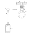
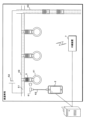
図1は、充電システムの構成例を示す説明図である。本実施の形態では、鉄道車両(公共交通機関の移動体。公共車両)に充電ポートを設け、鉄道車両の乗客であるユーザが携帯端末を充電可能とした充電システムについて説明する。充電システムは、情報処理装置1、端末2、充電装置3を含む。情報処理装置1及び端末2は、インターネット等のネットワーク(不図示)を介して通信接続されている。
The present invention will now be described in detail with reference to the drawings showing embodiments thereof.
(Embodiment 1)
Fig. 1 is an explanatory diagram showing a configuration example of a charging system. In this embodiment, a charging system will be described in which a railway vehicle (a mobile body of public transportation; a public vehicle) is provided with a charging port, and users who are passengers of the railway vehicle can charge their mobile terminals. The charging system includes an
なお、本実施の形態では公共車両の一例として鉄道車両を挙げるが、例えばバス、タクシー等の自動車であってもよい。また、本実施の形態では公共交通機関の移動体の一例として車両を挙げるが、充電装置3は航空機、船舶等に設けられてもよい。
In this embodiment, a railroad car is given as an example of a public vehicle, but it may also be a bus, a taxi, or other automobile. In addition, in this embodiment, a car is given as an example of a moving body of public transportation, but the
情報処理装置1は、種々の情報処理、情報の送受信が可能な情報処理装置であり、例えばサーバコンピュータ、パーソナルコンピュータ等である。本実施の形態では情報処理装置1がサーバコンピュータであるものとし、以下では簡潔のためサーバ1と読み替える。サーバ1は、鉄道車両に設けられた充電装置3を管理する管理装置として機能し、端末2が充電装置3に接続された場合、充電の許可を与えて充電を開始させる。
The
なお、本実施の形態ではサーバ1が車両外のクラウドサーバであるものとして説明するが、サーバ1に相当するローカルコンピュータを車両内に設置し、ローカルコンピュータで一連の処理を行ってもよい。
In this embodiment,
端末2は、ユーザが所持する携帯端末であり、例えばスマートフォン、タブレット端末等である。なお、端末2はスマートフォン等に限定されず、例えばノートパソコン、その他の電子機器であってもよい。本実施の形態では端末2に専用のアプリケーションプログラム(以下では「アプリ」と呼ぶ)がインストールされており、端末2は当該アプリを実行することでサーバ1との通信を行い、サーバ1から充電の許可通知を受けて充電を開始する。
The
充電装置3は、鉄道車両内に設けられた装置であって、端末2に電力を供給する充電ポートを有する充電器である。本実施の形態では、複数の充電装置3、3、3…が、鉄道車両内に設置された各吊り革41に設けられている。端末2は、充電ケーブル62を介して充電装置3に接続可能となっている。
The
具体的には、充電装置3は、鉄道車両内に設置された吊り革41のベルト部分に設けられている。充電装置3は、吊り革41を保持するシャフト42に沿って延設された電源ケーブル51に接続されており、電源ケーブル51を介して電源52(車両のバッテリ等)から受電した電力を端末2に供給する。充電装置3及び電源ケーブル51は、端末2の充電を行うための充電ユニットを構成する。
Specifically, the
また、充電装置3は吊り革41だけでなく、鉄道車両内の設置されたスタンションポール43にも設置されている。スタンションポール43に設置された充電装置3も同様に、スタンションポールに沿って延設された電源ケーブル51を介して、電源52から受電した電力を端末2に供給する。このように、本実施に形態に係る充電装置3は、ユーザが把持する把持具に設けられている。
The
なお、充電装置3は、シャフト42及びスタンションポール43に外付けされていてもよく、シャフト42及びスタンションポール43に内蔵されていてもよい。
The
また、電源ケーブル51はシャフト42及びスタンションポール43に内蔵されてもよく、シャフト42及びスタンションポール43の表面に露出した形で取り付けられていてもよい。また、電源52は鉄道車両のバッテリに限定されず、充電装置3のための専用バッテリ等であってもよい。
The
図2は、充電装置3に関する説明図である。上述の如く、充電装置3は吊り革41に設けられ、充電ケーブル62を介して端末2を接続可能となっている。充電装置3は、給電コネクタ33と、表示器36とを備える。
Figure 2 is an explanatory diagram of the
給電コネクタ33は、充電ケーブル62の接続を受け付ける充電ポートとして機能するコネクタであり、例えば磁気を用いて充電ケーブル62を着脱可能なマグネット式コネクタである。ユーザは、給電コネクタ33と対になり、充電ケーブル62の一端を接続可能なマグネット式の受電コネクタ61を所持しており、受電コネクタ61を給電コネクタ33に着脱可能となっている。充電装置3は、給電コネクタ33に受電コネクタ61が接続された場合、充電ケーブル62を介して電力を端末2に供給する。
The
本実施の形態に係る給電コネクタ33は、端末2に電力を供給する充電ポートとして機能するほかに、端末2との間でデータ通信を行う通信ポートとしても機能する。後述のように、専用のアプリがインストールされた端末2が給電コネクタ33に接続された場合、充電装置3は自身の識別子であるポートIDを端末2に出力する。端末2は、充電装置3から取得したポートIDと、ユーザの識別子であるユーザIDとをサーバ1に送信し、充電の許可を要求する。そして端末2は、サーバ1から充電の許可通知を受けて充電を開始する。
The
なお、本実施の形態では給電コネクタ33(充電ポート)としてマグネット式コネクタを挙げたが、例えば給電コネクタ33をUSB(タイプA、タイプC等)、Lightningなどの規格の接続ポートとし、充電ケーブル62を直接接続可能としてもよい。
In this embodiment, a magnetic connector is used as the power supply connector 33 (charging port), but the
表示器36は、端末2への充電速度を表示するインジケータである。充電装置3は、端末2を充電する際に電流値を計測し、計測した電流値に応じて表示器36に表示を行わせる。例えば図2にハッチングで示すように、充電装置3は、電流値の大小に応じて、位置又は複数のインジケータを点灯させる。
The
なお、図2では、充電装置3が給電コネクタ33、表示器36等を一つの筐体に収容した一体の装置であるものとして図示しているが、本実施の形態はこれに限定されない。例えば各部を電気的に接続するのみで、給電コネクタ33、表示器36等は別々のパーツとして個別に設けられていてもよい。すなわち、各部を一体の装置とする構成は必須ではない。
Note that in FIG. 2, the
また、本実施の形態では充電装置3を吊り革41等に設け、電力の供給だけでなくポートIDの送信や充電速度の表示を行うものとするが、単に給電コネクタ33を吊り革41等に設けるだけでもよい。すなわち、車両内には少なくとも充電ポート(給電コネクタ33)が設けられていればよく、充電速度を表示する表示器36等を設ける構成は必須ではない。
In addition, in this embodiment, the
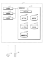
図3は、サーバ1の構成例を示すブロック図である。サーバ1は、制御部11、主記憶部12、通信部13、及び補助記憶部14を備える。
制御部11は、一又は複数のCPU(Central Processing Unit)、MPU(Micro-Processing Unit)、GPU(Graphics Processing Unit)等の演算処理装置を有し、補助記憶部14に記憶されたプログラムP1を読み出して実行することにより、種々の情報処理、制御処理等を行う。主記憶部12は、SRAM(Static Random Access Memory)、DRAM(Dynamic Random Access Memory)、フラッシュメモリ等の一時記憶領域であり、制御部11が演算処理を実行するために必要なデータを一時的に記憶する。通信部13は、通信に関する処理を行うための通信モジュールであり、外部と情報の送受信を行う。
3 is a block diagram showing an example of the configuration of the
The control unit 11 has one or more arithmetic processing devices such as a central processing unit (CPU), a micro-processing unit (MPU), a graphics processing unit (GPU), etc., and performs various information processing, control processing, etc. by reading and executing a program P1 stored in the
補助記憶部14は、大容量メモリ、ハードディスク等の不揮発性記憶領域であり、制御部11が処理を実行するために必要なプログラムP1、その他のデータを記憶している。また、補助記憶部14は、ポートDB141、運行DB142、ユーザDB143、広告DB144、充電履歴DB145を記憶している。ポートDB141は、各充電ポート(充電装置3)の情報を格納するデータベースである。運行DB142は、鉄道車両の運行情報を格納するデータベースである。ユーザDB143は、各ユーザの情報を格納するデータベースである。広告DB144は、端末2に配信する広告データを格納するデータベースである。充電履歴DB145は、充電ポートにおける端末2の充電履歴を格納するデータベースである。
The
なお、補助記憶部14はサーバ1に接続された外部記憶装置であってもよい。また、サーバ1は複数のコンピュータからなるマルチコンピュータであっても良く、ソフトウェアによって仮想的に構築された仮想マシンであってもよい。
The
また、本実施の形態においてサーバ1は上記の構成に限られず、例えば操作入力を受け付ける入力部、画像を表示する表示部等を含んでもよい。また、サーバ1は、CD(Compact Disk)-ROM、DVD(Digital Versatile Disc)-ROM等の可搬型記憶媒体1aを読み取る読取部を備え、可搬型記憶媒体1aからプログラムP1を読み取って実行するようにしても良い。あるいはサーバ1は、半導体メモリ1bからプログラムP1を読み込んでも良い。
In the present embodiment, the
図4は、端末2の構成例を示すブロック図である。端末2は、制御部21、主記憶部22、通信部23、表示部24、入力部25、補助記憶部26を備える。
制御部21は、一又は複数のCPU、MPU等の演算処理装置を有し、補助記憶部26に記憶されたプログラムP2を読み出して実行することにより、種々の情報処理、制御処理等を行う。主記憶部22は、RAM等の一時記憶領域であり、制御部21が演算処理を実行するために必要なデータを一時的に記憶する。通信部23は、通信に関する処理を行うための通信モジュールであり、外部と情報の送受信を行う。表示部24は、液晶ディスプレイ等の表示画面であり、画像を表示する。入力部25は、タッチパネル、メカニカルキー等の操作インターフェイスであり、ユーザから操作入力を受け付ける。補助記憶部26は、大容量メモリ等の不揮発性記憶領域であり、制御部21が処理を実行するために必要なプログラムP2、その他のデータを記憶している。
4 is a block diagram showing an example of the configuration of the
The
なお、端末2は、CD-ROM、DVD-ROM等の可搬型記憶媒体2aを読み取る読取部を備え、可搬型記憶媒体2aからプログラムP2を読み取って実行するようにしても良い。あるいは端末2は、半導体メモリ2bからプログラムP2を読み込んでも良い。
The
図5は、充電装置3の構成例を示すブロック図である。充電装置3は、制御部31、給電回路32、給電コネクタ33、電流計測器34、メモリ35、表示器36を備える。
制御部31は、FPGA(Field-Programmable Gate Array)等の演算処理装置であり、充電装置3の各部の動作を制御する。給電回路32は、端末2に供給する電力量を調整する電気回路である。給電コネクタ33は、端末2の充電ケーブル62が接続されるコネクタであり、受電コネクタ61を着脱可能なマグネット式コネクタである。電流計測器34は、端末2を充電する際の電流値を計測する計測器である。メモリ35は、ポートID等を記憶するメモリである。なお、メモリ35は制御部31と一体であってもよい。表示器36は、充電速度を表示するインジケータであり、電流計測器34が計測した電流値に応じた表示を行う。
5 is a block diagram showing an example of the configuration of the
The
なお、本実施の形態では一の制御部31が一の充電ポート(給電コネクタ33)における動作を制御するものとするが、一の制御部31に対して複数の充電ポートを設け、各充電ポートにおける動作を制御してもよい。
In this embodiment, one
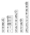
図6は、ポートDB141、運行DB142、ユーザDB143、広告DB144、及び充電履歴DB145のレコードレイアウトの一例を示す説明図である。
ポートDB141は、ポートID列、列車ID列、設置車両列、位置列を含む。ポートID列は、各充電ポート(充電装置3)を識別するためのポートIDを記憶している。列車ID列、設置車両列、及び位置列はそれぞれ、ポートIDと対応付けて、充電ポートが設置されている列車を示す列車ID、充電ポートが設置されている車両番号、及び車両内の位置を記憶している。
FIG. 6 is an explanatory diagram showing an example of the record layout of the
The
なお、以下の説明では便宜上、鉄道車両の運行単位である複数の車両を「列車」と呼び、列車を構成する各車両を単に「車両」と呼んで区別する。 For the sake of convenience, in the following explanation, a group of cars that make up a railway vehicle will be referred to as a "train," and each car that makes up a train will simply be referred to as a "car."
運行DB142は、列車ID列、路線列、停車駅列、停車時刻列、発車時刻列を含む。列車ID列は、各列車を識別するための列車IDを記憶している。路線列、停車駅列、停車時刻列、及び発車時刻列はそれぞれ、列車IDと対応付けて、路線名、停車駅名、各停車駅での停車時刻、及び発車時刻を記憶している。 Operation DB142 includes a train ID sequence, a route sequence, a stop station sequence, a stop time sequence, and a departure time sequence. The train ID sequence stores a train ID for identifying each train. The route sequence, stop station sequence, stop time sequence, and departure time sequence each store the route name, stop station name, stop time at each stop station, and departure time in association with the train ID.
ユーザDB143は、ユーザID列、氏名列、年齢列、性別列、定期区間列、ポイント列を記憶している。ユーザID列は、各ユーザを識別するためのユーザIDを記憶している。氏名列、年齢列、性別列、定期区間列、及びポイント列はそれぞれ、ユーザIDと対応付けて、ユーザの氏名、年齢、性別、定期区間、及び充電ポートの利用により付与されたポイント数を記憶している。後述のように、本実施の形態では充電ポートの利用特典として電子ポイントをユーザに付与する。 User DB143 stores a user ID column, a name column, an age column, a gender column, a regular section column, and a point column. The user ID column stores a user ID for identifying each user. The name column, age column, gender column, regular section column, and point column each store the user's name, age, gender, regular section, and the number of points awarded for using a charging port, in association with the user ID. As described below, in this embodiment, electronic points are awarded to the user as a benefit for using the charging port.
広告DB144は、広告ID列、広告データ列、対象者列、対象地域列を含む。広告ID列は、各広告を識別するための広告IDを記憶している。広告データ列、対象者列、及び対象地域列はそれぞれ、広告IDと対応付けて、広告データ(例えば画像)、広告の配信対象とするユーザの属性(年齢、性別等)、及び広告の配信対象とする地域を記憶している。 Advertisement DB144 includes an advertisement ID column, an advertisement data column, a target column, and a target area column. The advertisement ID column stores an advertisement ID for identifying each advertisement. The advertisement data column, target column, and target area column each store, in association with an advertisement ID, advertisement data (e.g., an image), attributes of users to whom the advertisement is to be delivered (age, gender, etc.), and the area to which the advertisement is to be delivered.
充電履歴DB145は、開始日時列、終了日時列、ポート列、ユーザ列、充電量列、乗車駅列、下車駅列、乗車車両列を含む。開始日時列、及び終了日時列はそれぞれ、充電ポートに端末2が接続されて充電を開始した日時、及び充電を終了した日時を記憶している。ポート列、ユーザ列、充電量列、乗車駅列、下車駅列、及び乗車車両列はそれぞれ、開始日時及び終了日時と対応付けて、端末2が接続された充電ポートのポートID、充電ポートを利用したユーザのユーザID、充電量、ユーザが乗車したと推定される乗車駅、下車駅、及びユーザが乗車した車両番号を記憶している。乗車駅及び下車駅は、例えば列車の運行情報と照らし合わせて、停車時刻が開始日時及び終了日時に近い停車駅が選択される。
The charging history DB145 includes a start date and time column, an end date and time column, a port column, a user column, a charging amount column, a boarding station column, a disembarking station column, and a boarding vehicle column. The start date and time column and the end date and time column store the date and time when the
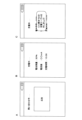
図7は、端末2の表示画面例を示す説明図である。図7A~Cではそれぞれ、充電開始前、充電中、及び充電終了前の画面例を図示している。図7A~Cの画面例に沿って、本実施の形態の概要を説明する。
Figure 7 is an explanatory diagram showing an example of the display screen of
充電装置3に接続された場合、端末2は専用のアプリを起動し、当該アプリ上で以下の処理を実行する。なお、アプリの起動はユーザが手動で行ってもよい。また、当該アプリは本システム専用のアプリケーションプログラムに限定されず、例えば交通系モバイルアプリと一体となって、そのアプリの一部のソフトウェアモジュールとして実装されていてもよい。
When connected to the
まず端末2は、充電ケーブル62を介して充電装置3との間の通信を行い、充電ポートの識別子であるポートIDを充電装置3から取得する。次に端末2は、充電装置3から取得したポートIDと、ユーザの識別子であるユーザIDとをサーバ1に送信し、充電の許可を要求する。
First, the
図7Aは、サーバ1への問い合わせ中に端末2が表示する画面例である。端末2は、充電の許可をサーバ1に問い合わせ中であることを表示すると共に、サーバ1から広告データの配信を受け、当該広告データを表示する。
Figure 7A is an example of a screen displayed by
なお、本実施の形態では端末2に配信するコンテンツとして広告を挙げたが、サーバ1は広告以外のコンテンツを配信してもよい。
In this embodiment, advertisements are given as an example of content to be delivered to the
配信する広告データは無作為に選択されてもよいが、サーバ1は、端末2が接続された充電装置3(充電ポート)に応じて広告データを選択してもよい。例えばサーバ1は、端末2から取得したポートIDに基づき、ユーザが乗車している列車をポートDB141から特定する。そしてサーバ1は、特定した列車の運行情報を運行DB142から読み出し、列車の現在地、すなわちユーザの現在地を特定する。なお、運行情報は外部のAPI(Application Programmable Interface)から取得してもよい。サーバ1は、特定した現在地を対象地域とする広告データを広告DB144から読み出し、端末2に配信する。
The advertising data to be distributed may be selected randomly, but the
また、上記では運行情報を参照することで列車の現在地まで特定することにしたが、例えばサーバ1は、列車の路線に応じて配信対象とする広告データを広告DB144に登録しておき、ユーザが乗車している列車の路線に応じて広告データを選択してもよい。すなわち、サーバ1は、ポートIDに応じて広告データを選択可能であればよく、運行情報まで参照して現在地を特定する構成は必須ではない。
In the above, the current location of the train is identified by referring to the operation information, but for example, the
また、上記では列車全体の位置から広告データを選択することにしたが、例えばサーバ1は、ユーザが乗車している車両の位置に応じて広告データを選択してもよい。例えばサーバ1は、ユーザが先頭車両に乗車しているか、あるいは最後尾の車両に乗車しているか等に応じて広告データを選択する。これにより、例えばユーザが先頭車両に乗車している場合に、ある駅で先頭車両から降りた方が近い商業施設の広告を出すなど、広告施策を好適化することができる。
Although in the above, the advertisement data is selected based on the position of the entire train, for example, the
サーバ1は、ポートIDが示す充電装置3以外にも、ユーザIDが示す接続ユーザに応じて広告データを選択してもよい。例えばサーバ1は、ユーザDB143を参照してユーザの年齢、性別等の属性を特定し、特定した属性を対象者とする広告データを広告DB144から読み出し、端末2に配信する。
The
端末2は、サーバ1から配信された広告データを表示し、ユーザに提示する。端末2は、充電許可に関するレスポンスがサーバ1から返信されるまで広告データの表示を継続する。
The
端末2が広告データを表示中に、サーバ1は、端末2から取得したポートID及びユーザIDに基づき、充電を許可するか否かを判定する。例えばサーバ1は、ポートDB141及びユーザDB143を参照して、ポートID及びユーザIDが正規のIDであるか否かを判定する。なお、IDの確認は判定処理の一例であって、本実施の形態はこれに限定されるものではない。例えばサーバ1は、ユーザに対して月々の最大充電量を定め、今月の利用充電量が最大充電量を上回っていないか判定してもよい。また、例えばサーバ1は、充電装置3の利用料の支払いが滞っていないか判定してもよい。このように、充電を許可するか否かを適切に判定可能であればよく、その判定内容は特に限定されない。
While the
判定が完了した場合、サーバ1は判定結果を端末2に通知する。すなわち、充電を許可すると判定した場合、サーバ1は、充電を許可する旨の許可通知を端末2に送信する。一方、充電を許可しないと判定した場合、サーバ1は、充電を許可しない旨のエラー通知を端末2に送信する。
When the determination is complete, the
充電の許可通知をサーバ1から取得した場合、端末2は許可通知を充電装置3に転送し、充電を開始する。この場合、端末2は広告データの表示を終了し、図7Bの画面に遷移する。例えば端末2は、バッテリの残量、電流値、充電時間等を表示する。また、充電装置3は、上述の如く、電流計測器34によって継続的に電流値を計測し、充電速度を表示器36に表示する。
When a charging permission notice is obtained from the
なお、本実施の形態ではサーバ1からの許可通知を受けて充電を開始するものとするが、例えば充電装置3は、許可通知の有無に関わらず充電を開始し、一定量の電力を端末2に供給するようにしてもよい。この場合、充電装置3はサーバ1から許可通知を受けた場合は充電を継続し、エラー通知を受けた場合は充電を終了する。これにより、接続時に既に端末2のバッテリが切れており、アプリを起動できない場合に好適に対処することができる。
In this embodiment, charging starts when a permission notification is received from the
本実施の形態においてサーバ1は、充電開始後、ユーザが下車予定の目的地付近に列車が到達した場合、所定の案内情報を端末2に出力して表示させる。目的地は、例えばユーザが定期券を有している定期区間における乗換駅、あるいは最終的な終着駅などである。目的地付近に列車が到達した場合、サーバ1は、列車の乗り換え等を案内する案内情報を端末2に出力し、表示させる。
In this embodiment, when the train arrives near the destination where the user plans to get off after charging has started, the
なお、目的地は定期区間の駅に限定されず、例えば充電装置3への接続時にユーザから個別に目的地(乗換駅、終着駅等)の入力を受け付けてもよい。また、例えばユーザの普段の乗車履歴(後述の充電履歴)から目的地を推定してもよい。
The destination is not limited to stations on the regular route, and may be input individually from the user (transfer station, terminal station, etc.) when connecting to the
例えばサーバ1は、ユーザが乗車している列車の運行情報を参照して、目的地付近に到達したか否かを判定する。例えばサーバ1は、目的地での停車時刻と現在時刻とを比較することで所定時間以内に目的地に到達するか判定するようにしてもよく、あるいは目的地の一つ手前の駅を発車したか否かを判定するようにしてもよい。目的地付近に到達したと判定した場合、サーバ1は案内情報を出力し、表示させる。図7Cに、案内情報を表示する際の画面例を図示する。図7Cに示すように、端末2は、目的地に到達するまでの予定時間等を示す案内情報をポップアップ表示し、充電の終了をユーザに促す。
For example, the
ユーザは、充電ケーブル62の接続を解除、あるいはアプリを終了させることで充電を終了する。充電が終了した場合、端末2は、ポートID、ユーザIDのほかに、充電装置3からの充電量を含む充電終了通知をサーバ1に送信し、充電を終了したことを通知する。
The user ends charging by disconnecting the charging
なお、本実施の形態では充電量(kWh)をサーバ1に通知するものとするが、充電量に代えて、又は充電量に加えて、充電時間をサーバ1に通知してもよい。
In this embodiment, the charge amount (kWh) is notified to the
充電終了通知を取得した場合、サーバ1は、ポートID及びユーザIDと対応付けて、端末2の充電履歴を充電履歴DB145に記録する。具体的には、サーバ1は、ポートID、ユーザIDのほかに、充電を開始した開始日時、充電を終了した終了日時、及び充電量を記録する。例えばサーバ1は、充電履歴DB145に記録された充電量に基づいて利用料を算出し、ユーザに支払いを要求する。
When the
なお、利用料は充電量ではなく充電時間、充電回数等に応じて算出してもよい。また、利用料を充電量等に応じて可変とする構成は必須ではなく、例えば一定期間毎に定額としてもよい。 The usage fee may be calculated based on the charging time, the number of charging times, etc., instead of the amount of charging. Also, it is not essential to configure the usage fee to be variable based on the amount of charging, etc., and it may be a fixed amount for a certain period of time, for example.
サーバ1はさらに、運行情報が示す各駅での停車時刻と、充電の開始日時及び終了日時とを比較して、ユーザが乗車及び下車したと推定される乗車駅及び下車駅を記録する。また、サーバ1は、端末2が接続された充電装置3が設けられている車両の車両番号等を記録する。
The
上記のように、サーバ1は、端末2が接続された充電装置3(充電ポート)に応じて、ユーザが乗り降りした駅、ユーザが乗車した車両、車両内での位置など、詳細な位置情報を割り出して記録する。これにより、GPS(Global Positioning System)等の位置座標よりも正確な位置情報を収集することができ、混雑緩和策の策定などに役立てることができる。
As described above, the
なお、サーバ1は、充電装置3での充電履歴からユーザの乗車及び下車を推定するだけでなく、ユーザが座席に着座したタイミングなど、車両内でのユーザの行動を推定してもよい。例えばサーバ1は、端末2が吊り革41の充電装置3からスタンションポール43の充電装置3に付け替えられた場合、ユーザが着座したものと推定する。あるいはサーバ1は、下車予定のない定期区間内のある駅で吊り革41の充電装置3から外された場合、ユーザが着座したものと推定する。これにより、ユーザがどの駅で座ることができたか等、車両の混雑具合を精度良く推定することができる。
The
サーバ1は、端末2の充電履歴を記録するほか、充電量に応じたポイント(特典)を付与する。当該ポイントは、例えば所定の加盟店で決済に利用可能な電子ポイントである。なお、当該ポイントは列車の乗車料金等に利用可能としてもよく、その利用用途は特に限定されない。例えばサーバ1は、充電量が多いほど付与量が多くなるようにポイントを付与する。
The
なお、サーバ1は、充電量以外の基準でポイントの付与量を定めてもよい。例えばサーバ1は、ユーザが充電に利用した充電装置3と同一車両に設けられている充電装置3、3、3…の利用率に応じて付与量を定める。利用率は、例えば充電中の充電装置3の数量を、充電装置3の総数で除算した値である。サーバ1は、ユーザが端末2を充電装置3に接続時に、同一車両内の充電装置3、3、3…の利用率が低いほど付与量が多くなるようにポイントを付与する。これにより、充電装置3の利用率が低い場合、すなわち混雑していない場合に乗車するようユーザに促すことができ、混雑緩和を図ることができる。
The
以上より、本実施の形態によれば、ユーザは携帯端末を好適に充電することができると同時に、ユーザの位置情報を正確に収集することができ、混雑緩和等にも役立てることができる。 As described above, this embodiment allows users to conveniently charge their mobile devices, while at the same time allowing accurate collection of user location information, which can be useful in easing congestion, etc.
図8は、充電システムが実行する処理手順の一例を示すフローチャートである。図8に基づき、充電システムが実行する処理内容について説明する。
端末2の制御部21は、自装置が充電装置3に接続された場合、専用のアプリを起動する(ステップS11)。制御部21は当該アプリを実行し、充電装置3からポートIDを取得する(ステップS12)。制御部21は、取得したポートIDと、ユーザIDとをサーバ1に送信し、充電の許可を要求する(ステップS13)。
8 is a flowchart showing an example of a processing procedure executed by the charging system. The processing contents executed by the charging system will be described with reference to FIG.
When the
端末2からの充電許可の要求を受け付けた場合、サーバ1の制御部11は、充電許可の判定が完了するまでの間に表示させる広告データを端末2に配信する(ステップS14)。例えば制御部11は、ポートIDが示す充電装置3が設けられた列車の運行情報を参照してユーザの現在地を特定し、特定した現在地を対象地域とする広告データを広告DB144から読み出して配信する。また、例えば制御部11は、ユーザIDが示すユーザの属性(年齢、性別等)を参照して、当該属性のユーザを対象者とする広告データを広告DB144から読み出して配信する。端末2の制御部21は、配信された広告データを表示する(ステップS15)。
When a request for charging permission is received from the
サーバ1の制御部11は、端末2から取得したポートID及びユーザIDに基づき、端末2の充電を許可するか否かを判定する(ステップS16)。制御部11は、判定結果を端末2に通知する(ステップS17)。
The control unit 11 of the
端末2の制御部21は、サーバ1からの通知に基づき、充電が許可されたか否かを判定する(ステップS18)。充電が許可されなかったと判定した場合(S18:NO)、制御部21は一連の処理を終了する。充電が許可されたと判定した場合(S18:YES)、制御部21は充電を開始する(ステップS19)。
The
充電の許可通知を端末2に送信した場合、サーバ1の制御部11は、列車の運行情報を参照して、目的地付近に到達したか否かを判定する(ステップS20)。目的地付近に到達していないと判定した場合(S20:NO)、制御部11は処理を待機する。目的地付近に到達したと判定した場合(S20:YES)、制御部11は、乗り換え等を案内する案内情報を端末2に送信する(ステップS21)。端末2の制御部21は案内情報を表示する(ステップS22)。なお、案内情報を未受信の場合、制御部21はステップS22をスキップしてステップS23に移行する。
When the charging permission notification is sent to the
制御部21は、充電を終了するか否かを判定する(ステップS23)。例えば制御部21は、アプリの終了、又は充電装置3との間の接続解除に応じて充電を終了すると判定する。充電を終了しないと判定した場合(S23:NO)、制御部21は処理を待機する。充電を終了すると判定した場合(S23:YES)、制御部21は、ポートID、ユーザID、充電量等を含む接続終了通知をサーバ1に送信し(ステップS24)、一連の処理を終了する。
The
端末2から接続終了通知を取得した場合、サーバ1の制御部11は、ポートID及びユーザIDと対応付けて、充電装置3への開始日時、充電の終了日時、充電量等の充電履歴を充電履歴DB145に記憶する(ステップS25)。また、制御部11は、充電量に応じたポイントをユーザに付与し(ステップS26)、一連の処理を終了する。
When the control unit 11 of the
なお、上記では充電装置3(充電ポート)が充電ケーブル62を介して充電を行う有線の充電器であるものとして説明したが、充電装置3をワイヤレス充電器としても良い。
In the above description, the charging device 3 (charging port) is a wired charger that charges via a charging
以上より、本実施の形態1によれば、公共交通機関の移動体に充電ポートを設け、充電ポートに端末2が接続された場合にポートID及びユーザIDに基づく判定を行って充電の許可通知を出力するようにすることで、端末2の充電を好適に行わせることができる。
As described above, according to the first embodiment, a charging port is provided on a moving object of public transportation, and when a
また、本実施の形態1によれば、充電ポートを通信ポートも兼ねた入出力ポートとし、端末2を経由してサーバ1との通信を行うことで、本システムを好適に実現することができる。
Furthermore, according to the
また、本実施の形態1によれば、充電許可に係る判定が完了するまでの間に広告データを配信することで、有効な広告施策を講じることができる。 Furthermore, according to the first embodiment, by distributing advertising data until the determination regarding charging permission is completed, it is possible to implement effective advertising measures.
また、本実施の形態1によれば、充電終了時に端末2から終了通知を受けて充電履歴を記録することで、列車の利用状況を好適に把握することができる。
In addition, according to this
また、本実施の形態1によれば、充電量(又は充電時間)を記録しておくことで、利用料の支払いの要求などを好適に行うことができる。
In addition, according to this
また、本実施の形態1によれば、充電量(又は充電時間)に応じてポイントを付与することで、充電装置3の利用を促進することができる。
Furthermore, according to the first embodiment, points can be awarded according to the amount of charge (or charging time), thereby promoting the use of the
また、本実施の形態1によれば、列車の運行情報に基づき、ユーザの現在地、ユーザが乗車している車両や車両内の位置など、正確な位置情報を特定することができる。
Furthermore, according to this
また、本実施の形態1によれば、ユーザの位置に応じた広告や案内情報などをユーザに提示することができる。
Furthermore, according to this
また、本実施の形態1によれば、サーバ1からの許可通知の有無に関わらず一定量の電力を端末2に供給することで、端末2のバッテリが切れているような事態に対処することができる。
In addition, according to the first embodiment, a certain amount of power is supplied to the
また、本実施の形態1によれば、吊り革41のような車両内の把持具に充電ポートを設けることで、ユーザにとって充電ポートを発見しやすく、かつ、接続しやすくすることができる。
In addition, according to this
また、本実施の形態1によれば、充電速度を表示する表示器36を設けることで、端末2の充電状況をユーザは容易に把握することができる。
In addition, according to the
また、本実施の形態1によれば、充電ポートをマグネット式の給電コネクタ33とすることで、乗車時に取り付けやすく、また、下車時に取り外しやすくすることができる。
In addition, according to this
(実施の形態2)
実施の形態1では、サーバ1が端末2と通信を行って充電の許可を与える形態について説明した。本実施の形態では、車両側の充電装置3と通信を行う形態について述べる。なお、実施の形態1と重複する内容については同一の符号を付して説明を省略する。
(Embodiment 2)
In the first embodiment, the
図9は、実施の形態2に係る充電システムの構成例を示す模式図である。本実施の形態に係る充電システムは、車両内に中継装置7を備える。中継装置7は、充電装置3とサーバ1との間の通信を中継する中継装置であり、各充電装置3と無線又は有線で接続されている。なお、中継装置7を備える構成は必須ではなく、充電装置3が単独でサーバ1と通信可能である場合は中継装置7を除外してもよい。
Figure 9 is a schematic diagram showing an example of the configuration of a charging system according to
図10は、実施の形態2に係る充電装置3の構成例を示すブロック図である。本実施の形態に係る充電装置3は通信部37を備える。通信部37は、中継装置7との間で通信を行う通信モジュールであり、中継装置7を介してサーバ1とデータの送受信を行う。
Figure 10 is a block diagram showing an example of the configuration of the
本実施の形態では、端末2ではなく充電装置3がサーバ1との間の通信を行い、ポートID及びユーザIDをサーバ1に送信して充電の許可通知を受信する。すなわち、充電装置3は、給電コネクタ33に充電ケーブル62が接続された場合、端末2からユーザIDを取得し、ポートIDと共にサーバ1へ送信する。その後、充電装置3はサーバ1から充電許可に係る判定結果の通知を受け、充電を開始する。その後、充電が終了した場合は充電終了通知をサーバ1へ送信し、充電履歴を記録させる。
In this embodiment, the charging
なお、一連の処理は充電装置3ではなく、充電装置3以外の車両内のローカルコンピュータ(例えば中継装置7)が処理主体となって行ってもよい。
The series of processes may be performed not by the charging
端末2ではなく車両側の装置が処理主体となってサーバ1と通信を行う点以外は実施の形態1と同様であるため、本実施の形態ではフローチャート等の詳細な説明は省略する。
This embodiment is the same as the first embodiment except that the vehicle-side device, rather than the
以上より、本実施の形態2によれば、車両側の装置で一連の処理を完結させることができ、本システムをより好適に実現することができる。 As described above, according to the second embodiment, a series of processes can be completed in the vehicle device, and the present system can be realized more suitably.
(変形例)
実施の形態1、2では充電装置3が交通機関の移動体(鉄道車両)に設けられるものとして説明したが、充電装置3は、不特定多数のユーザが利用する公共施設に設けられてもよい。公共施設は、例えば飲食店等の店舗などが考えられる。
(Modification)
In the first and second embodiments, the charging
例えば飲食店に充電装置3を設置する場合、ユーザ(顧客)が利用するテーブル等に位置又は複数の充電装置3を設ける。実施の形態1、2と同様に、充電ケーブル62を介して充電装置3に端末2が接続された場合、端末2は充電装置3からポートIDを取得し、ユーザIDと共にサーバ1へ送信する。サーバ1はユーザID及びポートIDを端末2から取得し、充電の許可通知を送信する。例えばサーバ1は、ポートIDを飲食店のテーブル、イス等と対応付けておくことで、ユーザが利用した飲食店だけでなく、店舗内でのユーザの位置(テーブル、イス等)まで特定することができる。
For example, when installing a
また、上記においてサーバ1は、充電装置3に端末2が接続された場合、広告以外にも飲食店で利用可能なクーポン(特典)を端末2に配信してもよい。また、例えばサーバ1は、端末2から飲食物の注文を受け付け、ユーザの位置を表すポートIDと共に注文内容を店舗スタッフに通知するようにしてもよい。このように、充電装置3を契機として種々の店舗支援を行うことができる。
In addition, in the above, when the
なお、上記で端末2は、充電ケーブル62の接続時に充電装置3からポートIDを取得するものとしたが、本変形例はこれに限定されるものではない。例えば飲食店のテーブル等に、ポートIDを記述した二次元コード(QRコード(登録商標)など)を用意しておき、端末2は当該コードを読み取ることでポートIDを取得してもよい。実施の形態1も同様である。このように、ポートIDの取得方法は充電装置3との間の通信に限定されず、充電装置3に対応するポートIDを端末2が取得可能であればよい。
In the above, the
上述の如く、本システムを交通機関の移動体以外に公共施設に適用してもよい。 As mentioned above, this system can be applied to public facilities in addition to moving vehicles for transportation.
今回開示された実施の形態はすべての点で例示であって、制限的なものではないと考えられるべきである。本発明の範囲は、上記した意味ではなく、特許請求の範囲によって示され、特許請求の範囲と均等の意味及び範囲内でのすべての変更が含まれることが意図される。 The embodiments disclosed herein are illustrative in all respects and should not be considered limiting. The scope of the present invention is indicated by the claims, not by the meaning described above, and is intended to include all modifications within the scope and meaning equivalent to the claims.
1 サーバ(情報処理装置)
11 制御部
12 主記憶部
13 通信部
14 補助記憶部
P1 プログラム
141 ポートDB
142 運行DB
143 ユーザDB
144 広告DB
145 充電履歴DB
2 端末
21 制御部
22 主記憶部
23 通信部
24 表示部
25 入力部
26 補助記憶部
P2 プログラム
3 充電装置
31 制御部
32 給電回路
33 給電コネクタ
34 電流計測器
35 メモリ
36 表示器
37 通信部
41 吊り革
42 シャフト
43 スタンションポール
51 電源ケーブル
52 電源
61 受電コネクタ
62 充電ケーブル
1 Server (information processing device)
11
142 Operation DB
143 User DB
144 Advertising DB
145 Charging history DB
2
Claims (11)
前記管理装置は、
前記充電ポートに携帯端末が有線接続された場合、前記充電ポートを示すポート識別子と、前記携帯端末に対応するユーザ識別子とを取得する取得部と、
前記ポート識別子及びユーザ識別子に基づき、前記携帯端末の充電を許可するか否かを判定する判定部と、
充電を許可すると判定した場合、前記充電ポートから前記携帯端末への電力の供給を許可する許可通知を出力する出力部と、
前記ポート識別子が示す前記充電ポートが設けられた前記移動体の運行情報を取得する第2取得部と、
前記運行情報に基づき、前記ユーザ識別子が示すユーザの位置を特定する特定部と
を備える充電システム。 A charging system including a charging port provided in a moving body of a public transportation system or a public facility, and a management device that manages the charging port,
The management device includes:
an acquisition unit that acquires, when a portable terminal is wired connected to the charging port, a port identifier that indicates the charging port and a user identifier that corresponds to the portable terminal;
a determination unit that determines whether or not to permit charging of the portable terminal based on the port identifier and the user identifier;
an output unit that outputs a permission notification that permits the supply of power from the charging port to the portable terminal when it is determined that charging is permitted ;
a second acquisition unit that acquires operation information of the moving object provided with the charging port identified by the port identifier;
an identification unit that identifies a location of the user identified by the user identifier based on the operation information;
A charging system comprising:
前記取得部は、前記携帯端末から前記ポート識別子及びユーザ識別子を取得し、
前記出力部は、前記許可通知を前記携帯端末に出力する
請求項1に記載の充電システム。 the charging port is an input/output port capable of supplying power to the portable terminal and communicating with the portable terminal, and outputs the port identifier to the portable terminal when the portable terminal is connected;
The acquisition unit acquires the port identifier and the user identifier from the mobile terminal,
The charging system according to claim 1 , wherein the output unit outputs the permission notification to the mobile terminal.
請求項2に記載の充電システム。 The charging system according to claim 2 , wherein when the output unit acquires the port identifier and the user identifier from the mobile terminal, the output unit outputs, to the mobile terminal, advertisement data to be displayed until a determination as to whether or not to permit charging is completed.
前記管理装置は、前記充電終了通知を取得した場合、前記ポート識別子及びユーザ識別子と対応付けて、前記携帯端末の充電履歴を記録する記録部を備える
請求項2又は3に記載の充電システム。 the acquisition unit acquires a charging completion notification from the portable terminal when charging at the charging port is completed;
The charging system according to claim 2 or 3, wherein the management device includes a recording unit that, when receiving the charging end notification, records a charging history of the mobile terminal in association with the port identifier and the user identifier.
前記記録部は、前記充電量又は充電時間を記録する
請求項4に記載の充電システム。 The acquisition unit acquires the charging end notification including a charging amount or a charging time at the charging port,
The charging system according to claim 4 , wherein the recording unit records the charging amount or the charging time.
請求項5に記載の充電システム。 The charging system according to claim 5 , wherein the management device includes an awarding unit that awards a privilege to the user identified by the user identifier in accordance with the charging amount or the charging time.
請求項1~6のいずれか1項に記載の充電システム。 The charging system according to claim 1 , wherein the output unit outputs information corresponding to the identified position of the user to the mobile terminal.
前記充電ポートは前記吊り革に設けられ、前記吊り革を保持するシャフトに沿って延設された電源ケーブルを介して電源から受電した電力を前記携帯端末に供給する
請求項1~7のいずれか1項に記載の充電システム。 The moving body is a public vehicle equipped with a hanging strap,
The charging system according to any one of claims 1 to 7 , wherein the charging port is provided in the hanging strap and supplies power received from a power source to the mobile terminal via a power cable extending along a shaft that holds the hanging strap.
請求項1~8のいずれか1項に記載の充電システム。 The charging system according to claim 1 , wherein the charging port supplies a constant amount of power to the portable terminal when the portable terminal is connected in a wired manner , regardless of whether the permission notification is given or not.
前記ポート識別子及びユーザ識別子に基づき、前記携帯端末の充電を許可するか否かを判定し、
充電を許可すると判定した場合、前記充電ポートから前記携帯端末への電力の供給を許可する許可通知を出力し、
前記ポート識別子が示す前記充電ポートが設けられた前記移動体の運行情報を取得し、
前記運行情報に基づき、前記ユーザ識別子が示すユーザの位置を特定する
処理をコンピュータに実行させる充電方法。 When a mobile terminal is connected to a charging port provided in a moving body of a public transportation system or a public facility, a port identifier indicating the charging port and a user identifier corresponding to the mobile terminal are acquired;
determining whether to permit charging of the portable terminal based on the port identifier and the user identifier;
When it is determined that charging is permitted, a permission notification is output to permit the supply of power from the charging port to the portable terminal;
Acquire operation information of the moving body in which the charging port indicated by the port identifier is provided,
Based on the operation information, the location of the user identified by the user identifier is identified.
A charging method that uses a computer to perform processing.
前記管理装置は、The management device includes:
前記充電ポートに携帯端末が有線接続された場合、前記充電ポートを示すポート識別子と、前記携帯端末に対応するユーザ識別子とを取得する取得部と、an acquisition unit that acquires, when a portable terminal is wired connected to the charging port, a port identifier that indicates the charging port and a user identifier that corresponds to the portable terminal;
前記ポート識別子及びユーザ識別子に基づき、前記携帯端末の充電を許可するか否かを判定する判定部と、a determination unit that determines whether or not to permit charging of the portable terminal based on the port identifier and the user identifier;
充電を許可すると判定した場合、前記充電ポートから前記携帯端末への電力の供給を許可する許可通知を出力する出力部とan output unit that outputs a permission notification that permits the supply of power from the charging port to the portable terminal when it is determined that charging is permitted;
を備え、Equipped with
前記充電ポートは、前記携帯端末が有線接続された場合、前記許可通知の有無に関わらず一定量の電力を前記携帯端末に供給するWhen the portable terminal is connected to the charging port via a wired connection, the charging port supplies a certain amount of power to the portable terminal regardless of the presence or absence of the permission notification.
充電システム。Charging system.
Priority Applications (1)
| Application Number | Priority Date | Filing Date | Title |
|---|---|---|---|
| JP2020087685A JP7474635B2 (en) | 2020-05-19 | 2020-05-19 | Charging system and charging method |
Applications Claiming Priority (1)
| Application Number | Priority Date | Filing Date | Title |
|---|---|---|---|
| JP2020087685A JP7474635B2 (en) | 2020-05-19 | 2020-05-19 | Charging system and charging method |
Publications (2)
| Publication Number | Publication Date |
|---|---|
| JP2021182824A JP2021182824A (en) | 2021-11-25 |
| JP7474635B2 true JP7474635B2 (en) | 2024-04-25 |
Family
ID=78606839
Family Applications (1)
| Application Number | Title | Priority Date | Filing Date |
|---|---|---|---|
| JP2020087685A Active JP7474635B2 (en) | 2020-05-19 | 2020-05-19 | Charging system and charging method |
Country Status (1)
| Country | Link |
|---|---|
| JP (1) | JP7474635B2 (en) |
Families Citing this family (4)
| Publication number | Priority date | Publication date | Assignee | Title |
|---|---|---|---|---|
| JP7609447B2 (en) * | 2022-03-25 | 2025-01-07 | 株式会社ベルデザイン | Customer attraction system |
| JP2023173805A (en) * | 2022-05-26 | 2023-12-07 | 株式会社ジャパンディスプレイ | Detection device and detection system |
| JP7171983B1 (en) | 2022-06-09 | 2022-11-16 | ターンオン有限会社 | Luminaire for event |
| JP7287729B1 (en) | 2022-06-09 | 2023-06-06 | ターンオン有限会社 | Luminaire for event |
Citations (5)
| Publication number | Priority date | Publication date | Assignee | Title |
|---|---|---|---|---|
| JP2002008102A (en) | 2000-06-21 | 2002-01-11 | Information Services International Dentsu Ltd | Advertising information display method and financial system using the same |
| KR101464080B1 (en) | 2013-05-25 | 2014-11-21 | 장석진 | A handle having mobile phone charging apparatus |
| JP2017127181A (en) | 2016-01-08 | 2017-07-20 | パナソニックIpマネジメント株式会社 | Server device control method and server device |
| US20170331307A1 (en) | 2016-05-12 | 2017-11-16 | Alstom Transport Technologies | Usb interface for recharging an electronic device, intended to equip a transport vehicle |
| JP2019161737A (en) | 2018-03-08 | 2019-09-19 | シャープ株式会社 | Independent type charging device and independent type charging system |
-
2020
- 2020-05-19 JP JP2020087685A patent/JP7474635B2/en active Active
Patent Citations (5)
| Publication number | Priority date | Publication date | Assignee | Title |
|---|---|---|---|---|
| JP2002008102A (en) | 2000-06-21 | 2002-01-11 | Information Services International Dentsu Ltd | Advertising information display method and financial system using the same |
| KR101464080B1 (en) | 2013-05-25 | 2014-11-21 | 장석진 | A handle having mobile phone charging apparatus |
| JP2017127181A (en) | 2016-01-08 | 2017-07-20 | パナソニックIpマネジメント株式会社 | Server device control method and server device |
| US20170331307A1 (en) | 2016-05-12 | 2017-11-16 | Alstom Transport Technologies | Usb interface for recharging an electronic device, intended to equip a transport vehicle |
| JP2019161737A (en) | 2018-03-08 | 2019-09-19 | シャープ株式会社 | Independent type charging device and independent type charging system |
Also Published As
| Publication number | Publication date |
|---|---|
| JP2021182824A (en) | 2021-11-25 |
Similar Documents
| Publication | Publication Date | Title |
|---|---|---|
| JP7474635B2 (en) | Charging system and charging method | |
| CN110239388B (en) | Charging management device, parking lot, and computer-readable storage medium | |
| JP6874643B2 (en) | Information provision method and information provision system for electric vehicles | |
| JP5948674B2 (en) | Car soliciting device, in-vehicle terminal device, car soliciting method and program thereof | |
| US9779365B2 (en) | Computer-implemented system and method for managing interchangeable EV charging-capable parking spaces | |
| JP4955126B2 (en) | Power supply device, charging device, information transmission method, information reception method, information transmission program, information reception program, and recording medium | |
| US20200132499A1 (en) | Information providing apparatus, information providing system, information providing method, and non-transitory recording medium | |
| US20150310379A1 (en) | Shared vehicle systems and methods | |
| US20220105821A1 (en) | Service system, service providing method, and storage medium | |
| US12397674B2 (en) | Information generation device, information generation method, program, and recording medium | |
| CN106296354B (en) | Method and system for improving co-traffic rate of driver and passenger | |
| US20200132494A1 (en) | Data generating apparatus, data generating system, data generation method, and non-transitory recording medium | |
| JP2021021257A (en) | Power feeding management device, power source device, power feeding management method, and computer program | |
| JP6892288B2 (en) | Transportation system and traffic usage management method | |
| JP2014174919A (en) | Taxi fare settlement system and taxi fare settlement method | |
| CN111886621A (en) | Information management apparatus and information management method | |
| JP6959001B2 (en) | Controls, billing systems, billing methods, and programs | |
| CN119012113A (en) | Non-transitory computer readable medium | |
| CN117494959A (en) | Information processing device, information processing method, and non-transitory storage medium | |
| JP2021093089A (en) | Management apparatus and management method | |
| JP7711671B2 (en) | Taxi vehicle management system | |
| CN113673986A (en) | Wallet Server, Wallet System, and Program-Stored Storage Medium | |
| JP7798047B2 (en) | Information processing device | |
| US20250145045A1 (en) | Server device | |
| US20250384515A1 (en) | Server apparatus and vehicle |
Legal Events
| Date | Code | Title | Description |
|---|---|---|---|
| A621 | Written request for application examination |
Free format text: JAPANESE INTERMEDIATE CODE: A621 Effective date: 20230220 |
|
| A711 | Notification of change in applicant |
Free format text: JAPANESE INTERMEDIATE CODE: A712 Effective date: 20230220 |
|
| A977 | Report on retrieval |
Free format text: JAPANESE INTERMEDIATE CODE: A971007 Effective date: 20231122 |
|
| A131 | Notification of reasons for refusal |
Free format text: JAPANESE INTERMEDIATE CODE: A131 Effective date: 20231205 |
|
| A521 | Request for written amendment filed |
Free format text: JAPANESE INTERMEDIATE CODE: A523 Effective date: 20240112 |
|
| TRDD | Decision of grant or rejection written | ||
| A01 | Written decision to grant a patent or to grant a registration (utility model) |
Free format text: JAPANESE INTERMEDIATE CODE: A01 Effective date: 20240402 |
|
| A61 | First payment of annual fees (during grant procedure) |
Free format text: JAPANESE INTERMEDIATE CODE: A61 Effective date: 20240415 |
|
| R150 | Certificate of patent or registration of utility model |
Ref document number: 7474635 Country of ref document: JP Free format text: JAPANESE INTERMEDIATE CODE: R150 |