JP7464036B2 - Window Units and Buildings - Google Patents
Window Units and Buildings Download PDFInfo
- Publication number
- JP7464036B2 JP7464036B2 JP2021206365A JP2021206365A JP7464036B2 JP 7464036 B2 JP7464036 B2 JP 7464036B2 JP 2021206365 A JP2021206365 A JP 2021206365A JP 2021206365 A JP2021206365 A JP 2021206365A JP 7464036 B2 JP7464036 B2 JP 7464036B2
- Authority
- JP
- Japan
- Prior art keywords
- window unit
- thickness
- end surface
- main body
- side portion
- Prior art date
- Legal status (The legal status is an assumption and is not a legal conclusion. Google has not performed a legal analysis and makes no representation as to the accuracy of the status listed.)
- Active
Links
- 229920005989 resin Polymers 0.000 claims description 27
- 239000011347 resin Substances 0.000 claims description 27
- 239000011521 glass Substances 0.000 claims description 22
- 239000002121 nanofiber Substances 0.000 claims description 15
- 238000009413 insulation Methods 0.000 description 15
- 239000002184 metal Substances 0.000 description 7
- 238000001125 extrusion Methods 0.000 description 4
- 239000012778 molding material Substances 0.000 description 3
- XKRFYHLGVUSROY-UHFFFAOYSA-N Argon Chemical compound [Ar] XKRFYHLGVUSROY-UHFFFAOYSA-N 0.000 description 2
- IJGRMHOSHXDMSA-UHFFFAOYSA-N Atomic nitrogen Chemical compound N#N IJGRMHOSHXDMSA-UHFFFAOYSA-N 0.000 description 2
- CURLTUGMZLYLDI-UHFFFAOYSA-N Carbon dioxide Chemical compound O=C=O CURLTUGMZLYLDI-UHFFFAOYSA-N 0.000 description 2
- 229920002101 Chitin Polymers 0.000 description 2
- 239000000853 adhesive Substances 0.000 description 2
- 230000001070 adhesive effect Effects 0.000 description 2
- 239000001913 cellulose Substances 0.000 description 2
- 229920002678 cellulose Polymers 0.000 description 2
- 239000002131 composite material Substances 0.000 description 2
- 238000005336 cracking Methods 0.000 description 2
- 238000010586 diagram Methods 0.000 description 2
- 239000011261 inert gas Substances 0.000 description 2
- 239000007787 solid Substances 0.000 description 2
- 229920000178 Acrylic resin Polymers 0.000 description 1
- 239000004925 Acrylic resin Substances 0.000 description 1
- 229910052786 argon Inorganic materials 0.000 description 1
- 239000001569 carbon dioxide Substances 0.000 description 1
- 229910002092 carbon dioxide Inorganic materials 0.000 description 1
- 239000004918 carbon fiber reinforced polymer Substances 0.000 description 1
- 239000002134 carbon nanofiber Substances 0.000 description 1
- 230000006866 deterioration Effects 0.000 description 1
- 230000000694 effects Effects 0.000 description 1
- 239000000835 fiber Substances 0.000 description 1
- 239000007789 gas Substances 0.000 description 1
- VNWKTOKETHGBQD-UHFFFAOYSA-N methane Chemical class C VNWKTOKETHGBQD-UHFFFAOYSA-N 0.000 description 1
- 230000004048 modification Effects 0.000 description 1
- 238000012986 modification Methods 0.000 description 1
- 239000002048 multi walled nanotube Substances 0.000 description 1
- 229910052757 nitrogen Inorganic materials 0.000 description 1
- 239000004033 plastic Substances 0.000 description 1
- 229920003023 plastic Polymers 0.000 description 1
- 229920005668 polycarbonate resin Polymers 0.000 description 1
- 239000004431 polycarbonate resin Substances 0.000 description 1
- 229920000728 polyester Polymers 0.000 description 1
- 229920001225 polyester resin Polymers 0.000 description 1
- 239000004645 polyester resin Substances 0.000 description 1
- 229920005990 polystyrene resin Polymers 0.000 description 1
- 102000004169 proteins and genes Human genes 0.000 description 1
- 108090000623 proteins and genes Proteins 0.000 description 1
- 229920002050 silicone resin Polymers 0.000 description 1
- 239000002109 single walled nanotube Substances 0.000 description 1
Images


Landscapes
- Wing Frames And Configurations (AREA)
- Securing Of Glass Panes Or The Like (AREA)
Description
本開示は、窓ユニットおよび建築物に関する。 This disclosure relates to window units and buildings.
中空層を有する窓ユニットが知られている(例えば、特許文献1)。窓ユニットは、中空部材と、ガイド片とを有する。中空部材とガイド片とは、一体成形される。ガイド片と中空部材との成形品は、ガラスまたはプラスチックから構成される。 A window unit having a hollow layer is known (for example, see Patent Document 1). The window unit has a hollow member and a guide piece. The hollow member and the guide piece are molded as a single unit. The molded product of the guide piece and the hollow member is made of glass or plastic.
建築物または乗物の断熱性の向上の観点から、窓ユニットの改善が求められている。樹脂製の窓ユニットは断熱性に優れる。しかし、樹脂製の窓ユニットは、熱によって変形する虞がある。 Improvements to window units are needed to improve the thermal insulation of buildings and vehicles. Resin window units have excellent thermal insulation properties. However, resin window units are at risk of deformation due to heat.
(1)上記課題を解決する窓ユニットは、第1端面および前記第1端面の反対側の第2端面を有する樹脂製の本体部と、前記本体部の前記第1端面に配置される第1フレーム部材と、前記本体部の前記第2端面に配置される第2フレーム部材と、を備え、前記本体部は、第1側部と、前記第1側部と反対側の第2側部と、前記第1側部と前記第2側部との間にある中央部と、を有し、前記中央部は、前記第1端面から前記第2端面まで延びる少なくとも1つの中空層を有し、前記本体部は、透明に構成され、前記中央部、前記第1側部、および、前記第2側部は、一体に構成され、前記第1側部の厚さおよび前記第2側部の厚さは、前記中央部の厚さと等しい、または前記中央部の厚さよりも大きい。この構成によれば、第1側部および第2側部が中央部を補強する。これによって、熱による窓の変形を抑制できる。 (1) A window unit that solves the above problem includes a resin body having a first end face and a second end face opposite to the first end face, a first frame member disposed on the first end face of the body, and a second frame member disposed on the second end face of the body, the body having a first side, a second side opposite to the first side, and a central portion between the first side and the second side, the central portion having at least one hollow layer extending from the first end face to the second end face, the body being transparent, the central portion, the first side, and the second side being integrally formed, and the thickness of the first side and the thickness of the second side being equal to or greater than the thickness of the central portion. According to this configuration, the first side and the second side reinforce the central portion. This makes it possible to suppress deformation of the window due to heat.
(2)上記(1)に記載の窓ユニットにおいて、前記第1側部の横幅および前記第2側部の横幅は、前記第1側部31の厚さおよび前記第2側部の厚さと等しい、または、前記第1側部31の厚さおよび前記第2側部の厚さよりも大きい。この構成によれば、本体部の中央部をさらに補強できる。
(2) In the window unit described in (1) above, the width of the first side portion and the width of the second side portion are equal to the thickness of the
(3)上記(1)または(2)に記載の窓ユニットにおいて、前記本体部は、厚さ方向に配置される複数の中空層を有し、複数の前記中空層それぞれの厚さは、5mm以上20mm以下である。中空層について20mmを超える厚さの増大は、断熱性の更なる向上に寄与し難い。このため、上記構成によって、窓ユニットの厚みを大きく増大させずに、断熱性を向上できる。 (3) In the window unit described in (1) or (2) above, the main body has a plurality of hollow layers arranged in the thickness direction, and the thickness of each of the plurality of hollow layers is 5 mm or more and 20 mm or less. Increasing the thickness of the hollow layers by more than 20 mm is unlikely to contribute to further improvement of the thermal insulation. Therefore, with the above configuration, it is possible to improve the thermal insulation without significantly increasing the thickness of the window unit.
(4)上記(1)~(3)のいずれか1つに記載の窓ユニットにおいて、前記本体部は、3個以上の中空層を有する。この構成によれば、室外に近い中空層と、室内に近い中空層との間に中空層が設けられるため、断熱性をさらに向上できる。 (4) In the window unit described in any one of (1) to (3) above, the main body has three or more hollow layers. With this configuration, a hollow layer is provided between a hollow layer close to the outside and a hollow layer close to the inside of the room, thereby further improving the insulation.
(5)上記(1)~(4)のいずれか1つに記載の窓ユニットにおいて、前記本体部は、ナノファイバーを含む樹脂によって構成される。この構成によれば、窓ユニットの強度を向上できる。 (5) In the window unit described in any one of (1) to (4) above, the main body is made of a resin containing nanofibers. This configuration improves the strength of the window unit.
(6)上記(1)~(5)のいずれか1つに記載の窓ユニットにおいて、前記本体部は、前記窓ユニットが取り付けられた取付状態において室内に向く内面と、前記内面の反対側の外面と、を有し、前記内面および前記外面の少なくとも一方は、ガラス層を有する。この構成によれば、窓ユニットの表面に傷が付くことを少なくできる。 (6) In the window unit described in any one of (1) to (5) above, the main body has an inner surface that faces the interior of the room when the window unit is installed, and an outer surface opposite the inner surface, and at least one of the inner surface and the outer surface has a glass layer. This configuration can reduce scratches on the surface of the window unit.
(7)上記(6)に記載の窓ユニットにおいて、前記本体部は面取部を有し、前記ガラス層の端縁は、前記面取部に沿うように延びる。この構成によれば、ガラス層の端縁が割れることを少なくできる。 (7) In the window unit described in (6) above, the main body has a chamfered portion, and the edge of the glass layer extends along the chamfered portion. This configuration reduces the risk of the edge of the glass layer cracking.
(8)上記(1)~(7)のいずれか1つに記載の窓ユニットにおいて、前記第1側部および前記第2側部のうちの一方は、戸尻部として構成され、前記戸尻部の側面には、凹部が設けられ、前記凹部に戸締り錠が設けられる。この構成によれば、戸締り錠を視認し難くできる。これによって、窓ユニットのデザインを向上できる。 (8) In the window unit described in any one of (1) to (7) above, one of the first side portion and the second side portion is configured as a door end portion, a recess is provided on the side of the door end portion, and a door lock is provided in the recess. With this configuration, the door lock can be made difficult to see. This can improve the design of the window unit.
(9)上記(1)~(8)のいずれか1つに記載の窓ユニットにおいて、前記第1フレーム部材および前記第2フレーム部材のうちの一方は、下側フレーム部として構成され、前記下側フレーム部は透明に構成される。この構成によれば、窓ユニットにおいて透明領域を広くできる。これによって、採光性が向上する。 (9) In the window unit described in any one of (1) to (8) above, one of the first frame member and the second frame member is configured as a lower frame portion, and the lower frame portion is configured to be transparent. With this configuration, the transparent area can be made larger in the window unit. This improves daylighting.
(10)上記(9)に記載の窓ユニットにおいて、前記下側フレーム部には、戸車ユニットが収容される戸車凹部が設けられ、前記戸車凹部の凹部内面と前記戸車ユニットとの間には、鏡面加工面を有するカバー部材が設けられ、前記カバー部材は、前記鏡面加工面が前記凹部内面に接触するように前記戸車凹部に設けられる。この構成によれば、カバー部材が光を反射する。これによって、戸車ユニットおよびカバー部材を視認し難くできる。 (10) In the window unit described in (9) above, the lower frame portion is provided with a roller recess in which a roller unit is housed, and a cover member having a mirror-finished surface is provided between the inner surface of the roller recess and the roller unit, and the cover member is provided in the roller recess so that the mirror-finished surface is in contact with the inner surface of the recess. With this configuration, the cover member reflects light. This makes it difficult to see the roller unit and the cover member.
(11)上記(1)~(10)のいずれか1つに記載の窓ユニットにおいて、前記第1側部および前記第2側部の少なくとも一方は、手引用スリットを有する。この構成によれば、窓ユニットを引き易くできる。 (11) In the window unit described in any one of (1) to (10) above, at least one of the first side portion and the second side portion has a hand slit. This configuration makes it easier to pull the window unit.
(12)上記(1)~(7)のいずれか1つの窓ユニットであって、固定窓用として構成される。この構成によれば、熱による変形が小さい固定窓を提供できる。 (12) A window unit according to any one of (1) to (7) above, configured for use as a fixed window. With this configuration, a fixed window with minimal deformation due to heat can be provided.
(13)建築物は、上記(1)~(12)のいずれか1つの窓ユニットを備える。この構成によれば、窓ユニットが変形し難いため、窓周辺に隙間が形成され難い。これによって、断熱性の低下が小さい建築物を提供できる。 (13) The building is equipped with any one of the window units described above in (1) to (12). With this configuration, the window unit is less likely to deform, and gaps are less likely to form around the window. This makes it possible to provide a building with minimal loss of insulation.
本開示の窓ユニットによれば、熱による変形を抑制できる。 The window unit disclosed herein can suppress deformation due to heat.
図1~図10を参照して窓ユニット10を説明する。
窓ユニット10は、建築物1の外壁に設けられる。窓ユニット10は、片引き窓、または、引違い窓2として構成される。窓ユニット10は、固定窓3として構成されてもよい(図12参照)。
The
The
<引違い窓用の窓ユニット>
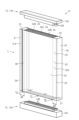
図1に示されるように、窓ユニット10は、引違い窓2の窓サッシとして構成される。図2に示されるように、窓ユニット10は、樹脂製の本体部11と、第1フレーム部材12と、第2フレーム部材13とを備える。
<Window unit for sliding windows>
As shown in Fig. 1, the
図3に示されるように、本体部11は、第1端面21と、第1端面21の反対側の第2端面22と、を有する。本体部11は、第1側面23と、第1側面23の反対側の第2側面24と、を有する。本体部11は、内面25と、外面26と、を有する。内面25は、窓ユニット10が窓枠に取り付けられた取付状態において室内に向く。外面26は、窓ユニット10が窓枠に取り付けられた取付状態において室外に向く。本実施形態では、第1端面21は、本体部11の上面であり、第2端面22は、本体部11の下面である。
3, the
図4に示されるように、一例では、本体部11の内面25および外面26の少なくとも一方は、概ね平坦に構成される。具体的には、内面25において、本体部11と第1側部31との境界に段差が設けられない。本体部11と第2側部32との境界には段差が設けられない。
As shown in FIG. 4, in one example, at least one of the
図5に示されるように、一例では、本体部11は、面取部27を有する。面取部27は、一方の面から他方の面に向かって曲がる曲面(R面とも呼ばれる)に構成される。面取部27は、内面25また外面26に対して傾斜するように構成されてもよい。
As shown in FIG. 5, in one example, the
面取部27は、内面25と第1側面23との間の角部、内面25と第2側面24との間の角部、外面26と第1側面23との間の角部、および、外面26と第2側面24との間の角部のうちの少なくとも1つに設けられる。例えば、面取部27は、第1角部28および第2角部29の少なくとも一方に設けられる。第1角部28は、本体部11においてガラス層36が設けられる面(例えば、内面25)と第1側面23との間の角部を示す。第2角部29は、本体部11においてガラス層36が設けられる面(例えば、内面25)と第2側面24との間の角部を示す。
The chamfered
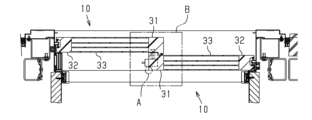
図3に示されるように、本体部11は、第1側部31と、第2側部32と、第1側部31と第2側部32との間にある中央部33と、を有する。第1側部31は、第1側面23を有する。第2側部32は、第2側面24を有する。第1側部31および第2側部32は、中実に構成される。すなわち、第1側部31および第2側部32は、内部に空隙がない構造を有する。
As shown in FIG. 3, the
第1側部31の厚さTAおよび第2側部32の厚さTBは、中央部33の厚さTCと等しい。第1側部31の厚さTAおよび第2側部32の厚さTBは、中央部33の厚さTCよりも大きくてもよい。第1側部31の厚さTAは、第1側部31において最も薄い部分の厚さによって定義される。第2側部32の厚さTBは、第2側部32において最も薄い部分の厚さによって定義される。
The thickness TA of the
第1側部31の横幅WAおよび第2側部32の横幅WBは、第1側部31の厚さTAおよび第2側部32の厚さTBと等しい。または、第1側部31の横幅WAおよび第2側部32の横幅WBは、第1側部31の厚さTAおよび第2側部32の厚さTBよりも大きい。第1側部31の横幅WAは、第1側部31の横幅WAにおいて最も狭い部分の厚さによって定義される。第2側部32の横幅WBは、第2側部32の横幅WBにおいて最も狭い部分の厚さによって定義される。
The width WA of the
第1側部31および第2側部32のうちの一方は、戸尻部31Aとして構成される。第1側部31および第2側部32のうちの他方は、戸先部32Aとして構成される。本実施形態では、第1側部31は、戸尻部31Aとして構成される。第2側部32は、戸先部32Aとして構成される。なお、引違い窓2の2つの窓ユニット10において、一方の窓ユニット10の第1側部31および第2側部32の配置は、他方の窓ユニット10の第1側部31および第2側部32の配置と左右逆の関係にある(図4参照)。
One of the
第1側部31および第2側部32の少なくとも一方は、手引用スリット38を有する。一例では、手引用スリット38は戸尻部31Aに設けられる。手引用スリット38は、戸尻部31Aの上端付近から下端付近まで延びる。
At least one of the
本体部11は、厚さ方向に配置される複数の中空層34を有する。具体的には、本体部11の中央部33は、少なくとも1つの中空層34を有する。中空層34は、第1端面21から第2端面22まで延びる。一例では、本体部11は、3個以上の中空層34を有する。本実施形態では、本体部11は、第1中空層34Aと、第2中空層34Bと、第3中空層34Cと、を有する。第1中空層34Aは、第2中空層34Bよりも外側に配置される。第3中空層34Cは、第1中空層34Aと第2中空層34Bとの間に配置される。
The
複数の中空層34それぞれの厚さは、5mm以上20mm以下である。好ましくは、複数の中空層34それぞれの厚さは、8mm以上15mm以下である。中空層34には、不活性ガス、または、空気が充填される。不活性ガスの例として、窒素、二酸化炭素、および、希ガスが挙げられる。一例では、中空層34には、空気またはアルゴンが充填される。
The thickness of each of the
本体部11は、透明に構成される。透明の本体部11は、入射光の一部を吸収、散乱、または反射させるものを含む。一例では、本体部11は、可視光を通すように透明に構成される。中央部33、第1側部31、および、第2側部32は、一体に構成される。本体部11は、透明樹脂によって構成される。一例では、本体部11は、ナノファイバーを含む透明樹脂によって構成される。透明樹脂として、ポリカーボネート樹脂、アクリル系樹脂、ポリスチレン樹脂、シリコーン樹脂、および、ポリエステル系樹脂が挙げられる。
The
ナノファイバーは、第1端面21から第2端面22に向く方向に沿うように配置される。例えば、本体部11は、押出成形機によって成形される。押出成形によって、ナノファイバーは、成形品の押し出し方向に沿うように配列される。
The nanofibers are arranged along the direction from the
ナノファイバーの例として、カーボンナノファイバー、ポリエステルナノファイバー、セルロースナノファイバー、および、DNAまたはたんぱく質から合成されるバイオナノファイバーが挙げられる。バイオナノファイバーの例として、キチンナノファイバーが挙げられる。一例では、セルロースナノファイバーが添加された透明樹脂が本体部11の成形材料として使用される。他の例では、キチンナノファイバーが添加された透明樹脂が本体部11の成形材料として使用される。さらに別の例では、単層カーボンナノチューブまたは多層カーボンナノチューブが添加された透明樹脂が本体部11の成形材料として使用される。
Examples of nanofibers include carbon nanofibers, polyester nanofibers, cellulose nanofibers, and bionanofibers synthesized from DNA or proteins. An example of a bionanofiber is chitin nanofiber. In one example, a transparent resin to which cellulose nanofibers have been added is used as the molding material for the
図5に示されるように、本体部11は、ガラス層36を有する。ガラス層36は、本体部11の内面25および外面26の一方または両方に設けられる。ガラス層36が設けられる部分は平坦に構成される。
As shown in FIG. 5, the
一例では、ガラス層36の厚さは、0.1mm以上0.5mm以下である。ガラス層36の端縁36Aは、面取部27に沿うように延びる。すなわち、ガラス層36の端縁36Aは、本体部11の第1側面23または第2側面24から離れたところに位置する。
In one example, the thickness of the
図6および図7に示されるように、本体部11において、戸尻部31Aには、戸締り錠42が設けられる。戸締り錠42の例として、クレセント錠、鎌錠、および、シリンダー錠が挙げられる。なお、図3において、戸締り錠42の記載は省略されている。具体的には、戸尻部31Aの側面には、凹部41が設けられ、戸締り錠42は、凹部41内に設けられる。戸締り錠42は、鎌錠として構成されてもよい。
As shown in Figs. 6 and 7, a locking
図3に示されるように、第1フレーム部材12は、本体部11の第1端面21に配置される。第2フレーム部材13は、本体部11の第2端面22に配置される。第1フレーム部材12は、第1ベース部14Aと、第1ベース部14Aから突出する第1突出部14Bとを有する。第1フレーム部材12は、中空層34の個数に応じた第1突出部14Bを有する。第1突出部14Bは、中空層34に嵌るように構成される。第1突出部14Bが中空層34に嵌め入れられた状態で、第1フレーム部材12は接着剤によって本体部11に固定される。
As shown in FIG. 3, the
第2フレーム部材13は、第2ベース部15Aと、第2ベース部15Aから突出する第2突出部15Bとを有する。第2フレーム部材13は、中空層34の個数に応じた第2突出部15Bを有する。第2突出部15Bは、中空層34に嵌るように構成される。第2突出部15Bが中空層34に嵌め入れられた状態で、第2フレーム部材13は接着剤によって本体部11に固定される。
The
第1フレーム部材12および第2フレーム部材13のうちの一方は、窓ユニット10の下部の下側フレーム部12Aとして構成される。第1フレーム部材12および第2フレーム部材13のうちの他方は、窓ユニット10の上部の上側フレーム部として構成される。本実施形態では、第1フレーム部材12が下側フレーム部12Aとして構成される。第2フレーム部材13が上側フレーム部13Aとして構成される。
One of the
上側フレーム部13A(すなわち、第2フレーム部材13)は、透明に構成される。上側フレーム部13A(すなわち、第2フレーム部材13)は、ナノファイバー含有の透明樹脂によって形成される。上側フレーム部13Aには、ガイド17が設けられる。ガイド17は、窓枠のガイドレール50が挿通するように構成される(図8参照)。
The upper frame portion 13A (i.e., the second frame member 13) is configured to be transparent. The upper frame portion 13A (i.e., the second frame member 13) is formed from a transparent resin containing nanofibers. The upper frame portion 13A is provided with a
上側フレーム部13Aは、不透明であってもよい。この場合、上側フレーム部13Aは、繊維強化樹脂によって構成されてもよい。上側フレーム部13Aは、樹脂成型品と金属部材との複合体であってもよい。 The upper frame portion 13A may be opaque. In this case, the upper frame portion 13A may be made of fiber-reinforced resin. The upper frame portion 13A may be a composite of a resin molded product and a metal member.
下側フレーム部12A(すなわち、第1フレーム部材12)は透明に構成される。下側フレーム部12A(すなわち、第1フレーム部材12)は、ナノファイバー含有の透明樹脂によって形成される。 The lower frame portion 12A (i.e., the first frame member 12) is configured to be transparent. The lower frame portion 12A (i.e., the first frame member 12) is formed from a transparent resin containing nanofibers.
図8および図9に示されるように、下側フレーム部12Aには、戸車ユニット47が収容される戸車凹部45が設けられる。戸車凹部45は、戸車ユニット47の戸車の一部が戸車凹部45から露出するように構成される。
As shown in Figures 8 and 9, the lower frame portion 12A is provided with a
図10に示されるように、戸車凹部45の凹部内面45Aと戸車ユニット47との間には、カバー部材48が設けられる。カバー部材48は、鏡面加工面48Aを有する。カバー部材48は、鏡面加工面48Aが凹部内面45Aに接触するように戸車凹部45に設けられる。
As shown in FIG. 10, a
下側フレーム部12Aは、不透明であってもよい。この場合、下側フレーム部12Aは、繊維強化樹脂によって構成されてもよい。下側フレーム部12Aは、樹脂成型品と金属部材との複合体であってもよい。 The lower frame portion 12A may be opaque. In this case, the lower frame portion 12A may be made of fiber-reinforced resin. The lower frame portion 12A may be a composite of a resin molded product and a metal member.
窓ユニット10の作用を説明する。窓ユニット10の本体部11は樹脂で成形される。このため、ガラス窓に比べて軽い。本体部11は、中空層34を有する。これによって、窓ユニット10の断熱性が向上する。本体部11は、中空層34を有する中央部33と、第1側部31と、第2側部32とを有する。中央部33は、第1側部31と第2側部32との間に位置する。中央部33、第1側部31、および、第2側部32は、一体に構成されている。第1側部31の厚さTAと第2側部32の厚さTBとは、本体部11の厚さTCと等しい、または、本体部11の厚さTCよりも大きい。第1側部31および第2側部32は、中実構造を有する。このような第1側部31および第2側部32は、本体部11を補強する。第1側部31および第2側部32は、窓サッシの框と同様の役割を果たす。このため、窓ユニット10において金属の框が省略される。窓ユニット10は、金属の框を有しないが、第1側部31および第2側部32によって本体部11が補強されるため、窓ユニット10は、変形し難い。
The function of the
<建築物>
図11を参照して、建築物1を説明する。建築物1は、引違い窓2を有する。引違い窓2は、窓ユニット10を備える。窓ユニット10を備える。窓ユニット10によって建築物1の断熱性が向上する。窓ユニット10は、樹脂によって構成される。窓ユニット10は、ガラス窓に比べて軽いため、引違い窓2の開閉の負担を軽減できる。樹脂製の窓は、日射の熱によって変形する虞がある。経年劣化で樹脂製の窓が変形すると、窓周辺に隙間が生じ、建築物1の断熱性が低下する虞がある。この点、窓ユニット10は熱による変形が小さい。このため、窓周辺に隙間が形成され難い。このようにして、建築物1の断熱性の低下を抑制できる。
<Buildings>
The
窓ユニット10および建築物1の効果を説明する。
(1)窓ユニット10は、樹脂製の本体部11と、第1フレーム部材12と、第2フレーム部材13と、を備える。本体部11は、第1側部31と、第2側部32と、中央部33と、を有する。中央部33は、少なくとも1つの中空層34を有する。本体部11は、透明に構成される。中央部33、第1側部31、および、第2側部32は、一体に構成される。第1側部31の厚さTAおよび第2側部32の厚さTBは、中央部33の厚さTCと等しい、または中央部33の厚さTCよりも大きい。この構成によれば、第1側部31および第2側部32が中央部33を補強する。これによって、熱よる窓の変形を抑制できる。
The effects of the
(1) The
(2)第1側部31の横幅WAおよび第2側部32の横幅WBは、第1側部31の厚さTAおよび第2側部32の厚さTBと等しい、または、第1側部31の厚さTAおよび第2側部32の厚さTBよりも大きい。この構成によれば、本体部11の中央部33をさらに補強できる。
(2) The width WA of the
(3)本体部11は、厚さ方向に配置される複数の中空層34を有する。複数の中空層34それぞれの厚さは、5mm以上20mm以下である。中空層34について20mmを超える厚さの増大は、断熱性の更なる向上に寄与し難い。このため、上記構成によって、窓ユニット10の厚みを大きく増大させずに、断熱性を向上できる。
(3) The
(4)本体部11は、3個以上の中空層34を有する。この構成によれば、室外に近い中空層34と、室内に近い中空層34との間に中空層34が設けられるため、断熱性をさらに向上できる。
(4) The
(5)本体部11は、ナノファイバーを含む樹脂によって構成される。この構成によれば、窓ユニット10の強度を向上できる。ナノファイバーは光を反射させ難いため、マイクロメートルオーダの繊維を含有させる場合に比べて、透明度の低下を抑制できる。
(5) The
(6)本体部11の内面25および外面26の少なくとも一方は、ガラス層36を有する。この構成によれば、窓ユニット10の表面に傷が付くことを少なくできる。ガラス層36の厚さは、0.1mm以上0.5mm以下であることが好ましい。このようにガラス層36を薄くすることによって、窓ユニット10の重さの増大を小さくできる。
(6) At least one of the
(7)本体部11は、面取部27を有する。ガラス層36の端縁36Aは、面取部27に沿うように延びる。この構成によれば、ガラス層36の端縁36Aが割れることを少なくできる。
(7) The
(8)第1側部31および第2側部32のうちの一方は、戸尻部31Aとして構成される。戸尻部31Aの側面には、凹部41が設けられる。凹部41には戸締り錠42が設けられる。この構成によれば、戸締り錠42を視認し難くできる。これによって、窓ユニット10のデザインを向上できる。
(8) One of the
(9)第1フレーム部材12および第2フレーム部材13のうちの一方は、下側フレーム部12Aとして構成される。下側フレーム部12Aは透明に構成される。この構成によれば、窓ユニット10において透明領域を広くできる。このため、窓ユニット10の採光性が向上する。
(9) One of the
(10)下側フレーム部12Aには、戸車ユニット47が収容される戸車凹部45が設けられる。戸車凹部45の凹部内面45Aと戸車ユニット47との間には、カバー部材48が設けられる。カバー部材48は、鏡面加工面48Aが凹部内面45Aに接触するように戸車凹部45に設けられる。この構成によれば、カバー部材48が光を反射する。これによって、戸車ユニット47およびカバー部材48を視認し難くできる。
(10) The lower frame portion 12A is provided with a
(11)第1側部31および第2側部32の少なくとも一方は、手引用スリット38を有する。この構成によれば、窓ユニット10を引き易くできる。一例では、手引用スリット38は、戸尻部31Aの上端付近から下端付近まで延びる。これによって、背の高い人から背の低い人まで、窓ユニット10を引き易くできる。
(11) At least one of the
(12)内面25または外面26において、本体部11と第1側部31との境界に段差が設けられないことが好ましい。内面25または外面26において、本体部11と第2側部32との境界には段差が設けられない。この構成によれば、窓ユニット10において、段差に基づく陰影が少なくなるため、窓ユニット10における採光部分が広がっているような印象を与えることができる。
(12) It is preferable that there is no step on the boundary between the
(13)建築物1は、窓ユニット10を備える。この構成によれば、窓ユニット10が変形し難いため、窓周辺に隙間が形成され難い。これによって、断熱性の低下が小さい建築物1を提供できる。
(13) The
<変形例>
上記実施形態は、窓ユニット10および建築物1が取り得る形態の例示であり、その形態を制限することを意図していない。窓ユニット10および建築物1は、上記実施形態に例示された形態とは異なる形態を取り得る。その例は、実施形態の構成の一部を置換、変更、省略した形態、または、実施形態に新たな構成を付加した形態である。以下に実施形態の変形例を示す。
<Modification>
The above embodiment is an example of the form that the
実施形態において、本体部11は、剛性部材を含んでもよい。剛性部材は、金属フレームまたは炭素繊維強化プラスチックである。剛性部材は、第1側部31および第2側部32の一方または両方に設けられる。剛性部材は、第1側部31および第2側部32の一方または両方に埋め込められてもよい。例えば、金属フレームを含む本体部11は、金属インサート押出成形によって形成される。
In an embodiment, the
実施形態では、第1フレーム部材12および第2フレーム部材13は、本体部11と別部材として構成されている。これに対して、第1フレーム部材12および第2フレーム部材13の一方は、本体部11と一体に構成されてもよい。
In the embodiment, the
戸締り錠42は、鏡面加工面を有するカバー部材によって隠されてもよい。例えば、戸締り錠42が設けられる凹部41の凹部内面に、鏡面加工面を有するカバー部材が設けられる。カバー部材は、鏡面加工面が凹部41の凹部内面に接触するように設けられる。この構成によって、戸締り錠42を視認し難くできる。また、戸締り錠42が視認され難くなることによって、窓ユニット10のデザイン性が向上する。
The locking
図12を参照して、窓ユニット10の他の使用例を説明する。
窓ユニット10は、固定窓3用として構成されてもよい。窓ユニット10は、本体部11と、第1フレーム部材12と、第2フレーム部材13とを備える。本体部11の第1側部31は、上に配置される。本体部11の第2側部32は、下に配置される。第1フレーム部材12は、窓ユニット10における横方向の一方の端部を構成する。第2フレーム部材13は、窓ユニット10における横方向の他方の端部を構成する。この構成によれば、熱による変形が小さい固定窓3を提供できる。窓ユニット10の変形が少ないため、固定窓3において隙間が形成され難くなる。このため、建築物1の断熱性の低下を抑制できる。
With reference to FIG. 12, another example of use of the
The
1…建築物、10…窓ユニット、11…本体部、12…第1フレーム部材、12A…下側フレーム部、13…第2フレーム部材、21…第1端面、22…第2端面、25…内面、26…外面、27…面取部、31…第1側部、31A…戸尻部、32…第2側部、33…中央部、34…中空層、36…ガラス層、41…凹部、42…錠、45…戸車凹部、45A…凹部内面、47…戸車ユニット、48…カバー部材、48A…鏡面加工面。 1...building, 10...window unit, 11...main body, 12...first frame member, 12A...lower frame member, 13...second frame member, 21...first end face, 22...second end face, 25...inner face, 26...outer face, 27...chamfered portion, 31...first side portion, 31A...door end portion, 32...second side portion, 33...central portion, 34...hollow layer, 36...glass layer, 41...recess, 42...lock, 45...wheel recess, 45A...recess inner face, 47...wheel unit, 48...cover member, 48A...mirror-finished surface.
Claims (13)
第1端面および前記第1端面の反対側の第2端面を有する樹脂製の本体部と、前記本体部の前記第1端面に配置される第1フレーム部材と、前記本体部の前記第2端面に配置される第2フレーム部材と、を備え、
前記本体部は、第1側部と、前記第1側部と反対側の第2側部と、前記第1側部と前記第2側部との間にある中央部と、を有し、
前記中央部は、前記第1端面から前記第2端面まで延びる少なくとも1つの中空層を有し、
前記本体部は、透明に構成され、
前記中央部、前記第1側部、および、前記第2側部は、一体に構成され、
前記第1側部の厚さおよび前記第2側部の厚さは、前記中央部の厚さと等しい、または前記中央部の厚さよりも大きく、
前記第1側部および前記第2側部のうちの一方は、戸尻部として構成され、
前記戸尻部の側面には、凹部が設けられ、
前記凹部に戸締り錠が設けられる、
窓ユニット。 1. A window unit comprising:
a resin body having a first end surface and a second end surface opposite to the first end surface, a first frame member disposed on the first end surface of the body, and a second frame member disposed on the second end surface of the body,
The body portion has a first side, a second side opposite the first side, and a central portion between the first side and the second side,
the central portion has at least one hollow layer extending from the first end surface to the second end surface,
The main body is transparent.
the central portion, the first side portion, and the second side portion are integrally formed;
a thickness of the first side portion and a thickness of the second side portion are equal to or greater than a thickness of the central portion;
One of the first side and the second side is configured as a tail portion;
A recess is provided on the side surface of the door end portion,
A lock is provided in the recess.
Window unit.
前記下側フレーム部は透明に構成される、
請求項1に記載の窓ユニット。 One of the first frame member and the second frame member is configured as a lower frame portion;
The lower frame portion is configured to be transparent.
2. A window unit according to claim 1 .
前記戸車凹部の凹部内面と前記戸車ユニットとの間には、鏡面加工面を有するカバー部材が設けられ、
前記カバー部材は、前記鏡面加工面が前記凹部内面に接触するように前記戸車凹部に設けられる、
請求項2に記載の窓ユニット。 The lower frame portion is provided with a roller recess in which a roller unit is housed,
A cover member having a mirror-finished surface is provided between the inner surface of the roller recess and the roller unit,
The cover member is provided in the roller recess so that the mirror-finished surface contacts the inner surface of the recess.
3. A window unit according to claim 2 .
第1端面および前記第1端面の反対側の第2端面を有する樹脂製の本体部と、前記本体部の前記第1端面に配置される第1フレーム部材と、前記本体部の前記第2端面に配置される第2フレーム部材と、を備え、
前記本体部は、第1側部と、前記第1側部と反対側の第2側部と、前記第1側部と前記第2側部との間にある中央部と、を有し、
前記中央部は、前記第1端面から前記第2端面まで延びる少なくとも1つの中空層を有し、
前記本体部は、透明に構成され、
前記中央部、前記第1側部、および、前記第2側部は、一体に構成され、
前記第1側部の厚さおよび前記第2側部の厚さは、前記中央部の厚さと等しい、または前記中央部の厚さよりも大きく、
前記第1フレーム部材および前記第2フレーム部材のうちの一方は、下側フレーム部として構成され、
前記下側フレーム部は透明に構成され、
前記下側フレーム部には、戸車ユニットが収容される戸車凹部が設けられ、
前記戸車凹部の凹部内面と前記戸車ユニットとの間には、鏡面加工面を有するカバー部材が設けられ、
前記カバー部材は、前記鏡面加工面が前記凹部内面に接触するように前記戸車凹部に設けられる、
窓ユニット。 1. A window unit comprising:
a resin body having a first end surface and a second end surface opposite to the first end surface, a first frame member disposed on the first end surface of the body, and a second frame member disposed on the second end surface of the body,
The body portion has a first side, a second side opposite the first side, and a central portion between the first side and the second side,
the central portion has at least one hollow layer extending from the first end surface to the second end surface,
The main body is transparent.
the central portion, the first side portion, and the second side portion are integrally formed;
a thickness of the first side portion and a thickness of the second side portion are equal to or greater than a thickness of the central portion;
One of the first frame member and the second frame member is configured as a lower frame portion;
The lower frame portion is transparent.
The lower frame portion is provided with a roller recess in which a roller unit is housed,
A cover member having a mirror-finished surface is provided between the inner surface of the roller recess and the roller unit,
The cover member is provided in the roller recess so that the mirror-finished surface contacts the inner surface of the recess.
Window unit.
請求項1~4のいずれか一項に記載の窓ユニット。 At least one of the first side and the second side has a hand slit.
A window unit according to any one of claims 1 to 4 .
第1端面および前記第1端面の反対側の第2端面を有する樹脂製の本体部と、前記本体部の前記第1端面に配置される第1フレーム部材と、前記本体部の前記第2端面に配置される第2フレーム部材と、を備え、
前記本体部は、第1側部と、前記第1側部と反対側の第2側部と、前記第1側部と前記第2側部との間にある中央部と、を有し、
前記中央部は、前記第1端面から前記第2端面まで延びる少なくとも1つの中空層を有し、
前記本体部は、透明に構成され、
前記中央部、前記第1側部、および、前記第2側部は、一体に構成され、
前記第1側部の厚さおよび前記第2側部の厚さは、前記中央部の厚さと等しい、または前記中央部の厚さよりも大きく、
前記第1側部および前記第2側部の少なくとも一方は、手引用スリットを有する、
窓ユニット。 1. A window unit comprising:
a resin body having a first end surface and a second end surface opposite to the first end surface, a first frame member disposed on the first end surface of the body, and a second frame member disposed on the second end surface of the body,
The body portion has a first side, a second side opposite the first side, and a central portion between the first side and the second side,
the central portion has at least one hollow layer extending from the first end surface to the second end surface,
The main body is transparent.
the central portion, the first side portion, and the second side portion are integrally formed;
a thickness of the first side portion and a thickness of the second side portion are equal to or greater than a thickness of the central portion;
At least one of the first side and the second side has a hand slit.
Window unit.
請求項1~6のいずれか一項に記載の窓ユニット。 A lateral width of the first side portion and a lateral width of the second side portion are equal to or greater than a thickness of the first side portion and a thickness of the second side portion.
A window unit according to any one of claims 1 to 6 .
複数の前記中空層それぞれの厚さは、5mm以上20mm以下である、
請求項1~7のいずれか一項に記載の窓ユニット。 The body portion has a plurality of hollow layers arranged in a thickness direction,
The thickness of each of the plurality of hollow layers is 5 mm or more and 20 mm or less.
A window unit according to any one of claims 1 to 7 .
請求項1~8のいずれか一項に記載の窓ユニット。 The body portion has three or more hollow layers.
A window unit according to any one of the preceding claims .
請求項1~9のいずれか一項に記載の窓ユニット。 The main body is made of a resin containing nanofibers.
A window unit according to any one of claims 1 to 9 .
前記内面および前記外面の少なくとも一方は、ガラス層を有する、
請求項1~10のいずれか一項に記載の窓ユニット。 The main body portion has an inner surface that faces the room when the window unit is attached, and an outer surface opposite to the inner surface,
At least one of the inner surface and the outer surface has a glass layer.
A window unit according to any one of the preceding claims .
前記ガラス層の端縁は、前記面取部に沿うように延びる、
請求項11に記載の窓ユニット。 The body portion has a chamfered portion,
The edge of the glass layer extends along the chamfered portion.
Window unit according to claim 11 .
Priority Applications (1)
| Application Number | Priority Date | Filing Date | Title |
|---|---|---|---|
| JP2021206365A JP7464036B2 (en) | 2021-12-20 | 2021-12-20 | Window Units and Buildings |
Applications Claiming Priority (1)
| Application Number | Priority Date | Filing Date | Title |
|---|---|---|---|
| JP2021206365A JP7464036B2 (en) | 2021-12-20 | 2021-12-20 | Window Units and Buildings |
Publications (2)
| Publication Number | Publication Date |
|---|---|
| JP2023091562A JP2023091562A (en) | 2023-06-30 |
| JP7464036B2 true JP7464036B2 (en) | 2024-04-09 |
Family
ID=86941817
Family Applications (1)
| Application Number | Title | Priority Date | Filing Date |
|---|---|---|---|
| JP2021206365A Active JP7464036B2 (en) | 2021-12-20 | 2021-12-20 | Window Units and Buildings |
Country Status (1)
| Country | Link |
|---|---|
| JP (1) | JP7464036B2 (en) |
Citations (6)
| Publication number | Priority date | Publication date | Assignee | Title |
|---|---|---|---|---|
| JP2001182450A (en) | 1999-12-28 | 2001-07-06 | Nippon Kodo Iryo Kenkyukai:Kk | Double layer window |
| JP2006124932A (en) | 2004-10-26 | 2006-05-18 | Sekisui House Ltd | Paper door frame member for window sash, and method of producing the same |
| JP3187630U (en) | 2013-09-26 | 2013-12-05 | 株式会社光 | Panel frame and panel kit |
| JP2017180026A (en) | 2016-03-31 | 2017-10-05 | 株式会社ウッドワン | Frame structure, frame body covering member, and frame body covering method |
| JP3231405U (en) | 2020-12-10 | 2021-04-01 | 泰久 和田 | Insulated sash door |
| JP2021104712A (en) | 2019-12-26 | 2021-07-26 | 株式会社豊田自動織機 | Shutter for vehicle |
-
2021
- 2021-12-20 JP JP2021206365A patent/JP7464036B2/en active Active
Patent Citations (6)
| Publication number | Priority date | Publication date | Assignee | Title |
|---|---|---|---|---|
| JP2001182450A (en) | 1999-12-28 | 2001-07-06 | Nippon Kodo Iryo Kenkyukai:Kk | Double layer window |
| JP2006124932A (en) | 2004-10-26 | 2006-05-18 | Sekisui House Ltd | Paper door frame member for window sash, and method of producing the same |
| JP3187630U (en) | 2013-09-26 | 2013-12-05 | 株式会社光 | Panel frame and panel kit |
| JP2017180026A (en) | 2016-03-31 | 2017-10-05 | 株式会社ウッドワン | Frame structure, frame body covering member, and frame body covering method |
| JP2021104712A (en) | 2019-12-26 | 2021-07-26 | 株式会社豊田自動織機 | Shutter for vehicle |
| JP3231405U (en) | 2020-12-10 | 2021-04-01 | 泰久 和田 | Insulated sash door |
Also Published As
| Publication number | Publication date |
|---|---|
| JP2023091562A (en) | 2023-06-30 |
Similar Documents
| Publication | Publication Date | Title |
|---|---|---|
| JPH07506558A (en) | Frameless heat insulating gloss material and its manufacturing method | |
| US20110225893A1 (en) | Frame assembly and plastic profile frame therefor | |
| JP7464036B2 (en) | Window Units and Buildings | |
| US8166705B2 (en) | Support structure for vehicular resin window | |
| CN104583520A (en) | Integrated window pane and window which comprises such a pane | |
| JP6114608B2 (en) | End face protection cover for multiple glass shoji and multiple glass shoji | |
| JP2008019065A (en) | Elevator glass door | |
| CN206245973U (en) | Outward opening broken-bridge aluminum alloy casement window | |
| JP2021510781A (en) | Openable glass construction with protective profile | |
| JP2014208961A (en) | Multiple-glass sliding door | |
| KR20130111689A (en) | Door and window having good sightseeing and enhanced airtightness | |
| JP2005083075A (en) | Glass door | |
| JP5322281B2 (en) | Door device | |
| JP2015143420A (en) | Multiple glass sash | |
| US20140065330A1 (en) | Glazing for a rail vehicle | |
| CN106246049A (en) | A kind of supporting middle stile structure being installed in the middle of door and window fan frame | |
| CN217897620U (en) | Aluminum-plastic co-extrusion profile structure of heat-insulation and sound-insulation door and window | |
| KR102664809B1 (en) | Support shaft and a door including the same | |
| JP3096372U (en) | Gas-filled security double glazing | |
| KR101289672B1 (en) | Sliding door for bus | |
| KR20100029307A (en) | Pair transparent panel window | |
| CN206615906U (en) | A kind of gate of car | |
| JPH0355741Y2 (en) | ||
| JP2014208568A (en) | Multiple glass shoji and frame body for multiple glass shoji | |
| JP2006124932A (en) | Paper door frame member for window sash, and method of producing the same |
Legal Events
| Date | Code | Title | Description |
|---|---|---|---|
| A621 | Written request for application examination |
Free format text: JAPANESE INTERMEDIATE CODE: A621 Effective date: 20221109 |
|
| A977 | Report on retrieval |
Free format text: JAPANESE INTERMEDIATE CODE: A971007 Effective date: 20231031 |
|
| A131 | Notification of reasons for refusal |
Free format text: JAPANESE INTERMEDIATE CODE: A131 Effective date: 20231107 |
|
| A521 | Request for written amendment filed |
Free format text: JAPANESE INTERMEDIATE CODE: A523 Effective date: 20231222 |
|
| TRDD | Decision of grant or rejection written | ||
| A01 | Written decision to grant a patent or to grant a registration (utility model) |
Free format text: JAPANESE INTERMEDIATE CODE: A01 Effective date: 20240227 |
|
| A61 | First payment of annual fees (during grant procedure) |
Free format text: JAPANESE INTERMEDIATE CODE: A61 Effective date: 20240311 |
|
| R150 | Certificate of patent or registration of utility model |
Ref document number: 7464036 Country of ref document: JP Free format text: JAPANESE INTERMEDIATE CODE: R150 |