JP7463575B2 - Information processing device, information processing method, and program - Google Patents
Information processing device, information processing method, and program Download PDFInfo
- Publication number
- JP7463575B2 JP7463575B2 JP2023009355A JP2023009355A JP7463575B2 JP 7463575 B2 JP7463575 B2 JP 7463575B2 JP 2023009355 A JP2023009355 A JP 2023009355A JP 2023009355 A JP2023009355 A JP 2023009355A JP 7463575 B2 JP7463575 B2 JP 7463575B2
- Authority
- JP
- Japan
- Prior art keywords
- region
- change
- amount
- image
- information processing
- Prior art date
- Legal status (The legal status is an assumption and is not a legal conclusion. Google has not performed a legal analysis and makes no representation as to the accuracy of the status listed.)
- Active
Links
Images


Classifications
-
- G—PHYSICS
- G06—COMPUTING OR CALCULATING; COUNTING
- G06T—IMAGE DATA PROCESSING OR GENERATION, IN GENERAL
- G06T11/00—Two-dimensional [2D] image generation
-
- A—HUMAN NECESSITIES
- A61—MEDICAL OR VETERINARY SCIENCE; HYGIENE
- A61B—DIAGNOSIS; SURGERY; IDENTIFICATION
- A61B6/00—Apparatus or devices for radiation diagnosis; Apparatus or devices for radiation diagnosis combined with radiation therapy equipment
-
- G—PHYSICS
- G06—COMPUTING OR CALCULATING; COUNTING
- G06F—ELECTRIC DIGITAL DATA PROCESSING
- G06F18/00—Pattern recognition
- G06F18/20—Analysing
- G06F18/21—Design or setup of recognition systems or techniques; Extraction of features in feature space; Blind source separation
- G06F18/214—Generating training patterns; Bootstrap methods, e.g. bagging or boosting
-
- G—PHYSICS
- G06—COMPUTING OR CALCULATING; COUNTING
- G06F—ELECTRIC DIGITAL DATA PROCESSING
- G06F18/00—Pattern recognition
- G06F18/20—Analysing
- G06F18/23—Clustering techniques
- G06F18/232—Non-hierarchical techniques
- G06F18/2321—Non-hierarchical techniques using statistics or function optimisation, e.g. modelling of probability density functions
-
- G—PHYSICS
- G06—COMPUTING OR CALCULATING; COUNTING
- G06N—COMPUTING ARRANGEMENTS BASED ON SPECIFIC COMPUTATIONAL MODELS
- G06N20/00—Machine learning
-
- G—PHYSICS
- G06—COMPUTING OR CALCULATING; COUNTING
- G06N—COMPUTING ARRANGEMENTS BASED ON SPECIFIC COMPUTATIONAL MODELS
- G06N3/00—Computing arrangements based on biological models
- G06N3/02—Neural networks
- G06N3/04—Architecture, e.g. interconnection topology
- G06N3/0464—Convolutional networks [CNN, ConvNet]
-
- G—PHYSICS
- G06—COMPUTING OR CALCULATING; COUNTING
- G06N—COMPUTING ARRANGEMENTS BASED ON SPECIFIC COMPUTATIONAL MODELS
- G06N3/00—Computing arrangements based on biological models
- G06N3/02—Neural networks
- G06N3/08—Learning methods
- G06N3/09—Supervised learning
-
- G—PHYSICS
- G06—COMPUTING OR CALCULATING; COUNTING
- G06T—IMAGE DATA PROCESSING OR GENERATION, IN GENERAL
- G06T7/00—Image analysis
- G06T7/0002—Inspection of images, e.g. flaw detection
- G06T7/0012—Biomedical image inspection
-
- G—PHYSICS
- G06—COMPUTING OR CALCULATING; COUNTING
- G06V—IMAGE OR VIDEO RECOGNITION OR UNDERSTANDING
- G06V10/00—Arrangements for image or video recognition or understanding
- G06V10/20—Image preprocessing
- G06V10/25—Determination of region of interest [ROI] or a volume of interest [VOI]
-
- G—PHYSICS
- G06—COMPUTING OR CALCULATING; COUNTING
- G06V—IMAGE OR VIDEO RECOGNITION OR UNDERSTANDING
- G06V10/00—Arrangements for image or video recognition or understanding
- G06V10/70—Arrangements for image or video recognition or understanding using pattern recognition or machine learning
- G06V10/77—Processing image or video features in feature spaces; using data integration or data reduction, e.g. principal component analysis [PCA] or independent component analysis [ICA] or self-organising maps [SOM]; Blind source separation
- G06V10/774—Generating sets of training patterns; Bootstrap methods, e.g. bagging or boosting
-
- G—PHYSICS
- G06—COMPUTING OR CALCULATING; COUNTING
- G06N—COMPUTING ARRANGEMENTS BASED ON SPECIFIC COMPUTATIONAL MODELS
- G06N3/00—Computing arrangements based on biological models
- G06N3/02—Neural networks
- G06N3/04—Architecture, e.g. interconnection topology
- G06N3/045—Combinations of networks
-
- G—PHYSICS
- G06—COMPUTING OR CALCULATING; COUNTING
- G06N—COMPUTING ARRANGEMENTS BASED ON SPECIFIC COMPUTATIONAL MODELS
- G06N3/00—Computing arrangements based on biological models
- G06N3/02—Neural networks
- G06N3/08—Learning methods
- G06N3/084—Backpropagation, e.g. using gradient descent
-
- G—PHYSICS
- G06—COMPUTING OR CALCULATING; COUNTING
- G06T—IMAGE DATA PROCESSING OR GENERATION, IN GENERAL
- G06T2207/00—Indexing scheme for image analysis or image enhancement
- G06T2207/20—Special algorithmic details
- G06T2207/20081—Training; Learning
Landscapes
- Engineering & Computer Science (AREA)
- Theoretical Computer Science (AREA)
- Physics & Mathematics (AREA)
- General Physics & Mathematics (AREA)
- Data Mining & Analysis (AREA)
- Health & Medical Sciences (AREA)
- Artificial Intelligence (AREA)
- Evolutionary Computation (AREA)
- Life Sciences & Earth Sciences (AREA)
- Computer Vision & Pattern Recognition (AREA)
- Software Systems (AREA)
- Medical Informatics (AREA)
- General Health & Medical Sciences (AREA)
- General Engineering & Computer Science (AREA)
- Computing Systems (AREA)
- Multimedia (AREA)
- Mathematical Physics (AREA)
- Biophysics (AREA)
- Biomedical Technology (AREA)
- Molecular Biology (AREA)
- Nuclear Medicine, Radiotherapy & Molecular Imaging (AREA)
- Evolutionary Biology (AREA)
- Bioinformatics & Computational Biology (AREA)
- Bioinformatics & Cheminformatics (AREA)
- Radiology & Medical Imaging (AREA)
- Databases & Information Systems (AREA)
- Computational Linguistics (AREA)
- Quality & Reliability (AREA)
- Probability & Statistics with Applications (AREA)
- Heart & Thoracic Surgery (AREA)
- Veterinary Medicine (AREA)
- Public Health (AREA)
- Animal Behavior & Ethology (AREA)
- Surgery (AREA)
- Pathology (AREA)
- Optics & Photonics (AREA)
- High Energy & Nuclear Physics (AREA)
- Image Analysis (AREA)
- Apparatus For Radiation Diagnosis (AREA)
Description
本明細書の開示は、情報処理装置、情報処理方法およびプログラムに関する。 The disclosure of this specification relates to an information processing device, an information processing method, and a program.
近年、画像認識分野において機械学習が用いられている。機械学習に基づく識別器で画像認識を行うためには、教示データと呼ばれる学習画像と正解データの組による学習が必要である。一般に、画像に描出される対象物体は、撮像時のさまざまな条件により濃度値が変動する。そのため、実際の画像において対象物体が有しうる濃度値を包括するように、大量の教示データを準備する必要がある。そこで、特許文献1では、画像数の少ないクラスに属する教示データに対して、アフィン変換(拡大、縮小、回転)と属性変換(明るさ、コントラスト、エッジ強度)をすることで、新たな教示データを生成する方法が開示されている。 In recent years, machine learning has been used in the field of image recognition. In order to perform image recognition using a classifier based on machine learning, learning is required using a set of training images called training data and correct answer data. In general, the density value of a target object depicted in an image varies depending on various conditions at the time of capturing the image. Therefore, it is necessary to prepare a large amount of training data so as to encompass the density values that the target object may have in the actual image. Therefore, Patent Document 1 discloses a method of generating new training data by performing affine transformation (enlargement, reduction, rotation) and attribute transformation (brightness, contrast, edge strength) on training data belonging to a class with a small number of images.
しかしながら、特許文献1に記載の方法では、教示データの濃度値を一律に変更するため、場合によっては望ましくなかった。 However, the method described in Patent Document 1 involves uniformly changing the concentration values of the teaching data, which may be undesirable in some cases.
本明細書の開示は、適切に濃度値を変更した新たな教示データを用いて識別器を学習させることを目的の一つとする。 One of the objectives of the disclosure of this specification is to train a classifier using new teaching data in which the density values have been appropriately changed.
なお、前記目的に限らず、後述する発明を実施するための形態に示す各構成により導かれる作用効果であって、従来の技術によっては得られない作用効果を奏することも本明細書の開示の他の目的の一つとして位置付けることができる。 In addition to the above-mentioned objective, the achievement of effects that are derived from the configurations shown in the detailed description of the invention described below and that cannot be obtained by conventional techniques can also be considered as another objective of the disclosure of this specification.
本明細書に開示の情報処理装置は、画像を取得する取得部と、前記画像に含まれる一部の領域を対象領域として抽出する抽出部と、前記対象領域に含まれる画素の濃度値の変化量の絶対値が前記対象領域以外の領域に含まれる画素の濃度値の変化量の絶対値に比べて大きくなるように前記対象領域に含まれる画素の濃度値の変化量を決定する決定部と、前記決定部が決定した変化量に基づいて前記対象領域に含まれる画素の濃度値を変更した学習画像を生成する生成部と、前記学習画像を用いて識別器の学習を行う学習部と、を備えることを特徴とする。 The information processing device disclosed in this specification is characterized by comprising an acquisition unit that acquires an image, an extraction unit that extracts a portion of an area included in the image as a target area, a determination unit that determines an amount of change in density value of pixels included in the target area such that the absolute value of the amount of change in density value of pixels included in the target area is greater than the absolute value of the amount of change in density value of pixels included in areas other than the target area, a generation unit that generates a training image in which the density values of pixels included in the target area are changed based on the amount of change determined by the determination unit, and a training unit that trains a classifier using the training image.
本明細書の開示によれば、適切に濃度値を変更した新たな教示データを用いて識別器を学習させることができる。 According to the disclosure of this specification, it is possible to train a classifier using new teaching data in which the density values have been appropriately changed.
本実施形態にかかる情報処理装置では、X線コンピュータ断層撮像(X線CT)装置で撮像された人体の3次元断層画像(3次元画像の一種)を処理する例を説明する。しかしながら、本明細書の開示の適用範囲は上述のX線CT装置で撮影された3次元断層画像に限定されるものではない。例えば、核磁気共鳴画像撮像装置(MRI)装置、ポジトロン断層撮像(PET)装置、3次元超音波撮像装置で撮像された3次元断層画像でもよい。その他にも、撮像時の条件を変更することによって、濃度値が変化する領域と、変化しない領域が存在する画像であればいかなる画像であっても良い。また、本明細書の開示は、3次元画像以外に、2次元画像(例えば、単純X線画像)にも適用可能である。具体的には、単純X線画像の他、電子線CT画像や自然画像にも適用可能である。例えば、交通状況を撮影したような自然画像であれば、画像中の車の濃度値を変化させ、道路や標識の濃度値は変化させないというように適用することが考えられる。 In the information processing device according to the present embodiment, an example of processing a three-dimensional tomographic image (a type of three-dimensional image) of a human body captured by an X-ray computed tomography (X-ray CT) device will be described. However, the scope of application of the disclosure of this specification is not limited to three-dimensional tomographic images captured by the above-mentioned X-ray CT device. For example, three-dimensional tomographic images captured by a nuclear magnetic resonance imaging (MRI) device, a positron emission tomography (PET) device, or a three-dimensional ultrasound imaging device may be used. In addition, any image may be used as long as there are areas in which the density value changes and areas in which it does not change by changing the conditions at the time of imaging. In addition, the disclosure of this specification can be applied to two-dimensional images (e.g., plain X-ray images) in addition to three-dimensional images. Specifically, in addition to plain X-ray images, it can also be applied to electron beam CT images and natural images. For example, in the case of a natural image such as a traffic situation image, it is possible to apply it by changing the density value of the car in the image and not changing the density value of the road or sign.
以下では、機械学習に基づく識別器で画像認識を行う一例として、画像から物体の領域を抽出する識別器について説明する。より具体的には、X線CT装置で撮像された3次元断層画像に対して、肺野の領域抽出を行うCNN(Convolutional Neural Network)を例に挙げて、本実施形態について説明する。ここで領域抽出とは、画像内を関心領域と関心領域以外の領域に分割する処理のことを指す。領域抽出は、画像処理の分野において、領域分割、画像分割、セグメンテーションとも呼ばれる。 Below, as an example of image recognition using a classifier based on machine learning, a classifier that extracts object regions from an image will be described. More specifically, this embodiment will be described using an example of a CNN (Convolutional Neural Network) that extracts lung field regions from a 3D tomographic image captured by an X-ray CT scanner. Here, region extraction refers to the process of dividing an image into a region of interest and a region other than the region of interest. In the field of image processing, region extraction is also called region division, image division, or segmentation.
本実施形態では、肺野の領域抽出を行うCNNの一例として、U-Net[O.Ronneberger et al., “U-Net:Convolutional Networks for Biomedical Image Segmentation,” Medical Image Computing and Computer-Assisted Intervention (MICCAI),vol.9351:234-241,2015.]を用いる。U-Netの学習には、学習画像である2次元断層画像(3次元断層画像を構成する複数の断層画像のうちの1枚)と2次元断層画像に対応する正解データが教示データとなる。本実施形態における正解データは、例えば肺野領域を表すマスク画像である。マスク画像とは、関心領域に属する画素か否かを2値で表した画像である。 In this embodiment, U-Net [O. Ronneberger et al., "U-Net: Convolutional Networks for Biomedical Image Segmentation," Medical Image Computing and Computer-Assisted Intervention (MICCAI), vol. 9351:234-241, 2015.] is used as an example of a CNN that extracts lung field regions. For learning U-Net, a two-dimensional tomographic image (one of multiple tomographic images that make up a three-dimensional tomographic image) that is a learning image and correct answer data corresponding to the two-dimensional tomographic image are used as teaching data. The correct answer data in this embodiment is, for example, a mask image that represents a lung field region. A mask image is an image that uses a binary value to indicate whether a pixel belongs to the region of interest or not.
なお、以下では物体の領域を抽出する識別器について説明するが、本明細書の開示の適用範囲はこれに限るものではない。例えば、物体の位置を検出する識別器であっても良いし、物体が何であるかを分類する識別器であっても良いし、物体がどのような状態であるかを解析する識別器であっても良い。その他にも、画像認識を行う識別器であれば何でもよい。 Note that, although the following describes a classifier that extracts an object region, the scope of application of the disclosure of this specification is not limited to this. For example, it may be a classifier that detects the position of an object, a classifier that classifies what an object is, or a classifier that analyzes the state of an object. Any other classifier that performs image recognition may be used.
<第一の実施形態>
第一の実施形態に係る情報処理装置は、教示データに含まれる夫々の学習画像を、撮影されている物体の特性や撮像条件等により濃度値が変わりうる領域と、撮影されている物体の特性や撮像条件等により濃度値が凡そ変わらない領域という2つの領域に分割する。そして、画像の濃度値が変わりうる領域に属する画素の濃度値を、所定の方法(後述)で変更(増減)する。一方、濃度値が凡そ変わらない領域に属する画素の濃度値は変更しない。このような方法で、教示データに元々含まれていたそれぞれの学習画像(以下では元画像と記述する)から、新たな学習画像を生成する。新しく生成された学習画像はそれぞれ、元の学習画像(元画像)に対応付けられた正解データとの間で一つの組として対応付けられる。この新しく生成された学習画像と正解データの組は、教示データに加えられる。最後に、新たに構築された教示データを使って、識別器の学習を行う。
First Embodiment
The information processing apparatus according to the first embodiment divides each learning image included in the teaching data into two regions: a region where the density value may change depending on the characteristics of the object being photographed, the imaging conditions, etc., and a region where the density value does not change substantially depending on the characteristics of the object being photographed, the imaging conditions, etc. Then, the density value of the pixels belonging to the region where the density value of the image may change is changed (increased or decreased) by a predetermined method (described later). On the other hand, the density value of the pixels belonging to the region where the density value does not change substantially is not changed. In this manner, new learning images are generated from each learning image (hereinafter referred to as the original image) originally included in the teaching data. Each newly generated learning image is associated with the correct answer data associated with the original learning image (original image) as a pair. This pair of the newly generated learning image and the correct answer data is added to the teaching data. Finally, the classifier is trained using the newly constructed teaching data.
以下の例では、学習画像中の人体領域(ただし肺野領域を除く)を、画像の濃度値が変わりうる領域と見なす。そして、空気領域を濃度値が凡そ変わらない領域と見なす。人体領域(ただし肺野領域を除く)を画像の濃度値が変わりうる領域と見なすのは、この領域が被検体の個人差や撮像時の条件により、異なる濃度値で描出されるためである。ここで、撮像時の条件とは、例えば管電圧などのX線CT装置に関する条件や、造影剤投与の有無などのことを指す。一方、空気領域は、撮像時の条件が変わっても凡そ同じ濃度値(空気:-1000HU)となる。そのため、このような領域の決定は、本実施形態において好適な事例である。 In the following example, the human body region (excluding the lung field region) in the training image is considered to be a region where the density value of the image may change. The air region is considered to be a region where the density value remains roughly the same. The human body region (excluding the lung field region) is considered to be a region where the density value of the image may change because this region is depicted with different density values depending on the individual differences of the subject and the conditions at the time of imaging. Here, the conditions at the time of imaging refer to, for example, conditions related to the X-ray CT device such as tube voltage, and the presence or absence of administration of contrast agent. On the other hand, the air region will have roughly the same density value (air: -1000 HU) even if the conditions at the time of imaging change. Therefore, determining the region in this manner is a suitable example in this embodiment.
なお以下では、元画像のうち画像の濃度値が変わりうる領域と見なされた領域のことを、濃度値を変更する対象領域と呼ぶ。そして、元画像のうち濃度値が凡そ変わらない領域と見なされた領域のことを、対象領域以外の領域と呼ぶ。また、本明細書に開示の技術で学習された識別器が抽出する領域のことを、識別器による領域抽出の対象となる領域、あるいは、関心領域と呼ぶ。本実施形態では、肺野領域が領域抽出の対象となる領域である。 Note that, below, a region of the original image that is considered to be a region where the density value of the image may change is referred to as a target region for changing the density value. A region of the original image that is considered to be a region where the density value does not change much is referred to as a region other than the target region. A region extracted by a classifier trained using the technology disclosed in this specification is referred to as a region that is the target of region extraction by the classifier, or a region of interest. In this embodiment, the lung field region is the region that is the target of region extraction.
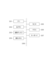
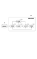
以下、図1を参照して、本実施形態に係る情報処理システムの機能構成について説明する。同図に示すように、本実施形態に係る情報処理装置100は、取得部101、抽出部102、決定部103、生成部104、学習部105で構成される。また、本実施形態における情報処理システムは、情報処理装置100の外部に記憶装置70を具備する。
The functional configuration of the information processing system according to this embodiment will be described below with reference to FIG. 1. As shown in the figure, the
記憶装置70はコンピュータ読み取り記憶媒体の一例であり、ハードディスクドライブ(HDD)やソリッドステイトドライブ(SSD)に代表される大容量情報記憶装置である。記憶装置70は、少なくとも1つ以上の元画像(3次元断層画像)を保持している。また、記憶装置70には、各々の元画像に対応する正解データが保持されている。記憶装置70が保持する元画像と正解データは、取得部101を介して情報処理装置100に入力される。本実施形態における正解データは、正解の肺野領域画像であり、肺野に属する画素か否かを2値で表したマスク画像である。このマスク画像は、関心領域の画素値が1、関心領域以外の領域の画素値が0で表されている。また、マスク画像は元画像と同じ画像サイズである。なお、マスク画像における画素値は、関心領域を表す画素と関心領域以外の領域を表す画素を区別可能であれば、どのような画素値を与えても構わない。例えば、画素値として1または2のいずれか一方を与えても良い。また、3つ以上の値の中から2つの値を割り当てても良い。また、マスク画像は上述のように元画像と同じ画像サイズであってもよいし、異なる画像サイズであっても良い。
The
以下、情報処理装置100を構成する各部について説明する。
The following describes each component of the
取得部101は、記憶装置70から教示データ(元画像と元画像に対応付いている正解データの組)を取得する。そして、取得した元画像を、抽出部102、決定部103、生成部104、学習部105に送信する。また、取得した正解データを学習部105に送信する。
The
抽出部102は、取得部101から取得した画像から、濃度値を変更する対象領域を抽出する。そして、抽出した対象領域の情報を生成部104に送信する。ここで、対象領域の情報とは、例えば、濃度値を変更する対象領域を表すマスク画像である。
The
決定部103は、取得部101から取得した画像と、抽出部102から取得した対象領域の情報とに基づいて、濃度値の変化量を決定する。そして、決定した濃度値の変化量を生成部104に送信する。
The
生成部104は、取得部101から取得した画像と、抽出部102から取得した対象領域の情報と、決定部103から取得した濃度値の変化量とに基づき、新たな学習画像を生成する。そして、生成した学習画像を学習部105に送信する。
The generation unit 104 generates a new learning image based on the image acquired from the
学習部105は、取得部101から取得した画像および正解データと、生成部104から取得した学習画像とに基づき、識別器の学習を行う。
The
なお、図1に示した情報処理装置100の各部の少なくとも一部は独立した装置として実現してもよい。また、夫々の機能を実現するソフトウェアとして実現してもよい。本実施形態では、各部はそれぞれソフトウェアにより実現されているものとする。
Note that at least some of the units of the
図2は、情報処理装置100のハードウェア構成の一例を示す図である。CPU(Central Processing Unit)2001は、主として各構成要素の動作を制御する。主メモリ2002は、CPU2001が実行する制御プログラムを格納したり、CPU2001によるプログラム実行時の作業領域を提供したりする。磁気ディスク2003は、オペレーティングシステム(OS)、周辺機器のデバイスドライバ、後述する処理等を行うためのプログラムを含む各種アプリケーションソフトを実現するためのプログラムを格納する。表示メモリ2004は、表示用データを一時記憶する。モニタ2005は、例えばCRTモニタや液晶モニタ等であり、表示メモリ2004からのデータに基づいて画像やテキスト等の表示を行う。マウス2006及びキーボード2007は、ユーザによるポインティング入力及び文字等の入力を夫々行う。上記各構成要素は、共通バス2008により互いに通信可能に接続されている。
2 is a diagram showing an example of the hardware configuration of the
CPU2001が主メモリ2002、磁気ディスク2003等に格納されているプログラムを実行することにより、図1に示した情報処理装置100の各部の機能(ソフトウェア)及び後述するフローチャートにおける処理が実現される。
The
また、CPU2001はプロセッサの一例に相当する。情報処理装置100は、CPU2001に加えて、GPU(Graphics Processing Unit)やFPGA(Field-Programmable Gate Array)の少なくともいずれかを有していてもよい。また、CPU2001に代えて、GPUやFPGAの少なくともいずれかを有していてもよい。主メモリ2002、磁気ディスク2003はメモリの一例に相当する。
The
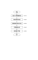
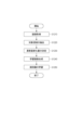
次に、本実施形態における情報処理装置100の処理手順について、図3を用いて説明する。
Next, the processing procedure of the
<ステップS310>
ステップS310において、取得部101は、記憶装置70から教示データ(元画像とそれに対応する正解データの組)を取得する。すなわち、取得部101は、画像を取得する取得部の一例に相当する。U-Netの学習には複数枚の画像が必要である。本実施形態では、記憶装置70が例えば1000枚の元画像を保持しているものとし、取得部101は1000枚の元画像とそれらに対応する正解データを取得する。
<Step S310>
In step S310, the
ここで図4を参照して、ステップS310で取得する元画像と正解データについて説明する。図4(a)は胸部を表した2次元断層画像410とそれに対応する正解データ450を示している。2次元断層画像410は、3次元断層画像(元画像)を構成する2次元断層画像の1枚である。また、2次元断層画像410に対応する正解データ450は肺野領域を表した2次元のマスク画像である。 Now, referring to FIG. 4, the original image and correct answer data acquired in step S310 will be described. FIG. 4(a) shows a two-dimensional tomographic image 410 representing the chest and its corresponding correct answer data 450. The two-dimensional tomographic image 410 is one of the two-dimensional tomographic images constituting the three-dimensional tomographic image (original image). The correct answer data 450 corresponding to the two-dimensional tomographic image 410 is a two-dimensional mask image representing the lung field region.
<ステップS320>
ステップS320において、抽出部102は、ステップS310で取得した教示データにおける夫々の元画像に対して、濃度値を変更する対象領域を抽出する。本実施形態においては、濃度値を変更する対象領域として空気以外の領域を抽出する。すなわち、画像に含まれる一部の領域を対象領域として抽出する。X線CT装置で撮像された3次元断層画像は、空気の濃度値が凡そ一定の値(-1000HU付近)になる。そのため、本実施形態ではしきい値処理法で空気以外の領域を抽出する。具体的には、抽出部102が-550HU以上を空気以外の領域として抽出し、濃度値を変更する対象領域を表すマスク画像を作成する。また、上記の方法で抽出した領域に対して、オープニング処理やクロージング処理を施したり、最大連結領域以外を削除する処理を施したりして、小さな孤立領域を削除しても良い。なお、上記のしきい値は一例であり、空気以外の領域を抽出できる値であればよい。
<Step S320>
In step S320, the
ステップS320では上述の方法によって、図4(b)に例示するような、濃度値を変更する対象領域を表すマスク画像420を作成する。マスク画像420は、2次元断層画像410と同じ画像サイズであり、濃度値を変更する対象領域421が画素値1、対象領域以外の領域422が画素値0として保持されている。 In step S320, a mask image 420 is created by the method described above, which represents the target region for which the density value is to be changed, as shown in FIG. 4B. The mask image 420 has the same image size as the two-dimensional tomographic image 410, and the target region 421 for which the density value is to be changed is held as a pixel value of 1, and the region outside the target region 422 is held as a pixel value of 0.
上記では、濃度値を変更する対象領域を抽出する方法として、しきい値処理法を用いたが、これに限るものではない。例えば、公知のセグメンテーション手法であるLevel-set法やGraph-cut法、Snake法などであっても良い。その他、濃度値を変更する対象領域421と対象領域以外の領域422を分割する方法であればいかなる方法であっても良い。また、情報処理装置100の外部から対象領域421を区別する情報(マスク画像など)を取得しても良い。
In the above, threshold processing is used as a method for extracting the target region for which the density value is to be changed, but this is not limiting. For example, known segmentation methods such as the Level-set method, Graph-cut method, and Snake method may be used. Any other method that divides the target region 421 for which the density value is to be changed from the region other than the target region 422 may be used. Information (such as a mask image) that distinguishes the target region 421 may also be obtained from outside the
<ステップS330>
ステップS330において、決定部103は、ステップS310で取得した夫々の元画像と、当該元画像に対してステップS320で抽出した対象領域421のマスク画像とに基づいて、対象領域421における元画像の濃度値を決定する。すなわち、決定部103は、画像に含まれる画素の濃度値の変化量を決定する決定部の一例に相当する。
<Step S330>
In step S330, the
より詳細に決定部103が行う濃度値の変化量の決定方法について説明する。X線CT装置で撮像された3次元断層画像は、被検体の個人差や撮像時の条件により、空気と水を除く物体の濃度値が-50~+50HUの範囲を変動することが起こり得る。そのため、本実施形態では、濃度値の変化量として-50~+50HUの間から乱数で決定した値を用いる。なお、濃度値の変化量は上記に限定されない。
The method for determining the amount of change in density value performed by the
また、濃度値の変化量は、決定部103が上限値と下限値をさらに決定し、上限値と下限値を超えない値の範囲から乱数で決定されるような構成でもよい。例えば、上限値を+30HU、下限値を-10HUとし、その間の値である+10HUが濃度値の変化量として乱数で決定される。なお、上記の数字は一例であり、これに限定されない。さらに、上限値もしくは下限値のいずれか一方のみを決定するような構成でもよい。また、上限値と下限値は自動で決定されてもよいしユーザが任意の値に決定してもよい。
The amount of change in the concentration value may be determined by a random number from a range of values that do not exceed the upper and lower limits, with the
また、対象領域421の濃度値を変更する場合に、一律に同じ変化量を用いずに対象領域421内の画素によって異なる濃度値の変化量を決定してもよい。すなわち、対象領域421に含まれる画素夫々の濃度値に基づいて、前記対象領域に含まれる画素夫々の濃度値の変化量を決定してもよい。この場合、例えば、トーンカーブを用いて濃度値が低い画素は濃度値の変化量を大きくし、濃度値が高い画素は濃度値の変化量を小さくする方法が考えられる。具体的には、後述の(1)式において濃度値が、xn original>xl originalだった場合、xn originalに対しては濃度値の変化量c=+10、xl originalに対しては濃度値の変化量c=+20が決定されるようにトーンカーブを調整する。 Furthermore, when changing the density value of the target region 421, the same amount of change may not be used across the board, but different amounts of change in density value may be determined for each pixel in the target region 421. That is, the amount of change in density value for each pixel included in the target region 421 may be determined based on the density value of each pixel included in the target region 421. In this case, for example, a method may be considered in which a tone curve is used to increase the amount of change in density value for pixels with low density values and decrease the amount of change in density value for pixels with high density values. Specifically, when the density value is x n original > x l original in the formula (1) described below, the tone curve is adjusted so that the amount of change in density value c = +10 for x n original and the amount of change in density value c = +20 for x l original are determined.
なお、2つの変化量が0より小さい場合には、濃度値が低い画素は濃度値の変化量の絶対値を小さくし、濃度値が高い画素は濃度値の変化量の絶対値を大きくしてもよい。上記によれば、実際の画像では起こり得ない濃度値を有する画像が生成されることを確率を低減できる。 Note that if the two amounts of change are smaller than 0, the absolute value of the amount of change in density value may be reduced for pixels with low density values, and increased for pixels with high density values. This can reduce the probability of generating an image with density values that would never occur in an actual image.
さらに、対象領域421内の画素の濃度値を変更する場合に、対象領域421に含まれる2つ以上の画素を含む部分領域を決定し、該部分領域内の画素の濃度値に基づいて部分領域ごとの濃度値の変化量を決定してもよい。 Furthermore, when changing the density values of pixels in the target region 421, a partial region including two or more pixels included in the target region 421 may be determined, and the amount of change in density value for each partial region may be determined based on the density values of the pixels in the partial region.
また、上記においては、対象領域421の濃度値の変化量のみを決定したが、濃度値の変化量の決定方法はこれに限定されるものではない。例えば、濃度値を変更する対象領域以外の領域422についても、微小な濃度値の変化量を決定する。この場合、対象領域421の濃度値の変化量に対して十分に小さい値(例えば、対象領域421の濃度値の変化量の10分の1の値)を当該領域の画素の濃度値に対して加算するようにしてもよい。 In the above, only the amount of change in density value of the target region 421 is determined, but the method of determining the amount of change in density value is not limited to this. For example, a small amount of change in density value is also determined for the region 422 other than the target region where the density value is to be changed. In this case, a value that is sufficiently small relative to the amount of change in density value of the target region 421 (for example, a value that is 1/10 of the amount of change in density value of the target region 421) may be added to the density value of the pixels in that region.
つまり、決定部103は、対象領域421に含まれる画素の濃度値の変化量及び対象領域以外の領域422に含まれる画素の濃度値の変化量の両方を決定する構成でもよい。具体的には、対象領域421に含まれる画素の濃度値の変化量の絶対値が対象領域以外の領域422に含まれる画素の濃度値の変化量の絶対値に比べて大きくなるように2つの値を決定し学習画像430を生成する。
In other words, the
すなわち、後述の(1)式のxi new=xi originalをxi new=xi original+c’(c≫c’)とする構成でもよい。 That is, x i new =x i original in equation (1) described later may be changed to x i new =x i original +c'(c>>c').
なお、この構成で対象領域以外の領域422の濃度値を変更せずに学習画像を作成する場合、c’=0とすることにより(1)式と同等になる。つまり、対象領域以外の領域422の濃度値を変更せずに学習画像430を作成する場合、c’を用いない構成でもよいし、c’を加算し、c’=0とする構成でもよい。 When creating a learning image with this configuration without changing the density values of the regions 422 other than the target region, it becomes equivalent to formula (1) by setting c' = 0. In other words, when creating a learning image 430 without changing the density values of the regions 422 other than the target region, it is possible to use a configuration that does not use c', or a configuration that adds c' and sets c' = 0.
すなわち、決定部103は、対象領域421に含まれる画素の濃度値の変化量と、対象領域以外の領域422に含まれる画素の濃度値の変化量のうち、少なくとも対象領域421に含まれる画素の濃度値の変化量cを決定すればよい。
In other words, the
<ステップS340>
ステップS340において、生成部104は、ステップS310で取得した夫々の元画像と、当該元画像に対してステップS320で抽出した濃度値を変更する対象領域のマスク画像420と、当該元画像に対してステップS330で決定した濃度値の変化量とに基づき、新たな学習画像430を生成する。すなわち、生成部104は、決定された濃度値の変化量に基づいて濃度値を変更する対象領域421の濃度値を変更した学習画像430を生成する。より具体的には、例えば、決定部103により決定された濃度値の変化量に基づいて濃度値を変更する対象領域421に含まれる画素の濃度値を一律に変更し、かつ対象領域以外の領域422に含まれる画素の濃度値を変更せずに学習画像430を生成する。
<Step S340>
In step S340, the generating unit 104 generates a new learning image 430 based on each original image acquired in step S310, the mask image 420 of the target region whose density value is to be changed extracted from the original image in step S320, and the amount of change in density value determined for the original image in step S330. That is, the generating unit 104 generates the learning image 430 in which the density value of the target region 421 whose density value is to be changed is changed based on the determined amount of change in density value. More specifically, for example, the generating unit 104 generates the learning image 430 by uniformly changing the density values of the pixels included in the target region 421 whose density value is to be changed based on the amount of change in density value determined by the determining
数式を用いて学習画像430の生成方法の説明を行う。決定部103が濃度値の変化量cを決定し、元画像をxoriginalとしたとき、新たな学習画像xnewを、以下の数式に基づいて生成部104が生成する。
A method for generating the training image 430 will be described using a formula. When the

なお、iは画素番号を示す。また、Tは、濃度値を変更する対象領域を表すマスク画像420において、濃度値を変更する対象領域に属する画素に付与された画素番号の集合である。生成部104は、この計算を、取得部101から取得したすべての元画像に対して行う。このとき、濃度値の変化量cは、すべての元画像で共通の値を用いる。
Note that i indicates the pixel number. Furthermore, T is a set of pixel numbers assigned to pixels belonging to a target region whose density value is to be changed in mask image 420 that represents the target region whose density value is to be changed. The generation unit 104 performs this calculation for all original images acquired from
上述の生成方法により、図4(c)に示すような、2次元断層画像410における対象領域421のみの濃度値が変更された学習画像430が生成される。 The above-described generation method generates a learning image 430 in which the density value of only the target region 421 in the two-dimensional tomographic image 410 is changed, as shown in FIG. 4(c).
なお、複数の濃度値の変化量cを用いて、1つの元画像から複数の学習画像430を生成しても良い。例えば、濃度値の変化量cの値として-20、-10、+10、+20のように4つ値を用いることで、1つの2次元断層画像410から図5に示すような4つの学習画像430a~430dを生成しても良い。ここで、学習画像430a~430dはそれぞれ、(1)式をc=-20,c=-10,c=10,c=20として計算することで得られる。 Note that multiple learning images 430 may be generated from one original image using multiple density value changes c. For example, four values such as -20, -10, +10, and +20 may be used as the density value change c, thereby generating four learning images 430a to 430d as shown in FIG. 5 from one two-dimensional tomographic image 410. Here, learning images 430a to 430d are obtained by calculating equation (1) with c = -20, c = -10, c = 10, and c = 20, respectively.
また、上記のように複数の濃度値の変化量cを決定する場合、決定する濃度値の数は元画像の枚数に基づいて決定してもよい。例えば、必要となる教示データが10000データに対して元画像が2000枚しかない場合には変化量cを5つ決定し、元画像が5000枚ある場合には変化量cを2つ決定する。上記のように、必要となるデータ数と元画像の枚数に基づいて変化量cの数を決定することにより所望の数のデータ数を得ることができる。なお、上記の数は一例でありこれに限定されない。さらに、上記では必要となる教示データに対して元画像が少ないほど変化量cの数を多くしたが、変化量cの数の決定方法もこれに限定されない。 When determining the amount of change c of multiple density values as described above, the number of density values to be determined may be determined based on the number of original images. For example, if there are 10,000 pieces of required teaching data and only 2,000 original images, five amounts of change c are determined, and if there are 5,000 original images, two amounts of change c are determined. As described above, the desired number of pieces of data can be obtained by determining the number of amounts of change c based on the number of required data and the number of original images. Note that the above numbers are merely examples and are not intended to be limiting. Furthermore, in the above, the number of amounts of change c is increased as the number of original images is smaller relative to the required teaching data, but the method of determining the number of amounts of change c is not limited to this.
また、濃度値の変化量cは、元画像ごとに異なる値を適用しても良いし、元画像が3次元画像である場合には、3次元画像を構成する2次元画像ごとに異なる値を適用しても良い。例えば、1つ目の元画像は濃度値の変化量を+10HU、2つ目の元画像は濃度値の変化量を-20HU、以降の元画像に対しても同様に異なる濃度値の変化量を適用して学習画像430を生成する方法が考えられる。 A different value may be applied to the amount of change in density value c for each original image, or if the original image is a three-dimensional image, a different value may be applied to each of the two-dimensional images that make up the three-dimensional image. For example, a method may be considered in which the amount of change in density value c for the first original image is +10 HU, the amount of change in density value for the second original image is -20 HU, and similarly different amounts of change in density value are applied to the subsequent original images to generate learning image 430.
また、学習画像430は、元画像の画素値に変化量cを加算して生成する方法以外の種々の演算により実現される。例えば、対象領域421に属する画素に対して、変化率aを元画像の画素値に乗算し学習画像430を生成する構成であっても良い。この場合、決定部103は、ステップS330において変化率aを決定する。
The learning image 430 can be realized by various calculations other than the method of generating the learning image 430 by adding the change amount c to the pixel value of the original image. For example, the learning image 430 can be generated by multiplying the pixel value of the original image by the change rate a for pixels belonging to the target region 421. In this case, the
なお、対象領域の濃度値を変更しない学習画像430の生成は、(1)式をc=0で計算することに相当する。 Note that generating a learning image 430 without changing the density value of the target region is equivalent to calculating equation (1) with c = 0.
<ステップS350>
ステップS350において、学習部105は、ステップS340で生成した学習画像430と、ステップS310で取得した元画像と正解データとに基づいてU-Netを学習させる。そして、学習の結果(識別器のパラメータ)を記憶装置70に出力する。
<Step S350>
In step S350, the
ここで、ステップS340で新たに生成した学習画像430は、元画像の濃度値を局所的に変えた画像である。したがって、元画像と新たに生成した学習画像430は、肺野領域の位置は変わらないため、元画像と同じ正解データを利用できる。図4を用いて説明すると、本実施形態で生成される学習画像430に対応する正解データは、2次元断層画像410に対応する正解データ450となる。すなわち、学習部105は、ステップS310で取得した教示データに学習画像430と正解データの組を追加した(データを水増しした)新たな教示データを生成する。そして、生成した新たな教示データを用いて、識別器の学習を行う。
Here, the training image 430 newly generated in step S340 is an image in which the density value of the original image has been locally changed. Therefore, the position of the lung field area does not change between the original image and the newly generated training image 430, and therefore the same correct answer data as the original image can be used. Explaining with reference to FIG. 4, the correct answer data corresponding to the training image 430 generated in this embodiment is the correct answer data 450 corresponding to the two-dimensional tomographic image 410. That is, the
学習方法は、例えば、CNNの学習において一般的な手法である誤差逆伝播法(Backpropagation)を用いる。これにより、U-Netが対象物体を識別するための複雑な特徴を学習し、未知の画像に対しても高度な領域抽出が可能になる。なお、学習方法は上記に限定されない。 The learning method is, for example, backpropagation, a common technique in CNN training. This allows the U-Net to learn complex features for identifying target objects, enabling advanced region extraction even for unknown images. Note that the learning method is not limited to the above.
また、本ステップで識別器の学習に用いる教示データには、ステップS340で生成した学習画像が含まれていれば何でもよい。例えば、学習に用いる教示データには、ステップS310で取得した元画像が含まれていなくても良い。 The teaching data used to train the classifier in this step may be anything as long as it includes the training images generated in step S340. For example, the teaching data used for training does not have to include the original images obtained in step S310.
さらに、学習部105は、本ステップで識別器の学習に用いる教示データを、記憶装置70に保存する構成であってもよい。また、教示データを入力して識別器の学習を行う他の情報処理装置への入力データとして、生成した教示データを保存する処理だけを行い、実際の学習は本装置では行わない構成であってもよい。この場合、夫々の元画像に対する正解データを入力する処理や、学習画像430と正解データとの対応付けを行う処理は、必ずしも行う必要はない。
Furthermore, the
以上の手順に従い、第一の実施形態に係る情報処理装置100は処理を行う。
The
ここで、図4(c)を参照して、第一の実施形態にかかる情報処理装置で生成される学習画像430と、特許文献1で開示されている技術で生成される学習画像440の差異を説明する。第一の実施形態にかかる情報処理装置で生成される学習画像430は、2次元断層画像410における対象領域421のみの濃度値が変更された画像である。それに対して、特許文献1に記載の技術で生成される学習画像440は、2次元断層画像410の濃度値を一律に変更した画像である。上述の通り、X線CT装置では、撮像時の条件が変わっても空気領域の濃度値は変化しない。そのため、特許文献1に記載の技術では、主に空気領域において実際には起こり得ない濃度値となるが、第一の実施形態にかかる情報処理装置が実施する生成方法では、空気領域の濃度値を正しく再現することができる。 Here, referring to FIG. 4(c), the difference between the learning image 430 generated by the information processing device according to the first embodiment and the learning image 440 generated by the technology disclosed in Patent Document 1 will be described. The learning image 430 generated by the information processing device according to the first embodiment is an image in which the density value of only the target region 421 in the two-dimensional tomographic image 410 is changed. In contrast, the learning image 440 generated by the technology described in Patent Document 1 is an image in which the density value of the two-dimensional tomographic image 410 is changed uniformly. As described above, in an X-ray CT device, the density value of the air region does not change even if the conditions at the time of imaging change. Therefore, in the technology described in Patent Document 1, the density value that cannot actually occur mainly in the air region is obtained, but the generation method implemented by the information processing device according to the first embodiment can correctly reproduce the density value of the air region.
第一の実施形態に係る情報処理装置100では、元画像において濃度値を変更する対象領域421を濃度値を変更しない対象領域以外の領域422と区別し、対象領域421についてのみ元画像から濃度値を変更して新たな学習画像を生成する。このようにすることで、画像中の物体の特性を考慮して新たな学習画像を生成できるため、識別器の画像認識の精度が向上する。
In the
<変形例1-1>
本実施形態では、識別器による領域抽出の対象となる領域(上述の説明では肺野領域)と、濃度値を変更する対象領域(上述の説明では肺野領域を除く人体領域)、濃度値を変更しない領域(上述の説明では空気領域)の3つの領域が、互いに重ならない例を説明した。
<Modification 1-1>
In this embodiment, an example has been described in which the three regions, namely, the region that is the target of region extraction by the classifier (in the above description, the lung field region), the region that is the target of density value change (in the above description, the human body region excluding the lung field region), and the region that does not have its density value changed (in the above description, the air region), do not overlap with each other.
しかしながら、これらの領域が互いに重なっていても、本実施形態の効果は得られる。例えば、領域抽出の対象となる領域を肝臓領域、濃度値を変更する対象領域も肝臓領域、濃度値を変更しない領域を肝臓以外の領域、として抽出してもよい。この時、領域抽出の対象となる領域(肝臓領域)と濃度値を変更する対象領域(肝臓領域)は、互いに領域が重なっている。なお、肝臓は一例であって、心臓や腎臓といった撮像時の条件が変わることで濃度値が変動しやすい物体を対象としてもよい。 However, the effects of this embodiment can be obtained even if these regions overlap each other. For example, the region to be extracted may be the liver region, the region to be extracted whose density value is to be changed may also be the liver region, and the region to be extracted whose density value is not to be changed may be a region other than the liver. In this case, the region to be extracted (liver region) and the region to be extracted whose density value is to be changed (liver region) overlap each other. Note that the liver is just one example, and the object whose density value is likely to change due to changes in imaging conditions, such as the heart or kidneys, may also be the target.
このような領域抽出の元で、第一の実施形態にかかる情報処理装置100は、以下の処理を行う。ステップS310、S350は上述の通りであるため、説明を省略する。ステップS320において、抽出部102は取得部101から正解データを取得する。そして、正解データに示されている領域(本例では肝臓領域)を、濃度値を変更する対象領域とする。すなわち、正解データに基づいて対象領域のマスク画像を生成する。ステップS330において、生成部104はステップS310で取得した元画像と、ステップS320で生成した対象領域のマスク画像とに基づき、新たな学習画像430を生成する。学習画像の生成方法、および濃度値の変化量cの決定方法は、ステップS330と同様である。
Based on such region extraction, the
本実施形態において情報処理装置100は、濃度値を変更する対象領域の濃度値を変更した学習画像を生成する。これはすなわち、領域抽出の対象となる領域の濃度値を変更したことと同じである。これにより、被検体の個人差や撮像時の条件により領域抽出の対象となる領域が異なる濃度値で描出される場合において、識別器の画像認識の精度が向上する。
In this embodiment, the
<第二の実施形態>
第一の実施形態にかかる情報処理装置では、対象領域の濃度値を予め定めた所定の値で増減して画像を生成する方法について説明した。しかしながら、予め定めた所定の値で対象領域の濃度値を変更すると、実際の画像では起こり得ない濃度値を有する学習画像が生成されてしまう可能性がある。
Second Embodiment
In the information processing device according to the first embodiment, a method for generating an image by increasing or decreasing the density value of a target region by a predetermined value has been described. However, if the density value of a target region is changed by a predetermined value, there is a possibility that a learning image having a density value that cannot occur in an actual image will be generated.
そこで、第二の実施形態にかかる情報処理装置では、濃度値を変更する対象領域の濃度値に基づいて濃度値の変化量を決定し、濃度値の変化量に基づいて新たな学習画像を生成する。以下、第一の実施形態との違いについて説明する。 Therefore, in the information processing device according to the second embodiment, the amount of change in density value is determined based on the density value of the target region in which the density value is to be changed, and a new learning image is generated based on the amount of change in density value. The differences from the first embodiment are explained below.
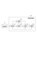
以下、図6を参照して、本実施形態に係る情報処理システムの機能構成について説明する。 The functional configuration of the information processing system according to this embodiment will be described below with reference to FIG. 6.
第二の実施形態に係る情報処理装置600は、取得部601、抽出部602、決定部603、生成部604、学習部605で構成される。また、本実施形態における情報処理システムは情報処理装置600の外部に記憶装置70を具備する。
The
本実施形態における情報処理システムは、第一の実施形態に記載の情報処理システムと基本的には同一であるため、重複部分の説明を省略する。 The information processing system in this embodiment is basically the same as the information processing system described in the first embodiment, so a description of the overlapping parts will be omitted.
以下では、情報処理装置600を構成する各部について説明する。
The following describes each component of the
取得部601は、記憶装置70から教示データ(元画像と元画像に対応付いている正解データの組)を取得する。そして、取得した元画像を、抽出部602、決定部603、生成部604、学習部605に送信する。また、取得した正解データを学習部605に送信する。
The
抽出部602は、取得部601から取得した画像から、濃度値を変更する対象領域を抽出する。そして、抽出した対象領域の情報を、決定部603と生成部604に送信する。
The
決定部603は、取得部601から取得した画像と、抽出部602から取得した対象領域の情報とに基づいて、濃度値の変化量を決定する。そして、決定した濃度値の変化量を生成部604に送信する。
The
生成部604は、取得部601から取得した画像と、抽出部602から取得した対象領域の情報と、決定部603から取得した濃度値の変化量とに基づき、新たな学習画像を生成する。そして、生成した学習画像を学習部605に送信する。
The generating
学習部605が行う処理は、第一の実施形態における学習部105と同様である。
The processing performed by the
次に、本実施形態における情報処理装置600の処理手順について、図7を用いて説明する。
Next, the processing procedure of the
<ステップS710~S720>
ステップS710~ステップS720の処理は、第一の実施形態におけるステップS310~S320と基本的には同一の処理であるため、説明を省略する。
<Steps S710 to S720>
The processing in steps S710 to S720 is basically the same as the processing in steps S310 to S320 in the first embodiment, and therefore a description thereof will be omitted.
<ステップS730>
ステップS730において、決定部603は、ステップS710で取得した夫々の元画像と、当該元画像に対してステップS720で抽出した対象領域421のマスク画像とに基づいて、対象領域における元画像の濃度値を分析する。そして、その結果に基づいて、夫々の元画像から学習画像を生成する処理に用いる濃度値の変化量を決定する。具体的な決定方法の一例としては、対象領域における元画像の平均濃度値を算出し、その値に基づいて濃度値の変化量を決定する。例えば、事前に用意した図8に示すような平均濃度値と濃度値の変化量の対応表を参照して、濃度値の変化量cを決定する。例えば、対象領域の平均濃度値mが+17であった場合、濃度値の変化量cとして、-40、-30、-20、-10、+10、+20といった6つの値を決定する。図8に示すような対応表は、医師やエンジニアなどが決定した適当な値で作成したものでも良いし、統計的な情報から作成したものであっても良い。
<Step S730>
In step S730, the
<ステップS740>
ステップS740において、生成部604は、ステップS710で取得した夫々の元画像と、当該元画像に対してステップS720で抽出した対象領域のマスク画像と、当該元画像に対してステップS730で決定した濃度値の変化量とに基づき、新たな学習画像を生成する。具体的には、第一の実施形態におけるステップS340の処理と同様に、対象領域の各画素の濃度値を数1に従って変更する。
<Step S740>
In step S740, the generating
<ステップS750>
ステップS750の処理は、第一の実施形態におけるステップS350と基本的には同一の処理であるため、説明を省略する。
<Step S750>
The process of step S750 is basically the same as the process of step S350 in the first embodiment, and therefore a description thereof will be omitted.
以上の手順に従い、第二の実施形態に係る情報処理装置600は処理を行う。
The
第二の実施形態に係る情報処理装置600では、対象領域の平均濃度値に基づいて決定した濃度値の変化量を用いて、対象領域の濃度値を変更して新たな学習画像を生成する。このようにすることで、画像中の物体の特性を考慮して新たな学習画像を生成できるため、識別器の画像認識の精度が向上する。
In the
<変形例2-1>
上記の実施例では、対象領域における元画像の濃度値に基づいて濃度値の変化量を決定する方法の一例として、対象領域の濃度値の平均値を用いる方法を説明した。しかし、対象領域における元画像の濃度値に基づいて濃度値の変化量を決定する方法はこれに限らない。例えば、対象領域の濃度値の他の統計値(例えば、メディアン値、分散値、最大値、最小値など)を用いてもよい。例えばメディアン値を用いることで、ノイズへのロバスト性を向上できる。いずれの場合においても、図8と同様に、事前に用意した統計値と変化量との対応表に基づいて、変化量を決定できる。また、対応表を用いる方法以外にも、統計値を入力して変化量を出力する任意の関数によって同様の機能を実現できる。また、統計値は、対象領域全体の濃度値の統計値ではなく、対象領域の一部の領域の濃度値の統計値であってもよい。例えば、元画像である3次元画像を構成する2次元断層画像(スライス画像)群から何枚かのスライス画像を所定の間隔やランダムに選択して、選択したスライス画像における対象領域の濃度値の統計値を用いるようにしてもよい。これによると、ステップS730の処理時間を削減することができる。
<Modification 2-1>
In the above embodiment, the method of using the average value of the density values of the target region has been described as an example of a method of determining the amount of change in density values based on the density values of the original image in the target region. However, the method of determining the amount of change in density values based on the density values of the original image in the target region is not limited to this. For example, other statistical values of the density values of the target region (for example, median value, variance value, maximum value, minimum value, etc.) may be used. For example, by using the median value, robustness against noise can be improved. In either case, the amount of change can be determined based on a correspondence table between statistical values and amount of change prepared in advance, as in FIG. 8. In addition to the method using the correspondence table, a similar function can be realized by inputting statistical values and outputting amount of change. In addition, the statistical value may be a statistical value of the density values of a part of the target region, rather than a statistical value of the density values of the entire target region. For example, some slice images may be selected at a predetermined interval or at random from a group of two-dimensional tomographic images (slice images) constituting the three-dimensional image that is the original image, and the statistical value of the density values of the target region in the selected slice images may be used. This can reduce the processing time of step S730.
<第三の実施形態>
第三の実施形態では、画像の付帯情報をもとに濃度値の変化量を決定し、濃度値の変化量に基づいて新たな学習画像を生成する方法について説明する。本実施形態では、濃度値の変化量を決定するために、医用画像の付帯情報の一般的な規格であるDICOM(Digital Imaging and Communications in Medicine)のヘッダ情報内の管電圧に関する情報を用いる。
Third Embodiment
In the third embodiment, a method for determining the amount of change in density value based on the supplementary information of an image and generating a new learning image based on the amount of change in density value will be described. In this embodiment, in order to determine the amount of change in density value, information on tube voltage in the header information of DICOM (Digital Imaging and Communications in Medicine), which is a general standard for supplementary information of medical images, is used.
X線CT装置において、管電圧を変更するとX線の透過力が変化し、各物体を表す濃度値が変化する。例えば、管電圧を高くした場合には、透過力が高いX線が増えるため、X線の減弱差が描出されにくく、3次元断層画像のコントラストが低くなる傾向にある。逆に、管電圧を低くした場合には、X線の透過力が低いため、X線の減弱差が描出されやすく、3次元断層画像の濃度値が低くなる。しかし、管電圧を変更して撮像した場合においても空気と水の濃度値は変わらない。したがって、本実施形態を適用するのに好適な事例であるといえる。 In an X-ray CT device, when the tube voltage is changed, the penetrating power of the X-rays changes, and the density value representing each object changes. For example, when the tube voltage is increased, the amount of X-rays with high penetrating power increases, making it difficult to depict differences in attenuation of the X-rays, and the contrast of the three-dimensional tomographic image tends to be low. Conversely, when the tube voltage is decreased, the penetrating power of the X-rays is low, making it easier to depict differences in attenuation of the X-rays, and the density value of the three-dimensional tomographic image decreases. However, the density values of air and water do not change even when imaging is performed with a changed tube voltage. Therefore, this is a suitable example for applying this embodiment.
第三の実施形態に係る情報処理装置900は、取得部901、抽出部902、決定部903、生成部904、学習部905で構成される。また、本実施形態における情報処理システムは情報処理装置900の外部に記憶装置70を具備する。
The
本実施形態における情報処理システムは、第二の実施形態に記載の情報処理システムと基本的には同一であるため、重複部分の説明を省略する。 The information processing system in this embodiment is basically the same as the information processing system described in the second embodiment, so a description of the overlapping parts will be omitted.
以下では、情報処理装置900を構成する各部について説明する。
The following describes each component of the
取得部901は、記憶装置70から教示データ(元画像と元画像に対応付いている正解データの組)を取得する。そして、取得した元画像を、抽出部902、生成部904、学習部905に送信する。また、画像の付帯情報を決定部903に、画像に対応付いている正解データを学習部905に送信する。
The
抽出部902が行う処理は、第一の実施形態における抽出部102と同様である。
The processing performed by the
決定部903は、取得部901から取得した画像の付帯情報に基づいて、濃度値の変化量を決定する。そして、決定した濃度値の変化量を生成部904に送信する。
The
生成部904が行う処理は、第二の実施形態における生成部604と同様である。
The processing performed by the
学習部905が行う処理は、第一の実施形態における学習部105と同様である。
The processing performed by the
次に、第三の実施形態にかかる情報処理装置900の処理手順について説明する。処理の全体像は、図7に示す第二の実施形態のフローチャートと同様である。
Next, the processing procedure of the
<ステップS1010>
ステップS1010において、取得部901は、第一の実施形態におけるステップS310の処理に加え、教示データに含まれる夫々の元画像の付帯情報を取得し、これを決定部903に送信する。
<Step S1010>
In step S<b>1010 , the
<ステップS1020>
ステップS1020の処理は、第一の実施形態におけるステップS320と基本的には同一の処理であるため、説明を省略する。
<Step S1020>
The process of step S1020 is basically the same as the process of step S320 in the first embodiment, and therefore a description thereof will be omitted.
<ステップS1030>
ステップS1030において、決定部903は、ステップS1010で取得した夫々の元画像の付帯情報に基づいて、夫々の元画像から学習画像を生成する処理に用いる濃度値の変化量を決定する。本実施形態では、濃度値の変化量を決定する際に、DICOMヘッダ内の管電圧の情報を利用する場合を例に説明する。具体的には、第二の実施形態におけるステップS730と同様に、事前に用意した管電圧と濃度値の変化量の対応表を参照して、管電圧に対応する濃度値の変化量を決定する。
<Step S1030>
In step S1030, the
なお、変化量の決定に用いる付帯情報は、管電圧に限られるものではない。例えば、撮像時の造影剤投与の有無の情報を用いても良い。X線CT装置において、造影剤を患者に投与して3次元断層画像を撮像すると、臓器などの濃度値が高くなる。そこで、「造影剤投与有り」の画像は、生成する学習画像の濃度値が元画像の濃度値よりも低くなるような値を濃度値の変化量を決定する。また、「造影剤投与無し」の画像は、元画像の濃度値よりも生成する学習画像の濃度値が高くなるような値を濃度値の変化量を決定する。上記によれば、実際の画像では起こり得ない濃度値を有する画像が生成される確率を低減できる。また、DICOMヘッダの情報ではなく、医師が作成した読影レポートの記載内容を利用して濃度値の変化量を決定しても良い。この場合は、例えば入手が困難な珍しい診断名の画像には、濃度値の変化量の数を多く決定してより多くの学習画像を生成するなどの利用の仕方が考えられる。その他、画像に関する付随的な情報であれば、どのような情報であってもよい。 The additional information used to determine the amount of change is not limited to the tube voltage. For example, information on whether or not a contrast agent was administered during imaging may be used. When a contrast agent is administered to a patient and a 3D tomographic image is captured in an X-ray CT scanner, the density value of the organs increases. Therefore, for an image with contrast agent administration, the amount of change in density value is determined to be a value that makes the density value of the learning image generated lower than that of the original image. For an image without contrast agent administration, the amount of change in density value is determined to be a value that makes the density value of the learning image generated higher than that of the original image. According to the above, it is possible to reduce the probability of generating an image with a density value that cannot occur in an actual image. In addition, the amount of change in density value may be determined using the contents of the interpretation report created by the doctor, rather than the information in the DICOM header. In this case, for example, for an image with a rare diagnosis that is difficult to obtain, a large number of changes in density value may be determined to generate more learning images. Any other information related to the image may be used.
<ステップS1040>
ステップS1040の処理は、第二の実施形態におけるステップS740と基本的には同一の処理であるため、説明を省略する。
<Step S1040>
The process of step S1040 is basically the same as the process of step S740 in the second embodiment, and therefore a description thereof will be omitted.
<ステップS1050>
ステップS1050の処理は、第一の実施形態におけるステップS350と基本的には同一の処理であるため、説明を省略する。
<Step S1050>
The process of step S1050 is basically the same as the process of step S350 in the first embodiment, and therefore a description thereof will be omitted.
以上の手順に従い、第三の実施形態に係る情報処理装置900は処理を行う。
The
第三の実施形態に係る情報処理装置900では、画像の付帯情報に基づいて決定した濃度値の変化量を用いて、対象領域の濃度値を変更して新たな学習画像を生成する。このようにすることで、画像中の物体の特性を考慮して新たな学習画像を生成できるため、識別器の画像認識の精度が向上する。
In the
<第四の実施形態>
第一実施形態から第三の実施形態では、元画像の一部を対象領域として抽出し濃度値を変更することで、新たな学習画像を生成する方法を説明した。しかしながら、撮像時の条件によっては、画像全体の濃度値が変化するだけでなく、物体間のコントラストが変化したり、物体間の濃度値の高低が逆転したりすることがある。例えば、X線CT装置で撮像された3次元断層画像においては、患者に造影剤を投与したときの時相の変化がこの事象に該当する。また、第三の実施形態で取り上げた管電圧に関しても、物体間のコントラストが多少変動する。
<Fourth embodiment>
In the first to third embodiments, a method for generating a new learning image by extracting a part of an original image as a target region and changing the density value has been described. However, depending on the conditions at the time of imaging, not only the density value of the entire image may change, but also the contrast between objects may change or the high and low density values between objects may be reversed. For example, in a three-dimensional tomographic image captured by an X-ray CT scanner, a change in time phase when a contrast agent is administered to a patient corresponds to this phenomenon. In addition, the contrast between objects may fluctuate slightly with respect to the tube voltage taken up in the third embodiment.
そこで、第四の実施形態では、濃度値を変更する複数の対象領域を抽出し、各々の対象領域に対して異なる濃度値の変化量を決定して新たな学習画像を生成する方法について説明する。以下では、具体的な例として、骨、空気・骨以外の2領域を対象領域とし、各々の対象領域に対して濃度値の変化量を決定する場合について説明する。 In the fourth embodiment, therefore, a method is described for extracting multiple target regions for which density values are to be changed, determining different amounts of change in density value for each target region, and generating a new learning image. As a specific example, the following describes a case in which two regions other than bone and air/bone are set as target regions, and an amount of change in density value is determined for each target region.
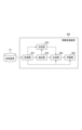
図11に示す第四の実施形態に係る情報処理装置1100は、取得部1101、抽出部1102、決定部1103、生成部1104、学習部1105で構成される。また、本実施形態における情報処理システムは情報処理装置1100の外部に記憶装置70を具備する。
The
本実施形態における情報処理システムは、第二の実施形態に記載の情報処理システムと基本的には同一であるため、重複部分の説明を省略する。 The information processing system in this embodiment is basically the same as the information processing system described in the second embodiment, so a description of the overlapping parts will be omitted.
以下では、情報処理装置1100を構成する各部について説明する。
The following describes each component of the
取得部1101が行う処理は、第二の実施形態における取得部1101と同様である。
The processing performed by the
抽出部1102は、取得部1101から取得した画像から、濃度値を変更する複数の対象領域を抽出する。具体的には、対象領域を2つ以上抽出する。そして、抽出した複数の対象領域の情報を、決定部1103と生成部1104に送信する。
The
決定部1103は、取得部1101から取得した画像と、抽出部1102から取得した複数の対象領域の情報とに基づいて、各々の対象領域に対応する濃度値の変化量を決定する。そして、決定した各々の対象領域に対応する濃度値の変化量を生成部1104に送信する。
The
生成部1104は、取得部1101から取得した画像と、抽出部1102から取得した複数の対象領域の情報と、決定部1103から取得した複数の対象領域の各々に対応する濃度値の変化量とに基づき、新たな学習画像を生成する。そして、生成した学習画像を学習部1105に送信する。
The generating unit 1104 generates a new learning image based on the image acquired from the acquiring
学習部1105が行う処理は、第一の実施形態における学習部105と同様である。
The processing performed by the
次に、第四の実施形態にかかる情報処理装置1100の処理手順について説明する。処理の全体像は、図7に示す第二の実施形態のフローチャートと同様である。
Next, the processing procedure of the
<ステップS1210>
ステップS1210の処理は、第一の実施形態におけるステップS310と基本的には同一の処理であるため、説明を省略する。
<Step S1210>
The process of step S1210 is basically the same as the process of step S310 in the first embodiment, and therefore a description thereof will be omitted.
<ステップS1220>
ステップS1220において、抽出部1102は、ステップS1210で取得した画像から、濃度値を変更する対象領域として、骨と空気・骨以外の2領域を抽出して2つのマスク画像を作成する。具体的には、しきい値処理法により、+600HU以上を骨領域、-550以上~+600HU未満を空気・骨以外の領域として抽出する。このとき、第一の実施形態におけるステップS320と同様に、抽出した領域に対して小さな孤立領域を削除する処理を加えても良い。
<Step S1220>
In step S1220, the
なお、対象領域は上述した骨領域と空気・骨以外の領域に限るものではない。例えば、情報処理装置1100の外部から物体ごとの領域情報を取得して、より詳細な分類となるような複数の対象領域を抽出しても良い。具体例として、X線CT装置で撮像された3次元断層画像において、臓器や骨ごとに対象領域を表すマスク画像を作成し、臓器や骨ごとに濃度値の変化量を決定することが考えられる。このようにすることで、造影剤投与による時相の変化などを再現可能である。
The target regions are not limited to the bone regions and regions other than air and bone described above. For example, region information for each object may be obtained from outside the
<ステップS1230>
ステップS1230において、決定部1103は、ステップS1210で取得した元画像と、ステップS1220で抽出した複数の対象領域のマスク画像とに基づいて、各々の対象領域に対応する濃度値の変化量を決定する。具体的には、第二の実施形態におけるステップS730と同様に、対象領域(骨、空気・骨以外)と濃度値の変化量の対応表を参照して、各々の領域に対応する濃度値の変化量を決定する。
<Step S1230>
In step S1230, the
<ステップS1240>
ステップS1240において、生成部1104は、ステップS1210で取得した元画像と、ステップS1220で抽出した複数の対象領域のマスク画像と、ステップS1230で決定した各々の対象領域に対応する濃度値の変化量とに基づき、新たな学習画像を生成する。具体的には、すべての対象領域の各画素の濃度値を数1に従って変更する。このとき、濃度値の変化量cとして、ステップS1230で決定した各々の対象領域に対応する値を用いる。
<Step S1240>
In step S1240, the generating unit 1104 generates a new learning image based on the original image acquired in step S1210, the mask images of the multiple target regions extracted in step S1220, and the change in density value corresponding to each target region determined in step S1230. Specifically, the density value of each pixel in all target regions is changed according to Equation 1. At this time, the value corresponding to each target region determined in step S1230 is used as the change in density value c.
<ステップS1250>
ステップS1250の処理は、第一の実施形態におけるステップS350と基本的には同一の処理であるため、説明を省略する。
<Step S1250>
The process of step S1250 is basically the same as the process of step S350 in the first embodiment, and therefore a description thereof will be omitted.
以上の手順に従い、第四の実施形態に係る情報処理装置1100は処理を行う。
The
第四の実施形態に係る情報処理装置1100では、濃度値を変更する複数の対象領域を抽出し、各々に対応する濃度値の変化量を用いて対象領域の濃度値を変更することで新たな学習画像を生成する。このようにすることで、画像中の物体の特性を考慮して新たな学習画像を生成できるため、識別器の画像認識の精度が向上する。
In the
(その他の実施形態)
本明細書の開示は、上述の実施形態の1以上の機能を実現するプログラムを、ネットワーク又は記憶媒体を介してシステム又は装置に供給し、そのシステム又は装置のコンピュータにおける1つ以上のプロセッサがプログラムを読出し実行する処理でも実現可能である。また、1以上の機能を実現する回路(例えば、ASIC)によっても実現可能である。
Other Embodiments
The disclosure of this specification can also be realized by a process in which a program for realizing one or more functions of the above-described embodiments is supplied to a system or device via a network or a storage medium, and one or more processors in a computer of the system or device read and execute the program. It can also be realized by a circuit (e.g., ASIC) for realizing one or more functions.
上述の各実施形態における情報処理装置は、単体の装置として実現してもよいし、複数の装置を互いに通信可能に組合せて上述の処理を実行する形態としてもよく、いずれも本発明の実施形態に含まれる。共通のサーバ装置あるいはサーバ群で、上述の処理を実行することとしてもよい。情報処理装置および情報処理システムを構成する複数の装置は所定の通信レートで通信可能であればよく、また同一の施設内あるいは同一の国に存在することを要しない。 The information processing device in each of the above-mentioned embodiments may be realized as a single device, or multiple devices may be combined so as to be able to communicate with each other and execute the above-mentioned processing, and either form is included in the embodiments of the present invention. The above-mentioned processing may be executed by a common server device or server group. The multiple devices constituting the information processing device and information processing system need only be able to communicate at a predetermined communication rate, and do not need to be located in the same facility or the same country.
本明細書に開示の実施形態には、前述した実施形態の機能を実現するソフトウェアのプログラムを、システムあるいは装置に供給し、そのシステムあるいは装置のコンピュータが該供給されたプログラムのコードを読みだして実行するという形態を含む。 The embodiments disclosed in this specification include a form in which a software program that realizes the functions of the above-mentioned embodiments is supplied to a system or device, and the computer of the system or device reads and executes the code of the supplied program.
したがって、実施形態に係る処理をコンピュータで実現するために、該コンピュータにインストールされるプログラムコード自体も本発明の実施形態の一つである。また、コンピュータが読みだしたプログラムに含まれる指示に基づき、コンピュータで稼働しているOSなどが、実際の処理の一部又は全部を行い、その処理によっても前述した実施形態の機能が実現され得る。 Therefore, the program code installed on a computer to realize the processing according to the embodiment by the computer is itself one embodiment of the present invention. Also, based on instructions contained in the program read by the computer, an OS or the like running on the computer may perform some or all of the actual processing, and the functions of the above-mentioned embodiments may also be realized by this processing.
また、本明細書の開示は上記実施形態に限定されるものではなく、本明細書の開示の趣旨に基づき種々の変形(各実施例の有機的な組合せを含む)が可能であり、それらを本明細書の開示の範囲から除外するものではない。即ち、上述した各実施例及びその変形例を組み合わせた構成も全て本明細書に開示の実施形態に含まれるものである。 Furthermore, the disclosure of this specification is not limited to the above-mentioned embodiment, and various modifications (including organic combinations of each example) are possible based on the spirit of the disclosure of this specification, and are not excluded from the scope of the disclosure of this specification. In other words, configurations that combine each of the above-mentioned examples and their modifications are all included in the embodiments disclosed in this specification.
100 情報処理装置
101 取得部
102 抽出部
103 決定部
104 生成部
105 学習部
REFERENCE SIGNS
Claims (15)
前記画像に含まれる、撮像条件によって濃度値が変動しやすい、第1の領域および該第1の領域とは異なる第2の領域を、濃度値を変更する対象領域として取得する対象領域の取得部と、
前記第1の領域に含まれる画素の濃度値の変化量である第1の変化量の絶対値および前記第2の領域に含まれる画素の濃度値の変化量である第2の変化量の絶対値が、他の領域に含まれる画素の濃度値の変化量の絶対値に比べて大きくなるように、前記第1の変化量と該第1の変化量と異なる前記第2の変化量を決定する決定部と、
前記決定部が決定した前記第1の変化量および前記第2の変化量に基づいて前記第1の領域に含まれる画素の濃度値および前記第2の領域に含まれる画素の濃度値を変更した学習画像を生成する生成部と、
前記学習画像を用いて識別器の学習を行う学習部と、
を備えることを特徴とする情報処理装置。 An acquisition unit that acquires an image;
a target region acquisition unit that acquires a first region and a second region different from the first region, the first region being included in the image and whose density value is likely to vary depending on an imaging condition, as a target region whose density value is to be changed;
a determination unit that determines the first amount of change and the second amount of change, which is different from the first amount of change, so that an absolute value of a first amount of change , which is an amount of change in density value of a pixel included in the first region, and an absolute value of a second amount of change, which is an amount of change in density value of a pixel included in the second region, are greater than absolute values of amounts of change in density value of pixels included in other regions;
a generation unit that generates a learning image in which density values of pixels included in the first region and density values of pixels included in the second region are changed based on the first change amount and the second change amount determined by the determination unit;
a learning unit that learns a classifier using the learning image;
An information processing device comprising:
臓器領域に対応する、第1の領域に含まれる画素の濃度値の変化量である第1の変化量の絶対値および第2の領域に含まれる画素の濃度値の変化量である第2の変化量の絶対値が、空気領域に対応する濃度値の変化量の絶対値に比べて大きくなるように、前記第1の変化量および該第1の変化量と異なる前記第2の変化量を決定する決定部と、
前記決定部が決定した前記第1の変化量および前記第2の変化量に基づいて前記画像の画素の濃度値を変更した学習画像を生成する生成部と、
前記学習画像を用いて識別器の学習を行う学習部と、
を備えることを特徴とする情報処理装置。 An acquisition unit that acquires an image;
a determination unit that determines a first change amount and a second change amount different from the first change amount so that an absolute value of a first change amount, which is a change amount of density values of pixels included in a first region corresponding to an organ region, and an absolute value of a second change amount , which is a change amount of density values of pixels included in a second region, are greater than an absolute value of a change amount of density values corresponding to an air region;
a generation unit that generates a learning image by changing density values of pixels of the image based on the first change amount and the second change amount determined by the determination unit;
a learning unit that learns a classifier using the learning image;
An information processing device comprising:
画像を取得する取得工程と、
前記画像に含まれる、撮像条件によって濃度値が変動しやすい、第1の領域および該第1の領域とは異なる第2の領域を、濃度値を変更する対象領域として取得する対象領域の取得工程と、
前記第1の領域に含まれる画素の濃度値の変化量である第1の変化量の絶対値および前記第2の領域に含まれる画素の濃度値の変化量である第2の変化量の絶対値が、前記対象領域以外の領域に含まれる画素の濃度値の変化量の絶対値に比べて大きくなるように、前記第1の変化量と該第1の変化量とは異なる前記第2の変化量とを決定する決定ステップと、
決定された前記第1の変化量および前記第2の変化量に基づいて前記第1の領域に含まれる画素の濃度値および前第2の領域に含まれる画素の濃度値を変更した学習画像を生成する生成工程と、
前記学習画像を用いて識別器の学習を行う学習工程と、
を備えることを特徴とする情報処理方法。 1. An information processing method executed by a processor, comprising:
An acquisition step of acquiring an image;
a target region acquisition step of acquiring a first region and a second region different from the first region, the first region being included in the image and the density value of which is likely to vary depending on an imaging condition , as a target region for changing the density value;
a determining step of determining the first amount of change and the second amount of change different from the first amount of change so that an absolute value of a first amount of change , which is an amount of change in density value of a pixel included in the first region, and an absolute value of a second amount of change, which is an amount of change in density value of a pixel included in the second region, are greater than an absolute value of an amount of change in density value of a pixel included in a region other than the target region;
a generating step of generating a learning image in which density values of pixels included in the first region and density values of pixels included in the second region are changed based on the determined first change amount and second change amount ;
a learning step of learning a classifier using the training images;
An information processing method comprising:
画像を取得する取得工程と、
臓器領域に対応する、第1の領域に含まれる画素の濃度値の変化量である第1の変化量の絶対値および第2の領域に含まれる画素の濃度値の変化量である第2の変化量の絶対値が、空気領域に対応する濃度値の変化量の絶対値に比べて大きくなるように、前記第1の変化量および該第1の変化量と異なる前記第2の変化量を決定する決定工程と、
決定された前記第1の変化量および前記第2の変化量に基づいて前記画像の画素の濃度値を変更した学習画像を生成する生成工程と、
前記学習画像を用いて識別器の学習を行う学習工程と、
を備えることを特徴とする情報処理方法。 1. An information processing method executed by a processor, comprising:
An acquisition step of acquiring an image;
determining a first amount of change, which is an amount of change in density of a pixel included in a first region corresponding to an organ region, and a second amount of change, which is different from the first amount of change, such that the absolute value of the first amount of change, which is an amount of change in density of a pixel included in a second region, is greater than the absolute value of the amount of change in density of an air region;
a generating step of generating a learning image in which density values of pixels of the image are changed based on the determined first change amount and the determined second change amount ;
a learning step of learning a classifier using the training images;
An information processing method comprising:
13. A program for causing a computer to execute each of the means of the information processing apparatus according to claim 1.
Priority Applications (1)
| Application Number | Priority Date | Filing Date | Title |
|---|---|---|---|
| JP2023009355A JP7463575B2 (en) | 2018-07-31 | 2023-01-25 | Information processing device, information processing method, and program |
Applications Claiming Priority (2)
| Application Number | Priority Date | Filing Date | Title |
|---|---|---|---|
| JP2018143719A JP7218118B2 (en) | 2018-07-31 | 2018-07-31 | Information processing device, information processing method and program |
| JP2023009355A JP7463575B2 (en) | 2018-07-31 | 2023-01-25 | Information processing device, information processing method, and program |
Related Parent Applications (1)
| Application Number | Title | Priority Date | Filing Date |
|---|---|---|---|
| JP2018143719A Division JP7218118B2 (en) | 2018-07-31 | 2018-07-31 | Information processing device, information processing method and program |
Publications (2)
| Publication Number | Publication Date |
|---|---|
| JP2023033639A JP2023033639A (en) | 2023-03-10 |
| JP7463575B2 true JP7463575B2 (en) | 2024-04-08 |
Family
ID=69231125
Family Applications (2)
| Application Number | Title | Priority Date | Filing Date |
|---|---|---|---|
| JP2018143719A Active JP7218118B2 (en) | 2018-07-31 | 2018-07-31 | Information processing device, information processing method and program |
| JP2023009355A Active JP7463575B2 (en) | 2018-07-31 | 2023-01-25 | Information processing device, information processing method, and program |
Family Applications Before (1)
| Application Number | Title | Priority Date | Filing Date |
|---|---|---|---|
| JP2018143719A Active JP7218118B2 (en) | 2018-07-31 | 2018-07-31 | Information processing device, information processing method and program |
Country Status (3)
| Country | Link |
|---|---|
| US (1) | US11961161B2 (en) |
| JP (2) | JP7218118B2 (en) |
| WO (1) | WO2020026852A1 (en) |
Families Citing this family (9)
| Publication number | Priority date | Publication date | Assignee | Title |
|---|---|---|---|---|
| WO2020262571A1 (en) * | 2019-06-28 | 2020-12-30 | 富士フイルム株式会社 | Learning image generation device, method and program , and learning method, device and program |
| CN111476729B (en) * | 2020-03-31 | 2023-06-09 | 北京三快在线科技有限公司 | Target identification method and device |
| JP7483528B2 (en) * | 2020-06-29 | 2024-05-15 | キヤノン株式会社 | Image processing device, image processing method, and program |
| JP7638681B2 (en) * | 2020-11-26 | 2025-03-04 | キヤノン株式会社 | Information processing system, medical imaging device, information terminal, information processing method and program |
| WO2022153474A1 (en) * | 2021-01-15 | 2022-07-21 | 日本電信電話株式会社 | Image processing device, image processing method, and program |
| JP7598018B2 (en) * | 2021-03-31 | 2024-12-11 | 富士通株式会社 | IMAGE IDENTIFICATION PROGRAM, IMAGE IDENTIFICATION METHOD, IMAGE IDENTIFICATION DEVICE, AND INFORMATION PROCESSING SYSTEM |
| JP2023065028A (en) * | 2021-10-27 | 2023-05-12 | 堺化学工業株式会社 | Teacher data production method, image analysis model production method, image analysis method, teacher data production program, image analysis program, and teacher data production device |
| JP2023074958A (en) * | 2021-11-18 | 2023-05-30 | キヤノンメディカルシステムズ株式会社 | MEDICAL IMAGE PROCESSING APPARATUS, MEDICAL IMAGE PROCESSING METHOD AND PROGRAM |
| JP2023179333A (en) * | 2022-06-07 | 2023-12-19 | ブラザー工業株式会社 | Computer program, processing method, and processing device |
Citations (10)
| Publication number | Priority date | Publication date | Assignee | Title |
|---|---|---|---|---|
| WO2007029467A1 (en) | 2005-09-05 | 2007-03-15 | Konica Minolta Medical & Graphic, Inc. | Image processing method and image processing device |
| JP2008287378A (en) | 2007-05-16 | 2008-11-27 | Hitachi Omron Terminal Solutions Corp | Image identification learning device and printed matter identification device using the same |
| JP2013122723A (en) | 2011-12-12 | 2013-06-20 | Seiko Epson Corp | Detection device and detection method |
| JP2016062225A (en) | 2014-09-17 | 2016-04-25 | 大日本印刷株式会社 | Image generation apparatus, image detection system, and image generation method |
| JP2017037424A (en) | 2015-08-07 | 2017-02-16 | 日本放送協会 | Learning device, recognition device, learning program and recognition program |
| CN106485695A (en) | 2016-09-21 | 2017-03-08 | 西北大学 | Medical image Graph Cut dividing method based on statistical shape model |
| JP2018089065A (en) | 2016-12-01 | 2018-06-14 | 株式会社島津製作所 | Fluoroscopic apparatus |
| CN108288064A (en) | 2017-01-09 | 2018-07-17 | 北京京东尚科信息技术有限公司 | Method and apparatus for generating picture |
| WO2018159775A1 (en) | 2017-03-03 | 2018-09-07 | 国立大学法人筑波大学 | Object tracking device |
| JP2019175093A (en) | 2018-03-28 | 2019-10-10 | パナソニックIpマネジメント株式会社 | Apparatus, method and program for estimation, and apparatus, method and program for learning |
Family Cites Families (9)
| Publication number | Priority date | Publication date | Assignee | Title |
|---|---|---|---|---|
| JP2006048370A (en) | 2004-08-04 | 2006-02-16 | Kagawa Univ | Pattern recognition method, teaching data generation method used therefor, and pattern recognition apparatus |
| JP2006301779A (en) * | 2005-04-18 | 2006-11-02 | Konica Minolta Photo Imaging Inc | Image processing system, image processing method, and image processing program |
| US8041090B2 (en) * | 2005-09-10 | 2011-10-18 | Ge Healthcare Uk Limited | Method of, and apparatus and computer software for, performing image processing |
| US20190272651A1 (en) * | 2008-05-07 | 2019-09-05 | Lawrence A. Lynn | Patient Monitoring System For Detecting Adverse Clinical Conditions |
| WO2014134522A1 (en) * | 2013-02-28 | 2014-09-04 | Lynn Lawrence A | System and method for generating quaternary images of biologic force propagation and recovery |
| US9836839B2 (en) * | 2015-05-28 | 2017-12-05 | Tokitae Llc | Image analysis systems and related methods |
| JP6361776B2 (en) * | 2016-09-02 | 2018-07-25 | カシオ計算機株式会社 | Diagnosis support apparatus, image processing method and program in diagnosis support apparatus |
| US10657444B2 (en) * | 2017-03-09 | 2020-05-19 | Thomas Danaher Harvey | Devices and methods using machine learning to reduce resource usage in surveillance |
| EP3918987B1 (en) * | 2019-01-31 | 2025-12-24 | FUJIFILM Corporation | Trained model |
-
2018
- 2018-07-31 JP JP2018143719A patent/JP7218118B2/en active Active
-
2019
- 2019-07-19 WO PCT/JP2019/028475 patent/WO2020026852A1/en not_active Ceased
-
2021
- 2021-01-25 US US17/157,699 patent/US11961161B2/en active Active
-
2023
- 2023-01-25 JP JP2023009355A patent/JP7463575B2/en active Active
Patent Citations (10)
| Publication number | Priority date | Publication date | Assignee | Title |
|---|---|---|---|---|
| WO2007029467A1 (en) | 2005-09-05 | 2007-03-15 | Konica Minolta Medical & Graphic, Inc. | Image processing method and image processing device |
| JP2008287378A (en) | 2007-05-16 | 2008-11-27 | Hitachi Omron Terminal Solutions Corp | Image identification learning device and printed matter identification device using the same |
| JP2013122723A (en) | 2011-12-12 | 2013-06-20 | Seiko Epson Corp | Detection device and detection method |
| JP2016062225A (en) | 2014-09-17 | 2016-04-25 | 大日本印刷株式会社 | Image generation apparatus, image detection system, and image generation method |
| JP2017037424A (en) | 2015-08-07 | 2017-02-16 | 日本放送協会 | Learning device, recognition device, learning program and recognition program |
| CN106485695A (en) | 2016-09-21 | 2017-03-08 | 西北大学 | Medical image Graph Cut dividing method based on statistical shape model |
| JP2018089065A (en) | 2016-12-01 | 2018-06-14 | 株式会社島津製作所 | Fluoroscopic apparatus |
| CN108288064A (en) | 2017-01-09 | 2018-07-17 | 北京京东尚科信息技术有限公司 | Method and apparatus for generating picture |
| WO2018159775A1 (en) | 2017-03-03 | 2018-09-07 | 国立大学法人筑波大学 | Object tracking device |
| JP2019175093A (en) | 2018-03-28 | 2019-10-10 | パナソニックIpマネジメント株式会社 | Apparatus, method and program for estimation, and apparatus, method and program for learning |
Also Published As
| Publication number | Publication date |
|---|---|
| JP2020021228A (en) | 2020-02-06 |
| JP2023033639A (en) | 2023-03-10 |
| US11961161B2 (en) | 2024-04-16 |
| US20210150711A1 (en) | 2021-05-20 |
| WO2020026852A1 (en) | 2020-02-06 |
| JP7218118B2 (en) | 2023-02-06 |
Similar Documents
| Publication | Publication Date | Title |
|---|---|---|
| JP7463575B2 (en) | Information processing device, information processing method, and program | |
| US11861829B2 (en) | Deep learning based medical image detection method and related device | |
| US11132792B2 (en) | Cross domain medical image segmentation | |
| US12347101B2 (en) | Method and apparatus for producing contrained medical image data | |
| US12518381B2 (en) | Method for aiding visualization of lesions in medical imagery and apparatus using the same | |
| EP3511942B1 (en) | Cross-domain image analysis using deep image-to-image networks and adversarial networks | |
| Maity et al. | Automatic lung parenchyma segmentation using a deep convolutional neural network from chest X-rays | |
| Shabani et al. | Self-supervised region-aware segmentation of COVID-19 CT images using 3D GAN and contrastive learning | |
| JP7662654B2 (en) | Learning device, method and program, image generating device, method and program, trained model, virtual image, and recording medium | |
| CN116797612B (en) | Ultrasound image segmentation method and device based on weakly supervised deep active contour model | |
| Rais et al. | Enhancing medical image analysis through geometric and photometric transformations | |
| Al-Shahad et al. | An Improved Pix2pix Generative Adversarial Network Model to Enhance Thyroid Nodule Segmentation | |
| Miao et al. | Spinal neoplasm image inpainting with deep convolutional neutral networks | |
| US20240202943A1 (en) | Cbct simulation for ct-to-cbct registration and cbct segmentation | |
| Luo et al. | Research on several key problems of medical image segmentation and virtual surgery | |
| Ding et al. | Research on Spinal Canal GenerationMethod based on Vertebral Foramina Inpainting of Spinal CT Images by using BEGAN. | |
| CN117980918A (en) | System and method for medical image conversion | |
| KR20230037195A (en) | Medical image classification method through image analysis based on machine learning model | |
| Li et al. | Intensity field decomposition for tissue-guided neural tomography | |
| US20260087591A1 (en) | System for improving visibility of medical images, and method of improving visibility using the same | |
| Chen et al. | Multi-Scale Boundary Perception Cascaded Segmentation Network for Pancreatic Lesione | |
| EP4502941A1 (en) | Lung region segmentation method and apparatus | |
| JP7483528B2 (en) | Image processing device, image processing method, and program | |
| Wang | GAN and diffusion-based frameworks for contrast removal and anatomically guided CT synthesis | |
| Wang et al. | 3D Matting: A Soft Segmentation Method Applied in Computed Tomography |
Legal Events
| Date | Code | Title | Description |
|---|---|---|---|
| A521 | Request for written amendment filed |
Free format text: JAPANESE INTERMEDIATE CODE: A523 Effective date: 20230216 |
|
| A621 | Written request for application examination |
Free format text: JAPANESE INTERMEDIATE CODE: A621 Effective date: 20230216 |
|
| A977 | Report on retrieval |
Free format text: JAPANESE INTERMEDIATE CODE: A971007 Effective date: 20231212 |
|
| RD01 | Notification of change of attorney |
Free format text: JAPANESE INTERMEDIATE CODE: A7421 Effective date: 20231213 |
|
| A131 | Notification of reasons for refusal |
Free format text: JAPANESE INTERMEDIATE CODE: A131 Effective date: 20231219 |
|
| A521 | Request for written amendment filed |
Free format text: JAPANESE INTERMEDIATE CODE: A523 Effective date: 20240213 |
|
| TRDD | Decision of grant or rejection written | ||
| A01 | Written decision to grant a patent or to grant a registration (utility model) |
Free format text: JAPANESE INTERMEDIATE CODE: A01 Effective date: 20240227 |
|
| A61 | First payment of annual fees (during grant procedure) |
Free format text: JAPANESE INTERMEDIATE CODE: A61 Effective date: 20240327 |
|
| R150 | Certificate of patent or registration of utility model |
Ref document number: 7463575 Country of ref document: JP Free format text: JAPANESE INTERMEDIATE CODE: R150 |