JP7463173B2 - Image forming device - Google Patents
Image forming device Download PDFInfo
- Publication number
- JP7463173B2 JP7463173B2 JP2020067875A JP2020067875A JP7463173B2 JP 7463173 B2 JP7463173 B2 JP 7463173B2 JP 2020067875 A JP2020067875 A JP 2020067875A JP 2020067875 A JP2020067875 A JP 2020067875A JP 7463173 B2 JP7463173 B2 JP 7463173B2
- Authority
- JP
- Japan
- Prior art keywords
- recording material
- image
- secondary transfer
- voltage
- image forming
- Prior art date
- Legal status (The legal status is an assumption and is not a legal conclusion. Google has not performed a legal analysis and makes no representation as to the accuracy of the status listed.)
- Active
Links
- 238000012546 transfer Methods 0.000 claims description 236
- 239000000463 material Substances 0.000 claims description 165
- 238000001514 detection method Methods 0.000 claims description 34
- 238000012360 testing method Methods 0.000 claims description 21
- 239000003086 colorant Substances 0.000 claims description 4
- 230000003287 optical effect Effects 0.000 claims 2
- 238000009751 slip forming Methods 0.000 claims 1
- 238000000034 method Methods 0.000 description 38
- 230000008569 process Effects 0.000 description 35
- 230000032258 transport Effects 0.000 description 30
- 239000000123 paper Substances 0.000 description 18
- 238000004364 calculation method Methods 0.000 description 17
- 230000003595 spectral effect Effects 0.000 description 16
- 230000015572 biosynthetic process Effects 0.000 description 15
- 230000008859 change Effects 0.000 description 12
- 238000010586 diagram Methods 0.000 description 10
- 238000012545 processing Methods 0.000 description 10
- 230000004044 response Effects 0.000 description 7
- 229920001971 elastomer Polymers 0.000 description 6
- 239000010410 layer Substances 0.000 description 6
- 238000011144 upstream manufacturing Methods 0.000 description 6
- 238000012937 correction Methods 0.000 description 5
- 230000006870 function Effects 0.000 description 5
- 239000005060 rubber Substances 0.000 description 5
- 239000002344 surface layer Substances 0.000 description 5
- 230000000007 visual effect Effects 0.000 description 4
- 229910052745 lead Inorganic materials 0.000 description 3
- 239000002245 particle Substances 0.000 description 3
- 229920005989 resin Polymers 0.000 description 3
- 239000011347 resin Substances 0.000 description 3
- 230000002159 abnormal effect Effects 0.000 description 2
- 238000010521 absorption reaction Methods 0.000 description 2
- 238000004737 colorimetric analysis Methods 0.000 description 2
- 230000000694 effects Effects 0.000 description 2
- 230000005684 electric field Effects 0.000 description 2
- 230000007613 environmental effect Effects 0.000 description 2
- 239000007787 solid Substances 0.000 description 2
- 239000004642 Polyimide Substances 0.000 description 1
- 229920006311 Urethane elastomer Polymers 0.000 description 1
- 239000002216 antistatic agent Substances 0.000 description 1
- 229920005549 butyl rubber Polymers 0.000 description 1
- 239000006229 carbon black Substances 0.000 description 1
- 238000006243 chemical reaction Methods 0.000 description 1
- 239000006258 conductive agent Substances 0.000 description 1
- 230000001186 cumulative effect Effects 0.000 description 1
- 230000007547 defect Effects 0.000 description 1
- 239000013013 elastic material Substances 0.000 description 1
- 239000000806 elastomer Substances 0.000 description 1
- 238000005516 engineering process Methods 0.000 description 1
- 239000003822 epoxy resin Substances 0.000 description 1
- 239000004744 fabric Substances 0.000 description 1
- -1 fluororesin Substances 0.000 description 1
- 229920001821 foam rubber Polymers 0.000 description 1
- 238000005286 illumination Methods 0.000 description 1
- 238000003384 imaging method Methods 0.000 description 1
- 239000004973 liquid crystal related substance Substances 0.000 description 1
- 230000007774 longterm Effects 0.000 description 1
- 230000014759 maintenance of location Effects 0.000 description 1
- 238000005259 measurement Methods 0.000 description 1
- 239000002184 metal Substances 0.000 description 1
- 229910052751 metal Inorganic materials 0.000 description 1
- 239000002985 plastic film Substances 0.000 description 1
- 229920006255 plastic film Polymers 0.000 description 1
- 229920000515 polycarbonate Polymers 0.000 description 1
- 239000004417 polycarbonate Substances 0.000 description 1
- 229920000647 polyepoxide Polymers 0.000 description 1
- 229920000728 polyester Polymers 0.000 description 1
- 229920001721 polyimide Polymers 0.000 description 1
- 229920002635 polyurethane Polymers 0.000 description 1
- 239000004814 polyurethane Substances 0.000 description 1
- 239000000843 powder Substances 0.000 description 1
- 238000003825 pressing Methods 0.000 description 1
- 229920002379 silicone rubber Polymers 0.000 description 1
- 239000004945 silicone rubber Substances 0.000 description 1
- 230000003068 static effect Effects 0.000 description 1
- 230000001360 synchronised effect Effects 0.000 description 1
Images


Classifications
-
- G—PHYSICS
- G03—PHOTOGRAPHY; CINEMATOGRAPHY; ANALOGOUS TECHNIQUES USING WAVES OTHER THAN OPTICAL WAVES; ELECTROGRAPHY; HOLOGRAPHY
- G03G—ELECTROGRAPHY; ELECTROPHOTOGRAPHY; MAGNETOGRAPHY
- G03G15/00—Apparatus for electrographic processes using a charge pattern
- G03G15/14—Apparatus for electrographic processes using a charge pattern for transferring a pattern to a second base
- G03G15/16—Apparatus for electrographic processes using a charge pattern for transferring a pattern to a second base of a toner pattern, e.g. a powder pattern, e.g. magnetic transfer
- G03G15/1605—Apparatus for electrographic processes using a charge pattern for transferring a pattern to a second base of a toner pattern, e.g. a powder pattern, e.g. magnetic transfer using at least one intermediate support
-
- G—PHYSICS
- G03—PHOTOGRAPHY; CINEMATOGRAPHY; ANALOGOUS TECHNIQUES USING WAVES OTHER THAN OPTICAL WAVES; ELECTROGRAPHY; HOLOGRAPHY
- G03G—ELECTROGRAPHY; ELECTROPHOTOGRAPHY; MAGNETOGRAPHY
- G03G15/00—Apparatus for electrographic processes using a charge pattern
- G03G15/50—Machine control of apparatus for electrographic processes using a charge pattern, e.g. regulating differents parts of the machine, multimode copiers, microprocessor control
- G03G15/5054—Machine control of apparatus for electrographic processes using a charge pattern, e.g. regulating differents parts of the machine, multimode copiers, microprocessor control by measuring the characteristics of an intermediate image carrying member or the characteristics of an image on an intermediate image carrying member, e.g. intermediate transfer belt or drum, conveyor belt
- G03G15/5058—Machine control of apparatus for electrographic processes using a charge pattern, e.g. regulating differents parts of the machine, multimode copiers, microprocessor control by measuring the characteristics of an intermediate image carrying member or the characteristics of an image on an intermediate image carrying member, e.g. intermediate transfer belt or drum, conveyor belt using a test patch
-
- G—PHYSICS
- G03—PHOTOGRAPHY; CINEMATOGRAPHY; ANALOGOUS TECHNIQUES USING WAVES OTHER THAN OPTICAL WAVES; ELECTROGRAPHY; HOLOGRAPHY
- G03G—ELECTROGRAPHY; ELECTROPHOTOGRAPHY; MAGNETOGRAPHY
- G03G15/00—Apparatus for electrographic processes using a charge pattern
- G03G15/14—Apparatus for electrographic processes using a charge pattern for transferring a pattern to a second base
- G03G15/16—Apparatus for electrographic processes using a charge pattern for transferring a pattern to a second base of a toner pattern, e.g. a powder pattern, e.g. magnetic transfer
- G03G15/1665—Apparatus for electrographic processes using a charge pattern for transferring a pattern to a second base of a toner pattern, e.g. a powder pattern, e.g. magnetic transfer by introducing the second base in the nip formed by the recording member and at least one transfer member, e.g. in combination with bias or heat
- G03G15/167—Apparatus for electrographic processes using a charge pattern for transferring a pattern to a second base of a toner pattern, e.g. a powder pattern, e.g. magnetic transfer by introducing the second base in the nip formed by the recording member and at least one transfer member, e.g. in combination with bias or heat at least one of the recording member or the transfer member being rotatable during the transfer
- G03G15/1675—Apparatus for electrographic processes using a charge pattern for transferring a pattern to a second base of a toner pattern, e.g. a powder pattern, e.g. magnetic transfer by introducing the second base in the nip formed by the recording member and at least one transfer member, e.g. in combination with bias or heat at least one of the recording member or the transfer member being rotatable during the transfer with means for controlling the bias applied in the transfer nip
-
- G—PHYSICS
- G03—PHOTOGRAPHY; CINEMATOGRAPHY; ANALOGOUS TECHNIQUES USING WAVES OTHER THAN OPTICAL WAVES; ELECTROGRAPHY; HOLOGRAPHY
- G03G—ELECTROGRAPHY; ELECTROPHOTOGRAPHY; MAGNETOGRAPHY
- G03G15/00—Apparatus for electrographic processes using a charge pattern
- G03G15/50—Machine control of apparatus for electrographic processes using a charge pattern, e.g. regulating differents parts of the machine, multimode copiers, microprocessor control
- G03G15/5004—Power supply control, e.g. power-saving mode, automatic power turn-off
-
- G—PHYSICS
- G03—PHOTOGRAPHY; CINEMATOGRAPHY; ANALOGOUS TECHNIQUES USING WAVES OTHER THAN OPTICAL WAVES; ELECTROGRAPHY; HOLOGRAPHY
- G03G—ELECTROGRAPHY; ELECTROPHOTOGRAPHY; MAGNETOGRAPHY
- G03G15/00—Apparatus for electrographic processes using a charge pattern
- G03G15/50—Machine control of apparatus for electrographic processes using a charge pattern, e.g. regulating differents parts of the machine, multimode copiers, microprocessor control
- G03G15/5016—User-machine interface; Display panels; Control console
-
- G—PHYSICS
- G03—PHOTOGRAPHY; CINEMATOGRAPHY; ANALOGOUS TECHNIQUES USING WAVES OTHER THAN OPTICAL WAVES; ELECTROGRAPHY; HOLOGRAPHY
- G03G—ELECTROGRAPHY; ELECTROPHOTOGRAPHY; MAGNETOGRAPHY
- G03G15/00—Apparatus for electrographic processes using a charge pattern
- G03G15/70—Detecting malfunctions relating to paper handling, e.g. jams
Description
本発明は、プリンタ、複写機、ファクシミリあるいは複合機などの電子写真技術を用いた画像形成装置に関する。 The present invention relates to an image forming device that uses electrophotographic technology, such as a printer, copier, facsimile, or multifunction device.
従来、感光ドラムに形成したトナー像を中間転写ベルトに一次転写し、中間転写ベルトに一次転写したトナー像を、記録材が二次転写部(ニップ部)を通過する際に記録材へ二次転写させる、中間転写方式の画像形成装置がある。この画像形成装置では、例えば記録材が二次転写部を通過中に二次転写電圧を印加し、二次転写部に所望の電流(目標電流)を流すことによって、中間転写ベルトから記録材へトナー像を転写させている。ただし、記録材は種類(紙種など)毎に電気抵抗が異なり得る。それ故、記録材がない時の二次転写部に目標電流を流すことが可能な基準電圧に、記録材の種類毎に予め決められている電圧値(分担電圧と呼ぶ)を加算した電圧が、二次転写電圧として印加される。なお、基準電圧は、二次転写部に複数の異なる値のテスト電流を順次に流し、それにより得られる電圧電流特性に基づき求められる(所謂、二転ATVC(Active Transfer Voltage Control)制御)。 Conventionally, there is an intermediate transfer type image forming apparatus in which a toner image formed on a photosensitive drum is primarily transferred to an intermediate transfer belt, and the toner image primarily transferred to the intermediate transfer belt is then secondarily transferred to the recording material when the recording material passes through a secondary transfer section (nip section). In this image forming apparatus, for example, a secondary transfer voltage is applied while the recording material is passing through the secondary transfer section, and a desired current (target current) is passed through the secondary transfer section, thereby transferring the toner image from the intermediate transfer belt to the recording material. However, the electrical resistance of the recording material may differ depending on the type (paper type, etc.). Therefore, a voltage obtained by adding a voltage value (called a shared voltage) that is predetermined for each type of recording material to a reference voltage that can pass a target current through the secondary transfer section when there is no recording material is applied as the secondary transfer voltage. The reference voltage is determined based on the voltage-current characteristics obtained by passing multiple test currents of different values sequentially through the secondary transfer section (so-called active transfer voltage control (ATVC)).
ところで、記録材の種類が同じであっても、記録材の電気抵抗は記録材の吸湿状態つまりは記録材に含まれる水分量によって異なり得る。そのため、画像形成ジョブ時に、上記したように基準電圧に分担電圧を加算した二次転写電圧が印加されたとしても、二次転写部に流れる電流が目標電流から外れ、トナー像が記録材へ適正に転写されないことがあった。そこで、二次転写電圧を調整するために、パッチトナー像を転写した記録材を出力する処理(出力モード)を実行可能な画像形成装置が提案されている(特許文献1)。特許文献1に記載の装置の場合、出力モードの実行により、二次転写部に印加する電圧を段階的に変化させながらパッチトナー像を転写した記録材が出力されることから、ユーザは出力される記録材により二次転写電圧の調整を手動又は自動で行い得る。
However, even if the type of recording material is the same, the electrical resistance of the recording material may differ depending on the moisture absorption state of the recording material, that is, the amount of moisture contained in the recording material. Therefore, even if a secondary transfer voltage obtained by adding a shared voltage to a reference voltage is applied during an image forming job as described above, the current flowing through the secondary transfer section may deviate from the target current, and the toner image may not be properly transferred to the recording material. In order to adjust the secondary transfer voltage, an image forming device capable of executing a process (output mode) for outputting a recording material onto which a patch toner image has been transferred has been proposed (Patent Document 1). In the case of the device described in
上記の出力モードでは、記録材のサイズや段階的に変化させる電圧の変更幅などによって、複数のパッチトナー像が複数枚の記録材にわかれて転写される場合がある。その場合、出力モード時に、記録材が排出されずに搬送経路の途中で詰まる所謂ジャムが生じると、従来では出力モードが強制的に終了されていた。そして、表示部に表示するなどして、ユーザに対し出力モードを強制終了した旨を報知するだけであった。そのため、ユーザは搬送経路から記録材を取り除いた後(ジャム解消後)に、再度、出力モードを開始する操作を最初からやり直さなければならず、手間がかかり面倒であった。つまり、従来の装置はユーザビリティが低かった。 In the above output mode, multiple patch toner images may be transferred to multiple sheets of recording material, depending on the size of the recording material and the range of change in the voltage that is changed in stages. In such a case, if a so-called jam occurs during output mode, in which the recording material is not discharged and gets stuck in the middle of the transport path, the output mode is conventionally forcibly terminated. Then, the user is simply notified that the output mode has been forcibly terminated, for example by displaying a message on the display unit. Therefore, after removing the recording material from the transport path (clearing the jam), the user must start the output mode again from the beginning, which is time-consuming and troublesome. In other words, conventional devices have low usability.
本発明は上記問題に鑑み、二次転写電圧を調整するための出力モードの実行中に、記録材が搬送経路の途中で詰まるジャムが生じた場合に、ユーザがジャム時に実行中であった出力モードをジャム解消後に引き続き実行できる画像形成装置の提供を目的とする。 In view of the above problem, the present invention aims to provide an image forming device that, when a recording material jams midway along the transport path while an output mode for adjusting the secondary transfer voltage is being executed, allows the user to continue executing the output mode that was being executed when the jam occurred after clearing the jam.
本発明の一態様は、像担持体にトナー像を形成する画像形成部と、前記像担持体からトナー像が転写される中間転写体と、前記中間転写体から記録材にトナー像を転写する転写部材と、前記転写部材に電圧を印加する電源と、前記転写部材に印可する転写電圧を調整するためのテストチャートであって、前記転写部材に異なる電圧を印加して複数のテストトナー像を前記中間転写体から複数の記録材に転写することで形成されるテストチャートを出力するモードを実行するように構成された制御部と、を備え、前記制御部は、前記モード実行中にジャムが発生した場合は、前記ジャムの解消後に前記モードを自動的に再開可能に構成され、前記制御部は、前記モード実行中において、前記テストチャートを出力する前に、前記テストチャート上に形成される複数のテストトナー像と同一条件で形成された複数のテストトナー像を記録材に出力することなく、前記テストチャートを出力するように構成され、前記ジャムが発生して前記モードを自動的に再開する場合は、前記ジャムにより排出されない前記複数の記録材の枚数に関わらず、前記複数の記録材の一枚目から出力するように構成されている、ことを特徴とする画像形成装置である。 According to one aspect of the present invention, there is provided an image forming apparatus comprising: an image forming unit that forms a toner image on an image carrier; an intermediate transfer body onto which the toner image is transferred from the image carrier; a transfer member that transfers the toner image from the intermediate transfer body to a recording material; a power source that applies a voltage to the transfer member; and a control unit that is configured to execute a mode for outputting a test chart for adjusting the transfer voltage to be applied to the transfer member, the test chart being formed by applying different voltages to the transfer member and transferring a plurality of test toner images from the intermediate transfer body to a plurality of recording materials, wherein if a jam occurs during execution of the mode, the control unit is configured to automatically resume the mode after the jam is cleared ; during execution of the mode, the control unit is configured to output the test chart without outputting, onto the recording material, a plurality of test toner images formed under the same conditions as the plurality of test toner images formed on the test chart, before outputting the test chart; and, when the jam occurs and the mode is automatically resumed, the image forming apparatus is configured to output from the first sheet of the plurality of recording materials regardless of the number of the plurality of recording materials that are not discharged due to the jam.
本発明によれば、二次転写電圧を調整するための出力モードの実行中に記録材の搬送が停止した場合に、ユーザは搬送停止時に実行中であった出力モードを、搬送経路から記録材を取り除いた後に引き続き実行することが容易にできる。 According to the present invention, if the conveyance of the recording material is stopped while an output mode for adjusting the secondary transfer voltage is being executed, the user can easily continue executing the output mode that was being executed when the conveyance was stopped after removing the recording material from the conveyance path.
[第一実施形態]
<画像形成装置>
以下、図面を参照して本発明の実施形態を説明する。まず、本実施形態の画像形成装置の構成について、図1を用いて説明する。図1に示す画像形成装置100は、電子写真方式のタンデム型のフルカラープリンタである。画像形成装置100は、それぞれイエロー、マゼンタ、シアン、ブラックの画像を形成する画像形成部Pa、Pb、Pc、Pdを有する。画像形成装置100は、装置本体100Aに接続された原稿読取装置(不図示)又は装置本体100Aに対し通信可能に接続されたパーソナルコンピュータ等の外部機器(不図示)からの画像情報に応じてトナー像を記録材Sに形成する。記録材Sとしては、普通紙、厚紙、ラフ紙、凹凸紙、コート紙等の用紙、プラスチックフィルム、布など、といった様々な種類のシート材が挙げられる。
[First embodiment]
<Image forming apparatus>
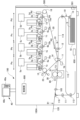
Hereinafter, an embodiment of the present invention will be described with reference to the drawings. First, the configuration of an image forming apparatus of this embodiment will be described with reference to FIG. 1. The
画像形成装置100の記録材の搬送プロセスについて説明する。記録材Sは給紙カセット10内に積載される形で収納されており、給紙ローラ13により画像形成タイミングに合わせて給紙カセット10から送り出される。給紙ローラ13により送り出された記録材Sは、搬送パス114の途中に配置されたレジストレーションローラ12へと搬送される。そして、レジストレーションローラ12において記録材Sの斜行補正やタイミング補正を行った後、記録材Sは二次転写部T2へと送られる。二次転写部T2は、二次転写内ローラ14と二次転写外ローラ11とにより形成される転写ニップ部であり、転写部材としての二次転写外ローラ11に二次転写電圧が印加されることに応じて記録材上にトナー像が転写される。二次転写外ローラ11は、芯金の外周に例えばイオン導電系発泡ゴム(NBRゴム)の弾性層を有し、外径が20~25mmに形成されている。また、二次転写外ローラ11は、例えば抵抗値が1×10⁵~1×10⁸Ω(N/N(23℃、50%RH)測定、2kV印加)に設定される。
The recording material conveying process of the
以上説明した二次転写部T2までの記録材Sの搬送プロセスに対して、同様のタイミングで二次転写部T2まで送られて来る画像の形成プロセスについて説明する。まず、画像形成部について説明するが、各色の画像形成部Pa、Pb、Pc、Pdは、現像装置1a、1b、1c、1dで使用するトナーの色がイエロー、マゼンタ、シアン、ブラックと異なる以外はほぼ同様に構成される。そこで、以下では、代表としてブラックの画像形成部Pdについて説明し、その他の画像形成部Pa、Pb、Pcについては説明を省略する。
The process of transporting the recording material S to the secondary transfer unit T2 described above will be compared with the process of forming an image sent to the secondary transfer unit T2 at the same timing. First, the image forming units Pa, Pb, Pc, and Pd for each color are configured in almost the same way, except that the toner colors used in the developing
画像形成部Pdは、主に現像装置1d、帯電装置2d、感光ドラム3d、感光ドラムクリーナ4d、及び露光装置5d等から構成される。矢印R1方向に回転される像担持体としての感光ドラム3dの表面は、帯電装置2dにより予め表面を一様に帯電され、その後、画像情報の信号に基づいて駆動される露光装置5dによって静電潜像が形成される。次に、感光ドラム3d上(像担持体上)に形成された静電潜像は、現像装置1dにより現像剤を用いてトナー像に現像される。そして、画像形成部Pdと中間転写ベルト20を挟んで配置される一次転写ローラ6dに一次転写電圧が印加されることに応じて、感光ドラム3d上に形成されたトナー像が、中間転写ベルト20上に一次転写される。一次転写ローラ6dには一次転写電源75dが接続されており、一次転写電源75dが正極性の一次転写電圧を一次転写ローラ6dに印加することで、感光ドラム3d上の負極性に帯電されたトナー像が中間転写ベルト20に転写される。また、一次転写電源75には、図示を省略したが、出力電圧を検出する一転電圧検出センサと、出力電流を検出する一転電流検出センサとが接続されている。感光ドラム3d上に僅かに残った一次転写残トナーは、感光ドラムクリーナ4dにより回収される。
The image forming section Pd is mainly composed of a developing
中間転写体としての中間転写ベルト20は、二次転写内ローラ14、テンションローラ15、及び駆動ローラ16に張架され、駆動ローラ16によって矢印R2方向へと駆動される。画像形成部Pa~Pdにより並列処理される各色の画像形成プロセスは、中間転写ベルト20上に一次転写された上流の色のトナー像上に順次重ね合わせるタイミングで行われる。その結果、最終的にはフルカラーのトナー像が中間転写ベルト20上に形成され、二次転写部T2へと搬送される。なお、二次転写部T2を通過した後の二次転写残トナーは、転写クリーナ装置22によって回収される。
The
以上、それぞれ説明した搬送プロセス及び画像形成プロセスをもって、二次転写部T2において記録材Sとフルカラートナー像のタイミングが一致し、二次転写が行われる。二次転写部T2は、中間転写ベルト20を挟んで二次転写内ローラ14側に二次転写外ローラ11を押圧させることで形成される。二次転写外ローラ11には、電圧可変の二次転写電源76が接続されている。また、二次転写電源76には、出力電圧を検出する電圧検出センサと、出力電流を検出する電流検出センサとが接続されている(後述の図2参照)。
Through the above-described conveying process and image forming process, the timing of the recording material S and the full-color toner image are synchronized at the secondary transfer section T2, and secondary transfer is performed. The secondary transfer section T2 is formed by pressing the secondary transfer
本実施形態では、二次転写内ローラ14を接地電位(0V)に接続する一方で、二次転写電源76により二次転写外ローラ11へトナーと逆極性の正極性の二次転写電圧(所定電圧)を印加することで、二次転写部T2に転写電界が生じる。二次転写外ローラ11は転写電界に応答して、中間転写ベルト20に転写された四色のトナー像つまりイエロー、マゼンタ、シアン、ブラックの負極性に帯電されたトナー像を、二次転写部T2に搬送される記録材Sへ一括して転写する。例えば、二次転写電源76により1~7kVの二次転写電圧が印加された場合に、二次転写部T2に40~120μAの電流が流れて、中間転写ベルト20上(中間転写体上)のトナー像が記録材Sに転写される。
In this embodiment, the inner
二次転写後、記録材Sは定着装置30へと搬送されて記録材上にトナー像が定着される。定着手段としての定着装置30は、トナー像が形成された記録材Sを挟持搬送する際に、記録材Sを加熱及び加圧してトナー像を記録材Sに定着させる。即ち、熱と圧力とが加えられることによって、記録材Sに形成されたトナー像のトナーが溶融、混合され、フルカラーの画像として記録材Sに定着される。このようにして、一連の画像形成プロセスは終了する。
After the secondary transfer, the recording material S is transported to the fixing
定着装置30によりトナー像が定着された記録材Sは、片面画像形成の場合、一対の排出ローラ105に挟持搬送されて、そのまま排出部としての排出トレイ120上に排出される。他方、両面画像形成の場合、切り替え部材110(フラッパなどと呼ばれる)によって、搬送経路が排出トレイ120に続く経路から両面搬送パス111へ切り替えられ、排出ローラ105に挟持搬送される記録材Sは両面搬送パス111へと送られる。その後、反転ローラ112によって先後端が入れ替えられ、両面パス113を介して再び搬送パス114へと送られる。その後の搬送ならびに裏面の画像形成プロセスに関しては、上述と同様なので説明を省略する。
In the case of single-sided image formation, the recording material S on which the toner image has been fixed by the fixing
上記した中間転写ベルト20は、例えば体積抵抗率が5×108~1×1014Ω・cm(23℃、50%RH)、硬度がMD-1硬度で60~85°(23℃、50%RH)に設定されている。また、静止摩擦係数が0.15~0.6(23℃、50%RH、HEIDON社製type94i)に設定されている。そして、中間転写ベルト20は、二次転写内ローラ14が当接する裏面側から、基層、弾性層、表層の3層構造を有する。基層は、ポリイミドやポリカーボネート等の樹脂、又は各種ゴム等に帯電防止剤としてカーボンブラックを適当量含有させた樹脂などの材料が用いられ、厚みが0.05~0.15mmに形成される。弾性層は、ウレタンゴムやシリコーンゴム等の各種ゴム等にイオン導電剤を適当量含有させた材料などが用いられ、厚みが0.1~0.5mmに形成される。表層は、フッ素樹脂等の樹脂材料が用いられ、厚みは0.0002~0.02mmに形成される。表層は、例えばポリウレタン、ポリエステル、エポキシ樹脂等の1種類の材料、あるいは弾性材ゴム、エラストマ、ブチルゴム等の弾性材料のうち2種類以上の材料が基材とされる。この基材に対して、表面エネルギを小さくし潤滑性を高めるために、例えばフッ素樹脂等の粉体や粒子を1種類あるいは2種類以上、または粒径を異ならして分散させることにより、表層を形成している。このような表層を有する中間転写ベルト20は、表面へのトナーの付着力が小さくなるので、トナーが記録材Sへ転写しやすくなる。
The
また、装置本体100A内には、搬送経路(113、114)において記録材Sが途中で詰まることなく搬送されているか否か、言い換えればジャムが生じたか否かを検出するために、複数のフォトセンサ81が搬送経路の適宜の位置に配置されている。フォトセンサ81は記録材Sの搬送方向に関し、例えば給紙カセット10の下流側、レジストレーションローラ12の上流側、二次転写部T2の上流側、定着装置30の上流側(二次転写部T2の下流側)、排出トレイ120の上流側などにそれぞれ配置される。フォトセンサ81は、例えば搬送経路(113、114)に向けて光を照射して、記録材Sの有無に応じて変化する反射光を検出するものである。排出トレイ120の上流側に配置されるフォトセンサ81が、排出トレイ120への記録材Sの排出を検出する排出検出手段に相当する。さらに、装置本体100A内には、装置本体100A内の温度や湿度を検出する環境センサ650が配置されている。
In addition, in the device
そして、装置本体100Aには開閉可能な扉500と、扉500の開閉を検出可能な開閉検出手段としての開閉センサ501が設けられている。例えば、記録材Sが排出されることなく搬送経路(113、114)の途中で詰まる所謂ジャムが生じた場合に、ユーザは扉500を開くことにより装置本体100A内に外からアクセスして、搬送経路から記録材Sを除去可能である。なお、図1では扉500と開閉センサ501とを1つだけ示しているが、搬送経路から記録材Sを除去するために、開閉可能な扉と開閉センサとは図示した以外の他の箇所にも設けられていてよい。
The device
<制御部>
また、図1に示すように、画像形成装置100は制御部600を備えている。制御部600について、図1を参照しながら図2を用いて説明する。なお、制御部600には図示した以外にも、例えば一次転写電源75a~75d、一転電圧検出センサや一転電流検出センサ、また搬送経路(113、114)において記録材Sを搬送する各種ローラを駆動する各種モータなどの各種機器が接続されている。しかし、ここでは発明の本旨でないので、それらの図示及び説明を省略している。
<Control Unit>
As shown in Fig. 1, the
制御手段としての制御部600は、画像形成動作などの画像形成装置1の各種動作を制御するものであり、例えばCPU(Central Processing Unit)601と、メモリ602とを有する。メモリ602はROM(Read Only Memory)やRAM(Random Access Memory)などにより構成され、画像形成装置1を制御するための各種プログラムや、後述する基準電圧や分担電圧などの各種データが記憶される。CPU601はメモリ602に記憶されている画像形成ジョブや後述する「二転電圧調整処理」などのプログラムを実行して、画像形成を行うよう画像形成装置100を動作させ得る。本実施形態の「二転電圧調整処理」(出力モード)については、後述する(図5参照)。また、CPU601は扉500の開閉に応じた経過時間や、給紙カセット10から送り出された記録材Sの枚数、排出トレイ120に排出された記録材Sの枚数などをカウントするカウンタとして機能し得る。排出トレイ120に排出された記録材Sの枚数は、排出済みカウンタとしてメモリ602に記憶される。なお、メモリ602は各種プログラムの実行に伴う演算処理結果などを一時的に記憶し得る。
The
制御部600には、入出力インタフェースを介して上述した二次転写電源76が接続されている。制御部600は、二次転写電源76を制御することにより二次転写外ローラ11に印加する電圧(二次転写電圧)を変更可能である。本実施形態の画像形成装置100は電圧検出センサ761、電流検出センサ762、環境センサ650を備え、これらが入出力インタフェースを介して制御部600に接続されている。電圧検出手段としての電圧検出センサ761は、二次転写電源76による二次転写外ローラ11への電圧の印加に伴い、二次転写部T2にかかる電圧を検出する。電流検出手段としての電流検出センサ762は二次転写電源76による二次転写外ローラ11への電圧印加に応じて、二次転写部T2を流れる電流を検出する。制御部600は、電圧検出センサ761により検出される電圧や電流検出センサ762により検出される電流を取得し得る。また、制御部600は、環境センサ650により検出された温湿度を適時に取得し得る。
The
また、画像形成装置100はユーザ入力部40を備え、ユーザ入力部40は入出力インタフェースを介して制御部600に接続されている。本実施形態の場合、ユーザ入力部40は操作部40aと表示部40bとを有し、操作部40aはユーザによる各種プログラムの開始や停止、あるいは各種データの入力を受け付ける各種スイッチやボタンなどが設けられている。表示部40bは、各種画面を表示可能な例えば液晶ディスプレイである。表示部40bは、実行可能な各種プログラムを提示するメニュー画面、パッチトナー像に関するデータ入力を受け付ける入力画面(図6参照)、ジャム解消後の処理を選択する選択画面(図7参照)、二次転写電圧を変更する変更画面(図8参照)などを表示する。なお、表示部40bに操作部40aのスイッチ等を模した仮想操作子を表示しておき、この仮想操作子を利用してユーザによる各種プログラムの開始指示や各種データの入力などを受け付けできるようにしてよい。つまり、ユーザ入力部40は所謂タッチパネルであってもよい。あるいは、ユーザ入力部40は装置本体100Aにデータ入出力可能に接続されたパーソナルコンピュータ等の外部機器であってもよい。
The
また、制御部600は開閉センサ501の検出信号を受信し、それに基づいて扉500の開閉状態を検出できる。さらに、制御部600は、複数のフォトセンサ81の検出信号を受信し、それに基づいて搬送経路(113、114)における記録材Sの有無つまりは記録材Sの滞留を検出することで、ジャムが生じたか否かを判定し得る。ジャムが生じた場合、制御部600は画像形成及び記録材Sの搬送を停止し、表示部40bなどを用いてユーザに対しジャムが発生した旨を報知する。
The
上述したように、制御部600は中間転写ベルト20上のトナー像を記録材Sに転写させるために、二次転写電源76を制御して二次転写外ローラ11に二次転写電圧を印加する。この際に、二次転写部T2にトナー像を適正に転写させ得る目標電流が流れるように、制御部600は二次転写電圧を設定する必要がある。仮に、二次転写部T2に流れる電流が目標電流より小さいと、中間転写ベルト20から記録材Sに対しトナー像が十分に転写されない転写不良が生じ、画像にかすれが生じ得る。反対に、二次転写部T2に流れる電流が目標電流より大きいと、二次転写部T2で異常放電が生じ、トナーの飛び散りや画像に滲みが生じ得る。これを避けるため、二次転写部T2には転写不良や異常放電などを生じさせない電流を目標電流として二次転写部T2に流す必要がある。
As described above, the
<二転ATVC制御について>
そこで、制御部600は二転ATVC(Auto Transfer Voltage Control)制御を実行して、二次転写電圧を設定する。二転ATVC制御は、二次転写部T2を記録材Sが通過していないときに、二次転写部T2に目標電流を流すことが可能な電圧を基準電圧として設定する制御である。この基準電圧は、環境(例えば温湿度)の変動や長期使用による中間転写ベルト20や二次転写外ローラ11の電気抵抗の変化に応じて変わることから、制御部600は二転ATVC制御を実行して基準電圧を適宜に更新する。基準電圧は、メモリ602に記憶されている。制御部600は、例えば電源投入後の前回転時や、画像形成した記録材Sの累計枚数が所定枚数(例えば1000枚)を超えた後の紙間などに、二転ATVC制御を実行する。
<About two-way ATVC control>
Therefore, the
公知であるが、二転ATVC制御の一例について簡単に説明する。制御部600は、二次転写外ローラ11に対しメモリ602に予め記憶されている複数の電流値の電流(I1、I2)を順次に流すように、二次転写電源76を制御してそれぞれに対応する電圧値の電圧(V1、V2)を二次転写外ローラ11に順に印加させる。ただし、一方の電流(I1)は目標電流より小さい電流値であり、他方の電流(I2)は目標電流より大きい電流値である。そして、制御部600はこれらから得られる電圧‐電流関係(I1、V1)と(I2、V2)を用いて線形近似を行い(Y=(I2-I1)/(V2-V1))、これを二次転写外ローラ11の電圧電流特性(V-I特性)と看做しメモリ602に記憶する。そして、制御部600は上記の電圧電流特性(Y)に従って、目標電流と目標電流より小さい電流(I1)との差分(ΔI)、電流(I1)を流した時に印加した電圧(V1)から、基準電圧(Vb=V1+ΔI/Y)を求め、これをメモリ602に記憶する。
Although it is well known, an example of two-transfer ATVC control will be briefly described below. The
なお、目標電流は、環境センサ650により検出される温湿度や、画像形成する記録材Sの種類(詳しくは厚みや坪量等)などによって決まる。具体的には、温湿度や記録材Sの種類毎に目標電流を規定した設定データテーブル(不図示)がメモリ602に予め記憶されており、制御部600はこの設定データテーブルを参照して温湿度や記録材Sの種類に応じた目標電流を決める。
The target current is determined by the temperature and humidity detected by the
上述したように、二転ATVC制御により求められる基準電圧は、二次転写部T2を記録材Sが通過していないときに、二次転写部T2に目標電流を流すことが可能な電圧(非通紙時の二次転写部T2の分担電圧Vb)である。これに対し、画像形成ジョブ時に二次転写外ローラ11に印加する二次転写電圧は、二次転写部T2を記録材Sが通過中であるときに、二次転写部T2に目標電流を流すことが可能な電圧でないと、転写不良等を生じさせる虞がある。そのため、二次転写電圧は、中間転写ベルト20や二次転写外ローラ11などの電気抵抗に加えて、画像形成する記録材Sの電気抵抗を考慮した電圧を印加する必要がある。
As described above, the reference voltage required by the secondary transfer ATVC control is a voltage that allows a target current to flow through the secondary transfer section T2 when the recording material S is not passing through the secondary transfer section T2 (the shared voltage Vb of the secondary transfer section T2 when no paper is passing through). In contrast, if the secondary transfer voltage applied to the outer
そこで、制御部600は、画像形成ジョブ時に二次転写外ローラ11に印加する二次転写電圧を、上記の基準電圧(Vb)と、記録材Sの電気抵抗を考慮した分担電圧(Vp)との和によって設定している。分担電圧(Vp)は記録材Sの電気抵抗が標準抵抗である場合の電圧値であり、記録材Sの種類等によって異なる電圧値が割り当てられてメモリ602に予め記憶されている。例えば、電気抵抗が大きい合成紙の分担電圧は、普通紙の分担電圧よりも高い電圧値(絶対値)が割り当てられる。
Therefore, the
<二次転写電圧の調整について>
ところで、記録材Sが例えば吸湿しやすい紙であるような場合には、記録材Sの種類が同じであっても、記録材Sの電気抵抗は吸湿状態によってつまりは記録材Sに含まれる水分量によって異なり得る。そのため、上記のように記録材Sの種類に応じた分担電圧を考慮した二次転写電圧を印加したにも関わらず、二次転写部T2に流れる電流が目標電流から外れ、中間転写ベルト20から記録材Sへの最適な二次転写が行えない虞がある。
<Adjusting the secondary transfer voltage>
Incidentally, when the recording material S is, for example, paper that easily absorbs moisture, even if the type of recording material S is the same, the electrical resistance of the recording material S may differ depending on the moisture absorption state, that is, the amount of moisture contained in the recording material S. Therefore, even if a secondary transfer voltage is applied taking into account the voltage distribution according to the type of recording material S as described above, the current flowing through the secondary transfer portion T2 may deviate from the target current, and there is a risk that optimal secondary transfer from the
そこで、ユーザが任意に出力モードを実行できるようにしている。出力モードは、二次転写電圧(より詳しくは分担電圧)を段階的に変えながら、代表的な色のパッチトナー像(以下、パッチ画像)を形成した記録材S(調整用チャートと呼ぶ)を出力して、調整用チャートに基づき二次転写電圧を調整可能とする処理である。二次転写電圧は、レッド、グリーン、ブルーなどの二次色のパッチ画像(多重画像)を記録材Sに転写可能な電圧値を下限電圧とし、ハーフトーンのパッチ画像に画像不良が生じる電圧値を上限電圧とする範囲内で調整される。ここで、図3及び図4に調整用チャートを示す。図3に示す調整用チャートは、記録材Sの搬送方向長さが420~487mmである場合を示す。図4に示す調整用チャートは、記録材Sの搬送方向長さが210~419mmである場合を示す。 Therefore, the output mode is made so that the user can execute it at will. The output mode is a process in which the recording material S (called the adjustment chart) on which a patch toner image (hereinafter, a patch image) of a representative color is formed is output while the secondary transfer voltage (more specifically, the shared voltage) is changed stepwise, and the secondary transfer voltage can be adjusted based on the adjustment chart. The secondary transfer voltage is adjusted within a range in which the lower limit voltage is a voltage value at which a patch image (multiple images) of a secondary color such as red, green, or blue can be transferred to the recording material S, and the upper limit voltage is a voltage value at which an image defect occurs in a halftone patch image. Here, the adjustment charts are shown in FIG. 3 and FIG. 4. The adjustment chart shown in FIG. 3 shows a case in which the length of the recording material S in the conveying direction is 420 to 487 mm. The adjustment chart shown in FIG. 4 shows a case in which the length of the recording material S in the conveying direction is 210 to 419 mm.
調整用チャートのパッチ画像は、ユーザが転写性の適否を判断しやすいサイズで形成される。図3及び図4に示す例では、パッチ画像としてブルー、ブラックのベタ画像とハーフトーン画像とが形成されている。パッチ画像がブルー、ブラックのベタ画像である場合、そのサイズは10mm角以上であればよく、25mm角以上がより好ましい。 The patch images of the adjustment chart are formed at a size that allows the user to easily judge the suitability of the transferability. In the example shown in Figures 3 and 4, blue and black solid images and halftone images are formed as patch images. When the patch images are blue and black solid images, their size should be 10 mm square or more, and 25 mm square or more is more preferable.
調整用チャートに形成するパッチ画像のサイズが決まると、1枚の記録材Sに形成されるパッチ画像の数が決まる。また、段階的に変更する二次転写電圧の数が多ければ、複数のパッチ画像が複数枚の調整用チャートに分かれて転写されることになり、図4に示すように、出力モードの実行に伴い2枚以上の調整用チャートが出力され得る。なお、各パッチ画像の傍には、例えばブラックで「-5~5」の数字(図3参照)、「-4~0」、「1~5」の数字(図4参照)が印字される。 Once the size of the patch images to be formed on the adjustment chart is determined, the number of patch images to be formed on one sheet of recording material S is also determined. Furthermore, if the number of secondary transfer voltages to be changed in stages is large, multiple patch images will be transferred separately to multiple adjustment charts, and as shown in FIG. 4, two or more adjustment charts may be output when the output mode is executed. Note that numbers such as "-5 to 5" (see FIG. 3), "-4 to 0", and "1 to 5" (see FIG. 4) are printed in black next to each patch image.
しかしながら、画像形成装置100では、上述した調整用チャートの出力時(出力モード時)であっても、記録材Sが搬送経路中(113、114)で詰まる所謂ジャムが生じ得る。ジャムが生じた場合、装置本体内において搬送中であった記録材Sの搬送がすべて停止される。既に述べた通り、従来ではジャムが生じた場合、調整用チャートの出力が途中であっても、出力モードが強制終了されていた。したがって、ユーザが搬送経路から記録材Sを除去してジャムを解消しても、出力モードが再開されなかった。それ故、ユーザはジャムにより出力モードが強制終了された場合に、操作部40aから出力モードを開始させる操作を最初からやり直さなければならず面倒であった。
However, in the
そこで、上記点に鑑み、本実施形態では、ユーザが搬送経路から記録材Sを除去してジャムを解消した場合に、ジャムが生じたときに実行中であった出力モードを、ユーザが再開し得るようにした。以下、本実施形態の二転電圧調整処理(出力モード)について、図1及び図2を参照しながら図5乃至図7を用いて説明する。この二転電圧調整処理は、例えば操作部40aからのユーザの開始指示に応じて制御部600により開始される。
In view of the above, in this embodiment, when the user removes the recording material S from the transport path to clear the jam, the user can resume the output mode that was running when the jam occurred. Below, the second transfer voltage adjustment process (output mode) of this embodiment will be described using Figures 5 to 7 with reference to Figures 1 and 2. This second transfer voltage adjustment process is started by the
制御部600は、例えば操作部40aから出力モードの開始指示を受信した場合、図5に示すように、ユーザにより操作部40aから入力された記録材Sの種類やサイズに従って、該当する記録材Sが収容されている給紙カセット10を特定する(S1)。また、制御部600は、表示部40bに図6に示す「入力画面」を表示する(S2)。
When the
図6に示す「入力画面」は、記録材Sのオモテ面のみにパッチ画像を形成するか、記録材Sの両面(オモテ面とウラ面)にパッチ画像を形成するかを、ユーザが選択可能である。また、「入力画面」は、複数のパッチ画像を形成するために段階的に変化させる二次転写電圧の中心値を、ユーザが上記パッチ画像形成面(オモテ面、ウラ面)ごとに変更入力可能である(ここでは、-20、-19・・・、0、+1、・・・+20)。例えば、「0」が入力された場合、記録材Sに予め割り当てられている電圧値(区別するために初期分担電圧と呼ぶ)が2500Vであれば、メモリ602に記憶されている基準電圧に2500Vを加算した電圧が中心電圧値に設定される。「+1」が入力された場合は、「基準電圧+初期分担電圧+(150V×「+1」)」が中心電圧値に設定される。「-20」が入力された場合は、「基準電圧+初期分担電圧+(150V×「-20」)」が中心電圧値に設定される。
The "input screen" shown in FIG. 6 allows the user to select whether to form a patch image only on the front side of the recording material S or to form a patch image on both sides (front side and back side) of the recording material S. The "input screen" also allows the user to change and input the center value of the secondary transfer voltage, which is changed stepwise to form multiple patch images, for each of the patch image forming surfaces (front side, back side) (here, -20, -19 ..., 0, +1, ... +20). For example, when "0" is input, if the voltage value (called the initial allocation voltage to distinguish) previously assigned to the recording material S is 2500 V, the voltage obtained by adding 2500 V to the reference voltage stored in the
本実施形態の場合、二次転写電圧を段階的に変化させる際の電圧の変更幅が、例えば150Vに設定されている。例えば初期分担電圧が2500VのA4サイズの両面コート紙に対し、中心電圧値を変更せずにパッチ画像を形成する場合、1900Vから3250Vまで150Vごとに10回に分けて二次転写電圧が変えられて、パッチ画像が形成される。この際に「オモテ面」のみにパッチ画像を形成する場合には、1枚目に「-4~0」の5回に分けて二次転写電圧が変えられてパッチ画像が形成される。そして、2枚目に「1~5」の5回に分けて二次転写電圧が変えられてパッチ画像が形成される。こうして、全部で2枚の調整用チャートが出力される(図4参照)。例えば初期分担電圧が2500VであるA3サイズの記録材Sの「オモテ面」のみにパッチ画像を形成する場合には、「-5~+5」の11回に分けて二次転写電圧が変えられてパッチ画像が形成される。この場合、調整用チャートが1枚だけ出力される(図3参照)。 In this embodiment, the change width of the voltage when the secondary transfer voltage is changed stepwise is set to, for example, 150V. For example, when forming a patch image on A4-size double-sided coated paper with an initial voltage of 2500V without changing the central voltage value, the secondary transfer voltage is changed 10 times from 1900V to 3250V in increments of 150V to form a patch image. In this case, when forming a patch image only on the "front side", the secondary transfer voltage is changed 5 times from "-4 to 0" on the first sheet to form a patch image. Then, the secondary transfer voltage is changed 5 times from "1 to 5" on the second sheet to form a patch image. In this way, a total of two adjustment charts are output (see FIG. 4). For example, when forming a patch image only on the "front side" of A3-size recording material S with an initial voltage of 2500V, the secondary transfer voltage is changed 11 times from "-5 to +5" to form a patch image. In this case, only one adjustment chart is output (see FIG. 3).
ユーザにより「入力画面」の「テストページの出力」が選択された場合に、制御部600は調整用チャートの出力制御を実質的に開始する。なお、制御部600は調整用チャートを何枚に分けて出力するか(チャート枚数と呼ぶ)を、操作部40aや「入力画面」からユーザ入力される各種情報などに基づいて決定する。
When the user selects "Test page output" on the "input screen", the
制御部600は、1枚の記録材Sに対し二次転写電圧を段階的に変化させながらパッチ画像を形成する調整用チャートの出力制御を行う(S3)。そして、制御部600は調整用チャートの出力制御を行いながら、ジャムが生じたか否かの判定を行う(S4)。制御部600はジャムが生じたか否かの判定を、上述したように、搬送経路に配置されている複数のフォトセンサ81の検出結果に基づいて行っている。
The
ジャムが生じていない場合(S4のNO)、制御部600は調整用チャートの出力制御を終了するか否かを判定する(S5)。この終了判定は、排出トレイ120に排出された記録材S(調整用チャート)の枚数が上記のチャート枚数に達したか否かによって判定される。制御部600は、排出トレイ120に排出された記録材S(調整用チャート)の枚数がチャート枚数に達した場合に、調整用チャートの出力制御を終了する。調整用チャートの出力制御を終了しない場合(S5のNO)、制御部600は次の記録材Sに対しパッチ画像を形成する調整用チャートの出力制御を行うべく、上記ステップS3の処理へ戻る。調整用チャートの出力制御を終了する場合(S5のYES)、制御部600は二転電圧調整処理を終了する。
If no jam has occurred (NO in S4), the
ユーザは、出力された調整用チャートを目視して手動で二次転写電圧を入力する(目視設定タイプ)。あるいは、ユーザは、出力された調整用チャートのパッチ画像を原稿読取装置(不図示)に読み込ませて、それにより得られる二次転写電圧を変更して二次転写電圧の調整を行う(原稿読取装置設定タイプ)。例えば、ユーザは調整用チャートを目視して二次転写電圧を調整する場合、各色の最適なパッチ画像の傍に記された補正値を(図3、図4参照)、操作部40aから入力する。これで、ユーザは二次転写電圧の調整を完了することができる。入力された補正値はメモリ602に記憶され、二次転写時に参照され、基準電圧に補正値に対応する分担電圧が加算された電圧値が、二次転写電圧として画像形成ジョブ時に印加される。なお、ユーザが調整用チャートのパッチ画像を原稿読取装置(不図示)に読み込ませることにより二次転写電圧を得る方法は、後述する装置本体100A内にカラーセンサ80(又はイメージスキャナ)が設けられた場合と同様であり、ここでは説明を省略する。
The user visually checks the outputted adjustment chart and manually inputs the secondary transfer voltage (visual setting type). Alternatively, the user reads the patch image of the outputted adjustment chart into a document reading device (not shown) and adjusts the secondary transfer voltage by changing the secondary transfer voltage obtained thereby (document reading device setting type). For example, when the user visually checks the adjustment chart and adjusts the secondary transfer voltage, the user inputs the correction value written beside the optimal patch image of each color (see Figures 3 and 4) from the
装置本体100A内にカラーセンサ80(又はイメージスキャナ)が設けられている場合(図1参照)、制御部600は後述するステップS6の処理を行ってから二転電圧調整処理を終了してよい(自動設定タイプ)。詳しくは後述するが、自動設定タイプの場合、制御部600はカラーセンサ80(又はイメージスキャナ)の検出結果に基づいて二次転写電圧を演算する。そして、ユーザは、演算により求められた二次転写電圧を「変更画面」(図8参照)から変更することができる(図5のS6参照)。
If a color sensor 80 (or image scanner) is provided inside the device
図6の説明に戻り、出力モードの実行中にジャムが生じた場合(S4のYES)、図示を省略したが、制御部600は画像形成及び記録材Sの搬送を停止し、表示部40bにジャムが発生した旨を表示し得る。ユーザはジャムが生じた場合、扉500を開けて搬送経路(113、114)に滞留した記録材Sを除去する。そして、ユーザは扉500を閉める。これにより、ジャムは解消される。この際に、制御部600は、記録材Sの搬送停止から扉500が閉められるまでの時間を計測し得る。
Returning to the explanation of FIG. 6, if a jam occurs during execution of the output mode (YES in S4), although not shown in the figure, the
ジャム解消後、制御部600は表示部40bに図7に示す「選択画面」を表示し(S7)、「選択画面」からユーザ入力があるまで処理を待機する。図7に示す「選択画面」は、出力モードのジャム解消後の処理を選択するための画面である。図7に示すように、「選択画面」では、「1枚目から再出力」、「途中から再出力」、「強制終了」のいずれかを、ユーザが選択可能である。制御部600は、「選択画面」からユーザ入力された上記いずれかの選択内容に従って、以下に示す異なる制御を実行する(S8)。「強制終了」が選択された場合、制御部600は調整用チャートの出力が途中であったとしても、二転電圧調整処理を終了する。即ち、ジャムが生じた際に実行中であった出力モードが再開されない。この場合、ユーザは調整用チャートを用いた二次転写電圧の調整を行い得ない。
After the jam is cleared, the
「1枚目から再出力」が選択された場合、制御部600は排出済みカウンタを「1」に設定し(S9)、ステップS3の処理に戻る。この場合、例え排出トレイ120に記録材S(調整用チャート)が何枚か排出済みであっても、再度、1枚目の調整用チャートから出力をやり直すように、出力モードが再開される。なお、この場合には、再出力された調整用チャートのうち、ジャムが生じる前に排出済みの調整用チャートと同じ頁であるものについては、記録材S上に「再出力」である旨を印字するのが好ましい。そうすることで、例えばユーザが出力された複数枚の調整用チャートを原稿読取装置(不図示)に読み取らせて二次転写電圧の調整を行う場合に、再出力されたものを適切に読み取らせることができる。
If "Re-output from the first sheet" is selected, the
他方、「途中から再出力」が選択された場合、制御部600はメモリ602に記憶されている「排出済みカウンタ(排出トレイ120に排出済みの記録材Sの枚数)」に「1」を加算して(S10)、ステップS3の処理に戻る。この場合、装置本体外に排出されていない記録材Sから出力モードが再開される。即ち、排出トレイ120に排出済みの記録材Sの次の記録材Sから出力するように、出力モードが再開される。調整用モードの再開後、ジャムが生じることなく調整用チャートの出力が終了すると(S5のYES)、制御部600は二転電圧調整処理を終了する。
On the other hand, if "Restart from midway" is selected, the
以上のように、本実施形態では、出力モードの実行中に例えジャムが生じたとしても、ユーザは1枚目の記録材Sから出力し直すことができる。ユーザは、ジャムが生じた場合に1枚目の記録材Sから出力し直すことを、選択画面(図7参照)から選択できる。これにより、ユーザはジャム解消後に、再度、出力モードを開始する操作を最初からやり直す必要がなく、出力モードを引き続き実行することが容易にできる。つまり、本実施形態の装置はユーザビリティが高い。 As described above, in this embodiment, even if a jam occurs while the output mode is being executed, the user can restart output from the first sheet of recording material S. The user can select from the selection screen (see FIG. 7) to restart output from the first sheet of recording material S when a jam occurs. This allows the user to easily continue executing the output mode after clearing the jam without having to start the output mode from the beginning again. In other words, the device of this embodiment has high usability.
また、ジャムの発生から解消までに、パッチトナー像の二次転写に影響を与えるだけの時間がかかった場合に、ユーザは1枚目から再出力した複数枚の記録材Sを用いて二次転写電圧の調整を行い得る。1枚目の記録材Sから出力し直すことにより、ジャムに起因する二次転写への影響を排除して複数枚の記録材S(調整用チャート)を出力でき、もってユーザは出力された複数枚の記録材Sを用い適切に二次転写電圧の調整を行い得る。 In addition, if the time it takes from the occurrence of a jam to its resolution is long enough to affect the secondary transfer of the patch toner image, the user can adjust the secondary transfer voltage by using multiple sheets of recording material S re-output from the first sheet. By re-outputting from the first sheet of recording material S, it is possible to output multiple sheets of recording material S (adjustment charts) while eliminating the effects on secondary transfer caused by the jam, and the user can appropriately adjust the secondary transfer voltage using the multiple sheets of recording material S output.
[第二実施形態]
図1に示すように、画像形成装置100として、装置本体100A内にカラーセンサ80(又はイメージスキャナ)が設けられた装置がある(図1参照)。その場合、制御部600は、出力モードの実行に伴い、カラーセンサ80(又はイメージスキャナ)の検出結果に基づいて二次転写電圧が自動的に設定(自動設定タイプ)される。以下、説明する。
[Second embodiment]
As shown in Fig. 1, the
画像形成装置100には、定着装置30の下流にカラーセンサ80が配置されている。本実施形態では、単色のパッチ画像(単色画像)に加え、マゼンタとシアンを重ねたブルーのパッチ画像(多重画像)の記録材Sへの転写性の適否を判定可能とすべく、色の波長の分光強度を測定可能なカラーセンサ80によって後述する各色の情報を取得する。この各色の情報を取得することを測色という。
In the
まず、濃度検出手段としてのカラーセンサ80について、図1を参照しながら図9を用いて説明する。図9に示すように、カラーセンサ80は分光センサであって、記録材S上のパッチ画像Tに光を照射する照射部としての白色LED201、パッチ画像Tから反射した反射光を波長ごとに分光する分光部としての回折格子202を有する。また、カラーセンサ80は、回折格子202により波長ごとに分解された光を検出するn画素から成るラインセンサ203(203-1~203-n)を有する。受光部としてのラインセンサ203が検出可能な波長領域は、実質的に可視光領域の全体に亘っており、例えば380~720nmの範囲に設定される。ラインセンサ203の撮像素子(203-1~203-n)として、例えばCMOSセンサが用いられる。なお、図示した構成例では、パッチ画像Tからの反射光を回折格子202に集光するレンズ206が設けられている。
First, the
本実施形態では、カラーセンサ80が主走査方向に4つ配置されている。これら4つのカラーセンサ80は、上記のように調整用チャートにおいて主走査方向の異なる位置に形成されたそれぞれのパッチ画像(図3、図4参照)を検出するために個別に用いられ得る。あるいは、調整用チャートに形成された複数のパッチ画像の1つを4つのカラーセンサ80のうちのいくつかで検出して、その検出結果を平均処理して用いるようにしてもよい。なお、ここで言う「主走査方向」は、記録材Sの搬送方向と交差する方向(二次転写外ローラ11の回転軸線方向)である。
In this embodiment, four
また、カラーセンサ80は、ラインセンサ203により検出された各画素の光強度値から各種演算を行う演算部204、各種データを保存するメモリ205を有する。演算部204は、図示を省略したが、光強度値から分光演算する分光演算部、画像濃度を演算する濃度演算部、Lab値を演算するLab演算部などを有している。
The
次に、カラーセンサ80の検出結果から、パッチ画像の画像濃度を演算する方法について説明する。カラーセンサ80の検出結果は、分光反射率データとして演算部204に送られて濃度演算が行われる。分光反射率データに基づいて濃度値を演算する場合、得られた各波長に対する分光反射率データに対し、イエロー、マゼンタ、シアンの単色画像や多重画像については、図10(a)に示すフィルタ特性を有するステータスAフィルタが用いられる。ブラックの単色画像については、図10(b)に示す視覚度分光特性(Visualともいう)を有するフィルタが用いられる。
Next, a method for calculating the image density of a patch image from the detection results of the
次に、測色つまりは色度値(L*a*b*)の演算方法について説明する。本実施形態の場合、カラーセンサ80において、演算部204はLab演算部を有しており、CIE(国際照明委員会)が規定するLab値(L*a*b*色空間のL*、a*、b*の各座標値)の演算を行い得る。以下に、カラーセンサ80によって読み取られた分光反射率に基づく色度値(L*a*b*)の演算方法を示す(ISO13655)。
Next, the method of calculating colorimetry, that is, chromaticity values (L*a*b*), will be described. In the case of this embodiment, in the
a.試料の分光反射率R(λ)を求める。(λ:380nm~780nm)
b.等色関数x(λ)、y(λ)、z(λ)と標準光分光分布SD50(λ)を用意する。なお、等色関数はJIS Z8701で規定される。他方、SD50(λ)はJIS Z8720で規定され、補助標準イルミナントD50とも呼ばれる。
c.分光反射率R(λ)、等色関数x(λ),y(λ),z(λ)及び標準光分光分布SD50(λ)を波長毎に乗算する。
R(λ)×SD50(λ)×x(λ)
R(λ)×SD50(λ)×y(λ)
R(λ)×SD50(λ)×z(λ)
d.(c)の積を波長領域全体に亘って積算する。
Σ{R(λ)×SD50(λ)×x(λ)}
Σ{R(λ)×SD50(λ)×y(λ)}
Σ{R(λ)×SD50(λ)×z(λ)}
e.等色関数y(λ)と標準光分光分布SD50(λ)との積の積算値を求める。
Σ{SD50(λ)×y(λ)}
f.XYZ色空間における座標を算出する。
X=100×Σ{SD50(λ)×y(λ)}/Σ{R(λ)×SD50(λ)×x(λ)}
Y=100×Σ{SD50(λ)×y(λ)}/Σ{R(λ)×SD50(λ)×y(λ)}
Z=100×Σ{SD50(λ)×y(λ)}/Σ{R(λ)×SD50(λ)×z(λ)}
g.(f)で得られたXYZ座標をL*a*b*色空間に変換する。
L*=116×(Y/Yn)^(1/3)-16
a*=500{(X/Xn)^(1/3)-(Y/Yn)^(1/3)}
b*=200{(Y/Yn)^(1/3)-(Z/Zn)^(1/3)}
a. Calculate the spectral reflectance R (λ) of the sample. (λ: 380 nm to 780 nm)
b. Prepare color matching functions x(λ), y(λ), z(λ) and standard light spectral distribution SD50(λ). Note that color matching functions are specified in JIS Z8701. On the other hand, SD50(λ) is specified in JIS Z8720 and is also called auxiliary standard illuminant D50.
c. Multiply the spectral reflectance R(λ), color matching functions x(λ), y(λ), z(λ) and standard light spectral distribution SD50(λ) for each wavelength.
R(λ)×SD50(λ)×x(λ)
R(λ)×SD50(λ)×y(λ)
R(λ)×SD50(λ)×z(λ)
d. The product of (c) is integrated over the entire wavelength range.
Σ{R(λ)×SD50(λ)×x(λ)}
Σ{R(λ)×SD50(λ)×y(λ)}
Σ{R(λ)×SD50(λ)×z(λ)}
e. Calculate the integrated value of the product of the color matching function y(λ) and the standard light spectral distribution SD50(λ).
Σ{SD50(λ)×y(λ)}
f. Calculate the coordinates in the XYZ color space.
X = 100 × Σ{SD50(λ) × y(λ)} / Σ{R(λ) × SD50(λ) × x(λ)}
Y = 100 × Σ{SD50(λ) × y(λ)} / Σ{R(λ) × SD50(λ) × y(λ)}
Z = 100 × Σ{SD50(λ) × y(λ)} / Σ{R(λ) × SD50(λ) × z(λ)}
g. Convert the XYZ coordinates obtained in (f) into the L*a*b* color space.
L*=116×(Y/Yn)^(1/3)−16
a*=500{(X/Xn)^(1/3)-(Y/Yn)^(1/3)}
b* = 200 {(Y/Yn)^(1/3) - (Z/Zn)^(1/3)}
上記(g)において、Xn,Yn,Znは基準となる白色点の座標を表す値(標準光三刺激値)である。また、上記はY/Yn≧0.008856のときの変換式であり、Y/Yn<0.008856の領域では次のように置き換えられる。
(X/Xn)^(1/3) → 7.78(X/Xn)^(1/3)+16/116
(Y/Yn)^(1/3) → 7.78(Y/Yn)^(1/3)+16/116
(Z/Zn)^(1/3) → 7.78(Z/Zn)^(1/3)+16/116
In the above (g), Xn, Yn, and Zn are values (standard tristimulus values) that represent the coordinates of the reference white point. The above is a conversion formula when Y/Yn≧0.008856, and in the region where Y/Yn<0.008856, it is replaced as follows:
(X/Xn)^(1/3) → 7.78(X/Xn)^(1/3) + 16/116
(Y/Yn)^(1/3) → 7.78(Y/Yn)^(1/3) + 16/116
(Z/Zn)^(1/3) → 7.78(Z/Zn)^(1/3) + 16/116
以上の演算により、分光反射率から色度値(L*a*b*)(「*」を省略することもある)を算出することができる。 By performing the above calculations, the chromaticity value (L*a*b*) (the "*" may be omitted) can be calculated from the spectral reflectance.
また、二次転写電圧条件の決定の際、色によっては記録材Sからの色差を利用する。色差とは、Lab3次元空間における2点間距離を求めているもので、下記式1により算出することができる。
記録材とパッチ画像との色差=((記録材(L)-パッチ画像(L))^2+(記録材(a)-パッチ画像(a))^2+(記録材(b)-パッチ画像(b))^2)^0.2 ・・・ 式1
Furthermore, when determining the secondary transfer voltage conditions, the color difference from the recording material S is utilized depending on the color. The color difference is obtained by finding the distance between two points in the Lab three-dimensional space, and can be calculated by the following
Color difference between recording material and patch image=((recording material (L)−patch image (L))^2+(recording material (a)−patch image (a))^2+(recording material (b)−patch image (b))^2)^0.2 (Equation 1)
なお、カラーセンサ80の校正を行うために、白色基準板を用いた白色LED光量調整や基準分光反射率に補正することが行われる。この校正処理としては、公知の処理を用いることができるので、ここでの説明は省略する。
To calibrate the
上記したカラーセンサ80を備えた画像形成装置100を用い、上述の出力モード(図5参照)を実行させる。この場合には、ブラック、グレー、ブルーの各パッチ画像が記録材S上に形成される。そして、定着装置30の通過後、記録材S上に形成されたパッチ画像をカラーセンサ80により読み取らせる。制御部600(図2参照)はカラーセンサ80から、グレーとブラックのパッチ画像に関しては画像濃度を取得し、ブルーのパッチ画像に関しては色度値(L*a*b*)を取得し、メモリ602に記憶する。なお、制御部600はジャム解消後に「途中から再出力」を行う場合、出力済みの調整用チャートについてはこれらの情報をリセットせずに保持しておく。他方、制御部600はジャム解消後に「1枚目から再出力」を行う場合、出力済みの調整用チャートに関するこれらの情報をリセットする。
The
本実施形態の場合、図5に示すように、制御部600は調整用チャートの出力制御を終了すると(S5のYES)、表示部40bに図8に示す「設定画面」を表示する(S6)。この際に、制御部600は、メモリ602に記憶した画像濃度と色度値(L*a*b*)とが規定値であるパッチ画像を形成したときの二次転写電圧を設定可能であり、メモリ602に記憶し得る。そして、「設定画面」が表示された場合、ユーザはこの「設定画面」を用いて二次転写電圧の調整を行うことができる。例えば、図8に示す「設定画面」における二次転写電圧の調整幅は、「150V」(1レベルと呼ぶ)である。本実施形態の場合、最大で「±20」レベル、つまり電圧調整範囲が「±3000V」に設定されている。一例として、ユーザが「+3」に設定した場合、メモリ602に記憶された二次転写電圧に「450V(150V×「+3」)」を加算した電圧値が、画像形成ジョブ時に印加する二次転写電圧に設定される。なお、この二次転写電圧の調整幅は、調整用チャートにパッチ画像を形成するために二次転写電圧を段階的に変化させる際の電圧の変更幅と同じ値に設定されている。
In this embodiment, as shown in FIG. 5, when the
以上のように、本実施形態においても、ユーザはジャムが生じた場合に1枚目の記録材Sから出力し直すことが容易にできるので、ユーザビリティが高い。また、ジャムの発生から解消までに、パッチトナー像の二次転写に影響を与えるだけの時間がかかったとしても、1枚目の記録材Sから測色し直して二次転写電圧の調整が行われるので、ジャムに起因する二次転写への影響を排除できる。これにより、出力された複数枚の記録材S(調整用チャート)を用いての二次転写電圧の調整が適切に行われ得る。 As described above, in this embodiment, the user can easily start over from the first sheet of recording material S if a jam occurs, so usability is high. Furthermore, even if it takes a long time from the occurrence of a jam to its resolution that would affect the secondary transfer of the patch toner image, color measurement is performed again from the first sheet of recording material S and the secondary transfer voltage is adjusted, so that the effect on the secondary transfer caused by the jam can be eliminated. This allows the secondary transfer voltage to be appropriately adjusted using multiple sheets of output recording material S (adjustment charts).
<他の実施形態>
なお、画像形成装置100として、上記したカラーセンサ80の代わりにイメージスキャナが定着装置30の下流に設けられた装置がある。その場合、制御部600は、出力モードの実行に伴い、イメージスキャナの検出結果に基づいて二次転写電圧が自動的に設定される。イメージスキャナとしては、例えばCISタイプやCCDタイプのイメージスキャナが用いられ、例えばレッド、グリーン、ブルーに対応したフィルタを通して、調整用チャートに形成されたパッチ画像の光強度を検出可能である。また、イメージスキャナは、検出した光強度に基づき、上述したカラーセンサ80と同様に、パッチ画像の画像濃度と色度値(L*a*b*)を演算し得る。そして、制御部600(図2参照)はイメージスキャナから、グレーとブラックのパッチ画像に関しては画像濃度を取得し、ブルーのパッチ画像に関しては色度値(L*a*b*)を取得する。以降の処理についても、上述したカラーセンサ80と同様であることから、説明を省略する。
<Other embodiments>
In addition, as the
なお、上述した各実施形態では、出力モードの実行中にジャムが生じた場合に、「選択画面」(図7参照)を表示し、「強制終了」の他に、「1枚目から再出力」と「途中から再出力」とを、ユーザが任意に選択できるようにしたが、これに限らない。例えば、ジャムが生じてからジャムが解消するまでの時間によって、「1枚目から再出力」と「途中から再出力」のいずれか一方しか、ユーザが選択できないようにしてもよい。具体的には、出力モードの実行中にジャムが生じた場合、「記録材Sの搬送停止から扉500が開閉されるまでに経過した時間」が所定時間(例えば3~5分)以上であれば、「選択画面」に「1枚目から再出力」を表示して「途中から再出力」を表示しない。反対に、「記録材Sの搬送停止から扉500が開閉されるまでに経過した時間」が所定時間より短ければ、「途中から再出力」を表示して「1枚目から再出力」を表示しない。
In the above-mentioned embodiments, when a jam occurs during the execution of the output mode, a "selection screen" (see FIG. 7) is displayed, and in addition to "forced termination," the user can select from "re-output from the first sheet" and "re-output from the middle," but this is not limited to the above. For example, depending on the time from when the jam occurs to when the jam is cleared, the user may only select either "re-output from the first sheet" or "re-output from the middle." Specifically, when a jam occurs during the execution of the output mode, if the "time elapsed from when the conveyance of the recording material S stops until the
ここで、ユーザはジャムが生じた場合、扉500を開けて搬送経路から記録材Sを取り除き、その後に扉500を閉める。本実施形態では、「記録材Sの搬送停止から扉500が開閉されるまでに経過した時間」を「ジャムが生じてから解消されるまでに係る時間」に相当するものと看做し、これに基づいて「選択画面」の表示内容を変えて、ユーザが選択できる処理を限定している。なお、「1枚目から再出力」と「途中から再出力」のいずれかを表示しないことに限らず、例えば選択可能時と異なる表示態様で表示して(例えば、グレー表示など表示色を変える)、ユーザ入力部40からのユーザ選択ができないようにしてもよい。
Here, if a jam occurs, the user opens the
これは、以下の理由による。例えば1枚目の調整用チャートの排出後、2枚目がジャムした場合に、ジャム解消後に2枚目の調整用チャートを出力させ、これと1枚目とを用いて調整した二次転写電圧を画像形成ジョブ時に印加すると、転写不良を生じさせる虞があった。その原因は、2枚目がジャムしてからそのジャムを解消するまでに時間がかかると(例えば3~5分以上)、装置本体100Aの環境が1枚目の調整用チャートを出力したときとジャム解消後とで異なるからである。具体的には、ジャム前後で装置本体100A内の湿度(記録材Sの水分量に影響する)が変わり得る。ジャム前後で装置本体100A内の湿度が異なれば、パッチ画像を形成する際に同じ二次転写電圧を印加しても、1枚目と2枚目とではパッチ画像の転写性に影響が生じる。そこで、上記のように、ジャム解消までに時間がかかった場合には「1枚目から再出力」させることで、装置本体100Aの環境が同じ条件でパッチ画像が形成された複数枚の調整用チャートを用いて、二次転写電圧の調整を行えるようにするのが好ましい。
This is due to the following reasons. For example, if the second sheet jams after the first adjustment chart is discharged, and the second adjustment chart is output after the jam is cleared, and the secondary transfer voltage adjusted using this and the first sheet is applied during the image formation job, there is a risk of poor transfer. The reason is that if it takes a long time (e.g., 3 to 5 minutes or more) from the time the second sheet jams to the time the jam is cleared, the environment of the device
また、上述した「選択画面」からユーザに選択させることなく、「記録材Sの搬送停止から扉500が開閉されるまでに経過した時間」が所定時間以上であれば、ジャム解消後に自動的に「1枚目から再出力」させてもよい。その場合、「記録材Sの搬送停止から扉500が開閉されるまでに経過した時間」が所定時間より短ければ、ジャム解消後に自動的に「途中から再出力」させればよい。図11に、そうする場合の二転電圧調整処理のフローチャートを示す。図11に示した二転電圧調整処理は、図5に示した二転電圧調整処理と比較して、S1~S6の処理は同じ処理であるので、それらの処理の説明を省略する。
In addition, without having the user select from the above-mentioned "selection screen", if the "time that has elapsed from the time the conveyance of the recording material S is stopped until the
図11に示すように、出力モードの実行中にジャムが生じた場合(S4のYES)、ユーザによるジャム解消後、制御部600は「記録材Sの搬送停止から扉500が開閉されるまでに経過した時間」が所定時間以上であるか否かを判定する(S20)。経過時間が所定時間以上である場合(S20のYES)、制御部600は排出済みカウンタを「1」に設定し(S9)、ステップS3の処理に戻る。この場合、例え排出トレイ120に記録材S(調整用チャート)が何枚か排出済みであっても、再度、1枚目の調整用チャートから出力をやり直すように、出力モードが再開される。
As shown in FIG. 11, if a jam occurs during output mode (YES in S4), after the user clears the jam, the
他方、経過時間が所定時間より短い場合(S20のNO)、制御部600はメモリ602に記憶されている「排出済みカウンタ(排出トレイ120に排出済みの記録材Sの枚数)」に「1」を加算して(S10)、ステップS3の処理に戻る。この場合、装置本体外に排出されていない記録材Sから出力モードが再開される。即ち、排出トレイ120に排出済みの記録材Sの次の記録材Sから出力するように、出力モードが再開される。こうすることにより、ユーザはジャム解消後に、再度、出力モードを開始する操作を最初からやり直す必要がない。
On the other hand, if the elapsed time is shorter than the predetermined time (NO in S20), the
あるいは、上述した「選択画面」からユーザに選択させることなく、また「記録材Sの搬送停止から扉500が開閉されるまでに経過した時間」に関わらず、ジャム解消後に自動的に「1枚目から再出力」させてもよい。図12に、そうする場合の二転電圧調整処理のフローチャートを示す。図12に示した二転電圧調整処理は、図5に示した二転電圧調整処理と比較して、S1~S6の処理は同じ処理であるので、それらの処理の説明を省略する。
Alternatively, the printer may automatically "re-output from the first sheet" after the jam is cleared without requiring the user to make a selection from the "selection screen" described above, and regardless of the "time that has elapsed from when the conveyance of the recording material S has stopped until the
図12に示すように、出力モードの実行中にジャムが生じた場合(S4のYES)、ユーザによるジャム解消後、制御部600は排出済みカウンタを「1」に設定し(S9)、ステップS3の処理に戻る。こうして、ジャムが生じた場合、再度、1枚目の調整用チャートから出力をやり直すように、出力モードが再開される。これにより、ユーザはジャム解消後に、再度、出力モードを開始する操作を最初からやり直す必要がない。
As shown in FIG. 12, if a jam occurs during execution of the output mode (YES in S4), after the user clears the jam, the
3a(3b、3c、3d)…像担持体(感光ドラム)、11…転写部材(二次転写外ローラ)、20…中間転写体(中間転写ベルト)、30…定着手段(定着装置)、40a…表示部、40b…操作部、76…電源(二次転写電源)、80…濃度検出手段(カラーセンサ)、81…排出検出手段(フォトセンサ)、100…画像形成装置、100A…装置本体、113…搬送経路(両面パス)、114…搬送経路(搬送パス)、120…排出部(排出トレイ)、201…照射部(白色LED)、202…分光部(回折格子)、203-1~203-n…受光部(ラインセンサ)、500…扉、501…開閉検出手段(開閉センサ)、600…制御手段(制御部)、761…電圧検出手段(電圧検出センサ)、762…電流検出手段(電流検出センサ)、S…記録材、T2…転写ニップ部(二次転写部)
3a (3b, 3c, 3d)...Image carrier (photosensitive drum), 11...Transfer member (secondary transfer outer roller), 20...Intermediate transfer body (intermediate transfer belt), 30...Fixing means (fixing device), 40a...Display unit, 40b...Operation unit, 76...Power supply (secondary transfer power supply), 80...Density detection means (color sensor), 81...Discharge detection means (photo sensor), 100...Image forming apparatus, 100A...Apparatus main body, 113...Transport path (double-sided path), 114...Transport path (transport path), 120...Discharge section (discharge tray), 201...Irradiation section (white LED), 202...Spectroscopic section (diffraction grating), 203-1 to 203-n...Light receiving section (line sensor), 500...Door, 501...Opening/closing detection means (opening/closing sensor), 600...Control means (control unit), 761...Voltage detection means (voltage detection sensor), 762...Current detection means (current detection sensor), S...Recording material, T2...Transfer nip portion (secondary transfer portion)
Claims (5)
前記像担持体からトナー像が転写される中間転写体と、
前記中間転写体から記録材にトナー像を転写する転写部材と、
前記転写部材に電圧を印加する電源と、
前記転写部材に印可する転写電圧を調整するためのテストチャートであって、前記転写部材に異なる電圧を印加して複数のテストトナー像を前記中間転写体から複数の記録材に転写することで形成されるテストチャートを出力するモードを実行するように構成された制御部と、を備え、
前記制御部は、前記モード実行中にジャムが発生した場合は、前記ジャムの解消後に前記モードを自動的に再開可能に構成され、
前記制御部は、前記モード実行中において、前記テストチャートを出力する前に、前記テストチャート上に形成される複数のテストトナー像と同一条件で形成された複数のテストトナー像を記録材に出力することなく、前記テストチャートを出力するように構成され、前記ジャムが発生して前記モードを自動的に再開する場合は、前記ジャムにより排出されない前記複数の記録材の枚数に関わらず、前記複数の記録材の一枚目から出力するように構成されている、
ことを特徴とする画像形成装置。 an image forming unit that forms a toner image on an image carrier;
an intermediate transfer member onto which a toner image is transferred from the image carrier;
a transfer member for transferring a toner image from the intermediate transfer body to a recording material;
A power source that applies a voltage to the transfer member;
a control unit configured to execute a mode for outputting a test chart for adjusting a transfer voltage applied to the transfer member, the test chart being formed by applying different voltages to the transfer member and transferring a plurality of test toner images from the intermediate transfer body to a plurality of recording materials;
the control unit is configured to automatically resume the mode after a jam occurs during execution of the mode, and
the control unit is configured to output the test chart during execution of the mode without outputting onto a recording material a plurality of test toner images formed under the same conditions as the plurality of test toner images formed on the test chart before outputting the test chart, and when the jam occurs and the mode is automatically resumed, output is performed from the first sheet of the plurality of recording materials regardless of the number of the plurality of recording materials that are not discharged due to the jam.
1. An image forming apparatus comprising:
ことを特徴とする請求項1記載の画像形成装置。 a fixing device that fixes the toner transferred to the recording material, and an optical sensor that detects reflected light when light is irradiated onto the toner fixed to the recording material by the fixing device, and the control unit adjusts the transfer voltage based on a detection result when the optical sensor detects the plurality of test toner images fixed to the recording material.
2. The image forming apparatus according to claim 1,
ことを特徴とする請求項1記載の画像形成装置。 a display unit that displays a screen, and the control unit is configured to, in the mode, cause the display unit to display a screen that allows a user to input an adjustment value for adjusting the setting of the transfer voltage, and to set the transfer voltage based on the input adjustment value.
2. The image forming apparatus according to claim 1,
ことを特徴とする請求項1ないし3のいずれか1項に記載の画像形成装置。 When a jam occurs on a second sheet of recording material during an image forming job in which toner images are continuously formed on a plurality of recording materials based on image information, the image forming job is resumed from the second sheet of recording material among the plurality of recording materials.
4. The image forming apparatus according to claim 1, wherein the first and second electrodes are arranged in a first direction.
ことを特徴とする請求項1ないし4のいずれか1項に記載の画像形成装置。 the plurality of test toner images include a first toner image formed by superimposing toners of different colors and a second toner image formed of a single color toner, and in the mode, the control unit applies different voltages to the transfer member to transfer the first toner image and the second toner image to the plurality of recording materials to form the test chart.
5. The image forming apparatus according to claim 1, wherein the image forming apparatus is a multi-color image forming apparatus.
Priority Applications (3)
| Application Number | Priority Date | Filing Date | Title |
|---|---|---|---|
| JP2020067875A JP7463173B2 (en) | 2020-04-03 | 2020-04-03 | Image forming device |
| US17/218,575 US11249422B2 (en) | 2020-04-03 | 2021-03-31 | Image forming apparatus |
| US17/582,772 US20220146968A1 (en) | 2020-04-03 | 2022-01-24 | Image forming apparatus |
Applications Claiming Priority (1)
| Application Number | Priority Date | Filing Date | Title |
|---|---|---|---|
| JP2020067875A JP7463173B2 (en) | 2020-04-03 | 2020-04-03 | Image forming device |
Publications (3)
| Publication Number | Publication Date |
|---|---|
| JP2021162824A JP2021162824A (en) | 2021-10-11 |
| JP2021162824A5 JP2021162824A5 (en) | 2023-03-27 |
| JP7463173B2 true JP7463173B2 (en) | 2024-04-08 |
Family
ID=77922037
Family Applications (1)
| Application Number | Title | Priority Date | Filing Date |
|---|---|---|---|
| JP2020067875A Active JP7463173B2 (en) | 2020-04-03 | 2020-04-03 | Image forming device |
Country Status (2)
| Country | Link |
|---|---|
| US (2) | US11249422B2 (en) |
| JP (1) | JP7463173B2 (en) |
Citations (4)
| Publication number | Priority date | Publication date | Assignee | Title |
|---|---|---|---|---|
| JP2010072235A (en) | 2008-09-17 | 2010-04-02 | Konica Minolta Business Technologies Inc | Image forming apparatus |
| JP2013037185A (en) | 2011-08-08 | 2013-02-21 | Fuji Xerox Co Ltd | Image forming apparatus and image forming system |
| JP2013083861A (en) | 2011-10-12 | 2013-05-09 | Canon Inc | Image formation device |
| JP2019099291A (en) | 2017-11-29 | 2019-06-24 | キヤノン株式会社 | Image forming system |
Family Cites Families (5)
| Publication number | Priority date | Publication date | Assignee | Title |
|---|---|---|---|---|
| JP2004280003A (en) * | 2003-03-19 | 2004-10-07 | Fuji Xerox Co Ltd | Image forming apparatus, image forming condition determining method, program |
| JP2005132049A (en) | 2003-10-31 | 2005-05-26 | Canon Inc | Chromaticity correcting method and color image forming apparatus |
| JP6084007B2 (en) * | 2011-12-22 | 2017-02-22 | キヤノン株式会社 | Image forming apparatus, method and program |
| JP6628540B2 (en) | 2015-10-06 | 2020-01-08 | キヤノン株式会社 | Image forming device |
| JP7458862B2 (en) * | 2020-04-03 | 2024-04-01 | キヤノン株式会社 | image forming device |
-
2020
- 2020-04-03 JP JP2020067875A patent/JP7463173B2/en active Active
-
2021
- 2021-03-31 US US17/218,575 patent/US11249422B2/en active Active
-
2022
- 2022-01-24 US US17/582,772 patent/US20220146968A1/en not_active Abandoned
Patent Citations (4)
| Publication number | Priority date | Publication date | Assignee | Title |
|---|---|---|---|---|
| JP2010072235A (en) | 2008-09-17 | 2010-04-02 | Konica Minolta Business Technologies Inc | Image forming apparatus |
| JP2013037185A (en) | 2011-08-08 | 2013-02-21 | Fuji Xerox Co Ltd | Image forming apparatus and image forming system |
| JP2013083861A (en) | 2011-10-12 | 2013-05-09 | Canon Inc | Image formation device |
| JP2019099291A (en) | 2017-11-29 | 2019-06-24 | キヤノン株式会社 | Image forming system |
Also Published As
| Publication number | Publication date |
|---|---|
| US11249422B2 (en) | 2022-02-15 |
| JP2021162824A (en) | 2021-10-11 |
| US20210311418A1 (en) | 2021-10-07 |
| US20220146968A1 (en) | 2022-05-12 |
Similar Documents
| Publication | Publication Date | Title |
|---|---|---|
| JP6628540B2 (en) | Image forming device | |
| US8843003B2 (en) | Image forming apparatus, image forming system, and image forming method | |
| JP7458862B2 (en) | image forming device | |
| CN111665702B (en) | Image forming apparatus having a plurality of image forming units | |
| US11195068B2 (en) | Image forming apparatus | |
| US8983355B2 (en) | Image forming apparatus and image forming method | |
| US11308369B2 (en) | Image forming apparatus with mode for setting transfer voltage | |
| WO2021002410A1 (en) | Image forming apparatus | |
| US20220308505A1 (en) | Image forming apparatus | |
| US20220197192A1 (en) | Image forming apparatus | |
| US20200050133A1 (en) | Image forming apparatus | |
| JP4820687B2 (en) | Color image forming apparatus | |
| JP7463173B2 (en) | Image forming device | |
| US11829088B2 (en) | Image forming apparatus using double-sided test chart | |
| JP2001083853A (en) | Image forming device | |
| JP4820686B2 (en) | Color image forming apparatus | |
| JP6135089B2 (en) | Image forming apparatus | |
| US11726419B2 (en) | Image forming apparatus | |
| JP2000267458A (en) | Image forming device | |
| US10996591B2 (en) | Image forming apparatus | |
| JP2010181666A (en) | Color image forming apparatus | |
| US20200089146A1 (en) | Image forming apparatus | |
| JP2023118624A (en) | Image forming apparatus | |
| JP2000231234A (en) | Image forming device | |
| JP2006018008A (en) | Image forming apparatus |
Legal Events
| Date | Code | Title | Description |
|---|---|---|---|
| A521 | Request for written amendment filed |
Free format text: JAPANESE INTERMEDIATE CODE: A523 Effective date: 20230316 |
|
| A621 | Written request for application examination |
Free format text: JAPANESE INTERMEDIATE CODE: A621 Effective date: 20230316 |
|
| A977 | Report on retrieval |
Free format text: JAPANESE INTERMEDIATE CODE: A971007 Effective date: 20231206 |
|
| A131 | Notification of reasons for refusal |
Free format text: JAPANESE INTERMEDIATE CODE: A131 Effective date: 20231212 |
|
| A521 | Request for written amendment filed |
Free format text: JAPANESE INTERMEDIATE CODE: A523 Effective date: 20240207 |
|
| TRDD | Decision of grant or rejection written | ||
| A01 | Written decision to grant a patent or to grant a registration (utility model) |
Free format text: JAPANESE INTERMEDIATE CODE: A01 Effective date: 20240227 |
|
| A61 | First payment of annual fees (during grant procedure) |
Free format text: JAPANESE INTERMEDIATE CODE: A61 Effective date: 20240327 |
|
| R150 | Certificate of patent or registration of utility model |
Ref document number: 7463173 Country of ref document: JP Free format text: JAPANESE INTERMEDIATE CODE: R150 |