JP7457706B2 - Detection device for bearings - Google Patents
Detection device for bearings Download PDFInfo
- Publication number
- JP7457706B2 JP7457706B2 JP2021528928A JP2021528928A JP7457706B2 JP 7457706 B2 JP7457706 B2 JP 7457706B2 JP 2021528928 A JP2021528928 A JP 2021528928A JP 2021528928 A JP2021528928 A JP 2021528928A JP 7457706 B2 JP7457706 B2 JP 7457706B2
- Authority
- JP
- Japan
- Prior art keywords
- bearing
- electrode
- electrodes
- detection device
- piezoelectric transducer
- Prior art date
- Legal status (The legal status is an assumption and is not a legal conclusion. Google has not performed a legal analysis and makes no representation as to the accuracy of the status listed.)
- Active
Links
- 238000001514 detection method Methods 0.000 title claims description 89
- 238000007667 floating Methods 0.000 claims description 45
- 239000000463 material Substances 0.000 claims description 42
- 238000000034 method Methods 0.000 claims description 20
- 230000033001 locomotion Effects 0.000 claims description 15
- 230000008878 coupling Effects 0.000 claims description 11
- 238000010168 coupling process Methods 0.000 claims description 11
- 238000005859 coupling reaction Methods 0.000 claims description 11
- 238000005096 rolling process Methods 0.000 claims description 6
- 239000004020 conductor Substances 0.000 claims description 4
- 239000010410 layer Substances 0.000 description 92
- 230000010287 polarization Effects 0.000 description 48
- 238000000151 deposition Methods 0.000 description 16
- 238000004519 manufacturing process Methods 0.000 description 16
- 229910052760 oxygen Inorganic materials 0.000 description 13
- 239000001301 oxygen Substances 0.000 description 13
- 230000008021 deposition Effects 0.000 description 12
- 238000000605 extraction Methods 0.000 description 11
- 239000013598 vector Substances 0.000 description 11
- QVGXLLKOCUKJST-UHFFFAOYSA-N atomic oxygen Chemical compound [O] QVGXLLKOCUKJST-UHFFFAOYSA-N 0.000 description 10
- 238000007650 screen-printing Methods 0.000 description 8
- 230000005284 excitation Effects 0.000 description 7
- 229910052451 lead zirconate titanate Inorganic materials 0.000 description 7
- HFGPZNIAWCZYJU-UHFFFAOYSA-N lead zirconate titanate Chemical compound [O-2].[O-2].[O-2].[O-2].[O-2].[Ti+4].[Zr+4].[Pb+2] HFGPZNIAWCZYJU-UHFFFAOYSA-N 0.000 description 7
- 230000000670 limiting effect Effects 0.000 description 7
- 239000010936 titanium Substances 0.000 description 7
- RTAQQCXQSZGOHL-UHFFFAOYSA-N Titanium Chemical compound [Ti] RTAQQCXQSZGOHL-UHFFFAOYSA-N 0.000 description 6
- 239000000919 ceramic Substances 0.000 description 6
- 238000004049 embossing Methods 0.000 description 6
- 229910052719 titanium Inorganic materials 0.000 description 6
- 230000000694 effects Effects 0.000 description 5
- 239000000203 mixture Substances 0.000 description 5
- 229910052726 zirconium Inorganic materials 0.000 description 5
- QCWXUUIWCKQGHC-UHFFFAOYSA-N Zirconium Chemical compound [Zr] QCWXUUIWCKQGHC-UHFFFAOYSA-N 0.000 description 4
- 230000009471 action Effects 0.000 description 4
- 125000004429 atom Chemical group 0.000 description 4
- 230000008901 benefit Effects 0.000 description 4
- 238000006073 displacement reaction Methods 0.000 description 4
- 230000005684 electric field Effects 0.000 description 4
- 239000012777 electrically insulating material Substances 0.000 description 4
- 238000005259 measurement Methods 0.000 description 4
- 229910052751 metal Inorganic materials 0.000 description 4
- 239000002184 metal Substances 0.000 description 4
- 230000036961 partial effect Effects 0.000 description 4
- 230000002093 peripheral effect Effects 0.000 description 4
- 230000008569 process Effects 0.000 description 4
- 239000000758 substrate Substances 0.000 description 4
- 238000005452 bending Methods 0.000 description 3
- 229910010293 ceramic material Inorganic materials 0.000 description 3
- 238000009826 distribution Methods 0.000 description 3
- 239000010408 film Substances 0.000 description 3
- 238000009434 installation Methods 0.000 description 3
- 238000005304 joining Methods 0.000 description 3
- 239000007769 metal material Substances 0.000 description 3
- 238000012986 modification Methods 0.000 description 3
- 230000004048 modification Effects 0.000 description 3
- -1 oxygen ions Chemical class 0.000 description 3
- 238000000926 separation method Methods 0.000 description 3
- 238000004544 sputter deposition Methods 0.000 description 3
- 230000005355 Hall effect Effects 0.000 description 2
- MCMNRKCIXSYSNV-UHFFFAOYSA-N Zirconium dioxide Chemical compound O=[Zr]=O MCMNRKCIXSYSNV-UHFFFAOYSA-N 0.000 description 2
- 230000001133 acceleration Effects 0.000 description 2
- 238000004026 adhesive bonding Methods 0.000 description 2
- PNEYBMLMFCGWSK-UHFFFAOYSA-N aluminium oxide Inorganic materials [O-2].[O-2].[O-2].[Al+3].[Al+3] PNEYBMLMFCGWSK-UHFFFAOYSA-N 0.000 description 2
- 238000004458 analytical method Methods 0.000 description 2
- 238000005229 chemical vapour deposition Methods 0.000 description 2
- 239000002131 composite material Substances 0.000 description 2
- 238000010276 construction Methods 0.000 description 2
- 239000013078 crystal Substances 0.000 description 2
- 238000011161 development Methods 0.000 description 2
- 238000010586 diagram Methods 0.000 description 2
- 238000005516 engineering process Methods 0.000 description 2
- 238000010438 heat treatment Methods 0.000 description 2
- 230000001939 inductive effect Effects 0.000 description 2
- 230000007246 mechanism Effects 0.000 description 2
- 238000013508 migration Methods 0.000 description 2
- 230000005012 migration Effects 0.000 description 2
- NJPPVKZQTLUDBO-UHFFFAOYSA-N novaluron Chemical compound C1=C(Cl)C(OC(F)(F)C(OC(F)(F)F)F)=CC=C1NC(=O)NC(=O)C1=C(F)C=CC=C1F NJPPVKZQTLUDBO-UHFFFAOYSA-N 0.000 description 2
- 230000003287 optical effect Effects 0.000 description 2
- BASFCYQUMIYNBI-UHFFFAOYSA-N platinum Chemical compound [Pt] BASFCYQUMIYNBI-UHFFFAOYSA-N 0.000 description 2
- 229920000642 polymer Polymers 0.000 description 2
- 239000011347 resin Substances 0.000 description 2
- 229920005989 resin Polymers 0.000 description 2
- 238000005245 sintering Methods 0.000 description 2
- 230000003068 static effect Effects 0.000 description 2
- 238000002207 thermal evaporation Methods 0.000 description 2
- 229910052721 tungsten Inorganic materials 0.000 description 2
- 238000003466 welding Methods 0.000 description 2
- 229910020696 PbZrxTi1−xO3 Inorganic materials 0.000 description 1
- BQCADISMDOOEFD-UHFFFAOYSA-N Silver Chemical compound [Ag] BQCADISMDOOEFD-UHFFFAOYSA-N 0.000 description 1
- 229910000831 Steel Inorganic materials 0.000 description 1
- 229910052770 Uranium Inorganic materials 0.000 description 1
- IHWJXGQYRBHUIF-UHFFFAOYSA-N [Ag].[Pt] Chemical compound [Ag].[Pt] IHWJXGQYRBHUIF-UHFFFAOYSA-N 0.000 description 1
- 239000000853 adhesive Substances 0.000 description 1
- 230000001070 adhesive effect Effects 0.000 description 1
- 239000012790 adhesive layer Substances 0.000 description 1
- 230000003321 amplification Effects 0.000 description 1
- 230000003466 anti-cipated effect Effects 0.000 description 1
- 238000013459 approach Methods 0.000 description 1
- 230000005540 biological transmission Effects 0.000 description 1
- 230000015572 biosynthetic process Effects 0.000 description 1
- 238000006243 chemical reaction Methods 0.000 description 1
- 238000005056 compaction Methods 0.000 description 1
- 230000006835 compression Effects 0.000 description 1
- 238000007906 compression Methods 0.000 description 1
- 238000001816 cooling Methods 0.000 description 1
- 229920001577 copolymer Polymers 0.000 description 1
- RKTYLMNFRDHKIL-UHFFFAOYSA-N copper;5,10,15,20-tetraphenylporphyrin-22,24-diide Chemical group [Cu+2].C1=CC(C(=C2C=CC([N-]2)=C(C=2C=CC=CC=2)C=2C=CC(N=2)=C(C=2C=CC=CC=2)C2=CC=C3[N-]2)C=2C=CC=CC=2)=NC1=C3C1=CC=CC=C1 RKTYLMNFRDHKIL-UHFFFAOYSA-N 0.000 description 1
- 238000002425 crystallisation Methods 0.000 description 1
- 230000008025 crystallization Effects 0.000 description 1
- 125000004122 cyclic group Chemical group 0.000 description 1
- 238000005137 deposition process Methods 0.000 description 1
- 230000006866 deterioration Effects 0.000 description 1
- 238000003745 diagnosis Methods 0.000 description 1
- 239000003989 dielectric material Substances 0.000 description 1
- 239000002019 doping agent Substances 0.000 description 1
- 230000005611 electricity Effects 0.000 description 1
- 238000011156 evaluation Methods 0.000 description 1
- 229920001519 homopolymer Polymers 0.000 description 1
- 239000000976 ink Substances 0.000 description 1
- 238000003780 insertion Methods 0.000 description 1
- 230000037431 insertion Effects 0.000 description 1
- 238000013507 mapping Methods 0.000 description 1
- 238000011089 mechanical engineering Methods 0.000 description 1
- 229910001092 metal group alloy Inorganic materials 0.000 description 1
- 229910052758 niobium Inorganic materials 0.000 description 1
- 239000010955 niobium Substances 0.000 description 1
- GUCVJGMIXFAOAE-UHFFFAOYSA-N niobium atom Chemical compound [Nb] GUCVJGMIXFAOAE-UHFFFAOYSA-N 0.000 description 1
- 229910000510 noble metal Inorganic materials 0.000 description 1
- 238000003199 nucleic acid amplification method Methods 0.000 description 1
- 125000002524 organometallic group Chemical group 0.000 description 1
- 125000004430 oxygen atom Chemical group O* 0.000 description 1
- SWELZOZIOHGSPA-UHFFFAOYSA-N palladium silver Chemical compound [Pd].[Ag] SWELZOZIOHGSPA-UHFFFAOYSA-N 0.000 description 1
- 230000000737 periodic effect Effects 0.000 description 1
- 229910052697 platinum Inorganic materials 0.000 description 1
- 229920006254 polymer film Polymers 0.000 description 1
- 239000000843 powder Substances 0.000 description 1
- 238000003825 pressing Methods 0.000 description 1
- 238000012545 processing Methods 0.000 description 1
- 230000008439 repair process Effects 0.000 description 1
- 230000004044 response Effects 0.000 description 1
- 230000000452 restraining effect Effects 0.000 description 1
- 230000002441 reversible effect Effects 0.000 description 1
- 229910052709 silver Inorganic materials 0.000 description 1
- 239000004332 silver Substances 0.000 description 1
- 239000007787 solid Substances 0.000 description 1
- 238000010183 spectrum analysis Methods 0.000 description 1
- 238000004528 spin coating Methods 0.000 description 1
- 239000010959 steel Substances 0.000 description 1
- 238000006467 substitution reaction Methods 0.000 description 1
- 239000010409 thin film Substances 0.000 description 1
- 229910052720 vanadium Inorganic materials 0.000 description 1
Images


Classifications
-
- G—PHYSICS
- G01—MEASURING; TESTING
- G01L—MEASURING FORCE, STRESS, TORQUE, WORK, MECHANICAL POWER, MECHANICAL EFFICIENCY, OR FLUID PRESSURE
- G01L3/00—Measuring torque, work, mechanical power, or mechanical efficiency, in general
- G01L3/02—Rotary-transmission dynamometers
- G01L3/04—Rotary-transmission dynamometers wherein the torque-transmitting element comprises a torsionally-flexible shaft
- G01L3/10—Rotary-transmission dynamometers wherein the torque-transmitting element comprises a torsionally-flexible shaft involving electric or magnetic means for indicating
- G01L3/101—Rotary-transmission dynamometers wherein the torque-transmitting element comprises a torsionally-flexible shaft involving electric or magnetic means for indicating involving magnetic or electromagnetic means
-
- F—MECHANICAL ENGINEERING; LIGHTING; HEATING; WEAPONS; BLASTING
- F16—ENGINEERING ELEMENTS AND UNITS; GENERAL MEASURES FOR PRODUCING AND MAINTAINING EFFECTIVE FUNCTIONING OF MACHINES OR INSTALLATIONS; THERMAL INSULATION IN GENERAL
- F16C—SHAFTS; FLEXIBLE SHAFTS; ELEMENTS OR CRANKSHAFT MECHANISMS; ROTARY BODIES OTHER THAN GEARING ELEMENTS; BEARINGS
- F16C41/00—Other accessories, e.g. devices integrated in the bearing not relating to the bearing function as such
- F16C41/007—Encoders, e.g. parts with a plurality of alternating magnetic poles
-
- F—MECHANICAL ENGINEERING; LIGHTING; HEATING; WEAPONS; BLASTING
- F16—ENGINEERING ELEMENTS AND UNITS; GENERAL MEASURES FOR PRODUCING AND MAINTAINING EFFECTIVE FUNCTIONING OF MACHINES OR INSTALLATIONS; THERMAL INSULATION IN GENERAL
- F16C—SHAFTS; FLEXIBLE SHAFTS; ELEMENTS OR CRANKSHAFT MECHANISMS; ROTARY BODIES OTHER THAN GEARING ELEMENTS; BEARINGS
- F16C19/00—Bearings with rolling contact, for exclusively rotary movement
- F16C19/52—Bearings with rolling contact, for exclusively rotary movement with devices affected by abnormal or undesired conditions
- F16C19/527—Bearings with rolling contact, for exclusively rotary movement with devices affected by abnormal or undesired conditions related to vibration and noise
-
- F—MECHANICAL ENGINEERING; LIGHTING; HEATING; WEAPONS; BLASTING
- F16—ENGINEERING ELEMENTS AND UNITS; GENERAL MEASURES FOR PRODUCING AND MAINTAINING EFFECTIVE FUNCTIONING OF MACHINES OR INSTALLATIONS; THERMAL INSULATION IN GENERAL
- F16C—SHAFTS; FLEXIBLE SHAFTS; ELEMENTS OR CRANKSHAFT MECHANISMS; ROTARY BODIES OTHER THAN GEARING ELEMENTS; BEARINGS
- F16C43/00—Assembling bearings
-
- G—PHYSICS
- G01—MEASURING; TESTING
- G01L—MEASURING FORCE, STRESS, TORQUE, WORK, MECHANICAL POWER, MECHANICAL EFFICIENCY, OR FLUID PRESSURE
- G01L1/00—Measuring force or stress, in general
- G01L1/18—Measuring force or stress, in general using properties of piezo-resistive materials, i.e. materials of which the ohmic resistance varies according to changes in magnitude or direction of force applied to the material
- G01L1/183—Measuring force or stress, in general using properties of piezo-resistive materials, i.e. materials of which the ohmic resistance varies according to changes in magnitude or direction of force applied to the material by measuring variations of frequency of vibrating piezo-resistive material
-
- G—PHYSICS
- G01—MEASURING; TESTING
- G01L—MEASURING FORCE, STRESS, TORQUE, WORK, MECHANICAL POWER, MECHANICAL EFFICIENCY, OR FLUID PRESSURE
- G01L3/00—Measuring torque, work, mechanical power, or mechanical efficiency, in general
- G01L3/02—Rotary-transmission dynamometers
- G01L3/04—Rotary-transmission dynamometers wherein the torque-transmitting element comprises a torsionally-flexible shaft
- G01L3/10—Rotary-transmission dynamometers wherein the torque-transmitting element comprises a torsionally-flexible shaft involving electric or magnetic means for indicating
- G01L3/108—Rotary-transmission dynamometers wherein the torque-transmitting element comprises a torsionally-flexible shaft involving electric or magnetic means for indicating involving resistance strain gauges
-
- G—PHYSICS
- G01—MEASURING; TESTING
- G01L—MEASURING FORCE, STRESS, TORQUE, WORK, MECHANICAL POWER, MECHANICAL EFFICIENCY, OR FLUID PRESSURE
- G01L5/00—Apparatus for, or methods of, measuring force, work, mechanical power, or torque, specially adapted for specific purposes
- G01L5/0009—Force sensors associated with a bearing
- G01L5/0019—Force sensors associated with a bearing by using strain gages, piezoelectric, piezo-resistive or other ohmic-resistance based sensors
-
- G—PHYSICS
- G01—MEASURING; TESTING
- G01M—TESTING STATIC OR DYNAMIC BALANCE OF MACHINES OR STRUCTURES; TESTING OF STRUCTURES OR APPARATUS, NOT OTHERWISE PROVIDED FOR
- G01M13/00—Testing of machine parts
- G01M13/04—Bearings
- G01M13/045—Acoustic or vibration analysis
-
- F—MECHANICAL ENGINEERING; LIGHTING; HEATING; WEAPONS; BLASTING
- F16—ENGINEERING ELEMENTS AND UNITS; GENERAL MEASURES FOR PRODUCING AND MAINTAINING EFFECTIVE FUNCTIONING OF MACHINES OR INSTALLATIONS; THERMAL INSULATION IN GENERAL
- F16C—SHAFTS; FLEXIBLE SHAFTS; ELEMENTS OR CRANKSHAFT MECHANISMS; ROTARY BODIES OTHER THAN GEARING ELEMENTS; BEARINGS
- F16C2202/00—Solid materials defined by their properties
- F16C2202/30—Electric properties; Magnetic properties
- F16C2202/36—Piezo-electric
-
- F—MECHANICAL ENGINEERING; LIGHTING; HEATING; WEAPONS; BLASTING
- F16—ENGINEERING ELEMENTS AND UNITS; GENERAL MEASURES FOR PRODUCING AND MAINTAINING EFFECTIVE FUNCTIONING OF MACHINES OR INSTALLATIONS; THERMAL INSULATION IN GENERAL
- F16C—SHAFTS; FLEXIBLE SHAFTS; ELEMENTS OR CRANKSHAFT MECHANISMS; ROTARY BODIES OTHER THAN GEARING ELEMENTS; BEARINGS
- F16C2233/00—Monitoring condition, e.g. temperature, load, vibration
-
- F—MECHANICAL ENGINEERING; LIGHTING; HEATING; WEAPONS; BLASTING
- F16—ENGINEERING ELEMENTS AND UNITS; GENERAL MEASURES FOR PRODUCING AND MAINTAINING EFFECTIVE FUNCTIONING OF MACHINES OR INSTALLATIONS; THERMAL INSULATION IN GENERAL
- F16C—SHAFTS; FLEXIBLE SHAFTS; ELEMENTS OR CRANKSHAFT MECHANISMS; ROTARY BODIES OTHER THAN GEARING ELEMENTS; BEARINGS
- F16C2326/00—Articles relating to transporting
- F16C2326/01—Parts of vehicles in general
Description
本発明は、ベアリングまたはその一部の振動、動作、または変位を検出するように構成された少なくとも1つのセンサ要素を備える、ベアリングのための検出装置に関する。本発明は、その2つの対向側面の1つにおいてベアリングの固定部を直接取り付けるべき検出装置を特に参照して開発された。 The present invention relates to a detection device for a bearing, comprising at least one sensor element configured to detect vibrations, movements or displacements of the bearing or a part thereof. The invention has been developed with particular reference to a detection device which is to be directly attached to a fixed part of the bearing on one of its two opposite sides.
知られているように、ベアリングは、2つの部品の間の相対動作を拘束できるように設計され、回転部品を引き留める及び支持するための様々なタイプの機構で用いられる装置である。 As is known, a bearing is a device designed to constrain relative motion between two parts and used in various types of mechanisms for restraining and supporting rotating parts.
使用の際、ベアリングは、静的な及び動的な両方の異なる負荷を受ける。静的な負荷は、通常ベアリングによって支持される重量に比例する一方で、動的な負荷は、通常ベアリングの使用の条件に依存する。したがって多くのシステムにおいて、ベアリングに作用する負荷を監視できることが望ましい。例えば、自動車分野において、車輪ハブのベアリングの負荷の情報は、有利に車の安定性の制御のためのシステムによって用いられる。 In use, bearings are subjected to different loads, both static and dynamic. Static loads are usually proportional to the weight supported by the bearing, while dynamic loads usually depend on the conditions of use of the bearing. Therefore, in many systems it is desirable to be able to monitor the loads acting on the bearings. For example, in the automotive field, information on the loads on the bearings of wheel hubs is advantageously used by systems for controlling the stability of the vehicle.
この目的において、一般的にベアリングの固定外輪に提供される環状溝を利用する、ベアリングの一側面に固定されたセンサユニットを備える回転パラメータを検出するための装置を備えるベアリングを提供することが知られる。センサユニットは、通常、回転内輪に対して固定される例えばフォニックホイールなど、少なくとも1つのエンコーダ要素を備え、このため固定リングに関連するセンサユニットによって運ばれる1またはそれ以上のセンサの前で回転する。このタイプの装置は、ベアリングの回転の検出ができ、例えばその回転速度及びその角加速度などのパラメータを得る。 For this purpose, it is known to provide a bearing with a device for detecting rotational parameters comprising a sensor unit fixed to one side of the bearing, typically using an annular groove provided in the fixed outer ring of the bearing. The sensor unit usually comprises at least one encoder element, for example a phononic wheel, which is fixed relative to the rotating inner ring and thus rotates in front of one or more sensors carried by the sensor unit associated with the fixed ring. This type of device allows detection of the rotation of the bearing and obtains parameters such as its rotational speed and its angular acceleration.
振動は、例えば過剰振動が、ベアリングが摩滅するまたは、その耐用年数の終わりに達する事実の兆候であると考えられるならば、ベアリングの条件の指標を提供できる、いくつかの重要なさらなるパラメータを示す。ベアリングによって耐えられる負荷に加えて、このため対応する振動も監視することが役立つことも証明する。そのためこのパラメータを検出することができる検出装置も提案され、パラメータのいくつかは圧電材料の使用に基づいてきた。 Vibration exhibits some important further parameters that can provide an indication of the condition of the bearing, for example if excessive vibration is considered a sign of the fact that the bearing is wearing out or reaching the end of its service life. . In addition to the loads withstood by the bearings, it also proves useful to monitor the corresponding vibrations for this purpose. Detection devices capable of detecting this parameter have therefore also been proposed, some of which have been based on the use of piezoelectric materials.
例えば請求項1のプレアンブルが基づかれる米国特許第5677488号は、圧電ホモポリマまたはコポリマで作られたフィルムによって構成される少なくとも1つのトランスデューサを備える、ベアリングの振動を検出する装置を記載し、このフィルムは、ベアリングの固定リングに直接接着されるまたは当該固定リングに固定される要素に接着される。1つの実施形態において、装置は、ベアリングの固定部に直接または間接に固定される実質的にU字型断面を有する実質的に環状のハウジング体を含み、少なくとも1つのアーチ型の圧電フィルムは、当該ハウジング体の底部壁または円周壁に接着される。装置の製造は、一般的に複雑で、装置の組み立ての間及びフィルムが接着される要素がベアリングの対応する部分に機械的に固定されるべきときの両方で、圧電ポリマフィルムの引き裂きのリスクを意味する。
For example, US Pat. No. 5,677,488, on which the preamble of
例えば5mm×5mmで、厚さが0.4mmのミリメータ程度である市販タイプの圧電プレートを含む、ラジアル荷重を検出する配置を有する、センサ付きのベアリングが国際公開第02/088653号で知られる。空洞がベアリングの内輪と外輪の1つに画定され、圧電プレートが-ベアリングの回転軸の近くのもの-空洞の底部壁に設置され、少なくとも1つのばねがプレートと空洞の対向壁の間に設置され、そのためばねは、ベアリングのラジアル方向にその反力を働かせる。この方法で、圧電プレートは、ベアリングのラジアル負荷の測定ができる。異なる実施形態において、ベアリングの振動の検出もできるために、圧電プレートのばねによって押し付けられる中間体が圧電プレートとばねの間に設置される。またこのタイプの構造は、一般的にベアリングのリングの1つにハウジング空洞を得るための要求に関して及び空洞の内側の検出システムの部品の組み立てに関しての両方で製造が複雑である。 A bearing with a sensor is known from WO 02/088653, with an arrangement for detecting radial loads, comprising a commercial type piezoelectric plate of the order of millimeters, for example 5 mm x 5 mm and a thickness of 0.4 mm. a cavity is defined in one of the inner and outer races of the bearing, a piezoelectric plate is located on a bottom wall of the cavity - near the axis of rotation of the bearing, and at least one spring is located between the plate and an opposing wall of the cavity. The spring therefore exerts its reaction force in the radial direction of the bearing. In this way, the piezoelectric plate allows measurement of the radial load on the bearing. In a different embodiment, an intermediate body is placed between the piezoelectric plate and the spring, which is pressed by the spring of the piezoelectric plate, in order to also be able to detect vibrations of the bearing. Also, this type of construction is generally complex to manufacture, both with respect to the requirement to obtain a housing cavity in one of the rings of the bearing and with respect to the assembly of the parts of the detection system inside the cavity.
その一般的な用語において、本発明の目的は、基本的に製造が単純で、コンパクトで安価なベアリングの固定部に固定されるように設計されたタイプの検出装置を提供することであるが、改善された検出及び/または高精度の検出及び操作の信頼性によって区別される。 In its general terms, the object of the invention is to provide a detection device of a type designed to be fixed in a fixed part of a bearing, which is basically simple to manufacture, compact and inexpensive, but It is distinguished by improved detection and/or high precision of detection and reliability of operation.
以後、さらに明確に出現する上記及び他の目的は、添付された特許請求の範囲に規定される特性を有するベアリング検出装置によって本発明に従って達成される。請求項は、本発明に関して本明細書に提供される技術的教示の不可欠な部分を構成する。 These and other objects, which will appear more clearly hereinafter, are achieved according to the invention by a bearing detection device having the characteristics defined in the appended claims. The claims constitute an integral part of the technical teachings provided herein with respect to the present invention.
本発明のさらなる目的、特性及び利点は、説明のための及び非限定の例として純粋に提供された添付された図面を参照して、その後の詳細な説明から明確に出現するであろう。 Further objects, characteristics and advantages of the invention will emerge clearly from the detailed description that follows, with reference to the accompanying drawings, which are offered purely as an illustrative and non-limiting example.
「1つの実施形態」(an embidimnt)、「1つの実施形態」(one embodiment)、「様々な実施形態」などへの言及は、本明細書のフレームワークにおいて、1つの実施形態に関して記載された少なくとも1つの特定の形態、構造、または特性が少なくとも1つの実施形態に含まれることを意図する。この理由で、本明細書の様々な点に存在する「1つの実施形態において」(in an embodiment)、「1つの実施形態において」(in one embodiment)、「様々な実施形態において」などの語句は、1つの同じ実施形態を指す必要はなく、代わりに異なる実施形態を指すこともある。さらに、本明細書のフレームワークで定義される特定の形態、構造、または特性は、示されるものと異なる1またはそれ以上の実施形態に適切な方法で組み合わされる。特に図の例を参照して本明細書に用いられる符号及び空間参照(例えば「上」(upper)、「下」(lower)、「上」(top)「下」(bottom)、「前」、「後」、「垂直」など)は、便宜のために提供されるのみであって、このため保護の範囲及び実施形態の範囲を定義しない。本明細書及び添付された特許請求の範囲において、一般用語「材料」は、複数の異なる材料の混合物、組成物または組み合わせも備えるとして理解されるべきである。本明細書及び添付された特許請求の範囲において、一般用語「力」及び「応力」は、検出を受ける少なくとも一部の機械的負荷及び/または振動によって及び/または最小の動作または変位にかかわらず決定される好ましくは動的タイプのベクトル物理量も含むとして理解されるべきである。本明細書及び添付された特許請求の範囲において、「軸方向」及び「半径方向」と呼ばれる方向は、本発明に従う装置が関連するベアリングのそれぞれ回転軸及び半径に平行な方向として理解されるべきである。図において、同じ符号は、互いに同様または技術的に等価である要素を指定するために用いられる。 References to "an embodiment," "one embodiment," "various embodiments," and the like are in the framework of this specification. It is intended that at least one particular form, structure, or characteristic be included in at least one embodiment. It is for this reason that phrases such as "in an embodiment," "in one embodiment," "in various embodiments," and the like appear at various points in this specification. do not necessarily refer to one and the same embodiment, but can instead refer to different embodiments. Moreover, the particular features, structures, or characteristics defined in the framework herein may be combined in any suitable manner into one or more embodiments different from those shown. Symbols and spatial references used herein with particular reference to illustration examples (e.g., "upper", "lower", "top", "bottom", "front") , "rear", "vertical", etc.) are provided for convenience only and thus do not define the scope of protection and scope of embodiments. In this specification and the appended claims, the general term "material" is to be understood as also comprising mixtures, compositions or combinations of a plurality of different materials. In this specification and the appended claims, the general terms "force" and "stress" refer to at least some mechanical loads and/or vibrations that are detected and/or regardless of the smallest movement or displacement. It is to be understood that it also includes vector physical quantities, preferably of dynamic type, that are determined. In this specification and in the appended claims, directions referred to as "axial" and "radial" are to be understood as directions parallel to the axis of rotation and radius, respectively, of the bearing to which the device according to the invention relates. It is. In the figures, the same reference numerals are used to designate elements that are similar or technically equivalent to each other.
図1-5において、本発明の可能な実施形態に従うベアリングのための検出装置は1で全体として指定される。図1-2において、装置1は、分離して示され、図3-4において、装置1は、取り付けられた状態、すなわち一般ベアリングに側面に固定されて示され、図5において、装置1は、分解図で表される。
In FIGS. 1-5, a detection device for a bearing according to a possible embodiment of the invention is designated as a whole with 1. In FIGS. 1-2 the
装置1は、それがポリマ材料または金属及びポリマ材料の組み合わせで作られる可能性を排除しないにもかかわらず、好ましくは金属材料で作られたハウジング体2を含む。様々な好ましい実施形態において、ハウジング体2は、実質的に環状形状を有し、一緒に結合された少なくとも2つの部品からなる(しかしながら他の形状、例えば円周の弧の形状などが可能である)。例示された場合において、本体4は、環状または環状体のハウジングまたはチャンバを画定するために結合される、以後簡単にするために、それぞれ「蓋」及び「ベース」と呼ばれる2つの実質的な環状体部品3及び4を備える。
The
様々な実施形態において、ベース4と蓋3は、実質的にU字型断面を有する、すなわち2つの円周壁と底部壁を備える。図において、蓋3の底部壁、外円周壁、及び内円周壁が、3a、3b、3cで指定される一方で、ベース4の対応する底部、外及び内壁が4a、4b、4cで指定される。当該内及び外壁は、ベース4が描かれる場合のように蓋3に部分的に受け入れられるまたはその逆であるように異なる直径を有する。図6も参照して、様々な実施形態において、ハウジング体2が組み立てられた状態にあるとき、ベース4の円周壁の外面は、蓋3の円周壁の内面と隣接する。
In various embodiments, the
様々な実施形態において、ベース4と蓋3は、以後記載される検出配置を本体2内に少なくとも部分的に取り囲むように他の部品の例えば溶接、または結合、またはアップセットまたは接着によって一緒に固定される。図において、当該検出配置の電気及び/または電子構成部品の例えば車のオンボード制御ユニットなど図示されない外部制御システムの電気接続のための配線5aのコネクタが5で指定される。
In various embodiments, the
ハウジング体2は、可能性のあるケージまたはリテーナを備えた2つのリングの間に設置された外輪6a、内輪6b、及び複数の転がり要素6cを備えるタイプの全体として6で指定される回転ベアリングの固定リングに対して機械的に固定されるように事前に取り決められる。検出装置1と組み合わせて用いられるベアリングの構造は、いずれにせよ既知のタイプであり、本発明の目的と無関係である。以下では、内輪6bが結合システムの適切な変更によって固定であるならば、内輪6bに装置を固定することは、本発明の範囲から排除されないにもかかわらず、ベアリングの固定リングは外輪6aであると仮定する(例えば、内輪6bに対して装置1を固定するための予測される要素は、実質的に外輪6aに対して装置1の固定を参照して記載される要素と同様である)。
The
様々な実施形態において、ハウジング体2は、ベアリング6の対応する固定リング6aと結合するように構成された少なくとも1つの結合端部を有する。例において、3dで指定される当該端部は、実質的に環状であり、蓋3の外部壁3bによって画定される。図1-5の例において、当該結合端部3dは、図6に観察されるように、ベアリング6の固定リング6aに画定される環状台座または溝を係合することができるように外に曲がる外壁3bの端部によって実質的に画定される。例において図5の6dで指定される上記環状溝は、リング6aの内側面に提供される、すなわちその円周側面は、リング6bの外円周側面に面する。このタイプの溝は、例えば汚れの侵入を防ぐためのシールドリングの固定のために市場で手に入れられる様々なベアリングに提供される。この観点では、様々な実施形態において、装置1のハウジング体2は、好ましくはベアリング6の転がり要素6cが配置される領域の汚れの可能な侵入に対して保護(protection)または保護(shielding)を提供するような形状にされる。
In various embodiments, the
他の実施形態において、壁3bの端部は、例えば図7に例示されるように当該環状溝6dの端部に対して係合される環状レリーフを画定するように異なった形状にされる一方で、同時にリング6aへの本体2の実質的な弾性またはスナップアクション結合を維持する。そのようなレリーフは、クイックまたはスナップアクション挿入/抽出ができるために、壁3bの丸まったまたは曲がった部分によって画定されるVまたはUを形成するために例えば反対方向に実質的に曲がったまたは傾斜した、形作られたプロファイルを有する。そのような構造によって、組み立ての間ベアリング6に向かって装置1に働く軸方向推力に続いて、当該部分は、-壁3bの最小であるが弾性によって-曲がり、ベアリングの対応するリング(ここでリング6a)の表面を滑り、その後弾性的に開き、対応する溝6dに係合する。反対の動作は、引く動作が装置1に加えられ、例えば以後記載されるタイプの抽出装置を用いて、ベアリング6からそれを分離する場合に生じる。
In other embodiments, the ends of the
特定の形状と無関係に、様々な優先的な実施形態において、結合端部を画定するハウジング体の壁は、ベアリングに面するハウジング体の底部壁を越えて軸方向に延在する弾性的に柔軟な部分を備える(参考までに本体2の底部壁4aを超えて延在する図35のFPで指定される壁の部分を参照)。もう一度一般的に、結合端部は、優先的にベアリングの対応するリング(例えばリング6a)の少なくとも1つの端部または表面を滑ることができるような形状にされ(例えば丸まったまたは傾斜した)、それぞれの壁部(例えば前述の部分FP)は、当該底部壁(例えば壁4a)においてまたは当該底部壁の近位で少なくとも曲がることができる。
Regardless of the specific shape, in various preferred embodiments, the wall of the housing body defining the coupling end is elastically flexible and extends axially beyond the bottom wall of the housing body facing the bearing. (For reference, see the portion of the wall designated by FP in FIG. 35 that extends beyond the
様々な実施形態において、ハウジング体2は、例えば図3及び4から明確に留意されるようにベアリング6の面または軸端部に対応する位置に、またはベアリング6に並んで設置されるように、その取り付けられた条件において、配置されるように設計される。このタイプの様々な実施形態において、本体2の横方向の障害または直径の寸法は、好ましくはベアリングの外輪の直径より小さい。代わりに、本体4の中央通路の周辺寸法または直径は、好ましくはベアリング6の内輪6bの対応する通路より大きい。
In various embodiments, the
センサ手段が設けられる当該検出配置は、ハウジング体2に取り付けられる。この配置は、以後説明されるように、優先的に実質的に環状形状を有し、ハウジング体2にベアリング6によって導入される機械的応力を伝達できる、図5の全体として7で指定される少なくとも1つの浮かんで取り付けられる本体を備える。
Said detection arrangement, on which the sensor means are provided, is mounted in the
浮体7は、電気絶縁材料または電気絶縁材料で少なくとも局所的に被覆された金属材料で作られる(または浮体で共操作されるべきセンサ手段は、電気絶縁方法で被覆される)。
The floating
図5をもう一度参照すると、検出配置はさらに、好ましくは実質的に環状形状を有し、ハウジング体2上の実質的に固定位置にまたは対応するハウジング内に取り付けられる支持体8’を有する、全体として8で指定されるセンサユニットを備える。センサユニット8、またはその支持体8’は、ハウジング体2に対して浮体7の機械的応力及び/または振動及び/または動作または変位を検出するように設計されたセンサ手段10及び20及び特に少なくとも応力センサ手段を有する。観察されるように、本体8’に関連する当該応力センサ手段は、特に例えば上記センサ手段またはトランスデューサに誘導される力または応力の変動など、応力及び/または機械的負荷及び/または振動に応答して電位差または電圧及び/または電流を発生するように設計されたタイプの少なくとも1つの圧電トランスデューサを備える。
Referring again to FIG. 5, the detection arrangement further comprises a support 8', preferably having a substantially annular shape and mounted in a substantially fixed position on the
同様に支持体8’は、電気接続導電トラックを予測し、そのいくつかはTで指定される。図5の例において、導電トラックTは、配線5aの近位端において提供されるコネクタ5と結合するように構成されたCBで指定されるコネクタの部分を形成するそれぞれの電気接続端子Cが関連するバッドPに終端する。この目的のために、ハウジング体2は、通路3eを備え、コネクタCBとアクセスでき、この通路は、-9で指定される要素によって概略的に表されるように-優先的にコネクタ自体の引き留め及び/または位置決め及び/または固定のために、封止、接着剤、及びフレームの中から少なくとも1が関連付けられる。例において、通路33及び要素9は、蓋3上、特にその底部壁3a上にある。
The support 8' likewise foresees electrically connected conductive tracks, some of which are designated T. In the example of FIG. 5, the conductive tracks T are associated with respective electrical connection terminals C forming part of a connector designated CB, configured to mate with a
様々な実施形態において、浮体7は、蓋3とセンサユニット8の間に設置される(すなわち、センサユニット8は、浮体7とベース4の間に設置される)。この理由で、また浮体7は、好ましくはユニット8によって運ばれるコネクタCBが配置される通路7aを備え、問題の部品の間の機械的な干渉を避けるような大きさにされる(代わりに、通路7aは、この場合において円周の弧の形状を有する浮体7の中断するものに対応する)。
In various embodiments, the floating
センサユニット8の本体8’は、当該応力センサ手段によって少なくとも局所的に画定される-図の8aで指定される-検出面を有する。様々な実施形態において、検出面8a(または少なくとも部分的にそれを画定する対応するセンサ手段10,20)は、(特に応力センサ手段によって画定される表面8aの1または複数の部分において)対応する浮体7の対応する対向面と少なくとも局所的に接触する。他の実施形態において、いずれにせよ浮体7からセンサユニット8にまたは対応するセンサ手段に機械的応力を伝達するように設計された少なくとも1つのさらなる中間要素または層(例えば樹脂の層、または接着層、またはポリマ層)が検出面8aと浮体7の当該対向面との間に設置される。
The body 8' of the
装置1の組み立てられた条件において、この理由でセンサユニット8は、好ましくは固定された位置に拘束された本体8’を備えるハウジング体2内に取り付けられ、浮体7の対向面は、検出面8aにある(直接または例えば樹脂など、他の可能な要素の介入を伴って)。ハウジング体の本体8’の固定は、接着または問題の2つの部品の間の機械的干渉によってまたはその間に適合する形状を提供することによって得られる。
In the assembled condition of the
様々な好ましい実施形態において、装置1は、特にベアリングの回転軸(この軸は図4のXで指定される)に少なくとも略平行な方向にセンサユニット8に向かって浮体7を押すために事前に取り決められた少なくとも1つの弾性要素を含む。様々な特に有利な実施形態において、当該少なくとも1つの弾性要素は、例えばその蓋3になど装置のハウジング体2によって一体的に定義される。そのような場合は、蓋3の底部壁3aが本体2の内側に向かって突き出る複数のエンボス加工3fを定義するような形状にされる、図1-5に例示される。これらのエンボス加工3fは、例えば図6に明確に観察されるように、浮体7の上面と接触し、センサユニット8に向かって浮体7を押し付ける意味において、ばねとして動作する。例において、複数のエンボス加工3fは、蓋3の壁3aに沿って角度的に分配されて提供される。以後説明されるように、ハウジング体2に対して区別できる部品として構成され、例えば皿ばね座金などそこに取り付けられる弾性要素を提供することも可能である。
In various preferred embodiments, the
理解されるように、例えば図5を参照して、装置1の組み立ては非常に単純である。ユニット8と浮体7は、パッドPに前に接続されたコネクタCBに対応する位置に浮体7の通路7aを備えて、ベース4に配置される。次に、コネクタCBに対応する位置に対応する通路3eを備えて、蓋3がベース4に結合され、フレーム9は、この通路に取り付けられる。その後ハウジング体2の2つの部品3,4は、例えば溶接などで一緒に固定される。その後装置1またはその本体2は、前に記載されるようにベアリング6と係合され、コネクタ5は、通路3eとフレーム9を通ってアクセス可能であるコネクタCBと結合される。
As can be seen, for example with reference to FIG. 5, assembly of the
図8は、単に例として、図5に見えるものと異なるが、同じ原理に従って実行される対応する応力センサ手段10及び20の配置を有するセンサユニット8の支持体8’の一部を描く。
Figure 8 depicts, by way of example only, a part of a support 8' of a
様々な実施形態において、本体8’は基本的に好ましくいが必須ではない平面である、基板を提供し、本体8’は、表示的に厚さが0.5から4mmである。本体8’は、電気的に絶縁な材料で作られる(例えばセラミック材料)または例えば金属または金属合金(例えば鋼)など電気的に絶縁材料で少なくとも一部が被覆された、または誘電材料(例えばポリマまたは金属酸化物または酸化物の混合物)の層で被覆された電気導電性材料で作られる、またはセラミック材料またはセラミック酸化物またはセラミック酸化物の混合物(例えばアルミナ、またはアルミナとジルコニアの混合物など)で作られる。様々な好ましい実施形態において、本体8’は、プリント回路基板を製造するのに適切な-必ずしも複合材料でないが-例えばヴェトロナイトまたはその他の材料で作られた通常のプリント回路基板(PCB)として形成される。 In various embodiments, the body 8' provides a substrate that is preferably, but not necessarily, essentially planar, and the body 8' is nominally 0.5 to 4 mm thick. The body 8' is made of an electrically insulating material (e.g. a ceramic material) or coated at least in part with an electrically insulating material, e.g. a metal or metal alloy (e.g. steel), or made of a dielectric material (e.g. a polymer). or made of an electrically conductive material coated with a layer of a ceramic material or a ceramic oxide or a mixture of ceramic oxides (such as alumina, or a mixture of alumina and zirconia) Made. In various preferred embodiments, the body 8' is formed as a conventional printed circuit board (PCB) made of, for example, vetronite or other materials suitable for manufacturing printed circuit boards, although not necessarily composite materials. Ru.
図8にそれぞれL、W、Hで指定される方向に延在する長さ、幅、及び厚さを有する圧電材料の少なくとも1つの層を備える、少なくとも1つの第1のトランスデューサが-検出面8aに対応する-ベース4の本体8’の主面または表面に提供される。これらの方向L、W及びHは、以後、本体8’の平面を参照してそれぞれ縦方向、横方向及び法線方向とも呼ばれる。
At least one first transducer comprises at least one layer of piezoelectric material having a length, width and thickness extending in the directions designated L, W, H, respectively in FIG. 8 - the
様々な実施形態において、10で指定される当該第1の圧電トランスデューサは、特にせん断応力、すなわち縦方向L及び/または横方向Wに少なくとも1つの成分を有する応力を検出するように構成される。当該トランスデューサは、浮体によって決定されるせん断応力を代表する電気信号を発生するために浮体7とともに共操作するように設計される。好ましくは、様々な実施形態において、本体8’の同じセンサ付きの面において、実質的に第1のトランスデューサと同じタイプであるが、当該第1のトランスデューサの方向と異なる方向のせん断応力を検出するように構成された少なくとも1つの第2の圧電トランスデューサが提供される。好ましくは、様々な実施形態において、本体8’の同じセンサ付きの面において、特に法線応力すなわちベアリングの軸方向の少なくとも1つの成分を有する応力を検出するように構成された好ましくは圧電タイプでもある少なくとも1つのさらなるトランスデューサが提供される。そのようなトランスデューサは、図5及び8の20で指定される。
In various embodiments, the first piezoelectric transducer, designated 10, is specifically configured to detect shear stresses, ie, stresses having at least one component in the longitudinal direction L and/or the lateral direction W. The transducer is designed to co-operate with the floating
言及されたように、様々な実施形態において、少なくとも1つのトランスデューサ10の上部上に、すなわち本体8’に対向するその側面に、-ベアリング3に加えられるまたはそれによって発生される負荷に続いて-ハウジング体2に対して最小の動作であるにもかかわらず実行することができる静止または接続される浮体7がある。この理由で、言い換えると、ベアリング3は、1またはそれ以上の圧電トランスデューサ10及び/または20によって大きさを測定することが望ましい方向L及び/またはW及び/またはHに少なくとも1つの成分を有する力をハウジング体2に伝達する。この力は、ハウジング体2から浮体7に移され、基本的に慣性質量として動作し、その後トランスデューサ10及び/または20によって検出され測定される。
As mentioned, in various embodiments, on the top of at least one
センサユニット8が浮体7に対して固定位置にあるとすると、方向W及び/または方向Lに浮体7に加えられる力は、-圧電効果によって-誘導されたせん断応力の大きさに比例する電位差を対応する電極に渡って発生するトランスデューサ10に応力を引き起こす。この方法で、ベアリング6によって本体2に与えられる負荷の方向に対応する情報を得ることができる。
Assuming that the
浮体7は、圧電トランスデューサ20の上部にあるまたは関連する。方向Hの少なくとも1つの成分を有する軸力が浮体7に加えられるとき、対応する応力は、圧電効果によって、誘導された垂直応力の大きさを表す電位差を対応する電極に渡って発生するトランスデューサ20に生じる。
The floating
様々な好ましい実施形態において、本発明に従う装置の検出配置は、図に例示されるように、好ましくは両方とも実質的に環状形状を有する単一の浮体7及び単一のセンサユニット8を備える。しかしながら、他の実施形態に従って、異なる形状(例えばアーチ型)の複数の区別できるフロート要素が提供され、そのそれぞれは、少なくとも1つのそれぞれの圧電トランスデューサ10及び/または20と機能的に組み合わされる。これらの場合において、様々な圧電トランスデューサは、すべて例えば環状形状を有する1つの同じセンサユニット8に提供される、または異なる形状(例えばアーチ型)の複数の区別できるセンサユニットが提供され、そのそれぞれは、少なくとも1つのそれぞれの浮体と機能的に組み合わされる。
In various preferred embodiments, the detection arrangement of the device according to the invention comprises a single floating
様々な実施形態において、トランスデューサまたはそれぞれのトランスデューサは、圧電材料の少なくとも1つの要素または層(以後簡単にするために「圧電層」と呼ばれる)と2つの電極を備え、そのそれぞれは、圧電層の主面と関連する。優先的に、電極は、電気導電材料で作られたトラック(以後、簡単にするために「導電トラック」と呼ぶ)によって定義され、これらのトラックは、-対応する電極の反対のその端部において-例えばパッドの形態で終端接続部を定義する可能性がある。例えばトランスデューサ10及びトランスデューサ20の圧電層がそれぞれ11及び21で指定される図8を参照して、文字「T」、「E」及び「P」(対応する符号が続く)は、それぞれ当該導電トラック、対応する電極のいくつか、及び対応する終端部またはパッドを識別する。電極EとトラックTは、必ずしも一体に形成される必要がないことに留意すべきである。例えば、プレートまたは薄層形状を備えるスタンドアロン体として圧電層11または21を形成し、その後対応する圧電層11または21の対向する主面に電極Eを形成し、その後、センサユニット8の本体8’のセンサ付き表面8a上に対応するパッドPを備えるトラックTを形成し、最後にセンサ付き表面に電極Eを運ぶ層11または21を固定し、電極Eと対応するトラックTの間に必要な接続を提供することが可能である。この解決法は、電極を備える部品が例えばPCBまたはハイブリット回路などの電気回路に配置され、次に半田付けされるSMDタイプの電子部品の取り付けと同様である。
In various embodiments, the or each transducer comprises at least one element or layer of piezoelectric material (hereinafter referred to as a "piezoelectric layer" for simplicity) and two electrodes, each of which Associated with the main surface. Preferentially, the electrodes are defined by tracks made of electrically conductive material (hereinafter referred to as "conductive tracks" for simplicity), these tracks - at their ends opposite the corresponding electrodes; - Possibility to define termination connections, for example in the form of pads. For example, with reference to FIG. 8, where the piezoelectric layers of
好ましくは、圧電層11及び/または21、トラックT、及び電極Eは、実質的に平面であり、互いに及び本体8’の対応する面の表面に実質的に平行に横たわる。
Preferably, the
様々な実施形態において、トランスデューサ10及び/または20、すなわちまたは圧電層11及び/または21は、例えばスクリーン印刷またはスピンコーティングによって、本体8’上に及び/または下電極上に少なくとも一部が材料の堆積によって得られる。
In various embodiments, the
優先的に、また電極Eまたは導電トラックTは、例えばスクリーン印刷技術、またはスパッタリング技術、または熱蒸発の技術で、または分配によってまたはさらに一般的に、対応する基板上に電気導電材料の堆積のための設計された任意の既知の技術による堆積技術を用いて形成される。 Preferentially, also the electrodes E or conductive tracks T are for the deposition of an electrically conductive material on the corresponding substrate, for example by a screen printing technique, or a sputtering technique, or a technique of thermal evaporation, or by dispensing or more generally. formed using any known technology deposition technique.
様々な優先的な実施形態において、全トランスデューサ10及び/または20は、本体8’上に異なる材料の連続層の堆積によって、すなわち、第1に層11及び/または21の下面上の少なくとも一部に設置されるべき電気導電部を堆積し、その後、圧電層11及び/または21を堆積し、最後に層11及び/または21の上面の少なくとも一部にあるべき電気導電トラックを堆積することによって得られる。
In various preferred embodiments, the
積み重ねられた層の堆積は、優先的にスクリーン印刷技術を用いて得られ、その場合圧電層11及び/または21は、厚さが20から300μm、好ましくは約100μmであり、代わりに電極E及びトラックTは、厚さが8から25μm、好ましくは約15μmである。代わりに、圧電層(及び電極E及び/またはトラックT)は、薄膜技術(例えばゾル-ゲル、スパッタリングまたはCVD(化学蒸着))を用いて堆積され、その場合、層は厚さが50から2000nm、好ましくは500から800nmである(トラック/電極は、厚さが50から200nm、好ましくは80から120nmであり、スパッタリング、熱蒸発、または有機金属インクによるスクリーン印刷によって堆積される)。
The deposition of the stacked layers is preferentially obtained using screen printing techniques, in which case the
層11またそれぞれの層11及び/または21は、圧電セラミック(ピエゾセラミック)ベースのペーストを用いて堆積される一方で、電極Eは、好ましくは貴金属の金属ベースのペーストを用いて得られる(例えば、白金、銀、銀パラジウム、または銀白金のベースのペースト)。
圧電層またはそれぞれの圧電層は、上記例示された技術と異なる及び/または必ずしも基板に材料を堆積または成長することによらない技術でも得られる。例えば、圧電層は、粉体の圧縮とその後のそれらの焼結によって得られる圧電セラミックで作られた本体として構成され、その2つの主面において、電極Eは、次に堆積または塗布され、その後代わりに本体8’の対応する面に提供される対応するトラックTに接続される。この場合においても、前に記載されたように、プロセスは、PCBまたはハイブリッド回路の圧電セラミック要素のSMDタイプの取り付けと同様である。 The or each piezoelectric layer may also be obtained using techniques different from those exemplified above and/or not necessarily by depositing or growing materials on a substrate. For example, the piezoelectric layer is constructed as a body made of piezoceramic obtained by compaction of powders and subsequent sintering of them, on its two main faces the electrodes E are then deposited or applied, and then Instead, it is connected to a corresponding track T provided on a corresponding side of the body 8'. In this case as well, the process is similar to the SMD type attachment of piezoceramic elements on a PCB or hybrid circuit, as previously described.
図9において、トランスデューサ10は、概略的に分解された図で示される。注目されるように、様々な実施形態において、圧電層11は、縦方向Lに延在し、それぞれ少なくとも1つの第1の電極E1と1つの第2の電極E2がある、2つの対向する主面11aと11bを有する。優先的に、本体8’の面8aの少なくとも一部が堆積されるまたはいずれにせよ得られる対応する導電トラックT1及びT2は、それぞれの電極E1及びE2と関連し、それぞれの接続パッドP1及びP2を画定する。
In FIG. 9 the
この種の実施形態は、圧電層21が円形状を有し、好ましくはまた円形であるそれぞれの電極E22及びE23がその対向する主面21a及び21bに関連する、トランスデューサ20において図10に示される。
An embodiment of this kind is shown in FIG. 10 in a
また、本体8’の面8aの少なくとも一部に提供される対応する導電トラックT22及びT23は、それぞれの電極E22及びE23と関連し、それぞれの接続パッドP22及びP23を画定する。圧電層21及び対応する電極E22,E23の円形状は、好ましいが、必須ではないことに留意すべきである。
Also, corresponding conductive tracks T22 and T23 provided on at least part of the
述べられたように、例えばスクリーン印刷によってなど、図8のトランスデューサ10及び20において上記例示されたタイプの積み重ねられた層の堆積を仮定すると、本体8’の面8a上に、始めに対応するパッドP2及びP23を備える電極E1及びE23を画定するトラックT2及びT23が堆積され、次に面8a上、及び電極E2及びE23を画定するトラックT2及びT23の部分上に、圧電層11及び21が堆積され、最後にトラックT1及びT22が堆積され、(パッドP1及びP22を備える)それらの部分は、面8aに延在し、電極E1及びE22を画定するそれらの部分は、代わりにそれぞれ圧電層11及び21の上面に延在する。
As mentioned, assuming the deposition of stacked layers of the type illustrated above in the
述べられたように、いずれにせよ、電極は、前に焼結またはいくつかの他の方法によって得られる層11及び/または21の対向する主面に形成された区別できる部分として構成され、その後、トラックT1,T2及びT22,T23が代わりに得られる本体8’上のトランスデューサ10及び20の組み立ての間に電気的に接続される。
As mentioned, in any case, the electrodes are constructed as distinct parts formed on the opposite main faces of
どのように電極E1及びE2が得られるかに無関係に、それらは櫛状電極であることが好ましく、すなわち電極は、それぞれ圧電層11の伸長の方向、ここでは縦方向Lにそれぞれ圧電層11の2つの対向する主面11a及び11bに延在する、少なくとも複数の部分、または歯部または指部を有する。
Irrespective of how the electrodes E1 and E2 are obtained, they are preferably comb-shaped electrodes, ie the electrodes are arranged in each case in the direction of the elongation of the
本発明の優先的な態様に従って、特に図9を参照すると、圧電トランスデューサ10は、少なくとも1つの第3の電極E3及び少なくとも1つの第4の電極E4を備え、また好ましくは、櫛状電極であり、いずれにせよそれぞれは、それぞれ圧電層11の2つの対向する主面11a及び11bにおいて縦方向Lに延在する複数の指部を有する。もう一度、本発明の当該優先的な態様に従って、第3の電極E3の指部は、第1の電極E1の指部と、互いにかみ合うまたは互い違いにある形態であり、第4の電極E4の指部は、第2の電極E2の指部F2と互いにかみ合うまたは互い違いにある形態である。
According to a preferred aspect of the invention, and with particular reference to FIG. 9, the
電極E3及びE4は、優先的に電極E1及びE2を形成するために用いられる技術と同じ技術を用いて、及び同じ製造ステップで得られる。したがって、もう一度スクリーン印刷技術によって重ねられた層の堆積の前述の例を参照して、電極E4を備えるトラックT4は、本体8’の電極E2を備えるトラックT2が得られるステップと同じ堆積ステップで形成される一方で、電極E3を備えるトラックT3は、一部が圧電層11上で、一部が本体8’上の電極E1を備えるトラックT1が得られるステップと同じ堆積ステップで形成される。
Electrodes E3 and E4 are preferentially obtained using the same technology and with the same manufacturing steps as used to form electrodes E1 and E2. Thus, referring once again to the above-mentioned example of the deposition of superimposed layers by the screen printing technique, the track T4 with the electrode E4 is formed in the same deposition step in which the track T2 with the electrode E2 of the body 8' is obtained. While the track T3 with the electrode E3 is formed in the same deposition step in which the track T1 with the electrode E1 is obtained partly on the
図11及び12は、層11の上面11aにおける電極E1及びE3の(図11)、及び層11の下面11bにおける電極E2及びE4の(図12)可能な形状の概略を例示する。理解されるように、非限定の例において、上記電極E1-E4は、櫛状電極であり、この理由で、それぞれの集電体または分配部から始まる、ここで層11の縦方向Lに互いに実質的に平行に、及び/または好ましくは等距離で(すなわち互いから実質的に一定の距離離れて)好ましくは延在する一連の部分または歯部または指部を備える。
11 and 12 schematically illustrate possible shapes of the electrodes E1 and E3 on the
例えば図11及び12を参照すると、対応する電極を識別する数が続く文字「D」及び「F」は、正確にそれぞれ電極Eの当該分配部及び対応する指部を示す。述べられたように、層11の1つの同じ面に配置された電極Eの指部Fは、互いにかみ合う。優先的な形態において、それぞれの櫛状電極Eの指部Fは、実質的に直線であるが、これは好ましいが不可欠な特徴を構成せず、指部が例えば異なる進行も有することができる。例において、層11の1つの同じ面に配置された2つの電極Eの分配部Dは、また実質的に互いに平行であるが、しかしどちらもこの特徴が不可欠であると見なされることはない。
11 and 12, for example, the letters "D" and "F" followed by a number identifying the corresponding electrode indicate exactly the distribution portion and the corresponding finger portion of the electrode E, respectively. As stated, the fingers F of the electrodes E arranged on one and the same face of the
トランスデューサ20が配置されたセンサユニット8の一部が、図13に観察でき、述べられたように上電極E22と下電極E23を備え、対応する圧電層21がその間に設置される。優先的に、トランスデューサ20が本体8’上の連続層の堆積によって得られたとき、層21は、好ましくは実質的に互いに同じである電極E22及びE23の周辺寸法より大きい周辺寸法(ここで円周)を有することが好ましい。電極E22及びE23と比較して層21のより大きい周辺大きさは、例えばスクリーン印刷など堆積プロセスの間、材料の様々な層の積み重ねを簡単にする。トランスデューサ20は、基本的に圧力センサとして動作する。すなわち、層21が圧縮されたとき、すなわち上電極E22が下電極E23に向かって押されたとき、すなわち浮体7がベアリングの軸Xに実質的に平行な方向に検出面8aに押し付けられたとき、層21は、電圧(または電位差)を発生する。
The part of the
トランスデューサ10が配置されたユニット8の一部が図14に観察でき、述べられたように、互いにかみ合うまたは互い違いある形態の少なくとも2つの下櫛状電極(ここでは図示されない)と、互いにかみ合うまたは互い違いある形態の少なくとも2つの上櫛状電極E1及びE3を備える圧電層11を備える。例えば1から600mm2、好ましくは2から100mm2である、層11の領域は、下電極E2,E4またはそれらの指部F2及びF4の少なくとも広く行き渡る部分を覆うようなものである。
A part of the
図15-19の断面図から、様々な実施形態において、どのように様々な電極Eの指部Fが実質的に対称で、相互に面するまたは対向する位置にあるかに留意すべきである。特に、上電極E1のそれぞれの指部F1は、下電極E2のそれぞれの指部F2と実質的に重なるまたは揃えられる位置にあり、好ましくは下電極E2の指部F2と実質的に同じ形状及び大きさを有する。同様に、上電極E3のそれぞれの指部F3は、下電極E4のそれぞれの指部F4と実質的に重なるまたは揃えられる位置にあり、好ましくは下電極E4の指部F4と実質的に同じ形状及び大きさを有する。 From the cross-sectional views of FIGS. 15-19, it should be noted how, in various embodiments, the fingers F of the various electrodes E are substantially symmetrical and in mutually facing or opposing positions. . In particular, each finger F1 of the upper electrode E1 is located substantially overlapping or aligned with a respective finger F2 of the lower electrode E2, and preferably has substantially the same shape and shape as the finger F2 of the lower electrode E2. It has a size. Similarly, each finger F3 of the upper electrode E3 is positioned substantially overlapping or aligned with each finger F4 of the lower electrode E4, and preferably has substantially the same shape as the finger F4 of the lower electrode E4. and has a size.
例えば図19を参照すると、このタイプの実施形態において、上電極E1及びE3の隣接する指部F1及びF3は、互いから実質的に第1の距離D1を置いて延在する一方で、電極E1の2つの連続指部F1の間の、それぞれ電極E3の2つの連続指部F3の間の距離D2は、実質的に第1の距離D1の2倍以上であり、好ましくは実質的に距離D1の2倍である。反対側で、また下電極E2及びE4の隣接する指部F2及びF4は、実質的に互いから当該第1の距離D1を置いて延在し、電極E2の2つの連続指部F2の間の及びそれぞれ電極E4の2つの連続指部F4の間の距離D2は、同様に実質的に第1の距離D1の2倍以上であり、好ましくは、実質的に距離D1の2倍である。 For example, with reference to FIG. 19, in this type of embodiment, adjacent fingers F1 and F3 of upper electrodes E1 and E3 extend substantially a first distance D1 from each other, while the electrodes The distance D2 between two consecutive fingers F1 of E1, respectively between two consecutive fingers F3 of electrode E3, is substantially at least twice the first distance D1 , preferably substantially The distance D is twice that of 1 . On the opposite side and adjacent fingers F2 and F4 of the lower electrodes E2 and E4 extend substantially at said first distance D1 from each other, between two consecutive fingers F2 of the electrode E2. The distance D 2 between two successive fingers F4 of and respectively of the electrode E4 is likewise substantially more than twice the first distance D 1 , preferably substantially twice the distance D 1 It is.
圧電層11は、優先的に例えばPZT(チタン酸ジルコン酸鉛)などセラミック材料で作られ、特にその後の機械的励起のためのものと異なる配向を備える圧電材料の分極を得ることが必要であるとき、前に分極プロセスを受けなければならない。この目的のために、一側面の下電極E2及びE4の少なくとも1つと、他の側面の上電極E1及びE3の少なくとも1つの間で、電場(表示的に1から5kV/mmである)が層11の内側の電気双極子が全て同じ方向に配向するように加えられる(この動作は、一般的にポーリングとして知られる)。知られているように、分極ステップを実行するために、トランスデューサ10-すなわちその層11-は、通常120℃から140℃など所定の温度、通常いずれにせよ選択される圧電材料によって変わるキュリー温度未満に加熱される(ここでその場合は、約350℃のキュリー温度を備える圧電セラミックと考えられる)。この温度に到達した後、電圧は、例えば1から50分、好ましくは10から20分の一定の時間加えられ、またその後この電圧は、加熱が中断したとき、その後の材料の冷却の間維持される。
The
圧電効果(すなわち機械的応力を受けるときの電位差を示す材料の容量または電場を受けたとき変形を受ける容量)は、本質的に結晶格子のゆがみに基づくことが思い出される。例えばPZTなど圧電セラミックの非常に共通なタイプは、キュリー温度より高い温度であるとき、面中心立方格子(FCC)によって区別され、面の頂点において、金属原子(例えば鉛原子)があり、面の中心において、酸素原子があり、格子の中心において酸素より重い原子(例えばチタンまたはジルコニウム)がある。キュリー温度以下において、格子は、チタンとジルコニウムの相対割合に応じて、正方晶または菱面体晶である。通常、両方の相が存在する50%に近い濃度が用いられる。例えば約60%チタンと40%ジルコニウムなど、高いキュリー温度を示すチタン上で不均衡なPZT組成物を用いることが有利である。200℃付近の温度を超えない場合において、いずれにせよ相対濃度が45%から55%、好ましくは52%チタンの相対濃度である、形態指向性領域間の境界の近くに留まることを勧める。例えばニオブなどのドーパントを用いて圧電センサの応答を改善することがさらに有利である(好ましくは1重量%未満の濃度)。 It is recalled that the piezoelectric effect (i.e. the capacity of a material to exhibit a potential difference when subjected to mechanical stress or to undergo deformation when subjected to an electric field) is essentially based on the distortion of the crystal lattice. The most common types of piezoelectric ceramics, for example PZT, are distinguished by a face-centered cubic lattice (FCC) when they are above the Curie temperature, with metal atoms (for example lead atoms) at the vertices of the faces, oxygen atoms at the centers of the faces and atoms heavier than oxygen (for example titanium or zirconium) at the center of the lattice. Below the Curie temperature, the lattice is tetragonal or rhombohedral, depending on the relative proportions of titanium and zirconium. Usually, concentrations close to 50% are used, where both phases are present. It is advantageous to use a PZT composition disproportionate to the titanium, which exhibits a high Curie temperature, for example about 60% titanium and 40% zirconium. It is advisable to stay close to the border between the morphology-oriented regions, where the relative concentration is in any case between 45% and 55%, preferably 52% titanium, provided that temperatures in the region of 200° C. are not exceeded. It is further advantageous to improve the response of the piezoelectric sensor using a dopant, such as niobium (preferably at a concentration of less than 1% by weight).
重い中心原子は、非対称の安定位置を推定し、電気双極子の形成をもたらす電荷の不均衡を引き起こす。この理由で圧電材料は、通常加熱によって支持される非常に強い電場によって分極され、望まれたようにその双極子を配向し、材料の機械的、熱的または電気的応力の限界に安定である集合分極を引き起こす。分極プロセスの終わりにおいて、材料の格子は、ゆがみ、質量及び電荷の変位の同じ機構で機械的または電気的応力に反応し、その表面の電荷の変動を発生する。材料は、分極しなくても、現象は発生するが、様々なドメインが不規則に配置されるので様々な効果が相殺される。 The heavy central atom assumes an asymmetric stable position and causes a charge imbalance that results in the formation of an electric dipole. For this reason piezoelectric materials are polarized by a very strong electric field, usually supported by heating, to orient their dipoles as desired and are stable to the limits of mechanical, thermal or electrical stress in the material. Causes collective polarization. At the end of the polarization process, the lattice of the material responds to mechanical or electrical stress with the same mechanism of distortion, displacement of mass and charge, producing fluctuations in the charge on its surface. The phenomenon occurs even if the material is not polarized, but because the various domains are randomly arranged, the various effects cancel each other out.
分極は、正電位(+)における分極電極と負電位(-)における電位の間で互い違いにある方向に圧電層11の平面にある。近年、どのように分極ステップが負電位における分極の極に向かって酸素空孔の移動を引き起こすかが証明された(例えば、G. Holzlechnerら、「電場の影響下でのPbZrxTi1- xO3 (PZT)の酸素空孔の再分配」、Solid State Ionics 262:625-629,2014参照)。さらにどのように酸素空孔のより大きい濃度が圧電セラミックの分極の減少を引き起こすかが証明された(例えば、A.B., Joshiら、「PZTの結晶化と圧電性能に及ぼす酸素空孔の影響」、Ferroelectrics、Vol.494,117-122,2016参照)。
The polarization is in the plane of the
本明細書で考えられる特定の場合において、この理由で分極の間、正電位において設置された電極の近位に層11の高品質の圧電材料が得られるであろう。「材料の品質」とはこの場合において、理想の場合において、例えばABO3の結晶の形態の利用可能な全てのOサイトを占める酸素空孔の濃度が低いため、または逆に酸素イオンの濃度が高いため結晶格子のより規則正しい構造である理解され、ここで最も一般的な場合では、PZTの結晶であり、Aは、鉛に対応し(A=Pb)、Bはジルコニウムまたはチタンに対応する(B=ZrまたはB=Ti)。この理由で材料の分極は、正電位に接続された電極の近位でさらに強く、(負の)酸素イオンが移動し、負電位に接続された電極の近位に(正の)酸素空孔を残す。
In the particular case considered here, for this reason a high quality piezoelectric material of
本発明のさらに優先的な態様に従って、圧電層11の分極は、その後に圧電トランスデューサ10がせん断応力を検出するために用いられたときに用いられる同じ電極の電気接続の形態と異なる様々な上及び下櫛状電極の電気接続の形態によって得られる。言い換えると、層11は、圧電材料の層の分極の目的とその後の層11自体によって発生される電気信号の測定または検出の目的の両方で少なくとも一部が役立つ電極を備える。
According to a further preferred aspect of the invention, the polarization of the
正確に、図19は、トランスデューサ10、またはその圧電層11の分極の可能なステップの概略表示であり、電極E1及びE2は、負電位(-)に一緒に電気的に接続される一方で、電極E3及びE4は、正電位(+)に一緒に接続され、電極E1及びE2と電気的に絶縁される。この理由で、酸素イオンは、指部F3及びF4の間を含む領域の近く、一部は、電極の下に横たわる領域及び一部は、電極のない領域で、正に荷電するF3-F4に最も近い領域の指部F3-F4とF1-F2のペアの間に集中する傾向がある一方で、酸素空孔は、指部F1及びF2の間を含む領域の近く、一部は、電極の下に横たわる領域、一部は、電極のない領域で、負に荷電するF1-F2に最も近い領域の指部F3-F4とF1-F2のペアの間に集中する傾向がある。
Precisely, FIG. 19 is a schematic representation of a possible step of polarization of the
図19において、層11の中心の小さい矢印VPは、一側面の電極E1とE3、及び他側面の電極E2とE4の間の電位差の適用によって決定される分極ベクトルを例として示す。理解されるように、PAで指定される分極軸は、方向W、すなわち縦方向Lを横切って延在する。それぞれ一対の重ねられた指部F1-F2とF3-F4の間の軸方向に(方向H)延在する圧電材料の領域は、当該一対の指部の間の横方向(方向W)に延在する材料の領域より分極が小さい。これは基本的に薄くなり長くなる傾向がある当該ペアの指部の間に設置された分極領域の変形による。
In FIG. 19, the small arrow VP in the center of the
代わりに図20は、検出目的のためのトランスデューサ10のその後の使用において、どのように電極E1-E4が層11の分極のステップで用いられるものと異なる電気接続の形態で利用されるかを描く。
Instead, FIG. 20 depicts how, in subsequent use of the
特に上電極E1及びE3は、(ここで純粋に例として、正電位+に)一緒に電気的に接続される一方で、下電極E2及びE4は、(ここで純粋に例として、負電位-に)一緒に電気的に接続され、他の2つの電極E1及びE3から電気的に絶縁される。この方法で、縦方向Lに少なくとも1つの成分を有する圧電層11に誘導されるせん断応力は、値が誘導されるせん断応力に実質的に比例する電位差を一側面の電極E1及びE3と他側面の電極E2及びE4の間に発生する。
In particular, upper electrodes E1 and E3 are electrically connected together (here, purely by way of example, to a positive potential +), while lower electrodes E2 and E4 are connected together (here, purely by way of example, to a negative potential -). ) are electrically connected together and electrically isolated from the other two electrodes E1 and E3. In this way, the shear stress induced in the
図21は、分極ベクトルVPの挙動を概略的な方法で正確に強調することが目的であり、その2つのみが拡大スケールで概略的に示される。層11が指部Fの伸長の、この理由で分極軸を実質的に横切るまたは垂直な方向(ここで実質的に縦方向L)に、少なくとも1つの成分を有するせん断応力SSを受けたとき、ベクトルVPの異方性回転が生じ、上電極E1及びE3と下電極E3及びE4の間の電荷の発現を引き起こす。
FIG. 21 is intended to precisely emphasize in a schematic manner the behavior of the polarization vectors VP, only two of which are shown schematically on an enlarged scale. When the
いずれにせよ、異なる方法で配向された複数のトランスデューサ10をセンサユニット8に提供することによって、ベアリング6がハウジング体2に与える応力の大きさとこれらの応力が発生する方向の両方を、浮体7によって検出することができることが理解されるであろう。
In any case, by providing the
このタイプの例は、図5に描かれ、さらに詳細に図22に描かれ、センサユニット8は、互いに対して実質的に120°に配向されたせん断応力SSを検出するように、ユニット自体の円周に沿って角度的に分配される3つのトランスデューサ10を含む。図5及び22の非限定の例において、同様に垂直応力、すなわちベアリングの軸方向Xの応力を検出するために3つのトランスデューサ20が提供される。もちろん、センサユニット8において、異なる数のトランスデューサ10及び/または20が予測される。
An example of this type is depicted in FIG. 5 and in more detail in FIG. 22, in which the
-上電極E1及びE3の指部F1及びF3と下電極E2及びE4の指部F2及びF4の間の対称配置によって区別され、上電極の指部が下電極の指部に実質的に面するまたは積み重ねられる-図19-21を参照して記載された実施形態は、圧電材料の対応する層11の縦方向(L)で生じる(少なくともとも1つの成分を有する)層11の変形の検出ができる。このタイプの動作は、前に言及された酸素空孔の移動の理由で得られた分極の非対称に基づく。しかしながら、これは、指部Fの間の異なる相対位置決め及び/または分極及び使用の間の電極Eの電気接続の異なる形態によって、異なる動作モードが得られるため本発明の不可欠な特徴を構成しない。
- distinguished by a symmetrical arrangement between the fingers F1 and F3 of the upper electrodes E1 and E3 and the fingers F2 and F4 of the lower electrodes E2 and E4, the fingers of the upper electrodes being substantially facing or stacked on the fingers of the lower electrodes - the embodiment described with reference to Figs. 19-21 allows the detection of deformations of the
例えば、図23-26は、上電極E1,E3と下電極E2,E4の間の、すなわち対応する指部の間の非対称の配置によって区別される実施形態を指す。図23から、どのようにトランスデューサ10の一般構造が、例えば積み重ねられた層のシルクスクリーン堆積の技術を用いる、製造の手順と同様なように、既に前に記載されたものと実質的に同様であるかに留意する。代わりに電極Eの指部Fの配置は、異なる。特に、2つの異なる電極の隣接する指部の間の距離は、1つの同じ電極の2つの連続指部の間の距離より小さい。
For example, Figures 23-26 refer to an embodiment that is distinguished by an asymmetrical arrangement between the upper electrodes E1, E3 and the lower electrodes E2, E4, i.e. between the corresponding fingers. From Figure 23 it is noted how the general structure of the
特にまた図24を参照すると、このタイプの様々な実施形態において、上電極E1及びE3の互いに近い隣接する指部F1及びF3は、互いに実質的に第1の距離D1を置いて(ここで縦方向Lに)延在する一方で、電極E1の2つの連続指部F1の間の距離D2は、距離D1の2倍より大きい(例において、D1の約3倍)。また電極E3の連続指部F3は、実質的に距離D2置いて離れる。上電極E1及びE3の互いに近づかない隣接する指部F1及びF3は、距離D2未満離れる距離D3を置いて延在することに留意すべきである(D3は、例においてD1の約2倍である。) Referring particularly also to FIG. 24, in various embodiments of this type, adjacent fingers F1 and F3 of upper electrodes E1 and E3 are arranged at substantially a first distance D 1 from each other (here in the longitudinal direction L), while the distance D 2 between two consecutive fingers F1 of the electrode E1 is greater than twice the distance D 1 (in the example approximately three times D 1 ). The successive fingers F3 of electrode E3 are also separated by a substantial distance D2 . It should be noted that the adjacent fingers F1 and F3 of the upper electrodes E1 and E3, which are not close to each other, extend at a distance D 3 apart which is less than a distance D 2 (D 3 is about D 1 in the example). It is twice as much.)
反対側では、下電極E2及びE4の互いに近い隣接する指部F2及びF4は、互いから実質的に当該第1の距離D1を置いて(ここで縦方向Lに)延在し、電極E2の連続指部F2、それぞれ電極E4の連続指部F4は、実質的に当該距離D2を置いてある。また下電極E2及びE4の互いに近づかない隣接する指部F2及びF4は、互いから実質的に距離D3を置いて延在する。 On the opposite side, close adjacent fingers F2 and F4 of the lower electrodes E2 and E4 extend substantially at said first distance D1 from each other (here in the longitudinal direction L) and The successive fingers F2 of the electrode E4, respectively the successive fingers F4 of the electrode E4, are substantially spaced apart by said distance D2 . Also, adjacent fingers F2 and F4 of lower electrodes E2 and E4 that are not close to each other extend at a substantial distance D3 from each other.
図24から同様にどのように電極E1のそれぞれの指部F1が電極E2のそれぞれの指部F2と実質的に重ねられるまたは揃えられる位置にあるか及び電極E3のそれぞれの指部F3が電極E4のそれぞれの指部F4と実質的に重ねられるまたは揃えられる位置にあるかを同様に留意すべきである。 FIG. 24 also shows how each finger F1 of electrode E1 is in a position substantially overlapping or aligned with a respective finger F2 of electrode E2 and how each finger F3 of electrode E3 is positioned substantially overlapping or aligned with a respective finger F2 of electrode E2. It should also be noted whether the fingers F4 are positioned substantially overlapping or aligned with the respective fingers F4.
この場合においても、圧電層11の分極は、その後圧電トランスデューサ10がせん断応力を検出すべきときに用いられる電気接続の形態と異なる様々な電極の電気接続の形態によって得られる。
In this case too, the polarization of the
実際に、図24は、トランスデューサ10、または圧電層11の分極の可能なステップを概略的に示し、その間、電極E1とE2は、負電位(-)に一緒に電気的に接続され、電極E3とE4は、正電位(+)に一緒に電気的に接続され、他の2つの電極E1及びE2と電気的に絶縁される。この場合においても、層11の中心の矢印VPは、一側面の電極E1及びE2と他側面の電極E3及びE4の間の電位差の適用によって決定される分極ベクトルを例として示す。
In fact, FIG. 24 shows diagrammatically possible steps of polarization of the
代わりに図25は、どのようにせん断応力の検出の目的のためのトランスデューサ10の有効な使用の間、電極E1-E4の電気接続の形態が、層11の分極の間、用いられるものと異なることを描く。特に上電極E1及びE3は、正電位(+)に(ここでは純粋に例として)電気的に接続され、下電極E2及びE4は、負電位(-)に(ここでは純粋に例として)電気的に接続され、他の2つの電極E1及びE3から電気的に絶縁される。
Alternatively, FIG. 25 shows how, during effective use of the
この方法において、図26に例示されるように、縦方向Lを横切る方向(すなわち方向W)に層11に誘導されるせん断応力SSは、当該せん断応力SSに比例する値の電位差を一側面の電極E1及びE3と他側面の電極E2及びE4の間に発生する。電極に電荷を発生する分極ベクトルの変動は、せん断応力によって引き起こされる分極ベクトルの回転として観察される。また読み取りは、例えば電極E1及びE2、対向面の一対の電極のみを接続することによってなされる。
In this method, as illustrated in FIG. 26, a shear stress SS induced in
理解されるように、例えば1つの同じ方向に全て配向されたそれぞれの指部Fを備える、図14-21に従う第1のトランスデューサ10と図23-26に従う第2のトランスデューサ10をユニット8に提供することによって、いずれにせよ第1のトランスデューサによって第1の方向(例えば縦方向Lに対応する)に実質的に作用する負荷と第2のトランスデューサによって第1の方向に実質的に垂直な第2の方向(例えば横方向Wに対応する)に作用する負荷の両方を検出することができるであろう。この種の実施形態は、例えばトランスデューサのシルクスクリーン堆積のステップの単純化ができる。
As can be seen, by providing the
例えば、同じ結果は、例えば垂直など、第2のトランスデューサ10の指部に対して異なる方法で配向される第1のトランスデューサ10の指部を備える(例えば図14-21に従う)同じタイプの第1のトランスデューサ10及び第2のトランスデューサ10をユニット8に提供することによっても得られる。そのような実施形態は、互いにさらに同様な信号をトランスデューサから得ることができる。
For example, the same result may be achieved by a first transducer of the same type (e.g. according to FIGS. 14-21) with the fingers of the
図27-29は、上電極E1,E3と下電極E2,E4の間の、すなわち対応する指部Fの間の非対称配置、特に方向Wに上電極E1,E3の少なくとも1つの指部が下電極E2,E4の少なくとも1つの指部に対して交互に配置される配置によって区別される他の実施形態を参照する。 Figures 27-29 refer to other embodiments that are distinguished by an asymmetric arrangement between the upper electrodes E1, E3 and the lower electrodes E2, E4, i.e. between the corresponding finger portions F, in particular an arrangement in which at least one finger portion of the upper electrodes E1, E3 is alternated with respect to at least one finger portion of the lower electrodes E2, E4 in the direction W.
トランスデューサ10の一般構造は、例えば積み重ねられた層のシルクスクリーン堆積の技術を用いる製造の手順と同様にように、当該交互に配置される配置から離れて前の図を参照して描かれたものと実質的に同様である。図27-29から実際に電極Eの指部Fの異なる配置が理解される。この場合においても2つの異なる電極の隣接指部の間の距離は、1つの同じ電極の2つの連続指部の間の距離より小さいが、上電極の指部Fは、下電極の指部Fに対して少なくとも部分的に交互に配置された位置である。
The general structure of the
特に図27を参照すると、このタイプの様々な実施形態において、上電極E1及びE3の互いに近い隣接する指部F1及びF3は、互いに実質的に第1の距離D1を置いて(ここで縦方向Lに)延在する一方で、電極E1の2つの連続指部F1の間の距離D2は、距離D1の2倍より大きい(例において、約D1の3倍)。また電極E3の連続指部F3は、実質的に距離D2離れている。上電極E1及びE3の互いに近くない隣接する指部F1及びF3は、距離D2未満である距離D3(例においてD3はD1の約2倍である)離れて延在することに留意すべきである。反対側で、下電極E2及びE4の互いに近い隣接する指部F2及びF4は、互いから実質的に第1の距離D1を置いて(ここで縦方向Lに)延在し、電極E2の連続指部F2、それぞれ電極E4の連続指部F4は、実質的に距離D2離れている。また下電極E2及びE4の互いに近くない隣接する指部F2及びF4は、実質的に距離D3離れて延在する。 With particular reference to FIG. 27, in various embodiments of this type, close adjacent fingers F1 and F3 of upper electrodes E1 and E3 are spaced apart (here vertically) at a substantially first distance D1 from each other. direction L), while the distance D 2 between two consecutive fingers F1 of the electrode E1 is greater than twice the distance D 1 (in the example approximately three times D 1 ). Also, consecutive fingers F3 of electrode E3 are separated by a substantial distance D2 . Note that adjacent fingers F1 and F3 of upper electrodes E1 and E3 that are not close to each other extend apart a distance D3 (in the example D3 is about twice D1 ) that is less than the distance D2 . Should. On the opposite side, close adjacent fingers F2 and F4 of the lower electrodes E2 and E4 extend at a substantially first distance D1 from each other (here in the longitudinal direction L) and The successive fingers F2, each successive finger F4 of the electrode E4, are substantially separated by a distance D2 . Also, adjacent fingers F2 and F4 of lower electrodes E2 and E4 that are not close to each other extend substantially a distance D3 apart.
図19-20及び24-26の配置から図27-29の配置を区別するものは、上電極E3のそれぞれの指部F3が下電極E4のそれぞれの指部F4に対して交互に配置された配置であり、上電極E1のそれぞれの指部F1が、下電極E2のそれぞれの指部F2に対して交互に配置された位置にあり、好ましくは、上電極E1のそれぞれの指部F1が下電極E4のそれぞれの指部F4と実質的に重ねられるまたは揃えられる位置にあることである。さらに一般的に、2つの上電極E1及びE3の1つのそれぞれの指部Fは、2つの下電極E2及びE4の1つのそれぞれの指部Fと実質的に重ねられるまたは揃えられる位置にある一方で、2つの上電極E1及びE3の他の1つのそれぞれの指部Fは、2つの下電極E2及びE4の他の1つのそれぞれの指部Fに対して実質的に交互に配置された位置にある。述べられたように、描かれた例において、上電極E1の指部F1は、下電極E4の指部F4と重ねられるまたは揃えられる位置にある一方で、上電極E3の指部F3は、下電極E2の指部F2に対して交互に配置された位置にある。 27-29 from the arrangements of Figs. 19-20 and 24-26 is that the finger F3 of each of the upper electrodes E3 is in an alternating position with respect to the finger F4 of each of the lower electrodes E4, and the finger F1 of each of the upper electrodes E1 is in an alternating position with respect to the finger F2 of each of the lower electrodes E2, and preferably the finger F1 of each of the upper electrodes E1 is in a substantially overlapping or aligned position with the finger F4 of each of the lower electrodes E4. More generally, the finger F of each of the two upper electrodes E1 and E3 is in a substantially overlapping or aligned position with the finger F of each of the two lower electrodes E2 and E4, while the finger F of each of the other of the two upper electrodes E1 and E3 is in a substantially alternating position with respect to the finger F of each of the other of the two lower electrodes E2 and E4. As mentioned, in the depicted example, the fingers F1 of the upper electrode E1 are in a position overlapping or aligned with the fingers F4 of the lower electrode E4, while the fingers F3 of the upper electrode E3 are in an interleaved position relative to the fingers F2 of the lower electrode E2.
この場合においても、圧電層11の分極は、圧電トランスデューサ10がせん断応力を検出するために用いられるとき用いられる形態と異なる様々な電極の電気接続の形態によって得られる。
Even in this case, the polarization of the
実際に、図27は、トランスデューサ10、または圧電層11の分極のステップを概略的に示し、その間、4つの電極E1,E2,E3,及びE4は、互いに電気的に絶縁であり、電位差は、2つの上電極の1つ-ここで正電位(+)に設定された電極E3-と2つの下電極の1つ-ここで負電位(-)に設定された電極E2-の間に適用され、電位差が与えられる2つの電極は、好ましくは指部Fが互いに対して交互にされた配置の位置にある(ここで電極E3及びE2の指部F3及びF2)電極である。再び、層11の中心において矢印VPは、電極E3及びE2の間の電位差の適用によって決定される分極ベクトルを例として示す。せん断応力に対応する信号は、また電極E1及びE4の間の分極ステップを実行し、その後電極E3及びE2の間の変形を測定することによって得られるが、代わりに一般的に分断することが望ましい、通常の圧縮からの信号に、より大きな影響がある。
Indeed, FIG. 27 schematically shows the steps of polarization of the
分極ベクトルVPは、正電位(+)に設定される電極E3の指部F3と負電位(-)に設定される下電極E2のそれぞれの指部F2の間の異なる距離の前で異なる値を有する。層11は、異なる分極を備える領域を有する。
The polarization vector VP has different values before different distances between the finger F3 of the electrode E3, which is set to a positive potential (+), and the respective finger F2 of the lower electrode E2, which is set to a negative potential (-). The
図28は、代わりにどのようにトランスデューサ10の有効な使用の間、電極E1-E4が層11の分極の間、用いられる形態と異なる形態で電気的に接続されるかを描く。特に、4つの電極E1,E2,E3,及びE4は、常に互いに電気的に絶縁にされ、電極E1とE4の間でせん断応力に続いて層11に誘導された電位差が検出される(描かれた非限定の例において、電極E1は、負電位-を検出し、電極E4は、正電位+を検出する)。この理由で、せん断応力の検出の目的のために用いられる電極Eは、指部が互いに実質的に重ねられるまたは揃えられる位置にある電極であると理解される。
28 depicts how, instead, during active use of the
この方法で、図29に例示されるように、縦方向Lを横切る方向に層11に誘導されるせん断応力SSは、当該せん断応力SSに比例する値を有する電位差を電極E1とE4の間に発生する。電極に電荷を発生する分極ベクトルの変動は、せん断応力によって引き起こされる分極ベクトルの回転として観察される。
In this way, as illustrated in FIG. 29, a shear stress SS induced in
前に記載された実施形態の様々な例において、2つの上櫛状電極E1及びE3と2つの下櫛状電極E2及びE4は圧電層11と関連する。しかしながら、他の実施形態において、櫛状電極の数は、より多い及び/または上電極及び/または指部の数は、下電極及び指部の数と異なる。
In various examples of the previously described embodiments, two upper comb electrodes E1 and E3 and two lower comb electrodes E2 and E4 are associated with the
もちろん、またトランスデューサ20の圧電層21は、前に分極を受けなければならない。圧電層21の場合において、対応する分極軸PAは、図13に示されるように、層21によって識別される平面を横切る方向(H)に延在する。この場合において、測定の間用いられる電極は、分極の間用いられる電極と一致する。
Of course, also the
一般的に分極の方向は、分極及び測定電極が一致する場合において圧電層11または21に垂直である。
Generally the direction of polarization is perpendicular to the
前に言及されたように、-例えば図4及び7を参照して-複数の端子Cを備える外部システムに電気接続するためのコネクタCBが、好ましくはセンサユニット8に関連付けられ(図5)、それぞれは、本体8’に提供されるそれぞれのパッドPと電気接触する一端部を有する。図22は、18パッドP及びこの理由で18端子Cの場合を例示するが(それぞれのトランスデューサ10のための4つ及びそれぞれのトランスデューサ20のための2つ)、場合によってはいくつかの共通な接続を備える、(2または4または6電極などを備えるかどうか)予測された圧電トランスデューサの数とタイプに依存する。
As previously mentioned - for example with reference to Figures 4 and 7 - a connector CB for electrical connection to an external system is preferably associated with the sensor unit 8 (Figure 5) with a number of terminals C, each having one end in electrical contact with a respective pad P provided on the body 8'. Figure 22 illustrates the case of 18 pads P and for this reason 18 terminals C (4 for each
有利にコネクタCBは、分極の目的のために用いられる製造設備に接続するために(すなわち、前に記載されたものに沿った電気接続の第1の形態で(例えば図19参照)利用される。その後、装置1の設置の際に、コネクタ5と配線5aは、トランスデューサ10及び/または20を、対応する検出を用いる外部システムに電気接続するために用いられ、電気接続の第2の形態は、前に記載されたものに沿う(例えば図20参照)。
Advantageously, connector CB is utilized for connection to manufacturing equipment used for polarization purposes (i.e. in a first form of electrical connection along those previously described (see e.g. FIG. 19)). Then, during installation of the
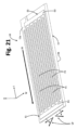
図30-31は、連続端部であるかわりにハウジング体2の結合端部が、特に蓋3の壁3bから軸方向に突き出る一連のタブまたは歯部3d’によって画定される実施形態を描く。図30-31は、また複数の柔軟なタブを画定するために複数の軸妨害物を有するハウジング体の壁の場合を描き、それぞれは結合端部のそれぞれの部分を画定する。
30-31 depict an embodiment in which, instead of being a continuous end, the joining end of the
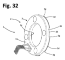
代わりに、図32-33は、ハウジング体4が据え込み、すなわち1つの本体部品の1またはそれ以上の部分を他の本体部品に曲げることによって互いに固定された、2つの部品3,4を備える、異なる実施形態を参照する。例において、蓋3の外壁3bは、壁3bがベース4の底部壁4aに対して後に曲がるタブ3hを画定する凹部3gを有する。好ましくは、また蓋3の内壁3cは、ベース4の壁4aに対して後に曲がる同様のタブ3iを有する。
Instead, Figures 32-33 show that the
図34及び35は、センサユニット8に向かって浮体7を押し付ける弾性手段が、ハウジング体2から区別できる要素によって構成される、変形の実施形態に対応する。この例において、その1つが図35の3f’で指定される、例えば板ばねまたは皿ばね座金などそれぞれの弾性要素を位置決めするためのハウジング体2の外側に面するエンボス加工3lが蓋3の壁3aに提供される。
Figures 34 and 35 correspond to a variant embodiment in which the elastic means pressing the
リング6aの内側周縁面にハウジング体2の固定の場合が前に例示されたが、これは、不可欠な特徴を構成しない。この目的のために、図36-37は、特に6eによって指定される対応する溝または環状台座内の、リング6aの外側周縁面と結合するための形状にされたハウジング体の場合を例示する。そのような場合において、蓋3の外壁6aは、前に例示された場合においてよりも高く、結合端部3dは、それに応じて変更される。6eで指定されたタイプの溝は、市場で入手できる様々なベアリングに提供される。
Although the case of fixing the
様々な実施形態において、本発明に従う検出装置のセンサ手段は、さらにベアリングの回転リングまたは回転リングと関連し、回転リングと共に回転する要素の角度動作を検出するために事前に取り決められたハウジング体上のセンサ要素を備える。このタイプの実施形態において、この理由で例えば速度または加速度など、ベアリングの回転に対応するパラメータも得ることができる。角度-位置トランスデューサに実質的に属する当該センサ要素は、センサユニットに取り付けられることが好ましい。 In various embodiments, the sensor means of the detection device according to the invention further comprises a sensor element on the housing body, which is prearranged for detecting the angular movement of the rotating ring of the bearing or of an element associated with the rotating ring and rotating together with it. In embodiments of this type, for this reason, parameters corresponding to the rotation of the bearing, such as for example speed or acceleration, can also be obtained. The sensor element, which essentially belongs to the angle-position transducer, is preferably attached to the sensor unit.
このタイプの実施形態は、図38-43に例示される。描かれる場合において、ベアリング6の回転リング6bと共に回転可能なまたは角度的に動作可能な31で指定される、少なくとも1つの励起要素の回転または角度動作を検出するために事前に取り決められる、30で指定される、少なくとも1つの回転または角度動作センサが、センサユニット8の本体8’に取り付けられる。
This type of embodiment is illustrated in Figures 38-43. In the case depicted, at 30 prearranged for detecting the rotational or angular movement of at least one excitation element, designated 31 rotatable or angularly movable together with the
示される例において、当該回転可能な要素31は、環状ディスクのような形状にされ、この理由でフォニックホイールなどを構成するが、これは不可欠な特徴を構成せず、要素31は、場合によっては回転センサ30を励起するように設計された1またはそれ以上の個別要素(例えば1またはそれ以上の小さい磁石)によって置換される。実際に、用いられるトランスデューサまたはエンコーダは、例えば、容量性または誘導性エンコーダ、または磁気エンコーダ、または光学エンコーダなど、目的に適合する任意のタイプであり、その場合において、回転センサ30は、それぞれ近接センサ、または磁気センサ(例えばホール効果または磁気抵抗センサ)、または光学センサである。
In the example shown, the
様々な優先的な実施形態において、センサ30は、例えばSMD(表面実装装置)タイプの部品など、例えば電気端子を備える本体を備える電子部品の形態の、例えばホール効果センサまたは磁気抵抗センサなどの磁気センサである。様々な実施形態において、センサ30は、特に回転または角度動作の方向も検出するように設計されたタイプのそれぞれの信号のための2つのそれぞれの端子または出力を備える、(例えば単一の部品またはパッケージに一体化された)2つの磁気検出要素を備える。センサユニット8の本体8’に設置及び/または半田付けされるように設計された磁気センサ30は、また少なくとも1つの圧電センサ10及び/または20を備える。
In various preferred embodiments, the
センサ30は、例えば図38,39及び42において8bで指定される好ましくは対応する貫通孔においてユニット8に取り付けられる。例えば図40-41に4dで指定された同様の貫通孔は、対応する位置に、ここでベース4の底部壁4aにハウジング体2に画定される。この方法で、回転センサ30の感知部分は、ハウジング体2の外側に特に、ベアリングの回転リング6bによって運ばれる励起要素31に直接面する(他方で、非金属材料で作られたベース4及び容量性または誘導性または磁気タイプのセンサ30の場合に開口4dは、不可欠でない)。
The
示される非限定の例において(例えばもう一度図40-41参照)、これらのトラックの第2の端部上のそれぞれの導電接続トラックT30の第1の端部において画定されるパッドP30に接続される、対応する端子C’を備える第2にコネクタCB’がセンサユニット8と関連し、代わりに回転センサ30の接続のためにパッドP30’が画定される(図42参照)。
In the non-limiting example shown (see again, for example, Figs. 40-41), a second connector CB' is associated with the
そのような場合において、様々な実施形態において、浮体7は、図40及び41の7bで指定される第2の通路を備え、第2の通路は、コネクタCB’が取り付けられるべき、及び浮体7とコネクタの間の機械的干渉を防ぐように大きさにされる場所に配置される。この場合においても、同様の通路3e’は、対応するフレーム9’が通路3eとコネクタCBに対応するフレーム9のために前に記載されたように取り付けられる蓋3に提供される。この場合においても、コネクタCB’に外部システムにセンサ30によって供給される信号を運ぶために対応する配線5a’を備える外部コネクタ5’が接続される。
In such cases, in various embodiments, the floating
いずれにせよ、(図示されない)他の実施形態に従って、2つのコネクタCB及びCB’の代わりに、センサユニット8は、例えば単一のコネクタCBなど単一のコネクタを備え、本体8’に提供される全ての導電トラック/パッド、または応力センサ手段10及び/または20に対応するトラック/パッド及び回転センサ30に対応するトラックが単一のコネクタに接続される。
In any case, according to other embodiments (not shown), instead of two connectors CB and CB', the
-述べられたように、用いられる回転センサ30のタイプに従って様々なタイプを有する-回転可能な励起要素31は、所定の位置にベアリングの回転リング6bまたは回転リングと共に回転する要素に固定され、要素31の回転は、センサ30によって検出される。例示された場合において、要素31は、例えば図43で観察されるように、ハウジング体の底部またはベース4の壁4aに面する位置で回転リング6bに取り付けられ、-本体8’の通路8b及びベース4の4dによって-センサ30の感知部分は、励起要素31に直接面する。
- as mentioned, of various types according to the type of
この場合においても、逆形態は、ベアリングの固定リングが内輪である場合において示されたものに対して可能である(その場合において、要素31は、外輪6aに固定され、装置1は、内輪6bに固定される)。
In this case too, the reverse configuration is possible to that shown in which the fixed ring of the bearing is the inner ring (in which case the
図43は、ベアリングのリング6bの外周側において提供される空洞または台座6b’において、励起要素31の組み立ての可能なモードを強調する。図43の例において、励起要素31は、実質的に半径方向に延在する。しかしながら、他の実施形態において、この要素は、また軸方向または実質的に回転軸と平行または一致する方向に延在する。
FIG. 43 highlights a possible mode of assembly of the
説明されるように、様々な優先的な実施形態において、本発明に従う検出装置のハウジング体は、いずれにせよベアリングに加えられる任意の可能な負荷がハウジング体にも伝達されるように、特にスナップアクション結合などによってベアリングの固定部に機械的に固定される。この固定は、装置とベアリングの偶然の分離を防ぐために必然的に頑丈で、信頼できなければならない。 As will be explained, in various preferred embodiments, the housing body of the detection device according to the invention is mechanically fixed to the fixed part of the bearing, in particular by a snap action connection or the like, so that any possible loads applied to the bearing in any case are also transferred to the housing body. This fixing must necessarily be robust and reliable to prevent accidental separation of the device and the bearing.
この理由のために、(例えば装置1の交換または修理のための)問題の2つの部品を分離することがいずれにせよ必要であったイベントにおいて、意図的に対応するベアリングから検出装置を分離するように構成された、抽出装置を提供することが便利である。そのような抽出装置の可能な実施形態は図44-46に概略的に描かれる。 For this reason, intentionally separating the sensing device from the corresponding bearing in the event that it was necessary in any case to separate the two parts in question (e.g. for replacement or repair of device 1) It is convenient to provide an extraction device configured to. Possible embodiments of such extraction devices are schematically depicted in Figures 44-46.
全体として40で指定される抽出装置は、複数の軸アーム42が特に実質的に円周に沿って分配される軸アームの中間点でヒンジが付けられた外縁領域を有する、好ましくは円形状の支持体41を備える。それぞれのアーム42を中間体41にヒンジで動かすために用いられるいくつかのピンが43で指定される。
The extraction device, designated generally at 40, has a plurality of
装置40は、さらに少なくとも1つの端部体を備える。様々な実施形態において、支持体41は、ここで簡単にするために「下部体」及び「上部体」とも定義される第1の端部体44及び第2の端部体46の間に軸方向に設置される。この理由のために、描かれた例を参照して、支持体41は、また簡単にするために「中間体」としても定義される。
下部体44は、厳密に不可欠でない。存在すると、下部体44は、ベアリング6の内輪に存在するための形状にされ、この目的のために、ベアリングの内輪のみに存在することができるような寸法の、おおよそフレア形状を有する先端44a及び/またはフランジ部44bを示す。例において、軸方向に延在し、中間体41と上部体46の両方に係合される少なくとも部分的なねじ式接続ロッド45が下部体44に対して中央に固定される。この目的のために、本体41及び46は、それぞれ雌ねじを備えるそれぞれの中心孔41a及び46aを有する。理解されるように、この方法で、本体41及び46は、接続ロッド45に沿って動かされる、すなわち単純にロッド45に対してそれらを回転することによって、下部体44(すなわちロッド45の下端部)に向かってまたは離れて動かされる。
The
優先的に上部体46は、ロッド45でその回転を促進するための形状にされた、例えば六角形プロファイルを有する少なくとも1つの本体部46bを有する。上部体46は、特に中間体41に面するその部分において、おおよそフレア型のまたは円錐台状の少なくとも外面部46cを有する。
Preferentially the
アーム42は、ロッド45に対して等距離の位置に中間体41にヒンジで動かされ、それぞれ装置1のハウジング体の外円周面と係合できるそれぞれの歯部を画定する、ここで「下部」とも呼ばれる、第1の端部42aを有する。代わりに42bで指定された、ここで「上部」とも呼ばれるアーム42の反対の端部は、上部体46の当該円錐台面46cと協働することができる。
The
使用の目的のために、上部体46は、装置1がアーム42を解放するまで、またはいずれにせよ、下端部42aの間に受け入れられる程度に、それらがそれらの下部に開くまで、ロッド45に沿ってねじを外される(この目的のために、例えば図44-46に観察されるように、上部体46の円錐台面46cの小さい直径の領域に対応する位置に上端部42bを持ってくることでさえ十分であり、この位置において上端部42bは、下端部42aよりロッド45に近い)。
For the purpose of use, the
次に、抽出装置40は、ベアリング6に中心に置かれる。この目的のために、下部体44が存在するならば、述べられたように、好ましくはベアリングの内輪の中心通路の直径より大きい直径を有する、検出装置1の中心通路の存在を利用して、ベアリング6の内輪に存在する。この位置決めは、アーム42の下端部42aが装置1と機械的に干渉することがないように広がるまたは開かれる事実によって可能にされる。このステップは、図44に概略的に示される。
The
その後中間体41は、その位置を調整する、すなわち、図45に例示されるように、実質的にベアリングの外輪の前に対応する位置に(すなわち装置1のハウジング体の外円周壁の対応するさらされた領域に)アームの下部42aによって定義される歯部を持ってくるために、ロッド45に沿ってねじ止めされるまたはねじを外される。
The
上記位置の抽出装置40によって、その後上部体46は、ロッド45にねじ止めされる、すなわち中間体41に(またはさらに一般的に、ロッド45の底端部に向かって)接近するようにそれに沿って動かされる。理解されるように、この方法で、上部体46は、実質的にくさびのように動作する、すなわちアーム41の上端部42bに対するその円錐台面の滑りは、当該上端部をロッド45からさらに離れて動かし、同時に、反対側において、アーム42の下端部42aをロッド45近くに動かし、対応する歯部は、装置1のハウジング体の外円周面と係合し、それをわずかにベアリング6の軸に向かって曲げ、そのためベアリングの外輪の対応する台座からハウジング体の結合端部を解放し(参照のために、ハウジング体2の結合端部が3dで指定されベアリングの外輪6a上の対応する台座が6dで指定される、図6及び7を参照)、その後装置1は、場合によっては、ベアリング6から相互に分離される。代わりのバージョンにおいて、傾斜面またはくさび形状を有するアーム42の下端部42aは、漸進的にベアリングと検出装置の間を貫通する一方で、上部体46は、回転し、相互の分離をもたらす。
With the
抽出装置40の例として示される実施形態は、記載された機能を損なうことなく、当業者に明白に出現する様々な変更を受けることが明確に出現する。例えば、ねじ式ロッド45は、上部体46に対して固定され、下部体44は、雌ねじを備える中心孔を有するまたは除外され、中間体41は、また固定されたまたは調節可能でない位置のロッド45に関連する。装置40は、またもし内円周壁がベアリングにハウジング体を固定するために用いられる結合端部を定義するならば、アーム42の下端部が装置1のハウジング体の内円周壁と係合するような方法で変更される(この理由で、この場合において、抽出装置は、当該円周壁の外側に曲げを引き起こし、この理由でベアリングから解放するように、互いから離れて動くようにアームの下端部を得るために考案されるであろう。
It clearly appears that the embodiment shown as an example of the
様々な実施形態において、本発明に従う検出装置のハウジング体は、例えばベアリングからそれを分離する目的のための、本体自体の握りを促進することを目的とする、1またはそれ以上の表面要素を定義し、好ましくは、1または複数の表面要素は、ハウジング体の少なくとも1つの円周壁において画定される。このタイプの例は、図47-50に示される。 In various embodiments, the housing body of the detection device according to the invention defines one or more surface elements intended to facilitate gripping of the body itself, for example for the purpose of separating it from the bearing. However, preferably one or more surface elements are defined in at least one circumferential wall of the housing body. An example of this type is shown in Figures 47-50.
図47-48は、例えば可能な実施形態において、どのようにハウジング体2がここで外壁であるその円周壁において、さらに特に蓋3の外壁3bにおいて環状レリーフまたは段差3n及び/または環状凹部3mを画定するような形状にされるかが強調される(そのような実施形態は、図43にも観察できる)。例において、段差3n及び凹部3mの両方は、示される方法で蓋3の製造の間、壁3bを変形することによって得られる。理解されるように、段差3n及び/または凹部3mの存在は、握りと特に(アーム42の歯形状端部42aが、段差3nの下で、凹部3mに係合する)図49のように、例えば抽出装置40を用いて例えば軸方向のけん引力または力など、ベアリング6に対して装置1のけん引力(引く作用)を働かせることが必要であるとき、その後ベアリング6から装置1を分離することを促進する。
47-48 show, for example, how in a possible embodiment the
図50は、代わりにここで外壁及びさらに特に蓋3の外壁3bである、ハウジング体2の周辺壁の円周に沿って分配される半径方向に外側を向いている表面エンボス加工3oの提供の場合を例示する。理解されるように、この場合も、エンボス加工3oは、握りと特にベアリング6に対して装置1のけん引力(引く作用)を働かせることが必要であるとき、その後ベアリング6から装置1を分離することを促進する。
FIG. 50 shows the provision of a radially outwardly facing surface embossing 3o distributed along the circumference of the peripheral wall of the
説明されたものから、本発明に従う検出装置の実施と動作が単純で信頼できることが理解されるであろう。 From what has been described, it will be appreciated that the implementation and operation of a detection device according to the present invention is simple and reliable.
観察されるように、最小の変位の存在にもかかわらず、比較的高い電位差または電圧の信号を得ることができる、複数の圧電トランスデューサが優先的にセンサユニットに提供される。トランスデューサは、検出要求に応じて適切に分配され、例えば特に検出面に平行な2つの方向の応力、相互に直交するせん断応力を検出するように設計された2つのトランスデューサ及び場合によっては特に検出面に直交する方向の力を検出するための圧電圧力トランスデューサを備える。原理において、20で指定されるタイプの垂直応力トランスデューサと10で指定されるタイプの少なくとも2つのせん断応力トランスデューサ(例えば、互いに同じであるが、互いに対して90°で配向される2つのトランスデューサ10)によって、ベアリングが受ける応力の3次元マッピングを再構成することができる。浮体の存在によって、提案された圧電トランスデューサは、非常に限られた応力、すなわちナノメートルオーダの浮体の移動の検出ができる。
As observed, the sensor unit is preferentially provided with a plurality of piezoelectric transducers, which are able to obtain signals of relatively high potential differences or voltages despite the presence of minimal displacements. The transducers can be suitably distributed depending on the sensing requirements, e.g. two transducers specifically designed to detect stresses in two directions parallel to the sensing surface, shear stresses perpendicular to each other and possibly especially the sensing surface. A piezo-voltage force transducer is provided to detect force in a direction perpendicular to the . In principle, a normal stress transducer of the type designated 20 and at least two shear stress transducers of the type designated 10 (e.g. two
実際に、好ましい解決方法の実質的な利点は、提案された検出システムが特に転がりベアリングなど、ベアリングの応力の検出ができ、応力の方向性も区別する事実によって示される。この関連で、転がりベアリングの従来の診断は、またベアリングのハウジングの一般的な振動を検出することによってなされるが、正確にその空間的方向性を識別することができないことに留意すべきである。振動の全体のレベルが特に非周期的な故障を検出するために、ベアリングの劣化を評価するために用いられても、初期段階において、故障または不適切な使用を識別するのに十分でなかった。内輪で、外輪で、転がり本体で、またはベアリングのケージで生じる周期的故障は、特定周期で振動の成分を作り出す。この周期は、ベアリングの形状及び回転の速度の関数であり、周波数領域の振動の分析によって識別される。本発明に従う提案された優先的な解決法は、例えば不適切な方法で加えられた負荷を識別する空間的方向性をこのタイプの分析に加えることができる。 Indeed, a substantial advantage of the preferred solution is demonstrated by the fact that the proposed detection system is capable of detecting stresses in bearings, especially rolling bearings, and also distinguishes the directionality of the stresses. In this connection, it should be noted that the conventional diagnosis of rolling bearings is also done by detecting the general vibration of the bearing housing, but cannot accurately identify its spatial orientation. . Even though the overall level of vibration was used to assess bearing deterioration, especially to detect non-periodic failures, it was not sufficient to identify failure or improper use at an early stage. . Cyclic failures that occur in the inner race, the outer race, the rolling body, or the cage of the bearing create a component of vibration at a specific period. This period is a function of the bearing geometry and the speed of rotation, and is identified by frequency domain vibration analysis. The proposed preferential solution according to the invention can add a spatial orientation to this type of analysis, for example to identify loads that have been applied in an inappropriate manner.
リアルタイムで作られた複数の次元のスペクトル分析は、本発明に従うセンサ付きベアリング支持装置によって、例えば自動車で(安定制御システム、ブレーキシステムなど)または他の状況で(電気モータドライブ、産業機器、電気家電など)、ベアリングに関する機械システムの運動状態の利用可能な情報を有するために、特に役立つことを証明する。 Multi-dimensional spectral analysis produced in real time can be achieved by the sensored bearing support device according to the invention, for example in automobiles (stability control systems, braking systems, etc.) or in other situations (electric motor drives, industrial equipment, electrical household appliances). etc.), proves particularly useful for having available information of the state of motion of mechanical systems with respect to bearings.
優先的な実施形態に従う、説明された検出装置の他の利点は、少なくとも1つのせん断応力トランスデューサが、電気接続の第1の形態の材料の分極の目的のための製造の間、及びその後の電気接続の第2の形態の検出の目的のための最終の使用の間の両方で利用される、電極の所定の構造を備えて、最初からまさに事前に取り決められる。この方法で第1の製造ステップで分極電極を提供し、その後の製造ステップで検出電極を提供しなければならない問題はもはやなく、すなわち、電極の複雑な組み立て動作と置換に頼る必要はなく、代わりに従来技術の典型例である。(例えばMarcelo Areias Trindadeら、「厚させん断圧電マクロ繊維複合材料の有効材料特性の評価」、COBEM 2011、第21回国際機械工学会議の議事録、2011年10月24~28日、ブラジル、ナタール、RN)。この理由で、本発明は、装置の及び/または製造プロセスの簡略化を提供する。 Another advantage of the described detection device according to a preferred embodiment is that the at least one shear stress transducer is used during manufacture for the purpose of polarization of the material of the first form of electrical connection and for subsequent electrical connection. The second form of connection is pre-arranged right from the beginning, with a predetermined structure of the electrodes utilized both during the final use for the purpose of detection. In this way there is no longer the problem of having to provide polarizing electrodes in a first manufacturing step and sensing electrodes in a subsequent manufacturing step, i.e. there is no need to resort to complex assembly operations and substitutions of electrodes, and alternative This is a typical example of the prior art. (e.g. Marcelo Areias Trindade et al., “Evaluation of effective material properties of thick shear piezoelectric macrofiber composites”, COBEM 2011, Proceedings of the 21st International Conference on Mechanical Engineering, October 24-28, 2011, Natal, Brazil) , RN). For this reason, the invention provides a simplification of the device and/or manufacturing process.
好ましくはスクリーン印刷技術によって、材料の層の連続堆積に基づいて、少なくとも1つのせん断応力トランスデューサの製造の好ましいプロセスにより、対応するセンサ手段の微細化によって、非常にコンパクトなセンサユニットを非常に簡単な方法で、低コストで得ることができる。センサ手段が、装置のハウジング体から区別できる部品として構成される意図的に提供された基板上に形成される、またはいずれにせよ関連する事実は、センサ手段の製造を容易にし、ハウジング体が、ベアリングへの設置の間、必然的に十分な機械応力を受ける必要があるとき、その損傷につながるリスクを減らす。 The preferred process of manufacturing the at least one shear stress transducer, based on the successive deposition of layers of material, preferably by screen printing techniques, allows a very compact sensor unit to be produced in a very simple manner, by miniaturization of the corresponding sensor means. method can be obtained at low cost. The fact that the sensor means are formed on a deliberately provided substrate, or in any case connected, configured as a part distinguishable from the housing body of the device, facilitates the manufacture of the sensor means, so that the housing body During installation on the bearing, it necessarily has to be subjected to sufficient mechanical stress, reducing the risk of its damage.
多数の変更が、続く特許請求の範囲によって定義される発明の範囲から逸脱せずに、例として記載された装置に当業者によってなされることが明確である。同様に、前に説明された実施形態を参照して開示された個々の特性は、他の実施形態において互いに組み合わされることが明確である。 It is clear that numerous modifications can be made to the device described by way of example by those skilled in the art without departing from the scope of the invention as defined by the following claims. It is likewise clear that the individual features disclosed with reference to the previously described embodiments can be combined with one another in other embodiments.
言及されたように、指部Fの実質的な直線形状は、好ましいにもかかわらず、不可欠な特徴を構成しない。指部は、実際に、曲がった及び/または例えばS字形状またはジグザク形状電極などの縦方向Lに対して角度を付けられた伸長部によって区別される展開を有する。 As mentioned, the substantially rectilinear shape of the fingers F, although preferred, does not constitute an essential feature. The fingers actually have a development distinguished by curved and/or angled extensions with respect to the longitudinal direction L, such as, for example, S-shaped or zigzag-shaped electrodes.
例えば距離D1及び/またはD2及び/またはD3など、前に提供された例で言及された距離は、優先的であるが非限定的であると理解されるべきであり、すなわち、電極の指部の間の距離及び/または上記要素の対応する配置または交互の配置は、例の例として示されているものと異なってもよい。提供される非限定の例において、分極及びせん断応力検出は、1つの同じ方向(ここで縦方向L)に延在する指部Fを参照して説明された。しかしながら、電極Eの他の部分も、特に指部の伸長部の方向の少なくとも1つの成分を有するせん断応力の場合に(図23の場合のように)、例えば指部Fに接合する電極の部分Dなど、検出に貢献してもよい。さらに一般的に、様々な実施形態において、電極Eは、第1の方向(ここで長さ方向L)に延在する第1の部分Fと当該第1の部分Fを横切る方向(ここで幅方向W)に延在する第2の部分Dの両方を予測し、当該電極Eの部分D及びFは、分極及び/または測定に参加できる。 The distances mentioned in the examples provided above, such as distances D1 and/or D2 and/or D3 , should be understood as preferential but non-limiting, i.e. the distance between the fingers of the electrode and/or the corresponding arrangement or alternation of said elements may differ from that shown as an example of the examples. In the non-limiting examples provided, the polarization and shear stress detection has been described with reference to a finger F extending in one and the same direction (here the longitudinal direction L). However, other parts of the electrode E may also contribute to the detection, such as for example the part D of the electrode joining the finger F, in particular in the case of shear stresses having at least one component in the direction of the extension of the finger (as in the case of FIG. 23). More generally, in various embodiments, the electrode E foresees both a first part F extending in a first direction (here the length direction L) and a second part D extending in a direction transverse to said first part F (here the width direction W), said parts D and F of said electrode E being able to participate in the polarization and/or measurement.
電極は、圧電材料11の層の縦方向(L)及び幅方向(W)の少なくとも1つの代わりに、上記2つの方向に対して角度を付けられたまたは斜めの方向に延在するような形状にされることができる。
The electrodes can be shaped to extend in at least one of the longitudinal (L) and width (W) directions of the layer of
本発明に従う検出装置の様々な好ましい実施形態において、提供される少なくとも1つの圧電センサによって発生された信号は、外部システム(例えば制御ユニット)によって検出されるように、対応する電気コネクタに直接供給され、そのため装置に電気を供給する必要がなくなる。しかしながら、さらに可能な実施形態において(例えば、角度位置トランスデューサがさらに提供される実施形態)、センサユニット8は、例えば信号の増幅及び/または処理及び/または伝達のために、回路配置(例えば本体8’自体に)を含む。この場合において、当該回路配置は、優先的に増幅及び/または処理及び/または伝達部品のための対応する電源段を備え、いずれにせよセンサ付きベースに提供される少なくとも1つの圧電センサは、いかなる場合でも電源を要求しないことが理解されたままである。
In various preferred embodiments of the detection device according to the invention, the signal generated by the at least one piezoelectric sensor provided is directly fed to a corresponding electrical connector for detection by an external system (e.g. a control unit). , so there is no need to supply electricity to the device. However, in further possible embodiments (e.g. embodiments in which an angular position transducer is further provided), the
以下に記載される特徴は、前に記載された少なくとも4つの電極を備える圧電トランスデューサの好ましい実施形態と見なす。 The features described below are considered preferred embodiments of the piezoelectric transducer with at least four electrodes as described above.
1.第1及び第3の電極(E1,E3)の部分または指部(F1,F3)が互いから実質的に第1の距離(D1)を置いて少なくとも縦方向(L)に延在し、それぞれ第1の電極(E1)の部分または指部(F1)、第3の電極(E3)の部分または指部(F3)は、実質的に第1の距離(D1)の2倍以上、好ましくは実質的に第1の距離(D1)の2倍離れた距離(D2)を置き、
第2及び第4の電極(E2,E4)の部分または指部(F2,F4)は、互いから実質的に第1の距離(D1)を置いて少なくとも縦方向(L)に延在し、それぞれ、第2の電極(E2)の部分または指部(F2)、第4の電極(E4)の部分または指部(F4)は、実質的に第1の距離(D1)の2倍以上、好ましくは実質的に第1の距離(D1)の2倍離れた距離(D2)を置き、及び好ましくは、
第1の電極(E1)のそれぞれの部分または指部(F1)は、第3の電極(E2)のそれぞれ当該部分または指部(F2)と実質的に重ねられるまたは揃えられる位置にあり、第3の電極(E3)のそれぞれの部分または指部(F3)は、第4の電極(E4)のそれぞれの当該部分または指部(F4)と実質的に重ねられるまたは揃えられる位置にある、圧電トランスデューサ。
1. portions or fingers (F1, F3) of the first and third electrodes (E1, E3) extend at least in the longitudinal direction (L) at a substantially first distance (D 1 ) from each other; The portion or finger portion (F1) of the first electrode (E1), the portion or finger portion (F3) of the third electrode (E3), respectively, is substantially twice or more the first distance (D 1 ), preferably at a distance (D 2 ) substantially twice the first distance (D 1 );
The portions or fingers (F2, F4) of the second and fourth electrodes (E2, E4) extend at least in the longitudinal direction (L) at a substantially first distance (D 1 ) from each other. , respectively, the portion or finger (F2) of the second electrode (E2) and the portion or finger (F4) of the fourth electrode (E4) are substantially twice the first distance (D 1 ). The distance (D 2 ) is preferably substantially twice the first distance (D 1 ), and preferably,
The respective portion or finger (F1) of the first electrode (E1) is positioned substantially overlapping or aligned with the respective portion or finger (F2) of the third electrode (E2); The respective portions or fingers (F3) of the third electrode (E3) are piezoelectric in a position substantially overlapping or aligned with the respective portions or fingers (F4) of the fourth electrode (E4). transducer.
2.第1及び第3の電極(E1,E3)またはそれぞれの部分または指部(F1,F3)が電気的に一緒に接続され(+)、第2及び第4の電極(E2,E4)またはそれぞれの部分または指部(F2,F4)が電気的に一緒に接続され(-)、第1及び第3の電極(E1,E3)から電気的に絶縁され、少なくとも縦方向(L)に延在に圧電材料の層(11)に誘導されたせん断応力(SS)が一側面の第1及び第3の電極(E1,E3)と、他の側面の第2及び第4の電極(E2,E4)の間に当該せん断応力(SS)に比例する値を有する電位差を発生する、1に記載の圧電トランスデューサ。
2. The first and third electrodes (E1, E3) or respective portions or fingers (F1, F3) are electrically connected together (+) and the second and fourth electrodes (E2, E4) or each parts or fingers (F2, F4) are electrically connected together (-) and electrically insulated from the first and third electrodes (E1, E3) and extend at least in the longitudinal direction (L). The shear stress (SS) induced in the layer of piezoelectric material (11) is applied to the first and third electrodes (E1, E3) on one side and the second and fourth electrodes (E2, E4) on the other side. 2. The piezoelectric transducer according to
3.第1及び第3の電極(E1,E3)の部分または指部(F1,F3)が互いから実質的に第1の距離(D1,D3)を置いて縦方向(L)に延在し、第1の電極(E1)の部分または指部(F1)は、第1の距離(D1,D3)の2倍より大きい第2の距離(D2)を置き、第3の電極(E3)の部分または指部(F3)は、実質的に第2の距離(D2)を置き、
第2及び第4の電極(F2,F4)の部分または指部(F2,F4)は、互いから実質的に第1の距離(D1,D3)を置いて縦方向(L)に延在し、それぞれ第2の電極(E2)の部分または指部(F2)、第4の電極(E4)の部分または指部(F4)は、実質的に第2の距離(D2)を置く、圧電トランスデューサ。
3. Portions or fingers (F1, F3) of the first and third electrodes (E1, E3) extend in the longitudinal direction (L) at a substantially first distance (D 1 , D 3 ) from each other. However, the portion or finger portion (F1) of the first electrode (E1) is placed at a second distance (D 2 ) larger than twice the first distance (D 1 , D 3 ), and (E3) or finger (F3) is substantially spaced a second distance (D 2 );
The portions or fingers (F2, F4) of the second and fourth electrodes (F2, F4) extend in the longitudinal direction (L) at a substantially first distance (D 1 , D 3 ) from each other. and the portions or fingers (F2) of the second electrode (E2) and the portions or fingers (F4) of the fourth electrode (E4) are substantially spaced apart by a second distance (D 2 ), respectively. , piezoelectric transducer.
4.-第1の電極(E1)のそれぞれの当該部分または指部(F1)が、第2の電極(E2)のそれぞれ当該部分または指部(F2)と実質的に重ねられるまたは揃えられる位置にあり、第3の電極(E3)のそれぞれの当該部分または指部(F3)は、第4の電極(E4)のそれぞれ当該部分または指部(F4)と実質的に重ねられるまたは揃えられる位置にある、または
-第1及び第3の電極(E1,E3)の1つのそれぞれ当該部分または指部(F1)は、第2及び第4の電極(E2,E4)の1つのそれぞれ当該部分または指部(F2)と実質的に重ねられるまたは揃えられる位置にあり、第1及び第3の電極(E1,E3)の他の1つのそれぞれ当該部分または指部(F3)は、第2及び第4の電極(E2,E4)の他の1つのそれぞれ当該部分または指部(F4)に対して実質的に交互に配置された位置にある、3に記載の圧電トランスデューサ。
4. A piezoelectric transducer according to
5.-第1の電極(E1)のそれぞれ当該部分または指部(F1)は、第2の電極(E2)のそれぞれ当該部分または指部(F2)と実質的に重ねられるまたは揃えられる位置にあり、第3の電極(E3)のそれぞれ当該部分または指部(F3)は、第4の電極(E4)のそれぞれ当該部分または指部(F4)と実質的に重ねられるまたは揃えられる位置にあり、第1及び第3の電極(E1,E3)またはそれぞれ当該部分または指部(F1,F3)は、電気的に一緒に接続され(+)、第2及び第4の電極(E2,E4)またはそれぞれ当該部分または指部(F2,F4)は、電気的に一緒に接続され(-)、第1及び第3の電極(E1,E3)と電気的に絶縁され、縦方向(L)を横切る方向(W)に圧電材料の層(11)に誘導されたせん断応力(SS)は、一側面の第1及び第3の電極(E1,E3)と、他の側面の第2及び第4の電極(E2,E4)の間に、当該せん断応力(SS)に比例する値を有する電位差を発生する、または
-第1及び第3の電極(E1,E3)の1つのそれぞれ当該部分または指部(F1)は、第2及び第4の電極(E2,E4)の1つのそれぞれ当該部分または指部(F2)と実質的に重ねられるまたは揃えられる位置にあり、第1及び第3の電極(E1,E3)の他の1つのそれぞれ当該部分または指部(F3)は、第2及び第4の電極(E2,E4)の他の1つのそれぞれ当該部分または指部(F4)に対して実質的に交互に配置された位置にあり、第1及び第3の電極(E1,E3)またはそれぞれ当該部分または指部(F1,F3)は、互いに電気的に絶縁であり、第3及び第4の電極(E3,E4)またはそれぞれ当該部分または指部(F3,F4)は、互いに及び第1及び第3の電極(E1,E3)に対して電気的に絶縁であり、縦方向(L)を横切る方向(W)に圧電材料の層(11)に誘導されたせん断応力(SS)は、一側面の第1及び第3の電極(E1,E3)の1つと、他側面の第2及び第4の電極(E2,E4)の1つの間に当該せん断応力(SS)に比例する値を有する電位差を発生し、第1及び第3の電極(E1,E3)の1つ及び第2及び第4の電極(E2,E4)の1つは、好ましくは当該部分または指部が実質的に互いに重なり合っているまたは互いに揃えられる位置にある電極である、4に記載の圧電トランスデューサ。
5. - the respective portion or finger (F1) of the first electrode (E1) is in a position substantially overlapping or aligned with the respective portion or finger (F2) of the second electrode (E2), and the respective portion or finger (F3) of the third electrode (E3) is in a position substantially overlapping or aligned with the respective portion or finger (F4) of the fourth electrode (E4), and the first and third electrodes (E1, E3) or the respective portions or fingers (F1, F3) are electrically connected together. and the second and fourth electrodes (E2, E4) or respective portions or fingers (F2, F4) are electrically connected together (-) and electrically insulated from the first and third electrodes (E1, E3), and a shear stress (SS) induced in the layer (11) of piezoelectric material in a direction (W) transverse to the longitudinal direction (L) generates a potential difference between the first and third electrodes (E1, E3) on one side and the second and fourth electrodes (E2, E4) on the other side, the potential difference having a value proportional to the shear stress (SS); or a respective portion or finger (F1) of one of the first and third electrodes (E1, E3) is in a position substantially overlapping or aligned with a respective portion or finger (F2) of one of the second and fourth electrodes (E2, E4), and a respective portion or finger (F3) of the other one of the first and third electrodes (E1, E3) is in a position substantially alternating with a respective portion or finger (F4) of the other one of the second and fourth electrodes (E2, E4), the first and third electrodes (E1, E3) or respective portions or fingers (F1, F3) being electrically insulated from one another, and the third and fourth electrodes (E3, E4) or respective portions (E3, E4) being in a position substantially alternating with a respective portion or finger (F4) of the other one of the second and fourth electrodes (E2, E4), 5. A piezoelectric transducer as described in
6.i)圧電材料の層(11)の第1の主面(11a)の少なくとも一部に第1の電極(E1)及び少なくとも1つの第3の電極(E3,E5)、またはそれぞれ当該部分または指部を備え、圧電材料の第1の層(11)の第2の主面(11b)の少なくとも一部に第2の電極(E2)及び少なくとも1つの第4の電極(E4,E6)またはそれぞれ当該部分または指部を備える圧電トランスデューサ(10)を形成するステップと、
ii)一側面の第1の電極(E1)と少なくとも1つの第3の電極(E3,E5)の少なくとも1つ、またはそれぞれの当該部分または指部、他の側面の第2の電極(E2)と少なくとも1つの第4の電極(E4,E6)の少なくとも1つ、またはそれぞれ当該部分または指部の間に電位差を加えることによって圧電材料の層(11)の分極を得るステップと、を備え、
ステップii)は、圧電トランスデューサ(10)がその後せん断の力を検出するために用いられる電極またはそれぞれ当該部分または指部の電気接続の第2の形態と異なる、電極またはそれぞれ当該部分または指部の電気接続の第1の形態で実行される、圧電トランスデューサを製造する方法。
6. i) on at least a part of the first main surface (11a) of the layer (11) of piezoelectric material, a first electrode (E1) and at least one third electrode (E3, E5), or each part or finger; a second electrode (E2) and at least one fourth electrode (E4, E6), or each forming a piezoelectric transducer (10) comprising the portion or finger;
ii) at least one of the first electrode (E1) and at least one third electrode (E3, E5) on one side, or the relevant part or finger of each, the second electrode (E2) on the other side; and obtaining a polarization of the layer of piezoelectric material (11) by applying a potential difference between at least one of the at least one fourth electrode (E4, E6) or the respective portion or finger;
Step ii) is characterized in that the piezoelectric transducer (10) is different from the second form of electrical connection of the electrode or respectively of the part or finger, with which the piezoelectric transducer (10) is then used to detect the shear force. A method of manufacturing a piezoelectric transducer, carried out with a first form of electrical connection.
Claims (15)
-前記ハウジング体(2)に設けられた検出装置であって、少なくとも1つの圧電トランスデューサ(10;20)を含むセンサ手段(10;20;30)を備える、検出配置と、を備え、
前記検出配置は、
-前記ハウジング体(2)に取り付けられ、前記ベアリング(6)の振動を機械的に伝達することに適した少なくとも1つの浮体(7)と、
-前記ハウジング体(2)の固定位置に取り付けられる少なくとも1つのセンサユニット(8)であって、前記少なくとも1つの浮体(7)の対応する表面を、直接または少なくとも1つの別の要素の介して受け入れるように構成された少なくとも1つの検出面(8a)を有する、少なくとも1つのセンサユニット(8)と、を備え、
前記少なくとも1つの圧電トランスデューサ(10;20)は、前記少なくとも1つの検出面(8a)の少なくとも一部を画定し、前記少なくとも1つの圧電トランスデューサ(10;20)の前記少なくとも1つの浮体(7)によって加えられる力の大きさに比例する電位差を発生するように構成される、ベアリング検出装置。 - a housing body (2) configured to be fixed to the fixing ring (6a) of the bearing (6);
- a detection device provided in said housing body (2), comprising a detection arrangement comprising sensor means (10; 20; 30) comprising at least one piezoelectric transducer (10; 20);
The detection arrangement is
- at least one floating body (7) attached to the housing body (2) and suitable for mechanically transmitting vibrations of the bearing (6);
- at least one sensor unit (8) mounted in a fixed position on said housing body (2) , which controls the corresponding surface of said at least one floating body (7), either directly or via at least one further element; at least one sensor unit (8) having at least one sensing surface (8a) configured to receive a
Said at least one piezoelectric transducer (10; 20) defines at least a part of said at least one detection surface (8a) and said at least one floating body (7) of said at least one piezoelectric transducer (10; 20) ) a bearing sensing device configured to generate a potential difference proportional to the magnitude of the force applied by the bearing sensing device.
縦方向(L)と横方向(W)に延在する圧電材料の層(11;21)と、
第1の電極(E1;E21)及び第2の電極(E2;E22)を備え、
前記第1の電極(E1;E21)と前記第2の電極(E2;E22)との間に前記圧電材料の層(11;21)が少なくとも部部的に延在する、請求項1または2に記載のベアリング検出装置。 The at least one piezoelectric transducer (10; 20 )
a layer (11; 21) of piezoelectric material extending in the longitudinal direction (L) and the transverse direction (W) ;
comprising a first electrode (E1; E21) and a second electrode (E2; E22) ,
Claim 1 or 2, wherein the layer (11; 21) of piezoelectric material extends at least partially between the first electrode (E1; E21) and the second electrode (E2; E22). Bearing detection device described in .
前記第1の圧電トランスデューサ(10)と前記少なくとも1つの第2の圧電トランスデューサ(20)は、前記第1の圧電トランスデューサ(10)が第1の方向のせん断応力を検出するように設計され、前記少なくとも1つの第2の圧電トランスデューサ(10)は、第2の方向のせん断応力を検出するように構成され、
前記第1の方向と前記第2の方向は、一方が他方を横断する、または、一方が他方に対して傾いている、請求項1乃至3のいずれか1項に記載のベアリング検出装置。 The at least one piezoelectric transducer (10; 20) is configured to generate a first potential difference indicative of a first shear stress (SS) applied to the at least one floating body (7). a piezoelectric transducer (10) and at least one second piezoelectric transducer (20) configured to generate a second potential difference indicative of a second shear stress (SS) applied to said at least one floating body ( 7 ); ) ,
The first piezoelectric transducer (10) and the at least one second piezoelectric transducer ( 20 ) are designed such that the first piezoelectric transducer (10) detects shear stress in a first direction; at least one second piezoelectric transducer (10) configured to detect shear stress in a second direction;
The bearing detection device according to any one of claims 1 to 3, wherein the first direction and the second direction cross each other or are inclined relative to the other .
前記少なくとも1つの圧電トランスデューサ(10)は、少なくとも1つの第3の電極(E3)と少なくとも1つの第4の電極(E4)とを有し、
前記少なくとも1つの第3の電極(E3)と前記少なくとも1つの第4の電極(E4)はそれぞれが、前記圧電材料の層(11)の前記第1の主面(11a)と前記第2の主面(11b)に延在する、請求項3に記載のベアリング検出装置。 Each of the first electrode (E1) and the second electrode (E2) of the at least one piezoelectric transducer (10) is connected to the first main surface (11a) and the second electrode of the layer (11) of piezoelectric material. has a plurality of parts or fingers (F1, F2) extending on the main surfaces (11a, 11b) of 2;
said at least one piezoelectric transducer (10) has at least one third electrode (E3) and at least one fourth electrode (E4);
The at least one third electrode (E3) and the at least one fourth electrode (E4) are arranged on the first main surface (11a) and the second main surface of the layer (11) of piezoelectric material, respectively. Bearing detection device according to claim 3 , which extends on the main surface (11b).
-前記第3の電極(E3)は、前記第1の電極(E1)の部分または指部(F1)と互いにかみ合うまたは互い違いにある形態であるそれぞれの部分または指部(F3)を有し、
前記第4の電極(E4)は、前記第2の電極(E2)の部分または指部(F2)とかみ合うまたは互い違いにある形態であるそれぞれの部分または指部(F4)を有する、請求項6に記載のベアリング検出装置。 - said at least one piezoelectric transducer (10) comprises said first electrode (E1), said second electrode (E2), said third electrode (E3), said fourth electrode (E4),
- said third electrode (E3) has a respective part or finger (F3) in an interlocking or staggered configuration with a part or finger (F1) of said first electrode (E1);
4. Said fourth electrode (E4) has a respective part or finger (F4) that is configured to interlock or stagger with a part or finger (F2) of said second electrode (E2). 6. The bearing detection device according to 6.
-実質的に環状である、少なくとも1つの第1の本体部品(3)と少なくとも1つの第2の本体部品(4)を備える、及び/又は
前記ベアリング(6)の固定リング(6a)と結合するように構成された、円周の少なくとも一部に沿って延在する結合構造を有する、請求項3に記載のベアリング検出装置。 The housing body (2) is
- comprises at least one first body part (3) and at least one second body part (4) that are substantially annular; and/or
4. A bearing detection device according to claim 3 , comprising a coupling structure extending along at least a portion of a circumference, adapted to couple with a fixing ring (6a) of the bearing (6).
前記固定リング(6a)に請求項1乃至12のいずれか1項に記載のベアリング検出装置が固定される、センサ付きベアリング。 comprising a fixed ring (6a), a rotating ring (6b), and a rolling element (6c) between the fixed ring (6a) and the rotating ring (6b),
A bearing with a sensor, wherein the bearing detection device according to any one of claims 1 to 12 is fixed to the fixing ring (6a).
i)請求項1乃至12のいずれか1項に記載のベアリング検出装置(1)を提供するステップと、 i) providing a bearing detection device (1) according to any one of claims 1 to 12;
ii)前記ベアリング(6)の固定リング(6a)に対して前記検出装置(1)を固定するステップと、 ii) fixing the detection device (1) to a fixing ring (6a) of the bearing (6);
iii)少なくとも1つの圧電トランスデューサ(10;20)によって、前記少なくとも1つの浮体(7)に加えられたせん断応力(SS)と垂直応力の少なくとも1つに比例する電位差を生成するステップと、を備える方法。 iii) generating, by at least one piezoelectric transducer (10; 20), a potential difference proportional to at least one of a shear stress (SS) and a normal stress applied to said at least one floating body (7); Method.
少なくとも1つの浮体(7)とセンサ手段(10;20;30)を備える、前記ハウジング体(2)に関連付けられる検出配置と、を備え、a detection arrangement associated with said housing body (2) comprising at least one floating body (7) and sensor means (10; 20; 30),
前記少なくとも1つの浮体(7)は、前記ハウジング体(2)内に取り付けられ、前記ベアリング(6)によって発生する機械的振動を伝達することができ、said at least one floating body (7) is mounted in said housing body (2) and is capable of transmitting mechanical vibrations generated by said bearings (6);
前記センサ手段(10;20;30)は、 The sensor means (10; 20; 30)
-少なくとも1つの検出面が前記少なくとも1つの浮体(7)によって圧力を加えられるとき電位差を発生することができる圧電トランスデューサ(10;20)と、 - a piezoelectric transducer (10; 20) capable of generating a potential difference when at least one sensing surface is pressurized by said at least one floating body (7);
-前記ベアリング(6)の回転リング(6b)または前記ベアリング(6)の前記回転リング(6b)と共に動くことができる要素(31)の動作または位置を検出するように構成された、角移動または回転移動(30)を感知するためのセンサ要素、の一方又は両方を含む、ベアリング検出装置。a bearing detection device comprising one or both of a sensor element for sensing angular or rotational movements (30) configured to detect the movement or position of the rotating ring (6b) of said bearing (6) or of an element (31) capable of moving together with said rotating ring (6b) of said bearing (6).
Applications Claiming Priority (3)
| Application Number | Priority Date | Filing Date | Title |
|---|---|---|---|
| IT102018000010522 | 2018-11-22 | ||
| IT102018000010522A IT201800010522A1 (en) | 2018-11-22 | 2018-11-22 | Bearing detection device |
| PCT/IB2019/060071 WO2020105008A1 (en) | 2018-11-22 | 2019-11-22 | Detection device for bearings |
Publications (3)
| Publication Number | Publication Date |
|---|---|
| JP2022507901A JP2022507901A (en) | 2022-01-18 |
| JPWO2020105008A5 JPWO2020105008A5 (en) | 2022-11-18 |
| JP7457706B2 true JP7457706B2 (en) | 2024-03-28 |
Family
ID=65576482
Family Applications (1)
| Application Number | Title | Priority Date | Filing Date |
|---|---|---|---|
| JP2021528928A Active JP7457706B2 (en) | 2018-11-22 | 2019-11-22 | Detection device for bearings |
Country Status (6)
| Country | Link |
|---|---|
| US (1) | US20220018392A1 (en) |
| EP (1) | EP3884177B1 (en) |
| JP (1) | JP7457706B2 (en) |
| CN (1) | CN113396292B (en) |
| IT (1) | IT201800010522A1 (en) |
| WO (1) | WO2020105008A1 (en) |
Families Citing this family (5)
| Publication number | Priority date | Publication date | Assignee | Title |
|---|---|---|---|---|
| CN112229634B (en) * | 2020-11-14 | 2021-10-29 | 罗斯(无锡)设备有限公司 | Stirring equipment bearing state online monitoring method |
| CN113898667A (en) * | 2021-10-27 | 2022-01-07 | 北京石墨烯技术研究院有限公司 | Bearing structure |
| CN114678732B (en) * | 2022-03-10 | 2023-12-01 | 贵州乌江水电开发有限责任公司 | Intelligent elastic metal plastic thrust tile on-line monitoring system |
| WO2024036412A1 (en) * | 2022-08-19 | 2024-02-22 | University Of Manitoba | Transducer for use with a rotary bearing |
| CN115343047A (en) * | 2022-09-14 | 2022-11-15 | 苏州铁近机电科技股份有限公司 | Bearing sound detection device |
Citations (5)
| Publication number | Priority date | Publication date | Assignee | Title |
|---|---|---|---|---|
| JP2001074767A (en) | 1999-09-03 | 2001-03-23 | Matsushita Electric Ind Co Ltd | Accelerometer and its manufacture |
| JP2004169756A (en) | 2002-11-18 | 2004-06-17 | Nsk Ltd | Bearing device with sensor |
| JP2007333169A (en) | 2006-06-19 | 2007-12-27 | Nsk Ltd | Bearing device with sensor |
| US20090266169A1 (en) | 2006-11-07 | 2009-10-29 | Universite De Reims Champagne Ardenne | Device and method for monitoring the vibratory condition of a rotating machine |
| JP2011191091A (en) | 2010-03-12 | 2011-09-29 | Seiko Epson Corp | Tuning-fork type vibrator element, vibrator, and sensor device |
Family Cites Families (22)
| Publication number | Priority date | Publication date | Assignee | Title |
|---|---|---|---|---|
| DE3908175C2 (en) * | 1988-03-14 | 1994-04-14 | Elco Co | Stress detector device |
| JP2794683B2 (en) * | 1991-04-16 | 1998-09-10 | 日産自動車株式会社 | Gear support bearing structure |
| DE19522543A1 (en) | 1994-08-01 | 1996-02-08 | Ntn Toyo Bearing Co Ltd | Piezoelectric measuring sensor system for roller bearings |
| JPH112239A (en) * | 1997-06-13 | 1999-01-06 | Nippon Seiko Kk | Device to measure various property of rolling bearing |
| FR2777327B1 (en) * | 1998-04-10 | 2000-05-19 | Roulements Soc Nouvelle | DEVICE FOR FIXING AN INFORMATION SENSOR FOR BEARING OR BEARING |
| DE10136438A1 (en) * | 2000-08-22 | 2002-03-07 | Bosch Gmbh Robert | Sensor arrangement for direct measurement of forces and moments acting on bearing box and derivation from these of other values useful in automatic vehicle control systems |
| JP4614524B2 (en) * | 2000-11-06 | 2011-01-19 | 株式会社鶴見製作所 | Electric corrosion prevention device for underwater rotating machine |
| NL1017977C2 (en) * | 2001-05-01 | 2002-11-05 | Skf Ab | Sensor assembly and sensor system for combined load determination of a bearing and condition monitoring of a bearing. |
| JP2002357220A (en) * | 2001-06-01 | 2002-12-13 | Nsk Ltd | Rolling bearing unit with rotation detecting device |
| ATE532043T1 (en) * | 2003-12-15 | 2011-11-15 | Skf Ab | DEVICE FOR MEASURING THE LOAD ON A BEARING, ANTI-FRICTION BEARING WITH A LOAD MEASUREMENT DEVICE AND ROTARY DRUM MACHINE |
| DE102004024851A1 (en) * | 2004-05-19 | 2005-12-22 | Fag Kugelfischer Ag & Co. Ohg | Machine part storage arrangement for use in paper machine, has piezo components arranged in construction unit that one of section of unit is clamped by force less than or equal to zero between components, where components are actuators |
| JP4811778B2 (en) * | 2005-03-16 | 2011-11-09 | 株式会社ジェイテクト | Load sensor built-in type bearing and hub unit using the same |
| JP5231070B2 (en) * | 2008-04-02 | 2013-07-10 | 株式会社ディスコ | Gas bearing contact detection mechanism |
| EP2327895A1 (en) * | 2009-11-27 | 2011-06-01 | Siemens Aktiengesellschaft | Bearing device with sensor for measuring the bearing force of a rotating shaft |
| DE102011054967B4 (en) * | 2011-10-31 | 2013-07-04 | Deutsches Zentrum für Luft- und Raumfahrt e.V. | Sensor device for monitoring a rolling bearing |
| US20150122025A1 (en) * | 2012-04-24 | 2015-05-07 | Aktiebolaget Skf | Method, computer program product & system |
| US9966813B2 (en) * | 2013-10-21 | 2018-05-08 | Panasonic Intellectual Property Management Co., Ltd. | Electric motor and electric device equipped with same |
| CN103982543B (en) * | 2014-05-28 | 2017-07-25 | 浙江师范大学 | Wind-driven generator perceives taper roll bearing certainly |
| GB2533090A (en) * | 2014-12-08 | 2016-06-15 | Skf Ab | Sensor device with mounting means |
| GB2542565A (en) * | 2015-09-22 | 2017-03-29 | Skf Ab | Bearing with vibration sensor and load detection |
| HRPK20160924B3 (en) * | 2016-07-22 | 2019-06-28 | Sveučilište u Zagrebu Fakultet elektrotehnike i računarstva | Device for measuring temperature or other physical values on rotational assembly wherein transmission of signals and energy between rotational assembly and stationary component is achieved by contactless transfer |
| JP2018087595A (en) * | 2016-11-29 | 2018-06-07 | 株式会社ジェイテクト | Rolling bearing device and oil supply unit |
-
2018
- 2018-11-22 IT IT102018000010522A patent/IT201800010522A1/en unknown
-
2019
- 2019-11-22 WO PCT/IB2019/060071 patent/WO2020105008A1/en unknown
- 2019-11-22 US US17/295,909 patent/US20220018392A1/en active Pending
- 2019-11-22 CN CN201980090019.0A patent/CN113396292B/en active Active
- 2019-11-22 JP JP2021528928A patent/JP7457706B2/en active Active
- 2019-11-22 EP EP19817413.8A patent/EP3884177B1/en active Active
Patent Citations (5)
| Publication number | Priority date | Publication date | Assignee | Title |
|---|---|---|---|---|
| JP2001074767A (en) | 1999-09-03 | 2001-03-23 | Matsushita Electric Ind Co Ltd | Accelerometer and its manufacture |
| JP2004169756A (en) | 2002-11-18 | 2004-06-17 | Nsk Ltd | Bearing device with sensor |
| JP2007333169A (en) | 2006-06-19 | 2007-12-27 | Nsk Ltd | Bearing device with sensor |
| US20090266169A1 (en) | 2006-11-07 | 2009-10-29 | Universite De Reims Champagne Ardenne | Device and method for monitoring the vibratory condition of a rotating machine |
| JP2011191091A (en) | 2010-03-12 | 2011-09-29 | Seiko Epson Corp | Tuning-fork type vibrator element, vibrator, and sensor device |
Also Published As
| Publication number | Publication date |
|---|---|
| JP2022507901A (en) | 2022-01-18 |
| US20220018392A1 (en) | 2022-01-20 |
| CN113396292B (en) | 2023-11-28 |
| EP3884177C0 (en) | 2023-10-18 |
| EP3884177B1 (en) | 2023-10-18 |
| WO2020105008A1 (en) | 2020-05-28 |
| CN113396292A (en) | 2021-09-14 |
| EP3884177A1 (en) | 2021-09-29 |
| IT201800010522A1 (en) | 2020-05-22 |
Similar Documents
| Publication | Publication Date | Title |
|---|---|---|
| JP7457706B2 (en) | Detection device for bearings | |
| CN112074716B (en) | Mechanical stress sensor and method of manufacture | |
| EP3789628B1 (en) | A vehicle brake pad and a production process thereof | |
| JP7458398B2 (en) | Support device with sensor for bearings | |
| US6291932B1 (en) | Stacked piezoelectric element and producing method therefor | |
| JP2006066901A (en) | Piezo-electric element | |
| JP4756309B2 (en) | High sensitivity piezoelectric element | |
| KR100979601B1 (en) | Knock sensor | |
| US20220205963A1 (en) | Gas sensor, component detection apparatus including gas sensor, inspection system including gas sensor, gas sensor inspection method, and gas sensor manufacturing method | |
| JPH08297141A (en) | Acceleration sensor | |
| CN111033200A (en) | Torque detector and method for manufacturing torque detector | |
| JPH06207950A (en) | Acceleration sensor | |
| JP2016176741A (en) | Acceleration sensor and manufacturing method thereof | |
| JP2014016296A (en) | Semiconductor physical quantity sensor |
Legal Events
| Date | Code | Title | Description |
|---|---|---|---|
| A521 | Request for written amendment filed |
Free format text: JAPANESE INTERMEDIATE CODE: A523 Effective date: 20221110 |
|
| A621 | Written request for application examination |
Free format text: JAPANESE INTERMEDIATE CODE: A621 Effective date: 20221110 |
|
| A131 | Notification of reasons for refusal |
Free format text: JAPANESE INTERMEDIATE CODE: A131 Effective date: 20231114 |
|
| A977 | Report on retrieval |
Free format text: JAPANESE INTERMEDIATE CODE: A971007 Effective date: 20231115 |
|
| A521 | Request for written amendment filed |
Free format text: JAPANESE INTERMEDIATE CODE: A523 Effective date: 20240205 |
|
| TRDD | Decision of grant or rejection written | ||
| A01 | Written decision to grant a patent or to grant a registration (utility model) |
Free format text: JAPANESE INTERMEDIATE CODE: A01 Effective date: 20240220 |
|
| A61 | First payment of annual fees (during grant procedure) |
Free format text: JAPANESE INTERMEDIATE CODE: A61 Effective date: 20240315 |
|
| R150 | Certificate of patent or registration of utility model |
Ref document number: 7457706 Country of ref document: JP Free format text: JAPANESE INTERMEDIATE CODE: R150 |