JP7456944B2 - Systems and methods for cardiac conduction block - Google Patents
Systems and methods for cardiac conduction block Download PDFInfo
- Publication number
- JP7456944B2 JP7456944B2 JP2020564790A JP2020564790A JP7456944B2 JP 7456944 B2 JP7456944 B2 JP 7456944B2 JP 2020564790 A JP2020564790 A JP 2020564790A JP 2020564790 A JP2020564790 A JP 2020564790A JP 7456944 B2 JP7456944 B2 JP 7456944B2
- Authority
- JP
- Japan
- Prior art keywords
- ablation
- electrode
- catheter
- generator
- cardiac
- Prior art date
- Legal status (The legal status is an assumption and is not a legal conclusion. Google has not performed a legal analysis and makes no representation as to the accuracy of the status listed.)
- Active
Links
- 238000000034 method Methods 0.000 title description 51
- 230000011128 cardiac conduction Effects 0.000 title description 2
- 238000002679 ablation Methods 0.000 claims description 102
- 210000005003 heart tissue Anatomy 0.000 claims description 78
- 230000000903 blocking effect Effects 0.000 claims description 66
- 239000004020 conductor Substances 0.000 claims description 39
- 230000000694 effects Effects 0.000 claims description 24
- 238000013153 catheter ablation Methods 0.000 claims description 22
- HKZLPVFGJNLROG-UHFFFAOYSA-M silver monochloride Chemical compound [Cl-].[Ag+] HKZLPVFGJNLROG-UHFFFAOYSA-M 0.000 claims description 17
- 229910021607 Silver chloride Inorganic materials 0.000 claims description 16
- 230000002441 reversible effect Effects 0.000 claims description 12
- 238000007674 radiofrequency ablation Methods 0.000 claims description 9
- QAMFBRUWYYMMGJ-UHFFFAOYSA-N hexafluoroacetylacetone Chemical compound FC(F)(F)C(=O)CC(=O)C(F)(F)F QAMFBRUWYYMMGJ-UHFFFAOYSA-N 0.000 claims description 8
- -1 poly(ethylenedioxythiophene) Polymers 0.000 claims description 7
- NRTOMJZYCJJWKI-UHFFFAOYSA-N Titanium nitride Chemical compound [Ti]#N NRTOMJZYCJJWKI-UHFFFAOYSA-N 0.000 claims description 6
- 229910052709 silver Inorganic materials 0.000 claims description 6
- 239000004332 silver Substances 0.000 claims description 6
- 229920001609 Poly(3,4-ethylenedioxythiophene) Polymers 0.000 claims description 2
- HTXDPTMKBJXEOW-UHFFFAOYSA-N dioxoiridium Chemical compound O=[Ir]=O HTXDPTMKBJXEOW-UHFFFAOYSA-N 0.000 claims description 2
- 229910000457 iridium oxide Inorganic materials 0.000 claims description 2
- BASFCYQUMIYNBI-UHFFFAOYSA-N platinum Chemical compound [Pt] BASFCYQUMIYNBI-UHFFFAOYSA-N 0.000 claims description 2
- 229910052715 tantalum Inorganic materials 0.000 claims description 2
- GUVRBAGPIYLISA-UHFFFAOYSA-N tantalum atom Chemical compound [Ta] GUVRBAGPIYLISA-UHFFFAOYSA-N 0.000 claims description 2
- 210000001519 tissue Anatomy 0.000 description 54
- 239000012530 fluid Substances 0.000 description 34
- 230000000747 cardiac effect Effects 0.000 description 26
- 239000000463 material Substances 0.000 description 14
- 206010003119 arrhythmia Diseases 0.000 description 13
- 230000006793 arrhythmia Effects 0.000 description 13
- 230000006870 function Effects 0.000 description 13
- 238000010586 diagram Methods 0.000 description 12
- 238000013507 mapping Methods 0.000 description 9
- 230000001225 therapeutic effect Effects 0.000 description 8
- 238000012795 verification Methods 0.000 description 8
- 230000002159 abnormal effect Effects 0.000 description 7
- 150000002500 ions Chemical class 0.000 description 7
- 230000004888 barrier function Effects 0.000 description 6
- 230000008901 benefit Effects 0.000 description 6
- 238000011156 evaluation Methods 0.000 description 6
- 238000010200 validation analysis Methods 0.000 description 6
- 210000002216 heart Anatomy 0.000 description 5
- 230000008569 process Effects 0.000 description 5
- 210000003492 pulmonary vein Anatomy 0.000 description 5
- 206010003658 Atrial Fibrillation Diseases 0.000 description 4
- BQCADISMDOOEFD-UHFFFAOYSA-N Silver Chemical compound [Ag] BQCADISMDOOEFD-UHFFFAOYSA-N 0.000 description 4
- 230000001746 atrial effect Effects 0.000 description 4
- 238000006243 chemical reaction Methods 0.000 description 4
- 239000011248 coating agent Substances 0.000 description 4
- 238000000576 coating method Methods 0.000 description 4
- 230000000670 limiting effect Effects 0.000 description 4
- 230000036279 refractory period Effects 0.000 description 4
- 238000002604 ultrasonography Methods 0.000 description 4
- 230000002861 ventricular Effects 0.000 description 4
- 230000036982 action potential Effects 0.000 description 3
- 239000012636 effector Substances 0.000 description 3
- 230000014509 gene expression Effects 0.000 description 3
- 238000002955 isolation Methods 0.000 description 3
- 238000012986 modification Methods 0.000 description 3
- 230000004048 modification Effects 0.000 description 3
- 230000001537 neural effect Effects 0.000 description 3
- 238000012360 testing method Methods 0.000 description 3
- 206010047302 ventricular tachycardia Diseases 0.000 description 3
- 206010003662 Atrial flutter Diseases 0.000 description 2
- OYPRJOBELJOOCE-UHFFFAOYSA-N Calcium Chemical compound [Ca] OYPRJOBELJOOCE-UHFFFAOYSA-N 0.000 description 2
- VEXZGXHMUGYJMC-UHFFFAOYSA-M Chloride anion Chemical compound [Cl-] VEXZGXHMUGYJMC-UHFFFAOYSA-M 0.000 description 2
- 108010052164 Sodium Channels Proteins 0.000 description 2
- 102000018674 Sodium Channels Human genes 0.000 description 2
- FAPWRFPIFSIZLT-UHFFFAOYSA-M Sodium chloride Chemical compound [Na+].[Cl-] FAPWRFPIFSIZLT-UHFFFAOYSA-M 0.000 description 2
- 208000003734 Supraventricular Tachycardia Diseases 0.000 description 2
- 208000001871 Tachycardia Diseases 0.000 description 2
- 239000003011 anion exchange membrane Substances 0.000 description 2
- 210000001992 atrioventricular node Anatomy 0.000 description 2
- 239000011575 calcium Substances 0.000 description 2
- 229910052791 calcium Inorganic materials 0.000 description 2
- 230000008602 contraction Effects 0.000 description 2
- 238000004090 dissolution Methods 0.000 description 2
- VYFYYTLLBUKUHU-UHFFFAOYSA-N dopamine Chemical compound NCCC1=CC=C(O)C(O)=C1 VYFYYTLLBUKUHU-UHFFFAOYSA-N 0.000 description 2
- 229940079593 drug Drugs 0.000 description 2
- 239000003814 drug Substances 0.000 description 2
- 239000008151 electrolyte solution Substances 0.000 description 2
- 230000007831 electrophysiology Effects 0.000 description 2
- 238000002001 electrophysiology Methods 0.000 description 2
- 210000001174 endocardium Anatomy 0.000 description 2
- 230000000642 iatrogenic effect Effects 0.000 description 2
- 239000012528 membrane Substances 0.000 description 2
- 230000002107 myocardial effect Effects 0.000 description 2
- 230000001575 pathological effect Effects 0.000 description 2
- 230000037361 pathway Effects 0.000 description 2
- 230000002028 premature Effects 0.000 description 2
- 230000002829 reductive effect Effects 0.000 description 2
- 238000000926 separation method Methods 0.000 description 2
- 239000011780 sodium chloride Substances 0.000 description 2
- 230000006794 tachycardia Effects 0.000 description 2
- JWZZKOKVBUJMES-UHFFFAOYSA-N (+-)-Isoprenaline Chemical compound CC(C)NCC(O)C1=CC=C(O)C(O)=C1 JWZZKOKVBUJMES-UHFFFAOYSA-N 0.000 description 1
- UCTWMZQNUQWSLP-VIFPVBQESA-N (R)-adrenaline Chemical compound CNC[C@H](O)C1=CC=C(O)C(O)=C1 UCTWMZQNUQWSLP-VIFPVBQESA-N 0.000 description 1
- 229930182837 (R)-adrenaline Natural products 0.000 description 1
- 208000034053 Accessory Atrioventricular Bundle Diseases 0.000 description 1
- 206010001497 Agitation Diseases 0.000 description 1
- 229930003347 Atropine Natural products 0.000 description 1
- OKTJSMMVPCPJKN-UHFFFAOYSA-N Carbon Chemical compound [C] OKTJSMMVPCPJKN-UHFFFAOYSA-N 0.000 description 1
- 206010015856 Extrasystoles Diseases 0.000 description 1
- UFHFLCQGNIYNRP-UHFFFAOYSA-N Hydrogen Chemical compound [H][H] UFHFLCQGNIYNRP-UHFFFAOYSA-N 0.000 description 1
- RKUNBYITZUJHSG-UHFFFAOYSA-N Hyosciamin-hydrochlorid Natural products CN1C(C2)CCC1CC2OC(=O)C(CO)C1=CC=CC=C1 RKUNBYITZUJHSG-UHFFFAOYSA-N 0.000 description 1
- DGAQECJNVWCQMB-PUAWFVPOSA-M Ilexoside XXIX Chemical compound C[C@@H]1CC[C@@]2(CC[C@@]3(C(=CC[C@H]4[C@]3(CC[C@@H]5[C@@]4(CC[C@@H](C5(C)C)OS(=O)(=O)[O-])C)C)[C@@H]2[C@]1(C)O)C)C(=O)O[C@H]6[C@@H]([C@H]([C@@H]([C@H](O6)CO)O)O)O.[Na+] DGAQECJNVWCQMB-PUAWFVPOSA-M 0.000 description 1
- 206010029470 Nodal rhythm Diseases 0.000 description 1
- ZLMJMSJWJFRBEC-UHFFFAOYSA-N Potassium Chemical compound [K] ZLMJMSJWJFRBEC-UHFFFAOYSA-N 0.000 description 1
- 208000000418 Premature Cardiac Complexes Diseases 0.000 description 1
- 229920001247 Reticulated foam Polymers 0.000 description 1
- 208000018452 Torsade de pointes Diseases 0.000 description 1
- 208000002363 Torsades de Pointes Diseases 0.000 description 1
- 201000008803 Wolff-Parkinson-white syndrome Diseases 0.000 description 1
- 230000005856 abnormality Effects 0.000 description 1
- FQPFAHBPWDRTLU-UHFFFAOYSA-N aminophylline Chemical compound NCCN.O=C1N(C)C(=O)N(C)C2=C1NC=N2.O=C1N(C)C(=O)N(C)C2=C1NC=N2 FQPFAHBPWDRTLU-UHFFFAOYSA-N 0.000 description 1
- 229960003556 aminophylline Drugs 0.000 description 1
- 230000003466 anti-cipated effect Effects 0.000 description 1
- 238000003491 array Methods 0.000 description 1
- QVGXLLKOCUKJST-UHFFFAOYSA-N atomic oxygen Chemical compound [O] QVGXLLKOCUKJST-UHFFFAOYSA-N 0.000 description 1
- 206010003668 atrial tachycardia Diseases 0.000 description 1
- RKUNBYITZUJHSG-SPUOUPEWSA-N atropine Chemical compound O([C@H]1C[C@H]2CC[C@@H](C1)N2C)C(=O)C(CO)C1=CC=CC=C1 RKUNBYITZUJHSG-SPUOUPEWSA-N 0.000 description 1
- 229960000396 atropine Drugs 0.000 description 1
- 210000003403 autonomic nervous system Anatomy 0.000 description 1
- 239000011324 bead Substances 0.000 description 1
- 230000033228 biological regulation Effects 0.000 description 1
- 210000002302 brachial artery Anatomy 0.000 description 1
- 210000005013 brain tissue Anatomy 0.000 description 1
- 210000004375 bundle of his Anatomy 0.000 description 1
- 229960005069 calcium Drugs 0.000 description 1
- 229910052799 carbon Inorganic materials 0.000 description 1
- 210000003169 central nervous system Anatomy 0.000 description 1
- 230000008859 change Effects 0.000 description 1
- 230000001684 chronic effect Effects 0.000 description 1
- 230000001276 controlling effect Effects 0.000 description 1
- 238000001816 cooling Methods 0.000 description 1
- 238000012937 correction Methods 0.000 description 1
- 230000002596 correlated effect Effects 0.000 description 1
- 229960003638 dopamine Drugs 0.000 description 1
- 238000003487 electrochemical reaction Methods 0.000 description 1
- 239000007772 electrode material Substances 0.000 description 1
- 229960005139 epinephrine Drugs 0.000 description 1
- 230000012953 feeding on blood of other organism Effects 0.000 description 1
- 210000003191 femoral vein Anatomy 0.000 description 1
- 239000000017 hydrogel Substances 0.000 description 1
- 229910052739 hydrogen Inorganic materials 0.000 description 1
- 239000001257 hydrogen Substances 0.000 description 1
- 238000003384 imaging method Methods 0.000 description 1
- 238000010348 incorporation Methods 0.000 description 1
- 230000001939 inductive effect Effects 0.000 description 1
- 238000003780 insertion Methods 0.000 description 1
- 230000037431 insertion Effects 0.000 description 1
- 230000016507 interphase Effects 0.000 description 1
- 239000003014 ion exchange membrane Substances 0.000 description 1
- 230000002427 irreversible effect Effects 0.000 description 1
- 229940039009 isoproterenol Drugs 0.000 description 1
- 210000004731 jugular vein Anatomy 0.000 description 1
- 208000021803 junctional tachycardia Diseases 0.000 description 1
- 210000005246 left atrium Anatomy 0.000 description 1
- 230000003902 lesion Effects 0.000 description 1
- 230000001617 migratory effect Effects 0.000 description 1
- 210000004165 myocardium Anatomy 0.000 description 1
- 210000005036 nerve Anatomy 0.000 description 1
- 229910052760 oxygen Inorganic materials 0.000 description 1
- 239000001301 oxygen Substances 0.000 description 1
- 210000001002 parasympathetic nervous system Anatomy 0.000 description 1
- 230000036961 partial effect Effects 0.000 description 1
- 230000000737 periodic effect Effects 0.000 description 1
- 230000002093 peripheral effect Effects 0.000 description 1
- 210000000578 peripheral nerve Anatomy 0.000 description 1
- 230000002085 persistent effect Effects 0.000 description 1
- SONNWYBIRXJNDC-VIFPVBQESA-N phenylephrine Chemical compound CNC[C@H](O)C1=CC=CC(O)=C1 SONNWYBIRXJNDC-VIFPVBQESA-N 0.000 description 1
- 229960001802 phenylephrine Drugs 0.000 description 1
- 208000014321 polymorphic ventricular tachycardia Diseases 0.000 description 1
- 239000011591 potassium Substances 0.000 description 1
- 229910052700 potassium Inorganic materials 0.000 description 1
- 238000012545 processing Methods 0.000 description 1
- 210000001147 pulmonary artery Anatomy 0.000 description 1
- 210000003742 purkinje fiber Anatomy 0.000 description 1
- 210000002321 radial artery Anatomy 0.000 description 1
- 230000009467 reduction Effects 0.000 description 1
- 230000033764 rhythmic process Effects 0.000 description 1
- 210000001013 sinoatrial node Anatomy 0.000 description 1
- 239000011734 sodium Substances 0.000 description 1
- 229910052708 sodium Inorganic materials 0.000 description 1
- 239000007787 solid Substances 0.000 description 1
- 230000000392 somatic effect Effects 0.000 description 1
- 230000004936 stimulating effect Effects 0.000 description 1
- 239000000126 substance Substances 0.000 description 1
- 230000002889 sympathetic effect Effects 0.000 description 1
- 210000002820 sympathetic nervous system Anatomy 0.000 description 1
- 208000024891 symptom Diseases 0.000 description 1
- 208000011580 syndromic disease Diseases 0.000 description 1
- 230000002792 vascular Effects 0.000 description 1
- 208000003663 ventricular fibrillation Diseases 0.000 description 1
- XLYOFNOQVPJJNP-UHFFFAOYSA-N water Substances O XLYOFNOQVPJJNP-UHFFFAOYSA-N 0.000 description 1
Images


Classifications
-
- A—HUMAN NECESSITIES
- A61—MEDICAL OR VETERINARY SCIENCE; HYGIENE
- A61B—DIAGNOSIS; SURGERY; IDENTIFICATION
- A61B18/00—Surgical instruments, devices or methods for transferring non-mechanical forms of energy to or from the body
- A61B18/04—Surgical instruments, devices or methods for transferring non-mechanical forms of energy to or from the body by heating
- A61B18/12—Surgical instruments, devices or methods for transferring non-mechanical forms of energy to or from the body by heating by passing a current through the tissue to be heated, e.g. high-frequency current
- A61B18/1206—Generators therefor
-
- A—HUMAN NECESSITIES
- A61—MEDICAL OR VETERINARY SCIENCE; HYGIENE
- A61B—DIAGNOSIS; SURGERY; IDENTIFICATION
- A61B5/00—Measuring for diagnostic purposes; Identification of persons
- A61B5/24—Detecting, measuring or recording bioelectric or biomagnetic signals of the body or parts thereof
- A61B5/25—Bioelectric electrodes therefor
- A61B5/279—Bioelectric electrodes therefor specially adapted for particular uses
- A61B5/28—Bioelectric electrodes therefor specially adapted for particular uses for electrocardiography [ECG]
- A61B5/283—Invasive
-
- A—HUMAN NECESSITIES
- A61—MEDICAL OR VETERINARY SCIENCE; HYGIENE
- A61B—DIAGNOSIS; SURGERY; IDENTIFICATION
- A61B18/00—Surgical instruments, devices or methods for transferring non-mechanical forms of energy to or from the body
- A61B18/02—Surgical instruments, devices or methods for transferring non-mechanical forms of energy to or from the body by cooling, e.g. cryogenic techniques
-
- A—HUMAN NECESSITIES
- A61—MEDICAL OR VETERINARY SCIENCE; HYGIENE
- A61B—DIAGNOSIS; SURGERY; IDENTIFICATION
- A61B18/00—Surgical instruments, devices or methods for transferring non-mechanical forms of energy to or from the body
- A61B18/04—Surgical instruments, devices or methods for transferring non-mechanical forms of energy to or from the body by heating
- A61B18/12—Surgical instruments, devices or methods for transferring non-mechanical forms of energy to or from the body by heating by passing a current through the tissue to be heated, e.g. high-frequency current
- A61B18/14—Probes or electrodes therefor
- A61B18/1492—Probes or electrodes therefor having a flexible, catheter-like structure, e.g. for heart ablation
-
- A—HUMAN NECESSITIES
- A61—MEDICAL OR VETERINARY SCIENCE; HYGIENE
- A61B—DIAGNOSIS; SURGERY; IDENTIFICATION
- A61B18/00—Surgical instruments, devices or methods for transferring non-mechanical forms of energy to or from the body
- A61B2018/00053—Mechanical features of the instrument of device
- A61B2018/00059—Material properties
- A61B2018/00071—Electrical conductivity
- A61B2018/00077—Electrical conductivity high, i.e. electrically conducting
-
- A—HUMAN NECESSITIES
- A61—MEDICAL OR VETERINARY SCIENCE; HYGIENE
- A61B—DIAGNOSIS; SURGERY; IDENTIFICATION
- A61B18/00—Surgical instruments, devices or methods for transferring non-mechanical forms of energy to or from the body
- A61B2018/00053—Mechanical features of the instrument of device
- A61B2018/00214—Expandable means emitting energy, e.g. by elements carried thereon
- A61B2018/0022—Balloons
-
- A—HUMAN NECESSITIES
- A61—MEDICAL OR VETERINARY SCIENCE; HYGIENE
- A61B—DIAGNOSIS; SURGERY; IDENTIFICATION
- A61B18/00—Surgical instruments, devices or methods for transferring non-mechanical forms of energy to or from the body
- A61B2018/00315—Surgical instruments, devices or methods for transferring non-mechanical forms of energy to or from the body for treatment of particular body parts
- A61B2018/00345—Vascular system
- A61B2018/00351—Heart
- A61B2018/00363—Epicardium
-
- A—HUMAN NECESSITIES
- A61—MEDICAL OR VETERINARY SCIENCE; HYGIENE
- A61B—DIAGNOSIS; SURGERY; IDENTIFICATION
- A61B18/00—Surgical instruments, devices or methods for transferring non-mechanical forms of energy to or from the body
- A61B2018/00315—Surgical instruments, devices or methods for transferring non-mechanical forms of energy to or from the body for treatment of particular body parts
- A61B2018/00345—Vascular system
- A61B2018/00351—Heart
- A61B2018/00386—Coronary vessels
-
- A—HUMAN NECESSITIES
- A61—MEDICAL OR VETERINARY SCIENCE; HYGIENE
- A61B—DIAGNOSIS; SURGERY; IDENTIFICATION
- A61B18/00—Surgical instruments, devices or methods for transferring non-mechanical forms of energy to or from the body
- A61B2018/00571—Surgical instruments, devices or methods for transferring non-mechanical forms of energy to or from the body for achieving a particular surgical effect
- A61B2018/00577—Ablation
-
- A—HUMAN NECESSITIES
- A61—MEDICAL OR VETERINARY SCIENCE; HYGIENE
- A61B—DIAGNOSIS; SURGERY; IDENTIFICATION
- A61B18/00—Surgical instruments, devices or methods for transferring non-mechanical forms of energy to or from the body
- A61B2018/00636—Sensing and controlling the application of energy
- A61B2018/00773—Sensed parameters
- A61B2018/00839—Bioelectrical parameters, e.g. ECG, EEG
-
- A—HUMAN NECESSITIES
- A61—MEDICAL OR VETERINARY SCIENCE; HYGIENE
- A61B—DIAGNOSIS; SURGERY; IDENTIFICATION
- A61B18/00—Surgical instruments, devices or methods for transferring non-mechanical forms of energy to or from the body
- A61B18/02—Surgical instruments, devices or methods for transferring non-mechanical forms of energy to or from the body by cooling, e.g. cryogenic techniques
- A61B2018/0212—Surgical instruments, devices or methods for transferring non-mechanical forms of energy to or from the body by cooling, e.g. cryogenic techniques using an instrument inserted into a body lumen, e.g. catheter
-
- A—HUMAN NECESSITIES
- A61—MEDICAL OR VETERINARY SCIENCE; HYGIENE
- A61B—DIAGNOSIS; SURGERY; IDENTIFICATION
- A61B18/00—Surgical instruments, devices or methods for transferring non-mechanical forms of energy to or from the body
- A61B18/04—Surgical instruments, devices or methods for transferring non-mechanical forms of energy to or from the body by heating
- A61B18/12—Surgical instruments, devices or methods for transferring non-mechanical forms of energy to or from the body by heating by passing a current through the tissue to be heated, e.g. high-frequency current
- A61B18/1206—Generators therefor
- A61B2018/1266—Generators therefor with DC current output
-
- A—HUMAN NECESSITIES
- A61—MEDICAL OR VETERINARY SCIENCE; HYGIENE
- A61B—DIAGNOSIS; SURGERY; IDENTIFICATION
- A61B18/00—Surgical instruments, devices or methods for transferring non-mechanical forms of energy to or from the body
- A61B18/04—Surgical instruments, devices or methods for transferring non-mechanical forms of energy to or from the body by heating
- A61B18/12—Surgical instruments, devices or methods for transferring non-mechanical forms of energy to or from the body by heating by passing a current through the tissue to be heated, e.g. high-frequency current
- A61B18/1206—Generators therefor
- A61B2018/1273—Generators therefor including multiple generators in one device
-
- A—HUMAN NECESSITIES
- A61—MEDICAL OR VETERINARY SCIENCE; HYGIENE
- A61B—DIAGNOSIS; SURGERY; IDENTIFICATION
- A61B18/00—Surgical instruments, devices or methods for transferring non-mechanical forms of energy to or from the body
- A61B18/04—Surgical instruments, devices or methods for transferring non-mechanical forms of energy to or from the body by heating
- A61B18/12—Surgical instruments, devices or methods for transferring non-mechanical forms of energy to or from the body by heating by passing a current through the tissue to be heated, e.g. high-frequency current
- A61B18/14—Probes or electrodes therefor
- A61B2018/1405—Electrodes having a specific shape
- A61B2018/1435—Spiral
-
- A—HUMAN NECESSITIES
- A61—MEDICAL OR VETERINARY SCIENCE; HYGIENE
- A61B—DIAGNOSIS; SURGERY; IDENTIFICATION
- A61B5/00—Measuring for diagnostic purposes; Identification of persons
- A61B5/24—Detecting, measuring or recording bioelectric or biomagnetic signals of the body or parts thereof
- A61B5/25—Bioelectric electrodes therefor
- A61B5/279—Bioelectric electrodes therefor specially adapted for particular uses
- A61B5/28—Bioelectric electrodes therefor specially adapted for particular uses for electrocardiography [ECG]
- A61B5/283—Invasive
- A61B5/287—Holders for multiple electrodes, e.g. electrode catheters for electrophysiological study [EPS]
-
- A—HUMAN NECESSITIES
- A61—MEDICAL OR VETERINARY SCIENCE; HYGIENE
- A61B—DIAGNOSIS; SURGERY; IDENTIFICATION
- A61B5/00—Measuring for diagnostic purposes; Identification of persons
- A61B5/68—Arrangements of detecting, measuring or recording means, e.g. sensors, in relation to patient
- A61B5/6846—Arrangements of detecting, measuring or recording means, e.g. sensors, in relation to patient specially adapted to be brought in contact with an internal body part, i.e. invasive
- A61B5/6847—Arrangements of detecting, measuring or recording means, e.g. sensors, in relation to patient specially adapted to be brought in contact with an internal body part, i.e. invasive mounted on an invasive device
- A61B5/6852—Catheters
- A61B5/6853—Catheters with a balloon
-
- A—HUMAN NECESSITIES
- A61—MEDICAL OR VETERINARY SCIENCE; HYGIENE
- A61B—DIAGNOSIS; SURGERY; IDENTIFICATION
- A61B5/00—Measuring for diagnostic purposes; Identification of persons
- A61B5/68—Arrangements of detecting, measuring or recording means, e.g. sensors, in relation to patient
- A61B5/6846—Arrangements of detecting, measuring or recording means, e.g. sensors, in relation to patient specially adapted to be brought in contact with an internal body part, i.e. invasive
- A61B5/6847—Arrangements of detecting, measuring or recording means, e.g. sensors, in relation to patient specially adapted to be brought in contact with an internal body part, i.e. invasive mounted on an invasive device
- A61B5/6852—Catheters
- A61B5/6855—Catheters with a distal curved tip
-
- A—HUMAN NECESSITIES
- A61—MEDICAL OR VETERINARY SCIENCE; HYGIENE
- A61B—DIAGNOSIS; SURGERY; IDENTIFICATION
- A61B5/00—Measuring for diagnostic purposes; Identification of persons
- A61B5/68—Arrangements of detecting, measuring or recording means, e.g. sensors, in relation to patient
- A61B5/6846—Arrangements of detecting, measuring or recording means, e.g. sensors, in relation to patient specially adapted to be brought in contact with an internal body part, i.e. invasive
- A61B5/6847—Arrangements of detecting, measuring or recording means, e.g. sensors, in relation to patient specially adapted to be brought in contact with an internal body part, i.e. invasive mounted on an invasive device
- A61B5/6852—Catheters
- A61B5/6856—Catheters with a distal loop
-
- A—HUMAN NECESSITIES
- A61—MEDICAL OR VETERINARY SCIENCE; HYGIENE
- A61B—DIAGNOSIS; SURGERY; IDENTIFICATION
- A61B5/00—Measuring for diagnostic purposes; Identification of persons
- A61B5/68—Arrangements of detecting, measuring or recording means, e.g. sensors, in relation to patient
- A61B5/6846—Arrangements of detecting, measuring or recording means, e.g. sensors, in relation to patient specially adapted to be brought in contact with an internal body part, i.e. invasive
- A61B5/6847—Arrangements of detecting, measuring or recording means, e.g. sensors, in relation to patient specially adapted to be brought in contact with an internal body part, i.e. invasive mounted on an invasive device
- A61B5/6852—Catheters
- A61B5/6858—Catheters with a distal basket, e.g. expandable basket
Description
先行出願の参照による組込み
本願は、米国特許法119条(e)項の下において、2018年2月9日に出願された米国特許仮出願第62/628810号の非仮出願としての利益を主張する。この米国特許仮出願第62/628810号は、参照によりその全体が本明細書に組み込まれる。本願と共に提出される出願データシート内において特定される国外優先権または国内優先権の主張の対象となるあらゆる出願が、連邦規則法典第37巻1.57条の下において、参照により本明細書に組み込まれる。
INCORPORATION BY REFERENCE OF PRIOR APPLICATION This application claims the benefit as a nonprovisional application under 35 U.S.C. 119(e) of U.S. Provisional Application No. 62/628,810, filed February 9, 2018. do. This US Provisional Patent Application No. 62/628,810 is incorporated herein by reference in its entirety. Any application claiming foreign or domestic priority identified in the application data sheet filed with this application is hereby incorporated by reference under 37 C.F.R. Section 1.57. Incorporated.
本開示は、電気生理学的心臓アブレーションデバイス、方法、およびシステムに関する。詳細には、本開示は、心臓組織遮断をもたらし、心臓組織を検証し、心臓組織をアブレーションするデバイス、方法、およびシステムに関する。 The present disclosure relates to electrophysiological cardiac ablation devices, methods, and systems. In particular, the present disclosure relates to devices, methods, and systems for providing cardiac tissue isolation, verifying cardiac tissue, and ablating cardiac tissue.
電気生理学的(EP)心臓アブレーション手技は、現行では、心臓組織の連続アブレーションと、次いである特定のアブレーションにより不整脈を含む異常な心臓活動の変化、低減、または修正が結果的に得られたか否かを後に評価することとを必要とする。このプロセスは、長い時間(例えば数時間)と手技室の使用とをしばしば要し、一般的に再生しない心臓組織の不要なまたは非治療的なアブレーションを結果的にもたらし得る。 Electrophysiological (EP) cardiac ablation procedures currently involve the sequential ablation of cardiac tissue and whether or not a particular ablation results in a change, reduction, or correction of abnormal cardiac activity, including arrhythmias. It is necessary to evaluate it later. This process often takes a long time (eg, several hours) and the use of a procedure room, and can result in unnecessary or nontherapeutic ablation of heart tissue that generally does not regenerate.
したがって、いくつかの実施形態においては、ある特定の心臓組織片が治療的アブレーションまたは医原的アブレーションのいずれに対して適したものであるかを検証する(例えば所与組織のアブレーションが実際に治療的であるか否かを可逆的に検証し、場合によってはその後に組織の永久的なアブレーションを行うために)ことを可能にするためのデバイスおよび/または方法を提供することが望ましい。これは、心臓組織に対して直流電流を印加するおよび/または高周波交流電流を印加することにより、心臓組織のアブレーションに拠らない可逆性遮断をもたらすことによって実施され得る。直流システムおよび方法は、直流電流印加時のアブレーションを防止し、したがって組織を保護するように実行され得る。 Therefore, in some embodiments, verifying whether a particular piece of cardiac tissue is suitable for therapeutic or iatrogenic ablation (e.g., whether a given tissue ablation is actually therapeutic) It would be desirable to provide a device and/or method for reversibly verifying whether or not the tissue has been removed, possibly followed by permanent ablation of the tissue. This may be accomplished by applying direct current and/or high frequency alternating current to the heart tissue, resulting in reversible non-ablative blockade of the heart tissue. Direct current systems and methods may be implemented to prevent ablation and thus protect tissue when applying direct current.
本明細書において開示される方法および装置またはデバイスはそれぞれ、複数の態様を有し、それらの態様のいずれもが、その望ましい特性に関して単独で役割を負うわけではない。以下、例えば添付の特許請求の範囲により示されるような本開示の範囲を限定することなく、本発明のより顕著な特徴を簡潔に論じる。 Each method and apparatus or device disclosed herein has multiple aspects, and no single aspect is solely responsible for its desirable properties. The more salient features of the invention will now be briefly discussed without limiting the scope of the disclosure as indicated, for example, by the appended claims.
いくつかの構成では、患者において心臓電気生理学的検査を実施する方法が本明細書において開示される。この方法は、第1の心臓標的組織の電気的活動を感知するステップと、第1の心臓標的組織の電気的活動が、関心対象の特徴を有することを判定するステップと、第1の心臓標的組織において可逆性伝導ブロックをもたらすのに十分な第1の非アブレーション直流電流を第1の心臓標的組織に対して送達するステップと、第1の非アブレーション直流電流を送達するステップの後に関心対象の特徴の存在を観察するステップとを含むことが可能である。 In some configurations, methods of performing cardiac electrophysiology testing in a patient are disclosed herein. The method includes the steps of: sensing electrical activity of a first cardiac target tissue; determining that the electrical activity of the first cardiac target tissue has a characteristic of interest; delivering a first non-ablative direct current to a first cardiac target tissue sufficient to effect a reversible conduction block in the tissue; observing the presence of the feature.
いくつかの構成では、関心対象の特徴は、異常な電気的活動を含む。いくつかの構成では、この方法は、関心対象の特徴が第1の心臓標的組織に対して第1の非アブレーション直流電流を送達するステップの後に存在しない場合に、第1の心臓標的組織をアブレーションするステップをさらに含むことが可能である。また、この方法は、第2の心臓標的組織の電気的活動を感知するステップと、第1の心臓標的組織の電気的活動が、関心対象の特徴を有することを判定するステップとをさらに含むことが可能である。 In some configurations, the feature of interest includes abnormal electrical activity. In some configurations, the method includes ablating the first cardiac target tissue if the feature of interest is not present after delivering the first non-ablative direct current to the first cardiac target tissue. The method may further include the step of: The method further includes sensing electrical activity of the second cardiac target tissue and determining that the electrical activity of the first cardiac target tissue has a characteristic of interest. is possible.
いくつかの構成では、この方法は、第2の心臓標的組織において可逆性伝導ブロックをもたらすのに十分な第2の非アブレーション直流電流を第2の心臓標的組織に対して送達するステップと、第2の非アブレーション直流電流を送達するステップの後に関心対象の特徴の存在を観察するステップとをさらに含むことが可能である。 In some configurations, the method includes delivering a second non-ablative direct current to the second cardiac target tissue sufficient to effect a reversible conduction block in the second cardiac target tissue; observing the presence of the feature of interest after delivering the two non-ablative direct currents.
いくつかの構成では、この方法は、病理学的不整脈が第2の心臓標的組織に対して第2の非アブレーション直流電流を送達するステップの後に存在しない場合に、第2の心臓標的組織をアブレーションするステップをさらに含むことが可能である。 In some configurations, the method includes ablating the second cardiac target tissue if a pathological arrhythmia is not present after delivering the second non-ablative direct current to the second cardiac target tissue. The method may further include the step of:
いくつかの構成では、第1の非アブレーション直流電流は、アノード直流電流と共に循環されるカソード直流電流を含むことが可能である。 In some configurations, the first non-ablative DC current can include a cathode DC current that is circulated with the anode DC current.
いくつかの構成では、第1の非アブレーション直流電流は、約1Hz未満、約0.5Hz未満、約0.1Hz未満、約0.05Hz未満、約0.01Hz未満、約0.01Hz~1Hzの間、および前出の数値の中の任意の2つを含む範囲の周波数を有する。 In some configurations, the first non-ablative direct current is less than about 1 Hz, less than about 0.5 Hz, less than about 0.1 Hz, less than about 0.05 Hz, less than about 0.01 Hz, between about 0.01 Hz and 1 Hz. and including any two of the preceding numbers.
いくつかの構成では、第1の非アブレーション直流電流は、約100mA未満、約50mA未満、約20mA未満、約10mA未満、約5mA未満、約1mA未満、もしくはさらに低いもの、または前出の数値の中の任意の2つを含む範囲の振幅を有する。 In some configurations, the first non-ablative direct current is less than about 100 mA, less than about 50 mA, less than about 20 mA, less than about 10 mA, less than about 5 mA, less than about 1 mA, or even lower, or any of the foregoing values. It has an amplitude in a range that includes any two of them.
いくつかの構成では、第1の心臓標的組織は、心筋、心内膜、または心外膜を含む。第1の心臓標的組織は、左心房組織および/または右心房組織、および/または左心室組織および/または右心室組織を含むことが可能である。また、第1の心臓標的組織は、肺動脈組織または肺静脈組織をさらに含むことが可能である。 In some configurations, the first cardiac target tissue includes myocardium, endocardium, or epicardium. The first cardiac target tissue can include left atrial tissue and/or right atrial tissue, and/or left ventricular tissue and/or right ventricular tissue. The first cardiac target tissue can also further include pulmonary artery tissue or pulmonary vein tissue.
いくつかの構成では、この方法は、心房細動、心房粗動、PSVT、または心室頻拍を含むがこれらに限定されない不整脈を治療するためのものである。 In some configurations, the method is for treating arrhythmia including, but not limited to, atrial fibrillation, atrial flutter, PSVT, or ventricular tachycardia.
いくつかの構成では、第1の心臓標的組織をアブレーションするステップは、アブレーション直流電流を送達するステップを含む。 In some configurations, ablating the first cardiac target tissue includes delivering an ablation direct current.
いくつかの構成では、第1の心臓標的組織をアブレーションするステップは、RFエネルギー、マイクロ波エネルギー、超音波エネルギー、冷凍アブレーション、熱エネルギー、および/またはレーザエネルギーを送達するステップを含む。いくつかの構成では、第1の心臓標的組織をアブレーションするステップは、冷凍アブレーションを送達するステップを含む。 In some configurations, ablating the first cardiac target tissue includes delivering RF energy, microwave energy, ultrasound energy, cryoablation, thermal energy, and/or laser energy. In some configurations, ablating the first cardiac target tissue includes delivering cryoablation.
いくつかの構成では、患者において心臓電気生理学的検査を実施する方法が開示される。この方法は、第1の心臓標的組織の電気的活動を感知するステップと、第1の心臓標的組織において可逆性伝導ブロックをもたらすのに十分な第1の非アブレーション電流を第1の心臓標的組織に対して送達するステップと、第1の非アブレーション電流を送達するステップの後に患者の心臓の異常な電気的活動を観察するステップとを含む。非アブレーション電流は、HFACおよび/または直流電流を含むことが可能である。また、この方法は、異常な電気的活動が第1の心臓標的組織に対して第1の非アブレーション電流を送達するステップの後に存在しない場合に、第1の心臓標的組織をアブレーションするステップをさらに含むことが可能である。 In some configurations, a method of performing cardiac electrophysiology testing on a patient is disclosed. The method includes the steps of: sensing electrical activity in a first cardiac target tissue; and applying a first non-ablative current to the first cardiac target tissue sufficient to effect a reversible conduction block in the first cardiac target tissue. and observing abnormal electrical activity of the patient's heart after delivering the first non-ablative current. Non-ablative currents can include HFAC and/or direct current. The method also further includes ablating the first cardiac target tissue if no abnormal electrical activity is present after delivering the first non-ablative current to the first cardiac target tissue. It is possible to include.
いくつかの構成では、電気生理学的心臓アブレーションシステムが本明細書において開示される。このシステムは、非アブレーションブロッキング電流を生成するように構成された第1の発生器と、アブレーションエネルギーモダリティを生成するように構成された第2の発生器と、カテーテルとを備える。このカテーテルは、第1の発生器および第2の発生器であることが可能な第2のアブレーションリザーバに対して結合されるように構成された近位端部と、遠位端部とを有する。カテーテルは、カテーテルの近位ゾーンからカテーテルの遠位ゾーンまで延在する導体をさらに備えることが可能である。導体は、一体型カテーテルの内部に配設され得る。また、このシステムは、カテーテルの遠位端部に配設され、第1の発生器に対して導電接続されるように構成された、少なくとも1つのブロッキング電極と、カテーテルの遠位端部に配設され、第2のアブレーションリザーバに対して導電接続されるように構成された、少なくとも1つのアブレーションエンドエフェクタとをさらに備えることが可能であり、第2のアブレーションリザーバは、例えばRF発生器、超音波発生器、マイクロ波発生器、および冷凍リザーバ等であることが可能である。また、このシステムは、少なくとも1つのブロッキング電極を介して第1の発生器から心臓組織までブロッキング電流を送達することにより、心臓組織に可逆性ブロックをもたらすように構成され得る。また、このシステムは、第2の発生器から少なくとも1つのアブレーション電極までアブレーションエネルギーモダリティを送達することにより心臓組織をアブレーションするようにさらに構成され得る。 In some configurations, an electrophysiological cardiac ablation system is disclosed herein. The system includes a first generator configured to generate a non-ablation blocking current, a second generator configured to generate an ablation energy modality, and a catheter. The catheter has a proximal end configured to be coupled to a second ablation reservoir, which can be a first generator and a second generator, and a distal end. . The catheter can further include a conductor extending from a proximal zone of the catheter to a distal zone of the catheter. The conductor may be disposed within the integral catheter. The system also includes at least one blocking electrode disposed at the distal end of the catheter and configured to be conductively connected to the first generator; and at least one ablation end effector configured to conductively connect to the second ablation reservoir, the second ablation reservoir being configured to include, for example, an RF generator, an It can be a sonic generator, a microwave generator, a frozen reservoir, etc. The system may also be configured to deliver a blocking current from the first generator to the heart tissue via at least one blocking electrode to provide a reversible block in the heart tissue. Additionally, the system may be further configured to ablate cardiac tissue by delivering an ablation energy modality from the second generator to the at least one ablation electrode.
いくつかの構成では、少なくとも1つのブロッキング電極は、高電荷密度材料を含む。 In some configurations, at least one blocking electrode includes a high charge density material.
いくつかの構成では、少なくとも1つのブロッキング電極は、銀および/または塩化銀および/または窒化チタンから作製される。 In some configurations, at least one blocking electrode is made of silver and/or silver chloride and/or titanium nitride.
いくつかの構成では、第1の発生器は、非アブレーションDCまたはHFACを発生させるように構成される。 In some configurations, the first generator is configured to generate non-ablative DC or HFAC.
いくつかの構成では、導体は、ワイヤを備える。 In some configurations, the conductor comprises a wire.
いくつかの構成では、少なくとも1つのブロッキング電極は、心臓組織活動を感知するように構成される。 In some configurations, at least one blocking electrode is configured to sense cardiac tissue activity.
いくつかの構成では、少なくとも1つのアブレーション電極は、カテーテルの遠位端部の一部分の外周部を覆う。 In some configurations, at least one ablation electrode circumferentially covers a portion of the distal end of the catheter.
いくつかの構成では、少なくとも1つのアブレーション電極は、RFアブレーション電極である。 In some configurations, at least one ablation electrode is an RF ablation electrode.
いくつかの構成では、カテーテルは、少なくとも1つのブロッキング電極と心臓組織との間の接触を可能にするのに十分な可撓性を有する。 In some configurations, the catheter has sufficient flexibility to allow contact between the at least one blocking electrode and cardiac tissue.
いくつかの構成では、少なくとも1つのブロッキング電極は、一体型カテーテルの遠位端部の近傍に配設されたバルーンなどの拡張可能部材上に配設され、バルーンは、少なくとも1つのブロッキング電極が心臓組織に直接的に接触し得るように膨張されるように構成される。 In some configurations, the at least one blocking electrode is disposed on an expandable member, such as a balloon, disposed proximate the distal end of the integrated catheter, and the balloon is configured such that the at least one blocking electrode is in contact with the heart. It is configured to be expanded so that it can directly contact tissue.
いくつかの構成では、電気生理学的心臓アブレーションシステムが本明細書において開示される。このシステムは、非アブレーションブロッキング電流を生成するように構成された発生器と、カテーテルとを備え得る。カテーテルは、発生器に対して結合されるように構成された近位端部および遠位端部を備え得る。カテーテルは、一体型カテーテルの近位ゾーンから一体型カテーテルの遠位ゾーンまで延在して、近位ゾーンおよび遠位ゾーン内に開口を画成する内部ルーメンを備えることが可能である。内部ルーメンは、カテーテルの近位ゾーンからカテーテルの遠位ゾーンまで流れる導電性流体を助長するように構成される。また、カテーテルは、一体型カテーテルの遠位ゾーンの近傍に配設され、発生器に対して導電接続されるように構成された、少なくとも1つのアブレーション電極をさらに備え得る。このシステムは、導電性流体を介して発生器から心臓組織まで非アブレーションブロッキング電流を送達することにより心臓組織を可逆的にブロックするように構成され得る。また、システムは、発生器から少なくとも1つのアブレーション電極まで電流を送達することにより心臓組織をアブレーションするように構成され得る。導電性流体は、例えば生理食塩水を含むある体積の導体流体であることが可能であり、心臓組織を可逆的にブロックするためにDC電流を運ぶように構成され得る。アブレーション電極は、例えばRF電極、またはマイクロ波アンテナ、レーザ、冷凍ポート、もしくは超音波トランスデューサ等の別のエンドエフェクタなどであることが可能である。 In some configurations, an electrophysiological cardiac ablation system is disclosed herein. The system may include a generator configured to generate a non-ablative blocking current and a catheter. The catheter may include a proximal end and a distal end configured to be coupled to the generator. The catheter can include an interior lumen extending from a proximal zone of the integrated catheter to a distal zone of the integrated catheter and defining an opening in the proximal zone and the distal zone. The interior lumen is configured to facilitate electrically conductive fluid flow from a proximal zone of the catheter to a distal zone of the catheter. The catheter may also further include at least one ablation electrode disposed proximate the distal zone of the integrated catheter and configured to be conductively connected to the generator. The system may be configured to reversibly block cardiac tissue by delivering a non-ablative blocking current from the generator to the cardiac tissue via a conductive fluid. Additionally, the system may be configured to ablate cardiac tissue by delivering electrical current from the generator to at least one ablation electrode. The conductive fluid can be a volume of conductive fluid, including, for example, saline, and can be configured to carry a DC current to reversibly block cardiac tissue. The ablation electrode can be, for example, an RF electrode or another end effector such as a microwave antenna, laser, cryoport, or ultrasound transducer.
いくつかの構成では、一体型カテーテルが本明細書において開示される。このカテーテルは、発生器に対して結合されるように構成された近位端部と、遠位端部と、一体型カテーテルの遠位端部の近傍に配設され、発生器に対して導電接続されるように構成された、少なくとも1つのブロッキング電極と、一体型カテーテルの遠位端部の近傍に配設され、発生器に対して導電接続されるように構成された、少なくとも1つのアブレーション電極とを備える。一体型カテーテルは、少なくとも1つのブロッキング電極を介して発生器から心臓組織までブロッキング電流を送達することにより心臓組織をブロックするように構成され、発生器から少なくとも1つのアブレーション電極まで電流を送達することにより心臓組織をアブレーションするように構成される。いくつかの実施形態では、電極の中の少なくとも1つが、心臓組織活動を感知するように構成される。いくつかの実施形態では、感知電極は、アブレーションエンドエフェクタおよび/または非アブレーション電流電極、あるいは別個の電極と共に一体化され得る。 In some configurations, an integrated catheter is disclosed herein. The catheter has a proximal end configured to be coupled to the generator, a distal end, and a distal end configured to be electrically conductive to the generator. at least one blocking electrode configured to be connected and at least one ablation disposed proximate the distal end of the integrated catheter and configured to be conductively connected to the generator. and an electrode. The integrated catheter is configured to block cardiac tissue by delivering a blocking current from the generator to the cardiac tissue via at least one blocking electrode, and the integrated catheter is configured to deliver current from the generator to the at least one ablation electrode. is configured to ablate cardiac tissue. In some embodiments, at least one of the electrodes is configured to sense cardiac tissue activity. In some embodiments, a sensing electrode may be integrated with an ablation end effector and/or a non-ablative current electrode, or a separate electrode.
以下の詳細な説明では、その一部を構成する添付の図面を参照とする。図面では、同一の符号は、文脈において別様のことが述べられない限り一般的には同様の構成要素を特定する。したがって、いくつかの実施形態では、パーツの番号は、複数の図面において同様の構成要素に対して使用される場合があり、または図面ごとに異なる場合がある。詳細な説明、図面、および特許請求の範囲において説明される例示の実施形態は、限定的なものとして意図されない。本明細書において示される主題の趣旨および範囲から逸脱することなく、他の実施形態が利用されてもよく、他の変更がなされてもよい。本明細書において一般的に説明されるようなおよび図面に示される本開示の態様は、多様な異なる構成での構成、代替、組合せ、および設計が可能であり、それらのいずれもが、明白に予期され、本開示の一部を形成する点が容易に理解されよう。 In the following detailed description, reference is made to the accompanying drawings, which form a part thereof. In the drawings, like numbers generally identify similar components unless the context dictates otherwise. Thus, in some embodiments, part numbers may be used for similar components in multiple drawings or may vary from drawing to drawing. The exemplary embodiments described in the detailed description, drawings, and claims are not intended to be limiting. Other embodiments may be utilized and other changes may be made without departing from the spirit and scope of the subject matter presented herein. The aspects of the disclosure as generally described herein and illustrated in the drawings are capable of being configured, substituted, combined, and designed in a variety of different configurations, any of which may be explicitly described as It will be readily appreciated that these are anticipated and form part of this disclosure.
以下、特定の実施形態および例が説明されるが、本開示の範囲は、具体的に開示される実施形態および/または使用以外、ならびにその明白な修正形態および均等物にまで及ぶ。したがって、本開示の範囲は、以下で説明されるいずれの特定の実施形態によっても限定されないものとして意図される。 Although specific embodiments and examples are described below, the scope of this disclosure extends to other than the specifically disclosed embodiments and/or uses, as well as obvious modifications and equivalents thereof. Accordingly, the scope of the present disclosure is not intended to be limited by any particular embodiments described below.
直流電流(DC)の印加は、可逆的なアブレーションに拠らない心臓組織遮断を有利にもたらし得る。理論により限定されるものではないが、DCはナトリウムチャネルを有利に不活性化することが可能であり、それにより低振幅にてロバスト性の組織ブロックを引き起こす。さらに、DCは、連続的な内向イオン電流をさらに引き起こすことが可能であり(カルシウム、ナトリウム、またはカリウムなどのイオン)、それにより低振幅にてロバスト性の組織ブロックを引き起こす。代替的にはまたは追加的には、高周波交流電流(AC)を印加することにより、心臓組織の可逆性遮断をもたらすことが可能である。いくつかの実施形態では、高周波ACは、DCとの組合せにおいて印加され得る。これは、従来的な組織アブレーション(または組織細動除去)のためのDCの利用とは対照的なものとなり得る。いくつかの実施形態は、高電荷化学作用により周期的なカソード電流およびアノード電流を送達することにより例えば心臓組織などの非神経組織に対してブロッキング直流電流(DC)を安全に送達するためのシステムおよび電極を伴う。 Application of direct current (DC) can advantageously provide reversible non-ablative cardiac tissue blockade. Without being limited by theory, DCs can advantageously inactivate sodium channels, thereby causing a robust tissue block at low amplitudes. Furthermore, DC can further induce continuous inward ionic currents (ions such as calcium, sodium, or potassium), thereby causing robust tissue blocks at low amplitudes. Alternatively or additionally, applying high frequency alternating current (AC) can provide reversible blockade of cardiac tissue. In some embodiments, high frequency AC may be applied in combination with DC. This can be contrasted with the use of DCs for traditional tissue ablation (or tissue defibrillation). Some embodiments provide a system for safely delivering blocking direct current (DC) to non-neural tissue, such as cardiac tissue, by delivering periodic cathodic and anodic currents with highly charged chemistry. and with electrodes.
理論により限定されるものではないが、例えば、心臓組織などの非神経組織における活動電位の伝搬は、ナトリウムチャネルの場合にはミリ秒オーダーの、典型的には絶対不応期および相対不応期の組合せの場合には1~20msである不応期をもたらし、したがってこの不応期よりも有意に長い(例えば約50msよりも長いなど)半期を有する非常に低周波数のAC電流波形が、組織遮断をもたらすためにさらに利用され得ることとなり、直流電流刺激として心臓組織により認知されることになる。そのため、本明細書において定義されるような直流電流は、活動電位が変調されることとなる組織の観点から直流電流として認知される低周波AC電流波形を包含し、機能的には直流電流である。その周波数は、電流の流れ方向が標的心臓組織の不応期全体に少なくともわたって一定である限りにおいて、例えば約1Hz未満、約0.5Hz未満、約0.1Hz未満、約0.05Hz未満、約0.01Hz未満、約0.005Hz未満、約0.0001Hz未満、または前出の数値の中の任意の2つを含む範囲などであることが可能である。 Without being limited by theory, for example, the propagation of action potentials in non-neural tissues, such as cardiac tissue, results in a refractory period, which is on the order of milliseconds for sodium channels, typically 1-20 ms for a combination of absolute and relative refractory periods, and therefore a very low frequency AC current waveform having a half-period significantly longer than this refractory period (e.g., longer than about 50 ms) can still be utilized to effect tissue block and be perceived by the cardiac tissue as a direct current stimulus. Thus, direct current as defined herein encompasses low frequency AC current waveforms that are perceived as direct current from the perspective of the tissue whose action potentials are to be modulated, and is functionally a direct current. The frequency can be, for example, less than about 1 Hz, less than about 0.5 Hz, less than about 0.1 Hz, less than about 0.05 Hz, less than about 0.01 Hz, less than about 0.005 Hz, less than about 0.0001 Hz, or a range including any two of the preceding values, so long as the direction of current flow is constant at least throughout the refractory period of the target cardiac tissue.
直流電流は、脳組織を含む神経組織、中枢神経、ならびに体性神経および自律神経(例えば交感神経系および副交感神経系)を含むがそれらに限定されない末梢神経をブロックするために利用されてきた。本明細書において説明されるようないくつかの実施形態では、非神経系の電気的に興奮され得る/導電性である組織が、有利に処理されて心筋組織を含む可逆性遮断をもたらし得る。 Direct current has been utilized to block nervous tissue, including brain tissue, the central nervous system, and peripheral nerves, including but not limited to somatic and autonomic nervous systems (e.g., sympathetic and parasympathetic nervous systems). In some embodiments as described herein, non-neural electrically excitable/conductive tissue may be advantageously treated to result in reversible blockade, including myocardial tissue.
いくつかの実施形態では、洞房結節、房室結節、ヒス束、左脚、右脚、バックマン束、例えばケント束などの解剖学的に多様な副伝導路、またはプルキンエ線維を含む、心臓の伝導系の1つまたは複数の部分が、非アブレーションDCおよび/またはHFACを用いて可逆的に処理され得る。いくつかの実施形態では、処理は、心臓の伝導系の前述の部分の中の1つまたはすべてを含まない。代替的にはまたは追加的には、例えば上述のような心臓の電気伝導系の一部ではない心筋組織などの心臓組織が、本明細書において開示されるようなシステムおよび方法を用いて処理され得る。 In some embodiments, anatomically diverse accessory pathways such as the sinoatrial node, the atrioventricular node, the bundle of His, the left bundle branch, the right bundle branch, the Bachmann bundle, the bundle of Kent, or the Purkinje fibers, One or more portions of the conduction system may be reversibly treated with non-ablative DC and/or HFAC. In some embodiments, the treatment does not involve one or all of the aforementioned portions of the cardiac conduction system. Alternatively or additionally, cardiac tissue, such as myocardial tissue that is not part of the cardiac electrical conduction system as described above, may be processed using the systems and methods as disclosed herein. obtain.
直流電流システムおよび方法は、DC印加時におけるアブレーションを防止する(したがって組織を保護する)ために実行され得る。これは、心臓組織のある特定の片/ゾーンが治療的アブレーションまたは医原的アブレーションのいずれに対して適したものであるかの検証(例えば所与組織のアブレーションが実際に治療的であるか否かを可逆的に検証するための)を容易にし得る。 Direct current systems and methods may be implemented to prevent ablation (and thus protect tissue) during DC application. This is used to verify whether a particular piece/zone of cardiac tissue is suitable for therapeutic or iatrogenic ablation (e.g. whether a given tissue ablation is actually therapeutic). reversible verification).
電磁エネルギー送達(例えばRFエネルギー、マイクロ波エネルギー、超音波エネルギー、レーザエネルギー、および/または磁気エネルギーなど)、熱アブレーション、冷凍アブレーション、化学的アブレーション、機械的アブレーション(例えばMaze手技)、およびそれらの組合せ等を含むが、これらに限定されないアブレーションを次いで組織に対して実行することが可能である。いくつかの実施形態では、アブレーションDCが、組織をアブレーションするまたは組織を別の様式で永久変化させるためにさらに利用されてもよい(例えば熱および/または損傷性/アブレーション性電気化学種を生成する、あるいは代替電極による可逆性遮断のために利用されるものよりもはるかに高強度のDCなど)。 Electromagnetic energy delivery (such as RF energy, microwave energy, ultrasound energy, laser energy, and/or magnetic energy), thermal ablation, cryoablation, chemical ablation, mechanical ablation (such as the Maze procedure), and combinations thereof. Ablation can then be performed on the tissue, including but not limited to, etc. In some embodiments, the ablation DC may be further utilized to ablate or otherwise permanently alter tissue (e.g., generating heat and/or damaging/ablative electrochemical species). , or much higher intensities of DC than those utilized for reversible blockade by alternative electrodes).
心臓組織の一時的ブロックをもたらすために利用されるDC電流は、結果的にアブレーションをもたらすものと比較して劇的に低い振幅を有し得る。例えば、0.1~20mA、0.1~5mA、0.1~10mA、1.0~10mA、5~20mA、10~20mA、5~50mA、または20~100mAが、心臓組織を一時的にブロックするために利用可能であり、あるいは、約100mA未満、約50mA未満、約20mA未満、約10mA未満、約5mA未満、約1mA未満、約0.5mA未満、約0.1mA未満、もしくはさらに低いもの、または前出の数値の中の任意の2つを含む範囲が利用可能である。本明細書において説明されるシステムは、これらの範囲内の安全かつ非アブレーション性のDCの送達を容易にし得る。このDCの振幅は、いくつかの例では上方または下方へ勾配するものであってもよく、非線形勾配関数を含む。いくつかの実施形態では、DC送達期間は、施術者が遮断をもたらすことを望む期間のみの間にわたり適用され得る(例えばシミュレーションされたアブレーションなど)。いくつかの実施形態では、任意の送達期間または相間期間は、例えば少なくとも約1秒、少なくとも約5秒、少なくとも約10秒、少なくとも約15秒、少なくとも約20秒、少なくとも約25秒、少なくとも約30秒、少なくとも約35秒、少なくとも約40秒、少なくとも約45秒、少なくとも約50秒、少なくとも約55秒、少なくとも約60秒、もしくは少なくともそれより長い秒、約1秒、約5秒、約10秒、約15秒、約20秒、約25秒、約30秒、約35秒、約40秒、約45秒、約50秒、約55秒、約60秒、もしくはそれより長い秒、または約1秒未満、約5秒未満、約10秒未満、約15秒未満、約20秒未満、約25秒未満、約30秒未満、約35秒未満、約40秒未満、約45秒未満、約50秒未満、約55秒未満、約60秒未満、もしくはそれより長い秒未満、少なくとも約1分、少なくとも約2分、少なくとも約3分、少なくとも約4分、少なくとも約5分、少なくとも約10分、少なくとも約15分、少なくとも約20分、少なくとも約25分、少なくとも約30分、少なくとも約35分、少なくとも約40分、少なくとも約45分、少なくとも約50分、少なくとも約55分、少なくとも約60分、もしくは少なくともそれより長い分、約1分、約2分、約3分、約4分、約5分、約10分、約15分、約20分、約25分、約30分、約35分、約40分、約45分、約50分、約55分、約60分、もしくはそれより長い分、または約1分未満、約2分未満、約3分未満、約4分未満、約5分未満、約10分未満、約15分未満、約20分未満、約25分未満、約30分未満、約35分未満、約40分未満、約45分未満、約50分未満、約55分未満、約60分未満、もしくはそれより長い分未満、あるいは前出の数値の中の任意の2つを含む範囲などであることが可能である。 The DC current utilized to effect a temporary block of cardiac tissue may have a dramatically lower amplitude compared to that resulting in ablation. For example, 0.1-20 mA, 0.1-5 mA, 0.1-10 mA, 1.0-10 mA, 5-20 mA, 10-20 mA, 5-50 mA, or 20-100 mA temporarily stimulates cardiac tissue. or less than about 100 mA, less than about 50 mA, less than about 20 mA, less than about 10 mA, less than about 5 mA, less than about 1 mA, less than about 0.5 mA, less than about 0.1 mA, or even lower. or a range including any two of the foregoing numbers is available. The systems described herein can facilitate safe and non-ablative delivery of DCs within these ranges. This DC amplitude may be upwardly or downwardly sloping in some examples and includes a nonlinear slope function. In some embodiments, the DC delivery period may be applied for only the period of time that the practitioner desires to effect blockage (eg, simulated ablation, etc.). In some embodiments, any delivery or interphase period is, for example, at least about 1 second, at least about 5 seconds, at least about 10 seconds, at least about 15 seconds, at least about 20 seconds, at least about 25 seconds, at least about 30 seconds. seconds, at least about 35 seconds, at least about 40 seconds, at least about 45 seconds, at least about 50 seconds, at least about 55 seconds, at least about 60 seconds, or at least longer seconds, about 1 second, about 5 seconds, about 10 seconds , about 15 seconds, about 20 seconds, about 25 seconds, about 30 seconds, about 35 seconds, about 40 seconds, about 45 seconds, about 50 seconds, about 55 seconds, about 60 seconds, or more seconds, or about 1 less than seconds, less than about 5 seconds, less than about 10 seconds, less than about 15 seconds, less than about 20 seconds, less than about 25 seconds, less than about 30 seconds, less than about 35 seconds, less than about 40 seconds, less than about 45 seconds, about 50 seconds Less than a second, less than about 55 seconds, less than about 60 seconds, or more seconds, at least about 1 minute, at least about 2 minutes, at least about 3 minutes, at least about 4 minutes, at least about 5 minutes, at least about 10 minutes, at least about 15 minutes, at least about 20 minutes, at least about 25 minutes, at least about 30 minutes, at least about 35 minutes, at least about 40 minutes, at least about 45 minutes, at least about 50 minutes, at least about 55 minutes, at least about 60 minutes; or at least longer, about 1 minute, about 2 minutes, about 3 minutes, about 4 minutes, about 5 minutes, about 10 minutes, about 15 minutes, about 20 minutes, about 25 minutes, about 30 minutes, about 35 minutes , about 40 minutes, about 45 minutes, about 50 minutes, about 55 minutes, about 60 minutes, or more minutes, or less than about 1 minute, less than about 2 minutes, less than about 3 minutes, less than about 4 minutes, about 5 minutes less than about 10 minutes, less than about 15 minutes, less than about 20 minutes, less than about 25 minutes, less than about 30 minutes, less than about 35 minutes, less than about 40 minutes, less than about 45 minutes, less than about 50 minutes, about 55 minutes It can be less than minutes, less than about 60 minutes, or more minutes, or a range including any two of the foregoing numbers.
いくつかの実施形態では、交番電流(例えばHFAC)を参照として本明細書において使用されるような高周波は、約1kHzまたはそれ以上の周波数を示し得るものであり、例えば約1.5kHz~約100kHzの間、約3kHz~約50kHzの間、約5kHz~約20kHzの間、約1kHz、約2kHz、約3kHz、約5kHz、約10kHz、約15kHz、約20kHz、約25kHz、約30kHz、約40kHz、約50kHz、約75kHz、約100kHz、もしくはそれよりも高いkHz、または前出の数値の中の任意の2つを含む範囲などであり得る。いくつかの実施形態では、この信号の振幅は、約0.1mA~約20mA、約0.5mA~約10mA、約0.5mA~約4mA、約0.5mA~約2.5mAの範囲、または前出の数値の中の任意の2つを含む他の範囲、あるいは本明細書の他の箇所において開示されるような他の振幅に及ぶことが可能である。印加される信号の振幅は、いくつかの例では上方または下方へ勾配するものであることが可能であり、非線形勾配関数を含む。また、交番電流の周波数または振幅を変調してもよい。 In some embodiments, high frequency, as used herein with reference to alternating current (e.g., HFAC), can refer to frequencies of about 1 kHz or more, such as from about 1.5 kHz to about 100 kHz. 3 kHz to 50 kHz, 5 kHz to 20 kHz, 1 kHz, 2 kHz, 3 kHz, 5 kHz, 10 kHz, 15 kHz, 20 kHz, 25 kHz, 30 kHz, 40 kHz , approx. 50 kHz, about 75 kHz, about 100 kHz, or higher kHz, or a range including any two of the foregoing numbers. In some embodiments, the amplitude of this signal ranges from about 0.1 mA to about 20 mA, about 0.5 mA to about 10 mA, about 0.5 mA to about 4 mA, about 0.5 mA to about 2.5 mA, or Other ranges including any two of the foregoing values or other amplitudes as disclosed elsewhere herein are possible. The amplitude of the applied signal can be upwardly or downwardly sloping in some examples, and includes a nonlinear slope function. Furthermore, the frequency or amplitude of the alternating current may be modulated.
本明細書において開示される図面を参照すると、ブロッキングデバイスは、アブレーションデバイスとは別個のものであってもよい/分離されたものであってもよい。いくつかの実施形態では、ブロッキングデバイスおよびアブレーションデバイスは、一体化されることが可能である。例示のシステムは、本明細書において開示される図面に示すものを含むがそれらに限定されない。 Referring to the figures disclosed herein, the blocking device may be separate/separate from the ablation device. In some embodiments, the blocking device and the ablation device can be integrated. Example systems include, but are not limited to, those shown in the figures disclosed herein.
図1A~図1Cを参照すると、ブロッキングDCは、組織のアブレーション深度または治療的アブレーション領域をガイドするためにRF(または他のアブレーション技術)を含むがそれに限定されないアブレーションモダリティで代替的に印加されてもよく、これは、ブロッキングDCの利用を伴わないアブレーションに比べて組織温存性のより高いまたはより高速のものとなり得る。 With reference to FIGS. 1A-1C, blocking DCs may alternatively be applied with ablation modalities including, but not limited to, RF (or other ablation techniques) to guide tissue ablation depth or therapeutic ablation areas. This may be more tissue-sparing or faster than ablation without the use of blocking DCs.
図1Aは、心臓組織に対して印加された場合の、時間の関数としてブロッキングDC振幅を示した一例のグラフ100を示す。垂直軸102は、ブロッキングDC振幅計量である。水平軸104は、時間である。ブロッキングDC振幅106は、時間がゼロに等しい場合の傾向である。ブロッキングDC振幅108は、のちの時間における傾向である。ブロッキングDC振幅108は、ブロッキングDC振幅106よりも高いDC振幅となり得る。いくつかの実施形態では、ブロッキングDC振幅108は、ブロッキングDC振幅106と同一のまたはより小さな振幅を有し得る。
FIG. 1A shows an
図1Bは、時間の関数として心臓組織に対して適用されたDC遮断の有効性を検証するEP評価を示した一例のグラフ110を示す。垂直軸112は、EP評価計量である。水平軸114は、時間である。遮断の第1の有効性検証116は、時間がゼロである以降におよびブロッキングDCが心臓組織に対して印加された後に行われる。第2の有効性検証118は、第1の有効性検証116に関連する時間後のどこかの時点にて行われる。第3の有効性検証119(およびそれ以降のもの)は、第2の有効性検証118に関連する時間後のどこかの時点にて行われる。
FIG. 1B shows an
図1Cは、時間の関数としてアブレーションを示した一例のグラフ120を示す。垂直軸122は、アブレーション計量である。水平軸124は、時間である。第1のアブレーション126は、図1Bにおける第1の有効性検証116後のある時点にて適用される。第2のアブレーション128は、第1のアブレーション126以降の時点に適用される。アブレーション計量128は、アブレーション計量126に比べてより高いまたはより低いアブレーション計量であり得る。いくつかの実施形態では、アブレーション計量128は、アブレーション計量126と同一のまたはより小さい振幅を有し得る。
FIG. 1C shows an
いくつかの実施形態では、第3の、第4の、第5の、およびその後のアブレーションなどの追加のアブレーションがさらに行われ得る。いくつかの実施形態では、約2回、約3回、約4回、約5回、もしくはそれを上回る回数の、または少なくとも約2回、少なくとも約3回、少なくとも約4回、少なくとも約5回、もしくは少なくともそれを上回る回数の評価/検証など(例えば、病理学的不整脈および/または異常な電気的活動、ならびに非アブレーション性ブロッキング電流の印加などの関心対象の特徴の存在を観察する)、複数の評価/検証が、アブレーション事象の前または後に行われ得る。いくつかの実施形態では、約2つ、約3つ、約4つ、約5つ、もしくはおよそそれを上回る数の、または少なくとも2つ、少なくとも3つ、少なくとも4つ、少なくとも5つ、もしくは少なくともそれを上回る数のアブレーション事象などの、少なくとも1つ、少なくとも2つ、または少なくともそれを上回る数のアブレーション事象が、評価後に行われ得る。いくつかの実施形態では、評価/検証は、患者の症状に関する明確な病因が特定されていない場合を含めて、いかなるアブレーション事象も伴わずに手技中にのみ実施される。 In some embodiments, additional ablations may further be performed, such as third, fourth, fifth, and subsequent ablations. In some embodiments, about 2 times, about 3 times, about 4 times, about 5 times, or more times, or at least about 2 times, at least about 3 times, at least about 4 times, at least about 5 times. , or at least multiple evaluations/verifications (e.g., observing the presence of features of interest such as pathological arrhythmia and/or abnormal electrical activity and application of non-ablative blocking current). Evaluation/verification of can be performed before or after the ablation event. In some embodiments, about 2, about 3, about 4, about 5, or about more, or at least 2, at least 3, at least 4, at least 5, or at least At least one, at least two, or at least more ablation events may be performed after the evaluation, such as more ablation events. In some embodiments, evaluation/verification is performed only during a procedure without any ablation event, including when no clear etiology has been identified for the patient's symptoms.
図2は、外部発生器に対して結合された流体カテーテルを有する一例のシステム200を示す。システム200は、発生器202を有し得る。いくつかの実施形態では、発生器202は、DC電流を供給し得る。いくつかの実施形態では、発生器202は、HFACなどのAC電流を供給し得る。発生器202は、カソード(および/またはアノード)導体204を有し得る。発生器は、リターンアノードおよび/またはリターンカソード(例えば患者の皮膚上に配置されたパッチ電極など)を備えることが可能である。
FIG. 2 shows an
発生器202は、カテーテル206に対して結合するように構成され得る。カテーテル206は、近位端部および遠位端部を有し得る。いくつかの実施形態では、発生器202は、カテーテル206の近位端部に対して取外し可能に結合され得る。
カテーテル206は、細長チューブであることが可能である。カテーテル206は、カテーテル206の近位端部から遠位端部まで(またはカテーテル206に部分的に沿った他の遠方からカテーテル206の遠位端部までまたはその付近まで)延在する内部空洞を有し得る。カテーテル206は、可変サイズの外径を有し得る。内部空洞は、可変サイズのカテーテル206の内径を画定し得る。カテーテル206は、カテーテル206の近位端部から遠位端部まで延在する様々な長さのものであることが可能である。
カテーテル206の内部空洞は、導電性流体208を保持するように構成され得る。いくつかの実施形態では、導電性流体208は、生理食塩水および/または別の適切な流体であることが可能である。いくつかの実施形態では、発生器202は、導電性流体208を通り流れる電流を生じさせ得る。
An internal cavity of
カテーテル206の内部空洞は、近位ゾーンから、例えばチューブ状構造体などの細長体の側壁部に沿って1つまたは複数の開口を備える遠位ゾーン内の開口まで、導電性流体208を運ぶように構成され得る。いくつかの実施形態では、これらの開口は、円形、楕円形、または他のアパーチャなどの弧状のものであるが、部分的に円形の、長手方向の、もしくはらせん状のスロット、および/または他の幾何学的形状を備えることも可能である。カテーテル206の遠位端部は、カテーテル206の遠位端部が心臓組織に隣接して位置するなど、解剖学的管腔を経由して患者内部に位置決めされることが可能である。位置決めされると、発生器202は、導電性流体208を介して運ばれる電流を発生し得る。導電性流体208は、カテーテル206の近位ゾーンから遠位ゾーンへと運ばれ、最終的に患者の心臓組織に対して直接接触するまたは少なくとも電気接触する。
The internal cavity of the
カテーテル206は、帯電した導電性流体208を運ぶおよび/または患者の体内に挿入されるために、導電性である様々な材料から作製され得る。
図3は、カテーテルの遠位端部に位置する電極を使用するための一例のシステム300を示す。例示のシステム300は、発生器302を有し得る。発生器302は、発生器202の特徴を有し得る。
FIG. 3 shows an
発生器302は、カテーテル306に対して結合するように構成され得る。カテーテル306は、カテーテル206の特徴を有し得る。カテーテル306は、カテーテル306内に配設された非流体導体304を有し得る。いくつかの実施形態では、非流体導体304は、ワイヤである。いくつかの実施形態では、発生器302は、非流体導体304に対して結合され得る。
カテーテル306は、カテーテル306の遠位端部にまたはその付近に配設された電極308を有し得る。いくつかの実施形態では、電極308は、非アブレーションDC電極である。いくつかの実施形態では、電極308は、DC電流および/またはAC(例えばHFAC)電流を印加し得る。いくつかの実施形態では、電極308は、患者の心臓組織に対して非アブレーション電流を印加するように構成される。いくつかの実施形態では、電極308は、カテーテル306の外縁部のすべてまたは一部を囲む。いくつかの実施形態では、電極308は、複数の電極を備える。
電極308は、様々な材料から作製され得る。いくつかの実施形態では、電極308は、銀(Ag)および/または塩化銀(AgCl)から作製され得る。いくつかの実施形態では、電極308は、窒化チタン(TiN)から作製され得る。いくつかの実施形態では、電極308は、炭素(C)から作製され得る。いくつかの実施形態では、電極308は、イオン選択性コーティングまたはイオン選択性膜を有する。いくつかの実施形態では、電極308は、イオン選択性コーティングまたはイオン選択性膜を有さない。
いくつかの実施形態では、電極が、高電荷容量材料を含む接触子を備え得る。この電極接触子は、いくつかの例では、約1mm2~約10mm2の間の、もしくは約1mm2、約2mm2、約3mm2、約4mm2、約5mm2、約6mm2、約7mm2、約8mm2、約9mm2、約10mm2、約20mm2、約50mm2、約100mm2、または前出の数値の中の任意の2つを含む範囲の幾何学的表面積を有し得る。電極接触子自体は、例えばBhadraらの米国特許第10,071,241号などにおいて説明されるものなどの高電荷容量材料から作製され得る。この米国特許は、参照によりその全体が本明細書に組み込まれる。代替的には、電極接触子は、高電荷容量材料で少なくとも部分的にまたは全体的に被覆されたベースを備え得る。いくつかの実施形態では、高電荷容量材料は、少なくとも約25μC、少なくとも約50μC、少なくとも約100μC、少なくとも約200μC、少なくとも約300μC、少なくとも約400μC、少なくとも約500μC、少なくとも約1,000μC、少なくとも約2,500μC、少なくとも約5,000μC、少なくとも約10,000μC、少なくとも約50,000μC、少なくとも約100,000μC、少なくとも約500,000μC、もしくはそれよりも高いμC、または前出の数値の中の任意の2つを含む範囲のQ値を有し得る。電極接触子のこのQ値は、電極接触子が酸素発生もしくは水素発生、または電極材料の溶解などの不可逆的な化学反応を生じ始める前に電極接触子を介して送達され得る電荷の総量を示し得る。高電荷容量材料の非限定的な例は、白金黒、酸化イリジウム、窒化チタン、タンタル、塩化銀、ポリ(エチレンジオキシチオフェン)、およびそれらの適切な組合せである。電極は、いくつかの実施形態ではフラクタル被覆電極であることが可能である。電気化学反応が発生するためのより広い表面積を生成するために、従来的な電極は、さらなる材料表面積を露出させるために、粗状表面、織成表面、被パターニング表面、網状発泡体構造体、多孔性焼結ビード構造体、ナノパターン構造体、またはマイクロパターン構造体などの、体積に対する表面積の比率が高い構造体から作製され得る。いくつかの実施形態では、電極は、例えばAckermannらの米国特許第9,008,800号およびAckermannらの米国特許出願公開第2018/0280691号において説明されるように、SINE(界面分離神経電極、separated-interface nerve electrode)またはEICCC(電子-イオン間電流転換セル、electron to ion current conversion cell)電極であることが可能であり、後者では、電極が、心臓組織にまたは心臓組織の付近の領域に電気接触するイオン伝導性材料を有するイオン伝導性材料-電解質溶液界面と接触状態にある電解質溶液中に浸漬される。これらの米国特許および米国特許出願公開は、参照によりその全体が本明細書に組み込まれる。 In some embodiments, the electrode may comprise a contact comprising a high charge capacity material. The electrode contact may have a geometric surface area, in some examples, between about 1 mm 2 and about 10 mm 2 , or in the range of about 1 mm 2 , about 2 mm 2 , about 3 mm 2 , about 4 mm 2 , about 5 mm 2 , about 6 mm 2 , about 7 mm 2 , about 8 mm 2 , about 9 mm 2 , about 10 mm 2 , about 20 mm 2 , about 50 mm 2 , about 100 mm 2 , or any two of the preceding values. The electrode contact itself may be made from a high charge capacity material, such as those described in U.S. Pat. No. 10,071,241 to Bhadra et al., which is incorporated herein by reference in its entirety. Alternatively, the electrode contact may comprise a base at least partially or entirely coated with a high charge capacity material. In some embodiments, the high charge capacity material may have a Q value of at least about 25 μC, at least about 50 μC, at least about 100 μC, at least about 200 μC, at least about 300 μC, at least about 400 μC, at least about 500 μC, at least about 1,000 μC, at least about 2,500 μC, at least about 5,000 μC, at least about 10,000 μC, at least about 50,000 μC, at least about 100,000 μC, at least about 500,000 μC, or higher, or a range including any two of the preceding values. This Q value of the electrode contact may indicate the total amount of charge that can be delivered through the electrode contact before it begins to undergo irreversible chemical reactions, such as oxygen or hydrogen evolution, or dissolution of the electrode material. Non-limiting examples of high charge capacity materials are platinum black, iridium oxide, titanium nitride, tantalum, silver chloride, poly(ethylenedioxythiophene), and suitable combinations thereof. The electrodes can be fractal coated electrodes in some embodiments. To create more surface area for the electrochemical reactions to occur, conventional electrodes can be made from structures with high surface area to volume ratios, such as roughened, woven, patterned, reticulated foam structures, porous sintered bead structures, nanopatterned structures, or micropatterned structures, to expose additional material surface area. In some embodiments, the electrodes can be SINE (separated-interface nerve electrode) or EICCC (electron to ion current conversion cell) electrodes, in which the electrode is immersed in an electrolyte solution in contact with an ionically conductive material-electrolyte solution interface with the ionically conductive material in electrical contact with the cardiac tissue or a region near the cardiac tissue, as described, for example, in U.S. Patent No. 9,008,800 to Ackermann et al. and U.S. Patent Application Publication No. 2018/0280691 to Ackermann et al., which are incorporated herein by reference in their entireties.
いくつかの実施形態では、このシステムは、例えばAckermannらの米国特許出願公開第2018/0280691号において説明されるものなどの銀電極および/または塩化銀電極を備えることが可能である。この米国特許出願公開は、参照によりその全体が本明細書に組み込まれる。いくつかの例では、患者の心臓組織ブロックのためのシステムは、再生可能電極を使用し得る。このシステムは、直流電流発生器、および/または塩化銀を含む少なくとも1つの電極を備え得る。また、このシステムは、心臓組織における伝導をブロックするのに十分な、および/または電極における塩化銀の量を低減させることにより塩化銀イオンおよび塩化物イオンを形成するのに十分な第1の極性を有する第1の直流電流を、電極を介して送達するように直流電流発生器に合図するように構成されたコントローラをさらに備え得る。また、このコントローラは、塩化銀の量を増大させることにより電極を再生させるのに十分な第2の極性を有する第2の直流電流を、電極を介して送達するように直流電流発生器に合図するようにさらに構成され得る。また、このシステムは、選択性バリアにより電極から離間された心臓組織界面をさらに備え得る。また、選択性バリアは、バリアを通り心臓組織界面に向かう例えば塩化物イオンなどの特定のイオンが心臓組織をブロックすることを可能にするようにさらに構成され得る。また、このシステムは、優勢な銀/塩化銀反応などの反応が発生しているか否かを判定するように構成されたセンサをさらに備え得る。コントローラは、センサからデータを受信し、水が電解されるなど望ましくない活動が発生している場合に第1の直流電流信号または第2の直流電流信号の少なくとも一方を停止または変調するようにさらに構成され得る。選択性バリアは、銀イオンがバリアを通過して心臓組織界面に向かって進むのを防止するようにさらに構成され得る。電極は、絶縁された筐体内に収容され得る。選択性バリアは、イオン交換膜および/またはヒドロゲルを備え得る。このシステムは、いくつかの例では任意の機械的に動くパーツを有さないことが可能である。コントローラは、低減された塩化銀の量が、第1の直流電流の送達前における電極の表面積よりも大きくなるように、第1の直流電流を送達するように構成され得る。コントローラは、低減された塩化銀の量が、第1の直流電流の送達前における電極の全機能表面積などの表面積を均一に覆うことが可能な量の例えば約1.25倍超、約1.5倍超、約2倍超、約3倍超、約4倍超、約5倍超、約10倍超、約15倍超、約20倍超、約50倍超、約100倍超、約1,000倍超、約5,000倍超、約10,000倍超、もしくはより高い倍数となるように、または前出の数値の中の任意の2つを含む範囲となるように、第1の直流電流を送達するようにさらに構成され得る。 In some embodiments, the system can include silver electrodes and/or silver chloride electrodes, such as those described in US Patent Application Publication No. 2018/0280691 to Ackermann et al. This US patent application publication is incorporated herein by reference in its entirety. In some examples, a system for patient heart tissue blocks may use reproducible electrodes. The system may include a direct current generator and/or at least one electrode containing silver chloride. The system also has a first polarity sufficient to block conduction in the cardiac tissue and/or to form silver chloride and chloride ions by reducing the amount of silver chloride at the electrodes. The controller may further include a controller configured to signal the direct current generator to deliver a first direct current having a first direct current through the electrode. The controller also signals the direct current generator to deliver a second direct current through the electrode having a second polarity sufficient to regenerate the electrode by increasing the amount of silver chloride. may be further configured to. The system may also further include a cardiac tissue interface separated from the electrode by a selective barrier. Additionally, the selective barrier may be further configured to allow certain ions, such as chloride ions, to block the heart tissue from passing through the barrier to the heart tissue interface. Additionally, the system may further include a sensor configured to determine whether a reaction, such as a predominant silver/silver chloride reaction, is occurring. The controller is further configured to receive data from the sensor and to stop or modulate at least one of the first direct current signal or the second direct current signal if an undesired activity is occurring, such as water being electrolyzed. can be configured. The selective barrier may be further configured to prevent silver ions from passing through the barrier toward the heart tissue interface. The electrode may be housed within an insulated housing. Selective barriers may include ion exchange membranes and/or hydrogels. This system may not have any mechanically moving parts in some instances. The controller may be configured to deliver the first direct current such that the reduced amount of silver chloride is greater than the surface area of the electrode before delivery of the first direct current. The controller is configured such that the reduced amount of silver chloride is, for example, greater than about 1.25 times, about 1. More than 5 times, more than about 2 times, more than about 3 times, more than about 4 times, more than about 5 times, more than about 10 times, more than about 15 times, more than about 20 times, more than about 50 times, more than about 100 times, about more than 1,000 times, more than about 5,000 times, more than about 10,000 times, or a higher multiple, or in a range including any two of the foregoing numbers. The device may be further configured to deliver a direct current of 1.
カテーテル306の遠位端部および電極308は、心臓組織に隣接して位置決めされ得る。発生器302は、非流体導体304を介して電極308へと運ばれる電流を発生し得る。電流は、電極308から標的心臓組織まで進み得る。
The distal end of
図4は、イオン選択性コーティングを用いずに使用するためのAg電極および/またはAgCl電極を使用し得る一例のシステム400を示す。システム400は、発生器302を有し得る。システム400は、カテーテル306を備え得る。
FIG. 4 shows an
いくつかの実施形態では、電極308は、Agおよび/またはAgClから作製されることが可能であり、イオン選択性コーティングを用いずに使用され得る。この構成は、一時的使用に適し得る。なぜならば、アブレーション手技期間中におけるAg溶解が最小限となるからである。
In some embodiments,
微粒子容器402が、電極308の周囲に位置決めされ得る。いくつかの実施形態では、微粒子容器402は、スポンジ、バスケット、メッシュ、および/または微粒子の漏れを防止するための何らかの他の同様のデバイスであることが可能である。いくつかの実施形態では、微粒子容器402が電極308の周囲に位置決めされない。微粒子容器402は、電極308を囲み電極308から分離し得る微粒子を捕捉するための、導電性である様々な材料から作製され得る。
A
図5Aは、一体化されたブロッキングおよびアブレーションカテーテルのための一例のシステム500を示す。いくつかの実施形態では、ブロッキングはDC電流および/またはAC電流によって実施される。いくつかの実施形態では、アブレーションは、RFアブレーション、あるいは熱アブレーションもしくは冷凍アブレーション、または本明細書の他の箇所において開示されるものなどの他の技術など、別の適切なアブレーション技術を用いて実施される。この構成は、本明細書において開示される送達技術のいずれかに組み込まれ得る。
FIG. 5A shows an
システム500は、発生器502を備え得る。発生器502は、本明細書において開示される他の発生器の特徴を有し得る。発生器502は、カテーテル506の近位端部に対して結合され得る。カテーテル506は、本明細書において開示される他のカテーテルの特徴を有し得る。導電性流体504は、カテーテル506を通り近位端部から遠位端部の開口まで流れ得る。発生器502により発生する電流は、導電性流体504によりカテーテル506の近位端部から遠位端部まで運ばれ得る。帯電した導電性流体504は、心臓組織に対して適用され得る。
電極508が、カテーテル506の遠位端部上に位置決めされ得る。電極508は、RFアブレーション電極であることが可能である。いくつかの実施形態では、電極508は、熱アブレーションまたは冷凍アブレーションを容易にするものなどの別の適切なアブレーション電極であることが可能である。いくつかの実施形態では、電極508は、発生した電流が電極508へと流れ得るように発生器502に対して導電接続される。電極508は、様々な材料から作製され得る。電極508は、本明細書において開示される他の電極の特徴を有し得る。
An
図5Bは、システム500の部分図512を示す。導電性流体504は、遠位開口または側部開口510から流出することによりカテーテル506の内部空洞から退出し得る。
FIG. 5B shows a
図5Aおよび図5Bを参照として上述した構成は、ブロッキングおよびアブレーション送達が同一のカテーテルに統合されるため有利となり得る。この構成により、同一の心臓組織のブロッキング電流を用いた検証とアブレーションとが容易になり得る(例えばこれらは他の場合であれば、2つ以上のカテーテルを使用することにより実施が困難となる)。この構成は、EP心臓アブレーション手技の速度を上昇させ得る。いくつかの実施形態では、導電性流体504は、非アブレーション性遮断のための電流伝導と、さらにプレアブレーション期間中の温度調整(例えばRFアブレーションにより引き起こされる熱事象後のシステムの冷却による)との両方の機能を果たし得る。
The configuration described above with reference to FIGS. 5A and 5B may be advantageous because blocking and ablation delivery are integrated into the same catheter. This configuration may facilitate verification and ablation of the same cardiac tissue with blocking currents (e.g., which would otherwise be difficult to perform using two or more catheters). . This configuration may increase the speed of EP cardiac ablation procedures. In some embodiments, the electrically
図6Aは、一体化されたブロッキングおよびアブレーションカテーテル用の一例のシステム600を示す。例示のシステム600は、発生器602を備え得る。発生器602は、本明細書において開示される他の発生器の特徴を有し得る。
FIG. 6A shows an
発生器602は、カテーテル606に対して結合され得る。カテーテル606は、本明細書において開示される他のカテーテルの特徴を有し得る。カテーテル606は、発生器602からカテーテル606の遠位端部へ電流を運ぶように構成された非流体導体604を有し得る。カテーテル606の遠位端部は、電極コア610を露出させる開口を有し得る。いくつかの実施形態では、電極コア610は、非アブレーション性DC電極である。いくつかの実施形態では、電極コア610は、Agおよび/またはAgClから作製される。いくつかの実施形態では、電極コアは、別の導電性材料から作製される。電流が、非流体導体604を介して発生器602から運ばれ、電極コア610を経由して患者の心臓組織に対して印加され得る。
カテーテル606の遠位端部が電極608を有し得る。電極608は、本明細書において開示される他の電極の特徴を有し得る。いくつかの実施形態では、電極608は、RFアブレーション電極である。電極608は、発生した電流が発生器602から発生器602へと流れ得るように、発生器602に対して導電接続され得る。
A distal end of
図6Bは、微粒子容器を有する一体化されたブロッキングおよびアブレーションカテーテルを備える一例のシステム614を示す。微粒子容器612が、電極608の周囲に配設され得る。いくつかの実施形態では、電極608全体が、微粒子容器612により覆われる。微粒子容器612は、メッシュ、スポンジ、バスケット、および/または微粒子の漏れを防止する何らかの他のデバイスであることが可能である。
FIG. 6B shows an
図6Aおよび図6Bを参照として上述した構成は、ブロッキングおよびアブレーション送達が同一のカテーテルに統合されるため有利となり得る。 The configuration described above with reference to FIGS. 6A and 6B may be advantageous because blocking and ablation delivery are integrated into the same catheter.
図7は、相関関係にあり得る、DC電流振幅の関数として所要アブレーションレベルを示した一例のグラフ700を示す。RFアブレーション、冷凍アブレーション、または他のアブレーションは、例えば所望のアブレーション深度を達成するためになど所望の治療的ブロックを達成するために必要とされるDC電流振幅により予測された投与量レベルにて送達され得る。
FIG. 7 shows an
垂直軸702は、所要アブレーションレベルである。水平軸704は、DC電流振幅である。例えば、DC振幅「x」708が所望レベルの治療効果を達成するために必要とされる場合には、約「y」706またはそれを上回るもしくは下回るアブレーションレベル(例えば出力および/または期間)が、同様の心臓組織体積をアブレーションするために送達される。
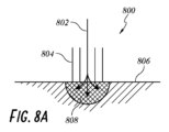
図8Aは、一例のブロックモード800を示す。ブロックモード800の適用は、心臓組織806に対して一体型カテーテル804を適用することを含み得る。電流が、ブロッキング導体802を経由して心臓組織806に対して印加され得るが、このブロッキング導体802は、一体型カテーテル804の電極、電極コア、非流体導体、および/または導電性流体であることが可能である。いくつかの実施形態では、ブロッキング導体802は、心臓組織806に対してブロッキングDC電流を印加する。好ましくは、カソード電流が、ブロッキング導体802の下方の心臓組織806を直接的にブロックするためにアノード電流に重ねて印加され得る。領域808は、ブロッキング導体802から心臓組織806へと流れる電流の結果として得られる心臓組織806のブロッキングされた体積を示し得る。送達された電流は、図7に示す「x」708であることが可能である。
FIG. 8A shows an
また、アノード電流が印加され得る(例えばより低い振幅でのアノード電流が、不整脈における役割を確認するために電極の近傍において心臓組織の興奮性を上昇させ得る)。いくつかの実施形態では、一体型カテーテル804は、1自由度またはそれ以上の自由度を有することにより一体型カテーテル804中に屈曲部をもたらすように関節動作可能であり得る。いくつかの実施形態では、一体型カテーテル804は、心臓組織806からの生体電位を測定するために使用され得る。いくつかの実施形態では、ブロッキング導体802は、ブロッキング電流を送達していないおよび/または電流送達と同時である場合に、生体電位を測定するために使用され得る。
Also, an anodic current may be applied (eg, an anodic current at a lower amplitude may increase the excitability of cardiac tissue in the vicinity of the electrode to confirm its role in arrhythmia). In some embodiments, the
図8Bは、一例のアブレーションモード810を示す。アブレーションモード810の適用は、組織806に対して一体型カテーテル804を適用することを含み得る。ブロッキング導体802の外部の周囲に位置決めされ得るアブレーション電極812は、心臓組織806をアブレーションし得る。領域814は、心臓組織806のアブレーションされた体積を示し得る。いくつかの実施形態では、領域814の体積は、領域808の体積と同様である。アブレーションレベルは、図7において示される「y」706であることが可能である。
FIG. 8B shows an
図9は、一例のマッピングカテーテル900を示す。マッピングカテーテルは、接触子を有さない細長部分902を有し得る。マッピングカテーテル900は、マッピングカテーテル900の遠位端部上におよび/または遠位端部の付近に位置決めされた一連の接触子904を有し得る。接触子904は、電極であることが可能である。いくつかの実施形態では、接触子904は、本明細書において開示される電極の特徴を有し得る。
FIG. 9 shows an
いくつかの実施形態では、接触子904は、カテーテル900の周囲部分を囲む。いくつかの実施形態では、接触子904は、相互から均等に離間される。いくつかの実施形態では、接触子904は、相互の間にそれぞれ異なる間隔を有する。いくつかの実施形態では、接触子904は、均等にサイズ設定される。いくつかの実施形態では、接触子904は、それぞれ異なるサイズを有する。
In some embodiments, contact 904 surrounds a peripheral portion of
いくつかの実施形態では、接触子904は、Agおよび/またはAgClから作製される。いくつかの実施形態では、接触子904は被覆され、アニオン交換膜などである。いくつかの実施形態では、接触子904は、微粒子容器により囲まれ、この微粒子容器は、バスケット、メッシュ、および/または他のカバリングを備え得る。いくつかの実施形態では、接触子904は、アニオン交換膜を介してなど、共に被覆される。いくつかの実施形態では、接触子904は、TiNまたは多孔性TiNなどの高電荷密度材料から作製される。
In some embodiments,
電流が、マッピングカテーテル900の1つまたは複数の接触子904を介して送達され得る。いくつかの実施形態では、DC電流および/またはAC電流が送達される。これは1つまたは複数のアブレーションが治療的であり得るか否かの評価を容易にし得る。いくつかの実施形態では、接触子904は、個別にまたは複数として選択されることが可能であり、例えば記録、ブロック、および/または刺激するために複数で選択され得る。
Electrical current may be delivered through one or
接触子904は、電流を方向付けるためにおよび/または心臓組織のブロッキングされる部分を選択するために使用され得る。
接触子904および本明細書において開示されるあらゆるブロッキング電極は、超音波などの1つまたは複数の他の特徴部を有することが可能である。 Contact 904 and any blocking electrodes disclosed herein can have one or more other features, such as ultrasound.
本明細書において開示されるあらゆるカテーテルが、マッピングカテーテル900などのマッピングカテーテルの形態を有し得る。カテーテル900および本明細書において開示されるあらゆるカテーテルは、心臓組織との緊密な接触を可能にする可撓性要素を有することが可能である。カテーテル900および本明細書において開示されるあらゆるカテーテルは、標的組織における活動電位の安全かつ可逆的なブロックを実現するために心臓組織に対してDCを送達し得るアドレス可能なDCブロッキング接触子を有し得る。
Any catheter disclosed herein may have the form of a mapping catheter, such as
図10は、一例のシステム1000を示す。例示のシステム1000は、発生器1002を有し得る。発生器1002は、本明細書において開示される発生器の特徴を有し得る。発生器1002は、カテーテル1006に対して結合され得る。カテーテル1006は、本明細書において開示される他のカテーテルの特徴を有し得る。
FIG. 10 shows an
カテーテル1006は、発生器1002からメッシュ部材1008上に位置決めされた接触子、電極、および/またはワイヤまで電流を伝導する非流体導体1004を有し得る。メッシュ部材1008は、カテーテル1006の遠位端部上に位置決めされ得る。いくつかの実施形態では、メッシュ部材1008は、心臓組織との接触時に変形可能である。いくつかの実施形態では、メッシュ部材1008は、外縁部に沿って位置決めされた表面接触子(電極)を有するメッシュ変形可能球状部であることが可能である。メッシュ部材1008は、外縁部に沿って延在するワイヤを有するメッシュ変形可能球状部であることが可能である。いくつかの実施形態では、表面接触子および/またはワイヤは、メッシュ部材1008の主軸に対して長手方向にまたは長手方向に対する垂直方向に倣うように位置決めされ得る。いくつかの実施形態では、表面接触子および/またはワイヤは、非流体導体1004により個別にまたは別個にアドレス可能であり得る。
The
図11は、一例のシステム1100を示す。例示のシステム1100は、発生器1102を有し得る。発生器1102は、本明細書において開示される発生器の特徴を有し得る。発生器1102は、カテーテル1106に対して結合され得る。カテーテル1106は、本明細書において開示される他のカテーテルの特徴を有し得る。
FIG. 11 shows an
カテーテル1106は、発生器1102から、バルーン1008または拡張可能ケージ等の拡張可能部材の外部上に位置決めされた導体1110(接触子、電極、および/またはワイヤなど)へと電流を伝導する非流体導体1104を有し得る。導体1110は、DCブロッキング電極接触子であることが可能である。使用時に、バルーン1008は、心臓組織に対して導体1110を圧迫するように膨張され得る。いくつかの実施形態では、これは、DC電流送達を含み得る心臓組織をブロックするための改善された電流送達を容易化し得る。
いくつかの実施形態では、DCブロッキング電極接触子を備え得る電極および/または接触子は、心臓組織における活動を感知し得る。これは、本明細書において開示される任意の電極、接触子、および/またはシステムに対して適用され得る。いくつかの実施形態では、他の感知接触子が、電極および/または接触子に隣接して位置決めされてもよく、この電極および/または接触子は、DCブロッキング電極接触子を備え得る。これは、本明細書において開示される任意の電極、接触子、および/またはシステムに対して適用され得る。 In some embodiments, the electrodes and/or contacts, which may include DC blocking electrode contacts, may sense activity in cardiac tissue. This may apply to any electrode, contact, and/or system disclosed herein. In some embodiments, other sensing contacts may be positioned adjacent to the electrodes and/or contacts, which may include DC blocking electrode contacts. This may apply to any electrode, contact, and/or system disclosed herein.
いくつかの実施形態では、電気回路の帰路は、遠位電極および/またはカテーテルベース電極を経由し得る。遠位電極は、皮膚上に配置されたパッチ電極を備え得る、遠位カテーテル。遠位電極は、より徹底的な対称近似を可能にするために使用され得る、アブレーションモダリティの送達によりアブレーションされた組織体積。 In some embodiments, the return path of the electrical circuit may be via the distal electrode and/or the catheter-based electrode. A distal catheter, where the distal electrode can comprise a patch electrode placed on the skin. A distal electrode may be used to allow for a more thorough symmetrical approximation of the tissue volume ablated by the delivery of the ablation modality.
次に、電気生理学的検査およびアブレーション手技を実施するための方法の実施形態を説明する。血管アクセスは、経皮的技術(例えば大腿静脈、内頸静脈、橈骨動脈または上腕動脈等)または静脈切開技術により得ることが可能である。ガイドワイヤを挿入し、カテーテルが、心臓の近傍の所望の位置までこのガイドワイヤ上において挿入され得る。例えば蛍光透視ガイダンスまたは他のガイダンスなどのイメージングが利用され得る。いくつかの例では、電気的活動を測定するために、感知電極が伝導経路に沿ってならびに心臓の心内膜に沿っておよび心内膜内を移動され得る。次いで、心臓またはその心腔がペーシングされて、異常を観察され得る。次いで、不整脈が、不整脈を誘発させる試みにおいて刺激電流および/または不整脈薬剤(エピネフリン、ドーパミン、フェニレフリン、イソプロテレノール、アミノフィリン、カルシウム、アトロピン、または他の薬剤を含むがそれらに限定されない)により惹起され、感知電極は、異常な電気的活動の発生源を位置特定するために移動され得る。非アブレーションDCまたはHFACが、異常な電気的活動の発生源であると考えられる心臓組織の第1の標的領域へとカテーテル上の電極を介して送達され得る。不整脈が止まる場合には、この第1の標的領域は、RFアブレーション技術または本明細書において開示されるものなどの他のアブレーション技術を利用して効率的にアブレーションされ得る。不整脈が止まらない場合には、第1の標的領域が免除され、第2の標的領域が非アブレーションDCまたはHFACで処理される。不整脈が止まる場合には、この第2の標的領域は、RFアブレーション技術または本明細書において開示されるものなどの他のアブレーション技術を利用して効率的にアブレーションされ得る。不整脈が止まらない場合には、第2の標的領域が免除され、第3の標的領域の探索を開始することが可能となり、このプロセスが繰り返され得る。 Next, embodiments of methods for performing electrophysiological testing and ablation procedures are described. Vascular access can be obtained by percutaneous techniques (eg, femoral vein, internal jugular vein, radial artery or brachial artery, etc.) or by phlebotomy techniques. A guidewire may be inserted and a catheter inserted over the guidewire to a desired location near the heart. Imaging, such as fluoroscopic guidance or other guidance, may be utilized. In some examples, sensing electrodes may be moved along the conduction pathway as well as along and within the endocardium of the heart to measure electrical activity. The heart or its chambers can then be paced and monitored for abnormalities. The arrhythmia is then induced by a stimulating current and/or an arrhythmia drug (including, but not limited to, epinephrine, dopamine, phenylephrine, isoproterenol, aminophylline, calcium, atropine, or other drugs) in an attempt to induce an arrhythmia. , the sensing electrode may be moved to locate the source of abnormal electrical activity. Non-ablated DCs or HFACs may be delivered via electrodes on a catheter to a first target area of cardiac tissue believed to be the source of abnormal electrical activity. If the arrhythmia ceases, this first target region can be efficiently ablated using RF ablation techniques or other ablation techniques such as those disclosed herein. If the arrhythmia does not stop, the first target area is waived and the second target area is treated with non-ablative DC or HFAC. If the arrhythmia ceases, this second target region can be efficiently ablated using RF ablation techniques or other ablation techniques such as those disclosed herein. If the arrhythmia does not stop, the second target area can be waived, a search for a third target area can begin, and the process can be repeated.
いくつかの実施形態では、非アブレーションブロックが肺静脈隔離手技との関連において利用され得る。肺静脈口までカテーテルを経中隔前進させた後に、非アブレーションブロックが、肺静脈口の周囲に周方向に行われる。それにより、一時的な周方向アブレーションゾーンが設けられ、これが、肺静脈と左心房との間における電気的伝搬を効果的にブロックする。不整脈が誘発可能でない場合には、永久的な周方向アブレーション損傷部が、本明細書の他の箇所において説明されるものを含むアブレーションモダリティにより形成され得る。 In some embodiments, non-ablative blocks may be utilized in conjunction with pulmonary vein isolation procedures. After transseptal advancement of the catheter to the pulmonary vein ostium, a non-ablative block is performed circumferentially around the pulmonary vein ostium. Thereby, a temporary circumferential ablation zone is provided, which effectively blocks electrical propagation between the pulmonary veins and the left atrium. If the arrhythmia is not inducible, a permanent circumferential ablation lesion may be created by ablation modalities including those described elsewhere herein.
いくつかの実施形態では、本明細書において開示されるようなシステムおよび方法で処理され得るいくつかの非限定的条件として、心房細動(慢性心房細動もしくは発作性心房細動)、QT延長症候群、ウォルフ・パーキンソン・ホワイト症候群、トルサードドポアン、心房性期外収縮、遊走性心房ペースメーカ、多源性心房頻拍、心房粗動、上室性頻拍症(PSVTを含む)、房室結節リエントリー性頻拍、接合部調律、接合部頻拍、房室結節性期外収縮、心室性期外収縮、頻拍性心室固有調律、単形性心室頻拍、多形性心室頻拍、右室流出路頻拍、および心室細動が含まれ得るがそれらに限定されない。 In some embodiments, some non-limiting conditions that may be treated with systems and methods as disclosed herein include atrial fibrillation (chronic or paroxysmal atrial fibrillation), QT prolongation. syndrome, Wolff-Parkinson-White syndrome, torsade de pointes, atrial premature beats, migratory atrial pacemaker, multisource atrial tachycardia, atrial flutter, supraventricular tachycardia (including PSVT), atrioventricular node reentrant tachycardia, junctional rhythm, junctional tachycardia, atrioventricular nodal premature contractions, ventricular premature contractions, tachyventricular idiosyncratic rhythm, monomorphic ventricular tachycardia, polymorphic ventricular tachycardia, May include, but are not limited to, right ventricular outflow tract tachycardia, and ventricular fibrillation.
本開示は、特定の実施形態および例の文脈において説明されたが、本開示は、具体的に開示される実施形態以外の他の代替的な実施形態および/または使用ならびにその明白な修正形態および均等物まで範囲が及ぶことが、当業者には理解されよう。さらに、本開示の実施形態の複数の変形例が、図示され詳細に説明されるが、本開示の範囲内に含まれる他の修正が、当業者には容易に明らかになろう。また、これらの実施形態の具体的な特徴および態様の様々な組合せまたは下位組合せがなされてもよく、それらが本開示の範囲内に依然として含まれることが予期される。例えば、一実施形態との関連において上述した特徴部が、本明細書において説明される異なる実施形態と共に使用されることが可能であり、この組合せは、本開示の範囲内に依然として含まれる。開示された実施形態の様々な特徴および態様は、本開示の実施形態の様々な態様を形成するために相互に組み合わされてもまたは相互に代用されてもよい点を理解されたい。したがって、本明細書における開示の範囲は、上述の特定の実施形態により限定されるべきではないことが意図される。したがって、別様のことが述べられない限りは、または明確に非両立的でない限りは、本発明の各実施形態は、本明細書において説明されるその本質的特徴に加えて、本明細書において開示される本発明のそれぞれの他の実施形態から本明細書において説明されるような1つまたは複数の特徴を備え得る。 Although this disclosure has been described in the context of particular embodiments and examples, this disclosure may include other alternative embodiments and/or uses other than the specifically disclosed embodiments, as well as obvious modifications and variations thereof. Those skilled in the art will understand that the range of equivalents extends. Additionally, while multiple variations of the embodiments of the disclosure are illustrated and described in detail, other modifications that fall within the scope of the disclosure will be readily apparent to those skilled in the art. It is also contemplated that various combinations or subcombinations of the specific features and aspects of these embodiments may be made and still fall within the scope of this disclosure. For example, features described above in connection with one embodiment can be used with different embodiments described herein and the combination remains within the scope of this disclosure. It is to be understood that various features and aspects of the disclosed embodiments may be combined with or substituted for each other to form various aspects of the disclosed embodiments. Therefore, it is intended that the scope of the disclosure herein should not be limited by the particular embodiments described above. Therefore, unless stated otherwise or clearly incompatible, each embodiment of the invention is defined herein in addition to its essential features as described herein. It may include one or more features as described herein from each other embodiment of the disclosed invention.
特定の態様、実施形態、または例との組合せにおいて説明された特徴部、材料、特徴、または群は、非両立的でない限り、本明細書における本章または他の箇所で説明された任意の他の態様、実施形態、または例に対して適用可能であるものとして理解されたい。本明細書(添付の特許請求の範囲、要約、および図面を含む)において開示されたすべての特徴部および/またはかように開示された任意の方法もしくはプロセスのすべてのステップは、かかる特徴部および/またはステップの中の少なくともいくつかが相互に排他的となる組合せを除いては、任意の組合せで組み合わされてもよい。保護範囲は、任意の前述の実施形態の詳細に限定されない。保護範囲は、本明細書(任意の添付の特許請求の範囲、要約、および図面を含む)において開示された特徴の任意の新規の1つもしくは任意の新規の組合せにまで、またはかように開示された任意の方法もしくはプロセスのステップの任意の新規の1つもしくは任意の新規の組合せにまで及ぶ。 A feature, material, feature, or group described in combination with a particular aspect, embodiment, or example may be used in conjunction with any other feature, material, feature, or group described in this section or elsewhere herein, unless incompatible. To be understood as applicable to any aspect, embodiment, or example. All features disclosed in this specification (including the appended claims, abstract, and drawings) and/or all steps of any method or process so disclosed may include such features and At least some of the steps may be combined in any combination except those combinations in which at least some of the steps are mutually exclusive. The scope of protection is not limited to the details of any of the previously described embodiments. The scope of protection extends to any novel one or any novel combination of features disclosed in this specification (including any appended claims, abstract, and drawings) or as such disclosed. It extends to any novel one or any novel combination of steps of any method or process made.
さらに、個別の実装形態の文脈において本開示内で説明される特定の特徴部は、単一の実装形態において組合せで実装されることも可能である。対照的に、単一の実相形態の文脈で説明される様々な特徴部は、別個にまたは任意の適切な下位組合せで複数の実装形態において実装されることも可能である。さらに、特徴部が、特定の組合せで動作するものとして上述される場合があるが、いくつかの例では、特許請求される組合せの中の1つまたは複数の特徴部が、その組合せから削除されることが可能であり、その組合せは、下位組合せまたは下位組合せの変形例として特許請求され得る。 Additionally, certain features that are described within this disclosure in the context of separate implementations can also be implemented in combination in a single implementation. In contrast, various features that are described in the context of a single entity can also be implemented in multiple implementations separately or in any suitable subcombination. Additionally, although features may be described above as operating in a particular combination, in some instances one or more features in the claimed combination may be deleted from the combination. and the combination may be claimed as a subcombination or a variation of a subcombination.
さらに、動作が、特定の順序において図面内に示されるまたは本明細書内に説明される場合があるが、かかる動作は、図示される特定の順序でもしくは連続的な順序で実施される必要はなく、またはそのすべての動作が所望の結果を達成するために実施される必要もない。図示または説明されない他の動作が、例示の方法およびプロセスに組み込まれ得る。例えば、1つまたは複数の追加の動作が、説明される動作のいずれかの前、後、同時、またはそれらの間に実施されることが可能である。さらに、これらの動作は、他の実装形態で再構成または再順序設定されてもよい。いくつかの実施形態では、図示されるおよび/または開示されるプロセスで実施される実際のステップが、図面に示すものとは異なり得る点が当業者には理解されよう。実施形態によっては、上述したステップのいくつかが、除外されてもよく、他のものが、追加されてもよい。さらに、上記に開示した具体的な実施形態の特徴部および特性が、さらなる実施形態を形成するために異なる様式で組み合わされてもよく、それらはいずれも本開示の範囲内に含まれる。また、上述の実装形態における様々なシステム構成要素の分離は、すべての実装形態においてかかる分離を必要としているものとして理解されるべきではなく、説明された構成要素およびシステムは、一般的には単一の製品として共に一体化されるか、または複数の製品へとパッケージングされることが可能である点を理解されたい。 Additionally, although operations may be illustrated in the drawings or described herein in a particular order, such operations need not be performed in the particular order depicted or in sequential order. No, or all, operations need not be performed to achieve a desired result. Other operations not shown or described may be incorporated into the example methods and processes. For example, one or more additional operations may be performed before, after, concurrently with, or during any of the described operations. Additionally, these operations may be rearranged or reordered in other implementations. Those skilled in the art will appreciate that in some embodiments, the actual steps performed in the illustrated and/or disclosed processes may differ from those shown in the drawings. Depending on the embodiment, some of the steps described above may be omitted and others may be added. Furthermore, the features and characteristics of the specific embodiments disclosed above may be combined in different ways to form further embodiments, all of which are within the scope of this disclosure. Furthermore, the separation of various system components in the implementations described above is not to be understood as requiring such separation in all implementations, and that the components and systems described are generally simple. It should be appreciated that they can be integrated together as one product or packaged into multiple products.
本開示においては、特定の態様、利点、および新規の特徴が本明細書内で説明される。必ずしもすべてのかかる利点が、任意の特定の実施形態にしたがって達成されなくてもよい。したがって、例えば、本開示は、本明細書において教示または示唆され得るような他の利点を必ずしも達成することなく、本明細書において教示されるような1つの利点または利点の組合せを実現する様式で具現化または実施されてもよい点が、当業者には理解されよう。 In this disclosure, certain aspects, advantages, and novel features are described herein. Not necessarily all such advantages may be achieved according to any particular embodiment. Thus, for example, the present disclosure is presented in a manner that achieves one advantage or combination of advantages as taught herein without necessarily achieving other advantages as may be taught or implied herein. Those skilled in the art will understand how it may be implemented or implemented.
とりわけ「可能である(can、could)」、「してもよい(may、might)」、および「例えば」等の本明細書において使用される条件表現は、別様のことが明示されない限り、または使用されるような文脈内で別様に理解されない限り、特定の実施形態が特定の特徴部、要素、および/またはステップを含むが、他の実施形態はそれらを含まないことを表現するように一般的には意図される。したがって、かかる条件表現は、特徴部、要素、および/またはステップが、1つまたは複数の実施形態にとっては何らかの点で必要とされることを、または1つまたは複数の実施形態が、これらの特徴部、要素、および/またはステップが任意の特定の実施形態に含まれるかもしくは任意の特定の実施形態で実施されるべきであるかを他の入力もしくは指示を用いてもしくは用いずに判断するための論理を必ず備えることを示唆するようには一般的には意図されない。「備える」、「含む」、および「有する」等の用語は、同義的であり、無制限的に包括的に使用され、追加の要素、特徴部、作業、および動作等を排除しない。さらに、「または」という用語は、包括的な意味で(および非排他的な意味で)使用され、そのため例えば要素のリストを接続するために使用される場合には、「または」という用語はそのリスト内の要素の1つ、いくつか、またはすべてを意味する。 Conditional expressions used herein such as "can, could," "may," and "for example," among others, unless expressly stated otherwise, or to express that a particular embodiment includes certain features, elements, and/or steps while other embodiments do not, unless otherwise understood within the context in which they are used. generally intended. Thus, such conditional expressions indicate that the features, elements, and/or steps are required in some respect for one or more embodiments, or that the features, elements, and/or steps are required in some respect for one or more embodiments. to determine, with or without other input or instruction, whether a section, element, and/or step is to be included or implemented in any particular embodiment; It is not generally intended to imply that this logic necessarily exists. The terms "comprising," "comprising," and "having" are used interchangeably and inclusively and do not exclude additional elements, features, acts, acts, and the like. Furthermore, the term "or" is used in an inclusive sense (and in a non-exclusive sense), so that when used, for example, to connect a list of elements, the term "or" Refers to one, some, or all of the elements in a list.
「X、Y、およびZの中の少なくとも1つ」という表現などの接続表現は、別様なことが明示されない限り、他の場合では、あるアイテム、項等がX、Y、またはZのいずれかであり得ることを表現するために一般的に使用されるものとしてその文脈により理解される。したがって、かかる接続表現は、特定の実施形態が少なくとも1つのX、少なくとも1つのY、および少なくとも1つのZの存在を必要とすることを示唆するように一般的には意図されない。 Unless otherwise expressly stated, conjunctions such as "at least one of X, Y, and Z" are understood by their context as generally used to express that an item, term, etc. may be either X, Y, or Z in other cases. Thus, such conjunctions are not generally intended to suggest that a particular embodiment requires the presence of at least one X, at least one Y, and at least one Z.
本明細書において使用されるような「約(approximately、about)」、「略」、および「実質的に」という用語などの本明細書において使用される程度表現は、所望の機能を依然として実施するまたは所望の結果を達成する、述べられた数値、量、または特徴に近い数値、量、または特徴を表す。例えば、「約」、「略」、および「実質的に」という用語は、述べられた量の10%未満、5%未満、1%未満、0.1%未満、0.01%未満の範囲内に含まれる量を示し得る。別の例では、いくつかの実施形態では、「ほぼ平行な」および「実質的に平行な」という用語は、15度以下だけ、10度以下だけ、5度以下だけ、3度以下だけ、1度以下だけ、0.1度以下だけ、または別の角度だけ正確な平行から逸脱する数値、量、または特徴を示す。 Expressions of extent as used herein, such as the terms "approximately," "approximately," and "substantially" as used herein, still perform the desired function. or represents a numerical value, quantity, or characteristic that approximates the stated numerical value, quantity, or characteristic that achieves a desired result. For example, the terms "about," "approximately," and "substantially" mean a range of less than 10%, less than 5%, less than 1%, less than 0.1%, less than 0.01% of the stated amount. can indicate the amount contained within. For another example, in some embodiments, the terms "substantially parallel" and "substantially parallel" refer to by no more than 15 degrees, no more than 10 degrees, no more than 5 degrees, no more than 3 degrees, by no more than 1 Indicates a value, quantity, or feature that deviates from exact parallelism by less than a degree, by less than 0.1 degree, or by another angle.
本明細書において開示される任意の方法は、挙げられた順序で実施される必要はない。本明細書において開示される方法は、施術者により行われる特定の作業を含むが、明確なまたは示唆的ないずれかの、それらの作業の任意の第三者による指示をさらに含み得る。例えば、「モータ速度を制御する」などの作業は、「モータ速度の制御を指示する」ことを含む。 Any method disclosed herein need not be performed in the order listed. The methods disclosed herein include certain tasks performed by a practitioner, but may further include any third-party direction of those tasks, either explicit or implied. For example, an operation such as "controlling motor speed" includes "instructing control of motor speed."
本明細書において説明される方法およびタスクはいずれも、コンピュータシステムにより実施され完全に自動化されてもよい。いくつかの例では、コンピュータシステムは、説明される機能を実施するためにネットワークを介して通信および相互運用される複数の異なるコンピュータまたはコンピューティングデバイス(例えば物理サーバ、ワークステーション、ストレージアレイ、クラウドコンピューティングリソース等)を備え得る。典型的には、かかる各コンピューティングデバイスは、メモリまたは他の持続性コンピュータ可読記憶媒体もしくはデバイス(例えば固体記憶デバイス、ディスクドライブ等)に記憶されたプログラム命令またはプログラムモジュールを実行するプロセッサ(または複数のプロセッサ)を備える。本明細書において開示される様々な機能は、かかるプログラム命令において具現化されてもよく、および/またはコンピュータシステムの特定用途向け回路(例えばASICまたはFPGA)に実装されてもよい。コンピュータシステムが複数のコンピューティングデバイスを備える場合には、これらのデバイスはコロケーションされてもよいが必須ではない。開示される方法およびタスクの結果は、固体メモリチップおよび/または磁気ディスクなどの物理ストレージデバイスを異なる状態のものへと転換することにより永続的に記憶され得る。いくつかの実施形態では、コンピュータシステムは、複数の別個の企業体または他のユーザにより共有される処理リソースを有するクラウドベースコンピューティングシステムであってもよい。 Any of the methods and tasks described herein may be performed by a computer system and fully automated. In some examples, a computer system may include multiple different computers or computing devices (e.g., physical servers, workstations, storage arrays, cloud computing devices) that communicate and interoperate over a network to perform the functions described. resources, etc.). Typically, each such computing device includes a processor(s) executing program instructions or program modules stored in memory or other persistent computer-readable storage medium or device (e.g., solid-state storage device, disk drive, etc.). processor). The various functionality disclosed herein may be embodied in such program instructions and/or implemented in special purpose circuitry (eg, an ASIC or FPGA) of a computer system. If the computer system includes multiple computing devices, these devices may, but need not, be co-located. The results of the disclosed methods and tasks may be permanently stored by converting physical storage devices such as solid state memory chips and/or magnetic disks into different states. In some embodiments, the computer system may be a cloud-based computing system with processing resources shared by multiple separate business entities or other users.
本開示の範囲は、本章または本明細書内の他の箇所における好ましい実施形態の具体的な開示により限定されるようには意図されず、本章もしくは本明細書の他の箇所に示されるようなまたは将来的に示されるようなものとして特許請求の範囲により定義され得る。特許請求の範囲における文言は、特許請求の範囲内において使用される文言に基づき幅広く解釈されるべきであり、本明細書内でまたは出願手続の最中に説明される例に限定されず、かような例は、非限定なものとして解釈されるべきである。 The scope of the present disclosure is not intended to be limited by the specific disclosure of preferred embodiments in this section or elsewhere herein, and the scope of the present disclosure is not intended to be limited by the specific disclosure of preferred embodiments in this section or elsewhere herein. or may be defined by the claims as shown in the future. The language in the claims should be interpreted broadly based on the language used in the claims, and not limited to the examples set forth herein or during prosecution. Such examples should be construed as non-limiting.
100 グラフ
102 垂直軸
104 水平軸
106 ブロッキングDC振幅
108 ブロッキングDC振幅
110 グラフ
112 垂直軸
114 水平軸
116 第1の有効性検証
118 第2の有効性検証
119 第3の有効性検証
120 グラフ
122 垂直軸
124 水平軸
126 第1のアブレーション、アブレーション計量
128 第2のアブレーション、アブレーション計量
200 システム
202 発生器
204 カソード(および/またはアノード)導体
206 カテーテル
208 導電性流体
300 システム
302 発生器
304 非流体導体
306 カテーテル
308 電極
400 システム
402 微粒子容器
500 システム
502 発生器
504 導電性流体
506 カテーテル
508 電極
510 遠位開口または側部開口
600 システム
602 発生器
604 非流体導体
606 カテーテル
608 電極
610 電極コア
612 微粒子容器
614 システム
700 グラフ
702 垂直軸
704 水平軸
800 ブロックモード
802 ブロッキング導体
804 カテーテル
806 心臓組織
808 領域
810 アブレーションモード
812 アブレーション電極
814 領域
900 マッピングカテーテル
902 細長部分
904 接触子
1000 システム
1002 発生器
1004 非流体導体
1006 カテーテル
1008 メッシュ部材、バルーン
1100 システム
1102 発生器
1104 非流体導体
1106 カテーテル
1110 導体
100
Claims (8)
非アブレーションブロッキング電流を生成するように構成された第1の発生器と、
アブレーションエネルギーを生成するように構成された第2の発生器と、
一体型カテーテルであって、前記一体型カテーテルは、前記第1の発生器および前記第2の発生器に対して結合されるように構成された近位端部と、遠位端部とを有し、
前記一体型カテーテルの前記近位端部から前記一体型カテーテルの前記遠位端部まで延在する導体であって、前記一体型カテーテルの内部に配設された導体、
前記一体型カテーテルの遠位ゾーンに配設され、前記第1の発生器に対して導電接続されるように構成された、少なくとも1つのブロッキング電極、および
前記一体型カテーテルの前記遠位ゾーンに配設され、前記第2の発生器に対して導電接続されるように構成された、少なくとも1つのアブレーション電極
をさらに備える、一体型カテーテルと
を備え、
前記システムは、前記少なくとも1つのブロッキング電極を介して前記第1の発生器から心臓組織まで前記ブロッキング電流を送達することにより、前記心臓組織に可逆性ブロックをもたらすように構成され、
前記システムは、前記第2の発生器から前記少なくとも1つのアブレーション電極まで前記アブレーションエネルギーを送達することにより心臓組織をアブレーションするように構成され、
前記カテーテルの前記遠位端部は、前記一体型カテーテル内に配置された前記少なくとも1つのブロッキング電極を露出させる開口を有し、
前記少なくとも1つのアブレーション電極は、前記一体型カテーテルの前記遠位端部の一部分の外周部を覆う、電気生理学的心臓アブレーションシステム。 An electrophysiological (EP) cardiac ablation system comprising:
a first generator configured to generate a non-ablative blocking current;
a second generator configured to generate ablation energy;
An integrated catheter, the integrated catheter having a proximal end configured to be coupled to the first generator and the second generator, and a distal end. death,
a conductor extending from the proximal end of the integrated catheter to the distal end of the integrated catheter, the conductor being disposed within the integrated catheter;
at least one blocking electrode disposed in the distal zone of the integrated catheter and configured to be conductively connected to the first generator; and at least one blocking electrode disposed in the distal zone of the integrated catheter. and an integrated catheter further comprising at least one ablation electrode arranged and configured to be conductively connected to the second generator;
The system is configured to deliver the blocking current from the first generator to the cardiac tissue via the at least one blocking electrode to provide a reversible block in the cardiac tissue;
the system is configured to ablate cardiac tissue by delivering the ablation energy from the second generator to the at least one ablation electrode;
the distal end of the catheter has an opening exposing the at least one blocking electrode disposed within the integral catheter ;
The at least one ablation electrode circumferentially covers a portion of the distal end of the integrated catheter.
Applications Claiming Priority (3)
| Application Number | Priority Date | Filing Date | Title |
|---|---|---|---|
| US201862628810P | 2018-02-09 | 2018-02-09 | |
| US62/628,810 | 2018-02-09 | ||
| PCT/US2019/017215 WO2019157285A1 (en) | 2018-02-09 | 2019-02-08 | Systems and methods for cardiac conduction block |
Publications (3)
| Publication Number | Publication Date |
|---|---|
| JP2021513432A JP2021513432A (en) | 2021-05-27 |
| JPWO2019157285A5 JPWO2019157285A5 (en) | 2022-02-16 |
| JP7456944B2 true JP7456944B2 (en) | 2024-03-27 |
Family
ID=67549693
Family Applications (1)
| Application Number | Title | Priority Date | Filing Date |
|---|---|---|---|
| JP2020564790A Active JP7456944B2 (en) | 2018-02-09 | 2019-02-08 | Systems and methods for cardiac conduction block |
Country Status (7)
| Country | Link |
|---|---|
| US (1) | US20210038101A1 (en) |
| EP (1) | EP3749194A4 (en) |
| JP (1) | JP7456944B2 (en) |
| CN (1) | CN111989036A (en) |
| AU (1) | AU2019216750A1 (en) |
| CA (1) | CA3090776A1 (en) |
| WO (1) | WO2019157285A1 (en) |
Families Citing this family (10)
| Publication number | Priority date | Publication date | Assignee | Title |
|---|---|---|---|---|
| US9387322B2 (en) | 2012-06-15 | 2016-07-12 | Case Western Reserve University | Therapy delivery devices and methods for non-damaging neural tissue conduction block |
| US10195434B2 (en) | 2012-06-15 | 2019-02-05 | Case Western Reserve University | Treatment of pain using electrical nerve conduction block |
| US20150238764A1 (en) | 2013-05-10 | 2015-08-27 | Case Western Reserve University | Systems and methods for preventing noise in an electric waveform for neural stimulation, block, or sensing |
| AU2016335931B2 (en) | 2015-10-06 | 2019-06-27 | Case Western Reserve University | High-charge capacity electrodes to deliver direct current nerve conduction block |
| US10864373B2 (en) | 2015-12-15 | 2020-12-15 | Case Western Reserve University | Systems for treatment of a neurological disorder using electrical nerve conduction block |
| WO2018187237A1 (en) | 2017-04-03 | 2018-10-11 | Presidio Medical, Inc. | Systems and methods for direct current nerve conduction block |
| CA3091769A1 (en) | 2018-02-20 | 2019-08-29 | Presidio Medical, Inc. | Methods and systems for nerve conduction block |
| US11752329B2 (en) | 2018-07-01 | 2023-09-12 | Presidio Medical, Inc. | Systems and methods for nerve conduction block |
| EP4061476A4 (en) | 2019-11-24 | 2023-12-13 | Presidio Medical, Inc. | Pulse generation and stimulation engine systems |
| US11553962B2 (en) * | 2020-01-24 | 2023-01-17 | Affera, Inc. | Systems for cardiac ablation and associated methods |
Citations (2)
| Publication number | Priority date | Publication date | Assignee | Title |
|---|---|---|---|---|
| US20140128865A1 (en) | 2012-11-05 | 2014-05-08 | Yossi Gross | Controlled renal artery ablation |
| US20140228837A1 (en) | 2011-10-04 | 2014-08-14 | The Board Of Trustees Of The Leland Stanford Junior University | Control of cardiac excitability using high frequency signals |
Family Cites Families (12)
| Publication number | Priority date | Publication date | Assignee | Title |
|---|---|---|---|---|
| US5868743A (en) * | 1995-12-13 | 1999-02-09 | Children's Medical Center Corporation | Cardiac ablation system with low temperature target site identification |
| US6415178B1 (en) * | 1996-09-16 | 2002-07-02 | Impulse Dynamics N.V. | Fencing of cardiac muscles |
| US6428537B1 (en) * | 1998-05-22 | 2002-08-06 | Scimed Life Systems, Inc. | Electrophysiological treatment methods and apparatus employing high voltage pulse to render tissue temporarily unresponsive |
| US20080275439A1 (en) * | 2002-01-25 | 2008-11-06 | David Francischelli | Cardiac ablation and electrical interface system and instrument |
| US8073538B2 (en) * | 2003-11-13 | 2011-12-06 | Cardio Polymers, Inc. | Treatment of cardiac arrhythmia by modification of neuronal signaling through fat pads of the heart |
| US8657814B2 (en) * | 2005-08-22 | 2014-02-25 | Medtronic Ablation Frontiers Llc | User interface for tissue ablation system |
| CN104066368B (en) * | 2011-09-22 | 2017-02-22 | 乔治华盛顿大学 | Systems and methods for visualizing ablated tissue |
| SG11201407873RA (en) * | 2012-05-29 | 2014-12-30 | Autonomix Medical Inc | Endoscopic sympathectomy systems and methods |
| US20150045675A1 (en) * | 2012-06-01 | 2015-02-12 | Ary Chernomorsky | Percutaneous methods and devices for carotid body ablation |
| US20150293192A1 (en) * | 2012-11-02 | 2015-10-15 | Brigham And Women's Hospital, Inc. | Method and appratus for suppressing electromagnetic fields induced by a magnetic resonance imaging system in electronic cables and devices |
| US9717552B2 (en) * | 2014-05-06 | 2017-08-01 | Cosman Intruments, Llc | Electrosurgical generator |
| EP3139853B1 (en) * | 2014-05-07 | 2018-12-19 | Pythagoras Medical Ltd. | Controlled tissue ablation apparatus |
-
2019
- 2019-02-08 JP JP2020564790A patent/JP7456944B2/en active Active
- 2019-02-08 CN CN201980023079.0A patent/CN111989036A/en active Pending
- 2019-02-08 EP EP19750457.4A patent/EP3749194A4/en active Pending
- 2019-02-08 CA CA3090776A patent/CA3090776A1/en active Pending
- 2019-02-08 WO PCT/US2019/017215 patent/WO2019157285A1/en unknown
- 2019-02-08 US US16/968,531 patent/US20210038101A1/en active Pending
- 2019-02-08 AU AU2019216750A patent/AU2019216750A1/en active Pending
Patent Citations (2)
| Publication number | Priority date | Publication date | Assignee | Title |
|---|---|---|---|---|
| US20140228837A1 (en) | 2011-10-04 | 2014-08-14 | The Board Of Trustees Of The Leland Stanford Junior University | Control of cardiac excitability using high frequency signals |
| US20140128865A1 (en) | 2012-11-05 | 2014-05-08 | Yossi Gross | Controlled renal artery ablation |
Also Published As
| Publication number | Publication date |
|---|---|
| CN111989036A (en) | 2020-11-24 |
| EP3749194A4 (en) | 2021-11-03 |
| JP2021513432A (en) | 2021-05-27 |
| US20210038101A1 (en) | 2021-02-11 |
| CA3090776A1 (en) | 2019-08-15 |
| EP3749194A1 (en) | 2020-12-16 |
| WO2019157285A1 (en) | 2019-08-15 |
| AU2019216750A1 (en) | 2020-08-27 |
Similar Documents
| Publication | Publication Date | Title |
|---|---|---|
| JP7456944B2 (en) | Systems and methods for cardiac conduction block | |
| CN110573102B (en) | Enhanced electroporation of cardiac tissue | |
| CN107921258B (en) | Cardiac pulsed field ablation | |
| US5759158A (en) | Systems and methods for conducting electrophysiological testing using high-voltage energy pulses to stun heart tissue | |
| DK2460486T3 (en) | Treatment of atrial fibrillation using high-frequency pacing and ablation of renal nerves | |
| US6743225B2 (en) | Electrophysiologic measure of endpoints for ablation lesions created in fibrillating substrates | |
| US6369465B1 (en) | Power supply for use in electrophysiological apparatus employing high-voltage pulses to render tissue temporarily unresponsive | |
| US6212426B1 (en) | Systems and methods for conducting electrophysiological testing using high-voltage energy pulses to stun tissue | |
| US6428537B1 (en) | Electrophysiological treatment methods and apparatus employing high voltage pulse to render tissue temporarily unresponsive | |
| WO2008083321A2 (en) | Position independent catheter | |
| JP2022024986A (en) | Automatically performing irreversible electroporation ablation during heart refractory period | |
| EP3673846A1 (en) | Device for an electrophysiology procedure | |
| JP2022024985A (en) | Cautious irreversible-electroporation (ire) protocol for avoiding bubble generation | |
| US11160607B2 (en) | Hyper-apertured ablation electrode | |
| CN117598771A (en) | Catheter, system and method for combining ablation modalities |
Legal Events
| Date | Code | Title | Description |
|---|---|---|---|
| A521 | Request for written amendment filed |
Free format text: JAPANESE INTERMEDIATE CODE: A523 Effective date: 20220207 |
|
| A621 | Written request for application examination |
Free format text: JAPANESE INTERMEDIATE CODE: A621 Effective date: 20220207 |
|
| A131 | Notification of reasons for refusal |
Free format text: JAPANESE INTERMEDIATE CODE: A131 Effective date: 20221219 |
|
| A601 | Written request for extension of time |
Free format text: JAPANESE INTERMEDIATE CODE: A601 Effective date: 20230310 |
|
| A601 | Written request for extension of time |
Free format text: JAPANESE INTERMEDIATE CODE: A601 Effective date: 20230519 |
|
| A521 | Request for written amendment filed |
Free format text: JAPANESE INTERMEDIATE CODE: A523 Effective date: 20230619 |
|
| A131 | Notification of reasons for refusal |
Free format text: JAPANESE INTERMEDIATE CODE: A131 Effective date: 20231010 |
|
| A521 | Request for written amendment filed |
Free format text: JAPANESE INTERMEDIATE CODE: A523 Effective date: 20240110 |
|
| TRDD | Decision of grant or rejection written | ||
| A01 | Written decision to grant a patent or to grant a registration (utility model) |
Free format text: JAPANESE INTERMEDIATE CODE: A01 Effective date: 20240213 |
|
| A61 | First payment of annual fees (during grant procedure) |
Free format text: JAPANESE INTERMEDIATE CODE: A61 Effective date: 20240314 |
|
| R150 | Certificate of patent or registration of utility model |
Ref document number: 7456944 Country of ref document: JP Free format text: JAPANESE INTERMEDIATE CODE: R150 |