JP7448525B2 - Manufacturing equipment and manufacturing method for resin containers - Google Patents
Manufacturing equipment and manufacturing method for resin containers Download PDFInfo
- Publication number
- JP7448525B2 JP7448525B2 JP2021512332A JP2021512332A JP7448525B2 JP 7448525 B2 JP7448525 B2 JP 7448525B2 JP 2021512332 A JP2021512332 A JP 2021512332A JP 2021512332 A JP2021512332 A JP 2021512332A JP 7448525 B2 JP7448525 B2 JP 7448525B2
- Authority
- JP
- Japan
- Prior art keywords
- preform
- air
- stretching rod
- time
- blow
- Prior art date
- Legal status (The legal status is an assumption and is not a legal conclusion. Google has not performed a legal analysis and makes no representation as to the accuracy of the status listed.)
- Active
Links
- 239000011347 resin Substances 0.000 title claims description 62
- 229920005989 resin Polymers 0.000 title claims description 62
- 238000004519 manufacturing process Methods 0.000 title claims description 44
- 238000000071 blow moulding Methods 0.000 claims description 60
- 238000001514 detection method Methods 0.000 claims description 34
- 238000000034 method Methods 0.000 claims description 27
- 238000001746 injection moulding Methods 0.000 description 27
- 230000032258 transport Effects 0.000 description 24
- 238000001816 cooling Methods 0.000 description 14
- 238000010438 heat treatment Methods 0.000 description 13
- 238000010103 injection stretch blow moulding Methods 0.000 description 13
- 230000007246 mechanism Effects 0.000 description 13
- 238000000465 moulding Methods 0.000 description 13
- 238000010586 diagram Methods 0.000 description 11
- 239000000463 material Substances 0.000 description 6
- 238000002347 injection Methods 0.000 description 5
- 239000007924 injection Substances 0.000 description 5
- 230000001965 increasing effect Effects 0.000 description 3
- 230000008859 change Effects 0.000 description 2
- 230000007547 defect Effects 0.000 description 2
- 230000003028 elevating effect Effects 0.000 description 2
- 229920000139 polyethylene terephthalate Polymers 0.000 description 2
- 239000005020 polyethylene terephthalate Substances 0.000 description 2
- 238000004904 shortening Methods 0.000 description 2
- 235000013361 beverage Nutrition 0.000 description 1
- 238000007664 blowing Methods 0.000 description 1
- 230000009172 bursting Effects 0.000 description 1
- 239000000539 dimer Substances 0.000 description 1
- 238000009826 distribution Methods 0.000 description 1
- 238000005259 measurement Methods 0.000 description 1
- 230000000704 physical effect Effects 0.000 description 1
- -1 polyethylene terephthalate Polymers 0.000 description 1
- 239000002994 raw material Substances 0.000 description 1
- 230000009467 reduction Effects 0.000 description 1
- 230000000630 rising effect Effects 0.000 description 1
- 238000003860 storage Methods 0.000 description 1
- 230000001960 triggered effect Effects 0.000 description 1
- 238000005303 weighing Methods 0.000 description 1
Images


Classifications
-
- B—PERFORMING OPERATIONS; TRANSPORTING
- B29—WORKING OF PLASTICS; WORKING OF SUBSTANCES IN A PLASTIC STATE IN GENERAL
- B29C—SHAPING OR JOINING OF PLASTICS; SHAPING OF MATERIAL IN A PLASTIC STATE, NOT OTHERWISE PROVIDED FOR; AFTER-TREATMENT OF THE SHAPED PRODUCTS, e.g. REPAIRING
- B29C49/00—Blow-moulding, i.e. blowing a preform or parison to a desired shape within a mould; Apparatus therefor
- B29C49/08—Biaxial stretching during blow-moulding
- B29C49/10—Biaxial stretching during blow-moulding using mechanical means for prestretching
- B29C49/12—Stretching rods
-
- B—PERFORMING OPERATIONS; TRANSPORTING
- B29—WORKING OF PLASTICS; WORKING OF SUBSTANCES IN A PLASTIC STATE IN GENERAL
- B29C—SHAPING OR JOINING OF PLASTICS; SHAPING OF MATERIAL IN A PLASTIC STATE, NOT OTHERWISE PROVIDED FOR; AFTER-TREATMENT OF THE SHAPED PRODUCTS, e.g. REPAIRING
- B29C49/00—Blow-moulding, i.e. blowing a preform or parison to a desired shape within a mould; Apparatus therefor
- B29C49/42—Component parts, details or accessories; Auxiliary operations
- B29C49/78—Measuring, controlling or regulating
- B29C49/783—Measuring, controlling or regulating blowing pressure
-
- B—PERFORMING OPERATIONS; TRANSPORTING
- B29—WORKING OF PLASTICS; WORKING OF SUBSTANCES IN A PLASTIC STATE IN GENERAL
- B29C—SHAPING OR JOINING OF PLASTICS; SHAPING OF MATERIAL IN A PLASTIC STATE, NOT OTHERWISE PROVIDED FOR; AFTER-TREATMENT OF THE SHAPED PRODUCTS, e.g. REPAIRING
- B29C49/00—Blow-moulding, i.e. blowing a preform or parison to a desired shape within a mould; Apparatus therefor
- B29C49/02—Combined blow-moulding and manufacture of the preform or the parison
- B29C2049/023—Combined blow-moulding and manufacture of the preform or the parison using inherent heat of the preform, i.e. 1 step blow moulding
-
- B—PERFORMING OPERATIONS; TRANSPORTING
- B29—WORKING OF PLASTICS; WORKING OF SUBSTANCES IN A PLASTIC STATE IN GENERAL
- B29C—SHAPING OR JOINING OF PLASTICS; SHAPING OF MATERIAL IN A PLASTIC STATE, NOT OTHERWISE PROVIDED FOR; AFTER-TREATMENT OF THE SHAPED PRODUCTS, e.g. REPAIRING
- B29C49/00—Blow-moulding, i.e. blowing a preform or parison to a desired shape within a mould; Apparatus therefor
- B29C49/42—Component parts, details or accessories; Auxiliary operations
- B29C49/48—Moulds
- B29C2049/4879—Moulds characterised by mould configurations
- B29C2049/4887—Mould halves consisting of an independent neck and main part
-
- B—PERFORMING OPERATIONS; TRANSPORTING
- B29—WORKING OF PLASTICS; WORKING OF SUBSTANCES IN A PLASTIC STATE IN GENERAL
- B29C—SHAPING OR JOINING OF PLASTICS; SHAPING OF MATERIAL IN A PLASTIC STATE, NOT OTHERWISE PROVIDED FOR; AFTER-TREATMENT OF THE SHAPED PRODUCTS, e.g. REPAIRING
- B29C49/00—Blow-moulding, i.e. blowing a preform or parison to a desired shape within a mould; Apparatus therefor
- B29C49/42—Component parts, details or accessories; Auxiliary operations
- B29C49/48—Moulds
- B29C2049/4879—Moulds characterised by mould configurations
- B29C2049/4892—Mould halves consisting of an independent main and bottom part
-
- B—PERFORMING OPERATIONS; TRANSPORTING
- B29—WORKING OF PLASTICS; WORKING OF SUBSTANCES IN A PLASTIC STATE IN GENERAL
- B29C—SHAPING OR JOINING OF PLASTICS; SHAPING OF MATERIAL IN A PLASTIC STATE, NOT OTHERWISE PROVIDED FOR; AFTER-TREATMENT OF THE SHAPED PRODUCTS, e.g. REPAIRING
- B29C49/00—Blow-moulding, i.e. blowing a preform or parison to a desired shape within a mould; Apparatus therefor
- B29C49/42—Component parts, details or accessories; Auxiliary operations
- B29C49/78—Measuring, controlling or regulating
- B29C49/783—Measuring, controlling or regulating blowing pressure
- B29C2049/7832—Blowing with two or more pressure levels
- B29C2049/7833—Blowing with three or more pressure levels
-
- B—PERFORMING OPERATIONS; TRANSPORTING
- B29—WORKING OF PLASTICS; WORKING OF SUBSTANCES IN A PLASTIC STATE IN GENERAL
- B29C—SHAPING OR JOINING OF PLASTICS; SHAPING OF MATERIAL IN A PLASTIC STATE, NOT OTHERWISE PROVIDED FOR; AFTER-TREATMENT OF THE SHAPED PRODUCTS, e.g. REPAIRING
- B29C49/00—Blow-moulding, i.e. blowing a preform or parison to a desired shape within a mould; Apparatus therefor
- B29C49/42—Component parts, details or accessories; Auxiliary operations
- B29C49/78—Measuring, controlling or regulating
- B29C49/783—Measuring, controlling or regulating blowing pressure
- B29C2049/7834—Pressure increase speed, e.g. dependent on stretch or position
-
- B—PERFORMING OPERATIONS; TRANSPORTING
- B29—WORKING OF PLASTICS; WORKING OF SUBSTANCES IN A PLASTIC STATE IN GENERAL
- B29C—SHAPING OR JOINING OF PLASTICS; SHAPING OF MATERIAL IN A PLASTIC STATE, NOT OTHERWISE PROVIDED FOR; AFTER-TREATMENT OF THE SHAPED PRODUCTS, e.g. REPAIRING
- B29C49/00—Blow-moulding, i.e. blowing a preform or parison to a desired shape within a mould; Apparatus therefor
- B29C49/42—Component parts, details or accessories; Auxiliary operations
- B29C49/78—Measuring, controlling or regulating
- B29C2049/7879—Stretching, e.g. stretch rod
-
- B—PERFORMING OPERATIONS; TRANSPORTING
- B29—WORKING OF PLASTICS; WORKING OF SUBSTANCES IN A PLASTIC STATE IN GENERAL
- B29C—SHAPING OR JOINING OF PLASTICS; SHAPING OF MATERIAL IN A PLASTIC STATE, NOT OTHERWISE PROVIDED FOR; AFTER-TREATMENT OF THE SHAPED PRODUCTS, e.g. REPAIRING
- B29C49/00—Blow-moulding, i.e. blowing a preform or parison to a desired shape within a mould; Apparatus therefor
- B29C49/42—Component parts, details or accessories; Auxiliary operations
- B29C49/78—Measuring, controlling or regulating
- B29C2049/788—Controller type or interface
- B29C2049/7882—Control interface, e.g. display
-
- B—PERFORMING OPERATIONS; TRANSPORTING
- B29—WORKING OF PLASTICS; WORKING OF SUBSTANCES IN A PLASTIC STATE IN GENERAL
- B29C—SHAPING OR JOINING OF PLASTICS; SHAPING OF MATERIAL IN A PLASTIC STATE, NOT OTHERWISE PROVIDED FOR; AFTER-TREATMENT OF THE SHAPED PRODUCTS, e.g. REPAIRING
- B29C2949/00—Indexing scheme relating to blow-moulding
- B29C2949/07—Preforms or parisons characterised by their configuration
- B29C2949/0715—Preforms or parisons characterised by their configuration the preform having one end closed
-
- B—PERFORMING OPERATIONS; TRANSPORTING
- B29—WORKING OF PLASTICS; WORKING OF SUBSTANCES IN A PLASTIC STATE IN GENERAL
- B29C—SHAPING OR JOINING OF PLASTICS; SHAPING OF MATERIAL IN A PLASTIC STATE, NOT OTHERWISE PROVIDED FOR; AFTER-TREATMENT OF THE SHAPED PRODUCTS, e.g. REPAIRING
- B29C49/00—Blow-moulding, i.e. blowing a preform or parison to a desired shape within a mould; Apparatus therefor
- B29C49/02—Combined blow-moulding and manufacture of the preform or the parison
- B29C49/06—Injection blow-moulding
-
- B—PERFORMING OPERATIONS; TRANSPORTING
- B29—WORKING OF PLASTICS; WORKING OF SUBSTANCES IN A PLASTIC STATE IN GENERAL
- B29C—SHAPING OR JOINING OF PLASTICS; SHAPING OF MATERIAL IN A PLASTIC STATE, NOT OTHERWISE PROVIDED FOR; AFTER-TREATMENT OF THE SHAPED PRODUCTS, e.g. REPAIRING
- B29C49/00—Blow-moulding, i.e. blowing a preform or parison to a desired shape within a mould; Apparatus therefor
- B29C49/08—Biaxial stretching during blow-moulding
- B29C49/10—Biaxial stretching during blow-moulding using mechanical means for prestretching
- B29C49/122—Drive means therefor
- B29C49/123—Electric drives, e.g. linear motors
-
- B—PERFORMING OPERATIONS; TRANSPORTING
- B29—WORKING OF PLASTICS; WORKING OF SUBSTANCES IN A PLASTIC STATE IN GENERAL
- B29C—SHAPING OR JOINING OF PLASTICS; SHAPING OF MATERIAL IN A PLASTIC STATE, NOT OTHERWISE PROVIDED FOR; AFTER-TREATMENT OF THE SHAPED PRODUCTS, e.g. REPAIRING
- B29C49/00—Blow-moulding, i.e. blowing a preform or parison to a desired shape within a mould; Apparatus therefor
- B29C49/28—Blow-moulding apparatus
-
- B—PERFORMING OPERATIONS; TRANSPORTING
- B29—WORKING OF PLASTICS; WORKING OF SUBSTANCES IN A PLASTIC STATE IN GENERAL
- B29C—SHAPING OR JOINING OF PLASTICS; SHAPING OF MATERIAL IN A PLASTIC STATE, NOT OTHERWISE PROVIDED FOR; AFTER-TREATMENT OF THE SHAPED PRODUCTS, e.g. REPAIRING
- B29C49/00—Blow-moulding, i.e. blowing a preform or parison to a desired shape within a mould; Apparatus therefor
- B29C49/42—Component parts, details or accessories; Auxiliary operations
- B29C49/4205—Handling means, e.g. transfer, loading or discharging means
- B29C49/42093—Transporting apparatus, e.g. slides, wheels or conveyors
- B29C49/42105—Transporting apparatus, e.g. slides, wheels or conveyors for discontinuous or batch transport
-
- B—PERFORMING OPERATIONS; TRANSPORTING
- B29—WORKING OF PLASTICS; WORKING OF SUBSTANCES IN A PLASTIC STATE IN GENERAL
- B29K—INDEXING SCHEME ASSOCIATED WITH SUBCLASSES B29B, B29C OR B29D, RELATING TO MOULDING MATERIALS OR TO MATERIALS FOR MOULDS, REINFORCEMENTS, FILLERS OR PREFORMED PARTS, e.g. INSERTS
- B29K2067/00—Use of polyesters or derivatives thereof, as moulding material
- B29K2067/003—PET, i.e. poylethylene terephthalate
Description
本開示は、例えば、飲料等が充填される樹脂製容器(中空容器)の製造装置及び製造方法に関する。より詳細には、射出成形されたプリフォームを延伸ブロー成形することで樹脂製容器とする樹脂製容器の製造装置及び製造方法に関する。 The present disclosure relates to, for example, an apparatus and method for manufacturing a resin container (hollow container) filled with a beverage or the like. More specifically, the present invention relates to an apparatus and method for manufacturing a resin container, which is made into a resin container by stretch-blow molding an injection-molded preform.
従来、例えば、ポリエチレンテレフタレート(PET)等の樹脂材料からなる樹脂製容器(中空容器)を製造する装置としては、プリフォームを延伸ブロー成形することで樹脂製容器とする二軸延伸ブロー成形装置を備えるものが知られている。 Conventionally, as an apparatus for manufacturing a resin container (hollow container) made of a resin material such as polyethylene terephthalate (PET), a biaxial stretch blow molding apparatus is used to stretch and blow mold a preform into a resin container. It is known what to prepare for.
二軸延伸ブロー成形装置としては、一般的に、射出成形により形成したプリフォームをブロー成形型内に配置した状態で、延伸ロッドによってプリフォームを延伸させると共に、高圧のブローエアによってプリフォームを延伸させることで樹脂製容器を形成するものが知られている(例えば、特許文献1参照)。 Biaxial stretch blow molding equipment generally involves stretching a preform formed by injection molding in a blow mold, and then stretching the preform using a stretching rod and using high-pressure blow air. It is known that a resin container is formed by this (see, for example, Patent Document 1).
そして、このように延伸ロッドとブローエアとによってプリフォームを延伸させる際には、一般的に、延伸ロッドの動作とブローエアの供給とが独立して制御されていた。例えば、ブローエアの供給の開始は、ブロー開始時間を起点とした待ち時間に基づいて制御されており、延伸ロッドの動作とは独立して制御されていた。 When stretching a preform using a stretching rod and blow air in this manner, the operation of the stretching rod and the supply of blow air are generally controlled independently. For example, the start of blow air supply has been controlled based on a waiting time starting from the blow start time, and has been controlled independently of the operation of the stretching rod.
ここで、樹脂製容器の製造装置には、プリフォームを射出成形する射出成形部と、プリフォームを延伸ブロー成形する延伸ブロー成形部とを備え、射出成形部から搬送したプリフォームを延伸ブロー成形部にて樹脂製容器(中空容器)とするものがある。 Here, the resin container manufacturing apparatus includes an injection molding section for injection molding a preform and a stretch blow molding section for stretch blow molding the preform, and stretch blow molding the preform conveyed from the injection molding section. Some parts are made of resin containers (hollow containers).
このような樹脂製容器の製造装置では、射出成形部にてプリフォームを射出成形する間に、延伸ブロー成形部にてプリフォームを延伸ブロー成形することで樹脂製容器を形成している。このため、プリフォームの射出成形時間に応じて、延伸ブロー成形時間を設定する必要がある。 In such a resin container manufacturing apparatus, a resin container is formed by stretch blow molding the preform in a stretch blow molding section while injection molding the preform in an injection molding section. Therefore, it is necessary to set the stretch blow molding time depending on the injection molding time of the preform.
近年は、プリフォームの射出成形時間(冷却時間含む)の飛躍的な短縮化が図られており、それに伴い、成形サイクル時間の短縮化(ハイサイクル化)が望まれている。成形サイクル時間の短縮化を図るためには、射出成形時間の短縮化に合わせて延伸ブロー成形時間の短縮化を図る必要がある。 In recent years, the injection molding time (including cooling time) of preforms has been dramatically shortened, and accordingly, shortening of the molding cycle time (high cycle time) has been desired. In order to shorten the molding cycle time, it is necessary to shorten the stretch blow molding time in accordance with the shortening of the injection molding time.
しかしながら、延伸ロッドとブローエアの供給とを独立して制御していると、この成形サイクル時間の短縮化に対応することが難しくなってきている。すなわち、上述のようなブロー開始時間を起点とした待ち時間に基づく制御(タイマー制御式)では、成形サイクル時間が短縮化されたブロー成形に対応することが難しくなってきている。 However, if the stretching rod and the supply of blow air are controlled independently, it is becoming difficult to respond to this reduction in molding cycle time. That is, it is becoming difficult to cope with blow molding where the molding cycle time is shortened with the control based on the waiting time (timer control type) starting from the blow start time as described above.
タイマー制御式では、延伸ロッドの下降開始時間やブローエアの導入開始時間が、ブロー開始時間を起点として例えば10ミリ秒単位で設定される。またタイマー制御式では、機械構成上、延伸ロッドの下降やブローエアの導入に関わる設定開始時間と実際の開始時間との間では、僅かながら誤差が生ずる。この誤差はブロー成形に影響を及ぼす。例えば、容器の品質(物性や外観等)が低下したり、破裂等の成形不良が頻発したりし、ブロー成形における容器の成形性や生産性が不安定化したりする虞がある。また誤差がブロー成形に及ぼす影響は、ブロー成形時間が短くなるほど大きくなる。 In the timer control type, the time to start lowering the stretching rod and the time to start introducing blow air are set, for example, in units of 10 milliseconds from the blow start time. Furthermore, in the timer control type, due to the mechanical configuration, there is a slight error between the set start time and the actual start time for lowering the stretching rod and introducing blow air. This error affects blow molding. For example, the quality of the container (physical properties, appearance, etc.) may deteriorate, molding defects such as bursting may occur frequently, and the moldability and productivity of the container in blow molding may become unstable. Furthermore, the influence of errors on blow molding becomes greater as the blow molding time becomes shorter.
さらに、ブロー成形時間が短くなると、独立したパラメーターである延伸ロッドの下降開始時間とブローエアの導入開始時間の各々を適切に調和させることは非常に困難になる。 Moreover, as the blow molding time becomes shorter, it becomes very difficult to properly match the independent parameters, the time to start lowering the stretching rod and the time to start introducing the blow air.
また成形サイクル時間(延伸ブロー成形時間)を短縮化すると、樹脂製容器の品質が悪化してしまう虞がある。また、ブロー成形時に破裂等の成形不良が頻発し、成形安定性が悪化してしまう虞がある。 Further, if the molding cycle time (stretch blow molding time) is shortened, the quality of the resin container may deteriorate. Moreover, molding defects such as rupture frequently occur during blow molding, and molding stability may deteriorate.
本開示は、このような事情に鑑みてなされたものであり、比較的短時間でプリフォームを適切に延伸ブロー成形でき、品質良好な樹脂製容器を安定的に製造できる樹脂製容器の製造装置及び製造方法を提供することを目的とする。 The present disclosure has been made in view of these circumstances, and provides a resin container manufacturing apparatus that can appropriately stretch-blow mold a preform in a relatively short time and can stably manufacture resin containers of good quality. and a manufacturing method.
上記の目的を達成するための一態様に係る樹脂製容器の製造装置は、
延伸ブロー成形型内に配置されたプリフォームを、延伸ロッドにより延伸すると共に、前記プリフォーム内にブローエアを導入することで当該プリフォームを延伸させて樹脂製容器とする樹脂製容器の製造装置であって、
前記プリフォーム内に挿入された前記延伸ロッドの実位置を検出する検出手段と、
前記検出手段の検出結果に基づいて、前記ブローエアの供給状態を制御する供給制御手段と、を有する樹脂製容器の製造装置にある。
A resin container manufacturing apparatus according to one embodiment for achieving the above object includes:
A resin container manufacturing apparatus in which a preform placed in a stretch blow mold is stretched by a stretching rod, and blow air is introduced into the preform to stretch the preform into a resin container. There it is,
detection means for detecting the actual position of the stretching rod inserted into the preform;
The apparatus for manufacturing a resin container includes a supply control means for controlling a supply state of the blow air based on a detection result of the detection means.
ここで、前記延伸ロッドの駆動源がサーボモータであり、前記検出手段は、前記サーボモータの回転位置に基づいて前記延伸ロッドの実位置を検出することが好ましい。 Here, it is preferable that the driving source of the stretching rod is a servo motor, and the detecting means detects the actual position of the stretching rod based on the rotational position of the servo motor.
また、上記の目的を達成するための一態様に係る樹脂製容器の製造方法は、
延伸ブロー成形型内に配置されたプリフォームを、延伸ロッドにより延伸すると共に、前記プリフォーム内にブローエアを導入することで当該プリフォームを延伸させて樹脂製容器とする樹脂製容器の製造方法であって、前記プリフォーム内に挿入された前記延伸ロッドの実位置を検出し、前記延伸ロッドの実位置に基づいて前記ブローエアの供給状態を制御することを特徴とする樹脂製容器の製造方法にある。
Further, a method for manufacturing a resin container according to one embodiment for achieving the above object includes:
A method for producing a resin container, in which a preform placed in a stretch blow molding mold is stretched by a stretching rod, and blow air is introduced into the preform to stretch the preform to form a resin container. The method for manufacturing a resin container is characterized in that the actual position of the stretching rod inserted into the preform is detected, and the supply state of the blow air is controlled based on the actual position of the stretching rod. be.
かかる本開示によれば、延伸ブロー成形時間が非常に短い条件(ハイサイクル条件)下でも、プリフォームを適切に延伸させて品質良好な樹脂製容器(中空容器)を安定的に製造することができる。 According to the present disclosure, even under conditions where the stretch blow molding time is very short (high cycle conditions), it is possible to appropriately stretch the preform and stably manufacture a resin container (hollow container) of good quality. can.
(第一実施形態)
以下、本開示の第一実施形態について図1~図5を参照して詳細に説明する。
図1に例示するように、本実施形態に係る樹脂製容器の製造装置である射出延伸ブロー成形装置100は、有底筒状のプリフォーム10を射出成形する射出成形部110と、射出成形部110で成形されたプリフォーム10を冷却する冷却部120と、プリフォーム10を加熱する加熱部(加熱装置)130と、加熱部130により加熱されたプリフォーム10を延伸ブロー成形して中空容器20(図3参照)を成形する延伸ブロー成形部140と、を備えている。
(First embodiment)
Hereinafter, a first embodiment of the present disclosure will be described in detail with reference to FIGS. 1 to 5.
As illustrated in FIG. 1, an injection stretch
この射出延伸ブロー成形装置100は、射出成形部110と延伸ブロー成形部140とがインラインで接続されているが、同時射出成形個数と同時ブロー成形個数とを不一致とした、いわゆる1.5ステージ方式と呼ばれる装置である。
In this injection stretch
また射出延伸ブロー成形装置100は、冷却部120から加熱部130及び延伸ブロー成形部140を循環するループ状の搬送ライン(搬送路)151を含む搬送部150を備えている。搬送部150は、搬送ライン151を、冷却部120から加熱部130にプリフォーム10を搬送すると共に、加熱部130で加熱されたプリフォーム10を延伸ブロー成形部140に向かって搬送する。さらに搬送部150は、搬送ライン151に沿って搬送されるプリフォーム10を把持して延伸ブロー成形部140に搬入する把持機構搬送部155を備えている。
The injection stretch
把持機構搬送部155は、プリフォーム10を延伸ブロー成形部140に搬入すると共に、後述するように延伸ブロー成形部140内で中間成形品を把持して搬送し、また最終成形品である中空容器20を把持して延伸ブロー成形部140から取り出し位置まで搬出する。
The gripping
本開示に係る射出延伸ブロー成形装置100は、延伸ブロー成形部(延伸ブロー成形装置)140の構成に特徴を有する。なお、射出成形部110、冷却部120及び加熱部130等のその他の構成は、公知のものであるため、ここでは簡単に説明する。
The injection stretch
射出成形部110は、型締め機構(型締め装置)111を備え、図示は省略するが上方に配されたコア型と下方に配されたキャビティ型とをこの型締め機構111によって型締めする。そして射出成形部110では、これらコア型とキャビティ型とで画成される射出空間内に、射出装置によって樹脂材料(原材料)を充填することで複数個のプリフォーム10が射出成形される。
The
ところで、この射出成形部110は、一度にN個(Nは2以上の整数)のプリフォーム10を成形できるように構成されている。具体的には、射出成形部110は、最大で24個(3列×8個)のプリフォーム10を同時に成形できるように構成されており、本実施形態では、12個(3列×4個)のプリフォーム10を一度に成形するように設定されている。
By the way, this
冷却部120は、プリフォーム10を強制冷却する。射出成形部110で射出成形されたプリフォーム10は、図示しない搬送装置によって射出成形部110から冷却部120に搬送され、この冷却部120において強制冷却される。冷却部120で所定温度まで冷却された各プリフォーム10は、搬送部150を構成する搬送ライン151に送出され、この搬送ライン151に沿って連続的に搬送される。
The
なお各プリフォーム10は、射出成形部110にてネック部を上向きとした正立状態に成形され、この状態で射出成形部110から冷却部120に搬送される。冷却部120は、このように正立状態で搬送されたプリフォーム10を、ネック部を下向きとした倒立状態に反転させる反転機構(図示は省略)を有する。各プリフォーム10は、冷却部120での冷却中に、反転機構によって倒立状態に反転され、搬送治具152上に倒立状態で保持される。
Note that each preform 10 is molded in the
上述のように本実施形態では、射出成形部110において12個のプリフォーム10が形成されるため、各プリフォーム10は、連続して搬送される一つおきの搬送治具152によって、それぞれ保持されることになる。
As described above, in this embodiment, since 12 preforms 10 are formed in the
搬送ライン151は、複数の搬送治具152が、スプロケット153等の駆動力によって連続して順次搬送されるように構成されている。搬送治具152は、冷却部120の下方に複数列に配置されており、プリフォーム10を保持した搬送治具152が搬送ライン151に順次搬出される。その後、搬送治具152に保持されたプリフォーム10は、この搬送ライン151に沿って搬送され、加熱部(加熱装置)130に搬入される。
The
加熱部130では、搬送治具152に保持されたプリフォーム10を、搬送ライン151に沿って移動させながら、延伸適正温度まで加熱する。なお搬送部150は、搬送治具152が搬送ライン151上で自転しながら移動するように構成されている。すなわち加熱部130内では、プリフォーム10が自転しながら加熱される。これにより、加熱部130において、プリフォーム10はその全周に亘って略均一な温度に加熱される。
In the
加熱部130によってプリフォーム10が加熱された後、プリフォーム10はさらに搬送ライン151に沿って搬送されて延伸ブロー成形部140に搬入される。詳しくは、プリフォーム10は搬送ライン151に沿って図示しない反転機構を備える反転部156に搬送される。搬送ライン151に沿って連続搬送されている各プリフォーム10は、この反転部156において所定個数ずつ反転されて正立状態となる。そして正立状態の各プリフォーム10が上述した把持機構搬送部155によって把持されて延伸ブロー成形部140まで搬送される。
After the
そして、反転部156にて把持機構搬送部155によって把持された所定個数のプリフォーム10は、ブローキャビティ型141内に搬入される。なお把持機構搬送部155は、各プリフォーム10をスライドさせる間に、各プリフォーム10の間隔を適宜調整する。
Then, a predetermined number of
把持機構搬送部155は、プリフォーム10のネック部を把持し、その状態でプリフォーム10を延伸ブロー成形部140まで移動させることができればよく、その構成は特に限定されるものではない。
The configuration of the gripping
延伸ブロー成形部140は、図2に例示するように、一対の割型からなるブローキャビティ型141と、底型142と、ブローコア型(ブローノズル型)143と、を有する延伸ブロー成形型144を複数備えている。各ブローキャビティ型141には、プリフォーム10を中空容器20に成形するための複数(例えば2つ)のキャビティ141aが形成されている。また延伸ブロー成形部140は、プリフォーム10内に挿入されてプリフォーム10を軸方向に延伸させる延伸ロッド145を備えている。
As illustrated in FIG. 2, the stretch
延伸ブロー成形部140が備える複数のブローキャビティ型141は、隣接して配置されており、これら複数のブローキャビティ型141は、一体的に移動して型締めされるように構成されている。図1に例示するように、本実施形態では、2つのブローキャビティ型(割型の一方)141が一枚のブロー型固定板146に固定されており、このブロー型固定板146に型締め装置(型締め機構)147が連結されている。すなわち、型締め装置147によってブロー型固定板146を移動させることで、2つのブローキャビティ型141のそれぞれが同時に型締め、或いは型開きされるようになっている。
A plurality of
このような延伸ブロー成形部140では、ブローキャビティ型141のキャビティ141a内に配置された各プリフォーム10を延伸ブロー成形することにより、最終成形品である中空容器20を形成する。
In such a stretch
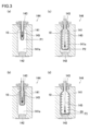
具体的には、図3に例示するように、延伸ロッド145を移動(下降)させて延伸ロッドによってプリフォーム10の底部を押圧すると共に、プリフォーム10内にブローエア(一次エア)を導入することで、プリフォーム10を縦軸方向及び横軸方向に延伸させる。すなわちプリフォーム10を所定の大きさまで膨張させる。
Specifically, as illustrated in FIG. 3, the stretching
より詳細には、図3(a)に例示するように、まずは延伸ロッド145を予め設定された第1の位置P1まで移動(下降)させて延伸ロッド145によってプリフォーム10を縦軸方向に延伸させる。次いで、延伸ロッド145が予め設定された第1の位置P1に達した時点でプリフォーム10内に低圧のブローエア(一次エア)を導入し、プリフォーム10を縦軸方向及び横軸方向に延伸させる(図3(b))。つまり、第1の位置P1は、プリフォーム10内に一次エアを導入させ始める基準となる位置である。なお、一次エアの導入時も、延伸ロッド145の移動(下降)は継続している。一次エアは、例えば0.3MPa~1.5MPaの圧力に設定される。
More specifically, as illustrated in FIG. 3(a), first, the stretching
その後、図3(c)に例示するように、延伸ロッド145が予め設定された第2の位置P2(第1の位置P1よりも下方)まで移動(下降)すると、プリフォーム10内に導入するブローエアの圧力を変更する。すなわちプリフォーム10に導入するブローエアを、一次エアから一次エアよりも高圧の二次エアに切り替える。つまり、第2の位置P2は、プリフォーム10内に二次エアを導入させ始める基準となる位置である。この一次エアから二次エアへの切替により、プリフォーム10をさらに縦軸方向及び横軸方向に延伸させる。同時に、延伸ロッド145を第2の位置P2から下方に移動させることでプリフォーム10を縦軸方向にさらに延伸させ、延伸ロッド145は予め設定された最終下降位置(ストレッチ完了位置)である第3の位置P3に静止する。これにより、最終成形品である中空容器20を形成する(図3(d))。二次エアは、例えば2.0MPa~3.5MPaの圧力に設定される。
Thereafter, as illustrated in FIG. 3(c), when the stretching
延伸ブロー成形部140(延伸ブロー成形型144)で成形された中空容器20は、内部のブローエアが排気された後、次のプリフォーム10が搬送されるタイミングで、把持機構搬送部155によって延伸ブロー成形部140の外側の取り出し位置Paまで搬送される。そして、中空容器20は取り出し位置Paにおいて装置外に取り出される(図1参照)。
After the internal blow air is exhausted, the
ところで、延伸ブロー成形部140では、射出成形部110で一度に形成されたN個のプリフォーム10をn(nは2以上の整数)回に分け、一度にM(N/n:Mは自然数))個の中空容器20を形成する。本実施形態では、射出成形部110で一度に形成された12個のプリフォーム10を3回に分け、一度に4個のプリフォーム10を延伸ブロー成形して中空容器20を形成している。
By the way, in the stretch
このように射出延伸ブロー成形装置100では、射出成形部110にて1回の射出成形を実施する間に、延伸ブロー成形部140では3回の延伸ブロー成形を実施しているため、1回の延伸ブロー成形に使える時間は非常に短い。このため、延伸ブロー成形における延伸ロッド145の移動やブローエアの供給は、高精度に制御する必要がある。
In this way, in the injection stretch blow
そこで射出延伸ブロー成形装置100では、延伸ロッド145の実位置を検出し、検出した延伸ロッド145の実位置に基づいて、ブローエア(一次エア及び二次エア)のプリフォーム10への導入開始・停止を制御している。つまり、従来は、ブロー開始時間を起点としたタイマー制御式であったプリフォーム10へのブローエアの導入の制御を、延伸ロッド145の実位置に基づく位置制御式とした。
Therefore, in the injection stretch blow
ここで、延伸ブロー成形部140は、図4のブロック図に例示するように、ブローコア型143(プリフォーム10)にブローエアを供給する供給部160と、延伸ロッド145を駆動する駆動部170と、これら供給部160と駆動部170とを制御する制御部180と、を備えている。
Here, the stretch
供給部160は、図示は省略するが、エア源及びエアタンクを備えると共に、エアタンクからブローコア型143にブローエアを供給する供給系及びブローコア型143からブローエアを排気する排気系を備えている。駆動部170は、延伸ロッド145を移動(昇降)させるための電動の駆動源を備えている。本実施形態では、駆動部170は、サーボモータ(電動モータ)を駆動源として備えている。
Although not shown, the
制御部180は、射出延伸ブロー成形装置100が備える各種機器の動作を制御するものであるが、その一つとして供給部160及び駆動部170の制御を行う。なお制御部180は、例えば、入出力装置、記憶装置(ROM、RAM等)、中央処理装置(CPU)、タイマカウンタ等で構成されている。
The
具体的には、制御部180は、駆動制御手段181と、検出手段182と、供給制御手段183と、を備えている。駆動制御手段181は、駆動部170のサーボモータによる延伸ロッド145の移動(昇降)を制御する。駆動制御手段181は、例えば、作業者による設定条件に基づいて、延伸ロッド145の移動の開始・停止及び移動速度等を適宜制御する。
Specifically, the
検出手段182は、駆動部170が備えるサーボモータ171の回転位置(エンコーダの出力値)に基づいて、延伸ロッド145の実際の位置(実位置)を検出する。検出手段182による延伸ロッド145の実位置の検出方法は、特に限定されるものではない。
The detection means 182 detects the actual position (actual position) of the stretching
供給制御手段183は、検出手段182の検出結果に基づいてブローエアの供給状態を制御する。具体的には、供給制御手段183は、検出手段182が検出した延伸ロッド145の実位置に基づいて供給部160を制御してブローコア型143へのブローエアの供給開始・停止等、すなわちプリフォーム10内へのブローエア(一次エア・二次エア)の導入開始・停止等を適宜制御する。このため、供給制御手段183は、検出手段182の検出結果に基づいて、プリフォーム10内に導入するブローエアを、一次エアから二次エアに切り替えることができる。本実施形態において、供給制御手段183は、延伸ロッド145の実位置が第2の位置P2にあることを検出手段182が検出すると、プリフォーム10内に導入するブローエアを、一次エアから二次エアに切り替えるように供給部160を制御する。
The supply control means 183 controls the blow air supply state based on the detection result of the detection means 182. Specifically, the supply control means 183 controls the
このように本実施形態では、延伸ロッド145が、任意に設定された二つの下降位置(第1の位置P1,第2の位置P2)に到達した時点で、ブローエア(一次エア・二次エア)をプリフォーム10に適宜導入させるようにした。これにより、プリフォーム10の長さや伸長状況に応じたブローエアの導入が可能になり、容器成形のハイサイクル化にも対応できるようになる。すなわち、従来はハイサイクル条件下での成形が困難であった中空容器20の製造も可能となる。例えば、重量が10g以下の薄肉容器を、ブロー成形時間0.6秒の条件で多数個同時に製造することも可能となる。
In this way, in this embodiment, when the stretching
また制御部180は、制御対象となる各種機器の制御条件を設定するための設定情報を画面に表示する比較的大型のディスプレイ(表示手段)190を備えると共に、このディスプレイ190の画面の表示状態を制御する表示制御手段184を備えている。
The
図5に例示するように、ディスプレイ190には、各種情報(制御条件、設定値、等)を必要に応じて設定可能かつ表示可能なメイン表示部191と、特定の情報等を常時表示させるサブ表示部192とが設けられている。本実施形態では、ディスプレイ190の中央部の領域がメイン表示部191として機能し、メイン表示部191の上側のヘッダー部193と、メイン表示部191の下側のフッター部194とがサブ表示部192として機能する。
As illustrated in FIG. 5, the
ディスプレイ190は、例えば、タッチパネル等で構成されており、作業者が各種制御条件(各種機器の動作条件や各種ステーションの制御条件)を入力する入力手段としても機能する。
The
表示制御手段184は、ディスプレイ190のメイン表示部191に、制御条件を設定するための情報を必要に応じて表示させる。表示制御手段184は、例えば、延伸ブロー成形に関しては、延伸ロッド145の実位置と、一次エア及び二次エアを含むブローエアの供給状態とを関連付けて設定可能な画面を表示する。
The display control means 184 causes the
作業者は、位置制御式のブローエアの供給制御により供給部160を制御する場合、タッチパネルとして機能するディスプレイ190に、各種制御条件(設定値)を入力する。例えば、メイン表示部191において、ブロー成形時間(「Blow time」)や、ブローエア排気時間(「Decomp. time」)等を入力すると共に、一次ブロー開始位置(「Pri.」)、2次ブロー開始位置(「Sec.」)およびストレッチ完了位置(不図示)に、延伸ロッド145の実位置として第1の位置の値(P1)、第2の位置の値(P2)および第3の位置の値(P3)をそれぞれ入力する。作業者は、当該入力操作を行うことで、一次ブロー(Pri.)でプリフォーム10に導入される一次エアと、二次ブロー(Sec.)でプリフォーム10に導入される二次エアとが、供給部160によって供給されるタイミングを設定することができる。なお、ブローエアの供給タイミングは、キャビティ141a毎に設定できるようになっている。また、メイン表示部191に、延伸ロッド145が第1の位置P1、第2の位置P2、および第3の位置P3のそれぞれの位置に到達するまでに要した時間(実測値)等を表示させることもできる。
When controlling the
このように本実施形態に係る射出延伸ブロー成形装置100では、作業者は、位置制御式のブローエアの供給制御の条件を、一画面にて適切に設定することができる。
As described above, in the injection stretch blow
さらに、射出延伸ブロー成形装置100は、位置制御式のブローエアの供給制御と、タイマー制御式のブローエアの供給制御とを切り替えることができるように構成されている。これにより、作業者は成形する中空容器20に応じた延伸ブロー成形の制御方式を選択することができ、装置の汎用性が高まる。
Furthermore, the injection stretch blow
図5に示す例では、ディスプレイ190の画面中のブローエア導入タイミング選択欄(「Blow timing select」)にて、タイマー(時間経過)を基準として一次エアと二次エアからなるブローエアの導入開始タイミングを定めた第1のブローエア導入制御手段(タイマー制御:「Blow timer」)と延伸ロッドの実位置(下降位置)を基準として一次エアと二次エアからなるブローエアの導入開始タイミングを定めた第2のブローエア導入制御手段(位置制御:「Stretch Position」)の何れかを選択することで、ブローエアの導入制御の切り替えを行うことができるようになっている。
In the example shown in FIG. 5, in the blow air introduction timing selection column (“Blow timing select”) on the screen of the
以上説明したように、本開示に係る樹脂製容器(中空容器)の製造装置及び製造方法によれば、延伸ブロー成形時間が非常に短い条件(ハイサイクル条件)下でも、プリフォームを適切に延伸させて品質良好な樹脂製容器(中空容器)を安定的に製造することができる。 As explained above, according to the apparatus and method for manufacturing a resin container (hollow container) according to the present disclosure, the preform can be stretched appropriately even under conditions where the stretch blow molding time is very short (high cycle conditions). As a result, resin containers (hollow containers) of good quality can be stably manufactured.
また、本開示に係る樹脂製容器(中空容器)の製造方法によれば、供給制御手段183は、検出された延伸ロッド145の実位置に基づいて、プリフォーム10に導入されるブローエアを一次エアから二次エアに切り替える。このため、延伸ロッド145の移動と、一次エアと二次エアの導入開始時間の各々と、を適切に調和させることができ、その結果、プリフォームを適切に延伸させて品質良好な樹脂製容器(中空容器)を製造することができる。
Further, according to the method for manufacturing a resin container (hollow container) according to the present disclosure, the supply control means 183 controls the blow air introduced into the
また、本開示に係る樹脂製容器(中空容器)の製造方法では、一次エアを導入させ始める基準となる位置である第1の位置P1と、一次エアよりも高圧の二次エアを導入させ始める基準となる位置である第2の位置P2が、それぞれ設定されている。供給制御手段183は、延伸ロッド145の実位置が第1の位置P1になると一次エアを導入させ始め、延伸ロッド145の実位置が第1の位置P1よりも下方に位置する第2の位置P2になると二次エアを導入させ始める。具体的には、延伸ロッド145の実位置が第2の位置P2にあることを検出手段182が検出すると、供給制御手段183は、プリフォーム10内に導入するブローエアを一次エアから二次エアに切り替える。このため、本開示に係る樹脂製容器(中空容器)の製造方法によれば、延伸ロッド145の実位置に基づいて精度よくブローエアを切り替えることができる。つまり、延伸ロッド145によるプリフォーム10の縦軸延伸(縦軸方向への延伸)に対応させるように、一次エアおよび二次エアによるプリフォーム10の横軸延伸(横軸方向への延伸)を実施することが可能になり、当該縦軸延伸と当該横軸延伸をより調和させて実施できる。また、本開示に係る樹脂製容器(中空容器)の製造方法によれば、二次エアの導入は、延伸ロッド145の実位置が第1の位置P1より下方に位置する第2の位置P2にあることが検出されたときに開始される。つまり、二次エアの導入は、延伸ロッド145の実位置に基づく位置制御により、適切なタイミングで行われるので、容器の芯ずれや肉厚分布の不良を防ぐこともできる。また、容器の剛性等の品質を上げるには、容器を構成する樹脂材料の配向結晶度を上げる必要がある。配向結晶度を上げるには、樹脂材料の延伸速度を上げること(延伸ロッドを高速で移動(下降動作)させ、かつ、ブローエアを短時間で導入させ、プリフォームを短時間で延伸させること)が有効である。しかし、樹脂材料の延伸速度を上げると、タイマー制御式では、延伸ロッドの移動とブローエアの導入タイミングとが適切に合わせ難くなる。これに対し、本開示に係る樹脂製容器(中空容器)の製造装置及び製造方法によれば、樹脂材料の延伸速度を上げても、延伸ロッド145の移動とブローエアの導入タイミングとが適切に合わせ易く、成形サイクル時間が短縮した条件下でも、従来より高品質の容器を製造することができる。
In addition, in the method for manufacturing a resin container (hollow container) according to the present disclosure, there is a first position P1 which is a reference position at which the primary air starts to be introduced, and a first position P1 where the secondary air having a higher pressure than the primary air starts to be introduced. A second position P2, which is a reference position, is set respectively. The supply control means 183 starts introducing the primary air when the actual position of the stretching
(第二実施形態)
次に、本開示の第二実施形態について、図6~図8を参照しつつ詳細に説明する。なお、第二実施形態の説明において、第一実施形態での説明と重複する部分については、適宜省略する。第二実施形態は、延伸ロッド145が第2の位置P2まで移動(下降)した時刻から所定の待機時間を経過した時に一次エアから二次エアへの切替が行われる点で、第一実施形態と異なる。
(Second embodiment)
Next, a second embodiment of the present disclosure will be described in detail with reference to FIGS. 6 to 8. In addition, in the description of the second embodiment, parts that overlap with the description of the first embodiment will be omitted as appropriate. The second embodiment differs from the first embodiment in that the switching from primary air to secondary air is performed when a predetermined waiting time has elapsed from the time when the stretching
図6は、各時刻における延伸ロッド145の位置を例示する図である。図7は、第二実施形態に係る延伸ブロー成形部140Aによる中空容器20Aの成形手順を説明する図である。なお、本明細書では、延伸ロッド145を初期位置から第2の位置P2まで下降させる時間(時刻t0から時刻t2までの時間)を延伸時間、延伸ロッド145が第2の位置P2で停止しており、かつ一次エアがプリフォーム10に導入されている時間(時刻t2から時刻t3までの時間)を第1の待機時間、延伸ロッド145が第2の位置P2で停止しており、かつ二次エアがプリフォーム10に導入されている時間(時刻t3から時刻t4までの時間)を第2の待機時間、延伸ロッド145を第2の位置P2から初期位置まで上昇させる時間(時刻t4から時刻t6までの時間)を後退時間とそれぞれ呼ぶ。なお、第二実施形態における図6の実線で示す例では、第2の位置P2と第3の位置P3は、同じ位置に設定される。
FIG. 6 is a diagram illustrating the position of the stretching
図6に例示するように、時刻t0から時刻t1において、延伸ロッド145は第1の位置P1まで下降する。これにより、プリフォーム10は縦軸方向に延伸する。一方、時刻t0から時刻t1の間、プリフォーム10内へブローエアは導入されていないため、横軸方向には延伸しない(図7(a))。
As illustrated in FIG. 6, the stretching
時刻t1から時刻t2において、延伸ロッド145は、第1の位置P1で停止することなく、第1の位置P1から第2の位置P2まで下降する。すなわち、延伸ロッド145は、延伸時間において下降し続け、プリフォーム10は縦軸方向に継続して延伸する。一方、検出手段182は、時刻t1において、延伸ロッド145が第1の位置P1まで下降したことを検出し、検出結果を供給制御手段183に送信する。供給制御手段183は、当該検出結果に基づいて、プリフォーム10に一次エアを導入するよう供給部160を制御する。その結果、時刻t1において、プリフォーム10内へは一次エアが導入され始める。プリフォーム10内へ一次エアが導入されると、プリフォーム10は横軸方向に延伸する(図7(b))。
From time t1 to time t2, the stretching
次に、第1の待機時間における延伸ロッド145の実位置とプリフォーム10内へ導入されるブローエアについて説明する。検出手段182は、時刻t2において、延伸ロッド145が第2の位置P2まで下降したことを検出し、検出結果を駆動制御手段181に送信する。駆動制御手段181は、当該検出結果に基づいて、延伸ロッド145の実位置が第2の位置P2にあることを検出した時刻から第1の待機時間および第2の待機時間が経過するまでの間(すなわち、時刻t2から時刻t4までの時間)、延伸ロッド145が第2の位置P2で停止するよう、延伸ロッド145を制御する。このため、第1の待機時間および第2の待機時間において、延伸ロッド145は第2の位置P2の位置で停止している。また、検出手段182は、時刻t2において、上記検出結果を供給制御手段183にも送信する。検出結果を受信した供給制御手段183は、延伸ロッド145の実位置が第2の位置P2にあることを検出した時刻から作業者が予め設定した所定の第1の待機時間が経過すると(すなわち、時刻t3になると)、プリフォーム10に導入するブローエアを一次エアから二次エアに切り替えるよう供給部160を制御する。つまり、本実施形態における第2の位置P2は、プリフォーム10内に二次エアを導入させ始める時刻を供給制御手段183がカウントし始める際の起点(基準)となる位置である。供給制御手段183は、上記のように供給部160を制御するので、第1の待機時間において、プリフォーム10内へは一次エアが導入され続ける。したがって、時刻t2において、プリフォーム10の側面における縦軸方向の略中央部分は他の部分よりも横軸方向に膨れた状態であるが(図7(c))、時刻t3になると、プリフォーム10には十分な一次エアが導入された状態となる(図7(d))。そして、時刻t3において、一次エアより高圧の二次エアの導入が開始される。
Next, the actual position of the stretching
次に時刻t3から時刻t6(第2の待機時間および後退時間)における延伸ロッド145の実位置とプリフォーム10内へ導入されるブローエアについて説明する。上述したように、第2の待機時間において、延伸ロッド145は第2の位置P2で停止している。すなわち、図6の実線で示すように、第2の位置P2と第3の位置P3は同一の位置である。時刻t4になると、駆動制御手段181は、延伸ロッド145を第2の位置P2から初期位置まで上昇させるよう、延伸ロッド145を制御する。つまり、時刻t4になると、延伸ロッド145はプリフォーム10の底部に対して上方に移動し始める。また、時刻t6において、検出手段182は、延伸ロッド145が初期位置まで上昇したことを検出し、検出結果を駆動制御手段181に送信する。駆動制御手段181は、当該検出結果に基づいて、延伸ロッド145が初期位置で停止するよう、延伸ロッド145を制御する。このため、後退時間において、延伸ロッド145は上昇し続け、時刻t6になると、延伸ロッド145の上昇が止まる。一方、時刻t3から時刻t5において、プリフォーム10には二次エアが導入され続ける。その結果、時刻t5において、プリフォーム10は、最終成形品である中空容器20Aとなる(図7(e))。なお、供給制御手段183は、時刻t5において、ブローエアの供給を停止して排気するよう供給部160を制御する。したがって、時刻t5から時刻t6において、ブローエアはプリフォーム10に供給されず排気される。
Next, the actual position of the stretching
図8は、第二実施形態に係るディスプレイ190Aの表示の一例を示す図である。図8に例示するように、第二実施形態に係るディスプレイ190Aには、各種情報(制御条件、設定値、等)を必要に応じて設定可能かつ表示可能なメイン表示部191Aと、第一実施形態と同様の構成であるサブ表示部192とが設けられている。メイン表示部191Aは、二次ブロー(Sec.)に関する表示領域の隣(図8において右隣)に供給制御手段183によるタイマー制御(Timer)に関する設定・表示領域が設けられている点と、延伸ロッドの下降位置とダイマー(時間経過)の両方を基準として一次エアと二次エアからなるブローエアの導入開始タイミングを定めた第3のブローエア導入手段(位置・タイマー併用制御「Stretch Position 2」)が追加されている点で、第一実施形態に係るメイン表示部191と異なる。タイマー制御(Timer)に関する設定領域には、第1の待機時間に対応する時間が入力(設定)される。また、タイマー 制御(Timer)に関する表示領域には、第1の待機時間の実測値が表示される。例えば、作業者がタイマー制御(Timer)に対して、製造する樹脂製容器に応じた所定の入力操作を行うと、延伸ロッド145が第2の位置P2まで下降した時刻から作業者が入力した時間が経過したときに、プリフォーム10に導入されるブローエアが一次エアから二次エアに切り替わるよう、供給制御手段183は供給部160を制御する。
FIG. 8 is a diagram showing an example of a display on a display 190A according to the second embodiment. As illustrated in FIG. 8, a display 190A according to the second embodiment includes a
ところで、例えば、比較的大きな樹脂製容器(例えば、1500ml用の容器)を製造する場合、小さな樹脂製容器(例えば、500ml用の容器)を製造する場合と比べて、二次エアを導入し始める前により多くの一次エアをプリフォーム10に導入しておく必要がある。これは、大きな樹脂製容器は、小さな樹脂製容器よりも横軸方向の幅を大きくする必要があるので、十分な一次エアがプリフォーム10に導入されないまま、第二エアがプリフォーム10に導入されると、悪質な容器が製造されてしまう虞があるからである。
By the way, for example, when manufacturing a relatively large resin container (for example, a 1500ml container), secondary air is introduced more often than when manufacturing a small resin container (for example, a 500ml container). It is necessary to introduce more primary air into the
本開示に係る樹脂製容器(中空容器)の製造装置及び製造方法によれば、供給制御手段183は、検出手段182が延伸ロッド145の実位置が第2の位置P2にあることを検出した時刻から所定の第1の待機時間(時刻t2から時刻t3までの時間)が経過すると、プリフォーム10内に導入するブローエアを、一次エアから二次エアに切り替えるように供給部160を制御する。したがって、検出手段182が延伸ロッド145の実位置が第2の位置P2にあることを検出した時刻から所定の第1の待機時間が経過するまでは、一次エアがプリフォーム10内に導入され続け、その後、二次エアがプリフォーム10内に導入され始める。このため、二次エアがプリフォーム10に導入される前に十分な一次エアをプリフォーム10に導入させることができる。このように、第二実施形態に係る射出延伸ブロー成形装置100Aは、第一実施形態に係る射出延伸ブロー成形装置100と比べて、二次エアが導入される前により多くの一次エアをプリフォーム10に導入させることができるので、特に比較的大きな樹脂製容器を製造する場合、良質な容器を製造することができる。また、本開示に係る樹脂製容器(中空容器)の製造装置及び製造方法によれば、成形サイクル時間が短い(延伸ロッド145が下降する速度が速い)場合であっても、延伸ロッド145の実位置に基づく位置制御とタイマー制御を組み合わせた制御により、延伸ロッド145によるプリフォーム10の縦軸延伸と、一次エアおよび二次エアによるプリフォーム10の横軸延伸と、を調和させて実施することができる。このため、射出延伸ブロー成形装置100Aは、プリフォーム10を適切に延伸させることができ、その結果、品質良好な樹脂製容器(中空容器)を製造することができる。
According to the apparatus and method for manufacturing a resin container (hollow container) according to the present disclosure, the supply control means 183 detects the time when the detection means 182 detects that the actual position of the stretching
また、本開示に係る樹脂製容器(中空容器)の製造装置及び製造方法によれば、第2の待機時間(時刻t3から時刻t4までの間)を含む時間(時刻t3から時刻t5までの間)において、プリフォーム10内には二次エアが導入される。したがって、延伸ロッド145は、プリフォーム10内に二次エアがある程度導入されてから、初期位置に向かって移動(上昇)し始める。このため、射出延伸ブロー成形装置100Aによれば、容器の形状が意図しない形状になることを防ぐことができる。
Further, according to the apparatus and method for manufacturing a resin container (hollow container) according to the present disclosure, the time period (from time t3 to time t5) including the second standby time (from time t3 to time t4) ), secondary air is introduced into the
また本開示は、上述した実施形態に限定されるものではない。例えば、上述の実施形態では、延伸ブロー成形部(延伸ブロー成形型)が一列に設けられた4個のキャビティを備えた構成を例示したが、キャビティの数は特に限定されず、例えば、8個、12個等であってもよい。 Further, the present disclosure is not limited to the embodiments described above. For example, in the above-described embodiment, the stretch blow molding part (stretch blow mold) has four cavities arranged in a row, but the number of cavities is not particularly limited, and for example, eight cavities are provided. , 12, etc. may be used.
第二実施形態において、駆動制御手段181は第1の待機時間および第2の待機時間において、延伸ロッド145が第2の位置P2で停止するよう、延伸ロッド145を制御しているが、この例に限られない。例えば、図6の一点鎖線で示すように、駆動制御手段181は、第1の待機時間においては延伸ロッド145が第2の位置P2で停止するよう延伸ロッド145を制御し、第2の待機時間においては延伸ロッド145が第2の位置P2の位置からさらに第3の位置P3へ下降するよう延伸ロッド145を制御してもよい。この場合、検出手段182は、例えば、時刻t4になると延伸ロッド145が中空容器20Aの底部まで下降したことを検出し、検出結果を駆動制御手段181に送信する。そして駆動制御手段181は、当該検出結果に基づいて、延伸ロッド145を初期位置まで上昇させるよう、延伸ロッド145を制御する。
In the second embodiment, the drive control means 181 controls the stretching
本出願は、2019年4月3日出願の日本国特許出願(特願2019-071569号)に基づくものであり、その内容はここに参照として取り込まれる。 This application is based on a Japanese patent application (Japanese Patent Application No. 2019-071569) filed on April 3, 2019, the contents of which are incorporated herein by reference.
Claims (8)
少なくとも前記ブローエアの開始位置を入力可能かつ表示可能な表示手段と、
前記プリフォーム内に挿入された前記延伸ロッドの実位置を検出する検出手段と、
前記表示手段に入力された前記ブローエアの開始位置と、前記検出手段の検出結果と、に基づいて、前記ブローエアの供給状態を制御する供給制御手段と、を有する、樹脂製容器の製造装置。 A resin container manufacturing apparatus in which a preform placed in a stretch blow molding mold is stretched by a stretching rod, and blow air is introduced into the preform to stretch the preform into a resin container. There it is,
Display means capable of inputting and displaying at least the starting position of the blow air;
detection means for detecting the actual position of the stretching rod inserted into the preform;
A manufacturing apparatus for a resin container, comprising: a supply control means for controlling a supply state of the blow air based on a starting position of the blow air input to the display means and a detection result of the detection means.
前記検出手段は、前記サーボモータの回転位置に基づいて前記延伸ロッドの実位置を検出する、請求項1に記載の樹脂製容器の製造装置。 The driving source of the stretching rod is a servo motor,
The resin container manufacturing apparatus according to claim 1, wherein the detection means detects the actual position of the stretching rod based on the rotational position of the servo motor.
少なくとも前記ブローエアの開始位置を入力可能かつ表示可能な表示手段に前記前記ブローエアの開始位置を入力し、
前記プリフォーム内に挿入された前記延伸ロッドの実位置を検出し、
前記表示手段に入力された前記ブローエアの開始位置と、前記延伸ロッドの実位置と、に基づいて前記ブローエアの供給状態を制御する、樹脂製容器の製造方法。 A method for manufacturing a resin container, in which a preform placed in a stretch blow molding mold is stretched by a stretching rod, and blow air is introduced into the preform to stretch the preform to form a resin container. There it is,
inputting the starting position of the blow air into a display means capable of inputting and displaying at least the starting position of the blow air;
detecting the actual position of the stretching rod inserted into the preform;
A method for manufacturing a resin container, wherein the supply state of the blow air is controlled based on a starting position of the blow air input to the display means and an actual position of the stretching rod.
Priority Applications (1)
| Application Number | Priority Date | Filing Date | Title |
|---|---|---|---|
| JP2024029961A JP2024051146A (en) | 2019-04-03 | 2024-02-29 | Manufacturing device and manufacturing method for resin container |
Applications Claiming Priority (3)
| Application Number | Priority Date | Filing Date | Title |
|---|---|---|---|
| JP2019071569 | 2019-04-03 | ||
| JP2019071569 | 2019-04-03 | ||
| PCT/JP2020/015382 WO2020204178A1 (en) | 2019-04-03 | 2020-04-03 | Resin container manufacturing device and manufacturing method |
Related Child Applications (1)
| Application Number | Title | Priority Date | Filing Date |
|---|---|---|---|
| JP2024029961A Division JP2024051146A (en) | 2019-04-03 | 2024-02-29 | Manufacturing device and manufacturing method for resin container |
Publications (2)
| Publication Number | Publication Date |
|---|---|
| JPWO2020204178A1 JPWO2020204178A1 (en) | 2020-10-08 |
| JP7448525B2 true JP7448525B2 (en) | 2024-03-12 |
Family
ID=72669059
Family Applications (2)
| Application Number | Title | Priority Date | Filing Date |
|---|---|---|---|
| JP2021512332A Active JP7448525B2 (en) | 2019-04-03 | 2020-04-03 | Manufacturing equipment and manufacturing method for resin containers |
| JP2024029961A Pending JP2024051146A (en) | 2019-04-03 | 2024-02-29 | Manufacturing device and manufacturing method for resin container |
Family Applications After (1)
| Application Number | Title | Priority Date | Filing Date |
|---|---|---|---|
| JP2024029961A Pending JP2024051146A (en) | 2019-04-03 | 2024-02-29 | Manufacturing device and manufacturing method for resin container |
Country Status (5)
| Country | Link |
|---|---|
| US (1) | US11958231B2 (en) |
| EP (1) | EP3950267A4 (en) |
| JP (2) | JP7448525B2 (en) |
| CN (2) | CN113825618B (en) |
| WO (1) | WO2020204178A1 (en) |
Families Citing this family (1)
| Publication number | Priority date | Publication date | Assignee | Title |
|---|---|---|---|---|
| WO2023189983A1 (en) * | 2022-03-30 | 2023-10-05 | 株式会社ユポ・コーポレーション | Labeled container and method for manufacturing same |
Citations (3)
| Publication number | Priority date | Publication date | Assignee | Title |
|---|---|---|---|---|
| WO2010083810A2 (en) | 2009-01-21 | 2010-07-29 | Khs Corpoplast & Co. Kg | Method and device for blow-forming containers |
| WO2014068080A1 (en) | 2012-11-01 | 2014-05-08 | Norgren Gmbh | Stretch blow molding system with simultaneous preblowing valve actuation |
| JP2017524572A (en) | 2014-07-25 | 2017-08-31 | シデル パルティシパションSidel Participations | Control method for blow molding method of container made of plastic material |
Family Cites Families (14)
| Publication number | Priority date | Publication date | Assignee | Title |
|---|---|---|---|---|
| US5169705A (en) | 1991-02-14 | 1992-12-08 | Husky Injection Molding Systems Ltd. | Servo electric driven stretch rods for blow molding machine |
| EP0499136A3 (en) * | 1991-02-14 | 1993-06-23 | Husky Injection Molding Systems Ltd. | Servo electric driven stretch rods for blow molding machine |
| JP3344595B2 (en) * | 1993-03-02 | 2002-11-11 | 日精エー・エス・ビー機械株式会社 | Biaxial stretch blow molding equipment |
| JPH09272147A (en) * | 1996-04-05 | 1997-10-21 | Mitsubishi Plastics Ind Ltd | Stretching apparatus of blow molding machine |
| JPH1076568A (en) * | 1996-09-05 | 1998-03-24 | Mitsubishi Plastics Ind Ltd | Method of blow molding |
| JP3907494B2 (en) | 2001-12-07 | 2007-04-18 | 日精エー・エス・ビー機械株式会社 | Blow molding method and apparatus |
| US8573964B2 (en) * | 2006-04-13 | 2013-11-05 | Amcor Limited | Liquid or hydraulic blow molding |
| FR2921293B1 (en) * | 2007-09-24 | 2012-11-02 | Sidel Participations | PROCESS FOR MANUFACTURING CONTAINERS COMPRISING AN INTERMEDIATE DEPRESSURIZATION OPERATION |
| DE202008005257U1 (en) * | 2008-04-17 | 2008-11-20 | Krones Ag | Device for blow molding |
| KR101378551B1 (en) * | 2012-03-26 | 2014-03-27 | (주)피스코 | Blowing Apparatus For The PET Bottle Apparatus And Setting Method Used Blowing Apparatus |
| CN104411475B (en) * | 2012-04-26 | 2017-06-20 | 诺冠股份公司 | Stretch blow molding system |
| FR2997339B1 (en) * | 2012-10-29 | 2014-12-12 | Sidel Participations | PROCESS FOR BLOWING CONTAINERS WITH A BEARING, AND MACHINE FOR SAID METHOD |
| FR2998207B1 (en) | 2012-11-20 | 2015-01-16 | Sidel Participations | METHOD OF STRETCH BLOWING A CONTAINER, COMPRISING A MEASUREMENT OF THE SHIFT OF THE STRETCH ROD DURING A BOXING OPERATION |
| JP7036415B2 (en) | 2017-10-10 | 2022-03-15 | 日本電気通信システム株式会社 | Radio base station equipment, mobile station control methods and programs |
-
2020
- 2020-04-03 CN CN202080033679.8A patent/CN113825618B/en active Active
- 2020-04-03 JP JP2021512332A patent/JP7448525B2/en active Active
- 2020-04-03 US US17/600,790 patent/US11958231B2/en active Active
- 2020-04-03 EP EP20783063.9A patent/EP3950267A4/en active Pending
- 2020-04-03 CN CN202311410131.2A patent/CN117261173A/en active Pending
- 2020-04-03 WO PCT/JP2020/015382 patent/WO2020204178A1/en unknown
-
2024
- 2024-02-29 JP JP2024029961A patent/JP2024051146A/en active Pending
Patent Citations (3)
| Publication number | Priority date | Publication date | Assignee | Title |
|---|---|---|---|---|
| WO2010083810A2 (en) | 2009-01-21 | 2010-07-29 | Khs Corpoplast & Co. Kg | Method and device for blow-forming containers |
| WO2014068080A1 (en) | 2012-11-01 | 2014-05-08 | Norgren Gmbh | Stretch blow molding system with simultaneous preblowing valve actuation |
| JP2017524572A (en) | 2014-07-25 | 2017-08-31 | シデル パルティシパションSidel Participations | Control method for blow molding method of container made of plastic material |
Also Published As
| Publication number | Publication date |
|---|---|
| US11958231B2 (en) | 2024-04-16 |
| CN113825618B (en) | 2023-11-17 |
| WO2020204178A1 (en) | 2020-10-08 |
| JPWO2020204178A1 (en) | 2020-10-08 |
| CN117261173A (en) | 2023-12-22 |
| US20220176609A1 (en) | 2022-06-09 |
| CN113825618A (en) | 2021-12-21 |
| JP2024051146A (en) | 2024-04-10 |
| EP3950267A1 (en) | 2022-02-09 |
| EP3950267A4 (en) | 2023-01-04 |
Similar Documents
| Publication | Publication Date | Title |
|---|---|---|
| KR20190087658A (en) | Manufacturing method of resin container, mold unit and molding machine | |
| US10870231B2 (en) | Biaxial stretching and blow molding device | |
| JP2024051146A (en) | Manufacturing device and manufacturing method for resin container | |
| US8721940B2 (en) | Method for producing a vessel from a preform, with feedback depending on the development point of the preform | |
| US11472091B2 (en) | Two step blow molding unit, apparatus and method | |
| US20190389117A1 (en) | Blow molding device and blow molding method | |
| US11478974B2 (en) | Blow molding machine and method for controlling blow molding machine | |
| JP6712259B2 (en) | Control method of blow molding method for container made of plastic material | |
| JP4388809B2 (en) | Component transfer method and apparatus for injection stretch blow molding system | |
| JP6012683B2 (en) | Molding machine and molding method for thermoplastic material container | |
| EP3954528A1 (en) | Resin container manufacturing method | |
| US11478973B2 (en) | Method for manufacturing resin container, and device for manufacturing resin container | |
| JP6727760B2 (en) | Hollow container manufacturing method and blow molding apparatus | |
| JP2006264035A (en) | Blow molding method | |
| WO2020209291A1 (en) | Resin molded article manufacturing device, and manufacturing device control method | |
| US20240123672A1 (en) | Method for manufacturing resin container and resin container manufacturing apparatus | |
| EP4029671A1 (en) | Method for producing resin container and apparatus for producing resin container | |
| EP4324620A1 (en) | Production method and production device for resin container | |
| JP2006305908A (en) | Method and apparatus for stretch blow molding | |
| US20240140015A1 (en) | Production method and production device for resin container | |
| TW202330237A (en) | Method for producing hollow molded article and injection stretch blow molding machine |
Legal Events
| Date | Code | Title | Description |
|---|---|---|---|
| A621 | Written request for application examination |
Free format text: JAPANESE INTERMEDIATE CODE: A621 Effective date: 20230329 |
|
| A131 | Notification of reasons for refusal |
Free format text: JAPANESE INTERMEDIATE CODE: A131 Effective date: 20231003 |
|
| A521 | Request for written amendment filed |
Free format text: JAPANESE INTERMEDIATE CODE: A523 Effective date: 20231130 |
|
| TRDD | Decision of grant or rejection written | ||
| A01 | Written decision to grant a patent or to grant a registration (utility model) |
Free format text: JAPANESE INTERMEDIATE CODE: A01 Effective date: 20240130 |
|
| A61 | First payment of annual fees (during grant procedure) |
Free format text: JAPANESE INTERMEDIATE CODE: A61 Effective date: 20240229 |
|
| R150 | Certificate of patent or registration of utility model |
Ref document number: 7448525 Country of ref document: JP Free format text: JAPANESE INTERMEDIATE CODE: R150 |