JP7448040B2 - Tire conveyance device - Google Patents
Tire conveyance device Download PDFInfo
- Publication number
- JP7448040B2 JP7448040B2 JP2022576993A JP2022576993A JP7448040B2 JP 7448040 B2 JP7448040 B2 JP 7448040B2 JP 2022576993 A JP2022576993 A JP 2022576993A JP 2022576993 A JP2022576993 A JP 2022576993A JP 7448040 B2 JP7448040 B2 JP 7448040B2
- Authority
- JP
- Japan
- Prior art keywords
- tire
- arm
- laser distance
- arms
- sensor
- Prior art date
- Legal status (The legal status is an assumption and is not a legal conclusion. Google has not performed a legal analysis and makes no representation as to the accuracy of the status listed.)
- Active
Links
- 230000008602 contraction Effects 0.000 claims description 20
- 230000007246 mechanism Effects 0.000 claims description 18
- 230000032258 transport Effects 0.000 description 19
- 238000001514 detection method Methods 0.000 description 13
- 238000000034 method Methods 0.000 description 11
- 230000008569 process Effects 0.000 description 10
- 238000010586 diagram Methods 0.000 description 7
- 230000005856 abnormality Effects 0.000 description 6
- 238000012937 correction Methods 0.000 description 5
- 238000012986 modification Methods 0.000 description 5
- 230000004048 modification Effects 0.000 description 5
- 238000012545 processing Methods 0.000 description 4
- 238000012546 transfer Methods 0.000 description 4
- 239000011324 bead Substances 0.000 description 3
- 230000002159 abnormal effect Effects 0.000 description 2
- 230000003028 elevating effect Effects 0.000 description 2
- 238000004804 winding Methods 0.000 description 2
- 238000004891 communication Methods 0.000 description 1
- 238000005516 engineering process Methods 0.000 description 1
- 230000001678 irradiating effect Effects 0.000 description 1
- 238000005259 measurement Methods 0.000 description 1
Images


Classifications
-
- B—PERFORMING OPERATIONS; TRANSPORTING
- B66—HOISTING; LIFTING; HAULING
- B66C—CRANES; LOAD-ENGAGING ELEMENTS OR DEVICES FOR CRANES, CAPSTANS, WINCHES, OR TACKLES
- B66C1/00—Load-engaging elements or devices attached to lifting or lowering gear of cranes or adapted for connection therewith for transmitting lifting forces to articles or groups of articles
- B66C1/10—Load-engaging elements or devices attached to lifting or lowering gear of cranes or adapted for connection therewith for transmitting lifting forces to articles or groups of articles by mechanical means
- B66C1/22—Rigid members, e.g. L-shaped members, with parts engaging the under surface of the loads; Crane hooks
- B66C1/28—Duplicate, e.g. pivoted, members engaging the loads from two sides
-
- B—PERFORMING OPERATIONS; TRANSPORTING
- B66—HOISTING; LIFTING; HAULING
- B66C—CRANES; LOAD-ENGAGING ELEMENTS OR DEVICES FOR CRANES, CAPSTANS, WINCHES, OR TACKLES
- B66C1/00—Load-engaging elements or devices attached to lifting or lowering gear of cranes or adapted for connection therewith for transmitting lifting forces to articles or groups of articles
- B66C1/10—Load-engaging elements or devices attached to lifting or lowering gear of cranes or adapted for connection therewith for transmitting lifting forces to articles or groups of articles by mechanical means
- B66C1/62—Load-engaging elements or devices attached to lifting or lowering gear of cranes or adapted for connection therewith for transmitting lifting forces to articles or groups of articles by mechanical means comprising article-engaging members of a shape complementary to that of the articles to be handled
- B66C1/66—Load-engaging elements or devices attached to lifting or lowering gear of cranes or adapted for connection therewith for transmitting lifting forces to articles or groups of articles by mechanical means comprising article-engaging members of a shape complementary to that of the articles to be handled for engaging holes, recesses, or abutments on articles specially provided for facilitating handling thereof
-
- B—PERFORMING OPERATIONS; TRANSPORTING
- B65—CONVEYING; PACKING; STORING; HANDLING THIN OR FILAMENTARY MATERIAL
- B65G—TRANSPORT OR STORAGE DEVICES, e.g. CONVEYORS FOR LOADING OR TIPPING, SHOP CONVEYOR SYSTEMS OR PNEUMATIC TUBE CONVEYORS
- B65G47/00—Article or material-handling devices associated with conveyors; Methods employing such devices
- B65G47/74—Feeding, transfer, or discharging devices of particular kinds or types
- B65G47/90—Devices for picking-up and depositing articles or materials
-
- B—PERFORMING OPERATIONS; TRANSPORTING
- B66—HOISTING; LIFTING; HAULING
- B66C—CRANES; LOAD-ENGAGING ELEMENTS OR DEVICES FOR CRANES, CAPSTANS, WINCHES, OR TACKLES
- B66C1/00—Load-engaging elements or devices attached to lifting or lowering gear of cranes or adapted for connection therewith for transmitting lifting forces to articles or groups of articles
- B66C1/10—Load-engaging elements or devices attached to lifting or lowering gear of cranes or adapted for connection therewith for transmitting lifting forces to articles or groups of articles by mechanical means
- B66C1/42—Gripping members engaging only the external or internal surfaces of the articles
- B66C1/44—Gripping members engaging only the external or internal surfaces of the articles and applying frictional forces
- B66C1/54—Internally-expanding grippers for handling hollow articles
-
- B—PERFORMING OPERATIONS; TRANSPORTING
- B66—HOISTING; LIFTING; HAULING
- B66C—CRANES; LOAD-ENGAGING ELEMENTS OR DEVICES FOR CRANES, CAPSTANS, WINCHES, OR TACKLES
- B66C13/00—Other constructional features or details
- B66C13/18—Control systems or devices
- B66C13/46—Position indicators for suspended loads or for crane elements
-
- B—PERFORMING OPERATIONS; TRANSPORTING
- B66—HOISTING; LIFTING; HAULING
- B66C—CRANES; LOAD-ENGAGING ELEMENTS OR DEVICES FOR CRANES, CAPSTANS, WINCHES, OR TACKLES
- B66C17/00—Overhead travelling cranes comprising one or more substantially horizontal girders the ends of which are directly supported by wheels or rollers running on tracks carried by spaced supports
- B66C17/04—Overhead travelling cranes comprising one or more substantially horizontal girders the ends of which are directly supported by wheels or rollers running on tracks carried by spaced supports with lifting beams, e.g. slewable beams, carrying load-engaging elements, e.g. magnets, hooks
-
- B—PERFORMING OPERATIONS; TRANSPORTING
- B65—CONVEYING; PACKING; STORING; HANDLING THIN OR FILAMENTARY MATERIAL
- B65G—TRANSPORT OR STORAGE DEVICES, e.g. CONVEYORS FOR LOADING OR TIPPING, SHOP CONVEYOR SYSTEMS OR PNEUMATIC TUBE CONVEYORS
- B65G2201/00—Indexing codes relating to handling devices, e.g. conveyors, characterised by the type of product or load being conveyed or handled
- B65G2201/02—Articles
- B65G2201/0273—Tires
Landscapes
- Engineering & Computer Science (AREA)
- Mechanical Engineering (AREA)
- Automation & Control Theory (AREA)
- Manipulator (AREA)
- Load-Engaging Elements For Cranes (AREA)
- Length Measuring Devices By Optical Means (AREA)
- Tyre Moulding (AREA)
Description
本発明は、タイヤ搬送装置、特に、横倒姿勢のタイヤの中心穴の上面開口縁に上方より複数のアームを挿入してアームのフックにて上面開口縁を下方から支持することでタイヤを持ち上げる装置に関する。 The present invention provides a tire transport device, and in particular, a plurality of arms are inserted from above into the upper opening edge of the center hole of a tire in a sideways position, and the upper opening edge is supported from below by the hooks of the arms to lift the tire. Regarding equipment.
タイヤ搬送装置は、先端にフックが形成された複数のアームと、アームを水平拡縮方向に移動させるアーム拡縮機構と、アーム及びアーム拡縮機構を昇降させる昇降機構とを有している。
タイヤ搬送装置は、横倒姿勢のタイヤの中心穴の上面開口の上方より複数のアームを下降させて上面開口内に挿入し、次にアームを広げる方向に移動させることでフックを上面開口縁の下方に移動させる。タイヤ搬送装置は、最後に、アームを上方に移動させて、フックにタイヤの上面開口縁を下方から支持させることで、タイヤを持ち上げる。
例えば、4本のアームをタイヤの内径に差し込んで移載する物品移載装置が知られている(例えば、特許文献1を参照)。
The tire conveyance device includes a plurality of arms each having a hook formed at its tip, an arm expansion/contraction mechanism that moves the arms in a horizontal expansion/contraction direction, and an elevation mechanism that raises and lowers the arms and the arm expansion/contraction mechanism.
The tire transport device lowers a plurality of arms from above the top opening of the center hole of a tire in a sideways position, inserts them into the top opening, and then moves the arms in the direction of widening to place the hooks on the edge of the top opening. Move it downward. Finally, the tire transport device lifts the tire by moving the arm upward and allowing the hook to support the upper opening edge of the tire from below.
For example, there is known an article transfer device that transfers items by inserting four arms into the inner diameter of a tire (for example, see Patent Document 1).
タイヤは一般に段積み保管されている。そして、段積みされたタイヤは、時間経過と共に変形して傾くことがある。タイヤは柔らかくて粘着性があるためである。
一方、タイヤ搬送装置は、定められた座標での停止制御が行われている。したがって、上記のように段積みされたタイヤが傾いていると、アームを下降させるときに、フックを傾いたタイヤに当ててしまうことがある。この場合、タイヤを搬送できなくなるだけでなく、タイヤを破損する可能性がある。
Tires are generally stored in stacks. The stacked tires may deform and tilt over time. This is because tires are soft and sticky.
On the other hand, the tire conveyance device is controlled to stop at predetermined coordinates. Therefore, if the stacked tires are tilted as described above, the hook may hit the tilted tires when lowering the arm. In this case, not only will the tires not be able to be transported, but there is a possibility that the tires will be damaged.
本発明の目的は、タイヤ搬送装置がタイヤを保持するときにアームがタイヤを破損しにくくすることにある。 An object of the present invention is to make it difficult for an arm to damage a tire when a tire conveyance device holds the tire.
以下に、課題を解決するための手段として複数の態様を説明する。これら態様は、必要に応じて任意に組み合せることができる。 A plurality of aspects will be described below as means for solving the problem. These aspects can be arbitrarily combined as necessary.
本発明の一見地に係るタイヤ搬送装置は、タイヤを持ち上げて搬送する装置であって、少なくとも3本のアームと、アーム拡縮機構と、昇降機構と、少なくとも3つの光反射センサと、コントローラとを備えている。
少なくとも3本のアームは、アーム本体と、アーム本体の下部に外側へ突出するように設けられておりタイヤを持ち上げるための突出部を有する。
アーム拡縮機構は、アームを水平拡縮方向に移動する。
昇降機構は、アームを昇降する。
少なくとも3つの光反射センサは、アームがタイヤの上方にありかつ縮径状態において突出部の先端を含む円の外側に配置されており、下方にある物体を検出する。なお、光反射センサは、光を下方に照射して得られた反射を検出可能なセンサである。また、下方とは、光反射センサの鉛直下の領域、または、鉛直下と鉛直下近傍を含む領域を意味する。後述するように、光反射センサは、下方にある物体までの距離を検出する距離センサであってもよい。光反射センサは、距離センサでなく、単純に下方にある物体の有無を検出するセンサであってもよい。
コントローラは、光反射センサの少なくとも1つによってタイヤが検出されると、アームの位置が不適切であると判断する。
この装置では、基本搬送動作として、昇降機構がアームを下降させてタイヤの内側に配置させ、続いてアーム拡縮機構が3本のアームのアーム本体を水平方向外側に拡げ、最後に昇降機装置がアームを上昇させてアームの突出部によってタイヤを持ち上げる。
この装置では、光反射センサがタイヤを検出すると、平面視で突出部に重なる位置にタイヤが配置されていることになる。この場合には、例えば、昇降機構はアームを下降させないので、タイヤが傾いたり位置が異なっていたりしていても、突出部がタイヤに接触しない。
全ての光反射センサがタイヤを検出しないときは、コントローラは、アームの位置が適切であると判断する。そして、コントローラは、タイヤの持ち上げ動作を行う。具体的には、コントローラは、アームを下降させ、アーム本体を水平方向外側に拡げ、アームを上昇させてアームの突出部によって、タイヤを持ち上げる。
コントローラは、光反射センサの少なくとも1つによってタイヤが検出されると、タイヤを検出したレーザ距離センサから円周中心を向く方向に少なくとも3本のアームを移動させてもよい。アームを移動させることで、アームの位置が補正される。
A tire conveyance device according to an aspect of the present invention is a device for lifting and conveying tires, and includes at least three arms, an arm expansion/contraction mechanism, an elevating mechanism, at least three light reflection sensors, and a controller. We are prepared.
The at least three arms include an arm body and a protrusion provided at the bottom of the arm body so as to protrude outward and for lifting the tire.
The arm expansion/contraction mechanism moves the arm in a horizontal expansion/contraction direction.
The lifting mechanism raises and lowers the arm.
At least three light reflective sensors are arranged with arms above the tire and outside a circle including the tip of the protrusion in the reduced diameter state to detect objects below. Note that the light reflection sensor is a sensor that can detect the reflection obtained by irradiating light downward. Further, the term "downward" means a region vertically below the light reflection sensor, or a region including vertically below and near the vertically below. As described later, the light reflection sensor may be a distance sensor that detects the distance to an object below. The light reflection sensor may be a sensor that simply detects the presence or absence of an object below, rather than a distance sensor.
The controller determines that the arm position is inappropriate when a tire is detected by at least one of the light reflective sensors.
In this device, as a basic conveyance operation, the lifting mechanism lowers the arm and places it inside the tire, then the arm expansion/contraction mechanism expands the arm bodies of the three arms horizontally outward, and finally, the elevator device lowers the arm and places it inside the tire. and lift the tire using the protruding part of the arm.
In this device, when the light reflection sensor detects a tire, it means that the tire is placed at a position overlapping the protrusion in plan view. In this case, for example, the elevating mechanism does not lower the arm, so the protrusion does not come into contact with the tire even if the tire is tilted or in a different position.
When none of the light reflection sensors detect tires, the controller determines that the arm position is appropriate. The controller then performs a tire lifting operation. Specifically, the controller lowers the arm, expands the arm body horizontally outward, raises the arm, and lifts the tire with the protrusion of the arm.
When a tire is detected by at least one of the light reflection sensors, the controller may move at least three arms in a direction toward the circumferential center from the laser distance sensor that detected the tire. By moving the arm, the position of the arm is corrected.
光反射センサはレーザ距離センサであってもよい。
コントローラは、レーザ距離センサによって計測する距離を監視し、複数のレーザ距離センサによって計測した距離同士に差異が生じると光反射センサによってタイヤが検出されていると判断してもよい。なお、レーザ距離センサによって計測する距離とは、レーザ距離センサと、レーザ距離センサの鉛直下にある物体(タイヤまたは床面等)との間の距離である。
この装置では、レーザ距離センサを用いることで、タイヤの有無を正確に検出できる。具体的には、短い距離を検出したセンサの真下にタイヤが存在することになる。
なお、本明細書において、光反射センサがタイヤを検出していない場合とは、レーザ距離センサが距離を検出しているが、タイヤ以外の物体との距離を検出している場合を含む。また、光反射センサがタイヤを検出している場合とは、レーザ距離センサが距離を検出しており、かつ、タイヤとの距離を検出している場合を含む。
The light reflection sensor may be a laser distance sensor.
The controller may monitor the distances measured by the laser distance sensors, and determine that the tire is detected by the light reflection sensor when a difference occurs between the distances measured by the plurality of laser distance sensors. Note that the distance measured by the laser distance sensor is the distance between the laser distance sensor and an object (such as a tire or a floor surface) located vertically below the laser distance sensor.
This device uses a laser distance sensor to accurately detect the presence or absence of tires. Specifically, the tire will be located directly below the sensor that has detected the short distance.
Note that in this specification, the case where the light reflection sensor is not detecting the tire includes the case where the laser distance sensor is detecting the distance, but is detecting the distance to an object other than the tire. Furthermore, the case where the light reflection sensor is detecting the tire includes the case where the laser distance sensor is detecting the distance and the distance to the tire.
コントローラは、短い距離を検出したレーザ距離センサから円周中心を向く方向にアームを移動させ、その後にレーザ距離センサによって計測する距離を監視してもよい。
この装置では、タイヤの真上にあったレーザ距離センサがタイヤから離れる方向にアームを移動させることで、アームの位置が補正される。この結果、突出部がタイヤに接触しにくくなり、したがってタイヤの搬送を継続できる。
コントローラは、複数のレーザ距離センサによって計測した距離同士の差異から、搬送可能なタイヤの数を判断してもよい。
この装置では、複数のレーザ距離センサによって計測した距離同士の差異があった場合にも、搬送可能な数のタイヤだけを搬送できる。したがって、タイヤの搬送効率が良くなる。
The controller may move the arm in a direction toward the center of the circumference from the laser distance sensor that detected the short distance, and then monitor the distance measured by the laser distance sensor.
In this device, the laser distance sensor located directly above the tire moves the arm in a direction away from the tire, thereby correcting the arm position. As a result, the protrusion becomes less likely to come into contact with the tire, and therefore the tire can be continued to be transported.
The controller may determine the number of tires that can be transported based on the difference between the distances measured by the plurality of laser distance sensors.
With this device, even if there is a difference between the distances measured by the plurality of laser distance sensors, only the number of tires that can be transported can be transported. Therefore, the tire conveyance efficiency is improved.
タイヤ搬送装置は、突出部の下面に設けられ、突出部の先端側が下方の物体と接触したことを検出する接触センサをさらに備えていてもよい。
コントローラは、アームの下降中に接触センサがタイヤを検出すると、昇降機構にアームのさらなる下降を停止させてもよい。
この装置では、アーム下端の接触センサがタイヤに接触すると、アームの下降が停止される。これにより、タイヤの破損が防止される。このように接触センサがタイヤを検出するということは光反射センサが検出できなかったが突出部に干渉する位置にタイヤがあったことを意味する。
The tire conveyance device may further include a contact sensor that is provided on the lower surface of the protrusion and detects that the tip side of the protrusion has come into contact with an object below.
The controller may cause the lifting mechanism to stop further lowering of the arm when the contact sensor detects a tire during lowering of the arm.
In this device, when the contact sensor at the lower end of the arm comes into contact with the tire, the lowering of the arm is stopped. This prevents damage to the tire. The fact that the contact sensor detects the tire in this manner means that the tire was located at a position that interfered with the protrusion, although the light reflection sensor could not detect it.
本発明に係るタイヤ搬送装置では、タイヤを保持するときにタイヤ搬送装置のアームがタイヤを破損しにくい。 In the tire transport device according to the present invention, the arm of the tire transport device is unlikely to damage the tire when holding the tire.
1.第1実施形態
(1)タイヤ搬送装置の基本構成
図1を用いて、タイヤ搬送装置1を説明する。図1は、タイヤ搬送装置の模式的正面図である。
タイヤ搬送装置1は、タイヤTを水平(タイヤの子午線断面が略水平になる状態)に吊持した状態で搬送する装置又は施設であり、具体的には、タイヤTを移動したり、段積みや段ばらししたりする。なお、図1の紙面直交方向が第1方向(矢印X)であり、図1の紙面左右方向が第2方向(矢印Y)である。鉛直方向は矢印Zで示されている。
なお、タイヤTは、中心穴4(図2)が設けられたゴム製の中空部材である。
1. First Embodiment (1) Basic configuration of tire conveyance device A
The
Note that the tire T is a hollow member made of rubber and provided with a center hole 4 (FIG. 2).
タイヤ搬送装置1は、ガントリークレーンとも呼ばれる構造であり、一対の第1レール3と、第2レール5と、移動ユニット7とを有している。
一対の第1レール3は、地上から上側に離れた位置に置いて、第1方向に平行に延びており、第2方向に互いに離れている。
The
The pair of
第2レール5は、一対の第1レール3に掛け渡されるように第2方向に延びており、X軸駆動装置71(図9)によって駆動されることで一対の第1レール3に沿って第1方向に移動可能である。
移動ユニット7は、第2レール5に支持されており、Y軸駆動装置73(図9)によって駆動されることで第2レール5に沿って第2方向に移動可能である。
The
The moving
タイヤ搬送装置1は、グリッパ装置9を有している。グリッパ装置9は、移動ユニット7に昇降可能に装着され、タイヤTを把持して移載する装置である。具体的には、グリッパ装置9は、タイヤTを内側から把持して上方に持ち上げた後、水平移動して移載する。
タイヤ搬送装置1は、Z軸駆動装置75を有している。Z軸駆動装置75は、その下部に取り付けたグリッパ装置9を昇降させる機構である。Z軸駆動装置75は、公知の技術であり、例えば、グリッパ装置9を吊り下げ支持するベルト(図示せず)、それを巻き取り/巻き戻すことでグリッパ装置9を昇降させる巻き上げ装置等を有している。
The
The
(2)グリッパ装置の詳細構成
グリッパ装置9は、Z軸駆動装置75に固定されたベース21と、ベース21から鉛直方向下側に延びる3本のアーム23を有している。
ベース21は、昇降台であり、Z軸駆動装置75のベルト(図示せず)により、移動ユニット7から上下方向に吊り下げられている。
3本のアーム23は、所定の円周上で120°の角度を空けて周方向等間隔に配置されている。
(2) Detailed configuration of gripper device The
The
The three
各アーム23のアーム本体24の下端には、水平方向外側に突出して延びるフック25が設けられている。フック25は、タイヤTの上側のビード部に下方から係止する。3本のアーム23の3つのフック25により、1つのタイヤTの上側のビード部に下方から係止した状態で、3本のアーム23を上昇させて、タイヤを持ち上げることが可能になる。
アーム23の外方向側面にはタッチセンサ(図示せず)が取り付けられていてよい。このタッチセンサは、アーム23を外方向に移動させていったときにアーム23の本体がタイヤTの中心穴4の上面開口縁に当接したことを検知するためのものである。
A
A touch sensor (not shown) may be attached to the outer side surface of the
グリッパ装置9は、アーム拡縮装置77(図9)を有している。アーム拡縮装置77は、3本のアーム23を水平方向に径方向に拡縮する(拡径状態と縮径状態とを切り換える)チャック装置である。アーム拡縮装置77は、ベース21に設けられている。
アーム拡縮装置77は、周知の技術であり、例えば、チャック用シリンダ(図示せず)と各アーム23を連動して作動させる連動機構(図示せず)とを有している。
なお、アーム23は、拡径位置において隣接するアーム23と円周方向に最も離れており、縮径位置において隣接するアーム23と円周方向に最も近づいている。
The
The arm expanding/
Note that the
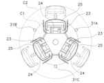
グリッパ装置9は、第1レーザ距離センサ31A、第2レーザ距離センサ31B、第3レーザ距離センサ31Cを有している。第1~第3レーザ距離センサ31A~31Cは、下方の物体とグリッパ装置9のベース21との高さ方向の距離を検出するためのものである。第1~第3レーザ距離センサ31A~31Cは、ベース21の下部に設けられ、真下につまり鉛直方向下側にレーザを発射するようになっている。
第1~第3レーザ距離センサ31A~31Cは、図2及び図3に示すように、フック25の円周方向間に配置されており、具体的には、所定の円周上で120°の角度を空けて配置されている。さらに具体的には、第1~第3レーザ距離センサ31A~31Cは、アーム23を最も縮めた時(縮径状態の一例)のフック25の先端を含む第1円C1の外側に配置されている。
この実施形態では、第1~第3レーザ距離センサ31A~31Cは、第1円C1に近接して配置されている。しかし、第1~第3レーザ距離センサ31A~31Cは、第1円C1と、アーム23最も拡げた時(拡径状態の一例)のフック25の先端を含む第2円C2との間に配置されていればよい。つまり、第1~第3レーザ距離センサ31A~31Cは、第1円C1より外側でかつ第2円C2より内側の範囲に配置されている。なお、第1~第3レーザ距離センサ31A~31Cは、第1円C1から半径方向外側に離れて設けられていてもよい。また、第1~第3レーザ距離センサ31A~31Cは、互いに円周方向に並んでいなくてもよい。つまり、第1~第3レーザ距離センサ31A~31Cは、中心からの距離を異ならせて配置してもよい。
The
The first to third
In this embodiment, the first to third
以上に述べたように、第1~第3レーザ距離センサ31A~31Cは、アーム23がタイヤTの上方にありかつ縮径状態において、フック25の先端を含む第1円C1の外側に配置され下方にある物体を検出する。
As described above, the first to third
グリッパ装置9は、フック25の下面に設けられ、フック25の先端側が上下動する第1~第3接触センサ33A~33C(図9)を有している。第1~第3接触センサ33A~33Cは、アーム23の下降中にフック25の底面がタイヤTの上面に衝突したことを検出するためのセンサである。
図4を用いて、接触センサの一例として、第1接触センサ33Aを説明する。図4は、アーム下部、フック、接触センサを示す部分側面図である。
The
The
第1接触センサ33Aは、上下回動式の板81を有している。板81は、基部側が水平方向に延びる回動軸81aによってアーム23の下部に支持されている。板81は、フック25の本体25aに当接する水平位置と、先端部が下方に離れた斜め位置との間で移動可能である。
第1接触センサ33Aは、板81を回動方向下側に弾性的に付勢するバネ(図示せず、例えば、コイルバネ)を有している。したがって、板81は通常は斜め位置にある。
第1接触センサ33Aは、荷重センサ(図示せず)を有している。荷重センサは、板81が下方の物体に当接して上方に回動して水平位置に移動すると、板81とフック25の他の部材との間で圧縮される位置に設けられている。
The
The
The
(3)タイヤ持ち上げ基本動作
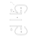
図5~図8を用いて、タイヤ搬送装置1が横倒姿勢にあるタイヤTを持ち上げる時の基本動作を説明する。図5~図8は、タイヤ持ち上げ動作の一状態を示す模式図である。
最初に、図5に示すように、グリッパ装置9をタイヤTの真上(つまり、中心穴の真上)に配置する。
(3) Basic Tire Lifting Operation The basic operation when the
First, as shown in FIG. 5, the
次に、図6に示すように、3本のアーム23を縮めた状態で下降させて上面開口縁6内側に挿入し、フック25の先端をタイヤTの上下方向中心付近に位置させる。
次に、図7に示すように、3本のアーム23をタイヤ径方向に拡大してフック25が平面視でタイヤTの上面開口縁6(ビード部)に係る位置まで移動させる。
Next, as shown in FIG. 6, the three
Next, as shown in FIG. 7, the three
最後に、図8に示すように、アーム23を上昇させて、フック25でタイヤTの中心穴4の上面開口縁6を下から支えて持ち上げる。
Finally, as shown in FIG. 8, the
(4)タイヤ搬送装置の制御構成
図9を用いて、タイヤ搬送装置1の制御構成を説明する。図9は、タイヤ搬送装置の制御構成を示すブロック図である。
タイヤ搬送装置1は、コントローラ51を有している。
(4) Control configuration of tire conveyance device The control configuration of the
The
コントローラ51は、プロセッサ(例えば、CPU)と、記憶装置(例えば、ROM、RAM、HDD、SSDなど)と、各種インターフェース(例えば、A/Dコンバータ、D/Aコンバータ、通信インターフェースなど)を有するコンピュータシステムである。コントローラ51は、記憶部(記憶装置の記憶領域の一部又は全部に対応)に保存されたプログラムを実行することで、各種制御動作を行う。
コントローラ51は、単一のプロセッサで構成されていてもよいが、各制御のために独立した複数のプロセッサから構成されていてもよい。
コントローラ51の各要素の機能は、一部又は全てが、コントローラ51を構成するコンピュータシステムにて実行可能なプログラムとして実現されてもよい。その他、コントローラ51の各要素の機能の一部は、カスタムICにより構成されていてもよい。
The
The
Part or all of the functions of each element of the
コントローラ51には、X軸駆動装置71、Y軸駆動装置73、Z軸駆動装置75、アーム拡縮装置77が接続されている。コントローラ51は、これら装置を制御可能である。
コントローラ51には、第1~第3レーザ距離センサ31A~31C、第1~第3接触センサ33A~33Cが接続されている。コントローラ51には、これらセンサから検出信号が入力される。
コントローラ51には、図示しないが、各装置の状態を検出するためのセンサ及びスイッチ、並びに情報入力装置が接続されている。
An
The
Although not shown, sensors and switches for detecting the status of each device, and an information input device are connected to the
(5)タイヤ持ち上げ制御動作の詳細
図10~図14を用いて、タイヤ持ち上げ制御動作の詳細を説明する。図10及び図11は、タイヤ搬送装置のタイヤ持ち上げ制御動作を示すフローチャートである。図12~図14は、タイヤとレーザ距離センサの位置関係の一状態を示す模式的平面図である。
以下に説明する制御フローチャートは例示であって、各ステップは必要に応じて省略及び入れ替え可能である。また、複数のステップが同時に実行されたり、一部又は全てが重なって実行されたりしてもよい。
さらに、制御フローチャートの各ブロックは、単一の制御動作とは限らず、複数のブロックで表現される複数の制御動作に置き換えることができる。
なお、各装置の動作は、制御部から各装置への指令の結果であり、これらはソフトウェア・アプリケーションの各ステップによって表現される。
(5) Details of tire lifting control operation Details of the tire lifting control operation will be explained using FIGS. 10 to 14. 10 and 11 are flowcharts showing the tire lifting control operation of the tire conveyance device. 12 to 14 are schematic plan views showing one state of the positional relationship between the tire and the laser distance sensor.
The control flowchart described below is an example, and each step can be omitted or replaced as necessary. Further, a plurality of steps may be executed simultaneously, or some or all of the steps may be executed overlappingly.
Furthermore, each block in the control flowchart is not limited to a single control operation, and can be replaced with a plurality of control operations expressed by a plurality of blocks.
Note that the operation of each device is the result of instructions from the control unit to each device, and these are expressed by each step of the software application.
ステップS1では、移動ユニット7が、タイヤTが置かれた位置の真上に移動させて停止させられる。具体的には、コントローラ51が、X軸駆動装置71及びY軸駆動装置73を制御することで上記動作を実行させる。なお、タイヤTの位置はあらかじめコントローラ51の記憶部に記憶されている。
In step S1, the moving
ステップS2では、各アーム23が、最内方向位置に移動させられる(つまり、縮径状態になる)。具体的には、コントローラ51が、アーム拡縮装置77を制御することで上記動作を実行させる。なお、各アーム23が最初から縮径状態にある場合は、上記動作は省略される。
In step S2, each
ステップS3では、グリッパ装置9が所定高さまで下降させられる。具体的には、コントローラ51は、Z軸駆動装置75を制御することで上記動作を実行させる。上記の所定高さは、例えば、アーム23の下部底面とタイヤTの最上面との高さ方向距離が所定の値(例えば、300mm)になる高さである。なお、タイヤTの最上面の高さは、あらかじめコントローラ51の記憶部に記憶されている。
In step S3, the
ステップS4では、第1~第3レーザ距離センサ31A~31Cが下方にレーザを照射し、反射してきたレーザを受光して下方の物体との距離を検出する。このとき、上記のようにグリッパ装置9が下降させられて第1~第3レーザ距離センサ31A~31CとタイヤTとの距離が近接しているので、検出精度が高くなる。
In step S4, the first to third
ステップS5では、第1~第3レーザ距離センサ31A~31Cの下方にある物体との距離が互いに異なっているか否かが判断される。YesであればプロセスはステップS6に移行し、NoであればプロセスはステップS9に移行する。
ステップS5においてYesの場合とは、例えば図12に示すように、第1~第3レーザ距離センサ31A~31Cのうち2つがタイヤTの中心穴4の真上にあるが、1つがタイヤTの真上にあり他の2つ比べて計測距離が短くなる場合である。これは、アーム23の位置が不適切な場合であり、アーム23を下降すると1つのフック25がタイヤTに当たってしまう。
ステップS5においてNoの場合とは、図13に示すように、第1~第3レーザ距離センサ31A~31Cの全てがタイヤTの中心穴4の真上にある場合である。
In step S5, it is determined whether the distances to the objects below the first to third
If Yes in step S5, for example, as shown in FIG. 12, two of the first to third
The case of No in step S5 means that all of the first to third
ステップS6では、上記判断が所定回数を超えたか否かが判断される。YesであればプロセスはステップS8に移行する。NoであればプロセスはS7に移行する。 In step S6, it is determined whether the above determination has exceeded a predetermined number of times. If Yes, the process moves to step S8. If No, the process moves to S7.
ステップS7では、グリッパ装置9が水平方向に移動させられる。なお、移動距離は例えば5~10mmである。具体的には、コントローラ51は、図12の白抜き矢印に示すように、第1~第3レーザ距離センサ31A~31Cのうち短い距離を検出したものが平面視でタイヤTの中心穴4の中に入るように(例えば、円周中心を向く方向に)グリッパ装置9つまりアーム23も移動させ、その後に第1~第3レーザ距離センサ31A~31Cによって計測する距離を監視する。したがって、アーム23の位置が補正される。この結果、アーム23がタイヤTに接触しにくくなる。ステップS7が終了すると、プロセスはステップS4に戻る。
なお、図14に示すように第1~第3レーザ距離センサ31A~31Cのうち2つがタイヤTの真上にあり他の1つ比べて計測距離が短くなる場合は、コントローラ51は、図14の白抜き矢印に示すように、第1~第3レーザ距離センサ31A~31Cのうち短い距離を検出した2つのものが平面視でタイヤTの中心穴4内に入るようにグリッパ装置9つまりアーム23も移動させる。
In step S7, the
Note that, as shown in FIG. 14, when two of the first to third
ステップS8では異常処理が行われる。具体的には、異常警報が発せられる。以後、作業者が手動操作、手作業等で異常状態を解消する処置を行なう。
ステップS9では、タイヤ保持・持ち上げ動作が行われる(後述)。
In step S8, abnormality processing is performed. Specifically, an abnormality alarm is issued. Thereafter, the operator takes steps to eliminate the abnormal condition by manual operation or the like.
In step S9, a tire holding/lifting operation is performed (described later).
以上に述べたように、コントローラ51は、第1~第3レーザ距離センサ31A~31Cによって計測する距離を監視し、タイヤTが検出されなければ、Z軸駆動装置75にアーム23を下降させて当該タイヤTを保持する。
一方、コントローラ51は、第1~第3レーザ距離センサ31A~31Cによって計測した距離同士に差異が生じる(つまり、第1~第3レーザ距離センサ31A~31CのいずれかがタイヤTを検出する)と、Z軸駆動装置75にアーム23を下降させない。これは、第1~第3レーザ距離センサ31A~31Cの少なくとも1つがタイヤTを検出するとそのセンサの計測距離が最も短くなり、その真下にタイヤTが存在することを意味する。つまり、平面視でフック25に重なる位置にタイヤTが配置されている(例えば、タイヤTが傾いたり、位置が異なっていたりする)。つまり、コントローラ51は、アーム23の位置が不適切であると判断する。
また、上記のように、第1~第3レーザ距離センサ31A~31Cの少なくとも1つが平面視でタイヤTの中心穴4の中に入っていない場合は、グリッパ装置9の平面位置の補正と下方距離の再計測が繰り返し行われる。つまり、計測距離同士が相違する場合(ステップS5でYes)はステップS7においてグリッパ装置9は所定距離(例えば、数mm)だけ移動させられ、ステップS5においてタイヤTとの距離が再計測される。なお、計測距離同士が相違するとは、例えば、30~50mmといった所定の値を超えた場合である。
As described above, the
On the other hand, the
Further, as described above, if at least one of the first to third
図11を用いて、図10のステップS9を詳細に説明する。
ステップS11では、例えば図5の状態からグリッパ装置9の下降が開始される。具体的には、コントローラ51がZ軸駆動装置75を制御することで上記動作を実行させる。
Step S9 in FIG. 10 will be explained in detail using FIG. 11.
In step S11, the
ステップS12では、第1~第3接触センサ33A~33Cの少なくとも1つがONしたか否かが判断される。具体的には、コントローラ51が第1~第3接触センサ33A~33Cからの検出信号に基づいて上記判断を行う。YesであればプロセスはステップS17に移行し、NoであればプロセスはステップS13に移行する。
In step S12, it is determined whether at least one of the first to
ステップS13ではグリッパ装置9が所定高さ位置に到達したか否かが判断される。具体的には、コントローラ51がセンサ(図示せず)からの検出信号に基づいて上記判断を行う。YesであればプロセスはステップS14に移行し、NoであればプロセスはステップS12に戻る。
In step S13, it is determined whether the
ステップS14では、グリッパ装置9の下降が停止される(例えば、図6の状態)。具体的には、コントローラ51がZ軸駆動装置75を制御することで上記動作を実行させる。
In step S14, the lowering of the
ステップS15では、3本のアーム23が半径方向外側に移動させられる(例えば、図7の状態)。具体的には、コントローラ51がアーム拡縮装置77を制御することで上記動作を実行させる。これにより、フック25がタイヤTの中心穴4の上面開口縁6の下方に位置する。なお、3本のアーム23の移動は、アーム23の本体部がタイヤTの中心穴4の上面開口縁に当接すると、タッチセンサ等の検出信号に従って停止させられる。
In step S15, the three
ステップS16では、グリッパ装置9は上昇させられる(例えば、図8の状態)。具体的には、コントローラ51がZ軸駆動装置75を制御することで上記動作を実行させる。これにより、各アーム23が上昇し、各アーム23のフック25がタイヤTの中心穴4の上面開口縁を下側から支え、タイヤT全体を持ち上げる。
In step S16, the
ステップS17では、異常処理が行われる。具体的には、アーム23のさらなる下降が停止させられる。さらに、異常警報が発せられ、以後、作業者が手動操作、手作業等で異常状態を解消する処置を行なう。このように第1~第3接触センサ33A~33Cの少なくとも1つがタイヤTを検出した場合は、第1~第3レーザ距離センサ31A~31Cの少なくとも1つがタイヤTを検出した場合とは異なり、位置補正を行わずに直ちに異常処理を行う。これは、上記の場合はタイヤTが位置補正等の調整によっても対応不可能な状態にあると考えられるからである。
In step S17, abnormality processing is performed. Specifically, further lowering of
2.第2実施形態
第1実施形態では、図10のステップS7の複数回の補正動作で補正できなかった場合、ステップS8において異常処理を行っていた。
上記の動作の変形例として、第2実施形態を説明する。なお、第2実施形態の基本構成及び動作は第1実施形態と同じである。
2. Second Embodiment In the first embodiment, if the correction cannot be made in the plurality of correction operations in step S7 in FIG. 10, abnormality processing is performed in step S8.
A second embodiment will be described as a modification of the above operation. Note that the basic configuration and operation of the second embodiment are the same as those of the first embodiment.
コントローラ51は、図10のステップS5とステップS6の間で、新たなステップとして、第1~第3レーザ距離センサ31A~31Cの検出結果に基づいて、上から何段目までならタイヤTを搬送可能か判断する。そして、搬送できるタイヤTがあれば、プロセスはステップS9に移行して、タイヤ保持・持ち上げ動作が実行される。なお、上記のタイヤ保持・持ち上げ動作では、タイヤTの搬送可能な分をまとめて搬送してもよいし、タイヤTを1つずつ搬送してもよい。
As a new step between step S5 and step S6 in FIG. 10, the
上記の場合、例えば、上側のタイヤTが傾くことで検出距離同士に差異が生じていたとすれば、上記のように最初に上側の傾いているタイヤTを搬送することで、次に下側のタイヤTも搬送可能になる。
以上の結果、第1~第3レーザ距離センサ31A~31Cによって計測した距離同士の差異があった場合に、搬送可能な数のタイヤTだけを搬送できる。したがって、タイヤTの搬送効率が良くなる。
In the above case, for example, if the difference in detection distance occurs because the upper tire T is tilted, by first transporting the upper tilted tire T as described above, then the lower tire T is transported. The tire T can also be transported.
As a result of the above, if there is a difference between the distances measured by the first to third
具体例を説明する。図1に示すようにタイヤTが三段であって、タイヤ幅が200mm、3段の全高さが600mmとする。なお、コントローラ51は、在庫データに基づいて、タイヤTが3段積まれていることを把握している。
最初に、図10のステップS4及びS5のように、タイヤTの上方300mmにおいて、第1~第3レーザ距離センサ31A~31CによりタイヤTとの距離が検出される。
A specific example will be explained. As shown in FIG. 1, the tire T has three stages, the tire width is 200 mm, and the total height of the three stages is 600 mm. Note that the
First, as in steps S4 and S5 in FIG. 10, the distance to the tire T is detected 300 mm above the tire T by the first to third
この実施形態では、図10におけるステップS7の補正動作を一度行い、しかし距離の差異を解消できずにその後にステップS5において再び距離同士に差異あり(ステップS5でYes)となった場合に、コントローラ51は、新たなステップとして、第1~第3レーザ距離センサ31A~31Cの検出結果に基づいて、上からから何段目までならタイヤTを搬送可能か判断する。
In this embodiment, if the correction operation in step S7 in FIG. 10 is performed once, but the difference in distance cannot be resolved, and then in step S5 there is a difference in distance again (Yes in step S5), the controller As a new step,
例えば、第1~第3レーザ距離センサ31A~31Cのうち、2つのセンサの検出結果が900mm(タイヤTを検出せず)、1つのセンサ検出結果が700mm(最下段のタイヤTを検出した)とする。この例では、コントローラ51は、例えば、上から2段のタイヤTは移載可能と判断する。これは、例えば、最下段のタイヤTは正しい位置にあるが、上側のタイヤTが傾いて上記のような検出距離の差異が生じた場合である。
そして、次に、図10のステップS9において、上側2段分のタイヤTが搬送される。
For example, among the first to third
Then, in step S9 of FIG. 10, the tires T for the upper two stages are transported.
次に、移動ユニット7が、最下段のタイヤTが置かれた位置の真上に戻ってくる。
最後に、タイヤ搬送装置1は、最下段のタイヤTを検出して、次に当該タイヤTを搬送する。
Next, the moving
Finally, the
3.実施形態の特徴
上記実施形態は、下記のようにも説明できる。
タイヤ搬送装置1(タイヤ搬送装置の一例)は、タイヤTを持ち上げて搬送する装置であって、少なくとも3本のアーム23と、アーム拡縮装置77と、Z軸駆動装置75と、コントローラ51とを備えている。
3本のアーム23(アームの一例)は、アーム本体24(アーム本体の一例)と、アーム本体24の下部に外側へ突出するように設けられておりタイヤTを持ち上げるためのフック25(突出部の一例)を有する。
アーム拡縮装置77(アーム拡縮機構の一例)は、アーム23を水平拡縮方向に移動する。
Z軸駆動装置75(昇降機構の一例)は、アーム23を昇降する。
第1~第3レーザ距離センサ31A~31Cは、アーム23がタイヤTの上方にありかつ縮径状態においてフック25の先端を含む第1円C1(円の一例)の外側に配置されており、下方にある物体を検出する。
コントローラ51は、第1~第3レーザ距離センサ31A~31C少なくとも1つによってタイヤTが検出されると、アーム23の位置が不適切であると判断する。
この装置では、第1~第3レーザ距離センサ31A~31CがタイヤTを検出すると、平面視でフック25に重なる位置にタイヤTが配置されていることになる。この場合には、例えば、Z軸駆動装置はアーム23を下降させないので、タイヤTが傾いたり位置が異なっていたりしていても、フック25がタイヤTに接触しない。
3. Features of the Embodiment The above embodiment can also be explained as follows.
The tire transport device 1 (an example of a tire transport device) is a device that lifts and transports a tire T, and includes at least three
The three arms 23 (an example of an arm) are provided with an arm body 24 (an example of an arm body) and a hook 25 (a protruding portion) provided at the bottom of the
The arm expansion/contraction device 77 (an example of an arm expansion/contraction mechanism) moves the
The Z-axis drive device 75 (an example of a lifting mechanism) moves the
The first to third
When the tire T is detected by at least one of the first to third
In this device, when the first to third
4.他の実施形態
以上、本発明の複数の実施形態について説明したが、本発明は上記実施形態に限定されるものではなく、発明の要旨を逸脱しない範囲で種々の変更が可能である。特に、本明細書に書かれた複数の実施形態及び変形例は必要に応じて任意に組み合せ可能である。
(1)アームの変形例
アームの数は4本以上、例えば、4本、5本でもよい。
(2)アーム水平移動動作の変形例
第1実施形態でアームの位置調整のために、アームを所定距離(数mm)移動させてから、レーザ距離センサによって下方の物体の再検出を行っていた。しかし、変形例として、下方の物体までの距離を計測しながらアームを移動させ続けてもよい。この場合、アームは、タイヤTを検出しなくなるまで移動させられる。
アームの位置調整は省略されてもよい。
4. Other Embodiments Although a plurality of embodiments of the present invention have been described above, the present invention is not limited to the above embodiments, and various changes can be made without departing from the gist of the invention. In particular, the multiple embodiments and modifications described in this specification can be arbitrarily combined as necessary.
(1) Modified examples of arms The number of arms may be four or more, for example, four or five.
(2) Modified example of arm horizontal movement operation In the first embodiment, in order to adjust the arm position, the arm was moved a predetermined distance (several mm) and then the object below was redetected by the laser distance sensor. . However, as a modification, the arm may continue to move while measuring the distance to the object below. In this case, the arm is moved until it no longer detects the tire T.
Adjustment of the arm position may be omitted.
(3)レーザ距離センサの変形例
レーザ距離センサは3個以上、例えば、4個、5個、6個でもよい。なお、レーザ距離センサは、アーム同士の間に1つずつ配置されることが好ましい。
レーザ距離センサではなく、反射物の有無を検出する反射型光電センサを用いてもよい。この場合、センサの真下のタイヤTの有無を検出でき、コントローラはタイヤTがある場合とない場合とを区別できる。
レーザ距離センサによる検出の前にグリッパ装置を下降させなくてもよい。また、グリッパ装置を下降させながらレーザ距離センサによる検出を行ってもよい。
(4)接触センサの変形例
接触センサは、フックの底面が下方の部材に接触したことを検出できればよく、種類、構造、数等は限定されない。例えば、接触センサは、上下動する当接部材と、当接部材を上下方向に案内する直動ガイドと、当接部材を下方に付勢するバネと、当接部材が下方の部材に当接して上方に移動すると当接部材とフックの他の部材との間で圧縮される荷重センサとを有していてもよい。
接触センサは、省略されてもよい。
(5)タイヤ搬送装置全体の変形例
タイヤ搬送装置は、ガントリークレーンに限定されず、所定の高さ位置を走行する天井搬送車に設けられてもよい。
(3) Modifications of laser distance sensors The number of laser distance sensors may be three or more, for example, four, five, or six. Note that it is preferable that one laser distance sensor be disposed between each arm.
Instead of a laser distance sensor, a reflective photoelectric sensor that detects the presence or absence of a reflective object may be used. In this case, the presence or absence of the tire T directly below the sensor can be detected, and the controller can distinguish between the presence and absence of the tire T.
It is not necessary to lower the gripper device before detection by the laser distance sensor. Alternatively, detection may be performed using a laser distance sensor while lowering the gripper device.
(4) Modified example of contact sensor The contact sensor is not limited in type, structure, number, etc., as long as it can detect that the bottom surface of the hook is in contact with a member below. For example, a contact sensor includes a contact member that moves up and down, a linear guide that guides the contact member in the vertical direction, a spring that biases the contact member downward, and a contact member that contacts a member below. The hook may also include a load sensor that is compressed between the abutment member and another member of the hook when the hook is moved upward.
The contact sensor may be omitted.
(5) Modification of the entire tire transport device The tire transport device is not limited to a gantry crane, but may be provided on an overhead transport vehicle that travels at a predetermined height position.
本発明は、横倒姿勢のタイヤの中心穴の上面開口縁に上方より複数のアームを挿入してアームのフックにて上面開口縁を下方から支持することでタイヤを持ち上げる装置に広く適用できる。 INDUSTRIAL APPLICATION This invention is widely applicable to the apparatus which lifts a tire by inserting a plurality of arms from above into the upper surface opening edge of the center hole of a tire in a sideways position, and supporting the upper surface opening edge from below with the hook of an arm.
1 :タイヤ搬送装置
3 :第1レール
5 :第2レール
7 :移動ユニット
9 :グリッパ装置
21 :ベース
23 :アーム
25 :フック
31A :第1レーザ距離センサ
31B :第2レーザ距離センサ
31C :第3レーザ距離センサ
33A :第1接触センサ
33B :第2接触センサ
33C :第3接触センサ
51 :コントローラ
71 :X軸駆動装置
73 :Y軸駆動装置
75 :Z軸駆動装置
77 :アーム拡縮装置
1: Tire conveyance device 3: First rail 5: Second rail 7: Moving unit 9: Gripper device 21: Base 23: Arm 25:
Claims (7)
前記少なくとも3本のアームを水平拡縮方向に移動するアーム拡縮機構と、
前記少なくとも3本のアームを昇降する昇降機構と、
前記少なくとも3本のアームが前記タイヤの上方にありかつ縮径状態において前記突出部の先端を含む円の外側に配置されており、下方にある物体を検出するための少なくとも3つの光反射センサと、
前記少なくとも3つの光反射センサの内の1以上の光反射センサによって前記タイヤが検出されると、前記少なくとも3本のアームの内の1以上のアームの位置が不適切であると判断するコントローラと、
を備える、タイヤ搬送装置。 at least three arms each having an arm body and a protrusion provided at a lower part of the arm body so as to protrude outward and for lifting the tire;
an arm expansion/contraction mechanism that moves the at least three arms in a horizontal expansion/contraction direction;
a lifting mechanism that lifts and lowers the at least three arms;
The at least three arms are above the tire and are arranged outside a circle including the tip of the protrusion in the reduced diameter state, and at least three light reflection sensors for detecting objects below. ,
a controller that determines that the position of one or more of the at least three arms is inappropriate when the tire is detected by one or more of the at least three light reflection sensors; ,
A tire conveyance device comprising:
前記コントローラは、前記レーザ距離センサによって計測する距離を監視し、前記複数のレーザ距離センサによって計測した距離同士に差異が生じると前記光反射センサによって前記タイヤが検出されていると判断する、請求項1に記載のタイヤ搬送装置。 The light reflection sensor is a laser distance sensor,
The controller monitors the distance measured by the laser distance sensor, and determines that the tire is detected by the light reflection sensor when a difference occurs between the distances measured by the plurality of laser distance sensors. 1. The tire conveyance device according to 1.
前記コントローラは、前記アームの下降中に前記接触センサが前記タイヤを検出すると、前記昇降機構に前記少なくとも3本のアームのさらなる下降を停止させる、請求項1~3のいずれかに記載のタイヤ搬送装置。 further comprising a contact sensor provided on the lower surface of the protrusion and detecting that the tip side of the protrusion has come into contact with an object below,
The tire conveyance according to any one of claims 1 to 3, wherein the controller causes the lifting mechanism to stop further lowering of the at least three arms when the contact sensor detects the tire while the arms are lowering. Device.
Applications Claiming Priority (3)
| Application Number | Priority Date | Filing Date | Title |
|---|---|---|---|
| JP2021008143 | 2021-01-21 | ||
| JP2021008143 | 2021-01-21 | ||
| PCT/JP2021/041586 WO2022158092A1 (en) | 2021-01-21 | 2021-11-11 | Tire transport apparatus |
Publications (3)
| Publication Number | Publication Date |
|---|---|
| JPWO2022158092A1 JPWO2022158092A1 (en) | 2022-07-28 |
| JPWO2022158092A5 JPWO2022158092A5 (en) | 2023-09-12 |
| JP7448040B2 true JP7448040B2 (en) | 2024-03-12 |
Family
ID=82548738
Family Applications (1)
| Application Number | Title | Priority Date | Filing Date |
|---|---|---|---|
| JP2022576993A Active JP7448040B2 (en) | 2021-01-21 | 2021-11-11 | Tire conveyance device |
Country Status (6)
| Country | Link |
|---|---|
| US (1) | US20240083695A1 (en) |
| EP (1) | EP4253301A1 (en) |
| JP (1) | JP7448040B2 (en) |
| KR (1) | KR20230111239A (en) |
| CN (1) | CN116710386A (en) |
| WO (1) | WO2022158092A1 (en) |
Families Citing this family (1)
| Publication number | Priority date | Publication date | Assignee | Title |
|---|---|---|---|---|
| CN116621018B (en) * | 2023-05-31 | 2023-12-22 | 荣成荣鹰橡胶制品有限公司 | Solid tire clamping and transferring device and using method |
Citations (4)
| Publication number | Priority date | Publication date | Assignee | Title |
|---|---|---|---|---|
| JP2004238147A (en) | 2003-02-06 | 2004-08-26 | Okura Yusoki Co Ltd | Holding device and transfer machine |
| JP2008162733A (en) | 2006-12-27 | 2008-07-17 | Murata Mach Ltd | Article transfer device |
| WO2020105268A1 (en) | 2018-11-19 | 2020-05-28 | 村田機械株式会社 | Orientation changing device |
| WO2020242294A1 (en) | 2019-05-28 | 2020-12-03 | Vmi Holland B.V. | Bead-apex storage system and method for handling a plurality of stacks with bead-apexes and spacers |
-
2021
- 2021-11-11 CN CN202180087797.1A patent/CN116710386A/en active Pending
- 2021-11-11 US US18/273,050 patent/US20240083695A1/en active Pending
- 2021-11-11 JP JP2022576993A patent/JP7448040B2/en active Active
- 2021-11-11 EP EP21921195.0A patent/EP4253301A1/en active Pending
- 2021-11-11 WO PCT/JP2021/041586 patent/WO2022158092A1/en active Application Filing
- 2021-11-11 KR KR1020237021683A patent/KR20230111239A/en unknown
Patent Citations (4)
| Publication number | Priority date | Publication date | Assignee | Title |
|---|---|---|---|---|
| JP2004238147A (en) | 2003-02-06 | 2004-08-26 | Okura Yusoki Co Ltd | Holding device and transfer machine |
| JP2008162733A (en) | 2006-12-27 | 2008-07-17 | Murata Mach Ltd | Article transfer device |
| WO2020105268A1 (en) | 2018-11-19 | 2020-05-28 | 村田機械株式会社 | Orientation changing device |
| WO2020242294A1 (en) | 2019-05-28 | 2020-12-03 | Vmi Holland B.V. | Bead-apex storage system and method for handling a plurality of stacks with bead-apexes and spacers |
Also Published As
| Publication number | Publication date |
|---|---|
| JPWO2022158092A1 (en) | 2022-07-28 |
| US20240083695A1 (en) | 2024-03-14 |
| KR20230111239A (en) | 2023-07-25 |
| CN116710386A (en) | 2023-09-05 |
| EP4253301A1 (en) | 2023-10-04 |
| WO2022158092A1 (en) | 2022-07-28 |
Similar Documents
| Publication | Publication Date | Title |
|---|---|---|
| EP3453656B1 (en) | Unloading apparatus and unloading method | |
| US10431485B2 (en) | Article transport facility | |
| US11066248B2 (en) | Article transport device | |
| JP7448040B2 (en) | Tire conveyance device | |
| US10134620B2 (en) | Robot system and incline detection method | |
| JP2019116336A (en) | Rotation type stocker and transfer system equipped with the same | |
| JP6690237B2 (en) | Automatic warehouse | |
| SK20994A3 (en) | Method and device for ascertain a number of things on palette and their unloading | |
| JP7314916B2 (en) | Goods transport equipment | |
| JP4941728B2 (en) | Article conveying device | |
| US20230382703A1 (en) | Control method, control device, and control system | |
| JP5190694B2 (en) | Learning device in article storage facility | |
| JP4038807B2 (en) | Stacker crane | |
| JP5445399B2 (en) | Transfer device and first-in-stock determination method | |
| KR20100062294A (en) | Apparatus for calibrating height of wafer cassette and method thereof | |
| JP2007182278A (en) | Article carrying device | |
| JP2541431B2 (en) | Stacker crane | |
| KR102709730B1 (en) | Overhead transport vehicle | |
| US20220080604A1 (en) | Robot system and offset acquisition method | |
| JP6673305B2 (en) | Automatic warehouse system | |
| KR20080072233A (en) | Apparatus for sensing wafer with robot arm | |
| JPH0398901A (en) | Automatic warehouse | |
| JP2023180591A (en) | Carrying system and control method thereof | |
| CN118458301A (en) | Position correction device and position correction method | |
| KR20220078486A (en) | Correction method and substrate transfer apparatus |
Legal Events
| Date | Code | Title | Description |
|---|---|---|---|
| A521 | Request for written amendment filed |
Free format text: JAPANESE INTERMEDIATE CODE: A523 Effective date: 20230623 |
|
| A621 | Written request for application examination |
Free format text: JAPANESE INTERMEDIATE CODE: A621 Effective date: 20230623 |
|
| TRDD | Decision of grant or rejection written | ||
| A01 | Written decision to grant a patent or to grant a registration (utility model) |
Free format text: JAPANESE INTERMEDIATE CODE: A01 Effective date: 20240130 |
|
| A61 | First payment of annual fees (during grant procedure) |
Free format text: JAPANESE INTERMEDIATE CODE: A61 Effective date: 20240212 |
|
| R150 | Certificate of patent or registration of utility model |
Ref document number: 7448040 Country of ref document: JP Free format text: JAPANESE INTERMEDIATE CODE: R150 |