JP7446730B2 - Image processing device, image processing method and program - Google Patents
Image processing device, image processing method and program Download PDFInfo
- Publication number
- JP7446730B2 JP7446730B2 JP2019133788A JP2019133788A JP7446730B2 JP 7446730 B2 JP7446730 B2 JP 7446730B2 JP 2019133788 A JP2019133788 A JP 2019133788A JP 2019133788 A JP2019133788 A JP 2019133788A JP 7446730 B2 JP7446730 B2 JP 7446730B2
- Authority
- JP
- Japan
- Prior art keywords
- image
- images
- frontal
- brightness
- motion contrast
- Prior art date
- Legal status (The legal status is an assumption and is not a legal conclusion. Google has not performed a legal analysis and makes no representation as to the accuracy of the status listed.)
- Active
Links
- 238000012545 processing Methods 0.000 title claims description 170
- 238000003672 processing method Methods 0.000 title claims description 5
- 210000004204 blood vessel Anatomy 0.000 claims description 151
- 238000000034 method Methods 0.000 claims description 125
- 238000012937 correction Methods 0.000 claims description 122
- 238000009826 distribution Methods 0.000 claims description 97
- 230000008569 process Effects 0.000 claims description 83
- 238000012790 confirmation Methods 0.000 claims description 38
- 238000005259 measurement Methods 0.000 claims description 27
- 238000004364 calculation method Methods 0.000 claims description 26
- 238000009499 grossing Methods 0.000 claims description 24
- 238000004458 analytical method Methods 0.000 claims description 14
- 230000009467 reduction Effects 0.000 claims description 7
- 230000004044 response Effects 0.000 claims description 7
- 230000000740 bleeding effect Effects 0.000 claims description 6
- 238000012935 Averaging Methods 0.000 claims description 2
- 238000003384 imaging method Methods 0.000 description 109
- 239000010410 layer Substances 0.000 description 71
- 238000012014 optical coherence tomography Methods 0.000 description 49
- 230000003287 optical effect Effects 0.000 description 49
- 210000001525 retina Anatomy 0.000 description 26
- FCKYPQBAHLOOJQ-UHFFFAOYSA-N Cyclohexane-1,2-diaminetetraacetic acid Chemical compound OC(=O)CN(CC(O)=O)C1CCCCC1N(CC(O)=O)CC(O)=O FCKYPQBAHLOOJQ-UHFFFAOYSA-N 0.000 description 19
- 238000006243 chemical reaction Methods 0.000 description 19
- 210000004126 nerve fiber Anatomy 0.000 description 18
- 230000002207 retinal effect Effects 0.000 description 18
- 230000001629 suppression Effects 0.000 description 18
- 238000003860 storage Methods 0.000 description 16
- 210000003161 choroid Anatomy 0.000 description 13
- 238000010606 normalization Methods 0.000 description 12
- 238000010801 machine learning Methods 0.000 description 11
- 239000002344 surface layer Substances 0.000 description 11
- 238000012986 modification Methods 0.000 description 10
- 230000004048 modification Effects 0.000 description 10
- 230000009466 transformation Effects 0.000 description 10
- 230000000694 effects Effects 0.000 description 9
- 239000013307 optical fiber Substances 0.000 description 9
- 230000006870 function Effects 0.000 description 7
- 238000003745 diagnosis Methods 0.000 description 6
- 238000010586 diagram Methods 0.000 description 6
- 239000000835 fiber Substances 0.000 description 5
- 210000001519 tissue Anatomy 0.000 description 5
- 238000012549 training Methods 0.000 description 5
- 238000013528 artificial neural network Methods 0.000 description 4
- 239000002131 composite material Substances 0.000 description 4
- 210000003743 erythrocyte Anatomy 0.000 description 4
- 230000000877 morphologic effect Effects 0.000 description 4
- 230000010287 polarization Effects 0.000 description 4
- 238000011946 reduction process Methods 0.000 description 4
- 210000004127 vitreous body Anatomy 0.000 description 4
- 208000034700 Vitreous opacities Diseases 0.000 description 3
- 230000017531 blood circulation Effects 0.000 description 3
- 210000001775 bruch membrane Anatomy 0.000 description 3
- 230000008859 change Effects 0.000 description 3
- 238000013135 deep learning Methods 0.000 description 3
- 239000006185 dispersion Substances 0.000 description 3
- 210000004379 membrane Anatomy 0.000 description 3
- 239000012528 membrane Substances 0.000 description 3
- 239000000203 mixture Substances 0.000 description 3
- 230000002093 peripheral effect Effects 0.000 description 3
- 238000003825 pressing Methods 0.000 description 3
- 230000011218 segmentation Effects 0.000 description 3
- 208000003098 Ganglion Cysts Diseases 0.000 description 2
- 206010025421 Macule Diseases 0.000 description 2
- 208000005400 Synovial Cyst Diseases 0.000 description 2
- 206010047642 Vitiligo Diseases 0.000 description 2
- 230000002159 abnormal effect Effects 0.000 description 2
- 230000015572 biosynthetic process Effects 0.000 description 2
- 210000004027 cell Anatomy 0.000 description 2
- 230000001427 coherent effect Effects 0.000 description 2
- 238000007796 conventional method Methods 0.000 description 2
- 238000013527 convolutional neural network Methods 0.000 description 2
- 238000006073 displacement reaction Methods 0.000 description 2
- 210000000720 eyelash Anatomy 0.000 description 2
- 238000001914 filtration Methods 0.000 description 2
- 239000011521 glass Substances 0.000 description 2
- 238000005286 illumination Methods 0.000 description 2
- 238000003702 image correction Methods 0.000 description 2
- 230000003993 interaction Effects 0.000 description 2
- 230000003902 lesion Effects 0.000 description 2
- 210000004072 lung Anatomy 0.000 description 2
- 210000003733 optic disk Anatomy 0.000 description 2
- 210000001747 pupil Anatomy 0.000 description 2
- 230000005855 radiation Effects 0.000 description 2
- 238000011160 research Methods 0.000 description 2
- 230000003595 spectral effect Effects 0.000 description 2
- 238000003786 synthesis reaction Methods 0.000 description 2
- 230000007704 transition Effects 0.000 description 2
- 238000002604 ultrasonography Methods 0.000 description 2
- 230000002792 vascular Effects 0.000 description 2
- 239000011165 3D composite Substances 0.000 description 1
- 208000010412 Glaucoma Diseases 0.000 description 1
- 230000003044 adaptive effect Effects 0.000 description 1
- 230000002411 adverse Effects 0.000 description 1
- 206010064930 age-related macular degeneration Diseases 0.000 description 1
- 238000002583 angiography Methods 0.000 description 1
- 238000013459 approach Methods 0.000 description 1
- 230000004397 blinking Effects 0.000 description 1
- 210000004556 brain Anatomy 0.000 description 1
- 230000015556 catabolic process Effects 0.000 description 1
- 210000000038 chest Anatomy 0.000 description 1
- 238000013500 data storage Methods 0.000 description 1
- 230000002950 deficient Effects 0.000 description 1
- 238000006731 degradation reaction Methods 0.000 description 1
- 201000010099 disease Diseases 0.000 description 1
- 208000037265 diseases, disorders, signs and symptoms Diseases 0.000 description 1
- 238000001839 endoscopy Methods 0.000 description 1
- 238000011156 evaluation Methods 0.000 description 1
- 238000002599 functional magnetic resonance imaging Methods 0.000 description 1
- 210000004220 fundus oculi Anatomy 0.000 description 1
- 210000003128 head Anatomy 0.000 description 1
- 210000002216 heart Anatomy 0.000 description 1
- 230000006872 improvement Effects 0.000 description 1
- 210000000936 intestine Anatomy 0.000 description 1
- 230000001678 irradiating effect Effects 0.000 description 1
- 210000003734 kidney Anatomy 0.000 description 1
- 210000004185 liver Anatomy 0.000 description 1
- 230000007774 longterm Effects 0.000 description 1
- 208000002780 macular degeneration Diseases 0.000 description 1
- 238000002595 magnetic resonance imaging Methods 0.000 description 1
- 230000007246 mechanism Effects 0.000 description 1
- 210000000056 organ Anatomy 0.000 description 1
- 210000000496 pancreas Anatomy 0.000 description 1
- 230000007170 pathology Effects 0.000 description 1
- 210000000608 photoreceptor cell Anatomy 0.000 description 1
- 108091008695 photoreceptors Proteins 0.000 description 1
- 238000002360 preparation method Methods 0.000 description 1
- 230000000306 recurrent effect Effects 0.000 description 1
- 210000003583 retinal pigment epithelium Anatomy 0.000 description 1
- 210000001210 retinal vessel Anatomy 0.000 description 1
- 238000002603 single-photon emission computed tomography Methods 0.000 description 1
- 230000002269 spontaneous effect Effects 0.000 description 1
Images


Description
本発明は、画像処理装置、画像処理方法及びプログラムに関する。 The present invention relates to an image processing device, an image processing method, and a program.
光干渉断層計(OCT;Optical Coherence Tomography)などの断層画像撮影装置を用いると、被検眼内部の状態を三次元的に観察できる。この断層画像撮影装置は、疾病の診断をより的確に行うのに有用であることから眼科診療に広く用いられている。OCTの形態として、例えば広帯域な光源とマイケルソン干渉計を組み合わせたTD-OCT(Time domain OCT)がある。これは、参照ミラーの位置を一定速度で移動させて信号アームで取得した後方散乱光との干渉光を計測し、深度方向の反射光強度分布を得るように構成されている。しかし、このようなTD-OCTでは機械的な走査が必要となるため高速な画像取得は難しい。そこで、より高速な画像取得法として広帯域光源を用い、分光器で干渉信号を取得するSD-OCT(Spectral domain OCT)や高速波長掃引光源を用いることで時間的に分光するSS-OCT(Swept Source OCT)が開発され、より広画角な断層画像を取得できるようになっている。 When a tomographic imaging device such as an optical coherence tomography (OCT) is used, the internal state of the eye to be examined can be observed three-dimensionally. This tomographic imaging apparatus is widely used in ophthalmological treatment because it is useful for more accurately diagnosing diseases. One form of OCT is, for example, TD-OCT (Time domain OCT), which combines a broadband light source and a Michelson interferometer. This is configured to move the position of the reference mirror at a constant speed and measure the interference light with the backscattered light acquired by the signal arm to obtain the reflected light intensity distribution in the depth direction. However, such TD-OCT requires mechanical scanning, making it difficult to obtain images at high speed. Therefore, as faster image acquisition methods, SD-OCT (Spectral domain OCT) uses a broadband light source and acquires interference signals with a spectrometer, and SS-OCT (Swept Source OCT) has been developed, making it possible to obtain tomographic images with a wider field of view.
被検眼の血管に関する病態を把握するためにOCTを用いて非侵襲に眼底血管を3次元で描出するOCT Angiography(以下、OCTAと表記)技術が用いられる。OCTAでは測定光で同一位置を複数回走査し、赤血球の変位と測定光との相互作用により得られるモーションコントラストを画像化する。図4(a)は速軸方向が水平(x軸)方向で、遅軸方向(y軸方向)の各位置(yi;1≦i≦n)においてr回連続でBスキャンを行うOCTA撮影の例を示している。なおOCTA撮像において同一位置で複数回走査することをクラスタ走査、同一位置で得られた複数枚の断層画像のことをクラスタと呼び、クラスタ単位でモーションコントラスト画像が生成される。 In order to understand the pathology related to the blood vessels of the subject's eye, an OCT angiography (hereinafter referred to as OCTA) technique is used to non-invasively visualize the fundus blood vessels in three dimensions using OCT. In OCTA, the same position is scanned multiple times with measurement light, and the motion contrast obtained by the interaction between the displacement of red blood cells and the measurement light is imaged. Figure 4(a) shows OCTA imaging in which the fast axis direction is horizontal (x axis) and B scans are performed r times consecutively at each position (yi; 1≦i≦n) in the slow axis direction (y axis direction). An example is shown. Note that in OCTA imaging, scanning the same position multiple times is called cluster scanning, and a plurality of tomographic images obtained at the same position is called a cluster, and a motion contrast image is generated in cluster units.
特許文献1には、OCTA画像(血管領域が強調されたen-face画像)において、固視ずれに起因してX方向(速軸方向)に延びる白線の帯状アーチファクトを抑制するために、輝度値をX方向に積算することによりY方向(遅軸方向)に沿った1次元輝度プロファイルと、該1次元輝度プロファイルを平滑化した平滑化1次元輝度プロファイルとの比または差に基づいて、断層画像に対して輝度補正する方法が開示されている。すなわち、特許文献1には、OCTA画像において速軸方向に沿って全域に存在する帯状アーチファクトを抑制する技術について開示されている。 Patent Document 1 discloses that in an OCTA image (an en-face image in which a blood vessel region is emphasized), a luminance value is A tomographic image is obtained based on the ratio or difference between a one-dimensional brightness profile along the Y direction (slow axis direction) and a smoothed one-dimensional brightness profile obtained by smoothing the one-dimensional brightness profile. A method for correcting brightness is disclosed. That is, Patent Document 1 discloses a technique for suppressing band-like artifacts that exist in the entire region along the fast axis direction in an OCTA image.
しかしながら、従来の手法では、速軸方向に沿って部分的に存在する帯状アーチファクトを低減することはできない。また、速軸方向に沿って存在する血管領域等の輝度値を過補正もしくは誤抑制してしまう可能性があった。 However, conventional methods cannot reduce band-like artifacts that partially exist along the fast axis direction. Furthermore, there is a possibility that the brightness values of blood vessel regions and the like existing along the fast axis direction may be overcorrected or erroneously suppressed.
本発明は上記課題に鑑みてなされたものであり、被検眼の画像におけるアーチファクトを低減することを目的の一つとする。 The present invention has been made in view of the above problems, and one of its objects is to reduce artifacts in images of an eye to be examined.
なお、前記目的に限らず、後述する発明を実施するための形態に示す各構成により導かれる作用効果であって、従来の技術によっては得られない作用効果を奏することも本件の他の目的の一つとして位置付けることができる。 In addition, other objectives of the present invention are not limited to the above-mentioned objectives, but also include the effects derived from each configuration shown in the detailed description of the invention described later, which cannot be obtained by conventional techniques. It can be positioned as one.
本発明の目的を達成するために、例えば本発明の画像処理装置の一つは、
被検眼の異なる深度範囲に対応する複数の正面画像を取得する取得手段と、
前記取得された複数の正面画像におけるアーチファクトが低減された複数の正面画像を生成する生成手段と、
複数の正面画像を学習して得た学習済モデルを用いて、前記取得された複数の正面画像のうちの少なくとも一つの正面画像におけるアーチファクトの状態を判定する判定手段と、
前記取得された複数の正面画像のうちの少なくとも一つの正面画像と前記アーチファクトの状態に関する判定結果とを撮影確認画面に表示し、アーチファクトの低減の要否に関する指定として操作者からの指示を受け付けることに応じて、前記撮影確認画面に表示された少なくとも一つの正面画像を、前記生成された複数の正面画像のうちの少なくとも一つの正面画像に切り換え、表示手段における表示画面が前記撮影確認画面からレポート画面に切り換わった後、前記生成された複数の正面画像を前記レポート画面に並べて表示するように、前記表示手段を制御する表示制御手段と、を備える。
In order to achieve the object of the present invention, one of the image processing devices of the present invention, for example,
an acquisition means for acquiring a plurality of frontal images corresponding to different depth ranges of the eye to be examined;
Generating means for generating a plurality of frontal images in which artifacts in the plurality of acquired frontal images are reduced;
a determination unit that uses a learned model obtained by learning a plurality of frontal images to determine a state of an artifact in at least one frontal image among the plurality of acquired frontal images;
Displaying at least one front image of the plurality of front images acquired and a determination result regarding the state of the artifact on a shooting confirmation screen , and accepting an instruction from an operator as a designation regarding whether or not reduction of the artifact is necessary. , the at least one frontal image displayed on the photographing confirmation screen is switched to at least one frontal image of the plurality of generated frontal images, and the display screen on the display means changes from the photographing confirmation screen to the report . A display control means is provided for controlling the display means so as to display the plurality of generated frontal images side by side on the report screen after the screen is switched.
本発明の一つによれば、被検眼の画像におけるアーチファクトを低減することができる。 According to one aspect of the present invention, artifacts in an image of an eye to be examined can be reduced.
[第1の実施形態]
本実施形態に係る画像処理装置は、OCTを用いて撮影した被検眼の断層画像の遅軸方向に生じた様々な輝度段差アーチファクトをロバストに抑制するために、以下の画像補正処理を行う。すなわち、断層画像の網膜表層と網膜外層間の輝度減衰率に基づいて血管候補領域の分布情報を生成する。次に、高次元平滑化断層画像の輝度値に対して、該血管候補領域に対して重み付けした低次元(速軸方向のみ)平滑化断層画像の輝度値を除算することにより、輝度補正係数値分布を生成する。さらに、断層画像の各画素に対して輝度補正係数値を乗算することで、断層画像の遅軸方向に生じた輝度段差アーチファクトをロバストに抑制する場合について説明する。ここで、遅軸方向に生じた輝度段差アーチファクトとは、例えば、固視ずれに起因してX方向(速軸方向)に延びる帯状アーチファクトのことである。なお、速軸方向は、例えば、3次元断層画像を取得する際に使用される測定光の主走査の軸方向のことである。
[First embodiment]
The image processing apparatus according to the present embodiment performs the following image correction processing in order to robustly suppress various luminance step artifacts that occur in the slow axis direction of a tomographic image of a subject's eye captured using OCT. That is, distribution information of blood vessel candidate regions is generated based on the brightness attenuation rate between the retinal surface layer and the retinal outer layer of the tomographic image. Next, by dividing the brightness value of the high-dimensional smoothed tomographic image by the brightness value of the low-dimensional (fast-axis direction only) smoothed tomographic image weighted for the blood vessel candidate region, the brightness correction coefficient value is calculated. Generate a distribution. Furthermore, a case will be described in which brightness step artifacts occurring in the slow axis direction of a tomographic image are robustly suppressed by multiplying each pixel of the tomographic image by a brightness correction coefficient value. Here, the luminance step artifact that occurs in the slow axis direction is, for example, a band-shaped artifact that extends in the X direction (fast axis direction) due to fixation shift. Note that the fast axis direction is, for example, the axial direction of the main scanning of the measurement light used when acquiring a three-dimensional tomographic image.
また、本実施形態で補正対象とする被検眼の断層画像の遅軸方向に生じた輝度段差の例について説明する。OCT断層画像の撮影中に被検眼の固視ずれが生じた場合には再走査が行われる。例えば、長時間にわたる撮影などでは、被検眼の睫毛や瞳孔の位置が初回走査時と再走査時とで異なる等の理由で再走査した領域の輝度が低くなり、図4(b)の白矢印で示すような帯状の低輝度な段差が生じやすい。なお、図4(b)において横方向が速軸方向、縦方向が遅軸方向である。また、帯状の輝度段差アーチファクトが画像の速軸方向の全域に生じるとは限らず、以下に示すようなケースにおいて速軸方向の一部に限局した帯状の輝度段差アーチファクトが生じるという課題がある。すなわち、再走査時に硝子体混濁を含む領域が走査され、影領域が生じた場合に断層画像上の再走査した領域内に速軸方向の一部に限局した帯状の低輝度段差が生じることがある(図4(e)の白矢印で示した低輝度段差)。 Furthermore, an example of a brightness level difference that occurs in the slow axis direction of a tomographic image of a subject's eye, which is a correction target in this embodiment, will be described. If a fixation shift of the subject's eye occurs during imaging of an OCT tomographic image, rescanning is performed. For example, during long-term imaging, the positions of the eyelashes and pupils of the subject's eye may differ between the first scan and the rescan, resulting in lower brightness in the rescanned area, as shown by the white arrow in Figure 4(b). A band-like low-luminance level difference as shown in is likely to occur. Note that in FIG. 4(b), the horizontal direction is the fast axis direction, and the vertical direction is the slow axis direction. In addition, the band-shaped brightness step artifact does not necessarily occur over the entire area of the image in the fast-axis direction, but in the following cases, a band-like brightness step artifact localized to a part of the fast-axis direction occurs. In other words, if an area containing vitreous opacity is scanned during rescanning and a shadow area occurs, a band-like low-intensity step localized in a part of the fast axis direction may occur within the rescanned area on the tomographic image. (low-luminance step indicated by the white arrow in FIG. 4(e)).
以下、図面を参照しながら、本発明の第1実施形態に係る画像処理装置を備える画像処理システムについて説明する。 DESCRIPTION OF THE PREFERRED EMBODIMENTS An image processing system including an image processing apparatus according to a first embodiment of the present invention will be described below with reference to the drawings.
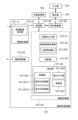
図2は、本実施形態に係る画像処理装置101を備える画像処理システム10の構成を示す図である。図2に示すように、画像処理システム10は、画像処理装置101が、インタフェースを介して断層画像撮影装置100(OCTとも言う)、外部記憶部102、入力部103、表示部104と接続されることにより構成されている。
FIG. 2 is a diagram showing the configuration of an
断層画像撮影装置100は、被検眼の断層画像を撮影する装置である。本実施形態においては、断層画像撮影装置100としてSD-OCTを用いるものとする。これに限らず、例えばSS-OCTを用いて構成しても良い。
The tomographic
図2(a)において、測定光学系100-1は前眼部像、被検眼のSLO眼底像、断層画像を取得するための光学系である。ステージ部100-2は、測定光学系100-1を前後左右に移動可能にする。ベース部100-3は、後述の分光器を内蔵している。 In FIG. 2(a), a measurement optical system 100-1 is an optical system for acquiring an anterior segment image, an SLO fundus image of the eye to be examined, and a tomographic image. The stage section 100-2 allows the measurement optical system 100-1 to move back and forth and left and right. The base portion 100-3 incorporates a spectrometer to be described later.
画像処理装置101は、ステージ部100-2の制御、アラインメント動作の制御、断層画像の再構成などを実行するコンピュータである。外部記憶部102は、断層撮像用のプログラム、患者情報、撮影データ、過去検査の画像データや計測データなどを記憶する。
The
入力部103はコンピュータへの指示を行い、具体的にはキーボードとマウスから構成される。表示部104は、例えばモニタからなる。
The
(断層画像撮影装置の構成)
本実施形態の断層画像撮影装置100における測定光学系及び分光器の構成について図2(b)を用いて説明する。
(Configuration of tomographic imaging device)
The configuration of the measurement optical system and spectrometer in the
まず、測定光学系100-1の内部について説明する。被検眼200に対向して対物レンズ201が設置され、その光軸上に第1ダイクロイックミラー202及び第2ダイクロイックミラー203が配置されている。これらのダイクロイックミラーによってOCT光学系の光路250、SLO光学系と固視灯用の光路251、及び前眼観察用の光路252とに波長帯域ごとに分岐される。
First, the inside of the measurement optical system 100-1 will be explained. An
SLO光学系と固視灯用の光路251は、SLO走査手段204、レンズ205及び206、ミラー207、第3ダイクロイックミラー208、APD(Avalanche Photodiode)209、SLO光源210、固視灯211を有している。
The
ミラー207は、穴あきミラーや中空のミラーが蒸着されたプリズムであり、SLO光源210による照明光と、被検眼からの戻り光とを分離する。第3ダイクロイックミラー208はSLO光源210の光路と固視灯211の光路とに波長帯域ごとに分離する。
The
SLO走査手段204は、SLO光源210から発せられた光を被検眼200上で走査するものであり、X方向に走査するXスキャナ、Y方向に走査するYスキャナから構成されている。本実施形態では、Xスキャナは高速走査を行う必要があるためポリゴンミラーで、Yスキャナはガルバノミラーによって構成されている。
The SLO scanning means 204 scans the
レンズ205はSLO光学系及び固視灯211の焦点合わせのため、不図示のモータによって駆動される。SLO光源210は780nm付近の波長の光を発生する。APD209は、被検眼からの戻り光を検出する。固視灯211は可視光を発生して被検者の固視を促すものである。
The
SLO光源210から発せられた光は、第3ダイクロイックミラー208で反射され、ミラー207を通過し、レンズ206及び205を通ってSLO走査手段204によって被検眼200上で走査される。被検眼200からの戻り光は、照明光と同じ経路を戻った後、ミラー207によって反射され、APD209へと導かれ、SLO眼底像が得られる。
The light emitted from the
固視灯211から発せられた光は、第3ダイクロイックミラー208、ミラー207を透過し、レンズ206及び205を通り、SLO走査手段204によって被検眼200上の任意の位置に所定の形状を作り、被検者の固視を促す。
The light emitted from the
前眼観察用の光路252には、レンズ212及び213、スプリットプリズム214、赤外光を検知する前眼部観察用のCCD215が配置されている。このCCD215は、不図示の前眼部観察用照射光の波長、具体的には970nm付近に感度を持つものである。スプリットプリズム214は、被検眼200の瞳孔と共役な位置に配置されており、被検眼200に対する測定光学系100-1のZ軸方向(光軸方向)の距離を、前眼部のスプリット像として検出できる。
OCT光学系の光路250は前述の通りOCT光学系を構成しており、被検眼200の断層画像を撮影するためのものである。より具体的には、断層画像を形成するための干渉信号を得るものである。XYスキャナ216は光を被検眼200上で走査するためのものであり、図2(b)では1枚のミラーとして図示されているが、実際はXY2軸方向の走査を行うガルバノミラーである。なお、本実施形態では、X方向(速軸方向)が、Xスキャナが測定光を被検眼の眼底上で走査する方向のことであり、また、Y方向(遅軸方向)が、Yスキャナが測定光を眼底上で走査する方向のことである。ただし、本実施形態のようにラスタスキャンではない場合には(例えば、サークルスキャン、ラジアルスキャン)、この限りではない。
The
レンズ217及び218のうち、レンズ217については光カプラー219に接続されているファイバー224から出射するOCT光源220からの光を、被検眼200に焦点合わせするために不図示のモータによって駆動される。この焦点合わせによって、被検眼200からの戻り光は同時にファイバー224の先端に、スポット状に結像されて入射されることとなる。次に、OCT光源220からの光路と参照光学系、分光器の構成について説明する。220はOCT光源、221は参照ミラー、222は分散補償硝子、223はレンズ、219は光カプラー、224から227は光カプラーに接続されて一体化しているシングルモードの光ファイバー、230は分光器である。
Of the
これらの構成によってマイケルソン干渉計を構成している。OCT光源220から出射された光は、光ファイバー225を通じ、光カプラー219を介して光ファイバー224側の測定光と、光ファイバー226側の参照光とに分割される。測定光は前述のOCT光学系光路を通じ、観察対象である被検眼200に照射され、被検眼200による反射や散乱により同じ光路を通じて光カプラー219に到達する。
These configurations constitute a Michelson interferometer. The light emitted from the OCT
一方、参照光は光ファイバー226、レンズ223、測定光と参照光の波長分散を合わせるために挿入された分散補償ガラス222を介して参照ミラー221に到達し反射される。そして同じ光路を戻り、光カプラー219に到達する。
On the other hand, the reference light reaches the reference mirror 221 and is reflected through the
光カプラー219によって、測定光と参照光は合波され干渉光となる。
The measurement light and the reference light are combined by the
ここで、測定光の光路長と参照光の光路長がほぼ同一となったときに干渉を生じる。参照ミラー221は、不図示のモータおよび駆動機構によって光軸方向に調整可能に保持され、測定光の光路長に参照光の光路長を合わせることが可能である。干渉光は光ファイバー227を介して分光器230に導かれる。
Here, interference occurs when the optical path length of the measurement light and the optical path length of the reference light become approximately the same. The reference mirror 221 is held adjustable in the optical axis direction by a motor and a drive mechanism (not shown), and can match the optical path length of the reference light to the optical path length of the measurement light. The interference light is guided to a
また、偏光調整部228、229は、各々光ファイバー224、226中に設けられ、偏光調整を行う。これらの偏光調整部は光ファイバーをループ状に引きまわした部分を幾つか持っている。このループ状の部分をファイバーの長手方向を中心として回転させることでファイバーに捩じりを加え、測定光と参照光の偏光状態を各々調整して合わせることができる。
Further,
分光器230はレンズ232、234、回折格子233、ラインセンサ231から構成される。光ファイバー227から出射された干渉光はレンズ234を介して平行光となった後、回折格子233で分光され、レンズ232によってラインセンサ231に結像される。
The
次に、OCT光源220の周辺について説明する。OCT光源220は、代表的な低コヒーレント光源であるSLD(Super Luminescent Diode)である。中心波長は855nm、波長バンド幅は約100nmである。ここで、バンド幅は、得られる断層画像の光軸方向の分解能に影響するため、重要なパラメータである。
Next, the surroundings of the OCT
光源の種類は、ここではSLDを選択したが、低コヒーレント光が出射できればよく、ASE(Amplified Spontaneous Emission)等を用いることができる。中心波長は眼を測定することを鑑みると近赤外光が適する。また、中心波長は得られる断層画像の横方向の分解能に影響するため、なるべく短波長であることが望ましい。双方の理由から中心波長は855nmとした。 As for the type of light source, SLD is selected here, but it is sufficient that it can emit low coherent light, and ASE (Amplified Spontaneous Emission) or the like may be used. Considering that the eye is to be measured, near-infrared light is suitable as the center wavelength. Furthermore, since the center wavelength affects the lateral resolution of the obtained tomographic image, it is desirable that the center wavelength be as short as possible. For both reasons, the center wavelength was set to 855 nm.
本実施形態では干渉計としてマイケルソン干渉計を用いたが、マッハツェンダー干渉計を用いても良い。測定光と参照光との光量差に応じて、光量差が大きい場合にはマッハツェンダー干渉計を、光量差が比較的小さい場合にはマイケルソン干渉計を用いることが望ましい。 In this embodiment, a Michelson interferometer is used as the interferometer, but a Mach-Zehnder interferometer may also be used. Depending on the difference in light intensity between the measurement light and the reference light, it is desirable to use a Mach-Zehnder interferometer when the difference in light intensity is large, and to use a Michelson interferometer when the difference in light intensity is relatively small.
(画像処理装置の構成)
本実施形態の画像処理装置101の構成について図1を用いて説明する。
(Configuration of image processing device)
The configuration of the
画像処理装置101は断層画像撮影装置100に接続されたパーソナルコンピュータ(PC)であり、画像取得部101-01、記憶部101-02、撮影制御部101-03、画像処理部101-04、表示制御部101-05を備える。また、画像処理装置101は演算処理装置CPUが画像取得部101-01、撮影制御部101-03、画像処理部101-04および表示制御部101-05を実現するソフトウェアモジュールを実行することで機能を実現する。本発明はこれに限定されず、例えば画像処理部101-04をASIC等の専用のハードウェアで実現してもよいし、表示制御部101-05をCPUとは異なるGPU等の専用プロセッサを用いて実現してもよい。また断層画像撮影装置100と画像処理装置101との接続はネットワークを介した構成であってもよい。
The
画像取得部101-01は断層画像撮影装置100により撮影されたSLO眼底像や断層画像の信号データを取得する。また画像取得部101-01は断層画像生成部101―11を有する。断層画像生成部101―11は断層画像撮影装置100により撮影された断層画像の信号データ(干渉信号)を取得して信号処理により断層画像を生成し、生成した断層画像を記憶部101-02に格納する。
The image acquisition unit 101-01 acquires signal data of the SLO fundus image and tomographic image photographed by the
撮影制御部101-03は、断層画像撮影装置100に対する撮影制御を行う。撮影制御には、断層画像撮影装置100に対して撮影パラメータの設定に関して指示することや、撮影の開始もしくは終了に関して指示することも含まれる。
The imaging control unit 101-03 performs imaging control for the
画像処理部101-04は、位置合わせ部101-41、画像特徴取得部101-42、投影部101-43、補正部101-44を有する。先に述べた画像取得部101-01は、本発明に係る第1の取得手段の一例である。画像特徴取得部101-42は断層画像から網膜や脈絡膜の層境界、血管候補領域、中心窩や視神経乳頭中心の位置を取得する。投影部101-43は画像特徴取得部101-42が取得した層境界の位置に基づく深度範囲で画像投影し、正面画像を生成する。補正部101-44は変換部101-441と重みづけ部101-442、演算部101-443を有する。補正部101-44は高次元平滑化断層画像と、血管候補領域の輝度を重み付けした断層画像を速軸方向に平滑化した低次元平滑化画像との演算処理により算出した輝度補正係数を用いて断層画像の遅軸方向に生じた輝度段差を抑制する処理を行う。変換部101-441は、高次元の概略輝度値分布を生成する高次元変換部101-4411と、低次元の概略輝度値分布を生成する低次元変換部101-4412とを備える。重み付け部101-442は、血管取得部101-421が取得した血管候補領域の分布情報に基づいて断層画像の輝度値を重み付けする。演算部101-443は、高次元変換部101-4411が生成した高次元平滑化画像と、低次元変換部101-4412が生成した低次元平滑化画像とを演算することで輝度補正係数値分布を算出する。 The image processing section 101-04 includes a positioning section 101-41, an image feature acquisition section 101-42, a projection section 101-43, and a correction section 101-44. The image acquisition unit 101-01 described above is an example of the first acquisition means according to the present invention. The image feature acquisition unit 101-42 acquires the layer boundaries of the retina and choroid, blood vessel candidate regions, and the positions of the fovea and the center of the optic disc from the tomographic image. The projection unit 101-43 projects an image in a depth range based on the position of the layer boundary acquired by the image feature acquisition unit 101-42, and generates a front image. The correction unit 101-44 includes a conversion unit 101-441, a weighting unit 101-442, and a calculation unit 101-443. The correction unit 101-44 uses a brightness correction coefficient calculated by arithmetic processing of a high-dimensional smoothed tomographic image and a low-dimensional smoothed image obtained by smoothing a tomographic image in which the brightness of the blood vessel candidate region is weighted in the fast axis direction. Processing is performed to suppress the brightness level difference that occurs in the slow axis direction of the tomographic image. The conversion unit 101-441 includes a high-dimensional conversion unit 101-4411 that generates a high-dimensional approximate luminance value distribution, and a low-dimensional conversion unit 101-4412 that generates a low-dimensional approximate luminance value distribution. The weighting unit 101-442 weights the brightness value of the tomographic image based on the distribution information of the blood vessel candidate region acquired by the blood vessel acquisition unit 101-421. The calculation unit 101-443 calculates the brightness correction coefficient value distribution by calculating the high-dimensional smoothed image generated by the high-dimensional conversion unit 101-4411 and the low-dimensional smoothed image generated by the low-dimensional conversion unit 101-4412. Calculate.
外部記憶部102は、被検眼の情報(患者の氏名、年齢、性別など)と、撮影した断層画像及びSLO画像や撮影パラメータ、該画像を処理して得られた画像、血管候補領域の分布データ、輝度補正係数値分布、操作者が設定したパラメータを関連付けて保持している。入力部103は、例えば、マウス、キーボード、タッチ操作画面などであり、操作者は、入力部103を介して、画像処理装置101や断層画像撮影装置100へ指示を行う。
The
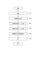
次に、図3を参照して本実施形態の画像処理装置101の処理手順を示す。図3は、本実施形態における本システム全体の動作処理の流れを示すフローチャートである。
Next, the processing procedure of the
<ステップ301>
操作者は入力部103を操作することにより、断層画像撮影装置100に対して指示するOCT画像(3次元断層画像)の撮影条件を設定する。
<Step 301>
By operating the
具体的には
1)スキャンモードの選択
2)スキャンモードに対応する撮影パラメータ設定
の手順からなり、本実施形態では以下のように設定してOCT撮影を実行する。
1)Macula 3Dスキャンモードを選択
2)以下の撮影パラメータを設定
2-1)走査領域サイズ:10x10mm
2-2)主走査方向:水平方向
2-3)走査間隔:0.01mm
2-4)固視灯位置:中心窩と視神経乳頭との中間
2-5)同一撮影位置でのBスキャン数:1
2-6)コヒーレンスゲート位置:硝子体側
次に、操作者は入力部103を操作して撮影画面中の撮影開始ボタン(非表示)を押下することにより、上記設定した撮影条件によるOCT断層画像の撮影を開始する。
Specifically, the procedure includes 1) selection of a scan mode, and 2) setting of imaging parameters corresponding to the scan mode. In this embodiment, OCT imaging is executed with the following settings.
1) Select Macula 3D scan mode 2) Set the following shooting parameters 2-1) Scan area size: 10x10mm
2-2) Main scanning direction: horizontal direction 2-3) Scanning interval: 0.01mm
2-4) Fixation lamp position: midway between the fovea and optic disc 2-5) Number of B scans at the same imaging position: 1
2-6) Coherence gate position: Vitreous body side Next, the operator operates the
撮影制御部101-03は断層画像撮影装置100に対して上記設定に基づいてOCT撮影を実施することを指示し、断層画像撮影装置100が対応するOCT断層画像を取得する。
The imaging control unit 101-03 instructs the
また断層画像撮影装置100はSLO画像の取得も行い、SLO動画像に基づく追尾処理を実行する。なお、本実施形態では同一走査位置における断層画像の撮像回数を1回(繰り返さない)とする。これに限らず、同一走査位置における撮像回数は任意の回数に設定してよい。
The
<ステップ302>
画像取得部101-01及び画像処理部101-04は、S301で取得された断層画像を再構成する。
<Step 302>
The image acquisition unit 101-01 and the image processing unit 101-04 reconstruct the tomographic image acquired in S301.
まず断層画像生成部101-11は画像取得部101-01が取得した干渉信号に対して波数変換及び高速フーリエ変換(FFT)、絶対値変換(振幅の取得)を行うことで断層画像を生成する。次に位置合わせ部101-41はBスキャン断層画像間の位置合わせを行う。 First, the tomographic image generation unit 101-11 generates a tomographic image by performing wave number transformation, fast Fourier transformation (FFT), and absolute value conversion (amplitude acquisition) on the interference signal acquired by the image acquisition unit 101-01. . Next, the positioning unit 101-41 performs positioning between the B-scan tomographic images.
さらに、画像特徴取得部101-42が断層画像から網膜及び脈絡膜の層境界、篩状板部の前面・後面の境界(非図示)を取得する。本実施形態では、図6(a)に示すように層境界として内境界膜1、神経線維層‐神経節細胞層境界2、神経節細胞層‐内網状層境界3、視細胞内節外節接合部4、網膜色素上皮5、ブルッフ膜6、脈絡膜-強膜境界7を取得する。また検出したブルッフ膜6の端部(ブルッフ膜開口端部)を視神経乳頭部のDisc境界として特定する。本実施形態では網膜及び脈絡膜の層境界及び篩状板部の前面・後面境界の取得法として可変形状モデルを用いるが、任意の公知のセグメンテーション手法を用いてよい。また取得する層境界は上記に限らない。例えば網膜の内網状層-内顆粒層境界、内顆粒層-外網状層境界、外網状層‐外顆粒層境界、外境界膜、視細胞外節先端(COST)を任意の公知のセグメンテーション法により取得してもよい。あるいは、脈絡膜の脈絡膜毛細血管板‐Sattler層境界、Sattler層‐Haller層境界を任意の公知のセグメンテーション法により取得する場合も本発明に含まれる。また、篩状板部の前面・後面境界は手動で設定してもよい。例えば、特定の層境界(例えば内境界膜1)の位置を所定量だけ動かすことにより手動で設定できる。 Furthermore, the image feature acquisition unit 101-42 acquires the layer boundaries of the retina and choroid, and the front and back boundaries (not shown) of the lamina cribrosa from the tomographic image. In this embodiment, as shown in FIG. 6(a), the layer boundaries include an internal limiting membrane 1, a nerve fiber layer-ganglion cell layer boundary 2, a ganglion cell layer-inner plexiform layer boundary 3, and an inner photoreceptor cell outer segment. The junction 4, retinal pigment epithelium 5, Bruch's membrane 6, and choroid-sclera border 7 are obtained. Furthermore, the detected end of Bruch's membrane 6 (opening end of Bruch's membrane) is specified as the Disc boundary of the optic disc. In this embodiment, a variable shape model is used as a method for obtaining the layer boundaries of the retina and choroid and the anterior and posterior boundaries of the lamina cribrosa, but any known segmentation method may be used. Furthermore, the layer boundaries to be acquired are not limited to those described above. For example, the inner plexiform layer-inner nuclear layer boundary, the inner nuclear layer-outer nuclear layer boundary, the outer plexiform layer-outer nuclear layer boundary, the outer limiting membrane, and the photoreceptor outer segment tip (COST) of the retina can be determined using any known segmentation method. You may obtain it. Alternatively, the present invention also includes the case where the choroidal capillary plate-Sattler layer boundary and the Sattler layer-Haller layer boundary of the choroid are obtained by any known segmentation method. Further, the front and rear boundaries of the lamina cribriform portion may be set manually. For example, it can be set manually by moving the position of a particular layer boundary (eg, internal limiting membrane 1) by a predetermined amount.
なお、層境界及び篩状板の前面・後面境界の取得処理は本ステップでなくS303の血管候補領域取得時に実施してもよい。 Note that the process for acquiring the layer boundaries and the anterior and posterior boundaries of the lamina cribrosa may be performed not in this step but at the time of acquiring the blood vessel candidate region in S303.
<ステップ303>
血管取得部101-421は、異なる所定の深度範囲間の輝度統計値を比較した結果に基づいて血管候補領域の分布に関する情報を生成する。
<Step 303>
The blood vessel acquisition unit 101-421 generates information regarding the distribution of blood vessel candidate regions based on the results of comparing brightness statistics between different predetermined depth ranges.
血管領域は図6(a)の601に示すように存在する深度範囲(層の種類)がおおよそ決まっており、かつ該領域下に影602が生じやすいという特徴がある。一方、断層画像の再走査領域上に生じる輝度段差アーチファクトや、硝子体混濁などの場合は、図6(a)の603に示すようにほとんどの深度範囲にわたって低輝度になりやすい。 As shown in 601 in FIG. 6(a), the blood vessel region has a roughly fixed depth range (layer type), and is characterized in that a shadow 602 is likely to occur under the region. On the other hand, in the case of brightness step artifacts or vitreous opacity that occur in the rescanning region of a tomographic image, the brightness tends to be low over most of the depth range, as shown at 603 in FIG. 6(a).
そこで、本実施形態では「血管が存在する可能性の高い深度範囲(網膜表層)」と「影による輝度低下が最も顕著に現れる深度範囲(網膜外層)」における輝度の相違度(差もしくは比率)に基づいて血管候補領域を特定する。 Therefore, in this embodiment, the degree of difference (difference or ratio) in brightness between "the depth range where blood vessels are likely to exist (surface layer of the retina)" and "the depth range where the decrease in brightness due to shadows is most noticeable (outer layer of the retina)" A blood vessel candidate region is identified based on.
血管候補領域マップ生成処理の詳細はS501~S506で説明する。なお、マップとは、被検眼の深度方向に交差する面内方向の分布情報の一例である。 Details of the blood vessel candidate region map generation process will be explained in S501 to S506. Note that the map is an example of distribution information in an in-plane direction intersecting the depth direction of the eye to be examined.
<ステップ304>
重み付け部101-442は、S303で血管取得部101-421が生成した血管候補領域の分布に関する情報を用いて断層画像の血管候補領域における輝度値を重み付けした重み付き断層画像を生成する。次に、高次元変換部101-4411が高次元平滑化断層画像を生成し、低次元変換部101-4412が該重み付き断層画像に対して速軸方向に平滑化処理を行った低次元平滑化断層画像を生成する。さらに演算部101-443が該高次元平滑化断層画像と該低次元平滑化断層画像との演算処理により断層画像用の輝度補正係数マップを生成する。
<Step 304>
The weighting unit 101-442 generates a weighted tomographic image by weighting the brightness values in the blood vessel candidate area of the tomographic image using the information regarding the distribution of the blood vessel candidate area generated by the blood vessel acquisition unit 101-421 in S303. Next, the high-dimensional transformation unit 101-4411 generates a high-dimensional smoothed tomographic image, and the low-dimensional transformation unit 101-4412 performs a smoothing process on the weighted tomographic image in the fast axis direction. generate a tomographic image. Further, the calculation unit 101-443 generates a brightness correction coefficient map for the tomographic image by performing calculation processing on the high-dimensional smoothed tomographic image and the low-dimensional smoothed tomographic image.
輝度補正係数マップ生成処理の詳細はS511~S516で説明する。 Details of the brightness correction coefficient map generation process will be explained in S511 to S516.
<ステップ305>
補正部101-44は、断層画像の各画素に対してS304で算出した輝度補正係数値を乗算することにより、輝度段差補正済の断層画像を生成する。なお、輝度補正係数の適用方法は乗算に限定されるものではなく、任意の公知の演算方法を適用してよい。例えば加算、減算、除算のいずれかを適用してもよい。また、輝度補正係数値を用いて3次元断層画像の少なくとも一部が補正されれば良い。このとき、3次元断層画像の少なくとも一部には、Cスキャン画像等も含まれる。
<Step 305>
The correction unit 101-44 multiplies each pixel of the tomographic image by the brightness correction coefficient value calculated in S304 to generate a tomographic image with brightness level difference corrected. Note that the method of applying the brightness correction coefficient is not limited to multiplication, and any known calculation method may be applied. For example, addition, subtraction, or division may be applied. Further, at least a portion of the three-dimensional tomographic image may be corrected using the brightness correction coefficient value. At this time, at least a portion of the three-dimensional tomographic image includes a C-scan image and the like.
<ステップ306>
表示制御部101-05は、S305で生成した輝度補正済の断層画像を表示部104に表示する。また、操作者が入力部103を用いて表示部104に表示された非図示のボタンもしくはショートカットメニューを選択することで、該輝度補正済の断層画像を記憶部101-02もしくは外部記憶部102に保存する。なお、画像生成手段の一例である画像処理部101-04が、補正された少なくとも一部の3次元断層画像に基づく少なくとも1つの正面画像(正面断層画像)を生成することが好ましい。このとき、表示制御部101-05は、生成された少なくとも1つの正面画像を表示部104に表示させることが好ましい。
<Step 306>
The display control unit 101-05 displays the brightness-corrected tomographic image generated in S305 on the
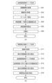
次に、図5(a)に示すフローチャートを参照しながら、S303で実行される処理の詳細について説明する。 Next, details of the process executed in S303 will be described with reference to the flowchart shown in FIG. 5(a).
<ステップ501>
血管取得部101-421は、S302で断層画像生成部101-11が生成した断層画像を取得する。
<Step 501>
The blood vessel acquisition unit 101-421 acquires the tomographic image generated by the tomographic image generation unit 101-11 in S302.
<ステップ502>
血管取得部101-421はS302で画像特徴取得部101-42が特定した網膜及び脈絡膜の層境界、篩状板部の前面・後面の境界データを取得する。
<Step 502>
The blood vessel acquisition unit 101-421 acquires boundary data of the layer boundaries of the retina and choroid, and the anterior and posterior surfaces of the lamina cribrosa, identified by the image feature acquisition unit 101-42 in S302.
<ステップ503>
血管取得部101-421は断層画像撮影装置100のロールオフ特性により生じる深度方向の信号減衰を補償するための補正処理(以下、ロールオフ補正と表記)を補正部101-44に対して指示し、補正部101-44が該ロールオフ補正処理を行う。
<Step 503>
The blood vessel acquisition unit 101-421 instructs the correction unit 101-44 to perform correction processing (hereinafter referred to as roll-off correction) to compensate for signal attenuation in the depth direction caused by the roll-off characteristics of the
ロールオフ補正を行うための深度方向の補正係数H(z)は、深度位置zを引数とする正規化ロールオフ特性関数をRoF(z)とした場合に、例えば式(1)のように表せ、該補正係数H(z)を断層画像の各画素値に対して乗じることでロールオフ補正が行われる。
H(z)={(BGa+2σ)/(BGa(z)+2σ(z))}/(1+RoF(z)-RoF(z0))・・・(1)
The correction coefficient H(z) in the depth direction for performing roll-off correction can be expressed, for example, as in equation (1), where RoF(z) is the normalized roll-off characteristic function with depth position z as an argument. , roll-off correction is performed by multiplying each pixel value of the tomographic image by the correction coefficient H(z).
H(z)={(BGa+2σ)/(BGa(z)+2σ(z))}/(1+RoF(z)-RoF(z0))...(1)
BGa及びσは、各々被検査物がない状態で取得したBスキャンデータ全体の輝度分布BGの平均値及び標準偏差を示す。またBGa(z)及びσ(z)は、被検査物がない状態で取得したBスキャンデータにおいて各深度位置(z)で算出した、z軸に直交する方向に関する輝度分布の平均値及び標準偏差を示す。z0はBスキャン範囲に含まれる基準の深度位置を示す。z0は任意の定数を設定してよいが、ここではzの最大値の1/4の値に設定するものとする。なおロールオフ補正式は上記に限られるものではなく、断層画像撮影装置100のロールオフ特性により生じる深度方向の信号減衰を補償する効果を持つ処理であれば任意の公知の補正処理を実行してよい。
BGa and σ each indicate the average value and standard deviation of the brightness distribution BG of the entire B-scan data acquired without an object to be inspected. In addition, BGa(z) and σ(z) are the average value and standard deviation of the brightness distribution in the direction perpendicular to the z-axis, calculated at each depth position (z) in B-scan data acquired without an object to be inspected. shows. z0 indicates a reference depth position included in the B-scan range. Although z0 may be set to any constant, it is assumed here that it is set to a value that is 1/4 of the maximum value of z. Note that the roll-off correction formula is not limited to the above, and any known correction process may be executed as long as it has the effect of compensating for signal attenuation in the depth direction caused by the roll-off characteristics of the
<ステップ504>
血管取得部101-421は異なる深度範囲の輝度統計値を比較するための準備として投影部101-43に網膜表層の正面断層画像と網膜外層の正面断層画像を生成するよう指示し、投影部101-43が該正面断層画像を生成する。投影法として任意の公知の投影法を用いてよいが、本実施形態では平均値投影を行うものとする。図6(b)に網膜表層の正面断層画像、同図6(c)に網膜外層の正面断層画像の例を示す。網膜表層の正面断層画像では(測定光と血管領域内の赤血球との相互作用により)血管領域における輝度値が高く、網膜外層の正面断層画像では影が生じることにより血管領域における輝度値が低くなることがわかる。
<Step 504>
The blood vessel acquisition unit 101-421 instructs the projection unit 101-43 to generate a frontal tomographic image of the surface layer of the retina and a frontal tomographic image of the outer layer of the retina in preparation for comparing luminance statistics values in different depth ranges, and -43 generates the front tomographic image. Any known projection method may be used as the projection method, but in this embodiment, average value projection is performed. FIG. 6(b) shows an example of a front tomographic image of the surface layer of the retina, and FIG. 6(c) shows an example of a front tomographic image of the outer layer of the retina. In a frontal tomographic image of the surface layer of the retina, the brightness value in the blood vessel area is high (due to the interaction between the measurement light and red blood cells in the blood vessel area), and in a frontal tomographic image of the outer layer of the retina, the brightness value in the blood vessel area is low due to shadows. I understand that.
<ステップ505>
情報生成手段の一例である血管取得部101-421は、異なる深度範囲の輝度統計値を比較するために、S504で算出した2種類の正面断層画像の輝度値に基づいて輝度減衰率Arの分布を算出する。異なる深度範囲における輝度統計値の比較に関する指標として、本実施形態では、(網膜表層正面断層画像の輝度)÷(網膜外層正面断層画像の輝度)を各画素(x,y)で算出し、輝度減衰率Ar(x,y)のマップ(図6(d))を生成する。
<Step 505>
The blood vessel acquisition unit 101-421, which is an example of information generation means, calculates the distribution of the brightness attenuation rate Ar based on the brightness values of the two types of frontal tomographic images calculated in S504, in order to compare the brightness statistical values in different depth ranges. Calculate. In this embodiment, as an index for comparing brightness statistical values in different depth ranges, (brightness of the superficial tomographic image of the retina) ÷ (brightness of the front tomographic image of the outer retinal layer) is calculated for each pixel (x, y), and the brightness A map (FIG. 6(d)) of the attenuation rate Ar(x,y) is generated.
<ステップ506>
血管取得部101-421は、S505で生成した輝度減衰率マップAr(x,y)を正規化することにより、血管領域らしさを表わす血管候補領域マップV(x,y)を生成する。
<Step 506>
The blood vessel acquisition unit 101-421 normalizes the brightness attenuation rate map Ar(x,y) generated in S505 to generate a blood vessel candidate region map V(x,y) representing the likelihood of a blood vessel region.
本実施形態では、S505で算出した輝度減衰率マップAr(x,y)に対して所定の値WLとWWを用いて正規化することで、血管候補領域マップV(x,y)を
V(x,y)=(Ar(x,y)-WL)/WW
として算出し、0≦V(x,y)≦1を満たすようにする。図6(e)に血管候補領域マップV(x,y)の例を示す。血管候補領域がハイライトされていることがわかる。なお、正規化処理は上記に限らず任意の公知の正規化法を用いてよい。
In this embodiment, by normalizing the brightness attenuation rate map Ar(x,y) calculated in S505 using predetermined values WL and WW, the blood vessel candidate region map V(x,y) is transformed into V( x,y)=(Ar(x,y)-WL)/WW
It is calculated as follows, and 0≦V(x,y)≦1 is satisfied. FIG. 6(e) shows an example of the blood vessel candidate region map V(x,y). It can be seen that the blood vessel candidate region is highlighted. Note that the normalization process is not limited to the above method, and any known normalization method may be used.
全ての深度範囲の輝度値を加算したProjection画像や、網膜外層の深度範囲で生成した正面断層画像における低輝度領域を血管領域とみなす場合には硝子体混濁による影(図6(a)の603)や白斑による影(図6(a)の605)も含まれてしまう。それに対し、本実施形態のS303で示した方法では血管候補領域(及び該血管から生じた出血領域)のみの分布情報を生成できる。また、OCTAのようなクラスタスキャンは不要で、単回スキャンの断層画像でも血管候補領域に関する分布情報を生成できる。 When a projection image in which the luminance values of all depth ranges are summed or a low luminance region in a frontal tomographic image generated in the depth range of the outer retinal layer is considered to be a blood vessel region, shadows due to vitreous opacity (603 in Fig. 6(a) ) and shadows due to vitiligo (605 in FIG. 6(a)) are also included. In contrast, the method shown in S303 of the present embodiment can generate distribution information only for blood vessel candidate regions (and bleeding regions that have arisen from the blood vessels). Further, a cluster scan like OCTA is not necessary, and distribution information regarding blood vessel candidate regions can be generated even with a single scan of a tomographic image.
なお、血管以外の遮蔽物(影の発生原因となる物体)、例えば白斑等の高輝度病変(図6(a)の604)の分布情報を生成する場合は、Aスキャン単位で例えば(網膜深層における輝度平均値)÷(網膜外層における輝度平均値)のような輝度減衰率を算出すればよい。ここで、血管領域、出血領域、高輝度病変等は、被検眼に含まれる領域であって、被検眼の深度方向に沿って発生する影の原因となる領域の一例である。 Note that when generating distribution information for occluding objects other than blood vessels (objects that cause shadows), for example, high-intensity lesions such as vitiligo (604 in Fig. 6(a)), for example (deep retinal layer What is necessary is to calculate a brightness attenuation rate such as (average brightness value in the outer layer of the retina)÷(average brightness value in the outer retinal layer). Here, the blood vessel region, bleeding region, high-intensity lesion, etc. are regions included in the eye to be examined, and are examples of regions that cause shadows that occur along the depth direction of the eye to be examined.
また、輝度減衰率の算出においては正面断層画像の生成は必須ではなく、3次元断層画像のままAスキャン単位で算出してもよい。さらに、輝度減衰率は異なる深度範囲の輝度統計値同士の比率に限定されるものではなく、例えば(異なる深度範囲の輝度統計値同士の)差分量に基づいて算出してもよい。 Furthermore, in calculating the brightness attenuation rate, it is not essential to generate a frontal tomographic image, and the calculation may be performed in A-scan units as is from a three-dimensional tomographic image. Furthermore, the brightness attenuation rate is not limited to the ratio of brightness statistical values in different depth ranges, but may be calculated based on the amount of difference (between brightness statistical values in different depth ranges), for example.
さらに、図5(b)に示すフローチャートを参照しながら、S304で実行される処理の詳細について説明する。 Furthermore, details of the process executed in S304 will be explained with reference to the flowchart shown in FIG. 5(b).
<ステップ511>
補正部101-44は、S302で断層画像生成部101-11が生成した断層画像を取得する。次に、操作者が表示部104に表示されたユーザインターフェースを介して所望の投影深度範囲と該投影深度範囲に対応する正面断層画像の生成を指示する。投影部101-43は、ロールオフ補正適用後の3次元断層画像に対して指示された深度範囲で投影し、正面断層画像(図7(a))を生成する。
<Step 511>
The correction unit 101-44 acquires the tomographic image generated by the tomographic image generation unit 101-11 in S302. Next, the operator instructs generation of a desired projection depth range and a front tomographic image corresponding to the projection depth range via the user interface displayed on the
なお本実施形態では、3次元断層画像の投影処理として、眼底正面に対応する面内の各画素に対応する深度方向の断層データの平均値を該画素の画素値としている。しかしながら投影処理はこのような平均値投影に限られず、任意の公知の投影方法を用いてよい。例えば、各画素に対応する深度方向の断層データの中央値や最大値、最頻値等を画素値としてもよい。さらに、背景輝度値に相当するノイズ閾値を超えた画素の輝度値のみを投影することで、背景領域の影響を除いた(眼底組織の輝度値に由来する)画素値を取得できる。 In this embodiment, in the projection process of the three-dimensional tomographic image, the average value of the tomographic data in the depth direction corresponding to each pixel in the plane corresponding to the front surface of the fundus is used as the pixel value of the pixel. However, the projection process is not limited to such average value projection, and any known projection method may be used. For example, the pixel value may be the median value, maximum value, mode value, etc. of the tomographic data in the depth direction corresponding to each pixel. Furthermore, by projecting only the luminance values of pixels that exceed the noise threshold corresponding to the background luminance value, it is possible to obtain pixel values (derived from the luminance value of the fundus tissue) excluding the influence of the background region.
<ステップ512>
高次元変換部101-4411は、正面断層画像の輝度値を2次元で平滑化することにより、第1の概略値分布の一例である高次元概略値分布を算出する。ここで、2次元での平滑化処理は、第1の概略値分布を取得する際に、正面画像を2次元で変換する処理(2次元の変換処理)の一例である。本実施形態では、高次元変換部101-4411は、S511で生成した正面断層画像における各画素の輝度値を2次元で平滑化することにより、図7(c)に示すような断層画像の輝度値に関する高次元概略値分布を算出する。
<Step 512>
The high-dimensional conversion unit 101-4411 calculates a high-dimensional approximate value distribution, which is an example of the first approximate value distribution, by two-dimensionally smoothing the brightness values of the frontal tomographic image. Here, the two-dimensional smoothing process is an example of a process of two-dimensionally converting the front image (two-dimensional conversion process) when obtaining the first approximate value distribution. In this embodiment, the high-dimensional conversion unit 101-4411 two-dimensionally smoothes the brightness value of each pixel in the front tomographic image generated in S511, so that the brightness of the tomographic image as shown in FIG. Compute a high-dimensional approximate value distribution for values.
なお、本実施形態では、概略値分布を算出する処理の例として平滑化処理を行ったが、後述するようにClosing処理やOpening処理等のモルフォロジー演算を行ってもよい。また平滑化処理は任意の空間フィルタを用いて平滑化もよいし、高速フーリエ変換(FFT)等を用いて断層データを周波数変換した上で、高周波成分を抑制することで平滑化してもよい。FFTを用いる場合、畳み込み演算が不要になるため、高速に平滑化処理を実行できる。断層データを周波数変換した上で高周波成分を抑制することで平滑化する場合、リンギングを抑制するために周波数領域で所定の窓関数(Hamming窓もしくはHanning窓)を適用したり、Butterworthフィルタ等を適用したりすることによって高周波成分を抑制してもよい。 Note that in this embodiment, smoothing processing is performed as an example of processing for calculating the approximate value distribution, but morphological operations such as closing processing and opening processing may also be performed as described later. Further, the smoothing process may be performed using an arbitrary spatial filter, or may be performed by frequency-converting the tomographic data using fast Fourier transform (FFT) or the like, and then suppressing high-frequency components. When FFT is used, the smoothing process can be executed at high speed because convolution calculation is not necessary. When smoothing tomographic data by frequency converting and suppressing high frequency components, a predetermined window function (Hamming window or Hanning window) is applied in the frequency domain or a Butterworth filter is applied to suppress ringing. The high frequency components may be suppressed by doing the following.
<ステップ513>
重み付け部101-442は、血管取得部101-421から血管候補領域マップV(x,y)(図7(d))を取得する。
<Step 513>
The weighting unit 101-442 acquires the blood vessel candidate region map V(x,y) (FIG. 7(d)) from the blood vessel acquiring unit 101-421.
<ステップ514>
重み付け部101-442は、血管候補領域マップV(x,y)の値を用いて断層画像の該血管候補領域における輝度値を重み付けする。なお、この重み付けは、第2の概略値分布の一例である低次元概略値分布を取得する際に、3次元断層画像を取得する際に使用される測定光の速軸方向に沿って存在する血管もしくは出血領域である所定の組織と、それ以外の領域とに対して実行される異なる算出処理の一例である。また、この重み付けは、本発明において必須ではない。
<Step 514>
The weighting unit 101-442 weights the luminance value in the blood vessel candidate region of the tomographic image using the value of the blood vessel candidate region map V(x,y). Note that this weighting exists along the fast axis direction of the measurement light used when acquiring the three-dimensional tomographic image when acquiring the low-dimensional approximate value distribution, which is an example of the second approximate value distribution. This is an example of different calculation processes executed for a predetermined tissue that is a blood vessel or bleeding area and for other areas. Further, this weighting is not essential in the present invention.
本実施形態では、血管候補領域マップV(x,y)の値(血管らしさ)が高い領域ほど、S511で取得した正面断層画像における該高い領域に対応する領域の輝度値が、S512で算出した高次元概略値I_2ds(x,y)に近づくように、また、該V(x,y)の値が低い領域ほど、S511で取得した正面断層画像の輝度値I(x,y)をできるだけ維持するように、正面断層画像を重み付けした重み付き正面画像I_w(x,y)を生成する。具体的には、以下として算出すれば良い。
I_w(x,y)=(1.0-V(x,y))*I(x,y)+V(x,y)*I_2ds(x,y)
In the present embodiment, the higher the value of the blood vessel candidate region map V (x, y) (likelihood of a blood vessel) is, the brightness value of the region corresponding to the higher region in the front tomographic image acquired in S511 is calculated in S512. The brightness value I(x,y) of the frontal tomographic image acquired in S511 is maintained as much as possible so that it approaches the high-dimensional approximate value I_2ds(x,y), and the lower the value of V(x,y) is, the lower the value of V(x,y) is. A weighted frontal image I_w(x,y) is generated by weighting the frontal tomographic image so that the frontal tomographic image is weighted. Specifically, it may be calculated as follows.
I_w(x,y)=(1.0-V(x,y))*I(x,y)+V(x,y)*I_2ds(x,y)
図7(e)に重み付き正面断層画像I_w(x,y)の例を示す。 FIG. 7(e) shows an example of the weighted front tomographic image I_w(x,y).
なお、ここで示した血管候補領域の輝度値に対する重み付け法はあくまで例であり、速軸方向に走行する血管候補領域の輝度値を増加させる処理もしくは該血管候補領域近傍の輝度値に近づける処理であれば任意の重み付けを行ってもよい。 Note that the weighting method for the brightness value of the blood vessel candidate region shown here is just an example, and the process of increasing the brightness value of the blood vessel candidate region running in the fast axis direction or the process of bringing it closer to the brightness value in the vicinity of the blood vessel candidate region. Any weighting may be applied if necessary.
<ステップ515>
低次元変換部101-4412は、断層画像の輝度値に関する低次元の概略値分布を算出する。具体的には、血管候補領域の輝度値を重み付けした正面断層画像の各画素の輝度値に対し、速軸方向に関する概略値分布を算出する処理(平滑化処理やモルフォロジー演算)を行う。図7(f)に本ステップで算出した低次元概略値分布の例を示す。速軸方向に走行する血管領域の輝度値が底上げされた画像に対して低次元変換(速軸方向の平滑化)処理を行うために、「速軸方向に走行する血管領域」が帯状の低輝度領域として残存する問題を回避できる。ここで、低次元での平滑化処理は、第2の概略値分布を取得する際に、正面画像を1次元で変換する処理(1次元の変換処理)の一例である。なおS512と同様に平滑化処理を周波数領域で実施する場合、リンギングを抑制するために周波数領域で所定の窓関数(Hamming窓やHanning窓等)を適用したり、Butterworthフィルタ等を適用したりすることによって高周波成分を抑制して平滑化してもよい。
<Step 515>
The low-dimensional conversion unit 101-4412 calculates a low-dimensional approximate value distribution regarding the brightness values of the tomographic image. Specifically, a process (smoothing process or morphological calculation) is performed to calculate an approximate value distribution in the fast axis direction for the brightness value of each pixel of the front tomographic image weighted with the brightness value of the blood vessel candidate region. FIG. 7(f) shows an example of the low-dimensional approximate value distribution calculated in this step. In order to perform low-dimensional transformation (smoothing in the fast axis direction) on an image in which the luminance value of the blood vessel region running in the fast axis direction has been raised, the "blood vessel region running in the fast axis direction" is Problems remaining as brightness areas can be avoided. Here, the low-dimensional smoothing process is an example of the process of converting the front image in one dimension (one-dimensional conversion process) when acquiring the second approximate value distribution. Note that when smoothing processing is performed in the frequency domain as in S512, a predetermined window function (Hamming window, Hanning window, etc.) or a Butterworth filter or the like is applied in the frequency domain to suppress ringing. By doing so, high frequency components may be suppressed and smoothed.
<ステップ516>
演算部101-443は、断層画像の高次元概略値分布と低次元概略値分布とを演算することにより、断層画像用の輝度補正係数分布を算出する。
<Step 516>
The calculation unit 101-443 calculates the brightness correction coefficient distribution for the tomographic image by calculating the high-dimensional approximate value distribution and the low-dimensional approximate value distribution of the tomographic image.
本実施形態では、S512で生成した2次元平滑化断層画像の輝度値をS515で生成した重み付き速軸方向平滑化断層画像の輝度値で除算することにより、断層画像用の輝度補正係数マップ(図7(g))を生成する。 In this embodiment, the brightness correction coefficient map for tomographic images ( FIG. 7(g)) is generated.
次に、図8(a)~図8(g)を用いて血管候補領域に対する輝度重み付けの効果(輝度段差アーチファクトのみを選択的に抑制しやすくする)について説明する。図8(a)は速軸方向の一定範囲に限局した帯状の輝度段差と、速軸方向に走行する血管領域の双方を含む断層画像の例である。速軸方向に走行する血管領域の輝度値を過補正することなく、帯状の輝度段差のみ選択的に抑制する必要がある。 Next, the effect of luminance weighting on blood vessel candidate regions (facilitating selective suppression of only luminance step artifacts) will be explained using FIGS. 8(a) to 8(g). FIG. 8A is an example of a tomographic image that includes both a band-shaped brightness step localized in a certain range in the fast axis direction and a blood vessel region running in the fast axis direction. It is necessary to selectively suppress only the band-shaped brightness level difference without overcorrecting the brightness value of the blood vessel region running in the fast axis direction.
血管候補領域に対する輝度重み付けを実施せずにS515の低次元変換処理、S516の輝度補正係数マップ算出処理、S305の輝度段差補正処理を各々実行した場合の処理結果の例を図8(b)、同図(d)、同図(f)に示す。図8(b)の白矢印で示した(速軸方向に走行する)血管領域において低輝度領域が帯状に残存し、輝度段差に類似している。そのため、図8(d)の白矢印で示した血管領域では輝度段差でないにも関わらず高い補正係数値が算出されてしまい、S305の輝度段差補正処理において速軸方向に走行する血管及びその近傍領域の輝度値の過補正が生じる(図8(f)の白矢印で示した領域)。 FIG. 8B shows an example of the processing results when the low-dimensional conversion process in S515, the brightness correction coefficient map calculation process in S516, and the brightness level difference correction process in S305 are executed without performing brightness weighting on the blood vessel candidate region. This figure is shown in (d) and (f) of the same figure. In the blood vessel region (running in the fast axis direction) indicated by the white arrow in FIG. 8(b), a band-shaped low luminance region remains and is similar to a luminance step. Therefore, a high correction coefficient value is calculated in the blood vessel region shown by the white arrow in FIG. Overcorrection of the brightness value of the area occurs (the area indicated by the white arrow in FIG. 8(f)).
一方、血管候補領域に対する輝度重み付けを実施してからS515の低次元変換処理、S516の輝度補正係数マップ算出処理、S305の輝度段差補正処理を各々実行した場合の処理結果を図8(c)、同図(e)、同図(g)に示す。図8(c)において、速軸方向に走行する血管領域に対応する帯状の低輝度領域は生じていない。そのため、図8(e)でも血管領域に対して適切な補正係数値が算出され、S305の輝度段差補正処理においても速軸方向に走行する血管及びその近傍領域の輝度値に対する過補正は見られない(図8(g))。 On the other hand, FIG. 8C shows the processing results when the low-dimensional conversion process in S515, the brightness correction coefficient map calculation process in S516, and the brightness level difference correction process in S305 are performed after performing brightness weighting on the blood vessel candidate region. This figure is shown in (e) and (g). In FIG. 8(c), there is no band-shaped low-luminance region corresponding to the blood vessel region running in the fast axis direction. Therefore, an appropriate correction coefficient value is calculated for the blood vessel region in FIG. 8(e), and no overcorrection of the brightness value of the blood vessel running in the fast axis direction and its neighboring region is observed in the brightness level difference correction process in S305. No (Figure 8(g)).
なお、本実施形態においては正面断層画像上に生じた帯状の輝度段差を抑制する(輝度段差補正済の正面断層画像を生成する)方法について説明したが、本発明はこれに限定されない。以下の手順で3次元断層画像上に生じた帯状の輝度段差を抑制し、輝度段差補正済の3次元断層画像を生成してもよい。 Note that although the present embodiment has described a method of suppressing band-shaped brightness steps that occur on a front tomographic image (generating a front tomographic image that has been corrected for brightness steps), the present invention is not limited to this. The band-shaped brightness level difference that occurs on the three-dimensional tomographic image may be suppressed by the following procedure, and a three-dimensional tomographic image with the brightness level difference corrected may be generated.
すなわち、多数の異なる投影深度範囲で正面断層画像を生成しておき、各正面断層画像に対して輝度段差補正係数マップを生成しておく。次に3次元断層画像上の各画素の輝度値に対して、該各画素が属する投影深度範囲に対応する輝度段差補正係数マップの値(補正係数値)を演算することによって輝度段差補正済の3次元断層画像を生成できる。異なる投影深度範囲として、例えば網膜表層・網膜深層・網膜外層・脈絡膜の4種類が挙げられる。あるいは、網膜及び脈絡膜に属する各層の種類を指定してもよい。 That is, front tomographic images are generated in a large number of different projection depth ranges, and a brightness level difference correction coefficient map is generated for each front tomographic image. Next, for the brightness value of each pixel on the three-dimensional tomographic image, the value of the brightness step correction coefficient map (correction coefficient value) corresponding to the projection depth range to which each pixel belongs is calculated. Can generate 3D tomographic images. The different projection depth ranges include, for example, four types: the retinal surface layer, the deep retinal layer, the outer retinal layer, and the choroid. Alternatively, the type of each layer belonging to the retina and choroid may be specified.
なお、Cスキャン画像に生じた輝度段差アーチファクトを抑制する場合、画像内に複数種の層が含まれるために(層境界付近の画素値に悪影響を及ぼさずに)輝度段差アーチファクトのみ選択的に抑制するのが難しい場合がある。輝度段差補正済の3次元断層画像を生成しておき、該輝度段差補正済の3次元断層画像からCスキャン画像を生成することにより、輝度段差補正済Cスキャン画像を得られる。 Note that when suppressing the luminance step artifact that occurs in a C-scan image, since the image contains multiple types of layers, it is necessary to selectively suppress only the luminance step artifact (without adversely affecting pixel values near the layer boundaries). It can be difficult to do so. A brightness level difference corrected C-scan image can be obtained by generating a three-dimensional tomographic image with brightness level difference correction in advance, and generating a C-scan image from the brightness level difference-corrected three-dimensional tomographic image.
また、本発明は、いわゆる3-Dスキャンで断層画像を撮影した場合に生じる帯状の輝度段差の補正処理に限定されるものではなく、種々のスキャンパターンで断層画像を撮影した場合の遅軸方向に生じる輝度段差の補正にも適用できる。例えば、半径の異なる多数のサークルスキャンや、ラジアルスキャンで撮影した場合の遅軸方向に生じる輝度段差を補正する場合も本発明に含まれる。なお、サークルスキャンの場合には、例えば、円周方向が速軸方向で、円周方向に直交する方向が遅軸方向と考えられる。また、ラジアルスキャンの場合には、例えば、所定の点を通り、放射状の各スキャン方向が速軸方向で、所定の点を中心とする円周方向が遅軸方向と考えられる。 Furthermore, the present invention is not limited to correction processing for band-shaped brightness steps that occur when tomographic images are taken using so-called 3-D scanning, but also for correction processing in the slow axis direction when tomographic images are taken using various scan patterns. It can also be applied to correct brightness differences that occur in For example, the present invention also includes the case of correcting a brightness level difference that occurs in the slow axis direction when photographing is performed using a large number of circle scans with different radii or a radial scan. In the case of circle scanning, for example, the circumferential direction is considered to be the fast axis direction, and the direction orthogonal to the circumferential direction is considered to be the slow axis direction. In the case of radial scanning, for example, each radial scan direction passing through a predetermined point is considered to be a fast axis direction, and the circumferential direction around the predetermined point is considered to be a slow axis direction.
以上述べた構成によれば、画像処理装置101はOCTを用いて撮影した被検眼の断層画像の遅軸方向に生じた様々な輝度段差アーチファクトをロバストに抑制するために、以下の画像補正処理を行う。すなわち、画像処理装置は、被検眼の深度方向に交差する面内方向の分布情報であって、3次元断層画像における複数の深度範囲に対応する複数の分布情報を比較することにより、深度方向に沿って発生する影の原因となる被検眼における所定の領域(血管候補領域)に関する分布情報を生成する。例えば、画像処理装置は、断層画像の網膜表層と網膜外層間の輝度減衰率に基づいて血管候補領域の分布情報を生成する。次に高次元平滑化断層画像の輝度値に対して、該血管候補領域の輝度値を重み付けした後に速軸方向に平滑化した断層画像の輝度値を除算することにより、輝度補正係数マップを生成する。さらに断層画像に対して輝度補正係数を乗算することで、断層画像の遅軸方向に生じた輝度段差アーチファクトをロバストに抑制する。なお、最終的に分布情報が生成されていればよく、生成の途中においては複数の分布情報として例えば画像(マップ)を生成する必要はない。
According to the configuration described above, the
これにより、被検眼の断層画像の遅軸方向に生じた輝度段差をロバストに抑制できる。 Thereby, it is possible to robustly suppress the brightness level difference that occurs in the slow axis direction of the tomographic image of the eye to be examined.
[第2の実施形態]
本実施形態に係る画像処理装置は、OCTを用いたクラスタ撮影により得られた被検眼の断層画像から生成したモーションコントラスト画像の遅軸方向に生じた様々な輝度段差アーチファクトをロバストに抑制するために、以下の画像処理を行う。すなわち、高次元平滑化モーションコントラスト画像の輝度値に対して、第1実施形態と同様の方法で取得した血管候補領域の輝度値を重み付けした後に速軸方向に平滑化したモーションコントラスト画像の輝度値を除算することで、輝度補正係数マップを生成する。さらに、断層画像に対して輝度補正係数を乗算することで、モーションコントラスト画像の遅軸方向に生じた輝度段差アーチファクトをロバストに抑制する場合について説明する。
[Second embodiment]
The image processing device according to the present embodiment is designed to robustly suppress various luminance step artifacts that occur in the slow axis direction of a motion contrast image generated from a tomographic image of a subject's eye obtained by cluster imaging using OCT. , performs the following image processing. That is, the brightness value of the motion contrast image is weighted with the brightness value of the blood vessel candidate region obtained in the same manner as in the first embodiment with respect to the brightness value of the high-dimensional smoothed motion contrast image, and then smoothed in the fast axis direction. A brightness correction coefficient map is generated by dividing . Furthermore, a case will be described in which a brightness step artifact occurring in the slow axis direction of a motion contrast image is robustly suppressed by multiplying a tomographic image by a brightness correction coefficient.
ここで、本実施形態で補正対象とする被検眼のモーションコントラスト画像の遅軸方向に生じた輝度段差の例について説明する。図4(b)に示した再走査領域が低輝度であるような断層画像を用いてモーションコントラスト画像を生成すると、図4(c)に示すようにモーションコントラスト画像上の対応する(白矢印で示した)領域に帯状の低輝度な段差を生じる。また、図4(e)に示すような再走査領域に短い低輝度な段差領域を含む断層画像を用いてモーションコントラスト画像を生成すると、モーションコントラスト画像上の対応する領域に短い帯状の低輝度な段差を生じるという課題がある。 Here, an example of a brightness level difference that occurs in the slow axis direction of a motion contrast image of a subject's eye to be corrected in this embodiment will be described. When a motion contrast image is generated using a tomographic image in which the rescanning region shown in FIG. 4(b) has low brightness, the corresponding (white arrow) A band-shaped, low-luminance step appears in the area (shown). Furthermore, when a motion contrast image is generated using a tomographic image that includes a short, low-intensity step region in the rescanning region as shown in FIG. There is a problem of creating a level difference.
さらに、同一位置で複数回走査した断層画像間の位置ずれが生じている場合には、実際には赤血球の変位が生じてない領域に対しても高いモーションコントラスト値が算出されてしまうため、図4(d)の白矢印で示すような帯状の高輝度な段差が生じる。なお、同一のモーションコントラスト画像上に低輝度な段差と高輝度な段差の双方が含まれる場合もある。また、網膜や脈絡膜等の眼組織が画像上の速軸方向の一部の範囲にしか含まれない場合や、層境界検出不良の領域が存在する場合などでは帯状の高輝度な段差が途中で途切れたり、該輝度段差の太さや高さが途中で変化したりする課題がある。 Furthermore, if there is a positional shift between tomographic images scanned multiple times at the same position, a high motion contrast value will be calculated even for areas where no displacement of red blood cells has actually occurred. A band-like high-intensity step as shown by the white arrow in 4(d) is generated. Note that the same motion contrast image may include both a low-luminance step and a high-luminance step. In addition, when ocular tissues such as the retina and choroid are included only in a part of the fast axis direction on the image, or when there are areas where layer boundaries are poorly detected, band-like high-intensity steps may appear in the middle. There is a problem that the brightness step may be interrupted or the thickness or height of the brightness step may change midway.
本実施形態に係る画像処理装置101を備える画像処理システム10の構成を図9に示す。画像取得部101-01にモーションコントラストデータ生成部101-12を、画像処理部101-04に合成部101-45を備える点が第一実施形態の場合と異なる。また本実施形態での画像処理フローを図10に示す。なお図10においてS1002とS1003は第1実施形態の場合と同様であるので説明は省略する。
FIG. 9 shows the configuration of an
<ステップ1001>
操作者は入力部103を操作することにより、断層画像撮影装置100に対して指示するOCT画像の撮影条件を設定する。
<
By operating the
具体的には
1)スキャンモードの選択
2)スキャンモードに対応する撮影パラメータ設定
の手順からなり、本実施形態では以下のように設定してOCT撮影を実行する。
1)OCTAスキャンモードを選択
2)以下の撮影パラメータを設定
2-1)走査領域サイズ:10x10mm
2-2)主走査方向:水平方向
2-3)走査間隔:0.01mm
2-4)固視灯位置:中心窩と視神経乳頭との中間
2-5)同一撮影位置でのBスキャン数:4
2-6)コヒーレンスゲート位置:硝子体側
次に、操作者は入力部103を操作して撮影画面中の撮影開始ボタン(非表示)を押下することにより、上記設定した撮影条件による繰り返しOCTA撮影を開始する。
Specifically, the procedure includes 1) selection of a scan mode, and 2) setting of imaging parameters corresponding to the scan mode. In this embodiment, OCT imaging is performed with the following settings.
1) Select OCTA scan mode 2) Set the following imaging parameters 2-1) Scan area size: 10x10mm
2-2) Main scanning direction: horizontal direction 2-3) Scanning interval: 0.01mm
2-4) Fixation lamp position: midway between the fovea and optic disc 2-5) Number of B scans at the same imaging position: 4
2-6) Coherence gate position: Vitreous body side Next, the operator operates the
撮影制御部101-03は断層画像撮影装置100に対して上記設定に基づいて繰り返しOCTA撮影を実施することを指示し、断層画像撮影装置100が対応するOCT断層画像を取得する。
The imaging control unit 101-03 instructs the
なお、本実施形態では本ステップにおける繰り返し撮像回数(クラスタ数)を5回とする。これに限らず、繰り返し撮像回数(クラスタ数)は任意の回数に設定してよい。 In this embodiment, the number of times of repeated imaging (the number of clusters) in this step is five times. The number of times of repeated imaging (the number of clusters) is not limited to this, and may be set to an arbitrary number of times.
また断層画像撮影装置100はSLO画像の取得も行い、SLO動画像に基づく追尾処理を実行する。
The
なおクラスタ数が2以上の場合、繰り返しOCTA撮影における追尾処理に用いる基準SLO画像は1回目のクラスタ撮影時に設定した基準SLO画像とし、全てのクラスタ撮影において共通の基準SLO画像を用いる。また2回目以降のクラスタ撮影中は、
・左右眼の選択
・追尾処理の実行有無
について1回目のクラスタ撮影の場合と同じ設定値を用いる(変更しない)ものとする。
Note that when the number of clusters is two or more, the reference SLO image used for tracking processing in repeated OCTA imaging is the reference SLO image set during the first cluster imaging, and a common reference SLO image is used in all cluster imaging. Also, during the second and subsequent cluster shooting,
- The same setting values as in the case of the first cluster imaging are used (not changed) for selection of left and right eyes and whether to execute tracking processing.
<ステップ1004>
画像取得部101-01及び画像処理部101-04は、位置合わせ部101-41が同一クラスタに属する断層画像同士の位置合わせとクラスタ間の断層画像の位置合わせを行い、該位置合わせ済断層画像を用いてモーションコントラスト画像を生成する。
<
In the image acquisition unit 101-01 and the image processing unit 101-04, the alignment unit 101-41 aligns tomographic images belonging to the same cluster and aligns tomographic images between clusters, and the aligned tomographic images Generate a motion contrast image using
モーションコントラストデータ生成部101-12が同一クラスタ内の隣接する断層画像間でモーションコントラストを算出する。本実施形態では、モーションコントラストとして脱相関値Mxyを以下の式(2)に基づき求める。 A motion contrast data generation unit 101-12 calculates motion contrast between adjacent tomographic images within the same cluster. In this embodiment, a decorrelation value Mxy is determined as the motion contrast based on the following equation (2).

ここで、Axyは断層画像データAの位置(x,y)における(FFT処理後の複素数データの)振幅、Bxyは断層データBの同一位置(x,y)における振幅を示している。0≦Mxy≦1であり、両振幅値の差異が大きいほど1に近い値をとる。式(2)のような脱相関演算処理を(同一クラスタに属する)任意の隣接する断層画像間で行い、得られた(1クラスタあたりの断層画像数-1)個のモーションコントラスト値の平均を画素値として持つ画像を最終的なモーションコントラスト画像として生成する。 Here, Axy indicates the amplitude (of complex number data after FFT processing) at the position (x, y) of the tomographic image data A, and Bxy indicates the amplitude at the same position (x, y) of the tomographic data B. 0≦Mxy≦1, and the larger the difference between both amplitude values, the closer the value is to 1. Perform the decorrelation calculation process as shown in Equation (2) between arbitrary adjacent tomographic images (belonging to the same cluster), and calculate the average of the obtained (number of tomographic images per cluster - 1) motion contrast values. An image having pixel values is generated as a final motion contrast image.
なお、ここではFFT処理後の複素数データの振幅に基づいてモーションコントラストを計算したが、モーションコントラストの計算法は上記に限定されない。例えば複素数データの位相情報に基づいてモーションコントラストを計算してもよいし、振幅と位相の両方の情報に基づいてモーションコントラストを計算してもよい。あるいは、複素数データの実部や虚部に基づいてモーションコントラストを計算してもよい。 Note that although the motion contrast is calculated here based on the amplitude of the complex number data after FFT processing, the method of calculating the motion contrast is not limited to the above. For example, motion contrast may be calculated based on phase information of complex number data, or may be calculated based on both amplitude and phase information. Alternatively, motion contrast may be calculated based on the real part or imaginary part of complex number data.
また、本実施形態ではモーションコントラストとして脱相関値を計算したが、モーションコントラストの計算法はこれに限定されない。例えば二つの値の差分に基づいてモーションコントラストを計算しても良いし、二つの値の比に基づいてモーションコントラストを計算してもよい。 Further, in this embodiment, a decorrelation value is calculated as the motion contrast, but the method of calculating the motion contrast is not limited to this. For example, the motion contrast may be calculated based on the difference between two values, or the motion contrast may be calculated based on the ratio of two values.
さらに、上記では取得された複数の脱相関値の平均値を求めることで最終的なモーションコントラスト画像を得ているが、本発明はこれに限定されない。例えば取得された複数の脱相関値の中央値、あるいは最大値を画素値として持つ画像を最終的なモーションコントラスト画像として生成しても良い。 Further, in the above, the final motion contrast image is obtained by calculating the average value of the plurality of acquired decorrelation values, but the present invention is not limited to this. For example, an image whose pixel value is the median value or maximum value of the plurality of acquired decorrelation values may be generated as the final motion contrast image.
画像処理部101-04は、繰り返しOCTA撮影を通して得られたモーションコントラスト画像群を3次元的に位置合わせし、加算平均することで高コントラストな合成モーションコントラスト画像を生成する。なお、合成処理は単純加算平均に限定されない。例えば各モーションコントラスト画像の輝度値に対して任意の重みづけをした上で平均した値でもよいし、中央値をはじめとする任意の統計値を算出してもよい。また位置合わせ処理を2次元的に行う場合も本発明に含まれる。 The image processing unit 101-04 three-dimensionally aligns a group of motion contrast images obtained through repeated OCTA imaging and averages them to generate a high-contrast composite motion contrast image. Note that the compositing process is not limited to simple arithmetic averaging. For example, the brightness value of each motion contrast image may be arbitrarily weighted and then averaged, or an arbitrary statistical value such as a median value may be calculated. The present invention also includes a case where the alignment process is performed two-dimensionally.
なお、合成部101-45が合成処理に不適なモーションコントラスト画像が含まれているか否かを判定した上で、不適と判定したモーションコントラスト画像を除いて合成処理を行うよう構成してもよい。例えば、各モーションコントラスト画像に対して評価値(例えば脱相関値の平均値や中央値)が所定の範囲外である場合に、合成処理に不適と判定すればよい。 Note that the compositing unit 101-45 may be configured to determine whether or not a motion contrast image inappropriate for the compositing process is included, and then perform the compositing process excluding the motion contrast image determined to be inappropriate. For example, if the evaluation value (for example, the average value or median value of decorrelation values) for each motion contrast image is outside a predetermined range, it may be determined that the motion contrast image is unsuitable for compositing processing.
本実施形態では合成部101-45がモーションコントラスト画像を3次元的に合成した後、補正部101-44がモーションコントラスト画像内に生じるプロジェクションアーチファクトを3次元的に抑制する処理を行う。 In this embodiment, after the synthesis unit 101-45 three-dimensionally synthesizes motion contrast images, the correction unit 101-44 performs processing to three-dimensionally suppress projection artifacts occurring in the motion contrast images.
ここで、プロジェクションアーチファクトは網膜表層血管内のモーションコントラストが深層側(網膜深層や網膜外層・脈絡膜)に映り込み、実際には血管の存在しない深層側の領域に高い脱相関値が生じる現象を指す。補正部101-44は、3次元の合成モーションコントラスト画像上に生じたプロジェクションアーチファクトを抑制する処理を実行する。任意の公知のプロジェクションアーチファクト抑制手法を用いてよいが、本実施形態ではStep-down Exponential Filteringを用いる。Step-down Exponential Filteringでは、3次元モーションコントラスト画像上の各Aスキャンデータに対して式(3)で表される処理を実行することにより、プロジェクションアーチファクトを抑制する。 Here, projection artifact refers to a phenomenon in which motion contrast within the superficial retinal blood vessels is reflected in the deep layers (deep retina, outer retina, and choroid), resulting in high decorrelation values in deep regions where no blood vessels actually exist. . The correction unit 101-44 executes processing to suppress projection artifacts generated on the three-dimensional composite motion contrast image. Although any known projection artifact suppression technique may be used, this embodiment uses Step-down Exponential Filtering. In Step-down Exponential Filtering, projection artifacts are suppressed by executing the process expressed by equation (3) on each A-scan data on a three-dimensional motion contrast image.

ここで、γは負の値を持つ減衰係数、D(x,y,z)はプロジェクションアーチファクト抑制処理前の脱相関値、DE(x,y,z)は該抑制処理後の脱相関値を表す。 Here, γ is an attenuation coefficient with a negative value, D (x, y, z) is a decorrelation value before projection artifact suppression processing, and DE (x, y, z) is a decorrelation value after the suppression processing. represents.
最後に、画像処理装置101は取得した画像群(SLO画像や断層画像)と該画像群の撮影条件データや、生成したモーションコントラスト画像と付随する生成条件データを検査日時、披検眼を同定する情報と関連付けて外部記憶部102へ保存する。
Finally, the
<ステップ1005>
重み付け部101-442は、S1003で血管取得部101-421が生成した血管候補領域の分布に関する情報を用いてモーションコントラスト画像の血管候補領域における輝度値を重み付けした重み付きモーションコントラスト画像を生成する。次に、高次元変換部101-4411が高次元平滑化モーションコントラスト画像を生成し、低次元変換部101-4412が該重み付きモーションコントラスト画像に対して速軸方向に平滑化処理を行った低次元平滑化モーションコントラスト画像を生成する。さらに演算部101-443が該高次元平滑化モーションコントラスト画像と該低次元平滑化モーションコントラスト画像との演算処理によりモーションコントラスト画像用の輝度補正係数マップを生成する。
<
The weighting unit 101-442 generates a weighted motion contrast image in which the luminance values in the blood vessel candidate region of the motion contrast image are weighted using the information regarding the distribution of the blood vessel candidate region generated by the blood vessel acquisition unit 101-421 in S1003. Next, the high-dimensional transformation unit 101-4411 generates a high-dimensional smoothed motion contrast image, and the low-dimensional transformation unit 101-4412 performs smoothing processing on the weighted motion contrast image in the fast axis direction. Generate a dimensionally smoothed motion contrast image. Further, the calculation unit 101-443 generates a brightness correction coefficient map for the motion contrast image by performing calculation processing on the high-dimensional smoothed motion contrast image and the low-dimensional smoothed motion contrast image.
なお、輝度補正係数マップ生成処理の詳細はS511~S516で説明する。 Note that details of the brightness correction coefficient map generation process will be explained in S511 to S516.
<ステップ1006>
補正部101-44は、モーションコントラスト画像の各画素に対してS1005で算出した輝度補正係数値を乗算することにより、輝度段差補正済のモーションコントラスト画像を生成する。なお、輝度補正係数の適用方法は乗算に限定されるものではなく、任意の公知の演算方法を適用してよい。また、輝度補正係数値を用いて3次元モーションコントラスト画像の少なくとも一部が補正されれば良い。このとき、3次元モーションコントラスト画像の少なくとも一部には、Cスキャンのモーションコントラスト画像等も含まれる。
<
The correction unit 101-44 multiplies each pixel of the motion contrast image by the brightness correction coefficient value calculated in S1005, thereby generating a motion contrast image with the brightness level difference corrected. Note that the method of applying the brightness correction coefficient is not limited to multiplication, and any known calculation method may be applied. Further, at least a portion of the three-dimensional motion contrast image may be corrected using the brightness correction coefficient value. At this time, at least a portion of the three-dimensional motion contrast image includes a C-scan motion contrast image and the like.
<ステップ1007>
表示制御部101-05は、S1006で生成した輝度補正済のモーションコントラスト画像を表示部104に表示する。また操作者が入力部103を用いて表示部104に表示された非図示のボタンもしくはショートカットメニューを選択することで、該輝度補正済モーションコントラスト画像を記憶部101-02もしくは外部記憶部102に保存する。なお、画像生成手段の一例である画像処理部101-04が、補正された少なくとも一部の3次元モーションコントラスト画像に基づく少なくとも1つの正面画像(正面モーションコントラスト画像)を生成することが好ましい。このとき、表示制御部101-05は、生成された少なくとも1つの正面画像を表示部104に表示させることが好ましい。
<
The display control unit 101-05 displays the brightness-corrected motion contrast image generated in S1006 on the
本実施形態では、図13のReportボタン1312を押下することにより、レポート画面1300を表示部104に表示する。レポート画面1300の左下に輝度段差補正済正面断層画像1309を表示しており、投影範囲に関してはリストボックス1310に表示されたリストから操作者が選択することで変更できる。該レポート画面1300左上のSLO画像上に、輝度段差補正済の正面断層画像もしくは正面モーションコントラスト画像を重畳表示する。またレポート画面1300中央の上下に投影深度範囲の異なる輝度段差補正済モーションコントラスト画像1301、1305を表示している。輝度段差補正済正面モーションコントラスト画像の投影範囲はリストボックスに表示された既定の深度範囲セット(1302及び1306)から操作者が選択することで変更できる。また、投影範囲の指定に用いる層境界の種類とオフセット位置を1303や1307のようなユーザインターフェースから変更したり、断層像上に重畳した層境界データ(1304及び1308)を入力部103から操作して移動させたりして投影範囲を変更できる。
In this embodiment, a report screen 1300 is displayed on the
さらに、輝度段差補正済モーションコントラスト画像の画像投影法やプロジェクションアーチファクト抑制処理の有無を例えばコンテキストメニューのようなユーザインターフェースから選択することにより変更してもよい。 Furthermore, the image projection method of the luminance step-corrected motion contrast image and the presence or absence of projection artifact suppression processing may be changed by selecting from a user interface such as a context menu.
さらに操作者が複数のモーションコントラスト画像を合成するための合成指示ボタン1311を押下することにより、輝度段差補正済の合成モーションコントラスト画像を生成してもよい。図13の合成指示ボタンは重ね合わせ処理の場合の例を示しているが、これに限らず貼り合わせ処理に関する合成指示である場合も本発明に含まれる。 Furthermore, the operator may press a combination instruction button 1311 for combining a plurality of motion contrast images, thereby generating a combined motion contrast image that has been corrected for brightness differences. Although the compositing instruction button in FIG. 13 shows an example for superimposing processing, the invention is not limited to this, and the present invention also includes a compositing instruction regarding pasting processing.
なお断層画像もしくはモーションコントラスト画像に対する輝度段差補正処理の適用可否を指定するユーザインターフェース(1313)を選択することで、輝度段差補正処理の適用可否を変更した断層画像もしくはモーションコントラスト画像を表示させてもよい。例えば、図13の1313に示したようなチェックボックスの選択/非選択に応じて、レポート画面1300に表示する断層画像やモーションコントラスト画像に対する輝度段差補正処理の適用状態(適用する/適用しない)を切り替えてよい。ユーザインターフェースはチェックボックスに限定されるものではなく、任意の公知のユーザインターフェースを用いてよい。また、輝度段差補正処理の適用可否を断層画像とモーションコントラスト画像とで独立に指示可能なユーザインターフェースを備えてもよい。例えば断層画像とモーションコントラスト画像とで別々の指示ボタンを備えてもよいし、単独のユーザインターフェースで、4種類の選択肢((1)両方に対して適用(2)断層画像に対してのみ適用(3)モーションコントラスト画像に対してのみ(4)どちらに対しても適用しない)の中から選択するよう構成してもよい。あるいは、輝度段差補正処理を適用した断層画像もしくはモーションコントラスト画像と、輝度段差補正処理を適用していない断層画像もしくはモーションコントラスト画像とを並べて表示部104に表示させてもよい。
Note that by selecting the user interface (1313) that specifies whether or not to apply brightness level difference correction processing to a tomographic image or motion contrast image, a tomographic image or motion contrast image with changed applicability of brightness level difference correction processing can be displayed. good. For example, the application status (apply/not apply) of brightness level difference correction processing to the tomographic image or motion contrast image displayed on the report screen 1300 can be determined depending on the selection/unselection of the check box shown in 1313 in FIG. You can switch. The user interface is not limited to check boxes, and any known user interface may be used. Further, a user interface may be provided that can independently instruct whether or not to apply brightness level difference correction processing for tomographic images and motion contrast images. For example, separate instruction buttons may be provided for tomographic images and motion contrast images, or a single user interface may provide four options ((1) apply to both, (2) apply only to tomographic images). It may be configured to select from 3) applied only to motion contrast images, and 4) applied to neither. Alternatively, a tomographic image or motion contrast image to which the brightness level difference correction process has been applied and a tomographic image or motion contrast image to which the brightness level difference correction process has not been applied may be displayed side by side on the
次に、図5(b)に示すフローチャートを参照しながら、S1005で実行される処理の詳細について説明する。 Next, details of the process executed in S1005 will be described with reference to the flowchart shown in FIG. 5(b).
<ステップ511>
補正部101-44は、S1004でモーションコントラストデータ生成部101-12及び合成部101-45が生成したモーションコントラスト画像及び合成モーションコントラスト画像を取得する。次に、操作者が表示部104に表示されたユーザインターフェースを介して所望の投影深度範囲と該投影深度範囲に対応する正面モーションコントラスト画像の生成を指示する。投影部101-43は、指示された深度範囲で投影し、正面モーションコントラスト画像(図11(a))を生成する。なお、本実施形態では、3次元モーションコントラスト画像の投影処理として、眼底正面に対応する面内の各画素に対応する深度方向のモーションコントラストデータの最大値を該画素の画素値としている。しかしながら投影処理はこのような最大値投影に限られず、任意の公知の投影方法を用いてよい。例えば、各画素に対応する深度方向のモーションコントラストデータの中央値や最大値、最頻値等を画素値としてもよい。
<Step 511>
The correction unit 101-44 obtains the motion contrast image and the composite motion contrast image generated by the motion contrast data generation unit 101-12 and the synthesis unit 101-45 in S1004. Next, the operator instructs generation of a desired projection depth range and a frontal motion contrast image corresponding to the projection depth range via the user interface displayed on the
<ステップ512>
高次元変換部101-4411は、正面モーションコントラスト画像の輝度値を2次元で平滑化することにより、高次元概略値分布を算出する。本実施形態では、高次元変換部101-4411は、S511で生成した正面モーションコントラスト画像における各画素の輝度値を2次元で平滑化することにより、図11(c)に示すようなモーションコントラスト画像の輝度値に関する高次元概略値分布を算出する。
<Step 512>
The high-dimensional conversion unit 101-4411 calculates a high-dimensional approximate value distribution by two-dimensionally smoothing the brightness values of the frontal motion contrast image. In this embodiment, the high-dimensional conversion unit 101-4411 creates a motion contrast image as shown in FIG. A high-dimensional approximate value distribution regarding the brightness values of is calculated.
なお、本実施形態では、概略値分布を算出する処理の例として平滑化処理を行ったが、後述するようにClosing処理やOpening処理等のモルフォロジー演算を行ってもよい。また平滑化処理は任意の空間フィルタを用いて平滑化もよいし、高速フーリエ変換(FFT)等を用いてモーションコントラストデータを周波数変換した上で、高周波成分を抑制することで平滑化してもよい。FFTを用いる場合、畳み込み演算が不要になるため、高速に平滑化処理を実行できる。 Note that in this embodiment, smoothing processing is performed as an example of processing for calculating the approximate value distribution, but morphological operations such as closing processing and opening processing may also be performed as described later. Further, the smoothing process may be performed by using an arbitrary spatial filter, or by converting the frequency of the motion contrast data using fast Fourier transform (FFT), etc., and then suppressing high frequency components. . When FFT is used, the smoothing process can be executed at high speed because convolution calculation is not necessary.
<ステップ513>
重み付け部101-442は、血管取得部101-421から血管候補領域マップV(x,y)(図7(d))を取得する。
<Step 513>
The weighting unit 101-442 acquires the blood vessel candidate region map V(x,y) (FIG. 7(d)) from the blood vessel acquiring unit 101-421.
<ステップ514>
重み付け部101-442は、血管候補領域マップV(x,y)の値を用いてモーションコントラスト画像の該血管候補領域における輝度値を重み付けする。なお、この重み付けは、第2の概略値分布の一例である低次元概略値分布を取得する際に、3次元モーションコントラスト画像を取得する際に使用される測定光の速軸方向に沿って存在する血管もしくは出血領域である所定の組織と、それ以外の領域とに対して実行される異なる算出処理の一例である。また、この重み付けは、本発明において必須ではない。
<Step 514>
The weighting unit 101-442 weights the luminance value in the blood vessel candidate region of the motion contrast image using the value of the blood vessel candidate region map V(x,y). Note that this weighting exists along the fast axis direction of the measurement light used when acquiring the three-dimensional motion contrast image when acquiring the low-dimensional approximate value distribution, which is an example of the second approximate value distribution. This is an example of different calculation processes executed for a predetermined tissue that is a blood vessel or a bleeding area, and for other areas. Further, this weighting is not essential in the present invention.
本実施形態では、血管候補領域マップV(x,y)の値(血管らしさ)が高い領域ほど、S511で取得した正面モーションコントラスト画像における該高い領域に対応する領域の輝度値が、S512で算出した高次元概略値M_2ds(x,y)に近づくように、また、該V(x,y)の値が低い領域ほど、S511で取得した正面モーションコントラスト画像の輝度値M(x,y)をできるだけ維持するように、正面モーションコントラスト画像を重み付けした重み付き正面モーションコントラスト画像M_w(x,y)を生成する。具体的には、以下として算出すれば良い。
M_w(x,y)=(1.0-V(x,y))*M(x,y)+V(x,y)*M_2ds(x,y)
In the present embodiment, the higher the value of the blood vessel candidate region map V (x, y) (likelihood of a blood vessel) is, the brightness value of the region corresponding to the higher region in the frontal motion contrast image acquired in S511 is calculated in S512. The brightness value M(x,y) of the frontal motion contrast image acquired in S511 is A weighted frontal motion contrast image M_w(x,y) is generated by weighting the frontal motion contrast image so as to maintain it as much as possible. Specifically, it may be calculated as follows.
M_w(x,y)=(1.0-V(x,y))*M(x,y)+V(x,y)*M_2ds(x,y)
図11(e)に重み付き正面モーションコントラスト画像M_w(x,y)の例を示す。 FIG. 11(e) shows an example of the weighted frontal motion contrast image M_w(x,y).
なお、ここで示した血管候補領域の輝度値に対する重み付け法はあくまで例であり、速軸方向に走行する血管候補領域の輝度値を減少させる処理もしくは該血管候補領域近傍の輝度値に近づける処理であれば任意の重み付けを行ってもよい。 Note that the weighting method for the brightness value of the blood vessel candidate region shown here is just an example, and the process of reducing the brightness value of the blood vessel candidate region running in the fast axis direction or the process of bringing it closer to the brightness value in the vicinity of the blood vessel candidate region. Any weighting may be applied if necessary.
<ステップ515>
低次元変換部101-4412は、モーションコントラスト画像の輝度値に関する低次元の概略値分布を算出する。具体的には、血管候補領域の輝度値を重み付けした正面モーションコントラスト画像の各画素の輝度値に対し、速軸方向に関する概略値分布を算出する処理(平滑化処理やモルフォロジー演算)を行う。図11(f)に本ステップで算出した低次元概略値分布の例を示す。速軸方向に走行する血管領域の輝度値が抑制された画像に対して、低次元変換(速軸方向の平滑化)処理を行うために、「速軸方向に走行する血管領域」が帯状の高輝度領域として残存する問題を回避できる。
<Step 515>
The low-dimensional conversion unit 101-4412 calculates a low-dimensional approximate value distribution regarding the brightness values of the motion contrast image. Specifically, processing (smoothing processing or morphological calculation) is performed to calculate the approximate value distribution in the fast axis direction for the luminance value of each pixel of the frontal motion contrast image weighted with the luminance value of the blood vessel candidate region. FIG. 11(f) shows an example of the low-dimensional approximate value distribution calculated in this step. In order to perform low-dimensional transformation (smoothing in the fast axis direction) on images in which the luminance values of blood vessel regions running in the fast axis direction are suppressed, the "vessel regions running in the fast axis direction" are transformed into band-shaped images. The problem of remaining high brightness areas can be avoided.
<ステップ516>
演算部101-443は、モーションコントラスト画像の高次元概略値分布と、モーションコントラスト画像の低次元概略値分布とを演算することにより、モーションコントラスト画像用の輝度補正係数分布を算出する。
<Step 516>
The calculation unit 101-443 calculates the luminance correction coefficient distribution for the motion contrast image by calculating the high-dimensional approximate value distribution of the motion contrast image and the low-dimensional approximate value distribution of the motion contrast image.
本実施形態ではS512で生成した2次元平滑化モーションコントラスト画像の輝度値とS515で生成した重み付き速軸方向平滑化モーションコントラスト画像の輝度値との除算により、モーションコントラスト画像用の輝度補正係数マップ(図11(g))を生成する。 In this embodiment, a brightness correction coefficient map for the motion contrast image is created by dividing the brightness value of the two-dimensional smoothed motion contrast image generated in S512 by the brightness value of the weighted fast-axis direction smoothed motion contrast image generated in S515. (Fig. 11(g)) is generated.
次に、図12(a)~図12(g)を用いて血管候補領域に対する輝度重み付けの効果(輝度段差アーチファクトのみを選択的に抑制しやすくする)について説明する。図12(a)は帯状の輝度段差(白線)と、速軸方向に走行する血管領域の双方を含むモーションコントラスト画像の例である。速軸方向に走行する血管領域の輝度値を過抑制することなく、帯状の輝度段差のみ選択的に抑制する必要がある。 Next, the effect of luminance weighting on blood vessel candidate regions (facilitating selective suppression of only luminance level difference artifacts) will be explained using FIGS. 12(a) to 12(g). FIG. 12A is an example of a motion contrast image that includes both a band-shaped brightness step (white line) and a blood vessel region running in the fast axis direction. It is necessary to selectively suppress only the band-shaped brightness step without over-suppressing the brightness value of the blood vessel region running in the fast axis direction.
血管候補領域に対する輝度重み付けを実施せずにS515の低次元変換処理、S516の輝度補正係数マップ算出処理、S1006の輝度段差補正処理を各々実行した場合の処理結果の例を図12(b)、同図(d)、同図(f)に示す。図12(b)の白矢印で示した(速軸方向に走行する)血管領域において高輝度領域が帯状に残存し、輝度段差に類似している。そのため、図12(d)の白矢印で示した血管領域では輝度段差でないにも関わらず低い補正係数値が算出され、S1006の輝度段差補正処理において速軸方向に走行する血管及びその近傍領域の輝度値の過抑制が生じる(図12(f)の白矢印で示した領域)。 FIG. 12B shows an example of the processing results when the low-dimensional conversion process in S515, the brightness correction coefficient map calculation process in S516, and the brightness level difference correction process in S1006 are executed without performing brightness weighting on the blood vessel candidate region. It is shown in the same figure (d) and the same figure (f). In the blood vessel region (traversing in the fast axis direction) indicated by the white arrow in FIG. 12(b), a band-like high brightness region remains and is similar to a brightness step. Therefore, a low correction coefficient value is calculated for the blood vessel region indicated by the white arrow in FIG. Over-suppression of the luminance value occurs (region indicated by the white arrow in FIG. 12(f)).
一方、血管候補領域に対する輝度重み付けを実施してからS515の低次元変換処理、S516の輝度補正係数マップ算出処理、S1006の輝度段差補正処理を各々実行した場合の処理結果を図12(c)、同図(e)、同図(g)に示す。図12(c)において、速軸方向に走行する血管領域に対応する帯状の高輝度領域は生じていない。そのため、図12(e)でも血管領域に対して適切な補正係数値が算出され、S1006の輝度段差補正処理においても速軸方向に走行する血管及びその近傍領域の輝度値に対する過抑制は見られない(図12(g))。 On the other hand, FIG. 12C shows the processing results when the low-dimensional conversion process in S515, the brightness correction coefficient map calculation process in S516, and the brightness level difference correction process in S1006 are performed after performing brightness weighting on the blood vessel candidate region. It is shown in the same figure (e) and the same figure (g). In FIG. 12(c), there is no band-shaped high-intensity region corresponding to a blood vessel region running in the fast axis direction. Therefore, an appropriate correction coefficient value is calculated for the blood vessel region in FIG. 12(e), and no excessive suppression of the brightness value of the blood vessel running in the fast axis direction and its neighboring region is observed in the brightness level difference correction processing of S1006. No (Figure 12(g)).
なお、本実施形態においては正面モーションコントラスト画像上に生じた帯状の輝度段差を抑制する(輝度段差補正済の正面モーションコントラスト画像を生成する)方法について説明したが、本発明はこれに限定されない。以下の手順で3次元モーションコントラスト画像上に生じた帯状の輝度段差を抑制し、輝度段差補正済の3次元モーションコントラスト画像を生成してもよい。 Although the present embodiment has described a method of suppressing band-shaped brightness steps that occur on a frontal motion contrast image (generating a frontal motion contrast image that has been corrected for brightness steps), the present invention is not limited to this. The band-shaped brightness level difference that occurs on the three-dimensional motion contrast image may be suppressed by the following procedure, and a three-dimensional motion contrast image that has been corrected for the brightness level difference may be generated.
すなわち、多数の異なる投影深度範囲で正面モーションコントラスト画像を生成しておき、各正面モーションコントラスト画像に対して輝度段差補正係数マップを生成しておく。次に3次元モーションコントラスト画像上の各画素の輝度値に対して、該各画素が属する投影深度範囲に対応する輝度段差補正係数マップの値(補正係数値)を演算することによって輝度段差補正済の3次元モーションコントラスト画像を生成できる。異なる投影深度範囲として、例えば網膜表層・網膜深層・網膜外層・脈絡膜の4種類が挙げられる。あるいは、網膜及び脈絡膜に属する各層の種類を指定してもよい。 That is, frontal motion contrast images are generated in a large number of different projection depth ranges, and a brightness level difference correction coefficient map is generated for each frontal motion contrast image. Next, the brightness level difference is corrected by calculating the value of the brightness level difference correction coefficient map (correction coefficient value) corresponding to the projection depth range to which each pixel belongs to the brightness value of each pixel on the three-dimensional motion contrast image. 3D motion contrast images can be generated. The different projection depth ranges include, for example, four types: the retinal surface layer, the deep retinal layer, the outer retinal layer, and the choroid. Alternatively, the type of each layer belonging to the retina and choroid may be specified.
また、輝度段差を補正するタイミングは、予め上述の手順で輝度段差補正済の3次元断層画像もしくは3次元モーションコントラスト画像を生成しておき、操作者から正面断層画像もしくは正面モーションコントラスト画像の生成指示があった時点でその正面画像を生成・表示してよい。輝度段差補正済の3次元断層画像もしくは3次元モーションコントラスト画像の生成タイミングの例として、例えば断層画像の撮影直後、再構成時、保存時が挙げられる。あるいは、操作者から正面断層画像もしくは正面モーションコントラスト画像の生成指示があった時点で(該指示で指定された投影深度範囲に対して)輝度段差補正を実施し、輝度段差補正済の正面断層画像もしくは正面モーションコントラスト画像を表示してもよい。正面断層画像の生成指示ユーザインターフェースとして、例えば図13に示したリストボックス1310が挙げられる。また、正面モーションコントラスト画像の生成指示ユーザインターフェースとして、例えば図13に示した投影深度範囲指定・変更用ユーザインターフェース(1302、1303、1304、1306、1307、1308)が挙げられる。なお事前に、もしくは操作者からの合成(重ね合わせもしくは貼り合わせ)指示に基づいて、各断層画像もしくはモーションコントラスト画像に対して輝度段差補正を実行し、それから合成してもよい。あるいは、合成画像(重ね合わせ画像もしくは貼り合わせ画像)に対して輝度段差補正を実施して表示部104に表示させてもよい。
In addition, the timing for correcting the brightness level difference is such that a 3D tomographic image or a 3D motion contrast image that has been corrected for the brightness level difference is generated in advance using the above procedure, and then the operator gives an instruction to generate a front tomographic image or a frontal motion contrast image. The frontal image may be generated and displayed at the moment the front image is detected. Examples of the timing of generating a three-dimensional tomographic image or a three-dimensional motion contrast image with brightness level difference correction include, for example, immediately after taking a tomographic image, at the time of reconstruction, and at the time of storage. Alternatively, when an operator instructs the generation of a frontal tomographic image or a frontal motion contrast image, the brightness level difference correction is performed (for the projection depth range specified by the instruction), and the brightness level difference corrected frontal tomographic image is created. Alternatively, a front motion contrast image may be displayed. An example of a user interface for instructing generation of a frontal tomographic image is a list box 1310 shown in FIG. 13 . Further, as the front motion contrast image generation instruction user interface, for example, the projection depth range designation/change user interface (1302, 1303, 1304, 1306, 1307, 1308) shown in FIG. 13 can be mentioned. Note that luminance level difference correction may be performed on each tomographic image or motion contrast image in advance or based on a composition (superimposition or pasting) instruction from the operator, and then composition may be performed. Alternatively, the brightness level difference correction may be performed on the composite image (overlaid image or composite image) and the resultant image may be displayed on the
さらに、本発明はいわゆる3-Dスキャンで撮影した場合に生じるモーションコントラスト画像上の帯状輝度段差の補正に限られるものではなく、種々のスキャンパターンで撮影した場合のモーションコントラスト画像上の遅軸方向に生じる輝度段差補正にも適用できる。例えば、半径の異なる多数のサークルスキャンや、ラジアルスキャンで撮影した場合の遅軸方向に生じる輝度段差を補正する場合も本発明に含まれる。 Furthermore, the present invention is not limited to correction of band-like brightness steps on motion contrast images that occur when photographing with so-called 3-D scanning, but also correction of band-like brightness steps in the slow axis direction on motion contrast images when photographing with various scan patterns. It can also be applied to correct brightness differences that occur in For example, the present invention also includes the case of correcting a brightness level difference that occurs in the slow axis direction when imaging is performed using a large number of circle scans with different radii or a radial scan.
以上述べた構成によれば、画像処理装置101はOCTを用いたクラスタ撮影により得られた被検眼の断層画像から生成したモーションコントラスト画像の遅軸方向に生じた様々な輝度段差アーチファクトをロバストに抑制するために、以下の画像処理を行う。すなわち、高次元平滑化モーションコントラスト画像の輝度値に対して、第1実施形態と同様の方法で取得した血管候補領域の輝度値を重み付けした後に速軸方向に平滑化したモーションコントラスト画像の輝度値を除算することで、輝度補正係数マップを生成する。さらに、断層画像に対して輝度補正係数を乗算することで、モーションコントラスト画像の遅軸方向に生じた輝度段差アーチファクトをロバストに抑制する。これにより、被検眼のモーションコントラスト画像の遅軸方向に生じた輝度段差をロバストに抑制できる。
According to the configuration described above, the
[第3の実施形態]
本実施形態に係る画像処理装置は、撮影確認画面において、上述した輝度段差アーチファクト抑制処理等の各種のアーチファクト低減処理が適用されていない正面画像(正面断層画像または正面モーションコントラスト画像)等の医用画像を表示し、一方、レポート画面では、アーチファクト低減処理が適用された医用画像を表示するものである。これにより、操作者は、例えば、撮影後の表示画面(撮影確認画面)においては、撮影成否(あるいは撮影失敗の程度)を容易に把握するために、各種処理ができるだけ施されていない状態の医用画像を確認することができる。また、操作者は、例えば、他の表示画面(レポート画面)においては、解析結果等を把握するために、解析に対しては不要な各種のアーチファクトができるだけ低減された医用画像を確認することができる。このため、操作者が目的に適した医用画像を確認可能とすることができる。
[Third embodiment]
The image processing apparatus according to the present embodiment displays a medical image such as a frontal image (frontal tomographic image or frontal motion contrast image) to which various artifact reduction processes such as the luminance step artifact suppression process described above have not been applied on the imaging confirmation screen. On the other hand, the report screen displays a medical image to which artifact reduction processing has been applied. As a result, in order to easily understand the success or failure (or degree of failure) of a medical image on the post-imaging display screen (imaging confirmation screen), the operator can, for example, display a medical You can check the image. In addition, for example, on other display screens (report screens), in order to understand the analysis results, the operator can check the medical images in which various artifacts unnecessary for analysis have been reduced as much as possible. can. Therefore, the operator can confirm a medical image suitable for the purpose.
なお、本実施形態におけるアーチファクトは、上述した輝度段差アーチファクトに限らず、上述した目的の範囲であれば何でも良い。例えば、本実施形態におけるアーチファクトは、OCTAにおけるプロジェクションアーチファクト(上層の血管の影の揺らぎをモーションコントラストとして誤検出することによって、下層において本来存在しない血管が描出されたもの)であっても良い。また、各種のアーチファクト低減処理自体は、撮影直後に実行開始されても良いし、撮影確認画面からレポート画面に遷移後に実行開始されても良い。また、画像処理部101-04は、各種のアーチファクトが低減された正面画像を生成する生成手段の一例である。また、撮影確認画面は、第1の正面画像の一例であり、レポート画面は第2の表示画面の一例である。また、レポート画面は、撮影確認画面から切り換わった後の表示画面の一つであり、各種処理後の画像や解析結果等を操作者が確認するための表示画面である。 Note that the artifact in this embodiment is not limited to the luminance level difference artifact described above, and may be any artifact within the range of the purpose described above. For example, the artifact in this embodiment may be a projection artifact in OCTA (a blood vessel that does not originally exist in the lower layer is depicted by erroneously detecting fluctuations in the shadow of the blood vessel in the upper layer as motion contrast). Furthermore, the various artifact reduction processes themselves may be started immediately after shooting, or may be started after the shooting confirmation screen is transitioned to the report screen. Further, the image processing unit 101-04 is an example of a generation unit that generates a front image in which various artifacts are reduced. Further, the shooting confirmation screen is an example of the first front image, and the report screen is an example of the second display screen. Further, the report screen is one of the display screens after switching from the shooting confirmation screen, and is a display screen for the operator to check images after various processing, analysis results, and the like.
また、本実施形態に係る画像処理装置は、断層画像もしくはモーションコントラスト画像の遅軸方向に生じた輝度段差アーチファクト抑制処理の適用要否に関する指示を受け付ける受付部を備えても良い。これにより、該受付部が撮影確認画面・レポート画面の各々で受け付けた該抑制処理の適用要否に関する指示に応じ、表示制御部が断層画像もしくはモーションコントラスト画像を該輝度段差アーチファクト抑制処理適用済、もしくは非適用の状態で表示部に表示させることができる。具体的には、撮影確認画面とレポート画面とで、断層画像及びモーションコントラスト画像を表示する際の輝度段差アーチファクト抑制処理の適用に関する設定を異ならせる場合について説明する。 Further, the image processing apparatus according to the present embodiment may include a reception unit that receives an instruction regarding whether or not to apply brightness step artifact suppression processing that occurs in the slow axis direction of a tomographic image or a motion contrast image. As a result, the display control unit displays the tomographic image or motion contrast image with the luminance step artifact suppression process applied, in response to the instruction regarding whether or not to apply the suppression process, which the reception unit receives on each of the imaging confirmation screen and the report screen. Alternatively, it can be displayed on the display unit in a non-applied state. Specifically, a case will be described in which settings regarding application of brightness level difference artifact suppression processing when displaying a tomographic image and a motion contrast image are made different between the imaging confirmation screen and the report screen.
本実施形態に係る画像処理装置は、受付部(非図示)を備える点が第1実施形態もしくは第2実施形態の場合と異なる。また、本実施形態での画像処理フローは第2実施形態の場合(図10)と同様である。なお、図10においてS1001~S1004は第2実施形態の場合と同様であるので説明は省略する。 The image processing apparatus according to the present embodiment differs from the first embodiment or the second embodiment in that it includes a reception section (not shown). Further, the image processing flow in this embodiment is the same as that in the second embodiment (FIG. 10). Note that in FIG. 10, steps S1001 to S1004 are the same as in the second embodiment, so their explanation will be omitted.
<ステップ1005>
重み付け部101-442は、第2実施形態のS1005と同様の処理を行うことによりモーションコントラスト画像用の輝度補正係数マップを生成する。なお、本実施形態では重み付け部101-442が第1実施形態のS304と同様の処理を行うことにより、断層画像用の輝度補正係数マップも生成するものとする。
<
The weighting unit 101-442 generates a brightness correction coefficient map for the motion contrast image by performing processing similar to S1005 of the second embodiment. Note that in this embodiment, the weighting unit 101-442 also generates a brightness correction coefficient map for tomographic images by performing the same process as S304 of the first embodiment.
<ステップ1006>
補正部101-44は、モーションコントラスト画像の各画素に対してS1005で算出したモーションコントラスト画像用の輝度補正係数値を乗算することにより、輝度段差補正済のモーションコントラスト画像を生成する。また、本実施形態では補正部101-44が断層画像の各画素に対してS1005で算出した断層画像用の輝度補正係数値を乗算することにより、輝度段差補正済の断層画像も生成しておく。
<
The correction unit 101-44 multiplies each pixel of the motion contrast image by the brightness correction coefficient value for the motion contrast image calculated in S1005, thereby generating a motion contrast image with the brightness level difference corrected. Further, in this embodiment, the correction unit 101-44 multiplies each pixel of the tomographic image by the brightness correction coefficient value for the tomographic image calculated in S1005, thereby generating a tomographic image with brightness level difference corrected. .
<ステップ1007>
S1002で生成した断層画像やS1004で生成したモーションコントラスト画像、補正部101-44が生成した輝度段差補正済のモーションコントラスト画像及び断層画像に基づき、表示制御部101-05が表示部104に撮影確認画面(図14)を表示する。本撮影確認画面においては、左上に眼底画像1401、左下に正面断層画像1402、該正面断層画像の各走査位置(1402a・1402b・1402c)に対応するBスキャン断層画像(1406a・1406b・1406c)を表示する。また取得した断層画像の画質指標値1405や、取得した3次元の断層画像の各スライスを自動で連続表示するための指示ボタン1404も備える。操作者は、該撮影確認画面に表示された断層画像やモーションコントラスト画像に基づき、撮影した断層画像の保存可否に関する指示(OKボタン1407もしくはNGボタン1408の押下)や繰り返し撮影の継続に関する指示(Repeatボタン1409の押下)を行う。受付部が受け付けた該指示に基づいて画像処理装置が対応するデータ保存・撮影継続処理を行う。さらに、第2実施形態のS1007と同様にReportボタン1312を押下することで、表示制御部101-05がレポート画面1300を表示部104に表示する。
<
Based on the tomographic image generated in S1002, the motion contrast image generated in S1004, and the motion contrast image and tomographic image with brightness step correction generated by the correction unit 101-44, the display control unit 101-05 displays the shooting confirmation on the
撮影確認画面(図14)においては左下に正面断層画像1402を表示し、モーションコントラスト画像の生成及び輝度段差補正処理が終わった段階で正面モーションコントラスト画像(図15(b))の表示に切り替える。本実施形態では、撮影確認画面の左側最下部に該撮影確認画面に表示する断層画像もしくはモーションコントラスト画像に対する輝度段差補正処理の適用可否を指示するためのユーザインターフェース1403を備えるものとする。図14では該ユーザインターフェース1403の例としてImage Quality Enhancementと表記されたチェックボックスが表示され、該チェックボックスを非選択の状態(OFFの状態)を表している。このような選択状態の場合には、表示制御部101-05は断層画像やモーションコントラスト画像を輝度段差補正処理非適用の状態(例えばモーションコントラスト画像においては、図15(b)のような状態)で表示部104に表示する。一方、該チェックボックスが選択された状態(ON)の場合は断層画像やモーションコントラスト画像を輝度段差補正処理適用済の状態(図15(a)や図15(c))で表示部104に表示する。なお、第2実施形態の場合と同様に、本撮影確認画面における輝度段差補正処理の適用可否を断層画像とモーションコントラスト画像とで独立に指示可能なユーザインターフェースを備えてもよい。例えば断層画像とモーションコントラスト画像とで別々の該指示ユーザインターフェースを備えてもよいし、単独のユーザインターフェースで、4種類の選択肢((1)両方に対して適用(2)断層画像に対してのみ適用(3)モーションコントラスト画像に対してのみ(4)どちらに対しても適用しない)の中から選択するよう構成してもよい。例えば(1)を選択することで実際の診療で用いる断層画像及びモーションコントラスト画像の画質を把握した上で断層画像の保存や繰り返し撮影継続の可否を指示できる。また(4)を選択することにより、断層画像の撮影不良箇所(低輝度領域)やモーションコントラスト画像を生成する際に白線を生じる原因となる断層画像間の位置ずれがどの程度、どこに存在するか把握した上で断層画像の保存や繰り返し撮影継続の可否を指示できる。あるいは、(3)を選択することで断層画像の撮影不良個所を把握しつつ、最終的なモーションコントラスト画像の画質を理解した状態で断層画像の保存や繰り返し撮影継続の可否を指示できる。細かな断層画像間の位置ずれのみ把握したい場合は、(2)を選択すればよい。
In the imaging confirmation screen (FIG. 14), a front tomographic image 1402 is displayed at the lower left, and when the motion contrast image generation and brightness level difference correction processing are completed, the display is switched to the front motion contrast image (FIG. 15(b)). In this embodiment, a user interface 1403 is provided at the bottom left side of the imaging confirmation screen for instructing whether or not to apply brightness level difference correction processing to the tomographic image or motion contrast image displayed on the imaging confirmation screen. In FIG. 14, a check box labeled "Image Quality Enhancement" is displayed as an example of the user interface 1403, and the check box is in an unselected state (OFF state). In such a selection state, the display control unit 101-05 displays the tomographic image and the motion contrast image in a state in which brightness level difference correction processing is not applied (for example, in the case of a motion contrast image, the state is as shown in FIG. 15(b)). is displayed on the
また、断層画像やモーションコントラスト画像に対する輝度段差補正処理の適用可否に関するユーザインターフェースは、撮影確認画面とレポート画面との間で独立に設定可能に構成してよい。例えば、断層画像やモーションコントラスト画像に対する該輝度段差補正処理を撮影画面においては非適用の状態、レポート画面においては適用済の状態で各々表示するような指示が選択された状態を該ユーザインターフェースのデフォルト設定としてよい。このように構成することで、撮影確認時には撮影失敗箇所を容易に把握でき、レポート画面においては診療に適した高画質な断層画像やモーションコントラスト画像を観察できる。 Further, the user interface regarding whether or not the brightness level difference correction process is applicable to tomographic images and motion contrast images may be configured to be able to be set independently between the imaging confirmation screen and the report screen. For example, the user interface defaults to a state where an instruction is selected to display the luminance level difference correction processing for tomographic images and motion contrast images in a non-applied state on the imaging screen and in a state where it is applied on the report screen. Good as a setting. With this configuration, it is possible to easily identify areas where imaging has failed during imaging confirmation, and high-quality tomographic images and motion contrast images suitable for medical treatment can be observed on the report screen.
このとき、表示画面が遷移した際に、表示画面の遷移前に選択された指示が遷移後にも反映されるように構成されても良い。例えば、撮影確認画面において選択された指示が、レポート画面に遷移された後にも反映されるように構成されても良い。また、例えば、レポート画面であって、所定の日時に得た画像が表示されている表示画面において選択された指示が、経過観察用の表示画面に遷移された後にも反映されるように構成されても良い。また、経過観察用の表示画面において選択された指示が、異なる日時の複数の画像に対して一括して反映されるように構成されても良い。これらにより、操作者の利便性を向上することができる。 At this time, when the display screen changes, the instruction selected before the display screen changes may be configured to be reflected even after the display screen changes. For example, the instruction selected on the shooting confirmation screen may be configured to be reflected even after transition to the report screen. Further, for example, an instruction selected on a display screen that is a report screen and on which images obtained at a predetermined date and time are displayed is configured to be reflected even after transition to a display screen for follow-up observation. It's okay. Further, the instruction selected on the progress observation display screen may be configured to be reflected on a plurality of images at different times and times at once. These can improve convenience for the operator.
さらに、撮影確認画面やレポート画面において適用可否を指定するユーザインターフェースが対象とする補正処理は輝度段差補正処理に限定されず、任意の公知の高画質化処理を選択可能に構成してもよい。例えば、撮影確認画面において機械学習による高画質化処理の適用可否の指示を受け付けるユーザインターフェースを備え、該ユーザインターフェースの選択状態に応じて断層画像もしくはモーションコントラスト画像に対する該高画質化処理の適用/非適用を切り替えて表示してもよい。 Further, the correction processing targeted by the user interface for specifying applicability on the shooting confirmation screen and the report screen is not limited to the luminance level difference correction processing, and any known image quality improvement processing may be selectable. For example, a user interface is provided that accepts an instruction as to whether to apply high image quality processing using machine learning on the imaging confirmation screen, and the high image quality processing is applied/disabled to a tomographic image or a motion contrast image depending on the selection state of the user interface. The application may be switched and displayed.
なお撮影確認画面やレポート画面において、所定のユーザインターフェースもしくはスクリプトにより輝度段差補正処理の適用・非適用を切り替えて断層画像もしくはモーションコントラスト画像を表示してもよい。あるいは、輝度段差補正処理適用済の断層画像もしくはモーションコントラスト画像と、輝度段差補正処理を適用していない断層画像もしくはモーションコントラスト画像とを並べて表示するよう画像処理装置101を構成してもよい。
Note that on the imaging confirmation screen or report screen, a tomographic image or a motion contrast image may be displayed by switching between application and non-application of the brightness level difference correction process using a predetermined user interface or script. Alternatively, the
以上述べた構成によれば、画像処理装置101は断層画像もしくはモーションコントラスト画像の遅軸方向に生じた輝度段差アーチファクト抑制処理の適用要否に関する指示を受け付ける受付部を備えてもよい。これにより、該受付部が撮影確認画面・レポート画面の各々で受け付けた該抑制処理の適用要否に関する指示に応じ、表示制御部が断層画像もしくはモーションコントラスト画像を該輝度段差アーチファクト抑制処理適用済、もしくは非適用の状態で表示部に表示させることができる。このため、撮影確認時には撮影失敗箇所を容易に確認でき、レポート画面観察時には診療に適した高画質な断層画像やモーションコントラスト画像を観察できる。
According to the configuration described above, the
(変形例1)
上述した様々な実施形態における撮影確認画面において、表示制御部が、正面画像(正面断層画像または正面モーションコントラスト画像)における各種アーチファクト(例えば、輝度段差アーチファクト)の状態の判定結果(分類結果)を、正面画像と一緒に表示させても良い。ここで、アーチファクトの状態とは、例えば、アーチファクトの有無である。このとき、例えば、少なくとも1つの被検眼の複数の正面画像に対して各種アーチファクトの状態(例えば、有無)のラベルを付けておき、そのラベルを付けた複数の正面画像による機械学習により得た学習済モデルを用いて、入力された正面画像において各種アーチファクトの状態(例えば、各種アーチファクトが存在すること)が撮影確認画面に表示される。すなわち、上述した学習済モデルを用いて得たアーチファクトの状態の判定結果を撮影確認画面に表示させることができる。これにより、例えば、学習済モデルを用いることにより、精度良く判定しつつ、処理時間を短縮することができる。このため、検者は、撮影直後であっても精度の良い判定結果を確認することができる。また、例えば、撮影直後であっても再撮影の要否等の検者による判断効率を向上させることができる。このため、診断の精度や効率を向上させることができる。なお、各種アーチファクトの状態のラベルは、ユーザインターフェースを介して操作者がマニュアル入力しても良いし、各種アーチファクトを自動または半自動で判定するルールベースの解析による実行結果であっても良い。また、アーチファクトの状態の判定結果が表示される表示画面は、撮影確認画面に限らず、例えば、レポート画面、経過観察用の表示画面、撮影前の各種調整用のプレビュー画面(各種のライブ動画像が表示される表示画面)等の少なくとも1つの表示画面に表示されても良い。
(Modification 1)
In the imaging confirmation screen in the various embodiments described above, the display control unit displays the determination results (classification results) of the states of various artifacts (for example, brightness step artifacts) in the frontal image (frontal tomographic image or frontal motion contrast image). It may also be displayed together with the front image. Here, the state of the artifact is, for example, the presence or absence of an artifact. At this time, for example, labels are attached to the states of various artifacts (for example, presence or absence) to multiple frontal images of at least one subject's eye, and the learning obtained by machine learning using the multiple frontal images with the labels is applied. Using the completed model, the state of various artifacts (for example, the presence of various artifacts) in the input frontal image is displayed on the imaging confirmation screen. That is, the determination result of the state of the artifact obtained using the above-described trained model can be displayed on the photographing confirmation screen. Thereby, for example, by using a trained model, it is possible to make a determination with high accuracy and to shorten the processing time. Therefore, the examiner can confirm highly accurate determination results even immediately after imaging. Furthermore, for example, even immediately after imaging, it is possible to improve the efficiency of the examiner's decision as to whether or not re-imaging is necessary. Therefore, the accuracy and efficiency of diagnosis can be improved. Note that the labels for the states of the various artifacts may be manually input by the operator via the user interface, or may be the results of a rule-based analysis that automatically or semi-automatically determines the various artifacts. In addition, the display screen on which the judgment result of the state of the artifact is displayed is not limited to the shooting confirmation screen, but also includes, for example, a report screen, a display screen for progress observation, a preview screen for various adjustments before shooting (various live video may be displayed on at least one display screen, such as a display screen on which an image is displayed.
ここで、機械学習には、例えば、多階層のニューラルネットワークから成る深層学習(Deep Learning)がある。また、多階層のニューラルネットワークの少なくとも1層には、例えば、畳み込みニューラルネットワーク(CNN:Convolutional Neural Network)を用いることができる。ただし、機械学習としては、深層学習に限らず、画像等の学習データの特徴量を学習によって自ら抽出(表現)可能なモデルであれば何でも良い。このとき、学習済モデルは、例えば、各種アーチファクトの状態に関する情報を正解データ(教師データ)とし、正面画像等の医用画像を入力データとする学習データを用いた教師あり学習により得ても良い。また、学習済モデルは、上述した正解データ(教師データ)を用いずに、例えば、少なくとも1つの被検眼の複数の正面画像等の複数の医用画像を学習データとして用いた教師なし学習により得ても良い。また、学習済モデルは、追加学習により更新されることで、例えば、操作者に適したモデルとしてカスタマイズされても良い。 Here, machine learning includes, for example, deep learning consisting of a multilayer neural network. Further, for example, a convolutional neural network (CNN) can be used for at least one layer of the multi-layer neural network. However, machine learning is not limited to deep learning, and any model may be used as long as it is capable of extracting (expressing) features of learning data such as images by itself through learning. At this time, the trained model may be obtained, for example, by supervised learning using learning data in which information regarding the states of various artifacts is used as correct data (supervised data) and medical images such as frontal images are used as input data. Furthermore, the trained model is obtained by unsupervised learning using, for example, multiple medical images such as multiple frontal images of at least one eye to be examined as learning data, without using the above-mentioned correct data (supervised data). Also good. Further, the learned model may be updated through additional learning, so that it can be customized as a model suitable for the operator, for example.
また、画像処理部101-04は、正面画像等の医用画像における各種アーチファクトの状態を判定する判定手段(分類手段)の一例である。このとき、判定手段は、例えば、医用画像におけるアーチファクトの有無を、アーチファクトの状態として判定(有無に分類)することができる。また、判定手段は、例えば、医用画像におけるアーチファクトの程度に応じた段階を、アーチファクトの状態として判定(医用画像を複数の段階のいずれかに分類)しても良い。このとき、複数の段階は、例えば、アーチファクトの有無であっても良いし、アーチファクトが多寡や存在範囲の大きさ等に応じた複数のレベルであっても良い。また、判定手段は、例えば、医用画像におけるアーチファクトの種類を、アーチファクトの状態として評価(医用画像を複数の種類のいずれかに分類)しても良い。 Further, the image processing unit 101-04 is an example of a determination unit (classification unit) that determines the state of various artifacts in a medical image such as a frontal image. At this time, the determining means can, for example, determine the presence or absence of an artifact in the medical image as an artifact state (classify it as presence or absence). Further, the determining means may determine, for example, a stage corresponding to the degree of the artifact in the medical image as the state of the artifact (classifying the medical image into one of a plurality of stages). At this time, the plurality of stages may be, for example, the presence or absence of artifacts, or may be a plurality of levels depending on the number of artifacts, the size of the existence range, etc. Further, the determining means may, for example, evaluate the type of artifact in the medical image as the state of the artifact (classify the medical image into one of a plurality of types).
また、上述した学習済モデルは、互いに対応する複数の種類の医用画像をセットとする学習データを用いた学習により得ても良い。このとき、学習済モデルは、例えば、同一被検眼の同一部位の(あるいは所定部位の少なくとも一部が共通する干渉信号により得た)正面断層画像と正面モーションコントラスト画像とをセットとする学習データを用いた学習により得ることができる。このように、互いに異なる種類である複数の医用画像をセットとする学習データを用いた学習によって、アーチファクトの状態の判定だけでなく、医用画像の特徴量に対応する種類に分類することができ、この分類の精度を向上させることができる。 Further, the trained model described above may be obtained by learning using learning data that is a set of multiple types of medical images that correspond to each other. At this time, the trained model uses, for example, learning data that is a set of a frontal tomographic image and a frontal motion contrast image of the same region of the same subject's eye (or obtained from an interference signal in which at least a part of a predetermined region is common). It can be obtained by learning using In this way, by learning using learning data that is a set of multiple medical images of different types, it is possible not only to determine the state of the artifact, but also to classify the medical image into a type that corresponds to the feature amount. The accuracy of this classification can be improved.
また、上述した様々な実施形態におけるレポート画面において、所望の層の層厚や各種の血管密度等の解析結果を表示させても良い。このとき、例えば、各種のアーチファクト低減処理が適用された医用画像を解析することで、精度の良い解析結果を表示させることができる。また、解析結果は、解析マップや、各分割領域に対応する統計値を示すセクター等で表示されても良い。なお、上述した学習済モデルは、医用画像の解析結果を学習データとして用いた学習により得たものであっても良い。また、学習済モデルは、医用画像とその医用画像の解析結果とを含む学習データや、医用画像とその医用画像とは異なる種類の医用画像の解析結果とを含む学習データ等を用いた学習により得たものであっても良い。また、学習済モデルは、正面断層画像及び正面モーションコントラスト画像のように、所定部位の異なる種類の複数の医用画像をセットとする入力データを含む学習データを用いた学習により得たものであっても良い。 Furthermore, analysis results such as the thickness of a desired layer and various blood vessel densities may be displayed on the report screen in the various embodiments described above. At this time, for example, by analyzing a medical image to which various artifact reduction processes have been applied, highly accurate analysis results can be displayed. Further, the analysis results may be displayed as an analysis map, sectors showing statistical values corresponding to each divided area, or the like. Note that the trained model described above may be obtained by learning using the analysis results of medical images as learning data. In addition, the trained model can be trained using training data that includes a medical image and the analysis result of the medical image, or training data that includes the medical image and the analysis result of a different type of medical image than the medical image. It may be something you have obtained. In addition, the trained model is obtained by learning using learning data that includes input data that is a set of multiple medical images of different types of predetermined parts, such as frontal tomographic images and frontal motion contrast images. Also good.
また、上述した様々な実施形態におけるレポート画面において、緑内障や加齢黄斑変性等の種々の診断結果を表示させても良い。このとき、例えば、各種のアーチファクト低減処理が適用された医用画像を解析することで、精度の良い診断結果を表示させることができる。また、診断結果は、特定された異常部位の位置を画像上に表示されても良いし、また、異常部位の状態等を文字等によって表示されても良い。なお、上述した学習済モデルは、医用画像の診断結果を学習データとして用いた学習により得たものであっても良い。また、学習済モデルは、医用画像とその医用画像の診断結果とを含む学習データや、医用画像とその医用画像とは異なる種類の医用画像の診断結果とを含む学習データ等を用いた学習により得たものであっても良い。 Furthermore, various diagnostic results such as glaucoma and age-related macular degeneration may be displayed on the report screen in the various embodiments described above. At this time, for example, by analyzing medical images to which various artifact reduction processes have been applied, highly accurate diagnostic results can be displayed. In addition, the diagnosis result may be displayed by displaying the position of the identified abnormal region on the image, or by displaying the state of the abnormal region by text or the like. Note that the trained model described above may be obtained by learning using diagnostic results of medical images as learning data. In addition, the trained model can be trained using training data that includes a medical image and the diagnosis result of the medical image, or training data that includes the medical image and the diagnosis result of a different type of medical image than the medical image. It may be something you have obtained.
また、上述した学習済モデルは、被検者の所定部位の異なる種類の複数の医用画像をセットとする入力データを含む学習データにより学習して得た学習済モデルであっても良い。このとき、学習データに含まれる入力データは、例えば、眼底のモーションコントラスト正面画像及び輝度正面画像(あるいは輝度断層画像)をセットとする入力データや、眼底の断層画像(Bスキャン画像)及びカラー眼底画像(あるいは蛍光眼底画像)をセットとする入力データ等が考えられる。また、異なる種類の複数の医療画像は、異なるもモダリティ、異なる光学系、異なる原理等により取得されたものであれば何でも良い。また、上述した学習済モデルは、被検者の異なる部位の複数の医用画像をセットとする入力データを含む学習データにより学習して得た学習済モデルであっても良い。このとき、学習データに含まれる入力データは、例えば、眼底の断層画像(Bスキャン画像)と前眼部の断層画像(Bスキャン画像)とをセットとする入力データや、眼底の黄斑の3次元OCT画像と眼底の視神経乳頭のサークルスキャン(またはラスタスキャン)断層画像とをセットとする入力データ等が考えられる。なお、学習データに含まれる入力データは、被検者の異なる部位及び異なる種類の複数の医用画像であっても良い。このとき、学習データに含まれる入力データは、例えば、前眼部の断層画像とカラー眼底画像とをセットとする入力データ等が考えられる。また、上述した学習済モデルは、被検者の所定部位の異なる撮影画角の複数の医用画像をセットとする入力データを含む学習データにより学習して得た学習済モデルであっても良い。また、学習データに含まれる入力データは、パノラマ画像のように、所定部位を複数領域に時分割して得た複数の医用画像を貼り合わせたものであっても良い。また、学習データに含まれる入力データは、被検者の所定部位の異なる日時の複数の医用画像をセットとする入力データであっても良い。 Further, the trained model described above may be a trained model obtained by learning using learning data including input data that is a set of a plurality of different types of medical images of a predetermined region of a subject. At this time, the input data included in the learning data is, for example, input data that is a set of a motion contrast frontal image and a brightness frontal image (or a brightness tomographic image) of the fundus, a tomographic image (B scan image) of the fundus, and a color fundus Input data such as a set of images (or fluorescent fundus images) can be considered. Further, the plurality of medical images of different types may be of any type as long as they are obtained using different modalities, different optical systems, different principles, etc. Further, the trained model described above may be a trained model obtained by learning using learning data including input data that is a set of a plurality of medical images of different parts of the subject. At this time, the input data included in the learning data is, for example, input data that is a set of a tomographic image of the fundus (B-scan image) and a tomographic image of the anterior segment (B-scan image), or a three-dimensional image of the macula of the fundus. Input data such as a set of an OCT image and a circle scan (or raster scan) tomographic image of the optic disc of the fundus can be considered. Note that the input data included in the learning data may be a plurality of medical images of different parts and different types of the subject. At this time, the input data included in the learning data may be, for example, input data that includes a tomographic image of the anterior segment of the eye and a color fundus image. Further, the above-mentioned trained model may be a trained model obtained by learning using learning data including input data that is a set of a plurality of medical images of a predetermined region of a subject at different photographing angles of view. Further, the input data included in the learning data may be a combination of a plurality of medical images obtained by time-divisionally dividing a predetermined region into a plurality of regions, such as a panoramic image. Further, the input data included in the learning data may be input data that is a set of a plurality of medical images of a predetermined region of the subject at different times and times.
また、上述した解析結果と診断結果とのうち少なくとも1つの結果が表示される表示画面は、レポート画面に限らず、例えば、撮影確認画面、経過観察用の表示画面、撮影前の各種調整用のプレビュー画面(各種のライブ動画像が表示される表示画面)等の少なくとも1つの表示画面に表示されても良い。例えば、上述した学習済モデルを用いて得た解析結果と診断結果とのうち少なくとも1つの結果を撮影確認画面に表示させることにより、検者は、撮影直後であっても精度の良い結果を確認することができる。 In addition, the display screen on which at least one of the above-mentioned analysis results and diagnostic results is displayed is not limited to the report screen, but includes, for example, an imaging confirmation screen, a display screen for follow-up observation, and a display screen for various adjustments before imaging. It may be displayed on at least one display screen such as a preview screen (a display screen on which various live moving images are displayed). For example, by displaying at least one of the analysis results and diagnostic results obtained using the trained model described above on the imaging confirmation screen, the examiner can confirm accurate results even immediately after imaging. can do.
(変形例2)
上述した様々な実施形態及び変形例におけるプレビュー画面において、ライブ動画像の少なくとも1つのフレーム毎に上述した学習済モデルが用いられるように構成されても良い。このとき、プレビュー画面において、異なる部位や異なる種類の複数のライブ動画像が表示されている場合には、各ライブ動画像に対応する学習済モデルが用いられるように構成されても良い。これにより、例えば、ライブ動画像であっても、処理時間を短縮することができるため、検者は撮影開始前に精度の高い情報を得ることができる。このため、例えば、再撮影の失敗等を低減することができるため、診断の精度や効率を向上させることができる。なお、複数のライブ動画像は、例えば、XYZ方向のアライメントのための前眼部の動画像、眼底観察光学系のフォーカス調整やOCTフォーカス調整のための眼底の正面動画像、OCTのコヒーレンスゲート調整(測定光路長と参照光路長との光路長差の調整)のための眼底の断層動画像等である。
(Modification 2)
In the preview screen in the various embodiments and modifications described above, the learned model described above may be used for each at least one frame of a live video image. At this time, if a plurality of live moving images of different parts or types are displayed on the preview screen, a learned model corresponding to each live moving image may be used. With this, for example, even for live moving images, the processing time can be shortened, so the examiner can obtain highly accurate information before starting imaging. Therefore, for example, it is possible to reduce failures in re-imaging, etc., and thus it is possible to improve the accuracy and efficiency of diagnosis. Note that the plurality of live moving images include, for example, a moving image of the anterior segment of the eye for alignment in the XYZ directions, a frontal moving image of the fundus for focus adjustment of the fundus observation optical system and OCT focus adjustment, and a coherence gate adjustment of OCT. This is a tomographic moving image of the fundus of the eye for (adjustment of the optical path length difference between the measurement optical path length and the reference optical path length).
また、上述した学習済モデルを適用可能な動画像は、ライブ動画像に限らず、例えば、記憶部に記憶(保存)された動画像であっても良い。このとき、例えば、記憶部に記憶(保存)された眼底の断層動画像の少なくとも1つのフレーム毎に位置合わせして得た動画像が表示画面に表示されても良い。例えば、硝子体を好適に観察したい場合には、フレーム上に硝子体ができるだけ存在する等の条件を基準とする基準フレームを選択し、選択された基準フレームに対して他のフレームが位置合わせされた動画像が表示画面に表示されても良い。 Further, the moving image to which the above-described trained model can be applied is not limited to a live moving image, but may be a moving image stored (saved) in a storage unit, for example. At this time, for example, a moving image obtained by aligning at least one frame of the tomographic moving image of the fundus oculi stored (saved) in the storage unit may be displayed on the display screen. For example, if you want to observe the vitreous body in a suitable manner, select a reference frame based on conditions such as as much vitreous body as possible on the frame, and align other frames with respect to the selected reference frame. A moving image may be displayed on the display screen.
(変形例3)
上述した様々な実施形態及び変形例においては、学習済モデルが追加学習中である場合、追加学習中の学習済モデル自体を用いて出力(推論・予測)することが難しい可能性がある。このため、追加学習中の学習済モデルに対する医用画像の入力を禁止することが良い。また、追加学習中の学習済モデルと同じ学習済モデルをもう一つ予備の学習済モデルとして用意しても良い。このとき、追加学習中には、予備の学習済モデルに対して医用画像の入力が実行できるようにすることが良い。そして、追加学習が完了した後に、追加学習後の学習済モデルを評価し、問題なければ、予備の学習済モデルから追加学習後の学習済モデルに置き換えれば良い。また、問題があれば、予備の学習済モデルが用いられるようにしても良い。
(Modification 3)
In the various embodiments and modifications described above, when a trained model is undergoing additional learning, it may be difficult to output (inference/predict) using the trained model itself that is undergoing additional learning. For this reason, it is preferable to prohibit the input of medical images to the learned model that is undergoing additional learning. Further, another trained model that is the same as the trained model that is currently being additionally trained may be prepared as a preliminary trained model. At this time, during additional learning, it is preferable to allow medical images to be input to the preliminary trained model. Then, after the additional learning is completed, the trained model after the additional learning is evaluated, and if there is no problem, the preliminary trained model may be replaced with the trained model after the additional learning. Furthermore, if there is a problem, a preliminary trained model may be used.
また、撮影部位毎に学習して得た学習済モデルを選択的に利用できるようにしても良い。具体的には、第1の撮影部位(肺、被検眼等)を含む学習データを用いて得た第1の学習済モデルと、第1の撮影部位とは異なる第2の撮影部位を含む学習データを用いて得た第2の学習済モデルと、を含む複数の学習済モデルのいずれかを選択する選択手段を有しても良い。このとき、操作者からの指示に応じて、選択された学習済モデルに対応する撮影部位(ヘッダの情報や、操作者により手動入力されたもの)と該撮影部位の撮影画像とがペアとなるデータを(例えば、病院や研究所等の外部施設のサーバ等からネットワークを介して)検索し、検索して得たデータを学習データとする学習を、選択された学習済モデルに対して追加学習として実行する制御手段と、を有しても良い。これにより、学習済モデルに対応する撮影部位の撮影画像を用いて、撮影部位毎に効率的に追加学習することができる。 Further, it may be possible to selectively use learned models obtained by learning for each part to be imaged. Specifically, a first trained model obtained using learning data including a first imaging region (lung, eye to be examined, etc.) and a learning model including a second imaging region different from the first imaging region. The second trained model obtained using the data may include selection means for selecting one of a plurality of trained models. At this time, in response to instructions from the operator, the imaged region corresponding to the selected learned model (header information or manually input by the operator) is paired with the imaged image of the region. Additional training is performed on the selected trained model by searching for data (for example, from a server in an external facility such as a hospital or research institute via a network), and using the data obtained through the search as learning data. and a control means that executes as a controller. Thereby, additional learning can be efficiently performed for each imaged body part using the photographed images of the body part corresponding to the trained model.
また、追加学習用の学習データを、病院や研究所等の外部施設のサーバ等からネットワークを介して取得する際には、改ざん、追加学習時のシステムトラブル等による信頼性低下を低減したい。そこで、デジタル署名やハッシュ化による一致性の確認を行うことで、追加学習用の学習データの正当性を検出しても良い。これにより、追加学習用の学習データを保護することができる。このとき、デジタル署名やハッシュ化による一致性の確認した結果として、追加学習用の学習データの正当性が検出できなかった場合には、その旨の警告を行い、その学習データによる追加学習を行わない。 Additionally, when acquiring learning data for additional learning via a network from a server in an external facility such as a hospital or research institute, it is desirable to reduce reliability degradation due to tampering, system troubles, etc. during additional learning. Therefore, the validity of the learning data for additional learning may be detected by checking the consistency using a digital signature or hashing. Thereby, learning data for additional learning can be protected. At this time, if the validity of the learning data for additional learning cannot be detected as a result of checking the consistency using digital signatures and hashing, a warning to that effect will be issued and additional learning will be performed using that learning data. do not have.
(変形例4)
上述した様々な実施形態及び変形例において、検者からの指示は、手動による指示(例えば、ユーザインターフェース等を用いた指示)以外にも、音声等による指示であっても良い。このとき、例えば、機械学習により得た音声認識エンジンを含む機械学習エンジンが用いられても良い。また、手動による指示は、キーボードやタッチパネル等を用いた文字入力による指示であっても良い。このとき、例えば、機械学習により得た文字認識エンジンを含む機械学習エンジンが用いられても良い。また、検者からの指示は、ジェスチャーによる指示であっても良い。このとき、機械学習により得たジェスチャー認識エンジンを含む機械学習エンジンが用いられても良い。ここで、機械学習には、上述したような深層学習があり、また、多階層のニューラルネットワークの少なくとも1層には、例えば、再帰型ニューラルネットワーク(RNN:Recurrernt Neural Network)を用いることができる。
(Modification 4)
In the various embodiments and modifications described above, the instructions from the examiner may be not only manual instructions (for example, instructions using a user interface or the like) but also voice instructions. At this time, for example, a machine learning engine including a speech recognition engine obtained by machine learning may be used. Further, the manual instruction may be an instruction by inputting characters using a keyboard, a touch panel, or the like. At this time, for example, a machine learning engine including a character recognition engine obtained by machine learning may be used. Further, the instructions from the examiner may be instructions by gesture. At this time, a machine learning engine including a gesture recognition engine obtained by machine learning may be used. Here, machine learning includes deep learning as described above, and for example, a recurrent neural network (RNN) can be used for at least one layer of a multilayer neural network.
(変形例5)
上述した様々な実施形態及び変形例においては、被検査物は被検眼に限らず、被検者の所定部位であればどこでも良い。また、被検者の所定部位の正面画像は、医用画像であれば、何でも良い。このとき、処理される医用画像は、被検者の所定部位の画像であり、所定部位の画像は被検者の所定部位の少なくとも一部を含む。また、当該医用画像は、被検者の他の部位を含んでもよい。また、医用画像は、静止画像又は動画像であってよく、白黒画像又はカラー画像であってもよい。さらに医用画像は、所定部位の構造(形態)を表す画像でもよいし、その機能を表す画像でもよい。機能を表す画像は、例えば、OCTA画像、ドップラーOCT画像、fMRI画像、及び超音波ドップラー画像等の血流動態(血流量、血流速度等)を表す画像を含む。なお、被検者の所定部位は、撮影対象に応じて決定されてよく、人眼(被検眼)、脳、肺、腸、心臓、すい臓、腎臓、及び肝臓等の臓器、頭部、胸部、脚部、並びに腕部等の任意の部位を含む。
(Modification 5)
In the various embodiments and modifications described above, the object to be examined is not limited to the eye to be examined, but may be any predetermined part of the examinee. Further, the frontal image of the predetermined region of the subject may be any medical image. At this time, the medical image to be processed is an image of a predetermined region of the subject, and the image of the predetermined region includes at least a part of the predetermined region of the subject. Further, the medical image may include other parts of the subject. Further, the medical image may be a still image or a moving image, and may be a black and white image or a color image. Furthermore, the medical image may be an image representing the structure (morphology) of a predetermined region, or an image representing its function. Images representing functions include, for example, images representing blood flow dynamics (blood flow volume, blood flow velocity, etc.) such as OCTA images, Doppler OCT images, fMRI images, and ultrasound Doppler images. The predetermined parts of the subject may be determined depending on the object to be photographed, and may include human eyes (eyes to be examined), organs such as the brain, lungs, intestines, heart, pancreas, kidneys, and liver, head, chest, Includes arbitrary parts such as legs and arms.
また、医用画像は、被検者の断層画像であってもよいし、正面画像であってもよい。正面画像は、例えば、眼底正面画像や、前眼部の正面画像、蛍光撮影された眼底画像、OCTで取得したデータ(3次元のOCTデータ)について撮影対象の深度方向における少なくとも一部の範囲のデータを用いて生成したEn-Face画像を含む。なお、En-Face画像は、3次元のOCTAデータ(3次元のモーションコントラストデータ)について撮影対象の深度方向における少なくとも一部の範囲のデータを用いて生成したOCTAのEn-Face画像(モーションコントラスト正面画像)であっても良い。また、3次元のOCTデータや3次元のモーションコントラストデータは、3次元の医用画像データの一例である。 Furthermore, the medical image may be a tomographic image of the subject or a frontal image. The frontal image is, for example, a frontal image of the fundus, a frontal image of the anterior segment of the eye, a fluorescently photographed fundus image, or at least a partial range in the depth direction of the object to be photographed regarding data acquired by OCT (three-dimensional OCT data). Contains En-Face images generated using the data. Note that the En-Face image is an OCTA En-Face image (motion contrast frontal image) generated using data of at least a part of the depth direction of the object to be imaged with respect to three-dimensional OCTA data (three-dimensional motion contrast data). image). Furthermore, three-dimensional OCT data and three-dimensional motion contrast data are examples of three-dimensional medical image data.
また、撮影装置とは、診断に用いられる画像を撮影するための装置である。撮影装置は、例えば、被検者の所定部位に光、X線等の放射線、電磁波、又は超音波等を照射することにより所定部位の画像を得る装置や、被写体から放出される放射線を検出することにより所定部位の画像を得る装置を含む。より具体的には、以下の実施形態に係る撮影装置は、少なくとも、X線撮影装置、CT装置、MRI装置、PET装置、SPECT装置、SLO装置、OCT装置、OCTA装置、眼底カメラ、及び内視鏡等を含む。 Further, the photographing device is a device for photographing images used for diagnosis. The imaging device is, for example, a device that obtains an image of a predetermined region of a subject by irradiating the subject with radiation such as light, X-rays, electromagnetic waves, or ultrasound, or a device that detects radiation emitted from the subject. includes a device for obtaining an image of a predetermined region. More specifically, the imaging device according to the following embodiments includes at least an X-ray imaging device, a CT device, an MRI device, a PET device, a SPECT device, an SLO device, an OCT device, an OCTA device, a fundus camera, and an endoscopy device. Including mirrors, etc.
なお、OCT装置としては、タイムドメインOCT(TD-OCT)装置やフーリエドメインOCT(FD-OCT)装置を含んでよい。また、フーリエドメインOCT装置はスペクトラルドメインOCT(SD-OCT)装置や波長掃引型OCT(SS-OCT)装置を含んでよい。また、SLO装置やOCT装置として、波面補償光学系を用いた波面補償SLO(AO-SLO)装置や波面補償OCT(AO-OCT)装置等を含んでよい。 Note that the OCT device may include a time domain OCT (TD-OCT) device and a Fourier domain OCT (FD-OCT) device. Further, the Fourier domain OCT device may include a spectral domain OCT (SD-OCT) device or a wavelength swept OCT (SS-OCT) device. Furthermore, the SLO device and OCT device may include a wavefront compensated SLO (AO-SLO) device using a wavefront adaptive optical system, a wavefront compensated OCT (AO-OCT) device, and the like.
[第4の実施形態]
本実施形態に係る画像処理装置は、広画角な断層画像もしくはモーションコントラスト画像の遅軸方向に生じた輝度段差アーチファクトをロバストに抑制するために、異なる深度範囲で算出した輝度統計値を、該輝度統計値の面内方向の分布に関する局所代表値で正規化した値に基づき血管候補領域の分布情報を生成する。すなわち、本実施形態に係る画像処理装置は、3次元断層画像における複数の深度範囲に対応する複数の分布情報を比較して得た分布情報と、複数の分布情報を比較して得た分布情報を局所代表値で正規化して(例えば、平滑化処理を行って)得た分布情報とを比較することにより、所定の領域(血管候補領域)に関する分布情報を生成することができる。なお、最終的に分布情報が生成されていればよく、生成の途中においては分布情報として例えば画像(マップ)を生成する必要はない。次に、高次元平滑化断層画像もしくはモーションコントラスト画像の輝度値に対して、該血管候補領域に対して重み付けした低次元(速軸方向のみ)平滑化断層画像もしくはモーションコントラスト画像の輝度値を除算することにより、輝度補正係数値分布を生成する。さらに、断層画像もしくはモーションコントラスト画像の各画素に対して輝度補正係数値を乗算することで、広画角な断層画像もしくはモーションコントラスト画像の遅軸方向に生じた輝度段差アーチファクトをロバストに抑制する場合について説明する。
[Fourth embodiment]
In order to robustly suppress brightness step artifacts that occur in the slow axis direction of a wide-angle tomographic image or a motion contrast image, the image processing device according to the present embodiment uses brightness statistical values calculated in different depth ranges to Distribution information of a blood vessel candidate region is generated based on a value normalized by a local representative value regarding the in-plane distribution of brightness statistics. In other words, the image processing apparatus according to the present embodiment uses distribution information obtained by comparing a plurality of distribution information corresponding to a plurality of depth ranges in a three-dimensional tomographic image, and distribution information obtained by comparing a plurality of distribution information. By comparing the distribution information obtained by normalizing (for example, performing smoothing processing) with a local representative value, distribution information regarding a predetermined region (blood vessel candidate region) can be generated. Note that it is sufficient that the distribution information is finally generated, and there is no need to generate, for example, an image (map) as the distribution information during the generation. Next, the brightness value of the low-dimensional smoothed tomographic image or motion contrast image weighted for the blood vessel candidate region is divided by the brightness value of the high-dimensional smoothed tomographic image or motion contrast image. By doing so, a luminance correction coefficient value distribution is generated. Furthermore, by multiplying each pixel of a tomographic image or motion contrast image by a brightness correction coefficient value, the brightness step artifact that occurs in the slow axis direction of a wide-angle tomographic image or motion contrast image can be robustly suppressed. I will explain about it.
ここで、本実施形態で補正対象とする輝度段差のうち広画角モーションコントラスト画像の遅軸方向に生じた輝度段差の例について説明する。同一位置で複数回走査した断層画像間の位置ずれが生じている場合には、実際には赤血球の変位が生じてない領域に対しても高いモーションコントラスト値が算出されてしまうため、帯状の高輝度な段差(白線)が生じる。本実施形態のように広画角なモーションコントラスト画像を取得する場合は、撮影時間が経過するに従って固視が不良になりやすいため、同一のモーションコントラスト画像上に輝度段差(白線)が多数生じることがある(図17(a)及び図18(a))。また、固視不良によって断層画像間の位置ずれだけでなく被検眼の瞬目や睫毛位置低下も生じるため、広画角モーションコントラスト画像においては高輝度な段差(白線)だけでなく低輝度な段差(黒帯)も多数含まれる場合がある。 Here, an example of a brightness level difference that occurs in the slow axis direction of a wide-angle motion contrast image among the brightness level differences to be corrected in this embodiment will be described. If there is a positional shift between tomographic images scanned multiple times at the same location, a high motion contrast value will be calculated even for areas where red blood cells have not actually been displaced. A brightness level difference (white line) occurs. When acquiring a motion contrast image with a wide angle of view as in this embodiment, fixation tends to become poor as the imaging time elapses, so many brightness steps (white lines) may occur on the same motion contrast image. (Fig. 17(a) and Fig. 18(a)). In addition, poor fixation causes not only positional deviation between tomographic images but also blinking of the subject's eye and a drop in the position of the eyelashes. (black belt) may also be included.
一方、広画角モーションコントラスト画像に対して第1実施形態のS303で説明した手順で血管候補領域の分布に関する情報を生成して第2実施形態のS1004~S1006で説明した手順で輝度段差補正済のモーションコントラスト画像を生成する場合、輝度減衰率が神経線維層厚の影響を受けやすくなるという課題がある。断層画像やモーションコントラスト画像の画角が小さい場合には部位ごとの神経線維層厚の相違が小さく、輝度減衰率に与える影響は小さい。しかし、断層画像やモーションコントラスト画像が広画角である場合には部位ごとの神経線維層厚の相違が大きく、輝度減衰率に与える影響が無視できなくなる。例えば図18(b)に示すように、血管の有無に関わらず(神経線維層厚の大きい)視神経乳頭部近傍(白色矢印部)では輝度減衰率が大きくなりやすく、(神経線維層厚の小さい)周辺部(灰色矢印部)では輝度減衰率が小さくなりやすい。従ってこのような血管候補領域の分布に関する情報に基づいて輝度段差補正を行うと、視神経乳頭部付近で高輝度な輝度段差(白線)が残存(図18(f)の白矢印部)する場合がある。また、周辺部では速軸方向に走行する血管領域のモーションコントラスト値が過抑制されたりする(図18(f)の灰色矢印部)場合が生じ得る。 On the other hand, information regarding the distribution of blood vessel candidate regions is generated for the wide-angle motion contrast image using the procedure described in S303 of the first embodiment, and brightness step correction is performed using the procedures described in S1004 to S1006 of the second embodiment. When generating a motion contrast image, there is a problem in that the brightness attenuation rate is easily influenced by the nerve fiber layer thickness. When the angle of view of a tomographic image or a motion contrast image is small, the difference in nerve fiber layer thickness from region to region is small, and the influence on the brightness attenuation rate is small. However, when a tomographic image or a motion contrast image has a wide angle of view, the difference in nerve fiber layer thickness from region to region is large, and the influence on the brightness attenuation rate cannot be ignored. For example, as shown in Figure 18(b), regardless of the presence or absence of blood vessels, the brightness attenuation rate tends to be large near the optic disc (white arrow) (where the nerve fiber layer thickness is large); ) The brightness attenuation rate tends to be small in the peripheral area (gray arrow area). Therefore, if brightness level difference correction is performed based on information regarding the distribution of blood vessel candidate regions, a high brightness level difference (white line) may remain near the optic disc (white arrow in Fig. 18(f)). be. Further, in the peripheral region, the motion contrast value of a blood vessel region running in the fast axis direction may be excessively suppressed (as shown by the gray arrow in FIG. 18(f)).
そこで、本実施形態ではS501からS505の手順で各Aスキャン位置における輝度減衰率(相違度を示す値であれば何でもよいが、本実施形態では差分値とする)を算出した後、各Aスキャン位置を中心とした面内方向の近傍領域における輝度減衰率の代表値(例えば平均値や中央値)を算出する。本実施形態では各Aスキャン位置において該代表値を用いて正規化することにより、輝度減衰率が神経線維層厚の影響を受けることを防止する。 Therefore, in this embodiment, after calculating the brightness attenuation rate at each A-scan position (any value indicating the degree of difference may be used, in this embodiment, the difference value is used) at each A-scan position in steps S501 to S505. A representative value (for example, an average value or a median value) of the brightness attenuation rate in a nearby area in the in-plane direction centering on the position is calculated. In this embodiment, by normalizing using the representative value at each A-scan position, the brightness attenuation rate is prevented from being influenced by the nerve fiber layer thickness.
本実施形態に係る画像処理装置101を備える画像処理システム10の構成及び本実施形態での画像処理フローは第2実施形態の場合と同様であるので省略する。なお図10においてS1003、S1005以外は第2実施形態の場合と同様であるので説明は省略する。
The configuration of an
<ステップ1003>
血管取得部101-421は、異なる所定の深度範囲間の輝度統計値を比較した結果に基づいて血管候補領域の分布に関する情報を生成する。本実施形態では「血管が存在する可能性の高い深度範囲(網膜表層)」と「影による輝度低下が最も顕著に現れる深度範囲(網膜外層)」における輝度の相違度(差もしくは比率)に基づいて血管候補領域を特定する。
<
The blood vessel acquisition unit 101-421 generates information regarding the distribution of blood vessel candidate regions based on the results of comparing brightness statistics between different predetermined depth ranges. This embodiment is based on the degree of difference (difference or ratio) in brightness between "the depth range where blood vessels are likely to exist (surface layer of the retina)" and "the depth range where the decrease in brightness due to shadows is most noticeable (outer layer of the retina)". to identify blood vessel candidate regions.
輝度減衰率が神経線維層厚の影響を受けるのを避けるため、本実施形態ではS501からS505の手順で各Aスキャン位置における輝度減衰率を算出した後、各Aスキャン位置を中心とした面内方向の近傍領域における輝度減衰率の代表値(局所平均値)を算出する。各Aスキャン位置で算出した輝度減衰率を該局所平均値で除算して正規化することにより、広画角断層画像に対してもロバストに血管候補領域の分布に関する情報を生成できる。なお、本発明における輝度減衰率の正規化は輝度減衰率の局所代表値に基づく方法に限定されるものではなく、例えば各Aスキャン位置で算出した輝度減衰率を神経線維層厚もしくは神経線維層厚の局所代表値(局所平均値等)で除算して正規化してもよい。すなわち、本実施形態に係る画像処理装置は、3次元断層画像における複数の深度範囲に対応する複数の分布情報を比較して得た分布情報と、被検眼の所定の層の層厚に関する分布情報とを比較することにより、所定の領域(血管候補領域)に関する分布情報を生成してもよい。 In order to avoid the brightness attenuation rate being affected by the nerve fiber layer thickness, in this embodiment, after calculating the brightness attenuation rate at each A-scan position in steps S501 to S505, A representative value (local average value) of the brightness attenuation rate in a region near the direction is calculated. By dividing the brightness attenuation rate calculated at each A-scan position by the local average value and normalizing it, information regarding the distribution of blood vessel candidate regions can be robustly generated even for a wide-angle tomographic image. Note that the normalization of the brightness attenuation rate in the present invention is not limited to the method based on the local representative value of the brightness attenuation rate; for example, the brightness attenuation rate calculated at each A-scan position is calculated based on the nerve fiber layer thickness or nerve fiber layer It may be normalized by dividing by a local representative value of thickness (local average value, etc.). That is, the image processing device according to the present embodiment uses distribution information obtained by comparing a plurality of distribution information corresponding to a plurality of depth ranges in a three-dimensional tomographic image, and distribution information regarding the layer thickness of a predetermined layer of the eye to be examined. Distribution information regarding a predetermined region (blood vessel candidate region) may be generated by comparing.
さらに、図5(a)に示すフローチャートを参照しながら、S1003で実行される処理の詳細について説明する。なお、S501からS504までは第1実施形態及び第2実施形態の場合と同様であるので省略する。 Furthermore, details of the process executed in S1003 will be described with reference to the flowchart shown in FIG. 5(a). Note that steps S501 to S504 are the same as in the first embodiment and the second embodiment, and will therefore be omitted.
<ステップ505>
情報生成手段の一例である血管取得部101-421は、異なる深度範囲の輝度統計値を比較するために、S504で算出した2種類の正面断層画像(図16(a)及び図16(b))の輝度値に基づいて輝度減衰率Arの分布を算出する。異なる深度範囲における輝度統計値の比較に関する指標として、本実施形態では、(網膜表層正面断層画像の輝度)―(網膜外層正面断層画像の輝度)を各画素(x,y)で算出し、輝度減衰率Ar(x,y)のマップ(図16(c))を生成する。
<Step 505>
The blood vessel acquisition unit 101-421, which is an example of an information generation unit, generates two types of frontal tomographic images (FIGS. 16(a) and 16(b) calculated in S504 in order to compare luminance statistical values in different depth ranges. ) is used to calculate the distribution of the brightness attenuation rate Ar. In this embodiment, as an index for comparing brightness statistical values in different depth ranges, (brightness of the superficial tomographic image of the retina) - (brightness of the front tomographic image of the outer retina) is calculated for each pixel (x, y), and the brightness A map (FIG. 16(c)) of the attenuation rate Ar(x,y) is generated.
<ステップ506>
血管取得部101-421は、S505で生成した輝度減衰率マップAr(x,y)を正規化することにより、血管領域らしさを表わす血管候補領域マップV(x,y)を生成する。
<Step 506>
The blood vessel acquisition unit 101-421 normalizes the brightness attenuation rate map Ar(x,y) generated in S505 to generate a blood vessel candidate region map V(x,y) representing the likelihood of a blood vessel region.
本実施形態では、S505で算出した輝度減衰率マップAr(x,y)の各画素位置(x,y)において所定サイズの近傍領域で該輝度減衰率に関する代表値を算出する。本実施形態では、代表値として局所平均を算出する。算出した局所平均値分布の例を図16(d)に示す。代表値はこれに限らず、任意の公知の代表値(例えば中央値)を算出してよい。次に、各画素位置(x,y)において輝度減衰率Ar(x,y)の値に対して該代表値を用いた正規化処理を行う。本実施形態では、正規化処理として減算処理を行う。本発明はこれに限定されず、例えば輝度減衰率として(網膜表層輝度代表値÷網膜外層輝度代表値)を算出する場合には本ステップでの該代表値を用いた正規化処理として除算処理を行ってもよい。また前述したように、本発明における輝度減衰率の正規化は輝度減衰率の局所代表値に基づく方法に限定されるものではなく、例えば各Aスキャン位置で算出した輝度減衰率を神経線維層厚もしくは神経線維層厚の局所代表値(局所平均値等)で除算して正規化してもよい。 In this embodiment, at each pixel position (x,y) of the brightness attenuation rate map Ar(x,y) calculated in S505, a representative value regarding the brightness attenuation rate is calculated in a neighboring area of a predetermined size. In this embodiment, a local average is calculated as the representative value. An example of the calculated local average value distribution is shown in FIG. 16(d). The representative value is not limited to this, and any known representative value (for example, median value) may be calculated. Next, normalization processing using the representative value is performed on the value of the brightness attenuation rate Ar (x, y) at each pixel position (x, y). In this embodiment, subtraction processing is performed as normalization processing. The present invention is not limited to this, and for example, when calculating (retina surface layer luminance representative value ÷ retinal outer layer luminance representative value) as the luminance attenuation rate, division processing is performed as normalization processing using the representative value in this step. You may go. Furthermore, as mentioned above, the normalization of the brightness attenuation rate in the present invention is not limited to the method based on the local representative value of the brightness attenuation rate, but for example, the brightness attenuation rate calculated at each A-scan position is used to determine the thickness of the nerve fiber layer. Alternatively, it may be normalized by dividing by a local representative value (local average value, etc.) of the nerve fiber layer thickness.
さらに、該正規化した輝度減衰率マップAr(x,y)に対して所定の値WLとWWを用いて正規化することで、血管候補領域マップV(x,y)を
V(x,y)=(Ar(x,y)-WL)/WW
として算出し、0≦V(x,y)≦1を満たすようにする。図16(e)に血管候補領域マップV(x,y)の例を示す。血管候補領域が部位によらず安定して描出されていることがわかる。なお、正規化処理は上記に限らず任意の公知の正規化法を用いてよい。
Furthermore, by normalizing the normalized brightness attenuation rate map Ar(x, y) using predetermined values WL and WW, the blood vessel candidate region map V(x, y) becomes V(x, y )=(Ar(x,y)-WL)/WW
It is calculated as follows, and 0≦V(x,y)≦1 is satisfied. FIG. 16(e) shows an example of the blood vessel candidate region map V(x,y). It can be seen that the blood vessel candidate region is stably depicted regardless of the location. Note that the normalization process is not limited to the above method, and any known normalization method may be used.
<ステップ1005>
重み付け部101-442は、S1003で血管取得部101-421が生成した血管候補領域の分布に関する情報(図17(d))を用いて広画角モーションコントラスト画像(図17(a))の血管候補領域における輝度値を重み付けした重み付きモーションコントラスト画像(図17(e))を生成する。次に、高次元変換部101-4411が高次元平滑化モーションコントラスト画像(図17(c))を生成し、低次元変換部101-4412が該重み付きモーションコントラスト画像に対して速軸方向に平滑化処理を行った低次元平滑化モーションコントラスト画像(図17(f))を生成する。さらに演算部101-443が該高次元平滑化モーションコントラスト画像と該低次元平滑化モーションコントラスト画像との演算処理によりモーションコントラスト画像用の輝度補正係数マップ(図17(g))を生成する。
<
The weighting unit 101-442 uses the information regarding the distribution of blood vessel candidate regions (FIG. 17(d)) generated by the blood vessel acquiring unit 101-421 in S1003 to determine the blood vessels in the wide-angle motion contrast image (FIG. 17(a)). A weighted motion contrast image (FIG. 17(e)) is generated by weighting the brightness values in the candidate area. Next, the high-dimensional transformation unit 101-4411 generates a high-dimensional smoothed motion contrast image (FIG. 17(c)), and the low-dimensional transformation unit 101-4412 transforms the weighted motion contrast image in the fast axis direction. A low-dimensional smoothed motion contrast image (FIG. 17(f)) that has been subjected to smoothing processing is generated. Furthermore, the calculation unit 101-443 generates a brightness correction coefficient map for the motion contrast image (FIG. 17(g)) by performing calculation processing on the high-dimensional smoothed motion contrast image and the low-dimensional smoothed motion contrast image.
さらに、図5(b)に示すフローチャートを参照しながら、S1005で実行される処理の詳細について説明する。なお、S514以外は第2実施形態の場合と同様であるので省略する。 Furthermore, details of the process executed in S1005 will be described with reference to the flowchart shown in FIG. 5(b). Note that the steps other than S514 are the same as in the second embodiment, and will therefore be omitted.
<ステップ514>
重み付け部101-442は、血管候補領域マップV(x,y)の値を用いてモーションコントラスト画像の該血管候補領域における輝度値を重み付けする。なお、この重み付けは、第2の概略値分布の一例である低次元概略値分布を取得する際に、3次元モーションコントラスト画像を取得する際に使用される測定光の速軸方向に沿って存在する血管もしくは出血領域である所定の組織と、それ以外の領域とに対して実行される異なる算出処理の一例である。また、この重み付けは、本発明において必須ではない。
<Step 514>
The weighting unit 101-442 weights the luminance value in the blood vessel candidate region of the motion contrast image using the value of the blood vessel candidate region map V(x,y). Note that this weighting exists along the fast axis direction of the measurement light used when acquiring the three-dimensional motion contrast image when acquiring the low-dimensional approximate value distribution, which is an example of the second approximate value distribution. This is an example of different calculation processes executed for a predetermined tissue that is a blood vessel or a bleeding area, and for other areas. Further, this weighting is not essential in the present invention.
本実施形態では、血管候補領域マップV(x,y)の値(血管らしさ)が高い領域ほど、S511で取得した正面モーションコントラスト画像における該高い領域に対応する領域の輝度値が、S512で算出した高次元概略値M_2ds(x,y)に近づくように、また、該V(x,y)の値が低い領域ほど、S511で取得した正面モーションコントラスト画像の輝度値M(x,y)をできるだけ維持するように、正面モーションコントラスト画像を重み付けした重み付き正面モーションコントラスト画像M_w(x,y)を生成する。具体的には、以下として算出すれば良い。
M_w(x,y)=(1.0-V(x,y))*M(x,y)+V(x,y)*M_2ds(x,y)
In the present embodiment, the higher the value of the blood vessel candidate region map V (x, y) (likelihood of a blood vessel) is, the brightness value of the region corresponding to the higher region in the frontal motion contrast image acquired in S511 is calculated in S512. The brightness value M(x,y) of the frontal motion contrast image obtained in S511 is A weighted frontal motion contrast image M_w(x,y) is generated by weighting the frontal motion contrast image so as to maintain it as much as possible. Specifically, it may be calculated as follows.
M_w(x,y)=(1.0-V(x,y))*M(x,y)+V(x,y)*M_2ds(x,y)
図17(e)に重み付き正面モーションコントラスト画像M_w(x,y)の例を示す。 FIG. 17(e) shows an example of the weighted frontal motion contrast image M_w(x,y).
ここで示した血管候補領域の輝度値に対する重み付け法はあくまで例であり、速軸方向に走行する血管候補領域の輝度値を減少させる処理もしくは該血管候補領域近傍の輝度値に近づける処理であれば任意の重み付けを行ってもよい。 The weighting method for the brightness value of the blood vessel candidate region shown here is just an example, and if the process is to reduce the brightness value of the blood vessel candidate region running in the fast axis direction or to bring it closer to the brightness value in the vicinity of the blood vessel candidate region, Any weighting may be applied.
なお広画角断層画像に生じる輝度段差は広画角モーションコントラスト画像に生じる輝度段差よりも輝度段差の深さ(高さ)のばらつきが大きいため、広画角断層画像に生じる輝度段差を抑制する場合には(広画角モーションコントラスト画像に生じる輝度段差を抑制する場合よりも)M_2dsに対する重みを小さく(M(x,y)に対する重みを大きく)することが望ましい。あるいは広画角断層画像用の血管候補領域マップVt(x,y)と広画角モーションコントラスト画像用の血管候補領域マップVm(x,y)とを別々に生成しておき、Vt(x,y)<Vm(x,y)となるようにしてもよい。 Note that the brightness level difference that occurs in wide-angle tomographic images has a larger variation in depth (height) than the brightness level difference that occurs in wide-angle motion contrast images, so the brightness level difference that occurs in wide-angle tomographic images is suppressed. In this case, it is desirable to lower the weight on M_2ds (larger the weight on M(x, y)) (than when suppressing the brightness level difference that occurs in a wide-angle motion contrast image). Alternatively, a blood vessel candidate region map Vt (x, y) for a wide-angle tomographic image and a blood vessel candidate region map Vm (x, y) for a wide-angle motion contrast image are generated separately, and Vt (x, y) is generated separately. y)<Vm(x, y).
次に、図18(a)~図18(g)を用いて輝度減衰率の正規化処理を適用した血管候補領域マップにより算出した血管候補領域に対する輝度重み付けの効果(広画角画像において、神経線維層厚の影響を受けずに輝度段差アーチファクトのみを選択的に抑制しやすくする)について説明する。図18(a)は多数の帯状の輝度段差(白線)と、速軸方向に走行する血管領域の双方を含むモーションコントラスト画像の例である。神経線維層厚が大きい領域(視神経乳頭近傍)においても小さい領域(広画角画像の周辺部)においても、安定して輝度段差のみ選択的に抑制する必要がある。 Next, the effect of luminance weighting on the blood vessel candidate region calculated by the blood vessel candidate region map to which the brightness attenuation rate normalization processing is applied using FIGS. 18(a) to 18(g) (in the wide-angle image, This section explains how to make it easier to selectively suppress only the luminance step artifact without being affected by the fiber layer thickness. FIG. 18A is an example of a motion contrast image that includes both a large number of band-shaped brightness steps (white lines) and a blood vessel region running in the fast axis direction. It is necessary to stably and selectively suppress only the brightness step, both in areas where the nerve fiber layer thickness is large (near the optic disc) and in small areas (periphery of a wide-angle image).
輝度減衰率の局所平均値による正規化処理を実施せずに生成した血管候補領域マップに基づいてS1003の血管候補領域マップ生成処理、S514の血管領域に対する重み付き画像生成処理、S1006の輝度段差補正処理を各々実行した場合の処理結果の例を図18(b)、同図(d)、同図(f)に示す。図18(b)の神経層厚の大きい領域(視神経乳頭部近傍(白矢印))においては非血管領域でも輝度減衰率が高く算出される一方で、神経線維層厚の小さい領域(血管候補領域マップ周辺部(灰色矢印))においては血管領域であるにも関わらず輝度減衰率が過少に算出されている。そのため、図18(d)の視神経乳頭部近傍(白矢印)では血管・非血管領域間の相違が小さくなりやすく、画像周辺部(灰色矢印)では血管領域が高輝度なまま残っている。結果的に、図18(f)の視神経乳頭部近傍(白矢印)では輝度段差の抑制が不十分となり、画像周辺部(灰色矢印)では血管領域の過抑制が生じている。 Blood vessel candidate region map generation processing in S1003, weighted image generation processing for the blood vessel region in S514, and luminance level difference correction in S1006 based on the blood vessel candidate region map generated without performing normalization processing using the local average value of brightness attenuation rate. Examples of processing results obtained when each process is executed are shown in FIGS. 18(b), 18(d), and 18(f). In the region with a large nerve fiber layer thickness (near the optic disc (white arrow)) in FIG. 18(b), the brightness attenuation rate is calculated to be high even in non-vascular regions, while in the region with a small nerve fiber layer thickness (vessel candidate region) In the periphery of the map (gray arrow)), the brightness attenuation rate is calculated to be too low even though the area is a blood vessel area. Therefore, in the vicinity of the optic nerve head (white arrow) in FIG. 18(d), the difference between blood vessel and non-vascular regions tends to be small, and the blood vessel region remains high brightness in the periphery of the image (gray arrow). As a result, the luminance level difference is insufficiently suppressed in the vicinity of the optic disc (white arrow) in FIG. 18(f), and the blood vessel region is oversuppressed in the image periphery (gray arrow).
一方、輝度減衰率の局所平均値による正規化処理を実施してからS1003の血管候補領域マップ生成処理、S514の血管領域に対する重み付き画像生成処理、S1006の輝度段差補正処理を各々実行した場合の処理結果を図18(c)、同図(e)、同図(g)に示す。図18(c)において、神経線維層厚が大きい領域(視神経乳頭部近傍)においても小さい領域(画像周辺部)においても、安定して血管領域が描出されている。そのため、図18(e)でも血管領域に対して適切な重み付けがなされ、S1006の輝度段差補正処理においても視神経乳頭部付近の輝度段差抑制不足や画像周辺部の血管領域の輝度値に対する過抑制は見られない(図18(g))。 On the other hand, in the case where the blood vessel candidate region map generation process in S1003, the weighted image generation process for the blood vessel area in S514, and the brightness level difference correction process in S1006 are executed after performing the normalization process using the local average value of the brightness attenuation rate, The processing results are shown in FIGS. 18(c), 18(e), and 18(g). In FIG. 18(c), blood vessel regions are stably depicted both in regions where the nerve fiber layer thickness is large (near the optic disc) and in regions where the nerve fiber layer thickness is small (periphery of the image). Therefore, appropriate weighting is performed on the blood vessel region in FIG. 18(e), and in the brightness level difference correction process in S1006, there is no insufficient suppression of the brightness level difference near the optic nerve head or excessive suppression of the brightness value of the blood vessel area in the peripheral area of the image. Not visible (Figure 18(g)).
なお、本実施形態においては広画角正面モーションコントラスト画像上に生じた帯状の輝度段差を抑制する(輝度段差補正済の正広画角面モーションコントラスト画像を生成する)方法について説明したが、本発明はこれに限定されない。以下の手順で広画角3次元モーションコントラスト画像上に生じた帯状の輝度段差を抑制し、輝度段差補正済の広画角3次元モーションコントラスト画像を生成してもよい。 Note that in this embodiment, a method for suppressing band-shaped brightness steps that occur on a wide-angle front motion contrast image (generating a normal wide-angle front motion contrast image with brightness steps corrected) has been described, but the present invention is not limited to this. The band-shaped brightness level difference that occurs on the wide-angle three-dimensional motion contrast image may be suppressed by the following procedure, and a wide-angle three-dimensional motion contrast image with the brightness level difference corrected may be generated.
すなわち、多数の異なる投影深度範囲で正面モーションコントラスト画像を生成しておき、各正面モーションコントラスト画像に対して輝度段差補正係数マップを生成しておく。次に3次元モーションコントラスト画像上の各画素の輝度値に対して、該各画素が属する投影深度範囲に対応する輝度段差補正係数マップの値(補正係数値)を演算することによって輝度段差補正済の3次元モーションコントラスト画像を生成できる。異なる投影深度範囲として、例えば網膜表層・網膜深層・網膜外層・脈絡膜の4種類が挙げられる。あるいは、網膜及び脈絡膜に属する各層の種類を指定してもよい。 That is, frontal motion contrast images are generated in a large number of different projection depth ranges, and a brightness level difference correction coefficient map is generated for each frontal motion contrast image. Next, the brightness level difference is corrected by calculating the value of the brightness level difference correction coefficient map (correction coefficient value) corresponding to the projection depth range to which each pixel belongs to the brightness value of each pixel on the three-dimensional motion contrast image. 3D motion contrast images can be generated. The different projection depth ranges include, for example, four types: the retinal surface layer, the deep retinal layer, the outer retinal layer, and the choroid. Alternatively, the type of each layer belonging to the retina and choroid may be specified.
また、輝度段差を補正するタイミングは、予め上述の手順で輝度段差補正済の広画角3次元断層画像もしくはモーションコントラスト画像を生成しておき、操作者から正面断層画像もしくはモーションコントラスト画像の生成指示があった時点でその正面画像を生成・表示してよい。輝度段差補正済の広画角3次元断層画像もしくはモーションコントラスト画像の生成タイミングの例として、例えば断層画像の撮影直後、再構成時、保存時が挙げられる。あるいは、操作者から広画角正面断層画像もしくはモーションコントラスト画像の生成指示があった時点で(該指示で指定された投影深度範囲に対して)輝度段差補正を実施し、輝度段差補正済の広画角正面断層画像もしくはモーションコントラスト画像を表示してもよい。 In addition, the timing for correcting the brightness level difference is such that a wide-angle three-dimensional tomographic image or a motion contrast image that has been corrected for the brightness level difference is generated in advance using the procedure described above, and then the operator gives an instruction to generate a front tomographic image or a motion contrast image. The frontal image may be generated and displayed at the moment the front image is detected. Examples of the timing of generating a wide-angle three-dimensional tomographic image or a motion contrast image with brightness level difference correction include, for example, immediately after taking a tomographic image, at the time of reconstruction, and at the time of storage. Alternatively, when the operator instructs the generation of a wide-angle front tomographic image or a motion contrast image, the brightness level difference correction is performed (for the projection depth range specified by the instruction), and the brightness level difference corrected wide A field-of-view front tomographic image or a motion contrast image may be displayed.
なお、本実施形態では広画角画像の例として広画角モーションコントラスト画像に対する輝度段差抑制処理について説明したが、本発明はこれに限定されるものではない。すなわち、本実施形態のS1003で説明した手順で生成した血管候補領域マップを用いて、第1実施形態のS304からS305で説明した画像処理を実施することにより、広画角断層画像に生じた輝度段差を(神経線維層厚が高い部位においても神経線維層厚が低い部位においても)ロバストに抑制することも本発明に含まれる。 Note that in this embodiment, the brightness level difference suppression process for a wide-angle motion contrast image has been described as an example of a wide-angle image, but the present invention is not limited thereto. That is, by performing the image processing described in S304 to S305 of the first embodiment using the blood vessel candidate region map generated in the procedure described in S1003 of this embodiment, the brightness generated in the wide-angle tomographic image is The present invention also includes robustly suppressing steps (both in areas where the nerve fiber layer thickness is high and in areas where the nerve fiber layer thickness is low).
以上述べた構成によれば、広画角な断層画像もしくはモーションコントラスト画像の遅軸方向に生じた輝度段差アーチファクトをロバストに抑制するために、異なる深度範囲で算出した輝度統計値を、該輝度統計値の面内方向の分布に関する局所代表値で正規化した値に基づき血管候補の分布情報を生成する。次に、高次元平滑化断層画像もしくはモーションコントラスト画像の輝度値に対して、該血管候補領域に対して重み付けした低次元(速軸方向のみ)平滑化断層画像もしくはモーションコントラスト画像の輝度値を除算することにより、輝度補正係数値分布を生成する。さらに、断層画像もしくはモーションコントラスト画像の各画素に対して輝度補正係数値を乗算することで、広画角な断層画像もしくはモーションコントラスト画像の遅軸方向に生じた輝度段差アーチファクトをロバストに抑制する。 According to the configuration described above, in order to robustly suppress the brightness step artifact that occurs in the slow axis direction of a wide-angle tomographic image or a motion contrast image, the brightness statistics calculated in different depth ranges are Distribution information of blood vessel candidates is generated based on values normalized by local representative values regarding the in-plane distribution of values. Next, the brightness value of the low-dimensional smoothed tomographic image or motion contrast image weighted for the blood vessel candidate region is divided by the brightness value of the high-dimensional smoothed tomographic image or motion contrast image. By doing so, a luminance correction coefficient value distribution is generated. Furthermore, by multiplying each pixel of a tomographic image or a motion contrast image by a brightness correction coefficient value, brightness step artifacts occurring in the slow axis direction of a wide-angle tomographic image or a motion contrast image are robustly suppressed.
これにより、被検眼の広画角な断層画像もしくはモーションコントラスト画像の遅軸方向に生じた輝度段差をロバストに抑制できる。 Thereby, it is possible to robustly suppress the brightness level difference that occurs in the slow axis direction of a wide-angle tomographic image or a motion contrast image of the eye to be examined.
[その他の実施形態]
上記の各実施形態では、本発明を画像処理装置101として実現したが、本発明の実施形態は画像処理装置101のみに限定されるものではない。例えば、本発明はシステム、装置、方法、プログラムもしくは記憶媒体等としての実施態様をとることができる。また、本発明は、以下の処理を実行することによっても実現される。即ち、上述した様々な実施形態及び変形例の機能を実現するソフトウェア(プログラム)を、ネットワーク又は各種記憶媒体を介してシステム或いは装置に供給し、そのシステム或いは装置のコンピュータ(またはCPUやMPU等)がプログラムを読み出して実行する処理である。
[Other embodiments]
In each of the embodiments described above, the present invention is implemented as the
Claims (17)
前記取得された複数の正面画像におけるアーチファクトが低減された複数の正面画像を生成する生成手段と、
複数の正面画像を学習して得た学習済モデルを用いて、前記取得された複数の正面画像のうちの少なくとも一つの正面画像におけるアーチファクトの状態を判定する判定手段と、
前記取得された複数の正面画像のうちの少なくとも一つの正面画像と前記アーチファクトの状態に関する判定結果とを撮影確認画面に表示し、アーチファクトの低減の要否に関する指定として操作者からの指示を受け付けることに応じて、前記撮影確認画面に表示された少なくとも一つの正面画像を、前記生成された複数の正面画像のうちの少なくとも一つの正面画像に切り換え、表示手段における表示画面が前記撮影確認画面からレポート画面に切り換わった後、前記生成された複数の正面画像を前記レポート画面に並べて表示するように、前記表示手段を制御する表示制御手段と、
を備える画像処理装置。 an acquisition means for acquiring a plurality of frontal images corresponding to different depth ranges of the eye to be examined;
Generating means for generating a plurality of frontal images in which artifacts in the plurality of acquired frontal images are reduced;
a determination unit that uses a learned model obtained by learning a plurality of frontal images to determine a state of an artifact in at least one frontal image among the plurality of acquired frontal images;
Displaying at least one front image of the plurality of front images acquired and a determination result regarding the state of the artifact on a shooting confirmation screen, and accepting an instruction from an operator as a designation regarding whether or not reduction of the artifact is necessary. , the at least one frontal image displayed on the photographing confirmation screen is switched to at least one frontal image of the plurality of generated frontal images, and the display screen on the display means changes from the photographing confirmation screen to the report. Display control means for controlling the display means so as to display the plurality of generated front images side by side on the report screen after switching to the screen;
An image processing device comprising:
前記取得された複数の正面画像におけるアーチファクトが低減された複数の正面画像を生成する生成手段と、
複数の正面画像を学習して得た学習済モデルを用いて、前記取得された複数の正面画像のうちの少なくとも一つの正面画像におけるアーチファクトの状態を判定する判定手段と、
前記取得された複数の正面画像のうちの少なくとも一つの正面画像と前記アーチファクトの状態に関する判定結果とを第1の表示画面に表示し、アーチファクトの低減の要否に関する指定として操作者からの指示を受け付けることに応じて、前記第1の表示画面に表示された少なくとも一つの正面画像を、前記生成された複数の正面画像のうちの少なくとも一つの正面画像に切り換え、表示手段における表示画面が前記第1の表示画面から第2の表示画面に切り換わった後、前記生成された複数の正面画像を前記第2の表示画面に並べて表示するように、前記表示手段を制御する表示制御手段と、
を備える画像処理装置。 an acquisition means for acquiring a plurality of frontal images corresponding to different depth ranges of the eye to be examined;
Generating means for generating a plurality of frontal images in which artifacts in the plurality of acquired frontal images are reduced;
a determination unit that uses a learned model obtained by learning a plurality of frontal images to determine a state of an artifact in at least one frontal image among the plurality of acquired frontal images;
Displaying at least one front image of the plurality of acquired front images and a determination result regarding the state of the artifact on a first display screen, and receiving an instruction from an operator as a designation regarding the necessity of artifact reduction. In response to the reception, at least one front image displayed on the first display screen is switched to at least one front image among the plurality of generated front images, and the display screen on the display means is switched to the first front image. Display control means for controlling the display means so as to display the plurality of generated front images side by side on the second display screen after switching from the first display screen to the second display screen;
An image processing device comprising:
前記生成手段は、前記補正された少なくとも一部の前記3次元断層画像または前記3次元モーションコントラスト画像に基づく少なくとも1つの正面画像を生成する請求項1乃至6のいずれか1項に記載の画像処理装置。 A first approximate value distribution obtained by performing two-dimensional smoothing processing on at least one frontal image based on a three-dimensional tomographic image or a three-dimensional motion contrast image of the eye to be examined , At least a portion of the three-dimensional tomographic image or the three-dimensional motion contrast image is calculated using the distribution of correction coefficient values obtained by dividing by the second approximate value distribution obtained by performing dimensional smoothing processing. further comprising a correction means for correcting the
The image processing according to any one of claims 1 to 6 , wherein the generating means generates at least one frontal image based on at least a portion of the corrected three-dimensional tomographic image or the three-dimensional motion contrast image. Device.
前記正面画像は、前記3次元断層画像から生成された正面断層画像と前記3次元モーションコントラスト画像から生成された正面モーションコントラスト画像とのいずれかである請求項7に記載の画像処理装置。 The generating means generates at least one frontal image based on at least a portion of the corrected three-dimensional tomographic image or the three-dimensional motion contrast image,
The image processing device according to claim 7 , wherein the front image is either a front tomographic image generated from the three-dimensional tomographic image or a front motion contrast image generated from the three-dimensional motion contrast image.
前記補正手段は、前記複数の深度範囲の各々に対して取得した補正係数の値の分布を用いて、前記3次元断層画像または前記3次元モーションコントラスト画像の少なくとも一部を補正する請求項7又は8に記載の画像処理装置。 The acquisition means acquires a distribution of correction coefficient values for each of a plurality of depth ranges specified based on a predetermined layer boundary of the eye to be examined;
8. The correction means corrects at least a portion of the three-dimensional tomographic image or the three-dimensional motion contrast image using a distribution of correction coefficient values obtained for each of the plurality of depth ranges. 8. The image processing device according to 8 .
前記取得手段は、前記生成された分布情報に基づいて、前記所定の領域と、それ以外の領域とで異なる算出処理により、前記第2の概略値分布を取得する請求項7乃至9のいずれか1項に記載の画像処理装置。 The generating means generates the three-dimensional information by comparing a plurality of distribution information in an in-plane direction intersecting the depth direction of the eye to be examined, which corresponds to a plurality of depth ranges in the three-dimensional tomographic image. Generating distribution information regarding a predetermined region that is a blood vessel-related region or a bleeding region existing along the fast axis direction of the measurement light used when acquiring the tomographic image or the three-dimensional motion contrast image,
Any one of claims 7 to 9 , wherein the acquisition means acquires the second approximate value distribution by different calculation processes for the predetermined area and other areas, based on the generated distribution information. The image processing device according to item 1.
前記生成手段は、前記2つの平均値を比較することにより、前記所定の領域に関する分布情報を生成する請求項10又は11に記載の画像処理装置。 The plurality of pieces of distribution information are two average values obtained by averaging brightness values calculated in two different depth ranges in the three-dimensional tomographic image in the depth direction,
The image processing apparatus according to claim 10 , wherein the generating means generates distribution information regarding the predetermined area by comparing the two average values.
前記取得された複数の正面画像におけるアーチファクトが低減された複数の正面画像を生成する工程と、
複数の正面画像を学習して得た学習済モデルを用いて、前記取得された複数の正面画像のうちの少なくとも一つの正面画像におけるアーチファクトの状態を判定する工程と、
前記取得された複数の正面画像のうちの少なくとも一つの正面画像と前記アーチファクトの状態に関する判定結果とを撮影確認画面に表示し、アーチファクトの低減の要否に関する指定として操作者からの指示を受け付けることに応じて、前記撮影確認画面に表示された少なくとも一つの正面画像を、前記生成された複数の正面画像のうちの少なくとも一つの正面画像に切り換え、表示手段における表示画面が前記撮影確認画面からレポート画面に切り換わった後、前記生成された複数の正面画像を前記レポート画面に並べて表示するように、前記表示手段を制御する工程と、
を含む画像処理方法。 acquiring a plurality of frontal images corresponding to different depth ranges of the eye to be examined ;
generating a plurality of frontal images in which artifacts in the plurality of acquired frontal images are reduced;
using a learned model obtained by learning a plurality of frontal images to determine the state of an artifact in at least one frontal image of the plurality of acquired frontal images;
Displaying at least one front image of the plurality of front images acquired and a determination result regarding the state of the artifact on a shooting confirmation screen, and accepting an instruction from an operator as a designation regarding whether or not reduction of the artifact is necessary. , the at least one frontal image displayed on the photographing confirmation screen is switched to at least one frontal image of the plurality of generated frontal images, and the display screen on the display means changes from the photographing confirmation screen to the report. controlling the display means so as to display the plurality of generated front images side by side on the report screen after switching to the screen;
image processing methods including;
前記取得された複数の正面画像におけるアーチファクトが低減された複数の正面画像を生成する工程と、
複数の正面画像を学習して得た学習済モデルを用いて、前記取得された複数の正面画像のうちの少なくとも一つの正面画像におけるアーチファクトの状態を判定する工程と、
前記取得された複数の正面画像のうちの少なくとも一つの正面画像と前記アーチファクトの状態に関する判定結果とを第1の表示画面に表示し、アーチファクトの低減の要否に関する指定として操作者からの指示を受け付けることに応じて、前記第1の表示画面に表示された少なくとも一つの正面画像を、前記生成された複数の正面画像のうちの少なくとも一つの正面画像に切り換え、表示手段における表示画面が前記第1の表示画面から第2の表示画面に切り換わった後、前記生成された複数の正面画像を前記第2の表示画面に並べて表示するように、前記表示手段を制御する工程と、
を含む画像処理方法。 acquiring a plurality of frontal images corresponding to different depth ranges of the eye to be examined ;
generating a plurality of frontal images in which artifacts in the plurality of acquired frontal images are reduced;
using a learned model obtained by learning a plurality of frontal images to determine the state of an artifact in at least one frontal image of the plurality of acquired frontal images;
Displaying at least one front image of the plurality of acquired front images and a determination result regarding the state of the artifact on a first display screen, and receiving an instruction from an operator as a designation regarding the necessity of artifact reduction. In response to the reception, at least one front image displayed on the first display screen is switched to at least one front image among the plurality of generated front images, and the display screen on the display means is switched to the first front image. controlling the display means so as to display the plurality of generated front images side by side on the second display screen after switching from the first display screen to the second display screen;
image processing methods including;
前記撮影装置と通信可能に接続された、請求項1乃至13のいずれか1項に記載の画像処理装置と、を備える画像処理システム。An image processing system comprising: the image processing device according to any one of claims 1 to 13, communicatively connected to the photographing device.
Priority Applications (1)
| Application Number | Priority Date | Filing Date | Title |
|---|---|---|---|
| PCT/JP2019/034685 WO2020054524A1 (en) | 2018-09-13 | 2019-09-04 | Image processing apparatus, image processing method, and program |
Applications Claiming Priority (4)
| Application Number | Priority Date | Filing Date | Title |
|---|---|---|---|
| JP2018171736 | 2018-09-13 | ||
| JP2018171736 | 2018-09-13 | ||
| JP2019044264 | 2019-03-11 | ||
| JP2019044264 | 2019-03-11 |
Publications (3)
| Publication Number | Publication Date |
|---|---|
| JP2020146433A JP2020146433A (en) | 2020-09-17 |
| JP2020146433A5 JP2020146433A5 (en) | 2022-04-07 |
| JP7446730B2 true JP7446730B2 (en) | 2024-03-11 |
Family
ID=72431219
Family Applications (1)
| Application Number | Title | Priority Date | Filing Date |
|---|---|---|---|
| JP2019133788A Active JP7446730B2 (en) | 2018-09-13 | 2019-07-19 | Image processing device, image processing method and program |
Country Status (1)
| Country | Link |
|---|---|
| JP (1) | JP7446730B2 (en) |
Citations (5)
| Publication number | Priority date | Publication date | Assignee | Title |
|---|---|---|---|---|
| JP2010110656A (en) | 2010-02-15 | 2010-05-20 | Canon Inc | Tomographic image photographing apparatus, tomographic image photographing method, program and program storing medium |
| JP2012161427A (en) | 2011-02-04 | 2012-08-30 | Nidek Co Ltd | Ophthalmic photographing device |
| WO2017143300A1 (en) | 2016-02-19 | 2017-08-24 | Optovue, Inc. | Methods and apparatus for reducing artifacts in oct angiography using machine learning techniques |
| JP2018015189A (en) | 2016-07-27 | 2018-02-01 | 株式会社トプコン | Ophthalmic image processing apparatus and ophthalmic imaging apparatus |
| JP2018138159A (en) | 2017-01-11 | 2018-09-06 | キヤノン株式会社 | Image processing device, optical interference tomographic imaging apparatus, image processing method, and program |
-
2019
- 2019-07-19 JP JP2019133788A patent/JP7446730B2/en active Active
Patent Citations (5)
| Publication number | Priority date | Publication date | Assignee | Title |
|---|---|---|---|---|
| JP2010110656A (en) | 2010-02-15 | 2010-05-20 | Canon Inc | Tomographic image photographing apparatus, tomographic image photographing method, program and program storing medium |
| JP2012161427A (en) | 2011-02-04 | 2012-08-30 | Nidek Co Ltd | Ophthalmic photographing device |
| WO2017143300A1 (en) | 2016-02-19 | 2017-08-24 | Optovue, Inc. | Methods and apparatus for reducing artifacts in oct angiography using machine learning techniques |
| JP2018015189A (en) | 2016-07-27 | 2018-02-01 | 株式会社トプコン | Ophthalmic image processing apparatus and ophthalmic imaging apparatus |
| JP2018138159A (en) | 2017-01-11 | 2018-09-06 | キヤノン株式会社 | Image processing device, optical interference tomographic imaging apparatus, image processing method, and program |
Also Published As
| Publication number | Publication date |
|---|---|
| JP2020146433A (en) | 2020-09-17 |
Similar Documents
| Publication | Publication Date | Title |
|---|---|---|
| JP7229881B2 (en) | MEDICAL IMAGE PROCESSING APPARATUS, TRAINED MODEL, MEDICAL IMAGE PROCESSING METHOD AND PROGRAM | |
| JP7250653B2 (en) | Image processing device, image processing method and program | |
| JP7269413B2 (en) | MEDICAL IMAGE PROCESSING APPARATUS, MEDICAL IMAGE PROCESSING SYSTEM, MEDICAL IMAGE PROCESSING METHOD AND PROGRAM | |
| JP7341874B2 (en) | Image processing device, image processing method, and program | |
| JP7305401B2 (en) | Image processing device, method of operating image processing device, and program | |
| US9918625B2 (en) | Image processing apparatus and control method of image processing apparatus | |
| WO2020183791A1 (en) | Image processing device and image processing method | |
| JP7374615B2 (en) | Information processing device, information processing method and program | |
| JP7478216B2 (en) | Ophthalmic device, method for controlling ophthalmic device, and program | |
| JP7362403B2 (en) | Image processing device and image processing method | |
| JP2022155690A (en) | Image processing device, image processing method, and program | |
| JP7332463B2 (en) | Control device, optical coherence tomography device, control method for optical coherence tomography device, and program | |
| WO2020050308A1 (en) | Image processing device, image processing method and program | |
| JP7009265B2 (en) | Image processing equipment, image processing methods and programs | |
| WO2020054524A1 (en) | Image processing apparatus, image processing method, and program | |
| JP7194136B2 (en) | OPHTHALMOLOGICAL APPARATUS, OPHTHALMOLOGICAL APPARATUS CONTROL METHOD, AND PROGRAM | |
| WO2020075719A1 (en) | Image processing device, image processing method, and program | |
| JP2021164535A (en) | Image processing device, image processing method and program | |
| JP7344847B2 (en) | Image processing device, image processing method, and program | |
| JP7446730B2 (en) | Image processing device, image processing method and program | |
| JP7387812B2 (en) | Image processing device, image processing method and program | |
| JP7327954B2 (en) | Image processing device and image processing method | |
| WO2020049828A1 (en) | Image processing apparatus, image processing method, and program | |
| JP2023010308A (en) | Image processing device and image processing method | |
| JP2022121202A (en) | Image processing device and image processing method |
Legal Events
| Date | Code | Title | Description |
|---|---|---|---|
| A521 | Request for written amendment filed |
Free format text: JAPANESE INTERMEDIATE CODE: A523 Effective date: 20220330 |
|
| A621 | Written request for application examination |
Free format text: JAPANESE INTERMEDIATE CODE: A621 Effective date: 20220330 |
|
| A131 | Notification of reasons for refusal |
Free format text: JAPANESE INTERMEDIATE CODE: A131 Effective date: 20230425 |
|
| A521 | Request for written amendment filed |
Free format text: JAPANESE INTERMEDIATE CODE: A523 Effective date: 20230623 |
|
| A131 | Notification of reasons for refusal |
Free format text: JAPANESE INTERMEDIATE CODE: A131 Effective date: 20230926 |
|
| A521 | Request for written amendment filed |
Free format text: JAPANESE INTERMEDIATE CODE: A523 Effective date: 20231113 |
|
| RD01 | Notification of change of attorney |
Free format text: JAPANESE INTERMEDIATE CODE: A7421 Effective date: 20231213 |
|
| TRDD | Decision of grant or rejection written | ||
| A01 | Written decision to grant a patent or to grant a registration (utility model) |
Free format text: JAPANESE INTERMEDIATE CODE: A01 Effective date: 20240130 |
|
| A61 | First payment of annual fees (during grant procedure) |
Free format text: JAPANESE INTERMEDIATE CODE: A61 Effective date: 20240228 |
|
| R151 | Written notification of patent or utility model registration |
Ref document number: 7446730 Country of ref document: JP Free format text: JAPANESE INTERMEDIATE CODE: R151 |