JP7440452B2 - electric vehicle - Google Patents
electric vehicle Download PDFInfo
- Publication number
- JP7440452B2 JP7440452B2 JP2021064928A JP2021064928A JP7440452B2 JP 7440452 B2 JP7440452 B2 JP 7440452B2 JP 2021064928 A JP2021064928 A JP 2021064928A JP 2021064928 A JP2021064928 A JP 2021064928A JP 7440452 B2 JP7440452 B2 JP 7440452B2
- Authority
- JP
- Japan
- Prior art keywords
- battery case
- bead
- fixing part
- center
- brace
- Prior art date
- Legal status (The legal status is an assumption and is not a legal conclusion. Google has not performed a legal analysis and makes no representation as to the accuracy of the status listed.)
- Active
Links
- 239000011324 bead Substances 0.000 claims description 116
- 239000000463 material Substances 0.000 claims description 47
- 239000002826 coolant Substances 0.000 claims description 20
- 239000000725 suspension Substances 0.000 claims description 12
- 238000005516 engineering process Methods 0.000 description 3
- 238000010586 diagram Methods 0.000 description 2
- 238000000034 method Methods 0.000 description 2
- 230000032683 aging Effects 0.000 description 1
- 230000007423 decrease Effects 0.000 description 1
- 230000005611 electricity Effects 0.000 description 1
- 239000000446 fuel Substances 0.000 description 1
- 238000012423 maintenance Methods 0.000 description 1
- 239000002184 metal Substances 0.000 description 1
- 238000012986 modification Methods 0.000 description 1
- 230000004048 modification Effects 0.000 description 1
Images


Classifications
-
- H—ELECTRICITY
- H01—ELECTRIC ELEMENTS
- H01M—PROCESSES OR MEANS, e.g. BATTERIES, FOR THE DIRECT CONVERSION OF CHEMICAL ENERGY INTO ELECTRICAL ENERGY
- H01M50/00—Constructional details or processes of manufacture of the non-active parts of electrochemical cells other than fuel cells, e.g. hybrid cells
- H01M50/20—Mountings; Secondary casings or frames; Racks, modules or packs; Suspension devices; Shock absorbers; Transport or carrying devices; Holders
- H01M50/233—Mountings; Secondary casings or frames; Racks, modules or packs; Suspension devices; Shock absorbers; Transport or carrying devices; Holders characterised by physical properties of casings or racks, e.g. dimensions
- H01M50/242—Mountings; Secondary casings or frames; Racks, modules or packs; Suspension devices; Shock absorbers; Transport or carrying devices; Holders characterised by physical properties of casings or racks, e.g. dimensions adapted for protecting batteries against vibrations, collision impact or swelling
-
- B—PERFORMING OPERATIONS; TRANSPORTING
- B62—LAND VEHICLES FOR TRAVELLING OTHERWISE THAN ON RAILS
- B62D—MOTOR VEHICLES; TRAILERS
- B62D21/00—Understructures, i.e. chassis frame on which a vehicle body may be mounted
- B62D21/11—Understructures, i.e. chassis frame on which a vehicle body may be mounted with resilient means for suspension, e.g. of wheels or engine; sub-frames for mounting engine or suspensions
-
- B—PERFORMING OPERATIONS; TRANSPORTING
- B60—VEHICLES IN GENERAL
- B60K—ARRANGEMENT OR MOUNTING OF PROPULSION UNITS OR OF TRANSMISSIONS IN VEHICLES; ARRANGEMENT OR MOUNTING OF PLURAL DIVERSE PRIME-MOVERS IN VEHICLES; AUXILIARY DRIVES FOR VEHICLES; INSTRUMENTATION OR DASHBOARDS FOR VEHICLES; ARRANGEMENTS IN CONNECTION WITH COOLING, AIR INTAKE, GAS EXHAUST OR FUEL SUPPLY OF PROPULSION UNITS IN VEHICLES
- B60K1/00—Arrangement or mounting of electrical propulsion units
- B60K1/04—Arrangement or mounting of electrical propulsion units of the electric storage means for propulsion
-
- H—ELECTRICITY
- H01—ELECTRIC ELEMENTS
- H01M—PROCESSES OR MEANS, e.g. BATTERIES, FOR THE DIRECT CONVERSION OF CHEMICAL ENERGY INTO ELECTRICAL ENERGY
- H01M10/00—Secondary cells; Manufacture thereof
- H01M10/60—Heating or cooling; Temperature control
- H01M10/61—Types of temperature control
- H01M10/613—Cooling or keeping cold
-
- H—ELECTRICITY
- H01—ELECTRIC ELEMENTS
- H01M—PROCESSES OR MEANS, e.g. BATTERIES, FOR THE DIRECT CONVERSION OF CHEMICAL ENERGY INTO ELECTRICAL ENERGY
- H01M10/00—Secondary cells; Manufacture thereof
- H01M10/60—Heating or cooling; Temperature control
- H01M10/62—Heating or cooling; Temperature control specially adapted for specific applications
- H01M10/625—Vehicles
-
- H—ELECTRICITY
- H01—ELECTRIC ELEMENTS
- H01M—PROCESSES OR MEANS, e.g. BATTERIES, FOR THE DIRECT CONVERSION OF CHEMICAL ENERGY INTO ELECTRICAL ENERGY
- H01M10/00—Secondary cells; Manufacture thereof
- H01M10/60—Heating or cooling; Temperature control
- H01M10/65—Means for temperature control structurally associated with the cells
- H01M10/655—Solid structures for heat exchange or heat conduction
- H01M10/6552—Closed pipes transferring heat by thermal conductivity or phase transition, e.g. heat pipes
-
- H—ELECTRICITY
- H01—ELECTRIC ELEMENTS
- H01M—PROCESSES OR MEANS, e.g. BATTERIES, FOR THE DIRECT CONVERSION OF CHEMICAL ENERGY INTO ELECTRICAL ENERGY
- H01M50/00—Constructional details or processes of manufacture of the non-active parts of electrochemical cells other than fuel cells, e.g. hybrid cells
- H01M50/20—Mountings; Secondary casings or frames; Racks, modules or packs; Suspension devices; Shock absorbers; Transport or carrying devices; Holders
- H01M50/249—Mountings; Secondary casings or frames; Racks, modules or packs; Suspension devices; Shock absorbers; Transport or carrying devices; Holders specially adapted for aircraft or vehicles, e.g. cars or trains
-
- B—PERFORMING OPERATIONS; TRANSPORTING
- B60—VEHICLES IN GENERAL
- B60K—ARRANGEMENT OR MOUNTING OF PROPULSION UNITS OR OF TRANSMISSIONS IN VEHICLES; ARRANGEMENT OR MOUNTING OF PLURAL DIVERSE PRIME-MOVERS IN VEHICLES; AUXILIARY DRIVES FOR VEHICLES; INSTRUMENTATION OR DASHBOARDS FOR VEHICLES; ARRANGEMENTS IN CONNECTION WITH COOLING, AIR INTAKE, GAS EXHAUST OR FUEL SUPPLY OF PROPULSION UNITS IN VEHICLES
- B60K1/00—Arrangement or mounting of electrical propulsion units
- B60K1/04—Arrangement or mounting of electrical propulsion units of the electric storage means for propulsion
- B60K2001/0405—Arrangement or mounting of electrical propulsion units of the electric storage means for propulsion characterised by their position
- B60K2001/0438—Arrangement under the floor
-
- H—ELECTRICITY
- H01—ELECTRIC ELEMENTS
- H01M—PROCESSES OR MEANS, e.g. BATTERIES, FOR THE DIRECT CONVERSION OF CHEMICAL ENERGY INTO ELECTRICAL ENERGY
- H01M2220/00—Batteries for particular applications
- H01M2220/20—Batteries in motive systems, e.g. vehicle, ship, plane
Description
本明細書に開示の技術は、電動車両に関する。なお、本明細書において、電動車両は、バッテリに蓄えられた電力を使用して走行する車両を意味する。電動車両には、電力と燃料を使用して走行するハイブリッド車が含まれる。 The technology disclosed herein relates to an electric vehicle. Note that in this specification, an electric vehicle means a vehicle that runs using electric power stored in a battery. Electric vehicles include hybrid vehicles that use electricity and fuel to run.
特許文献1に開示の電動車両は、フロアパネルの下側に配置されたバッテリケースを有している。この電動車両では、前側のサスペンションを支持するフレーム(すなわち、サスペンションメンバ)とバッテリケースとが、2つの接続部材(すなわち、サスペンションサイドレールリヤ)によって接続されている。一方の接続部材は、車幅方向の中央よりも右側に配置されている。他方の、接続部材は、車幅方向の中央よりも左側に配置されている。この構成によれば、車両の衝突時にボディに加わる荷重をバッテリケースに伝えることができるため、ボディに加わる荷重を低減できる。
The electric vehicle disclosed in
特許文献1の車両では、左右の接続部材が分離されている。このため、車両が左右のいずれか一方で衝突したときに、衝突した部分と反対側に位置する接続部材に荷重が加わらず、荷重を十分にバッテリケースに伝えることができない。例えば、車両が右側で衝突した場合には、右側の接続部材を介してバッテリケースの右側部分へ荷重が加わる。しかしながら、この場合、左側の接続部材に荷重が加わり難く、バッテリケースの左側部分へ荷重が伝わり難い。このように、フレームとバッテリケースとを接続する接続部材が左右で分離されている場合には、左右の片側で衝突が生じたときに、バッテリケースで荷重を適切に受けることができないという問題が生じる。なお、特許文献1には、バッテリケースとその前側のフレームを接続する接続部材が開示されているが、バッテリケースとその後側のフレームを接続する接続部材においても同様の問題が生じる。
In the vehicle of
この問題を解決するために、車幅方向の中央の両側に跨って伸びる板状の接続部材によってフレームとバッテリケースを接続することができる。この構成によれば、左右に偏った衝突時の荷重をバッテリケースの右側部分と左側部分の両方に伝えることが可能である。しかしながら、板状の接続部材によってフレームとバッテリケースを接続する場合、接続部材として十分な強度を確保することが困難である。このため、車両の衝突時に、接続部材が変形し易く、バッテリケースに荷重が伝わり難い。 In order to solve this problem, the frame and the battery case can be connected by a plate-shaped connecting member extending across both sides of the center in the vehicle width direction. According to this configuration, it is possible to transmit the load at the time of a collision that is biased to the left or right to both the right side portion and the left side portion of the battery case. However, when connecting the frame and the battery case using a plate-shaped connecting member, it is difficult to ensure sufficient strength as the connecting member. Therefore, in the event of a vehicle collision, the connecting member is easily deformed, making it difficult for load to be transmitted to the battery case.
本明細書では、フレームとバッテリケースとを接続する接続部材を有する車両において、接続部材として十分な強度を確保するとともに、左右に偏った衝突時の荷重をバッテリケースの右側部分と左側部分の両方に伝えることが可能な技術を提案する。 In this specification, in a vehicle having a connection member that connects a frame and a battery case, the connection member has sufficient strength, and the load at the time of a collision that is biased to the left and right is transferred to both the right and left sides of the battery case. We propose technologies that can be passed on to people.
本明細書が開示する電動車両は、フロアパネルと、バッテリケースと、フレームと、ブレースを有する。前記バッテリケースは、前記フロアパネルの下側に配置されており、バッテリを収容している。前記フレームは、前記バッテリケースの前方または後方に配置されており、サスペンションを支持する。前記ブレースは、前記電動車両の車幅方向における中央の両側に跨って伸びており、前記中央よりも右側に位置する第1固定部で前記フレームに固定されており、前記中央よりも左側に位置する第2固定部で前記フレームに固定されており、前記中央よりも右側に位置する第3固定部で前記バッテリケースに固定されており、前記中央よりも左側に位置する第4固定部で前記バッテリケースに固定されている。前記ブレースが、第1板材と第2板材を有する。前記第1板材が、前記中央よりも右側に位置するとともに前後方向に伸びる第1ビードと、前記中央よりも左側に位置するとともに前後方向に伸びる第2ビードと、を有する。前記第2板材が、前記第1ビードによって構成された前記第1板材の表面の第1凹部と前記第2ビードによって構成された前記第1板材の表面の第2凹部とを覆うように前記第1板材に重ねられた状態で前記第1板材に固定されている。 The electric vehicle disclosed herein includes a floor panel, a battery case, a frame, and a brace. The battery case is disposed below the floor panel and houses a battery. The frame is disposed in front or behind the battery case and supports a suspension. The brace extends across both sides of the center of the electric vehicle in the vehicle width direction, is fixed to the frame at a first fixing portion located to the right of the center, and is fixed to the frame at a first fixing portion located to the left of the center. A second fixing part located to the right of the center is fixed to the battery case, a third fixing part located to the right of the center is fixed to the battery case, and a fourth fixing part located to the left of the center is fixed to the battery case. Fixed to the battery case. The brace has a first plate and a second plate. The first plate member has a first bead located on the right side of the center and extending in the front-rear direction, and a second bead located on the left side of the center and extending in the front-rear direction. The second plate material covers a first concave portion on the surface of the first plate material formed by the first bead and a second concave portion on the surface of the first plate material formed by the second bead. The first plate material is fixed to the first plate material in a state of being stacked on one plate material.
この電動車両では、フレームとバッテリケースとを接続する接続部材が、ブレースにより構成されている。ブレースは、電動車両の車幅方向における中央の両側に跨って伸びており、中央よりも右側と左側のそれぞれでフレームとバッテリケースに接続されている。すなわち、車両の右側から左側までつながったブレースによって接続部材が構成されている。したがって、左右に偏った衝突時の荷重をバッテリケースの右側部分と左側部分の両方に伝えることができる。また、ブレースは、第1板材と第2板材を有している。第1板材は、前後方向に伸びる第1ビード及び第2ビードを有しており、第2板材は各ビードによって構成された凹部を覆っている。このため、ブレースに、第1ビードと第2板材によって構成された筒状部、及び、第2ビードと第2板材によって構成された筒状部が前後方向に沿って伸びる構造が形成されている。この構造によって、ブレースに高い強度が付与されている。したがって、ブレースによって、フレームからバッテリケースに適切に荷重を伝えることができる。 In this electric vehicle, a connecting member that connects the frame and the battery case is configured by a brace. The brace extends across both sides of the center of the electric vehicle in the vehicle width direction, and is connected to the frame and the battery case on the right and left sides of the center, respectively. That is, the connecting member is constituted by a brace that extends from the right side to the left side of the vehicle. Therefore, the load at the time of a collision that is biased to the left or right can be transmitted to both the right side portion and the left side portion of the battery case. Moreover, the brace has a first plate material and a second plate material. The first plate material has a first bead and a second bead extending in the front-rear direction, and the second plate material covers the recess formed by each bead. For this reason, the brace is formed with a structure in which a cylindrical part formed by the first bead and the second plate material and a cylindrical part formed by the second bead and the second plate extend along the front-rear direction. . This structure gives the brace high strength. Therefore, the brace can appropriately transfer the load from the frame to the battery case.
本明細書が開示する一例の電動車両は、前記第1固定部において前記ブレースを前記フレームに固定する第1ボルトと、前記第2固定部において前記ブレースを前記フレームに固定する第2ボルトと、前記第3固定部において前記ブレースを前記バッテリケースに固定する第3ボルトと、前記第4固定部において前記ブレースを前記バッテリケースに固定する第4ボルトと、をさらに有していてもよい。 An example of an electric vehicle disclosed in this specification includes a first bolt that fixes the brace to the frame at the first fixing part, and a second bolt that fixes the brace to the frame at the second fixing part. The battery may further include a third bolt that fixes the brace to the battery case at the third fixing part, and a fourth bolt that fixes the brace to the battery case at the fourth fixing part.
この構成によれば、第1ボルト、第2ボルト、第3ボルト及び第4ボルトを取り外すことで、ブレースをフレーム及びバッテリケースから取り外すことができる。これによって、電動車両のメンテナンス性が向上する。 According to this configuration, the brace can be removed from the frame and the battery case by removing the first bolt, the second bolt, the third bolt, and the fourth bolt. This improves the maintainability of the electric vehicle.
本明細書が開示する一例の電動車両では、前記ブレースが、前記中央よりも右側に位置するとともに前記第3固定部よりも後方に位置する第5固定部で前記バッテリケースに固定されており、前記中央よりも左側に位置するとともに前記第4固定部よりも後方に位置する第6固定部で前記バッテリケースに固定されていてもよい。 In an example of an electric vehicle disclosed in this specification, the brace is fixed to the battery case at a fifth fixing part located to the right of the center and rearward of the third fixing part, The battery case may be fixed to the battery case by a sixth fixing part located on the left side of the center and rearward of the fourth fixing part.
この構成によれば、ブレースによってバッテリケースの前部が補強され、バッテリケースの変形が抑制される。 According to this configuration, the front portion of the battery case is reinforced by the brace, and deformation of the battery case is suppressed.
本明細書が開示する一例の電動車両では、前記バッテリケース内に、車幅方向に伸びる冷却液パイプが設けられていてもよい。前記バッテリケースを下側から平面視したときに、前記第3固定部と前記第5固定部の間及び前記第4固定部と前記第6固定部の間の少なくとも一方に前記冷却液パイプが配置されていてもよい。 In an example of an electric vehicle disclosed in this specification, a coolant pipe extending in the vehicle width direction may be provided within the battery case. When the battery case is viewed in plan from below, the coolant pipe is disposed between at least one of the third fixing part and the fifth fixing part and between the fourth fixing part and the sixth fixing part. may have been done.
この構成によれば、冷却液パイプの破損を抑制できる。 According to this configuration, damage to the coolant pipe can be suppressed.
本明細書が開示する一例の電動車両では、前記第1ビードが、前記第1固定部から前記第3固定部まで伸びており、前記第2ビードが、前記第2固定部から前記第4固定部まで伸びていてもよい。 In an example electric vehicle disclosed in this specification, the first bead extends from the first fixing part to the third fixing part, and the second bead extends from the second fixing part to the fourth fixing part. It may extend to the middle.
この構成によれば、ブレースの強度がより向上する。 According to this configuration, the strength of the brace is further improved.
本明細書が開示する一例の電動車両では、前記第1凹部と前記第2凹部が、前記第1板材の下面に設けられていてもよい。前記第2板材が、前記第1板材の下側に配置されていてもよい。前記第1ビードが、前記第2板材よりも前側まで伸びる前側部分と、前記第2板材よりも後方まで伸びる後側部分を有していてもよい。前記第2ビードが、前記第2板材よりも前側まで伸びる前側部分と、前記第2板材よりも後方まで伸びる後側部分を有していてもよい。前記第1固定部が、前記第1ビードの前記前側部分に設けられていてもよい。前記第2固定部が、前記第2ビードの前記前側部分に設けられていてもよい。前記第3固定部が、前記第1ビードの前記後側部分に設けられていてもよい。前記第4固定部が、前記第2ビードの前記後側部分に設けられていてもよい。 In an example of an electric vehicle disclosed in this specification, the first recess and the second recess may be provided on the lower surface of the first plate. The second plate material may be arranged below the first plate material. The first bead may have a front portion extending to the front side of the second plate material and a rear portion extending to the rear side of the second plate material. The second bead may have a front portion extending to the front side of the second plate material and a rear portion extending to the rear side of the second plate material. The first fixing portion may be provided at the front portion of the first bead. The second fixing portion may be provided at the front portion of the second bead. The third fixing portion may be provided at the rear portion of the first bead. The fourth fixing portion may be provided at the rear portion of the second bead.
この構成によれば、各固定部において適切にブレースを固定できる。 According to this configuration, the brace can be appropriately fixed at each fixing portion.
本明細書が開示する一例の電動車両では、前記ブレースが、前記ブレースの上面が凸となるとともに車幅方向に沿って伸びる横ビードをさらに有していてもよい。前記車両が、前記ブレースと前記バッテリケースの間の空間に進入した異物を前記空間外に排出する排出部を有していてもよい。前記横ビードと前記バッテリケースの間の隙間の幅が、前記排出部の幅よりも狭くてもよい。 In an example of an electric vehicle disclosed in this specification, the brace may further include a horizontal bead that has a convex upper surface and extends along the vehicle width direction. The vehicle may include a discharge section that discharges foreign matter that has entered a space between the brace and the battery case out of the space. The width of the gap between the horizontal bead and the battery case may be narrower than the width of the discharge part.
この構成によれば、横ビードによって、ブレースとバッテリケースの間の空間への異物(例えば、石)の進入を抑制できる。また、当該空間に異物が進入した場合には、排出部から異物を排出することができる。 According to this configuration, the horizontal bead can prevent foreign objects (for example, stones) from entering the space between the brace and the battery case. Further, if a foreign object enters the space, the foreign object can be discharged from the discharge section.
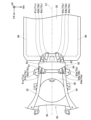
図1は、実施形態の電動車両10を示している。なお、各図において、車両前方を矢印FRにより示し、車両上方を矢印UPにより示し、車両右方を矢印RHにより示している。電動車両10は、バッテリケース20とフレーム30を有している。図2に示すように、バッテリケース20は、フロアパネル40の下側に配置されている。フロアパネル40は、電動車両10のキャビンの床を構成する板状の部材である。バッテリケース20は、バッテリ22を収容している。図示していないが、電動車両10は、走行用モータを有している。バッテリ22から走行用モータに電力が供給されることによって、走行用モータが駆動し、電動車両10が走行する。図1に示すように、フレーム30は、バッテリケース20の前方に配置されている。フレーム30は、電動車両10のフロントコンパートメント内に配置されている。フレーム30は、バッテリケース20と略同じ高さに配置されている。フレーム30は、電動車両10のボディに固定されている。フレーム30には、フロントサスペンション(図示省略)が接続されている。フレーム30は、フロントサスペンションを支持している。フレーム30は、フロントサスペンションメンバと呼ばれる場合がある。
FIG. 1 shows an
図3に示すように、フレーム30は、前後方向に伸びる2つのサイドレール32、34と、車幅方向(すなわち、電動車両10の左右方向)に伸びる2つのクロスメンバ36、38を有している。サイドレール32、34は、車幅方向に間隔を開けて配置されている。図3を含む各図において、一点鎖線は、電動車両10の車幅方向における中央C1を示している。サイドレール32は中央C1よりも左側に配置されており、サイドレール34は中央C1よりも右側に配置されている。クロスメンバ36は、サイドレール32の前端とサイドレール34の前端とを接続している。クロスメンバ38は、クロスメンバ36の後方において、サイドレール32とサイドレール34とを接続している。サイドレール32、34には、フロントサスペンションが取り付けられる。
As shown in FIG. 3, the
図4に示すように、電動車両10は、ブレース50を有している。ブレース50は、フレーム30とバッテリケース20とを接続している。図5、6に示すように、ブレース50は、板状の部材である。ブレース50は、第1板材51と第2板材52を有している。第1板材51と第2板材52のそれぞれは、プレス加工によって成型された金属製の板材である。
As shown in FIG. 4,
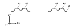
図5に示すように、第1板材51は、電動車両10の中央C1の両側に跨って伸びている。第1板材51には、前後方向に沿って伸びる4つのビード61~64が形成されている。ビード61~64のそれぞれは、第1板材51が湾曲した部分によって構成されている。図7に示すように、ビード61~64のそれぞれの範囲内において、第1板材51の上面に凸部が形成されており、第1板材51の下面に凹部が形成されている。図5、6に示すように、ビード61、62は電動車両10の中央C1よりも左側に配置されており、ビード63、64は電動車両10の中央C1よりも右側に配置されている。ビード61の前端に、取付孔61a、61bが設けられている。ビード61の後端に、取付孔61cが設けられている。ビード61は、取付孔61a、61bから取付孔61cまで伸びている。ビード62の前端に、取付孔62aが設けられている。ビード62の後端に、取付孔62cが設けられている。ビード62のうちの取付孔62aと取付孔62cの間の位置に、取付孔62bが設けられている。ビード62は、取付孔62aから取付孔62bを経由して取付孔62cまで伸びている。ビード63の前端に、取付孔63aが設けられている。ビード63の後端に、取付孔63cが設けられている。ビード63のうちの取付孔63aと取付孔63cの間の位置に、取付孔63bが設けられている。ビード63は、取付孔63aから取付孔63bを経由して取付孔63cまで伸びている。ビード64の前端に、取付孔64a、64bが設けられている。ビード64の後端に、取付孔64cが設けられている。ビード64は、取付孔64a、64bから取付孔64cまで伸びている。ブレース50の前方の部分では、ビード62とビード63の間に間隔部65が設けられている。間隔部65の後方には、ビード62とビード63とを接続している板状部66が設けられている。板状部66には、車幅方向に伸びる横ビード68が形成されている。横ビード68は、板状部66が湾曲した部分によって構成されている。横ビード68の範囲内において、板状部66の上面に凸部が形成されており、板状部66の下面に凹部が形成されている。横ビード68は、ビード62からビード63まで伸びている。また、板状部66には、2つの排出孔80が形成されている。排出孔80は、横ビード68の後方に配置されている。
As shown in FIG. 5, the
図5、6に示すように、第2板材52は、電動車両10の中央C1の両側に跨って伸びている。第2板材52は、第1板材51の下側に配置されており、第1板材51に溶接されている。すなわち、第2板材52の上面が第1板材51の下面に接した状態で、第2板材52は第1板材51に固定されている。第2板材52は、第1板材51の間隔部65を部分的に塞いでいる。図8に示すように、第2板材52が第1板材51の下面を覆っている範囲では、第2板材52はビード61からビード64まで伸びている。第2板材52は、ビード61~64によって構成された凹部(第1板材51の下面に形成された凹部)を覆っている。ビード61~64のぞれぞれと第2板材52によって、閉じ断面を有する筒状部が構成されている。各筒状部は、電動車両10の前後方向に沿って伸びている。このように、ブレース50が前後方向に沿って伸びる筒状部を中央C1の両側に有することで、ブレース50の強度の向上が図られている。図5、6に示すように、ビード61~64は、第2板材52よりも前方まで伸びている。図7に示すように、第2板材52よりも前方の位置では、ビード61~64によって構成される凹部が第2板材52によって覆われていない。すなわち、第2板材52よりも前方の位置では、ビード61~64によって構成される凹部が解放されている。図5、6に示すように、取付孔61a、61b、62a、63a、64a、64bは、ビード61~64のうちの第2板材52よりも前方の部分に配置されている。ビード61~64は、第2板材52よりも後方まで伸びている。第2板材52よりも後方の位置では、ビード61~64によって構成される凹部が第2板材52によって覆われていない。すなわち、第2板材52よりも後方の位置では、ビード61~64によって構成される凹部が解放されている。取付孔61c、62b、62c、63b、63c、64cは、ビード61~64のうちの第2板材52よりも後方の部分に配置されている。
As shown in FIGS. 5 and 6, the
図3に示すように、サイドレール32には、取付孔71a、71bが設けられている。クロスメンバ38の左端には、取付孔72aが設けられている。クロスメンバ38の右端には、取付孔73aが設けられている。サイドレール34には、取付孔74a、74bが設けられている。バッテリケース20の下面の前端には、取付孔71c、72b、73b、74cが設けられている。取付孔71c、72bは中央C1よりも左側に配置されている。取付孔72bは、取付孔71cと中央C1の間に配置されている。取付孔73b、74cは中央C1よりも右側に配置されている。取付孔73bは、取付孔74cと中央C1の間に配置されている。バッテリケース20の下面には、取付孔72bの後方の位置に、取付孔72cが設けられている。バッテリケース20の下面には、取付孔73bの後方の位置に、取付孔73cが設けられている。
As shown in FIG. 3, the
図4に示すように、ブレース50は、フレーム30とバッテリケース20に固定されている。より詳細には、ブレース50は、中央C1よりも左側に位置する取付孔61a、61bで、サイドレール32の取付孔71a、71bにボルト及びナットによって固定されている。また、ブレース50は、中央C1よりも左側に位置する取付孔61cで、バッテリケース20の取付孔71cにボルト及びナットによって固定されている。また、ブレース50は、中央C1よりも左側に位置する取付孔62aで、クロスメンバ38の取付孔72aにボルト及びナットによって固定されている。また、ブレース50は、中央C1よりも左側に位置する取付孔62bで、バッテリケース20の取付孔72bにボルト及びナットによって固定されている。また、ブレース50は、中央C1よりも左側に位置する取付孔62cで、バッテリケース20の取付孔72cにボルト及びナットによって固定されている。また、ブレース50は、中央C1よりも右側に位置する取付孔63aで、クロスメンバ38の取付孔73aにボルト及びナットによって固定されている。また、ブレース50は、中央C1よりも右側に位置する取付孔63bで、バッテリケース20の取付孔73bにボルト及びナットによって固定されている。また、ブレース50は、中央C1よりも右側に位置する取付孔63cで、バッテリケース20の取付孔73cにボルト及びナットによって固定されている。また、ブレース50は、中央C1よりも右側に位置する取付孔64a、64bで、サイドレール34の取付孔74a、74bにボルト及びナットによって固定されている。また、ブレース50は、中央C1よりも右側に位置する取付孔64cで、バッテリケース20の取付孔74cにボルト及びナットによって固定されている。なお、ビード61~64が上側に凸となる形状を有しているので、ビード61~64の上側に位置するフレーム30に対してビード61~64は密着することができる。また、取付孔61a、61b、62a、63a、64a、64bの位置においてビード61~64によって構成される凹部が第2板材52によって覆われていないので、取付孔61a、61b、62a、63a、64a、64bにおいて好適にボルトを締結することができる。したがって、ブレース50をフレーム30に好適に固定することができる。また、ビード61~64が上側に凸となる形状を有しているので、ビード61~64の上側に位置するバッテリケース20に対してビード61~64は密着することができる。また、取付孔61c、62b、62c、63b、63c、64cの位置においてビード61~64によって構成される凹部が第2板材52によって覆われていないので、取付孔61c、62b、62c、63b、63c、64cにおいて好適にボルトを締結することができる。したがって、ブレース50をバッテリケース20に好適に固定することができる。このように、ブレース50は、フレーム30とバッテリケース20とを接続している。ブレース50がバッテリケース20に取り付けられた状態では、図9に示すように、横ビード68は、バッテリケース20の前端20fに対向する位置に配置されている。横ビード68は、バッテリケース20の前端20fに沿って伸びている。また、排出孔80は、バッテリケース20の下側に配置されている。
As shown in FIG. 4, the
図3、4に示すように、バッテリケース20の内部に、冷却液を循環させるための冷却液パイプ96、98が設けられている。冷却液パイプ96から図示しない分岐流路を介して冷却液パイプ98へ冷却液が流れる。このように冷却液が流れることによって、バッテリケース20内のバッテリ22が冷却される。バッテリケース20を下側から平面視したときに、冷却液パイプ96が取付孔62bと取付孔62cの間を通っており、冷却液パイプ98が取付孔63bと取付孔63cの間を通っている。
As shown in FIGS. 3 and 4,
電動車両10が前方で衝突したときには、フレーム30に荷重が加わる。フレーム30に加わった荷重は、ブレース50を介してバッテリケース20へ伝えられる。上述したように、第1板材51が前後方向に伸びるビード61~64を中央C1の両側に有しており、第2板材52が各ビード61~64の凹部を塞いでいる。これによって、前後方向に伸びる筒状部がブレース50に形成されている。このため、ブレース50がフレーム30から加わる荷重に対して高い強度を有しており、フレーム30からブレース50を介してバッテリケース20へ荷重が伝わり易い。特に、本実施形態では、ビード61~64のそれぞれが、フレーム30に対する固定部(すなわち、取付孔61a、61b、62a、63a、64a、64b)からバッテリケース20に対する固定部(すなわち、取付孔61c、62b、62c、63b、63c、64c)まで伸びている。このため、ブレース50がフレーム30から加わる荷重に対してより高い強度を有しており、フレーム30からビード61~64を介してバッテリケース20へより効果的に荷重を伝えることができる。このように、衝突荷重がバッテリケース20へ伝えられることで、電動車両10のボディに加わる荷重が低減される。
When
また、ブレース50に加わる荷重が所定値を超えると、図10に示すように、フレーム30とバッテリケース20の間の位置でブレース50が折れ曲がる。これによって、バッテリケース20に過度に高い荷重が加わることが抑制され、バッテリケース20の変形が抑制される。特に、ブレース50の第1板材51は、中央C1よりも左側で前後方向に間隔を開けて配置された2つの取付孔62b、62cでバッテリケース20に固定されており、取付孔62b、62cがビード62で接続されている。また、ブレース50の第1板材51は、中央C1よりも右側で前後方向に間隔を開けて配置された2つの取付孔63b、63cでバッテリケース20に固定されており、取付孔63b、63cがビード63で接続されている。この構造によって、バッテリケース20の前側の部分(すなわち、取付孔62b、63bと取付孔62c、63cの間の部分)が補強されている。このため、図10に示すように、バッテリケース20の変形がより効果的に抑制される。また、図4に示すように、冷却液パイプ96が取付孔62bと取付孔62cの間を通っている。すなわち、冷却液パイプ96が、バッテリケース20のうちのブレース50によって補強された領域に配置されている。また、冷却液パイプ98が取付孔63bと取付孔63cの間を通っている。すなわち、冷却液パイプ98が、バッテリケース20のうちのブレース50によって補強された領域に配置されている。したがって、電動車両10の衝突時に、冷却液パイプ96、98が破損し難い。
Furthermore, when the load applied to the
また、ブレース50が第1板材51と第2板材52を張り合わせた板状の部材であり、ブレース50が中央C1の両側でフレーム30とバッテリケース20に固定されているので、電動車両10が前方の片側(例えば、右側または左側)で衝突した場合でもブレース50は衝突荷重をバッテリケース20へ効果的に伝えることができる。例えば、電動車両10が前方の右側で衝突した場合、フレーム30のサイドレール34からブレース50のビード63、64を介してバッテリケース20の右側部分(すなわち、中央C1よりも右側の部分)に荷重が加わる。また、ビード63、64は、第1板材51の板状部66及び第2板材52によってビード61、62に接続されている。このため、ビード63、64からビード61、62へ荷重が加わり易い。ビード61、62に加わる荷重はバッテリケース20の左側部分(すなわち、中央C1よりも左側の部分)へ伝わる。このように、電動車両10が前方の右側で衝突した場合でも、ブレース50によれば、バッテリケース20の右側部分と左側部分に効果的に荷重を伝えることができる。また、同様にして、電動車両10が前方の左側で衝突した場合でも、ブレース50によれば、バッテリケース20の右側部分と左側部分に効果的に荷重を伝えることができる。したがって、片側衝突時でも、電動車両10のボディに加わる荷重が低減される。
Furthermore, since the
また、図9に示すように、ブレース50に横ビード68が設けられていることによって、横ビード68とバッテリケース20の間の隙間90の幅W1が狭くなっている。これによって、電動車両10の走行時に、ブレース50とバッテリケース20の間の空間92に異物(例えば、小石等)が入り込むことが抑制される。また、ブレース50の第1板材51には、排出孔80が設けられている。排出孔80の直径R1は、隙間90の幅W1よりも大きい。したがって、隙間90から空間92内に異物が進入したとしても、異物を排出孔80から下側へ排出することができる。また、ブレース50の後端とバッテリケース20の間の隙間94の幅W2は、隙間90の幅W1よりも広い。したがって、隙間90から空間92内に異物が進入したとしても、異物を隙間94から後方へ排出することができる。このように、実施形態の電動車両10では、横ビード68によってブレース50とバッテリケース20の間の空間92に異物が進入することが抑制されるとともに、空間92に異物が進入したとしても排出孔80及び隙間94から異物を空間92の外部へ排出することができる。
Further, as shown in FIG. 9, by providing the
また、電動車両10では、ブレース50がボルト締めによってフレーム30及びバッテリケース20に固定されている。このため、メンテナンス時に、ブレース50をフレーム30及びバッテリケース20から取り外すことができる。このため、フレーム30及びバッテリケース20のメンテナンス性が高い。例えば、経年劣化によってバッテリ22の容量が低下した場合に、バッテリケース20を取り換えることができる。
Further, in the
なお、上述した実施形態の電動車両では、第1板材に上側に凸となるビードが設けられており、第2板材が第1板材の下面の凹部(すなわち、ビード)を覆っていた。しかしながら、第1板材に下側に凸となるビードが設けられており、第2板材が第1板材の上面の凹部(すなわち、ビード)を覆っていてもよい。 Note that in the electric vehicle of the above-described embodiment, the first plate member was provided with an upwardly convex bead, and the second plate member covered the concave portion (i.e., bead) on the lower surface of the first plate member. However, the first plate material may be provided with a bead that is convex downward, and the second plate material may cover the recessed portion (i.e., the bead) on the upper surface of the first plate material.
また、上述した実施形態の電動車両では、バッテリケースとバッテリケースの前側に配置されたフレーム(すなわち、フロントサスペンションを支持するフレーム)とがブレースによって接続されていたが、バッテリケースとバッテリケースの後側に配置されたフレーム(すなわち、リアサスペンションを支持するフレーム)とがブレースによって接続されてもよい。この場合でも、本明細書に開示の技術を適用することができる。 Furthermore, in the electric vehicle of the above-described embodiment, the battery case and the frame disposed on the front side of the battery case (i.e., the frame supporting the front suspension) were connected by a brace, but the battery case and the frame disposed on the front side of the battery case were connected by a brace. A frame arranged on the side (ie, a frame supporting the rear suspension) may be connected by a brace. Even in this case, the technology disclosed in this specification can be applied.
実施形態の取付孔63a、64a、64bは、第1固定部の一例である。実施形態の取付孔61a、61b、62aは、第2固定部の一例である。実施形態の取付孔63b、64cは、第3固定部の一例である。実施形態の取付孔61c、62b、は、第4固定部の一例である。実施形態の取付孔63cは、第5固定部の一例である。実施形態の取付孔62cは、第6固定部の一例である。実施形態のビード63、64は、第1ビードの一例である。実施形態のビード61、62は、第2ビードの一例である。実施形態の取付孔63a、64a、64bに締結されているボルトは、第1ボルトの一例である。実施形態の取付孔61a、61b、62aに締結されているボルトは、第2ボルトの一例である。実施形態の取付孔63b、64cに締結されているボルトは、第3ボルトの一例である。実施形態の取付孔61c、62bに締結されているボルトは、第4ボルトの一例である。
The attachment holes 63a, 64a, and 64b of the embodiment are examples of first fixing parts. The attachment holes 61a, 61b, and 62a of the embodiment are examples of second fixing parts. The attachment holes 63b and 64c of the embodiment are an example of a third fixing part. The attachment holes 61c and 62b of the embodiment are examples of the fourth fixing part. The
以上、実施形態について詳細に説明したが、これらは例示にすぎず、特許請求の範囲を限定するものではない。特許請求の範囲に記載の技術には、以上に例示した具体例をさまざまに変形、変更したものが含まれる。本明細書または図面に説明した技術要素は、単独あるいは各種の組み合わせによって技術有用性を発揮するものであり、出願時請求項記載の組み合わせに限定されるものではない。また、本明細書または図面に例示した技術は複数目的を同時に達成するものであり、そのうちの1つの目的を達成すること自体で技術有用性を持つものである。 Although the embodiments have been described in detail above, these are merely examples and do not limit the scope of the claims. The techniques described in the claims include various modifications and changes to the specific examples illustrated above. The technical elements described in this specification or the drawings exhibit technical usefulness singly or in various combinations, and are not limited to the combinations described in the claims as filed. Furthermore, the techniques illustrated in this specification or the drawings simultaneously achieve multiple objectives, and achieving one of the objectives has technical utility in itself.
10 :電動車両
20 :バッテリケース
30 :フレーム
50 :ブレース
51 :第1板材
52 :第2板材
61~64:ビード
68 :横ビード
80 :排出孔
96 :冷却液パイプ
98 :冷却液パイプ
10: Electric vehicle 20: Battery case 30: Frame 50: Brace 51: First plate 52:
Claims (5)
フロアパネルと、
前記フロアパネルの下側に配置されており、バッテリを収容しているバッテリケースと、
前記バッテリケースの前方または後方に配置されており、サスペンションを支持するフレームと、
前記電動車両の車幅方向における中央の両側に跨って伸びており、前記中央よりも右側に位置する第1固定部で前記フレームに固定されており、前記中央よりも左側に位置する第2固定部で前記フレームに固定されており、前記中央よりも右側に位置する第3固定部で前記バッテリケースに固定されており、前記中央よりも左側に位置する第4固定部で前記バッテリケースに固定されているブレースと、
を有し、
前記ブレースが、
前記中央よりも右側に位置するとともに前後方向に伸びる第1ビードと、前記中央よりも左側に位置するとともに前後方向に伸びる第2ビードと、を有する第1板材と、
前記第1ビードによって構成された前記第1板材の表面の第1凹部と前記第2ビードによって構成された前記第1板材の表面の第2凹部とを覆うように前記第1板材に重ねられた状態で前記第1板材に固定された第2板材と、
を有し、
前記ブレースが、前記中央よりも右側に位置するとともに前記第3固定部よりも後方に位置する第5固定部で前記バッテリケースに固定されており、前記中央よりも左側に位置するとともに前記第4固定部よりも後方に位置する第6固定部で前記バッテリケースに固定されており、
前記バッテリケース内に、車幅方向に伸びる冷却液パイプが設けられており、
前記バッテリケースを下側から平面視したときに、前記第3固定部と前記第5固定部の間及び前記第4固定部と前記第6固定部の間の少なくとも一方に前記冷却液パイプが配置されている、
電動車両。 An electric vehicle,
floor panel and
a battery case disposed below the floor panel and accommodating a battery;
a frame that is disposed in front or behind the battery case and supports a suspension;
A first fixing portion extends across both sides of the center of the electric vehicle in the vehicle width direction, and is fixed to the frame with a first fixing portion located to the right of the center, and a second fixing portion located to the left of the center. A third fixing part located to the right of the center is fixed to the battery case, and a fourth fixing part located to the left of the center is fixed to the battery case. braces that are
has
The brace is
a first plate material having a first bead located on the right side of the center and extending in the front-rear direction; and a second bead located on the left side of the center and extending in the front-rear direction;
superimposed on the first plate material so as to cover a first concave portion on the surface of the first plate material formed by the first bead and a second concave portion on the surface of the first plate material formed by the second bead. a second plate member fixed to the first plate member in a state;
has
The brace is fixed to the battery case with a fifth fixing part located to the right of the center and rearward of the third fixing part, and a fifth fixing part located to the left of the center and rearward of the third fixing part. fixed to the battery case with a sixth fixing part located rearward than the fixing part;
A coolant pipe extending in the vehicle width direction is provided in the battery case,
When the battery case is viewed in plan from below, the coolant pipe is disposed at least one between the third fixing part and the fifth fixing part and between the fourth fixing part and the sixth fixing part. has been,
electric vehicle.
フロアパネルと、 floor panel and
前記フロアパネルの下側に配置されており、バッテリを収容しているバッテリケースと、 a battery case disposed below the floor panel and housing a battery;
前記バッテリケースの前方または後方に配置されており、サスペンションを支持するフレームと、 a frame that is disposed in front or behind the battery case and supports a suspension;
前記電動車両の車幅方向における中央の両側に跨って伸びており、前記中央よりも右側に位置する第1固定部で前記フレームに固定されており、前記中央よりも左側に位置する第2固定部で前記フレームに固定されており、前記中央よりも右側に位置する第3固定部で前記バッテリケースに固定されており、前記中央よりも左側に位置する第4固定部で前記バッテリケースに固定されているブレースと、 A first fixing part extends across both sides of the center of the electric vehicle in the vehicle width direction, and is fixed to the frame with a first fixing part located to the right of the center, and a second fixing part located to the left of the center. fixed to the frame at a portion, fixed to the battery case by a third fixing portion located to the right of the center, and fixed to the battery case by a fourth fixing portion located to the left of the center. braces that are
を有し、 has
前記ブレースが、 The brace is
前記中央よりも右側に位置するとともに前後方向に伸びる第1ビードと、前記中央よりも左側に位置するとともに前後方向に伸びる第2ビードと、を有する第1板材と、 a first plate material having a first bead located on the right side of the center and extending in the front-rear direction; and a second bead located on the left side of the center and extending in the front-rear direction;
前記第1ビードによって構成された前記第1板材の表面の第1凹部と前記第2ビードによって構成された前記第1板材の表面の第2凹部とを覆うように前記第1板材に重ねられた状態で前記第1板材に固定された第2板材と、 superimposed on the first plate so as to cover a first recess on the surface of the first plate formed by the first bead and a second recess on the surface of the first plate formed by the second bead. a second plate member fixed to the first plate member in a state;
を有し、 has
前記ブレースが、前記ブレースの上面が凸となるとともに車幅方向に沿って伸びる横ビードをさらに有し、The brace further includes a horizontal bead that has a convex upper surface and extends along the vehicle width direction,
前記電動車両が、前記ブレースと前記バッテリケースの間の空間に進入した異物を前記空間外に排出する排出部を有し、The electric vehicle has a discharge part that discharges foreign matter that has entered the space between the brace and the battery case out of the space,
前記横ビードと前記バッテリケースの間の隙間の幅が、前記排出部の幅よりも狭い、The width of the gap between the horizontal bead and the battery case is narrower than the width of the discharge part.
電動車両。electric vehicle.
前記第2固定部において前記ブレースを前記フレームに固定する第2ボルトと、
前記第3固定部において前記ブレースを前記バッテリケースに固定する第3ボルトと、
前記第4固定部において前記ブレースを前記バッテリケースに固定する第4ボルトと、
をさらに有する、請求項1または2に記載の電動車両。 a first bolt that fixes the brace to the frame at the first fixing part;
a second bolt that fixes the brace to the frame at the second fixing part;
a third bolt that fixes the brace to the battery case at the third fixing part;
a fourth bolt that fixes the brace to the battery case at the fourth fixing part;
The electric vehicle according to claim 1 or 2 , further comprising:
前記第2ビードが、前記第2固定部から前記第4固定部まで伸びている、
請求項1または2に記載の電動車両。 the first bead extends from the first fixing part to the third fixing part,
the second bead extends from the second fixing part to the fourth fixing part;
The electric vehicle according to claim 1 or 2 .
前記第2板材が、前記第1板材の下側に配置されており、
前記第1ビードが、前記第2板材よりも前側まで伸びる前側部分と、前記第2板材よりも後方まで伸びる後側部分を有しており、
前記第2ビードが、前記第2板材よりも前側まで伸びる前側部分と、前記第2板材よりも後方まで伸びる後側部分を有しており、
前記第1固定部が、前記第1ビードの前記前側部分に設けられており、
前記第2固定部が、前記第2ビードの前記前側部分に設けられており、
前記第3固定部が、前記第1ビードの前記後側部分に設けられており、
前記第4固定部が、前記第2ビードの前記後側部分に設けられている、
請求項4に記載の電動車両。 the first recess and the second recess are provided on the lower surface of the first plate;
the second plate material is arranged below the first plate material,
The first bead has a front part extending to the front side of the second plate material and a rear part extending to the rear side of the second plate material,
The second bead has a front part extending to the front side of the second plate material and a rear part extending to the rear side of the second plate material,
the first fixing portion is provided on the front portion of the first bead;
the second fixing portion is provided on the front portion of the second bead;
the third fixing portion is provided on the rear portion of the first bead;
the fourth fixing portion is provided at the rear portion of the second bead;
The electric vehicle according to claim 4 .
Priority Applications (4)
| Application Number | Priority Date | Filing Date | Title |
|---|---|---|---|
| JP2021064928A JP7440452B2 (en) | 2021-04-06 | 2021-04-06 | electric vehicle |
| DE102022107505.2A DE102022107505A1 (en) | 2021-04-06 | 2022-03-30 | ELECTRIC VEHICLE |
| CN202210335779.7A CN115246305A (en) | 2021-04-06 | 2022-03-31 | Electric vehicle |
| US17/712,196 US20220320666A1 (en) | 2021-04-06 | 2022-04-04 | Electrified vehicle |
Applications Claiming Priority (1)
| Application Number | Priority Date | Filing Date | Title |
|---|---|---|---|
| JP2021064928A JP7440452B2 (en) | 2021-04-06 | 2021-04-06 | electric vehicle |
Publications (2)
| Publication Number | Publication Date |
|---|---|
| JP2022160277A JP2022160277A (en) | 2022-10-19 |
| JP7440452B2 true JP7440452B2 (en) | 2024-02-28 |
Family
ID=83282479
Family Applications (1)
| Application Number | Title | Priority Date | Filing Date |
|---|---|---|---|
| JP2021064928A Active JP7440452B2 (en) | 2021-04-06 | 2021-04-06 | electric vehicle |
Country Status (4)
| Country | Link |
|---|---|
| US (1) | US20220320666A1 (en) |
| JP (1) | JP7440452B2 (en) |
| CN (1) | CN115246305A (en) |
| DE (1) | DE102022107505A1 (en) |
Citations (5)
| Publication number | Priority date | Publication date | Assignee | Title |
|---|---|---|---|---|
| JP2013212752A (en) | 2012-04-02 | 2013-10-17 | Mitsubishi Motors Corp | Under-floor cover for vehicle |
| JP2015217899A (en) | 2014-05-21 | 2015-12-07 | マツダ株式会社 | Vehicle body structure of vehicle |
| US9937781B1 (en) | 2016-12-19 | 2018-04-10 | GM Global Technology Operations LLC | Battery pack mounting architecture with shear plate for electric drive motor vehicles |
| DE102018123357A1 (en) | 2017-09-25 | 2019-03-28 | Ford Global Technologies, Llc | CHASSIS GROUP |
| CN211731061U (en) | 2020-01-22 | 2020-10-23 | 丰田自动车株式会社 | Underbody structure of electric vehicle |
Family Cites Families (1)
| Publication number | Priority date | Publication date | Assignee | Title |
|---|---|---|---|---|
| JP6816664B2 (en) | 2017-06-30 | 2021-01-20 | トヨタ自動車株式会社 | Body front structure |
-
2021
- 2021-04-06 JP JP2021064928A patent/JP7440452B2/en active Active
-
2022
- 2022-03-30 DE DE102022107505.2A patent/DE102022107505A1/en active Pending
- 2022-03-31 CN CN202210335779.7A patent/CN115246305A/en active Pending
- 2022-04-04 US US17/712,196 patent/US20220320666A1/en active Pending
Patent Citations (5)
| Publication number | Priority date | Publication date | Assignee | Title |
|---|---|---|---|---|
| JP2013212752A (en) | 2012-04-02 | 2013-10-17 | Mitsubishi Motors Corp | Under-floor cover for vehicle |
| JP2015217899A (en) | 2014-05-21 | 2015-12-07 | マツダ株式会社 | Vehicle body structure of vehicle |
| US9937781B1 (en) | 2016-12-19 | 2018-04-10 | GM Global Technology Operations LLC | Battery pack mounting architecture with shear plate for electric drive motor vehicles |
| DE102018123357A1 (en) | 2017-09-25 | 2019-03-28 | Ford Global Technologies, Llc | CHASSIS GROUP |
| CN211731061U (en) | 2020-01-22 | 2020-10-23 | 丰田自动车株式会社 | Underbody structure of electric vehicle |
Also Published As
| Publication number | Publication date |
|---|---|
| DE102022107505A1 (en) | 2022-10-06 |
| CN115246305A (en) | 2022-10-28 |
| US20220320666A1 (en) | 2022-10-06 |
| JP2022160277A (en) | 2022-10-19 |
Similar Documents
| Publication | Publication Date | Title |
|---|---|---|
| US10399425B2 (en) | Automobile vehicle | |
| US10688857B2 (en) | Vehicle body structure | |
| US10780923B2 (en) | Vehicle platform | |
| US7370886B2 (en) | Vehicle lower frame structure | |
| US10994788B2 (en) | Vehicle bottom structure | |
| US10850597B2 (en) | Vehicle body lower structure | |
| US10710636B2 (en) | Vehicle front portion structure | |
| US11433949B2 (en) | Body of electric vehicle | |
| JP7343462B2 (en) | vehicle | |
| JP7144385B2 (en) | electric vehicle body | |
| US11654972B2 (en) | Vehicle | |
| US20230072159A1 (en) | Vehicle | |
| JP6137105B2 (en) | Battery drive battery mounting structure | |
| US11584447B2 (en) | Electric vehicle structure | |
| JP7440452B2 (en) | electric vehicle | |
| US11701958B2 (en) | Electric powered vehicle | |
| US20210371011A1 (en) | Electric powered vehicle | |
| JP7107907B2 (en) | vehicle body | |
| JP2018161934A (en) | Floor structure of vehicle body | |
| CN112109811A (en) | Vehicle body structure and vehicle including the same | |
| JP7372272B2 (en) | vehicle | |
| CN218661322U (en) | Battery pack frame structure integrated with automobile body and automobile | |
| JP5848627B2 (en) | Car body rear structure | |
| CN117799702A (en) | Chassis frame, chassis assembly and vehicle | |
| JP2013159238A (en) | Vehicle body rear structure |
Legal Events
| Date | Code | Title | Description |
|---|---|---|---|
| A621 | Written request for application examination |
Free format text: JAPANESE INTERMEDIATE CODE: A621 Effective date: 20230601 |
|
| A977 | Report on retrieval |
Free format text: JAPANESE INTERMEDIATE CODE: A971007 Effective date: 20231109 |
|
| A131 | Notification of reasons for refusal |
Free format text: JAPANESE INTERMEDIATE CODE: A131 Effective date: 20231121 |
|
| A521 | Request for written amendment filed |
Free format text: JAPANESE INTERMEDIATE CODE: A523 Effective date: 20240104 |
|
| TRDD | Decision of grant or rejection written | ||
| A01 | Written decision to grant a patent or to grant a registration (utility model) |
Free format text: JAPANESE INTERMEDIATE CODE: A01 Effective date: 20240123 |
|
| A61 | First payment of annual fees (during grant procedure) |
Free format text: JAPANESE INTERMEDIATE CODE: A61 Effective date: 20240215 |
|
| R151 | Written notification of patent or utility model registration |
Ref document number: 7440452 Country of ref document: JP Free format text: JAPANESE INTERMEDIATE CODE: R151 |