JP7439092B2 - Terminals, wireless communication methods and systems - Google Patents
Terminals, wireless communication methods and systems Download PDFInfo
- Publication number
- JP7439092B2 JP7439092B2 JP2021534460A JP2021534460A JP7439092B2 JP 7439092 B2 JP7439092 B2 JP 7439092B2 JP 2021534460 A JP2021534460 A JP 2021534460A JP 2021534460 A JP2021534460 A JP 2021534460A JP 7439092 B2 JP7439092 B2 JP 7439092B2
- Authority
- JP
- Japan
- Prior art keywords
- cancellation
- dci
- transmission
- pusch
- time domain
- Prior art date
- Legal status (The legal status is an assumption and is not a legal conclusion. Google has not performed a legal analysis and makes no representation as to the accuracy of the status listed.)
- Active
Links
- 238000004891 communication Methods 0.000 title claims description 63
- 238000000034 method Methods 0.000 title claims description 41
- 230000005540 biological transmission Effects 0.000 claims description 89
- 230000011664 signaling Effects 0.000 claims description 23
- 238000012545 processing Methods 0.000 description 63
- 238000010586 diagram Methods 0.000 description 21
- 238000005259 measurement Methods 0.000 description 17
- 238000013468 resource allocation Methods 0.000 description 13
- 230000009977 dual effect Effects 0.000 description 9
- 238000013507 mapping Methods 0.000 description 7
- 238000005516 engineering process Methods 0.000 description 6
- 230000006870 function Effects 0.000 description 6
- 238000010295 mobile communication Methods 0.000 description 6
- 125000004122 cyclic group Chemical group 0.000 description 5
- 238000007726 management method Methods 0.000 description 5
- 230000003321 amplification Effects 0.000 description 4
- 238000006243 chemical reaction Methods 0.000 description 4
- 238000012937 correction Methods 0.000 description 4
- 238000003199 nucleic acid amplification method Methods 0.000 description 4
- 238000004364 calculation method Methods 0.000 description 3
- 238000013461 design Methods 0.000 description 3
- 230000007774 longterm Effects 0.000 description 3
- 230000008569 process Effects 0.000 description 3
- 101150071746 Pbsn gene Proteins 0.000 description 2
- 230000009471 action Effects 0.000 description 2
- 230000002776 aggregation Effects 0.000 description 2
- 238000004220 aggregation Methods 0.000 description 2
- 238000012790 confirmation Methods 0.000 description 2
- 230000008878 coupling Effects 0.000 description 2
- 238000010168 coupling process Methods 0.000 description 2
- 238000005859 coupling reaction Methods 0.000 description 2
- 230000007274 generation of a signal involved in cell-cell signaling Effects 0.000 description 2
- 238000012546 transfer Methods 0.000 description 2
- 101000741965 Homo sapiens Inactive tyrosine-protein kinase PRAG1 Proteins 0.000 description 1
- 102100038659 Inactive tyrosine-protein kinase PRAG1 Human genes 0.000 description 1
- 230000006978 adaptation Effects 0.000 description 1
- 239000000969 carrier Substances 0.000 description 1
- 108010015046 cell aggregation factors Proteins 0.000 description 1
- 239000003795 chemical substances by application Substances 0.000 description 1
- 230000001934 delay Effects 0.000 description 1
- 238000009795 derivation Methods 0.000 description 1
- 239000000835 fiber Substances 0.000 description 1
- 238000001914 filtration Methods 0.000 description 1
- 238000011835 investigation Methods 0.000 description 1
- 239000006249 magnetic particle Substances 0.000 description 1
- 230000000873 masking effect Effects 0.000 description 1
- 238000012986 modification Methods 0.000 description 1
- 230000004048 modification Effects 0.000 description 1
- 239000013307 optical fiber Substances 0.000 description 1
- 230000002093 peripheral effect Effects 0.000 description 1
- 230000009467 reduction Effects 0.000 description 1
- 230000003252 repetitive effect Effects 0.000 description 1
- 238000013519 translation Methods 0.000 description 1
- 238000012384 transportation and delivery Methods 0.000 description 1
- 238000011144 upstream manufacturing Methods 0.000 description 1
Images


Classifications
-
- H—ELECTRICITY
- H04—ELECTRIC COMMUNICATION TECHNIQUE
- H04W—WIRELESS COMMUNICATION NETWORKS
- H04W72/00—Local resource management
- H04W72/20—Control channels or signalling for resource management
- H04W72/23—Control channels or signalling for resource management in the downlink direction of a wireless link, i.e. towards a terminal
-
- H—ELECTRICITY
- H04—ELECTRIC COMMUNICATION TECHNIQUE
- H04W—WIRELESS COMMUNICATION NETWORKS
- H04W72/00—Local resource management
- H04W72/50—Allocation or scheduling criteria for wireless resources
- H04W72/56—Allocation or scheduling criteria for wireless resources based on priority criteria
- H04W72/566—Allocation or scheduling criteria for wireless resources based on priority criteria of the information or information source or recipient
- H04W72/569—Allocation or scheduling criteria for wireless resources based on priority criteria of the information or information source or recipient of the traffic information
-
- H—ELECTRICITY
- H04—ELECTRIC COMMUNICATION TECHNIQUE
- H04W—WIRELESS COMMUNICATION NETWORKS
- H04W72/00—Local resource management
- H04W72/12—Wireless traffic scheduling
- H04W72/1263—Mapping of traffic onto schedule, e.g. scheduled allocation or multiplexing of flows
- H04W72/1268—Mapping of traffic onto schedule, e.g. scheduled allocation or multiplexing of flows of uplink data flows
Description
本開示は、次世代移動通信システムにおける端末、無線通信方法及びシステムに関する。 The present disclosure relates to a terminal , a wireless communication method , and a system in a next-generation mobile communication system.
Universal Mobile Telecommunications System(UMTS)ネットワークにおいて、更なる高速データレート、低遅延などを目的としてLong Term Evolution(LTE)が仕様化された(非特許文献1)。また、LTE(Third Generation Partnership Project(3GPP) Release(Rel.)8、9)の更なる大容量、高度化などを目的として、LTE-Advanced(3GPP Rel.10-14)が仕様化された。 In Universal Mobile Telecommunications System (UMTS) networks, Long Term Evolution (LTE) has been specified for the purpose of higher data rates, lower delays, etc. (Non-Patent Document 1). Furthermore, LTE-Advanced (3GPP Rel. 10-14) has been specified for the purpose of further increasing capacity and sophistication of LTE (Third Generation Partnership Project (3GPP) Release (Rel.) 8, 9).
LTEの後継システム(例えば、5th generation mobile communication system(5G)、5G+(plus)、New Radio(NR)、3GPP Rel.15以降などともいう)も検討されている。 Successor systems to LTE (for example, also referred to as 5th generation mobile communication system (5G), 5G+ (plus), New Radio (NR), 3GPP Rel. 15 or later) are also being considered.
将来の無線通信システム(例えば、5G、NRなど)では、例えば、高速及び大容量(例えば、enhanced Mobile Broad Band(eMBB))、超多数端末(例えば、massive Machine Type Communication(mMTC)、Internet of Things(IoT))、超高信頼及び低遅延(例えば、Ultra Reliable and Low Latency Communications(URLLC))など、通信要件(requirement)が異なる複数のサービス(ユースケース、通信タイプ、等ともいう)が混在すること想定される。 Future wireless communication systems (e.g., 5G, NR, etc.) will require, for example, high speed and large capacity (e.g. enhanced Mobile Broad Band (eMBB)), massive number of terminals (e.g. massive Machine Type Communication (mMTC), Internet of Things Multiple services (also referred to as use cases, communication types, etc.) with different communication requirements, such as (IoT), ultra-reliable and low-latency communications (URLLC), etc., coexist. It is assumed that.
また、遅延削減及び/又は信頼性に対する通信要件を満たすために、スケジュールされたuplink(UL)送信に対して取消(cancellation、preemption、interruption、割り込み、中断、等ともいう)を行うことが想定される。UL送信の取消が適切に行われなければ、システム性能が低下するおそれがある。 It is also envisaged that scheduled uplink (UL) transmissions will be subject to cancellation, preemption, interruption, etc. in order to meet communication requirements for delay reduction and/or reliability. Ru. If UL transmission is not canceled properly, system performance may deteriorate.
そこで、本開示は、UL送信の取消を適切に行う端末、無線通信方法及びシステムを提供することを目的の一つとする。 Therefore, one object of the present disclosure is to provide a terminal , a wireless communication method , and a system that appropriately cancel UL transmission.
本開示の一態様に係る端末は、物理上りリンク共有チャネル(PUSCH)送信のキャンセル指示を含む下り制御情報(DCI)を受信する受信部と、前記DCIに基づいて決定されるキャンセル開始位置と、キャンセルを行う時間領域リソースを示すビットマップと、に基づいて、前記PUSCH送信のキャンセルを行うように制御する制御部と、を有し、前記制御部は、前記ビットマップにおいて、前記PUSCH送信が設定される時間領域リソースのうち一部の時間領域リソースに対応するビットの値が1である場合、前記一部の時間領域リソース以降に設定される前記PUSCH送信のキャンセルを行うように制御する。 A terminal according to an aspect of the present disclosure includes: a receiving unit that receives downlink control information (DCI) including a cancellation instruction for physical uplink shared channel ( PUSCH ) transmission; a cancellation start position determined based on the DCI; a bitmap indicating a time-domain resource to be canceled; and a control unit configured to control the PUSCH transmission to be canceled based on the bitmap, and the control unit controls whether the PUSCH transmission is When the value of the bit corresponding to a part of the time domain resources among the time domain resources to be set is 1, control is performed to cancel the PUSCH transmission set after the part of the time domain resource.
本開示の一態様によれば、UL送信の取消を適切に行うことができる。 According to one aspect of the present disclosure, UL transmission can be appropriately canceled.
(サービス)
将来の無線通信システム(例えば、NR)では、モバイルブロードバンドのさらなる高度化(例えば、enhanced Mobile Broadband(eMBB))、多数同時接続を実現するマシンタイプ通信(例えば、massive Machine Type Communications(mMTC)、Internet of Things(IoT))、高信頼かつ低遅延通信(例えば、Ultra-Reliable and Low-Latency Communications(URLLC))などのトラフィックタイプ(サービス、サービスタイプ、通信タイプ、ユースケース、等ともいう)が想定される。例えば、URLLCでは、eMBBより小さい遅延及びより高い信頼性が要求される。
(service)
Future wireless communication systems (e.g. NR) will require further advancement of mobile broadband (e.g. enhanced Mobile Broadband (eMBB)), machine type communications (e.g. massive Machine Type Communications (mMTC)) that realize multiple simultaneous connections, Internet Assumed traffic types (also referred to as services, service types, communication types, use cases, etc.) include be done. For example, URLLC requires lower delay and higher reliability than eMBB.
トラフィックタイプは、物理レイヤにおいては、以下の少なくとも一つに基づいて識別されてもよい。
・異なる優先度(priority)を有する論理チャネル
・変調及び符号化方式(Modulation and Coding Scheme(MCS))テーブル(MCSインデックステーブル)
・チャネル品質指示(Channel Quality Indication(CQI))テーブル
・DCIフォーマット
・当該DCI(DCIフォーマット)に含まれる(付加される)巡回冗長検査(Cyclic Redundancy Check(CRC))ビットのスクランブル(マスク)に用いられる特定の無線ネットワーク一時識別子(Radio Network Temporary Identifier(RNTI))(例えば、URLLC用のRNTI、MCS-C-RNTI等)
・RRC(Radio Resource Control)パラメータ
・サーチスペース
・DCI内の所定フィールド(例えば、新たに追加されるフィールド又は既存のフィールドの再利用)
The traffic type may be identified at the physical layer based on at least one of the following:
・Logical channels with different priorities ・Modulation and Coding Scheme (MCS) table (MCS index table)
・Channel Quality Indication (CQI) table ・DCI format ・Cyclic Redundancy Check (CRC) included in (added to) the DCI (DCI format) Used for scrambling (masking) bits A specific Radio Network Temporary Identifier (RNTI) (e.g. RNTI for URLLC, MCS-C-RNTI, etc.)
・RRC (Radio Resource Control) parameters ・Search space ・Predetermined fields in DCI (for example, newly added fields or reuse of existing fields)
また、PUSCHのトラフィックタイプは、以下の少なくとも一つに基づいて決定されてもよい。
・当該PUSCHの変調次数、ターゲット符号化率、TBSの少なくとも一つの決定に用いられるMCSインデックステーブル(例えば、MCSインデックステーブル3を利用するか否か)
・当該PUSCHのスケジューリングに用いられるDCIのCRCスクランブルに用いられるRNTI(例えば、C-RNTI又はMCS-C-RNTIのどちらでCRCスクランブルされるか)
Further, the PUSCH traffic type may be determined based on at least one of the following.
- MCS index table used to determine at least one of the modulation order, target coding rate, and TBS of the PUSCH (for example, whether to use MCS index table 3)
・RNTI used for CRC scrambling of DCI used for scheduling of the PUSCH (for example, which one is used for CRC scrambling, C-RNTI or MCS-C-RNTI)
トラフィックタイプは、通信要件(遅延、誤り率などの要件、要求条件)、データ種別(音声、データなど)などに関連付けられてもよい。 The traffic type may be associated with communication requirements (delay, error rate, etc., requirements), data type (voice, data, etc.), and the like.
URLLCの要件とeMBBの要件の違いは、URLLCの遅延(latency)がeMBBの遅延よりも小さいことであってもよいし、URLLCの要件が信頼性の要件を含むことであってもよい。 The difference between the URLLC requirements and the eMBB requirements may be that the URLLC latency is smaller than the eMBB delay, or the URLLC requirements may include reliability requirements.
(UL取消指示)
UL送信のUE間多重(UL UE間多重、UL inter-UE multiplexing)をサポートするために、UL取消(cancellation)指示(indication)が検討されている。
(UL cancellation instruction)
To support UL inter-UE multiplexing of UL transmissions, UL cancellation indications are being considered.
例えば、UL取消指示は、1つのUEに対して既にスケジュールされた又は設定された(configured)eMBB UL送信を取り消すことによって、別のUEのURLLC UL送信を可能にする。eMBB UEがUL取消指示を検出した場合、当該UEは、UL送信を取り消す(キャンセルする、中止する)。UL送信を取り消すことは、UL送信をプリエンプトする(preempt)、UL送信を先取りする、UL送信に代わる、などと読み替えられてもよい。UL取消指示は、スケジュールされた又は設定された優先度の低いUL送信のリソースを用いる優先度の高いUL送信が発生した場合に、優先度の低いUL送信を取り消すことを指示してもよい。 For example, a UL cancellation indication cancels an eMBB UL transmission already scheduled or configured for one UE, thereby allowing another UE's URLLC UL transmission. When the eMBB UE detects the UL cancellation instruction, the UE cancels (cancels, stops) the UL transmission. Canceling UL transmission may be read as preempting UL transmission, preempting UL transmission, replacing UL transmission, and the like. The UL cancellation instruction may instruct to cancel a low-priority UL transmission when a high-priority UL transmission using resources of a scheduled or set low-priority UL transmission occurs.
UL取消指示は、UL取消指示を受信したUEに対してスケジュールされたUL送信を中断(interrupt)してもよい。また、UL取消指示は、UL取消指示を受信したUEが、当該UEのいかなる送信も意図されないと想定するリソースを通知するために用いられてもよい。 The UL cancellation indication may interrupt scheduled UL transmissions for the UE that received the UL cancellation indication. The UL cancellation indication may also be used to inform the UE that receives the UL cancellation indication of the resources for which no transmission of the UE is intended.
UL取消指示を実現するために、取消指示用に少なくともグループ共通(group common(GC))-下り制御情報(DCI、物理下り制御チャネル(PDCCH))をサポートすることが検討されている。取消指示用のUE固有(UE-specific)DCIをサポートするかは、まだ決められていない。 In order to implement UL cancellation instructions, it is being considered to support at least group common (GC)-downlink control information (DCI, physical downlink control channel (PDCCH)) for cancellation instructions. It has not yet been decided whether to support UE-specific DCI for cancellation instructions.
しかしながら、UL取消のための時間/周波数リソースの指示に関するUL取消指示シグナリングの詳細が十分に検討されていない。 However, the details of UL cancellation indication signaling regarding the indication of time/frequency resources for UL cancellation have not been sufficiently considered.
UL取消が適用される時間リソースは暗示的に決定されてもよい。例えば、時間リソースは、取消動作のための最小処理時間によって決定されてもよい。 The time resources to which UL cancellation applies may be determined implicitly. For example, time resources may be determined by the minimum processing time for a cancellation operation.
UL取消が適用される時間リソースはネットワークによって明示的に指示されてもよい。例えば、時間リソースは、DCIによって指示されてもよいし、無線リソース制御(radio resource control(RRC))によって指示されてもよい。 The time resources to which UL cancellation applies may be explicitly indicated by the network. For example, time resources may be indicated by DCI or radio resource control (RRC).
UL取消が適用される周波数リソースはネットワークによって明示的に指示されてもよい。例えば、時間リソースは、DCIによって指示されてもよいし、RRCによって指示されてもよい。 The frequency resources to which UL cancellation applies may be explicitly indicated by the network. For example, time resources may be indicated by DCI or RRC.
GC-PDCCHに基づくUL取消が行われる場合、UL取消が適用される時間リソースが、UL取消DCIによって明示的に指示されてもよいし、UL取消が適用される周波数リソースが、UL取消DCIによって明示的に指示されてもよい。 When UL cancellation based on GC-PDCCH is performed, the time resources to which UL cancellation is applied may be explicitly indicated by the UL cancellation DCI, and the frequency resources to which UL cancellation is applied may be specified by the UL cancellation DCI. May be explicitly instructed.
UL取消指示の設計が、DCIフォーマット2_1(DLプリエンプション指示)に基づくことが検討されている。 It is being considered that the design of the UL cancellation instruction is based on DCI format 2_1 (DL preemption instruction).
DL送信のUE間多重(DL UE間多重、DL inter-UE multiplexing)は、DLプリエンプション指示を用いる。プリエンプション指示は、DCIフォーマット2_1を用い、14ビットのビットマップを含む。DCIフォーマット2_1は、interruption(INT)-RNTIによってスクランブルされたCRCを有してもよい。ビットマップの解釈は、上位レイヤシグナリングによって変更可能である。各ビットは、時間ドメインにおける1つのOFDMシンボルと、周波数ドメインにおける帯域幅部分(bandwidth part(BWP))の全体と、を表してもよいし、時間ドメインにおける2つのOFDMシンボルと、周波数ドメインにおけるBWPの半分と、を表してもよい。 Inter-UE multiplexing of DL transmission (DL inter-UE multiplexing) uses a DL preemption instruction. The preemption instruction uses DCI format 2_1 and includes a 14-bit bitmap. DCI format 2_1 may have a CRC scrambled by interruption (INT)-RNTI. The interpretation of the bitmap can be changed by higher layer signaling. Each bit may represent one OFDM symbol in the time domain and an entire bandwidth part (BWP) in the frequency domain, or two OFDM symbols in the time domain and a BWP in the frequency domain. It may also represent half of .
図1A-図1Cは、DLプリエンプション指示の一例を示す図である。この例では、図1Aに示すように、既にスケジュールされたUE Aに対して、プリエンプション指示が送信される。図1Bに示すように、プリエンプション指示における各ビットは、DLプリエンプション指示の後の特定のスロット内の、2つのOFDMシンボルとBWPの半分とに対応する。1のビットに対応する部分は、プリエンプトされる(UE BへのDL送信に用いられる)リソースを示す。図1Cに示すように、UE Bの2番目のDL送信リソースは、UE Aに対してスケジュールされたDL送信リソースと重複するため、UE Bの2番目のDL送信は、UE Aに対してスケジュールされたDL送信をプリエンプトする。 1A to 1C are diagrams illustrating an example of DL preemption instructions. In this example, a preemption indication is sent to the already scheduled UE A, as shown in FIG. 1A. As shown in FIG. 1B, each bit in the preemption indication corresponds to two OFDM symbols and half a BWP within a particular slot after the DL preemption indication. The part corresponding to the 1 bit indicates the resource to be preempted (used for DL transmission to UE B). As shown in Figure 1C, UE B's second DL transmission resource overlaps with the scheduled DL transmission resource for UE A, so UE B's second DL transmission resource is scheduled for UE A. DL transmission is preempted.
DLプリエンプション指示は、UE Aに対してスケジュールされたDL送信を中断する(interrupt)。また、DLプリエンプション指示は、UE Aが、UE Aに対するいかなる送信も意図されないと想定するリソースを通知するために用いられる。 The DL preemption indication interrupts the scheduled DL transmission for UE A. The DL preemption indication is also used for UE A to notify the resources that are not intended for any transmission to UE A.
一方、URLLC PUSCH送信に対し、DL送信(PDSCH送信)と異なる特徴が検討されている。 On the other hand, different characteristics from DL transmission (PDSCH transmission) are being considered for URLLC PUSCH transmission.
URLLC PUSCH送信がミニスロットに基づく繰り返し(ミニスロットベース繰り返し、mini-slot based repetition)と、DCI内における繰り返し数の動的指示と、をサポートすることが検討されている。UEは、ミニスロットベース繰り返しにおいて、1スロットより短い期間(例えば、ミニスロット)を単位として同じデータ(例えば、トランスポートブロック(TB))を繰り返し送信する。 It is being considered that URLLC PUSCH transmissions support mini-slot based repetition and dynamic indication of the number of repetitions within the DCI. In minislot-based repetition, the UE repeatedly transmits the same data (eg, transport block (TB)) in units of a period shorter than one slot (eg, minislot).
データの繰り返しの数(例えば、アグリゲーション因子(aggregation factor)、繰り返し因子(repetition factor)、pusch-AggregationFactor、Kなど)は、上位レイヤシグナリングによって設定されてもよい。 The number of data repetitions (eg, aggregation factor, repetition factor, push-AggregationFactor, K, etc.) may be set by upper layer signaling.
URLLC PUSCH送信が少なくともPUSCH間繰り返し(inter-PUSCH-repetition)周波数ホッピング(FH)とスロット間FHとをサポートすることが検討されている。PUSCH間繰り返しFHは、PUSCH(繰り返し)の間においてFHを行う。 It is contemplated that URLLC PUSCH transmission will support at least inter-PUSCH-repetition frequency hopping (FH) and inter-slot FH. Repeated FH between PUSCHs is performed between PUSCHs (repetitions).
図2は、eMBB PUSCHとURLLC PUSCHの一例を示す図である。この例において、URLLC UEによって送信されるURLLC PUSCHは、ミニスロットベース繰り返し(2シンボルのPUSCHの4つの繰り返し)と、PUSCH間繰り返しFHと、を用いる。eMBB UE#1、#2に対してスケジュールされたeMBB PUSCHは、URLLC PUSCHと重複するため、取り消される。eMBB UE#3に対してスケジュールされたeMBB PUSCHは、URLLC PUSCHと重複しないため、取り消されない。
FIG. 2 is a diagram illustrating an example of eMBB PUSCH and URLLC PUSCH. In this example, the URLLC PUSCH transmitted by the URLLC UE uses minislot-based repetition (4 repetitions of 2-symbol PUSCH) and inter-PUSCH repetition FH. The eMBB PUSCH scheduled for
このURLLC PUSCHのような複雑なUL送信に基づくUL取消に対し、DLプリエンプション指示シグナリングを再利用することは、効率的でなく正確でない。 For UL cancellation based on complex UL transmissions such as this URLLC PUSCH, reusing DL preemption indication signaling is not efficient and accurate.
そこで、本発明者らは、UL取消のためのリソースを適切に指示する方法を着想した。 Therefore, the present inventors came up with a method for appropriately indicating resources for UL cancellation.
以下、本開示に係る実施形態について、図面を参照して詳細に説明する。各実施形態に係る無線通信方法は、それぞれ単独で適用されてもよいし、組み合わせて適用されてもよい。 Hereinafter, embodiments according to the present disclosure will be described in detail with reference to the drawings. The wireless communication methods according to each embodiment may be applied singly or in combination.
(無線通信方法)
UEは、GC-PDCCHに基づくUL取消指示(GC-PDCCHベースUL取消GC-PDCCH based UL cancellation indication)によって、UL取消リソースを指示されてもよい。言い換えれば、UEは、GC-PDCCHにおいてUL取消指示を含むDCI(グループ共通DCI)を受信してもよい。UEは、このDCIによって指示されたリソースを用いるUL送信の取消を行ってもよい。
(Wireless communication method)
The UE may be instructed on UL cancellation resources by a GC-PDCCH based UL cancellation indication. In other words, the UE may receive the DCI (group common DCI) including the UL cancellation instruction on the GC-PDCCH. The UE may cancel UL transmission using the resources indicated by this DCI.
<実施形態1>
GC-PDCCHベースUL取消指示において、UL取消が適用される時間リソースは、UL取消DCIによって明示的に指示されてもよい。時間リソースは、スロット、ミニスロット、シンボル、の少なくとも1つであってもよい。
<
In the GC-PDCCH-based UL cancellation indication, the time resources to which UL cancellation is applied may be explicitly indicated by the UL cancellation DCI. The time resources may be at least one of slots, minislots, and symbols.
UEは、時間ドメインリソース指示粒度(時間粒度、granularity)を、上位レイヤシグナリングによって明示的に設定(指示)されてもよい。UL取消指示によって指示される時間リソース(例えば、ブロック)は、時間粒度にわたって連続するシンボルであってもよい。 The UE may be explicitly configured (indicated) with time domain resource indication granularity by upper layer signaling. The time resources (eg, blocks) indicated by the UL cancellation indication may be consecutive symbols across time granularity.
時間粒度の値(範囲)は、{1,2,3,…x}シンボルであってもよい。時間粒度の最大値xは7であってもよいし、14であってもよいし、ハーフスロット内のシンボル数であってもよいし、スロット内のシンボル数であってもよい。UEは、時間粒度を設定されない場合、時間粒度としてデフォルト値を用いてもよい。デフォルト値は、1又は2シンボルであってもよい。 The value (range) of time granularity may be {1, 2, 3,...x} symbols. The maximum value x of the time granularity may be 7, 14, the number of symbols within a half slot, or the number of symbols within a slot. The UE may use a default value as the time granularity if the time granularity is not configured. The default value may be 1 or 2 symbols.
時間粒度は、セルと、キャリア(コンポーネントキャリア)と、BWPと、の少なくとも1つ毎に設定されてもよい。 The time granularity may be set for at least one of a cell, a carrier (component carrier), and a BWP.
UL取消が適用される時間リソースは、DCI内の次の時間リソース指示フォーマット1~3のいずれかのフィールドによって指示されてもよい。 The time resource to which UL cancellation applies may be indicated by any of the following fields of time resource indication formats 1 to 3 in the DCI.
《時間リソース指示フォーマット1》
時間リソース指示フォーマットは、ビットマップであってもよい。ビットマップ内の各ビットは、時間粒度にわたって連続するシンボルであってもよい。
《Time
The time resource indication format may be a bitmap. Each bit in the bitmap may be a consecutive symbol across time granularity.
[ビットマップ]
ビットマップは、次のビットマップ1、2の少なくとも1つに従ってもよい。
[bitmap]
The bitmap may follow at least one of the following
[[ビットマップ1]]
ビットマップは、時間リソースの開始シンボル(開始位置)のみを明示的に指示してもよい。時間リソースの終了シンボルは特定の期間の最終シンボルであってもよい。特定の期間は、開始シンボルを含むスロットであってもよいし、開始シンボルを含むハーフスロットであってもよい。
[[Bitmap 1]]
The bitmap may explicitly indicate only the starting symbol (starting position) of the time resource. The ending symbol of a time resource may be the last symbol of a particular period. The specific period may be a slot containing a starting symbol or a half slot containing a starting symbol.
[[ビットマップ2]]
ビットマップは、時間リソースの開始シンボル(開始位置)と、時間リソースの持続時間(duration)と、を明示的に指示してもよい。
[[Bitmap 2]]
The bitmap may explicitly indicate the starting symbol (starting position) of the time resource and the duration of the time resource.
[ビットマップ指示方法]
ミニスロットベース繰り返しを用いるURLLC PUSCHに対し、ビットマップは、次のビットマップ指示方法1、2のいずれかに従ってもよい。
[Bitmap instruction method]
For URLLC PUSCH with minislot-based repetition, the bitmap may follow either of the following
[[ビットマップ指示方法1]]
UL取消指示内のビットマップは、最初の繰り返しを指示してもよい。例えば、ビットマップは、最初の繰り返しの開始位置を示してもよい。残りの繰り返しに用いられる時間リソースは、繰り返し数と、最初の繰り返しに用いられる時間リソースと、に基づいて導出されてもよい。繰り返し数は、当該UL取消指示内の別のフィールドによって指示されてもよい。
[[Bitmap instruction method 1]]
A bitmap within the UL cancellation indication may indicate the first iteration. For example, the bitmap may indicate the starting position of the first iteration. The time resources used for the remaining iterations may be derived based on the number of iterations and the time resources used for the first iteration. The number of repetitions may be indicated by another field within the UL cancellation instruction.
2番目以降の繰り返しは、最初の繰り返しに続いてもよい。2番目以降の繰り返しの長さは、最初の繰り返しと等しくてもよい。 The second and subsequent iterations may follow the first iteration. The length of the second and subsequent iterations may be equal to the length of the first iteration.
[[ビットマップ指示方法2]]
ミニスロットベース繰り返しを用いるURLLC PUSCHに対し、UL取消指示内のビットマップは、すべての繰り返しに用いられる全ての時間リソースを指示してもよい。
[[Bitmap instruction method 2]]
For URLLC PUSCH with minislot-based repetitions, the bitmap in the UL cancellation indication may indicate all time resources used for all repetitions.
当該UL取消指示は、繰り返し数を含まなくてもよい。 The UL cancellation instruction does not need to include the number of repetitions.
[具体例]
[[ビットマップ1の具体例]]
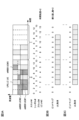
図3A-図3Cは、ビットマップ1を用いるUL取消指示の一例を示す図である。
[Concrete example]
[[Specific example of bitmap 1]]
3A to 3C are diagrams illustrating an example of a UL cancellation
図3Aの例において、URLLC UEは、URLLC 2シンボルPUSCHの8繰り返しを行う(設定される)。このURLLC PUSCHは、既にスケジュールされたeMBB UE#1~#3のPUSCHとオーバーラップする。eMBB UE#1~#3は、2シンボルの時間粒度を上位レイヤシグナリングによって設定され、GC-PDCCHによってUL取消指示を受信する。
In the example of FIG. 3A, the URLLC UE performs (configures) 8 repetitions of the URLLC 2-symbol PUSCH. This URLLC PUSCH overlaps with the already scheduled PUSCH of
この例では、UL取消指示のビットマップサイズは14ビットである。時間粒度が2シンボルであるため、各ビットは、2シンボルのブロックに対応し、ビット#0~#13は、スロット#0、#1にわたる14ブロック(ブロック#0~#13、28シンボル)に対応する。
In this example, the bitmap size of the UL cancellation instruction is 14 bits. Since the time granularity is 2 symbols, each bit corresponds to a block of 2 symbols, and
図3Bは、ビットマップ指示方法1を用いるビットマップと、それによって指示される時間リソースと、を示す。UL取消指示内のビットマップのビット#2のみが1を示す。当該UL取消指示内の繰り返し数は2を示す。
FIG. 3B shows a bitmap using
よって、UL取消の1番目の繰り返しの開始シンボルは、ブロック#2(スロット#0のシンボル#4)であり、1番目の繰り返しの終了シンボルは、同じスロット#0の最終シンボル(シンボル#13)であり、1つの繰り返しの長さ(持続時間、開始シンボルから終了シンボルまで)は5ブロック(10シンボル)である。繰り返し数が2であるため、1番目の繰り返しに続く2番目の繰り返しは、スロット#1のシンボル#0からシンボル#9までである。このように、eMBB UE#1~#3は、指示された2つの繰り返し(スロット#0のシンボル#4からスロット#1のシンボル#9まで)を、UL取消の時間リソースとして決定する。
Therefore, the starting symbol of the first repetition of UL cancellation is block #2 (
図3Cは、ビットマップ指示方法2を用いるビットマップと、それによって指示される時間リソースと、を示す。UL取消指示内のビットマップのビット#2、#7のみが1を示す。
FIG. 3C shows a bitmap using
よって、ビット#2に対応する1番目の時間リソースの開始シンボルは、ブロック#2(スロット#0のシンボル#4)であり、それに対応する終了シンボルは、同じスロット#0の最終シンボル(シンボル#13)である。ビット#7に対応する2番目の時間リソースの開始シンボルは、ブロック#7(スロット#1のシンボル#0)であり、それに対応する終了シンボルは、同じスロット#1の最終シンボル(シンボル#13)である。このように、eMBB UE#1~#3は、指示された2つの時間リソース(スロット#0のシンボル#4からスロット#1のシンボル#13まで)を、UL取消の時間リソースとして決定する。
Therefore, the starting symbol of the first time resource corresponding to bit #2 is block #2 (
[[ビットマップ2の具体例]]
図4A-図4Cは、ビットマップ2を用いるUL取消指示の一例を示す図である。
[[Specific example of bitmap 2]]
4A to 4C are diagrams illustrating an example of a UL cancellation
図4Aの例は、図3Aと同様である。 The example in FIG. 4A is similar to FIG. 3A.
図4Bは、ビットマップ指示方法1を用いるビットマップと、それによって指示される時間リソースと、を示す。UL取消指示内のビットマップのビット#2のみが1を示す。当該UL取消指示内の繰り返し数は8を示す。
FIG. 4B shows a bitmap using
よって、UL取消の1番目の繰り返しの開始シンボルは、ブロック#2(スロット#0のシンボル#4)である。繰り返し数は、8ブロック(16シンボル)である。このように、eMBB UE#1~#3は、指示された8個の繰り返し(スロット#0のシンボル#4からスロット#1のシンボル#9まで)を、UL取消の時間リソースとして決定する。
Therefore, the starting symbol of the first repetition of UL cancellation is block #2 (
図4Cは、ビットマップ指示方法2を用いるビットマップと、それによって指示される時間リソースと、を示す。UL取消指示内のビットマップのビット#2~#9のみが1を示す。
FIG. 4C shows a bitmap using
よって、UL取消の時間リソースは、ブロック#2~#9(スロット#0のシンボル#4からスロット#1のシンボル#9まで)である。このように、eMBB UE#1~#3は、指示されたブロック#2~#9(スロット#0のシンボル#4からスロット#1のシンボル#9まで)を、UL取消の時間リソースとして決定する。
Therefore, the time resources for UL cancellation are
《時間リソース指示フォーマット2》
時間リソース指示フォーマットは、周波数リソースの指示に用いられるリソース指示値(Resource Indication Value(RIV))と同様の指示であってもよい。UL取消のためのRIVは、UL取消の時間リソースの少なくとも一部の、開始シンボル(開始位置、開始ブロック)及び長さ(送信長、ブロック数)と、を示す値であってもよい。
《Time
The time resource indication format may be an instruction similar to a resource indication value (RIV) used for indicating frequency resources. The RIV for UL cancellation may be a value indicating the starting symbol (starting position, starting block) and length (transmission length, number of blocks) of at least a portion of the time resource for UL cancellation.
例えば、RIVは、(開始位置の最大値-開始位置)が長さ以上である場合に、開始位置の最大値×(長さ-1)+開始位置であってもよく、(開始位置の最大値-開始位置)が長さよりも短い場合に、0であってもよい。 For example, RIV may be the maximum value of the start position x (length - 1) + start position, where (maximum value of the start position - start position) is greater than or equal to the length; May be 0 if the value (starting position) is shorter than the length.
[RIV指示方法]
ミニスロットベース繰り返しを用いるURLLC PUSCHに対し、RIVは、次のRIV指示方法1、2のいずれかに従ってもよい。
[RIV instruction method]
For URLLC PUSCH with minislot-based repetition, the RIV may follow either of the following
[[RIV指示方法1]]
UL取消指示内のRIVは、最初の繰り返しを指示してもよい。例えば、RIVは、最初の繰り返しの開始シンボル(開始位置、開始ブロック)と、最初の繰り返しの長さ(ブロック数)を示してもよい。残りの繰り返しに用いられる時間リソースは、繰り返し数と、最初の繰り返しに用いられる時間リソースと、に基づいて導出されてもよい。繰り返し数は、当該UL取消指示内の別のフィールドによって指示されてもよい。
[[RIV instruction method 1]]
The RIV in the UL cancellation instruction may indicate the first iteration. For example, the RIV may indicate the starting symbol (starting position, starting block) of the first repetition and the length (number of blocks) of the first repetition. The time resources used for the remaining iterations may be derived based on the number of iterations and the time resources used for the first iteration. The number of repetitions may be indicated by another field within the UL cancellation instruction.
2番目以降の繰り返しは、最初の繰り返しに続いてもよい。2番目以降の繰り返しの長さは、最初の繰り返しと等しくてもよい。 The second and subsequent iterations may follow the first iteration. The length of the second and subsequent iterations may be equal to the length of the first iteration.
[[RIV指示方法2]]
ミニスロットベース繰り返しを用いるURLLC PUSCHに対し、UL取消指示内のRIVは、すべての繰り返しに用いられる全ての時間リソースを指示してもよい。
[[RIV instruction method 2]]
For URLLC PUSCH with minislot-based repetitions, the RIV in the UL cancellation indication may indicate all time resources used for all repetitions.
[具体例]
図5A-図5Cは、RIVを用いるUL取消指示の一例を示す図である。
[Concrete example]
5A to 5C are diagrams illustrating an example of a UL cancellation instruction using RIV.
図5Aの例は、前述の図3Aと同様である。 The example in FIG. 5A is similar to FIG. 3A described above.
図5Bは、RIV指示方法1を用いるRIVと、それによって指示される時間リソースと、を示す。UL取消指示内のRIVは、開始位置が2であり長さが1であることを示す。当該UL取消指示内の繰り返し数は8を示す。
FIG. 5B shows an RIV using
よって、UL取消の時間リソースの1番目の繰り返しの開始シンボルは、ブロック#2(スロット#0のシンボル#4)であり、1番目の繰り返しの長さは1ブロック(2シンボル)であり、繰り返し数は、8ブロック(16シンボル)である。このように、eMBB UE#1~#3は、指示された8個の繰り返し(スロット#0のシンボル#4からスロット#1のシンボル#9まで)を、UL取消の時間リソースとして決定する。
Therefore, the starting symbol of the first repetition of the time resource for UL cancellation is block #2 (
図5Cは、RIV指示方法2を用いるRIVと、それによって指示される時間リソースと、を示す。UL取消指示内のRIVが2である場合、このRIVは、開始位置が2であり長さが8であることを示す。
FIG. 5C shows an RIV using
よって、UL取消の時間リソースの開始シンボルは、ブロック#2(スロット#0のシンボル#4)であり、時間リソースの長さは8ブロック(16シンボル)である。このように、eMBB UE#1~#3は、指示された時間リソース(スロット#0のシンボル#4からスロット#1のシンボル#9まで)を、UL取消の時間リソースとして決定する。
Therefore, the starting symbol of the time resource for UL cancellation is block #2 (
時間リソースの指示にRIVを用いることによって、開始及び長さの指示値(Start and Length Indicator(SLIV))を用いる場合に比べて、時間リソースを柔軟に指示できる。SLIVと開始シンボル及び長さとの関連付けが上位レイヤシグナリングによって設定される場合に比べて、シグナリングのオーバーヘッドを抑えることができる。 By using RIV to indicate time resources, time resources can be indicated more flexibly than when using a Start and Length Indicator (SLIV). Signaling overhead can be reduced compared to the case where the association between the SLIV and the start symbol and length is set by upper layer signaling.
《時間リソース指示フォーマット3》
時間リソース指示フォーマットは、SLIVと同様の指示であってもよい。UL取消のためのSLIVは、URLLC PUSCH用に設計された時間ドメインリソース割り当て(time domain resource assignment)フィールドを再利用してもよい。
《Time
The time resource instruction format may be an instruction similar to SLIV. SLIV for UL cancellation may reuse the time domain resource assignment fields designed for URLLC PUSCH.
繰り返し数は、SLIVのフィールドによって結合されて(jointly)指示されてもよいし、別のフィールドによってSLIVと独立に(separately)指示されてもよい。 The number of repetitions may be indicated jointly by a field in SLIV, or may be indicated separately from SLIV by another field.
時間ドメインリソース割り当てフィールドは、最初の繰り返しを指示してもよい。例えば、SLIVは、最初の繰り返しの開始シンボル(開始位置、開始ブロック)と、最初の繰り返しの長さ(シンボル数、ブロック数)と、最初の繰り返しのスロットオフセットと、繰り返し数と、の少なくとも1つを示してもよい。残りの繰り返しに用いられる時間リソースは、繰り返し数と、最初の繰り返しに用いられる時間リソースと、に基づいて導出されてもよい。スロットオフセットは、UL取消指示から最初の繰り返しまでのスロット数であってもよい。 The time domain resource allocation field may indicate the first iteration. For example, SLIV includes at least one of the starting symbol (starting position, starting block) of the first repetition, the length (number of symbols, number of blocks) of the first repetition, the slot offset of the first repetition, and the number of repetitions. You may also indicate one. The time resources used for the remaining iterations may be derived based on the number of iterations and the time resources used for the first iteration. The slot offset may be the number of slots from the UL cancellation instruction to the first iteration.
2番目以降の繰り返しは、最初の繰り返しに続いてもよい。2番目以降の繰り返しの長さは、最初の繰り返しと等しくてもよい。 The second and subsequent iterations may follow the first iteration. The length of the second and subsequent iterations may be equal to the length of the first iteration.
最初の繰り返しのスロットオフセットと、最初の繰り返しの開始位置と、最初の繰り返しの長さと、繰り返し数と、の少なくとも1つと、SLIVの値と、の関連付け(例えば、テーブル、リスト、PUSCH時間ドメインリソース割り当てリスト)が、仕様に規定されてもよいし、上位レイヤシグナリング(例えば、PUSCH-TimeDomainResourceAllocationList)によって設定されてもよい。 An association (e.g., table, list, PUSCH time-domain resource allocation list) may be specified in the specification or may be set by upper layer signaling (for example, PUSCH-TimeDomainResourceAllocationList).
時間粒度として1が設定された場合、又は時間粒度が設定されない場合、SLIVは開始のシンボル番号と長さのシンボル数とに関連付けられてもよい。時間粒度が設定される場合、時間粒度のシンボルを有するブロックに対し、SLIVは開始のブロック番号と長さのブロック数とに関連付けられてもよい。 If the time granularity is set to 1, or if the time granularity is not set, the SLIV may be associated with a starting symbol number and a length symbol number. If time granularity is configured, the SLIV may be associated with a starting block number and a length block number for blocks with time granularity symbols.
[具体例]
図6A-図6Cは、SLIVを用いるUL取消指示の一例を示す図である。
[Concrete example]
6A to 6C are diagrams illustrating an example of a UL cancellation instruction using SLIV.
図6Aの例は、前述の図3Aと同様である。この例において、時間粒度は1であってもよいし、時間粒度は設定されなくてもよい。 The example in FIG. 6A is similar to FIG. 3A described above. In this example, the time granularity may be 1 or no time granularity may be set.
図6Bは、SLIV=3によって指示されるUL取消の時間リソースを示し、図6Cは、PUSCH時間ドメインリソース割り当てリストの一例を示す。この例のリストは、SLIVの値に対応する行インデックスと、最初の繰り返しのスロットオフセットと、最初の繰り返しの開始位置と、最初の繰り返しの長さと、繰り返し数と、を示す。 FIG. 6B shows time resources for UL cancellation indicated by SLIV=3, and FIG. 6C shows an example of a PUSCH time domain resource allocation list. This example list shows the row index corresponding to the value of SLIV, the slot offset of the first iteration, the starting position of the first iteration, the length of the first iteration, and the number of iterations.
UL取消指示内のSLIVが3である場合、このSLIVは、スロットオフセットが1であり開始位置Sが4であり長さLが2であり繰り返し数Kが8であることを示す。 If the SLIV in the UL cancellation instruction is 3, this SLIV indicates that the slot offset is 1, the starting position S is 4, the length L is 2, and the number of repetitions K is 8.
UL取消指示がスロット#0の1つ前のスロットで受信されたとすると、UL取消の時間リソースの1番目の繰り返しの開始シンボルは、シンボル#4(スロット#0のシンボル#4)であり、1番目の繰り返しの長さは2シンボルであり、繰り返し数は、8(16シンボル)である。このように、eMBB UE#1~#3は、指示された8個の繰り返し(スロット#0のシンボル#4からスロット#1のシンボル#9まで)を、UL取消の時間リソースとして決定する。
Assuming that the UL cancellation instruction is received in the slot before
図6Aの例において、時間粒度が2に設定された場合、SLIVは、S=2、L=1、K=8に関連付けられてもよい。 In the example of FIG. 6A, if the time granularity is set to 2, the SLIV may be associated with S=2, L=1, K=8.
時間リソースの指示にSLIVを用い、SLIVと開始シンボル及び長さとの関連付けを制限することによって、UL取消指示のオーバーヘッドを抑えることができる。 By using SLIV to indicate time resources and limiting the association between SLIV, start symbol, and length, the overhead of UL cancellation instructions can be suppressed.
この実施形態によれば、UL取消が適用される時間リソースを適切に指示できると共に、UL取消指示のシグナリングのオーバーヘッドを抑えることができる。 According to this embodiment, the time resources to which UL cancellation is applied can be appropriately indicated, and the overhead of signaling the UL cancellation instruction can be suppressed.
<実施形態2>
GC-PDCCHベースUL取消指示において、UL取消が適用される周波数リソースは、UL取消DCIによって明示的に指示されてもよい。周波数リソースは、CC、BWP、ハーフBWP、physical resource block(PRB)、resource element(RE)、の少なくとも1つであってもよい。
<
In the GC-PDCCH-based UL cancellation instruction, the frequency resources to which UL cancellation is applied may be explicitly indicated by the UL cancellation DCI. The frequency resource may be at least one of CC, BWP, half BWP, physical resource block (PRB), and resource element (RE).
UEは、周波数ドメインリソース指示粒度(周波数粒度、granularity)を、上位レイヤシグナリングによって明示的に設定(指示)されてもよい。UL取消指示によって指示される周波数リソース(例えば、ブロック)は、周波数粒度にわたって連続するシンボルであってもよい。 The UE may be explicitly configured (indicated) with frequency domain resource indication granularity by upper layer signaling. The frequency resources (eg, blocks) indicated by the UL cancellation indication may be consecutive symbols across frequency granularity.
周波数粒度の値(範囲)は、{1,2,3,…x}PRBであってもよい。周波数粒度の最大値xはBWPの最大サイズであってもよい。UEは、周波数粒度を設定されない場合、周波数粒度としてデフォルト値を用いてもよい。デフォルト値は、1又は2PRBであってもよい。 The value (range) of frequency granularity may be {1, 2, 3,...x}PRB. The maximum value x of the frequency granularity may be the maximum size of the BWP. The UE may use a default value as the frequency granularity if the frequency granularity is not configured. The default value may be 1 or 2 PRBs.
周波数粒度は、セルと、キャリア(コンポーネントキャリア)と、BWPと、の少なくとも1つ毎に設定されてもよい。 The frequency granularity may be set for at least one of a cell, a carrier (component carrier), and a BWP.
UL取消が適用される周波数リソースは、DCI内の次の周波数リソース指示フィールド1、2の少なくとも1つのフィールドによって指示されてもよい。 The frequency resource to which UL cancellation applies may be indicated by at least one of the following frequency resource indication fields 1, 2 in the DCI.
《周波数リソース指示フィールド1》
周波数リソース指示フィールド1は、スケジューリングのためのDCIフォーマット0_0又は0_1内の周波数ドメインリソース割り当て(frequency domain resource assignment)フィールドを、UL取消指示シグナリング設計のために再利用してもよい。
《Frequency
Frequency
周波数ドメインリソース割り当てフィールドは、サイズ(RB数)NBWP sizeのアクティブキャリアBWP内の、連続して割り当てられたインターリーブされていないvirtual resource block(VRB)のセットを、UEに指示する。 The frequency domain resource allocation field indicates to the UE a set of consecutively allocated non-interleaved virtual resource blocks (VRBs) within the active carrier BWP of size (number of RBs) N BWP size .
周波数ドメインリソース割り当てフィールドは、開始VRBと連続して割り当てられたRBの長さLRBsとに対応するRIVから成ってもよい。例えば、長さ-1がfloor(NBWP size/2)以下である場合、RIV=NBWP size(LRBs-1)+RBstartであり、そうでない場合、RIV=NBWP size(NBWP size-LRBs+1)+(NBWP size+1-RBstart)である。ここで、LRBsは1以上でありNBWP size-RBstartを超えない。 The frequency domain resource allocation field may consist of an RIV corresponding to a starting VRB and a length of successively allocated RBs L RBs . For example, if length -1 is less than or equal to floor (N BWP size /2), then RIV = N BWP size (L RBs -1) + RB start ; otherwise, RIV = N BWP size (N BWP size - L RBs + 1) + (N BWP size + 1 - RB start ). Here, L RBs is 1 or more and does not exceed N BWP size - RB start .
《周波数リソース指示フィールド2》
周波数リソース指示フィールド2は、スケジューリングのためのDCIフォーマット0_0又は0_1内の周波数ホッピングフラグ(frequency hopping flag)フィールドを、UL取消指示シグナリング設計のために再利用してもよい。
《Frequency
The frequency
この実施形態によれば、UL取消が適用される周波数リソースを適切に指示できると共に、UL取消指示のシグナリングのオーバーヘッドを抑えることができる。 According to this embodiment, the frequency resources to which UL cancellation is applied can be appropriately indicated, and the overhead of signaling the UL cancellation instruction can be suppressed.
<実施形態3>
DCIフォーマット2_xを用いてUL取消指示を運ぶ新規GC-PDCCHが導入されてもよい。xは任意の整数であってもよい。
<
A new GC-PDCCH may be introduced that carries the UL cancellation indication using DCI format 2_x. x may be any integer.
特定種類のRNTIによってスクランブルされたCRCを有するDCIフォーマット2_xを用いて、N個のUL取消指示(UL取消指示1,UL取消指示2,…,UL取消指示j,…,UL取消指示N(1≦j≦N))が送信されてもよい。特定種類のRNTIは、INT-RNTIと異なる種類であってもよいし、INT-RNTIであってもよい。特定種類のRNTIは、UL_INT-RNTI、UL-INT-RNTI、新規INT-RNTIなどと呼ばれてもよい。
N UL cancellation instructions (
UL取消指示jは次の情報を含んでもよい。
・時間ドメインリソース割り当て(実施形態1が適用されてもよい)
・周波数ドメインリソース割り当て(実施形態2が適用されてもよい)
・周波数ホッピングフラグ(実施形態2が適用されてもよい)
・繰り返し因子Kの動的指示(実施形態1が適用されてもよい)
The UL cancellation instruction j may include the following information.
- Time domain resource allocation (
- Frequency domain resource allocation (
- Frequency hopping flag (
・Dynamic instruction of repetition factor K (
この実施形態によれば、UEグループに対してUL取消指示を適切に通知できる。 According to this embodiment, a UL cancellation instruction can be appropriately notified to a UE group.
<その他>
前述の各実施形態において、UL取消指示は、繰り返しでないUL送信のリソースを示してもよいし、FHが適用されないUL送信のリソースを示してもよい。
<Others>
In each of the embodiments described above, the UL cancellation instruction may indicate a resource for non-repetitive UL transmission, or may indicate a resource for UL transmission to which FH is not applied.
前述の各実施形態において、DCIフォーマット0_0又は0_1の代わりに他のDCIフォーマット(例えば、PUSCHのスケジューリングに用いられるDCIフォーマット)が用いられてもよい。 In each of the embodiments described above, other DCI formats (for example, DCI formats used for PUSCH scheduling) may be used instead of DCI format 0_0 or 0_1.
PUSCH繰り返し、スロット又はサブスロット又はミニスロットにわたる複数PUSCH、PUSCHブラインド再送、複数スロットPUSCH又は複数サブスロットPUSCH又は複数ミニスロットPUSCH、同じTBを含む複数PUSCH、複数スロット又は複数サブスロット又は複数ミニスロットにわたるTBの繰り返し、は互いに読み替えられてもよい。複数の繰り返しが1つのPUSCHであってもよい。 PUSCH repetition, multiple PUSCH over slots or subslots or minislots, PUSCH blind retransmission, multiple slots PUSCH or multiple subslots PUSCH or multiple minislots PUSCH, multiple PUSCHs containing the same TB, multiple slots or multiple subslots or multiple minislots The repetitions of TB may be read interchangeably. Multiple repetitions may be one PUSCH.
本開示において、繰り返し数(repetition number)、繰り返し因子(repetition factor)、K、は互いに読み替えられてもよい。 In the present disclosure, repetition number, repetition factor, and K may be interchanged.
(無線通信システム)
以下、本開示の一実施形態に係る無線通信システムの構成について説明する。この無線通信システムでは、本開示の上記各実施形態に係る無線通信方法のいずれか又はこれらの組み合わせを用いて通信が行われる。
(wireless communication system)
The configuration of a wireless communication system according to an embodiment of the present disclosure will be described below. In this wireless communication system, communication is performed using any one of the wireless communication methods according to the above-described embodiments of the present disclosure or a combination thereof.
図7は、一実施形態に係る無線通信システムの概略構成の一例を示す図である。無線通信システム1は、Third Generation Partnership Project(3GPP)によって仕様化されるLong Term Evolution(LTE)、5th generation mobile communication system New Radio(5G NR)などを用いて通信を実現するシステムであってもよい。
FIG. 7 is a diagram illustrating an example of a schematic configuration of a wireless communication system according to an embodiment. The
また、無線通信システム1は、複数のRadio Access Technology(RAT)間のデュアルコネクティビティ(マルチRATデュアルコネクティビティ(Multi-RAT Dual Connectivity(MR-DC)))をサポートしてもよい。MR-DCは、LTE(Evolved Universal Terrestrial Radio Access(E-UTRA))とNRとのデュアルコネクティビティ(E-UTRA-NR Dual Connectivity(EN-DC))、NRとLTEとのデュアルコネクティビティ(NR-E-UTRA Dual Connectivity(NE-DC))などを含んでもよい。
Furthermore, the
EN-DCでは、LTE(E-UTRA)の基地局(eNB)がマスタノード(Master Node(MN))であり、NRの基地局(gNB)がセカンダリノード(Secondary Node(SN))である。NE-DCでは、NRの基地局(gNB)がMNであり、LTE(E-UTRA)の基地局(eNB)がSNである。 In EN-DC, an LTE (E-UTRA) base station (eNB) is a master node (Master Node (MN)), and an NR base station (gNB) is a secondary node (Secondary Node (SN)). In NE-DC, the NR base station (gNB) is the MN, and the LTE (E-UTRA) base station (eNB) is the SN.
無線通信システム1は、同一のRAT内の複数の基地局間のデュアルコネクティビティ(例えば、MN及びSNの双方がNRの基地局(gNB)であるデュアルコネクティビティ(NR-NR Dual Connectivity(NN-DC)))をサポートしてもよい。
The
無線通信システム1は、比較的カバレッジの広いマクロセルC1を形成する基地局11と、マクロセルC1内に配置され、マクロセルC1よりも狭いスモールセルC2を形成する基地局12(12a-12c)と、を備えてもよい。ユーザ端末20は、少なくとも1つのセル内に位置してもよい。各セル及びユーザ端末20の配置、数などは、図に示す態様に限定されない。以下、基地局11及び12を区別しない場合は、基地局10と総称する。
The
ユーザ端末20は、複数の基地局10のうち、少なくとも1つに接続してもよい。ユーザ端末20は、複数のコンポーネントキャリア(Component Carrier(CC))を用いたキャリアアグリゲーション(Carrier Aggregation(CA))及びデュアルコネクティビティ(DC)の少なくとも一方を利用してもよい。
The
各CCは、第1の周波数帯(Frequency Range 1(FR1))及び第2の周波数帯(Frequency Range 2(FR2))の少なくとも1つに含まれてもよい。マクロセルC1はFR1に含まれてもよいし、スモールセルC2はFR2に含まれてもよい。例えば、FR1は、6GHz以下の周波数帯(サブ6GHz(sub-6GHz))であってもよいし、FR2は、24GHzよりも高い周波数帯(above-24GHz)であってもよい。なお、FR1及びFR2の周波数帯、定義などはこれらに限られず、例えばFR1がFR2よりも高い周波数帯に該当してもよい。 Each CC may be included in at least one of a first frequency band (Frequency Range 1 (FR1)) and a second frequency band (Frequency Range 2 (FR2)). Macro cell C1 may be included in FR1, and small cell C2 may be included in FR2. For example, FR1 may be a frequency band below 6 GHz (sub-6 GHz), and FR2 may be a frequency band above 24 GHz (above-24 GHz). Note that the frequency bands and definitions of FR1 and FR2 are not limited to these, and FR1 may correspond to a higher frequency band than FR2, for example.
また、ユーザ端末20は、各CCにおいて、時分割複信(Time Division Duplex(TDD))及び周波数分割複信(Frequency Division Duplex(FDD))の少なくとも1つを用いて通信を行ってもよい。
Further, the
複数の基地局10は、有線(例えば、Common Public Radio Interface(CPRI)に準拠した光ファイバ、X2インターフェースなど)又は無線(例えば、NR通信)によって接続されてもよい。例えば、基地局11及び12間においてNR通信がバックホールとして利用される場合、上位局に該当する基地局11はIntegrated Access Backhaul(IAB)ドナー、中継局(リレー)に該当する基地局12はIABノードと呼ばれてもよい。
The plurality of
基地局10は、他の基地局10を介して、又は直接コアネットワーク30に接続されてもよい。コアネットワーク30は、例えば、Evolved Packet Core(EPC)、5G Core Network(5GCN)、Next Generation Core(NGC)などの少なくとも1つを含んでもよい。
ユーザ端末20は、LTE、LTE-A、5Gなどの通信方式の少なくとも1つに対応した端末であってもよい。
The
無線通信システム1においては、直交周波数分割多重(Orthogonal Frequency Division Multiplexing(OFDM))ベースの無線アクセス方式が利用されてもよい。例えば、下りリンク(Downlink(DL))及び上りリンク(Uplink(UL))の少なくとも一方において、Cyclic Prefix OFDM(CP-OFDM)、Discrete Fourier Transform Spread OFDM(DFT-s-OFDM)、Orthogonal Frequency Division Multiple Access(OFDMA)、Single Carrier Frequency Division Multiple Access(SC-FDMA)などが利用されてもよい。
In the
無線アクセス方式は、波形(waveform)と呼ばれてもよい。なお、無線通信システム1においては、UL及びDLの無線アクセス方式には、他の無線アクセス方式(例えば、他のシングルキャリア伝送方式、他のマルチキャリア伝送方式)が用いられてもよい。
A wireless access scheme may be referred to as a waveform. Note that in the
無線通信システム1では、下りリンクチャネルとして、各ユーザ端末20で共有される下り共有チャネル(Physical Downlink Shared Channel(PDSCH))、ブロードキャストチャネル(Physical Broadcast Channel(PBCH))、下り制御チャネル(Physical Downlink Control Channel(PDCCH))などが用いられてもよい。
In the
また、無線通信システム1では、上りリンクチャネルとして、各ユーザ端末20で共有される上り共有チャネル(Physical Uplink Shared Channel(PUSCH))、上り制御チャネル(Physical Uplink Control Channel(PUCCH))、ランダムアクセスチャネル(Physical Random Access Channel(PRACH))などが用いられてもよい。
In the
PDSCHによって、ユーザデータ、上位レイヤ制御情報、System Information Block(SIB)などが伝送される。PUSCHによって、ユーザデータ、上位レイヤ制御情報などが伝送されてもよい。また、PBCHによって、Master Information Block(MIB)が伝送されてもよい。 User data, upper layer control information, System Information Block (SIB), etc. are transmitted through the PDSCH. User data, upper layer control information, etc. may be transmitted by PUSCH. Furthermore, a Master Information Block (MIB) may be transmitted via the PBCH.
PDCCHによって、下位レイヤ制御情報が伝送されてもよい。下位レイヤ制御情報は、例えば、PDSCH及びPUSCHの少なくとも一方のスケジューリング情報を含む下り制御情報(Downlink Control Information(DCI))を含んでもよい。 Lower layer control information may be transmitted by PDCCH. The lower layer control information may include, for example, downlink control information (DCI) that includes scheduling information for at least one of PDSCH and PUSCH.
なお、PDSCHをスケジューリングするDCIは、DLアサインメント、DL DCIなどと呼ばれてもよいし、PUSCHをスケジューリングするDCIは、ULグラント、UL DCIなどと呼ばれてもよい。なお、PDSCHはDLデータで読み替えられてもよいし、PUSCHはULデータで読み替えられてもよい。 Note that the DCI that schedules PDSCH may be called DL assignment, DL DCI, etc., and the DCI that schedules PUSCH may be called UL grant, UL DCI, etc. Note that PDSCH may be replaced with DL data, and PUSCH may be replaced with UL data.
PDCCHの検出には、制御リソースセット(COntrol REsource SET(CORESET))及びサーチスペース(search space)が利用されてもよい。CORESETは、DCIをサーチするリソースに対応する。サーチスペースは、PDCCH候補(PDCCH candidates)のサーチ領域及びサーチ方法に対応する。1つのCORESETは、1つ又は複数のサーチスペースに関連付けられてもよい。UEは、サーチスペース設定に基づいて、あるサーチスペースに関連するCORESETをモニタしてもよい。 A control resource set (CORESET) and a search space may be used to detect the PDCCH. CORESET corresponds to a resource for searching DCI. The search space corresponds to a search area and a search method for PDCCH candidates. One CORESET may be associated with one or more search spaces. The UE may monitor the CORESET associated with a certain search space based on the search space configuration.
1つのサーチスペースは、1つ又は複数のアグリゲーションレベル(aggregation Level)に該当するPDCCH候補に対応してもよい。1つ又は複数のサーチスペースは、サーチスペースセットと呼ばれてもよい。なお、本開示の「サーチスペース」、「サーチスペースセット」、「サーチスペース設定」、「サーチスペースセット設定」、「CORESET」、「CORESET設定」などは、互いに読み替えられてもよい。 One search space may correspond to PDCCH candidates corresponding to one or more aggregation levels. One or more search spaces may be referred to as a search space set. Note that "search space", "search space set", "search space setting", "search space set setting", "CORESET", "CORESET setting", etc. in the present disclosure may be read interchangeably.
PUCCHによって、チャネル状態情報(Channel State Information(CSI))、送達確認情報(例えば、Hybrid Automatic Repeat reQuest ACKnowledgement(HARQ-ACK)、ACK/NACKなどと呼ばれてもよい)及びスケジューリングリクエスト(Scheduling Request(SR))の少なくとも1つを含む上り制御情報(Uplink Control Information(UCI))が伝送されてもよい。PRACHによって、セルとの接続確立のためのランダムアクセスプリアンブルが伝送されてもよい。 PUCCH allows channel state information (CSI), delivery confirmation information (for example, may be called Hybrid Automatic Repeat reQuest ACKnowledgement (HARQ-ACK), ACK/NACK, etc.), and scheduling request ( Uplink Control Information (UCI) including at least one of SR)) may be transmitted. A random access preamble for establishing a connection with a cell may be transmitted by PRACH.
なお、本開示において下りリンク、上りリンクなどは「リンク」を付けずに表現されてもよい。また、各種チャネルの先頭に「物理(Physical)」を付けずに表現されてもよい。 Note that in the present disclosure, downlinks, uplinks, etc. may be expressed without adding "link". Furthermore, various channels may be expressed without adding "Physical" at the beginning.
無線通信システム1では、同期信号(Synchronization Signal(SS))、下りリンク参照信号(Downlink Reference Signal(DL-RS))などが伝送されてもよい。無線通信システム1では、DL-RSとして、セル固有参照信号(Cell-specific Reference Signal(CRS))、チャネル状態情報参照信号(Channel State Information Reference Signal(CSI-RS))、復調用参照信号(DeModulation Reference Signal(DMRS))、位置決定参照信号(Positioning Reference Signal(PRS))、位相トラッキング参照信号(Phase Tracking Reference Signal(PTRS))などが伝送されてもよい。
In the
同期信号は、例えば、プライマリ同期信号(Primary Synchronization Signal(PSS))及びセカンダリ同期信号(Secondary Synchronization Signal(SSS))の少なくとも1つであってもよい。SS(PSS、SSS)及びPBCH(及びPBCH用のDMRS)を含む信号ブロックは、SS/PBCHブロック、SS Block(SSB)などと呼ばれてもよい。なお、SS、SSBなども、参照信号と呼ばれてもよい。 The synchronization signal may be, for example, at least one of a primary synchronization signal (PSS) and a secondary synchronization signal (SSS). A signal block including SS (PSS, SSS) and PBCH (and DMRS for PBCH) may be called an SS/PBCH block, SS Block (SSB), etc. Note that SS, SSB, etc. may also be called reference signals.
また、無線通信システム1では、上りリンク参照信号(Uplink Reference Signal(UL-RS))として、測定用参照信号(Sounding Reference Signal(SRS))、復調用参照信号(DMRS)などが伝送されてもよい。なお、DMRSはユーザ端末固有参照信号(UE-specific Reference Signal)と呼ばれてもよい。
In addition, in the
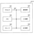
(基地局)
図8は、一実施形態に係る基地局の構成の一例を示す図である。基地局10は、制御部110、送受信部120、送受信アンテナ130及び伝送路インターフェース(transmission line interface)140を備えている。なお、制御部110、送受信部120及び送受信アンテナ130及び伝送路インターフェース140は、それぞれ1つ以上が備えられてもよい。
(base station)
FIG. 8 is a diagram illustrating an example of the configuration of a base station according to an embodiment. The
なお、本例では、本実施の形態における特徴部分の機能ブロックを主に示しており、基地局10は、無線通信に必要な他の機能ブロックも有すると想定されてもよい。以下で説明する各部の処理の一部は、省略されてもよい。
Note that this example mainly shows functional blocks that are characteristic of the present embodiment, and it may be assumed that
制御部110は、基地局10全体の制御を実施する。制御部110は、本開示に係る技術分野での共通認識に基づいて説明されるコントローラ、制御回路などから構成することができる。
The
制御部110は、信号の生成、スケジューリング(例えば、リソース割り当て、マッピング)などを制御してもよい。制御部110は、送受信部120、送受信アンテナ130及び伝送路インターフェース140を用いた送受信、測定などを制御してもよい。制御部110は、信号として送信するデータ、制御情報、系列(sequence)などを生成し、送受信部120に転送してもよい。制御部110は、通信チャネルの呼処理(設定、解放など)、基地局10の状態管理、無線リソースの管理などを行ってもよい。
The
送受信部120は、ベースバンド(baseband)部121、Radio Frequency(RF)部122、測定部123を含んでもよい。ベースバンド部121は、送信処理部1211及び受信処理部1212を含んでもよい。送受信部120は、本開示に係る技術分野での共通認識に基づいて説明されるトランスミッター/レシーバー、RF回路、ベースバンド回路、フィルタ、位相シフタ(phase shifter)、測定回路、送受信回路などから構成することができる。
The transmitting/receiving
送受信部120は、一体の送受信部として構成されてもよいし、送信部及び受信部から構成されてもよい。当該送信部は、送信処理部1211、RF部122から構成されてもよい。当該受信部は、受信処理部1212、RF部122、測定部123から構成されてもよい。
The transmitter/
送受信アンテナ130は、本開示に係る技術分野での共通認識に基づいて説明されるアンテナ、例えばアレイアンテナなどから構成することができる。
The transmitting/receiving
送受信部120は、上述の下りリンクチャネル、同期信号、下りリンク参照信号などを送信してもよい。送受信部120は、上述の上りリンクチャネル、上りリンク参照信号などを受信してもよい。
The transmitter/
送受信部120は、デジタルビームフォーミング(例えば、プリコーディング)、アナログビームフォーミング(例えば、位相回転)などを用いて、送信ビーム及び受信ビームの少なくとも一方を形成してもよい。
The transmitting/receiving
送受信部120(送信処理部1211)は、例えば制御部110から取得したデータ、制御情報などに対して、Packet Data Convergence Protocol(PDCP)レイヤの処理、Radio Link Control(RLC)レイヤの処理(例えば、RLC再送制御)、Medium Access Control(MAC)レイヤの処理(例えば、HARQ再送制御)などを行い、送信するビット列を生成してもよい。 The transmitting/receiving unit 120 (transmission processing unit 1211) performs Packet Data Convergence Protocol (PDCP) layer processing, Radio Link Control (RLC) layer processing (for example, on the data, control information, etc. acquired from the control unit 110). RLC retransmission control), Medium Access Control (MAC) layer processing (for example, HARQ retransmission control), etc. may be performed to generate a bit string to be transmitted.
送受信部120(送信処理部1211)は、送信するビット列に対して、チャネル符号化(誤り訂正符号化を含んでもよい)、変調、マッピング、フィルタ処理、離散フーリエ変換(Discrete Fourier Transform(DFT))処理(必要に応じて)、逆高速フーリエ変換(Inverse Fast Fourier Transform(IFFT))処理、プリコーディング、デジタル-アナログ変換などの送信処理を行い、ベースバンド信号を出力してもよい。 The transmitting/receiving unit 120 (transmission processing unit 1211) performs channel encoding (which may include error correction encoding), modulation, mapping, filter processing, and discrete Fourier transform (DFT) on the bit string to be transmitted. A baseband signal may be output after performing transmission processing such as processing (if necessary), Inverse Fast Fourier Transform (IFFT) processing, precoding, and digital-to-analog conversion.
送受信部120(RF部122)は、ベースバンド信号に対して、無線周波数帯への変調、フィルタ処理、増幅などを行い、無線周波数帯の信号を、送受信アンテナ130を介して送信してもよい。
The transmitting/receiving unit 120 (RF unit 122) may perform modulation, filter processing, amplification, etc. on the baseband signal in a radio frequency band, and may transmit the signal in the radio frequency band via the transmitting/receiving
一方、送受信部120(RF部122)は、送受信アンテナ130によって受信された無線周波数帯の信号に対して、増幅、フィルタ処理、ベースバンド信号への復調などを行ってもよい。
On the other hand, the transmitting/receiving section 120 (RF section 122) may perform amplification, filter processing, demodulation into a baseband signal, etc. on the radio frequency band signal received by the transmitting/receiving
送受信部120(受信処理部1212)は、取得されたベースバンド信号に対して、アナログ-デジタル変換、高速フーリエ変換(Fast Fourier Transform(FFT))処理、逆離散フーリエ変換(Inverse Discrete Fourier Transform(IDFT))処理(必要に応じて)、フィルタ処理、デマッピング、復調、復号(誤り訂正復号を含んでもよい)、MACレイヤ処理、RLCレイヤの処理及びPDCPレイヤの処理などの受信処理を適用し、ユーザデータなどを取得してもよい。 The transmitting/receiving unit 120 (reception processing unit 1212) performs analog-to-digital conversion, fast Fourier transform (FFT) processing, and inverse discrete Fourier transform (IDFT) on the acquired baseband signal. )) processing (if necessary), applying reception processing such as filter processing, demapping, demodulation, decoding (which may include error correction decoding), MAC layer processing, RLC layer processing and PDCP layer processing, User data etc. may also be acquired.
送受信部120(測定部123)は、受信した信号に関する測定を実施してもよい。例えば、測定部123は、受信した信号に基づいて、Radio Resource Management(RRM)測定、Channel State Information(CSI)測定などを行ってもよい。測定部123は、受信電力(例えば、Reference Signal Received Power(RSRP))、受信品質(例えば、Reference Signal Received Quality(RSRQ)、Signal to Interference plus Noise Ratio(SINR)、Signal to Noise Ratio(SNR))、信号強度(例えば、Received Signal Strength Indicator(RSSI))、伝搬路情報(例えば、CSI)などについて測定してもよい。測定結果は、制御部110に出力されてもよい。
The transmitting/receiving unit 120 (measuring unit 123) may perform measurements regarding the received signal. For example, the
伝送路インターフェース140は、コアネットワーク30に含まれる装置、他の基地局10などとの間で信号を送受信(バックホールシグナリング)し、ユーザ端末20のためのユーザデータ(ユーザプレーンデータ)、制御プレーンデータなどを取得、伝送などしてもよい。
The transmission path interface 140 transmits and receives signals (backhaul signaling) between devices included in the
なお、本開示における基地局10の送信部及び受信部は、送受信部120、送受信アンテナ130及び伝送路インターフェース140の少なくとも1つによって構成されてもよい。
Note that the transmitting unit and receiving unit of the
なお、制御部110は、ユーザ端末20から、上りリンク制御チャネル(PUCCH)のための位相追従参照信号(Phase Tracking Reference Signal(PTRS))を受信してもよい。制御部110は、当該PTRSに基づいて、当該PUCCHの位相ノイズを低減(補正)してもよい。
Note that the
(ユーザ端末)
図9は、一実施形態に係るユーザ端末の構成の一例を示す図である。ユーザ端末20は、制御部210、送受信部220及び送受信アンテナ230を備えている。なお、制御部210、送受信部220及び送受信アンテナ230は、それぞれ1つ以上が備えられてもよい。
(user terminal)
FIG. 9 is a diagram illustrating an example of the configuration of a user terminal according to an embodiment. The
なお、本例では、本実施の形態における特徴部分の機能ブロックを主に示しており、ユーザ端末20は、無線通信に必要な他の機能ブロックも有すると想定されてもよい。以下で説明する各部の処理の一部は、省略されてもよい。
Note that this example mainly shows functional blocks that are characteristic of the present embodiment, and it may be assumed that the
制御部210は、ユーザ端末20全体の制御を実施する。制御部210は、本開示に係る技術分野での共通認識に基づいて説明されるコントローラ、制御回路などから構成することができる。
The
制御部210は、信号の生成、マッピングなどを制御してもよい。制御部210は、送受信部220及び送受信アンテナ230を用いた送受信、測定などを制御してもよい。制御部210は、信号として送信するデータ、制御情報、系列などを生成し、送受信部220に転送してもよい。
The
送受信部220は、ベースバンド部221、RF部222、測定部223を含んでもよい。ベースバンド部221は、送信処理部2211、受信処理部2212を含んでもよい。送受信部220は、本開示に係る技術分野での共通認識に基づいて説明されるトランスミッター/レシーバー、RF回路、ベースバンド回路、フィルタ、位相シフタ、測定回路、送受信回路などから構成することができる。
The transmitting/receiving
送受信部220は、一体の送受信部として構成されてもよいし、送信部及び受信部から構成されてもよい。当該送信部は、送信処理部2211、RF部222から構成されてもよい。当該受信部は、受信処理部2212、RF部222、測定部223から構成されてもよい。
The transmitting/receiving
送受信アンテナ230は、本開示に係る技術分野での共通認識に基づいて説明されるアンテナ、例えばアレイアンテナなどから構成することができる。
The transmitting/receiving
送受信部220は、上述の下りリンクチャネル、同期信号、下りリンク参照信号などを受信してもよい。送受信部220は、上述の上りリンクチャネル、上りリンク参照信号などを送信してもよい。
The transmitter/
送受信部220は、デジタルビームフォーミング(例えば、プリコーディング)、アナログビームフォーミング(例えば、位相回転)などを用いて、送信ビーム及び受信ビームの少なくとも一方を形成してもよい。
The transmitting/receiving
送受信部220(送信処理部2211)は、例えば制御部210から取得したデータ、制御情報などに対して、PDCPレイヤの処理、RLCレイヤの処理(例えば、RLC再送制御)、MACレイヤの処理(例えば、HARQ再送制御)などを行い、送信するビット列を生成してもよい。 The transmission/reception unit 220 (transmission processing unit 2211) performs PDCP layer processing, RLC layer processing (e.g. RLC retransmission control), MAC layer processing (e.g. , HARQ retransmission control), etc., to generate a bit string to be transmitted.
送受信部220(送信処理部2211)は、送信するビット列に対して、チャネル符号化(誤り訂正符号化を含んでもよい)、変調、マッピング、フィルタ処理、DFT処理(必要に応じて)、IFFT処理、プリコーディング、デジタル-アナログ変換などの送信処理を行い、ベースバンド信号を出力してもよい。 The transmitting/receiving unit 220 (transmission processing unit 2211) performs channel encoding (which may include error correction encoding), modulation, mapping, filter processing, DFT processing (as necessary), and IFFT processing on the bit string to be transmitted. , precoding, digital-to-analog conversion, etc., and output a baseband signal.
なお、DFT処理を適用するか否かは、トランスフォームプリコーディングの設定に基づいてもよい。送受信部220(送信処理部2211)は、あるチャネル(例えば、PUSCH)について、トランスフォームプリコーディングが有効(enabled)である場合、当該チャネルをDFT-s-OFDM波形を用いて送信するために上記送信処理としてDFT処理を行ってもよいし、そうでない場合、上記送信処理としてDFT処理を行わなくてもよい。 Note that whether or not to apply DFT processing may be based on the settings of transform precoding. When transform precoding is enabled for a certain channel (for example, PUSCH), the transmitting/receiving unit 220 (transmission processing unit 2211) performs the above processing in order to transmit the channel using the DFT-s-OFDM waveform. DFT processing may be performed as the transmission processing, or if not, DFT processing may not be performed as the transmission processing.
送受信部220(RF部222)は、ベースバンド信号に対して、無線周波数帯への変調、フィルタ処理、増幅などを行い、無線周波数帯の信号を、送受信アンテナ230を介して送信してもよい。
The transmitting/receiving unit 220 (RF unit 222) may perform modulation, filter processing, amplification, etc. on the baseband signal in a radio frequency band, and may transmit the signal in the radio frequency band via the transmitting/receiving
一方、送受信部220(RF部222)は、送受信アンテナ230によって受信された無線周波数帯の信号に対して、増幅、フィルタ処理、ベースバンド信号への復調などを行ってもよい。
On the other hand, the transmitting/receiving section 220 (RF section 222) may perform amplification, filter processing, demodulation into a baseband signal, etc. on the radio frequency band signal received by the transmitting/receiving
送受信部220(受信処理部2212)は、取得されたベースバンド信号に対して、アナログ-デジタル変換、FFT処理、IDFT処理(必要に応じて)、フィルタ処理、デマッピング、復調、復号(誤り訂正復号を含んでもよい)、MACレイヤ処理、RLCレイヤの処理及びPDCPレイヤの処理などの受信処理を適用し、ユーザデータなどを取得してもよい。 The transmission/reception unit 220 (reception processing unit 2212) performs analog-to-digital conversion, FFT processing, IDFT processing (if necessary), filter processing, demapping, demodulation, and decoding (error correction) on the acquired baseband signal. (which may include decoding), MAC layer processing, RLC layer processing, and PDCP layer processing may be applied to obtain user data and the like.
送受信部220(測定部223)は、受信した信号に関する測定を実施してもよい。例えば、測定部223は、受信した信号に基づいて、RRM測定、CSI測定などを行ってもよい。測定部223は、受信電力(例えば、RSRP)、受信品質(例えば、RSRQ、SINR、SNR)、信号強度(例えば、RSSI)、伝搬路情報(例えば、CSI)などについて測定してもよい。測定結果は、制御部210に出力されてもよい。
The transmitting/receiving section 220 (measuring section 223) may perform measurements regarding the received signal. For example, the
なお、本開示におけるユーザ端末20の送信部及び受信部は、送受信部220及び送受信アンテナ230の少なくとも1つによって構成されてもよい。
Note that the transmitting unit and receiving unit of the
送受信部220は、時間ドメイン及び周波数ドメインの少なくとも1つにおけるリソースの開始位置(例えば、開始ブロック、開始シンボル、開始RB、など)に関する下り制御情報(DCI)を受信してもよい。制御部210は、前記開始位置の粒度の設定と前記DCIとに基づいて、前記リソースを用いる上り(UL)送信の取消(例えば、cancellation)を行ってもよい。
The transmitting/receiving
前記DCIは、時間ドメインリソース割り当てと、時間ドメインにおける繰り返しの数(例えば、繰り返し数、繰り返し因子)と、周波数ドメインリソース割り当てと、周波数ホッピングフラグと、の少なくとも1つのフィールドを含んでもよい(実施形態1~3)。 The DCI may include at least one field of a time domain resource allocation, a number of repetitions in the time domain (e.g., repetition number, repetition factor), a frequency domain resource allocation, and a frequency hopping flag (in embodiments). 1-3).
前記時間ドメインリソース割り当てのフィールドは、ビットマップと、前記開始位置及び長さに基づく値(例えば、RIV、SLIVなど)と、の少なくとも1つによって、前記リソースを示してもよい(実施形態1)。 The time-domain resource allocation field may indicate the resource by at least one of a bitmap and a value based on the starting position and length (e.g., RIV, SLIV, etc.) (Embodiment 1) .
前記リソースは、時間ドメインにおいて繰り返され、前記時間ドメインリソース割り当てのフィールドは、最初の繰り返しのリソースを示してもよい(実施形態1)。 The resource may be repeated in the time domain, and the field of the time domain resource allocation may indicate the resource of the first repetition (Embodiment 1).
前記DCIは、下り(DL)プリエンプション指示に用いられる無線ネットワーク一時識別子(例えば、INT-RNTI)と異なる種類のRNTI(例えば、UL_INT-RNTI)によってスクランブルされる巡回冗長検査(CRC)を有してもよい(実施形態3)。 The DCI has a cyclic redundancy check (CRC) scrambled by a radio network temporary identifier (e.g., INT-RNTI) used for downlink (DL) preemption indication and a different type of RNTI (e.g., UL_INT-RNTI). (Embodiment 3).
前記DCIは、端末のグループに対して共通に送信されてもよい(例えば、DCIはGC-PDCCHによって運ばれてもよい、DCIはグループ共通DCIであってもよい)(実施形態1~3)。
The DCI may be commonly transmitted to a group of terminals (for example, the DCI may be carried by a GC-PDCCH, the DCI may be a group common DCI) (
(ハードウェア構成)
なお、上記実施形態の説明に用いたブロック図は、機能単位のブロックを示している。これらの機能ブロック(構成部)は、ハードウェア及びソフトウェアの少なくとも一方の任意の組み合わせによって実現される。また、各機能ブロックの実現方法は特に限定されない。すなわち、各機能ブロックは、物理的又は論理的に結合した1つの装置を用いて実現されてもよいし、物理的又は論理的に分離した2つ以上の装置を直接的又は間接的に(例えば、有線、無線などを用いて)接続し、これら複数の装置を用いて実現されてもよい。機能ブロックは、上記1つの装置又は上記複数の装置にソフトウェアを組み合わせて実現されてもよい。
(Hardware configuration)
It should be noted that the block diagram used to explain the above embodiment shows blocks in functional units. These functional blocks (components) are realized by any combination of at least one of hardware and software. Furthermore, the method for realizing each functional block is not particularly limited. That is, each functional block may be realized using one physically or logically coupled device, or may be realized using two or more physically or logically separated devices directly or indirectly (e.g. , wired, wireless, etc.) and may be realized using a plurality of these devices. The functional block may be realized by combining software with the one device or the plurality of devices.
ここで、機能には、判断、決定、判定、計算、算出、処理、導出、調査、探索、確認、受信、送信、出力、アクセス、解決、選択、選定、確立、比較、想定、期待、みなし、報知(broadcasting)、通知(notifying)、通信(communicating)、転送(forwarding)、構成(configuring)、再構成(reconfiguring)、割り当て(allocating、mapping)、割り振り(assigning)などがあるが、これらに限られない。例えば、送信を機能させる機能ブロック(構成部)は、送信部(transmitting unit)、送信機(transmitter)などと呼称されてもよい。いずれも、上述したとおり、実現方法は特に限定されない。 Here, functions include judgment, decision, judgement, calculation, calculation, processing, derivation, investigation, exploration, confirmation, reception, transmission, output, access, solution, selection, selection, establishment, comparison, assumption, expectation, and consideration. , broadcasting, notifying, communicating, forwarding, configuring, reconfiguring, allocating, mapping, assigning, etc. Not limited. For example, a functional block (configuration unit) that performs transmission may be called a transmitting unit, a transmitter, or the like. In either case, as described above, the implementation method is not particularly limited.
例えば、本開示の一実施形態における基地局、ユーザ端末などは、本開示の無線通信方法の処理を行うコンピュータとして機能してもよい。図10は、一実施形態に係る基地局及びユーザ端末のハードウェア構成の一例を示す図である。上述の基地局10及びユーザ端末20は、物理的には、プロセッサ1001、メモリ1002、ストレージ1003、通信装置1004、入力装置1005、出力装置1006、バス1007などを含むコンピュータ装置として構成されてもよい。
For example, a base station, a user terminal, etc. in an embodiment of the present disclosure may function as a computer that performs processing of the wireless communication method of the present disclosure. FIG. 10 is a diagram illustrating an example of the hardware configuration of a base station and a user terminal according to an embodiment. The
なお、本開示において、装置、回路、デバイス、部(section)、ユニットなどの文言は、互いに読み替えることができる。基地局10及びユーザ端末20のハードウェア構成は、図に示した各装置を1つ又は複数含むように構成されてもよいし、一部の装置を含まずに構成されてもよい。
Note that in the present disclosure, words such as apparatus, circuit, device, section, unit, etc. can be read interchangeably. The hardware configuration of the
例えば、プロセッサ1001は1つだけ図示されているが、複数のプロセッサがあってもよい。また、処理は、1のプロセッサによって実行されてもよいし、処理が同時に、逐次に、又はその他の手法を用いて、2以上のプロセッサによって実行されてもよい。なお、プロセッサ1001は、1以上のチップによって実装されてもよい。
For example, although only one
基地局10及びユーザ端末20における各機能は、例えば、プロセッサ1001、メモリ1002などのハードウェア上に所定のソフトウェア(プログラム)を読み込ませることによって、プロセッサ1001が演算を行い、通信装置1004を介する通信を制御したり、メモリ1002及びストレージ1003におけるデータの読み出し及び書き込みの少なくとも一方を制御したりすることによって実現される。
Each function in the
プロセッサ1001は、例えば、オペレーティングシステムを動作させてコンピュータ全体を制御する。プロセッサ1001は、周辺装置とのインターフェース、制御装置、演算装置、レジスタなどを含む中央処理装置(Central Processing Unit(CPU))によって構成されてもよい。例えば、上述の制御部110(210)、送受信部120(220)などの少なくとも一部は、プロセッサ1001によって実現されてもよい。
The
また、プロセッサ1001は、プログラム(プログラムコード)、ソフトウェアモジュール、データなどを、ストレージ1003及び通信装置1004の少なくとも一方からメモリ1002に読み出し、これらに従って各種の処理を実行する。プログラムとしては、上述の実施形態において説明した動作の少なくとも一部をコンピュータに実行させるプログラムが用いられる。例えば、制御部110(210)は、メモリ1002に格納され、プロセッサ1001において動作する制御プログラムによって実現されてもよく、他の機能ブロックについても同様に実現されてもよい。
Furthermore, the
メモリ1002は、コンピュータ読み取り可能な記録媒体であり、例えば、Read Only Memory(ROM)、Erasable Programmable ROM(EPROM)、Electrically EPROM(EEPROM)、Random Access Memory(RAM)、その他の適切な記憶媒体の少なくとも1つによって構成されてもよい。メモリ1002は、レジスタ、キャッシュ、メインメモリ(主記憶装置)などと呼ばれてもよい。メモリ1002は、本開示の一実施形態に係る無線通信方法を実施するために実行可能なプログラム(プログラムコード)、ソフトウェアモジュールなどを保存することができる。
ストレージ1003は、コンピュータ読み取り可能な記録媒体であり、例えば、フレキシブルディスク、フロッピー(登録商標)ディスク、光磁気ディスク(例えば、コンパクトディスク(Compact Disc ROM(CD-ROM)など)、デジタル多用途ディスク、Blu-ray(登録商標)ディスク)、リムーバブルディスク、ハードディスクドライブ、スマートカード、フラッシュメモリデバイス(例えば、カード、スティック、キードライブ)、磁気ストライプ、データベース、サーバ、その他の適切な記憶媒体の少なくとも1つによって構成されてもよい。ストレージ1003は、補助記憶装置と呼ばれてもよい。
The
通信装置1004は、有線ネットワーク及び無線ネットワークの少なくとも一方を介してコンピュータ間の通信を行うためのハードウェア(送受信デバイス)であり、例えばネットワークデバイス、ネットワークコントローラ、ネットワークカード、通信モジュールなどともいう。通信装置1004は、例えば周波数分割複信(Frequency Division Duplex(FDD))及び時分割複信(Time Division Duplex(TDD))の少なくとも一方を実現するために、高周波スイッチ、デュプレクサ、フィルタ、周波数シンセサイザなどを含んで構成されてもよい。例えば、上述の送受信部120(220)、送受信アンテナ130(230)などは、通信装置1004によって実現されてもよい。送受信部120(220)は、送信部120a(220a)と受信部120b(220b)とで、物理的に又は論理的に分離された実装がなされてもよい。
The
入力装置1005は、外部からの入力を受け付ける入力デバイス(例えば、キーボード、マウス、マイクロフォン、スイッチ、ボタン、センサなど)である。出力装置1006は、外部への出力を実施する出力デバイス(例えば、ディスプレイ、スピーカー、Light Emitting Diode(LED)ランプなど)である。なお、入力装置1005及び出力装置1006は、一体となった構成(例えば、タッチパネル)であってもよい。
The
また、プロセッサ1001、メモリ1002などの各装置は、情報を通信するためのバス1007によって接続される。バス1007は、単一のバスを用いて構成されてもよいし、装置間ごとに異なるバスを用いて構成されてもよい。
Further, each device such as the
また、基地局10及びユーザ端末20は、マイクロプロセッサ、デジタル信号プロセッサ(Digital Signal Processor(DSP))、Application Specific Integrated Circuit(ASIC)、Programmable Logic Device(PLD)、Field Programmable Gate Array(FPGA)などのハードウェアを含んで構成されてもよく、当該ハードウェアを用いて各機能ブロックの一部又は全てが実現されてもよい。例えば、プロセッサ1001は、これらのハードウェアの少なくとも1つを用いて実装されてもよい。
The
(変形例)
なお、本開示において説明した用語及び本開示の理解に必要な用語については、同一の又は類似する意味を有する用語と置き換えてもよい。例えば、チャネル、シンボル及び信号(シグナル又はシグナリング)は、互いに読み替えられてもよい。また、信号はメッセージであってもよい。参照信号(reference signal)は、RSと略称することもでき、適用される標準によってパイロット(Pilot)、パイロット信号などと呼ばれてもよい。また、コンポーネントキャリア(Component Carrier(CC))は、セル、周波数キャリア、キャリア周波数などと呼ばれてもよい。
(Modified example)
Note that terms explained in this disclosure and terms necessary for understanding this disclosure may be replaced with terms having the same or similar meanings. For example, channel, symbol and signal may be interchanged. Also, the signal may be a message. The reference signal may also be abbreviated as RS, and may be called a pilot, pilot signal, etc. depending on the applicable standard. Further, a component carrier (CC) may also be called a cell, a frequency carrier, a carrier frequency, or the like.
無線フレームは、時間領域において1つ又は複数の期間(フレーム)によって構成されてもよい。無線フレームを構成する当該1つ又は複数の各期間(フレーム)は、サブフレームと呼ばれてもよい。さらに、サブフレームは、時間領域において1つ又は複数のスロットによって構成されてもよい。サブフレームは、ニューメロロジー(numerology)に依存しない固定の時間長(例えば、1ms)であってもよい。 A radio frame may be composed of one or more periods (frames) in the time domain. Each of the one or more periods (frames) constituting a radio frame may be called a subframe. Furthermore, a subframe may be composed of one or more slots in the time domain. A subframe may have a fixed time length (eg, 1 ms) that does not depend on numerology.
ここで、ニューメロロジーは、ある信号又はチャネルの送信及び受信の少なくとも一方に適用される通信パラメータであってもよい。ニューメロロジーは、例えば、サブキャリア間隔(SubCarrier Spacing(SCS))、帯域幅、シンボル長、サイクリックプレフィックス長、送信時間間隔(Transmission Time Interval(TTI))、TTIあたりのシンボル数、無線フレーム構成、送受信機が周波数領域において行う特定のフィルタリング処理、送受信機が時間領域において行う特定のウィンドウイング処理などの少なくとも1つを示してもよい。 Here, the numerology may be a communication parameter applied to at least one of transmission and reception of a certain signal or channel. Numerology includes, for example, subcarrier spacing (SCS), bandwidth, symbol length, cyclic prefix length, transmission time interval (TTI), number of symbols per TTI, and radio frame configuration. , a specific filtering process performed by the transceiver in the frequency domain, a specific windowing process performed by the transceiver in the time domain, etc.
スロットは、時間領域において1つ又は複数のシンボル(Orthogonal Frequency Division Multiplexing(OFDM)シンボル、Single Carrier Frequency Division Multiple Access(SC-FDMA)シンボルなど)によって構成されてもよい。また、スロットは、ニューメロロジーに基づく時間単位であってもよい。 A slot may be constituted by one or more symbols (Orthogonal Frequency Division Multiplexing (OFDM) symbols, Single Carrier Frequency Division Multiple Access (SC-FDMA) symbols, etc.) in the time domain. Furthermore, a slot may be a time unit based on numerology.
スロットは、複数のミニスロットを含んでもよい。各ミニスロットは、時間領域において1つ又は複数のシンボルによって構成されてもよい。また、ミニスロットは、サブスロットと呼ばれてもよい。ミニスロットは、スロットよりも少ない数のシンボルによって構成されてもよい。ミニスロットより大きい時間単位で送信されるPDSCH(又はPUSCH)は、PDSCH(PUSCH)マッピングタイプAと呼ばれてもよい。ミニスロットを用いて送信されるPDSCH(又はPUSCH)は、PDSCH(PUSCH)マッピングタイプBと呼ばれてもよい。 A slot may include multiple minislots. Each minislot may be made up of one or more symbols in the time domain. Furthermore, a mini-slot may also be called a sub-slot. A minislot may be made up of fewer symbols than a slot. PDSCH (or PUSCH) transmitted in time units larger than minislots may be referred to as PDSCH (PUSCH) mapping type A. PDSCH (or PUSCH) transmitted using minislots may be referred to as PDSCH (PUSCH) mapping type B.
無線フレーム、サブフレーム、スロット、ミニスロット及びシンボルは、いずれも信号を伝送する際の時間単位を表す。無線フレーム、サブフレーム、スロット、ミニスロット及びシンボルは、それぞれに対応する別の呼称が用いられてもよい。なお、本開示におけるフレーム、サブフレーム、スロット、ミニスロット、シンボルなどの時間単位は、互いに読み替えられてもよい。 Radio frames, subframes, slots, minislots, and symbols all represent time units for transmitting signals. Other names may be used for the radio frame, subframe, slot, minislot, and symbol. Note that time units such as frames, subframes, slots, minislots, and symbols in the present disclosure may be read interchangeably.
例えば、1サブフレームはTTIと呼ばれてもよいし、複数の連続したサブフレームがTTIと呼ばれてよいし、1スロット又は1ミニスロットがTTIと呼ばれてもよい。つまり、サブフレーム及びTTIの少なくとも一方は、既存のLTEにおけるサブフレーム(1ms)であってもよいし、1msより短い期間(例えば、1-13シンボル)であってもよいし、1msより長い期間であってもよい。なお、TTIを表す単位は、サブフレームではなくスロット、ミニスロットなどと呼ばれてもよい。 For example, one subframe may be called a TTI, multiple consecutive subframes may be called a TTI, and one slot or minislot may be called a TTI. In other words, at least one of the subframe and TTI may be a subframe (1ms) in existing LTE, a period shorter than 1ms (for example, 1-13 symbols), or a period longer than 1ms. It may be. Note that the unit representing the TTI may be called a slot, minislot, etc. instead of a subframe.
ここで、TTIは、例えば、無線通信におけるスケジューリングの最小時間単位のことをいう。例えば、LTEシステムでは、基地局が各ユーザ端末に対して、無線リソース(各ユーザ端末において使用することが可能な周波数帯域幅、送信電力など)を、TTI単位で割り当てるスケジューリングを行う。なお、TTIの定義はこれに限られない。 Here, TTI refers to, for example, the minimum time unit for scheduling in wireless communication. For example, in the LTE system, a base station performs scheduling to allocate radio resources (frequency bandwidth, transmission power, etc. that can be used by each user terminal) to each user terminal on a TTI basis. Note that the definition of TTI is not limited to this.
TTIは、チャネル符号化されたデータパケット(トランスポートブロック)、コードブロック、コードワードなどの送信時間単位であってもよいし、スケジューリング、リンクアダプテーションなどの処理単位となってもよい。なお、TTIが与えられたとき、実際にトランスポートブロック、コードブロック、コードワードなどがマッピングされる時間区間(例えば、シンボル数)は、当該TTIよりも短くてもよい。 The TTI may be a transmission time unit of a channel-coded data packet (transport block), a code block, a codeword, etc., or may be a processing unit of scheduling, link adaptation, etc. Note that when a TTI is given, the time interval (for example, the number of symbols) to which transport blocks, code blocks, code words, etc. are actually mapped may be shorter than the TTI.
なお、1スロット又は1ミニスロットがTTIと呼ばれる場合、1以上のTTI(すなわち、1以上のスロット又は1以上のミニスロット)が、スケジューリングの最小時間単位となってもよい。また、当該スケジューリングの最小時間単位を構成するスロット数(ミニスロット数)は制御されてもよい。 Note that when one slot or one minislot is called a TTI, one or more TTIs (that is, one or more slots or one or more minislots) may be the minimum time unit for scheduling. Further, the number of slots (minislot number) that constitutes the minimum time unit of the scheduling may be controlled.
1msの時間長を有するTTIは、通常TTI(3GPP Rel.8-12におけるTTI)、ノーマルTTI、ロングTTI、通常サブフレーム、ノーマルサブフレーム、ロングサブフレーム、スロットなどと呼ばれてもよい。通常TTIより短いTTIは、短縮TTI、ショートTTI、部分TTI(partial又はfractional TTI)、短縮サブフレーム、ショートサブフレーム、ミニスロット、サブスロット、スロットなどと呼ばれてもよい。 A TTI having a time length of 1 ms may be called a normal TTI (TTI in 3GPP Rel. 8-12), normal TTI, long TTI, normal subframe, normal subframe, long subframe, slot, etc. A TTI that is shorter than a normal TTI may be referred to as an abbreviated TTI, short TTI, partial or fractional TTI, shortened subframe, short subframe, minislot, subslot, slot, or the like.
なお、ロングTTI(例えば、通常TTI、サブフレームなど)は、1msを超える時間長を有するTTIで読み替えてもよいし、ショートTTI(例えば、短縮TTIなど)は、ロングTTIのTTI長未満かつ1ms以上のTTI長を有するTTIで読み替えてもよい。 Note that long TTI (for example, normal TTI, subframe, etc.) may be read as TTI with a time length exceeding 1 ms, and short TTI (for example, short TTI, etc.) It may also be read as a TTI having the above TTI length.
リソースブロック(Resource Block(RB))は、時間領域及び周波数領域のリソース割当単位であり、周波数領域において、1つ又は複数個の連続した副搬送波(サブキャリア(subcarrier))を含んでもよい。RBに含まれるサブキャリアの数は、ニューメロロジーに関わらず同じであってもよく、例えば12であってもよい。RBに含まれるサブキャリアの数は、ニューメロロジーに基づいて決定されてもよい。 A resource block (RB) is a unit of resource allocation in the time domain and frequency domain, and may include one or more continuous subcarriers (subcarriers) in the frequency domain. The number of subcarriers included in an RB may be the same regardless of the numerology, and may be 12, for example. The number of subcarriers included in an RB may be determined based on numerology.
また、RBは、時間領域において、1つ又は複数個のシンボルを含んでもよく、1スロット、1ミニスロット、1サブフレーム又は1TTIの長さであってもよい。1TTI、1サブフレームなどは、それぞれ1つ又は複数のリソースブロックによって構成されてもよい。 Additionally, an RB may include one or more symbols in the time domain and may be one slot, one minislot, one subframe, or one TTI long. One TTI, one subframe, etc. may each be composed of one or more resource blocks.
なお、1つ又は複数のRBは、物理リソースブロック(Physical RB(PRB))、サブキャリアグループ(Sub-Carrier Group(SCG))、リソースエレメントグループ(Resource Element Group(REG))、PRBペア、RBペアなどと呼ばれてもよい。 Note that one or more RBs include a physical resource block (Physical RB (PRB)), a sub-carrier group (SCG), a resource element group (REG), a PRB pair, and an RB. They may also be called pairs.
また、リソースブロックは、1つ又は複数のリソースエレメント(Resource Element(RE))によって構成されてもよい。例えば、1REは、1サブキャリア及び1シンボルの無線リソース領域であってもよい。 Further, a resource block may be configured by one or more resource elements (REs). For example, 1 RE may be a radio resource region of 1 subcarrier and 1 symbol.
帯域幅部分(Bandwidth Part(BWP))(部分帯域幅などと呼ばれてもよい)は、あるキャリアにおいて、あるニューメロロジー用の連続する共通RB(common resource blocks)のサブセットのことを表してもよい。ここで、共通RBは、当該キャリアの共通参照ポイントを基準としたRBのインデックスによって特定されてもよい。PRBは、あるBWPで定義され、当該BWP内で番号付けされてもよい。 Bandwidth Part (BWP) (also called partial bandwidth, etc.) refers to a subset of contiguous common resource blocks (RBs) for a certain numerology in a certain carrier. Good too. Here, the common RB may be specified by an RB index based on a common reference point of the carrier. PRBs may be defined in a BWP and numbered within that BWP.
BWPには、UL BWP(UL用のBWP)と、DL BWP(DL用のBWP)とが含まれてもよい。UEに対して、1キャリア内に1つ又は複数のBWPが設定されてもよい。 BWP may include UL BWP (BWP for UL) and DL BWP (BWP for DL). One or more BWPs may be configured within one carrier for a UE.
設定されたBWPの少なくとも1つがアクティブであってもよく、UEは、アクティブなBWPの外で所定の信号/チャネルを送受信することを想定しなくてもよい。なお、本開示における「セル」、「キャリア」などは、「BWP」で読み替えられてもよい。 At least one of the configured BWPs may be active and the UE may not expect to transmit or receive a given signal/channel outside of the active BWP. Note that "cell", "carrier", etc. in the present disclosure may be replaced with "BWP".
なお、上述した無線フレーム、サブフレーム、スロット、ミニスロット及びシンボルなどの構造は例示に過ぎない。例えば、無線フレームに含まれるサブフレームの数、サブフレーム又は無線フレームあたりのスロットの数、スロット内に含まれるミニスロットの数、スロット又はミニスロットに含まれるシンボル及びRBの数、RBに含まれるサブキャリアの数、並びにTTI内のシンボル数、シンボル長、サイクリックプレフィックス(Cyclic Prefix(CP))長などの構成は、様々に変更することができる。 Note that the structures of the radio frame, subframe, slot, minislot, symbol, etc. described above are merely examples. For example, the number of subframes included in a radio frame, the number of slots per subframe or radio frame, the number of minislots included in a slot, the number of symbols and RBs included in a slot or minislot, the number of symbols included in an RB, The number of subcarriers, the number of symbols in a TTI, the symbol length, the cyclic prefix (CP) length, and other configurations can be changed in various ways.
また、本開示において説明した情報、パラメータなどは、絶対値を用いて表されてもよいし、所定の値からの相対値を用いて表されてもよいし、対応する別の情報を用いて表されてもよい。例えば、無線リソースは、所定のインデックスによって指示されてもよい。 In addition, the information, parameters, etc. described in this disclosure may be expressed using absolute values, relative values from a predetermined value, or using other corresponding information. may be expressed. For example, radio resources may be indicated by a predetermined index.
本開示においてパラメータなどに使用する名称は、いかなる点においても限定的な名称ではない。さらに、これらのパラメータを使用する数式などは、本開示において明示的に開示したものと異なってもよい。様々なチャネル(PUCCH、PDCCHなど)及び情報要素は、あらゆる好適な名称によって識別できるので、これらの様々なチャネル及び情報要素に割り当てている様々な名称は、いかなる点においても限定的な名称ではない。 The names used for parameters and the like in this disclosure are not limiting in any respect. Furthermore, the mathematical formulas etc. using these parameters may differ from those explicitly disclosed in this disclosure. Since the various channels (PUCCH, PDCCH, etc.) and information elements can be identified by any suitable designation, the various names assigned to these various channels and information elements are not in any way exclusive designations. .
本開示において説明した情報、信号などは、様々な異なる技術のいずれかを使用して表されてもよい。例えば、上記の説明全体に渡って言及され得るデータ、命令、コマンド、情報、信号、ビット、シンボル、チップなどは、電圧、電流、電磁波、磁界若しくは磁性粒子、光場若しくは光子、又はこれらの任意の組み合わせによって表されてもよい。 The information, signals, etc. described in this disclosure may be represented using any of a variety of different technologies. For example, data, instructions, commands, information, signals, bits, symbols, chips, etc., which may be referred to throughout the above description, may refer to voltages, currents, electromagnetic waves, magnetic fields or magnetic particles, light fields or photons, or any of these. It may also be represented by a combination of
また、情報、信号などは、上位レイヤから下位レイヤ及び下位レイヤから上位レイヤの少なくとも一方へ出力され得る。情報、信号などは、複数のネットワークノードを介して入出力されてもよい。 Further, information, signals, etc. may be output from the upper layer to the lower layer and from the lower layer to at least one of the upper layer. Information, signals, etc. may be input and output via multiple network nodes.
入出力された情報、信号などは、特定の場所(例えば、メモリ)に保存されてもよいし、管理テーブルを用いて管理してもよい。入出力される情報、信号などは、上書き、更新又は追記をされ得る。出力された情報、信号などは、削除されてもよい。入力された情報、信号などは、他の装置へ送信されてもよい。 Input/output information, signals, etc. may be stored in a specific location (eg, memory) or may be managed using a management table. Information, signals, etc. that are input and output can be overwritten, updated, or added. The output information, signals, etc. may be deleted. The input information, signals, etc. may be transmitted to other devices.
情報の通知は、本開示において説明した態様/実施形態に限られず、他の方法を用いて行われてもよい。例えば、本開示における情報の通知は、物理レイヤシグナリング(例えば、下り制御情報(Downlink Control Information(DCI))、上り制御情報(Uplink Control Information(UCI)))、上位レイヤシグナリング(例えば、Radio Resource Control(RRC)シグナリング、ブロードキャスト情報(マスタ情報ブロック(Master Information Block(MIB))、システム情報ブロック(System Information Block(SIB))など)、Medium Access Control(MAC)シグナリング)、その他の信号又はこれらの組み合わせによって実施されてもよい。 Notification of information is not limited to the aspects/embodiments described in this disclosure, and may be performed using other methods. For example, the information notification in this disclosure may be performed using physical layer signaling (e.g., Downlink Control Information (DCI), uplink control information (UCI)), upper layer signaling (e.g., Radio Resource Control (RRC) signaling, broadcast information (Master Information Block (MIB), System Information Block (SIB), etc.), Medium Access Control (MAC) signaling), other signals, or a combination thereof. It may be carried out by
なお、物理レイヤシグナリングは、Layer 1/Layer 2(L1/L2)制御情報(L1/L2制御信号)、L1制御情報(L1制御信号)などと呼ばれてもよい。また、RRCシグナリングは、RRCメッセージと呼ばれてもよく、例えば、RRC接続セットアップ(RRC Connection Setup)メッセージ、RRC接続再構成(RRC Connection Reconfiguration)メッセージなどであってもよい。また、MACシグナリングは、例えば、MAC制御要素(MAC Control Element(CE))を用いて通知されてもよい。
Note that the physical layer signaling may be called
また、所定の情報の通知(例えば、「Xであること」の通知)は、明示的な通知に限られず、暗示的に(例えば、当該所定の情報の通知を行わないことによって又は別の情報の通知によって)行われてもよい。 Further, notification of prescribed information (for example, notification of "X") is not limited to explicit notification, but may be made implicitly (for example, by not notifying the prescribed information or by providing other information) (by notification).
判定は、1ビットで表される値(0か1か)によって行われてもよいし、真(true)又は偽(false)で表される真偽値(boolean)によって行われてもよいし、数値の比較(例えば、所定の値との比較)によって行われてもよい。 The determination may be made by a value expressed by 1 bit (0 or 1), or by a boolean value expressed by true or false. , may be performed by numerical comparison (for example, comparison with a predetermined value).
ソフトウェアは、ソフトウェア、ファームウェア、ミドルウェア、マイクロコード、ハードウェア記述言語と呼ばれるか、他の名称で呼ばれるかを問わず、命令、命令セット、コード、コードセグメント、プログラムコード、プログラム、サブプログラム、ソフトウェアモジュール、アプリケーション、ソフトウェアアプリケーション、ソフトウェアパッケージ、ルーチン、サブルーチン、オブジェクト、実行可能ファイル、実行スレッド、手順、機能などを意味するよう広く解釈されるべきである。 Software includes instructions, instruction sets, code, code segments, program code, programs, subprograms, software modules, whether referred to as software, firmware, middleware, microcode, hardware description language, or by any other name. , should be broadly construed to mean an application, software application, software package, routine, subroutine, object, executable, thread of execution, procedure, function, etc.
また、ソフトウェア、命令、情報などは、伝送媒体を介して送受信されてもよい。例えば、ソフトウェアが、有線技術(同軸ケーブル、光ファイバケーブル、ツイストペア、デジタル加入者回線(Digital Subscriber Line(DSL))など)及び無線技術(赤外線、マイクロ波など)の少なくとも一方を使用してウェブサイト、サーバ、又は他のリモートソースから送信される場合、これらの有線技術及び無線技術の少なくとも一方は、伝送媒体の定義内に含まれる。 Additionally, software, instructions, information, etc. may be sent and received via a transmission medium. For example, if the software uses wired technology (such as coaxial cable, fiber optic cable, twisted pair, Digital Subscriber Line (DSL), etc.) and/or wireless technology (such as infrared, microwave) to , a server, or other remote source, these wired and/or wireless technologies are included within the definition of a transmission medium.
本開示において使用する「システム」及び「ネットワーク」という用語は、互換的に使用され得る。「ネットワーク」は、ネットワークに含まれる装置(例えば、基地局)のことを意味してもよい。 As used in this disclosure, the terms "system" and "network" may be used interchangeably. "Network" may refer to devices (eg, base stations) included in the network.
本開示において、「プリコーディング」、「プリコーダ」、「ウェイト(プリコーディングウェイト)」、「擬似コロケーション(Quasi-Co-Location(QCL))」、「Transmission Configuration Indication state(TCI状態)」、「空間関係(spatial relation)」、「空間ドメインフィルタ(spatial domain filter)」、「送信電力」、「位相回転」、「アンテナポート」、「アンテナポートグル-プ」、「レイヤ」、「レイヤ数」、「ランク」、「リソース」、「リソースセット」、「リソースグループ」、「ビーム」、「ビーム幅」、「ビーム角度」、「アンテナ」、「アンテナ素子」、「パネル」などの用語は、互換的に使用され得る。 In this disclosure, "precoding", "precoder", "weight (precoding weight)", "quasi-co-location (QCL)", "Transmission Configuration Indication state (TCI state)", "spatial "spatial relation", "spatial domain filter", "transmission power", "phase rotation", "antenna port", "antenna port group", "layer", "number of layers", Terms such as "rank", "resource", "resource set", "resource group", "beam", "beam width", "beam angle", "antenna", "antenna element", and "panel" are interchangeable. can be used.
本開示においては、「基地局(Base Station(BS))」、「無線基地局」、「固定局(fixed station)」、「NodeB」、「eNB(eNodeB)」、「gNB(gNodeB)」、「アクセスポイント(access point)」、「送信ポイント(Transmission Point(TP))」、「受信ポイント(Reception Point(RP))」、「送受信ポイント(Transmission/Reception Point(TRP))」、「パネル」、「セル」、「セクタ」、「セルグループ」、「キャリア」、「コンポーネントキャリア」などの用語は、互換的に使用され得る。基地局は、マクロセル、スモールセル、フェムトセル、ピコセルなどの用語で呼ばれる場合もある。 In this disclosure, "Base Station (BS)", "Wireless base station", "Fixed station", "NodeB", "eNB (eNodeB)", "gNB (gNodeB)", "Access point", "Transmission Point (TP)", "Reception Point (RP)", "Transmission/Reception Point (TRP)", "Panel" , "cell," "sector," "cell group," "carrier," "component carrier," and the like may be used interchangeably. A base station is sometimes referred to by terms such as macrocell, small cell, femtocell, and picocell.
基地局は、1つ又は複数(例えば、3つ)のセルを収容することができる。基地局が複数のセルを収容する場合、基地局のカバレッジエリア全体は複数のより小さいエリアに区分でき、各々のより小さいエリアは、基地局サブシステム(例えば、屋内用の小型基地局(Remote Radio Head(RRH)))によって通信サービスを提供することもできる。「セル」又は「セクタ」という用語は、このカバレッジにおいて通信サービスを行う基地局及び基地局サブシステムの少なくとも一方のカバレッジエリアの一部又は全体を指す。 A base station can accommodate one or more (eg, three) cells. If a base station accommodates multiple cells, the overall coverage area of the base station can be partitioned into multiple smaller areas, and each smaller area is divided into base station subsystems (e.g., small indoor base stations (Remote Radio Communication services can also be provided by the Head (RRH)). The term "cell" or "sector" refers to part or all of the coverage area of a base station and/or base station subsystem that provides communication services in this coverage.
本開示においては、「移動局(Mobile Station(MS))」、「ユーザ端末(user terminal)」、「ユーザ装置(User Equipment(UE))」、「端末」などの用語は、互換的に使用され得る。 In this disclosure, terms such as "Mobile Station (MS)," "user terminal," "User Equipment (UE)," and "terminal" are used interchangeably. can be done.
移動局は、加入者局、モバイルユニット、加入者ユニット、ワイヤレスユニット、リモートユニット、モバイルデバイス、ワイヤレスデバイス、ワイヤレス通信デバイス、リモートデバイス、モバイル加入者局、アクセス端末、モバイル端末、ワイヤレス端末、リモート端末、ハンドセット、ユーザエージェント、モバイルクライアント、クライアント又はいくつかの他の適切な用語で呼ばれる場合もある。 A mobile station is a subscriber station, mobile unit, subscriber unit, wireless unit, remote unit, mobile device, wireless device, wireless communication device, remote device, mobile subscriber station, access terminal, mobile terminal, wireless terminal, remote terminal. , handset, user agent, mobile client, client, or some other suitable terminology.
基地局及び移動局の少なくとも一方は、送信装置、受信装置、無線通信装置などと呼ばれてもよい。なお、基地局及び移動局の少なくとも一方は、移動体に搭載されたデバイス、移動体自体などであってもよい。当該移動体は、乗り物(例えば、車、飛行機など)であってもよいし、無人で動く移動体(例えば、ドローン、自動運転車など)であってもよいし、ロボット(有人型又は無人型)であってもよい。なお、基地局及び移動局の少なくとも一方は、必ずしも通信動作時に移動しない装置も含む。例えば、基地局及び移動局の少なくとも一方は、センサなどのInternet of Things(IoT)機器であってもよい。 At least one of a base station and a mobile station may be called a transmitting device, a receiving device, a wireless communication device, or the like. Note that at least one of the base station and the mobile station may be a device mounted on a mobile body, the mobile body itself, or the like. The moving object may be a vehicle (for example, a car, an airplane, etc.), an unmanned moving object (for example, a drone, a self-driving car, etc.), or a robot (manned or unmanned). ). Note that at least one of the base station and the mobile station includes devices that do not necessarily move during communication operations. For example, at least one of the base station and the mobile station may be an Internet of Things (IoT) device such as a sensor.
また、本開示における基地局は、ユーザ端末で読み替えてもよい。例えば、基地局及びユーザ端末間の通信を、複数のユーザ端末間の通信(例えば、Device-to-Device(D2D)、Vehicle-to-Everything(V2X)などと呼ばれてもよい)に置き換えた構成について、本開示の各態様/実施形態を適用してもよい。この場合、上述の基地局10が有する機能をユーザ端末20が有する構成としてもよい。また、「上り」、「下り」などの文言は、端末間通信に対応する文言(例えば、「サイド(side)」)で読み替えられてもよい。例えば、上りチャネル、下りチャネルなどは、サイドチャネルで読み替えられてもよい。
Furthermore, the base station in the present disclosure may be replaced by a user terminal. For example, communication between a base station and a user terminal is replaced with communication between multiple user terminals (for example, it may be called Device-to-Device (D2D), Vehicle-to-Everything (V2X), etc.). Regarding the configuration, each aspect/embodiment of the present disclosure may be applied. In this case, the
同様に、本開示におけるユーザ端末は、基地局で読み替えてもよい。この場合、上述のユーザ端末20が有する機能を基地局10が有する構成としてもよい。
Similarly, the user terminal in the present disclosure may be replaced by a base station. In this case, the
本開示において、基地局によって行われるとした動作は、場合によってはその上位ノード(upper node)によって行われることもある。基地局を有する1つ又は複数のネットワークノード(network nodes)を含むネットワークにおいて、端末との通信のために行われる様々な動作は、基地局、基地局以外の1つ以上のネットワークノード(例えば、Mobility Management Entity(MME)、Serving-Gateway(S-GW)などが考えられるが、これらに限られない)又はこれらの組み合わせによって行われ得ることは明らかである。 In this disclosure, the operations performed by the base station may be performed by its upper node in some cases. In a network including one or more network nodes having a base station, various operations performed for communication with a terminal may be performed by the base station, one or more network nodes other than the base station (e.g. It is clear that this can be done by a Mobility Management Entity (MME), a Serving-Gateway (S-GW), etc. (but not limited to these) or a combination thereof.
本開示において説明した各態様/実施形態は単独で用いてもよいし、組み合わせて用いてもよいし、実行に伴って切り替えて用いてもよい。また、本開示において説明した各態様/実施形態の処理手順、シーケンス、フローチャートなどは、矛盾の無い限り、順序を入れ替えてもよい。例えば、本開示において説明した方法については、例示的な順序を用いて様々なステップの要素を提示しており、提示した特定の順序に限定されない。 Each aspect/embodiment described in this disclosure may be used alone, may be used in combination, or may be switched and used in accordance with execution. Further, the order of the processing procedures, sequences, flowcharts, etc. of each aspect/embodiment described in this disclosure may be changed as long as there is no contradiction. For example, the methods described in this disclosure use an example order to present elements of the various steps and are not limited to the particular order presented.
本開示において説明した各態様/実施形態は、Long Term Evolution(LTE)、LTE-Advanced(LTE-A)、LTE-Beyond(LTE-B)、SUPER 3G、IMT-Advanced、4th generation mobile communication system(4G)、5th generation mobile communication system(5G)、Future Radio Access(FRA)、New-Radio Access Technology(RAT)、New Radio(NR)、New radio access(NX)、Future generation radio access(FX)、Global System for Mobile communications(GSM(登録商標))、CDMA2000、Ultra Mobile Broadband(UMB)、IEEE 802.11(Wi-Fi(登録商標))、IEEE 802.16(WiMAX(登録商標))、IEEE 802.20、Ultra-WideBand(UWB)、Bluetooth(登録商標)、その他の適切な無線通信方法を利用するシステム、これらに基づいて拡張された次世代システムなどに適用されてもよい。また、複数のシステムが組み合わされて(例えば、LTE又はLTE-Aと、5Gとの組み合わせなど)適用されてもよい。 Each aspect/embodiment described in this disclosure is applicable to Long Term Evolution (LTE), LTE-Advanced (LTE-A), LTE-Beyond (LTE-B), SUPER 3G, IMT-Advanced, 4th generation mobile communication system ( 4G), 5th generation mobile communication system (5G), Future Radio Access (FRA), New-Radio Access Technology (RAT), New Radio (NR), New radio access (NX), Future generation radio access (FX), Global System for Mobile communications (GSM (registered trademark)), CDMA2000, Ultra Mobile Broadband (UMB), IEEE 802.11 (Wi-Fi (registered trademark)), IEEE 802.16 (WiMAX (registered trademark)), IEEE 802. 20, Ultra-WideBand (UWB), Bluetooth (registered trademark), and other appropriate wireless communication methods, and next-generation systems expanded based on these may be applied. Furthermore, a combination of multiple systems (for example, a combination of LTE or LTE-A and 5G) may be applied.
本開示において使用する「に基づいて」という記載は、別段に明記されていない限り、「のみに基づいて」を意味しない。言い換えれば、「に基づいて」という記載は、「のみに基づいて」と「に少なくとも基づいて」の両方を意味する。 As used in this disclosure, the phrase "based on" does not mean "based solely on" unless explicitly stated otherwise. In other words, the phrase "based on" means both "based only on" and "based at least on."
本開示において使用する「第1の」、「第2の」などの呼称を使用した要素へのいかなる参照も、それらの要素の量又は順序を全般的に限定しない。これらの呼称は、2つ以上の要素間を区別する便利な方法として本開示において使用され得る。したがって、第1及び第2の要素の参照は、2つの要素のみが採用され得ること又は何らかの形で第1の要素が第2の要素に先行しなければならないことを意味しない。 As used in this disclosure, any reference to elements using the designations "first," "second," etc. does not generally limit the amount or order of those elements. These designations may be used in this disclosure as a convenient way to distinguish between two or more elements. Thus, reference to a first and second element does not imply that only two elements may be employed or that the first element must precede the second element in any way.
本開示において使用する「判断(決定)(determining)」という用語は、多種多様な動作を包含する場合がある。例えば、「判断(決定)」は、判定(judging)、計算(calculating)、算出(computing)、処理(processing)、導出(deriving)、調査(investigating)、探索(looking up、search、inquiry)(例えば、テーブル、データベース又は別のデータ構造での探索)、確認(ascertaining)などを「判断(決定)」することであるとみなされてもよい。 As used in this disclosure, the term "determining" may encompass a wide variety of actions. For example, "judgment" can mean judging, calculating, computing, processing, deriving, investigating, looking up, search, inquiry ( For example, searching in a table, database, or other data structure), ascertaining, etc. may be considered to be "determining."
また、「判断(決定)」は、受信(receiving)(例えば、情報を受信すること)、送信(transmitting)(例えば、情報を送信すること)、入力(input)、出力(output)、アクセス(accessing)(例えば、メモリ中のデータにアクセスすること)などを「判断(決定)」することであるとみなされてもよい。 In addition, "judgment (decision)" includes receiving (e.g., receiving information), transmitting (e.g., sending information), input (input), output (output), access ( may be considered to be "determining", such as accessing data in memory (eg, accessing data in memory).
また、「判断(決定)」は、解決(resolving)、選択(selecting)、選定(choosing)、確立(establishing)、比較(comparing)などを「判断(決定)」することであるとみなされてもよい。つまり、「判断(決定)」は、何らかの動作を「判断(決定)」することであるとみなされてもよい。 In addition, "judgment" is considered to mean "judging" resolving, selecting, choosing, establishing, comparing, etc. Good too. In other words, "judgment (decision)" may be considered to be "judgment (decision)" of some action.
また、「判断(決定)」は、「想定する(assuming)」、「期待する(expecting)」、「みなす(considering)」などで読み替えられてもよい。 Further, "judgment (decision)" may be read as "assuming", "expecting", "considering", etc.
本開示に記載の「最大送信電力」は送信電力の最大値を意味してもよいし、公称最大送信電力(the nominal UE maximum transmit power)を意味してもよいし、定格最大送信電力(the rated UE maximum transmit power)を意味してもよい。 "Maximum transmit power" as described in this disclosure may mean the maximum value of transmit power, the nominal maximum transmit power (the UE maximum transmit power), or the rated maximum transmit power (the UE maximum transmit power). rated UE maximum transmit power).
本開示において使用する「接続された(connected)」、「結合された(coupled)」という用語、又はこれらのあらゆる変形は、2又はそれ以上の要素間の直接的又は間接的なあらゆる接続又は結合を意味し、互いに「接続」又は「結合」された2つの要素間に1又はそれ以上の中間要素が存在することを含むことができる。要素間の結合又は接続は、物理的であっても、論理的であっても、あるいはこれらの組み合わせであってもよい。例えば、「接続」は「アクセス」で読み替えられてもよい。 As used in this disclosure, the terms "connected", "coupled", or any variations thereof refer to any connection or coupling, direct or indirect, between two or more elements. can include the presence of one or more intermediate elements between two elements that are "connected" or "coupled" to each other. The coupling or connection between elements may be physical, logical, or a combination thereof. For example, "connection" may be replaced with "access."
本開示において、2つの要素が接続される場合、1つ以上の電線、ケーブル、プリント電気接続などを用いて、並びにいくつかの非限定的かつ非包括的な例として、無線周波数領域、マイクロ波領域、光(可視及び不可視の両方)領域の波長を有する電磁エネルギーなどを用いて、互いに「接続」又は「結合」されると考えることができる。 In this disclosure, when two elements are connected, they may be connected using one or more electrical wires, cables, printed electrical connections, etc., as well as in the radio frequency domain, microwave can be considered to be "connected" or "coupled" to each other using electromagnetic energy having wavelengths in the light (both visible and invisible) range.
本開示において、「AとBが異なる」という用語は、「AとBが互いに異なる」ことを意味してもよい。なお、当該用語は、「AとBがそれぞれCと異なる」ことを意味してもよい。「離れる」、「結合される」などの用語も、「異なる」と同様に解釈されてもよい。 In the present disclosure, the term "A and B are different" may mean "A and B are different from each other." Note that the term may also mean that "A and B are each different from C". Terms such as "separate" and "coupled" may also be interpreted similarly to "different."
本開示において、「含む(include)」、「含んでいる(including)」及びこれらの変形が使用されている場合、これらの用語は、用語「備える(comprising)」と同様に、包括的であることが意図される。さらに、本開示において使用されている用語「又は(or)」は、排他的論理和ではないことが意図される。 Where "include", "including" and variations thereof are used in this disclosure, these terms are inclusive, as is the term "comprising". It is intended that Furthermore, the term "or" as used in this disclosure is not intended to be exclusive or.
本開示において、例えば、英語でのa, an及びtheのように、翻訳によって冠詞が追加された場合、本開示は、これらの冠詞の後に続く名詞が複数形であることを含んでもよい。 In this disclosure, when articles are added by translation, such as a, an, and the in English, the disclosure may include that the nouns following these articles are plural.
以上、本開示に係る発明について詳細に説明したが、当業者にとっては、本開示に係る発明が本開示中に説明した実施形態に限定されないということは明らかである。本開示に係る発明は、請求の範囲の記載に基づいて定まる発明の趣旨及び範囲を逸脱することなく修正及び変更態様として実施することができる。したがって、本開示の記載は、例示説明を目的とし、本開示に係る発明に対して何ら制限的な意味をもたらさない。 Although the invention according to the present disclosure has been described in detail above, it is clear for those skilled in the art that the invention according to the present disclosure is not limited to the embodiments described in the present disclosure. The invention according to the present disclosure can be implemented as modifications and variations without departing from the spirit and scope of the invention as determined based on the claims. Therefore, the description of the present disclosure is for the purpose of illustrative explanation and does not have any limiting meaning on the invention according to the present disclosure.
Claims (5)
前記DCIに基づいて決定されるキャンセル開始位置と、キャンセルを行う時間領域リソースを示すビットマップと、に基づいて、前記PUSCH送信のキャンセルを行うように制御する制御部と、を有し、
前記制御部は、前記ビットマップにおいて、前記PUSCH送信が設定される時間領域リソースのうち一部の時間領域リソースに対応するビットの値が1である場合、前記一部の時間領域リソース以降に設定される前記PUSCH送信のキャンセルを行うように制御する端末。 a receiving unit that receives downlink control information (DCI) including an instruction to cancel physical uplink shared channel ( PUSCH ) transmission;
a control unit that controls to cancel the PUSCH transmission based on a cancellation start position determined based on the DCI and a bitmap indicating a time domain resource to be canceled ;
In the bitmap, when the value of a bit corresponding to some time domain resources among the time domain resources in which the PUSCH transmission is configured is 1, the control unit configures the PUSCH transmission to be set after the some time domain resources. A terminal that controls to cancel the PUSCH transmission .
前記DCIに基づいて決定されるキャンセル開始位置と、キャンセルを行う時間領域リソースを示すビットマップと、に基づいて、前記PUSCH送信のキャンセルを行うように制御するステップと、を有し、
端末は、前記ビットマップにおいて、前記PUSCH送信が設定される時間領域リソースのうち一部の時間領域リソースに対応するビットの値が1である場合、前記一部の時間領域リソース以降に設定される前記PUSCH送信のキャンセルを行うように制御する、端末の無線通信方法。 receiving downlink control information (DCI) including an instruction to cancel physical uplink shared channel ( PUSCH ) transmission;
controlling to cancel the PUSCH transmission based on a cancellation start position determined based on the DCI and a bitmap indicating a time domain resource to be canceled;
In the bitmap, if the value of a bit corresponding to some time domain resources among the time domain resources to which the PUSCH transmission is configured is 1, the terminal is configured to configure the PUSCH transmission after the some time domain resources. A wireless communication method for a terminal, which controls to cancel the PUSCH transmission .
前記端末は、
物理上りリンク共有チャネル(PUSCH)送信のキャンセル指示を含む下り制御情報(DCI)を受信する受信部と、
前記DCIに基づいて決定されるキャンセル開始位置と、キャンセルを行う時間領域リソースを示すビットマップと、に基づいて、前記PUSCH送信のキャンセルを行うように制御する制御部と、を有し、
前記制御部は、前記ビットマップにおいて、前記PUSCH送信が設定される時間領域リソースのうち一部の時間領域リソースに対応するビットの値が1である場合、前記一部の時間領域リソース以降に設定される前記PUSCH送信のキャンセルを行うように制御し、
前記基地局は、
前記DCIを送信する送信部を有する、システム。 A system having a terminal and a base station,
The terminal is
a receiving unit that receives downlink control information (DCI) including an instruction to cancel physical uplink shared channel ( PUSCH ) transmission;
a control unit that controls to cancel the PUSCH transmission based on a cancellation start position determined based on the DCI and a bitmap indicating a time domain resource to be canceled;
In the bitmap, when the value of a bit corresponding to some time domain resources among the time domain resources in which the PUSCH transmission is configured is 1, the control unit configures the PUSCH transmission to be set after the some time domain resources. control to cancel the PUSCH transmission,
The base station is
A system, comprising a transmitter that transmits the DCI .
Applications Claiming Priority (1)
| Application Number | Priority Date | Filing Date | Title |
|---|---|---|---|
| PCT/JP2019/028875 WO2021014576A1 (en) | 2019-07-23 | 2019-07-23 | Terminal and wireless communication method |
Publications (3)
| Publication Number | Publication Date |
|---|---|
| JPWO2021014576A1 JPWO2021014576A1 (en) | 2021-01-28 |
| JPWO2021014576A5 JPWO2021014576A5 (en) | 2022-06-09 |
| JP7439092B2 true JP7439092B2 (en) | 2024-02-27 |
Family
ID=74193553
Family Applications (1)
| Application Number | Title | Priority Date | Filing Date |
|---|---|---|---|
| JP2021534460A Active JP7439092B2 (en) | 2019-07-23 | 2019-07-23 | Terminals, wireless communication methods and systems |
Country Status (6)
| Country | Link |
|---|---|
| US (1) | US20220272739A1 (en) |
| EP (1) | EP4007417A4 (en) |
| JP (1) | JP7439092B2 (en) |
| CN (1) | CN114402688A (en) |
| MX (1) | MX2022000887A (en) |
| WO (1) | WO2021014576A1 (en) |
Families Citing this family (4)
| Publication number | Priority date | Publication date | Assignee | Title |
|---|---|---|---|---|
| PL4080812T3 (en) | 2018-01-13 | 2024-03-18 | Wilus Institute Of Standards And Technology Inc. | Device using channel multiplexing in wireless communication |
| EP4329253A2 (en) | 2019-10-07 | 2024-02-28 | Wilus Institute of Standards and Technology Inc. | Method and device for cancelling uplink transmission in wireless communication system |
| US20210352678A1 (en) * | 2020-05-07 | 2021-11-11 | Qualcomm Incorporated | Resource identification for uplink scheduled transmission after cancellation indication receipt |
| US11956732B2 (en) * | 2021-09-28 | 2024-04-09 | Qualcomm Incorporated | Autonomous physical uplink shared channel repetition cancellation for energy-limited devices |
Citations (1)
| Publication number | Priority date | Publication date | Assignee | Title |
|---|---|---|---|---|
| WO2018128970A1 (en) | 2017-01-06 | 2018-07-12 | Sharp Laboratories Of America, Inc. | Signaling, procedures, user equipment and base stations for uplink ultra reliable low latency communications |
Family Cites Families (5)
| Publication number | Priority date | Publication date | Assignee | Title |
|---|---|---|---|---|
| US10932278B2 (en) * | 2017-03-20 | 2021-02-23 | Convida Wireless, Llc | Scheduling and control in new radio using preemption indication |
| PL4080812T3 (en) * | 2018-01-13 | 2024-03-18 | Wilus Institute Of Standards And Technology Inc. | Device using channel multiplexing in wireless communication |
| US11357017B2 (en) * | 2019-01-11 | 2022-06-07 | Lenovo (Singapore) Pte. Ltd. | Method and apparatus for transmitting a high priority uplink transmission |
| WO2020206099A1 (en) * | 2019-04-02 | 2020-10-08 | Apple Inc. | System and method of downlink control channel signaling for uplink coexistence of multiple service types |
| US11350453B2 (en) * | 2019-07-18 | 2022-05-31 | Samsung Electronics Co., Ltd. | System and method for performing transmission cancellation indication monitoring |
-
2019
- 2019-07-23 MX MX2022000887A patent/MX2022000887A/en unknown
- 2019-07-23 US US17/628,707 patent/US20220272739A1/en active Pending
- 2019-07-23 WO PCT/JP2019/028875 patent/WO2021014576A1/en unknown
- 2019-07-23 JP JP2021534460A patent/JP7439092B2/en active Active
- 2019-07-23 EP EP19938585.7A patent/EP4007417A4/en active Pending
- 2019-07-23 CN CN201980100454.7A patent/CN114402688A/en active Pending
Patent Citations (1)
| Publication number | Priority date | Publication date | Assignee | Title |
|---|---|---|---|---|
| WO2018128970A1 (en) | 2017-01-06 | 2018-07-12 | Sharp Laboratories Of America, Inc. | Signaling, procedures, user equipment and base stations for uplink ultra reliable low latency communications |
Non-Patent Citations (1)
| Title |
|---|
| vivo,Summary#2 of UL inter UE Tx prioritization/multiplexing[online],3GPP TSG RAN WG1 #97 R1-1907819,Internet<URL:https://www.3gpp.org/ftp/tsg_ran/WG1_RL1/TSGR1_97/Docs/R1-1907819.zip>,2019年05月17日,1-35頁 |
Also Published As
| Publication number | Publication date |
|---|---|
| MX2022000887A (en) | 2022-02-11 |
| EP4007417A1 (en) | 2022-06-01 |
| WO2021014576A1 (en) | 2021-01-28 |
| US20220272739A1 (en) | 2022-08-25 |
| CN114402688A (en) | 2022-04-26 |
| EP4007417A4 (en) | 2023-03-22 |
| JPWO2021014576A1 (en) | 2021-01-28 |
Similar Documents
| Publication | Publication Date | Title |
|---|---|---|
| JP7168676B2 (en) | Terminal, wireless communication method, base station and system | |
| JP7348169B2 (en) | Terminals, wireless communication methods, base stations and systems | |
| JP7439092B2 (en) | Terminals, wireless communication methods and systems | |
| JP7273072B2 (en) | Terminal, wireless communication method and system | |
| JP7438138B2 (en) | Terminal, wireless communication method and wireless communication system | |
| JP7177168B2 (en) | Terminal, wireless communication method, base station and system | |
| JP7305763B2 (en) | Terminal, wireless communication method, base station and system | |
| JP2023171931A (en) | Terminal, radio communication method, base station, and system | |
| JP7413414B2 (en) | Terminals, wireless communication methods, base stations and systems | |
| JP7457696B2 (en) | Terminals, wireless communication methods, base stations and systems | |
| JP7398459B2 (en) | Terminals, wireless communication methods, base stations and systems | |
| JP7197678B2 (en) | Terminal, wireless communication method, base station and system | |
| WO2019225689A1 (en) | User terminal and wireless communication method | |
| JP7116157B2 (en) | Terminal, wireless communication method, base station and system | |
| JP7355812B2 (en) | Terminals, wireless communication methods, base stations and systems | |
| JP7445366B2 (en) | Terminals, wireless communication methods, base stations and systems | |
| JP7367028B2 (en) | Terminals, wireless communication methods and systems | |
| JP7413389B2 (en) | Terminals, wireless communication methods, base stations and systems | |
| JP7413388B2 (en) | Terminals, wireless communication methods, base stations and systems | |
| JP2023156318A (en) | Terminal, wireless communication method, and system | |
| WO2020222273A1 (en) | User terminal and wireless communication method | |
| JP7351921B2 (en) | Terminals, wireless communication methods, base stations and systems | |
| JP7431179B2 (en) | Terminals, wireless communication methods and systems | |
| JP7445367B2 (en) | Terminals, wireless communication methods, base stations and systems | |
| JP7375017B2 (en) | Terminals, wireless communication methods, base stations and systems |
Legal Events
| Date | Code | Title | Description |
|---|---|---|---|
| A521 | Request for written amendment filed |
Free format text: JAPANESE INTERMEDIATE CODE: A523 Effective date: 20220601 |
|
| A621 | Written request for application examination |
Free format text: JAPANESE INTERMEDIATE CODE: A621 Effective date: 20220601 |
|
| A131 | Notification of reasons for refusal |
Free format text: JAPANESE INTERMEDIATE CODE: A131 Effective date: 20230822 |
|
| A521 | Request for written amendment filed |
Free format text: JAPANESE INTERMEDIATE CODE: A523 Effective date: 20231020 |
|
| RD03 | Notification of appointment of power of attorney |
Free format text: JAPANESE INTERMEDIATE CODE: A7423 Effective date: 20231020 |
|
| TRDD | Decision of grant or rejection written | ||
| A01 | Written decision to grant a patent or to grant a registration (utility model) |
Free format text: JAPANESE INTERMEDIATE CODE: A01 Effective date: 20240116 |
|
| A61 | First payment of annual fees (during grant procedure) |
Free format text: JAPANESE INTERMEDIATE CODE: A61 Effective date: 20240214 |
|
| R150 | Certificate of patent or registration of utility model |
Ref document number: 7439092 Country of ref document: JP Free format text: JAPANESE INTERMEDIATE CODE: R150 |