JP7168676B2 - Terminal, wireless communication method, base station and system - Google Patents
Terminal, wireless communication method, base station and system Download PDFInfo
- Publication number
- JP7168676B2 JP7168676B2 JP2020547889A JP2020547889A JP7168676B2 JP 7168676 B2 JP7168676 B2 JP 7168676B2 JP 2020547889 A JP2020547889 A JP 2020547889A JP 2020547889 A JP2020547889 A JP 2020547889A JP 7168676 B2 JP7168676 B2 JP 7168676B2
- Authority
- JP
- Japan
- Prior art keywords
- harq
- uplink
- pucch
- downlink
- slot
- Prior art date
- Legal status (The legal status is an assumption and is not a legal conclusion. Google has not performed a legal analysis and makes no representation as to the accuracy of the status listed.)
- Active
Links
Images


Classifications
-
- H—ELECTRICITY
- H04—ELECTRIC COMMUNICATION TECHNIQUE
- H04L—TRANSMISSION OF DIGITAL INFORMATION, e.g. TELEGRAPHIC COMMUNICATION
- H04L1/00—Arrangements for detecting or preventing errors in the information received
- H04L1/12—Arrangements for detecting or preventing errors in the information received by using return channel
- H04L1/16—Arrangements for detecting or preventing errors in the information received by using return channel in which the return channel carries supervisory signals, e.g. repetition request signals
- H04L1/18—Automatic repetition systems, e.g. Van Duuren systems
- H04L1/1829—Arrangements specially adapted for the receiver end
- H04L1/1854—Scheduling and prioritising arrangements
-
- H—ELECTRICITY
- H04—ELECTRIC COMMUNICATION TECHNIQUE
- H04L—TRANSMISSION OF DIGITAL INFORMATION, e.g. TELEGRAPHIC COMMUNICATION
- H04L5/00—Arrangements affording multiple use of the transmission path
- H04L5/003—Arrangements for allocating sub-channels of the transmission path
- H04L5/0053—Allocation of signaling, i.e. of overhead other than pilot signals
- H04L5/0055—Physical resource allocation for ACK/NACK
-
- H—ELECTRICITY
- H04—ELECTRIC COMMUNICATION TECHNIQUE
- H04L—TRANSMISSION OF DIGITAL INFORMATION, e.g. TELEGRAPHIC COMMUNICATION
- H04L1/00—Arrangements for detecting or preventing errors in the information received
- H04L1/12—Arrangements for detecting or preventing errors in the information received by using return channel
- H04L1/16—Arrangements for detecting or preventing errors in the information received by using return channel in which the return channel carries supervisory signals, e.g. repetition request signals
- H04L1/18—Automatic repetition systems, e.g. Van Duuren systems
- H04L1/1867—Arrangements specially adapted for the transmitter end
- H04L1/1896—ARQ related signaling
-
- H—ELECTRICITY
- H04—ELECTRIC COMMUNICATION TECHNIQUE
- H04W—WIRELESS COMMUNICATION NETWORKS
- H04W72/00—Local resource management
- H04W72/20—Control channels or signalling for resource management
- H04W72/23—Control channels or signalling for resource management in the downlink direction of a wireless link, i.e. towards a terminal
-
- H—ELECTRICITY
- H04—ELECTRIC COMMUNICATION TECHNIQUE
- H04L—TRANSMISSION OF DIGITAL INFORMATION, e.g. TELEGRAPHIC COMMUNICATION
- H04L1/00—Arrangements for detecting or preventing errors in the information received
- H04L1/004—Arrangements for detecting or preventing errors in the information received by using forward error control
- H04L1/0072—Error control for data other than payload data, e.g. control data
- H04L1/0073—Special arrangements for feedback channel
-
- H—ELECTRICITY
- H04—ELECTRIC COMMUNICATION TECHNIQUE
- H04L—TRANSMISSION OF DIGITAL INFORMATION, e.g. TELEGRAPHIC COMMUNICATION
- H04L1/00—Arrangements for detecting or preventing errors in the information received
- H04L1/12—Arrangements for detecting or preventing errors in the information received by using return channel
- H04L1/16—Arrangements for detecting or preventing errors in the information received by using return channel in which the return channel carries supervisory signals, e.g. repetition request signals
- H04L1/1607—Details of the supervisory signal
- H04L1/1664—Details of the supervisory signal the supervisory signal being transmitted together with payload signals; piggybacking
-
- H—ELECTRICITY
- H04—ELECTRIC COMMUNICATION TECHNIQUE
- H04L—TRANSMISSION OF DIGITAL INFORMATION, e.g. TELEGRAPHIC COMMUNICATION
- H04L1/00—Arrangements for detecting or preventing errors in the information received
- H04L1/12—Arrangements for detecting or preventing errors in the information received by using return channel
- H04L1/16—Arrangements for detecting or preventing errors in the information received by using return channel in which the return channel carries supervisory signals, e.g. repetition request signals
- H04L1/1607—Details of the supervisory signal
- H04L1/1671—Details of the supervisory signal the supervisory signal being transmitted together with control information
Description
本開示は、次世代移動通信システムにおけるユーザ端末及び無線通信方法に関する。 The present disclosure relates to user terminals and wireless communication methods in next-generation mobile communication systems.
UMTS(Universal Mobile Telecommunications System)ネットワークにおいて、さらなる高速データレート、低遅延などを目的としてロングタームエボリューション(LTE:Long Term Evolution)が仕様化された(非特許文献1)。また、LTEからの更なる広帯域化及び高速化を目的として、LTEの後継システム(例えば、LTE-A(LTE-Advanced)、FRA(Future Radio Access)、4G、5G、5G+(plus)、NR(New RAT)、LTE Rel.14、15~、などともいう)も検討されている。 In the UMTS (Universal Mobile Telecommunications System) network, long term evolution (LTE: Long Term Evolution) has been specified for the purpose of further high data rate, low delay, etc. (Non-Patent Document 1). Also, for the purpose of further broadening and speeding up from LTE, successor systems of LTE (for example, LTE-A (LTE-Advanced), FRA (Future Radio Access), 4G, 5G, 5G + (plus), NR ( New RAT), LTE Rel.14, 15, etc.) are also being considered.
既存のLTEシステム(例えば、LTE Rel.8-13)では、1msのサブフレーム(伝送時間間隔(TTI:Transmission Time Interval)等ともいう)を用いて、下りリンク(DL:Downlink)及び/又は上りリンク(UL:Uplink)の通信が行われる。当該サブフレームは、チャネル符号化された1データパケットの送信時間単位であり、スケジューリング、リンクアダプテーション、再送制御(HARQ:Hybrid Automatic Repeat reQuest)などの処理単位となる。 In the existing LTE system (eg, LTE Rel.8-13), 1 ms subframe (transmission time interval (TTI: Transmission Time Interval), etc.) using the downlink (DL: Downlink) and / or up Link (UL: Uplink) communication is performed. The subframe is a transmission time unit for one channel-encoded data packet, and is a processing unit for scheduling, link adaptation, retransmission control (HARQ: Hybrid Automatic Repeat reQuest), and the like.
また、既存のLTEシステム(例えば、LTE Rel.8-13)では、ユーザ端末は、上り制御チャネル(例えば、PUCCH:Physical Uplink Control Channel)又は上り共有チャネル(例えば、PUSCH:Physical Uplink Shared Channel)を用いて、上り制御情報(UCI:Uplink Control Information)を送信する。当該上り制御チャネルの構成(フォーマット)は、PUCCHフォーマット等と呼ばれる。 Further, in the existing LTE system (eg, LTE Rel.8-13), the user terminal, uplink control channel (eg, PUCCH: Physical Uplink Control Channel) or uplink shared channel (eg, PUSCH: Physical Uplink Shared Channel) is used to transmit uplink control information (UCI). The configuration (format) of the uplink control channel is called a PUCCH format or the like.
将来の無線通信システム(以下、NRとも記す)では、上り制御チャネル(例えば、PUCCH)を用いてUCIを送信する場合、上位レイヤシグナリング及び下り制御情報(DCI)内の所定フィールド値に基づいて、当該上り制御チャネル用のリソース(例えば、PUCCHリソース)を決定することが検討されている。 In future wireless communication systems (hereinafter also referred to as NR), when UCI is transmitted using an uplink control channel (for example, PUCCH), based on a predetermined field value in higher layer signaling and downlink control information (DCI), Determining resources for the uplink control channel (for example, PUCCH resources) is under consideration.
また、NRでは、DL信号(例えば、PDSCH)に対する送達確認信号(HARQ-ACKとも呼ぶ)の送信タイミングを当該PDSCHをスケジューリングするDCIでUEに指定することが検討されている。そのため、異なる送信期間(例えば、スロット)にスケジューリングされるPDSCHにそれぞれ対応するHARQ-ACKの送信タイミング(又は、PUCCHリソース)が同じスロットに指定されるケースも生じる。 Also, in NR, it is being considered to designate the transmission timing of an acknowledgment signal (also called HARQ-ACK) for a DL signal (eg, PDSCH) to a UE by DCI that schedules the PDSCH. Therefore, there may be a case where HARQ-ACK transmission timings (or PUCCH resources) corresponding to PDSCHs scheduled in different transmission periods (for example, slots) are assigned to the same slot.
かかる場合、HARQ-ACKの送信をどのように制御するかが問題となる。例えば、URLLC(Ultra Reliable and Low Latency Communications)等では、HARQ-ACKの送信タイミングのフレキシブル化、又はHARQ-ACKの低遅延化等が要求されるが、どのように制御するかについて十分に検討されていない。 In such a case, the problem is how to control the transmission of HARQ-ACK. For example, in URLLC (Ultra Reliable and Low Latency Communications), etc., flexible transmission timing of HARQ-ACK or low delay of HARQ-ACK is required. not
そこで、本開示は、送達確認信号の送信タイミングを柔軟に設定可能となるユーザ端末及び無線通信方法を提供することを目的の1つとする。 Accordingly, one object of the present disclosure is to provide a user terminal and a wireless communication method that enable flexible setting of the transmission timing of an acknowledgment signal.
本開示の一態様に係る端末は、下り共有チャネルのスケジュールに利用される下り制御情報に基づいて前記下り共有チャネルに対応する送達確認信号の送信タイミングをスロットより短い所定数のシンボル単位で決定する制御部と、前記下り制御情報で指定される上り制御チャネルリソースに基づいて前記送達確認信号を送信する送信部と、を有し、複数の上り制御チャネルと、上り共有チャネルとが重複する場合、前記制御部は、前記複数の上り制御チャネルのうち一部の上り制御チャネルに対応する送達確認信号を前記上り共有チャネルを利用して送信し、他の上り制御チャネルに対応する送達確認信号を送信しないように制御する。 A terminal according to an aspect of the present disclosure determines the transmission timing of an acknowledgment signal corresponding to the downlink shared channel based on downlink control information used for scheduling the downlink shared channel in units of a predetermined number of symbols shorter than a slot. and a transmitting unit configured to transmit the acknowledgment signal based on uplink control channel resources specified by the downlink control information, and when a plurality of uplink control channels and uplink shared channels overlap, The control unit transmits an acknowledgment signal corresponding to a part of the uplink control channels among the plurality of uplink control channels using the uplink shared channel, and transmits an acknowledgment signal corresponding to other uplink control channels. control not to
本開示の一態様によれば、送達確認信号の送信タイミングを柔軟に設定可能となる。 According to one aspect of the present disclosure, it is possible to flexibly set the transmission timing of the acknowledgment signal.
将来の無線通信システム(例えば、LTE Rel.15以降、5G、NRなど)では、UCIの送信に用いられる上り制御チャネル(例えば、PUCCH)用の構成(フォーマット、PUCCHフォーマット(PF)等ともいう)が検討されている。例えば、LTE Rel.15では、5種類のPF0~4をサポートすることが検討されている。なお、以下に示すPFの名称は例示にすぎず、異なる名称が用いられてもよい。 In future wireless communication systems (e.g., LTE Rel.15 and later, 5G, NR, etc.), the configuration for the uplink control channel (e.g., PUCCH) used for UCI transmission (also referred to as format, PUCCH format (PF), etc.) is being considered. For example, LTE Rel. 15, it is being considered to support five types of PF0-4. Note that the names of the PFs shown below are merely examples, and different names may be used.
例えば、PF0及び1は、2ビット以下(up to 2 bits)のUCI(例えば、送達確認情報(HARQ-ACK:Hybrid Automatic Repeat reQuest-Acknowledge、ACK又はNACK等ともいう))の送信に用いられるPFである。PF0は、1又は2シンボルに割り当て可能であるため、ショートPUCCH又はシーケンスベース(sequence-based)ショートPUCCH等とも呼ばれる。一方、PF1は、4-14シンボルに割り当て可能であるため、ロングPUCCH等とも呼ばれる。PF1では、CS(Cyclic Shift)及びOCC(Orthogonal Cover Code)の少なくとも一つを用いた時間領域のブロック拡散により、同一のPRB内で複数のユーザ端末が符号分割多重(CDM)されてもよい。 For example, PF0 and 1 are 2 bits or less (up to 2 bits) UCI (for example, acknowledgment information (HARQ-ACK: Hybrid Automatic Repeat reQuest-Acknowledge, ACK or NACK, etc.) PF used for transmission) is. Since PF0 can be assigned to 1 or 2 symbols, it is also called short PUCCH, sequence-based short PUCCH, or the like. On the other hand, PF1 can be assigned to 4 to 14 symbols, so it is also called long PUCCH or the like. In PF1, a plurality of user terminals may be code division multiplexed (CDM) within the same PRB by block spreading in the time domain using at least one of CS (Cyclic Shift) and OCC (Orthogonal Cover Code).
PF2-4は、2ビットを超える(more than 2 bits)UCI(例えば、チャネル状態情報(CSI:Channel State Information)(又は、CSIとHARQ-ACK及び/又はスケジューリング要求(SR)))の送信に用いられるPFである。PF2は、1又は2シンボルに割り当て可能であるため、ショートPUCCH等とも呼ばれる。一方、PF3、4は、4-14シンボルに割り当て可能であるため、ロングPUCCH等とも呼ばれる。PF4では、DFT前の(周波数領域)のブロック拡散を用いて複数のユーザ端末がCDMされてもよい。
PF2-4 for transmission of more than 2 bits UCI (eg, Channel State Information (CSI) (or CSI and HARQ-ACK and/or scheduling request (SR))) is the PF used. Since PF2 can be assigned to one or two symbols, it is also called short PUCCH or the like. On the other hand,
当該上り制御チャネルの送信に用いられるリソース(例えば、PUCCHリソース)の割り当て(allocation)は、上位レイヤシグナリング及び/又は下り制御情報(DCI)を用いて行われる。ここで、上位レイヤシグナリングは、例えば、RRC(Radio Resource Control)シグナリング、システム情報(例えば、RMSI:Remaining Minimum System Information、OSI:Other system information、MIB:Master Information Block、SIB:System Information Blockの少なくとも一つ)、ブロードキャスト情報(PBCH:Physical Broadcast Channel)の少なくとも一つであればよい。 Allocation of resources (for example, PUCCH resources) used for transmission of the uplink control channel is performed using higher layer signaling and/or downlink control information (DCI). Here, the higher layer signaling is, for example, RRC (Radio Resource Control) signaling, system information (e.g., RMSI: Remaining Minimum System Information, OSI: Other system information, MIB: Master Information Block, SIB: At least one of System Information Block and broadcast information (PBCH: Physical Broadcast Channel).
具体的には、ユーザ端末に対しては、一以上のPUCCHリソースをそれぞれ含む一以上のセット(PUCCHリソースセット)が上位レイヤシグナリングにより通知(設定(configure))される。例えば、ユーザ端末に対して、K(例えば、1≦K≦4)個のPUCCHリソースセットが無線基地局から通知されてもよい。各PUCCHリソースセットは、M(例えば、8≦M≦32)個のPUCCHリソースを含んでもよい。 Specifically, one or more sets each including one or more PUCCH resources (PUCCH resource sets) are reported (configured) to the user terminal through higher layer signaling. For example, K (eg, 1≦K≦4) PUCCH resource sets may be reported from the radio base station to the user terminal. Each PUCCH resource set may include M (eg, 8≦M≦32) PUCCH resources.
ユーザ端末は、UCIのペイロードサイズ(UCIペイロードサイズ)に基づいて、設定されたK個のPUCCHリソースセットから単一のPUCCHリソースセットを決定してもよい。UCIペイロードサイズは、巡回冗長検査(CRC:Cyclic Redundancy Code)ビットを含まないUCIのビット数であってもよい。 The user terminal may determine a single PUCCH resource set from the configured K PUCCH resource sets based on the UCI payload size (UCI payload size). The UCI payload size may be the number of UCI bits not including Cyclic Redundancy Code (CRC) bits.
ユーザ端末は、決定されたPUCCHリソースセットに含まれるM個のPUCCHリソースから、DCI及び黙示的な(implicit)情報(黙示的指示(implicit indication)情報又は黙示的インデックス等ともいう)の少なくとも一つに基づいて、UCIの送信に用いるPUCCHリソースを決定してもよい。 The user terminal, from M PUCCH resources included in the determined PUCCH resource set, at least one of DCI and implicit information (implicit indication information or implicit index, etc.) , the PUCCH resource used for UCI transmission may be determined.
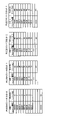
図1は、PUCCHリソースの割り当ての一例を示す図である。図1では、一例として、K=4であり、4個のPUCCHリソースセット#0-#3が無線基地局からユーザ端末に上位レイヤシグナリングにより設定(configure)されるものとする。また、PUCCHリソースセット#0-#3は、それぞれ、M(例えば、8≦M≦32)個のPUCCHリソース#0-#M-1を含むものとする。なお、各PUCCHリソースセットが含むPUCCHリソースの数は、同一であってもよいし、異なってもよい。
FIG. 1 is a diagram illustrating an example of PUCCH resource allocation. In FIG. 1, as an example, K=4 and four PUCCH
図1に示すように、ユーザ端末に対してPUCCHリソースセット#0~#3が設定される場合、ユーザ端末は、UCIペイロードサイズに基づいていずれかのPUCCHリソースセットを選択する。
As shown in FIG. 1, when PUCCH
例えば、UCIペイロードサイズが1又は2ビットである場合、PUCCHリソースセット#0が選択される。また、UCIペイロードサイズが3ビット以上N2-1ビット以下である場合、PUCCHリソースセット#1が選択される。また、UCIペイロードサイズがN2ビット以上N3-1ビット以下である場合、PUCCHリソースセット#2が選択される。同様に、UCIペイロードサイズがN3ビット以上N3-1ビット以下である場合、PUCCHリソースセット#3が選択される。For example, if the UCI payload size is 1 or 2 bits, PUCCH
このように、PUCCHリソースセット#i(i=0,…,K-1)が選択されるUCIペイロードサイズの範囲は、Niビット以上Ni+1-1ビット以下(すなわち、{Ni,…,Ni+1-1}ビット)と示される。Thus, the range of UCI payload sizes for which PUCCH resource set #i (i = 0, ..., K-1) is selected is N i bits or more and N i + 1 -1 bits or less (that is, {N i , ..., N i+1 −1} bits).
ここで、PUCCHリソースセット#0、#1用のUCIペイロードサイズの開始位置(開始ビット数)N0、N1は、それぞれ、1、3であってもよい。これにより、2ビット以下のUCIを送信する場合にPUCCHリソースセット#0が選択されるので、PUCCHリソースセット#0は、PF0及びPF1の少なくとも一つ用のPUCCHリソース#0~#M-1を含んでもよい。一方、2ビットを超えるUCIを送信する場合にはPUCCHリソースセット#1~#3のいずれかが選択されるので、PUCCHリソースセット#1~#3は、それぞれ、PF2、PF3及びPF4の少なくとも一つ用のPUCCHリソース#0~#M-1を含んでもよい。Here, the starting position (number of starting bits) N 0 and N 1 of the UCI payload size for PUCCH resource sets #0 and #1 may be 1 and 3, respectively. As a result, PUCCH
NRでは、PDSCHをスケジュールするDCIを利用して当該PDSCHに対するHARQ-ACKの送信タイミング(例えば、K1)をUEに通知する。K1は、PUCCHリソースが設定されるスロットに関する情報であってもよい。 In NR, the DCI that schedules the PDSCH is used to notify the UE of the HARQ-ACK transmission timing (eg, K1) for the PDSCH. K1 may be information about slots in which PUCCH resources are configured.
UEは、基地局から通知されるPUCCHリソースセットと、PDSCHをスケジュールするDCIで通知されるHARQ-ACKの送信タイミングに基づいてHARQ-ACKの送信を制御する。HARQ-ACKの送信は、HARQ-ACKコードブックを利用して(HARQ-ACKコードブック単位)で制御される。 The UE controls HARQ-ACK transmission based on the PUCCH resource set notified from the base station and the HARQ-ACK transmission timing notified by the DCI that schedules the PDSCH. HARQ-ACK transmission is controlled using a HARQ-ACK codebook (per HARQ-ACK codebook).
各PDSCHに対するHARQ-ACK送信タイミングがDCIで柔軟に設定可能であるため、異なるスロットで送信されるPDSCHに対するHARQ-ACKの送信タイミングが同じスロットに設定されるケースも生じる(図2参照)。 Since the HARQ-ACK transmission timing for each PDSCH can be flexibly set by DCI, there is a case where the transmission timing of HARQ-ACK for PDSCHs transmitted in different slots is set in the same slot (see FIG. 2).
図2では、スロット(SL#1)で送信されるPDSCHに対するHARQ-ACK#1と、スロット(SL#3)で送信されるPDSCHに対するHARQ-ACK#2の送信タイミングが同じスロット(ここでは、スロット(SL#7))に設定される場合を示している。例えば、PDSCH#1をスケジューリングするDCI#1に含まれるK1=6、PDSCH#2をスケジューリングするDCI#2に含まれるK1=4であった場合、HARQ-ACK#1及びHARQ-ACK#2の送信タイミングが同じスロット(SL#7)に設定される。
In FIG. 2, HARQ-
かかる場合、HARQ-ACK#1とHARQ-ACK#2の送信をどのように制御するかが問題となる。例えば、各スロットにおいてHARQ-ACK送信に利用するPUCCHリソースを制限(例えば、1つのPUCCHリソースに制限)することが考えられる。図2に示す例では、DCI#1のPUCCHリソースインディケータがスロット先頭の2シンボルを指示し、もう1つのDCI#2のPUCCHリソースインディケータがスロット最後尾の2シンボルを指示している。この場合、最後のDCI#2のPUCCHリソースインディケータによって示されたPUCCHリソースを用いて、2つのHARQ-ACK#1とHARQ-ACK#2を送信することができる。
In such a case, the problem is how to control the transmission of HARQ-
ところで、NRでは、あるUEが、要求条件の異なる複数のサービス(例えば、URLLC(Ultra Reliable and Low Latency Communications)及びeMBB(enhanced Mobile Broad Band)など)に関連する複数の通信(トラフィックタイプの異なる複数の通信)を行うことが想定される。 By the way, in NR, a certain UE performs multiple communications (multiple traffic types with different communication).
特に、3GPP Rel.16(NR Rel.16、5G+等ともいう)では、URLLCの要求条件の拡張(enhancement)(例えば、信頼性及び遅延に対してRel.15よりも厳しい要求条件が課されることが)が想定される。URLLCでは、HARQ-ACKの送信タイミングのフレキシブル化、又はHARQ-ACKの低遅延化等が要求されるが、どのように制御するかについて十分に検討されていない。In particular, 3GPP Rel. 16 (also referred to as NR Rel. 16, 5G + , etc.), enhancements to the URL LLC requirements (e.g., more stringent requirements for reliability and delay than Rel. 15 are imposed) is assumed. In URLLLC, flexible transmission timing of HARQ-ACK, low delay of HARQ-ACK, etc. are required, but how to control them has not been sufficiently studied.
そこで、本発明者らは、1つのスロットにおいて異なる複数の上り制御チャネルリソースが割当てられる際に、当該複数の上り制御チャネルリソースを利用した送信方法を検討し、本願発明に至った。 Therefore, the present inventors studied a transmission method using a plurality of different uplink control channel resources when one slot is allocated with a plurality of uplink control channel resources, and arrived at the present invention.
以下、本開示の一実施形態について、図面を参照して詳細に説明する。 An embodiment of the present disclosure will be described in detail below with reference to the drawings.
(第1の態様)
第1の態様は、下り共有チャネル(PDSCH)のスケジュールに利用される下り制御情報(DCI)に基づいて、下り共有チャネル(PDSCH)に対する送達確認信号(HARQ-ACK)の送信タイミングを、1スロットより短い所定数のシンボル単位(ユニット)で決定する。そして、下り制御情報で指定される上り制御チャネルリソースに基づいて送達確認信号を送信してもよい。基地局は、HARQ-ACKの送信タイミングを1スロットより短い所定数のシンボル単位(ユニット)で指定するフィールドを含んだDCIをユーザ端末に対して送信してもよい。(First aspect)
In a first aspect, the transmission timing of the acknowledgment signal (HARQ-ACK) for the downlink shared channel (PDSCH) is set to 1 slot based on the downlink control information (DCI) used for the schedule of the downlink shared channel (PDSCH). Determined by a predetermined number of shorter symbol units (units). Then, the acknowledgment signal may be transmitted based on the uplink control channel resource designated by the downlink control information. The base station may transmit to the user terminal DCI including a field designating the transmission timing of HARQ-ACK in units of a predetermined number of symbols shorter than one slot.
上記した通り、NRでは、PDSCHに対するHARQ-ACKの送信タイミングを、当該PDSCHをスケジューリングするDCIでUEに指定する。具体的には、DCIに含まれる所定フィールド(HARQ-ACKフィードバックタイミング)において、HARQ-ACKのフィードバックに用いるスロットが指定される。 As described above, in NR, the timing of HARQ-ACK transmission for the PDSCH is specified to the UE by the DCI that schedules the PDSCH. Specifically, a slot to be used for HARQ-ACK feedback is specified in a predetermined field (HARQ-ACK feedback timing) included in DCI.
第1の態様は、HARQ-ACKの送信タイミングを指定する時間単位として、1スロットよりも粒度が小さい時間単位(以下、ユニットと呼ぶ)が用いられる。DCIにセットされたパラメータK1によって、PDSCHに対するHARQ-ACKを送信するユニットを指示できる。 In the first mode, a time unit (hereinafter referred to as a unit) having a granularity smaller than one slot is used as the time unit for designating the transmission timing of HARQ-ACK. A parameter K1 set in the DCI may indicate the unit sending HARQ-ACK for the PDSCH.
図3には、粒度が7シンボルのユニットが適用されたHARQ-ACK送信タイミングの例が示されている。本例では、DCIによってスケジュールされたPDSCHの次のユニットからカウントを開始している。また、ユニットのサイズは1スロットを2分割する7シンボルである。この場合、7シンボル毎にユニット番号が増加する。図3に示す例では、ユーザ端末は、スロット(SL#l)においてDCI#1でスケジューリングされるPDSCH#1を受信し、スロット(SL#3)においてDCI#2でスケジューリングされるPDSCH#2を受信している。また、DCI#1でスケジューリングされるPDSCH#1の次のユニット番号はnであるとする。
FIG. 3 shows an example of HARQ-ACK transmission timing where a unit with a granularity of 7 symbols is applied. In this example, the count starts from the next unit of PDSCH scheduled by DCI. Also, the size of the unit is 7 symbols that divide one slot into two. In this case, the unit number increases every 7 symbols. In the example shown in FIG. 3 , the user terminal receives
DCI#1は、PDSCH#1をスケジュールしていて、DCI#1にセットされたパラメータK1(=11)によって、PDSCH#1に対するHARQ-ACKを送信するユニット(=n+10)を指示している。DCI#2は、PDSCH#2をスケジュールしていて、DCI#2にセットされたパラメータK1(=8)によって、PDSCH#2に対するHARQ-ACKを送信するユニット(=n+11)を指示している。本例では、DCI#1とDCI#2が同じスロット(SL#7)を指示している。
さらに、DCI#1に含まれるPUCCHインディケータフィールドはPUCCHリソース#1を指示しており、DCI#2に含まれるPUCCHインディケータフィールドはPUCCHリソース#2を指示している。PUCCHリソース#1は、スロット(SL#7)の先頭2シンボルが割り当てられていて、PUCCHリソース#2は、スロット(SL#7)の最終2シンボルが割り当てられている。
Furthermore, the PUCCH indicator field included in
図4を参照して、DCIの次のユニットからカウントを開始する例について説明する。また、ユニットの粒度は7シンボルの例を示している。ユーザ端末は、スロット(SL#l)においてDCI#1でスケジューリングされるPDSCH#1を受信し、スロット(SL#3)においてDCI#2でスケジューリングされるPDSCH#2を受信している。また、DCI#1の次のユニット番号はnであるとする。なお、カウントを開始するタイミングは、これに限られない。例えば、当該DCIが含まれるユニットからカウントを開始してもよい。
An example of starting counting from the unit next to DCI will be described with reference to FIG. Also, the granularity of the unit shows an example of 7 symbols. The user terminal receives
DCI#1は、PDSCH#1をスケジュールしていて、DCI#1にセットされたパラメータK1(=13)によって、PDSCH#1に対するHARQ-ACKを送信するユニット(=n+12)を指示している。DCI#2は、PDSCH#2をスケジュールしていて、DCI#2にセットされたパラメータK1(=10)によって、PDSCH#2に対するHARQ-ACKを送信するユニット(=n+13)を指示している。本例では、DCI#1とDCI#2が同じスロット(SL#7)を指示している。
HARQ-ACKの送信タイミングを指定する時間単位としてのユニットの粒度はPDSCHの長さ(時間領域)に基づいて決定することができる。ユニットの粒度はスケジュールされるPDSCHの長さに応じて動的に切り替えることができる。例えば、PDSCHに割り当てられるシンボル数(N)が7シンボルよりも少ない場合(N<7)、シンボル数(N)の2倍の粒度をユニットに適用することができる。一方、PDSCHに割り当てられるシンボル数(N)が7シンボルよりも大きい場合(N≧7)、PDSCHのシンボル数(N)と同じ粒度をユニットに適用することができる。HARQ-ACKの送信タイミングを指定するユニットの粒度は、パラメータK1の粒度と呼ぶことができる。 The granularity of the unit as a unit of time specifying the transmission timing of HARQ-ACK can be determined based on the PDSCH length (time domain). The unit granularity can be switched dynamically depending on the length of the scheduled PDSCH. For example, if the number of symbols (N) allocated to the PDSCH is less than 7 symbols (N<7), a granularity of twice the number of symbols (N) can be applied to the unit. On the other hand, if the number of symbols (N) allocated to PDSCH is greater than 7 symbols (N≧7), the same granularity as the number of symbols (N) of PDSCH can be applied to the unit. The granularity of the unit specifying the transmission timing of HARQ-ACK can be called the granularity of parameter K1.
このように、HARQ-ACKの送信タイミングを指定する時間単位として1スロットよりも粒度が小さいユニットを用いることにより、スロット単位であれば同じスロットが指定されるところ、異なるユニットを指定できるようになる。これにより、HARQ-ACKの送信タイミングを、1スロットよりも短い所定数のシンボル単位で指定できるので、送信タイミングとして1スロットの粒度を適用する場合に比べて、HARQ-ACK#2の送信タイミングが衝突する確率が低減され、HARQ-ACKの送信タイミングが柔軟に設定される。 In this way, by using a unit with a granularity smaller than one slot as the time unit for specifying the transmission timing of HARQ-ACK, it becomes possible to specify a different unit instead of the same slot being specified in slot units. . As a result, the transmission timing of HARQ-ACK can be specified in units of a predetermined number of symbols that are shorter than one slot. The probability of collision is reduced and the transmission timing of HARQ-ACK is set flexibly.
あるいは、PUCCHリソースの指定に利用されるPUCCHリソースセット(例えば、PUCCHリソースセット1以降)に含まれるPUCCHリソース候補の数を所定値より多くなるように定義してもよい。所定値としては、例えば8であってもよい。また、DCIに含まれるPUCCHリソース通知フィールドのビット数も3ビットより多くなるように設定してもよい。つまり、本実施の形態に示すように1スロットにおいて複数のPUCCHリソースをサポートする第1構成において、既存のメカニズム(1スロットにおいて1つのPUCCHリソースのみサポートする第2構成)のPUCCHリソースセット(例えば、PUCCHリソースセット1以降)の候補数8より多くなるように設定する。これにより、1スロットに複数のPUCCHリソースをサポートする構成において、PUCCHリソースをより詳細に設定することができる。 Alternatively, the number of PUCCH resource candidates included in PUCCH resource sets (for example, PUCCH resource set 1 and later) used for specifying PUCCH resources may be defined to be greater than a predetermined value. The predetermined value may be 8, for example. Also, the number of bits of the PUCCH resource notification field included in DCI may be set to be more than 3 bits. That is, in the first configuration that supports multiple PUCCH resources in one slot as shown in this embodiment, the existing mechanism (second configuration that supports only one PUCCH resource in one slot) PUCCH resource set (for example, PUCCH resource set 1 or later) is set so that the number of candidates is greater than 8. This allows more detailed configuration of PUCCH resources in a configuration that supports multiple PUCCH resources in one slot.
ユーザ端末は、上位レイヤシグナリングを用いて複数のPUCCHリソースセットが設定される。1つのPUCCHリソースセットには複数のPUCCHリソースの中から1つのPUCCHリソースを選択可能に構成されている。例えば、所定ビットで表現されるPUCCHリソース指定フィールド(ARI)に対してビット数に応じた数のPUCCHリソース(PUCCHリソースID)が規定される。ユーザ端末は、1つのPUCCHリソースセットにおいてDCIで指定されたARIに対応したPUCCHリソースを選択できる。 A user terminal is configured with multiple PUCCH resource sets using higher layer signaling. One PUCCH resource set is configured so that one PUCCH resource can be selected from a plurality of PUCCH resources. For example, a number of PUCCH resources (PUCCH resource IDs) corresponding to the number of bits are defined for a PUCCH resource designation field (ARI) expressed in predetermined bits. A user terminal can select PUCCH resources corresponding to ARIs specified by DCI in one PUCCH resource set.
既存のメカニズム(上記第2構成)では、PUCCHリソース指定フィールドのARIを3ビットで表現し、8つのPUCCHリソース候補の中から1つのPUCCHリソースを選択可能に構成する。これに対して、上記第1構成では、PUCCHリソース指定フィールドのARIを4ビット以上で表現し、8つを超えるPUCCHリソース候補を含むPUCCHリソースセットの中からそれぞれ1スロットに設定される2以上のPUCCHリソースを選択可能に構成する。 In the existing mechanism (second configuration above), the ARI of the PUCCH resource designation field is represented by 3 bits, and one PUCCH resource can be selected from eight PUCCH resource candidates. On the other hand, in the first configuration, the ARI of the PUCCH resource designation field is represented by 4 bits or more, and 2 or more set in 1 slot from the PUCCH resource set including more than 8 PUCCH resource candidates. Configure PUCCH resources to be selectable.
図5は第1構成において適用可能なテーブル構成を示している。4つのPUCCHリソースセット0からPUCCHリソースセット3が設定されるケースを想定している。PUCCHリソースセット0は、PUCCHリソース指定フィールドが5ビットで構成されていて、32個のPUCCHリソース候補が設定されている。PUCCHリソースセット1~3は、PUCCHリソース指定フィールドが4ビットで構成されていて、16個のPUCCHリソース候補が設定されている。第1構成では1スロットで複数のPUCCHリソースがサポートされるので、第2構成に比べてPUCCHリソース候補数が増加されている。 FIG. 5 shows a table configuration applicable in the first configuration. A case is assumed in which four PUCCH resource sets 0 to 3 are configured. In PUCCH resource set 0, the PUCCH resource designation field is composed of 5 bits, and 32 PUCCH resource candidates are set. In PUCCH resource sets 1 to 3, the PUCCH resource designation field is composed of 4 bits, and 16 PUCCH resource candidates are set. Since multiple PUCCH resources are supported in one slot in the first configuration, the number of PUCCH resource candidates is increased compared to the second configuration.
上記第1構成に対応したPUCCHリソースセットと、上記第2構成に対応したPUCCHリソースセットとを共に設定し、サービスタイプに応じて切り替えても良い。例えば、超高信頼低遅延のサービスタイプであるURLLC(Ultra-Reliable and Low Latency Communications)と、高速大容量のサービスタイプであるeMBB(enhanced Mobile BroadBand)とがある。URLLCを第1のサービスタイプと呼び、eMBBを第2のサービスタイプと呼ぶこととする。 A PUCCH resource set corresponding to the first configuration and a PUCCH resource set corresponding to the second configuration may be set together and switched according to the service type. For example, there are URLLC (Ultra-Reliable and Low Latency Communications), which is an ultra-reliable and low-delay service type, and eMBB (enhanced Mobile Broadband), which is a high-speed, large-capacity service type. Let us refer to URLLC as the first service type and eMBB as the second service type.
URLLCに対応するサービスタイプ(又は、トラフィックタイプ)と、eMBBに対応するサービスタイプは、以下の少なくとも一つに基づいて識別されてもよい。
・異なる優先度(priority)を有する論理チャネル
・変調及び符号化方式(MCS:Modulation and Coding Scheme)テーブル(MCSインデックステーブル)
・DCIフォーマット
・当該DCI(DCIフォーマット)に含まれる(付加される)巡回冗長検査(CRC:Cyclic Redundancy Check)ビットのスクランブル(マスク)に用いられる(無線ネットワーク一時識別子(RNTI:System Information-Radio Network Temporary Identifier))
・RRC(Radio Resource Control)パラメータ
・特定のRNTI(例えば、URLLC用のRNTI、MCS-C-RNTI等)
・サーチスペース
・DCI内の所定フィールド(例えば、新たに追加されるフィールド又は既存のフィールドの再利用)A service type (or traffic type) corresponding to URLLC and a service type corresponding to eMBB may be identified based on at least one of the following.
Logical channels with different priorities Modulation and Coding Scheme (MCS) table (MCS index table)
-DCI format -Used to scramble (mask) cyclic redundancy check (CRC: Cyclic Redundancy Check) bits included in (added to) the DCI (DCI format) (radio network temporary identifier (RNTI: System Information-Radio Network Temporary Identifier))
・RRC (Radio Resource Control) parameters ・Specific RNTI (for example, RNTI for URLLC, MCS-C-RNTI, etc.)
- Search Space - Predetermined fields in the DCI (e.g. newly added fields or re-use of existing fields)
例えば、UEは、上記条件(例えば、DCIに適用されるRNTI(Radio Network Temporary Identifier)、変調及び符号化テーブル、及び送信パラメータの少なくとも一つ)に基づいて、URLLCであるかeMBBであるかを判断してもよい。例えば、URLLCと判断した場合、UEは、HARQ-ACKの送信タイミングを指定する時間単位として、1スロットよりも粒度が小さい時間単位を適用してもよい。 For example, the UE, based on the above conditions (eg, RNTI (Radio Network Temporary Identifier) applied to DCI, modulation and coding table, and at least one of transmission parameters), whether URLLLC or eMBB You can judge. For example, when determining URLLC, the UE may apply a time unit with a granularity smaller than one slot as the time unit for designating the transmission timing of HARQ-ACK.
第1構成に対応したPUCCHリソースセットは第1のサービスタイプ(URLLC)に適用し、第2構成に対応したPUCCHリソースセットはeMBBに適用する。または、第1構成に対応したPUCCHリソースセットのうち、所定数(例えば、8つのPUCCHリソース候補)は、第1のサービスタイプと第2のサービスタイプで共用する。例えば、図5に示すPUCCHリソースセット1の場合であれば、ARI=0000~0111までは、8つのPUCCHリソース候補を第1のサービスタイプと第2のサービスタイプで共用する。そして、ARI=0111~1111で指定される残りのPUCCHリソース候補は第1のサービスタイプにのみ適用する。 The PUCCH resource set corresponding to the first configuration applies to the first service type (URLLC), and the PUCCH resource set corresponding to the second configuration applies to eMBB. Alternatively, a predetermined number (for example, eight PUCCH resource candidates) of the PUCCH resource set corresponding to the first configuration are shared between the first service type and the second service type. For example, in the case of PUCCH resource set 1 shown in FIG. 5, 8 PUCCH resource candidates are shared between the first service type and the second service type from ARI=0000 to 0111. And the remaining PUCCH resource candidates specified by ARI=0111 to 1111 apply only to the first service type.
また、上記第1構成に対応したPUCCHリソースセットと、上記第2構成に対応したPUCCHリソースセットのいずれを適用するかを上位レイヤシグナリングで設定しても良い。 Also, which of the PUCCH resource set corresponding to the first configuration and the PUCCH resource set corresponding to the second configuration is to be applied may be set by higher layer signaling.
(第2の態様)
第2の態様は、所定スロットに設定される複数のPUCCHと、PUSCHとが重複する場合、複数のPUCCHにそれぞれ割当てられるHARQ-ACKのうち少なくとも一部のHARQ-ACKがPUSCHを利用して送信される。(Second aspect)
In the second aspect, when a plurality of PUCCHs set in a predetermined slot and the PUSCH overlap, at least some of the HARQ-ACKs assigned to the plurality of PUCCHs are transmitted using the PUSCH. be done.
1スロットにおいて異なるHARQ-ACK送信用に複数のPUCCHが指定されるケースが想定される。さらに、これら複数のPUCCHがPUSCHと重複する(衝突)ケースが想定される。 A case is assumed in which multiple PUCCHs are designated for different HARQ-ACK transmissions in one slot. Furthermore, a case where these multiple PUCCHs overlap with PUSCH (collision) is assumed.
かかる状況において、第2の態様は、全てのPUCCH上の複数のHARQ-ACKを、1つのHARQ-ACKコードブックにセットして、PUSCH上に多重して送信する(ピギーバック)。例えば、図6Aに示すように、同じスロットにおいて異なるHARQ-ACK#1、#2の送信タイミングが指定され、HARQ-ACK#1、#2の送信に指定されたPUCCH#1、#2と、PUSCHとが時間領域において重複している。
In such a situation, the second mode sets multiple HARQ-ACKs on all PUCCHs to one HARQ-ACK codebook and multiplexes and transmits them on PUSCH (piggyback). For example, as shown in FIG. 6A, different transmission timings of HARQ-
第2の態様は、HARQ-ACK#1、#2を1つのHARQ-ACKコードブック(CB0)にセットし、PUSCH上の所定リソースに多重して送信する。また、異なるHARQ-ACK#1、#2を各々のHARQ-ACKコードブック(CB0、CB1)にセットし、それらをPUSCH上の所定リソースに多重しても良い(図6B参照)。
In the second mode, HARQ-
また、全てのPUCCH上のHARQ-ACKをPUSCHに多重するのではなく、1部(1つ又はいくつか)のPUCCH上のHARQ-ACKをPUSCHに多重し、残りはドロップすることもできる。 Also, instead of multiplexing all HARQ-ACKs on PUCCH to PUSCH, one part (one or several) of HARQ-ACKs on PUCCH can be multiplexed to PUSCH and the rest can be dropped.
いずれのPUCCH上のHARQ-ACKをPUSCHに多重するか所定ルールに基づいて決定することができる。例えば、1スロット内に指定されたPUCCHのうち最も時間が早いPUCCHだけを選択する(ルール1)。または、HARQ-ACKの数が最も大きいPUCCHを選択する(ルール2)。または、コーディングレートが所定値(例えば最大値)になるまで所定順序でPUCCHを選択する(ルール3)。ルール3の場合、所定順序はルール1又はルール2にしたがって決めても良い。
Which HARQ-ACK on PUCCH is multiplexed on PUSCH can be determined based on a predetermined rule. For example, among PUCCHs specified in one slot, only the PUCCH with the earliest time is selected (Rule 1). Alternatively, select the PUCCH with the largest number of HARQ-ACKs (Rule 2). Alternatively, PUCCHs are selected in a predetermined order until the coding rate reaches a predetermined value (for example, maximum value) (Rule 3). For
第2の態様において、PUSCHにおいてPUCCHが衝突したシンボルに、当該PUCCH上のHARQ-ACKを多重することができる。図6Cに示す例では、PUSCHとPUCCH#1とシンボルSBx(1以上のシンボル)において衝突している。したがって、PUCCH#1上のHARQ-ACK#1はシンボルSBxに多重する。
In the second aspect, it is possible to multiplex HARQ-ACK on PUCCH on a symbol with which PUCCH collides on PUSCH. In the example shown in FIG. 6C, PUSCH and
また、PUSCHにおいてPUCCHが衝突したシンボルにおいてDMRSが配置されていれば、HARQ-ACKは次のシンボルに多重してもよい。 Also, if a DMRS is arranged in a symbol in which PUCCH collides in PUSCH, HARQ-ACK may be multiplexed in the next symbol.
また、所定スロットに設定される複数のPUCCHと、PUSCHとが重複する場合、PUSCHをドロップしても良い。ドロップしたPUSCHがUCIを含んでいる場合、少なくともHARQ-ACKは衝突した最後又は最初のPUCCHに多重して送信してもよい。 Also, when PUSCH overlaps with a plurality of PUCCHs configured in a predetermined slot, PUSCH may be dropped. If the dropped PUSCH contains UCI, at least HARQ-ACK may be multiplexed to the last or first collided PUCCH and transmitted.
また、所定スロットに設定される複数のPUCCHと、PUSCHとが重複する場合、エラーケースの対応を取ることができる。例えば、エラーケースでは、エラーを通知するか、または何も通知しない。 In addition, when a plurality of PUCCHs set in a predetermined slot and PUSCH overlap, it is possible to take measures for error cases. For example, in the error case, signal an error or nothing.
また、所定スロットに設定される複数のPUCCHと、PUSCHとが重複する場合、各PUCCHのサイズが最大2ビットである場合にのみ、PUCCHを用いたHARQ-ACKの送信を認めてもよい。このとき、PUSCHにおいてPUCCHと衝突するリソースはパンクチャしてもよい。データをパンクチャ処理するとは、データ用に割り当てられたリソースを使えることを想定して(又は、使用できないリソース量を考慮しないで)符号化を行うが、実際に利用できないリソース(例えば、UCI用リソース)に符号化シンボルをマッピングしない(リソースを空ける)ことをいう。つまり、マッピングされた上りデータの符号系列にUCIを上書きする。受信側では、当該パンクチャされたリソースの符号化シンボルを復号に用いないようにすることで、パンクチャによる特性劣化を抑制することができる。 Also, when a plurality of PUCCHs configured in a predetermined slot overlap with PUSCH, HARQ-ACK transmission using PUCCH may be permitted only when the size of each PUCCH is 2 bits at maximum. At this time, resources in PUSCH that collide with PUCCH may be punctured. Puncturing data means that encoding is performed on the assumption that resources allocated for data can be used (or without considering the amount of resources that cannot be used), but resources that are not actually available (for example, resources for UCI ) is not mapped (to free resources). That is, the UCI is overwritten on the mapped code sequence of the uplink data. On the receiving side, by not using the coded symbols of the punctured resource for decoding, it is possible to suppress characteristic deterioration due to puncturing.
(第3の態様)
第3の態様は、所定スロットに設定される複数のPUCCHが重複(衝突)する場合、それらのPUCCH上の全てのHARQ-ACKを1つのHARQ-ACKコードブックにセットして、いずれか1つのPUCCHを用いて送信する。(Third aspect)
In the third aspect, when multiple PUCCHs set in a predetermined slot overlap (collide), all HARQ-ACKs on those PUCCHs are set to one HARQ-ACK codebook, and any one It transmits using PUCCH.
複数HARQ-ACKの送信に用いられるPUCCHリソースは、UCIのペイロードサイズと、DCIに含まれるARIと、を用いて決定しても良い。ユーザ端末に対してはPUCCHリソースセットが上位レイヤシグナリングにより設定される。UCIペイロードサイズに基づいて、複数のPUCCHリソースセットから単一のPUCCHリソースセットを決定する。そして、決定されたPUCCHリソースセットに含まれるM個のPUCCHリソースから、DCIに含まれるARIに基づいて、PUCCHリソースを決定してもよい。 PUCCH resources used for transmitting multiple HARQ-ACKs may be determined using the payload size of UCI and the ARI included in DCI. A PUCCH resource set is configured for a user terminal by higher layer signaling. A single PUCCH resource set is determined from multiple PUCCH resource sets based on the UCI payload size. Then, from the M PUCCH resources included in the determined PUCCH resource set, PUCCH resources may be determined based on the ARI included in the DCI.
複数HARQ-ACKの送信に用いられるPUCCHリソースとして特別のPUCCHリソースを準備してもよい。特別のPUCCHリソースの情報を上位レイヤシグナリングによってユーザ端末へ通知してもよい。ユーザ端末は、所定スロットに設定される複数のPUCCHが重複(衝突)する場合、それらのPUCCH上の全てのHARQ-ACKを1つのHARQ-ACKコードブックにセットして、特別のPUCCHリソースを用いて送信する。 A special PUCCH resource may be prepared as a PUCCH resource used for transmission of multiple HARQ-ACKs. The information of the special PUCCH resource may be notified to the user terminal by higher layer signaling. When multiple PUCCHs set in a predetermined slot overlap (collide), the user terminal sets all HARQ-ACKs on those PUCCHs to one HARQ-ACK codebook and uses a special PUCCH resource. to send.
また、所定スロットに設定される複数のPUCCHが重複(衝突)する場合、それらのPUCCH上の全てのHARQ-ACKを、異なるHARQ-ACKコードブックにセットして、いずれか1つのPUCCHを用いて送信してもよい。 Also, when multiple PUCCHs set in a predetermined slot overlap (collide), all HARQ-ACKs on those PUCCHs are set to different HARQ-ACK codebooks, and using any one PUCCH You may send.
また、所定スロットに設定される複数のPUCCHが重複(衝突)する場合、一部のHARQ-ACKは1つ又は複数のHARQ-ACKコードブックにセットして、いずれか1つのPUCCHを用いて送信し、残りのHARQ-ACKはドロップしてもよい。いずれのPUCCH上のHARQ-ACKを残すかは第2の態様に示した所定ルールを適用することができる。 Also, when multiple PUCCHs set in a given slot overlap (collide), some HARQ-ACKs are set in one or more HARQ-ACK codebooks and transmitted using any one of the PUCCHs. and the remaining HARQ-ACKs may be dropped. The predetermined rule shown in the second aspect can be applied to determine which HARQ-ACK on PUCCH is left.
また、所定スロットに設定される複数のPUCCHとPUSCH(又はロングPUCCH)とが衝突した場合の動作を規定した第2の態様と、所定スロットに設定される複数のPUCCHが衝突した場合の動作を規定した第3の態様と、をサービスタイプ(URLLCとeMBB)に応じて切り替えても良い。 In addition, a second aspect that defines the operation when multiple PUCCH and PUSCH (or long PUCCH) set in a predetermined slot collide, and the operation when multiple PUCCH set in a predetermined slot collide You may switch according to a service type (URLLC and eMBB) with the stipulated 3rd aspect.
次に、所定スロットに設定される複数のPUCCHと、UCIを含んだロングPUCCHとが衝突する場合のHARQ-ACK送信について説明する。 Next, HARQ-ACK transmission when a plurality of PUCCHs set in predetermined slots and a long PUCCH including UCI collide will be described.
1スロットにおいて異なるHARQ-ACK送信用に複数のPUCCHが指定され、さらに、これら複数のPUCCHがロングPUCCHと重複する(衝突)場合を想定する。 Assume that multiple PUCCHs are designated for different HARQ-ACK transmissions in one slot, and these multiple PUCCHs overlap (collide) with the long PUCCH.
かかる状況において、全てのPUCCH上の複数のHARQ-ACKを、1つのHARQ-ACKコードブックにセットして、ロングPUCCH上に多重して送信する(ピギーバック)。また、異なるHARQ-ACK#1、#2を各々のHARQ-ACKコードブック(CB0、CB1)にセットし、それらをロングPUCCH上の所定リソースに多重しても良い。
In such a situation, multiple HARQ-ACKs on all PUCCHs are set in one HARQ-ACK codebook and multiplexed and transmitted on long PUCCH (piggyback). Alternatively, different HARQ-
また、全てのPUCCH上のHARQ-ACKをロングPUCCHに多重するのではなく、1部(1つ又はいくつか)のPUCCH上のHARQ-ACKをロングPUCCHに多重し、残りはドロップすることもできる。 Also, instead of multiplexing all HARQ-ACKs on PUCCH to long PUCCH, it is also possible to multiplex part (one or several) HARQ-ACKs on PUCCH to long PUCCH and drop the rest. .
いずれのPUCCH上のHARQ-ACKをロングPUCCHに多重するか所定ルールに基づいて決定することができる(第2の態様のルール1から3を参照)。
Which HARQ-ACK on which PUCCH is to be multiplexed to the long PUCCH can be determined based on predetermined rules (see
ロングPUCCHにおいてPUCCHが衝突したシンボルに、当該PUCCH上のHARQ-ACKを多重することができる。また、ロングPUCCHにおいてPUCCHが衝突したシンボルにおいてDMRSが配置されていれば、HARQ-ACKは次のシンボルに多重してもよい。また、ドロップしたロングPUCCHがUCIを含んでいる場合、少なくともHARQ-ACKは衝突した最後又は最初のPUCCHに多重してもよい。または、すべてのUCIをドロップしてもよい。 HARQ-ACK on the PUCCH can be multiplexed on symbols with which the PUCCH collides in the long PUCCH. Also, if a DMRS is assigned to a symbol in which PUCCH collides in long PUCCH, HARQ-ACK may be multiplexed in the next symbol. Also, if the dropped long PUCCH contains UCI, at least HARQ-ACK may be multiplexed to the last or first collided PUCCH. Alternatively, all UCIs may be dropped.
また、所定スロットに設定される複数のPUCCHと、ロングPUCCHとが重複する場合、ロングPUCCHをドロップしても良い。ドロップしたロングPUCCHがUCIを含んでいる場合、少なくともHARQ-ACKは衝突した最後又は最初のPUCCHに多重して送信してもよい。 Also, when a plurality of PUCCHs configured in a predetermined slot overlap with a long PUCCH, the long PUCCH may be dropped. If the dropped long PUCCH contains UCI, at least HARQ-ACK may be multiplexed to the last or first collided PUCCH and transmitted.
また、所定スロットに設定される複数のPUCCHと、ロングPUCCHとが重複する場合、エラーケースの対応を取ることができる。例えば、エラーケースでは、エラーを通知するか、または何も通知しない。 In addition, when a plurality of PUCCHs configured in a predetermined slot and a long PUCCH overlap, it is possible to take measures for error cases. For example, in the error case, signal an error or nothing.
また、所定スロットに設定される複数のPUCCHと、ロングPUCCHとが重複する場合、各PUCCHのサイズが最大2ビットである場合にのみ、PUCCHを用いたHARQ-ACKの送信を認めてもよい。このとき、ロングPUCCHにおいてPUCCHと衝突するリソースはパンクチャしてもよい。 Also, when a plurality of PUCCHs configured in a predetermined slot overlap with a long PUCCH, transmission of HARQ-ACK using PUCCH may be permitted only when the size of each PUCCH is 2 bits at maximum. At this time, resources that collide with PUCCH in long PUCCH may be punctured.
(第4の態様)
第4の態様は、所定スロットに設定される複数のPUCCHリソースが衝突する場合に、それら複数のPUCCHリソースのうち時間的に最も早いPUCCHリソース(PUCCHリソースA)と、PUCCHリソースAに衝突するPUCCHリソース(PUCCHリソースB)とに含まれる複数HARQ-ACKを1つのHARQ-ACKコードブックにセットして、PUCCHリソースAおよびPUCCHリソースBを指示するDCIのうち時間的に最も遅いDCIが指示するPUCCHリソースに多重する。PUCCHリソースBは複数のPUCCHリソースでもよい。(Fourth aspect)
In the fourth aspect, when a plurality of PUCCH resources set in a predetermined slot collide, the PUCCH resource (PUCCH resource A) that is the earliest in time among the plurality of PUCCH resources and the PUCCH that collides with PUCCH resource A Multiple HARQ-ACKs included in the resource (PUCCH resource B) are set in one HARQ-ACK codebook, and the PUCCH indicated by the DCI that indicates the PUCCH resource A and the PUCCH resource B that is the slowest in terms of time Multiplexing resources. PUCCH resource B may be multiple PUCCH resources.
ユーザ端末は、DCIで通知されるHARQ-ACKの送信タイミング(スロット)が同じであり、かつ、スロット内で時間方向に最初に割当てられるHARQ-ACK用のPUCCHリソースと、他のPUCCHリソースとが衝突する場合、複数HARQ-ACKを1つのHARQ-ACKコードブックにセットしてまとめて所定リソースから送信される。所定のPUCCHリソースは、例えば、ユーザ端末が検出した最後のDCIフォーマットに基づいて決定したPUCCHリソースであってもよい。 The user terminal has the same HARQ-ACK transmission timing (slot) notified by DCI, and the PUCCH resource for HARQ-ACK that is allocated first in the time direction within the slot and the other PUCCH resource. In case of collision, multiple HARQ-ACKs are set in one HARQ-ACK codebook and sent together from a given resource. The predetermined PUCCH resource may be, for example, a PUCCH resource determined based on the last DCI format detected by the user terminal.
図7を参照して、HARQ-ACKコードブックの制御及びPUCCHを用いたHARQ-ACKフィードバックについて説明する。 HARQ-ACK feedback using HARQ-ACK codebook control and PUCCH will be described with reference to FIG.
ユーザ端末は、スロット(SL#1)においてDCI#1でスケジューリングされるPDSCH#1を受信し、スロット(SL#3)においてDCI#2でスケジューリングされるPDSCH#2を受信している。本例では、DCI#1及びDCI#2に関して、DCI#2をユーザ端末が検出する最後のDCIであると解釈する。
The user terminal receives
DCI#1は、PDSCH#1をスケジュールしていて、DCI#1にセットされたパラメータK1(=6)によって、PDSCH#1に対するHARQ-ACKを送信するスロットを指示している。DCI#2は、PDSCH#2をスケジュールしていて、DCI#2にセットされたパラメータK1(=4)によって、PDSCH#2に対するHARQ-ACKを送信するスロットを指示している。本例では、DCI#1とDCI#2が同じスロット(SL#7)を指示している。
さらに、DCI#1に含まれるPUCCHインディケータフィールドはPUCCHリソース#1を指示しており、DCI#2に含まれるPUCCHインディケータフィールドはPUCCHリソース#2を指示している。PUCCHリソース#1は、スロット(SL#7)の先頭2シンボル(例えば、シンボル#0、#1)が割り当てられていて、PUCCHリソース#2は、スロット(SL#7)のシンボル#2、#2が割り当てられている。PUCCHリソース#1は、スロット(SL#7)において最も早いPUCCHリソースである。
Furthermore, the PUCCH indicator field included in
ユーザ端末は、スロット(SL#1)、スロット(SL#3)において、DCI#1、DCI#2をそれぞれ検出し、DCI#1、DCI#2に基づいてPDSCH#1及びPDSCH#2を復調し、PDSCH#1及びPDSCH#2に対するHARQ-ACK#1及びHARQ-ACK#2を決定する。
The user terminal detects
ユーザ端末は、DCI#1、#2で通知されるHARQ-ACKの送信タイミング(例えば、PUCCHリソースが割当てられるスロット)に基づいて、HARQ-ACKコードブックの生成を制御する。具体的には、DCI#1、#2で通知されるHARQ-ACKの送信タイミング(スロット)が同じスロット(SL#7)であることを認識する。さらに、PUCCHリソースにスロット(SL#7)において最も早いPUCCHリソースが含まれていることを認識する。その認識結果を受けて、PDSCH#1及びPDSCH#2に対するHARQ-ACK#1及びHARQ-ACK#2を、同じHARQ-ACKコードブックにセットするためのHARQ-ACKコードブックを生成する。
The user terminal controls the generation of the HARQ-ACK codebook based on the HARQ-ACK transmission timing (for example, slots to which PUCCH resources are allocated) notified by
(無線通信システム)
以下、本開示の一実施形態に係る無線通信システムの構成について説明する。この無線通信システムでは、本開示の上記各実施形態に係る無線通信方法のいずれか又はこれらの組み合わせを用いて通信が行われる。(wireless communication system)
A configuration of a wireless communication system according to an embodiment of the present disclosure will be described below. In this radio communication system, communication is performed using any one of the radio communication methods according to the above embodiments of the present disclosure or a combination thereof.
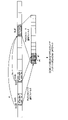
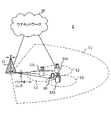
図8は、一実施形態に係る無線通信システムの概略構成の一例を示す図である。無線通信システム1は、3GPP(Third Generation Partnership Project)によって仕様化されるLTE(Long Term Evolution)、5G NR(5th generation mobile communication system New Radio)などを用いて通信を実現するシステムであってもよい。
FIG. 8 is a diagram illustrating an example of a schematic configuration of a radio communication system according to an embodiment. The
また、無線通信システム1は、複数のRAT(Radio Access Technology)間のデュアルコネクティビティ(マルチRATデュアルコネクティビティ(MR-DC:Multi-RAT Dual Connectivity))をサポートしてもよい。MR-DCは、LTE(E-UTRA:Evolved Universal Terrestrial Radio Access)とNRとのデュアルコネクティビィティ(EN-DC:E-UTRA-NR Dual Connectivity)、NRとLTEとのデュアルコネクティビィティ(NE-DC:NR-E-UTRA Dual Connectivity)などを含んでもよい。
The
EN-DCでは、LTE(E-UTRA)の基地局(eNB)がマスターノード(MN:Master Node)であり、NRの基地局(gNB)がセカンダリーノード(SN:Secondary Node)である。NE-DCでは、NRの基地局(gNB)がMNであり、LTE(E-UTRA)の基地局(eNB)がSNである。 In EN-DC, an LTE (E-UTRA) base station (eNB) is a master node (MN: Master Node), and an NR base station (gNB) is a secondary node (SN: Secondary Node). In NE-DC, the NR base station (gNB) is the MN, and the LTE (E-UTRA) base station (eNB) is the SN.
無線通信システム1は、同一のRAT内の複数の基地局間のデュアルコネクティビティ(例えば、MN及びSNの双方がNRの基地局(gNB)であるデュアルコネクティビティ(NN-DC:NR-NR Dual Connectivity))をサポートしてもよい。
The
無線通信システム1は、比較的カバレッジの広いマクロセルC1を形成する基地局11と、マクロセルC1内に配置され、マクロセルC1よりも狭いスモールセルC2を形成する基地局12(12a-12c)と、を備えてもよい。ユーザ端末20は、少なくとも1つのセル内に位置してもよい。各セル及びユーザ端末20の配置、数などは、図に示す態様に限定されない。以下、基地局11及び12を区別しない場合は、基地局10と総称する。
A
ユーザ端末20は、複数の基地局10のうち、少なくとも1つに接続してもよい。ユーザ端末20は、複数のコンポーネントキャリア(CC:Component Carrier)を用いたキャリアアグリゲーション(Carrier Aggregation)及びデュアルコネクティビティ(DC)の少なくとも一方を利用してもよい。
A
各CCは、第1の周波数帯(FR1:Frequency Range 1)及び第2の周波数帯(FR2:Frequency Range 2)の少なくとも1つに含まれてもよい。マクロセルC1はFR1に含まれてもよいし、スモールセルC2はFR2に含まれてもよい。例えば、FR1は、6GHz以下の周波数帯(サブ6GHz(sub-6GHz))であってもよいし、FR2は、24GHzよりも高い周波数帯(above-24GHz)であってもよい。なお、FR1及びFR2の周波数帯、定義などはこれらに限られず、例えばFR1がFR2よりも高い周波数帯に該当してもよい。 Each CC may be included in at least one of a first frequency band (FR1: Frequency Range 1) and a second frequency band (FR2: Frequency Range 2). Macrocell C1 may be included in FR1, and small cell C2 may be included in FR2. For example, FR1 may be a frequency band below 6 GHz (sub-6 GHz), and FR2 may be a frequency band above 24 GHz (above-24 GHz). Note that the frequency bands and definitions of FR1 and FR2 are not limited to these, and for example, FR1 may correspond to a higher frequency band than FR2.
また、ユーザ端末20は、各CCにおいて、時分割複信(TDD:Time Division Duplex)及び周波数分割複信(FDD:Frequency Division Duplex)の少なくとも1つを用いて通信を行ってもよい。
Also, the
複数の基地局10は、有線(例えば、CPRI(Common Public Radio Interface)に準拠した光ファイバ、X2インターフェースなど)又は無線(例えば、NR通信)によって接続されてもよい。例えば、基地局11及び12間においてNR通信がバックホールとして利用される場合、上位局に該当する基地局11はIAB(Integrated Access Backhaul)ドナー、中継局(リレー)に該当する基地局12はIABノードと呼ばれてもよい。
The plurality of
基地局10は、他の基地局10を介して、又は直接コアネットワーク30に接続されてもよい。コアネットワーク30は、例えば、EPC(Evolved Packet Core)、5GCN(5G Core Network)、NGC(Next Generation Core)などの少なくとも1つを含んでもよい。
A
ユーザ端末20は、LTE、LTE-A、5Gなどの通信方式の少なくとも1つに対応した端末であってもよい。
The
無線通信システム1においては、直交周波数分割多重(OFDM:Orthogonal Frequency Division Multiplexing)ベースの無線アクセス方式が利用されてもよい。例えば、下りリンク(DL:Downlink)及び上りリンク(UL:Uplink)の少なくとも一方において、CP-OFDM(Cyclic Prefix OFDM)、DFT-s-OFDM(Discrete Fourier Transform Spread OFDM)、OFDMA(Orthogonal Frequency Division Multiple Access)、SC-FDMA(Single Carrier Frequency Division Multiple Access)などが利用されてもよい。
In the
無線アクセス方式は、波形(waveform)と呼ばれてもよい。なお、無線通信システム1においては、UL及びDLの無線アクセス方式には、他の無線アクセス方式(例えば、他のシングルキャリア伝送方式、他のマルチキャリア伝送方式)が用いられてもよい。
A radio access scheme may be referred to as a waveform. Note that in the
無線通信システム1では、下りリンクチャネルとして、各ユーザ端末20で共有される下り共有チャネル(PDSCH:Physical Downlink Shared Channel)、ブロードキャストチャネル(PBCH:Physical Broadcast Channel)、下り制御チャネル(PDCCH:Physical Downlink Control Channel)などが用いられてもよい。
In the
また、無線通信システム1では、上りリンクチャネルとして、各ユーザ端末20で共有される上り共有チャネル(PUSCH:Physical Uplink Shared Channel)、上り制御チャネル(PUCCH:Physical Uplink Control Channel)、ランダムアクセスチャネル(PRACH:Physical Random Access Channel)などが用いられてもよい。
In the
PDSCHによって、ユーザデータ、上位レイヤ制御情報、SIB(System Information Block)などが伝送される。PUSCHによって、ユーザデータ、上位レイヤ制御情報などが伝送されてもよい。また、PBCHによって、MIB(Master Information Block)が伝送されてもよい。 User data, higher layer control information, SIB (System Information Block), etc. are transmitted by the PDSCH. User data, higher layer control information, and the like may be transmitted by PUSCH. Moreover, MIB (Master Information Block) may be transmitted by PBCH.
PDCCHによって、下位レイヤ制御情報が伝送されてもよい。下位レイヤ制御情報は、例えば、PDSCH及びPUSCHの少なくとも一方のスケジューリング情報を含む下り制御情報(DCI:Downlink Control Information)を含んでもよい。 Lower layer control information may be transmitted by the PDCCH. The lower layer control information may include, for example, downlink control information (DCI) including scheduling information for at least one of PDSCH and PUSCH.
なお、PDSCHをスケジューリングするDCIは、DLアサインメント、DL DCIなどと呼ばれてもよいし、PUSCHをスケジューリングするDCIは、ULグラント、UL DCIなどと呼ばれてもよい。なお、PDSCHはDLデータで読み替えられてもよいし、PUSCHはULデータで読み替えられてもよい。 Note that DCI for scheduling PDSCH may be called DL assignment, DL DCI, etc., and DCI for scheduling PUSCH may be called UL grant, UL DCI, etc. FIG. PDSCH may be replaced with DL data, and PUSCH may be replaced with UL data.
PDCCHの検出には、制御リソースセット(CORESET:COntrol REsource SET)及びサーチスペース(search space)が利用されてもよい。CORESETは、DCIをサーチするリソースに対応する。サーチスペースは、PDCCH候補(PDCCH candidates)のサーチ領域及びサーチ方法に対応する。1つのCORESETは、1つ又は複数のサーチスペースに関連付けられてもよい。UEは、サーチスペース設定に基づいて、あるサーチスペースに関連するCORESETをモニタしてもよい。 A control resource set (CORESET: COntrol REsource SET) and a search space may be used to detect the PDCCH. CORESET corresponds to a resource searching for DCI. A search space corresponds to a search area and search method for PDCCH candidates. A CORESET may be associated with one or more search spaces. The UE may monitor CORESETs associated with certain search spaces based on the search space settings.
1つのSSは、1つ又は複数のアグリゲーションレベル(aggregation Level)に該当するPDCCH候補に対応してもよい。1つ又は複数のサーチスペースは、サーチスペースセットと呼ばれてもよい。なお、本開示の「サーチスペース」、「サーチスペースセット」、「サーチスペース設定」、「サーチスペースセット設定」、「CORESET」、「CORESET設定」などは、互いに読み替えられてもよい。 One SS may correspond to PDCCH candidates corresponding to one or more aggregation levels. One or more search spaces may be referred to as a search space set. Note that "search space", "search space set", "search space setting", "search space set setting", "CORESET", "CORESET setting", etc. in the present disclosure may be read interchangeably.
PUCCHによって、チャネル状態情報(CSI:Channel State Information)、の送達確認情報(例えば、HARQ-ACK(Hybrid Automatic Repeat reQuest)、ACK/NACKなどと呼ばれてもよい)、スケジューリングリクエスト(SR:Scheduling Request)などが伝送されてもよい。PRACHによって、セルとの接続確立のためのランダムアクセスプリアンブルが伝送されてもよい。 By PUCCH, channel state information (CSI: Channel State Information), acknowledgment information (eg, HARQ-ACK (Hybrid Automatic Repeat reQuest), ACK / NACK, etc.), scheduling request (SR: Scheduling Request ), etc. may be transmitted. A random access preamble for connection establishment with a cell may be transmitted by the PRACH.
なお、本開示において下りリンク、上りリンクなどは「リンク」を付けずに表現されてもよい。また、各種チャネルの先頭に「物理(Physical)」を付けずに表現されてもよい。 Note that, in the present disclosure, downlink, uplink, etc. may be expressed without "link". Also, various channels may be expressed without adding "Physical" to the head.
無線通信システム1では、同期信号(SS:Synchronization Signal)、下りリンク参照信号(DL-RS:Downlink Reference Signal)などが伝送されてもよい。無線通信システム1では、DL-RSとして、セル固有参照信号(CRS:Cell-specific Reference Signal)、チャネル状態情報参照信号(CSI-RS:Channel State Information Reference Signal)、復調用参照信号(DMRS:DeModulation Reference Signal)、位置決定参照信号(PRS:Positioning Reference Signal)、位相トラッキング参照信号(PTRS:Phase Tracking Reference Signal)などが伝送されてもよい。
In the
同期信号は、例えば、プライマリ同期信号(PSS:Primary Synchronization Signal)及びセカンダリ同期信号(SSS:Secondary Synchronization Signal)の少なくとも1つであってもよい。SS(PSS、SSS)及びPBCH(及びPBCH用のDMRS)を含む信号ブロックは、SS/PBCHブロック、SSB(SS Block)などと呼ばれてもよい。なお、SS、SSBなども、参照信号と呼ばれてもよい。 The synchronization signal may be, for example, at least one of a primary synchronization signal (PSS) and a secondary synchronization signal (SSS). A signal block including SS (PSS, SSS) and PBCH (and DMRS for PBCH) may be called SS/PBCH block, SSB (SS Block), and so on. Note that SS, SSB, etc. may also be referred to as reference signals.
また、無線通信システム1では、上りリンク参照信号(UL-RS:Uplink Reference Signal)として、測定用参照信号(SRS:Sounding Reference Signal)、復調用参照信号(DMRS)などが伝送されてもよい。なお、DMRSはユーザ端末固有参照信号(UE-specific Reference Signal)と呼ばれてもよい。
Also, in the
(基地局)
図9は、一実施形態に係る基地局の構成の一例を示す図である。基地局10は、制御部110、送受信部120、送受信アンテナ130及び伝送路インターフェース(transmission line interface)140を備えている。なお、制御部110、送受信部120及び送受信アンテナ130及び伝送路インターフェース140は、それぞれ1つ以上が備えられてもよい。(base station)
FIG. 9 is a diagram illustrating an example of the configuration of a base station according to one embodiment. The
なお、本例では、本実施の形態における特徴部分の機能ブロックを主に示しており、基地局10は、無線通信に必要な他の機能ブロックも有すると想定されてもよい。以下で説明する各部の処理の一部は、省略されてもよい。
It should be noted that this example mainly shows the functional blocks characteristic of the present embodiment, and it may be assumed that the
制御部110は、基地局10全体の制御を実施する。制御部110は、本開示に係る技術分野での共通認識に基づいて説明されるコントローラ、制御回路などから構成することができる。
The
制御部110は、信号の生成、スケジューリング(例えば、リソース割り当て、マッピング)などを制御してもよい。制御部110は、送受信部120、送受信アンテナ130及び伝送路インターフェース140を用いた送受信、測定などを制御してもよい。制御部110は、信号として送信するデータ、制御情報、系列(sequence)などを生成し、送受信部120に転送してもよい。制御部110は、通信チャネルの呼処理(設定、解放など)、基地局10の状態管理、無線リソースの管理などを行ってもよい。
The
送受信部120は、ベースバンド(baseband)部121、RF(Radio Frequency)部122、測定部123を含んでもよい。ベースバンド部121は、送信処理部1211及び受信処理部1212を含んでもよい。送受信部120は、本開示に係る技術分野での共通認識に基づいて説明されるトランスミッター/レシーバー、RF回路、ベースバンド回路、フィルタ、位相シフタ(phase shifter)、測定回路、送受信回路などから構成することができる。
The
送受信部120は、一体の送受信部として構成されてもよいし、送信部及び受信部から構成されてもよい。当該送信部は、送信処理部1211、RF部122から構成されてもよい。当該受信部は、受信処理部1212、RF部122、測定部123から構成されてもよい。
The transmitting/receiving
送受信アンテナ130は、本開示に係る技術分野での共通認識に基づいて説明されるアンテナ、例えばアレイアンテナなどから構成することができる。
The transmitting/receiving
送受信部120は、上述の下りリンクチャネル、同期信号、下りリンク参照信号などを送信してもよい。送受信部120は、上述の上りリンクチャネル、上りリンク参照信号などを受信してもよい。
The transmitting/receiving
送受信部120は、デジタルビームフォーミング(例えば、プリコーディング)、アナログビームフォーミング(例えば、位相回転)などを用いて、送信ビーム及び受信ビームの少なくとも一方を形成してもよい。
The
送受信部120(送信処理部1211)は、例えば制御部110から取得したデータ、制御情報などに対して、PDCP(Packet Data Convergence Protocol)レイヤの処理、RLC(Radio Link Control)レイヤの処理(例えば、RLC再送制御)、MAC(Medium Access Control)レイヤの処理(例えば、HARQ再送制御)などを行い、送信するビット列を生成してもよい。
The transmission/reception unit 120 (transmission processing unit 1211) performs PDCP (Packet Data Convergence Protocol) layer processing and RLC (Radio Link Control) layer processing (for example, for data and control information acquired from the
送受信部120(送信処理部1211)は、送信するビット列に対して、チャネル符号化(誤り訂正符号化を含んでもよい)、変調、マッピング、フィルタ処理、離散フーリエ変換(DFT:Discrete Fourier Transform)処理(必要に応じて)、逆高速フーリエ変換(IFFT:Inverse Fast Fourier Transform)処理、プリコーディング、デジタル-アナログ変換などの送信処理を行い、ベースバンド信号を出力してもよい。 Transmitting/receiving section 120 (transmission processing section 1211) performs channel coding (which may include error correction coding), modulation, mapping, filtering, and discrete Fourier transform (DFT) processing on a bit string to be transmitted. Transmission processing such as (optionally), Inverse Fast Fourier Transform (IFFT) processing, precoding, digital-to-analog conversion, etc. may be performed to output the baseband signal.
送受信部120(RF部122)は、ベースバンド信号に対して、無線周波数帯への変調、フィルタ処理、増幅などを行い、無線周波数帯の信号を、送受信アンテナ130を介して送信してもよい。
The transmitting/receiving unit 120 (RF unit 122) may perform modulation to a radio frequency band, filter processing, amplification, and the like on the baseband signal, and may transmit the radio frequency band signal via the transmitting/receiving
一方、送受信部120(RF部122)は、送受信アンテナ130によって受信された無線周波数帯の信号に対して、増幅、フィルタ処理、ベースバンド信号への復調などを行ってもよい。
On the other hand, the transmitting/receiving unit 120 (RF unit 122) may perform amplification, filtering, demodulation to a baseband signal, and the like on the radio frequency band signal received by the transmitting/receiving
送受信部120(受信処理部1212)は、取得されたベースバンド信号に対して、アナログ-デジタル変換、高速フーリエ変換(FFT:Fast Fourier Transform)処理、逆離散フーリエ変換(IDFT:Inverse Discrete Fourier Transform)処理(必要に応じて)、フィルタ処理、デマッピング、復調、復号(誤り訂正復号を含んでもよい)、MACレイヤ処理、RLCレイヤの処理及びPDCPレイヤの処理などの受信処理を適用し、ユーザデータなどを取得してもよい。 The transmission/reception unit 120 (reception processing unit 1212) performs analog-to-digital conversion, fast Fourier transform (FFT) processing, and inverse discrete Fourier transform (IDFT) on the acquired baseband signal. Applying reception processing such as processing (if necessary), filtering, demapping, demodulation, decoding (which may include error correction decoding), MAC layer processing, RLC layer processing and PDCP layer processing, user data etc., can be obtained.
送受信部120(測定部123)は、受信した信号に関する測定を実施してもよい。例えば、測定部123は、受信した信号に基づいて、RRM(Radio Resource Management)測定、CSI(Channel State Information)測定などを行ってもよい。測定部123は、受信電力(例えば、RSRP(Reference Signal Received Power))、受信品質(例えば、RSRQ(Reference Signal Received Quality)、SINR(Signal to Interference plus Noise Ratio)、SNR(Signal to Noise Ratio))、信号強度(例えば、RSSI(Received Signal Strength Indicator))、伝搬路情報(例えば、CSI)などについて測定してもよい。測定結果は、制御部110に出力されてもよい。
The transmitter/receiver 120 (measuring unit 123) may measure the received signal. For example, the
伝送路インターフェース140は、コアネットワーク30に含まれる装置、他の基地局10などとの間で信号を送受信(バックホールシグナリング)し、ユーザ端末20のためのユーザデータ(ユーザプレーンデータ)、制御プレーンデータなどを取得、伝送などしてもよい。
The transmission path interface 140 transmits and receives signals (backhaul signaling) to and from devices included in the
なお、本開示における基地局10の送信部及び受信部は、送受信部120、送受信アンテナ130及び伝送路インターフェース140の少なくとも1つによって構成されてもよい。
Note that the transmitter and receiver of the
制御部110は、HARQ-ACKの送信タイミングを指定する時間単位として、1スロットよりも粒度が小さい時間単位(ユニット)を用いて、DCIにセットされるパラメータK1を制御する。
また制御部110は、HARQ-ACKの送信タイミングを指定する時間単位としてのユニットの粒度はPDSCHの長さ(時間領域)に基づいて決定することができる。ユニットの粒度はスケジュールされるPDSCHの長さに応じて動的に切り替えることができる。例えば、PDSCHに割り当てられるシンボル数(N)が7シンボルよりも少ない場合(N<7)、シンボル数(N)の2倍の粒度をユニットに適用することができる。一方、PDSCHに割り当てられるシンボル数(N)が7シンボルよりも大きい場合(N≧7)、PDSCHのシンボル数(N)と同じ粒度をユニットに適用することができる。
Further,
また制御部110は、上位レイヤシグナリングを用いて複数のPUCCHリソースセットを設定する。
Also,
(ユーザ端末)
図10は、一実施形態に係るユーザ端末の構成の一例を示す図である。ユーザ端末20は、制御部210、送受信部220及び送受信アンテナ230を備えている。なお、制御部210、送受信部220及び送受信アンテナ230は、それぞれ1つ以上が備えられてもよい。(user terminal)
FIG. 10 is a diagram illustrating an example of the configuration of a user terminal according to one embodiment. The
なお、本例では、本実施の形態における特徴部分の機能ブロックを主に示しており、ユーザ端末20は、無線通信に必要な他の機能ブロックも有すると想定されてもよい。以下で説明する各部の処理の一部は、省略されてもよい。
It should be noted that this example mainly shows the functional blocks that characterize the present embodiment, and it may be assumed that the
制御部210は、ユーザ端末20全体の制御を実施する。制御部210は、本開示に係る技術分野での共通認識に基づいて説明されるコントローラ、制御回路などから構成することができる。
The
制御部210は、信号の生成、マッピングなどを制御してもよい。制御部210は、送受信部220及び送受信アンテナ230を用いた送受信、測定などを制御してもよい。制御部210は、信号として送信するデータ、制御情報、系列などを生成し、送受信部220に転送してもよい。
The
送受信部220は、ベースバンド部221、RF部222、測定部223を含んでもよい。ベースバンド部221は、送信処理部2211、受信処理部2212を含んでもよい。送受信部220は、本開示に係る技術分野での共通認識に基づいて説明されるトランスミッター/レシーバー、RF回路、ベースバンド回路、フィルタ、位相シフタ、測定回路、送受信回路などから構成することができる。
The transmitting/receiving
送受信部220は、一体の送受信部として構成されてもよいし、送信部及び受信部から構成されてもよい。当該送信部は、送信処理部2211、RF部222から構成されてもよい。当該受信部は、受信処理部2212、RF部222、測定部223から構成されてもよい。
The transmitting/receiving
送受信アンテナ230は、本開示に係る技術分野での共通認識に基づいて説明されるアンテナ、例えばアレイアンテナなどから構成することができる。
The transmitting/receiving
送受信部220は、上述の下りリンクチャネル、同期信号、下りリンク参照信号などを受信してもよい。送受信部220は、上述の上りリンクチャネル、上りリンク参照信号などを送信してもよい。
The
送受信部220は、デジタルビームフォーミング(例えば、プリコーディング)、アナログビームフォーミング(例えば、位相回転)などを用いて、送信ビーム及び受信ビームの少なくとも一方を形成してもよい。
The
送受信部220(送信処理部2211)は、例えば制御部210から取得したデータ、制御情報などに対して、PDCPレイヤの処理、RLCレイヤの処理(例えば、RLC再送制御)、MACレイヤの処理(例えば、HARQ再送制御)などを行い、送信するビット列を生成してもよい。
The transmission/reception unit 220 (transmission processing unit 2211) performs PDCP layer processing, RLC layer processing (for example, RLC retransmission control), MAC layer processing (for example, for data and control information acquired from the
送受信部220(送信処理部2211)は、送信するビット列に対して、チャネル符号化(誤り訂正符号化を含んでもよい)、変調、マッピング、フィルタ処理、DFT処理(必要に応じて)、IFFT処理、プリコーディング、デジタル-アナログ変換などの送信処理を行い、ベースバンド信号を出力してもよい。 The transmitting/receiving unit 220 (transmission processing unit 2211) performs channel coding (which may include error correction coding), modulation, mapping, filtering, DFT processing (if necessary), and IFFT processing on a bit string to be transmitted. , precoding, digital-analog conversion, and other transmission processing may be performed, and the baseband signal may be output.
なお、DFT処理を適用するか否かは、トランスフォームプリコーディングの設定に基づいてもよい。送受信部220(送信処理部2211)は、あるチャネル(例えば、PUSCH)について、トランスフォームプリコーディングが有効(enabled)である場合、当該チャネルをDFT-s-OFDM波形を用いて送信するために上記送信処理としてDFT処理を行ってもよいし、そうでない場合、上記送信処理としてDFT処理を行わなくてもよい。 Note that whether or not to apply the DFT process may be based on transform precoding settings. Transmitting/receiving unit 220 (transmission processing unit 2211), for a certain channel (for example, PUSCH), if transform precoding is enabled, the above to transmit the channel using the DFT-s-OFDM waveform The DFT process may be performed as the transmission process, or otherwise the DFT process may not be performed as the transmission process.
送受信部220(RF部222)は、ベースバンド信号に対して、無線周波数帯への変調、フィルタ処理、増幅などを行い、無線周波数帯の信号を、送受信アンテナ230を介して送信してもよい。
The transmitting/receiving unit 220 (RF unit 222) may perform modulation to a radio frequency band, filter processing, amplification, and the like on the baseband signal, and may transmit the radio frequency band signal via the transmitting/receiving
一方、送受信部220(RF部222)は、送受信アンテナ230によって受信された無線周波数帯の信号に対して、増幅、フィルタ処理、ベースバンド信号への復調などを行ってもよい。
On the other hand, the transmitting/receiving section 220 (RF section 222) may perform amplification, filtering, demodulation to a baseband signal, and the like on the radio frequency band signal received by the transmitting/receiving
送受信部220(受信処理部2212)は、取得されたベースバンド信号に対して、アナログ-デジタル変換、FFT処理、IDFT処理(必要に応じて)、フィルタ処理、デマッピング、復調、復号(誤り訂正復号を含んでもよい)、MACレイヤ処理、RLCレイヤの処理及びPDCPレイヤの処理などの受信処理を適用し、ユーザデータなどを取得してもよい。 The transmission/reception unit 220 (reception processing unit 2212) performs analog-to-digital conversion, FFT processing, IDFT processing (if necessary), filtering, demapping, demodulation, decoding (error correction) on the acquired baseband signal. decoding), MAC layer processing, RLC layer processing, PDCP layer processing, and other reception processing may be applied to acquire user data and the like.
送受信部220(測定部223)は、受信した信号に関する測定を実施してもよい。例えば、測定部223は、受信した信号に基づいて、RRM測定、CSI測定などを行ってもよい。測定部223は、受信電力(例えば、RSRP)、受信品質(例えば、RSRQ、SINR、SNR)、信号強度(例えば、RSSI)、伝搬路情報(例えば、CSI)などについて測定してもよい。測定結果は、制御部210に出力されてもよい。
Transmitter/receiver 220 (measuring unit 223) may measure the received signal. For example, the
なお、本開示におけるユーザ端末20の送信部及び受信部は、送受信部220、送受信アンテナ230及び伝送路インターフェース240の少なくとも1つによって構成されてもよい。
Note that the transmitter and receiver of the
制御部210は、下り共有チャネル(PDSCH)のスケジュールに利用される下り制御情報(DCI)に基づいて、下り共有チャネル(PDSCH)に対する送達確認信号(HARQ-ACK)の送信タイミングを、1スロットより短い所定数のシンボル単位(ユニット)で決定する。
Based on the downlink control information (DCI) used for the schedule of the downlink shared channel (PDSCH), the
また制御部210は、HARQ-ACKの送信タイミングを指定する時間単位としてのユニットの粒度はPDSCHの長さ(時間領域)に基づいて決定することができる。ユニットの粒度はスケジュールされるPDSCHの長さに応じて動的に切り替えることができる。
Also,
また制御部210は、上記第1構成に対応したPUCCHリソースセットと、上記第2構成に対応したPUCCHリソースセットとを共に設定し、サービスタイプに応じて切り替えても良い。
Also, the
また制御部210は、所定スロットに設定される複数のPUCCHと、PUSCHとが重複する場合、複数のPUCCHにそれぞれ割当てられるHARQ-ACKのうち少なくとも一部のHARQ-ACKがPUSCHを利用して送信するように制御する。
In addition, when a plurality of PUCCHs set in a predetermined slot and the PUSCH overlap, the
また制御部210は、また、PUSCHにおいてPUCCHが衝突したシンボルにおいてDMRSが配置されていれば、HARQ-ACKは次のシンボルに多重する。また、所定スロットに設定される複数のPUCCHと、PUSCHとが重複する場合、PUSCHをドロップしても良い。ドロップしたPUSCHがUCIを含んでいる場合、少なくともHARQ-ACKは衝突した最後又は最初のPUCCHに多重して送信する。また、所定スロットに設定される複数のPUCCHと、PUSCHとが重複する場合、エラーケースの対応を取ることができる。例えば、エラーケースでは、エラーを通知するか、または何も通知しない。また、所定スロットに設定される複数のPUCCHと、PUSCHとが重複する場合、各PUCCHのサイズが最大2ビットである場合にのみ、PUCCHを用いたHARQ-ACKの送信を認める。このとき、PUSCHにおいてPUCCHと衝突するリソースはパンクチャする。
In addition,
また制御部210は、所定スロットに設定される複数のPUCCHが重複(衝突)する場合、それらのPUCCH上の全てのHARQ-ACKを1つのHARQ-ACKコードブックにセットして、いずれか1つのPUCCHを用いて送信するように制御する。また制御部210は、複数HARQ-ACKの送信に用いられるPUCCHリソースとして特別のPUCCHリソースを準備してもよい。特別のPUCCHリソースの情報を上位レイヤシグナリングによってユーザ端末へ通知する。ユーザ端末は、所定スロットに設定される複数のPUCCHが重複(衝突)する場合、それらのPUCCH上の全てのHARQ-ACKを1つのHARQ-ACKコードブックにセットして、特別のPUCCHリソースを用いて送信する。
Further, when a plurality of PUCCHs set in a predetermined slot overlap (collide), the
また、所定スロットに設定される複数のPUCCHが重複(衝突)する場合、それらのPUCCH上の全てのHARQ-ACKを、異なるHARQ-ACKコードブックにセットして、いずれか1つのPUCCHを用いて送信してもよい。また、所定スロットに設定される複数のPUCCHが重複(衝突)する場合、一部のHARQ-ACKは1つ又は複数のHARQ-ACKコードブックにセットして、いずれか1つのPUCCHを用いて送信し、残りのHARQ-ACKはドロップしてもよい。いずれのPUCCH上のHARQ-ACKを残すかは第2の態様に示した所定ルールを適用することができる。 Also, when multiple PUCCHs set in a predetermined slot overlap (collide), all HARQ-ACKs on those PUCCHs are set to different HARQ-ACK codebooks, and using any one PUCCH You may send. Also, when multiple PUCCHs set in a given slot overlap (collide), some HARQ-ACKs are set in one or more HARQ-ACK codebooks and transmitted using any one of the PUCCHs. and the remaining HARQ-ACKs may be dropped. The predetermined rule shown in the second aspect can be applied to determine which HARQ-ACK on PUCCH is left.
また、所定スロットに設定される複数のPUCCHとPUSCH(又はロングPUCCH)とが衝突した場合の動作を規定した第2の態様と、所定スロットに設定される複数のPUCCHが衝突した場合の動作を規定した第3の態様と、をサービスタイプ(URLLCとeMBB)に応じて切り替えても良い。 In addition, a second aspect that defines the operation when multiple PUCCH and PUSCH (or long PUCCH) set in a predetermined slot collide, and the operation when multiple PUCCH set in a predetermined slot collide You may switch according to a service type (URLLC and eMBB) with the stipulated 3rd aspect.
また制御部210は、DCIで通知されるHARQ-ACKの送信タイミング(スロット)が同じであり、かつ、いずれかのHARQ-ACKが割り当てられたPUCCHリソースが当該スロット内で時間的に最も早いPUCCHリソースであれば、複数HARQ-ACKを1つのHARQ-ACKコードブックにセットしてまとめて所定リソースから送信されるように制御する。
In addition,
また制御部210は、所定スロットに設定される複数のPUCCHリソースが衝突する場合に、衝突する複数のPUCCHリソースの中に所定スロットにおいて時間的に最も早いPUCCHリソースが含まれていれば、それら衝突する複数のPUCCHリソース上の複数HARQ-ACKを1つのHARQ-ACKコードブックにセットして、いずれかのPUCCHリソースに多重する。
Further, when a plurality of PUCCH resources configured in a predetermined slot collide, if the plurality of colliding PUCCH resources includes the earliest PUCCH resource in a predetermined slot,
(ハードウェア構成)
なお、上記実施形態の説明に用いたブロック図は、機能単位のブロックを示している。これらの機能ブロック(構成部)は、ハードウェア及びソフトウェアの少なくとも一方の任意の組み合わせによって実現される。また、各機能ブロックの実現方法は特に限定されない。すなわち、各機能ブロックは、物理的又は論理的に結合した1つの装置を用いて実現されてもよいし、物理的又は論理的に分離した2つ以上の装置を直接的又は間接的に(例えば、有線、無線などを用いて)接続し、これら複数の装置を用いて実現されてもよい。機能ブロックは、上記1つの装置又は上記複数の装置にソフトウェアを組み合わせて実現されてもよい。(Hardware configuration)
It should be noted that the block diagrams used in the description of the above embodiments show blocks in units of functions. These functional blocks (components) are realized by any combination of at least one of hardware and software. Also, the method of implementing each functional block is not particularly limited. That is, each functional block may be implemented using one device that is physically or logically coupled, or directly or indirectly using two or more devices that are physically or logically separated (e.g. , wired, wireless, etc.) and may be implemented using these multiple devices. A functional block may be implemented by combining software in the one device or the plurality of devices.
ここで、機能には、判断、決定、判定、計算、算出、処理、導出、調査、探索、確認、受信、送信、出力、アクセス、解決、選択、選定、確立、比較、想定、期待、みなし、報知(broadcasting)、通知(notifying)、通信(communicating)、転送(forwarding)、構成(configuring)、再構成(reconfiguring)、割り当て(allocating、mapping)、割り振り(assigning)などがあるが、これらに限られない。例えば、送信を機能させる機能ブロック(構成部)は、送信部(transmitting unit)、送信機(transmitter)などと呼称されてもよい。いずれも、上述したとおり、実現方法は特に限定されない。 where function includes judgment, decision, determination, calculation, calculation, processing, derivation, investigation, search, confirmation, reception, transmission, output, access, resolution, selection, selection, establishment, comparison, assumption, expectation, deem , broadcasting, notifying, communicating, forwarding, configuring, reconfiguring, allocating, mapping, assigning, etc. Not limited. For example, a functional block (component) responsible for transmission may be referred to as a transmitting unit, transmitter, or the like. In either case, as described above, the implementation method is not particularly limited.
例えば、本開示の一実施形態における基地局、ユーザ端末などは、本開示の無線通信方法の処理を行うコンピュータとして機能してもよい。図11は、一実施形態に係る基地局及びユーザ端末のハードウェア構成の一例を示す図である。上述の基地局10及びユーザ端末20は、物理的には、プロセッサ1001、メモリ1002、ストレージ1003、通信装置1004、入力装置1005、出力装置1006、バス1007などを含むコンピュータ装置として構成されてもよい。
For example, a base station, a user terminal, or the like in an embodiment of the present disclosure may function as a computer that performs processing of the wireless communication method of the present disclosure. FIG. 11 is a diagram illustrating an example of hardware configurations of a base station and a user terminal according to one embodiment. The
なお、本開示において、装置、回路、デバイス、部(section)、ユニットなどの文言は、互いに読み替えることができる。基地局10及びユーザ端末20のハードウェア構成は、図に示した各装置を1つ又は複数含むように構成されてもよいし、一部の装置を含まずに構成されてもよい。
In the present disclosure, terms such as apparatus, circuit, device, section, and unit can be read interchangeably. The hardware configuration of the
例えば、プロセッサ1001は1つだけ図示されているが、複数のプロセッサがあってもよい。また、処理は、1のプロセッサによって実行されてもよいし、処理が同時に、逐次に、又はその他の手法を用いて、2以上のプロセッサによって実行されてもよい。なお、プロセッサ1001は、1以上のチップによって実装されてもよい。
For example, although only one
基地局10及びユーザ端末20における各機能は、例えば、プロセッサ1001、メモリ1002などのハードウェア上に所定のソフトウェア(プログラム)を読み込ませることによって、プロセッサ1001が演算を行い、通信装置1004を介する通信を制御したり、メモリ1002及びストレージ1003におけるデータの読み出し及び書き込みの少なくとも一方を制御したりすることによって実現される。
Each function in the
プロセッサ1001は、例えば、オペレーティングシステムを動作させてコンピュータ全体を制御する。プロセッサ1001は、周辺装置とのインターフェース、制御装置、演算装置、レジスタなどを含む中央処理装置(CPU:Central Processing Unit)によって構成されてもよい。例えば、上述の制御部110(210)、送受信部120(220)などの少なくとも一部は、プロセッサ1001によって実現されてもよい。
The
また、プロセッサ1001は、プログラム(プログラムコード)、ソフトウェアモジュール、データなどを、ストレージ1003及び通信装置1004の少なくとも一方からメモリ1002に読み出し、これらに従って各種の処理を実行する。プログラムとしては、上述の実施形態において説明した動作の少なくとも一部をコンピュータに実行させるプログラムが用いられる。例えば、制御部110(210)は、メモリ1002に格納され、プロセッサ1001において動作する制御プログラムによって実現されてもよく、他の機能ブロックについても同様に実現されてもよい。
The
メモリ1002は、コンピュータ読み取り可能な記録媒体であり、例えば、ROM(Read Only Memory)、EPROM(Erasable Programmable ROM)、EEPROM(Electrically EPROM)、RAM(Random Access Memory)、その他の適切な記憶媒体の少なくとも1つによって構成されてもよい。メモリ1002は、レジスタ、キャッシュ、メインメモリ(主記憶装置)などと呼ばれてもよい。メモリ1002は、本開示の一実施形態に係る無線通信方法を実施するために実行可能なプログラム(プログラムコード)、ソフトウェアモジュールなどを保存することができる。
The
ストレージ1003は、コンピュータ読み取り可能な記録媒体であり、例えば、フレキシブルディスク、フロッピー(登録商標)ディスク、光磁気ディスク(例えば、コンパクトディスク(CD-ROM(Compact Disc ROM)など)、デジタル多用途ディスク、Blu-ray(登録商標)ディスク)、リムーバブルディスク、ハードディスクドライブ、スマートカード、フラッシュメモリデバイス(例えば、カード、スティック、キードライブ)、磁気ストライプ、データベース、サーバ、その他の適切な記憶媒体の少なくとも1つによって構成されてもよい。ストレージ1003は、補助記憶装置と呼ばれてもよい。
The
通信装置1004は、有線ネットワーク及び無線ネットワークの少なくとも一方を介してコンピュータ間の通信を行うためのハードウェア(送受信デバイス)であり、例えばネットワークデバイス、ネットワークコントローラ、ネットワークカード、通信モジュールなどともいう。通信装置1004は、例えば周波数分割複信(FDD:Frequency Division Duplex)及び時分割複信(TDD:Time Division Duplex)の少なくとも一方を実現するために、高周波スイッチ、デュプレクサ、フィルタ、周波数シンセサイザなどを含んで構成されてもよい。例えば、上述の送受信部120(220)、送受信アンテナ130(230)などは、通信装置1004によって実現されてもよい。送受信部120(220)は、送信部120a(220a)と受信部120b(220b)とで、物理的に又は論理的に分離された実装がなされてもよい。
The
入力装置1005は、外部からの入力を受け付ける入力デバイス(例えば、キーボード、マウス、マイクロフォン、スイッチ、ボタン、センサなど)である。出力装置1006は、外部への出力を実施する出力デバイス(例えば、ディスプレイ、スピーカー、LED(Light Emitting Diode)ランプなど)である。なお、入力装置1005及び出力装置1006は、一体となった構成(例えば、タッチパネル)であってもよい。
The
また、プロセッサ1001、メモリ1002などの各装置は、情報を通信するためのバス1007によって接続される。バス1007は、単一のバスを用いて構成されてもよいし、装置間ごとに異なるバスを用いて構成されてもよい。
Devices such as the
また、基地局10及びユーザ端末20は、マイクロプロセッサ、デジタル信号プロセッサ(DSP:Digital Signal Processor)、ASIC(Application Specific Integrated Circuit)、PLD(Programmable Logic Device)、FPGA(Field Programmable Gate Array)などのハードウェアを含んで構成されてもよく、当該ハードウェアを用いて各機能ブロックの一部又は全てが実現されてもよい。例えば、プロセッサ1001は、これらのハードウェアの少なくとも1つを用いて実装されてもよい。
In addition, the
(変形例)
なお、本開示において説明した用語及び本開示の理解に必要な用語については、同一の又は類似する意味を有する用語と置き換えてもよい。例えば、チャネル、シンボル及び信号(シグナル又はシグナリング)は、互いに読み替えられてもよい。また、信号はメッセージであってもよい。参照信号は、RS(Reference Signal)と略称することもでき、適用される標準によってパイロット(Pilot)、パイロット信号などと呼ばれてもよい。また、コンポーネントキャリア(CC:Component Carrier)は、セル、周波数キャリア、キャリア周波数などと呼ばれてもよい。(Modification)
The terms explained in this disclosure and the terms necessary for understanding the present disclosure may be replaced with terms having the same or similar meanings. For example, channel, symbol and signal (signal or signaling) may be interchanged. A signal may also be a message. The reference signal may be abbreviated as RS (Reference Signal), or may be called a pilot, a pilot signal, etc. according to the applicable standard. A component carrier (CC: Component Carrier) may also be called a cell, a frequency carrier, a carrier frequency, or the like.
無線フレームは、時間領域において1つ又は複数の期間(フレーム)によって構成されてもよい。無線フレームを構成する当該1つ又は複数の各期間(フレーム)は、サブフレームと呼ばれてもよい。さらに、サブフレームは、時間領域において1つ又は複数のスロットによって構成されてもよい。サブフレームは、ニューメロロジー(numerology)に依存しない固定の時間長(例えば、1ms)であってもよい。 A radio frame may consist of one or more periods (frames) in the time domain. Each of the one or more periods (frames) that make up a radio frame may be called a subframe. Furthermore, a subframe may consist of one or more slots in the time domain. A subframe may be a fixed time length (eg, 1 ms) independent of numerology.
ここで、ニューメロロジーは、ある信号又はチャネルの送信及び受信の少なくとも一方に適用される通信パラメータであってもよい。ニューメロロジーは、例えば、サブキャリア間隔(SCS:SubCarrier Spacing)、帯域幅、シンボル長、サイクリックプレフィックス長、送信時間間隔(TTI:Transmission Time Interval)、TTIあたりのシンボル数、無線フレーム構成、送受信機が周波数領域において行う特定のフィルタリング処理、送受信機が時間領域において行う特定のウィンドウイング処理などの少なくとも1つを示してもよい。 Here, a numerology may be a communication parameter that applies to the transmission and/or reception of a signal or channel. Numerology, for example, subcarrier spacing (SCS), bandwidth, symbol length, cyclic prefix length, transmission time interval (TTI), number of symbols per TTI, radio frame structure, transmission and reception specific filtering operations performed by the receiver in the frequency domain, specific windowing operations performed by the transceiver in the time domain, and/or the like.
スロットは、時間領域において1つ又は複数のシンボル(OFDM(Orthogonal Frequency Division Multiplexing)シンボル、SC-FDMA(Single Carrier Frequency Division Multiple Access)シンボルなど)によって構成されてもよい。また、スロットは、ニューメロロジーに基づく時間単位であってもよい。 A slot may consist of one or more symbols (OFDM (Orthogonal Frequency Division Multiplexing) symbol, SC-FDMA (Single Carrier Frequency Division Multiple Access) symbol, etc.) in the time domain. A slot may also be a unit of time based on numerology.
スロットは、複数のミニスロットを含んでもよい。各ミニスロットは、時間領域において1つ又は複数のシンボルによって構成されてもよい。また、ミニスロットは、サブスロットと呼ばれてもよい。ミニスロットは、スロットよりも少ない数のシンボルによって構成されてもよい。ミニスロットより大きい時間単位で送信されるPDSCH(又はPUSCH)は、PDSCH(PUSCH)マッピングタイプAと呼ばれてもよい。ミニスロットを用いて送信されるPDSCH(又はPUSCH)は、PDSCH(PUSCH)マッピングタイプBと呼ばれてもよい。 A slot may include multiple minislots. Each minislot may consist of one or more symbols in the time domain. A minislot may also be referred to as a subslot. A minislot may consist of fewer symbols than a slot. A PDSCH (or PUSCH) transmitted in time units larger than a minislot may be referred to as PDSCH (PUSCH) Mapping Type A. PDSCH (or PUSCH) transmitted using minislots may be referred to as PDSCH (PUSCH) mapping type B.
無線フレーム、サブフレーム、スロット、ミニスロット及びシンボルは、いずれも信号を伝送する際の時間単位を表す。無線フレーム、サブフレーム、スロット、ミニスロット及びシンボルは、それぞれに対応する別の呼称が用いられてもよい。なお、本開示におけるフレーム、サブフレーム、スロット、ミニスロット、シンボルなどの時間単位は、互いに読み替えられてもよい。 Radio frames, subframes, slots, minislots and symbols all represent units of time in which signals are transmitted. Radio frames, subframes, slots, minislots and symbols may be referred to by other corresponding designations. Note that time units such as frames, subframes, slots, minislots, and symbols in the present disclosure may be read interchangeably.
例えば、1サブフレームはTTIと呼ばれてもよいし、複数の連続したサブフレームがTTIと呼ばれてよいし、1スロット又は1ミニスロットがTTIと呼ばれてもよい。つまり、サブフレーム及びTTIの少なくとも一方は、既存のLTEにおけるサブフレーム(1ms)であってもよいし、1msより短い期間(例えば、1-13シンボル)であってもよいし、1msより長い期間であってもよい。なお、TTIを表す単位は、サブフレームではなくスロット、ミニスロットなどと呼ばれてもよい。 For example, one subframe may be called a TTI, multiple consecutive subframes may be called a TTI, and one slot or minislot may be called a TTI. That is, at least one of the subframe and TTI may be a subframe (1 ms) in existing LTE, a period shorter than 1 ms (eg, 1-13 symbols), or a period longer than 1 ms may be Note that the unit representing the TTI may be called a slot, mini-slot, or the like instead of a subframe.
ここで、TTIは、例えば、無線通信におけるスケジューリングの最小時間単位のことをいう。例えば、LTEシステムでは、基地局が各ユーザ端末に対して、無線リソース(各ユーザ端末において使用することが可能な周波数帯域幅、送信電力など)を、TTI単位で割り当てるスケジューリングを行う。なお、TTIの定義はこれに限られない。 Here, TTI refers to, for example, the minimum time unit of scheduling in wireless communication. For example, in the LTE system, a base station performs scheduling to allocate radio resources (frequency bandwidth, transmission power, etc. that can be used by each user terminal) to each user terminal on a TTI basis. Note that the definition of TTI is not limited to this.
TTIは、チャネル符号化されたデータパケット(トランスポートブロック)、コードブロック、コードワードなどの送信時間単位であってもよいし、スケジューリング、リンクアダプテーションなどの処理単位となってもよい。なお、TTIが与えられたとき、実際にトランスポートブロック、コードブロック、コードワードなどがマッピングされる時間区間(例えば、シンボル数)は、当該TTIよりも短くてもよい。 The TTI may be a transmission time unit of channel-encoded data packets (transport blocks), code blocks, codewords, or the like, or may be a processing unit of scheduling, link adaptation, or the like. Note that when a TTI is given, the time interval (for example, the number of symbols) in which transport blocks, code blocks, codewords, etc. are actually mapped may be shorter than the TTI.
なお、1スロット又は1ミニスロットがTTIと呼ばれる場合、1以上のTTI(すなわち、1以上のスロット又は1以上のミニスロット)が、スケジューリングの最小時間単位となってもよい。また、当該スケジューリングの最小時間単位を構成するスロット数(ミニスロット数)は制御されてもよい。 Note that when one slot or one minislot is called a TTI, one or more TTIs (that is, one or more slots or one or more minislots) may be the minimum scheduling time unit. Also, the number of slots (the number of mini-slots) constituting the minimum time unit of the scheduling may be controlled.
1msの時間長を有するTTIは、通常TTI(3GPP Rel.8-12におけるTTI)、ノーマルTTI、ロングTTI、通常サブフレーム、ノーマルサブフレーム、ロングサブフレーム、スロットなどと呼ばれてもよい。通常TTIより短いTTIは、短縮TTI、ショートTTI、部分TTI(partial又はfractional TTI)、短縮サブフレーム、ショートサブフレーム、ミニスロット、サブスロット、スロットなどと呼ばれてもよい。 A TTI having a time length of 1 ms may also be called a normal TTI (TTI in 3GPP Rel. 8-12), normal TTI, long TTI, normal subframe, normal subframe, long subframe, slot, and so on. A TTI that is shorter than a regular TTI may also be called a shortened TTI, a short TTI, a partial or fractional TTI, a shortened subframe, a short subframe, a minislot, a subslot, a slot, and so on.
なお、ロングTTI(例えば、通常TTI、サブフレームなど)は、1msを超える時間長を有するTTIで読み替えてもよいし、ショートTTI(例えば、短縮TTIなど)は、ロングTTIのTTI長未満かつ1ms以上のTTI長を有するTTIで読み替えてもよい。 Note that the long TTI (e.g., normal TTI, subframe, etc.) may be replaced with a TTI having a time length exceeding 1 ms, and the short TTI (e.g., shortened TTI, etc.) is less than the TTI length of the long TTI and 1 ms A TTI having the above TTI length may be read instead.
リソースブロック(RB:Resource Block)は、時間領域及び周波数領域のリソース割当単位であり、周波数領域において、1つ又は複数個の連続した副搬送波(サブキャリア(subcarrier))を含んでもよい。RBに含まれるサブキャリアの数は、ニューメロロジーに関わらず同じであってもよく、例えば12であってもよい。RBに含まれるサブキャリアの数は、ニューメロロジーに基づいて決定されてもよい。 A resource block (RB) is a resource allocation unit in the time domain and the frequency domain, and may include one or more consecutive subcarriers (subcarriers) in the frequency domain. The number of subcarriers included in the RB may be the same regardless of the neumerology, eg twelve. The number of subcarriers included in an RB may be determined based on neumerology.
また、RBは、時間領域において、1つ又は複数個のシンボルを含んでもよく、1スロット、1ミニスロット、1サブフレーム又は1TTIの長さであってもよい。1TTI、1サブフレームなどは、それぞれ1つ又は複数のリソースブロックによって構成されてもよい。 Also, an RB may contain one or more symbols in the time domain and may be 1 slot, 1 minislot, 1 subframe or 1 TTI long. One TTI, one subframe, etc. may each be configured with one or more resource blocks.
なお、1つ又は複数のRBは、物理リソースブロック(PRB:Physical RB)、サブキャリアグループ(SCG:Sub-Carrier Group)、リソースエレメントグループ(REG:Resource Element Group)、PRBペア、RBペアなどと呼ばれてもよい。 Note that one or more RBs are physical resource blocks (PRBs), sub-carrier groups (SCGs), resource element groups (REGs), PRB pairs, RB pairs, and the like. may be called.
また、リソースブロックは、1つ又は複数のリソースエレメント(RE:Resource Element)によって構成されてもよい。例えば、1REは、1サブキャリア及び1シンボルの無線リソース領域であってもよい。 Also, a resource block may be composed of one or more resource elements (RE: Resource Element). For example, 1 RE may be a radio resource region of 1 subcarrier and 1 symbol.
帯域幅部分(BWP:Bandwidth Part)(部分帯域幅などと呼ばれてもよい)は、あるキャリアにおいて、あるニューメロロジー用の連続する共通RB(common resource blocks)のサブセットのことを表してもよい。ここで、共通RBは、当該キャリアの共通参照ポイントを基準としたRBのインデックスによって特定されてもよい。PRBは、あるBWPで定義され、当該BWP内で番号付けされてもよい。 A Bandwidth Part (BWP) (which may also be called a Bandwidth Part) may represent a subset of contiguous common resource blocks (RBs) for a neuron on a carrier. good. Here, the common RB may be identified by an RB index based on the common reference point of the carrier. PRBs may be defined in a BWP and numbered within that BWP.
BWPには、UL用のBWP(UL BWP)と、DL用のBWP(DL BWP)とが含まれてもよい。UEに対して、1キャリア内に1つ又は複数のBWPが設定されてもよい。 The BWP may include a BWP for UL (UL BWP) and a BWP for DL (DL BWP). One or multiple BWPs may be configured for a UE within one carrier.
設定されたBWPの少なくとも1つがアクティブであってもよく、UEは、アクティブなBWPの外で所定の信号/チャネルを送受信することを想定しなくてもよい。なお、本開示における「セル」、「キャリア」などは、「BWP」で読み替えられてもよい。 At least one of the configured BWPs may be active and the UE may not expect to transmit or receive a given signal/channel outside the active BWP. Note that "cell", "carrier", etc. in the present disclosure may be read as "BWP".
なお、上述した無線フレーム、サブフレーム、スロット、ミニスロット及びシンボルなどの構造は例示に過ぎない。例えば、無線フレームに含まれるサブフレームの数、サブフレーム又は無線フレームあたりのスロットの数、スロット内に含まれるミニスロットの数、スロット又はミニスロットに含まれるシンボル及びRBの数、RBに含まれるサブキャリアの数、並びにTTI内のシンボル数、シンボル長、サイクリックプレフィックス(CP:Cyclic Prefix)長などの構成は、様々に変更することができる。 It should be noted that the above structures such as radio frames, subframes, slots, minislots and symbols are only examples. For example, the number of subframes contained in a radio frame, the number of slots per subframe or radio frame, the number of minislots contained within a slot, the number of symbols and RBs contained in a slot or minislot, the number of Configurations such as the number of subcarriers, the number of symbols in a TTI, the symbol length, the Cyclic Prefix (CP) length, etc. can be varied.
また、本開示において説明した情報、パラメータなどは、絶対値を用いて表されてもよいし、所定の値からの相対値を用いて表されてもよいし、対応する別の情報を用いて表されてもよい。例えば、無線リソースは、所定のインデックスによって指示されてもよい。 In addition, the information, parameters, etc. described in the present disclosure may be expressed using absolute values, may be expressed using relative values from a predetermined value, or may be expressed using other corresponding information. may be represented. For example, radio resources may be indicated by a predetermined index.
本開示においてパラメータなどに使用する名称は、いかなる点においても限定的な名称ではない。さらに、これらのパラメータを使用する数式などは、本開示において明示的に開示したものと異なってもよい。様々なチャネル(PUCCH(Physical Uplink Control Channel)、PDCCH(Physical Downlink Control Channel)など)及び情報要素は、あらゆる好適な名称によって識別できるので、これらの様々なチャネル及び情報要素に割り当てている様々な名称は、いかなる点においても限定的な名称ではない。 The names used for parameters and the like in this disclosure are not limiting names in any way. Further, the formulas and the like using these parameters may differ from those expressly disclosed in this disclosure. Since the various channels (PUCCH (Physical Uplink Control Channel), PDCCH (Physical Downlink Control Channel), etc.) and information elements can be identified by any suitable name, the various names assigned to these various channels and information elements is not a definitive designation in any way.
本開示において説明した情報、信号などは、様々な異なる技術のいずれかを使用して表されてもよい。例えば、上記の説明全体に渡って言及され得るデータ、命令、コマンド、情報、信号、ビット、シンボル、チップなどは、電圧、電流、電磁波、磁界若しくは磁性粒子、光場若しくは光子、又はこれらの任意の組み合わせによって表されてもよい。 Information, signals, etc. described in this disclosure may be represented using any of a variety of different technologies. For example, data, instructions, commands, information, signals, bits, symbols, chips, etc. that may be referred to throughout the above description may refer to voltages, currents, electromagnetic waves, magnetic fields or magnetic particles, light fields or photons, or any of these. may be represented by a combination of
また、情報、信号などは、上位レイヤから下位レイヤ及び下位レイヤから上位レイヤの少なくとも一方へ出力され得る。情報、信号などは、複数のネットワークノードを介して入出力されてもよい。 Also, information, signals, etc. may be output from higher layers to lower layers and/or from lower layers to higher layers. Information, signals, etc. may be input and output through multiple network nodes.
入出力された情報、信号などは、特定の場所(例えば、メモリ)に保存されてもよいし、管理テーブルを用いて管理してもよい。入出力される情報、信号などは、上書き、更新又は追記をされ得る。出力された情報、信号などは、削除されてもよい。入力された情報、信号などは、他の装置へ送信されてもよい。 Input/output information, signals, and the like may be stored in a specific location (for example, memory), or may be managed using a management table. Input and output information, signals, etc. may be overwritten, updated or appended. Output information, signals, etc. may be deleted. Input information, signals, etc. may be transmitted to other devices.
情報の通知は、本開示において説明した態様/実施形態に限られず、他の方法を用いて行われてもよい。例えば、本開示における情報の通知は、物理レイヤシグナリング(例えば、下り制御情報(DCI:Downlink Control Information)、上り制御情報(UCI:Uplink Control Information))、上位レイヤシグナリング(例えば、RRC(Radio Resource Control)シグナリング、ブロードキャスト情報(マスタ情報ブロック(MIB:Master Information Block)、システム情報ブロック(SIB:System Information Block)など)、MAC(Medium Access Control)シグナリング)、その他の信号又はこれらの組み合わせによって実施されてもよい。 Notification of information is not limited to the aspects/embodiments described in this disclosure, and may be performed using other methods. For example, the notification of information in the present disclosure includes physical layer signaling (e.g., downlink control information (DCI: Downlink Control Information), uplink control information (UCI: Uplink Control Information)), higher layer signaling (e.g., RRC (Radio Resource Control ) signaling, broadcast information (Master Information Block (MIB), System Information Block (SIB), etc.), MAC (Medium Access Control) signaling), other signals or combinations thereof. good too.
なお、物理レイヤシグナリングは、L1/L2(Layer 1/Layer 2)制御情報(L1/L2制御信号)、L1制御情報(L1制御信号)などと呼ばれてもよい。また、RRCシグナリングは、RRCメッセージと呼ばれてもよく、例えば、RRC接続セットアップ(RRC Connection Setup)メッセージ、RRC接続再構成(RRC Connection Reconfiguration)メッセージなどであってもよい。また、MACシグナリングは、例えば、MAC制御要素(MAC CE(Control Element))を用いて通知されてもよい。
The physical layer signaling may also be called L1/L2 (
また、所定の情報の通知(例えば、「Xであること」の通知)は、明示的な通知に限られず、暗示的に(例えば、当該所定の情報の通知を行わないことによって又は別の情報の通知によって)行われてもよい。 In addition, notification of predetermined information (for example, notification of “being X”) is not limited to explicit notification, but implicit notification (for example, by not notifying the predetermined information or by providing another information by notice of
判定は、1ビットで表される値(0か1か)によって行われてもよいし、真(true)又は偽(false)で表される真偽値(boolean)によって行われてもよいし、数値の比較(例えば、所定の値との比較)によって行われてもよい。 The determination may be made by a value (0 or 1) represented by 1 bit, or by a boolean value represented by true or false. , may be performed by numerical comparison (eg, comparison with a predetermined value).
ソフトウェアは、ソフトウェア、ファームウェア、ミドルウェア、マイクロコード、ハードウェア記述言語と呼ばれるか、他の名称で呼ばれるかを問わず、命令、命令セット、コード、コードセグメント、プログラムコード、プログラム、サブプログラム、ソフトウェアモジュール、アプリケーション、ソフトウェアアプリケーション、ソフトウェアパッケージ、ルーチン、サブルーチン、オブジェクト、実行可能ファイル、実行スレッド、手順、機能などを意味するよう広く解釈されるべきである。 Software, whether referred to as software, firmware, middleware, microcode, hardware description language or otherwise, includes instructions, instruction sets, code, code segments, program code, programs, subprograms, and software modules. , applications, software applications, software packages, routines, subroutines, objects, executables, threads of execution, procedures, functions, and the like.
また、ソフトウェア、命令、情報などは、伝送媒体を介して送受信されてもよい。例えば、ソフトウェアが、有線技術(同軸ケーブル、光ファイバケーブル、ツイストペア、デジタル加入者回線(DSL:Digital Subscriber Line)など)及び無線技術(赤外線、マイクロ波など)の少なくとも一方を使用してウェブサイト、サーバ、又は他のリモートソースから送信される場合、これらの有線技術及び無線技術の少なくとも一方は、伝送媒体の定義内に含まれる。 Software, instructions, information, etc. may also be sent and received over a transmission medium. For example, the software uses wired technology (coaxial cable, fiber optic cable, twisted pair, Digital Subscriber Line (DSL), etc.) and/or wireless technology (infrared, microwave, etc.) to create websites, Wired and/or wireless technologies are included within the definition of transmission medium when sent from a server or other remote source.
本開示において使用する「システム」及び「ネットワーク」という用語は、互換的に使用され得る。「ネットワーク」は、ネットワークに含まれる装置(例えば、基地局)のことを意味してもよい。 As used in this disclosure, the terms "system" and "network" may be used interchangeably. A “network” may refer to devices (eg, base stations) included in a network.
本開示において、「プリコーディング」、「プリコーダ」、「ウェイト(プリコーディングウェイト)」、「擬似コロケーション(QCL:Quasi-Co-Location)」、「TCI状態(Transmission Configuration Indication state)」、「空間関係(spatial relation)」、「空間ドメインフィルタ(spatial domain filter)」、「送信電力」、「位相回転」、「アンテナポート」、「アンテナポートグル-プ」、「レイヤ」、「レイヤ数」、「ランク」、「リソース」、「リソースセット」、「リソースグループ」、「ビーム」、「ビーム幅」、「ビーム角度」、「アンテナ」、「アンテナ素子」、「パネル」などの用語は、互換的に使用され得る。 In the present disclosure, "precoding", "precoder", "weight (precoding weight)", "quasi-co-location (QCL: Quasi-Co-Location)", "TCI state (Transmission Configuration Indication state)", "spatial relationship (spatial relation)", "spatial domain filter", "transmission power", "phase rotation", "antenna port", "antenna port group", "layer", "number of layers", " Terms such as "rank", "resource", "resource set", "resource group", "beam", "beam width", "beam angle", "antenna", "antenna element", "panel" are used interchangeably. can be used for
本開示においては、「基地局(BS:Base Station)」、「無線基地局」、「固定局(fixed station)」、「NodeB」、「eNodeB(eNB)」、「gNodeB(gNB)」、「アクセスポイント(access point)」、「送信ポイント(TP:Transmission Point)」、「受信ポイント(RP:Reception Point)」、「送受信ポイント(TRP:Transmission/Reception Point)」、「パネル」、「セル」、「セクタ」、「セルグループ」、「キャリア」、「コンポーネントキャリア」などの用語は、互換的に使用され得る。基地局は、マクロセル、スモールセル、フェムトセル、ピコセルなどの用語で呼ばれる場合もある。 In the present disclosure, "base station (BS)", "radio base station", "fixed station", "NodeB", "eNodeB (eNB)", "gNodeB (gNB)", " Access point", "Transmission Point (TP)", "Reception Point (RP)", "Transmission/Reception Point (TRP)", "Panel", "Cell" , “sector,” “cell group,” “carrier,” “component carrier,” etc. may be used interchangeably. A base station may also be referred to by terms such as macrocell, small cell, femtocell, picocell, and the like.
基地局は、1つ又は複数(例えば、3つ)のセルを収容することができる。基地局が複数のセルを収容する場合、基地局のカバレッジエリア全体は複数のより小さいエリアに区分でき、各々のより小さいエリアは、基地局サブシステム(例えば、屋内用の小型基地局(RRH:Remote Radio Head))によって通信サービスを提供することもできる。「セル」又は「セクタ」という用語は、このカバレッジにおいて通信サービスを行う基地局及び基地局サブシステムの少なくとも一方のカバレッジエリアの一部又は全体を指す。 A base station may serve one or more (eg, three) cells. When a base station accommodates multiple cells, the overall coverage area of the base station can be partitioned into multiple smaller areas, each smaller area being associated with a base station subsystem (e.g., an indoor small base station (RRH: Communications services may also be provided by a Remote Radio Head). The terms "cell" or "sector" refer to part or all of the coverage area of at least one of the base stations and base station subsystems that serve communication within such coverage.
本開示においては、「移動局(MS:Mobile Station)」、「ユーザ端末(user terminal)」、「ユーザ装置(UE:User Equipment)」、「端末」などの用語は、互換的に使用され得る。 In this disclosure, terms such as “Mobile Station (MS),” “user terminal,” “User Equipment (UE),” “terminal,” etc. may be used interchangeably. .
移動局は、加入者局、モバイルユニット、加入者ユニット、ワイヤレスユニット、リモートユニット、モバイルデバイス、ワイヤレスデバイス、ワイヤレス通信デバイス、リモートデバイス、モバイル加入者局、アクセス端末、モバイル端末、ワイヤレス端末、リモート端末、ハンドセット、ユーザエージェント、モバイルクライアント、クライアント又はいくつかの他の適切な用語で呼ばれる場合もある。 Mobile stations include subscriber stations, mobile units, subscriber units, wireless units, remote units, mobile devices, wireless devices, wireless communication devices, remote devices, mobile subscriber stations, access terminals, mobile terminals, wireless terminals, remote terminals. , a handset, a user agent, a mobile client, a client, or some other suitable term.
基地局及び移動局の少なくとも一方は、送信装置、受信装置、無線通信装置などと呼ばれてもよい。なお、基地局及び移動局の少なくとも一方は、移動体に搭載されたデバイス、移動体自体などであってもよい。当該移動体は、乗り物(例えば、車、飛行機など)であってもよいし、無人で動く移動体(例えば、ドローン、自動運転車など)であってもよいし、ロボット(有人型又は無人型)であってもよい。なお、基地局及び移動局の少なくとも一方は、必ずしも通信動作時に移動しない装置も含む。例えば、基地局及び移動局の少なくとも一方は、センサなどのIoT(Internet of Things)機器であってもよい。 At least one of a base station and a mobile station may also be called a transmitting device, a receiving device, a wireless communication device, and so on. At least one of the base station and the mobile station may be a device mounted on a mobile object, the mobile object itself, or the like. The mobile object may be a vehicle (e.g., car, airplane, etc.), an unmanned mobile object (e.g., drone, self-driving car, etc.), or a robot (manned or unmanned ). Note that at least one of the base station and the mobile station includes devices that do not necessarily move during communication operations. For example, at least one of the base station and the mobile station may be an IoT (Internet of Things) device such as a sensor.
また、本開示における基地局は、ユーザ端末で読み替えてもよい。例えば、基地局及びユーザ端末間の通信を、複数のユーザ端末間の通信(例えば、D2D(Device-to-Device)、V2X(Vehicle-to-Everything)などと呼ばれてもよい)に置き換えた構成について、本開示の各態様/実施形態を適用してもよい。この場合、上述の基地局10が有する機能をユーザ端末20が有する構成としてもよい。また、「上り」、「下り」などの文言は、端末間通信に対応する文言(例えば、「サイド(side)」)で読み替えられてもよい。例えば、上りチャネル、下りチャネルなどは、サイドチャネルで読み替えられてもよい。
Also, the base station in the present disclosure may be read as a user terminal. For example, communication between a base station and a user terminal is replaced with communication between multiple user terminals (for example, D2D (Device-to-Device), V2X (Vehicle-to-Everything), etc.) Regarding the configuration, each aspect/embodiment of the present disclosure may be applied. In this case, the
同様に、本開示におけるユーザ端末は、基地局で読み替えてもよい。この場合、上述のユーザ端末20が有する機能を基地局10が有する構成としてもよい。
Similarly, user terminals in the present disclosure may be read as base stations. In this case, the
本開示において、基地局によって行われるとした動作は、場合によってはその上位ノード(upper node)によって行われることもある。基地局を有する1つ又は複数のネットワークノード(network nodes)を含むネットワークにおいて、端末との通信のために行われる様々な動作は、基地局、基地局以外の1つ以上のネットワークノード(例えば、MME(Mobility Management Entity)、S-GW(Serving-Gateway)などが考えられるが、これらに限られない)又はこれらの組み合わせによって行われ得ることは明らかである。 In this disclosure, operations described as being performed by a base station may also be performed by its upper node in some cases. In a network that includes one or more network nodes with a base station, various operations performed for communication with a terminal may involve the base station, one or more network nodes other than the base station (e.g., Obviously, it can be performed by MME (Mobility Management Entity), S-GW (Serving-Gateway), etc. (but not limited to these) or a combination thereof.
本開示において説明した各態様/実施形態は単独で用いてもよいし、組み合わせて用いてもよいし、実行に伴って切り替えて用いてもよい。また、本開示において説明した各態様/実施形態の処理手順、シーケンス、フローチャートなどは、矛盾の無い限り、順序を入れ替えてもよい。例えば、本開示において説明した方法については、例示的な順序を用いて様々なステップの要素を提示しており、提示した特定の順序に限定されない。 Each aspect/embodiment described in the present disclosure may be used alone, may be used in combination, or may be used by switching according to execution. Also, the processing procedures, sequences, flowcharts, etc. of each aspect/embodiment described in the present disclosure may be rearranged as long as there is no contradiction. For example, the methods described in this disclosure present elements of the various steps using a sample order, and are not limited to the specific order presented.
本開示において説明した各態様/実施形態は、LTE(Long Term Evolution)、LTE-A(LTE-Advanced)、LTE-B(LTE-Beyond)、SUPER 3G、IMT-Advanced、4G(4th generation mobile communication system)、5G(5th generation mobile communication system)、FRA(Future Radio Access)、New-RAT(Radio Access Technology)、NR(New Radio)、NX(New radio access)、FX(Future generation radio access)、GSM(登録商標)(Global System for Mobile communications)、CDMA2000、UMB(Ultra Mobile Broadband)、IEEE 802.11(Wi-Fi(登録商標))、IEEE 802.16(WiMAX(登録商標))、IEEE 802.20、UWB(Ultra-WideBand)、Bluetooth(登録商標)、その他の適切な無線通信方法を利用するシステム、これらに基づいて拡張された次世代システムなどに適用されてもよい。また、複数のシステムが組み合わされて(例えば、LTE又はLTE-Aと、5Gとの組み合わせなど)適用されてもよい。 Each aspect/embodiment described in the present disclosure is LTE (Long Term Evolution), LTE-A (LTE-Advanced), LTE-B (LTE-Beyond), SUPER 3G, IMT-Advanced, 4G (4th generation mobile communication system), 5G (5th generation mobile communication system), FRA (Future Radio Access), New-RAT (Radio Access Technology), NR (New Radio), NX (New radio access), FX (Future generation radio access), GSM (Registered Trademark), CDMA2000, UMB (Ultra Mobile Broadband), IEEE 802.11 (Wi-Fi (Registered Trademark)), IEEE 802.16 (WiMAX (Registered Trademark)), IEEE 802.16 (Registered Trademark). 20, UWB (Ultra-WideBand), Bluetooth (registered trademark), and other appropriate wireless communication methods, and extended next-generation systems based on these. Also, multiple systems may be applied in combination (for example, a combination of LTE or LTE-A and 5G).
本開示において使用する「に基づいて」という記載は、別段に明記されていない限り、「のみに基づいて」を意味しない。言い換えれば、「に基づいて」という記載は、「のみに基づいて」と「に少なくとも基づいて」の両方を意味する。 As used in this disclosure, the phrase "based on" does not mean "based only on," unless expressly specified otherwise. In other words, the phrase "based on" means both "based only on" and "based at least on."
本開示において使用する「第1の」、「第2の」などの呼称を使用した要素へのいかなる参照も、それらの要素の量又は順序を全般的に限定しない。これらの呼称は、2つ以上の要素間を区別する便利な方法として本開示において使用され得る。したがって、第1及び第2の要素の参照は、2つの要素のみが採用され得ること又は何らかの形で第1の要素が第2の要素に先行しなければならないことを意味しない。 Any reference to elements using the "first," "second," etc. designations used in this disclosure does not generally limit the quantity or order of those elements. These designations may be used in this disclosure as a convenient method of distinguishing between two or more elements. Thus, references to first and second elements do not imply that only two elements may be employed or that the first element must precede the second element in any way.
本開示において使用する「判断(決定)(determining)」という用語は、多種多様な動作を包含する場合がある。例えば、「判断(決定)」は、判定(judging)、計算(calculating)、算出(computing)、処理(processing)、導出(deriving)、調査(investigating)、探索(looking up、search、inquiry)(例えば、テーブル、データベース又は別のデータ構造での探索)、確認(ascertaining)などを「判断(決定)」することであるとみなされてもよい。 The term "determining" as used in this disclosure may encompass a wide variety of actions. For example, "determining" includes judging, calculating, computing, processing, deriving, investigating, looking up, searching, inquiring ( For example, looking up in a table, database, or another data structure), ascertaining, etc. may be considered to be "determining."
また、「判断(決定)」は、受信(receiving)(例えば、情報を受信すること)、送信(transmitting)(例えば、情報を送信すること)、入力(input)、出力(output)、アクセス(accessing)(例えば、メモリ中のデータにアクセスすること)などを「判断(決定)」することであるとみなされてもよい。 Also, "determining (deciding)" includes receiving (e.g., receiving information), transmitting (e.g., transmitting information), input, output, access ( accessing (e.g., accessing data in memory), etc.
また、「判断(決定)」は、解決(resolving)、選択(selecting)、選定(choosing)、確立(establishing)、比較(comparing)などを「判断(決定)」することであるとみなされてもよい。つまり、「判断(決定)」は、何らかの動作を「判断(決定)」することであるとみなされてもよい。 Also, "determining" is considered to be "determining" resolving, selecting, choosing, establishing, comparing, etc. good too. That is, "determining (determining)" may be regarded as "determining (determining)" some action.
また、「判断(決定)」は、「想定する(assuming)」、「期待する(expecting)」、「みなす(considering)」などで読み替えられてもよい。 Also, "judgment (decision)" may be read as "assuming", "expecting", "considering", or the like.
本開示において使用する「接続された(connected)」、「結合された(coupled)」という用語、又はこれらのあらゆる変形は、2又はそれ以上の要素間の直接的又は間接的なあらゆる接続又は結合を意味し、互いに「接続」又は「結合」された2つの要素間に1又はそれ以上の中間要素が存在することを含むことができる。要素間の結合又は接続は、物理的であっても、論理的であっても、あるいはこれらの組み合わせであってもよい。例えば、「接続」は「アクセス」で読み替えられてもよい。 The terms “connected”, “coupled”, or any variation thereof, as used in this disclosure, refer to any connection or coupling, direct or indirect, between two or more elements. and can include the presence of one or more intermediate elements between two elements that are "connected" or "coupled" to each other. Couplings or connections between elements may be physical, logical, or a combination thereof. For example, "connection" may be read as "access".
本開示において、2つの要素が接続される場合、1つ以上の電線、ケーブル、プリント電気接続などを用いて、並びにいくつかの非限定的かつ非包括的な例として、無線周波数領域、マイクロ波領域、光(可視及び不可視の両方)領域の波長を有する電磁エネルギーなどを用いて、互いに「接続」又は「結合」されると考えることができる。 In this disclosure, when two elements are connected, using one or more wires, cables, printed electrical connections, etc., and as some non-limiting and non-exhaustive examples, radio frequency domain, microwave They can be considered to be “connected” or “coupled” together using the domain, electromagnetic energy having wavelengths in the optical (both visible and invisible) domain, and the like.
本開示において、「AとBが異なる」という用語は、「AとBが互いに異なる」ことを意味してもよい。なお、当該用語は、「AとBがそれぞれCと異なる」ことを意味してもよい。「離れる」、「結合される」などの用語も、「異なる」と同様に解釈されてもよい。 In the present disclosure, the term "A and B are different" may mean "A and B are different from each other." The term may also mean that "A and B are different from C". Terms such as "separate," "coupled," etc. may also be interpreted in the same manner as "different."
本開示において、「含む(include)」、「含んでいる(including)」及びこれらの変形が使用されている場合、これらの用語は、用語「備える(comprising)」と同様に、包括的であることが意図される。さらに、本開示において使用されている用語「又は(or)」は、排他的論理和ではないことが意図される。 Where "include," "including," and variations thereof are used in this disclosure, these terms are inclusive, as is the term "comprising." is intended. Furthermore, the term "or" as used in this disclosure is not intended to be an exclusive OR.
本開示において、例えば、英語でのa, an及びtheのように、翻訳によって冠詞が追加された場合、本開示は、これらの冠詞の後に続く名詞が複数形であることを含んでもよい。 In this disclosure, where articles have been added by translation, such as a, an, and the in English, the disclosure may include the plural nouns following these articles.
以上、本開示に係る発明について詳細に説明したが、当業者にとっては、本開示に係る発明が本開示中に説明した実施形態に限定されないということは明らかである。本開示に係る発明は、請求の範囲の記載に基づいて定まる発明の趣旨及び範囲を逸脱することなく修正及び変更態様として実施することができる。したがって、本開示の記載は、例示説明を目的とし、本開示に係る発明に対して何ら制限的な意味をもたらさない。 Although the invention according to the present disclosure has been described in detail above, it will be apparent to those skilled in the art that the invention according to the present disclosure is not limited to the embodiments described in this disclosure. The invention according to the present disclosure can be implemented as modifications and changes without departing from the spirit and scope of the invention determined based on the description of the claims. Therefore, the description of the present disclosure is for illustrative purposes and does not impose any limitation on the invention according to the present disclosure.
Claims (6)
前記下り制御情報で指定される上り制御チャネルリソースに基づいて前記送達確認信号を送信する送信部と、を有し、
複数の上り制御チャネルと、上り共有チャネルとが重複する場合、前記制御部は、前記複数の上り制御チャネルのうち一部の上り制御チャネルに対応する送達確認信号を前記上り共有チャネルを利用して送信し、他の上り制御チャネルに対応する送達確認信号を送信しないように制御することを特徴とする端末。 a control unit that determines transmission timing of an acknowledgment signal corresponding to the downlink shared channel in units of a predetermined number of symbols shorter than a slot based on downlink control information used for scheduling the downlink shared channel;
a transmitting unit that transmits the acknowledgment signal based on an uplink control channel resource specified by the downlink control information ;
When a plurality of uplink control channels and an uplink shared channel overlap, the control unit transmits acknowledgment signals corresponding to some uplink control channels out of the plurality of uplink control channels using the uplink shared channel. A terminal characterized by controlling so as not to transmit an acknowledgment signal corresponding to another uplink control channel .
前記下り制御情報で指定される上り制御チャネルリソースに基づいて前記送達確認信号を送信する工程と、を有し、
複数の上り制御チャネルと、上り共有チャネルとが重複する場合、前記複数の上り制御チャネルのうち一部の上り制御チャネルに対応する送達確認信号を前記上り共有チャネルを利用して送信し、他の上り制御チャネルに対応する送達確認信号を送信しないことを特徴とする端末の無線通信方法。 determining the transmission timing of an acknowledgment signal corresponding to the downlink shared channel in units of a predetermined number of symbols shorter than a slot based on downlink control information used for scheduling the downlink shared channel;
transmitting the acknowledgment signal based on an uplink control channel resource specified by the downlink control information ;
When a plurality of uplink control channels and uplink shared channels overlap, an acknowledgment signal corresponding to some uplink control channels out of the plurality of uplink control channels is transmitted using the uplink shared channels, and the other uplink shared channels are used to transmit A wireless communication method for a terminal, characterized in that an acknowledgment signal corresponding to an uplink control channel is not transmitted .
前記下り制御情報で指定する上り制御チャネルリソースを利用して送信される前記送達確認信号を受信する受信部と、を有し、
複数の上り制御チャネルと、上り共有チャネルとが重複する場合、前記制御部は、前記複数の上り制御チャネルのうち一部の上り制御チャネルに対応する送達確認信号を前記上り共有チャネルを利用して受信し、他の上り制御チャネルに対応する送達確認信号を受信しないように制御することを特徴とする基地局。 a control unit that designates the transmission timing of an acknowledgment signal corresponding to the downlink shared channel in units of a predetermined number of symbols shorter than a slot, based on downlink control information used for scheduling the downlink shared channel;
a receiving unit that receives the acknowledgment signal transmitted using the uplink control channel resource specified by the downlink control information ;
When a plurality of uplink control channels and an uplink shared channel overlap, the control unit transmits acknowledgment signals corresponding to some uplink control channels out of the plurality of uplink control channels using the uplink shared channel. A base station characterized by controlling so as not to receive an acknowledgment signal corresponding to another uplink control channel .
前記端末は、
下り共有チャネルのスケジュールに利用される下り制御情報に基づいて前記下り共有チャネルに対応する送達確認信号の送信タイミングをスロットより短い所定数のシンボル単位で決定する制御部と、
前記下り制御情報で指定される上り制御チャネルリソースに基づいて前記送達確認信号を送信する送信部と、を有し、
複数の上り制御チャネルと、上り共有チャネルとが重複する場合、前記制御部は、前記複数の上り制御チャネルのうち一部の上り制御チャネルに対応する送達確認信号を前記上り共有チャネルを利用して送信し、他の上り制御チャネルに対応する送達確認信号を送信しないように制御し、
前記基地局は、
前記下り制御情報に基づいて、前記下り共有チャネルに対応する送達確認信号の送信タイミングを、スロットより短い所定数のシンボル単位で指定する制御部と、
前記下り制御情報で指定する前記上り制御チャネルリソースを利用して送信される前記送達確認信号を受信する受信部と、を有することを特徴とするシステム。 A system having a terminal and a base station,
The terminal is
a control unit that determines transmission timing of an acknowledgment signal corresponding to the downlink shared channel in units of a predetermined number of symbols shorter than a slot based on downlink control information used for scheduling the downlink shared channel;
a transmitting unit that transmits the acknowledgment signal based on an uplink control channel resource specified by the downlink control information;
When a plurality of uplink control channels and an uplink shared channel overlap, the control unit transmits acknowledgment signals corresponding to some uplink control channels out of the plurality of uplink control channels using the uplink shared channel. control not to transmit acknowledgment signals corresponding to other uplink control channels,
The base station
a control unit that specifies, based on the downlink control information, the transmission timing of the acknowledgment signal corresponding to the downlink shared channel in units of a predetermined number of symbols shorter than a slot;
a receiving unit that receives the acknowledgment signal transmitted using the uplink control channel resource specified by the downlink control information.
Applications Claiming Priority (1)
| Application Number | Priority Date | Filing Date | Title |
|---|---|---|---|
| PCT/JP2018/036599 WO2020066025A1 (en) | 2018-09-28 | 2018-09-28 | User terminal and wireless communication method |
Publications (2)
| Publication Number | Publication Date |
|---|---|
| JPWO2020066025A1 JPWO2020066025A1 (en) | 2021-08-30 |
| JP7168676B2 true JP7168676B2 (en) | 2022-11-09 |
Family
ID=69951263
Family Applications (1)
| Application Number | Title | Priority Date | Filing Date |
|---|---|---|---|
| JP2020547889A Active JP7168676B2 (en) | 2018-09-28 | 2018-09-28 | Terminal, wireless communication method, base station and system |
Country Status (5)
| Country | Link |
|---|---|
| US (1) | US20220038242A1 (en) |
| EP (1) | EP3860254A4 (en) |
| JP (1) | JP7168676B2 (en) |
| CN (1) | CN113170430B (en) |
| WO (1) | WO2020066025A1 (en) |
Families Citing this family (7)
| Publication number | Priority date | Publication date | Assignee | Title |
|---|---|---|---|---|
| US20200145144A1 (en) * | 2018-11-02 | 2020-05-07 | Qualcomm Incorporated | Hybrid automatic repeat request feedback for low latency transmissions |
| JP2022516949A (en) * | 2019-01-09 | 2022-03-03 | アイディーエーシー ホールディングス インコーポレイテッド | Methods, devices and systems for extended control signaling of ultra-reliable transmission |
| EP3909359A4 (en) * | 2019-01-10 | 2022-10-05 | Sharp Kabushiki Kaisha | Subslot-based harq-ack timing and pucch resource determination for ultra-low latency pdsch transmission |
| KR20200087465A (en) * | 2019-01-11 | 2020-07-21 | 삼성전자주식회사 | Method and apparatus for transmission and reception of feedback in wirelss communication system |
| EP3965492A4 (en) * | 2019-05-03 | 2022-11-16 | Ntt Docomo, Inc. | User equipment and communication method |
| CN110311762B (en) * | 2019-07-16 | 2021-04-16 | 北京紫光展锐通信技术有限公司 | Feedback information transmission method, device, terminal and storage medium |
| JP2023126999A (en) * | 2020-08-06 | 2023-09-13 | シャープ株式会社 | Terminal device and communication method |
Family Cites Families (16)
| Publication number | Priority date | Publication date | Assignee | Title |
|---|---|---|---|---|
| JP2012129761A (en) * | 2010-12-15 | 2012-07-05 | Sharp Corp | Radio communication system, base station device, mobile station device, radio communication method, and integrated circuit |
| JP2013102398A (en) * | 2011-11-09 | 2013-05-23 | Ntt Docomo Inc | Radio communication system, user terminal and radio communication method |
| US9526091B2 (en) * | 2012-03-16 | 2016-12-20 | Intel Corporation | Method and apparatus for coordination of self-optimization functions in a wireless network |
| JP2015065621A (en) * | 2013-09-26 | 2015-04-09 | 株式会社Nttドコモ | User terminal, base station and radio communication method |
| EP3297368A4 (en) * | 2015-07-17 | 2019-01-30 | NTT DoCoMo, Inc. | User terminal, wireless base station, and wireless communication method |
| WO2017078128A1 (en) * | 2015-11-05 | 2017-05-11 | 株式会社Nttドコモ | User terminal, radio base station and radio communication method |
| CN106685581B (en) * | 2015-11-06 | 2021-09-28 | 北京三星通信技术研究有限公司 | Transmission method of physical uplink shared channel and user equipment |
| US10368348B2 (en) * | 2015-11-18 | 2019-07-30 | Qualcomm Incorporated | Physical control channel signaling on a shared communication medium |
| EP3387771A1 (en) * | 2015-12-08 | 2018-10-17 | Nokia Solutions and Networks Oy | Hybrid automatic repeat request acknowledgement feedback using periodic and aperiodic physical uplink control channel resources |
| US20180132229A1 (en) * | 2016-11-04 | 2018-05-10 | Mediatek Inc. | Method And Apparatus For Multiplexing Physical Uplink Control Channels In Mobile Communications |
| CN108306720B (en) * | 2017-01-13 | 2022-06-21 | 北京三星通信技术研究有限公司 | Method and equipment for transmitting UCI information |
| EP3579610A1 (en) * | 2017-02-03 | 2019-12-11 | Fujitsu Limited | Wireless communication system, base station device, terminal device and wireless communication method |
| US10448414B2 (en) * | 2017-03-23 | 2019-10-15 | Sharp Kabushiki Kaisha | Downlink control channel for uplink ultra-reliable and low-latency communications |
| EP3603266A4 (en) * | 2017-03-23 | 2021-05-26 | Apple Inc. | Scheduling and hybrid automatic repeat request operation and codebook design for new radio carrier aggregation |
| US10548096B2 (en) * | 2017-04-21 | 2020-01-28 | Samsung Electronics Co., Ltd. | Information type multiplexing and power control |
| US10708866B2 (en) * | 2018-04-05 | 2020-07-07 | Samsung Electronics Co., Ltd. | Signaling of control information in a communication system |
-
2018
- 2018-09-28 US US17/280,590 patent/US20220038242A1/en not_active Abandoned
- 2018-09-28 JP JP2020547889A patent/JP7168676B2/en active Active
- 2018-09-28 EP EP18935986.2A patent/EP3860254A4/en active Pending
- 2018-09-28 WO PCT/JP2018/036599 patent/WO2020066025A1/en unknown
- 2018-09-28 CN CN201880099809.0A patent/CN113170430B/en active Active
Non-Patent Citations (2)
| Title |
|---|
| Ericsson,On dynamic switching between 1ms TTI and sTTI[online],3GPP TSG RAN WG1 #89,3GPP,2017年05月19日,R1-1708860,検索日[2022.06.09],Internet<URL:http://www.3gpp.org/ftp/tsg_ran/WG1_RL1/TSGR1_89/Docs/R1-1708860.zip> |
| Ericsson,On PUCCH Resource Allocation[online],3GPP TSG RAN WG1 #90bis,3GPP,2017年10月13日,R1-1718639,検索日[2022.06.09],Internet<URL:http://www.3gpp.org/ftp/tsg_ran/WG1_RL1/TSGR1_90b/Docs/R1-1718639.zip> |
Also Published As
| Publication number | Publication date |
|---|---|
| WO2020066025A1 (en) | 2020-04-02 |
| US20220038242A1 (en) | 2022-02-03 |
| EP3860254A1 (en) | 2021-08-04 |
| CN113170430B (en) | 2024-03-12 |
| JPWO2020066025A1 (en) | 2021-08-30 |
| EP3860254A4 (en) | 2022-08-03 |
| CN113170430A (en) | 2021-07-23 |
Similar Documents
| Publication | Publication Date | Title |
|---|---|---|
| JP7230060B2 (en) | Terminal, wireless communication method, base station and system | |
| JP7193549B2 (en) | Terminal, wireless communication method and system | |
| JP7168676B2 (en) | Terminal, wireless communication method, base station and system | |
| WO2020065740A1 (en) | User terminal | |
| JP7335329B2 (en) | Terminal, wireless communication method and system | |
| JP7305763B2 (en) | Terminal, wireless communication method, base station and system | |
| WO2020217408A1 (en) | User terminal and wireless communication method | |
| JP2023123556A (en) | Terminal, wireless communication method, base station, and system | |
| WO2022163559A1 (en) | Terminal, wireless communication method, and base station | |
| JP7244545B2 (en) | Terminal, wireless communication method, base station and system | |
| JP7337837B2 (en) | Terminal, wireless communication method, base station and system | |
| WO2020202478A1 (en) | User terminal and wireless communication method | |
| WO2020188821A1 (en) | User terminal and wireless communication method | |
| JP7299215B2 (en) | Terminal, wireless communication method, base station and system | |
| WO2022024379A1 (en) | Terminal, wireless communication method, and base station | |
| JP7367028B2 (en) | Terminals, wireless communication methods and systems | |
| JP7308942B2 (en) | Terminal, wireless communication method, base station and system | |
| JP7321251B2 (en) | Terminal, wireless communication method, base station and system | |
| WO2020065978A1 (en) | User equipment | |
| JP7335349B2 (en) | Terminal, wireless communication method, base station and system | |
| JP7351921B2 (en) | Terminals, wireless communication methods, base stations and systems | |
| JP7230179B2 (en) | Terminal, wireless communication method and system | |
| JP7265001B2 (en) | Terminal, wireless communication method and system | |
| JP7330597B2 (en) | Terminal, wireless communication method and system | |
| JP7237994B2 (en) | Terminal, wireless communication method, base station and system |
Legal Events
| Date | Code | Title | Description |
|---|---|---|---|
| A521 | Request for written amendment filed |
Free format text: JAPANESE INTERMEDIATE CODE: A523 Effective date: 20210621 |
|
| A621 | Written request for application examination |
Free format text: JAPANESE INTERMEDIATE CODE: A621 Effective date: 20210621 |
|
| A131 | Notification of reasons for refusal |
Free format text: JAPANESE INTERMEDIATE CODE: A131 Effective date: 20220614 |
|
| A521 | Request for written amendment filed |
Free format text: JAPANESE INTERMEDIATE CODE: A523 Effective date: 20220812 |
|
| TRDD | Decision of grant or rejection written | ||
| A01 | Written decision to grant a patent or to grant a registration (utility model) |
Free format text: JAPANESE INTERMEDIATE CODE: A01 Effective date: 20220927 |
|
| A61 | First payment of annual fees (during grant procedure) |
Free format text: JAPANESE INTERMEDIATE CODE: A61 Effective date: 20221027 |
|
| R150 | Certificate of patent or registration of utility model |
Ref document number: 7168676 Country of ref document: JP Free format text: JAPANESE INTERMEDIATE CODE: R150 |