JP7438452B2 - air conditioning system - Google Patents
air conditioning system Download PDFInfo
- Publication number
- JP7438452B2 JP7438452B2 JP2023506669A JP2023506669A JP7438452B2 JP 7438452 B2 JP7438452 B2 JP 7438452B2 JP 2023506669 A JP2023506669 A JP 2023506669A JP 2023506669 A JP2023506669 A JP 2023506669A JP 7438452 B2 JP7438452 B2 JP 7438452B2
- Authority
- JP
- Japan
- Prior art keywords
- air
- room
- opening
- wind direction
- control
- Prior art date
- Legal status (The legal status is an assumption and is not a legal conclusion. Google has not performed a legal analysis and makes no representation as to the accuracy of the status listed.)
- Active
Links
- 238000004378 air conditioning Methods 0.000 title claims description 77
- 238000009423 ventilation Methods 0.000 claims description 143
- 239000003507 refrigerant Substances 0.000 claims description 15
- 238000010438 heat treatment Methods 0.000 description 22
- 238000000034 method Methods 0.000 description 22
- 238000001816 cooling Methods 0.000 description 21
- 230000008569 process Effects 0.000 description 18
- 238000001514 detection method Methods 0.000 description 14
- 238000010586 diagram Methods 0.000 description 14
- 230000008859 change Effects 0.000 description 13
- 238000007664 blowing Methods 0.000 description 5
- 230000001143 conditioned effect Effects 0.000 description 4
- 230000007423 decrease Effects 0.000 description 3
- 230000006870 function Effects 0.000 description 3
- 238000004891 communication Methods 0.000 description 2
- 230000000694 effects Effects 0.000 description 2
- 230000004048 modification Effects 0.000 description 2
- 238000012986 modification Methods 0.000 description 2
- 230000004044 response Effects 0.000 description 2
- 208000035473 Communicable disease Diseases 0.000 description 1
- 239000003086 colorant Substances 0.000 description 1
- 230000003247 decreasing effect Effects 0.000 description 1
- 238000005265 energy consumption Methods 0.000 description 1
- 230000006872 improvement Effects 0.000 description 1
- 238000009434 installation Methods 0.000 description 1
- 230000000737 periodic effect Effects 0.000 description 1
- 238000003825 pressing Methods 0.000 description 1
- 230000000630 rising effect Effects 0.000 description 1
- 238000003756 stirring Methods 0.000 description 1
Images


Classifications
-
- F—MECHANICAL ENGINEERING; LIGHTING; HEATING; WEAPONS; BLASTING
- F24—HEATING; RANGES; VENTILATING
- F24F—AIR-CONDITIONING; AIR-HUMIDIFICATION; VENTILATION; USE OF AIR CURRENTS FOR SCREENING
- F24F11/00—Control or safety arrangements
- F24F11/70—Control systems characterised by their outputs; Constructional details thereof
- F24F11/72—Control systems characterised by their outputs; Constructional details thereof for controlling the supply of treated air, e.g. its pressure
- F24F11/79—Control systems characterised by their outputs; Constructional details thereof for controlling the supply of treated air, e.g. its pressure for controlling the direction of the supplied air
-
- F—MECHANICAL ENGINEERING; LIGHTING; HEATING; WEAPONS; BLASTING
- F24—HEATING; RANGES; VENTILATING
- F24F—AIR-CONDITIONING; AIR-HUMIDIFICATION; VENTILATION; USE OF AIR CURRENTS FOR SCREENING
- F24F11/00—Control or safety arrangements
- F24F11/70—Control systems characterised by their outputs; Constructional details thereof
- F24F11/80—Control systems characterised by their outputs; Constructional details thereof for controlling the temperature of the supplied air
- F24F11/86—Control systems characterised by their outputs; Constructional details thereof for controlling the temperature of the supplied air by controlling compressors within refrigeration or heat pump circuits
-
- F—MECHANICAL ENGINEERING; LIGHTING; HEATING; WEAPONS; BLASTING
- F24—HEATING; RANGES; VENTILATING
- F24F—AIR-CONDITIONING; AIR-HUMIDIFICATION; VENTILATION; USE OF AIR CURRENTS FOR SCREENING
- F24F11/00—Control or safety arrangements
- F24F11/89—Arrangement or mounting of control or safety devices
Description
本開示は、空調システムに関する。 The present disclosure relates to air conditioning systems.
特開2017-142013号公報(特許文献1)は、開閉可能な構造を有する開口部が存在する空調区画に設けられた空調機が、開口部が閉じられていない状態で運転を続けることによる消費エネルギー量の増大を抑制するための空調機の制御装置を開示する。 Japanese Patent Laid-Open No. 2017-142013 (Patent Document 1) discloses that an air conditioner installed in an air conditioning compartment in which an opening with a structure that can be opened and closed continues to operate without the opening being closed. An air conditioner control device for suppressing an increase in energy consumption is disclosed.
近年、感染症の予防のために、空調が必要な夏冬でも換気が重要であることが認識されるようになっている。しかしながら、特開2017-142013号公報(特許文献1)に示されるように、換気時の空調装置の運転を抑制して、省エネルギー運転を行なうことについては対策されているが、換気による快適性の低下については問題視されていなかった。また、空調と換気を同時に行なう場合の換気効率については、さらに改善の余地があった。 In recent years, it has been recognized that ventilation is important even in summer and winter when air conditioning is required to prevent infectious diseases. However, as shown in Japanese Unexamined Patent Application Publication No. 2017-142013 (Patent Document 1), measures have been taken to suppress the operation of air conditioners during ventilation to save energy; The decline was not seen as a problem. Furthermore, there was room for further improvement in ventilation efficiency when air conditioning and ventilation were performed simultaneously.
本開示は、換気時であっても快適性を維持することができる空調システムについて開示することを目的とする。本開示は、換気時に換気を促進することができる空調システムについて開示することを他の目的とする。 The present disclosure aims to disclose an air conditioning system that can maintain comfort even during ventilation. Another object of the present disclosure is to disclose an air conditioning system that can promote ventilation during ventilation.
本開示は、部屋の空調を行なう空調システムに関する。空調システムは、部屋に設けられた開口部の開閉状態を検出するように構成されたセンサと、部屋の空気を吸い込み、空調して部屋に送出する空調装置と、センサの出力に応じて空調装置を制御する制御装置とを備える。制御装置は、開口部が閉状態から開状態に変化したことをセンサが検出した場合に、空調装置に空調の増強をさせることが可能に構成される。 The present disclosure relates to an air conditioning system that air-conditions a room. An air conditioning system consists of a sensor configured to detect the open/closed state of an opening provided in a room, an air conditioner that sucks in air from the room, conditions it, and sends it out to the room, and an air conditioner that controls the air conditioner according to the output of the sensor. and a control device that controls the. The control device is configured to allow the air conditioner to increase air conditioning when the sensor detects that the opening changes from a closed state to an open state.
本開示の他の局面に従う空調システムは、部屋に設けられた開口部の開閉状態を検出するように構成されたセンサと、部屋の空気を吸い込み、空調して部屋に送出する空調装置と、部屋に向けて送出する空気の向きを変更することが可能である風向変更部と、センサの出力に応じて空調装置を制御する制御装置とを備える。制御装置は、開口部が閉状態から開状態に変化したことをセンサが検出した場合に、部屋の換気が促進されるように、部屋に送出する空気の向きを風向変更部によって制御する風向制御を行なうことが可能に構成される。 An air conditioning system according to another aspect of the present disclosure includes a sensor configured to detect an open/closed state of an opening provided in a room, an air conditioner that sucks in air from the room, conditions the air, and sends the air to the room. The air conditioner includes a wind direction changing section that can change the direction of air sent toward the air conditioner, and a control device that controls the air conditioner according to the output of the sensor. The control device has a wind direction control system that uses a wind direction change unit to control the direction of air sent into the room so that ventilation of the room is promoted when the sensor detects that the opening has changed from a closed state to an open state. It is configured so that it can be carried out.
本開示の空調システムによれば、換気時に速やかに空調運転を増強することが可能であるので、換気時の部屋の快適性を維持することができる。 According to the air conditioning system of the present disclosure, it is possible to quickly increase air conditioning operation during ventilation, so the comfort of the room during ventilation can be maintained.
本開示の他の局面に従う空調システムによれば、窓等を空けたときに換気が促進される。 According to the air conditioning system according to another aspect of the present disclosure, ventilation is promoted when windows and the like are opened.
以下、本開示の実施の形態について、図面を参照しながら詳細に説明する。以下では、複数の実施の形態について説明するが、各実施の形態で説明された構成を適宜組み合わせることは出願当初から予定されている。なお、図中同一または相当部分には同一符号を付してその説明は繰返さない。なお、以下の図は各構成部材の大きさの関係が実際のものとは異なる場合がある。 Embodiments of the present disclosure will be described in detail below with reference to the drawings. Although a plurality of embodiments will be described below, it has been planned from the beginning of the application to appropriately combine the configurations described in each embodiment. In addition, the same reference numerals are attached to the same or corresponding parts in the drawings, and the description thereof will not be repeated. Note that in the following figures, the size relationship of each component may differ from the actual one.
実施の形態1.
図1は、実施の形態1の空調システムの構成を示す図である。図1に示す空調システム1は、熱源および冷熱源として働く室外機10と、熱および冷熱を利用する室内機20と、リモコン30と、開閉検知センサ40とを備える。室外機10と室内機20とは、部屋100を空調する空調装置2を構成する。
FIG. 1 is a diagram showing the configuration of an air conditioning system according to the first embodiment. The
室外機10は、圧縮機11と、室外熱交換器12と、ファン13と、四方弁14と、制御装置15とを備える。
The
室内機20は、同じ部屋100に配置される複数の空調ユニット20A~20Dを備える。空調ユニット20Aは、膨張弁21Aと、室内熱交換器22Aと、ファン23Aと、風向変更部24Aと、制御装置25Aとを備える。空調ユニット20Bは、膨張弁21Bと、室内熱交換器22Bと、ファン23Bと、風向変更部24Bと、制御装置25Bとを備える。空調ユニット20Cは、膨張弁21Cと、室内熱交換器22Cと、ファン23Cと、風向変更部24Cと、制御装置25Cとを備える。空調ユニット20Dは、膨張弁21Dと、室内熱交換器22Dと、ファン23Dと、風向変更部24Dと、制御装置25Dとを備える。
The
制御装置15は、ユーザから与えられる運転指令信号と各種センサの出力とに応じて、圧縮機11と、四方弁14と、ファン13とを制御する。
The
制御装置15は、CPU(Central Processing Unit)16、メモリ17および図示しない入出力バッファ等を含む。CPU16は、メモリ17に格納されているプログラムを展開して実行する。このプログラムは、制御装置15の処理手順が記されたプログラムである。制御装置15は、これらのプログラムに従って、空調システム1における各機器の制御を実行する。制御装置15が行なう空調制御については、ソフトウェアによる処理に限られず、専用のハードウェア(電子回路)で処理することも可能である。
The
圧縮機11は、制御装置15から受ける制御信号によって運転周波数を変更するように構成される。圧縮機11の運転周波数を変更することにより圧縮機11の出力が調整される。圧縮機11には種々のタイプ、たとえば、ロータリータイプ、往復タイプ、スクロールタイプ、スクリュータイプ等のものを採用することができる。
四方弁14は、制御装置15から受ける制御信号によって冷房運転状態および暖房運転状態のいずれかになるように制御される。冷房運転状態では、圧縮機11から吐出された冷媒が室外熱交換器12に送られ、室内機20を通過した冷媒が圧縮機11に吸入される。暖房運転状態では、圧縮機11から吐出された冷媒が室内機20に送られ、室外熱交換器12を通過した冷媒が圧縮機11に吸入される。なお、圧縮機11の吸入口と四方弁14との間には図示しないアキュムレータが設けられていても良い。また、圧縮機11の吐出口と四方弁14との間には図示しないオイルセパレータが設けられていても良い。
The four-
膨張弁21Aは、制御装置25Aから受ける制御信号に基づいて、全開、SH(スーパーヒート:加熱度)制御、SC(サブクール:過冷却度)制御または閉止のいずれかを行なうように開度が制御される。ファン23Aおよび風向変更部24Aは、制御装置25Aから受ける制御信号に基づいて吹出し風量および風向を制御する。
The opening degree of the
膨張弁21Bは、制御装置25Bから受ける制御信号に基づいて、全開、SH制御、SC制御または閉止のいずれかを行なうように開度が制御される。ファン23Bおよび風向変更部24Bは、制御装置25Bから受ける制御信号に基づいて吹出し風量および風向を制御する。
The opening degree of the
膨張弁21Cは、制御装置25Cから受ける制御信号に基づいて、全開、SH制御、SC制御または閉止のいずれかを行なうように開度が制御される。ファン23Cおよび風向変更部24Cは、制御装置25Cから受ける制御信号に基づいて吹出し風量および風向を制御する。
The opening degree of the
膨張弁21Dは、制御装置25Dから受ける制御信号に基づいて、全開、SH制御、SC制御または閉止のいずれかを行なうように開度が制御される。ファン23Dおよび風向変更部24Dは、制御装置25Dから受ける制御信号に基づいて吹出し風量および風向を制御する。
The opening degree of the
リモコン30は、壁面などに配置され、被空調対象空間の目標温度などを設定、表示するように構成される。リモコン30は、CPU31、メモリ32および表示部33等を含む。リモコン30が行なう設定、表示などの制御については、ソフトウェアによる処理に限られず、専用のハードウェア(電子回路)で処理することも可能である。
The
開閉検知センサ40は、部屋100に設けられた窓およびドアなどの開口部の開閉状態を検知するように構成される。
The opening/
実施の形態1の空調システム1は、部屋100の開口部の開閉状態に基づいて、換気時の快適性の低下を防ぐように室外機10および室内機20からなる空調装置2を制御する。また、実施の形態1の空調システムは、部屋100の開口部の開閉状態に基づいて、換気時の換気を促進するように、室外機10および室内機20からなる空調装置を制御する。
The
図2は、室外機、室内機およびリモコンの各制御部の構成を説明するためのブロック図である。図2では、室内機の制御装置25A~25Dを代表的に制御装置25と表記する。
FIG. 2 is a block diagram for explaining the configuration of each control section of the outdoor unit, indoor unit, and remote controller. In FIG. 2, the
制御装置25は、たとえば、リモコン30からの指令を受けて、室内機20全般を制御する。制御装置25は、制御部として動作するCPU26と記憶部として動作するメモリ27と、センサ等からの入力信号を受ける入力部28と、各種制御信号を出力する出力部29とを含む。CPU26とメモリ27と入力部28と出力部29とはデータバスで接続されており、データをやりとりしている。
The
開閉検知センサ40は、窓側の開口の開閉を検知する開閉センサ41と、廊下側の開口の開閉を検知する開閉センサ42とを含む。なお、換気に使用される開口の数によって、開閉センサの数は増減しても良い。
The opening/
入力部28は、図示しない室温センサなどからの入力を受ける室温認識部と、開閉センサ41,42の出力を受ける開閉認識部とを含む。
The
CPU26は、プログラムを実行することによって、通常制御部、窓開判定部、窓閉判定部、換気制御部として動作する。通常制御部は、空調の通常制御を行なう。窓開判定部は、開閉センサ41,42に基づいて窓等の開口部の開きを判定する。窓閉判定部は、開閉センサ41,42に基づいて窓等の開口部の閉じを判定する。換気制御部は、開口部が開いている場合に換気用の制御を行なう。
The
メモリ27は、CPU26で実行されるプログラム、およびCPU26が制御に使用するデータを記憶する。たとえば、室内機20が設置される部屋100のフロアマップがデータとしてメモリ27に記憶されている。なお、フロアマップデータは、マップそのものがメモリ内にあるわけではなく、位置情報を示すポインタ、アドレス番号であってもよい。
The
出力部29は、風向、風量、冷媒の流量を制御する制御信号を室内機20のベーン、ファン、膨張弁にそれぞれ出力する。換気時には、出力部29からは、室外機の制御装置15に対して増強運転を実行するように制御信号が出力される。
The
制御装置15は、制御部として動作するCPU16と記憶部として動作するメモリ17と、センサ等からの入力信号を受ける入力部18とを含む。
The
CPU16は、室外機の内部の圧縮機、四方弁、室外ファンなどの制御を行なう。メモリ17は、CPU16で実行されるプログラムと、CPU16が制御に使用するデータとを記憶する。入力部18は、図示しない外気温センサの検出信号などを受ける。
The
リモコン30は、冷房/暖房の運転切替を行なう運転切替部、空調対象空間の目標温度を設定する温度設定部、および表示部33等を含む。表示部33がタッチパネルなどの場合には、運転切替部、温度設定部も表示部33と一体化されている。なお、運転切替部、温度設定部を押しボタン、調整つまみなどで構成しても良い。
The
本実施の形態では、室内機に配置される制御装置25と室外機に配置される制御装置15と、リモコン30とが連携して制御を実行する。なお、必ずしも、3つの制御装置によって制御されなくても良く、制御装置が1つにまとめられていても良く、制御装置の数は任意に変更可能である。
In this embodiment, the
図3は、室内機の構成を説明するための断面図である。図3に示す室内機20は、送風手段の一例であるファン23と、熱交換器22とを含む。なお、図3には図示しないが、室内機20は、制御装置25と、吸込温度センサとをさらに含む。
FIG. 3 is a sectional view for explaining the configuration of the indoor unit. The
室内機20は、図3の断面図に示すように、部屋100の天井に埋め込まれて設置される天井埋め込み型の室内機である。室内機20は、中央に設けられた吸込口から吸い込んだ室内の空気を空気調和し、そして、空気調和した空気を吸込口の周囲に設けられた吹出口から室内へ吹出す。吹出口には、風向変更部24の一種であるベーンが設けられ、風向制御および吹出し口の開閉を行なう。図3では、上下方向の風向を変える上下風向ベーンが示されているが、図示しない左右風向ベーンも設けられている。風向変更部24は、上下風向ベーンおよび左右風向ベーンを含む。なお、ベーンは、フラップまたはルーバーと呼ばれることもある。
The
ファン23は、制御装置25に制御され、吸込口から吹出口に向かう空気の流れを生じさせる。つまり、ファン23は、回転に伴って、吸込口から室内の空気を吸い込み、熱交換器22を通過させた調和空気を、吹出口から送風する。
The
暖房運転中に、室内の現在温度が設定温度に到達してサーモOFF状態になると、ファン23が、風量を抑制するように制御される。たとえば、リモコン30から室内温度と設定温度が送信され、制御装置25がサーモOFFと判定する。サーモOFFと判定した制御装置25は、ファン23の風量を抑制させる。
During heating operation, when the current indoor temperature reaches the set temperature and the thermostat is turned off, the
吸込温度センサは、たとえば、ファン23の近傍に配置され、ファン23の回転に伴って吸込口から吸い込まれた空気の吸込温度を計測する。制御装置25は、計測された吸込温度の情報を吸込温度センサから直接受けるか、または、リモコン30を通じて受ける。なお、吸込温度センサの配置位置は、空調機100内における他の位置であってもよい。たとえば、吸込温度センサは、吸込口の近傍に配置されていてもよい。
The suction temperature sensor is placed near the
熱交換器22は、たとえば、室外機10との間で循環する冷媒と吸込口から吸い込んだ空気との間で熱交換させることで、空気を調和する。たとえば、熱交換器22は、吸込口から吸い込んだ空気を冷却,加熱,または除湿等する。
The heat exchanger 22 conditions the air by, for example, exchanging heat between the refrigerant circulating with the
なお、サーモOFF状態になると、熱交換器22による熱交換が、停止するように制御される。たとえば、サーモOFF状態では、制御装置25は、膨張弁を閉じて冷媒の循環を停止させたり、冷媒を圧縮する圧縮機を停止させたりすることによって、熱交換器22の熱交換を停止させる。
Note that when the thermostat is turned off, the heat exchange by the heat exchanger 22 is controlled to stop. For example, in the thermo-OFF state, the
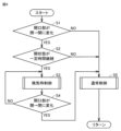
図4は、空調システムの換気時および通常時の制御を切替える処理を説明するためのフローチャートである。このフローチャートの処理は、図2における制御装置25において実行される。このフローチャートの処理は、CPU26が窓開判定部、窓閉判定部、換気制御部として動作する場合の処理に相当する。なお、リモコン30または制御装置15においてこのフローチャートの処理が実行されても良い。
FIG. 4 is a flowchart illustrating a process for switching between control of the air conditioning system during ventilation and during normal operation. The processing in this flowchart is executed in the
まずステップS1において、制御装置25は、開閉センサの出力に基づいて窓等の開口部が閉状態から開状態に変化したか否かを判断する。変化が検出されない場合には(S1でNO)、ステップS5において通常制御が実行される。
First, in step S1, the
変化が検出された場合には(S1でYES)、ステップS2において開口部の開状態が一定時間継続したか否かが判断される。開状態が一定時間継続せずに閉状態に戻った場合には(S2でNO)、ステップS5において通常制御が実行される。これにより、換気目的ではない窓等の開閉が排除される。 If a change is detected (YES in S1), it is determined in step S2 whether the open state of the opening continues for a certain period of time. If the open state does not continue for a certain period of time and returns to the closed state (NO in S2), normal control is executed in step S5. This eliminates the opening and closing of windows, etc. that are not for ventilation purposes.
開状態が一定時間継続した場合には(S2でYES)、ステップS3において換気時制御が実行される。そして、ステップS4において、制御装置25は、開閉センサの出力に基づいて窓等の開口部が開状態から閉状態に変化したか否かを判断する。変化が検出されない場合には(S4でNO)、ステップS3における換気時制御が維持される。変化が検出された場合には(S4でYES)、ステップS5において通常制御が実行される。
If the open state continues for a certain period of time (YES in S2), ventilation control is executed in step S3. Then, in step S4, the
図5は、通常制御時(冷房)のサーモON判定処理を説明するためのフローチャートである。このフローチャートの処理は、室内機20の制御装置25で実行される。ステップS11において、制御装置25は、サーモOFF判定後に、一定時間が経過したか否かを判断する。一定時間が経過していない場合(S11でNO)、このフローチャートのスタートに処理が戻される。
FIG. 5 is a flowchart for explaining thermo ON determination processing during normal control (cooling). The processing in this flowchart is executed by the
一定時間が経過していた場合(S11でYES)、ステップS12において、制御装置25は、室温が「設定温度+定数」で示される判定温度よりも高いか否かを判断する。室温が判定温度よりも高くない場合(S12でNO)、このフローチャートのスタートに処理が戻される。
If a certain period of time has elapsed (YES in S11), in step S12, the
室温が判定温度よりも高い場合(S12でYES)、サーモON状態に制御が切替えられる。サーモON状態では、圧縮機11が運転状態となり、室内機20の膨張弁21の開度が制御され、ファン23も風量設定に従った回転となる。
If the room temperature is higher than the determination temperature (YES in S12), the control is switched to the thermo ON state. In the thermo ON state, the
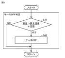
図6は、通常制御時(冷房)のサーモOFF判定処理を説明するためのフローチャートである。このフローチャートの処理は、室内機20の制御装置25で実行される。ステップS21において、制御装置25は、室温が「設定温度-定数」で示される判定温度よりも低いか否かを判断する。室温が判定温度よりも低くない場合(S21でNO)、このフローチャートのスタートに処理が戻される。
FIG. 6 is a flowchart for explaining the thermo-off determination process during normal control (cooling). The processing in this flowchart is executed by the
室温が判定温度よりも低い場合(S21でYES)、サーモOFF状態に制御が切替えられる。サーモOFF状態では、圧縮機11が停止状態となるか、または室内機20の膨張弁21が閉止される。
If the room temperature is lower than the determination temperature (YES in S21), the control is switched to the thermo-off state. In the thermo-OFF state, the
なお、サーモON判定およびサーモOFF判定は、換気制御時に実行される急速運転では、通常運転時に対して、判定温度が変更される。急速運転と通常制御との違いは温度上昇または下降の速度である。急速運転では、基本的には、素早く、強めに冷房する。図4のステップS3で実行される換気制御時には、急速運転が実行され、サーモON判定とするタイミングを早くする。 Note that in the thermo ON determination and the thermo OFF determination, in the rapid operation performed during ventilation control, the determination temperature is changed from that in the normal operation. The difference between rapid operation and normal control is the rate of temperature rise or fall. Rapid operation basically cools the air quickly and strongly. During the ventilation control performed in step S3 in FIG. 4, rapid operation is performed to accelerate the timing of thermo ON determination.
また、急速運転では、通常制御時よりも圧縮機容量制御の制限を緩くする。通常制御では、設定温度と周囲温度の差が縮まってくると室内機の膨張弁および圧縮機容量制御を省エネ制御にするが、急速運転ではその制限を弱める。 In addition, during rapid operation, restrictions on compressor capacity control are made more relaxed than during normal control. In normal control, when the difference between the set temperature and the ambient temperature narrows, the indoor unit's expansion valve and compressor capacity control are put into energy-saving control, but in rapid operation, these restrictions are weakened.
たとえば、夏に換気すると室温が一気に上がるので、通常制御だと室温がある程度上昇してしまうが、急速運転を行なうことによって、通常制御よりも室温を上昇させないようにできる。 For example, when ventilation occurs in the summer, the room temperature rises all at once, so if normal control is used, the room temperature will rise to some extent, but by performing rapid operation, the room temperature can be kept from rising as much as normal control.
図5、図6で説明した冷房時の例について説明する。
通常時では、以下のように判定温度が設定されているとする。
サーモON条件:室温>設定温度+定数A
サーモOFF条件:室温<設定温度-定数A
これに対して、急速運転時には、判定温度は以下のように設定される。
サーモON条件:室温>設定温度+定数B
サーモOFF条件:室温<設定温度-定数B
なお、定数A,Bは、マージンを示す温度幅を示し、A>Bである。
An example during cooling explained in FIGS. 5 and 6 will be explained.
It is assumed that in normal times, the determination temperature is set as follows.
Thermo ON condition: room temperature > set temperature + constant A
Thermo OFF condition: room temperature < set temperature - constant A
On the other hand, during rapid operation, the determination temperature is set as follows.
Thermo ON condition: room temperature > set temperature + constant B
Thermo OFF condition: room temperature < set temperature - constant B
Note that constants A and B indicate a temperature range indicating a margin, and A>B.
このように判定温度を変えることによって、換気時に急速運転を行ない、サーモON、サーモOFFの判定のタイミングを早めることができる。 By changing the determination temperature in this manner, rapid operation can be performed during ventilation, and the timing of determining whether the thermostat is ON or OFF can be brought forward.
図7は、通常制御時(暖房)のサーモON判定処理を説明するためのフローチャートである。このフローチャートの処理は、室内機20の制御装置25で実行される。ステップS31において、制御装置25は、サーモOFF判定後に、一定時間が経過したか否かを判断する。一定時間が経過していない場合(S31でNO)、このフローチャートのスタートに処理が戻される。
FIG. 7 is a flowchart for explaining thermo ON determination processing during normal control (heating). The processing in this flowchart is executed by the
一定時間が経過していた場合(S31でYES)、ステップS32において、制御装置25は、室温が「設定温度-定数」で示される判定温度よりも低いか否かを判断する。室温が判定温度よりも低くない場合(S32でNO)、このフローチャートのスタートに処理が戻される。
If a certain period of time has elapsed (YES in S31), in step S32, the
室温が判定温度よりも低い場合(S32でYES)、サーモON状態に制御が切替えられる。サーモON状態では、圧縮機11およびファン13が運転状態となり、室内機20の膨張弁21の開度が制御され、ファン23も回転する。
If the room temperature is lower than the determination temperature (YES in S32), the control is switched to the thermo ON state. In the thermo ON state, the
図8は、通常制御時(暖房)のサーモOFF判定処理を説明するためのフローチャートである。このフローチャートの処理は、室内機20の制御装置25で実行される。ステップS41において、制御装置25は、室温が「設定温度+定数」で示される判定温度よりも高いか否かを判断する。室温が判定温度よりも高くない場合(S41でNO)、このフローチャートのスタートに処理が戻される。
FIG. 8 is a flowchart for explaining the thermo-off determination process during normal control (heating). The processing in this flowchart is executed by the
室温が判定温度よりも高い場合(S41でYES)、サーモOFF状態に制御が切替えられる。サーモOFF状態では、圧縮機11が停止状態となるか、または室内機20の膨張弁21が閉止される。
If the room temperature is higher than the determination temperature (YES in S41), the control is switched to the thermo-OFF state. In the thermo-OFF state, the
暖房時においても、サーモON判定およびサーモOFF判定は、換気制御時に実行される急速運転では、通常運転時に対して、判定温度が変更される。急速運転と通常制御との違いは温度上昇または下降の速度である。急速運転では、基本的には、素早く、強めに暖房する。暖房時においても、図4のステップS3で実行される換気制御時には、急速運転が実行され、サーモON判定とするタイミングを早くする。 Even during heating, the determination temperature for thermo ON determination and thermo OFF determination is changed in the rapid operation performed during ventilation control compared to the normal operation. The difference between rapid operation and normal control is the rate of temperature rise or fall. Rapid operation basically heats the room quickly and strongly. Even during heating, rapid operation is performed during the ventilation control performed in step S3 in FIG. 4, and the timing of thermo ON determination is accelerated.
たとえば、冬に換気すると室温が一気に下がるので、通常制御だと室温がある程度下がってしまう。したがって、換気時には、急速運転を実行し、通常制御よりも室温が下がらないようにする。 For example, when ventilation occurs in winter, the room temperature suddenly drops, so normal control will cause the room temperature to drop to a certain extent. Therefore, during ventilation, perform rapid operation to prevent the room temperature from falling below normal control.
図9は、実施の形態1における換気時制御を説明するためのフローチャートである。このフローチャートの処理は、図4のステップS3の処理の詳細を示している。 FIG. 9 is a flowchart for explaining ventilation control in the first embodiment. The process in this flowchart shows details of the process in step S3 in FIG.
換気時制御では、ステップS51において空調装置において空調を増強する運転が実行される。具体的には、制御装置25がファン23の回転速度を通常運転時に設定されている回転速度よりも増加させ、かつ室外機においては制御装置15が圧縮機11の運転周波数を増加させる。なお、空調の増強は、ファンの回転速度の増加と、圧縮機の運転周波数の増加のいずれか一方のみであっても良い。特に、外気温が室内の適温と差が大きい夏および冬などには、圧縮機11の運転周波数を増加させ、冷媒の循環量を増やすことが望ましい。また、サーモON/OFF判定の判定温度も急速運転を許容するように変更される。
In the ventilation control, in step S51, the air conditioner performs an operation to enhance air conditioning. Specifically, the
続いて、ステップS52において、制御装置25は、室内温度が室外温度よりも低いか否かを判断する。室内温度<室外温度が成立した場合(S52でYES)、制御装置25は、ステップS53において開口部と反対方向に風向を設定する。一方、室内温度<室外温度が成立しない場合(S52でNO)、制御装置25は、ステップS54において開口部の方向に風向を設定する。
Subsequently, in step S52, the
以下に、ステップS53、S54の風向と換気との関係について説明する。図10は、換気していない場合の風向を説明するための図である。図10に示すように、風向変更部24A、24Bは、リモコンなどで設定された風向に対応する角度にベーンを制御する。一般的には、中央部の吸込口から室内の空気が吸い込まれ、空調されて、吸込口の周囲の吹出口から空調された空気が吹出し、図中矢印に示すように、空気が部屋100内を循環している。
The relationship between the wind direction and ventilation in steps S53 and S54 will be explained below. FIG. 10 is a diagram for explaining the wind direction when ventilation is not performed. As shown in FIG. 10, the wind
すなわち、通常制御時には、室内機は、空気を循環させて温度を一定にする。室内機は、空気を循環させるだけで換気はできない。 That is, during normal control, the indoor unit circulates air to keep the temperature constant. Indoor units only circulate air, but cannot provide ventilation.
図11は、実施の形態1における夏期または中間期における換気時の風向制御を説明するための図である。夏は、外気温が室温よりも高い。春、秋などの中間期においても外気温が室温よりも高い場合がある。このような場合に、図11に示すように室内機の風向が制御される。 FIG. 11 is a diagram for explaining wind direction control during ventilation in the summer or intermediate season in the first embodiment. In summer, the outside temperature is higher than the room temperature. Even in intermediate seasons such as spring and autumn, the outside temperature may be higher than the room temperature. In such a case, the wind direction of the indoor unit is controlled as shown in FIG.
本実施の形態では、天井埋め込み型の4方向吹出しの室内機の風向きに方向性を持たせることで、部屋全体の空気の流れを作る。その前提としては、冷たい空気は暖かい空気の方に移動するという法則がある。冷たい空気は、気圧が高く、暖かい空気は気圧が低いからである。 In this embodiment, the air flow throughout the room is created by giving directionality to the wind direction of the ceiling-embedded indoor unit that blows out in four directions. The premise behind this is the law that cold air moves towards warm air. This is because cold air has high pressure and warm air has low pressure.
基本の考え方としては、部屋の外の方が室内よりも気温が高い夏などは、開口部とは反対側の方向に風向制御が行なわれる。すると、図11に示すように、温かい空気は、矢印W1,W2に示すように開口部である窓103から部屋100の奥に向けて送られる。すると、冷たい空気は、矢印W3,W4,W5に示すように流れて窓103の下側から部屋100の外に押し出される。
The basic idea is that in summer, when the temperature outside the room is higher than inside, the wind direction is controlled in the direction opposite to the opening. Then, as shown in FIG. 11, the warm air is sent toward the back of the
このように、部屋全体の空気の流れがあると、室内外の温度差によって、開口部において空気が順次入れ替わるため、室内機を用いた部屋全体の換気が実現できる。 In this way, when there is air flow throughout the room, the air is sequentially exchanged at the openings due to the temperature difference between indoors and outdoors, making it possible to ventilate the entire room using an indoor unit.
通常の室内機の運用だと、基本的に窓付近しか換気がされないが、本実施の形態では、開口部が開いたことを検出すると換気が促進されるように風向制御が行なわれる。 When a normal indoor unit is operated, ventilation is basically performed only near the window, but in this embodiment, when it is detected that an opening is opened, the wind direction is controlled to promote ventilation.
図12は、実施の形態1における冬期または中間期における換気時の風向制御を説明するための図である。冬は、外気温が室温よりも低い。また、春、秋などの中間期においても外気温が室温よりも低い場合がある。このような場合に、図12に示すように室内機の風向が制御される。 FIG. 12 is a diagram for explaining wind direction control during ventilation during the winter season or the intermediate season in the first embodiment. In winter, the outside temperature is lower than room temperature. Furthermore, the outside temperature may be lower than the room temperature even in intermediate seasons such as spring and autumn. In such a case, the wind direction of the indoor unit is controlled as shown in FIG. 12.
基本の考え方としては、部屋の外の方が室内よりも気温が低い冬などは、開口部の方向に風向制御をする。すると、図12に示すように、温かい空気は、矢印W14,W13,W15に示すように部屋100の奥から窓103に向けて送られる。すると、冷たい外気が矢印W11,W12に示すように窓103の下側から部屋100の内部に流入する。
The basic idea is that in winter, when the temperature outside the room is lower than inside, the direction of the wind is controlled in the direction of the opening. Then, as shown in FIG. 12, warm air is sent from the back of the
厳密には、通常の風向制御をしていても、室内機のベーンが動くため、空気が攪拌されるし、人の移動等によって窓付近以外の空気も移動するため、多少は換気される。しかし、本実施の形態では、部屋の奥の空気を積極的に開口側に移動させるため、通常の室内機の運用よりも換気効果は高い。 Strictly speaking, even with normal airflow direction control, the vanes of the indoor unit move, stirring the air, and air moving outside of the window area due to people moving around, resulting in some ventilation. However, in this embodiment, air from the back of the room is actively moved toward the opening, so the ventilation effect is higher than when operating a normal indoor unit.
なお、換気時の風向を自動で決定するには、いくつかの方法が考えられる。
まず、単純にリモコンの設定が冷房モードであれば夏(外気温>室温)、暖房モードであれば冬(外気温<室温)であるとして、換気時の風向を切替えることができる。
Note that several methods can be considered to automatically determine the wind direction during ventilation.
First, if the remote control is set to cooling mode, it is summer (outside temperature > room temperature), and if heating mode is set, it is winter (outside temperature < room temperature), and the wind direction during ventilation can be changed.
また、リモコンの設定が冷暖自動切替モードである場合には、カレンダーを内蔵したスケジュール機能で季節を判定し風向を設定したり、天気予報を受信して温度の高低を判断して風向を設定したりしても良い。 In addition, if the remote control is set to automatic cooling/heating switching mode, you can use the schedule function with a built-in calendar to determine the season and set the wind direction, or receive the weather forecast and determine the high or low temperature and set the wind direction. You can also
また、中間期は、外気温と設定温度が近い値のため、換気時の圧縮機の増強運転をしないようにし、開口部の状態変化に応答して風向と風量制御のみを実行するようにしても良い。 In addition, during the intermediate period, since the outside temperature and the set temperature are close to each other, the compressor should not be operated at increased capacity during ventilation, and only the wind direction and volume should be controlled in response to changes in the opening conditions. Also good.
以上説明したように、実施の形態1の空調システムは、開口部の状態により開状態で空調運転を増強させる。
As explained above, the air conditioning system of
具体的には、開口部が開いたことを検知した後すぐ、夏冬では圧縮機の運転周波数を増加させ、急速冷房または急速暖房を実施する。併せて、風速を通常よりも一段回強くするようにファンを制御する。圧縮機の運転周波数の増加とファン回転速度の増加のいずれか一方を行なうようにしても良い。 Specifically, immediately after detecting that the opening has opened, in summer and winter, the operating frequency of the compressor is increased to perform rapid cooling or rapid heating. At the same time, the fan is controlled to increase the wind speed one step higher than normal. Either one of the compressor operating frequency and the fan rotation speed may be increased.
これにより、換気時に室温が空調の目標温度から離れることを少なくすることができる。したがって、換気時のユーザの快適性を向上させることができる。 Thereby, it is possible to reduce the possibility that the room temperature deviates from the target temperature of the air conditioner during ventilation. Therefore, user comfort during ventilation can be improved.
また、実施の形態1の空調システムは、開口部が開いた状態において、空調運転の増強に加えて、換気を促すような部屋全体の空気の流れを作るように風向を制御する。なお、空調運転の増強をせずに、換気を促すように風向を制御しても良い。特に、春秋の中間期では風量または風向制御のみとしてもよい。
In addition, the air conditioning system of
これにより、換気時に空調システムによって換気が促進される。したがって、部屋全体の換気が行なえるとともに換気時間が短時間で済む。 This facilitates ventilation by the air conditioning system during ventilation. Therefore, the entire room can be ventilated and the ventilation time can be shortened.
なお、本実施の形態では、空調運転の増強を行なう場合を説明したが、本実施の形態のように、換気を優先するモードと、従来のように、窓を開けた場合に省エネを優先するモードとの両方を実行できるように空調システムを構成しておき、ユーザがいずれを使用するかを選べるようにしても良い。 In addition, in this embodiment, a case has been described in which the air conditioning operation is increased, but there is a mode in which ventilation is prioritized as in this embodiment, and a mode in which energy saving is prioritized when windows are opened as in the past. The air conditioning system may be configured to be able to execute both modes, and the user may be able to select which mode to use.
実施の形態2.
換気時に窓に加えてドアなどの開口部も開く場合もある。実施の形態2では、複数の開口部を考慮する。換気を促すためには窓およびドアなど2箇所以上の開口がある方が望ましい。複数の開口の各々に設けた接点または温度センサなどからの2箇所の入力信号を室内機に入力するように空調システムを構成してもよい。
In addition to windows, openings such as doors may also be opened during ventilation. In the second embodiment, a plurality of openings are considered. To promote ventilation, it is preferable to have two or more openings such as windows and doors. The air conditioning system may be configured so that input signals from two locations, such as contacts or temperature sensors provided at each of the plurality of openings, are input to the indoor unit.
図13は、実施の形態2で対象とする空調対象空間のフロアマップの一例を示す上面図である。図13には、天井側から、床面を見たときの図が示されている。図13に示す部屋100Aは、屋外に面した壁面に窓103が設けられ、廊下または別室との境界である壁面にドア104が設けられている。空調ユニット20A~20Dが天井面に配置されている。
FIG. 13 is a top view showing an example of a floor map of a space to be air-conditioned in the second embodiment. FIG. 13 shows a view of the floor viewed from the ceiling. In the
空調ユニット20A~20Dの各々は、図3で示した構成であるが、図13では4つの吹出口から4方向に風を送ることができる天井埋め込みカセット形の室内機であることがよくわかる。4つの吹出口の各々にはベーンが設けられており、吹出口を開閉したり、開状態において風向を変えたりすることができる。
Each of the
窓103の開閉を検知する開閉センサ41が窓103付近に配置され、ドア104の開閉を検知する開閉センサ42がドア104付近に配置されている。各々の開閉センサとしては、接点式の開閉センサ、または、温度の変化で開閉を検知する温度センサを用いることができる。
An opening/
図14は、実施の形態2における夏期の冷房運転時における換気時の風向制御を説明するための側面図である。図14には、図13のXIV-XIV断面に相当する、廊下がある場合も含めた使用例の状態が示されている。夏の冷房運転中に窓103およびドア104を開けて換気をする場合の風向制御を図14によって説明する。ただし、窓を開けても強風が吹きこまない環境であるとする。
FIG. 14 is a side view for explaining wind direction control during ventilation during summer cooling operation in the second embodiment. FIG. 14 shows a usage example including a case where there is a hallway, which corresponds to the XIV-XIV cross section in FIG. 13. Wind direction control when ventilation is performed by opening the
室内機から風が吹出していない場合、冷気は部屋の下側に、暖気は部屋の上側に貯まる。窓を開けても強風が吹きこまない環境の場合には、窓を開けると部屋の下部では冷たい室内から暖かい屋外に向けて空気はゆっくりと移動していく。 If no air is blowing out from the indoor unit, cold air will accumulate at the bottom of the room and warm air will accumulate at the top of the room. If you are in an environment where strong winds do not blow in even when you open the windows, when you open the windows, the air slowly moves from the cold indoors at the bottom of the room to the warm outdoors.
これらの空気の特徴を考えると、廊下または別室側が閉鎖空間の場合、空調ユニット20A、20Bの各々からドア104の開口部に向けて送風することによって、図14の大きな矢印のように、室外から暖気を室内側に取り込み、室内の冷気が室内下部を回り込んで、外部に移動する空気の流れが実現できる。これにより、窓から新鮮な空気が入り、部屋全体の換気が促進される。
Considering these air characteristics, if the hallway or separate room side is a closed space, by blowing air from each of the
なお、ドア104が設けられている壁面の反対側である廊下、もしくは別室側が閉鎖空間でなく、別の外部への開放部を持つ場合でも、屋外から部屋100Aを通過し廊下から別の外部に向かう空気の流れができるため、この場合も問題なく換気できる。
Note that even if the hallway or separate room on the opposite side of the wall where the
図15は、実施の形態2における夏期の冷房運転時における換気時の風向制御を説明するための上面図である。この例の4台の室内機は壁についている1台のリモコンで操作される。4台の室内機は、リモコンの操作等によって、4台とも同時に換気運転になったり、通常制御になったりする。ただし、温度センサは個別についているので、サーモONするタイミング等は個々に異なる。 FIG. 15 is a top view for explaining wind direction control during ventilation during summer cooling operation in the second embodiment. The four indoor units in this example are operated by one remote control attached to the wall. The four indoor units can be put into ventilation operation or into normal control at the same time by operating a remote control or the like. However, since the temperature sensors are individually attached, the timing of turning on the thermostat etc. differs from case to case.
図15の部屋100Bの例では、窓とドアが対向する壁面に設けられていないが、このような場合であっても、各室内機において窓側に近い吹出口を閉じ、ドア側に近い吹出口を開き、図中矢印に示すように風向を設定することによって、換気を促進させることができる。
In the example of
すなわち、部屋に対して複数の室内機がある場合は、部屋への吸気および部屋からの排気がスムーズにいくように、換気時にそれぞれの室内機の風向角度を変化させる。 That is, when there are multiple indoor units for a room, the wind direction and angle of each indoor unit is changed during ventilation so that air can be smoothly taken in and exhausted from the room.
夏または外気温が高い中間期は、屋内側開口部であるドアの方向またはドアに位置が近い空調ユニット20Aの方向に風向を設定し、外気を冷やしつつ室内上部に送り、冷えた空気が室内下部を流れ窓から室外へ出ていく気流を作り、室内全体を換気する。なお、ドアに位置が近い室内機の配置、および各室内機におけるドアの方向は、予め記憶されているフロアマップからわかる。
In summer or mid-season when the outside temperature is high, set the wind direction toward the door that is the opening on the indoor side or in the direction of the
図16は、実施の形態2における冬期の暖房運転時における換気時の風向制御を説明するための側面図である。図17は、実施の形態2における冬期の暖房運転時における換気時の風向制御を説明するための上面図である。冬期の暖房運転時においても同様に換気時には空調の増強運転を行なうとともに、夏期とは反対方向への風向制御を行なう。 FIG. 16 is a side view for explaining wind direction control during ventilation during heating operation in winter in the second embodiment. FIG. 17 is a top view for explaining wind direction control during ventilation during heating operation in winter in the second embodiment. Similarly, during heating operation in the winter, the air conditioning is reinforced during ventilation, and the wind direction is controlled in the opposite direction to that in the summer.
すなわち、寒い時期は、空調ユニット20A~20Dの各々において、窓側に近い吹出口を開き、ドア側に近い吹出口を閉じ、屋外側開口部に向かうように風向を設定する。
That is, during the cold season, in each of the
冬または外気温が低い中間期は、屋外側開口部である窓または換気口の方向、もしくはそれらに位置が近い空調ユニット20Dの方向に風向を設定し、温かい空気が室内上部を流れ、冷たい空気が室内下部を流れる気流を作り、室内全体を換気する。なお、窓または換気口に位置が近い室内機の配置、および各室内機における窓または換気口の方向は、予め記憶されているフロアマップからわかる。
In winter or during the middle months when the outside temperature is low, the wind direction is set in the direction of the window or vent that is the outdoor opening, or in the direction of the
図18は、実施の形態2における換気時の制御を説明するためのフローチャートである。ステップS101において、未換気時間がリセットされる。そしてステップS102において通常制御が開始される。一定時間が経過するまでは(S103でNO)、未換気のまま通常制御が継続される。未換気のまま一定時間が経過した場合(S103でYES)、ステップS104において、制御装置25は、開口部の開放を要求する旨の通知を出力する。たとえば、ステップS104において、「換気制御を開始してよいか?」というメッセージがリモコンの画面上に表示される。ユーザが開放を拒否する場合には(S105でYES)、再びステップS101からの処理が繰返される。一方、ユーザが開放に同意する場合、たとえば、ユーザが手動で窓を開けてOKボタンを押した場合は(S105でNO)、ステップS106において制御装置25は、開口部の開閉センサの出力に基づいて、開口部の開放が完了したか否かを判断する。
FIG. 18 is a flowchart for explaining control during ventilation in the second embodiment. In step S101, the non-ventilation time is reset. Then, normal control is started in step S102. Until a certain period of time has elapsed (NO in S103), normal control is continued without ventilation. If a certain period of time has passed without ventilation (YES in S103), in step S104, the
開口部の開放が完了していない場合(S106でNO)、ステップS104に戻り制御装置25は開口部の開放を要求するメッセージをリモコン画面などに再び出力する。
If the opening of the opening has not been completed (NO in S106), the process returns to step S104 and the
一方、開口部の開放が完了した場合(S106でYES)、ステップS107以降の換気時制御が実行される。 On the other hand, when opening of the opening is completed (YES in S106), ventilation control from step S107 onwards is executed.
なお、ステップS104においてリモコンに「換気時制御を開始してよいか?」の画面が表示され、ユーザが手動で窓を開けてOKボタンを押したら(S105でYES,かつS106でYES)、ステップS107以降の換気制御を開始するようにしても良い。 In addition, in step S104, the screen "Can you start ventilation control?" is displayed on the remote control, and if the user manually opens the window and presses the OK button (YES in S105 and YES in S106), step You may make it start ventilation control after S107.
また、これに代えて、定期的な換気制御を許可する設定にしておき、窓が時間になったら自動で開く仕組みを持った建物であれば、自動的に換気時制御を開始するようにしても良い。 Alternatively, you can set it to allow periodic ventilation control, and if the building has a system that automatically opens the windows when the time comes, you can set it to automatically start ventilation control. Also good.
換気時制御では、まず、ステップS107において、制御装置25は、現在のシーズンを判定する。シーズン判定は、カレンダー、気温、配信される天気予報などに基づいて判断することができる。そしてステップS108において、図14~図17で説明したように、シーズンに対応する風向および風量が決定される。そしてステップS109において換気終了の基準を計算する。ステップS109における換気終了の基準は、たとえば換気制御の時間経過で判断する場合、敷地面積と開口部開度から定まる換気量に基づいて一定割合以上の空気を入れ替えられる時間を算出し、その時間経過を基準とする。また、換気終了を温度で判断する場合は、通常の冷房、暖房のサーモON/OFFの関係式を用いて換気制御終了判定を行なう。たとえば、通常時に密閉空間において空調が安定して実施されている場合は、基本は大半がサーモOFF状態である。このような場合、換気のために開口部を開放すると室温と外気温度の差が大きく生まれサーモON条件を満たす。サーモON条件を満たした時点から急速増強空調(快適換気運転)を行ない、その後にサーモOFF条件になった段階で換気制御終了とする。
In the ventilation control, first, in step S107, the
続いて、ステップS110において制御装置25は、決定された風量および風向で換気時の快適性を維持する快適換気運転を実行する。快適換気運転は、ステップS111において換気制御の終了判定条件が成立するまで行なわれる。
Subsequently, in step S110, the
ステップS111における換気制御の終了判定条件は、換気制御の時間経過または、室温と設定温度の関係に基づいて決定することができる。終了判定にどの条件を用いるか、または両方のANDまたはORを用いるかについては、ユーザが選択できるようにしても良い。 The conditions for determining the end of ventilation control in step S111 can be determined based on the elapsed time of ventilation control or the relationship between the room temperature and the set temperature. The user may be able to select which condition to use for the termination determination, or whether to use both AND or OR.
換気制御の終了判定条件が成立した場合(S111でYES)、ステップS112において、制御装置25は開口部を閉鎖するように要求するメッセージをリモコン画面などに通知する。そして、ステップS113において制御装置25は、開口部の開閉センサの出力に基づいて、開口部の閉鎖が完了したか否かを判断する。なお、換気後の快適性を保つべく、十分な換気ができたら、開口部を閉状態にすることをリモコン表示部などによってユーザに報知して、手動で開口部を閉じるようにしたが、自動で開口部を閉状態にするようにしてもよい。
If the ventilation control end determination condition is satisfied (YES in S111), in step S112, the
開口部の閉鎖が完了しない場合(S113でNO)、ステップS110以降の処理が繰返される。一方、開口部の閉鎖が完了した場合(S113でYES)、ステップS101に処理が戻り、未換気時間がリセットされ、ステップS102以降の処理が繰返される。 If the closing of the opening is not completed (NO in S113), the processes from step S110 onwards are repeated. On the other hand, when the opening has been completely closed (YES in S113), the process returns to step S101, the unventilated time is reset, and the processes from step S102 onwards are repeated.
さらに、開口部の閉鎖が完了したことを開閉センサが検知した後に(S113でYES)、低下した部屋全体の快適な状況になるように短時間だが一定時間増強運転を全方向に実施するという制御をステップS101の処理の前に追加しても良い。ただし、このときは換気時とは異なり、風向を開口部開前の状態に戻すことが好ましい。 Furthermore, after the opening/closing sensor detects that the opening has been closed (YES in S113), control is performed to perform enhanced operation in all directions for a short but fixed period of time to make the entire room comfortable. may be added before the processing in step S101. However, at this time, unlike during ventilation, it is preferable to return the wind direction to the state before the opening was opened.
以上説明したように、実施の形態2の空調システムによれば、冷房運転時の換気、暖房運転時の換気で以下のような風向切替が行なわれる。
As explained above, according to the air conditioning system of
図14、図15に示したように、冷房運転時の換気では、窓を開くと汚れた冷気は屋外の暖気側に移動するため室内全体で換気される。そして、出ていく冷気と入れ替わりで、新鮮な暖気が部屋上部に侵入する。室内機は、その空気を冷やしながら、屋内の開口部であるドア側に送風する。 As shown in FIGS. 14 and 15, in ventilation during cooling operation, when a window is opened, dirty cold air moves to the warm air outside, so the entire room is ventilated. Then, fresh warm air enters the upper part of the room to replace the cold air that leaves. The indoor unit cools the air and blows it toward the door, which is an opening inside the room.
また、図16、図17に示したように、暖房運転時の換気では、汚れた暖気は室内機によって屋外への開口部に送風され、屋外に排出される。そして、出ていく暖気と入れ替わりで、新鮮な冷気が部屋下部に侵入し、屋内の開口部であるドア側から一部が流出する。 Further, as shown in FIGS. 16 and 17, during ventilation during heating operation, dirty warm air is blown by the indoor unit to an opening to the outdoors and is discharged outdoors. Then, to replace the outgoing warm air, fresh cold air enters the lower part of the room, and some of it flows out from the door, which is the opening inside the room.
このようにして、本実施の形態の空調システムによれば、冷房運転時においても暖房運転時においても、室内機によって換気が促進される。 In this way, according to the air conditioning system of this embodiment, ventilation is promoted by the indoor unit both during cooling operation and during heating operation.
実施の形態3.
開口部の配置によっては、換気されにくいエリアが部屋の中に生じる場合がある。実施の形態3では、そのようなエリアが存在する場合の換気時の制御について説明する。
Embodiment 3.
Depending on the placement of the openings, there may be areas in the room that are difficult to ventilate. In Embodiment 3, control during ventilation when such an area exists will be described.
図19は、換気されにくいエリアが部屋の中に生じるフロアマップの一例を示す図である。図19に示す部屋100Cでは、ドアと窓の2か所の開口部が近接しており、実施の形態2のように風向制御をすると換気されにくいエリア110が生じる。
FIG. 19 is a diagram showing an example of a floor map in which areas that are difficult to ventilate occur in a room. In the
図20は、実施の形態3における換気時の風向制御を説明するための上面図である。図21は、実施の形態3における換気時の風向制御を説明するための側面図である。図20、図21に示すように、壁に面した換気されにくいエリア110に風を吹出すことができる吹出口を開いて、空調ユニット20A,20Bの換気制御中の風向設定を“自動“に設定変更することによって、換気されにくいエリアの空気を攪拌し、換気することができる。
FIG. 20 is a top view for explaining wind direction control during ventilation in Embodiment 3. FIG. 21 is a side view for explaining wind direction control during ventilation in Embodiment 3. As shown in FIGS. 20 and 21, an air outlet that can blow air into an
なお、一部の空気は、換気されにくいエリア110と空調ユニット20A,20Bの間を循環するため、換気効率は落ちるが、ある程度の量の空気は右側にも流れていくため、換気はできる。したがって、実施の形態2のような制御を行なうよりも換気効率は改善される。
Note that some air circulates between the
換気時にどの室内機のどの吹出口を開くかについては、予めフロアマップから定めておくことができる。 Which outlet of which indoor unit should be opened during ventilation can be determined in advance from the floor map.
なお、このような室内構成の場合は、室内機だけで換気を促進しようとせず、素直にサーキュレータを置いた方が換気効率は良い。したがって、室内機に、換気制御中に接点ONする機能を持たせ、換気制御中のみサーキュレータの電源をONするようにしても良い。 In addition, in the case of such an indoor configuration, ventilation efficiency is better if you simply place a circulator instead of trying to promote ventilation with the indoor unit alone. Therefore, the indoor unit may be provided with a function of turning on the contact during ventilation control, and the circulator may be powered on only during ventilation control.
実施の形態4.
開口部の配置によっては、換気時に比較的強い風が吹き抜ける場合がある。実施の形態4では、そのような場合の換気時の制御について説明する。
Embodiment 4.
Depending on the arrangement of the openings, relatively strong winds may blow through during ventilation. In Embodiment 4, ventilation control in such a case will be described.
図22は、換気時の自然の風が空調システムによって妨げられる例を説明するための図である。たとえば、対向する2つの壁の各々に窓が設けられている部屋100Dを考える。このような場合に、窓から窓に向かって強風が吹き抜けることが考えられる。たとえば、マンションの上層階では、このような状況が生じやすい。
FIG. 22 is a diagram for explaining an example in which natural wind during ventilation is obstructed by an air conditioning system. For example, consider a
たとえば、冷房運転時に換気モードに制御された場合、窓104Dから強風が吹込み、換気モードでの室内機120A,120Bの送風方向が自然風と逆向きであるときを考える。
For example, consider a case where when the ventilation mode is controlled during cooling operation, a strong wind blows in from the window 104D, and the air blowing direction of the
自然風の風量が室内機の風量程度で妨げられないくらい強風の場合は、問題にならない。たとえば、周りに遮蔽物のないマンションなど、窓を開けることで強風が吹きこむ環境の場合は、窓を開放しただけで十分換気されるので、室内機の風向および風速が自然風を妨げても問題にはならない。快適性を保つため、空調システムは増強運転さえ行なえていればよい。 If the wind is strong enough that the natural airflow is not hindered by the indoor unit's airflow, this will not be a problem. For example, if you live in an environment where strong winds blow in when you open the windows, such as in an apartment with no shields around you, just opening the windows will provide sufficient ventilation, even if the indoor unit's wind direction and speed impede the natural wind. It's not a problem. To maintain comfort, the air conditioning system only needs to be able to operate at increased capacity.
しかし、家屋の周囲の見通しが悪い場合など、自然風が通り抜けにくい場合には、室内機からの送風が換気を妨げてしまう。 However, if it is difficult for natural wind to pass through, such as when there is poor visibility around the house, the air blown from the indoor unit will hinder ventilation.
そこで、本実施の形態では、室内機から吹出す空気の向きを自然風の通過方向に一致させる。図23は、実施の形態4における換気時の風向制御を説明するための側面図である。 Therefore, in this embodiment, the direction of the air blown out from the indoor unit is made to match the direction in which the natural wind passes. FIG. 23 is a side view for explaining wind direction control during ventilation in Embodiment 4.
図23に示すように、実施の形態4では、部屋100Eの2つの開口である窓103Eとドア104Eに、風向風量計41E,42Eをそれぞれ設ける。室内機120A,120Bの風が直接当たらない位置に風向風量計41E,42Eを設置することにより、自然風の風向を正確に検知することができる。
As shown in FIG. 23, in the fourth embodiment, wind direction and flow
制御装置25は、開閉センサからの出力に加えて、風向風量計41E,42Eで検出された風向および風量に基づいて、室内機からの送風方向を決定する。図23では、風向風量計41E,42Eで検出された大きな矢印で示す主な風の流れに一致するように、制御装置25は、室内機120A,120Bの風向制御部124A,124Bを用いて風向を制御する。これにより、開口部を通過する全体の風量を増加させて換気量を増やすことができる。
The
実施の形態4では、図23に示すように風向計を開口部に設置し、風の出口側に向かって送風するよう制御することで、換気量を増やすことができる。 In Embodiment 4, as shown in FIG. 23, the amount of ventilation can be increased by installing a wind vane in the opening and controlling the air to be blown toward the outlet side.
なお、風向風量計をつけない場合でも、ユーザが換気時に室内機の風向を選択できるようにしても良い。たとえば、自然風がいつも同じ方向に吹く設置場所の場合は手動で風向を自然風と同じ方向に設定すればよい。日によって風向きが変わる場合は、「風の吹込みが強い方を開口部として設定してください。」というメッセージを出力してユーザに設定を要求しても良い。 Note that even if a wind direction and flow meter is not attached, the user may be able to select the wind direction of the indoor unit during ventilation. For example, if the installation location is such that the natural wind always blows in the same direction, you can manually set the wind direction to the same direction as the natural wind. If the wind direction changes depending on the day, a message may be output to request the user to set the opening, ``Please set the opening with the strongest wind blowing.''
種々の変形例.
図24は、開閉センサの変形例を説明するための図である。実施の形態1~4では、開口部の状態認識には、開口部付近に設置した接点または温度センサを用いた。これに代えて、開口部から離れた位置に設置された赤外線センサを用いても良い。
Various variations.
FIG. 24 is a diagram for explaining a modification of the opening/closing sensor. In the first to fourth embodiments, a contact point or a temperature sensor installed near the opening is used to recognize the state of the opening. Instead of this, an infrared sensor installed at a position away from the opening may be used.
たとえば、室内機に設置された赤外線センサによって、温度分布を色表示する熱画像を得て、通信によってスマートフォンに表示させる。初期設定時に、ユーザは、スマートフォン上の熱画像における開口部の位置を指タッチで指定する。この操作によって、熱画像の画素の位置から室内機に開口部の場所をインプットし、その部分の温度変化を赤外線センサで検出し、開口部の開閉を検出しても良い。 For example, an infrared sensor installed in an indoor unit obtains a thermal image that displays temperature distribution in color, and displays it on a smartphone via communication. At the time of initial setting, the user specifies the position of the opening in the thermal image on the smartphone by touching the finger. Through this operation, the location of the opening may be input to the indoor unit from the position of the pixel of the thermal image, and the temperature change in that area may be detected by an infrared sensor to detect whether the opening is open or closed.
このようにすれば、開口部付近に温度センサを設置する工事を行なわなくて済む。
なお、熱画像上における開口部の指定方法は、たとえば、4点タッチして、四角形の範囲で開口部を指定したり、1点タッチしてタッチした点の周囲の類似色の温度帯を自動的に開口部に指定したりしてもよい。また、熱画像上の2か所をタッチし、2つの開口部を指定する、など、種々の指定方法が考えられる。基本的に、開放部に向かって送風する制御としておいて、さらに屋内側の開口部と屋外側の開口部とを分けて認識すれば、室内全体の風向を揃える制御が可能となる。
In this way, it is not necessary to install a temperature sensor near the opening.
The method of specifying the opening on the thermal image is, for example, by touching four points and specifying the opening in a rectangular range, or by touching one point and automatically calculating the temperature range of similar colors around the touched point. It may also be designated as an opening. Furthermore, various designation methods are possible, such as touching two places on the thermal image to designate two openings. Basically, if the control is to blow air toward the open area, and if the indoor opening and the outdoor opening are recognized separately, it becomes possible to control the air to align the direction of the air throughout the room.
また、図15および図17に示したような複数の室内機の風向角度に関しての指令は、フロアマップのパターンに合わせて予め用意した設定を各室内機にそれぞれ設定しても良い。また、複数の室内機の制御を管理するシステムコントローラを用意して、温度分布を色表示するアプリと連携するように、システムコントローラが判断して各室内機に最適な風向角度を指示するコマンドを送信してもよい。また、温度分布を示す熱画像を記録し効果確認をしてもよい。 Further, as for commands regarding the wind direction and angle of a plurality of indoor units as shown in FIGS. 15 and 17, settings prepared in advance according to the floor map pattern may be set for each indoor unit. In addition, we have prepared a system controller that manages the control of multiple indoor units, and in conjunction with an app that displays temperature distribution in color, the system controller determines and sends commands that instruct each indoor unit to the optimal wind direction and angle. You can also send it. Alternatively, a thermal image showing the temperature distribution may be recorded to confirm the effect.
なお、図2で代表的に示した制御装置25は、図1の室内機20A~20Dの制御装置25A~25Dのうち、アドレスの番号、DIPスイッチ、通信等で代表として管理する制御装置をどれか1つに決めたものであっても良い。制御装置25A~25Dの代表以外の制御装置には、代表の制御装置からの風向指示が送信される。その場合は、代表で管理する制御装置の記憶部にマップと機器の位置、開口部位置の情報を保持する。そして、代表の制御装置において、図11等の配置の場合に窓側にある室内機20Bと、壁側にある室内機20Aとで、マップに対する風向指示を異なるように決めてもよい。
Note that the
(まとめ)
本開示は、部屋100の空調を行なう空調システム1に関する。空調システム1は、部屋100に設けられた開口部の開閉状態を検出するように構成された開閉検知センサ40と、部屋100の空気を吸い込み、空調して部屋100に送出する空調装置2と、開閉検知センサ40の出力に応じて空調装置2を制御する制御装置25とを備える。制御装置25は、開口部が閉状態から開状態に変化したことを開閉検知センサ40が検出した場合に、空調装置2に空調の増強をさせることが可能に構成される。
(summary)
The present disclosure relates to an
好ましくは、空調装置2は、冷媒を循環させるための圧縮機11と、部屋100の空気と冷媒との間で熱交換を行なう熱交換器22と、熱交換器22に部屋の空気を送るためのファン23とを含む。空調装置2は、圧縮機11の運転周波数の増加、またはファン23の回転速度の増加によって空調を増強する。
Preferably, the
好ましくは、制御装置25は、運転モードとして、第1モードと第2モードとのいずれかをユーザの設定に基づいて選択するように構成される。第1モードは、開口部が閉状態から開状態に変化したことを開閉検知センサ40が検出した場合に、空調装置2に空調の増強をさせる運転モードである(換気優先)。第2モードは、開口部が閉状態から開状態に変化したことを開閉検知センサ40が検出した場合に、空調装置2に空調の抑制をさせる運転モードである(エコ運転優先)。
Preferably, the
好ましくは、空調装置2は、部屋100に向けて送出する空気の向きを変更することが可能である風向変更部24をさらに含む。制御装置25は、開口部が開状態であるときに、部屋100の換気が促進されるように、部屋100に送出する空気の向きを風向変更部24によって制御する風向制御を行なうことが可能に構成される。
Preferably, the
より好ましくは、風向制御において、制御装置25は、室温が外気温よりも高い場合には、開口部に向かう第1方向に空気を送出するように風向変更部24を制御し、室温が外気温よりも低い場合には、第1方向と反対の第2方向に向けて空気を送出するように風向変更部24を制御する。
More preferably, in the wind direction control, the
より好ましくは、空調システム1は、開口部を通過する風の向きを検出する風向風量計41E,42Eをさらに備える。風向制御において、制御装置25は、風向風量計41E,42Eの出力に基づいて風向変更部24を制御する。
More preferably, the
本開示の他の局面に関する空調システム1は、部屋100に設けられた開口部の開閉状態を検出するように構成された開閉検知センサ40と、部屋100の空気を吸い込み、空調して部屋100に送出する空調装置2と、部屋100に向けて送出する空気の向きを変更することが可能である風向変更部24と、開閉検知センサ40の出力に応じて空調装置2を制御する制御装置25とを備える。制御装置25は、開口部が閉状態から開状態に変化したことを開閉検知センサ40が検出した場合に、部屋100の換気が促進されるように、部屋100に送出する空気の向きを風向変更部24によって制御する風向制御を行なうことが可能に構成される。
An
今回開示された実施の形態は、すべての点で例示であって制限的なものではないと考えられるべきである。本開示の範囲は、上記した実施の形態の説明ではなくて請求の範囲によって示され、請求の範囲と均等の意味および範囲内でのすべての変更が含まれることが意図される。 The embodiments disclosed this time should be considered to be illustrative in all respects and not restrictive. The scope of the present disclosure is indicated by the claims rather than the description of the embodiments described above, and it is intended that all changes within the meaning and range equivalent to the claims are included.
1 空調システム、2 空調装置、10 室外機、11 圧縮機、12,22,22A,22B,22C,22D 熱交換器、13,23,23A,23B,23C,23D ファン、14 四方弁、15,25,25A,25B,25C,25D 制御装置、16,26 CPU、17,27,32 メモリ、18,28 入力部、20,120A,120B 室内機、20A,20B,20C,20D 空調ユニット、21,21A,21B,21C,21D 膨張弁、24,24A,24B,24C,24D 風向変更部、29 出力部、30 リモコン、33 表示部、40 開閉検知センサ、41,42 開閉センサ、41E,42E 風向風量計、100,100A,100C,100D,100E 部屋、103,103E,104D 窓、104,104E ドア、110 エリア、124A,124B 風向制御部。 1 Air conditioning system, 2 Air conditioner, 10 Outdoor unit, 11 Compressor, 12, 22, 22A, 22B, 22C, 22D Heat exchanger, 13, 23, 23A, 23B, 23C, 23D Fan, 14 Four-way valve, 15, 25, 25A, 25B, 25C, 25D Control device, 16, 26 CPU, 17, 27, 32 Memory, 18, 28 Input section, 20, 120A, 120B Indoor unit, 20A, 20B, 20C, 20D Air conditioning unit, 21, 21A, 21B, 21C, 21D Expansion valve, 24, 24A, 24B, 24C, 24D Wind direction changing section, 29 Output section, 30 Remote control, 33 Display section, 40 Open/close detection sensor, 41, 42 Open/close sensor, 41E, 42E Wind direction/air volume Total, 100, 100A, 100C, 100D, 100E Room, 103, 103E, 104D Window, 104, 104E Door, 110 Area, 124A, 124B Wind direction control section.
Claims (5)
前記部屋に設けられた開口部の開閉状態を検出するように構成されたセンサと、
前記開口部を通過する風の向きを検出する風向センサと、
前記部屋の空気を吸い込み、空調して前記部屋に送出する空調装置と、
前記センサの出力に応じて前記空調装置を制御する制御装置とを備え、
前記制御装置は、前記開口部が閉状態から開状態に変化したことを前記センサが検出した場合に、前記空調装置に空調の増強をさせることが可能に構成され、
前記空調装置は、
前記部屋に向けて送出する空気の向きを変更することが可能である風向変更部を含み、
前記制御装置は、前記開口部が開状態であるときに、前記部屋の換気が促進されるように、前記部屋に送出する空気の向きを前記風向変更部によって制御する風向制御を行なうことが可能に構成され、
前記風向制御において、前記制御装置は、前記風向センサの出力に基づいて前記風向変更部を制御する、空調システム。 An air conditioning system that air-conditions a room,
a sensor configured to detect an open/closed state of an opening provided in the room;
a wind direction sensor that detects the direction of wind passing through the opening;
an air conditioner that sucks in air from the room, conditions it, and sends it to the room;
and a control device that controls the air conditioner according to the output of the sensor,
The control device is configured to be able to cause the air conditioner to increase air conditioning when the sensor detects that the opening changes from a closed state to an open state,
The air conditioner includes:
including a wind direction changing unit capable of changing the direction of air sent toward the room,
The control device is capable of performing wind direction control in which the direction of air sent into the room is controlled by the wind direction changing unit so that ventilation of the room is promoted when the opening is in an open state. consists of
In the air-conditioning system, in the wind direction control, the control device controls the wind direction changing section based on the output of the wind direction sensor.
冷媒を循環させるための圧縮機と、
前記部屋の空気と前記冷媒との間で熱交換を行なう熱交換器と、
前記熱交換器に前記部屋の空気を送るためのファンとを含み、
前記空調装置は、前記圧縮機の運転周波数の増加、または前記ファンの回転速度の増加によって空調を増強する、請求項1に記載の空調システム。 The air conditioner includes:
a compressor for circulating refrigerant;
a heat exchanger that exchanges heat between the air in the room and the refrigerant;
a fan for sending air from the room to the heat exchanger,
The air conditioning system according to claim 1, wherein the air conditioner enhances air conditioning by increasing the operating frequency of the compressor or increasing the rotational speed of the fan.
前記第1モードは、前記開口部が閉状態から開状態に変化したことを前記センサが検出した場合に、前記空調装置に空調の増強をさせる運転モードであり、
前記第2モードは、前記開口部が閉状態から開状態に変化したことを前記センサが検出した場合に、前記空調装置に空調の抑制をさせる運転モードである、請求項1に記載の空調システム。 The control device is configured to select either a first mode or a second mode as an operating mode based on user settings,
The first mode is an operation mode in which the air conditioner increases air conditioning when the sensor detects that the opening changes from a closed state to an open state,
The air conditioning system according to claim 1 , wherein the second mode is an operation mode that causes the air conditioner to suppress air conditioning when the sensor detects that the opening changes from a closed state to an open state. .
冷媒を循環させるための圧縮機と、
前記部屋の空気と前記冷媒との間で熱交換を行なう熱交換器と、
前記熱交換器に前記部屋の空気を送るためのファンとを含み、
前記空調装置は、前記圧縮機の運転周波数の増加、または前記ファンの回転速度の増加によって空調を増強する、請求項1に記載の空調システム。 The air conditioner includes:
a compressor for circulating refrigerant;
a heat exchanger that exchanges heat between the air in the room and the refrigerant;
a fan for sending air from the room to the heat exchanger,
The air conditioning system according to claim 1 , wherein the air conditioner enhances air conditioning by increasing the operating frequency of the compressor or increasing the rotational speed of the fan.
Applications Claiming Priority (1)
| Application Number | Priority Date | Filing Date | Title |
|---|---|---|---|
| PCT/JP2021/011409 WO2022195853A1 (en) | 2021-03-19 | 2021-03-19 | Air conditioning system |
Publications (3)
| Publication Number | Publication Date |
|---|---|
| JPWO2022195853A1 JPWO2022195853A1 (en) | 2022-09-22 |
| JPWO2022195853A5 JPWO2022195853A5 (en) | 2023-04-05 |
| JP7438452B2 true JP7438452B2 (en) | 2024-02-26 |
Family
ID=83319982
Family Applications (1)
| Application Number | Title | Priority Date | Filing Date |
|---|---|---|---|
| JP2023506669A Active JP7438452B2 (en) | 2021-03-19 | 2021-03-19 | air conditioning system |
Country Status (2)
| Country | Link |
|---|---|
| JP (1) | JP7438452B2 (en) |
| WO (1) | WO2022195853A1 (en) |
Citations (8)
| Publication number | Priority date | Publication date | Assignee | Title |
|---|---|---|---|---|
| JP2011137595A (en) | 2009-12-28 | 2011-07-14 | Mitsubishi Electric Corp | Air conditioning system |
| WO2014167837A1 (en) | 2013-04-12 | 2014-10-16 | パナソニック株式会社 | Air-conditioning system and controller |
| JP2015001360A (en) | 2013-06-18 | 2015-01-05 | アズビル株式会社 | Automatic air capacity control method in central air conditioning system |
| JP2015152201A (en) | 2014-02-13 | 2015-08-24 | 大和ハウス工業株式会社 | Window opening or closing system |
| JP2016023819A (en) | 2014-07-16 | 2016-02-08 | トヨタホーム株式会社 | Air conditioning system |
| JP2016075443A (en) | 2014-10-08 | 2016-05-12 | 三菱電機株式会社 | Ventilation system and ventilation method |
| JP2018162925A (en) | 2017-03-27 | 2018-10-18 | 三菱電機株式会社 | Air conditioning control device, air conditioner, air conditioning system, air conditioning control method, and program |
| JP2019113240A (en) | 2017-12-22 | 2019-07-11 | シャープ株式会社 | Drain water backflow prevention device |
-
2021
- 2021-03-19 WO PCT/JP2021/011409 patent/WO2022195853A1/en active Application Filing
- 2021-03-19 JP JP2023506669A patent/JP7438452B2/en active Active
Patent Citations (8)
| Publication number | Priority date | Publication date | Assignee | Title |
|---|---|---|---|---|
| JP2011137595A (en) | 2009-12-28 | 2011-07-14 | Mitsubishi Electric Corp | Air conditioning system |
| WO2014167837A1 (en) | 2013-04-12 | 2014-10-16 | パナソニック株式会社 | Air-conditioning system and controller |
| JP2015001360A (en) | 2013-06-18 | 2015-01-05 | アズビル株式会社 | Automatic air capacity control method in central air conditioning system |
| JP2015152201A (en) | 2014-02-13 | 2015-08-24 | 大和ハウス工業株式会社 | Window opening or closing system |
| JP2016023819A (en) | 2014-07-16 | 2016-02-08 | トヨタホーム株式会社 | Air conditioning system |
| JP2016075443A (en) | 2014-10-08 | 2016-05-12 | 三菱電機株式会社 | Ventilation system and ventilation method |
| JP2018162925A (en) | 2017-03-27 | 2018-10-18 | 三菱電機株式会社 | Air conditioning control device, air conditioner, air conditioning system, air conditioning control method, and program |
| JP2019113240A (en) | 2017-12-22 | 2019-07-11 | シャープ株式会社 | Drain water backflow prevention device |
Also Published As
| Publication number | Publication date |
|---|---|
| JPWO2022195853A1 (en) | 2022-09-22 |
| WO2022195853A1 (en) | 2022-09-22 |
Similar Documents
| Publication | Publication Date | Title |
|---|---|---|
| US7832465B2 (en) | Affordable and easy to install multi-zone HVAC system | |
| EP2581675A1 (en) | Ventilation and air-conditioning apparatus and method for controlling same | |
| WO2010131336A1 (en) | Air conditioning device | |
| JP4478082B2 (en) | Control method of air conditioner | |
| JP2012184868A (en) | Air conditioning system | |
| WO2019146121A1 (en) | Air conditioning system and ventilation device | |
| CN112728716A (en) | Intelligent air conditioner energy-saving control method and device | |
| JP6161452B2 (en) | Air conditioner system | |
| EP3686501B1 (en) | Heat exchanging type ventilation system | |
| AU2004230976B2 (en) | Air conditioning system | |
| KR101243226B1 (en) | The Control Method Of an Air Conditioning System | |
| JP5607998B2 (en) | Circulation device and ventilation structure of circulation device | |
| JP7438452B2 (en) | air conditioning system | |
| CN111279136B (en) | Air conditioner | |
| JP6537705B2 (en) | Control device, air conditioning system, air conditioning method and program | |
| JP6288138B2 (en) | Control device | |
| JP2019178811A (en) | Air conditioner | |
| JP7292046B2 (en) | Humidification air conditioning system | |
| JP3425295B2 (en) | Air conditioning system equipment | |
| JP2011075168A (en) | Air conditioner | |
| JP2021188852A (en) | Environment control system | |
| JPH08145432A (en) | Air conditioner | |
| EP4130590A1 (en) | Ventilation/air conditioning system | |
| EP4130591A1 (en) | Ventilation and air conditioning system | |
| US20220390136A1 (en) | Air conditioning system |
Legal Events
| Date | Code | Title | Description |
|---|---|---|---|
| A521 | Request for written amendment filed |
Free format text: JAPANESE INTERMEDIATE CODE: A523 Effective date: 20230120 |
|
| A621 | Written request for application examination |
Free format text: JAPANESE INTERMEDIATE CODE: A621 Effective date: 20230120 |
|
| A131 | Notification of reasons for refusal |
Free format text: JAPANESE INTERMEDIATE CODE: A131 Effective date: 20230905 |
|
| A521 | Request for written amendment filed |
Free format text: JAPANESE INTERMEDIATE CODE: A523 Effective date: 20231024 |
|
| TRDD | Decision of grant or rejection written | ||
| A01 | Written decision to grant a patent or to grant a registration (utility model) |
Free format text: JAPANESE INTERMEDIATE CODE: A01 Effective date: 20240116 |
|
| A61 | First payment of annual fees (during grant procedure) |
Free format text: JAPANESE INTERMEDIATE CODE: A61 Effective date: 20240213 |
|
| R150 | Certificate of patent or registration of utility model |
Ref document number: 7438452 Country of ref document: JP Free format text: JAPANESE INTERMEDIATE CODE: R150 |