JP7438340B2 - System consisting of a sensor and a fixing device - Google Patents
System consisting of a sensor and a fixing device Download PDFInfo
- Publication number
- JP7438340B2 JP7438340B2 JP2022518007A JP2022518007A JP7438340B2 JP 7438340 B2 JP7438340 B2 JP 7438340B2 JP 2022518007 A JP2022518007 A JP 2022518007A JP 2022518007 A JP2022518007 A JP 2022518007A JP 7438340 B2 JP7438340 B2 JP 7438340B2
- Authority
- JP
- Japan
- Prior art keywords
- sensor
- feature
- opening
- shape
- sensor body
- Prior art date
- Legal status (The legal status is an assumption and is not a legal conclusion. Google has not performed a legal analysis and makes no representation as to the accuracy of the status listed.)
- Active
Links
- 230000000295 complement effect Effects 0.000 claims description 12
- 230000033001 locomotion Effects 0.000 claims description 11
- 230000002093 peripheral effect Effects 0.000 claims 1
- 238000011161 development Methods 0.000 description 13
- 230000018109 developmental process Effects 0.000 description 13
- 238000001514 detection method Methods 0.000 description 4
- 238000009434 installation Methods 0.000 description 4
- 230000004308 accommodation Effects 0.000 description 2
- 238000010276 construction Methods 0.000 description 2
- 238000004519 manufacturing process Methods 0.000 description 2
- 239000000126 substance Substances 0.000 description 2
- 210000002105 tongue Anatomy 0.000 description 2
- 239000011324 bead Substances 0.000 description 1
- 230000001419 dependent effect Effects 0.000 description 1
- 238000005516 engineering process Methods 0.000 description 1
- 238000003780 insertion Methods 0.000 description 1
- 230000037431 insertion Effects 0.000 description 1
- 238000011900 installation process Methods 0.000 description 1
- 239000000463 material Substances 0.000 description 1
- 230000008054 signal transmission Effects 0.000 description 1
Images


Classifications
-
- G—PHYSICS
- G01—MEASURING; TESTING
- G01P—MEASURING LINEAR OR ANGULAR SPEED, ACCELERATION, DECELERATION, OR SHOCK; INDICATING PRESENCE, ABSENCE, OR DIRECTION, OF MOVEMENT
- G01P1/00—Details of instruments
- G01P1/02—Housings
- G01P1/026—Housings for speed measuring devices, e.g. pulse generator
-
- G—PHYSICS
- G01—MEASURING; TESTING
- G01P—MEASURING LINEAR OR ANGULAR SPEED, ACCELERATION, DECELERATION, OR SHOCK; INDICATING PRESENCE, ABSENCE, OR DIRECTION, OF MOVEMENT
- G01P3/00—Measuring linear or angular speed; Measuring differences of linear or angular speeds
- G01P3/42—Devices characterised by the use of electric or magnetic means
- G01P3/44—Devices characterised by the use of electric or magnetic means for measuring angular speed
- G01P3/48—Devices characterised by the use of electric or magnetic means for measuring angular speed by measuring frequency of generated current or voltage
- G01P3/481—Devices characterised by the use of electric or magnetic means for measuring angular speed by measuring frequency of generated current or voltage of pulse signals
- G01P3/487—Devices characterised by the use of electric or magnetic means for measuring angular speed by measuring frequency of generated current or voltage of pulse signals delivered by rotating magnets
-
- G—PHYSICS
- G01—MEASURING; TESTING
- G01D—MEASURING NOT SPECIALLY ADAPTED FOR A SPECIFIC VARIABLE; ARRANGEMENTS FOR MEASURING TWO OR MORE VARIABLES NOT COVERED IN A SINGLE OTHER SUBCLASS; TARIFF METERING APPARATUS; MEASURING OR TESTING NOT OTHERWISE PROVIDED FOR
- G01D11/00—Component parts of measuring arrangements not specially adapted for a specific variable
- G01D11/30—Supports specially adapted for an instrument; Supports specially adapted for a set of instruments
-
- G—PHYSICS
- G01—MEASURING; TESTING
- G01P—MEASURING LINEAR OR ANGULAR SPEED, ACCELERATION, DECELERATION, OR SHOCK; INDICATING PRESENCE, ABSENCE, OR DIRECTION, OF MOVEMENT
- G01P1/00—Details of instruments
Landscapes
- Physics & Mathematics (AREA)
- General Physics & Mathematics (AREA)
- Clamps And Clips (AREA)
- Transmission And Conversion Of Sensor Element Output (AREA)
Description
本発明は、センサならびに該センサと固定装置とからなるシステムに関し、特に、本発明は、センサならびに該センサと固定装置からなるシステムの位置合わせに依存して物理量を検出するためのセンサに関する。 The invention relates to a sensor and a system consisting of a sensor and a fixing device, and in particular the invention relates to a sensor for detecting a physical quantity depending on the alignment of a sensor and a system consisting of a sensor and a fixing device.
これまで、特に車両の回転数検出の分野では、主にパッシブセンサが、例えばABS、ASR、またはESPなどの支援システムの機能を可能にするために使用されてきた。 Until now, especially in the field of vehicle rotational speed detection, mainly passive sensors have been used to enable the functioning of assistance systems, such as, for example, ABS, ASR or ESP.
最近では、ますます多くのアクティブセンサが、つまり供給電圧の印加により活動化し、出力信号を生成するセンサが使用されている。したがって、例えば既にセンサ内では、バスシステムを介して伝送され、制御機器内で評価することができるデータプロトコルが生成される。その他に、診断機能を実装する手段も存在している。 Nowadays, more and more active sensors are used, ie sensors that are activated by the application of a supply voltage and produce an output signal. Thus, for example, already in the sensor a data protocol is generated that can be transmitted via the bus system and evaluated in the control equipment. Other means exist to implement diagnostic functionality.
特に、ホイール回転数検出の分野では、ホイールの運動方向を検出するために、少なくとも2つの測定要素を有するセンサが使用される。それゆえ、これらのセンサの使用の際にはホイール回転数センサを、予め定められた配向で車両に取り付ける必要があり、それによって、センサの測定要素は、磁極ホイールの運動に対して位置合わせされることになる。この位置合わせは、動作中でも変更されてはならない。 In particular, in the field of wheel rotation speed detection, sensors with at least two measuring elements are used to detect the direction of movement of the wheel. Therefore, when using these sensors it is necessary to mount the wheel speed sensor on the vehicle in a predetermined orientation, so that the measuring element of the sensor is aligned with respect to the movement of the magnetic pole wheel. That will happen. This alignment must not be changed during operation.
したがって、本発明の根底にある課題は、上記の問題を解決し、センサならびに該センサと該センサを容易にかつ恒久的に位置合わせすることができる固定装置とからなるシステムを提供することである。 The problem underlying the invention is therefore to solve the above problems and to provide a system consisting of a sensor and a fixing device with which it can be easily and permanently aligned. .
この課題は、請求項1に記載のセンサならびに請求項8に記載のシステムによって解決される。好適な発展形態は、従属請求項に含まれている。
This object is solved by a sensor according to
本発明の一態様によれば、軸線周りのセンサの位置合わせに依存して物理量を検出するためのセンサのセンサ本体は、外面に予め定められた第1の形状特徴を有し、この第1の形状特徴は、軸線周りのセンサの予め定められた位置合わせを可能にするように形成されている。 According to one aspect of the invention, a sensor body of a sensor for detecting a physical quantity depending on alignment of the sensor about an axis has a first predetermined shape feature on an outer surface, the first The geometric features are configured to allow predetermined alignment of the sensor about the axis.
この形状特徴により、基本的に固定装置との形状結合的な接続を形成する手段が与えられ、それによって、センサの予め定められた位置合わせが容易にかつ恒久的に可能になる。 This geometrical feature essentially provides a means for forming a positive-fitting connection with the fixation device, thereby allowing a predetermined alignment of the sensor easily and permanently.
センサの好適な発展形態では、物理量は、センサ近傍の物体の運動によって引き起こされる磁気パルスであり、センサは、対象物体の運動の方向を磁気的に検出するアクティブ回転数センサとして構成されている。 In a preferred development of the sensor, the physical quantity is a magnetic pulse caused by the movement of an object in the vicinity of the sensor, and the sensor is designed as an active rotational speed sensor that magnetically detects the direction of movement of the object.
そのようなアクティブセンサを車両のホイールの回転数検出領域に適用することは、信号伝送の簡素化と、例えば診断機能の実装とを可能にさせる。さらに、アクティブ回転数センサを設けることにより、停止状態から緩慢な運動を完全にもしくはより正確に検出することができる。好適には、運動方向は、センサ内に磁気パルス用の複数の測定要素を設けることによって検出される。つまり、このセンサによれば、例えば対象物体としての磁極ホイールの運動も、運動の方向も検出することができる。 The application of such active sensors in the rotation speed detection area of the wheels of a vehicle makes it possible to simplify signal transmission and, for example, to implement diagnostic functions. Furthermore, by providing an active rotational speed sensor, slow motion can be detected completely or more accurately from a stopped state. Preferably, the direction of movement is detected by providing a plurality of measuring elements for magnetic pulses in the sensor. In other words, with this sensor, it is possible to detect both the movement and the direction of movement of, for example, a magnetic pole wheel as a target object.
センサのさらなる好適な発展形態では、第1の形状特徴は、センサ本体の外面に凹部を有する。 In a further preferred development of the sensor, the first geometrical feature has a recess on the outer surface of the sensor body.
センサ本体の凹部は簡単に形成することができ、この凹部に対して相補的な対応部分、詳細には隆起部が固定装置に設けられている場合には、センサの位置合わせを可能にする手段が容易に提供される。 A recess in the sensor body can be formed in a simple manner, and if a complementary counterpart to this recess, in particular a raised part, is provided on the fixing device, means allowing alignment of the sensor. is easily provided.
センサの他の好適な発展形態では、第1の形状特徴は、センサ本体の外面に隆起部を有する。 In another preferred development of the sensor, the first geometrical feature has a bulge on the outer surface of the sensor body.
センサ本体における隆起部を、任意選択的に凹部と組み合わせて容易に形成することもでき、隆起部に対して、および場合によっては凹部に対しても相補的な対応部分が設けられている場合には、センサの位置合わせを可能にする手段も容易に提供される。 A raised part in the sensor body can also be easily formed, optionally in combination with a recessed part, if a complementary counterpart is provided for the raised part and possibly also for the recessed part. Also readily provided are means to enable alignment of the sensor.
センサのさらなる好適な発展形態によれば、センサ本体は、実質的に円形の円筒形状を有し、センサの位置合わせは、実質的に円形の円筒形状の長手軸線周りの予め定められた配向であり、隆起部は、センサハウジングの周面における予め定められた箇所に配置されている。 According to a further preferred development of the sensor, the sensor body has a substantially circular cylindrical shape, and the alignment of the sensor is in a predetermined orientation about the longitudinal axis of the substantially circular cylindrical shape. The raised portion is located at a predetermined location on the circumferential surface of the sensor housing.
センサの原理的には従来の構造形態に対応するこの構造形態によって、センサを、大規模な設計変更なしで従来の取り付け場所に取り付けることが可能になる。 This construction, which corresponds in principle to the conventional construction of the sensor, allows the sensor to be installed in conventional mounting locations without major design changes.
センサのさらなる好適な発展形態では、隆起部は、センサ本体の隣接する端部から軸線方向に距離を有する。 In a further preferred development of the sensor, the elevation has an axial distance from the adjacent end of the sensor body.
この特徴により、センサの取り付けが容易になる。なぜなら、センサは、最初からセンサの配向を気にすることなく容易に固定装置の開口部に差込可能であるからである。引き続き、センサは、予め定められた配向を達成し、隆起部との形状結合を可能にさせるために、わずかな回転力で回転可能である。 This feature facilitates sensor installation. This is because the sensor can be easily inserted into the opening of the fixation device without worrying about the orientation of the sensor from the beginning. Subsequently, the sensor can be rotated with a slight rotational force in order to achieve a predetermined orientation and to enable a positive engagement with the ridge.
センサの好適な発展形態では、隆起部は、長手軸線に対して平行に延びるリブを形成する。 In a preferred development of the sensor, the elevation forms a rib extending parallel to the longitudinal axis.
長手軸線に対して平行にリブを設けることは、製造技術的に容易に実施可能であり、センサの配向を確実にかつ恒久的に維持することができる。 Providing the ribs parallel to the longitudinal axis is easily implemented in terms of manufacturing technology and allows the orientation of the sensor to be maintained reliably and permanently.
本発明のさらなる態様によれば、センサと、該センサ用の固定装置とからなるシステムが提供され、ここで、固定装置は、センサ本体を収容するように構成された収容装置を有する収容本体と、収容本体において第1の形状特徴に対して相補的な第2の形状特徴とを有している。 According to a further aspect of the invention, there is provided a system comprising a sensor and a securing device for the sensor, wherein the securing device includes a housing body having a housing configured to receive the sensor body. , and a second shape feature complementary to the first shape feature in the housing body.
このシステムにより、センサと固定装置との間に形状結合的な接続を形成する手段が与えられ、それによって、センサの予め定められた位置合わせが容易にかつ恒久的に可能になる。 This system provides a means for forming a positive-fitting connection between the sensor and the fixation device, thereby allowing a predetermined alignment of the sensor easily and permanently.
システムの好適な発展形態では、収容装置は、実質的に円形の断面を有する細長い開口部を有し、第2の形状特徴は、開口部の長手方向に沿った溝を有する。 In a preferred development of the system, the receiving device has an elongated opening with a substantially circular cross section, and the second feature has a groove along the longitudinal direction of the opening.
そのような収容装置では、実質的に円形の円筒形状を有するセンサ本体と、センサハウジングの周面における予め定められた箇所に配置された隆起部とを有するセンサを容易にかつ確実に位置合わせすることが可能である。 Such a housing device facilitates and reliably aligns a sensor having a sensor body having a substantially circular cylindrical shape and a ridge disposed at a predetermined location on the circumferential surface of the sensor housing. Is possible.
さらに、システムのさらなる好適な発展形態では、付加的に、第1の形状特徴および第2の形状特徴に対して相補的な第3の形状特徴を有する固定手段が設けられている。 Furthermore, in a further advantageous development of the system, fixing means are additionally provided which have a third geometrical feature complementary to the first and second geometrical features.
そのような固定手段を設けることにより、センサは、配向を維持したまま確実に固定することができる。 By providing such a fixing means, the sensor can be securely fixed while maintaining its orientation.
システムのさらなる好適な発展形態では、固定手段は、開口部に収容され、その中で径方向に開口部とセンサ本体との間にクランプされるように構成されたクランプスリーブを有し、ここで、クランプスリーブは、自身の周面に第3の形状特徴を備えている。 In a further preferred development of the system, the fixing means has a clamping sleeve adapted to be accommodated in the opening and clamped therein radially between the opening and the sensor body, wherein , the clamp sleeve has a third feature on its circumferential surface.
このクランプスリーブを設けることにより、センサは、開口部への挿入の際に予め定められた配向で同時にかつ確実に固定することができ、それによって、取り付け過程が簡略化されるにもかかわらず、センサを必要に応じてさらに軸線方向にシフトさせることが可能になる。 By providing this clamping sleeve, the sensor can be simultaneously and reliably fixed in a predetermined orientation upon insertion into the opening, which nevertheless simplifies the installation process. It becomes possible to shift the sensor further in the axial direction as required.
システムのさらなる好適な発展形態では、第3の形状特徴は、クランプスリーブの周面における軸線方向のスリットとして形成され、ここで、スリット長手方向側面は、クランプスリーブの周面における2つの離間された端部区分を形成する。 In a further preferred development of the system, the third geometrical feature is formed as an axial slit in the circumferential surface of the clamping sleeve, wherein the longitudinal sides of the slit are formed by two spaced apart slits in the circumferential surface of the clamping sleeve. Forming the end section.
そのようなクランプスリーブは、開口部やセンサの許容誤差に対して不感であり、容易に形成することができる。 Such a clamping sleeve is insensitive to aperture and sensor tolerances and is easy to form.
システムの好適な発展形態では、2つの端部区分は、径方向外側に湾曲し、溝およびクランプスリーブは、2つの端部区分が溝内へ突出するように形成され、センサの隆起部が、径方向外側に溝内へ突出する2つの端部区分の間に配置される。 In a preferred development of the system, the two end sections are curved radially outward, the groove and the clamping sleeve are formed in such a way that the two end sections project into the groove, and the ridge of the sensor is It is arranged between two end sections that project radially outwardly into the groove.
この配置により、取り付けが容易になる。なぜなら、クランプスリーブを、既に事前に第3の形状特徴の適正な配向で取り付けることができるからである。 This arrangement facilitates installation. This is because the clamping sleeve can already be installed in advance with the correct orientation of the third feature.
システムの好適な発展形態では、第3の形状特徴は、付加的に、径方向外側に開口部の溝内へ突出する隆起部を有する。 In a preferred development of the system, the third feature additionally has a bulge which projects radially outward into the groove of the opening.
クランプスリーブのそのような構成により、その製造が簡素化される。 Such a configuration of the clamping sleeve simplifies its manufacture.
以下では、本発明を実施例に基づき添付図面を参照して説明する。 In the following, the invention will be explained based on embodiments and with reference to the accompanying drawings.
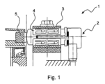
図1は、本発明によるシステム1の組み込み状況の側方断面図を示し、このシステム1は、センサ2、固定装置3、および固定手段4を備える。代替的な実施形態では、固定手段4は設けられていないが、固定装置は、別個の固定機構が不要となるように構成されている。
FIG. 1 shows a side sectional view of the installation situation of a
さらに、図1は、回転の際にセンサ2によって検出される磁気パルスを開始させる磁極ホイール5を示す。
Furthermore, FIG. 1 shows a
図2は、第1の形状特徴7を有するセンサ2の側面図を示す。このセンサは、軸線Aを有し、ここでは、センサ2は、軸線A周りのセンサ2の位置合わせに依存して物理量を検出するためのセンサである。特に、センサ2は、センサ2に関する物質の運動の結果としての物理量の変化を検出し、この場合、運動は、軸線A周りのセンサ2の予め定められた位置合わせにおいてのみ検出可能である。物質は、この実施形態では、自身の歯付き磁極ホイール5であり、センサ2は、検出方向が磁極ホイール5の接線方向に対応するように軸線A周りの自身の位置合わせが選択されている場合にのみ、磁極ホイール5の磁気パルスを検出する。
FIG. 2 shows a side view of a
センサ2は、アクティブ回転数センサとして構成されており、つまり、給電電圧の印加によって活動化し、出力信号を生成するセンサとして構成されている。
The
センサ2は、センサ本体6を有する。このセンサ本体6の外面にはリブが設けられており、つまり第1の形状特徴7としての隆起部が設けられている。この隆起部は、センサハウジング6の周面における予め定められた箇所に設けられており、それによって、この第1の形状特徴7は、センサ2の軸線A周りでセンサ2の予め定められた位置合わせを可能にさせる。
The
代替的な実施形態では、隆起部としてリブが設けられるのではなく、例えばテーパー状の隆起部が第1の形状特徴7として設けられる。代替的に、第1の形状特徴7が凹部である、つまり、例えば軸線Aに沿ったビードや接線方向の平坦部などであることも同様に可能である。
In an alternative embodiment, instead of a rib being provided as the ridge, for example a tapered ridge is provided as the
センサ本体6は、実質的に円形の円筒形状を有している。この実質的に円形の円筒形状を有するとは、完全に円形の円筒形状から外れて第1の形状特徴が存在すること、および/またはその他の機能面、例えばキー面が存在することを意味する。軸線Aは、この実施形態では、センサ本体6の実質的に円形の円筒形状の長手軸線である。リブは、長手軸線に対して平行に配置されている。
The
図2において同様に示されているように、隆起部は、センサ本体6の隣接する端部から軸線方向に距離Dを有する。この距離Dは、この実施形態では8mmであるが、代替的に、この距離より長くても短くてもよい。
As also shown in FIG. 2, the ridge has an axial distance D from the adjacent end of the
図3は、第2の形状特徴8を有する固定装置3の正面図を示す。この固定装置3は、センサ本体6を収容するように構成された収容装置10を有する収容本体9を備えている。収容装置10は、この実施形態では、収容本体9の孔部として、詳細には実質的に円形の断面を有する細長い開口部として実施されているが、代替的に、例えば、対応する設計のセンサ2をねじ込むためのねじ山であってもよい。
FIG. 3 shows a front view of the
固定装置3は、さらに収容本体9において、孔部の長手方向に沿った第2の形状特徴8としての溝を有する。この第2の形状特徴8は、第1の形状特徴7に対して相補的であり、このことは、第1の形状特徴7の特性と第2の形状特徴8の特性とが補足し合い、第1の形状特徴7と第2の形状特徴8とが互いに一致することを意味する。
The fixing
図4は、取り付けられたセンサ2と、相補的な形状特徴7,8とを有する固定装置3の正面図を示す。
FIG. 4 shows a front view of the
図5は、第1の実施形態における、取り付けられたセンサ2と、付加的な固定手段4とを有する図4の表示の断面図を示す。この固定手段4は、第3の形状特徴11を有し、この第3の形状特徴11は、第1の形状特徴7および第2の形状特徴8に対して相補的であり、あるいはこの第3の形状特徴は、第1の形状特徴7および第2の形状特徴の形状特性を補足し合うように成形されている。
FIG. 5 shows a cross-sectional view of the display of FIG. 4 with an attached
この実施形態では、固定手段4は、クランプスリーブを有する。このクランプスリーブは、開口部、つまり収容装置10に収容され、その中で径方向に開口部とセンサ本体6との間にクランプされるように構成されている。
In this embodiment, the fixing means 4 have a clamping sleeve. This clamping sleeve is arranged to be accommodated in the opening, i.e. the receiving
クランプスリーブは、自身の周面に第3の形状特徴11を備えている。この実施形態では、第3の形状特徴11は、クランプスリーブの周面における2つの端部区分12,13の間に軸線方向の間隙を有する。このことは、クランプスリーブにおける自身の周面において軸線方向に貫通スリットが設けられていることを意味する。軸線A周りのセンサ2およびクランプスリーブの位置合わせを実現するために、このスリット、詳細には第3の形状特徴11を通って、センサ本体6のリブが溝内に、詳細には第2の形状特徴8内に突出する。
The clamping sleeve is provided with a
クランプスリーブは、さらに、確実なクランプ力を加えるためのばね要素14を備えている。これらのばね要素14は、長手方向の端部においてクランプスリーブに一体的に形成された、もしくはクランプスリーブに固定された実質的に細長い矩形の舌状片である。代替的に他の形状も、例えば正方形も可能である。一般に、それらは、3辺における舌状片の輪郭の打ち抜き加工によって形成され、次いで、外方に湾曲され、それによって、それらは、事前ストレスをかけられ、外方に突出させられる。したがって、クランプスリーブの材料の弾性特性により、ばね要素14は、収容本体9の開口部内に挿入される場合に、径方向のクランプ力を加える。
The clamping sleeve further comprises a
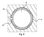
図6は、第2の実施形態における、取り付けられたセンサ2と、付加的な固定手段4とを有する図4の表示の断面図を示す。
FIG. 6 shows a cross-sectional view of the display of FIG. 4 with an attached
図6の固定手段4が、図5の固定手段4と異なるのは、端部区分12,13が、軸線方向のクリアランスを形成するために、周面において終端するのではなく、端部区分が、径方向外側に湾曲し、溝内へ突出し、その間に軸線方向のクリアランスが形成される点にある。 The fixing means 4 of FIG. 6 differs from the fixing means 4 of FIG. , curved radially outwardly and protrude into the groove at a point between which an axial clearance is formed.
つまり、このシステム1では、センサ本体6の隆起部は、径方向外側に溝内へ突出する2つの端部区分12,13の間に配置されている。
Thus, in this
固定手段4の代替的な実施形態では、この固定手段4は、外側に孔部の溝内へ突出する端部区分12,13も、軸線方向で他の位置における径方向内側に湾曲した端部区分も有する。内側に湾曲する端部区分は、溝内に突出しており、この溝は、センサ2の一実施形態において、センサハウジング6内で長手方向に設けられている。
In an alternative embodiment of the fastening means 4, this fastening means 4 has both
図7は、代替的な第2の形状特徴8,8’および代替的な第3の形状特徴11,11’を有する固定装置3の正面図を示す。
FIG. 7 shows a front view of the
固定手段4の代替的な第3の形状特徴11,11’は、貫通スリット(図5)の他に、付加的に隆起部を第3の形状特徴11’として有している。この隆起部は、収容本体9に対する軸線A周りのクランプスリーブの位置合わせを実現するために、クランプスリーブ、詳細には固定手段4から径方向外側にさらなる溝内へ、詳細には第3の形状特徴11’内へ突出する。センサ2は、クランプスリーブに対する軸線A周りで、クランプスリーブのスリット内の、詳細には第3の形状特徴11内のリブによって位置合わせされる。代替的な実施形態では、溝が、センサ本体6のリブ用の孔部に設けられるのではなく、センサ本体6のリブが、クランプスリーブのスリット内に突出するだけである。
The alternative
本明細書、以下の特許請求の範囲、ならびに図面に示されるすべての特徴は、個別においても、相互の任意の組み合わせにおいても、本発明に必須のものとなり得る。 All features shown in the specification, the following claims and the drawings can be essential to the invention both individually and in any combination with each other.
1 システム
2 センサ
3 固定装置
4 固定手段
5 磁極ホイール
6 センサ本体
7 第1の形状特徴
8 第2の形状特徴
9 収容本体
10 収容装置
11 第3の形状特徴
12 クランプスリーブの周面における端部
13 クランプスリーブの周面における端部
14 ばね要素
A 軸線
1
Claims (6)
前記センサ(2)用の固定装置(3)であって、前記固定装置(3)は、センサ本体(6)を収容するように構成された収容装置(10)を有する収容本体(9)と、前記収容本体(9)において第1の形状特徴(7)に対して相補的な第2の形状特徴(8)とを有している、固定装置(3)と、
からなるシステム(1)であって、
前記第1の形状特徴(7)は、前記センサ本体(6)の外面に隆起部を有しており、
前記センサ本体(6)は、実質的に円形の円筒形状を有し、前記センサ(2)の位置合わせは、実質的に円形の円筒形状の長手軸線周りの予め定められた配向であり、前記隆起部は、センサハウジング(6)の周面における予め定められた箇所に配置されており、
前記システム(1)は、前記第1の形状特徴(7)および前記第2の形状特徴(8)に対して相補的な第3の形状特徴(11)を有する固定手段(4)を有しており、
前記収容装置(10)は、実質的に円形の断面を有する細長い開口部を有し、前記第2の形状特徴(8)は、前記開口部の長手方向に沿った溝を有し、前記固定手段(4)は、前記開口部に収容され、前記開口部の中で径方向に前記開口部と前記センサ本体(6)との間にクランプされるように構成されたクランプスリーブを有し、前記クランプスリーブは、自身の周面に前記第3の形状特徴(11)を備えており、
前記第3の形状特徴(11)は、前記クランプスリーブの周面における軸線方向のスリットとして形成され、スリット長手方向側面は、2つの離間された端部区分(12,13)を形成し、
前記2つの端部区分(12,13)は、径方向外側に湾曲し、前記溝および前記クランプスリーブは、前記2つの端部区分(12,13)が前記溝内へ突出するように形成され、前記センサ(2)のセンサ本体(6)の隆起部が、径方向外側に前記溝内へ突出する前記2つの端部区分(12,13)の間に配置されており、
前記第3の形状特徴(11)を通って、前記センサ(2)のセンサ本体(6)の隆起部が前記第2の形状特徴(8)内に突出する
システム(1)。 A sensor (2) for detecting a physical quantity depending on the alignment of a sensor (2) about an axis (A) of the sensor (2), said sensor (2) being arranged on the outer surface of a sensor body (6). a sensor body (6) having a predetermined first shape feature (7), said first shape feature (7) being a predetermined shape of said sensor (2) about said axis (A); a sensor (2) configured to allow for controlled alignment;
A fixing device (3) for said sensor (2), said fixing device (3) comprising a housing body (9) having a housing device (10) configured to house a sensor body (6). , a second geometrical feature (8) complementary to the first geometrical feature (7) on the receiving body (9);
A system (1) consisting of
The first shape feature (7) has a raised portion on the outer surface of the sensor body (6),
The sensor body (6) has a substantially circular cylindrical shape, and the alignment of the sensor (2) is in a predetermined orientation about the longitudinal axis of the substantially circular cylindrical shape; The raised portion is arranged at a predetermined location on the circumferential surface of the sensor housing (6),
Said system (1) comprises fixation means (4) having a third shape feature (11) complementary to said first shape feature (7) and said second shape feature (8). and
The receiving device (10) has an elongated opening with a substantially circular cross section, the second feature (8) having a groove along the length of the opening, and the second feature (8) comprising a groove along the length of the opening; the means (4) having a clamping sleeve received in said opening and configured to be clamped radially within said opening and between said opening and said sensor body (6); The clamp sleeve is provided with the third shape feature (11) on its peripheral surface,
said third feature (11) is formed as an axial slit in the circumferential surface of said clamping sleeve, the longitudinal sides of the slit forming two spaced apart end sections (12, 13);
The two end sections (12, 13) are curved radially outwardly, and the groove and the clamping sleeve are formed such that the two end sections (12, 13) project into the groove. , a raised part of the sensor body (6) of said sensor (2) is arranged between said two end sections (12, 13) projecting radially outwardly into said groove;
A system (1) in which a ridge of the sensor body (6) of the sensor (2) projects through the third feature (11) into the second feature (8).
Applications Claiming Priority (3)
| Application Number | Priority Date | Filing Date | Title |
|---|---|---|---|
| DE102019125405.1A DE102019125405A1 (en) | 2019-09-20 | 2019-09-20 | Sensor and system consisting of the sensor and a fastening device |
| DE102019125405.1 | 2019-09-20 | ||
| PCT/EP2020/074537 WO2021052762A1 (en) | 2019-09-20 | 2020-09-03 | Sensor, and system comprising the sensor and comprising a fastening apparatus |
Publications (2)
| Publication Number | Publication Date |
|---|---|
| JP2022548967A JP2022548967A (en) | 2022-11-22 |
| JP7438340B2 true JP7438340B2 (en) | 2024-02-26 |
Family
ID=72470334
Family Applications (1)
| Application Number | Title | Priority Date | Filing Date |
|---|---|---|---|
| JP2022518007A Active JP7438340B2 (en) | 2019-09-20 | 2020-09-03 | System consisting of a sensor and a fixing device |
Country Status (6)
| Country | Link |
|---|---|
| US (1) | US20220404385A1 (en) |
| EP (1) | EP4031882B1 (en) |
| JP (1) | JP7438340B2 (en) |
| CN (1) | CN114424069B (en) |
| DE (1) | DE102019125405A1 (en) |
| WO (1) | WO2021052762A1 (en) |
Families Citing this family (2)
| Publication number | Priority date | Publication date | Assignee | Title |
|---|---|---|---|---|
| US11260690B2 (en) | 2020-03-31 | 2022-03-01 | Bendix Commercial Vehicle Systems Llc | Wheel speed sensor assembly with stepped alignment key |
| DE102021202438A1 (en) | 2021-03-12 | 2022-09-15 | Knorr-Bremse Systeme für Nutzfahrzeuge GmbH | CLAMPING SLEEVE FOR INSTALLATION OF A ROTARY SENSOR, AND ROTARY SENSOR ARRANGEMENT AND ROTARY SENSOR SYSTEM WITH SUCH A CLAMPING SLEEVE |
Citations (1)
| Publication number | Priority date | Publication date | Assignee | Title |
|---|---|---|---|---|
| WO2018234418A1 (en) | 2017-06-20 | 2018-12-27 | Knorr-Bremse Systeme für Nutzfahrzeuge GmbH | Arrangement of vehicle speed sensor and clamping sleeve for sensing the speed of rotation of a rotor |
Family Cites Families (20)
| Publication number | Priority date | Publication date | Assignee | Title |
|---|---|---|---|---|
| IT214173Z2 (en) * | 1988-02-19 | 1990-04-02 | Magneti Marelli Spa | ASTIFORM ASSEMBLY BUSHING PARTICULARLY FOR AN ELECTROMAGNETIC SENSOR |
| DE4020981A1 (en) * | 1990-07-02 | 1992-01-16 | Pasquale Dipl Ing Cianci | Clamping workpiece from one side - involves serrated bush segments expanded into workpiece clamping hole by hydraulically actuated drawbar |
| DE69815739T2 (en) * | 1997-03-31 | 2004-04-22 | Nsk Ltd. | Ball bearing with speed sensor |
| US6546824B2 (en) * | 2001-08-16 | 2003-04-15 | Deere & Company | Sensor mounting assembly |
| CN100483121C (en) * | 2003-02-26 | 2009-04-29 | 罗伯特·博施有限公司 | Apparatus for fixing measuring sensor |
| ES1056475Y (en) * | 2003-12-18 | 2004-07-16 | Zertan Sa | PERFECTED TURBIDITY SENSOR. |
| US8065790B2 (en) * | 2007-02-23 | 2011-11-29 | Continental Automotive Systems Us, Inc. | Bearing mounted sensor assembly |
| DE102010029955A1 (en) * | 2010-06-10 | 2011-12-15 | Endress + Hauser Gmbh + Co. Kg | Pressure sensor with a cylindrical pressure measuring cell |
| DE102010049552B4 (en) * | 2010-10-25 | 2012-05-31 | Schaeffler Technologies Gmbh & Co. Kg | Rolling bearing sensor, rolling bearing with a rolling bearing sensor and arrangement of a rolling bearing sensor |
| DE102013000204A1 (en) * | 2013-01-08 | 2014-07-24 | Wabco Gmbh | Sensor device for measuring speed on a wheel of a vehicle, brake system for a vehicle and vehicle therewith and use of the sensor device for measuring speed on a wheel of a vehicle |
| DE102013213243A1 (en) * | 2013-03-12 | 2014-09-18 | Robert Bosch Gmbh | Exhaust gas sensors for oriented installation in an exhaust system |
| DE102013010925A1 (en) * | 2013-06-29 | 2015-01-15 | Wabco Gmbh | Sensor device and sensor arrangement for detecting a wheel speed of a vehicle, wheel speed detection system for a vehicle and vehicle with it, and method for producing and using such a sensor device |
| GB2526247B (en) * | 2014-03-12 | 2018-12-05 | Rtl Mat Ltd | Methods and apparatus relating to deployment of fibre optic assemblies by burial. |
| CN204376003U (en) * | 2014-09-25 | 2015-06-03 | 深圳市大富科技股份有限公司 | Coaxial connector assemblies and coaxial connector |
| DE102014224346A1 (en) * | 2014-11-28 | 2016-06-02 | Voith Patent Gmbh | Spigot for a hit connection and roller drive train with such a pin receptacle |
| DE102015105550B4 (en) * | 2015-04-10 | 2022-04-28 | J. N. Eberle Federnfabrik Gmbh | Ferrule and a method of making a ferrule |
| CN207207961U (en) * | 2017-08-11 | 2018-04-10 | 襄阳冠通机械有限公司 | A kind of clamping and fixing device of vehicle bridge sensor |
| CN208366363U (en) * | 2018-07-10 | 2019-01-11 | 无锡四纬测控技术有限公司 | A kind of automatically cleaning sensor holder |
| CN208596174U (en) * | 2018-08-21 | 2019-03-12 | 艾礼富电子(深圳)有限公司 | A kind of velocity sensor |
| CN209239098U (en) * | 2018-12-05 | 2019-08-13 | 山东威达机械股份有限公司 | The clamping device and collet of collet |
-
2019
- 2019-09-20 DE DE102019125405.1A patent/DE102019125405A1/en active Pending
-
2020
- 2020-09-03 US US17/760,594 patent/US20220404385A1/en active Pending
- 2020-09-03 JP JP2022518007A patent/JP7438340B2/en active Active
- 2020-09-03 EP EP20771227.4A patent/EP4031882B1/en active Active
- 2020-09-03 CN CN202080066053.7A patent/CN114424069B/en active Active
- 2020-09-03 WO PCT/EP2020/074537 patent/WO2021052762A1/en unknown
Patent Citations (1)
| Publication number | Priority date | Publication date | Assignee | Title |
|---|---|---|---|---|
| WO2018234418A1 (en) | 2017-06-20 | 2018-12-27 | Knorr-Bremse Systeme für Nutzfahrzeuge GmbH | Arrangement of vehicle speed sensor and clamping sleeve for sensing the speed of rotation of a rotor |
Also Published As
| Publication number | Publication date |
|---|---|
| JP2022548967A (en) | 2022-11-22 |
| CN114424069A (en) | 2022-04-29 |
| CN114424069B (en) | 2024-04-30 |
| WO2021052762A1 (en) | 2021-03-25 |
| DE102019125405A1 (en) | 2021-03-25 |
| EP4031882A1 (en) | 2022-07-27 |
| EP4031882B1 (en) | 2023-11-08 |
| US20220404385A1 (en) | 2022-12-22 |
Similar Documents
| Publication | Publication Date | Title |
|---|---|---|
| JP7438340B2 (en) | System consisting of a sensor and a fixing device | |
| US7290351B2 (en) | Mounting bracket, rolling bearing and corresponding assembly method | |
| US11279335B2 (en) | Device for detecting wheel speed | |
| US6231241B1 (en) | Rotation support apparatus with rotational speed sensing device | |
| US9766260B2 (en) | Arrangement for determining a revolution rate and direction of rotation of a rotating component | |
| US10001502B2 (en) | Fastening device for an electronic component, in particular an acceleration sensor for airbag systems | |
| JP7311435B2 (en) | A device consisting of a rotary pulse generator and a clamping sleeve for detecting the number of revolutions of the rotor | |
| US9921236B2 (en) | Sensor device for speed measurement on a wheel of a vehicle | |
| JP6019049B2 (en) | Tire valve unit | |
| KR19980701446A (en) | DEVICE FOR MEASURING ROTATIONAL MOVEMENTS | |
| EP3129792B1 (en) | Wheel speed sensor | |
| JP2003042176A (en) | Assembly with charged bearing connected by single piece sensor and housing | |
| US9997315B2 (en) | Switch | |
| JP2000142341A (en) | Rotation supporting device with rotating speed detecting device | |
| JP6303937B2 (en) | Wheel speed sensor | |
| JP2000142341A5 (en) | ||
| JP2006162404A (en) | Wheel bearing with rotation speed detection device | |
| JP6524850B2 (en) | Accelerator device | |
| JP2020525790A (en) | Arrangement structure that connects the wheel support and chassis control arm | |
| CN113841055B (en) | Sensor system and method for rotationally positioning a rotational speed sensor of a sensor system | |
| JP7232592B2 (en) | Method for manufacturing rotation prevention mechanism, rotation member, rotation stopper, sensor unit, and rotation prevention mechanism | |
| US20030019262A1 (en) | Motor vehicle lock | |
| JP7420017B2 (en) | rotation detection device | |
| JPH11118817A (en) | Rolling bearing unit with rotating speed detector | |
| JP5194879B2 (en) | Rolling bearing unit with physical quantity measuring device |
Legal Events
| Date | Code | Title | Description |
|---|---|---|---|
| A621 | Written request for application examination |
Free format text: JAPANESE INTERMEDIATE CODE: A621 Effective date: 20220413 |
|
| A977 | Report on retrieval |
Free format text: JAPANESE INTERMEDIATE CODE: A971007 Effective date: 20230322 |
|
| A131 | Notification of reasons for refusal |
Free format text: JAPANESE INTERMEDIATE CODE: A131 Effective date: 20230404 |
|
| A521 | Request for written amendment filed |
Free format text: JAPANESE INTERMEDIATE CODE: A523 Effective date: 20230629 |
|
| A131 | Notification of reasons for refusal |
Free format text: JAPANESE INTERMEDIATE CODE: A131 Effective date: 20230925 |
|
| A521 | Request for written amendment filed |
Free format text: JAPANESE INTERMEDIATE CODE: A523 Effective date: 20231122 |
|
| TRDD | Decision of grant or rejection written | ||
| A01 | Written decision to grant a patent or to grant a registration (utility model) |
Free format text: JAPANESE INTERMEDIATE CODE: A01 Effective date: 20240115 |
|
| A61 | First payment of annual fees (during grant procedure) |
Free format text: JAPANESE INTERMEDIATE CODE: A61 Effective date: 20240213 |
|
| R150 | Certificate of patent or registration of utility model |
Ref document number: 7438340 Country of ref document: JP Free format text: JAPANESE INTERMEDIATE CODE: R150 |