EP3129792B1 - Wheel speed sensor - Google Patents
Wheel speed sensor Download PDFInfo
- Publication number
- EP3129792B1 EP3129792B1 EP15702359.9A EP15702359A EP3129792B1 EP 3129792 B1 EP3129792 B1 EP 3129792B1 EP 15702359 A EP15702359 A EP 15702359A EP 3129792 B1 EP3129792 B1 EP 3129792B1
- Authority
- EP
- European Patent Office
- Prior art keywords
- electromagnetic sensor
- flange
- tone ring
- wheel speed
- wheel
- Prior art date
- Legal status (The legal status is an assumption and is not a legal conclusion. Google has not performed a legal analysis and makes no representation as to the accuracy of the status listed.)
- Active
Links
- 238000004891 communication Methods 0.000 claims description 9
- 238000012544 monitoring process Methods 0.000 claims description 8
- 125000006850 spacer group Chemical group 0.000 claims description 6
- 239000000463 material Substances 0.000 claims description 5
- 229910000859 α-Fe Inorganic materials 0.000 claims description 4
- 238000003780 insertion Methods 0.000 claims description 3
- 230000037431 insertion Effects 0.000 claims description 3
- 230000004907 flux Effects 0.000 description 5
- 229910052751 metal Inorganic materials 0.000 description 3
- 239000002184 metal Substances 0.000 description 3
- PXHVJJICTQNCMI-UHFFFAOYSA-N Nickel Chemical compound [Ni] PXHVJJICTQNCMI-UHFFFAOYSA-N 0.000 description 2
- 230000008859 change Effects 0.000 description 2
- 238000012360 testing method Methods 0.000 description 2
- HCHKCACWOHOZIP-UHFFFAOYSA-N Zinc Chemical compound [Zn] HCHKCACWOHOZIP-UHFFFAOYSA-N 0.000 description 1
- 230000006978 adaptation Effects 0.000 description 1
- 238000013459 approach Methods 0.000 description 1
- 238000010276 construction Methods 0.000 description 1
- 230000001419 dependent effect Effects 0.000 description 1
- 238000013461 design Methods 0.000 description 1
- 238000006073 displacement reaction Methods 0.000 description 1
- 210000005069 ears Anatomy 0.000 description 1
- 238000000605 extraction Methods 0.000 description 1
- UQSXHKLRYXJYBZ-UHFFFAOYSA-N iron oxide Inorganic materials [Fe]=O UQSXHKLRYXJYBZ-UHFFFAOYSA-N 0.000 description 1
- 230000014759 maintenance of location Effects 0.000 description 1
- WPBNNNQJVZRUHP-UHFFFAOYSA-L manganese(2+);methyl n-[[2-(methoxycarbonylcarbamothioylamino)phenyl]carbamothioyl]carbamate;n-[2-(sulfidocarbothioylamino)ethyl]carbamodithioate Chemical compound [Mn+2].[S-]C(=S)NCCNC([S-])=S.COC(=O)NC(=S)NC1=CC=CC=C1NC(=S)NC(=O)OC WPBNNNQJVZRUHP-UHFFFAOYSA-L 0.000 description 1
- 230000007246 mechanism Effects 0.000 description 1
- 150000002739 metals Chemical class 0.000 description 1
- 229910052759 nickel Inorganic materials 0.000 description 1
- NDLPOXTZKUMGOV-UHFFFAOYSA-N oxo(oxoferriooxy)iron hydrate Chemical compound O.O=[Fe]O[Fe]=O NDLPOXTZKUMGOV-UHFFFAOYSA-N 0.000 description 1
- 230000035699 permeability Effects 0.000 description 1
- 239000000126 substance Substances 0.000 description 1
- 239000011701 zinc Substances 0.000 description 1
- 229910052725 zinc Inorganic materials 0.000 description 1
Images


Classifications
-
- G—PHYSICS
- G01—MEASURING; TESTING
- G01P—MEASURING LINEAR OR ANGULAR SPEED, ACCELERATION, DECELERATION, OR SHOCK; INDICATING PRESENCE, ABSENCE, OR DIRECTION, OF MOVEMENT
- G01P3/00—Measuring linear or angular speed; Measuring differences of linear or angular speeds
- G01P3/42—Devices characterised by the use of electric or magnetic means
- G01P3/44—Devices characterised by the use of electric or magnetic means for measuring angular speed
- G01P3/48—Devices characterised by the use of electric or magnetic means for measuring angular speed by measuring frequency of generated current or voltage
- G01P3/481—Devices characterised by the use of electric or magnetic means for measuring angular speed by measuring frequency of generated current or voltage of pulse signals
- G01P3/488—Devices characterised by the use of electric or magnetic means for measuring angular speed by measuring frequency of generated current or voltage of pulse signals delivered by variable reluctance detectors
-
- G—PHYSICS
- G01—MEASURING; TESTING
- G01P—MEASURING LINEAR OR ANGULAR SPEED, ACCELERATION, DECELERATION, OR SHOCK; INDICATING PRESENCE, ABSENCE, OR DIRECTION, OF MOVEMENT
- G01P3/00—Measuring linear or angular speed; Measuring differences of linear or angular speeds
- G01P3/42—Devices characterised by the use of electric or magnetic means
- G01P3/44—Devices characterised by the use of electric or magnetic means for measuring angular speed
-
- G—PHYSICS
- G01—MEASURING; TESTING
- G01D—MEASURING NOT SPECIALLY ADAPTED FOR A SPECIFIC VARIABLE; ARRANGEMENTS FOR MEASURING TWO OR MORE VARIABLES NOT COVERED IN A SINGLE OTHER SUBCLASS; TARIFF METERING APPARATUS; MEASURING OR TESTING NOT OTHERWISE PROVIDED FOR
- G01D5/00—Mechanical means for transferring the output of a sensing member; Means for converting the output of a sensing member to another variable where the form or nature of the sensing member does not constrain the means for converting; Transducers not specially adapted for a specific variable
- G01D5/12—Mechanical means for transferring the output of a sensing member; Means for converting the output of a sensing member to another variable where the form or nature of the sensing member does not constrain the means for converting; Transducers not specially adapted for a specific variable using electric or magnetic means
- G01D5/14—Mechanical means for transferring the output of a sensing member; Means for converting the output of a sensing member to another variable where the form or nature of the sensing member does not constrain the means for converting; Transducers not specially adapted for a specific variable using electric or magnetic means influencing the magnitude of a current or voltage
- G01D5/142—Mechanical means for transferring the output of a sensing member; Means for converting the output of a sensing member to another variable where the form or nature of the sensing member does not constrain the means for converting; Transducers not specially adapted for a specific variable using electric or magnetic means influencing the magnitude of a current or voltage using Hall-effect devices
- G01D5/145—Mechanical means for transferring the output of a sensing member; Means for converting the output of a sensing member to another variable where the form or nature of the sensing member does not constrain the means for converting; Transducers not specially adapted for a specific variable using electric or magnetic means influencing the magnitude of a current or voltage using Hall-effect devices influenced by the relative movement between the Hall device and magnetic fields
-
- G—PHYSICS
- G01—MEASURING; TESTING
- G01P—MEASURING LINEAR OR ANGULAR SPEED, ACCELERATION, DECELERATION, OR SHOCK; INDICATING PRESENCE, ABSENCE, OR DIRECTION, OF MOVEMENT
- G01P1/00—Details of instruments
- G01P1/02—Housings
- G01P1/026—Housings for speed measuring devices, e.g. pulse generator
-
- H—ELECTRICITY
- H02—GENERATION; CONVERSION OR DISTRIBUTION OF ELECTRIC POWER
- H02K—DYNAMO-ELECTRIC MACHINES
- H02K29/00—Motors or generators having non-mechanical commutating devices, e.g. discharge tubes or semiconductor devices
- H02K29/06—Motors or generators having non-mechanical commutating devices, e.g. discharge tubes or semiconductor devices with position sensing devices
- H02K29/08—Motors or generators having non-mechanical commutating devices, e.g. discharge tubes or semiconductor devices with position sensing devices using magnetic effect devices, e.g. Hall-plates, magneto-resistors
-
- F—MECHANICAL ENGINEERING; LIGHTING; HEATING; WEAPONS; BLASTING
- F16—ENGINEERING ELEMENTS AND UNITS; GENERAL MEASURES FOR PRODUCING AND MAINTAINING EFFECTIVE FUNCTIONING OF MACHINES OR INSTALLATIONS; THERMAL INSULATION IN GENERAL
- F16C—SHAFTS; FLEXIBLE SHAFTS; ELEMENTS OR CRANKSHAFT MECHANISMS; ROTARY BODIES OTHER THAN GEARING ELEMENTS; BEARINGS
- F16C41/00—Other accessories, e.g. devices integrated in the bearing not relating to the bearing function as such
- F16C41/007—Encoders, e.g. parts with a plurality of alternating magnetic poles
Definitions
- the present invention relates to a wheel speed sensor, and preferably a wheel speed sensor and monitoring system for a wheeled vehicle.
- Document US 2012/0112742 A1 discloses a speed sensor having a sensor housing for accommodating a magnetic field sensor element, an adapter for holding the sensor housing and a magnetic encoder.
- the invention provides for the speed sensor to have a device for length adaptation or air gap adjustment, and for the device to have a clamping mechanism for holding the sensor housing.
- Document US 6,463,818 B1 discloses a brake sensor comprising a bushing for insertion into a cylindrical aperture defined by a mounting bracket.
- the bushing further provides for retention of a cylindrical sensor housing which is enveloped around its circumference by the bushing and positioned adjacent a rotating flux focusing element.
- the bushing is formed from a sheet of spring metal and shaped into a cylinder.
- a pair of outwardly projecting retaining brackets extend from a first end of the sheet and are positioned at one end of the cylinder.
- a pair of outwardly projecting dimples are formed in the sheet near the edge of the sheet opposite the first edge, the dimples being sized to allow insertion of the bushing into a cylindrical aperture but function to resist extraction for the bushing after passing completely through the cylindrical aperture.
- JP 2009/144812 A discloses a sensor body having a generally rectangular cross-section.
- the sensor body is inserted into a space defined between two generally straight arms extending along a radial direction and fixed in place by a clip connection.
- the invention provides a wheel speed sensor in accordance with claim 1 and a wheel speed monitoring system in accordance with claim 4.
- Advantageous embodiments are subject to the dependent claims.
- Fig. 1 shows an unassembled wheel speed sensor 50 including an electromagnetic sensor 52 having a communication connector 54 at a proximal end and an electromagnetic sensor head 60 at a distal end.
- the communication connector 54 is a cable harness.
- the electromagnetic sensor 52 includes an integrated circuit 62 and a magnet 64 (shown in Fig. 2 ) enclosed within the sensor head 60.
- a sensor interface 66 represented by the distal end of the sensor head 60 enables securement of the electromagnetic sensor 52 to another object.
- the communication connector 54 provides a connection from the integrated circuit 62 to a remote control unit (not shown).
- the integrated circuit 62 and the magnet 64 of the electromagnetic sensor head 60 operates as a magnetic-field sensor.
- the magnet typically is a permanent magnet.
- Fig. 1 also shows an annular flange 70 including an annular or cylindrical shaped metallic ring 72 and an outer element 74 extending outwardly about a portion of the outer circumferential surface of the cylindrical shaped ring.
- the outer element 74 is overmolded onto the annular metallic ring 72.
- the annular flange 70 includes a flange interface 76. While shown as a depression for receiving the distal end of the electromagnetic sensor head 60 in Fig. 1 , the flange interface 76 typically is a physical structure as discussed herein below.
- the flange 70 includes an open bore aperture 78 for receiving a wheel shaft, wherein the flange acts as a spacer along a wheel shaft.
- Figure 2 shows the wheel speed sensor 50 provided adjacent a tone ring 80.
- the tone ring 80 is a magnetically attractive material, and typically a ferrite that comprises any of several magnetic substances that consist essentially of ferric oxide combined with the oxides of one or more other metals (such as manganese, nickel, or zinc).
- a ferrite has high magnetic permeability and high electrical resistivity. However, a ferrite does not output a magnetic field, and thus does not act as a magnet. A permanent magnet is not contemplated for the tone ring.
- Fig. 3 shows a tone ring 80 having an annular shaped ring 82 and an open bore aperture 84 for receiving a wheel shaft therethrough.
- Fig. 4 shows the tone ring 80 having a plurality of projecting elements 86 projecting outwardly from one face of the tone ring 80.
- the plurality of projecting elements are disposed in an alternating pattern that comprises hills and valleys forming ridges extending outwardly toward the outer edge of the tone ring.
- the projecting elements are teeth in some embodiments.
- the projecting elements 86 are replaced by a plurality of apertures (not shown) extending through the tone ring 80 and providing an aperture pattern at essentially the same locations as the projecting elements 86, or at least adjacent an outer edge of the one face of the tone ring.
- a plurality of cavities (not shown) provided in the tone ring 80 act as closed bore apertures.
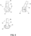
- Fig 5 shows one embodiment of an electromagnetic sensor 90 that includes an electromagnetic sensor head 92 having a substantially box-shape.
- the electromagnetic sensor 90 includes a sensor interface 94 in the form of tabs or ears, such as rigid or flexible tabs, projecting outwardly from opposing sides of the substantially box shaped electromagnetic sensor head 92. Other shaped projections 94 are contemplated.
- the electromagnetic sensor includes a central part 96 disposed between the electromagnetic sensor head 92 at the distal end, and the communication connector 98.
- a slightly raised cylindrical surface 99 is shown on a side of the electromagnetic sensor head 92 to indicate the sensing side to be faced with the tone ring 80.
- the center of the raised cylindrical surface 99 indicates the position of the integrated circuit 62 embedded in the electromagnetic sensor head 92 to be aligned with the tone ring 80.
- Three views of the electromagnetic sensor 90 are provided to show the overall shape thereof.
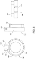
- Fig. 6 shows three views of a flange 100 or spacer for receiving the electromagnetic sensor 90 of Fig. 5 to form a wheel speed sensor.
- the flange includes a metal ring 102 and an outer element 104.
- the flange 100 further includes a flange interface 106 defined by a pair of parallel, outwardly projecting arms 107 facing each other, and a sensor head receiving slot or opening 108 therebetween.
- the arms 107 each include open bore apertures 109 in alignment with each other and are configured to receive the electromagnetic sensor head 92.
- the open bore apertures 109 are configured to receive the tabs 94 of the electromagnetic sensor head 92.
- Fig. 7 shows three views of the electromagnetic sensor 90 and the flange 100 combined to form a wheel speed sensor 110.
- the electromagnetic sensor head 92 is disposed in the sensor head receiving slot 108 and the tabs 94 projecting from the electromagnetic sensor head 92 are locked into the respective apertures 109 of the flange 100.
- At least one of the arms 107 or tabs 94 have a certain amount of elasticity, or are flexible to enable forcing of the electromagnetic sensor head 92 into the slot 108.
- the arms are semi-rigid in some embodiments.
- a snap fit or locking occurs to for the wheel speed sensor 110.
- the pair of parallel spaced arms 107 projecting outwardly from the flange 100 are monolithic with the flange.
- the parallel, spaced arms 107 are attached or secured to the flange 100.
- Fig. 8 shows front and side views of a wheel hub 120.
- the wheel hub 120 includes an annular front face 122, a wheel bearing receiving aperture 124 and an inner face 126.
- the aperture 124 has an inner diameter and the inner face 126 is flat. While not shown, a path through the wheel hub120 for a wheel shaft may be provided.
- Fig. 9 shows front and side views of a wheel bearing 130 having a central open bore aperture 132 extending through the bearing.
- the wheel bearing 130 is dimensioned to fit within the bearing receiving aperture 124 of the wheel hub 120.
- Fig. 10 shows part of a fork 140, typically for mounting to a motorcycle.
- the fork 140 includes an elongated lower fork bar 142 having an open bore fork aperture 144 and an upper fork bar 146 having a greater dimension in one direction than the lower fork bar.
- Fig. 11 shows the components for a portion of a cycle wheel assembly wherein the wheel speed sensor 50 is mounted as a part of the assembly.
- the components shown are the wheel hub 120 that receives the wheel bearing 130 and the tone ring 80. Further, the wheel speed sensor 50 is disposed between the tone ring 80 and the fork 140.
- the components are assembled in the order shown.
- An axle or wheel shaft extends through aligned apertures in the components and into/through the wheel hub 120. The apertures are in axial alignment with each other and similar in diameter.
- Fig. 12 shows the components of Fig. 11 assembled, wherein the wheel hub 120, the wheel speed sensor 50 and the fork 140 visible.
- the wheel hub 120 is configured to receive the wheel bearing 130 and tone ring 80.
- the tone ring 80 is integrated adjacent to the wheel bearing 130 in the wheel hub 120.
- Fig. 13 shows a perspective view of an embodiment of a wheel assembly 150 similar to the arrangement of Fig. 12 .
- a wheel shaft 152 The wheel shaft 152 extends through a fork 154.
- the structure 155 supporting the fork 154 is only for purposes of illustration.
- the wheel speed sensor 156 is disposed adjacent the fork 154 and the wheel hub 158. Portions of the tone ring 160 are visible facing the wheel speed sensor 156.
- the above components all receive the wheel shaft 152 therethrough.
- the components of Fig. 12 operate as a wheel speed monitoring system that operates as set forth below.
- the tone ring shown in Fig. 13 rotates with a wheel (not shown).
- the integrated circuit 62 is disposed between the magnet 64 and the tone ring 80.
- the magnet 64 projects a magnetic field through the integrated circuit 62 and the tone ring 80.
- the tone ring 80 is a magnetic attractive material.
- the tone ring 80 affects the magnetic field projected by the magnet 64. Rotation of the tone ring 80, and specifically movement of the spaced projections 86 of the tone ring 80 past the integrated circuit 62 cause changes in the magnetic field of the magnet 64 that are detected by the integrated circuit.
- the magnetic flux density projected onto the integrated circuit 62 varies in a sinusoidal manner, due to the change in displacement between the magnet 64 and the outer edge of the tone ring 80.
- the integrated circuit 62 contains a magnetic-field sensor such as Hall sensor or Magneto Resistive sensor that senses the variation of the magnetic flux density projected by the magnet 64.
- the integrated circuit 62 sends electrical signal such as current in different amplitudes corresponding to the variation of the magnetic flux density sensed by its magnetic-field sensor to a control unit via the communication connector 54. The frequency of change in the current signal between a low value and a greater value determines the wheel speed.
- rotation of the tone ring 80 relative to the wheel speed sensor 50 alters magnetic flux density projected by the magnet 64 sensed by the integrated circuit 62, and the integrated circuit 62 sends an electrical signal, typically current in different amplitudes as an output that is proportional to rotational speed of the tone ring 80 relative to a control unit via the communication connector 54.
- the above embodiments are all predicated on the flange 70 having an open bore aperture 78 for receiving a wheel shaft.
- the above embodiments are all directed to a wheel speed sensor that is disposed on the wheel shaft and acts as a spacer for components thereon.
- the flange of the wheel speed sensor is provided with various shapes for mounting on a vehicle so that the sensor head is disposed adjacent to an outer part of the tone ring for sensing the passage thereby.
- the outer edge of the flat tone ring has an extension projecting perpendicular to the plane of the flat tone ring and extending about the entire circumference of the outer edge.
- the extension forms a cylindrical shape. Alternating projections from on outer face or apertures are provided in the extension about the entirety of the extension.
- the embodiments disclosed below permit mounting of an electromagnetic sensor to different flanges to enable use with various vehicles.
- the cost and time to develop, test and tool for a large number of wheel speed sensors for various vehicles is minimized, as only a large number of receiving flanges are required, that are less expensive and complicated than wheel speed sensors designed for specific vehicles.
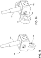
- Fig. 14 shows two views of an embodiment of the wheel speed sensor 170 having the same or similar snap fit arrangement for mounting the electromagnetic sensor 172 to the flange 174 having a bushing 176.
- the arrangement enables a quick and easy snap fitting connection between the electromagnetic sensor 172 and the flange 174.
- the bushing 176 is mounted to a fixed part of a vehicle so that the sensor head is aligned near a tone ring for measuring wheel speed.
- Fig. 15 is a perspective view of the embodiment shown in Fig 14 .
- a fastener (not shown) utilizes the bushing 176 to mount the wheel speed sensor 170.
- Fig. 16 is another embodiment of the wheel speed sensor 180.
- the embodiment of Fig. 16 is similar to the embodiment of Figs. 14 and 15 , except the bushing 186 of the flange 184 is oriented perpendicular and sidewardly from the bushing arrangement shown in Figs. 14 and 15 .
- the wheel speed sensor 180 of Fig. 16 is mounted in a different vehicle or mounting location to provide the sensor head adjacent the tone ring.
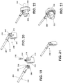
- Fig. 17 is two views of another embodiment of the wheel speed sensor 190.
- the electromagnetic sensor 192 has the same snap mounting arrangement with the flange 194 as the embodiments discussed above.
- the flange 194 includes a pair of bushings 196 for mounting the wheel speed sensor 190.
- Fig. 18 is a perspective view the wheel speed sensor 190.
- flanges have bushings that are at 45, 75, 135 or other degree angles with respect to a rear or side of the sensor head of the wheel speed sensor.
- Figs. 19 and 20 show an embodiment of a wheel speed sensor 200 corresponding to the claimed invention. More specifically, Fig. 19 shows an unassembled wheel speed sensor that includes an electromagnetic sensor 202 having a communication connector 204 at a proximal end an electromagnetic sensor head 206 at a distal end.
- the electromagnetic sensor head 206 is substantially box shaped.
- the electromagnetic sensor 202 has a sensor interface defined by a slot 208 extending about at least three sides of the substantially box-shaped electromagnetic sensor head 206.
- the slot 208 is defined by a narrow lip 209 at the tone ring facing end of the electromagnetic sensor head 206.
- the substantially box-shaped electromagnetic sensor head 206 is defined by an essentially flat face at the tone ring facing end.
- Fig, 19 also shows a flange 210 that acts as a spacer when placed on a wheel shaft.
- the flange has an annular shape and an open bore aperture 212 for receiving a wheel shaft.
- the flange also has a flange interface comprising a pair of parallel outwardly projecting arms 214 having inwardly oriented projections at the distal ends thereof to receive the electromagnetic sensor head 206.
- a retainer element 216 is provided for securing the electromagnetic sensor 202 to the flange 210.
- Fig. 20 shows the assembled wheel speed sensor 200 formed from the components shown in Fig. 19 . More specifically, the electromagnetic sensor head 206 of the electromagnetic sensor 202 is located between the arms 214 that have inwardly oriented projections at the distal ends. A lip at the rear of the electromagnetic sensor head 206 contacts the arms 214 while the slot 208 is adjacent the opposing side of the arms 214. Then the retainer element 216 is seated in the slot 208 to lock the electromagnetic sensor 202 and the flange 210 together to form the wheel speed sensor 200 that is prepared for use with a wheel shaft.
- the wheel speed sensor 220 shown in Fig. 21 is essentially identical to the wheel speed sensor 200 shown in Fig. 20 , except the flange has a reduced length and the pair of parallel outwardly projecting arms are not centered on an outer wall of the cylindrical shaped flange.
- Figs. 22 and 23 show the wheel speed sensor 200 of Fig. 20 disposed on a wheel shaft 222 adjacent a wheel hub 224.
- the perspective view of Fig. 23 shows a tone ring 226 disposed in or adjacent the wheel hub 224 that rotates with a wheel hub.
- the wheel speed sensor 200 measures wheel speed in a similar manner to the embodiment discussed above.
- Fig. 24 does not correspond to the claimed invention and shows the electromagnetic sensor 202 and a separate retainer element 216 of Fig. 19 , along with a plurality of different flanges 230, 232, 234, 236.
- the different flanges have bushings for mounted to a fixed part of a vehicle.
- the bushings have different orientations with respect the electromagnetic sensor head 206 of the electromagnetic sensor 202.
- the flange for a specific vehicle is selected, secured to the electromagnetic sensor 202 to form a wheel speed sensor with the retainer element 216, and mounted to a vehicle adjacent a tone ring via the bushings and a fastener (not shown).
- Fig. 25 shows wheel speed sensors 240, 242, 244, 246 assembled from the electromagnetic sensor 202 and the respective flanges 230, 232, 234, 236 shown in Fig. 24 .
- the invention provides, among other things, an easy approach to providing an easy to assemble wheel speed sensor for mounting on any vehicle.
- the invention enables a vehicle manufacturer to use a common, validated electromagnetic sensor design, with different mounting flanges for different vehicles that have different mounting constraints, thus substantially reduces the time and costs for developing, testing and tooling for different wheel speed sensors, as the cost of developing and tooling a new flange, which is a mechanical component that is less complicated than the electromagnetic sensor is minimal compared to a complete wheel speed sensor.
Description
- This application claims priority from
U.S. provisional application 61/978,568, filed April 11, 2014 - The present invention relates to a wheel speed sensor, and preferably a wheel speed sensor and monitoring system for a wheeled vehicle.
- Document
US 2012/0112742 A1 discloses a speed sensor having a sensor housing for accommodating a magnetic field sensor element, an adapter for holding the sensor housing and a magnetic encoder. The invention provides for the speed sensor to have a device for length adaptation or air gap adjustment, and for the device to have a clamping mechanism for holding the sensor housing. - Document
US 6,463,818 B1 discloses a brake sensor comprising a bushing for insertion into a cylindrical aperture defined by a mounting bracket. The bushing further provides for retention of a cylindrical sensor housing which is enveloped around its circumference by the bushing and positioned adjacent a rotating flux focusing element. The bushing is formed from a sheet of spring metal and shaped into a cylinder. A pair of outwardly projecting retaining brackets extend from a first end of the sheet and are positioned at one end of the cylinder. In addition, a pair of outwardly projecting dimples are formed in the sheet near the edge of the sheet opposite the first edge, the dimples being sized to allow insertion of the bushing into a cylindrical aperture but function to resist extraction for the bushing after passing completely through the cylindrical aperture. -
JP 2009/144812 A - The invention provides a wheel speed sensor in accordance with claim 1 and a wheel speed monitoring system in accordance with
claim 4. Advantageous embodiments are subject to the dependent claims. - Other aspects of the invention will become apparent by consideration of the detailed description and accompanying drawings.
-
-
Fig. 1 is a front cross sectional view of an unassembled wheel speed sensor comprising an electromagnetic sensor and a flange. -
Fig. 2 is a side view of a wheel speed sensor and a tone ring. -
Fig. 3 is a front view of a tone ring. -
Fig. 4 is a side view of the tone ring ofFig. 3 . -
Fig. 5 is views of one example of an electromagnetic sensor. -
Fig. 6 is views of one example of a flange. -
Fig. 7 is views of a wheel speed sensor formed from the sensor ofFig. 5 and the flange ofFig. 6 . -
Fig. 8 is front and side views of a wheel hub. -
Fig. 9 is front and side views of a wheel bearing. -
Fig. 10 is front and side views of a fork. -
Fig. 11 is an unassembled view of an example of the components for a portion of a wheel assembly with a speed sensor. -
Fig. 12 is a side view of the components of the example ofFig. 11 as assembled. -
Fig. 13 is a perspective view of an example of a wheel assembly. -
Fig. 14 is two views of an example of the wheel speed sensor. -
Fig. 15 is a perspective view of the example ofFig. 14 . -
Fig. 16 is two views of another example of the wheel speed sensor. -
Fig. 17 is two views of another example of the wheel speed sensor. -
Fig. 18 is a perspective view of the example ofFig. 17 . -
Fig. 19 is a view of an embodiment of unassembled wheel speed sensor according to the invention including an electromagnetic sensor, a flange and a clip. -
Fig. 20 is the assembled wheel speed sensor ofFig. 19 . -
Fig. 21 is the wheel speed sensor ofFig. 20 with a different flange. -
Fig. 22 is a wheel assembly. -
Fig. 23 is a perspective view of the wheel assembly ofFig. 22 . -
Fig. 24 is the electromagnetic sensor ofFig. 19 provided with a plurality of different flanges, not corresponding to the claimed invention. -
Fig. 25 is wheel speed sensors assembled from the electromagnetic sensor and the flanges shown inFig. 24 . - Before any embodiments of the invention are explained in detail, it is to be understood that the invention is not limited in its application to the details of construction and the arrangement of components set forth in the following description or illustrated in the following drawings. The invention is capable of other embodiments and of being practiced or of being carried out in various ways.
- In the following description, only
Figures 19-23 show embodiments of the claimed invention. - All other Figures or examples - even when referring to embodiments - show details of examples which constitute background information and which may help to better understand the claimed invention.
-
Fig. 1 shows an unassembledwheel speed sensor 50 including an electromagnetic sensor 52 having a communication connector 54 at a proximal end and anelectromagnetic sensor head 60 at a distal end. In some embodiments, the communication connector 54 is a cable harness. The electromagnetic sensor 52 includes anintegrated circuit 62 and a magnet 64 (shown inFig. 2 ) enclosed within thesensor head 60. Asensor interface 66, represented by the distal end of thesensor head 60 enables securement of the electromagnetic sensor 52 to another object. The communication connector 54 provides a connection from theintegrated circuit 62 to a remote control unit (not shown). In some embodiments, theintegrated circuit 62 and themagnet 64 of theelectromagnetic sensor head 60 operates as a magnetic-field sensor. The magnet typically is a permanent magnet. -
Fig. 1 also shows anannular flange 70 including an annular or cylindrical shapedmetallic ring 72 and anouter element 74 extending outwardly about a portion of the outer circumferential surface of the cylindrical shaped ring. In some embodiments, theouter element 74 is overmolded onto the annularmetallic ring 72. Theannular flange 70 includes aflange interface 76. While shown as a depression for receiving the distal end of theelectromagnetic sensor head 60 inFig. 1 , theflange interface 76 typically is a physical structure as discussed herein below. Theflange 70 includes anopen bore aperture 78 for receiving a wheel shaft, wherein the flange acts as a spacer along a wheel shaft. -
Figure 2 shows thewheel speed sensor 50 provided adjacent atone ring 80. Thetone ring 80 is a magnetically attractive material, and typically a ferrite that comprises any of several magnetic substances that consist essentially of ferric oxide combined with the oxides of one or more other metals (such as manganese, nickel, or zinc). A ferrite has high magnetic permeability and high electrical resistivity. However, a ferrite does not output a magnetic field, and thus does not act as a magnet. A permanent magnet is not contemplated for the tone ring. -
Fig. 3 shows atone ring 80 having an annular shapedring 82 and an open bore aperture 84 for receiving a wheel shaft therethrough.Fig. 4 shows thetone ring 80 having a plurality of projectingelements 86 projecting outwardly from one face of thetone ring 80. In another embodiment, the plurality of projecting elements are disposed in an alternating pattern that comprises hills and valleys forming ridges extending outwardly toward the outer edge of the tone ring. The projecting elements are teeth in some embodiments. In another embodiment, the projectingelements 86 are replaced by a plurality of apertures (not shown) extending through thetone ring 80 and providing an aperture pattern at essentially the same locations as the projectingelements 86, or at least adjacent an outer edge of the one face of the tone ring. In some embodiments, a plurality of cavities (not shown) provided in thetone ring 80 act as closed bore apertures. -
Fig 5 shows one embodiment of anelectromagnetic sensor 90 that includes anelectromagnetic sensor head 92 having a substantially box-shape. Theelectromagnetic sensor 90 includes asensor interface 94 in the form of tabs or ears, such as rigid or flexible tabs, projecting outwardly from opposing sides of the substantially box shapedelectromagnetic sensor head 92. Other shapedprojections 94 are contemplated. Further, the electromagnetic sensor includes a central part 96 disposed between theelectromagnetic sensor head 92 at the distal end, and thecommunication connector 98. Finally, a slightly raised cylindrical surface 99 is shown on a side of theelectromagnetic sensor head 92 to indicate the sensing side to be faced with thetone ring 80. The center of the raised cylindrical surface 99 indicates the position of theintegrated circuit 62 embedded in theelectromagnetic sensor head 92 to be aligned with thetone ring 80. Three views of theelectromagnetic sensor 90 are provided to show the overall shape thereof. -
Fig. 6 shows three views of aflange 100 or spacer for receiving theelectromagnetic sensor 90 ofFig. 5 to form a wheel speed sensor. The flange includes ametal ring 102 and anouter element 104. Theflange 100 further includes aflange interface 106 defined by a pair of parallel, outwardly projectingarms 107 facing each other, and a sensor head receiving slot or opening 108 therebetween. Finally, thearms 107 each includeopen bore apertures 109 in alignment with each other and are configured to receive theelectromagnetic sensor head 92. Theopen bore apertures 109 are configured to receive thetabs 94 of theelectromagnetic sensor head 92. -
Fig. 7 shows three views of theelectromagnetic sensor 90 and theflange 100 combined to form awheel speed sensor 110. When combined, theelectromagnetic sensor head 92 is disposed in the sensorhead receiving slot 108 and thetabs 94 projecting from theelectromagnetic sensor head 92 are locked into therespective apertures 109 of theflange 100. At least one of thearms 107 ortabs 94 have a certain amount of elasticity, or are flexible to enable forcing of theelectromagnetic sensor head 92 into theslot 108. For instance, the arms are semi-rigid in some embodiments. Upon entrance of thetabs 94 into theapertures 109, a snap fit or locking occurs to for thewheel speed sensor 110. In some embodiments, the pair of parallel spacedarms 107 projecting outwardly from theflange 100 are monolithic with the flange. In other embodiments, the parallel, spacedarms 107 are attached or secured to theflange 100. -
Fig. 8 shows front and side views of awheel hub 120. Thewheel hub 120 includes an annularfront face 122, a wheelbearing receiving aperture 124 and aninner face 126. Theaperture 124 has an inner diameter and theinner face 126 is flat. While not shown, a path through the wheel hub120 for a wheel shaft may be provided. -
Fig. 9 shows front and side views of awheel bearing 130 having a central open bore aperture 132 extending through the bearing. Thewheel bearing 130 is dimensioned to fit within thebearing receiving aperture 124 of thewheel hub 120. -
Fig. 10 shows part of afork 140, typically for mounting to a motorcycle. Thefork 140 includes an elongatedlower fork bar 142 having an openbore fork aperture 144 and anupper fork bar 146 having a greater dimension in one direction than the lower fork bar. -
Fig. 11 shows the components for a portion of a cycle wheel assembly wherein thewheel speed sensor 50 is mounted as a part of the assembly. The components shown are thewheel hub 120 that receives thewheel bearing 130 and thetone ring 80. Further, thewheel speed sensor 50 is disposed between thetone ring 80 and thefork 140. The components are assembled in the order shown. An axle or wheel shaft extends through aligned apertures in the components and into/through thewheel hub 120. The apertures are in axial alignment with each other and similar in diameter.Fig. 12 shows the components ofFig. 11 assembled, wherein thewheel hub 120, thewheel speed sensor 50 and thefork 140 visible. Thewheel hub 120 is configured to receive thewheel bearing 130 andtone ring 80. Thus, thetone ring 80 is integrated adjacent to the wheel bearing 130 in thewheel hub 120. -
Fig. 13 shows a perspective view of an embodiment of awheel assembly 150 similar to the arrangement ofFig. 12 . InFig. 13 , awheel shaft 152. Thewheel shaft 152 extends through afork 154. Thestructure 155 supporting thefork 154 is only for purposes of illustration. Thewheel speed sensor 156 is disposed adjacent thefork 154 and thewheel hub 158. Portions of thetone ring 160 are visible facing thewheel speed sensor 156. As is illustrated inFig. 13 , the above components all receive thewheel shaft 152 therethrough. The components ofFig. 12 operate as a wheel speed monitoring system that operates as set forth below. - In operation, the tone ring shown in
Fig. 13 rotates with a wheel (not shown). As shown inFig. 2 , theintegrated circuit 62 is disposed between themagnet 64 and thetone ring 80. Themagnet 64 projects a magnetic field through theintegrated circuit 62 and thetone ring 80. Thetone ring 80 is a magnetic attractive material. Thus, thetone ring 80 affects the magnetic field projected by themagnet 64. Rotation of thetone ring 80, and specifically movement of the spacedprojections 86 of thetone ring 80 past theintegrated circuit 62 cause changes in the magnetic field of themagnet 64 that are detected by the integrated circuit. - In one embodiment, when the
tone ring 80 is in rotary motion, the magnetic flux density projected onto theintegrated circuit 62 varies in a sinusoidal manner, due to the change in displacement between themagnet 64 and the outer edge of thetone ring 80. In one embodiment, theintegrated circuit 62 contains a magnetic-field sensor such as Hall sensor or Magneto Resistive sensor that senses the variation of the magnetic flux density projected by themagnet 64. Theintegrated circuit 62 sends electrical signal such as current in different amplitudes corresponding to the variation of the magnetic flux density sensed by its magnetic-field sensor to a control unit via the communication connector 54. The frequency of change in the current signal between a low value and a greater value determines the wheel speed. - In conclusion, rotation of the
tone ring 80 relative to thewheel speed sensor 50 alters magnetic flux density projected by themagnet 64 sensed by the integratedcircuit 62, and theintegrated circuit 62 sends an electrical signal, typically current in different amplitudes as an output that is proportional to rotational speed of thetone ring 80 relative to a control unit via the communication connector 54. - The above embodiments are all predicated on the
flange 70 having anopen bore aperture 78 for receiving a wheel shaft. Thus, the above embodiments are all directed to a wheel speed sensor that is disposed on the wheel shaft and acts as a spacer for components thereon. In other embodiments set forth below, the flange of the wheel speed sensor is provided with various shapes for mounting on a vehicle so that the sensor head is disposed adjacent to an outer part of the tone ring for sensing the passage thereby. - In some embodiments, the outer edge of the flat tone ring has an extension projecting perpendicular to the plane of the flat tone ring and extending about the entire circumference of the outer edge. Thus, the extension forms a cylindrical shape. Alternating projections from on outer face or apertures are provided in the extension about the entirety of the extension. Thus, rotation of the tone ring is sensed by a wheel speed sensor that is disposed outwardly of the tone ring. Accordingly, various mounting locations are available and various flanges are needed to locate the wheel speed sensor so that the sensor head is aligned properly with the tone ring.
- The embodiments disclosed below permit mounting of an electromagnetic sensor to different flanges to enable use with various vehicles. By utilizing one electromagnetic sensor with a large number of flanges, the cost and time to develop, test and tool for a large number of wheel speed sensors for various vehicles is minimized, as only a large number of receiving flanges are required, that are less expensive and complicated than wheel speed sensors designed for specific vehicles.
-
Fig. 14 shows two views of an embodiment of thewheel speed sensor 170 having the same or similar snap fit arrangement for mounting theelectromagnetic sensor 172 to theflange 174 having abushing 176. The arrangement enables a quick and easy snap fitting connection between theelectromagnetic sensor 172 and theflange 174. In use, thebushing 176 is mounted to a fixed part of a vehicle so that the sensor head is aligned near a tone ring for measuring wheel speed.Fig. 15 is a perspective view of the embodiment shown inFig 14 . A fastener (not shown) utilizes thebushing 176 to mount thewheel speed sensor 170. -
Fig. 16 is another embodiment of thewheel speed sensor 180. The embodiment ofFig. 16 is similar to the embodiment ofFigs. 14 and15 , except thebushing 186 of theflange 184 is oriented perpendicular and sidewardly from the bushing arrangement shown inFigs. 14 and15 . Thus, thewheel speed sensor 180 ofFig. 16 is mounted in a different vehicle or mounting location to provide the sensor head adjacent the tone ring. -
Fig. 17 is two views of another embodiment of thewheel speed sensor 190. Theelectromagnetic sensor 192 has the same snap mounting arrangement with theflange 194 as the embodiments discussed above. Theflange 194 includes a pair ofbushings 196 for mounting thewheel speed sensor 190.Fig. 18 is a perspective view thewheel speed sensor 190. - In other embodiments (not shown) flanges have bushings that are at 45, 75, 135 or other degree angles with respect to a rear or side of the sensor head of the wheel speed sensor.
-
Figs. 19 and 20 show an embodiment of awheel speed sensor 200 corresponding to the claimed invention. More specifically,Fig. 19 shows an unassembled wheel speed sensor that includes anelectromagnetic sensor 202 having acommunication connector 204 at a proximal end anelectromagnetic sensor head 206 at a distal end. Theelectromagnetic sensor head 206 is substantially box shaped. Theelectromagnetic sensor 202 has a sensor interface defined by aslot 208 extending about at least three sides of the substantially box-shapedelectromagnetic sensor head 206. Theslot 208 is defined by anarrow lip 209 at the tone ring facing end of theelectromagnetic sensor head 206. The substantially box-shapedelectromagnetic sensor head 206 is defined by an essentially flat face at the tone ring facing end. -
Fig, 19 also shows aflange 210 that acts as a spacer when placed on a wheel shaft. The flange has an annular shape and anopen bore aperture 212 for receiving a wheel shaft. The flange also has a flange interface comprising a pair of parallel outwardly projectingarms 214 having inwardly oriented projections at the distal ends thereof to receive theelectromagnetic sensor head 206. Aretainer element 216 is provided for securing theelectromagnetic sensor 202 to theflange 210. -
Fig. 20 shows the assembledwheel speed sensor 200 formed from the components shown inFig. 19 . More specifically, theelectromagnetic sensor head 206 of theelectromagnetic sensor 202 is located between thearms 214 that have inwardly oriented projections at the distal ends. A lip at the rear of theelectromagnetic sensor head 206 contacts thearms 214 while theslot 208 is adjacent the opposing side of thearms 214. Then theretainer element 216 is seated in theslot 208 to lock theelectromagnetic sensor 202 and theflange 210 together to form thewheel speed sensor 200 that is prepared for use with a wheel shaft. - The wheel speed sensor 220 shown in
Fig. 21 is essentially identical to thewheel speed sensor 200 shown inFig. 20 , except the flange has a reduced length and the pair of parallel outwardly projecting arms are not centered on an outer wall of the cylindrical shaped flange. -
Figs. 22 and 23 show thewheel speed sensor 200 ofFig. 20 disposed on awheel shaft 222 adjacent awheel hub 224. The perspective view ofFig. 23 shows a tone ring 226 disposed in or adjacent thewheel hub 224 that rotates with a wheel hub. Thewheel speed sensor 200 measures wheel speed in a similar manner to the embodiment discussed above. -
Fig. 24 does not correspond to the claimed invention and shows theelectromagnetic sensor 202 and aseparate retainer element 216 ofFig. 19 , along with a plurality ofdifferent flanges electromagnetic sensor head 206 of theelectromagnetic sensor 202. Thus, the flange for a specific vehicle is selected, secured to theelectromagnetic sensor 202 to form a wheel speed sensor with theretainer element 216, and mounted to a vehicle adjacent a tone ring via the bushings and a fastener (not shown). -
Fig. 25 showswheel speed sensors electromagnetic sensor 202 and therespective flanges Fig. 24 . - Thus, the invention provides, among other things, an easy approach to providing an easy to assemble wheel speed sensor for mounting on any vehicle. The invention enables a vehicle manufacturer to use a common, validated electromagnetic sensor design, with different mounting flanges for different vehicles that have different mounting constraints, thus substantially reduces the time and costs for developing, testing and tooling for different wheel speed sensors, as the cost of developing and tooling a new flange, which is a mechanical component that is less complicated than the electromagnetic sensor is minimal compared to a complete wheel speed sensor. Various features and advantages of the invention are set forth in the following claims.
Claims (8)
- A wheel speed sensor (200) comprising:an electromagnetic sensor (52; 202), comprising:a substantially box-shaped electromagnetic sensor head (60; 206) disposed at a distal end of the electromagnetic sensor (52; 202), the electromagnetic sensor head (60; 206) comprising a magnet (64) and an integrated circuit (62), the electromagnetic sensor head (60; 206) being configured to sense movement by a tone ring (80) comprising magnetic attractive material;a communication connector (54; 204) disposed at a proximal end of the electromagnetic sensor (52; 204) and in communication with the electromagnetic sensor head (60; 206);a sensor interface disposed at the distal end of the electromagnetic sensor (52; 202), the sensor interface comprising a slot (208) extending about at least three sides of the substantially box-shaped electromagnetic sensor head (60; 206), wherein the slot (208) is defined by a narrow lip (209) at a front end of the electromagnetic sensor head (60; 206), anda separate retainer element (216);anda flange (210) having an annular shape and comprising a spacer for receiving a wheel shaft (222) of a vehicle through an open bore aperture (212) of the flange (210), the flange (210) including a flange interface comprising a pair of parallel spaced arms (214) projecting outwardly from the flange (210) with respect to an axis of the bore aperture (212), each of the spaced arms (214) including a projection at an outward distal end thereof, wherein the projections of the arms (214) face towards each other;wherein the electromagnetic sensor (52; 204) is configured such that it can be secured to the flange interface by insertion of the substantially box-shaped electromagnetic sensor head between the pair of spaced arms (214) of the flange interface, wherein a lip at a rear of the sensor head (60; 206) contacts the arms (214) while the slot (208) is adjacent an opposing side of the arms (214), and by securement of the retainer element (216) within the slot (208) of the substantially box-shaped electromagnetic sensor head (60; 206).
- The wheel speed sensor according to claim 1, wherein the pair of parallel spaced arms (214, 214) projecting outwardly from the flange (210) are monolithic with the flange (210).
- The wheel speed sensor according to claim 1, wherein the electromagnetic sensor head (60; 206) is configured to sense movement by a tone ring (80) comprising a ferrite as the magnetic attractive material.
- A wheel speed monitoring system comprising:a wheel speed sensoraccording to one of claims 1-3, anda tone ring (80) formed of magnetically attractive material for securement to a wheel bearing or wheel hub (224), the tone ring (80) including an open bore aperture (212) for receiving a wheel shaft (222), the tone ring (80) further including one of: a plurality of projecting elements (86) projecting outwardly from one face of the tone ring (80) and disposed in an alternating pattern at least adjacent an outer edge of the one face of the tone ring (80), and a plurality of apertures disposed in an aperture pattern at least adjacent an outer edge of the one face of the tone ring (80),wherein rotation of the tone ring (80) relative to the electromagnetic sensor is configured to alter the magnetic field density projected onto the integrated circuit (62), and the integrated circuit (62) is configured to provide an electrical output that is proportional to rotational speed of the tone ring (80) relative to the electromagnetic sensor.
- The wheel speed monitoring system according to claim 4, further comprising:
a wheel bearing (224) having an aperture (212) for receiving a wheel shaft (222), and the wheel bearing (224) configured to receive the tone ring (80). - The wheel speed monitoring system according to claim 4, wherein the flange (210) comprises a cylindrical shaped ring and an outer element extending outwardly about a portion of the outer circumferential surface of the cylindrical shaped ring, the flange (210) including an open bore aperture (212) for receiving a wheel shaft (222), wherein the flange (210) acts as a spacer (210) along the wheel shaft (222).
- The wheel speed monitoring system of claim 4, wherein the magnet (64) and the integrated circuit (62) of the electromagnetic sensor head comprise a magnetic-field sensor.
- The wheel speed monitoring system according to claim 4, wherein the plurality of projecting elements (86) projecting outwardly from a face of the tone ring (80) and disposed in a pattern, comprises hills and valleys forming ridges extending outwardly toward the outer edge of the tone ring (80), wherein the electromagnetic sensor is configured to sense the valleys and hills during rotation of the tone ring (80).
Applications Claiming Priority (2)
| Application Number | Priority Date | Filing Date | Title |
|---|---|---|---|
| US201461978568P | 2014-04-11 | 2014-04-11 | |
| PCT/US2015/012444 WO2015156888A1 (en) | 2014-04-11 | 2015-01-22 | Wheel speed sensor |
Publications (2)
| Publication Number | Publication Date |
|---|---|
| EP3129792A1 EP3129792A1 (en) | 2017-02-15 |
| EP3129792B1 true EP3129792B1 (en) | 2021-06-02 |
Family
ID=52444672
Family Applications (1)
| Application Number | Title | Priority Date | Filing Date |
|---|---|---|---|
| EP15702359.9A Active EP3129792B1 (en) | 2014-04-11 | 2015-01-22 | Wheel speed sensor |
Country Status (4)
| Country | Link |
|---|---|
| US (1) | US10488427B2 (en) |
| EP (1) | EP3129792B1 (en) |
| CN (1) | CN106461698B (en) |
| WO (1) | WO2015156888A1 (en) |
Families Citing this family (4)
| Publication number | Priority date | Publication date | Assignee | Title |
|---|---|---|---|---|
| IT201800004657A1 (en) * | 2018-04-18 | 2019-10-18 | WHEEL HUB GROUP FITTED WITH AN INNOVATIVE SENSOR HOLDER SUPPORT | |
| US11890943B1 (en) | 2019-12-04 | 2024-02-06 | Parker-Hannifin Corporation | High-resolution wheel speed sensor for a vehicle |
| US20220132725A1 (en) * | 2020-11-03 | 2022-05-05 | Harvest International, Inc. | Rotational speed sensors for agricultural seed planter |
| KR102330813B1 (en) * | 2021-06-11 | 2021-12-01 | 아센텍 주식회사 | Wheel speed sensor apparatus |
Family Cites Families (37)
| Publication number | Priority date | Publication date | Assignee | Title |
|---|---|---|---|---|
| US3911302A (en) * | 1974-11-27 | 1975-10-07 | Rockwell International Corp | Wheel speed sensor module assembly |
| JPS6026872A (en) * | 1983-07-20 | 1985-02-09 | 豊田合成株式会社 | Intermediate holder for hose |
| US4940936A (en) * | 1989-02-24 | 1990-07-10 | The Torrington Company | Antifriction bearing with a clip-on sensor cooperating with a shaft mounted magnetic encoder retainer ring |
| FR2660975B1 (en) * | 1990-04-13 | 1992-06-19 | Roulements Soc Nouvelle | ROLLING BODY BEARING EQUIPPED WITH AN ORIENTABLE INFORMATION SENSOR DEVICE. |
| US5166611A (en) * | 1992-01-08 | 1992-11-24 | Production Research, Inc. | Tone wheel with coined serrations for engaging an annular support surface and method of assembling same on a wheel bearing seal |
| FR2710985B1 (en) * | 1993-10-06 | 1995-11-24 | Skf France | Encoder element for bearings provided with an information sensor and bearing assembly comprising such an encoder element. |
| US5614822A (en) * | 1994-01-28 | 1997-03-25 | Nsk Ltd. | Rolling bearing unit with rotational speed detection device having a tone wheel and a sensor |
| FR2756879A1 (en) * | 1996-12-06 | 1998-06-12 | Adwest Oci Sa | Mounting for cable sheath in motor vehicle |
| US5920193A (en) * | 1997-05-19 | 1999-07-06 | Itt Manufacturing Enterprises, Inc. | Snap-fit integrated wheel speed sensor assembly |
| JP2000019190A (en) * | 1998-07-03 | 2000-01-21 | Koyo Seiko Co Ltd | Wheel bearing device |
| US6463818B1 (en) * | 2000-04-04 | 2002-10-15 | International Truck Intellectual Property Company, L.L.C. | High retention force anti-lock brake sensor clip |
| JP2002340922A (en) * | 2001-01-25 | 2002-11-27 | Nsk Ltd | Rotation detector for wheel |
| US6570375B2 (en) * | 2001-03-08 | 2003-05-27 | Daimlerchrysler Corporation | Wheel speed sensor with positive mounting latch |
| FR2823811B1 (en) * | 2001-04-18 | 2003-08-22 | Skf Ab | MECHANICAL ASSEMBLY COMPRISING AN INSTRUMENT BEARING |
| DE10210184A1 (en) * | 2002-03-07 | 2003-09-18 | Philips Intellectual Property | Magnetic field arrangement for detection of the position and rotational velocity of a rotating element has a coil arrangement for generation of an additional time varying magnetic field to reduce finishing tolerance effects |
| US6911817B2 (en) * | 2002-12-23 | 2005-06-28 | American Electronics Components, Inc. | Wheel-speed sensor |
| CN1800859A (en) * | 2004-12-31 | 2006-07-12 | 比亚迪股份有限公司 | Sensor manufacturing process |
| JP4522278B2 (en) * | 2005-01-25 | 2010-08-11 | Ntn株式会社 | Bearing device with rotational speed detector |
| FR2883052A1 (en) * | 2005-03-08 | 2006-09-15 | Raymond Et Cie Soc En Commandi | DEVICE FOR ASSEMBLING A CONNECTING ELEMENT ON A FIXED SUPPORT |
| US7988481B2 (en) * | 2005-06-21 | 2011-08-02 | Ideal Industries, Inc. | Electrical disconnect with push-in connectors |
| DE102005030364B4 (en) * | 2005-06-29 | 2011-01-27 | Siemens Ag | Method for generating an X-ray image sequence and an X-ray image recording system |
| US7503213B2 (en) * | 2006-04-27 | 2009-03-17 | American Axle & Manufacturing, Inc. | Bimetallic sensor mount for axles |
| JP2007303416A (en) | 2006-05-12 | 2007-11-22 | Toyota Industries Corp | Variable displacement compressor |
| JP2008180617A (en) * | 2007-01-25 | 2008-08-07 | Ntn Corp | Bearing device for wheel with revolution detector |
| US8237431B2 (en) | 2007-07-05 | 2012-08-07 | Terry Fruehling | Wheel speed sensor |
| US8136994B2 (en) * | 2007-10-10 | 2012-03-20 | Jtekt Corporation | Sensor-equipped rolling bearing apparatus |
| JP2009144812A (en) * | 2007-12-13 | 2009-07-02 | Jtekt Corp | Bearing device with sensor |
| US8253413B2 (en) * | 2008-09-22 | 2012-08-28 | Infineon Technologies Ag | System that obtains a switching point with the encoder in a static position |
| JP5166218B2 (en) * | 2008-11-25 | 2013-03-21 | 株式会社ジェイテクト | Rolling bearing device with sensor |
| EP2417463A1 (en) | 2009-04-07 | 2012-02-15 | Aktiebolaget SKF | Rolling bearing assembly with rotation sensing means and device equipped with such an assembly |
| US8710830B2 (en) | 2009-05-19 | 2014-04-29 | Aktiebolaget Skf | Support member, rotation device comprising such a support and rolling bearing assembly including such a detection device |
| JP5349157B2 (en) | 2009-06-19 | 2013-11-20 | Ntn株式会社 | Rotation detection device and bearing with rotation detection device |
| DE102009054521A1 (en) * | 2009-07-28 | 2011-02-03 | Continental Teves Ag & Co. Ohg | Speed sensor |
| US9787503B2 (en) * | 2010-07-12 | 2017-10-10 | Cisco Technology, Inc. | Utilizing proxy internet protocol addressing in a gateway for communicating with multiple service provider networks |
| WO2013098584A1 (en) | 2011-12-28 | 2013-07-04 | Aktiebolaget Skf | Bearing assembly and rotary electric machine comprising such a bearing |
| US8860404B2 (en) * | 2012-06-18 | 2014-10-14 | Allegro Microsystems, Llc | Magnetic field sensors and related techniques that can provide a self-test using signals and related thresholds |
| CN203011935U (en) * | 2012-09-03 | 2013-06-19 | 大陆汽车电子(长春)有限公司 | Wheel speed sensor |
-
2015
- 2015-01-22 EP EP15702359.9A patent/EP3129792B1/en active Active
- 2015-01-22 WO PCT/US2015/012444 patent/WO2015156888A1/en active Application Filing
- 2015-01-22 CN CN201580019034.8A patent/CN106461698B/en active Active
- 2015-01-22 US US15/127,703 patent/US10488427B2/en active Active
Non-Patent Citations (1)
| Title |
|---|
| None * |
Also Published As
| Publication number | Publication date |
|---|---|
| CN106461698B (en) | 2020-08-11 |
| WO2015156888A1 (en) | 2015-10-15 |
| CN106461698A (en) | 2017-02-22 |
| EP3129792A1 (en) | 2017-02-15 |
| US20170176488A1 (en) | 2017-06-22 |
| US10488427B2 (en) | 2019-11-26 |
Similar Documents
| Publication | Publication Date | Title |
|---|---|---|
| EP1584908B1 (en) | Torque detecting apparatus and manufacturing method thereof | |
| JP6578343B2 (en) | Automotive chassis sensor | |
| EP3129792B1 (en) | Wheel speed sensor | |
| KR101127869B1 (en) | Sensor arrangement for detecting a difference angle | |
| JP5870607B2 (en) | Resolver and rolling bearing device with resolver | |
| US8823366B2 (en) | Non-contacting sensor assembly | |
| JPH0649826U (en) | Bearing seal device and bearing device | |
| US5583431A (en) | Hub unit with rotation speed sensor | |
| JP2008268016A (en) | Wheel speed sensor | |
| JP2020535406A (en) | Module for detecting the rotating handle of a motor vehicle | |
| CN109923029A (en) | Torque index sensor and transfer including the torque index sensor | |
| JPH04102062U (en) | Rotational speed sensor device and rotating bearing equipped with the device | |
| JP2007085906A (en) | Mounting structure of rotation detecting sensor | |
| CN111971875B (en) | Motor with a motor housing having a motor housing with a motor housing | |
| US10871501B2 (en) | Wheel speed sensor with integrated clamping sleeve | |
| JP4672052B2 (en) | Rotation sensor device | |
| CN111556955A (en) | Sensing device | |
| JPH08184602A (en) | Rolling bearing unit with rotating speed detector | |
| JP2008157762A (en) | Torque-measuring device | |
| JP4348756B2 (en) | Rotation support device with rotation speed detection device | |
| CN105513893A (en) | Switch | |
| JP5101711B2 (en) | Speed sensor assembly | |
| JP2008002885A (en) | Wheel bearing apparatus with wheel speed detector | |
| JP3413596B2 (en) | Rotation sensor | |
| JPH11118817A (en) | Rolling bearing unit with rotating speed detector |
Legal Events
| Date | Code | Title | Description |
|---|---|---|---|
| STAA | Information on the status of an ep patent application or granted ep patent |
Free format text: STATUS: THE INTERNATIONAL PUBLICATION HAS BEEN MADE |
|
| PUAI | Public reference made under article 153(3) epc to a published international application that has entered the european phase |
Free format text: ORIGINAL CODE: 0009012 |
|
| STAA | Information on the status of an ep patent application or granted ep patent |
Free format text: STATUS: REQUEST FOR EXAMINATION WAS MADE |
|
| 17P | Request for examination filed |
Effective date: 20161111 |
|
| AK | Designated contracting states |
Kind code of ref document: A1 Designated state(s): AL AT BE BG CH CY CZ DE DK EE ES FI FR GB GR HR HU IE IS IT LI LT LU LV MC MK MT NL NO PL PT RO RS SE SI SK SM TR |
|
| AX | Request for extension of the european patent |
Extension state: BA ME |
|
| DAX | Request for extension of the european patent (deleted) | ||
| STAA | Information on the status of an ep patent application or granted ep patent |
Free format text: STATUS: EXAMINATION IS IN PROGRESS |
|
| 17Q | First examination report despatched |
Effective date: 20180301 |
|
| RAP1 | Party data changed (applicant data changed or rights of an application transferred) |
Owner name: ROBERT BOSCH GMBH |
|
| STAA | Information on the status of an ep patent application or granted ep patent |
Free format text: STATUS: EXAMINATION IS IN PROGRESS |
|
| GRAP | Despatch of communication of intention to grant a patent |
Free format text: ORIGINAL CODE: EPIDOSNIGR1 |
|
| STAA | Information on the status of an ep patent application or granted ep patent |
Free format text: STATUS: GRANT OF PATENT IS INTENDED |
|
| INTG | Intention to grant announced |
Effective date: 20210201 |
|
| GRAS | Grant fee paid |
Free format text: ORIGINAL CODE: EPIDOSNIGR3 |
|
| GRAA | (expected) grant |
Free format text: ORIGINAL CODE: 0009210 |
|
| STAA | Information on the status of an ep patent application or granted ep patent |
Free format text: STATUS: THE PATENT HAS BEEN GRANTED |
|
| REG | Reference to a national code |
Ref country code: CH Ref legal event code: EP |
|
| AK | Designated contracting states |
Kind code of ref document: B1 Designated state(s): AL AT BE BG CH CY CZ DE DK EE ES FI FR GB GR HR HU IE IS IT LI LT LU LV MC MK MT NL NO PL PT RO RS SE SI SK SM TR |
|
| REG | Reference to a national code |
Ref country code: GB Ref legal event code: FG4D |
|
| REG | Reference to a national code |
Ref country code: AT Ref legal event code: REF Ref document number: 1398951 Country of ref document: AT Kind code of ref document: T Effective date: 20210615 |
|
| REG | Reference to a national code |
Ref country code: IE Ref legal event code: FG4D |
|
| REG | Reference to a national code |
Ref country code: DE Ref legal event code: R096 Ref document number: 602015069942 Country of ref document: DE |
|
| REG | Reference to a national code |
Ref country code: LT Ref legal event code: MG9D |
|
| PG25 | Lapsed in a contracting state [announced via postgrant information from national office to epo] |
Ref country code: HR Free format text: LAPSE BECAUSE OF FAILURE TO SUBMIT A TRANSLATION OF THE DESCRIPTION OR TO PAY THE FEE WITHIN THE PRESCRIBED TIME-LIMIT Effective date: 20210602 Ref country code: BG Free format text: LAPSE BECAUSE OF FAILURE TO SUBMIT A TRANSLATION OF THE DESCRIPTION OR TO PAY THE FEE WITHIN THE PRESCRIBED TIME-LIMIT Effective date: 20210902 Ref country code: LT Free format text: LAPSE BECAUSE OF FAILURE TO SUBMIT A TRANSLATION OF THE DESCRIPTION OR TO PAY THE FEE WITHIN THE PRESCRIBED TIME-LIMIT Effective date: 20210602 Ref country code: FI Free format text: LAPSE BECAUSE OF FAILURE TO SUBMIT A TRANSLATION OF THE DESCRIPTION OR TO PAY THE FEE WITHIN THE PRESCRIBED TIME-LIMIT Effective date: 20210602 |
|
| REG | Reference to a national code |
Ref country code: NL Ref legal event code: MP Effective date: 20210602 |
|
| REG | Reference to a national code |
Ref country code: AT Ref legal event code: MK05 Ref document number: 1398951 Country of ref document: AT Kind code of ref document: T Effective date: 20210602 |
|
| PG25 | Lapsed in a contracting state [announced via postgrant information from national office to epo] |
Ref country code: LV Free format text: LAPSE BECAUSE OF FAILURE TO SUBMIT A TRANSLATION OF THE DESCRIPTION OR TO PAY THE FEE WITHIN THE PRESCRIBED TIME-LIMIT Effective date: 20210602 Ref country code: GR Free format text: LAPSE BECAUSE OF FAILURE TO SUBMIT A TRANSLATION OF THE DESCRIPTION OR TO PAY THE FEE WITHIN THE PRESCRIBED TIME-LIMIT Effective date: 20210903 Ref country code: SE Free format text: LAPSE BECAUSE OF FAILURE TO SUBMIT A TRANSLATION OF THE DESCRIPTION OR TO PAY THE FEE WITHIN THE PRESCRIBED TIME-LIMIT Effective date: 20210602 Ref country code: RS Free format text: LAPSE BECAUSE OF FAILURE TO SUBMIT A TRANSLATION OF THE DESCRIPTION OR TO PAY THE FEE WITHIN THE PRESCRIBED TIME-LIMIT Effective date: 20210602 Ref country code: NO Free format text: LAPSE BECAUSE OF FAILURE TO SUBMIT A TRANSLATION OF THE DESCRIPTION OR TO PAY THE FEE WITHIN THE PRESCRIBED TIME-LIMIT Effective date: 20210902 Ref country code: PL Free format text: LAPSE BECAUSE OF FAILURE TO SUBMIT A TRANSLATION OF THE DESCRIPTION OR TO PAY THE FEE WITHIN THE PRESCRIBED TIME-LIMIT Effective date: 20210602 |
|
| PG25 | Lapsed in a contracting state [announced via postgrant information from national office to epo] |
Ref country code: AT Free format text: LAPSE BECAUSE OF FAILURE TO SUBMIT A TRANSLATION OF THE DESCRIPTION OR TO PAY THE FEE WITHIN THE PRESCRIBED TIME-LIMIT Effective date: 20210602 Ref country code: ES Free format text: LAPSE BECAUSE OF FAILURE TO SUBMIT A TRANSLATION OF THE DESCRIPTION OR TO PAY THE FEE WITHIN THE PRESCRIBED TIME-LIMIT Effective date: 20210602 Ref country code: PT Free format text: LAPSE BECAUSE OF FAILURE TO SUBMIT A TRANSLATION OF THE DESCRIPTION OR TO PAY THE FEE WITHIN THE PRESCRIBED TIME-LIMIT Effective date: 20211004 Ref country code: NL Free format text: LAPSE BECAUSE OF FAILURE TO SUBMIT A TRANSLATION OF THE DESCRIPTION OR TO PAY THE FEE WITHIN THE PRESCRIBED TIME-LIMIT Effective date: 20210602 Ref country code: RO Free format text: LAPSE BECAUSE OF FAILURE TO SUBMIT A TRANSLATION OF THE DESCRIPTION OR TO PAY THE FEE WITHIN THE PRESCRIBED TIME-LIMIT Effective date: 20210602 Ref country code: EE Free format text: LAPSE BECAUSE OF FAILURE TO SUBMIT A TRANSLATION OF THE DESCRIPTION OR TO PAY THE FEE WITHIN THE PRESCRIBED TIME-LIMIT Effective date: 20210602 Ref country code: CZ Free format text: LAPSE BECAUSE OF FAILURE TO SUBMIT A TRANSLATION OF THE DESCRIPTION OR TO PAY THE FEE WITHIN THE PRESCRIBED TIME-LIMIT Effective date: 20210602 Ref country code: SK Free format text: LAPSE BECAUSE OF FAILURE TO SUBMIT A TRANSLATION OF THE DESCRIPTION OR TO PAY THE FEE WITHIN THE PRESCRIBED TIME-LIMIT Effective date: 20210602 Ref country code: SM Free format text: LAPSE BECAUSE OF FAILURE TO SUBMIT A TRANSLATION OF THE DESCRIPTION OR TO PAY THE FEE WITHIN THE PRESCRIBED TIME-LIMIT Effective date: 20210602 |
|
| REG | Reference to a national code |
Ref country code: DE Ref legal event code: R097 Ref document number: 602015069942 Country of ref document: DE |
|
| PLBE | No opposition filed within time limit |
Free format text: ORIGINAL CODE: 0009261 |
|
| STAA | Information on the status of an ep patent application or granted ep patent |
Free format text: STATUS: NO OPPOSITION FILED WITHIN TIME LIMIT |
|
| PG25 | Lapsed in a contracting state [announced via postgrant information from national office to epo] |
Ref country code: DK Free format text: LAPSE BECAUSE OF FAILURE TO SUBMIT A TRANSLATION OF THE DESCRIPTION OR TO PAY THE FEE WITHIN THE PRESCRIBED TIME-LIMIT Effective date: 20210602 |
|
| 26N | No opposition filed |
Effective date: 20220303 |
|
| PG25 | Lapsed in a contracting state [announced via postgrant information from national office to epo] |
Ref country code: AL Free format text: LAPSE BECAUSE OF FAILURE TO SUBMIT A TRANSLATION OF THE DESCRIPTION OR TO PAY THE FEE WITHIN THE PRESCRIBED TIME-LIMIT Effective date: 20210602 |
|
| PG25 | Lapsed in a contracting state [announced via postgrant information from national office to epo] |
Ref country code: IT Free format text: LAPSE BECAUSE OF FAILURE TO SUBMIT A TRANSLATION OF THE DESCRIPTION OR TO PAY THE FEE WITHIN THE PRESCRIBED TIME-LIMIT Effective date: 20210602 |
|
| REG | Reference to a national code |
Ref country code: DE Ref legal event code: R119 Ref document number: 602015069942 Country of ref document: DE |
|
| PG25 | Lapsed in a contracting state [announced via postgrant information from national office to epo] |
Ref country code: MC Free format text: LAPSE BECAUSE OF FAILURE TO SUBMIT A TRANSLATION OF THE DESCRIPTION OR TO PAY THE FEE WITHIN THE PRESCRIBED TIME-LIMIT Effective date: 20210602 |
|
| REG | Reference to a national code |
Ref country code: CH Ref legal event code: PL |
|
| GBPC | Gb: european patent ceased through non-payment of renewal fee |
Effective date: 20220122 |
|
| REG | Reference to a national code |
Ref country code: BE Ref legal event code: MM Effective date: 20220131 |
|
| PG25 | Lapsed in a contracting state [announced via postgrant information from national office to epo] |
Ref country code: LU Free format text: LAPSE BECAUSE OF NON-PAYMENT OF DUE FEES Effective date: 20220122 Ref country code: GB Free format text: LAPSE BECAUSE OF NON-PAYMENT OF DUE FEES Effective date: 20220122 Ref country code: DE Free format text: LAPSE BECAUSE OF NON-PAYMENT OF DUE FEES Effective date: 20220802 |
|
| PG25 | Lapsed in a contracting state [announced via postgrant information from national office to epo] |
Ref country code: FR Free format text: LAPSE BECAUSE OF NON-PAYMENT OF DUE FEES Effective date: 20220131 Ref country code: BE Free format text: LAPSE BECAUSE OF NON-PAYMENT OF DUE FEES Effective date: 20220131 |
|
| PG25 | Lapsed in a contracting state [announced via postgrant information from national office to epo] |
Ref country code: LI Free format text: LAPSE BECAUSE OF NON-PAYMENT OF DUE FEES Effective date: 20220131 Ref country code: CH Free format text: LAPSE BECAUSE OF NON-PAYMENT OF DUE FEES Effective date: 20220131 |
|
| PG25 | Lapsed in a contracting state [announced via postgrant information from national office to epo] |
Ref country code: IE Free format text: LAPSE BECAUSE OF NON-PAYMENT OF DUE FEES Effective date: 20220122 |
|
| PG25 | Lapsed in a contracting state [announced via postgrant information from national office to epo] |
Ref country code: HU Free format text: LAPSE BECAUSE OF FAILURE TO SUBMIT A TRANSLATION OF THE DESCRIPTION OR TO PAY THE FEE WITHIN THE PRESCRIBED TIME-LIMIT; INVALID AB INITIO Effective date: 20150122 |