JP7438245B2 - Terminal and communication method - Google Patents
Terminal and communication method Download PDFInfo
- Publication number
- JP7438245B2 JP7438245B2 JP2021574429A JP2021574429A JP7438245B2 JP 7438245 B2 JP7438245 B2 JP 7438245B2 JP 2021574429 A JP2021574429 A JP 2021574429A JP 2021574429 A JP2021574429 A JP 2021574429A JP 7438245 B2 JP7438245 B2 JP 7438245B2
- Authority
- JP
- Japan
- Prior art keywords
- lte
- signal
- terminal
- qcl
- base station
- Prior art date
- Legal status (The legal status is an assumption and is not a legal conclusion. Google has not performed a legal analysis and makes no representation as to the accuracy of the status listed.)
- Active
Links
- 238000004891 communication Methods 0.000 title claims description 47
- 238000000034 method Methods 0.000 title claims description 35
- 238000005516 engineering process Methods 0.000 claims description 28
- 238000010586 diagram Methods 0.000 description 26
- 230000011664 signaling Effects 0.000 description 22
- 230000005540 biological transmission Effects 0.000 description 19
- 230000006870 function Effects 0.000 description 14
- 238000012545 processing Methods 0.000 description 11
- 230000008569 process Effects 0.000 description 6
- 238000004364 calculation method Methods 0.000 description 3
- 238000013507 mapping Methods 0.000 description 3
- 238000012986 modification Methods 0.000 description 3
- 230000004048 modification Effects 0.000 description 3
- 125000004122 cyclic group Chemical group 0.000 description 2
- 230000007774 longterm Effects 0.000 description 2
- 238000010295 mobile communication Methods 0.000 description 2
- 230000003287 optical effect Effects 0.000 description 2
- 230000008054 signal transmission Effects 0.000 description 2
- 238000001228 spectrum Methods 0.000 description 2
- 230000009471 action Effects 0.000 description 1
- 230000006978 adaptation Effects 0.000 description 1
- 230000002776 aggregation Effects 0.000 description 1
- 238000004220 aggregation Methods 0.000 description 1
- 239000003795 chemical substances by application Substances 0.000 description 1
- 238000012790 confirmation Methods 0.000 description 1
- 230000008878 coupling Effects 0.000 description 1
- 238000010168 coupling process Methods 0.000 description 1
- 238000005859 coupling reaction Methods 0.000 description 1
- 238000009795 derivation Methods 0.000 description 1
- 230000009977 dual effect Effects 0.000 description 1
- 239000000835 fiber Substances 0.000 description 1
- 238000001914 filtration Methods 0.000 description 1
- 238000011835 investigation Methods 0.000 description 1
- 239000006249 magnetic particle Substances 0.000 description 1
- 238000007726 management method Methods 0.000 description 1
- 230000002093 peripheral effect Effects 0.000 description 1
- 238000013468 resource allocation Methods 0.000 description 1
- 238000013519 translation Methods 0.000 description 1
Images


Classifications
-
- H—ELECTRICITY
- H04—ELECTRIC COMMUNICATION TECHNIQUE
- H04W—WIRELESS COMMUNICATION NETWORKS
- H04W16/00—Network planning, e.g. coverage or traffic planning tools; Network deployment, e.g. resource partitioning or cells structures
- H04W16/14—Spectrum sharing arrangements between different networks
-
- H—ELECTRICITY
- H04—ELECTRIC COMMUNICATION TECHNIQUE
- H04W—WIRELESS COMMUNICATION NETWORKS
- H04W48/00—Access restriction; Network selection; Access point selection
- H04W48/18—Selecting a network or a communication service
-
- H—ELECTRICITY
- H04—ELECTRIC COMMUNICATION TECHNIQUE
- H04W—WIRELESS COMMUNICATION NETWORKS
- H04W56/00—Synchronisation arrangements
Description
本発明は、無線通信システムにおける端末及び通信方法に関する。 The present invention relates to a terminal and a communication method in a wireless communication system.
LTE(Long Term Evolution)の後継システムであるNR(New Radio)(「5G」ともいう。)においては、要求条件として、大容量のシステム、高速なデータ伝送速度、低遅延、多数の端末の同時接続、低コスト、省電力等を満たす技術が検討されている(例えば非特許文献1)。 The requirements for NR (New Radio) (also referred to as "5G"), which is the successor system to LTE (Long Term Evolution), are a large capacity system, high data transmission speed, low latency, and simultaneous support for a large number of terminals. Techniques that satisfy connectivity, low cost, power saving, etc. are being considered (for example, Non-Patent Document 1).
LTEとNRを同一バンド内で共存させる動的周波数共有技術(Dynamic spectrum sharing, DSS)が検討されている(例えば非特許文献2)。異なるRAT(Radio Access Technology)を単一キャリアに共存させることで、システム世代切り替え時期のトラフィック需要に柔軟に対応することが可能となる。 Dynamic spectrum sharing (DSS) technology that allows LTE and NR to coexist within the same band is being considered (for example, Non-Patent Document 2). By allowing different RATs (Radio Access Technologies) to coexist on a single carrier, it becomes possible to flexibly respond to traffic demands at the time of system generation switching.
現在のDSSの仕様では、同期を行うための信号がLTE端末向け及びNR端末向けにそれぞれ送信される。すなわち、同様の機能を有する信号が各RAT(Radio Access Technology)向けに送出されるため、システム全体におけるオーバヘッドが増大する。 In the current DSS specifications, signals for synchronization are transmitted to LTE terminals and NR terminals, respectively. That is, since signals having similar functions are sent to each RAT (Radio Access Technology), the overhead in the entire system increases.
本発明は上記の点に鑑みてなされたものであり、無線通信システムにおいて、複数のRAT(Radio Access Technology)を単一キャリアに共存させる場合のオーバヘッドを削減することを目的とする。 The present invention has been made in view of the above points, and an object of the present invention is to reduce the overhead when a plurality of RATs (Radio Access Technologies) coexist on a single carrier in a wireless communication system.
開示の技術によれば、第1のRAT(Radio Access Technology)の第1の信号を受信する受信部と、前記第1の信号と、第2のRATの第2の信号とのQCL(Quasi-co-location)関係を用いて、前記第2のRATのセルと同期する制御部とを有し、前記受信部は、第3のRATの第3の信号を前記第2のRATにおけるデータ復号に使用する端末が提供される。
According to the disclosed technology, a receiver receives a first signal of a first RAT (Radio Access Technology), and performs QCL (Quasi-CLI) between the first signal and a second signal of a second RAT. a control unit that synchronizes with a cell of the second RAT using a co-location relationship , and the receiving unit is configured to transmit a third signal of a third RAT to data decoding in the second RAT. You will be provided with a device to use .
開示の技術によれば、無線通信システムにおいて、複数のRAT(Radio Access Technology)を単一キャリアに共存させる場合のオーバヘッドを削減することができる。 According to the disclosed technology, it is possible to reduce overhead when a plurality of RATs (Radio Access Technologies) coexist on a single carrier in a wireless communication system.
以下、図面を参照して本発明の実施の形態を説明する。なお、以下で説明する実施の形態は一例であり、本発明が適用される実施の形態は、以下の実施の形態に限られない。 Embodiments of the present invention will be described below with reference to the drawings. Note that the embodiment described below is an example, and the embodiment to which the present invention is applied is not limited to the following embodiment.
本発明の実施の形態の無線通信システムの動作にあたっては、適宜、既存技術が使用される。ただし、当該既存技術は、例えば既存のLTEであるが、既存のLTEに限られない。また、本明細書で使用する用語「LTE」は、特に断らない限り、LTE-Advanced、及び、LTE-Advanced以降の方式(例:NR)を含む広い意味を有するものとする。 Existing techniques are used as appropriate for the operation of the wireless communication system according to the embodiment of the present invention. However, the existing technology is, for example, existing LTE, but is not limited to existing LTE. Further, the term "LTE" used in this specification has a broad meaning including LTE-Advanced and a system after LTE-Advanced (eg, NR) unless otherwise specified.
また、以下で説明する本発明の実施の形態では、既存のLTEで使用されているSS(Synchronization signal)、PSS(Primary SS)、SSS(Secondary SS)、PBCH(Physical broadcast channel)、PRACH(Physical random access channel)、PDCCH(Physical Downlink Control Channel)、PDSCH(Physical Downlink Shared Channel)、PUCCH(Physical Uplink Control Channel)、PUSCH(Physical Uplink Shared Channel)等の用語を使用する。これは記載の便宜上のためであり、これらと同様の信号、機能等が他の名称で呼ばれてもよい。また、NRにおける上述の用語は、NR-SS、NR-PSS、NR-SSS、NR-PBCH、NR-PRACH等に対応する。ただし、NRに使用される信号であっても、必ずしも「NR-」と明記しない。 In addition, in the embodiments of the present invention described below, SS (Synchronization signal), PSS (Primary SS), SSS (Secondary SS), PBCH (Physical broadcast channel), PRACH (Physical Terms such as random access channel), PDCCH (Physical Downlink Control Channel), PDSCH (Physical Downlink Shared Channel), PUCCH (Physical Uplink Control Channel), and PUSCH (Physical Uplink Shared Channel) are used. This is for convenience of description, and signals, functions, etc. similar to these may be referred to by other names. Also, the above terms in NR correspond to NR-SS, NR-PSS, NR-SSS, NR-PBCH, NR-PRACH, etc. However, even if the signal is used for NR, it is not necessarily specified as "NR-".
また、本発明の実施の形態において、複信(Duplex)方式は、TDD(Time Division Duplex)方式でもよいし、FDD(Frequency Division Duplex)方式でもよいし、又はそれ以外(例えば、Flexible Duplex等)の方式でもよい。 Further, in the embodiment of the present invention, the duplex method may be a TDD (Time Division Duplex) method, an FDD (Frequency Division Duplex) method, or another method (for example, Flexible Duplex, etc.). This method may also be used.
また、本発明の実施の形態において、無線パラメータ等が「設定される(Configure)」とは、所定の値が予め設定(Pre-configure)されることであってもよいし、基地局10又は端末20から通知される無線パラメータが設定されることであってもよい。
Furthermore, in the embodiment of the present invention, "configure" the wireless parameters etc. may mean pre-configuring a predetermined value, or may mean that the
図1は、本発明の実施の形態における無線通信システムの構成例を示す図である。本発明の実施の形態における無線通信システムは、図1に示されるように、基地局10及び端末20を含む。図1には、基地局10及び端末20が1つずつ示されているが、これは例であり、それぞれ複数であってもよい。
FIG. 1 is a diagram showing a configuration example of a wireless communication system according to an embodiment of the present invention. A wireless communication system according to an embodiment of the present invention includes a
基地局10は、1つ以上のセルを提供し、端末20と無線通信を行う通信装置である。無線信号の物理リソースは、時間領域及び周波数領域で定義され、時間領域はOFDM(Orthogonal Frequency Division Multiplexing)シンボル数で定義されてもよいし、周波数領域はサブキャリア数又はリソースブロック数で定義されてもよい。基地局10は、同期信号及びシステム情報を端末20に送信する。同期信号は、例えば、NR-PSS及びNR-SSSである。システム情報は、例えば、NR-PBCHにて送信され、報知情報ともいう。同期信号及びシステム情報は、SSB(SS/PBCH block)と呼ばれてもよい。図1に示されるように、基地局10は、DL(Downlink)で制御信号又はデータを端末20に送信し、UL(Uplink)で制御信号又はデータを端末20から受信する。基地局10及び端末20はいずれも、ビームフォーミングを行って信号の送受信を行うことが可能である。また、基地局10及び端末20はいずれも、MIMO(Multiple Input Multiple Output)による通信をDL又はULに適用することが可能である。また、基地局10及び端末20はいずれも、CA(Carrier Aggregation)によるセカンダリセル(SCell:Secondary Cell)及びプライマリセル(PCell:Primary Cell)を介して通信を行ってもよい。さらに、端末20は、DC(Dual Connectivity)による基地局10のプライマリセル及び他の基地局10のプライマリセカンダリセル(PSCell:Primary Secondary Cell)を介して通信を行ってもよい。
The
端末20は、スマートフォン、携帯電話機、タブレット、ウェアラブル端末、M2M(Machine-to-Machine)用通信モジュール等の無線通信機能を備えた通信装置である。図1に示されるように、端末20は、DLで制御信号又はデータを基地局10から受信し、ULで制御信号又はデータを基地局10に送信することで、無線通信システムにより提供される各種通信サービスを利用する。また、端末20は、基地局10から送信される各種の参照信号を受信し、当該参照信号の受信結果に基づいて伝搬路品質の測定を実行する。
The
以下、LTE及びNRを同一バンド内に共存させるDSS(Dynamic Spectrum Sharing)技術の例を説明する。DSS技術により、異なるRAT(Radio Access Technology)を単一キャリアに共存させることで、システム世代切り替え時期のトラフィック需要に柔軟に対応することが可能となる。 An example of a DSS (Dynamic Spectrum Sharing) technology that allows LTE and NR to coexist in the same band will be described below. DSS technology allows different RATs (Radio Access Technologies) to coexist on a single carrier, making it possible to flexibly respond to traffic demands at the time of system generation switching.
図2は、DSSによる下りリンクのチャネル配置例を示す図である。図2に示される時間領域は、LTEの1サブフレームに対応する。図2に示されるように、下りリンクにおいて、LTEの信号又はチャネルとして、「LTE-CRS(Cell specific reference signal)」、「LTE-PDCCH」及び「LTE-PDSCH」が送信される。また、図2に示されるように、下りリンクにおいて、NRのチャネルとして、「NR-PDCCH」及び「NR-PDSCH」が送信される。例えば、図示しないが、これら以外の物理チャネル・信号が配置されてもよい。例えば、「NR-PDSCH」は、DM-RS(Demodulation reference signal)が配置されるリソースを含んでもよい。例えば、図2に示されるように、「NR-PDSCH」領域内に、「LTE-CRS」が配置されることがある。 FIG. 2 is a diagram illustrating an example of downlink channel arrangement using DSS. The time domain shown in FIG. 2 corresponds to one subframe of LTE. As shown in FIG. 2, "LTE-CRS (Cell specific reference signal)", "LTE-PDCCH", and "LTE-PDSCH" are transmitted as LTE signals or channels in the downlink. Furthermore, as shown in FIG. 2, "NR-PDCCH" and "NR-PDSCH" are transmitted as NR channels in the downlink. For example, although not shown, physical channels and signals other than these may be arranged. For example, "NR-PDSCH" may include resources where a DM-RS (Demodulation reference signal) is allocated. For example, as shown in FIG. 2, "LTE-CRS" may be arranged within the "NR-PDSCH" region.
図3は、DSSによる上りリンクのチャネル配置例を示す図である。図3に示されるように、LTE及びNRの上りリンクのチャネル又は信号が、周波数帯を共有して配置される。図3に示されるように、例えば、低い周波数から高い周波数に、「NR-PUCCH」、「LTE-PUCCH」、「LTE-PRACH」、「LTE-PUSCH」、「NR-PUSCH」、「NR-PRACH」、「LTE-PUSCH」、「LTE-PUCCH」、「NR-PUCCH」の順で配置される。また、「LTE-PUSCH」、「NR-PUSCH」及び「NR-PRACH」が配置される周波数領域に、「LTE-SRS(Sounding Reference Signal)」又は「NR-SRS」が配置されてもよい。 FIG. 3 is a diagram illustrating an example of uplink channel arrangement using DSS. As shown in FIG. 3, LTE and NR uplink channels or signals are arranged to share a frequency band. As shown in FIG. 3, for example, from low frequency to high frequency, "NR-PUCCH", "LTE-PUCCH", "LTE-PRACH", "LTE-PUSCH", "NR-PUSCH", "NR- PRACH," "LTE-PUSCH," "LTE-PUCCH," and "NR-PUCCH." Further, "LTE-SRS (Sounding Reference Signal)" or "NR-SRS" may be arranged in the frequency region where "LTE-PUSCH", "NR-PUSCH", and "NR-PRACH" are arranged.
なお、上述では、LTEとNRが周波数多重される例を示したが、その他の多重法でもよく、例えば時間多重されてもよいし、空間多重されてもよい。 Note that although the above example shows an example in which LTE and NR are frequency multiplexed, other multiplexing methods may be used, such as time multiplexing or spatial multiplexing.
図4は、DSSにおける周波数割り当ての例(1)を示す図である。図4に示されるように、キャリア#1においてLTE、キャリア#2においてLTE及びNR、キャリア#3においてNR、キャリア#4においてNRをBS(Base station)が提供するものする。 FIG. 4 is a diagram showing an example (1) of frequency allocation in DSS. As shown in FIG. 4, a BS (Base station) provides LTE on carrier #1, LTE and NR on carrier #2, NR on carrier #3, and NR on carrier #4.
例えば、NRのUE(User Equipment)に対して、図4に示されるパターン1のように、キャリア#1にLTEのPCell(Primary Cell)、キャリア#2にNRのPSCell(Primary Secondary Cell)、キャリア#3にSCell(Secondary Cell)、キャリア#4にSCellが配置されてもよい。また、例えば、NRのUEに対して、図4に示されるパターン2のように、キャリア#2にLTEのPCell及びNRのPSCell、キャリア#3にSCell、キャリア#4にSCellが配置されてもよい。また、例えば、NRのUEに対して、図4に示されるパターン3のように、キャリア#2にNRのPCell、キャリア#3にSCell、キャリア#4にSCellが配置されてもよい。 For example, for an NR UE (User Equipment), as shown in pattern 1 shown in FIG. An SCell (Secondary Cell) may be placed in #3, and an SCell may be placed in carrier #4. Furthermore, for example, for an NR UE, as in pattern 2 shown in FIG. good. Further, for example, for an NR UE, an NR PCell may be placed on carrier #2, an SCell on carrier #3, and an SCell on carrier #4, as in pattern 3 shown in FIG. 4.
例えば、LTEのUEに対して、図4に示されるパターン1のように、キャリア#1にLTEのPCellが配置されてもよい。また、例えば、LTEのUEに対して、図4に示されるパターン2のように、キャリア#2にLTEのPCellが配置されてもよい。また、例えば、LTEのUEに対して、図4に示されるパターン3のように、キャリア#1にLTEのPCell、キャリア#2にLTEのSCellが配置されてもよい。また、例えば、LTEのUEに対して、図4に示されるパターン4のように、キャリア#1にLTEのSCell、キャリア#2にLTEのPCellが配置されてもよい。 For example, for an LTE UE, an LTE PCell may be placed on carrier #1, as in pattern 1 shown in FIG. 4. Further, for example, for an LTE UE, an LTE PCell may be placed on carrier #2 as in pattern 2 shown in FIG. 4 . Further, for example, for an LTE UE, an LTE PCell may be placed on carrier #1 and an LTE SCell may be placed on carrier #2, as in pattern 3 shown in FIG. Furthermore, for example, for an LTE UE, an LTE SCell may be placed on carrier #1 and an LTE PCell may be placed on carrier #2, as in pattern 4 shown in FIG.
図5は、DSSにおける周波数割り当ての例(2)を示す図である。図5に示されるように、キャリア#1においてLTE及びNR、キャリア#2においてNR、キャリア#3においてNRをBSが提供するものする。 FIG. 5 is a diagram showing an example (2) of frequency allocation in DSS. As shown in FIG. 5, the BS provides LTE and NR on carrier #1, NR on carrier #2, and NR on carrier #3.
例えば、NRのUEに対して、図5に示されるパターン1のように、キャリア#1にLTEのPCell及びNRのSCell、キャリア#2にNRのPSCell、キャリア#3にNRのSCellが配置されてもよい。また、例えば、NRのUEに対して、図5に示されるパターン2のように、キャリア#1にLTEのPCell及びNRのPSCell、キャリア#2にNRのPSCell、キャリア#3にNRのSCellが配置されてもよい。また、例えば、NRのUEに対して、図5に示されるパターン3のように、キャリア#1にNRのPCell、キャリア#2にNRのPSCell、キャリア#3にNRのSCellが配置されてもよい。 For example, for an NR UE, as in pattern 1 shown in FIG. 5, an LTE PCell and an NR SCell are placed on carrier #1, an NR PSCell is placed on carrier #2, and an NR SCell is placed on carrier #3. You can. Also, for example, for an NR UE, as shown in pattern 2 shown in FIG. may be placed. Furthermore, for example, for an NR UE, as in pattern 3 shown in FIG. good.
例えば、LTEのUEに対して、図5に示されるパターン1のように、キャリア#1にLTEのPCellが配置されてもよい。 For example, for an LTE UE, an LTE PCell may be placed on carrier #1, as in pattern 1 shown in FIG. 5.
表1は、LTE及びNRの同期信号又は参照信号を目的ごとに示した例である。 Table 1 is an example showing LTE and NR synchronization signals or reference signals for each purpose.
表1に示されるように、LTEとNRでは、同一又は類似する目的のためそれぞれ信号が規定されている。目的とは、用途を意味してもよい。粗同期には、LTEではLTE-PSS/SSS、NRではNR-PSS/SSSが使用される。精度の高い同期には、LTEではCRS、NRではNR-TRSが使用される。NR-TRSは、NR-CSI(Channel State Information)-RS for trackingと呼ばれてもよい。下り伝搬路推定には、LTEではLTE-CRS/CSI-RS、NRではNR-CSI-RSが使用される。上り伝搬路推定には、LTEではLTE-SRS、NRではNR-SRSが使用される。位相雑音推定には、LTEでは当該目的のための信号は設定されず、NRではNR-PT(Phase tracking)-RSが使用される。データ復号には、LTEではLTE-CRS/DM-RS、NRではNR-DM-RSが使用される。報知信号復号には、LTEではCRS、NRではNR-PBCH-DM-RSが使用される。 As shown in Table 1, LTE and NR each define signals for the same or similar purposes. Purpose may also mean use. For coarse synchronization, LTE-PSS/SSS is used in LTE, and NR-PSS/SSS is used in NR. For highly accurate synchronization, CRS is used in LTE, and NR-TRS is used in NR. NR-TRS may also be called NR-CSI (Channel State Information)-RS for tracking. For downlink channel estimation, LTE-CRS/CSI-RS is used in LTE, and NR-CSI-RS is used in NR. For uplink channel estimation, LTE-SRS is used in LTE, and NR-SRS is used in NR. For phase noise estimation, a signal for this purpose is not set in LTE, and NR-PT (Phase tracking)-RS is used in NR. For data decoding, LTE-CRS/DM-RS is used in LTE, and NR-DM-RS is used in NR. For broadcast signal decoding, CRS is used in LTE, and NR-PBCH-DM-RS is used in NR.
なお、名称は同一であっても、物理信号の構成が異なる場合がある。例えば、LTEのCSI-RSと、NRのCSI-RSでは、物理信号の構成が異なる。 Note that even if the names are the same, the configurations of the physical signals may be different. For example, LTE CSI-RS and NR CSI-RS have different physical signal configurations.
図6は、LTE下りリンクのチャネル配置例を示す図である。図6に示される時間領域はLTEの1サブフレームに対応し、周波数領域は、1リソースブロックに対応する。図6に示されるように、LTE-CRSが参照信号として送信され、LTE-PDCCHが制御信号として送信される。 FIG. 6 is a diagram illustrating an example of LTE downlink channel arrangement. The time domain shown in FIG. 6 corresponds to one LTE subframe, and the frequency domain corresponds to one resource block. As shown in FIG. 6, LTE-CRS is transmitted as a reference signal and LTE-PDCCH is transmitted as a control signal.
図7は、NR下りリンクのチャネル配置例を示す図である。図7に示される時間領域はNRの1スロットに対応し、周波数領域は、1リソースブロックに対応し、サブキャリア間隔は、15kHzとする。図7に示されるように、NR-DM-RSが参照信号として送信され、NR-PDCCHが制御信号として送信される。 FIG. 7 is a diagram illustrating an example of NR downlink channel arrangement. The time domain shown in FIG. 7 corresponds to one NR slot, the frequency domain corresponds to one resource block, and the subcarrier interval is 15 kHz. As shown in FIG. 7, NR-DM-RS is transmitted as a reference signal and NR-PDCCH is transmitted as a control signal.
図8は、DSSによるLTE及びNR下りリンクのチャネル配置例を示す図である。現状のDSSの仕様では、同一目的の信号が、LTE端末向け、NR端末向けにそれぞれ送信されてしまう。図8に示されるように、LTEの信号及びNRの信号をそれぞれ送信すると、オーバヘッドが増大し、データを送信するリソースが減少する。 FIG. 8 is a diagram illustrating an example of LTE and NR downlink channel arrangement using DSS. In the current DSS specifications, signals for the same purpose are transmitted to LTE terminals and NR terminals, respectively. As shown in FIG. 8, when LTE signals and NR signals are transmitted respectively, overhead increases and resources for transmitting data decrease.
そこで、一部の信号及び/又はチャネルをRAT間で共有することにより、オーバヘッドの低減を実現する。例えば、端末20は、LTE-CRSを用いて、NRの信号・チャネルを受信してもよい。また、例えば、端末20は、LTE-SSを用いてNRセルとの同期を確立してもよい。 Therefore, overhead can be reduced by sharing some signals and/or channels between RATs. For example, the terminal 20 may receive an NR signal/channel using LTE-CRS. Further, for example, the terminal 20 may establish synchronization with the NR cell using LTE-SS.
以下、参照信号間の関係を規定するQCL(Quasi-co-location)に関して説明する。QCLは複数のタイプが規定されている。QCLタイプAは、ドップラシフト、ドップラスプレッド、平均遅延、遅延速度に関する。QCLタイプBは、ドップラシフト、ドップラスプレッドに関する。QCLタイプCは、ドップラシフト、平均遅延に関する。QCLタイプDは、空間受信パラメータ(Spatial Rx parameter)に関する。したがって、QCLタイプA、B又はCは、時間又は周波数同期処理に関連するQCL情報であり、QCLタイプDはビーム制御に関連するQCL情報である。 QCL (Quasi-co-location) that defines the relationship between reference signals will be explained below. Multiple types of QCL are defined. QCL type A relates to Doppler shift, Doppler spread, average delay, and delay rate. QCL type B relates to Doppler shift and Doppler spread. QCL type C concerns Doppler shift, average delay. QCL type D relates to spatial reception parameters (Spatial Rx parameters). Therefore, QCL type A, B or C is QCL information related to time or frequency synchronization processing, and QCL type D is QCL information related to beam control.
ここで、例えば、あるSSブロックとあるCSI-RSがQCLタイプDである場合、端末20は、当該SSブロックと当該CSI-RSとは同一のDLビームで基地局10から送信されると想定して、同一の受信ビームフォーミングを適用して受信することができる。以下の説明において、主として「QCLタイプD」に関して説明するが、適宜QCLタイプA、B又はCと置換されてもよい。なお、以降、時間同期、周波数同期及びビーム制御を区別せず「同期」又は「同期処理」と表記することがある。
Here, for example, if a certain SS block and a certain CSI-RS are of QCL type D, the terminal 20 assumes that the SS block and the CSI-RS are transmitted from the
図9は、参照信号間のQCL関係の例を示す図である。上述のように、QCLは2つの信号間で規定され、当該信号間における無線パラメータが同一であるとみなすことができる場合にQCLであると規定される。図9において、QCL関係(QCL association)の例を示す。当該QCL関係には、ソース、デスティネーションという親子関係が存在する。例えば、図9に示されるように、QCLタイプC及びDのソースはSSBであり、デスティネーションはTRS(Tracking Reference Signal又はCSI-RS for tracking)である。また、QCLタイプA及びDのソースはTRSであり、デスティネーションはCSI-RS、PDCCH DM-RS(Demodulation reference signal)及びPDSCH DM-RSである。 FIG. 9 is a diagram illustrating an example of QCL relationships between reference signals. As described above, QCL is defined between two signals, and QCL is defined when the radio parameters between the signals can be considered to be the same. FIG. 9 shows an example of QCL association. The QCL relationship has a parent-child relationship of source and destination. For example, as shown in FIG. 9, the source of QCL types C and D is SSB, and the destination is TRS (Tracking Reference Signal or CSI-RS for tracking). Further, the source of QCL types A and D is TRS, and the destination is CSI-RS, PDCCH DM-RS (Demodulation reference signal), and PDSCH DM-RS.
既存技術では、ある信号に対して、QCLのソース信号を示す情報を通知する。例えば、基地局10は、デスティネーションであるTRSに対して、SSBをソースとするQCLタイプC及びDであることを端末20に通知する。QCLに関する情報を通知するシグナリングは、TCI(Transmission configuration indicator)によって実行されてもよい。
In the existing technology, information indicating a QCL source signal is notified for a certain signal. For example, the
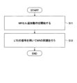
図10は、本発明の実施の形態における同期に係る動作例を説明するためのフローチャートである。ステップS11において、端末20はNRセル追加動作を開始する。ステップS12において、端末20は、LTEの信号を用いて、NRセルとの同期を行う。図11に示されるように、ステップS12において、端末20は、LTEの信号をソースとし、NRの信号をデスティネーションとするQCL設定を利用してもよい。 FIG. 10 is a flowchart for explaining an operation example related to synchronization in the embodiment of the present invention. In step S11, the terminal 20 starts an NR cell addition operation. In step S12, the terminal 20 performs synchronization with the NR cell using the LTE signal. As shown in FIG. 11, in step S12, the terminal 20 may use a QCL setting in which the LTE signal is the source and the NR signal is the destination.
図11は、本発明の実施の形態におけるQCL設定に係る動作例を説明するためのフローチャートである。ステップS21において、LTEの信号をQCLソースとし、NRの信号をQCLデスティネーションとするQCL設定を行う。当該QCL設定は、基地局10から端末20に通知されてもよい。続いて、端末20は、当該QCL設定を利用してNRセルとの同期を行う(S22)。
FIG. 11 is a flowchart for explaining an example of operation related to QCL setting in the embodiment of the present invention. In step S21, QCL settings are performed in which the LTE signal is the QCL source and the NR signal is the QCL destination. The QCL settings may be notified from the
例えば、以下のA)-D)のLTEの信号をQCLソースとしてもよい。
A)SS(PSS及びSSSの一部又はすべて)
B)PBCHの参照信号
C)CRS
D)CSI-RS
E)DM-RS
For example, the following LTE signals A) to D) may be used as the QCL source.
A) SS (part or all of PSS and SSS)
B) PBCH reference signal C) CRS
D) CSI-RS
E) DM-RS
例えば、以下のa)-d)のNRの信号をQCLソースとしてもよい。
a)SSB(PSS、SSS、PBCH-DM-RSの一部又はすべて)
b)DM-RS(PDSCH DM-RS、PDCCH DM-RSの一部又はすべて)
c)CSI-RS
d)TRS(CSI-RS for tracking)
For example, the following NR signals a) to d) may be used as the QCL source.
a) SSB (Part or all of PSS, SSS, PBCH-DM-RS)
b) DM-RS (part or all of PDSCH DM-RS, PDCCH DM-RS)
c) CSI-RS
d) TRS (CSI-RS for tracking)
例えば、上述したQCL関係の定義は、以下の1)-3)に示す通りであってもよい。
1)QCL関係は、NRで規定されたQCLタイプA、タイプB、タイプC及びタイプDの一部又は全部を含んでもよい。
2)QCL関係は、LTEで規定されたQCLとして規定されてもよい。QCLに関連するパラメータは、遅延スプレッド(delay spread)、ドップラスプレッド、ドップラシフト、平均ゲイン(average gain)、平均遅延(average delay)、空間受信パラメータ(spatial Rx parameter)の一部又は全部を含んでもよい。
3)QCLに関連するパラメータは、上述以外の新たに規定されたパラメータであってもよい。
For example, the definition of the QCL relationship described above may be as shown in 1) to 3) below.
1) The QCL relationship may include some or all of QCL type A, type B, type C, and type D defined in NR.
2) The QCL relationship may be defined as QCL defined in LTE. Parameters related to QCL may include some or all of delay spread, Doppler spread, Doppler shift, average gain, average delay, spatial Rx parameters. good.
3) Parameters related to QCL may be newly defined parameters other than those described above.
端末20は、同一種別の参照信号をデフォルトでQCLであると想定してもよい。例えば、LTE-PSS/SSSは、NR-PSS/SSSとQCLであると想定されてもよい。例えば、LTE-CRSは、NR-TRSとQCLであると想定されてもよい。例えば、表1に示した目的又は用途が同一であるLTEの信号とNRの信号とはQCLであると想定されてもよい。 The terminal 20 may assume that the same type of reference signal is QCL by default. For example, LTE-PSS/SSS may be assumed to be NR-PSS/SSS and QCL. For example, LTE-CRS may be assumed to be NR-TRS and QCL. For example, it may be assumed that the LTE signal and the NR signal shown in Table 1, which have the same purpose or use, are QCL.
本発明の実施の形態は、第一のRATと第二のRATがDSSされている時を主な例として記載したが、必ずしもDSSされている必要はない。例えば、DSSが適用されていないときに、第二のRATが第一のRATの信号を元にQCLを確立してもよい。 Although the embodiments of the present invention have been described using the case where the first RAT and the second RAT are DSS as a main example, they do not necessarily need to be DSS. For example, when DSS is not applied, the second RAT may establish QCL based on the first RAT's signal.
本発明の実施の形態は、上りリンク、下りリンク、送信又は受信の区別に関わらず適用することができる。上り信号及びチャネルと、下り信号及びチャネルとは相互に読み替えることができる。上りフィードバック情報と、下り制御シグナリングとは相互に読み替えることができる。 Embodiments of the present invention can be applied regardless of uplink, downlink, transmission, or reception. Uplink signals and channels and downlink signals and channels can be read interchangeably. Uplink feedback information and downlink control signaling can be read interchangeably.
上述の実施例における基地局10から端末20へのシグナリング又は端末20から基地局10へのシグナリングは、明示的(explicit)な方法に限定されず、暗黙的(implicit)な方法によって通知されてもよい。また、シグナリングは行われず、仕様で一意に規定されてもよい。
The signaling from the
上述の実施例における基地局10から端末20へのシグナリング又は端末20から基地局10へのシグナリングは、RRCシグナリング、MAC-CEによるシグナリング又はDCIによるシグナリング等の異なるレイヤのシグナリングであってもよいし、報知情報(MIB(Master Information Block)、SIB(System Information Block))によるシグナリングであってもよい。また、例えば、RRCシグナリングとDCIによるシグナリングを組み合わせてもよいし、RRCシグナリングとMAC-CEによるシグナリングを組み合わせてもよいし、RRCシグナリング、MAC-CEによるシグナリング及びDCIによるシグナリングを組み合わせてもよい。
The signaling from the
上述の実施例では、LTE及びNRとして説明したが、NRより将来の通信システム(例えば、「6G」と呼ぶ)との間で適用されてもよい。例えば、上述の実施例は、NR及び6Gの共存技術に適用されてもよい。 Although the above-mentioned embodiment has been described as LTE and NR, it may also be applied to a future communication system (for example, called "6G") than NR. For example, the embodiments described above may be applied to NR and 6G coexistence technologies.
同様に、一般的に、次世代のシステムが前世代のシステムの信号及び/又はチャネルを受信してもよい。例えば、システムは複数の世代をまたがってもよい。例えば、あるシステムは、二世代前のシステムの参照信号を適用してもよい。複数の世代の参照信号を適用してもよい。例えば、あるシステムは、同期は二世代前のシステムの参照信号を適用し、データ復号は一世代前のシステムの参照信号を適用してもよい。同様に、本技術の適用は世代の前後によるRATの違いでなくてもよい。すなわち、一般的に、異なるRATで適用されてもよい。 Similarly, next generation systems may generally receive signals and/or channels of previous generation systems. For example, a system may span multiple generations. For example, a certain system may apply a reference signal from a system two generations ago. Reference signals of multiple generations may be applied. For example, in a certain system, a reference signal from a system two generations ago may be used for synchronization, and a reference signal from a system one generation ago may be used for data decoding. Similarly, the present technology does not need to be applied to differences in RAT between previous and previous generations. That is, it may generally be applied with different RATs.
上記では、将来システムが過去システムの信号及び/又はチャネルを適用することについて記載したが、逆に、過去システムが将来システムの信号及び/又はチャネルを適用してもよい。 Although it has been described above that the future system applies the signals and/or channels of the past system, conversely, the past system may apply the signals and/or channels of the future system.
上述の実施例中の「データ」はPDSCHを示してもよいし、PDCCHを示してもよいし、PBCHを示してもよい。また、「データ」は上りリンク信号及び/又はチャネルを示してもよい。 "Data" in the above embodiments may indicate PDSCH, PDCCH, or PBCH. Additionally, "data" may indicate uplink signals and/or channels.
上述の実施例は互いに組み合わせることが可能である。上述の実施例に示される特徴は様々な組み合わせで互いに組み合わせることが可能である。当該組み合わせは、開示される特定の組み合わせに限定されない。 The embodiments described above can be combined with each other. The features shown in the embodiments described above can be combined with each other in various combinations. Such combinations are not limited to the particular combinations disclosed.
上述の実施例により、端末20は、LTEの信号を用いてNRの同期を行うことで、NRの同期に係る信号量を低減させることができる。 According to the above embodiment, the terminal 20 can reduce the amount of signals related to NR synchronization by performing NR synchronization using LTE signals.
すなわち、無線通信システムにおいて、複数のRAT(Radio Access Technology)を単一キャリアに共存させる場合のオーバヘッドを削減することができる。 That is, in a wireless communication system, it is possible to reduce overhead when a plurality of RATs (Radio Access Technologies) coexist on a single carrier.
(装置構成)
次に、これまでに説明した処理及び動作を実行する基地局10及び端末20の機能構成例を説明する。基地局10及び端末20は上述した実施例を実施する機能を含む。ただし、基地局10及び端末20はそれぞれ、実施例の中の一部の機能のみを備えることとしてもよい。
(Device configuration)
Next, an example of the functional configuration of the
<基地局10>
図12は、本発明の実施の形態における基地局10の機能構成の一例を示す図である。図12に示されるように、基地局10は、送信部110と、受信部120と、設定部130と、制御部140とを有する。図12に示される機能構成は一例に過ぎない。本発明の実施の形態に係る動作を実行できるのであれば、機能区分及び機能部の名称はどのようなものでもよい。
<
FIG. 12 is a diagram showing an example of the functional configuration of
送信部110は、端末20側に送信する信号を生成し、当該信号を無線で送信する機能を含む。また、送信部110は、ネットワークノード間メッセージを他のネットワークノードに送信する。受信部120は、端末20から送信された各種の信号を受信し、受信した信号から、例えばより上位のレイヤの情報を取得する機能を含む。また、送信部110は、端末20へNR-PSS、NR-SSS、NR-PBCH、DL/UL制御信号等を送信する機能を有する。また、受信部120は、ネットワークノード間メッセージを他のネットワークノードから受信する。
The transmitting
設定部130は、予め設定される設定情報、及び、端末20に送信する各種の設定情報を格納する。設定情報の内容は、例えば、DSSの設定に係る情報等である。
The
制御部140は、実施例において説明したように、DSSの設定に係る制御を行う。また、制御部140は、DSSによる通信を制御する。制御部140における信号送信に関する機能部を送信部110に含め、制御部140における信号受信に関する機能部を受信部120に含めてもよい。
The
<端末20>
図13は、本発明の実施の形態における端末20の機能構成の一例を示す図である。図13に示されるように、端末20は、送信部210と、受信部220と、設定部230と、制御部240とを有する。図13に示される機能構成は一例に過ぎない。本発明の実施の形態に係る動作を実行できるのであれば、機能区分及び機能部の名称はどのようなものでもよい。
<
FIG. 13 is a diagram showing an example of the functional configuration of the terminal 20 in the embodiment of the present invention. As shown in FIG. 13, the terminal 20 includes a
送信部210は、送信データから送信信号を作成し、当該送信信号を無線で送信する。受信部220は、各種の信号を無線受信し、受信した物理レイヤの信号からより上位のレイヤの信号を取得する。また、受信部220は、基地局10から送信されるNR-PSS、NR-SSS、NR-PBCH、DL/UL/SL制御信号等を受信する機能を有する。また、例えば、送信部210は、D2D通信として、他の端末20に、PSCCH(Physical Sidelink Control Channel)、PSSCH(Physical Sidelink Shared Channel)、PSDCH(Physical Sidelink Discovery Channel)、PSBCH(Physical Sidelink Broadcast Channel)等を送信し、受信部220は、他の端末20から、PSCCH、PSSCH、PSDCH又はPSBCH等を受信する。
The
設定部230は、受信部220により基地局10から受信した各種の設定情報を格納する。また、設定部230は、予め設定される設定情報も格納する。設定情報の内容は、例えば、DSSの設定に係る情報等である。
The
制御部240は、実施例において説明したように、DSSの設定に係る制御を行う。また、制御部240は、DSSによる通信を制御する。制御部240における信号送信に関する機能部を送信部210に含め、制御部240における信号受信に関する機能部を受信部220に含めてもよい。
The
(ハードウェア構成)
上記実施形態の説明に用いたブロック図(図12及び図13)は、機能単位のブロックを示している。これらの機能ブロック(構成部)は、ハードウェア及びソフトウェアの少なくとも一方の任意の組み合わせによって実現される。また、各機能ブロックの実現方法は特に限定されない。すなわち、各機能ブロックは、物理的又は論理的に結合した1つの装置を用いて実現されてもよいし、物理的又は論理的に分離した2つ以上の装置を直接的又は間接的に(例えば、有線、無線などを用いて)接続し、これら複数の装置を用いて実現されてもよい。機能ブロックは、上記1つの装置又は上記複数の装置にソフトウェアを組み合わせて実現されてもよい。
(Hardware configuration)
The block diagrams (FIGS. 12 and 13) used to explain the above embodiments show blocks in functional units. These functional blocks (components) are realized by any combination of at least one of hardware and software. Furthermore, the method for realizing each functional block is not particularly limited. That is, each functional block may be realized using one physically or logically coupled device, or may be realized using two or more physically or logically separated devices directly or indirectly (e.g. , wired, wireless, etc.) and may be realized using a plurality of these devices. The functional block may be realized by combining software with the one device or the plurality of devices.
機能には、判断、決定、判定、計算、算出、処理、導出、調査、探索、確認、受信、送信、出力、アクセス、解決、選択、選定、確立、比較、想定、期待、見做し、報知(broadcasting)、通知(notifying)、通信(communicating)、転送(forwarding)、構成(configuring)、再構成(reconfiguring)、割り当て(allocating、mapping)、割り振り(assigning)などがあるが、これらに限られない。たとえば、送信を機能させる機能ブロック(構成部)は、送信部(transmitting unit)や送信機(transmitter)と呼称される。いずれも、上述したとおり、実現方法は特に限定されない。 Functions include judgment, decision, judgment, calculation, calculation, processing, derivation, investigation, exploration, confirmation, reception, transmission, output, access, resolution, selection, selection, establishment, comparison, assumption, expectation, consideration, These include, but are not limited to, broadcasting, notifying, communicating, forwarding, configuring, reconfiguring, allocating, mapping, and assigning. I can't. For example, a functional block (configuration unit) that performs transmission is called a transmitting unit or a transmitter. In either case, as described above, the implementation method is not particularly limited.
例えば、本開示の一実施の形態における基地局10、端末20等は、本開示の無線通信方法の処理を行うコンピュータとして機能してもよい。図14は、本開示の一実施の形態に係る基地局10及び端末20のハードウェア構成の一例を示す図である。上述の基地局10及び端末20は、物理的には、プロセッサ1001、記憶装置1002、補助記憶装置1003、通信装置1004、入力装置1005、出力装置1006、バス1007などを含むコンピュータ装置として構成されてもよい。
For example, the
なお、以下の説明では、「装置」という文言は、回路、デバイス、ユニット等に読み替えることができる。基地局10及び端末20のハードウェア構成は、図に示した各装置を1つ又は複数含むように構成されてもよいし、一部の装置を含まずに構成されてもよい。
In addition, in the following description, the word "apparatus" can be read as a circuit, a device, a unit, etc. The hardware configuration of the
基地局10及び端末20における各機能は、プロセッサ1001、記憶装置1002等のハードウェア上に所定のソフトウェア(プログラム)を読み込ませることによって、プロセッサ1001が演算を行い、通信装置1004による通信を制御したり、記憶装置1002及び補助記憶装置1003におけるデータの読み出し及び書き込みの少なくとも一方を制御したりすることによって実現される。
Each function in the
プロセッサ1001は、例えば、オペレーティングシステムを動作させてコンピュータ全体を制御する。プロセッサ1001は、周辺装置とのインタフェース、制御装置、演算装置、レジスタ等を含む中央処理装置(CPU:Central Processing Unit)で構成されてもよい。例えば、上述の制御部140、制御部240等は、プロセッサ1001によって実現されてもよい。
The
また、プロセッサ1001は、プログラム(プログラムコード)、ソフトウェアモジュール又はデータ等を、補助記憶装置1003及び通信装置1004の少なくとも一方から記憶装置1002に読み出し、これらに従って各種の処理を実行する。プログラムとしては、上述の実施の形態において説明した動作の少なくとも一部をコンピュータに実行させるプログラムが用いられる。例えば、図12に示した基地局10の制御部140は、記憶装置1002に格納され、プロセッサ1001で動作する制御プログラムによって実現されてもよい。また、例えば、図13に示した端末20の制御部240は、記憶装置1002に格納され、プロセッサ1001で動作する制御プログラムによって実現されてもよい。上述の各種処理は、1つのプロセッサ1001によって実行される旨を説明してきたが、2以上のプロセッサ1001により同時又は逐次に実行されてもよい。プロセッサ1001は、1以上のチップによって実装されてもよい。なお、プログラムは、電気通信回線を介してネットワークから送信されてもよい。
Further, the
記憶装置1002は、コンピュータ読み取り可能な記録媒体であり、例えば、ROM(Read Only Memory)、EPROM(Erasable Programmable ROM)、EEPROM(Electrically Erasable Programmable ROM)、RAM(Random Access Memory)等の少なくとも1つによって構成されてもよい。記憶装置1002は、レジスタ、キャッシュ、メインメモリ(主記憶装置)等と呼ばれてもよい。記憶装置1002は、本開示の一実施の形態に係る通信方法を実施するために実行可能なプログラム(プログラムコード)、ソフトウェアモジュール等を保存することができる。
The
補助記憶装置1003は、コンピュータ読み取り可能な記録媒体であり、例えば、CD-ROM(Compact Disc ROM)等の光ディスク、ハードディスクドライブ、フレキシブルディスク、光磁気ディスク(例えば、コンパクトディスク、デジタル多用途ディスク、Blu-ray(登録商標)ディスク)、スマートカード、フラッシュメモリ(例えば、カード、スティック、キードライブ)、フロッピー(登録商標)ディスク、磁気ストリップ等の少なくとも1つによって構成されてもよい。上述の記憶媒体は、例えば、記憶装置1002及び補助記憶装置1003の少なくとも一方を含むデータベース、サーバその他の適切な媒体であってもよい。
The
通信装置1004は、有線ネットワーク及び無線ネットワークの少なくとも一方を介してコンピュータ間の通信を行うためのハードウェア(送受信デバイス)であり、例えばネットワークデバイス、ネットワークコントローラ、ネットワークカード、通信モジュールなどともいう。通信装置1004は、例えば周波数分割複信(FDD:Frequency Division Duplex)及び時分割複信(TDD:Time Division Duplex)の少なくとも一方を実現するために、高周波スイッチ、デュプレクサ、フィルタ、周波数シンセサイザなどを含んで構成されてもよい。例えば、送受信アンテナ、アンプ部、送受信部、伝送路インターフェース等は、通信装置1004によって実現されてもよい。送受信部は、送信部と受信部とで、物理的に、または論理的に分離された実装がなされてもよい。
The
入力装置1005は、外部からの入力を受け付ける入力デバイス(例えば、キーボード、マウス、マイクロフォン、スイッチ、ボタン、センサ等)である。出力装置1006は、外部への出力を実施する出力デバイス(例えば、ディスプレイ、スピーカー、LEDランプ等)である。なお、入力装置1005及び出力装置1006は、一体となった構成(例えば、タッチパネル)であってもよい。
The
また、プロセッサ1001及び記憶装置1002等の各装置は、情報を通信するためのバス1007によって接続される。バス1007は、単一のバスを用いて構成されてもよいし、装置間ごとに異なるバスを用いて構成されてもよい。
Further, each device such as the
また、基地局10及び端末20は、マイクロプロセッサ、デジタル信号プロセッサ(DSP:Digital Signal Processor)、ASIC(Application Specific Integrated Circuit)、PLD(Programmable Logic Device)、FPGA(Field Programmable Gate Array)等のハードウェアを含んで構成されてもよく、当該ハードウェアにより、各機能ブロックの一部又は全てが実現されてもよい。例えば、プロセッサ1001は、これらのハードウェアの少なくとも1つを用いて実装されてもよい。
The
(実施の形態のまとめ)
以上、説明したように、本発明の実施の形態によれば、第1のRAT(Radio Access Technology)の第1の信号を受信する受信部と、前記第1の信号と、第2のRATの第2の信号とのQCL(Quasi-co-location)関係を用いて、前記第2のRATのセルと同期する制御部とを有する端末が提供される。
(Summary of embodiments)
As described above, according to the embodiment of the present invention, there is provided a receiving section that receives a first signal of a first RAT (Radio Access Technology), a receiver that receives the first signal of the first RAT, and a receiver that receives the first signal of the first RAT (Radio Access Technology). A terminal is provided that includes a control unit that synchronizes with a cell of the second RAT using a QCL (Quasi-co-location) relationship with a second signal.
上記の構成により、端末20は、LTEの信号を用いてNRの同期を行うことで、NRの同期に係る信号量を低減させることができる。すなわち、無線通信システムにおいて、複数のRAT(Radio Access Technology)を単一キャリアに共存させる場合のオーバヘッドを削減することができる。 With the above configuration, the terminal 20 can reduce the amount of signals related to NR synchronization by performing NR synchronization using LTE signals. That is, in a wireless communication system, it is possible to reduce overhead when a plurality of RATs (Radio Access Technologies) coexist on a single carrier.
前記第2のRATは、前記第1のRATと同一のキャリアで送信されてもよい。端末20は、LTEの信号を用いて同一キャリアのNRの同期を行うことで、NRの同期に係る信号量を低減させることができる。 The second RAT may be transmitted on the same carrier as the first RAT. The terminal 20 can reduce the amount of signals related to NR synchronization by synchronizing NRs of the same carrier using LTE signals.
前記QCL関係は、前記第1の信号がQCLソースであり、前記第2の信号がQCLデスティネーションであってもよい。当該構成により、端末20は、LTEの信号を用いてNRの同期を行うことで、NRの同期に係る信号量を低減させることができる。 The QCL relationship may be such that the first signal is a QCL source and the second signal is a QCL destination. With this configuration, the terminal 20 can reduce the amount of signals related to NR synchronization by performing NR synchronization using LTE signals.
前記制御部は、用途が類似する前記第1の信号及び前記第2の信号を、QCLであると想定してもよい。当該構成により、端末20は、LTEの信号を用いてNRの同期を行うことで、NRの同期に係る信号量を低減させることができる。 The control unit may assume that the first signal and the second signal, which have similar uses, are QCL. With this configuration, the terminal 20 can reduce the amount of signals related to NR synchronization by performing NR synchronization using LTE signals.
また、本発明の実施の形態によれば、第1のRAT(Radio Access Technology)の第1の信号を受信する受信手順と、前記第1の信号と、第2のRATの第2の信号とのQCL(Quasi-co-location)関係を用いて、前記第2のRATのセルと同期する制御手順とを端末が実行する通信方法が提供される。 Further, according to an embodiment of the present invention, a reception procedure for receiving a first signal of a first RAT (Radio Access Technology), and a reception procedure for receiving a first signal of a first RAT (Radio Access Technology); A communication method is provided in which a terminal executes a control procedure for synchronizing with a cell of the second RAT using a QCL (Quasi-co-location) relationship.
上記の構成により、端末20は、LTEの信号を用いてNRの同期を行うことで、NRの同期に係る信号量を低減させることができる。すなわち、無線通信システムにおいて、複数のRAT(Radio Access Technology)を単一キャリアに共存させる場合のオーバヘッドを削減することができる。 With the above configuration, the terminal 20 can reduce the amount of signals related to NR synchronization by performing NR synchronization using LTE signals. That is, in a wireless communication system, it is possible to reduce overhead when a plurality of RATs (Radio Access Technologies) coexist on a single carrier.
(実施形態の補足)
以上、本発明の実施の形態を説明してきたが、開示される発明はそのような実施形態に限定されず、当業者は様々な変形例、修正例、代替例、置換例等を理解するであろう。発明の理解を促すため具体的な数値例を用いて説明がなされたが、特に断りのない限り、それらの数値は単なる一例に過ぎず適切な如何なる値が使用されてもよい。上記の説明における項目の区分けは本発明に本質的ではなく、2以上の項目に記載された事項が必要に応じて組み合わせて使用されてよいし、ある項目に記載された事項が、別の項目に記載された事項に(矛盾しない限り)適用されてよい。機能ブロック図における機能部又は処理部の境界は必ずしも物理的な部品の境界に対応するとは限らない。複数の機能部の動作が物理的には1つの部品で行われてもよいし、あるいは1つの機能部の動作が物理的には複数の部品により行われてもよい。実施の形態で述べた処理手順については、矛盾の無い限り処理の順序を入れ替えてもよい。処理説明の便宜上、基地局10及び端末20は機能的なブロック図を用いて説明されたが、そのような装置はハードウェアで、ソフトウェアで又はそれらの組み合わせで実現されてもよい。本発明の実施の形態に従って基地局10が有するプロセッサにより動作するソフトウェア及び本発明の実施の形態に従って端末20が有するプロセッサにより動作するソフトウェアはそれぞれ、ランダムアクセスメモリ(RAM)、フラッシュメモリ、読み取り専用メモリ(ROM)、EPROM、EEPROM、レジスタ、ハードディスク(HDD)、リムーバブルディスク、CD-ROM、データベース、サーバその他の適切な如何なる記憶媒体に保存されてもよい。
(Supplementary information on the embodiment)
Although the embodiments of the present invention have been described above, the disclosed invention is not limited to such embodiments, and those skilled in the art will understand various modifications, modifications, alternatives, replacements, etc. Probably. Although the invention has been explained using specific numerical examples to facilitate understanding of the invention, unless otherwise specified, these numerical values are merely examples, and any appropriate values may be used. The classification of items in the above explanation is not essential to the present invention, and matters described in two or more items may be used in combination as necessary, and matters described in one item may be used in another item. may be applied to the matters described in (unless inconsistent). The boundaries of functional units or processing units in the functional block diagram do not necessarily correspond to the boundaries of physical components. The operations of a plurality of functional sections may be physically performed by one component, or the operations of one functional section may be physically performed by a plurality of components. Regarding the processing procedures described in the embodiments, the order of processing may be changed as long as there is no contradiction. Although the
また、情報の通知は、本開示で説明した態様/実施形態に限られず、他の方法を用いて行われてもよい。例えば、情報の通知は、物理レイヤシグナリング(例えば、DCI(Downlink Control Information)、UCI(Uplink Control Information))、上位レイヤシグナリング(例えば、RRC(Radio Resource Control)シグナリング、MAC(Medium Access Control)シグナリング、報知情報(MIB(Master Information Block)、SIB(System Information Block))、その他の信号又はこれらの組み合わせによって実施されてもよい。また、RRCシグナリングは、RRCメッセージと呼ばれてもよく、例えば、RRC接続セットアップ(RRC Connection Setup)メッセージ、RRC接続再構成(RRC Connection Reconfiguration)メッセージ等であってもよい。 Further, the notification of information is not limited to the aspects/embodiments described in this disclosure, and may be performed using other methods. For example, the notification of information may include physical layer signaling (e.g., DCI (Downlink Control Information), UCI (Uplink Control Information)), upper layer signaling (e.g., RRC (Radio Resource Control) signaling, MAC (Medium Access Control) signaling, It may be implemented by broadcast information (MIB (Master Information Block), SIB (System Information Block)), other signals, or a combination thereof. RRC signaling may also be called an RRC message, for example, RRC It may be a connection setup (RRC Connection Setup) message, an RRC connection reconfiguration (RRC Connection Reconfiguration) message, or the like.
本開示において説明した各態様/実施形態は、LTE(Long Term Evolution)、LTE-A(LTE-Advanced)、SUPER 3G、IMT-Advanced、4G(4th generation mobile communication system)、5G(5th generation mobile communication system)、FRA(Future Radio Access)、NR(new Radio)、W-CDMA(登録商標)、GSM(登録商標)、CDMA2000、UMB(Ultra Mobile Broadband)、IEEE 802.11(Wi-Fi(登録商標))、IEEE 802.16(WiMAX(登録商標))、IEEE 802.20、UWB(Ultra-WideBand)、Bluetooth(登録商標)、その他の適切なシステムを利用するシステム及びこれらに基づいて拡張された次世代システムの少なくとも一つに適用されてもよい。また、複数のシステムが組み合わされて(例えば、LTE及びLTE-Aの少なくとも一方と5Gとの組み合わせ等)適用されてもよい。 Each aspect/embodiment described in this disclosure applies to LTE (Long Term Evolution), LTE-A (LTE-Advanced), SUPER 3G, IMT-Advanced, 4G (4th generation mobile communication system), and 5G (5th generation mobile communication system). system), FRA (Future Radio Access), NR (new Radio), W-CDMA (registered trademark), GSM (registered trademark), CDMA2000, UMB (Ultra Mobile Broadband), IEEE 802.11 (Wi-Fi (registered trademark) )), IEEE 802.16 (WiMAX (registered trademark)), IEEE 802.20, UWB (Ultra-WideBand), Bluetooth (registered trademark), and systems that utilize and are extended based on these. It may be applied to at least one next generation system. Furthermore, a combination of a plurality of systems may be applied (for example, a combination of at least one of LTE and LTE-A and 5G).
本明細書で説明した各態様/実施形態の処理手順、シーケンス、フローチャート等は、矛盾の無い限り、順序を入れ替えてもよい。例えば、本開示において説明した方法については、例示的な順序を用いて様々なステップの要素を提示しており、提示した特定の順序に限定されない。 The order of the processing procedures, sequences, flowcharts, etc. of each aspect/embodiment described in this specification may be changed as long as there is no contradiction. For example, the methods described in this disclosure use an example order to present elements of the various steps and are not limited to the particular order presented.
本明細書において基地局10によって行われるとした特定動作は、場合によってはその上位ノード(upper node)によって行われることもある。基地局10を有する1つ又は複数のネットワークノード(network nodes)からなるネットワークにおいて、端末20との通信のために行われる様々な動作は、基地局10及び基地局10以外の他のネットワークノード(例えば、MME又はS-GW等が考えられるが、これらに限られない)の少なくとも1つによって行われ得ることは明らかである。上記において基地局10以外の他のネットワークノードが1つである場合を例示したが、他のネットワークノードは、複数の他のネットワークノードの組み合わせ(例えば、MME及びS-GW)であってもよい。
In this specification, specific operations performed by the
本開示において説明した情報又は信号等は、上位レイヤ(又は下位レイヤ)から下位レイヤ(又は上位レイヤ)へ出力され得る。複数のネットワークノードを介して入出力されてもよい。 The information, signals, etc. described in this disclosure may be output from an upper layer (or lower layer) to a lower layer (or upper layer). It may be input/output via multiple network nodes.
入出力された情報等は特定の場所(例えば、メモリ)に保存されてもよいし、管理テーブルを用いて管理してもよい。入出力される情報等は、上書き、更新、又は追記され得る。出力された情報等は削除されてもよい。入力された情報等は他の装置へ送信されてもよい。 The input/output information may be stored in a specific location (eg, memory) or may be managed using a management table. Information etc. to be input/output may be overwritten, updated, or additionally written. The output information etc. may be deleted. The input information etc. may be transmitted to other devices.
本開示における判定は、1ビットで表される値(0か1か)によって行われてもよいし、真偽値(Boolean:true又はfalse)によって行われてもよいし、数値の比較(例えば、所定の値との比較)によって行われてもよい。 The determination in the present disclosure may be performed based on a value represented by 1 bit (0 or 1), a truth value (Boolean: true or false), or a comparison of numerical values (e.g. , comparison with a predetermined value).
ソフトウェアは、ソフトウェア、ファームウェア、ミドルウェア、マイクロコード、ハードウェア記述言語と呼ばれるか、他の名称で呼ばれるかを問わず、命令、命令セット、コード、コードセグメント、プログラムコード、プログラム、サブプログラム、ソフトウェアモジュール、アプリケーション、ソフトウェアアプリケーション、ソフトウェアパッケージ、ルーチン、サブルーチン、オブジェクト、実行可能ファイル、実行スレッド、手順、機能などを意味するよう広く解釈されるべきである。 Software includes instructions, instruction sets, code, code segments, program code, programs, subprograms, software modules, whether referred to as software, firmware, middleware, microcode, hardware description language, or by any other name. , should be broadly construed to mean an application, software application, software package, routine, subroutine, object, executable, thread of execution, procedure, function, etc.
また、ソフトウェア、命令、情報などは、伝送媒体を介して送受信されてもよい。例えば、ソフトウェアが、有線技術(同軸ケーブル、光ファイバケーブル、ツイストペア、デジタル加入者回線(DSL:Digital Subscriber Line)など)及び無線技術(赤外線、マイクロ波など)の少なくとも一方を使用してウェブサイト、サーバ、又は他のリモートソースから送信される場合、これらの有線技術及び無線技術の少なくとも一方は、伝送媒体の定義内に含まれる。 Additionally, software, instructions, information, etc. may be sent and received via a transmission medium. For example, if the software uses wired technology (coaxial cable, fiber optic cable, twisted pair, digital subscriber line (DSL), etc.) and/or wireless technology (infrared, microwave, etc.) to When transmitted from a server or other remote source, these wired and/or wireless technologies are included within the definition of transmission medium.
本開示において説明した情報、信号などは、様々な異なる技術のいずれかを使用して表されてもよい。例えば、上記の説明全体に渡って言及され得るデータ、命令、コマンド、情報、信号、ビット、シンボル、チップなどは、電圧、電流、電磁波、磁界若しくは磁性粒子、光場若しくは光子、又はこれらの任意の組み合わせによって表されてもよい。 The information, signals, etc. described in this disclosure may be represented using any of a variety of different technologies. For example, data, instructions, commands, information, signals, bits, symbols, chips, etc., which may be referred to throughout the above description, may refer to voltages, currents, electromagnetic waves, magnetic fields or magnetic particles, light fields or photons, or any of these. It may also be represented by a combination of
なお、本開示において説明した用語及び本開示の理解に必要な用語については、同一の又は類似する意味を有する用語と置き換えてもよい。例えば、チャネル及びシンボルの少なくとも一方は信号(シグナリング)であってもよい。また、信号はメッセージであってもよい。また、コンポーネントキャリア(CC:Component Carrier)は、キャリア周波数、セル、周波数キャリアなどと呼ばれてもよい。 Note that terms explained in this disclosure and terms necessary for understanding this disclosure may be replaced with terms having the same or similar meanings. For example, at least one of the channel and the symbol may be a signal. Also, the signal may be a message. Further, a component carrier (CC) may be called a carrier frequency, a cell, a frequency carrier, or the like.
本開示において使用する「システム」及び「ネットワーク」という用語は、互換的に使用される。 As used in this disclosure, the terms "system" and "network" are used interchangeably.
また、本開示において説明した情報、パラメータなどは、絶対値を用いて表されてもよいし、所定の値からの相対値を用いて表されてもよいし、対応する別の情報を用いて表されてもよい。例えば、無線リソースはインデックスによって指示されるものであってもよい。 In addition, the information, parameters, etc. described in this disclosure may be expressed using absolute values, relative values from a predetermined value, or using other corresponding information. may be expressed. For example, radio resources may be indicated by an index.
上述したパラメータに使用する名称はいかなる点においても限定的な名称ではない。さらに、これらのパラメータを使用する数式等は、本開示で明示的に開示したものと異なる場合もある。様々なチャネル(例えば、PUCCH、PDCCHなど)及び情報要素は、あらゆる好適な名称によって識別できるので、これらの様々なチャネル及び情報要素に割り当てている様々な名称は、いかなる点においても限定的な名称ではない。 The names used for the parameters described above are not restrictive in any respect. Furthermore, the mathematical formulas etc. using these parameters may differ from those explicitly disclosed in this disclosure. Since the various channels (e.g. PUCCH, PDCCH, etc.) and information elements may be identified by any suitable designation, the various names assigned to these various channels and information elements are in no way exclusive designations. isn't it.
本開示においては、「基地局(BS:Base Station)」、「無線基地局」、「基地局装置」、「固定局(fixed station)」、「NodeB」、「eNodeB(eNB)」、「gNodeB(gNB)」、「アクセスポイント(access point)」、「送信ポイント(transmission point)」、「受信ポイント(reception point)、「送受信ポイント(transmission/reception point)」、「セル」、「セクタ」、「セルグループ」、「キャリア」、「コンポーネントキャリア」などの用語は、互換的に使用され得る。基地局は、マクロセル、スモールセル、フェムトセル、ピコセルなどの用語で呼ばれる場合もある。 In this disclosure, "Base Station (BS)," "wireless base station," "base station device," "fixed station," "NodeB," "eNodeB (eNB)," and "gNodeB (gNB),” “access point,” “transmission point,” “reception point,” “transmission/reception point,” “cell,” “sector,” Terms such as "cell group," "carrier," "component carrier," and the like may be used interchangeably. A base station is sometimes referred to by terms such as macrocell, small cell, femtocell, and picocell.
基地局は、1つ又は複数(例えば、3つ)のセルを収容することができる。基地局が複数のセルを収容する場合、基地局のカバレッジエリア全体は複数のより小さいエリアに区分でき、各々のより小さいエリアは、基地局サブシステム(例えば、屋内用の小型基地局(RRH:Remote Radio Head)によって通信サービスを提供することもできる。「セル」又は「セクタ」という用語は、このカバレッジにおいて通信サービスを行う基地局及び基地局サブシステムの少なくとも一方のカバレッジエリアの一部又は全体を指す。 A base station can accommodate one or more (eg, three) cells. If a base station accommodates multiple cells, the overall coverage area of the base station can be partitioned into multiple smaller areas, and each smaller area is divided into multiple subsystems (e.g., small indoor base stations (RRHs)). The term "cell" or "sector" refers to a part or all of the coverage area of a base station and/or base station subsystem that provides communication services in this coverage. refers to
本開示においては、「移動局(MS:Mobile Station)」、「ユーザ端末(user terminal)」、「ユーザ装置(UE:User Equipment)」、「端末」などの用語は、互換的に使用され得る。 In this disclosure, terms such as "Mobile Station (MS)," "user terminal," "User Equipment (UE)," and "terminal" may be used interchangeably. .
移動局は、当業者によって、加入者局、モバイルユニット、加入者ユニット、ワイヤレスユニット、リモートユニット、モバイルデバイス、ワイヤレスデバイス、ワイヤレス通信デバイス、リモートデバイス、モバイル加入者局、アクセス端末、モバイル端末、ワイヤレス端末、リモート端末、ハンドセット、ユーザエージェント、モバイルクライアント、クライアント、又はいくつかの他の適切な用語で呼ばれる場合もある。 A mobile station is defined by a person skilled in the art as a subscriber station, mobile unit, subscriber unit, wireless unit, remote unit, mobile device, wireless device, wireless communication device, remote device, mobile subscriber station, access terminal, mobile terminal, wireless It may also be referred to as a terminal, remote terminal, handset, user agent, mobile client, client, or some other suitable terminology.
基地局及び移動局の少なくとも一方は、送信装置、受信装置、通信装置などと呼ばれてもよい。なお、基地局及び移動局の少なくとも一方は、移動体に搭載されたデバイス、移動体自体などであってもよい。当該移動体は、乗り物(例えば、車、飛行機など)であってもよいし、無人で動く移動体(例えば、ドローン、自動運転車など)であってもよいし、ロボット(有人型又は無人型)であってもよい。なお、基地局及び移動局の少なくとも一方は、必ずしも通信動作時に移動しない装置も含む。例えば、基地局及び移動局の少なくとも一方は、センサなどのIoT(Internet of Things)機器であってもよい。 At least one of a base station and a mobile station may be called a transmitting device, a receiving device, a communication device, or the like. Note that at least one of the base station and the mobile station may be a device mounted on a mobile body, the mobile body itself, or the like. The moving object may be a vehicle (for example, a car, an airplane, etc.), an unmanned moving object (for example, a drone, a self-driving car, etc.), or a robot (manned or unmanned). ). Note that at least one of the base station and the mobile station includes devices that do not necessarily move during communication operations. For example, at least one of the base station and the mobile station may be an IoT (Internet of Things) device such as a sensor.
また、本開示における基地局は、ユーザ端末で読み替えてもよい。例えば、基地局及びユーザ端末間の通信を、複数の端末20間の通信(例えば、D2D(Device-to-Device)、V2X(Vehicle-to-Everything)などと呼ばれてもよい)に置き換えた構成について、本開示の各態様/実施形態を適用してもよい。この場合、上述の基地局10が有する機能を端末20が有する構成としてもよい。また、「上り」及び「下り」などの文言は、端末間通信に対応する文言(例えば、「サイド(side)」)で読み替えられてもよい。例えば、上りチャネル、下りチャネルなどは、サイドチャネルで読み替えられてもよい。
Furthermore, the base station in the present disclosure may be replaced by a user terminal. For example, communication between a base station and a user terminal is replaced with communication between a plurality of terminals 20 (for example, it may be called D2D (Device-to-Device), V2X (Vehicle-to-Everything), etc.). Regarding the configuration, each aspect/embodiment of the present disclosure may be applied. In this case, the terminal 20 may have the functions that the
同様に、本開示におけるユーザ端末は、基地局で読み替えてもよい。この場合、上述のユーザ端末が有する機能を基地局が有する構成としてもよい。 Similarly, the user terminal in the present disclosure may be replaced by a base station. In this case, the base station may have the functions that the user terminal described above has.
本開示で使用する「判断(determining)」、「決定(determining)」という用語は、多種多様な動作を包含する場合がある。「判断」、「決定」は、例えば、判定(judging)、計算(calculating)、算出(computing)、処理(processing)、導出(deriving)、調査(investigating)、探索(looking up、search、inquiry)(例えば、テーブル、データベース又は別のデータ構造での探索)、確認(ascertaining)した事を「判断」「決定」したとみなす事などを含み得る。また、「判断」、「決定」は、受信(receiving)(例えば、情報を受信すること)、送信(transmitting)(例えば、情報を送信すること)、入力(input)、出力(output)、アクセス(accessing)(例えば、メモリ中のデータにアクセスすること)した事を「判断」「決定」したとみなす事などを含み得る。また、「判断」、「決定」は、解決(resolving)、選択(selecting)、選定(choosing)、確立(establishing)、比較(comparing)などした事を「判断」「決定」したとみなす事を含み得る。つまり、「判断」「決定」は、何らかの動作を「判断」「決定」したとみなす事を含み得る。また、「判断(決定)」は、「想定する(assuming)」、「期待する(expecting)」、「みなす(considering)」などで読み替えられてもよい。 As used in this disclosure, the terms "determining" and "determining" may encompass a wide variety of operations. "Judgment" and "decision" include, for example, judging, calculating, computing, processing, deriving, investigating, looking up, search, and inquiry. (e.g., searching in a table, database, or other data structure), and regarding an ascertaining as a "judgment" or "decision." In addition, "judgment" and "decision" refer to receiving (e.g., receiving information), transmitting (e.g., sending information), input, output, and access. (accessing) (e.g., accessing data in memory) may include considering something as a "judgment" or "decision." In addition, "judgment" and "decision" refer to resolving, selecting, choosing, establishing, comparing, etc. as "judgment" and "decision". may be included. In other words, "judgment" and "decision" may include regarding some action as having been "judged" or "determined." Further, "judgment (decision)" may be read as "assuming", "expecting", "considering", etc.
「接続された(connected)」、「結合された(coupled)」という用語、又はこれらのあらゆる変形は、2又はそれ以上の要素間の直接的又は間接的なあらゆる接続又は結合を意味し、互いに「接続」又は「結合」された2つの要素間に1又はそれ以上の中間要素が存在することを含むことができる。要素間の結合又は接続は、物理的なものであっても、論理的なものであっても、或いはこれらの組み合わせであってもよい。例えば、「接続」は「アクセス」で読み替えられてもよい。本開示で使用する場合、2つの要素は、1又はそれ以上の電線、ケーブル及びプリント電気接続の少なくとも一つを用いて、並びにいくつかの非限定的かつ非包括的な例として、無線周波数領域、マイクロ波領域及び光(可視及び不可視の両方)領域の波長を有する電磁エネルギーなどを用いて、互いに「接続」又は「結合」されると考えることができる。 The terms "connected", "coupled", or any variations thereof, refer to any connection or coupling, direct or indirect, between two or more elements and to each other. It may include the presence of one or more intermediate elements between two elements that are "connected" or "coupled." The bonds or connections between elements may be physical, logical, or a combination thereof. For example, "connection" may be read as "access." As used in this disclosure, two elements may include one or more electrical wires, cables, and/or printed electrical connections, as well as in the radio frequency domain, as some non-limiting and non-inclusive examples. , electromagnetic energy having wavelengths in the microwave and optical (both visible and non-visible) ranges.
参照信号は、RS(Reference Signal)と略称することもでき、適用される標準によってパイロット(Pilot)と呼ばれてもよい。 The reference signal can also be abbreviated as RS (Reference Signal), and may also be called a pilot depending on the applied standard.
本開示において使用する「に基づいて」という記載は、別段に明記されていない限り、「のみに基づいて」を意味しない。言い換えれば、「に基づいて」という記載は、「のみに基づいて」と「に少なくとも基づいて」の両方を意味する。 As used in this disclosure, the phrase "based on" does not mean "based solely on" unless explicitly stated otherwise. In other words, the phrase "based on" means both "based only on" and "based at least on."
本開示において使用する「第1の」、「第2の」などの呼称を使用した要素へのいかなる参照も、それらの要素の量又は順序を全般的に限定しない。これらの呼称は、2つ以上の要素間を区別する便利な方法として本開示において使用され得る。したがって、第1及び第2の要素への参照は、2つの要素のみが採用され得ること、又は何らかの形で第1の要素が第2の要素に先行しなければならないことを意味しない。 As used in this disclosure, any reference to elements using the designations "first," "second," etc. does not generally limit the amount or order of those elements. These designations may be used in this disclosure as a convenient way to distinguish between two or more elements. Thus, reference to a first and second element does not imply that only two elements may be employed or that the first element must precede the second element in any way.
上記の各装置の構成における「手段」を、「部」、「回路」、「デバイス」等に置き換えてもよい。 "Means" in the configurations of each of the above devices may be replaced with "unit", "circuit", "device", etc.
本開示において、「含む(include)」、「含んでいる(including)」及びそれらの変形が使用されている場合、これらの用語は、用語「備える(comprising)」と同様に、包括的であることが意図される。さらに、本開示において使用されている用語「又は(or)」は、排他的論理和ではないことが意図される。 Where "include", "including" and variations thereof are used in this disclosure, these terms, like the term "comprising," are inclusive. It is intended that Furthermore, the term "or" as used in this disclosure is not intended to be exclusive or.
無線フレームは時間領域において1つ又は複数のフレームによって構成されてもよい。時間領域において1つ又は複数の各フレームはサブフレームと呼ばれてもよい。サブフレームは更に時間領域において1つ又は複数のスロットによって構成されてもよい。サブフレームは、ニューメロロジ(numerology)に依存しない固定の時間長(例えば、1ms)であってもよい。 A radio frame may be composed of one or more frames in the time domain. Each frame or frames in the time domain may be called a subframe. A subframe may also be composed of one or more slots in the time domain. A subframe may have a fixed time length (eg, 1 ms) that does not depend on numerology.
ニューメロロジは、ある信号又はチャネルの送信及び受信の少なくとも一方に適用される通信パラメータであってもよい。ニューメロロジは、例えば、サブキャリア間隔(SCS:SubCarrier Spacing)、帯域幅、シンボル長、サイクリックプレフィックス長、送信時間間隔(TTI:Transmission Time Interval)、TTIあたりのシンボル数、無線フレーム構成、送受信機が周波数領域において行う特定のフィルタリング処理、送受信機が時間領域において行う特定のウィンドウイング処理などの少なくとも1つを示してもよい。 Numerology may be a communication parameter applied to the transmission and/or reception of a signal or channel. Numerology includes, for example, subcarrier spacing (SCS), bandwidth, symbol length, cyclic prefix length, transmission time interval (TTI), number of symbols per TTI, radio frame configuration, and transmitter/receiver. It may also indicate at least one of a specific filtering process performed in the frequency domain, a specific windowing process performed by the transceiver in the time domain, and the like.
スロットは、時間領域において1つ又は複数のシンボル(OFDM(Orthogonal Frequency Division Multiplexing)シンボル、SC-FDMA(Single Carrier Frequency Division Multiple Access)シンボル等)で構成されてもよい。スロットは、ニューメロロジに基づく時間単位であってもよい。 A slot may be composed of one or more symbols (OFDM (Orthogonal Frequency Division Multiplexing) symbols, SC-FDMA (Single Carrier Frequency Division Multiple Access) symbols, etc.) in the time domain. A slot may be a unit of time based on numerology.
スロットは、複数のミニスロットを含んでもよい。各ミニスロットは、時間領域において1つ又は複数のシンボルによって構成されてもよい。また、ミニスロットは、サブスロットと呼ばれてもよい。ミニスロットは、スロットよりも少ない数のシンボルによって構成されてもよい。ミニスロットより大きい時間単位で送信されるPDSCH(又はPUSCH)は、PDSCH(又はPUSCH)マッピングタイプAと呼ばれてもよい。ミニスロットを用いて送信されるPDSCH(又はPUSCH)は、PDSCH(又はPUSCH)マッピングタイプBと呼ばれてもよい。 A slot may include multiple minislots. Each minislot may be made up of one or more symbols in the time domain. Furthermore, a mini-slot may also be called a sub-slot. A minislot may be made up of fewer symbols than a slot. PDSCH (or PUSCH) transmitted in time units larger than minislots may be referred to as PDSCH (or PUSCH) mapping type A. PDSCH (or PUSCH) transmitted using minislots may be referred to as PDSCH (or PUSCH) mapping type B.
無線フレーム、サブフレーム、スロット、ミニスロット及びシンボルは、いずれも信号を伝送する際の時間単位を表す。無線フレーム、サブフレーム、スロット、ミニスロット及びシンボルは、それぞれに対応する別の呼称が用いられてもよい。 Radio frames, subframes, slots, minislots, and symbols all represent time units for transmitting signals. Other names may be used for the radio frame, subframe, slot, minislot, and symbol.
例えば、1サブフレームは送信時間間隔(TTI:Transmission Time Interval)と呼ばれてもよいし、複数の連続したサブフレームがTTIと呼ばれてよいし、1スロット又は1ミニスロットがTTIと呼ばれてもよい。つまり、サブフレーム及びTTIの少なくとも一方は、既存のLTEにおけるサブフレーム(1ms)であってもよいし、1msより短い期間(例えば、1-13シンボル)であってもよいし、1msより長い期間であってもよい。なお、TTIを表す単位は、サブフレームではなくスロット、ミニスロットなどと呼ばれてもよい。 For example, one subframe may be called a Transmission Time Interval (TTI), multiple consecutive subframes may be called a TTI, and one slot or minislot may be called a TTI. You can. In other words, at least one of the subframe and TTI may be a subframe (1ms) in existing LTE, a period shorter than 1ms (for example, 1-13 symbols), or a period longer than 1ms. It may be. Note that the unit representing the TTI may be called a slot, minislot, etc. instead of a subframe.
ここで、TTIは、例えば、無線通信におけるスケジューリングの最小時間単位のことをいう。例えば、LTEシステムでは、基地局が各端末20に対して、無線リソース(各端末20において使用することが可能な周波数帯域幅、送信電力など)を、TTI単位で割り当てるスケジューリングを行う。なお、TTIの定義はこれに限られない。 Here, TTI refers to, for example, the minimum time unit for scheduling in wireless communication. For example, in the LTE system, a base station performs scheduling to allocate radio resources (frequency bandwidth, transmission power, etc. that can be used by each terminal 20) to each terminal 20 on a TTI basis. Note that the definition of TTI is not limited to this.
TTIは、チャネル符号化されたデータパケット(トランスポートブロック)、コードブロック、コードワードなどの送信時間単位であってもよいし、スケジューリング、リンクアダプテーションなどの処理単位となってもよい。なお、TTIが与えられたとき、実際にトランスポートブロック、コードブロック、コードワードなどがマッピングされる時間区間(例えば、シンボル数)は、当該TTIよりも短くてもよい。 The TTI may be a transmission time unit of a channel-coded data packet (transport block), a code block, a codeword, etc., or may be a processing unit of scheduling, link adaptation, etc. Note that when a TTI is given, the time interval (for example, the number of symbols) to which transport blocks, code blocks, code words, etc. are actually mapped may be shorter than the TTI.
なお、1スロット又は1ミニスロットがTTIと呼ばれる場合、1以上のTTI(すなわち、1以上のスロット又は1以上のミニスロット)が、スケジューリングの最小時間単位となってもよい。また、当該スケジューリングの最小時間単位を構成するスロット数(ミニスロット数)は制御されてもよい。 Note that when one slot or one minislot is called a TTI, one or more TTIs (that is, one or more slots or one or more minislots) may be the minimum time unit for scheduling. Further, the number of slots (minislot number) that constitutes the minimum time unit of the scheduling may be controlled.
1msの時間長を有するTTIは、通常TTI(LTE Rel.8-12におけるTTI)、ノーマルTTI、ロングTTI、通常サブフレーム、ノーマルサブフレーム、ロングサブフレーム、スロットなどと呼ばれてもよい。通常TTIより短いTTIは、短縮TTI、ショートTTI、部分TTI(partial又はfractional TTI)、短縮サブフレーム、ショートサブフレーム、ミニスロット、サブスロット、スロットなどと呼ばれてもよい。 A TTI having a time length of 1 ms may be called a normal TTI (TTI in LTE Rel. 8-12), normal TTI, long TTI, normal subframe, normal subframe, long subframe, slot, etc. A TTI that is shorter than a normal TTI may be referred to as an abbreviated TTI, short TTI, partial or fractional TTI, shortened subframe, short subframe, minislot, subslot, slot, or the like.
なお、ロングTTI(例えば、通常TTI、サブフレームなど)は、1msを超える時間長を有するTTIで読み替えてもよいし、ショートTTI(例えば、短縮TTIなど)は、ロングTTIのTTI長未満かつ1ms以上のTTI長を有するTTIで読み替えてもよい。 Note that long TTI (for example, normal TTI, subframe, etc.) may be read as TTI with a time length exceeding 1 ms, and short TTI (for example, short TTI, etc.) It may also be read as a TTI having the above TTI length.
リソースブロック(RB)は、時間領域及び周波数領域のリソース割当単位であり、周波数領域において、1つ又は複数個の連続した副搬送波(subcarrier)を含んでもよい。RBに含まれるサブキャリアの数は、ニューメロロジに関わらず同じであってもよく、例えば12であってもよい。RBに含まれるサブキャリアの数は、ニューメロロジに基づいて決定されてもよい。 A resource block (RB) is a resource allocation unit in a time domain and a frequency domain, and may include one or more continuous subcarriers in the frequency domain. The number of subcarriers included in an RB may be the same regardless of the numerology, and may be 12, for example. The number of subcarriers included in an RB may be determined based on newerology.
また、RBの時間領域は、1つ又は複数個のシンボルを含んでもよく、1スロット、1ミニスロット、1サブフレーム、又は1TTIの長さであってもよい。1TTI、1サブフレームなどは、それぞれ1つ又は複数のリソースブロックで構成されてもよい。 Additionally, the time domain of an RB may include one or more symbols and may be one slot, one minislot, one subframe, or one TTI long. One TTI, one subframe, etc. may each be composed of one or more resource blocks.
なお、1つ又は複数のRBは、物理リソースブロック(PRB:Physical RB)、サブキャリアグループ(SCG:Sub-Carrier Group)、リソースエレメントグループ(REG:Resource Element Group)、PRBペア、RBペアなどと呼ばれてもよい。 Note that one or more RBs include physical resource blocks (PRBs), sub-carrier groups (SCGs), resource element groups (REGs), PRB pairs, RB pairs, etc. May be called.
また、リソースブロックは、1つ又は複数のリソースエレメント(RE:Resource Element)によって構成されてもよい。例えば、1REは、1サブキャリア及び1シンボルの無線リソース領域であってもよい。 Further, a resource block may be configured by one or more resource elements (REs). For example, 1 RE may be a radio resource region of 1 subcarrier and 1 symbol.
帯域幅部分(BWP:Bandwidth Part)(部分帯域幅などと呼ばれてもよい)は、あるキャリアにおいて、あるニューメロロジ用の連続する共通RB(common resource blocks)のサブセットのことを表してもよい。ここで、共通RBは、当該キャリアの共通参照ポイントを基準としたRBのインデックスによって特定されてもよい。PRBは、あるBWPで定義され、当該BWP内で番号付けされてもよい。 A Bandwidth Part (BWP) (which may also be called a partial bandwidth or the like) may represent a subset of consecutive common resource blocks (RBs) for a certain numerology in a certain carrier. Here, the common RB may be specified by an RB index based on a common reference point of the carrier. PRBs may be defined in a BWP and numbered within that BWP.
BWPには、UL用のBWP(UL BWP)と、DL用のBWP(DL BWP)とが含まれてもよい。UEに対して、1キャリア内に1つ又は複数のBWPが設定されてもよい。 The BWP may include a UL BWP (UL BWP) and a DL BWP (DL BWP). One or more BWPs may be configured within one carrier for a UE.
設定されたBWPの少なくとも1つがアクティブであってもよく、UEは、アクティブなBWPの外で所定の信号/チャネルを送受信することを想定しなくてもよい。なお、本開示における「セル」、「キャリア」などは、「BWP」で読み替えられてもよい。 At least one of the configured BWPs may be active and the UE may not expect to transmit or receive a given signal/channel outside of the active BWP. Note that "cell", "carrier", etc. in the present disclosure may be replaced with "BWP".
上述した無線フレーム、サブフレーム、スロット、ミニスロット及びシンボルなどの構造は例示に過ぎない。例えば、無線フレームに含まれるサブフレームの数、サブフレーム又は無線フレームあたりのスロットの数、スロット内に含まれるミニスロットの数、スロット又はミニスロットに含まれるシンボル及びRBの数、RBに含まれるサブキャリアの数、並びにTTI内のシンボル数、シンボル長、サイクリックプレフィックス(CP:Cyclic Prefix)長などの構成は、様々に変更することができる。 The structures of radio frames, subframes, slots, minislots, symbols, etc. described above are merely examples. For example, the number of subframes included in a radio frame, the number of slots per subframe or radio frame, the number of minislots included in a slot, the number of symbols and RBs included in a slot or minislot, the number of symbols included in an RB, Configurations such as the number of subcarriers, the number of symbols within a TTI, the symbol length, and the cyclic prefix (CP) length can be changed in various ways.
本開示において、例えば、英語でのa, an及びtheのように、翻訳により冠詞が追加された場合、本開示は、これらの冠詞の後に続く名詞が複数形であることを含んでもよい。 In this disclosure, when articles are added by translation, such as a, an, and the in English, the disclosure may include that the nouns following these articles are plural.
本開示において、「AとBが異なる」という用語は、「AとBが互いに異なる」ことを意味してもよい。なお、当該用語は、「AとBがそれぞれCと異なる」ことを意味してもよい。「離れる」、「結合される」などの用語も、「異なる」と同様に解釈されてもよい。 In the present disclosure, the term "A and B are different" may mean "A and B are different from each other." Note that the term may also mean that "A and B are each different from C". Terms such as "separate" and "coupled" may also be interpreted similarly to "different."
本開示において説明した各態様/実施形態は単独で用いてもよいし、組み合わせて用いてもよいし、実行に伴って切り替えて用いてもよい。また、所定の情報の通知(例えば、「Xであること」の通知)は、明示的に行うものに限られず、暗黙的(例えば、当該所定の情報の通知を行わない)ことによって行われてもよい。 Each aspect/embodiment described in this disclosure may be used alone, may be used in combination, or may be switched and used in accordance with execution. In addition, notification of prescribed information (for example, notification of "X") is not limited to being done explicitly, but may also be done implicitly (for example, not notifying the prescribed information). Good too.
以上、本開示について詳細に説明したが、当業者にとっては、本開示が本開示中に説明した実施形態に限定されるものではないということは明らかである。本開示は、請求の範囲の記載により定まる本開示の趣旨及び範囲を逸脱することなく修正及び変更態様として実施することができる。したがって、本開示の記載は、例示説明を目的とするものであり、本開示に対して何ら制限的な意味を有するものではない。 Although the present disclosure has been described in detail above, it is clear to those skilled in the art that the present disclosure is not limited to the embodiments described in the present disclosure. The present disclosure can be implemented as modifications and variations without departing from the spirit and scope of the present disclosure as determined by the claims. Therefore, the description of the present disclosure is for the purpose of illustrative explanation and is not intended to have any limiting meaning on the present disclosure.
10 基地局
110 送信部
120 受信部
130 設定部
140 制御部
20 端末
210 送信部
220 受信部
230 設定部
240 制御部
1001 プロセッサ
1002 記憶装置
1003 補助記憶装置
1004 通信装置
1005 入力装置
1006 出力装置
10
Claims (5)
前記第1の信号と、第2のRATの第2の信号とのQCL(Quasi-co-location)関係を用いて、前記第2のRATのセルと同期する制御部とを有し、
前記受信部は、第3のRATの第3の信号を前記第2のRATにおけるデータ復号に使用する端末。 a receiving unit that receives a first signal of a first RAT (Radio Access Technology);
a control unit that synchronizes with a cell of the second RAT using a QCL (Quasi-co-location) relationship between the first signal and a second signal of the second RAT ;
The receiving unit is a terminal that uses a third signal of a third RAT for data decoding in the second RAT .
前記第1の信号と、第2のRATの第2の信号とのQCL(Quasi-co-location)関係を用いて、前記第2のRATのセルと同期する制御手順と、
第3のRATの第3の信号を前記第2のRATにおけるデータ復号に使用する手順とを端末が実行する通信方法。 a reception procedure for receiving a first signal of a first RAT (Radio Access Technology);
A control procedure for synchronizing with a cell of the second RAT using a QCL (Quasi-co-location) relationship between the first signal and a second signal of the second RAT ;
A communication method in which a terminal executes a procedure of using a third signal of a third RAT for data decoding in the second RAT .
Applications Claiming Priority (1)
| Application Number | Priority Date | Filing Date | Title |
|---|---|---|---|
| PCT/JP2020/003822 WO2021152859A1 (en) | 2020-01-31 | 2020-01-31 | Terminal and communication method |
Publications (2)
| Publication Number | Publication Date |
|---|---|
| JPWO2021152859A1 JPWO2021152859A1 (en) | 2021-08-05 |
| JP7438245B2 true JP7438245B2 (en) | 2024-02-26 |
Family
ID=77079897
Family Applications (1)
| Application Number | Title | Priority Date | Filing Date |
|---|---|---|---|
| JP2021574429A Active JP7438245B2 (en) | 2020-01-31 | 2020-01-31 | Terminal and communication method |
Country Status (2)
| Country | Link |
|---|---|
| JP (1) | JP7438245B2 (en) |
| WO (1) | WO2021152859A1 (en) |
Citations (4)
| Publication number | Priority date | Publication date | Assignee | Title |
|---|---|---|---|---|
| US20150341882A1 (en) | 2013-01-03 | 2015-11-26 | Intel Corporation | Apparatus and method for cross-carrier quasi co-location signaling in a new carrier type (nct) wireless network |
| JP2015536097A (en) | 2012-09-26 | 2015-12-17 | インターデイジタル パテント ホールディングス インコーポレイテッド | Method, system and apparatus for operation in a long term evolution (LTE) system |
| WO2017038741A1 (en) | 2015-09-01 | 2017-03-09 | 株式会社Nttドコモ | User terminal, wireless base station, and wireless communication method |
| US20190037579A1 (en) | 2016-04-20 | 2019-01-31 | Lg Electronics Inc. | Method for connecting to a base station with flexible bandwidth |
-
2020
- 2020-01-31 WO PCT/JP2020/003822 patent/WO2021152859A1/en active Application Filing
- 2020-01-31 JP JP2021574429A patent/JP7438245B2/en active Active
Patent Citations (4)
| Publication number | Priority date | Publication date | Assignee | Title |
|---|---|---|---|---|
| JP2015536097A (en) | 2012-09-26 | 2015-12-17 | インターデイジタル パテント ホールディングス インコーポレイテッド | Method, system and apparatus for operation in a long term evolution (LTE) system |
| US20150341882A1 (en) | 2013-01-03 | 2015-11-26 | Intel Corporation | Apparatus and method for cross-carrier quasi co-location signaling in a new carrier type (nct) wireless network |
| WO2017038741A1 (en) | 2015-09-01 | 2017-03-09 | 株式会社Nttドコモ | User terminal, wireless base station, and wireless communication method |
| US20190037579A1 (en) | 2016-04-20 | 2019-01-31 | Lg Electronics Inc. | Method for connecting to a base station with flexible bandwidth |
Non-Patent Citations (1)
| Title |
|---|
| Nokia, Nokia Shanghai Bell,Enhancements on Multi-TRP/Panel Transmission [online],3GPP TSG RAN WG1 #98bis Meeting R1-1910915,[検索日 2020.07.13], インターネット <URL: https://www.3gpp.org/ftp/TSG_RAN/WG1_RL1/TSGR1_98b/Docs/R1-1910915.zip>,2019年10月04日,p.1-21 |
Also Published As
| Publication number | Publication date |
|---|---|
| WO2021152859A1 (en) | 2021-08-05 |
| JPWO2021152859A1 (en) | 2021-08-05 |
Similar Documents
| Publication | Publication Date | Title |
|---|---|---|
| JP7313428B2 (en) | TERMINAL, BASE STATION, METHOD AND SYSTEM | |
| JP7427694B2 (en) | Terminals, base stations, communication methods and systems | |
| JP2023156440A (en) | Terminal, base station, and communication method | |
| JP7386223B2 (en) | Terminal, base station device, communication method, and wireless communication system | |
| JP7241172B2 (en) | User equipment and base station equipment | |
| WO2021152860A1 (en) | Terminal and communication method | |
| JP7369211B2 (en) | Terminal, base station and communication method | |
| WO2021199415A1 (en) | Terminal, and communication method | |
| JP7443402B2 (en) | Terminals, base stations, communication systems and communication methods | |
| WO2022149194A1 (en) | Terminal, base station, and communication method | |
| WO2022009288A1 (en) | Terminal, base station, and communication method | |
| JP7386250B2 (en) | Terminals, base stations, communication methods, and systems | |
| JP7343591B2 (en) | Terminal and communication method | |
| JP7383031B2 (en) | Terminals, communication methods, and wireless communication systems | |
| JP7170842B2 (en) | User equipment and base station equipment | |
| JP7438245B2 (en) | Terminal and communication method | |
| JPWO2020161907A1 (en) | User device | |
| JP7478171B2 (en) | Terminal and communication method | |
| JP7427687B2 (en) | Terminal, communication system, and communication method | |
| JP7422163B2 (en) | Terminal, base station, and communication method | |
| JP7364679B2 (en) | Terminals, communication systems and communication methods | |
| WO2023012883A1 (en) | Terminal, base station, and communication method | |
| JP7373559B2 (en) | User equipment and wireless communication systems | |
| JP7402235B2 (en) | Terminals, communication methods, and wireless communication systems | |
| WO2022085203A1 (en) | Terminal, and communication method |
Legal Events
| Date | Code | Title | Description |
|---|---|---|---|
| A621 | Written request for application examination |
Free format text: JAPANESE INTERMEDIATE CODE: A621 Effective date: 20221201 |
|
| A131 | Notification of reasons for refusal |
Free format text: JAPANESE INTERMEDIATE CODE: A131 Effective date: 20231031 |
|
| A521 | Request for written amendment filed |
Free format text: JAPANESE INTERMEDIATE CODE: A523 Effective date: 20231226 |
|
| TRDD | Decision of grant or rejection written | ||
| A01 | Written decision to grant a patent or to grant a registration (utility model) |
Free format text: JAPANESE INTERMEDIATE CODE: A01 Effective date: 20240116 |
|
| A61 | First payment of annual fees (during grant procedure) |
Free format text: JAPANESE INTERMEDIATE CODE: A61 Effective date: 20240213 |
|
| R150 | Certificate of patent or registration of utility model |
Ref document number: 7438245 Country of ref document: JP Free format text: JAPANESE INTERMEDIATE CODE: R150 |