JP7313428B2 - TERMINAL, BASE STATION, METHOD AND SYSTEM - Google Patents
TERMINAL, BASE STATION, METHOD AND SYSTEM Download PDFInfo
- Publication number
- JP7313428B2 JP7313428B2 JP2021508677A JP2021508677A JP7313428B2 JP 7313428 B2 JP7313428 B2 JP 7313428B2 JP 2021508677 A JP2021508677 A JP 2021508677A JP 2021508677 A JP2021508677 A JP 2021508677A JP 7313428 B2 JP7313428 B2 JP 7313428B2
- Authority
- JP
- Japan
- Prior art keywords
- resources
- radio access
- access technology
- information
- information indicating
- Prior art date
- Legal status (The legal status is an assumption and is not a legal conclusion. Google has not performed a legal analysis and makes no representation as to the accuracy of the status listed.)
- Active
Links
Images


Classifications
-
- H—ELECTRICITY
- H04—ELECTRIC COMMUNICATION TECHNIQUE
- H04L—TRANSMISSION OF DIGITAL INFORMATION, e.g. TELEGRAPHIC COMMUNICATION
- H04L5/00—Arrangements affording multiple use of the transmission path
- H04L5/14—Two-way operation using the same type of signal, i.e. duplex
- H04L5/1469—Two-way operation using the same type of signal, i.e. duplex using time-sharing
-
- H—ELECTRICITY
- H04—ELECTRIC COMMUNICATION TECHNIQUE
- H04W—WIRELESS COMMUNICATION NETWORKS
- H04W72/00—Local resource management
- H04W72/20—Control channels or signalling for resource management
- H04W72/23—Control channels or signalling for resource management in the downlink direction of a wireless link, i.e. towards a terminal
-
- H—ELECTRICITY
- H04—ELECTRIC COMMUNICATION TECHNIQUE
- H04W—WIRELESS COMMUNICATION NETWORKS
- H04W72/00—Local resource management
- H04W72/04—Wireless resource allocation
- H04W72/044—Wireless resource allocation based on the type of the allocated resource
- H04W72/0446—Resources in time domain, e.g. slots or frames
-
- H—ELECTRICITY
- H04—ELECTRIC COMMUNICATION TECHNIQUE
- H04W—WIRELESS COMMUNICATION NETWORKS
- H04W72/00—Local resource management
- H04W72/12—Wireless traffic scheduling
- H04W72/1215—Wireless traffic scheduling for collaboration of different radio technologies
-
- H—ELECTRICITY
- H04—ELECTRIC COMMUNICATION TECHNIQUE
- H04W—WIRELESS COMMUNICATION NETWORKS
- H04W72/00—Local resource management
- H04W72/50—Allocation or scheduling criteria for wireless resources
- H04W72/54—Allocation or scheduling criteria for wireless resources based on quality criteria
- H04W72/541—Allocation or scheduling criteria for wireless resources based on quality criteria using the level of interference
-
- H—ELECTRICITY
- H04—ELECTRIC COMMUNICATION TECHNIQUE
- H04L—TRANSMISSION OF DIGITAL INFORMATION, e.g. TELEGRAPHIC COMMUNICATION
- H04L5/00—Arrangements affording multiple use of the transmission path
- H04L5/003—Arrangements for allocating sub-channels of the transmission path
- H04L5/0058—Allocation criteria
- H04L5/0064—Rate requirement of the data, e.g. scalable bandwidth, data priority
-
- H—ELECTRICITY
- H04—ELECTRIC COMMUNICATION TECHNIQUE
- H04L—TRANSMISSION OF DIGITAL INFORMATION, e.g. TELEGRAPHIC COMMUNICATION
- H04L5/00—Arrangements affording multiple use of the transmission path
- H04L5/0091—Signaling for the administration of the divided path
- H04L5/0094—Indication of how sub-channels of the path are allocated
-
- H—ELECTRICITY
- H04—ELECTRIC COMMUNICATION TECHNIQUE
- H04W—WIRELESS COMMUNICATION NETWORKS
- H04W88/00—Devices specially adapted for wireless communication networks, e.g. terminals, base stations or access point devices
- H04W88/02—Terminal devices
- H04W88/06—Terminal devices adapted for operation in multiple networks or having at least two operational modes, e.g. multi-mode terminals
Landscapes
- Engineering & Computer Science (AREA)
- Signal Processing (AREA)
- Computer Networks & Wireless Communication (AREA)
- Quality & Reliability (AREA)
- Mobile Radio Communication Systems (AREA)
Description
本発明は、無線通信システムにおけるユーザ装置及び基地局装置に関する。 The present invention relates to user equipment and base station equipment in a radio communication system.
LTE(Long Term Evolution)の後継システムであるNR(New Radio)(「5G」ともいう。)においては、要求条件として、大容量のシステム、高速なデータ伝送速度、低遅延、多数の端末の同時接続、低コスト、省電力等を満たす技術が検討されている(例えば非特許文献1)。 In NR (New Radio) (also referred to as "5G"), which is the successor system of LTE (Long Term Evolution), the requirements are a large-capacity system, high-speed data transmission speed, low delay, simultaneous connection of many terminals, low cost, power saving, etc. Technologies are being studied (for example, Non-Patent Document 1).
NRの無線通信システムでは、準静的なTDD設定が可能であったLTEと比較して、より柔軟な設定が可能となっている。例えば、NRのTDD設定においては、DL(Downlink)リソース又はUL(Uplink)リソースをシンボル単位でスケジューリングすることが可能である(例えば非特許文献2)。 In the NR radio communication system, more flexible settings are possible compared to LTE, which allows semi-static TDD settings. For example, in the NR TDD setting, it is possible to schedule DL (Downlink) resources or UL (Uplink) resources in units of symbols (for example, Non-Patent Document 2).
NRの無線通信システムが導入されると共に、eMTC(enhanced Machine Type Communication)又はNB-IoT(Narrow Band Internet of Things)は、LTEと同様のTDD設定をサポートする。NRに対応する通常のユーザ装置はLTEよりも柔軟なTDD設定が可能であるため、eMTC又はNB-IoTが使用する周波数帯域と近接する周波数帯域でNRに対応する通常のユーザ装置が通信を行う場合、TDD設定によっては干渉が発生する可能性があった。 With the introduction of NR radio communication systems, eMTC (enhanced Machine Type Communication) or NB-IoT (Narrow Band Internet of Things) will support TDD configurations similar to LTE. Since normal user equipment that supports NR can have TDD settings that are more flexible than LTE, normal user equipment that supports NR communicates in a frequency band close to the frequency band used by eMTC or NB-IoT. Interference could occur depending on the TDD setting.
本発明は上記の点に鑑みてなされたものであり、異なる時分割多重設定が適用される無線通信それぞれにおいて、適切なスケジューリングを行うことを目的とする。 The present invention has been made in view of the above points, and it is an object of the present invention to perform appropriate scheduling in each wireless communication to which different time division multiplexing settings are applied.
開示の技術によれば、第1の無線アクセステクノロジにおける上りリンク及び下りリンクにおけるリソースに関する情報と、第2の無線アクセステクノロジにおけるリソースの配置パターンを示す情報と、を受信する受信部と、前記リソースに関する情報及び前記配置パターンを示す情報に基づき、前記第1の無線アクセステクノロジにおける上りリンク及び下りリンクに使用するリソースを決定する制御部と、を備え、前記配置パターンを示す情報は、前記第2の無線アクセステクノロジにおいて予約されたリソースの時間領域の位置及び周期を示し、前記決定されたリソースは、前記第2の無線アクセステクノロジにおいて予約されたリソースとの重複を回避するように構成される、端末が提供される。
According to the disclosed technology,in the first radio access technologyInformation about resources in uplink and downlinkand information indicating a resource allocation pattern in the second radio access technology;and information about the resourceand information indicating the arrangement patternBased onSaida control unit that determines resources to be used for uplink and downlink in the first radio access technology, the information indicating the allocation pattern indicates the position and period in the time domain of the reserved resource in the second radio access technology;The determined resource isSaidSecond radio access technologybooked inA terminal is provided that is configured to avoid duplication of resources.
開示の技術によれば、異なる時分割多重設定が適用される無線通信それぞれにおいて、適切なスケジューリングを行うことができる。 According to the disclosed technique, appropriate scheduling can be performed for each wireless communication to which different time division multiplexing settings are applied.
以下、図面を参照して本発明の実施の形態を説明する。なお、以下で説明する実施の形態は一例であり、本発明が適用される実施の形態は、以下の実施の形態に限られない。 BEST MODE FOR CARRYING OUT THE INVENTION Hereinafter, embodiments of the present invention will be described with reference to the drawings. In addition, the embodiment described below is an example, and the embodiment to which the present invention is applied is not limited to the following embodiment.
本発明の実施の形態の無線通信システムの動作にあたっては、適宜、既存技術が使用される。ただし、当該既存技術は、例えば既存のLTEであるが、既存のLTEに限られない。また、本明細書で使用する用語「LTE」は、特に断らない限り、LTE-Advanced、及び、LTE-Advanced以降の方式(例:NR)を含む広い意味を有するものとする。 Existing technologies are appropriately used for the operation of the wireless communication system according to the embodiment of the present invention. However, the existing technology is, for example, existing LTE, but is not limited to existing LTE. In addition, the term “LTE” used in this specification has a broad meaning including LTE-Advanced and LTE-Advanced and subsequent systems (eg, NR) unless otherwise specified.
また、以下で説明する本発明の実施の形態では、既存のLTEで使用されているSS(Synchronization signal)、PSS(Primary SS)、SSS(Secondary SS)、PBCH(Physical broadcast channel)、PRACH(Physical random access channel)、等の用語を使用する。これは記載の便宜上のためであり、これらと同様の信号、機能等が他の名称で呼ばれてもよい。また、NRにおける上述の用語は、NR-SS、NR-PSS、NR-SSS、NR-PBCH、NR-PRACH等に対応する。ただし、NRに使用される信号であっても、必ずしも「NR-」と明記しない。 In addition, in the embodiments of the present invention described below, terms such as SS (Synchronization signal), PSS (Primary SS), SSS (Secondary SS), PBCH (Physical broadcast channel), and PRACH (Physical random access channel) used in existing LTE are used. This is for convenience of description, and signals, functions, etc. similar to these may be referred to by other names. Also, the above terms in NR correspond to NR-SS, NR-PSS, NR-SSS, NR-PBCH, NR-PRACH, and so on. However, even a signal used for NR is not necessarily specified as "NR-".
また、本発明の実施の形態において、複信(Duplex)方式は、TDD(Time Division Duplex)方式でもよいし、FDD(Frequency Division Duplex)方式でもよいし、又はそれ以外(例えば、Flexible Duplex等)の方式でもよい。 Further, in the embodiment of the present invention, the duplex system may be a TDD (Time Division Duplex) system, an FDD (Frequency Division Duplex) system, or other systems (for example, Flexible Duplex).
また、本発明の実施の形態において、無線パラメータ等が「設定される(Configure)」とは、所定の値が予め設定(Pre-configure)されることであってもよいし、基地局装置10又はユーザ装置20から通知される無線パラメータが設定されることであってもよい。
Further, in the embodiment of the present invention, “configure” of radio parameters and the like may mean that predetermined values are set in advance (Pre-configure), or that radio parameters notified from the
図1は、本発明の実施の形態における無線通信システムを説明するための図である。本発明の実施の形態における無線通信システムは、図1に示されるように、基地局装置10及びユーザ装置20を含む。図1には、基地局装置10及びユーザ装置20が1つずつ示されているが、これは例であり、それぞれ複数であってもよい。
FIG. 1 is a diagram for explaining a radio communication system according to an embodiment of the present invention. A radio communication system according to an embodiment of the present invention includes a
基地局装置10は、1つ以上のセルを提供し、ユーザ装置20と無線通信を行う通信装置である。無線信号の物理リソースは、時間領域及び周波数領域で定義され、時間領域はOFDMシンボル数で定義されてもよいし、周波数領域はサブキャリア数又はリソースブロック数で定義されてもよい。基地局装置10は、同期信号及びシステム情報をユーザ装置20に送信する。同期信号は、例えば、NR-PSS及びNR-SSSである。システム情報は、例えば、NR-PBCHにて送信され、報知情報ともいう。図1に示されるように、基地局装置10は、DL(Downlink)で制御信号又はデータをユーザ装置20に送信し、UL(Uplink)で制御信号又はデータをユーザ装置20から受信する。基地局装置10及びユーザ装置20はいずれも、ビームフォーミングを行って信号の送受信を行うことが可能である。また、基地局装置10及びユーザ装置20はいずれも、MIMO(Multiple Input Multiple Output)による通信をDL又はULに適用することが可能である。また、基地局装置10及びユーザ装置20はいずれも、CA(Carrier Aggregation)によるSCell(Secondary Cell)及びPCell(Primary Cell)を介して通信を行ってもよい。
The
ユーザ装置20は、スマートフォン、携帯電話機、タブレット、ウェアラブル端末、M2M(Machine-to-Machine)用通信モジュール等の無線通信機能を備えた通信装置である。図1に示されるように、ユーザ装置20は、DLで制御信号又はデータを基地局装置10から受信し、ULで制御信号又はデータを基地局装置10に送信することで、無線通信システムにより提供される各種通信サービスを利用する。
The
図2は、TDDのUL/DL設定の例(1)を説明するための図である。LTEにおけるTDDのUL/DL設定は、図2に示されるように、10サブフレームの周期を有し、サブフレーム単位でDL、UL又はスペシャルサブフレームを規定する。スペシャルサブフレームとは、DLシンボル、GP(Guard Period)シンボル及びULシンボルを含むサブフレームである。LTEにおけるTDDのUL/DL設定によるリソースは、準静的に設定される。eMTC(enhanced Machine Type Communication)又はNB-IoT(Narrow Band Internet of Things)に対応するユーザ装置20は、図2に示されるLTEにおけるTDDのUL/DL設定をサポートする。
FIG. 2 is a diagram for explaining an example (1) of TDD UL/DL settings. The UL/DL configuration of TDD in LTE has a period of 10 subframes and defines DL, UL or special subframes in units of subframes, as shown in FIG. A special subframe is a subframe including a DL symbol, a GP (Guard Period) symbol and a UL symbol. Resources according to UL/DL configuration of TDD in LTE are configured semi-statically. A
図3は、準静的なシグナリングによる無線フレーム構成の例を説明するための図である。図3に示されるNRの無線フレーム構成を有するTDD設定は、例えば、RRC(Radio Resource Control)を介する準静的なシグナリングによってユーザ装置20に通知される。図3に示される「Flex」は、DL又はULとして使用可能であるリソースを示す。セル固有の当該TDD設定として、所定の期間における1つ又は2つのDL-Flex-ULパターンが設定可能であり、UE固有のTDD設定として、各スロットに対していずれかのDL-Flex-ULパターンが設定可能である。当該TDD設定の周期は、例えば、0.5ms、0.625ms、1ms、1.25ms、2ms、2.5ms、3ms、4ms、5ms又は10ms等である。
FIG. 3 is a diagram for explaining an example of a radio frame configuration by semi-static signaling. The TDD setting having the NR radio frame configuration shown in FIG. 3 is notified to the
図4は、動的なシグナリングによる無線フレーム構成の例を説明するための図である。図4に示されるNRの無線フレーム構成を有するTDD設定は、例えば、DCI(Downlink Control Information)を介する動的なシグナリングによってユーザ装置20に通知される。
上位レイヤシグナリングにより、複数のスロットフォーマットの中から2n通りのスロットフォーマットが設定される。例えば、56のスロットフォーマットの中からスロットフォーマットが選択されてもよい。nは、DCIに含まれるSFI(Slot Format Indicator)におけるビット数に対応する。図4に示されるように、SFIによって、モニタリング周期ごとに1つのスロットフォーマットが動的に通知される。図4に示されるように、スロットフォーマットは、DL、Flex又はULが配置されるリソースから構成される。「Flex」は、DL又はULとして使用可能であるリソースを示す。当該TDD設定の周期は、例えば、1、2、4、5、8、10、16又は20スロット等である。FIG. 4 is a diagram for explaining an example of a radio frame configuration by dynamic signaling. The TDD setting having the NR radio frame configuration shown in FIG. 4 is notified to the
2n slot formats are set from a plurality of slot formats by higher layer signaling. For example, a slot format may be selected from among 56 slot formats. n corresponds to the number of bits in SFI (Slot Format Indicator) included in DCI. As shown in FIG. 4, SFI dynamically signals one slot format per monitoring period. As shown in Figure 4, a slot format consists of resources in which DL, Flex or UL are placed. "Flex" indicates a resource that can be used as DL or UL. The TDD setting cycle is, for example, 1, 2, 4, 5, 8, 10, 16, or 20 slots.
図5は、TDDのUL/DL設定の例(2)を説明するための図である。NRにおける動的なTDDのUL/DL設定は、図5に示されるように、シンボル単位のスケジューリングが可能である。1スロット内において、シンボル単位でDL、UL又はFlexibleを規定する。Flexibleとは、DLシンボル又はULシンボルである。例えば、図5に示されるように、1スロット内のすべてのシンボルがDLであってもよいし、1スロット内のすべてのシンボルがULであってもよいし、1スロット内のすべてのシンボルがFlexibleであってもよい。また、図5に示されるように、1スロットがDLシンボルとFlexibleシンボルで構成されてもよいし、1スロットがDLシンボル、Flexibleシンボル及びULシンボルで構成されてもよい。 FIG. 5 is a diagram for explaining an example (2) of TDD UL/DL settings. The dynamic TDD UL/DL configuration in NR is capable of per-symbol scheduling, as shown in FIG. Within one slot, DL, UL or Flexible is specified in units of symbols. Flexible is a DL symbol or a UL symbol. For example, as shown in FIG. 5, all symbols in one slot may be DL, all symbols in one slot may be UL, or all symbols in one slot may be Flexible. Also, as shown in FIG. 5, one slot may consist of a DL symbol and a flexible symbol, or one slot may consist of a DL symbol, a flexible symbol and a UL symbol.
図6は、eMTCキャリア又はNB-IoTキャリアの配置の例を示す図である。図6に示されるように、eMTCキャリア又はNB-IoTキャリアと、PRB(Physical Resource Block)が配置されるNRキャリアとが配置されるシナリオが想定される。図6に示されるシナリオ#1では、アンカーキャリア又はノンアンカーキャリアを含むNB-IoTキャリアと、NRキャリアとが隣接して配置される。図6に示されるシナリオ#2では、eMTCキャリアと、NRキャリアとが隣接して配置され、NB-IoTキャリアと、NRキャリアとが隣接して配置される。図6に示されるシナリオ#2では、eMTCキャリアと、NRキャリアとが隣接して配置され、ガードバンドに配置されたNB-IoTキャリアと、NRキャリアとが隣接して配置される。これらのシナリオのように、eMTC又はNB-IoTに使用されるキャリアと、NRに使用されるキャリアとは隣接して共存することが想定される。
FIG. 6 is a diagram illustrating an example of the deployment of eMTC carriers or NB-IoT carriers. As shown in FIG. 6, a scenario is assumed in which eMTC carriers or NB-IoT carriers and NR carriers in which PRBs (Physical Resource Blocks) are arranged are arranged. In
図7は、TDDのUL/DL配置パターンの例(1)を示す図である。ネットワークオペレータの観点では、NRとLTEとで、時間領域におけるUL又はDLの配置パターンを同一にすることが検討されている。図7は、UL又はDLの配置パターンをLTE-IoTとNRとで同一にした例である。図7に示されるように、NRのスロット#0及びスロット#5にDLが配置され、LTEのサブフレーム#0及びサブフレーム#5にDLが配置され、NRのスロット#2、スロット#3、スロット#4、スロット#7、スロット#8及びスロット#9にULが配置され、LTEのサブフレーム#2、サブフレーム#3、サブフレーム#4、サブフレーム#7、サブフレーム#8及びサブフレーム#9にULが配置されるため、NRとLTEとで、時間領域におけるUL又はDLの配置パターンは同一となる。
FIG. 7 is a diagram illustrating an example (1) of a TDD UL/DL arrangement pattern. From a network operator's point of view, it is being considered to have the same UL or DL allocation pattern in the time domain for NR and LTE. FIG. 7 is an example in which the UL or DL arrangement pattern is the same for LTE-IoT and NR. As shown in FIG. 7 , DL is arranged in
図8は、TDDのUL/DL配置パターンの例(2)を示す図である。図8は、NRとLTEが異なるSCS(SubCarrier Spacing)を有し、UL又はDLの配置パターンをLTE-IoTとNRとで同一にした例である。図8に示されるように、NRのスロット#0、スロット#1、スロット#10及びスロット#11にDLが配置され、LTEのサブフレーム#0及びサブフレーム#5にDLが配置され、NRのスロット#4からスロット#9及びスロット#14からスロット#19にULが配置され、LTEのサブフレーム#2、サブフレーム#3、サブフレーム#4、サブフレーム#7、サブフレーム#8及びサブフレーム#9にULが配置されるため、NRとLTEとで、時間領域におけるUL又はDLの配置パターンは同一となる。
FIG. 8 is a diagram illustrating an example (2) of a TDD UL/DL arrangement pattern. FIG. 8 is an example in which NR and LTE have different SCS (SubCarrier Spacing) and the same UL or DL arrangement pattern is used for LTE-IoT and NR. As shown in FIG. 8 , DLs are arranged in
図9は、TDDのUL/DL配置パターンの例(3)を示す図である。図9を用いて、NRとLTEとで、UL又はDLの配置パターンを同一にすることが困難な場合を説明する。ネットワークオペレータがLTE-TDDをULが多数配置される設定で運用する場合、NRのSS/PBCHブロックがLTEのULサブフレームと衝突する可能性がある。 FIG. 9 is a diagram illustrating an example (3) of a TDD UL/DL arrangement pattern. A case where it is difficult to make the same UL or DL arrangement pattern for NR and LTE will be described with reference to FIG. When a network operator operates LTE-TDD in a configuration in which many ULs are arranged, SS/PBCH blocks of NR may collide with UL subframes of LTE.
図9に示されるように、NRのスロット#0からスロット#3に配置されたSS/PBCHブロックは、LTEのサブフレーム#0からサブフレーム#3に時間領域で重複する。LTEのULはサブフレーム#2及びサブフレーム#3に配置されるため、NRのSS/PBCHブロックとLTEのULが衝突する。
As shown in FIG. 9, the SS/PBCH blocks arranged in
図10は、TDDのUL/DL配置パターンの例(4)を示す図である。図10を用いて、NRにおけるシンボル単位のスケジューリングによって、UL又はDLの配置パターンを同一にすることが困難になる場合を説明する。NRのスロット#7でシンボル単位のスケジューリングが行われ、当該スロットにULシンボルが含まれる場合、LTEのサブフレーム#7がDLであるため、NRのULとLTEのDLとが衝突する。
FIG. 10 is a diagram illustrating an example (4) of a TDD UL/DL arrangement pattern. Using FIG. 10, a case will be described where it is difficult to make the UL or DL allocation pattern the same due to symbol-by-symbol scheduling in NR. When scheduling is performed on a symbol-by-symbol basis in
図11は、本発明の実施の形態におけるTDDのUL/DL配置パターンの例(1)を示す図である。時間領域においてNRとLTEが異なるUL/DL配置パターンとなる問題は、信号又はチャネルをパンクチャリング又は除外してレートマッチングすることで解消することができる。NRにおいては、動的なUL/DL設定により、UL/DL配置パターンが再設定されてもよい。以降、「パンクチャリング」との記載は、「除外してレートマッチング」又は「除外されてレートマッチング」との記載に置換されてもよい。 FIG. 11 is a diagram showing an example (1) of a TDD UL/DL arrangement pattern according to the embodiment of the present invention. The problem of different UL/DL constellation patterns for NR and LTE in the time domain can be resolved by puncturing or excluding signals or channels for rate matching. In NR, dynamic UL/DL configuration may reconfigure the UL/DL constellation pattern. Henceforth, the description of "puncturing" may be replaced with the description of "excluded rate matching" or "excluded rate matching".
図11に示されるように、NRの信号又はチャネルがパンクチャリングされてもよい。図11は、Flexible又はULのNRのスロット#1からスロット#4までがパンクチャリングされる例である。当該パンクチャリングにより、NR又はLTEのULとDLによる時間領域の重複が回避される。
As shown in FIG. 11, NR signals or channels may be punctured. FIG. 11 is an example in which flexible or UL
図12は、本発明の実施の形態におけるTDDのUL/DL配置パターンの例(2)を示す図である。図12に示されるように、NRの信号又はチャネルがパンクチャリングされてもよい。図12は、シンボル単位のスケジューリングが行われるNRのスロット#7がパンクチャリングされる例である。当該パンクチャリングにより、NR又はLTEのULとDLによる時間領域の重複が回避される。
FIG. 12 is a diagram showing an example (2) of the TDD UL/DL arrangement pattern in the embodiment of the present invention. As shown in FIG. 12, NR signals or channels may be punctured. FIG. 12 is an example in which
図13は、本発明の実施の形態におけるTDDのUL/DL配置パターンの例(3)を示す図である。 図13に示されるように、LTEの信号又はチャネルがパンクチャリングされてもよい。図13は、DLのLTEのスロット#1からスロット#4までがパンクチャリングされる例である。当該パンクチャリングにより、NR又はLTEのULとDLによる時間領域の重複が回避される。
FIG. 13 is a diagram showing an example (3) of the TDD UL/DL arrangement pattern in the embodiment of the present invention. The LTE signal or channel may be punctured as shown in FIG. FIG. 13 is an example in which DL
図14は、本発明の実施の形態におけるTDDのUL/DL配置パターンの例(4)を示す図である。図14に示されるように、LTEの信号又はチャネルがパンクチャリングされてもよい。図14は、シンボル単位のスケジューリングが行われるNRのスロット#7に対応するLTEのサブフレーム#7がパンクチャリングされる例である。当該パンクチャリングにより、NR又はLTEのULとDLによる時間領域の重複が回避される。
FIG. 14 is a diagram showing an example (4) of the TDD UL/DL arrangement pattern in the embodiment of the present invention. The LTE signal or channel may be punctured as shown in FIG. FIG. 14 is an example in which
図15は、本発明の実施の形態におけるTDDのUL/DL配置パターンの例(5)を示す図である。時間領域においてNRとLTEが異なるUL/DL配置パターンとなる問題を解決するため、LTE-IoTデバイスに対して、NRのUL/DLリソース配置パターンを通知するシグナリングが導入されてもよい。当該シグナリングに基づいて、図13及び図14で説明したLTEの信号又はチャネルのパンクチャリング又は除外されたレートマッチングが実行されてもよい。以降、「パンクチャリング」との記載は、「除外してレートマッチング」又は「除外されてレートマッチング」との記載に置換されてもよい。 FIG. 15 is a diagram showing an example (5) of the TDD UL/DL arrangement pattern in the embodiment of the present invention. To solve the problem of different UL/DL allocation patterns for NR and LTE in the time domain, signaling may be introduced to notify LTE-IoT devices of UL/DL resource allocation patterns for NR. Based on this signaling, puncturing or excluded rate matching of LTE signals or channels as described in FIGS. 13 and 14 may be performed. Henceforth, the description of "puncturing" may be replaced with the description of "excluded rate matching" or "excluded rate matching".
NRのUL/DLリソース配置パターンを通知するシグナリングは、例えば、に関する以下1)-5)の情報を含んでもよい。
1)予約されたUL/DLのスロット番号又はシンボル番号、及びその周期等時間領域の位置を示す情報
2)予約されたUL/DLが配置されるSFN(System Frame Number)
3)SS/PBCHブロックの数、周期又は時間領域の位置を示す情報
4)SSのSCSを示す情報
5)データのSCSを示す情報The signaling that notifies the UL/DL resource allocation pattern of NR may include, for example, the following information about 1)-5).
1) Information indicating the slot number or symbol number of the reserved UL/DL and the position of the time domain such as its period 2) SFN (System Frame Number) where the reserved UL/DL is arranged
3) Information indicating the number of SS/PBCH blocks, period, or position in time domain 4) Information indicating SCS of SS 5) Information indicating SCS of data
上記のNRのUL/DLリソース配置パターンを通知するシグナリングによって、図15に示されるように、SS/PBCHブロックの時間領域の位置を示す情報に基づいて、LTEのサブフレーム#0からサブフレーム#3をパンクチャリングする例である。当該パンクチャリングにより、NR又はLTEのULとDLによる時間領域の重複が回避される。なお、SS/PBCHブロックがLTEのサブフレームと時間領域で重複する場合、LTEのサブフレームがUL又はDLであるかによらず、重複したすべてのLTEのサブフレームをパンクチャリングしてもよい。
This is an example of puncturing
図16は、本発明の実施の形態におけるTDDのUL/DL配置パターンの例(6)を示す図である。上記のNRのUL/DLリソース配置パターンを通知するシグナリングによって、図16に示されるように、NRのULシンボルの時間領域の位置を特定し、LTEのサブフレーム#7のうちNRのULシンボルと重複するDLシンボルをパンクチャリング又は除外してレートマッチングする例である。当該パンクチャリング又は当該レートマッチングにより、NR又はLTEのULとDLによる時間領域の重複が回避される。なお、LTEのPDSCHは、NRのULシンボルと衝突するDLシンボルを除いたDLシンボルに対してレートマッチングされてもよい。
FIG. 16 is a diagram showing an example (6) of the TDD UL/DL arrangement pattern in the embodiment of the present invention. This is an example of rate matching by identifying the time domain position of the NR UL symbol, and puncturing or excluding the DL symbol that overlaps with the NR UL symbol in
時間領域においてNRとLTEが異なるUL/DL配置パターンとなる問題を解決する他の方法として、例えばリリース16以降のUEが所定のセルにキャンプオン可能か否かを示すフラグ情報が、レガシUEとは別途規定されてもよい。例えば、当該フラグ情報により、レガシUEに分類されるNB-IoTデバイスのみがキャンプオン可能であるセルを構成することにより、NRのUEと同一セルにキャンプオンしないようにしてもよい。 As another method to solve the problem that NR and LTE have different UL/DL allocation patterns in the time domain, for example, flag information indicating whether or not a UE after Release 16 can camp on a predetermined cell may be defined separately from the legacy UE. For example, by configuring a cell in which only NB-IoT devices classified as legacy UEs can camp on with the flag information, NR UEs may not camp on the same cell.
また、時間領域においてNRとLTEが異なるUL/DL配置パターンとなる問題を解決する他の方法として、図15で説明したシグナリングと同様の情報を有する逆方向のシグナリングが導入されてもよい。すなわち、NRデバイスに対して、LTEのUL/DLリソース配置パターンを通知するシグナリングが導入されてもよい。当該シグナリングに基づいて、図11及び図12で説明したNRの信号又はチャネルのパンクチャリング又は除外されたレートマッチングが実行されてもよい。 Also, as another method to solve the problem of different UL/DL constellation patterns for NR and LTE in the time domain, reverse signaling having information similar to the signaling described in FIG. 15 may be introduced. That is, signaling may be introduced to notify the LTE UL/DL resource allocation pattern to the NR device. Based on this signaling, NR signal or channel puncturing or excluded rate matching as described in FIGS. 11 and 12 may be performed.
図17は、本発明の実施の形態におけるUL/DLリソース配置に係る動作を説明するためのシーケンス図である。 FIG. 17 is a sequence diagram for explaining operations related to UL/DL resource allocation according to the embodiment of the present invention.
ステップS1において、基地局装置10は、UL/DLリソース配置パターンをユーザ装置20に送信する。さらに、上述のLTE-IoTデバイスに対するNRのUL/DLリソース配置パターンを通知するシグナリングが基地局装置10からユーザ装置20に送信されてもよい。また、上述のNRデバイスに対するLTEのUL/DLリソース配置パターンを通知するシグナリングが基地局装置10からユーザ装置20に送信されてもよい。
In step S<b>1 , the
続いて、ステップS2において、ユーザ装置20は、ステップS1で受信したUL/DLリソース配置パターンに基づいて、無線フレームにUL/DLリソースを設定する。さらに、上述のLTE-IoTデバイスに対するNRのUL/DLリソース配置パターンを通知するシグナリングに基づいて、ユーザ装置20は、図13、図14、図15又は図16で説明したLTEの信号又はチャネルのパンクチャリング又は除外されたレートマッチングを行ってもよい。また、さらに、上述のNRデバイスに対するLTEのUL/DLリソース配置パターンを通知するシグナリングに基づいて、ユーザ装置20は、図11又は図12で説明したNRの信号又はチャネルのパンクチャリング又は除外されたレートマッチングを行ってもよい。
Subsequently, in step S2, the
続いて、ステップS3において、基地局装置10及びユーザ装置20は、設定されたUL/DLリソースを使用して通信を行う。
Subsequently, in step S3, the
上述の実施例により、ユーザ装置20は、時間領域においてNRとLTEが異なるUL/DL配置パターンとなる場合、自装置のRAT(Radio Access Technology)と異なるRATにおけるUL/DL配置パターンを示す情報を取得して、被干渉又は与干渉となりうる自装置の信号をパンクチャリング又は除外してレートマッチングすることで、リソースの使用効率を向上させることができる。RATとは、例えば、NR、LTE、LTE-A(LTE-Advanced)、NB-IoT、SUPER 3G、IMT-Advanced、4G(4th generation mobile communication system)、5G(5th generation mobile communication system)、FRA(Future Radio Access)、W-CDMA(登録商標)、GSM(登録商標)、CDMA2000、UMB(Ultra Mobile Broadband)、IEEE 802.11(Wi-Fi(登録商標))、IEEE 802.16(WiMAX(登録商標))、IEEE 802.20、UWB(Ultra-WideBand)、Bluetooth(登録商標)等のような無線通信ネットワークにおける物理的な接続方法を規定する無線アクセステクノロジである。また、LTEとeMTCのように同一RAT上で部分的に異なる物理的な接続方法が規定されている無線方式の差異によって、本発明の実施の形態における無線アクセステクノロジは定義されてもよい。すなわち、例えば、LTE、eMTC及びNB-IoTは、それぞれ異なる無線アクセステクノロジとして分類されてもよい。
According to the above-described embodiment, when the
すなわち、異なる時分割多重設定が適用される無線通信それぞれにおいて、適切なスケジューリングを行うことができる。 That is, appropriate scheduling can be performed for each wireless communication to which different time division multiplexing settings are applied.
(装置構成)
次に、これまでに説明した処理及び動作を実行する基地局装置10及びユーザ装置20の機能構成例を説明する。基地局装置10及びユーザ装置20は上述した実施例を実施する機能を含む。ただし、基地局装置10及びユーザ装置20はそれぞれ、実施例の中の一部の機能のみを備えることとしてもよい。(Device configuration)
Next, functional configuration examples of the
<基地局装置10>
図18は、基地局装置10の機能構成の一例を示す図である。図18に示されるように、基地局装置10は、送信部110と、受信部120と、設定部130と、制御部140とを有する。図18に示される機能構成は一例に過ぎない。本発明の実施の形態に係る動作を実行できるのであれば、機能区分及び機能部の名称はどのようなものでもよい。<
FIG. 18 is a diagram showing an example of the functional configuration of the
送信部110は、ユーザ装置20側に送信する信号を生成し、当該信号を無線で送信する機能を含む。受信部120は、ユーザ装置20から送信された各種の信号を受信し、受信した信号から、例えばより上位のレイヤの情報を取得する機能を含む。また、送信部110は、ユーザ装置20へNR-PSS、NR-SSS、NR-PBCH、DL/UL制御信号等を送信する機能を有する。
The
設定部130は、予め設定される設定情報、及び、ユーザ装置20に送信する各種の設定情報を記憶装置に格納し、必要に応じて記憶装置から読み出す。設定情報の内容は、例えば、TDDのUL/DL設定に係る設定等である。
The
制御部140は、実施例において説明したように、TDDのUL/DL設定に係る処理を行い、TDDのUL/DL設定が適用された通信を制御する。制御部140における信号送信に関する機能部を送信部110に含め、制御部140における信号受信に関する機能部を受信部120に含めてもよい。
As described in the embodiment, the
<ユーザ装置20>
図19は、ユーザ装置20の機能構成の一例を示す図である。図19に示されるように、ユーザ装置20は、送信部210と、受信部220と、設定部230と、制御部240とを有する。図19に示される機能構成は一例に過ぎない。本発明の実施の形態に係る動作を実行できるのであれば、機能区分及び機能部の名称はどのようなものでもよい。<
FIG. 19 is a diagram showing an example of the functional configuration of the
送信部210は、送信データから送信信号を作成し、当該送信信号を無線で送信する。受信部220は、各種の信号を無線受信し、受信した物理レイヤの信号からより上位のレイヤの信号を取得する。また、受信部220は、基地局装置10から送信されるNR-PSS、NR-SSS、NR-PBCH、DL/UL/SL制御信号等を受信する機能を有する。また、例えば、送信部210は、D2D通信として、他のユーザ装置20に、PSCCH(Physical Sidelink Control Channel)、PSSCH(Physical Sidelink Shared Channel)、PSDCH(Physical Sidelink Discovery Channel)、PSBCH(Physical Sidelink Broadcast Channel)等を送信し、受信部120は、他のユーザ装置20から、PSCCH、PSSCH、PSDCH又はPSBCH等を受信する。
The
設定部230は、受信部220により基地局装置10又はユーザ装置20から受信した各種の設定情報を記憶装置に格納し、必要に応じて記憶装置から読み出す。また、設定部230は、予め設定される設定情報も格納する。設定情報の内容は、例えば、TDDのUL/DL設定に係る設定等である。
The
制御部240は、実施例において説明したように、基地局装置10から取得したTDDのUL/DL設定に係る情報に基づいて、TDDのUL/DL設定が適用された通信を制御する。制御部240における信号送信に関する機能部を送信部210に含め、制御部240における信号受信に関する機能部を受信部220に含めてもよい。
As described in the embodiment, the
(ハードウェア構成)
上記実施形態の説明に用いたブロック図(図18及び図19)は、機能単位のブロックを示している。これらの機能ブロック(構成部)は、ハードウェア及びソフトウェアの少なくとも一方の任意の組み合わせによって実現される。また、各機能ブロックの実現方法は特に限定されない。すなわち、各機能ブロックは、物理的又は論理的に結合した1つの装置を用いて実現されてもよいし、物理的又は論理的に分離した2つ以上の装置を直接的又は間接的に(例えば、有線、無線などを用いて)接続し、これら複数の装置を用いて実現されてもよい。機能ブロックは、上記1つの装置又は上記複数の装置にソフトウェアを組み合わせて実現されてもよい。(Hardware configuration)
The block diagrams (FIGS. 18 and 19) used to describe the above embodiments show blocks in functional units. These functional blocks (components) are realized by any combination of at least one of hardware and software. Also, the method of realizing each functional block is not particularly limited. That is, each functional block may be implemented using one device that is physically or logically coupled, or may be implemented using two or more physically or logically separated devices that are directly or indirectly (e.g., wired, wireless, etc.) connected and implemented using these multiple devices. A functional block may be implemented by combining software in the one device or the plurality of devices.
機能には、判断、決定、判定、計算、算出、処理、導出、調査、探索、確認、受信、送信、出力、アクセス、解決、選択、選定、確立、比較、想定、期待、見做し、報知(broadcasting)、通知(notifying)、通信(communicating)、転送(forwarding)、構成(configuring)、再構成(reconfiguring)、割り当て(allocating、mapping)、割り振り(assigning)などがあるが、これらに限られない。たとえば、送信を機能させる機能ブロック(構成部)は、送信部(transmitting unit)や送信機(transmitter)と呼称される。いずれも、上述したとおり、実現方法は特に限定されない。 Functions include, but are not limited to, determining, determining, determining, calculating, calculating, processing, deriving, examining, searching, confirming, receiving, transmitting, outputting, accessing, resolving, selecting, selecting, establishing, comparing, assuming, expecting, assuming, broadcasting, notifying, communicating, forwarding, configuring, reconfiguring, allocating, mapping, assigning, and the like. For example, a functional block (component) that makes transmission work is called a transmitting unit or a transmitter. In either case, as described above, the implementation method is not particularly limited.
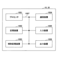
例えば、本開示の一実施の形態における基地局装置10、ユーザ装置20等は、本開示の無線通信方法の処理を行うコンピュータとして機能してもよい。図20は、本開示の一実施の形態に係る基地局装置10及びユーザ装置20のハードウェア構成の一例を示す図である。上述の基地局装置10及びユーザ装置20は、物理的には、プロセッサ1001、記憶装置1002、補助記憶装置1003、通信装置1004、入力装置1005、出力装置1006、バス1007などを含むコンピュータ装置として構成されてもよい。
For example, the
なお、以下の説明では、「装置」という文言は、回路、デバイス、ユニット等に読み替えることができる。基地局装置10及びユーザ装置20のハードウェア構成は、図に示した各装置を1つ又は複数含むように構成されてもよいし、一部の装置を含まずに構成されてもよい。
In the following description, the term "apparatus" can be read as a circuit, device, unit, or the like. The hardware configuration of the
基地局装置10及びユーザ装置20における各機能は、プロセッサ1001、記憶装置1002等のハードウェア上に所定のソフトウェア(プログラム)を読み込ませることによって、プロセッサ1001が演算を行い、通信装置1004による通信を制御したり、記憶装置1002及び補助記憶装置1003におけるデータの読み出し及び書き込みの少なくとも一方を制御したりすることによって実現される。
Each function in the
プロセッサ1001は、例えば、オペレーティングシステムを動作させてコンピュータ全体を制御する。プロセッサ1001は、周辺装置とのインタフェース、制御装置、演算装置、レジスタ等を含む中央処理装置(CPU:Central Processing Unit)で構成されてもよい。例えば、上述の制御部140、制御部240等は、プロセッサ1001によって実現されてもよい。
The
また、プロセッサ1001は、プログラム(プログラムコード)、ソフトウェアモジュール又はデータ等を、補助記憶装置1003及び通信装置1004の少なくとも一方から記憶装置1002に読み出し、これらに従って各種の処理を実行する。プログラムとしては、上述の実施の形態において説明した動作の少なくとも一部をコンピュータに実行させるプログラムが用いられる。例えば、図18に示した基地局装置10の制御部140は、記憶装置1002に格納され、プロセッサ1001で動作する制御プログラムによって実現されてもよい。また、例えば、図19に示したユーザ装置20の制御部240は、記憶装置1002に格納され、プロセッサ1001で動作する制御プログラムによって実現されてもよい。上述の各種処理は、1つのプロセッサ1001によって実行される旨を説明してきたが、2以上のプロセッサ1001により同時又は逐次に実行されてもよい。プロセッサ1001は、1以上のチップによって実装されてもよい。なお、プログラムは、電気通信回線を介してネットワークから送信されてもよい。
The
記憶装置1002は、コンピュータ読み取り可能な記録媒体であり、例えば、ROM(Read Only Memory)、EPROM(Erasable Programmable ROM)、EEPROM(Electrically Erasable Programmable ROM)、RAM(Random Access Memory)等の少なくとも1つによって構成されてもよい。記憶装置1002は、レジスタ、キャッシュ、メインメモリ(主記憶装置)等と呼ばれてもよい。記憶装置1002は、本開示の一実施の形態に係る通信方法を実施するために実行可能なプログラム(プログラムコード)、ソフトウェアモジュール等を保存することができる。
The
補助記憶装置1003は、コンピュータ読み取り可能な記録媒体であり、例えば、CD-ROM(Compact Disc ROM)等の光ディスク、ハードディスクドライブ、フレキシブルディスク、光磁気ディスク(例えば、コンパクトディスク、デジタル多用途ディスク、Blu-ray(登録商標)ディスク)、スマートカード、フラッシュメモリ(例えば、カード、スティック、キードライブ)、フロッピー(登録商標)ディスク、磁気ストリップ等の少なくとも1つによって構成されてもよい。上述の記憶媒体は、例えば、記憶装置1002及び補助記憶装置1003の少なくとも一方を含むデータベース、サーバその他の適切な媒体であってもよい。
The
通信装置1004は、有線ネットワーク及び無線ネットワークの少なくとも一方を介してコンピュータ間の通信を行うためのハードウェア(送受信デバイス)であり、例えばネットワークデバイス、ネットワークコントローラ、ネットワークカード、通信モジュールなどともいう。通信装置1004は、例えば周波数分割複信(FDD:Frequency Division Duplex)及び時分割複信(TDD:Time Division Duplex)の少なくとも一方を実現するために、高周波スイッチ、デュプレクサ、フィルタ、周波数シンセサイザなどを含んで構成されてもよい。例えば、送受信アンテナ、アンプ部、送受信部、伝送路インターフェース等は、通信装置1004によって実現されてもよい。送受信部は、送信部と受信部とで、物理的に、または論理的に分離された実装がなされてもよい。
The
入力装置1005は、外部からの入力を受け付ける入力デバイス(例えば、キーボード、マウス、マイクロフォン、スイッチ、ボタン、センサ等)である。出力装置1006は、外部への出力を実施する出力デバイス(例えば、ディスプレイ、スピーカー、LEDランプ等)である。なお、入力装置1005及び出力装置1006は、一体となった構成(例えば、タッチパネル)であってもよい。
The
また、プロセッサ1001及び記憶装置1002等の各装置は、情報を通信するためのバス1007によって接続される。バス1007は、単一のバスを用いて構成されてもよいし、装置間ごとに異なるバスを用いて構成されてもよい。
Devices such as the
また、基地局装置10及びユーザ装置20は、マイクロプロセッサ、デジタル信号プロセッサ(DSP:Digital Signal Processor)、ASIC(Application Specific Integrated Circuit)、PLD(Programmable Logic Device)、FPGA(Field Programmable Gate Array)等のハードウェアを含んで構成されてもよく、当該ハードウェアにより、各機能ブロックの一部又は全てが実現されてもよい。例えば、プロセッサ1001は、これらのハードウェアの少なくとも1つを用いて実装されてもよい。
In addition, the
(実施の形態のまとめ)
以上、説明したように、本発明の実施の形態によれば、時分割複信の上りリンク及び下りリンクに使用するリソースの設定と、自装置と異なる無線アクセステクノロジにおける時分割複信の上りリンク及び下りリンクに使用するリソースの配置パターンを示す情報とを基地局装置から受信する受信部と、前記リソースの設定と、前記配置パターンを示す情報とに基づいて、自装置が使用する時分割複信の上りリンク及び下りリンクに使用するリソースを決定する制御部と、前記決定された時分割複信の上りリンク及び下りリンクに使用するリソースにおいて前記基地局装置と通信を行う通信部とを有するユーザ装置が提供される。(Summary of embodiment)
As described above, according to the embodiment of the present invention, a receiving unit that receives from a base station apparatus a setting of resources to be used for uplink and downlink of time division duplex and information indicating an allocation pattern of resources to be used for uplink and downlink of time division duplex in a radio access technology different from that of the own apparatus, a control unit that determines resources to be used for uplink and downlink of time division duplex that are used by the apparatus based on the information indicating the resource setting and the allocation pattern, and the determined time. A user apparatus is provided that has a communication unit that communicates with the base station apparatus in resources used for uplink and downlink of division duplex.
上記の構成により、ユーザ装置20は、時間領域においてNRとLTEが異なるUL/DL配置パターンとなる場合、自装置のRAT(Radio Access Technology)と異なるRATにおけるUL/DL配置パターンを示す情報を取得して、被干渉又は与干渉となりうる自装置の信号をパンクチャリングすることで、リソースの使用効率を向上させることができる。すなわち、異なる時分割多重設定が適用される無線通信それぞれにおいて、適切なスケジューリングを行うことができる。
With the above configuration, when
前記制御部は、前記配置パターンを示す情報に基づいて、前記リソースの設定の一部をパンクチャリング又は除外してレートマッチングしてもよい。当該構成により、ユーザ装置20は、時間領域においてNRとLTEが異なるUL/DL配置パターンとなる場合、自装置のRATと異なるRATにおけるUL/DL配置パターンを示す情報を取得して、被干渉又は与干渉となりうる自装置の信号をパンクチャリング又は除外してレートマッチングすることで、リソースの使用効率を向上させることができる。
The control unit may perform rate matching by puncturing or excluding part of the resource configuration based on the information indicating the allocation pattern. With this configuration, when NR and LTE have different UL / DL allocation patterns in the time domain, the
前記制御部は、前記リソースの設定における上りリンクの信号の時間領域の位置と、前記配置パターンを示す情報における下りリンクの信号の時間領域の位置とが重複した場合、前記重複したリソースの設定における上りリンクの信号をパンクチャリング又は除外してレートマッチングし、前記リソースの設定における下りリンクの信号の時間領域の位置と、前記配置パターンを示す情報における上りリンクの信号の時間領域の位置とが重複した場合、前記重複したリソースの設定における下りリンクの信号をパンクチャリング又は除外してレートマッチングしてもよい。当該構成により、ユーザ装置20は、時間領域においてNRとLTEが異なるUL/DL配置パターンとなる場合、自装置のRATと異なるRATにおけるUL/DL配置パターンを示す情報を取得して、被干渉又は与干渉となりうる自装置の信号をパンクチャリング又は除外してレートマッチングすることで、リソースの使用効率を向上させることができる。
When the time domain position of the uplink signal in the resource configuration and the time domain position of the downlink signal in the information indicating the allocation pattern overlap, the control unit performs rate matching by puncturing or excluding the uplink signal in the overlapping resource configuration, and puncturing or excluding the downlink signal in the overlapping resource configuration when the time domain position of the downlink signal in the resource configuration and the time domain position of the uplink signal in the information indicating the allocation pattern overlap. You can match. With this configuration, when NR and LTE have different UL / DL allocation patterns in the time domain, the
前記制御部は、前記配置パターンを示す情報における同期信号及び物理報知チャネルのブロックの時間領域の位置と重複する前記リソースの設定における信号をすべてパンクチャリング又は除外してレートマッチングしてもよい。当該構成により、ユーザ装置20は、時間領域においてNRとLTEが異なるUL/DL配置パターンとなる場合、自装置のRATと異なるRATにおけるUL/DL配置パターンを示す情報を取得して、被干渉又は与干渉となりうる自装置の信号をパンクチャリング又は除外してレートマッチングすることで、リソースの使用効率を向上させることができる。
The control unit may perform rate matching by puncturing or excluding all signals in the resource configuration that overlap with the time domain positions of blocks of synchronization signals and physical broadcast channels in the information indicating the allocation pattern. With this configuration, when NR and LTE have different UL / DL allocation patterns in the time domain, the
前記制御部は、前記配置パターンを示す情報においてシンボル単位で配置される上りリンクの信号と、前記リソースの設定における信号の下りリンクのシンボルとが重複した場合、前記重複したリソースの設定における下りリンクのシンボルを除いた下りリンクのシンボルでレートマッチングしてもよい。当該構成により、ユーザ装置20は、時間領域においてNRとLTEが異なるUL/DL配置パターンとなる場合、自装置のRATと異なるRATにおけるUL/DL配置パターンを示す情報を取得して、被干渉又は与干渉となりうる自装置の信号をパンクチャリングした後のDLリソースでレートマッチングを行うことで適切なエラーレートを維持する通信ができる。
When the uplink signal arranged in symbol units in the information indicating the arrangement pattern overlaps with the downlink symbol of the signal in the resource setting, the control unit may perform rate matching with downlink symbols excluding the downlink symbol in the overlapping resource setting. With this configuration, when NR and LTE have different UL/DL allocation patterns in the time domain, the
また、本発明の実施の形態によれば、時分割複信の上りリンク及び下りリンクに使用するリソースの設定と、自装置と異なる無線アクセステクノロジにおける時分割複信の上りリンク及び下りリンクに使用するリソースの配置パターンを示す情報とをユーザ装置に送信する送信部と、前記リソースの設定と、前記配置パターンを示す情報とに基づいて、自装置が使用する時分割複信の上りリンク及び下りリンクに使用するリソースを決定する制御部と、前記決定された時分割複信の上りリンク及び下りリンクに使用するリソースにおいて前記ユーザ装置と通信を行う通信部とを有する基地局装置が提供される。 Further, according to the embodiment of the present invention, there are provided a transmission unit configured to transmit, to the user apparatus, configuration of resources used for time division duplex uplink and downlink and information indicating an allocation pattern of resources used for time division duplex uplink and downlink in a radio access technology different from that of the own apparatus, a control unit determining resources used for time division duplex uplink and downlink used by the own apparatus based on the resource configuration and information indicating the allocation pattern, and the determined time division duplex uplink. and a communication unit that communicates with the user equipment in resources used for downlink.
上記の構成により、ユーザ装置20は、時間領域においてNRとLTEが異なるUL/DL配置パターンとなる場合、自装置のRAT(Radio Access Technology)と異なるRATにおけるUL/DL配置パターンを示す情報を取得して、被干渉又は与干渉となりうる自装置の信号をパンクチャリング又は除外してレートマッチングすることで、リソースの使用効率を向上させることができる。すなわち、異なる時分割多重設定が適用される無線通信それぞれにおいて、適切なスケジューリングを行うことができる。
With the above configuration, when the
(実施形態の補足)
以上、本発明の実施の形態を説明してきたが、開示される発明はそのような実施形態に限定されず、当業者は様々な変形例、修正例、代替例、置換例等を理解するであろう。発明の理解を促すため具体的な数値例を用いて説明がなされたが、特に断りのない限り、それらの数値は単なる一例に過ぎず適切な如何なる値が使用されてもよい。上記の説明における項目の区分けは本発明に本質的ではなく、2以上の項目に記載された事項が必要に応じて組み合わせて使用されてよいし、ある項目に記載された事項が、別の項目に記載された事項に(矛盾しない限り)適用されてよい。機能ブロック図における機能部又は処理部の境界は必ずしも物理的な部品の境界に対応するとは限らない。複数の機能部の動作が物理的には1つの部品で行われてもよいし、あるいは1つの機能部の動作が物理的には複数の部品により行われてもよい。実施の形態で述べた処理手順については、矛盾の無い限り処理の順序を入れ替えてもよい。処理説明の便宜上、基地局装置10及びユーザ装置20は機能的なブロック図を用いて説明されたが、そのような装置はハードウェアで、ソフトウェアで又はそれらの組み合わせで実現されてもよい。本発明の実施の形態に従って基地局装置10が有するプロセッサにより動作するソフトウェア及び本発明の実施の形態に従ってユーザ装置20が有するプロセッサにより動作するソフトウェアはそれぞれ、ランダムアクセスメモリ(RAM)、フラッシュメモリ、読み取り専用メモリ(ROM)、EPROM、EEPROM、レジスタ、ハードディスク(HDD)、リムーバブルディスク、CD-ROM、データベース、サーバその他の適切な如何なる記憶媒体に保存されてもよい。(Supplement to the embodiment)
Although the embodiments of the present invention have been described above, the disclosed invention is not limited to such embodiments, and those skilled in the art will understand various modifications, modifications, alternatives, replacements, and the like. Although specific numerical examples have been used to facilitate understanding of the invention, these numerical values are merely examples and any appropriate values may be used unless otherwise specified. The division of items in the above description is not essential to the present invention, and the items described in two or more items may be used in combination as necessary, and the items described in one item may be applied to the items described in another item (as long as there is no contradiction). Boundaries of functional or processing units in functional block diagrams do not necessarily correspond to boundaries of physical components. The operations of a plurality of functional units may be physically performed by one component, or the operations of one functional unit may be physically performed by a plurality of components. As for the processing procedures described in the embodiments, the processing order may be changed as long as there is no contradiction. For convenience of explanation of processing, the
また、情報の通知は、本開示で説明した態様/実施形態に限られず、他の方法を用いて行われてもよい。例えば、情報の通知は、物理レイヤシグナリング(例えば、DCI(Downlink Control Information)、UCI(Uplink Control Information))、上位レイヤシグナリング(例えば、RRC(Radio Resource Control)シグナリング、MAC(Medium Access Control)シグナリング、報知情報(MIB(Master Information Block)、SIB(System Information Block))、その他の信号又はこれらの組み合わせによって実施されてもよい。また、RRCシグナリングは、RRCメッセージと呼ばれてもよく、例えば、RRC接続セットアップ(RRC Connection Setup)メッセージ、RRC接続再構成(RRC Connection Reconfiguration)メッセージ等であってもよい。 Also, notification of information is not limited to the aspects/embodiments described in this disclosure, and may be performed using other methods. For example, the notification of information, physical layer signaling (e.g., DCI (Downlink Control Information), UCI (Uplink Control Information)), higher layer signaling (e.g., RRC (Radio Resource Control) signaling, MAC (Medium Access Control) signaling, broadcast information (MIB (Master Information Block), SIB (System Information Block)), other signals or a combination thereof may be implemented.In addition, RRC signaling may also be referred to as an RRC message. For example, it may be an RRC connection setup message, an RRC connection reconfiguration message, or the like.
本開示において説明した各態様/実施形態は、LTE(Long Term Evolution)、LTE-A(LTE-Advanced)、SUPER 3G、IMT-Advanced、4G(4th generation mobile communication system)、5G(5th generation mobile communication system)、FRA(Future Radio Access)、NR(new Radio)、W-CDMA(登録商標)、GSM(登録商標)、CDMA2000、UMB(Ultra Mobile Broadband)、IEEE 802.11(Wi-Fi(登録商標))、IEEE 802.16(WiMAX(登録商標))、IEEE 802.20、UWB(Ultra-WideBand)、Bluetooth(登録商標)、その他の適切なシステムを利用するシステム及びこれらに基づいて拡張された次世代システムの少なくとも一つに適用されてもよい。また、複数のシステムが組み合わされて(例えば、LTE及びLTE-Aの少なくとも一方と5Gとの組み合わせ等)適用されてもよい。 Each aspect/embodiment described in the present disclosure includes LTE (Long Term Evolution), LTE-A (LTE-Advanced), SUPER 3G, IMT-Advanced, 4G (4th generation mobile communication system), 5G (5th generation mobile communication system), FRA (Future Radio Access), NR (new Radio), W-CDMA (registered trademark), GSM (registered trademark), CDMA2000, UMB (Ultra Mobile Broadband ), IEEE 802.11 (Wi-Fi®), IEEE 802.16 (WiMAX®), IEEE 802.20, Ultra-WideBand (UWB), Bluetooth®, other suitable systems, and/or next-generation systems enhanced based on these. Also, a plurality of systems may be applied in combination (for example, a combination of at least one of LTE and LTE-A and 5G, etc.).
本明細書で説明した各態様/実施形態の処理手順、シーケンス、フローチャート等は、矛盾の無い限り、順序を入れ替えてもよい。例えば、本開示において説明した方法については、例示的な順序を用いて様々なステップの要素を提示しており、提示した特定の順序に限定されない。 The procedures, sequences, flow charts, etc. of each aspect/embodiment described herein may be interchanged as long as there is no inconsistency. For example, the methods described in this disclosure present elements of the various steps using a sample order, and are not limited to the specific order presented.
本明細書において基地局装置10によって行われるとした特定動作は、場合によってはその上位ノード(upper node)によって行われることもある。基地局装置10を有する1つ又は複数のネットワークノード(network nodes)からなるネットワークにおいて、ユーザ装置20との通信のために行われる様々な動作は、基地局装置10及び基地局装置10以外の他のネットワークノード(例えば、MME又はS-GW等が考えられるが、これらに限られない)の少なくとも1つによって行われ得ることは明らかである。上記において基地局装置10以外の他のネットワークノードが1つである場合を例示したが、他のネットワークノードは、複数の他のネットワークノードの組み合わせ(例えば、MME及びS-GW)であってもよい。
A specific operation performed by the
本開示において説明した情報又は信号等は、上位レイヤ(又は下位レイヤ)から下位レイヤ(又は上位レイヤ)へ出力され得る。複数のネットワークノードを介して入出力されてもよい。 Information, signals, or the like described in this disclosure may be output from a higher layer (or lower layer) to a lower layer (or higher layer). It may be input and output via multiple network nodes.
入出力された情報等は特定の場所(例えば、メモリ)に保存されてもよいし、管理テーブルを用いて管理してもよい。入出力される情報等は、上書き、更新、又は追記され得る。出力された情報等は削除されてもよい。入力された情報等は他の装置へ送信されてもよい。 Input/output information and the like may be stored in a specific location (for example, memory), or may be managed using a management table. Input/output information and the like can be overwritten, updated, or appended. The output information and the like may be deleted. The entered information and the like may be transmitted to another device.
本開示における判定は、1ビットで表される値(0か1か)によって行われてもよいし、真偽値(Boolean:true又はfalse)によって行われてもよいし、数値の比較(例えば、所定の値との比較)によって行われてもよい。 The determination in the present disclosure may be performed by a value represented by 1 bit (0 or 1), may be performed by a true/false value (Boolean: true or false), or may be performed by numerical comparison (e.g., comparison with a predetermined value).
ソフトウェアは、ソフトウェア、ファームウェア、ミドルウェア、マイクロコード、ハードウェア記述言語と呼ばれるか、他の名称で呼ばれるかを問わず、命令、命令セット、コード、コードセグメント、プログラムコード、プログラム、サブプログラム、ソフトウェアモジュール、アプリケーション、ソフトウェアアプリケーション、ソフトウェアパッケージ、ルーチン、サブルーチン、オブジェクト、実行可能ファイル、実行スレッド、手順、機能などを意味するよう広く解釈されるべきである。 Software shall be construed broadly to mean instructions, instruction sets, code, code segments, program code, programs, subprograms, software modules, applications, software applications, software packages, routines, subroutines, objects, executables, threads of execution, procedures, functions, etc., whether referred to as software, firmware, middleware, microcode, hardware description language or otherwise.
また、ソフトウェア、命令、情報などは、伝送媒体を介して送受信されてもよい。例えば、ソフトウェアが、有線技術(同軸ケーブル、光ファイバケーブル、ツイストペア、デジタル加入者回線(DSL:Digital Subscriber Line)など)及び無線技術(赤外線、マイクロ波など)の少なくとも一方を使用してウェブサイト、サーバ、又は他のリモートソースから送信される場合、これらの有線技術及び無線技術の少なくとも一方は、伝送媒体の定義内に含まれる。 Software, instructions, information, etc. may also be sent and received over a transmission medium. For example, if the software is transmitted from a website, server, or other remote source using wired technologies (coaxial cable, fiber optic cable, twisted pair, Digital Subscriber Line (DSL), etc.) and/or wireless technologies (infrared, microwave, etc.), then these wired and/or wireless technologies are included within the definition of transmission medium.
本開示において説明した情報、信号などは、様々な異なる技術のいずれかを使用して表されてもよい。例えば、上記の説明全体に渡って言及され得るデータ、命令、コマンド、情報、信号、ビット、シンボル、チップなどは、電圧、電流、電磁波、磁界若しくは磁性粒子、光場若しくは光子、又はこれらの任意の組み合わせによって表されてもよい。 Information, signals, etc. described in this disclosure may be represented using any of a variety of different technologies. For example, the data, instructions, commands, information, signals, bits, symbols, chips, etc. that may be referred to throughout the above description may be represented by voltages, currents, electromagnetic waves, magnetic fields or magnetic particles, optical fields or photons, or any combination thereof.
なお、本開示において説明した用語及び本開示の理解に必要な用語については、同一の又は類似する意味を有する用語と置き換えてもよい。例えば、チャネル及びシンボルの少なくとも一方は信号(シグナリング)であってもよい。また、信号はメッセージであってもよい。また、コンポーネントキャリア(CC:Component Carrier)は、キャリア周波数、セル、周波数キャリアなどと呼ばれてもよい。 The terms explained in this disclosure and the terms necessary for understanding the present disclosure may be replaced with terms having the same or similar meanings. For example, the channel and/or symbols may be signaling. A signal may also be a message. A component carrier (CC) may also be called a carrier frequency, a cell, a frequency carrier, or the like.
本開示において使用する「システム」及び「ネットワーク」という用語は、互換的に使用される。 As used in this disclosure, the terms "system" and "network" are used interchangeably.
また、本開示において説明した情報、パラメータなどは、絶対値を用いて表されてもよいし、所定の値からの相対値を用いて表されてもよいし、対応する別の情報を用いて表されてもよい。例えば、無線リソースはインデックスによって指示されるものであってもよい。 In addition, the information, parameters, etc. described in the present disclosure may be expressed using absolute values, may be expressed using relative values from a predetermined value, or may be expressed using corresponding other information. For example, radio resources may be indexed.
上述したパラメータに使用する名称はいかなる点においても限定的な名称ではない。さらに、これらのパラメータを使用する数式等は、本開示で明示的に開示したものと異なる場合もある。様々なチャネル(例えば、PUCCH、PDCCHなど)及び情報要素は、あらゆる好適な名称によって識別できるので、これらの様々なチャネル及び情報要素に割り当てている様々な名称は、いかなる点においても限定的な名称ではない。 The names used for the parameters described above are not limiting names in any way. Further, the formulas, etc., using these parameters may differ from those expressly disclosed in this disclosure. The various names assigned to these various channels and information elements are not limiting names in any way, as the various channels (e.g., PUCCH, PDCCH, etc.) and information elements can be identified by any suitable names.
本開示においては、「基地局(BS:Base Station)」、「無線基地局」、「基地局装置」、「固定局(fixed station)」、「NodeB」、「eNodeB(eNB)」、「gNodeB(gNB)」、「アクセスポイント(access point)」、「送信ポイント(transmission point)」、「受信ポイント(reception point)、「送受信ポイント(transmission/reception point)」、「セル」、「セクタ」、「セルグループ」、「キャリア」、「コンポーネントキャリア」などの用語は、互換的に使用され得る。基地局は、マクロセル、スモールセル、フェムトセル、ピコセルなどの用語で呼ばれる場合もある。 In the present disclosure, "base station (BS)", "radio base station", "base station apparatus", "fixed station", "NodeB", "eNodeB (eNB)", "gNodeB (gNB)", "access point", "transmission point", "reception point", "transmission / reception point", "cell", "sector", "cell Terms such as "group", "carrier", "component carrier" may be used interchangeably. A base station may also be referred to by terms such as macrocell, small cell, femtocell, picocell, and the like.
基地局は、1つ又は複数(例えば、3つ)のセルを収容することができる。基地局が複数のセルを収容する場合、基地局のカバレッジエリア全体は複数のより小さいエリアに区分でき、各々のより小さいエリアは、基地局サブシステム(例えば、屋内用の小型基地局(RRH:Remote Radio Head)によって通信サービスを提供することもできる。「セル」又は「セクタ」という用語は、このカバレッジにおいて通信サービスを行う基地局及び基地局サブシステムの少なくとも一方のカバレッジエリアの一部又は全体を指す。 A base station may serve one or more (eg, three) cells. When a base station accommodates multiple cells, the overall coverage area of the base station can be partitioned into multiple smaller areas, and each smaller area can also be served by a base station subsystem (e.g., a small indoor base station (RRH: Remote Radio Head)).The terms "cell" or "sector" refer to part or all of the coverage area of at least one of the base station and base station subsystem serving communication services in this coverage.
本開示においては、「移動局(MS:Mobile Station)」、「ユーザ端末(user terminal)」、「ユーザ装置(UE:User Equipment)」、「端末」などの用語は、互換的に使用され得る。 In this disclosure, terms such as “Mobile Station (MS),” “user terminal,” “User Equipment (UE),” “terminal,” etc. may be used interchangeably.
移動局は、当業者によって、加入者局、モバイルユニット、加入者ユニット、ワイヤレスユニット、リモートユニット、モバイルデバイス、ワイヤレスデバイス、ワイヤレス通信デバイス、リモートデバイス、モバイル加入者局、アクセス端末、モバイル端末、ワイヤレス端末、リモート端末、ハンドセット、ユーザエージェント、モバイルクライアント、クライアント、又はいくつかの他の適切な用語で呼ばれる場合もある。 A mobile station may also be referred to by those skilled in the art as a subscriber station, mobile unit, subscriber unit, wireless unit, remote unit, mobile device, wireless device, wireless communication device, remote device, mobile subscriber station, access terminal, mobile terminal, wireless terminal, remote terminal, handset, user agent, mobile client, client, or some other suitable term.
基地局及び移動局の少なくとも一方は、送信装置、受信装置、通信装置などと呼ばれてもよい。なお、基地局及び移動局の少なくとも一方は、移動体に搭載されたデバイス、移動体自体などであってもよい。当該移動体は、乗り物(例えば、車、飛行機など)であってもよいし、無人で動く移動体(例えば、ドローン、自動運転車など)であってもよいし、ロボット(有人型又は無人型)であってもよい。なお、基地局及び移動局の少なくとも一方は、必ずしも通信動作時に移動しない装置も含む。例えば、基地局及び移動局の少なくとも一方は、センサなどのIoT(Internet of Things)機器であってもよい。 At least one of a base station and a mobile station may be called a transmitter, a receiver, a communication device, and the like. At least one of the base station and the mobile station may be a device mounted on a mobile object, the mobile object itself, or the like. The mobile object may be a vehicle (e.g., car, airplane, etc.), an unmanned mobile object (e.g., drone, self-driving car, etc.), or a robot (manned or unmanned). Note that at least one of the base station and the mobile station includes devices that do not necessarily move during communication operations. For example, at least one of the base station and the mobile station may be an IoT (Internet of Things) device such as a sensor.
また、本開示における基地局は、ユーザ端末で読み替えてもよい。例えば、基地局及びユーザ端末間の通信を、複数のユーザ装置20間の通信(例えば、D2D(Device-to-Device)、V2X(Vehicle-to-Everything)などと呼ばれてもよい)に置き換えた構成について、本開示の各態様/実施形態を適用してもよい。この場合、上述の基地局装置10が有する機能をユーザ装置20が有する構成としてもよい。また、「上り」及び「下り」などの文言は、端末間通信に対応する文言(例えば、「サイド(side)」)で読み替えられてもよい。例えば、上りチャネル、下りチャネルなどは、サイドチャネルで読み替えられてもよい。
Also, the base station in the present disclosure may be read as a user terminal. For example, each aspect / embodiment of the present disclosure may be applied to a configuration in which communication between a base station and a user terminal is replaced with communication between a plurality of user devices 20 (for example, may be called D2D (Device-to-Device), V2X (Vehicle-to-Everything), etc.). In this case, the
同様に、本開示におけるユーザ端末は、基地局で読み替えてもよい。この場合、上述のユーザ端末が有する機能を基地局が有する構成としてもよい。 Similarly, user terminals in the present disclosure may be read as base stations. In this case, the base station may have the functions that the above-described user terminal has.
本開示で使用する「判断(determining)」、「決定(determining)」という用語は、多種多様な動作を包含する場合がある。「判断」、「決定」は、例えば、判定(judging)、計算(calculating)、算出(computing)、処理(processing)、導出(deriving)、調査(investigating)、探索(looking up、search、inquiry)(例えば、テーブル、データベース又は別のデータ構造での探索)、確認(ascertaining)した事を「判断」「決定」したとみなす事などを含み得る。また、「判断」、「決定」は、受信(receiving)(例えば、情報を受信すること)、送信(transmitting)(例えば、情報を送信すること)、入力(input)、出力(output)、アクセス(accessing)(例えば、メモリ中のデータにアクセスすること)した事を「判断」「決定」したとみなす事などを含み得る。また、「判断」、「決定」は、解決(resolving)、選択(selecting)、選定(choosing)、確立(establishing)、比較(comparing)などした事を「判断」「決定」したとみなす事を含み得る。つまり、「判断」「決定」は、何らかの動作を「判断」「決定」したとみなす事を含み得る。また、「判断(決定)」は、「想定する(assuming)」、「期待する(expecting)」、「みなす(considering)」などで読み替えられてもよい。 As used in this disclosure, the terms "determining" and "determining" may encompass a wide variety of actions. "Judgement", "determining" can include, for example, judging, calculating, computing, processing, deriving, investigating, looking up, searching, inquiring (e.g., searching in a table, database, or other data structure), ascertaining ascertaining as "judging", "determining", etc. In addition, "determining" and "determining" include receiving (e.g., receiving information), transmitting (e.g., transmitting information), input, output, and accessing (e.g., accessing data in memory). Also, "determining" or "determining" may include resolving, selecting, choosing, establishing, comparing, etc., to be regarded as "determining" or "determining." In other words, "judgment" and "decision" may include considering that some action is "judgment" and "decision". Also, "judgment (decision)" may be read as "assuming", "expecting", "considering", or the like.
「接続された(connected)」、「結合された(coupled)」という用語、又はこれらのあらゆる変形は、2又はそれ以上の要素間の直接的又は間接的なあらゆる接続又は結合を意味し、互いに「接続」又は「結合」された2つの要素間に1又はそれ以上の中間要素が存在することを含むことができる。要素間の結合又は接続は、物理的なものであっても、論理的なものであっても、或いはこれらの組み合わせであってもよい。例えば、「接続」は「アクセス」で読み替えられてもよい。本開示で使用する場合、2つの要素は、1又はそれ以上の電線、ケーブル及びプリント電気接続の少なくとも一つを用いて、並びにいくつかの非限定的かつ非包括的な例として、無線周波数領域、マイクロ波領域及び光(可視及び不可視の両方)領域の波長を有する電磁エネルギーなどを用いて、互いに「接続」又は「結合」されると考えることができる。 The terms "connected", "coupled", or any variation thereof, mean any direct or indirect connection or coupling between two or more elements, and may include the presence of one or more intermediate elements between two elements that are "connected" or "coupled" to each other. Couplings or connections between elements may be physical, logical, or a combination thereof. For example, "connection" may be read as "access". As used in this disclosure, two elements can be considered to be “connected” or “coupled” to each other using at least one of one or more wires, cables, and printed electrical connections, and using electromagnetic energy having wavelengths in the radio frequency, microwave, and light (both visible and invisible) regions, as some non-limiting and non-exhaustive examples.
参照信号は、RS(Reference Signal)と略称することもでき、適用される標準によってパイロット(Pilot)と呼ばれてもよい。 The reference signal may be abbreviated as RS (Reference Signal), or may be referred to as Pilot according to the applicable standard.
本開示において使用する「に基づいて」という記載は、別段に明記されていない限り、「のみに基づいて」を意味しない。言い換えれば、「に基づいて」という記載は、「のみに基づいて」と「に少なくとも基づいて」の両方を意味する。 As used in this disclosure, the phrase "based on" does not mean "based only on," unless expressly specified otherwise. In other words, the phrase "based on" means both "based only on" and "based at least on."
本開示において使用する「第1の」、「第2の」などの呼称を使用した要素へのいかなる参照も、それらの要素の量又は順序を全般的に限定しない。これらの呼称は、2つ以上の要素間を区別する便利な方法として本開示において使用され得る。したがって、第1及び第2の要素への参照は、2つの要素のみが採用され得ること、又は何らかの形で第1の要素が第2の要素に先行しなければならないことを意味しない。 Any reference to elements using the "first," "second," etc. designations used in this disclosure does not generally limit the quantity or order of those elements. These designations may be used in this disclosure as a convenient method of distinguishing between two or more elements. Thus, reference to a first and second element does not imply that only two elements can be employed or that the first element must precede the second element in any way.
上記の各装置の構成における「手段」を、「部」、「回路」、「デバイス」等に置き換えてもよい。 The “means” in the configuration of each device described above may be replaced with “unit”, “circuit”, “device”, or the like.
本開示において、「含む(include)」、「含んでいる(including)」及びそれらの変形が使用されている場合、これらの用語は、用語「備える(comprising)」と同様に、包括的であることが意図される。さらに、本開示において使用されている用語「又は(or)」は、排他的論理和ではないことが意図される。 Where "include," "including," and variations thereof are used in this disclosure, these terms, like the term "comprising," are intended to be inclusive. Furthermore, the term "or" as used in this disclosure is not intended to be an exclusive OR.
無線フレームは時間領域において1つ又は複数のフレームによって構成されてもよい。時間領域において1つ又は複数の各フレームはサブフレームと呼ばれてもよい。サブフレームは更に時間領域において1つ又は複数のスロットによって構成されてもよい。サブフレームは、ニューメロロジ(numerology)に依存しない固定の時間長(例えば、1ms)であってもよい。 A radio frame may consist of one or more frames in the time domain. Each frame or frames in the time domain may be referred to as a subframe. A subframe may also consist of one or more slots in the time domain. A subframe may be of a fixed length of time (eg, 1 ms) independent of numerology.
ニューメロロジは、ある信号又はチャネルの送信及び受信の少なくとも一方に適用される通信パラメータであってもよい。ニューメロロジは、例えば、サブキャリア間隔(SCS:SubCarrier Spacing)、帯域幅、シンボル長、サイクリックプレフィックス長、送信時間間隔(TTI:Transmission Time Interval)、TTIあたりのシンボル数、無線フレーム構成、送受信機が周波数領域において行う特定のフィルタリング処理、送受信機が時間領域において行う特定のウィンドウイング処理などの少なくとも1つを示してもよい。 A numerology may be a communication parameter that applies to the transmission and/or reception of a signal or channel. The numerology may indicate at least one of, for example, SubCarrier Spacing (SCS), bandwidth, symbol length, cyclic prefix length, Transmission Time Interval (TTI), number of symbols per TTI, radio frame structure, certain filtering operations performed by the transceiver in the frequency domain, certain windowing operations performed by the transceiver in the time domain, etc.
スロットは、時間領域において1つ又は複数のシンボル(OFDM(Orthogonal Frequency Division Multiplexing)シンボル、SC-FDMA(Single Carrier Frequency Division Multiple Access)シンボル等)で構成されてもよい。スロットは、ニューメロロジに基づく時間単位であってもよい。 A slot may consist of one or more symbols (OFDM (Orthogonal Frequency Division Multiplexing) symbol, SC-FDMA (Single Carrier Frequency Division Multiple Access) symbol, etc.) in the time domain. A slot may be a unit of time based on numerology.
スロットは、複数のミニスロットを含んでもよい。各ミニスロットは、時間領域において1つ又は複数のシンボルによって構成されてもよい。また、ミニスロットは、サブスロットと呼ばれてもよい。ミニスロットは、スロットよりも少ない数のシンボルによって構成されてもよい。ミニスロットより大きい時間単位で送信されるPDSCH(又はPUSCH)は、PDSCH(又はPUSCH)マッピングタイプAと呼ばれてもよい。ミニスロットを用いて送信されるPDSCH(又はPUSCH)は、PDSCH(又はPUSCH)マッピングタイプBと呼ばれてもよい。 A slot may include multiple minislots. Each minislot may consist of one or more symbols in the time domain. A minislot may also be referred to as a subslot. A minislot may consist of fewer symbols than a slot. PDSCH (or PUSCH) transmitted in time units larger than minislots may be referred to as PDSCH (or PUSCH) mapping type A. PDSCH (or PUSCH) transmitted using minislots may be referred to as PDSCH (or PUSCH) mapping type B.
無線フレーム、サブフレーム、スロット、ミニスロット及びシンボルは、いずれも信号を伝送する際の時間単位を表す。無線フレーム、サブフレーム、スロット、ミニスロット及びシンボルは、それぞれに対応する別の呼称が用いられてもよい。 Radio frames, subframes, slots, minislots and symbols all represent units of time in which signals are transmitted. Radio frames, subframes, slots, minislots and symbols may be referred to by other corresponding designations.
例えば、1サブフレームは送信時間間隔(TTI:Transmission Time Interval)と呼ばれてもよいし、複数の連続したサブフレームがTTIと呼ばれてよいし、1スロット又は1ミニスロットがTTIと呼ばれてもよい。つまり、サブフレーム及びTTIの少なくとも一方は、既存のLTEにおけるサブフレーム(1ms)であってもよいし、1msより短い期間(例えば、1-13シンボル)であってもよいし、1msより長い期間であってもよい。なお、TTIを表す単位は、サブフレームではなくスロット、ミニスロットなどと呼ばれてもよい。 For example, one subframe may be referred to as a Transmission Time Interval (TTI), multiple consecutive subframes may be referred to as a TTI, and one slot or minislot may be referred to as a TTI. That is, at least one of the subframe and TTI may be a subframe (1 ms) in existing LTE, may be a period shorter than 1 ms (eg, 1-13 symbols), or may be a period longer than 1 ms. Note that the unit representing the TTI may be called a slot, mini-slot, or the like instead of a subframe.
ここで、TTIは、例えば、無線通信におけるスケジューリングの最小時間単位のことをいう。例えば、LTEシステムでは、基地局が各ユーザ装置20に対して、無線リソース(各ユーザ装置20において使用することが可能な周波数帯域幅、送信電力など)を、TTI単位で割り当てるスケジューリングを行う。なお、TTIの定義はこれに限られない。
Here, TTI refers to, for example, the minimum time unit of scheduling in wireless communication. For example, in the LTE system, the base station performs scheduling to allocate radio resources (frequency bandwidth, transmission power, etc. that can be used by each user equipment 20) to each
TTIは、チャネル符号化されたデータパケット(トランスポートブロック)、コードブロック、コードワードなどの送信時間単位であってもよいし、スケジューリング、リンクアダプテーションなどの処理単位となってもよい。なお、TTIが与えられたとき、実際にトランスポートブロック、コードブロック、コードワードなどがマッピングされる時間区間(例えば、シンボル数)は、当該TTIよりも短くてもよい。 The TTI may be a transmission time unit of channel-encoded data packets (transport blocks), code blocks, codewords, or the like, or may be a processing unit of scheduling, link adaptation, or the like. Note that when a TTI is given, the time interval (for example, the number of symbols) in which transport blocks, code blocks, codewords, etc. are actually mapped may be shorter than the TTI.
なお、1スロット又は1ミニスロットがTTIと呼ばれる場合、1以上のTTI(すなわち、1以上のスロット又は1以上のミニスロット)が、スケジューリングの最小時間単位となってもよい。また、当該スケジューリングの最小時間単位を構成するスロット数(ミニスロット数)は制御されてもよい。 Note that when one slot or one minislot is called a TTI, one or more TTIs (that is, one or more slots or one or more minislots) may be the minimum scheduling time unit. Also, the number of slots (the number of mini-slots) constituting the minimum time unit of the scheduling may be controlled.
1msの時間長を有するTTIは、通常TTI(LTE Rel.8-12におけるTTI)、ノーマルTTI、ロングTTI、通常サブフレーム、ノーマルサブフレーム、ロングサブフレーム、スロットなどと呼ばれてもよい。通常TTIより短いTTIは、短縮TTI、ショートTTI、部分TTI(partial又はfractional TTI)、短縮サブフレーム、ショートサブフレーム、ミニスロット、サブスロット、スロットなどと呼ばれてもよい。 A TTI having a duration of 1 ms may also be called a normal TTI (TTI in LTE Rel. 8-12), normal TTI, long TTI, normal subframe, normal subframe, long subframe, slot, and so on. A TTI that is shorter than a regular TTI may also be called a shortened TTI, a short TTI, a partial or fractional TTI, a shortened subframe, a short subframe, a minislot, a subslot, a slot, and so on.
なお、ロングTTI(例えば、通常TTI、サブフレームなど)は、1msを超える時間長を有するTTIで読み替えてもよいし、ショートTTI(例えば、短縮TTIなど)は、ロングTTIのTTI長未満かつ1ms以上のTTI長を有するTTIで読み替えてもよい。 A long TTI (e.g., normal TTI, subframe, etc.) may be replaced with a TTI having a time length exceeding 1 ms, and a short TTI (e.g., shortened TTI, etc.) may be replaced with a TTI having a TTI length of less than the TTI length of the long TTI and 1 ms or more.
リソースブロック(RB)は、時間領域及び周波数領域のリソース割当単位であり、周波数領域において、1つ又は複数個の連続した副搬送波(subcarrier)を含んでもよい。RBに含まれるサブキャリアの数は、ニューメロロジに関わらず同じであってもよく、例えば12であってもよい。RBに含まれるサブキャリアの数は、ニューメロロジに基づいて決定されてもよい。 A resource block (RB) is a resource allocation unit in the time domain and the frequency domain, and may include one or more consecutive subcarriers in the frequency domain. The number of subcarriers included in the RB may be the same regardless of the numerology, and may be 12, for example. The number of subcarriers included in an RB may be determined based on numerology.
また、RBの時間領域は、1つ又は複数個のシンボルを含んでもよく、1スロット、1ミニスロット、1サブフレーム、又は1TTIの長さであってもよい。1TTI、1サブフレームなどは、それぞれ1つ又は複数のリソースブロックで構成されてもよい。 Also, the time domain of an RB may include one or more symbols and may be 1 slot, 1 minislot, 1 subframe, or 1 TTI long. One TTI, one subframe, etc. may each consist of one or more resource blocks.
なお、1つ又は複数のRBは、物理リソースブロック(PRB:Physical RB)、サブキャリアグループ(SCG:Sub-Carrier Group)、リソースエレメントグループ(REG:Resource Element Group)、PRBペア、RBペアなどと呼ばれてもよい。 One or more RBs may also be called a physical resource block (PRB), a sub-carrier group (SCG), a resource element group (REG), a PRB pair, an RB pair, or the like.
また、リソースブロックは、1つ又は複数のリソースエレメント(RE:Resource Element)によって構成されてもよい。例えば、1REは、1サブキャリア及び1シンボルの無線リソース領域であってもよい。 Also, a resource block may be composed of one or more resource elements (RE: Resource Element). For example, 1 RE may be a radio resource region of 1 subcarrier and 1 symbol.
帯域幅部分(BWP:Bandwidth Part)(部分帯域幅などと呼ばれてもよい)は、あるキャリアにおいて、あるニューメロロジ用の連続する共通RB(common resource blocks)のサブセットのことを表してもよい。ここで、共通RBは、当該キャリアの共通参照ポイントを基準としたRBのインデックスによって特定されてもよい。PRBは、あるBWPで定義され、当該BWP内で番号付けされてもよい。 A Bandwidth Part (BWP) (which may also be referred to as a Bandwidth Part) may refer to a subset of contiguous common resource blocks (RBs) for a numerology on a carrier. Here, the common RB may be identified by an RB index based on the common reference point of the carrier. PRBs may be defined in a BWP and numbered within that BWP.
BWPには、UL用のBWP(UL BWP)と、DL用のBWP(DL BWP)とが含まれてもよい。UEに対して、1キャリア内に1つ又は複数のBWPが設定されてもよい。 The BWP may include a BWP for UL (UL BWP) and a BWP for DL (DL BWP). One or multiple BWPs may be configured for a UE within one carrier.
設定されたBWPの少なくとも1つがアクティブであってもよく、UEは、アクティブなBWPの外で所定の信号/チャネルを送受信することを想定しなくてもよい。なお、本開示における「セル」、「キャリア」などは、「BWP」で読み替えられてもよい。 At least one of the configured BWPs may be active and the UE may not expect to transmit or receive a given signal/channel outside the active BWP. Note that "cell", "carrier", etc. in the present disclosure may be read as "BWP".
上述した無線フレーム、サブフレーム、スロット、ミニスロット及びシンボルなどの構造は例示に過ぎない。例えば、無線フレームに含まれるサブフレームの数、サブフレーム又は無線フレームあたりのスロットの数、スロット内に含まれるミニスロットの数、スロット又はミニスロットに含まれるシンボル及びRBの数、RBに含まれるサブキャリアの数、並びにTTI内のシンボル数、シンボル長、サイクリックプレフィックス(CP:Cyclic Prefix)長などの構成は、様々に変更することができる。 The structures such as radio frames, subframes, slots, minislots and symbols described above are exemplary only. For example, the number of subframes included in a radio frame, the number of slots per subframe or radio frame, the number of minislots included in a slot, the number of symbols and RBs included in a slot or minislot, the number of subcarriers included in an RB, and the number of symbols in a TTI, the symbol length, the cyclic prefix (CP) length, etc. can be variously changed.
本開示において、例えば、英語でのa, an及びtheのように、翻訳により冠詞が追加された場合、本開示は、これらの冠詞の後に続く名詞が複数形であることを含んでもよい。 In this disclosure, where articles have been added by translation, such as a, an, and the in English, the disclosure may include the plural nouns following these articles.
本開示において、「AとBが異なる」という用語は、「AとBが互いに異なる」ことを意味してもよい。なお、当該用語は、「AとBがそれぞれCと異なる」ことを意味してもよい。「離れる」、「結合される」などの用語も、「異なる」と同様に解釈されてもよい。 In the present disclosure, the term "A and B are different" may mean "A and B are different from each other." The term may also mean that "A and B are different from C". Terms such as "separate," "coupled," etc. may also be interpreted in the same manner as "different."
本開示において説明した各態様/実施形態は単独で用いてもよいし、組み合わせて用いてもよいし、実行に伴って切り替えて用いてもよい。また、所定の情報の通知(例えば、「Xであること」の通知)は、明示的に行うものに限られず、暗黙的(例えば、当該所定の情報の通知を行わない)ことによって行われてもよい。 Each aspect/embodiment described in the present disclosure may be used alone, may be used in combination, or may be used by switching according to execution. Further, notification of predetermined information (e.g., notification of “being X”) is not limited to explicit notification, but may be performed implicitly (e.g., not notification of the predetermined information).
なお、本開示において、送信部210及び受信部220は、通信部の一例である。送信部110及び受信部120は、通信部の一例である。TDDのUL/DL設定は、時分割複信における上りリンク及び下りリンクに使用するリソースの設定の一例である。RATは、無線アクセステクノロジの一例である。SS/PBCHブロックは、同期信号及び物理報知チャネルのブロックの一例である。
In addition, in this disclosure, the
以上、本開示について詳細に説明したが、当業者にとっては、本開示が本開示中に説明した実施形態に限定されるものではないということは明らかである。本開示は、請求の範囲の記載により定まる本開示の趣旨及び範囲を逸脱することなく修正及び変更態様として実施することができる。したがって、本開示の記載は、例示説明を目的とするものであり、本開示に対して何ら制限的な意味を有するものではない。 Although the present disclosure has been described in detail above, it should be apparent to those skilled in the art that the present disclosure is not limited to the embodiments described in this disclosure. The present disclosure can be practiced with modifications and variations without departing from the spirit and scope of the present disclosure as defined by the claims. Accordingly, the description of the present disclosure is for illustrative purposes and is not meant to be limiting in any way.
10 基地局装置
110 送信部
120 受信部
130 設定部
140 制御部
20 ユーザ装置
210 送信部
220 受信部
230 設定部
240 制御部
1001 プロセッサ
1002 記憶装置
1003 補助記憶装置
1004 通信装置
1005 入力装置
1006 出力装置10
Claims (5)
前記リソースに関する情報及び前記配置パターンを示す情報に基づき、前記第1の無線アクセステクノロジにおける上りリンク及び下りリンクに使用するリソースを決定する制御部と、を備え、
前記配置パターンを示す情報は、前記第2の無線アクセステクノロジにおいて予約されたリソースの時間領域の位置及び周期を示し、
前記決定されたリソースは、前記第2の無線アクセステクノロジにおいて予約されたリソースとの重複を回避するように構成される、端末。 a receiving unit that receives information about uplink and downlink resources in a first radio access technology and information indicating a resource allocation pattern in a second radio access technology ;
A control unit that determines resources to be used for uplink and downlink in the first radio access technology based on the information on the resources and the information indicating the allocation pattern ,
The information indicating the allocation pattern indicates the position and period of the time domain of the reserved resource in the second radio access technology,
A terminal, wherein the determined resources are configured to avoid overlap with reserved resources in the second radio access technology.
端末に、前記リソースに関する情報と、前記配置パターンを示す情報と、を送信する送信部と、
を備え、
前記リソースに関する情報及び前記配置パターンを示す情報は、前記端末に、前記第1の無線アクセステクノロジにおける上りリンク及び下りリンクに使用するリソースを決定させ、
前記配置パターンを示す情報は、前記第2の無線アクセステクノロジにおいて予約されたリソースの時間領域の位置及び周期を示し、
前記決定されたリソースは、前記第2の無線アクセステクノロジにおいて予約されたリソースとの重複を回避するように構成される、基地局。 a control unit that sets information about uplink and downlink resources in a first radio access technology and information indicating a resource allocation pattern in a second radio access technology ;
a transmission unit that transmits information about the resource and information indicating the allocation pattern to the terminal ;
with
The information about the resources and the information indicating the allocation pattern cause the terminal to determine resources to use for uplink and downlink in the first radio access technology ;
The information indicating the allocation pattern indicates the position and period of the time domain of the reserved resource in the second radio access technology,
A base station, wherein the determined resources are configured to avoid overlapping with reserved resources in the second radio access technology.
端末が第1の無線アクセステクノロジにおける上りリンク及び下りリンクにおけるリソースに関する情報と、第2の無線アクセステクノロジにおけるリソースの配置パターンを示す情報と、を受信するステップと、
前記端末が前記リソースに関する情報及び前記配置パターンを示す情報に基づき、前記第1の無線アクセステクノロジにおける上りリンク及び下りリンクに使用するリソースを決定するステップと、を有し、
前記配置パターンを示す情報は、前記第2の無線アクセステクノロジにおいて予約されたリソースの時間領域の位置及び周期を示し、
前記決定されたリソースは、前記第2の無線アクセステクノロジにおいて予約されたリソースとの重複を回避するように構成される、方法。 A method of communication comprising:
a step in which the terminal receives information about uplink and downlink resources in a first radio access technology and information indicating a resource allocation pattern in a second radio access technology ;
determining resources to be used by the terminal for uplink and downlink in the first radio access technology based on the information about the resources and the information indicating the allocation pattern ;
The information indicating the allocation pattern indicates the position and period of the time domain of the reserved resource in the second radio access technology,
The method, wherein the determined resources are configured to avoid overlapping with reserved resources in the second radio access technology.
前記端末は、
第1の無線アクセステクノロジにおける上りリンク及び下りリンクにおけるリソースに関する情報と、第2の無線アクセステクノロジにおけるリソースの配置パターンを示す情報と、を、前記基地局から受信し、
前記リソースに関する情報及び前記配置パターンを示す情報に基づき、第1の無線アクセステクノロジにおける上りリンク及び下りリンクに使用するリソースを決定し、
前記配置パターンを示す情報は、前記第2の無線アクセステクノロジにおいて予約されたリソースの時間領域の位置及び周期を示し、
前記決定されたリソースは、前記第2の無線アクセステクノロジにおいて予約されたリソースとの重複を回避するように構成される、システム。 A system comprising a terminal and a base station,
The terminal is
receiving information about uplink and downlink resources in a first radio access technology and information indicating resource allocation patterns in a second radio access technology from the base station;
determining resources to be used for uplink and downlink in a first radio access technology based on the information about the resources and the information indicating the allocation pattern ;
The information indicating the allocation pattern indicates the position and period of the time domain of the reserved resource in the second radio access technology,
The system, wherein the determined resources are configured to avoid overlapping with reserved resources in the second radio access technology.
Applications Claiming Priority (1)
| Application Number | Priority Date | Filing Date | Title |
|---|---|---|---|
| PCT/JP2019/013909 WO2020194760A1 (en) | 2019-03-28 | 2019-03-28 | User device and base station device |
Publications (3)
| Publication Number | Publication Date |
|---|---|
| JPWO2020194760A1 JPWO2020194760A1 (en) | 2020-10-01 |
| JPWO2020194760A5 JPWO2020194760A5 (en) | 2022-12-13 |
| JP7313428B2 true JP7313428B2 (en) | 2023-07-24 |
Family
ID=72609239
Family Applications (1)
| Application Number | Title | Priority Date | Filing Date |
|---|---|---|---|
| JP2021508677A Active JP7313428B2 (en) | 2019-03-28 | 2019-03-28 | TERMINAL, BASE STATION, METHOD AND SYSTEM |
Country Status (6)
| Country | Link |
|---|---|
| US (1) | US20220182212A1 (en) |
| EP (1) | EP3952504A4 (en) |
| JP (1) | JP7313428B2 (en) |
| KR (1) | KR20210142099A (en) |
| CN (1) | CN113615274A (en) |
| WO (1) | WO2020194760A1 (en) |
Families Citing this family (6)
| Publication number | Priority date | Publication date | Assignee | Title |
|---|---|---|---|---|
| EP4005124B1 (en) * | 2019-07-26 | 2024-02-28 | Telefonaktiebolaget LM Ericsson (publ) | Dual-connectivity single uplink schemes |
| WO2023002574A1 (en) * | 2021-07-20 | 2023-01-26 | 株式会社Nttドコモ | Terminal, wireless communication method, and base station |
| JPWO2023002573A1 (en) * | 2021-07-20 | 2023-01-26 | ||
| WO2023058121A1 (en) * | 2021-10-05 | 2023-04-13 | 株式会社安川電機 | Communication system, communication control circuit, and communication method |
| WO2023058120A1 (en) * | 2021-10-05 | 2023-04-13 | 株式会社安川電機 | Radio communication device and communication method |
| WO2023058116A1 (en) * | 2021-10-05 | 2023-04-13 | 株式会社安川電機 | Communication system and communication method |
Family Cites Families (4)
| Publication number | Priority date | Publication date | Assignee | Title |
|---|---|---|---|---|
| CN109923918B (en) * | 2016-11-02 | 2023-05-02 | 株式会社Ntt都科摩 | User device and base station |
| US10165565B2 (en) * | 2017-03-24 | 2018-12-25 | Qualcomm Incorporated | Legacy and new radio coexistence frame and control design |
| KR102234254B1 (en) * | 2017-05-01 | 2021-03-31 | 엘지전자 주식회사 | Method and apparatus for allocating resources in wireless communication system |
| US10849115B2 (en) * | 2018-09-10 | 2020-11-24 | Apple Inc. | Downlink control channel design in new radio systems |
-
2019
- 2019-03-28 WO PCT/JP2019/013909 patent/WO2020194760A1/en unknown
- 2019-03-28 JP JP2021508677A patent/JP7313428B2/en active Active
- 2019-03-28 KR KR1020217027693A patent/KR20210142099A/en not_active Application Discontinuation
- 2019-03-28 EP EP19921434.7A patent/EP3952504A4/en active Pending
- 2019-03-28 CN CN201980094321.3A patent/CN113615274A/en active Pending
- 2019-03-28 US US17/441,552 patent/US20220182212A1/en active Pending
Non-Patent Citations (4)
| Title |
|---|
| Ericsson,Coexistence of NB-IoT with NR[online],3GPP TSG RAN WG1 #96 R1-1901749,Internet<URL:http://www.3gpp.org/ftp/tsg_ran/WG1_RL1/TSGR1_96/Docs/R1-1901749.zip>,2019年02月16日 |
| Qualcomm Incorporated,Coexistence of NB-IoT with NR[online],3GPP TSG RAN WG1 #96 R1-1902377,Internet<URL:http://www.3gpp.org/ftp/tsg_ran/WG1_RL1/TSGR1_96/Docs/R1-1902377.zip>,2019年02月16日 |
| Qualcomm Incorporated,Coexistence with NR[online],3GPP TSG RAN WG1 #93 R1-1807118,Internet<URL:http://www.3gpp.org/ftp/tsg_ran/WG1_RL1/TSGR1_93/Docs/R1-1807118.zip>,2018年05月12日 |
| SoftBank,TDD NB-IoT coexistence with NR[online],3GPP TSG RAN WG1 #92b R1- 1804890,Internet<URL:http://www.3gpp.org/ftp/tsg_ran/WG1_RL1/TSGR1_92b/Docs/R1-1804890.zip>,2018年04月06日 |
Also Published As
| Publication number | Publication date |
|---|---|
| WO2020194760A1 (en) | 2020-10-01 |
| EP3952504A1 (en) | 2022-02-09 |
| EP3952504A4 (en) | 2022-10-19 |
| CN113615274A (en) | 2021-11-05 |
| KR20210142099A (en) | 2021-11-24 |
| JPWO2020194760A1 (en) | 2020-10-01 |
| US20220182212A1 (en) | 2022-06-09 |
Similar Documents
| Publication | Publication Date | Title |
|---|---|---|
| JP7313428B2 (en) | TERMINAL, BASE STATION, METHOD AND SYSTEM | |
| JP7308277B2 (en) | Terminal, base station, communication method and communication system | |
| JP2024024117A (en) | Terminal and communication method | |
| JP7241172B2 (en) | User equipment and base station equipment | |
| JP7386223B2 (en) | Terminal, base station device, communication method, and wireless communication system | |
| WO2021149110A1 (en) | Terminal and communication method | |
| US20240057031A1 (en) | Terminal, base station, and transmission method | |
| US20240049195A1 (en) | Terminal, base station and communication method | |
| JP7201786B2 (en) | TERMINAL, BASE STATION, COMMUNICATION METHOD, AND WIRELESS COMMUNICATION SYSTEM | |
| US20230209651A1 (en) | Terminal, base station, and communication method | |
| JP7386250B2 (en) | Terminals, base stations, communication methods, and systems | |
| JP7170842B2 (en) | User equipment and base station equipment | |
| JP7248709B2 (en) | TERMINAL, BASE STATION, COMMUNICATION METHOD, AND WIRELESS COMMUNICATION SYSTEM | |
| JP7250048B2 (en) | TERMINAL, BASE STATION, COMMUNICATION METHOD, AND WIRELESS COMMUNICATION SYSTEM | |
| JP7203199B2 (en) | Terminal, base station and communication method | |
| JP7273859B2 (en) | User equipment and base station equipment | |
| WO2021044598A1 (en) | Terminal and communication method | |
| JPWO2020161907A1 (en) | User device | |
| WO2023012883A1 (en) | Terminal, base station, and communication method | |
| JP7366144B2 (en) | Terminals, base stations, communication methods, and communication systems | |
| WO2022239091A1 (en) | Terminal and communication method | |
| WO2022208635A1 (en) | Terminal and communication method | |
| JP7438245B2 (en) | Terminal and communication method | |
| US20230284181A1 (en) | Terminal and communication method | |
| WO2023002587A1 (en) | Terminal and communication method |
Legal Events
| Date | Code | Title | Description |
|---|---|---|---|
| A621 | Written request for application examination |
Free format text: JAPANESE INTERMEDIATE CODE: A621 Effective date: 20220315 |
|
| A521 | Request for written amendment filed |
Free format text: JAPANESE INTERMEDIATE CODE: A523 Effective date: 20221205 |
|
| A131 | Notification of reasons for refusal |
Free format text: JAPANESE INTERMEDIATE CODE: A131 Effective date: 20230322 |
|
| A521 | Request for written amendment filed |
Free format text: JAPANESE INTERMEDIATE CODE: A523 Effective date: 20230516 |
|
| TRDD | Decision of grant or rejection written | ||
| A01 | Written decision to grant a patent or to grant a registration (utility model) |
Free format text: JAPANESE INTERMEDIATE CODE: A01 Effective date: 20230613 |
|
| A61 | First payment of annual fees (during grant procedure) |
Free format text: JAPANESE INTERMEDIATE CODE: A61 Effective date: 20230711 |
|
| R150 | Certificate of patent or registration of utility model |
Ref document number: 7313428 Country of ref document: JP Free format text: JAPANESE INTERMEDIATE CODE: R150 |