JP7436680B2 - General constraint information for video coding - Google Patents
General constraint information for video coding Download PDFInfo
- Publication number
- JP7436680B2 JP7436680B2 JP2022541250A JP2022541250A JP7436680B2 JP 7436680 B2 JP7436680 B2 JP 7436680B2 JP 2022541250 A JP2022541250 A JP 2022541250A JP 2022541250 A JP2022541250 A JP 2022541250A JP 7436680 B2 JP7436680 B2 JP 7436680B2
- Authority
- JP
- Japan
- Prior art keywords
- flag
- video
- bitstream
- mode
- equal
- Prior art date
- Legal status (The legal status is an assumption and is not a legal conclusion. Google has not performed a legal analysis and makes no representation as to the accuracy of the status listed.)
- Active
Links
- 238000000034 method Methods 0.000 claims description 228
- 238000012545 processing Methods 0.000 claims description 59
- 238000006243 chemical reaction Methods 0.000 claims description 55
- 238000012952 Resampling Methods 0.000 claims description 8
- 230000015654 memory Effects 0.000 claims description 6
- 238000013139 quantization Methods 0.000 description 37
- 230000009466 transformation Effects 0.000 description 26
- 230000003044 adaptive effect Effects 0.000 description 23
- 238000003672 processing method Methods 0.000 description 18
- 230000011664 signaling Effects 0.000 description 17
- 239000013598 vector Substances 0.000 description 16
- 230000004044 response Effects 0.000 description 12
- 238000010586 diagram Methods 0.000 description 10
- 238000004590 computer program Methods 0.000 description 9
- 230000008569 process Effects 0.000 description 8
- 238000013461 design Methods 0.000 description 7
- 241000023320 Luma <angiosperm> Species 0.000 description 6
- OSWPMRLSEDHDFF-UHFFFAOYSA-N methyl salicylate Chemical compound COC(=O)C1=CC=CC=C1O OSWPMRLSEDHDFF-UHFFFAOYSA-N 0.000 description 6
- 239000011159 matrix material Substances 0.000 description 5
- 238000005192 partition Methods 0.000 description 5
- 230000006835 compression Effects 0.000 description 4
- 238000007906 compression Methods 0.000 description 4
- 230000009977 dual effect Effects 0.000 description 4
- 238000005516 engineering process Methods 0.000 description 4
- 239000011449 brick Substances 0.000 description 3
- 238000004891 communication Methods 0.000 description 3
- 230000006870 function Effects 0.000 description 3
- 230000003993 interaction Effects 0.000 description 3
- 230000003287 optical effect Effects 0.000 description 3
- 230000008901 benefit Effects 0.000 description 2
- 238000011161 development Methods 0.000 description 2
- 230000018109 developmental process Effects 0.000 description 2
- 238000006073 displacement reaction Methods 0.000 description 2
- 238000013507 mapping Methods 0.000 description 2
- 230000002093 peripheral effect Effects 0.000 description 2
- 230000000644 propagated effect Effects 0.000 description 2
- 238000013515 script Methods 0.000 description 2
- 238000000926 separation method Methods 0.000 description 2
- 230000002123 temporal effect Effects 0.000 description 2
- 238000012360 testing method Methods 0.000 description 2
- 238000000844 transformation Methods 0.000 description 2
- 208000037170 Delayed Emergence from Anesthesia Diseases 0.000 description 1
- 241000249931 Doronicum maximum Species 0.000 description 1
- 101100202505 Saccharomyces cerevisiae (strain ATCC 204508 / S288c) SCM4 gene Proteins 0.000 description 1
- 230000004913 activation Effects 0.000 description 1
- 230000006978 adaptation Effects 0.000 description 1
- 238000003491 array Methods 0.000 description 1
- 230000005540 biological transmission Effects 0.000 description 1
- 230000000903 blocking effect Effects 0.000 description 1
- 238000004422 calculation algorithm Methods 0.000 description 1
- 238000004364 calculation method Methods 0.000 description 1
- 230000001413 cellular effect Effects 0.000 description 1
- 230000006837 decompression Effects 0.000 description 1
- 230000007423 decrease Effects 0.000 description 1
- 230000003247 decreasing effect Effects 0.000 description 1
- 238000009795 derivation Methods 0.000 description 1
- 238000001914 filtration Methods 0.000 description 1
- 230000007274 generation of a signal involved in cell-cell signaling Effects 0.000 description 1
- 230000002427 irreversible effect Effects 0.000 description 1
- 230000009467 reduction Effects 0.000 description 1
- 230000002441 reversible effect Effects 0.000 description 1
- 230000011218 segmentation Effects 0.000 description 1
- 239000004065 semiconductor Substances 0.000 description 1
- 239000000758 substrate Substances 0.000 description 1
- 238000012546 transfer Methods 0.000 description 1
- 230000000007 visual effect Effects 0.000 description 1
Images


Classifications
-
- H—ELECTRICITY
- H04—ELECTRIC COMMUNICATION TECHNIQUE
- H04N—PICTORIAL COMMUNICATION, e.g. TELEVISION
- H04N19/00—Methods or arrangements for coding, decoding, compressing or decompressing digital video signals
- H04N19/10—Methods or arrangements for coding, decoding, compressing or decompressing digital video signals using adaptive coding
- H04N19/189—Methods or arrangements for coding, decoding, compressing or decompressing digital video signals using adaptive coding characterised by the adaptation method, adaptation tool or adaptation type used for the adaptive coding
- H04N19/196—Methods or arrangements for coding, decoding, compressing or decompressing digital video signals using adaptive coding characterised by the adaptation method, adaptation tool or adaptation type used for the adaptive coding being specially adapted for the computation of encoding parameters, e.g. by averaging previously computed encoding parameters
-
- H—ELECTRICITY
- H04—ELECTRIC COMMUNICATION TECHNIQUE
- H04N—PICTORIAL COMMUNICATION, e.g. TELEVISION
- H04N19/00—Methods or arrangements for coding, decoding, compressing or decompressing digital video signals
- H04N19/70—Methods or arrangements for coding, decoding, compressing or decompressing digital video signals characterised by syntax aspects related to video coding, e.g. related to compression standards
-
- H—ELECTRICITY
- H04—ELECTRIC COMMUNICATION TECHNIQUE
- H04N—PICTORIAL COMMUNICATION, e.g. TELEVISION
- H04N19/00—Methods or arrangements for coding, decoding, compressing or decompressing digital video signals
- H04N19/10—Methods or arrangements for coding, decoding, compressing or decompressing digital video signals using adaptive coding
- H04N19/169—Methods or arrangements for coding, decoding, compressing or decompressing digital video signals using adaptive coding characterised by the coding unit, i.e. the structural portion or semantic portion of the video signal being the object or the subject of the adaptive coding
- H04N19/186—Methods or arrangements for coding, decoding, compressing or decompressing digital video signals using adaptive coding characterised by the coding unit, i.e. the structural portion or semantic portion of the video signal being the object or the subject of the adaptive coding the unit being a colour or a chrominance component
-
- H—ELECTRICITY
- H04—ELECTRIC COMMUNICATION TECHNIQUE
- H04N—PICTORIAL COMMUNICATION, e.g. TELEVISION
- H04N11/00—Colour television systems
- H04N11/04—Colour television systems using pulse code modulation
- H04N11/042—Codec means
- H04N11/044—Codec means involving transform coding
-
- H—ELECTRICITY
- H04—ELECTRIC COMMUNICATION TECHNIQUE
- H04N—PICTORIAL COMMUNICATION, e.g. TELEVISION
- H04N19/00—Methods or arrangements for coding, decoding, compressing or decompressing digital video signals
- H04N19/10—Methods or arrangements for coding, decoding, compressing or decompressing digital video signals using adaptive coding
- H04N19/102—Methods or arrangements for coding, decoding, compressing or decompressing digital video signals using adaptive coding characterised by the element, parameter or selection affected or controlled by the adaptive coding
- H04N19/103—Selection of coding mode or of prediction mode
- H04N19/105—Selection of the reference unit for prediction within a chosen coding or prediction mode, e.g. adaptive choice of position and number of pixels used for prediction
-
- H—ELECTRICITY
- H04—ELECTRIC COMMUNICATION TECHNIQUE
- H04N—PICTORIAL COMMUNICATION, e.g. TELEVISION
- H04N19/00—Methods or arrangements for coding, decoding, compressing or decompressing digital video signals
- H04N19/10—Methods or arrangements for coding, decoding, compressing or decompressing digital video signals using adaptive coding
- H04N19/102—Methods or arrangements for coding, decoding, compressing or decompressing digital video signals using adaptive coding characterised by the element, parameter or selection affected or controlled by the adaptive coding
- H04N19/12—Selection from among a plurality of transforms or standards, e.g. selection between discrete cosine transform [DCT] and sub-band transform or selection between H.263 and H.264
-
- H—ELECTRICITY
- H04—ELECTRIC COMMUNICATION TECHNIQUE
- H04N—PICTORIAL COMMUNICATION, e.g. TELEVISION
- H04N19/00—Methods or arrangements for coding, decoding, compressing or decompressing digital video signals
- H04N19/10—Methods or arrangements for coding, decoding, compressing or decompressing digital video signals using adaptive coding
- H04N19/102—Methods or arrangements for coding, decoding, compressing or decompressing digital video signals using adaptive coding characterised by the element, parameter or selection affected or controlled by the adaptive coding
- H04N19/124—Quantisation
- H04N19/126—Details of normalisation or weighting functions, e.g. normalisation matrices or variable uniform quantisers
-
- H—ELECTRICITY
- H04—ELECTRIC COMMUNICATION TECHNIQUE
- H04N—PICTORIAL COMMUNICATION, e.g. TELEVISION
- H04N19/00—Methods or arrangements for coding, decoding, compressing or decompressing digital video signals
- H04N19/10—Methods or arrangements for coding, decoding, compressing or decompressing digital video signals using adaptive coding
- H04N19/169—Methods or arrangements for coding, decoding, compressing or decompressing digital video signals using adaptive coding characterised by the coding unit, i.e. the structural portion or semantic portion of the video signal being the object or the subject of the adaptive coding
- H04N19/17—Methods or arrangements for coding, decoding, compressing or decompressing digital video signals using adaptive coding characterised by the coding unit, i.e. the structural portion or semantic portion of the video signal being the object or the subject of the adaptive coding the unit being an image region, e.g. an object
- H04N19/176—Methods or arrangements for coding, decoding, compressing or decompressing digital video signals using adaptive coding characterised by the coding unit, i.e. the structural portion or semantic portion of the video signal being the object or the subject of the adaptive coding the unit being an image region, e.g. an object the region being a block, e.g. a macroblock
-
- H—ELECTRICITY
- H04—ELECTRIC COMMUNICATION TECHNIQUE
- H04N—PICTORIAL COMMUNICATION, e.g. TELEVISION
- H04N19/00—Methods or arrangements for coding, decoding, compressing or decompressing digital video signals
- H04N19/60—Methods or arrangements for coding, decoding, compressing or decompressing digital video signals using transform coding
Description
関連出願の相互参照
本願は、2020年1月5日出願の国際特許出願第PCT/CN2020/070368号の優先権および利益を主張する2021年1月5日出願の国際特許出願第PCT/CN2021/070279号に基づく。上記出願の開示全体は、本明細書の開示として参照によりここに援用される。
Cross-reference of related applications
This application is based on International Patent Application No. PCT/CN2021/070279 filed on January 5, 2021, which claims priority and benefit from International Patent Application No. PCT/CN2020/070368 filed on January 5, 2020 . Based on . The entire disclosure of the above application is hereby incorporated by reference as the disclosure herein .
この特許明細書は、画像および映像の符号化および復号化に関する。 This patent specification relates to image and video encoding and decoding.
デジタル映像は、インターネット及び他のデジタル通信ネットワークにおいて最大の帯域幅の使用量を占めている。映像を受信及び表示することが可能である接続されたユーザ機器の数が増加するにつれ、デジタル映像の使用に対する帯域幅需要は増大し続けることが予測される。 Digital video accounts for the largest amount of bandwidth usage on the Internet and other digital communication networks. It is expected that the bandwidth demands for digital video usage will continue to increase as the number of connected user equipment capable of receiving and displaying video increases.
本明細書は、他のコーディングツールに加え、ACT(Adaptive Color Transform)モードを使用する、映像符号化および復号化のためのシステム、方法およびデバイスを開示する。 This specification discloses systems, methods, and devices for video encoding and decoding that use an Adaptive Color Transform (ACT) mode in addition to other coding tools.
1つの例示的な態様において、映像処理の方法が開示される。この方法は、映像の現在の映像ブロックと前記映像のビットストリームとの間での変換のために、前記現在の映像ブロックをコーディングするために使用されるACT(Adaptive Color Tranform)モードのための最大許容サイズおよび/または最小許容サイズを決定することと、前記決定に基づいて、前記変換を実行することと、を含む。 In one exemplary aspect, a method of video processing is disclosed. This method uses a maximum Adaptive Color Transform (ACT) mode for converting between a current video block of a video and a bitstream of the video, which is used to code the current video block. determining an acceptable size and/or a minimum acceptable size; and performing the transformation based on the determination.
別の例示的な態様において、映像処理の方法が開示される。この方法は、映像の現在の映像ブロックと前記映像のビットストリームとの間での変換のために、前記現在の映像ブロックをコーディングするために使用されるパレットモードに対して、最大許容パレットサイズおよび/または最小許容予測子サイズを決定することと、前記決定に基づいて、前記変換を実行すると、を含み、前記最大許容パレットサイズおよび/または最小許容予測子サイズは、前記現在の映像ブロックのコーディング特性に基づく。 In another exemplary aspect, a method of video processing is disclosed. The method determines, for conversion between a current video block of video and a bitstream of the video, a maximum allowable palette size and a palette mode used to code the current video block. and/or determining a minimum allowable predictor size; and performing the transform based on the determination, wherein the maximum allowable palette size and/or the minimum allowable predictor size are based on the coding of the current video block. Based on characteristics.
さらに別の例示的な態様において、映像処理の方法が開示される。この方法は、映像の現在の映像ブロックと前記映像のビットストリームとの間で変換を実行することを含み、前記ビットストリームは、フォーマット規則に準拠し、前記現在の映像ブロックは、パレットモードコーディングツールを使用してコーディングされ、前記フォーマット規則は、前記ビットストリームにおける前記現在の映像ブロックのためのエスケープシンボルの2値化に関連付けられたパラメータが前記現在の映像ブロックのコーディングされた情報に基づくことを規定する。 In yet another exemplary aspect, a method of video processing is disclosed. The method includes performing a conversion between a current video block of a video and a bitstream of the video, the bitstream conforming to formatting rules, and the current video block being converted to a palette mode coding tool. and the format rule specifies that the parameters associated with the binarization of escape symbols for the current video block in the bitstream are based on the coded information of the current video block. stipulate.
さらに別の例示的な態様において、映像処理の方法が開示される。この方法は、1つのブロックを含む映像と前記映像のビットストリームとの間での変換のために、前記ブロックのサイズがACT(Adaptive Color Transform)モードの最大許容サイズよりも大きいことを決定することと、前記決定に基づいて、前記変換を実行することと、を含み、前記ブロックのサイズが前記ACTモードの最大許容サイズよりも大きいことに応答して、前記ブロックを複数のサブブロックに分割し、複数のサブブロックの各々が同じ予測モードを共有し、1つのサブブロックレベルで前記ACTモードは有効にする。 In yet another exemplary aspect, a method of video processing is disclosed. The method includes determining that the size of the block is larger than a maximum allowable size of an ACT (Adaptive Color Transform) mode for converting between a video including one block and a bitstream of the video. and performing the transformation based on the determination, and in response to the size of the block being larger than the maximum allowable size of the ACT mode, dividing the block into a plurality of sub-blocks. , each of a plurality of sub-blocks shares the same prediction mode, and the ACT mode is enabled at one sub-block level.
さらに別の例示的な態様において、映像処理の方法が開示される。この方法は、映像の現在の映像ブロックと前記映像のビットストリームとの間で変換を行うことを含み、前記ビットストリームは、前記現在の映像ブロックにおけるACT(Adaptive Color Transform)モードの使用の指示が前記ビットストリームにおいて信号通知されるか否かが、前記現在の映像ブロックの寸法または前記ACTモードに対する最大許容サイズのうちの少なくとも1つに基づくことを規定するフォーマット規則に準拠する。 In yet another exemplary aspect, a method of video processing is disclosed. The method includes converting between a current video block of video and a bitstream of the video, the bitstream including an indication of the use of an ACT (Adaptive Color Transform) mode in the current video block. Complying with formatting rules specifying whether or not to be signaled in the bitstream is based on at least one of the current video block size or a maximum allowed size for the ACT mode.
さらに別の例示的な態様において、映像処理の方法が開示される。この方法は、映像の現在の映像ユニットと前記映像のビットストリームとの間で変換を行うことを含み、前記ビットストリームが、フォーマット規則に準拠し、前記フォーマット規則は、ビットストリームに第1のフラグが含まれているかどうかを規定し、前記第1のフラグは、SPS(Sequence Parameter Set)における第2のフラグが、前記現在の映像ユニットに対してACT(Adaptive Color Transform)モードが無効であることを規定するかどうかを示す。 In yet another exemplary aspect, a method of video processing is disclosed. The method includes converting between a current video unit of video and a bitstream of the video, the bitstream conforming to a formatting rule, the formatting rule including a first flag in the bitstream. The first flag specifies whether the second flag in the SPS (Sequence Parameter Set) is included, and the second flag in the SPS (Sequence Parameter Set) specifies whether the ACT (Adaptive Color Transform) mode is invalid for the current video unit. Indicates whether the
さらに別の例示的な態様において、映像処理の方法が開示される。この方法は、映像の現在の映像ユニットと前記映像のビットストリームとの間で変換を行うことを含み、前記ビットストリームが、フォーマット規則に準拠し、前記フォーマット規則は、ビットストリームに第1のフラグが含まれているかどうかを規定し、前記第1のフラグは、SPS(Sequence Parameter Set)における第2のフラグが、前記現在の映像ユニットに対してBDPCM(Block-based Delta Pulse Code Modulation)モードが無効であることを規定するかどうかを示す。 In yet another exemplary aspect, a method of video processing is disclosed. The method includes converting between a current video unit of video and a bitstream of the video, the bitstream conforming to a formatting rule, the formatting rule including a first flag in the bitstream. A second flag in SPS (Sequence Parameter Set) specifies whether BDPCM (Block-based Delta Pulse Code Modulation) mode is included for the current video unit. Indicates whether to specify invalidity.
さらに別の例示的な態様において、映像処理の方法が開示される。この方法は、映像の現在の映像ユニットと前記映像のビットストリームとの間で変換を実行することを含み、前記ビットストリームが、フォーマット規則に準拠し、前記フォーマット規則は、ビットストリームに第1のフラグが含まれているかどうかを規定し、前記第1のフラグは、SPS(Sequence Parameter Set)における第2のフラグが、前記現在の映像ユニットのクロマ成分に対してBDPCM(Block-based Delta Pulse Code Modulation)モードが無効であることを規定するかどうかを示す。 In yet another exemplary aspect, a method of video processing is disclosed. The method includes performing a conversion between a current video unit of a video and a bitstream of the video, the bitstream conforming to a formatting rule, the formatting rule including a first The first flag specifies whether a second flag in a SPS (Sequence Parameter Set) includes a BDPCM (Block-based Delta Pulse Code) for the chroma component of the current video unit. Indicates whether to specify that the Modulation mode is invalid.
さらに別の例示的な態様において、映像処理の方法が開示される。この方法は、映像の現在の映像ユニットと前記映像のビットストリームとの間で変換を実行することを含み、前記ビットストリームが、フォーマット規則に準拠し、前記フォーマット規則は、ビットストリームに第1のフラグが含まれているかどうかを規定し、前記第1のフラグは、SPS(Sequence Parameter Set)における第2のフラグが、前記現在の映像ユニットに対してパレットが無効であることを規定するかどうかを示す。 In yet another exemplary aspect, a method of video processing is disclosed. The method includes performing a conversion between a current video unit of a video and a bitstream of the video, the bitstream conforming to a formatting rule, the formatting rule including a first a flag is included, the first flag specifies whether a second flag in a SPS (Sequence Parameter Set) specifies that the palette is invalid for the current video unit; shows.
さらに別の例示的な態様において、映像処理の方法が開示される。この方法は、映像の現在の映像ユニットと前記映像のビットストリームとの間で変換を実行することを含み、前記ビットストリームが、フォーマット規則に準拠し、前記フォーマット規則は、ビットストリームに第1のフラグが含まれているかどうかを規定し、前記第1のフラグは、SPS(Sequence Parameter Set)における第2のフラグが、前記現在の映像ユニットに対してRPR(Reference Picture Resampling)モードが無効化されることを規定するかどうかを示す。 In yet another exemplary aspect, a method of video processing is disclosed. The method includes performing a conversion between a current video unit of a video and a bitstream of the video, the bitstream conforming to a formatting rule, the formatting rule including a first The first flag specifies whether a second flag in the SPS (Sequence Parameter Set) is included, and the first flag specifies whether the RPR (Reference Picture Resampling) mode is disabled for the current video unit. Indicates whether or not it stipulates that
さらに別の例示的な態様において、映像処理の方法が開示される。この方法は、現在の映像ブロックに対してACT(Adaptive Color Transform)モードを有効にする際に、追加の量子化パラメータオフセットを適用することを規定する規則に従って、映像の現在の映像ブロックと前記映像のビットストリームとの間で変換を実行することを含む。 In yet another exemplary aspect, a method of video processing is disclosed. This method combines a current video block of a video with the said video according to a rule specifying that an additional quantization parameter offset is applied when enabling ACT (Adaptive Color Transform) mode for the current video block. , including performing conversions to and from the bitstream.
さらに別の例示的な態様において、映像処理の方法が開示される。この方法は、規則に従って、映像の現在の映像ブロックと前記映像のビットストリーム表現との間で変換を実行することを含み、前記現在の映像ブロックは、YCgCo色変換またはYCgCo逆色変換を現在の映像ブロックに適用するジョイントCbCrコーディングモードを使用してコーディングされ、前記現在の映像ブロックは、前記YCgCo色変換を使用する前記ジョイントCbCrコーディングモードを使用してコーディングされたことに起因して、前記現在の映像ブロックに関連付けられたPH(Picture Header)またはPPS(Picture Parameter Set)において、-5とは異なる量子化パラメータオフセット値を使用することを規定する。 In yet another exemplary aspect, a method of video processing is disclosed. The method includes performing a conversion between a current video block of a video and a bitstream representation of the video according to a rule, the current video block converting a YCgCo color transform or a YCgCo inverse color transform into a current video block. the current video block is coded using the joint CbCr coding mode applying the YCgCo color transform; It is specified that a quantization parameter offset value different from -5 is used in the PH (Picture Header) or PPS (Picture Parameter Set) associated with the video block of .
さらに別の例示的な態様において、映像処理の方法が開示される。この方法は、規則に従って、映像の現在の映像ブロックと前記映像のビットストリーム表現との間で変換を実行することを含み、前記現在の映像ブロックは、YCgCo-R色変換またはYCgCo-R逆色変換を現在の映像ブロックに適用するジョイントCbCrコーディングモードを使用してコーディングされ、前記現在の映像ブロックは、前記YCgCo-R色変換を使用する前記ジョイントCbCrコーディングモードを使用してコーディングされたことに起因して、前記現在の映像ブロックに関連付けられたPH(Picture Header)またはPPS(Picture Parameter Set)において、所定のオフセットとは異なる量子化パラメータオフセット値を使用することを規定する。 In yet another exemplary aspect, a method of video processing is disclosed. The method includes performing a conversion between a current video block of a video and a bitstream representation of the video according to a rule, wherein the current video block is a YCgCo-R color transform or a YCgCo-R inverse color transform. the current video block is coded using the joint CbCr coding mode that uses the YCgCo-R color transform; Therefore, it is defined that a quantization parameter offset value different from a predetermined offset is used in a PH (Picture Header) or a PPS (Picture Parameter Set) associated with the current video block.
さらに別の例示的な態様において、映像エンコーダ装置が開示される。この映像エンコーダは、上述した方法を実装するように構成されたプロセッサを備える。 In yet another exemplary aspect, a video encoder apparatus is disclosed. The video encoder comprises a processor configured to implement the method described above.
さらに別の例示的な態様において、映像デコーダ装置が開示される。この映像デコーダは、上述した方法を実装するように構成されたプロセッサを備える。 In yet another exemplary aspect, a video decoder apparatus is disclosed. The video decoder comprises a processor configured to implement the method described above.
さらに別の例示的な態様では、コードが記憶された非一時的なコンピュータ可読媒体が開示される。このコードは、本明細書に記載の方法の1つをプロセッサが実行可能なコードの形式で実施する。 In yet another exemplary aspect, a non-transitory computer-readable medium having code stored thereon is disclosed. The code implements one of the methods described herein in the form of processor-executable code.
これらの及び他の特徴は、本文書全体にわたって説明される。 These and other features are explained throughout this document.
本明細書では、理解を容易にするために章の見出しを使用しており、その技術および各章に記載された実施形態の適用可能性をその章のみに限定するものではない。さらに、H.266という用語は、ある説明において、理解を容易にするためだけに用いられ、開示される技術の範囲を限定するために用いられたものではない。このように、本明細書で説明される技術は、他の映像コーデックプロトコル及び設計にも適用可能である。 Chapter headings are used herein for ease of understanding and do not limit the applicability of the techniques and embodiments described in each chapter to that chapter. Furthermore, H. The term H.266 is used in certain descriptions for ease of understanding only and is not used to limit the scope of the disclosed technology. As such, the techniques described herein are also applicable to other video codec protocols and designs.
1.発明の概要 1. Summary of the invention
本明細書は、画像/映像のコーディング技術に関する。具体的には、画像/映像のコーディングにおける適応型色変換に関する。これは、例えば、Versatile Video Codingなど、開発中の規格に適用されてもよい。本発明は、将来の映像コーディング規格または映像コーデックにも適用可能である。 TECHNICAL FIELD This specification relates to image/video coding techniques. Specifically, it relates to adaptive color conversion in image/video coding. This may apply, for example, to standards under development, such as Versatile Video Coding. The invention is also applicable to future video coding standards or video codecs.
2.簡単な説明 2. easy explanation
映像コーディング規格は、主に周知のITU-TおよびISO/IEC規格の開発によって発展してきた。ITU-TはH.261とH.263を作り、ISO/IECはMPEG-1とMPEG-4 Visualを作り、両団体はH.262/MPEG-2 VideoとH.264/MPEG-4 AVC(Advanced Video Coding)とH.265/HEVC規格を共同で作った。H.262以来、映像コーディング規格は、時間予測と変換コーディングが利用されるハイブリッド映像コーディング構造に基づく。HEVCを超えた将来の映像コーディング技術を探索するため、2015年には、VCEGとMPEGが共同でJVET(Joint Video Exploration Team)を設立した。それ以来、多くの新しい方法がJVETによって採用され、JEM(Joint Exploration Mode)と呼ばれる参照ソフトウェアに組み込まれてきた。2018年4月には、VCEG(Q6/16)とISO/IEC JTC1 SC29/WG11(MPEG)の間にJVET(Joint Video Expert Team)が発足し、HEVCと比較して50%のビットレート削減を目標にVVC規格の策定に取り組んでいる。 Video coding standards have evolved primarily through the development of the well-known ITU-T and ISO/IEC standards. ITU-T is H. 261 and H. ISO/IEC created MPEG-1 and MPEG-4 Visual, and both organizations created H.263. 262/MPEG-2 Video and H.262/MPEG-2 Video. 264/MPEG-4 AVC (Advanced Video Coding) and H.264/MPEG-4 AVC (Advanced Video Coding). They jointly created the H.265/HEVC standard. H. Since H.262, video coding standards are based on a hybrid video coding structure where temporal prediction and transform coding are utilized. In 2015, VCEG and MPEG jointly established the Joint Video Exploration Team (JVET) to explore future video coding technologies beyond HEVC. Since then, many new methods have been adopted by JVET and incorporated into a reference software called JEM (Joint Exploration Mode). In April 2018, JVET (Joint Video Expert Team) was established between VCEG (Q6/16) and ISO/IEC JTC1 SC29/WG11 (MPEG), and has achieved a 50% bit rate reduction compared to HEVC. The goal is to formulate a VVC standard.
最新版のVVC草案、即ち、Versatile Video Coding(ドラフト7)は、以下のhttp://phenix.it-sudparis.eu/jvet/doc_end_user/documents/16_Geneva/wg11/JVET-P2001-v14.zipで取得できる。 The latest version of the VVC draft, ie Versatile Video Coding (Draft 7), is available at the following http://phenix. it-sudparis. eu/jvet/doc_end_user/documents/16_Geneva/wg11/JVET-P2001-v14. It can be obtained as zip.
VTMと呼ばれるVVCの最新の参照ソフトウェアは、以下で確認することができる。https://vcgit.hhi.fraunhofer.de/jvet/VVCSoftware_VTM/tags/VTM-7.0 The latest reference software for VVC, called VTM, can be found below. https://vcgit. hhi. fraunhofer. de/jvet/VVCSoftware_VTM/tags/VTM-7.0
2.1.HEVC-SCCにおけるACT(Adaptive colour transform) 2.1. ACT (Adaptive color transform) in HEVC-SCC
第18回JCT-VC総会(2014年6月30日~7月9日、札幌、日本国)において、HEVC SCC(Screen Content Coding)試験モデル2にACT(Adaptive Colour Transform)が採用された。ACTは、YCoCgおよびYCoCg-R色空間に基づいて色変換行列を使用して、予測残差領域においてインループ色空間変換を行う。ACTは、フラグcu_residual_act_flagを使用して、CUレベルで適応的にオンまたはオフにされる。ACTは、HEVCですでにサポートされている別のコンポーネント間非相関方法であるCCP(Cross Component Prediction)と組み合わせることができる。両方が有効にされる場合、図1に示すように、デコーダにおいてCCPの後にACTが行われる。 At the 18th JCT-VC General Meeting (June 30th to July 9th, 2014, Sapporo, Japan), ACT (Adaptive Color Transform) was adopted as HEVC SCC (Screen Content Coding) test model 2. ACT performs in-loop color space transformation in the prediction residual domain using color transformation matrices based on YCoCg and YCoCg-R color spaces. ACT is adaptively turned on or off at the CU level using the flag cu_residual_act_flag. ACT can be combined with Cross Component Prediction (CCP), another component decorrelation method already supported in HEVC. If both are enabled, ACT follows CCP in the decoder, as shown in FIG.
2.1.1.ACTにおける色空間変換 2.1.1. Color space conversion in ACT
ACTにおける色空間変換は、YCoCg-R変換に基づく。非可逆コーディングおよび可逆コーディング(cu_transquant_bypass_flag=0または1)の両方は、同じ逆変換を使用するが、非可逆コーディングの場合、CoおよびCg成分に追加の1ビットの左シフトが適用される。具体的には、非可逆および可逆のコーディングのための前後方向変換に以下の色空間変換が使用される。
非可逆コーディングのための前方向変換(非標準的):
Color space conversion in ACT is based on YCoCg-R conversion. Both lossy and lossless coding (cu_transquant_bypass_flag=0 or 1) use the same inverse transform, but for lossy coding, an additional 1-bit left shift is applied to the Co and Cg components. Specifically, the following color space transformations are used for forward and backward transformations for lossy and lossless coding.
Forward transform for lossy coding (non-standard):

可逆コーディングのための前方向変換(非標準的): Forward transform for lossless coding (non-standard):

後方向変換(標準): Backward transformation (standard):

前方向色変換は正規化されず、その基準はYおよびCgに対しては√6/4にほぼ等しく、Coに対しては√2/2に等しい。正規化されていない前方向変換の性質を補償するために、(Y,Co,Cg)にそれぞれ(-5,-3,-5)のデルタQPを適用する。言い換えれば、CUのための所与の「通常の」QPの場合、ACTがオンにされると、量子化パラメータは、(Y、Co、Cg)に対して、それぞれ、(QP-5、QP-3、QP-5)に等しく設定される。調整された量子化パラメータは、CUにおける残差の量子化および逆量子化にのみ影響を及ぼす。非ブロック化のために、依然として「通常の」QP値が使用される。調整されたQP値が負にならないようにするために、QP値に0へのクリッピングを適用する。なお、このQP調整は、非可逆コーディングにおいて量子化が行われない(cu_transquant_bypass_flag=1)ため、可逆コーディングにのみ適用可能である。SCM4において、追加のQPオフセット値のPPS/スライスレベルの信号通知が導入される。これらのQPオフセット値は、適応型色変換が適用される場合、CUのために(-5、-3、-5)の代わりに使用してもよい。 The forward color transform is not normalized and its criteria are approximately equal to √6/4 for Y and Cg and equal to √2/2 for Co. To compensate for the unnormalized forward transform nature, we apply a delta QP of (-5, -3, -5) to (Y, Co, Cg), respectively. In other words, for a given "normal" QP for CU, when ACT is turned on, the quantization parameters are (QP-5, QP -3, QP-5). The adjusted quantization parameters only affect the quantization and inverse quantization of the residuals in the CU. For deblocking, "normal" QP values are still used. To prevent the adjusted QP value from being negative, apply clipping to 0 on the QP value. Note that this QP adjustment is applicable only to reversible coding because quantization is not performed in irreversible coding (cu_transquant_bypass_flag=1). In SCM4, PPS/slice level signaling of additional QP offset values is introduced. These QP offset values may be used instead of (-5, -3, -5) for the CU if adaptive color transformation is applied.
色成分の入力ビット深度が異なる場合、ACT中に適切な左シフトを適用してサンプルビット深度を最大ビット深度に位置合わせし、適切な右シフトを適用してACT後の元のサンプルビット深度を復元する。 If the input bit depths of the color components are different, apply an appropriate left shift during ACT to align the sample bit depth to the maximum bit depth, and apply an appropriate right shift to align the original sample bit depth after ACT. Restore.
2.2.VVCにおけるACT 2.2. ACT in VVC
図2は、ACTが適用されるVVCの復号化フローチャートを示す。図2に示すように、色空間変換は残差ドメインで実行される。具体的には、1つの追加の復号化モジュール、すなわち逆ACTを逆変換した後に導入し、YCgCoドメインから元のドメインに戻るように残差を変換する。 FIG. 2 shows a VVC decoding flowchart to which ACT is applied. As shown in Figure 2, color space conversion is performed in the residual domain. Specifically, one additional decoding module, namely inverse ACT, is introduced after the inverse transform to transform the residual from the YCgCo domain back to the original domain.
VVCにおいて、最大変換サイズが1つのCU(Coding Unit)の幅または高さよりも小さくない限り、1つのCUリーフノードを変換処理の単位としても使用する。従って、提案された実装例において、1つのCUに対してACTフラグを信号通知し、その残差をコーディングするための色空間を選択する。さらに、HEVC ACT設計に続いて、インターおよびIBC CUの場合、ACTは、CU内に少なくとも1つの非ゼロ係数がある場合にのみ有効にされる。イントラCUの場合、ACTは、クロマ成分が同じ輝度成分のイントラ予測モード、すなわちDMモードを選択する場合にのみ有効にされる。 In VVC, one CU leaf node is also used as a unit of conversion processing unless the maximum conversion size is smaller than the width or height of one CU (Coding Unit). Therefore, in the proposed implementation, one CU signals an ACT flag and selects a color space for coding its residual. Furthermore, following the HEVC ACT design, for inter and IBC CUs, ACT is only enabled if there is at least one non-zero coefficient in the CU. In the case of an intra CU, ACT is enabled only when the chroma component selects the intra prediction mode of the same luminance component, ie, the DM mode.
色空間変換に使用されるコア変換は、HEVCに使用されるコア変換と同じに保たれる。また、HEVCにおけるACT設計と同様に、色変換の前後における残差信号のダイナミックレンジの変化を補償するために、変換残差に対して、(-5,-5,-3)のQP調整を適用する。 The core transform used for color space conversion is kept the same as the core transform used for HEVC. Also, similar to the ACT design in HEVC, in order to compensate for changes in the dynamic range of the residual signal before and after color conversion, QP adjustment of (-5, -5, -3) is applied to the conversion residual. Apply.
他方、前方向および逆方向色変換は、3つの成分すべての残差にアクセスする必要がある。それに対応して、提案された実装形態において、ACTは、3つの成分のすべての残差が利用可能であるとは限らない以下の2つのシナリオにおいて無効化される。
1.別個の3つのパーティション:別個のツリーを適用する場合、1つのCTU内の輝度およびクロマサンプルを異なる構造で分割する。この結果、輝度ツリーにおけるCUは輝度成分のみを含み、クロマツリーにおけるCUは2つのクロマ成分のみを含む。
2.ISP(Intra Sub-partition Prediction):ISPサブパーティションは、クロマ信号が分割されずにコーディングされる間、輝度にのみ適用される。現在のISP設計において、最後のISPサブパーティションを除き、他のサブパーティションは、輝度成分のみを含む。
On the other hand, forward and backward color transforms require access to the residuals of all three components. Correspondingly, in the proposed implementation, ACT is disabled in the following two scenarios where not all residuals of the three components are available.
1. Three separate partitions: When applying separate trees, the luminance and chroma samples within one CTU are divided into different structures. As a result, CUs in the luminance tree contain only the luminance component, and CUs in the chroma tree contain only two chroma components.
2. ISP (Intra Sub-partition Prediction): ISP sub-partition applies only to luminance while the chroma signal is coded without being split. In current ISP designs, except the last ISP subpartition, the other subpartitions only contain luminance components.
VVC草案におけるコーディングユニットのテキストを以下に示す。 The text of the coding unit in the VVC draft is shown below.


1に等しいcu_act_enabled_flagは、現在のコーディングユニットの残差がYCgCo色空間でコーディングされることを規定する。0に等しいcu_act_enabled_flagは、現在のコーディングユニットの残差が元の色空間でコーディングされることを規定する。cu_act_enabled_flagが存在しない場合、0に等しいと推測される。 cu_act_enabled_flag equal to 1 specifies that the residual of the current coding unit is coded in YC g Co color space. cu_act_enabled_flag equal to 0 specifies that the residual of the current coding unit is coded in the original color space. If cu_act_enabled_flag is not present, it is assumed to be equal to 0.
2.3.VVCにおける変換スキップモード 2.3. Conversion skip mode in VVC
HEVCにおけるように、ブロックの残差は、ブロックのための変換処理を完全にスキップする変換スキップモードを使用してコーディングすることができる。また、変換スキップブロックに対しては、VTM7.0において6*(internalBitDepth-inputBitDepth)+4に等しく設定されるSPSにおいて信号通知される最小許容QP(Quantization Parameter)が使用される。 As in HEVC, the residual of a block can be coded using a transform skip mode that completely skips transform processing for the block. Also, for transform skip blocks, the minimum allowed QP (Quantization Parameter) signaled in the SPS is used which is set equal to 6*(internalBitDepth-inputBitDepth)+4 in VTM7.0.
2.4.BDPCM(Block-based Delta Pulse Code Modulation) 2.4. BDPCM (Block-based Delta Pulse Code Modulation)
JVET-M0413において、BDPCM(Block-based Delta Pulse Modulation)がスクリーンコンテンツを効率的にコーディングするために提案され、その後、VVCに採用される。 In JVET-M0413, BDPCM (Block-based Delta Pulse Modulation) is proposed to efficiently code screen content, and then adopted in VVC.
BDPCMで使用される予測方向は、垂直予測モードおよび水平予測モードであり得る。イントラ予測は、イントラ予測と同様に、予測方向(水平または垂直予測)にサンプルコピーすることで、ブロック全体で予測する。残差を量子化し、量子化された残差とその予測子(水平または垂直)量子化値との間のデルタを符号化する。これは、以下のように説明することができる。サイズM(行)×N(列)のブロックについて、ri,j,0≦i≦M-1、0≦j≦N-1を、上または左ブロックの境界サンプルからのフィルタリングされていないサンプルを使用して、水平方向(予測ブロックに対して左隣の画素値を1ラインずつコピーする)または垂直方向(予測ブロックにおける各ラインに上隣のラインをコピーする)にイントラ予測を行った後の予測残差とする。Q(ri,j)、0≦i≦M-1、0≦j≦N-1は、残差ri,jの量子化バージョンを表し、この場合、残差は、元のブロックと予測ブロック値との間の差である。次に、ブロックDPCMが量子化された残差サンプルに適用され、その結果、要素ri,jを有する修正されたM×N個の配列R~が得られる。垂直BDPCMが信号通知されると、以下のようになる。 The prediction directions used in BDPCM may be vertical prediction mode and horizontal prediction mode. Similar to intra prediction, intra prediction predicts the entire block by copying samples in the prediction direction (horizontal or vertical prediction). Quantize the residual and encode the delta between the quantized residual and its predictor (horizontal or vertical) quantization value. This can be explained as follows. For a block of size M (rows) × N (columns), let r i,j , 0≦i≦M−1, 0≦j≦N−1 be the unfiltered samples from the boundary samples of the top or left block. After performing intra prediction in the horizontal direction (copying the pixel value next to the left to the prediction block one line at a time) or vertically (copying the next line above to each line in the prediction block) using Let be the predicted residual of Q(r i,j ), 0≦i≦M−1, 0≦j≦N−1 represents the quantized version of the residual r i,j , where the residual is divided between the original block and the prediction This is the difference between the block value and the block value. A block DPCM is then applied to the quantized residual samples, resulting in a modified M×N array R ~ with elements r i,j . When vertical BDPCM is signaled, the following occurs.

水平予測の場合、類似した規則が適用され、残差量子化サンプルは、以下の式によって得られる。 For horizontal prediction, similar rules apply and the residual quantization samples are obtained by the following equation:

残差量子化サンプルr~ i,jはデコーダに送られる。 The residual quantized samples r ~ i,j are sent to the decoder.
デコーダ側では、上記の計算を逆にして、Q(ri,j)、0≦i≦M-1、0≦j≦N-1を生成する。 On the decoder side, the above calculation is reversed to generate Q(r i,j ), 0≦i≦M−1, 0≦j≦N−1.
垂直予測の場合 For vertical prediction

水平方向の場合 For horizontal direction

逆量子化された残差Q-1(Q(ri,j))をイントラブロック予測値に加算し、再構成されたサンプル値を生成する。 The dequantized residual Q −1 (Q(r i,j )) is added to the intra block predicted value to generate a reconstructed sample value.
このスキームの主な利点は、逆方向のBDPCMを、係数の構文解析中にオンザフライで行うことができ、係数の構文解析中に予測子を追加するだけで済むこと、または、構文解析後に行うことができることである。 The main advantage of this scheme is that the backward BDPCM can be done on-the-fly during coefficient parsing, by simply adding predictors during coefficient parsing, or it can be done after parsing. This is something that can be done.
VTM7.0において、BDPCMはまた、クロマブロックに適用されてもよく、クロマBDPCMは、輝度BDPCMモードとは別個のフラグおよびBDPCM方向を有する。 In VTM7.0, BDPCM may also be applied to the chroma block, and chroma BDPCM has a separate flag and BDPCM direction from the luminance BDPCM mode.
2.5.変換係数のスケーリング処理 2.5. Scaling of conversion coefficients
JVET-P2001-vEにおける変換係数のスケーリング処理に関するテキストは、以下のように作成されている。 The text regarding scaling processing of conversion coefficients in JVET-P2001-vE is created as follows.
この処理への入力は以下の通りである。
-現在のピクチャの左上の輝度サンプルに対する現在の輝度変換ブロックの左上のサンプルを規定する輝度位置(xTbY,yTbY)
-変換ブロックの幅を規定する変数nTbW、
-変換ブロックの高さを規定する変数nTbH、
-コーディングユニットの予測モードを規定する変数predMode、
-現在のブロックの色成分を規定する変数cIdx。
The inputs to this process are as follows.
- luminance position (xTbY, yTbY) that defines the upper left sample of the current luminance transformation block relative to the upper left luminance sample of the current picture;
- variable nTbW, which defines the width of the conversion block;
- variable nTbH, which defines the height of the transformation block;
- a variable predMode that defines the prediction mode of the coding unit;
- the variable cIdx, which defines the color components of the current block;
この処理の出力は、要素d[x][y]を有するスケーリングされた変換係数の(nTbW)×(nTbH)配列dである。 The output of this process is an (nTbW)×(nTbH) array d of scaled transform coefficients with elements d[x][y].
量子化パラメータqPは、以下のように導出される。
-cIdxが0に等しい場合、以下が適用される。
qP=Qp’Y (1129)
-あるいは、TuCResMode[xTbY][yTbY]が2である場合、以下が適用される。
qP=Qp’CbCr (1130)
-あるいは、cIdxが1である場合、以下が適用される。
qP=Qp’Cb (1131)
-そうでない場合(cIdx=2)、以下が適用される。
qP=Qp’Cr (1132)
The quantization parameter qP is derived as follows.
- If cIdx is equal to 0, the following applies:
qP= Qp'Y (1129)
- Alternatively, if TuCResMode[xTbY][yTbY] is 2, the following applies:
qP= Qp'CbCr (1130)
- Alternatively, if cIdx is 1, the following applies:
qP= Qp'Cb (1131)
- Otherwise (cIdx=2), the following applies:
qP= Qp'Cr (1132)
量子化パラメータqPを修正し、変数rectNonTsFlagおよびbdShiftを以下のように導出する。
-transform_skip_flag[xTbY][yTbY][cIdx]が0である場合、以下が適用される。
qP=qP-(cu_act_enabled_flag[xTbY][yTbY]?5:0) (1133)
rectNonTsFlag=(((Log2(nTbW)+Log2(nTbH))&1)==1)?1:0 (1134)
bdShift=BitDepth+rectNonTsFlag+((Log2(nTbW)+Log2(nTbH))/2)-5+pic_dep_quant_enabled_flag (1135)
-そうでない場合(transform_skip_flag[xTbY][yTbY][cIdx]が1である場合)、以下が適用される。
qP=Max(QpPrimeTsMin,qP)-(cu_act_enabled_flag[xTbY][yTbY]?5:0) (1136)
rectNonTsFlag=0 (1137)
bdShift=10 (1138)
The quantization parameter qP is modified and the variables rectNonTsFlag and bdShift are derived as follows.
- If transform_skip_flag[xTbY][yTbY][cIdx] is 0, the following applies.
qP=qP-(cu_act_enabled_flag[xTbY][yTbY]?5:0) (1133)
rectNonTsFlag=(((Log2(nTbW)+Log2(nTbH))&1)==1)? 1:0 (1134)
bdShift=BitDepth+rectNonTsFlag+((Log2(nTbW)+Log2(nTbH))/2)-5+pic_dep_quant_enabled_flag (1135)
- Otherwise (transform_skip_flag[xTbY][yTbY][cIdx] is 1), the following applies:
qP=Max(QpPrimeTsMin, qP)-(cu_act_enabled_flag[xTbY][yTbY]?5:0) (1136)
rectNonTsFlag=0 (1137)
bdShift=10 (1138)
変数bdOffsetは、以下のように導出される。
bdOffset=(1<<bdShift)>>1 (1139)
The variable bdOffset is derived as follows.
bdOffset=(1<<bdShift)>>1 (1139)
list levelScale[][]は、levelScale[j]={40,45,51,57,64,72},{57,64,72,80,90,102}のように規定され、この場合j=0..1,k=0..5である。 list levelScale[][] is defined as levelScale[j]={40, 45, 51, 57, 64, 72}, {57, 64, 72, 80, 90, 102}, in which case j= 0. .. 1, k=0. .. It is 5.
(nTbW)×(nTbH)配列dzは、(nTbW)×(nTbH)配列TransCoeffLevel[xTbY][yTbY][cIdx]に等しく設定される。 The (nTbW)×(nTbH) array dz is set equal to the (nTbW)×(nTbH) array TransCoeffLevel[xTbY][yTbY][cIdx].
x=0..nTbW-1,y=0..nTbH-1である場合、スケーリングされた変換係数d[x][y]を導出するために、以下が適用される。
-中間倍率m[x][y]は、以下のように導出される。
-以下の条件の1または複数が真である場合、m[x][y]は、16に等しく設定される。
-sps_scaling_list_enabled_flagは0に等しい。
-pic_scaling_list_present_flagは0に等しい。
-transform_skip_flag[xTbY][yTbY][cIdx]は1に等しい。
-scaling_matrix_for_lfnst_disabled_flagは1に等しく、lfnst_idx[xTbY][yTbY]は0に等しくない。
-そうでない場合、以下が適用される。
-表36で規定されているように、predMode、cIdx、nTbW、nTbHに基づいて変数idを導出し、変数log2MatrixSizeを以下のように導出する。
log2MatrixSize=(id<2)?1:(id<8)?2:3(1140)
-倍率m[x][y]は、以下のように導出される。
m[x][y]=ScalingMatrixRec[id][i][j]
i=(x<<log2MatrixSize)>>Log2(nTbW),
j=(y<<log2MatrixSize)>>Log2(nTbH) (1141)
-idが13より大きく、xおよびyの両方が0である場合、m[0][0]は、さらに以下のように修正される。
m[0][0]=ScalingMatrixDCRec[id-14] (1142)
x=0. .. nTbW-1, y=0. .. nTbH-1, the following applies to derive the scaled transform coefficients d[x][y].
- The intermediate magnification m[x][y] is derived as follows.
- m[x][y] is set equal to 16 if one or more of the following conditions are true:
- sps_scaling_list_enabled_flag is equal to 0.
- pic_scaling_list_present_flag is equal to 0.
- transform_skip_flag[xTbY][yTbY][cIdx] is equal to 1.
-scaling_matrix_for_lfnst_disabled_flag is equal to 1 and lfnst_idx[xTbY][yTbY] is not equal to 0.
– Otherwise, the following shall apply:
- Derive the variable id based on predMode, cIdx, nTbW, nTbH as specified in Table 36 and derive the variable log2MatrixSize as follows:
log2MatrixSize=(id<2)? 1:(id<8)? 2:3 (1140)
- The magnification m[x][y] is derived as follows.
m[x][y]=ScalingMatrixRec[id][i][j]
i=(x<<log2MatrixSize)>>Log2(nTbW),
j=(y<<log2MatrixSize)>>Log2(nTbH) (1141)
If -id is greater than 13 and both x and y are 0, then m[0][0] is further modified as follows.
m[0][0]=ScalingMatrixDCRec[id-14] (1142)
注-以下の条件のいずれかが真である場合、量子化行列要素m[x][y]をゼロにすることができる。
-xは32より大きい。
-yは32より大きい。
-復号化されたtuは、デフォルトの変換モードでコーディングされておらず(すなわち、変換タイプが0でなく)、xが16よりも大きい。
-復号化されたtuは、デフォルトの変換モードでコーディングされておらず(すなわち、変換タイプが0でなく)、yが16よりも大きい。
-倍率ls[x][y]は、以下のように導出される。
-pic_dep_quant_enabled_flagが1と等しく、transform_skip_flag[xTbY][yTbY][cIdx]が0である場合、以下が適用される。
ls[x][y]=(m[x][y]*levelScale[rectNonTsFlag][(qP+1)%6])<<((qP+1)/6) (1143)
-そうでない場合(pic_dep_quant_enabled_flagが0に等しい、またはtransform_skip_flag[xTbY][yTbY][cIdx]が1に等しい場合)、以下が適用される。
ls[x][y]=(m[x][y]*levelScale[rectNonTsFlag][qP%6])<<(qP/6) (1144)
-BdpcmFlag[xTbY][yYbY][cIdx]が1に等しい場合、dz[x][y]は以下に修正される。
-BdpcmDir[xTbY][yYbY][cIdx]が0に等しく、xが0より大きい場合、以下が適用される。
dz[x][y]=Clip3(CoeffMin,CoeffMax,dz[x-1][y]+dz[x][y]) (1145)
-あるいは、BdpcmDir[xTbY][yTbY][cIdx]が1に等しく、yが0より大きい場合、以下が適用される。
dz[x][y]=Clip3(CoeffMin,CoeffMax,dz[x][y-1]+dz[x][y]) (1146)
-値dnc[x][y]は、以下のように導出される。
dnc[x][y]=(dz[x][y]*ls[x][y]+bdOffset)>>bdShift (1147)
-スケーリングされた変換係数d[x][y]は、以下のように導出される。
d[x][y]=Clip3(CoeffMin,CoeffMax,dnc[x][y]) (1148)
Note - The quantization matrix element m[x][y] can be zero if any of the following conditions are true:
-x is greater than 32.
-y is greater than 32.
- The decoded tu is not coded with the default transform mode (ie the transform type is not 0) and x is greater than 16.
- The decoded tu is not coded with the default transform mode (ie the transform type is not 0) and y is greater than 16.
- The magnification ls[x][y] is derived as follows.
- If pic_dep_quant_enabled_flag is equal to 1 and transform_skip_flag[xTbY][yTbY][cIdx] is 0, then the following applies:
ls[x][y]=(m[x][y]*levelScale[rectNonTsFlag][(qP+1)%6])<<((qP+1)/6) (1143)
- Otherwise (if pic_dep_quant_enabled_flag is equal to 0 or transform_skip_flag[xTbY][yTbY][cIdx] is equal to 1), the following applies:
ls[x][y]=(m[x][y]*levelScale[rectNonTsFlag][qP%6])<<(qP/6) (1144)
- If BdpcmFlag[xTbY][yYbY][cIdx] is equal to 1, dz[x][y] is modified to:
- If BdpcmDir[xTbY][yYbY][cIdx] is equal to 0 and x is greater than 0, then the following applies:
dz[x][y]=Clip3(CoeffMin, CoeffMax, dz[x-1][y]+dz[x][y]) (1145)
- Alternatively, if BdpcmDir[xTbY][yTbY][cIdx] is equal to 1 and y is greater than 0, then the following applies:
dz[x][y]=Clip3(CoeffMin, CoeffMax, dz[x][y-1]+dz[x][y]) (1146)
-The value dnc[x][y] is derived as follows.
dnc[x][y]=(dz[x][y]*ls[x][y]+bdOffset) >>bdShift (1147)
- The scaled transform coefficients d[x][y] are derived as follows.
d[x][y]=Clip3(CoeffMin, CoeffMax, dnc[x][y]) (1148)
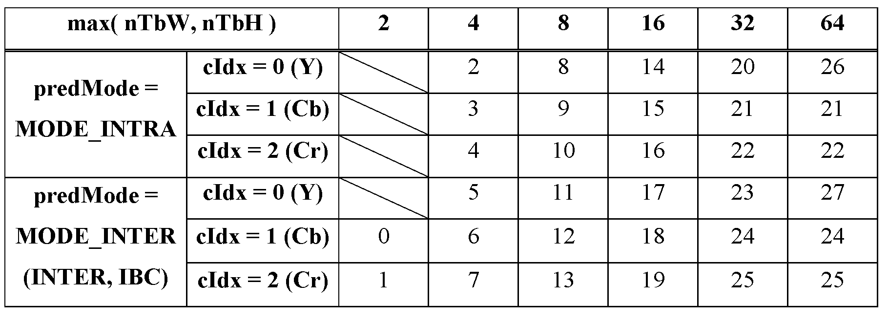
表36-predMode、cIdx、nTbW、およびnTbHに従ったスケーリング行列識別変数idの規定 Table 36 - Definition of scaling matrix identification variable id according to predMode, cIdx, nTbW, and nTbH
2.6.パレットモード
2.6.1.パレットモードの概念
2.6. Palette mode 2.6.1. Palette mode concept
パレットモードの背景にある基本的な考えは、CUにおけるピクセルを代表的な色値の小さな集合で表現することである。この集合をパレットと呼ぶ。また、エスケープシンボルの後に(場合によっては量子化された)成分値を信号通知することによって、パレットの外側にあるサンプルを示すこともできる。このような画素をエスケープ画素と呼ぶ。パレットモードを図3に示す。図3に示すように、3つのコロック成分(輝度、および2つのクロマ成分)を有する画素ごとに、パレットへのインデックスを創設し、パレットにおいて創設された値に基づいてブロックを再構成することができる。 The basic idea behind palette mode is to represent pixels in the CU with a small set of representative color values. This set is called a palette. It is also possible to indicate samples that are outside the palette by signaling the (possibly quantized) component value after the escape symbol. Such pixels are called escape pixels. The palette mode is shown in FIG. As shown in Figure 3, for each pixel with three Korok components (luminance and two chroma components), it is possible to create an index into the palette and reconstruct the block based on the values created in the palette. can.
2.6.2.パレットエントリのコーディング 2.6.2. Coding a palette entry
パレットエントリのコーディングのために、パレット予測子が維持される。SPSにおいて、パレットの最大サイズおよびパレット予測子が信号通知される。HEVC-SCCにおいて、palette_predictor_initializer_present_flagがPPSに導入される。このフラグが1である場合、ビットストリームにおいて、パレット予測子を初期化するためのエントリが信号通知される。パレット予測子は、各CTU行、各スライス、および各タイルの始めに初期化される。palette_predictor_initializer_present_flagの値によって、palette_predictorを0にリセットするか、またはPPSに信号通知されたパレット予測子の初期化エントリを使用してパレット予測子を初期化する。HEVC-SCCでは、PPSレベルでパレット予測子の初期化を明確に無効にするために、サイズ0のパレット予測子イニシャライザを有効にした。 A palette predictor is maintained for coding of palette entries. In SPS, the maximum size of the palette and the palette predictor are signaled. In HEVC-SCC, palette_predictor_initializer_present_flag is introduced in PPS. If this flag is 1, an entry is signaled in the bitstream to initialize the palette predictor. The palette predictor is initialized at the beginning of each CTU row, each slice, and each tile. The value of palette_predictor_initializer_present_flag either resets palette_predictor to 0 or initializes the palette predictor using the palette predictor initialization entry signaled to the PPS. In HEVC-SCC, we enabled a size 0 palette predictor initializer to explicitly disable palette predictor initialization at the PPS level.
パレットプレディクタのエントリごとに、再利用フラグが信号通知され、現在のパレットの一部であるかどうかが示される。これを図4に示す。再利用フラグは、ゼロのランレングスコーディングを使用して送信される。この後、新しいパレットエントリ数は、次数0、すなわちEGー0のEG(Exponential Golomb)コードを使用して信号通知される。最後に、新しいパレットエントリのコンポーネント値が通知されます。 For each entry in the palette predictor, a reuse flag is signaled to indicate whether it is part of the current palette. This is shown in FIG. The reuse flag is transmitted using a run length coding of zero. After this, the new palette entry number is signaled using an EG (Exponential Golomb) code of degree 0, EG-0. Finally, you will be notified of the component values for the new palette entry.
2.6.3.パレットインデックスのコーディング 2.6.3. Coding the palette index
パレットインデックスは、図5に示すように、水平方向および垂直方向の横断走査を使用してコーディングされる。palette_transpose_flagを使用して、ビットストリームにおける走査順序が明確に信号通知される。以下のサブセクションでは、走査が水平であると仮定する。 The palette index is coded using horizontal and vertical cross-scans, as shown in FIG. The palette_transpose_flag is used to explicitly signal the scan order in the bitstream. In the following subsections we assume that the scan is horizontal.
パレットインデックスは、2つのパレットサンプルモードを使用してコーディングされる。「COPY_LEFT」および「COPY_ABOVE」「COPY_LEFT」モードにおいて、パレットインデックスは復号化されたインデックスに割り当てられる。「COPY_ABOVE」モードでは、上の行のサンプルのパレットインデックスをコピーする。「COPY_LEFT」モードと「COPY_ABOVE」モードの両方の場合、同じモードを使用してコーディングされる後続のサンプルの数を規定する実行値を信号通知する。 Palette indexes are coded using two palette sample modes. "COPY_LEFT" and "COPY_ABOVE" In the "COPY_LEFT" mode, the palette index is assigned to the decoded index. The "COPY_ABOVE" mode copies the palette index of the sample in the top row. For both "COPY_LEFT" and "COPY_ABOVE" modes, an execution value is signaled that defines the number of subsequent samples to be coded using the same mode.
パレットモードにおいて、エスケープシンボルに対するインデックスの値が、パレットエントリ数である。そして、エスケープシンボルが「COPY_LEFT」または「COPY_ABOVE」モードにおける実行の一部である場合、エスケープシンボルごとにエスケープ成分値が信号通知される。パレットインデックスのコーディングを図6に示す。 In palette mode, the index value for the escape symbol is the number of palette entries. The escape component value is then signaled for each escape symbol if the escape symbol is part of execution in the "COPY_LEFT" or "COPY_ABOVE" modes. The coding of the palette index is shown in FIG.
この構文順序は、以下のようにして実行される。まず、CUのためのインデックス値の数が信号通知される。これに続いて、トランケーテッドバイナリコーディング(truncated binary coding)を使用して、CU全体の実際のインデックス値を信号通知する。バイパスモードでは、インデックスの数およびインデックス値の両方がコーディングされる。これにより、インデックス関連バイパスビンがグループ化される。次に、パレットサンプルモード(必要な場合)および実行は、インターリーブ方式で信号通知される。最後に、CU全体のためのエスケープシンボルに対応する成分エスケープ値がグループ化され、バイパスモードでコーディングされる。エスケープシンボルの2値化は、第3次数、すなわち、EG-3のEGコーディングである。 This syntactic order is implemented as follows. First, the number of index values for the CU is signaled. Following this, truncated binary coding is used to signal the actual index value for the entire CU. In bypass mode, both the number of indexes and the index value are coded. This groups index-related bypass bins. Palette sample mode (if required) and execution are then signaled in an interleaved manner. Finally, component escape values corresponding to escape symbols for the entire CU are grouped and coded in bypass mode. Binarization of escape symbols is EG coding of the third order, ie, EG-3.
インデックス値を信号通知した後、追加の構文要素last_run_type_flagが信号通知される。この構文要素は、インデックスの数と連動して、ブロックにおける最後の実行に対応する実行値を信号通知する必要をなくす。 After signaling the index value, an additional syntax element last_run_type_flag is signaled. This syntax element, in conjunction with the number of indices, eliminates the need to signal the execution value corresponding to the last execution in the block.
HEVC-SCCでは、パレットモードは、4:2:2、4:2:0、およびモノクロのクロマフォーマットに対しても有効になる。パレットエントリおよびパレットインデックスの信号通知は、すべてのクロマフォーマットに対してほぼ同じである。非モノクロフォーマットの場合、各パレットエントリは、3つの成分からなる。モノクロフォーマットの場合、各パレットエントリは単一の成分からなる。サブサンプリングされたクロマ方向の場合、クロマサンプルは、2で割り切れる輝度サンプル指数に関連付けられる。CUのパレットインデックスを再構成した後、サンプルに単一の成分しか関連付けられていない場合、パレットエントリの第1の成分のみが使用される。信号通知における唯一の違いは、エスケープ成分値である。エスケープシンボルごとに、信号通知されるエスケープ成分値の数は、そのシンボルに関連付けられた成分の数によって異なってもよい。 In HEVC-SCC, palette mode is also enabled for 4:2:2, 4:2:0, and monochrome chroma formats. Palette entry and palette index signaling is approximately the same for all chroma formats. For non-monochrome formats, each palette entry consists of three components. In monochrome format, each palette entry consists of a single component. For subsampled chroma directions, chroma samples are associated with a luminance sample index that is divisible by two. After reconstructing the CU's palette index, if only a single component is associated with the sample, only the first component of the palette entry is used. The only difference in signaling is the escape component value. For each escape symbol, the number of escape component values signaled may vary depending on the number of components associated with that symbol.
2.6.4.デュアルツリーにおけるパレット 2.6.4. Palette in dual tree
VVCにおいて、イントラスライスのコーディングにデュアルツリーコーディング構造が用いられるので、輝度成分および2つのクロマ成分は、異なるパレットおよびパレットインデックスを有してもよい。また、2つのクロマ成分は、同じパレットおよびパレットインデックスを共有する。 In VVC, a dual-tree coding structure is used for intra-slice coding, so the luminance component and the two chroma components may have different palettes and palette indices. Also, the two chroma components share the same palette and palette index.
2.6.5.ラインベースのCGパレットモード 2.6.5. Line-based CG palette mode
VVCには、ラインベースのCGパレットモードが採用された。この方法では、横断走査モードに基づいて、パレットモードの各CUをmのサンプルの複数のセグメント(本試験ではm=16)に分割する。各セグメントにおけるパレット実行コーディングの符号化順序は、以下のとおりである。それぞれのピクセルに対して、このピクセルが前のピクセルと同じモードであるかどうか、即ち、前回走査したピクセルと現在のピクセルが両方とも実行タイプのCOPY_ABOVEであるかどうか、または前回走査したピクセルおよび現在のピクセルが両方とも実行タイプINDEXで且つ同じインデックス値であるかどうかを示す、1つのコンテキストコーディングされたビンrun_copy_flag=0が信号通知される。そうでない場合、run_copy_flag=1が通知される。ピクセルと前のピクセルとが異なるモードである場合、ピクセルの実行タイプ、即ち、INDEXまたはCOPY_ABOVEを示す1つのコンテキストコーディングされたビンcopy_above_palette_indices_flagが信号通知される。VTM6.0におけるパレットモードと同様に、デコーダは、サンプルが最初の行(水平横断走査)または最初の列(垂直横断走査)にある場合、INDEXモードがデフォルトで使用されるので、実行タイプを構文解析する必要がない。また、デコーダは、前に構文解析された実行タイプがCOPY_ABOVEである場合、実行タイプを構文解析する必要がない。1つのセグメントにおけるピクセルのパレット実行コーディングの後、各ラインCG内のスループットを改善するために、インデックス値(INDEXモードの場合)および量子化されたエスケープカラーをバイパスコーディングされ、コンテキストコーディングされたビンの符号化/構文解析とは別にグループ分けする。この場合、インデックス値は、VTMの場合のようにパレット実行コーディングの前に処理される代わりに、実行コーディングの後にコーディング/構文解析されるので、エンコーダは、インデックス値の数、num_palette_indices_minus1および最後の実行タイプcopy_above_indices_for_final_run_flagを信号通知する必要がない。 A line-based CG palette mode was adopted for VVC. The method divides each CU in pallet mode into multiple segments of m samples (m=16 in this test) based on the cross-scan mode. The coding order of palette execution coding in each segment is as follows. For each pixel, whether this pixel is in the same mode as the previous pixel, i.e. whether the last scanned pixel and the current pixel are both of execution type COPY_ABOVE, or whether the last scanned pixel and the current pixel are One context-coded bin run_copy_flag=0 is signaled indicating whether the pixels of are both of run type INDEX and the same index value. Otherwise, run_copy_flag=1 is signaled. If the pixel and the previous pixel are in different modes, one context-coded bin copy_above_palette_indices_flag indicating the execution type of the pixel, ie INDEX or COPY_ABOVE, is signaled. Similar to palette mode in VTM6.0, the decoder uses the execution type syntax as INDEX mode is used by default if the sample is in the first row (horizontal traversal scan) or first column (vertical traversal scan). No need to analyze. Also, the decoder does not need to parse the execution type if the previously parsed execution type is COPY_ABOVE. After palette-performing coding of pixels in one segment, bypassing the index value (in INDEX mode) and quantized escape color of the coded and context-coded bins to improve throughput within each line CG. Grouped separately from encoding/parsing. In this case, the index values are coded/parsed after the execution coding instead of being processed before the palette execution coding as in the VTM case, so the encoder uses the number of index values, num_palette_indices_minus1 and the last execution There is no need to signal type copy_above_indices_for_final_run_flag.
3.本明細書に開示される実施形態および解決策によって解決される技術的課題 3. Technical problems solved by the embodiments and solutions disclosed herein
現在の設計において、1つのブロックに対してACTモードおよび輝度BDPCMモードを有効にすることができる。しかし、ACTモードでコーディングされたブロックでは、クロマBDPCMモードは常に無効化される。そのため、効率が低い可能性がある同じコーディングユニット内の輝度ブロックとクロマブロックとでは、予測信号を異なるように導出してもよい。 In the current design, ACT mode and luminance BDPCM mode can be enabled for one block. However, for blocks coded in ACT mode, chroma BDPCM mode is always disabled. Therefore, prediction signals may be derived differently for luminance blocks and chroma blocks within the same coding unit that may have low efficiency.
ACTが有効化される場合、ブロックの量子化パラメータ(QP)は負の数になる可能性がある。 When ACT is enabled, the quantization parameter (QP) of a block can be a negative number.
ACTの現在の設計は、可逆コーディングをサポートしない。 The current design of ACT does not support lossless coding.
ACTの使用の信号通知は、ブロックサイズに依存しない。 Signaling the use of ACT is independent of block size.
最大パレットサイズおよび最大予測子サイズは固定数であり、これはパレットモードの柔軟性を制限する場合がある。 The maximum palette size and maximum predictor size are fixed numbers, which may limit the flexibility of palette modes.
エスケープサンプルは、2値化方法として3次の指数ゴロム(EG)を使用するが、エスケープサンプルの2値化はQP(Quantization Parameter)に依存しない。 Escape samples use third-order Exponential Golomb (EG) as a binarization method, but the binarization of escape samples does not depend on QP (Quantization Parameter).
4.技術的解決策 4. technical solution
以下に詳述する技術的解決策は、一般的な概念を説明するための例であると考えられるべきである。これらの技術的解決策は狭い意味で解釈されるべきではない。さらに、これらの技術的解決策は、任意の方法で組み合わせることができる。 The technical solution detailed below should be considered as an example to explain the general concept. These technical solutions should not be interpreted in a narrow sense. Furthermore, these technical solutions can be combined in any way.
以下の説明において、「ブロック」という用語は、映像領域、例えばCU(Coding Unit)、PU(Prediction Unit)、TU(Transform Unit)を表すことができ、これらの映像領域は、3つの色成分におけるサンプルを含んでよい。「BDPCM」という用語は、VVCにおける設計に限定されないが、異なる予測信号生成方法を使用して残差をコーディングする技術を提示してもよい。 In the following description, the term "block" can represent a video area, such as a CU (Coding Unit), a PU (Prediction Unit), or a TU (Transform Unit), and these video areas are defined as three color components. May include samples. The term "BDPCM" is not limited to designs in VVC, but may refer to techniques for coding residuals using different prediction signal generation methods.
ACTとBDPCMの相互作用(項目1~4)
1.クロマBDPCMモードを有効にするかどうかは、ACTおよび/または輝度BDPCMモードの使用に依存してもよい。
a.一例において、ブロックにおいてACTが有効にされる場合、クロマBDPCMモードの使用の指示(例えば、intra_bdpcm_chroma_flag)は、輝度BDPCMモードの使用の指示(例えば、intra_bdpcm_luma_flag)であると推測してもよい。
i.一例において、クロマBDPCMモードの推測値は、(ACTおよび輝度BDPCMモードが有効化されている? 真:偽)と定義される。
1.一例において、intra_bdpcm_chroma_flagは、intra_bdpcm_luma_flagが偽である場合、偽に等しくなるように設定してもよい。
a.代替的に、intra_bdpcm_luma_flagが真である場合、intra_bdpcm_chroma_flagを真に等しく設定してもよい。
ii.代替的に、一例において、ブロックに対する輝度BDPCMモードおよびACTの使用の指示が真である場合、クロマBDPCMモードの使用の指示が真であると推測してもよい。
b.代替的に、ブロックのためのACTの使用を信号通知するかどうかは、条件付きでチェックしてもよく、例えば、同じBDPCM予測方向を、このブロックにおける輝度サンプルおよびクロマサンプルの両方に使用する。
i.さらに代替的に、BDPCMモードの使用後、ACTの使用の指示が信号通知される。
Interaction between ACT and BDPCM (items 1-4)
1. Enabling chroma BDPCM mode may depend on the use of ACT and/or luminance BDPCM mode.
a. In one example, if ACT is enabled in a block, an indication to use a chroma BDPCM mode (eg, intra_bdpcm_chroma_flag) may be inferred to be an indication to use a luminance BDPCM mode (eg, intra_bdpcm_luma_flag).
i. In one example, the chroma BDPCM mode guess is defined as (ACT and luma BDPCM mode enabled? true: false).
1. In one example, intra_bdpcm_chroma_flag may be set equal to false if intra_bdpcm_luma_flag is false.
a. Alternatively, if intra_bdpcm_luma_flag is true, intra_bdpcm_chroma_flag may be set equal to true.
ii. Alternatively, in one example, if the indication to use luma BDPCM mode and ACT for a block is true, then it may be inferred that the indication to use chroma BDPCM mode is true.
b. Alternatively, whether to signal the use of ACT for a block may be conditionally checked, eg, use the same BDPCM prediction direction for both luma and chroma samples in this block.
i. Further alternatively, after using the BDPCM mode, an indication to use ACT is signaled.
2.ブロックにおいてACTが有効にされる場合、クロマBDPCMモードの予測方向の指示(例えば、intra_bdpcm_chroma_dir_flag)は、輝度BDPCMモードの使用の予測方向の指示(例えば、intra_bdpcm_luma_dir_flag)であると推測してもよい。
a.一例において、intra_bdpcm_chroma_dir_flagの推論値は、(ACTが有効にされている?intra_bdpcm_luma_dir_flag:0)と定義される。
i.一例において、輝度BDPCMモードの予測方向の指示が水平である場合、クロマBDPCMモードの予測方向の指示は水平であると推測してもよい。
ii.代替的に、一例において、輝度BDPCMモードの予測方向の指示が垂直である場合、クロマBDPCMモードの予測方向の指示は垂直であると推測してもよい。
2. If ACT is enabled in a block, the prediction direction indication for chroma BDPCM mode (e.g., intra_bdpcm_chroma_dir_flag) may be inferred to be the prediction direction indication for use of luma BDPCM mode (e.g., intra_bdpcm_luma_dir_flag).
a. In one example, the inferred value of intra_bdpcm_chroma_dir_flag is defined as (ACT enabled? intra_bdpcm_luma_dir_flag: 0).
i. In one example, if the prediction direction indication for the luminance BDPCM mode is horizontal, it may be inferred that the prediction direction indication for the chroma BDPCM mode is horizontal.
ii. Alternatively, in one example, if the prediction direction indication for the luma BDPCM mode is vertical, the prediction direction indication for the chroma BDPCM mode may be inferred to be vertical.
3.ACTおよびBDPCMモードは、排他的に適用してもよい。
a.一例において、ブロックにおいてACTモードが有効にされる場合、このブロックにおいてBDPCMモードを無効化してもよい。
i.さらに代替的に、BDPCMモードの使用の指示は、ACTモードの使用の指示の信号通知の後に信号通知されてもよい。
ii.さらに代替的に、BDPCMモードの使用の指示は、信号通知されず、偽(0)と推測してもよい。
b.一例において、ブロックにおいてBDPCMモードが有効にされている場合、このブロックではACTモードを無効化してもよい。
i.さらに代替的に、ACTモードの使用の指示は、BDPCMモードの使用の指示の信号通知の後に信号通知されてもよい。
ii.さらに代替的に、ACTモードの使用の指示は、信号通知されず、偽(0)と推測してもよい。
c.一例において、上記例におけるBDPCMモードは、輝度BDPCMモードおよび/またはクロマBDPCMモードを表してもよい。
3. ACT and BDPCM modes may be applied exclusively.
a. In one example, if ACT mode is enabled in a block, BDPCM mode may be disabled in this block.
i. Further alternatively, the indication to use the BDPCM mode may be signaled after the signaling of the indication to use the ACT mode.
ii. Still alternatively, the indication to use BDPCM mode may not be signaled and may be assumed to be false (0).
b. In one example, if BDPCM mode is enabled in a block, ACT mode may be disabled in this block.
i. Further alternatively, the instruction to use ACT mode may be signaled after the signaling of the instruction to use BDPCM mode.
ii. Still alternatively, the indication to use ACT mode may not be signaled and may be assumed to be false (0).
c. In one example, the BDPCM mode in the above example may represent a luminance BDPCM mode and/or a chroma BDPCM mode.
4.デコーダにおいて、逆BDPCMの前に逆ACTを適用してもよい。
a.一例において、ACTは、輝度およびクロマBDPCMが異なる予測モードを有する場合であっても適用できる。
b.代替的に、エンコーダにおいて、BDPCMの後に順方向ACTを適用してもよい。
4. In the decoder, inverse ACT may be applied before inverse BDPCM.
a. In one example, ACT can be applied even if the luminance and chroma BDPCMs have different prediction modes.
b. Alternatively, forward ACT may be applied after BDPCM at the encoder.
ACT有効時のQP設定(項目5)
5.ACTが有効にされている場合、QPをクリッピングすることが提案される。
a.一例において、クリッピング関数は、(l,h,x)と定義されてもよく、lは、入力xの可能な限り低い値であり、hは、入力xの可能な限り高い値である。
i.一例において、lは0に等しく設定されてもよい。
ii.一例において、hは63に等しく設定されてもよい。
b.一例において、QPは、2.5章で示すqPであってもよい。
c.一例において、クリッピングは、ACTモードのQP調整の後に行われてもよい。
d.一例において、変換スキップが適用される場合、lは、変換スキップモードのための最小許容QPに等しく設定されてもよい。
QP settings when ACT is enabled (item 5)
5. If ACT is enabled, it is suggested to clip the QP.
a. In one example, a clipping function may be defined as (l, h, x), where l is the lowest possible value of input x and h is the highest possible value of input x.
i. In one example, l may be set equal to 0.
ii. In one example, h may be set equal to 63.
b. In one example, QP may be qP as shown in Section 2.5.
c. In one example, clipping may be performed after QP adjustment in ACT mode.
d. In one example, if transform skipping is applied, l may be set equal to the minimum allowed QP for transform skipping mode.
パレットモード関連(項目6-7)
6.最大許容パレットサイズおよび/または最大許容予測子サイズの値は、コーディング特性に依存してもよい。第1のコーディング特性に関連付けられた最大パレットサイズ(またはパレット予測子サイズ)をS1とし、第2のコーディング特性に関連付けられた最大パレットサイズ(またはパレット予測子サイズ)をS2とする。
a.一例において、コーディング特性は色成分である。
i.一例において、異なる色成分のための最大許容パレットサイズおよび/または最大許容予測子サイズは、異なる値を有してもよい。
ii.一例において、第1の色成分(例えば、YCbCrにおけるY、RGBにおけるG)の最大許容パレットサイズおよび/または最大許容予測子サイズの値は、第1の色成分を除く他の2つの色成分(例えば、YCbCrにおけるCbおよびCr、B、RGBにおけるR)の値と異なってもよい。
b.一例において、コーディング特性は、量子化パラメータ(QP)でもよい。
i.一例において、QP1がQP2より大きい場合は、QP1に対するS1および/またはS2は、QP2に対するS1および/またはS2より小さい。
ii.一例において、QPは、スライスレベルQPであってもよいし、ブロックレベルQPであってもよい。
c.一例において、S2は、S1以上であってもよい。
d.第1のコーディング特性および第2のコーディング特性に対し、最大パレットサイズ/パレット予測子サイズの指示を別個に信号通知してもよく、または一方から他方に推測してもよい。
i.一例において、S1は信号通知されてもよく、S2はS1.に基づいて導出されてもよい。
1.一例において、S2はS1-nと推測してもよい。
2.一例において、S2は、S1>>nであると推測してもよい。
3.一例において、S2をfloor(S1/n)と推測してもよく、floor(x)は、x以下の最大限の整数を表す。
e.一例において、S1および/またはS2は、ハイレベル(例えば、SPS/PPS/PH/スライスヘッダ)で信号通知され、ロワーレベル(例えば、CU/ブロック)で調整されてよい。
i.S1および/またはS2をどのように調整するかは、コーディングされた情報に依存してもよい。
1.S1および/またはS2をどのように調整するかは、現在のQPに依存してもよい。
a.一例において、現在のQPを増加させると、S1および/またはS2が低下する。
2.S1および/またはS2の調整方法はブロック寸法に依存してもよい。
a.一例において、現在のブロックのサイズが増加する場合は、S1および/またはS2を増加させる。
f.S1および/またはS2は、LMCSが使用されるかどうかに依存してもよい。
Palette mode related (item 6-7)
6. The values of maximum allowed palette size and/or maximum allowed predictor size may depend on coding characteristics. Let the maximum palette size (or palette predictor size) associated with the first coding characteristic be S 1 and the maximum palette size (or palette predictor size) associated with the second coding characteristic be S 2 .
a. In one example, the coding characteristic is a color component.
i. In one example, the maximum allowed palette size and/or maximum allowed predictor size for different color components may have different values.
ii. In one example, the maximum allowed palette size and/or maximum allowed predictor size values for a first color component (e.g., Y in YCbCr, G in RGB) are the same as those for the other two color components (e.g., Y in YCbCr, G in RGB). For example, the values of Cb and Cr in YCbCr, B, and R in RGB may be different.
b. In one example, the coding characteristic may be a quantization parameter (QP).
i. In one example, if QP 1 is greater than QP 2 , S 1 and/or S 2 for QP 1 is less than S 1 and/or S 2 for QP 2 .
ii. In one example, the QP may be a slice level QP or a block level QP.
c. In one example, S 2 may be greater than or equal to S 1 .
d. Maximum palette size/palette predictor size indications may be signaled separately for the first coding characteristic and the second coding characteristic, or may be inferred from one to the other.
i. In one example, S 1 may be signaled and S 2 may be signaled . may be derived based on.
1. In one example, S 2 may be inferred to be S 1 -n.
2. In one example, S 2 may assume that S 1 >>n.
3. In one example, S 2 may be assumed to be floor(S 1 /n), where floor(x) represents the largest integer less than or equal to x.
e. In one example, S 1 and/or S 2 may be signaled at a high level (eg, SPS/PPS/PH/slice header) and adjusted at a lower level (eg, CU/block).
i. How to adjust S 1 and/or S 2 may depend on the coded information.
1. How to adjust S 1 and/or S 2 may depend on the current QP.
a. In one example, increasing the current QP decreases S 1 and/or S 2 .
2. The method of adjusting S 1 and/or S 2 may depend on the block size.
a. In one example, if the size of the current block increases, S 1 and/or S 2 are increased.
f. S 1 and/or S 2 may depend on whether LMCS is used.
7.エスケープサンプル/ピクセルのための2値化方法に関連付けられたパラメータは、コーディングされた情報、例えば、量子化パラメータ(QP)に依存してもよい。
a.一例において、EG2値化方法を利用してもよく、kで表されるEG2値化の順番は、コーディングされた情報に依存してもよい。
i.一例において、現在のQPが増加すると、kを低減するようにしてもよい。
7. The parameters associated with the binarization method for escape samples/pixels may depend on the coded information, for example the quantization parameter (QP).
a. In one example, an EG binarization method may be utilized, and the order of EG binarization, denoted by k, may depend on the coded information.
i. In one example, k may be decreased as the current QP increases.
ACTモードの信号通知(項目8-10)
8.最大および/または最小許容ACTサイズの指示は、シーケンス/映像/スライス/タイル/サブピクチャ/ブリック/他の映像処理ユニットレベルで信号通知されてもよく、またはコーディングされた情報に基づいて導出されてもよい。
a.一例において、それらは、SPS/PPS/ピクチャヘッダ/スライスヘッダにおいて信号通知されてもよい。
b.一例において、それらは、ACTが有効にされていることに応じて等、条件付きで信号通知されてもよい。
c.一例において、最大および/または最小許容ACTサイズのNレベルは、例えば、N=2などで信号通知/定義されてもよい。
i.一例において、最大および/または最小許容ACTサイズは、K0またはK1のいずれかに設定されてもよい(例えば、K0=64、K1=32)。
ii.さらに、代替的に、レベルの指示が信号通知されてもよく、例えば、N=2の場合、フラグを信号通知してもよい。
d.一例において、最大および/または最小許容ACTサイズと、最大および/または最小許容変換(または変換スキップ)サイズ(例えば、輝度成分のための)との間の差の指示を信号通知してもよい。
e.一例において、最大および/または最小許容ACTサイズは、(例えば、輝度成分のために)最大および/または最小許容(または変換スキップ)サイズから導出されてもよい。
f.さらに代替的に、ACT使用の指示およびACTに関する他のサイド情報を信号通知するかどうか、および/またはどのように通知するかは、される最大および/または最小許容値に依存してもよい。
ACT mode signal notification (item 8-10)
8. The maximum and/or minimum allowed ACT size indication may be signaled at the sequence/video/slice/tile/subpicture/brick/other video processing unit level or derived based on coded information. Good too.
a. In one example, they may be signaled in the SPS/PPS/picture header/slice header.
b. In one example, they may be signaled conditionally, such as in response to ACT being enabled.
c. In one example, N levels of maximum and/or minimum allowed ACT size may be signaled/defined, such as N=2, for example.
i. In one example, the maximum and/or minimum allowed ACT size may be set to either K0 or K1 (eg, K0=64, K1=32).
ii. Furthermore, an indication of the level may alternatively be signaled, for example, if N=2, a flag may be signaled.
d. In one example, an indication of a difference between a maximum and/or minimum allowed ACT size and a maximum and/or minimum allowed transform (or transform skip) size (eg, for a luminance component) may be signaled.
e. In one example, the maximum and/or minimum allowable ACT size may be derived from the maximum and/or minimum allowable (or transform skip) size (eg, for a luminance component).
f. Still alternatively, whether and/or how the indication of ACT usage and other side information regarding the ACT is signaled may depend on the maximum and/or minimum allowed values.
9.ブロックが最大許容ACTサイズ(または最大許容変換サイズ)よりも大きい場合、このブロックは、複数のサブブロックに自動的に分割されてもよく、すべてのサブブロックが同じ予測モードを共有し(例えば、これらのすべてがイントラコーディングされる)、ACTは、ブロックレベルの代わりに、サブブロックレベルで有効にされてもよい。 9. If a block is larger than the maximum allowed ACT size (or maximum allowed transform size), this block may be automatically divided into multiple subblocks, with all subblocks sharing the same prediction mode (e.g. (all of which are intra-coded), ACT may be enabled at the sub-block level instead of the block level.
10.ACTモードの使用の指示は、ブロック寸法(例えば、ブロックの幅および/または高さ、ブロックの幅×高さ、ブロックの幅と高さの比、ブロックの幅と高さの最大値/最小値)および/または最大許容ACTのサイズに基づいて、条件付きで信号通知されてもよい。
a.一例において、ACTモードの使用の指示は、ブロック寸法に応じた特定の条件が、例えば、満たされている場合、信号通知されてもよい。
i.一例において、条件は、現在のブロックの幅がm以下である、および/または現在のブロックの高さがn以下であるかどうかである。
ii.一例において、条件とは、現在のブロックの幅×高さがmより小さいかまたはm以下であるかである。
iii.一例において、条件は、現在のブロックの幅×高さがmよりも大きいかまたはm以上であるかである。
b.代替的に、一例において、ACTモードの使用の指示は、ブロック寸法に応じた特定の条件が、例えば、満たされていない場合、信号通知されなくてもよい。
i.一例において、条件は、現在のブロックの幅がmよりも大きいか、および/または現在のブロックの高さがnよりも大きいかである。
ii.一例において、条件とは、現在のブロックの幅×高さがmより小さいかまたはm以下であるかである。
iii.一例において、条件は、現在のブロックの幅×高さがmよりも大きいかまたはm以上であるかである。
iv.さらに代替的に、ACTモードの使用の指示が0であると推測してもよい。
c.上記例において、変数m、nは、予め定義されてもよく(例えば、4、64、128)、または信号通知されてもよく、またはオンザフライで導出されてもよい。
i.一例において、mおよび/またはnは、SPS/PPS/APS/CTU行/CTUグループのCTU/CU/ブロックにおける復号メッセージに基づいて導出されてもよい。
1.一例において、mおよび/またはnは、最大許容変換サイズ(例えば、MaxTbSizeY)に等しく設定されてもよい。
10. Instructions for using ACT mode include block dimensions (e.g., block width and/or height, block width x height, block width to height ratio, maximum/minimum block width and height) ) and/or the size of the maximum allowed ACT.
a. In one example, an instruction to use ACT mode may be signaled if certain conditions depending on the block size are met, for example.
i. In one example, the condition is whether the width of the current block is less than or equal to m, and/or the height of the current block is less than or equal to n.
ii. In one example, the condition is whether the width x height of the current block is less than or equal to m.
iii. In one example, the condition is that the width x height of the current block is greater than or equal to m.
b. Alternatively, in one example, the instruction to use ACT mode may not be signaled if certain conditions depending on the block size are not met, for example.
i. In one example, the condition is that the width of the current block is greater than m and/or the height of the current block is greater than n.
ii. In one example, the condition is whether the width x height of the current block is less than or equal to m.
iii. In one example, the condition is that the width x height of the current block is greater than or equal to m.
iv. Further alternatively, it may be assumed that the indication for use of ACT mode is zero.
c. In the example above, the variables m, n may be predefined (eg, 4, 64, 128), or signaled, or derived on the fly.
i. In one example, m and/or n may be derived based on decoded messages in CTUs/CUs/blocks of SPS/PPS/APS/CTU rows/CTU groups.
1. In one example, m and/or n may be set equal to the maximum allowed transform size (eg, MaxTbSizeY).
一般制約情報構文における制約フラグの信号通知(項目11-16)
なお、以下の制約フラグは、SPS以外の映像ユニットにおいて信号通知されてもよい。例えば、それらは、JVET-P2001-vEに規定される一般的な制約情報構文で信号通知されてもよい。
Signaling of constraint flags in general constraint information syntax (item 11-16)
Note that the following constraint flags may be signaled in video units other than SPS. For example, they may be signaled in the general constraint information syntax specified in JVET-P2001-vE.
11.SPS ACT有効化フラグ(例えば、sps_act_enabled_flag)が0であるかどうかを規定するために、制約フラグを有することが提案される。
a.一例において、このフラグは、no_act_constraint_flagと表されてもよい。
i.このフラグが1に等しい場合、SPS ACT有効化フラグ(例えば、sps_act_enabled_flag)は0に等しい。
ii.このフラグが0に等しい場合、このような制約は課されない。
11. It is proposed to have a constraint flag to specify whether the SPS ACT enabled flag (eg sps_act_enabled_flag) is 0.
a. In one example, this flag may be expressed as no_act_constraint_flag.
i. If this flag is equal to 1, the SPS ACT enabled flag (eg, sps_act_enabled_flag) is equal to 0.
ii. If this flag is equal to 0, no such constraint is imposed.
12.SPS BDPCM有効化フラグ(例えば、sps_bdpcm_enabled_flag)が0であるかどうかを規定するために、制約フラグを有することが提案される。
a.一例において、このフラグは、no_bdpcm_constraint_flagと表されてもよい。
i.このフラグが1に等しい場合、SPS BDPCM有効化フラグ(例えば、sps_bdpcm_enabled_flag)は0に等しい。
ii.このフラグが0に等しい場合、このような制約は課されない。
12. It is proposed to have a constraint flag to specify whether the SPS BDPCM enabled flag (eg sps_bdpcm_enabled_flag) is 0.
a. In one example, this flag may be represented as no_bdpcm_constraint_flag.
i. If this flag is equal to 1, the SPS BDPCM enabled flag (eg, sps_bdpcm_enabled_flag) is equal to 0.
ii. If this flag is equal to 0, no such constraint is imposed.
13.SPSクロマBDPCM有効化フラグ(例えば、sps_bdpcm_chroma_enabled_flag)が0であるかどうかを規定するために、制約フラグを有することが提案される。
a.一例において、このフラグは、no_bdpcm_chroma_constraint_flagと表されてもよい。
i.このフラグが1に等しい場合、SPSクロマBDPCM有効化フラグ(例えば、sps_bdpcm_chroma_enabled_flag)は、0に等しい。
ii.このフラグが0に等しい場合、このような制約は課されない。
13. It is proposed to have a constraint flag to specify whether the SPS chroma BDPCM enabled flag (eg sps_bdpcm_chroma_enabled_flag) is 0.
a. In one example, this flag may be represented as no_bdpcm_chroma_constraint_flag.
i. If this flag is equal to 1, the SPS chroma BDPCM enabled flag (eg, sps_bdpcm_chroma_enabled_flag) is equal to 0.
ii. If this flag is equal to 0, no such constraint is imposed.
14.SPSパレット有効化フラグ(例えば、sps_palette_enabled_flag)が0であるかどうかを規定するために、制約フラグを有することが提案される。
a.一例において、このフラグは、no_palette_constraint_flagと表されてもよい。
i.このフラグが1である場合、SPSパレット有効化フラグ(例えば、sp_palette_enabled_flag)は0に等しい。
ii.このフラグが0に等しい場合、このような制約は課されない。
14. It is proposed to have a constraint flag to specify whether the SPS palette enabled flag (eg sps_palette_enabled_flag) is 0.
a. In one example, this flag may be represented as no_palette_constraint_flag.
i. If this flag is 1, the SPS palette enabled flag (eg, sp_palette_enabled_flag) is equal to 0.
ii. If this flag is equal to 0, no such constraint is imposed.
15.SPS RPR有効化フラグ(例えば、ref_pic_resampling_enabled_flag)が0であるかどうかを規定するために、制約フラグを有することが提案される。
a.一例において、このフラグは、no_ref_pic_resampling_constraint_flagと表されてもよい。
i.このフラグが1に等しい場合、SPS RPR有効化フラグ(例えば、ref_pic_resampling_enabled_flag)は0である。
ii.このフラグが0に等しい場合、このような制約は課されない。
15. It is proposed to have a constraint flag to specify whether the SPS RPR enabled flag (eg ref_pic_resampling_enabled_flag) is 0.
a. In one example, this flag may be expressed as no_ref_pic_resampling_constraint_flag.
i. If this flag is equal to 1, the SPS RPR enabled flag (eg, ref_pic_resampling_enabled_flag) is 0.
ii. If this flag is equal to 0, no such constraint is imposed.
16.上記の例(黒丸11~15)において、このような制約フラグは、例えば、クロマフォーマット(例えば、chroma_format_idc)および/または別個のプレーンコーディングまたはChromaArrayTypeに応じて、条件付きで信号通知されてもよい。 16. In the example above (filled circles 11-15), such constraint flags may be signaled conditionally, eg, depending on the chroma format (eg, chroma_format_idc) and/or the separate plane coding or ChromaArrayType.
ACT QP オフセット(項目17ー19)
17.ACTがブロックに適用する場合、ACTオフセットは、他のクロマオフセット(例えば、PPSおよび/またはPH(Picture Header)および/またはSH(Slice Header)におけるもの)を適用した後に、適用してもよいことが提案される。
ACT QP Offset (Items 17-19)
17. When ACT is applied to a block, the ACT offset may be applied after applying other chroma offsets (e.g. those in PPS and/or PH (Picture Header) and/or SH (Slice Header)). is proposed.
18.ブロックに対してYCgCo色変換を適用する場合、JCbCrモード2に対して、-5以外のPPSオフセットおよび/またはPHオフセットを有することが提案される。
a.一例において、オフセットは、-5以外であってもよい。
b.一例において、オフセットは、PPSにおいて(例えば、pps_act_cbcr_qp_offset_plus6として)示されてもよく、オフセットは、pps_act_cbcr_qp_offset_plus6-6として設定されてもよい。
c.一例において、オフセットは、PPSにおいて(例えば、pps_act_cbcr_qp_offset_plus7として)示されてもよく、オフセットは、pps_act_cbcr_qp_offset_plus7-7として設定されてもよい。
18. When applying YCgCo color transformation to a block, it is proposed to have a PPS offset and/or a PH offset other than -5 for JCbCr mode 2.
a. In one example, the offset may be other than -5.
b. In one example, the offset may be indicated in the PPS (eg, as pps_act_cbcr_qp_offset_plus6), and the offset may be set as pps_act_cbcr_qp_offset_plus6-6.
c. In one example, the offset may be indicated in the PPS (eg, as pps_act_cbcr_qp_offset_plus7), and the offset may be set as pps_act_cbcr_qp_offset_plus7-7.
19.1つのブロックにYCgCo-Rを適用する場合、JCbCrモード2に対して1以外のPPSオフセットおよび/またはPHオフセットを有することが提案される。
a.一例において、オフセットは、-1以外であってもよい。
b.一例において、オフセットは、PPSにおいて(例えば、pps_act_cbcr_qp_offsetとして)示されてもよく、オフセットは、pps_act_cbcr_qp_offsetとして設定されてもよい。
c.一例において、オフセットは、PPSにおいて(例えば、pps_act_cbcr_qp_offset_plus1として)示されてもよく、オフセットは、pps_act_cbcr_qp_offset_plus1-1として設定されてもよい。
19. When applying YCgCo-R to one block, it is proposed to have a PPS offset and/or a PH offset other than 1 for JCbCr mode 2.
a. In one example, the offset may be other than -1.
b. In one example, the offset may be indicated in the PPS (eg, as pps_act_cbcr_qp_offset), and the offset may be set as pps_act_cbcr_qp_offset.
c. In one example, the offset may be indicated in the PPS (eg, as pps_act_cbcr_qp_offset_plus1), and the offset may be set as pps_act_cbcr_qp_offset_plus1-1.
一般的な技術(項目20ー21)
20.上記例において、S1,S2,l、h、m、nおよび/またはkは整数であり、下記に依存してもよい。
a.一例において、デフォルトモードは、DPS/SPS/VPS/PPS/APS/ピクチャヘッダ/スライスヘッダ/タイルグループヘッダ/LCU(Largest Coding Unit)/CU(Coding Unit)/LCU行/LCUグループ/TU/PUブロック/映像コーディングユニットにおいて信号通知されてもよい。
b.CU/PU/TU/ブロック/映像コーディングユニットの位置
c.エッジに沿ったサンプルを含むブロックのコーディングされたモード
d.エッジに沿ってサンプルを含むブロックに適用される変換行列
e.現在のブロックおよび/またはその近傍のブロックのブロック寸法/ブロック形状
f.カラーフォーマットの表示(例えば、4:2:0、4:4:4、RGB、YUV等)
g.コーディングツリー構造(例えば、デュアルツリーまたはシングルツリー)
h.スライス/タイルグループのタイプおよび/またはピクチャのタイプ
i.色成分(例えば、CbまたはCrにのみ適用してもよい)
j.時間層ID
k.標準のプロファイル/レベル/層
l.代替的に、S1,S2,l、h、m、nおよび/またはkは、デコーダに信号通知されてもよい。
General techniques (items 20-21)
20. In the above example, S 1 , S 2 , l, h, m, n and/or k are integers and may depend on:
a. In one example, the default mode is DPS/SPS/VPS/PPS/APS/Picture header/Slice header/Tile group header/LCU (Largest Coding Unit)/CU (Coding Unit)/LCU row/LCU group/TU/PU block / may be signaled at the video coding unit.
b. Location of CU/PU/TU/block/video coding unit c. Coded mode of block containing samples along edges d. Transformation matrix applied to blocks containing samples along edges e. Block dimensions/block shapes of the current block and/or its neighboring blocks f. Color format display (e.g. 4:2:0, 4:4:4, RGB, YUV, etc.)
g. Coding tree structure (e.g. dual tree or single tree)
h. Type of slice/tile group and/or type of picture i. Color components (e.g. may be applied only to Cb or Cr)
j. Time layer ID
k. Standard Profiles/Levels/Layers l. Alternatively, S 1 , S 2 , l, h, m, n and/or k may be signaled to the decoder.
21.上述の提案された方法は、特定の条件下で適用してもよい。
a.一例において、この条件は、カラーフォーマットが4:2:0および/または4:2:2であることである。
b.一例において、上記方法の使用の指示は、SPS/PPS/ピクチャヘッダ/スライスヘッダのような、シーケンス/ピクチャ/スライス/タイル/ブリック/映像領域レベルで信号通知されてもよい。
c.一例において、上記方法の使用は、下記に依存してもよい。
i.映像コンテンツ(例えば、スクリーンコンテンツまたは自然コンテンツ)
ii.一例において、デフォルトモードは、DPS/SPS/VPS/PPS/APS/ピクチャヘッダ/スライスヘッダ/タイルグループヘッダ/LCU(Largest Coding Unit)/CU(Coding Unit)/LCU行/LCUグループ/TU/PUブロック/映像コーディングユニットにおいて信号通知されてもよい。
iii.CU/PU/TU/ブロック/映像コーディングユニットの位置
iv.エッジに沿ったサンプルを含むブロックのコーディングされたモード
v.エッジに沿ってサンプルを含むブロックに適用される変換行列
vi.現在のブロックおよび/またはその近傍のブロックのブロック寸法
vii.現在のブロックおよび/またはその近傍のブロックのブロック形状
viii.カラーフォーマットの表示(例えば、4:2:0、4:4:4、RGB、YUV等)
ix.コーディングツリー構造(例えば、デュアルツリーまたはシングルツリー)
x.スライス/タイルグループのタイプおよび/またはピクチャのタイプ
xi.色成分(例えば、CbまたはCrにのみ適用してもよい)
xii.時間層ID
xiii.標準のプロファイル/レベル/層
xiv.代替的に、mおよび/またはnは、デコーダに信号通知されてもよい。
21. The proposed method described above may be applied under certain conditions.
a. In one example, this condition is that the color format is 4:2:0 and/or 4:2:2.
b. In one example, the instruction to use the method may be signaled at the sequence/picture/slice/tile/brick/video region level, such as SPS/PPS/picture header/slice header.
c. In one example, use of the above method may depend on:
i. Video content (e.g. screen content or natural content)
ii. In one example, the default mode is DPS/SPS/VPS/PPS/APS/Picture header/Slice header/Tile group header/LCU (Largest Coding Unit)/CU (Coding Unit)/LCU row/LCU group/TU/PU block / may be signaled at the video coding unit.
iii. Location of CU/PU/TU/block/video coding unit iv. Coded mode of block containing samples along edges v. Transformation matrix applied to blocks containing samples along edges vi. Block dimensions of the current block and/or its neighboring blocks vii. Block shape of the current block and/or its neighboring blocks viii. Color format display (e.g. 4:2:0, 4:4:4, RGB, YUV, etc.)
ix. Coding tree structure (e.g. dual tree or single tree)
x. Type of slice/tile group and/or type of picture xi. Color components (e.g. may be applied only to Cb or Cr)
xii. Time layer ID
xiii. Standard Profiles/Levels/Layers xiv. Alternatively, m and/or n may be signaled to the decoder.
5.実施形態 5. Embodiment
本実施形態はJVET-P2001-vEに基づく。新規に追加されたテキストは、太字のイタリック体の下線付きテキストで強調表示されている。削除されたテキストにはイタリック体のテキストで記されている。 This embodiment is based on JVET-P2001-vE. Newly added text is highlighted with bold italic underlined text . Deleted text is marked in italic text.
5.1.実施形態#1 5.1. Embodiment #1
本実施形態は、ACTモードとBDPCMモードとの間の相互作用に関する。 This embodiment relates to the interaction between ACT mode and BDPCM mode.

5.2.実施形態♯2 5.2. Embodiment #2
本実施形態は、ACTモードとBDPCMモードとの間の相互作用に関する。 This embodiment relates to the interaction between ACT mode and BDPCM mode.
1に等しいintra_bdpcm_chroma_flagは、位置(x0,y0)の現在のクロマコーディングブロックにBDPCMを適用することを規定し、即ち、変換をスキップし、イントラクロマ予測モードをintra_bdpcm_chroma_dir_flagで規定する。0に等しいintra_bdpcm_chroma_flagは、位置(x0,y0)の現在のクロマコーディングブロックにBDPCMが適用されないことを規定する。 intra_bdpcm_chroma_flag equal to 1 specifies applying BDPCM to the current chroma coding block at position (x0, y0), i.e., skips the transform, and specifies the intra chroma prediction mode with intra_bdpcm_chroma_dir_flag. intra_bdpcm_chroma_flag equal to 0 specifies that BDPCM is not applied to the current chroma coding block at position (x0, y0).
intra_bdpcm_chroma_flagが存在せず、cu_act_enabled_flagは偽である場合、それは0に等しいと推測される。
intra_bdpcm_chroma_flagが存在せず、cu_act_enabled_flagがtrueである場合、それはintra_bdpcm_luma_flagに等しいと推測される。
If intra_bdpcm_chroma_flag is not present and cu_act_enabled_flag is false , it is assumed to be equal to 0.
If intra_bdpcm_chroma_flag is not present and cu_act_enabled_flag is true, it is inferred to be equal to intra_bdpcm_luma_flag.
x=x0..x0+cbWidth-1,y=y0..y0+cbHeight-1,およびcIdx=1..2の場合、変数BdpcmFlag[x][y][cIdx]は、intra_bdpcm_chroma_flagに等しく設定される。 x=x0. .. x0+cbWidth-1, y=y0. .. y0+cbHeight-1, and cIdx=1. .. 2, the variable BdpcmFlag[x][y][cIdx] is set equal to intra_bdpcm_chroma_flag.
0に等しいintra_bdpcm_chroma_dir_flagは、BDPCM予測方向が水平であることを規定する。1に等しいintra_bdpcm_chroma_dir_flagは、BDPCM予測方向が垂直であることを規定する。cu_act_enabled_flagが真である場合、intra_bdpcm_chroma_dir_flagはintra_bdpcm_luma_dir_flagに等しく設定される。 intra_bdpcm_chroma_dir_flag equal to 0 specifies that the BDPCM prediction direction is horizontal. intra_bdpcm_chroma_dir_flag equal to 1 specifies that the BDPCM prediction direction is vertical. If cu_act_enabled_flag is true, intra_bdpcm_chroma_dir_flag is set equal to intra_bdpcm_luma_dir_flag.
x=x0..x0+cbWidth-1,y=y0..y0+cbHeight-1,およびcIdx=1..2の場合、変数BdpcmDir[x][y][cIdx]は、intra_bdpcm_chroma_dir_flagに等しく設定される。 x=x0. .. x0+cbWidth-1, y=y0. .. y0+cbHeight-1, and cIdx=1. .. 2, the variable BdpcmDir[x][y][cIdx] is set equal to intra_bdpcm_chroma_dir_flag.
5.3.実施形態#3 5.3. Embodiment #3
本実施形態はQP設定に関する。 This embodiment relates to QP settings.
8.7.3.変換係数のスケーリング処理 8.7.3. Scaling of conversion coefficients
この処理への入力は以下の通りである。
-現在のピクチャの左上の輝度サンプルに対する現在の輝度変換ブロックの左上のサンプルを規定する輝度位置(xTbY,yTbY)
-変換ブロックの幅を規定する変数nTbW、
-変換ブロックの高さを規定する変数nTbH、
-コーディングユニットの予測モードを規定する変数predMode、
-現在のブロックの色成分を規定する変数cIdx。
The inputs to this process are as follows.
- luminance position (xTbY, yTbY) that defines the upper left sample of the current luminance transformation block relative to the upper left luminance sample of the current picture;
- variable nTbW, which defines the width of the conversion block;
- variable nTbH, which defines the height of the transformation block;
- a variable predMode that defines the prediction mode of the coding unit;
- the variable cIdx, which defines the color components of the current block;
この処理の出力は、要素d[x][y]を有するスケーリングされた変換係数の(nTbW)×(nTbH)配列dである。
…
The output of this process is an (nTbW)×(nTbH) array d of scaled transform coefficients with elements d[x][y].
…
量子化パラメータqPを修正し、変数rectNonTsFlagおよびbdShiftを以下のように導出する。
-transform_skip_flag[xTbY][yTbY][cIdx]が0に等しい場合、以下が適用される。
qP=qP-(cu_act_enabled_flag[xTbY][yTbY]?5:0) (1133)
qP=Clip3(0,63,qP)
rectNonTsFlag=(((Log2(nTbW)+Log2(nTbH))&1)==1)?1:0 (1134)
bdShift=BitDepth+rectNonTsFlag+((Log2(nTbW)+Log2(nTbH))/2)-5+pic_dep_quant_enabled_flag (1135)
-そうでない場合(transform_skip_flag[xTbY][yTbY][cIdx]が1に等しい場合)、以下が適用される。
qP=Max(QpPrimeTsMin,qP)-(cu_act_enabled_flag[xTbY][yTbY]?5:0) (1136)
qP=Max(QpPrimeTsMin,qP-(cu_act_enabled_flag[xTbY][yTbY]?5:0))
rectNonTsFlag=0 (1137)
bdShift=10 (1138)
…
The quantization parameter qP is modified and the variables rectNonTsFlag and bdShift are derived as follows.
- If transform_skip_flag[xTbY][yTbY][cIdx] is equal to 0, the following applies.
qP=qP-(cu_act_enabled_flag[xTbY][yTbY]?5:0) (1133)
qP=Clip3(0,63,qP)
rectNonTsFlag=(((Log2(nTbW)+Log2(nTbH))&1)==1)? 1:0 (1134)
bdShift=BitDepth+rectNonTsFlag+((Log2(nTbW)+Log2(nTbH))/2)-5+pic_dep_quant_enabled_flag (1135)
- Otherwise (transform_skip_flag[xTbY][yTbY][cIdx] is equal to 1), the following applies:
qP=Max(QpPrimeTsMin, qP)-(cu_act_enabled_flag[xTbY][yTbY]?5:0) (1136)
qP=Max(QpPrimeTsMin, qP-(cu_act_enabled_flag[xTbY][yTbY]?5:0))
rectNonTsFlag=0 (1137)
bdShift=10 (1138)
…
5.4.実施形態#4
8.7.1 量子化パラメータの導出処理
…
-CbおよびCr成分、Qp’CbおよびQp’Cr、並びに結合Cb-CrコーディングQp’CbCrのためのクロマ量子化パラメータは、以下のように導出される。
Qp’Cb=Clip3(-QpBdOffset,63,qPCb+pps_cb_qp_offset+slice_cb_qp_offset+CuQpOffsetCb)+QpBdOffset (1122)
Qp’Cr=Clip3(-QpBdOffset,63,qPCr+pps_cr_qp_offset+slice_cr_qp_offset+CuQpOffsetCr)+QpBdOffset (1123)
Qp’CbCr=Clip3(-QpBdOffset,63,qPCbCr+pps_joint_cbcr_qp_offset+slice_joint_cbcr_qp_offset+CuQpOffsetCbCr)+QpBdOffset (1124)
5.4. Embodiment #4
8.7.1 Quantization parameter derivation process...
- The chroma quantization parameters for the Cb and Cr components, Qp'Cb and Qp'Cr, and the combined Cb-Cr coding Qp'CbCr are derived as follows.
Qp'Cb=Clip3(-QpBdOffset, 63, qPCb+pps_cb_qp_offset+slice_cb_qp_offset+CuQpOffsetCb)+QpBdOffset (1122)
Qp'Cr=Clip3(-QpBdOffset, 63, qPCr+pps_cr_qp_offset+slice_cr_qp_offset+CuQpOffsetCr)+QpBdOffset (1123)
Qp'CbCr=Clip3(-QpBdOffset, 63, qPCbCr+pps_joint_cbcr_qp_offset+slice_joint_cbcr_qp_offset+CuQpOffsetCbCr)+QpBdOffse t (1124)
5.5.実施形態#5
7.3.9.5.コーディングユニット構文
5.5. Embodiment #5
7.3.9.5. coding unit syntax

K0およびK1は32に等しく設定される。K0 and K1 are set equal to 32.
5.6.実施形態#6
7.3.9.5.コーディングユニット構文
5.6. Embodiment #6
7.3.9.5. coding unit syntax

図7は、本明細書で開示される様々な技術が実装され得る例示的な映像処理システム1700を示すブロック図である。様々な実装形態は、システム700のコンポーネントの一部又は全部を含んでもよい。システム700は、映像コンテンツを受信するための入力702を含んでもよい。映像コンテンツは、未加工又は非圧縮フォーマット、例えば、8又は10ビットのマルチコンポーネント画素値で受信されてもよく、又は圧縮又は符号化フォーマットで受信されてもよい。入力702は、ネットワークインターフェース、周辺バスインターフェース、又は記憶インターフェースを表してもよい。ネットワークインターフェースの例は、イーサネット(登録商標)、PON(登録商標;Passive Optical Network)等の有線インターフェース、およびWi-Fi(登録商標)またはセルラーインターフェース等の無線インターフェースを含む。
FIG. 7 is a block diagram illustrating an example
システム700は、本明細書に記載される様々なコーディング又は符号化方法を実装することができるコーディングコンポーネント704を含んでもよい。コーディングコンポーネント704は、入力702からの映像の平均ビットレートをコーディングコンポーネント704の出力に低減し、映像のコーディングされた表現を生成してもよい。従って、コーディング技術は、映像圧縮または映像コード変換技術と呼ばれることがある。コーディングコンポーネント704の出力は、コンポーネント706によって表されるように、記憶されてもよいし、接続された通信を介して送信されてもよい。入力702において受信された、記憶された又は通信された映像のビットストリーム(又はコーディングされた)表現は、表示インターフェース710に送信される画素値又は表示可能な映像を生成するためのコンポーネント708によって使用されてよい。ビットストリーム表現からユーザが見ることができる映像を生成する処理は、映像展開と呼ばれることがある。さらに、特定の映像処理操作を「コーディング」操作又はツールと呼ぶが、コーディングツール又は操作は、エンコーダ及びそれに対応する、コーディングの結果を逆にする復号化ツール又は操作が、デコーダによって行われることが理解されよう。
周辺バスインターフェースまたは表示インターフェースの例は、USB(登録商標;Universal Serial Bus)またはHDMI(登録商標;High Definiyion Multimedia Interface)またはディスプレイポート等を含んでもよい。ストレージインターフェースの例は、SATA(Serial Advanced Technology Attachment)、PCI、IDEインターフェース等を含む。本明細書に記載される技術は、携帯電話、ノートパソコン、スマートフォン、又はデジタルデータ処理及び/又は映像表示を実施可能な他のデバイス等の様々な電子デバイスに実施されてもよい。 Examples of peripheral bus or display interfaces may include a Universal Serial Bus (USB) or a High Definition Multimedia Interface (HDMI) or a display port, or the like. Examples of storage interfaces include SATA (Serial Advanced Technology Attachment), PCI, IDE interfaces, and the like. The techniques described herein may be implemented in a variety of electronic devices, such as mobile phones, laptops, smartphones, or other devices capable of performing digital data processing and/or video display.
図8は、映像処理装置800のブロック図である。装置800は、本明細書に記載の方法の1または複数を実装するために使用してもよい。装置800は、スマートフォン、タブレット、コンピュータ、IoT(Internet of Things)受信機等により実施されてもよい。装置800は、1または複数のプロセッサ802と、1または複数のメモリ804と、映像処理ハードウェア806と、を含んでもよい。1または複数のプロセッサ802は、本明細書に記載される1または複数の方法(例えば、図5Aおよび図5Bに記載)を実装するように構成されてもよい。1または複数のメモリ804は、本明細書で説明される方法および技術を実装するために使用されるデータおよびコードを記憶するために使用してもよい。映像処理ハードウェア806は、本明細書に記載される技術をハードウェア回路にて実装するために使用してもよい。いくつかの実施形態において、ハードウェア806は、プロセッサ802、例えばグラフィックプロセッサ内に部分的にまたは全体が含まれてもよい。
FIG. 8 is a block diagram of a
図9は、本開示の技法を利用し得る例示的な映像コーディングシステム100を示すブロック図である。図9に示すように、映像コーディングシステム100は、送信元デバイス110と、送信先デバイス120と、を備えてもよい。送信元デバイス110は、符号化された映像データを生成するものであり、映像符号化機器とも呼ばれ得る。送信先デバイス120は、送信元デバイス110によって生成された符号化映像データを復号化してよく、映像復号化デバイスと呼ばれ得る。送信元デバイス110は、映像ソース112と、映像エンコーダ114と、入出力(I/O)インターフェース116と、を含んでよい。
FIG. 9 is a block diagram illustrating an example
映像ソース112は、映像キャプチャデバイスなどのソース、映像コンテンツプロバイダからの映像データを受信するためのインターフェース、および/または映像データを生成するためのコンピュータグラフィックスシステム、またはこれらのソースの組み合わせを含んでもよい。映像データは、1または複数のピクチャを含んでもよい。映像エンコーダ114は、映像ソース112からの映像データを符号化し、ビットストリームを生成する。ビットストリームは、映像データのコーディングされた表現を形成するビットのシーケンスを含んでもよい。ビットストリームは、コーディングされたピクチャおよび関連付けられたデータを含んでもよい。コーディングされたピクチャは、ピクチャのコーディングされた表現である。関連付けられたデータは、シーケンスパラメータセット、ピクチャパラメータセット、および他の構文構造を含んでもよい。I/Oインターフェース116は、変復調器(モデム)および/または送信機を含んでもよい。符号化された映像データは、ネットワーク130aを介して、I/Oインターフェース116を介して送信先デバイス120に直接送信されてよい。符号化された映像データは、送信先デバイス120がアクセスするために、記憶媒体/サーバ130bに記憶してもよい。
送信先デバイス120は、I/Oインターフェース126、映像デコーダ124、および表示装置122を含んでもよい。
I/Oインターフェース126は、受信機および/またはモデムを含んでもよい。I/Oインターフェース126は、送信元デバイス110または記憶媒体/サーバ130bから符号化された映像データを取得してもよい。映像デコーダ124は、符号化された映像データを復号化してもよい。表示装置122は、復号化された映像データをユーザに表示してもよい。表示装置122は、送信先デバイス120と一体化されてもよく、または外部表示装置とインターフェースで接続するように構成される送信先デバイス120の外部にあってもよい。
I/
映像エンコーダ114および映像デコーダ124は、HEVC(High Efficiency Video Coding)規格、VVM(Versatile Video Coding)規格、および他の現在のおよび/またはさらなる規格等の映像圧縮規格に従って動作してもよい。
図10は、映像エンコーダ200の一例を示すブロック図であり、映像エンコーダ200は、図9に示されるシステム100における映像エンコーダ114であってもよい。
FIG. 10 is a block diagram showing an example of a video encoder 200, and the video encoder 200 may be the
映像エンコーダ200は、本開示の技術のいずれか又は全部を実行するように構成されてもよい。図10の例において、映像エンコーダ200は、複数の機能コンポーネントを備える。本開示で説明される技法は、映像エンコーダ200の様々なコンポーネント間で共有されてもよい。いくつかの例では、プロセッサは、本開示で説明される技術のいずれかまたはすべてを行うように構成してもよい。 Video encoder 200 may be configured to perform any or all of the techniques of this disclosure. In the example of FIG. 10, video encoder 200 includes multiple functional components. The techniques described in this disclosure may be shared between various components of video encoder 200. In some examples, a processor may be configured to perform any or all of the techniques described in this disclosure.
映像エンコーダ200の機能コンポーネントは、分割ユニット201と、モード選択ユニット203、動き推定ユニット204、動き補償ユニット205及びイントラ予測ユニット206を含んでもよい予測ユニット202と、残差生成ユニット207と、変換ユニット208と、量子化ユニット209と、逆量子化ユニット210と、逆変換ユニット211と、再構成ユニット212と、バッファ213と、エントロピー符号化ユニット214と、を含んでもよい。
The functional components of video encoder 200 include: a
他の例において、映像エンコーダ200は、より多くの、より少ない、又は異なる機能コンポーネントを含んでもよい。一例において、予測ユニット202は、IBC(Intra Block Copy)ユニットを含んでもよい。IBCユニットは、少なくとも1つの参照ピクチャが現在の映像ブロックが位置するピクチャであるIBCモードにおいて予測を行うことができる。 In other examples, video encoder 200 may include more, fewer, or different functional components. In one example, prediction unit 202 may include an IBC (Intra Block Copy) unit. The IBC unit may perform prediction in an IBC mode where at least one reference picture is the picture in which the current video block is located.
さらに、動き推定ユニット204及び動き補償ユニット205などのいくつかのコンポーネントは、高度に統合されてもよいが、説明のために、図10の例においては別々に表されている。 Additionally, some components, such as motion estimation unit 204 and motion compensation unit 205, may be highly integrated, but are represented separately in the example of FIG. 10 for illustrative purposes.
分割ユニット201は、1つのピクチャを1または複数の映像ブロックに分割してよい。映像エンコーダ200及び映像デコーダ300は、様々な映像ブロックサイズをサポートしてもよい。
The
モード選択ユニット203は、例えば、エラー結果に基づいて、イントラ又はインターのいずれかのコーディングモードの1つを選択し、得られたイントラ又はインターコーディングブロックを、残差生成ユニット207に供給して残差ブロックデータを生成し、また再構成ユニット212に供給して参照ピクチャとして使用するために符号化ブロックを再構成してもよい。いくつかの例において、モード選択ユニット203は、インター予測信号およびイントラ予測信号に基づいて予測を行うCIIP(Combination of Intra and Inter Prediction)モードを選択してもよい。モード選択ユニット203は、インター予測の場合、ブロックのために動きベクトルの解像度(例えば、サブピクセル又は整数ピクセル精度)を選択してもよい。
Mode selection unit 203 selects one of the coding modes, either intra or inter, based on the error result, and supplies the resulting intra or inter coding block to
現在の映像ブロックに対してインター予測を実行するために、動き推定ユニット204は、バッファ213からの1または複数の参照フレームと現在の映像ブロックとを比較することにより、現在の映像ブロックのために動き情報を生成してもよい。動き補償ユニット205は、現在の映像ブロックに関連付けられたピクチャ以外のバッファ213からのピクチャの動き情報及び復号化サンプルに基づいて、現在の映像ブロックのために予測映像ブロックを判定してもよい。
To perform inter prediction on the current video block, motion estimation unit 204 performs inter prediction for the current video block by comparing the current video block with one or more reference frames from
動き推定ユニット204及び動き補償ユニット205は、例えば、現在の映像ブロックがIスライスであるか、Pスライスであるか、又はBスライスであるかに基づいて、現在の映像ブロックに対して異なる演算を実行してもよい。 Motion estimation unit 204 and motion compensation unit 205 perform different operations on the current video block based on, for example, whether the current video block is an I slice, a P slice, or a B slice. May be executed.
いくつかの例において、動き推定ユニット204は、現在の映像ブロックに対して単方向予測を実行し、動き推定ユニット204は、現在の映像ブロックに対する参照映像ブロックのために、リスト0又はリスト1の参照ピクチャを検索してもよい。そして、動き推定ユニット204は、参照映像ブロックと、現在の映像ブロックと参照映像ブロックとの間の空間的変位を示す動きベクトルとを含む、リスト0またはリスト1における参照ピクチャを示す参照インデックスを生成してもよい。動き推定ユニット204は、参照インデックス、予測方向インジケータ、および動きベクトルを、現在の映像ブロックの動き情報として出力してもよい。動き補償ユニット205は、現在の映像ブロックの動き情報が示す参照映像ブロックに基づいて、現在のブロックの予測映像ブロックを生成してもよい。 In some examples, motion estimation unit 204 performs unidirectional prediction on the current video block, and motion estimation unit 204 performs unidirectional prediction on the current video block, and motion estimation unit 204 performs unidirectional prediction on list 0 or list 1 for the reference video block for the current video block. Reference pictures may also be searched. The motion estimation unit 204 then generates a reference index indicating a reference picture in list 0 or list 1 that includes a reference video block and a motion vector indicating a spatial displacement between the current video block and the reference video block. You may. Motion estimation unit 204 may output the reference index, prediction direction indicator, and motion vector as motion information for the current video block. Motion compensation unit 205 may generate a predicted video block of the current block based on a reference video block indicated by the motion information of the current video block.
他の例において、動き推定ユニット204は、現在の映像ブロックを双方向予測してもよく、動き推定ユニット204は、リスト0における参照ピクチャの中から現在の映像ブロックために参照映像ブロックを検索してもよく、また、リスト1における参照ピクチャの中から現在の映像ブロックのために別の参照映像ブロックを検索してもよい。そして、動き推定ユニット204は、参照映像ブロックを含むリスト0およびリスト1における参照ピクチャを示す参照インデックスと、参照映像ブロックと現在の映像ブロックとの間の空間的変位を示す動きベクトルとを生成してもよい。動き推定ユニット204は、現在の映像ブロックの参照インデックスおよび動きベクトルを、現在の映像ブロックの動き情報として出力してもよい。動き補償ユニット205は、現在の映像ブロックの動き情報が示す参照映像ブロックに基づいて、現在の映像ブロックの予測映像ブロックを生成してもよい。 In other examples, motion estimation unit 204 may bidirectionally predict the current video block, and motion estimation unit 204 searches for a reference video block for the current video block among the reference pictures in list 0. Alternatively, another reference video block may be searched for the current video block among the reference pictures in list 1. The motion estimation unit 204 then generates a reference index indicating the reference pictures in list 0 and list 1 that include the reference video block, and a motion vector indicating the spatial displacement between the reference video block and the current video block. It's okay. Motion estimation unit 204 may output the reference index and motion vector of the current video block as motion information of the current video block. Motion compensation unit 205 may generate a predicted video block of the current video block based on a reference video block indicated by the motion information of the current video block.
いくつかの例において、動き推定ユニット204は、デコーダの復号化処理のために、動き情報のフルセットを出力してもよい。 In some examples, motion estimation unit 204 may output a full set of motion information for decoding processing at a decoder.
いくつかの例では、動き推定ユニット204は、現在の映像のために動き情報のフルセットを出力しなくてもよい。むしろ、動き推定ユニット204は、別の映像ブロックの動き情報を参照して、現在の映像ブロックの動き情報を信号通知してもよい。例えば、動き推定ユニット204は、現在の映像ブロックの動き情報が近傍の映像ブロックの動き情報に十分に類似していると判定してもよい。 In some examples, motion estimation unit 204 may not output a full set of motion information for the current video. Rather, motion estimation unit 204 may signal motion information for a current video block with reference to motion information for another video block. For example, motion estimation unit 204 may determine that the motion information of the current video block is sufficiently similar to the motion information of neighboring video blocks.
一例において、動き推定ユニット204は、現在の映像ブロックに関連付けられた構文構造において、現在の映像ブロックが別の映像ブロックと同じ動き情報を有することを映像デコーダ300に示す値を示してもよい。 In one example, motion estimation unit 204 may indicate a value in a syntactic structure associated with the current video block that indicates to video decoder 300 that the current video block has the same motion information as another video block.
別の例において、動き推定ユニット204は、現在の映像ブロックに関連付けられた構文構造において、別の映像ブロックと、MVD(Motion Vector Difference)と、を識別してもよい。動きベクトル差分は、現在の映像ブロックの動きベクトルと、示された映像ブロックの動きベクトルとの差分を示す。映像デコーダ300は、指示された映像ブロックの動きベクトルと、動きベクトル差分と、を用いて、現在の映像ブロックの動きベクトルを判定してもよい。 In another example, motion estimation unit 204 may identify another video block and a Motion Vector Difference (MVD) in a syntactic structure associated with the current video block. The motion vector difference indicates the difference between the motion vector of the current video block and the motion vector of the indicated video block. The video decoder 300 may determine the motion vector of the current video block using the motion vector of the designated video block and the motion vector difference.
上述したように、映像エンコーダ200は、動きベクトルを予測的に信号通知してもよい。映像エンコーダ200によって実装され得る予測信号通知技法の2つの例は、AMVP(Advanced Motion Vector Prediction)およびマージモード信号通知を含む。 As mentioned above, video encoder 200 may predictively signal motion vectors. Two examples of predictive signaling techniques that may be implemented by video encoder 200 include Advanced Motion Vector Prediction (AMVP) and merge mode signaling.
イントラ予測ユニット206は、現在の映像ブロックに対してイントラ予測を行ってもよい。イントラ予測ユニット206が現在の映像ブロックをイントラ予測する場合、イントラ予測ユニット206は、同じピクチャにおける他の映像ブロックの復号化されたサンプルに基づいて、現在の映像ブロックのための予測データを生成してもよい。現在の映像ブロックのための予測データは、予測された映像ブロック及び様々な構文要素を含んでもよい。 Intra prediction unit 206 may perform intra prediction on the current video block. When intra prediction unit 206 intra-predicts a current video block, intra prediction unit 206 generates prediction data for the current video block based on decoded samples of other video blocks in the same picture. It's okay. Prediction data for a current video block may include a predicted video block and various syntax elements.
残差生成ユニット207は、現在の映像ブロックから現在の映像ブロックの予測された映像ブロックを減算することによって(例えば、マイナス符号によって示されている)、現在の映像ブロックのために残差データを生成してもよい。現在の映像ブロックの残差データは、現在の映像ブロックにおけるサンプルの異なるサンプル成分に対応する残差映像ブロックを含んでもよい。
他の例において、例えば、スキップモードにおいて、現在の映像ブロックのための残差データがなくてもよく、残差生成ユニット207は、減算演算を実行しなくてもよい。
In other examples, for example in skip mode, there may be no residual data for the current video block and the
変換処理ユニット208は、現在の映像ブロックに関連付けられた残差映像ブロックに1または複数の変換を適用することによって、現在の映像ブロックのために1または複数の変換係数映像ブロックを生成してもよい。
Transform processing
変換処理ユニット208が現在の映像ブロックに関連付けられた変換係数映像ブロックを生成した後、量子化ユニット209は、現在の映像ブロックに関連付けられた1または複数の量子化パラメータ(QP)の値に基づいて、現在の映像ブロックに関連付けられた変換係数映像ブロックを量子化してもよい。
After the
逆量子化ユニット210および逆変換ユニット211は、変換係数映像ブロックに逆量子化および逆変換をそれぞれ適用し、変換係数映像ブロックから残差映像ブロックを再構成してもよい。再構成ユニット212は、予測ユニット202が生成した1または複数の予測映像ブロックから対応するサンプルに再構成された残差映像ブロックを加え、バッファ213での記憶のために現在のブロックに関連付けられた再構成された映像ブロックを生成してよい。
Inverse quantization unit 210 and inverse transform unit 211 may apply inverse quantization and inverse transform to the transform coefficient video blocks, respectively, and reconstruct residual video blocks from the transform coefficient video blocks.
再構成ユニット212が映像ブロックを再構成した後、映像ブロックにおける映像ブロッキングアーチファクトを縮小するために、ループフィルタリング演算を行ってもよい。
After
エントロピー符号化ユニット214は、映像エンコーダ200の他の機能コンポーネントからデータを受信してもよい。エントロピー符号化ユニット214は、データを受信すると、1または複数のエントロピー符号化演算を行い、エントロピー符号化されたデータを生成し、エントロピー符号化されたデータを含むビットストリームを出力してもよい。 Entropy encoding unit 214 may receive data from other functional components of video encoder 200. Upon receiving the data, entropy encoding unit 214 may perform one or more entropy encoding operations, generate entropy encoded data, and output a bitstream containing the entropy encoded data.
図11は、映像デコーダ300の一例を示すブロック図であり、この映像デコーダ300は、図9に示すシステム100における映像デコーダ114であってもよい。
FIG. 11 is a block diagram showing an example of a video decoder 300, and this video decoder 300 may be the
映像デコーダ300は、本開示の技術のいずれか又は全部を実行するように構成されてもよい。図11の実施例において、映像デコーダ300は、複数の機能コンポーネントを含む。本開示で説明される技法は、映像デコーダ300の様々なコンポーネント間で共有されてもよい。いくつかの例では、プロセッサは、本開示で説明される技術のいずれかまたはすべてを行うように構成してもよい。 Video decoder 300 may be configured to perform any or all of the techniques of this disclosure. In the example of FIG. 11, video decoder 300 includes multiple functional components. The techniques described in this disclosure may be shared between various components of video decoder 300. In some examples, a processor may be configured to perform any or all of the techniques described in this disclosure.
図11の例において、映像デコーダ300は、エントロピー復号化ユニット301、動き補償ユニット302、イントラ予測ユニット303、逆量子化ユニット304、逆変換ユニット305、及び再構成ユニット306、並びにバッファ307を備える。映像デコーダ300は、いくつかの例では、映像エンコーダ200(図10)に関して説明した符号化パスとほぼ逆の復号化パスを行ってもよい。
In the example of FIG. 11, the video decoder 300 includes an entropy decoding unit 301, a
エントロピー復号化ユニット301は、符号化されたビットストリームを取り出す。符号化されたビットストリームは、エントロピー符号化された映像データ(例えば、映像データの符号化されたブロック)を含んでもよい。エントロピー復号化ユニット301は、エントロピー符号化された映像データを復号化し、エントロピー復号された映像データから、動き補償ユニット302は、動きベクトル、動きベクトル精度、参照ピクチャリストインデックス、および他の動き情報を含む動き情報を決定してもよい。動き補償ユニット302は、例えば、AMVP及びマージモードを実行することにより、このような情報を判定してもよい。
Entropy decoding unit 301 retrieves the encoded bitstream. The encoded bitstream may include entropy encoded video data (eg, encoded blocks of video data). The entropy decoding unit 301 decodes the entropy encoded video data, and from the entropy decoded video data, the
動き補償ユニット302は、動き補償されたブロックを生成してもよく、場合によっては、補間フィルタに基づいて補間を実行する。サブピクセルの精度で使用される補間フィルタのための識別子が、構文要素に含まれてもよい。
動き補償ユニット302は、映像ブロックの符号化の間に映像エンコーダ20によって使用されるような補間フィルタを使用して、参照ブロックのサブ整数ピクセルのための補間値を計算してもよい。動き補償ユニット302は、受信した構文情報に基づいて、映像エンコーダ200が使用する補間フィルタを判定し、この補間フィルタを使用して予測ブロックを生成してもよい。
動き補償ユニット302は、符号化された映像シーケンスのフレームおよび/またはスライスを符号化するために使用されるブロックのサイズを判定するための構文情報、符号化された映像シーケンスのピクチャの各マクロブロックがどのように分割されるかを記述する分割情報、各分割がどのように符号化されるかを示すモード、各インター符号化されたブロックに対する1または複数の参照フレーム(および参照フレームリスト)、および符号化された映像シーケンスを復号化するための他の情報のいくつかを用いてもよい。
イントラ予測ユニット303は、例えば、ビットストリームにおいて受信したイントラ予測モードを使用して、空間的に隣接するブロックから予測ブロックを形成してもよい。逆量子化ユニット303は、ビットストリームに提供され、エントロピー復号化ユニット301によって復号された量子化された映像ブロック係数を逆量子化(すなわち、逆量子化)する。逆変換ユニット303は、逆変換を適用する。 Intra prediction unit 303 may form predictive blocks from spatially adjacent blocks using, for example, intra prediction modes received in the bitstream. Dequantization unit 303 dequantizes (ie, dequantizes) the quantized video block coefficients provided to the bitstream and decoded by entropy decoding unit 301 . Inverse transform unit 303 applies an inverse transform.
再構成ユニット306は、残差ブロックと、動き補償ユニット202又はイントラ予測ユニット303によって生成された対応する予測ブロックとを合計し、復号化されたブロックを形成してもよい。所望であれば、ブロックアーチファクトを除去するために、復号化されたブロックをフィルタリングするためにデブロッキングフィルタを適用してもよい。復号化された映像ブロックは、バッファ307に記憶され、バッファ307は、後続の動き補償/イントラ予測のために参照ブロックを提供し、また表示装置に表示するために復号化された映像を生成する。
図12~図24は、上述した技術的解決策を実装することができる例示的な方法を示し、例えば、この実施形態は図7~図11に示す。 12-24 illustrate exemplary ways in which the above-mentioned technical solution can be implemented, for example this embodiment is shown in FIGS. 7-11.
図12は、映像処理の方法1200の一例を示すフローチャートを示す。方法1200は、動作1210において、映像の現在の映像ブロックと映像のビットストリームとの間の変換のために、現在の映像ブロックをコーディングするために使用されるACT(Adaptive Color Transform)モードのための最大許容サイズおよび/または最小許容サイズを決定することを含む。
FIG. 12 shows a flowchart illustrating an example of a
方法1200は、動作1220において、決定に基づいて変換を実行することを含む。
図13は、映像処理の方法1300の一例を示すフローチャートを示す。方法1300は、動作1310において、映像の現在の映像ブロックと映像のビットストリームとの間の変換のために、現在の映像ブロックをコーディングするために使用されるパレットモードに対して、最大許容パレットサイズおよび/または最小許容予測子サイズを決定することを含み、最大許容パレットサイズおよび/または最小許容予測子サイズは現在の映像ブロックのコーディング特性に基づく。
FIG. 13 shows a flowchart illustrating an example of a
方法1300は、動作1320において、決定に基づいて変換を実行することを含む。
図14は、映像処理の方法1400の一例を示すフローチャートを示す。方法1400は、動作1410において、映像の現在の映像ブロックと映像のビットストリームとの間の変換を実行することを含み、現在の映像ブロックは、パレットモードコーディングツールを使用してコーディングされ、ビットストリームは、ビットストリームにおける現在の映像ブロックのためのエスケープシンボルの2値化に関連付けられたパラメータが現在の映像ブロックのコーディングされた情報に基づくことを規定するフォーマット規則に準拠する。
FIG. 14 shows a flowchart illustrating an example of a
図15は、映像処理の方法1500の一例を示すフローチャートを示す。方法1500は、動作1510において、ブロックを含む映像と映像のビットストリームとの間の変換のために、ブロックのサイズがACT(Adaptive Color Transform)モードにおける最大許容サイズよりも大きいことを決定することを含む。
FIG. 15 shows a flowchart illustrating an example of a
方法1500は、動作1520において、決定に基づいて、変換を行うことを含み、ブロックのサイズがACTモードに対する最大許容サイズよりも大きいことに応答して、ブロックを複数のサブブロックに分割し、複数のサブブロックの各々が同じ予測モードを共有し、ACTモードがサブブロックレベルにおいて有効にされる。
The
図16は、映像処理の方法1600の一例を示すフローチャートを示す。方法1600は、動作1610において、映像の現在の映像ブロックと映像のビットストリームとの間の変換を実行することを含み、ビットストリームは、現在の映像ブロックにおけるACT(Adaptive Color Transform)モードの使用の指示がビットストリームにおいて信号通知されるかどうかは、現在の映像ブロックの寸法またはACTモードに対する最大許容サイズのうちの少なくとも1つに基づくことを規定するフォーマット規則に準拠する。
FIG. 16 shows a flowchart illustrating an example of a
図17は、映像処理の方法1700の一例を示すフローチャートを示す。方法1700は、動作1710において、映像の現在の映像ユニットと映像のビットストリームとの間の変換を実行することを含み、ビットストリームが、ビットストリームに第1のフラグが含まれているかどうかを規定するフォーマット規則に準拠し、第1のフラグは、SPS(Sequence Parameter Set)における第2のフラグが、現在の映像ユニットに対してACT(Adaptive Color Transform)モードが無効にされることを規定するかどうかを示す。
FIG. 17 shows a flowchart illustrating an example of a
図18は、映像処理の方法1800の一例を示すフローチャートを示す。方法1800は、動作1810において、映像の現在の映像ユニットと映像のビットストリームとの間の変換を実行することを含み、ビットストリームが、ビットストリームに第1のフラグが含まれているかどうかを規定するフォーマット規則に準拠し、第1のフラグは、SPS(Sequence Parameter Set)における第2のフラグが、現在の映像ユニットに対してBDPCM(Block-based Delta Pulse Code Modulation)モードが無効にすることを規定するかどうかを示す。
FIG. 18 shows a flowchart illustrating an example of a
図19は、映像処理の方法1900の一例を示すフローチャートを示す。方法1900は、動作1910において、現在の映像の映像ユニットと映像のビットストリームとの間の変換を実行することを含み、ビットストリームは、ビットストリームに第1のフラグが含まれているかどうかを規定するフォーマット規則に準拠し、第1のフラグは、SPS(Sequence Parameter Set)における第2のフラグが、現在の映像ユニットのクロマ成分のためのBDPCM(Block-based Delta Pulse Code Modulation)モードを無効にすることを規定するかどうかを示す。
FIG. 19 shows a flowchart illustrating an example of a
図20は、映像処理の方法2000の一例を示すフローチャートを示す。方法2000は、動作2010において、映像の現在の映像ユニットと映像のビットストリームとの間の変換を実行することを含み、ビットストリームが、ビットストリームに第1のフラグが含まれているかどうかを規定するフォーマット規則に準拠し、第1のフラグは、SPS(Sequence Parameter Set)における第2のフラグが、現在の映像ユニットに対してパレット無効にすることを規定するかどうかを示す。
FIG. 20 shows a flowchart illustrating an example of a
図21は、映像処理の方法2100の一例を示すフローチャートを示す。方法2100は、動作2110において、映像の現在の映像ユニットと映像のビットストリームとの間の変換を実行することを含み、ビットストリームが、ビットストリームに第1のフラグが含まれているかどうかを規定するフォーマット規則に準拠し、第1のフラグは、SPS(Sequence Parameter Set)における第2のフラグが、現在の映像ユニットに対してRPR(Reference Picture Resampling)モードが無効にされることを規定するかどうかを示す。
FIG. 21 shows a flowchart illustrating an example of a
図22は、映像処理の方法2200の一例を示すフローチャートを示す。方法2200は、動作2210において、現在の映像ブロックに対してACT(Adaptive Color Transform)モードを有効にする場合、追加の量子化パラメータオフセットを適用することを規定する規則に従って、映像の現在の映像ブロックと映像のビットストリームとの間の変換を実行することを含む。
FIG. 22 shows a flowchart illustrating an example of a
図23は、映像処理の方法2300の一例を示すフローチャートを示す。方法2300は、動作2310において、規則に従って、映像の現在の映像ブロックと映像のビットストリーム表現との間の変換を実行することを含み、現在の映像ブロックは、YCgCo色変換またはYCgCo逆色変換を現在の映像ブロックに適用するジョイントCbCrコーディングモードを使用してコーディングされ、規則は、現在の映像ブロックが、YCgCo色変換を使用するジョイントCbCrコーディングモードを使用してコーディングされるため、現在の映像ブロックに関連付けられたPH(Picture Header)またはPPS(Picture Parameter Set)において、-5とは異なる量子化パラメータオフセット値を使用することを規定する。
FIG. 23 shows a flowchart illustrating an example of a
図24は、映像処理の方法2400の一例を示すフローチャートを示す。方法2400は、動作2410において、規則に従って、映像の現在の映像ブロックと映像のビットストリーム表現との間の変換を実行することを含み、現在の映像ブロックは、YCgCo-R色変換またはYCgCo-R逆色変換を現在の映像ブロックに適用するジョイントCbCrコーディングモードを使用してコーディングされ、規則は、現在の映像ブロックが、YCgCo-R色変換を使用するジョイントCbCrコーディングモードを使用してコーディングされるため、現在の映像ブロックに関連付けられたPH(Picture Header)またはPPS(Picture Parameter Set)において、所定のオフセットとは異なる量子化パラメータオフセット値を使用することを規定する。
FIG. 24 shows a flowchart illustrating an example of a
次に、いくつかの実施形態において好適な解決策を列挙する。 Next, preferred solutions in some embodiments are listed.
A1.映像の現在の映像ブロックと前記映像のビットストリームとの間の変換のために、前記現在の映像ブロックをコーディングするために使用されるACT(Adaptive Color Transform)モードのための最大許容サイズおよび/または最小許容サイズを決定することと、前記決定に基づいて、前記変換を実行することと、を含む、映像処理の方法。 A1. maximum allowable size and/or for an ACT (Adaptive Color Transform) mode used to code the current video block for conversion between a current video block of video and a bitstream of the video; A method of video processing comprising: determining a minimum allowable size; and based on the determination, performing the transformation.
A2.前記ACTモードのための前記最大許容サイズまたは前記最小許容サイズは、色成分のための変換ブロックまたは変換スキップブロックのための最大許容サイズまたは最小許容サイズに基づく、解決策A1に記載の方法。 A2. The method according to solution A1, wherein the maximum allowed size or the minimum allowed size for the ACT mode is based on the maximum allowed size or the minimum allowed size for a transform block or a transform skip block for a color component.
A3.前記色成分が輝度成分である、解決策A2に記載の方法。 A3. The method according to solution A2, wherein the color component is a luminance component.
A4.前記最大許容サイズまたは前記最小許容サイズに基づいて、前記ビットストリームにおいてACTモードの指示を信号通知する、解決策A1に記載の方法。 A4. The method according to solution A1, wherein an indication of ACT mode is signaled in the bitstream based on the maximum allowed size or the minimum allowed size.
A5.前記最大許容サイズまたは前記最小許容サイズに基づいて、前記ACTモードに関するビットストリームにおいてサイド情報を信号通知する、解決策A1に記載の方法。 A5. The method according to solution A1, wherein side information is signaled in the bitstream for the ACT mode based on the maximum allowed size or the minimum allowed size.
A6.前記最大許容サイズまたは前記最小許容サイズが、SPS(Sequence Parameter Set)、PPS(Picture Parameter Set)、ピクチャヘッダ、またはスライスヘッダにおいて信号通知される、解決策A1に記載の方法。 A6. The method according to solution A1, wherein the maximum allowed size or the minimum allowed size is signaled in a sequence parameter set (SPS), a picture parameter set (PPS), a picture header or a slice header.
A7.前記ACTモードが有効化される場合、前記ビットストリームにおいて前記最大許容サイズまたは前記最小許容サイズが信号通知される、解決策A1に記載の方法。 A7. The method according to solution A1, wherein if the ACT mode is enabled, the maximum allowed size or the minimum allowed size is signaled in the bitstream.
A8.前記最大許容サイズがK0であり、前記最小許容サイズがK1であり、K0およびK1が正の整数である、解決策A1に記載の方法。 A8. The method according to solution A1, wherein the maximum allowed size is K0, the minimum allowed size is K1, and K0 and K1 are positive integers.
A9.K0=64およびK1=32である、解決策A8に記載の方法。 A9. The method according to solution A8, where K0=64 and K1=32.
A10.ACTコーディングされたブロックに対する前記最大許容サイズまたは前記最小許容サイズと、変換ブロックまたは変換スキップブロックに対する対応サイズとの間の差が、前記ビットストリームにおいて信号通知される、解決策A1に記載の方法。 A10. The method according to solution A1, wherein a difference between the maximum allowed size or the minimum allowed size for an ACT coded block and the corresponding size for a transform block or transform skipped block is signaled in the bitstream.
A11.映像の現在の映像ブロックと前記映像のビットストリームとの間の変換のために、前記現在の映像ブロックをコーディングするために使用されるパレットモードに対して、最大許容パレットサイズおよび/または最小許容予測子サイズを決定することと、前記決定に基づいて、前記変換を実行することとを含み、前記最大許容パレットサイズおよび/または前記最小許容予測子サイズは、前記現在の映像ブロックのコーディング特性に基づく、映像処理の方法。 A11. For conversion between a current video block of video and a bitstream of the video, a maximum allowed palette size and/or a minimum allowed prediction for the palette mode used to code the current video block. determining a child size; and performing the transform based on the determination, wherein the maximum allowed palette size and/or the minimum allowed predictor size are based on coding characteristics of the current video block. , video processing methods.
A12.前記コーディング特性は前記映像の色成分であり、前記最大許容パレットサイズは異なる色成分ごとに異なる、解決策A11に記載の方法。 A12. The method of solution A11, wherein the coding characteristic is a color component of the video, and the maximum allowed palette size is different for different color components.
A13.前記コーディング特性は、量子化パラメータである、解決策A11に記載の方法。 A13. The method according to solution A11, wherein the coding characteristic is a quantization parameter.
A14.S1は、第1のコーディング特性に関連付けられた前記最大許容パレットサイズまたは前記最小許容予測子サイズであり、S2は、第2のコーディング特性に関連付けられた前記最大許容パレットサイズまたは前記最小許容予測子サイズであり、S1およびS2は正の整数である、解決策A11に記載の方法。 A14. S1 is the maximum allowed palette size or the minimum allowed predictor size associated with a first coding characteristic, and S2 is the maximum allowed palette size or the minimum allowed predictor size associated with a second coding characteristic. The method according to solution A11, where S1 and S2 are positive integers.
A15.S2がS1以上である、解決策A14に記載の方法。 A15. The method according to solution A14, wherein S2 is greater than or equal to S1.
A16.前記ビットストリームにおいてS1およびS2が別個に信号通知される、解決策A14に記載の方法。 A16. The method according to solution A14, wherein S1 and S2 are signaled separately in the bitstream.
A17.前記ビットストリームにおいてS1が信号通知され、S2がS1から推測されるまたは導出される、解決策A14に記載の方法。 A17. The method according to solution A14, wherein S1 is signaled in the bitstream and S2 is inferred or derived from S1.
A18.S2=S1-n、であり、nは非ゼロ整数である、解決策A17に記載の方法。 A18. The method according to solution A17, where S2=S1-n, where n is a non-zero integer.
A19.S1およびS2は前記第1のレベルで信号通知され、第1のレベルよりも低い第2のレベルに調整される、解決策A14に記載の方法。 A19. The method according to solution A14, wherein S1 and S2 are signaled at said first level and adjusted to a second level lower than the first level.
A20.前記第1のレベルは、シーケンスレベル、ピクチャレベル、またはスライスレベルであり、前記第2のレベルは、コーディングユニットレベルまたはブロックレベルである、解決策A19に記載の方法。 A20. The method according to solution A19, wherein the first level is a sequence level, a picture level or a slice level and the second level is a coding unit level or a block level.
A21.S1およびS2は、LMCS(Luma Mapping with Chroma Scaling)を使用した輝度マッピングが前記現在の映像ブロックに適用されるかどうかに基づく、解決策A14に記載の方法。 A21. The method according to solution A14, wherein S1 and S2 are based on whether luminance mapping using LMCS (Luma Mapping with Chroma Scaling) is applied to the current video block.
A22.映像の現在の映像ブロックと前記映像のビットストリームとの間の変換を実行することを含み、前記ビットストリームは、フォーマット規則に準拠し、前記現在の映像ブロックは、パレットモードコーディングツールを使用してコーディングされ、前記フォーマット規則は、前記ビットストリームにおける前記現在の映像ブロックのためのエスケープシンボルの2値化に関連付けられたパラメータが前記現在の映像ブロックのコーディングされた情報に基づくことを規定する、映像処理の方法。 A22. performing a conversion between a current video block of video and a bitstream of the video, wherein the bitstream conforms to formatting rules, and the current video block is encoded using a palette mode coding tool; coded, the format rules specifying that parameters associated with binarization of escape symbols for the current video block in the bitstream are based on coded information of the current video block. Method of processing.
A23.前記コーディングされた情報は、1または複数の量子化パラメータを含む、解決策A22に記載の方法。 A23. The method according to solution A22, wherein the coded information includes one or more quantization parameters.
A24.前記2値化は、次数kを有する指数ゴロム2値化方法を使用し、kは、前記コーディングされた情報に基づく非負の整数である、解決策A22に記載の方法。 A24. The method according to solution A22, wherein the binarization uses an exponential Golomb binarization method with order k, where k is a non-negative integer based on the coded information.
A25.ブロックを含む映像と前記映像のビットストリームとの間の変換のために、前記ブロックのサイズがACT(Adaptive Color Transform)モードの最大許容サイズよりも大きいことを決定することと、前記決定に基づいて、前記変換を実行することと、を含み、前記ブロックのサイズが前記ACTモードの前記最大許容サイズよりも大きいことに応答して、前記ブロックを複数のサブブロックに分割し、前記複数のサブブロックの各々が同じ予測モードを共有し、サブブロックレベルで前記ACTモードが有効にされる、映像処理の方法。 A25. determining that the size of the block is larger than a maximum allowable size of an ACT (Adaptive Color Transform) mode for conversion between a video including a block and a bitstream of the video, and based on the determination; , performing the transformation, and in response to the size of the block being larger than the maximum allowable size of the ACT mode, dividing the block into a plurality of sub-blocks; each share the same prediction mode, and the ACT mode is enabled at the sub-block level.
A26.映像の現在の映像ブロックと前記映像のビットストリームとの間の変換を実行することを含み、前記ビットストリームは、前記現在の映像ブロックにおけるACT(Adaptive Color Transform)モードの使用の指示が前記ビットストリームにおいて信号通知されるかどうかが、前記現在の映像ブロックの寸法または前記ACTモードに対する最大許容サイズのうちの少なくとも1つに基づくことを規定するフォーマット規則に準拠する、映像処理の方法。 A26. performing a transformation between a current video block of video and a bitstream of the video, wherein the bitstream is configured such that an indication of the use of an ACT (Adaptive Color Transform) mode in the current video block is applied to the bitstream; A method of video processing conforming to a formatting rule that specifies whether a video block is signaled based on at least one of a size of the current video block or a maximum allowed size for the ACT mode.
A27.前記現在の映像ブロックの幅がm以下であるか、または前記現在の映像ブロックの高さがn以下であることにより、前記指示が信号通知され、mおよびnは正の整数である、解決策A26に記載の方法。 A27. Solution: the indication is signaled by the width of the current video block being less than or equal to m or the height of the current video block being less than or equal to n, m and n being positive integers. The method described in A26.
A28.前記指示は、前記現在の映像ブロックの幅と前記現在の映像ブロックの高さとの積がm以下であることに起因して信号通知され、mは正の整数である、解決策A26に記載の方法。 A28. The indication is signaled due to the product of the current video block width and the current video block height being less than or equal to m, where m is a positive integer, as in solution A26. Method.
A29.前記現在の映像ブロックの幅がmより大きいか、または前記現在の映像ブロックの高さがnより大きいことに起因して前記指示が信号通知されず、mおよびnが正の整数である、解決策A26に記載の方法。 A29. The indication is not signaled because the width of the current video block is greater than m or the height of the current video block is greater than n, and m and n are positive integers. The method described in Measure A26.
A30.mが予め定義されている、解決策A27~A29のいずれかに記載の方法。 A30. The method according to any of the solutions A27 to A29, wherein m is predefined.
A31.SPS(Sequence Parameter Set)、PPS(Picture Parameter Set)、APS(Adaptation parameter Set)、CTU(Coding Tree Unit)行、CTUグループ、CU(Coding Unit)、または前記ブロックにおける復号化されたメッセージに基づいてmを導出する、解決策A27~A29のいずれかに記載の方法。 A31. SPS (Sequence Parameter Set), PPS (Picture Parameter Set), APS (Adaptation Parameter Set), CTU (Coding Tree Unit) row, CTU group, CU (Codin g Unit), or based on the decoded messages in said block. The method according to any of solutions A27 to A29, for deriving m.
A32.前記指示が信号通知されず、ゼロであると推測される、解決策A26に記載の方法。 A32. The method according to solution A26, wherein the indication is not signaled and is assumed to be zero.
次に、いくつかの実施形態において好適な別の解決策を列挙する。 Next, alternative solutions suitable in some embodiments are listed.
B1.映像の現在の映像ユニットと前記映像のビットストリーとの間の変換を実行することを含み、前記ビットストリームが、フォーマット規則に準拠し、前記フォーマット規則は、前記ビットストリームに第1のフラグが含まれているかどうかを規定し、前記第1のフラグは、SPS(Sequence Paramter Set)における第2のフラグが、前記現在の映像ユニットに対してACT(Adaptive Parameter Set)モードが無効であることを規定するかどうかを示す、映像処理の方法。 B1. performing a conversion between a current video unit of a video and a bitstream of the video, the bitstream conforming to a formatting rule, the formatting rule including a first flag in the bitstream; A second flag in SPS (Sequence Parameter Set) specifies whether ACT (Adaptive Parameter Set) mode is disabled for the current video unit. The video processing method that indicates whether or not to
B2.前記第1のフラグは、前記映像の出力層のセットにおける1または複数のピクチャのための一般制約情報を含む、解決策B1に記載の方法。 B2. The method of solution B1, wherein the first flag includes general constraint information for one or more pictures in the set of output layers of the video.
B3.前記第1のフラグはno_act_constraint_flagであり、前記第2のフラグはsps_act_enabled_flagである、解決策B1またはB2に記載の方法。 B3. The method according to solution B1 or B2, wherein the first flag is no_act_constraint_flag and the second flag is sps_act_enabled_flag.
B4.前記第1のフラグが1に等しいことに起因して、前記第2のフラグが0に等しい、解決策B1~B3のいずれかに記載の方法。 B4. The method according to any of the solutions B1 to B3, wherein due to the first flag being equal to 1, the second flag is equal to 0.
B5.0に等しい前記第2のフラグは、前記現在の映像ユニットに対して前記ACTモードが無効であることを規定する、解決策B1~B3のいずれか1項に記載の方法。 The method according to any one of solutions B1 to B3, wherein the second flag equal to B5.0 specifies that the ACT mode is disabled for the current video unit.
B6.前記第1のフラグが1に等しいことに起因して、前記第2のフラグが0または1のいずれかに等しくなることができる、解決策B1~B3のいずれかに記載の方法。 B6. The method according to any of the solutions B1 to B3, wherein due to the first flag being equal to 1, the second flag can be equal to either 0 or 1.
B7.映像の現在の映像ユニットと前記映像のビットストリーとの間の変換を実行することを含み、前記ビットストリームが、フォーマット規則に準拠し、前記フォーマット規則は、前記ビットストリームに第1のフラグが含まれているかどうかを規定し、前記第1のフラグは、SPS(Sequence Parameter Set)における第2のフラグが、前記現在の映像ユニットに対してBDPCM(Block-based Delta Pulse Code Modulation)モードが無効であることを規定するかどうかを示す、映像処理の方法。 B7. performing a conversion between a current video unit of a video and a bitstream of the video, the bitstream conforming to a formatting rule, the formatting rule including a first flag in the bitstream; The first flag specifies whether the second flag in the SPS (Sequence Parameter Set) indicates that the BDPCM (Block-based Delta Pulse Code Modulation) mode is disabled for the current video unit. A method of image processing that indicates whether a certain thing is specified or not.
B8.前記第1のフラグは、前記映像の出力レイヤのセットにおける1または複数のピクチャのための一般制約情報を含む、解決策B7に記載の方法。 B8. The method of solution B7, wherein the first flag includes general constraint information for one or more pictures in the set of output layers of the video.
B9.前記第1のフラグはno_bdpcm_constraint_flagであり、前記第2のフラグはsps_bdpcm_enabled_flagである、解決策B7またはB8に記載の方法。 B9. The method according to solution B7 or B8, wherein the first flag is no_bdpcm_constraint_flag and the second flag is sps_bdpcm_enabled_flag.
B10.前記第1のフラグが1に等しいことに起因して、前記第2のフラグが0に等しい、解決策B7~B9のいずれかに記載の方法。 B10. The method according to any of the solutions B7 to B9, wherein the second flag is equal to 0 due to the first flag being equal to 1.
B11.0に等しい前記第2のフラグは、前記現在の映像ユニットに対してBDPCMモードが無効であることを規定する、解決策B7~B9のいずれか1項に記載の方法。 The method according to any one of solutions B7 to B9, wherein the second flag equal to B11.0 specifies that BDPCM mode is disabled for the current video unit.
B12.前記第1のフラグが1に等しいことに起因して、前記第2のフラグが0または1のいずれかに等しくなることができる、解決策B7~B9のいずれかに記載の方法。 B12. The method according to any of the solutions B7 to B9, wherein due to the first flag being equal to 1, the second flag can be equal to either 0 or 1.
B13.映像の現在の映像ユニットと前記映像のビットストリームとの間の変換を実行することを含み、前記ビットストリームが、フォーマット規則に準拠し、前記フォーマット規則は、ビットストリームに第1のフラグが含まれているかどうかを規定し、前記第1のフラグは、SPS(Sequence Parameter Set)における第2のフラグが、前記現在の映像ユニットのクロマ成分に対してBDPCM(Block-based Delta Pulse Code Modulation)モードが無効であることを規定するかどうかを示す、映像処理の方法。 B13. performing a conversion between a current video unit of a video and a bitstream of the video, the bitstream conforming to a formatting rule, the formatting rule determining that the bitstream includes a first flag; The first flag specifies whether the second flag in the SPS (Sequence Parameter Set) specifies whether the BDPCM (Block-based Delta Pulse Code Modulation) mode is set for the chroma component of the current video unit. Video processing method that indicates whether to specify invalidity.
B14.前記第1のフラグは、前記映像の出力層のセットにおける1または複数のピクチャのための一般制約情報を含む、解決策B13に記載の方法。 B14. The method of solution B13, wherein the first flag includes general constraint information for one or more pictures in the set of output layers of the video.
B15.前記第1のフラグはno_bdpcm_chroma_constraint_flagであり、前記第2のフラグはsps_bdpcm_chroma_enabled_flagである、解決策B13またはB14に記載の方法。 B15. The method according to solution B13 or B14, wherein the first flag is no_bdpcm_chroma_constraint_flag and the second flag is sps_bdpcm_chroma_enabled_flag.
B16.前記第1のフラグが1に等しいことに起因して、前記第2のフラグが0に等しい、解決策B13~B15のいずれかに記載の方法。 B16. The method according to any of the solutions B13 to B15, wherein the second flag is equal to 0 due to the first flag being equal to 1.
B17.0に等しい前記第2のフラグは、前記現在の映像ユニットの前記クロマ成分に対して前記BDPCMモードが無効であることを規定する、解決策B13~B15のいずれかに記載の方法。 The method according to any of solutions B13 to B15, wherein the second flag equal to B17.0 specifies that the BDPCM mode is disabled for the chroma component of the current video unit.
B18.前記第1のフラグが1に等しいことに起因して、前記第2のフラグが0または1のいずれかに等しくなることができる、解決策B13~B15のいずれかに記載の方法。 B18. The method according to any of the solutions B13 to B15, wherein due to the first flag being equal to 1, the second flag can be equal to either 0 or 1.
B19.映像の現在の映像ユニットと前記映像のビットストリームとの間の変換を実行することを含み、前記ビットストリームが、フォーマット規則に準拠し、前記フォーマット規則は、前記ビットストリームに第1のフラグが含まれているかどうかを規定し、前記第1のフラグは、SPS(Sequence Paramter Set)における第2のフラグが、前記現在の映像ユニットに対してパレットモードが無効であることを規定するかどうかを示す、映像処理の方法。 B19. performing a conversion between a current video unit of a video and a bitstream of the video, the bitstream conforming to a formatting rule, the formatting rule including a first flag in the bitstream; and the first flag indicates whether a second flag in the SPS (Sequence Parameter Set) specifies that the palette mode is disabled for the current video unit. , video processing methods.
B20.前記第1のフラグは、前記映像の出力層のセットにおける1または複数のピクチャのための一般制約情報を含む、解決策B19に記載の方法。 B20. The method of solution B19, wherein the first flag includes general constraint information for one or more pictures in the set of output layers of the video.
B21.前記第1のフラグはno_palette_constraint_flagであり、前記第2のフラグはsps_palette_enabled_flagである、解決策B19またはB20に記載の方法。 B21. The method according to solution B19 or B20, wherein the first flag is no_palette_constraint_flag and the second flag is sps_palette_enabled_flag.
B22.前記第1のフラグが1に等しいことに起因して、前記第2のフラグは0に等しい、解決策B19~B21のいずれかに記載の方法。 B22. The method according to any of solutions B19 to B21, wherein due to the first flag being equal to 1, the second flag is equal to 0.
B23.0に等しい前記第2のフラグは、前記現在の映像ユニットに対して前記パレットモードが無効であることを規定する、解決策B19~B21のいずれか1項に記載の方法。 The method of any one of solutions B19-B21, wherein the second flag equal to B23.0 specifies that the palette mode is disabled for the current video unit.
B24.前記第1のフラグが1に等しいことに起因して、前記第2のフラグが0または1のいずれかに等しくなることができる、解決策B19~B21のいずれかに記載の方法。 B24. The method according to any of the solutions B19 to B21, wherein due to the first flag being equal to 1, the second flag can be equal to either 0 or 1.
B25.映像の現在の映像ユニットと前記映像のビットストリームとの間の変換を実行することを含み、前記ビットストリームが、フォーマット規則に準拠し、前記フォーマット規則は、前記ビットストリームに第1のフラグが含まれているかどうかを規定し、前記第1のフラグは、SPS(Sequence Parameter Set)における第2のフラグが、前記現在の映像ユニットに対してRPR(Reference Picture Resampling)モードが無効であることを規定するかどうかを示す、映像処理方法。 B25. performing a conversion between a current video unit of a video and a bitstream of the video, the bitstream conforming to a formatting rule, the formatting rule including a first flag in the bitstream; A second flag in an SPS (Sequence Parameter Set) specifies whether the RPR (Reference Picture Resampling) mode is disabled for the current video unit. The video processing method that indicates whether or not.
B26.前記第1のフラグは、前記映像の出力層のセットにおける1または複数のピクチャのための一般制約情報を含む、解決策B25に記載の方法。 B26. The method of solution B25, wherein the first flag includes general constraint information for one or more pictures in the set of output layers of the video.
B27.前記第1のフラグはno_ref_pic_resampling_constraint_flagであり、前記第2のフラグはref_pic_resampling_enabled_flagである、解決策B25またはB26に記載の方法。 B27. The method according to solution B25 or B26, wherein the first flag is no_ref_pic_resampling_constraint_flag and the second flag is ref_pic_resampling_enabled_flag.
B28.前記第1のフラグが1に等しいことに起因して、前記第2のフラグが0に等しい、解決策B25~B27のいずれかに記載の方法。 B28. The method according to any of solutions B25 to B27, wherein the second flag is equal to 0 due to the first flag being equal to 1.
B29.0に等しい前記第2のフラグは、前記現在の映像ユニットに対して前記RPRモードが無効であることを規定する、解決策B25~B27のいずれかに記載の方法。 The method according to any of solutions B25 to B27, wherein the second flag equal to B29.0 specifies that the RPR mode is disabled for the current video unit.
B30.前記第1のフラグが0に等しいことに起因して、前記第2のフラグが0または1のいずれかに等しくなることができる、解決策B25~B27のいずれかに記載の方法。 B30. The method according to any of solutions B25 to B27, wherein due to the first flag being equal to 0, the second flag can be equal to either 0 or 1.
B31.前記フォーマット規則は、前記第1のフラグが前記ビットストリームにおいて信号通知されるかどうかが条件に基づいていることをさらに規定する、解決策B1~B30のいずれかに記載の方法。 B31. The method according to any of solutions B1-B30, wherein the formatting rule further specifies that whether the first flag is signaled in the bitstream is based on a condition.
B32.前記条件は、前記映像のクロマフォーマットのタイプである、解決策B31に記載の方法。 B32. The method according to solution B31, wherein the condition is a type of chroma format of the video.
次に、いくつかの実施形態において好適なさらに別の解決策を列挙する。 Next, further solutions suitable in some embodiments are listed.
C1.現在の映像ブロックに対してACT(Adaptive Color Transform)モードを有効にする場合、追加の量子化パラメータオフセットを適用することを規定する規則に従って、映像の前記現在の映像ブロックと前記映像のビットストリームとの間の変換を実行することを含む、映像処理の方法。 C1. When enabling ACT (Adaptive Color Transform) mode for a current video block, the current video block of video and the bitstream of the video are A method of video processing comprising performing conversions between
C2.前記追加の量子化パラメータオフセットは、1または複数のクロマオフセットが適用された後に適用される、解決策C1に記載の方法。 C2. The method according to solution C1, wherein the additional quantization parameter offset is applied after one or more chroma offsets are applied.
C3.前記1または複数のクロマオフセットは、PPS(Picture Parameter Set)、PH(Picture Header)、またはSH(Slice Header)に規定される、解決策C2に記載の方法。 C3. The method according to solution C2, wherein the one or more chroma offsets are defined in a PPS (Picture Parameter Set), a PH (Picture Header), or an SH (Slice Header).
C4.規則に従って、映像の現在の映像ブロックと前記映像のビットストリーム表現との間の変換を実行することを含み、前記現在の映像ブロックは、YCgCo色変換またはYCgCo逆色変換を前記現在の映像ブロックに適用するジョイントCbCrコーディングモードを使用してコーディングされ、前記規則は、前記現在の映像ブロックが前記YCgCo色変換を使用する前記ジョイントCbCrコーディングモードを使用してコーディングされる事に起因して、前記現在の映像ブロックに関連付けられたPH(Picture Header)またはPPS(Picture Parameter Set)において、-5とは異なる量子化パラメータオフセット値を使用することを規定する、映像処理の方法。 C4. performing a conversion between a current video block of a video and a bitstream representation of the video according to a rule, the current video block performing a YCgCo color transform or a YCgCo inverse color transform to the current video block; the current video block is coded using the joint CbCr coding mode that uses the YCgCo color transform; A method of video processing, comprising: using a quantization parameter offset value different from -5 in a PH (Picture Header) or a PPS (Picture Parameter Set) associated with a video block.
C5.前記ジョイントCbCrモードは、JCbCrモード2を含む、解決策C4に記載の方法。 C5. The method according to solution C4, wherein the joint CbCr mode comprises JCbCr mode 2.
C6.規則に従って、映像の現在の映像ブロックと前記映像のビットストリーム表現との間の変換を実行することを含み、前記現在の映像ブロックは、YCgCo-R色変換またはYCgCo-R逆色変換を現在の映像ブロックに適用するジョイントCbCrコーディングモードを使用してコーディングされ、前記規則は、前記現在の映像ブロックが前記YCgCo-R色変換を使用する前記ジョイントCbCrコーディングモードを使用してコーディングされたことに起因して、前記現在の映像ブロックに関連付けられたPH(Picture Header)またはPPS(Picture Parameter Set)において、所定のオフセットとは異なる量子化パラメータオフセット値を使用することを規定する、映像処理の方法。 C6. performing a conversion between a current video block of a video and a bitstream representation of the video according to a rule, the current video block converting a YCgCo-R color transform or a YCgCo-R inverse color transform into a current video block; coded using a joint CbCr coding mode applied to a video block, said rule is due to said current video block being coded using said joint CbCr coding mode using said YCgCo-R color transform. A method of video processing, wherein a quantization parameter offset value different from a predetermined offset is used in a PH (Picture Header) or a PPS (Picture Parameter Set) associated with the current video block.
C7.前記ジョイントCbCrモードがJCbCrモード2を含む、解決策C6に記載の方法。 C7. The method according to solution C6, wherein the joint CbCr mode comprises JCbCr mode 2.
C8.前記所定のオフセットが1である、解決策C6またはC7に記載の方法。 C8. The method according to solution C6 or C7, wherein the predetermined offset is 1.
C9.前記予め定められたオフセットが-1である、解決策C6またはC7に記載の方法。 C9. The method according to solution C6 or C7, wherein the predetermined offset is -1.
次に、いくつかの実施形態において好適なさらに別の解決策を列挙する。 Next, further solutions suitable in some embodiments are listed.
P1.ACT(Adaptive Color Transform)モードおよび/または輝度BDPCM(Block-based Delta Pulse Code Modulation)モードを映像ブロックに使用することが有効であるかどうかに基づいて、映像の前記映像ブロックに対してBDPCMモードを有効にするかどうかの決定を行うことと、前記決定に従って、前記映像ブロックと前記映像のビットストリーム表現との間の変換を実行することと、を含む、映像処理の方法。 P1. Based on whether it is effective to use an ACT (Adaptive Color Transform) mode and/or a luminance BDPCM (Block-based Delta Pulse Code Modulation) mode for the video block, the BDPCM mode is set for the video block of the video. A method of video processing comprising: making a determination whether to enable; and performing a conversion between the video block and a bitstream representation of the video in accordance with the determination.
P2.前記映像ブロックに対して前記ACTモードが有効である信号通知と、前記輝度BDPCMモードの前記使用に関連付けられた第2のフラグの第2の値の信号通知とに基づいて、前記クロマBDPCMモードの有効化に関連付けられた第1のフラグの第1の値の信号通知を決定する、解決策P1に記載の方法。 P2. of the chroma BDPCM mode based on signaling that the ACT mode is enabled for the video block and signaling a second value of a second flag associated with the use of the luminance BDPCM mode. The method according to solution P1, determining the signaling of a first value of a first flag associated with activation.
P3.前記ACTモードが有効であることに応答して、前記第1のフラグの前記第1の値が偽の値となり、前記第2のフラグの前記第2の値が偽の値となる、解決策P2に記載の方法。 P3. Solution: in response to the ACT mode being enabled, the first value of the first flag is a false value and the second value of the second flag is a false value. The method described in P2.
P4.前記第2のフラグの前記第2の値が真の値であることに応答して、前記第1のフラグの前記第1の値が真の値となる、解決策P2に記載の方法。 P4. The method of solution P2, wherein the first value of the first flag becomes a true value in response to the second value of the second flag being a true value.
P5.前記映像ブロックに対する前記ACTモードの信号通知は、前記映像ブロックの輝度サンプルおよびクロマサンプルに使用されているのと同じBDPCM予測方向に条件付きで基づく、解決策P1に記載の方法。 P5. The method of solution P1, wherein the signaling of the ACT mode for the video block is conditionally based on the same BDPCM prediction direction that is used for the luminance and chroma samples of the video block.
P6.前記ACTモードの前記信号通知は、前記クロマBDPCMモードおよび前記輝度BDPCMモードの信号通知の後に示される、解決策P5に記載の方法。 P6. The method according to solution P5, wherein the signaling of the ACT mode is indicated after the signaling of the chroma BDPCM mode and the luminance BDPCM mode.
P7.前記ACTモードの前記使用が有効であることに応答して、前記クロマBDPCMモードの第1の予測方向を示す第1の値が、前記輝度BDPCMモードの第2の予測方向を示す第2の値から導出される、解決策P1に記載の方法。 P7. In response to the use of the ACT mode being enabled, a first value indicating a first prediction direction of the chroma BDPCM mode is a second value indicating a second prediction direction of the luminance BDPCM mode. The method according to solution P1, which is derived from.
P8.解決策P7の方法において、前記クロマBDPCMモードの前記第1の予測方向を示す前記第1の値は、前記輝度BDPCMモードの前記第2の予測方向を示す前記第2の値と同じである。 P8. In the method of solution P7, the first value indicating the first prediction direction of the chroma BDPCM mode is the same as the second value indicating the second prediction direction of the luminance BDPCM mode.
P9.前記クロマBDPCMモードの前記第1の予測方向および前記輝度BDPCMモードの前記第2の予測方向は、水平方向である、解決策P8に記載の方法。 P9. The method according to solution P8, wherein the first prediction direction of the chroma BDPCM mode and the second prediction direction of the luminance BDPCM mode are horizontal directions.
P10.前記クロマBDPCMモードの前記第1の予測方向および前記輝度BDPCMモードの前記第2の予測方向は、垂直方向である、解決策P8に記載の方法。 P10. The method according to solution P8, wherein the first prediction direction of the chroma BDPCM mode and the second prediction direction of the luminance BDPCM mode are vertical directions.
P11.前記ACTモードの使用が無効であることに応答して、前記クロマBDPCMモードの前記第1の予測方向を示す前記第1の値が0となる、解決策P1に記載の方法。 P11. The method of solution P1, wherein in response to the use of the ACT mode being disabled, the first value indicating the first prediction direction of the chroma BDPCM mode is zero.
P12.ACT(Adaptive Color Transform)モードを映像ブロックに使用することが有効であるどうかに基づいて、映像の前記映像ブロックに対してBDPCM(Block-based Delta Pulse Code Modulation)モードを有効にするかどうかの決定を行うことと、前記決定に従って、前記映像ブロックと前記映像のビットストリーム表現との間の変換を実行することと、を含む、映像処理の方法。 P12. Determining whether to enable BDPCM (Block-based Delta Pulse Code Modulation) mode for the video block of the video based on whether it is effective to use ACT (Adaptive Color Transform) mode for the video block. and performing a conversion between the video block and a bitstream representation of the video according to the determination.
P13.前記ACTモードが前記映像ブロックに対して有効であることに応答して、前記BDPCMモードが前記映像ブロックに対して無効にされる、解決策P12に記載の方法。 P13. The method of solution P12, wherein the BDPCM mode is disabled for the video block in response to the ACT mode being enabled for the video block.
P14.前記ACTモードを示す第2のフラグの後に、前記BDPCMモードを示す第1のフラグが信号通知される、解決策P13に記載の方法。 P14. The method according to solution P13, wherein a first flag indicating the BDPCM mode is signaled after the second flag indicating the ACT mode.
P15.前記BDPCMモードを示すフラグが信号通知されず、前記フラグが偽の値または0であると決定される、解決策P13に記載の方法。 P15. The method according to solution P13, wherein the flag indicating the BDPCM mode is not signaled and the flag is determined to have a false value or zero.
P16.前記BDPCMモードが前記映像ブロックに対して有効であることに応答して、前記ACTモードが前記映像ブロックに対して無効にされる、解決策P12に記載の方法。 P16. The method of solution P12, wherein the ACT mode is disabled for the video block in response to the BDPCM mode being enabled for the video block.
P17.前記BDPCMモードを示す第1のフラグが、前記ACTモードを示す第2のフラグの前に信号通知される、解決策P16に記載の方法。 P17. The method according to solution P16, wherein a first flag indicating the BDPCM mode is signaled before a second flag indicating the ACT mode.
P18.前記ACTモードを示すフラグが信号通知されず、前記フラグが偽の値または0であると決定される、解決策P16に記載の方法。 P18. The method according to solution P16, wherein the flag indicating the ACT mode is not signaled and the flag is determined to have a false value or zero.
P19.前記BDPCMモードは、輝度BDPCMモードおよび/またはクロマBDPCMモードを含む、解決策P12~P18のいずれかに記載の方法。 P19. The method according to any of the solutions P12 to P18, wherein the BDPCM mode includes a luminance BDPCM mode and/or a chroma BDPCM mode.
P20.前記クロマBDPCMモードおよび前記輝度BDPCMモードが異なる予測モードに関連付けられる場合、前記ACTモードが適用される、解決策P1に記載の方法。 P20. The method according to solution P1, wherein the ACT mode is applied if the chroma BDPCM mode and the luminance BDPCM mode are associated with different prediction modes.
P21.前記クロマBDPCMモードまたは前記輝度BDPCMモードの後に順方向ACTモードを適用する、解決策P20に記載の方法。 P21. The method according to solution P20, wherein a forward ACT mode is applied after the chroma BDPCM mode or the luminance BDPCM mode.
P22.前記ACTモードが有効であることに応答して、前記映像ブロックのためのQP(Quantization Parameter)をクリッピングする、解決策P1~P21のいずれかに記載の方法。 P22. The method according to any of the solutions P1 to P21, wherein a QP (Quantization Parameter) for the video block is clipped in response to the ACT mode being enabled.
P23.前記QPをクリッピングするためのクリッピング関数が、(l,h,x)と定義され、lは、入力xの最小可能値であり、hは、入力xの最大可能値である、解決策P22に記載の方法。 P23. The clipping function for clipping the QP is defined as (l, h, x), where l is the minimum possible value of input x and h is the maximum possible value of input x. Method described.
P24.lが0に等しい、解決策P23に記載の方法。 P24. The method according to solution P23, where l is equal to 0.
P25.hが63に等しい、解決策P23に記載の方法。 P25. The method according to solution P23, where h is equal to 63.
P26.前記ACTモードのために前記QPを調整した後、前記映像ブロックの前記QPをクリッピングする、解決策P22に記載の方法。 P26. The method of solution P22, wherein the QP of the video block is clipped after adjusting the QP for the ACT mode.
P27.変換スキップが前記映像ブロックに適用される事に応答して、lが、変換スキップモードのための最小許容QPに等しくなる、解決策P23に記載の方法。 P27. The method of solution P23, wherein in response to transform skip being applied to the video block, l equals the minimum allowed QP for transform skip mode.
P28.l、h、m、n、および/またはkが、(i)前記DPS/SPS/VPS/PPS/APS/ピクチャヘッダ/スライスヘッダ/タイルグループヘッダ/LCU(Largest Coding Unit)/CU(Coding Unit)/LCU行/LCUグループ/TU/PUブロック/映像コーディングユニットにおいて信号通知されるメッセージ、(ii)CU/PU/TU/ブロック/映像コーディングユニットの位置、(iii)前記エッジに沿った前記サンプルを含む前記ブロックのコーディングされたモード、(iv)前記エッジに沿ってサンプルを含むブロックに適用される変換行列、(v)現在のブロックおよび/またはその近傍のブロックのブロック寸法/ブロック形状、(vi)前記カラーフォーマットの指示(例えば、4:2:0、4:4:4、RGB、YUV等)、(vii)コーディングツリー構造(例えば、デュアルツリーまたはシングルツリー)、(viii)スライス/タイルグループのタイプおよび/またはピクチャのタイプ、(ix)色成分(例えば、CbまたはCrにのみ適用してもよい)(x)時間層ID、または、(xi)標準のプロファイル/レベル/層に依存する整数である、解決策P23~P26に記載の方法。 P28. l, h, m, n, and/or k are (i) the DPS/SPS/VPS/PPS/APS/picture header/slice header/tile group header/LCU (Largest Coding Unit)/CU (Coding Unit); /LCU row/LCU group/TU/PU block/video coding unit; (ii) the location of the CU/PU/TU/block/video coding unit; (iii) the sample along the edge; (iv) a transformation matrix applied to the block containing samples along the edge; (v) block dimensions/block shapes of the current block and/or its neighboring blocks; (vi) ) an indication of the color format (e.g., 4:2:0, 4:4:4, RGB, YUV, etc.); (vii) a coding tree structure (e.g., dual tree or single tree); (viii) slice/tile group. and/or the type of picture; (ix) the color component (may only apply to Cb or Cr, for example); (x) the temporal layer ID; or (xi) the standard profile/level/layer. The method described in solutions P23 to P26, which is an integer.
P29.l、h、m、nおよび/またはkがデコーダに信号通知される、解決策P23~P26のいずれかに記載の方法。 P29. The method according to any of the solutions P23 to P26, wherein l, h, m, n and/or k are signaled to the decoder.
P30.カラーフォーマットが4:2:0または4:2:2である、解決策P30に記載の方法。 P30. The method according to solution P30, where the color format is 4:2:0 or 4:2:2.
P31.前記ACTモード、前記BDPCMモード、前記クロマBDPCMモード、または前記輝度BDPCMモードの指示が、シーケンス、ピクチャ、スライス、タイル、ブリック、または映像領域レベルで信号通知される、解決策P1~P30のいずれかに記載の方法。 P31. Any of the solutions P1 to P30, wherein the indication of said ACT mode, said BDPCM mode, said chroma BDPCM mode or said luminance BDPCM mode is signaled at sequence, picture, slice, tile, brick or video region level. The method described in.
以下の技術的解決策は、前記上記解決策のいずれかに適用可能である。 The following technical solutions are applicable to any of the above solutions.
O1.前記変換は、前記ビットストリーム表現から前記映像を復号化することを含む、先行する解決策のいずれかに記載の方法。 O1. A method according to any of the preceding solutions, wherein said converting comprises decoding said video from said bitstream representation.
O2.前記変換は、前記ビットストリーム表現に前記映像を符号化することを含む、先行する解決策のいずれかに記載の方法。 O2. A method according to any of the preceding solutions, wherein said converting comprises encoding said video into said bitstream representation.
O3.前記変換は、現在の映像ユニットから前記ビットストリームを生成することを含み、前記方法は、前記ビットストリームを非一時的コンピュータ可読記録媒体に記憶することをさらに含む、先行する請求項のいずれかに記載の方法。 O3. 10. The method of claim 1, wherein the converting includes generating the bitstream from a current video unit, and the method further includes storing the bitstream on a non-transitory computer-readable recording medium. Method described.
O4.映像を表すビットストリームをコンピュータ可読記録媒体に記憶する方法であって、先行する請求項に記載の方法に従って、映像からビットストリームを生成し、前記ビットストリームを前記コンピュータ可読記録媒体に書き込むことを含む、方法。 O4. A method of storing a bitstream representing a video on a computer-readable recording medium, comprising generating a bitstream from a video and writing the bitstream on the computer-readable recording medium according to the method of the preceding claims. ,Method.
O5.先行する請求項のいずれかに記載の方法を実装するように構成されたプロセッサを備える映像処理装置。 O5. A video processing device comprising a processor configured to implement a method according to any of the preceding claims.
O6.命令が記憶されたコンピュータ可読媒体であって、前記命令が実行されると、プロセッサに、先行する請求項に記載の方法を実行させる、コンピュータ可読媒体。 O6. A computer-readable medium having instructions stored thereon that, when executed, cause a processor to perform the method of the preceding claims.
O7.先行する請求項のいずれかに記載のように生成された前記ビットストリーム表現を記憶するコンピュータ可読媒体。 O7. A computer readable medium storing said bitstream representation generated as claimed in any preceding claim.
O8.前記映像処理装置は、先行する請求項に記載の方法を実装するように構成された、ビットストリーム表現を記憶するための映像処理装置。 O8. A video processing device for storing a bitstream representation, the video processing device being configured to implement the method according to the preceding claims.
O9.本明細書に記載の方法を使用して生成され、コンピュータ可読媒体に記憶されるビットストリーム。 O9. A bitstream generated using the methods described herein and stored on a computer-readable medium.
本明細書では、「映像処理」という用語は、映像符号化、映像復号化、映像圧縮、または映像展開を指すことができる。例えば、映像圧縮アルゴリズムは、映像の画素表現から対応するビットストリーム表現への変換、またはその逆の変換中に適用されてもよい。現在の映像ブロックのビットストリーム表現は、例えば、構文によって規定されるように、ビットストリーム内の同じ場所または異なる場所に拡散されるビットに対応していてもよい。例えば、1つのマクロブロックは、変換およびコーディングされた誤り残差値の観点から、且つビットストリームにおけるヘッダおよび他のフィールドにおけるビットを使用して、符号化されてもよい。 As used herein, the term "video processing" can refer to video encoding, video decoding, video compression, or video decompression. For example, a video compression algorithm may be applied during conversion from a pixel representation of a video to a corresponding bitstream representation, or vice versa. The bitstream representation of the current video block may correspond to bits that are spread at the same or different locations within the bitstream, for example, as defined by the syntax. For example, one macroblock may be encoded in terms of transformed and coded error residual values and using bits in headers and other fields in the bitstream.
本明細書に記載された開示された、およびその他の解決策、実施例、実施形態、モジュール、および機能動作の実装形態は、本明細書に開示された構造およびその構造的等価物を含め、デジタル電子回路、またはコンピュータソフトウェア、ファームウェア、若しくはハードウェアで実施されてもよく、またはそれらの1つ以上の組み合わせで実施してもよい。開示された、およびその他の実施形態は、1または複数のコンピュータプログラム製品、すなわち、データ処理装置によって実装されるため、またはデータ処理装置の動作を制御するために、コンピュータ可読媒体上に符号化されたコンピュータプログラム命令の1または複数のモジュールとして実施することができる。このコンピュータ可読媒体は、機械可読記憶デバイス、機械可読記憶基板、メモリデバイス、機械可読伝播信号をもたらす物質の組成物、またはこれらの1または複数の組み合わせであってもよい。「データ処理装置」という用語は、例えば、プログラマブルプロセッサ、コンピュータ、または複数のプロセッサ、若しくはコンピュータを含む、データを処理するためのすべての装置、デバイス、および機械を含む。この装置は、ハードウェアの他に、当該コンピュータプログラムの実行環境を作るコード、例えば、プロセッサファームウェア、プロトコルスタック、データベース管理システム、オペレーティングシステム、またはこれらの1または複数の組み合わせを構成するコードを含むことができる。伝播信号は、人工的に生成した信号、例えば、機械で生成した電気、光、または電磁信号であり、適切な受信装置に送信するための情報を符号化するために生成される。 Implementations of the disclosed and other solutions, examples, embodiments, modules, and functional operations described herein, including the structures disclosed herein and structural equivalents thereof, include: It may be implemented in digital electronic circuitry, or computer software, firmware, or hardware, or a combination of one or more thereof. The disclosed and other embodiments may be implemented as one or more computer program products, i.e., encoded on a computer-readable medium for implementation by or for controlling the operation of a data processing apparatus. may be implemented as one or more modules of computer program instructions. The computer-readable medium can be a machine-readable storage device, a machine-readable storage substrate, a memory device, a composition of matter that provides a machine-readable propagated signal, or a combination of one or more of these. The term "data processing apparatus" includes all apparatus, devices, and machines for processing data, including, for example, a programmable processor, a computer, or multiple processors or computers. In addition to hardware, this device may include code that creates an execution environment for the computer program, such as processor firmware, a protocol stack, a database management system, an operating system, or a combination of one or more of these. I can do it. A propagated signal is an artificially generated signal, such as a mechanically generated electrical, optical, or electromagnetic signal, that is generated to encode information for transmission to a suitable receiving device.
コンピュータプログラム(プログラム、ソフトウェア、ソフトウェアアプリケーション、スクリプト、またはコードとも呼ばれる)は、コンパイルされた言語または解釈された言語を含む任意の形式のプログラミング言語で記述することができ、また、それは、スタンドアロンプログラムとして、またはコンピューティング環境で使用するのに適したモジュール、コンポーネント、サブルーチン、または他のユニットとして含む任意の形式で展開することができる。コンピュータプログラムは、必ずしもファイルシステムにおけるファイルに対応するとは限らない。プログラムは、他のプログラムまたはデータを保持するファイルの一部(例えば、マークアップ言語文書に格納された1または複数のスクリプト)に記録されていてもよいし、当該プログラム専用の単一のファイルに記憶されていてもよいし、複数の調整ファイル(例えば、1または複数のモジュール、サブプログラム、またはコードの一部を格納するファイル)に記憶されていてもよい。コンピュータプログラムを、1つのサイトに位置する1つのコンピュータ、または複数のサイトに分散され通信ネットワークによって相互接続される複数のコンピュータで実行させるように展開することも可能である。 A computer program (also called a program, software, software application, script, or code) can be written in any form of programming language, including compiled or interpreted languages, and it can also be written as a standalone program. , or as a module, component, subroutine, or other unit suitable for use in a computing environment. Computer programs do not necessarily correspond to files in a file system. A program may be part of a file that holds other programs or data (e.g., one or more scripts stored in a markup language document), or it may be a single file dedicated to the program. or may be stored in multiple adjustment files (eg, files that store one or more modules, subprograms, or portions of code). It is also possible to deploy a computer program to run on one computer located at one site, or on multiple computers distributed at multiple sites and interconnected by a communications network.
本明細書に記載された処理およびロジックフローは、入力データ上で動作し、出力を生成することによって機能を実行するための1または複数のコンピュータプログラムを実行する1または複数のプログラマブルプロセッサによって実行されることができる。処理およびロジックフローはまた、特定用途のロジック回路、例えば、FPGA(Field Programmable Gate Array)またはASIC(Application Specific Integrated Circuit)によって実行されることができ、装置はまた、特別目的のロジック回路として実装されることができる。 The processes and logic flows described herein are performed by one or more programmable processors that execute one or more computer programs to perform functions by operating on input data and generating output. can be done. The processing and logic flows may also be performed by special purpose logic circuits, such as field programmable gate arrays (FPGAs) or application specific integrated circuits (ASICs), and the apparatus may also be implemented as special purpose logic circuits. can be done.
コンピュータプログラムの実行に適したプロセッサは、例えば、汎用および専用マイクロプロセッサの両方、並びに任意の種類のデジタルコンピュータの任意の1または複数のプロセッサを含む。一般的に、プロセッサは、リードオンリーメモリまたはランダムアクセスメモリまたはその両方から命令およびデータを受信する。コンピュータの本質的な要素は、命令を実行するためのプロセッサと、命令およびデータを記憶するための1または複数のメモリデバイスとである。一般的に、コンピュータは、データを記憶するための1または複数の大容量記憶デバイス、例えば、磁気、光磁気ディスク、または光ディスクを含んでもよく、またはこれらの大容量記憶デバイスからデータを受信するか、またはこれらにデータを転送するように動作可能に結合されてもよい。しかしながら、コンピュータは、このようなデバイスを有する必要はない。コンピュータプログラム命令およびデータを記憶するのに適したコンピュータ可読媒体は、あらゆる形式の不揮発性メモリ、媒体、およびメモリデバイスを含み、例えば、EPROM、EEPROM、フラッシュ記憶装置、磁気ディスク、例えば内部ハードディスクまたはリムーバブルディスク、光磁気ディスク、およびCD-ROMおよびDVD-ROMディスク等の半導体記憶装置を含む。プロセッサおよびメモリは、特定用途のロジック回路によって補完されてもよく、または特定用途のロジック回路に組み込まれてもよい。 Processors suitable for the execution of a computer program include, by way of example, both general and special purpose microprocessors, as well as any one or more processors of any type of digital computer. Generally, a processor receives instructions and data from read-only memory and/or random access memory. The essential elements of a computer are a processor for executing instructions and one or more memory devices for storing instructions and data. Generally, a computer may include one or more mass storage devices for storing data, such as magnetic, magneto-optical, or optical disks, or receiving data from these mass storage devices. , or may be operably coupled to transfer data thereto. However, a computer does not need to have such a device. Computer readable media suitable for storing computer program instructions and data include all forms of non-volatile memory, media and memory devices, such as EPROM, EEPROM, flash storage, magnetic disks such as internal hard disks or removable It includes semiconductor storage devices such as disks, magneto-optical disks, and CD-ROM and DVD-ROM disks. The processor and memory may be supplemented by or incorporated into special purpose logic circuits.
本特許明細書は多くの詳細を含むが、これらは、任意の主題の範囲または特許請求の範囲を限定するものと解釈されるべきではなく、むしろ、特定の技術の特定の実施形態に特有であり得る特徴の説明と解釈されるべきである。本特許文献において別個の実施形態のコンテキストで説明されている特定の特徴は、1つの例において組み合わせて実装してもよい。逆に、1つの例のコンテキストで説明された様々な特徴は、複数の実施形態において別個にまたは任意の適切なサブコンビネーションで実装してもよい。さらに、特徴は、特定の組み合わせで作用するものとして上記に記載され、最初にそのように主張されていてもよいが、主張された組み合わせからの1または複数の特徴は、場合によっては、組み合わせから抜粋されることができ、主張された組み合わせは、サブコンビネーションまたはサブコンビネーションのバリエーションに向けられてもよい。 Although this patent specification contains many details, these should not be construed as limitations on the scope of any subject matter or claims, but rather as specific to particular embodiments of particular technology. It should be interpreted as a description of possible characteristics. Certain features that are described in this patent document in the context of separate embodiments may also be implemented in combination in a single example. Conversely, various features that are described in the context of a single example may be implemented in multiple embodiments separately or in any suitable subcombination. Furthermore, although features may be described above and initially claimed as acting in a particular combination, one or more features from the claimed combination may in some cases be different from the combination. A combination that can be abstracted and claimed may be directed to subcombinations or variations of subcombinations.
同様に、動作は図面において特定の順番で示されているが、これは、所望の結果を達成するために、このような動作が示された特定の順番でまたは連続した順番で行われること、または示された全ての動作が行われることを必要とするものと理解されるべきではない。また、特許文献に記載されている例における様々なシステムのコンポーネントの分離は、全ての実施形態においてこのような分離を必要とするものと理解されるべきではない。
いくつかの実装形態および例のみが記載されており、この特許文献に記載され図示されているコンテンツに基づいて、他の実施形態、拡張および変形が可能である。
Similarly, although acts are shown in a particular order in the drawings, this does not mean that such acts may be performed in the particular order shown or in sequential order to achieve a desired result; or should not be understood as requiring that all illustrated operations be performed. Also, the separation of various system components in the examples described in the patent literature is not to be understood as requiring such separation in all embodiments.
Only some implementations and examples have been described; other embodiments, extensions and variations are possible based on the content described and illustrated in this patent document.
Claims (14)
映像の現在の映像ユニットと、前記映像のビットストリームとの間の変換を実行すること、
を有し、
前記ビットストリームは、フォーマット規則に準拠し、
前記フォーマット規則は、第1のフラグno_ref_pic_resampling_constraint_flagが前記ビットストリームに含まれるか否かを規定し、
前記第1のフラグは、前記映像の出力層のセットにおける1または複数のピクチャに対する一般制約情報を有し、
前記第1のフラグは、前記ビットストリームのSPS(Sequence Parameter Set)における第2のフラグref_pic_resampling_enabled_flagが、前記現在の映像ユニットに対してリサンプリングモードが無効であることを規定するか否かを示し、
前記フォーマット規則は更に、第6のフラグが前記ビットストリームに含まれるか否かを規定し、
前記第6のフラグは、前記映像の出力層の前記セットにおける前記1または複数のピクチャに対する第3の一般制約情報を有し、
前記第6のフラグは、前記SPSにおける第7のフラグが、前記現在の映像ユニットに対するパレットモードが無効であることを規定するか否かを示し、
前記第6のフラグは、no_palette_constraint_flagとして示され、
前記第7のフラグは、sps_palette_enabled_flagとして示され、
前記第7のフラグは1に等しい前記第6のフラグに起因して、0に等しく、
0に等しい前記第7のフラグは、前記パレットモードが前記現在の映像ユニットに対して無効であることを規定する、方法。 A method of processing video data, the method comprising:
performing a conversion between a current video unit of a video and a bitstream of the video;
has
the bitstream conforms to formatting rules;
The format rule defines whether a first flag no_ref_pic_resampling_constraint_flag is included in the bitstream;
the first flag has general constraint information for one or more pictures in the set of output layers of the video;
The first flag indicates whether a second flag ref_pic_resampling_enabled_flag in a SPS (Sequence Parameter Set) of the bitstream specifies that resampling mode is disabled for the current video unit;
The formatting rule further specifies whether a sixth flag is included in the bitstream;
the sixth flag has third general constraint information for the one or more pictures in the set of output layers of the video;
the sixth flag indicates whether a seventh flag in the SPS specifies that the palette mode for the current video unit is disabled;
The sixth flag is indicated as no_palette_constraint_flag,
The seventh flag is indicated as sps_palette_enabled_flag,
the seventh flag is equal to 0 due to the sixth flag being equal to 1;
The method , wherein the seventh flag equal to 0 specifies that the palette mode is disabled for the current video unit .
0に等しい前記第2のフラグは、前記リサンプリングモードが前記現在の映像ユニットに対して無効であることを規定する、請求項1に記載の方法。 the second flag is equal to 0 due to the first flag being equal to 1;
2. The method of claim 1 , wherein the second flag equal to 0 specifies that the resampling mode is disabled for the current video unit.
前記第3のフラグは、前記映像の出力層の前記セットにおける前記1または複数のピクチャに対する第2の一般制約情報を有し、
前記第3のフラグは、前記SPSにおける第4のフラグが、前記現在の映像ユニットに対してパルスコード変換モードが無効であることを規定するか否かを示す、請求項1または2に記載の方法。 The formatting rule further specifies whether a third flag is included in the bitstream;
the third flag has second general constraint information for the one or more pictures in the set of output layers of the video;
3. The third flag indicates whether a fourth flag in the SPS specifies that a pulse code conversion mode is disabled for the current video unit. Method.
前記第4のフラグは、sps_bdpcm_enabled_flagとして示される、請求項3に記載の方法。 the third flag is indicated as no_bdpcm_constraint_flag;
4. The method of claim 3 , wherein the fourth flag is designated as sps_bdpcm_enabled_flag.
0に等しい前記第4のフラグは、前記パルスコード変換モードが前記現在の映像ユニットに対して無効であることを規定する、請求項3または4に記載の方法。 the fourth flag is equal to 0 due to the third flag being equal to 1;
5. A method according to claim 3 or 4 , wherein the fourth flag equal to 0 specifies that the pulse code conversion mode is disabled for the current video unit.
前記第8のフラグは、前記映像の出力層の前記セットにおける前記1または複数のピクチャに対する第4の一般制約情報を有し、
前記第8のフラグは、前記SPSにける第9のフラグが、前記現在の映像ユニットに対する色変換モードが無効であることを規定するか否かを示す、請求項1から5のいずれか一項に記載の方法。 The formatting rule further specifies whether an eighth flag is included in the bitstream;
the eighth flag has fourth general constraint information for the one or more pictures in the set of output layers of the video;
The eighth flag indicates whether or not the ninth flag in the SPS specifies that the color conversion mode for the current video unit is invalid. The method described in section.
前記第9のフラグは、sps_act_enabled_flagとして示される、請求項6に記載の方法。 The eighth flag is indicated as no_act_constraint_flag,
7. The method of claim 6 , wherein the ninth flag is designated as sps_act_enabled_flag.
0に等しい前記第9のフラグは、前記色変換モードが前記現在の映像ユニットに対して無効であることを規定する、請求項6または7に記載の方法。 the ninth flag is equal to 0 due to the eighth flag being equal to 1;
8. A method according to claim 6 or 7 , wherein the ninth flag equal to 0 specifies that the color conversion mode is disabled for the current video unit.
前記命令は、前記プロセッサによって実行された際に、前記プロセッサに、
映像の現在の映像ユニットと、前記映像のビットストリームとの間の変換を実行すること、
を行わせ、
前記ビットストリームは、フォーマット規則に準拠し、
前記フォーマット規則は、第1のフラグno_ref_pic_resampling_constraint_flagが前記ビットストリームに含まれるか否かを規定し、
前記第1のフラグは、前記映像の出力層のセットにおける1または複数のピクチャに対する一般制約情報を有し、
前記第1のフラグは、前記ビットストリームのSPS(Sequence Parameter Set)における第2のフラグref_pic_resampling_enabled_flagが、前記現在の映像ユニットに対してリサンプリングモードが無効であることを規定するか否かを示し、
前記フォーマット規則は更に、第6のフラグが前記ビットストリームに含まれるか否かを規定し、
前記第6のフラグは、前記映像の出力層の前記セットにおける前記1または複数のピクチャに対する第3の一般制約情報を有し、
前記第6のフラグは、前記SPSにおける第7のフラグが、前記現在の映像ユニットに対するパレットモードが無効であることを規定するか否かを示し、
前記第6のフラグは、no_palette_constraint_flagとして示され、
前記第7のフラグは、sps_palette_enabled_flagとして示され、
前記第7のフラグは1に等しい前記第6のフラグに起因して、0に等しく、
0に等しい前記第7のフラグは、前記パレットモードが前記現在の映像ユニットに対して無効であることを規定する、装置。 An apparatus for processing video data, comprising a processor and a non-transitory memory having instructions, the apparatus comprising:
The instructions, when executed by the processor, cause the processor to:
performing a conversion between a current video unit of a video and a bitstream of the video;
let them do it;
the bitstream conforms to formatting rules;
The format rule defines whether a first flag no_ref_pic_resampling_constraint_flag is included in the bitstream;
the first flag has general constraint information for one or more pictures in the set of output layers of the video;
The first flag indicates whether a second flag ref_pic_resampling_enabled_flag in a SPS (Sequence Parameter Set) of the bitstream specifies that resampling mode is disabled for the current video unit;
The formatting rule further specifies whether a sixth flag is included in the bitstream;
the sixth flag has third general constraint information for the one or more pictures in the set of output layers of the video;
the sixth flag indicates whether a seventh flag in the SPS specifies that the palette mode for the current video unit is disabled;
The sixth flag is indicated as no_palette_constraint_flag,
The seventh flag is indicated as sps_palette_enabled_flag,
the seventh flag is equal to zero due to the sixth flag being equal to one;
The apparatus , wherein the seventh flag equal to 0 specifies that the palette mode is disabled for the current video unit .
映像の現在の映像ユニットと、前記映像のビットストリームとの間の変換を実行すること、
を行わせ、
前記ビットストリームは、フォーマット規則に準拠し、
前記フォーマット規則は、第1のフラグno_ref_pic_resampling_constraint_flagが前記ビットストリームに含まれるか否かを規定し、
前記第1のフラグは、前記映像の出力層のセットにおける1または複数のピクチャに対する一般制約情報を有し、
前記第1のフラグは、前記ビットストリームのSPS(Sequence Parameter Set)における第2のフラグref_pic_resampling_enabled_flagが、前記現在の映像ユニットに対してリサンプリングモードが無効であることを規定するか否かを示し、
前記フォーマット規則は更に、第6のフラグが前記ビットストリームに含まれるか否かを規定し、
前記第6のフラグは、前記映像の出力層の前記セットにおける前記1または複数のピクチャに対する第3の一般制約情報を有し、
前記第6のフラグは、前記SPSにおける第7のフラグが、前記現在の映像ユニットに対するパレットモードが無効であることを規定するか否かを示し、
前記第6のフラグは、no_palette_constraint_flagとして示され、
前記第7のフラグは、sps_palette_enabled_flagとして示され、
前記第7のフラグは1に等しい前記第6のフラグに起因して、0に等しく、
0に等しい前記第7のフラグは、前記パレットモードが前記現在の映像ユニットに対して無効であることを規定する、
命令を格納した非一時的コンピュータ可読記憶媒体。 to the processor,
performing a conversion between a current video unit of a video and a bitstream of the video;
let them do it;
the bitstream conforms to formatting rules;
The format rule defines whether a first flag no_ref_pic_resampling_constraint_flag is included in the bitstream;
the first flag has general constraint information for one or more pictures in the set of output layers of the video;
The first flag indicates whether a second flag ref_pic_resampling_enabled_flag in a SPS (Sequence Parameter Set) of the bitstream specifies that resampling mode is disabled for the current video unit;
The formatting rule further specifies whether a sixth flag is included in the bitstream;
the sixth flag has third general constraint information for the one or more pictures in the set of output layers of the video;
the sixth flag indicates whether a seventh flag in the SPS specifies that the palette mode for the current video unit is disabled;
The sixth flag is indicated as no_palette_constraint_flag,
The seventh flag is indicated as sps_palette_enabled_flag,
the seventh flag is equal to 0 due to the sixth flag being equal to 1;
said seventh flag equal to 0 specifies that said palette mode is disabled for said current video unit;
A non-transitory computer-readable storage medium containing instructions.
前記映像の現在の映像ユニットに対するビットストリームを生成すること、
前記ビットストリームを非一時的コンピュータ可読記録媒体に格納することと、
を有し、
前記ビットストリームは、フォーマット規則に準拠し、
前記フォーマット規則は、第1のフラグno_ref_pic_resampling_constraint_flagが前記ビットストリームに含まれるか否かを規定し、
前記第1のフラグは、前記映像の出力層のセットにおける1または複数のピクチャに対する一般制約情報を有し、
前記第1のフラグは、前記ビットストリームのSPS(Sequence Parameter Set)における第2のフラグref_pic_resampling_enabled_flagが、前記現在の映像ユニットに対してリサンプリングモードが無効であることを規定するか否かを示し、
前記フォーマット規則は更に、第6のフラグが前記ビットストリームに含まれるか否かを規定し、
前記第6のフラグは、前記映像の出力層の前記セットにおける前記1または複数のピクチャに対する第3の一般制約情報を有し、
前記第6のフラグは、前記SPSにおける第7のフラグが、前記現在の映像ユニットに対するパレットモードが無効であることを規定するか否かを示し、
前記第6のフラグは、no_palette_constraint_flagとして示され、
前記第7のフラグは、sps_palette_enabled_flagとして示され、
前記第7のフラグは1に等しい前記第6のフラグに起因して、0に等しく、
0に等しい前記第7のフラグは、前記パレットモードが前記現在の映像ユニットに対して無効であることを規定する、方法。 A method for storing a video bitstream, the method comprising:
generating a bitstream for a current video unit of the video;
storing the bitstream on a non-transitory computer-readable recording medium;
has
the bitstream conforms to formatting rules;
The format rule defines whether a first flag no_ref_pic_resampling_constraint_flag is included in the bitstream;
the first flag has general constraint information for one or more pictures in the set of output layers of the video;
The first flag indicates whether a second flag ref_pic_resampling_enabled_flag in a SPS (Sequence Parameter Set) of the bitstream specifies that resampling mode is disabled for the current video unit;
The formatting rule further specifies whether a sixth flag is included in the bitstream;
the sixth flag has third general constraint information for the one or more pictures in the set of output layers of the video;
the sixth flag indicates whether a seventh flag in the SPS specifies that the palette mode for the current video unit is disabled;
The sixth flag is indicated as no_palette_constraint_flag,
The seventh flag is indicated as sps_palette_enabled_flag,
the seventh flag is equal to 0 due to the sixth flag being equal to 1;
The method, wherein the seventh flag equal to 0 specifies that the palette mode is disabled for the current video unit.
Priority Applications (1)
| Application Number | Priority Date | Filing Date | Title |
|---|---|---|---|
| JP2023200159A JP2024023413A (en) | 2020-01-05 | 2023-11-27 | General constraint information for video coding |
Applications Claiming Priority (3)
| Application Number | Priority Date | Filing Date | Title |
|---|---|---|---|
| CN2020070368 | 2020-01-05 | ||
| CNPCT/CN2020/070368 | 2020-01-05 | ||
| PCT/CN2021/070279 WO2021136554A1 (en) | 2020-01-05 | 2021-01-05 | General constraints information for video coding |
Related Child Applications (1)
| Application Number | Title | Priority Date | Filing Date |
|---|---|---|---|
| JP2023200159A Division JP2024023413A (en) | 2020-01-05 | 2023-11-27 | General constraint information for video coding |
Publications (2)
| Publication Number | Publication Date |
|---|---|
| JP2023511026A JP2023511026A (en) | 2023-03-16 |
| JP7436680B2 true JP7436680B2 (en) | 2024-02-22 |
Family
ID=76687345
Family Applications (2)
| Application Number | Title | Priority Date | Filing Date |
|---|---|---|---|
| JP2022541250A Active JP7436680B2 (en) | 2020-01-05 | 2021-01-05 | General constraint information for video coding |
| JP2023200159A Pending JP2024023413A (en) | 2020-01-05 | 2023-11-27 | General constraint information for video coding |
Family Applications After (1)
| Application Number | Title | Priority Date | Filing Date |
|---|---|---|---|
| JP2023200159A Pending JP2024023413A (en) | 2020-01-05 | 2023-11-27 | General constraint information for video coding |
Country Status (6)
| Country | Link |
|---|---|
| US (4) | US20220345730A1 (en) |
| EP (1) | EP4070558A4 (en) |
| JP (2) | JP7436680B2 (en) |
| KR (1) | KR20220115965A (en) |
| CN (3) | CN115191118A (en) |
| WO (3) | WO2021136553A1 (en) |
Families Citing this family (4)
| Publication number | Priority date | Publication date | Assignee | Title |
|---|---|---|---|---|
| US20230130958A1 (en) * | 2020-01-14 | 2023-04-27 | Hyundai Motor Company | Video encoding and decoding using adaptive color transform |
| EP4319149A3 (en) | 2020-03-20 | 2024-04-17 | ByteDance Inc. | Constraints on reference picture lists for subpictures |
| US11451811B2 (en) * | 2020-04-05 | 2022-09-20 | Tencent America LLC | Method and apparatus for video coding |
| BR112022021342A2 (en) * | 2020-04-20 | 2022-12-13 | Bytedance Inc | VIDEO PROCESSING METHOD, VIDEO DATA PROCESSING APPARATUS, COMPUTER READABLE NON-TRANSITORY STORAGE AND RECORDING MEDIA |
Citations (4)
| Publication number | Priority date | Publication date | Assignee | Title |
|---|---|---|---|---|
| US20210044820A1 (en) | 2019-08-06 | 2021-02-11 | Op Solutions, Llc | Implicit signaling of adaptive resolution management based on frame type |
| US20220141495A1 (en) | 2019-07-19 | 2022-05-05 | Wilus Institute Of Standards And Technology Inc. | Video signal processing method and device |
| US20220295091A1 (en) | 2019-12-03 | 2022-09-15 | Sharp Kabushiki Kaisha | Video coding apparatus and video decoding apparatus |
| US20220337836A1 (en) | 2019-10-28 | 2022-10-20 | Lg Electronics Inc. | Method and device for encoding/decoding image using color space conversion, and method for transmitting bitstream |
Family Cites Families (42)
| Publication number | Priority date | Publication date | Assignee | Title |
|---|---|---|---|---|
| US6016163A (en) * | 1997-03-12 | 2000-01-18 | Scientific-Atlanta, Inc. | Methods and apparatus for comparing blocks of pixels |
| US7369612B2 (en) * | 2000-12-11 | 2008-05-06 | Sony Corporation | Video decoder and method for using the same |
| KR101348365B1 (en) | 2006-08-02 | 2014-01-10 | 삼성전자주식회사 | An video encoding/decoding method and apparatus |
| US9338475B2 (en) | 2008-04-16 | 2016-05-10 | Intel Corporation | Tone mapping for bit-depth scalable video codec |
| US7902540B2 (en) | 2008-05-21 | 2011-03-08 | International Business Machines Corporation | Fast P-I-N photodetector with high responsitivity |
| US9001883B2 (en) | 2011-02-16 | 2015-04-07 | Mediatek Inc | Method and apparatus for slice common information sharing |
| US9438906B2 (en) | 2011-03-03 | 2016-09-06 | Sun Patent Trust | Method of encoding an image into a coded image, method of decoding a coded image, and apparatuses thereof |
| US9344721B2 (en) * | 2011-06-23 | 2016-05-17 | Saab Ab | Best quality given a maximum bit rate |
| US9451258B2 (en) | 2012-04-03 | 2016-09-20 | Qualcomm Incorporated | Chroma slice-level QP offset and deblocking |
| US20130272390A1 (en) | 2012-04-16 | 2013-10-17 | Qualcomm Incorporated | Uniform granularity for quantization matrix in video coding |
| US9414054B2 (en) | 2012-07-02 | 2016-08-09 | Microsoft Technology Licensing, Llc | Control and use of chroma quantization parameter values |
| US9591302B2 (en) | 2012-07-02 | 2017-03-07 | Microsoft Technology Licensing, Llc | Use of chroma quantization parameter offsets in deblocking |
| US10070125B2 (en) | 2013-07-31 | 2018-09-04 | Nokia Technologies Oy | Method and apparatus for video coding and decoding |
| US9510002B2 (en) * | 2013-09-09 | 2016-11-29 | Apple Inc. | Chroma quantization in video coding |
| JP6229904B2 (en) * | 2013-12-06 | 2017-11-15 | ホアウェイ・テクノロジーズ・カンパニー・リミテッド | Image decoding apparatus, image encoding apparatus, and encoded data conversion apparatus |
| CN110971905B (en) | 2014-03-14 | 2023-11-17 | Vid拓展公司 | Method, apparatus and storage medium for encoding and decoding video content |
| US9948933B2 (en) | 2014-03-14 | 2018-04-17 | Qualcomm Incorporated | Block adaptive color-space conversion coding |
| WO2015163456A1 (en) * | 2014-04-25 | 2015-10-29 | シャープ株式会社 | Image decoding device, image coding device, and coded data conversion device |
| EP3192261A1 (en) | 2014-09-12 | 2017-07-19 | VID SCALE, Inc. | Inter-component de-correlation for video coding |
| WO2016049894A1 (en) * | 2014-09-30 | 2016-04-07 | Mediatek Inc. | Scaling in color transform |
| GB2531004A (en) | 2014-10-06 | 2016-04-13 | Canon Kk | Residual colour transform signalled at sequence level for specific coding modes |
| WO2016056977A1 (en) | 2014-10-06 | 2016-04-14 | Telefonaktiebolaget L M Ericsson (Publ) | Coding and deriving quantization parameters |
| US9883184B2 (en) * | 2014-10-07 | 2018-01-30 | Qualcomm Incorporated | QP derivation and offset for adaptive color transform in video coding |
| US10687069B2 (en) | 2014-10-08 | 2020-06-16 | Microsoft Technology Licensing, Llc | Adjustments to encoding and decoding when switching color spaces |
| US9986248B2 (en) * | 2015-01-29 | 2018-05-29 | Qualcomm Incorporated | Palette mode coding for video coding |
| WO2016120468A1 (en) * | 2015-01-29 | 2016-08-04 | Canon Kabushiki Kaisha | Palette predictor initializer when encoding or decoding self-contained coding structures |
| US10158836B2 (en) | 2015-01-30 | 2018-12-18 | Qualcomm Incorporated | Clipping for cross-component prediction and adaptive color transform for video coding |
| CN107431826B (en) * | 2015-02-16 | 2020-06-02 | 寰发股份有限公司 | Video data coding and decoding method and device thereof |
| CN107534782B (en) * | 2015-04-08 | 2020-09-08 | 寰发股份有限公司 | Palette mode coding and decoding method in video coding and decoding |
| JP6593122B2 (en) | 2015-11-20 | 2019-10-23 | 富士通株式会社 | Moving picture coding apparatus, moving picture coding method, and program |
| US10200698B2 (en) * | 2016-08-09 | 2019-02-05 | Intel Corporation | Determining chroma quantization parameters for video coding |
| AU2016231584A1 (en) | 2016-09-22 | 2018-04-05 | Canon Kabushiki Kaisha | Method, apparatus and system for encoding and decoding video data |
| US10574989B2 (en) | 2016-10-17 | 2020-02-25 | Arris Enterprises Llc | Temporal local activity for quantization parameter (QP) offset for video coding |
| CN116320495A (en) | 2016-11-28 | 2023-06-23 | 韩国电子通信研究院 | Method and apparatus for filtering |
| EP3425911A1 (en) | 2017-07-06 | 2019-01-09 | Thomson Licensing | A method and a device for picture encoding and decoding |
| CN108701363B (en) | 2017-07-07 | 2021-06-29 | 广东虚拟现实科技有限公司 | Method, apparatus and system for identifying and tracking objects using multiple cameras |
| US10523968B2 (en) * | 2017-09-18 | 2019-12-31 | Google Llc | Coding of last significant coefficient flags |
| US20200236381A1 (en) | 2017-09-28 | 2020-07-23 | Sharp Kabushiki Kaisha | Value limiting filter apparatus, video coding apparatus, and video decoding apparatus |
| KR102432486B1 (en) | 2017-11-22 | 2022-08-12 | 삼성전자주식회사 | Apparatus for video decoding, computing system comprising the same and method for video decoding |
| CN111416976B (en) * | 2019-01-08 | 2023-12-08 | 浙江大学 | Video decoding method, video encoding method, device, equipment and storage medium |
| US11032548B2 (en) * | 2019-06-24 | 2021-06-08 | Tencent America LLC | Signaling for reference picture resampling |
| WO2021101317A1 (en) * | 2019-11-22 | 2021-05-27 | 엘지전자 주식회사 | Image encoding/decoding method and device using lossless color transform, and method for transmitting bitstream |
-
2021
- 2021-01-05 WO PCT/CN2021/070265 patent/WO2021136553A1/en active Application Filing
- 2021-01-05 CN CN202180008244.2A patent/CN115191118A/en active Pending
- 2021-01-05 KR KR1020227021593A patent/KR20220115965A/en active Search and Examination
- 2021-01-05 EP EP21736195.5A patent/EP4070558A4/en active Pending
- 2021-01-05 JP JP2022541250A patent/JP7436680B2/en active Active
- 2021-01-05 CN CN202180008261.6A patent/CN115211123A/en active Pending
- 2021-01-05 WO PCT/CN2021/070282 patent/WO2021136555A1/en active Application Filing
- 2021-01-05 WO PCT/CN2021/070279 patent/WO2021136554A1/en unknown
- 2021-01-05 CN CN202180008254.6A patent/CN115152220A/en active Pending
-
2022
- 2022-07-05 US US17/857,924 patent/US20220345730A1/en active Granted
- 2022-07-05 US US17/857,874 patent/US11838523B2/en active Active
-
2023
- 2023-09-21 US US18/471,485 patent/US20240064315A1/en active Pending
- 2023-11-27 JP JP2023200159A patent/JP2024023413A/en active Pending
- 2023-11-30 US US18/524,994 patent/US20240114156A1/en active Pending
Patent Citations (8)
| Publication number | Priority date | Publication date | Assignee | Title |
|---|---|---|---|---|
| US20220141495A1 (en) | 2019-07-19 | 2022-05-05 | Wilus Institute Of Standards And Technology Inc. | Video signal processing method and device |
| JP2022542851A (en) | 2019-07-19 | 2022-10-07 | ウィルス インスティテュート オブ スタンダーズ アンド テクノロジー インコーポレイティド | Video signal processing method and apparatus |
| US20210044820A1 (en) | 2019-08-06 | 2021-02-11 | Op Solutions, Llc | Implicit signaling of adaptive resolution management based on frame type |
| JP2022544164A (en) | 2019-08-06 | 2022-10-17 | オーピー ソリューションズ, エルエルシー | Implicit Signaling of Adaptive Resolution Management Based on Frame Type |
| US20220337836A1 (en) | 2019-10-28 | 2022-10-20 | Lg Electronics Inc. | Method and device for encoding/decoding image using color space conversion, and method for transmitting bitstream |
| JP2023500644A (en) | 2019-10-28 | 2023-01-10 | エルジー エレクトロニクス インコーポレイティド | Image encoding/decoding method, apparatus and method for bitstream transmission using color space conversion |
| US20220295091A1 (en) | 2019-12-03 | 2022-09-15 | Sharp Kabushiki Kaisha | Video coding apparatus and video decoding apparatus |
| JP2023011955A (en) | 2019-12-03 | 2023-01-25 | シャープ株式会社 | Dynamic image coding device and dynamic image decoding device |
Also Published As
| Publication number | Publication date |
|---|---|
| EP4070558A1 (en) | 2022-10-12 |
| WO2021136553A1 (en) | 2021-07-08 |
| CN115152220A (en) | 2022-10-04 |
| JP2023511026A (en) | 2023-03-16 |
| WO2021136554A1 (en) | 2021-07-08 |
| WO2021136555A1 (en) | 2021-07-08 |
| CN115211123A (en) | 2022-10-18 |
| US20240114156A1 (en) | 2024-04-04 |
| CN115191118A (en) | 2022-10-14 |
| JP2024023413A (en) | 2024-02-21 |
| US20220345730A1 (en) | 2022-10-27 |
| US11838523B2 (en) | 2023-12-05 |
| US20220353495A1 (en) | 2022-11-03 |
| KR20220115965A (en) | 2022-08-19 |
| US20240064315A1 (en) | 2024-02-22 |
| EP4070558A4 (en) | 2023-04-19 |
Similar Documents
| Publication | Publication Date | Title |
|---|---|---|
| JP7436680B2 (en) | General constraint information for video coding | |
| JP7451731B2 (en) | Deblocking parameters for chroma components | |
| JP7332795B2 (en) | Base size constraints for chroma intra mode | |
| WO2020253861A1 (en) | Adaptive in-loop color-space transform for video coding | |
| US11671591B2 (en) | Quantization properties of adaptive in-loop color-space transform for video coding | |
| US20240089501A1 (en) | Joint use of adaptive colour transform and differential coding of video | |
| US20230362375A1 (en) | Adaptive Colour Transform in Image/Video Coding | |
| US20230007256A1 (en) | Signaling of Quantization Parameters in Video Coding | |
| WO2021155833A1 (en) | Palette mode for local dual tree | |
| WO2021143802A1 (en) | Deblocking filtering using quantization parameter information | |
| WO2021139707A1 (en) | Joint coding of chroma residuals and adaptive color transforms | |
| JP2023521119A (en) | Minimum Allowable Quantization for Transformation of Skipped Blocks in Video Coding |
Legal Events
| Date | Code | Title | Description |
|---|---|---|---|
| A521 | Request for written amendment filed |
Free format text: JAPANESE INTERMEDIATE CODE: A523 Effective date: 20220711 |
|
| A621 | Written request for application examination |
Free format text: JAPANESE INTERMEDIATE CODE: A621 Effective date: 20220711 |
|
| A977 | Report on retrieval |
Free format text: JAPANESE INTERMEDIATE CODE: A971007 Effective date: 20230815 |
|
| A131 | Notification of reasons for refusal |
Free format text: JAPANESE INTERMEDIATE CODE: A131 Effective date: 20230829 |
|
| A521 | Request for written amendment filed |
Free format text: JAPANESE INTERMEDIATE CODE: A523 Effective date: 20231127 |
|
| TRDD | Decision of grant or rejection written | ||
| A01 | Written decision to grant a patent or to grant a registration (utility model) |
Free format text: JAPANESE INTERMEDIATE CODE: A01 Effective date: 20240109 |
|
| A61 | First payment of annual fees (during grant procedure) |
Free format text: JAPANESE INTERMEDIATE CODE: A61 Effective date: 20240208 |
|
| R150 | Certificate of patent or registration of utility model |
Ref document number: 7436680 Country of ref document: JP Free format text: JAPANESE INTERMEDIATE CODE: R150 |