JP7434608B2 - Lens drive device and camera module - Google Patents
Lens drive device and camera module Download PDFInfo
- Publication number
- JP7434608B2 JP7434608B2 JP2022569923A JP2022569923A JP7434608B2 JP 7434608 B2 JP7434608 B2 JP 7434608B2 JP 2022569923 A JP2022569923 A JP 2022569923A JP 2022569923 A JP2022569923 A JP 2022569923A JP 7434608 B2 JP7434608 B2 JP 7434608B2
- Authority
- JP
- Japan
- Prior art keywords
- holding member
- lens
- accommodation recess
- recess
- lens holding
- Prior art date
- Legal status (The legal status is an assumption and is not a legal conclusion. Google has not performed a legal analysis and makes no representation as to the accuracy of the status listed.)
- Active
Links
- 230000004308 accommodation Effects 0.000 claims description 238
- 239000000853 adhesive Substances 0.000 claims description 100
- 230000001070 adhesive effect Effects 0.000 claims description 100
- 230000003287 optical effect Effects 0.000 claims description 50
- 238000003860 storage Methods 0.000 claims description 17
- 230000007246 mechanism Effects 0.000 claims description 14
- 238000000465 moulding Methods 0.000 claims description 4
- 238000005520 cutting process Methods 0.000 claims description 2
- 239000002184 metal Substances 0.000 description 38
- 229910052751 metal Inorganic materials 0.000 description 38
- 238000004804 winding Methods 0.000 description 31
- BGPVFRJUHWVFKM-UHFFFAOYSA-N N1=C2C=CC=CC2=[N+]([O-])C1(CC1)CCC21N=C1C=CC=CC1=[N+]2[O-] Chemical compound N1=C2C=CC=CC2=[N+]([O-])C1(CC1)CCC21N=C1C=CC=CC1=[N+]2[O-] BGPVFRJUHWVFKM-UHFFFAOYSA-N 0.000 description 20
- 125000006850 spacer group Chemical group 0.000 description 18
- 230000002093 peripheral effect Effects 0.000 description 16
- 101100011863 Arabidopsis thaliana ERD15 gene Proteins 0.000 description 11
- 101100338060 Saccharomyces cerevisiae (strain ATCC 204508 / S288c) GTS1 gene Proteins 0.000 description 11
- 238000001746 injection moulding Methods 0.000 description 9
- 238000010586 diagram Methods 0.000 description 7
- 239000000463 material Substances 0.000 description 7
- XEEYBQQBJWHFJM-UHFFFAOYSA-N Iron Chemical compound [Fe] XEEYBQQBJWHFJM-UHFFFAOYSA-N 0.000 description 6
- 230000008859 change Effects 0.000 description 5
- NJPPVKZQTLUDBO-UHFFFAOYSA-N novaluron Chemical compound C1=C(Cl)C(OC(F)(F)C(OC(F)(F)F)F)=CC=C1NC(=O)NC(=O)C1=C(F)C=CC=C1F NJPPVKZQTLUDBO-UHFFFAOYSA-N 0.000 description 5
- 230000001105 regulatory effect Effects 0.000 description 5
- 238000003780 insertion Methods 0.000 description 4
- 230000037431 insertion Effects 0.000 description 4
- 238000004080 punching Methods 0.000 description 4
- 239000000758 substrate Substances 0.000 description 4
- 229920000106 Liquid crystal polymer Polymers 0.000 description 3
- 239000004977 Liquid-crystal polymers (LCPs) Substances 0.000 description 3
- 238000001723 curing Methods 0.000 description 3
- 238000003384 imaging method Methods 0.000 description 3
- 229910052742 iron Inorganic materials 0.000 description 3
- 101150020450 lsr2 gene Proteins 0.000 description 3
- 238000000034 method Methods 0.000 description 3
- 229920003002 synthetic resin Polymers 0.000 description 3
- 239000000057 synthetic resin Substances 0.000 description 3
- 238000003466 welding Methods 0.000 description 3
- 239000000696 magnetic material Substances 0.000 description 2
- 229910000679 solder Inorganic materials 0.000 description 2
- 239000000725 suspension Substances 0.000 description 2
- RYGMFSIKBFXOCR-UHFFFAOYSA-N Copper Chemical compound [Cu] RYGMFSIKBFXOCR-UHFFFAOYSA-N 0.000 description 1
- 229910000881 Cu alloy Inorganic materials 0.000 description 1
- BQCADISMDOOEFD-UHFFFAOYSA-N Silver Chemical compound [Ag] BQCADISMDOOEFD-UHFFFAOYSA-N 0.000 description 1
- 230000001154 acute effect Effects 0.000 description 1
- 229910045601 alloy Inorganic materials 0.000 description 1
- 239000000956 alloy Substances 0.000 description 1
- 229910000963 austenitic stainless steel Inorganic materials 0.000 description 1
- 239000011231 conductive filler Substances 0.000 description 1
- 229910052802 copper Inorganic materials 0.000 description 1
- 239000010949 copper Substances 0.000 description 1
- 230000001788 irregular Effects 0.000 description 1
- 230000009191 jumping Effects 0.000 description 1
- 238000012986 modification Methods 0.000 description 1
- 230000004048 modification Effects 0.000 description 1
- 238000013008 moisture curing Methods 0.000 description 1
- 239000002245 particle Substances 0.000 description 1
- 230000008569 process Effects 0.000 description 1
- 229910052709 silver Inorganic materials 0.000 description 1
- 239000004332 silver Substances 0.000 description 1
- 230000006641 stabilisation Effects 0.000 description 1
- 238000011105 stabilization Methods 0.000 description 1
- 238000006467 substitution reaction Methods 0.000 description 1
- 238000001029 thermal curing Methods 0.000 description 1
- 229920001187 thermosetting polymer Polymers 0.000 description 1
Images


Classifications
-
- G—PHYSICS
- G02—OPTICS
- G02B—OPTICAL ELEMENTS, SYSTEMS OR APPARATUS
- G02B7/00—Mountings, adjusting means, or light-tight connections, for optical elements
- G02B7/02—Mountings, adjusting means, or light-tight connections, for optical elements for lenses
-
- G—PHYSICS
- G02—OPTICS
- G02B—OPTICAL ELEMENTS, SYSTEMS OR APPARATUS
- G02B7/00—Mountings, adjusting means, or light-tight connections, for optical elements
- G02B7/02—Mountings, adjusting means, or light-tight connections, for optical elements for lenses
- G02B7/04—Mountings, adjusting means, or light-tight connections, for optical elements for lenses with mechanism for focusing or varying magnification
-
- G—PHYSICS
- G03—PHOTOGRAPHY; CINEMATOGRAPHY; ANALOGOUS TECHNIQUES USING WAVES OTHER THAN OPTICAL WAVES; ELECTROGRAPHY; HOLOGRAPHY
- G03B—APPARATUS OR ARRANGEMENTS FOR TAKING PHOTOGRAPHS OR FOR PROJECTING OR VIEWING THEM; APPARATUS OR ARRANGEMENTS EMPLOYING ANALOGOUS TECHNIQUES USING WAVES OTHER THAN OPTICAL WAVES; ACCESSORIES THEREFOR
- G03B30/00—Camera modules comprising integrated lens units and imaging units, specially adapted for being embedded in other devices, e.g. mobile phones or vehicles
Description
本開示は、例えばカメラ付き携帯機器等に搭載されるレンズ駆動装置に関する。 The present disclosure relates to a lens driving device mounted on, for example, a camera-equipped mobile device.
従来、ベース、レンズホルダ、及び、ベースとレンズホルダとを連結する板バネを備えたカメラモジュールが知られている(特許文献1参照。)。 2. Description of the Related Art Conventionally, a camera module is known that includes a base, a lens holder, and a leaf spring that connects the base and the lens holder (see Patent Document 1).
このカメラモジュールでは、接着剤によるレンズホルダの内周面とレンズバレルの外周面との間の接着が強固に行われるよう、レンズホルダの内周面の上側部分に螺旋溝が形成されている。 In this camera module, a spiral groove is formed in the upper portion of the inner circumferential surface of the lens holder so that the inner circumferential surface of the lens holder and the outer circumferential surface of the lens barrel are firmly bonded with an adhesive.
しかしながら、上述のカメラモジュールでは、落下等により強い衝撃が加えられると、螺旋溝内に位置する接着剤は、レンズホルダから剥がれ、レンズバレルとともに螺旋溝に沿って回転してしまうおそれがある。 However, in the above-described camera module, when a strong impact is applied due to a fall or the like, the adhesive located in the spiral groove may peel off from the lens holder and rotate along the spiral groove together with the lens barrel.
そこで、レンズバレル等のレンズ体をより強固に保持できるレンズ保持部材を備えたレンズ駆動装置を提供することが望まれる。 Therefore, it is desired to provide a lens drive device that includes a lens holding member that can more firmly hold a lens body such as a lens barrel.
本発明の一実施形態に係るレンズ駆動装置は、筐体を含む固定側部材と、前記筐体内に配置されるとともにレンズ体を保持可能なレンズ保持部材と、前記レンズ保持部材を前記固定側部材に対して移動させる駆動機構と、を備え、前記レンズ体が前記レンズ保持部材に接着剤によって固定されるレンズ駆動装置において、前記レンズ保持部材は、光軸方向である上下方向に延びるとともに内側に前記レンズ体を配置可能な筒状部を有し、前記筒状部の内面には、前記レンズ保持部材を成形加工した際の金型の合わせ目であるパーティングラインが、光軸方向における前記筒状部の中央部に形成されており、前記パーティングラインの上側にある前記筒状部の上側内面と前記パーティングラインの下側にある前記筒状部の下側内面とのそれぞれには前記接着剤を収容可能な収容凹部が形成されており、前記収容凹部の形状は、前記収容凹部に収容される前記接着剤の形状とかみ合うことによって前記レンズ体と前記レンズ保持部材との間の相対的な上下方向の移動を規制する。 A lens driving device according to an embodiment of the present invention includes: a fixed side member including a housing; a lens holding member disposed within the housing and capable of holding a lens body; In the lens driving device, the lens body is fixed to the lens holding member with an adhesive, and the lens holding member extends in the vertical direction, which is the optical axis direction, and extends inwardly. It has a cylindrical part in which the lens body can be placed, and on the inner surface of the cylindrical part, a parting line, which is a joint of a mold when molding the lens holding member, is formed along the optical axis direction. are formed in the center of the cylindrical part, and on the upper inner surface of the cylindrical part above the parting line and the lower inner surface of the cylindrical part below the parting line, respectively. An accommodating recess capable of accommodating the adhesive is formed, and the shape of the accommodating recess engages with the shape of the adhesive accommodated in the accommodating recess, thereby increasing the distance between the lens body and the lens holding member. Regulates relative vertical movement.
上述のレンズ駆動装置におけるレンズ保持部材は、レンズ体をより強固に保持できる。 The lens holding member in the lens driving device described above can hold the lens body more firmly.
以下、本発明の実施形態に係るレンズ駆動装置101について図面を参照して説明する。図1Aは、レンズ体LSが取り付けられたレンズ駆動装置101の上方斜視図であり、図1Bは、レンズ体LSの上方斜視図である。図2は、レンズ駆動装置101の分解斜視図である。
Hereinafter, a
図1Aにおいて、X1は、三次元直交座標系を構成するX軸の一方向を表し、X2は、X軸の他方向を表す。また、Y1は、三次元直交座標系を構成するY軸の一方向を表し、Y2は、Y軸の他方向を表す。同様に、Z1は、三次元直交座標系を構成するZ軸の一方向を表し、Z2は、Z軸の他方向を表す。本実施形態では、光軸JDはZ軸に平行に延びる。そして、レンズ駆動装置101のX1側は、レンズ駆動装置101の前側(正面側)に相当し、レンズ駆動装置101のX2側は、レンズ駆動装置101の後側(背面側)に相当する。また、レンズ駆動装置101のY1側は、レンズ駆動装置101の右側に相当し、レンズ駆動装置101のY2側は、レンズ駆動装置101の左側に相当する。また、レンズ駆動装置101のZ1側は、レンズ駆動装置101の上側に相当し、レンズ駆動装置101のZ2側は、レンズ駆動装置101の下側に相当する。他の図においても同様である。
In FIG. 1A, X1 represents one direction of the X-axis constituting a three-dimensional orthogonal coordinate system, and X2 represents the other direction of the X-axis. Further, Y1 represents one direction of the Y-axis constituting the three-dimensional orthogonal coordinate system, and Y2 represents the other direction of the Y-axis. Similarly, Z1 represents one direction of the Z axis that constitutes the three-dimensional orthogonal coordinate system, and Z2 represents the other direction of the Z axis. In this embodiment, the optical axis JD extends parallel to the Z-axis. The X1 side of the
レンズ駆動装置101は、図1A及び図2に示すように、固定側部材RGの一部であるカバー部材4を含む。
As shown in FIGS. 1A and 2, the
カバー部材4は、各部材を覆う筐体HSとして機能するように構成されている。本実施形態では、カバー部材4は、鉄等の軟磁性体材料で形成された板材に抜き加工及び絞り加工等を施して作製され、ヨークとしての機能を果たす。但し、カバー部材4は、オーステナイト系ステンレス鋼等の非磁性金属で形成された板材に抜き加工及び絞り加工等を施して作製されていてもよい。
The
カバー部材4は、矩形筒状の外周壁部4Aと、外周壁部4Aの上端(Z1側の端)と連続するように設けられた矩形環状且つ平板状の天板部4Bと、を有する。天板部4Bの中央には、略円形の開口4kが形成されている。外周壁部4Aは、第1側板部4A1~第4側板部4A4を含む。第1側板部4A1と第3側板部4A3とは互いに対向し、第2側板部4A2と第4側板部4A4とは互いに対向している。そして、第1側板部4A1及び第3側板部4A3は、第2側板部4A2及び第4側板部4A4に対して垂直に延びている。なお、天板部4Bは、平板状に限定されず、凹部或いは凸部を有していてもよい。
The
レンズ体LSは、例えば、少なくとも1枚のレンズを備えた筒状のレンズバレルである。図1Bに示す例では、レンズ体LSは、二段筒状の外形を有する。具体的には、レンズ体LSは、下段の円筒体の外周面ESがレンズ保持部材2と接触し、レンズ保持部材2によって保持されるように構成されている。また、本実施形態では、外周面ESは、レンズサイズを大きくできるよう、ネジ山等が形成されていない滑らかな円筒面で構成されている。
The lens body LS is, for example, a cylindrical lens barrel including at least one lens. In the example shown in FIG. 1B, the lens body LS has a two-stage cylindrical outer shape. Specifically, the lens body LS is configured such that the outer peripheral surface ES of the lower cylindrical body contacts the
次に、図2、図3A、図3B、図4A、図4B、図5A、及び図5Bを参照し、筐体HSとしてのカバー部材4内に収容される各部材について説明する。図2は、レンズ駆動装置101の分解斜視図である。図3Aは、レンズ体LSが取り外された状態のレンズ駆動装置101の上方斜視図であり、図3Bは、レンズ体LSが取り外された状態のレンズ駆動装置101の正面図である。図4Aは、レンズ体LSが取り外された状態のレンズ駆動装置101の上面図であり、図4Bは、レンズ体LSが取り外された状態のレンズ駆動装置101の底面図である。図5Aは、レンズ体LS、カバー部材4、及びスペーサ1が取り外された状態のレンズ駆動装置101の上方斜視図である。図5Bは、レンズ体LS、カバー部材4、及びスペーサ1が取り外された状態のレンズ駆動装置101の正面図である。なお、図5A及び図5Bでは、明瞭化のため、コイル3にドットパターンが付されている。
Next, each member accommodated in the
レンズ駆動装置101は、図2に示すように、レンズ体LSを保持可能なレンズ保持部材2と、レンズ保持部材2を光軸方向に沿って移動させることができる駆動機構MKと、レンズ保持部材2を光軸方向に移動可能に支持する板ばね6と、板ばね6が固定される固定側部材RGと、外部との電気的な接続をもたらす金属部材7とを含む。光軸方向は、レンズ体LSに関する光軸JDの方向、及び、光軸JDに平行な方向を含む。
As shown in FIG. 2, the
駆動機構MKは、図2に示すように、八角環状に巻かれたコイル3と、矩形筒状の外周壁部4Aを備える外側ケースを兼ねたカバー部材4と、磁石5とを含む。磁石5は、コイル3の二辺と対向して配置された第1磁石5A及び第2磁石5Bを含む。
As shown in FIG. 2, the drive mechanism MK includes a
固定側部材RGは、スペーサ1と、カバー部材4と、金属部材7が埋め込まれたベース部材18とを含む。
The fixed side member RG includes a
板ばね6は、レンズ保持部材2とカバー部材4(厳密にはスペーサ1)との間に配置される上側板ばね16と、レンズ保持部材2とベース部材18との間に配置される下側板ばね26とを含む。下側板ばね26は、第1下側板ばね26A及び第2下側板ばね26Bを含む。
The
レンズ駆動装置101は、典型的には、図1Aに示すように略直方体形状の外形を有し、撮像素子(図示せず。)を実装した外部基板(図示せず。)の上に取り付けられる。外部基板と、レンズ駆動装置101と、レンズ保持部材2に装着されたレンズ体LSと、レンズ体LSに対向するように外部基板に実装された撮像素子とはカメラモジュールを構成する。コイル3は、下側板ばね26、金属部材7、及び外部基板を介して電源に接続される。コイル3に電流が流れると、駆動機構MKは、光軸方向に沿った電磁力を発生させる。
The
レンズ駆動装置101は、この電磁力を利用し、撮像素子のZ1側(被写体側)で、光軸方向に沿ってレンズ保持部材2を移動させることで自動焦点調節機能を実現する。具体的には、レンズ駆動装置101は、撮像素子から離れる方向にレンズ保持部材2を移動させてマクロ撮影を可能にし、撮像素子に近づく方向にレンズ保持部材2を移動させて無限遠撮影を可能にしている。
The
次に、レンズ保持部材2及び駆動機構MKについて説明する。図6Aは、レンズ保持部材2の上方斜視図であり、図6Bは、図6Aのレンズ保持部材2にコイル3が巻かれた状態を示すレンズ保持部材2の上方斜視図である。図7Aは、レンズ保持部材2の下方斜視図であり、図7Bは、図7Aのレンズ保持部材2にコイル3が巻かれた状態を示すレンズ保持部材2の下方斜視図である。図8Aは、レンズ保持部材2の上面図であり、図8Bは、図8Aのレンズ保持部材2にコイル3が巻かれた状態を示すレンズ保持部材2の上面図である。図9Aは、Y1側から見たレンズ保持部材2の右側面図であり、図9Bは、図9Aに示すレンズ保持部材2にコイル3が巻かれた状態を示すレンズ保持部材2の右側面図である。図9Cは、Y2側から見たレンズ保持部材2の左側面図であり、図9Dは、図9Cに示すレンズ保持部材2にコイル3が巻かれた状態を示すレンズ保持部材2の左側面図である。図10Aは、図7Bに示す範囲R1内の部分の拡大図であり、図10Bは、図7Bに示す範囲R2内の部分をY2側から見たときの拡大図である。図11Aは、金属部材7及びベース部材18が取り外された状態のレンズ駆動装置101の底面図であり、図11Bは、更に第1下側板ばね26A、第2下側板ばね26B、及びレンズ保持部材2が取り外された状態のレンズ駆動装置101の底面図である。なお、図6B、図7B、図8B、図9B、図9D、図10A、図10B、図11A、及び図11Bでは、明瞭化のため、コイル3にはドットパターンが付されている。
Next, the
本実施形態では、レンズ保持部材2は、液晶ポリマー(LCP)等の合成樹脂を射出成形することで作製されている。具体的には、レンズ保持部材2は、図6Aに示すように、光軸方向に沿って延びるように形成された筒状部12と、光軸方向における撮像素子側(Z2側)に形成されたフランジ部(鍔状部)52とを含む。本実施形態では、筒状部12は、上側の約半分が略円筒状に形成されている。
In this embodiment, the
筒状部12には、筒状部12の内面SFとレンズ体LSの外周面ES(図1B参照。)との間に接着剤が配置されるように、内周面に収容凹部SRが形成されている。図6A及び図6Bに示す例では、筒状部12の内周面には20個の収容凹部SRが形成されている。また、筒状部12には、被写体側の端面に、窪み12dhを有した台座部12dが四箇所に設けられている。そして、台座部12dには、図5Aに示すように、上側板ばね16の内側部分16iが載置される。
A housing recess SR is formed in the inner peripheral surface of the
筒状部12の外周面には、図6Aに示すように、コイル3を内側から支持する外壁部としてのコイル支持部12jが設けられている。本実施形態では、コイル支持部12jは、上面視で八角環状のコイル3を支持できるよう、上面視で八角形状の外形を有する。コイル支持部12jの被写体側には、光軸方向においてフランジ部52と対向するように径方向外側に突出した庇部12hが四箇所に形成されている。そして、図6Bに示すように、コイル3は、コイル支持部12jに支持され且つ光軸方向において庇部12hとフランジ部52との間に挟まれるようにしてレンズ保持部材2の外周面に八角環状に装着されている。
As shown in FIG. 6A, the outer peripheral surface of the
フランジ部52は、筒状部12の撮像素子側(Z2側)の端部から径方向外側に突出している。フランジ部52の被写体側にはコイル3が配置されている。フランジ部52には、図7Bに示すように、光軸JDを挟んで切欠部52kが二つ形成されている。そして、切欠部52kにはコイル3を構成する導電性の線材の一部である延在部33が通されている。具体的には、切欠部52kの一方にはコイル3の巻き終わり側の線材の一部である延在部33Aが通され、切欠部52kの他方にはコイル3の巻き始め側の線材の一部である延在部33Bが通されている。切欠部52kを形成するフランジ部52の縁部は、丸くなる(角張らない)ように構成されている。縁部と接するコイル3を構成する線材の断線を防止するためである。
The
フランジ部52は、図7Aに示すように、撮像素子側(Z2側)の面から下方(Z2方向)に突出する丸形凸状の四つの突設部2tと、同じく下方(Z2方向)に突出する角形凸状の二つの突出部72と、を含む。
As shown in FIG. 7A, the
突出部72は、図7Bに示すように、コイル3(巻回部13)の巻き終わり側に対応する突出部72Aと、コイル3の巻き始め側に対応する突出部72Bとを含む。すなわち、コイル3を構成する線材の両端は、二つの突出部72に巻き付けられて保持される。
As shown in FIG. 7B, the
突設部2tは、図7A及び図11Aに示すように、第1下側板ばね26Aに形成された二つの貫通孔26r(図12B参照。)に対応する二つの突設部2tと、第2下側板ばね26Bに形成された二つの貫通孔26r(図12B参照。)に対応する二つの突設部2tと、を含む。そして、突設部2tには、第1下側板ばね26A及び第2下側板ばね26Bのそれぞれの第1支持部(可動側支持部)としての内側部分26iが装着され且つ固定される。第1下側板ばね26A及び第2下側板ばね26Bのそれぞれの内側部分26iの固定は、内側部分26iに形成された貫通孔26rに挿通された突設部2tを熱かしめすることによって実現される。図7A及び図7Bでは、突設部2tは、熱かしめされた後の先端が変形した状態で図示されている。突設部2tを図示する他の図においても同様である。
As shown in FIGS. 7A and 11A, the protruding
次に、レンズ駆動装置101の駆動機構MKについて説明する。駆動機構MKは、図11Bに示すように、コイル3、カバー部材4、及び磁石5を含む。磁石5は、カバー部材4の四つの側面のうちの二つと対向するように配置された第1磁石5A及び第2磁石5Bを含む。そして、駆動機構MKは、コイル3に流れる電流と磁石5が発生する磁界とで駆動力(推力)を発生させ、レンズ保持部材2を光軸方向に沿って上下に移動させる。
Next, the drive mechanism MK of the
コイル3は、図7Bに示すように、レンズ保持部材2の外周に導電性(金属製)の線材(導線)を巻回することによって形成されている。具体的には、コイル3は、八角環状に巻かれて形成されたコイル本体部としての巻回部13と、巻回部13から延びて突出部72に巻き付けられる延在部33とを含む。図7Bは、明瞭化のため、巻回部13に関しては、絶縁部材で表面を被覆された導電性の線材の詳細な巻回状態の図示を省略している。すなわち、巻回部13は、簡略化されて図示されている。巻回部13を図示する他の図においても同様である。
The
延在部33は、コイル3の巻き終わり側で巻回部13の外周側に位置する巻回部13の端部(巻き終わり部分)に繋がっている延在部33Aと、コイル3の巻き始め側で巻回部13の内周側に位置する巻回部13の端部(巻き始め部分)に繋がっている延在部33Bとを含む。
The extending
具体的には、延在部33Bは、図10Bに示すように、突出部72Bに巻き付けられる巻き付け部33mと、レンズ保持部材2の底面(Z2側の面)と対向して延びる対向部33cと、切欠部52kに挿通されてフランジ部52の撮像素子側(Z2側)から被写体側(Z1側)に延びる挿通部33kとを含む。
Specifically, as shown in FIG. 10B, the extending
本実施形態では、延在部33Bは、コイル3を構成する線材がレンズ保持部材2のコイル支持部12j(図6A参照。)に巻き付けられる前に、レンズ保持部材2の突出部72Bに巻き付けられる。図10Bに示す例では、コイル3を構成する線材の一部が突出部72Bに3ターン巻き付けられている。これにより、巻き付け部33mが突出部72Bに形成され、延在部33Bの一部が突出部72Bに保持される。但し、延在部33Bは、コイル3を構成する線材がレンズ保持部材2のコイル支持部12jに巻き付けられた後で、突出部72Bに巻き付けられてもよい。
In this embodiment, the extending
典型的には、延在部33Bの一部が突出部72Bに巻き付けられた後で、コイル3を構成する線材の残りの部分は、レンズ保持部材2のコイル支持部12jに巻き付けられる。その際には、図10Bに示すように、巻き付け部33mから延びる延在部33Bの一部は、フランジ部52の下側から切欠部52kを通ってフランジ部52の上側に延びる。このとき、レンズ保持部材2の底面と対向する部分が延在部33Bの対向部33cを構成し、切欠部52kを通る部分が延在部33Bの挿通部33kを構成する。
Typically, after a portion of the extending
レンズ保持部材2のコイル支持部12jに巻き付けられたコイル3の巻回部13は、図6Bに示すように、レンズ保持部材2の周囲を囲む位置に配置されている。また、巻回部13は、コイル支持部12jにより内側から支持された状態で、庇部12hとフランジ部52とに挟まれるようにして、フランジ部52の被写体側に固定されている。また、巻回部13の内周面がコイル支持部12jにより等方的にバランス良く支持されるため、巻回部13は、コイル3の中心軸とレンズ保持部材2の中心軸とが一致した状態で、レンズ保持部材2に保持される。したがって、レンズ保持部材2に保持されたレンズ体LSの光軸JDは、レンズ保持部材2及びコイル3のそれぞれの中心軸と容易に一致するように構成されている。
The winding
レンズ保持部材2の外周への線材の巻き付けが終了すると、巻回部13の巻き終わり側の端部に繋がる延在部33Aは、図10Aに示すように、フランジ部52の被写体側から切欠部52kを介してフランジ部52の撮像素子側に引き出される。具体的には、挿通部33kが切欠部52kを通過し、対向部33cがレンズ保持部材2の底面と対向して延び、巻き付け部33mがレンズ保持部材2の突出部72Aに巻き付けられる。図10Aに示す例では、延在部33Aは、突出部72Aに3ターン巻き付けられている。
When the winding of the wire rod around the outer periphery of the
次に、駆動機構MKを構成するカバー部材4について説明する。本実施形態では、カバー部材4は、鉄等の軟磁性体材料で形成された板材に抜き加工及び絞り加工等を施して作製され、ヨークとしての機能を果たす。具体的には、カバー部材4は、図3Aに示すように、収納部4sを定める箱状の外形を有する。そして、上述のように、カバー部材4は、矩形筒状の外周壁部4Aと、外周壁部4Aの上端(Z1側の端)と連続するように設けられた平板状且つ矩形環状の天板部4Bとを有する。このように構成されたカバー部材4は、図11Bに示すように、コイル3及び磁石5を収納部4s内に収容する。そして、カバー部材4は、図3A及び図3Bに示すように、ベース部材18に結合される。
Next, the
次に、駆動機構MKを構成する磁石5について説明する。磁石5は、図2に示すように略直方体形状を有する。そして、磁石5は、図11Bに示すように、コイル3の外側に位置するとともに、カバー部材4を構成する矩形筒状の外周壁部4Aの四つの側面(側板部)のうちの互いに対向する二つに沿うように配置されている。具体的には、図11A及び図11Bに示すように、第1磁石5Aは、突出部72Aと対向する第2側板部4A2に沿うように配置され、第2磁石5Bは、突出部72Bと対向する第4側板部4A4に沿うように配置されている。そして、第1磁石5A及び第2磁石5Bのそれぞれは、接着剤によってカバー部材4に固定され、例えば、内側(光軸JDに近い側)がN極、外側がS極となるように配置されている。但し、第1磁石5A及び第2磁石5Bのそれぞれは、内側がS極、外側がN極となるように配置されていてもよい。
Next, the
次に、図12A、図12B、図13A、図13B、及び、図14A~図14Dを参照し、板ばね6及び固定側部材RGについて説明する。図12A及び図12Bは、板ばね6の構成例を示す図である。具体的には、図12Aは、上側板ばね16の上面図であり、図12Bは、下側板ばね26の底面図である。図13A及び図13Bは、第2下側板ばね26Bとコイル3との接続構造の一例を説明する図である。具体的には、図13Aは、図11Aに示す範囲R3の拡大図であり、図13Bは、図11Aに示す範囲R3内の部分をY2側から見たときの第2下側板ばね26B、コイル3、及びレンズ保持部材2の拡大図である。なお、図13A及び図13Bでは、明瞭化のため、接合材としての導電性接着剤CAがクロスパターンで示されている。また、図13A及び図13Bでは、明瞭化のため、レンズ保持部材2に粗いドットパターンが付され、コイル3に細かいドットパターンが付されている。図14A~図14Dは、固定側部材RGとしてのベース部材18の構成例を示す図である。具体的には、図14Aは、ベース部材18に埋設される金属部材7が取り除かれた状態にあるベース部材18の上方斜視図であり、図14Bは、金属部材7の上方斜視図であり、図14Cは、金属部材7を含むベース部材18の上方斜視図であり、図14Dは、第1下側板ばね26A及び第2下側板ばね26Bが取り付けられた状態にあるベース部材18の上方斜視図である。なお、図14Cでは、明瞭化のため、金属部材7にドットパターンが付されている。また、図14Dでは、明瞭化のため、下側板ばね26にドットパターンが付されている。
Next, the
図12A、図12B、図13A、図13B、及び、図14A~図14Dに示す例では、板ばね6は、銅合金を主な材料とした金属板から作製されている。板ばね6は、図2に示すように、レンズ保持部材2とカバー部材4(厳密にはスペーサ1)との間に配置される上側板ばね16と、レンズ保持部材2とベース部材18との間に配置される下側板ばね26とを含む。レンズ保持部材2と板ばね6(上側板ばね16、第1下側板ばね26A、及び第2下側板ばね26B)とが組み合わされた状態で、板ばね6は、レンズ保持部材2が光軸方向(Z軸方向)へ移動可能となるように、レンズ保持部材2を支持している。下側板ばね26は、コイル3に電流を供給するための給電部材としても機能する。そのため、第1下側板ばね26Aはコイル3の一端に電気的且つ機械的に接続され、第2下側板ばね26Bはコイル3の他端に電気的且つ機械的に接続されている。上側板ばね16とカバー部材4との間にはスペーサ1が配置されている。スペーサ1は、レンズ保持部材2がZ1方向に移動したときにレンズ保持部材2とカバー部材4とが衝突するのを防止できるように配置されている。すなわち、スペーサ1は、レンズ保持部材2とカバー部材4の天板部4Bとの間に空間を形成できるように配置されている。但し、別の構造等によってレンズ保持部材2とカバー部材4の天板部4Bとの間に空間を形成できるのであれば、スペーサ1は省略されてもよい。
In the examples shown in FIGS. 12A, 12B, 13A, 13B, and 14A to 14D, the
上側板ばね16は、図12Aに示すように、略矩形環状の外形を有する。そして、上側板ばね16は、可動側部材(レンズ保持部材2)に固定される第1支持部(可動側支持部)としての内側部分16iと、固定側部材RGに固定される第2支持部(固定側支持部)としての二つの外側部分16eと、内側部分16iと二つの外側部分16eとの間に位置する四つの弾性腕部16gとを含む。具体的には、二つの外側部分16eのそれぞれは、二つの角部分16bと、それら二つの角部分16bを繋ぐ桟部16rとを有している。桟部16rは、スペーサ1と磁石5とで挟持されて接着剤で固定される。そして、スペーサ1、カバー部材4、及び磁石5は、固定側部材RGとして機能する。
The
上側板ばね16がレンズ駆動装置101に組み込まれた際には、図5Aに示すように、内側部分16iは、レンズ保持部材2の台座部12d(図6A参照。)に載置される。そして、内側部分16iは、台座部12dに形成された窪み12dhに塗布された接着剤AD(図5A参照。)により、レンズ保持部材2に固定される。外側部分16eは、図5Bに示すように、磁石5の上面(Z1側の面)に接し、スペーサ1(図5Bでは図示せず。)と磁石5との間に挟持され且つ固定される。そして、スペーサ1と磁石5との間に挟持され且つ固定された外側部分16eは、固定側部材RGとして機能する。
When the
上側板ばね16は、図12Aに示すように、光軸JDに関して二回回転対称となるように形成されている。そして、上側板ばね16は、内側部分16iでレンズ保持部材2に固定され、外側部分16eでスペーサ1を介してカバー部材4に固定されている。そのため、上側板ばね16は、レンズ保持部材2をバランス良く支持できる。
As shown in FIG. 12A, the
第1下側板ばね26A及び第2下側板ばね26Bは、図12Bに示すように、それぞれの内側形状が略半円周形状となるように構成されている。そして、第1下側板ばね26A及び第2下側板ばね26Bのそれぞれは、可動側部材(レンズ保持部材2)に固定される第1支持部(可動側支持部)としての内側部分26iと、固定側部材RG(ベース部材18)に固定される第2支持部(固定側支持部)としての外側部分26eと、内側部分26iと外側部分26eとの間に位置する二つの弾性腕部26gとを含む。
As shown in FIG. 12B, the first
第1下側板ばね26A及び第2下側板ばね26Bのそれぞれの内側部分26iは、図12Bに示すように、レンズ保持部材2の突設部2tに接合される二つの内側接合部分26cと、二つの内側接合部分26cの間を繋ぐ連結部26pと、コイル3の延在部33と対向する接続板部26hとを含む。
As shown in FIG. 12B, each
第1下側板ばね26A及び第2下側板ばね26Bがレンズ駆動装置101に組み込まれた際には、図7Aに示すレンズ保持部材2の四つの突設部2tのそれぞれは、図12Bに示す第1下側板ばね26A及び第2下側板ばね26Bのそれぞれの内側接合部分26cに設けられた円形の貫通孔26rに挿通される。そして、内側接合部分26cは、例えば、突設部2tに熱かしめ又は冷間かしめが施されることにより、図11Aに示すように、レンズ保持部材2に固定される。これにより、第1下側板ばね26A及び第2下側板ばね26Bのそれぞれの内側部分26iは、レンズ保持部材2に位置決めされ且つ固定される。
When the first
第1下側板ばね26Aの外側部分26eは、図12Bに示すように、ベース部材18に接合される外側接合部分26dを含む。第1下側板ばね26Aの外側接合部分26dに設けられた貫通孔26sは、ベース部材18の上面に設けられた突設部18t(図14A参照。)を受け入れる。そして、突設部18tは、熱かしめ又は冷間かしめが施されて外側接合部分26dに固定される。これにより、第1下側板ばね26Aの外側部分26eは、図14Dに示すように、ベース部材18に位置決めされ且つ固定される。第2下側板ばね26Bについても同様である。
The
このように、第1下側板ばね26Aは、二つの内側接合部分26cを介してレンズ保持部材2に接続され、二つの外側接合部分26dを介してベース部材18に接続されている。第2下側板ばね26Bについても同様である。この構成により、第1下側板ばね26A及び第2下側板ばね26Bは、レンズ保持部材2を光軸方向へ移動可能な状態でバランス良く支持できる。
In this way, the first
次に、図13A及び図13Bを参照し、第2下側板ばね26Bとコイル3との接続構造の一例について説明する。なお、第2下側板ばね26Bに関する説明は、第1下側板ばね26Aにも同様に適用される。
Next, an example of a connection structure between the second
第2下側板ばね26Bの内側部分26iの接続板部26hは、図13A及び図13Bに示すように、レンズ駆動装置101が組み立てられた際に、レンズ保持部材2の突堤部82(図10B参照。)と対向するように構成されている。すなわち、接続板部26hの被写体側(Z1側)の面は、図13Aに示すように、突堤部82で囲まれた凹状の収容部82sと対向する。そして、コイル3の延在部33Bの対向部33cは、図13Aに示すように、第2下側板ばね26Bの内側部分26i(接続板部26h)の被写体側の面とレンズ保持部材2の撮像素子側(Z2側)の面との間を通って延びる。なお、突堤部82は、レンズ保持部材2の底面に形成された段差部によって構成されている。そして、レンズ保持部材2の撮像素子側(Z2側)の面は、収容部82sの内底面を構成している。
As shown in FIGS. 13A and 13B, the connecting
収容部82sは、コイル3の延在部33Bと第2下側板ばね26Bとを接続する導電性接着剤CAを収容できるように構成されている。本実施形態では、突堤部82が突出部72Bと隣り合う位置に形成されているので、突出部72Bの側壁は、突堤部82の一部として好適に利用されている。したがって、突出部72Bと隣り合う位置に収容部82sが設けられている。
The
第2下側板ばね26Bがレンズ保持部材2に組み付けられた際には、図13Bに示すように、突出部72Bは、その先端(Z2側の端)が第2下側板ばね26Bの内側部分26iの撮像素子側(Z2側)に位置するように、内側部分26iよりも下方(Z2方向)に突出している。また、巻き付け部33mの一部も内側部分26iの撮像素子側(Z2側)に位置するように突出部72Bに巻き付けられている。
When the second
第2下側板ばね26Bとコイル3の延在部33Bは、合成樹脂中に銀粒子等の導電性フィラーが分散された導電性接着剤CAで電気的且つ物理的に接続されている。具体的には、第2下側板ばね26Bをレンズ保持部材2に組み込む前に、レンズ保持部材2の突堤部82で囲まれた収容部82sに導電性接着剤CAが塗布され、その後、第2下側板ばね26Bがレンズ保持部材2に装着される。そして、レンズ保持部材2の突設部2tが熱かしめされ、且つ、導電性接着剤CAが熱硬化される。導電性接着剤CAの収容部82sへの塗布から導電性接着剤CAの熱硬化までは、典型的には、突出部72Bが鉛直上方に突出するようにレンズ保持部材2が逆さまに配置された状態で行われる。そのため、導電性接着剤CAは、流動性を有する場合であっても、所望の位置(収容部82s内の位置)に適切に保持され得る。そして、対向部33cの一部は、収容部82s内に配置されているため、導電性接着剤CA内に埋設される。なお、導電性接着剤CAは、熱硬化型に限らず、紫外線硬化型又は湿気硬化型のものであってもよい。
The second
次に固定側部材RGについて説明する。固定側部材RGは、上側板ばね16を固定するスペーサ1、カバー部材4、及び磁石5と、第1下側板ばね26A及び第2下側板ばね26Bのそれぞれを固定するベース部材18とを含む。
Next, the fixed side member RG will be explained. The fixed member RG includes a
ベース部材18は、液晶ポリマー等の合成樹脂を用いた射出成形によって作製される。本実施形態では、ベース部材18は、図14Aに示すように、矩形板枠状の外形を有する部材であり、中央に円形の開口18kが形成されている。また、ベース部材18の被写体側(Z1側)の面(上面)には、上方に向かって突出する丸形凸状の六つの突設部18tが設けられている。突設部18tは、第1下側板ばね26A及び第2下側板ばね26Bのそれぞれにおける外側接合部分26dに設けられた貫通孔26s(図12B参照。)に挿通される。この際、突設部18tは熱かしめが施されて外側接合部分26dに固定される。図14A、図14C、及び図14Dでは、突設部18tは、熱かしめされた後の先端が変形した状態で図示されている。突設部18tを図示する他の図においても同様である。なお、突設部18tは冷間かしめが施されて外側接合部分26dに固定されてもよい。
The
ベース部材18には、図14Bに示すような、銅若しくは鉄又はそれらを主成分とする合金等の材料を含む金属板から形成された金属部材7がインサート成形されて埋め込まれている。金属部材7は、第1金属部材7A~第4金属部材7Dを含む。第1金属部材7A~第4金属部材7Dのそれぞれは、図14Cに示すように、一部がベース部材18の上面(Z1側の面)に露出している。そして、互いに電気的に絶縁されている第1金属部材7A及び第2金属部材7Bのそれぞれは、ベース部材18の正面側(X1側)の端部から下方(Z2方向)に延びる端子部7AT及び端子部7BTを介し、撮像素子を実装した外部基板(図示せず。)に電気的且つ機械的に接続される。また、第1金属部材7Aは、図14C及び図14Dに示すように、露出部7APにおいて、半田等の接合材により或いは溶接により、第1下側板ばね26Aに電気的且つ機械的に接続され、第2金属部材7Bは、露出部7BPにおいて、半田等の接合材により或いは溶接により、第2下側板ばね26Bに電気的且つ機械的に接続されている。更に、第1下側板ばね26Aはコイル3の一端に電気的且つ機械的に接続され、第2下側板ばね26Bはコイル3の他端に電気的且つ機械的に接続されている。そのため、コイル3は、第1金属部材7A及び第2金属部材7Bと第1下側板ばね26A及び第2下側板ばね26Bとを介して電流の供給を受けることができる。
As shown in FIG. 14B, a
第3金属部材7Cは二つの接続部7CPを含み、第4金属部材7Dは二つの接続部7DPを含む。第3金属部材7Cは、図14Cに示すように、カバー部材4の四隅の下端部のうちの二つに対応するように二つの接続部7CPをベース部材18の上面に露出させている。同様に、第4金属部材7Dは、図14Cに示すように、カバー部材4の四隅の下端部のうちの残りの二つに対応するように二つの接続部7DPをベース部材18の上面に露出させている。
The
そして、カバー部材4の外周壁部4Aの下端部に近いところにある内面は、図3Aに示すように、ベース部材18の外周側面に組み合わされ且つ位置決めされる。その後、ベース部材18は、接続部7CP及び接続部7DPのそれぞれとカバー部材4の四隅の下端部とが溶接されてカバー部材4に固定される。この状態において、カバー部材4とベース部材18とは少なくとも部分的には接着剤で固定されていてもよい。その結果、第3金属部材7C、第4金属部材7D、及びカバー部材4は、電気的に一体化され、第4金属部材7Dの端子部7DTを介して接地される。
The inner surface of the
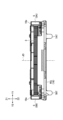
次に、図15A、図15B、図16A、及び図16Bを参照し、レンズ保持部材2の筒状部12の内面SFに形成された収容凹部SRについて説明する。図15A及び図15Bは、レンズ保持部材2の全体図である。具体的には、図15Aは、レンズ保持部材2の上方斜視図であり、図15Bは、レンズ保持部材2の上面図である。図16A及び図16Bは、レンズ保持部材2の断面図である。具体的には、図16A及び図16Bは、図15Bに示す一点鎖線L1を含むYZ平面に平行な仮想平面におけるレンズ保持部材2の断面を示している。より具体的には、図16Aは、その断面を斜め上から見たときの状態を示し、図16Bは、その断面をX1側(前側)から見たときの状態を示している。
Next, with reference to FIGS. 15A, 15B, 16A, and 16B, the accommodation recess SR formed on the inner surface SF of the
筒状部12の内面SFは、図15A、図16A、及び図16Bに示すように、光軸方向の中央部に形成されているパーティングラインPLを境として上下に分割されている。なお、筒状部12の内面SFの中央部に形成されているパーティングラインPLは、内面SFの上端と下端との間の中点を通るパーティングラインPLばかりでなく、中点から上下にずれた位置にある点を通るパーティングラインPLであってもよい。すなわち、内面SFの中央部は、内面SFの上端部及び下端部以外の部分を意味する。
As shown in FIGS. 15A, 16A, and 16B, the inner surface SF of the
パーティングラインPLは、レンズ保持部材2を射出成形する際に利用された複数の金型の分割面(パーティング面)に対応する線である。この例では、レンズ保持部材2は、図示されない上側金型及び下側金型を含む複数の金型を用いて成形され、パーティングラインPLは、上側金型と下側金型との間の合わせ目に相当する。
The parting line PL is a line corresponding to a dividing surface (parting surface) of a plurality of molds used when injection molding the
具体的には、内面SFは、パーティングラインPLを境に上側内面USFと下側内面LSFとに分けられている。図15A及び図16Aでは、明瞭化のため、上側内面USFには粗いドットパターンが付され、下側内面LSFには細かいドットパターンが付されている。 Specifically, the inner surface SF is divided into an upper inner surface USF and a lower inner surface LSF with the parting line PL as a boundary. In FIGS. 15A and 16A, for clarity, the upper inner surface USF is marked with a coarse dot pattern, and the lower inner surface LSF is marked with a fine dot pattern.
図15A、図15B、図16A、及び図16Bに示すレンズ保持部材2の筒状部12の内面SFには、収容凹部SRが形成されている。図16Bでは、明瞭化のため、収容凹部SRにはクロスパターンが付されている。
A housing recess SR is formed on the inner surface SF of the
収容凹部SRは、レンズ体LSとレンズ保持部材2との間で、レンズ体LSとレンズ保持部材2とを接着するための接着剤(図示せず。)を収容できるように形成された凹部の一例である。この例では、収容凹部SRは、図15Bに示すように、光軸JDを中心とする円の円周に沿って等間隔に20個設けられている。具体的には、20個の収容凹部SR(第1収容凹部SR1~第20収容凹部SR20)は、円周に沿って角度α(=18度)毎に形成されている。そして、二つの収容凹部SRの間(第1収容凹部SR1と第2収容凹部SR2との間)には、レンズ体LSの外周面ES(図1B参照。)と接触する接触部CS(第1接触部CS1)が配置されている。なお、収容凹部SRは、光軸JDを中心とする円の円周に沿って不等間隔に形成されていてもよい。また、収容凹部SRは、筒状部12の内面SFに1つだけ形成されていてもよい。
The accommodation recess SR is a recess formed between the lens body LS and the
複数(この例では20個)の収容凹部SRは、典型的には、図15A、図16A、及び図16Bに示すように同じ形状を有する。但し、複数の収容凹部SRは、異なる形状のものを含んでいてもよい。なお、図15A、図16A、及び図16Bでは、明瞭化のため、第1収容凹部SR1及び第2収容凹部SR2のみが引き出し線によって特定され、第3収容凹部SR3~第20収容凹部SR20については引き出し線による特定が省略されている。また、図15A、図15B、図16A、及び図16Bでは、明瞭化のため、接触部CSに関しては、第1接触部CS1のみが引き出し線によって特定され、残りの19個の接触部については引き出し線による特定が省略されている。 The plurality of (20 in this example) accommodation recesses SR typically have the same shape as shown in FIGS. 15A, 16A, and 16B. However, the plurality of accommodation recesses SR may have different shapes. In addition, in FIGS. 15A, 16A, and 16B, for clarity, only the first accommodation recess SR1 and the second accommodation recess SR2 are specified by lead lines, and the third to twentieth accommodation recesses SR3 to 20 are specified by lead lines. Identification using lead lines has been omitted. Furthermore, in FIGS. 15A, 15B, 16A, and 16B, for the sake of clarity, only the first contact part CS1 is specified by the lead line, and the remaining 19 contact parts are identified by the lead line. Identification by line is omitted.
図15A、図16A、及び図16Bに示すように、収容凹部SRのそれぞれは、上側内面USFに形成される上側収容凹部USRと下側内面LSFに形成される下側収容凹部LSRとを含んでいてもよい。同様に、接触部CSのそれぞれは、上側内面USFに形成される上側接触部UCSと下側内面LSFに形成される下側接触部LCSとを含んでいてもよい。 As shown in FIGS. 15A, 16A, and 16B, each of the accommodation recesses SR includes an upper accommodation recess USR formed on the upper inner surface USF and a lower accommodation recess LSR formed on the lower inner surface LSF. You can stay there. Similarly, each of the contact portions CS may include an upper contact portion UCS formed on the upper inner surface USF and a lower contact portion LCS formed on the lower inner surface LSF.
例えば、第1収容凹部SR1は、第1上側収容凹部USR1及び第1下側収容凹部LSR1を含む。同様に、第2収容凹部SR2は、第2上側収容凹部USR2及び第2下側収容凹部LSR2を含む。そして、第1上側収容凹部USR1と第2上側収容凹部USR2との間には第1上側接触部UCS1が配置され、第1下側収容凹部LSR1と第2下側収容凹部LSR2との間には第1下側接触部LCS1が配置されている。 For example, the first housing recess SR1 includes a first upper housing recess USR1 and a first lower housing recess LSR1. Similarly, the second storage recess SR2 includes a second upper storage recess USR2 and a second lower storage recess LSR2. The first upper contact portion UCS1 is disposed between the first upper housing recess USR1 and the second upper housing recess USR2, and the first upper contact portion UCS1 is disposed between the first lower housing recess LSR1 and the second lower housing recess LSR2. A first lower contact portion LCS1 is arranged.
図16Bに示すように、第1上側収容凹部USR1は、上下方向に延在しており、パーティングラインPLと接する下端部(幅狭部)と、筒状部12の上端と接する上端部(幅広部)とを有する。同様に、第1下側収容凹部LSR1は、上下方向に延在しており、パーティングラインPLと接する上端部(幅狭部)と、筒状部12の下端と接する下端部(幅広部)とを有する。
As shown in FIG. 16B, the first upper accommodation recess USR1 extends in the vertical direction, and has a lower end portion (narrow width portion) in contact with the parting line PL and an upper end portion (narrow width portion) in contact with the upper end of the
この例では、第1上側収容凹部USR1の下端部の幅W1は、第1上側収容凹部USR1の上端部の幅W2より小さい。また、第1下側収容凹部LSR1の上端部の幅W3は、第1下側収容凹部LSR1の下端部の幅W4より小さい。射出成形後にレンズ保持部材2から金型を分離できるように、幅W1は幅W2以下である必要があり、幅W3も幅W4以下である必要があるためである。なお、この例では、幅W1と幅W3は同じ大きさであり、幅W2は幅W4より小さい。但し、第1上側収容凹部USR1の下端部と第1下側収容凹部LSR1の上端部とが少なくとも部分的に接しているのであれば、幅W1と幅W3は異なる大きさであってもよい。また、幅W2は、幅W4と同じ大きさであってもよく、幅W4より大きくてもよい。
In this example, the width W1 of the lower end of the first upper housing recess USR1 is smaller than the width W2 of the upper end of the first upper housing recess USR1. Further, the width W3 of the upper end of the first lower accommodation recess LSR1 is smaller than the width W4 of the lower end of the first lower accommodation recess LSR1. This is because the width W1 needs to be less than or equal to the width W2, and the width W3 also needs to be less than or equal to the width W4 so that the mold can be separated from the
また、この例では、第1上側収容凹部USR1は、その左端部がXY平面に対して角度β1を形成する平面で区切られ、且つ、その右端部がXY平面に対して角度β2を形成する平面で区切られるように形成されている。同様に、第1下側収容凹部LSR1は、その左端部がXY平面に対して角度β3を形成する平面で区切られ、且つ、その右端部がXY平面に対して角度β4を形成する平面で区切られるように形成されている。なお、この例では、角度β1と角度β2とは同じ大きさであり、角度β3と角度β4とは同じ大きさである。また、角度β1(角度β2)は、角度β3(角度β4)より大きい。但し、角度β1~角度β4は全て同じ大きさであってもよく、それぞれが異なる大きさであってもよい。また、この例では、角度β1~角度β4は鋭角であるが、直角(90度)であってもよく、鈍角であってもよい。 In this example, the first upper storage recess USR1 is partitioned by a plane whose left end forms an angle β1 with respect to the XY plane, and whose right end forms a plane which forms an angle β2 with the XY plane. It is formed so that it is separated by . Similarly, the first lower storage recess LSR1 has its left end section separated by a plane forming an angle β3 with respect to the XY plane, and its right end section separated by a plane forming an angle β4 with respect to the XY plane. It is designed so that it can be Note that in this example, the angle β1 and the angle β2 are the same size, and the angle β3 and the angle β4 are the same size. Further, the angle β1 (angle β2) is larger than the angle β3 (angle β4). However, angles β1 to β4 may all have the same size, or may have different sizes. Further, in this example, the angles β1 to β4 are acute angles, but they may be right angles (90 degrees) or obtuse angles.
また、この例では、20個の収容凹部SRは、深さDP(図15B参照。)が全て同じになるように構成されているが、深さの異なるものを含んでいてもよい。また、この例では、20個の収容凹部SRは、上側収容凹部USRの深さと下側収容凹部LSRの深さとが同じになるように構成されているが、上側収容凹部USRの深さと下側収容凹部LSRの深さは異なっていてもよい。 Further, in this example, the 20 accommodation recesses SR are configured so that they all have the same depth DP (see FIG. 15B), but may include ones with different depths. Furthermore, in this example, the 20 accommodation recesses SR are configured such that the depth of the upper accommodation recess USR is the same as the depth of the lower accommodation recess LSR, but the depth of the upper accommodation recess USR and the lower The depths of the accommodation recesses LSR may be different.
上述の構成により、収容凹部SRに収容された接着剤は、レンズ体LSとレンズ保持部材2とを強固に接着できる。そして、収容凹部SR内で硬化した接着剤(以下、「硬化接着剤HA」とする。)がレンズ保持部材2から剥がれてしまった場合であっても、硬化接着剤HAは、レンズ体LSがレンズ保持部材2から抜け落ちてしまうのを防止できる。硬化接着剤HAは、少なくともパーティングラインPLに近い位置にある部分において、収容凹部SRと同じ形状を有するためである。すなわち、上側収容凹部USRにある硬化接着剤HAの一部は、上端部の幅が下端部の幅より大きい形状により、下方への移動が制限されるためであり、下側収容凹部LSRにある硬化接着剤HAの一部は、下端部の幅が上端部の幅より大きい形状により、上方への移動が制限されるためである。なお、図16Aは、硬化接着剤HAの一例である第1硬化接着剤HA1を示している。図16Aの第1硬化接着剤HA1は、第1収容凹部SR1内で硬化した接着剤であり、明瞭化のため、第1収容凹部SR1から分離された状態で示されている。
With the above configuration, the adhesive accommodated in the accommodation recess SR can firmly bond the lens body LS and the
また、硬化接着剤HAは、レンズ保持部材2から剥がれてしまった場合であっても、その形状により、レンズ保持部材2に対するレンズ体LSの上下方向における移動を制限できるばかりでなく、レンズ保持部材2に対するレンズ体LSの光軸JD回りの回転をも制限できる。
Further, even if the cured adhesive HA is peeled off from the
なお、接着剤は、収容凹部SRを完全に満たす必要はなく、レンズ保持部材2に対する光軸方向におけるレンズ体LSの移動と光軸JD回りのレンズ体LSの回転とを抑制するのに十分な量が収容凹部SR内に配置されていればよい。すなわち、硬化接着剤HAは、収容凹部SRと全く同じ形状を有する必要はない。図16Aに示す第1硬化接着剤HA1は、第1上側収容凹部USR1の上端部に近い部分において第1上側収容凹部USR1とは異なる形状を有し、且つ、第1下側収容凹部LSR1の下端部に近い部分において第1下側収容凹部LSR1とは異なる形状を有する。第1収容凹部SR1は、パーティングラインPLに近い部分が接着剤で満たされているが、その内部空間の全体が接着剤で満たされているわけではないためである。
Note that the adhesive does not need to completely fill the housing recess SR, but is sufficient to suppress the movement of the lens body LS in the optical axis direction with respect to the
次に、図17A及び図17Bを参照し、レンズ保持部材2の別の構成例であるレンズ保持部材2Xについて説明する。図17A及び図17Bは、レンズ保持部材2Xの断面図である。具体的には、図17Aは、図16Aに対応する図であり、その断面を斜め上から見たときの状態を示している。また、図17Bは、図16Bに対応する図であり、その断面をX1側(前側)から見たときの状態を示している。
Next, a
図17A及び図17Bに示すレンズ保持部材2Xは、上側内面USFに溝部GRを有する点で、上側内面USFに上側収容凹部USRを有するレンズ保持部材2と異なるが、その他の点でレンズ保持部材2と共通している。そのため、以下では、共通部分の説明が省略され、相違部分が詳説される。
The
なお、図17Aでは、明瞭化のため、上側内面USFには粗いドットパターンが付され、下側内面LSFには細かいドットパターンが付されている。また、図17Bでは、明瞭化のため、収容凹部SR(下側収容凹部LSR)にはクロスパターンが付されている。また、図17A及び図17Bでは、明瞭化のため、第1下側収容凹部LSR1及び第2下側収容凹部LSR2のみが引き出し線によって特定され、他の下側収容凹部LSRについては引き出し線による特定が省略されている。また、図17A及び図17Bでは、明瞭化のため、接触部CSに関しては、第1下側接触部LCS1のみが引き出し線によって特定され、他の下側接触部LCSについては引き出し線による特定が省略されている。 In addition, in FIG. 17A, for clarity, a coarse dot pattern is attached to the upper inner surface USF, and a fine dot pattern is attached to the lower inner surface LSF. Further, in FIG. 17B, for clarity, a cross pattern is attached to the accommodation recess SR (lower accommodation recess LSR). In addition, in FIGS. 17A and 17B, for clarity, only the first lower housing recess LSR1 and the second lower housing recess LSR2 are identified by lead lines, and the other lower housing recesses LSR are identified by lead lines. is omitted. In addition, in FIGS. 17A and 17B, for the sake of clarity, regarding the contact portion CS, only the first lower contact portion LCS1 is specified by a leader line, and the other lower contact portions LCS are not identified by the leader line. has been done.
溝部GRは、レンズ体LSとレンズ保持部材2Xとの間で、レンズ体LSとレンズ保持部材2Xとを接着するための接着剤(図示せず。)を収容できるように形成された収容凹部SRの別の一例である。図17A及び図17Bに示す例では、溝部GRは、螺旋状に形成された溝を含む部分である。そして、溝部GRは、レンズ体LSの滑らかな外周面ES(図1B参照。)と対向するように形成されている。
The groove GR is a storage recess SR formed between the lens body LS and the
上述の構成により、収容凹部SR(下側収容凹部LSR)及び溝部GRのそれぞれに収容された接着剤は、レンズ体LSとレンズ保持部材2Xとを強固に接着できる。そして、収容凹部SR(下側収容凹部LSR)内及び溝部GR内のそれぞれで硬化した接着剤(硬化接着剤HA)がレンズ保持部材2Xから剥がれてしまった場合であっても、硬化接着剤HAは、レンズ体LSがレンズ保持部材2Xから抜け落ちてしまうのを防止できる。収容凹部SR内にある硬化接着剤HAは、少なくともパーティングラインPLに近い位置にある部分において、収容凹部SRと同じ形状を有するためである。すなわち、溝部GRにある硬化接着剤HAは、螺旋状に延びる形状により、上下方向への移動が制限されるためであり、下側収容凹部LSR内にある硬化接着剤HAは、下端部の幅が上端部の幅より大きい形状により、上方への移動が制限されるためである。また、硬化接着剤HAは、筒状部12の内面SFに溝部GRのみが形成されている場合のようにレンズ体LSが光軸JDの回りに回転してしまうのを防止できる。下側収容凹部LSR内にある硬化接着剤HAによってレンズ体LSの上下動及び回転移動が制限されるためである。
With the above configuration, the adhesive accommodated in each of the accommodation recess SR (lower accommodation recess LSR) and the groove GR can firmly adhere the lens body LS and the
そのため、下側収容凹部LSR内にある硬化接着剤HAは、レンズ保持部材2から剥がれてしまった場合であっても、その形状により、レンズ保持部材2Xに対するレンズ体LSの上下方向における移動を制限できるばかりでなく、レンズ保持部材2Xに対するレンズ体LSの光軸JD回りの回転をも制限できる。
Therefore, even if the cured adhesive HA in the lower accommodation recess LSR is peeled off from the
また、図17A及び図17Bに示す例では、筒状部12の内面SFは、上側内面USFに溝部GRを有し、下側内面LSFに略台形状の収容凹部SR(下側収容凹部LSR)を有するように形成されているが、上側内面USFに略台形状の収容凹部SR(上側収容凹部USR)を有し、下側内面LSFに溝部GRを有するように形成されていてもよい。但し、何れの場合においても、筒状部12の内面SFとレンズ体LSとを接着するための接着剤は、望ましくは、溝部GR側から供給され、溝部GRを通じて略台形状の収容凹部SRに供給される。
In the example shown in FIGS. 17A and 17B, the inner surface SF of the
次に、図18A~図18Fを参照し、収容凹部SRの別の構成例について説明する。図18A~図18Fは、収容凹部SRの6つの構成例を示す図である。具体的には、図18Aは、収容凹部SRの正面図であり、図16Bに示す一点鎖線で囲まれた範囲R4の拡大図に相当する。同様に、図18B~図18Fは、収容凹部SRb~収容凹部SRfの正面図であり、図18Aに対応している。なお、図18A~図18Fに示す収容凹部SR及び収容凹部SRb~収容凹部SRfは何れも同じ深さDPを有するように形成されている。 Next, another configuration example of the accommodation recess SR will be described with reference to FIGS. 18A to 18F. 18A to 18F are diagrams showing six configuration examples of the accommodation recess SR. Specifically, FIG. 18A is a front view of the accommodation recess SR, and corresponds to an enlarged view of the range R4 surrounded by the dashed line shown in FIG. 16B. Similarly, FIGS. 18B to 18F are front views of the accommodation recesses SRb to SRf, and correspond to FIG. 18A. Note that the housing recess SR and the housing recesses SRb to SRf shown in FIGS. 18A to 18F are all formed to have the same depth DP.
図18Aに示す例では、収容凹部SRは、上側収容凹部USR及び下側収容凹部LSRを含む。上側収容凹部USRは、パーティングラインPLに接する下端部と筒状部12の上面に接する上端部とを有する。下側収容凹部LSRは、パーティングラインPLに接する上端部と筒状部12の下面に接する下端部とを有する。そして、上側収容凹部USRは、下端部の幅W1が上端部の幅W2より小さくなるように形成され、下側収容凹部LSRは、上端部の幅W3が下端部の幅W4より小さくなるように形成されている。
In the example shown in FIG. 18A, the housing recess SR includes an upper housing recess USR and a lower housing recess LSR. The upper housing recess USR has a lower end that contacts the parting line PL and an upper end that contacts the upper surface of the
図18Bに示す例では、収容凹部SRbは、上側収容凹部USRb及び下側収容凹部LSRbを含む。収容凹部SRbは、筒状部12の内面SFにおける上側収容凹部USRbの周方向における位置と下側収容凹部LSRbの周方向における位置とがずれている点で、図18Aに示す収容凹部SRと異なるが、その他の点で同じである。
In the example shown in FIG. 18B, the housing recess SRb includes an upper housing recess USRb and a lower housing recess LSRb. The accommodation recess SRb differs from the accommodation recess SR shown in FIG. 18A in that the position of the upper accommodation recess USRb in the circumferential direction and the position of the lower accommodation recess LSRb in the circumferential direction on the inner surface SF of the
具体的には、上側収容凹部USRbの下端部と下側収容凹部LSRbの上端部とは幅W5にわたって重複する重複部分を有する。一方で、上側収容凹部USRbの下端部は、下側収容凹部LSRbの上端部と重複しない幅W6の非重複部分を重複部分の左側に有し、下側収容凹部LSRbの上端部は、上側収容凹部USRbの下端部と重複しない幅W7の非重複部分を重複部分の右側に有する。 Specifically, the lower end of the upper housing recess USRb and the upper end of the lower housing recess LSRb have an overlapping portion that overlaps over the width W5. On the other hand, the lower end of the upper accommodation recess USRb has a non-overlapping part with a width W6 that does not overlap with the upper end of the lower accommodation recess LSRb on the left side of the overlapping part, and the upper end of the lower accommodation recess LSRb A non-overlapping portion with a width W7 that does not overlap with the lower end of the recess USRb is provided on the right side of the overlapping portion.
なお、上側収容凹部USRbの下端部は、重複部分の両側に非重複部分を有していてもよい。すなわち、下側収容凹部LSRbの上端部は、その全幅にわたって、上側収容凹部USRbの下端部の一部と重複していてもよい。同様に、下側収容凹部LSRbの上端部は、重複部分の両側に非重複部分を有していてもよい。すなわち、上側収容凹部USRbの下端部は、その全幅にわたって、下側収容凹部LSRbの上端部の一部と重複していてもよい。 Note that the lower end portion of the upper storage recess USRb may have non-overlapping portions on both sides of the overlapping portion. That is, the upper end portion of the lower accommodation recess LSRb may overlap a part of the lower end portion of the upper accommodation recess USRb over its entire width. Similarly, the upper end portion of the lower housing recess LSRb may have non-overlapping portions on both sides of the overlapping portion. That is, the lower end portion of the upper storage recess USRb may overlap a part of the upper end portion of the lower storage recess LSRb over its entire width.
図18Cに示す例では、収容凹部SRcは、上側収容凹部USRc及び下側収容凹部LSRcを含む。収容凹部SRcは、上側収容凹部USRcの左端部及び右端部が上方に向かって真っ直ぐに延びる部分を含む点で、図18Aに示す収容凹部SRと異なるが、その他の点で同じである。 In the example shown in FIG. 18C, the accommodation recess SRc includes an upper accommodation recess USRc and a lower accommodation recess LSRc. The accommodation recess SRc differs from the accommodation recess SR shown in FIG. 18A in that the left and right ends of the upper accommodation recess USRc include portions extending straight upward, but is otherwise the same.
具体的には、上側収容凹部USRcは、下端部の幅W8が上端部の幅W9より小さくなるように形成されている。また、上側収容凹部USRcは、パーティングラインPLから上方に高さH1の位置まで真っ直ぐに延びた後で周方向に拡がりながら更に上方に延びている。 Specifically, the upper housing recess USRc is formed such that the width W8 at the lower end is smaller than the width W9 at the upper end. Further, the upper housing recess USRc extends straight upward from the parting line PL to a height H1 position, and then extends further upward while expanding in the circumferential direction.
図18Dに示す例では、収容凹部SRdは、上側収容凹部USRd及び下側収容凹部LSRdを含む。収容凹部SRdは、上側収容凹部USRdがパーティングラインPLから上方に向かって階段状に拡がる点で、図18Aに示す収容凹部SRと異なるが、その他の点で同じである。 In the example shown in FIG. 18D, the accommodation recess SRd includes an upper accommodation recess USRd and a lower accommodation recess LSRd. The accommodation recess SRd differs from the accommodation recess SR shown in FIG. 18A in that the upper accommodation recess USRd expands upward from the parting line PL in a stepwise manner, but is the same in other respects.
具体的には、上側収容凹部USRdは、下端部の幅W10が上端部の幅W11より小さくなるように形成されている。また、上側収容凹部USRdは、パーティングラインPLから上方に真っ直ぐに延びた後で周方向に真っ直ぐに広がり、この上方への延伸と周方向への拡張とを更に二回繰り返すように形成されている。 Specifically, the upper housing recess USRd is formed such that the width W10 at the lower end is smaller than the width W11 at the upper end. Further, the upper accommodation recess USRd is formed so as to extend straight upward from the parting line PL, then spread straight in the circumferential direction, and repeat this upward extension and circumferential expansion two more times. There is.
図18Eに示す例では、収容凹部SReは、上側収容凹部USRe及び下側収容凹部LSReを含む。収容凹部SReは、上側収容凹部USReの左端部がパーティングラインPLから上方に向かって真っ直ぐに延びる点、及び、下側収容凹部LSReの右端部がパーティングラインPLから下方に向かって真っ直ぐに延びる点で、図18Aに示す収容凹部SRと異なるが、その他の点で同じである。 In the example shown in FIG. 18E, the accommodation recess SRe includes an upper accommodation recess USRe and a lower accommodation recess LSRe. The accommodation recess SRe is such that the left end of the upper accommodation recess USRe extends straight upward from the parting line PL, and the right end of the lower accommodation recess LSRe extends straight downward from the parting line PL. Although it differs from the accommodation recess SR shown in FIG. 18A in this respect, it is the same in other respects.
具体的には、上側収容凹部USReは、下端部の幅W12が上端部の幅W13より小さくなるように形成されている。また、下側収容凹部LSReは、上端部の幅W12が下端部の幅W14より小さくなるように形成されている。 Specifically, the upper accommodation recess USRe is formed such that the width W12 at the lower end is smaller than the width W13 at the upper end. Further, the lower housing recess LSRe is formed such that the width W12 at the upper end is smaller than the width W14 at the lower end.
図18Fに示す例では、収容凹部SRfは、上側収容凹部USRf及び下側収容凹部LSRfを含む。収容凹部SRfは、上側収容凹部USRfがパーティングラインPLから上方に向かって真っ直ぐに延びる点、下側収容凹部LSRfがパーティングラインPLから下方に向かって真っ直ぐに延びる点、及び、上側収容凹部USRfの周方向における位置と下側収容凹部LSRfの周方向における位置とがずれている点で、図18Aに示す収容凹部SRと異なるが、その他の点で同じである。 In the example shown in FIG. 18F, the accommodation recess SRf includes an upper accommodation recess USRf and a lower accommodation recess LSRf. The accommodation recess SRf has two points: an upper accommodation recess USRf extends straight upward from the parting line PL, a lower accommodation recess LSRf extends straight downward from the parting line PL, and an upper accommodation recess USRf. It differs from the accommodation recess SR shown in FIG. 18A in that the position in the circumferential direction of and the position of the lower accommodation recess LSRf in the circumferential direction are different from each other, but are the same in other respects.
具体的には、上側収容凹部USRfの下端部と下側収容凹部LSRfの上端部とは幅W15にわたって重複する重複部分を有する。一方で、上側収容凹部USRfの下端部は、下側収容凹部LSRfの上端部と重複しない幅W16の非重複部分を重複部分の左側に有し、下側収容凹部LSRfの上端部は、上側収容凹部USRfの下端部と重複しない幅W17の非重複部分を重複部分の右側に有する。 Specifically, the lower end of the upper housing recess USRf and the upper end of the lower housing recess LSRf have an overlapping portion that overlaps across the width W15. On the other hand, the lower end of the upper accommodation recess USRf has a non-overlapping part with a width W16 that does not overlap with the upper end of the lower accommodation recess LSRf on the left side of the overlapping part, and the upper end of the lower accommodation recess LSRf has a non-overlapping part on the left side of the overlapping part. A non-overlapping portion with a width W17 that does not overlap with the lower end of the recessed portion USRf is provided on the right side of the overlapping portion.
図18B~図18Fに示す収容凹部SRb~収容凹部SRfは何れも、図18Aに示す収容凹部SRと同様に、硬化接着剤HAがレンズ保持部材2から剥がれてしまった場合であっても、レンズ体LSがレンズ保持部材2から抜け落ちてしまうのを防止できる。硬化接着剤HAは、少なくともパーティングラインPLに近い位置にある部分において、収容凹部SRb~収容凹部SRfのそれぞれと同じ形状を有するためである。すなわち、上側収容凹部USRb~上側収容凹部USReのそれぞれにおける硬化接着剤HAは、上端部の幅が下端部の幅より大きい形状により、下方への移動が制限されるためである。また、下側収容凹部LSRb~下側収容凹部LSReのそれぞれにおける硬化接着剤HAは、下端部の幅が上端部の幅より大きい形状により、上方への移動が制限されるためである。
Like the housing recess SR shown in FIG. 18A, all of the housing recesses SRb to SRf shown in FIGS. It is possible to prevent the body LS from falling off from the
また、収容凹部SRbでは、上側収容凹部USRbの下端部と下側収容凹部LSRbの上端部とが重複しない非重複部分が存在するため、収容凹部SRbにおける硬化接着剤HAの上下方向における移動が制限されるためである。 Furthermore, in the accommodation recess SRb, since there is a non-overlapping portion where the lower end of the upper accommodation recess USRb and the upper end of the lower accommodation recess LSRb do not overlap, vertical movement of the cured adhesive HA in the accommodation recess SRb is restricted. This is to be done.
同様に、収容凹部SRfでも、上側収容凹部USRfの下端部と下側収容凹部LSRfの上端部とが重複しない非重複部分が存在するため、収容凹部SRfにおける硬化接着剤HAの上下方向における移動が制限されるためである。 Similarly, in the accommodation recess SRf, there is a non-overlapping portion where the lower end of the upper accommodation recess USRf and the upper end of the lower accommodation recess LSRf do not overlap, so that the vertical movement of the cured adhesive HA in the accommodation recess SRf is prevented. This is because it is restricted.
また、図18Aに示す例では、収容凹部SRは、上側収容凹部USR及び下側収容凹部LSRを含むが、図17A及び図17Bに示す例のように、上側収容凹部USRは、螺旋状の溝を含む溝部GRで置き換えられていてもよい。また、収容凹部SRは、下側収容凹部LSRが螺旋状の溝を含む溝部GRで置き換えられていてもよい。図18B~図18Fに示す例においても同様である。 Further, in the example shown in FIG. 18A, the accommodation recess SR includes an upper accommodation recess USR and a lower accommodation recess LSR, but as in the example shown in FIGS. 17A and 17B, the upper accommodation recess USR includes a spiral groove. may be replaced by a groove GR including the groove portion GR. Further, the lower accommodation recess LSR may be replaced with a groove GR including a spiral groove in the accommodation recess SR. The same applies to the examples shown in FIGS. 18B to 18F.
次に、図19A~図19Eを参照し、収容凹部SRの更に別の構成例について説明する。図19A~図19Eは、収容凹部SRの4つの構成例を示す図である。具体的には、図19Aは、収容凹部SRhの正面図であり、図18Aに対応している。図19Bは、図19Aに示す一点鎖線L2及び光軸JDを含む仮想平面におけるレンズ保持部材2(収容凹部SRh)の断面を示し、図16Bに示す一点鎖線で囲まれた範囲R5の拡大図に対応している。図19C~図19Eは、収容凹部SRi~収容凹部SRkの断面図であり、図19Bに対応している。なお、図19A~図19Eに示す収容凹部SRh~収容凹部SRkは何れも、図19Aに示すように、周方向において同じ幅W21を有するように形成されている。 Next, with reference to FIGS. 19A to 19E, still another example of the configuration of the housing recess SR will be described. 19A to 19E are diagrams showing four configuration examples of the accommodation recess SR. Specifically, FIG. 19A is a front view of the housing recess SRh, and corresponds to FIG. 18A. FIG. 19B shows a cross section of the lens holding member 2 (accommodating recess SRh) in a virtual plane including the dashed-dotted line L2 and the optical axis JD shown in FIG. 19A, and is an enlarged view of the range R5 surrounded by the dashed-dotted line shown in FIG. 16B. Compatible. 19C to 19E are cross-sectional views of the accommodation recesses SRi to SRk, and correspond to FIG. 19B. Note that the accommodation recesses SRh to SRk shown in FIGS. 19A to 19E are all formed to have the same width W21 in the circumferential direction, as shown in FIG. 19A.
図19A及び図19Bに示す例では、収容凹部SRhは、上側収容凹部USRh及び下側収容凹部LSRhを含む。上側収容凹部USRhは、パーティングラインPLに接する下端部と筒状部12の上面に接する上端部とを有する。下側収容凹部LSRhは、パーティングラインPLに接する上端部と筒状部12の下面に接する下端部とを有する。そして、収容凹部SRhは、上側収容凹部USRhの下端部及び上端部、並びに、下側収容凹部LSRhの上端部及び下端部のそれぞれの幅W21が何れも等しくなるように形成されている。
In the example shown in FIGS. 19A and 19B, the housing recess SRh includes an upper housing recess USRh and a lower housing recess LSRh. The upper housing recess USRh has a lower end that contacts the parting line PL and an upper end that contacts the upper surface of the
その上で、上側収容凹部USRhは、下端部の深さDP1が上端部の深さDP2より小さくなるように形成され、下側収容凹部LSRhは、上端部の深さDP1が下端部の深さDP3より小さくなるように形成されている。 In addition, the upper housing recess USRh is formed such that the depth DP1 of the lower end is smaller than the depth DP2 of the upper end, and the lower housing recess LSRh is formed such that the depth DP1 of the upper end is smaller than the depth DP1 of the lower end. It is formed to be smaller than DP3.
図19A及び図19Bに示す例では、収容凹部SRhは、深さDP2と深さDP3とが同じ大きさになるように形成されているが、深さDP2と深さDP3とは互いに異なる大きさであってもよい。 In the example shown in FIGS. 19A and 19B, the accommodation recess SRh is formed so that the depth DP2 and the depth DP3 have the same size, but the depth DP2 and the depth DP3 have different sizes. It may be.
図19Cに示す例では、収容凹部SRiは、上側収容凹部USRi及び下側収容凹部LSRiを含む。収容凹部SRiは、上側収容凹部USRiの下端部の深さDP4と下側収容凹部LSRiの上端部の深さDP5とが異なる点で、図19Bに示す収容凹部SRhと異なるが、その他の点で同じである。 In the example shown in FIG. 19C, the housing recess SRi includes an upper housing recess USRi and a lower housing recess LSRi. The accommodation recess SRi differs from the accommodation recess SRh shown in FIG. 19B in that the depth DP4 of the lower end of the upper accommodation recess USRi is different from the depth DP5 of the upper end of the lower accommodation recess LSRi, but in other respects. It's the same.
具体的には、上側収容凹部USRiの下端部の深さDP4は、下側収容凹部LSRiの上端部の深さDP5より小さい。また、上側収容凹部USRiの下端部の深さDP4は、上側収容凹部USRiの上端部の深さDP6より小さく、下側収容凹部LSRiの上端部の深さDP5は、下側収容凹部LSRiの下端部の深さDP7より小さい。 Specifically, the depth DP4 of the lower end of the upper housing recess USRi is smaller than the depth DP5 of the upper end of the lower housing recess LSRi. Further, the depth DP4 of the lower end of the upper accommodation recess USRi is smaller than the depth DP6 of the upper end of the upper accommodation recess USRi, and the depth DP5 of the upper end of the lower accommodation recess LSRi is the lower end of the lower accommodation recess LSRi. depth DP7.
また、図19Cに示す例では、収容凹部SRiは、深さDP4が深さDP5より小さくなるように形成されているが、深さDP4は深さDP5より大きくてもよい。また、収容凹部SRiは、深さDP6が深さDP7より小さくなるように形成されているが、深さDP6は深さDP7と同じであってもよく深さDP7より大きくてもよい。 Further, in the example shown in FIG. 19C, the accommodation recess SRi is formed so that the depth DP4 is smaller than the depth DP5, but the depth DP4 may be larger than the depth DP5. Moreover, although the accommodation recess SRi is formed so that the depth DP6 is smaller than the depth DP7, the depth DP6 may be the same as the depth DP7 or may be larger than the depth DP7.
図19Dに示す例では、収容凹部SRjは、上側収容凹部USRj及び下側収容凹部LSRjを含む。収容凹部SRjは、上下方向において上側収容凹部USRjの深さが変化しない部分を含む点で、図19Bに示す収容凹部SRhと異なるが、その他の点で同じである。 In the example shown in FIG. 19D, the housing recess SRj includes an upper housing recess USRj and a lower housing recess LSRj. The accommodation recess SRj differs from the accommodation recess SRh shown in FIG. 19B in that it includes a portion where the depth of the upper accommodation recess USRj does not change in the vertical direction, but is the same in other respects.
具体的には、上側収容凹部USRjは、下端部の深さDP8が上端部の深さDP9より小さくなるように形成されている。また、上側収容凹部USRjは、パーティングラインPLから上方に高さH2の位置まで深さDP8が変化しないように形成されている。そして、上側収容凹部USRjは、高さH2の位置から上端部まで所定の勾配で深くなるように形成されている。 Specifically, the upper housing recess USRj is formed such that the depth DP8 at the lower end is smaller than the depth DP9 at the upper end. Further, the upper housing recess USRj is formed so that the depth DP8 does not change upward from the parting line PL to a position at a height H2. The upper storage recess USRj is formed to become deeper at a predetermined slope from the height H2 to the upper end.
図19Eに示す例では、収容凹部SRkは、上側収容凹部USRk及び下側収容凹部LSRkを含む。収容凹部SRkは、上側収容凹部USRkがパーティングラインPLから上方に向かって階段状に深くなる点で、図19Bに示す収容凹部SRhと異なるが、その他の点で同じである。 In the example shown in FIG. 19E, the accommodation recess SRk includes an upper accommodation recess USRk and a lower accommodation recess LSRk. The accommodation recess SRk differs from the accommodation recess SRh shown in FIG. 19B in that the upper accommodation recess USRk becomes deeper in a stepwise manner upward from the parting line PL, but is the same in other respects.
具体的には、上側収容凹部USRkは、下端部の深さDP10が上端部の深さDP12より小さくなるように形成されている。また、上側収容凹部USRkは、パーティングラインPLから上方に高さH3の位置まで深さDP10が変化しないように形成されている。そして、上側収容凹部USRkは、高さH3のところで深さDP11となり、パーティングラインPLから上方に高さH4の位置まで深さDP11が変化しないように形成されている。そして、上側収容凹部USRkは、高さH4のところで深さDP12となり、上端部に達するまで深さDP12が変化しないように形成されている。 Specifically, the upper accommodation recess USRk is formed such that the depth DP10 at the lower end is smaller than the depth DP12 at the upper end. Further, the upper housing recess USRk is formed so that the depth DP10 does not change upward from the parting line PL to a position at a height H3. The upper accommodation recess USRk has a depth DP11 at a height H3, and is formed so that the depth DP11 does not change upward from the parting line PL to a position at a height H4. The upper accommodation recess USRk has a depth DP12 at the height H4, and is formed so that the depth DP12 does not change until it reaches the upper end.
図19A~図19Eに示す収容凹部SRh~収容凹部SRkは何れも、図18Aに示す収容凹部SRと同様に、硬化接着剤HAがレンズ保持部材2から剥がれてしまった場合であっても、レンズ体LSがレンズ保持部材2から抜け落ちてしまうのを防止できる。硬化接着剤HAは、少なくともパーティングラインPLに近い位置にある部分において、収容凹部SRh~収容凹部SRkのそれぞれと同じ形状を有するためである。すなわち、上側収容凹部USRh~上側収容凹部USRkのそれぞれにおける硬化接着剤HAは、上端部の深さが下端部の深さより大きい形状により、下方への移動が制限されるためである。また、下側収容凹部LSRh~下側収容凹部LSRkのそれぞれにおける硬化接着剤HAは、下端部の深さが上端部の深さより大きい形状により、上方への移動が制限されるためである。
Like the housing recess SR shown in FIG. 18A, the housing recesses SRh to SRk shown in FIG. 19A to FIG. It is possible to prevent the body LS from falling off from the
また、図19A及び図19Bに示す例では、収容凹部SRhは、上側収容凹部USRh及び下側収容凹部LSRhを含むが、図17A及び図17Bに示す例のように、上側収容凹部USRhは、螺旋状の溝を含む溝部GRで置き換えられていてもよい。また、収容凹部SRhは、下側収容凹部LSRhが螺旋状の溝を含む溝部GRで置き換えられていてもよい。図19C~図19Eに示す例においても同様である。 Further, in the example shown in FIGS. 19A and 19B, the accommodation recess SRh includes an upper accommodation recess USRh and a lower accommodation recess LSRh, but as in the example shown in FIGS. 17A and 17B, the upper accommodation recess USRh has a spiral shape. It may be replaced with a groove portion GR including a shaped groove. In addition, the lower accommodation recess LSRh may be replaced with a groove GR including a spiral groove in the accommodation recess SRh. The same applies to the examples shown in FIGS. 19C to 19E.
上述のように、レンズ駆動装置101は、筐体HSとしてのカバー部材4を含む固定側部材RGと、筐体HS内に配置されるとともにレンズ体LSを保持可能なレンズ保持部材2と、レンズ保持部材2を固定側部材RGに対して移動させる駆動機構MKと、を備えている。そして、レンズ体LSは、レンズ保持部材2に接着剤によって固定されている。
As described above, the
レンズ保持部材2は、光軸方向(上下方向)に延びるとともに内側にレンズ体LSを配置可能な筒状部12を有する。具体的には、筒状部12の内面SFには、レンズ保持部材2を成形加工した際の金型の合わせ目であるパーティングラインPLが、光軸方向における筒状部12の中央部に形成されている。そして、パーティングラインPLの上側にある筒状部12の上側内面USFとパーティングラインPLの下側にある筒状部12の下側内面LSFとのそれぞれには接着剤を収容可能な収容凹部SRが形成されている。そして、それぞれの収容凹部SRの形状は、収容凹部SRに収容される接着剤の形状とかみ合うことによってレンズ体LSとレンズ保持部材2との間の相対的な上下方向の移動を規制できるように構成されている。
The
例えば、図18Aに示す例では、上側収容凹部USRに収容される硬化接着剤HAの一部は、上端部の幅が下端部の幅より大きい形状を有するため、上側収容凹部USRとかみ合い、下方への移動が規制される。また、下側収容凹部LSRに収容される硬化接着剤HAの一部は、下端部の幅が上端部の幅より大きい形状を有するため、下側収容凹部LSRとかみ合い、上方への移動が規制される。図18B~図18Eに示す例においても同様である。 For example, in the example shown in FIG. 18A, a part of the cured adhesive HA accommodated in the upper accommodation recess USR has a shape in which the width of the upper end part is larger than the width of the lower end part, so that it engages with the upper accommodation recess part USR and moves downward. Movement to is regulated. In addition, since a portion of the cured adhesive HA accommodated in the lower accommodation recess LSR has a shape in which the width at the lower end is larger than the width at the upper end, it engages with the lower accommodation recess LSR and its upward movement is restricted. be done. The same applies to the examples shown in FIGS. 18B to 18E.
また、図18Bに示す例では、上側収容凹部USRbに収容される硬化接着剤HAの一部は、下端部の幅が重複部分の幅W5より大きいため、上側収容凹部USRbとかみ合い、下方への移動が規制される。また、下側収容凹部LSRbに収容される硬化接着剤HAの一部は、上端部の幅が重複部分の幅W5より大きいため、下側収容凹部LSRbとかみ合い、上方への移動が規制される。同様に、図18Fに示す例では、上側収容凹部USRfに収容される硬化接着剤HAの一部は、下端部の幅が重複部分の幅W15より大きいため、上側収容凹部USRfとかみ合い、下方への移動が規制される。また、下側収容凹部LSRfに収容される硬化接着剤HAの一部は、上端部の幅が重複部分の幅W15より大きいため、下側収容凹部LSRfとかみ合い、上方への移動が規制される。 In addition, in the example shown in FIG. 18B, a portion of the cured adhesive HA accommodated in the upper accommodation recess USRb has a lower end width larger than the width W5 of the overlapping part, so that it engages with the upper accommodation recess USRb and moves downward. Movement will be regulated. Further, since the width of the upper end portion of the cured adhesive HA accommodated in the lower accommodation recess LSRb is larger than the width W5 of the overlapping portion, the part of the cured adhesive HA accommodated in the lower accommodation recess LSRb engages with the lower accommodation recess LSRb, and its upward movement is restricted. . Similarly, in the example shown in FIG. 18F, a portion of the cured adhesive HA accommodated in the upper accommodation recess USRf has a lower end width larger than the width W15 of the overlapping part, so it engages with the upper accommodation recess USRf and moves downward. movement is regulated. Further, since the width of the upper end portion of the cured adhesive HA accommodated in the lower accommodation recess LSRf is larger than the width W15 of the overlapping portion, the part of the cured adhesive HA accommodated in the lower accommodation recess LSRf engages with the lower accommodation recess LSRf, and its upward movement is restricted. .
この構成により、レンズ保持部材2は、レンズ体LSとレンズ保持部材2とを接着する接着剤(収容凹部SRに収容される硬化接着剤HA)がレンズ保持部材2から剥がれてしまった場合であっても、レンズ保持部材2は、依然としてレンズ体LSを強固に保持できる。収容凹部SRと硬化接着剤HAとのかみ合いにより、レンズ体LSとレンズ保持部材2との間の相対的な上下動が規制され、レンズ体LS(レンズ体LSに付着している硬化接着剤HA)とレンズ保持部材2との結合が維持されるためである。
With this configuration, the
また、上側内面USFにおける収容凹部SR(上側収容凹部USR)と下側内面LSFにおける収容凹部SR(下側収容凹部LSR)との少なくとも何れか一方の収容凹部SRは、例えば、パーティングラインPLに近い位置におけるパーティング面に平行な断面の全部が、パーティング面に垂直な方向において、パーティングラインPLから遠い位置におけるパーティング面に平行な断面と重なるように構成されていてもよい。 Further, at least one of the housing recesses SR (upper housing recess USR) on the upper inner surface USF and the housing recess SR (lower housing recess LSR) on the lower inner surface LSF is located at the parting line PL, for example. The entire cross section parallel to the parting surface at a close position may be configured to overlap, in the direction perpendicular to the parting surface, with the cross section parallel to the parting surface at a position far from the parting line PL.
レンズ保持部材2が射出成形によって作製される場合、レンズ保持部材2を射出成形する際に用いられる金型が射出成形後にパーティングラインPL(パーティング面)から離れる方向にレンズ保持部材2から分離されるようにするためである。
When the
例えば、図17A及び図17Bに示す例では、下側内面LSFにおける下側収容凹部LSRは、パーティングラインPLに近い位置にある上端部におけるパーティング面に平行な断面の全部が、パーティング面に垂直な方向において、パーティングラインPLから遠い位置にある下端部におけるパーティング面に平行な断面と重なるように構成されている。 For example, in the example shown in FIGS. 17A and 17B, in the lower housing recess LSR in the lower inner surface LSF, the entire cross section parallel to the parting surface at the upper end near the parting line PL is aligned with the parting surface. In the direction perpendicular to , it is configured to overlap with a cross section parallel to the parting surface at the lower end located far from the parting line PL.
また、図18Aに示す例では、下側内面LSFにおける下側収容凹部LSRは、パーティングラインPLに近い位置である上端部におけるパーティング面に平行な上側断面(幅W3、深さDPの断面)の全部が、パーティング面に垂直な方向において、パーティングラインPLから遠い位置にある下端部におけるパーティング面に平行な下側断面(幅W4、深さDPの断面)と重なるように構成されている。すなわち、下側収容凹部LSRは、Z2側から見たときの平面視において、上側断面(幅W3、深さDPの断面)の全部が下側断面(幅W4、深さDPの断面)の一部と重なるように構成されている。図18B~図18Eに示す例においても同様である。 In the example shown in FIG. 18A, the lower accommodation recess LSR in the lower inner surface LSF has an upper cross section (width W3, depth DP ) is configured to overlap with the lower cross section (width W4, depth DP cross section) parallel to the parting surface at the lower end located far from the parting line PL in the direction perpendicular to the parting surface. has been done. That is, in a plan view when viewed from the Z2 side, the entire upper cross section (cross section with width W3 and depth DP) of the lower housing recess LSR is part of the lower cross section (cross section with width W4 and depth DP). It is structured so that it overlaps with the section. The same applies to the examples shown in FIGS. 18B to 18E.
また、図18Fに示す例では、上側内面USFにおける上側収容凹部USRfは、パーティングラインPLに近い位置である下端部におけるパーティング面に平行な断面(幅W15+W16、深さDPの断面)の全部が、パーティング面に垂直な方向において、パーティングラインPLから遠い位置にある上端部におけるパーティング面に平行な断面(幅W15+W16、深さDPの断面)と重なるように構成されている。すなわち、上側収容凹部USRfは、Z1側から見たときの平面視において、下側断面(幅W15+W16、深さDPの断面)の全部が上側断面(幅W15+W16、深さDPの断面)の全部と重なるように構成されている。 In the example shown in FIG. 18F, the upper accommodation recess USRf on the upper inner surface USF includes the entire cross section (width W15+W16, depth DP cross section) parallel to the parting surface at the lower end, which is a position close to the parting line PL. is configured to overlap with a cross section (width W15+W16, depth DP) parallel to the parting surface at the upper end located at a position far from the parting line PL in the direction perpendicular to the parting surface. That is, in the upper housing recess USRf, in plan view when viewed from the Z1 side, the entire lower cross section (cross section with width W15 + W16 and depth DP) is the entire upper cross section (cross section with width W15 + W16 and depth DP). are configured to overlap.
この構成により、レンズ保持部材2は、複数の金型を用いた射出成形によって容易に作製され得る。その上で、レンズ保持部材2は、レンズ体LSとレンズ保持部材2とを接着する接着剤(収容凹部SRに収容される硬化接着剤HA)がレンズ保持部材2から剥がれてしまった場合であっても、レンズ保持部材2は、依然としてレンズ体LSを強固に保持できる。収容凹部SRと硬化接着剤HAとのかみ合いにより、レンズ体LSに付着している硬化接着剤HAとレンズ保持部材2との結合が維持されるためである。
With this configuration, the
具体的には、上記少なくとも何れか一方の収容凹部SRは、例えば図18A~図18Eに示すように、パーティングラインPLから遠い位置における幅寸法が、パーティングラインPLに近い位置における幅寸法よりも大きくなるように構成されていてもよい。 Specifically, as shown in FIGS. 18A to 18E, for example, the width of at least one of the accommodation recesses SR at a position farther from the parting line PL is larger than the width at a position closer to the parting line PL. may also be configured to be larger.
或いは、上記少なくとも何れか一方の収容凹部SRは、例えば図19B~図19Eに示すように、パーティングラインPLから遠い位置における深さ寸法DPが、パーティングラインPLに近い位置における深さ寸法DPよりも大きくなるように形成されていてもよい。 Alternatively, as shown in FIGS. 19B to 19E, for example, the depth dimension DP of at least one of the accommodation recesses SR at a position far from the parting line PL may be the same as the depth dimension DP at a position close to the parting line PL. It may be formed to be larger than that.
上述の構成では、レンズ体LSとレンズ保持部材2とを接着する接着剤(収容凹部SRに収容される硬化接着剤HA)がレンズ保持部材2から剥がれてしまった場合であっても、レンズ保持部材2は、レンズ体LSを強固に保持できる。硬化接着剤HAによってレンズ体LSとレンズ保持部材2との結合が維持されるためである。例えば、レンズ保持部材2は、落下等の強い衝撃が加えられて硬化接着剤HAが筒状部12の内面SFにおける界面から剥がれたとしても、収容凹部SRと硬化接着剤HAとのかみ合いにより、光軸方向におけるレンズ体LSの移動と光軸JD回りのレンズ体LSの回転とを抑制することができる。なお、接着剤は、収容凹部SRを完全に満たす必要はなく、レンズ保持部材2に対する光軸方向におけるレンズ体LSの移動と光軸JD回りのレンズ体LSの回転とを抑制するのに十分な量が収容凹部SR内に配置されていればよい。
In the above configuration, even if the adhesive (hardened adhesive HA accommodated in the housing recess SR) that bonds the lens body LS and the
上記少なくとも何れか一方の収容凹部SRは、望ましくは、筒状部12の周方向に離間して複数設けられている。例えば、上述の実施形態では、収容凹部SRは、図15Bに示すように、光軸JDを中心とする円の円周に沿って角度αの間隔毎に20個設けられている。この構成により、レンズ保持部材2は、レンズ保持部材2に対する光軸方向におけるレンズ体LSの移動と光軸JD回りのレンズ体LSの回転とをより確実に抑制できる。
At least one of the above-mentioned accommodation recesses SR is desirably provided in plurality at intervals in the circumferential direction of the
収容凹部SRは、望ましくは、上側内面USF及び下側内面LSFの双方に形成されている。そして、上側内面USFにおける上側収容凹部USR、及び、下側内面LSFにおける下側収容凹部LSRのそれぞれは、パーティングラインPLに近い位置におけるパーティング面に平行な断面の全部が、パーティング面に垂直な方向において、パーティングラインPLから遠い位置におけるパーティング面に平行な断面と重なるように構成されている。この構成により、レンズ保持部材2は、複数の金型を用いた射出成形によって容易に作製され得る。その上で、レンズ保持部材2は、レンズ保持部材2に対する光軸方向におけるレンズ体LSの上下動をより確実に規制できる。上側収容凹部USRに収容される硬化接着剤HAの一部と上側収容凹部USRとのかみ合いによってレンズ保持部材2に関するレンズ体LSの下方への移動が規制され、且つ、下側収容凹部LSRに収容される硬化接着剤HAの一部と下側収容凹部LSRとのかみ合いによってレンズ保持部材2に関するレンズ体LSの上方への移動が規制されるためである。
The accommodation recess SR is preferably formed on both the upper inner surface USF and the lower inner surface LSF. In each of the upper accommodation recess USR on the upper inner surface USF and the lower accommodation recess LSR on the lower inner surface LSF, the entire cross section parallel to the parting surface at a position close to the parting line PL is on the parting surface. In the vertical direction, it is configured to overlap with a cross section parallel to the parting surface at a position far from the parting line PL. With this configuration, the
上側内面USFにおける収容凹部SR(上側収容凹部USR)の下端部(幅狭部)の少なくとも一部と下側内面LSFにおける収容凹部SR(下側収容凹部LSR)の上端部(幅狭部)の少なくとも一部とは、望ましくは、パーティングラインPLを挟んで対向している。すなわち、上側収容凹部USRと下側収容凹部LSRとは、パーティングラインPLのところで空間的に繋がっている。この構成により、レンズ体LSとレンズ保持部材2とを接着するための接着剤は、上側収容凹部USRを通じて下側収容凹部LSRに供給され、或いは、下側収容凹部LSRを通じて上側収容凹部USRに供給され得る。
At least a part of the lower end (narrow width part) of the accommodation recess SR (upper accommodation recess USR) on the upper inner surface USF and the upper end (narrow width part) of the accommodation recess SR (lower accommodation recess LSR) on the lower inner surface LSF. At least a portion thereof is preferably opposed to each other across the parting line PL. That is, the upper accommodation recess USR and the lower accommodation recess LSR are spatially connected at the parting line PL. With this configuration, the adhesive for bonding the lens body LS and the
上側内面USFにおける収容凹部SR(上側収容凹部USR)の下端部の一部と下側内面LSFにおける収容凹部SR(下側収容凹部LSR)の上端部の一部とは、パーティングラインPLを挟んで対向していてもよい。そして、上側収容凹部USRの下端部は、パーティングラインPLを挟んで下側収容凹部LSRの上端部と対向していない部分を有していてもよい。また、下側収容凹部LSRの上端部は、パーティングラインPLを挟んで上側収容凹部USRの下端部と対向していない部分を有していてもよい。 A part of the lower end of the accommodation recess SR (upper accommodation recess USR) on the upper inner surface USF and a part of the upper end of the accommodation recess SR (lower accommodation recess LSR) on the lower inner surface LSF are located on both sides of the parting line PL. They may be facing each other. The lower end of the upper housing recess USR may have a portion that does not face the upper end of the lower housing recess LSR across the parting line PL. Further, the upper end of the lower accommodation recess LSR may have a portion that does not face the lower end of the upper accommodation recess USR across the parting line PL.
例えば、図18Fに示す例では、上側収容凹部USRfの下端部の一部と下側収容凹部LSRfの上端部の一部とは、パーティングラインPLを挟んで幅W15にわたって対向している。この構成により、レンズ体LSとレンズ保持部材2とを接着するための接着剤は、上側収容凹部USRfを通じて下側収容凹部LSRfに供給され、或いは、下側収容凹部LSRfを通じて上側収容凹部USRfに供給され得る。
For example, in the example shown in FIG. 18F, a part of the lower end of the upper accommodation recess USRf and a part of the upper end of the lower accommodation recess LSRf face each other across the width W15 with the parting line PL in between. With this configuration, the adhesive for bonding the lens body LS and the
その上で、図18Fに示す例では、上側収容凹部USRfの下端部は、パーティングラインPLを挟んで下側収容凹部LSRfの上端部と対向しない幅W16にわたる部分(下側接触部LCSの上端部と対向する部分)を有する。また、下側収容凹部LSRfの上端部は、パーティングラインPLを挟んで上側収容凹部USRfの下端部と対向しない幅W17にわたる部分(上側接触部UCSの下端部と対向する部分)を有する。この構成により、レンズ体LSとレンズ保持部材2とを接着する接着剤(収容凹部SRに収容される硬化接着剤HA)がレンズ保持部材2から剥がれてしまった場合であっても、レンズ保持部材2は、依然としてレンズ体LSを強固に保持できる。硬化接着剤HAと収容凹部SR(接触部CS)とのかみ合いによってレンズ体LSとレンズ保持部材2との結合が維持されるためである。
In addition, in the example shown in FIG. 18F, the lower end of the upper housing recess USRf is a portion extending over a width W16 that does not face the upper end of the lower housing recess LSRf across the parting line PL (the upper end of the lower contact portion LCS). (a part facing the part). Further, the upper end of the lower housing recess LSRf has a portion spanning a width W17 (a portion facing the lower end of the upper contact portion UCS) that does not face the lower end of the upper housing recess USRf across the parting line PL. With this configuration, even if the adhesive that adheres the lens body LS and the lens holding member 2 (hardened adhesive HA accommodated in the housing recess SR) is peeled off from the
なお、収容凹部SR(収容凹部SRf)は、上側収容凹部USRfの下端部のみが、パーティングラインPLを挟んで下側収容凹部LSRfの上端部と対向しない部分(下側接触部LCSの上端部と対向する部分)を有するように構成されていてもよい。すなわち、収容凹部SRは、下側収容凹部LSRfの上端部がその全幅にわたって上側収容凹部USRfの下端部と対向するように形成されていてもよい。 In addition, in the accommodation recess SR (accommodation recess SRf), only the lower end of the upper accommodation recess USRf does not face the upper end of the lower accommodation recess LSRf across the parting line PL (the upper end of the lower contact part LCS (a portion facing the other side). That is, the accommodation recess SR may be formed such that the upper end of the lower accommodation recess LSRf faces the lower end of the upper accommodation recess USRf over its entire width.
或いは、収容凹部SRは、下側収容凹部LSRfの上端部のみが、パーティングラインPLを挟んで上側収容凹部USRfの下端部と対向しない部分(上側接触部UCSの下端部と対向する部分)を有するように構成されていてもよい。すなわち、収容凹部SRは、上側収容凹部USRfの下端部がその全幅にわたって下側収容凹部LSRfの上端部と対向するように形成されていてもよい。 Alternatively, the housing recess SR has a portion in which only the upper end of the lower housing recess LSRf does not face the lower end of the upper housing recess USRf across the parting line PL (the portion facing the lower end of the upper contact portion UCS). It may be configured to have. That is, the accommodation recess SR may be formed such that the lower end of the upper accommodation recess USRf faces the upper end of the lower accommodation recess LSRf over its entire width.
或いは、上側収容凹部USRfの下端部と下側収容凹部LSRfの上端部とは、パーティングラインPLを挟んで対向しないように構成されていてもよい。すなわち、収容凹部SRは、上側収容凹部USRfの下端部がその全幅にわたって下側接触部LCSの上端部と対向し、且つ、下側収容凹部LSRfの上端部がその全幅にわたって上側接触部UCSの下端部と対向するように形成されていてもよい。 Alternatively, the lower end of the upper accommodation recess USRf and the upper end of the lower accommodation recess LSRf may be configured not to face each other across the parting line PL. That is, in the accommodation recess SR, the lower end of the upper accommodation recess USRf faces the upper end of the lower contact part LCS over its entire width, and the upper end of the lower accommodation recess LSRf faces the lower end of the upper contact part UCS over its entire width. It may be formed so as to face the section.
また、上側内面USF及び下側内面LSFの一方に形成された収容凹部SRは、パーティングラインPLに近い位置におけるパーティング面に平行な断面の全部が、パーティング面に垂直な方向において、パーティングラインPLから遠い位置におけるパーティング面に平行な断面と重なるように構成され、且つ、上側内面USF及び下側内面LSFの他方に形成された収容凹部SRは、螺旋状の溝によって構成されていてもよい。なお、螺旋状の溝は、螺旋状の凹凸部が形成された金型を回転させながら抜くことで加工されるため、複数の円環状の溝が平行に形成される形態に比べて加工が容易である。 In addition, the accommodation recess SR formed on one of the upper inner surface USF and the lower inner surface LSF has a cross section parallel to the parting surface at a position near the parting line PL that is entirely parallel to the parting surface in the direction perpendicular to the parting surface. The housing recess SR, which is configured to overlap a cross section parallel to the parting surface at a position far from the cutting line PL and is formed on the other of the upper inner surface USF and the lower inner surface LSF, is configured by a spiral groove. You can. Note that the spiral groove is machined by rotating and punching a mold with spiral grooves, so it is easier to process than a form in which multiple annular grooves are formed in parallel. It is.
例えば、図17A及び図17Bに示すように、上側内面USFに螺旋状の溝を含む溝部GRが形成され、下側内面LSFに収容凹部SR(下側収容凹部LSR)が形成されていてもよい。この構成では、接着剤は、レンズ体LSがレンズ保持部材2の筒状部12の内側に配置された状態で溝部GRに上から供給され、溝部GRを通って下側収容凹部LSRに至る。そのため、この構成では、接着剤の上方からの供給が容易に行われる。
For example, as shown in FIGS. 17A and 17B, a groove GR including a spiral groove may be formed on the upper inner surface USF, and a housing recess SR (lower housing recess LSR) may be formed on the lower inner surface LSF. . In this configuration, the adhesive is supplied from above to the groove GR with the lens body LS disposed inside the
収容凹部SRは、幅寸法がパーティングラインPLから離れるにつれて大きくなるように構成されていてもよい。この構成では、真上又は真下から見たときの収容凹部SRの開口が大きくなるため、接着剤が供給されやすくなる。 The accommodation recess SR may be configured such that its width increases as it moves away from the parting line PL. In this configuration, since the opening of the housing recess SR becomes larger when viewed from directly above or below, the adhesive can be easily supplied.
以上、本発明の好ましい実施形態について詳説した。しかしながら、本発明は、上述した実施形態に制限されることはない。上述した実施形態は、本発明の範囲を逸脱することなしに、種々の変形又は置換等が適用され得る。また、上述の実施形態を参照して説明された特徴のそれぞれは、技術的に矛盾しない限り、適宜に組み合わされてもよい。 The preferred embodiments of the present invention have been described above in detail. However, the invention is not limited to the embodiments described above. Various modifications or substitutions may be made to the embodiments described above without departing from the scope of the present invention. Furthermore, the features described with reference to the above-described embodiments may be combined as appropriate unless technically inconsistent.
例えば、自動焦点調節機能を実現する上記実施形態では、第1下側板ばね26Aと延在部33Aとが電気的且つ機械的に接続され、且つ、第2下側板ばね26Bと延在部33Bとが電気的且つ機械的に接続される構成としたが、本発明は、この構成に限定されない。本発明は、例えば、手振れ補正機能付きのレンズ駆動装置においては、上側板ばね16が二つに分割され、その一方が延在部33Aに電気的且つ機械的に接続され、且つ、他方が延在部33Bに電気的且つ機械的に接続される構成を含んでいてもよい。この構成では、上側板ばね16は、支持部材としての磁石ホルダとレンズ保持部材2とを繋ぐように配置され、且つ、レンズ保持部材2を光軸方向へ移動可能に支持するように構成される。この場合、上側板ばね16は、レンズ保持部材2に固定される第1支持部としての内側部分16iと、磁石ホルダに固定される第2支持部としての外側部分16eと、内側部分16iと外側部分16eとの間に位置する弾性腕部16gとを含む。磁石ホルダは、レンズ保持部材2に保持されたコイル3に対向する磁石5を保持する部材であり、典型的には、サスペンションワイヤを介してベース部材18に接続され、サスペンションワイヤにより、光軸方向に垂直な方向に移動可能に支持されている。具体的には、磁石ホルダは、磁石5と、磁石5に対向するようにベース部材18上に設置された、コイル3とは別のコイルとによって構成される駆動機構によって光軸方向に垂直な方向に移動できるように構成されている。この構成では、レンズ保持部材2の上端部側(Z1側)に切欠部を有するフランジ部が設けられていてもよい。また、突出部72は、上側板ばね16が配置される側であるレンズ保持部材2の光軸方向における一端部である上端部から上方に突出するように設けられる。なお、磁石ホルダは、光軸方向に移動するレンズ保持部材に対して、光軸方向には移動しない固定側部材として機能する。
For example, in the above embodiment that realizes the automatic focus adjustment function, the first
また、上述の実施形態では、コイル3は、レンズ保持部材2の外周面側に八角環状に巻かれている。しかしながら、本発明はこの構成に限定されない。コイル3は、レンズ保持部材2の側面に保持される長円形又は小判形(オーバル形)のコイル本体部、すなわち、中心軸が光軸方向に垂直となるように配置されたコイル本体部を有するコイルであってもよい。具体的には、コイル3は、上面視で略矩形状の外形を有するコイル支持部12jを備えたレンズ保持部材2の四つの側面のそれぞれに保持される四つのオーバル形のコイル本体部を有するコイルであってもよく、レンズ保持部材2の四つの側面のうちの対向する二つのそれぞれに保持される二つのオーバル形のコイル本体部を有するコイルであってもよい。この場合、第1磁石5Aは、二つの二極磁石の組み合わせであってもよく、一つの四極磁石であってもよい。第2磁石5Bについても同様である。
Further, in the embodiment described above, the
また、磁石5は、レンズ保持部材2の四つの辺部のうちの二つと対向するように配置されているが、四つの辺部のそれぞれと対向するように配置されていてもよく、四つの角壁部のそれぞれと対向するように配置されていてもよい。
Further, although the
また、上述の実施形態では、駆動機構MKは、レンズ保持部材2に設けられたコイル3と、コイル3に対向するように配置された磁石5とを利用するように構成されているが、圧電方式等の他の駆動方式が利用されてもよい。圧電方式が採用される場合、カバー部材4は、磁性金属で形成されていてもよい。
Further, in the above-described embodiment, the drive mechanism MK is configured to utilize the
本願は、2020年12月17日に出願した日本国特許出願2020-209648号に基づく優先権を主張するものであり、この日本国特許出願の全内容を本願に参照により援用する。 This application claims priority based on Japanese patent application No. 2020-209648 filed on December 17, 2020, and the entire contents of this Japanese patent application are incorporated by reference into this application.
1・・・スペーサ 2、2X・・・レンズ保持部材 2t・・・突設部 3・・・コイル 4・・・カバー部材 4A・・・外周壁部 4A1・・・第1側板部 4A2・・・第2側板部 4A3・・・第3側板部 4A4・・・第4側板部 4B・・・天板部 4k・・・開口 4s・・・収納部 5・・・磁石 5A・・・第1磁石 5B・・・第2磁石 6・・・板ばね 7・・・金属部材 7A・・・第1金属部材 7AP・・・露出部 7AT・・・端子部 7B・・・第2金属部材 7BP・・・露出部 7BT・・・端子部 7C・・・第3金属部材 7CP・・・接続部 7D・・・第4金属部材 7DP・・・接続部 7DT・・・端子部 12・・・筒状部 12d・・・台座部 12dh・・・窪み 12h・・・庇部 12j・・・コイル支持部 13・・・巻回部 16・・・上側板ばね 16b・・・角部分 16e・・・外側部分 16g・・・弾性腕部 16i・・・内側部分 16r・・・桟部 18・・・ベース部材 18k・・・開口 18t・・・突設部 26・・・下側板ばね 26A・・・第1下側板ばね 26B・・・第2下側板ばね 26c・・・内側接合部分 26d・・・外側接合部分 26e・・・外側部分 26g・・・弾性腕部 26h・・・接続板部 26i・・・内側部分 26p・・・連結部 26r・・・貫通孔 26s・・・貫通孔 33、33A、33B・・・延在部 33c・・・対向部 33k・・・挿通部 33m・・・巻き付け部 52・・・フランジ部 52k・・・切欠部 72、72A、72B・・・突出部 82・・・突堤部 82s・・・収容部 101・・・レンズ駆動装置 AD・・・接着剤 CA・・・導電性接着剤 CS・・・接触部 ES・・・外周面 GR・・・溝部 HA・・・硬化接着剤 HA1・・・第1硬化接着剤 HS・・・筐体 JD・・・光軸 LCS・・・下側接触部 LS・・・レンズ体 LSF・・・下側内面 LSR、LSRb~LSRf、LSRh~LSRk・・・下側収容凹部 MK・・・駆動機構 PL・・・パーティングライン RG・・・固定側部材 SF・・・内面 SR、SRb~SRf、SRh~SRk・・・収容凹部 UCS・・・上側接触部 USF・・・上側内面 USR、USRb~USRf、USRh~USRk・・・上側収容凹部
1...
Claims (11)
前記筐体内に配置されるとともにレンズ体を保持可能なレンズ保持部材と、
前記レンズ保持部材を前記固定側部材に対して移動させる駆動機構と、を備え、
前記レンズ体が前記レンズ保持部材に接着剤によって固定されるレンズ駆動装置において、
前記レンズ保持部材は、光軸方向である上下方向に延びるとともに内側に前記レンズ体を配置可能な筒状部を有し、
前記筒状部の内面には、前記レンズ保持部材を成形加工した際の金型の合わせ目であるパーティングラインが、光軸方向における前記筒状部の中央部に形成されており、
前記パーティングラインの上側にある前記筒状部の上側内面と前記パーティングラインの下側にある前記筒状部の下側内面とのそれぞれには前記接着剤を収容可能な収容凹部が形成されており、
前記収容凹部の形状は、前記収容凹部に収容される前記接着剤の形状とかみ合うことによって前記レンズ体と前記レンズ保持部材との間の相対的な上下方向の移動を規制することを特徴とする、
レンズ駆動装置。 a fixed side member including a casing;
a lens holding member disposed within the housing and capable of holding a lens body;
a drive mechanism that moves the lens holding member relative to the fixed side member,
In a lens driving device in which the lens body is fixed to the lens holding member with an adhesive,
The lens holding member has a cylindrical part that extends in the vertical direction that is the optical axis direction and in which the lens body can be placed,
On the inner surface of the cylindrical part, a parting line, which is a joint of the mold when molding the lens holding member, is formed at the center of the cylindrical part in the optical axis direction,
A storage recess capable of accommodating the adhesive is formed in each of the upper inner surface of the cylindrical portion above the parting line and the lower inner surface of the cylindrical portion below the parting line. and
The shape of the housing recess is characterized in that it engages with the shape of the adhesive housed in the housing recess to restrict relative vertical movement between the lens body and the lens holding member. ,
Lens drive device.
請求項1に記載のレンズ駆動装置。 At least one of the accommodation recesses on the upper inner surface and the accommodation recess on the lower inner surface has a cross section parallel to the parting surface at a position close to the parting line whose entire cross section is parallel to the parting surface. configured to overlap a cross section parallel to the parting surface at a position far from the parting line in a direction perpendicular to the surface;
The lens driving device according to claim 1.
前記パーティングラインから遠い位置における幅寸法が、前記パーティングラインに近い位置における幅寸法よりも大きくなるように形成され、
或いは、前記パーティングラインから遠い位置における深さ寸法が、前記パーティングラインに近い位置における深さ寸法よりも大きくなるように形成されている、
請求項2に記載のレンズ駆動装置。 The at least one of the accommodation recesses is
formed so that the width dimension at a position far from the parting line is larger than the width dimension at a position close to the parting line,
Alternatively, the depth dimension at a position far from the parting line is larger than the depth dimension at a position close to the parting line.
The lens driving device according to claim 2.
請求項2又は3に記載のレンズ駆動装置。 A plurality of at least one of the accommodation recesses is provided spaced apart in a circumferential direction of the cylindrical part,
The lens driving device according to claim 2 or 3.
請求項1又は請求項2に記載のレンズ駆動装置。 Each of the accommodation recess on the upper inner surface and the accommodation recess on the lower inner surface has a cross section parallel to the parting surface at a position close to the parting line that has a cross section parallel to the parting surface in a direction perpendicular to the parting surface. configured to overlap with a cross section parallel to the parting surface at a position far from the parting line;
The lens driving device according to claim 1 or claim 2.
請求項5に記載のレンズ駆動装置。 At least a portion of the lower end of the accommodation recess on the upper inner surface and at least a portion of the upper end of the accommodation recess on the lower inner surface are opposed to each other with the parting line in between.
The lens driving device according to claim 5.
請求項6に記載のレンズ駆動装置。 A portion of the lower end of the accommodation recess on the upper inner surface and a portion of the upper end of the accommodation recess on the lower inner surface are opposed to each other across the parting line, and the accommodation recess on the upper inner surface is opposed to each other across the parting line. has a lower end portion that does not face the upper end portion of the accommodation recess on the lower inner surface with the parting line in between, and the upper end portion of the accommodation recess on the lower inner surface is located at the parting line. a portion of the upper inner surface that does not face the lower end of the housing recess,
The lens driving device according to claim 6.
請求項1又は請求項2に記載のレンズ駆動装置。 The housing recess formed on one of the upper inner surface and the lower inner surface has a cross section parallel to the parting surface at a position close to the parting line, such that the entire cross section is parallel to the parting surface in a direction perpendicular to the parting surface. The accommodation recess formed on the other of the upper inner surface and the lower inner surface is configured to overlap with a cross section parallel to the parting surface at a position far from the cutting line, and the accommodation recess formed on the other of the upper inner surface and the lower inner surface is configured by a spiral groove. There is,
The lens driving device according to claim 1 or claim 2.
請求項8に記載のレンズ駆動装置。 the spiral groove is formed on the upper inner surface;
The lens driving device according to claim 8.
請求項1乃至請求項9の何れか一項に記載のレンズ駆動装置。 The accommodation recess is configured such that its width increases as it moves away from the parting line.
A lens driving device according to any one of claims 1 to 9.
前記レンズ体と、
前記レンズ体に対向する撮像素子と、を有する、
カメラモジュール。 A lens driving device according to any one of claims 1 to 10,
the lens body;
an image sensor facing the lens body;
The camera module.
Applications Claiming Priority (3)
| Application Number | Priority Date | Filing Date | Title |
|---|---|---|---|
| JP2020209648 | 2020-12-17 | ||
| JP2020209648 | 2020-12-17 | ||
| PCT/JP2021/045301 WO2022131119A1 (en) | 2020-12-17 | 2021-12-09 | Lens driving device, and camera module |
Publications (2)
| Publication Number | Publication Date |
|---|---|
| JPWO2022131119A1 JPWO2022131119A1 (en) | 2022-06-23 |
| JP7434608B2 true JP7434608B2 (en) | 2024-02-20 |
Family
ID=82059133
Family Applications (1)
| Application Number | Title | Priority Date | Filing Date |
|---|---|---|---|
| JP2022569923A Active JP7434608B2 (en) | 2020-12-17 | 2021-12-09 | Lens drive device and camera module |
Country Status (3)
| Country | Link |
|---|---|
| JP (1) | JP7434608B2 (en) |
| CN (1) | CN116601565A (en) |
| WO (1) | WO2022131119A1 (en) |
Citations (4)
| Publication number | Priority date | Publication date | Assignee | Title |
|---|---|---|---|---|
| JP2005227500A (en) | 2004-02-12 | 2005-08-25 | Fujinon Corp | Imaging device |
| JP2009128680A (en) | 2007-11-26 | 2009-06-11 | Olympus Corp | Mirror frame and lens unit |
| WO2010116687A1 (en) | 2009-04-06 | 2010-10-14 | パナソニック株式会社 | Lens unit |
| JP2014112121A (en) | 2012-12-05 | 2014-06-19 | Konica Minolta Inc | Lens barre, and image acquisition unit |
Family Cites Families (2)
| Publication number | Priority date | Publication date | Assignee | Title |
|---|---|---|---|---|
| JPH11211957A (en) * | 1998-01-23 | 1999-08-06 | Nikon Corp | Lens holding member |
| JP6944283B2 (en) * | 2017-06-27 | 2021-10-06 | 日本電産サンキョー株式会社 | Lens unit and manufacturing method of lens unit |
-
2021
- 2021-12-09 JP JP2022569923A patent/JP7434608B2/en active Active
- 2021-12-09 WO PCT/JP2021/045301 patent/WO2022131119A1/en active Application Filing
- 2021-12-09 CN CN202180084699.2A patent/CN116601565A/en active Pending
Patent Citations (4)
| Publication number | Priority date | Publication date | Assignee | Title |
|---|---|---|---|---|
| JP2005227500A (en) | 2004-02-12 | 2005-08-25 | Fujinon Corp | Imaging device |
| JP2009128680A (en) | 2007-11-26 | 2009-06-11 | Olympus Corp | Mirror frame and lens unit |
| WO2010116687A1 (en) | 2009-04-06 | 2010-10-14 | パナソニック株式会社 | Lens unit |
| JP2014112121A (en) | 2012-12-05 | 2014-06-19 | Konica Minolta Inc | Lens barre, and image acquisition unit |
Also Published As
| Publication number | Publication date |
|---|---|
| JPWO2022131119A1 (en) | 2022-06-23 |
| CN116601565A (en) | 2023-08-15 |
| WO2022131119A1 (en) | 2022-06-23 |
Similar Documents
| Publication | Publication Date | Title |
|---|---|---|
| CN101689010B (en) | Camera module | |
| JP6392698B2 (en) | Lens drive device | |
| WO2016175210A1 (en) | Lens drive device | |
| JPWO2019131316A1 (en) | Lens drive and camera module | |
| CN211718600U (en) | Lens driving device and camera module | |
| JP7434608B2 (en) | Lens drive device and camera module | |
| CN108572425B (en) | Lens driving device, camera module, and method for manufacturing lens driving device | |
| JP2016148812A (en) | Lens drive device | |
| JP2020154254A (en) | Lens driving device, camera module, and method for manufacturing lens driving device | |
| JP6826212B2 (en) | Manufacturing method of lens drive device, camera module, and lens drive device | |
| JP7394229B2 (en) | Lens drive device and camera module | |
| JP7441759B2 (en) | Lens drive device and camera module | |
| JP2019082641A (en) | Lens driver and camera module | |
| JP7323622B2 (en) | Lens driver and camera module | |
| JP2023132242A (en) | Lens drive device and camera module | |
| JP2021018361A (en) | Lens drive device, camera module and method for manufacturing lens drive device | |
| JP7304946B2 (en) | LENS DRIVING DEVICE, CAMERA MODULE, AND LENS DRIVING DEVICE MANUFACTURING METHOD | |
| JP6848080B2 (en) | Manufacturing method of lens drive device, camera module, and lens drive device | |
| JP2019082640A (en) | Lens driver and camera module | |
| CN114391119B (en) | Lens driving device and camera module | |
| JP2021131421A (en) | Lens drive device, camera module, and manufacturing method for lens drive device | |
| CN111108424B (en) | Lens driving device, camera module, and method for manufacturing lens driving device | |
| WO2019181350A1 (en) | Lens drive device and camera module | |
| CN209132492U (en) | Lens driver and camera model | |
| WO2019181352A1 (en) | Lens drive device and camera module |
Legal Events
| Date | Code | Title | Description |
|---|---|---|---|
| A621 | Written request for application examination |
Free format text: JAPANESE INTERMEDIATE CODE: A621 Effective date: 20230227 |
|
| TRDD | Decision of grant or rejection written | ||
| A01 | Written decision to grant a patent or to grant a registration (utility model) |
Free format text: JAPANESE INTERMEDIATE CODE: A01 Effective date: 20240116 |
|
| A61 | First payment of annual fees (during grant procedure) |
Free format text: JAPANESE INTERMEDIATE CODE: A61 Effective date: 20240207 |
|
| R150 | Certificate of patent or registration of utility model |
Ref document number: 7434608 Country of ref document: JP Free format text: JAPANESE INTERMEDIATE CODE: R150 |