JP7431663B2 - Voice guidance device and parking fee payment machine - Google Patents
Voice guidance device and parking fee payment machine Download PDFInfo
- Publication number
- JP7431663B2 JP7431663B2 JP2020085617A JP2020085617A JP7431663B2 JP 7431663 B2 JP7431663 B2 JP 7431663B2 JP 2020085617 A JP2020085617 A JP 2020085617A JP 2020085617 A JP2020085617 A JP 2020085617A JP 7431663 B2 JP7431663 B2 JP 7431663B2
- Authority
- JP
- Japan
- Prior art keywords
- speaker
- sound
- output
- audio
- payment
- Prior art date
- Legal status (The legal status is an assumption and is not a legal conclusion. Google has not performed a legal analysis and makes no representation as to the accuracy of the status listed.)
- Active
Links
- XLYOFNOQVPJJNP-UHFFFAOYSA-N water Substances O XLYOFNOQVPJJNP-UHFFFAOYSA-N 0.000 description 31
- 230000007613 environmental effect Effects 0.000 description 16
- 241000607479 Yersinia pestis Species 0.000 description 15
- 238000000034 method Methods 0.000 description 12
- 238000010586 diagram Methods 0.000 description 10
- 230000006870 function Effects 0.000 description 9
- 230000008859 change Effects 0.000 description 8
- 238000001514 detection method Methods 0.000 description 8
- 238000012856 packing Methods 0.000 description 8
- 238000005516 engineering process Methods 0.000 description 7
- 238000012545 processing Methods 0.000 description 7
- 230000000694 effects Effects 0.000 description 6
- 238000004891 communication Methods 0.000 description 5
- 238000003780 insertion Methods 0.000 description 5
- 230000037431 insertion Effects 0.000 description 5
- 230000008569 process Effects 0.000 description 5
- 230000005236 sound signal Effects 0.000 description 5
- 241000255925 Diptera Species 0.000 description 4
- 238000009434 installation Methods 0.000 description 4
- 238000004458 analytical method Methods 0.000 description 3
- 238000004364 calculation method Methods 0.000 description 3
- 230000001681 protective effect Effects 0.000 description 3
- 241001674044 Blattodea Species 0.000 description 2
- 238000006424 Flood reaction Methods 0.000 description 2
- XEEYBQQBJWHFJM-UHFFFAOYSA-N Iron Chemical compound [Fe] XEEYBQQBJWHFJM-UHFFFAOYSA-N 0.000 description 2
- 230000001442 anti-mosquito Effects 0.000 description 2
- 230000015572 biosynthetic process Effects 0.000 description 2
- 239000000463 material Substances 0.000 description 2
- 239000012528 membrane Substances 0.000 description 2
- 238000012986 modification Methods 0.000 description 2
- 230000004048 modification Effects 0.000 description 2
- 230000003287 optical effect Effects 0.000 description 2
- 241000700159 Rattus Species 0.000 description 1
- 229910000831 Steel Inorganic materials 0.000 description 1
- 230000005540 biological transmission Effects 0.000 description 1
- 238000005422 blasting Methods 0.000 description 1
- 230000002542 deteriorative effect Effects 0.000 description 1
- 238000000605 extraction Methods 0.000 description 1
- 230000003993 interaction Effects 0.000 description 1
- 229910052742 iron Inorganic materials 0.000 description 1
- 238000012544 monitoring process Methods 0.000 description 1
- 230000008520 organization Effects 0.000 description 1
- 230000001151 other effect Effects 0.000 description 1
- 230000002265 prevention Effects 0.000 description 1
- 239000011347 resin Substances 0.000 description 1
- 229920005989 resin Polymers 0.000 description 1
- 239000010959 steel Substances 0.000 description 1
- 238000003786 synthesis reaction Methods 0.000 description 1
- 230000003313 weakening effect Effects 0.000 description 1
Images
Landscapes
- Devices For Checking Fares Or Tickets At Control Points (AREA)
- Details Of Audible-Bandwidth Transducers (AREA)
- Reverberation, Karaoke And Other Acoustics (AREA)
Description
本発明は、屋外や半屋外の駐車場に設置される駐車料金精算機に代表される音声案内装置における、雨水の侵入防止と音声の聴き取り易さを兼ね備えた製品構造と機能に関するものである。 The present invention relates to a product structure and function that prevents rainwater from entering and makes it easy to hear voices in voice guidance devices such as parking fee payment machines installed in outdoor or semi-outdoor parking lots. .
従来より、屋外製品への雨水の侵入を防止しつつ音声出力を阻害させない技術が開示されている。 Conventionally, techniques have been disclosed that prevent rainwater from entering outdoor products and do not interfere with audio output.
例えば特許文献1では、携帯型無線通信機のスピーカグリル内に浸入した水を排水するのに充分な音圧が得られるスピーカを課題とし、スピーカに、AFアンプの印加電圧を音声信号出力時より高くしたのち、前記アンプに音声信号に代えて低周波の連続した排水信号を入力して、AFアンプの印加電圧を音声信号出力時より高くしてスピーカへの出力電圧の振幅を大きくし、また、前記アンプに音声信号に代えて低周波の連続した信号を入力して、スピーカが高い音圧を発生できるようにして、その音圧でもってスピーカグリル内に浸入した水を排水する技術が開示されている。
For example, in
また、例えば特許文献2では、大型化を招くことなく、音量の確保と水密性の確保とを両立する屋外端末装置を提供することを課題とし、本体ケースは、天板部を貫くスピーカ穴の周囲に外側隆起部を備え、カバーとの間に隙間空間部を形成し、外側隆起部は、隙間空間部の内側と外側とを接続する切欠部を有し、隙間空間部においてスピーカ穴と切欠部との間には、略T字形状の内側隆起部が設けられ、スピーカから発せられた音は、スピーカ穴、隙間空間部および切欠部を経由して本体ケースの外側へ放出される、一方、切欠部から水が浸入しても、外側隆起部とT字形状の内側隆起部との間の毛細管現象や表面張力などの相互作用によって、スピーカ穴側への水の浸入が制限される技術が開示されている。 Furthermore, for example, in Patent Document 2, the object is to provide an outdoor terminal device that achieves both sound volume and watertightness without increasing the size, and the main body case has a speaker hole that penetrates the top plate. An outer protrusion is provided around the periphery to form a gap space between the cover and the outer protrusion, the outer protrusion has a notch that connects the inside and outside of the gap space, and the speaker hole and the notch are formed in the gap space. A substantially T-shaped inner raised part is provided between the two parts, and the sound emitted from the speaker is emitted to the outside of the main case via the speaker hole, the gap space, and the notch part. , a technology in which even if water enters through the notch, water intrusion into the speaker hole side is restricted by interactions such as capillarity and surface tension between the outer ridge and the T-shaped inner ridge. is disclosed.
さらに、例えば特許文献3では、スピーカ等の音源部品が内蔵されるとともに防水性能を備えた電子機器において、使用時における良好な音響性能を確保することを課題とし、筐体に取り付けられて防水機能を有するスピーカを覆うカバー部材において、その裏面のうち、スピーカの音を通す多数の放音孔が存在する領域にブラスト加工を施すことにより、水との間の界面張力を減じる所定の粗さを確保し、各々の放音孔の周囲における水との親和性を向上させることにより、放音孔に付着した水が表面張力によってそこに止まることが抑止でき、放音孔が水で塞がれる事態を防止することができ、また、縦に並んだ複数の放音孔を誘導溝によって連結し、放音孔に付着した水を誘導溝を介して効果的に下方に通流させる構成が開示されている。 Furthermore, for example, in Patent Document 3, the problem is to ensure good acoustic performance during use in an electronic device that has a built-in sound source component such as a speaker and has waterproof performance. In a cover member covering a speaker having By securing the water and improving the affinity with water around each sound emitting hole, it is possible to prevent water adhering to the sound emitting hole from staying there due to surface tension, and the sound emitting hole is blocked by water. In addition, a configuration is disclosed in which a plurality of vertically arranged sound emitting holes are connected by a guide groove, and water adhering to the sound emitting holes is effectively caused to flow downward through the guide groove. has been done.
上記特許文献1の技術では、携帯型無線通信機から排水させる際に、スピーカに高い音圧を掛けて排水するが、浸水したかどうかの判断を利用者が行う必要もあり、わざわざ排水のための操作が必要となり煩雑である。
In the technology of
また、上記特許文献2の技術では、確かに水の侵入は少なく抑えられるだろうが、音声が筐体外部まで届きにくく、利用者が音声を聴くという観点から、有効な対策手段とは言い難い。 Additionally, although the technology of Patent Document 2 can certainly reduce water intrusion, it is difficult for the audio to reach the outside of the casing, and from the perspective of the user listening to the audio, it is difficult to say that it is an effective countermeasure. .
また、上記特許文献3の技術では、ブラスト加工等に費用と手間がかかり、コスト高を招くことになる。 Further, in the technique of Patent Document 3, blasting and the like require expense and effort, leading to high costs.
本発明の技術は、雨水の筐体内部への侵入を防止しつつ、音声出力が阻害されることを防止し、これらを安価に実現し得る製品構造を有する音声案内装置と、これを搭載した駐車場精算機を実現することを課題としている。 The technology of the present invention provides an audio guidance device that has a product structure that prevents rainwater from entering the inside of the housing and prevents audio output from being obstructed, and that can achieve these at a low cost. The goal is to realize a parking lot payment machine.
1)上記の課題を解決するために、本発明の第1の音声案内装置は、
筐体と、
前記筐体の内部に設けられ、振動板を有するスピーカを含むスピーカユニットと
を具備し、
前記筐体は、前記スピーカから出力された音声を当該筐体の外部へ出力する外部開口部を有し、
前記スピーカユニットは、前記スピーカの振動板の位置に対応した位置に複数の内部開口孔を有し、
前記外部開口部と前記複数の内部開口孔とは、空間部を隔てて前記筐体の正面視にて互いに重ならないように配置され、
前記外部開口部は、前記筐体の正面視において、鉛直方向を長手方向とし長さが異なる複数の長孔が並設されることで構成され、前記正面視にて、前記内部開口孔よりも下側に配置され、
前記外部開口部の複数の長孔の下端部は全て同一高さ位置に形成され、当該高さ位置は前記空間部の底面と面一である
ことを特徴とする。
1) In order to solve the above problems, the first voice guidance device of the present invention includes the following:
A casing and
a speaker unit provided inside the housing and including a speaker having a diaphragm;
The housing has an external opening that outputs the audio output from the speaker to the outside of the housing,
The speaker unit has a plurality of internal opening holes at positions corresponding to the positions of the diaphragm of the speaker,
The external opening and the plurality of internal openings are arranged so as not to overlap each other when viewed from the front of the casing, with a space between them;
When viewed from the front of the housing, the external opening is configured by a plurality of elongated holes having different lengths in the vertical direction and arranged in parallel, and when viewed from the front, the external opening is longer than the internal opening. placed at the bottom,
The lower ends of the plurality of elongated holes of the external opening are all formed at the same height position, and the height position is flush with the bottom surface of the space part.
上記1)に記載の音声案内装置によれば、雨水等が装置に降りかかって、外部開口部から浸水しても、空間部の底部(樋部)と長孔の下端部が同一高さゆえに、直ぐに外部に排水され、内部に雨水が溜まることがない。また、外部開口部が複数の長さの異なる長孔で形成されているゆえに、外部開口部に水の表面張力のために水膜が張ったとしても、いずれかの長さの異なる外部開口部には水の表面張力とのバランスが異なるために、水膜が全ての外部開口部に張ることはなく、音声出力が阻害されて、利用者が聴き取り難くなることがない。また、外部開口部と前記複数の内部開口孔が空間部を隔てて正面視にて互いに重ならないように配置されているゆえに、雨水等が内部開口孔に直接降り込むこともない。 According to the voice guidance device described in 1) above, even if rainwater falls on the device and floods from the external opening, the bottom of the space (gutter) and the lower end of the slot are at the same height. , the water is immediately drained outside, and rainwater does not accumulate inside. In addition, since the external opening is formed of a plurality of elongated holes with different lengths, even if a water film is formed at the external opening due to the surface tension of water, any of the external openings with different lengths Since the balance between the surface tension of the water and the water is different, the water film does not cover all the external openings, so the audio output is not obstructed and the user has no difficulty hearing. Further, since the external opening and the plurality of internal openings are arranged so as not to overlap each other in a front view with a space between them, rainwater or the like does not directly fall into the internal openings.
2)上記の課題を解決するために、本発明の第2の音声案内装置は、第1の音声案内装置において、
音声案内出力部を有し、
前記音声案内出力部は、音声案内を出力する動作のタイミングではないタイミングで特殊音を出力する
ことを特徴とする。
2) In order to solve the above problems, the second audio guidance device of the present invention includes the following in the first audio guidance device:
It has a voice guidance output section,
The audio guidance output unit is characterized in that it outputs a special sound at a timing that is not the timing of an operation to output audio guidance.
上記2)に記載の音声案内装置によれば、特殊音の効果によって、害虫等が外部開口部の内部に侵入し難くなり、空間部に害虫等やその死骸が堆積して音声の流通が阻害されて聴き取り難くなることを防止できる。 According to the voice guidance device described in 2) above, the effect of the special sound makes it difficult for pests etc. to invade the inside of the external opening, and the pests etc. and their carcasses accumulate in the space, which obstructs the distribution of the voice. This prevents the sound from becoming difficult to hear.
3)上記の課題を解決するために、本発明の第3の音声案内装置は、第2の音声案内装置において、
前記特殊音は、周波数スイープ音と、超低周波のハム音とを含み、
前記音声案内出力部は、前記特殊音を出力するタイミングで、前記周波スイープ音と前記ハム音とを定期的に切り換えて出力する
ことを特徴とする。
3) In order to solve the above problems, the third audio guidance device of the present invention includes the following in the second audio guidance device:
The special sound includes a frequency sweep sound and an extremely low frequency hum sound,
The audio guidance output section is characterized in that it periodically switches and outputs the frequency sweep sound and the hum sound at the timing of outputting the special sound.
上記3)に記載の音声案内装置によれば、蚊に効果のあるとされるアンチモスキート音や、他の害虫に効果のあるとされる複数の周波数を含んだスイープ音や、主に振動として空間内に伝搬するハム音によって、様々な害虫類が排除できる可能性がある。 According to the voice guidance device described in 3) above, an anti-mosquito sound that is said to be effective against mosquitoes, a sweep sound that includes multiple frequencies that are said to be effective against other pests, and mainly a vibration sound. The hum that propagates through the space has the potential to eliminate various pests.
4)上記の課題を解決するために、本発明の駐車料金精算機は、
前記2)又は3)の音声案内装置を具備し、
前記音声案内装置に、
精算動作の開始から終了までは精算動作に係る音声案内出力動作をさせ、
精算動作以外のタイミングで、前記特殊音を出力させることを特徴とする。
4) In order to solve the above problems, the parking fee adjustment machine of the present invention has the following features:
Equipped with the audio guidance device of 2) or 3) above,
The voice guidance device,
From the start to the end of the payment operation, the audio guidance output operation related to the payment operation is performed,
The special sound is output at a timing other than the payment operation.
上記4)に記載の駐車料金精算機によれば、特殊音によって利用者が不快に感じることがない。 According to the parking fee adjustment machine described in 4) above, the user does not feel uncomfortable due to the special sound.
本発明によれば、雨水の筐体内部への侵入を防止しつつ、音声出力が阻害されることを防止し、これらを安価に実現し得る製品構造を有する音声案内装置と、これを搭載した駐車場精算機を提供することができる。 According to the present invention, there is provided a voice guidance device having a product structure that prevents rainwater from entering the inside of a housing, prevents audio output from being obstructed, and realizes these at a low cost, and a voice guidance device equipped with the same. A parking lot payment machine can be provided.
以下、本発明の実施の形態について図面を参照しながら説明する。以下の実施形態は、本発明の好適な具体例であって、種々の好ましい技術を開示しているが、本発明の技術範囲はこれらの態様に限定されるものではない。 Embodiments of the present invention will be described below with reference to the drawings. Although the following embodiments are preferred specific examples of the present invention and disclose various preferred techniques, the technical scope of the present invention is not limited to these aspects.
図1は本発明の実施例の駐車場1の構成図である。図1は、屋外に設置される駐車場1の入場レーン191及び出場レーン192の近傍を示す斜視図である。図1に示されるように、駐車場1には入場レーン191と出場レーン192が設けられ、入場レーン191と出場レーン192の間には、アイランド193が設けられている。アイランド193には、入場レーン191側に向かって駐車券発行機(入口発券機)100aと入口ゲート開閉機194が設けられ、出場レーン192側に向かって出口精算機100cと出口ゲート開閉機195が設けられている。出場レーン192を挟んで他のアイランド193の反対側には、事前精算機100bが設けられている。駐車券発行機100a、出口精算機100c及び事前精算機100bの上方をそれぞれ覆うように保護屋根195が設けられている。
FIG. 1 is a configuration diagram of a
入場レーン191や出場レーン192や、その近傍に置かれる機器類は、図のように保護屋根195で保護されているものの、雨水を完全に排除することは出来ない。保護屋根195は、装置よりも利用者が雨天等の場合に極力濡れないように保護する程度の作用しか発揮できない。
Although the
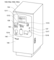
図2は、本発明の一実施形態に係る駐車料金精算機100の斜視図である。ここで、駐車料金精算機100は、駐車券発行機100a、出口精算機100c及び事前精算機100bの総称である。
FIG. 2 is a perspective view of the parking
駐車料金精算機100は、直方体状のものであり、利用者と面する側の上部全体に前面パネル1311を備えている。この前面パネル1311には、中央上部にタッチパネル式表示器(操作部)134と、中央中部に駐車券またはカード用の券挿入/取出口1312と、中央下部に紙幣挿入/払出シャッター部1314と、左横下部にQRコードリーダ(QRコードは登録商標)182と、右横下部に釣銭/領収証取出口1318とがそれぞれ配置されている。
The parking
前面パネル1311には、左横中部に非接触ICカードリーダ136と、右横中部に硬貨投入口1315、精算取消し釦137および係員呼出釦1317とがさらに備えられている。タッチパネル式表示器134は、釦、テンキーなどが操作部として代わりに用いられてよい。
The
タッチパネル式表示器134は、利用日時、駐車場名、駐車料金、操作方法の説明等を表示する画面を有する。タッチパネル式表示器134は、利用者に、精算、領収証発行、個別ロック式(フラップ式)の駐車場の場合は、駐車スペース番号などを入力するための各種選択キーを表示する。
The
QRコードリーダ182は、例えば、レーザースキャナを内蔵した光学的読取装置である。QRコードリーダ182は、前面パネル1311上の透明カバーに覆われた内部から外部に向けてレーザ光をスキャンすることで、上記透明カバーに翳したレシート等に印刷されたコードを読み取る。なお、利用者の保持するスマートフォン等の携帯端末の画面に出力された画像に含まれるコードの読み取りも可能である。
The
駐車料金精算機100は、通常の紙幣・硬貨での支払いに加えて、様々な種類の電子マネー決済に対応可能な、非接触ICカードリーダ136を備えている。この非接触ICカードリーダ136は、電子マネー機能を有する非接触ICカード、例えば、交通系電子マネー、流通系電子マネー、当該駐車場機関が発行する独自のICカード等の読取りができるマルチタイプのICカードリーダである。なお、非接触ICチップを用いた媒体はカードの形態に限らず、非接触ICタグ、非接触ICチップ搭載型スマートフォン等もあり、本願ではこれら様々な媒体用の非接触リーダを総称して非接触ICカードリーダとしている。さらに、前述のコード読み取り可能なQRコードリーダ182も、非接触リーダの一種である。
The parking
これら多数の精算方法を備えた駐車料金精算機100では、利用者が精算処理の操作方法等を理解するために、タッチパネル式表示器134で操作方法をアニメーション等で表示して案内することがあるが、さらに音声出力部140から音声を出力し、利用者の操作をガイドする機能を有している。そのための音声出力部140は、前面パネル1311の下方で前扉145に複数開口した開口孔(スピーカ孔146)の内部に後述するスピーカ141を備えて、開口孔(スピーカ孔146)より音声を出力するようになっている。
In the parking
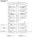
図3は、図2の駐車料金精算機のハードウェア構成を示したブロック図である。 FIG. 3 is a block diagram showing the hardware configuration of the parking fee adjustment machine of FIG. 2.
駐車料金精算機100は、制御装置としてのCPU(Central Processing Unit)110と、メモリ120と、これらとバス125を介して接続されるインターフェイス部130とを有する。メモリ120は、ROM(Read Only Memory)、RAM(Random Access Memory)、フラッシュメモリ等から構成され、CPU110の後述する各種機能を実行するためのプログラムや種々の駐車データ等が記憶される。
The parking
インターフェイス部130には、タッチパネル式表示器134、カードリーダ/ライタ135、非接触ICカードリーダ136、精算取消し釦137、領収証プリンタ131、コインセレクタ132、紙幣・硬貨払出装置133、紙幣リーダ138、音声出力部140、通信部160、I/O信号端子171、および、車両センサ(車両検出部)172がさらに接続されている。
The
また、音声出力部140には、スピーカ141とアンプ回路(不図示)やアンプ電源の切換回路等(不図示)も含まれる。ただし、音声合成等の音源データはメモリ120に記憶されている。
The
また、駐車料金精算機100が、事前精算機100bである場合には、上記の、I/O信号端子171、車両センサ(車両検出部)172に替えて、人感センサ181と、QRコードリーダ182と、インターホン(係員呼出釦)183が接続されている。
In addition, when the parking
これらインターフェイス部130に接続された各要素は、CPU110により制御され、例えばタッチパネル式表示器134による画面表示や音声出力部140による音声ガイドに基づいて、利用者は円滑に操作を行うことができる。インターホン183を利用することで、オペレータと会話することも可能である。
Each of the elements connected to the
カードリーダ/ライタ135は、駐車券の磁気ストライプに所定の情報(入場日時、割引情報、車両番号、識別番号など)を書き込み、かつ、駐車券にこの所定の情報を印字する。そして、カードリーダ/ライタ135は、券挿入/取出口1312に挿入された駐車券の所定の情報を、磁気ストライプから読み込み、入場時刻および割引情報に基づいて、駐車料金を精算する。
The card reader/
コインセレクタ132は、硬貨投入口に投入された硬貨を選別、計数する。紙幣リーダ138は、紙幣挿入/払出シャッター部に投入された紙幣を選別、計数する。紙幣・硬貨払出装置133は、精算により釣銭等を計数し、紙幣挿入/払出部シャッター1314あるいは釣銭/領収証取出口1318に払い出す。領収証プリンタ131は、レシート紙に精算額、入場日時等をプリントして領収証として発行する。
The
通信部160は、LAN(Local Area Network)/インターネットを介して、駐車場管理装置(図示しない)等の他の装置と通信するためのNIC(Network Interface Card)であり、モデム、ルータ、その他の通信機器を組み合わせてもよい。また、LAN回線は有線でも無線でもよい。
The
車両センサ172は、ゲート開閉機(図1参照)の入出場ゲート前後に埋設されたループコイルに接続されている。車両センサ172は、ループコイルと協働して車両検出センサとして機能し、車両の入出場があるか否かを検出する。ループコイルは、入場レーン側(第1のループコイル)および出場レーン側(第2のループコイル)の一組のコイルで構成される。なお、車両センサ172として、例えば赤外線を利用した光学式センサが代わりに用いられてもよい。
The
I/O信号端子171は、ゲート開閉機に接続され、入出場ゲートの開閉動作に必要な入出力信号線の接続端子である。入場レーンまたは出場レーンに設けられたカメラにより撮影された画像を取得する画像取得部があってもよい。
The I/
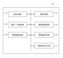
図4は、本発明の一実施形態に係るCPU110の制御機能ブロック図である。CPU110は、料金計算部111、精算処理部112、車両/人体検知部113、精算情報送信部114、環境情報受信部115、環境情報分析部116、および特殊音生成出力部117を備えている。これらの機能部は、メモリ120に保存されたプログラムを、CPU110が実行することにより実現される。
FIG. 4 is a control function block diagram of the
料金計算部111、精算処理部112は、後述するように、当該駐車料金精算機100が設置される駐車場1の精算に必要な処理を実行する。
The
車両/人体検知部113は、後述するように、精算動作の開始と終了を検出する。なお、出口精算機100cにおいては車両検知部となり、事前精算機100bにおいては人体検知部となる。
The vehicle/human
精算情報送信部114は、精算処理部112による精算に必要な処理の完了に際して駐車場管理装置等に、精算に必要な処理の結果として出力される情報である精算情報を送信する。 The payment information transmitting unit 114 transmits payment information, which is information output as a result of the processing necessary for payment, to the parking lot management device or the like when the payment processing unit 112 completes the processing necessary for payment.
環境情報受信部115、環境情報分析部116、特殊音生成出力部117の機能の詳細は後述する。
Details of the functions of the environmental
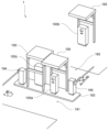
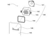
図5は、本発明の一実施形態に係る音声出力部140を構成する内部部品の取り付け構造を示す。
FIG. 5 shows a mounting structure of internal parts constituting the
同図に示すように、音声出力部140は、前扉145とスピーカユニット148とを有する。
As shown in the figure, the
前扉145は、駐車料金精算機100の筐体の一部であり、防犯性も鑑みて鉄板で構成されている。前扉145には鉄板の板厚のほぼ同等の幅のスリット状のスピーカ孔146(外部開口部)が複数開口している。スピーカ孔146の各々は、鉛直方向を長手方向としたスリット(長孔)である。複数のスピーカ孔146は、水平方向に並列に設置されている。また、スピーカ孔146はその開口範囲の両端のスリット部が最も縦に長く、中央に行くにしたがって徐々に長さが短くなる。ただし、これらの複数のスリット状のスピーカ孔146の下端部は同一高さに揃っている。結果的には複数のスリット状のスピーカ孔146は、前扉145を正面から見て概ね凹状となるよう開口している。
The
スピーカユニット148は、スピーカ141、スピーカカバー142、スピーカ開口孔143及びパッキン144を有する。
The
パッキン144は、前扉145の裏面側に当接している。パッキン144は矩形の中空形状であり、可撓性のある材質で形成され、裏面側に両面テープが貼られていて、スピーカカバー142に貼り付けられている。スピーカカバー142は樹脂製で裏側が開口した空間となって前面に多数のスピーカ開口孔143を有する。スピーカカバー142の両脇には取付部が張り出している。前扉145の裏面側にも図示しない取付部が突出している。スピーカカバー142の取付部と前扉145裏側の取付部が、スピーカカバー142と前扉145の間にパッキン144を挟んだ状態で勘合され、勘合された状態でスピーカカバー142の裏側から図示しない取付ネジによりナット締めされる。
The packing 144 is in contact with the back side of the
スピーカ141はスピーカカバー142の裏側より、スピーカカバー142内部に挿入され、図示しない取付ネジによりネジ止めされている。これらを取り付けた状態では、パッキン144は前扉145の裏面とスピーカカバー142の前面に挟まれて取付前の厚みよりも若干潰されながら取付られる。
The
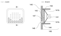
図6は、本発明の一実施形態に係る駐車料金精算機100の音声出力部140の内部部品の取り付け詳細図である。図6(1)正面図には、前扉145の正面より見てスピーカ孔146の位置と、パッキン144の位置と、スピーカ開口孔143の位置の関係を示している。図6(2)は正面図において矢印で示した箇所の断面図である。
FIG. 6 is a detailed diagram showing the installation of internal components of the
図のように、スピーカカバー142の内部のスピーカ141のコーン(振動板の一例)の位置に対応した領域に複数のスピーカ開口孔143(内部開口孔)が位置する。スピーカ孔146(外部開口部)と複数のスピーカ開口孔143(内部開口孔)は、空間部147を隔てて正面視にて互いに重ならないように配置されている。本実施形態では、正面視にて、スピーカ孔146が、スピーカ開口孔143の開けられている領域、すなわちコーンの位置に対応した領域よりも下側に配置されている。
As shown in the figure, a plurality of speaker apertures 143 (internal apertures) are located inside the
スピーカ孔146(外部開口部)は複数の長さが異なる鉛直な長孔を並設するよう形成されている。スピーカ孔146(外部開口部)は、スピーカ開口孔143(内部開口孔)の開口部領域の外側に配置されている。スピーカ孔146(外部開口部)の各長孔の下端部は同一高さ位置に形成されて、当該高さ位置に空間部147の底部(樋部)となるように、パッキン144が位置している。すなわち、空間部147の鉛直方向の底部と、スピーカ孔136の各スリットの下端部は、面一(つらいち)である。
The speaker hole 146 (external opening) is formed such that a plurality of vertical elongated holes having different lengths are arranged in parallel. The speaker hole 146 (external opening) is arranged outside the opening area of the speaker opening 143 (internal opening). The lower end of each slot of the speaker hole 146 (external opening) is formed at the same height position, and the packing 144 is located at the height position to form the bottom (gutter part) of the
このような構成の音声出力部140(音声案内装置の一例)によれば、雨水等が装置に降りかかって、スピーカ孔146(外部開口部)から浸水しても、空間部147の底部(樋部)と長孔の下端部が同一高さゆえに、直ぐに外部に排水され、内部に雨水が溜まることがない。また、スピーカ孔146(外部開口部)が複数の長さの異なる長孔で形成されているゆえに、スピーカ孔146(外部開口部)に水の表面張力のために水膜が張ったとしても、いずれかの長さの異なるスピーカ孔146(外部開口部)には水の表面張力とのバランスが異なるために、水膜が全てのスピーカ孔146(外部開口部)に張ることはなく、水膜が張ったことにより音声出力が阻害されて利用者が聴き取り難くなることがない。また、スピーカ孔146(外部開口部)と前記複数のスピーカ開口孔143(内部開口孔)が空間部147を隔てて正面視にて互いに重ならないように配置されているゆえに、雨水等がスピーカ開口孔143(内部開口孔)に直接降り込むこともない。
According to the audio output unit 140 (an example of an audio guidance device) having such a configuration, even if rainwater or the like falls on the device and floods from the speaker hole 146 (external opening), the bottom of the space 147 (gutter) Because the lower end of the elongated hole and the lower end of the long hole are at the same height, water drains to the outside immediately and rainwater does not accumulate inside. Furthermore, since the speaker hole 146 (external opening) is formed of a plurality of elongated holes with different lengths, even if a water film forms over the speaker hole 146 (external opening) due to the surface tension of water, Because the balance with the surface tension of water is different between speaker holes 146 (external openings) that have different lengths, a water film does not extend over all the speaker holes 146 (external openings), and the water film This prevents the user from having difficulty listening due to the sound output being obstructed by the tension. Furthermore, since the speaker hole 146 (external opening) and the plurality of speaker opening holes 143 (internal openings) are arranged with the
なお、スピーカ開口孔143(内部開口孔)には、別途水の侵入を防止しつつ、スピーカ141の音声出力を阻害しにくい、防水膜状のシートによって保護してもよい。または、スピーカ141のコーン部が防水性の材質や処理を施してあってもよい。ただし、防水膜状のシートでは音声出力が籠ってしまい、利用者にとって聴き難いこともあり、防水膜状シートは設けずに、図示しないスピーカ内部の水抜孔が下方に開口していてもよいが、後述する害虫等の侵入を防止する目的で、スピーカ開口孔143(内部開口孔)には粗い目のシートで保護されるのが良い。
Note that the speaker opening hole 143 (internal opening hole) may be protected by a waterproof membrane-like sheet that prevents water from entering and does not easily interfere with the audio output of the
このように、本実施形態の構造的特徴により、雨水の侵入による音声案内出力の性能の低下は防止できるが、一方で、特に鉛直で長さの長いスリット状のスピーカ孔146からは、季節や周辺環境によっては害虫が侵入してくる可能性が考えられる。害虫が内部に侵入してしまい、死骸となって堆積等してしまうと、音声案内出力の性能に影響しかねない。そこで、本実施形態ではさらに害虫等を排除する工夫を講じている。
As described above, the structural features of this embodiment can prevent the performance of the audio guidance output from deteriorating due to the intrusion of rainwater, but on the other hand, especially from the vertical and long slit-shaped
すなわち、本実施形態においては、通常の音声案内出力動作以外のタイミングで、音声出力部140より特殊音を出力する。
That is, in this embodiment, the special sound is output from the
このようにした音声出力装置140(音声案内装置の一例)によれば、特殊音の効果によって、害虫等が外部開口部の内部に侵入し難くなり、空間部147に害虫等やその死骸が堆積して音声の流通が阻害されて聴き取り難くなることを防止できる。
According to the voice output device 140 (an example of a voice guidance device), the effect of the special sound makes it difficult for pests etc. to invade the inside of the external opening, and pests etc. and their carcasses accumulate in the
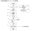
図7は、本発明の一実施形態に係る駐車料金精算機100のフロー図である。この例は駐車料金精算機100が出口精算機100cである場合の例を示している。
FIG. 7 is a flow diagram of the parking
図7において、駐車料金精算機100のCPU110は、ステップS1で第1ループを監視し、ONとなればステップS2に移行して、もし特殊音がすでに出力されていれば停止し、ステップS3で料金計算・精算処理を実行した後、ステップS4で出口ゲート開閉機195にゲート開の信号を出力する。続いてCPU110は、ステップS5で第2ループを監視して、車両が出場レーン192を通過したことを検知したらステップS6に移行して出口ゲート開閉機195にゲート閉の信号を出力し、ステップS7で駐車データ(駐車券番号・駐車時間・精算料金・出場時刻等)を駐車場管理装置に送信し、同時に出場した車両の駐車データを在車から出場済みに更新し、処理を終える。
In FIG. 7, the
CPU110は、ステップS1で、第1ループを監視しながら、車両が検出されずにOFFの際には、ステップS8に移行して、環境情報を受信して、情報に変化があった場合はその情報の内容を分析し、特に変化なければNOとなってステップS1に戻るが、変化があった場合はステップS9に移行して特殊音を生成して出力する。
In step S1, while monitoring the first loop, the
例えば、環境情報受信部115が、環境情報として外部のウェブサイトの天気の情報を受信して、環境情報分析部116がその情報が一定以上の降雨の情報であると判断した場合、特殊音生成出力部117は、雨水がスピーカ孔146から侵入する可能性を考慮して、極力水膜がスピーカ孔146に付着することがない様に、特許文献1のようなBEEP音を生成して出力する。このBEEP音は人の可聴領域の信号であるが、出力されるのは、出口精算機100cの近傍に車両が無い状態に限定されているので、利用者の音声案内を阻害することはない。
For example, if the environmental
要するに、本発明の技術を採用した駐車場精算機100においては、精算動作の開始から終了までは精算動作に係る音声案内出力動作をおこない、精算動作以外のタイミングで、前記特殊音を出力する。そのため、特殊音によって利用者が不快に感じることがない。なお、本発明の実施例における精算動作とは、利用者からの操作を受け付け可能な状態と利用者に案内出力している状態のことを意味し、駐車券発行機であれば車両の入場の際の駐車券発行案内開始から車両の通過完了の検知までの動作である。
In short, in the parking
上記の環境情報と分析による特殊音の生成はこれに限らない。例えば、季節は外部からでも内部時計からでも判断され、蚊などの害虫が多く発生する季節や時間帯では、特に天候の変化によらずとも、特殊音を生成して出力してもよい。 The generation of special sounds based on the above environmental information and analysis is not limited to this. For example, the season can be determined both from the outside and from the internal clock, and in seasons and times when pests such as mosquitoes occur in large numbers, a special sound may be generated and output, regardless of changes in the weather.
この際の特殊音は、一定の高周波音か、ヒトの可聴領域の上限付近からさらに高い周波数を含む、周波数スイープ音か、若しくは、超低周波のハム音が、定期的に切換わるとよい。 The special sound at this time may be a constant high-frequency sound, a frequency sweep sound including higher frequencies from near the upper limit of the human audible range, or an extremely low-frequency hum sound, which are periodically switched.
これは、蚊に効果のあるとされるアンチモスキート音や、他の害虫に効果のあるとされる複数の周波数を含んだスイープ音や、主に振動として空間内に伝搬するハム音によって、様々な害虫類が排除できる可能性があるからである。 This includes anti-mosquito sounds that are said to be effective against mosquitoes, sweep sounds that include multiple frequencies that are said to be effective against other pests, and hum sounds that mainly propagate within the space as vibrations. This is because there is a possibility that harmful pests can be eliminated.
一説によると蚊は基本的に6kHz(キロヘルツ)から9kHzと、16kHzから18kHzの音を嫌うといわれており、この周波数の音声信号をCPU110で生成して特殊音声として出力すればよい。予めこのような信号データを記録しておき、状況に応じて選択して出力してもよい。また、ネズミなども15kHzから17kHzの音を嫌うとも、20kHzから26kHzまでを嫌うとの説もある。このように、害虫の種類によっては、効果のある周波数帯が異なる。
According to one theory, it is said that mosquitoes basically dislike sounds from 6 kHz (kilohertz) to 9 kHz and from 16 kHz to 18 kHz, and the
また、害虫として内部に侵入するとたまに電気的ショートなどの事故の原因となるゴキブリを対策するために、音声信号として低周波のハム音を生成して筐体内部に振動として伝搬させる方法も効果が期待できる。また、ハム音の出力のタイミングを変える(間欠的に出力する)ことで、ゴキブリに周囲の状況の変化として逃避行動を誘発させ、空間内部に留まることを防止することも期待できる。 In addition, in order to prevent cockroaches, which sometimes cause accidents such as electrical shorts when they invade the interior as pests, it is also effective to generate a low-frequency hum sound as an audio signal and propagate it as vibration inside the housing. You can expect it. In addition, by changing the timing of the output of the hum sound (outputting it intermittently), it is expected that the change in the surrounding situation will induce cockroaches to escape and prevent them from staying inside the space.
このようなハム音は、引用文献1と同様に、スピーカ141のコーンの振動による空気の振動であるため、ハム音を特殊音として出力する本実施形態によれば、雨水が水膜となってスピーカ孔146やスピーカ開口孔143を含む各開口部に付着することを解消することができる。
Similar to cited
本実施形態の変形として、環境情報受信部115が、数ミリ程度の雨・激しい雨・ゲリラ豪雨・台風・降雪等の天候にかかわる情報を受信し、環境情報分析部116が受信した情報を分析し、特殊音生成出力部117が生成する特殊音の種類と出力タイミングを決定するように構成してもよい。典型的には、環境情報受信部115が前述の天候の種類の情報を天候の情報のウェブサイトから受信し、環境情報分析部116が受信した情報の中からテキストを読み込んで天候の種類を特定し、時間帯を特定する。この変形構成によれば、天候から予想される水膜が張る頻度に応じた頻度で前述の水膜防止用のBEEP音を出力することなどができるようになり、特殊音の出力の効果を高めることができる。
As a modification of this embodiment, the environmental
なお、予報の情報を読み込んで、特殊音生成出力部117が、予め環境情報に基づいて、特殊音の種類と出力予定時刻を決定していてもよい。実際に降雨や降雪が生じてからよりも、事前に特殊音を出力開始しておいたほうが効果は高い。この変形構成によれば、天候の変化より前にBEEP音等を出力することができるようになり、特殊音の出力の効果を高めることができる。さらに、出力の停止や程度を弱める方向の変更には、現在の降雨量・降雪量といった数値の情報の更新を確認してから、変更を実行するのがよい。この変形構成によれば、予報に基づいて特殊音の出力の効果を高めた後、実際の降雨量など天候の変化に即してBEEP音を出力することなどができるようになり、特殊音の出力の効果を高めることができるようになる。
Note that the special sound generation/
本発明の実施例において、音声案内装置を搭載した駐車場の機器として、駐車料金精算機100を例示したが、駐車券発行機や、定期券読み取り機、ICカード読み取り機、といった他の形態の装置であっても、屋外や半屋外に設置され、且つ、利用者に音声案内をする機能有する機器においては、本発明の技術が採用され得る。
In the embodiment of the present invention, the parking
以上説明した本発明に係る特徴部分のうち、少なくとも2つの特徴部分を組み合わせることも可能である。すなわち各実施形態で説明した種々の特徴部分は、各実施形態の区別なく、任意に組み合わされてもよい。また上記で記載した種々の効果は、あくまで例示であって限定されるものではなく、また他の効果が発揮されてもよい。 It is also possible to combine at least two of the characteristic parts according to the present invention described above. That is, the various characteristic portions described in each embodiment may be arbitrarily combined without distinction between each embodiment. Further, the various effects described above are merely examples and are not limited, and other effects may also be exhibited.
また、本発明は、請求の範囲及び明細書全体から読み取ることのできる発明の要旨又は思想に反しない範囲で適宜変更可能であり、そのような変更を伴う業務管理システムもまた本発明の技術思想に含まれる。 Furthermore, the present invention can be modified as appropriate within the scope or spirit of the invention that can be read from the claims and the specification as a whole, and a business management system that involves such modifications may also be modified without departing from the technical spirit of the present invention. include.
本発明は、屋外または半屋外に設置されて音声案内動作を含む動作をおこなう機器において、活用され得るもので、特に駐車場の料金精算機等において好適に利用することができる。 INDUSTRIAL APPLICABILITY The present invention can be used in equipment that is installed outdoors or semi-outdoors and performs operations including voice guidance operations, and is particularly suitable for use in parking lot fare adjustment machines and the like.
100…駐車料金精算機(出口精算機・事前精算機)
140…音声出力装置(音声案内装置)
141…スピーカ
142…スピーカカバー
143…スピーカ開口孔(内部開口孔)
144…パッキン
145…前扉
146…スピーカ孔(外部開口部)
147…空間部
148…スピーカユニット
110…CPU
115…環境情報受信部
116…環境情報分析部
117…特殊音生成出力部
100...Parking fee payment machine (exit payment machine/advance payment machine)
140...Audio output device (voice guidance device)
141...
144...Packing 145...
147...
115...Environmental information receiving section 116...Environmental
Claims (4)
前記筐体の内部に設けられ、振動板を有するスピーカを含むスピーカユニットと
を具備し、
前記筐体は、前記スピーカから出力された音声を当該筐体の外部へ出力する外部開口部を有し、
前記スピーカユニットは、前記スピーカの振動板の位置に対応した位置に複数の内部開口孔を有し、
前記外部開口部と前記複数の内部開口孔とは、空間部を隔てて前記筐体の正面視にて互いに重ならないように配置され、
前記外部開口部は、前記筐体の正面視において、鉛直方向を長手方向とし長さが異なる複数の長孔が並設されることで構成され、前記正面視にて、前記内部開口孔よりも下側に配置され、
前記外部開口部の複数の長孔の下端部は全て同一高さ位置に形成され、当該高さ位置は前記空間部の底面と面一である
音声案内装置。 A casing and
a speaker unit provided inside the housing and including a speaker having a diaphragm;
The housing has an external opening that outputs the audio output from the speaker to the outside of the housing,
The speaker unit has a plurality of internal opening holes at positions corresponding to the positions of the diaphragm of the speaker,
The external opening and the plurality of internal openings are arranged so as not to overlap each other when viewed from the front of the casing, with a space between them;
When viewed from the front of the housing, the external opening is configured by a plurality of elongated holes having different lengths in the vertical direction and arranged in parallel, and when viewed from the front, the external opening is longer than the internal opening. placed at the bottom,
The lower ends of the plurality of elongated holes of the external opening are all formed at the same height position, and the height position is flush with the bottom surface of the space.
音声案内出力部を有し、
前記音声案内出力部は、音声案内を出力する動作のタイミングではないタイミングで特殊音を出力する
音声案内装置。 The voice guidance device according to claim 1,
It has a voice guidance output section,
The audio guidance output unit outputs a special sound at a timing that is not the timing of an operation to output audio guidance.
前記特殊音は、周波数スイープ音と、超低周波のハム音とを含み、
前記音声案内出力部は、前記特殊音を出力するタイミングで、前記周波数スイープ音と前記ハム音とを定期的に切り換えて出力する
音声案内装置。 The voice guidance device according to claim 2,
The special sound includes a frequency sweep sound and an extremely low frequency hum sound,
The audio guidance output unit periodically switches and outputs the frequency sweep sound and the hum sound at the timing of outputting the special sound.
前記音声案内装置に、
精算動作の開始から終了までは精算動作に係る音声案内出力動作をさせ、
精算動作以外のタイミングで、前記特殊音を出力させる
駐車料金精算機。 Equipped with the audio guidance device according to claim 2 or 3,
The voice guidance device,
From the start to the end of the payment operation, the audio guidance output operation related to the payment operation is performed,
A parking fee payment machine that outputs the special sound at a timing other than the payment operation.
Priority Applications (2)
| Application Number | Priority Date | Filing Date | Title |
|---|---|---|---|
| JP2020085617A JP7431663B2 (en) | 2020-05-15 | 2020-05-15 | Voice guidance device and parking fee payment machine |
| JP2024014803A JP7606638B2 (en) | 2020-05-15 | 2024-02-02 | Audio guidance device and parking lot processing device |
Applications Claiming Priority (1)
| Application Number | Priority Date | Filing Date | Title |
|---|---|---|---|
| JP2020085617A JP7431663B2 (en) | 2020-05-15 | 2020-05-15 | Voice guidance device and parking fee payment machine |
Related Child Applications (1)
| Application Number | Title | Priority Date | Filing Date |
|---|---|---|---|
| JP2024014803A Division JP7606638B2 (en) | 2020-05-15 | 2024-02-02 | Audio guidance device and parking lot processing device |
Publications (2)
| Publication Number | Publication Date |
|---|---|
| JP2021179868A JP2021179868A (en) | 2021-11-18 |
| JP7431663B2 true JP7431663B2 (en) | 2024-02-15 |
Family
ID=78511586
Family Applications (2)
| Application Number | Title | Priority Date | Filing Date |
|---|---|---|---|
| JP2020085617A Active JP7431663B2 (en) | 2020-05-15 | 2020-05-15 | Voice guidance device and parking fee payment machine |
| JP2024014803A Active JP7606638B2 (en) | 2020-05-15 | 2024-02-02 | Audio guidance device and parking lot processing device |
Family Applications After (1)
| Application Number | Title | Priority Date | Filing Date |
|---|---|---|---|
| JP2024014803A Active JP7606638B2 (en) | 2020-05-15 | 2024-02-02 | Audio guidance device and parking lot processing device |
Country Status (1)
| Country | Link |
|---|---|
| JP (2) | JP7431663B2 (en) |
Families Citing this family (1)
| Publication number | Priority date | Publication date | Assignee | Title |
|---|---|---|---|---|
| JP7802619B2 (en) * | 2022-06-28 | 2026-01-20 | 株式会社Tbグループ | display device |
Citations (2)
| Publication number | Priority date | Publication date | Assignee | Title |
|---|---|---|---|---|
| JP2014204227A (en) | 2013-04-03 | 2014-10-27 | 株式会社コロナ | Remote control device |
| JP2018011112A (en) | 2016-07-11 | 2018-01-18 | 株式会社Soken | Cover for acoustic device |
Family Cites Families (5)
| Publication number | Priority date | Publication date | Assignee | Title |
|---|---|---|---|---|
| JPS5848850Y2 (en) * | 1980-02-14 | 1983-11-08 | 株式会社富士通ゼネラル | Speaker drip-proof device |
| US4566085A (en) * | 1982-01-19 | 1986-01-21 | Wein Products, Inc. | High intensity ultrasonic generator |
| JPH09319994A (en) * | 1996-05-31 | 1997-12-12 | Matsushita Electric Ind Co Ltd | Parking lot management system |
| JP2011164128A (en) * | 2010-02-04 | 2011-08-25 | Koyo Electronics Ind Co Ltd | Repelling guide device |
| JP2011205994A (en) * | 2010-03-30 | 2011-10-20 | Panasonic Corp | Automotive audio system |
-
2020
- 2020-05-15 JP JP2020085617A patent/JP7431663B2/en active Active
-
2024
- 2024-02-02 JP JP2024014803A patent/JP7606638B2/en active Active
Patent Citations (2)
| Publication number | Priority date | Publication date | Assignee | Title |
|---|---|---|---|---|
| JP2014204227A (en) | 2013-04-03 | 2014-10-27 | 株式会社コロナ | Remote control device |
| JP2018011112A (en) | 2016-07-11 | 2018-01-18 | 株式会社Soken | Cover for acoustic device |
Also Published As
| Publication number | Publication date |
|---|---|
| JP2024032968A (en) | 2024-03-12 |
| JP7606638B2 (en) | 2024-12-25 |
| JP2021179868A (en) | 2021-11-18 |
Similar Documents
| Publication | Publication Date | Title |
|---|---|---|
| JP3526928B2 (en) | Non-contact IC card system | |
| US7660574B2 (en) | Cellular telephone device having a non-contact type integrated circuit card processing section | |
| US6157314A (en) | Parking facility access control | |
| US6744369B2 (en) | Gate entry system using short range radio communications with user terminal devices | |
| JP7606638B2 (en) | Audio guidance device and parking lot processing device | |
| US20210040772A1 (en) | Digital door lock, door lock control server, and door lock system | |
| JP2006059249A (en) | Ticket information processing system | |
| EP3961586A1 (en) | Open-type intelligent screening channel system | |
| KR102006802B1 (en) | Vehicle access control system of apartment house | |
| CN108986271A (en) | A kind of safe burglar-proof gate inhibition control device based on Internet of Things | |
| JP3526496B2 (en) | Non-contact identification device for access control | |
| JP2002279455A (en) | Automatic ticket gate | |
| JP2011175550A (en) | Ticket gate and ticket gate system | |
| RU2736697C2 (en) | Digital cash register for paying a visit to a paid institution, where individual places are not provided | |
| JPH08147533A (en) | Banknote movement monitoring system | |
| JP7401705B2 (en) | Parking fee payment machine | |
| WO2013133776A1 (en) | Device for prevention of information copying from magnetic strips of cards used in automatic teller machines | |
| JP7033760B2 (en) | Luggage storage box | |
| KR101021334B1 (en) | Mobile phone with Hi-Pass part | |
| DE60316749T2 (en) | Environmental control system, in particular for controlling access to a terrain | |
| JP4722307B2 (en) | Contactless token | |
| KR20060008140A (en) | Accessory for mobile communication terminal with RF chip, advertising method, data collection and advertising effect analysis method | |
| JPH0215156Y2 (en) | ||
| JP4594479B2 (en) | Automatic ticket gate | |
| JP3183333B2 (en) | Control monitoring equipment |
Legal Events
| Date | Code | Title | Description |
|---|---|---|---|
| A621 | Written request for application examination |
Free format text: JAPANESE INTERMEDIATE CODE: A621 Effective date: 20230417 |
|
| RD02 | Notification of acceptance of power of attorney |
Free format text: JAPANESE INTERMEDIATE CODE: A7422 Effective date: 20230417 |
|
| A131 | Notification of reasons for refusal |
Free format text: JAPANESE INTERMEDIATE CODE: A131 Effective date: 20231205 |
|
| A521 | Request for written amendment filed |
Free format text: JAPANESE INTERMEDIATE CODE: A523 Effective date: 20231205 |
|
| A977 | Report on retrieval |
Free format text: JAPANESE INTERMEDIATE CODE: A971007 Effective date: 20231206 |
|
| TRDD | Decision of grant or rejection written | ||
| A01 | Written decision to grant a patent or to grant a registration (utility model) |
Free format text: JAPANESE INTERMEDIATE CODE: A01 Effective date: 20240109 |
|
| A61 | First payment of annual fees (during grant procedure) |
Free format text: JAPANESE INTERMEDIATE CODE: A61 Effective date: 20240202 |
|
| R150 | Certificate of patent or registration of utility model |
Ref document number: 7431663 Country of ref document: JP Free format text: JAPANESE INTERMEDIATE CODE: R150 |