JP7429333B2 - EEG measurement device - Google Patents
EEG measurement device Download PDFInfo
- Publication number
- JP7429333B2 JP7429333B2 JP2023539049A JP2023539049A JP7429333B2 JP 7429333 B2 JP7429333 B2 JP 7429333B2 JP 2023539049 A JP2023539049 A JP 2023539049A JP 2023539049 A JP2023539049 A JP 2023539049A JP 7429333 B2 JP7429333 B2 JP 7429333B2
- Authority
- JP
- Japan
- Prior art keywords
- measurement
- electroencephalogram
- front part
- head
- electrode
- Prior art date
- Legal status (The legal status is an assumption and is not a legal conclusion. Google has not performed a legal analysis and makes no representation as to the accuracy of the status listed.)
- Active
Links
- 238000005259 measurement Methods 0.000 title claims description 149
- 210000003128 head Anatomy 0.000 claims description 42
- 238000012545 processing Methods 0.000 claims description 36
- 210000001061 forehead Anatomy 0.000 claims description 24
- 238000000034 method Methods 0.000 claims description 10
- 230000008569 process Effects 0.000 claims description 8
- 238000004891 communication Methods 0.000 description 32
- 239000000463 material Substances 0.000 description 27
- 238000013480 data collection Methods 0.000 description 26
- 238000003860 storage Methods 0.000 description 16
- 238000010586 diagram Methods 0.000 description 14
- 210000004556 brain Anatomy 0.000 description 13
- 238000012360 testing method Methods 0.000 description 10
- 238000010998 test method Methods 0.000 description 6
- -1 polybutylene terephthalate Polymers 0.000 description 5
- 239000011347 resin Substances 0.000 description 5
- 229920005989 resin Polymers 0.000 description 5
- HBBGRARXTFLTSG-UHFFFAOYSA-N Lithium ion Chemical compound [Li+] HBBGRARXTFLTSG-UHFFFAOYSA-N 0.000 description 4
- 239000004743 Polypropylene Substances 0.000 description 4
- 229910001416 lithium ion Inorganic materials 0.000 description 4
- 229920001707 polybutylene terephthalate Polymers 0.000 description 4
- 229920001155 polypropylene Polymers 0.000 description 4
- 230000002123 temporal effect Effects 0.000 description 4
- 230000008859 change Effects 0.000 description 3
- 238000006243 chemical reaction Methods 0.000 description 3
- 239000004020 conductor Substances 0.000 description 3
- WABPQHHGFIMREM-UHFFFAOYSA-N lead(0) Chemical compound [Pb] WABPQHHGFIMREM-UHFFFAOYSA-N 0.000 description 3
- 229920003355 Novatec® Polymers 0.000 description 2
- 230000003321 amplification Effects 0.000 description 2
- 238000004458 analytical method Methods 0.000 description 2
- 210000005069 ears Anatomy 0.000 description 2
- 230000006870 function Effects 0.000 description 2
- VZCCETWTMQHEPK-QNEBEIHSSA-N gamma-linolenic acid Chemical compound CCCCC\C=C/C\C=C/C\C=C/CCCCC(O)=O VZCCETWTMQHEPK-QNEBEIHSSA-N 0.000 description 2
- RLAWWYSOJDYHDC-BZSNNMDCSA-N lisinopril Chemical compound C([C@H](N[C@@H](CCCCN)C(=O)N1[C@@H](CCC1)C(O)=O)C(O)=O)CC1=CC=CC=C1 RLAWWYSOJDYHDC-BZSNNMDCSA-N 0.000 description 2
- 238000003199 nucleic acid amplification method Methods 0.000 description 2
- 229920001296 polysiloxane Polymers 0.000 description 2
- 230000004044 response Effects 0.000 description 2
- 239000007779 soft material Substances 0.000 description 2
- 229920006346 thermoplastic polyester elastomer Polymers 0.000 description 2
- JOYRKODLDBILNP-UHFFFAOYSA-N Ethyl urethane Chemical compound CCOC(N)=O JOYRKODLDBILNP-UHFFFAOYSA-N 0.000 description 1
- 229910021607 Silver chloride Inorganic materials 0.000 description 1
- 230000004308 accommodation Effects 0.000 description 1
- GTKRFUAGOKINCA-UHFFFAOYSA-M chlorosilver;silver Chemical compound [Ag].[Ag]Cl GTKRFUAGOKINCA-UHFFFAOYSA-M 0.000 description 1
- 229920001971 elastomer Polymers 0.000 description 1
- 239000007772 electrode material Substances 0.000 description 1
- 238000005401 electroluminescence Methods 0.000 description 1
- 230000010365 information processing Effects 0.000 description 1
- 239000011810 insulating material Substances 0.000 description 1
- 239000012212 insulator Substances 0.000 description 1
- 239000004973 liquid crystal related substance Substances 0.000 description 1
- 238000004519 manufacturing process Methods 0.000 description 1
- 229910052751 metal Inorganic materials 0.000 description 1
- 239000002184 metal Substances 0.000 description 1
- 229940028444 muse Drugs 0.000 description 1
- 238000011056 performance test Methods 0.000 description 1
- 230000000704 physical effect Effects 0.000 description 1
- 239000002504 physiological saline solution Substances 0.000 description 1
- 239000004033 plastic Substances 0.000 description 1
- 229920003023 plastic Polymers 0.000 description 1
- 238000003825 pressing Methods 0.000 description 1
- GMVPRGQOIOIIMI-DWKJAMRDSA-N prostaglandin E1 Chemical compound CCCCC[C@H](O)\C=C\[C@H]1[C@H](O)CC(=O)[C@@H]1CCCCCCC(O)=O GMVPRGQOIOIIMI-DWKJAMRDSA-N 0.000 description 1
- 230000003014 reinforcing effect Effects 0.000 description 1
- 238000011160 research Methods 0.000 description 1
- 239000005060 rubber Substances 0.000 description 1
- 238000010079 rubber tapping Methods 0.000 description 1
- 229910052709 silver Inorganic materials 0.000 description 1
- 239000004332 silver Substances 0.000 description 1
- HKZLPVFGJNLROG-UHFFFAOYSA-M silver monochloride Chemical compound [Cl-].[Ag+] HKZLPVFGJNLROG-UHFFFAOYSA-M 0.000 description 1
- 239000007787 solid Substances 0.000 description 1
- 229910001220 stainless steel Inorganic materials 0.000 description 1
- 239000010935 stainless steel Substances 0.000 description 1
- 238000009864 tensile test Methods 0.000 description 1
- 230000009466 transformation Effects 0.000 description 1
Images


Classifications
-
- A—HUMAN NECESSITIES
- A61—MEDICAL OR VETERINARY SCIENCE; HYGIENE
- A61B—DIAGNOSIS; SURGERY; IDENTIFICATION
- A61B5/00—Measuring for diagnostic purposes; Identification of persons
- A61B5/24—Detecting, measuring or recording bioelectric or biomagnetic signals of the body or parts thereof
- A61B5/25—Bioelectric electrodes therefor
- A61B5/251—Means for maintaining electrode contact with the body
- A61B5/256—Wearable electrodes, e.g. having straps or bands
-
- A—HUMAN NECESSITIES
- A61—MEDICAL OR VETERINARY SCIENCE; HYGIENE
- A61B—DIAGNOSIS; SURGERY; IDENTIFICATION
- A61B5/00—Measuring for diagnostic purposes; Identification of persons
- A61B5/24—Detecting, measuring or recording bioelectric or biomagnetic signals of the body or parts thereof
- A61B5/25—Bioelectric electrodes therefor
- A61B5/279—Bioelectric electrodes therefor specially adapted for particular uses
- A61B5/291—Bioelectric electrodes therefor specially adapted for particular uses for electroencephalography [EEG]
-
- A—HUMAN NECESSITIES
- A61—MEDICAL OR VETERINARY SCIENCE; HYGIENE
- A61B—DIAGNOSIS; SURGERY; IDENTIFICATION
- A61B5/00—Measuring for diagnostic purposes; Identification of persons
- A61B5/24—Detecting, measuring or recording bioelectric or biomagnetic signals of the body or parts thereof
- A61B5/316—Modalities, i.e. specific diagnostic methods
- A61B5/369—Electroencephalography [EEG]
Description
本発明は脳波計測装置に関し、より詳細には、生体頭部に装着された状態で脳波を測定することができる脳波計測装置に関する。 The present invention relates to an electroencephalogram measurement device, and more particularly to an electroencephalogram measurement device that can measure brain waves while being attached to a living body's head.
人体等、生体の頭部に装着して脳波を測定するためのウェアラブルな脳波計測装置(ウェアラブル脳波計)としては、特許文献1(非特許文献1)、及び非特許文献2,3に記載の装置が知られている。特許文献1(非特許文献1)の脳波計測装置は前頭部側に2電極を備え、OuterバンドとInnerバンドとからなる2重バンド構造を有しているが、OuterバンドとInnerバンドとの各々は一体型の部品であり(特許文献1のFIG.16)、特許文献1(非特許文献1)の装置は装着感に問題を有する。非特許文献2の脳波計測装置は前頭部側に2電極を備えるヘアバンド型の装置であるが、当該装置はソフトな素材を用いたヘアバンド型であるために耐久性に問題を有し、また非特許文献2の装置においては断線等の故障のリスクが高いと考えられる。非特許文献3の脳波計測装置は本体から多数の電極が飛び出した構造を有しているが、当該装置は左側頭部から後頭部、右側頭部に沿って装置が配置されるように生体頭部に装着される構造をとっているために前頭部側の電極が十分に固定されない恐れがあり、また非特許文献3の装置においては多数の電極からの多数の配線が本体部分から突出しているため、非特許文献3の装置は耐久性にも問題を有する。
Wearable electroencephalogram measurement devices (wearable electroencephalographs) that are attached to the head of a living body such as a human body to measure brain waves include those described in Patent Document 1 (Non-Patent Document 1) and Non-Patent
従来のウェアラブル脳波計としてはヘアバンド型などソフトな素材を用いている脳波計が主流であるが、それらは耐久性に劣り、それらにおける断線等の故障の頻度が高かった。これに対し、耐久性を上げるためにハードな素材で作製された筐体構造を有するウェアラブル脳波計が用いられる場合、人によって頭部の形状はさまざまに異なるため、全ての人の頭部に適合する脳波計を作製することは困難であり、したがって脳波計を装着することにより検査対象者(脳波測定を受ける者)が頭部に痛みを感じる場合があるという問題や、装着時に検査対象者の頭部に電極が十分に接触しない、或いは検査対象者が感じる痛みにより脳波に影響が出る等の原因により信号の質が安定しないという問題等がある。 The mainstream of conventional wearable electroencephalograms are hairband-type electroencephalograms that use soft materials, but they lack durability and frequently suffer from failures such as wire breakage. On the other hand, when a wearable electroencephalograph is used, which has a housing structure made of hard materials to increase durability, it is suitable for all people's heads because the shape of the head varies depending on the person. It is difficult to produce an electroencephalogram that can be used to measure electroencephalograms.Therefore, there are problems in that the test subject (the person receiving the electroencephalogram measurement) may feel pain in the head when wearing the electroencephalograph. There are problems in that the quality of the signal is unstable due to causes such as the electrode not making sufficient contact with the head or the pain felt by the test subject affecting the brain waves.
以上に鑑み、本発明は、計測される脳波信号の質の向上に資するべく、耐久性の向上、及び、フィット感の向上を両立しうる構造を有するウェアラブルな脳波計測装置を提供することを課題とする。 In view of the above, an object of the present invention is to provide a wearable brain wave measurement device having a structure that can improve both durability and fit in order to contribute to improving the quality of measured brain wave signals. shall be.
上記課題を解決するべく、本発明は、生体頭部に装着可能な脳波計測装置であって、中央表側部品と、左表側部品と、右表側部品と、裏側部品とを少なくとも含み、装着時に左側頭部から前頭部、右側頭部へと生体頭部に沿って配置されるよう湾曲した形状を有する収容部と、裏側部品に固定され、装着時に前頭部に接触する少なくとも1つの測定電極と、測定電極を介して得られる電気信号を処理する、収容部内に収容された信号処理部とを備え、中央表側部品と、左表側部品と、右表側部品と、裏側部品とのうち少なくとも2つの部品の剛性が互いに異なる、脳波計測装置を提供する。 In order to solve the above-mentioned problems, the present invention provides an electroencephalogram measurement device that can be attached to a living body's head, and includes at least a central front part, a left front part, a right front part, and a back part. an accommodating part having a curved shape so as to be arranged along the living body's head from the head to the forehead to the right side of the head; and at least one measurement electrode fixed to the back side component and in contact with the forehead when worn. and a signal processing section housed in the housing section that processes the electrical signal obtained through the measurement electrode, and at least two of the center front side component, the left front side component, the right front side component, and the back side component. Provided is an electroencephalogram measuring device in which two parts have different stiffnesses.
上記脳波計測装置において、測定電極の数は少なくとも2以上であってよい。 In the electroencephalogram measurement device described above, the number of measurement electrodes may be at least two or more.
上記脳波計測装置において、左表側部品及び前記右表側部品の剛性は、中央表側部品の剛性よりも高いものとしてよい。 In the electroencephalogram measurement device, the left front component and the right front component may have higher rigidity than the center front component.
上記脳波計測装置において、測定電極の数が2以上である場合、装着時に前頭部に接触する測定電極の面のそれぞれの中心は、裏側部品の形状に沿って40mm以上、90mm以下だけ互いに左右に離間していてよい。 In the above electroencephalogram measurement device, when the number of measurement electrodes is 2 or more, the centers of the surfaces of the measurement electrodes that contact the forehead when worn are separated from each other by 40 mm or more and 90 mm or less along the shape of the back side component. It is okay to be separated from each other.
上記脳波計測装置において、装着時に前頭部に接触する測定電極の面の輪郭は、直径10mm~25mmの円形状を有するものであってよい。 In the above electroencephalogram measurement device, the contour of the surface of the measurement electrode that contacts the forehead when worn may have a circular shape with a diameter of 10 mm to 25 mm.
上記脳波計測装置において、信号処理部は、左表側部品と裏側部品との間、又は右表側部品と裏側部品との間に配置されていてよい。 In the above electroencephalogram measuring device, the signal processing section may be arranged between the left front side component and the back side component, or between the right front side component and the back side component.
本発明の脳波計測装置を用いることにより、電極と信号処理部とを接続する導線の断線等のリスクが低減し、耐久性が向上するとともに、ユーザ(検査対象者)の装着感が向上し測定できる脳波の信号の質を向上させることができる。 By using the electroencephalogram measuring device of the present invention, the risk of disconnection of the conductive wire connecting the electrode and the signal processing section is reduced, durability is improved, and the user (person to be tested) feels more comfortable wearing it during measurement. Can improve the quality of brain wave signals.
以下、本発明の例示的実施形態である脳波計測装置を、図面を参照しつつ説明する。ただし本発明による脳波計測装置が以下に説明する具体的態様に限定されるわけではなく、本発明の範囲内で適宜変更可能であることに留意する。後述の実施形態に含まれる個々の機能、要素等は本発明の範囲内で適宜削除・変更可能であるし(例えば後述の図13中、信号処理部にメモリデバイスを設けて脳波計測データを当該メモリデバイスに記憶することとして通信部を設けない態様で脳波計測装置を実施してもよい)、実施形態に含まれない任意の機能、要素等を本発明の範囲内で追加することも可能である。例えば、以下の実施形態においては、収容部が中央表側部品と、左表側部品と、右表側部品と、裏側部品との4つの部品から構成されるものとして説明するが、部品の数を4以上とする等、収容部の構成部品の数は任意に変更可能である(例えば中央表側部品が2つの部品に分解されてよい)。また収容部の各構成部品の材料は絶縁体とすることが好ましいが、各電極、回路要素間の短絡(ショート)等の問題が生じない範囲において、各構成部品の少なくとも一部が金属等の導電性材料を含んで構成されていてもよい。各構成部品は、シリコン、ゴム、プラスチック、樹脂をはじめとして任意の材料から作製されてよく、任意の複数の材料から作製されていてもよいし、個々の構成部品が更に2以上の部品へと分解可能であってもよい。収容部の構成部品に限らず、脳波計測装置に関するあらゆる構成要素は、特に言及がない限り任意の材料から作製することができるし任意の数の要素に分解可能であってよい。以下の実施形態においては測定電極の数が2であるとして説明するが、測定電極の数を1としたり、3以上としたりする等、測定電極の数は1以上の任意の数に変更可能であるし、測定電極の位置も任意である。参照電極、グラウンド電極の数も任意に変更可能である(脳波計測装置が動作する限りにおいてはそれらのうち少なくとも一方を設けなくてもよい)。装着補助バンドとしては実施形態に示す態様に限らず任意のバンドを用いることが可能であるし、装着補助バンドを用いなくても脳波計測装置1を実施可能である。信号処理等を行う後述の各種機能部は、ASIC(application specific integrated circuit:特定用途向け集積回路)、組み込みシステム、マイクロコンピュータ等、任意の構成により実現可能であるし、各種機能部にCPU(Central Processing Unit:中央処理装置)、メモリデバイス等を備えることでデジタル情報処理を行ってもよい。また以下の実施形態におけるユーザとは、人間をはじめとする任意の生物であってよく、脳波計測装置全体のサイズ、各構成要素のサイズも任意である。
DETAILED DESCRIPTION OF THE PREFERRED EMBODIMENTS An electroencephalogram measuring device according to an exemplary embodiment of the present invention will be described below with reference to the drawings. However, it should be noted that the electroencephalogram measuring device according to the present invention is not limited to the specific embodiments described below, and can be modified as appropriate within the scope of the present invention. Individual functions, elements, etc. included in the embodiments described later can be deleted or changed as appropriate within the scope of the present invention (for example, in FIG. 13 described later, a memory device is provided in the signal processing section to store the electroencephalogram measurement data (The electroencephalogram measurement device may be implemented in a manner in which the communication section is not provided as it is stored in a memory device), and it is also possible to add arbitrary functions, elements, etc. that are not included in the embodiments within the scope of the present invention. be. For example, in the following embodiment, the storage section will be described as being composed of four parts: a central front part, a left front part, a right front part, and a back part. The number of component parts of the storage part can be changed arbitrarily (for example, the central front part may be disassembled into two parts). In addition, it is preferable that the material of each component of the housing part be an insulator, but at least a portion of each component is made of metal, etc., as long as problems such as short circuits between electrodes and circuit elements do not occur. The structure may include a conductive material. Each component may be made of any material including silicone, rubber, plastic, or resin, or may be made of any number of materials, or each component may be further made into two or more parts. It may be decomposable. All components related to the electroencephalogram measurement device, not only the components of the housing part, can be made of any material and can be disassembled into any number of elements unless otherwise specified. In the following embodiments, the number of measurement electrodes will be explained as two, but the number of measurement electrodes can be changed to any number greater than or equal to 1, such as 1 or 3 or more. The position of the measurement electrode is also arbitrary. The number of reference electrodes and ground electrodes can also be changed arbitrarily (at least one of them does not need to be provided as long as the electroencephalogram measurement device operates). As the attachment assistance band, any band can be used without being limited to the embodiments shown in the embodiments, and the
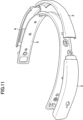
図1~図6は、本発明の一実施形態である脳波計測装置を、装着するユーザの前方斜め下から(図1)、後方斜め下から(図2)、上から(図3)、下から(図4)、右耳側から(図5)、左耳側から(図6)、それぞれ見たときの概略図であり、図7は、本発明の一実施形態である脳波計測装置をユーザの頭部に装着した態様を示す概略図である。図7に示すとおり、ユーザは左側頭部から前頭部、右側頭部へと、脳波計測装置1が自己の頭部に沿って配置されるよう脳波計測装置1を装着し、クリップ状の部材(絶縁体材料から形成されるとする)の内側に配置された参照電極8(クリップ状部材の両側の部品それぞれに参照電極8が配置されており、合計2つの参照電極8が配置されるが、以降の記載においてはまとめて参照電極8と呼ぶ。)が耳と接触するよう、クリップ状の部材で自己の耳を挟む。上述のとおり脳波計測装置1のサイズは任意であるが、一例においては高さ(図5,図6のように脳波計測装置1を見た時の短辺方向の長さ)30mm、幅(図3,図4のように脳波計測装置1を見た時の左右方向の長さであり、装着時のユーザにおける左右方向の長さ)190mm、奥行(図3,図4のように脳波計測装置1を見た時の縦方向の長さであり、装着時のユーザにおける前後方向の長さ)150mmとすることができる(突起、脚部分は除く)。
脳波計測装置1は、頭部に装着した場合、収容部が、頭部に沿って左右の耳介に向けて帯状に延在しており、収容部の左右の端部は、それぞれ左右の耳介の上部付近に位置することになる。脳波計測装置1を上方から見ると、端部付近の曲率が中央部の曲率より小さい半円形状となっており、収容部の略中央部が、法線方向の厚さが最小となっており、上下方向の幅も最小となっている。参照電極8は、収容部の長手方向の一方側の端部に設けられてもよい。
1 to 6 show an electroencephalogram measuring device according to an embodiment of the present invention from diagonally below the front of a user wearing it (FIG. 1), from diagonally below the rear (FIG. 2), from above (FIG. 3), and from below. (Fig. 4), from the right ear side (Fig. 5), and from the left ear side (Fig. 6). FIG. 2 is a schematic diagram showing a state in which the device is worn on a user's head. As shown in FIG. 7, the user wears the
When the
脳波計測装置1は、右表側部品2、中央表側部品3、左表側部品4、裏側部品5を含んで構成される、装着時に左側頭部から前頭部、右側頭部へとユーザの頭部に沿って配置されるよう湾曲した形状を有する収容部と、裏側部品5に固定され、装着時にユーザの前頭部に接触する少なくとも1つの測定電極6,7(本実施形態においては測定電極の数を2とするが、上述のとおり測定電極の数は1以上の任意の数であってよい)と、互いに左右に離間した測定電極6,7のうち少なくとも一方を介して得られる電気信号を処理する、収容部内に収容された信号処理部(後述の図13中の信号処理部25を参照)とを備える。後に詳しく説明するとおり、中央表側部品3と、左表側部品4と、右表側部品2と、裏側部品5とのうち少なくとも2つの部品の剛性は互いに異なり、一例においては、右表側部品2の剛性と左表側部品4との剛性が、中央表側部品3の剛性よりも高くなるよう(より好ましくは、右表側部品2の剛性と左表側部品4との剛性が、裏側部品5の剛性よりも高くなるよう)、各部品の材料、形状が選択される。すなわち、部品の剛性は、材料や、部品の断面形状を選択することによって、適切に設定することができる。なお、図1~図12は概略図であり、脳波計測装置1における各部の寸法等がこれら図面の例に限定されるわけではないが、一例において、中央表側部品3の周方向長さは、脳波計測装置1の周方向長さ(突起、脚部分は除く。以下同様)の約30%~約50%であってよく、左表側部品4の周方向長さは、脳波計測装置1の周方向長さの約25~約35%であってよく、右表側部品2の周方向長さは、脳波計測装置1の周方向長さの約25~約35%であってよい。左表側部品4の周方向長さと右表側部品2の周方向長さとは互いに等しくてもよいし、互いに異なっていてもよい。
The
測定電極6は、(被覆された)導線を介して信号処理部25と接続されており、測定電極7も、(被覆された)導線を介して信号処理部25と接続されている。脳波計測装置1は更に参照電極8を備え、参照電極8は、(被覆された)参照電極リード線(導線)9を介して信号処理部25に接続されている。その他、脳波計測装置1にグラウンド電極(GND電極)を設ける場合(後述の図13中、GND電極24。グラウンド電極をユーザの頭部、或いは身体の任意の位置に接触させることにより、脳波計測装置1の動作における基準電位を印加することができ、この基準電位を、その他の電極の電位の基準として用いることができる。)は、グラウンド電極が(被覆された)導線を介して信号処理部25と接続されている。なお、これらの各電極は別個に信号処理部25に接続されて電気信号を信号処理部25に入力するよう構成されており(各電極から別個に(被覆された)導線が延びて、信号処理部25の別個の端子に接続される。参照電極リード線9以外の(被覆された)導線は収容部の内部のみを通るように各(被覆された)導線を配線することにより断線リスクを低減させることができる(グラウンド電極24が頭部以外に接触する構成をとる場合等もあり、収容部内部で配線することは必須ではない)。)、各電極どうしが短絡状態にあるわけではないことに留意する。また各電極の材料は任意であるが、一例においてはステンレス、銀-塩化銀(Ag/AgCl)、又は銀を電極材料とすることができる。
The
測定電極6と測定電極7との形状は任意であるが、一例においては、装着時にユーザの前頭部に接触する面(図2参照)の輪郭が、直径10mm~25mmの円形状を有するよう形成される(3以上の測定電極を設ける場合も同様。また円形状の一部に凹部を設ける等、適宜調整してもよい)。また測定電極6と測定電極7との装着時にユーザの前頭部(額)に接触する面の形状も任意であり、例えば図3,図4に示されるとおり平面としてもよいし、凹面(装着時のユーザからみて、前頭部に接触する面が少なくとも一部凹んでいる面)としてもよいし、凸面(装着時のユーザからみて、前頭部に接触する面が少なくとも一部出っ張っている面)としてもよいが、ユーザに良好な装着感を与えるためには凸面以外の形状とすることが好ましい(3以上の測定電極を設ける場合も同様)。測定電極6と測定電極7は、ユーザの前頭部に沿うような形状にすることにより、接触する面積が大きくなり、脳波の測定精度を向上させることが可能である。参照電極8、グラウンド電極24の形状、サイズも同様であってよく任意である。また、測定電極6,7の、装着時に前頭部に接触する面(図2参照)のそれぞれの中心が、裏側部品5の形状に沿って(図3,図4の方向から脳波計測装置1を見た時に、裏側部品5の描く曲線に沿って)40mm以上、90mm以下だけ互いに左右に離間するように測定電極6,7を配置することが好ましい(3以上の測定電極を設ける場合も、同様の間隔で各測定電極を配置してよい)。測定電極6,7の間隔としては、前側頭囲(頭囲のうち両耳中心よりも前側の長さ)の20%程度とすることが好ましく(更に、測定電極6,7の、装着時に前頭部に接触する面のそれぞれの中心点の中間点が前頭部の中央、すなわちユーザの鼻すじ線(の延長線)上の位置に位置するよう、ユーザは脳波計測装置1を装着することが好ましい)、複数の人間の前側頭囲を計測した結果として、前側頭囲の20%という長さは概ね40mm~90mmの範囲内に収まると考えられるからである。例えば、測定電極6と測定電極7の位置の一例として、国際10-20法のFp1、Fp2の位置でもよい。
The shape of the
右表側部品2には操作部として電源ボタン10が設けられており、ユーザが電源ボタン10を押下することにより脳波計測装置1の動作のオン(動作状態)とオフ(停止状態)が切り換えられる。また右表側部品2には表示LED(light emitting diode:発光ダイオード)11が設けられており、動作状態や充電状態に応じて点灯、消灯、点滅や発光色が切り換えられる。右側部品2には充電ポート(充電口)12も設けられており、充電ポートの蓋13を開いて充電ポート12に充電ケーブルを接続することにより、電源部32(図13参照)のリチウムイオン電池を充電することができる。裏側部品5のうち、右表側部品2に対応する位置には(右側)滑り止めシート14が、左表側部品4に対応する位置には(左側)滑り止めシート15がそれぞれ設けられており、ユーザの頭部に装着された状態において脳波計測装置1が頭部からずれることを防止する。滑り止めシート14,15の材料は任意であるが、一例においてはウレタン、シリコン等を滑り止めシート14,15の材料として用いることができる。また裏側部品5における右表側部品2側の端部には(右側)補助バンド取り付け孔16が、裏側部品5における左表側部品4側の端部には(左側)補助バンド取り付け孔17が、それぞれ設けられており、図8に示す装着補助バンド(ベルト)19の一端と他端とを補助バンド取り付け孔16,17にそれぞれ通して装着補助バンド19を脳波計測装置1に接続することにより(図8の装着補助バンド19中、一端の面ファスナーフック部21A側に取り付けられた長方形環の形状のリング状部材20を横に向けて(両端側の面ファスナーフック部21A、面ファスナーループ部21Bは曲げ可能であるとする)当該リング状部材20を補助バンド取り付け孔16に通し、他端の面ファスナーフック部21A側のリング状部材20を横に向けて当該リング状部材20を補助バンド取り付け孔17に通して、更にそれぞれの面ファスナーフック部21Aを折り返して面ファスナーループ部21Bに付着させる)、装着時における脳波計測装置1の位置の安定性を向上させることができる。
A
図9~図12は、収容部を各構成部品に分解した時の分解図(図9~図11は斜視図。図12は装着するユーザの上から見た図)である。このように表側部品を分割構造とすることでユーザの装着感が向上する。図13に示す信号処理部25、通信部29は、一例においては回路基板上に各回路要素、素子等を配置することで構成され、左表側部品4と裏側部品5との間の空間内の回路基板収容位置22に当該回路基板が配置される(回路基板の位置は任意であり、好ましくは、左表側部品4と裏側部品5との間、又は右表側部品2と裏側部品5との間に配置される。左表側部品4の剛性と右表側部品2の剛性とを、中央表側部品3の剛性よりも高く裏側部品5の剛性よりも高くする態様においては、このような回路基板の配置をとることにより回路基板が衝撃から保護される。)。右表側部品2、中央表側部品3、左表側部品4、裏側部品5は、それらのうち少なくとも2つの部品の剛性が互いに異なるように材料、形状などを選択して作製され、特に、右表側部品2の剛性と左表側部品4の剛性とが、中央表側部品3の剛性よりも高く、また裏側部品5の剛性よりも高くなるよう各部品を作製することが好ましい。中央表側部品3及び裏側部品5のねじ止めのために補強部材を用いることができる。
9 to 12 are exploded views of the accommodating portion when it is disassembled into each component (FIGS. 9 to 11 are perspective views; FIG. 12 is a view seen from above by the user wearing the device). The split structure of the front side component improves the user's wearing comfort. In one example, the
なお、本実施形態における「剛性」とは、一定の長さの部材の場合に、材料のヤング率(縦弾性係数)、断面形状による断面二次モーメントによって定められるものである。すなわち、部品の長さが同じという前提の下では、同じ断面形状の部品同士の場合に或る部品の材料のヤング率が別の部品の材料のヤング率よりも高い場合や、同じヤング率の材料の部品同士の場合に或る部品の断面二次モーメントが別の部品の断面二次モーメントよりも大きい場合に、「或る部品の剛性が別の部品の剛性よりも高い」こととなる。ただし、本実施形態においては、断面形状に起因する断面二次モーメントより、材料に起因するヤング率の方の部品の剛性への寄与を大きくしている。すなわち、主として部品ごとの材料の適切な選択によって、部品ごとのより適切な剛性を達成するようにしている。ヤング率の測定方法としては、例えば右表側部品2を打ち抜いて面方向(収容部形成時に裏側部品5と概ね平行となる面の方向)の縦横の幅が約1.8mm、当該面方向(厳密には曲面だが近似的に平面とみなす)と垂直な方向の厚み約0.1mmのサンプルを作製してこれを試験サンプルとし、特許第6857784号明細書の段落[0118]に記載のように、島津製作所社製、島津精密万能試験機オートグラフAG-IS MS型を用いて、20℃生理食塩液中にて引張試験を実施し、応力-伸び曲線から引張弾性率としてヤング率(MPa)を算出(引張速度は100mm/分)することにより、右表側部品2のヤング率を測定できる。中央表側部品3、左表側部品4、裏側部品5等、その他の部品のヤング率も同様に測定することができる(裏側部品5のサンプルにおける「面方向」は、例えば右表側部品2のサンプルの「面方向」と概ね平行となる面の方向としてよい)。右表側部品2、中央表側部品3、左表側部品4、裏側部品5の材料は任意であり、それら部品のヤング率の数値も任意の値であってよいが、一例においては、
中央表側部品3のヤング率(引張弾性率)が49.5MPa(メガパスカル)であり(東レ・デュポン社製 材料:熱可塑性ポリエステルエラストマー ハイトレル(登録商標) グレード:4047N。試験方法はJIS K7113-1995準拠)、
右表側部品2と左表側部品4とのヤング率(引張弾性率)が、いずれも2550MPa(メガパスカル)であり(三菱エンジニアリング社製 材料:PBT樹脂(ポリブチレンテレフタレート樹脂) ノバデュラン(登録商標) グレード:5010R5。試験方法はISO 527-1, 527-2準拠)、
裏側部品のヤング率(引張弾性率)が1350MPa(メガパスカル)である(日本ポリプロ社製 材料:PP(ポリプロピレン) ノバテック(登録商標) グレード:BC4BSW。試験方法はJIS K7161 7162:1994準拠)
ように各部品を作製することができる(各材料の物性値はメーカー公表の仕様値であるため試験方法が互いに異なるが、ヤング率の大小関係は試験方法を統一しても不変である)。
断面二次モーメントについては、断面形状から公知の公式によって求めることができる。収容部の略中央部に位置する中央表側部品3の法線方向の厚さを小さくすることにより、中央表側部品3の断面形状を断面二次モーメントがより小さいものとし、剛性をより小さくすることができる。
Note that "rigidity" in this embodiment is determined by the Young's modulus (longitudinal elastic modulus) of the material and the moment of inertia of the cross-sectional shape in the case of a member of a certain length. In other words, under the assumption that the lengths of the parts are the same, if the parts have the same cross-sectional shape, the Young's modulus of the material of one part may be higher than that of the material of another part, or the Young's modulus of the material of the same part may be higher than that of the material of another part. In the case of material parts, if the moment of inertia of one part is larger than the moment of inertia of another part, it is said that "the rigidity of one part is higher than the rigidity of another part". However, in this embodiment, Young's modulus caused by the material makes a greater contribution to the rigidity of the component than the moment of inertia caused by the cross-sectional shape. That is, more appropriate rigidity for each part is achieved primarily by appropriate selection of materials for each part. To measure the Young's modulus, for example, punch out the right
The Young's modulus (tensile modulus) of the center
The Young's modulus (tensile modulus) of the right
The Young's modulus (tensile modulus) of the back side part is 1350 MPa (megapascal) (manufactured by Japan Polypropylene Co., Ltd. Material: PP (polypropylene) Novatec (registered trademark) Grade: BC4BSW. Test method is based on JIS K7161 7162:1994)
(The physical property values of each material are the specifications announced by the manufacturer, so the testing methods are different, but the magnitude relationship of Young's modulus remains unchanged even if the testing methods are unified.)
The moment of inertia of area can be determined from the cross-sectional shape using a known formula. By reducing the thickness in the normal direction of the
図13は、本発明の一実施形態である脳波計測装置の構成を示すブロック図であり、図14は、データ収集端末装置の構成を示すブロック図である。本実施形態においては、脳波計測装置1による測定で得られた脳波データが脳波計測装置1からデータ収集端末装置33へと送信されて、データ収集端末装置33において脳波データの解析処理等が行われるとする。
FIG. 13 is a block diagram showing the configuration of an electroencephalogram measuring device according to an embodiment of the present invention, and FIG. 14 is a block diagram showing the configuration of a data collection terminal device. In this embodiment, the brain wave data obtained by the measurement by the brain
図13に示す脳波計測装置1は、N個(Nは1以上の自然数)の測定電極である測定電極6~測定電極23(測定電極が1つであれば測定電極23は不要)と、REF電極(参照電極)8と、GND電極(グラウンド電極)24と、信号処理部25と、通信部29と、操作部10と、表示LED11と、電源部32とを備える。既に述べたとおり各電極は別個に信号処理部25に接続されており、各電極からの電気信号が信号処理部25の増幅回路26に入力される。
The
信号処理部25は、増幅回路26と、A/Dコンバータ(Analog-to-Digital Converter)27と、デジタル信号処理部28とを備える。増幅回路26は、各種電極からの電気信号として入力される生体電位を増幅する回路であり、測定電極6と参照電極8との間の電位差を測定し、この電位差を増幅した上でA/Dコンバータ27へと出力し、また測定電極7と参照電極8との間の電位差を測定し、この電位差を増幅した上でA/Dコンバータ27へと出力する等の処理を行う(測定電極の数が3以上のときも同様)。A/Dコンバータ27は、アナログ信号をデジタル信号に変換する変換回路であり、増幅回路26からアナログ信号として入力される上記各種の電位差をアナログ信号からデジタル信号に変換してデジタル信号処理部28に出力する。デジタル信号処理部28は、一例においては上述のとおりCPU、RAM(Random Access Memory:ランダムアクセスメモリ)、ROM(Read Only Memory:リードオンリーメモリ)等のメモリデバイス等から構成され、A/Dコンバータ27から入力されたデジタル信号を処理して、例えば測定電極6と参照電極8との間の電位差を数値として示すデジタル信号を生成したり、測定電極7と参照電極8との間の電位差を数値として示すデジタル信号を生成したりして(測定電極の数が3以上のときも同様)、それらデジタル信号を通信部29の通信回路31に出力する。またデジタル信号処理部28は、メモリデバイスに記憶されたプログラムをCPUが実行することにより、A/Dコンバータ27から入力されたデジタル信号に対してFFT(Fast Fourier Transformation:高速フーリエ変換)を実行する等の処理を行って、得られた結果を示すデジタル信号を通信部29の通信回路31に出力してもよい。
The
通信部29は、アンテナ30と、通信回路31とを備える。通信回路31は、デジタル信号処理部28から入力されたデジタル信号を、アンテナ30を介してデータ収集端末装置33へと送信する。一例において、通信部29はBLE(Bluetooth Low Energy)方式でデータ収集端末装置33の通信部42と無線通信する。
The
操作部10は既に説明したとおり電源ボタン10であり、ユーザが電源ボタン10を押下することにより脳波計測装置1の動作のオン(動作状態)とオフ(停止状態)が切り換えられる。表示LED11は、動作状態や充電状態に応じて、その点灯、消灯、点滅や発光色が切り換えられる。電源部32は、リチウムイオン電池、及び脳波計測装置1の各部に電力供給するための回路等を含み、収容部内に配置されている。
As already explained, the
図14に示すデータ収集端末装置33は、制御部34と、記憶部37と、通信部42と、入出力部45と、電源部49とを備える。
The data
制御部34は、CPU35と、一時メモリとしてRAM36とを備える。CPU35が記憶部37に記録された計測プログラム38を実行することにより、CPU35は、脳波計測装置1から受信した脳波測定データを処理して各種の計測処理を行う(上述のFFTをデータ収集端末装置33側で行う場合は、FFTを実行するためのプログラムが計測プログラム38として記憶部37に記憶される)。またCPU35は、記憶部37に記憶された、OS(Operating System:オペレーティングシステム)、各種アプリケーション等の各種プログラム39を実行することでデータ収集端末装置33の各種動作を実行、制御する。
The
記憶部37は、ハードディスクドライブ、SSD(Solid State Drive)等を備えた記録装置であり、上述の計測プログラム38、各種プログラム39を記憶する。また記憶部37は、計測データ40(FFT処理を実行して得られる解析結果のデータ等)、及び各種データ41を記憶する。
The
通信部42は、アンテナ43と、通信回路44とを備える。通信回路44は、脳波計測装置1からの脳波測定データの受信等のデータ送受信を、アンテナ43を介して行う。一例において、通信部42はBLE方式で脳波計測装置1の通信部31と無線通信する。
The
入出力部45は、データ収集端末装置33の操作者(脳波測定データの解析を行う者)がデータ収集端末装置33に命令やデータを入力するためのキーボード46、マウス47、及び各種表示を行うためのディスプレイ装置48(液晶ディスプレイ装置、有機エレクトロルミネッセンス(有機EL:organic electro-luminescence)ディスプレイ装置等)を備える。その他、入出力部45はスピーカー等の出力装置を備えてよい。
The input/
電源部49は、外部電源からの給電を受けてデータ収集端末装置33の各部に電力供給を行うための回路等を含み、リチウムイオン電池等のバッテリを備えていてもよい。
The
図15は、本発明の一実施形態である脳波計測装置、及びデータ収集端末装置の動作を示すフローチャートである。まず脳波計測装置1のユーザ(検査対象者)は、電源ボタン10を1~2秒程度の間、押下し続けることにより脳波計測装置1を起動させる(ステップS101)。なお、データ収集端末装置33は既に起動しているとする。脳波計測装置1が起動すると、データ収集端末装置33側でBLE接続が有効になっていることを条件として、脳波計測装置1の通信部29とデータ収集端末装置33の通信部42との間でBLE接続が確立される(ステップS102)。脳波計測装置1のユーザは、図7に示すとおり脳波計測装置1を自己の頭部に装着し、測定電極6,7を自己の前頭部に、好ましくは測定電極6,7の位置が頭部の中心線から互いに左右対称となるよう接触させるとともに、参照電極8を自己の耳に接触させる。また脳波計測装置1にグラウンド電極24が備えられている場合は、グラウンド電極24を自己の頭部、或いは身体の任意の位置に接触させる。
FIG. 15 is a flowchart showing the operations of the electroencephalogram measurement device and the data collection terminal device, which are one embodiment of the present invention. First, the user of the electroencephalogram measurement device 1 (test subject) starts the
この状態において、測定電極6の電位と参照電極8の電位との間の電位差が増幅回路26で増幅されて、増幅されたアナログ信号がA/Dコンバータ27でデジタル信号に変換され、A/Dコンバータ27による変換で生成されたデジタル信号がデジタル信号処理部28により処理されて(ステップS103)、それにより生成される、測定電極6の電位と参照電極8の電位との間の電位差の時間変化を示すデジタル信号が、脳波計測装置1の通信部29からデータ収集端末装置33の通信部42へと送信される(ステップS104)。同様に、測定電極7の電位と参照電極8の電位との間の電位差が増幅回路26で増幅されて、増幅されたアナログ信号がA/Dコンバータ27でデジタル信号に変換され、A/Dコンバータ27による変換で生成されたデジタル信号がデジタル信号処理部28により処理されて(ステップS103)、それにより生成される、測定電極7の電位と参照電極8の電位との間の電位差の時間変化を示すデジタル信号が、脳波計測装置1の通信部29からデータ収集端末装置33の通信部42へと送信される(ステップS104)。測定電極が3以上の場合も、同様に各測定電極の電位と参照電極8の電位との間の電位差の時間変化を示すデジタル信号が生成されて脳波計測装置1の通信部29からデータ収集端末装置33の通信部42へと送信される。脳波計測装置1側でのこれらの処理は、脳波計測装置1の電源ボタン10が再度1~2秒程度押下され続けることにより脳波計測装置1が電源OFFとされない限り、所定の時間間隔をあけつつ繰り返し行われ続ける(ステップS105の判断処理におけるNO)。データ収集端末装置33の操作者の入力に応じてデータ収集端末装置33のCPU35により測定アプリケーション(計測プログラム38に含まれるとする)の実行が開始されると、計測プログラム38を実行するCPU35は、脳波計測装置1から受信したデジタル信号に基づき、各々のチャンネル(一例においては、測定電極7の電位と参照電極8の電位との間の電位差をチャンネル1の電位差とし、測定電極6の電位と参照電極8の電位との間の電位差をチャンネル2の電位差とする)の脳波データ(電位差の時間変化データ等)を計測データ40として記憶部37に記憶させ続ける。データ収集端末装置33の操作者の入力(ディスプレイ装置48上の計測終了ボタンのタップ)に応じて、脳波データの記憶部37への記憶は終了され、またデータ収集端末装置33の操作者の入力(脳波計測装置1との通信接続の解除)に応じて、脳波計測装置1とデータ収集端末装置33との間のBLE接続が解除(切断)される。脳波計測装置1の電源ボタン10が再度1~2秒程度押下され続けることにより脳波計測装置1が電源OFFとされると(ステップS105の判断処理におけるYES)、脳波計測装置1の動作は停止する(ステップS106)
In this state, the potential difference between the potential of the
本発明の脳波計測装置の実施例として、以下の構成の脳波計測装置を作製し、性能試験を行った。
(実施例の脳波計測装置)
・形状…図9~12に示す形状
・測定電極(額電極)の数…2つ(CH1,CH2)
・額電極の(接触面中心間の)間隔…60mm
・額電極の形状…平面型、接触面の輪郭は直径15mmの円形状
・参照電極(耳電極)の形状…凹型、接触面の輪郭は直径15mmの円形状
・収容部の各構成部品の材料
(中央表側部品3)東レ・デュポン社製 熱可塑性ポリエステルエラストマー ハイトレル(登録商標) グレード:4047N。ヤング率49.5MPa(試験方法はJIS K7113-1995準拠)
(右表側部品2と左表側部品4)三菱エンジニアリング社製 PBT樹脂(ポリブチレンテレフタレート樹脂) ノバデュラン(登録商標) グレード:5010R5。ヤング率2550MPa(試験方法はISO 527-1, 527-2準拠)
(裏側部品)日本ポリプロ社製 材料:PP(ポリプロピレン) ノバテック(登録商標) グレード:BC4BSW。ヤング率1350MPa(試験方法はJIS K7161 7162:1994準拠)
As an example of the electroencephalogram measurement device of the present invention, an electroencephalogram measurement device having the following configuration was manufactured and a performance test was conducted.
(Example electroencephalogram measurement device)
・Shape...shape shown in Figures 9 to 12 ・Number of measurement electrodes (forehead electrodes)...2 (CH1, CH2)
・Distance between forehead electrodes (between centers of contact surfaces)…60mm
・Forehead electrode shape: flat, contact surface outline is circular with a diameter of 15 mm ・Reference electrode (ear electrode) shape: concave, contact surface is circular with a diameter of 15 mm ・Materials of each component of the housing part (Central front part 3) Thermoplastic polyester elastomer Hytrel (registered trademark) grade: 4047N manufactured by DuPont-Toray. Young's modulus 49.5 MPa (test method based on JIS K7113-1995)
(Right
(Back side part) Made by Nippon Polypro Co., Ltd. Material: PP (polypropylene) Novatec (registered trademark) Grade: BC4BSW. Young's modulus 1350MPa (test method based on JIS K7161 7162:1994)
上記構成の脳波計測装置を被験者が頭部に装着して装着感を確認したところ、額電極の当たりについては、凸型湾曲電極(直径15mm)、凹型湾曲電極(直径20mm)の試作品と比べて改善され、耳電極の挟み強度については、平型直径11mmの試作品と比べて改善され、こめかみ部のあたりについても上記材料を選択することにより締め付け感が低減し痛みが解消された。
When subjects wore the electroencephalogram measurement device with the above configuration on their heads and confirmed the fit, the contact of the forehead electrode was compared to prototypes with a convex curved electrode (
さらに、上記実施例の構成の脳波計測装置を用いて被験者の脳波計測試験を行い、既存の計測装置であるポリメイト(登録商標)(株式会社ミユキ技研)を用いて行った脳波計測試験との結果の一致性を検証した。両試験結果の相関係数を以下の表1~表4に示す。


以上のとおり、実施例の脳波計測装置においては被験者の装着感、既存の脳波計測装置との計測結果の一致性の両方において良好な結果が得られた。 As described above, the electroencephalogram measurement device of the example achieved good results in both the subject's wearing comfort and the consistency of measurement results with existing electroencephalogram measurement devices.
本発明は、医療機器、研究機器をはじめとする任意の産業での脳波計測のために利用可能である。 The present invention can be used for electroencephalogram measurement in any industry including medical equipment and research equipment.
1 脳波計測装置
2 右表側部品
3 中央表側部品
4 左表側部品
5 裏側部品
6 (右側)測定電極(額電極)
7 (左側)測定電極(額電極)
8 参照電極(REF電極、耳電極)
9 (被覆された)参照電極リード線
10 電源ボタン(操作部)
11 表示LED
12 充電ポート
13 充電ポートの蓋
14 (右側)滑り止めシート
15 (左側)滑り止めシート
16 (右側)補助バンド取り付け孔
17 (左側)補助バンド取り付け孔
18 人体頭部
19 装着補助バンド
20 リング状部材
21A 面ファスナー(フック)
21B 面ファスナー(ループ)
22 回路基板収容位置
23 第Nの測定電極(Nは2以上)
24 グラウンド電極(GND電極)
25 信号処理部
26 増幅回路
27 A/D(アナログ/デジタル)コンバータ
28 デジタル信号処理部
29 通信部
30 アンテナ
31 通信回路
32 電源部(リチウムイオン電池等)
33 データ収集端末装置
34 制御部
35 CPU
36 RAM
37 記憶部
38 計測プログラム
39 各種プログラム
40 計測データ
41 各種データ
42 通信部
43 アンテナ
44 通信回路
45 入出力部
46 キーボード
47 マウス
48 ディスプレイ装置
49 電源部
1
7 (Left side) Measuring electrode (forehead electrode)
8 Reference electrode (REF electrode, ear electrode)
9 (covered) reference
11 Display LED
12 Charging
21B Velcro fastener (loop)
22 Circuit
24 Ground electrode (GND electrode)
25
33 Data
36 RAM
37
Claims (6)
少なくとも、中央表側部品と、左表側部品と、右表側部品と、裏側部品とから一体的に構成され、装着時に左側頭部から前頭部、右側頭部へと前記生体頭部に沿って配置されるよう湾曲した形状を有し、前記裏側部品が前記生体頭部に沿って曲線を描く形状である、収容部と、
前記裏側部品に固定され、装着時に前記前頭部に接触する少なくとも1つの測定電極と、
前記測定電極を介して得られる電気信号を処理する、前記収容部内に収容された信号処理部と
を備え、
前記中央表側部品と、前記左表側部品と、前記右表側部品と、前記裏側部品とのうち少なくとも2つの部品の剛性が互いに異なり、
前記測定電極は前記収容部の内部のみを通るように配線された導線を介して前記信号処理部に接続される、
脳波計測装置。 An electroencephalogram measuring device that has a shape that extends in a band shape along the living body's head toward the left and right auricles, and that can be attached to the living body's head,
It is integrally composed of at least a central front part, a left front part, a right front part, and a back part, and is arranged along the biological head from the left side of the head to the front of the head to the right side of the head when worn. an accommodating part having a curved shape such that the back side component draws a curve along the living body's head ;
at least one measurement electrode fixed to the backside part and contacting the forehead when worn;
and a signal processing section housed in the housing section that processes the electrical signal obtained through the measurement electrode,
At least two of the center front part, the left front part, the right front part, and the back part have different rigidities,
The measurement electrode is connected to the signal processing unit via a conductive wire that is routed only through the inside of the housing unit.
EEG measurement device.
Priority Applications (1)
| Application Number | Priority Date | Filing Date | Title |
|---|---|---|---|
| JP2024010123A JP2024046663A (en) | 2021-09-07 | 2024-01-26 | EEG measurement device |
Applications Claiming Priority (3)
| Application Number | Priority Date | Filing Date | Title |
|---|---|---|---|
| JP2021145735 | 2021-09-07 | ||
| JP2021145735 | 2021-09-07 | ||
| PCT/JP2022/033451 WO2023038029A1 (en) | 2021-09-07 | 2022-09-06 | Brain wave measurement device |
Related Child Applications (1)
| Application Number | Title | Priority Date | Filing Date |
|---|---|---|---|
| JP2024010123A Division JP2024046663A (en) | 2021-09-07 | 2024-01-26 | EEG measurement device |
Publications (3)
| Publication Number | Publication Date |
|---|---|
| JPWO2023038029A1 JPWO2023038029A1 (en) | 2023-03-16 |
| JPWO2023038029A5 JPWO2023038029A5 (en) | 2023-09-06 |
| JP7429333B2 true JP7429333B2 (en) | 2024-02-07 |
Family
ID=85507639
Family Applications (2)
| Application Number | Title | Priority Date | Filing Date |
|---|---|---|---|
| JP2023539049A Active JP7429333B2 (en) | 2021-09-07 | 2022-09-06 | EEG measurement device |
| JP2024010123A Pending JP2024046663A (en) | 2021-09-07 | 2024-01-26 | EEG measurement device |
Family Applications After (1)
| Application Number | Title | Priority Date | Filing Date |
|---|---|---|---|
| JP2024010123A Pending JP2024046663A (en) | 2021-09-07 | 2024-01-26 | EEG measurement device |
Country Status (4)
| Country | Link |
|---|---|
| JP (2) | JP7429333B2 (en) |
| CN (1) | CN117915837A (en) |
| CA (1) | CA3231722A1 (en) |
| WO (1) | WO2023038029A1 (en) |
Citations (5)
| Publication number | Priority date | Publication date | Assignee | Title |
|---|---|---|---|---|
| JP2012095905A (en) | 2010-11-04 | 2012-05-24 | Panasonic Corp | Brain wave measurement system, method, and computer program |
| CN109009100A (en) | 2018-07-26 | 2018-12-18 | 北京机械设备研究所 | A kind of headgear assembly with forehead EEG Signals collecting function |
| CN110585551A (en) | 2019-09-24 | 2019-12-20 | 喜临门家具股份有限公司 | Light awakening control system based on sleep staging |
| WO2020026880A1 (en) | 2018-08-02 | 2020-02-06 | パナソニックIpマネジメント株式会社 | Active electrode, electroencephalograph, control device, and control method |
| US20200306493A1 (en) | 2019-03-25 | 2020-10-01 | Bose Corporation | Smart relaxation mask |
Family Cites Families (2)
| Publication number | Priority date | Publication date | Assignee | Title |
|---|---|---|---|---|
| WO2015100499A1 (en) | 2014-01-06 | 2015-07-09 | Interaxon Inc. | Wearable apparatus for brain sensors |
| US20210163650A1 (en) | 2019-02-26 | 2021-06-03 | Menicon Co., Ltd. | Polymer material |
-
2022
- 2022-09-06 WO PCT/JP2022/033451 patent/WO2023038029A1/en active Application Filing
- 2022-09-06 JP JP2023539049A patent/JP7429333B2/en active Active
- 2022-09-06 CA CA3231722A patent/CA3231722A1/en active Pending
- 2022-09-06 CN CN202280060596.7A patent/CN117915837A/en active Pending
-
2024
- 2024-01-26 JP JP2024010123A patent/JP2024046663A/en active Pending
Patent Citations (5)
| Publication number | Priority date | Publication date | Assignee | Title |
|---|---|---|---|---|
| JP2012095905A (en) | 2010-11-04 | 2012-05-24 | Panasonic Corp | Brain wave measurement system, method, and computer program |
| CN109009100A (en) | 2018-07-26 | 2018-12-18 | 北京机械设备研究所 | A kind of headgear assembly with forehead EEG Signals collecting function |
| WO2020026880A1 (en) | 2018-08-02 | 2020-02-06 | パナソニックIpマネジメント株式会社 | Active electrode, electroencephalograph, control device, and control method |
| US20200306493A1 (en) | 2019-03-25 | 2020-10-01 | Bose Corporation | Smart relaxation mask |
| CN110585551A (en) | 2019-09-24 | 2019-12-20 | 喜临门家具股份有限公司 | Light awakening control system based on sleep staging |
Also Published As
| Publication number | Publication date |
|---|---|
| JP2024046663A (en) | 2024-04-03 |
| JPWO2023038029A1 (en) | 2023-03-16 |
| CN117915837A (en) | 2024-04-19 |
| WO2023038029A1 (en) | 2023-03-16 |
| CA3231722A1 (en) | 2023-03-16 |
Similar Documents
| Publication | Publication Date | Title |
|---|---|---|
| US20200268272A1 (en) | Headgear with displaceable sensors for electrophysiology measurement and training | |
| US10548500B2 (en) | Apparatus for measuring bioelectrical signals | |
| KR102361026B1 (en) | Bioelectrical signal measuring apparatus | |
| US10335083B2 (en) | Systems and methods for detecting and analyzing biosignals | |
| JP7023023B2 (en) | Biological signal measuring device | |
| CN101933805B (en) | Auricle-installed device and bio-signal measurement apparatus | |
| US20180020937A1 (en) | Wearable electrocardiographic measurement device | |
| JP2009530064A (en) | Electrode and electrode headset | |
| KR20150085730A (en) | Wireless Earhook Earset/Earphone concealing electrodes and acquisition system of electroencephalograph for brain monitoring and brain-computer interface | |
| KR20170083217A (en) | Electronic apparatus and the control method thereof | |
| EP3977933A1 (en) | Biological information monitoring system | |
| JP7429333B2 (en) | EEG measurement device | |
| JP2019201995A (en) | Electrode for acquiring biological signal and biological signal measuring system | |
| KR102171566B1 (en) | Method, apparatus and computer program for measuring biological signals | |
| WO2019225244A1 (en) | Biological signal acquisition electrode, biological signal acquisition electrode pair, and biological signal measurement system | |
| US20230148963A1 (en) | Multi-body earpiece | |
| CN210204731U (en) | Multipurpose physiological detection device | |
| TWM566551U (en) | Multi-purpose physiological inspection device and system | |
| JP2019063290A (en) | Apparatus and system for measuring brain activity | |
| US20220304614A1 (en) | Electroencephalogram measurement structure | |
| JP7339083B2 (en) | Electroencephalogram measurement device | |
| US20200107741A1 (en) | Electrodes and electrode units for gathering electroencephalographic data | |
| JP2023152839A (en) | Bioelectric potential measurement system |
Legal Events
| Date | Code | Title | Description |
|---|---|---|---|
| A521 | Request for written amendment filed |
Free format text: JAPANESE INTERMEDIATE CODE: A523 Effective date: 20230623 |
|
| A621 | Written request for application examination |
Free format text: JAPANESE INTERMEDIATE CODE: A621 Effective date: 20230623 |
|
| A871 | Explanation of circumstances concerning accelerated examination |
Free format text: JAPANESE INTERMEDIATE CODE: A871 Effective date: 20230623 |
|
| A131 | Notification of reasons for refusal |
Free format text: JAPANESE INTERMEDIATE CODE: A131 Effective date: 20230821 |
|
| A521 | Request for written amendment filed |
Free format text: JAPANESE INTERMEDIATE CODE: A523 Effective date: 20231020 |
|
| TRDD | Decision of grant or rejection written | ||
| A01 | Written decision to grant a patent or to grant a registration (utility model) |
Free format text: JAPANESE INTERMEDIATE CODE: A01 Effective date: 20231227 |
|
| A61 | First payment of annual fees (during grant procedure) |
Free format text: JAPANESE INTERMEDIATE CODE: A61 Effective date: 20240126 |
|
| R150 | Certificate of patent or registration of utility model |
Ref document number: 7429333 Country of ref document: JP Free format text: JAPANESE INTERMEDIATE CODE: R150 |