JP7428496B2 - rotating device - Google Patents
rotating device Download PDFInfo
- Publication number
- JP7428496B2 JP7428496B2 JP2019183882A JP2019183882A JP7428496B2 JP 7428496 B2 JP7428496 B2 JP 7428496B2 JP 2019183882 A JP2019183882 A JP 2019183882A JP 2019183882 A JP2019183882 A JP 2019183882A JP 7428496 B2 JP7428496 B2 JP 7428496B2
- Authority
- JP
- Japan
- Prior art keywords
- fluid
- camera
- light
- inner shell
- rotating device
- Prior art date
- Legal status (The legal status is an assumption and is not a legal conclusion. Google has not performed a legal analysis and makes no representation as to the accuracy of the status listed.)
- Active
Links
- 239000012530 fluid Substances 0.000 claims description 56
- 238000003384 imaging method Methods 0.000 claims description 23
- 230000002093 peripheral effect Effects 0.000 claims description 12
- 239000007788 liquid Substances 0.000 description 25
- 239000007787 solid Substances 0.000 description 16
- 238000010586 diagram Methods 0.000 description 4
- 230000004048 modification Effects 0.000 description 4
- 238000012986 modification Methods 0.000 description 4
- XLYOFNOQVPJJNP-UHFFFAOYSA-N water Substances O XLYOFNOQVPJJNP-UHFFFAOYSA-N 0.000 description 3
- 238000005119 centrifugation Methods 0.000 description 2
- 230000005484 gravity Effects 0.000 description 2
- 238000000926 separation method Methods 0.000 description 2
- 239000002002 slurry Substances 0.000 description 2
- 238000003466 welding Methods 0.000 description 2
- 229910000831 Steel Inorganic materials 0.000 description 1
- 230000018044 dehydration Effects 0.000 description 1
- 238000006297 dehydration reaction Methods 0.000 description 1
- 238000007599 discharging Methods 0.000 description 1
- 239000003651 drinking water Substances 0.000 description 1
- 235000020188 drinking water Nutrition 0.000 description 1
- 239000003814 drug Substances 0.000 description 1
- 229940079593 drug Drugs 0.000 description 1
- 235000013305 food Nutrition 0.000 description 1
- 239000010800 human waste Substances 0.000 description 1
- 238000005286 illumination Methods 0.000 description 1
- 230000001771 impaired effect Effects 0.000 description 1
- 238000004519 manufacturing process Methods 0.000 description 1
- 238000000034 method Methods 0.000 description 1
- 239000000203 mixture Substances 0.000 description 1
- 238000010248 power generation Methods 0.000 description 1
- 239000010865 sewage Substances 0.000 description 1
- 125000006850 spacer group Chemical group 0.000 description 1
- 239000010959 steel Substances 0.000 description 1
- 239000000126 substance Substances 0.000 description 1
- 239000012780 transparent material Substances 0.000 description 1
- 238000004065 wastewater treatment Methods 0.000 description 1
Images


Landscapes
- Accessories Of Cameras (AREA)
- Centrifugal Separators (AREA)
Description
本発明は、回転体を有する回転装置に関する。 The present invention relates to a rotating device having a rotating body.
従来、回転体を有する回転装置として、例えば、特開平10-128155号公報に記載されるように、シリンダの内部にスクリュウコンベアを有し、シリンダの内部に供給した原液スラリを回転により分離し、比重の小さい軽液と比重の大きい重液に遠心分離する装置が知られている。 Conventionally, as a rotating device having a rotating body, for example, as described in Japanese Patent Application Laid-Open No. 10-128155, a screw conveyor is provided inside a cylinder, and an undiluted solution slurry supplied to the inside of the cylinder is separated by rotation. A device is known that centrifuges a light liquid with a low specific gravity and a heavy liquid with a high specific gravity.
このような回転装置において、シリンダ内の流体の流れ、挙動など液体の状態を確認して、装置の改善や改良などを行うことが考えられる。しかしながら、この種の回転装置において、シリンダ内の流体などの状態を把握することは難しい。例えば、シリンダを透明な部材により構成し、シリンダの外側からシリンダ内の流体の状態を観察することが考えられる。ところが、スクリュコンベアが高速で回転しているため、流体が撹拌され、流体の流れや挙動などを把握することが困難となる。 In such a rotating device, it is conceivable to improve the device by checking the state of the fluid, such as the flow and behavior of the fluid inside the cylinder. However, in this type of rotating device, it is difficult to grasp the state of the fluid inside the cylinder. For example, it is conceivable to configure the cylinder with a transparent member and observe the state of the fluid inside the cylinder from outside the cylinder. However, since the screw conveyor rotates at high speed, the fluid is agitated, making it difficult to understand the flow and behavior of the fluid.
そこで、内部の流体の状態を的確に把握することができる回転装置の開発が望まれている。 Therefore, it is desired to develop a rotating device that can accurately grasp the state of the internal fluid.
本開示の一態様に係る回転装置は、回転軸線を中心に回転し、周面に流体が供給される回転体と、撮像方向を撮像対象に向けて回転体に取り付けられ、回転体と共に回転する撮像部とを備えて構成される。この回転装置によれば、回転体に取り付けられ回転体と共に回転する撮像部を備えることにより、回転体の周りの流体の状態を的確に撮像することができる。このため、流体の流れなどの状態が的確に把握することができる。 A rotating device according to one aspect of the present disclosure includes a rotating body that rotates around a rotation axis and a fluid is supplied to the peripheral surface thereof, and a rotating body that is attached to the rotating body with an imaging direction directed toward an imaging target and rotates together with the rotating body. and an imaging section. According to this rotating device, by including the imaging section that is attached to the rotating body and rotates together with the rotating body, it is possible to accurately image the state of the fluid around the rotating body. Therefore, conditions such as fluid flow can be accurately grasped.
また、本開示の一態様に係る回転装置において、撮像部は、内部電源を有しており、内部電源の電力供給により作動してもよい。この場合、撮像部が内部電源の電力供給により作動するため、撮像部に対し外部から電源供給する必要がなく、撮像部に電線を接続する必要がない。従って、撮像部の回転により電線が絡まるなどの支障なく撮像が行える。 Furthermore, in the rotating device according to one aspect of the present disclosure, the imaging unit includes an internal power source and may be operated by power supply from the internal power source. In this case, since the imaging section is operated by power supply from the internal power supply, there is no need to supply power to the imaging section from the outside, and there is no need to connect an electric wire to the imaging section. Therefore, imaging can be performed without problems such as entanglement of electric wires due to rotation of the imaging unit.
また、本開示の一態様に係る回転装置は、回転体の周面に羽根が設けられ、周面に供給される流体を遠心分離する遠心分離装置であってもよい。この場合、周面に供給される流体の流れを的確に把握することができる。このため、流体の流れを考慮して、遠心分離装置の改良が適切に行える。 Further, the rotating device according to one aspect of the present disclosure may be a centrifugal separator in which blades are provided on the circumferential surface of a rotating body and centrifugally separates fluid supplied to the circumferential surface. In this case, it is possible to accurately grasp the flow of fluid supplied to the peripheral surface. Therefore, the centrifugal separator can be appropriately improved in consideration of fluid flow.
本開示に係る発明によれば、内部の流体の状態を的確に把握することができる。 According to the invention according to the present disclosure, it is possible to accurately grasp the state of the internal fluid.
以下、本開示の実施形態について、図面を参照しながら説明する。なお、図面の説明において同一要素には同一符号を付し、重複する説明は省略する。 Embodiments of the present disclosure will be described below with reference to the drawings. In addition, in the description of the drawings, the same elements are given the same reference numerals, and overlapping description will be omitted.
(第一実施形態)
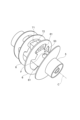
図1は、本開示の実施形態に係る回転装置1の構成概要を示した斜視図である。図2は、回転装置1の構成概要を示した縦断面図である。説明の便宜上、図1では、主たる内部構造も示している。
(First embodiment)
FIG. 1 is a perspective view showing a general configuration of a
回転装置1は、スクリュウデカンタ型の遠心分離装置に適用したものであり、供給される流体Fを固体と液体に分離する。この回転装置1は、例えば、食品、飲料水、薬品、化学製品、鉄鋼製品等の製造プロセスや、屎尿処理、下水処理、スラリ処理、工場排水処理等の水処理といった様々な分野において、固液分離に用いることができる。
The
回転装置1は、回転筒2を備えている。回転筒2は、固体と液体を混合した流体Fを供給され、その流体Fを固体と液体に分離する。回転筒2は、例えば、ケーシング3内に収容され、水平方向に向けた回転軸線Cを中心に回転する。回転筒2は、内外多重に設けられる外胴4及び内胴5を有している。
The
外胴4は、回転軸線Cを中心に回転する円筒体である。外胴4の一方の端部には軸部41が取り付けられている。外胴4の一方の端部は、軸部41により閉塞されている。外胴4の一方の端部は、軸部41を介して軸受42により回転可能に軸支されている。外胴4の他方の端部には軸部43が取り付けられている。外胴4の他方の端部は、軸部43に取り付けられる板体44により閉塞されている。板体44は、環状の部材であって、軸部43の外周側に取り付けられている。外胴4の一方の端部は、軸部43を介して軸受45により回転可能に軸支されている。外胴4は、モータ46の動力により回転する。すなわち、モータ46の動力は、例えば、軸部41を介して外胴4に伝達される。これにより、外胴4が一定の方向に回転する。
The
内胴5は、回転軸線Cを中心に回転する円筒状の回転体である。内胴5は、外胴4の内側(中心側)に配置され、外胴4と同心状に設けられている。内胴5の周面には、流体Fが供給される。内胴5の一方の端部は、軸部41により軸受けされている。内胴5の他方の端部は、軸部43に軸受けされている。内胴5は、モータ51の動力により回転する。すなわち、モータ51の動力は、例えば、遊星歯車機構などを通じて内胴5に伝達される。これにより、内胴5が外胴4と同一の方向に回転する。
The
内胴5には、羽根6が取り付けられている。すなわち、内胴5の周面には、羽根6が設けられている。羽根6は、内胴5の回転と共に回転する。羽根6は、内胴5の周方向に沿って螺旋状に形成されている。羽根6は、いわゆるスクリュウ羽根である。羽根6及び内胴5は、スクリュウコンベアを構成する。すなわち、羽根6は、流体Fから分離された固体Sを軸方向に向けて移送する。
A
内胴5の内側には、供給管52が設けられている。供給管52は、流体Fを供給するための管体である。供給管52は、軸部41の内側を通って内胴5の内側へ延びている。供給管52により内胴5の内側へ移送された流体Fは、供給口53から内胴5と外胴4の間へ吐出される。つまり、供給口53を通じて、内胴5の周面に流体Fが供給される。供給口53は、例えば、内胴5の内外を貫通した孔の外周面における開口である。また、供給口53は、例えば、内胴5の周方向に沿って複数形成される。図2では、二つの供給口53が図示されているが、二つ以上の供給口53が形成されていてもよい。なお、内胴5の外周面から突出した管体を設け、この管体の開口を供給口53としてもよい。
A
回転装置1には、カメラ71を備えている。カメラ71は、回転装置1に供給される流体Fを撮像するための撮像部として機能する。カメラ71は、内胴5の外周に取り付けられ、内胴5と共に回転する。カメラ71は、撮像方向を供給口53に向けて取り付けられている。ここでは、撮像対象は供給口53から吐出される流体Fである。カメラ71の取付は、例えばネジ止めや溶接などにより、内胴5にしっかりと固定できるように行われる。また、カメラ71に枠部材を外装して、カメラ71を取り付けてもよい。
The
回転装置1には、ライト72を備えている。ライト72は、カメラ71の撮像対象を照らすための照明器具である。回転筒2の内部は暗いため、ライト72がないと適切な撮像が困難となる。そこで、ライト72を設けることにより、カメラ71により撮像対象を適切に撮像することができる。ライト72は、内胴5の外周に取り付けられ、内胴5と共に回転する。ここでは、ライト72は、照明方向を供給口53に向けて取り付けられる。ライト72は、例えばカメラ71と隣接して設けられる。ライト72の取付は、例えばネジ止めや溶接などにより、内胴5にしっかりと固定できるように行われる。また、ライト72に枠部材を外装して、ライト72を取り付けてもよい。
The
カメラ71及びライト72としては、例えば、羽根6と羽根6の間に設置できるような小型のものが用いられる。この場合、カメラ71及びライト72の設置のために羽根6を切除する必要がない。このため、遠心分離の機能が損なわれることが抑制される。また、カメラ71及びライト72として、例えば、内胴5の外周面から液面までの距離より高さの低いものが用いられる。液面は、流体Fが分離されて生成される液体の表面である。このようなカメラ71及びライト72を用いることにより、分離した液体などの流れを乱すことなく遠心分離を行うことができる。カメラ71及びライト72としては、防水性のものが用いられる。これにより、流体F(分離された液体L及び固体Sを含む)によりカメラ71及びライト72が損傷することを防止することができる。
As the
カメラ71は、内部に設けられる記録媒体などに撮像データを保存可能なものが用いられる。この場合、撮像データを外部に出力するための配線が不要となる。ライト72は、撮像対象の全体に光を当てられるものが用いられる。例えば、ライト72として用いる照明器具の光の指向性が強い場合には拡散板を用いられる。これにより、広い範囲に光を照射することができる。
The
カメラ71は、内部電源を有しており、内部電源の電力供給により作動する。例えば、カメラ71は、バッテリを内蔵し、バッテリの電力により作動するものが用いられる。この場合、カメラ71が内部電源の電力供給により作動するため、カメラ71に対し外部から電源供給する必要がなく、カメラ71に電線を接続する必要がない。従って、カメラ71の回転により電線が絡まるなどの支障なく撮像が行える。ライト72は、内部電源を有しており、内部電源の電力供給により作動する。例えば、ライト72は、バッテリを内蔵し、バッテリの電力により作動するものが用いられる。この場合、ライト72が内部電源の電力供給により作動するため、ライト72に対し外部から電源供給する必要がなく、ライト72に電線を接続する必要がない。従って、ライト72の回転により電線が絡まるなどの支障なく撮像が行える。
The
カメラ71及びライト72として、内胴5の回転による遠心力に耐え得る強度を有するものが用いられる。これにより、遠心分離時にカメラ71及びライト72が損傷することを抑制することができる。バッテリとして電池を用いるライト72の場合、バッテリ収容部にスペーサなど設置しスプリング端子を予め縮めて用いてもよい。この場合、電池のスプリング端子が遠心力により縮んでライト72が作動しなくなることを抑制することができる。
As the
内胴5の外周には、ウエイト73が取り付けられている。ウエイト73は、内胴5の外周においてカメラ71及びライト72と対称の位置に設置されている。ウエイト73は、カメラ71及びライト72との重量のバランスをとるためのカウンタウエイトである。ウエイト73を設けることにより、内胴5の回転振動を抑制することができる。
A
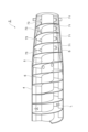
図3は、カメラ71及びライト72を示す斜視図である。図3に示すように、内胴5の外周にカメラ71及びライト72が設置されている。カメラ71及びライト72は、供給口53に向けて設けられている。羽根6は、リボン型のスクリュウ羽根であり、内胴5の外周面と羽根部分との間に空隙61が形成されている。このため、空隙61を通して、カメラ71及びライト72を供給口53に向けることが可能となる。これに対し、例えば、羽根6として、空隙61のない標準型のスクリュウ羽根を用いる場合、羽根6の一部を切り抜いて、カメラ71及びライト72を供給口53に向けてもよい。
FIG. 3 is a perspective view showing the
次に、本実施形態に係る回転装置1の動作について説明する。
Next, the operation of the
図2において、まず、カメラ71及びライト72が作動させられる。カメラ71は撮像状態とされ、ライト72は発光状態とされる。そして、外胴4、内胴5及び羽根6が回転させられる。この状態において、供給管52を通じて流体Fが内胴5の内側へ供給される。そして、流体Fは、供給口53から内胴5の外側へ吐出され、内胴5の外周面の周囲へ供給される。
In FIG. 2, first,
このとき、供給口53から吐出される流体Fは、ライト72の作動により明るく照らされる。そして、カメラ71により、流体Fの流れを適切に撮像することができる。すなわち、カメラ71は、供給口53と一緒に回転している。このため、供給口53から流れ出る流体Fの流出角度、流出の横幅、液体Lの液面への衝突の状態など流体Fの状態が的確に観察することができる。
At this time, the fluid F discharged from the
図4は、実際にカメラ71により流体Fを撮像した画像である。図4に示すように、供給口53から斜めの方向(矢印方向)に流体Fが流れ出ていることがわかる。また、流体Fの流出角度、流出の横幅、液体Lの液面への衝突の状態など流体Fの状態が的確に把握することができる。
FIG. 4 is an image of the fluid F actually captured by the
そして、図2において、内胴5と外胴4の間に流出した流体Fは、回転筒2の回転によって遠心分離される。すなわち、流体Fは、液体Lと固体Sに分離される。固体Sは、羽根6により一方の端部に向けて移送されて回転筒2から排出される。一方、液体Lは、他方の端部において回転筒2から排出される。
In FIG. 2, the fluid F flowing out between the
以上説明したように、本実施形態に係る回転装置1によれば、内胴5に取り付けられ内胴5と共に回転するカメラ71を備えることにより、内胴5の供給口53から吐出される流体Fの状態を適切に撮像することができる。このため、流体Fの流れなどの状態が的確に把握することができる。
As explained above, according to the
仮に、内胴5の供給口53から吐出される流体Fの状態を把握するために、外胴4を透明な材料で作製して、回転筒2の外部から流体Fを観察する場合、流体Fの流れを的確に把握することは困難である。すなわち、内胴5及び流体Fは高速で回転しているため、供給口53から吐出される流体Fの状態を視認することが難しい。そこで、本実施形態に係る回転装置1では、内胴5にカメラ71と取り付けて、内胴5と一緒に回転するカメラ71により撮像を行うことにより、内胴5の供給口53から吐出される流体Fを適切に撮像することができ、流体Fの流れなどの状態が的確に把握することができるのである。
If the
また、本実施形態に係る回転装置1によれば、カメラ71が内部電源の電力供給により作動する。このため、カメラ71に対し外部から電源供給する必要がなく、カメラ71に電線を接続する必要がない。従って、カメラ71の回転により電線が絡まるなどの支障なく撮像が適切に行える。
Further, according to the
また、本実施形態に係る回転装置1によれば、外胴4と内胴5の間に供給される流体Fを遠心分離する遠心分離装置に用いられることにより、外胴4と内胴5の間に供給される流体Fの流れ、分離される液体L及び固体Sの流れを確実に把握することができる。このため、流体Fなどの流れを考慮して、遠心分離装置の改良を適切に行うことができる。
Moreover, according to the
以上のように、本開示の実施形態について説明したが、本開示は上述した各実施形態に限定されるものではない。本発明は、特許請求の範囲の記載の要旨を逸脱しない範囲で様々な変形態様で実施することができる。 As mentioned above, although the embodiments of the present disclosure have been described, the present disclosure is not limited to each embodiment described above. The present invention can be implemented in various modifications without departing from the gist of the claims.
例えば、上述した実施形態においては、カメラ71を供給口53に向けて設ける場合について説明したが、カメラ71を他の部分に向けて設けてもよい。例えば、図5に示すように、カメラ71を液体Lの液面に向けて設けてもよい。カメラ71は、液体Lの排出側の端部に近い位置に設けられる。このとき、カメラ71に隣接してライト72を設けてもよい。このようにカメラ71を設けることにより、液体Lの表層流を撮像でき、実際の画像又は映像によって表層流を観察することができる。
For example, in the embodiment described above, a case has been described in which the
また、図6に示すように、固体Sが堆積され始める位置においてカメラ71を液体Lの液面に向けて設けてもよい。例えば、カメラ71は、内胴5の中央付近の位置に設けられる。このとき、カメラ71に隣接してライト72を設けてもよい。このようにカメラ71を設けることにより、液体L内における固体Sを撮像でき、実際の画像又は映像によって固体S(固体ケーキ)を観察することができる。
Further, as shown in FIG. 6, the
また、図7に示すように、固体Sの排出側の端部付近の位置においてカメラ71を固体Sに向けて設けてもよい。このとき、カメラ71に隣接してライト72を設けてもよい。このようにカメラ71を設けることにより、固体Sの脱水の過程を観察することができる。また、図5、図6及び図7の一部又は全部のカメラ71の設置を組み合わせて回転装置を構成してもよい。
Further, as shown in FIG. 7, a
また、上述した実施形態においては、回転装置1を遠心分離装置に適用した場合について説明したが、回転体を有する他の装置などに回転装置を適用してもよい。例えば、水車、発電用水車、軸流液体タービン、遠心ポンプ、液体用ターボポンプ、蒸気タービンなどに適用してもよい。
Further, in the above-described embodiment, a case has been described in which the
1 回転装置
2 回転筒
3 ケーシング
4 外胴
5 内胴(回転体)
6 羽根
41 軸部
42 軸受
43 軸部
44 板体
45 軸受
46 モータ
51 モータ
52 供給管
53 供給口
61 空隙
71 カメラ(撮像部)
72 ライト
73 ウエイト
C 回転軸線
F 流体
L 液体
S 固体
1 Rotating
6
72
Claims (2)
回転軸線を中心に回転し、周面に前記流体が供給される内胴と、
前記内胴と共に前記回転軸線を中心に回転し、前記内胴を取り囲むように前記内胴と同心状に配置される外胴と、
撮像方向を撮像対象である前記流体に向けて前記内胴の前記周面に取り付けられ、前記内胴と共に回転する撮像部と、
を備え、
前記周面には、前記内胴の周方向に沿って螺旋状に延びる羽根が設けられ、
前記羽根の間の前記周面には、前記流体を前記周面に供給する供給口が形成され、
前記撮像部は、前記羽根に形成された孔部を通して前記撮像方向が前記供給口を向くように、前記周面に配置されている、遠心分離装置。 A centrifugal separator for centrifuging fluid,
an inner barrel that rotates around a rotational axis and has a circumferential surface supplied with the fluid;
an outer shell that rotates around the rotational axis together with the inner shell and is arranged concentrically with the inner shell so as to surround the inner shell;
an imaging unit that is attached to the circumferential surface of the inner barrel and rotates together with the inner barrel , with the imaging direction facing the fluid that is the imaging target;
Equipped with
The peripheral surface is provided with a blade extending spirally along the circumferential direction of the inner shell,
A supply port for supplying the fluid to the peripheral surface is formed in the peripheral surface between the blades,
In the centrifugal separator, the imaging unit is arranged on the peripheral surface so that the imaging direction faces the supply port through a hole formed in the blade .
請求項1に記載の遠心分離装置。 The imaging unit has an internal power source and is operated by power supply from the internal power source.
The centrifugal separator according to claim 1.
Priority Applications (1)
| Application Number | Priority Date | Filing Date | Title |
|---|---|---|---|
| JP2019183882A JP7428496B2 (en) | 2019-10-04 | 2019-10-04 | rotating device |
Applications Claiming Priority (1)
| Application Number | Priority Date | Filing Date | Title |
|---|---|---|---|
| JP2019183882A JP7428496B2 (en) | 2019-10-04 | 2019-10-04 | rotating device |
Publications (2)
| Publication Number | Publication Date |
|---|---|
| JP2021058836A JP2021058836A (en) | 2021-04-15 |
| JP7428496B2 true JP7428496B2 (en) | 2024-02-06 |
Family
ID=75380959
Family Applications (1)
| Application Number | Title | Priority Date | Filing Date |
|---|---|---|---|
| JP2019183882A Active JP7428496B2 (en) | 2019-10-04 | 2019-10-04 | rotating device |
Country Status (1)
| Country | Link |
|---|---|
| JP (1) | JP7428496B2 (en) |
Citations (4)
| Publication number | Priority date | Publication date | Assignee | Title |
|---|---|---|---|---|
| WO2000055575A1 (en) | 1999-03-16 | 2000-09-21 | Nippon Steel Corporation | Wall surface observing device |
| JP2010117712A (en) | 2008-10-14 | 2010-05-27 | Nsk Ltd | Centrifugal microscope |
| JP2016159188A (en) | 2015-02-26 | 2016-09-05 | 倉敷紡績株式会社 | Agitation device |
| JP2017510434A (en) | 2014-01-22 | 2017-04-13 | セラノス, インコーポレイテッドTheranos, Inc. | High speed compact centrifuge for small volume samples |
-
2019
- 2019-10-04 JP JP2019183882A patent/JP7428496B2/en active Active
Patent Citations (4)
| Publication number | Priority date | Publication date | Assignee | Title |
|---|---|---|---|---|
| WO2000055575A1 (en) | 1999-03-16 | 2000-09-21 | Nippon Steel Corporation | Wall surface observing device |
| JP2010117712A (en) | 2008-10-14 | 2010-05-27 | Nsk Ltd | Centrifugal microscope |
| JP2017510434A (en) | 2014-01-22 | 2017-04-13 | セラノス, インコーポレイテッドTheranos, Inc. | High speed compact centrifuge for small volume samples |
| JP2016159188A (en) | 2015-02-26 | 2016-09-05 | 倉敷紡績株式会社 | Agitation device |
Also Published As
| Publication number | Publication date |
|---|---|
| JP2021058836A (en) | 2021-04-15 |
Similar Documents
| Publication | Publication Date | Title |
|---|---|---|
| JP6865848B2 (en) | Seal assembly for centrifuges | |
| JP6947181B2 (en) | Drive device | |
| WO2018030324A1 (en) | Drive device | |
| JP2009268963A (en) | Vertical centrifugal separator | |
| JP7428496B2 (en) | rotating device | |
| JP2022512180A (en) | centrifuge | |
| ES2855104T3 (en) | Centrifuge for material separation | |
| KR101152176B1 (en) | Centrifugal | |
| RU2004139021A (en) | SCREW CENTRIFUGE WITH A CONTINUOUS ROTOR, CONTAINING A CUTTING DISC, AND METHOD OF OPERATING IT | |
| CA2942707C (en) | Decanter centrifuge with double axial sealing | |
| JP2014091093A (en) | Pusher type centrifuge | |
| JP2004536706A5 (en) | ||
| US6312372B1 (en) | Outlet of a centrifugal separator having a reaction driven rotor | |
| JP6006453B1 (en) | Centrifuge | |
| JP2009103077A (en) | Impeller for sewage pump, and sewage pump | |
| SE444838B (en) | AIR-DRIVE ENGINE FOR PUMP DRIVING | |
| JP4333286B2 (en) | Screw decanter centrifuge | |
| RU2631951C1 (en) | Vacuum centrifuge | |
| JP2005074373A (en) | Screw decanter type centrifugal separator | |
| JP6063668B2 (en) | pump | |
| JP2018527182A (en) | Cooling device for driving part of solid bowl screw centrifuge | |
| SE463399B (en) | HELMANTEL CENTRIFUG WITH SHIPPING SCREW | |
| US20220347698A1 (en) | Solid-bowl screw centrifuge | |
| KR101574179B1 (en) | Centrifugal dehydrator of having improved watertightness | |
| JP2016059905A (en) | Centrifugal separator |
Legal Events
| Date | Code | Title | Description |
|---|---|---|---|
| A621 | Written request for application examination |
Free format text: JAPANESE INTERMEDIATE CODE: A621 Effective date: 20220606 |
|
| A977 | Report on retrieval |
Free format text: JAPANESE INTERMEDIATE CODE: A971007 Effective date: 20230524 |
|
| A131 | Notification of reasons for refusal |
Free format text: JAPANESE INTERMEDIATE CODE: A131 Effective date: 20230530 |
|
| A521 | Request for written amendment filed |
Free format text: JAPANESE INTERMEDIATE CODE: A523 Effective date: 20230724 |
|
| A131 | Notification of reasons for refusal |
Free format text: JAPANESE INTERMEDIATE CODE: A131 Effective date: 20231003 |
|
| A521 | Request for written amendment filed |
Free format text: JAPANESE INTERMEDIATE CODE: A523 Effective date: 20231120 |
|
| TRDD | Decision of grant or rejection written | ||
| A01 | Written decision to grant a patent or to grant a registration (utility model) |
Free format text: JAPANESE INTERMEDIATE CODE: A01 Effective date: 20240109 |
|
| A61 | First payment of annual fees (during grant procedure) |
Free format text: JAPANESE INTERMEDIATE CODE: A61 Effective date: 20240125 |
|
| R150 | Certificate of patent or registration of utility model |
Ref document number: 7428496 Country of ref document: JP Free format text: JAPANESE INTERMEDIATE CODE: R150 |