JP7427766B2 - Image selection support device, image selection support method, and image selection support program - Google Patents
Image selection support device, image selection support method, and image selection support program Download PDFInfo
- Publication number
- JP7427766B2 JP7427766B2 JP2022505008A JP2022505008A JP7427766B2 JP 7427766 B2 JP7427766 B2 JP 7427766B2 JP 2022505008 A JP2022505008 A JP 2022505008A JP 2022505008 A JP2022505008 A JP 2022505008A JP 7427766 B2 JP7427766 B2 JP 7427766B2
- Authority
- JP
- Japan
- Prior art keywords
- image
- still image
- still
- selection support
- support device
- Prior art date
- Legal status (The legal status is an assumption and is not a legal conclusion. Google has not performed a legal analysis and makes no representation as to the accuracy of the status listed.)
- Active
Links
- 238000000034 method Methods 0.000 title claims description 32
- 238000012545 processing Methods 0.000 claims description 86
- 238000004458 analytical method Methods 0.000 claims description 39
- 238000003384 imaging method Methods 0.000 claims description 35
- 238000005286 illumination Methods 0.000 claims description 27
- 238000000295 emission spectrum Methods 0.000 claims description 12
- 238000001514 detection method Methods 0.000 claims description 9
- 238000003745 diagnosis Methods 0.000 claims description 8
- 230000004044 response Effects 0.000 claims description 5
- 239000000284 extract Substances 0.000 claims description 4
- 230000000052 comparative effect Effects 0.000 claims 1
- 238000001839 endoscopy Methods 0.000 description 29
- 238000013473 artificial intelligence Methods 0.000 description 22
- 238000010586 diagram Methods 0.000 description 22
- 238000012360 testing method Methods 0.000 description 18
- 238000004140 cleaning Methods 0.000 description 15
- 230000003287 optical effect Effects 0.000 description 14
- 238000004891 communication Methods 0.000 description 13
- 238000003860 storage Methods 0.000 description 11
- 238000003780 insertion Methods 0.000 description 8
- 230000037431 insertion Effects 0.000 description 8
- 230000003902 lesion Effects 0.000 description 5
- 239000004065 semiconductor Substances 0.000 description 5
- 230000008878 coupling Effects 0.000 description 4
- 238000010168 coupling process Methods 0.000 description 4
- 238000005859 coupling reaction Methods 0.000 description 4
- 238000007689 inspection Methods 0.000 description 4
- 230000007170 pathology Effects 0.000 description 4
- 210000004204 blood vessel Anatomy 0.000 description 3
- 201000011510 cancer Diseases 0.000 description 3
- 238000005406 washing Methods 0.000 description 3
- 230000002159 abnormal effect Effects 0.000 description 2
- 238000009825 accumulation Methods 0.000 description 2
- 239000003086 colorant Substances 0.000 description 2
- 230000000295 complement effect Effects 0.000 description 2
- 238000002591 computed tomography Methods 0.000 description 2
- 230000001678 irradiating effect Effects 0.000 description 2
- 238000002595 magnetic resonance imaging Methods 0.000 description 2
- 238000004519 manufacturing process Methods 0.000 description 2
- 210000004400 mucous membrane Anatomy 0.000 description 2
- 238000001228 spectrum Methods 0.000 description 2
- XLYOFNOQVPJJNP-UHFFFAOYSA-N water Substances O XLYOFNOQVPJJNP-UHFFFAOYSA-N 0.000 description 2
- 238000005452 bending Methods 0.000 description 1
- 238000004364 calculation method Methods 0.000 description 1
- 239000000470 constituent Substances 0.000 description 1
- 238000012937 correction Methods 0.000 description 1
- 201000010099 disease Diseases 0.000 description 1
- 208000037265 diseases, disorders, signs and symptoms Diseases 0.000 description 1
- 230000000762 glandular Effects 0.000 description 1
- 239000004973 liquid crystal related substance Substances 0.000 description 1
- 229910044991 metal oxide Inorganic materials 0.000 description 1
- 150000004706 metal oxides Chemical class 0.000 description 1
- 238000012986 modification Methods 0.000 description 1
- 230000004048 modification Effects 0.000 description 1
- 210000003097 mucus Anatomy 0.000 description 1
- 238000003825 pressing Methods 0.000 description 1
- 238000005096 rolling process Methods 0.000 description 1
- 210000001519 tissue Anatomy 0.000 description 1
Images


Classifications
-
- G—PHYSICS
- G06—COMPUTING; CALCULATING OR COUNTING
- G06T—IMAGE DATA PROCESSING OR GENERATION, IN GENERAL
- G06T7/00—Image analysis
- G06T7/0002—Inspection of images, e.g. flaw detection
- G06T7/0012—Biomedical image inspection
-
- G—PHYSICS
- G06—COMPUTING; CALCULATING OR COUNTING
- G06F—ELECTRIC DIGITAL DATA PROCESSING
- G06F3/00—Input arrangements for transferring data to be processed into a form capable of being handled by the computer; Output arrangements for transferring data from processing unit to output unit, e.g. interface arrangements
- G06F3/01—Input arrangements or combined input and output arrangements for interaction between user and computer
- G06F3/048—Interaction techniques based on graphical user interfaces [GUI]
- G06F3/0484—Interaction techniques based on graphical user interfaces [GUI] for the control of specific functions or operations, e.g. selecting or manipulating an object, an image or a displayed text element, setting a parameter value or selecting a range
- G06F3/04845—Interaction techniques based on graphical user interfaces [GUI] for the control of specific functions or operations, e.g. selecting or manipulating an object, an image or a displayed text element, setting a parameter value or selecting a range for image manipulation, e.g. dragging, rotation, expansion or change of colour
-
- A—HUMAN NECESSITIES
- A61—MEDICAL OR VETERINARY SCIENCE; HYGIENE
- A61B—DIAGNOSIS; SURGERY; IDENTIFICATION
- A61B1/00—Instruments for performing medical examinations of the interior of cavities or tubes of the body by visual or photographical inspection, e.g. endoscopes; Illuminating arrangements therefor
- A61B1/04—Instruments for performing medical examinations of the interior of cavities or tubes of the body by visual or photographical inspection, e.g. endoscopes; Illuminating arrangements therefor combined with photographic or television appliances
- A61B1/045—Control thereof
-
- G—PHYSICS
- G06—COMPUTING; CALCULATING OR COUNTING
- G06F—ELECTRIC DIGITAL DATA PROCESSING
- G06F3/00—Input arrangements for transferring data to be processed into a form capable of being handled by the computer; Output arrangements for transferring data from processing unit to output unit, e.g. interface arrangements
- G06F3/01—Input arrangements or combined input and output arrangements for interaction between user and computer
- G06F3/048—Interaction techniques based on graphical user interfaces [GUI]
- G06F3/0481—Interaction techniques based on graphical user interfaces [GUI] based on specific properties of the displayed interaction object or a metaphor-based environment, e.g. interaction with desktop elements like windows or icons, or assisted by a cursor's changing behaviour or appearance
- G06F3/0482—Interaction with lists of selectable items, e.g. menus
-
- G—PHYSICS
- G16—INFORMATION AND COMMUNICATION TECHNOLOGY [ICT] SPECIALLY ADAPTED FOR SPECIFIC APPLICATION FIELDS
- G16H—HEALTHCARE INFORMATICS, i.e. INFORMATION AND COMMUNICATION TECHNOLOGY [ICT] SPECIALLY ADAPTED FOR THE HANDLING OR PROCESSING OF MEDICAL OR HEALTHCARE DATA
- G16H10/00—ICT specially adapted for the handling or processing of patient-related medical or healthcare data
- G16H10/60—ICT specially adapted for the handling or processing of patient-related medical or healthcare data for patient-specific data, e.g. for electronic patient records
-
- G—PHYSICS
- G16—INFORMATION AND COMMUNICATION TECHNOLOGY [ICT] SPECIALLY ADAPTED FOR SPECIFIC APPLICATION FIELDS
- G16H—HEALTHCARE INFORMATICS, i.e. INFORMATION AND COMMUNICATION TECHNOLOGY [ICT] SPECIALLY ADAPTED FOR THE HANDLING OR PROCESSING OF MEDICAL OR HEALTHCARE DATA
- G16H15/00—ICT specially adapted for medical reports, e.g. generation or transmission thereof
-
- G—PHYSICS
- G16—INFORMATION AND COMMUNICATION TECHNOLOGY [ICT] SPECIALLY ADAPTED FOR SPECIFIC APPLICATION FIELDS
- G16H—HEALTHCARE INFORMATICS, i.e. INFORMATION AND COMMUNICATION TECHNOLOGY [ICT] SPECIALLY ADAPTED FOR THE HANDLING OR PROCESSING OF MEDICAL OR HEALTHCARE DATA
- G16H30/00—ICT specially adapted for the handling or processing of medical images
- G16H30/20—ICT specially adapted for the handling or processing of medical images for handling medical images, e.g. DICOM, HL7 or PACS
-
- G—PHYSICS
- G16—INFORMATION AND COMMUNICATION TECHNOLOGY [ICT] SPECIALLY ADAPTED FOR SPECIFIC APPLICATION FIELDS
- G16H—HEALTHCARE INFORMATICS, i.e. INFORMATION AND COMMUNICATION TECHNOLOGY [ICT] SPECIALLY ADAPTED FOR THE HANDLING OR PROCESSING OF MEDICAL OR HEALTHCARE DATA
- G16H30/00—ICT specially adapted for the handling or processing of medical images
- G16H30/40—ICT specially adapted for the handling or processing of medical images for processing medical images, e.g. editing
-
- G—PHYSICS
- G06—COMPUTING; CALCULATING OR COUNTING
- G06F—ELECTRIC DIGITAL DATA PROCESSING
- G06F2203/00—Indexing scheme relating to G06F3/00 - G06F3/048
- G06F2203/048—Indexing scheme relating to G06F3/048
- G06F2203/04803—Split screen, i.e. subdividing the display area or the window area into separate subareas
-
- G—PHYSICS
- G06—COMPUTING; CALCULATING OR COUNTING
- G06F—ELECTRIC DIGITAL DATA PROCESSING
- G06F3/00—Input arrangements for transferring data to be processed into a form capable of being handled by the computer; Output arrangements for transferring data from processing unit to output unit, e.g. interface arrangements
- G06F3/01—Input arrangements or combined input and output arrangements for interaction between user and computer
- G06F3/048—Interaction techniques based on graphical user interfaces [GUI]
- G06F3/0484—Interaction techniques based on graphical user interfaces [GUI] for the control of specific functions or operations, e.g. selecting or manipulating an object, an image or a displayed text element, setting a parameter value or selecting a range
- G06F3/04842—Selection of displayed objects or displayed text elements
-
- G—PHYSICS
- G06—COMPUTING; CALCULATING OR COUNTING
- G06T—IMAGE DATA PROCESSING OR GENERATION, IN GENERAL
- G06T2200/00—Indexing scheme for image data processing or generation, in general
- G06T2200/24—Indexing scheme for image data processing or generation, in general involving graphical user interfaces [GUIs]
-
- G—PHYSICS
- G06—COMPUTING; CALCULATING OR COUNTING
- G06T—IMAGE DATA PROCESSING OR GENERATION, IN GENERAL
- G06T2207/00—Indexing scheme for image analysis or image enhancement
- G06T2207/10—Image acquisition modality
- G06T2207/10068—Endoscopic image
-
- G—PHYSICS
- G06—COMPUTING; CALCULATING OR COUNTING
- G06T—IMAGE DATA PROCESSING OR GENERATION, IN GENERAL
- G06T2207/00—Indexing scheme for image analysis or image enhancement
- G06T2207/10—Image acquisition modality
- G06T2207/10141—Special mode during image acquisition
- G06T2207/10152—Varying illumination
-
- G—PHYSICS
- G06—COMPUTING; CALCULATING OR COUNTING
- G06T—IMAGE DATA PROCESSING OR GENERATION, IN GENERAL
- G06T2207/00—Indexing scheme for image analysis or image enhancement
- G06T2207/30—Subject of image; Context of image processing
- G06T2207/30004—Biomedical image processing
- G06T2207/30096—Tumor; Lesion
Landscapes
- Engineering & Computer Science (AREA)
- Health & Medical Sciences (AREA)
- General Health & Medical Sciences (AREA)
- Medical Informatics (AREA)
- Theoretical Computer Science (AREA)
- Public Health (AREA)
- Nuclear Medicine, Radiotherapy & Molecular Imaging (AREA)
- Radiology & Medical Imaging (AREA)
- Physics & Mathematics (AREA)
- Primary Health Care (AREA)
- Epidemiology (AREA)
- General Engineering & Computer Science (AREA)
- General Physics & Mathematics (AREA)
- Life Sciences & Earth Sciences (AREA)
- Surgery (AREA)
- Human Computer Interaction (AREA)
- Quality & Reliability (AREA)
- Computer Vision & Pattern Recognition (AREA)
- Veterinary Medicine (AREA)
- Animal Behavior & Ethology (AREA)
- Molecular Biology (AREA)
- Heart & Thoracic Surgery (AREA)
- Biomedical Technology (AREA)
- Pathology (AREA)
- Optics & Photonics (AREA)
- Biophysics (AREA)
- Endoscopes (AREA)
Description
本発明は、内視鏡による撮影で得られた画像の選択を支援する画像選択支援装置、画像選択支援方法、及び画像選択支援プログラムに関する。 The present invention relates to an image selection support device, an image selection support method, and an image selection support program that support selection of images obtained by imaging with an endoscope.
従来、内視鏡による撮影で得られた画像を蓄積する画像管理システムが知られている。画像管理システムに蓄積された画像は、例えば、内視鏡による検査に関して作成されるレポートにキーイメージとして挿入される。 2. Description of the Related Art Conventionally, image management systems are known that accumulate images obtained by imaging with an endoscope. Images stored in the image management system are inserted, for example, as key images into a report created regarding an examination using an endoscope.
画像の取得は、例えば、内視鏡の操作者による画像の取得操作が行われたタイミングで、すなわち手動で行われる。 The image acquisition is performed manually, for example, at the timing when the endoscope operator performs an image acquisition operation.
又は、画像の取得は、内視鏡の操作者による画像の取得操作によらずに自動で行われる。例えば、特許文献1には、病変画像など診断に最適な画像を漏れなく確実に保存するために、内視鏡によって観察対象を撮像して得られた画像信号から粘膜情報の指標値を算出し、その指標値に基づいて画像信号が特定の条件を満たすと判別された特定画像信号を自動的に保存する構成が開示されている。
Alternatively, image acquisition is performed automatically without an image acquisition operation by an endoscope operator. For example, in
レポートのキーイメージ等に用いる画像は、手動及び自動で取得された各画像の中から選択可能であることが望ましい。 It is desirable that the image used as the key image of the report can be selected from manually and automatically acquired images.
例えば、手動で取得された画像は、操作者の取得操作の遅れにより、ブレが大きいなど、不適切なタイミングの画像である場合がある。また、手動で取得された画像のみでは、操作者が取得操作を失念したり取得操作を失敗したりすることにより必要な画像が得られない場合がある。 For example, a manually acquired image may have an inappropriate timing, such as a large blur due to a delay in the operator's acquisition operation. Furthermore, if only manually acquired images are used, the necessary images may not be obtained because the operator forgets or fails in the acquisition operation.
一方で、画像を自動で取得する場合に、必要な画像を自動で取得するための完全な基準を定めることは困難である。このため、自動で取得された画像には、不必要な画像が含まれる場合がある。また、自動で取得された画像のみでは、必要な画像が得られない場合がある。 On the other hand, when automatically acquiring images, it is difficult to define complete standards for automatically acquiring necessary images. Therefore, automatically acquired images may include unnecessary images. Further, there are cases where a necessary image cannot be obtained only from automatically acquired images.
しかしながら、手動及び自動で取得された各画像の中から画像を選択する構成とすると、これらの画像の中から適切な画像を選択することは困難である。例えば、画像の選択者は、手動で取得された画像について、その画像の撮影時刻と近い撮影時刻に自動で取得された画像がいずれであるかを特定することが困難であり、これらの画像を比較することが困難である。 However, if an image is selected from among manually and automatically acquired images, it is difficult to select an appropriate image from among these images. For example, it is difficult for an image selector to identify manually captured images that were automatically captured at a time close to that image's capture time. Difficult to compare.
本発明は、上記事情に鑑みてなされたものであり、手動及び自動で取得された各画像の中から適切な画像を容易に選択可能にする画像選択支援装置、画像選択支援方法、及び画像選択支援プログラムを提供することを目的とする。 The present invention has been made in view of the above circumstances, and provides an image selection support device, an image selection support method, and an image selection support method that make it possible to easily select an appropriate image from manually and automatically acquired images. The purpose is to provide support programs.
本発明の画像選択支援装置は、プロセッサとメモリとを有し、内視鏡により得られる撮影画像データに基づく静止画像の選択を支援する画像選択支援装置であって、上記メモリには、上記内視鏡の操作者による静止画像の取得操作があった時の上記撮影画像データに基づいて取得された第1静止画像と、上記取得操作があった時と異なる時の上記撮影画像データから取得された1つ以上の第2静止画像と、が記録され、上記プロセッサが、上記1つ以上の第2静止画像の中から、上記第1静止画像の撮影時刻との間で予め定められた条件を満たす撮影時刻を有する第3静止画像を抽出し、上記第1静止画像と上記第3静止画像とを対応付けるものである。 The image selection support device of the present invention is an image selection support device that has a processor and a memory and supports the selection of still images based on captured image data obtained by an endoscope. A first still image acquired based on the photographed image data when the endoscope operator performed a still image acquisition operation, and a first still image acquired from the photographed image data at a time different from when the acquisition operation was performed. one or more second still images are recorded, and the processor determines a predetermined condition between the one or more second still images and the shooting time of the first still image. A third still image having a satisfying shooting time is extracted, and the first still image and the third still image are associated with each other.
本発明の画像選択支援方法は、内視鏡により得られる撮影画像データに基づく静止画像の選択を支援する画像選択支援方法であって、上記内視鏡の操作者による静止画像の取得操作があった時の上記撮影画像データに基づいて取得された第1静止画像と、上記取得操作があった時と異なる時の上記撮影画像データから取得された1つ以上の第2静止画像と、を用いて、上記1つ以上の第2静止画像の中から、上記第1静止画像の撮影時刻との間で予め定められた条件を満たす撮影時刻を有する第3静止画像を抽出し、上記第1静止画像と上記第3静止画像とを対応付けるものである。 The image selection support method of the present invention is an image selection support method that supports the selection of still images based on photographed image data obtained by an endoscope, and the image selection support method is an image selection support method that supports the selection of still images based on captured image data obtained by an endoscope. A first still image acquired based on the photographed image data at a time when the acquisition operation was performed, and one or more second still images acquired from the photographed image data at a time different from when the acquisition operation was performed. A third still image having a photographing time that satisfies a predetermined condition between the photographing time of the first still image is extracted from among the one or more second still images, and The image and the third still image are associated with each other.
本発明の画像選択支援プログラムは、内視鏡により得られる撮影画像データに基づく静止画像の選択を支援する画像選択支援プログラムであって、上記内視鏡の操作者による静止画像の取得操作があった時の上記撮影画像データに基づいて取得された第1静止画像と、上記取得操作があった時と異なる時の上記撮影画像データから取得された1つ以上の第2静止画像と、を用いて、上記1つ以上の第2静止画像の中から、上記第1静止画像の撮影時刻との間で予め定められた条件を満たす撮影時刻を有する第3静止画像を抽出し、上記第1静止画像と上記第3静止画像とを対応付ける、処理をコンピュータに実行させるためのものである。 The image selection support program of the present invention is an image selection support program that supports the selection of still images based on photographed image data obtained by an endoscope, and the image selection support program supports the selection of still images based on photographed image data obtained by an endoscope, and the image selection support program is an image selection support program that supports the selection of still images based on captured image data obtained by an endoscope. A first still image acquired based on the photographed image data at a time when the acquisition operation was performed, and one or more second still images acquired from the photographed image data at a time different from when the acquisition operation was performed. A third still image having a photographing time that satisfies a predetermined condition between the photographing time of the first still image is extracted from among the one or more second still images, and This is for causing the computer to execute processing for associating the image with the third still image.
本発明によれば、手動及び自動で取得された各画像の中から適切な画像を容易に選択可能にする画像選択支援装置、画像選択支援方法、及び画像選択支援プログラムを提供することができる。 According to the present invention, it is possible to provide an image selection support device, an image selection support method, and an image selection support program that enable easy selection of appropriate images from manually and automatically acquired images.
以下、本発明の実施形態について図面を参照して説明する。 Embodiments of the present invention will be described below with reference to the drawings.
(実施形態の一例)
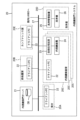
図1は、病院内システム全体構成の一例を示す図である。図1に示すシステムは、病院情報システム(HIS:Hospital Information System)10と、内視鏡部門システム20と、病理部門システム30と、医用画像保管システム40と、他部門システム50とを備え、これらは院内LAN(Local Area Network)60に接続されて相互に連携可能となっている。
(Example of embodiment)
FIG. 1 is a diagram showing an example of the overall configuration of an in-hospital system. The system shown in FIG. 1 includes a hospital information system (HIS) 10, an
HIS10は、医療事務会計システム、診療予約システム、診療情報システム等を含む包括的なシステムであり、電子カルテデータベース等を有する。電子カルテデータベースには、患者の診療情報を記録した電子カルテが保管される。 The HIS 10 is a comprehensive system including a medical accounting system, a medical reservation system, a medical information system, etc., and has an electronic medical record database. The electronic medical record database stores electronic medical records that record patient medical information.
他の診療科から内視鏡部門に対して検査依頼が行われる場合の検査の依頼(オーダ)に関する情報(以下、検査依頼情報という)が発行されると、その情報がHIS10を介して内視鏡部門システム20に送信される。
When information regarding a test request (order) (hereinafter referred to as test request information) is issued when a test request is made to the endoscopy department from another clinical department, that information is sent to the endoscopy department via HIS10. It is transmitted to the
検査依頼情報には、例えば、患者情報、オーダーキー情報(「オーダ番号」「発生日時」等)、依頼元情報(「依頼科名」「依頼医師名」「依頼日」等)、オーダ情報(「依頼病名」「検査目的」「検査種別」「検査項目」「検査部位」「コメント」等)、検査予約情報(「検査日」「実施時刻」等)等が含まれる。患者情報は、患者に関する情報であり、患者固有の情報である「患者ID」、「患者氏名」、「生年月日」、「年齢」、「性別」、「入院/外来区分」等が含まれる。 Test request information includes, for example, patient information, order key information ("order number", "date and time of occurrence", etc.), requester information ("requesting department name", "requesting doctor name", "request date", etc.), order information ( This includes information such as "name of requested disease," "test purpose," "test type," "test items," "test site," "comments," etc.), test reservation information ("test date," "implementation time," etc.), and so on. Patient information is information about the patient, and includes patient-specific information such as "patient ID," "patient name," "date of birth," "age," "gender," and "inpatient/outpatient classification." .
内視鏡部門システム20は、内視鏡部門の管理を行うためのシステムである。
The
病理部門システム30は、病理部門の管理を行うためのシステムである。
The
医用画像保管システム40は、内視鏡装置、CT(Computed Tomography)、MRI(Magnetic Resonance Imaging)等の医療画像診断装置からの検査画像を電子的に保存、検索、解析するシステムである。医用画像保管システム40は、例えばPACS(Picture Archiving and Communication Systems)であってもよいし、医療用画像を保存可能な他のシステムであってもよい。
The medical
他部門システム50は、その他の部門の管理を行うためのシステムである。
The
図2は、図1に示すシステムにおける内視鏡部門システムの概略構成を示す図である。内視鏡部門には、受付20Aと、前処置室20Bと、複数の内視鏡検査室(以下、検査室)20Cと、洗浄室20Dと、カンファレンス室20Eとが含まれる。
FIG. 2 is a diagram showing a schematic configuration of the endoscopy department system in the system shown in FIG. 1. The endoscopy department includes a
受付20Aは、検査の受付を行う場所である。前処置室20Bは、内視鏡検査の前に行う問診及び前処置を行うための部屋である。検査室20Cは、内視鏡検査を行うための部屋である。洗浄室20Dは、内視鏡検査に用いたスコープ等の洗浄を行うための部屋である。
The
図2に示す内視鏡部門システム20は、内視鏡部門サーバ21と、複数のクライアントPC(Personal Computer)22と、画像処理装置23と、内視鏡装置24と、洗浄管理装置25と、洗浄機26とを備える。内視鏡部門サーバ21、複数のクライアントPC22、画像処理装置23、及び洗浄管理装置25は部門内LAN27に接続されている。部門内LAN27は院内LAN60に接続されている。
The
画像処理装置23及び内視鏡装置24は、複数の検査室20Cの各々に設置されている。画像処理装置23及び内視鏡装置24は、互いに通信を行うことにより、互いの内部時刻を同期させる同期処理を行う。
The
内視鏡装置24は、先端に撮像素子を有する挿入部(スコープ)を備え、撮像素子の連続撮影により得られる連続した撮影画像データを画像処理装置23へ入力する。内視鏡装置24の構成例については図5において後述する。
The
また、内視鏡装置24は、内視鏡装置24の操作者からの静止画像の取得操作(例えばボタン押下)があった時に撮像素子により得られた撮影画像データに基づく第1静止画像を生成する。第1静止画像は、操作者からの取得操作により取得された手動取得画像である。また、内視鏡装置24は、生成する第1静止画像に、その第1静止画像が得られた時の内視鏡装置24の内部時刻である撮影時刻の情報を付加する。そして、内視鏡装置24は、生成した第1静止画像を画像処理装置23へ入力する。
Furthermore, the
画像処理装置23は、画像処理装置23が設置される検査室20Cの内視鏡装置24に接続されている。画像処理装置23は、内視鏡装置24から撮影画像データを受信する解析装置を構成する。
The
画像処理装置23には、内視鏡装置24の連続撮影により得られる撮影画像データが連続して入力される。画像処理装置23は、内視鏡装置24から連続して入力される撮影画像データのうち、内視鏡装置24の操作者からの静止画像の取得操作があった時と異なる時の撮影画像データに基づく第2静止画像を生成する。第2静止画像は、操作者からの取得操作によらずに取得された自動取得画像である。また、画像処理装置23は、生成する第2静止画像に、その第2静止画像が得られた時の画像処理装置23の内部時刻である撮影時刻の情報を付加する。
Photographed image data obtained by continuous photographing by the
例えば、画像処理装置23は、連続して入力される撮影画像データに基づいてAI(Artificial Intelligence)による解析を行う。そして、画像処理装置23は、内視鏡装置24から連続して入力される撮影画像データのうち、解析の結果に基づく時の撮影画像データに基づく第2静止画像を生成する。解析の結果に基づく時は、上記の取得操作があった時と異なる時の一例であり、例えば撮影画像データに基づいて特異所見を検出した時である。特異所見は、例えば悪性腫瘍等の病変であるが、これに限らず各種の特異所見とすることができる。
For example, the
また、画像処理装置23は、内視鏡装置24から入力された第1静止画像と、生成した第2静止画像とを、部門内LAN27を介して内視鏡部門サーバ21へ送信する。画像処理装置23によって送信された第1静止画像及び第2静止画像は、内視鏡部門サーバ21の制御により、図1に示した医用画像保管システム40によって保管される。
The
なお、内視鏡装置24が生成した第1静止画像を、画像処理装置23を介して内視鏡部門サーバ21へ送信する構成について説明したが、画像処理装置23を介さずに内視鏡装置24が第1静止画像を内視鏡部門サーバ21へ送信する構成としてもよい。また、内視鏡装置24として、画像処理装置23を一体化したものを用いてもよい。
Note that although a configuration has been described in which the first still image generated by the
洗浄機26と洗浄管理装置25は洗浄室20Dに設置されている。洗浄機26は、内視鏡検査に用いたスコープ等の洗浄を行う機器である。
The cleaning
洗浄管理装置25は、洗浄機26に接続されており、洗浄機26による洗浄履歴等の情報を内視鏡部門サーバ21に登録するためのコンピュータである。
The
内視鏡部門サーバ21は、クライアントPC22、画像処理装置23、及び洗浄管理装置25を統括制御するコンピュータである。内視鏡部門サーバ21には、データベースDBが内蔵されており、このデータベースDBに各種情報(検査依頼情報、検査結果情報等)が格納される。
The
クライアントPC22には、所定のアプリケーションプログラムがインストールされており、このプログラムにより、データベースDBに記録されているデータの参照及び編集、データベースへのデータの登録等が可能となっている。
A predetermined application program is installed in the
図3は、図2に示す内視鏡部門システムにおけるクライアントPCの内部構成を示すブロック図である。図3に示すように、クライアントPC22のそれぞれは、入力部22a、表示部22b、記録部22c、送受信部22d、及び制御部22eで構成される。
FIG. 3 is a block diagram showing the internal configuration of a client PC in the endoscopy department system shown in FIG. 2. As shown in FIG. 3, each of the
入力部22aは、各種入力を行うための入力手段であり、キーボード、タッチパネル等の入力デバイスや、マウス・トラックボール等のポインティングデバイスから構成されている。
The
表示部22bは、画像、レポート等の各種表示を行うためのディスプレイであり、LCD(Liquid Crystal Display)やCRT(Cathode Ray Tube)などで構成されている。
The
記録部22cは、各種データを記録するためのハードディスク等で構成されている。
The
送受信部22dは、送受信インタフェース回路などから構成され、各種指示、各種要求、及び各種データを、部門内LAN27を介して送受信する処理を実行する。
The transmitting/receiving
制御部22eは、プログラムを実行して処理を行う各種のプロセッサと、RAM(Random Access Memory)と、ROM(Read Only Memory)を含む。
The
各種のプロセッサとしては、プログラムを実行して各種処理を行う汎用的なプロセッサであるCPU(Central Processing Unit)、FPGA(Field Programmable Gate Array)等の製造後に回路構成を変更可能なプロセッサであるプログラマブルロジックデバイス(Programmable Logic Device:PLD)、又はASIC(Application Specific Integrated Circuit)等の特定の処理を実行させるために専用に設計された回路構成を有するプロセッサである専用電気回路等が含まれる。 Various types of processors include CPU (Central Processing Unit), which is a general-purpose processor that executes programs and performs various processes, and programmable logic, which is a processor whose circuit configuration can be changed after manufacturing, such as FPGA (Field Programmable Gate Array). This includes a dedicated electric circuit such as a programmable logic device (PLD) or an application specific integrated circuit (ASIC), which is a processor having a circuit configuration exclusively designed to execute a specific process.
これら各種のプロセッサの構造は、より具体的には、半導体素子等の回路素子を組み合わせた電気回路である。 More specifically, the structure of these various processors is an electric circuit that is a combination of circuit elements such as semiconductor elements.
制御部22eは、各種のプロセッサのうちの1つで構成されてもよいし、同種又は異種の2つ以上のプロセッサの組み合わせ(例えば、複数のFPGAの組み合わせ又はCPUとFPGAの組み合わせ)で構成されてもよい。
The
制御部22eは、上記プログラム、部門内LAN27を介し外部から送信される各種の要求、及び入力部22aから入力される指示情報などに従ってクライアントPC22の各部の制御を行う。
The
図4は、クライアントPC22のアプリケーションの基本画面の一例を示す図である。ユーザがクライアントPC22でアプリケーションを立ち上げてログインすると、制御部22eは、基本画面データをデータベースDBから取得し、図4に示した基本画面を表示部22bに表示させる。なお、クライアントPC22は、例えば検査室20CのクライアントPC22であるが、これに限らず図2に示した他のクライアントPC22であってもよい。
FIG. 4 is a diagram showing an example of the basic screen of the application on the
この基本画面は、検査依頼情報(一部を抜粋した情報)の一覧リストを表示する領域Aと、各種操作ボタンを表示する領域Bと、領域Aのリストで選択された検査依頼情報に対して有効なランチャーを表示する領域Cとで構成されている。 This basic screen consists of area A that displays a list of inspection request information (partially extracted information), area B that displays various operation buttons, and area A that displays the inspection request information selected from the list in area A. It is made up of an area C that displays valid launchers.
領域Aのリストには、各検査依頼情報に対して“来院”“受付”“検査”“会計”等の処理項目が設けられ、各検査依頼情報に対して各処理項目で示される処理が終了した場合に、各処理項目に“○”印が表示されるようになっている。 In the list of area A, processing items such as "visit," "reception," "inspection," and "accounting" are provided for each test request information, and the processing indicated by each processing item for each test request information is completed. In this case, a “○” mark will be displayed for each processing item.
この印を表示するためのデータについては、各処理が終了したときに、内視鏡部門サーバ21によってデータベースDBに登録される。例えば、内視鏡部門サーバ21は、検査依頼情報に基づく検査が終了すると、検査が終了したことを示す情報を該検査依頼情報に対応付けてデータベースDBに登録する。これにより、“検査”の処理項目に“○”印が表示されるようになる。各処理が終了したかどうかの情報は、手動で入力しても良いし、クライアントPC22や内視鏡装置24から自動的に通知できるようにしてもよい。
Data for displaying this mark is registered in the database DB by the
このアプリケーションは操作ボタンとして“レポート”ボタンC1を有し、“レポート”ボタンC1は図4に示した基本画面の領域Cに表示される。このボタンC1は、領域Aのリストから選択した検査依頼情報に基づく検査に対し、レポートの作成作業を行うためのボタンである。 This application has a "report" button C1 as an operation button, and the "report" button C1 is displayed in area C of the basic screen shown in FIG. This button C1 is a button for creating a report for the test based on the test request information selected from the list in area A.
クライアントPC22の制御部22eは、この基本画面を表示するためのデータをデータベースDBから定期的に取得し、表示部22bに表示させる。
The
図2に示すシステムでは、クライアントPC22の制御部22eが、実施された検査に対してレポートの作成を行う指示が行われた場合に、レポートに挿入するための静止画像の、レポート作成者(例えば医師)による選択を支援するものである。
In the system shown in FIG. 2, when the
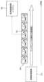
図5は、内視鏡装置24の一例を示す図である。図5に示すように、内視鏡装置24は、内視鏡1と、この内視鏡1が接続される制御装置4及び光源装置5と、を備える。
FIG. 5 is a diagram showing an example of the
制御装置4には、内視鏡1によって被検体内を撮像して得られる撮像画像等を表示する表示装置7と、制御装置4に対して各種情報を入力するためのインタフェースである入力部6と、が接続されている。制御装置4は、内視鏡1、光源装置5、及び表示装置7を制御する。
The
表示装置7は、表示画素が二次元状に配列された表示面を有し、この表示面の各表示画素に、画像データを構成する画素データが描画されることで、この画像データに基づく画像の表示が行われる。表示装置7は、制御装置4からの指令に応じて表示画像を切り替える表示部を構成する。
The
内視鏡1は、一方向に延びる管状部材であって被検体内に挿入される挿入部110と、挿入部110の基端部に設けられ、観察モード切替操作、撮像記録操作、鉗子操作、送気送水操作、及び吸引操作等を行うための操作部材が設けられた操作部11と、操作部11に隣接して設けられたアングルノブ12と、内視鏡1を制御装置4と光源装置5にそれぞれ着脱自在に接続するコネクタ部13A,13Bを含むユニバーサルコード13と、を含む。
The
なお、図5では省略されているが、操作部11及び挿入部110の内部には、細胞又はポリープ等の生体組織を採取するための鉗子を挿入する鉗子孔、送気及び送水用のチャンネル、吸引用のチャンネル等の各種のチャンネルが設けられる。
Although omitted in FIG. 5, inside the
挿入部110は、可撓性を有する軟性部10Aと、軟性部10Aの先端に設けられた湾曲部10Bと、湾曲部10Bの先端に設けられた硬質の先端部10Cとから構成される。
The
湾曲部10Bは、アングルノブ12の回動操作により湾曲自在に構成されている。この湾曲部10Bは、内視鏡1が使用される被検体の部位等に応じて、任意の方向及び任意の角度に湾曲でき、先端部10Cを所望の方向に向けることができる。
The bending
図6は、図5に示す内視鏡装置24の内部構成を示す模式図である。図7は、図6に示した光源装置5が発生させる光のスペクトルの一例を示す図である。
FIG. 6 is a schematic diagram showing the internal configuration of the
光源装置5は、照明光として、通常光と特殊光とを切り替えて照射可能である。通常光は、白色光等の、医師等の人間による認識に適した発光スペクトルを有する光である。特殊光は、通常光とは発光スペクトルが異なる、IEE(Image-Enhanced Endoscopy:画像強調観察)等のコンピュータによる解析に適した発光スペクトルを有する光である。
The
具体的には、光源装置5は、光源用プロセッサ151と、光源部152と、光路結合部154と、を備える。光源用プロセッサ151は、制御装置4のシステム制御部44と接続されており、システム制御部44からの指令に基づいて光源部152を制御する。
Specifically, the
光源部152は、例えば、複数の半導体光源を有し、これらをそれぞれ点灯又は消灯し、点灯する場合には各半導体光源の発光量を制御することにより、観察対象を照明する照明光を発する。本実施形態では、光源部152は、V-LED(Violet Light Emitting Diode)152a、B-LED(Blue Light Emitting Diode)152b、G-LED(Green Light Emitting Diode)152c、及びR-LED(Red Light Emitting Diode)152dの4色のLEDを有する。 The light source unit 152 has, for example, a plurality of semiconductor light sources, turns on or off each of these, and when turned on, controls the amount of light emitted from each semiconductor light source to emit illumination light that illuminates the observation target. In the present embodiment, the light source section 152 includes a V-LED (Violet Light Emitting Diode) 152a, a B-LED (Blue Light Emitting Diode) 152b, and a G-LED (Green Light Emitting Diode) 15. 2c, and R-LED (Red Light Emitting Diode) 152d four-color LED.
光源用プロセッサ151は、V-LED152a、B-LED152b、G-LED152c、及びR-LED152dをそれぞれ独立に制御することで、紫色光V、青色光B、緑色光G、又は赤色光Rをそれぞれ独立に光量を変えて発光可能である。図7に示すように、V-LED152aは、中心波長405±10nm、波長範囲380~420nmの紫色光Vを発生する。B-LED152bは、中心波長450±10nm、波長範囲420~500nmの青色光Bを発生する。G-LED152cは、波長範囲が480~600nmに及ぶ緑色光Gを発生する。R-LED152dは、中心波長620~630nmで、波長範囲が600~650nmに及ぶ赤色光Rを発生する。
The
また、光源用プロセッサ151は、通常光の照射時には、紫色光V、青色光B、緑色光G、及び赤色光R間の光量比がVc:Bc:Gc:Rcとなる白色光を発光するように、各LED152a~52dを制御する。なお、Vc、Bc、Gc、Rc>0である。
Further, the
また、光源用プロセッサ151は、特殊光の照射時には、短波長の狭帯域光としての紫色光V、青色光B、緑色光G、及び赤色光Rとの光量比がVs:Bs:Gs:Rsとなる特殊光を発光するように、各LED152a~52dを制御する。
In addition, when irradiating special light, the
光量比Vs:Bs:Gs:Rsは、通常光の照射時に使用する光量比Vc:Bc:Gc:Rcと異なっており、観察目的に応じて適宜定められる。例えば、表層血管を強調する場合には、Vsを、他のBs、Gs、Rsよりも大きくすることが好ましく、中深層血管を強調する場合には、Gsを、他のVs、Gs、Rsよりも大きくすることが好ましい。 The light amount ratio Vs:Bs:Gs:Rs is different from the light amount ratio Vc:Bc:Gc:Rc used during normal light irradiation, and is appropriately determined depending on the observation purpose. For example, when emphasizing superficial blood vessels, it is preferable to make Vs larger than other Bs, Gs, and Rs, and when emphasizing middle and deep blood vessels, it is preferable to make Gs larger than other Vs, Gs, and Rs. It is also preferable to make it larger.
光路結合部154は、V-LED152a、B-LED152b、G-LED152c、及びR-LED152dから出射される各光を結合し、結合した光を照明光として出射する。光源部152の光路結合部154から出射された照明光は、ユニバーサルコード13に内蔵された後述のライトガイド153に入射し、挿入部110の先端部10Cに設けられた照明用レンズ150を通って被写体に照射される。
The optical
内視鏡1の先端部10Cには、対物レンズ121及びレンズ群122を含む撮像光学系と、この撮像光学系を通して被写体を撮像する撮像素子123と、RAM等のメモリ125と、通信インタフェース(I/F)126と、撮像駆動部127と、光源部152から出射された照明光を照明用レンズ150に導くためのライトガイド153と、が設けられている。撮像素子123は、本発明の撮像部を構成する。
The
ライトガイド153は、先端部10Cからユニバーサルコード13のコネクタ部13Aまで延びている。ユニバーサルコード13のコネクタ部13Aが光源装置5に接続された状態で、光源装置5の光源部152から出射される照明光がライトガイド153に入射可能な状態となる。
The
撮像素子123は、CCD(Charge Coupled Device)イメージセンサ又はCMOS(Complementary Metal Oxide Semiconductor)イメージセンサ等が用いられる。本実施形態においては、撮像素子123は、ローリングシャッタを用いるCMOSである。
As the
撮像素子123は、複数の画素が二次元状に配置された受光面を有し、上記の撮像光学系によりこの受光面に結像された光学像を各画素において電気信号(撮像信号)に変換する。そして、撮像素子123は、変換した撮像信号をアナログ信号から所定のビット数のデジタル信号に変換し、デジタル信号に変換した撮像信号をメモリ125に出力する。撮像素子123は、例えば原色又は補色等のカラーフィルタを搭載するものが用いられる。
The
撮像素子123は、対物レンズ121の光軸Axに対して受光面が垂直となる状態で先端部10Cに配置されていてもよいし、対物レンズ121の光軸Axに対して受光面が平行となる状態で先端部10Cに配置されていてもよい。
The
内視鏡1に設けられる撮像光学系は、撮像素子123と対物レンズ121との間における被写体からの光の光路上にあるレンズ、プリズム等の光学部材(上記のレンズ群122を含む)と、対物レンズ121と、によって構成される。撮像光学系は、対物レンズ121のみで構成される場合もある。
The imaging optical system provided in the
メモリ125は、撮像素子123から出力されたデジタルの撮像信号を一時的に記録する。
The
通信I/F126は、制御装置4の通信インタフェース(I/F)41と接続される。通信I/F126は、メモリ125に記録された撮像信号を、ユニバーサルコード13内の信号線を通して制御装置4に伝送する。
Communication I/
撮像駆動部127は、通信I/F126を介して制御装置4のシステム制御部44と接続されている。撮像駆動部127は、通信I/F126で受信されるシステム制御部44からの指令に基づいて、撮像素子123及びメモリ125を駆動する。
The
制御装置4は、ユニバーサルコード13によって内視鏡1の通信I/F126と接続される通信I/F41と、信号処理部42と、表示コントローラ43と、システム制御部44と、記録媒体45と、を備える。
The
通信I/F41は、内視鏡1の通信I/F126から伝送されてきた撮像信号を受信して信号処理部42に伝達する。
The communication I/
信号処理部42は、通信I/F41から受けた撮像信号を一時記録するメモリを内蔵しており、メモリに記録された撮像信号の集合である撮像画像信号を処理(デモザイク処理又はガンマ補正処理等の画像処理)して、認識処理等が可能な形式の撮像画像情報を生成する。信号処理部42によって生成された撮像画像情報は、ハードディスク又はフラッシュメモリ等の記録媒体45に記録される。
The
表示コントローラ43は、信号処理部42によって生成された撮像画像情報に基づく撮像画像を表示装置7に表示させる。信号処理部42によって生成された撮像画像情報を構成する各画素データの座標は、表示装置7の表示面を構成するいずれかの表示画素の座標と対応付けて管理されている。
The
システム制御部44は、制御装置4の各部を制御すると共に、内視鏡1の撮像駆動部127と光源装置5の光源用プロセッサ151とに指令を送り、内視鏡装置24の全体を統括制御する。例えば、システム制御部44は、撮像駆動部127を介して撮像素子123の制御を行う。また、システム制御部44は、光源用プロセッサ151を介して光源部152の制御を行う。
The
システム制御部44や信号処理部42は、プログラムを実行して処理を行う各種のプロセッサと、RAMと、ROMを含む。
The
各種のプロセッサとしては、プログラムを実行して各種処理を行う汎用的なプロセッサであるCPU、FPGA等の製造後に回路構成を変更可能なプロセッサであるプログラマブルロジックデバイス、又はASIC等の特定の処理を実行させるために専用に設計された回路構成を有するプロセッサである専用電気回路等が含まれる。 Various types of processors include CPUs, which are general-purpose processors that execute programs and perform various processes, programmable logic devices, which are processors whose circuit configuration can be changed after manufacturing, such as FPGAs, and ASICs, which execute specific processes. This includes a dedicated electrical circuit that is a processor having a circuit configuration specifically designed to perform the processing.
これら各種のプロセッサの構造は、より具体的には、半導体素子等の回路素子を組み合わせた電気回路である。 More specifically, the structure of these various processors is an electric circuit that is a combination of circuit elements such as semiconductor elements.
システム制御部44や信号処理部42は、各種のプロセッサのうちの1つで構成されてもよいし、同種又は異種の2つ以上のプロセッサの組み合わせ(例えば、複数のFPGAの組み合わせ又はCPUとFPGAの組み合わせ)で構成されてもよい。
The
次に、内視鏡装置24における照明光の発光スペクトルの切り替え方法と、内視鏡装置24における照明光の発光スペクトルの切り替えに伴う、画像処理装置23における第2静止画像の生成方法と、の具体例について説明する。
Next, a method for switching the emission spectrum of illumination light in the
例えば、内視鏡装置24は、内視鏡装置24による連続した撮影中に、照明光の発光スペクトルを周期的に切り替える。一例としては、内視鏡装置24は、9フレーム分の時間だけ照明光を白色光等の通常光とし、その直後の1フレーム分の時間だけ照明光を狭帯域光等の特殊光とする切り替えを、周期的に行う。ここでいうフレームとは、内視鏡装置24による撮影フレームである。なお、各周期における通常光の時間と特殊光の時間との比率は1:9に限らず任意に設定することができる。
For example, the
この場合、内視鏡装置24による連続した撮影により得られる撮影画像データには、通常光での撮影により得られた撮影画像データ(通常光の撮影画像データ)と、特殊光での撮影により得られた撮影画像データ(特殊光の撮影画像データ)と、が含まれる。
In this case, the photographed image data obtained by continuous photographing with the
内視鏡装置24は、例えば、通常光の撮影画像データに基づく通常光の映像と、特殊光の撮影画像データに基づく特殊光の画像と、を表示装置7により表示する。又は、内視鏡装置24は、特殊光の撮影画像データに基づく特殊光の画像については、表示装置7により表示せずに(すなわちバックグラウンドで)、解析等の処理対象としてもよい。
The
また、内視鏡装置24は、連続した撮影により得られる撮影画像データのうち、通常光の撮影画像データと、特殊光の撮影画像データと、の少なくともいずれかを画像処理装置23へ入力する。
Further, the
画像処理装置23は、内視鏡装置24から連続して入力される撮影画像データのうち、通常光の撮影画像データに基づいて特異所見の検出を行ってもよいし、特殊光の撮影画像データに基づいて特異所見の検出を行ってもよいし、両方の撮影画像データに基づいて特異所見の検出を行ってもよい。
The
また、画像処理装置23は、例えば通常光の撮影画像データに基づいて特異所見を検出すると、その撮影画像データに基づく通常光の第2静止画像を生成する。又は、画像処理装置23は、特殊光の撮影画像データに基づいて特異所見を検出すると、その撮影画像データに基づく特殊光の第2静止画像を生成する。
Furthermore, when the
又は、画像処理装置23は、特殊光の撮影画像データに基づいて特異所見を検出すると、その特殊光の撮影画像データに基づく特殊光の第2静止画像と、通常光の撮影画像データに基づく通常光の第2静止画像と、の両方を生成してもよい。この場合の通常光の撮影画像データは、例えば、内視鏡装置24から画像処理装置23へ入力された通常光の撮影画像データのうち、特異所見が検出された特殊光の撮影画像データの撮影時刻と最も近い撮影時刻を有する撮影画像データである。
Alternatively, when the
内視鏡装置24が照明光を通常光と特殊光とに交互に切り替える場合について説明したが、照明光の切り替えはこれに限らない。すなわち、内視鏡装置24は、照明光を、発光スペクトルが異なる2つ以上の照明光に周期的に切り替えてもよい。例えば、内視鏡装置24は、通常光と、第1の特殊光と、第1の特殊光と発光スペクトルが異なる第2の特殊光と、に周期的に切り替えてもよい。画像処理装置23は、内視鏡装置24から連続して入力される撮影画像データのうち、任意の発光スペクトルの撮影画像データに基づいて特異所見を検出する。
Although a case has been described in which the
図8は、第1静止画像及び第2静止画像の蓄積の一例を示す図である。図8において、横軸は時間を示している。 FIG. 8 is a diagram showing an example of accumulation of the first still image and the second still image. In FIG. 8, the horizontal axis indicates time.
例えば医師は、内視鏡装置24を用いた診断中に、内視鏡装置24のディスプレイ(例えば図5の表示装置7)に表示されるライブ画像を見ながら、特異所見を見出した場合等の任意のタイミングで、内視鏡装置24に対して静止画像の取得操作を行う。
For example, when a doctor discovers a peculiar finding while viewing a live image displayed on the display of the endoscope 24 (for example, the
これにより、内視鏡装置24において第1静止画像が生成される。図8に示す例では、第1静止画像として手動取得画像51,52が生成されている。手動取得画像51,52は、それぞれ手動取得画像51,52が生成された時刻を示す時刻情報とともに、医用画像保管システム40に蓄積される。
As a result, a first still image is generated in the
また、医師による診察と並行して、画像処理装置23は、内視鏡装置24から連続して入力される撮影画像データに基づくAIによる解析で特異所見(例えば悪性腫瘍等の病変)を検出する。このAIによる解析は、例えば、医師等から見えない状態で(バックエンドで)行われるバックエンドAI解析である。
In addition, in parallel with the examination by the doctor, the
例えば、画像処理装置23は、内視鏡装置24によって観察対象を撮像して得られた撮影画像データから、AIにより粘膜情報の指標値を算出する。指標値は、例えば、画像信号に表される観察対象の血管、腺管、発赤、ひだ、粘液のうち少なくとも1つの状態を示す値である。そして、画像処理装置23は、算出した指標値に基づいて、観察対象の粘膜情報(粘膜の状態)が悪性腫瘍等の病変に該当するか否かを判定することにより、悪性腫瘍等の病変(特異所見)を検出する。
For example, the
画像処理装置23は、内視鏡装置24から連続して入力される撮影画像データのうち、バックエンドAI解析により特異所見を検出した時の撮影画像データに基づく第2静止画像を生成する。図8に示す例では、第2静止画像として自動取得画像53~57が生成されている。自動取得画像53~57は、それぞれ自動取得画像53~57が生成された時刻を示す時刻情報とともに、医用画像保管システム40に蓄積される。
The
図9は、クライアントPC22の画像選択画面の一例を示す図である。内視鏡装置24を用いた診断により第1静止画像及び第2静止画像を医用画像保管システム40に蓄積した後に、基本画面の領域Cに含まれる“画面表示”ボタンC2が指示されると、図2に示した領域A,Bに代えて、領域D~Fが表示される。
FIG. 9 is a diagram showing an example of an image selection screen of the
領域Fには、領域D,Eに対する各種の操作を行うためのボタン等の操作部が配置される。 In area F, operation units such as buttons for performing various operations on areas D and E are arranged.
領域D,Eには、対象の患者について生成された第1静止画像(手動取得画像)及び第2静止画像(自動取得画像)が生成される。クライアントPC22の制御部22eは、これらの静止画像を医用画像保管システム40から取得することによって表示する。
In regions D and E, a first still image (manually acquired image) and a second still image (automatically acquired image) of the target patient are generated. The
領域Dには、対象の患者について生成された第1静止画像が並べて表示される。図9に示す例では4枚の第1静止画像が領域Dに表示されている。なお、画面スクロール等により、より多くの第1静止画像が領域Dに表示可能であってもよい。 In area D, first still images generated for the target patient are displayed side by side. In the example shown in FIG. 9, four first still images are displayed in area D. Note that more first still images may be able to be displayed in area D by screen scrolling or the like.
太枠D1は、領域Dに表示された第1静止画像のうち、選択中の第1静止画像を囲むように表示される。図9に示す例では左上の第1静止画像が選択されている。例えば、領域Fの操作部に対する操作により、領域Dに表示された第1静止画像のうち、選択中の第1静止画像が切り替わり、それに伴って太枠D1も移動する。 The thick frame D1 is displayed so as to surround the selected first still image among the first still images displayed in the area D. In the example shown in FIG. 9, the first still image on the upper left is selected. For example, by operating the operation unit in area F, the selected first still image among the first still images displayed in area D is switched, and the thick frame D1 is also moved accordingly.
領域Eには、対象の患者について生成された第2静止画像のうち、領域Dにおいて選択中の第1静止画像の撮影時刻との間で予め定められた条件を満たす撮影時刻を有する自動取得画像が、第3静止画像として並べて表示される。 Region E includes an automatically acquired image having a photographing time that satisfies a predetermined condition between the second still images generated for the target patient and the photographing time of the first still image being selected in region D. are displayed side by side as the third still image.
具体的には、制御部22eは、第2静止画像の中から、選択中の第1静止画像の時刻情報との差の大きさが閾値(一定値)以下の時刻情報を有する第2静止画像を抽出し、抽出した第2静止画像を第3静止画像として領域Eに並べて表示する。閾値は、例えば数秒から数十秒の範囲の値であるが、この範囲の値に限らない。図9に示す例では、5枚の第2静止画像が第3静止画像として領域Eに表示されている。
Specifically, the
このように、制御部22eは、第1静止画像と第3静止画像とを対応付けて表示部22bに表示させる。第1静止画像と第3静止画像とを対応付けて表示させるとは、第1静止画像と第3静止画像とを対比可能に表示させることであり、例えば図9に示すように、第1静止画像と第3静止画像とを表示部22bのそれぞれ異なる領域に同時に表示させることである。
In this way, the
レポート作成者は、領域Fの操作部に対する操作により、対応付けて表示された第1静止画像及び第3静止画像の中からキーイメージを選択することができる。キーイメージは、レポートに挿入される1つ以上の静止画像である。図9に示す例では、レポート作成者は、領域Dの左上の1枚の第1静止画像と、領域Eの5枚の第3静止画像と、の中からキーイメージを選択することができる。選択されたキーイメージは、第1静止画像及び第3静止画像の中からユーザによる選択操作がされた選択静止画像を構成し、内視鏡装置24による検査のレポートへの挿入画像の候補画像となる。
The report creator can select a key image from the first still image and third still image that are displayed in association with each other by operating the operation unit in area F. A key image is one or more still images that are inserted into a report. In the example shown in FIG. 9, the report creator can select a key image from one first still image in the upper left of area D and five third still images in area E. The selected key image constitutes the selected still image selected by the user from among the first still image and the third still image, and serves as a candidate image for insertion into the report of the examination by the
これらの第1静止画像及び第3静止画像は、互いに撮影時刻が近い各静止画像である。これにより、レポート作成者は、手動で取得された第1静止画像か、又はその第1静止画像と同時期に自動で取得された第3静止画像のいずれかを、キーイメージとして選択することができる。このため、例えば、第1静止画像の品質が悪い(例えばブレが大きい)場合は、第3静止画像の中から品質のよい画像を選択して差し替えることができる。 These first still images and third still images are still images whose photographing times are close to each other. This allows the report creator to select either the manually acquired first still image or the third still image automatically acquired at the same time as the first still image as the key image. can. Therefore, for example, if the quality of the first still image is poor (for example, there is a large amount of blur), an image with good quality can be selected from among the third still images and replaced.
また、レポート作成者が領域Fの操作部に対する操作により、領域Dの選択中の第1静止画像を右上の第1静止画像に切り替えると、制御部22eは、第2静止画像の中から、右上の第1静止画像の時刻情報との差の大きさが閾値以下の時刻情報を有する第2静止画像を抽出し、抽出した第2静止画像を第3静止画像として領域Eに並べて表示する。この場合も同様に、レポート作成者は、対応付けて表示された第1静止画像及び第3静止画像の中からキーイメージを選択することができる。
Further, when the report creator switches the selected first still image in area D to the upper right still image by operating the operation unit in area F, the
レポート作成者は、領域Dの他の第1静止画像についても同様に、第1静止画像及び第3静止画像の中からキーイメージを選択する。なお、領域Fの操作部に対する操作により、領域Dの一部の第1静止画像の削除が可能であってもよい。 Similarly, for the other first still images in area D, the report creator selects a key image from among the first still image and the third still image. Note that a portion of the first still image in area D may be able to be deleted by operating the operation unit in area F.
図10は、クライアントPC22の見落とし懸念画像表示画面の一例を示す図である。図9に示した領域Fの操作部に対する操作により、制御部22eは、領域D,Eに代えて領域Gを表示部22bに表示させる。
FIG. 10 is a diagram showing an example of an image display screen that may be overlooked on the
領域Gには、第2静止画像の中から制御部22eが抽出した第4静止画像が並べて表示される。第4静止画像は、第2静止画像のうち、領域Dのすべての第1静止画像の撮影時刻との間で上記の条件が不適合となる撮影時刻を有する第2静止画像である。
In area G, fourth still images extracted by the
具体的には、制御部22eは、領域D,Eに代えて領域Gを表示させる場合に、第2静止画像の中から、領域Dのすべての第1静止画像の時刻情報との差の大きさが閾値より大きい時刻情報を有する第2静止画像を抽出し、抽出した第2静止画像を第4静止画像として領域Gに並べて表示する。
Specifically, when displaying area G instead of areas D and E, the
すなわち、第4静止画像は、静止画像の取得操作が行われなかった時間帯にバックエンドAI解析に基づく自動撮影により得られた第2静止画像である。したがって、第4静止画像には、内視鏡装置24による診察時の見落としが懸念される画像が含まれる。
That is, the fourth still image is a second still image obtained by automatic shooting based on back-end AI analysis during a time period when no still image acquisition operation was performed. Therefore, the fourth still image includes an image that is likely to be overlooked during medical examination by the
レポート作成者は、領域Fの操作部に対する操作により、領域Gに表示された第4静止画像の中からキーイメージを選択することができる。 The report creator can select a key image from among the fourth still images displayed in area G by operating the operation unit in area F.
これにより、内視鏡装置24の操作者(例えば医師)が静止画像の取得操作を失念したり取得操作を失敗したりしても、自動で取得された第4静止画像の中からキーイメージを選択して補間することができる。また、内視鏡装置24の操作者は、自身で見出した明確な病変部等のみに注力して、静止画像の取得操作を行うことが可能になる。
As a result, even if the operator (for example, a doctor) of the
図10に示した例では、抽出された第4静止画像のみを領域Gに表示する場合について説明したが、第4静止画像の表示方法はこれに限らない。例えば、制御部22eは、複数の第4静止画像を、時刻情報とともに時系列順に並べて表示させてもよい。又は、制御部22eは、第4静止画像を、図9に示した画面により選択済みのキーイメージとともに時系列順に表示させてもよい。これにより、レポート作成者は、見落としが懸念される第4静止画像が、内視鏡装置24による診察時のいずれの段階におけるものかを容易に把握することができる。
In the example shown in FIG. 10, a case has been described in which only the extracted fourth still image is displayed in the area G, but the method of displaying the fourth still image is not limited to this. For example, the
図9,図10に示した画面によるキーイメージの選択後、レポート作成者が、領域Cの “レポート”ボタンC1を指示すると、レポートの作成作業を行うためのレポート作成画面が表示部22bに表示される。
After selecting a key image using the screens shown in FIGS. 9 and 10, when the report creator instructs the "Report" button C1 in area C, a report creation screen for performing report creation work is displayed on the
そして、レポート作成画面においては、図9において説明した各操作によってキーイメージとして選択された各静止画像が、レポートに挿入する画像として選択可能になっている。これにより、レポート操作者は、第1静止画像(手動取得画像)及び第2静止画像(自動取得画像)の中から選択した適切なキーイメージを挿入したレポートを容易に作成することができる。 Then, on the report creation screen, each still image selected as a key image by each operation described in FIG. 9 can be selected as an image to be inserted into the report. Thereby, the report operator can easily create a report in which an appropriate key image selected from the first still image (manually acquired image) and the second still image (automatically acquired image) is inserted.
作成したレポートは、例えば内視鏡部門サーバ21のデータベースDBに保存される。
The created report is stored in the database DB of the
図11は、画像処理装置23によるバックエンドAI解析の一例を示す図である。図11において、横軸は時間を示す。撮影画像データ群80は、内視鏡装置24から画像処理装置23へ連続して入力される各撮影画像データである。
FIG. 11 is a diagram illustrating an example of back-end AI analysis by the
画像処理装置23は、バックエンドAI解析の一例として、撮影画像データ群80に含まれる撮影画像データのそれぞれを対象として、対象の撮影画像データに基づく正診率を算出する。正診率は、撮影画像データに基づく静止画像により正しい診断が行われる確率である。撮影画像データに基づく正診率は、例えば、撮影画像データと正診率との組み合わせの多数のサンプルにより学習済みのAIモデルを用いて行うことができる。
As an example of back-end AI analysis, the
そして、画像処理装置23は、算出した正診率が閾値(一例としては90%)以上である撮影画像データが一定数(一例としては6フレーム)連続した場合に、その連続した撮影画像データの少なくとも一部に基づいて第2静止画像を生成する。図11に示す例では、画像処理装置23は、撮影画像データ群80における撮影画像データ81に基づいて第2静止画像を生成している。そして、画像処理装置23は、生成した第2静止画像を、内視鏡部門サーバ21を介して医用画像保管システム40に蓄積させる。
Then, when a certain number (for example, 6 frames) of consecutive captured image data whose calculated accuracy rate is equal to or higher than a threshold value (90% as an example), the
図12は、特殊光観察時の自動取得に基づく通常光撮影の一例を示すシーケンス図である。まず、内視鏡装置24が、光源部152による照明光を特殊光に設定する(ステップS1)。次に、内視鏡装置24が、撮像素子123による連続撮影を開始し、連続撮影により得られる連続した撮影画像データの画像処理装置23への入力を開始する(ステップS2)。この撮影画像データは、特殊光が照射された状態の撮影により得られた撮影画像データとなる。
FIG. 12 is a sequence diagram showing an example of normal light photography based on automatic acquisition during special light observation. First, the
また、画像処理装置23が、内視鏡装置24からの撮影画像データに基づく上記のバックエンドAI解析を開始する(ステップS3)。
Further, the
次に、画像処理装置23が、内視鏡装置24からの撮影画像データに基づいて特異所見を検出したとする(ステップS4)。この場合に、画像処理装置23は、バックエンドAI解析を停止し(ステップS5)、特異所見を検出した撮影画像データに基づく静止画像(特殊光)を生成する(ステップS6)。
Next, it is assumed that the
次に、画像処理装置23が、特異所見を検出したことを示す検出信号を内視鏡装置24へ送信する(ステップS7)。これに応じて、内視鏡装置24は、光源部152による照明光を通常光(例えば白色光)に設定する(ステップS8)。
Next, the
次に、内視鏡装置24が、撮像素子123による撮影により得られた撮影画像データを画像処理装置23へ入力する(ステップS9)。この撮影画像データは、通常光が照射された状態の撮影により得られた撮影画像データとなる。
Next, the
次に、画像処理装置23が、内視鏡装置24から入力された撮影画像データに基づく静止画像(通常光)を生成する(ステップS10)。
Next, the
次に、内視鏡装置24は、光源部152による照明光を特殊光に設定する(ステップS11)。次に、内視鏡装置24が、撮像素子123による連続撮影を再度開始し、連続撮影により得られる連続した撮影画像データの画像処理装置23への入力を開始する(ステップS12)。この撮影画像データは、特殊光が照射された状態の撮影により得られた撮影画像データとなる。
Next, the
また、画像処理装置23が、内視鏡装置24からの撮影画像データに基づく上記のバックエンドAI解析を再度開始する(ステップS13)。この後、画像処理装置23において特異所見が再度検出されると、ステップS5~S12が繰り返される。
Furthermore, the
図12に示した処理において、画像処理装置23は、ステップS10により生成した通常光の静止画像を、上記の第2静止画像として医用画像保管システム40に蓄積させる。
In the process shown in FIG. 12, the
このように、特殊光観察時に、バックエンドAI解析により静止画像が自動で取得されると、それと連動して、内視鏡装置24の操作者による切替操作なしに、レポート向けの通常光の静止画像を同時に撮影・記録することができる。
In this way, when a still image is automatically acquired by back-end AI analysis during special light observation, in conjunction with this, the still image of normal light for reporting is automatically acquired without any switching operation by the operator of the
これにより、内視鏡装置24の操作者による照明光の切替操作を不要とし、操作負荷や操作の煩わしさを低減することができる。また、照明光の切替操作が介在しないため、特殊光の撮影時とほぼ同じタイミングの通常光の静止画像が得られるため、同じシーンについての特殊光の静止画像及び通常光の静止画像を得ることができる。また、内視鏡装置24の操作者がレポートや静止画像の記録のことを考えずに、検査や診断に注力できる。
This eliminates the need for the operator of the
図12に示した例では、ステップS8~S10において、内視鏡装置24が通常光の撮影画像データを画像処理装置23へ送信し、その撮影画像データに基づいて画像処理装置23が通常光の静止画像を生成する処理について説明したが、このような処理に限らない。例えば、内視鏡装置24が、通常光の撮影画像データに基づいて通常光の静止画像を生成し、生成した通常光の静止画像を画像処理装置23へ送信する処理としてもよい。
In the example shown in FIG. 12, in steps S8 to S10, the
また、画像処理装置23が撮影画像データに基づいて特異所見を検出した場合にバックエンドAI解析を停止する処理について説明したが、画像処理装置23は特異所見を検出した場合にバックエンドAI解析を継続してもよい。
Furthermore, although we have described the process of stopping back-end AI analysis when the
(変形例)
選択された静止画像の用途として、内視鏡による検査に関して作成されるレポートに挿入されるキーイメージについて説明したが、選択された静止画像の用途は、これに限らず各種の用途とすることができる。
(Modified example)
As the use of the selected still image, we have explained the key image to be inserted into the report created regarding the examination using an endoscope, but the use of the selected still image is not limited to this, but can be used for various other purposes. can.
また、バックエンドAI解析の例として正診率の算出について説明したが、バックエンドAI解析はこれに限らず、特異所見を検出可能な各種の解析とすることができる。また、静止画像を自動で取得するための解析としてAIを用いた解析について説明したが、静止画像を自動で取得するための解析を、AIを用いない特定のアルゴリズムに基づいて行うようにしてもよい。 Further, although calculation of the accuracy rate has been described as an example of back-end AI analysis, the back-end AI analysis is not limited to this, and can be various types of analysis that can detect specific findings. In addition, although we have explained the analysis using AI for automatically acquiring still images, it is also possible to perform analysis for automatically acquiring still images based on a specific algorithm that does not use AI. good.
また、第1静止画像及び第2静止画像を医用画像保管システム40に蓄積する構成について説明したが、第1静止画像及び第2静止画像を、内視鏡部門サーバ21、クライアントPC22、又は画像処理装置23などに蓄積する構成としてもよい。
Furthermore, although the configuration has been described in which the first still image and the second still image are stored in the medical
また、第1静止画像と第3静止画像とを対比可能に表示させることの例として、図9においては第1静止画像と第3静止画像とを表示部22bのそれぞれ異なる領域に同時に表示させることについて説明したが、クライアントPC22の制御部22eは、第1静止画像と第3静止画像とを時間的に切り替えながら表示部22bに表示させることで、第1静止画像と第3静止画像とを対比可能に表示させてもよい。
Further, as an example of displaying the first still image and the third still image in a way that allows them to be compared, in FIG. 9, the first still image and the third still image are simultaneously displayed in different areas of the
以上説明したように、本明細書には次の事項が開示されている。 As explained above, the following matters are disclosed in this specification.
(1)
プロセッサとメモリとを有し、内視鏡により得られる撮影画像データに基づく静止画像の選択を支援する画像選択支援装置であって、
上記メモリには、
上記内視鏡の操作者による静止画像の取得操作があった時の上記撮影画像データに基づいて取得された第1静止画像と、上記取得操作があった時と異なる時の上記撮影画像データから取得された1つ以上の第2静止画像と、が記録され、
上記プロセッサが、
上記1つ以上の第2静止画像の中から、上記第1静止画像の撮影時刻との間で予め定められた条件を満たす撮影時刻を有する第3静止画像を抽出し、
上記第1静止画像と上記第3静止画像とを対応付ける、
画像選択支援装置。
(1)
An image selection support device that has a processor and a memory and supports selection of still images based on captured image data obtained by an endoscope,
In the above memory,
A first still image acquired based on the photographed image data when the operator of the endoscope performed a still image acquisition operation, and a first still image acquired from the photographed image data at a time different from when the acquisition operation was performed. one or more second still images obtained;
The above processor is
extracting a third still image having a photographing time that satisfies a predetermined condition between the photographing time of the first still image and the photographing time of the first still image from among the one or more second still images;
associating the first still image with the third still image;
Image selection support device.
(2)
(1)記載の画像選択支援装置であって、
上記プロセッサは、上記第1静止画像と上記第3静止画像とを対応付けてディスプレイに表示させる、
画像選択支援装置。
(2)
The image selection support device according to (1),
The processor causes the first still image and the third still image to be displayed in association with each other on a display.
Image selection support device.
(3)
(2)記載の画像選択支援装置であって、
上記プロセッサは、上記第1静止画像と上記第3静止画像とを対比可能に上記ディスプレイに表示させる、
画像選択支援装置。
(3)
(2) The image selection support device described in
The processor causes the first still image and the third still image to be displayed on the display so as to be comparable.
Image selection support device.
(4)
(2)又は(3)記載の画像選択支援装置であって、
上記プロセッサは、上記第1静止画像と上記第3静止画像とを上記ディスプレイのそれぞれ異なる領域に同時に表示させる、
画像選択支援装置。
(4)
The image selection support device according to (2) or (3),
The processor causes the first still image and the third still image to be displayed simultaneously in different areas of the display.
Image selection support device.
(5)
(2)又は(3)記載の画像選択支援装置であって、
上記プロセッサは、上記第1静止画像と上記第3静止画像とを時間的に切り替えながら上記ディスプレイに表示させる、
画像選択支援装置。
(5)
The image selection support device according to (2) or (3),
The processor displays the first still image and the third still image on the display while temporally switching between the first still image and the third still image.
Image selection support device.
(6)
(2)から(5)のいずれか1つに記載の画像選択支援装置であって、
上記プロセッサは、対応付けて上記ディスプレイに表示させた上記第1静止画像及び上記第3静止画像の中からユーザによる選択操作がされた静止画像を選択静止画像として選択する、
画像選択支援装置。
(6)
The image selection support device according to any one of (2) to (5),
The processor selects, as a selected still image, a still image on which a selection operation has been performed by the user from among the first still image and the third still image that are displayed in correspondence on the display.
Image selection support device.
(7)
(2)から(6)のいずれか1つに記載の画像選択支援装置であって、
上記プロセッサは、
上記1つ以上の第2静止画像の中から、上記第1静止画像の撮影時刻との間で上記条件が不適合となる撮影時刻を有する第4静止画像を抽出し、
上記第4静止画像を上記ディスプレイに表示させ、
上記第4静止画像の中からユーザによる選択操作がされた静止画像を選択静止画像として選択する、
画像選択支援装置。
(7)
The image selection support device according to any one of (2) to (6),
The above processor is
extracting from among the one or more second still images a fourth still image having a photographing time at which the above conditions are not met with the photographing time of the first still image;
displaying the fourth still image on the display;
selecting a still image on which a selection operation has been performed by the user from among the fourth still images as a selected still image;
Image selection support device.
(8)
(6)又は(7)記載の画像選択支援装置であって、
上記選択静止画像は、上記内視鏡による検査のレポートへの挿入画像の候補画像である、
画像選択支援装置。
(8)
The image selection support device according to (6) or (7),
The selected still image is a candidate image to be inserted into the report of the examination using the endoscope.
Image selection support device.
(9)
(1)から(8)のいずれか1つに記載の画像選択支援装置であって、
上記第2静止画像は、上記撮影画像データの解析に基づく特異所見の検出に応じて上記撮影画像データから取得された静止画像である、
画像選択支援装置。
(9)
The image selection support device according to any one of (1) to (8),
The second still image is a still image obtained from the photographed image data in response to the detection of a peculiar finding based on the analysis of the photographed image data.
Image selection support device.
(10)
(9)記載の画像選択支援装置であって、
上記解析は、上記撮影画像データに基づく、上記第2静止画像により正しい診断が行われる確率である正診率の算出を含み、
上記第2静止画像は、算出された上記正診率が一定値以上である上記撮影画像データが一定数以上連続して得られた時の上記撮影画像データから取得された静止画像である、
画像選択支援装置。
(10)
(9) The image selection support device described in (9),
The analysis includes calculating an accuracy rate, which is the probability that a correct diagnosis will be made using the second still image, based on the captured image data,
The second still image is a still image obtained from the photographed image data when a certain number or more of the photographed image data in which the calculated accuracy rate is equal to or higher than a certain value are consecutively obtained.
Image selection support device.
(11)
(9)又は(10)記載の画像選択支援装置であって、
上記解析は、上記内視鏡から上記撮影画像データを受信する解析装置によって行われ、
上記第2静止画像は、上記解析装置によって上記撮影画像データから取得された静止画像である、
画像選択支援装置。
(11)
The image selection support device according to (9) or (10),
The analysis is performed by an analysis device that receives the captured image data from the endoscope,
The second still image is a still image acquired from the captured image data by the analysis device,
Image selection support device.
(12)
(9)から(11)のいずれか1つに記載の画像選択支援装置であって、
上記第2静止画像は、上記撮影画像データの解析に基づく上記特異所見の検出に応じて上記内視鏡の撮影の照明光の発光スペクトルが切り替わった状態で上記内視鏡により得られた撮影画像データから取得された静止画像を含む、
画像選択支援装置。
(12)
The image selection support device according to any one of (9) to (11),
The second still image is a photographed image obtained by the endoscope in a state where the emission spectrum of the illumination light for photographing by the endoscope is switched in accordance with the detection of the peculiar finding based on the analysis of the photographed image data. Contains still images obtained from the data,
Image selection support device.
(13)
(12)記載の画像選択支援装置であって、
上記第2静止画像は、上記特異所見が検出された上記撮影画像データから取得された静止画像と、上記特異所見の検出に応じて上記内視鏡の撮影の照明光の発光スペクトルが切り替わった状態で上記内視鏡により得られた撮影画像データから取得された静止画像と、を含む、
画像選択支援装置。
(13)
(12) The image selection support device according to
The second still image is a still image obtained from the photographed image data in which the peculiar finding is detected, and a state in which the emission spectrum of the illumination light for imaging by the endoscope is switched in accordance with the detection of the peculiar finding. a still image obtained from photographed image data obtained by the endoscope,
Image selection support device.
(14)
(1)から(13)のいずれか1つに記載の画像選択支援装置であって、
上記プロセッサは、上記1つ以上の第2静止画像の中から、上記第1静止画像の撮影時刻との差が一定値以下である撮影時刻を有する上記第3静止画像を抽出する、
画像選択支援装置。
(14)
The image selection support device according to any one of (1) to (13),
The processor extracts, from the one or more second still images, the third still image having a photographing time at which a difference from the photographing time of the first still image is equal to or less than a certain value;
Image selection support device.
(15)
(1)から(14)のいずれか1つに記載の画像選択支援装置であって、
上記プロセッサは、上記第1静止画像が複数取得された場合に、取得された上記第1静止画像の中からユーザによる選択操作がされた第1静止画像について上記第3静止画像を抽出する、
画像選択支援装置。
(15)
The image selection support device according to any one of (1) to (14),
The processor extracts the third still image for the first still image for which the user has performed a selection operation from among the acquired first still images when a plurality of the first still images are acquired.
Image selection support device.
(16)
内視鏡により得られる撮影画像データに基づく静止画像の選択を支援する画像選択支援方法であって、
上記内視鏡の操作者による静止画像の取得操作があった時の上記撮影画像データに基づいて取得された第1静止画像と、上記取得操作があった時と異なる時の上記撮影画像データから取得された1つ以上の第2静止画像と、を用いて、
上記1つ以上の第2静止画像の中から、上記第1静止画像の撮影時刻との間で予め定められた条件を満たす撮影時刻を有する第3静止画像を抽出し、
上記第1静止画像と上記第3静止画像とを対応付ける、
画像選択支援方法。
(16)
An image selection support method for supporting the selection of still images based on captured image data obtained by an endoscope, the method comprising:
A first still image acquired based on the photographed image data when the operator of the endoscope performs a still image acquisition operation, and a first still image acquired from the photographed image data at a time different from when the acquisition operation was performed. using the acquired one or more second still images,
extracting a third still image having a photographing time that satisfies a predetermined condition between the photographing time of the first still image and the photographing time of the first still image from among the one or more second still images;
associating the first still image with the third still image;
Image selection support method.
(16)
内視鏡により得られる撮影画像データに基づく静止画像の選択を支援する画像選択支援プログラムであって、
上記内視鏡の操作者による静止画像の取得操作があった時の上記撮影画像データに基づいて取得された第1静止画像と、上記取得操作があった時と異なる時の上記撮影画像データから取得された1つ以上の第2静止画像と、を用いて、
上記1つ以上の第2静止画像の中から、上記第1静止画像の撮影時刻との間で予め定められた条件を満たす撮影時刻を有する第3静止画像を抽出し、
上記第1静止画像と上記第3静止画像とを対応付ける、
処理をコンピュータに実行させるための画像選択支援プログラム。
(16)
An image selection support program that supports selection of still images based on captured image data obtained by an endoscope,
A first still image acquired based on the photographed image data when the operator of the endoscope performed a still image acquisition operation, and a first still image acquired from the photographed image data at a time different from when the acquisition operation was performed. using the acquired one or more second still images,
extracting a third still image having a photographing time that satisfies a predetermined condition between the photographing time of the first still image and the photographing time of the first still image from among the one or more second still images;
associating the first still image with the third still image;
An image selection support program that allows a computer to perform processing.
以上、図面を参照しながら各種の実施の形態について説明したが、本発明はかかる例に限定されないことは言うまでもない。当業者であれば、特許請求の範囲に記載された範疇内において、各種の変更例又は修正例に想到し得ることは明らかであり、それらについても当然に本発明の技術的範囲に属するものと了解される。また、発明の趣旨を逸脱しない範囲において、上記実施の形態における各構成要素を任意に組み合わせてもよい。 Although various embodiments have been described above with reference to the drawings, it goes without saying that the present invention is not limited to such examples. It is clear that those skilled in the art can come up with various changes or modifications within the scope of the claims, and these naturally fall within the technical scope of the present invention. Understood. Further, each of the constituent elements in the above embodiments may be arbitrarily combined without departing from the spirit of the invention.
なお、本出願は、2020年3月3日出願の日本特許出願(特願2020-036270)に基づくものであり、その内容は本出願の中に参照として援用される。 This application is based on a Japanese patent application (Japanese Patent Application No. 2020-036270) filed on March 3, 2020, and the contents thereof are incorporated as a reference in this application.
1 内視鏡
4 制御装置
5 光源装置
6,22a 入力部
7 表示装置
10 HIS
10A 軟性部
10B 湾曲部
10C 先端部
11 操作部
12 アングルノブ
13 ユニバーサルコード
13A コネクタ部
13B コネクタ部
20 内視鏡部門システム
20A 受付
20B 前処置室
20C 検査室
20D 洗浄室
20E カンファレンス室
21 内視鏡部門サーバ
22 クライアントPC
22b 表示部
22c 記録部
22d 送受信部
22e 制御部
23 画像処理装置
24 内視鏡装置
25 洗浄管理装置
26 洗浄機
27 部門内LAN
30 病理部門システム
40 医用画像保管システム
41,126 通信I/F
42 信号処理部
43 表示コントローラ
44 システム制御部
45 記録媒体
50 他部門システム
51,52 手動取得画像
53~57 自動取得画像
60 院内LAN
80 撮影画像データ群
81 撮影画像データ
110 挿入部
121 対物レンズ
122 レンズ群
123 撮像素子
125 メモリ
127 撮像駆動部
150 照明用レンズ
151 光源用プロセッサ
152 光源部
152a V-LED
152b B-LED
152c G-LED
152d R-LED
153 ライトガイド
154 光路結合部
D1 太枠
1
10A
30
42
80 Photographed
152b B-LED
152c G-LED
152d R-LED
153
Claims (14)
前記メモリには、
前記内視鏡の操作者による静止画像の取得操作があった時の前記撮影画像データに基づいて取得された第1静止画像と、前記取得操作があった時と異なる時の前記撮影画像データから取得された1つ以上の第2静止画像であって、前記撮影画像データの解析に基づく特異所見の検出に応じて前記撮影画像データから取得された1つ以上の第2静止画像と、が記録され、
前記プロセッサが、
前記1つ以上の第2静止画像の中から、前記第1静止画像の撮影時刻との間で予め定められた条件を満たす撮影時刻を有する第3静止画像を抽出し、
前記第1静止画像と前記第3静止画像とを対応付けてディスプレイに表示させ、
対応付けて前記ディスプレイに表示させた前記第1静止画像及び前記第3静止画像の中からユーザによる選択操作がされた静止画像を選択静止画像として選択する、
画像選択支援装置。 An image selection support device that has a processor and a memory and supports selection of still images based on captured image data obtained by an endoscope,
The memory includes:
A first still image acquired based on the photographed image data when the endoscope operator performed a still image acquisition operation, and a first still image obtained from the photographed image data at a time different from when the acquisition operation was performed. One or more second still images acquired, the one or more second still images acquired from the photographed image data in response to detection of a peculiar finding based on analysis of the photographed image data are recorded. is,
The processor,
extracting a third still image having a photographing time that satisfies a predetermined condition between the photographing time of the first still image and the photographing time of the first still image from among the one or more second still images;
displaying the first still image and the third still image in correspondence on a display;
selecting a still image on which a selection operation has been performed by the user as a selected still image from among the first still image and the third still image that are displayed in correspondence on the display;
Image selection support device.
前記プロセッサは、前記第1静止画像と前記第3静止画像とを対比可能に前記ディスプレイに表示させる、
画像選択支援装置。 The image selection support device according to claim 1,
The processor causes the display to display the first still image and the third still image in a comparative manner.
Image selection support device.
前記プロセッサは、前記第1静止画像と前記第3静止画像とを前記ディスプレイのそれぞれ異なる領域に同時に表示させる、
画像選択支援装置。 The image selection support device according to claim 1 or 2,
The processor causes the first still image and the third still image to be simultaneously displayed in different areas of the display.
Image selection support device.
前記プロセッサは、前記第1静止画像と前記第3静止画像とを時間的に切り替えながら前記ディスプレイに表示させる、
画像選択支援装置。 The image selection support device according to claim 1 or 2,
The processor displays the first still image and the third still image on the display while switching over time.
Image selection support device.
前記プロセッサは、
前記1つ以上の第2静止画像の中から、前記第1静止画像の撮影時刻との間で前記条件が不適合となる撮影時刻を有する第4静止画像を抽出し、
前記第4静止画像を前記ディスプレイに表示させ、
前記第4静止画像の中からユーザによる選択操作がされた静止画像を選択静止画像として選択する、
画像選択支援装置。 The image selection support device according to any one of claims 1 to 4,
The processor includes:
extracting from the one or more second still images a fourth still image having a photographing time at which the condition is not compatible with the photographing time of the first still image;
displaying the fourth still image on the display;
selecting a still image on which a selection operation has been performed by the user from among the fourth still images as a selected still image;
Image selection support device.
前記選択静止画像は、前記内視鏡による検査のレポートへの挿入画像の候補画像である、
画像選択支援装置。 The image selection support device according to any one of claims 1 to 5,
The selected still image is a candidate image of an image to be inserted into the report of the examination using the endoscope.
Image selection support device.
前記解析は、前記撮影画像データに基づく、前記第2静止画像により正しい診断が行われる確率である正診率の算出を含み、 The analysis includes calculating an accuracy rate, which is the probability that a correct diagnosis will be made using the second still image, based on the captured image data,
前記第2静止画像は、算出された前記正診率が一定値以上である前記撮影画像データが一定数以上連続して得られた時の前記撮影画像データから取得された静止画像である、 The second still image is a still image obtained from the photographed image data when a certain number or more of the photographed image data in which the calculated accuracy rate is equal to or higher than a certain value are consecutively obtained.
画像選択支援装置。 Image selection support device.
前記解析は、前記内視鏡から前記撮影画像データを受信する解析装置によって行われ、 The analysis is performed by an analysis device that receives the captured image data from the endoscope,
前記第2静止画像は、前記解析装置によって前記撮影画像データから取得された静止画像である、 The second still image is a still image acquired from the captured image data by the analysis device,
画像選択支援装置。 Image selection support device.
前記第2静止画像は、前記撮影画像データの解析に基づく前記特異所見の検出に応じて前記内視鏡の撮影の照明光の発光スペクトルが切り替わった状態で前記内視鏡により得られた撮影画像データから取得された静止画像を含む、 The second still image is a captured image obtained by the endoscope in a state where the emission spectrum of the illumination light for imaging by the endoscope is switched in accordance with the detection of the peculiar finding based on the analysis of the captured image data. Contains still images obtained from the data,
画像選択支援装置。 Image selection support device.
前記第2静止画像は、前記特異所見が検出された前記撮影画像データから取得された静止画像と、前記特異所見の検出に応じて前記内視鏡の撮影の照明光の発光スペクトルが切り替わった状態で前記内視鏡により得られた撮影画像データから取得された静止画像と、を含む、 The second still image is a still image obtained from the photographed image data in which the peculiar finding was detected, and a state in which the emission spectrum of illumination light for imaging by the endoscope is switched in accordance with the detection of the peculiar finding. a still image obtained from photographed image data obtained by the endoscope,
画像選択支援装置。 Image selection support device.
前記プロセッサは、前記1つ以上の第2静止画像の中から、前記第1静止画像の撮影時刻との差が一定値以下である撮影時刻を有する前記第3静止画像を抽出する、 The processor extracts, from the one or more second still images, the third still image having a photographing time at which a difference from the photographing time of the first still image is equal to or less than a certain value;
画像選択支援装置。 Image selection support device.
前記プロセッサは、前記第1静止画像が複数取得された場合に、取得された前記第1静止画像の中からユーザによる選択操作がされた第1静止画像について前記第3静止画像を抽出する、 The processor extracts the third still image for the first still image for which the user has performed a selection operation from among the acquired first still images, when a plurality of the first still images are acquired.
画像選択支援装置。 Image selection support device.
前記内視鏡の操作者による静止画像の取得操作があった時の前記撮影画像データに基づいて取得された第1静止画像と、前記取得操作があった時と異なる時の前記撮影画像データから取得された1つ以上の第2静止画像であって、前記撮影画像データの解析に基づく特異所見の検出に応じて前記撮影画像データから取得された1つ以上の第2静止画像と、を用いて、 A first still image acquired based on the photographed image data when the endoscope operator performed a still image acquisition operation, and a first still image obtained from the photographed image data at a time different from when the acquisition operation was performed. one or more second still images obtained, the one or more second still images obtained from the photographed image data in response to the detection of a peculiar finding based on the analysis of the photographed image data; hand,
前記1つ以上の第2静止画像の中から、前記第1静止画像の撮影時刻との間で予め定められた条件を満たす撮影時刻を有する第3静止画像を抽出し、 extracting a third still image having a photographing time that satisfies a predetermined condition between the photographing time of the first still image and the photographing time of the first still image from among the one or more second still images;
前記第1静止画像と前記第3静止画像とを対応付けてディスプレイに表示させ、 displaying the first still image and the third still image in association on a display;
対応付けて前記ディスプレイに表示させた前記第1静止画像及び前記第3静止画像の中からユーザによる選択操作がされた静止画像を選択静止画像として選択する、 selecting a still image on which a selection operation has been performed by the user as a selected still image from among the first still image and the third still image that are displayed in correspondence on the display;
画像選択支援方法。 Image selection support method.
前記内視鏡の操作者による静止画像の取得操作があった時の前記撮影画像データに基づいて取得された第1静止画像と、前記取得操作があった時と異なる時の前記撮影画像データから取得された1つ以上の第2静止画像であって、前記撮影画像データの解析に基づく特異所見の検出に応じて前記撮影画像データから取得された1つ以上の第2静止画像と、を用いて、 A first still image acquired based on the photographed image data when the endoscope operator performed a still image acquisition operation, and a first still image obtained from the photographed image data at a time different from when the acquisition operation was performed. one or more second still images obtained, the one or more second still images obtained from the photographed image data in response to the detection of a peculiar finding based on the analysis of the photographed image data; hand,
前記1つ以上の第2静止画像の中から、前記第1静止画像の撮影時刻との間で予め定められた条件を満たす撮影時刻を有する第3静止画像を抽出し、 extracting a third still image having a photographing time that satisfies a predetermined condition between the photographing time of the first still image and the photographing time of the first still image from among the one or more second still images;
前記第1静止画像と前記第3静止画像とを対応付けてディスプレイに表示させ、 displaying the first still image and the third still image in association on a display;
対応付けて前記ディスプレイに表示させた前記第1静止画像及び前記第3静止画像の中からユーザによる選択操作がされた静止画像を選択静止画像として選択する、 selecting a still image on which a selection operation has been performed by the user as a selected still image from among the first still image and the third still image that are displayed in correspondence on the display;
処理をコンピュータに実行させるための画像選択支援プログラム。 An image selection support program that allows a computer to perform processing.
Applications Claiming Priority (3)
| Application Number | Priority Date | Filing Date | Title |
|---|---|---|---|
| JP2020036270 | 2020-03-03 | ||
| JP2020036270 | 2020-03-03 | ||
| PCT/JP2021/000926 WO2021176852A1 (en) | 2020-03-03 | 2021-01-13 | Image selection assist device, image selection assist method, and image selection assist program |
Publications (3)
| Publication Number | Publication Date |
|---|---|
| JPWO2021176852A1 JPWO2021176852A1 (en) | 2021-09-10 |
| JPWO2021176852A5 JPWO2021176852A5 (en) | 2022-10-06 |
| JP7427766B2 true JP7427766B2 (en) | 2024-02-05 |
Family
ID=77613670
Family Applications (1)
| Application Number | Title | Priority Date | Filing Date |
|---|---|---|---|
| JP2022505008A Active JP7427766B2 (en) | 2020-03-03 | 2021-01-13 | Image selection support device, image selection support method, and image selection support program |
Country Status (4)
| Country | Link |
|---|---|
| US (1) | US20220414873A1 (en) |
| JP (1) | JP7427766B2 (en) |
| CN (1) | CN115279249A (en) |
| WO (1) | WO2021176852A1 (en) |
Citations (1)
| Publication number | Priority date | Publication date | Assignee | Title |
|---|---|---|---|---|
| WO2018216618A1 (en) | 2017-05-25 | 2018-11-29 | 日本電気株式会社 | Information processing device, control method, and program |
Family Cites Families (7)
| Publication number | Priority date | Publication date | Assignee | Title |
|---|---|---|---|---|
| JP3887453B2 (en) * | 1997-05-23 | 2007-02-28 | オリンパス株式会社 | Endoscope device |
| JP4663698B2 (en) * | 2007-09-13 | 2011-04-06 | オリンパス株式会社 | Image display device, image display method, and image display program |
| JP6013020B2 (en) * | 2012-05-02 | 2016-10-25 | オリンパス株式会社 | Endoscope apparatus and method for operating endoscope apparatus |
| JP2014018471A (en) * | 2012-07-19 | 2014-02-03 | Hoya Corp | Image processor of endoscope |
| WO2016084779A1 (en) * | 2014-11-27 | 2016-06-02 | オリンパス株式会社 | Image playback apparatus and image playback program |
| JP6907324B2 (en) * | 2017-08-25 | 2021-07-21 | 富士フイルム株式会社 | Diagnostic support system, endoscopic system and diagnostic support method |
| CN111526773B (en) * | 2017-12-28 | 2023-08-18 | 富士胶片株式会社 | Endoscopic image acquisition system and method |
-
2021
- 2021-01-13 JP JP2022505008A patent/JP7427766B2/en active Active
- 2021-01-13 CN CN202180018819.9A patent/CN115279249A/en active Pending
- 2021-01-13 WO PCT/JP2021/000926 patent/WO2021176852A1/en active Application Filing
-
2022
- 2022-08-31 US US17/823,852 patent/US20220414873A1/en active Pending
Patent Citations (1)
| Publication number | Priority date | Publication date | Assignee | Title |
|---|---|---|---|---|
| WO2018216618A1 (en) | 2017-05-25 | 2018-11-29 | 日本電気株式会社 | Information processing device, control method, and program |
Also Published As
| Publication number | Publication date |
|---|---|
| US20220414873A1 (en) | 2022-12-29 |
| WO2021176852A1 (en) | 2021-09-10 |
| JPWO2021176852A1 (en) | 2021-09-10 |
| CN115279249A (en) | 2022-11-01 |
Similar Documents
| Publication | Publication Date | Title |
|---|---|---|
| JP7346285B2 (en) | Medical image processing device, endoscope system, operating method and program for medical image processing device | |
| JP5459423B2 (en) | Diagnostic system | |
| JP6889282B2 (en) | Medical image processing equipment and methods, endoscopic systems, processor equipment, diagnostic support equipment and programs | |
| JP2006095304A (en) | System and method for editing image stream captured in vivo | |
| JP2017108792A (en) | Endoscope work support system | |
| US11423318B2 (en) | System and methods for aggregating features in video frames to improve accuracy of AI detection algorithms | |
| JP7326308B2 (en) | MEDICAL IMAGE PROCESSING APPARATUS, OPERATION METHOD OF MEDICAL IMAGE PROCESSING APPARATUS, ENDOSCOPE SYSTEM, PROCESSOR DEVICE, DIAGNOSTIC SUPPORT DEVICE, AND PROGRAM | |
| US20090023993A1 (en) | System and method for combined display of medical devices | |
| WO2021145265A1 (en) | Medical image processing device, endoscope system, diagnosis assistance method, and program | |
| US20230281968A1 (en) | Recording Medium, Method for Generating Learning Model, Surgical Support Device and Information Processing Method | |
| US20200082849A1 (en) | Information processing apparatus, information processing method, and information processing program | |
| JP2017099509A (en) | Endoscopic work support system | |
| WO2014061554A1 (en) | Image processing device and image processing method | |
| JPWO2020184257A1 (en) | Medical image processing equipment and methods | |
| JP2008188214A (en) | Medical image display system | |
| US20220338717A1 (en) | Endoscopic examination support device, endoscopic examination support method, and endoscopic examination support program | |
| US20230222666A1 (en) | Medical image processing apparatus, method for operating medical image processing apparatus, and non-transitory computer readable medium | |
| CN116134363A (en) | Endoscope system and working method thereof | |
| JP7427766B2 (en) | Image selection support device, image selection support method, and image selection support program | |
| WO2012001560A2 (en) | Colposcopy network system and method for evaluation of image quality | |
| JP2017086685A (en) | Endoscope work support system | |
| WO2019039252A1 (en) | Medical image processing device and medical image processing method | |
| US20210241457A1 (en) | Endoscope system, and image processing apparatus and image processing method used in endoscope system | |
| US20240136034A1 (en) | Information processing apparatus, information processing method, endoscope system, and report creation support device | |
| WO2023166647A1 (en) | Medical assistance system and image display method |
Legal Events
| Date | Code | Title | Description |
|---|---|---|---|
| A521 | Request for written amendment filed |
Free format text: JAPANESE INTERMEDIATE CODE: A523 Effective date: 20220810 |
|
| A621 | Written request for application examination |
Free format text: JAPANESE INTERMEDIATE CODE: A621 Effective date: 20220810 |
|
| A131 | Notification of reasons for refusal |
Free format text: JAPANESE INTERMEDIATE CODE: A131 Effective date: 20230912 |
|
| A521 | Request for written amendment filed |
Free format text: JAPANESE INTERMEDIATE CODE: A523 Effective date: 20231025 |
|
| TRDD | Decision of grant or rejection written | ||
| A01 | Written decision to grant a patent or to grant a registration (utility model) |
Free format text: JAPANESE INTERMEDIATE CODE: A01 Effective date: 20240123 |
|
| A61 | First payment of annual fees (during grant procedure) |
Free format text: JAPANESE INTERMEDIATE CODE: A61 Effective date: 20240124 |
|
| R150 | Certificate of patent or registration of utility model |
Ref document number: 7427766 Country of ref document: JP Free format text: JAPANESE INTERMEDIATE CODE: R150 |