JP7427560B2 - gaming machine - Google Patents
gaming machine Download PDFInfo
- Publication number
- JP7427560B2 JP7427560B2 JP2020133552A JP2020133552A JP7427560B2 JP 7427560 B2 JP7427560 B2 JP 7427560B2 JP 2020133552 A JP2020133552 A JP 2020133552A JP 2020133552 A JP2020133552 A JP 2020133552A JP 7427560 B2 JP7427560 B2 JP 7427560B2
- Authority
- JP
- Japan
- Prior art keywords
- jackpot
- game
- explaining
- command
- performance
- Prior art date
- Legal status (The legal status is an assumption and is not a legal conclusion. Google has not performed a legal analysis and makes no representation as to the accuracy of the status listed.)
- Active
Links
- 230000000694 effects Effects 0.000 claims description 2171
- 230000033001 locomotion Effects 0.000 claims description 611
- 230000009471 action Effects 0.000 claims description 202
- 239000003086 colorant Substances 0.000 claims description 124
- 230000000875 corresponding effect Effects 0.000 description 1033
- 238000000034 method Methods 0.000 description 594
- 230000008569 process Effects 0.000 description 588
- 238000004519 manufacturing process Methods 0.000 description 542
- 238000010586 diagram Methods 0.000 description 280
- 235000019557 luminance Nutrition 0.000 description 267
- 230000015654 memory Effects 0.000 description 265
- 230000004044 response Effects 0.000 description 223
- 238000003860 storage Methods 0.000 description 195
- 230000008859 change Effects 0.000 description 173
- 238000012545 processing Methods 0.000 description 153
- 230000002829 reductive effect Effects 0.000 description 147
- 230000001276 controlling effect Effects 0.000 description 133
- 238000012790 confirmation Methods 0.000 description 131
- 239000000872 buffer Substances 0.000 description 130
- OMFRMAHOUUJSGP-IRHGGOMRSA-N bifenthrin Chemical group C1=CC=C(C=2C=CC=CC=2)C(C)=C1COC(=O)[C@@H]1[C@H](\C=C(/Cl)C(F)(F)F)C1(C)C OMFRMAHOUUJSGP-IRHGGOMRSA-N 0.000 description 105
- 238000013461 design Methods 0.000 description 100
- 230000004397 blinking Effects 0.000 description 81
- 208000003443 Unconsciousness Diseases 0.000 description 59
- 238000002834 transmittance Methods 0.000 description 53
- 238000011161 development Methods 0.000 description 52
- 230000009191 jumping Effects 0.000 description 52
- 230000007423 decrease Effects 0.000 description 45
- 230000004048 modification Effects 0.000 description 42
- 238000012986 modification Methods 0.000 description 42
- 238000001514 detection method Methods 0.000 description 39
- 238000004880 explosion Methods 0.000 description 39
- 230000001976 improved effect Effects 0.000 description 39
- 230000007704 transition Effects 0.000 description 38
- 230000001965 increasing effect Effects 0.000 description 33
- 230000035553 feeding performance Effects 0.000 description 31
- 238000009795 derivation Methods 0.000 description 29
- 230000006870 function Effects 0.000 description 28
- 238000011084 recovery Methods 0.000 description 27
- 230000000630 rising effect Effects 0.000 description 26
- 239000012536 storage buffer Substances 0.000 description 26
- 230000014509 gene expression Effects 0.000 description 20
- 230000009467 reduction Effects 0.000 description 19
- 230000005540 biological transmission Effects 0.000 description 15
- 238000007781 pre-processing Methods 0.000 description 15
- 239000011521 glass Substances 0.000 description 14
- 230000008901 benefit Effects 0.000 description 13
- 238000004458 analytical method Methods 0.000 description 11
- 230000003247 decreasing effect Effects 0.000 description 11
- 238000010304 firing Methods 0.000 description 11
- 239000006071 cream Substances 0.000 description 10
- 238000007726 management method Methods 0.000 description 10
- 241001085205 Prenanthella exigua Species 0.000 description 9
- 230000000052 comparative effect Effects 0.000 description 9
- 238000005520 cutting process Methods 0.000 description 8
- 238000012805 post-processing Methods 0.000 description 8
- 238000003825 pressing Methods 0.000 description 8
- 230000000717 retained effect Effects 0.000 description 8
- 230000001737 promoting effect Effects 0.000 description 7
- 238000005401 electroluminescence Methods 0.000 description 6
- 238000000605 extraction Methods 0.000 description 6
- 239000004973 liquid crystal related substance Substances 0.000 description 6
- 239000000725 suspension Substances 0.000 description 6
- 206010034719 Personality change Diseases 0.000 description 5
- 238000005034 decoration Methods 0.000 description 5
- 230000001360 synchronised effect Effects 0.000 description 5
- 206010037660 Pyrexia Diseases 0.000 description 4
- 238000013459 approach Methods 0.000 description 4
- 230000001174 ascending effect Effects 0.000 description 4
- 210000000988 bone and bone Anatomy 0.000 description 4
- 238000004891 communication Methods 0.000 description 4
- 238000004590 computer program Methods 0.000 description 4
- 230000029087 digestion Effects 0.000 description 4
- 230000005611 electricity Effects 0.000 description 4
- 239000000284 extract Substances 0.000 description 4
- 238000005259 measurement Methods 0.000 description 4
- 229920006395 saturated elastomer Polymers 0.000 description 4
- 241000238557 Decapoda Species 0.000 description 3
- 241000032989 Ipomoea lacunosa Species 0.000 description 3
- 101100495054 Mus musculus Ccndbp1 gene Proteins 0.000 description 3
- 241000722921 Tulipa gesneriana Species 0.000 description 3
- 230000003111 delayed effect Effects 0.000 description 3
- 238000003745 diagnosis Methods 0.000 description 3
- 238000005562 fading Methods 0.000 description 3
- 230000003031 feeding effect Effects 0.000 description 3
- 238000005286 illumination Methods 0.000 description 3
- 230000007246 mechanism Effects 0.000 description 3
- 230000001151 other effect Effects 0.000 description 3
- 230000003578 releasing effect Effects 0.000 description 3
- 230000003252 repetitive effect Effects 0.000 description 3
- 230000033764 rhythmic process Effects 0.000 description 3
- 230000003068 static effect Effects 0.000 description 3
- 230000000007 visual effect Effects 0.000 description 3
- 206010016322 Feeling abnormal Diseases 0.000 description 2
- 208000001613 Gambling Diseases 0.000 description 2
- 230000005856 abnormality Effects 0.000 description 2
- 238000010521 absorption reaction Methods 0.000 description 2
- 238000013019 agitation Methods 0.000 description 2
- 230000003466 anti-cipated effect Effects 0.000 description 2
- 239000012141 concentrate Substances 0.000 description 2
- 239000004020 conductor Substances 0.000 description 2
- 238000012938 design process Methods 0.000 description 2
- 239000002360 explosive Substances 0.000 description 2
- 210000003128 head Anatomy 0.000 description 2
- 238000012544 monitoring process Methods 0.000 description 2
- 230000010355 oscillation Effects 0.000 description 2
- 238000004904 shortening Methods 0.000 description 2
- 239000000758 substrate Substances 0.000 description 2
- 230000008093 supporting effect Effects 0.000 description 2
- 229920003002 synthetic resin Polymers 0.000 description 2
- 239000000057 synthetic resin Substances 0.000 description 2
- 241000566113 Branta sandvicensis Species 0.000 description 1
- 235000000177 Indigofera tinctoria Nutrition 0.000 description 1
- 241001201614 Prays Species 0.000 description 1
- 238000007792 addition Methods 0.000 description 1
- 230000000903 blocking effect Effects 0.000 description 1
- 238000005516 engineering process Methods 0.000 description 1
- 230000002708 enhancing effect Effects 0.000 description 1
- 210000000887 face Anatomy 0.000 description 1
- 230000006872 improvement Effects 0.000 description 1
- 229940097275 indigo Drugs 0.000 description 1
- COHYTHOBJLSHDF-UHFFFAOYSA-N indigo powder Natural products N1C2=CC=CC=C2C(=O)C1=C1C(=O)C2=CC=CC=C2N1 COHYTHOBJLSHDF-UHFFFAOYSA-N 0.000 description 1
- 230000002452 interceptive effect Effects 0.000 description 1
- 230000001788 irregular Effects 0.000 description 1
- 238000007562 laser obscuration time method Methods 0.000 description 1
- 238000012423 maintenance Methods 0.000 description 1
- 230000014759 maintenance of location Effects 0.000 description 1
- 239000000203 mixture Substances 0.000 description 1
- 230000002040 relaxant effect Effects 0.000 description 1
- 238000012546 transfer Methods 0.000 description 1
- 230000009466 transformation Effects 0.000 description 1
- 230000001960 triggered effect Effects 0.000 description 1
- 238000013024 troubleshooting Methods 0.000 description 1
Images


Classifications
-
- Y—GENERAL TAGGING OF NEW TECHNOLOGICAL DEVELOPMENTS; GENERAL TAGGING OF CROSS-SECTIONAL TECHNOLOGIES SPANNING OVER SEVERAL SECTIONS OF THE IPC; TECHNICAL SUBJECTS COVERED BY FORMER USPC CROSS-REFERENCE ART COLLECTIONS [XRACs] AND DIGESTS
- Y02—TECHNOLOGIES OR APPLICATIONS FOR MITIGATION OR ADAPTATION AGAINST CLIMATE CHANGE
- Y02B—CLIMATE CHANGE MITIGATION TECHNOLOGIES RELATED TO BUILDINGS, e.g. HOUSING, HOUSE APPLIANCES OR RELATED END-USER APPLICATIONS
- Y02B20/00—Energy efficient lighting technologies, e.g. halogen lamps or gas discharge lamps
- Y02B20/40—Control techniques providing energy savings, e.g. smart controller or presence detection
Description
本発明は、遊技者にとって有利な有利状態に制御可能な遊技機に関する。 The present invention relates to a gaming machine that can be controlled to advantageous conditions that are advantageous to players.
従来、可変表示が開始されてから終了するまでにおける複数のパート(たとえば、導入パート、当否決定パート、エピローグパートなど)を設け、遊技者の興趣を高める遊技機が知られている(特許文献1)。また、大当り図柄のうち、非確変図柄(通常大当り図柄)で仮停止した後に大当り図柄が再変動し、その後に非確変図柄または確変図柄が停止するような再抽選演出を実行する遊技機が知られている(特許文献2)。 Conventionally, a gaming machine is known in which a plurality of parts (for example, an introduction part, a win/fail decision part, an epilogue part, etc.) are provided from the start to the end of a variable display to increase player's interest (Patent Document 1) ). In addition, among the jackpot symbols, a gaming machine that executes a re-lottery effect in which the jackpot symbol changes again after a temporary stop with a non-probability variable symbol (normal jackpot symbol), and then the non-probability variable symbol or the probability variable symbol stops, is known. (Patent Document 2).
上述した遊技機によれば、実行される一連の演出の流れをより良く見せることに関してはまだまだ改良の余地があった。 According to the gaming machine described above, there is still room for improvement in making the flow of a series of performances executed look better.
本発明は、かかる実情に鑑み考え出されたものであり、その目的は、実行される一連の演出をより好適に見せることができる遊技機を提供することである。 The present invention was devised in view of such circumstances, and its purpose is to provide a gaming machine that can more suitably display a series of effects to be executed.
(1) 遊技者にとって有利な有利状態に制御可能な遊技機であって、
可動体と、
表示手段と、
複数の発光手段と、
前記発光手段の制御を行う発光制御手段と、を備え、
前記発光制御手段は、輝度データで構成された輝度データテーブルを用いて前記発光手段を制御し、
前記有利状態に制御されるか否かを報知する報知演出を実行可能であり、
前記報知演出は、
第1報知演出と、第2報知演出と、を含み、
前記有利状態に制御されるか否かの当否が報知されるまでの導入パートと、当該当否が報知される当否報知パートと、当該当否報知後であって前記有利状態に制御される旨が決定されているときに実行されるエピローグパートとを含んで構成され、
導入パートにおいて、キャラクタが発するセリフ音と、キャラクタの動作に対応する動作音と、が出力される特定シーンがあり、
前記特定シーンにおいて、キャラクタが発するセリフ音の方がキャラクタの動作に対応する動作音よりも大きく出力され、
前記有利状態に制御される旨が決定されているときに実行される前記報知演出における当否報知パートにおいて、前記可動体が第1位置から前記表示手段の前面側の第2位置に進出し、
前記発光制御手段は、
当否報知パートにおいて、前記可動体が前記第2位置に進出するときに、可動体可動用の輝度データテーブルを用いて前記発光手段を制御し、当該可動体が当該第2位置から前記第1位置に退避する途中で、当該可動体可動用の輝度データテーブルからエピローグパートに対応する輝度データテーブルに切り替え、当該エピローグパートに対応する輝度データテーブルを用いて前記発光手段を制御し、
エピローグパートにおいて、エピローグパートに対応する輝度データテーブルを用いて前記発光手段を制御し、
前記第1報知演出において用いられる前記可動体可動用の輝度データテーブルと、前記第2報知演出において用いられる前記可動体可動用の輝度データテーブルと、は共通であり、
可動体可動用の輝度データテーブルは、有彩色を表す輝度データと、無彩色を表す輝度データと、が交互に用いられるように構成され、
エピローグパートに対応する輝度データテーブルは、第1有彩色を表す輝度データと、第2有彩色を表す輝度データと、を含む複数の有彩色を表す輝度データが順次用いられるように構成され、
可動体可動用の輝度データテーブルにおける有彩色を表す輝度データと、エピローグパートに対応する輝度データテーブルにおける有彩色を表す輝度データと、で用いられる時間が異なり、
前記発光制御手段は、
エラーが発生したときに、エラー用輝度データテーブルを用いることで、前記発光手段を制御し、
前記可動体可動用の輝度データテーブルを用いて前記発光手段を制御しているときに前記エラーが発生した場合、エラー用輝度データテーブルを用いて前記発光手段を制御し、かつ前記可動体可動用の輝度データテーブルに対応するタイマ値を更新するように制御する、
ことを特徴としている。
(1) A gaming machine that can be controlled to an advantageous state advantageous to the player,
A movable body,
a display means;
multiple light emitting means;
A light emission control means for controlling the light emission means,
The light emission control means controls the light emission means using a brightness data table composed of brightness data ,
It is possible to perform a notification effect to notify whether or not the vehicle is controlled to the advantageous state;
The above announcement performance is
Including a first notification performance and a second notification performance,
An introduction part until the propriety of being controlled to the advantageous state is notified , a propriety reporting part in which the propriety is notified, and a part that explains the fact that the control is to be controlled to the advantageous condition after the propriety is notified. and an epilogue part that is executed when the
In the introductory part, there is a specific scene where the character's dialogue sounds and action sounds corresponding to the character's actions are output.
In the specific scene, the dialogue sound emitted by the character is output louder than the action sound corresponding to the character's action,
In the success/failure notification part of the notification performance that is executed when it is determined that the control will be in the advantageous state, the movable body advances from the first position to a second position on the front side of the display means,
The light emission control means includes:
In the success/failure notification part, when the movable body advances to the second position, the light emitting means is controlled using a brightness data table for moving the movable body, and the movable body moves from the second position to the first position. During the evacuation, the luminance data table for moving the movable body is switched to a luminance data table corresponding to the epilogue part, and the luminance data table corresponding to the epilogue part is used to control the light emitting means,
In the epilogue part, controlling the light emitting means using a brightness data table corresponding to the epilogue part,
The brightness data table for moving the movable body used in the first notification effect and the brightness data table for moving the movable body used in the second notification effect are common,
The brightness data table for moving the movable body is configured such that brightness data representing chromatic colors and brightness data representing achromatic colors are used alternately,
The brightness data table corresponding to the epilogue part is configured such that brightness data representing a plurality of chromatic colors including brightness data representing a first chromatic color and brightness data representing a second chromatic color are sequentially used,
The time used is different between the brightness data representing chromatic colors in the brightness data table for movable body movement and the brightness data representing chromatic colors in the brightness data table corresponding to the epilogue part ,
The light emission control means includes:
When an error occurs, controlling the light emitting means by using an error brightness data table,
If the error occurs while controlling the light emitting means using the brightness data table for moving the movable body, the light emitting means is controlled using the error brightness data table, and the light emitting means for moving the movable body is controlled. control to update the timer value corresponding to the brightness data table of
It is characterized by
また、後述する発明を実施するための形態には、以下の(2)の遊技機に係る発明が含まれる。従来より、遊技機において、特開2013-99572号公報に示されているような、可動体の動作(演出動作)によって演出結果を報知可能となっており、該可動体の動作時には、画像表示部においてエフェクト画像(効果画像)の表示を行うことで可動体の動作を強調するものがあった。しかしながら、このような遊技機にあっては、可動体の演出動作の際に画像表示部にて効果画像の表示を行うのみであるため、遊技興趣を向上できないという問題があり、この点に鑑み、遊技興趣を向上することのできる遊技機の提供が求められている。 Further, the embodiments for carrying out the invention described below include the invention related to the gaming machine (2) below. Conventionally, in gaming machines, it has been possible to notify performance results by the movement (performance movement) of a movable body, as shown in Japanese Unexamined Patent Publication No. 2013-99572, and when the movable body operates, an image is displayed. In some cases, the movement of a movable body is emphasized by displaying an effect image. However, in such gaming machines, the effect image is only displayed on the image display section when the movable body performs a performance operation, so there is a problem that the enjoyment of the game cannot be improved. There is a need for a gaming machine that can improve gaming enjoyment.
(2) 遊技者にとって有利な有利状態(例えば、大当り遊技状態)に制御可能な遊技機(例えば、パチンコ遊技機1)であって、
動作可能に設けられた可動体(例えば、第1可動体109SG401、第2可動体109SG402L、第3可動体109SG402R)と、
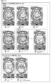
前記可動体を動作させることにより演出結果を報知する特定演出(例えば、可動体動作演出Aや可動体動作演出B)と、前記特定演出が実行されるよりも前に前記可動体を繰り返し動作させることにより前記特定演出が実行されることを示唆する示唆演出(例えば、可動体動作示唆演出Aや可動体動作示唆演出B)と、を実行可能な演出実行手段(例えば、演出制御用CPU120が図283-19に示す可変表示中演出処理を実行する部分)と、
を備え、
前記演出実行手段は、
前記示唆演出を実行するときは前記可動体に対する効果画像を表示しない一方、前記特定演出を実行するときは前記可動体に対する効果画像を表示し(例えば、図283-32~図283-35に示すように、可動体動作示唆演出Bの実行中は、画像表示装置5において爆発のエフェクト画像109SG005Bを表示しない一方で、可動体動作演出Bの実行中は、画像表示装置5において爆発のエフェクト画像109SG005Bを表示する部分)、
前記示唆演出を実行しているときに特定画像を表示するとともに、該特定画像を徐々に拡大表示し(例えば、図283-32及び図283-34に示すように、スーパーリーチβ1のリーチ演出中であれば味方キャラクタBと敵キャラクタAとを表示し、これら味方キャラクタBと敵キャラクタAを拡大表示していく部分と、スーパーリーチβ2のリーチ演出中であれば味方キャラクタBと敵キャラクタBを表示し、これら味方キャラクタBと敵キャラクタBを拡大表示していく部分)、
前記特定画像を徐々に拡大表示しているときは、該特定画像に対する効果画像を表示可能であり(例えば、図283-32及び図283-34に示すように、拡大表示期間中に画像表示装置5においてエフェクト画像109SG005Xを表示する部分)、
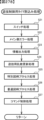
前記特定画像は第1特定画像と該第1特定画像とは異なる第2特定画像とを含み、前記第1特定画像が表示されるときと前記第2特定画像が表示されるときとで有利状態に制御される割合が異なり(例えば、図283-9に示すように、リーチ演出中に味方キャラクタBと敵キャラクタBが表示されるスーパーリーチβ2の可変表示は、リーチ演出中に味方キャラクタBと敵キャラクタAが表示されるスーパーリーチβ1の可変表示よりも大当り遊技状態に制御される割合が高い部分)、
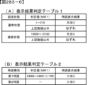
前記演出実行手段による前記可動体の制御周期は、前記特定画像および前記効果画像の更新周期と異なる(例えば、第1可動体109SG401、第2可動体109SG402L、第3可動体109SG402Rの移動制御周期は1msであるのに対して、画像表示装置5に表示される演出画像の更新周期は33msである部分)
ことを特徴としている。
この特徴によれば、効果画像によって特定画像の拡大表示や可動体の演出動作をより一層目立たせることができるので、遊技興趣を向上できる。
(2) A gaming machine (for example, Pachinko gaming machine 1) that can be controlled to an advantageous state (for example, a jackpot gaming state) that is advantageous to the player,
A movable body (for example, a first movable body 109SG401, a second movable body 109SG402L, a third movable body 109SG402R) that is movably provided,
A specific performance that notifies the performance result by operating the movable body (for example, movable body motion performance A or movable body motion performance B), and repeatedly moves the movable body before the specific performance is executed. Suggestive effects that suggest that the specific effect is to be executed (for example, movable body movement suggestion effect A or movable body movement suggestion effect B), and effect execution means (for example, the
Equipped with
The performance execution means is
When executing the suggestion effect, the effect image for the movable body is not displayed, while when executing the specific effect, the effect image for the movable body is displayed (for example, as shown in FIGS. 283-32 to 283-35). As shown, while the movable body motion suggestion production B is executed, the explosion effect image 109SG005B is not displayed on the
A specific image is displayed while the suggested effect is being executed, and the specific image is gradually enlarged and displayed (for example, as shown in FIGS. 283-32 and 283-34, during the reach effect of super reach β1) If so, ally character B and enemy character A will be displayed, and ally character B and enemy character A will be enlarged and displayed, and if super reach β2 is in reach effect, ally character B and enemy character B will be (The part where the friendly character B and enemy character B are enlarged and displayed)
When the specific image is gradually enlarged and displayed, an effect image for the specific image can be displayed (for example, as shown in FIGS. 283-32 and 283-34, the
The specific image includes a first specific image and a second specific image different from the first specific image, and is in an advantageous state when the first specific image is displayed and when the second specific image is displayed. (For example, as shown in Figure 283-9, the variable display of Super Reach β2 in which ally character B and enemy character B are displayed during a reach performance is (The part where the ratio of control to the jackpot game state is higher than the variable display of super reach β1 where enemy character A is displayed),
The control cycle of the movable body by the effect execution means is different from the update cycle of the specific image and the effect image (for example, the movement control cycle of the first movable body 109SG401, the second movable body 109SG402L, and the third movable body 109SG402R is 1ms, whereas the update cycle of the effect image displayed on the
It is characterized by
According to this feature, it is possible to make the enlarged display of a specific image and the effect movement of the movable body even more conspicuous by using the effect image, so that the interest in the game can be improved.
尚、本発明は、本発明の請求項に記載された発明特定事項のみを有するものであって良いし、本発明の請求項に記載された発明特定事項とともに該発明特定事項以外の構成を有するものであっても良い。 Note that the present invention may have only the matters specifying the invention described in the claims of the present invention, or may have configurations other than the matters specifying the invention together with the matters specifying the invention described in the claims of the present invention. It may be something.
<パチンコ遊技機の構成など>
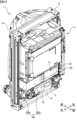
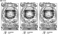
図1は、本実施の形態に係るパチンコ遊技機の正面図である。図1には、遊技機の一例であるパチンコ遊技機1における主要部材の配置レイアウトが示されている。遊技機の一例であるパチンコ遊技機1は、大別して、遊技盤面を構成する遊技盤(ゲージ盤)2と、遊技盤2を支持固定する遊技機用枠(台枠)3とから構成されている。遊技盤2には、遊技領域が形成され、この遊技領域には、遊技媒体としての遊技球が、所定の打球発射装置から発射されて打ち込まれる。
<Configuration of pachinko machine, etc.>
FIG. 1 is a front view of a pachinko gaming machine according to this embodiment. FIG. 1 shows an arrangement layout of main components in a
パチンコ遊技機1においては、特別図柄が可変表示することで遊技が行われる。特別図柄の「可変表示」とは、たとえば、複数種類の特別図柄を変動可能に表示することである(後述の他の図柄についても同じ)。変動としては、複数の図柄の更新表示、複数の図柄のスクロール表示、1以上の図柄の変形、1以上の図柄の拡大/縮小などがある。特別図柄や後述の普通図柄の変動では、複数種類の特別図柄または普通図柄が更新表示される。後述の飾り図柄の変動では、複数種類の飾り図柄がスクロール表示または更新表示されたり、1以上の飾り図柄が変形や拡大/縮小されたりする。なお、変動には、ある図柄を点滅表示する態様も含まれる。可変表示の最後には、表示結果として所定の特別図柄が停止表示(導出または導出表示などともいう)される(後述の他の図柄の可変表示についても同じ)。なお、可変表示を変動表示、変動と表現する場合がある。
In the
なお、パチンコ遊技機1において可変表示される特別図柄としては、2種類の特別図柄が設けられている。たとえば、一方の特別図柄を「第1特図」や「第1特別図柄」ともいい、他方の特別図柄を「第2特図」や「第2特別図柄」ともいう。また、第1特図を用いた特図ゲームを「第1特図ゲーム」といい、第2特図を用いた特図ゲームを「第2特図ゲーム」ともいう。
It should be noted that two types of special symbols are provided as the special symbols that are variably displayed in the
遊技盤2における遊技領域の中央付近には画像表示装置5が設けられている。画像表示装置5は、たとえばLCD(液晶表示装置)や有機EL(Electro Luminescence)などから構成され、各種の演出画像を表示する。画像表示装置5は、プロジェクタおよびスクリーンから構成されていてもよい。画像表示装置5には、各種の演出画像が表示される。
An
たとえば、画像表示装置5の画面上では、第1特図ゲームや第2特図ゲームと同期して、特別図柄とは異なる複数種類の装飾識別情報としての飾り図柄(数字などを示す図柄など)の可変表示が行われる。ここでは、第1特図ゲームまたは第2特図ゲームに同期して、「左」、「中」、「右」の各飾り図柄表示エリアにおいて飾り図柄が可変表示(たとえば上下方向のスクロール表示や更新表示)される。なお、同期して実行される特図ゲームおよび飾り図柄の可変表示を総称して単に可変表示ともいう。
For example, on the screen of the
画像表示装置5の画面上には、実行が保留されている可変表示に対応する保留表示や、実行中の可変表示に対応するアクティブ表示を表示するための表示エリアが設けられていてもよい。保留表示およびアクティブ表示を総称して可変表示に対応する可変表示対応表示ともいう。
A display area may be provided on the screen of the
保留されている可変表示の数は保留記憶数ともいう。第1特図ゲームに対応する保留記憶数を第1保留記憶数、第2特図ゲームに対応する保留記憶数を第2保留記憶数ともいう。第1保留記憶数と第2保留記憶数との合計を合計保留記憶数ともいう。 The number of pending variable displays is also called the number of pending memories. The number of pending memories corresponding to the first special figure game is also referred to as the first number of pending memories, and the number of pending memories corresponding to the second special figure game is also referred to as the second number of pending memories. The sum of the first number of pending memories and the second number of pending memories is also referred to as the total number of pending memories.
画像表示装置5の左側の遊技盤2上には、パチンコ遊技機1で実行される演出において登場する夢夢ちゃんというキャラクタが描かれている。夢夢ちゃんは、パチンコ遊技機1で用いられるコンテンツにおいて登場する主人公である。また、画像表示装置5の右下の遊技盤2上には、パチンコ遊技機1で実行される演出において登場するジャムちゃんというキャラクタが描かれている。ジャムちゃんは、パチンコ遊技機1で用いられるコンテンツにおいて登場するキャラクタである。
On the
画像表示装置5の下方には入賞球装置6Aが設けられており、入賞球装置6Aの右側方には、可変入賞球装置6Bが設けられている。
A winning
入賞球装置6Aは、たとえば所定の玉受部材によって常に遊技球が進入可能な一定の開放状態に保たれる第1始動入賞口を形成する。第1始動入賞口に遊技球が進入したときには、所定個(たとえば3個)の賞球が払い出されるとともに、第1特図ゲームが開始され得る。
The winning
可変入賞球装置6B(普通電動役物)は、ソレノイド81(図6参照)によって閉鎖状態と開放状態とに変化する第2始動入賞口(電チュー)を形成する。可変入賞球装置6Bは、たとえば、一対の可動翼片を有する電動チューリップ型役物を備え、ソレノイド81がオフ状態であるときに可動翼片が垂直位置となることにより、第2始動入賞口に遊技球が進入しない閉鎖状態になる(第2始動入賞口が閉鎖状態になるともいう。)。その一方で、可変入賞球装置6Bは、ソレノイド81がオン状態であるときに可動翼片が傾動位置となることにより、第2始動入賞口に遊技球が進入できる開放状態になる(第2始動入賞口が開放状態になるともいう)。第2始動入賞口に遊技球が進入したときには、所定個(たとえば3個)の賞球が払い出されるとともに、第2特図ゲームが開始され得る。なお、可変入賞球装置6Bは、閉鎖状態と開放状態とに変化するものであればよく、電動チューリップ型役物を備えるものに限定されない。
The variable winning
遊技盤2の所定位置(図1に示す例では、遊技領域の左下方3箇所と可変入賞球装置6Bの上方1箇所)には、所定の玉受部材によって常に一定の開放状態に保たれる一般入賞口10が設けられる。この場合には、一般入賞口10のいずれかに進入したときには、所定個数(たとえば10個)の遊技球が賞球として払い出される。
At predetermined positions on the game board 2 (in the example shown in FIG. 1, three locations on the lower left side of the game area and one location above the variable winning
入賞球装置6Aと可変入賞球装置6Bとの間には、大入賞口を有する特別可変入賞球装置7Aが設けられている。特別可変入賞球装置7Aは、ソレノイド82(図6参照)によって開閉駆動される大入賞口扉を備え、その大入賞口扉によって開放状態と閉鎖状態とに変化する特定領域としての大入賞口(以下、通常大入賞口と称する)を形成する。
A special variable winning ball device 7A having a big winning hole is provided between the winning
たとえば、特別可変入賞球装置7Aは、パチンコ遊技機1の奥側に位置する遊技盤2と、パチンコ遊技機1の手前側(遊技者側)に位置するガラス扉枠3a(図2参照)との間の空間に大入賞口扉を備えており、この大入賞口扉がパチンコ遊技機1の奥側と手前側との間を水平方向にスライド開閉することで、遊技球による通常大入賞口への経路が開放される。具体的には、ソレノイド82がオフ状態である場合、大入賞口扉がパチンコ遊技機1の手前側にスライド移動することで通常大入賞口を閉鎖状態として、遊技球が通常大入賞口に進入(通過)できなくなる。一方、ソレノイド82がオン状態である場合、大入賞口扉がパチンコ遊技機1の奥側にスライド移動することで通常大入賞口を開放状態として、遊技球が通常大入賞口に進入しやすくなる。
For example, the special variable winning ball device 7A has a
通常大入賞口に進入した遊技球は、通常大入賞口の内部に設けられた領域を通過することでカウントスイッチ23によって検出される。遊技球がカウントスイッチ23(図6参照)によって検出されることで、賞球として検出に応じた遊技球(たとえば、1回の検出ごとに10個)が遊技者に払い出される。通常大入賞口に遊技球が進入したときには、たとえば第1始動入賞口や第2始動入賞口および一般入賞口10に遊技球が進入したときよりも多くの賞球が払い出される。また、カウントスイッチ23によって検出された遊技球の個数が上限数(たとえば、10個)に達すると、1ラウンドが終了し、通常大入賞口が閉鎖状態に制御される。
The game ball that has entered the normal big winning opening is detected by the
パチンコ遊技機1においては、特別可変入賞球装置7Aの隣にV可変入賞球装置7Bが設けられている。V可変入賞球装置7Bは、ソレノイド83(図6参照)によって開閉駆動される大入賞口扉を備え、その大入賞口扉によって開放状態と閉鎖状態とに変化する大入賞口(以下、V大入賞口と称する)を形成する。
In the
たとえば、特別可変入賞球装置7Bは、遊技盤2とガラス扉枠3aとの間の空間に大入賞口扉を備えており、この大入賞口扉がパチンコ遊技機1の奥側と手前側との間を水平方向にスライド開閉することで、遊技球によるV大入賞口への経路が開放される。具体的には、ソレノイド83がオフ状態である場合、大入賞口扉がパチンコ遊技機1の手前側にスライド移動することでV大入賞口を閉鎖状態として、遊技球がV大入賞口に進入(通過)できなくなる。一方、ソレノイド83がオン状態である場合、大入賞口扉がパチンコ遊技機1の奥側にスライド移動することでV大入賞口を開放状態として、遊技球がV大入賞口に進入しやすくなる。
For example, the special variable winning ball device 7B is equipped with a big winning opening door in the space between the
V大入賞口に進入した遊技球は、V大入賞口の内部に設けられた特定領域(V入賞領域とも称する)を通過することでV入賞スイッチ24(図6参照)によって検出される。遊技球がV入賞スイッチ24によって検出されることで、遊技状態が確変状態に制御される。つまり、本実施の形態においては、大当り遊技状態のラウンド中においてV大入賞口に遊技球が進入したことを条件にV入賞が発生し、遊技状態が確変状態に制御されるようになっている。なお、通常大入賞口およびV大入賞口をまとめて大入賞口とも称する。また、大入賞口をアタッカとも称する。
The game ball that has entered the V big winning hole is detected by the V winning switch 24 (see FIG. 6) by passing through a specific area (also referred to as the V winning area) provided inside the V big winning hole. When the game ball is detected by the
一般入賞口10を含む各入賞口に遊技球が進入することを「入賞」ともいう。特に、始動口(第1始動入賞口、第2始動入賞口)への入賞を始動入賞ともいう。
Entering the game ball into each winning hole including the general winning
パチンコ遊技機1においては、特別図柄とは異なる複数種類の普通識別情報としての普通図柄の可変表示を行う。このような普通図柄の可変表示は、普図ゲームともいう。
In the
画像表示装置5の右方には、遊技球が通過可能な通過ゲート41が設けられている。遊技球が通過ゲート41を通過したことに基づき、普図ゲームが実行される。
A
遊技盤2の表面には、上記の構成以外にも、遊技球の流下方向や速度を変化させる風車および多数の障害釘が設けられている。遊技領域の最下方には、いずれの入賞口にも進入しなかった遊技球が取り込まれるアウト口が設けられている。
In addition to the above structure, the surface of the
遊技機用枠3の左右上部位置には、効果音などを再生出力するためのスピーカ8L,8Rが設けられている。
At the left and right upper positions of the
遊技盤2の所定位置(図1では画像表示装置5の上方位置)には、演出に応じて動作する可動体32が設けられている。可動体32は、「POWERFULII」という文字列により構成されている。「POWERFULII」は、パチンコ遊技機1の機種名であってもよいし、パチンコ遊技機1で用いられるコンテンツを表す名称(たとえば、アニメのタイトルや歌手の名前など)であってもよい。また、可動体32に付された文字は、パチンコ遊技機1で用いられるコンテンツにおいて登場するキャラクタの名前(たとえば、主人公である夢夢ちゃんを示す「夢夢」)を示してもよい。本実施の形態においては、パチンコ遊技機1の機種名(パワフルII)が可動体32に示されている。
A
本実施の形態において、可動体32は、図1に示すように画像表示装置5の上方の位置と、画像表示装置5の前面に被さる(重畳する)位置との間で移動可能である。具体的には、可動体32は、「POWERFULII」という文字が斜めに落下する(「P」が下方、「II」が上方となるように落下する)ことで画像表示装置5の前面に被さる(重畳する)位置で停止する。なお、可動体32は、役物とも称される。
In this embodiment, the
遊技機用枠3の右下部位置には、遊技球を打球発射装置により遊技領域に向けて発射するために遊技者などによって操作される打球操作ハンドル(操作ノブ)30が設けられている。
At the lower right position of the
遊技領域の下方における遊技機用枠3の所定位置には、賞球として払い出された遊技球や所定の球貸機により貸し出された遊技球を、打球発射装置へと供給可能に保持(貯留)する打球供給皿(上皿)が設けられている。なお、遊技機用枠3には、上皿とは別に、上皿満タン時に賞球が払い出される払出部(打球供給皿)を設けてもよい。
At a predetermined position of the
遊技領域の下方における遊技機用枠3の所定位置には、遊技者が把持して傾倒操作(前後左右方向への操作、遊技者の手前に引く操作)が可能な操作桿としてのスティックコントローラ31Aが取り付けられている。スティックコントローラ31Aの本体内部などには、操作桿に対する傾倒操作を検知するコントローラセンサユニット35A(図6参照)が設けられている。また、スティックコントローラ31Aには、スティックコントローラ31Aを振動動作させるためのバイブレータ用モータ(図示省略)が内蔵されている。なお、スティックコントローラ31Aは、遊技者の手前に引く操作が可能であるため、「トリガ」とも称する。
At a predetermined position of the
遊技領域の下方における遊技機用枠3の所定位置には、遊技者が押圧操作などにより所定の指示操作を可能なプッシュボタン31Bが設けられている。プッシュボタン31Bに対する操作は、プッシュセンサ35B(図6参照)により検出される。
At a predetermined position of the
パチンコ遊技機1では、遊技者の動作(操作など)を検出する検出手段として、スティックコントローラ31Aやプッシュボタン31Bが設けられるが、これら以外の検出手段が設けられていてもよい。
In the
パチンコ遊技機1は、遊技盤2の左下に特図LED基板9020を備える。特図LED基板9020は、遊技制御用マイクロコンピュータ100によって制御され、第1保留記憶数や第2保留記憶数などを、LEDの点灯/点滅/消灯によって報知するLED基板である。特図LED基板9020においては、複数のLEDによる点灯/点滅/消灯などの点灯態様の組合せによって、第1特図ゲームにおける特別図柄(第1特図)の種類や第2特図ゲームにおける特別図柄(第2特図)の種類を表す。たとえば、後述する図4(a)に示すように、特図LED基板9020においては、特図1可変表示部9021に設けられた複数のLEDによる点灯/点滅/消灯などの点灯態様の組合せによって、第1特図の種類を表し、特図2可変表示部9022に設けられた複数のLEDによる点灯/点滅/消灯などの点灯態様の組合せによって、第2特図の種類を表す。なお、本実施の形態においては、「点灯態様」という用語を、後述する枠ランプなどの各種ランプにおける点灯、点滅、および消灯を含む概念として用いる。
The
さらに、パチンコ遊技機1は、画像表示装置5の左下に第4図柄ユニット9050を備える。第4図柄ユニット9050は、演出制御用CPU120によって制御され、特図の変動や保留記憶数、右打ち表示などを、LEDの点灯/点滅/消灯によって報知するLED基板である。第4図柄ユニット9050においては、複数のLEDによる点灯/点滅/消灯などの点灯態様の組合せによって、第1特図ゲームにおける特別図柄(第1特図)の種類や第2特図ゲームにおける特別図柄(第2特図)の種類を表す。たとえば、後述する図4(b)に示すように、第4図柄ユニット9050においては、特図1可変表示部9053に設けられた複数のLEDによる点灯/点滅/消灯などの点灯態様の組合せによって、第1特図の種類を表し、特図2可変表示部9054に設けられた複数のLEDによる点灯/点滅/消灯などの点灯態様の組合せによって、第2特図の種類を表す。
Further, the
パチンコ遊技機1は、遊技盤2および遊技機用枠3において複数のランプ(遊技効果ランプとも称する。)を備える。具体的には、パチンコ遊技機1は、可動体32に設けられた役物ランプ9Aと、遊技盤2の左側に設けられた盤左ランプ9Bと、特別可変入賞球装置7Bの付近に設けられたアタッカランプ9Eと、特別可変入賞球装置7Aの付近に設けられたVアタッカランプ9Fと、V大入賞口が開放してV入賞が発生可能な大当り遊技状態のラウンド中であることやV入賞が発生したことを報知するVランプ9Gと、可変入賞球装置6Bの付近に設けられた電チューランプ9Hと、スティックコントローラ31Aに設けられたスティックコントローラランプ9Jと、プッシュボタン31Bに設けられたプッシュボタンランプ9Kと、遊技機用枠3の左側に設けられた枠左ランプ9Lと、遊技機用枠3の右側に設けられた枠右ランプ9Rとを備える。Vランプは、大当りが発生したことを報知するものであってもよい。
The
役物ランプ9Aは、役物ランプ9A1~9A4といった複数のランプから構成されている。具体的には、可動体32に含まれる「POWERFULII」という文字が付された部材が4分割されており、役物ランプ9A1は「P」および「O」の部分の裏側、役物ランプ9A2は「W」および「E」の部分の裏側、役物ランプ9A3は「R」および「F」の部分の裏側、役物ランプ9A4は「U」および「L」の部分の裏側に各々配置されている。これにより、役物ランプ9A1~9A4が「POWERFULII」という文字が付された部材の裏側で点灯(発光)することで、「POWERFULII」が点灯(発光)するようになっている。
The
盤左ランプ9Bは、盤左ランプ9B1~9B5といった複数のランプから構成されている。遊技盤2の左側には、パチンコ遊技機1で用いられるコンテンツにおいて主人公(たとえば、主人公である夢夢ちゃんを示す「夢夢」)が描かれており、盤左ランプ9B1~9B5は、その主人公が描かれた遊技盤2の部分の裏側に各々配置されている。これにより、盤左ランプ9B1~9B5が主人公が描かれた遊技盤2の部分の裏側で点灯(発光)することで、主人公が描かれた遊技盤2の部分が点灯(発光)するようになっている。
The board left
アタッカランプ9Eは、特別可変入賞球装置7Bの付近において遊技盤2の裏側に配置されている。これにより、アタッカランプ9Eが遊技盤2の裏側で点灯(発光)することで、特別可変入賞球装置7Bの付近を点灯(発光)するようになっている。また、Vアタッカランプ9Fは、特別可変入賞球装置7Aの付近において遊技盤2の裏側に配置されている。これにより、Vアタッカランプ9Fが遊技盤2の裏側で点灯(発光)することで、特別可変入賞球装置7Aの付近を点灯(発光)するようになっている。
The
Vランプ9Gは、「V」と描かれた遊技盤2の部分の裏側に配置されている。これにより、Vランプ9Gが「V」と描かれた遊技盤2の部分の裏側で点灯(発光)することで、「V」と描かれた遊技盤2の部分が点灯(発光)するようになっている。電チューランプ9Hは、可変入賞球装置6Bの付近に配置されており、点灯(発光)することで、特別可変入賞球装置7Bの付近を点灯(発光)するようになっている。
The
スティックコントローラランプ9Jは、スティックコントローラ31Aに設けられており、点灯(発光)することで、スティックコントローラ31Aを点灯(発光)するようになっている。プッシュボタンランプ9Kは、プッシュボタン31Bに設けられており、点灯(発光)することで、プッシュボタン31Bを点灯(発光)するようになっている。
The
枠左ランプ9Lは、遊技機用枠3の左側に設けられた複数のランプ9L1~9L12(図3で後述する)によって構成されており、各ランプが点灯(発光)することで、遊技機用枠3の左側を点灯(発光)するようになっている。枠右ランプ9Rは、遊技機用枠3の右側に設けられた複数のランプ9R2~9L12(図3で後述する)によって構成されており、各ランプが点灯(発光)することで、遊技機用枠3の右側を点灯(発光)するようになっている。なお、枠左ランプ9Lおよび枠右ランプ9Rを総称して枠ランプとも称する。また、役物ランプ9A、盤左ランプ9B、アタッカランプ9E、Vアタッカランプ9F、Vランプ9G、電チューランプ9H、スティックコントローラランプ9J、プッシュボタンランプ9K、枠左ランプ9L、および枠右ランプ9Rを、総称して遊技効果ランプ9とも称する。
The frame left lamp 9L is composed of a plurality of lamps 9L1 to 9L12 (described later in FIG. 3) provided on the left side of the
図2は、本実施の形態に係るパチンコ遊技機1の背面斜視図である。パチンコ遊技機1の背面には、基板ケース201に収納された主基板11が搭載されている。主基板11には、設定キー51や設定切替スイッチ52が設けられている。設定キー51は、設定変更状態または設定確認状態に切り替えるための錠スイッチとして機能する。設定切替スイッチ52は、設定変更状態において大当りの当選確率や出玉率などの設定値を変更するための設定スイッチとして機能する。設定キー51や設定切替スイッチ52は、たとえば電源基板17(図6参照)の所定位置といった、主基板11の外部に取り付けられてもよい。
FIG. 2 is a rear perspective view of the
主基板11の背面中央には、表示モニタ29が配置され、表示モニタ29の側方には表示切替スイッチ30(図6参照)が配置されている。表示モニタ29は、たとえば7セグメントのLED表示装置を用いて、構成されていればよい。表示モニタ29および表示切替スイッチ30は、遊技機用枠3を開放した状態で遊技盤2の裏面側を視認した場合に、主基板11を視認する際の正面に配置されている。
A display monitor 29 is arranged at the center of the back surface of the
表示モニタ29は、たとえば連比や役比、ベースなどの入賞情報を表示可能である。連比は、賞球合計数のうち大入賞口(アタッカ)への入賞による賞球数が占める割合である。役比は、賞球合計数のうち第2始動入賞口(電チュー)への入賞による賞球数と大入賞口(アタッカ)への入賞による賞球数が占める割合である。ベースは、打ち出した遊技球数に対する賞球合計数が占める割合である。設定変更状態や設定確認状態であるときに、表示モニタ29は、パチンコ遊技機1における設定値を表示可能である。表示モニタ29は、設定変更状態や設定確認状態であるときに、変更や確認の対象となる設定値などを表示可能であればよい。
The display monitor 29 can display winning information such as consecutive ratios, winning ratios, and bases. The consecutive ratio is the ratio of the number of prize balls that land in the big prize opening (attacker) out of the total number of prize balls. The winning ratio is the ratio of the number of prize balls that land in the second starting prize opening (electronic chew) to the number of prize balls that land in the big prize opening (attacker) out of the total number of prize balls. The base is the ratio of the total number of prize balls to the number of game balls launched. When in the setting change state or setting confirmation state, the display monitor 29 can display the setting values in the
設定キー51や設定切替スイッチ52は、遊技機用枠3を閉鎖した状態であるときに、パチンコ遊技機1の正面側から操作が不可能となっている。遊技機用枠3には、ガラス窓を有するガラス扉枠3aが回動可能に設けられ、ガラス扉枠3aにより遊技領域を開閉可能に構成されている。ガラス扉枠3aを閉鎖したときに、ガラス窓を通して遊技領域を透視可能である。
The setting
パチンコ遊技機1において、縦長の方形枠状に形成された外枠1aの右端部には、セキュリティカバー50Aが取り付けられている。セキュリティカバー50Aは、遊技機用枠3を閉鎖したときに、設定キー51や設定切替スイッチ52を含む基板ケース201の右側部を、背面側から被覆する。セキュリティカバー50Aは、短片50Aaおよび長片50Abを含む略L字状の部材であり、透明性を有する合成樹脂により構成されていればよい。
In the
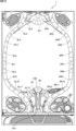
図3は、枠ランプを説明するための図である。枠左ランプ9Lは、遊技機用枠3の上方から下方に亘って左回りに、枠左ランプ9L1~9L12の12個のランプ群を有する。枠左ランプ9Lは、複数のランプ(この例では12個のランプ)を各々点灯または点滅することで、遊技機用枠3の左側付近を発光させる。一方、枠右ランプ9Rは、遊技機用枠3の上方から下方に亘って右回りに、枠左ランプ9R2~9L12の11個のランプ群を有する。枠右ランプ9Rは、複数のランプ(この例では11個のランプ)を各々点灯または点滅することで、遊技機用枠3の右側付近を発光させる。
FIG. 3 is a diagram for explaining the frame lamp. The frame left lamp 9L has a group of 12 lamps including left frame lamps 9L1 to 9L12 running counterclockwise from the top to the bottom of the
図4は、特図LED基板9020および第4図柄ユニット9050を説明するための図である。図4(a)に示すように、特図LED基板9020は、第1特図の可変表示を示す特図1可変表示部9021と、第2特図の可変表示を示す特図2可変表示部9022と、第1特図ゲームに対応する第1保留記憶数を示す特図1記憶表示部9023と、第2特図ゲームに対応する第2保留記憶数を示す特図2記憶表示部9024と、普図保留記憶数を示す普図記憶表示部9025と、普通図柄の可変表示を示す普図表示部9026と、遊技者に対して右打ちを促す右打ち表示部9030と、確変状態の有無を示す確変表示部9028と、時短状態の有無を示す時短表示部9029と、大当りのラウンド数を示すラウンド表示部9027とを備える。各表示部は、LEDなどの点灯手段による点灯または点滅によって、特図や普通図柄の可変表示の有無やその結果、現在の遊技状態、および保留数などを、遊技者に対して報知することができる。
FIG. 4 is a diagram for explaining the special
たとえば、特図1可変表示部9021は、第1特図ゲームにおける第1特別図柄の可変表示が行われているか否か、および当該可変表示の結果によって決まった第1特別図柄の停止図柄を、LEDなどの点灯手段による点灯/点滅/消灯によって遊技者に報知する。特図2可変表示部9022は、第2特図ゲームにおける第2特別図柄の可変表示が行われているか否か、および当該可変表示の結果によって決まった第2特別図柄の停止図柄を、LEDなどの点灯手段による点灯/点滅/消灯によって遊技者に報知する。
For example, the special figure 1
さらに、特図LED基板9020は、右打ち表示部9030におけるLEDなどの点灯手段による点灯/点滅/消灯によって、右打ちをすることを遊技者に促すことができる。本実施の形態においては、右打ちをすることを遊技者に促す場合、右打ち表示部9030におけるLEDなどの点灯手段が点灯(発光)し、右打ちをすることを遊技者に促さない場合、すなわち左打ちすることを遊技者に促す場合、右打ち表示部9030におけるLEDなどの点灯手段が消灯する。CPU103は、図柄確定後に、演出制御用CPU120に右打ち表示点灯指定コマンドを送信するとともに、右打ち表示部9030を点灯させ、通常状態に戻る前の高ベース状態において最終変動によって図柄が確定した後に、演出制御用CPU120に右打ち表示消灯指定コマンドを送信するとともに、右打ち表示部9030を消灯させる。なお、パチンコ遊技機1が大当り遊技状態後に高ベースに制御されない大当りを有する場合、演出制御用CPU120は、大当りラウンド中においてのみ、右打ち表示部9030を点灯させてもよい。この場合、CPU103は、演出制御用CPU120に大当り終了指定コマンドを送信するとともに、右打ち表示部9030を消灯させる。
Furthermore, the special
ここで、右打ちとは、遊技盤2に設けられた遊技領域において遊技媒体が流下可能な第1流下経路と第2流下経路とのうち、当該第2流下経路に向けて遊技球を発射させるように打球操作ハンドル30を操作すること(打ち方)である。第1流下経路は、たとえば、遊技領域のうちの左側の領域を通る経路であって、その先には入賞球装置6Aに形成された第1始動入賞口が存在する一方で、可変入賞球装置6Bに形成された第2始動入賞口が存在しない経路である。第2流下経路は、たとえば、遊技領域のうちの右側の領域を通る経路であって、その先には可変入賞球装置6Bに形成された第2始動入賞口や大入賞口(通常大入賞口,V大入賞口)が存在する経路である。遊技者が第1流下経路に向けて遊技球を発射させると、遊技球が第1流下経路を通って、第1始動入賞口の方へと流れ込む。遊技者が第2流下経路に向けて遊技球を発射させると、遊技球が第2流下経路を通って、第2始動入賞口や大入賞口(通常大入賞口,V大入賞口)の方へと流れ込む。
Here, hitting right means firing the game ball toward the second downstream path of the first downstream path and the second downstream path through which the game medium can flow down in the game area provided on the
本実施の形態においては、大当りが発生した後の大当り遊技、および大当り遊技後の遊技状態(時短状態や確変状態)において、遊技者が右打ちをすることで、遊技領域の右側に設けられた第2始動入賞口や大入賞口に遊技球を進入させるようになっており、その間、右打ち表示部9030は、右打ちすることを遊技者に促す。遊技者は、右打ちすることを促す表示が行われている間に右打ちすることで、第2始動入賞口に遊技球を進入させて所定個(たとえば3個)の賞球が払い出されるとともに第2特図ゲームの権利を得ることができたり、また、通常大入賞口に遊技球を進入させて所定個(たとえば10個)の賞球が払い出されたりする。さらに、詳しくは後述するが、確変大当りのラウンド中においてはV大入賞口が開放するが、遊技者は、右打ちすることを促す表示が行われている間に右打ちすることで、V大入賞口に遊技球を進入させて確変状態に制御されるための権利を得ることもできる。このため、右打ちすることを促す表示が行われている間に右打ちすることで、遊技者は総合的に有利となり得る。なお、右打ちとは異なり、第1流下経路に向けて遊技球を発射させるように打球操作ハンドル30を操作すること(打ち方)を、左打ちとも称する。
In this embodiment, in a jackpot game after a jackpot occurs, and in a gaming state (time saving state or variable probability state) after a jackpot game, when the player hits right, a The game ball is made to enter the second starting winning hole or the big winning hole, and during this time, the right-
図4(b)に示すように、第4図柄ユニット9050は、第1特図ゲームに対応する第1保留記憶数を示す特図1記憶表示部9051と、第2特図ゲームに対応する第2保留記憶数を示す特図2記憶表示部9052と、第1特図の可変表示の状況または表示結果を示す特図1可変表示部9053と、第2特図の可変表示の状況または表示結果を示す特図2可変表示部9054と、遊技者に対して右打ちを促す右打ち表示部9055とを備える。各表示部は、LEDなどの点灯手段による点灯/点滅/消灯によって、特図の可変表示の有無、保留数、および右打ち指示などを、遊技者に対して報知することができる。
As shown in FIG. 4(b), the
たとえば、特図1可変表示部9053は、第1特図ゲームにおける第1特別図柄の可変表示が行われているか否か、および当該可変表示の結果によって決まった第1特別図柄の停止図柄を、LEDなどの点灯手段による点灯/点滅/消灯によって遊技者に報知する。特図2可変表示部9054は、第2特図ゲームにおける第2特別図柄の可変表示が行われているか否か、および当該可変表示の結果によって決まった第2特別図柄の停止図柄を、LEDなどの点灯手段による点灯/点滅/消灯によって遊技者に報知する。
For example, the special figure 1
以下では、特図1可変表示部9021や特図1可変表示部9053におけるLEDなどの点灯手段によって第1特別図柄の停止図柄の変動を表すことを、第1特別図柄の変動表示(可変表示)とも称する。また、特図2可変表示部9022や特図2可変表示部9054におけるLEDなどの点灯手段によって第2特別図柄の停止図柄の変動を表すことを、第2特別図柄の変動表示(可変表示)とも称する。
In the following, the variation display (variable display) of the first special symbol indicates that the variation of the stop symbol of the first special symbol is represented by lighting means such as LED in the
さらに、本実施の形態においては、右打ちをすることを遊技者に促す場合、第4図柄ユニット9050の右打ち表示部9055におけるLEDなどの点灯手段が点灯(発光)し、右打ちをすることを遊技者に促さない場合、すなわち左打ちすることを遊技者に促す場合、右打ち表示部9055におけるLEDなどの点灯手段が消灯する。演出制御用CPU120は、図柄確定後に、CPU103から右打ち表示点灯指定コマンドを受信したことに基づいて、右打ち表示部9055を点灯させ、通常状態に戻る前の高ベース状態において最終変動によって図柄が確定した後に、CPU103から右打ち表示消灯指定コマンドを受信したことに基づいて、右打ち表示部9055を消灯させる。なお、パチンコ遊技機1が大当り遊技状態後に高ベースに制御されない大当りを有する場合、演出制御用CPU120は、大当りラウンド中においてのみ、右打ち表示部9055を点灯させてもよい。この場合、演出制御用CPU120は、CPU103から大当り終了指定コマンドを受信したことに基づいて、右打ち表示部9055を消灯させる。
Furthermore, in the present embodiment, when urging the player to play right, the lighting means such as an LED in the right
図4(c)は、第4図柄ユニットと遊技効果ランプとの関係を説明するための図である。パチンコ遊技機1では、演出制御コマンドのうち、後述する前変動パターンコマンドおよび後変動パターンコマンド、あるいは図柄確定コマンドを演出制御用CPU120が受信したときに、第4図柄ユニット9050と遊技効果ランプとで、点灯/点滅/消灯などの点灯態様の切り替え有無を異ならせる。前変動パターンコマンドおよび後変動パターンコマンドは、後述する遊技制御用マイクロコンピュータ100のCPU103から、演出制御基板12の演出制御用CPU120に対して出力されるコマンドであり、前変動パターンコマンドおよび後変動パターンコマンドで1セットでCPU103から演出制御用CPU120に対して出力される。以下では、前変動パターンコマンドおよび後変動パターンコマンドをまとめて変動パターンコマンドとも称する。
FIG. 4(c) is a diagram for explaining the relationship between the fourth symbol unit and the game effect lamp. In the
具体的には、演出制御用CPU120は、CPU103から変動パターンコマンドを受信したときに、第4図柄ユニット9050におけるLED(特図1可変表示9053や特図2可変表示9054)の点灯態様を変化させる。たとえば、演出制御用CPU120は、第1特図ゲームに対応する変動パターンコマンドをCPU103から受信すると、受信した当該変動パターンコマンドに基づき、特図1可変表示9053の点灯態様を、第1特別図柄の停止を示す消灯から、第1特別図柄の変動を示す点滅に切り替える。また、演出制御用CPU120は、第2特図ゲームに対応する変動パターンコマンドをCPU103から受信すると、受信した当該変動パターンコマンドに基づき、特図2可変表示9054の点灯態様を、第2特別図柄の停止を示す消灯から、第2特別図柄の変動を示す点滅に切り替える。
Specifically, when receiving a variation pattern command from the
一方、演出制御用CPU120は、CPU103から変動パターンコマンドを受信しても、遊技効果ランプにおけるLED(枠ランプなど)の点灯態様を変化させることなく、当該変動パターンコマンドを受信する前の点灯態様を維持させる。
On the other hand, even if the
また、演出制御用CPU120は、CPU103から図柄確定コマンドを受信したときに、第4図柄ユニット9050におけるLED(特図1可変表示9053や特図2可変表示9054)の点灯態様を変化させる。たとえば、演出制御用CPU120は、第1特図ゲームにおいて図柄の変動を終了することを指定する図柄確定コマンドをCPU103から受信すると、受信した当該図柄確定コマンドに基づき、特図1可変表示9053の点灯態様を、第1特別図柄の変動を示す点滅から、第1特別図柄の停止を示す消灯に切り替える。また、演出制御用CPU120は、第2特図ゲームにおいて図柄の変動を終了することを指定する図柄確定コマンドをCPU103から受信すると、受信した当該図柄確定コマンドに基づき、特図2可変表示9054の点灯態様を、第2特別図柄の変動を示す点滅から、第2特別図柄の停止を示す消灯に切り替える。
In addition, when receiving the symbol confirmation command from the
一方、演出制御用CPU120は、CPU103から図柄確定コマンドを受信しても、遊技効果ランプにおけるLED(枠ランプなど)の点灯態様を変化させることなく、当該図柄確定コマンドを受信する前の点灯態様を維持させる。
On the other hand, even if the
このように、パチンコ遊技機1は、第4図柄ユニット9050においては、変動パターンコマンドや図柄確定コマンドを受信したことに応じてランプ(LED)の態様が変化する。それに対し、パチンコ遊技機1は、遊技効果ランプ9においては、変動パターンコマンドや図柄確定コマンドを受信したことに関わらずそのコマンド受信の前後でランプの態様が維持される。なお、パチンコ遊技機1は、変動パターンコマンドを受信したことに応じて遊技効果ランプ9の態様が変化するようにしてもよい。たとえば、パチンコ遊技機1は、遊技状態が通常状態から大当り後の時短状態へと変化した場合に、時短状態が開始される変動パターンコマンドを受信したことに応じて通常状態の点灯態様から時短状態の点灯態様へと遊技効果ランプ9の態様を変化させてもよい。
In this way, in the
図5は、画像表示装置5における画面の表示態様を説明するための図である。画像表示装置5の表示領域の大部分は、飾り図柄の可変表示やリーチ演出などの画像が表示される。具体的には、画像表示装置5の画面中央、第1特図ゲームや第2特図ゲームと同期して、特別図柄とは異なる複数種類の装飾識別情報としての飾り図柄(数字などを示す図柄など)の可変表示が行われる。ここでは、第1特図ゲームまたは第2特図ゲームに同期して、「左」,「中」,「右」の各飾り図柄表示エリア5L,5C,5Rにおいて飾り図柄が可変表示(たとえば上下方向のスクロール表示や更新表示)される。なお、同期して実行される特図ゲームおよび飾り図柄の可変表示を総称して単に可変表示ともいう。
FIG. 5 is a diagram for explaining the display mode of the screen on the
画像表示装置5の画面の下端部には、第1保留記憶数を円形の保留表示の数によって表示可能な第1保留記憶表示エリア5Dと、第2保留記憶数を円形の保留表示の数によって表示可能な第2保留記憶表示エリア5Uと、実行中の可変表示に対応する保留表示をアクティブ表示として表示するためのアクティブ表示エリア5Aとが設けられている。
At the lower end of the screen of the
画像表示装置5の画面の右上端部には、特別図柄の可変表示中であることを示す第4図柄5Jが表示される。第4図柄5Jの下部には、第1保留記憶数や第2保留記憶数を示す数字が表示される。保留数を示す数字は、左側が第1保留記憶数、右側が第2保留記憶数を示している。保留数を示す表示の下部には、各飾り図柄よりも小さいサイズの小図柄5Mが表示されている。小図柄は、「左」の飾り図柄表示エリア5Lに表示されている飾り図柄、「中」の飾り図柄表示エリア5Cに表示されている飾り図柄、「右」の飾り図柄表示エリア5Rに表示されている飾り図柄のそれぞれに対応する図柄が横方向に並列されている。また、小図柄5Mは、可変表示中は非表示化させることがなく、常時、画像表示装置5の画面に表示されている図柄でもある。
At the upper right end of the screen of the
なお、図5に示すように、画像表示装置5の画面の中央部に飾り図柄が配置されており、小図柄5Mは、画像表示装置5の画面の右端部において飾り図柄よりも小さいサイズにて配置されている。このため、小図柄5Mの視認性は、飾り図柄の視認性よりも低くなっている。
As shown in FIG. 5, a decorative pattern is arranged at the center of the screen of the
なお、図5(a)に示すように、画像表示装置5の画面の形状は四角形または略四角形であるが、遊技盤2は、画像表示装置5の画面の端部に覆いかぶさるようにして固定されている。このため、図5(b)に示すように、パチンコ遊技機1を正面から見た場合、画像表示装置5の画面の一部(特に端部)は、遊技盤2によって視認できない、または視認困難になっている。
As shown in FIG. 5(a), the screen of the
<基板構成>
図6は、パチンコ遊技機1に搭載された各種基板などを説明するための図である。図6に示すように、パチンコ遊技機1には、主基板11、演出制御基板12、音声制御基板13、中継基板15などが搭載されている。その他にも、パチンコ遊技機1の背面には、たとえば払出制御基板、情報端子基板、発射制御基板などといった、各種の基板が配置されている。さらには、電源スイッチ91に接続された電源基板17も搭載されている。各種制御基板は、導体パターンが形成されて電気部品を実装可能なプリント配線板などの電子回路基板だけでなく、電子回路基板に電気部品が実装されて特定の電気的機能を実現するように構成された電子回路実装基板を含む概念である。
<Substrate configuration>
FIG. 6 is a diagram for explaining various boards etc. mounted on the
パチンコ遊技機1では、商用電源などの外部電源におけるAC100Vといった交流電源からの電力を、電源基板17により主基板11や演出制御基板12などの各種制御基板を含めた電気部品に供給可能である。電源基板17は、たとえば交流(AC)を直流(DC)に変換するための整流回路、所定の直流電圧を特定の直流電圧(たとえば直流12Vや直流5Vなど)に変換するための電源回路などを備えている。
In the
主基板11は、メイン側の制御基板であり、パチンコ遊技機1における上記遊技の進行(特図ゲームの実行(保留の管理を含む)、普図ゲームの実行(保留の管理を含む)、大当り遊技状態、遊技状態など)を制御する機能を有する。主基板11は、遊技制御用マイクロコンピュータ100、スイッチ回路110、出力回路111などを有する。
The
主基板11に搭載された遊技制御用マイクロコンピュータ100は、たとえば1チップのマイクロコンピュータであり、ROM(Read Only Memory)101と、RAM(Random Access Memory)102と、CPU(Central Processing Unit)103と、乱数回路104と、I/O(Input/Output port)105と、RTC(Real Time Clock)106とを備える。
The
CPU103は、ROM101に記憶されたプログラムを実行することにより、遊技の進行を制御する処理(主基板11の機能を実現する処理)を行う。このとき、ROM101が記憶する各種データ(後述の変動パターン、後述の演出制御コマンド、後述の各種決定を行う際に参照される各種テーブルなどのデータ)が用いられ、RAM102がメインメモリとして使用される。RAM102は、その一部または全部がパチンコ遊技機1に対する電力供給が停止しても、所定期間記憶内容が保存されるバックアップRAMとなっている。なお、ROM101に記憶されたプログラムの全部または一部をRAM102に展開して、RAM102上で実行するようにしてもよい。
The
乱数回路104は、遊技の進行を制御するときに使用される各種の乱数値(遊技用乱数)を示す数値データを更新可能にカウントする。遊技用乱数は、CPU103が所定のコンピュータプログラムを実行することで更新されるもの(ソフトウェアで更新されるもの)であってもよい。
The
I/O105は、たとえば各種信号(後述の検出信号)が入力される入力ポートと、各種信号(特図LED基板9020などを制御(駆動)する信号、ソレノイド駆動信号)を伝送するための出力ポートとを含んで構成される。
The I/
スイッチ回路110は、遊技球検出用の各種スイッチ(ゲートスイッチ21、始動口スイッチ(第1始動口スイッチ22Aおよび第2始動口スイッチ22B)、カウントスイッチ23、V入賞スイッチ24)からの検出信号(遊技球が通過または進入してスイッチがオンになったことを示す検出信号など)を取り込んで遊技制御用マイクロコンピュータ100に伝送する。検出信号の伝送により、遊技球の通過または進入が検出されたことになる。
The
スイッチ回路110には、電源基板17からのリセット信号、電源断信号、クリア信号が取り込まれて遊技制御用マイクロコンピュータ100に伝送される。リセット信号は、遊技制御用マイクロコンピュータ100などの制御回路を動作停止状態とするための動作停止信号であり、電源監視回路、ウォッチドッグタイマ内蔵IC、システムリセットICのいずれかを用いて出力可能であればよい。電源断信号は、パチンコ遊技機1において用いられる所定電源電圧が所定値を超えるとオフ状態となり、所定電源電圧が所定値以下になった期間が電断基準時間以上まで継続したときにオン状態となる。クリア信号は、たとえば電源基板17に設けられたクリアスイッチ92に対する押圧操作などに応じてオン状態となる。
A reset signal, a power-off signal, and a clear signal from the
出力回路111は、遊技制御用マイクロコンピュータ100からのソレノイド駆動信号を、ソレノイド81、ソレノイド82、またはソレノイド83に伝送する。
The
主基板11には、表示モニタ29、表示切替スイッチ30、設定キー51、設定切替スイッチ52、扉開放センサ90が接続されている。扉開放センサ90は、ガラス扉枠3aを含めた遊技機用枠3の開放を検知する。
A
主基板11(遊技制御用マイクロコンピュータ100)は、遊技の進行の制御の一部として、遊技の進行に応じて演出制御コマンド(遊技の進行状況などを指定(通知)するコマンド)を演出制御基板12に供給する。主基板11から出力された演出制御コマンドは、中継基板15により中継され、演出制御基板12に供給される。当該演出制御コマンドには、たとえば主基板11における各種の決定結果(たとえば、特図ゲームの表示結果(大当り種類を含む。)、特図ゲームを実行する際に使用される変動パターン(詳しくは後述))、遊技の状況(たとえば、可変表示の開始や終了、大入賞口の開放状況、入賞の発生、保留記憶数、遊技状態)、エラーの発生などを指定するコマンドなどが含まれる。
The main board 11 (game control microcomputer 100) is a production control board that sends production control commands (commands that specify (notify) the progress of the game, etc.) according to the progress of the game as part of the control of the progress of the game. Supply to 12. The production control command output from the
演出制御基板12は、主基板11とは独立したサブ側の制御基板であり、演出制御コマンドを受信し、受信した演出制御コマンドに基づいて演出(遊技の進行に応じた種々の演出であり、可動体32の駆動、エラー報知、電断復旧の報知などの各種報知を含む)を実行する機能を有する。
The
演出制御基板12には、演出制御用CPU120と、ROM121と、RAM122と、表示制御部123と、乱数回路124と、I/O125とが搭載されている。
The
演出制御用CPU120は、ROM121に記憶されたプログラムを実行することにより、表示制御部123とともに演出を実行するための処理(演出制御基板12の上記機能を実現するための処理であり、実行する演出の決定などを含む)を行う。このとき、ROM121が記憶する各種データ(各種テーブルなどのデータ)が用いられ、RAM122がメインメモリとして使用される。
The
演出制御用CPU120は、コントローラセンサユニット35Aやプッシュセンサ35Bからの検出信号(遊技者による操作を検出したときに出力される信号であり、操作内容を適宜示す信号)に基づいて演出の実行を表示制御部123に指示することもある。
The
表示制御部123は、VDP(Video Display Processor)、CGROM(Character Generator ROM)、VRAM(Video RAM)などを備え、演出制御用CPU120からの演出の実行指示に基づき、演出を実行する。
The
表示制御部123は、演出制御用CPU120からの演出の実行指示に基づき、実行する演出に応じた映像信号を画像表示装置5に供給することで、演出画像を画像表示装置5に表示させる。演出制御用CPU120は、演出画像の表示に同期した音声出力を行うために音指定信号(出力する音声を指定する信号)を音声制御基板13に供給したり、遊技効果ランプ9の点灯/消灯を行うための輝度データ(ランプの点灯/消灯態様を指定する信号)をLEDドライバに供給したりする。また、演出制御用CPU120は、可動体32を動作させる信号を当該可動体32または当該可動体32を駆動する駆動回路に供給する。
The
音声制御基板13は、スピーカ8L,8Rを駆動する各種回路を搭載しており、当該音指定信号に基づきスピーカ8L,8Rを駆動し、当該音指定信号が指定する音声をスピーカ8L,8Rから出力させる。
The
詳しくは後述するが、各遊技効果ランプは、LED(ランプ)と当該LEDに電流を供給するLEDドライバとが搭載された遊技効果ランプLED基板を有する。LEDドライバは、演出制御用CPU120からの輝度データに基づき遊技効果ランプ9に含まれる各LED(ランプ)に対する電流を調整することで、遊技効果ランプ9を点灯/点滅/消灯させる。このようにして、演出制御用CPU120は、遊技効果ランプ9の点灯/点滅/消灯を制御する。
As will be described in detail later, each game effect lamp has a game effect lamp LED board on which an LED (lamp) and an LED driver that supplies current to the LED are mounted. The LED driver lights/blinks/extinguishes the
乱数回路124は、各種演出を実行するために使用される各種の乱数値(演出用乱数)を示す数値データを更新可能にカウントする。演出用乱数は、演出制御用CPU120が所定のコンピュータプログラムを実行することで更新されるもの(ソフトウェアで更新されるもの)であってもよい。
The
演出制御基板12に搭載されたI/O125は、たとえば主基板11などから伝送された演出制御コマンドを取り込むための入力ポートと、各種信号(映像信号、音指定信号、輝度データの信号)を伝送するための出力ポートとを含んで構成される。
The I/
演出制御基板12および音声制御基板13といった、主基板11以外の基板をサブ基板ともいう。パチンコ遊技機1のようにサブ基板が機能別に複数設けられていてもよいし、1のサブ基板が複数の機能を有するように構成してもよい。
Boards other than the
第4図柄ユニット9050は、演出制御基板12に接続されており、演出制御用CPU120の制御によって各表示部を点灯(点滅)可能となっている。
The
<遊技の進行の概略>
上述した構成を備えるパチンコ遊技機1においては、以下のようにして遊技が進行する。パチンコ遊技機1が備える打球操作ハンドル30への遊技者による回転操作により、遊技球が遊技領域に向けて発射される。遊技球が通過ゲート41を通過すると、普通図柄表示器20による普図ゲームが開始される。なお、前回の普図ゲームの実行中の期間などに遊技球が通過ゲート41を通過した場合(遊技球が通過ゲート41を通過したが当該通過に基づく普図ゲームを直ちに実行できない場合)には、当該通過に基づく普図ゲームは所定の上限数(たとえば4)まで保留される。
<Outline of game progress>
In the
この普図ゲームでは、特定の普通図柄(普図当り図柄)が停止表示されれば、普通図柄の表示結果が「普図当り」となる。その一方、確定普通図柄として、普図当り図柄以外の普通図柄(普図ハズレ図柄)が停止表示されれば、普通図柄の表示結果が「普図ハズレ」となる。「普図当り」となると、可変入賞球装置6Bを所定期間開放状態とする開放制御が行われる(第2始動入賞口が開放状態になる)。
In this general pattern game, if a specific normal pattern (a pattern per normal pattern) is stopped and displayed, the display result of the normal pattern becomes ``a common pattern hit''. On the other hand, if a normal symbol other than the regular symbol (ordinary symbol losing symbol) is stopped and displayed as a confirmed ordinary symbol, the display result of the ordinary symbol becomes "ordinary symbol losing". When it becomes a "normal map hit", opening control is performed to keep the variable winning
入賞球装置6Aに形成された第1始動入賞口に遊技球が進入すると、特図LED基板9020の特図1可変表示部9021による第1特図ゲームが開始される。
When the game ball enters the first starting prize opening formed in the winning
可変入賞球装置6Bに形成された第2始動入賞口に遊技球が進入すると、特図LED基板9020の特図2可変表示部9022による第2特図ゲームが開始される。
When the game ball enters the second start winning hole formed in the variable winning
なお、特図ゲームの実行中の期間や、後述する大当り遊技状態に制御されている期間に、遊技球が始動入賞口へ進入(入賞)した場合(始動入賞が発生したが当該始動入賞に基づく特図ゲームを直ちに実行できない場合)には、当該進入に基づく特図ゲームは所定の上限数(たとえば4)までその実行が保留される。 In addition, if the game ball enters the starting winning hole (winning) during the period when the special drawing game is being executed or during the period when the jackpot game state described below is being controlled (a starting winning has occurred, but the starting winning is based on the starting winning). If the special figure game cannot be executed immediately), the execution of the special figure game based on the entry is suspended until a predetermined upper limit number (for example, 4) is reached.
特図ゲームにおいて、特図LED基板9020の特図1可変表示部9021や特図2可変表示部9022に設けられた複数のLEDの点灯態様の組合せが、特定の特別図柄(大当り図柄、後述の大当り種類に応じて実際の図柄は異なる。)に対応する点灯態様の組合せとなったときに、「大当り」となる。なお、特図LED基板9020の特図1可変表示部9021や特図2可変表示部9022に設けられた複数のLEDの点灯態様の組合せにおける、特定の特別図柄(大当り図柄)に対応する点灯態様を、「特定表示結果」とも称する。また、特図LED基板9020の特図1可変表示部9021や特図2可変表示部9022に設けられた複数のLEDの点灯態様の組合せが、大当り図柄とは異なる特別図柄(ハズレ図柄)に対応する点灯態様の組合せとなったときに、「ハズレ」となる。なお、特図LED基板9020の特図1可変表示部9021や特図2可変表示部9022に設けられた複数のLEDの点灯態様の組合せにおける、大当り図柄とは異なる特別図柄(ハズレ図柄)に対応する点灯態様を、「ハズレ表示結果」とも称する。
In the special figure game, the combination of lighting modes of the plurality of LEDs provided in the special figure 1
特図ゲームでの表示結果が「大当り」になった後には、遊技者にとって有利な有利状態として大当り遊技状態に制御される。なお、有利状態として小当り遊技状態に制御されるようにしてもよい。ここで、小当りとは、大当りと比較して大入賞口の開放回数が少ない回数まで許容される当りである。なお、小当り遊技状態が終了した場合、遊技状態は変化しない。すなわち、小当り遊技状態の前後において、確変状態から通常状態に移行したり通常状態から確変状態に移行したりすることはない。また、大当り種類と同様に、「小当り」にも小当り種別を設けてもよい。 After the display result in the special figure game becomes a "jackpot", the game is controlled to be in a jackpot game state as an advantageous state for the player. It should be noted that the advantageous state may be controlled to be a small winning game state. Here, a small win is a win that is allowed up to a smaller number of openings of the big winning opening than a jackpot. Note that when the small winning gaming state ends, the gaming state does not change. That is, before and after the small winning gaming state, there is no transition from the variable probability state to the normal state or from the normal state to the variable probability state. Further, similar to the jackpot type, a small hit type may also be provided for the "small hit".
大当り遊技状態では、特別可変入賞球装置7により形成される大入賞口が所定の態様で開放状態となる。当該開放状態は、所定期間(たとえば29秒間や1.8秒間)の経過タイミングと、大入賞口に進入した遊技球の数が所定個数(たとえば9個)に達するまでのタイミングとのうちのいずれか早いタイミングまで継続される。この所定期間は、1ラウンドにおいて大入賞口を開放することができる上限期間であり、以下、開放上限期間ともいう。このように大入賞口が開放状態となる1のサイクルをラウンド(ラウンド遊技)という。大当り遊技状態では、当該ラウンドが所定の上限回数(10回や7回)に達するまで繰り返し実行可能となっている。
In the jackpot game state, the jackpot formed by the special variable winning
大当り遊技状態においては、遊技者は、遊技球を大入賞口に進入させることで、賞球を得ることができる。従って、大当り遊技状態は、遊技者にとって有利な状態である。大当り遊技状態におけるラウンド数が多いほど、また、開放上限期間が長い程遊技者にとって有利となる。 In the jackpot game state, the player can receive a prize ball by entering the game ball into the jackpot opening. Therefore, the jackpot gaming state is an advantageous state for the player. The greater the number of rounds in the jackpot game state and the longer the open upper limit period, the more advantageous it is for the player.
なお、「大当り」には、大当り種類が設定されている。たとえば、大入賞口の開放態様(ラウンド数や開放上限期間)や、大当り遊技状態後の遊技状態(通常状態、時短状態、確変状態など)を複数種類用意し、これらに応じて大当り種類が設定されている。大当り種類として、多くの賞球を得ることができる大当り種類や、賞球の少ない大当り種類、または、ほとんど賞球を得ることができない大当り種類が設けられていてもよい。 In addition, a jackpot type is set for "jackpot". For example, we prepare multiple types of opening modes for the jackpot (number of rounds and upper limit opening period) and gaming states after the jackpot gaming state (normal state, time-saving state, variable probability state, etc.), and set the jackpot type accordingly. has been done. As the jackpot types, there may be provided a jackpot type in which many prize balls can be obtained, a jackpot type in which few prize balls can be obtained, or a jackpot type in which hardly any prize balls can be obtained.
大当り遊技状態が終了した後は、上記大当り種類に応じて、時短状態や確変状態に制御されることがある。 After the jackpot gaming state ends, the game may be controlled to a time saving state or a variable probability state depending on the type of jackpot.
時短状態では、平均的な特図変動時間(特図を変動させる期間)を通常状態よりも短縮させる制御(時短制御)が実行される。時短状態では、平均的な普図変動時間(普図を変動させる期間)を通常状態よりも短縮させたり、普図ゲームで「普図当り」となる確率を通常状態よりも向上させたりするなどにより、第2始動入賞口に遊技球が進入しやすくなる制御(高開放制御、高ベース制御)も実行される。時短状態は、特別図柄(特に第2特別図柄)の変動効率が向上する状態であるので、遊技者にとって有利な状態である。 In the time-saving state, control (time-saving control) is executed to shorten the average special symbol variation time (period for varying the special symbol) compared to the normal state. In the time-saving state, the average fluctuation time of a common figure (the period during which a common figure changes) is shorter than in the normal state, and the probability of hitting a "normal figure" in the common figure game is improved compared to the normal state. Accordingly, control (high opening control, high base control) that makes it easier for the game ball to enter the second starting prize opening is also executed. The time saving state is a state in which the variation efficiency of the special symbols (especially the second special symbol) is improved, so it is an advantageous state for the player.
確変状態(確率変動状態)では、時短制御に加えて、表示結果が「大当り」となる確率が通常状態よりも高くなる確変制御が実行される。確変状態は、特別図柄の変動効率が向上することに加えて「大当り」となりやすい状態であるので、遊技者にとってさらに有利な状態である。 In the variable probability state (probability variable state), in addition to the time saving control, variable probability control is executed in which the probability that the displayed result is a "jackpot" is higher than in the normal state. The variable probability state is a state that is more advantageous to the player because it improves the efficiency of changing the special symbols and is also a state where it is easy to hit the jackpot.
時短状態や確変状態は、所定回数の特図ゲームが実行されたことと、次回の大当り遊技状態が開始されたことなどといった、いずれか1つの終了条件が先に成立するまで継続する。所定回数の特図ゲームが実行されたことが終了条件となるものを、回数切り(回数切り時短、回数切り確変など)ともいう。 The time saving state and the variable probability state continue until any one of the end conditions is met first, such as the execution of the special figure game a predetermined number of times and the start of the next jackpot game state. A condition where the termination condition is that the special figure game has been executed a predetermined number of times is also referred to as a number-cutting (time-saving number-cutting, variable number-cutting probability, etc.).
通常状態とは、遊技者にとって有利な大当り遊技状態などの有利状態、時短状態、確変状態などの特別状態以外の遊技状態のことであり、普図ゲームにおける表示結果が「普図当り」となる確率および特図ゲームにおける表示結果が「大当り」となる確率などのパチンコ遊技機1が、パチンコ遊技機1の初期設定状態(たとえばシステムリセットが行われた場合のように、電源投入後に所定の復帰処理を実行しなかったとき)と同一に制御される状態である。
A normal state is a game state other than a special state such as an advantageous state such as a jackpot game state that is advantageous to the player, a time saving state, or a variable probability state, and the display result in the Fuzu game is "Fuzu hit". The
確変制御が実行されている状態を高確状態、確変制御が実行されていない状態を低確状態ともいう。時短制御が実行されている状態を高ベース状態、時短制御が実行されていない状態を低ベース状態ともいう。これらを組合せて、時短状態は低確高ベース状態、確変状態は高確高ベース状態、通常状態は低確低ベース状態などともいわれる。高確状態かつ低ベース状態は高確低ベース状態ともいう。 A state in which variable probability control is being executed is also referred to as a high probability state, and a state in which variable probability control is not executed is also referred to as a low probability state. A state in which time saving control is being executed is also referred to as a high base state, and a state in which time saving control is not being executed is also referred to as a low base state. Combining these, the time-saving state is also called a low-probability high-base state, the variable probability state is a high-probability high-base state, and the normal state is called a low-probability low-base state. The high certainty state and low base state is also referred to as the high certainty low base state.
なお、遊技状態は、大当り遊技状態中に遊技球が特定領域(たとえば、大入賞口内の特定領域)を通過したことに基づいて、変化してもよい。たとえば、遊技球が特定領域を通過したとき、その大当り遊技状態後に確変状態に制御してもよい。 Note that the gaming state may change based on the game ball passing through a specific area (for example, a specific area within the big winning opening) during the jackpot gaming state. For example, when the game ball passes through a specific area, the control may be changed to a variable probability state after the jackpot game state.
パチンコ遊技機1では、遊技の進行に応じて種々の演出(遊技の進行状況を報知したり、遊技を盛り上げたりする演出)が実行される。なお、演出は、画像表示装置5に各種の演出画像を表示することによって行われるが、表示に加えて、または表示に代えて、スピーカ8L,8Rからの音声出力、遊技効果ランプ9の点灯や消灯、可動体32の動作、あるいは、これらの一部または全部を含む任意の演出装置を用いた演出として行われてもよい。
In the
遊技の進行に応じて実行される演出として、画像表示装置5に設けられた「左」、「中」、「右」の飾り図柄表示エリア5L,5C,5Rでは、第1特図ゲームまたは第2特図ゲームが開始されることに対応して、飾り図柄の可変表示が開始される。第1特図ゲームや第2特図ゲームにおいて表示結果(確定特別図柄ともいう。)が停止表示されるタイミングでは、飾り図柄の可変表示の表示結果となる確定飾り図柄(3つの飾り図柄の組合せ)も停止表示(導出)される。
As a performance executed according to the progress of the game, the "left", "middle", and "right" decorative
飾り図柄の可変表示が開始されてから終了するまでの期間では、飾り図柄の可変表示の態様が所定のリーチ態様となる(リーチが成立する)ことがある。ここで、リーチ態様とは、画像表示装置5の画面上にて停止表示された飾り図柄が後述の大当り組合せの一部を構成しているときに未だ停止表示されていない飾り図柄については可変表示が継続している態様などのことである。
During the period from when the variable display of the decorative symbols starts until it ends, the mode of the variable display of the decorative symbols may become a predetermined reach mode (reach is established). Here, the reach mode refers to the variable display of decorative symbols that are not yet displayed while the decorative symbols that are stopped and displayed on the screen of the
また、飾り図柄の可変表示中に上記リーチ態様となったことに対応してリーチ演出が実行される。パチンコ遊技機1では、演出態様に応じて表示結果(特図ゲームの表示結果や飾り図柄の可変表示の表示結果)が「大当り」となる割合(大当り信頼度、大当り期待度とも呼ばれる。)が異なる複数種類のリーチ演出が実行される。リーチ演出には、たとえば、ノーマルリーチと、ノーマルリーチよりも大当り信頼度の高いスーパーリーチとがある。また、スーパーリーチには、スーパーリーチの前半部分で終了するスーパーリーチの前半、スーパーリーチの前半から発展するスーパーリーチの後半、およびスーパーリーチの前半から発展する最終リーチがある。本実施の形態においては、ノーマルリーチで可変表示の表示結果が導出されるよりも、スーパーリーチの前半で可変表示の表示結果が導出される方が、大当り信頼度が高い。また、スーパーリーチの前半で可変表示の表示結果が導出されるよりも、スーパーリーチの後半で可変表示の表示結果が導出される方が、大当り信頼度が高い。また、スーパーリーチの後半で可変表示の表示結果が導出されるよりも、最終リーチで可変表示の表示結果が導出される方が、大当り信頼度が高い。なお、以下では、「スーパーリーチ」を「SPリーチ」、「スーパーリーチの前半」を「SP前半(SP前半リーチ)」、「スーパーリーチの後半」を「SP後半(SP後半リーチ)」、「最終リーチ」を「SP最終(SP最終リーチ)」とも称する。
Furthermore, a ready-to-win effect is executed in response to the above-mentioned ready-to-win mode being set during the variable display of the decorative symbols. In the
特図ゲームの表示結果が「大当り」に対応する点灯態様の組合せ(上述した特定表示結果)となるときには、画像表示装置5の画面上において、飾り図柄の可変表示の表示結果として、予め定められた大当り組合せとなる確定飾り図柄が導出される(飾り図柄の可変表示の表示結果が「大当り」となる)。一例として、「左」、「中」、「右」の飾り図柄表示エリア5L,5C,5Rにおける所定の有効ライン上に同一の飾り図柄(たとえば、「7」など)が揃って停止表示される。
When the display result of the special figure game becomes a combination of lighting modes corresponding to a "jackpot" (the above-mentioned specific display result), a predetermined display result is displayed on the screen of the
大当り遊技状態の終了後に確変状態に制御される「確変大当り」である場合には、奇数の飾り図柄(たとえば、「7」など)が揃って停止表示され、大当り遊技状態の終了後に確変状態に制御されない「非確変大当り(通常大当り)」である場合には、偶数の飾り図柄(たとえば、「6」など)が揃って停止表示されるようにしてもよい。この場合、奇数の飾り図柄を確変図柄、偶数の飾り図柄を非確変図柄(通常図柄)ともいう。非確変図柄でリーチ態様となった後に、最終的に「確変大当り」となる昇格演出を実行するようにしてもよい。昇格演出としては、たとえば、大当り表示結果として非確変図柄(通常図柄)を仮停止させた後に確変図柄に昇格するか否かを煽るための再抽選演出を実行してもよい。また、大当り遊技状態中に非確変大当りから確変大当りに昇格するラウンド昇格演出を実行してもよい。 In the case of a "probable variable jackpot" that is controlled to a variable probability state after the end of the jackpot gaming state, odd-numbered decorative patterns (for example, "7", etc.) will be stopped and displayed, and the state will be changed to a variable probability state after the jackpot gaming state ends. In the case of an uncontrolled "uncertain variable jackpot (normal jackpot)", even-numbered decorative symbols (for example, "6", etc.) may be stopped and displayed all together. In this case, the odd-numbered decorative patterns are also referred to as variable probability patterns, and the even-numbered decorative patterns are also referred to as non-probable variable patterns (normal patterns). After reaching the reach mode with non-probability variable symbols, a promotion performance that ultimately becomes a "probability variable jackpot" may be executed. As the promotion performance, for example, a re-lottery performance may be performed to incite whether or not to promote to a probability variable symbol after temporarily stopping a non-probability variable symbol (normal symbol) as a jackpot display result. Further, a round promotion effect may be executed during the jackpot game state in which a non-probable variable jackpot is promoted to a certain variable jackpot.
特図ゲームの表示結果が「ハズレ」に対応する点灯態様の組合せ(上述したハズレ表示結果)となる場合には、飾り図柄の可変表示の態様がリーチ態様とならずに、飾り図柄の可変表示の表示結果として、非リーチ組合せの確定飾り図柄(「非リーチハズレ」ともいう。)が停止表示される(飾り図柄の可変表示の表示結果が「非リーチハズレ」となる)ことがある。また、表示結果が「ハズレ」となる場合には、飾り図柄の可変表示の態様がリーチ態様となった後に、飾り図柄の可変表示の表示結果として、大当り組合せでない所定のリーチ組合せ(「リーチハズレ」ともいう)の確定飾り図柄が停止表示される(飾り図柄の可変表示の表示結果が「リーチハズレ」となる)こともある。 If the display result of the special figure game is a combination of lighting modes corresponding to "losing" (the above-mentioned losing display result), the variable display mode of the decorative symbol will not be the reach mode, but the variable display mode of the decorative symbol will be changed. As a display result, a fixed decorative pattern of a non-reach combination (also referred to as a "non-reach loss") may be stopped and displayed (the display result of the variable display of decorative patterns may become a "non-reach loss"). In addition, if the display result is a "lose", after the variable display mode of the decorative design becomes the reach mode, a predetermined reach combination that is not a jackpot combination ("reach loss") is displayed as the display result of the variable display of the decorative symbol. The fixed decorative pattern (also referred to as "decorative pattern") may be stopped and displayed (the display result of the variable display of the decorative pattern may be "reach loss").
パチンコ遊技機1が実行可能な演出には、上記の可変表示対応表示(保留表示やアクティブ表示)を表示することも含まれる。また、他の演出として、たとえば、大当り信頼度を予告する予告演出などが飾り図柄の可変表示中に実行される。予告演出には、実行中の可変表示における大当り信頼度を予告する予告演出や、実行前の可変表示(実行が保留されている可変表示)における大当り信頼度を予告する先読予告演出がある。先読予告演出として、可変表示対応表示(保留表示やアクティブ表示)の表示態様を通常とは異なる態様に変化させる演出が実行されるようにしてもよい。
The performances that can be performed by the
また、画像表示装置5において、飾り図柄の可変表示中に飾り図柄を一旦仮停止させた後に可変表示を再開させることで、1回の可変表示を擬似的に複数回の可変表示のように見せる擬似連演出を実行するようにしてもよい。
In addition, in the
大当り遊技状態中にも、大当り遊技状態を報知する大当り中演出が実行される。大当り中演出としては、ラウンド数を報知する演出や、大当り遊技状態の価値が向上することを示す昇格演出が実行されてもよい。 Even during the jackpot game state, a jackpot performance for notifying the jackpot game state is executed. As the jackpot performance, a performance that notifies the number of rounds or a promotion performance that indicates that the value of the jackpot game state is improved may be executed.
また、たとえば特図ゲームなどが実行されていないときには、画像表示装置5にデモ(デモンストレーション)画像が表示される(客待ちデモ演出が実行される)。 Further, for example, when a special figure game or the like is not being executed, a demonstration image is displayed on the image display device 5 (a customer waiting demonstration effect is executed).
<大当りに関する各種テーブル>
図7および図8を参照しながら、大当りに関する各種テーブルについて説明する。
<Various tables regarding jackpots>
Various tables related to jackpots will be explained with reference to FIGS. 7 and 8.
[当り種別]
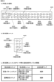
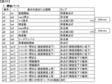
図7は、当り種別を説明するための図である。図7に示すように、当り種別表においては、大当りにおける当りの種別(種類)ごとに、大当り遊技状態の終了後の大当り確率、大当り遊技状態の終了後のベース、および、大当りにおける開放回数(ラウンド数)が示されている。
[Win type]
FIG. 7 is a diagram for explaining the winning types. As shown in FIG. 7, in the hit type table, for each type of hit in the jackpot, the jackpot probability after the end of the jackpot gaming state, the base after the end of the jackpot gaming state, and the number of openings in the jackpot ( number of rounds) is shown.
具体的には、大当りの種別としては、通常大当り1,2および確変大当り1~9が設けられている。なお、以下では、各ラウンドの標記を「R」で表すことがある。たとえば、1ラウンド目は1R目、2ラウンド目は2R目とも称する。
Specifically, as the types of jackpots,
通常大当り1は、3ラウンドの大当り遊技状態の終了後に、低確率状態かつ高ベース状態に制御される大当りである。通常大当り1においては、このような低確高ベース状態が、所定回数(たとえば、50回)に亘って可変表示(特図変動)が実行されるまで継続する。
通常大当り2は、3ラウンドの大当り遊技状態の終了後に、低確率状態かつ高ベース状態に制御される大当りである。通常大当り2においては、このような低確高ベース状態が、所定回数(たとえば、100回)に亘って可変表示(特図変動)が実行されるまで継続する。
確変大当り1~5は、3ラウンドの大当り遊技状態の終了後に、高確率状態かつ高ベース状態に制御される大当りである。確変大当り1においては、このような高確高ベース状態が、所定回数(たとえば、100回)に亘って可変表示(特図変動)が実行されるまで継続する。
確変大当り6は、5ラウンドの大当り遊技状態の終了後に、高確率状態かつ高ベース状態に制御される大当りである。確変大当り6においては、このような高確高ベース状態が、所定回数(たとえば、100回)に亘って可変表示(特図変動)が実行されるまで継続する。
Probable
確変大当り7は、7ラウンドの大当り遊技状態の終了後に、高確率状態かつ高ベース状態に制御される大当りである。確変大当り7においては、このような高確高ベース状態が、所定回数(たとえば、100回)に亘って可変表示(特図変動)が実行されるまで継続する。
Probable
確変大当り8,9は、10ラウンドの大当り遊技状態の終了後に、高確率状態かつ高ベース状態に制御される大当りである。確変大当り8,9においては、このような高確高ベース状態が、所定回数(たとえば、100回)に亘って可変表示(特図変動)が実行されるまで継続する。
[各乱数]
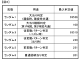
図8は、各乱数を説明するための図である。図8に示すように、各乱数は、以下のように使用される。具体的には、ランダム1は、大当りにするか否かを判定する当り判定用のランダムカウンタである。ランダム1は、たとえば、1から1ずつ加算更新されてその上限である65536まで加算更新された後、再度1から加算更新される。ランダム2は、大当り種類(種別)を決定する(大当り種類決定用)ランダムカウンタである。
[Random numbers]
FIG. 8 is a diagram for explaining each random number. As shown in FIG. 8, each random number is used as follows. Specifically,
ランダム3およびランダム4は、変動パターンのうちの後変動に対応する変動パターン(以下、後変動パターンと称する)(変動時間)を決定する(後変動パターン判定用)ランダムカウンタである。後変動とは、特別図柄の変動のうち、後半部分の変動を指す。なお、ランダム3は、ハズレ時に対応する後変動パターンを決定するランダムカウンタであり、たとえば、1ずつ更新され、1から加算更新されてその上限である65519まで加算更新された後、再度1から加算更新される。ランダム4は、当り時に対応する後変動パターンを決定するランダムカウンタであり、たとえば、1から1ずつ加算更新されてその上限である239まで加算更新された後、再度1から加算更新される。
Random 3 and
ランダム5は、変動パターンのうちの前変動に対応する変動パターン(以下、前変動パターンと称する)(変動時間)を決定する(前変動パターン判定用)ランダムカウンタである。前変動とは、特別図柄の変動のうち、前半部分の変動を指す。ランダム5は、たとえば、1から1ずつ加算更新されてその上限である251まで加算更新された後、再度1から加算更新される。ランダム6は、普通図柄に基づく当りを発生させるか否か決定する(普通図柄当り判定用)ランダムカウンタである。ランダム6は、たとえば、1から1ずつ加算更新されてその上限である201まで加算更新された後、再度1から加算更新される。
本実施の形態では、遊技者にとって有利な有利状態としての大当り遊技状態に制御されるか否かが大当り判定用乱数(ランダム1)の値に基づいて決定される。そして、複数種類の大当りのうち、いずれの大当りとするかが、大当り種類判定用乱数(ランダム2)の値に基づいて決定される。このとき、ランダム2の値に基づいて大当り図柄も決定するようにすればよい。
In this embodiment, it is determined based on the value of the random number for jackpot determination (random 1) whether or not the control is to be controlled to a jackpot gaming state which is an advantageous state for the player. Then, out of the plurality of types of jackpots, which jackpot is to be determined is determined based on the value of the jackpot type determination random number (random 2). At this time, the jackpot symbol may also be determined based on the value of
また、まず、後変動パターン判定用乱数(ランダム3,4)を用いて当りまたはハズレに応じて後変動パターンが決定され、前変動パターン判定用乱数(ランダム5)を用いて前変動パターンが決定される。このように、この実施の形態では、2段階の抽選処理によって変動パターンが決定される。
In addition, first, the post-variation pattern is determined according to the hit or loss using the random numbers for determining the post-variation pattern (
[大当り判定テーブル、大当り種類判定テーブル]
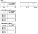
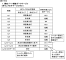
図9は、大当り判定テーブルおよび大当り種類判定テーブルを説明するための図である。これらテーブルは、ROM101に記憶されている。
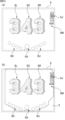
[Jackpot determination table, jackpot type determination table]
FIG. 9 is a diagram for explaining the jackpot determination table and the jackpot type determination table. These tables are stored in the
図9(a)は、大当り判定テーブルを示す説明図である。大当り判定テーブルとは、ROM101に記憶されているデータの集まりであって、ランダム1と比較される大当り判定値が設定されているテーブルである。大当り判定テーブルには、通常状態(確変状態でない遊技状態、すなわち非確変状態)において用いられる通常時(非確変時)大当り判定テーブルと、確変状態において用いられる確変時大当り判定テーブルとがある。
FIG. 9(a) is an explanatory diagram showing a jackpot determination table. The jackpot determination table is a collection of data stored in the
通常時大当り判定テーブルには、図9(a)の上欄に記載されている判定値数の分だけ大当り判定値が設定され、確変時大当り判定テーブルには、図9(a)の下欄に記載されている判定値数の分だけ大当り判定値が設定されている。確変時大当り判定テーブルに設定された大当り判定値は、通常時大当り判定テーブルに設定された大当り判定値と共通の大当り判定値に、確変時固有の大当り判定値が加えられたことにより、通常時大当り判定テーブルよりも多い個数の大当り判定値が設定されている。これにより、確変状態においては、通常状態よりも高い確率で大当りとする判定がなされる。 In the normal time jackpot determination table, jackpot determination values are set as many as the number of determination values listed in the upper column of FIG. 9(a), and in the variable probability jackpot determination table, the jackpot determination values are set in the lower column of FIG. 9(a). Jackpot determination values are set for the number of determination values listed in . The jackpot judgment value set in the jackpot judgment table when the probability is variable is the same as the jackpot judgment value set in the jackpot judgment table during normal times, by adding the jackpot judgment value unique to the jackpot judgment value when the probability is variable. A larger number of jackpot judgment values than the jackpot judgment table are set. As a result, in the variable probability state, a jackpot is determined with a higher probability than in the normal state.
CPU103は、所定の時期に、乱数回路104のカウント値を抽出して抽出値を大当り判定用乱数(ランダム1)の値と比較するが、大当り判定用乱数値が図9(a)に示すいずれかの大当り判定値に一致すると、特別図柄に関して大当り(通常大当り、または、確変大当り)にすることに決定する。なお、図9(a)には、大当りになる確率(割合)またはハズレになる確率(割合)が示されている。
The
図9(b),(c)は、大当り種類判定テーブルを示す説明図である。図9(b)は、第1特別図柄により大当りと判定されたときの大当り種類を決定するために用いる第1特図大当り種類判定テーブルである。図9(c)は、第2特別図柄により大当りと判定されたときの大当り種類を決定するために用いる第2特図大当り種類判定テーブルである。 FIGS. 9(b) and 9(c) are explanatory diagrams showing the jackpot type determination table. FIG. 9(b) is a first special pattern jackpot type determination table used to determine the jackpot type when a jackpot is determined based on the first special symbol. FIG. 9(c) is a second special pattern jackpot type determination table used to determine the jackpot type when a jackpot is determined based on the second special symbol.
図9(b)の第1特図大当り種類判定テーブルには、大当り種類判定用のランダム2の値と比較される数値であって、通常大当り1,2および確変大当り1~4のそれぞれに対応した判定値数の分だけ判定値が設定されている。たとえば、図9(b)に示すように、第1特図について、通常大当り1は100個のランダム2のうちの25個のランダム2の値が割り当てられ、通常大当り2は100個のランダム2のうちの25個のランダム2の値が割り当てられ、確変大当り1は100個のランダム2のうちの5個のランダム2の値が割り当てられ、確変大当り2は100個のランダム2のうちの37個のランダム2の値が割り当てられ、確変大当り3は100個のランダム2のうちの4個のランダム2の値が割り当てられ、確変大当り4は100個のランダム2のうちの4個のランダム2の値が割り当てられている。
The first special figure jackpot type determination table in FIG. 9(b) contains numerical values that are compared with the random 2 value for determining the jackpot type, and correspond to
図9(c)の第2特別図柄大当り種類判定テーブルには、ランダム2の値と比較される数値であって、確変大当り5~9のそれぞれに対応した判定値数の分だけ判定値が設定されている。たとえば、図9(c)に示すように、第2特図について、確変大当り5は100個のランダム2のうちの10個のランダム2の値が割り当てられ、確変大当り6は100個のランダム2のうちの5個のランダム2の値が割り当てられ、確変大当り7は100個のランダム2のうちの5個のランダム2の値が割り当てられ、確変大当り8は100個のランダム2のうちの70個のランダム2の値が割り当てられ、確変大当り9は100個のランダム2のうちの10個のランダム2の値が割り当てられている。
In the second special symbol jackpot type determination table in FIG. 9(c), judgment values are set as many as the number of judgment values corresponding to each of probability
このような各種の大当り種類判定テーブルを用いて、CPU103は、大当り種類として、ランダム2の値が一致した大当り種類判定値に対応する種類を決定するともに、大当り図柄として、ランダム2の値が一致した大当り図柄を決定する。これにより、大当り種類と、大当り種類に対応する大当り図柄とが同時に決定される。
Using such various jackpot type determination tables, the
<演出制御コマンド>
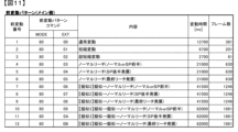
図10は、演出制御コマンドの一例を説明するための図である。メイン側の制御基板である主基板11に搭載された遊技制御用マイクロコンピュータ100は、遊技制御状態に応じて、各種の演出制御コマンドを演出制御用CPU120へ送信する。演出制御コマンドは、たとえば2バイト構成であり、1バイト目はMODE(コマンドの分類)を示し、2バイト目はEXT(コマンドの種類)を示す。なお、図10に示されたコマンド形態は一例であって、他のコマンド形態を用いてもよい。なお、以下において、「(H)」は16進数であることを示すが、本明細書においては、省略する場合もある。
<Production control command>
FIG. 10 is a diagram for explaining an example of the production control command. The
コマンド80XX(H)は、特別図柄の可変表示に対応して画像表示装置5において可変表示される飾り図柄の変動パターンのうち、前変動に対応する変動パターン(前変動パターン)を指定する変動パターンコマンドである(XXは、前変動パターンの番号に対応)。サブ側における前変動とは、特別図柄の可変表示に対応して画像表示装置5において可変表示される飾り図柄の変動のうち、前半部分の変動を指す。複数種類の前変動パターンのそれぞれに対して一意な番号を付した場合に、その番号で特定される前変動パターンのそれぞれに対応する前変動パターンコマンドがある。
Command 80XX(H) is a variation pattern that specifies a variation pattern corresponding to a previous variation (previous variation pattern) among variation patterns of decorative symbols that are variably displayed on the
コマンド84XX(H)は、特別図柄の可変表示に対応して画像表示装置5において可変表示される飾り図柄の変動パターンのうち、後変動に対応する変動パターン(後変動パターン)を指定する変動パターンコマンドである(XXは、後変動パターンの番号に対応)。サブ側における後変動とは、特別図柄の可変表示に対応して画像表示装置5において可変表示される飾り図柄の変動のうち、後半部分の変動を指す。複数種類の後変動パターンのそれぞれに対して一意な番号を付した場合に、その番号で特定される後変動パターンのそれぞれに対応する後変動パターンコマンドがある。
Command 84XX(H) is a variation pattern that specifies a variation pattern corresponding to a later variation (later variation pattern) among the variation patterns of decorative symbols that are variably displayed on the
前変動パターンコマンドおよび後変動パターンコマンドは、2つのコマンドが1セットとなってCPU103から演出制御用CPU120に送信される。演出制御用CPU120は、前変動パターンコマンドおよび後変動パターンコマンドのうち、いずれか一方のみを受信しただけでは変動パターンを特定することができず、前変動パターンコマンドおよび後変動パターンコマンドの両方を受信することで変動パターンを特定することができる。
The pre-variation pattern command and the post-variation pattern command are transmitted as a set of two commands from the
コマンド8101(H)は、第1特図の可変表示の開始を指定する第1可変表示開始コマンドである。コマンド8102(H)は、第2特図の可変表示の開始を指定する第2可変表示開始コマンドである。演出制御用CPU101は、コマンド8101(H)またはコマンド8102(H)を受信すると、画像表示装置5において飾り図柄の可変表示を開始するように制御する。
Command 8101 (H) is a first variable display start command that specifies the start of variable display of the first special figure. Command 8102 (H) is a second variable display start command that specifies the start of variable display of the second special figure. When the
コマンド8C01(H)は、ハズレに決定されていることを示す表示結果1指定コマンド(ハズレ指定コマンド)である。コマンド8C02(H)は、通常大当り1に決定されていることを示す表示結果2指定コマンド(通常大当り1指定コマンド)である。コマンド8C03(H)は、通常大当り2に決定されていることを示す表示結果3指定コマンド(通常大当り2指定コマンド)である。コマンド8C04(H)は、確変大当り1に決定されていることを示す表示結果4指定コマンド(確変大当り1指定コマンド)である。コマンド8C05(H)は、確変大当り2に決定されていることを示す表示結果5指定コマンド(確変大当り2指定コマンド)である。コマンド8C06(H)は、確変大当り3に決定されていることを示す表示結果6指定コマンド(確変大当り3指定コマンド)である。コマンド8C07(H)は、確変大当り4に決定されていることを示す表示結果7指定コマンド(確変大当り4指定コマンド)である。コマンド8C08(H)は、確変大当り5に決定されていることを示す表示結果8指定コマンド(確変大当り5指定コマンド)である。コマンド8C09(H)は、確変大当り6に決定されていることを示す表示結果9指定コマンド(確変大当り6指定コマンド)である。コマンド8C10(H)は、確変大当り7に決定されていることを示す表示結果10指定コマンド(確変大当り7指定コマンド)である。コマンド8C11(H)は、確変大当り8に決定されていることを示す表示結果11指定コマンド(確変大当り8指定コマンド)である。コマンド8C12(H)は、確変大当り9に決定されていることを示す表示結果12指定コマンド(確変大当り9指定コマンド)である。ハズレ指定コマンド、通常大当り1,2指定コマンド、および確変大当り1~9指定コマンドの各々、あるいはこれらをまとめて8C系コマンドとも称する。
Command 8C01 (H) is a
コマンド8D01(H)は、第1特図の可変表示を開始することを示す第1図柄変動指定コマンドである。コマンド8D02(H)は、第2特図の可変表示を開始することを示す第2図柄変動指定コマンドである。第1図柄変動指定コマンドおよび第2図柄変動指定コマンドの各々、あるいはこれらをまとめて8D系コマンドとも称する。コマンド8F00(H)は、第1特図や第2特図の変動を終了することを指定する図柄確定指定コマンドである。 Command 8D01 (H) is a first symbol variation designation command indicating to start variable display of the first special symbol. Command 8D02 (H) is a second symbol variation designation command indicating to start variable display of the second special symbol. Each of the first symbol variation designation command and the second symbol variation designation command, or these collectively, are also referred to as 8D series commands. Command 8F00 (H) is a symbol confirmation designation command that specifies to end the variation of the first special symbol and the second special symbol.
コマンド9000(H)は、遊技機に関する電力供給が開始されたときに送信される初期化を指定(電源投入時の初期画面を表示することを指定)する初期化指定コマンドである。コマンド9200(H)は、遊技機に関する電力供給が再開されたときに送信される停電の復旧を指定(停電復旧画面を表示することを指定)する停電復旧指定コマンドである。コマンド9500(H)は、通常状態の背景を指定する通常状態指定コマンドである。コマンド9501(H)は、時短状態の背景を指定する時短状態指定コマンドである。コマンド9502(H)は、確変状態の背景を指定する確変状態指定コマンドである。通常状態指定コマンド、時短状態指定コマンド、および確変状態指定コマンドの各々、あるいはこれらをまとめて95系コマンドや背景指定コマンドとも称する。 Command 9000 (H) is an initialization designation command that designates initialization (designates displaying the initial screen when the power is turned on) to be sent when power supply to the gaming machine is started. Command 9200 (H) is a power outage recovery designation command that is sent when power supply to the gaming machine is resumed and designates recovery from a power outage (specifies displaying a power outage recovery screen). Command 9500 (H) is a normal state designation command that designates the background of the normal state. Command 9501 (H) is a time-saving state designation command that designates the background of the time-saving state. Command 9502 (H) is a variable probability state designation command that specifies the background of the variable probability state. Each of the normal state designation command, time-saving state designation command, and variable probability state designation command, or these commands collectively, are also referred to as 95-series commands or background designation commands.
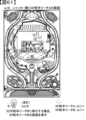
コマンド9F00(H)は、客待ちのデモンストレーション表示に移行することを指定する客待ちデモ指定コマンドである。演出制御用CPU120は、客待ちデモ指定コマンドを受信したことにより現在保留が無いと判断する。そして、演出制御用CPU120は、客待ちデモ指定コマンドを受信してから30秒後にデモンストレーション用の映像を画像表示装置5に流す。なお、演出制御用CPU120は、客待ちデモ指定コマンドを受信してから30秒後にデモンストレーション用のランプ態様で遊技効果ランプ9を点灯させる。なお、デモンストレーション用の遊技効果ランプ9の点灯態様は、通常状態での遊技効果ランプ9の点灯態様よりも賑やか(輝度が高い、点滅の態様が多い、レインボー点灯など)である。これにより、パチンコ遊技機1の魅力を遊技者に示すことができる。なお、客待ちのデモンストレーション表示においては、通常状態での背景(以下、通常背景とも称する)が表示されるとともに、各飾り図柄表示エリア5L,5C,5Rにおいて飾り図柄が停止して表示される。また、客待ちのデモンストレーション表示においては、遊技機1のタイトル(たとえば、「POWERFULII」)が表示されたり、演出の一部の紹介画像(静止画または動画)が表示されたりする場合もある。
Command 9F00(H) is a customer waiting demonstration designation command that specifies transition to a customer waiting demonstration display. The
コマンドA001(H)は、通常大当り1の開始を指定する大当り開始1指定コマンドである。コマンドA002(H)は、通常大当り2の開始を指定する大当り開始2指定コマンドである。コマンドA003(H)は、確変大当り1の開始を指定する確変大当り開始3指定コマンドである。コマンドA004(H)は、確変大当り2の開始を指定する確変大当り開始4指定コマンドである。コマンドA005(H)は、確変大当り3の開始を指定する確変大当り開始5指定コマンドである。コマンドA006(H)は、確変大当り4の開始を指定する確変大当り開始6指定コマンドである。コマンドA007(H)は、確変大当り5の開始を指定する確変大当り開始7指定コマンドである。コマンドA008(H)は、確変大当り6の開始を指定する確変大当り開始8指定コマンドである。コマンドA009(H)は、確変大当り7の開始を指定する確変大当り開始9指定コマンドである。コマンドA010(H)は、確変大当り8の開始を指定する確変大当り開始10指定コマンドである。コマンドA011(H)は、確変大当り9の開始を指定する確変大当り開始11指定コマンドである。大当り開始1~11指定コマンドの各々、あるいはこれらをまとめてA0系コマンドとも称する。
Command A001 (H) is a
A1XX(H)は、XXで示す回数目(ラウンド)の大入賞口の開放中を示す大入賞口開放中指定コマンドである。大入賞口開放中指定コマンドを、A1系コマンドとも称する。A2XX(H)は、XXで示す回数目(ラウンド)の大入賞口の閉鎖を示す大入賞口開放後指定コマンドである。大入賞口開放後指定コマンドを、A2系コマンドとも称する。 A1XX(H) is a command indicating that the big winning hole is being opened for the number of times (round) indicated by XX. The grand prize opening designation command is also referred to as the A1 series command. A2XX(H) is a specified command after the opening of the grand prize opening indicating the closing of the grand prize opening of the number (round) indicated by XX. The command specified after opening the big prize opening is also referred to as the A2 series command.
コマンドA301(H)は、通常大当り1の終了を指定する大当り終了1指定コマンドである。コマンドA302(H)は、通常大当り2の終了を指定する大当り終了2指定コマンドである。コマンドA303(H)は、確変大当り1の終了を指定する大当り終了3指定コマンドである。コマンドA304(H)は、確変大当り2の終了を指定する大当り終了4指定コマンドである。コマンドA305(H)は、確変大当り3の終了を指定する大当り終了5指定コマンドである。コマンドA306(H)は、確変大当り4の終了を指定する大当り終了6指定コマンドである。コマンドA307(H)は、確変大当り5の終了を指定する大当り終了7指定コマンドである。コマンドA308(H)は、確変大当り6の終了を指定する大当り終了8指定コマンドである。コマンドA309(H)は、確変大当り7の終了を指定する大当り終了9指定コマンドである。コマンドA310(H)は、確変大当り8の終了を指定する大当り終了10指定コマンドである。コマンドA311(H)は、確変大当り9の終了を指定する大当り終了11指定コマンドである。大当り終了1~11指定コマンドの各々、あるいはこれらをまとめてA3系コマンドとも称する。
Command A301 (H) is a
コマンドAD00(H)は、V入賞が発生したことを指定する確変判定装置通過指定コマンドである。確変判定装置通過指定コマンドは、V大入賞口を通過した遊技球がV入賞領域に進入してV入賞スイッチ24により検出されるときに送信されるコマンドである。
Command AD00(H) is a probability change determination device passage designation command that designates that a V winning has occurred. The probability change determination device passing designation command is a command that is sent when the game ball that has passed through the V big winning opening enters the V winning area and is detected by the
コマンドB100(H)は、第1始動入賞があったことを指定する第1始動入賞指定コマンドである。コマンドB200(H)は、第2始動入賞があったことを指定する第2始動入賞指定コマンドである。 Command B100 (H) is a first starting winning designation command that specifies that there is a first starting winning. Command B200 (H) is a second starting winning designation command that specifies that there is a second starting winning.
コマンドC1XX(H)は、第1保留記憶数がXXで示す数になったことを指定する第1保留記憶数指定コマンドである。第1保留記憶数指定コマンドを、C1系コマンドとも称する。コマンドC2XX(H)は、第2保留記憶数がXXで示す数になったことを指定する第2保留記憶する指定コマンドである。第2保留記憶数指定コマンドを、C2系コマンドとも称する。 Command C1XX(H) is a first pending storage number designation command that specifies that the first pending storage number has reached the number indicated by XX. The first pending storage number designation command is also referred to as a C1 series command. Command C2XX(H) is a second pending storage designation command that specifies that the second pending storage number has reached the number indicated by XX. The second pending storage number designation command is also referred to as a C2-based command.
コマンドC4XX(H)およびコマンドC6XX(H)は、第1始動入賞口または第2始動入賞口への始動入賞時における大当り判定、大当り種類判定、変動パターン種類判定などの入賞時判定結果の内容を示す演出制御コマンドである。このうち、コマンドC4XX(H)は、入賞時判定結果のうち、大当りとなるか否か、および、大当りの種類の判定結果を示す図柄指定コマンドである。 Command C4XX (H) and command C6XX (H) display the contents of the winning determination results such as jackpot determination, jackpot type determination, fluctuation pattern type determination, etc. at the time of starting winning into the first starting winning opening or the second starting winning opening. This is the production control command shown. Among these, the command C4XX(H) is a symbol designation command that indicates whether or not it will be a jackpot among the winning determination results and the determination result of the type of jackpot.
C7XX(H)は、XXで示す回数目(ラウンド)の大入賞口への遊技球の通過を示す大入賞口入賞指定コマンドである。 C7XX(H) is a grand prize opening designation command that indicates passage of the game ball to the grand prize opening for the number of times (round) indicated by XX.
MODEがFD(H)でありかつ、EXTの4bit目が0であるコマンドは、右打ち表示の消灯を示す右打ち表示消灯指定コマンドである。MODEデータがFD(H)でありかつ、EXTデータの4bit目が1であるコマンドは、右打ち表示の点灯を示す右打ち表示点灯指定コマンドである。本実施の形態においては、特に右打ち表示点灯指定コマンドを、FD系コマンドとも称する。 A command in which the MODE is FD (H) and the 4th bit of EXT is 0 is a right-handed player display light-off designation command indicating that the right-handed player display is turned off. A command in which the MODE data is FD (H) and the 4th bit of the EXT data is 1 is a right-handed hitting display lighting designation command indicating lighting of the right-handed hitting display. In this embodiment, the right-handed display lighting designation command is also referred to as an FD-related command.
遊技制御用マイクロコンピュータ100は、始動入賞時に、大当りとなるか否か、大当りの種類、変動パターン種類判定用乱数の値がいずれの判定値の範囲となるかを判定する。そして、図柄指定コマンドのEXTデータに、大当りとなることを指定する値、および、大当りの種類を指定する値を設定し、演出制御用CPU120に送信する制御を行う。また、遊技制御用マイクロコンピュータ100は、変動種別コマンドのEXTデータに変動パターン種別の判定結果としての判定値の範囲を指定する値を設定し、演出制御用CPU120に送信する制御を行う。演出制御用CPU120は、図柄指定コマンドに設定されている値に基づいて、表示結果が大当りとなるか否か、大当りの種別を認識できるとともに、変動種別コマンドに基づいて、変動パターン種別を認識できる。
The
<変動パターン>
図11~図17を参照しながら、変動パターンの内容および変動パターンの決定などについて説明する。
<Variation pattern>
The contents of the variation pattern, determination of the variation pattern, etc. will be explained with reference to FIGS. 11 to 17.
本実施の形態においては、メイン側である遊技制御用マイクロコンピュータ100によって、複数種類の変動パターンが設定される。各変動パターンは、メイン変動番号によって管理されるとともに、前変動に対応する変動パターンである前変動パターンと、後変動に対応する後変動パターンとの組合せで構成され、当該組合せによって互いに異なる内容を含むようになっている。なお、前変動パターンは、図10を用いて説明した前変動パターンコマンド(80XX(H))に対応し、後変動パターンは、図10を用いて説明した後変動パターンコマンド(84XX(H))に対応する。
In this embodiment, a plurality of types of variation patterns are set by the main
[メイン側の前変動パターン]
図11は、メイン側における前変動パターンの一例を説明するための図である。前変動番号が各々割り当てられた複数種類の前変動パターンのうち、前変動番号1は、通常変動(たとえば、13秒間に亘る飾り図柄の変動)を指定する前変動パターンコマンド(8000(H))である。前変動番号2は、短縮変動(たとえば、7秒間に亘る飾り図柄の変動)を指定する前変動パターンコマンド(8001(H))である。前変動番号3は、超短縮変動(たとえば、3秒間に亘る飾り図柄の変動)を指定する前変動パターンコマンド(8002(H))である。
[Main side previous fluctuation pattern]
FIG. 11 is a diagram for explaining an example of a pre-variation pattern on the main side. Among the plurality of types of previous variation patterns each assigned a previous variation number, the
前変動番号4は、ノーマルリーチ(ノーマルorSP前半)(リーチ態様となった後にノーマルリーチで終了するかSP前半リーチで終了するリーチ)を指定する前変動パターンコマンド(8003(H))である。前変動番号5は、ノーマルリーチ(SP後半発展)(リーチ態様となった後にSP後半リーチに発展するリーチ)を指定する前変動パターンコマンド(8004(H))である。前変動番号6は、ノーマルリーチ(最終リーチ発展)(リーチ態様となった後に最終リーチに発展するリーチ)を指定する前変動パターンコマンド(8005(H))である。
前変動番号7は、擬似変動を1回した後にノーマルリーチ(ノーマルorSP前半)を実行することを指定する前変動パターンコマンド(8006(H))である。擬似変動とは、飾り図柄の可変表示(変動表示)が開始されてから当該可変表示の表示結果が導出表示されるまでに、当該可変表示を一旦仮停止させた後に当該可変表示を再開するような可変表示(変動表示)である。このような擬似変動を繰り返す演出を擬似連ともいう。擬似連を実行することで、1個の保留記憶に基づく可変表示を、擬似的に複数回の可変表示のように遊技者に見せることができる。なお、一旦仮停止させた後に再開する可変表示を「再可変表示」とも称する。前変動番号8は、擬似変動を1回した後にノーマルリーチ(SP後半発展)を実行することを指定する前変動パターンコマンド(8007(H))である。前変動番号9は、擬似変動を1回した後にノーマルリーチ(最終リーチ発展)を指定する前変動パターンコマンド(8008(H))である。
前変動番号10は、擬似変動を2回した後にノーマルリーチ(ノーマルorSP前半)を実行することを指定する前変動パターンコマンド(8009(H))である。前変動番号11は、擬似変動を2回した後にノーマルリーチ(SP後半発展)を実行することを指定する前変動パターンコマンド(800A(H))である。前変動番号12は、擬似変動を2回した後にノーマルリーチ(最終リーチ発展)を指定する前変動パターンコマンド(800B(H))である。
The
前変動パターンの各々は、変動時間が指定されており、各変動時間に亘って画像表示装置5にアニメーション(動画)が表示される。なお、パチンコ遊技機1においては、動画を構成する静止画1枚分(フレームと称する)につき、約33.3msec分の時間を要する。たとえば、前変動番号7~9のパターンの場合、変動時間として41500mseが設定されており、そのフレーム数は、約1246枚となる。また、前変動番号10~12のパターンの場合、変動時間として62000mseが設定されており、そのフレーム数は、約1861枚となる。
A variation time is specified for each of the previous variation patterns, and an animation (moving picture) is displayed on the
[メイン側の後変動パターン]
図12は、メイン側における後変動パターンの一例を説明するための図である。後変動番号が各々割り当てられた複数種類の後変動パターンのうち、後変動番号1は、13秒変動を指定する後変動パターンコマンド(8400(H))である。後変動番号2は、7秒変動を指定する後変動パターンコマンド(8401(H))である。後変動番号3は、3秒変動を指定する後変動パターンコマンド(8402(H))である。後変動番号4は、擬似連ガセを実行することを指定する後変動パターンコマンド(8403(H))である。擬似連ガセとは、擬似連を実行すると見せかけて結局は擬似連を実行しない演出などである。
[Main side post-variation pattern]
FIG. 12 is a diagram for explaining an example of a post-variation pattern on the main side. Among the plurality of types of post-fluctuation patterns to which post-fluctuation numbers are assigned,
後変動番号5は、ノーマルリーチ(ハズレ)(リーチ態様となるがSPリーチに発展することなくハズレ態様となる飾り図柄の変動)を指定する後変動パターンコマンド(8404(H))である。後変動番号6は、SP前半(ハズレ)(SPリーチに発展するがSPリーチの前半でハズレ態様となる飾り図柄の変動)を指定する後変動パターンコマンド(8405(H))である。後変動番号7は、SP後半(ハズレ)(SPリーチの後半に発展するがSPリーチの後半でハズレ態様となる飾り図柄の変動)を指定する後変動パターンコマンド(8406(H))である。後変動番号8は、最終リーチ(ハズレ)(最終リーチに発展するが最終リーチでハズレ態様となる飾り図柄の変動)を指定する後変動パターンコマンド(8407(H))である。
後変動番号9は、ノーマルリーチ(当り)(リーチ態様となって当り態様となる飾り図柄の変動)を指定する後変動パターンコマンド(8408(H))である。後変動番号10は、SP前半(当り)(SPリーチに発展してSPリーチの前半で当り態様となる飾り図柄の変動)を指定する後変動パターンコマンド(8409(H))である。後変動番号11は、SP後半(当り)(SPリーチの後半に発展してSPリーチの後半で当り態様となる飾り図柄の変動)を指定する後変動パターンコマンド(840A(H))である。後変動番号12は、最終リーチ(当り)(最終リーチに発展して最終リーチで当り態様となる飾り図柄の変動)を指定する後変動パターンコマンド(840B(H))である。
[後変動パターンの判定]
後変動パターンは、大当り判定において、大当りおよびハズレのいずれに決定されたかに応じて異なるランダムカウンタを用いて決定される。図13は、ハズレ時における後変動パターン判定テーブルを説明するための図である。図13に示すように、大当り判定においてハズレに決定された場合、図8で説明したランダム3を用いて後変動パターンが決定される。さらに、大当り判定においてハズレに決定された場合、消化後の保留記憶数に応じて、異なる判定値数を用いて後変動パターンが決定され、さらに、決定される後変動番号も異なる。
[Determination of post-change pattern]
The post-change pattern is determined using a different random counter depending on whether the jackpot is determined to be a jackpot or a loss in the jackpot determination. FIG. 13 is a diagram for explaining the post-variation pattern determination table at the time of a loss. As shown in FIG. 13, if the jackpot determination is determined to be a loss, a post-variation pattern is determined using
具体的には、図13(a)に示すように、消化後の保留記憶数が0個の場合、後変動番号1,4,5~8のうちからいずれかの後変動パターンが決定され、後変動パターンの各々に対して異なる判定値数が設けられている。なお、SPリーチや最終リーチに発展する後変動番号6~8のいずれかに決定される確率(後変動番号6~8の選択率)は、約1/102となっている。
Specifically, as shown in FIG. 13(a), when the number of retained memories after digestion is 0, one of the post-change patterns from
消化後の保留記憶数が1個の場合、後変動番号1,4,5~8のうちからいずれかの後変動パターンが決定され、後変動パターンの各々に対して異なる判定値数が設けられている。なお、SPリーチや最終リーチに発展する後変動番号6~8のいずれかに決定される確率(後変動番号6~8の選択率)は、約1/102となっている。
When the number of retained memories after digestion is one, one of the post-fluctuation patterns is determined from
消化後の保留記憶数が2個の場合、後変動番号2,4,5~8のうちからいずれかの後変動パターンが決定され、後変動パターンの各々に対して異なる判定値数が設けられている。なお、SPリーチや最終リーチに発展する後変動番号6~8のいずれかに決定される確率(後変動番号6~8の選択率)は、約1/102となっている。
When the number of retained memories after digestion is two, one of the post-fluctuation patterns is determined from
消化後の保留記憶数が3個の場合、後変動番号3,4,5~8のうちからいずれかの後変動パターンが決定され、後変動パターンの各々に対して異なる判定値数が設けられている。なお、SPリーチや最終リーチに発展する後変動番号6~8のいずれかに決定される確率(後変動番号6~8の選択率)は、約1/102となっている。
When the number of retained memories after digestion is 3, one of the post-fluctuation patterns is determined from
このように、消化後の保留記憶数に応じて異なる判定値数を用いて後変動パターンが決定され、さらに、消化後の保留記憶数に応じて異なる判定値数を用いて後変動番号が決定されるため、残っている保留記憶数に応じて変動パターンの種類が変化し、これにより、遊技に多様性を持たせて遊技の興趣を向上させることができる。 In this way, the post-fluctuation pattern is determined using a different number of judgment values depending on the number of retained memories after consumption, and furthermore, the post-fluctuation number is determined using a different number of judgment values depending on the number of retained memories after consumption. Therefore, the type of variation pattern changes depending on the number of remaining reserved memories, thereby making it possible to add variety to the game and improve the interest of the game.
図14は、大当り時における後変動パターン判定テーブルを説明するための図である。図14に示すように、大当り判定において大当りに決定された場合、図8で説明したランダム4を用いて後変動パターンが決定される。さらに、大当り判定において大当りに決定された場合、大当りの種類に応じて、異なる判定値数を用いて後変動パターンが決定される。
FIG. 14 is a diagram for explaining a post-change pattern determination table at the time of a jackpot. As shown in FIG. 14, when a jackpot is determined in the jackpot determination, a post-variation pattern is determined using
具体的には、図14(a)に示すように、通常大当り1,2、確変大当り1,2,5~8のいずれかに決定された場合、後変動番号9~12のうちからいずれかの後変動パターンが決定され、後変動パターンの各々に対して異なる判定値数が設けられている。なお、SPリーチや最終リーチに発展する後変動番号10~12のいずれかに決定される確率(後変動番号10~12の選択率)は、約1/1.1となっている。
Specifically, as shown in FIG. 14(a), if it is determined to be a
確変大当り3,9のいずれかに決定された場合、後変動番号9~12のうちからいずれかの後変動パターンが決定され、後変動パターンの各々に対して異なる判定値数が設けられている。なお、SPリーチや最終リーチに発展する後変動番号10~12のいずれかに決定される確率(後変動番号10~12の選択率)は、約1/1.1となっている。
When it is determined to be either a
確変大当り4に決定された場合、後変動番号9~12のうちからいずれかの後変動パターンが決定され、後変動パターンの各々に対して異なる判定値数が設けられている。なお、SPリーチや最終リーチに発展する後変動番号10~12のいずれかに決定される確率(後変動番号10~12の選択率)は、約1/1.1となっている。
When the probability variable jackpot is determined to be 4, one of the later variation patterns is determined from among the
このように、大当りの種類に応じて異なる判定値数を用いて後変動パターンが決定されるため、大当りの種類に応じて変動パターンの種類が変化し、これにより、遊技に多様性を持たせて遊技の興趣を向上させることができる。 In this way, since the post-fluctuation pattern is determined using a different number of judgment values depending on the type of jackpot, the type of fluctuation pattern changes depending on the type of jackpot, and this makes it possible to add variety to the game. It is possible to improve the interest of the game.
また、図13に示すように、SPリーチや最終リーチに発展する後変動番号6~8のいずれかに決定される確率は、ハズレ時が約1/102となっているのに対して、大当り時がそれよりも高い約1/1.1となっているため、SPリーチや最終リーチに発展した場合には、大当りが発生することに対して遊技者に期待させることができる。
In addition, as shown in Figure 13, the probability of being determined to be one of the
[前変動パターンの判定]
図15は、前変動パターン判定テーブルを説明するための図である。前変動パターンは、先に決定された後変動パターンの種類に応じて異なるランダム5の判定値数を用いて決定される。さらに、先に決定された後変動パターンの種類に応じて、決定される前変動番号も異なる。
[Judgment of previous fluctuation pattern]
FIG. 15 is a diagram for explaining the previous variation pattern determination table. The pre-fluctuation pattern is determined using the number of random 5 determination values that differ depending on the type of the pre-determined post-fluctuation pattern. Further, the pre-variation number to be determined also differs depending on the type of the post-variation pattern previously determined.
具体的には、図15(a)に示すように、後変動番号1の後変動パターンに決定された場合、前変動番号1の前変動パターンに決定される。図15(b)に示すように、後変動番号2の後変動パターンに決定された場合、前変動番号2の前変動パターンに決定される。図15(c)に示すように、後変動番号3の後変動パターンに決定された場合、前変動番号3の前変動パターンに決定される。図15(d)に示すように、後変動番号4の後変動パターンに決定された場合、前変動番号1の前変動パターンに決定される。
Specifically, as shown in FIG. 15(a), when the subsequent variation pattern with the
図15(e)に示すように、後変動番号5,9のいずれかの後変動パターンに決定された場合、前変動番号4,7のいずれかの前変動パターンに決定される。図15(f)に示すように、後変動番号6,10のいずれかの後変動パターンに決定された場合、前変動番号4,7,10のいずれかの前変動パターンに決定される。図15(g)に示すように、後変動番号7の後変動パターンに決定された場合、前変動番号5,8,11のいずれかの前変動パターンに決定される。
As shown in FIG. 15(e), when the subsequent variation pattern with the
図15(h)に示すように、後変動番号11の後変動パターンに決定された場合、前変動番号5,8,11のいずれかの前変動パターンに決定される。図15(i)に示すように、後変動番号8の後変動パターンに決定された場合、前変動番号6,9,12のいずれかの前変動パターンに決定される。図15(j)に示すように、後変動番号12の後変動パターンに決定された場合、前変動番号6,9,12のいずれかの前変動パターンに決定される。
As shown in FIG. 15(h), when the post-variation pattern with
[全変動パターン]
図16は、メイン側における全変動パターンの一例を説明するための図である。図13~図15で説明したようにして、後変動パターンおよび前変動パターンが決定されると、図16に示すようなメイン変動番号1~26の変動パターンのいずれかとなる。
[Total fluctuation pattern]
FIG. 16 is a diagram for explaining an example of a total variation pattern on the main side. When the post-variation pattern and the pre-variation pattern are determined as explained in FIGS. 13 to 15, one of the variation patterns with
図17は、サブ側における演出パターンの抽選の一例を説明するための図である。図17に示すように、サブ側である演出制御用CPU120は、メイン側であるCPU103から受信した変動パターンコマンドに基づき、演出パターンを抽選によって決定する。
FIG. 17 is a diagram for explaining an example of a lottery of production patterns on the sub side. As shown in FIG. 17, the
たとえば、演出制御用CPU120は、CPU103からメイン変動番号7~9のいずれかに対応する変動パターンコマンドを受信すると、複数種類のリーチ演出のうち、後述するSP前半リーチAのハズレパターンの演出、または、SP前半リーチBのハズレパターンの演出のいずれかに決定する。演出制御用CPU120は、CPU103からメイン変動番号18~20のいずれかに対応する変動パターンコマンドを受信すると、複数種類のリーチ演出のうち、後述するSP前半リーチAの当りパターンの演出、または、SP前半リーチBの当りパターンの演出のいずれかに決定する。
For example, when the
演出制御用CPU120は、CPU103からメイン変動番号10~12のいずれかに対応する変動パターンコマンドを受信すると、複数種類のリーチ演出のうち、後述するSP後半リーチAのハズレパターンの演出、または、SP後半リーチBのハズレパターンの演出のいずれかに決定する。演出制御用CPU120は、CPU103からメイン変動番号21~23のいずれかに対応する変動パターンコマンドを受信すると、複数種類のリーチ演出のうち、後述するSP後半リーチAの当りパターンの演出、または、SP後半リーチBの当りパターンの演出のいずれかに決定する。
When the
<動作>
次に、パチンコ遊技機1の動作(作用)を説明する。
<Operation>
Next, the operation (function) of the
[主基板11の主要な動作]
まず、主基板11における主要な動作を説明する。
[Main operations of main board 11]
First, the main operations of the
(特別図柄プロセス処理)
図18は、遊技制御メイン処理の一例を示すフローチャートである。パチンコ遊技機1に対して電力供給が開始されると、遊技制御用マイクロコンピュータ100が起動し、CPU103によって遊技制御メイン処理が実行される。
(Special design process processing)
FIG. 18 is a flowchart showing an example of game control main processing. When power supply to the
図18に示す遊技制御メイン処理において、CPU103は、まず、割込禁止に設定する(ステップS1)。続いて、CPU103は、必要な初期設定を行う(ステップS2)。初期設定には、スタックポインタの設定、内蔵デバイス(CTC(カウンタ/タイマ回路)、パラレル入出力ポートなど)のレジスタ設定、RAM102をアクセス可能状態にする設定などが含まれる。
In the game control main process shown in FIG. 18, the
次に、CPU103は、復旧条件が成立したか否かを判定する(ステップS3)。復旧条件は、クリア信号がオフ状態であり、バックアップデータがあり、バックアップRAMが正常である場合に、成立可能である。パチンコ遊技機1の電力供給が開始されたときに、たとえば電源基板17に設けられたクリアスイッチ92が押圧操作されていれば、オン状態のクリア信号が遊技制御用マイクロコンピュータ100に入力される。このようなオン状態のクリア信号が入力されている場合には、ステップS3にて復旧条件が成立していないと判定すればよい。バックアップデータは、遊技制御用のバックアップRAMとなるRAM102に保存可能であればよい。ステップS3では、バックアップデータの有無やデータ誤りの有無などを確認あるいは検査して、復旧条件が成立し得るか否かを判定すればよい。
Next, the
CPU103は、復旧条件が成立した場合には(ステップS3でY)、復旧処理(ステップS4)を実行した後に、設定確認処理(ステップS5)を実行する。CPU103は、ステップS4の復旧処理により、RAM102の記憶内容に基づいて作業領域の設定が行われる。RAM102に記憶されたバックアップデータを用いて作業領域を設定することで、電力供給が停止したときの遊技状態に復旧し、たとえば特別図柄の変動中であった場合には、停止前の状態から特別図柄の変動を再開可能であればよい。
If the recovery condition is satisfied (Y in step S3), the
CPU103は、復旧条件が成立しなかった場合には(ステップS3でN)、初期化処理(ステップS6)を実行した後に、設定変更処理(ステップS7)を実行する。ステップS6の初期化処理は、RAM102に記憶されるフラグ、カウンタ、バッファをクリアするクリア処理を含み、クリア処理の実行により作業領域に初期値が設定される。
If the recovery condition is not satisfied (N in step S3), the
ステップS5の設定確認処理では、予め定められた設定確認条件が成立したか否かを判定する。設定確認条件は、たとえば電力供給が開始されたときに、扉開放センサ90からの検出信号がオン状態であるとともに設定キー51がオン操作されている場合に成立する。ステップS5の設定確認処理が実行されるのは、ステップS3において、クリア信号がオフ状態であることを含めた復旧条件が成立した場合である。したがって、設定確認条件が成立し得るのは、クリア信号がオフ状態である場合となるので、クリア信号がオフ状態であることも、設定確認条件に含めることができる。
In the setting confirmation process of step S5, it is determined whether predetermined setting confirmation conditions are satisfied. The setting confirmation condition is satisfied, for example, when the detection signal from the door
ステップS5の設定確認処理において設定確認条件が成立した場合には、パチンコ遊技機1において設定されている設定値を確認可能な設定確認状態となり、主基板11から演出制御基板12に対して、設定確認開始コマンドが送信される。設定確認状態においては、パチンコ遊技機1にて設定されている設定値を表示モニタ29の表示により確認することが可能となっている。設定確認状態を終了するときには、主基板11から演出制御基板12に対して、設定確認終了コマンドが送信される。
If the setting confirmation conditions are satisfied in the setting confirmation process in step S5, the setting confirmation state is reached in which the setting values set in the
パチンコ遊技機1が設定確認状態であるときには、パチンコ遊技機1における遊技の進行を停止させる遊技停止状態としてもよい。遊技停止状態であるときには、打球操作ハンドル30の操作による遊技球の発射、各種スイッチによる遊技球の検出などが停止され、また、ハズレ図柄などを停止表示したり、ハズレ図柄とは異なる遊技停止状態に対応した表示が行われたりするように制御すればよい。設定確認状態が終了するときには、これに伴う遊技停止状態も終了すればよい。
When the
CPU103は、ステップS7の設定変更処理では、予め定められた設定変更条件が成立したか否かを判定する。設定変更条件は、たとえば電力供給が開始されたときに、扉開放センサ90からの検出信号がオン状態であるとともに設定キー51がオン操作されている場合に成立する。設定変更条件は、クリア信号がオン状態であることを含んでいてもよい。
In the setting change process of step S7, the
ステップS7の設定変更処理において設定変更条件が成立した場合には、パチンコ遊技機1において設定されている設定値を変更可能な設定変更状態となり、主基板11から演出制御基板12に対して、設定変更開始コマンドが送信される。設定変更状態においては、表示モニタ29に設定値が表示され、設定切替スイッチ52の操作を検出するごとに表示モニタ29に表示している数値を順次更新して表示する。その後、CPU103は、設定キー51が遊技場の係員などによる操作でオフとなったことに基づいて、表示モニタ29に表示されている設定値をRAM102のバックアップ領域に格納(更新記憶)するとともに、表示モニタ29を消灯させる。設定変更状態を終了するときには、主基板11から演出制御基板12に対して、設定変更終了コマンドが送信される。
If the setting change conditions are satisfied in the setting change process in step S7, the setting change state is entered in which the setting values set in the
パチンコ遊技機1が設定変更状態であるときには、設定確認状態であるときと同様に、パチンコ遊技機1を遊技停止状態としてもよい。設定変更状態が終了するときには、これに伴う遊技停止状態も終了すればよい。
When the
演出制御基板12側では、設定確認開始コマンドや設定変更開始コマンドを受信すると、設定確認中である旨や設定変更中である旨を報知する制御が行われてもよい。たとえば、画像表示装置5において所定の画像を表示したり、スピーカ8L,8Rから所定の音を出力したり、遊技効果ランプ9といった発光部材を所定の態様により発光させたりしてもよい。
On the
クリア信号は、たとえば電源基板17に設けられたクリアスイッチ92の押圧操作などによりオン状態となる。したがって、電力供給が開始されたときに、扉開放センサ90からの検出信号がオンであるとともに設定キー51がオンである場合には、クリアスイッチ92がオンであればステップS6の初期化処理とともにステップS7の設定変更処理が実行されて設定変更状態に制御可能となり、クリアスイッチ92がオフであればステップS4の復旧処理とともにステップS5の設定確認処理が実行されて設定確認状態に制御可能となる。電力供給が開始されたときに、扉開放センサ90からの検出信号がオフである場合、または設定キー51がオフである場合には、クリアスイッチ92がオンであればステップS6の初期化処理が実行される一方で設定変更状態には制御されず、クリアスイッチ92がオフであればステップS4の復旧処理が実行される一方で設定確認状態には制御されない。
The clear signal is turned on, for example, by pressing a
設定確認処理または設定変更処理を実行した後に、CPU103は、乱数回路104を初期設定する乱数回路設定処理を実行する(ステップS8)。そして、CPU103は、所定時間(たとえば2ms)ごとに定期的にタイマ割込がかかるように遊技制御用マイクロコンピュータ100に内蔵されているCTCのレジスタの設定を行い(ステップS9)、割込みを許可する(ステップS10)。その後、ループ処理に入る。以後、所定時間(たとえば2ms)ごとにCTCから割込み要求信号がCPU103へ送出され、CPU103は定期的にタイマ割込み処理を実行することができる。
After executing the setting confirmation process or the setting change process, the
(遊技制御用タイマ割込み処理)
図19は、遊技制御用タイマ割込み処理の一例を示すフローチャートである。遊技制御メイン処理を実行したCPU103は、CTCからの割込み要求信号を受信して割込み要求を受け付けると、図19のフローチャートに示す遊技制御用タイマ割込み処理を実行する。図19に示す遊技制御用タイマ割込み処理を開始すると、CPU103は、まず、所定のスイッチ処理を実行することにより、スイッチ回路110を介してゲートスイッチ21、第1始動口スイッチ22A、第2始動口スイッチ22B、カウントスイッチ23といった各種スイッチからの検出信号の受信の有無を判定する(ステップS21)。続いて、CPU103は、所定のメイン側エラー処理を実行することにより、パチンコ遊技機1の異常診断を行い、その診断結果に応じて必要ならば警告を発生可能とする(ステップS22)。この後、CPU103は、所定の情報出力処理を実行することにより、たとえばパチンコ遊技機1の外部に設置されたホール管理用コンピュータに供給される大当り情報(大当りの発生回数などを示す情報)、始動情報(始動入賞の回数などを示す情報)、確率変動情報(確変状態となった回数などを示す情報)などのデータを出力する(ステップS23)。
(Timer interrupt processing for game control)
FIG. 19 is a flowchart showing an example of game control timer interrupt processing. When the
CPU103は、情報出力処理に続いて、主基板11の側で用いられる遊技用乱数の少なくとも一部をソフトウェアにより更新するための遊技用乱数更新処理を実行する(ステップS24)。この後、CPU103は、特別図柄プロセス処理を実行する(ステップS25)。CPU103がタイマ割込みごとに特別図柄プロセス処理を実行することにより、特図ゲームの実行および保留の管理や、大当り遊技状態の制御、遊技状態の制御などが実現される。
Following the information output process, the
特別図柄プロセス処理に続いて、普通図柄プロセス処理が実行される(ステップS26)。CPU103がタイマ割込みごとに普通図柄プロセス処理を実行することにより、ゲートスイッチ21からの検出信号に基づく(通過ゲート41に遊技球が通過したことに基づく)普図ゲームの実行および保留の管理や、「普図当り」に基づく可変入賞球装置6Bの開放制御などを可能にする。普図ゲームの実行は、普図表示部9026を駆動することにより行われ、普図記憶表示部9025を点灯させることにより普図保留数を表示する。
Following the special symbol process, the normal symbol process is executed (step S26). The
普通図柄プロセス処理を実行した後、遊技制御用タイマ割込み処理の一部として、電断が発生したときの処理、賞球を払い出すための処理などが行われてもよい。その後、CPU103は、コマンド制御処理を実行する(ステップS27)。CPU103は、上記各処理にて演出制御コマンドを送信設定することがある。ステップS27のコマンド制御処理では、送信設定された演出制御コマンドを演出制御基板12などのサブ側の制御基板に対して伝送させる処理が行われる。コマンド制御処理を実行した後には、割込みを許可してから、遊技制御用タイマ割込み処理を終了する。
After executing the normal symbol process processing, processing for when a power outage occurs, processing for paying out prize balls, etc. may be performed as part of the game control timer interrupt processing. After that, the
(特別図柄プロセス処理)
図20は、特別図柄プロセス処理の一例を示すフローチャートである。特別図柄プロセス処理は、図19に示すステップS25にて実行される処理の一例を示すフローチャートである。この特別図柄プロセス処理において、CPU103は、まず、始動入賞判定処理を実行する(ステップS101)。
(Special design process processing)
FIG. 20 is a flowchart showing an example of special symbol process processing. The special symbol process process is a flowchart showing an example of the process executed in step S25 shown in FIG. In this special symbol process, the
始動入賞判定処理では、始動入賞の発生を検出し、RAM102の所定領域に保留情報を格納し保留記憶数を更新する処理が実行される。始動入賞が発生すると、表示結果(大当り種別を含む)や変動パターンを決定するための乱数値が抽出され、保留情報として記憶される。また、抽出した乱数値に基づいて、表示結果や変動パターンを先読判定する処理が実行されてもよい。保留情報や保留記憶数を記憶した後には、演出制御基板12に始動入賞の発生、保留記憶数、先読判定などの判定結果を指定するための演出制御コマンドを送信するための送信設定が行われる。こうして送信設定された始動入賞時の演出制御コマンドは、たとえば特別図柄プロセス処理が終了した後、図19に示すステップS27のコマンド制御処理が実行されることなどにより、主基板11から演出制御基板12に対して伝送される。
In the starting winning determination process, a process of detecting the occurrence of a starting winning, storing pending information in a predetermined area of the
ステップS101にて始動入賞判定処理を実行した後、CPU103は、RAM102に設けられた特図プロセスフラグの値に応じて、ステップS110~S117の処理のいずれかを選択して実行する。なお、特別図柄プロセス処理の各処理(ステップS110~S117)では、各処理に対応した演出制御コマンドを演出制御基板12に送信するための送信設定が行われる。
After executing the starting winning determination process in step S101, the
ステップS110の特別図柄通常処理は、特図プロセスフラグの値が“0”(初期値)のときに実行される。この特別図柄通常処理では、保留情報の有無などに基づいて、第1特図ゲームまたは第2特図ゲームを開始するか否かの判定が行われる。また、特別図柄通常処理では、表示結果決定用の乱数値に基づき、特別図柄や飾り図柄の表示結果を「大当り」とするか否かや「大当り」とする場合の大当り種別を、その表示結果が導出表示される以前に決定(事前決定)する。さらに、特別図柄通常処理では、決定された表示結果に対応して、特図ゲームにおいて停止表示させる確定特別図柄(大当り図柄、ハズレ図柄のいずれか)が設定される。その後、特図プロセスフラグの値が“1”に更新され、特別図柄通常処理は終了する。なお、第2特図を用いた特図ゲームが第1特図を用いた特図ゲームよりも優先して実行されるようにしてもよい(特図2優先消化ともいう)。また、第1始動入賞口および第2始動入賞口への遊技球の入賞順序を記憶し、入賞順に特図ゲームの開始条件を成立させるようにしてもよい(入賞順消化ともいう)。
The special symbol normal process in step S110 is executed when the value of the special symbol process flag is "0" (initial value). In this special symbol normal processing, it is determined whether or not to start the first special symbol game or the second special symbol game based on the presence or absence of reservation information. In addition, in the special symbol normal processing, based on the random number value for determining the display result, the display result determines whether or not the display result of the special symbol or decorative symbol is a "jackpot" and if it is a "jackpot", the jackpot type. is determined (predetermined) before it is derived and displayed. Further, in the special symbol normal processing, a confirmed special symbol (either a jackpot symbol or a losing symbol) to be stopped and displayed in the special symbol game is set in accordance with the determined display result. After that, the value of the special symbol process flag is updated to "1", and the special symbol normal processing ends. Note that the special pattern game using the second special pattern may be executed with priority over the special pattern game using the first special pattern (also referred to as
乱数値に基づき各種の決定を行う場合には、ROM101に格納されている各種のテーブル(乱数値と比較される決定値が決定結果に割り当てられているテーブル)が参照される。主基板11における他の決定、演出制御基板12における各種の決定についても同じである。演出制御基板12においては、各種のテーブルがROM121に格納されている。
When making various decisions based on random numbers, various tables (tables in which decision values to be compared with random numbers are assigned to decision results) stored in the
ステップS111の変動パターン設定処理は、特図プロセスフラグの値が“1”のときに実行される。この変動パターン設定処理には、表示結果を「大当り」とするか否かの事前決定結果などに基づき、変動パターン決定用の乱数値を用いて変動パターンを複数種類のいずれかに決定する処理などが含まれている。変動パターン設定処理では、変動パターンを決定したときに、特図プロセスフラグの値が“2”に更新され、変動パターン設定処理は終了する。 The variation pattern setting process in step S111 is executed when the value of the special figure process flag is "1". This fluctuation pattern setting process includes a process of determining one of multiple types of fluctuation patterns using random values for determining the fluctuation pattern, based on the pre-determined result of whether or not the displayed result is a "jackpot". It is included. In the variation pattern setting process, when the variation pattern is determined, the value of the special figure process flag is updated to "2", and the variation pattern setting process ends.
変動パターンは、特図ゲームの実行時間(特図変動時間)(飾り図柄の可変表示の実行時間でもある)や、飾り図柄の可変表示の態様(リーチの有無など)、飾り図柄の可変表示中の演出内容(リーチ演出の種類など)を指定するものであり、可変表示パターンとも呼ばれる。 The variation pattern includes the execution time of the special figure game (special figure variation time) (also the execution time of the variable display of decorative symbols), the variable display mode of the ornamental symbols (whether or not there is reach, etc.), and the variable display period of the decorative symbols. It specifies the presentation content (type of reach effect, etc.), and is also called a variable display pattern.
ステップS112の特別図柄変動処理は、特図プロセスフラグの値が“2”のときに実行される。この特別図柄変動処理には、特図1可変表示部9021や特図2可変表示部9022において特別図柄を変動させるための設定を行う処理や、その特別図柄が変動を開始してからの経過時間を計測する処理などが含まれている。また、計測された経過時間が変動パターンに対応する特図変動時間に達したか否かの判定も行われる。そして、特別図柄の変動を開始してからの経過時間が特図変動時間に達したときには、特図プロセスフラグの値が“3”に更新され、特別図柄変動処理は終了する。
The special symbol variation process in step S112 is executed when the value of the special symbol process flag is "2". This special symbol variation process includes processing to make settings for varying the special symbol in the
ステップS113の特別図柄停止処理は、特図プロセスフラグの値が“3”のときに実行される。この特別図柄停止処理には、特図1可変表示部9021や特図2可変表示部9022にて特別図柄の変動を停止させ、特別図柄の表示結果となる確定特別図柄を停止表示(導出)させるための設定を行う処理が含まれている。そして、表示結果が「大当り」である場合には特図プロセスフラグの値が“4”に更新される。また、表示結果が「ハズレ」である場合には、特図プロセスフラグの値が“0”に更新される。表示結果が「ハズレ」である場合、時短状態や確変状態に制御されているときであって、回数切りの終了成立する場合には、遊技状態も更新される。特図プロセスフラグの値が更新されると、特別図柄停止処理は終了する。
The special symbol stop process in step S113 is executed when the value of the special symbol process flag is "3". This special symbol stopping process involves stopping the variation of the special symbols in the
ステップS114の大当り開放前処理は、特図プロセスフラグの値が“4”のときに実行される。この大当り開放前処理には、表示結果が「大当り」となったことなどに基づき、大当り遊技状態においてラウンドの実行を開始して大入賞口を開放状態とするための設定を行う処理などが含まれている。大入賞口を開放状態とするときには、大入賞口扉用のソレノイド82に対してソレノイド駆動信号を供給する処理が実行される。このときには、たとえば大当り種別がいずれであるかに対応して、大入賞口を開放状態とする開放上限期間や、ラウンドの上限実行回数を設定する。これらの設定が終了すると、特図プロセスフラグの値が“5”に更新され、大当り開放前処理は終了する。
The jackpot opening preprocessing in step S114 is executed when the value of the special figure process flag is "4". This jackpot opening pre-processing includes processing to start a round in the jackpot game state and set the jackpot opening state based on the display result being a "jackpot", etc. It is. When the big winning opening is opened, a process is executed to supply a solenoid drive signal to the
ステップS115の大当り開放中処理は、特図プロセスフラグの値が“5”のときに実行される。この大当り開放中処理には、大入賞口を開放状態としてからの経過時間を計測する処理や、その計測した経過時間やカウントスイッチ23によって検出された遊技球の個数などに基づいて、大入賞口を開放状態から閉鎖状態に戻すタイミングとなったか否かを判定する処理などが含まれている。そして、大入賞口を閉鎖状態に戻すときには、大入賞口扉用のソレノイド82に対するソレノイド駆動信号の供給を停止させる処理などを実行した後、特図プロセスフラグの値が“6”に更新し、大当り開放中処理を終了する。
The jackpot opening process in step S115 is executed when the value of the special figure process flag is "5". This jackpot opening process includes a process of measuring the elapsed time since the jackpot opening is opened, and a process of measuring the elapsed time since the jackpot opening is opened, and based on the measured elapsed time and the number of game balls detected by the
ステップS116の大当り開放後処理は、特図プロセスフラグの値が“6”のときに実行される。この大当り開放後処理には、大入賞口を開放状態とするラウンドの実行回数が設定された上限実行回数に達したか否かを判定する処理や、上限実行回数に達した場合に大当り遊技状態を終了させるための設定を行う処理などが含まれている。そして、ラウンドの実行回数が上限実行回数に達していないときには、特図プロセスフラグの値が“5”に更新される一方、ラウンドの実行回数が上限実行回数に達したときには、特図プロセスフラグの値が“7”に更新される。特図プロセスフラグの値が更新されると、大当り解放後処理は終了する。 The jackpot opening process in step S116 is executed when the value of the special figure process flag is "6". This jackpot opening process includes a process to determine whether the number of executions of the round with the jackpot opening in the open state has reached the set upper limit number of executions, and a process to enter the jackpot game state when the upper limit number of executions has been reached. This includes processing to make settings for terminating the process. When the number of executions of the round has not reached the upper limit number of executions, the value of the special figure process flag is updated to "5", while when the number of executions of the round has reached the upper limit number of executions, the value of the special figure process flag is updated to "5". The value is updated to "7". When the value of the special figure process flag is updated, the jackpot release post-processing ends.
ステップS117の大当り終了処理は、特図プロセスフラグの値が“7”のときに実行される。この大当り終了処理には、大当り遊技状態の終了を報知する演出動作としてのエンディング演出が実行される期間に対応した待ち時間が経過するまで待機する処理や、大当り遊技状態の終了に対応して確変制御や時短制御を開始するための各種の設定を行う処理などが含まれている。こうした設定が行われたときには、特図プロセスフラグの値が“0”に更新され、大当り終了処理は終了する。 The jackpot end process in step S117 is executed when the value of the special figure process flag is "7". This jackpot ending process includes a process of waiting until the waiting time corresponding to the period in which the ending performance is executed as a performance operation to notify the end of the jackpot gaming state, and a process of waiting until the waiting time corresponding to the end of the jackpot gaming state has changed. It includes processing to perform various settings for starting control and time-saving control. When such settings are made, the value of the special figure process flag is updated to "0", and the jackpot ending process ends.
パチンコ遊技機1は、設定値に応じて大当りの当選確率や出玉率が変わる構成とされている。たとえば、特別図柄プロセス処理の特別図柄通常処理において、設定値に応じた表示結果判定テーブル(当選確率)を用いることにより、大当りの当選確率や出玉率が変わるようになっている。たとえば設定値は1~6の6段階からなり、6が最も大当りの当選確率が高く、6、5、4、3、2、1の順に値が小さくなるほど大当りの当選確率が低くなる。この例において、設定値として6が設定されている場合には遊技者にとって最も有利度が高く、6、5、4、3、2、1の順に値が小さくなるほど有利度が段階的に低くなる。設定値に応じて大当りの当選確率が変われば、出玉率も設定値に応じて変わってもよい。大当りの当選確率は設定値に関わらず一定であるのに対し、大当り遊技状態におけるラウンド数が設定値に応じて変わってもよい。パチンコ遊技機1は、遊技者にとっての有利度が異なる複数の設定値のうちいずれかを設定可能に構成されていればよい。パチンコ遊技機1において設定されている設定値は、主基板11の側から演出制御基板12の側へ設定値指定コマンドが送信されることにより通知される。
The
パチンコ遊技機1に設定可能な設定値は、5個以下や7個以上であってもよい。パチンコ遊技機1に設定される設定値が小さいほど遊技者にとって有利となるようにしてもよい。パチンコ遊技機1に設定される設定値に応じて遊技性が変化するようにしてもよい。たとえば、パチンコ遊技機1に設定される設定値が1である場合は、通常状態での大当り確率が1/320、確変状態が65%の割合でループする遊技性(いわゆる確変ループタイプ)とし、パチンコ遊技機1に設定されている設定値が2である場合は、通常状態での大当り確率が1/200、大当り遊技中に遊技球が、特別可変入賞球装置7の内部に設けられた所定スイッチを通過することに基づいて大当り遊技終了後の遊技状態を確変状態に制御する一方で、変動特図に応じて大当り遊技中に遊技球が所定スイッチを通過する割合が異なる遊技性(いわゆるV確変タイプ)とし、パチンコ遊技機1に設定されている設定値が3である場合は、大当り確率が1/320であり、高ベース中(時短制御中)に遊技球が特別可変入賞球装置7の内部に設けられた所定スイッチを通過することに基づいて大当り遊技状態に制御する遊技性(いわゆる1種2種混合タイプ)としてもよい。パチンコ遊技機1に設定されている設定値が1~3のいずれかである場合は遊技性が同一であるが、これら設定値が1~3のいずれかである場合よりも大当り確率が高い一方で大当り遊技中に獲得可能な賞球数が少ない設定(たとえば、パチンコ遊技機1に設定されている設定値が4~6のいずれかである場合)を設けてもよい。設定値に応じて遊技性を変化させる場合は、共通のスイッチを異なる用途に使用してもよい。具体的には、設定値が1~3の場合は、特別可変入賞球装置7内に設けられた所定スイッチを演出用スイッチ(遊技球が所定領域を通過するごとに所定の演出を実行するためのスイッチ)として使用し、設定値が4~6の場合は、所定スイッチを遊技用スイッチ(遊技球が所定スイッチを通過したことに基づいて遊技状態を確変状態や大当り遊技状態に制御するためのスイッチ)として使用してもよい。
The number of setting values that can be set in the
大当り種別は、大当り種別判定テーブルにおける判定値の割当てに基づいて、設定値に応じて異なる割合で決定されてもよい。あるいは、大当り種別は、設定値に関わらず共通の割合で決定されてもよい。変動パターンは、変動パターン判定テーブルにおける判定値の割当てに基づいて、設定値に応じて異なる割合で決定されてもよい。あるいは、変動パターンは、設定値に関わらず共通の割合で決定されてもよい。設定値に応じてノーマルリーチやスーパーリーチの実行割合が異なることで、ノーマルリーチやスーパーリーチが実行される頻度により設定値が示唆されてもよい。あるいは、設定値に関わらずノーマルリーチやスーパーリーチの実行割合は共通であってもよい。その他、設定値に応じて、異なる割合で任意の設定示唆演出を実行可能としたものであってもよい。 The jackpot type may be determined at different rates depending on the setting value based on the allocation of judgment values in the jackpot type judgment table. Alternatively, the jackpot type may be determined by a common ratio regardless of the setting value. The variation pattern may be determined at different rates depending on the set value, based on the allocation of determination values in the variation pattern determination table. Alternatively, the variation pattern may be determined at a common rate regardless of the set value. The setting value may be suggested by the frequency with which normal reach and super reach are performed by varying the execution rate of normal reach and super reach depending on the setting value. Alternatively, the execution rate of normal reach and super reach may be the same regardless of the setting value. In addition, it may be possible to perform arbitrary setting suggestion effects at different rates depending on the setting value.
(始動入賞判定処理)
図21は、始動入賞判定処理を示すフローチャートである。CPU103は、図20に示す特別図柄プロセス処理のS101において始動入賞判定処理を実行する。始動入賞判定処理においてCPU103は、まず、入賞球装置6Aが形成する第1始動入賞口に対応して設けられた第1始動口スイッチ22Aからの検出信号に基づき、第1始動口スイッチ22Aがオンであるか否かを判定する(ステップS51)。このとき、第1始動口スイッチ22Aがオンであれば(ステップS51でY)、第1特図を用いた特図ゲームの保留記憶数である第1特図保留記憶数が、所定の上限値(たとえば上限記憶数としての「4」)となっているか否かを判定する(ステップS52)。CPU103は、たとえば図示しない遊技制御カウンタ設定部に設けられた第1保留記憶数カウンタの格納値である第1保留記憶数カウント値を読み取ることにより、第1特図保留記憶数を特定できればよい。ステップS52にて第1特図保留記憶数が上限値ではないときには(ステップS52でN)、たとえば図示しない遊技制御バッファ設定部に設けられた始動口バッファの格納値を、「1」に設定する(ステップS53)。
(Start winning determination process)
FIG. 21 is a flowchart showing the starting winning determination process. The
ステップS51にて第1始動口スイッチ22Aがオフであるときや(ステップS51でN)、ステップS52にて第1特図保留記憶数が上限値に達しているときには(ステップS52でY)、可変入賞球装置6Bが形成する第2始動入賞口に対応して設けられた第2始動口スイッチ22Bからの検出信号に基づき、第2始動口スイッチ22Bがオンであるか否かを判定する(ステップS54)。このとき、第2始動口スイッチ22Bがオンであれば(ステップS54でY)、第2特図を用いた特図ゲームの保留記憶数である第2特図保留記憶数が、所定の上限値(たとえば上限記憶数としての「4」)となっているか否かを判定する(ステップS55)。CPU103は、たとえば図示しない遊技制御カウンタ設定部に設けられた第2保留記憶数カウンタの格納値である第2保留記憶数カウント値を読み取ることにより、第2特図保留記憶数を特定できればよい。ステップS55にて第2特図保留記憶数が上限値ではないときには(ステップS55でN)、たとえば図示しない遊技制御バッファ設定部に設けられた始動口バッファの格納値を、「2」に設定する(ステップS56)。
When the first
ステップS53,ステップS56の処理のいずれかを実行した後には、始動口バッファの格納値である始動口バッファ値に応じた特図保留記憶数を1加算するように更新する(ステップS57)。たとえば、始動口バッファ値が「1」であるときには第1保留記憶数カウント値を1加算する一方で、始動口バッファ値が「2」であるときには第2保留記憶数カウント値を1加算する。こうして、第1保留記憶数カウント値は、第1始動入賞口を遊技球が通過(進入)して第1特図を用いた特図ゲームに対応した第1始動条件が成立したときに、1増加するように更新される。また、第2保留記憶数カウント値は、第2始動入賞口を遊技球が通過(進入)して第2特図を用いた特図ゲームに対応した第2始動条件が成立したときに、1増加するように更新される。このときには、合計保留記憶数も1加算するように更新する(ステップS58)。たとえば、図示しない遊技制御カウンタ設定部に設けられた合計保留記憶数カウンタの格納値である合計保留記憶数カウント値を、1加算するように更新すればよい。 After executing either of the processes of step S53 or step S56, the number of special symbols pending stored according to the starting opening buffer value, which is the stored value of the starting opening buffer, is updated to be incremented by 1 (step S57). For example, when the starting port buffer value is "1", the first pending storage number count value is incremented by 1, while when the starting port buffer value is "2", the second pending storage number count value is added by 1. In this way, the first pending memory number count value is 1 when the game ball passes (enters) the first starting prize opening and the first starting condition corresponding to the special pattern game using the first special pattern is established. Updated to increase. In addition, the second pending memory number count value is 1 when the game ball passes (enters) the second starting prize opening and the second starting condition corresponding to the special pattern game using the second special pattern is established. Updated to increase. At this time, the total number of pending memories is also updated by adding 1 (step S58). For example, the total pending storage number count value, which is the stored value of the total pending storage number counter provided in the game control counter setting section (not shown), may be updated by adding one.
ステップS58の処理を実行した後に、CPU103は、乱数回路104や図示しない遊技制御カウンタ設定部のランダムカウンタによって更新されている数値データのうちから、大当り判定用の乱数値ランダム1や大当り種類判定用の乱数値ランダム2、変動パターン判定用の乱数値ランダム3,4を示す数値データを抽出する(ステップS59)。こうして抽出した各乱数値を示す数値データは、始動口バッファ値に応じた特図保留記憶部における空きエントリの先頭に、保留情報としてセットされることで記憶される(ステップS60)。たとえば、始動口バッファ値が「1」であるときには、図示しない第1特図保留記憶部に乱数値ランダム1~ランダム4を示す数値データが格納される一方、始動口バッファ値が「2」であるときには、図示しない第2特図保留記憶部に乱数値ランダム1~ランダム4を示す数値データが格納される。
After executing the process of step S58, the
大当り判定用の乱数値ランダム1や大当り種類判定用の乱数値ランダム2を示す数値データは、特別図柄や飾り図柄の変動表示結果を「大当り」とするか否か、さらには変動表示結果を「大当り」とする場合の大当り種別を判定するために用いられる。変動パターン判定用の乱数値ランダム3,4は、特別図柄や飾り図柄の変動表示時間を含む変動パターンを判定するために用いられる。CPU103は、ステップS59の処理を実行することにより、特別図柄や飾り図柄の変動表示結果や変動表示時間を含む可変表示態様の判定に用いられる乱数値のうち全部を示す数値データを抽出する。
Numerical data indicating random number random 1 for jackpot determination and random number random 2 for jackpot type determination determines whether or not the fluctuating display result of special symbols and decorative symbols is considered a "jackpot". It is used to determine the type of jackpot in the case of "jackpot". The
ステップS59の処理に続いて、始動口バッファ値に応じた始動口入賞指定コマンドの送信設定が行われる(ステップS60)。たとえば、始動口バッファ値が「1」であるときにはROM101における第1始動入賞指定コマンドテーブルの記憶アドレスを送信コマンドバッファにおいて送信コマンドポインタにより指定されたバッファ領域に格納することなどにより、演出制御基板12に対して第1始動入賞指定コマンドを送信するための設定を行う。これに対して、始動口バッファ値が「2」であるときにはROM101における第2始動入賞指定コマンドテーブルの記憶アドレスを送信コマンドバッファのバッファ領域に格納することなどにより、演出制御基板12に対して第2始動入賞指定コマンドを送信するための設定を行う。こうして設定された始動入賞指定コマンドは、たとえば特別図柄プロセス処理が終了した後、図19に示すS27のコマンド制御処理が実行されることなどにより、主基板11から演出制御基板12に対して伝送される。
Following the process of step S59, transmission settings for a starting opening winning designation command according to the starting opening buffer value are performed (step S60). For example, when the starting opening buffer value is "1", the
CPU103は、ステップS60の処理に続いて、保留記憶に対応する保存領域に乱数値を保存する(ステップS61)。その後、CPU103は、始動口バッファをクリアして、その格納値を「0」に初期化してから(ステップS62)、始動入賞判定処理を終了する。これにより、第1始動口スイッチ22Aと第2始動口スイッチ22Bの双方が同時に有効な遊技球の始動入賞を検出した場合でも、確実に双方の有効な始動入賞の検出に基づく処理を完了できる。
Following the process of step S60, the
(特別図柄通常処理)
図22は、特別図柄通常処理の一例を示すフローチャートである。図22に示すように、特別図柄通常処理において、CPU103は、第1保留記憶バッファ(第1特別図柄の保留記憶情報を記憶するための記憶バッファ)または第2保留記憶バッファ(第2特別図柄の保留記憶情報を記憶するための記憶バッファ)に保留記憶データがあるか否かを判定する(ステップS1001)。第1保留記憶バッファおよび第2保留記憶バッファのどちらにも保留記憶データがない場合には(ステップS1001でN)、変動停止から所定期間が経過したか否かを判定する(ステップS1002)。変動停止から所定期間が経過しない場合(ステップS1002でN)、特別図柄通常処理を終了する。一方、変動停止から所定期間が経過している場合(ステップS1002でY)、客待ちデモ指定コマンドを送信するための処理をし(ステップS1003)、特別図柄通常処理を終了する。ここで、客待ちデモ指定コマンドを送信すると、客待ちデモ指定コマンドを送信したことを示す客待ちデモ指定コマンド送信済フラグをセットする。そして、客待ちデモ指定コマンドを送信した後に次回のタイマ割込以降の特別図柄通常処理を実行する場合には、客待ちデモ指定コマンド送信済フラグがセットされていることに基づいて、重ねて客待ちデモ指定コマンドを送信しないように制御される。このような客待ちデモ指定コマンド送信済フラグは、次回の特別図柄の変動表示が開始されるときにリセットされる。
(Special design normal processing)
FIG. 22 is a flowchart showing an example of special symbol normal processing. As shown in FIG. 22, in the special symbol normal processing, the
第1保留記憶バッファまたは第2保留記憶バッファに保留記憶データがあるときには(ステップS1001でY)、CPU103は、保留特定領域に設定されているデータのうち1番目のデータが「第2」を示すデータであるか否かを判定する(ステップS1004)。保留特定領域に設定されている1番目のデータが「第2」を示すデータでない(すなわち、「第1」を示すデータである)場合(ステップS1004でN)、CPU103は、特別図柄ポインタ(第1特別図柄について特別図柄プロセス処理を行っているのか第2特別図柄について特別図柄プロセス処理を行っているのかを示すフラグ)に「第1」を示すデータを設定する(ステップS1005)。保留特定領域に設定されている1番目のデータが「第2」を示すデータである場合(ステップS1004でY)、CPU103は、特別図柄ポインタに「第2」を示すデータを設定する(ステップS1006)。
When there is pending storage data in the first pending storage buffer or the second pending storage buffer (Y in step S1001), the
この実施の形態では、以下、特別図柄ポインタに「第1」を示すデータが設定されたか「第2」を示すデータが設定されたかに応じて、第1特別図柄の変動表示と、第2特別図柄の変動表示とを、共通の処理ルーチンを用いて実行する。特別図柄ポインタに「第1」を示すデータが設定されたときには、第1保留記憶バッファに記憶された保留記憶データに基づいて、第1特別図柄の変動表示が行われる。一方、特別図柄ポインタに「第2」を示すデータが設定されたときには、第2保留記憶バッファに記憶された保留記憶データに基づいて、第2特別図柄の変動表示が行われる。 In this embodiment, the first special symbol is displayed in a variable manner and the second special symbol is displayed in a variable manner depending on whether data indicating "first" or "second" is set in the special symbol pointer. The variable display of symbols is executed using a common processing routine. When data indicating "first" is set in the special symbol pointer, a variable display of the first special symbol is performed based on the pending storage data stored in the first pending storage buffer. On the other hand, when data indicating "second" is set in the special symbol pointer, a variable display of the second special symbol is performed based on the pending storage data stored in the second pending storage buffer.
ステップS1004~ステップS1006の制御により、第2保留記憶バッファ内に第2保留記憶のデータが1つでも存在すれば、その第2保留記憶のデータに基づいた第2特別図柄の変動表示が、第1保留記憶のデータに基づいた第1特別図柄の変動表示に優先して実行される。 Through the control in steps S1004 to S1006, if even one piece of data in the second pending memory exists in the second pending memory buffer, the variable display of the second special symbol based on the data in the second pending memory is This is executed in priority to the variable display of the first special symbol based on the data of the first pending memory.
次に、CPU103は、特別図柄ポインタが示す方の保留記憶数=1に対応する保存領域に格納されている各乱数値を読み出してRAM102の保留記憶バッファに格納する(ステップS1007)。具体的には、CPU103は、特別図柄ポインタが「第1」を示している場合には、第1保留記憶バッファにおける第1保留記憶数=1に対応する保存領域に格納されている各乱数値を読み出してRAM102の保留記憶バッファに格納する。また、CPU103は、特別図柄ポインタが「第2」を示している場合には、第2保留記憶バッファにおける第2保留記憶数=1に対応する保存領域に格納されている各乱数値を読み出してRAM102の保留記憶バッファに格納する。
Next, the
そして、CPU103は、特別図柄ポインタが示す方の保留記憶数カウンタのカウント値を1減算し、かつ、各保存領域の内容をシフトする(ステップS1008)。具体的には、CPU103は、特別図柄ポインタが「第1」を示している場合には、第1保留記憶数カウンタのカウント値を1減算し、かつ、第1保留記憶バッファにおける各保存領域の内容をシフトする。また、特別図柄ポインタが「第2」を示している場合に、第2保留記憶数カウンタのカウント値を1減算し、かつ、第2保留記憶バッファにおける各保存領域の内容をシフトする。
Then, the
すなわち、CPU103は、特別図柄ポインタが「第1」を示している場合に、RAM102の第1保留記憶バッファにおいて第1保留記憶数=n(n=2,3,4)に対応する保存領域に格納されている各乱数値を、第1保留記憶数=n-1に対応する保存領域に格納する。また、特別図柄ポインタが「第2」を示す場合に、RAM102の第2保留記憶バッファにおいて第2保留記憶数=n(n=2,3,4)に対応する保存領域に格納されている各乱数値を、第2保留記憶数=n-1に対応する保存領域に格納する。
That is, when the special symbol pointer indicates "first", the
よって、各第1保留記憶数(または、各第2保留記憶数)に対応するそれぞれの保存領域に格納されている各乱数値が抽出された順番は、常に、第1保留記憶数(または、第2保留記憶数)=1,2,3,4の順番と一致するようになっている。 Therefore, the order in which each random value stored in each storage area corresponding to each first pending memory number (or each second pending memory number) is extracted is always based on the first pending memory number (or each second pending memory number). The second pending storage number) is arranged to match the order of 1, 2, 3, and 4.
次に、CPU103は、減算後の特別図柄ポインタが示す方の保留記憶数カウンタの値に基づいて、特別図柄ポインタが示す方の保留記憶数指定コマンドを演出制御用CPU120に送信する制御を行う(ステップS1009)。この場合、特別図柄ポインタに「第1」を示す値が設定されている場合には、CPU103は、第1保留記憶数指定コマンドを送信する制御を行う。また、特別図柄ポインタに「第2」を示す値が設定されている場合には、CPU103は、第2保留記憶数指定コマンドを送信する制御を行う。
Next, the
次に、CPU103は、背景指定コマンドを送信し(ステップS1010)、保留記憶バッファからランダムR(大当り判定用乱数)を読み出し、大当り判定モジュールを実行する(ステップS1011)。なお、この場合、CPU103は、始動入賞判定処理で抽出し第1保留記憶バッファや第2保留記憶バッファに予め格納した大当り判定用乱数を読み出し、大当り判定を行う。大当り判定モジュールは、予め決められている大当り判定値(図8参照)と大当り判定用乱数とを比較し、それらが一致したら大当りとすることに決定する処理を実行するプログラムである。すなわち、大当り判定の処理を実行するプログラムである。
Next, the
大当り判定の処理では、遊技状態が確変状態(高確率状態)の場合は、遊技状態が非確変状態(通常遊技状態および時短状態)の場合よりも、大当りとなる確率が高くなるように構成されている。具体的には、予め大当り判定値の数が多く設定されている確変時大当り判定テーブル(図9(a)の下欄の数値が設定されているテーブル)と、大当り判定値の数が確変時大当り判定テーブルよりも少なく設定されている通常時大当り判定テーブル(図9(a)の上欄の数値が設定されているテーブル)とが設けられている。そして、CPU103は、遊技状態が確変状態であるか否かを確認し、遊技状態が確変状態であるときは、確変時大当り判定テーブルを使用して大当りの判定の処理を行い、遊技状態が通常状態や時短状態であるときは、通常時大当り判定テーブルを使用して大当りの判定の処理を行う。すなわち、CPU103は、大当り判定用乱数(ランダム1)の値が図9(a)に示すいずれかの大当り判定値に一致すると、特別図柄に関して大当りとすることに決定する。大当りとすることに決定した場合には(ステップS1011でY)、ステップS1012に移行する。なお、大当りとするか否か決定するということは、大当り遊技状態に移行させるか否か決定するということであるが、特別図柄における停止図柄を大当り図柄とするか否か決定するということでもある。
In the jackpot determination process, when the gaming state is variable probability state (high probability state), the probability of hitting the jackpot is higher than when the gaming state is non-probable variable state (normal gaming state and time saving state). ing. Specifically, there is a variable-probability jackpot determination table in which a large number of jackpot determination values are set in advance (the table in which the numbers in the lower column of FIG. 9(a) are set), and a table in which the number of jackpot determination values is A normal jackpot judgment table (table in which the numerical values in the upper column of FIG. 9(a) are set) is provided, which is set smaller than the jackpot judgment table. Then, the
なお、現在の遊技状態が確変状態であるか否かの確認は、確変フラグがセットされているか否かにより行われる。確変フラグは、遊技状態を確変状態に移行するときにセットされ、確変状態を終了するときにリセットされる。具体的には、確変フラグは、大当り遊技を終了する処理においてセットされ、その後、所定回数(たとえば、100回)の変動表示が行われたという条件と、次回の大当りが決定されたという条件とのいずれか早い方の条件が成立したときに、特別図柄の変動表示を終了して停止図柄を停止表示するタイミングでリセットされる。 It should be noted that confirmation of whether the current gaming state is a variable probability state is performed based on whether or not a variable probability flag is set. The variable probability flag is set when the gaming state is transferred to a variable probability state, and is reset when the variable probability state is ended. Specifically, the probability variation flag is set in the process of ending the jackpot game, and then the variation display is performed a predetermined number of times (for example, 100 times), and the next jackpot has been determined. It is reset at the timing when the earlier of the following conditions is satisfied, the variable display of the special symbol is ended and the stop symbol is stopped and displayed.
大当り判定用乱数(ランダム1)の値がいずれの大当り判定値にも一致しなければ(ステップS1011でN)、後述するステップS1015に進む。 If the value of the random number for jackpot determination (random 1) does not match any jackpot determination value (N in step S1011), the process advances to step S1015, which will be described later.
ステップS1011において大当り判定用乱数(ランダム1)の値がいずれかの大当り判定値に一致すれば、CPU103は、大当りであることを示す大当りフラグをセットする(ステップS1012)。なお、大当りフラグは、大当り遊技が終了するときにリセットされる。そして、大当り種別を複数種類のうちのいずれかに決定するために使用するテーブルとして、図9(b)の第1特別図柄大当り種類判定用テーブルおよび図9(c)の第2特別図柄大当り種類判定用テーブルのうち、いずれかのテーブルを選択する。具体的には、CPU103は、特別図柄ポインタが「第1」を示している場合には、図9(b)に示す第1特別図柄大当り種類判定用テーブルを選択する。また、CPU103は、特別図柄ポインタが「第2」を示している場合において、図9(c)の第2特別図柄大当り種類判定用テーブルを選択する。そして、CPU103は、始動入賞判定処理で抽出し第1保留記憶バッファや第2保留記憶バッファに予め格納した大当り種別判定用乱数を読み出し、選択した大当り種別判定テーブルを用いて、保留記憶バッファに格納された大当り種類判定用の乱数(ランダム2)の値と一致する値に対応した大当り種別および大当り図柄を決定する(ステップS1013)。
If the value of the random number for jackpot determination (random 1) matches any jackpot determination value in step S1011, the
また、CPU103は、決定した大当り種別を示す大当り種別データをRAM102における大当り種別バッファに設定する(ステップS1014)。
Further, the
次に、CPU103は、特別図柄の停止図柄を設定する(ステップS1015)。具体的には、大当りフラグがセットされていない場合には、ハズレ図柄となる「-」を特別図柄の停止図柄として設定する。大当りフラグがセットされている場合には、大当り種別の決定結果に応じて、ステップS1014により決定された大当り図柄を特別図柄の停止図柄に設定する。
Next, the
そして、CPU103は、表示結果指定コマンドを送信し(ステップS1016)、特別図柄プロセスフラグの値を変動パターン設定処理(ステップS111)に対応した値に更新する(ステップS1017)。
Then, the
(変動パターン設定処理)
図23は、変動パターン設定処理の一例を示すフローチャートである。図23に示すように、変動パターン設定処理において、CPU103は、保留記憶数および大当りの有無に応じて、ランダム3,4に基づいて後変動パターンを決定する(ステップS1101)。具体的には、CPU103は、ハズレ時の場合、保留記憶数に応じて図13に示す後変動パターン判定テーブルを選択し、選択した後変動パターン判定テーブルと、ランダム3の値とに基づいて後変動パターンを決定する。また、CPU103は、大当り時の場合、大当りの種類に応じて図14に示す後変動パターン判定テーブルを選択し、選択した後変動パターン判定テーブルと、ランダム4の値とに基づいて後変動パターンを決定する。
(Fluctuation pattern setting process)
FIG. 23 is a flowchart illustrating an example of the variation pattern setting process. As shown in FIG. 23, in the variation pattern setting process, the
次に、CPU103は、ランダム5に基づいて、前変動パターンを決定する(ステップS1102)。具体的には、CPU103は、S1102で決定した後変動パターンに応じて図15に示す前変動パターン判定テーブルを選択し、選択した前変動パターン判定テーブルと、ランダム5の値とに基づいて前変動パターンを決定する。
Next, the
次に、CPU103は、決定した変動パターン(前変動パターンおよび後変動パターン)に対応する変動パターンコマンドを、演出制御用CPU120に送信する制御を行う(ステップS1103)。
Next, the
次に、CPU103は、RAM102に形成されている変動時間タイマに、選択された変動パターンに対応した変動時間に応じた値を設定する(ステップS1104)。そして、CPU103は、図柄変動指定コマンドを、演出制御用CPU120に送信する制御を行い(ステップS1105)、特別図柄プロセスフラグの値を特別図柄変動処理(ステップS112)に対応した値に更新する(ステップS1106)。
Next, the
(特別図柄変動処理)
図24は、特別図柄変動処理の一例を示すフローチャートである。図24に示すように、特別図柄変動処理において、CPU103は、変動時間タイマを1減算し(ステップS1201)、変動時間タイマがタイムアウトしたら(ステップS1202でY)、特別図柄プロセスフラグの値を特別図柄停止処理(ステップS113)に対応した値に更新する(ステップS1203)。変動時間タイマがタイムアウトしていない場合には(ステップS1202でN)、そのまま処理を終了する。
(Special symbol variation processing)
FIG. 24 is a flowchart showing an example of special symbol variation processing. As shown in FIG. 24, in the special symbol fluctuation process, the
(特別図柄停止処理)
図25は、特別図柄停止処理の一例を示すフローチャートである。図25に示すように、特別図柄停止処理において、CPU103は、終了フラグをセットして特別図柄の変動表示を終了させ、特図1可変表示部9021または特図2可変表示部9022に停止図柄を導出表示する制御を行う(ステップS1301)。なお、特別図柄ポインタに「第1」を示すデータが設定されている場合には特図1可変表示部9021での第1特別図柄の変動を終了させ、特別図柄ポインタに「第2」を示すデータが設定されている場合には特図2可変表示部9022での第2特別図柄の変動を終了させる。また、演出制御用CPU120に図柄確定指定コマンドをセットする(ステップS1302)。これにより、図柄確定指定コマンドが演出制御用CPU120に送信される。次に、CPU103は、大当りフラグがセットされているか否かを判定する(ステップS1303)。そして、大当りフラグがセットされていない場合には(ステップS1303でN)、ステップS1309に移行する。
(Special pattern stop processing)
FIG. 25 is a flowchart showing an example of special symbol stop processing. As shown in FIG. 25, in the special symbol stop processing, the
大当りフラグがセットされている場合には(ステップS1303でY)、CPU103は、確変フラグおよび時短フラグをリセットする(ステップS1304)。次に、演出制御用CPU120に、大当り開始指定コマンドおよび右打ち表示点灯コマンドを送信する(ステップS1305)。
If the jackpot flag is set (Y in step S1303), the
また、ROМ101に記憶されている開放パターンデータを参照し、通常大入賞口およびV大入賞口について、開放回数(たとえば、5回や10回)、開放時間(たとえば、29秒)、ラウンド間のインターバル時間(たとえば、0.5秒)などの開放態様を示すデータを所定の記憶領域にセットする(ステップS1306)。たとえば、3Rの通常大当りの場合、1~3Rの全てにおいて通常大入賞口を開放させる開放態様などをRAM102に設けられる所定の記憶領域に記憶する。5Rの確変大当りの場合、1~3R目および5R目に通常大入賞口を開放させ、4R目にV大入賞口を開放させる開放態様などをRAM102に設けられる所定の記憶領域に記憶する。また、10Rの確変大当りの場合、1~8R目および10R目に通常大入賞口を開放させ、9R目にV大入賞口を開放させる開放態様などをRAM102に設けられる所定の記憶領域に記憶する。開放回数(5回や10回)のデータは、開放回数を計数するための開放回数カウンタにセットされる。
Also, with reference to the opening pattern data stored in the ROМ101, the number of openings (for example, 5 times or 10 times), the opening time (for example, 29 seconds), and the time between rounds for the normal big winning hole and the V big winning hole. Data indicating an opening mode such as an interval time (for example, 0.5 seconds) is set in a predetermined storage area (step S1306). For example, in the case of a 3R normal jackpot, opening modes for opening the normal jackpot in all of 1 to 3R are stored in a predetermined storage area provided in the
また、大入賞口制御タイマに、大当り表示時間であるファンファーレ時間(大当りが発生したことをたとえば、画像表示装置5において報知する時間)に相当する値を設定する(ステップS1307)。以降、大当り開放前処理において、大入賞口制御タイマが1減算されて、0になると大入賞口が開放されてラウンドが開始される。そして、特別図柄プロセスフラグの値を大当り開放前処理(ステップS114)に対応した値に更新し(ステップS1308)、処理を終了する。
Further, a value corresponding to a fanfare time (a time for notifying the occurrence of a jackpot on the
ステップS1303で大当りフラグがセットされていないと判定された場合には(ステップS1304でN)、CPU103は、時短状態であることを示す時短フラグがセットされているか否かを判定する(ステップS1309)。時短フラグがセットされていない場合は(ステップS1309でN)、ステップS1316の処理へ移行する。時短フラグがセットされている場合には(ステップS1309でY)、時短状態の残り変動回数を示す時短回数カウンタのカウンタ値を1減算する(ステップS1310)。次に、CPU103は、時短回数カウンタの値が0になったか否かを確認する(ステップS1311)。時短回数カウンタの値が0になった場合は(ステップS1311でY)、時短状態の継続期間が終了したと判断して、時短フラグをリセットする(ステップS1312)。これにより、時短状態においてハズレ表示結果となる変動表示が特定回数(100回)行われたときに、遊技状態が時短状態から非時短状態に移行する。ステップS1311において、時短回数カウンタの値が0になっていない場合には(ステップS1311でN)、ステップS1316の処理へ移行する。
If it is determined in step S1303 that the jackpot flag is not set (N in step S1304), the
ステップS1312の後は、確変状態であることを示す確変フラグがセットされているか否かを判定する(ステップS1313)。確変フラグがセットされている場合には(ステップS1313でY)、確変フラグをリセットする(ステップS1314)。次に、CPU103は、遊技状態が時短状態から通常状態(低確率/低ベース状態)に移行したことに応じて、演出制御用CPU120に通常状態指定コマンドを送信し(ステップS1315)、ステップS1316に進む。ステップS1313において確変フラグがセットされていない場合には(ステップS1313でN)、ステップS1314の処理を行わずに、ステップS1315に移行する。そして、特別図柄プロセスフラグの値を特別図柄通常処理(ステップS110)に対応した値に更新し(ステップS1316)、処理を終了する。
After step S1312, it is determined whether a variable probability flag indicating a variable probability state is set (step S1313). If the probability variation flag is set (Y in step S1313), the probability variation flag is reset (step S1314). Next, the
(大当り開放前処理)
図26は、大当り開放前処理の一例を示すフローチャートである。図26に示すように、大当り開放前処理において、CPU103は、大入賞口制御タイマの値を-1(減算更新)する(ステップS1401)。そして、大入賞口制御タイマの値が0であるか否かを判定し(ステップS1402)、大入賞口制御タイマの値が0になっていなければ(ステップS1402でN)、処理を終了する。
(Jackpot release preprocessing)
FIG. 26 is a flowchart showing an example of jackpot release preprocessing. As shown in FIG. 26, in the jackpot release preprocessing, the
大入賞口制御タイマの値が0になっている場合には(ステップS1402でY)、演出制御用CPU120に大入賞口開放中指定コマンドを送信する(ステップS1403)。そして、開放パターンに応じてソレノイド82を駆動して通常大入賞口を開放する(ステップS1404)。これにより、1R目においては通常大入賞口が開放する。
When the value of the big winning hole control timer is 0 (Y in step S1402), a big winning hole opening designation command is transmitted to the performance control CPU 120 (step S1403). Then, the
次に、CPU103は、開放パターンデータ(たとえば、ステップS1306によりRAM102に記憶されたデータ)に基づいて、大入賞口制御タイマに、大入賞口が開放可能な最大時間(大入賞口開放時間)に応じた大入賞口開放時間(たとえば、29秒)を設定する(ステップS1405)。そして、特別図柄プロセスフラグの値を大当り開放中処理(ステップS115)に応じた値に更新し(ステップS1406)、処理を終了する。
Next, based on the opening pattern data (for example, the data stored in the
(大当り開放中処理)
図27は、大当り開放中処理の一例を示すフローチャートである。図27に示すように、大当り開放中処理において、CPU103は、大入賞口制御タイマの値を-1(減算更新)する(ステップS1501)。
(Processing during jackpot opening)
FIG. 27 is a flowchart showing an example of the jackpot opening process. As shown in FIG. 27, in the jackpot opening process, the
そして、CPU103は、大入賞口制御タイマの値が0になったか否かを確認する(ステップS1502)。大入賞口制御タイマの値が0になっているときは(ステップS1502でY)、ステップS1511の処理へ移行する。大入賞口制御タイマの値が0になっていないときは(ステップS1502でN)、通常大入賞口またはV大入賞口を開放中か否かを判定する(ステップS1503)。通常大入賞口またはV大入賞口が開放中か否かは、開放回数カウンタの値により判定すればよい。
Then, the
ステップS1503で、通常大入賞口またはV大入賞口が開放中でないと判定された場合には(ステップS1503でN)、処理を終了する。 In step S1503, if it is determined that the normal big winning hole or the V big winning hole is not open (N in step S1503), the process ends.
通常大入賞口またはV大入賞口が開放中であれば(ステップS1503でY)、カウントスイッチ23またはV入賞スイッチ24がオンになっているか否かを判定する(ステップS1504)。カウントスイッチ23とV入賞スイッチ24のいずれもがオンになっていなければ(ステップS1504でN)、処理を終了する。一方、カウントスイッチ23またはV入賞スイッチ24のいずれか一方がオンとなっていれば(ステップS1504でY)、入賞個数カウンタを+1(加算更新)する(ステップS1505)。
If the normal big winning hole or the V big winning hole is open (Y in step S1503), it is determined whether the
次に、確変決定フラグがセットされているか否かを判定する(ステップS1506)。確変決定フラグは、V入賞が発生したときに確変状態に制御されることが決定されたことによりセットされるフラグである。確変決定フラグがセットされていれば(ステップS1506でY)、ステップS1510の処理へ移行する。一方、確変決定フラグがセットされていなければ(ステップS1506でN)、V入賞スイッチ24がオンになっているか否かを判定する(ステップS1507)。V入賞スイッチ24がオンになっていなければ(ステップS1507でN)、ステップS1510の処理へ移行する。一方、V入賞スイッチがオンになっていれば(ステップS1507でY)、確変決定フラグをセットし(ステップS1508)、確変判定装置通過指定コマンドを送信し(ステップS1509)、ステップS1510の処理へ移行する。
Next, it is determined whether the probability variation determination flag is set (step S1506). The variable probability determination flag is a flag that is set when it is determined that control is to be performed in a variable probability state when a V winning occurs. If the probability variation determination flag is set (Y in step S1506), the process moves to step S1510. On the other hand, if the probability change determination flag is not set (N in step S1506), it is determined whether or not the
そして、CPU103は、入賞個数カウンタの値が所定数(たとえば10)になっているか否を判定する(ステップS1510)。入賞個数カウンタの値が所定数になっていなければ(ステップS1510でN)、処理を終了する。
Then, the
入賞個数カウンタの値が所定数になっているときには(ステップS1510でY)、CPU103は、ソレノイド82を駆動して通常大入賞口を閉鎖する制御、または、ソレノイド83を駆動してV大入賞口を閉鎖する制御のいずれか一方の制御を行う(ステップS1511)。次に、CPU103は、入賞個数カウンタの値をクリアする(0にする)処理を行う(ステップS1512)。次に、CPU103は、特別図柄プロセスフラグの値を大当り開放後処理(ステップS116)に応じた値に更新し(ステップS1513)、処理を終了する。
When the value of the number of winnings counter reaches a predetermined value (Y in step S1510), the
(大当り開放後処理)
図28は、大当り開放後処理の一例を示すフローチャートである。図28に示すように、大当り開放後処理において、CPU103は、開放回数カウンタの値が0であるか否かを判定する(ステップS1601)。
(Post-processing after jackpot release)
FIG. 28 is a flowchart showing an example of the jackpot release post-processing. As shown in FIG. 28, in the jackpot release post-processing, the
開放回数カウンタの値が0であれば(ステップS1601でY)、演出制御用CPU120に大当り終了指定マンドを送信し(ステップS1602)、大入賞口制御タイマに大当り終了時間(大当り遊技が終了したことをたとえば、画像表示装置5において報知する時間)に相当する値を設定し(ステップS1603)、特別図柄プロセスフラグの値を大当り終了処理(ステップS117)に応じた値に更新し(ステップS1604)、処理を終了する。 If the value of the opening number counter is 0 (Y in step S1601), a jackpot end designation command is sent to the performance control CPU 120 (step S1602), and a jackpot end time (indication that the jackpot game has ended) is sent to the jackpot control timer. For example, set a value corresponding to the time to be notified on the image display device 5 (step S1603), update the value of the special symbol process flag to a value corresponding to the jackpot end process (step S117) (step S1604), Finish the process.
ステップS1601において、開放回数カウンタの値が0でなければ(ステップS1601でN)、演出制御用CPU120に大入賞口開放後指定マンドを送信し(ステップS1605)、大入賞口制御タイマに、ラウンドが終了してから次のラウンドが開始するまでのインターバル時間に相当する値を設定する(ステップS1606)。 In step S1601, if the value of the number of openings counter is not 0 (N in step S1601), a specified command after opening the big winning opening is sent to the performance control CPU 120 (step S1605), and the round is set in the big winning opening control timer. A value corresponding to the interval time from the end to the start of the next round is set (step S1606).
次に、CPU103は、V大入賞口が開放するラウンド(V開放ラウンドとも称する)の前、すなわち、次のラウンドがV開放ラウンドであるか否かを判定する(ステップS1607)。V開放ラウンド前でない場合(ステップS1607でN)、ソレノイド82を駆動して通常大入賞口を開放する制御を行う(ステップS1608)。一方、V開放ラウンド前である場合(ステップS1607でY)、ソレノイド83を駆動してV大入賞口を開放する制御を行う(ステップS1609)。
Next, the
ステップS1608またはステップS1609の後、CPU103は、演出制御用CPU120に大入賞口開放中指定マンドを送信する(ステップS1610)。そして、CPU103は、特別図柄プロセスフラグの値を大当り開放中処理(ステップS115)に応じた値に更新し(ステップS1611)、処理を終了する。
After step S1608 or step S1609, the
(大当り終了処理)
図29は、大当り終了処理の一例を示すフローチャートである。図29に示すように、大当り終了処理において、CPU103は、大当り終了時間が設定された大入賞口制御タイマの値を1減算する(ステップS1701)。そして、CPU103は、大入賞口制御タイマの値が0になっているか否か(大当り終了時間が経過したか否か)を判定する(ステップS1702)。大入賞口制御タイマの値が0になっていなければ(ステップS1702でN)、処理を終了する。大入賞口制御タイマの値が0になっていれば(ステップS1702でY)、大当りフラグをリセットする(ステップS1703)。
(Jackpot end processing)
FIG. 29 is a flowchart showing an example of the jackpot termination process. As shown in FIG. 29, in the jackpot end process, the
次に、CPU103は、V入賞領域を通過することでセットされる確変決定フラグがセットされているか否かを判定する(ステップS1704)。確変決定フラグがセットされていなければ(ステップS1704でN)、ステップS1705の処理へ移行する。ステップS1704において、確変決定フラグがセットされていれば(ステップS1704でY)、確変状態であることを示す確変フラグをセットする(ステップS1707)。次に、演出制御用CPU120に確変状態指定コマンドを送信し(ステップS1708)、確変決定フラグをリセットし(ステップS1709)、ステップS1710の処理へ移行する。
Next, the
ステップS1710では、時短状態であることを示す時短フラグをセットし(ステップS1710)、時短回数カウンタに100をセットする(ステップS1711)。そして、ステップS1712の処理へ移行する。 In step S1710, a time saving flag indicating the time saving state is set (step S1710), and a time saving number counter is set to 100 (step S1711). Then, the process moves to step S1712.
一方、ステップS1704において、確変決定フラグがセットされていなければ(ステップS1704でN)、ステップS1705では、時短状態であることを示す時短フラグをセットし(ステップS1705)、時短回数カウンタに100をセットし(ステップS1706)、ステップS1712の処理へ移行する。 On the other hand, in step S1704, if the probability change determination flag is not set (N in step S1704), in step S1705, a time saving flag indicating that the time saving state is in effect is set (step S1705), and a time saving number counter is set to 100. (step S1706), and the process moves to step S1712.
ステップS1712では、演出制御用CPU120に時短状態指定コマンドを送信する(ステップS1712)。そして、CPU103は、特別図柄プロセスフラグの値を特別図柄通常処理(ステップS110)に対応した値に更新し(ステップS1713)、処理を終了する。なお、演出制御用CPU120側は、CPU103から送信される確変状態指定コマンドなどにより、確変、時短、通常のいずれの遊技状態にあるかを認識することが可能となる。
In step S1712, a time saving state designation command is transmitted to the production control CPU 120 (step S1712). Then, the
[演出制御基板12の主要な動作]
次に、演出制御基板12における主要な動作を説明する。
[Main operations of the production control board 12]
Next, the main operations in the
(演出制御メイン処理)
演出制御基板12では、電源基板などから電源電圧の供給を受けると、演出制御用CPU120が起動して、図30のフローチャートに示すような演出制御メイン処理を実行する。図30は、演出制御メイン処理の一例を示すフローチャートである。図30に示す演出制御メイン処理を開始すると、演出制御用CPU120は、まず、所定の初期化処理を実行して(ステップS71)、RAM122のクリアや各種初期値の設定、また演出制御基板12に搭載されたCTC(カウンタ/タイマ回路)のレジスタ設定などを行う。また、初期動作制御処理を実行する(ステップS72)。初期動作制御処理では、可動体32を駆動して初期位置に戻す制御、所定の動作確認を行う制御といった可動体32の初期動作を行う制御が実行される。
(Main processing for production control)
When the
その後、タイマ割込みフラグがオンとなっているか否かの判定を行う(ステップS73)。タイマ割込みフラグは、たとえばCTCのレジスタ設定に基づき、所定時間(たとえば2ミリ秒)が経過するごとにオン状態にセットされる。このとき、タイマ割込みフラグがオフであれば(ステップS73でN)、ステップS73の処理を繰り返し実行して待機する。 Thereafter, it is determined whether the timer interrupt flag is on (step S73). The timer interrupt flag is set to an on state every time a predetermined time (for example, 2 milliseconds) elapses, based on the register settings of the CTC, for example. At this time, if the timer interrupt flag is off (N in step S73), the process in step S73 is repeatedly executed and the process waits.
また、演出制御基板12の側では、所定時間が経過するごとに発生するタイマ割込みとは別に、主基板11からの演出制御コマンドを受信するための割込みが発生する。この割込みは、たとえば主基板11からの演出制御INT信号がオン状態となることにより発生する割込みである。演出制御INT信号がオン状態となることによる割込みが発生すると、演出制御用CPU120は、自動的に割込み禁止に設定するが、自動的に割込み禁止状態にならないCPUを用いている場合には、割込み禁止命令(DI命令)を発光することが望ましい。演出制御用CPU120は、演出制御INT信号がオン状態となることによる割込みに対応して、たとえば所定のコマンド受信割込み処理を実行する。このコマンド受信割込み処理では、I/O125に含まれる入力ポートのうちで、中継基板15を介して主基板11から送信された制御信号を受信する所定の入力ポートより、演出制御コマンドを取り込む。このとき取り込まれた演出制御コマンドは、たとえばRAM122に設けられた演出制御コマンド受信用バッファに格納する。その後、演出制御用CPU120は、割込み許可に設定してから、コマンド受信割込み処理を終了する。
Furthermore, on the side of the
ステップS73にてタイマ割込みフラグがオンである場合には(ステップS73でY)、タイマ割込みフラグをクリアしてオフ状態にするとともに(ステップS74)、コマンド解析処理を実行する(ステップS75)。コマンド解析処理では、たとえば主基板11の遊技制御用マイクロコンピュータ100から送信されて演出制御コマンド受信用バッファに格納されている各種の演出制御コマンドを読み出した後に、その読み出された演出制御コマンドに対応した設定や制御などが行われる。たとえば、どの演出制御コマンドを受信したかや演出制御コマンドが特定する内容などを演出制御プロセス処理などで確認できるように、読み出された演出制御コマンドをRAM122の所定領域に格納したり、RAM122に設けられた受信フラグをオンしたりする。また、演出制御コマンドが遊技状態を特定する場合、遊技状態に応じた背景の表示を表示制御部123に指示してもよい。
If the timer interrupt flag is on in step S73 (Y in step S73), the timer interrupt flag is cleared and turned off (step S74), and command analysis processing is executed (step S75). In the command analysis process, for example, after reading various production control commands transmitted from the
ステップS75にてコマンド解析処理を実行した後には、演出制御プロセス処理を実行する(ステップS76)。演出制御プロセス処理では、たとえば画像表示装置5の表示領域における演出画像の表示動作、スピーカ8L,8Rからの音声出力動作、遊技効果ランプ9および装飾用LEDといった装飾発光体における点灯動作、可動体32の駆動動作といった、各種の演出装置を動作させる制御が行われる。また、各種の演出装置を用いた演出動作の制御内容について、主基板11から送信された演出制御コマンドなどに応じた判定や決定、設定などが行われる。
After executing the command analysis process in step S75, the production control process process is executed (step S76). In the performance control process processing, for example, the display operation of the performance image in the display area of the
ステップS76の演出制御プロセス処理に続いて、演出用乱数更新処理が実行され(ステップS77)、演出制御基板12の側で用いられる演出用乱数の少なくとも一部がソフトウェアにより更新される。その後、ステップS73の処理に戻る。ステップS73の処理に戻る前に、他の処理が実行されてもよい。
Following the performance control process processing in step S76, a performance random number update process is executed (step S77), and at least a portion of the performance random numbers used on the
(演出制御プロセス処理)
図31は、演出制御プロセス処理の一例を示すフローチャートである。演出制御プロセス処理は、図30のステップS76にて実行される処理である。図31に示す演出制御プロセス処理において、演出制御用CPU120は、まず、先読予告設定処理を実行する(ステップS161)。先読予告設定処理では、たとえば、主基板11から送信された始動入賞時の演出制御コマンドに基づいて、先読予告演出を実行するための判定や決定、設定などが行われる。また、当該演出制御コマンドから特定される保留記憶数に基づき保留表示を表示するための処理が実行される。
(Production control process processing)
FIG. 31 is a flowchart showing an example of the production control process. The production control process process is a process executed in step S76 of FIG. 30. In the performance control process shown in FIG. 31, the
ステップS161の処理を実行した後、演出制御用CPU120は、たとえばRAM122に設けられた演出プロセスフラグの値に応じて、以下のようなステップS170~S175の処理のいずれかを選択して実行する。
After executing the process of step S161, the
ステップS170の可変表示開始待ち処理は、演出プロセスフラグの値が“0”(初期値)のときに実行される処理である。この可変表示開始待ち処理は、主基板11から可変表示の開始を指定するコマンドなどを受信したか否かに基づき、画像表示装置5における飾り図柄の可変表示を開始するか否かを判定する処理などを含んでいる。画像表示装置5における飾り図柄の可変表示を開始すると判定された場合、演出プロセスフラグの値を“1”に更新し、可変表示開始待ち処理を終了する。
The variable display start waiting process in step S170 is a process that is executed when the value of the production process flag is "0" (initial value). This variable display start waiting process is a process of determining whether or not to start variable display of decorative patterns on the
ステップS171の可変表示開始設定処理は、演出プロセスフラグの値が“1”のときに実行される処理である。この可変表示開始設定処理では、演出制御コマンドにより特定される表示結果や変動パターンに基づいて、飾り図柄の可変表示の表示結果(確定飾り図柄)、飾り図柄の可変表示の態様、リーチ演出や各種予告演出などの各種演出の実行の有無やその態様や実行開始タイミングなどを決定する。そして、その決定結果などを反映した演出制御パターン(表示制御部123に演出の実行を指示するための制御データの集まり)を設定する。その後、設定した演出制御パターンに基づいて、飾り図柄の可変表示の実行開始を表示制御部123に指示し、演出プロセスフラグの値を“2”に更新し、可変表示開始設定処理を終了する。表示制御部123は、飾り図柄の可変表示の実行開始の指示により、画像表示装置5において、飾り図柄の可変表示を開始させる。
The variable display start setting process in step S171 is a process that is executed when the value of the production process flag is "1". In this variable display start setting process, based on the display result and fluctuation pattern specified by the production control command, the display result of the variable display of the decorative pattern (determined decorative pattern), the mode of variable display of the decorative pattern, the reach effect, etc. It determines whether or not various performances such as preview performances are to be executed, their mode, execution start timing, and the like. Then, a performance control pattern (a collection of control data for instructing the
ステップS172の可変表示中演出処理は、演出プロセスフラグの値が“2”のときに実行される処理である。この可変表示中演出処理において、演出制御用CPU120は、表示制御部123を指示することで、ステップS171にて設定された演出制御パターンに基づく演出画像を画像表示装置5の表示画面に表示させることや、可動体32を駆動させること、音声制御基板13に対する指令(効果音信号)の出力によりスピーカ8L,8Rから音声や効果音を出力させること、LEDドライバに対する指令(ランプ制御データ)の出力により遊技効果ランプ9や装飾用LEDを点灯/消灯/点滅させることといった、飾り図柄の可変表示中における各種の演出制御を実行する。こうした演出制御を行った後、たとえば演出制御パターンから飾り図柄の可変表示終了を示す終了コードが読み出されたこと、あるいは、主基板11から確定飾り図柄を停止表示させることを指定するコマンドを受信したことなどに対応して、飾り図柄の表示結果となる確定飾り図柄を停止表示させる。確定飾り図柄を停止表示したときには、演出プロセスフラグの値が“3”に更新され、可変表示中演出処理は終了する。
The variable display effect processing in step S172 is a process that is executed when the value of the effect process flag is "2". In this variable display performance process, the
ステップS173の特図当り待ち処理は、演出プロセスフラグの値が“3”のときに実行される処理である。この特図当り待ち処理において、演出制御用CPU120は、主基板11から大当り遊技状態を開始することを指定する演出制御コマンドの受信があったか否かを判定する。そして、大当り遊技状態を開始することを指定する演出制御コマンドを受信したきに、そのコマンドが大当り遊技状態の開始を指定するものであれば、演出プロセスフラグの値を“4”に更新する。また、大当り遊技状態を開始することを指定するコマンドを受信せずに、当該コマンドの受信待ち時間が経過したときには、特図ゲームにおける表示結果が「ハズレ」であったと判定して、演出プロセスフラグの値を初期値である“0”に更新する。演出プロセスフラグの値を更新すると、特図当り待ち処理を終了する。
The special figure hit waiting process in step S173 is a process that is executed when the value of the production process flag is "3". In this special figure winning waiting process, the
ステップS174の大当り中演出処理は、演出プロセスフラグの値が“4”のときに実行される処理である。この大当り中演出処理において、演出制御用CPU120は、たとえば大当り遊技状態における演出内容に対応した演出制御パターンなどを設定し、その設定内容に基づく大当り遊技状態における各種の演出制御を実行する。また、大当り中演出処理では、たとえば主基板11から大当り遊技状態を終了することを指定するコマンドを受信したことに対応して、演出プロセスフラグの値をエンディング演出処理に対応した値である“5”に更新し、大当り中演出処理を終了する。
The jackpot performance process in step S174 is a process that is executed when the value of the performance process flag is "4". In this jackpot performance processing, the
ステップS175のエンディング演出処理は、演出プロセスフラグの値が“5”のときに実行される処理である。このエンディング演出処理において、演出制御用CPU120は、たとえば大当り遊技状態の終了などに対応した演出制御パターンなどを設定し、その設定内容に基づく大当り遊技状態の終了時におけるエンディング演出の各種の演出制御を実行する。その後、演出プロセスフラグの値を初期値である“0”に更新し、エンディング演出処理を終了する。
The ending effect processing in step S175 is a process that is executed when the value of the effect process flag is "5". In this ending performance processing, the
(可変表示開始設定処理)
図32は、可変表示開始設定処理の一例を示すフローチャートである。図32に示すように、演出制御用CPU120は、可変表示の結果がハズレに決定されているか否かを確認する(ステップS7101)。演出制御用CPU120は、ハズレに決定されている場合には、変動パターンコマンドとして、非リーチ変動パターンに対応したコマンドを受信したか否か確認する(ステップS7103)。
(Variable display start setting process)
FIG. 32 is a flowchart illustrating an example of variable display start setting processing. As shown in FIG. 32, the
演出制御用CPU120は、非リーチ変動パターンに対応したコマンドを受信したと判定した場合、ハズレ図柄決定用データテーブルを用いて、リーチにならないハズレの表示結果を演出図柄の最終停止として決定し(ステップS7105)、ステップS7106へ進む。
When determining that the command corresponding to the non-reach variation pattern has been received, the
ステップS7103の処理で非リーチ変動パターンではないと判定した場合(リーチ変動パターンであると判定した場合)は、リーチ図柄の組合せを構成する演出図柄の停止図柄を決定し(ステップS7104)、ステップS7106へ進む。 If it is determined in the process of step S7103 that it is not a non-reach variation pattern (if it is determined that it is a reach variation pattern), the stop symbols of the production symbols constituting the combination of reach symbols are determined (step S7104), and step S7106 Proceed to.
また、ステップS7101の処理でハズレとすることに決定されていない場合(大当りとすることが決定された場合)に、演出制御用CPU101は、大当りの種別に応じて、大当り図柄の組合せを構成する演出図柄の停止図柄を決定し(ステップS7102)、ステップS7106へ進む。
In addition, if it is not determined to be a loss in the process of step S7101 (if it is determined to be a jackpot), the
次に、変動表示における各種演出を設定するための処理を行う演出設定処理(ステップS7106)を実行した後、ステップS7107に進む。たとえば、演出制御用CPU101は、ステップS7106の演出設定処理において、大当りを示唆する(大当りか否かを煽る)演出を実行するか否かを決定する。具体的には、演出制御用CPU101は、大当りを示唆する(大当りか否かを煽る)演出として、後述する図128(r41)に示すカットイン演出を実行するか否かを決定する。本実施の形態において、演出制御用CPU101は、変動パターンコマンドによって指定された変動パターンに基づき最終リーチに発展するか否かを特定し、最終リーチに発展する場合には、当該変動パターンに基づき大当りか否かを特定し、特定した大当りか否かの結果に基づきカットイン演出を実行するか否か、および実行する場合のカットイン演出の種類(赤カットイン演出、緑カットイン演出)を決定する。演出制御用CPU101は、カットイン演出を実行する場合には、カットイン演出を実行するための情報を、演出設定処理において設定する。
Next, after executing a performance setting process (step S7106) for setting various performances in the variable display, the process advances to step S7107. For example, the
ステップS7107では、演出制御パターンを複数種類の演出制御パターンのうちのいずれかに決定する。ステップS7107においては、変動パターンコマンドによって指定された変動パターン、および、ステップS7106の処理で決定した演出の演出制御パターンなどにより指定された各種演出制御(演出動作)パターンに応じて、図柄変動制御パターンテーブルに格納されている複数種類の図柄変動制御パターンのうち、指定された各種演出動作パターンに対応するいずれかの演出制御パターンを使用パターンとして選択決定する。 In step S7107, the effect control pattern is determined to be one of a plurality of types of effect control patterns. In step S7107, the symbol fluctuation control pattern is determined according to the fluctuation pattern specified by the fluctuation pattern command and various performance control (performance movement) patterns specified by the performance control pattern of the performance determined in the process of step S7106. Among the plurality of types of symbol variation control patterns stored in the table, one of the performance control patterns corresponding to the designated various performance operation patterns is selected and determined as the pattern to be used.
ROM121に記憶されている制御パターンテーブルには、たとえば、演出図柄の変動が開始されてから最終停止図柄となる確定演出図柄が停止表示されるまでの期間における画像表示装置5の表示領域における演出図柄の変動表示動作、リーチ演出における演出表示動作、擬似連の演出による演出表示動作、および、予告演出における演出表示動作といった各種の演出動作の制御内容を示すデータが、図柄変動制御パターンとして複数種類格納されている。
The control pattern table stored in the
また、各図柄変動制御パターンは、たとえば、演出制御プロセスタイマ設定値、演出制御プロセスタイマ判定値、演出表示制御データ、音声制御データ、輝度データ、および、終了コードといった、演出図柄の変動表示に応じた各種の演出動作を制御するための制御データを含み、時系列的に、各種の演出制御の内容、および、演出制御の切替えタイミングなどが設定されている。 In addition, each symbol fluctuation control pattern corresponds to the fluctuating display of the performance symbols, such as performance control process timer setting value, performance control process timer judgment value, performance display control data, audio control data, brightness data, and end code. It includes control data for controlling various performance operations, and the content of various performance controls, switching timing of performance control, etc. are set in chronological order.
次に、演出制御パターンに応じたプロセステーブルを選択する(ステップS7108)。そして、選択したプロセステーブルのプロセスデータにおけるプロセスタイマ(演出設定プロセスタイマ)をスタートさせる(ステップS7109)。 Next, a process table corresponding to the production control pattern is selected (step S7108). Then, a process timer (effect setting process timer) in the process data of the selected process table is started (step S7109).
ステップS7109の処理を実行したら、プロセスデータの内容(表示制御実行データ、輝度データ、音番号データ)にしたがって演出装置(演出用部品としての画像表示装置5、演出用部品としての各種ランプ、および、演出用部品としてのスピーカ8L,8R)の制御を開始する(ステップS7110)。たとえば、表示制御実行データにしたがって、画像表示装置5において変動パターンに応じた画像(演出図柄を含む。)を表示させるために指令を出力する。また、各種LEDなどの発光体を点灯/消灯制御を行わせるために、LEDドライバに対して制御信号(ランプ制御データ)を出力する。また、スピーカ8L,8Rからの音声出力を行わせるために、音声制御基板13に対して制御信号(音番号データ)を出力する。
After executing the process in step S7109, the production device (the
そして、変動表示時間タイマに、変動パターンコマンドで特定される変動時間に相当する値を設定し(ステップS7111)、演出制御プロセスフラグの値を可変表示中演出処理(ステップS172)に対応した値にし(ステップS7112)、可変表示開始設定処理が終了する。 Then, the variable display time timer is set to a value corresponding to the variable time specified by the variable pattern command (step S7111), and the value of the production control process flag is set to a value corresponding to the variable display production process (step S172). (Step S7112), the variable display start setting process ends.
<遊技の進行の詳細>
上述したように構成されているパチンコ遊技機1においては、以下のように遊技が進行する。パチンコ遊技機1においては、遊技者はまず左打ちによって、遊技領域のうちの左側の領域を通る第1流下経路に向けて遊技球を発射させる。発射された遊技球が入賞球装置6Aに形成された第1始動入賞口に進入すると、第1特図ゲームが開始される。第1特図ゲームの結果、特図1可変表示部9021が大当り図柄を示す表示態様となると、大当りが発生する。
<Details of game progress>
In the
第1特図ゲームにおける大当りの種別としては、前述したように、通常大当り1,2、確変大当り1~4がある。大当りが発生すると、ファンファーレ演出が実行されるとともに、遊技者に対して右打ちを促す右打ち促進演出が実行される。右打ち促進演出としては、画像表示装置5の画面上に右打ちを促す文字(たとえば、「右打ち」)および図形(たとえば、第2流下経路の方向である右方向に向けられた矢印)の画像を表示するとともに、特図LED基板9020の右打ち表示部9030および第4図柄ユニット9050の右打ち表示部9055においてもたとえばLEDなどの点灯手段の点灯によって右打ちを促す。これにより、遊技者は、それ以降、右打ちをすることになる。
As described above, the types of jackpots in the first special figure game include
大当り遊技状態のラウンド中においては、大入賞口が所定回数(たとえば、3Rの通常大当りの場合は3回、10Rの確変大当りの場合は10回)に亘って開放する。大入賞口の1回の開放は、所定期間(たとえば29秒間)の経過タイミングと、大入賞口に進入した遊技球の数が所定個数(たとえば10個)に達するまでのタイミングと、のうちのいずれか早いタイミングまで継続される。 During a round in the jackpot game state, the jackpot is opened a predetermined number of times (for example, 3 times in the case of a 3R normal jackpot, 10 times in the case of a 10R variable jackpot). One opening of the grand prize opening is determined by the timing when a predetermined period of time (for example, 29 seconds) has elapsed, and the timing until the number of game balls that have entered the grand prize opening reaches a predetermined number (for example, 10 balls). This will continue until the earliest of the two.
大当り遊技状態後のエンディング演出が終了すると、所定回数(たとえば、100回)の変動に亘って遊技状態が時短状態に制御される。さらに、大当りラウンド中にV入賞が発生した場合、時短状態に制御されている所定回数(たとえば100回)の変動に亘って遊技状態が確変状態に制御される。 When the ending performance after the jackpot game state ends, the game state is controlled to be a time saving state over a predetermined number of fluctuations (for example, 100 times). Further, when a V win occurs during a jackpot round, the gaming state is controlled to be variable in probability over a predetermined number of fluctuations (for example, 100 times) controlled to be in a time saving state.
大当りラウンド後の確変状態や時短状態においても、引き続き、画像表示装置5、右打ち表示部9030、および右打ち表示部9055によって右打ち促進演出が継続して実行される。このため、遊技者は、最初の大当り(初当りとも称する)が発生した以降、大当りラウンドが終了した後の時短状態においても、常に右打ち促進演出によって右打ちするように促される。
Even in the variable probability state or time saving state after the jackpot round, the
時短状態においては、平均的な特図変動時間(特図を変動させる期間)を通常状態よりも短縮させる制御が実行されたり、また、平均的な普図変動時間(普図を変動させる期間)を通常状態よりも短縮させる制御が実行されたり、さらに、普図ゲームで「普図当り」となる確率を通常状態よりも向上させる制御が実行されたりする。また、時短状態においては、第2始動入賞口を形成する可変入賞球装置6Bが開状態になる頻度を高くすることにより第2始動入賞口に遊技球が進入する頻度を高くして第2始動入賞口への入賞を容易化(高進入化、高頻度化)する電チューサポート制御が行われてもよい。
In the short time state, control is executed to shorten the average special symbol fluctuation time (the period in which the special symbol is varied) compared to the normal state, and the average regular symbol fluctuation time (the period in which the regular symbol is varied) is executed. Control is performed to shorten the period of time compared to the normal state, and furthermore, control is performed to improve the probability of "hitting the common drawing" in the common drawing game compared to the normal state. In addition, in the time saving state, by increasing the frequency of the variable winning
大当りラウンド後の時短状態においては、発射された遊技球が可変入賞球装置6Bに形成された第2始動入賞口に進入することで、第2特図ゲームが開始される。第2特図ゲームの結果、特図2可変表示部9022が大当り図柄を示す表示態様となると、大当り(連チャン当りとも称する)が発生する。
In the time saving state after the jackpot round, the second special drawing game is started by the fired game ball entering the second starting winning hole formed in the variable winning
第2特図ゲームにおける大当りの種別としては、前述したように、確変大当り5~9がある。大当りが発生すると、ファンファーレ演出が実行される。なお、画像表示装置5、右打ち表示部9030、および右打ち表示部9055による右打ち促進演出は、初当り時から継続している。
As mentioned above, the types of jackpots in the second special figure game include probability-
大当り遊技状態のラウンド中においては、大入賞口が所定回数(たとえば、10回)に亘って開放する。大入賞口の1回の開放は、所定期間(たとえば29秒間)の経過タイミングと、大入賞口に進入した遊技球の数が所定個数(たとえば10個)に達するまでのタイミングと、のうちのいずれか早いタイミングまで継続される。 During a round in the jackpot game state, the jackpot is opened a predetermined number of times (for example, 10 times). One opening of the grand prize opening is determined by the timing when a predetermined period of time (for example, 29 seconds) has elapsed, and the timing until the number of game balls that have entered the grand prize opening reaches a predetermined number (for example, 10 balls). This will continue until the earliest of the two.
そして、大当り遊技状態後のエンディング演出が終了すると、初当り時と同様に、所定回数(たとえば、100回)の変動に亘って遊技状態が時短状態かつ確変状態(高確高ベース状態)に制御される。連チャン当りにおける大当りラウンド後の確変状態においても、引き続き、画像表示装置5、右打ち表示部9030、および右打ち表示部9055によって右打ち促進演出が継続して実行される。このため、遊技者は、初当りが発生した以降、大当りラウンドが終了した後の確変状態や時短状態において連チャン当りが発生し、当該連チャン当りの大当りラウンドが終了した後の確変状態や時短状態においても、常に右打ち促進演出によって右打ちするように促される。
Then, when the ending performance after the jackpot game state is finished, the game state is controlled to be a time-saving state and a variable probability state (high probability, high base state) for a predetermined number of fluctuations (for example, 100 times), similar to the first winning state. be done. Even in the variable probability state after the jackpot round in consecutive winnings, the
初当りの大当りラウンドが終了した後の確変状態や時短状態、および連チャン当りの大当りラウンドが終了した後の確変状態や時短状態のいずれかで大当りが発生することなく確変状態や時短状態が終了すると、通常状態(低確低ベース状態)に遊技状態が制御され、画像表示装置5、右打ち表示部9030、および右打ち表示部9055による右打ち促進演出も終了する。これにより、遊技者は、再び左打ちによって、遊技領域のうちの左側の領域を通る第1流下経路に向けて遊技球を発射させることになる。
The variable probability state or short time state ends without a jackpot occurring in either the variable probability state or short time state after the first jackpot round ends, or the variable probability state or short time state after the jackpot round for consecutive wins ends. Then, the gaming state is controlled to the normal state (low probability low base state), and the right-handed hitting promotion effect by the
<演出の流れ>
次に、パチンコ遊技機1で実行される一連の演出の流れについて説明する。図33は、一連の演出の流れを説明するための図である。パチンコ遊技機1では、変動表示が開始されてから変動表示が停止するまでの間に報知演出が実行される。報知演出は、特図や飾り図柄の変動が大当りを示す態様で停止するか否か、すなわち大当り遊技状態に制御されるか否かを遊技者に報知する演出である。報知演出は、複数の演出のパートから形成されており、本実施の形態においては、開始パート、煽りパート、当りエピローグパート、ハズレエピローグパート、役物動作パート、救済当りパート、再抽選パート、およびファンファーレパートが含まれる。再抽選パートの後は、大当り遊技状態へ移行するまでに実行されるファンファーレパートとなる。なお、煽りパートのことを導入パートとも称する。また、当りエピローグパートと、ハズレエピローグパートとをまとめてエピローグパートとも称する。
<Production flow>
Next, the flow of a series of performances executed by the
[開始パート]
開始パートは、前変動パターンに対応する演出が実行されるパートである。開始パートは、変動が開始され擬似連やノーマルリーチが実行された後にSPリーチが開始するまでの期間を示すパートでもある。なお、開始パートには非リーチハズレとなる変動も含まれる。
[Start part]
The start part is a part in which a performance corresponding to the previous variation pattern is executed. The start part is also a part that indicates the period from when the fluctuation is started and the pseudo link or normal reach is executed until the SP reach is started. Note that the starting part also includes fluctuations that result in non-reach losses.
[煽りパート(導入パート)]
煽りパート(導入パート)は、SPリーチ(スーパーリーチとも称する)の開始時(SPリーチのタイトル表示の開始タイミング)から大当りかハズレかの分岐を向かえるタイミングまでを含む。また、煽りパートは、実行する演出により大当りとなるかハズレとなるかを煽るパートである。煽りパートは、開始パートの後に実行されるSP前半リーチAやSP前半リーチBに対応するパート、SP前半リーチから発展するSP後半リーチA,SP後半リーチB,SP最終リーチのいずれかに対応するパートが含まれる。なお、SP前半リーチA,SP前半リーチBをまとめてSP前半、SP後半リーチA,SP後半リーチB,SP最終リーチをまとめてSP後半と称することもある。
[Inciting part (introduction part)]
The incitement part (introduction part) includes the time from the start of SP Reach (also called Super Reach) (the start timing of the title display of SP Reach) to the timing when you can reach the branch of jackpot or loss. Moreover, the inciting part is a part that incites whether it will be a jackpot or a loss depending on the performance executed. The inciting part corresponds to the part corresponding to SP first half reach A or SP first half reach B that is executed after the start part, or the SP second half reach A, SP second half reach B, or SP final reach that develops from SP first half reach. Parts included. Note that the SP first half reach A and the SP first half reach B may be collectively referred to as the SP first half, the SP second half reach A, the SP second half reach B, and the SP final reach may be collectively referred to as the SP second half.
[エピローグパート]
エピローグパートは、各煽りパートの後において大当り表示結果となることを報知する当りエピローグパート、および、ハズレ表示結果となることを報知するハズレエピローグパートを含む。当りエピローグパートにおいては、エピローグパートの少なくとも最終部分において、変動中の図柄が大当り表示結果となって大当り遊技状態に制御される旨を報知するようなストーリー展開による演出が実行される。ハズレエピローグパートにおいては、エピローグパートの少なくとも最終部分において、変動中の図柄がハズレ表示結果となって大当り遊技状態に制御されない旨を報知するようなストーリー展開による演出が実行される。
[Epilogue part]
The epilogue part includes a winning epilogue part that informs that a jackpot display result will be obtained after each promotion part, and a loss epilogue part that informs that a loss display result will be obtained. In the winning epilogue part, at least in the final part of the epilogue part, an effect based on a story development is executed to notify that the fluctuating symbols become a jackpot display result and the jackpot game state is controlled. In the loss epilogue part, at least in the final part of the epilogue part, an effect based on a story development is executed to notify that the fluctuating symbols become a loss display result and are not controlled to a jackpot game state.
また、エピローグパートにおいて、大当り表示結果となることの報知は、後述する最終リーチのように、導入パート後、当否報知を行うときに役物可動により報知するときと、最終リーチ以外のSPリーチのように、役物を用いず液晶(画像表示装置5)におけるストーリー展開により報知するときとがある。エピローグパートのうち、役物可動により報知する当りエピローグパートを当否報知パートとも称する。具体的には、SP前半リーチA,BおよびSP後半リーチA,Bにおいては、導入パートの後に実行されるエピローグパートにおいて、大当りが発生する場合は上述したような当りエピローグパートによって液晶を用いたストーリー演出の結末として大当り遊技状態に制御される旨が報知され、大当りが発生しない場合はハズレエピローグパートによって液晶を用いたストーリー演出の結末として大当り遊技状態に制御されない旨が報知される。ストーリー演出における最初のストーリー展開によって、当りか否かが示唆されることもある。一方、最終リーチにおいては、導入パートの後に実行されるエピローグパートにおいて、先ずは当否報知パート(役物動作パート)によって役物が動作することで大当り遊技状態に制御されるか否かの分岐があり、その後、大当りが発生する場合は上述したような当りエピローグパートによって液晶を用いたストーリー演出の結末として大当り遊技状態に制御される旨が報知され、大当りが発生しない場合はハズレエピローグパートによって液晶を用いたストーリー演出の結末として大当り遊技状態に制御されない旨が報知される。このように、最終リーチにおける当りエピローグパートには、当否報知パートと、その後に訪れる当りエピローグパートまたはハズレエピローグパートとが含まれる。 In addition, in the epilogue part, the notification of the jackpot display result is notified by movable accessories when announcing the win or failure after the introduction part, like the final reach described later, and when SP reach other than the final reach is announced. There are times when notifications are made by the development of a story on the liquid crystal display (image display device 5) without using any accessories. Among the epilogue parts, the winning epilogue part that is notified by movable accessories is also referred to as the win/fail notification part. Specifically, in SP first half reach A, B and SP second half reach A, B, if a jackpot occurs in the epilogue part that is executed after the introduction part, the liquid crystal is used in the hit epilogue part as described above. It is reported that the game state is controlled to be a jackpot game state as the conclusion of the story performance, and when a jackpot does not occur, it is reported by a loss epilogue part that the control is not controlled to the jackpot game state as the conclusion of the story performance using a liquid crystal. Depending on the first story development in the story direction, it may be suggested whether or not the game is a success. On the other hand, in the final reach, in the epilogue part that is executed after the introduction part, first of all, the win/fail notification part (accessory object movement part) determines whether or not the action of the accessory will lead to a jackpot game state. After that, if a jackpot occurs, the winning epilogue part as described above will notify you that the game will be controlled to a jackpot gaming state as the conclusion of the story production using the liquid crystal, and if a jackpot does not occur, the loss epilogue part will notify you that the game will be controlled to a jackpot gaming state. As the conclusion of the story production using , it is announced that the game will not be controlled to a jackpot game state. In this way, the winning epilogue part in the final reach includes a win/fail notification part and a subsequent winning epilogue part or loss epilogue part.
また、SP前半リーチAに対応して、SP前半リーチAの当りエピローグパート、SP前半リーチAのハズレエピローグパートが実行される。SP前半リーチBに対応して、SP前半リーチBの当りエピローグパート、SP前半リーチBのハズレエピローグパートが実行される。SP後半リーチAに対応して、SP後半リーチAの当りエピローグパート、SP後半リーチAのハズレエピローグパートが実行される。SP後半リーチBに対応して、SP後半リーチBの当りエピローグパート、SP後半リーチBのハズレエピローグパートが実行される。SP最終リーチに対応して、SP最終リーチの当りエピローグパート、SP最終リーチのハズレエピローグパートが実行される。 In addition, corresponding to SP first half reach A, a winning epilogue part of SP first half reach A and a loss epilogue part of SP first half reach A are executed. Corresponding to SP first half reach B, a winning epilogue part of SP first half reach B and a loss epilogue part of SP first half reach B are executed. Corresponding to SP second half reach A, a winning epilogue part of SP second half reach A and a loss epilogue part of SP second half reach A are executed. Corresponding to SP second half reach B, a winning epilogue part of SP second half reach B and a loss epilogue part of SP second half reach B are executed. Corresponding to the SP final reach, a winning epilogue part of the SP final reach and a loss epilogue part of the SP final reach are executed.
[役物動作パート]
役物動作パートは、可動体32を動作させることによりSP前半からSP後半へ発展することを示す演出が実行されるSP後半発展時の期間に対応するパートである。役物動作パートは、SP前半リーチAの煽りパートあるいは、SPリーチ前半Bの煽りパートの後に実行される。そして、役物動作パートの後は、SP後半リーチAの煽りパート、SP後半リーチBの煽りパート、SP最終リーチの煽りパートのいずれかが実行される。
[Accessory action part]
The accessory motion part is a part corresponding to the period during which the SP second half develops, in which a performance indicating the development from the first half SP to the second half SP is performed by moving the
[救済当りパート]
救済当りパートは、一旦ハズレと見せかけてその後大当りであることを示唆する救済当り演出が実行されるパートである。救済当りパートは、SP後半リーチAのハズレエピローグパート、SP後半リーチBのハズレエピローグパート、あるいはSP最終リーチのハズレエピローグパートのいずれかから発展することがあるパートである。
[Relief part]
The relief winning part is a part in which a relief winning performance is performed that first appears to be a loss and then suggests a jackpot. The relief hit part is a part that may develop from any of the loss epilogue part of the SP second half reach A, the loss epilogue part of the SP second half reach B, or the loss epilogue part of the SP final reach.
[再抽選パート]
再抽選パートは、大当り表示結果が表示される当りエピローグパートの後に実行されるパートである。具体的には、再抽選演出は、SP前半リーチAの当りエピローグパート、SPリーチ前半Bの当りエピローグパート、SP後半リーチAの当りエピローグパート、SP後半リーチBの当りエピローグパート、SP最終リーチの当りエピローグパート、および救済当りパートの後に実行される。なお、本実施例においては各当りパート(当りエピローグパート、救済当りパート)の後に必ず再抽選パートが実行されるが、再抽選演出パートに移行しない場合があってもよい。たとえば、救済パートの後は再抽選パートが実行されないようにしてもよいし、当りエピローグパートの後に再抽選パートが実行されないようにしてもよいし、大当り表示結果として確変図柄(確変となることを示す奇数図柄)が導出される場合には再抽選パートが実行されないようにしてもよい。
[Re-lottery part]
The re-lottery part is a part that is executed after the winning epilogue part in which the jackpot display result is displayed. Specifically, the re-lottery performance is the winning epilogue part of the first half of SP reach A, the winning epilogue part of first half of SP reach B, the winning epilogue part of second half of SP reach A, the winning epilogue part of second half of SP reach B, and the winning epilogue part of SP final reach. Executed after the win epilogue part and the rescue win part. In addition, in this embodiment, the re-lottery part is always executed after each winning part (winning epilogue part, relief winning part), but there may be cases where the re-lottery presentation part does not proceed. For example, the re-lottery part may not be executed after the relief part, the re-lottery part may not be executed after the winning epilogue part, or the jackpot display result may be a variable probability symbol (probably variable). The re-lottery part may not be executed when an odd number symbol (shown in the figure) is derived.
[当否決定前後の関係]
次に、一連の演出を当否決定の前後のタイミングで区切った場合の例について説明する。図34は、当否決定前後の関係、SP前半リーチA大当り、SP最終リーチ大当りを説明するための図である。ここで、当否決定とは、煽りパートの最終段階において大当り表示結果となるかハズレ表示結果となるかの分岐を示す演出のことである。図34(A)に示すように、一連の演出は、変動開始から変動停止までにおいて、当否決定の前後のタイミングで当否決定前と当否決定後とで実行されるパートに分けることができる。当否決定前のパートには、開始パート、煽りパートが含まれる。また、当否決定後のパートには、エピローグパート(当り、ハズレ)、救済当りパート、再抽選パートが含まれる。
[Relationship before and after determination of validity]
Next, an example will be described in which a series of effects are divided at timings before and after the decision of success or failure. FIG. 34 is a diagram for explaining the relationship before and after determination of success, SP first half reach A jackpot, and SP final reach jackpot. Here, the success/failure determination is an effect that indicates a branching of whether the result is a jackpot display result or a loss display result at the final stage of the promotion part. As shown in FIG. 34(A), the series of performances can be divided into parts that are executed before and after the decision is made, at timings before and after the decision is made, from the start of the variation to the stop of the variation. The parts before the determination of whether or not the answer is correct include a starting part and an inciting part. In addition, the part after the success/failure determination includes an epilogue part (win, loss), a relief part, and a re-lottery part.
このように、変動開始から変動停止までの一連の演出は、複数のパートから構成されている。また、変動開始から変動停止までをSPリーチ開始(後変動開始)の前後で分けることもできる。このような場合には、SPリーチ開始前が前述した前変動の変動パターンに対応し、SPリーチ開始後が前述した後変動の変動パターンに対応する。 In this way, the series of performances from the start of fluctuation to the stop of fluctuation consists of multiple parts. Furthermore, the period from the start of variation to the stop of variation can be divided into before and after the start of SP reach (post-variation start). In such a case, before the start of SP reach corresponds to the above-mentioned fluctuation pattern of the before fluctuation, and after the start of SP reach corresponds to the fluctuation pattern of the after fluctuation described above.
次に、図34(B)を用いて各変動パターンのうちSP前半リーチA大当りの変動パターンであるメイン変動番号20の変動パターンについて説明する。SP前半リーチA大当りの変動パターンでは、変動開始からSPリーチ開始(後変動開始)までが開始パートとなる。そして、SPリーチ開始(後変動開始)から当否決定までが煽りパート(SP前半リーチA)となる。SP前半リーチA大当りの変動パターンでは、当否決定のタイミングで役物が可動することはない。そして、当否決定から再抽選演出開始までがエピローグパート(SP前半リーチA当り)となる。そして、再抽選演出開始から変動停止までが再抽選パートとなる。たとえば、SP前半リーチA大当りの変動パターンでは、開始パートが60秒、煽りパート(SP前半リーチA)が20秒、エピローグパート(SP前半リーチA当り)が15秒、再抽選パートが20秒となるような時間が設定されている。
Next, the fluctuation pattern of
次に、図34(C)を用いて各変動パターンのうちSP最終リーチ大当りの変動パターンであるメイン変動番号26の変動パターンについて説明する。SP最終リーチ大当りの変動パターンでは、変動開始からSPリーチ開始(後変動開始)までが開始パートとなる。そして、SPリーチ開始(後変動開始)からSP後半発展までが煽りパート(SP前半リーチA)となる。そして、SP後半発展から当否決定までが煽りパート(SP最終リーチ)となる。SP最終リーチ大当りの変動パターンでは、当否決定のタイミングで役物が可動することはない。そして、当否決定から再抽選演出開始までがエピローグパート(SP最終リーチ当り)となる。そして、再抽選演出開始から変動停止までが再抽選パートとなる。たとえば、SP最終リーチ大当りの変動パターンでは、開始パートが60秒、煽りパート(SP前半リーチA)が20秒、煽りパート(SP最終リーチ)が25秒、エピローグパート(SP最終リーチ当り)が30秒、再抽選パートが20秒となるような時間が設定されている。
Next, the variation pattern of
図34(B),(C)に示すように、SP前半リーチAよりも期待度の高いSP最終リーチの方が、変動時間が長い。また、SP前半リーチAよりも期待度の高いSP最終リーチの方が合計の煽りパートの時間、エピローグパートの時間が長くなっている。これにより、期待度の高い変動程遊技者を煽る期間を長くできるとともに、当たったときの余韻の時間も長くできるため、祝福感を高めることができる。 As shown in FIGS. 34(B) and (C), the SP final reach, which has a higher expectation level, has a longer fluctuation time than the SP first half reach A. In addition, the total duration of the incitement part and the duration of the epilogue part are longer in the SP final reach, which has higher expectations than in the SP first half reach A. As a result, the period of excitement for the player can be lengthened as the variation has a higher degree of expectation, and the lingering time when a win can be lengthened, thereby increasing the sense of celebration.
<シナリオについて>
次に、一連の演出の中で実行される演出内容と遊技効果ランプ9との対応関係についてパート毎のシナリオによりに説明する。ここで述べるシナリオとは、一連の演出の各場面がどのような内容で進行するかをまとめた台本の役割がある。各パートのシナリオは、後述する各パートに対応した演出態様を説明するための図に対応している。画像表示装置5の画面上で実行される演出や、遊技効果ランプ9の態様などの内容は、後述する演出態様を説明するための図を用いて詳細に説明する。以下では、各パートのシナリオを説明するための図と、後述する演出態様を説明するための図との対応関係を説明する。
<About the scenario>
Next, the correspondence between the performance contents executed in a series of performances and the
図35は、開始パートのシナリオを説明するための図である。図33の番号1に対応する開始パートのシナリオは、後述する図55~図61の演出態様に対応している。図36は、煽りパート(SP前半リーチA)のシナリオを説明するための図である。図33の番号2に対応する煽りパート(SP前半リーチA)のシナリオは、後述する図62~図67の演出態様に対応している。図38は、当りエピローグパート(SP前半リーチA)、ハズレエピローグパート(SP前半リーチA)のシナリオを説明するための図である。図33の番号3に対応する当りエピローグパート(SP前半リーチA)のシナリオは、後述する図68~図69の演出態様に対応している。図33の番号4に対応するハズレエピローグパート(SP前半リーチA)のシナリオは、後述する図70~図71の演出態様に対応している。
FIG. 35 is a diagram for explaining the scenario of the start part. The scenario of the start part corresponding to
図38は、煽りパート(SP前半リーチB)のシナリオを説明するための図である。図33の番号5に対応する煽りパート(SP前半リーチB)のシナリオは、後述する図72~図77の演出態様に対応している。図39は、当りエピローグパート(SP前半リーチB)、ハズレエピローグパート(SP前半リーチB)のシナリオを説明するための図である。図33の番号6に対応する当りエピローグパート(SP前半リーチB)のシナリオは、後述する図78~図80の演出態様に対応している。図33の番号7に対応するハズレエピローグパート(SP前半リーチB)のシナリオは、後述する図81~図82の演出態様に対応している。図40は、役物動作パート(SP後半発展時)のシナリオを説明するための図である。図33の番号8に対応する役物動作パート(SP後半発展時)のシナリオは、後述する図83の演出態様に対応している。
FIG. 38 is a diagram for explaining the scenario of the inciting part (SP first half reach B). The scenario of the inciting part (SP first half reach B) corresponding to
図41は、煽りパート(SP後半リーチA)のシナリオを説明するための図である。図33の番号9に対応する煽りパート(SP後半リーチA)のシナリオは、後述する図84~図96の演出態様に対応している。図42は、当りエピローグパート(SP後半リーチA)、ハズレエピローグパート(SP後半リーチA)のシナリオを説明するための図である。図33の番号10に対応する当りエピローグパート(SP後半リーチA)のシナリオは、後述する図97~図98の演出態様に対応している。図33の番号11に対応するハズレエピローグパート(SP後半リーチA)のシナリオは、後述する図99~図100の演出態様に対応している。
FIG. 41 is a diagram for explaining the scenario of the inciting part (SP second half reach A). The scenario of the inciting part (SP second half reach A) corresponding to
図43は、煽りパート(SP後半リーチB)のシナリオを説明するための図である。図33の番号12に対応する煽りパート(SP後半リーチB)のシナリオは、後述する図101~図109の演出態様に対応している。図44は、当りエピローグパート(SP後半リーチB)、ハズレエピローグパート(SP後半リーチB)のシナリオを説明するための図である。図33の番号13に対応する当りエピローグパート(SP後半リーチB)のシナリオは、後述する図110~図112の演出態様に対応している。図33の番号14に対応するハズレエピローグパート(SP後半リーチB)のシナリオは、後述する図113~図114の演出態様に対応している。
FIG. 43 is a diagram for explaining the scenario of the inciting part (SP second half reach B). The scenario of the inciting part (SP second half reach B) corresponding to
図45および図46は、煽りパート(SP最終リーチ)のシナリオを説明するための図である。図33の番号15に対応する煽りパート(SP最終リーチ)のシナリオは、後述する図115~図132の演出態様に対応している。図47は、当りエピローグパート(SP最終リーチ)、ハズレエピローグパート(SP最終リーチ)のシナリオを説明するための図である。図33の番号16に対応する当りエピローグパート(SP最終リーチ)のシナリオは、後述する図133~図136の演出態様に対応している。図33の番号17に対応するハズレエピローグパート(SP最終リーチ)のシナリオは、後述する図137~図138の演出態様に対応している。図48は、救済当りパートのシナリオを説明するための図である。図33の番号18に対応する救済当りパートのシナリオは、後述する図139~図140の演出態様に対応している。
FIG. 45 and FIG. 46 are diagrams for explaining the scenario of the inciting part (SP final reach). The scenario of the inciting part (SP final reach) corresponding to
図49は、再抽選パート(ボタン操作後に奇数図柄または偶数図柄導出)のシナリオを説明するための図である。図33の番号19に対応する再抽選パート(ボタン操作後に奇数図柄または偶数図柄導出)のシナリオは、後述する図141~図156の演出態様に対応している。図50は、再抽選パート(ボタン操作後に奇数図柄導出)、ファンファーレパートのシナリオを説明するための図である。図33の番号20に対応する再抽選パート(ボタン操作後に奇数図柄導出)のシナリオは、後述する図157~図159の演出態様に対応している。図33の番号22に対応するファンファーレパートのシナリオは、後述する図160の演出態様に対応している。図51は、再抽選パート(ボタン操作後に偶数図柄導出)、ファンファーレパートのシナリオを説明するための図である。図33の番号21に対応する再抽選パート(ボタン操作後に偶数図柄導出)のシナリオは、後述する図161~図163の演出態様に対応している。図33の番号22に対応するファンファーレパートのシナリオは、後述する図164の演出態様に対応している。
FIG. 49 is a diagram for explaining the scenario of the re-lottery part (odd-numbered symbols or even-numbered symbols derived after button operation). The scenario of the re-lottery part (odd-numbered symbols or even-numbered symbols derived after button operation) corresponding to
<LEDドライバ(ランプドライバ)への出力の仕組み>
図52は、LEDドライバへの出力の仕組みを説明するための図である。本実施の形態において、演出制御基板12に搭載された演出制御用CPU120は、遊技効果ランプ9に含まれる複数のランプ(LED)のうちの1または複数のランプ(LED)を点灯/点滅/消灯させるための輝度データを、LEDドライバ(ランプドライバとも称する)に出力する。なお、以下では、演出制御用CPU120によってLEDなどのランプに対して行われる点灯/点滅/消灯の制御を、ランプ制御とも称する。LEDドライバは、演出制御用CPU120から受信した輝度データに基づき、ランプ制御対象となる遊技効果ランプ9に含まれる各ランプを点灯/点滅/消灯させるため、当該各ランプに流れる電流を調整する。各遊技効果ランプ9は、LEDドライバにより調整された電流に基づき、点灯/点滅/消灯する。
<Mechanism of output to LED driver (lamp driver)>
FIG. 52 is a diagram for explaining the mechanism of output to the LED driver. In this embodiment, the
より具体的に説明すると、演出制御基板12のROM121やRAM122には、各遊技効果ランプ9をランプ制御するための輝度データが格納された輝度データテーブルが記憶されている。輝度データテーブルは、エラーの発生時に用いられるエラー用輝度データテーブルと、SPリーチ中の各パート(煽りパート、当りエピローグパート、ハズレエピローグパート、および役物動作パートなど)において用いられるSPリーチ用輝度データテーブルと、背景用輝度データテーブルとを含む。
More specifically, the
さらに、背景用輝度データテーブルは、低確低ベース状態(通常状態)において用いられる通常背景用輝度データテーブルと、ファンファーレ演出が実行されるファンファーレ状態において用いられるファンファーレ背景用輝度データテーブルと、大当り遊技状態のラウンド中において用いられる大当り背景用輝度データテーブルと、大当り遊技状態の終了を報知するエンディング演出が実行されるエンディング状態において用いられるエンディンング背景用輝度データテーブルと、高確高ベース状態(確変状態)において用いられる確変背景用輝度データテーブルとを含む。 Furthermore, the background brightness data table includes a normal background brightness data table used in a low-accuracy low base state (normal state), a fanfare background brightness data table used in a fanfare state where a fanfare performance is executed, and a fanfare background brightness data table used in a fanfare state where a fanfare performance is executed. The brightness data table for the jackpot background used during the round of the jackpot game state, the brightness data table for the ending background used in the ending state in which the ending performance that notifies the end of the jackpot game state, and the brightness data table for the ending background used during the round of the high-accuracy high base state This includes a variable background brightness data table used in the following conditions.
上述した背景用輝度データテーブルの各々は重なることなく用いられ、通常状態、ファンファーレ状態、大当り遊技状態、エンディング状態、および確変状態など、複数種類の遊技状態のうちのいずれの遊技状態に制御されているかに応じて、いずれかの背景用輝度データテーブルが用いられる。すなわち、演出制御用CPU120は、制御中の遊技状態ごとにいずれかの背景用輝度データテーブルを用いて、当該背景用輝度データテーブルに基づく輝度データをLEDドライバに出力する。これにより、制御中の遊技状態に応じて、各遊技効果ランプ9がランプ制御される。
Each of the background brightness data tables described above is used without overlapping, and is controlled to any one of a plurality of gaming states such as a normal state, a fanfare state, a jackpot gaming state, an ending state, and a variable probability state. One of the background brightness data tables is used depending on the background brightness data table. That is, the
さらに、エラー用輝度データテーブル、SPリーチ用輝度データテーブル、および背景用輝度データテーブルの各々に対しては、用いられる際の優先度が定められている。具体的には、図52に示すように、エラー用輝度データテーブル、SPリーチ用輝度データテーブル、および背景用輝度データテーブルの順に用いられる際の優先度が高くなっている。 Furthermore, the priority level when used is determined for each of the error brightness data table, the SP reach brightness data table, and the background brightness data table. Specifically, as shown in FIG. 52, the priority level increases when the error brightness data table, the SP reach brightness data table, and the background brightness data table are used in this order.
たとえば、演出制御用CPU120は、通常状態において通常背景用輝度データテーブルに基づき輝度データを出力しているときにSPリーチに発展した場合、当該SPリーチに対応するSPリーチ用輝度データテーブルを通常背景用輝度データテーブルよりも優先的に用いて、当該SPリーチ用輝度データテーブルに基づき輝度データをLEDドライバに出力する。これにより、通常背景用輝度データテーブルに基づき通常状態に対応する態様で遊技効果ランプ9がランプ制御されているときにSPリーチに発展すると、SPリーチ用輝度データテーブルに基づきSPリーチに対応する態様で遊技効果ランプ9がランプ制御される。なお、SPリーチ用輝度データテーブルに基づく輝度データがLEDドライバに出力されている期間においては、通常背景用輝度データテーブルに基づく輝度データはLEDドライバに出力されないが、SPリーチが終了した後、通常状態に戻った場合には通常背景用輝度データテーブルに基づく輝度データがLEDドライバに出力され、大当りとなってファンファーレ状態となった場合にはファンファーレ背景用輝度データテーブルに基づく輝度データがLEDドライバに出力される。
For example, when outputting brightness data based on the normal background brightness data table in the normal state and the SP reach develops, the
より具体的には、演出制御用CPU120は、制御中の遊技状態に対応するランプ制御の時間をタイマによって計時しながら、当該制御中の遊技状態に対応する背景用輝度データテーブルを用いてLEDドライバに輝度データを出力するが、SPリーチなどに発展すると、当該SPリーチに対応するSPリーチ用輝度データテーブルを、背景用輝度データテーブルよりも優先的に用いてLEDドライバに輝度データを出力する。この間、演出制御用CPU120は、背景用輝度データテーブルを用いたランプ制御の時間の計時を止めることなく、タイマの値を更新させ続ける。つまり、演出制御用CPU120は、SPリーチ用輝度データテーブルに基づき遊技効果ランプ9をランプ制御している間においても、背景用輝度データテーブルに含まれる輝度データを更新し続けるが、当該背景用輝度データテーブルに含まれる輝度データは、SPリーチ用輝度データテーブルに含まれる輝度データよりも優先度が低いために、当該背景用輝度データテーブルに含まれる輝度データについてはLEDドライバに出力しないようになっている。そして、演出制御用CPU120は、SPリーチが終了した後、更新し続けていた輝度データの続きから、背景用輝度データテーブルに含まれる輝度データを再びLEDドライバに出力し始める。
More specifically, the
また、たとえば、演出制御用CPU120は、SPリーチ中においてSPリーチ用輝度データテーブルに基づき輝度データを出力しているときにエラーが発生した場合、当該エラーに対応するエラー用輝度データテーブルをSPリーチ用輝度データテーブルよりも優先的に用いて、当該エラー用輝度データテーブルに基づき輝度データをLEDドライバに出力する。これにより、SPリーチ用輝度データテーブルに基づきSPリーチに対応する態様で遊技効果ランプ9がランプ制御されているときにエラーが発生すると、エラー用輝度データテーブルに基づきエラーに対応する態様で遊技効果ランプ9がランプ制御される。なお、エラー用輝度データテーブルに基づく輝度データがLEDドライバに出力されている期間においては、SPリーチ用輝度データテーブルに基づく輝度データはLEDドライバに出力されないが、エラーが解除されて再びSPリーチ中の遊技状態に戻った場合には、SPリーチ用輝度データテーブルに基づく輝度データがLEDドライバに出力される。
For example, if an error occurs while outputting brightness data based on the brightness data table for SP reach during SP reach, the
より具体的には、演出制御用CPU120は、制御中のSPリーチに対応するランプ制御の時間をタイマによって計時しながら、当該SPリーチに対応するSPリーチ用輝度データテーブルを用いてLEDドライバに輝度データを出力するが、エラーが発生すると、当該エラーに対応するエラー用輝度データテーブルを、SPリーチ用輝度データテーブルよりも優先的に用いてLEDドライバに輝度データを出力する。この間、演出制御用CPU120は、SPリーチ用輝度データテーブルを用いたランプ制御の時間の計時を止めることなく、タイマの値を更新させ続ける。つまり、演出制御用CPU120は、エラー用輝度データテーブルに基づき遊技効果ランプ9をランプ制御している間においても、SPリーチ用輝度データテーブルに含まれる輝度データを更新し続けるが、当該SPリーチ用輝度データテーブルに含まれる輝度データは、エラー用輝度データテーブルに含まれる輝度データよりも優先度が低いために、当該SPリーチ用輝度データテーブルに含まれる輝度データについてはLEDドライバに出力しないようになっている。そして、演出制御用CPU120は、エラーが解除された後、更新し続けていた輝度データの続きから、SPリーチ用輝度データテーブルに含まれる輝度データを再びLEDドライバに出力し始める。
More specifically, the
<遊技効果ランプの点灯態様>
本実施の形態においては、上述したような演出制御用CPU120によるLEDドライバへの輝度データの出力によって、各遊技効果ランプ9がランプ制御される。ここで、図53および図54を参照しながら、各遊技効果ランプ9の点灯態様について詳細に説明する。図53および図54は、遊技効果ランプ9の点灯態様を説明するための図である。
<Lighting mode of game effect lamp>
In this embodiment, each
本実施形態においては、枠ランプ、役物ランプ9A、盤左ランプ9B、アタッカランプ9E、Vアタッカランプ9F、および電チューランプ9Hといった各遊技効果ランプ9の点灯に関する用語として、「消灯」、「略消灯」、「点灯」、および「点滅」などを用いる。また、前述したように、「点灯」および「点滅」による各遊技効果ランプ9の態様を「点灯態様」とも称する。
In this embodiment, terms related to the lighting of each
「消灯」という用語は、遊技効果ランプ9が点灯しておらず輝度が0となる状態を含む。「略消灯」という用語は、遊技効果ランプ9が点灯しているがその輝度が極低輝度(たとえば、後述する輝度「1」)となる状態を含む。
The term "lights out" includes a state in which the
たとえば、図53(X1)に示すように、枠ランプの輝度データとして規定されるRGB(Red、Green、Blue)のデータが「000」である場合、枠ランプは「消灯」する。また、枠ランプの輝度データ(RGBのデータ)が「111」である場合、枠ランプは極低輝度で白色に点灯する。本実施の形態においては、このようなRGBのデータが「111」となる枠ランプの状態を、便宜上「略消灯」と称する場合がある。 For example, as shown in FIG. 53 (X1), when the RGB (Red, Green, Blue) data defined as the luminance data of the frame lamp is "000", the frame lamp is "extinguished". Further, when the luminance data (RGB data) of the frame lamp is "111", the frame lamp lights in white at extremely low luminance. In this embodiment, the state of the frame lamp in which the RGB data is "111" may be referred to as "substantially off" for convenience.
図53(X1)に示すように、役物ランプ9Aの輝度データとして規定されるRRRR(Red、Red、Red、Red)のデータが「0000」である場合、役物ランプ9Aは「消灯」する。また、役物ランプ9Aの輝度データ(RRRRのデータ)が「1111」である場合、役物ランプ9Aは極低輝度で赤色に点灯する。本実施の形態においては、このようなRRRRのデータが「1111」となる役物ランプ9Aの状態を、便宜上「略消灯」と称する場合がある。
As shown in FIG. 53 (X1), when the data of RRRR (Red, Red, Red, Red) defined as the brightness data of the
図53(X1)に示すように、盤左ランプ9Bの輝度データとして規定されるWWWWW(White、White、White、White、White)のデータが「00000」である場合、盤左ランプ9Bは「消灯」する。また、盤左ランプ9Bの輝度データ(WWWWWのデータ)が「11111」である場合、盤左ランプ9Bは極低輝度で点灯する。本実施の形態においては、このようなWWWWWのデータが「11111」となる盤左ランプ9Bの状態を、便宜上「略消灯」と称する場合がある。
As shown in FIG. 53 (X1), when the data of WWWWW (White, White, White, White, White) defined as the brightness data of the panel left
図53(X1)に示すように、アタッカランプ9Eの輝度データとして規定されるRGB(Red、Green、Blue)のデータが「000」である場合、アタッカランプ9Eは「消灯」する。また、アタッカランプ9Eの輝度データ(RGBのデータ)が「111」である場合、アタッカランプ9Eは極低輝度で点灯する。本実施の形態においては、このようなRGBのデータが「111」となるアタッカランプ9Eの状態を、便宜上「略消灯」と称する場合がある。
As shown in FIG. 53 (X1), when the RGB (Red, Green, Blue) data defined as the brightness data of the
図53(X1)に示すように、Vアタッカランプ9Fの輝度データとして規定されるWWW(White、White、White)のデータが「000」である場合、Vアタッカランプ9Fは「消灯」する。また、Vアタッカランプ9Fの輝度データ(WWWのデータ)が「111」である場合、Vアタッカランプ9Fは極低輝度で点灯する。本実施の形態においては、このようなWWWのデータが「111」となるVアタッカランプ9Fの状態を、便宜上「略消灯」と称する場合がある。
As shown in FIG. 53 (X1), when the WWW (White, White, White) data defined as the brightness data of the
図53(X1)に示すように、電チューランプ9Hの輝度データとして規定されるRGB(Red、Green、Blue)のデータが「000」である場合、電チューランプ9Hは「消灯」する。また、電チューランプ9Hの輝度データ(RGBのデータ)が「111」である場合、電チューランプ9Hは極低輝度で点灯する。本実施の形態においては、このようなRGBのデータが「111」となる電チューランプ9Hの状態を、便宜上「略消灯」と称する場合がある。
As shown in FIG. 53 (X1), when the RGB (Red, Green, Blue) data defined as the brightness data of the
「点灯」という用語は、遊技効果ランプ9が常に点灯している常時点灯と、遊技効果ランプ9に含まれる複数の並んだランプが順番に消灯から点灯に切り替わるウェーブ点灯と、遊技効果ランプ9が輝度を変化させながらぼんやり点灯しているモヤ点灯とを含む。具体的には、「点灯」は、輝度データが「2」~「F」のうちのいずれかである場合における遊技効果ランプ9の点灯を含む。なお、輝度データは、16進数のデータであって「0」から「F」まで指定することができ、「0」が輝度がなく、「1」が最も輝度が低く、「F」が最も輝度が高くなる。
The term "lighting" refers to constant lighting in which the
たとえば、図53(X2)に示すように、枠左ランプ9L1~9L12の輝度データ(RGBのデータ)が「AAA」である場合、枠左ランプ9L1~9L12は「点灯」し、特にこの場合、輝度が高いため、枠左ランプ9L1~9L12は明るく点灯する。 For example, as shown in FIG. 53 (X2), when the luminance data (RGB data) of the frame left lamps 9L1 to 9L12 is "AAA", the frame left lamps 9L1 to 9L12 are "lit", and especially in this case, Since the brightness is high, the lamps 9L1 to 9L12 on the left side of the frame are lit brightly.
図53(X3)に示すように、枠右ランプ9R2~9R12の輝度データ(RGBのデータ)が「AAA」である場合、枠右ランプ9R2~9R12は「点灯」し、特にこの場合、輝度が高いため、枠右ランプ9R2~9R12は明るく点灯する。 As shown in FIG. 53 (X3), when the brightness data (RGB data) of the right frame lamps 9R2 to 9R12 is "AAA", the right frame lamps 9R2 to 9R12 are "lit", and especially in this case, the brightness is Since the height is high, the lamps 9R2 to 9R12 on the right side of the frame are lit brightly.
図54(X4)に示すように、役物ランプ9Aの輝度データ(RRRRのデータ)が「AAAA」である場合、役物ランプ9Aは「点灯」し、特にこの場合、輝度が高いため、役物ランプ9Aは明るく点灯する。
As shown in FIG. 54 (X4), when the brightness data (RRRR data) of the
図54(X5)に示すように、盤左ランプ9Bの輝度データ(WWWWWのデータ)が「AAAAA」である場合、盤左ランプ9Bは「点灯」し、特にこの場合、輝度が高いため、盤左ランプ9Bは明るく点灯する。
As shown in FIG. 54 (X5), when the brightness data (WWWWW data) of the board left
図54(X6)に示すように、アタッカランプ9Eの輝度データ(RGBのデータ)が「AAA」である場合、アタッカランプ9Eは「点灯」し、特にこの場合、輝度が高いため、アタッカランプ9Eは明るく点灯する。Vアタッカランプ9Fの輝度データ(WWWのデータ)が「AAA」である場合、Vアタッカランプ9Fは「点灯」し、特にこの場合、輝度が高いため、Vアタッカランプ9Fは明るく点灯する。電チューランプ9Hの輝度データ(RGBのデータ)が「AAA」である場合、電チューランプ9Hは「点灯」し、特にこの場合、輝度が高いため、電チューランプ9Hは明るく点灯する。
As shown in FIG. 54 (X6), when the brightness data (RGB data) of the
「点滅」という用語は、遊技効果ランプ9が上述した「消灯」や「点灯」以外の態様であって、各ランプの点灯における輝度が第1輝度と当該第1輝度よりも高い第2輝度との間で交互に切り替わるような態様を含む。たとえば、「点滅」は、点灯と消灯または略消灯とを繰り返すことを含み、具体的には、「点滅」は、輝度データが「2」~「F」のうちのいずれかである場合と、輝度データが「0」や「1」である場合とを時間の経過とともに切り替わることを含む。上述したように、本実施の形態においては、ランプの点灯態様として、モヤ点灯があるが、当該モヤ点灯は遊技効果ランプ9が輝度を変化させながらぼんやり点灯している状態であるのに対して、点滅は、遊技効果ランプ9に含まれる各ランプの全体が点灯と消灯または略消灯とを繰り返す点で、両者が異なる。
The term "blinking" refers to a mode in which the
<パチンコ遊技機1の演出態様>
次に、図55~図164を参照しながら、遊技中におけるパチンコ遊技機1の演出態様について説明する。なお、本実施の形態においては、メイン変動番号9、12、15、20、23、26のいずれかの変動パターンが選択された場合の演出態様について説明する。
<Production mode of
Next, with reference to FIGS. 55 to 164, the presentation mode of the
具体的には、メイン変動番号9の変動パターンが選択された場合、図33に示す複数のルートのうち、開始パート(1)、SP前半リーチAの煽りパート(2)、SP前半リーチAのハズレエピローグパート(4)の順に演出が遷移するか、あるいは、開始パート(1)、SP前半リーチBの煽りパート(5)、SP前半リーチBのハズレエピローグパート(7)の順に演出が遷移する。
Specifically, when the fluctuation pattern with
メイン変動番号12の変動パターンが選択された場合、開始パート(1)、SP前半リーチAの煽りパート(2)、役物動作パート(8)、SP後半リーチAの煽りパート(9)、SP後半リーチAのハズレエピローグパート(11)の順に演出が遷移するか、開始パート(1)、SP前半リーチAの煽りパート(2)、役物動作パート(8)、SP後半リーチBの煽りパート(12)、SP後半リーチBのハズレエピローグパート(14)の順に演出が遷移するか、開始パート(1)、SP前半リーチBの煽りパート(5)、役物動作パート(8)、SP後半リーチAの煽りパート(9)、SP後半リーチBのハズレエピローグパート(14)の順に演出が遷移するか、開始パート(1)、SP前半リーチBの煽りパート(5)、役物動作パート(8)、SP後半リーチBの煽りパート(12)、SP後半リーチBのハズレエピローグパート(14)の順に演出が遷移する。 When the variation pattern with main variation number 12 is selected, the start part (1), SP first half reach A incitement part (2), accessory movement part (8), SP second half reach A incitement part (9), SP The production transitions in the order of the losing epilogue part (11) of the second half of reach A, or the start part (1), the inciting part of the first half of the SP reach A (2), the role-playing part (8), and the inciting part of the second half of the SP reach B. (12), the production transitions in the order of the loss epilogue part (14) of the second half of SP reach B, the start part (1), the instigation part of reach B of the first half of SP (5), the character movement part (8), and the second half of SP The production transitions in the following order: Reach A's inciting part (9), SP second half Reach B's loss epilogue part (14), or start part (1), SP first half Reach B's inciting part (5), and role-playing part ( 8), the promotion part (12) of SP second half reach B, and the loss epilogue part (14) of SP second half reach B.
メイン変動番号15の変動パターンが選択された場合、開始パート(1)、SP前半リーチAの煽りパート(2)、役物動作パート(8)、SP最終リーチの煽りパート(15)、SP最終リーチのハズレエピローグパート(17)の順に演出が遷移するか、開始パート(1)、SP前半リーチBの煽りパート(5)、役物動作パート(8)、SP最終リーチの煽りパート(15)、SP最終リーチのハズレエピローグパート(17)の順に演出が遷移する。
If the variation pattern with
メイン変動番号20の変動パターンが選択された場合、開始パート(1)、SP前半リーチAの煽りパート(2)、SP前半リーチAの当りエピローグパート(3)の順に演出が遷移するか、開始パート(1)、SP前半リーチBの煽りパート(5)、SP前半リーチBの当りエピローグパート(6)の順に演出が遷移する。
If the variation pattern with
メイン変動番号20の変動パターンが選択された場合、開始パート(1)、SP前半リーチAの煽りパート(2)、役物動作パート(8)、SP後半リーチAの煽りパート(9)、SP後半リーチAの当りエピローグパート(10)の順に演出が遷移するか、開始パート(1)、SP前半リーチAの煽りパート(2)、役物動作パート(8)、SP後半リーチBの煽りパート(12)、SP後半リーチBの当りエピローグパート(13)の順に演出が遷移するか、開始パート(1)、SP前半リーチBの煽りパート(5)、役物動作パート(8)、SP後半リーチAの煽りパート(9)、SP後半リーチBの当りエピローグパート(10)の順に演出が遷移するか、開始パート(1)、SP前半リーチBの煽りパート(5)、役物動作パート(8)、SP後半リーチBの煽りパート(12)、SP後半リーチBの当りエピローグパート(13)の順に演出が遷移する。
When the variation pattern with
メイン変動番号26の変動パターンが選択された場合、開始パート(1)、SP前半リーチAの煽りパート(2)、役物動作パート(8)、SP最終リーチの煽りパート(15)、SP最終リーチの当りエピローグパート(16)の順に演出が遷移するか、開始パート(1)、SP前半リーチBの煽りパート(5)、役物動作パート(8)、SP最終リーチの煽りパート(15)、SP最終リーチの当りエピローグパート(16)の順に演出が遷移する。
When the variation pattern with
また、図中においては、遊技効果ランプ9に含まれる各ランプの態様やスピーカ8L,8Rから出力される演出音などについても示されている。なお、本実施の形態において当りエピローグ後は必ず再抽選パートが実行されるようになっているが、再抽選演出が実行されず当りエピローグパートで終了する変動パターンがあってもよい。また、全変動パターンの一例には、救済当りパートに対応する変動パターンの記載は省略していたが、救済当りパートに対応する変動パターンについても説明する。なお、当りの場合はハズレの変動パターンよりも変動時間が長いため、ハズレと見せかけて当りとなる救済当りパートは、その変動時間を利用して救済当りパートによる演出を実行してもよい。
Further, in the figure, the mode of each lamp included in the
[開始パートにおける演出態様]
図55~図61を参照しながら、開始パートにおける演出態様について説明する。
[Production style in the start part]
The production mode in the start part will be explained with reference to FIGS. 55 to 61.
図55(a1)に示すように、1個の保留記憶に基づき可変表示(変動表示)が開始すると、画像表示装置5の画面上では、飾り図柄表示エリア5L,5C,5Rにおいて飾り図柄が可変表示するとともに、第4図柄5Jが可変表示し、さらに、小図柄5Mが可変表示する。画面上では、可変表示中の背景としてキャラクタや景色の画像を含む背景画像が表示される。本実施の形態においては、通常遊技状態中の変動において登場するキャラクタとして夢夢ちゃんと言う女の子が飛んでいる画像が表示される。夢夢ちゃんは、パチンコ遊技機1で実行される演出において味方キャラクタとして登場する主要なキャラクタである。
As shown in FIG. 55(a1), when the variable display (fluctuating display) starts based on one pending memory, the decorative symbols are displayed in the decorative
変動開始時には、遊技効果ランプ9が通常背景に対応する黄色で点灯する。なお、可変表示中においては、演出音が適宜スピーカ8L,8Rから出力されるが、演出音については一部の図面のみ記載している。また、遊技効果ランプ9による通常背景に対応する黄色の点灯を、「背景黄点灯」と称する。演出制御用CPU120は、図52を参照しながら説明した通常背景用輝度データテーブルに基づき、遊技効果ランプ9を背景黄点灯のパターンで点灯させる。なお、ここで言う「点灯」は、図53および図54を参照しながら説明したように、常時点灯、ウェーブ点灯、およびモヤ点灯などを含み、以下の説明においても同様である。
At the start of the variation, the
図55(a2)に示すように、左右の飾り図柄が「2」図柄で仮停止するリーチ態様となった後に、中図柄に擬似連図柄としての「NEXT」図柄が停止する。「NEXT」図柄が停止することにより、擬似的な変動の2変動目が開始されることが示される。「NEXT」図柄の停止時には、遊技効果ランプ9が赤色で点滅する。なお、ここで言う「点滅」は、図53および図54を参照しながら説明したように、ランプが点灯と消灯とを繰り返すことを含み、以下の説明においても同様である。その後、図55(a3)に示すように、擬似連演出による2回目の可変表示が行われることを示す「×2」の文字が表示される。「×2」の表示時には、遊技効果ランプ9が白色で2回点滅する。
As shown in FIG. 55(a2), after the left and right decorative symbols are temporarily stopped at the "2" symbol in a ready-to-reach mode, the "NEXT" symbol as a pseudo-continuous symbol stops at the middle symbol. When the "NEXT" symbol stops, it is indicated that the second variation of the pseudo variation is started. When the "NEXT" symbol is stopped, the
その後、図56(a4)に示すように、擬似的な変動の2変動目として再変動が行われる。画面の左上には、2回目の可変表示であることを示す「×2」の文字が小さく表示される。再変動時には、遊技効果ランプ9が背景黄点灯のパターンで点灯する。その後、図56(a5)に示すように、リーチ態様となった後に、中図柄に擬似連図柄としての「NEXT」図柄が停止する。「NEXT」図柄が停止することにより、擬似的な変動の3変動目が開始されることが示される。「NEXT」図柄の停止時には、遊技効果ランプ9が赤色で点滅する。その後、図56(a6)に示すように、擬似連演出による3回目の可変表示が行われることを示す「×3」の文字が表示される。「×3」の表示時には、遊技効果ランプ9が白色で2回点滅する。
Thereafter, as shown in FIG. 56(a4), a second variation of the pseudo variation is performed. At the upper left of the screen, small characters "x2" are displayed, indicating that this is the second variable display. At the time of re-fluctuation, the
その後、図57(a7)に示すように、3回目の可変表示として擬似的な再変動が行われる。画面の左上には、3回目の可変表示であることを示す「×3」の文字が小さく表示される。再変動時には、遊技効果ランプ9が背景黄点灯のパターンで点灯する。その後、図57(a8)に示すように、左の飾り図柄表示エリア5Lにおいて「2」が停止するとともに、右の飾り図柄表示エリア5Rにおいても「2」が停止するリーチテンパイと称されるリーチ態様となる。リーチテンパイ時には、遊技効果ランプ9が赤色で点滅する。そして、図57(a9)に示すように、リーチテンパイ時の態様で中図柄が変動したまま背景の暗転が開始され画面が暗くなる。背景暗転開始時には、遊技効果ランプ9が赤色で点灯する。
Thereafter, as shown in FIG. 57(a7), a pseudo re-variation is performed as the third variable display. At the upper left of the screen, small characters "x3" are displayed, indicating that this is the third variable display. At the time of re-fluctuation, the
その後、図58(a10)に示すように、飾り図柄、夢夢ちゃんのキャラクタ画像の表示を隠すようにシャッターの形状の画像(以下、単にシャッターとも称する)が表示される。飾り図柄のレイヤや夢夢ちゃんのキャラクタのレイヤよりもシャッターのレイヤの方が優先度が高い。優先度が高いとは画像のレイヤ(画像の層)が前面側に位置するということである。図58(a10)に示すように、シャッターは画面の上下から画面の中央に向けて閉まるように表示される。シャッターの画像により、シャッターよりも後ろの画像が視認できなくなっていく。また、シャッターが徐々に閉鎖する状況に合わせて画面輝度が徐々に低下する。(a10)のシャッターが閉まる状態では、段階的に輝度を低下させながら遊技効果ランプ9が赤色で点灯する。
Thereafter, as shown in FIG. 58 (a10), a shutter-shaped image (hereinafter also simply referred to as a shutter) is displayed so as to hide the display of the decorative pattern and Yumu-chan's character image. The shutter layer has a higher priority than the decorative pattern layer or Yumu-chan's character layer. High priority means that the image layer (image layer) is located on the front side. As shown in FIG. 58 (a10), the shutter is displayed so as to close from the top and bottom of the screen toward the center of the screen. Due to the image of the shutter, images behind the shutter become invisible. In addition, the screen brightness gradually decreases as the shutter gradually closes. When the shutter is closed (a10), the
その後、図58(a11)に示すように、シャッターがさらに閉まり画面輝度が(a10)の時点よりも低下する。(a11)のシャッターが閉まる状態では、遊技効果ランプ9の輝度が(a10)の時点からさらに低下して遊技効果ランプ9が赤色で点灯する。その後、図58(a12)に示すように、シャッターがさらに閉まり画面輝度が(a11)の時点よりも低下する。(a12)のシャッターが閉まる状態では、遊技効果ランプ9の輝度が(a11)の時点からさらに低下して遊技効果ランプ9が赤色で点灯する。画面輝度は、(a10)~(a12)にかけてたとえば(a10)75%>(a11)50%>(a12)25%の関係となるように徐々に低下していく。また、遊技効果ランプ9の輝度が(a10)~(a12)にかけて徐々に低下していく。
Thereafter, as shown in FIG. 58 (a11), the shutter is further closed and the screen brightness is lower than at the time (a10). In the state where the shutter is closed (a11), the brightness of the
その後、図59(a13)に示すように、シャッターが完全に閉まる。(a13)のシャッターが閉まった状態では、遊技効果ランプ9の輝度が(a12)の時点と同じ輝度を維持した状態で遊技効果ランプ9が赤色で点灯する。その後、図59(a14)~(a15)にかけてシャッターが閉鎖された状態が維持される。(a14)および(a15)のシャッターの閉鎖が維持された状態では、遊技効果ランプ9の輝度が(a13)の時点と同じ輝度を維持した状態で遊技効果ランプ9が赤色で点灯する。
Thereafter, as shown in FIG. 59 (a13), the shutter is completely closed. When the shutter is closed in (a13), the
その後、図60(a16)~(a18)にかけてシャッターが徐々に開放する状況に合わせて画面輝度が徐々に向上する。(a16)のシャッターが開く状態では、遊技効果ランプ9の輝度が(a15)の時点と同じ輝度を維持した状態で遊技効果ランプ9が赤色で点灯する。その後、図60(a17)に示すように、シャッターがさらに開放し画面輝度が(a16)の時点よりも向上する。(a17)のシャッターが開く状態では、遊技効果ランプ9の輝度が(a16)の時点と同じ輝度を維持した状態で遊技効果ランプ9が赤色で点灯する。その後、図60(a18)に示すように、シャッターがさらに開放し画面輝度が(a17)の時点よりも向上する。(a18)のシャッターが開く状態では、遊技効果ランプ9の輝度が(a17)の時点と同じ輝度を維持した状態で遊技効果ランプ9が赤色で点灯する。
Thereafter, from (a16) to (a18) in FIG. 60, the screen brightness gradually increases as the shutter gradually opens. When the shutter is open in (a16), the
画面輝度は、(a16)~(a17)にかけてたとえば(a16)25%<(a17)50%<(a18)75%の関係となるように徐々に向上していく。また、遊技効果ランプ9は、(a16)~(a18)にかけて輝度を維持しながら赤点灯で点灯する。そして、図61(a19)に示すように、シャッターが完全に開いたときは、SP前半リーチAに対応する画面が表示される。(a19)のシャッターが開いた状態では画面輝度が100%となっている。また、(a19)のシャッターが開いた状態では、遊技効果ランプ9が消灯している。なお、「消灯」ではなく「略消灯」であってもよい。また、シャッターが開放していく際に、SP前半リーチBに移行することが決定されていた場合には、SP前半リーチBに対応する画面が表示されることとなる。(a19)の状態からSP前半リーチAが実行される場合には、図62(b1)の演出へ移行し、(a19)の状態からSP前半リーチBが実行される場合には、図72(e1)の演出へ移行する。
The screen brightness gradually improves from (a16) to (a17) such that, for example, (a16) 25%<(a17) 50%<(a18) 75%. Further, the
[煽りパート(SP前半リーチA)における演出態様]
図62~図67を参照しながら、煽りパート(SP前半リーチA)における演出態様について説明する。煽りパート(SP前半リーチA)は、味方キャラクタである夢夢ちゃんが敵キャラクタである爆チューを追いかけるストーリーが展開されていくパートである。煽りパート(SP前半リーチA)では、夢夢ちゃんが爆チューを捕まえることができれば大当り、夢夢ちゃんが爆チューを捕まえることができなければハズレとなることを煽るストーリーが展開される。
[Production mode in the inciting part (SP first half reach A)]
With reference to FIGS. 62 to 67, the production mode in the inciting part (SP first half reach A) will be described. The inciting part (SP first half reach A) is the part where the story unfolds in which the ally character Yumu-chan chases the enemy character Bakuchu. In the inciting part (SP first half reach A), a story is told that if Yume-chan can catch Bakuchu, it will be a jackpot, and if Yume-chan can't catch Bakuchu, it will be a loss.
図62(b1)に示すように、SP前半リーチAが実行される煽りパートでは、「爆チューを捕まえろ!」とのSP前半リーチAに対応するタイトルが表示される。タイトル表示によりこれから実行されるSP前半の演出の内容が示される。(b1)のタイトル表示が表示されている状態では、遊技効果ランプ9は消灯している。その後、図62(b2)に示すように、タイトル表示が消去されるとともに、爆チューという敵キャラクタが着地する様子を示す画像が表示される。(b2)のタイトル表示が消えた状態では、遊技効果ランプ9が赤色で点滅する。また、(b2)のタイトル表示に関する画像が消えたタイミングで、SP前半リーチAに対応するBGMが出力される。その後、図62(b3)に示すように、敵キャラである爆チューが画面中央に着地してポーズを取る画像が表示される。(b3)の敵キャラが登場する状態では、遊技効果ランプ9が赤色で点灯する。
As shown in FIG. 62(b1), in the inciting part in which the SP first half reach A is executed, a title corresponding to the SP first half reach A, "Catch the Bakuchu!", is displayed. The title display indicates the contents of the first half of the SP that will be executed from now on. In the state where the title display (b1) is displayed, the
その後、図63(b4)に示すように、味方キャラクタである夢夢ちゃんと敵キャラクタである爆チューとが画面中央で向かい合う対峙の画像が表示される。(b4)の対峙の状態において、遊技効果ランプ9は、夢夢ちゃんが表示されている左側が夢夢ちゃんのキャラクタに対応して緑色で点灯する。また、遊技効果ランプ9は、爆チューが表示されている右側が爆チューのキャラクタに対応して赤色で点灯する。その後、(b5)に示すように、キャラクタが対峙している画面において夢夢ちゃんのセリフ「見つけたわ」に対応する字幕表示「見つけたわ」が表示される。(b5)の対峙の状態において、左側の遊技効果ランプ9は、夢夢ちゃんがセリフを発していることに対応して緑色で点滅する。また、右側の遊技効果ランプ9は、爆チューのキャラクタに対応して赤色で点灯する。
Thereafter, as shown in FIG. 63(b4), an image of a confrontation between the ally character Yumu-chan and the enemy character Bakuchu in the center of the screen is displayed. In the confrontation state of (b4), the
その後、図63(b6)に示すように、キャラクタが対峙している画面において爆チューのセリフ「見つかった」に対応する字幕表示「見つかった」が表示される。(b6)の対峙の状態において、左側の遊技効果ランプ9は、夢夢ちゃんのキャラクタに対応して緑色で点灯する。また、右側の遊技効果ランプ9は、爆チューがセリフを発していることに対応して赤色で点滅する。
Thereafter, as shown in FIG. 63(b6), a subtitle display "Found" corresponding to Bakuchu's line "Found" is displayed on the screen where the characters are facing each other. In the confrontation state of (b6), the left
その後、図64(b7)に示すように、味方キャラクタである夢夢ちゃんが画面上に拡大されて表示される。また、(b7)に示すように、夢夢アップの画面において夢夢ちゃんのセリフ「捕まえるわよ!」に対応する字幕表示「捕まえるわよ!」が表示される。また、(b7)の夢夢アップの状態において、遊技効果ランプ9は、夢夢ちゃんがセリフを発していることに対応して緑色で点滅する。その後、(b8)に示すように、夢夢ちゃんが爆チューを追いかける画像が表示される。また、(b8)の夢夢追っかけの状態において、遊技効果ランプ9は、夢夢ちゃんがセリフ「とぉ」を発していることに対応して緑色で点滅する。その後、(b9)に示すように、爆チューが夢夢ちゃんから逃げる画像が表示される。また、(b9)の爆チュー逃げるの状態において、遊技効果ランプ9は、爆チューがセリフ「ヘヘへ」を発していることに対応して赤色で点滅する。
Thereafter, as shown in FIG. 64(b7), Yumu-chan, who is an ally character, is displayed enlarged on the screen. Further, as shown in (b7), a subtitle display "I'll catch you!" corresponding to Yumu-chan's line "I'll catch you!" is displayed on the Yume-up screen. In addition, in the state of (b7) where Yume-chan is up, the
その後、図65(b10)に示すように、部屋の背景が画面上に表示される。(b10)の部屋背景の状態において、遊技効果ランプ9は、黄色で点灯する。その後、(b11)に示すように、画面左側の夢夢ちゃんが画面右側の爆チューを追いかける画像が表示される。(b11)に示すように、夢夢追っかけの画面において夢夢ちゃんのセリフ「待て~」に対応する字幕表示「待て~」が表示される。また、夢夢ちゃんの映像に合わせ物理的な音(以下、物理音と称する)としての夢夢ちゃんの足音「ザッザッザッ」が出力される。また、爆チューの映像に合わせ物理音としての爆チューの足音「タタタタッ」が出力される。また、(b11)の夢夢追っかけの状態において、左側の遊技効果ランプ9は、夢夢ちゃんがセリフを発していることに対応して緑色で点滅する。また、右側の遊技効果ランプ9は、爆チューのキャラクタに対応して赤色で点灯する。
Thereafter, the background of the room is displayed on the screen as shown in FIG. 65 (b10). In the room background state of (b10), the
その後、図65(b12)に示すように、画面左側の夢夢ちゃんが画面右側の爆チューを追いかける画像が続けて表示される。(b11)に示すように、夢夢ちゃんの映像に合わせ物理音としての夢夢ちゃんの足音「ザッザッザッ」が出力される。また、爆チューの映像に合わせ物理音としての爆チューの足音「タタタタッ」が出力される。また、(b12)の夢夢追っかけの状態において、左側の遊技効果ランプ9は、夢夢ちゃんのキャラクタに対応して緑色で点灯する。また、右側の遊技効果ランプ9は、爆チューのキャラクタに対応して赤色で点灯する。
After that, as shown in FIG. 65 (b12), an image of Yumu-chan on the left side of the screen chasing Bakuchu on the right side of the screen is successively displayed. As shown in (b11), the sound of Yume-chan's footsteps "zazazaza" as a physical sound is output in accordance with Yume-chan's video. In addition, the physical sound of Bakuchu's footsteps, ``tatatatat'', is output along with the image of Bakuchu. Further, in the state of Yumemu chasing (b12), the left
その後、図66(b13)に示すように、爆チューの後ろ姿が表示されるとともに、夢夢ちゃんの手の一部が表示され、爆チューが夢夢ちゃんから逃げる画面となる。(b13)に示すように、爆チュー逃げるの画面において爆チューのセリフ「捕まるもんか!」に対応する字幕表示「捕まるもんか!」が表示される。また、夢夢ちゃんの映像に合わせ物理音としての夢夢ちゃんの足音「ザッザッザッ」が出力される。また、爆チューの映像に合わせ物理音としての爆チューの足音「タタタタッ」が出力される。また、(b13)の爆チュー逃げるの状態において、遊技効果ランプ9は、爆チューがセリフを発していることに対応して赤色で点滅する。
After that, as shown in FIG. 66 (b13), Bakuchu's back view is displayed, and a part of Yumu-chan's hand is also displayed, resulting in a screen where Bakuchu runs away from Yumu-chan. As shown in (b13), on the screen of Bakuchu running away, the subtitle display "Catch me!" corresponding to Bakuchu's line "Catch me!" is displayed. In addition, the physical sound of Yume-chan's footsteps ``Zazazaza'' is output along with Yume-chan's video. In addition, the physical sound of Bakuchu's footsteps, ``tatatatat'', is output along with the image of Bakuchu. Furthermore, in the state of (b13) in which Bakuchu runs away, the
その後、図66(b14)に示すように、画面右側の爆チューが画面左側の夢夢ちゃんから逃げるためにジャンプする画像が表示される。(b14)に示すように、爆チューのジャンプの映像に合わせ擬似的な音(以下、擬音と称する)としての爆チューのジャンプ音「ピョ~ン」が出力される。また、(b14)の爆チュージャンプの状態において、遊技効果ランプ9は、爆チューがジャンプしていることに対応して白色で2回点滅する。その後、(b15)に示すように、敵キャラクタである爆チューが画面上に拡大されて表示される。また、(b15)に示すように、爆チューアップの画面において、遊技効果ランプ9は、爆チューのキャラクタに対応して赤色で点灯する。
After that, as shown in FIG. 66 (b14), an image of Bakuchu on the right side of the screen jumping to escape from Yumu-chan on the left side of the screen is displayed. As shown in (b14), Bakuchu's jumping sound "pyon" is output as a pseudo sound (hereinafter referred to as onomatopoeia) in accordance with the video of Bakuchu's jump. Furthermore, in the Bakuchu jumping state of (b14), the
その後、図67(b16)に示すように、味方キャラクタである夢夢ちゃんが画面上に拡大されて表示される。また、(b16)に示すように、夢夢アップの画面において、遊技効果ランプ9は、夢夢ちゃんのキャラクタに対応して緑色で点灯する。その後、(b17)に示すように、夢夢ちゃんがジャンプして爆チューに飛びかかる画像が表示される。(b17)に示すように、夢夢ジャンプの画面において夢夢ちゃんのセリフ「とりゃ~!」が出力される。また、(b17)の夢夢ジャンプの状態において、BGMがOFFになるとともに、遊技効果ランプ9は、夢夢ちゃんがジャンプしていることに対応して白色で3回点滅する。
Thereafter, as shown in FIG. 67 (b16), Yumu-chan, who is an ally character, is enlarged and displayed on the screen. Further, as shown in (b16), on the Yume-up screen, the
その後、図67(b18)に示すように、夢夢ちゃんが拡大されて表示される当否決定の場面における画面が表示される。また、(b18)の当否決定前の場面において、遊技効果ランプ9は、当否決定の場面に対応するように、白色の点灯を維持する。当否決定前の場面が消音となることにより、当否決定の分岐の場面であることが分かり易い。(b18)の状態から、SP前半リーチAでの大当りとなることが決定されていた場合には、(c1)の演出へ移行する。(b18)の状態から、SP前半リーチAでのハズレとなることが決定されていた場合には、(d1)の演出へ移行する。(b18)の状態から、後半のSPリーチへ発展することが決定されていた場合には、(h1)の演出へ移行する。
Thereafter, as shown in FIG. 67 (b18), a screen is displayed in which Yumu-chan is displayed in an enlarged manner for deciding whether or not to accept the decision. In addition, in the scene before the decision of success or failure (b18), the
[当りエピローグパート(SP前半リーチA)における演出態様]
図68~図69を参照しながら、当りエピローグパート(SP前半リーチA)における演出態様について説明する。当りエピローグパート(SP前半リーチA)は、夢夢ちゃんが爆チューを捕まえるストーリーが展開されていくことで大当り遊技状態に制御されることが報知されるパートである。
[Production mode in the winning epilogue part (SP first half reach A)]
The production mode in the winning epilogue part (SP first half reach A) will be explained with reference to FIGS. 68 and 69. The winning epilogue part (SP first half reach A) is a part where it is announced that the story of Yumu-chan catching Bakuchu unfolds and the game will be controlled to a jackpot gaming state.
図68(c1)に示すように、SP前半リーチAの当りエピローグパートでは、爆チューのしっぽを夢夢ちゃんが手で捕まえる画像が表示される。また、(c1)の爆チュー捕まえるの状態では、夢夢ちゃんが爆チューを捕まえる映像に合わせ、物理音としての夢夢ちゃんが捕まえる音「バシッ!」が出力される。また、(c1)の爆チュー捕まえるの状態において、遊技効果ランプ9は、爆チューを捕まえることに対応して(b18)の点灯態様を示す(tb18)の白色よりも明るめの白色で点滅する。
As shown in FIG. 68 (c1), in the hit epilogue part of the first half of the SP Reach A, an image of Yumu-chan catching Bakuchu's tail with her hand is displayed. In addition, in the state of (c1) where Bakuchu is caught, a physical sound of Yumu-chan catching "Bashit!" is output in accordance with the video of Yumu-chan catching Bakuchu. Further, in the state of catching a Bakushu (c1), the
その後、図68(c2)に示すように、爆チューを捕まえた夢夢ちゃんがブイサインをしている画像が表示される。(c2)に示すように、爆チューを捕まえるの状態では、夢夢ちゃんのセリフ「楽勝よ!」に対応する字幕表示「楽勝よ!」が表示される。また、(c2)の状態において、遊技効果ランプ9は、大当りとなったことを示すようにレインボー色でなめらかに点灯する。以下、レインボー色のなめらかな点灯をレインボー点灯(なめらか)とも称する。また、(c2)の状態において、当り用のBGMが出力される。その後、(c3)に示すように、爆チューを捕まえた夢夢ちゃんがブイサインをしている画像が劇画風の静止画で表示される。(c3)の静止画の状態において、遊技効果ランプ9は、レインボー点灯(なめらか)となる。
After that, as shown in FIG. 68 (c2), an image of Yumu-chan, who caught the Bakuchu, giving the buoy sign is displayed. As shown in (c2), in the state of catching Bakuchu, the subtitle display ``Rakusho yo!'' corresponding to Yumu-chan's line ``Rakusho yo!'' is displayed. Further, in the state (c2), the
その後、図69(c4)に示すように、大当り表示結果を示す飾り図柄組合せ「222」を画面上に大きく表示する図柄出しの演出が実行される。(c4)に示すように、図柄出しでは「222」の図柄が拡大されるとともに、集中線により図柄が強調される。(c4)の図柄出しの状態において、遊技効果ランプ9は、明るめの白色で点滅する。その後、(c5)に示すように、図柄組合せ「222」が(c4)の状態よりも縮小されて表示される。(c5)の図柄出しの状態において、遊技効果ランプ9は、白色で点滅すする。その後、(c6)に示すように、図柄組合せ「222」が(c5)の状態よりもさらに縮小されて通常サイズで表示される。(c6)の2図柄(通常サイズ)の状態において、遊技効果ランプ9は、レインボー点灯(なめらか)の点灯態様を維持する。
Thereafter, as shown in FIG. 69(c4), a symbol display effect is executed in which the decorative symbol combination "222" indicating the jackpot display result is displayed in a large size on the screen. As shown in (c4), the "222" symbol is enlarged and emphasized by the concentrated lines in the symbol display. In the state of displaying symbols (c4), the
[ハズレエピローグパート(SP前半リーチA)における演出態様]
図70~図71を参照しながら、ハズレエピローグパート(SP前半リーチA)における演出態様について説明する。ハズレエピローグパート(SP前半リーチA)は、夢夢ちゃんが爆チューを捕まえられなかったストーリーが展開されていくことで大当り遊技状態に制御されないことが報知されるパートである。
[Production style in the losing epilogue part (SP first half reach A)]
With reference to FIGS. 70 and 71, the effect mode in the loss epilogue part (SP first half reach A) will be explained. The lose-lose epilogue part (SP first half reach A) is the part where it is announced that the story of Yumu-chan not being able to catch the Bakushu unfolds and that the game will not be controlled by the jackpot game state.
図70(d1)に示すように、SP前半リーチAのハズレエピローグパートでは、夢夢ちゃんが爆チューを捕まえられなかった画像が表示される。また、(d1)の爆チュー捕まえられずの状態では、夢夢ちゃんが爆チューを捕まえられなかった映像に合わせ、擬音としての夢夢ちゃんが捕まえられなかった音「スカッ」が出力される。また、(d1)の爆チュー捕まえられずの状態において、遊技効果ランプ9は、爆チューを捕まえられなかったことに対応して(b18)の点灯態様を示す(tb18)の白色よりも暗めの白色で点灯する。
As shown in FIG. 70 (d1), in the loss epilogue part of the first half of the SP Reach A, an image of Yumu-chan failing to catch the Bakuchu is displayed. In addition, in the state of (d1) in which Bakuchu cannot be caught, the onomatopoeic sound "Sukak" that Yumu-chan was unable to catch is output in conjunction with the video of Yumu-chan failing to catch Bakuchu. In addition, in the state of (d1) where the Bakushu cannot be caught, the
その後、図70(d2)に示すように、爆チューを捕まえられなかった夢夢ちゃんが膝をついて残念がり、爆チューが喜んでいる画像が表示される。(d2)に示すように、残念の状態において、遊技効果ランプ9は、(d1)の点灯態様を示す(td1)の白色よりも暗めの白色で点灯する。その後、(d3)に示すように、画面が暗転される。(d3)の画面暗転の状態において、遊技効果ランプ9は、消灯する。その後、図71(d4)に示すように、通常画面においてハズレ図柄組合せである「232」の図柄が表示される。(d4)の通常画面が表示されている状態において、遊技効果ランプ9は、(a1)の点灯態様を示す(ta1)と共通の背景黄点灯のパターンで点灯する。
After that, as shown in FIG. 70 (d2), an image is displayed in which Yumu-chan, who was unable to catch Bakuchu, is kneeling in regret, and Bakuchu is happy. As shown in (d2), in the disappointing state, the
[煽りパート(SP前半リーチB)における演出態様]
図72~図77を参照しながら、煽りパート(SP前半リーチB)における演出態様について説明する。煽りパート(SP前半リーチB)は、味方キャラクタである夢夢ちゃんと敵キャラクタであるボインゴとがホッケーで対決するストーリーが展開されていくパートである。煽りパート(SP前半リーチB)では、夢夢ちゃんがボインゴに勝てば大当り、夢夢ちゃんがボインゴに負ければハズレとなることを煽るストーリーが展開される。
[Production style in the inciting part (SP first half reach B)]
With reference to FIGS. 72 to 77, the production mode in the inciting part (SP first half reach B) will be explained. The inciting part (SP first half reach B) is the part where the story unfolds in which the ally character Yumu-chan and the enemy character Boingo face off in a hockey game. In the incitement part (SP first half reach B), a story is developed that incites that if Yume-chan wins against Boingo, it will be a jackpot, and if Yume-chan loses to Boingo, it will be a loss.
図72(e1)に示すように、SP前半リーチBが実行される煽りパートでは、「ビリビリホッケー対決」とのSP前半リーチBに対応するタイトルが表示される。タイトル表示によりこれから実行されるSP前半の演出の内容が示される。(e1)のタイトル表示が表示されている状態では、遊技効果ランプ9は消灯している。その後、図72(e2)に示すように、画面がひび割れタイトル表示が消去される画像が表示される。(e2)の画面がひび割れタイトル表示が消えた状態では、遊技効果ランプ9が緑色で点滅する。その後、(e3)に示すように、味方キャラクタである夢夢ちゃんと敵キャラクタであるボインゴとが画面上に現れる対戦キャラ登場の画像が表示される。(e3)の対戦キャラが登場する状態では、遊技効果ランプ9が緑色で点灯する。
As shown in FIG. 72(e1), in the inciting part in which SP first half reach B is executed, a title corresponding to SP first half reach B with "Bilibili Hockey Showdown" is displayed. The title display indicates the contents of the first half of the SP that will be executed from now on. In the state where the title display (e1) is displayed, the
その後、図73(e4)に示すように、味方キャラクタである画面左手前の夢夢ちゃんと敵キャラクタである画面右奥のボインゴとが向かい合う対峙の画像が表示される。(e4)の対峙の状態において、遊技効果ランプ9は、夢夢ちゃんが表示されている左側が夢夢ちゃんのキャラクタに対応して緑色で点灯する。また、遊技効果ランプ9は、ボインゴが表示されている右側がボインゴのキャラクタに対応してクリーム色で点灯する。また、(e4)のタイトル表示が消えたタイミングで、SP前半リーチBに対応するBGMが出力される。その後、(e5)に示すように、キャラクタが対峙している画面において夢夢ちゃんのセリフ「負けないからね」に対応する字幕表示「負けないからね」が表示される。(e5)の対峙の状態において、左側の遊技効果ランプ9は、夢夢ちゃんがセリフを発していることに対応して緑色で点滅する。また、右側の遊技効果ランプ9は、ボインゴのキャラクタに対応してクリーム色で点灯する。
Thereafter, as shown in FIG. 73(e4), an image of a confrontation between the friendly character Yumu-chan in the front left of the screen and the enemy character Boingo in the back right of the screen is displayed. In the confrontation state (e4), the
その後、図73(e6)に示すように、キャラクタが対峙している画面においてボインゴのセリフ「かかってこい」に対応する字幕表示「かかってこい」が表示される。(e6)の対峙の状態において、左側の遊技効果ランプ9は、夢夢ちゃんのキャラクタに対応して緑色で点灯する。また、右側の遊技効果ランプ9は、ボインゴがセリフを発していることに対応してクリーム色で点滅する。
Thereafter, as shown in FIG. 73(e6), a subtitle display "Come on, come on," corresponding to Boingo's line "Come on," is displayed on the screen where the characters are facing each other. In the confrontation state of (e6), the
その後、図74(e7)に示すように、味方キャラクタである夢夢ちゃんがパックを打つ画像が表示される。また、(e7)に示すように、夢夢ちゃんのターンである画面において、夢夢ちゃんのセリフ「や~」が出力される。また、(e7)の夢夢ターンの状態において、遊技効果ランプ9は、夢夢ちゃんがセリフを発していることに対応して緑色で点滅する。その後、(e8)に示すように、夢夢ちゃんが打ったパックが拡大表示される。また、(e8)のパック表示の状態において、遊技効果ランプ9は、パックが動作する物理音「シュー」に対応して白色で2回点滅する。その後、(e9)に示すように、ボインゴが夢夢ちゃんのパックを防ぐ状態の画像が表示される。また、(e9)のボインゴ防ぐの状態において、遊技効果ランプ9は、ボインゴのキャラクタに対応してクリーム色で点灯する。
After that, as shown in FIG. 74 (e7), an image of Yumu-chan, who is an ally character, hitting a puck is displayed. Furthermore, as shown in (e7), on the screen that is Yumu-chan's turn, Yumu-chan's line "Ya~" is output. In addition, in the state of Yumemu turn (e7), the
その後、図75(e10)に示すように、弾かれたパックが宙を舞う画像が表示される。(e10)のパック中を舞うの状態において、パックが回転する物理音「シュルルッ」が出力される。また、(e10)の状態において、左側の遊技効果ランプ9は、夢夢ちゃんのキャラクタに対応して緑色で点灯する。また、右側の遊技効果ランプ9は、ボインゴのキャラクタに対応してクリーム色で点灯する。その後、(e11)に示すように、敵キャラクタであるボインゴがパックを打つ画像が表示される。また、(e11)に示すように、ボインゴのターンである画面において、ボインゴのセリフ「よいしょ~」が出力される。また、(e11)のボインゴターンの状態において、遊技効果ランプ9は、ボインゴがセリフを発していることに対応してクリーム色で点滅する。その後、(e12)に示すように、ボインゴが打ったパックが拡大表示される。また、(e12)のパック表示の状態において、遊技効果ランプ9は、パックが動作する物理音「シュー」に対応して白色で3回点滅する。
Thereafter, as shown in FIG. 75 (e10), an image of the puck flying in the air is displayed. In the state of (e10) dancing in the puck, the physical sound of the puck rotating "shururu" is output. Further, in the state (e10), the left
その後、図76(e13)に示すように、夢夢ちゃんがパックを直接受けることでダメージを与えられ、電気が走り骨が透ける画像が表示される。(e13)に示すように、夢夢ダメージの状態において、夢夢ちゃんのセリフ「うわ~」が出力される。また、(e13)の夢夢ダメージの状態において、遊技効果ランプ9は、夢夢ちゃんがダメージを受けたことに対応して白色で2回点滅する。その後、(e14)に示すように、夢夢ちゃんがダメージを与えられ、電気が走り骨が透ける画像が表示される。また、(e14)の夢夢ダメージの状態において、遊技効果ランプ9は、夢夢ちゃんがダメージを受けたことに対応して白色で2回点滅する。その後、(e15)に示すように、夢夢ちゃんがダメージを与えられ、電気が走り骨が透ける画像が(e13)と同様の内容で表示される。また、(e15)の夢夢ダメージの状態において、遊技効果ランプ9は、夢夢ちゃんがダメージを受けたことに対応して白色で2回点滅する。
After that, as shown in FIG. 76 (e13), Yumu-chan is damaged by being directly hit by the pack, and an image is displayed in which electricity is running and her bones are visible. As shown in (e13), in the state of Yumu damage, Yumu-chan's line "Wow" is output. Furthermore, in the state of Yumemu damage (e13), the
その後、図77(e16)に示すように、夢夢ちゃんがダメージを与えられ、電気が走り骨が透ける画像が(e14)と同様の内容で表示される。また、(e16)の夢夢ダメージの状態において、BGMがOFFになるとともに、遊技効果ランプ9は、夢夢ちゃんがダメージを受けたことに対応して白色で2回点滅する。その後、(e17)に示すように、夢夢ちゃんがダメージを受けた状態が表示される当否決定前の場面における場面となる。(e17)の当否決定前の場面において、遊技効果ランプ9は、当否決定前の場面に対応するように、白色の点灯を維持する。当否決定前の場面が消音となることにより、当否決定の分岐の場面であることが分かり易い。(e17)の状態から、SP前半リーチBでの大当りとなることが決定されていた場合には、(f1)の演出へ移行する。(e17)の状態から、SP前半リーチBでのハズレとなることが決定されていた場合には、(g1)の演出へ移行する。(e17)の状態から、後半のSPリーチへ発展することが決定されていた場合には、(h1)の演出へ移行する。
After that, as shown in FIG. 77 (e16), an image of Yumu-chan being damaged and electricity running through her bones is displayed with the same content as (e14). Further, in the state of Yumu-chan damage (e16), the BGM is turned off and the
[当りエピローグパート(SP前半リーチB)における演出態様]
図78~図80を参照しながら、当りエピローグパート(SP前半リーチB)における演出態様について説明する。当りエピローグパート(SP前半リーチB)は、夢夢ちゃんがボインゴに勝利したストーリーが展開されていくことで大当り遊技状態に制御されることが報知されるパートである。
[Production mode in the winning epilogue part (SP first half reach B)]
With reference to FIGS. 78 to 80, the production mode in the winning epilogue part (SP first half reach B) will be explained. The winning epilogue part (SP first half reach B) is a part where it is announced that the story of Yumu-chan's victory over Boingo unfolds and the game will be controlled to a jackpot gaming state.
図78(f1)に示すように、SP前半リーチBの当りエピローグパートでは、夢夢ちゃんがパックを打ち返す画像が表示される。また、(f1)の夢夢ちゃんがパックを打ち返すことで攻撃する夢夢攻撃の状態では、夢夢ちゃんのセリフ「行け~!」に対応する字幕表示「行け~!」が表示される。また、(f1)の夢夢攻撃の状態において、遊技効果ランプ9は、夢夢ちゃんが攻撃することに対応して(e17)の点灯態様を示す(te17)の白色よりも明るめの白色で点滅する。
As shown in FIG. 78 (f1), in the hit epilogue part of reach B in the first half of the SP, an image of Yumu-chan hitting the puck back is displayed. Furthermore, in the state of the Yumu attack (f1) in which Yumu-chan attacks by hitting the puck back, a subtitle display "Go!" corresponding to Yumu-chan's line "Go!" is displayed. In addition, in the state of Yumu attack (f1), the
その後、図78(f2)に示すように、夢夢ちゃんの攻撃を受けたボインゴが吹っ飛ぶ画像が表示される。(f2)に示すように、ボインゴ攻撃受けるの状態では、ボインゴのセリフ「うわー!」に対応する字幕表示「うわー!」が表示される。また、(f2)の状態において、遊技効果ランプ9は、大当りとなったことを示すレインボー点灯(なめらか)となる。また、(f2)の状態において、当り用のBGMが出力される。その後(f3)に示すように、夢夢ちゃんがガッツポーズし、ボインゴが倒れている夢夢勝利の画像が表示される。(f3)に示すように、夢夢勝利の状態では、夢夢ちゃんのセリフ「楽勝よ!」に対応する字幕表示「楽勝よ!」が表示される。また、(f3)の状態において、遊技効果ランプ9は、レインボー点灯(なめらか)となる。
After that, as shown in FIG. 78 (f2), an image of Boingo being blown away by Yumu-chan's attack is displayed. As shown in (f2), in the state of being attacked by Boingo, a subtitle display "Wow!" corresponding to Boingo's line "Wow!" is displayed. Further, in the state (f2), the
その後、(f4)に示すように、夢夢勝利の画像が劇画風の静止画で表示される。(f4)の静止画の状態において、遊技効果ランプ9は、レインボー点灯(なめらか)となる。その後、図79(f5)に示すように、大当り表示結果を示す飾り図柄組合せ「222」を画面上に大きく表示する図柄出しの演出が実行される。(f5)に示すように、図柄出しでは「222」の図柄が拡大されるとともに、集中線により図柄が強調される。(f5)の図柄出しの状態において、遊技効果ランプ9は、白色で点滅する。その後、(f6)に示すように、図柄組合せ「222」が(f5)の状態よりも縮小されて表示される。(f6)の図柄出しの状態において、遊技効果ランプ9は、白色で点滅する。その後、図80(f7)に示すように、図柄組合せ「222」が(f6)の状態よりもさらに縮小されて通常サイズで表示される。(f7)の2図柄(通常サイズ)の状態において、遊技効果ランプ9は、レインボー点灯(なめらか)の点灯態様を維持する。
Thereafter, as shown in (f4), the image of Yumu Shoshi is displayed as a still image in the style of a comic book. In the still image state of (f4), the
[ハズレエピローグパート(SP前半リーチB)における演出態様]
図81~図82を参照しながら、ハズレエピローグパート(SP前半リーチB)における演出態様について説明する。ハズレエピローグパート(SP前半リーチB)は、夢夢ちゃんがボインゴに敗北したストーリーが展開されていくことで大当り遊技状態に制御されないことが報知されるパートである。
[Production style in the losing epilogue part (SP first half reach B)]
With reference to FIGS. 81 and 82, the effect mode in the losing epilogue part (SP first half reach B) will be explained. The loss epilogue part (SP first half reach B) is a part where the story of Yumu-chan being defeated by Boingo unfolds and it is announced that the game will not be controlled by the jackpot game state.
図81(g1)に示すように、SP前半リーチBのハズレエピローグパートでは、ボインゴの攻撃を受けた夢夢ちゃんが吹っ飛ぶ画像が表示される。(g1)に示すように、夢夢飛ばされるの状態において、遊技効果ランプ9は、夢夢ちゃんが飛ばされたことに対応して(e17)の点灯態様を示す(te17)の白色よりも暗めの白色で点灯する。その後(g2)に示すように、(g1)の状態よりも夢夢ちゃんが遠くに吹っ飛ぶ画像が表示される。(g2)に示すように、夢夢飛ばされるの状態において、遊技効果ランプ9は、夢夢ちゃんが飛ばされたことに対応して(e17)の点灯態様を示す(te17)の白色よりも暗めの白色で点灯する。
As shown in FIG. 81 (g1), in the loss epilogue part of reach B in the first half of the SP, an image of Yumu-chan being blown away after being attacked by Boingo is displayed. As shown in (g1), in the state of Yume-chan being blown away, the
その後、図81(g3)に示すように、ボインゴに敗北した夢夢ちゃんが膝をついて残念がり、ボインゴが笑っている画像が表示される。(g3)に示すように、残念の状態において、遊技効果ランプ9は、(g1),(g2)の点灯態様を示す(tg1),(tg2)の白色よりも暗めの白色で点灯する。その後、図82(g4)に示すように、画面が暗転される。(g4)の画面暗転の状態において、遊技効果ランプ9は、消灯する。その後、図82(g5)に示すように、通常画面においてハズレ図柄組合せである「232」の図柄が表示される。(g5)の通常画面が表示されている状態において、遊技効果ランプ9は、(a1)の点灯態様を示す(ta1)と共通の背景黄点灯のパターンで点灯する。
After that, as shown in FIG. 81 (g3), an image of Yumu-chan kneeling down in regret after being defeated by Boingo and Boingo smiling is displayed. As shown in (g3), in the regrettable state, the
[役物動作パート(後半発展時)における演出態様]
図83を参照しながら、役物動作パート(後半発展時)における演出態様について説明する。
[Production style in the character movement part (second half development)]
With reference to FIG. 83, the performance mode in the accessory action part (second half development) will be described.
図83(h1)に示すように、SP前半リーチAまたはSP前半リーチBからSP後半リーチA,SP後半リーチB,SP最強リーチのうちのいずれかの後半のSPリーチへ発展するときには、役物としての可動体32が動作する。具体的には、役物が画面上方から画面の前面に向けて斜めに傾きつつ落下する演出が実行される。(h1)に示すように、役物の落下の開始に合わせ画面上では役物に対して放射線状のエフェクト画像が表示される。エフェクト画像により、夢夢ちゃんのキャラクタや縮小された「2」の飾り図柄が視認できなくなる。また、(h1)の状態では、役物落下に合わせて遊技効果ランプ9が赤色で点滅する。
As shown in FIG. 83 (h1), when developing from SP first half reach A or SP first half reach B to SP second half reach A, SP second half reach B, or SP strongest reach, the accessory The
その後、(h2)の状態では、(h1)の状態からさらに役物が落下する。(h2)の状態では、役物落下に合わせて遊技効果ランプ9が赤色で点滅する。その後、(h3)の状態では、縮小された「2」の飾り図柄が表示されていた場所と重なる位置まで、役物の文字のうち「P」の文字が位置するように、役物がさらに落下する。(h3)の状態では、遊技効果ランプ9が赤色で点滅する。(h3)の状態から役物が上昇する演出が実行される。役物上昇後にSP後半リーチAに発展することが決定されていた場合には、(i1)の演出へ移行する。役物上昇後にSP後半リーチBに発展することが決定されていた場合には、(n1)の演出へ移行する。役物上昇後にSP最終リーチに発展することが決定されていた場合には、(r1)の演出へ移行する。
Thereafter, in the state (h2), the accessory falls further from the state (h1). In the state (h2), the
[煽りパート(SP後半リーチA)における演出態様]
図84~図96を参照しながら、煽りパート(SP後半リーチA)における演出態様について説明する。煽りパート(SP後半リーチA)は、味方キャラクタである夢夢ちゃんおよびジャムちゃんが敵キャラクタである爆チューを追いかけるストーリーが展開されていくパートである。煽りパート(SP後半リーチA)では、夢夢ちゃんとジャムちゃんとで爆チューを捕まえることができれば大当り、夢夢ちゃんとジャムちゃんとで爆チューを捕まえることができなければハズレとなることを煽るストーリーが展開される。
[Production mode in the inciting part (SP second half reach A)]
With reference to FIGS. 84 to 96, the production mode in the inciting part (SP second half reach A) will be described. The inciting part (SP second half reach A) is a part in which the story unfolds in which the ally characters Yumu-chan and Jam-chan chase the enemy character Bakuchu. In the inciting part (SP second half reach A), a story is told that if Yume-chan and Jam-chan can catch Bakuchu, it will be a jackpot, and if Yumu-chan and Jam-chan can't catch Bakuchu, it will be a loss. Ru.
図84(i1)に示すように、SP後半リーチAが実行される煽りパートでは、「爆チューを捕まえろ!」とのSP後半リーチAに対応するタイトルが表示される。タイトル表示によりこれから実行されるSP後半リーチの演出の内容が示される。(i1)のタイトル表示が表示されている状態では、遊技効果ランプ9は、黄色で点灯している。その後、(i2)に示すように、味方キャラクタである夢夢ちゃんおよびジャムちゃん(左端のキャラクタ)と敵キャラクタである爆チューとが画面中央で向かい合う対峙の画像が表示される。(i2)の対峙の状態において、遊技効果ランプ9は、夢夢ちゃんおよびジャムちゃんが表示されている左側が2人のキャラクタに対応して白色で点灯する。また、遊技効果ランプ9は、爆チューが表示されている右側が爆チューのキャラクタに対応して赤色で点灯する。また、(i2)のタイトル表示に関する画像が消えたタイミングで、SP後半リーチAに対応するBGMが出力される。その後、(i3)に示すように、キャラクタが対峙している画面において夢夢ちゃんのセリフ「逃がさないわ!」に対応する字幕表示「逃がさないわ!」が表示される。(i3)の対峙の状態において、左側の遊技効果ランプ9は、夢夢ちゃんがセリフを発していることに対応して緑色で点滅する。また、右側の遊技効果ランプ9は、爆チューのキャラクタに対応して赤色で点灯する。
As shown in FIG. 84 (i1), in the inciting part in which the SP second half reach A is executed, a title corresponding to the SP second half reach A, "Catch the Bakushu!", is displayed. The title display indicates the contents of the SP second half reach performance that will be executed from now on. In the state where the title display (i1) is displayed, the
その後、図85(i4)に示すように、キャラクタが対峙している画面においてジャムちゃんのセリフ「私も手伝うわ!」に対応する字幕表示「私も手伝うわ!」が表示される。(i4)の対峙の状態において、左側の遊技効果ランプ9は、ジャムちゃんがセリフを発していることに対応して紫色で点滅する。また、右側の遊技効果ランプ9は、爆チューのキャラクタに対応して赤色で点灯する。その後、(i5)に示すように、キャラクタが対峙している画面において爆チューのセリフ「また逃げてやるぞ!」に対応する字幕表示「また逃げてやるぞ!」が表示される。(i5)の対峙の状態において、左側の遊技効果ランプ9は、夢夢ちゃんおよびジャムちゃんの2人のキャラクタに対応して白色で点灯する。また、右側の遊技効果ランプ9は、爆チューがセリフを発していることに対応して赤色で点滅する。
After that, as shown in FIG. 85 (i4), a subtitle display ``I'll help you too!'' corresponding to Jam-chan's line ``I'll help you too!'' is displayed on the screen where the characters are facing each other. In the confrontation state (i4), the left
その後、図85(i6)に示すように、ジャムちゃんが表示されるときに、ジャムちゃんのセリフ「捕まえてやる!」に対応する字幕表示「捕まえてやる!」が表示される。(i6)のジャム表示の状態において、遊技効果ランプ9は、ジャムちゃんがセリフを発していることに対応して紫色で点滅する。その後、図86(i7)に示すように、夢夢ちゃんが表示されるときに、夢夢ちゃんのセリフ「行くぞ~」に対応する字幕表示「行くぞ~」が表示される。(i7)の夢夢表示の状態において、遊技効果ランプ9は、夢夢ちゃんがセリフを発していることに対応して緑色で点滅する。
After that, as shown in FIG. 85 (i6), when Jam-chan is displayed, a subtitle display "I'll catch you!" corresponding to Jam-chan's line "I'll catch you!" is displayed. In the jam display state (i6), the
その後、図86(i8)に示すように、爆チューが表示されるときに、爆チューのセリフ「かかってこい!」に対応する字幕表示「かかってこい!」が表示される。(i8)の爆チュー表示の状態において、遊技効果ランプ9は、爆チューがセリフを発していることに対応して赤色で点滅する。その後、(i9)に示すように、ジャムちゃんが爆チューを追いかける画像が表示されるときに、ジャムちゃんのセリフ「待てー!」に対応する字幕表示「待てー!」が表示される。(i9)のジャム追っかけの状態において、遊技効果ランプ9は、ジャムちゃんがセリフを発していることに対応して紫色で点滅する。
Thereafter, as shown in FIG. 86 (i8), when Bakuchu is displayed, a subtitle display "Come on!" corresponding to the line "Come on!" of Bakuchu is displayed. In the Bakuchu display state of (i8), the
その後、図87(i10)に示すように、爆チューがジャムちゃんから逃げる画像が表示されるときに、物理音として爆チューの足音「タタタッ」が出力される。また、(i10)の爆チュー逃げるの状態において、遊技効果ランプ9は、爆チューが逃げていることに対応して赤色で点滅する。その後、図87(i11)に示すように、部屋の背景が画面上に表示される。(i11)の部屋背景の状態において、遊技効果ランプ9は、黄色で点灯する。その後、(i12)に示すように、画面左側のジャムちゃんが画面右側の爆チューを追いかける画像が表示される。また、(i12)に示すように、ジャム追っかけの画面においてジャムちゃんのセリフ「待てー!」に対応する字幕表示「待てー!」が表示される。(i12)に示すように、ジャムちゃんの映像に合わせ物理音としてのジャムちゃんの足音「ザッザッザッ」が出力される。また、爆チューの映像に合わせ物理音としての爆チューの足音「タタタタッ」が出力される。また、(i12)のジャム追っかけの状態において、左側の遊技効果ランプ9は、ジャムちゃんがセリフを発していることに対応して紫色で点滅する。また、右側の遊技効果ランプ9は、爆チューのキャラクタに対応して赤色で点灯する。
After that, as shown in FIG. 87 (i10), when an image of Bakuchu running away from Jam-chan is displayed, the sound of Bakuchu's footsteps "tatatap" is output as a physical sound. Furthermore, in the state (i10) where the Bakushu is running away, the
その後、図88(i13)に示すように、画面左側のジャムちゃんが画面右側の爆チューを追いかける画像が続けて表示される。(i13)に示すように、ジャムちゃんの映像に合わせ物理音としてのジャムちゃんの足音「ザッザッザッ」が出力される。また、爆チューの映像に合わせ物理音としての爆チューの足音「タタタタッ」が出力される。また、(i13)のジャム追っかけの状態において、左側の遊技効果ランプ9は、ジャムちゃんのキャラクタに対応して紫色で点灯する。また、右側の遊技効果ランプ9は、爆チューのキャラクタに対応して赤色で点灯する。その後、(i14)に示すように、ジャムちゃんがジャンプして爆チューに飛びかかる画像が表示される。(i14)に示すように、ジャムジャンプの状態において、遊技効果ランプ9は、ジャムちゃんがジャンプしていることに対応して白色で3回点滅する。
After that, as shown in FIG. 88 (i13), an image of Jam-chan on the left side of the screen chasing Bakuchu on the right side of the screen is successively displayed. As shown in (i13), Jam-chan's footsteps "za-za-za-za" as a physical sound are outputted in accordance with Jam-chan's image. In addition, the physical sound of Bakuchu's footsteps, ``tatatatat'', is output along with the image of Bakuchu. Furthermore, in the jam chasing state (i13), the left
その後、図88(i15)に示すように、画面右側の爆チューが画面左側のジャムちゃんから逃げるためにジャンプする画像が表示される。(i15)に示すように、爆チューのジャンプの映像に合わせ擬音としての爆チューのジャンプ音「ピョ~ン」が出力される。また、(i15)の爆チュージャンプの状態において、遊技効果ランプ9は、爆チューがジャンプしていることに対応して白色で2回点滅する。その後、図89(i16)に示すように、ジャムちゃんが爆チューを捕まえられなかった画像が表示される。また、(i16)の爆チュー捕まえられずの状態では、ジャムちゃんのセリフ「捕まえられないよー」に対応する字幕表示「捕まえられないよー」が表示される。また、ジャムちゃんが爆チューを捕まえられなかった映像に合わせ、擬音としてのジャムちゃんが捕まえられなかった音「スカッ」が出力される。また、(i16)の爆チュー捕まえられずの状態において、左側の遊技効果ランプ9は、ジャムちゃんがセリフを発していることに対応して紫色で点滅する。また、右側の遊技効果ランプ9は、爆チューのキャラクタに対応して赤色で点灯する。
After that, as shown in FIG. 88 (i15), an image of Bakuchu on the right side of the screen jumping to escape from Jam-chan on the left side of the screen is displayed. As shown in (i15), Bakuchu's jumping sound "Pyon" is output as an onomatopoeic sound in conjunction with the video of Bakuchu's jump. Further, in the Bakuchu jumping state (i15), the
その後、図89(i17)に示すように、夢夢ちゃんが表示されるときに、夢夢ちゃんのセリフ「次は私よ!」に対応する字幕表示「次は私よ!」が表示される。(i17)の夢夢表示の状態において、遊技効果ランプ9は、夢夢ちゃんがセリフを発していることに対応して緑色で点滅する。その後、(i18)に示すように、夢夢ちゃんが爆チューを追いかける画像が表示される。(i18)の爆チュー追っかけの状態において、遊技効果ランプ9は、夢夢ちゃんが動作していることに対応して緑色で点滅する。
After that, as shown in FIG. 89 (i17), when Yumu-chan is displayed, the subtitle display "Next is me!" corresponding to Yumu-chan's line "Next is me!" is displayed. . In the dream display state of (i17), the
その後、図90(i19)に示すように、爆チューが夢夢ちゃんから逃げる画像が表示されるときに、物理音として爆チューの足音「タタタタッ」が出力される。また、(i19)の爆チュー逃げるの状態において、遊技効果ランプ9は、爆チューが逃げていることに対応して赤色で点滅する。その後、図90(i20)に示すように、部屋の背景が画面上に表示される。(i20)の部屋背景の状態において、遊技効果ランプ9は、黄色で点灯する。その後、(i21)に示すように、画面左側の夢夢ちゃんが画面右側の爆チューを追いかける画像が表示される。(i21)に示すように、夢夢追っかけの画面において夢夢ちゃんのセリフ「待てー!」に対応する字幕表示「待てー!」が表示される。また、(i21)に示すように、夢夢ちゃんの映像に合わせ物理音としての夢夢ちゃんの足音「ザッザッザッ」が出力される。また、爆チューの映像に合わせ物理音としての爆チューの足音「タタタタッ」が出力される。また、(i21)の夢夢追っかけの状態において、左側の遊技効果ランプ9は、夢夢ちゃんがセリフを発していることに対応して緑色で点滅する。また、右側の遊技効果ランプ9は、爆チューのキャラクタに対応して赤色で点灯する。
After that, as shown in FIG. 90 (i19), when an image of Bakuchu running away from Yumu-chan is displayed, the sound of Bakuchu's footsteps "tatatatat" is output as a physical sound. In addition, in the state (i19) where the Bakushu is running away, the
その後、図91(i22)に示すように、画面左側の夢夢ちゃんが画面右側の爆チューを追いかける画像が続けて表示される。(i22)に示すように、夢夢ちゃんの映像に合わせ物理音としての夢夢ちゃんの足音「ザッザッザッ」が出力される。また、爆チューの映像に合わせ物理音としての爆チューの足音「タタタタッ」が出力される。また、(i22)の夢夢追っかけの状態において、左側の遊技効果ランプ9は、夢夢ちゃんのキャラクタに対応して緑色で点灯する。また、右側の遊技効果ランプ9は、爆チューのキャラクタに対応して赤色で点灯する。その後、(i23)に示すように、夢夢ちゃんがジャンプして爆チューに飛びかかる画像が表示される。(i23)に示すように、夢夢ジャンプの状態において、遊技効果ランプ9は、夢夢ちゃんがジャンプしていることに対応して白色で3回点滅する。
After that, as shown in FIG. 91 (i22), an image of Yumu-chan on the left side of the screen chasing Bakuchu on the right side of the screen is successively displayed. As shown in (i22), the sound of Yume-chan's footsteps "Zazazaza" as a physical sound is output in accordance with Yume-chan's video. In addition, the physical sound of Bakuchu's footsteps, ``tatatatat'', is output along with the image of Bakuchu. In addition, in the state of chasing Yume (i22), the left
その後、図91(i24)に示すように、画面右側の爆チューが画面左側のジャムちゃんから逃げるためにジャンプする画像が表示される。(i24)に示すように、爆チューのジャンプの映像に合わせ擬音としての爆チューのジャンプ音「ピョ~ン」が出力される。また、(i24)の爆チュージャンプの状態において、遊技効果ランプ9は、爆チューがジャンプしていることに対応して白色で2回点滅する。その後、図92(i25)に示すように、夢夢ちゃんが爆チューを捕まえられなかった画像が表示される。また、(i25)の爆チュー捕まえられずの状態では、夢夢ちゃんのセリフ「捕まえられないよー」に対応する字幕表示「捕まえられないよー」が表示される。また、夢夢ちゃんが爆チューを捕まえられなかった映像に合わせ、擬音としての夢夢ちゃんが捕まえられなかった音「スカッ」が出力される。また、(i25)の爆チュー捕まえられずの状態において、左側の遊技効果ランプ9は、夢夢ちゃんがセリフを発していることに対応して緑色で点滅する。また、右側の遊技効果ランプ9は、爆チューのキャラクタに対応して赤色で点灯する。
After that, as shown in FIG. 91 (i24), an image of Bakuchu on the right side of the screen jumping to escape from Jam-chan on the left side of the screen is displayed. As shown in (i24), Bakuchu's jumping sound "Pyon" is output as an onomatopoeic sound in conjunction with the video of Bakuchu's jump. Further, in the Bakuchu jumping state (i24), the
その後、図92(i26)に示すように、夢夢ちゃんとジャムちゃんという味方2人が表示される。(i26)に示すように、味方2人が表示されるときに、味方2人のセリフ「次は2人よ!」に対応する字幕表示「次は2人よ!」が表示される。(i26)の味方2人表示の状態において、左側の遊技効果ランプ9は、ジャムちゃんがセリフを発していることに対応して紫色で点滅する。また、右側の遊技効果ランプ9は、夢夢ちゃんがセリフを発していることに対応して緑色で点滅する。その後、(i27)に示すように、夢夢ちゃんが画面上に拡大されて表示される。また、(i27)の夢夢アップの状態において、遊技効果ランプ9は、夢夢ちゃんのキャラクタに対応して緑色で点灯する。
After that, as shown in FIG. 92 (i26), two allies, Yumu-chan and Jam-chan, are displayed. As shown in (i26), when two allies are displayed, a subtitle display "Next time, two people!" corresponding to the two allies' dialogue "Next time, two people!" is displayed. In the state of displaying two allies (i26), the
その後、図93(i28)に示すように、画面左側にジャムちゃん、画面右側に夢夢ちゃんが拡大されて表示される。(i28)に示すように、夢夢とジャムアップの状態では、左側の遊技効果ランプ9は、ジャムちゃんのキャラクタに対応して紫色で点灯する。また、右側の遊技効果ランプ9は、夢夢ちゃんのキャラクタに対応して緑色で点灯する。その後、(i29)に示すように、画面左側の夢夢ちゃんとジャムちゃんの2人が、画面右側の爆チューを追いかける画像が表示される。(i29)に示すように、2人で追っかけの状態において、左側の遊技効果ランプ9は、2人のキャラクタに対応して白色で点灯する。また、右側の遊技効果ランプ9は、爆チューのキャラクタに対応して赤色で点灯する。
Thereafter, as shown in FIG. 93 (i28), Jam-chan is enlarged and displayed on the left side of the screen, and Yumu-chan is displayed on the right side of the screen. As shown in (i28), in the state of Yumu and Jam Up, the left
その後、図30(i30)に示すように、画面左側の夢夢ちゃんとジャムちゃんの2人が画面右側の爆チューを追いかける画像が続けて表示される。(i30)では、(i29)よりも2人が爆チューに近づいた画像が表示される。(i30)に示すように、夢夢ちゃんとジャムちゃんの映像に合わせ物理音としての夢夢ちゃんとジャムちゃんの足音「ザッザッザッ」が出力される。また、爆チューの映像に合わせ物理音としての爆チューの足音「タタタタッ」が出力される。また、(i30)の2人で追っかけの状態において、左側の遊技効果ランプ9は、2人のキャラクタに対応して白色で点灯する。また、右側の遊技効果ランプ9は、爆チューのキャラクタに対応して赤色で点灯する。
After that, as shown in FIG. 30 (i30), an image of Yumu-chan and Jam-chan on the left side of the screen chasing Bakuchu on the right side of the screen is successively displayed. In (i30), an image in which the two people are closer to Bakushu than in (i29) is displayed. As shown in (i30), the physical sound of Yume-chan and Jam-chan's footsteps ``Za-za-za'' is output along with the images of Yume-chan and Jam-chan. In addition, the physical sound of Bakuchu's footsteps, ``tatatatat'', is output along with the image of Bakuchu. Furthermore, in the state of (i30) where two players are chasing each other, the left
その後、図94(i31)に示すように、ジャムちゃんが画面上に拡大されて表示される。また、(i31)に示すように、ジャムアップの画面において、遊技効果ランプ9は、ジャムちゃんのキャラクタに対応して紫色で点灯する。その後、(i32)に示すように、ジャムちゃんがジャンプして爆チューに飛びかかる画像が表示される。(i32)に示すように、ジャムジャンプの画面においてジャムちゃんのセリフ「わぁ~」が出力される。また、(i32)のジャムジャンプの状態において、遊技効果ランプ9は、ジャムちゃんがジャンプしていることに対応して紫色で点滅する。
After that, as shown in FIG. 94 (i31), Jam-chan is enlarged and displayed on the screen. Further, as shown in (i31), on the Jam Up screen, the
その後、図94(i33)に示すように、夢夢ちゃんが画面上に拡大されて表示される。また、(i33)に示すように、夢夢アップの画面において、遊技効果ランプ9は、夢夢ちゃんのキャラクタに対応して緑色で点灯する。その後、図95(i34)に示すように、夢夢ちゃんがジャンプして爆チューに飛びかかる画像が表示される。(i35)に示すように、夢夢ジャンプの画面において夢夢ちゃんのセリフ「わぁ~」が出力される。また、(i34)の夢夢ジャンプの状態において、遊技効果ランプ9は、夢夢ちゃんがジャンプしていることに対応して緑色で点滅する。その後、(i35)に示すように、夢夢ちゃんとジャムちゃんの2人がジャンプして爆チューに飛びかかる画像が表示される。(i35)に示すように、2人ジャンプの状態において、味方2人のセリフ「待てー!」に対応する字幕表示「待てー!」が表示される。(i35)の2人ジャンプの状態において、遊技効果ランプ9は、2人がジャンプしていることに対応して白色で3回点滅する。
Thereafter, as shown in FIG. 94 (i33), Yumu-chan is enlarged and displayed on the screen. Further, as shown in (i33), on the Yume-up screen, the
その後、図95(i36)に示すように、夢夢ちゃんとジャムちゃんと2人がジャンプしている画像が静止画1として表示される。(i36)の2人ジャンプの状態において、BGMがOFFになるとともに、遊技効果ランプ9は、2人がジャンプしていることに対応して白色で点滅する。その後、図96(i37)に示すように、夢夢ちゃんとジャムちゃんの2人がジャンプしている画像が静止画2として表示される。(i37)の2人ジャンプの状態において、遊技効果ランプ9は、2人がジャンプしていることに対応して白色で点滅する。その後、(i38)に示すように、夢夢ちゃんとジャムちゃんの2人がジャンプしている画像が静止画3として表示される。(i38)の2人ジャンプの状態において、遊技効果ランプ9は、2人がジャンプしていることに対応して白色で点滅する。
Thereafter, as shown in FIG. 95 (i36), an image of Yume-chan and Jam-chan jumping is displayed as
その後、図96(i39)に示すように、夢夢ちゃんとジャムちゃんと2人がジャンプしている画像が静止画4として表示される当否決定前の場面となる。(i39)の当否決定前の場面において、遊技効果ランプ9は、当否決定前の場面に対応するように、白色の点灯を維持する。当否決定前の場面が消音となることにより、当否決定の分岐の場面であることが分かり易い。(i39)の状態から、SP後半リーチAでの大当りとなることが決定されていた場合には、(j1)の演出へ移行する。(i39)の状態から、SP後半リーチAでのハズレとなること、あるいは、救済当りとなることが決定されていた場合には、(k1)の演出へ移行する。
Thereafter, as shown in FIG. 96 (i39), an image of Yumu-chan and Jam-chan jumping is displayed as
[当りエピローグパート(SP後半リーチA)における演出態様]
図97~図98を参照しながら、当りエピローグパート(SP後半リーチA)における演出態様について説明する。当りエピローグパート(SP後半リーチA)は、夢夢ちゃんとジャムちゃんとで爆チューを捕まえるストーリーが展開されていくことで大当り遊技状態に制御されることが報知されるパートである。
[Production mode in the winning epilogue part (SP second half reach A)]
With reference to FIGS. 97 and 98, the production mode in the winning epilogue part (SP second half reach A) will be explained. The winning epilogue part (SP second half reach A) is a part in which it is announced that the game will be controlled to a jackpot gaming state as the story of Yumu-chan and Jam-chan catching Bakuchu unfolds.
図97(j1)に示すように、SP後半リーチAの当りエピローグパートでは、爆チューのしっぽを夢夢ちゃんとジャムちゃんが手で捕まえる画像が表示される。また、(j1)の爆チュー捕まえるの状態では、夢夢ちゃんとジャムちゃんが爆チューを捕まえる映像に合わせ、物理音としての夢夢ちゃんとジャムちゃんが捕まえる音「バシッ!」が出力される。また、(j1)の爆チュー捕まえるの状態において、遊技効果ランプ9は、爆チューを捕まえることに対応して(i39)の点灯態様を示す(ti39)の白色よりも明るめの白色で点滅する。
As shown in FIG. 97 (j1), in the hit epilogue part of reach A in the second half of the SP, an image of Yumu-chan and Jam-chan catching Bakuchu's tail with their hands is displayed. In addition, in the (j1) state of catching Bakuchu, the physical sound of Yumu-chan and Jam-chan catching ``Bashi!'' is output in conjunction with the video of Yumu-chan and Jam-chan catching Bakuchu. In addition, in the state of (j1) of catching a Bakuchu, the
その後、図97(j2)に示すように、爆チューを捕まえた夢夢ちゃんがブイサインをし、爆チューの上にジャムちゃんが乗っている画像が表示される。(j2)に示すように、爆チューを捕まえるの状態では、ジャムちゃんのセリフ「残念だったわね!」に対応する字幕表示「残念だったわね!」が表示される。また、(j2)の状態において、遊技効果ランプ9は、大当りとなったことを示すレインボー点灯(なめらか)となる。また、(j2)の状態において、当り用のBGMが出力される。その後、(j3)に示すように、爆チューを捕まえた夢夢ちゃんがブイサインをし、爆チューの上にジャムちゃんが乗っている画像が劇画風の静止画で表示される。(j3)の静止画の状態において、遊技効果ランプ9は、レインボー点灯(なめらか)となる。
After that, as shown in FIG. 97 (j2), Yumu-chan, who caught Bakuchu, makes a buoy sign, and an image of Jam-chan sitting on Bakuchu is displayed. As shown in (j2), in the state of catching Bakushu, the subtitle display ``It was a shame!'' corresponding to Jam-chan's line ``It was a shame!'' is displayed. Further, in the state (j2), the
その後、図98(j4)に示すように、大当り表示結果を示す飾り図柄組合せ「222」を画面上に大きく表示する図柄出しの演出が実行される。(j4)に示すように、図柄出しでは「222」の図柄が拡大されるとともに、集中線により図柄が強調される。(j4)の図柄出しの状態において、遊技効果ランプ9は、白色で点滅する。その後、(j5)に示すように、図柄組合せ「222」が(j4)の状態よりも縮小されて表示される。(j5)の図柄出しの状態において、遊技効果ランプ9は、白色で点滅する。その後、(j6)に示すように、図柄組合せ「222」が(j5)の状態よりもさらに縮小されて通常サイズで表示される。(j6)の2図柄(通常サイズ)の状態において、遊技効果ランプ9は、レインボー点灯(なめらか)の点灯態様を維持する。
Thereafter, as shown in FIG. 98 (j4), a symbol display effect is executed in which the decorative symbol combination "222" indicating the jackpot display result is displayed in a large size on the screen. As shown in (j4), the symbol "222" is enlarged in the symbol display and is emphasized by the concentrated line. In the state of displaying symbols (j4), the
[ハズレエピローグパート(SP後半リーチA)における演出態様]
図99~図100を参照しながら、ハズレエピローグパート(SP後半リーチA)における演出態様について説明する。ハズレエピローグパート(SP後半リーチA)は、夢夢ちゃんとジャムちゃんとが爆チューを捕まえられなかったストーリーが展開されていくことで大当り遊技状態に制御されないことが報知されるパートである。
[Production style in the losing epilogue part (SP second half reach A)]
With reference to FIGS. 99 to 100, the production mode in the loss epilogue part (SP second half reach A) will be explained. The loss epilogue part (SP second half reach A) is the part where the story of Yumu-chan and Jam-chan not being able to catch the Bakushu unfolds, and it is announced that the game will not be controlled by the jackpot game state.
図99(k1)に示すように、SP後半リーチAのハズレエピローグパートでは、夢夢ちゃんとジャムちゃんが爆チューを捕まえられなかった画像が表示される。また、(k1)の爆チュー捕まえられずの状態では、夢夢ちゃんとジャムちゃんが爆チューを捕まえられなかった映像に合わせ、擬音としての捕まえられなかった音「スカッ」が出力される。また、(k1)の爆チュー捕まえられずの状態において、遊技効果ランプ9は、爆チューを捕まえられなかったことに対応して(i39)の点灯態様を示す(ti39)の白色よりも暗めの白色で点灯する。
As shown in FIG. 99 (k1), in the loss epilogue part of Reach A in the second half of the SP, an image of Yumu-chan and Jam-chan failing to catch Bakuchu is displayed. In addition, in the state of (k1) where Bakuchu could not be caught, the onomatopoeic sound ``Sukak'' is output along with the video of Yumu-chan and Jam-chan failing to catch Bakuchu. In addition, in the state of (k1) where the Bakushu cannot be caught, the
その後、図99(k2)に示すように、爆チューが画面上に拡大されて表示される。また、(k2)に示すように、爆チューアップの画面において、爆チューのセリフ「うっしっしっ!」に対応する字幕表示「うっしっしっ!」が表示される。(k2)の爆チューアップの状態において、遊技効果ランプ9は、(k1)の点灯態様を示す(tk1)の白色よりも暗めの白色で点灯する。その後、(k3)に示すように、爆チューを捕まえられなかった夢夢ちゃんとジャムちゃんが膝をついて残念がる画像が表示される。(k3)に示すように、残念の状態において、遊技効果ランプ9は、(k1)の点灯態様を示す(tk1)の白色よりも暗めの白色で点灯する。その後、図100(k4)に示すように、画面が暗転される。(k4)の画面暗転の状態において、遊技効果ランプ9は、消灯する。その後、(k5)に示すように、通常画面において、ハズレ図柄組合せである「232」の図柄が表示される。(k5)の通常画面が表示されている状態において、遊技効果ランプ9は、(a1)の点灯態様を示す(ta1)と共通の背景黄点灯のパターンで点灯する。(k5)の状態から、救済当りとなることが決定されていた場合には、(v1)の演出へ移行する。
Thereafter, as shown in FIG. 99(k2), the Bakushu is enlarged and displayed on the screen. Further, as shown in (k2), on the Bakushu-up screen, a subtitle display "Usssssss!" corresponding to the line "Usssssssssssssssssssssssssssss" in Bakusshu is displayed. In the explosive chew-up state of (k2), the
[煽りパート(SP後半リーチB)における演出態様]
図101~図109を参照しながら、煽りパート(SP後半リーチB)における演出態様について説明する。煽りパート(SP後半リーチB)は、味方キャラクタであるジャムちゃんおよびナナちゃんと敵キャラクタであるカニのロボットとが対決するストーリーが展開されていくパートである。煽りパート(SP後半リーチB)では、ジャムちゃんとナナちゃんとがカニのロボットがボインゴに勝てば大当り、ジャムちゃんとナナちゃんとがカニのロボットに負ければハズレとなることを煽るストーリーが展開される。
[Production mode in the inciting part (SP second half reach B)]
With reference to FIGS. 101 to 109, the presentation mode in the inciting part (SP second half reach B) will be described. The inciting part (SP second half reach B) is a part in which a story develops in which ally characters Jam-chan and Nana-chan confront the enemy character crab robot. In the incitement part (SP second half reach B), a story is developed in which Jam-chan and Nana-chan incite that if the crab robot beats Boingo, they will win the jackpot, and if Jam-chan and Nana-chan lose to the crab robot, they will lose.
図101(n1)に示すように、SP後半リーチBが実行される煽りパートでは、「激震ロボバトル」とのSP後半リーチBに対応するタイトルが表示される。タイトル表示によりこれから実行されるSP後半の演出の内容が示される。タイトル表示の下には、このリーチでの大当り期待度が星の数で示される。なお、この大当り期待度を示す表示は、他のSPリーチで表示されるようにしてもよい。(n1)のタイトル表示が表示されている状態では、遊技効果ランプ9は、黄色で点灯している。その後、(n2)に示すように、味方キャラクタであるジャムちゃんおよびナナちゃん(左端のキャラクタ)と敵キャラクタであるカニのロボットとが向かい合う対峙の画像が表示される。(n2)に示すように、キャラクタが対峙している画面において味方2人のセリフ「負けないわ!」に対応する字幕表示「負けないわ!」が表示される。(n2)の対峙の状態において、左側の遊技効果ランプ9は、2人がセリフを発していることに対応して白色で点滅する。また、右側の遊技効果ランプ9は、カニのキャラクタに対応して赤色で点灯する。また、(n2)のタイトル表示に関する画像が消えたタイミングで、SP後半リーチBに対応するBGMが出力される。
As shown in FIG. 101 (n1), in the inciting part in which the SP second half reach B is executed, a title corresponding to the SP second half reach B, "Gekushin Robo Battle", is displayed. The title display indicates the content of the performance in the second half of the SP that will be executed from now on. Below the title display, the number of stars indicates the expected jackpot in this reach. Note that this display indicating the jackpot expectation level may be displayed at another SP reach. In the state where the title display (n1) is displayed, the
その後、図101(n3)に示すように、敵キャラクタであるカニがビームを撃つカニ攻撃の画像が表示される。また、(n3)のカニ攻撃の状態において、遊技効果ランプ9は、カニの攻撃に対応して白色で2回点滅する。その後、図102(n4)に示すように、ジャムちゃんとナナちゃんがカニのビームから逃げる画像が表示される。(n4)に示すように、2人が逃げている画面において、味方2人のセリフ「きゃー!」に対応する字幕表示「きゃー!」が表示される。(n4)の2人逃げるの状態において、遊技効果ランプ9は、2人が走って逃げる動作に対応して白色で3回点滅する。
Thereafter, as shown in FIG. 101 (n3), an image of a crab attack in which the enemy character crab shoots a beam is displayed. Furthermore, in the crab attack state (n3), the
その後、図102(n5)に示すように、ジャムちゃんとナナちゃんの2人がカニのビームから逃げるために岩場の窪みに逃げる画像が表示される。(n5)の2人ジャンプの状態において、遊技効果ランプ9は、黄色で点灯する。その後、(n6)に示すように、岩場の上をビームが通過する画像が表示される。(n6)のビームが通過の状態において、遊技効果ランプ9は、黄色で点灯する。その後、図103(n7)に示すように、ジャムちゃんとナナちゃんの2人が岩場の影で安堵する画像が表示される。(n7)に示すように、2人が安堵している画面においてジャムのセリフ「はぁはぁ」に対応する字幕表示「はぁはぁ」が表示される。(n7)の対峙の状態において、左側の遊技効果ランプ9は、ジャムちゃんがセリフを発していることに対応して紫色で点滅する。また、右側の遊技効果ランプ9は、ナナちゃんのキャラクタに対応してピンク色で点灯する。
After that, as shown in FIG. 102 (n5), an image of Jam-chan and Nana-chan running into a hollow in the rocky area to escape from the crab's beam is displayed. In the two-person jump state (n5), the
その後、図103(n8)に示すように、ジャムちゃんが画面上に拡大されて表示される。また、(n8)に示すように、ジャムアップの画面においてジャムちゃんのセリフ「こっちの番よ!」に対応する字幕表示「こっちの番よ!」が表示される。また、(n8)のジャムアップの状態において、遊技効果ランプ9は、ジャムちゃんがセリフを発していることに対応して紫色で点滅する。その後、(n9)に示すように、ジャムちゃんがカニに向けてデルタブレイクの言う技により攻撃する画像が表示される。また、(n9)のジャム攻撃の状態において、遊技効果ランプ9は、ジャムちゃんがセリフ「デルタブレイク」を発していることに対応して紫色で点滅する。
After that, as shown in FIG. 103 (n8), Jam-chan is enlarged and displayed on the screen. Further, as shown in (n8), a subtitle display ``It's my turn!'' corresponding to Jam-chan's line ``It's my turn!'' is displayed on the Jam Up screen. Furthermore, in the jam-up state (n8), the
その後、図104(n10)に示すように、ジャムちゃんの攻撃によりカニがダメージを受ける画像が表示される。また、(n10)のカニ攻撃の状態において、遊技効果ランプ9は、カニがセリフ「ぐぬぬ~」を発していることに対応して赤色で点滅する。その後、(n11)に示すように、ジャムちゃんおよびナナちゃんの2人とカニとが向かい合う対峙の画像が表示される。(n11)の対峙の状態において、左側の遊技効果ランプ9は、2人のキャラクタに対応して白色で点灯する。また、右側の遊技効果ランプ9は、カニのキャラクタに対応して赤色で点灯する。その後、(n12)に示すように、敵キャラクタであるカニがビームを撃つカニ攻撃の画像が表示される。また、(n12)のカニ攻撃の状態において、遊技効果ランプ9は、カニの攻撃に対応して白色で2回点滅する。
After that, as shown in FIG. 104 (n10), an image of the crab being damaged by Jam-chan's attack is displayed. Further, in the crab attack state (n10), the
その後、図105(n13)に示すように、ジャムちゃんとナナちゃんがカニのビームから逃げる画像が表示される。(n13)に示すように、2人が逃げている画面において、味方2人のセリフ「きゃー!」に対応する字幕表示「きゃー!」が表示される。(n13)の2人逃げるの状態において、遊技効果ランプ9は、2人が走って逃げる動作に対応して白色で3回点滅する。その後、(n14)に示すように、ビームがジャムちゃんとナナちゃんに近づいた画像が表示される。(n14)のビームの状態において、遊技効果ランプ9は、黄色で点灯する。その後、(n15)に示すように、ジャムちゃんとナナちゃんの2人がカニのビームをくらいダメージを受ける画像が表示される。また、(n15)の2人がダメージ受けるの状態において、遊技効果ランプ9は、2人がダメージを受けたことに対応して白色で3回点滅する。
After that, as shown in FIG. 105 (n13), an image of Jam-chan and Nana-chan running away from the crab's beam is displayed. As shown in (n13), on the screen where the two people are running away, a subtitle display "Kya!" corresponding to the two allies' lines "Kya!" is displayed. In the state of (n13) where two people run away, the
その後、図106(n16)に示すように、ダメージを受けたジャムちゃんとナナちゃんが立ち上がる画像が表示される。(n16)に示すように、2人が立ち上がる画面において、味方2人のセリフ「これからよ!」に対応する字幕表示「これからよ!」が表示される。(n16)の2人立ち上がるの状態において、左側の遊技効果ランプ9は、ジャムちゃんのキャラクタに対応して紫色で点灯する。また、右側の遊技効果ランプ9は、ナナちゃんのキャラクタに対応してピンク色で点灯する。その後、(n17)に示すように、ナナちゃんが画面上に拡大されて表示される。また、(n17)のナナアップの状態において、遊技効果ランプ9は、ナナちゃんのキャラクタに対応してピンク色で点灯する。その後、(n18)に示すように、ナナちゃんが祈りを捧げる画面が表示される。ナナちゃんの祈りを捧げる動作は敵を混乱させる演出として実行される。また、(n18)のナナ祈りの状態において、遊技効果ランプ9は、ナナちゃんの祈りを捧げる動作に対応してピンク色で点滅する。
After that, as shown in FIG. 106 (n16), an image of Jam-chan and Nana-chan standing up after receiving damage is displayed. As shown in (n16), on the screen where the two people stand up, a subtitle display "From now on!" corresponding to the two allies' lines "From now on!" is displayed. In the state of (n16) where two people stand up, the
その後、図107(n19)に示すように、ナナちゃんの祈りの演出によりカニが混乱する画像が表示される。また、(n19)のカニ混乱の状態において、遊技効果ランプ9は、カニの混乱動作に対応して白色で3回点滅する。その後、(n20)に示すように、混乱から回復したカニが怒る画像が表示される。(n20)のカニ怒るの状態において、遊技効果ランプ9は、カニのキャラクタに対応して赤色で点灯する。その後、(n21)に示すように、カニが腕を振りかぶり攻撃する画像が表示される。また、(n21)のカニ攻撃の状態において、遊技効果ランプ9は、カニの攻撃に対応して赤色で点滅する。
After that, as shown in FIG. 107 (n19), an image of the crab being confused by Nana's prayer performance is displayed. Further, in the state of crab confusion (n19), the
その後、図108(n22)に示すように、ナナちゃんがカニの攻撃をくらいダメージを受ける画像が表示される。また、(n22)のナナダメージ受けるの状態において、遊技効果ランプ9は、ナナちゃんがダメージを受けたことに対応して白色で3回点滅する。その後、(n23)に示すように、ジャムちゃんがリモコンを持って操作する画像が表示される。(n23)に示すように、ジャムリモコン操作の画面においてジャムのセリフ「わたしにまかせて!」に対応する字幕表示「わたしにまかせて!」が表示される。また、(n23)のジャムリモコン操作の状態において、遊技効果ランプ9は、ジャムちゃんがセリフを発していることに対応して紫色で点滅する。その後、(n24)に示すように、ジャムちゃんがリモコンのボタンを押そうとする画像が表示される。(n24)に示すように、ジャムリモコン操作の状態において、遊技効果ランプ9は、ジャムちゃんがリモコンを操作することに対応して紫色で点灯する。
After that, as shown in FIG. 108 (n22), an image of Nana receiving damage from a crab attack is displayed. Furthermore, in the state of Nana receiving damage (n22), the
その後、図109(n25)に示すように、天から手が出てくる演出が実行される。(n25)に示すように、天から手が出る状態において、遊技効果ランプ9は、白色で2回点滅する。その後、(n26)に示すように、天から伸びた手がカニを捕まえに行く画像が表示される。(n26)に示すように、カニを捕まえに行く状態において、BGMがOFFになるとともに、遊技効果ランプ9は、白色で2回点滅する。その後、(n27)に示すように、カニと手が拡大された画像が表示される当否決定前の場面となる。(n27)の当否決定前の場面において、遊技効果ランプ9は、当否決定前の場面に対応するように、白色の点灯を維持する。当否決定前の場面が消音となることにより、当否決定の分岐の場面であることが分かり易い。(n27)の状態から、SP後半リーチBでの大当りとなることが決定されていた場合には、(o1)の演出へ移行する。(n27)の状態から、SP後半リーチBでのハズレとなること、あるいは、救済当りとなることが決定されていた場合には、(p1)の演出へ移行する。
Thereafter, as shown in FIG. 109 (n25), an effect in which a hand appears from the sky is performed. As shown in (n25), the
[当りエピローグパート(SP後半リーチB)における演出態様]
図110~図112を参照しながら、当りエピローグパート(SP後半リーチB)における演出態様について説明する。当りエピローグパート(SP後半リーチB)は、ジャムちゃんとナナちゃんとがカニのロボットに勝利したストーリーが展開されていくことで大当り遊技状態に制御されることが報知されるパートである。
[Production mode in the winning epilogue part (SP second half reach B)]
With reference to FIGS. 110 to 112, the effect mode in the winning epilogue part (SP second half reach B) will be explained. The winning epilogue part (SP second half reach B) is a part in which it is announced that the game will be controlled to a jackpot game state as the story of Jam-chan and Nana-chan winning against the crab robot unfolds.
図110(o1)に示すように、SP後半リーチBの当りエピローグパートでは、天から伸びた手がカニを捕まえる画像が表示される。また、(o1)に示すように、カニを捕まえた画面においてカニのセリフ「やられた~」に対応する字幕表示「やられた~」が表示される。また、(o1)のカニ捕まえるの状態において、遊技効果ランプ9は、カニを捕まえることに対応して(n27)の点灯態様を示す(tn27)の白色よりも明るめの白色で点滅する。その後、(o2)に示すように、捕まえられたカニがお店の看板として設置された画像が表示される。また、(o2)カニが看板となったお店の状態において、遊技効果ランプ9は、大当りとなったことを示すレインボー点灯(なめらか)となる。また、(o2)の状態において、当り用のBGMが出力される。
As shown in FIG. 110 (o1), in the hit epilogue part of reach B in the second half of the SP, an image of a hand reaching out from the sky and catching a crab is displayed. Further, as shown in (o1), on the screen where the crab is caught, a subtitle display "Yareta~" corresponding to the crab's line "Yareta ~" is displayed. In addition, in the crab catching state (o1), the
その後、図110(o3)に示すように、カニが看板となったお店の前にジャムちゃんとナナちゃんとが表示される画面となる。また、(o3)に示すように、カニが看板となったお店の画面においてジャムちゃんのセリフ「いい看板ね」に対応する字幕表示「いい看板ね」が表示される。また、(o3)のカニが看板となったお店の状態において、遊技効果ランプ9は、レインボー点灯(なめらか)となる。その後、図111(o4)に示すように、カニが看板となったお店の前でジャムちゃんとナナちゃんとが表示される画面が継続される。また、(o4)に示すように、カニが看板となったお店の画面においてナナちゃんのセリフ「しっかり働きなさい」に対応する字幕表示「しっかり働きなさい」が表示される。また、(o4)のカニが看板となったお店の状態において、遊技効果ランプ9は、レインボー点灯(なめらか)となる。その後、(o5)に示すように、カニが看板となったお店の画像が劇画風の静止画で表示される。(o5)の静止画の状態において、遊技効果ランプ9は、レインボー点灯(なめらか)となる。
After that, as shown in FIG. 110 (o3), a screen appears in which Jam-chan and Nana-chan are displayed in front of a shop whose signboard is a crab. Furthermore, as shown in (o3), on the screen of a shop with a crab as a signboard, a subtitle display ``Nice signboard'' corresponding to Jam-chan's line ``Nice signboard'' is displayed. In addition, in the state of the shop (o3) where the crab is the signboard, the
その後、図111(o6)に示すように、大当り表示結果を示す飾り図柄組合せ「222」を画面上に大きく表示する図柄出しの演出が実行される。(o6)に示すように、図柄出しでは「222」の図柄が拡大されるとともに、集中線により図柄が強調される。(o6)の図柄出しの状態において、遊技効果ランプ9は、白色で点滅する。その後、図112(o7)に示すように、図柄組合せ「222」が(o6)の状態よりも縮小されて表示される。(o7)の図柄出しの状態において、遊技効果ランプ9は、白色で点滅する。その後、(o8)に示すように、図柄組合せ「222」が(o7)の状態よりもさらに縮小されて通常サイズで表示される。(o8)の2図柄(通常サイズ)の状態において、遊技効果ランプ9は、レインボー点灯(なめらか)の点灯態様を維持する。
Thereafter, as shown in FIG. 111 (o6), a symbol display effect is executed in which the decorative symbol combination "222" indicating the jackpot display result is displayed in a large size on the screen. As shown in (o6), the symbol "222" is enlarged and emphasized by the concentrated line in the symbol display. In the state of displaying symbols (o6), the
[ハズレエピローグパート(SP後半リーチB)における演出態様]
図113~図114を参照しながら、ハズレエピローグパート(SP後半リーチB)における演出態様について説明する。ハズレエピローグパート(SP後半リーチB)は、ジャムちゃんとナナちゃんとがカニのロボットに敗北したストーリーが展開されていくことで大当り遊技状態に制御されないことが報知されるパートである。
[Production style in the losing epilogue part (SP second half reach B)]
With reference to FIGS. 113 and 114, the effect mode in the loss epilogue part (SP second half reach B) will be explained. The loss epilogue part (SP second half reach B) is a part where the story of Jam-chan and Nana-chan being defeated by a crab robot unfolds, and it is announced that the game will not be controlled by the jackpot game state.
図113(p1)に示すように、SP後半リーチBのハズレエピローグパートでは、天から伸びた手がカニを捕まえられなかった画像が表示される。また、(p1)のカニ捕まえられずの状態において、遊技効果ランプ9は、カニを捕まえられなかったことに対応して(n27)の点灯態様を示す(tn27)の白色よりも暗めの白色で点灯する。その後、(p2)に示すように、カニが横歩きで逃げて行く画像が表示される。(p2)のカニ逃げるの状態において、遊技効果ランプ9は、(p1)の点灯態様を示す(tp1)の白色よりも暗めの白色で点灯する。その後、(p3)に示すように、カニに逃げられたジャムちゃんとナナちゃんが俯いて残念がる画像が表示される。また、(p3)に示すように、残念がる画面において、味方2人のセリフ「そんな~」に対応する字幕表示「そんな~」が表示される。また、(p3)に示すように、残念の状態において、遊技効果ランプ9は、(p1)の点灯態様を示す(tp1)の白色よりも暗めの白色で点灯する。
As shown in FIG. 113 (p1), in the loss epilogue part of reach B in the second half of the SP, an image of a hand extending from the sky failing to catch a crab is displayed. In addition, in the state of not being able to catch a crab (p1), the
その後、図114(p4)に示すように、画面が暗転される。(p4)の画面暗転の状態において、遊技効果ランプ9は、消灯する。その後、(p5)に示すように、通常画面においてハズレ図柄組合せである「232」の図柄が表示される。(p5)の通常画面が表示されている状態において、遊技効果ランプ9は、(a1)の点灯態様を示す(ta1)と共通の背景黄点灯のパターンで点灯する。(p5)の状態から、救済当りとなることが決定されていた場合には、(v1)の演出へ移行する。
Thereafter, as shown in FIG. 114 (p4), the screen is darkened. In the screen darkening state of (p4), the
[煽りパート(SP最終リーチ)における演出態様]
図115~図132を参照しながら、煽りパート(SP最終リーチ)における演出態様について説明する。煽りパート(SP最終リーチ)は、味方キャラクタである、夢夢ちゃん、ジャムちゃん、ナナちゃん、メイドA、メイドB、ADの6人が敵キャラクタである爆チューを追いかけるストーリーが展開されていくパートである。煽りパート(SP最終リーチ)では、6人が爆チューを捕まえることができれば大当り、6人が爆チューを捕まえることができなければハズレとなることを煽るストーリーが展開される。また、煽りパート(SP最終リーチ)は、全てのリーチの中で最も大当り期待度が高いリーチである。
[Production mode in the inciting part (SP final reach)]
With reference to FIGS. 115 to 132, the production mode in the inciting part (SP final reach) will be described. The inciting part (SP final reach) is the part where a story unfolds in which six ally characters, Yumu-chan, Jam-chan, Nana-chan, Maid A, Maid B, and AD, chase after the enemy character Bakuchu. It is. In the inciting part (SP final reach), a story is told that if 6 people can catch Bakchu, it will be a jackpot, and if 6 people can't catch Bakchu, it will be a loss. Moreover, the inciting part (SP final reach) is the reach with the highest jackpot expectation among all the reaches.
図115(r1)に示すように、SP最終リーチが実行される煽りパートでは、「6人で爆チューを捕まえろ!」とのSP最終リーチに対応するタイトルが表示される。タイトル表示によりこれから実行されるSP最終リーチの演出の内容が示される。(r1)のタイトル表示が表示されている状態では、遊技効果ランプ9は、黄色で点灯している。その後、(r2)に示すように、味方キャラクタであるAD,メイドA,メイドB,ナナちゃん、ジャムちゃん、夢夢ちゃんの6人と、敵キャラクタである爆チューとが画面中央で向かい合う対峙の画像が表示される。キャラクタが対峙している画面において味方6人のセリフ「これで最後よ」が出力される。また、(r2)の対峙の状態において、左側の遊技効果ランプ9は、6人のキャラクタがセリフを発していることに対応して白色で点滅する。また、右側の遊技効果ランプ9は、爆チューのキャラクタに対応して赤色で点灯する。また、(r2)のタイトル表示に関する画像が消えたタイミングで、SP最終リーチに対応するBGMが出力される。
As shown in FIG. 115 (r1), in the inciting part in which the SP final reach is executed, a title corresponding to the SP final reach, ``Six people catch Bakuchu!'' is displayed. The title display indicates the content of the SP final reach performance that will be executed from now on. In the state where the title display (r1) is displayed, the
その後、図115(r3)に示すように、キャラクタが対峙している画面において爆チューのセリフ「また逃げてやるぞ」が出力される。(r3)の対峙の状態において、左側の遊技効果ランプ9は、6人のキャラクタに対応して白色で点灯する。また、右側の遊技効果ランプ9は、爆チューがセリフを発していることに対応して赤色で点滅する。その後、図116(r4)に示すように、ADが表示されるときに、ADのセリフ「わたしに任せて!」に対応する字幕表示「わたしに任せて!」が表示される。(r4)のAD表示の状態において、遊技効果ランプ9は、ADがセリフを発していることに対応してオレンジ色で点滅する。その後、(r5)に示すように、メイドAが表示されるときに、メイドAのセリフ「見てなさい」に対応する字幕表示「見てなさい」が表示される。(r5)のメイドA表示の状態において、遊技効果ランプ9は、メイドAがセリフを発していることに対応して青色で点滅する。その後、(r6)に示すように、メイドBが表示されるときに、メイドBのセリフ「頑張るんだから」に対応する字幕表示「頑張るんだから」が表示される。(r6)のメイドB表示の状態において、遊技効果ランプ9は、メイドBがセリフを発していることに対応してハワイアンブルー色で点滅する。
After that, as shown in FIG. 115 (r3), Bakuchu's line ``I'll run away again'' is output on the screen where the characters are facing each other. In the confrontation state (r3), the left
その後、図117(r7)に示すように、ナナちゃんが表示されるときに、ナナちゃんのセリフ「捕まえちゃうぞ~」に対応する字幕表示「捕まえちゃうぞ~」が表示される。(r7)のナナちゃん表示の状態において、遊技効果ランプ9は、ナナちゃんがセリフを発していることに対応してピンク色で点滅する。その後、(r8)に示すように、ジャムちゃんが表示されるときに、ジャムちゃんのセリフ「余裕でしょ」に対応する字幕表示「余裕でしょ」が表示される。(r8)のジャムちゃん表示の状態において、遊技効果ランプ9は、ジャムちゃんがセリフを発していることに対応して紫色で点滅する。その後、(r9)に示すように、夢夢ちゃんが表示されるときに、夢夢ちゃんのセリフ「みんな行くよ~!」に対応する字幕表示「みんな行くよ~!」が表示される。(r9)の夢夢ちゃん表示の状態において、遊技効果ランプ9は、夢夢ちゃんがセリフを発していることに対応して緑色で点滅する。
After that, as shown in FIG. 117 (r7), when Nana-chan is displayed, a subtitle display "I'll catch you" corresponding to Nana-chan's line "I'll catch you" is displayed. In the Nana-chan display state of (r7), the
その後、図118(r10)に示すように、爆チューが表示されるときに、爆チューのセリフ「何人でもかかってこい」に対応する字幕表示「何人でもかかってこい」が表示される。(r10)の爆チュー表示の状態において、遊技効果ランプ9は、爆チューがセリフを発していることに対応して赤色で点滅する。その後、(r11)に示すように、メイドAが爆チューを追いかける画像が表示されるときに、メイドAのセリフ「待てー!」に対応する字幕表示「待てー!」が表示される。(r11)のジャム追っかけの状態において、遊技効果ランプ9は、メイドAがセリフを発していることに対応して青色で点滅する。その後、(r12)に示すように、ADとメイドAが爆チューを追いかける画像が表示されるときに、味方2人のセリフ「待て待てー!」に対応する字幕表示「待て待てー!」が表示される。(r12)のAD&メイドA追っかけの状態において、左側の遊技効果ランプ9は、ADのキャラクタがセリフを発していることに対応してオレンジ色で点滅する。また、右側の遊技効果ランプ9は、メイドAのキャラクタがセリフを発していることに対応して青色で点滅する。
Thereafter, as shown in FIG. 118 (r10), when Bakuchu is displayed, a subtitle display ``Anyone can come over'' corresponding to the Bakuchu's line ``Anyone can come over'' is displayed. In the Bakuchu display state of (r10), the
その後、図119(r13)に示すように、爆チューが逃げる画像が表示されるときに、爆チューのセリフ「捕まるかー!」に対応する字幕表示「捕まるかー!」が表示される。また、物理音として爆チューの足音「タタタタッ」が出力される。また、(r13)の爆チュー逃げるの状態において、遊技効果ランプ9は、爆チューが逃げていることに対応して赤色で点滅する。その後、(r14)に示すように、爆チューが逃げて画面から捌けていく画像が表示される。また、物理音として爆チューの足音「タタタタッ」が出力される。また、(r14)の爆チュー逃げるの状態において、遊技効果ランプ9は、赤色で点灯する。その後、(r15)に示すように、街の背景が画面上に表示される。(r15)の街背景の状態において、遊技効果ランプ9は、黄色で点灯する。
Thereafter, as shown in FIG. 119 (r13), when an image of Bakuchu escaping is displayed, a subtitle display ``Will you be caught!'' corresponding to Bakuchu's line ``Will you be caught?'' is displayed. In addition, the sound of Bakuchu's footsteps "tatatatat" is output as a physical sound. In addition, in the state (r13) where the Bakushu is running away, the
その後、図120(r16)に示すように、ナナちゃんが爆チューを追いかける画像が表示されるときに、ナナちゃんのセリフ「待てー!」に対応する字幕表示「待てー!」が表示される。(r16)のナナ追っかけの状態において、遊技効果ランプ9は、ナナちゃんがセリフを発していることに対応してピンク色で点滅する。その後、(r17)に示すように、メイドBとナナちゃんが爆チューを追いかける画像が表示されるときに、味方2人のセリフ「待て待てー!」に対応する字幕表示「待て待てー!」が表示される。(r17)のメイドB&ナナ追っかけの状態において、左側の遊技効果ランプ9は、メイドBのキャラクタがセリフを発していることに対応してハワイアンブルー色で点滅する。また、右側の遊技効果ランプ9は、ナナちゃんのキャラクタがセリフを発していることに対応してピンク色で点滅する。
After that, as shown in Figure 120 (r16), when an image of Nana-chan chasing Bakuchu is displayed, a subtitle display "Wait!" corresponding to Nana-chan's line "Wait!" is displayed. . In the Nana chasing state (r16), the
その後、図120(r18)に示すように、爆チューが逃げる画像が表示されるときに、爆チューのセリフ「うぉー!」に対応する字幕表示「うぉー!」が表示される。また、物理音として爆チューの足音「タタタタッ」が出力される。また、(r18)の爆チュー逃げるの状態において、遊技効果ランプ9は、爆チューが逃げていることに対応して赤色で点滅する。その後、図121(r19)に示すように、街の背景が画面上に表示される。(r19)の街背景の状態において、遊技効果ランプ9は、黄色で点灯する。
After that, as shown in FIG. 120 (r18), when an image of Bakuchu running away is displayed, a subtitle display "Wow!" corresponding to Bakuchu's line "Wow!" is displayed. In addition, the sound of Bakuchu's footsteps "tatatatat" is output as a physical sound. Furthermore, in the state of (r18) where the Bakushu is running away, the
その後、図121(r20)に示すように、夢夢ちゃんが爆チューを追いかける画像が表示されるときに、夢夢ちゃんのセリフ「待てー!」に対応する字幕表示「待てー!」が表示される。(r20)の夢夢追っかけの状態において、遊技効果ランプ9は、夢夢ちゃんがセリフを発していることに対応して緑色で点滅する。その後、(r21)に示すように、夢夢ちゃんとジャムちゃんが爆チューを追いかける画像が表示されるときに、味方2人のセリフ「待て待てー!」に対応する字幕表示「待て待てー!」が表示される。(r21)の夢夢&ジャム追っかけの状態において、左側の遊技効果ランプ9は、ジャムちゃんのキャラクタがセリフを発していることに対応して紫色で点滅する。また、右側の遊技効果ランプ9は、夢夢ちゃんのキャラクタがセリフを発していることに対応して緑色で点滅する。
After that, as shown in Figure 121 (r20), when an image of Yumu-chan chasing Bakuchu is displayed, a subtitle display "Wait!" corresponding to Yumu-chan's line "Wait!" is displayed. be done. In the dream chasing state of (r20), the
その後、図122(r22)に示すように、街の背景が画面上に表示される。(r22)の街背景の状態において、遊技効果ランプ9は、黄色で点灯する。その後、(r23)に示すように、爆チューが逃げる画像が表示されるときに、爆チューのセリフ「やばいー!」に対応する字幕表示「やばいー!」が表示される。また、物理音として爆チューの足音「タタタタッ」が出力される。また、(r23)の爆チュー逃げるの状態において、遊技効果ランプ9は、爆チューが逃げていることに対応して赤色で点滅する。
Thereafter, as shown in FIG. 122 (r22), the background of the city is displayed on the screen. In the city background state (r22), the
その後、図122(r24)に示すように、ADのキャラクタがアップとなった場面では、ADに対応したオレンジ色で遊技効果ランプ9が点灯する。その後、図123(r25)に示すように、ADがジャンプする動作を実行する場面では、オレンジ色で遊技効果ランプ9が点滅する。このときADのセリフ音として「あぃー!」が出力されるが字幕は表示されない。その後、(r26)に示すように、メイドAのキャラクタがアップとなった場面では、メイドAに対応した青色で遊技効果ランプ9が点灯する。その後、(r27)に示すように、メイドAがジャンプする動作を実行する場面では、青色で遊技効果ランプ9が点滅する。このときメイドAのセリフ音として「とぉ!」が出力されるが字幕は表示されない。
Thereafter, as shown in FIG. 122 (r24), in a scene where the AD character is up, the
その後、図124(r28)に示すように、メイドBのキャラクタがアップとなった場面では、メイドBに対応したハワイアンブルー色で遊技効果ランプ9が点灯する。その後、(r29)に示すように、メイドBがジャンプする動作を実行する場面では、ハワイアンブルー色で遊技効果ランプ9が点滅する。このときメイドBのセリフ音としてメイドAと同じセリフ「とぉ!」が出力されるが字幕は表示されない。その後、(r30)に示すように、ナナちゃんのキャラクタがアップとなった場面では、ナナちゃんに対応したピンク色で遊技効果ランプ9が点灯する。その後、図125(r31)に示すように、ナナちゃんがジャンプする動作を実行する場面では、ピンク色で遊技効果ランプ9が点滅する。このときナナちゃんのセリフ音として「ていや!」が出力されるが字幕は表示されない。
Thereafter, as shown in FIG. 124 (r28), in a scene where Maid B's character is close-up, the
その後、図125(r32)に示すように、ジャムちゃんのキャラクタがアップとなった場面では、ジャムちゃんに対応した紫色で遊技効果ランプ9が点灯する。その後、(r33)に示すように、ジャムちゃんがジャンプする動作を実行する場面では、紫色で遊技効果ランプ9が点滅する。このときジャムちゃんのセリフ音として「とりゃー!」が出力されるが字幕は表示されない。その後、図126(r34)に示すように、夢夢ちゃんのキャラクタがアップとなった場面では、夢夢ちゃんに対応した緑色で遊技効果ランプ9が点灯する。その後、(r35)に示すように、夢夢ちゃんがジャンプする動作を実行する場面では、緑色で遊技効果ランプ9が点滅する。このとき夢夢ちゃんのセリフ音として「おりゃー!」が出力されるが字幕は表示されない。
Thereafter, as shown in FIG. 125 (r32), in a scene where the Jam-chan character is up, the
その後、図126(r36)に示すように、分割された画面上に6人のキャラクタの顔がアップされる画像が表示される。(r36)に示すように、味方6人アップの画像が表示されるときに、味方6人のセリフ「これで最後だ!」に対応する字幕表示「これで最後だ!」が表示される。また、(r36)の味方6人アップの状態において、遊技効果ランプ9は、6人がセリフを発していることに対応して白色で2回点滅する。その後、図127(r37)に示すように、味方6人アップの画像が引き続き表示される。また、(r37)の味方6人アップの状態において、遊技効果ランプ9は、白色で点灯する。
Thereafter, as shown in FIG. 126 (r36), an image in which the faces of six characters are shown up is displayed on the divided screen. As shown in (r36), when a close-up image of six allies is displayed, a subtitle display "This is the last!" corresponding to the six allies' lines "This is the last!" is displayed. Furthermore, in the state of (r36) where six allies are up, the
その後、図127(r38)に示すように、街の背景とともに爆チューが表示される。また、(r38)の爆チュー表示の状態において、遊技効果ランプ9は、爆チューのキャラクタに対応して赤色で点灯する。その後、(r39)に示すように、爆チューが拡大されて表示される。また、(r39)に示すように、爆チューアップの画像が表示されるときに、爆チューのセリフ「やべえ!!!」に対応する字幕表示「やべえ!!!」が表示される。また、(r39)の爆チューアップの状態において、遊技効果ランプ9は、爆チューがセリフを発していることに対応して赤色で点滅する。
Thereafter, as shown in FIG. 127 (r38), Bakuchu is displayed along with the city background. Further, in the state of Bakuchu display (r38), the
その後、図128(r40)に示すように、爆チューアップの画像に重ねてプッシュボタン31Bを示す画像とタイムゲージとが、集中線とともに表示される。また、(r40)の爆チューアップ+ボタン表示の状態において、遊技効果ランプ9は、白色で3回点滅する。その後、ボタン操作有効期間内に遊技者がボタン操作すると、(r41)に示すように、画面上にパチンコ遊技機1における主要キャラクタであるナナちゃん、夢夢ちゃん、ジャムちゃんの3人がカットイン表示がされる。カットイン表示とは、表示されている画像に別の画像が割り込んで表示される演出である。また、カットイン表示は、カットイン表示の色で大当り期待度を示すことも可能である。たとえば、カットイン表示が赤色である場合は、緑色である場合よりも大当り期待度が高い。また、(r41)のカットインの状態において、遊技効果ランプ9は、カットイン表示の色に応じて、赤色または緑色で点灯する。
Thereafter, as shown in FIG. 128 (r40), an image showing the
その後、図128(r42)に示すように、カットイン表示が捌けた後は、爆チューに向かって6人が飛びかかる画像が表示される。また、(r42)のカットイン捌けるの状態において、BGMがOFFになるとともに、遊技効果ランプ9は、白色で点灯する。その後、図129(r43)に示すように、味方6人が表示される画面のときに、遊技効果ランプ9は白色で点灯する。その後、(r44)に示すように、爆チューが表示される画面のときに、遊技効果ランプ9は赤色で点灯する。その後、(r45)に示すように、(r43)のときよりも拡大された味方6人が表示されるときに、遊技効果ランプ9は白色で点灯する。その後、図130(r46)に示すように、(r44)のときよりも拡大された爆チューが表示されるときに、遊技効果ランプ9は赤色で点灯する。
Thereafter, as shown in FIG. 128 (r42), after the cut-in display is finished, an image of six people jumping towards Bakuchu is displayed. Further, in the state of cut-in and release (r42), the BGM is turned off and the
その後、図130(r47)に示すように、(r45)のときよりも拡大された味方6人が表示されるとき、味方6人のセリフ「追い詰めたぞ!」に対応する字幕表示「追い詰めたぞ!」が表示される。また、(r47)の味方6人表示の状態において、遊技効果ランプ9は、味方6人がセリフを発していることに対応して白色で3回点滅する。その後、(r48)に示すように、爆チューの表示と6人の表示とが交互に入れ替り表示される。(r48)の状態において、遊技効果ランプ9は、赤色で点灯する。
After that, as shown in Figure 130 (r47), when the six allies are displayed enlarged than in (r45), the subtitles corresponding to the six allies' lines "We've cornered you!" are displayed "We've cornered you!" " is displayed. Furthermore, in the state of displaying six allies (r47), the
その後、図131(r49)に示すように、スティックコントローラ31A(トリガ)に対応する画像が画面の中央に集まってくる画像が表示される。(r49)に示すように、トリガ表示が中央へ集まってくることに対応して遊技者に操作を促進させるめの操作促進に対応する音が出力される。また、(r49)のトリガ表示中央への状態において、遊技効果ランプ9は赤色で点灯する。その後、(r50)に示すように、(r49)よりもトリガ表示が画面の中央に集まってくる画像が表示される。(r50)に示すように、トリガ表示が中央へ集まってくることに対応して遊技者に操作を促進させるめの操作促進に対応する音が出力される。また、(r50)のトリガ表示中央への状態において、遊技効果ランプ9は赤色で点灯する。
Thereafter, as shown in FIG. 131 (r49), an image in which images corresponding to the
その後、図131(r51)に示すように、爆チューの画像が静止画1として表示される。このとき、爆チューの画像に重ねて「引け!」の文字とともに、トリガを操作させるための促進表示と、タイムゲージが表示される。(r51)の引け表示(静止画1)が表示される状態において、遊技者に操作を促進させるめの操作促進に対応する音が出力される。また、(r51)の引け表示(静止画1)が表示される状態において、遊技効果ランプ9は赤色で点滅する。
Thereafter, as shown in FIG. 131 (r51), the image of Bakuchu is displayed as
その後、図132(r52)に示すように、爆チューの画像が静止画2として表示される。このとき、爆チューの画像に重ねて「引け!」の文字とともに、トリガを操作させるための促進表示と、タイムゲージが表示される。タイムゲージは、(r51)のときよりも減少している。(r52)の引け表示(静止画2)が表示される状態において、操作促進に対応する音が出力されるとともに、遊技効果ランプ9は赤色で点滅する。その後、(r53)に示すように、爆チューの画像が静止画3として表示される。このとき、爆チューの画像に重ねて「引け!」の文字とともに、トリガを操作させるための促進表示と、タイムゲージが表示される。タイムゲージは、(r52)のときよりも減少している。(r53)の引け表示(静止画3)が表示される状態において、操作促進に対応する音が出力されるとともに、遊技効果ランプ9は赤色で点滅する。
Thereafter, as shown in FIG. 132 (r52), the image of Bakuchu is displayed as
その後、図132(r54)に示すように、爆チューの画像が静止画4として表示される当否決定前の場面となる。このとき、爆チューの画像に重ねて「引け!」の文字とともに、トリガを操作させるための促進表示と、タイムゲージが表示される。タイムゲージは、(r53)のときよりも減少している。(r54)の当否決前定の場面として引け表示(静止画4)が表示される状態において、操作促進に対応する音が出力されるとともに、遊技効果ランプ9は赤色で点滅する。(r54)の状態から、SP最終リーチでの大当りとなることが決定されていた場合には、(s1)の演出へ移行する。(r54)の状態から、SP最終リーチでのハズレとなること、あるいは、救済当りとなることが決定されていた場合には、(u1)の演出へ移行する。
Thereafter, as shown in FIG. 132 (r54), the scene before the decision is made where the image of Bakuchu is displayed as
[当りエピローグパート(SP最終リーチ)における演出態様]
図133~図136を参照しながら、当りエピローグパート(SP最終リーチ)における演出態様について説明する。当りエピローグパート(SP最終リーチ)は、6人が爆チューを捕まえるストーリーが展開されていくことで大当り遊技状態に制御されることが報知されるパートである。
[Production mode in the winning epilogue part (SP final reach)]
With reference to FIGS. 133 to 136, the production mode in the winning epilogue part (SP final reach) will be explained. The winning epilogue part (SP final reach) is a part where it is announced that the game will be controlled to a jackpot game state as the story in which six people catch the Bakushu unfolds.
図133(s1)に示すように、SP最終リーチの当りエピローグパートでは、(s1)に示すように、役物の落下の開始に合わせ画面上では役物に対して放射線状のエフェクト画像が表示される。このエフェクト画像は、SPリーチ後半へと発展する際のエフェクト画像よりも派手な演出態様となっている。また、当該エフェクト画像により、爆チューのキャラクタや縮小された「2」の飾り図柄が視認できなくなる。また、(s1)の状態では、役物落下に合わせて遊技効果ランプ9がレインボー色で点滅する。
As shown in FIG. 133 (s1), in the SP final reach epilogue part, as shown in (s1), a radial effect image is displayed on the screen as the object begins to fall. be done. This effect image has a more flashy presentation than the effect image when the SP reach develops into the second half. In addition, due to the effect image, the Bakuchu character and the reduced "2" decorative pattern are no longer visible. Further, in the state (s1), the
その後、図133(s2)の状態では、(s1)の状態からさらに役物が落下する。(s2)の状態では、役物落下に合わせて遊技効果ランプ9がレインボー色で点滅する。その後、(s3)の状態では、縮小された「2」の飾り図柄が表示されていた場所と重なる位置まで、役物の文字のうち「P」の文字が位置するように、役物がさらに落下する。(s3)の状態では、遊技効果ランプ9がレインボー色で点滅する。(s3)の状態から役物が上昇する演出が実行される。その後、図134(s4)に示すように、役物上昇後の状態では、夢夢ちゃんが爆チューを捕まえた場面が表示される。また、(s4)に示すように、爆チューのセリフ「うぅ、捕まった」に対応する字幕表示「うぅ、捕まった」が表示がされる。(s4)の爆チュー捕まえるの状態では、遊技効果ランプ9がレインボー点灯(なめらか)となる。また、(s4)の状態において、当り用のBGMが出力される。
Thereafter, in the state of FIG. 133 (s2), the accessory falls further from the state of (s1). In the state of (s2), the
その後、図134(s5)に示すように、爆チューを捕まえて6人が喜んでいる画像が表示される。また、(s5)に示すように、夢夢ちゃんのセリフ「みんな、やったね!」に対応する字幕表示「みんな、やったね!」が表示される。(s5)の爆チュー捕まえるの状態では、遊技効果ランプ9がレインボー点灯(なめらか)となる。その後、(s6)に示すように、続いて爆チューを捕まえて6人が喜んでいる画像が表示される。また、(s6)に示すように、字幕表示「みんな、やったね!」が続けて表示される。(s6)の爆チュー捕まえるの状態では、遊技効果ランプ9がレインボー点灯(なめらか)となる。
After that, as shown in FIG. 134 (s5), an image of the six people being happy after catching Bakuchu is displayed. Furthermore, as shown in (s5), a subtitle display "Everyone did it!" corresponding to Yumu-chan's line "Everyone did it!" is displayed. In the state of catching the Bakushu (s5), the
その後、図135(s7)に示すように、爆チューを捕まえて6人が喜んでいる画像が劇画風の静止画で表示される。(s7)の静止画の状態において、遊技効果ランプ9は、レインボー点灯(なめらか)となる。その後、(s8)に示すように、大当り表示結果を示す飾り図柄組合せ「222」を画面上に大きく表示する図柄出しの演出が実行される。(s8)に示すように、図柄出しでは「222」の図柄が拡大されるとともに、集中線により図柄が強調される。(s8)の図柄出しの状態において、遊技効果ランプ9は、白色で点滅する。その後、(s9)に示すように、図柄組合せ「222」が(s8)の状態よりも縮小されて表示される。(s9)の図柄出しの状態において、遊技効果ランプ9は、白色で点滅する。その後、図136(s10)に示すように、図柄組合せ「222」が(s9)の状態よりもさらに縮小されて通常サイズで表示される。(s10)の2図柄(通常サイズ)の状態において、遊技効果ランプ9は、レインボー点灯(なめらか)の点灯態様を維持する。
Thereafter, as shown in FIG. 135 (s7), an image of six people celebrating after catching Bakuchu is displayed as a still image in the style of a comic book. In the still image state of (s7), the
[ハズレエピローグパート(SP最終リーチ)における演出態様]
図137~図138を参照しながら、ハズレエピローグパート(SP最終リーチ)における演出態様について説明する。ハズレエピローグパート(SP最終リーチ)は、6人が爆チューを捕まえられなかったストーリーが展開されていくことで大当り遊技状態に制御されないことが報知されるパートである。
[Production mode in the losing epilogue part (SP final reach)]
With reference to FIGS. 137 and 138, the production mode in the loss epilogue part (SP final reach) will be explained. The lose-lose epilogue part (SP final reach) is a part in which it is announced that the game will not be controlled to a jackpot game state as the story unfolds in which the six players were unable to catch the Bakushu.
図137(u1)に示すように、SP最終リーチのハズレエピローグパートでは、爆チューが逃げていく画像が表示される。また、(u1)の爆チュー逃げるの状態において、遊技効果ランプ9は、爆チューを捕まえられなかったことに対応して(r54)の点灯態様を示す(tr54)の白色よりも暗めの白色で点灯する。その後、(u2)に示すように、爆チューが遠くに逃げて爆チューを捕まえられなかった6人が残念がる画像が表示される。また、(u2)に示すように、残念の画面において、爆チューのセリフ「残念でした~」に対応する字幕表示「残念でした~」が表示される。(u2)に示すように、残念の状態において、遊技効果ランプ9は、(u1)の点灯態様を示す(tu1)の白色よりも暗めの白色で点灯する。
As shown in FIG. 137 (u1), in the loss epilogue part of the SP final reach, an image of Bakuchu running away is displayed. In addition, in the state of (u1) where the Bakushu escapes, the
その後、図137(u3)に示すように、画面が暗転される。(u3)の画面暗転の状態において、遊技効果ランプ9は、消灯する。その後、図138(u4)に示すように、通常画面において、ハズレ図柄組合せである「232」の図柄が表示される。(u4)の通常画面が表示されている状態において、遊技効果ランプ9は、(a1)の点灯態様を示す(ta1)と共通の背景黄点灯のパターンで点灯する。(u4)の状態から、救済当りとなることが決定されていた場合には、(v1)の演出へ移行する。
Thereafter, as shown in FIG. 137 (u3), the screen is darkened. In the screen darkening state (u3), the
[救済当りパートにおける演出態様]
図139~図140を参照しながら、救済当りパートにおける演出態様について説明する。救済当りパートは、ハズレのストーリーの展開後に大当りとなる救済演出によるストーリーが展開されていくパートである。救済当りパートでは、他のリーチでは登場しなかったドラム君という救済(復活)に対応するプレミアムキャラクタが登場する。
[Production style in the rescue part]
With reference to FIGS. 139 to 140, the effect mode in the rescue part will be explained. The rescue winning part is a part in which a story is developed based on a rescue performance that becomes a jackpot after the story of a loss is developed. In the rescue part, a premium character named Drum-kun, who does not appear in other reaches, appears.
図139(v1)に示すように、救済当りパートでは、ドラム君というキャラクタが画面上に表示される救済演出が実行される。ドラム君が表示されることで遊技者はハズレと見せかけた復活当りであることを認識できる。(v1)の救済演出において、遊技効果ランプ9は、(td4,tg5,tp5,tu4)よりも明るめの赤色で点灯する。その後、(v3)に示すように、画面がホワイトアウトする。(v2)のホワイトアウトにおいて、遊技効果ランプ9は、白色で点灯する。
As shown in FIG. 139 (v1), in the relief part, a relief effect in which a character named Drum-kun is displayed on the screen is executed. By displaying Mr. Drum, the player can recognize that he has won a comeback disguised as a loss. In the rescue performance of (v1), the
その後、図140(v3)に示すように、大当り表示結果を示す飾り図柄組合せ「222」を画面上に大きく表示する図柄出しの演出が実行される。(v3)に示すように、図柄出しでは「222」の図柄が拡大されるとともに、集中線により図柄が強調される。(v3)の図柄出しの状態において、遊技効果ランプ9は、白色で点滅する。その後、図140(v4)に示すように、図柄組合せ「222」が(v3)の状態よりも縮小されて表示される。(v4)の図柄出しの状態において、遊技効果ランプ9は、白色で点滅する。その後、(v5)に示すように、図柄組合せ「222」が(v4)の状態よりもさらに縮小されて通常サイズで表示される。(v5)の2図柄(通常サイズ)の状態において、遊技効果ランプ9は、レインボー点灯(なめらか)の点灯態様を維持する。
Thereafter, as shown in FIG. 140 (v3), a symbol display effect is executed in which the decorative symbol combination "222" indicating the jackpot display result is displayed in a large size on the screen. As shown in (v3), the "222" symbol is enlarged and emphasized by concentrated lines in the symbol display. In the state of displaying symbols (v3), the
[再抽選パート(ボタン操作後に奇数図柄または偶数図柄導出)における演出態様]
図141~図156を参照しながら、再抽選パート(ボタン操作後に奇数図柄または偶数図柄導出)における演出態様について説明する。図141~図156では、煽り演出における図柄出しの詳細な演出から、再抽選演出においてボタン操作がされるまでの一連の演出の流れについて説明する。
[Production mode in the re-lottery part (odd or even symbols derived after button operation)]
With reference to FIGS. 141 to 156, the performance mode in the re-lottery part (odd number or even number design derived after button operation) will be described. In FIGS. 141 to 156, the flow of a series of presentations from detailed presentation of symbols in the promotion presentation to button operation in the re-lottery presentation will be explained.
図141(A1)に示すように、大当り表示結果を示す飾り図柄組合せ「222」を画面上に大きく表示する図柄出しの演出が実行される。(A1)に示すように、2図柄拡大の状態では、「222」の図柄が拡大されるとともに、集中線により図柄が強調される。(A1)の2図柄拡大の状態において、遊技効果ランプ9は、白色で点滅する。その後、(A2)に示すように、図柄組合せ「222」が(A1)の状態よりも拡大されて表示される。(A2)の2図柄拡大の状態において、遊技効果ランプ9は、白色で点滅する。その後、(A3)に示すように、図柄組合せ「222」が縮小されて表示される。(A3)の2図柄縮小の状態において、遊技効果ランプ9は、白色で点滅で点灯する。
As shown in FIG. 141 (A1), a symbol display effect is executed in which the decorative symbol combination "222" indicating the jackpot display result is displayed in a large size on the screen. As shown in (A1), in the state of 2-symbol enlargement, the symbol "222" is enlarged and the symbol is emphasized by the concentrated line. In the state of 2-symbol enlargement (A1), the
その後、図142(A4)に示すように、図柄組合せ「222」がさらに縮小されて表示される。(A4)の2図柄縮小の状態において、遊技効果ランプ9は、白色で点滅する。その後、(A5)に示すように、図柄組合せ「222」がさらに縮小されて通常サイズで表示される。(A5)の2図柄通常サイズの状態において、遊技効果ランプ9は、レインボー色でなめらかに点灯する。その後、(A6)に示すように、背景が切り替わり再抽選演出がスタートする。(A6)の状態では、図柄組合せ「222」が上下に揺れる揺れ期間となる。(A6)においては、図柄が通常位置から上方向に上がった画面が表示されている。(A6)の2図柄揺れの状態において、遊技効果ランプ9は、消灯する。
Thereafter, as shown in FIG. 142 (A4), the symbol combination "222" is further reduced and displayed. In the state of 2-symbol reduction (A4), the
ここで、(A5)の状態から(A6)の状態にかけては、図柄が揺れている期間を省略している。具体的には、図柄が通常サイズのときに図柄は揺れている。そして、通常サイズになった後、引き続き再抽選パートの図柄揺れが開始される。このとき、図柄出しが完了することに関連するタイミング(たとえば、通常サイズになる直前タイミング、通常サイズになってからのタイミング、図柄揺れを開始するタイミングなどを含む)で、遊技効果ランプ9は、白色の点滅からレインボー色のなめらか点灯に切り替わる。これにより、図柄出しから再抽選演出にかけてスムーズな図柄出し、スムーズな揺れ期間への移行、図柄揃いによる祝福を画面とランプの発光により実行することができる。その後、図143(A7)の図柄揺れ期間においては、図柄が通常位置から下方向に下がった画面が表示されている。(A7)の2図柄揺れの状態において、遊技効果ランプ9は、消灯する。
Here, from the state (A5) to the state (A6), the period in which the symbols are shaking is omitted. Specifically, when the pattern is normal size, the pattern is shaking. Then, after the size becomes normal, the symbol fluctuation of the re-lottery part starts. At this time, at a timing related to the completion of symbol dispensing (for example, including the timing immediately before the normal size, the timing after the normal size, the timing when the symbol starts swinging, etc.), the
その後、図143(A8)に示すように、図柄揺れ期間においては、図柄が中央に表示された画面が表示されている。(A8)に示すように、2図柄揺れの状態において、遊技効果ランプ9は、消灯する。その後、(A9)に示すように、再抽選演出のによる動き始めの期間において2図柄が(A8)の状態よりも縮小されて表示される。(A9)の2図柄縮小の状態において、遊技効果ランプ9は、赤色で点滅する。その後、図144(A10)に示すように、(A9)の状態からさらに2図柄が縮小されて表示される。(A10)の2図柄縮小の状態において、遊技効果ランプ9は、赤色で点滅する。
Thereafter, as shown in FIG. 143 (A8), during the symbol fluctuation period, a screen with the symbol displayed in the center is displayed. As shown in (A8), the
その後、図144(A11)~図148(A24)にかけて飾り図柄として用いられている数字が高速で変動することで入替表示が行われる。入替表示が行われると、一旦仮停止した飾り図柄が他の図柄に順次入れ替わることで、次々と飾り図柄が切り替わる。たとえば、(A11)に示すように、高速変動中に2図柄が薄く表示される。(A11)の変動の状態において、遊技効果ランプ9は、赤色で点滅する。その後、(A12)に示すように、高速変動中に3図柄がくっきりと表示される。(A12)の3図柄の状態において、遊技効果ランプ9は、赤色で点滅する。それ以降、図145(A13)~図148(A23)にかけて3図柄,4図柄,5図柄,6図柄,7図柄,1図柄といったように、図柄が高速変動しながら入れ替わるようにして、薄い表示とくっきりした表示とが繰り返される。図145(A13)~図148(A23)にかけて、遊技効果ランプ9は、赤色で点滅する。
Thereafter, from FIG. 144 (A11) to FIG. 148 (A24), the numbers used as decorative patterns change at high speed to perform replacement display. When the replacement display is performed, the temporarily stopped decorative pattern is sequentially replaced with another pattern, and thus the decorative pattern is switched one after another. For example, as shown in (A11), two symbols are displayed faintly during high-speed fluctuation. In the state of variation (A11), the
その後、2図柄から始まった高速変動が1周期して再度2図柄がくっきりと表示される図148(A24)において、2図柄の下にボタン画像とタイムゲージとがうっすら表示される。その後、図149(A25)に示すように、高速変動中に2図柄が薄く表示されているときにボタン画像とタイムゲージとがくっきり表示される。それ以降、図149(A26)~図156(A46)にかけて3図柄,4図柄,5図柄,6図柄,7図柄,1図柄,2図柄,3図柄,4図柄,5図柄,6図柄といったように、図柄が高速変動しながら入れ替わるようにして、薄い表示とくっきりした表示とが繰り返される。また、タイムゲージが時間とともに徐々に減少する。図148(A24)~図156(A46)にかけて、遊技効果ランプ9は、赤色で点滅する。そして、(A46)の状態からプッシュボタン31Bが操作されたとき、奇数図柄が導出されることが決定されていた場合には、(B1)の演出へ移行する。(A46)の状態からプッシュボタン31Bが操作されたとき、偶数図柄が導出されることが決定されていた場合には、(C1)の演出へ移行する。
After that, in FIG. 148 (A24), where the high-speed fluctuation that started from the 2 symbols passes through one cycle and the 2 symbols are clearly displayed again, a button image and a time gauge are faintly displayed below the 2 symbols. Thereafter, as shown in FIG. 149 (A25), when the two symbols are displayed faintly during high-speed fluctuation, the button image and time gauge are clearly displayed. After that, from Figure 149 (A26) to Figure 156 (A46), 3 symbols, 4 symbols, 5 symbols, 6 symbols, 7 symbols, 1 symbol, 2 symbols, 3 symbols, 4 symbols, 5 symbols, 6 symbols, etc. , the symbols are replaced while changing at high speed, and a thin display and a clear display are repeated. Also, the time gauge gradually decreases over time. From FIG. 148 (A24) to FIG. 156 (A46), the
[再抽選パート(ボタン操作後に奇数図柄導出)における演出態様]
図157~図160を参照しながら、再抽選パート(ボタン操作後に奇数図柄導出)における演出態様について説明する。図157~図160では、再抽選演出においてボタン操作が操作された後に奇数図柄が導出されるまでの一連の演出の流れについて説明する。
[Production mode in the re-lottery part (odd number design derived after button operation)]
With reference to FIGS. 157 to 160, the production mode in the re-lottery part (odd-numbered symbols derived after button operation) will be described. 157 to 160, the flow of a series of performances from when a button is operated until an odd numbered symbol is derived in the re-lottery performance will be explained.
図157(B1)に示すように、大当り表示結果を示す飾り図柄組合せ「333」を画面上に大きく表示する図柄出しの演出が実行される。(B1)に示すように、3図柄拡大の状態では、背景が明るくなり「333」の図柄が拡大されるとともに、集中線により図柄が強調される。(B1)の3図柄拡大の状態において、遊技効果ランプ9は、白色で点滅する。その後、(B2)に示すように、図柄組合せ「333」が(B1)の状態よりも拡大されて表示される。(B2)の3図柄拡大の状態において、遊技効果ランプ9は、白色で点滅する。その後、(B3)に示すように、図柄組合せ「333」が縮小されて表示される。(B3)の3図柄縮小の状態において、遊技効果ランプ9は、白色で点滅する。
As shown in FIG. 157 (B1), a symbol display effect is executed in which the decorative symbol combination "333" indicating the jackpot display result is displayed in a large size on the screen. As shown in (B1), in the three-symbol enlargement state, the background becomes brighter, the "333" symbol is enlarged, and the symbol is emphasized by the concentrated line. In the state of 3-symbol enlargement (B1), the
その後、図158(B4)に示すように、図柄組合せ「333」がさらに縮小されて表示される。(B4)の3図柄縮小の状態において、遊技効果ランプ9は、白色で点滅する。その後、(B5)に示すように、図柄組合せ「333」がさらに縮小されて通常サイズで表示される。(B5)の3図柄通常サイズの状態において、遊技効果ランプ9は、レインボー色で点滅する。その後、(B6)に示すように、図柄組合せ「333」が上下に揺れる揺れ期間となる。(B6)においては、図柄が通常位置から上方向に上がった画面が表示されている。(B6)の3図柄揺れの状態において、遊技効果ランプ9は、レインボー色で点滅する。その後、図159(B7)に示すように背景が通常背景へと変化する。(B7)の通常背景においても図柄揺れ期間が継続する。(B7)の通常背景揺れの状態では、図柄が通常位置から下方向に下がった画面が表示されている。(B7)の通常背景揺れの状態において、遊技効果ランプ9は、レインボー色で点滅する。
Thereafter, as shown in FIG. 158 (B4), the symbol combination "333" is further reduced and displayed. In the state of 3-symbol reduction (B4), the
その後、図159(B8)に示すように、「333」の飾り図柄が確定停止する。また、(B8)の図柄確定期間では、小図柄も「333」で確定停止する。(B8)の図柄確定期間において、遊技効果ランプ9は、レインボー色で点滅する。その後、(B9)に示すように、引き続き図柄確定期間が継続される。(B9)の図柄確定期間では、遊技効果ランプ9は、レインボー色の点滅の点灯態様を維持する。その後、図160(D1)のファンファーレ期間において、(B9)の状態と同じ画面が表示される。しかし、遊技効果ランプ9の態様は、ファンファーレに対応した消灯となる。その後、(D2)に示すように、遊技効果ランプ9の態様に遅れて画面がファンファーレ態様を示す「FEVER」の文字と夢夢ちゃんとが表示される画面に切替わる。また、このときの遊技効果ランプ9の態様はファンファーレ態様の点灯が維持される。
Thereafter, as shown in FIG. 159 (B8), the decorative pattern "333" is fixed and stopped. In addition, in the symbol confirmation period (B8), the small symbol is also fixed and stopped at "333". During the symbol determination period (B8), the
[再抽選パート(ボタン操作後に偶数図柄導出)における演出態様]
図161~図164を参照しながら、再抽選パート(ボタン操作後に偶数図柄導出)における演出態様について説明する。図161~図164では、再抽選演出においてボタン操作が操作された後に偶数図柄が導出されるまでの一連の演出の流れについて説明する。
[Production mode in the re-lottery part (even numbered symbols are derived after button operation)]
With reference to FIGS. 161 to 164, the production mode in the re-lottery part (even number symbols are derived after button operation) will be described. 161 to 164, the flow of a series of performances from when a button is operated until an even numbered symbol is derived in the re-lottery performance will be explained.
図161(C1)に示すように、大当り表示結果を示す飾り図柄組合せ「222」を画面上に大きく表示する図柄出しの演出が実行される。(C1)に示すように、2図柄拡大の状態では、背景が明るくなり「222」の図柄が拡大されるとともに、集中線により図柄が強調される。(C1)の2図柄拡大の状態において、遊技効果ランプ9は、白色で点滅する。その後、(C2)に示すように、図柄組合せ「222」が(C1)の状態よりも拡大されて表示される。(C2)の2図柄拡大の状態において、遊技効果ランプ9は、白色で点滅する。その後、(C3)に示すように、図柄組合せ「222」が縮小されて表示される。(C3)の2図柄縮小の状態において、遊技効果ランプ9は、白色で点滅する。
As shown in FIG. 161 (C1), a symbol display effect is executed in which the decorative symbol combination "222" indicating the jackpot display result is displayed in a large size on the screen. As shown in (C1), in the 2-symbol enlargement state, the background becomes brighter, the "222" symbol is enlarged, and the symbol is emphasized by the concentrated line. In the state of 2-symbol enlargement (C1), the
その後、図162(C4)に示すように、図柄組合せ「222」がさらに縮小されて表示される。(C4)の2図柄縮小の状態において、遊技効果ランプ9は、白色で点滅する。その後、(C5)に示すように、図柄組合せ「222」がさらに縮小されて通常サイズで表示される。(C5)の2図柄通常サイズの状態において、遊技効果ランプ9は、レインボー色でなめらかに点灯する。その後、(C6)に示すように、背景が(A46)の状態に戻り、図柄組合せ「222」が上下に揺れる揺れ期間となる。(C6)においては、図柄が通常位置から上方向に上がった画面が表示されている。(C6)の2図柄揺れの状態において、遊技効果ランプ9は、レインボー色でなめらかに点灯する。その後、図163(C7)に示すように背景が通常背景へと変化する。(C7)の通常背景においても図柄揺れ期間が継続する。(C7)の通常背景揺れの状態では、図柄が通常位置から下方向に下がった画面が表示されている。(C7)の通常背景揺れの状態において、遊技効果ランプ9は、レインボー色でなめらかに点灯する。
Thereafter, as shown in FIG. 162 (C4), the symbol combination "222" is further reduced and displayed. In the state of 2-symbol reduction (C4), the
その後、図163(C8)に示すように、「222」の飾り図柄が確定停止する。また、(C8)の図柄確定期間では、小図柄も「222」で確定停止する。(C8)の図柄確定期間において、遊技効果ランプ9は、レインボー色でなめらかに点灯する。その後、(C9)に示すように、引き続き図柄確定期間が継続される。(C9)の図柄確定期間では、遊技効果ランプ9は、レインボー色のなめらかな点灯を維持する。その後、図164(E1)のファンファーレ期間において、(C9)の状態と同じ画面が表示される。しかし、遊技効果ランプ9の態様は、ファンファーレに対応した消灯となる。その後、(E2)に示すように、遊技効果ランプ9の態様に遅れて画面がファンファーレ態様を示す「FEVER」の文字と夢夢ちゃんとが表示される画面に切替わる。また、このときの遊技効果ランプ9の態様はファンファーレ態様の点灯が維持される。
Thereafter, as shown in FIG. 163 (C8), the decorative pattern "222" is fixed and stopped. In addition, in the symbol confirmation period (C8), the small symbols are also fixed and stopped at "222". During the symbol determination period (C8), the
<パチンコ遊技機1の演出態様における特徴部分の説明>
次に、前述したパチンコ遊技機1の演出態様における特徴部分や変形例などについて、詳細に説明する。
<Explanation of the characteristic parts of the production mode of the
Next, the characteristic parts and modifications of the production mode of the
(開始5)
前述したシャッターは、閉じることで後ろで実行されている演出の画像を視認不能とし、閉じた後に開くことで実行されている演出の画像を視認可能とする画像である。また、シャッターは、煽りパートの開始前という煽りパートに関連したタイミングで実行される。そして、シャッターが閉まる態様となる場合には、演出が視認可能な領域が狭くなるにつれて画面輝度を低下させ、シャッターが開く態様となる場合には、演出が視認可能な領域が広くなるにつれて画面輝度が高くなる。これによれば、シャッターの閉鎖、開放時に現実みをもたせることで、演出の流れを好適に見せることができる。なお、後ろで実行されている演出の画像を視認不能や視認可能とすることをシャッターの画像を用いて実行したが、シャッター以外の画像であってもよく、役物で同様の演出を実行してもよい。
(Start 5)
The above-mentioned shutter is an image that, when closed, makes the image of the effect being executed behind the camera invisible, and when it is closed and then opened, the image of the effect that is being executed becomes visible. Further, the shutter is executed at a timing related to the inciting part, that is, before the inciting part starts. When the shutter closes, the screen brightness decreases as the area where the effects are visible becomes narrower, and when the shutter opens, the screen brightness decreases as the area where the effects become visible becomes wider. becomes higher. According to this, by making the closing and opening of the shutter realistic, it is possible to suitably show the flow of the performance. In addition, although the image of the shutter was used to make the image of the performance being performed in the background invisible or visible, it could be an image other than the shutter, and the same performance could be performed using a role model. It's okay.
(開始6)
また、前述したシャッターは、画面中央に向けて画面の上下の端から閉まっていく態様である。これによれば、徐々に画面輝度が変化していく演出を好適に見せることができる。また、シャッターは、襖のように画面両端から中央に向かって閉まっていく態様であってもよい。また、シャッターは、画面の上端から画面の下端に向かって閉まっていく態様であってもよい。
(Start 6)
Furthermore, the shutter described above is configured to close from the top and bottom edges of the screen toward the center of the screen. According to this, it is possible to suitably display an effect in which the screen brightness gradually changes. Further, the shutter may be configured to close from both ends of the screen toward the center, like a sliding door. Further, the shutter may be configured to close from the top end of the screen toward the bottom end of the screen.
(開始7)
また、前述した図58に示すように、シャッターの淵の画像は、黒色で表現されている。これによれば、図58(a12)に示すようなシャッターが閉まりきる寸前において、画面輝度が下がっているときに実行される演出とシャッターの淵との境界を曖昧にし、違和感を無くすことができる。図60(a16)に示すようなシャッターが開き始めるときも同様に違和感を無くすことができる。
(Start 7)
Further, as shown in FIG. 58 described above, the image of the edge of the shutter is expressed in black. According to this, when the shutter is about to close as shown in FIG. 58 (a12), the boundary between the effect performed when the screen brightness is lowered and the edge of the shutter can be blurred, and the sense of discomfort can be eliminated. . Similarly, when the shutter starts to open as shown in FIG. 60 (a16), the sense of discomfort can be eliminated.
(開始8)
また、前述した図60,図61に示すように、シャッターが開いた後は、SP前半リーチが開始される。シャッターが開ききるまでは、SP前半リーチの演出が開始されずに徐々に画面輝度が高くなり、シャッター開放後にSP前半の演出が進行する。これによれば、SP前半リーチの演出は、遊技者にとって注目したい演出のため、シャッターが開く前に演出が実行されてしまうことで不満を与えてしまうことを防止できる。
(Start 8)
Further, as shown in FIGS. 60 and 61 described above, after the shutter is opened, the SP first half reach is started. Until the shutter is fully opened, the SP first half reach performance does not start, and the screen brightness gradually increases, and after the shutter is opened, the SP first half performance progresses. According to this, since the SP first half reach performance is a performance that the player wants to pay attention to, it is possible to prevent dissatisfaction caused by the performance being executed before the shutter is opened.
(開始10)
また、前述した図57(a9)に示すように、シャッターの閉鎖が開始される前に画面の輝度が先に下がり、シャッターが完全に閉鎖するタイミングに合わせてシャッターが閉まりきるようになっている。ここで、シャッターが閉鎖するタイミングと合わせて画面の輝度を低下させてしまうと、画面暗転のスピードが速くなり過ぎてしまう恐れがある。そこで、事前に画面輝度を低下することを開始することにより、画面暗転のスピードを適切なものとして、一連の演出を好適に見せることができる。
(Start 10)
Furthermore, as shown in FIG. 57 (a9) described above, the brightness of the screen is first lowered before the shutter starts closing, and the shutter is completely closed at the timing when the shutter is completely closed. . Here, if the brightness of the screen is reduced at the same time as the shutter closes, there is a risk that the screen will darken too quickly. Therefore, by starting to reduce the screen brightness in advance, the speed of the screen darkening can be set to an appropriate value, and a series of effects can be presented in a suitable manner.
(開始12)
また、前述したシャッターが開放するまでは、いずれのSP前半リーチが開始されるかを遊技者に分からなくしている。これによれば、いずれの演出が実行されるかに期待を持たすことができる。
(Start 12)
In addition, the player does not know which SP first half reach will start until the aforementioned shutter is released. According to this, it is possible to have expectations as to which performance will be executed.
(開始13)
なお、前述したシャッターによる演出は、SP前半に発展するタイミング以外のタイミングで実行されるようにしてもよい。たとえば、擬似連における再変動2回目から再変動3回目のタイミングであってもよい。また、シャッターが閉鎖してから開放するときに当該変動の保留表示であるアクティブ保留の変化を示唆するアイコン画像(たとえば、緑色の保留画像)を表示し、当該アイコン画像に対応してアクティブ保留が変化(たとえば、青色から緑色に変化するなど)するようにしてもよい。また、SP前半リーチからSP後半リーチへ発展するタイミングでシャッターによる演出を実行してもよい。これによれば、シャッターによる演出の興趣を向上させることができる。
(Start 13)
Note that the effect using the shutter described above may be performed at a timing other than the timing that develops in the first half of the SP. For example, the timing may be from the second re-variation to the third re-variation in the pseudo-association. In addition, when the shutter closes and then opens, an icon image (for example, a green pending image) that suggests a change in the active pending display, which is a pending display of the change, is displayed, and the active pending display corresponds to the icon image. It may also be configured to change (for example, change from blue to green). Furthermore, a shutter effect may be performed at the timing of the development from the SP first half reach to the SP second half reach. According to this, it is possible to improve the interest of the performance using the shutter.
(開始15)
また、前述したシャッターが閉まり自動で開くパターン以外に、シャッターが閉まった後にボタン画像が表示され、ボタン操作を実行することによりシャッターが開放するパターンを設けてもよい。これによれば、シャッターによる演出が複数種類設けられるため、シャッターによる演出の興趣が向上する。
(Start 15)
In addition to the above-described pattern in which the shutter closes and opens automatically, a pattern may be provided in which a button image is displayed after the shutter is closed, and the shutter is opened by performing a button operation. According to this, since a plurality of types of effects by the shutter are provided, the interest of the effects by the shutter is improved.
(煽り1)
また、前述した当否の煽りを行う煽りパートは、味方キャラクタと敵キャラクタとが交互に争う展開で更新されていく演出があった(たとえば、SP前半リーチBやSP後半リーチBなど)。このような煽りパートでの演出は、味方キャラクタがダメージを負うシーンがある。また、このような煽りパートの演出は、エピローグパートよりも画像の表示の切り替え間隔が早いとともに、画像の表示の切り替え数も多くなっている。これによれば、煽りパートにおいてエピローグパートよりも展開の早い演出とすることにより、煽りパートを好適に見せることができる。
(Inciting 1)
In addition, the above-mentioned inciting part in which the validity is incited was updated as the friendly characters and enemy characters alternately fight each other (for example, SP first half reach B, SP second half reach B, etc.). In this kind of inciting part, there are scenes in which an ally character takes damage. Furthermore, in the production of such an inciting part, the image display switching interval is faster and the number of image display switching is greater than that of the epilogue part. According to this, the inciting part can be shown suitably by making the inciting part develop faster than the epilogue part.
(煽り2)
また、前述した図63(b5)などに示すように、煽りパートにおいては、一番最初に味方キャラクタのセリフが発生し、当該セリフに対応する字幕表示がされていた。これによれば、煽りパートにおいて味方キャラクタを好適に認識させることができる。
(Inciting 2)
Further, as shown in FIG. 63(b5) and the like described above, in the inciting part, the ally character's dialogue occurs first, and subtitles corresponding to the dialogue are displayed. According to this, it is possible to suitably recognize the ally character in the inciting part.
(煽り3)
なお、一番最初に表示される味方キャラクタの字幕表示は、煽りパートの別の場面における字幕表示よりも長い期間表示されるように設定されるようにしてもよい。これによれば、味方キャラクタをしっかりと認識させることができる。
(Inciting 3)
Note that the subtitle display of the ally character displayed first may be set to be displayed for a longer period than the subtitle display in another scene of the inciting part. According to this, the ally character can be clearly recognized.
(煽り4)
また、前述した図67(b17)などに示すように、味方キャラクタがセリフを発したときに、字幕表示がされない場面がある。これによれば、一番最初に表示される味方キャラクタの字幕表示を好適に示しつつ、全てのセリフに対して字幕表示を付するよりも画面表示を好適に示すことができる。
(Inciting 4)
Further, as shown in FIG. 67 (b17) described above, there are scenes in which subtitles are not displayed when an ally character utters a line. According to this, while suitably displaying the subtitle display of the ally character displayed first, it is possible to display the screen display more suitably than when subtitle display is attached to all lines.
(煽り5)
また、前述した煽りパートにおいては、前半のタイミングで実行される第1煽りパートとしてのSP前半リーチA,SP前半リーチBと、後半のタイミングで実行される第2煽りパートとしてのSP後半リーチA,SP後半リーチB,SP最終リーチとがあった。そして、第1煽りパートであっても、第2煽りパートであっても味方キャラクタが活躍する場面がある。また、いずれの煽りパートであっても一番最初に味方キャラクタのセリフが発生し、当該セリフに対応する字幕表示がされていた。これによれば、いずれの煽りパートであっても味方キャラクタを好適に認識させることができる。
(Inciting 5)
In addition, in the above-mentioned inciting part, SP first half reach A, SP first half reach B as the first inciting part that is executed at the timing of the first half, and SP second half reach A as the second inciting part that is executed at the timing of the second half. , SP late reach B, and SP final reach. There are also scenes in which ally characters play an active role, whether in the first inciting part or in the second inciting part. Also, in any of the incitement parts, a line from an ally character occurs first, and subtitles corresponding to the line are displayed. According to this, it is possible to suitably recognize the ally character in any of the inciting parts.
(煽り6)
また、前述した煽りパートにおいては、SP前半リーチBに対応する煽りパートにおいては、夢夢ちゃんのキャラクタが活躍し、SP後半リーチBに対応する煽りパートにおいては、ジャムちゃんやナナちゃんのキャラクタが活躍する場面があった。そして、SP前半リーチBでは、一番最初に活躍する味方キャラクタの夢夢ちゃんによるセリフが発生し、当該セリフに対応する字幕表示がされていた。またSP後半リーチBでは、一番最初に活躍する味方キャラクタのジャムちゃんとナナちゃんとによるセリフが発生し、当該セリフに対応する字幕表示がされていた。これによれば、いずれの煽りパートにおいても、味方キャラクタを好適に認識させることができる。なお、活躍するキャラクタは1人であっても2人以上であってもよい。また、前半の煽りパートと後半の煽りパートとで活躍するキャラクタが同じであってもよい。
(Inciting 6)
In addition, in the aforementioned inciting part, the character of Yumu-chan plays an active role in the inciting part corresponding to reach B in the first half of the SP, and the characters of Jam-chan and Nana-chan play an active role in the inciting part corresponding to reach B in the second half of the SP. There were scenes where he was active. Then, in the first half of the SP Reach B, a line by Yumu-chan, the first ally character to play an active role, occurred, and subtitles corresponding to the line were displayed. In addition, in the second half of the SP Reach B, dialogues by the first ally characters Jam-chan and Nana-chan occurred, and subtitles corresponding to the dialogues were displayed. According to this, the ally character can be suitably recognized in any of the provocation parts. Note that the number of active characters may be one or two or more. Furthermore, the same character may play an active role in the first half and the second half.
(煽り11)
また、前述の図63(b5),(b6)に示すように、味方キャラクタと敵キャラクタとが表示されている状況下に各々のキャラクタがセリフを発する場面がある。このような状況下において、セリフに対する字幕表示は一定の大きさであるとともに、一定の表示位置に表示される。これによれば、キャラクタ毎にセリフの表示態様を変えないことにより、バグなどが怒る機会を減らすことができる。
(Inciting 11)
Furthermore, as shown in FIGS. 63(b5) and 63(b6), there are scenes in which each character speaks a line in a situation where an ally character and an enemy character are displayed. Under such circumstances, subtitles for lines are displayed in a fixed size and at a fixed display position. According to this, by not changing the display mode of lines for each character, it is possible to reduce the chances of bugs and the like getting angry.
(煽りカットイン2)
また、前述の図127(r39)~図128(r42)に示すように、カットイン表示が実行されるタイミングにおいて、ボタン画像の促進表示が表示される前に字幕表示が表示される。これによれば、字幕表示に注目して画面を見ている遊技者に引き続きボタン画像を見せることができるため、ボタン画像を見逃さないようにすることができ、カットイン表示を好適に実行させることができる。
(Inciting cut-in 2)
Further, as shown in FIGS. 127 (r39) to 128 (r42) described above, at the timing when the cut-in display is executed, the subtitle display is displayed before the button image promotion display is displayed. According to this, the button image can be continuously shown to the player who is watching the screen with attention to the subtitle display, so that the button image can be prevented from being overlooked, and the cut-in display can be suitably executed. Can be done.
(煽りカットイン3)
また、前述の図128(r41)~図130(r47)に示すように、カットイン表示が捌けた後の所定期間はセリフが無い設計となっている。そして、セリフ無しの所定期間経過後にセリフが発せられ、当該セリフに対して字幕表示が付される。これによれば、カットイン表示後の期間において遊技者を演出に集中させることができ、好適なカットイン表示とすることができる。
(Inciting cut-in 3)
Furthermore, as shown in FIG. 128 (r41) to FIG. 130 (r47) described above, the design is such that there is no dialogue for a predetermined period after the cut-in display is completed. Then, after a predetermined period of time without dialogue has elapsed, dialogue is uttered, and subtitles are displayed for the dialogue. According to this, the player can be made to concentrate on the performance during the period after the cut-in display, and a suitable cut-in display can be achieved.
(当否1)
また、前述の図132(r54)に示すように、当否決定の場面は、煽りパートとエピローグパートとの間にあった。そして、当否決定の場面では、操作手段としてのトリガを操作することを契機にして、その後に遊技者に大当りか否かが報知されていた。また、当否決定の場面では、大当りとなる場合にトリガ操作後に役物が可動していた。これによれば、操作手段を用いた好適な当否決定の場面とすることで演出の興趣が向上する。
(True or false 1)
Furthermore, as shown in FIG. 132 (r54) described above, the scene where the decision was made was between the provocation part and the epilogue part. In the scene of determining whether or not the game is a jackpot, the player is notified of whether or not he or she has won the jackpot by operating a trigger as an operating means. In addition, in the scene of deciding whether to win or not, the accessory was moved after the trigger was operated in case of a jackpot. According to this, the interest of the performance is improved by creating a scene where appropriate decision is made using the operating means.
(当否2)
また、前述の図130(r47)~図132(r54)に示すように、操作手段に対応する画像が表示される前に味方キャラクタによる字幕表示がされ、その後、操作手段に対応する画面により、実行されていた演出が視認できなくなる。そして、その後に実行されていた演出が再び操作手段の画像とともに認識可能となる。これによれば、操作手段の導入を画面全体に表示することによりインパクトを与えつつ、操作手段が操作できるタイミングではしっかりと実行されていた演出を表示し、演出の進行を好適に見せることができる。
(True or false 2)
Furthermore, as shown in FIGS. 130 (r47) to 132 (r54) described above, subtitles are displayed by the ally character before the image corresponding to the operating means is displayed, and after that, the screen corresponding to the operating means displays the subtitles. The performance that was being performed becomes no longer visible. Then, the performance that was executed after that can be recognized again together with the image of the operating means. According to this, it is possible to give an impact by displaying the introduction of the operation means over the entire screen, and to display the performance that was being executed properly at the timing when the operation means can be operated, so that the progress of the performance can be shown in a suitable manner. .
(当否3)
また、前述の図130(r48)~図131(r51)に示すように、操作手段が操作可能となるための導入画像((r49)~(r50)の画像)が表示されている最中にも演出が進行されている。これによれば、裏で演出を進行させておくことにより、操作手段を操作可能である画像((r51)の画像)に注目させることができるとともに、演出の展開にも注目させることができる。
(True or false 3)
In addition, as shown in FIGS. 130 (r48) to 131 (r51), while the introduction images (images (r49) to (r50)) for enabling the operation means are being displayed, The production is also in progress. According to this, by allowing the performance to proceed in the background, it is possible to draw attention to the image (image (r51)) in which the operating means can be operated, and also to draw attention to the development of the performance.
(当否4)
また、前述の図132(r51)~図132(r54)においては、促進表示としてのトリガ画像が表示されているときに、爆チューの画像において画像の切り替わり毎にしっぽが僅かに動いていた。このように、促進表示が表示されている最中に演出が進行されるようにしてもよい。ここで、演出の進行としてしっぽが動く程度ではなく場面の切り替わりやキャラクタの動作があってもよい。これによれば、促進表示中の演出の展開にも注目させることができる。
(True or false 4)
In addition, in FIGS. 132 (r51) to 132 (r54) described above, when the trigger image was displayed as a promotion display, the tail of the Bakuchu image moved slightly every time the image changed. In this way, the performance may be performed while the promotion display is being displayed. Here, the progression of the presentation may include scene changes and character movements, rather than just the tail moving. According to this, it is possible to draw attention to the development of the performance during the promotion display.
(当否5)
また、促進表示の表示中に進行する演出は、促進表示が表示される前に実行されていた演出よりも進行が遅くなっている。これによれば、操作手段を操作させるための促進表示に対して遊技者を注目させることができ、促進表示と演出の進行とのバランスを取ることができる。なお、促進表示の表示中に進行する演出は、導入画像が表示中に進行する演出よりも進行の速度が遅くなっていようにすればよい。これによれば、促進表示の表示中と、導入画像の表示中とで演出の進行速度に違いを持たせることができる。
(True or false 5)
Furthermore, the performance that progresses while the promotion display is being displayed is slower than the performance that was being executed before the promotion display was displayed. According to this, it is possible to draw the player's attention to the promotion display for operating the operating means, and it is possible to maintain a balance between the promotion display and the progress of the performance. Note that the performance that progresses while the promotion display is being displayed may progress at a slower speed than the performance that progresses while the introduction image is being displayed. According to this, the speed of progress of the performance can be made different between when the promotion display is being displayed and when the introduction image is being displayed.
(当否6)
また、前述の図130(r47)に示すような導入画像が表示される前のセリフには、エコーをかけるようにすることが好ましい。これによれば、導入画像が表示される前に遊技者を盛り上げることができる。
(True or false 6)
Further, it is preferable to apply an echo to the lines before the introduction image as shown in FIG. 130 (r47) is displayed. According to this, the players can be excited before the introduction image is displayed.
(当否7)
また、前述の図130(r47)~図131(r49)に示すように、導入画像が表示される前の字幕表示を削除した後に導入画像が表示される。これによれば、導入画像と字幕表示との表示されるタイミングが重なることを防止することができる。
(True or false 7)
Further, as shown in FIG. 130 (r47) to FIG. 131 (r49) described above, the introduction image is displayed after the subtitle display before the introduction image is displayed is deleted. According to this, it is possible to prevent the display timings of the introduction image and the subtitle display from overlapping.
(当否14)
また、前述の図95(i36)~図96(i39)にかけては、夢夢ちゃんとジャムちゃんの2人のキャラクタが表示される画像を徐々に拡大させて表示させ、(i39)のタイミングでは、1枚の画像を所定期間静止させて表示する。その後、大当りなら当りエピローグパートの映像が流れ、ハズレならハズレエピローグパートの映像が流れる。1枚の画像を所定期間静止させて表示する期間においては、画像1枚を流用して使用できるため、データ容量を削減しつつ好適に当否決定の場面を煽ることができる。なお、2人のキャラクタが表示される画像を徐々に拡大させて表示させる期間においては、図95(i36)~図96(i39)において示したようりも多くの画像(たとえば、10枚)を用いてもよい。
(True or false 14)
In addition, from FIG. 95 (i36) to FIG. 96 (i39) described above, the image in which the two characters Yume-chan and Jam-chan are displayed is gradually enlarged and displayed, and at the timing of (i39), 1 The images are displayed in a static state for a predetermined period of time. After that, if you hit the jackpot, the winning epilogue part will be shown, and if you lose, the losing epilogue part will be shown. During the period in which one image is displayed stationary for a predetermined period of time, one image can be reused and used, so it is possible to reduce the data capacity and suitably stimulate the scene of determination of validity. In addition, during the period in which the images in which the two characters are displayed are gradually enlarged and displayed, more images (for example, 10 images) than shown in FIGS. 95 (i36) to 96 (i39) are displayed. May be used.
(当否16)
また、前述の図131(r49)~図132(r54)にかけては、スティックコントローラ31A(トリガ)に対応する画像が画面の中央に集まってくる画像が表示される導入画像の表示期間がある。その後、トリガを操作させるための促進表示が表示される期間がある。促進表示の表示期間では、複数枚の画像を徐々に動かしキャラクタが動作しているように見せている。その後、当否決定の分岐の場面でトリガを操作することにより大当りなら当りエピローグパートの映像が流れ、ハズレならハズレエピローグパートの映像が流れる。これらの期間は、いずれも映像が動いているように見える動的な表示がされる期間である。これによれば、一連の演出を動的な流れの中で実行させることができ、好適な演出の流れとすることができる。
(True or false 16)
Further, from FIG. 131 (r49) to FIG. 132 (r54) described above, there is an introduction image display period in which images corresponding to the
(当否18)
また、前述の図133(s1)~図136(s10)、図137(u1)~図138(u4)に示した当否決定の場面以降の当りエピローグパート、ハズレエピローグパートについて説明する。当りエピローグパートでは、役物動作の演出の後に当りエピローグパートに対応する映像が流れる。また、ハズレエピローグパートでは、ハズレエピローグパートに対応する演出の後に画面が暗転し、その後通常画面へと戻る。これによれば、当否決定の場面以降において複数の映像切り替えていく流れとなっているため、好適な演出の流れとすることができる。
(True or false 18)
Also, the winning epilogue part and the losing epilogue part after the scenes of the decision of validity shown in FIG. 133 (s1) to FIG. 136 (s10) and FIG. 137 (u1) to FIG. 138 (u4) described above will be explained. In the winning epilogue part, a video corresponding to the winning epilogue part is played after the performance of the character's action. In addition, in the lose-lose epilogue part, the screen turns black after the effect corresponding to the lose-lose epilogue part, and then returns to the normal screen. According to this, since the flow is such that a plurality of images are switched after the scene where the decision is made, a suitable flow of presentation can be achieved.
(エピローグ1)
前述した当りエピローグパートは、ハズレ時には移行しないパートであり、敵キャラクタが不利になるシーンがあるとともに、味方キャラクタが有利となるシーンがあるパートである。また、当りエピローグパートでは、煽りパートよりも演出におけるの画像表示の切り替え数が少なくなっている。これによれば、各パートにおいて適切な演出を実行でき、一連の演出の流れを好適に見せることができる。
(Epilogue 1)
The above-mentioned win epilogue part is a part that does not shift in the event of a loss, and is a part that includes a scene where the enemy character is at a disadvantage and a scene where the ally character is at an advantage. Also, in the winning epilogue part, the number of image display changes in the performance is smaller than in the promotion part. According to this, it is possible to perform an appropriate performance in each part, and it is possible to suitably show the flow of a series of performances.
(エピローグ4)
前述した図104(n10)に示すように、煽りパートにおける敵キャラクタがダメージを受ける場面の敵キャラクタのセリフに対しては字幕表示を付さない。それに対し、図110(o1)に示すように、当りエピローグパートにおける敵キャラクタがダメージを受ける(カニ捕まえるの場面)の場面の敵キャラクタのセリフに対しては字幕表示を付している。これによれば、当りエピローグパートでは煽りパートで表示されなかった字幕表示が表示されるため祝福感を強調することができる。
(Epilogue 4)
As shown in FIG. 104 (n10) described above, subtitles are not displayed for the lines of the enemy character in the scene where the enemy character receives damage in the provocation part. On the other hand, as shown in FIG. 110(o1), subtitles are displayed for the lines of the enemy character in the scene where the enemy character receives damage in the winning epilogue part (crab catching scene). According to this, the subtitle display that was not displayed in the promotion part is displayed in the winning epilogue part, so that the feeling of celebration can be emphasized.
(エピローグ6)
前述した図134(s5)~(s6)に示すように、当りエピローグパートで表示される字幕表示は、煽りパートで表示される字幕表示よりも長い期間表示される設計となっている。これによれば、最終的な当りエピローグパートにおける字幕表示を長い期間表示させることにより、遊技者を大当りの余韻に浸らせ祝福感を強調することができる。なお、字幕表示を表示するときに文字数が多い方が少ない場合よりも長く表示されるようにしてもよい。このような場合であっても、当りエピローグパートと煽りパートとで同数(たとえば、5文字)の字幕表示がされる場合には、当りエピローグパートの方が字幕表示が表示される期間が長くなるように設計すればよい。
(Epilogue 6)
As shown in FIGS. 134 (s5) to (s6) described above, the subtitle display displayed in the winning epilogue part is designed to be displayed for a longer period than the subtitle display displayed in the provocation part. According to this, by displaying the subtitles in the final winning epilogue part for a long period of time, it is possible to immerse the player in the afterglow of the jackpot and emphasize the sense of celebration. Note that when displaying subtitles, a subtitle with a larger number of characters may be displayed for a longer time than a subtitle with a smaller number of characters. Even in such a case, if the same number of subtitles (for example, 5 characters) are displayed in the winning epilogue part and the provocation part, the subtitle display period will be longer for the winning epilogue part. It should be designed like this.
(エピローグ15)
前述した図134(s6)~図135(s8)に示すように、当りエピローグパートにおける最終のセリフに対する最終の字幕表示は、図柄出しの演出が実行される前に消去される設計となっている。これによれば、字幕表示が飾り図柄に被ってしまうこと、および、図柄出しの演出におけるメッセージであると誤認させてしまうことを防止することができる。よって、当りエピローグパートにおける演出を好適に見せることができる。
(Epilogue 15)
As shown in FIG. 134 (s6) to FIG. 135 (s8) described above, the final subtitle display for the final line in the winning epilogue part is designed to be erased before the symbol display is executed. . According to this, it is possible to prevent the subtitle display from covering the decorative pattern and from causing the subtitle display to be mistakenly recognized as a message in the presentation of the pattern. Therefore, the performance in the winning epilogue part can be shown suitably.
(エピローグ17)
前述した図136(s10)に示すように、図柄出しの演出が完了し、遊技者が飾り図柄を認識可能なタイミングにおいて、飾り図柄と背景として表示されるキャラクタなどの画像は静止画となっている。これによれば、飾り図柄の背景が動画となっていることで飾り図柄が見え難くなることを防止できる。
(Epilogue 17)
As shown in FIG. 136 (s10) described above, when the presentation of the symbols is completed and the player can recognize the decorative symbols, the decorative symbols and images such as characters displayed as the background become still images. There is. According to this, it is possible to prevent the decorative pattern from becoming difficult to see because the background of the decorative pattern is a moving image.
(エピローグ18)
前述した図135(s7)に示すように、当りエピローグパートにおいて流れていた映像は、図柄出しの演出が実行される前のタイミングで静止画となる。これによれば、図柄出しの開始のタイミングから図柄が見え難くなることを防止することができる。
(Epilogue 18)
As shown in FIG. 135 (s7) described above, the video that was being played during the winning epilogue part becomes a still image at a timing before the symbol appearance is executed. According to this, it is possible to prevent the symbols from becoming difficult to see from the timing of the start of symbol display.
(エピローグ19)
前述した図135(s7)に示すように、当りエピローグパートにおいて表示される静止画は劇画風の特殊な態様となっている。これによれば、静止画に特殊な態様の効果が付さることで、映像が静止したことを強調し、場面が切り替わったことを示唆することにより、好適な当りエピローグパートとすることができる。
(Epilogue 19)
As shown in FIG. 135 (s7) described above, the still image displayed in the winning epilogue part has a special feature similar to a comic book. According to this, by adding a special type of effect to a still image, it is possible to emphasize that the video is still, and to suggest that the scene has changed, thereby making it possible to make it a suitable epilogue part.
(エピローグ21)
前述した図134(s6)に示す図柄出しの前の字幕表示は、表示を徐々に消去するフェード効果を付さないようにすることが望ましい。ここで、その他のタイミングで表示される字幕表示に対しては、表示を徐々に消すフェード効果を付してもよい。これによれば、最終の字幕表示以外は、フェード効果を付すことで効果的な切り替えとすることができるとともに、最終の字幕表示を瞬時に消去することで最終の字幕表示が飾り図柄に被ってしまうこと、および、図柄出しの演出におけるメッセージであると誤認させてしまうことを防止することができる。よって、当りエピローグパートにおける演出を好適に見せることができる。
(Epilogue 21)
It is desirable that the subtitle display before the display of the symbols shown in FIG. 134 (s6) described above does not have a fade effect that gradually erases the display. Here, subtitles displayed at other timings may be given a fade effect that gradually erases the display. According to this, by adding a fade effect to the display of subtitles other than the final one, effective switching can be achieved, and by instantly erasing the final subtitle display, the final subtitle display can overlap the decorative pattern. It is possible to prevent the message from being put away and from being mistakenly recognized as a message in the presentation of the symbols. Therefore, the performance in the winning epilogue part can be shown suitably.
(エピローグ22)
前述した図136(s10)に示すように、図柄出しの演出の際には、飾り図柄と小図柄との両方が表示される。そして、飾り図柄に対しては集中線によるエフェクト画像が付加されるが、小図柄にはエフェクト画像が付加されない。さらに、飾り図柄およびエフェクト画像よりも飾り図柄の方が優先順位が高く手前側で表示される。これによれば、飾り図柄に関してエフェクト画像による演出効果を高めつつ、小図柄により変動表示中であることを認識させることでき、好適な当りエピローグパートとすることができる。
(Epilogue 22)
As shown in FIG. 136 (s10) described above, both the decorative pattern and the small pattern are displayed when the pattern is displayed. An effect image of saturated lines is added to the decorative pattern, but no effect image is added to the small pattern. Furthermore, the decorative pattern has a higher priority than the decorative pattern and the effect image and is displayed on the near side. According to this, it is possible to enhance the production effect of the effect image regarding the decorative symbols, and to make it possible to recognize that the small symbols are being displayed in a variable manner, thereby making it possible to provide a suitable winning epilogue part.
(エピローグ23)
前述した図136(s10)に示すように、図柄出しの演出の際には、飾り図柄と小図柄との両方が表示される。ここで、飾り図柄の図柄出しが終了するタイミングで飾り図柄と小図柄との動きを同期させるようにしてもよい。具体的には、飾り図柄の図柄出しが終了し上下に図柄が揺れている図柄揺れ期間において、小図柄も飾り図柄と同じ動きで上下に揺れるようにしてもよい。これによれば、飾り図柄と小図柄との動きを合わせることで、当りエピローグパートにおける演出の流れを好適に見せることができる。
(Epilogue 23)
As shown in FIG. 136 (s10) described above, both the decorative pattern and the small pattern are displayed when the pattern is displayed. Here, the movement of the decorative pattern and the small pattern may be synchronized at the timing when the pattern display of the decorative pattern ends. Specifically, during the symbol shaking period in which the display of the decorative symbols is finished and the symbols are shaking up and down, the small symbols may also be made to swing up and down with the same movement as the decorative symbols. According to this, by matching the movement of the decorative pattern and the small pattern, it is possible to suitably show the flow of the performance in the winning epilogue part.
(エピローグ24)
前述した図157(B1)~図158(B5)に示すように、再抽選パートにおける図柄出しの演出の際には、飾り図柄と小図柄との両方が表示される。そして、飾り図柄に対しては集中線によるエフェクト画像が付加されるが、小図柄にはエフェクト画像が付加されない。さらに、飾り図柄およびエフェクト画像よりも飾り図柄の方が優先順位が高く手前側で表示される。これによれば、飾り図柄に関してエフェクト画像による演出効果を高めつつ、小図柄により変動表示中であることを認識させることできる。
(Epilogue 24)
As shown in FIGS. 157 (B1) to 158 (B5) described above, both decorative symbols and small symbols are displayed during the presentation of symbols in the re-lottery part. An effect image of saturated lines is added to the decorative pattern, but no effect image is added to the small pattern. Furthermore, the decorative pattern has a higher priority than the decorative pattern and the effect image and is displayed on the near side. According to this, it is possible to enhance the presentation effect of the effect image regarding the decorative pattern, and to make it possible to recognize that the small pattern is being displayed in a variable manner.
(エピローグ25)
前述した図136(s10)に示すように、図柄出しの演出の際には、飾り図柄と小図柄との両方が一旦図柄が揃っている状態で表示されるようにしてもよい。そして、再抽選パートに移行することに連動して、飾り図柄と小図柄との両方が再度変動するようにしてもよい。これによれば、飾り図柄と小図柄とを同期して好適な表示とすることができる。
(Epilogue 25)
As shown in FIG. 136 (s10) described above, when presenting a pattern, both the decorative pattern and the small pattern may be displayed in a state where the pattern is aligned. Then, in conjunction with the transition to the re-lottery part, both the decorative symbols and the small symbols may be changed again. According to this, the decorative pattern and the small pattern can be synchronized and suitably displayed.
(再抽選演出3)
前述した図142(A5)に示すように、当りエピローグパートにおける図柄出しの演出の最終の状態では、飾り図柄を揺れ表示するとともに集中線によるエフェクト画像が付加されている。その状態から(A6)に示すような再抽選演出の背景に切り替わる際も引き続き集中線によるエフェクト画像が付加されている。また、遊技効果ランプ9は、なめらかレインボー点灯から消灯に切り替わる。つまり、図柄出しから再抽選演出にかけて、図柄揺れとエフェクトの態様とは継続し、背景とランプとは切り替える設計となっている。これによれば、どの飾り図柄から再抽選演出が始まったのかを分かり易くすることができる。
(Re-lottery performance 3)
As shown in FIG. 142 (A5) described above, in the final state of the symbol presentation in the winning epilogue part, the decorative symbols are displayed in a swaying manner and an effect image with concentrated lines is added. Even when switching from that state to the background of the re-lottery effect as shown in (A6), the effect image with concentrated lines continues to be added. Further, the
(再抽選演出6)
前述した図144(A10)~図156(A46),図157(B1)~図158(B5)に示す流れのように、再抽選演出では、縮小サイズの飾り図柄により図柄送りが実行され、ボタンの動作促進表示が表示される。そして、遊技者がボタンを操作することにより、図柄が拡大されて表示される図柄出しの演出が実行される。つまり、図柄出しの瞬間から最終的に報知される飾り図柄が拡大されて表示される。これによれば、拡大し始めから最終的に報知される図柄となっているため、遊技者に最終的な報知図柄が何であるかを分かり易く示すことができる。
(Re-lottery performance 6)
As shown in the flow shown in FIG. 144 (A10) to FIG. 156 (A46) and FIG. 157 (B1) to FIG. The operation promotion display will be displayed. Then, when the player operates a button, a pattern display effect is executed in which the pattern is enlarged and displayed. In other words, the decorative pattern that is finally announced is displayed in an enlarged manner from the moment the pattern is put out. According to this, since the symbol is finally notified from the beginning of expansion, it is possible to clearly show the player what the final notified symbol is.
(再抽選演出16)
前述した図141(A1)~図142(A5)部分における図柄出しと、図161(C1)~図162(C5)部分における図柄出しとは、略同一の映像を用いて実行される。具体的には、「2」図柄による図柄出しやエフェクト画像については同じ画像が用いられ、背景部分が異なるような態様で図柄出しが実行される。これによれば、図柄出しの映像を略同一とすることができるため、遊技者に確変図柄へ昇格しなかったことを分かり易く示すことができる。なお、背景も含め図柄出し部分の映像を全く同じにしてもよい。
(Re-lottery performance 16)
The pattern display in the portions of FIGS. 141 (A1) to 142 (A5) and the pattern placement in the portions of FIGS. 161 (C1) to 162 (C5) described above are executed using substantially the same video. Specifically, the same image is used for the pattern display and effect image using the "2" pattern, and the pattern pattern is executed in such a manner that the background portions are different. According to this, since the images of the symbols appearing can be made substantially the same, it is possible to clearly show to the player that the symbols have not been promoted to the variable probability symbols. In addition, the image of the pattern part including the background may be made completely the same.
(再抽選演出17)
前述した図柄出しの演出では、図柄を一旦拡大表示させてから画面中央の位置で通常サイズとする一連の演出が実行される。これによれば、図柄の拡大と縮小とで一連の図柄出しの演出を好適に見せることができる。
(Re-lottery performance 17)
In the above-mentioned pattern display, a series of effects is performed in which the pattern is once enlarged and then displayed in its normal size at the center of the screen. According to this, by enlarging and reducing the symbols, it is possible to suitably display a series of symbols.
(再抽選演出18)
前述した図柄出しの演出では、当りエピローグパートにおける図柄出し演出のデータと、再抽選演出における図柄出し演出のデータとにおいて、共通の図柄出しのデータを用いるようにしてもよい。そして、共通の図柄出しのデータと複数の飾り図柄の組合せとで一連の図柄出しの演出を実行すればよい。これによれば、図柄出しの演出を好適に見せつつ、データ容量を削減することができる。なお、当りエピローグパートにおける図柄出し演出のデータと、再抽選演出における図柄出し演出のデータとにおいて、略同一のデータを用いるようにしてもよい。
(Re-lottery performance 18)
In the above-mentioned symbol presentation performance, common symbol presentation data may be used in the data for the symbol presentation performance in the winning epilogue part and the data for the symbol presentation performance in the re-lottery performance. Then, a series of symbol presentation effects may be executed using the common symbol presentation data and a combination of a plurality of decorative patterns. According to this, it is possible to reduce the data capacity while presenting a suitable design effect. It should be noted that substantially the same data may be used in the data for the symbol presentation performance in the winning epilogue part and the data for the symbol presentation performance in the re-lottery presentation.
<演出態様に関する詳細説明>
次に、前述した演出態様に関して、特に言及すべき特徴部分や変形例について、図165~図191を参照しながら、詳細に説明する。
<Detailed explanation regarding production mode>
Next, with regard to the above-mentioned production mode, characteristic parts and modifications that should be particularly mentioned will be explained in detail with reference to FIGS. 165 to 191.
[煽り12,13,15について]
図165では、煽りパートにおける特徴部分について、番号を振って説明する。
[About Inciting 12, 13, 15]
In FIG. 165, the characteristic parts of the inciting part are numbered and explained.
((b11)~(b13)部分の詳細説明図)
図165は、前述したSP前半リーチAの(b11)~(b13)部分の詳細説明図である。図165(b11)に示すように、画面上の夢夢ちゃんと爆チューとの関係は、左右方向では、左側に夢夢ちゃん、右側に爆チューという関係である。このキャラクタ配置に合わせ枠左ランプは夢夢ちゃんに対応した緑点灯となり、枠右ランプは爆チューに対応した赤点灯となる。また、(b11)の状態では、セリフ音として夢夢ちゃんのセリフ「待て~」が出力され、物理音としての夢夢ちゃんの足音「ザッザッザッ」が出力され、物理音としての爆チューの足音「タタタタッ」が出力される。
(Detailed explanatory diagram of (b11) to (b13) parts)
FIG. 165 is a detailed explanatory diagram of portions (b11) to (b13) of the SP first half reach A described above. As shown in FIG. 165 (b11), the relationship between Yume-chan and Bakuchu on the screen is such that in the left-right direction, Yume-chan is on the left and Bakuchu is on the right. In line with this character arrangement, the lamp on the left side of the frame lights up in green, corresponding to Yumu-chan, and the lamp on the right side of the frame lights up in red, corresponding to Bakuchu. In addition, in the state of (b11), Yumu-chan's line "Wait~" is output as a dialogue sound, Yumu-chan's footsteps "Zazazaza" is output as a physical sound, and Bakuchu's footsteps "Zazaza" are output as a physical sound. "Tatatatat" is output.
また、(b11)に示すように、画面上の夢夢ちゃんと爆チューとの関係は、前後方向では、前方に爆チュー、後方に夢夢ちゃんという関係である。遊技者から見た位置関係は、爆チューが近くに居て、夢夢ちゃんが遠くに居るという位置関係である。それに対し音量の関係は、「待て~」の夢夢ちゃんのセリフ音>爆チューの足音「タタタタッ」>夢夢ちゃんの足音「ザッザッザッ」という関係である。このように、遠い夢夢ちゃんのセリフ音の方が、近い爆チューの足音よりも大きくなるように音量のデータが設定されている。 Further, as shown in (b11), the relationship between Yumu-chan and Bakuchu on the screen is such that in the front-rear direction, Bakuchu is in the front and Yumu-chan is behind. The positional relationship seen from the player's perspective is that Bakuchu is nearby and Yumu-chan is far away. On the other hand, the relationship between the volumes is as follows: the sound of Yumu-chan's line, "Wait~" > the sound of Bakuchu's footsteps, "ta-ta-ta-ta" > the sound of Yumu-chan's footsteps, "za-za-za-za". In this way, the volume data is set so that the sounds of Yumu-chan's lines in the distance are louder than the footsteps of Bakuchu, who are closer.
図165(b12)では、画面上の夢夢ちゃんと爆チューとの関係は、左右方向、前後方向ともに(b11)の状態と同様である。(b12)では、セリフ音は出力されず、物理音としての夢夢ちゃんの足音「ザッザッザッ」と、物理音としての爆チューの足音「タタタタッ」とが出力される。音量の関係は、「爆チューの足音「タタタタッ」>夢夢ちゃんの足音「ザッザッザッ」という関係である。このように、セリフ音が出力されない場合には、画面上の前後関係に合うように、近い爆チューの足音が遠い夢夢ちゃんの足音よりも大きくなるように音量のデータが設定されている。 In FIG. 165 (b12), the relationship between Yumu-chan and Bakuchu on the screen is the same as in (b11) in both the left-right direction and the front-back direction. In (b12), no dialogue sound is output, and the physical sounds of Yumu-chan's footsteps "zazazaza" and Bakuchu's footsteps "tatatatat" are output as physical sounds. The relationship between the volumes is ``Bakuchu's footsteps ``tatata tat'' > Yume-chan's footsteps ``zazazaza''. In this way, when dialogue sounds are not output, the volume data is set so that Bakuchu's nearby footsteps are louder than Yumu-chan's distant footsteps, to match the context on the screen.
図165(b13)では、画面上の夢夢ちゃんと爆チューとの関係は、左右方向では、左側に夢夢ちゃん、右側に爆チューという関係である。また、(b13)の状態では、セリフ音として爆チューのセリフ「捕まるもんか!」が出力され、物理音としての夢夢ちゃんの足音「ザッザッザッ」が出力され、物理音としての爆チューの足音「タタタタッ」が出力される。また、(b13)に示すように、画面上の夢夢ちゃんと爆チューとの関係は、前後方向では、前方に夢夢ちゃん、後方に爆チューという関係である。遊技者から見た位置関係は、夢夢ちゃんが近くに居て、爆チューが遠くに居るという位置関係である。それに対し音量の関係は、「捕まるもんか!」の爆チューのセリフ音>夢夢ちゃんの足音「ザッザッザッ」>爆チューの足音「タタタタッ」という関係である。このように、遠い爆チューのセリフ音の方が、近い夢夢ちゃんの足音よりも大きくなるように音量のデータが設定されている。 In FIG. 165 (b13), the relationship between Yumu-chan and Bakuchu on the screen is such that in the left-right direction, Yumu-chan is on the left and Bakuchu is on the right. In addition, in the state of (b13), Bakuchu's line "Catch me!" is output as a dialogue sound, Yumu-chan's footsteps "Zazazaza" is output as a physical sound, and Bakuchu's footsteps as a physical sound. "Tatatatat" is output. Furthermore, as shown in (b13), the relationship between Yume-chan and Bakuchu on the screen is such that in the front-rear direction, Yume-chan is in the front and Bakuchu is behind. The positional relationship seen from the player's perspective is that Yumu-chan is nearby and Bakuchu is far away. On the other hand, the relationship between the volumes is as follows: Bakuchu's line sound in "Let's get caught!" > Yumu-chan's footsteps "zazazaza" > Bakuchu's footsteps "tatatatat". In this way, the volume data is set so that the sound of Bakuchu's lines in the distance is louder than the sound of Yumu-chan's footsteps, which are closer.
(煽り12)
煽りパートにおいては、SPリーチのBGMが出力されるとともに、セリフ音と物理音(動作音とも称する)とが重なるタイミングで出力される場面がある。セリフ音と物理音とが重なるタイミングで出力される場合には、セリフ音の方が物理音よりもスピーカ8L,8Rから出力されるときに大きな音量で出力される。これによれば、物理音を演出の一部として出力することで演出のリアリティを出しつつ、セリフ音と物理音とが重なったときにセリフ音を大きく出力することで演出の内容を遊技者に伝わりやすくすることができる。よって、結果として、煽りパートにおける演出のより良く見せることができる。
(Inciting 12)
In the inciting part, the BGM of SP Reach is output, and there are also scenes where dialogue sounds and physical sounds (also referred to as action sounds) are output at the same timing. When the dialogue sound and the physical sound are output at the same timing, the dialogue sound is output at a louder volume than the physical sound from the
(煽り13)
ここで、パチンコ遊技機1における各種の演出を実際に作るときの作業工程について説明する。まず、パチンコ遊技機1においてSPリーチなどの変動時間に対応した各演出用の映像が作成される。この映像に合わせて、BGMや物理音、擬音、効果音、セリフ音などの演出音を専用のソフトで1つずつ付けていく。出来上がった映像と音とを流し、さらに音の強弱を付けていく。このような一連の作業工程において、映像上の実際の距離感のままリアリティを持って音を出力することよりも、リアリティを捨て遊技者に伝わりやすい実際の距離感を無視した音が出力されるように音のデータが設定されている。これにより、一連の演出を好適に示すことができる。
(Inciting 13)
Here, the working process when actually creating various performances in the
(煽り15)
また、遊技者の距離感が遠いキャラクタのセリフ音と、遊技者の距離感が近い物理音とが重なった場合には、セリフ音の方が物理音よりも大きく聞こえるように音のデータが設定されている。これにより、リアリティを捨て遊技者に伝わりやすい実際の距離感を無視した音が出力されるため、演出の内容を遊技者に伝わりやすくすることができる。
(Inciting 15)
Additionally, if the dialogue sound of a character who is far away from the player overlaps with the physical sound from a character who is closer to the player, the sound data is set so that the dialogue sound is heard louder than the physical sound. has been done. As a result, a sound is output that ignores the actual sense of distance that is easy to convey to the player, abandoning reality, so that the content of the performance can be easily conveyed to the player.
[煽り14,16について]
図166,図167では、煽りパートにおける特徴部分について、番号を振って説明する。
[About Inciting 14 and 16]
In FIGS. 166 and 167, characteristic parts of the inciting part will be explained by assigning numbers.
(音量レベルの説明)
図166は、音量レベルを説明するための図である。図166(A)に示すように、パチンコ遊技機1から出力される音のうち、セリフ音、物理音(足音)、SPリーチのBGMにおける音量レベルの関係について説明する。出力される音量のレベルは、セリフ音>物理音(足音)>SPリーチのBGMという関係になる。また、これら3つの音が重なる場合には、字幕ありのセリフ音の場合と、字幕なしのセリフ音の場合とで音の出力の仕方が異なっている。
(Explanation of volume level)
FIG. 166 is a diagram for explaining the volume level. As shown in FIG. 166(A), among the sounds output from the
図166(B)に示すように、字幕ありのセリフ音の場合には、セリフ音(字幕あり)と物理音およびSPリーチのBGMが重なるタイミングで出力される際に、SPリーチのBGMの音量レベルを小さくして出力するように制御される。それに対し、図166(C)に示すように、字幕なしのセリフ音の場合には、セリフ音(字幕なし)と物理音およびSPリーチのBGMが重なるタイミングで出力される際に、セリフ音>物理音(足音)>SPリーチのBGMという関係を保ったままいずれの音量レベルも変更することなく出力するように制御される。 As shown in FIG. 166(B), in the case of dialogue sound with subtitles, when the dialogue sound (with subtitles), physical sound, and SP reach BGM are output at the same timing, the volume of SP reach BGM is It is controlled to output at a lower level. On the other hand, as shown in FIG. 166(C), in the case of dialogue sound without subtitles, when the dialogue sound (without subtitles) is output at the timing when the physical sound and SP reach BGM overlap, the dialogue sound> It is controlled to output without changing any volume level while maintaining the relationship of physical sound (footsteps)>SP reach BGM.
(煽り14)
このように、キャラクタの物理音とセリフ音とが重なって出力される場合には、セリフ音が物理音よりも大きく聞こえるように調整されて出力される。たとえば、物理音とセリフ音とが重なって出力される場合には、図166(B)に示すように、セリフ音の出力期間に合わせSPリーチのBGMを小さくするように調整する。このようにすれば、リアリティを出しつつ、演出の内容を遊技者に伝わりやすくすることができる。
(Inciting 14)
In this way, when the physical sound of the character and the dialogue sound are outputted in an overlapping manner, the dialogue sound is adjusted and output so that it is heard louder than the physical sound. For example, when the physical sound and the dialogue sound are output in an overlapping manner, as shown in FIG. 166(B), the BGM of the SP reach is adjusted to be small in accordance with the output period of the dialogue sound. In this way, it is possible to make the content of the performance easier to convey to the players while creating a sense of reality.
(煽り16)
また、図166(B),(C)に示したように、物理音と重なるセリフ音に字幕がある場合と、物理音と重なるセリフ音に字幕がない場合とでは、セリフ音に字幕がある場合の方が、SPリーチのBGMの音量を下げた分大きく聞こえるように調整される。字幕ありのセリフ音の方が、字幕なしのセリフ音に比べSPリーチの内容に関連している。よって、SPリーチの内容に関連している字幕ありのセリフ音を大きく出力することにより遊技者に演出の内容を理解しやすくすることができる。
(Inciting 16)
Furthermore, as shown in FIGS. 166(B) and (C), there is a subtitle on the dialogue sound that overlaps with the physical sound, and a case where there is no subtitle on the dialogue sound that overlaps with the physical sound. In the case, the BGM of SP Reach is adjusted so that it sounds louder by lowering the volume. Dialogue sounds with subtitles are more related to the content of SP reach than dialogue sounds without subtitles. Therefore, it is possible to make it easier for the player to understand the content of the performance by outputting loud dialogue sounds with subtitles that are related to the content of the SP reach.
(音量レベルの説明)
図167は、音量レベルを説明するための図である。図167により図166とは異なる方法により音量を効果的に出力する方法を説明する。図167と図166とでは、出力される音量のレベルの関係は、セリフ音>物理音(足音)>SPリーチのBGMとなり同じである。しかしながら、図167(B)に示すように、キャラクタの物理音とセリフ音とが重なって出力される場合には、セリフ音を物理音よりも大きくする調整をする。
(Explanation of volume level)
FIG. 167 is a diagram for explaining the volume level. A method for effectively outputting the volume by a method different from that shown in FIG. 166 will be explained with reference to FIG. 167. In FIG. 167 and FIG. 166, the relationship of output volume levels is the same: dialogue sound>physical sound (footsteps)>SP reach BGM. However, as shown in FIG. 167(B), when the character's physical sound and the dialogue sound overlap and are output, the dialogue sound is adjusted to be louder than the physical sound.
(煽り16)
図167(B),(C)に示したように、物理音と重なるセリフ音に字幕がある場合と、物理音と重なるセリフ音に字幕がない場合とでは、セリフ音に字幕がある場合の方のみ音量を大きくする調整がされる。これにより、SPリーチの内容に関連している字幕ありのセリフ音を大きく出力することにより遊技者に演出の内容を理解しやすくすることができる。
(Inciting 16)
As shown in Figures 167(B) and (C), there is a difference between a case where a dialogue sound that overlaps with a physical sound has a subtitle, a case where a dialogue sound that overlaps with a physical sound has a subtitle, and a case where a dialogue sound that overlaps with a physical sound has a subtitle. The volume will be adjusted to be louder only for those who are listening. As a result, it is possible to make it easier for the player to understand the content of the performance by outputting loud dialogue sounds with subtitles that are related to the content of the SP reach.
[煽り7,8について]
図168~170では、煽りパートにおける特徴部分について、番号を振って説明する。
[About
In FIGS. 168 to 170, the characteristic parts of the inciting part are numbered and explained.
((r24)~(r27)部分の詳細説明図)
図168は、前述した最終リーチの(r24)~(r27)部分の詳細説明図である。(r24)に示すように、ADのキャラクタがアップとなった場面では、ADに対応したオレンジ色で遊技効果ランプ9が点灯する。その後、(r25)に示すように、ADがジャンプする動作を実行する場面では、オレンジで遊技効果ランプ9が点滅する。このときADのセリフ音として「あぃー!」が出力されるが字幕は表示されない。その後、(r25’)に示すように、ADが画面から捌ける場面では、遊技効果ランプ9が白色で3回点滅する。
(Detailed explanatory diagram of (r24) to (r27) parts)
FIG. 168 is a detailed explanatory diagram of the (r24) to (r27) portions of the final reach mentioned above. As shown in (r24), in a scene where the AD character is up, the
その後、(r26)に示すように、メイドAのキャラクタがアップとなった場面では、メイドAに対応した青色で遊技効果ランプ9が点灯する。その後、(r27)に示すように、メイドAがジャンプする動作を実行する場面では、青色で遊技効果ランプ9が点滅する。このときメイドAのセリフ音として「とぉ!」が出力されるが字幕は表示されない。その後、(r27’)に示すように、メイドAが画面から捌ける場面では、遊技効果ランプ9が白色で3回点滅する。
Thereafter, as shown in (r26), in a scene where Maid A's character is close-up, the
((r28)~(r31)部分の詳細説明図)
図169は、前述した最終リーチの(r28)~(r31)部分の詳細説明図である。(r28)に示すように、メイドBのキャラクタがアップとなった場面では、メイドBに対応したハワイアンブルー色で遊技効果ランプ9が点灯する。その後、(r29)に示すように、メイドBがジャンプする動作を実行する場面では、ハワイアンブルー色で遊技効果ランプ9が点滅する。このときメイドBのセリフ音としてメイドAと同じセリフ「とぉ!」が出力されるが字幕は表示されない。その後、(r29’)に示すように、メイドBが画面から捌ける場面では、遊技効果ランプ9が白色で3回点滅する。
(Detailed explanatory diagram of (r28) to (r31) parts)
FIG. 169 is a detailed explanatory diagram of the (r28) to (r31) portions of the final reach mentioned above. As shown in (r28), in a scene where Maid B's character is close-up, the
その後、(r30)に示すように、ナナちゃんのキャラクタがアップとなった場面では、ナナちゃんに対応したピンク色で遊技効果ランプ9が点灯する。その後、(r31)に示すように、ナナちゃんがジャンプする動作を実行する場面では、ピンク色で遊技効果ランプ9が点滅する。このときナナちゃんのセリフ音として「ていや!」が出力されるが字幕は表示されない。その後、(r31’)に示すように、ナナちゃんが画面から捌ける場面では、遊技効果ランプ9が白色で3回点滅する。
Thereafter, as shown in (r30), in a scene where Nana-chan's character is up, the
((r32)~(r35)部分の詳細説明図)
図170は、前述した最終リーチの(r32)~(r35)部分の詳細説明図である。(r32)に示すように、ジャムちゃんのキャラクタがアップとなった場面では、ジャムちゃんに対応した紫色で遊技効果ランプ9が点灯する。その後、(r32)に示すように、ジャムちゃんがジャンプする動作を実行する場面では、紫色で遊技効果ランプ9が点滅する。このときジャムちゃんのセリフ音として「とりゃー!」が出力されるが字幕は表示されない。その後、(r32’)に示すように、ジャムちゃんが画面から捌ける場面では、遊技効果ランプ9が白色で3回点滅する。
(Detailed explanatory diagram of (r32) to (r35) parts)
FIG. 170 is a detailed explanatory diagram of the (r32) to (r35) portions of the final reach mentioned above. As shown in (r32), in a scene where Jam-chan's character is up, the
その後、(r34)に示すように、夢夢ちゃんのキャラクタがアップとなった場面では、夢夢ちゃんに対応した緑色で遊技効果ランプ9が点灯する。その後、(r35)に示すように、夢夢ちゃんがジャンプする動作を実行する場面では、緑色で遊技効果ランプ9が点滅する。このとき夢夢ちゃんのセリフ音として「おりゃー!」が出力されるが字幕は表示されない。その後、(r35’)に示すように、夢夢ちゃんが画面から捌ける場面では、遊技効果ランプ9が白色で3回点滅する。
Thereafter, as shown in (r34), in a scene where Yume-chan's character is close-up, the
ここで、r25,r27,r29,r31,r33,r35のような場面では、出力されるセリフは気合を入れているような一言のセリフである。そして、これら特定のシーンでは、シーンの切替えが他のシーンよりも早くなっている。また、これら特定のシーンでは、他の字幕を付したシーンと比べると字幕がストーリー展開に直接的に関係しない。これらの理由により、セリフに対応した字幕表示が付されていない。 Here, in scenes such as r25, r27, r29, r31, r33, and r35, the output lines are one-word lines that seem to be enthusiastic. In these specific scenes, the scene switching is faster than in other scenes. Furthermore, in these specific scenes, the subtitles are not directly related to the story development compared to other subtitled scenes. For these reasons, subtitles corresponding to the lines are not displayed.
(煽り7)
図168~図170に示したように、煽りパートにおいてキャラクタがセリフを発するが字幕を付さないシーンが存在する(たとえば、r25,r27,r29,r31,r33,r35の場面)。しかし、このような特定のシーンであっても、キャラクタに対応する色で枠ランプが点灯するように遊技効果ランプ9の輝度データ(孫テーブルにおけるRGBのデータ)が指定されている。このようにすれば、セリフ音に対して字幕を表示しない場面においても遊技効果ランプ9の点灯態様により演出を強調することができる。これにより、キャラクタに対応した演出を好適に実行することができ、煽りパートを好適に遊技者に見せることができる。
(Inciting 7)
As shown in FIGS. 168 to 170, there are scenes in which characters utter lines in the provocative part, but no subtitles are attached (for example, scenes r25, r27, r29, r31, r33, and r35). However, even in such a specific scene, the brightness data (RGB data in the grandchild table) of the
(煽り8)
また、図168~図170に示したように、キャラクタが登場する場面(たとえば、r24,r26,r28,r30,r32,r34)では、その前のシーンにおいて該当するキャラクタに対応する色以外の色で遊技効果ランプ9を点灯させる制御が行われる。具体的には、(r24)の場面の前では、(r22)の黄色や(r23)の赤色で遊技効果ランプ9が点灯/点滅した後にADのキャラクタに対応したオレンジ色で遊技効果ランプ9が点灯するシナリオとなる。また、(r26)の場面の前では、(r25)のオレンジ色や(r25’)の白色で遊技効果ランプ9が点灯/点滅した後にメイドAのキャラクタに対応した青色で遊技効果ランプ9が点灯するシナリオとなる。また、(r28)の場面の前では、(r27)の青色や(r27’)の白色で遊技効果ランプ9が点灯/点滅した後にメイドBのキャラクタに対応したハワイアンブルー色で遊技効果ランプ9が点灯するシナリオとなる。また、(r30)の場面の前では、(r29)のハワイアンブルー色や(r29’)の白色で遊技効果ランプ9が点灯/点滅した後にナナちゃんのキャラクタに対応したピンク色で遊技効果ランプ9が点灯するシナリオとなる。また、(r32)の場面の前では、(r31)のピンク色や(r31’)の白色で遊技効果ランプ9が点灯/点滅した後にジャムちゃんのキャラクタに対応した紫色で遊技効果ランプ9が点灯するシナリオとなる。また、(r34)の場面の前では、(r33)の紫色や(r33’)の白色で遊技効果ランプ9が点灯した後に夢夢ちゃんのキャラクタに対応した緑色で遊技効果ランプ9が点灯するシナリオとなる。このように、キャラクタが登場する前に該当するキャラクタに対応する色とは異なる色で遊技効果ランプ9を点灯する制御が行われた後に、当該キャラクタに対応する色で遊技効果ランプ9を点灯する制御が行われる。よって、表示されたキャラクタが変化すること、変化したキャラクタがいずれのキャラクタであるかを遊技者に分かり易く示すことをランプの態様で表現することができ、好適な煽りパートとすることができる。
(Inciting 8)
Furthermore, as shown in FIGS. 168 to 170, in scenes where characters appear (for example, r24, r26, r28, r30, r32, r34), colors other than those corresponding to the character in the previous scene are used. Control is performed to turn on the
[開始1~4について]
図171~図172の特徴部分について、番号を振って説明する。
[About start 1 to 4]
Characteristic parts in FIGS. 171 and 172 will be explained by assigning numbers.
((b18)~(i1)における役物動作の詳細説明図)
図171は、(b18)~(i1)における役物動作の詳細説明図である。(b18)に示す当否決定前の場面では、遊技効果ランプ9が白色の点灯態様を維持する。その後、SP後半リーチに発展する場合に、役物としての可動体32が動作する。具体的には、役物が画面上方から画面の前面に向けて斜めに傾きつつ落下する演出が実行される。(h1)に示すように、役物の落下の開始に合わせ画面上では役物に対して放射線状のエフェクト画像が表示される。エフェクト画像により、夢夢ちゃんのキャラクタや縮小された「2」の飾り図柄が視認できなくなる。また、(h1)の状態では、役物落下に合わせて遊技効果ランプ9が赤色で点滅する。
(Detailed explanatory diagram of accessory movements in (b18) to (i1))
FIG. 171 is a detailed explanatory diagram of the accessory motion in (b18) to (i1). In the scene shown in (b18) before the determination of validity, the
その後、(h2)の状態では、縮小された「2」の飾り図柄が表示されていた場所と重なる位置まで、役物の文字のうち「P」の文字が位置するように、役物がさらに落下する。(h2)の状態では、遊技効果ランプ9が赤色で点滅する。また、効果音として役物の落下に対応する役物対応音が出力される。その後、(h3)の状態では、(h2)の状態での落下位置で役物の位置が維持される。(h3)の状態では、遊技効果ランプ9が赤色で点滅する。
After that, in the state (h2), the accessory is further moved so that the letter "P" among the characters of the accessory is located at a position that overlaps with the place where the reduced decorative pattern of "2" was displayed. Fall. In the state (h2), the
その後、(h4)に示すように、役物が上昇(役物が進出位置から退避位置へ移動する)を開始する。(h4)の状態では、遊技効果ランプ9が黄色で点滅する。(h3)状態から(h4)の退避中の状態となるときに、役物動作パートの輝度データテーブルからSP後半リーチA(煽りパート)の輝度データテーブルへと出力される輝度データテーブルが変化する。その後、(h5)の状態では、役物がさらに上昇する。(h5)の状態では、遊技効果ランプ9が黄色で点滅する。
Thereafter, as shown in (h4), the accessory starts to rise (the accessory moves from the advanced position to the retreated position). In the state (h4), the
図172は、(b18)~(i1)における役物動作の詳細説明図である。(h5)の後、(h6)の状態では、役物がさらに上昇する。(h6)の状態では、遊技効果ランプ9が黄色で点滅する。その後、(h7)に示すように、役物がさらに上昇するときに役物に対応して表示されていたエフェクト画像が薄くなる。エフェクト画像が薄くなる(透過率が高くなる)ことで、SP後半リーチAに対応する背景がうっすら見え始める。(h7)の状態では、遊技効果ランプ9が黄色で点灯する。また、効果音としてSP後半リーチに対応するBGMであるSP後半対応音が出力される。なお、BGMとともにSP後半のタイトルに関連した効果音が出力されるようにしてもよい。その後、(h8)の状態では、(h7)の状態からさらに役物が上昇する。(h8)の状態では、(h7)の状態よりもエフェクト画像が薄くなるため、背景表示が見えやすくなる。(h8)の状態では、遊技効果ランプ9が黄色で点灯する。
FIG. 172 is a detailed explanatory diagram of the accessory movements in (b18) to (i1). After (h5), in the state of (h6), the accessory increases further. In the state (h6), the
その後、(h9)の状態では、役物がさらに上昇する。(h9)の状態では、(h8)の状態よりもエフェクト画像が薄くなるため、背景表示が見えやすくなる。(h9)の状態では、遊技効果ランプ9が黄色で点灯する。その後、(h10)の状態では、役物がさらに上昇する。(h10)の状態では、(h9)の状態よりもエフェクト画像が薄くなるため、背景表示が見えやすくなる。(h10)の状態では、遊技効果ランプ9が黄色で点灯する。その後、(i1)の状態では、エフェクト画像が無くなりSP後半リーチAの開始の場面に対応したタイトルがくっきりと表示される。(i1)の状態では、遊技効果ランプ9が黄色で点灯する。
After that, in the state (h9), the accessory increases further. In the state (h9), the effect image is lighter than in the state (h8), so the background display becomes easier to see. In the state (h9), the
(開始1)
図171および図172に示すように、役物が動作することにより、SP前半リーチAの演出からSP後半リーチAの演出へと演出が切り替わる。また、役物が落下する動作に応じて役物動作に対応するエフェクト画像が表示がされる。その後、役物が上昇する途中で役物動作に対応するエフェクト画像からSP後半リーチAに対応する画面へと表示が徐々に切り替わる。また、役物が上昇する途中で役物動作パートの輝度データテーブル(後述する図202に示す子テーブルWD8)からSP後半リーチAの輝度データテーブル(後述する図204および図205に示す子テーブルWD9)へと輝度データテーブルが切り替えられる。また、役物が上昇する途中でSP後半対応音(たとえば、SP後半のBGM)が出力される。ここで、役物動作に対応するエフェクト画像は、役物が画面に重畳する位置にある前提で表示されるようになっている。しかし、役物が初期位置に戻ったときまでエフェクト画像が表示がされてしまうと、美観がよくない表示となってしまう。そこで、役物が初期位置への戻り動作を完了するまでにSP後半に対応する背景表示に切り替えることにより表示の美観を損ねないようにすることができる。また、役物が初期位置へ戻る途中で効果音や遊技効果ランプ9の輝度データテーブルがSP後半に対応するものに切り替えられるため、SP後半の煽りパートを好適に表示させることができる。
(Start 1)
As shown in FIGS. 171 and 172, as the accessory moves, the performance switches from the SP first half reach A performance to the SP second half reach A performance. Further, in accordance with the motion of the accessory falling, an effect image corresponding to the action of the accessory is displayed. Thereafter, while the accessory is rising, the display gradually switches from the effect image corresponding to the action of the accessory to the screen corresponding to reach A in the second half of the SP. In addition, while the accessory is rising, the brightness data table of the accessory movement part (child table WD8 shown in FIG. 202 described later) to the brightness data table of SP second half reach A (child table WD9 shown in FIGS. 204 and 205 described later) is changed. ) The brightness data table is switched to Further, while the accessory is rising, a sound corresponding to the second half of the SP (for example, BGM of the second half of the SP) is output. Here, the effect image corresponding to the action of the accessory is displayed on the premise that the accessory is in a position superimposed on the screen. However, if the effect image is displayed until the accessory returns to its initial position, the display will not look good. Therefore, by switching to the background display corresponding to the second half of the SP before the accessory completes the return operation to the initial position, the aesthetic appearance of the display can be prevented. Further, since the sound effects and the brightness data table of the
(開始2)
図171および図172に示すように、役物が動作することにより、SP前半リーチAの演出からSP後半リーチAの演出へと演出が切り替わる。また、役物の動作前には、画面の左右下隅に「2」図柄が縮小されて表示されている。役物が動作した場合には、縮小された「2」の飾り図柄が表示されていた場所と重なる位置まで、役物の文字のうち「P」の文字が位置するように、役物が落下する。また、役物が落下する動作に応じて役物動作に対応するエフェクト画像が、縮小表示されている「2」図柄よりも前方の優先されるレイヤにて表示される。そして、役物が落下位置から上昇し「2」図柄が役物と重ならない位置となった以降に、エフェクト画像が徐々に薄くなるとともに、SP後半リーチAに対応する背景や「2」図柄がうっすら表示される。これによれば、役物動作中は、縮小された飾り図柄が表示されてしまうことで、美観が良くない表示となることを防ぐことができる。また、役物動作に対応するエフェクト画像は、役物が画面に重畳する位置にある前提で表示されるようになっている。しかし、役物が初期位置に戻ったときまでエフェクト画像が表示がされてしまうと、美観がよくない表示となってしまう。そこで、役物が初期位置への戻り動作を完了するまでにSP後半に対応する背景表示に切り替えることにより表示の美観を損ねないようにすることができる。また、役物の上昇の途中で縮小された飾り図柄が表示されるため、役物動作に応じた好適な演出の切り替えとすることができる。
(Start 2)
As shown in FIGS. 171 and 172, as the accessory moves, the performance switches from the SP first half reach A performance to the SP second half reach A performance. Furthermore, before the accessory moves, a reduced "2" symbol is displayed at the lower left and right corners of the screen. When the accessory moves, the accessory falls so that the letter "P" among the characters on the accessory is located at a position that overlaps with the place where the reduced decorative pattern of "2" was displayed. do. Further, in accordance with the motion of the accessory falling, an effect image corresponding to the action of the accessory is displayed in a prioritized layer in front of the "2" symbol that is displayed in a reduced size. Then, after the accessory rises from the falling position and the "2" symbol does not overlap with the accessory, the effect image gradually becomes lighter, and the background and "2" symbol corresponding to reach A in the second half of the SP disappear. It is displayed faintly. According to this, it is possible to prevent an aesthetically unsightly display from being displayed due to the reduced decorative pattern being displayed during the action of the accessory. Furthermore, the effect image corresponding to the action of the accessory is displayed on the premise that the accessory is located at a position where it is superimposed on the screen. However, if the effect image is displayed until the accessory returns to its initial position, the display will not look good. Therefore, by switching to the background display corresponding to the second half of the SP before the accessory completes the return operation to the initial position, the aesthetic appearance of the display can be prevented. Further, since the reduced decorative pattern is displayed during the ascending of the accessory, it is possible to switch the performance appropriately according to the action of the accessory.
(開始3)
図171に示すように、役物が動作し、落下の最下端の位置に到達する前にエフェクト画像を表示する。これによれば、縮小された飾り図柄を早目に隠すことができ、役物を交えた好適な演出の切り替えとすることができる。
(Start 3)
As shown in FIG. 171, the effect image is displayed before the accessory moves and reaches the lowest position of the fall. According to this, it is possible to quickly hide the reduced decorative pattern, and it is possible to change the suitable presentation including accessories.
(開始4)
なお、エフェクト画像から後半に発展する際の演出の画像に切り替わる際に役物に関連する画像を表示するようにしてもよい。具体的には、図172(h7)~(h10)に対応する場面において、役物が上昇する際に「POWERFULII」の文字や、主要キャラクタである夢夢ちゃん、ジャムちゃん、ナナちゃんの画像などが表示されるようにしてもよい。これによれば、演出が切り替わる際に連動性を持たせることで、役物を交えた好適な演出の切替えを見せることができる。
(Start 4)
Note that an image related to the accessory may be displayed when switching from the effect image to the image of the performance that will develop in the latter half. Specifically, in the scenes corresponding to FIG. 172 (h7) to (h10), when the accessory rises, the words "POWERFULII" and images of the main characters Yumu-chan, Jam-chan, Nana-chan, etc. may be displayed. According to this, by providing interlocking when the production changes, it is possible to show a suitable change in production that includes the use of accessories.
[エピローグ7,8,10~14,20について]
図173~図174では、エピローグパートにおける特徴部分について、番号を振って説明する。
[About
In FIGS. 173 and 174, the characteristic parts of the epilogue part are numbered and explained.
((r54)~(s4)における役物動作の詳細説明図)
図173は、(r54)~(s4)における役物動作の詳細説明図である。(r54)の当否決定前の場面では、操作促進に対応する音が出力されるとともに、遊技効果ランプ9は赤色で点滅する。このとき画面上には爆チューのキャラクタととともにスティックコントローラ31A(トリガ)に対応する操作画像が表示されている。また、操作画像の下方には、操作の促進を促す操作促進表示としてタイムゲージが表示されている。遊技者が所定期間内にスティックコントローラ31Aを引く動作を実行するか、所定期間が経過することにより、役物としての可動体32が動作する。具体的には、役物が画面上方から画面の前面に向けて斜めに傾きつつ落下する演出が実行される。ここで、当否報知の場面において役物が落下している時間は、SP後半に発展する場面において役物が落下している時間よりも長くなっている。
(Detailed explanatory diagram of accessory movements in (r54) to (s4))
FIG. 173 is a detailed explanatory diagram of the accessory motion in (r54) to (s4). In the scene before determining the validity of (r54), a sound corresponding to the operation promotion is outputted, and the
(s1)に示すように、役物の落下の開始に合わせ画面上では役物に対して放射線状のエフェクト画像が表示される。このエフェクト画像は、SPリーチ後半へと発展する際のエフェクト画像よりも派手な演出態様となっている。具体的には、(s1)のような当否報知の場面におけるエフェクト画像は、レインボー色である。なお、SP後半に発展する場面におけるエフェクト画像は、青色や赤色である。また、当該エフェクト画像により、爆チューのキャラクタや縮小された「2」の飾り図柄が視認できなくなる。また、(s1)の状態では、役物落下に合わせて遊技効果ランプ9がレインボー色で点滅する。
As shown in (s1), a radial effect image is displayed on the screen with respect to the accessory as the accessory begins to fall. This effect image has a more flashy presentation than the effect image when the SP reach develops into the second half. Specifically, the effect image in the scene of the success/failure notification like (s1) is a rainbow color. Note that the effect images in scenes that develop in the latter half of the SP are blue and red. In addition, due to the effect image, the Bakuchu character and the reduced "2" decorative pattern are no longer visible. Further, in the state (s1), the
その後、(s2)の状態では、縮小された「2」の飾り図柄が表示されていた場所と重なる位置まで、役物の文字のうち「P」の文字が位置するように、役物が落下する。(s2)の状態では、遊技効果ランプ9がレインボー色で点滅する。その後、(s3)の状態では、(s2)の状態での落下位置で役物の位置が維持される。(s3)の状態では、遊技効果ランプ9がレインボー色で点滅する。
After that, in the state (s2), the accessory falls so that the letter "P" among the characters of the accessory is located at a position that overlaps with the place where the reduced decorative pattern of "2" was displayed. do. In the state (s2), the
その後、(s3-2)に示すように、役物が上昇(役物が進出位置から退避位置へ移動する)を開始する。(s3-2)の状態では、遊技効果ランプ9が白色で点滅する。(s3)の状態から(s3-2)の退避中状態となるときに、当りエピローグパートの役物動作用の輝度データテーブルから当りエピローグパートの当りエピローグ用の輝度データテーブルへと出力される輝度データテーブルが変化する。その後、(s3-3)の状態では、役物がさらに上昇する。(s3-3)の状態では、遊技効果ランプ9が白色で点滅する。
Thereafter, as shown in (s3-2), the accessory starts to rise (the accessory moves from the advanced position to the retreated position). In the state of (s3-2), the
図174は、(r54)~(s4)における役物動作の詳細説明図である。(s3-3)の後、(s3-4)の状態では、役物がさらに上昇する。(s3-4)の状態では、遊技効果ランプ9が白色で点滅する。その後、(s3-5)に示すように、役物がさらに上昇するときに役物に対応して表示されていたエフェクト画像が薄くなる。エフェクト画像が薄くなる(透過率が高くなる)ことで、SP最終リーチの当りエピローグパートに対応する背景がうっすら見え始める。(s3-5)の状態では、遊技効果ランプ9が白色で点滅する。また、効果音としてSP最終リーチの当りエピローグパートに対応するBGMである当りエピローグパート対応音が出力される。その後、(s3-6)の状態では、(s3-5)の状態からさらに役物が上昇する。(s3-6)の状態では、(s3-5)の状態よりもエフェクト画像が薄くなるため、背景表示が見えやすくなる。(s3-6)の状態で、遊技効果ランプ9が白色で点滅する。
FIG. 174 is a detailed explanatory diagram of the accessory motion in (r54) to (s4). After (s3-3), in the state of (s3-4), the accessory increases further. In the state of (s3-4), the
その後、(s3-7)の状態では、役物がさらに上昇する。(s3-7)の状態では、(s3-6)の状態よりもエフェクト画像が薄くなるため、背景表示が見えやすくなる。(s3-7)の状態では、遊技効果ランプ9が白色で点滅する。その後、(s3-8)の状態では、役物がさらに上昇する。(s3-8)の状態では、(s3-7)の状態よりもエフェクト画像が薄くなるため、背景表示が見えやすくなる。(s3-8)の状態では、遊技効果ランプ9が白色で点滅する。その後、(s4)の状態では、夢夢ちゃんが爆チューを捕まえた場面が表示される。このとき、効果音として演出成功時の音が出力される。また、爆チューのセリフ「うぅ、捕まった」とともに字幕表示がされる。(s4)の状態では、遊技効果ランプ9がレインボー色でなめらかに点灯する。
After that, in the state of (s3-7), the accessory increases further. In the state (s3-7), the effect image is lighter than in the state (s3-6), so the background display becomes easier to see. In the state of (s3-7), the
(エピローグ7)
図173~図174に示したように、役物が落下する動作に応じて役物動作に対応するエフェクト画像が表示がされる。その後、役物は所定の退避パターンにより初期位置へ移動する。役物が上昇する途中で役物動作に対応するエフェクト画像からSP最終リーチの当りエピローグパートに対応する画面へと表示が徐々に切り替わる。ここで、役物動作に対応するエフェクト画像は、役物が画面に重畳する位置にある前提で表示されるようになっている。しかし、役物が初期位置に戻ったときまでエフェクト画像が表示がされてしまうと、美観がよくない表示となってしまう。そこで、役物が初期位置への戻り動作を完了するまでにSP前半リーチに対応する背景表示に切り替えることにより表示の美観を損ねないようにすることができる。
(Epilogue 7)
As shown in FIGS. 173 and 174, an effect image corresponding to the action of the accessory object is displayed in accordance with the action of the accessory object falling. Thereafter, the accessory moves to the initial position according to a predetermined retreat pattern. While the accessory is rising, the display gradually switches from the effect image corresponding to the action of the accessory to the screen corresponding to the epilogue part of the final reach of the SP. Here, the effect image corresponding to the action of the accessory is displayed on the premise that the accessory is in a position superimposed on the screen. However, if the effect image is displayed until the accessory returns to its initial position, the display will not look good. Therefore, by switching to the background display corresponding to the SP first half reach before the accessory completes the return operation to the initial position, the aesthetic appearance of the display can be prevented.
(エピローグ8)
役物が初期位置に戻るような動作を行うことが前提で、エピローグに対応する表示に切替わるタイミングは、戻り動作の開始のタイミングに関連した上昇中のタイミングとなる。これによれば、戻り動作の開始に関連したタイミングでエピローグに対応する表示に切り替えられるため、役物が初期位置に戻る前に役物動作に対応したエフェクト画像の表示が終了する。よって、役物が初期位置へ戻った際にエフェクト画像が表示されているという状況を防ぐことができ、演出の美観を損ねることがない。なお、エピローグに対応する表示に切替わるタイミングは、役物が上昇を開始するタイミングと同じタイミングであってもよい。また、役物は落下位置において回転動作や移動動作を実行するようにしてもよい。
(Epilogue 8)
It is assumed that the accessory performs an action to return to its initial position, and the timing at which the display changes to the one corresponding to the epilogue is the timing during the ascent, which is related to the timing at which the return action starts. According to this, since the display is switched to the one corresponding to the epilogue at a timing related to the start of the return motion, the display of the effect image corresponding to the accessory motion ends before the accessory returns to the initial position. Therefore, it is possible to prevent a situation where the effect image is displayed when the accessory returns to the initial position, and the aesthetic appearance of the performance is not spoiled. Note that the timing of switching to the display corresponding to the epilogue may be the same timing as the timing when the accessory starts to rise. Furthermore, the accessory may perform a rotating motion or a moving motion at the falling position.
(エピローグ10)
役物が初期位置への戻り動作を行いエピローグに対応する表示が開始されることに連動してエピローグパートに対応するBGMが出力されるようにしてもよい。これによれば、BGMによりエピローグパートの開始を示唆することで、エピローグパートを好適に開始することができる。
(Epilogue 10)
BGM corresponding to the epilogue part may be output in conjunction with the accessory returning to its initial position and the display corresponding to the epilogue starting. According to this, the epilogue part can be suitably started by suggesting the start of the epilogue part using the BGM.
(エピローグ11)
役物が初期位置への戻り動作を行いエピローグに対応する表示が開始されることに連動してエピローグパートに対応する効果音が出力されるようにしてもよい。これによれば、効果音によりエピローグパートの開始を示唆することで、エピローグパートを好適に開始することができる。
(Epilogue 11)
A sound effect corresponding to the epilogue part may be output in conjunction with the accessory returning to its initial position and the display corresponding to the epilogue starting. According to this, the epilogue part can be suitably started by suggesting the start of the epilogue part with the sound effect.
(エピローグ12)
役物が初期位置への戻り動作を行いエピローグに対応する表示が開始されることに連動してエピローグパートに対応するBGMおよび効果音が出力されるようにしてもよい。これによれば、BGMと効果音とによりエピローグパートの開始を示唆することで、エピローグパートを好適に開始することができる。
(Epilogue 12)
BGM and sound effects corresponding to the epilogue part may be output in conjunction with the accessory returning to its initial position and the display corresponding to the epilogue starting. According to this, the epilogue part can be suitably started by suggesting the start of the epilogue part using BGM and sound effects.
(エピローグ13)
役物が初期位置への戻り動作を行いエピローグに対応する表示がされている状況ではセリフ音が出力されず、役物が初期位置へ戻った後のエピローグ表示においてセリフ音を出力するとともに字幕を表示すればよい。これによれば、字幕が見え難いタイミングで字幕が表示されることを避け、エピローグパートを好適に実行することができる。
(Epilogue 13)
In situations where the accessory returns to its initial position and a display corresponding to the epilogue is displayed, dialogue sounds are not output, and dialogue sounds are output and subtitles are displayed in the epilogue display after the accessory returns to its initial position. Just display it. According to this, it is possible to avoid displaying the subtitles at a timing when the subtitles are difficult to see, and it is possible to suitably execute the epilogue part.
(エピローグ14)
役物が初期位置へ戻ったタイミングで、エピローグ表示においてセリフ音を出力するとともに字幕を表示すればよい。これによれば、セリフをしっかりと認識させることができ、エピローグパートを好適に実行することができる。
(Epilogue 14)
At the timing when the accessory returns to its initial position, dialogue sounds may be output and subtitles may be displayed in the epilogue display. According to this, the lines can be clearly recognized and the epilogue part can be suitably executed.
(エピローグ20)
図173~図174に示したように、煽りパートにおける当否決定前の場面から役物が可動することにより当りエピローグパートへと演出の態様が切り替わる。また、役物が落下する動作に応じて役物動作に対応するエフェクト画像が表示がされる。その後、役物が上昇する途中で役物動作に対応するエフェクト画像からSP最終リーチの当りエピローグパートに対応する画面へと表示が徐々に切り替わる。また、役物が上昇する途中で役物動作に対応する輝度データテーブルから当りエピローグパートに対応する輝度データテーブルへと輝度データテーブルが切り替えられる。また、役物が上昇する途中で当りエピローグパート対応音が出力される。また、(s3-5)~(s3-8)にかけて役物が初期位置へと変化するまでに表示される当りエピローグパートに対応した背景表示の際には、セリフ音が出力されることがない。その後、役物の初期位置への移動が完了してエフェクト画像の表示が終了した(s4)の状態においてセリフ音が出力されるとともに字幕表示が表示される。ここで、役物動作に対応するエフェクト画像は、役物が画面に重畳する位置にある前提で表示されるようになっている。しかし、役物が初期位置に戻ったときまでエフェクト画像が表示がされてしまうと、美観がよくない表示となってしまう。そこで、役物が初期位置への戻り動作を完了するまでに当りエピローグパートに対応する背景表示に切り替えることにより表示の美観を損ねないようにすることができる。また、役物の上昇の途中で効果音や遊技効果ランプ9の輝度データテーブルが当りエピローグパートに対応するものに切り替えられるため、当りエピローグパートを好適に表示させることができる。さらに、字幕が初期位置への戻り動作を完了した後に表示されることで、当りエピローグパートを好適に表示させることができる。
(Epilogue 20)
As shown in FIGS. 173 and 174, the performance changes from the scene before the win/fail decision in the incitement part to the winning epilogue part by moving the accessory. Further, in accordance with the motion of the accessory falling, an effect image corresponding to the action of the accessory is displayed. Thereafter, while the accessory is rising, the display gradually switches from the effect image corresponding to the action of the accessory to a screen corresponding to the SP final reach hit epilogue part. Further, while the accessory is rising, the brightness data table is switched from the brightness data table corresponding to the action of the accessory to the brightness data table corresponding to the winning epilogue part. Also, while the accessory is rising, a sound corresponding to the winning epilogue part is output. Also, during the background display corresponding to the hit epilogue part that is displayed before the accessory changes to its initial position from (s3-5) to (s3-8), no dialogue sound is output. . Thereafter, in a state in which the movement of the accessory to the initial position is completed and the display of the effect image is completed (s4), dialogue sounds are output and subtitles are displayed. Here, the effect image corresponding to the action of the accessory is displayed on the premise that the accessory is in a position superimposed on the screen. However, if the effect image is displayed until the accessory returns to its initial position, the display will not look good. Therefore, by switching to the background display corresponding to the epilogue part before the accessory completes its return operation to the initial position, the aesthetic appearance of the display can be prevented. Further, since the sound effect and the brightness data table of the
[エピローグ2,3,5について]
図175では、エピローグパートにおける特徴部分について、番号を振って説明する。
[About
In FIG. 175, the characteristic parts in the epilogue part are numbered and explained.
(字幕数とセリフ数との関係)
図175は、字幕数とセリフ数との関係を説明するための図である。図175では、各SPリーチの種類と、各SPリーチに対応するエピローグの種類とにおいて、演出中のキャラクタのセリフの数と、セリフに対応する字幕の数の数を示している。たとえば、SP前半リーチAの場合、セリフ数8に対し字幕数5である。また、SP前半リーチAの当りエピローグパートの場合、セリフ数1に対し字幕数1である。SP前半リーチAのハズレエピローグパートの場合は、セリフが無いため字幕も無い。
(Relationship between number of subtitles and number of lines)
FIG. 175 is a diagram for explaining the relationship between the number of subtitles and the number of lines. FIG. 175 shows the number of lines of characters being produced and the number of subtitles corresponding to the lines for each type of SP reach and the type of epilogue corresponding to each SP reach. For example, in the case of SP first half reach A, the number of lines is 8 and the number of subtitles is 5. In addition, in the case of the winning epilogue part of the first half of SP Reach A, the number of lines is 1 and the number of subtitles is 1. In the case of the losing epilogue part of Reach A in the first half of the SP, there are no dialogues, so there are no subtitles.
また、SP前半リーチBの場合、セリフ数5に対し字幕数3である。また、SP前半リーチBの当りエピローグパートの場合、セリフ数3に対し字幕数3である。SP前半リーチBのハズレエピローグパートの場合は、セリフが無いため字幕も無い。また、SP後半リーチAの場合、セリフ数16に対し字幕数14である。また、SP後半リーチAの当りエピローグパートの場合、セリフ数1に対し字幕数1である。SP後半リーチAのハズレエピローグパートの場合、セリフ数1に対し字幕数1である。 In addition, in the case of SP first half reach B, the number of lines is 5 and the number of subtitles is 3. In addition, in the case of the winning epilogue part of the first half of SP Reach B, the number of lines is 3 and the number of subtitles is 3. In the case of the losing epilogue part of Reach B in the first half of the SP, there are no dialogues, so there are no subtitles. In addition, in the case of SP second half reach A, the number of lines is 16 and the number of subtitles is 14. In addition, in the case of the winning epilogue part of the second half of SP Reach A, the number of lines is 1 and the number of subtitles is 1. In the case of the lose-lose epilogue part of the second half of the SP Reach A, the number of lines is 1 and the number of subtitles is 1.
また、SP後半リーチBの場合、セリフ数9に対し字幕数7である。また、SP後半リーチBの当りエピローグパートの場合、セリフ数3に対し字幕数3である。SP後半リーチBのハズレエピローグパートの場合、セリフ数1に対し字幕数1である。また、SP最終リーチの場合、セリフ数27に対し字幕数19である。また、SP最終リーチの当りエピローグパートの場合、セリフ数2に対し字幕数2である。SP最終リーチのハズレエピローグパートの場合、セリフ数1に対し字幕数1である。 In addition, in the case of SP second half reach B, the number of lines is 9 and the number of subtitles is 7. In addition, in the case of the winning epilogue part of the second half of SP Reach B, the number of lines is 3 and the number of subtitles is 3. In the case of the lose-lose epilogue part of reach B in the second half of the SP, the number of lines is 1 and the number of subtitles is 1. In addition, in the case of SP final reach, the number of lines is 27 and the number of subtitles is 19. In addition, in the case of the epilogue part of the SP final reach, the number of lines is 2 and the number of subtitles is 2. In the case of the lose-lose epilogue part of the SP final reach, the number of subtitles is 1 for each line of dialogue.
(エピローグ2)
図175に示すように、エピローグパートおいてキャラクタのセリフに対して字幕を表示する割合は、煽りパートであるSPリーチ中のキャラクタに対して字幕を表示する割合よりも高くなっている。これによれば、エピローグパートにおいて字幕をしっかりと表示することにより、キャラクタが何を喋っているのかを分かり易くすることができる。また、当りエピローグパートにおいて、字幕により祝福感の協調を行うことができる。また、煽りパートにおいては、エピローグパートよりも画面の切り替わりが多いため、字幕を表示したとしても表示時間が短くなってしまったりすることで補助的な字幕表示により演出が邪魔してしまわないようにし、画像の切り替わりで演出を伝えることを第一とすることができる。これにより、煽りパートにおいて好適な演出を実行することができる。
(Epilogue 2)
As shown in FIG. 175, the proportion of subtitles displayed for characters' lines in the epilogue part is higher than the proportion of subtitles displayed for characters in SP reach, which is the incitement part. According to this, by clearly displaying subtitles in the epilogue part, it is possible to make it easier to understand what the character is saying. Also, in the winning epilogue part, subtitles can be used to create a feeling of blessing. Also, in the inciting part, there are more screen changes than in the epilogue part, so even if subtitles are displayed, the display time will be shorter, so that the display of auxiliary subtitles will not interfere with the production. , it is possible to convey the effect primarily through image switching. Thereby, suitable performance can be performed in the inciting part.
(エピローグ3)
図175に示すように、エピローグパートにおいては、セリフに対し必ず字幕を表示する構成となっている。これによれば、当りエピローグパートにおいて、キャラクタが何を喋っているかを分かり易く示すことで祝福感を強調することができる。
(Epilogue 3)
As shown in FIG. 175, in the epilogue part, subtitles are always displayed for the dialogue. According to this, in the winning epilogue part, it is possible to emphasize the sense of congratulations by clearly showing what the characters are saying.
(エピローグ5)
図175に示すように、煽りパートであるSPリーチには複数の種類があり、それぞれ演出の展開が異なりセリフ数も異なっている。しかし、いずれのSPリーチであっても、エピローグパートおいてキャラクタのセリフに対して字幕を表示する割合は、SPリーチ中のキャラクタに対して字幕を表示する割合よりも高くなっている。これによれば、いずれのSPリーチが実行される場合であってもエピローグパートにおいて字幕をしっかりと表示することにより、キャラクタが何を喋っているのかを分かり易くすることができる。また、当りエピローグパートにおいて、字幕により祝福感の協調を行うことができる。また、煽りパートにおいては、エピローグパートよりも画面の切り替わりが多いため、画像の切り替わりで演出を伝えることを第一に、補助的な字幕表示により演出が邪魔してしまわないようにすることができる。これにより、煽りパートにおいて好適な演出を実行することができる。
(Epilogue 5)
As shown in FIG. 175, there are multiple types of SP reach, which is the inciting part, and each type has a different development and a different number of lines. However, in any SP reach, the proportion of subtitles displayed for characters' lines in the epilogue part is higher than the proportion of subtitles displayed for characters in SP reach. According to this, by clearly displaying subtitles in the epilogue part no matter which SP reach is executed, it is possible to make it easier to understand what the character is saying. Also, in the winning epilogue part, subtitles can be used to create a feeling of blessing. Also, in the inciting part, there are more screen changes than in the epilogue part, so it is possible to convey the effect primarily through image switching, and to prevent the effect from getting in the way by displaying auxiliary subtitles. . Thereby, suitable performance can be performed in the inciting part.
[再抽選演出1,4,5,7~18について]
図176,図177では、再抽選パートにおける特徴部分について、番号を振って説明する。
[About
In FIGS. 176 and 177, characteristic parts in the re-lottery part will be explained by assigning numbers.
(再抽選パートの詳細説明)
図176は、再抽選パートにおける(A1)~(A23)部分の詳細説明図である。図177は、再抽選パートにおける(A24)~(A46)部分の詳細説明図である。
(Detailed explanation of re-lottery part)
FIG. 176 is a detailed explanatory diagram of portions (A1) to (A23) in the re-lottery part. FIG. 177 is a detailed explanatory diagram of portions (A24) to (A46) in the re-lottery part.
大当り表示結果が導出される際には、(A1),(A2)に示すように図柄が拡大表示された後、(A3),(A4)に示すように図柄が縮小される。その後、(A5)に示すように、図柄が通常サイズとなる。そして、(A6)に示すように、背景が再抽選演出用の背景に切り替えられ再抽選演出がスタートする。ここで、(A5)の状態から(A6)の状態にかけては、図柄が揺れている期間を省略している。具体的には、図柄が通常サイズのときに図柄は揺れている。そして、通常サイズになった後、引き続き再抽選パートの図柄揺れが開始される。このとき、図柄出しが完了することに関連するタイミング(たとえば、通常サイズになる直前タイミング、通常サイズになってからのタイミング、図柄揺れを開始するタイミングなどを含む)で、遊技効果ランプ9は、白色の点滅からレインボー色のなめらか点灯に切り替わる。これにより、図柄出しから再抽選演出にかけてスムーズな図柄出し、スムーズな揺れ期間への移行、図柄揃いによる祝福を画面とランプの発光により実行することができる。
When the jackpot display result is derived, the symbols are enlarged as shown in (A1) and (A2), and then are reduced in size as shown in (A3) and (A4). Thereafter, as shown in (A5), the pattern becomes normal size. Then, as shown in (A6), the background is switched to the background for the re-lottery effect and the re-lottery effect is started. Here, from the state (A5) to the state (A6), the period in which the symbols are shaking is omitted. Specifically, when the pattern is normal size, the pattern is shaking. Then, after the size becomes normal, the symbol fluctuation of the re-lottery part starts. At this time, at a timing related to the completion of symbol dispensing (for example, including the timing immediately before the normal size, the timing after the normal size, the timing when the symbol swing starts, etc.), the
その後、(A7),(A8)に示すように図柄上下に揺れる揺れ期間となる。その後、(A9),(A10)に示すように、中央に位置する「2」図柄が一旦縮小される。その後、(A11)~(A23)にかけて飾り図柄として用いられている「2」,「3」,「4」,「5」,「6」,「7」,「1」が全て表示される態様で高速の変動が行われる。その後に再び、(A10’)~(A23’)にかけて飾り図柄として用いられる「2」,「3」,「4」,「5」,「6」,「7」,「1」が全て表示される態様で高速の変動が行われる。 Thereafter, as shown in (A7) and (A8), there is a period of oscillation in which the symbol oscillates up and down. Thereafter, as shown in (A9) and (A10), the "2" symbol located in the center is temporarily reduced. After that, "2", "3", "4", "5", "6", "7", and "1" used as decorative patterns from (A11) to (A23) are all displayed. A high-speed fluctuation is performed at After that, "2", "3", "4", "5", "6", "7", and "1" used as decorative patterns are displayed again from (A10') to (A23'). The high-speed fluctuations are performed in a similar manner.
その後、(A24)に示すように、全ての飾りが2周期した後に、最初に表示されていた「2」図柄とともにボタン画像がうっすら表示される。その後、(A25)~(A46)にかけて飾り図柄が「2」,「3」,「4」,「5」,「6」,「7」,「1」と高速で変動するとともに、時間の経過に合わせてボタン画像の下に表示されるタイムゲージが減少していく。タイムゲージは、ボタン操作の有効期間を示す表示である。操作有効期間内にプッシュボタン31Bが操作された場合、あるいは、操作有効期間内にプッシュボタン31Bが操作されずボタン操作の有効期間が終了した場合には、図157~図164に示すように奇数図柄あるいは偶数図柄が導出表示され、大当りに移行する。
Thereafter, as shown in (A24), after all the decorations have been displayed twice, the button image is faintly displayed together with the "2" symbol that was initially displayed. After that, from (A25) to (A46), the decorative pattern changes rapidly as "2", "3", "4", "5", "6", "7", and "1", and as time passes The time gauge displayed under the button image will decrease accordingly. The time gauge is a display indicating the valid period of button operation. If the
(再抽選演出1)
図176に示すように、再抽選演出では、再抽選前に一旦仮停止表示されていた「2」図柄を拡大表示、縮小表示、揺れ表示をした後に、そのまま「2」図柄を用いて再抽選演出が開始される。再抽出演出開始時には、「2」図柄が縮小され、縮小された「2」図柄から再抽選演出の変動が開始される。再抽選演出中は、「2」図柄から高速の変動により図柄が入れ替る図柄送り演出が実行される。このようにすれば、一旦仮停止表示されていた飾り図柄を用いて再抽選演出が開始され、再抽選演出の開始時には一旦仮停止表示されていた図柄を用いて図柄送り演出が実行されるため、どの飾り図柄から再抽選が始まったかが遊技者にとって分かり易い。結果として、一連の演出の流れをよく見せることができる。
(Re-lottery performance 1)
As shown in Figure 176, in the re-lottery performance, after the "2" symbol that was temporarily stopped and displayed before the re-lottery is enlarged, reduced, and oscillated, the "2" symbol is used as it is for the re-lottery. The performance begins. At the start of the re-extraction performance, the "2" symbol is reduced, and the variation of the re-lottery performance is started from the reduced "2" symbol. During the re-lottery performance, a symbol feeding performance is executed in which the symbols are replaced by high-speed fluctuations starting from the "2" symbol. In this way, the re-lottery effect will be started using the decorative symbols that were once temporarily stopped and displayed, and at the start of the re-lottery effect, the symbol forwarding effect will be executed using the symbols that were once temporarily stopped and displayed. , it is easy for the player to understand from which decorative symbol the re-lottery starts. As a result, the flow of a series of performances can be clearly shown.
(再抽選演出4)
再抽選演出における図柄送り演出の開始時は、当りエピローグパートから表示したままだった飾り図柄を縮小した状態から変動が開始される。これによれば、異なる飾り図柄に変更する処理を実行することなく、一連の演出の流れをよく見せることができる。
(Re-lottery performance 4)
At the start of the symbol feeding performance in the re-lottery performance, the variation starts from the reduced state of the decorative symbols that have been displayed from the winning epilogue part. According to this, it is possible to clearly show the flow of a series of effects without executing the process of changing to a different decorative pattern.
(再抽選演出5)
図柄送り演出では縮小された図柄により変動が開始され変動中の図柄の大きさは均一の縮小サイズである。これによれば、図柄送り演出時の変動の見た目をなめらかにすることができ、一連の演出の流れをよく見せることができる。
(Re-lottery performance 5)
In the symbol feeding performance, the fluctuation is started by the reduced symbol, and the size of the symbol being fluctuated is a uniform reduced size. According to this, it is possible to make the appearance of the fluctuation during the symbol feeding performance smooth, and it is possible to clearly show the flow of a series of performances.
(再抽選演出7)
図176に示すように、再抽選演出では、再抽選前に一旦仮停止表示されていた「2」図柄を拡大表示、縮小表示、揺れ表示をした後に、そのまま「2」図柄を用いて再抽選演出が開始される。再抽出演出開始時には、「2」図柄が縮小され、縮小された「2」図柄から再抽選演出の変動が開始される。再抽選演出中は、「2」図柄から高速の変動により図柄が入れ替る図柄送り演出が実行される。そして、再抽選演出中は、「2」,「3」,「4」,「5」,「6」,「7」,「1」と全ての飾り図柄が順に送られ、その後に再度「2」図柄が表示される図柄送り演出が実行される。このように、一旦仮停止表示されていた飾り図柄を用いて再抽選演出が開始され、複数種類の飾り図柄の変動を経て再度最初に仮停止表示されていた飾り図柄が表示される。これによれば、最終の表示結果がすぐに表示されず全ての飾り図柄を見せる図柄送り演出によって、一連の演出の流れをよく見せることができる。
(Re-lottery performance 7)
As shown in Figure 176, in the re-lottery performance, after the "2" symbol that was temporarily stopped and displayed before the re-lottery is enlarged, reduced, and oscillated, the "2" symbol is used as it is for the re-lottery. The performance begins. At the start of the re-extraction performance, the "2" symbol is reduced, and the variation of the re-lottery performance is started from the reduced "2" symbol. During the re-lottery performance, a symbol feeding performance is executed in which the symbols are replaced by high-speed fluctuations starting from the "2" symbol. During the re-lottery performance, all the decorative symbols are sent in order: "2", "3", "4", "5", "6", "7", "1", and then "2" again. ” A symbol feeding performance in which symbols are displayed is executed. In this way, a re-lottery performance is started using the ornamental symbols that were once displayed in a temporary stop, and after a plurality of types of variations in the ornamental symbols, the ornamental symbols that were initially displayed in a temporary halt are displayed again. According to this, the flow of a series of effects can be clearly shown by the pattern advancing effect in which all decorative patterns are shown without displaying the final display result immediately.
(再抽選演出8)
再抽選演出における図柄送り演出では、「2」,「3」,「4」,「5」,「6」,「7」,「1」と全ての飾り図柄が順に送られ、再度、「2」,「3」,「4」,「5」,「6」,「7」,「1」と全ての飾り図柄が順に送られる。このように、飾り図柄の数字が順番に送られるため、一連の演出の流れをよく見せることができる。
(Re-lottery performance 8)
In the symbol feeding performance in the re-lottery performance, all decorative symbols are sent in order of "2", "3", "4", "5", "6", "7", "1", and again "2". '', ``3'', ``4'', ``5'', ``6'', ``7'', and ``1'', all the decorative patterns are sent in order. In this way, since the numbers of the decorative designs are sent in order, it is possible to clearly see the flow of a series of effects.
(再抽選演出9)
再抽選演出における図柄送り演出では、一旦仮停止したときの図柄の透過度で全ての図柄を表示するとともに、変動中は透過度を上げる。具体的には、透過度が0%の「2」図柄、透過度が50%の「2」図柄、透過度が0%の「3」図柄、透過度が50%の「3」図柄、透過度が0%の「4」図柄、透過度が50%の「4」図柄のように、図柄が切り替わる。これによれば、図柄送り演出中に全ての図柄を透過度が低い態様できっちりと表示させることができるため、どのような図柄が送られているかを把握することができる。
(Re-lottery performance 9)
In the symbol feeding performance in the re-lottery performance, all symbols are displayed with the transparency of the symbols when temporarily stopped, and the transparency is increased during fluctuation. Specifically, the "2" symbol with 0% transparency, the "2" symbol with 50% transparency, the "3" symbol with 0% transparency, the "3" symbol with 50% transparency, and the "3" symbol with 50% transparency. The symbols change, such as a "4" symbol with a transparency of 0% and a "4" symbol with a transparency of 50%. According to this, all the symbols can be clearly displayed with low transparency during the symbol feeding performance, so that it is possible to grasp what kind of symbol is being sent.
(再抽選演出10)
再抽選演出における図柄送り演出では、「2」,「3」,「4」,「5」,「6」,「7」,「1」と全ての飾り図柄が順に送られるが、各図柄が表示されている時間は同じである。これによれば、全ての図柄を一定の時間表示させることができ、一連の演出の流れをよく見せることができる。
(Re-lottery performance 10)
In the pattern sending effect in the re-lottery effect, all the decorative patterns are sent in order of ``2'', ``3'', ``4'', ``5'', ``6'', ``7'', and ``1'', but each symbol The displayed time is the same. According to this, all the symbols can be displayed for a certain period of time, and the flow of a series of effects can be clearly shown.
(再抽選演出11)
図柄送り演出中に、ボタン画像およびタイムゲージから形成される促進表示が表示される。促進表示が表示される位置は、図柄送り演出中の飾り図柄の変動が表示される位置とは重ならない位置である。このようにすれば、促進表示が図柄送り演出中の飾り図柄と重ならないため、図柄送りを遊技者に視認させ易くすることができる。なお、促進表示の一部が図柄送り演出中の飾り図柄と一部重なるようにしてもよい。
(Re-lottery performance 11)
During the symbol feeding performance, a promotion display formed from a button image and a time gauge is displayed. The position where the promotion display is displayed is a position that does not overlap with the position where the fluctuation of the decorative symbols during the symbol feeding performance is displayed. In this way, since the promotion display does not overlap with the decorative symbols during the symbol feeding performance, it is possible to make it easier for the player to visually recognize the symbol feeding. Note that a part of the promotion display may partially overlap with a decorative pattern during the pattern feeding performance.
(再抽選演出12)
図176,図177に示すように、促進表示は、図柄送り演出中の全ての飾り図柄が表示される変動を2回繰り返した後の(A24),(A25)において表示が開始される。このように予め定められた図柄送りのパターンが2回繰り返されるまで促進画像が表示されないため、遊技者に図柄送り演出をしっかりと認識させることができる。
(Re-lottery performance 12)
As shown in FIGS. 176 and 177, the promotion display starts at (A24) and (A25) after repeating twice the variation in which all decorative symbols are displayed during the symbol feeding performance. Since the promotion image is not displayed until the predetermined pattern of symbol feeding is repeated twice in this way, the player can be made to clearly recognize the pattern of pattern feeding.
(再抽選演出13)
なお、再抽選演出の開始時の図柄は、2図柄以外の場合もある。このような場合であっても、動作促進表示としてのボタン画像が表示されるタイミングは一定である。たとえば、2図柄の場合、動作促進表示が表示されるタイミングでは、再び2図柄が表示されるタイミングであった。5図柄の場合も同様に、動作促進表示が表示されるタイミングでは、再び5図柄が表示されるタイミングであればよい。つまり、いずれの図柄により再抽選演出が開始されたとしても送られる図柄の数は同一である。これによれば、制御を一定にできるため処理負担を軽減することができる。
(Re-lottery performance 13)
Note that the symbols at the start of the re-lottery performance may be other than two symbols. Even in such a case, the timing at which the button image is displayed as an action promotion display is constant. For example, in the case of 2 symbols, the timing at which the movement promotion display is displayed is the timing at which 2 symbols are displayed again. Similarly, in the case of 5 symbols, the timing at which the movement promotion display is displayed may be the timing at which 5 symbols are displayed again. In other words, no matter which symbol is used to start the re-lottery performance, the number of symbols sent is the same. According to this, the control can be made constant, so that the processing load can be reduced.
(再抽選演出14)
抽選演出では、偶数図柄(たとえば2図柄)を表示した後に偶数図柄(たとえば2図柄)を表示するパターン、偶数図柄(たとえば2図柄)を表示した後に奇数図柄(たとえば3図柄)を表示するパターンが設けられていた。これに加え、奇数図柄(たとえば7図柄)を表示した後に奇数図柄(たとえば7図柄)を表示するパターンを設けてもよい。奇数図柄から奇数図柄に図柄を送る演出においては、図柄送りの際にすべて同じ奇数図柄が送られるようにすればよい。しかし、いずれのパターンであっても再抽選演出における図柄送り期間の演出の尺は同じ設計とすればよい。これによれば、データ容量を増やさずいずれのパターンでも好適な再抽選演出とすることができる。
(Re-lottery performance 14)
In the lottery performance, there are two patterns: a pattern in which an even numbered symbol (for example, 2 symbols) is displayed and then an even numbered symbol (for example, 2 symbols) is displayed, and a pattern in which an even numbered symbol (for example, 2 symbols) is displayed and then an odd numbered symbol (for example, 3 symbols) is displayed. It was set up. In addition to this, a pattern may be provided in which an odd numbered symbol (for example, 7 symbols) is displayed after an odd numbered symbol (for example, 7 symbols) is displayed. In a performance in which symbols are sent from an odd numbered symbol to an odd numbered symbol, all the same odd numbered symbols may be sent at the time of symbol feeding. However, regardless of the pattern, the length of the performance during the symbol feeding period in the re-lottery performance may be designed to be the same. According to this, it is possible to provide a suitable re-lottery effect for any pattern without increasing the data capacity.
(再抽選演出15)
抽選演出では、偶数図柄(たとえば2図柄)を表示した後に偶数図柄(たとえば2図柄)を表示するパターン、偶数図柄(たとえば2図柄)を表示した後に奇数図柄(たとえば3図柄)を表示するパターン、奇数図柄(たとえば7図柄)を表示した後に奇数図柄(たとえば7図柄)を表示するパターンのいずれであっても、共通のデータを用いている。つまり、演出のデータは同じで、飾り図柄に関するデータをパターンにより変更する設計となっている。これによれば、専用のパターンを設けなくてよいので、データ量を削減することができる。
(Re-lottery performance 15)
In the lottery performance, a pattern in which an even numbered symbol (for example, 2 symbols) is displayed after which an even numbered symbol (for example, 2 symbols) is displayed, a pattern in which an odd numbered symbol (for example, 3 symbols) is displayed after an even numbered symbol (for example, 2 symbols) is displayed, Common data is used in any of the patterns in which an odd numbered symbol (for example, 7 symbols) is displayed after an odd numbered symbol (for example, 7 symbols) is displayed. In other words, the production data is the same, but the design is such that the data related to the decorative design is changed depending on the pattern. According to this, there is no need to provide a dedicated pattern, so the amount of data can be reduced.
[煽り21~27について]
図178~図181では、煽りパートにおける特徴部分について、番号を振って説明する。
[About Inciting 21-27]
In FIGS. 178 to 181, characteristic parts of the inciting part will be explained by assigning numbers.
(フェード効果)
図178は、煽りパートにおける(b4)~(b6)部分の詳細説明図および大当りラウンド中の比較図である。煽りパートにおいては、セリフに対する字幕に対しフェード効果が付される。フェード効果は、表示が徐々に鮮明となるフェードインと、表示が徐々に消去されていくフェードアウトとで構成される効果である。図178(A)では、煽りパートであるSP前半リーチAにおいて、フェード効果が付された演出の一部について説明する。
(fade effect)
FIG. 178 is a detailed explanatory diagram of portions (b4) to (b6) in the promotion part and a comparison diagram during the jackpot round. In the provocative part, a fade effect is applied to the subtitles for the dialogue. The fade effect is an effect consisting of a fade-in in which the display gradually becomes clearer and a fade-out in which the display gradually disappears. In FIG. 178(A), a part of the production with a fade effect in SP first half reach A, which is the inciting part, will be explained.
(b4)の状態では、夢夢ちゃんと爆チューとが対峙する画面が表示されている。その後、(b4’)に示すように、夢夢ちゃんのセリフに対応する「見つけたわ」の字幕が透過率70%で表示される。その後、(b5)に示すように、夢夢ちゃんのセリフに対応する「見つけたわ」の字幕が透過率0%で表示される。このように、セリフに対応する字幕が表示されるときにフェードインの効果が付される。なお、(b4’)の状態では、「見つけたわ」のセリフ音の出力はされておらず、(b5)の状態のように字幕透過率0%のときにセリフ音の出力がされている。 In state (b4), a screen where Yumu-chan and Bakuchu confront each other is displayed. After that, as shown in (b4'), the subtitle "I found it" corresponding to Yumu-chan's line is displayed with a transparency of 70%. After that, as shown in (b5), the subtitle "I found it" corresponding to Yumu-chan's line is displayed with a transparency of 0%. In this way, a fade-in effect is added when subtitles corresponding to dialogue are displayed. In addition, in the state (b4'), the dialogue sound for "I found it" is not output, and the dialogue sound is output when the subtitle transparency is 0%, as in the state (b5). .
その後、(b5’)に示すように、夢夢ちゃんのセリフに対応する「見つけたわ」の透過率0%の字幕の下のレイヤに、爆チューのセリフに対応する「見つかった」の透過率70%の字幕がフェードイン効果を付して表示される。その後、(b5’’)に示すように、「見つけたわ」の字幕の透過率と「見つかった」の字幕の透過率とがともに40%となった状態で表示される。その後、(b6)に示すように、爆チューのセリフに対応する「見つかった」の字幕が透過率0%で表示される。このように、夢夢ちゃんのセリフに対応する字幕「見つけたわ」は、(b5’)~(b6)へと徐々にフェードアウトしていく。それに対し、爆チューのセリフに対応する「見つかった」の字幕は、(b5’)~(b6)へと徐々にフェードインしていく。なお、(b5’),(b5’’)の状態では、「見つかった」のセリフ音の出力はされておらず、(b6)の状態のように字幕透過率0%のときにセリフ音の出力がされている。 After that, as shown in (b5'), in the layer below the subtitle with 0% transparency for "I found it", which corresponds to Yumu-chan's dialogue, "I found it", which corresponds to Bakuchu's dialogue, is transparent. Subtitles with a rate of 70% are displayed with a fade-in effect. Thereafter, as shown in (b5''), the subtitle "I found it" and the subtitle "I found it" are displayed with a transparency of both 40%. After that, as shown in (b6), the subtitle "Found" corresponding to Bakuchu's line is displayed with a transparency of 0%. In this way, the subtitle "I found it" that corresponds to Yumu-chan's lines gradually fades out from (b5') to (b6). On the other hand, the subtitle "Found" that corresponds to Bakuchu's line gradually fades in from (b5') to (b6). Note that in the states (b5') and (b5''), the dialogue sound for "found" is not output, and when the subtitle transparency is 0% as in the state (b6), the dialogue sound is not output. There is output.
図178は(B)に示すように、大当りラウンド中は、楽曲に合わせキャラクタが歌う演出が実行される。たとえば、図178(B)では、ナナちゃんが歌った歌の進行に合わせて「いつかきっと手に入れるから」と字幕(歌詞)が表示される。その後、すぐに「小さなこの手でつかみ取る」と歌の進行に合わせて字幕(歌詞)が表示される。大当りラウンド中のこのような字幕(歌詞)が続けて表示される場合は、フェード効果は付されないようになっている。これは、楽曲が流れているときはリズムで楽曲の進行が理解できるため、フェード効果を付さずに字幕(歌詞)を切り替えても切り替えのタイミングが分かり易いからである。 As shown in FIG. 178 (B), during the jackpot round, a performance in which the characters sing along with the music is performed. For example, in FIG. 178(B), subtitles (lyrics) such as "I'll definitely get it someday" are displayed as the song sung by Nana-chan progresses. Immediately afterwards, subtitles (lyrics) appear as the song progresses, saying, ``I'll grab it with my little hands.'' If such subtitles (lyrics) are displayed continuously during the jackpot round, no fade effect is applied. This is because when a song is playing, the progress of the song can be understood by the rhythm, so even if the subtitles (lyrics) are switched without adding a fade effect, the timing of the change is easy to understand.
(煽り21)
煽りパートにおいては、図178(A)に示すように、キャラクタのセリフに対して字幕が表示されるシーンがある。そして、字幕が表示される場合には、最初に表示される第1の字幕の表示期間と次に表示される第2の字幕の表示期間とが重なるように表示される期間がある。第1の字幕と、第2の字幕とが重なるように表示されるときにフェード効果が付される。フェード効果により、表示されている文字の透過率が異なる状態で変化が起こる。これによれば、重なるように字幕が表示される場合であってもフェード効果により字幕の変化が分かり易くなることにより、字幕の切り替わりを分かり易くすることができる。
(Inciting 21)
In the provocation part, as shown in FIG. 178(A), there is a scene in which subtitles are displayed for the character's dialogue. When subtitles are displayed, there is a period in which the first subtitles are displayed so that the first subtitle display period overlaps with the second subtitle display period that is displayed next. A fade effect is applied when the first subtitle and the second subtitle are displayed so as to overlap. A fade effect causes a change in the transparency of the displayed text with different states. According to this, even if the subtitles are displayed so as to overlap, the change in the subtitles is made easier to understand due to the fade effect, so that the switching of the subtitles can be made easier to understand.
(煽り22)
図178(A)に示すように、キャラクタが対峙する場面において、一のキャラクタのセリフに対応する第1の字幕が表示され、続けて別のキャラクタのセリフに対応する第2の字幕が表示されることがある。この場合、第1の字幕が透過率0%で表示されている箇所に第2の字幕が透過率70%で重なって表示される。その後、第1の字幕がフェードアウトし、第2の字幕がフェードインし透過率0%の表示となる。これによれば、重なるように字幕が表示される場合であってもフェード効果により、字幕の切り替わりが分かり易い。
(Inciting 22)
As shown in FIG. 178(A), in a scene where characters confront each other, a first subtitle corresponding to one character's line is displayed, followed by a second subtitle corresponding to another character's line. Sometimes. In this case, the second subtitle is displayed at a transmittance of 70%, overlapping the location where the first subtitle is displayed at a transmittance of 0%. After that, the first subtitle fades out, and the second subtitle fades in, resulting in a display with a transmittance of 0%. According to this, even if the subtitles are displayed so as to overlap, the switching of the subtitles is easy to understand due to the fade effect.
(字幕表示の変形例)
第1の字幕と第2の字幕とが重なるタイミングで表示される際には、2つの字幕の両方にフェード効果を付すのではなく、いずれか一方の字幕にフェード効果を付すようにしてもよい。具体的には、第1の字幕表示にフェード効果を付さず、第2の字幕表示にフェード効果を付すパターン、第1の字幕表示にフェード効果を付し、第2の字幕表示にフェード効果を付さないパターンが考えられる。前述した第1の字幕表示にフェード効果を付すとともに、第2の字幕表示にフェード効果を付すパターンに入れ替えて、いずれかのパターンを適用してもよい。また、フェード効果を付す場合に、第1の字幕表示の上に第2の字幕表示を重ねてもよいし、第1の字幕表示の下に第2の字幕表示を重ねるようにしてもよい。
(Variation example of subtitle display)
When the first subtitle and the second subtitle are displayed at the same timing, instead of adding a fade effect to both of the two subtitles, a fade effect may be applied to one of the subtitles. . Specifically, a pattern in which a fade effect is not applied to the first subtitle display and a fade effect is applied to the second subtitle display, and a pattern in which a fade effect is applied to the first subtitle display and a fade effect is applied to the second subtitle display. A pattern that does not include is possible. Either pattern may be applied by replacing the pattern with the above-described pattern in which a fade effect is applied to the first subtitle display and a fade effect is applied to the second subtitle display. Furthermore, when applying a fade effect, the second subtitle display may be superimposed on the first subtitle display, or the second subtitle display may be superimposed on the first subtitle display.
また、字幕が表示されるタイミングが重なる場合について、第1のキャラクタと第2のキャラクタとのセリフに対する字幕について説明した。しかし、同一のキャラクタが続けてセリフを発する場合に、第1のセリフに対する字幕表示の後、第2のセリフに対する字幕表示が重なるようにしてもよい。このような場合に、字幕表示にフェード効果を付してもよい。 In addition, the subtitles for the lines of the first character and the second character have been described in the case where the timings at which the subtitles are displayed overlap. However, when the same character utters lines consecutively, the subtitle display for the second line may be overlapped after the subtitle display for the first line. In such a case, a fade effect may be added to the subtitle display.
(煽り24)
図178は(B)に示すように、大当りラウンド中は、楽曲に合わせキャラクタが歌う演出が実行される。そして、歌の進行に合わせて字幕(歌詞)が表示される。しかしながら、大当りラウンド中は、字幕(歌詞)が続けて表示される場合であってもフェード効果を付さない。楽曲が流れているときはリズムで楽曲の進行が理解できるため、フェード効果を付さずに字幕(歌詞)を切り替えても切り替えのタイミングが分かり易いからである。また、大当りラウンド中の楽曲は、パチンコ遊技機1に搭載のコンテンツの代表的な楽曲のためフェード効果を付さなくても次に表示される歌詞が遊技者に分かり易いからである。これによれば、フェード効果を付す作業を大当りラウンド中に省略することができ、一連の演出のをよく見せることがでできる。
(Inciting 24)
As shown in FIG. 178 (B), during the jackpot round, a performance in which the characters sing along with the music is performed. Subtitles (lyrics) are then displayed as the song progresses. However, during the jackpot round, even if subtitles (lyrics) are continuously displayed, no fade effect is applied. This is because when a song is playing, the progress of the song can be understood from the rhythm, so even if the subtitles (lyrics) are switched without adding a fade effect, it is easy to understand the timing of the change. In addition, since the music during the jackpot round is a representative music of the content installed in the
(字幕の透過率と音の出力との関係について)
図179は、セリフに対する字幕の透過率と音の出力との関係を示す説明図である。図179は、図178(A)の夢夢ちゃんのセリフ「見つけたわ」と、爆チューのセリフ「見つかった」とが発せられるときの状況を示している。図179においてグラフの横軸は、フレーム数を示している。「見つけたわ」の字幕は、透過率100%から1フレーム後に透過率70%で表示される。さらに、その1フレーム後に透過率0%で表示される。これにより、2フレームの期間に亘り「見つけたわ」の字幕がフェードインの効果を付して表示される。この期間において「見つけたわ」のセリフ音は出力されていない。
(About the relationship between subtitle transparency and sound output)
FIG. 179 is an explanatory diagram showing the relationship between the transmittance of subtitles for dialogue and sound output. FIG. 179 shows the situation when Yume-chan's line "I found it" and Bakuchu's line "I found it" in FIG. 178(A) are uttered. In FIG. 179, the horizontal axis of the graph indicates the number of frames. The subtitle "I found it" is displayed at 70% transparency one frame after 100% transparency. Furthermore, after one frame, the image is displayed with a transmittance of 0%. As a result, the subtitle "I found it" is displayed with a fade-in effect over a period of two frames. During this period, the sound of the line "I found it" was not output.
その後、「見つけたわ」のセリフ音が出力される期間、「見つけたわ」の字幕は透過率0%で表示される。そして、「見つけたわ」のセリフ音の出力が終了した後の3フレームの無音期間であるT1の期間において、2フレームに亘り引き続き「見つけたわ」の字幕が透過率0%で表示される。その後、T1の残り1フレームの期間に亘り、「見つけたわ」の字幕が透過率0%から透過率100%で表示される。これにより、1フレームの期間に亘り「見つけたわ」の字幕がフェードアウトの効果を付して表示される。 After that, the subtitle "I found it" is displayed with a transparency of 0% during the period when the dialogue sound "I found it" is output. Then, during period T1, which is a three-frame silent period after the output of the dialogue sound of "I found it", the subtitle "I found it" is continuously displayed with a transparency of 0% for two frames. . Thereafter, for the remaining one frame period of T1, the subtitle "I found it" is displayed with a transparency of 0% to 100%. As a result, the subtitle "I found it" is displayed with a fade-out effect over a period of one frame.
また、T1の期間では、「見つかった」のセリフ音に関しても出力されていないが、T1の期間開始時の1フレーム後を起点として、「見つかった」の字幕がフェードインの効果を付して表示される。具体的には、「見つかった」の字幕は、透過率100%から1フレーム後に透過率70%で表示される。さらに、その1フレーム後に透過率0%で表示される。これにより、2フレームの期間に亘り「見つかった」の字幕がフェードインの効果を付して表示される。 Also, during the T1 period, the dialogue sound for "found" is not output, but starting from one frame after the start of the T1 period, the subtitle "found" is faded in. Is displayed. Specifically, the subtitle "Found" is displayed at a transmittance of 70% one frame after the transmittance is 100%. Furthermore, after one frame, the image is displayed with a transmittance of 0%. As a result, the subtitle "Found" is displayed with a fade-in effect over a period of two frames.
その後、「見つかった」のセリフ音が出力される期間、「見つかった」の字幕は透過率0%で表示される。そして、「見つかった」のセリフ音の出力が終了した後の3フレームの無音期間であるT2の期間において、2フレームに亘り引き続き「見つかった」の字幕が透過率0%で表示される。その後、T2の残り1フレームの期間に亘り、「見つかった」の字幕が透過率0%から透過率100%で表示される。これにより、1フレームの期間に亘り「見つかった」の字幕がフェードアウトの効果を付して表示される。 After that, the subtitle "Found" is displayed with a transparency of 0% during the period when the dialogue sound "Found" is output. Then, during a period T2, which is a three-frame silent period after the output of the dialogue sound of "found," the subtitle "found" is continuously displayed with a transmittance of 0% for two frames. Thereafter, for the remaining one frame period of T2, the subtitle "Found" is displayed with a transparency of 0% to 100%. As a result, the subtitle "Found" is displayed with a fade-out effect over a period of one frame.
図179に示すように、夢夢ちゃんのキャラクタに対応する「見つけたわ」の第1字幕と、爆チューのキャラクタに対応する「見つかった」の第2字幕は、同じフェードインおよびフェードアウトのフェード効果が付される。また、フェードインが2フレームの期間に亘って実行されるのに対し、フェードアウトは1フレームの期間に亘って実行される。 As shown in Figure 179, the first subtitle "I found it" corresponding to Yumu-chan's character and the second subtitle "I found it" corresponding to Bakuchu's character have the same fade-in and fade-out. Effects are added. Furthermore, fade-in is performed over a period of two frames, whereas fade-out is performed over a period of one frame.
(煽り23)
図179に示すように、「見つかった」の第2字幕に対応するセリフ音の出力タイミングは、第1字幕と第2字幕とが重なるように表示され、フェード効果が付される期間には出力されない。そして、第2字幕に対応するセリフ音は、透過度0%で第2字幕が表示されたときから出力される。これによれば、フェード効果により字幕の切り替わりが分かり易い上に、第2字幕が表示されてからセリフ音が出力されるため、視覚と聴覚とにより演出内容を把握しやすくすることができる。
(Inciting 23)
As shown in Figure 179, the output timing of the dialogue sound corresponding to the second subtitle "found" is displayed so that the first subtitle and the second subtitle overlap, and is output during the period when the fade effect is applied. Not done. Then, the dialogue sound corresponding to the second subtitle is output from when the second subtitle is displayed with a transparency of 0%. According to this, the switching of subtitles is easy to understand due to the fade effect, and since the dialogue sound is output after the second subtitle is displayed, it is possible to easily understand the content of the performance visually and audibly.
(煽りパートとエピローグパートとにおける字幕の対比)
図180は、(b4)~(b6)部分の詳細説明図および(o3)~(o5)部分の詳細説明図である。図180(A)は、煽りパートにおける(b4)~(b6)部分の詳細説明図である。また、図180(B)は、(o3)~(o5)部分の詳細説明図である。図180(A)および図180(B)は、2つのキャラクタが発するセリフに対して字幕表示が続けて表示される点で共通している。しかし、図180(A)と図180(B)とでは、第1字幕が表示されてから第2字幕が表示されるまでの期間が異なっている。
(Comparison of subtitles between the incitement part and the epilogue part)
FIG. 180 is a detailed explanatory diagram of portions (b4) to (b6) and a detailed explanatory diagram of portions (o3) to (o5). FIG. 180(A) is a detailed explanatory diagram of portions (b4) to (b6) in the inciting part. Further, FIG. 180(B) is a detailed explanatory diagram of portions (o3) to (o5). 180(A) and 180(B) have in common that subtitles are displayed consecutively for lines uttered by two characters. However, the period from when the first subtitle is displayed to when the second subtitle is displayed is different between FIG. 180(A) and FIG. 180(B).
図180(A)に示すように、(b4)~(b7)部分では、(b4)において、夢夢ちゃんと爆チューとが対峙する表示がされる。その後、(b5)において、夢夢ちゃんのセリフ「見つけたわ」に対応する第1字幕が表示される。その後、(b6)において、爆チューのセリフ「見つかった」に対応する第2字幕が表示される。その後、(b6’)において、夢夢ちゃんが画面上に拡大表示される。その後、夢夢ちゃんのセリフ「捕まえるわよ!」に対応する字幕が表示される。(b4)の開始時から(b6)の終了時までにおける時間t1は約3秒である。 As shown in FIG. 180(A), in parts (b4) to (b7), in (b4), it is displayed that Yumu-chan and Bakuchu are facing each other. After that, in (b5), the first subtitle corresponding to Yumu-chan's line "I found it" is displayed. After that, in (b6), a second subtitle corresponding to Bakuchu's line "I found it" is displayed. After that, in (b6'), Yumu-chan is enlarged and displayed on the screen. After that, subtitles corresponding to Yumu-chan's line "I'll catch you!" are displayed. The time t1 from the start of (b4) to the end of (b6) is about 3 seconds.
図180(B)に示すように、(o3)~(o5)部分では、(o3)において、ジャムちゃんとナナちゃんとともに倒したカニが看板となったお店が表示され、ジャムちゃんのセリフ「いい看板ね」に対応する第1字幕が表示される。その後、(o3’)~(o3’’)にかけて、字幕無しのカニが看板となったお店の背景が表示される。その後、(o4)において、ナナちゃんのセリフ「しっかり働きなさい」に対応する第2字幕が表示される。その後、カニが看板となったお店の背景が静止画となる。(o3)の開始時から(o5)の終了時までにおける時間t1は約10秒である。 As shown in Figure 180(B), in parts (o3) to (o5), a shop whose signboard was the crab that Jam-chan and Nana-chan defeated in (o3) is displayed, and Jam-chan's line " The first subtitle corresponding to "Signboard Nene" is displayed. After that, from (o3') to (o3''), the background of a shop with a crab as a signboard is displayed without subtitles. After that, at (o4), a second subtitle corresponding to Nana's line "Work hard" is displayed. Afterwards, the background of the shop with the crab as its sign becomes a still image. The time t1 from the start of (o3) to the end of (o5) is approximately 10 seconds.
図180(A),(B)に示すように、煽りパートとエピローグパートとでは、1シーン(0~t1の期間や0~t2の期間)において、セリフに対応する字幕が複数回表示される場合がある。字幕が複数回表示される場合において、時間尺に余裕があるときは、一旦表示した字幕表示が消去することによって字幕表示の切り替わりを分かり易くすることも考えられる。しかし、0~t1の期間のように時間尺に余裕が無い場合は、字幕表示を一旦消去するという措置が取り難い。そのため、図178,図179に示したように、字幕表示にフェード効果を付すことにより字幕の切り替わりを分かり易くすることができる。
As shown in FIGS. 180(A) and (B), in the incitement part and the epilogue part, subtitles corresponding to dialogue are displayed multiple times in one scene (
ここで、パチンコ遊技機1においては、最初に映像が作成されて、その後にセリフ等の音声が付けられる。その後、各セリフに対応した字幕表示が付けられる。仮に、時間尺が多めに取れない0~t1の期間において字幕表示を一旦消去するための期間を長くした映像を作り直すと手間がかかってしまう。そこで、フェード効果を付すことにより映像を作り直さなくとも字幕の切り替わりを分かり易くすることができる。また、カニの看板のお店が表示される当りエピローグパートのように時間尺に余裕がある場合であっても一律にフェード効果を付すことにより、全体の作業負担が減少し、字幕の切り替え時に違和感が生じることがないようにすることができる。
Here, in the
(煽り26)
図180に示すように、第1字幕と第2字幕とが被らない(o3)~(o5)部分における所定のシーンにおいても、字幕表示についてフェード効果を付している。なお、フェード効果については、フェードインとフェードアウトとのうち少なくともいずれか一方の効果を付すようにしてもよい。映像の作成の後に作成される字幕表示において、字幕表示が被るか否かでフェード効果を付していくのは手間がかかる。そこで、字幕表示に対し一律にフェード効果を付すことにより、作業負担が増加することを防止できる。
(Inciting 26)
As shown in FIG. 180, a fade effect is applied to the subtitle display even in predetermined scenes in the portions (o3) to (o5) where the first subtitle and the second subtitle do not overlap. As for the fade effect, at least one of fade-in and fade-out may be applied. In the subtitle display created after the video is created, it is time-consuming to add a fade effect depending on whether the subtitle display overlaps or not. Therefore, by uniformly applying a fade effect to subtitle display, it is possible to prevent the workload from increasing.
(煽り25)
ここで、図示はしていないが、エピローグパートであっても字幕表示のタイミングが重なる場合がある。しかしながら、図180に示すように、エピローグパートでは、煽りパートよりも字幕表示から字幕表示までの期間が長く取られているシーンが多い。これは、煽りパートは演出の進行が早く、エピローグパートは演出の進行が煽りパート程早くないためである。これにより、煽りパートの方がエピローグパートよりも字幕表示が重なるタイミングで表示される割合が高くなっている。このような場合に、効果的に字幕表示に対してフェード効果を付すことにより、字幕の切り替え時に違和感を与えないようにすることができる。
(Inciting 25)
Here, although not shown, the timing of subtitle display may overlap even in the epilogue part. However, as shown in FIG. 180, in the epilogue part, there are many scenes in which the period from subtitle display to subtitle display is longer than that in the provocation part. This is because the direction in the inciting part progresses quickly, and the direction in the epilogue part does not progress as quickly as in the inciting part. As a result, the provocation part is displayed at a higher rate than the epilogue part when the subtitles overlap. In such a case, by effectively applying a fade effect to the subtitle display, it is possible to prevent the user from feeling uncomfortable when switching between subtitles.
[煽り27について]
図181では、煽りパートにおける特徴部分について、番号を振って説明する。
[About Inciting 27]
In FIG. 181, the characteristic parts of the inciting part are numbered and explained.
(煽り27)
図181は、字幕表示の比較例を説明するための図である。たとえば、図181(A)の比較例1に示すように、「見つけたわ」、「見つかった」のような同じようなセリフに対する字幕表示が連続して表示されることがある。このような場合に、フェード効果を何ら付さず空白期間無しで字幕表示が切り替わると字幕表示の切り替わりが分かり難くなってしまう。また、長いセリフに対する字幕表示や早い進行のセリフに対する字幕表示に関しても、空白期間を設けず字幕を切り替えた場合に違和感が生じる可能性がある。このような場合に、字幕表示にフェード効果を付すことにより違和感を解消することができる。また、図181(B)の比較例2に示すように、「見つけたわ」の字幕表示に対し「見つかった」を重ね、その後「見つかった」と表示することも考えられる。このような場合には、フェード効果を付さないことにより字幕表示が見難くなってしまう。また、図181(C)の比較例3に示すように、「見つけたわ」の字幕表示と「見つかった」の字幕表示とを上下2段で表示することも考えられる。このような場合には、字幕表示により演出の表示領域少なくなってしまうので、字幕表示が表示される領域以外における演出の妨げとなってしまう。それに対し、本実施の形態のように、字幕表示に対しフェード効果を付すことによりこのような問題を解決することができる。
(Inciting 27)
FIG. 181 is a diagram for explaining a comparative example of subtitle display. For example, as shown in Comparative Example 1 in FIG. 181(A), subtitles for similar lines such as "I found it" and "I found it" may be displayed consecutively. In such a case, if the subtitle display is switched without any fade effect or blank period, it will be difficult to understand the subtitle display switching. Furthermore, when displaying subtitles for long lines or for lines that progress quickly, an unnatural feeling may occur if the subtitles are switched without providing a blank period. In such a case, the sense of discomfort can be eliminated by adding a fade effect to the subtitle display. Furthermore, as shown in Comparative Example 2 in FIG. 181(B), it is also possible to overlay "found" on the subtitle display of "found" and then display "found". In such a case, subtitle display becomes difficult to see by not adding a fade effect. Furthermore, as shown in Comparative Example 3 in FIG. 181(C), it is also possible to display the subtitle display of "I found it" and the subtitle display of "I found it" in two upper and lower rows. In such a case, the subtitle display reduces the area for displaying the effect, which impedes the effect in areas other than the area where the subtitle display is displayed. On the other hand, such a problem can be solved by adding a fade effect to subtitle display as in the present embodiment.
[エピローグ23について]
図182では、エピローグパートにおける特徴部分について、番号を振って説明する。
[About Epilogue 23]
In FIG. 182, the characteristic parts in the epilogue part are numbered and explained.
図182は、(B4)~(B11)部分の詳細説明図である。図182により、画面上の飾り図柄や小図柄を用いた演出と、遊技効果ランプ9を用いた演出との対応関係について説明する。(B4)に示すように、再抽選パートの図柄出しの演出において、拡大されていた「3」図柄が縮小される。このときの遊技効果ランプ9の態様は、白色で点滅する。次いで、(B5)に示すように、「3」図柄が通常サイズで表示される。このときの遊技効果ランプ9の態様は、レインボー色で点滅する。次いで、(B6)に示すように、「3」図柄が上下に微小に揺れ表示される。このときの遊技効果ランプ9の態様は、レインボー色で点滅する。
FIG. 182 is a detailed explanatory diagram of portions (B4) to (B11). With reference to FIG. 182, a description will be given of the correspondence between effects using decorative patterns and small patterns on the screen and effects using the
次いで、(B7)に示すように、画面が再抽選用の背景から通常背景に変化し、この通常背景において、引続き「3」図柄が上下に微小に揺れ表示される。このときの遊技効果ランプ9の態様は、レインボー色で点滅する。その後、図柄確定コマンドを受信したことに基づいて、(B8)に示すように、飾り図柄および小図柄が確定停止する。このときの遊技効果ランプ9の態様は、レインボー色で点滅する。(B9)に示すように、図柄確定期間は、所定期間(たとえば、0.5s)継続し、画面上は(B8)と同様の表示が維持される。このときの遊技効果ランプ9の態様は、レインボー色の点滅の点灯態様が維持される。
Next, as shown in (B7), the screen changes from the background for the re-lottery to the normal background, and in this normal background, the "3" symbol continues to be displayed with slight vertical shaking. At this time, the
その後、ファンファーレコマンドを受信したことに基づいて、約10msec後に遊技効果ランプ9の態様が切り替わってファンファーレ対応となる。また、ファンファーレコマンドを受信したことに基づいて、約33msec後に画面が切り替わって「FEVER」が表示される態様に変化する。具体的には、(D1)に示すように、ファンファーレコマンドを受信した後のファンファーレ期間において、画面は(B9)の状態を維持する。それに対し、遊技効果ランプ9の態様は画面の態様よりも早くファンファーレ対応に切替わる。(D1)における遊技効果ランプ9の態様は消灯である。次いで、(D2)に示すように、遊技効果ランプ9の態様に遅れて画面がファンファーレ態様を示す「FEVER」の文字と夢夢ちゃんとが表示される画面に切替わる。また、このときの遊技効果ランプ9は、ファンファーレ対応の点灯態様が維持される。
Thereafter, based on the reception of the fanfare command, the mode of the
[エピローグ28~31について]
図183では、エピローグパートにおける特徴部分について、番号を振って説明する。
[About Epilogue 28-31]
In FIG. 183, the characteristic parts in the epilogue part are numbered and explained.
図183は、図柄出しの変形例を説明するための図である。変形例においては、(Y1)~(Y7)の順に図柄出しが実行されるようにしてもよい。具体的には、(Y1)に示すように、爆チューを捕まえる場面で縮小された飾り図柄(縮小図柄)が画面の左上で「222」の状態で揃う。ことのきの遊技効果ランプ9の態様は、レインボー点灯(なめらか)である。次いで、(Y2)に示すように、画面が静止画となり縮小図柄が上下に微小に揺れる。このときの遊技効果ランプ9の態様は、レインボー点灯(なめらか)である。
FIG. 183 is a diagram for explaining a modified example of pattern placement. In a modified example, the symbols may be put out in the order of (Y1) to (Y7). Specifically, as shown in (Y1), the reduced decorative patterns (reduced patterns) in the scene of catching the Bakuchu are aligned in the state of "222" at the upper left of the screen. The mode of the
次いで、(Y3)に示すように、画面の左上の縮小された飾り図柄が一旦消去される。このときの遊技効果ランプ9の態様は、レインボー点灯(なめらか)である。次いで、(Y4)に示すように、画面の中央から消去されていた「222」の飾りが図柄拡大されて表示される。このときの遊技効果ランプ9の態様は、白点滅である。次いで、(Y5)に示すように、「222」の飾り図柄が(Y4)の状態から拡大されて表示される。このときの遊技効果ランプ9の態様は、白点滅である。次いで、(Y6)に示すように、「222」の飾り図柄が(Y5)の状態から拡大されて表示される。このときの遊技効果ランプ9の態様は、白点滅である。次いで、(Y7)に示すように、「222」の飾り図柄が(Y6)の状態から拡大されて表示される。このときの遊技効果ランプ9の態様は、白点滅である。
Next, as shown in (Y3), the reduced decorative pattern at the upper left of the screen is temporarily erased. The mode of the
変形例の図柄出しでは、飾り図柄が、SPリーチ開始時にリーチ態様で画面左上隅へ移動し、(Y1)に示すような当りエピローグパート時に図柄が揃う。そして、(Y2)に示すような縮小図柄揺れ期間後に一旦削除された縮小図柄は、画面中央の位置から拡大されて図柄第の演出が実行される。 In the variation of the symbol display, the decorative symbols move to the upper left corner of the screen in a reach mode at the start of SP reach, and the symbols are aligned at the winning epilogue part as shown in (Y1). Then, the reduced symbol once deleted after the reduced symbol fluctuation period as shown in (Y2) is enlarged from the center position of the screen and the first symbol effect is executed.
(エピローグ28)
当りエピローグパートにおいて、当りエピローグを構成する画像が順次表示されている状態(当りエピローグの映像が流れている状態)のときに飾り図柄は、画面の表示領域における端側の位置(画面左上隅の位置)にある。画面が静止画となり当りエピローグの映像が終了するタイミングに関連して、縮小図柄が消去されるとともに画面の中央の領域を用いて拡大表示される図柄出しの演出が実行される。また、輝度データテーブルは、画面が静止画となるタイミングに関連して、当りエピローグパートに対応した輝度データテーブルから、図柄出しに対応する輝度データテーブルへと切り替わる。これによれば、当りエピローグパートの映像が流れている状態では縮小図柄を画面の端側に位置させることで当りエピローグパートの映像を邪魔せず、当りエピローグパートの映像の展開が終了し図柄出しをする際は、画面端側と画面中央とを用いて連続したように飾り図柄を拡大表示することで、大当り図柄を強調させて遊技者に示すことができる。さらに、輝度データテーブルを切り替えることで、シーンの切り替わりを好適に見せることができる。このように、当りエピローグパートを好適に見せることができる。
(Epilogue 28)
In the winning epilogue part, when the images that make up the winning epilogue are being displayed in sequence (the winning epilogue video is being played), the decorative pattern is placed at the edge of the display area of the screen (in the upper left corner of the screen). location). In relation to the timing when the screen becomes a still image and the epilogue video ends, a reduced pattern is erased and a pattern display effect is executed in which the reduced pattern is erased and enlarged using the center area of the screen. Further, the brightness data table is switched from the brightness data table corresponding to the winning epilogue part to the brightness data table corresponding to the symbol display in relation to the timing when the screen becomes a still image. According to this, when the image of the winning epilogue part is flowing, the reduced symbol is positioned at the edge of the screen so that it does not interfere with the image of the winning epilogue part, and the image of the winning epilogue part is finished and the symbol is released. When playing, the jackpot symbols can be emphasized and shown to the player by enlarging and displaying the decorative symbols in a continuous manner using the edge of the screen and the center of the screen. Furthermore, by switching the brightness data table, it is possible to suitably show the change of scenes. In this way, the winning epilogue part can be shown suitably.
(エピローグ29)
当りエピローグパートにおいて、当りエピローグを構成する画像が順次表示されている状態(当りエピローグの映像が流れている状態)のときに飾り図柄は、画面の表示領域における端側の位置(画面左上隅の位置)に「222」と揃った状態で表示される。これによれば、当りエピローグ映像が流れている最中も縮小された飾り図柄により、大当り表示結果となっていることを遊技者に認識させることができる。
(Epilogue 29)
In the winning epilogue part, when the images that make up the winning epilogue are being displayed in sequence (the winning epilogue video is being played), the decorative pattern is placed at the edge of the display area of the screen (in the upper left corner of the screen). ``222'' is displayed in the same position. According to this, even while the winning epilogue video is being played, the player can be made aware of the fact that a jackpot display result has been obtained by the reduced decorative pattern.
(エピローグ30)
当りエピローグパートにおいて、当りエピローグを構成する画像が順次表示されている状態(当りエピローグの映像が流れている状態)のときに飾り図柄は、画面の表示領域における端側の位置(画面左上隅の位置)に表示される。また、画面が静止画となり当りエピローグの映像が終了するタイミングに関連して、(Y1)で表示されていた字幕表示が消去され、左上隅の位置の縮小図柄が消去されるとともに画面の中央の領域を用いて飾り図柄が拡大表示される。これによれば、字幕表示が飾り図柄と重なって表示されてしまうことや、図柄出しのときに何らかのメッセージが示されていると勘違いされることを防止することができ、当りエピローグパートを好適に見せることができる。
(Epilogue 30)
In the winning epilogue part, when the images that make up the winning epilogue are being displayed in sequence (the winning epilogue video is being played), the decorative pattern is placed at the edge of the display area of the screen (in the upper left corner of the screen). position). In addition, in relation to the timing when the screen becomes a still image and the epilogue video ends, the subtitle display that was displayed at (Y1) is erased, the reduced image at the upper left corner is erased, and the image at the center of the screen is erased. The decorative pattern is enlarged and displayed using the area. According to this, it is possible to prevent the subtitle display from being displayed overlapping with the decorative pattern, or from being misunderstood to be showing some kind of message when the pattern is displayed, and to appropriately display the winning epilogue part. I can show you.
(エピローグ31)
変形例においては、飾り図柄が、SPリーチ開始時にリーチ態様で画面左上隅へ移動する。これによれば、SPリーチ開始時から位置させることで、SPリーチ中も演出の展開を邪魔しないようにすることができ、一連の演出を好適に見せることができる。
(Epilogue 31)
In a modified example, the decorative pattern moves to the upper left corner of the screen in a reach mode at the start of SP reach. According to this, by positioning it from the start of the SP reach, it is possible to avoid disturbing the development of the performance even during the SP reach, and it is possible to suitably show a series of performances.
図184~図187は、再抽選の変形例を説明するための図である。変形例においては、たとえば、(F1)~(F12)の順に図柄出しから再抽選が実行される場合について説明する。具体的には、(F1),(F2)に示すように図柄が拡大表示された後、(F3),(F4)に示すように図柄が縮小される。その後、(F5)に示すように、図柄が通常サイズとなる。そして、(F6)に示すように、背景が再抽選演出用の背景に切り替えられ、再抽選演出がスタートする。その後、(F7)に示すように図柄が上下に揺れる揺れ期間となる。その後、(F8)~(F9)にかけて「3」図柄が縮小されて表示される。 FIGS. 184 to 187 are diagrams for explaining modified examples of the re-lottery. In a modified example, a case will be described in which, for example, a re-lottery is executed from the drawing of symbols in the order of (F1) to (F12). Specifically, after the symbols are enlarged and displayed as shown in (F1) and (F2), the symbols are reduced as shown in (F3) and (F4). Thereafter, as shown in (F5), the pattern becomes normal size. Then, as shown in (F6), the background is switched to the background for the re-lottery effect, and the re-lottery effect starts. Thereafter, as shown in (F7), there is a shaking period in which the symbols shake up and down. Thereafter, from (F8) to (F9), the "3" symbol is displayed in a reduced size.
その後、(F10)に示すように、「3」図柄の下にボタン画像とタイムゲージとがうっすら表示される。その後、(F11)に示すように、「3」図柄が表示された状態でボタン画像とタイムゲージとがくっきり表示される。そして、(F12)に示すように、時間の経過とともにタイムゲージが減少していく。タイムゲージは、ボタン操作の有効期間を示す表示である。 Thereafter, as shown in (F10), a button image and a time gauge are faintly displayed below the "3" symbol. Thereafter, as shown in (F11), the button image and time gauge are clearly displayed with the "3" symbol displayed. Then, as shown in (F12), the time gauge decreases as time passes. The time gauge is a display indicating the valid period of button operation.
(F12)の状態から遊技者がプッシュボタン31Bを操作した場合を図185に示す。図185では、(G1)~(G27)において実行される再抽選演出について説明する。(F12)の状態から遊技者がプッシュボタン31Bを操作した場合には、(G1)~(G13)にかけて飾り図柄として用いられている「3」,「4」,「5」,「6」,「7」,「1」,「2」が全て表示される態様で高速の変動が行われる。その後、(G14)に示すように、高速変動前に表示されていた「3」図柄が表示される。
FIG. 185 shows a case where the player operates the
その後、(G15),(G16)に示すように図柄が拡大表示された後、(G17),(G18)に示すように図柄が縮小される。その後、(G19)に示すように、図柄が通常サイズとなる。そして、背景が図柄揺れ用の背景に切り替えられる。ここでは、図柄揺れとして、図柄が画面上を奥側と手前側とに回転動作をすることで図柄を揺らす動作が実行される。具体的には、(G20)~(G21)にかけて図柄が奥側に揺れた後、(G22)~(G23)にかけて図柄が手前側に揺れことにより初期位置へと変化する。その後、(G24)~(G25)にかけて図柄が手前側に揺れた後、(G26)~(G27)にかけて図柄が奥側に揺れることにより初期位置へと変化する。 Thereafter, the symbols are enlarged and displayed as shown in (G15) and (G16), and then reduced as shown in (G17) and (G18). Thereafter, as shown in (G19), the pattern becomes the normal size. Then, the background is switched to a background for pattern shaking. Here, as the symbol shaking, an operation of shaking the symbol is performed by rotating the symbol on the screen from the back side to the front side. Specifically, after the symbol swings toward the back from (G20) to (G21), the symbol swings toward the front from (G22) to (G23), thereby changing to the initial position. Thereafter, the symbol swings toward the front from (G24) to (G25), and then swings toward the back from (G26) to (G27), thereby changing to the initial position.
(F12)の状態から遊技者がプッシュボタン31Bを操作しなかった場合を図186に示す。図186では、(H1)~(H27)において実行される再抽選演出について説明する。(F12)の状態から遊技者がプッシュボタン31Bを操作しなかった場合には、(H1)~(H6)にかけて「3」図柄が表示されたままで、時間の経過とともにタイムゲージが減少していく。その後、(H7)に示すように、ボタン画像がうっすら表示されボタン画像が消去されていく。その後、(H8)~(H20)にかけて飾り図柄として用いられている「3」,「4」,「5」,「6」,「7」,「1」,「2」が全て表示される態様で高速の変動が行われる。その後、(H21)に示すように、高速変動前に表示されていた「3」図柄が表示される。
FIG. 186 shows a case where the player does not operate the
その後、(H22),(H23)に示すように図柄が拡大表示された後、(H24),(H25)に示すように図柄が縮小される。その後、(H26)に示すように、図柄が通常サイズとなる。そして、(H27)に示すように、背景が(G20)~(G27)で示した背景に切り替えられる。プッシュボタン31Bが操作されない場合の(H22)~(H26)のおける図柄出しの動きは、プッシュボタン31Bが操作された場合の(G15)~(G19)における図柄出しの動きと同じである。しかしながら、プッシュボタン31Bが操作された場合は、プッシュボタン31Bが操作されなかった場合のタイムゲージの減少分の時間が3図柄を揺らす演出を実行する期間で吸収されている。つまり、ボタンがどのタイミングで操作されたとしても、ボタンが操作されるまでの期間が3図柄を揺らす演出の尺で吸収されることになる。
Thereafter, the symbols are enlarged and displayed as shown in (H22) and (H23), and then reduced as shown in (H24) and (H25). After that, as shown in (H26), the pattern becomes the normal size. Then, as shown in (H27), the background is switched to the backgrounds shown in (G20) to (G27). The movement of the symbols in (H22) to (H26) when the
そして、(G27)あるいは(H27)の後に、図187に示すような演出が実行される。図187では、(J1)~(J18)において実行される再抽選演出について説明する。(G27)あるいは(H27)の後、(J1)に示すように、画面が一旦ホワイトアウトする。その後、(J2)~(J9)にかけて「3」図柄が一回転する。具体的には、(J2)の状態から「3図柄」の垂直方向を軸にして左回りに(J3),(J4),(J5),(J6),(J7),(J8),(J9)と回転する。回転の動きは速いので一瞬でクルッと図柄が回転するように見える。 Then, after (G27) or (H27), an effect as shown in FIG. 187 is executed. In FIG. 187, the re-lottery effect executed in (J1) to (J18) will be explained. After (G27) or (H27), the screen temporarily goes white out as shown in (J1). After that, the "3" symbol rotates once from (J2) to (J9). Specifically, from the state (J2), move counterclockwise around the vertical direction of the "3 symbols" to (J3), (J4), (J5), (J6), (J7), (J8), ( J9) and rotate. The rotation is so fast that the design appears to rotate in an instant.
その後、(J10)に示すように、「3」図柄が縮小表示された後に、(J11)~(J12)にかけて図柄が奥側に揺れた後、(J13)~(J14)にかけて図柄が手前側に揺れることにより初期位置へと変化する。その後、(J15)~(J16)にかけて図柄が手前側に揺れた後、(J17)~(J18)にかけて図柄が奥側に揺れることにより初期位置へと変化する。(J11)~(J18)にかけての図柄揺れの動きは、(G20)~(G27)にかけての図柄の揺れの動きと同じである。そして、(J18)において図柄が通常位置で綺麗に停止する。 After that, as shown in (J10), after the "3" symbol is displayed in a reduced size, the symbol swings toward the back from (J11) to (J12), and then from (J13) to (J14), the symbol moves toward the front. It changes to the initial position by swinging. Thereafter, the symbol swings toward the front from (J15) to (J16), and then swings toward the back from (J17) to (J18), thereby changing to the initial position. The shaking movement of the symbols from (J11) to (J18) is the same as the shaking movement of the symbols from (G20) to (G27). Then, at (J18), the symbol stops neatly at the normal position.
[ハズレ1~7について]
ハズレエピローグパートにおける特徴部分について、番号を振って説明する。
[About
The characteristic parts of the failure epilogue part will be explained by numbering them.
(図柄確定期間について)
図188は、図柄確定期間の詳細説明図である。図188の(X1)は図132の(r54)に対応する当否決定のタイミングを示す図である。この状態から当りエピローグパートに移行した場合の図柄確定期間の詳細を(X2)~(X5)により説明する。また、(X1)の状態からハズレエピローグパートに移行した場合の図柄確定期間の詳細を(X6)~(X9)により説明する。
(About the design confirmation period)
FIG. 188 is a detailed explanatory diagram of the symbol determination period. (X1) in FIG. 188 is a diagram showing the timing of determination of validity corresponding to (r54) in FIG. 132. The details of the symbol confirmation period when moving from this state to the winning epilogue part will be explained using (X2) to (X5). Further, the details of the symbol confirmation period when the state moves from the state (X1) to the losing epilogue part will be explained using (X6) to (X9).
(X1)の状態から当りエピローグパートに移行する場合は、(X2)に示すように、爆チューを捕まえた(s5)の状態の画像が表示される。その後、(X3)に示すように、通常画面に制御された後に(B8)のような図柄が確定停止する図柄確定期間となる。図柄確定期間は、図柄確定指定コマンドを受信したのち0.5s間継続される。その後、(X4)に示すように、(B11)のようなファンファーレ期間となる。その後、(X5)に示すように、大当りラウンド期間となる。 When transitioning from the state (X1) to the hit epilogue part, an image of the state in which the Bakuchu is caught (s5) is displayed, as shown in (X2). Thereafter, as shown in (X3), after being controlled to the normal screen, a symbol determination period begins in which symbols such as (B8) are determined and stopped. The symbol confirmation period continues for 0.5 seconds after receiving the symbol confirmation designation command. After that, as shown in (X4), a fanfare period like (B11) begins. After that, as shown in (X5), a jackpot round period begins.
(X1)の状態からハズレエピローグパートに移行する場合は、(X6)に示すように、爆チューを捕まえられなかった残念(u2)の状態の画像が表示される。その後、(X7)に示すように、背景がブラックアウトするとともに「232」のハズレ表示結果を示す図柄組合せが表示される。その後、(X8)に示すように、遊技者の目を引き付ける効果のあるキャラクタ画像が描かれたアイキャッチ画像が表示される。その後、通常画面に制御された後に(X9)のような図柄が確定停止する図柄確定期間となる。図柄確定期間は、図柄確定指定コマンドを受信したのち0.5s間継続される。図柄確定期間終了後に次の変動表示に対応する保留記憶があれば、次の変動表示が開始される。 When transitioning from the state (X1) to the loss epilogue part, as shown in (X6), an image of the state of regret (u2) of not being able to catch the Bakuchu is displayed. Thereafter, as shown in (X7), the background is blacked out and a symbol combination indicating a losing display result of "232" is displayed. Thereafter, as shown in (X8), an eye-catching image depicting a character image that has the effect of attracting the player's attention is displayed. Thereafter, after being controlled to the normal screen, there is a symbol determination period in which symbols such as (X9) are determined and stopped. The symbol confirmation period continues for 0.5 seconds after receiving the symbol confirmation designation command. If there is a pending memory corresponding to the next variable display after the end of the symbol confirmation period, the next variable display will be started.
(ブラックアウトの詳細説明)
図189は、ブラックアウトの詳細説明図である。図189(X10)~(X22)の順でブラックアウトの詳細を説明する。(X10)に示すように、爆チューを捕まえられなかった残念(u2)の状態の画像が表示される。この状態から、ブラックアウトの背景が透過率を徐々に低下させて表示されるとともに、中央に表示される飾り図柄の1つである「3」を示す中図柄の背景が透過率を徐々に低下させて表示される。透過率を低下させることにより、ブラックアウト背景が徐々に暗くなり、中図柄が徐々にくっきりと現れるようになる。
(Detailed explanation of blackout)
FIG. 189 is a detailed explanatory diagram of blackout. The details of blackout will be explained in the order of FIG. 189 (X10) to (X22). As shown in (X10), an image of the unfortunate state (u2) of not being able to catch Bakuchu is displayed. From this state, the blackout background will be displayed with its transmittance gradually decreasing, and the background of the middle design showing "3", which is one of the decorative designs displayed in the center, will gradually decrease its transmittance. displayed. By lowering the transmittance, the blackout background gradually becomes darker, and the middle design gradually becomes clearer.
(X10)の後、(X11)に示すように、ブラックアウト背景の透過率が70%、中図柄の透過率が100%で表示される。その後、(X12)に示すように、ブラックアウト背景の透過率が60%、中図柄の透過率が90%で表示される。その後、(X13)に示すように、ブラックアウト背景の透過率が50%、中図柄の透過率が80%で表示される。その後、(X14)に示すように、ブラックアウト背景の透過率が40%、中図柄の透過率が60%で表示される。その後、(X15)に示すように、ブラックアウト背景の透過率が30%、中図柄の透過率が40%で表示される。その後、(X16)に示すように、ブラックアウト背景の透過率が20%、中図柄の透過率が20%で表示される。その後、(X17)に示すように、ブラックアウト背景の透過率が10%、中図柄の透過率が0%で表示される。その後、(X18)に示すように、ブラックアウト背景の透過率が0%、中図柄の透過率が0%で表示される。 After (X10), as shown in (X11), the blackout background is displayed with a transmittance of 70% and the medium pattern with a transmittance of 100%. Thereafter, as shown in (X12), the blackout background is displayed with a transmittance of 60% and the medium pattern with a transmittance of 90%. Thereafter, as shown in (X13), the blackout background is displayed with a transmittance of 50% and the medium pattern with a transmittance of 80%. Thereafter, as shown in (X14), the blackout background is displayed with a transmittance of 40% and the medium pattern with a transmittance of 60%. Thereafter, as shown in (X15), the blackout background is displayed with a transmittance of 30% and the medium pattern with a transmittance of 40%. Thereafter, as shown in (X16), the blackout background is displayed with a transmittance of 20% and the medium pattern with a transmittance of 20%. Thereafter, as shown in (X17), the blackout background is displayed with a transmittance of 10% and the medium pattern with a transmittance of 0%. Thereafter, as shown in (X18), the blackout background is displayed with a transmittance of 0% and the medium pattern with a transmittance of 0%.
その後、(X19)~(X20)に亘って中図柄である「3」の図柄が上下に揺れる図柄揺れ期間となる。図柄揺れ期間後は、(X21)に示すように、アイキャッチ画像が表示される。その後、(X22)に示すように、図柄確定期間となる。図189に示すように、背景のブラックアウトは、中図柄のフェードインよりも開始が早く、背景のブラックアウトの方が中図柄のフェードインよりも透過率の切り替わりの段階数が多くなっている。 After that, from (X19) to (X20), there is a symbol shaking period in which the middle symbol "3" swings up and down. After the symbol shaking period, an eye-catching image is displayed as shown in (X21). After that, as shown in (X22), the symbol confirmation period begins. As shown in Figure 189, the background blackout starts earlier than the medium pattern fade-in, and the background blackout has more stages of transmittance switching than the medium pattern fade-in. .
(ハズレ1)
図188に示すように、当否決定後にハズレとなる場合には、ハズレエピローグパートにおいてブラックアウト背景時にハズレ図柄が表示される。その後、アイキャッチ画面による切り替わり画像が表示された後に、リーチ開始時の通常背景に画面が切り替わる。これによれば、アイキャッチ画面により、ハズレ時の画面の切り替わりを好適に見せることができる。
(Loss 1)
As shown in FIG. 188, if the game is a loss after the determination of success or failure, a loss symbol is displayed during the blackout background in the loss epilogue part. After that, a switching image based on the eye-catching screen is displayed, and then the screen switches to the normal background at the start of the reach. According to this, by using the eye-catching screen, it is possible to suitably show the switching of the screen when the game loses.
(ハズレ2)
図189に示すように、ハズレエピローグパートにおいて、ハズレ時の背景が徐々にブラックアウトしていきつつ、中図柄が徐々にフェードインしていく。これによれば、ハズレ時の画像と中図柄とが、ブラックアウトとフェードインとの関係で反比例して表示されていくため、双方の関係によりハズレ時の表示を好適に見せることができる。
(Loss 2)
As shown in FIG. 189, in the loss epilogue part, the background at the time of loss gradually blacks out, and the middle symbol gradually fades in. According to this, since the image at the time of a loss and the medium symbol are displayed in inverse proportion to each other due to the relationship between blackout and fade-in, the display at the time of a loss can be made to look suitable due to the relationship between the two.
(ハズレ3)
図189に示すように、ハズレエピローグパートにおいて、ハズレ時の背景を透過率100%から0%までブラックアウトしていくのに必要な段階数は、中図柄を透過率100%から0%までフェードインしていくのに必要な段階数よりも多くなっている。具体的には、背景のブラックアウトは(X11)~(X18)にかけての8段階であるのに対し、中図柄のフェードインは(X12)~(X17)までの6段階である。これによれば、ハズレ時の画像と中図柄とが、ブラックアウトとフェードインとの関係で反比例して表示され、しかも透過率の変更の段階数が異なるため、双方の関係によりハズレ時の表示を好適に見せることができる。
(Loss 3)
As shown in Figure 189, in the loss epilogue part, the number of stages required to black out the background at the time of loss from 100% to 0% transparency is as follows: The number of steps is greater than the number of steps required to progress in the process. Specifically, the blackout of the background is in 8 steps from (X11) to (X18), while the fade-in of the middle pattern is in 6 steps from (X12) to (X17). According to this, the image at the time of loss and the middle symbol are displayed in inverse proportion due to the relationship between blackout and fade-in, and the number of stages of change in transmittance is different, so the display at the time of loss depends on the relationship between the two. can be displayed in a suitable manner.
(ハズレ4)
図189に示すように、ハズレ時の背景がブラックアウトしていく変化の方が、中図柄がフェードインしていく変化よりも先に開始される。これによれば、ハズレ時の画像と中図柄とが、ブラックアウトとフェードインとの関係で反比例して表示され、しかもブラックアウトの方が図柄のフェードインよりも早いため、双方の関係によりハズレ時の表示を好適に見せることができる。
(Loss 4)
As shown in FIG. 189, the change in which the background is blacked out at the time of a loss starts earlier than the change in which the middle symbol fades in. According to this, the image at the time of a loss and the middle symbol are displayed in inverse proportion to each other due to the relationship between blackout and fade-in, and since the blackout is faster than the fade-in of the symbol, the loss occurs due to the relationship between the two. It is possible to display the time in a suitable manner.
(ハズレ5)
ブラックアウトする前のハズレ時の映像は、表示される画像が切り替わっていくのに対し、ブラックアウトする際の画像は、表示される画像に変化がない。これによれば、変化のない画像の状態でブラックアウトが開始されることで、ブラックアウトを好適に見せることができる。なお、画像が切り替わるとは、画面の絵が切り替わること、映像の角度が切り替わること、表示されている場面自体が切り替わることを含む。また、画像に変化がないとは、同じ静止画であること、動画であっても映像の角度は切り替わらず、動いているとしても一部の映像のみが微小に動いていることを含む。
(Loss 5)
The image displayed at the time of the loss before the blackout changes, whereas the image displayed at the time of the blackout does not change. According to this, blackout can be made to look suitable by starting blackout when the image remains unchanged. Note that switching images includes switching the picture on the screen, switching the angle of the video, and switching the displayed scene itself. In addition, the expression "no change in the image" includes that the image is the same still image, that the angle of the image does not change even if it is a moving image, and that even if the image is moving, only a part of the image moves slightly.
(ハズレ6)
ハズレ時の背景がブラックアウトしていくとともに、中図柄がフェードインしていった結果、(X18)~(X20)に示すように、透過率が0%の中図柄と、透過率が0%のブラックアウトした背景とが所定期間表示される。この所定期間においては、(X19)~(X20)に示すような図柄揺れ期間が含まれる。図柄揺れ期間は、中図柄を中央位置から上方位置、中央位置、下方位置、中央位置へと移動する周期を1周期として、少なくとも2周期分は図柄の揺れを繰り返すようにすればよい。このような期間を含む所定期間は、中図柄が透過率100%から透過率0%の状態になるまでのフェードインが実行される期間よりも長く設定されていればよい。また、所定期間は、アイキャッチが表示される期間よりも長く設定されていればよい。これによれば、背景が透過率0%のブラックアウトされている表示において、中図柄が鮮明な状態で表示される期間が所定期間あるため、ハズレである旨を好適に見せることができる。
(Loss 6)
As the background at the time of loss blacked out, the medium symbol faded in, and as shown in (X18) to (X20), the medium symbol with a transmittance of 0% and the medium symbol with a transmittance of 0% A blacked-out background is displayed for a predetermined period of time. This predetermined period includes symbol fluctuation periods as shown in (X19) to (X20). The symbol shaking period may be such that the symbol oscillates repeatedly for at least two cycles, with one cycle being the period in which the middle symbol is moved from the center position to the upper position, the center position, the lower position, and the center position. The predetermined period including such a period may be set to be longer than the period during which the fade-in is executed from the state where the medium symbol changes from 100% transmittance to 0% transmittance. Further, the predetermined period may be set longer than the period during which the eye catch is displayed. According to this, in a display in which the background is blacked out with a transmittance of 0%, there is a predetermined period in which the middle symbol is displayed in a clear state, so that it is possible to suitably show that the player has lost.
(ハズレ7)
図188,図189に示すように、アイキャッチ画面では、パチンコ遊技機1に関する情報として、タイトルの「POWERFULII」の文字と、主要キャラクタである夢夢ちゃん、ジャムちゃん、ナナちゃんの画像とが表示される。これによれば、アイキャッチ画像によりパチンコ遊技機1の情報を的確に伝えることができる。
(Loss 7)
As shown in FIGS. 188 and 189, the eye-catching screen displays the title "POWERFULII" and images of the main characters Yumu-chan, Jam-chan, and Nana-chan as information about the
[ハズレ8,10~17について]
ハズレエピローグパートにおける特徴部分について、番号を振って説明する。
[Regarding
The characteristic parts of the failure epilogue part will be explained by numbering them.
(ハズレ時の遊技効果ランプについて)
図190は、ハズレ時の遊技効果ランプの詳細説明図およびハズレ時の変形例を説明するための図である。図190には、第4図柄ユニット9050の特図可変表示の点灯態様についても記載されている。図190(X30)~(X36)がハズレ時の遊技効果ランプの詳細説明図であり、(X40)~(X46)がハズレ時の変形例を示す図である。なお、図190に示す例は、SP最終リーチにおけるハズレ時の演出を示しているが、SP前半リーチA,BやSP後半リーチA,Bなど、その他のリーチにおけるハズレ時の演出に対して、図190に示す技術を適用してもよい。
(About the game effect lamp when losing)
FIG. 190 is a detailed explanatory diagram of the game effect lamp in the case of a loss and a diagram for explaining a modification example in the case of a loss. FIG. 190 also describes the lighting mode of the special symbol variable display of the
本実施の形態では、(X30)の味方キャラクタ6人が残念がっている演出から(X31)の背景画像がブラックアウトする演出にかけて、ハズレ時の輝度データテーブルが用いられる。なお、図190に示すハズレ時の輝度データテーブルは、後述する図216に示すハズレエピローグパートにおける子テーブルWD17の時間tu1~tu3で指定された孫テーブルに対応する。 In this embodiment, the brightness data table at the time of loss is used from the effect (X30) in which six ally characters are disappointed to the effect in (X31) in which the background image is blacked out. Note that the brightness data table at the time of loss shown in FIG. 190 corresponds to the grandchild table specified by the times tu1 to tu3 of child table WD17 in the loss epilogue part shown in FIG. 216, which will be described later.
背景画像がブラックアウトした後、アイキャッチ画像が表示される。アイキャッチ画像とは、遊技者の注目を集める画像であり、本実施の形態においては、SPリーチにおける一連の演出の結果、ハズレ図柄が導出(仮停止)されて通常画面に戻る前にアイキャッチ画像が表示される。 The featured image appears after the background image blacks out. An eye-catching image is an image that attracts the player's attention, and in this embodiment, as a result of a series of effects in SP Reach, an eye-catching image is displayed before a losing symbol is derived (temporarily stopped) and the screen returns to the normal screen. The image is displayed.
(X32)のアイキャッチ画面への切替え期間から(X33)のアイキャッチ画面の表示にかけて、切り替え用(アイキャッチ用)の輝度データテーブルが用いられる。その後、(X34)の通常画面への切替え期間および(X35)の図柄確定期間を経由して、保留ありのときの変動パターンコマンドを受信したときに実行される(X36)の次変動にかけて、背景用の輝度データテーブルが用いられる。なお、図190に示す背景用の輝度データテーブルは、後述する図216に示すハズレエピローグパートにおける子テーブルWD17の時間tu4で指定された孫テーブル26に対応する。 A brightness data table for switching (for eye-catching) is used from the switching period to the eye-catching screen (X32) to the display of the eye-catching screen (X33). After that, through the switching period to the normal screen (X34) and the symbol confirmation period (X35), the background changes to the next fluctuation (X36), which is executed when the fluctuation pattern command with hold is received. A luminance data table for Note that the background brightness data table shown in FIG. 190 corresponds to the grandchild table 26 specified at time tu4 of the child table WD17 in the lose epilogue part shown in FIG. 216, which will be described later.
なお、(X35)の図柄確定期間の後に保留なしのときに客待ちコマンドを受信したときも背景用の輝度データテーブルが維持される。なお、客待ちコマンドを受信することに対応して、演出画面がデモンストレーション表示となり、デモンストレーション用の輝度データテーブルが用いられてもよい。 Note that the background brightness data table is maintained even when a customer waiting command is received when there is no reservation after the symbol confirmation period (X35). In addition, in response to receiving the customer waiting command, the production screen may be displayed as a demonstration, and a brightness data table for demonstration may be used.
第4図柄ユニット9050の特図可変表示との関係では、(X30)から(X34)にかけて、第4図柄ユニット9050の特図可変表示は、点滅している。そして、図柄確定コマンドを受信することにより、(X35)の状態では第4図柄ユニット9050の特図可変表示が、消灯となる。その後、保留ありのときの変動パターンコマンドを受信することにより、(X36)の状態では第4図柄ユニット9050の特図可変表示が、点滅となる。なお、(X35)の図柄確定期間の後に保留なしのときは客待ちコマンドを受信しても第4図柄ユニット50の特図可変表示は消灯を維持する。
In relation to the special symbol variable display of the
また、ハズレ時の変形例として、各状態における輝度データテーブルが本実施の形態と異なるようにしてもよい。具体的には、(X40)の残念から(X41)の背景ブラックアウトにかけて、ハズレ時の輝度データテーブルが用いられる。その後、(X42)のアイキャッチ画面切り替え期間、(X43)のアイキャッチ画面、(X44)の通常画面切り替え期間、(X45)の図柄確定期間にかけて、切り替え用(アイキャッチ用)の輝度データテーブルが用いられるようにしてもよい。そして、(X36)の次変動において、背景用の輝度データテーブルが用いられるようにしてもよい。 Furthermore, as a modification in case of a loss, the brightness data table in each state may be different from that in this embodiment. Specifically, from the disappointment of (X40) to the background blackout of (X41), the brightness data table at the time of failure is used. After that, during the (X42) eye-catch screen switching period, (X43) eye-catch screen, (X44) normal screen switching period, and (X45) symbol confirmation period, the brightness data table for switching (eye-catching) is It may also be used. Then, in the next variation of (X36), the background brightness data table may be used.
ここで、切替え用(アイキャッチ用)の輝度データテーブルの最初の輝度データは、アイキャッチ表示前(ハズレ時)の輝度データテーブルの最終の輝度データ(消灯)よりも輝度が大きくなっている。また、切替え用(アイキャッチ用)の輝度データテーブルの最初の輝度データは、変動開始時の背景に対応する輝度データテーブル(消灯含まず)の最初の輝度データよりも輝度が大きくなっている。 Here, the first brightness data in the brightness data table for switching (for eye-catching) has a higher brightness than the last brightness data (lights out) in the brightness data table before eye-catching display (when losing). In addition, the first brightness data in the brightness data table for switching (for eye-catching) is higher in brightness than the first brightness data in the brightness data table (not including turning off) corresponding to the background at the start of variation.
(ハズレ8)
ハズレ時の遊技効果ランプ9の詳細説明図の特徴部分を説明する。演出画面は、当否決定の演出後にハズレ時の映像に切り替えられる。その後、ハズレ表示結果が表示されるブラックアウトの表示の後に、アイキャッチ画面に切り替えられる。さらにその後、通常画面に切り替えられてから図柄が確定停止する画面が表示される。また、輝度データテーブルは、当否決定時の輝度データテーブルからハズレ時の輝度データテーブルへと切り替えられる。その後、切替え用(アイキャッチ用)の輝度データテーブに切り替えられる。さらにその後、変動開始時の背景の輝度データテーブルに切り替えられる。ここで、アイキャッチ画面に切り替えられるタイミングで輝度データテーブルが、切替え用(アイキャッチ用)の輝度データテーブルに切り替えられる。また、通常画面に切り替えられるタイミングで輝度データテーブルが、背景の輝度データテーブルに切り替えられる。そして、第4図柄ユニット9050の特図可変表示は、図柄確定コマンドの受信により点滅から消灯に切り替わるが、背景用の輝度データテーブルは、図柄確定コマンドの受信によっても切り替わらない。また、第4図柄ユニット9050の特図可変表示は、次変動の変動パターンコマンドの受信により消灯から点滅に切り替わるが、背景用の輝度データテーブルは、図柄確定コマンドの受信によっても切り替わらない。これによれば、アイキャッチ画面の終了に伴い輝度データテーブルが背景用の輝度データテーブルへ切り替えられ、その輝度データテーブルが次変動まで継続されるため、図柄確定コマンドの受信に対応した輝度データテーブルを別途作成する必要がなく、ハズレ時の演出から次変動まで違和感なくランプによる演出を見せることができ、一連の演出を好適に見せることができる。
(Loss 8)
Characteristic parts of the detailed explanatory diagram of the
(ハズレ10)
アイキャッチ画面の終了に伴い輝度データテーブルが背景用の輝度データテーブルへ切り替えられ後、保留記憶がなく客待ちデモ指定コマンドを受信したとしても背景用の輝度データテーブルが継続して用いられる。これによれば、背景用の輝度データテーブルに切り替えた以降は、継続して同じ輝度データテーブルを用いることができるため、違和感なくランプによる演出を見せることができ、一連の演出を好適に見せることができる。
(Loss 10)
After the brightness data table is switched to the background brightness data table with the end of the eye-catching screen, the background brightness data table continues to be used even if there is no pending memory and a customer waiting demo designation command is received. According to this, after switching to the brightness data table for the background, the same brightness data table can be used continuously, so it is possible to show the effect using the lamp without any discomfort, and it is possible to show a series of effects suitably. Can be done.
(ハズレ11)
第4図柄ユニット9050の特図可変表示は、図柄が確定停止する演出の契機となる図柄確定コマンドの受信により点滅から消灯に切り替わる。これによれば、第4図柄ユニット9050の特図可変表示について、ハズレ時の流れを分かり易く遊技者に示すことができる。
(Loss 11)
The special symbol variable display of the
(ハズレ12)
第4図柄ユニット9050の特図可変表示は、次変動が開始する契機となる次変動の変動パターンコマンドの受信により消灯から点滅に切り替わる。これによれば、第4図柄ユニット9050の特図可変表示について、ハズレ時の流れを分かり易く遊技者に示すことができる。
(Loss 12)
The special symbol variable display of the
(ハズレ13)
ハズレ時の変形例を説明する。(X40)の味方キャラクタ6人が残念がっている演出から(X41)の背景画像がブラックアウトする演出にかけて、ハズレ時の輝度データテーブルが用いられる。背景画像がブラックアウトした後、アイキャッチ画像が表示される。(X42)のアイキャッチ画面への切替え期間から(X45)の図柄確定期間にかけて、切り替え用(アイキャッチ用)の輝度データテーブルが用いられる。その後、保留ありのときの変動パターンコマンドを受信したときに、背景用の輝度データテーブルに輝度データテーブルが切り替わる。つまり、アイキャッチ画面に切り替えられるタイミングで輝度データテーブルが、切替え用(アイキャッチ用)の輝度データテーブルに切り替えられ、図柄確定期間もその輝度データテーブルが維持され、次変動に切り替えられるタイミングで背景の輝度データテーブルに切り替えられる。また、図柄確定期間では、切替え用(アイキャッチ用)の輝度データテーブルの最終の輝度データである消灯が用いられる。これによれば、背景の輝度データテーブルに切り替えた後、次の変動パターンコマンドを受信するまで切替え用(アイキャッチ用)の輝度データテーブルの最終の輝度データが維持されるため、ハズレであることを認識し易くすることができ、結果としてハズレを好適に見せることができる。
(Loss 13)
A modification example in case of a loss will be explained. The brightness data table at the time of failure is used from the effect in which the six ally characters are disappointed in (X40) to the effect in which the background image is blacked out in (X41). The featured image is displayed after the background image is blacked out. A brightness data table for switching (for eye-catching) is used from the switching period to the eye-catching screen (X42) to the symbol confirmation period (X45). Thereafter, when a variation pattern command for when there is suspension is received, the brightness data table is switched to the brightness data table for the background. In other words, at the timing of switching to the eye-catching screen, the brightness data table is switched to the brightness data table for switching (for eye-catching), and that brightness data table is maintained during the symbol confirmation period, and at the timing of switching to the next variation, the brightness data table is switched to the brightness data table for switching (eye-catching). can be switched to the brightness data table. Further, in the symbol determination period, the final brightness data of the brightness data table for switching (for eye-catching) is used. According to this, after switching to the background brightness data table, the final brightness data of the switching (eye-catching) brightness data table is maintained until the next fluctuation pattern command is received, so it is a loss. As a result, losses can be shown in an appropriate manner.
(ハズレ14)
切替え用(アイキャッチ用)の輝度データテーブルの最終の輝度データは消灯と維持するデータとなっている。そして、背景用の輝度データテーブルには、消灯を維持するデータが用いられていない。これによれば、背景用の輝度データテーブルには、消灯維持の輝度データが用いられていないため、背景表示がされているときに消灯していることがハズレ時特有のものとなるため、ハズレであることを認識し易くすることができる。
(Loss 14)
The final brightness data in the brightness data table for switching (eye-catching) is data that is maintained when the light is turned off. The background brightness data table does not use data for keeping the lights off. According to this, the brightness data table for the background does not use brightness data for keeping the lights off, so the fact that the lights are off when the background is displayed is a characteristic of losing, so This can make it easier to recognize that
(ハズレ15)
図柄確定後に、保留記憶がない場合には、客待ち指定コマンドを受信することにより、切替え用(アイキャッチ用)の輝度データテーブルから背景用の輝度データテーブルに切り替わる。これによれば、客待ち指定コマンドを受信することにより、背景用の輝度データテーブルに切り替わるため、ハズレであったことを認識させ易くすることができる。
(Loss 15)
After the symbol is determined, if there is no pending memory, the brightness data table for switching (for eye catching) is switched to the brightness data table for background by receiving a customer waiting designation command. According to this, when the customer waiting designation command is received, the brightness data table for the background is switched to, so that it is possible to easily recognize that there was a loss.
(ハズレ16)
切替え用(アイキャッチ用)の輝度データテーブルの最初の輝度データは、アイキャッチ画像の表示前(ハズレ時)の輝度データテーブルの最終の輝度データ(消灯)よりも輝度が大きくなっている。これによれば、アイキャッチ画面に切り替わる前よりも遊技効果ランプ9を高輝度で発光させることができるため、アイキャッチ画面と遊技効果ランプ9とにより、切り替わりを認識させ易い。
(Loss 16)
The first brightness data in the brightness data table for switching (for eye-catching) has a higher brightness than the last brightness data (lights out) in the brightness data table before displaying the eye-catching image (when losing). According to this, the
(ハズレ17)
切替え用(アイキャッチ用)の輝度データテーブルの最初の輝度データは、変動開始時の背景に対応する輝度データテーブル(消灯含まず)の最初の輝度データよりも輝度が大きくなっている。これによれば、アイキャッチ画面に切り替わるときに遊技効果ランプ9を高輝度で発光させることができるため、アイキャッチ画面と遊技効果ランプ9とにより、切り替わりを認識させ易い。
(Loss 17)
The first brightness data in the brightness data table for switching (for eye-catching) is higher in brightness than the first brightness data in the brightness data table (not including turning off) corresponding to the background at the start of variation. According to this, since the
[当否8~12について]
当否決定に関連する部分における特徴部分について、番号を振って説明する。
[Regarding
The characteristic parts in the parts related to the determination of validity will be explained by assigning numbers.
((r48)部分の詳細説明)
図191は、(r48)部分の詳細説明図である。図191(r48)は、当否決定前の最終の煽りが実行される場面である。図191(A)は、画面の切り替えを示す説明図であり、図191(B)は、画面の切り替えと時間との関係を示す説明図である。図191(A)に示すように、(r48)部分では、(r48-1)のような爆チューの表示がされた後に、(r48-2)のような味方6人の表示がされる。その後、再び(r48-1)のような爆チューの表示がされた後に、(r48-2)のような味方6人の表示がされる。以降、(r48-1)と(r48-2)との静止画の切り替えが繰返され、図191(B)に示すように、徐々に切り替え速度が速くなる。そして、味方キャラクタの画像と敵キャラクタの画像とは、時間経過とともに徐々に拡大して表示されるようになっている。
(Detailed explanation of (r48) part)
FIG. 191 is a detailed explanatory diagram of the (r48) portion. FIG. 191 (r48) shows a scene in which the final instigation is performed before the decision is made. FIG. 191(A) is an explanatory diagram showing screen switching, and FIG. 191(B) is an explanatory diagram showing the relationship between screen switching and time. As shown in FIG. 191(A), in the (r48) part, after the Bakushu (r48-1) is displayed, six allies are displayed as (r48-2). After that, the display of Bakushu like (r48-1) is displayed again, and then the display of 6 allies like (r48-2) is displayed. Thereafter, switching between still images (r48-1) and (r48-2) is repeated, and the switching speed gradually increases as shown in FIG. 191(B). The image of the friendly character and the image of the enemy character are gradually enlarged and displayed as time passes.
(当否8)
煽りパートにおける(r48)の当否決定前の場面は、映像の動きを遅くなるスローモーション期間となっている。また、(r48)の前に実行される演出は、複数の画像データからキャラクタの動きを描写しているのに対し、(r48)において実行される演出は、爆チューの画像と味方6人の画像とを用いて実行される。そして、味方キャラクタの画像と敵キャラクタの画像とを、時間経過とともに徐々に拡大して表示することによりキャラクタが動作しているように見せている。ここで、スローモーション期間にスローモーション期間以外と同じ量の画像データを用いて映像を作成するとデータ量が少なくぎこちない動きとなってしまう。かと言ってスローモーション期間の動きをなめらかにするために大量のデータを用いると容量が大きくなり過ぎる。そこで、スローモーション期間に用いられる画像を少なくし、表示の切り替えと拡大によりキャラクタが動作しているように見せることで、データ容量を削減することができる。なお、スローモーション期間で用いられる画像の枚数は、スローモーション期間以外よりも少量であれば何枚であってもよい。
(True or false 8)
The scene before the determination of the validity of (r48) in the provocation part is a slow motion period in which the movement of the video is slowed down. Also, the effect executed before (r48) depicts the character's movement from multiple image data, whereas the effect executed in (r48) depicts the image of Bakuchu and the six allies. This is done using images. Then, the image of the friendly character and the image of the enemy character are gradually enlarged and displayed over time to make it appear as if the characters are moving. Here, if a video is created using the same amount of image data during the slow motion period as during the non-slow motion periods, the amount of data will be small and the motion will be awkward. However, if a large amount of data is used to smooth the movement during the slow motion period, the capacity will become too large. Therefore, the data capacity can be reduced by reducing the number of images used during the slow motion period and by switching and enlarging the display to make it appear as if the character is moving. Note that the number of images used in the slow-motion period may be any number as long as it is smaller than in the periods other than the slow-motion period.
(当否9)
図191(B)に示すように、味方キャラクタの画像と敵キャラクタの画像との画像の切替え速度は、徐々に早くなっていく。これによれば、画像の切替え速度が最も早くなった後に、トリガ操作を促す促進表示が表示されることになるため、味方キャラクタが有利となる場面が展開されるか敵キャラクタが有利となる場面が展開されるかを煽ることが可能となり、興趣が向上する。また、交互に画像が切り替わることで、味方キャラクタと敵キャラクタとをそれぞれ1枚の画像を用いて実行していることを気付きにくくすることができる。
(True or false 9)
As shown in FIG. 191(B), the image switching speed between the image of the ally character and the image of the enemy character gradually becomes faster. According to this, a promotion display prompting the trigger operation will be displayed after the image switching speed becomes the fastest, so a scene will develop where the friendly character has an advantage, or the enemy character will have an advantage. It becomes possible to stimulate the development of the game, increasing interest. Furthermore, by alternately switching the images, it is possible to make it difficult to notice that one image is used for each of the friendly character and the enemy character.
(当否10)
(r48)におけるスローモーション期間の演出をSP前半リーチからSP後半リーチ,SP最終リーチへの発展時タイミングで実行するようにしてもよい。これによれば、SP前半リーチから発展するタイミングにおいても好適に演出を実行することができる。
(True or false 10)
The effect of the slow motion period in (r48) may be executed at the timing of development from SP first half reach to SP second half reach and SP final reach. According to this, it is possible to suitably perform the performance even at the timing when the SP first half reach develops.
(当否11)
(r48)におけるスローモーション期間において、味方キャラクタおよび敵キャラクタの少なくとも一方が2枚以上の画像を用いて構成されていてもよい。たとえば、味方キャラクタであれば、画像1、画像2、画像3、画像4、画像1…と4枚の画像を繰返し用いることにより、キャラクタの髪の毛や服が徐々に動くように見せるようにしてもよい。これによれば、キャラクタ自体のデータは流用しつつ一部のデータのみ変更することにより、データ変更の作業量を減少させながら動作している様子をより忠実に表現することができる。
(True or false 11)
In the slow motion period in (r48), at least one of the ally character and the enemy character may be configured using two or more images. For example, if it is an ally character, you can make it look like the character's hair and clothes are gradually moving by repeatedly using four images:
(当否12)
(r48)におけるスローモーション期間において、複数枚の画像からキャラクタの髪の毛や服が徐々に動くように見せる場合に、髪の毛や服の動きはスローモーション期間以外の期間と同程度の速度で動くように見える設計としてもよい。ここで、スローモーション期間に動作をなめらかに見せるためにスローモーションの動きに合わせ画像の枚数を多くすると容量が大きくなってしまう。しかしながら、スローモーション期間の動きを早くすることにより、使用する画像枚数を少なくしても動作がぎこちなくなることがなく、データ容量を削減させつつ、動作している様子をより忠実に表現することができる。
(True or false 12)
During the slow motion period in (r48), when making it appear that the character's hair and clothes gradually move from multiple images, the movement of the hair and clothes will now move at the same speed as the period other than the slow motion period. It may be designed to be visible. Here, if the number of images is increased to match the slow motion motion in order to make the motion appear smooth during the slow motion period, the capacity will increase. However, by speeding up the movement during the slow motion period, the movement does not become jerky even if the number of images used is reduced, and it is possible to more faithfully represent the movement while reducing the amount of data. can.
<遊技効果ランプに関する説明>
次に、遊技効果ランプ9のランプ制御について、図192~図260を参照しながら説明する。
<Explanation regarding game effect lamps>
Next, lamp control of the
[輝度データテーブルを用いた遊技効果ランプのランプ制御について]
演出制御用CPU120は、ROM121やRAM122に格納された輝度データテーブルを用いて、遊技効果ランプ9に含まれる複数のランプのうちの1または複数のランプをランプ制御によって点灯/点滅/消灯させる。
[About lamp control of game effect lamps using brightness data table]
The
具体的には、表示制御部124は、主基板11に搭載されたCPU105から送信される変動パターンコマンドに応じて、サブ変動時間を設定する。サブ変動時間は、表示される画像の1フレーム(33msec)で1減算されるカウンタである。表示制御部124は、サブ変動時間が各パートに対応する表示(たとえば、開始パートや煽りパートなどの各パートにおける各種表示(リーチ表示など))を開始するタイミングとなったときに、ROM121やRAM122に格納された画像データ(動画データ,アニメーションデータ)に基づき、画像表示装置5の表示制御を行う。表示制御部124は、自身が行っている表示制御に応じて、画像表示装置5に表示させる演出表示(演出シーン)に対応して拡張コマンドを設定し、当該拡張コマンドを演出制御用CPU120に送信する。演出制御用CPU120は、表示制御部124から受信した拡張コマンドに基づき、表示制御部124によって表示制御が行われる演出表示(演出シーン)に対応する親テーブルのアドレスを特定する。
Specifically, the
たとえば、図272は、輝度データテーブルを用いたランプ制御の一例を説明するための図である。図272に示すように、表示制御部124がSP前半リーチAの当りエピローグにおける表示制御を行う場合、当該SP前半リーチAの当りエピローグを指定するための拡張コマンドを演出制御用CPU120に送信する。演出制御用CPU120は、表示制御部124から受信した拡張コマンドに基づき、SP前半リーチAの当りエピローグに対応する親テーブルのアドレスを特定する。
For example, FIG. 272 is a diagram for explaining an example of lamp control using a brightness data table. As shown in FIG. 272, when the
親テーブルでは、遊技効果ランプ9に含まれる各種ランプのうちのランプ制御の対象となるランプ(点灯箇所)を指定する情報と、各ランプに対してランプ制御が行われる最大時間を指定する情報と、各ランプに対するランプ制御時に参照される子テーブルを指定する情報(子テーブルの指定アドレス)とが格納されている。なお、親テーブルにおいては、ランプ制御の対象となるランプのみが指定されており、ランプ制御の対象とならないランプについては指定されない。たとえば、後述する図192に示す親テーブルにおいては、ランプ制御の対象として枠ランプと、役物ランプ9Aと、盤左ランプ9Bと、アタッカランプ9E、Vアタッカランプ9F、および電チューランプ9Hとが指定され、各ランプに対してランプ制御が行われる最大時間として600000msecが指定されている。そして、図192に示す親テーブルにおいては、枠ランプに対して子テーブルWD1が指定され、役物ランプ9Aに対して子テーブルYD1が指定され、盤左ランプ9Bに対して子テーブルLD1が指定され、アタッカランプ9E、Vアタッカランプ9F、および電チューランプ9Hに対して子テーブルAD1が指定されている。
The parent table contains information that specifies which lamps (lighting locations) are subject to lamp control among the various lamps included in the
詳しくは図206を用いて後述するが、図272に示すように、SP前半リーチA当りエピローグ用の親テーブルにおいては、枠ランプに対してランプ制御が行われる最大時間として600000msec(10分間)が指定されており、演出制御用CPU120は、この600000msec(10分間)を計時するために10msecごとにカウンタを1減算する。すなわち、演出制御用CPU120は、カウンタの減算処理を60000回実行することで、600000msec(10分間)を計時したことになる。演出制御用CPU120は、最大600000msec(10分間)を計時するまで、親テーブルによって指定された子テーブルを用いてランプ制御を行うようになっている。SP前半リーチA当りエピローグ用の親テーブルにおいては、子テーブルとしてWD3が指定されている。
The details will be described later using FIG. 206, but as shown in FIG. 272, in the parent table for the epilogue per reach A in the first half of SP, 600000 msec (10 minutes) is the maximum time for lamp control to be performed on the frame lamp. This is specified, and the
子テーブルには、遊技効果ランプ9に含まれる各種ランプのうちのランプ制御の対象となるランプ(点灯箇所)を指定する情報と、ランプ制御が行われる各時間で参照される孫テーブルを指定する情報(孫テーブルの指定アドレス)とが格納されている。たとえば、後述する図193に示す枠ランプ用の子テーブルにおいては、ta1~ta19といった各時間に対して参照される孫テーブル(W4、W11、W12、W21など)が指定されている。
The child table specifies information that specifies the lamp (lighting location) that is the target of lamp control among the various lamps included in the
詳しくは図206を用いて後述するが、図272に示すように、SP前半リーチA当りエピローグ用の子テーブルWD3においては、枠ランプに対してランプ制御が行われる時間として300msecが指定されており、演出制御用CPU120は、10msecごとにカウンタを1減算することで3000msecを計時し、当該計時が3000msecに到達するまで、子テーブルWD3によって指定された孫テーブルを用いてランプ制御を行うようになっている。SP前半リーチA当りエピローグ用の子テーブルWD3においては、孫テーブルとしてW4が指定されている。
The details will be described later using FIG. 206, but as shown in FIG. 272, in the child table WD3 for the epilogue per SP first half reach A, 300 msec is specified as the time for lamp control to be performed for the frame lamp. , the
孫テーブルには、遊技効果ランプ9に含まれる各種ランプのうちのランプ制御の対象となるランプ(点灯箇所)を指定する情報と、ランプ制御が行われる各時間で用いられる輝度データとが格納されている。たとえば、後述する図230に示す孫テーブルW4においては、30msecごとに用いられるRGBに対応する輝度データが格納されている。
The grandchild table stores information that specifies the lamp (lighting location) that is the target of lamp control among the various lamps included in the
輝度データの値はランプ制御の対象となるランプに出力される電流値に対応している。たとえば、枠ランプは、「R」、「G」、「B」といった3つの素子からなるLEDによって構成されるが、各素子に対する輝度データは、各素子に対して出力される電流値に対応する。具体的には、輝度データは、0~Fまでの16段階に電流値が分かれており、輝度データが0の場合は電流値が最低値(たとえば、0)となり、輝度データがFの場合は電流値が最大値となる。たとえば、「R」の素子に「A」の輝度データが出力されると、当該「A」の輝度データに対応する電流が「R」の素子に流れ、「G」の素子に「1」の輝度データが出力されると、当該「1」の輝度データに対応する電流が「G」の素子に流れ、「G」の素子に「F」の輝度データが出力されると、当該「F」の輝度データに対応する電流が「G」の素子に流れる。 The value of the brightness data corresponds to the current value output to the lamp that is the target of lamp control. For example, a frame lamp is composed of LEDs consisting of three elements, "R", "G", and "B", and the brightness data for each element corresponds to the current value output to each element. . Specifically, the brightness data has current values divided into 16 levels from 0 to F. When the brightness data is 0, the current value is the lowest value (for example, 0), and when the brightness data is F, the current value is the lowest value (for example, 0). The current value reaches its maximum value. For example, when brightness data of "A" is output to the "R" element, a current corresponding to the brightness data of "A" flows to the "R" element, and a current of "1" flows to the "G" element. When brightness data is output, a current corresponding to the brightness data of "1" flows through the "G" element, and when brightness data of "F" is output to the "G" element, the current corresponding to the brightness data of "1" flows through the "F" element. A current corresponding to the luminance data flows through the "G" element.
枠ランプは、RGBの各素子に輝度データに対応する電流が流れることで、様々な色で発光可能である。また、枠ランプは、輝度データに基づく発光によって、前述した各キャラクタに応じた色で点灯することができる。一例としては、夢夢ちゃんが登場するような演出においては、輝度データとして「F00」のデータがLEDランプからLEDに出力され、当該データに対応する電流が流れることで、LEDが赤色に点灯する。メイドAが登場するような演出においては、輝度データとして「00F」のデータがLEDランプからLEDに出力され、当該データに対応する電流が流れることで、LEDが青色に点灯する。メイドBが登場するような演出においては、輝度データとして「0AC」のデータがLEDランプからLEDに出力され、当該データに対応する電流が流れることで、LEDがハワイアンブルー色に点灯する。ADが登場するような演出においては、輝度データとして「FF0」のデータがLEDランプからLEDに出力され、当該データに対応する電流が流れることで、LEDが黄色に点灯する。ジャムちゃんが登場するような演出においては、輝度データとして「A5F」のデータがLEDランプからLEDに出力され、当該データに対応する電流が流れることで、LEDが紫色に点灯する。ナナちゃんが登場するような演出においては、輝度データとして「F3F」のデータがLEDランプからLEDに出力され、当該データに対応する電流が流れることで、LEDがピンク色に点灯する。爆チューが登場するような演出においては、輝度データとして「F00」のデータがLEDランプからLEDに出力され、当該データに対応する電流が流れることで、LEDが赤色に点灯する。ボインゴが登場するような演出においては、輝度データとして「FEA」のデータがLEDランプからLEDに出力され、当該データに対応する電流が流れることで、LEDがクリーム色に点灯する。 The frame lamp can emit light in various colors by causing currents corresponding to brightness data to flow through each RGB element. Further, the frame lamp can be lit in a color corresponding to each character described above by emitting light based on the luminance data. For example, in a production where Yume-chan appears, the data "F00" is output from the LED lamp to the LED as the brightness data, and when the current corresponding to the data flows, the LED lights up in red. . In a production in which Maid A appears, data of "00F" is outputted from the LED lamp to the LED as luminance data, and when a current corresponding to the data flows, the LED lights up in blue. In a production where Maid B appears, data of "0AC" is outputted from the LED lamp to the LED as luminance data, and as a current corresponding to the data flows, the LED lights up in Hawaiian blue color. In a performance where an AD appears, data of "FF0" is outputted from the LED lamp to the LED as luminance data, and when a current corresponding to the data flows, the LED lights up in yellow. In a production in which Jam-chan appears, the data "A5F" is outputted from the LED lamp to the LED as luminance data, and when a current corresponding to the data flows, the LED lights up in purple. In a performance where Nana-chan appears, "F3F" data is output from the LED lamp to the LED as brightness data, and when a current corresponding to the data flows, the LED lights up in pink. In a production where Bakuchu appears, data "F00" is output from the LED lamp to the LED as brightness data, and when a current corresponding to the data flows, the LED lights up in red. In a performance in which Boingo appears, "FEA" data is output from the LED lamp to the LED as luminance data, and when a current corresponding to the data flows, the LED lights up in cream color.
詳しくは図230を用いて後述するが、図272に示すように、孫テーブルW4においては、各ランプについて、輝度データ(RGBのデータ)として「000」と「AAA」とが30msec間隔で交互に指定されている。演出制御用CPU120は、10msecごとにカウンタを1減算することで子テーブルによって指定された時間である3000msecを計時し、当該計時が300msecに到達するまで、孫テーブルW4に基づき30msec間隔で輝度データをLEDドライバに出力する。そして、LEDドライバは、受信した輝度データに基づき、指定されたLEDに対して、当該輝度データに対応する電流を流す。これにより、演出制御用CPU120は、LEDドライバを介して、遊技効果ランプ9に含まれる各ランプをランプ制御することができる。
Details will be described later using FIG. 230, but as shown in FIG. 272, in the grandchild table W4, "000" and "AAA" are alternately displayed at 30 msec intervals as luminance data (RGB data) for each lamp. specified. The
上述したように、演出制御用CPU120は、親テーブル、子テーブル、および孫テーブルの各々に対応するタイマを有しており、当該タイマを一定の周期(たとえば、10msec周期)で減算しながら、親テーブル、子テーブル、および孫テーブルに基づきランプ制御を行う。
As described above, the
具体的には、演出制御用CPU120は、孫テーブルの最初の指定箇所から輝度データの出力を開始し、当該孫テーブルの最後の指定箇所まで輝度データの出力を完了した場合において、当該孫テーブルを指定している子テーブルに対応するタイマの値が未だ残っていれば、再び当該孫テーブルの最初の指定箇所から輝度データの出力を開始する。一方、演出制御用CPU120は、孫テーブルに基づき輝度データを出力している間において、当該孫テーブルを指定している子テーブルに対応するタイマの値が0になれば、今度は、当該子テーブルを指定している親テーブルによって指定されている別の子テーブルに対応するタイマをセットして、当該子テーブルで指定する孫テーブルの最初の指定箇所から輝度データの出力を開始する。これにより、孫テーブルが切り替わり、切り替わった後の孫テーブルに基づきランプ制御が行われる。
Specifically, the
演出制御用CPU120による子テーブルのタイマ管理について、図を参照しながら説明する。図273は、子テーブルのタイマ管理による孫テーブルを用いたランプ制御の一例を説明するための図である。図273に示すように、SP前半リーチA当りエピローグ用の子テーブルにおいては、枠ランプに対してランプ制御が行われる時間として3000msecが指定され、かつ孫テーブルとしてW4が指定されている。孫テーブルW4においては、各ランプについて、輝度データ(RGBのデータ)として「000」と「AAA」とが30msec間隔で交互に指定されている。なお、説明の便宜上、最初の30msecにおけるデータ「000」をデータ1、次の30msecにおけるデータ「AAA」をデータ2、次の30msecにおけるデータ「000」をデータ3、次の30msecにおけるデータ「AAA」をデータ4、次の30msecにおけるデータ「000」をデータ5、次の30msecにおけるデータ「AAA」をデータ6、次の30msecにおけるデータ「000」をデータ7と称する。
The timer management of the child table by the
演出制御用CPU120は、10msecごとにカウンタを1減算することで子テーブルWD3によって指定された3000msecを計時し、当該計時が3000msecに到達するまで、孫テーブルW4に基づき30msec間隔でデータ1~データ7の輝度データをLEDドライバに出力するが、データ1からデータ7まで出力した後、未だ計時が3000msecに到達していなければ、再度、最初のデータ1から順に輝度データをLEDドライバに出力する。演出制御用CPU120は、やがて、計時が3000msecに到達すると、その時点で孫テーブルW4に基づく輝度データの出力を停止し、子テーブルによって指定された次の孫テーブルW1に基づく輝度データの出力を開始する。このように、演出制御用CPU120は、子テーブルによって指定された時間が経過するまで、輝度データの出力をループさせるようになっている。
The
なお、後述する図192に示す親テーブルのように、600000msec(10分)に亘って子データが指定されており、このような親テーブルにおける10分データは、不具合対策の役割を担う。すなわち、演出制御用CPU120は、CPU103からの演出制御コマンドに基づき親テーブルを切り替えてランプ制御を行うが、ある親テーブルに基づきランプ制御が行われている間に何らかの不具合が生じて、演出制御用CPU120がCPU103からの演出制御コマンドを受信しなかった場合でも、10分間は同じ親テーブルに基づきランプ制御が行われるため、不具合が生じたところから次々と違うランプ制御が行われてしまうことを防止することができる。
Note that, as in the parent table shown in FIG. 192, which will be described later, child data is specified for 600,000 msec (10 minutes), and such 10-minute data in the parent table plays the role of troubleshooting. That is, the
また、後述する図193に示す子テーブルのように、最終の指定箇所に600000msec(10分)に亘って孫データが指定されており、このような子テーブルにおける10分データは、子テーブルに対応するタイマの値が0となったときに、未だ親テーブルのタイマが残っていることにより、再び子テーブルの最初の指定箇所からランプ制御が行われてしまうことを防止する役割を担う。 Also, as in the child table shown in Figure 193, which will be described later, grandchild data is specified for 600,000 msec (10 minutes) at the last specified location, and the 10-minute data in such a child table corresponds to the child table. When the value of the timer reaches 0, the timer of the parent table still remains, which plays a role in preventing lamp control from being performed again from the first specified location of the child table.
また、後述する図235に示す孫テーブルのように、最終の指定箇所に600000msec(10分)に亘って輝度データが指定されており、このような孫テーブルにおける10分データは、孫テーブルに対応するタイマの値が0となったときに、未だ子テーブルのタイマが残っていることにより、再び孫テーブルの最初の指定箇所からランプ制御が行われてしまうことを防止する役割を担う。 In addition, as in the grandchild table shown in Figure 235, which will be described later, luminance data is specified for 600000 msec (10 minutes) at the final specified location, and the 10-minute data in such a grandchild table corresponds to the grandchild table. When the value of the timer reaches 0, the timer of the child table still remains, which plays the role of preventing ramp control from being performed again from the first specified location of the grandchild table.
このように、孫テーブルの最後に指定された輝度データを10分データとすることで、決められた一の発光でランプが維持されるため、ランプの点灯の変化が起こり続ける不具合を防止することができる。さらに、子テーブルの最後に指定された孫テーブルの最後に600000msec(10分)に亘る輝度データを指定するようにすれば、より効果的にランプの点灯の変化が起こり続ける不具合を防止することができる。 In this way, by setting the brightness data specified at the end of the grandchild table as 10-minute data, the lamp is maintained with one fixed light emission, which prevents the problem of the lamp lighting constantly changing. Can be done. Furthermore, by specifying luminance data for 600000 msec (10 minutes) at the end of the grandchild table specified at the end of the child table, it is possible to more effectively prevent the problem of continuous changes in lamp lighting. can.
上述したように、輝度データテーブルは、親テーブル、子テーブル、および孫テーブルによって構成されているが、以下で説明する各パートにおいて用いられる輝度データテーブルにおいては、親テーブル、子テーブル、および孫テーブルのうち、特徴的なテーブルのみを示し、その他のテーブルを省略することがある。 As mentioned above, the brightness data table is composed of a parent table, a child table, and a grandchild table, but in the brightness data table used in each part explained below, the parent table, child table, and grandchild table Among them, only characteristic tables are shown and other tables may be omitted.
[開始パートにおいて用いられる輝度データテーブル]
図192は、開始パートに用いられる輝度データテーブルにおける親テーブルの一例を説明するための図である。図192に示すように、開始パートに用いられる輝度データテーブルにおける親テーブルでは、各遊技効果ランプ9に対してランプ制御が行われる最大時間として600000msec(10分)と、各遊技効果ランプ9に対するランプ制御時に参照される子テーブル(WD1,YD1,LD1,AD1)を指定する情報とが格納されている。
[Luminance data table used in the start part]
FIG. 192 is a diagram for explaining an example of a parent table in the luminance data table used for the start part. As shown in FIG. 192, in the parent table of the brightness data table used in the start part, the maximum time for lamp control to be performed for each
図193は、開始パートに用いられる輝度データテーブルにおける枠ランプ用の子テーブルの一例を説明するための図である。図193に示すように、枠ランプの子テーブルWD1では、枠ランプについて、開始パートの時間を細分化するとともに、各時間帯で参照される孫テーブルが指定されている。なお、本実施形態においては、特に特徴のある孫テーブルのみを子テーブルにおいて記載し、その他の孫テーブルについては「省略」で示してその説明を省略する。 FIG. 193 is a diagram for explaining an example of a child table for frame lamps in the luminance data table used in the start part. As shown in FIG. 193, in the frame lamp child table WD1, the time of the start part of the frame lamp is subdivided, and a grandchild table to be referenced in each time period is specified. In this embodiment, only particularly characteristic grandchild tables are described as child tables, and other grandchild tables are indicated by "omitted" and their explanations are omitted.
たとえば、時間ta1、時間ta4、および時間ta7においては、孫テーブルW21が指定されている。孫テーブルW21は、図52を参照しながら説明した通常背景用輝度データテーブルに含まれ、後述する図260に示す背景輝度データテーブルにおける枠ランプ用の孫テーブルW21に対応する。図260に示すように、孫テーブルW21においては、枠ランプに含まれる各ランプに出力されるRGBのデータとして「550」、「770」、または「880」が指定されている。演出制御用CPU120は、孫テーブルW21に基づきランプ制御を行うことで、枠ランプを通常背景に対応する黄色(背景黄点灯のパターン)で点灯させる。
For example, at time ta1, time ta4, and time ta7, grandchild table W21 is specified. The grandchild table W21 is included in the normal background brightness data table described with reference to FIG. 52, and corresponds to the frame lamp grandchild table W21 in the background brightness data table shown in FIG. 260, which will be described later. As shown in FIG. 260, in the grandchild table W21, "550", "770", or "880" is specified as RGB data to be output to each lamp included in the frame lamp. The
時間ta3および時間ta6においては、孫テーブルW4が指定されている。孫テーブルW4は、後述する図230に示す白点滅(白フラッシュ)輝度データテーブルにおける枠ランプ用の孫テーブルW4に対応する。図230に示すように、孫テーブルW4においては、枠ランプに含まれる各ランプに出力されるRGBのデータとして、30msec間隔で交互に「000」と「AAA」とが指定されている。演出制御用CPU120は、孫テーブルW4に基づきランプ制御を行うことで、枠ランプを白色で点滅させる。本実施形態において、演出制御用CPU120は、孫テーブルW4に基づき150msec(30msec×5)に亘ってランプ制御を行うことで、枠ランプを白色で2回点滅させる。
At time ta3 and time ta6, grandchild table W4 is specified. The grandchild table W4 corresponds to the grandchild table W4 for the frame lamp in the white blinking (white flash) brightness data table shown in FIG. 230, which will be described later. As shown in FIG. 230, in the grandchild table W4, "000" and "AAA" are specified alternately at 30 msec intervals as RGB data output to each lamp included in the frame lamp. The
時間ta10~ta12においては、孫テーブルW11が指定されている。孫テーブルW11は、後述する図251に示すシャッター1輝度データテーブルにおける枠ランプ用の孫テーブルW11に対応する。図251に示すように、孫テーブルW11においては、枠ランプに含まれる各ランプに出力されるRGBのデータとして、30msec間隔で「A00」から「600」まで輝度データが段階的に低くなるように指定されている。演出制御用CPU120は、孫テーブルW11に基づきランプ制御を行うことで、図58(a10)~(a12)に示したようなシャッターが閉まるような演出に対応させて、段階的に輝度を低下させながら枠ランプを赤色で点灯させる。
During times ta10 to ta12, grandchild table W11 is designated. The grandchild table W11 corresponds to the grandchild table W11 for the frame lamp in the
時間ta13~ta18においては、孫テーブルW12が指定されている。孫テーブルW12は、後述する図251に示すシャッター2輝度データテーブルにおける枠ランプ用の孫テーブルW12に対応する。図251に示すように、孫テーブルW12においては、枠ランプに含まれる各ランプに出力されるRGBのデータとして、30msecで「600」が指定されている。演出制御用CPU120は、孫テーブルW12に基づきランプ制御を行うことで、図59(a13)~(a15)および図60(a16)~(a18)に示したようなシャッターが閉まりきった状態から所定時間維持された後に段階的に開くような演出に対応させて、輝度を低下させた状態で維持させながら枠ランプを赤色で点灯させる。
During times ta13 to ta18, grandchild table W12 is designated. The grandchild table W12 corresponds to the grandchild table W12 for the frame lamp in the
このように、開始パートの子テーブルWD1においては、シャッターが閉まりきる前の時間ta1~ta12においては、背景黄点灯、赤点滅、白点滅、および赤点灯などのように、枠ランプが色や輝度を変えながら点灯/点滅するように輝度データが切り替わるのに対して、シャッターが閉まりきった後の時間ta13~ta18においては、枠ランプが輝度を低下させた状態で維持しながら赤色で点灯するように輝度データが維持される。これにより、シャッターが閉まる前は枠ランプの点灯態様によって開始パートにおける演出を盛り上げ、シャッターが閉まっているときは枠ランプの点灯態様を維持することでシャッターが開いたときの演出の内容に遊技者を注目させることができ、その結果、その後の煽りパートにおける演出をよりよく遊技者に見せることができる。 In this way, in the child table WD1 of the start part, during the time ta1 to ta12 before the shutter is completely closed, the frame lamp changes color and brightness, such as background lighting in yellow, flashing red, flashing white, and lighting in red. While the brightness data switches so that it lights up/blinks while changing the brightness, at times ta13 to ta18 after the shutter is completely closed, the frame lamp lights up in red while maintaining its brightness in a lowered state. Brightness data is maintained. As a result, before the shutter closes, the lighting mode of the frame lamp enhances the performance in the start part, and when the shutter is closed, by maintaining the lighting mode of the frame lamp, the player can enjoy the content of the performance when the shutter opens. As a result, the subsequent performance in the inciting part can be shown better to the player.
なお、本実施の形態においては、図59(a13)に示したように、シャッターが閉まりきったタイミングから、枠ランプが輝度を低下させた状態で維持しながら赤色で点灯するように輝度データが維持されていたが、これに限らない。たとえば、シャッターが閉まりきった後、所定時間(たとえば、1秒間)が経過してから、枠ランプが輝度を低下させた状態で維持しながら赤色で点灯するように輝度データが維持されていてもよい。あるいは、シャッターが閉まる動作に関連したタイミング(たとえば、シャッターが閉まり始めるタイミング、シャッターが閉まり始める直前のタイミングなど)から、枠ランプが輝度を低下させた状態で維持しながら赤色で点灯するように輝度データが維持されていてもよい。 In addition, in this embodiment, as shown in FIG. 59 (a13), the luminance data is set such that the frame lamp lights up in red while maintaining the reduced luminance from the timing when the shutter is completely closed. maintained, but is not limited to this. For example, even if the brightness data is maintained so that after a predetermined period of time (for example, 1 second) has elapsed after the shutter is fully closed, the frame lamp remains in a reduced brightness state and turns on in red. good. Alternatively, from the timing related to the shutter closing operation (for example, the timing when the shutter starts to close, the timing just before the shutter starts to close, etc.), the brightness can be adjusted so that the frame lamp lights up in red while maintaining the brightness in a reduced state. Data may be maintained.
開始パートの最後となる時間ta19においては、図61(a19)に示したようなシャッターが完全に開ききった状態で維持されるような演出に対応させて、枠ランプが消灯する。なお、ここで言う「消灯」は、図53を参照しながら説明したように、輝度データが「0」となる状態であるが、時間ta19においては、輝度データが「1」となる略消灯となってもよい。なお、以下の説明においても、「消灯」の部分は、「略消灯」であってもよい。時間ta19においては最大10分間に亘って孫テーブルに基づきランプ制御が行われるようになっており、子テーブルWD1に対応するタイマの値が0になるまで、10分間に亘って孫テーブルに基づき枠ランプが消灯を維持する。 At time ta19, which is the end of the start part, the frame lamp is turned off in response to the effect of keeping the shutter fully open as shown in FIG. 61 (a19). Note that "lights out" here refers to a state in which the luminance data is "0" as explained with reference to FIG. It's okay to be. In addition, in the following description, "lights out" may also be "substantially lights out". At time ta19, ramp control is performed based on the grandchild table for a maximum of 10 minutes, and the frame control is performed based on the grandchild table for 10 minutes until the value of the timer corresponding to child table WD1 becomes 0. The lamp remains off.
このように、シャッターが開ききった状態においては枠ランプが消灯するため、枠ランプの点灯態様によって、シャッターが開ききったタイミングを遊技者に分かり易く伝えることができる。また、開始パートの後に実行されるSP前半リーチAの煽りパートやSP前半リーチBの煽りパートにおいては、シャッターが開ききった状態かつ枠ランプが消灯した状態で開始され、各SP前半リーチに対応する輝度データテーブルに基づき、枠ランプが点灯や点滅を始める。このように、シャッターが開ききった状態かつ枠ランプが消灯した状態となった後、SP前半リーチにおける演出の進行に合わせて枠ランプが点灯開始するため、SP前半リーチが開始したことを遊技者に分かり易く伝えることができる。 In this manner, the frame lamp is turned off when the shutter is fully open, so the timing at which the shutter is fully opened can be clearly communicated to the player by the lighting manner of the frame lamp. In addition, the inciting part of SP first half reach A and the inciting part of SP first half reach B, which are executed after the start part, are started with the shutter fully open and the frame lamp turned off, and correspond to each SP first half reach. The frame lamp starts lighting or blinking based on the brightness data table. In this way, after the shutter is fully open and the frame lamp is turned off, the frame lamp starts lighting up in accordance with the progress of the SP first half reach, so the player cannot know that the SP first half reach has started. can be conveyed in an easy-to-understand manner.
[SP前半リーチA煽りパートにおいて用いられる輝度データテーブル]
図194は、SP前半リーチAの煽りパートに用いられる輝度データテーブルにおける親テーブルの一例を説明するための図である。図194に示すように、SP前半リーチAの煽りパートに用いられる輝度データテーブルにおける親テーブルでは、各遊技効果ランプ9に対してランプ制御が行われる最大時間として600000msec(10分)と、各遊技効果ランプ9に対するランプ制御時に参照される子テーブル(WD2,YD2,LD2,AD2)を指定する情報とが格納されている。
[Brightness data table used in the first half of SP Reach A fanning part]
FIG. 194 is a diagram for explaining an example of a parent table in the brightness data table used for the inciting part of SP first half reach A. As shown in FIG. 194, in the parent table of the brightness data table used for the inciting part of the first half of SP reach A, the maximum time for lamp control to be performed for each
図195は、SP前半リーチAの煽りパートに用いられる輝度データテーブルにおける枠ランプ用の子テーブルの一例を説明するための図である。枠ランプの子テーブルWD2に含まれる各孫テーブルは、図52を参照しながら説明したSPリーチ用輝度データテーブルに含まれる。図195に示すように、枠ランプの子テーブルWD2では、枠ランプについて、SP前半リーチAの煽りパートの時間を細分化するとともに、各時間帯で参照される孫テーブルが指定されている。 FIG. 195 is a diagram for explaining an example of a child table for frame lamps in the brightness data table used for the inciting part of SP first half reach A. Each grandchild table included in the child table WD2 of the frame lamp is included in the SP reach brightness data table described with reference to FIG. 52. As shown in FIG. 195, in the child table WD2 of the frame lamp, the time of the promotion part of the SP first half reach A is subdivided for the frame lamp, and a grandchild table to be referred to in each time period is specified.
たとえば、時間tb10の1560msec間においては、孫テーブルW3が指定されている。孫テーブルW3は、後述する図229に示す黄色もや輝度データテーブルにおける枠ランプ用の孫テーブルW3に対応する。図229に示すように、孫テーブルW3においては、枠ランプに含まれる各ランプに出力されるRGBのデータとして180msec間隔で「440」、「660」、および「880」がまばらに指定されている。演出制御用CPU120は、孫テーブルW3に基づきランプ制御を行うことで、枠ランプをSPリーチの背景に対応する黄色でもやがかかったように点灯させる。
For example, grandchild table W3 is specified during 1560 msec of time tb10. The grandchild table W3 corresponds to the grandchild table W3 for the frame lamp in the yellow haze luminance data table shown in FIG. 229, which will be described later. As shown in FIG. 229, in the grandchild table W3, "440", "660", and "880" are sparsely specified at 180 msec intervals as RGB data output to each lamp included in the frame lamp. . The
時間tb14の150msec間および時間tb17の210msec間においては、各々孫テーブルW4が指定されている。演出制御用CPU120は、孫テーブルW4に基づきランプ制御を行うことで、枠ランプを白色で点滅させる。
Grandchild table W4 is designated for 150 msec of time tb14 and 210 msec of time tb17, respectively. The
ここで、図230に示すように、孫テーブルW4においては、枠ランプに含まれる各ランプに出力されるRGBのデータとして、30msec間隔で交互に「000」と「AAA」とが指定されており、最初の30msecが「000」(消灯)、次の30msecが「AAA」(白色で点灯)、次の30msecが「000」(消灯)、次の30msecが「AAA」(白色で点灯)、次の30msecが「000」(消灯)、次の30msecが「AAA」(白色で点灯)、最後の30msecが「000」(消灯)となっている。すなわち、210msec(30msec×7)からなる1周期分に亘って枠ランプが「消灯」と「点灯」とを交互に繰り替えることで、複数回、枠ランプが白色で点滅(白フラッシュ)する。たとえば、演出制御用CPU120が210msec(30msec×7)からなる1周期分に亘って孫テーブルW4に基づきランプ制御を行うと、枠ランプが3回に亘って白点滅し、演出制御用CPU120が150msec(30msec×5)に亘って孫テーブルW4に基づきランプ制御を行うと、枠ランプが2回に亘って白点滅する。
Here, as shown in FIG. 230, in the grandchild table W4, "000" and "AAA" are specified alternately at 30 msec intervals as RGB data output to each lamp included in the frame lamp. , the first 30 msec is "000" (lights off), the next 30 msec is "AAA" (lights out in white), the next 30 msec is "000" (lights out), the next 30 msec is "AAA" (lights in white), the next 30 msec is "000" (light off), the next 30 msec is "AAA" (lit in white), and the last 30 msec is "000" (light off). That is, the frame lamp flashes white multiple times (white flash) by alternately repeating "off" and "on" of the frame lamp over one cycle of 210 msec (30 msec x 7). For example, when the
時間tb14および時間tb17のいずれにおいても、孫テーブルW4が指定されているが、時間tb14では、150msecという1周期よりも短い時間で演出制御用CPU120が孫テーブルW4に基づきランプ制御を行うことで、枠ランプが2回に亘って白点滅し、時間tb17では、210msecからなる1周期の時間で演出制御用CPU120が孫テーブルW4に基づきランプ制御を行うことで、枠ランプが3回に亘って白点滅する。
At both time tb14 and time tb17, the grandchild table W4 is specified, but at time tb14, the
このように、演出制御用CPU120は、1つの子テーブルWD2において、互いに異なる複数のタイミングで同じ孫テーブルW4に基づきランプ制御を行うことで、互いに異なる複数のタイミングで枠ランプを白色で点滅させる一方で、互いに異なる複数のタイミング間ではそのランプ制御で孫テーブルW4を参照する時間を異ならせることで、枠ランプを白色で点滅させる回数を2回にしたり3回にしたりすることができる。これにより、互いに異なる複数のタイミングの各々で別の孫テーブルを用意することなく、共通する孫テーブルW4を用いながらもその参照時間を変化させることで、ランプ制御に用いるデータ容量を削減しつつ、白点滅の回数を異ならせることができる。その結果、データ容量を削減しながら、枠ランプを用いた多様な演出(ランプ表現)を実現することができる。
In this way, the
SP前半リーチAの煽りパートの最後となる時間tb18においては、図67(b18)に示したような当否分岐(大当り、ハズレ、SPリーチ後半発展)となる当否決定前において夢夢ちゃんが爆チューを捕まえるか否かを煽るような演出に対応させて、枠ランプが白色で点灯する。時間tb18においては最大10分間に亘って孫テーブルW8に基づきランプ制御が行われるようになっている。たとえば、孫テーブルW8は、後述する図249に示す操作促進なし煽り2輝度データテーブルにおける枠ランプ用の孫テーブルW8に対応する。図249に示すように、孫テーブルW8においては、枠ランプに含まれる各ランプに出力されるRGBのデータとして、100000msecで「FDC」が指定されており、子テーブルWD2に対応するタイマの値が0になるまで、10分間に亘って孫テーブルW8に基づき枠ランプが白色の点灯を維持する。 At time tb18, which is the last part of the promotion part of the first half of SP reach A, Yumu-chan makes a Bakuchu before the decision of success or failure (jackpot, loss, development of the second half of SP reach) as shown in Figure 67 (b18). The frame lamp lights up in white in response to a performance that incites whether or not the player will catch it. At time tb18, lamp control is performed for a maximum of 10 minutes based on grandchild table W8. For example, the grandchild table W8 corresponds to the grandchild table W8 for the frame lamp in the second brightness data table without operation promotion shown in FIG. 249, which will be described later. As shown in FIG. 249, in the grandchild table W8, "FDC" is specified at 100000 msec as RGB data to be output to each lamp included in the frame lamp, and the value of the timer corresponding to the child table WD2 is The frame lamp remains lit white based on the grandchild table W8 for 10 minutes until it reaches 0.
これにより、SP前半リーチAの煽りパートにおける当否分岐では、図67(b18)に示したように、消音された状態で枠ランプが白点灯で維持されることになり、遊技者に対して当否分岐(決めのタイミング)を分かり易く伝えることができる。 As a result, in the win/fail decision in the inciting part of the first half of the SP reach A, as shown in FIG. 67 (b18), the frame lamp remains lit white with the sound muted, and the player Can communicate branching (decisive timing) in an easy-to-understand manner.
また、SP前半リーチA煽りパートの子テーブルWD2においては、キャラクタが登場する場合には当該キャラクタに対応する色で枠ランプが点灯するように輝度データ(孫テーブルにおけるRGBのデータ)が指定され、キャラクタがセリフを発する場合には当該キャラクタに対応する色で枠ランプが点滅するように輝度データ(孫テーブルにおけるRGBのデータ)が指定されている。 In addition, in the child table WD2 of the SP first half reach A inciting part, brightness data (RGB data in the grandchild table) is specified so that when a character appears, the frame lamp is lit in the color corresponding to the character, When a character utters a line, brightness data (RGB data in the grandchild table) is specified so that the frame lamp blinks in a color corresponding to the character.
たとえば、時間tb4において、演出制御用CPU120は、図63(b4)に示したような画面の左側に位置する夢夢ちゃんと画面の右側に位置する爆チューとが対峙するような演出に対応させて、夢夢ちゃんに対応する緑色で枠左ランプを点灯させ、爆チューに対応する赤色で枠右ランプを点灯させる。時間tb5において、演出制御用CPU120は、図63(b5)に示したような画面の左側に位置する夢夢ちゃんがセリフを発するような演出に対応させて、夢夢ちゃんに対応する緑色で枠左ランプを点滅させる。時間tb6において、演出制御用CPU120は、図63(b6)に示したような画面の右側に位置する爆チューがセリフを発するような演出に対応させて、爆チューに対応する赤色で枠右ランプを点滅させる。
For example, at time tb4, the
これにより、セリフを発するキャラクタが複数表示される場面において、いずれのキャラクタがセリフを発しているのかについて、枠ランプの点灯/点滅によって好適に表現することができ、煽りパートにおける演出を好適に遊技者に見せることができる。 As a result, in a scene where multiple characters uttering lines are displayed, which character is uttering lines can be appropriately expressed by lighting/blinking of the frame lamp, and the production in the inciting part can be suitably expressed in the game. can be shown to others.
また、SP前半リーチA煽りパートの子テーブルWD2においては、キャラクタがアクションを起こす場合には当該キャラクタに対応する色で枠ランプが点灯するように輝度データ(孫テーブルにおけるRGBのデータ)が指定されている。 In addition, in the child table WD2 of the reach A incitement part in the first half of the SP, brightness data (RGB data in the grandchild table) is specified so that when a character takes an action, the frame lamp lights up in the color corresponding to the character. ing.
たとえば、時間tb11において、演出制御用CPU120は、図65(b11)に示したような画面の左側に位置する夢夢ちゃんが爆チューを追いかけるような演出に対応させて、夢夢ちゃんに対応する緑色で枠左ランプを点滅させる。さらに、時間tb8および時間tb9において、演出制御用CPU120は、図63(b8),(b9)に示したようなキャラクタのセリフがある一方で字幕がない場合において、当該キャラクタに対応する色で枠ランプを点滅させる。
For example, at time tb11, the
このように、図64(b8),(b9)に示したようにキャラクタのセリフがある一方で字幕がない場合であっても、当該キャラクタに対応する色で枠ランプが点灯/点滅するように輝度データ(孫テーブルにおけるRGBのデータ)が指定されている。これにより、字幕表示がない場面においても、遊技効果ランプ9の点灯態様によりキャラクタがセリフを発せしていることを好適に表現することができ、煽りパートにおける演出を好適に遊技者に見せることができる。
In this way, as shown in Figures 64 (b8) and (b9), even if a character has dialogue but no subtitles, the frame lamp lights/flashes in the color corresponding to the character. Luminance data (RGB data in the grandchild table) is specified. As a result, even in scenes where subtitles are not displayed, it is possible to suitably express that the character is uttering lines by the lighting mode of the
[SP前半リーチA当りエピローグパートにおいて用いられる輝度データテーブル]
図196は、SP前半リーチAの当りエピローグパートに用いられる輝度データテーブルにおける枠ランプ用の親テーブルおよび子テーブルの一例を説明するための図である。
[Brightness data table used in the epilogue part per reach A in the first half of SP]
FIG. 196 is a diagram for explaining an example of a parent table and a child table for frame lamps in the brightness data table used in the winning epilogue part of SP first half reach A.
図196(a1)に示すように、SP前半リーチAの当りエピローグパートに用いられる当りエピローグ用の親テーブルでは、各遊技効果ランプ9に対してランプ制御が行われる最大時間として600000msec(10分)と、各遊技効果ランプ9に対するランプ制御時に参照される子テーブル(WD3,YD3,LD3,AD3)を指定する情報とが格納されている。
As shown in FIG. 196 (a1), in the parent table for the winning epilogue used for the winning epilogue part of SP first half reach A, the maximum time for lamp control to be performed for each
図196(a2)に示すように、SP前半リーチAの当りエピローグパートに用いられる当りエピローグ用の子テーブルWD3では、枠ランプについて、SP前半リーチAの当りエピローグパートにおける当りエピローグ部分の時間を細分化するとともに、各時間帯で参照される孫テーブルが指定されている。なお、枠ランプの子テーブルWD3に含まれる各孫テーブルは、図52を参照しながら説明したSPリーチ用輝度データテーブルに含まれる。 As shown in FIG. 196 (a2), in the child table WD3 for winning epilogue used for the winning epilogue part of SP first half reach A, the time of the winning epilogue part in the winning epilogue part of SP first half reach A is subdivided for the frame lamp. In addition to specifying a grandchild table to be referenced in each time period. Note that each grandchild table included in the child table WD3 of the frame lamp is included in the SP reach brightness data table described with reference to FIG. 52.
たとえば、時間tc1においては、孫テーブルW4が指定されている。演出制御用CPU120は、孫テーブルW4に基づきランプ制御を行うことで、図67(b18)に示した当否分岐の後、図68(c1)に示したような爆チューを捕まえるような演出に対応させて、枠ランプを白色で点滅させる。
For example, at time tc1, grandchild table W4 is specified. By performing lamp control based on the grandchild table W4, the
前述したように、当否分岐(tb18)における白点灯はRGBのデータが「FDC」であるのに対して、当り確定後のtc1における白点滅はRGBのデータが「FFF]である。これにより、当り時においては、当否分岐と同色(白色)でかつ当否分岐よりも明るく枠ランプが点滅するため、遊技効果ランプ9の点灯態様によって当りとなったことを遊技者に分かり易く伝えることができる。
As mentioned above, the white lighting at the win/fail branch (tb18) has RGB data of "FDC", whereas the white flashing at tc1 after the win is determined has RGB data of "FFF". At the time of winning, the frame lamp flashes in the same color (white) as the win/fail branch and brighter than the win/fail branch, so that the winning can be clearly communicated to the player by the lighting mode of the
時間tc2および時間tc3においては、孫テーブルW1が指定されている。孫テーブルW1は、後述する図225に示すなめらかレインボー輝度データテーブルにおける枠ランプ用の孫テーブルW1に対応する。図225に示すように、孫テーブルW1においては、枠ランプに含まれる各ランプに出力されるRGBのデータとして、30msec間隔で七色(レインボー色)に対応する様々な輝度のデータがまばらに指定されている。演出制御用CPU120は、孫テーブルW1に基づきランプ制御を行うことで、図68(c2),(c3)に示したような爆チューを捕まえたような演出に対応させて、枠ランプを当り確定に対応するレインボー色で点灯させる。
At time tc2 and time tc3, grandchild table W1 is specified. The grandchild table W1 corresponds to the grandchild table W1 for the frame lamp in the smooth rainbow luminance data table shown in FIG. 225, which will be described later. As shown in FIG. 225, in the grandchild table W1, various brightness data corresponding to seven colors (rainbow colors) are sparsely specified at 30 msec intervals as RGB data output to each lamp included in the frame lamp. ing. The
図196(b1)に示すように、SP前半リーチAの当りエピローグパートに用いられる共通図柄出し用の親テーブルでは、各遊技効果ランプ9に対してランプ制御が行われる最大時間として600000msec(10分)と、各遊技効果ランプ9に対するランプ制御時に参照される子テーブル(WD0,YD0,LD0,AD0)を指定する情報とが格納されている。
As shown in FIG. 196(b1), in the parent table for common symbol display used for the hit epilogue part of SP first half reach A, the maximum time for lamp control to be performed for each
図196(b2)に示すように、SP前半リーチAの当りエピローグパートに用いられる共通図柄出し用の子テーブルWD0では、枠ランプについて、SPリーチ前半Aの当りエピローグパートにおける図柄出し部分の時間を細分化するとともに、各時間帯で参照される孫テーブルが指定されている。なお、枠ランプの子テーブルWD0に含まれる各孫テーブルは、図52を参照しながら説明したSPリーチ用輝度データテーブルに含まれる。また、共通図柄出し用の子テーブルWD0は、SPリーチ前半A,B、SPリーチ後半A,B、およびSP最終リーチにおいて共通で用いられる。 As shown in FIG. 196 (b2), in the child table WD0 for common symbol display used in the winning epilogue part of SP reach A in the first half, the time for the symbol display part in the winning epilogue part of SP reach first half A is calculated for the frame lamp. In addition to subdivision, a grandchild table that is referenced in each time period is specified. Note that each grandchild table included in the child table WD0 of the frame lamp is included in the SP reach brightness data table described with reference to FIG. 52. Further, the child table WD0 for common symbol display is commonly used in the first half of SP reach A and B, the second half of SP reach A and B, and the final SP reach.
たとえば、時間tc4および時間tc5の5000msec間においては、孫テーブルW4が指定されている。演出制御用CPU120は、孫テーブルW4に基づきランプ制御を行うことで、図69(c4),(c5)に示したような当り図柄を出すような演出に対応させて、枠ランプを図柄出しに対応する明るめの白色で点滅させる。
For example, grandchild table W4 is specified for 5000 msec between time tc4 and time tc5. The
当りエピローグパートの最後となる時間tc6においては、図69(c6)に示したような最終的に当り図柄が画面中央で表示されるような演出に対応させて、枠ランプがレインボー色でなめらかに点灯する。時間tc6においては最大10分間に亘って孫テーブルに基づきランプ制御が行われるようになっており、子テーブルWD3に対応するタイマの値が0になるまで、10分間に亘って孫テーブルW1に基づき枠ランプがレインボー色の点灯を維持する。 At time tc6, which is the last of the winning epilogue part, the frame lamp is colored smoothly in rainbow colors to correspond to the final winning symbol displayed in the center of the screen as shown in Figure 69 (c6). Light. At time tc6, ramp control is performed based on the grandchild table for a maximum of 10 minutes, and lamp control is performed based on the grandchild table W1 for 10 minutes until the value of the timer corresponding to child table WD3 becomes 0. The frame lamp remains lit in rainbow colors.
このように、当りエピローグパートの子テーブルにおいては、時間tc2および時間tc3に対して孫テーブルW1が指定され、当該孫テーブルW1に基づき、爆チューを捕まえたような演出に対応させて、枠ランプがレインボー色でなめらかに点灯し、さらに、時間tc6に対しても孫テーブルW1が指定され、当該孫テーブルW1に基づき、当り図柄が画面中央で表示されるような演出に対応させて、枠ランプがレインボー色でなめらかに点灯する。これにより、当りエピローグパートにおいては、当り報知時に用いる当りエピローグ用の孫テーブルと、当り図柄の表示時に用いる図柄出し用の孫テーブルとを共通にすることで、互いに異なる複数のタイミングの各々で別の孫テーブルを用意することなく、レインボー色で点灯させるためのランプ制御に用いるデータ容量を削減しつつ、一体感のある演出によって各々の演出を盛り上げることができる。その結果、データ容量を削減しながら、枠ランプを用いて当りエピローグパートにおける演出を遊技者によりよく見せることができる。 In this way, in the child table of the winning epilogue part, the grandchild table W1 is specified for time tc2 and time tc3, and based on the grandchild table W1, the frame lamp is lights up smoothly in a rainbow color, and furthermore, the grandchild table W1 is specified for time tc6, and the frame lamp is set to correspond to the effect that the winning symbol is displayed in the center of the screen based on the grandchild table W1. lights up smoothly in rainbow colors. As a result, in the winning epilogue part, by making the grandchild table for the winning epilogue used when notifying the win and the grandchild table for drawing the symbol used when displaying the winning symbol, different It is possible to enliven each performance by creating a sense of unity while reducing the amount of data used to control the lamps to light them in rainbow colors without having to prepare a grandchild table. As a result, the performance in the winning epilogue part can be shown better to the player by using the frame lamp while reducing the data capacity.
[SP前半リーチAハズレエピローグパートにおいて用いられる輝度データテーブル]
図197は、SP前半リーチAのハズレエピローグパートに用いられる輝度データテーブルにおける枠ランプ用の親テーブルおよび子テーブルの一例を説明するための図である。
[Brightness data table used in SP first half reach A loss epilogue part]
FIG. 197 is a diagram for explaining an example of a parent table and a child table for frame lamps in the brightness data table used in the loss epilogue part of SP first half reach A.
図197(a1)に示すように、SP前半リーチAのハズレエピローグパートに用いられる共通ハズレエピローグ用の親テーブルでは、各遊技効果ランプ9に対してランプ制御が行われる最大時間として600000msec(10分)と、各遊技効果ランプ9に対するランプ制御時に参照される子テーブル(WD4,YD4,LD4,AD4)を指定する情報とが格納されている。
As shown in FIG. 197 (a1), in the parent table for the common loss epilogue used for the loss epilogue part of the SP first half reach A, the maximum time for lamp control to be performed for each
図197(a2)に示すように、SP前半リーチAのハズレエピローグパートに用いられる共通ハズレエピローグ用の子テーブルWD4では、枠ランプについて、SPリーチ前半Aにおけるハズレエピローグパートの時間を細分化するとともに、各時間帯で参照される孫テーブルが指定されている。なお、枠ランプの子テーブルWD4に含まれる各孫テーブルは、図52を参照しながら説明したSPリーチ用輝度データテーブルに含まれる。また、共通ハズレエピローグ用の子テーブルWD4は、SPリーチ前半A,B、SPリーチ後半A,B、およびSP最終リーチにおいて共通で用いられる。 As shown in FIG. 197 (a2), in the child table WD4 for the common loss epilogue used for the loss epilogue part of the first half of SP reach A, the time of the loss epilogue part in the first half of SP reach A is subdivided with respect to the frame lamp. , the grandchild table that is referenced in each time period is specified. Note that each grandchild table included in the child table WD4 of the frame lamp is included in the SP reach brightness data table described with reference to FIG. 52. Further, the child table WD4 for the common loss epilogue is commonly used in the first half of SP reach A and B, the second half of SP reach A and B, and the final SP reach.
たとえば、時間td1の200msec間においては、孫テーブルW13が指定されている。孫テーブルW13は、後述する図252に示すハズレ1輝度データテーブルにおける枠ランプ用の孫テーブルW13に対応する。図252に示すように、孫テーブルW13においては、枠ランプに含まれる各ランプに出力されるRGBのデータとして、最初の10msecで「888」が指定され、次の190msecで「444」が指定されている。演出制御用CPU120は、孫テーブルW13に基づきランプ制御を行うことで、図67(b18)に示した当否分岐の後、図70(d1)に示したような爆チューを捕まえ損ねるような演出に対応させて、枠ランプを白色で点灯させる。
For example, during 200 msec of time td1, grandchild table W13 is specified. The grandchild table W13 corresponds to the grandchild table W13 for the frame lamp in the
前述したように、当否分岐(tb18)における白点灯はRGBのデータが「FDC」であるのに対して、ハズレ報知後のtd1における白点灯はRGBのデータが「888」や「444」である。これにより、ハズレ時においては、当否分岐(tb18)における白点灯を利用して同色を維持しながら、より暗く枠ランプを白色で点灯させることができるため、好適にハズレとなったことを遊技者に報知することができる。 As mentioned above, the white lighting at the win/fail branch (tb18) has RGB data of "FDC", whereas the white lighting at td1 after the loss notification has RGB data of "888" or "444". . As a result, in the event of a loss, it is possible to use the white lighting in the win/fail branch (tb18) to maintain the same color while lighting the frame lamp darker in white, allowing the player to conveniently notify the player of the loss. can be notified.
時間td2の5800msec間においては、孫テーブルW14が指定されている。孫テーブルW14は、後述する図252に示すハズレ2輝度データテーブルにおける枠ランプ用の孫テーブルW14に対応する。図252に示すように、孫テーブルW14においては、枠ランプに含まれる各ランプに出力されるRGBのデータとして250msec間隔で「444」または「111」が指定されている。演出制御用CPU120は、孫テーブルW14に基づきランプ制御を行うことで、図70(d2)に示したような夢夢ちゃんが負けて残念がっている演出に対応させて、枠ランプをtd1よりも暗めの白色で点灯させる。
During 5800 msec of time td2, grandchild table W14 is designated. The grandchild table W14 corresponds to the grandchild table W14 for the frame lamp in the
前述したように、当り時(tc2,tc3)におけるレインボー点灯はRGBのデータが30msec間隔で切り替わるのに対して、ハズレ時(td2)における暗めの白点灯はRGBのデータが当り時よりも長い250msec間隔で切り替わる。これにより、当り時においては、ハズレ時よりも、短い間隔で枠ランプの点灯色が切り替わるため、遊技効果ランプ9の点灯態様によって当りとなったことを遊技者に分かり易く伝えることができる。さらに、当り時においては枠ランプによる点灯をハズレ時よりも強調する一方で、ハズレ時においては枠ランプによる点灯を当り時よりも落ち着かせることができ、その結果、当りやハズレを対照的なランプ態様で遊技者に分かり易く伝えることができる。
As mentioned above, when the rainbow lights up at the time of winning (tc2, tc3), the RGB data switches at intervals of 30 msec, whereas when the darker white lighting occurs at the time of loss (td2), the RGB data changes for 250 msec longer than at the time of winning. Switch at intervals. Thereby, since the lighting color of the frame lamp changes at a shorter interval when winning, than when losing, it is possible to clearly inform the player that he has won by the lighting mode of the
時間td3においては、孫テーブルW15が指定されている。孫テーブルW15は、後述する図253に示すハズレ3輝度データテーブルにおける枠ランプ用の孫テーブルW15に対応する。図253に示すように、孫テーブルW15においては、枠ランプに含まれる各ランプに出力されるRGBのデータとして、最初の10msecで「444」が指定され、次の550msecで「111」が指定され、最後の600000msec(10分間)で「111」が指定されている。演出制御用CPU120は、孫テーブルW15に基づきランプ制御を行うことで、図70(d3)に示したようなハズレが報知されて画面が暗転するような演出に対応させて、枠ランプを消灯させる。
At time td3, grandchild table W15 is designated. The grandchild table W15 corresponds to the grandchild table W15 for the frame lamp in the
時間td4においては、孫テーブルW21が指定されている。演出制御用CPU120は、孫テーブルW21に基づきランプ制御を行うことで、図71(d4)に示したような通常画面が表示されるような演出に対応させて、枠ランプを背景黄点灯のパターンで点灯させる。すなわち、ハズレ時において通常画面が表示された状態で用いられる孫テーブルW21は、通常背景に対応する点灯態様であり、開始パートにおける時間ta1、時間ta4、および時間ta7で指定される孫テーブルW21と共通する。
At time td4, grandchild table W21 is designated. By performing lamp control based on the grandchild table W21, the
時間td4において、孫テーブルW21に含まれる輝度データを繰り返し参照しながらランプ制御が行われる。具体的には、演出制御用CPU120は、後述する図260に示す孫テーブルW21に基づき、保留ありの場合に次の変動を指定する変動パターンコマンドを受信するまで、あるいは、保留なしの場合に時間経過で客待ちコマンドを受信するまで、RGBのデータを切り替えながらランプ制御を行い、最終のRGBのデータに基づくランプ制御を行っても未だ変動パターンコマンドや客待ちコマンドを受信していなければ、再び最初のRGBのデータに基づくランプ制御を行う。
At time td4, lamp control is performed while repeatedly referring to the luminance data included in the grandchild table W21. Specifically, based on the grandchild table W21 shown in FIG. 260, which will be described later, the
図190に示したように、時間td3で枠ランプが消灯してから、時間td4で通常画面が表示されるような演出に対応させて枠ランプが背景黄点灯のパターンで点灯するまでの間においては、アイキャッチ画面が表示されるとともに当該アイキャッチ画面に対応する輝度データテーブルに基づく枠ランプが点灯する。このように、ハズレ時における枠ランプのランプ制御においては、アイキャッチ画面に対応する輝度データテーブル(孫テーブル)が用いられた後、通常画面に対応する輝度データテーブルとして開始パートにおいても用いられる孫テーブルW21が用いられる。これにより、アイキャッチ画面が表示された後であって、図柄が確定するまでに用いる輝度データテーブルを別途用意する必要がなく、開始パートにおいても用いられる孫テーブルW21に基づきランプ制御を行うことで、枠ランプによる演出を違和感なく遊技者に見せることができる。 As shown in FIG. 190, during the period from when the frame lamp goes out at time td3 until when the frame lamp lights up in a yellow background lighting pattern in response to the display of the normal screen at time td4. In this case, an eye-catching screen is displayed and a frame lamp based on the brightness data table corresponding to the eye-catching screen is lit. In this way, in the lamp control of the frame lamp at the time of failure, the brightness data table (grandchild table) corresponding to the eye-catching screen is used, and then the grandchild table, which is also used in the start part, is used as the brightness data table corresponding to the normal screen. Table W21 is used. As a result, there is no need to separately prepare a brightness data table to be used after the eye-catching screen is displayed and before the design is finalized, and lamp control can be performed based on the grandchild table W21 that is also used in the start part. , the performance using the frame lamp can be shown to the player without any discomfort.
[SP前半リーチB煽りパートにおいて用いられる輝度データテーブル]
図198は、SP前半リーチBの煽りパートに用いられる輝度データテーブルにおける親テーブルの一例を説明するための図である。図198に示すように、SP前半リーチBの煽りパートに用いられる輝度データテーブルにおける親テーブルでは、各遊技効果ランプ9に対してランプ制御が行われる最大時間として600000msec(10分)と、各遊技効果ランプ9に対するランプ制御時に参照される子テーブル(WD5,YD5,LD5,AD5)を指定する情報とが格納されている。
[Brightness data table used in the first half of SP reach B fanning part]
FIG. 198 is a diagram for explaining an example of a parent table in the brightness data table used for the inciting part of the SP first half reach B. As shown in FIG. 198, in the parent table of the brightness data table used for the inciting part of the first half of SP reach B, the maximum time for which lamp control is performed for each
図199は、SP前半リーチBの煽りパートに用いられる輝度データテーブルにおける枠ランプ用の子テーブルの一例を説明するための図である。枠ランプの子テーブルWD5に含まれる各孫テーブルは、図52を参照しながら説明したSPリーチ用輝度データテーブルに含まれる。図199に示すように、枠ランプの子テーブルWD5では、枠ランプについて、SP前半リーチBの煽りパートの時間を細分化するとともに、各時間帯で参照される孫テーブルが指定されている。 FIG. 199 is a diagram for explaining an example of a child table for frame lamps in the brightness data table used for the inciting part of the first half of SP reach B. Each grandchild table included in the child table WD5 of the frame lamp is included in the SP reach brightness data table described with reference to FIG. 52. As shown in FIG. 199, in the child table WD5 of the frame lamp, the time of the promotion part of the SP first half reach B is subdivided for the frame lamp, and a grandchild table to be referred to in each time period is specified.
たとえば、時間te8の150msec間および時間te12の210msec間においては、各々孫テーブルW4が指定されている。演出制御用CPU120は、孫テーブルW4に基づきランプ制御を行うことで、枠ランプを白色で点滅させる。時間te8および時間te12のいずれにおいても、孫テーブルW4が指定されているが、時間te8では、150msecという1周期よりも短い時間で演出制御用CPU120が孫テーブルW4に基づきランプ制御を行うことで、枠ランプが2回に亘って白点滅し、時間te12では、210msecからなる1周期の時間で演出制御用CPU120が孫テーブルW4に基づきランプ制御を行うことで、枠ランプが3回に亘って白点滅する。
For example, grandchild table W4 is specified for 150 msec of time te8 and for 210 msec of time te12. The
このように、演出制御用CPU120は、1つの子テーブルWD5において、互いに異なる複数のタイミングで同じ孫テーブルW4に基づきランプ制御を行うことで、互いに異なる複数のタイミングで枠ランプを白色で点滅させる一方で、互いに異なる複数のタイミング間ではそのランプ制御で孫テーブルW4を参照する時間を異ならせることで、枠ランプを白色で点滅させる回数を2回にしたり3回にしたりすることができる。これにより、互いに異なる複数のタイミングの各々で別の孫テーブルを用意することなく、共通する孫テーブルW4を用いながらもその参照時間を変化させることで、ランプ制御に用いるデータ容量を削減しつつ、白点滅の回数を異ならせることができる。その結果、データ容量を削減しながら、枠ランプを用いた多様な演出(ランプ表現)を実現することができる。
In this way, the
SP前半リーチBの煽りパートの最後となる時間te17においては、図77(e17)に示したような当否分岐(大当り、ハズレ、SPリーチ後半発展)において夢夢ちゃんが負けるか否かを煽るような演出に対応させて、枠ランプが白色で点灯する。時間te18においては最大10分間に亘って孫テーブルW8に基づきランプ制御が行われるようになっている。 At time te17, which is the last part of the promotion part of the first half of SP reach B, the player tries to incite whether or not Yumu-chan loses in the win/fail branch (jackpot, loss, second half development of SP reach) as shown in Figure 77 (e17). The frame lamp lights up in white to correspond to the performance. At time te18, lamp control is performed for a maximum of 10 minutes based on grandchild table W8.
これにより、SP前半リーチBの煽りパートにおける当否分岐では、図77(e17)に示したように、消音された状態で枠ランプが白点灯で維持されることになり、遊技者に対して当否分岐(決めのタイミング)を分かり易く伝えることができる。 As a result, in the win/fail branch in the inciting part of the first half of the SP reach B, as shown in FIG. 77 (e17), the frame lamp remains lit white with the sound muted, and the player Can communicate branching (decisive timing) in an easy-to-understand manner.
また、SP前半リーチB煽りパートの子テーブルWD5においては、キャラクタが登場する場合には当該キャラクタに対応する色で枠ランプが点灯するように輝度データ(孫テーブルにおけるRGBのデータ)が指定され、キャラクタがセリフを発する場合には当該キャラクタに対応する色で枠ランプが点滅するように輝度データ(孫テーブルにおけるRGBのデータ)が指定されている。 In addition, in the child table WD5 of the SP first half reach B incitement part, brightness data (RGB data in the grandchild table) is specified so that when a character appears, the frame lamp lights up in the color corresponding to the character, When a character utters a line, brightness data (RGB data in the grandchild table) is specified so that the frame lamp blinks in a color corresponding to the character.
たとえば、時間te4において、演出制御用CPU120は、図73(e4)に示したような画面の左側に位置する夢夢ちゃんと画面の右側に位置するボインゴとが対峙するような演出に対応させて、夢夢ちゃんに対応する緑色で枠左ランプを点灯させ、ボインゴに対応するクリーム色で枠右ランプを点灯させる。時間te5において、演出制御用CPU120は、図73(e5)に示したような画面の左側に位置する夢夢ちゃんがセリフを発するような演出に対応させて、夢夢ちゃんに対応する緑色で枠左ランプを点滅させる。時間te6において、演出制御用CPU120は、図73(e6)に示したような画面の右側に位置するボインゴがセリフを発するような演出に対応させて、ボインゴに対応するクリーム色で枠右ランプを点滅させる。
For example, at time te4, the
これにより、セリフを発するキャラクタが複数表示される場面において、いずれのキャラクタがセリフを発しているのかについて、枠ランプの点灯/点滅によって好適に表現することができ、煽りパートにおける演出を好適に遊技者に見せることができる。 As a result, in a scene where multiple characters uttering lines are displayed, which character is uttering lines can be appropriately expressed by lighting/blinking of the frame lamp, and the production in the inciting part can be suitably expressed in the game. can be shown to others.
また、SP前半リーチB煽りパートの子テーブルWD5においては、キャラクタがアクションを起こす場合には当該キャラクタに対応する色で枠ランプが点灯するように輝度データ(孫テーブルにおけるRGBのデータ)が指定されている。 In addition, in the child table WD5 of the reach B incitement part in the first half of the SP, brightness data (RGB data in the grandchild table) is specified so that when a character takes an action, the frame lamp lights up in the color corresponding to the character. ing.
たとえば、時間te11において、演出制御用CPU120は、図75(e11)に示したようなボインゴがパックを打つような演出に対応させて、ボインゴに対応するクリーム色で枠ランプを点滅させる。さらに、時間te7において、演出制御用CPU120は、図74(e7)に示したような夢夢ちゃんのセリフがある一方で字幕がない場合において、当該夢夢ちゃんに対応する緑色で枠ランプを点滅させる。
For example, at time te11, the
このように、図74(e7)に示したようにキャラクタのセリフがある一方で字幕がない場合であっても、当該キャラクタに対応する色で枠ランプが点灯/点滅するように輝度データ(孫テーブルにおけるRGBのデータ)が指定されている。これにより、字幕表示がない場面においても、遊技効果ランプ9の点灯態様によりキャラクタがセリフを発せしていることを好適に表現することができ、煽りパートにおける演出を好適に遊技者に見せることができる。
In this way, as shown in Figure 74 (e7), even if a character has dialogue but no subtitles, the luminance data (subtitles RGB data in the table) are specified. As a result, even in scenes where subtitles are not displayed, it is possible to suitably express that the character is uttering lines by the lighting manner of the
[SP前半リーチB当りエピローグパートにおいて用いられる輝度データテーブル]
図200は、SP前半リーチBの当りエピローグパートに用いられる輝度データテーブルにおける枠ランプ用の親テーブルおよび子テーブルの一例を説明するための図である。
[Brightness data table used in the epilogue part per reach B in the first half of SP]
FIG. 200 is a diagram for explaining an example of a parent table and a child table for frame lamps in the brightness data table used in the winning epilogue part of SP first half reach B.
図200(a1)に示すように、SP前半リーチBの当りエピローグパートに用いられる当りエピローグ用の親テーブルでは、各遊技効果ランプ9に対してランプ制御が行われる最大時間として600000msec(10分)と、各遊技効果ランプ9に対するランプ制御時に参照される子テーブル(WD6,YD6,LD6,AD6)を指定する情報とが格納されている。
As shown in FIG. 200 (a1), in the parent table for the winning epilogue used for the winning epilogue part of SP first half reach B, the maximum time for lamp control to be performed for each
図200(a2)に示すように、SP前半リーチBの当りエピローグパートに用いられる当りエピローグ用の子テーブルWD6では、枠ランプについて、SP前半リーチBの当りエピローグパートにおける当りエピローグ部分の時間を細分化するとともに、各時間帯で参照される孫テーブルが指定されている。なお、枠ランプの子テーブルWD6に含まれる各孫テーブルは、図52を参照しながら説明したSPリーチ用輝度データテーブルに含まれる。 As shown in FIG. 200 (a2), in the child table WD6 for winning epilogue used for the winning epilogue part of SP first half reach B, the time of the winning epilogue part in the winning epilogue part of SP first half reach B is subdivided for the frame lamp. In addition to specifying a grandchild table to be referenced in each time period. Note that each grandchild table included in the child table WD6 of the frame lamp is included in the SP reach brightness data table described with reference to FIG. 52.
たとえば、時間tf1においては、孫テーブルW4が指定されている。演出制御用CPU120は、孫テーブルW4に基づきランプ制御を行うことで、図77(e17)に示した当否分岐の後、図78(f1)に示したような夢夢ちゃんがパックを打ち返すような演出に対応させて、枠ランプを白色で点滅させる。
For example, at time tf1, grandchild table W4 is specified. The
当否分岐(te17)における白点灯は、後述する図249に示す孫テーブルW8に基づいており、そのRGBのデータが「FDC」であるのに対して、当り確定後のtf1における白点滅はRGBのデータが「FFF]である。これにより、当り時においては、当否分岐と同色(白色)でかつ当否分岐よりも明るく枠ランプが点滅するため、遊技効果ランプ9の点灯態様によって当りとなったことを遊技者に分かり易く伝えることができる。
The white lighting in the win/fail branch (te17) is based on the grandchild table W8 shown in FIG. The data is "FFF".As a result, at the time of a win, the frame lamp flashes in the same color (white) as the win/fail branch and brighter than the win/fail branch, so it can be determined that the win has occurred depending on the lighting mode of the
時間tf2~tf4においては、孫テーブルW1が指定されている。演出制御用CPU120は、孫テーブルW1に基づきランプ制御を行うことで、図78(f2)~(f4)に示したようなボインゴが攻撃を受けて夢夢ちゃんが勝利するような演出に対応させて、枠ランプを当り確定に対応するレインボー色でなめらかに点灯させる。
During times tf2 to tf4, grandchild table W1 is designated. The
図200(b1)に示すように、SP前半リーチBの当りエピローグパートに用いられる共通図柄出し用の親テーブルでは、各遊技効果ランプ9に対してランプ制御が行われる最大時間として600000msec(10分)と、各遊技効果ランプ9に対するランプ制御時に参照される子テーブル(WD0,YD0,LD0,AD0)を指定する情報とが格納されている。
As shown in FIG. 200 (b1), in the parent table for common symbol display used in the hit epilogue part of SP first half reach B, the maximum time for lamp control to be performed for each
図200(b2)に示すように、SP前半リーチBの当りエピローグパートに用いられる共通図柄出し用の子テーブルWD0では、枠ランプについて、SPリーチ前半Bの当りエピローグパートにおける図柄出し部分の時間を細分化するとともに、各時間帯で参照される孫テーブルが指定されている。 As shown in FIG. 200 (b2), in the child table WD0 for common symbol display used in the winning epilogue part of the first half of SP reach B, regarding the frame lamp, the time of the symbol display part in the winning epilogue part of the first half of SP reach B is In addition to subdivision, a grandchild table that is referenced in each time period is specified.
たとえば、時間tf5および時間tf6の5000msec間においては、孫テーブルW4が指定されている。演出制御用CPU120は、孫テーブルW4に基づきランプ制御を行うことで、図79(f5),(f6)に示したような当り図柄を出すような演出に対応させて、枠ランプを図柄出しに対応する明るめの白色で点滅させる。
For example, grandchild table W4 is specified for 5000 msec between time tf5 and time tf6. The
当りエピローグパートの最後となる時間tf7においては、図80(f7)に示したような最終的に当り図柄が画面中央で表示されるような演出に対応させて、枠ランプがレインボー色でなめらかに点灯する。時間tf7においては最大10分間に亘って孫テーブルに基づきランプ制御が行われるようになっており、子テーブルWD6に対応するタイマの値が0になるまで、10分間に亘って孫テーブルW1に基づき枠ランプがレインボー色の点灯を維持する。 At time tf7, which is the last of the winning epilogue part, the frame lamp is colored smoothly in rainbow colors to correspond to the final winning symbol displayed in the center of the screen as shown in Figure 80 (f7). Light. At time tf7, ramp control is performed based on the grandchild table for a maximum of 10 minutes, and the ramp control is performed based on the grandchild table W1 for 10 minutes until the value of the timer corresponding to child table WD6 becomes 0. The frame lamp remains lit in rainbow colors.
このように、当りエピローグパートの子テーブルにおいては、時間tf2~tf4に対して孫テーブルW1が指定され、当該孫テーブルW1に基づき、ボインゴが攻撃を受けて夢夢ちゃんが勝利するような演出に対応させて、枠ランプがレインボー色でなめらかに点灯し、さらに、時間tf7に対しても孫テーブルW1が指定され、当該孫テーブルW1に基づき、当り図柄が画面中央で表示されるような演出に対応させて、枠ランプがレインボー色でなめらかに点灯する。これにより、当りエピローグパートにおいては、当り報知時に用いる当りエピローグ用の孫テーブルと、当り図柄の表示時に用いる図柄出し用の孫テーブルとを共通にすることで、互いに異なる複数のタイミングの各々で別の孫テーブルを用意することなく、レインボー色で点灯させるためのランプ制御に用いるデータ容量を削減しつつ、一体感のある演出によって各々の演出を盛り上げることができる。その結果、データ容量を削減しながら、枠ランプを用いて当りエピローグパートにおける演出を遊技者によりよく見せることができる。 In this way, in the child table of the winning epilogue part, the grandchild table W1 is specified for times tf2 to tf4, and based on the grandchild table W1, an effect is created in which Boingo is attacked and Yumu-chan wins. Correspondingly, the frame lamp lights up smoothly in rainbow colors, and furthermore, the grandchild table W1 is specified for time tf7, and the winning symbol is displayed in the center of the screen based on the grandchild table W1. Correspondingly, the frame lamp lights up smoothly in rainbow colors. As a result, in the winning epilogue part, by making the grandchild table for the winning epilogue used when notifying the win and the grandchild table for drawing the symbol used when displaying the winning symbol, different It is possible to enliven each performance by creating a sense of unity while reducing the amount of data used to control the lamps to light them in rainbow colors without having to prepare a grandchild table. As a result, the performance in the winning epilogue part can be shown better to the player by using the frame lamp while reducing the data capacity.
[SP前半リーチBハズレエピローグパートにおいて用いられる輝度データテーブル]
図201は、SP前半リーチBのハズレエピローグパートに用いられる輝度データテーブルにおける枠ランプ用の親テーブルおよび子テーブルの一例を説明するための図である。
[Brightness data table used in SP first half reach B loss epilogue part]
FIG. 201 is a diagram for explaining an example of a parent table and a child table for frame lamps in the brightness data table used in the loss epilogue part of SP first half reach B.
図201(a1)に示すように、SP前半リーチBのハズレエピローグパートに用いられる共通ハズレエピローグ用の親テーブルでは、各遊技効果ランプ9に対してランプ制御が行われる最大時間として600000msec(10分)と、各遊技効果ランプ9に対するランプ制御時に参照される子テーブル(WD4,YD4,LD4,AD4)を指定する情報とが格納されている。
As shown in FIG. 201 (a1), in the parent table for the common loss epilogue used for the loss epilogue part of the SP first half reach B, the maximum time for lamp control to be performed for each
図200(a2)に示すように、SP前半リーチBのハズレエピローグパートに用いられる共通ハズレエピローグ用の子テーブルWD4では、枠ランプについて、SPリーチ前半Bにおけるハズレエピローグパートの時間を細分化するとともに、各時間帯で参照される孫テーブルが指定されている。 As shown in FIG. 200 (a2), in the child table WD4 for the common loss epilogue used for the loss epilogue part of the first half of SP reach B, the time of the loss epilogue part of the first half of SP reach B is subdivided with respect to the frame lamp. , the grandchild table that is referenced in each time period is specified.
たとえば、時間tg1および時間tg2の200msec間においては、孫テーブルW13が指定されている。演出制御用CPU120は、孫テーブルW13に基づきランプ制御を行うことで、図77(e17)に示した当否分岐の後、図81(g1)に示したような夢夢ちゃんが飛ばされるような演出に対応させて、枠ランプを白色で点灯させる。
For example, grandchild table W13 is specified for 200 msec between time tg1 and time tg2. By performing lamp control based on the grandchild table W13, the
当否分岐(te17)における白点灯は、後述する図249に示す孫テーブルW8に基づいており、そのRGBのデータが「FDC」であるのに対して、ハズレ報知後のtg1における白点灯は、後述する図252に示す孫テーブルW13に基づいており、そのRGBのデータが「888」や「444」である。これにより、ハズレ時においては、当否分岐(te17)における白点灯を利用して同色を維持しながら、より暗く枠ランプを白色で点灯させることができるため、好適にハズレとなったことを遊技者に報知することができる。 The white lighting in the win/fail branch (te17) is based on the grandchild table W8 shown in FIG. 249, which will be described later, and its RGB data is "FDC", whereas the white lighting in tg1 after the loss notification is based on the grandchild table W8 shown in FIG. 249, which will be described later. It is based on the grandchild table W13 shown in FIG. 252, and its RGB data is "888" or "444". As a result, in the event of a loss, while maintaining the same color by using the white lighting in the win/fail branch (te17), the frame lamp can be illuminated in a darker white color, allowing the player to conveniently notify the player of the loss. can be notified.
時間tg3の5800msec間においては、孫テーブルW14が指定されている。演出制御用CPU120は、孫テーブルW14に基づきランプ制御を行うことで、図70(g2),(g3)に示したような夢夢ちゃんが負けて残念がっている演出に対応させて、枠ランプをtg1よりも暗めの白色で点灯させる。
During 5800 msec of time tg3, grandchild table W14 is designated. The
当り時(tf2~tf4)におけるレインボー点灯は、後述する図225に示す孫テーブルW1に基づいており、そのRGBのデータが30msec間隔で切り替わるのに対して、ハズレ時(tg3)における暗めの白点灯は、後述する図252に示す孫テーブルW14に基づいており、そのRGBのデータが当り時よりも長い250msec間隔で切り替わる。これにより、当り時においては、ハズレ時よりも、短い間隔で枠ランプの点灯色が切り替わるため、遊技効果ランプ9の点灯態様によって当りとなったことを遊技者に分かり易く伝えることができる。さらに、当り時においては枠ランプによる点灯をハズレ時よりも強調する一方で、ハズレ時においては枠ランプによる点灯を当り時よりも落ち着かせることができ、その結果、当りやハズレを対照的なランプ態様で遊技者に分かり易く伝えることができる。
The rainbow lighting at the time of winning (tf2 to tf4) is based on the grandchild table W1 shown in FIG. 225, which will be described later, and the RGB data switches at intervals of 30 msec, while the darker white lighting at the time of loss (tg3) is based on the grandchild table W14 shown in FIG. 252, which will be described later, and its RGB data is switched at an interval of 250 msec, which is longer than that at the time of hit. Thereby, since the lighting color of the frame lamp changes at a shorter interval when winning, than when losing, it is possible to clearly inform the player that he has won by the lighting mode of the
時間tg4においては、孫テーブルW15が指定されている。演出制御用CPU120は、孫テーブルW15に基づきランプ制御を行うことで、図82(g4)に示したようなハズレが報知されて画面が暗転するような演出に対応させて、枠ランプを消灯させる。
At time tg4, grandchild table W15 is designated. The
時間tg5においては、孫テーブルW21が指定されている。演出制御用CPU120は、孫テーブルW21に基づきランプ制御を行うことで、図81(g5)に示したような通常画面が表示されるような演出に対応させて、枠ランプを背景黄点灯のパターンで点灯させる。また、時間tg5において、孫テーブルW21に含まれる輝度データを繰り返し参照しながらランプ制御が行われる。
At time tg5, grandchild table W21 is designated. By performing lamp control based on the grandchild table W21, the
[SP後半発展時の役物動作パートにおいて用いられる輝度データテーブル]
図202は、SP後半発展時の役物動作パートに用いられる輝度データテーブルにおける枠ランプ用の子テーブルの一例を説明するための図である。枠ランプの子テーブルWD8に含まれる孫テーブルは、図52を参照しながら説明したSPリーチ用輝度データテーブルに含まれる。図202に示すように、枠ランプの子テーブルWD8では、枠ランプについて、役物動作パートで参照される孫テーブルが指定されている。また、子テーブルWD8は、図171(h1)~(h3)(図83(h1)~(h3))に示した役物動作の前半部分(落下部分)に対応する枠ランプのランプ制御に用いられる。
[Brightness data table used in the role model movement part during the second half of SP development]
FIG. 202 is a diagram for explaining an example of a child table for frame lamps in the brightness data table used for the accessory motion part during the second half of SP development. The grandchild table included in the child table WD8 of the frame lamp is included in the SP reach brightness data table described with reference to FIG. 52. As shown in FIG. 202, in the child table WD8 of the frame lamp, a grandchild table that is referred to in the accessory action part is specified for the frame lamp. In addition, the child table WD8 is used for lamp control of the frame lamp corresponding to the first half (falling part) of the accessory movement shown in Fig. 171 (h1) to (h3) (Fig. 83 (h1) to (h3)). It will be done.
たとえば、時間th1~th3の7000msec間においては、孫テーブルW2が指定されている。孫テーブルW2は、後述する図228に示す役物動作赤点滅輝度データテーブルにおける枠ランプ用の孫テーブルW2に対応する。図228に示すように、孫テーブルW2においては、枠ランプに含まれる各ランプに出力されるRGBのデータとして、最初の40msecで「A00」が指定され、次の30msecで「333」が指定されている。演出制御用CPU120は、孫テーブルW2に基づきランプ制御を行うことで、図77(e17)に示した当否分岐の後、図83(h1)~(h3)に示したような役物が落下するような演出に対応させて、枠ランプを赤色で点滅させる。
For example, grandchild table W2 is specified during 7000 msec from time th1 to th3. The grandchild table W2 corresponds to the grandchild table W2 for the frame lamp in the accessory action red blinking brightness data table shown in FIG. 228, which will be described later. As shown in FIG. 228, in the grandchild table W2, "A00" is specified in the first 40 msec as RGB data output to each lamp included in the frame lamp, and "333" is specified in the next 30 msec. ing. By performing lamp control based on the grandchild table W2, the
なお、役物が落下する時間th1~th3の7000msec間においては、役物ランプ9Aに対してもランプ制御が行われる。たとえば、役物が落下する時間th1~th3の7000msec間においては、演出制御用CPU120は、役物ランプ9Aにおける役物の落下動作に対応する子テーブル、および当該子テーブルによって指定された孫テーブルに基づき、役物ランプ9Aを赤色で点滅させる。
It should be noted that lamp control is also performed on the
これにより、枠ランプや役物ランプ9Aによる点灯態様によって、役物が落下する演出に対してより効果的に遊技者に注目させることができる。
Thereby, depending on the lighting mode of the frame lamp and the
[SP後半リーチA煽りパートにおいて用いられる輝度データテーブル]
図203は、SP後半リーチAの煽りパートに用いられる輝度データテーブルにおける親テーブルの一例を説明するための図である。図203に示すように、SP後半リーチAの煽りパートに用いられる輝度データテーブルにおける親テーブルでは、各遊技効果ランプ9に対してランプ制御が行われる最大時間として600000msec(10分)と、各遊技効果ランプ9に対するランプ制御時に参照される子テーブル(WD9,YD9,LD9,AD9)を指定する情報とが格納されている。
[Brightness data table used in the second half of SP Reach A fanning part]
FIG. 203 is a diagram for explaining an example of a parent table in the brightness data table used for the inciting part of the second half of the SP reach A. As shown in FIG. 203, in the parent table of the brightness data table used for the inciting part of reach A in the second half of SP, the maximum time for which lamp control is performed for each
図204および図205は、SP後半リーチAの煽りパートに用いられる輝度データテーブルにおける枠ランプ用の子テーブルの一例を説明するための図である。枠ランプの子テーブルWD9に含まれる各孫テーブルは、図52を参照しながら説明したSPリーチ用輝度データテーブルに含まれる。図204および図205に示すように、枠ランプの子テーブルWD9では、枠ランプについて、SP後半リーチAの煽りパートの時間を細分化するとともに、各時間帯で参照される孫テーブルが指定されている。 FIGS. 204 and 205 are diagrams for explaining an example of a child table for frame lamps in the brightness data table used for the inciting part of SP second half reach A. Each grandchild table included in the child table WD9 of the frame lamp is included in the SP reach luminance data table described with reference to FIG. 52. As shown in FIGS. 204 and 205, in the child table WD9 of the frame lamp, the time of the inciting part of the SP second half reach A is subdivided for the frame lamp, and the grandchild table to be referenced in each time period is specified. There is.
時間th4~th10に対応する輝度データは、図171(h4)~図172(h10)に示した役物動作の後半部分(上昇部分)に対応する枠ランプのランプ制御に用いられる。具体的には、時間th4~th6においては、役物が上昇する演出に対応して、枠ランプが黄色で点滅し、その後、時間th7~th10において、孫テーブルW3に基づき、枠ランプがSPリーチの背景に対応する黄色でもやがかかったように点灯する。これにより、枠ランプが黄色の点滅から徐々にSP後半リーチAの背景に対応する黄色でもやがかかったような点灯に変化することで、SP後半リーチAに発展したことを遊技者に分かり易く伝えることができる。 The brightness data corresponding to times th4 to th10 is used for lamp control of the frame lamp corresponding to the latter half (rising portion) of the accessory motion shown in FIGS. 171 (h4) to 172 (h10). Specifically, from time th4 to th6, the frame lamp blinks in yellow in response to the effect that the accessory rises, and then from time th7 to th10, the frame lamp flashes in yellow based on the grandchild table W3. It lights up in a hazy yellow color that corresponds to the background. As a result, the frame lamp gradually changes from flashing yellow to yellow and hazy lighting that corresponds to the background of SP second half reach A, making it easier for players to understand that SP second half reach A has developed. I can tell you.
なお、役物が上昇する時間th4~th10においては、役物ランプ9Aに対してもランプ制御が行われる。たとえば、役物が上昇する時間th4~th10間においては、演出制御用CPU120は、役物ランプ9Aにおける役物の上昇動作に対応する子テーブル、および当該子テーブルによって指定された孫テーブルに基づき、役物ランプ9Aを徐々に消灯させるように、役物ランプ9Aの輝度を段階的に低下させる。
Incidentally, during the time period th4 to th10 when the accessory rises, lamp control is also performed on the
これにより、役物ランプ9Aによる点灯態様によって、役物が上昇することに対して遊技者に意識させない一方で、枠ランプによる点灯態様によって、SP後半リーチAに発展したことを示す画面に対して遊技者に注目させることができる。
As a result, the lighting mode of the
時間ti1の1130msec間と、時間ti20の1330msec間と、時間ti11の1560msec間とにおいては、孫テーブルW3が指定されている。演出制御用CPU120は、孫テーブルW3に基づきランプ制御を行うことで、枠ランプをSPリーチの背景に対応する黄色でもやがかかったように点灯させる。
The grandchild table W3 is specified for 1130 msec of time ti1, 1330 msec of time ti20, and 1560 msec of time ti11. The
ここで、図229に示すように、孫テーブルW3においては、720msec(180msec×4)からなる1周期分に亘って枠ランプの輝度データが切り替わる。時間th7~th10、および時間ti1では、1周期を超える1130msec間で演出制御用CPU120が孫テーブルW3に基づきランプ制御を行うことで、枠ランプが1130msecに亘って黄色に点灯し、時間ti20では、1周期を超える1330msec間で演出制御用CPU120が孫テーブルW3に基づきランプ制御を行うことで、枠ランプが1330msecに亘って黄色に点灯し、時間ti11では、2周期を超える1560msec間で演出制御用CPU120が孫テーブルW3に基づきランプ制御を行うことで、枠ランプが1560msecに亘って黄色に点灯する。
Here, as shown in FIG. 229, in the grandchild table W3, the luminance data of the frame lamp is switched over one period consisting of 720 msec (180 msec x 4). From time th7 to th10 and time ti1, the
このように、演出制御用CPU120は、1つの子テーブルWD9において、互いに異なる複数のタイミングで同じ孫テーブルW3に基づきランプ制御を行うことで、互いに異なる複数のタイミングで枠ランプを黄色で点灯させる一方で、互いに異なる複数のタイミング間ではそのランプ制御で孫テーブルW3を参照する時間を異ならせることで、枠ランプを黄色で点灯させる時間を変化させることができる。これにより、1つの子テーブルWD9において、互いに異なる複数のタイミングの各々で別の孫テーブルを用意することなく、共通する孫テーブルW3を用いながらもその参照時間を変化させることで、ランプ制御に用いるデータ容量を削減しつつ、SPリーチの背景に対応する黄色で枠ランプを点灯させる時間を異ならせることができる。その結果、データ容量を削減しながら、枠ランプを用いた多様な演出(ランプ表現)を実現することができる。
In this way, the
時間ti15および時間ti24の150msec間と、時間ti14、ti23、および時間ti35の210msec間とにおいては、各々孫テーブルW4が指定されている。演出制御用CPU120は、孫テーブルW4に基づきランプ制御を行うことで、枠ランプを白色で点滅させる。時間ti15、時間ti24、時間ti14、時間ti23、および時間ti35のいずれにおいても、孫テーブルW4が指定されているが、時間ti15および時間ti24では、150msecという1周期よりも短い時間で演出制御用CPU120が孫テーブルW4に基づきランプ制御を行うことで、枠ランプが2回に亘って白点滅し、時間ti14、時間ti23、および時間ti35では、210msecからなる1周期の時間で演出制御用CPU120が孫テーブルW4に基づきランプ制御を行うことで、枠ランプが3回に亘って白点滅する。
The grandchild table W4 is specified for 150 msec between time ti15 and time ti24, and for 210 msec between time ti14, ti23, and time ti35. The
このように、演出制御用CPU120は、1つの子テーブルWD9において、互いに異なる複数のタイミングで同じ孫テーブルW4に基づきランプ制御を行うことで、互いに異なる複数のタイミングで枠ランプを白色で点滅させる一方で、互いに異なる複数のタイミング間ではそのランプ制御で孫テーブルW4を参照する時間を異ならせることで、枠ランプを白色で点滅させる回数を2回にしたり3回にしたりすることができる。これにより、互いに異なる複数のタイミングの各々で別の孫テーブルを用意することなく、共通する孫テーブルW4を用いながらもその参照時間を変化させることで、ランプ制御に用いるデータ容量を削減しつつ、白点滅の回数を異ならせることができる。その結果、データ容量を削減しながら、枠ランプを用いた多様な演出(ランプ表現)を実現することができる。
In this way, the
時間ti36~ti38の1000msec間においては、孫テーブルW7が指定されている。孫テーブルW7は、後述する図249に示す操作促進なし煽り1輝度データテーブルにおける枠ランプ用の孫テーブルW7に対応する。図249に示すように、孫テーブルW7においては、枠ランプに含まれる各ランプに出力されるRGBのデータとして、30msec間隔で交互に「FDC」と「300」とが指定されている。演出制御用CPU120は、孫テーブルW7に基づきランプ制御を行うことで、枠ランプを白色で点滅させる。
Grandchild table W7 is designated for 1000 msec from time ti36 to time ti38. The grandchild table W7 corresponds to the grandchild table W7 for the frame lamp in the 1 brightness data table without operation promotion shown in FIG. 249, which will be described later. As shown in FIG. 249, in the grandchild table W7, "FDC" and "300" are specified alternately at 30 msec intervals as RGB data output to each lamp included in the frame lamp. The
SP後半リーチAの煽りパートの最後となる時間ti39においては、図95(i39)に示したような当否分岐(大当り、ハズレ)において夢夢ちゃんおよびジャムちゃんが爆チューを捕まえるか否かを煽るような演出に対応させて、枠ランプが白色で点灯する。時間ti39においては最大10分間に亘って孫テーブルW8に基づきランプ制御が行われるようになっている。図249に示すように、孫テーブルW8においては、枠ランプに含まれる各ランプに出力されるRGBのデータとして、100000msecで「FDC」が指定されており、子テーブルWD2に対応するタイマの値が0になるまで、10分間に亘って孫テーブルW8に基づき枠ランプが白色の点灯を維持する。 At time ti39, which is the last part of the promotion part of reach A in the second half of SP, Yume-chan and Jam-chan incite whether or not they will catch Bakuchu in the win/fail branch (jackpot, loss) as shown in Figure 95 (i39). In response to the effect, the frame lamp lights up in white. At time ti39, lamp control is performed for a maximum of 10 minutes based on grandchild table W8. As shown in FIG. 249, in the grandchild table W8, "FDC" is specified at 100000 msec as RGB data to be output to each lamp included in the frame lamp, and the value of the timer corresponding to the child table WD2 is The frame lamp remains lit white based on the grandchild table W8 for 10 minutes until it reaches 0.
このように、SP後半リーチAにおける子テーブルWD9では、操作促進がないリーチであって、孫テーブルW7に基づき枠ランプが白色で点滅した後、孫テーブルW8に基づき枠ランプが白色で点灯する。具体的には、操作促進が行われないSP後半リーチAの煽りパートにおける当否分岐では、孫テーブルW7の最後の輝度データ(RGBのデータ)である「FDC」(白色の点灯)を利用するように、孫テーブルW8の輝度データ(RGBのデータ)が設計されているため、ランプ制御に用いるデータ容量を増やしすぎることなく、遊技者に対して当否分岐(決めのタイミング)を分かり易く伝えることができる。 In this way, in the child table WD9 in the SP second half reach A, the reach is without operation promotion, and after the frame lamp flashes in white based on the grandchild table W7, the frame lamp lights up in white based on the grandchild table W8. Specifically, the final brightness data (RGB data) of grandchild table W7, "FDC" (white lighting), is used for the right/fail decision in the incitement part of reach A in the second half of the SP where no operation promotion is performed. In addition, since the brightness data (RGB data) of the grandchild table W8 is designed, it is possible to clearly communicate the win/fail branch (timing of decision) to the player without increasing the data capacity used for lamp control too much. can.
さらに、図95(i39)に示したように、消音された状態で枠ランプが白点灯で維持されることになり、遊技者に対して当否分岐(決めのタイミング)を分かり易く伝えることができる。 Furthermore, as shown in FIG. 95 (i39), the frame lamp remains illuminated in white with the sound muted, making it possible to clearly inform the player of the decision (timing of decision). .
また、図249に示すように、時間ti36~ti38の1000msec間で用いられる孫テーブルW7の最後のRGBのデータは、「FDC」が指定され、さらに、その後の時間ti39で用いられる孫テーブルW8の最後のRGBのデータも、同じく「FDC」が指定されている。これにより、演出制御用CPU120は、孫テーブルW7に基づき「FDC」の輝度データをLEDドライバに出力した状態を維持して、その後、孫テーブルW8に基づき「FDC」の輝度データを継続してLEDドライバに出力するため、データ量を増やし過ぎることなく、より簡単なランプ制御によって、好適に当否分岐の決めのタイミングを演出することができる。
Further, as shown in FIG. 249, "FDC" is specified for the last RGB data of the grandchild table W7 used for 1000 msec from time ti36 to ti38, and furthermore, "FDC" is specified for the data of the last RGB of the grandchild table W7 used for 1000 msec from time ti36 to ti38. Similarly, "FDC" is designated for the last RGB data. As a result, the
また、SP後半リーチA煽りパートの子テーブルWD9においては、キャラクタが登場する場合には当該キャラクタに対応する色で枠ランプが点灯するように輝度データ(孫テーブルにおけるRGBのデータ)が指定され、キャラクタがセリフを発する場合には当該キャラクタに対応する色で枠ランプが点滅するように輝度データ(孫テーブルにおけるRGBのデータ)が指定されている。 In addition, in the child table WD9 of the second half of the SP reach A incitement part, brightness data (RGB data in the grandchild table) is specified so that when a character appears, the frame lamp lights up in the color corresponding to the character, When a character utters a line, brightness data (RGB data in the grandchild table) is specified so that the frame lamp blinks in a color corresponding to the character.
たとえば、時間ti2において、演出制御用CPU120は、図84(i2)に示したような画面の左側に位置する夢夢ちゃんおよびジャムちゃんと画面の右側に位置する爆チューとが対峙するような演出に対応させて、夢夢ちゃんおよびジャムちゃんの2人に対応する白色で枠左ランプを点灯させ、爆チューに対応する赤色で枠右ランプを点灯させる。時間ti3において、演出制御用CPU120は、図84(i3)に示したような画面の左側に位置する夢夢ちゃんがセリフを発するような演出に対応させて、夢夢ちゃんに対応する緑色で枠左ランプを点滅させる。時間ti4において、演出制御用CPU120は、図85(i4)に示したような画面の左側に位置するジャムちゃんがセリフを発するような演出に対応させて、ジャムちゃんに対応する紫色で枠左ランプを点滅させる。時間ti5において、演出制御用CPU120は、図85(i5)に示したような画面の右側に位置する爆チューがセリフを発するような演出に対応させて、爆チューに対応する赤色で枠右ランプを点滅させる。
For example, at time ti2, the
これにより、セリフを発するキャラクタが複数表示される場面において、いずれのキャラクタがセリフを発しているのかについて、枠ランプの点灯/点滅によって好適に表現することができ、煽りパートにおける演出を好適に遊技者に見せることができる。 As a result, in a scene where multiple characters uttering lines are displayed, which character is uttering lines can be appropriately expressed by lighting/blinking of the frame lamp, and the production in the inciting part can be suitably expressed in the game. can be shown to others.
また、SP後半リーチA煽りパートの子テーブルWD9においては、キャラクタがアクションを起こす場合には当該キャラクタに対応する色で枠ランプが点灯するように輝度データ(孫テーブルにおけるRGBのデータ)が指定されている。 In addition, in the child table WD9 of the reach A incitement part in the second half of the SP, brightness data (RGB data in the grandchild table) is specified so that when a character takes an action, the frame lamp lights up in the color corresponding to the character. ing.
たとえば、時間ti21において、演出制御用CPU120は、図90(i21)に示したような画面の左側に位置する夢夢ちゃんが爆チューを追いかけるような演出に対応させて、夢夢ちゃんに対応する緑色で枠左ランプを点滅させる。さらに、時間ti32および時間ti34において、演出制御用CPU120は、図94(i32)および図95(i34)に示したようなキャラクタのセリフがある一方で字幕がない場合において、当該キャラクタに対応する色で枠ランプを点滅させる。
For example, at time ti21, the
このように、図94(i32)および図95(i34)に示したようにキャラクタのセリフがある一方で字幕がない場合であっても、当該キャラクタに対応する色で枠ランプが点灯/点滅するように輝度データ(孫テーブルにおけるRGBのデータ)が指定されている。これにより、字幕表示がない場面においても、遊技効果ランプ9の点灯態様によりキャラクタがセリフを発せしていることを好適に表現することができ、煽りパートにおける演出を好適に遊技者に見せることができる。
In this way, as shown in Figure 94 (i32) and Figure 95 (i34), even if a character has dialogue but no subtitles, the frame lamp lights/flashes in the color corresponding to the character. The brightness data (RGB data in the grandchild table) is specified as follows. As a result, even in scenes where subtitles are not displayed, it is possible to suitably express that the character is uttering lines by the lighting manner of the
[SP後半リーチA当りエピローグパートにおいて用いられる輝度データテーブル]
図206は、SP後半リーチAの当りエピローグパートに用いられる輝度データテーブルにおける枠ランプ用の親テーブルおよび子テーブルの一例を説明するための図である。
[Brightness data table used in the epilogue part per reach A in the second half of SP]
FIG. 206 is a diagram for explaining an example of a parent table and a child table for frame lamps in the brightness data table used in the winning epilogue part of SP second half reach A.
図206(a1)に示すように、SP後半リーチAの当りエピローグパートに用いられる当りエピローグ用の親テーブルでは、各遊技効果ランプ9に対してランプ制御が行われる最大時間として600000msec(10分)と、各遊技効果ランプ9に対するランプ制御時に参照される子テーブル(WD10,YD10,LD10,AD10)を指定する情報とが格納されている。
As shown in FIG. 206 (a1), in the parent table for the winning epilogue used for the winning epilogue part of SP second half reach A, the maximum time for lamp control to be performed for each
図206(a2)に示すように、SP後半リーチAの当りエピローグパートに用いられる当りエピローグ用の子テーブルWD10では、枠ランプについて、SP後半リーチAの当りエピローグパートにおける当りエピローグ部分の時間を細分化するとともに、各時間帯で参照される孫テーブルが指定されている。なお、枠ランプの子テーブルWD10に含まれる各孫テーブルは、図52を参照しながら説明したSPリーチ用輝度データテーブルに含まれる。 As shown in FIG. 206 (a2), in the child table WD10 for winning epilogue used for the winning epilogue part of SP second half reach A, the time of the winning epilogue part in the winning epilogue part of SP second half reach A is subdivided for the frame lamp. In addition to specifying a grandchild table to be referenced in each time period. Note that each grandchild table included in the child table WD10 of the frame lamp is included in the SP reach luminance data table described with reference to FIG. 52.
たとえば、時間tj1~tj3においては、孫テーブルW4が指定されている。演出制御用CPU120は、孫テーブルW4に基づきランプ制御を行うことで、図96(i39)に示した当否分岐の後、図97(j1)に示したような爆チューを捕まえるような演出に対応させて、枠ランプを白色で点滅させる。
For example, during times tj1 to tj3, grandchild table W4 is specified. By performing lamp control based on the grandchild table W4, the
当否分岐(ti39)における白点灯は、後述する図249に示す孫テーブルW8に基づいており、そのRGBのデータが「FDC」であるのに対して、当り確定後のtj1における白点滅はRGBのデータが「FFF]である。これにより、当り時においては、当否分岐と同色(白色)でかつ当否分岐よりも明るく枠ランプが点滅するため、遊技効果ランプ9の点灯態様によって当りとなったことを遊技者に分かり易く伝えることができる。
The white lighting in the win/fail branch (ti39) is based on the grandchild table W8 shown in FIG. The data is "FFF".As a result, at the time of a win, the frame lamp flashes in the same color (white) as the win/fail branch and brighter than the win/fail branch, so it can be determined that the win has occurred depending on the lighting mode of the
時間tj2,tj3においては、孫テーブルW1が指定されている。演出制御用CPU120は、孫テーブルW1に基づきランプ制御を行うことで、図97(j2),(j3)に示したような爆チューを捕まえたような演出に対応させて、枠ランプを当り確定に対応するレインボー色でなめらかに点灯させる。
At times tj2 and tj3, grandchild table W1 is designated. The
図206(b1)に示すように、SP後半リーチAの当りエピローグパートに用いられる共通図柄出し用の親テーブルでは、各遊技効果ランプ9に対してランプ制御が行われる最大時間として600000msec(10分)と、各遊技効果ランプ9に対するランプ制御時に参照される子テーブル(WD0,YD0,LD0,AD0)を指定する情報とが格納されている。
As shown in FIG. 206 (b1), in the parent table for common symbol display used in the hit epilogue part of SP second half reach A, the maximum time for lamp control to be performed for each
図206(b2)に示すように、SP後半リーチAの当りエピローグパートに用いられる共通図柄出し用の子テーブルWD0では、枠ランプについて、SP後半リーチAの当りエピローグパートにおける図柄出し部分の時間を細分化するとともに、各時間帯で参照される孫テーブルが指定されている。 As shown in FIG. 206 (b2), in the child table WD0 for common symbol display used in the winning epilogue part of SP second half reach A, the time period of the symbol display part in the winning epilogue part of SP second half reach A is calculated for the frame lamp. In addition to subdivision, a grandchild table that is referenced in each time period is specified.
たとえば、時間tj4および時間tj5の5000msec間においては、孫テーブルW4が指定されている。演出制御用CPU120は、孫テーブルW4に基づきランプ制御を行うことで、図98(j4),(j5)に示したような当り図柄を出すような演出に対応させて、枠ランプを図柄出しに対応する明るめの白色で点滅させる。
For example, grandchild table W4 is specified for 5000 msec between time tj4 and time tj5. The
当りエピローグパートの最後となる時間tj6においては、図98(j6)に示したような最終的に当り図柄が画面中央で表示されるような演出に対応させて、枠ランプがレインボー色でなめらかに点灯する。時間tj6においては最大10分間に亘って孫テーブルに基づきランプ制御が行われるようになっており、子テーブルWD10に対応するタイマの値が0になるまで、10分間に亘って孫テーブルW1に基づき枠ランプがレインボー色の点灯を維持する。 At time tj6, which is the last of the winning epilogue part, the frame lamp is colored smoothly in rainbow colors to correspond to the final winning symbol displayed in the center of the screen as shown in Figure 98 (j6). Light. At time tj6, ramp control is performed based on the grandchild table for a maximum of 10 minutes, and lamp control is performed based on the grandchild table W1 for 10 minutes until the value of the timer corresponding to child table WD10 becomes 0. The frame lamp remains lit in rainbow colors.
このように、当りエピローグパートの子テーブルにおいては、時間tj2,tj3に対して孫テーブルW1が指定され、当該孫テーブルW1に基づき、爆チューを捕まえたような演出に対応させて、枠ランプがレインボー色でなめらかに点灯し、さらに、時間tj6に対しても孫テーブルW1が指定され、当該孫テーブルW1に基づき、当り図柄が画面中央で表示されるような演出に対応させて、枠ランプがレインボー色でなめらかに点灯する。これにより、当りエピローグパートにおいては、当り報知時に用いる当りエピローグ用の孫テーブルと、当り図柄の表示時に用いる図柄出し用の孫テーブルとを共通にすることで、互いに異なる複数のタイミングの各々で別の孫テーブルを用意することなく、レインボー色で点灯させるためのランプ制御に用いるデータ容量を削減しつつ、一体感のある演出によって各々の演出を盛り上げることができる。その結果、データ容量を削減しながら、枠ランプを用いて当りエピローグパートにおける演出を遊技者によりよく見せることができる。 In this way, in the child table of the winning epilogue part, the grandchild table W1 is specified for times tj2 and tj3, and based on the grandchild table W1, the frame lamp is set to correspond to the effect of catching a Bakushu. It lights up smoothly in a rainbow color, and furthermore, the grandchild table W1 is specified for time tj6, and the frame lamp lights up in response to an effect such that the winning symbol is displayed in the center of the screen based on the grandchild table W1. Lights up smoothly in rainbow colors. As a result, in the winning epilogue part, by making the grandchild table for the winning epilogue used when notifying the win and the grandchild table for drawing out symbols used when displaying the winning symbol, different It is possible to enliven each performance by creating a sense of unity while reducing the amount of data used to control the lamps to light them in rainbow colors without having to prepare a grandchild table. As a result, the performance in the winning epilogue part can be shown better to the player by using the frame lamp while reducing the data capacity.
[SP後半リーチAハズレエピローグパートにおいて用いられる輝度データテーブル]
図207は、SP後半リーチAのハズレエピローグパートに用いられる輝度データテーブルにおける枠ランプ用の親テーブルおよび子テーブルの一例を説明するための図である。
[Brightness data table used in SP second half reach A loss epilogue part]
FIG. 207 is a diagram for explaining an example of a parent table and a child table for frame lamps in the brightness data table used in the lose epilogue part of SP second half reach A.
図207(a1)に示すように、SP後半リーチAのハズレエピローグパートに用いられる共通ハズレエピローグ用の親テーブルでは、各遊技効果ランプ9に対してランプ制御が行われる最大時間として600000msec(10分)と、各遊技効果ランプ9に対するランプ制御時に参照される子テーブル(WD4,YD4,LD4,AD4)を指定する情報とが格納されている。
As shown in FIG. 207 (a1), in the parent table for the common loss epilogue used for the loss epilogue part of the second half of SP Reach A, the maximum time for lamp control to be performed for each
図207(a2)に示すように、SP後半リーチAのハズレエピローグパートに用いられる共通ハズレエピローグ用の子テーブルWD4では、枠ランプについて、SPリーチ前半Bにおけるハズレエピローグパートの時間を細分化するとともに、各時間帯で参照される孫テーブルが指定されている。 As shown in FIG. 207 (a2), in the child table WD4 for the common loss epilogue used for the loss epilogue part of the second half of SP reach A, the time of the loss epilogue part in the first half of SP reach B is subdivided with respect to the frame lamp. , a grandchild table that is referenced in each time period is specified.
たとえば、時間tk1の200msec間においては、孫テーブルW13が指定されている。演出制御用CPU120は、孫テーブルW13に基づきランプ制御を行うことで、図96(i39)に示した当否分岐の後、図99(k1)に示したような爆チューを捕まえ損ねるような演出に対応させて、枠ランプを白色で点灯させる。
For example, during 200 msec of time tk1, grandchild table W13 is specified. By performing lamp control based on the grandchild table W13, the
当否分岐(ti39)における白点灯は、後述する図249に示す孫テーブルW8に基づいており、そのRGBのデータが「FDC」であるのに対して、ハズレ報知後のtk1における白点灯は、後述する図252に示す孫テーブルW13に基づいており、そのRGBのデータが「888」や「444」である。これにより、ハズレ時においては、当否分岐(ti39)における白点灯を利用して同色を維持しながら、より暗く枠ランプを白色で点灯させることができるため、好適にハズレとなったことを遊技者に報知することができる。 The white lighting in the win/fail branch (ti39) is based on the grandchild table W8 shown in FIG. It is based on the grandchild table W13 shown in FIG. 252, and its RGB data is "888" or "444". As a result, in the event of a loss, it is possible to maintain the same color by using the white lighting in the win/fail branch (ti39), while lighting the frame lamp darker in white, allowing the player to conveniently notify the player of the loss. can be notified.
時間tk2および時間tk3の5800msec間においては、孫テーブルW14が指定されている。演出制御用CPU120は、孫テーブルW14に基づきランプ制御を行うことで、図99(k2),(k3)に示したような夢夢ちゃんが負けて残念がっている演出に対応させて、枠ランプをtk1よりも暗めの白色で点灯させる。
The grandchild table W14 is designated for 5800 msec between time tk2 and time tk3. The
当り時(tj2,tj3)におけるレインボー点灯は、後述する図225に示す孫テーブルW1に基づいており、そのRGBのデータが30msec間隔で切り替わるのに対して、ハズレ時(tk2,tk3)における暗めの白点灯は、後述する図252に示す孫テーブルW14に基づいており、そのRGBのデータが当り時よりも長い250msec間隔で切り替わる。これにより、当り時においては、ハズレ時よりも、短い間隔で枠ランプの点灯色が切り替わるため、遊技効果ランプ9の点灯態様によって当りとなったことを遊技者に分かり易く伝えることができる。さらに、当り時においては枠ランプによる点灯をハズレ時よりも強調する一方で、ハズレ時においては枠ランプによる点灯を当り時よりも落ち着かせることができ、その結果、当りやハズレを対照的なランプ態様で遊技者に分かり易く伝えることができる。
The rainbow lighting at the time of winning (tj2, tj3) is based on the grandchild table W1 shown in FIG. The white lighting is based on the grandchild table W14 shown in FIG. 252, which will be described later, and the RGB data is switched at an interval of 250 msec, which is longer than that at the time of hit. Thereby, since the lighting color of the frame lamp changes at a shorter interval when winning, than when losing, it is possible to clearly inform the player that he has won by the lighting mode of the
時間tk4においては、孫テーブルW15が指定されている。演出制御用CPU120は、孫テーブルW15に基づきランプ制御を行うことで、図100(k4)に示したようなハズレが報知されて画面が暗転するような演出に対応させて、枠ランプを消灯させる。
At time tk4, grandchild table W15 is designated. The
時間tk5においては、孫テーブルW21が指定されている。演出制御用CPU120は、孫テーブルW21に基づきランプ制御を行うことで、図100(k5)に示したような通常画面が表示されるような演出に対応させて、枠ランプを背景黄点灯のパターンで点灯させる。また、時間tk5において、孫テーブルW21に含まれる輝度データを繰り返し参照しながらランプ制御が行われる。
At time tk5, grandchild table W21 is designated. By performing lamp control based on the grandchild table W21, the
[SP後半リーチB煽りパートにおいて用いられる輝度データテーブル]
図208は、SP後半リーチBの煽りパートに用いられる輝度データテーブルにおける親テーブルの一例を説明するための図である。図208に示すように、SP後半リーチBの煽りパートに用いられる輝度データテーブルにおける親テーブルでは、各遊技効果ランプ9に対してランプ制御が行われる最大時間として600000msec(10分)と、各遊技効果ランプ9に対するランプ制御時に参照される子テーブル(WD12,YD12,LD12,AD12)を指定する情報とが格納されている。
[Brightness data table used in the second half of SP Reach B fanning part]
FIG. 208 is a diagram for explaining an example of a parent table in the brightness data table used for the inciting part of the second half of the SP reach B. As shown in FIG. 208, in the parent table of the brightness data table used for the inciting part of the second half of SP reach B, the maximum time for lamp control to be performed for each
図209は、SP後半リーチBの煽りパートに用いられる輝度データテーブルにおける枠ランプ用の子テーブルの一例を説明するための図である。枠ランプの子テーブルWD12に含まれる各孫テーブルは、図52を参照しながら説明したSPリーチ用輝度データテーブルに含まれる。図209に示すように、枠ランプの子テーブルWD12では、枠ランプについて、SP後半リーチBの煽りパートの時間を細分化するとともに、各時間帯で参照される孫テーブルが指定されている。 FIG. 209 is a diagram for explaining an example of a child table for frame lamps in the brightness data table used for the inciting part of the second half of the SP reach B. Each grandchild table included in the child table WD12 of the frame lamp is included in the SP reach brightness data table described with reference to FIG. 52. As shown in FIG. 209, in the child table WD12 of the frame lamp, the time of the inciting part of the SP second half reach B is subdivided for the frame lamp, and a grandchild table to be referred to in each time period is specified.
時間th4~th10に対応する輝度データは、図171(h4)~図172(h10)に示した役物動作の後半部分(上昇部分)に対応する枠ランプのランプ制御に用いられる。具体的には、時間th4~th6においては、役物が上昇する演出に対応して、枠ランプが黄色で点滅し、その後、時間th7~th10において、孫テーブルW3に基づき、枠ランプがSPリーチの背景に対応する黄色でもやがかかったように点灯する。これにより、枠ランプが黄色の点滅から徐々にSP後半リーチBの背景に対応する黄色でもやがかかったような点灯に変化することで、SP後半リーチBに発展したことを遊技者に分かり易く伝えることができる。 The brightness data corresponding to times th4 to th10 is used for lamp control of the frame lamp corresponding to the latter half (rising portion) of the accessory motion shown in FIGS. 171 (h4) to 172 (h10). Specifically, from time th4 to th6, the frame lamp blinks in yellow in response to the effect that the accessory rises, and then from time th7 to th10, the frame lamp flashes in yellow based on the grandchild table W3. It lights up in a hazy yellow color that corresponds to the background. As a result, the frame lamp gradually changes from flashing yellow to yellow and hazy lighting that corresponds to the background of SP second half reach B, making it easier for players to understand that SP second half reach B has developed. I can tell you.
なお、役物が上昇する時間th4~th10においては、役物ランプ9Aに対してもランプ制御が行われる。たとえば、役物が上昇する時間th4~th10間においては、演出制御用CPU120は、役物ランプ9Aにおける役物の上昇動作に対応する子テーブル、および当該子テーブルによって指定された孫テーブルに基づき、役物ランプ9Aを徐々に消灯させるように、役物ランプ9Aの輝度を段階的に低下させる。
Incidentally, during the time period th4 to th10 when the accessory rises, lamp control is also performed on the
これにより、役物ランプ9Aによる点灯態様によって、役物が上昇することに対して遊技者に意識させない一方で、枠ランプによる点灯態様によって、SP後半リーチBに発展したことを示す画面に対して遊技者に注目させることができる。
As a result, while the lighting mode of the
時間tn5の1130msec間と、時間tn14の1330msec間と、時間tn6の1560msec間とにおいては、孫テーブルW3が指定されている。演出制御用CPU120は、孫テーブルW3に基づきランプ制御を行うことで、枠ランプをSPリーチの背景に対応する黄色でもやがかかったように点灯させる。
The grandchild table W3 is specified for 1130 msec at time tn5, 1330 msec at time tn14, and 1560 msec at time tn6. The
ここで、図229に示すように、孫テーブルW3においては、720msec(180msec×4)からなる1周期分に亘って枠ランプの輝度データが切り替わる。時間th7~th10、時間tn1、および時間tn5では、1周期を超える1130msec間で演出制御用CPU120が孫テーブルW3に基づきランプ制御を行うことで、枠ランプが1130msecに亘って黄色に点灯し、時間tn14では、1周期を超える1330msec間で演出制御用CPU120が孫テーブルW3に基づきランプ制御を行うことで、枠ランプが1330msecに亘って黄色に点灯し、時間tn6では、2周期を超える1560msec間で演出制御用CPU120が孫テーブルW3に基づきランプ制御を行うことで、枠ランプが1560msecに亘って黄色に点灯する。
Here, as shown in FIG. 229, in the grandchild table W3, the luminance data of the frame lamp is switched over one cycle of 720 msec (180 msec x 4). At time th7 to th10, time tn1, and time tn5, the
このように、演出制御用CPU120は、1つの子テーブルWD12において、互いに異なる複数のタイミングで同じ孫テーブルW3に基づきランプ制御を行うことで、互いに異なる複数のタイミングで枠ランプを黄色で点灯させる一方で、互いに異なる複数のタイミング間ではそのランプ制御で孫テーブルW3を参照する時間を異ならせることで、枠ランプを黄色で点灯させる時間を変化させることができる。これにより、1つの子テーブルWD12において、互いに異なる複数のタイミングの各々で別の孫テーブルを用意することなく、共通する孫テーブルW3を用いながらもその参照時間を変化させることで、ランプ制御に用いるデータ容量を削減しつつ、SPリーチの背景に対応する黄色で枠ランプを点灯させる時間を異ならせることができる。その結果、データ容量を削減しながら、枠ランプを用いた多様な演出(ランプ表現)を実現することができる。
In this way, the
時間tn3、時間tn12、および時間tn25の150msec間と、時間tn4、tn13、時間tn15、時間tn19、および時間tn22の210msec間とにおいては、各々孫テーブルW4が指定されている。演出制御用CPU120は、孫テーブルW4に基づきランプ制御を行うことで、枠ランプを白色で点滅させる。時間tn3、時間tn12、時間tn25、時間tn4、時間tn13、時間tn15、時間tn19、および時間tn22のいずれにおいても、孫テーブルW4が指定されているが、時間tn3、時間tn12、および時間tn25では、150msecという1周期よりも短い時間で演出制御用CPU120が孫テーブルW4に基づきランプ制御を行うことで、枠ランプが2回に亘って白点滅し、時間tn4、時間tn13、時間tn15、時間tn19、および時間tn22では、210msecからなる1周期の時間で演出制御用CPU120が孫テーブルW4に基づきランプ制御を行うことで、枠ランプが3回に亘って白点滅する。
The grandchild table W4 is specified for each of the 150 msec period of time tn3, time tn12, and time tn25, and the 210 msec period of time tn4, tn13, time tn15, time tn19, and time tn22. The
このように、演出制御用CPU120は、1つの子テーブルWD12において、互いに異なる複数のタイミングで同じ孫テーブルW4に基づきランプ制御を行うことで、互いに異なる複数のタイミングで枠ランプを白色で点滅させる一方で、互いに異なる複数のタイミング間ではそのランプ制御で孫テーブルW4を参照する時間を異ならせることで、枠ランプを白色で点滅させる回数を2回にしたり3回にしたりすることができる。これにより、互いに異なる複数のタイミングの各々で別の孫テーブルを用意することなく、共通する孫テーブルW4を用いながらもその参照時間を変化させることで、ランプ制御に用いるデータ容量を削減しつつ、白点滅の回数を異ならせることができる。その結果、データ容量を削減しながら、枠ランプを用いた多様な演出(ランプ表現)を実現することができる。
In this way, the
SP後半リーチBの煽りパートの最後となる時間tn27においては、図109(n27)に示したような当否分岐(大当り、ハズレ)においてカニを捕まえるか否かを煽るような演出に対応させて、枠ランプが白色で点灯する。時間tn27においては最大10分間に亘って孫テーブルW8に基づきランプ制御が行われるようになっている。 At time tn27, which is the last part of the inciting part of reach B in the second half of the SP, in response to the effect of inciting whether or not to catch a crab in the win/fail branch (jackpot, loss) as shown in FIG. 109 (n27), The frame lamp lights up white. At time tn27, lamp control is performed for a maximum of 10 minutes based on grandchild table W8.
これにより、SP後半リーチBの煽りパートにおける当否分岐では、図109(n27)に示したように、消音された状態で枠ランプが白点灯で維持されることになり、遊技者に対して当否分岐(決めのタイミング)を分かり易く伝えることができる。 As a result, in the win/fail branch in the inciting part of reach B in the second half of the SP, as shown in FIG. 109 (n27), the frame lamp remains lit white with the sound muted, and the player Can communicate branching (decisive timing) in an easy-to-understand manner.
また、SP後半リーチB煽りパートの子テーブルWD12においては、キャラクタが登場する場合には当該キャラクタに対応する色で枠ランプが点灯するように輝度データ(孫テーブルにおけるRGBのデータ)が指定され、キャラクタがセリフを発する場合には当該キャラクタに対応する色で枠ランプが点滅するように輝度データ(孫テーブルにおけるRGBのデータ)が指定されている。 In addition, in the child table WD12 of the SP second half reach B incitement part, brightness data (RGB data in the grandchild table) is specified so that when a character appears, the frame lamp is lit in the color corresponding to the character, When a character utters a line, brightness data (RGB data in the grandchild table) is specified so that the frame lamp blinks in a color corresponding to the character.
たとえば、時間tn2において、演出制御用CPU120は、図101(n2)に示したような画面の左側に位置するジャムちゃんおよびナナちゃんと画面の右側に位置するカニとが対峙するような演出に対応させて、ジャムちゃんおよびナナちゃんの2人に対応する白色で枠左ランプを点滅させ、カニに対応する赤色で枠右ランプを点灯させる。さらに、画面の左側に位置するジャムちゃんおよびナナちゃんは、セリフを発しているため、演出制御用CPU120は、枠左ランプを白色で点滅させる。
For example, at time tn2, the
これにより、セリフを発するキャラクタが複数表示される場面において、いずれのキャラクタがセリフを発しているのかについて、枠ランプの点灯/点滅によって好適に表現することができ、煽りパートにおける演出を好適に遊技者に見せることができる。 As a result, in a scene where multiple characters uttering lines are displayed, which character is uttering lines can be appropriately expressed by lighting/blinking of the frame lamp, and the production in the inciting part can be suitably expressed in the game. can be shown to others.
また、SP後半リーチB煽りパートの子テーブルWD12においては、キャラクタがアクションを起こす場合には当該キャラクタに対応する色で枠ランプが点灯するように輝度データ(孫テーブルにおけるRGBのデータ)が指定されている。 In addition, in the child table WD12 of the reach B incitement part in the second half of the SP, brightness data (RGB data in the grandchild table) is specified so that when a character takes an action, the frame lamp lights up in the color corresponding to the character. ing.
たとえば、時間tn18において、演出制御用CPU120は、図106(n18)に示したようなナナちゃんが祈るような演出に対応させて、ナナちゃんに対応するピンク色で枠ランプを点滅させる。さらに、時間tn10において、演出制御用CPU120は、図104(n10)に示したようなキャラクタ(カニ)のセリフがある一方で字幕がない場合において、当該キャラクタ(カニ)に対応する色(赤色)で枠ランプを点滅させる。
For example, at time tn18, the
このように、図104(n10)に示したようにキャラクタのセリフがある一方で字幕がない場合であっても、当該キャラクタに対応する色で枠ランプが点灯/点滅するように輝度データ(孫テーブルにおけるRGBのデータ)が指定されている。これにより、字幕表示がない場面においても、遊技効果ランプ9の点灯態様によりキャラクタがセリフを発せしていることを好適に表現することができ、煽りパートにおける演出を好適に遊技者に見せることができる。
In this way, as shown in Figure 104 (n10), even if a character has dialogue but no subtitles, the luminance data (subtitles RGB data in the table) are specified. As a result, even in scenes where subtitles are not displayed, it is possible to suitably express that the character is uttering lines by the lighting manner of the
[SP後半リーチB当りエピローグパートにおいて用いられる輝度データテーブル]
図210は、SP後半リーチBの当りエピローグパートに用いられる輝度データテーブルにおける枠ランプ用の親テーブルおよび子テーブルの一例を説明するための図である。
[Brightness data table used in the epilogue part per reach B in the second half of SP]
FIG. 210 is a diagram for explaining an example of a parent table and a child table for frame lamps in the brightness data table used in the winning epilogue part of SP second half reach B.
図210(a1)に示すように、SP後半リーチBの当りエピローグパートに用いられる当りエピローグ用の親テーブルでは、各遊技効果ランプ9に対してランプ制御が行われる最大時間として600000msec(10分)と、各遊技効果ランプ9に対するランプ制御時に参照される子テーブル(WD13,YD13,LD13,AD13)を指定する情報とが格納されている。
As shown in FIG. 210 (a1), in the parent table for the winning epilogue used for the winning epilogue part of the second half of SP Reach B, the maximum time for lamp control to be performed for each
図210(a2)に示すように、SP後半リーチBの当りエピローグパートに用いられる当りエピローグ用の子テーブルWD13では、枠ランプについて、SP後半リーチBの当りエピローグパートにおける当りエピローグ部分の時間を細分化するとともに、各時間帯で参照される孫テーブルが指定されている。なお、枠ランプの子テーブルWD13に含まれる各孫テーブルは、図52を参照しながら説明したSPリーチ用輝度データテーブルに含まれる。 As shown in FIG. 210 (a2), in the child table WD13 for the winning epilogue used for the winning epilogue part of the SP second half reach B, the time of the winning epilogue part in the winning epilogue part of the SP second half reach B is subdivided for the frame lamp. In addition to specifying a grandchild table to be referenced in each time period. Note that each grandchild table included in the child table WD13 of the frame lamp is included in the SP reach brightness data table described with reference to FIG. 52.
たとえば、時間to1においては、孫テーブルW4が指定されている。演出制御用CPU120は、孫テーブルW4に基づきランプ制御を行うことで、図109(n27)に示した当否分岐の後、図110(o1)に示したようなカニを捕まえるような演出に対応させて、枠ランプを白色で点滅させる。
For example, at time to1, grandchild table W4 is specified. By performing lamp control based on the grandchild table W4, the
当否分岐(tn27)における白点灯は、後述する図249に示す孫テーブルW8に基づいており、そのRGBのデータが「FDC」であるのに対して、当り確定後のto1における白点滅はRGBのデータが「FFF]である。これにより、当り時においては、当否分岐と同色(白色)でかつ当否分岐よりも明るく枠ランプが点滅するため、遊技効果ランプ9の点灯態様によって当りとなったことを遊技者に分かり易く伝えることができる。
The white lighting in the win/fail branch (tn27) is based on the grandchild table W8 shown in FIG. The data is "FFF".As a result, at the time of a win, the frame lamp flashes in the same color (white) as the win/fail branch and brighter than the win/fail branch, so it can be determined that the win has occurred depending on the lighting mode of the
時間to2~to5においては、孫テーブルW1が指定されている。演出制御用CPU120は、孫テーブルW1に基づきランプ制御を行うことで、図110(o2)~図111(o5)に示したような捕まえたカニをお店の看板として働かせてジャムちゃんとナナちゃんが喜ぶような演出に対応させて、枠ランプを当り確定に対応するレインボー色でなめらかに点灯させる。
During times to2 to to5, grandchild table W1 is designated. The
図210(b1)に示すように、SP後半リーチBの当りエピローグパートに用いられる共通図柄出し用の親テーブルでは、各遊技効果ランプ9に対してランプ制御が行われる最大時間として600000msec(10分)と、各遊技効果ランプ9に対するランプ制御時に参照される子テーブル(WD0,YD0,LD0,AD0)を指定する情報とが格納されている。
As shown in FIG. 210 (b1), in the parent table for common symbol display used in the hit epilogue part of the second half of SP Reach B, the maximum time for lamp control to be performed for each
図210(b2)に示すように、SP後半リーチBの当りエピローグパートに用いられる共通図柄出し用の子テーブルWD0では、枠ランプについて、SPリーチ後半Bの当りエピローグパートにおける図柄出し部分の時間を細分化するとともに、各時間帯で参照される孫テーブルが指定されている。 As shown in FIG. 210 (b2), in the child table WD0 for common symbol display used in the winning epilogue part of the second half of SP reach B, the time period of the symbol display part in the winning epilogue part of the second half of SP reach B is set for the frame lamp. In addition to subdivision, a grandchild table that is referenced in each time period is specified.
たとえば、時間to6および時間to7の5000msec間においては、孫テーブルW4が指定されている。演出制御用CPU120は、孫テーブルW4に基づきランプ制御を行うことで、図111(o6)および図112(o7)に示したような当り図柄を出すような演出に対応させて、枠ランプを図柄出しに対応する明るめの白色で点滅させる。
For example, grandchild table W4 is specified for 5000 msec between time to6 and time to7. By performing lamp control based on the grandchild table W4, the
当りエピローグパートの最後となる時間to8においては、図112(o8)に示したような最終的に当り図柄が画面中央で表示されるような演出に対応させて、枠ランプがレインボー色でなめらかに点灯する。時間to8においては最大10分間に亘って孫テーブルに基づきランプ制御が行われるようになっており、子テーブルWD13に対応するタイマの値が0になるまで、10分間に亘って孫テーブルW1に基づき枠ランプがレインボー色の点灯を維持する。 At time to8, which is the last part of the winning epilogue part, the frame lamp is colored smoothly in rainbow colors to correspond to the final winning symbol displayed in the center of the screen as shown in Figure 112 (o8). Light. At time to8, ramp control is performed based on the grandchild table for a maximum of 10 minutes, and the lamp control is performed based on the grandchild table W1 for 10 minutes until the value of the timer corresponding to child table WD13 becomes 0. The frame lamp remains lit in rainbow colors.
このように、当りエピローグパートの子テーブルにおいては、時間to2~to5に対して孫テーブルW1が指定され、当該孫テーブルW1に基づき、捕まえたカニをお店の看板として働かせてジャムちゃんとナナちゃんが喜ぶような演出に対応させて、枠ランプがレインボー色でなめらかに点灯し、さらに、時間to8に対しても孫テーブルW1が指定され、当該孫テーブルW1に基づき、当り図柄が画面中央で表示されるような演出に対応させて、枠ランプがレインボー色でなめらかに点灯する。これにより、当りエピローグパートにおいては、当り報知時に用いる当りエピローグ用の孫テーブルと、当り図柄の表示時に用いる図柄出し用の孫テーブルとを共通にすることで、互いに異なる複数のタイミングの各々で別の孫テーブルを用意することなく、レインボー色で点灯させるためのランプ制御に用いるデータ容量を削減しつつ、一体感のある演出によって各々の演出を盛り上げることができる。その結果、データ容量を削減しながら、枠ランプを用いて当りエピローグパートにおける演出を遊技者によりよく見せることができる。 In this way, in the child table of the winning epilogue part, the grandchild table W1 is specified for times to2 to to5, and based on the grandchild table W1, Jam-chan and Nana-chan make the caught crab work as a signboard for the shop. In response to the pleasing effect, the frame lamp lights up smoothly in rainbow colors, and furthermore, the grandchild table W1 is specified for time to8, and the winning symbol is displayed in the center of the screen based on the grandchild table W1. The frame lamp lights up smoothly in rainbow colors to match the effect. As a result, in the winning epilogue part, by making the grandchild table for the winning epilogue used when notifying the win and the grandchild table for drawing the symbol used when displaying the winning symbol, different It is possible to enliven each performance by creating a sense of unity while reducing the amount of data used to control the lamps to light them in rainbow colors without having to prepare a grandchild table. As a result, the performance in the winning epilogue part can be shown better to the player by using the frame lamp while reducing the data capacity.
[SP後半リーチBハズレエピローグパートにおいて用いられる輝度データテーブル]
図211は、SP後半リーチBのハズレエピローグパートに用いられる輝度データテーブルにおける枠ランプ用の親テーブルおよび子テーブルの一例を説明するための図である。
[Brightness data table used in SP second half reach B loss epilogue part]
FIG. 211 is a diagram for explaining an example of a parent table and a child table for frame lamps in the brightness data table used in the lose epilogue part of the second half of SP Reach B.
図211(a1)に示すように、SP後半リーチBのハズレエピローグパートに用いられる共通ハズレエピローグ用の親テーブルでは、各遊技効果ランプ9に対してランプ制御が行われる最大時間として600000msec(10分)と、各遊技効果ランプ9に対するランプ制御時に参照される子テーブル(WD4,YD4,LD4,AD4)を指定する情報とが格納されている。
As shown in FIG. 211 (a1), in the parent table for the common loss epilogue used for the loss epilogue part of the second half of SP Reach B, the maximum time for lamp control to be performed for each
図211(a2)に示すように、SP後半リーチBのハズレエピローグパートに用いられる共通ハズレエピローグ用の子テーブルWD4では、枠ランプについて、SPリーチ後半Bにおけるハズレエピローグパートの時間を細分化するとともに、各時間帯で参照される孫テーブルが指定されている。 As shown in FIG. 211 (a2), in the child table WD4 for the common loss epilogue used for the loss epilogue part in the second half of SP reach B, the time of the loss epilogue part in the second half of SP reach B is subdivided with respect to the frame lamp. , the grandchild table that is referenced in each time period is specified.
たとえば、時間tp1の200msec間においては、孫テーブルW13が指定されている。演出制御用CPU120は、孫テーブルW13に基づきランプ制御を行うことで、図109(n27)に示した当否分岐の後、図113(p1)に示したようなカニを捕まえ損ねるような演出に対応させて、枠ランプを白色で点灯させる。
For example, during 200 msec of time tp1, grandchild table W13 is specified. By performing lamp control based on the grandchild table W13, the
当否分岐(tn27)における白点灯は、後述する図249に示す孫テーブルW8に基づいており、そのRGBのデータが「FDC」であるのに対して、ハズレ報知後のtp1における白点灯は、後述する図252に示す孫テーブルW13に基づいており、そのRGBのデータが「888」や「444」である。これにより、ハズレ時においては、当否分岐(tn27)における白点灯を利用して同色を維持しながら、より暗く枠ランプを白色で点灯させることができるため、好適にハズレとなったことを遊技者に報知することができる。 The white lighting in the win/fail branch (tn27) is based on the grandchild table W8 shown in FIG. 249, which will be described later, and its RGB data is "FDC", whereas the white lighting in tp1 after the loss notification is based on the grandchild table W8 shown in FIG. 249, which will be described later. It is based on the grandchild table W13 shown in FIG. 252, and its RGB data is "888" or "444". As a result, in the event of a loss, it is possible to maintain the same color by using the white lighting in the win/fail branch (tn27), while lighting the frame lamp darker in white, so that the player can conveniently notify the player of the loss. can be notified.
時間tp2および時間tp3の5800msec間においては、孫テーブルW14が指定されている。演出制御用CPU120は、孫テーブルW14に基づきランプ制御を行うことで、図113(p2),(p3)に示したようなジャムちゃんとナナちゃんが負けて残念がっている演出に対応させて、枠ランプをtp1よりも暗めの白色で点灯させる。
The grandchild table W14 is designated for 5800 msec between time tp2 and time tp3. The
当り時(to2~to5)におけるレインボー点灯は、後述する図225に示す孫テーブルW1に基づいており、そのRGBのデータが30msec間隔で切り替わるのに対して、ハズレ時(tp2,tp3)における暗めの白点灯は、後述する図252に示す孫テーブルW14に基づいており、そのRGBのデータが当り時よりも長い250msec間隔で切り替わる。これにより、当り時においては、ハズレ時よりも、短い間隔で枠ランプの点灯色が切り替わるため、遊技効果ランプ9の点灯態様によって当りとなったことを遊技者に分かり易く伝えることができる。さらに、当り時においては枠ランプによる点灯をハズレ時よりも強調する一方で、ハズレ時においては枠ランプによる点灯を当り時よりも落ち着かせることができ、その結果、当りやハズレを対照的なランプ態様で遊技者に分かり易く伝えることができる。
The rainbow lighting at the time of winning (to2 to to5) is based on the grandchild table W1 shown in FIG. The white lighting is based on the grandchild table W14 shown in FIG. 252, which will be described later, and the RGB data is switched at an interval of 250 msec, which is longer than that at the time of hit. Thereby, since the lighting color of the frame lamp changes at a shorter interval when winning, than when losing, it is possible to clearly inform the player that he has won by the lighting mode of the
時間tp4においては、孫テーブルW15が指定されている。演出制御用CPU120は、孫テーブルW15に基づきランプ制御を行うことで、図114(p4)に示したようなハズレが報知されて画面が暗転するような演出に対応させて、枠ランプを消灯させる。
At time tp4, grandchild table W15 is designated. The
時間tp5においては、孫テーブルW21が指定されている。演出制御用CPU120は、孫テーブルW21に基づきランプ制御を行うことで、図114(p5)に示したような通常画面が表示されるような演出に対応させて、枠ランプを背景黄点灯のパターンで点灯させる。また、時間tp5において、孫テーブルW21に含まれる輝度データを繰り返し参照しながらランプ制御が行われる。
At time tp5, grandchild table W21 is designated. By performing lamp control based on the grandchild table W21, the
[SP最終リーチ煽りパートにおいて用いられる輝度データテーブル]
図212は、SP最終リーチの煽りパートに用いられる輝度データテーブルにおける親テーブルの一例を説明するための図である。図212に示すように、SP最終リーチの煽りパートに用いられる輝度データテーブルにおける親テーブルでは、各遊技効果ランプ9に対してランプ制御が行われる最大時間として600000msec(10分)と、各遊技効果ランプ9に対するランプ制御時に参照される子テーブル(WD15,YD15,LD15,AD15)を指定する情報とが格納されている。
[Brightness data table used in SP final reach promotion part]
FIG. 212 is a diagram for explaining an example of a parent table in the brightness data table used for the promotion part of the SP final reach. As shown in FIG. 212, in the parent table of the brightness data table used for the SP final reach promotion part, the maximum time for lamp control to be performed for each
図213および図214は、SP最終リーチの煽りパートに用いられる輝度データテーブルにおける枠ランプ用の子テーブルの一例を説明するための図である。枠ランプの子テーブルWD15に含まれる各孫テーブルは、図52を参照しながら説明したSPリーチ用輝度データテーブルに含まれる。図213および図214に示すように、枠ランプの子テーブルWD15では、枠ランプについて、SP最終リーチの煽りパートの時間を細分化するとともに、各時間帯で参照される孫テーブルが指定されている。 FIGS. 213 and 214 are diagrams for explaining examples of child tables for frame lamps in the brightness data table used for the promotion part of the SP final reach. Each grandchild table included in the child table WD15 of the frame lamp is included in the SP reach brightness data table described with reference to FIG. 52. As shown in FIGS. 213 and 214, in the child table WD15 of the frame lamp, the time of the SP final reach promotion part is subdivided for the frame lamp, and the grandchild table to be referenced in each time period is specified. .
時間th4~th10に対応する輝度データは、図171(h4)~図172(h10)に示した役物動作の後半部分(上昇部分)に対応する枠ランプのランプ制御に用いられる。具体的には、時間th4~th6においては、役物が上昇する演出に対応して、枠ランプが黄色で点滅し、その後、時間th7~th10において、孫テーブルW3に基づき、枠ランプがSPリーチの背景に対応する黄色でもやがかかったように点灯する。これにより、枠ランプが黄色の点滅から徐々にSP最終リーチの背景に対応する黄色でもやがかかったような点灯に変化することで、SP最終リーチに発展したことを遊技者に分かり易く伝えることができる。 The brightness data corresponding to times th4 to th10 is used for lamp control of the frame lamp corresponding to the latter half (rising portion) of the accessory motion shown in FIGS. 171 (h4) to 172 (h10). Specifically, from time th4 to th6, the frame lamp blinks in yellow in response to the effect that the accessory rises, and then from time th7 to th10, the frame lamp flashes in yellow based on the grandchild table W3. It lights up in a hazy yellow color that corresponds to the background. As a result, the frame lamp gradually changes from blinking yellow to yellow and hazy lighting that corresponds to the background of the SP final reach, thereby clearly informing the player that the SP final reach has been reached. Can be done.
なお、役物が上昇する時間th4~th10においては、役物ランプ9Aに対してもランプ制御が行われる。たとえば、役物が上昇する時間th4~th10間においては、演出制御用CPU120は、役物ランプ9Aにおける役物の上昇動作に対応する子テーブル、および当該子テーブルによって指定された孫テーブルに基づき、役物ランプ9Aを徐々に消灯させるように、役物ランプ9Aの輝度を段階的に低下させる。
Incidentally, during the time period th4 to th10 when the accessory rises, lamp control is also performed on the
これにより、役物ランプ9Aによる点灯態様によって、役物が上昇することに対して遊技者に意識させない一方で、枠ランプによる点灯態様によって、SP最終リーチに発展したことを示す画面に対して遊技者に注目させることができる。
As a result, the lighting mode of the
時間tr1の1130msec間と、時間tr19および時間tr22の1330msec間と、時間tr15の1560msec間とにおいては、孫テーブルW3が指定されている。演出制御用CPU120は、孫テーブルW3に基づきランプ制御を行うことで、枠ランプをSPリーチの背景に対応する黄色でもやがかかったように点灯させる。
The grandchild table W3 is specified for 1130 msec of time tr1, 1330 msec of time tr19 and time tr22, and 1560 msec of time tr15. The
ここで、図229に示すように、孫テーブルW3においては、720msec(180msec×4)からなる1周期分に亘って枠ランプの輝度データが切り替わる。時間th7~th10、および時間tr1では、1周期を超える1130msec間で演出制御用CPU120が孫テーブルW3に基づきランプ制御を行うことで、枠ランプが1130msecに亘って黄色に点灯し、時間tr19および時間tr22では、1周期を超える1330msec間で演出制御用CPU120が孫テーブルW3に基づきランプ制御を行うことで、枠ランプが1330msecに亘って黄色に点灯し、時間tr15では、2周期を超える1560msec間で演出制御用CPU120が孫テーブルW3に基づきランプ制御を行うことで、枠ランプが1560msecに亘って黄色に点灯する。
Here, as shown in FIG. 229, in the grandchild table W3, the luminance data of the frame lamp is switched over one period consisting of 720 msec (180 msec x 4). At time th7 to th10 and time tr1, the
このように、演出制御用CPU120は、1つの子テーブルWD15において、互いに異なる複数のタイミングで同じ孫テーブルW3に基づきランプ制御を行うことで、互いに異なる複数のタイミングで枠ランプを黄色で点灯させる一方で、互いに異なる複数のタイミング間ではそのランプ制御で孫テーブルW3を参照する時間を異ならせることで、枠ランプを黄色で点灯させる時間を変化させることができる。これにより、1つの子テーブルWD15において、互いに異なる複数のタイミングの各々で別の孫テーブルを用意することなく、共通する孫テーブルW3を用いながらもその参照時間を変化させることで、ランプ制御に用いるデータ容量を削減しつつ、SPリーチの背景に対応する黄色で枠ランプを点灯させる時間を異ならせることができる。その結果、データ容量を削減しながら、枠ランプを用いた多様な演出(ランプ表現)を実現することができる。
In this way, the
さらに、SP後半リーチAの煽りパートで用いられる子テーブルWD9、SP後半リーチBの煽りパートで用いられる子テーブルWD12、およびSP最終リーチの煽りパートで用いられる子テーブルWD15のいずれにおいても、互いに異なる複数のタイミングの各々で別の孫テーブルを用意することなく、共通する孫テーブルW3を用いながらもその参照時間を変化させるため、複数のリーチ演出において、ランプ制御に用いるデータ容量を削減しつつ、SPリーチの背景に対応する黄色で枠ランプを点灯させる時間を異ならせることができる。なお、SP前半リーチAの煽りパートで用いられる子テーブルWD2やSP前半リーチBの煽りパートで用いられる子テーブルWD5においても同様に、互いに異なる複数のタイミングの各々で別の孫テーブルを用意することなく、共通する孫テーブルW3を用いながらもその参照時間を変化させることで、ランプ制御に用いるデータ容量を削減しつつ、SPリーチの背景に対応する黄色で枠ランプを点灯させる時間を異ならせてもよい。 Furthermore, child table WD9 used in the promotion part of SP second half reach A, child table WD12 used in the promotion part of SP second half reach B, and child table WD15 used in the promotion part of SP final reach are all different from each other. In order to change the reference time while using a common grandchild table W3 without preparing a separate grandchild table for each of multiple timings, the data capacity used for ramp control is reduced in multiple reach effects, You can vary the time the frame lamp lights up in yellow, which corresponds to the background of SP Reach. Similarly, for the child table WD2 used in the promotion part of SP first half reach A and the child table WD5 used in the promotion part of SP first half reach B, different grandchild tables should be prepared at each of a plurality of mutually different timings. By changing the reference time while using the common grandchild table W3, the amount of data used for lamp control can be reduced, and the time to light the frame lamp in yellow corresponding to the background of SP reach can be changed. Good too.
時間tr36の150msec間と、時間tr40および時間tr47の210msec間とにおいては、各々孫テーブルW4が指定されている。演出制御用CPU120は、孫テーブルW4に基づきランプ制御を行うことで、枠ランプを白色で点滅させる。時間tr36、時間tr40、および時間tr47のいずれにおいても、孫テーブルW4が指定されているが、時間tr36では、150msecという1周期よりも短い時間で演出制御用CPU120が孫テーブルW4に基づきランプ制御を行うことで、枠ランプが2回に亘って白点滅し、時間tr40および時間tr47では、210msecからなる1周期の時間で演出制御用CPU120が孫テーブルW4に基づきランプ制御を行うことで、枠ランプが3回に亘って白点滅する。
Grandchild table W4 is designated for 150 msec of time tr36 and for 210 msec of time tr40 and time tr47. The
このように、演出制御用CPU120は、1つの子テーブルWD15において、互いに異なる複数のタイミングで同じ孫テーブルW4に基づきランプ制御を行うことで、互いに異なる複数のタイミングで枠ランプを白色で点滅させる一方で、互いに異なる複数のタイミング間ではそのランプ制御で孫テーブルW4を参照する時間を異ならせることで、枠ランプを白色で点滅させる回数を2回にしたり3回にしたりすることができる。これにより、互いに異なる複数のタイミングの各々で別の孫テーブルを用意することなく、共通する孫テーブルW4を用いながらもその参照時間を変化させることで、ランプ制御に用いるデータ容量を削減しつつ、白点滅の回数を異ならせることができる。その結果、データ容量を削減しながら、枠ランプを用いた多様な演出(ランプ表現)を実現することができる。
In this way, the
さらに、SP前半リーチAの煽りパートで用いられる子テーブルWD2、SP前半リーチBの煽りパートで用いられる子テーブルWD5、SP後半リーチAの煽りパートで用いられる子テーブルWD9、SP後半リーチBの煽りパートで用いられる子テーブルWD12、およびSP最終リーチの煽りパートで用いられる子テーブルWD15のいずれにおいても、互いに異なる複数のタイミングの各々で別の孫テーブルを用意することなく、共通する孫テーブルW4を用いながらもその参照時間を変化させることで、ランプ制御に用いるデータ容量を削減しつつ、白点滅の回数を異ならせることができる。その結果、データ容量を削減しながら、枠ランプを用いた多様な演出(ランプ表現)を実現することができる。 Furthermore, child table WD2 used in the inciting part of SP first half reach A, child table WD5 used in the inciting part of SP first half reach B, child table WD9 used in the inciting part of SP second half reach A, and child table WD9 used in the inciting part of SP second half reach B. In both the child table WD12 used in the part and the child table WD15 used in the SP final reach promotion part, a common grandchild table W4 can be used without preparing separate grandchild tables at each of a plurality of mutually different timings. By changing the reference time while using the lamp, it is possible to reduce the amount of data used for lamp control and to vary the number of white flashes. As a result, it is possible to realize various effects (lamp expressions) using frame lamps while reducing data capacity.
時間tr41においては、孫テーブルW5または孫テーブルW6が指定されている。演出設定処理において赤カットイン演出を実行する情報が設定された場合には、時間tr41において孫テーブルW5が指定され、演出設定処理において緑カットイン演出を実行する情報が設定された場合には、時間tr41において孫テーブルW6が指定される。 At time tr41, grandchild table W5 or grandchild table W6 is designated. When the information to execute the red cut-in effect is set in the effect setting process, the grandchild table W5 is specified at time tr41, and when the information to execute the green cut-in effect is set in the effect setting process, Grandchild table W6 is designated at time tr41.
孫テーブルW5は、後述する図233~図235に示す共通赤カットイン輝度データテーブルにおける枠ランプ用の孫テーブルW5a~W5eに対応する。図233~図235に示すように、孫テーブルW5(W5a~W5e)においては、枠ランプに含まれる各ランプに出力されるRGBのデータとして、最初に30msec間隔でRのデータのみに対して様々な輝度を示すデータが指定され、次の20msec間隔でRのデータのみに対して様々な輝度を示すデータが指定され、最後に30msecと40msecとで交互にRのデータのみに対して様々な輝度を示すデータが指定されている。演出制御用CPU120は、孫テーブルW5に基づきランプ制御を行うことで、図128(r41)に示したようなカットイン演出(赤カットイン演出)に対応させて、枠ランプを赤色で点灯させる。
The grandchild table W5 corresponds to the grandchild tables W5a to W5e for frame lamps in the common red cut-in luminance data table shown in FIGS. 233 to 235, which will be described later. As shown in FIGS. 233 to 235, in the grandchild table W5 (W5a to W5e), as RGB data output to each lamp included in the frame lamp, only the R data is initially changed at 30 msec intervals. Data showing various brightnesses is specified, then data showing various brightnesses is specified only for R data at intervals of 20 msec, and finally, various brightnesses are specified for only R data alternately at 30 msec and 40 msec. Data indicating that is specified. The
孫テーブルW6は、後述する図242~図244に示す共通緑カットイン輝度データテーブルにおける枠ランプ用の孫テーブルW6a~W6eに対応する。図242~図244に示すように、孫テーブルW6(W6a~W6e)においては、枠ランプに含まれる各ランプに出力されるRGBのデータとして、最初に30msec間隔でGのデータのみに対して様々な輝度を示すデータが指定され、次の20msec間隔でGのデータのみに対して様々な輝度を示すデータが指定され、最後に30msecと40msecとで交互にGのデータのみに対して様々な輝度を示すデータが指定されている。演出制御用CPU120は、孫テーブルW6に基づきランプ制御を行うことで、図128(r41)に示したようなカットイン演出(緑カットイン演出)に対応させて、枠ランプを緑色で点灯させる。
The grandchild table W6 corresponds to the grandchild tables W6a to W6e for frame lamps in the common green cut-in luminance data table shown in FIGS. 242 to 244, which will be described later. As shown in FIGS. 242 to 244, in the grandchild table W6 (W6a to W6e), as RGB data output to each lamp included in the frame lamp, only G data is first changed at 30 msec intervals. Data showing various brightness is specified, then data showing various brightness is specified only for G data at the next 20 msec interval, and finally, various brightness is specified for only G data alternately at 30 msec and 40 msec. Data indicating that is specified. The
図128(r40),(r41)に示したように、プッシュボタン31Bが表示されてカットイン演出が実行されるときには、キャラクタがセリフを発することなく、字幕表示もされないようになっている。さらに、SP最終リーチにおいてカットイン演出以外の場面でランプ制御の対象となる枠ランプは、カットイン演出においても引き続きランプ制御の対象となっている。
As shown in FIGS. 128 (r40) and (r41), when the
これにより、カットイン演出を実行するにあたって遊技者にプッシュボタン31Bの操作を促す表示(ボタン表示)と字幕表示とが重なることがなく、両者が重なることによっていずれかの表示を認識し難くさせてしまったり、表示の内容を誤認させてしまったりすることを防止することができる。さらに、カットイン演出および当該カットイン演出のためのボタン表示におけるランプ制御の輝度データ(孫テーブルW4,W5,W6におけるRGBのデータ)は、SP最終リーチの煽りパートにおけるランプ制御と同じ箇所の枠ランプを用いるように設計されていることで、余計なランプによる点灯/点滅などが混じってしまい、美観を損ねることを防止することができ、好適な煽りパートにおける演出を提供することができる。
As a result, the display prompting the player to operate the
なお、本実施の形態においては、ボタン表示およびカットイン演出と、その他のSP最終リーチにおける演出とで、いずれも枠ランプを用いている点でランプ制御の対象が共通しているが、これに限らない。たとえば、ボタン表示およびカットイン演出と、その他のSP最終リーチにおける演出とで、枠ランプ、役物ランプ9A、および盤左ランプ9Bなど、いずれか1つ以上の遊技効果ランプ9のみを用いている点でランプ制御の対象が共通していてもよいし、全ての遊技効果ランプ9を用いている点でランプ制御の対象が共通していてもよい。
In addition, in this embodiment, the target of lamp control is common in that the button display and cut-in performance and other SP final reach performances use frame lamps. Not exclusively. For example, only one or more of the
時間tr49および時間tr50の860msecにおいては、孫テーブルW9が指定されている。孫テーブルW9は、後述する図250に示すトリガ表示輝度データテーブルにおける枠ランプ用の孫テーブルW9に対応する。図250に示すように、孫テーブルW9においては、枠ランプに含まれる各ランプに出力されるRGBのデータとして、30msecで「D00」が指定されている。演出制御用CPU120は、孫テーブルW9に基づきランプ制御を行うことで、図131(r49),(r50)に示したようなスティックコントローラ31A(トリガ)が中央で表示されるような演出に対応させて、枠ランプを赤色で点灯させる。
At 860 msec of time tr49 and time tr50, grandchild table W9 is designated. The grandchild table W9 corresponds to the grandchild table W9 for the frame lamp in the trigger display brightness data table shown in FIG. 250, which will be described later. As shown in FIG. 250, in the grandchild table W9, "D00" is specified at 30 msec as RGB data to be output to each lamp included in the frame lamp. The
SP最終リーチの煽りパートの最後となる時間tr51~tr54においては、孫テーブルW10が指定されている。孫テーブルW10は、後述する図250に示す操作促進輝度データテーブルにおける枠ランプ用の孫テーブルW10に対応する。図250に示すように、孫テーブルW10においては、枠ランプに含まれる各ランプに出力されるRGBのデータとして、30msec間隔で「500」または「D00]が指定されている。演出制御用CPU120は、孫テーブルW10に基づきランプ制御を行うことで、図131(r51)~図132(r54)に示したようなスティックコントローラ31A(トリガ)を引くことを遊技者に促すような演出に対応させて、枠ランプを赤色で点滅させる。時間tr51~tr54においては最大10分間に亘って孫テーブルW10に基づきランプ制御が行われるようになっており、子テーブルWD15に対応するタイマの値が0になるまで、10分間に亘って孫テーブルW10に基づき枠ランプが赤色の点滅を維持する。
In the time period tr51 to tr54, which is the last part of the promotion part of the SP final reach, the grandchild table W10 is specified. The grandchild table W10 corresponds to the grandchild table W10 for the frame lamp in the operation promotion brightness data table shown in FIG. 250, which will be described later. As shown in FIG. 250, in the grandchild table W10, "500" or "D00" is specified at 30 msec intervals as RGB data output to each lamp included in the frame lamp. , by performing lamp control based on the grandchild table W10, it is possible to correspond to effects that encourage the player to pull the
これにより、SP最終リーチの煽りパートにおける当否分岐では、図131(r49)~図132(r54)に示したように、操作促進に対応する音やリーチに対応する音(BGM)が出力された状態で枠ランプが白点滅、赤点灯、赤点滅といったように次々と切り替わることになり、当否分岐(決めのタイミング)における遊技者に対する操作促進の演出を盛り上げることができる。 As a result, in the correctness branch in the SP final reach incitement part, the sound corresponding to the operation promotion and the sound (BGM) corresponding to the reach are output as shown in Figures 131 (r49) to 132 (r54). In this state, the frame lamp will be switched one after another, such as flashing white, lighting red, and flashing red, thereby making it possible to enhance the effect of promoting operations for the player at the winning/failing branch (deciding timing).
ここで、SP前半リーチAの煽りパートで用いられる子テーブルWD2、SP前半リーチBの煽りパートで用いられる子テーブルWD5、SP後半リーチAの煽りパートで用いられる子テーブルWD9、およびSP後半リーチBの煽りパートで用いられる子テーブルWD12のように、スティックコントローラ31A(トリガ)を引くことを遊技者に促すような操作促進が行われない場合には、煽りパートの最後の当否分岐で枠ランプが白色で点灯することを維持して、その後、当りエピローグパートまたはハズレエピローグパートに移行する。一方、SP最終リーチの煽りパートで用いられる子テーブルWD15のように、スティックコントローラ31A(トリガ)を引くことを遊技者に促すような操作促進が行われる場合には、図130(r47)に示したように味方キャラクタが爆チューを捕まえるか否かを煽るような演出において白点滅した後、さらに、図130(r48)に示したように爆チューと味方キャラクタとが交互に切り替わって表示されるような演出に対応させて枠ランプが赤色で点灯した後、孫テーブルW9に切り替えて当該孫テーブルW9に基づき、図131(r49),(r50)に示したようなスティックコントローラ31A(トリガ)が中央で表示されるような演出に対応させて、枠ランプが赤色で点灯する。
Here, child table WD2 used in the inciting part of SP first half reach A, child table WD5 used in the inciting part of SP first half reach B, child table WD9 used in the inciting part of SP second half reach A, and SP second half reach B. When the operation promotion that prompts the player to pull the
このように、当否分岐において遊技者による操作を促すような操作促進が行われないSPリーチ演出においては、消音状態とし、かつ枠ランプを白点灯で維持することで、演出が停止したような演出を遊技者に見せることができ、当否分岐(決めのタイミング)を遊技者に分かり易く伝えることができる。一方、当否分岐において遊技者による操作を促すような操作促進が行われるSPリーチ演出においては、操作促進に対応する音やリーチに対応する音(BGM)が出力された状態とし、さらに、操作促進に対応する態様となるように枠ランプを制御するために孫テーブルを複数回切り替えて用いることで、当否分岐の決めのタイミングを、枠ランプの点灯態様によって好適に演出することができる。このように、当否分岐において操作促進が行われない場合と、操作促進が行われる場合とで、異なる音制御やランプ制御によって、好適に当否分岐の決めのタイミングを演出することができる。さらに、当否分岐において遊技者による操作を促すような操作促進が行われるSP最終リーチにおいては、孫テーブルW10に基づき、輝度データ(RGBのデータ)が30msec間隔で、「500」と「D00]との間で順次切り替わる。これにより、当否分岐の決めのタイミングを、枠ランプの点灯態様によって好適に演出することができる。 In this way, in the SP reach effect where no operation promotion is performed to encourage the player to perform an operation in the win/fail situation, by muting the sound and keeping the frame lamp illuminated in white, the effect can be created as if the effect had stopped. can be shown to the player, and the win/fail branch (timing of decision) can be clearly communicated to the player. On the other hand, in the SP reach performance where operation promotion is performed to encourage the player to perform an operation in a win/fail situation, a sound corresponding to the operation promotion and a sound (BGM) corresponding to the reach are output, and furthermore, the operation promotion By switching and using the grandchild table multiple times in order to control the frame lamp in a mode corresponding to the above, it is possible to suitably produce the timing for deciding whether or not to make a decision based on the lighting mode of the frame lamp. In this way, the timing of deciding whether to decide whether to decide whether to decide whether to decide whether or not to win can be suitably produced by different sound control and lamp control depending on whether operation promotion is not performed or when operation is promoted in the case of a judgment or failure. Furthermore, in the SP final reach where operation promotion is performed to encourage the player to perform an operation in the win/fail branch, the brightness data (RGB data) is changed to "500" and "D00" at 30 msec intervals based on the grandchild table W10. As a result, the timing for deciding whether or not to make a decision can be suitably expressed by the lighting mode of the frame lamp.
また、SP最終リーチ煽りパートの子テーブルWD15においては、キャラクタが登場する場合には当該キャラクタに対応する色で枠ランプが点灯するように輝度データ(孫テーブルにおけるRGBのデータ)が指定され、キャラクタがセリフを発する場合には当該キャラクタに対応する色で枠ランプが点滅するように輝度データ(孫テーブルにおけるRGBのデータ)が指定されている。 In addition, in the child table WD15 of the SP final reach promotion part, brightness data (RGB data in the grandchild table) is specified so that when a character appears, the frame lamp is lit in the color corresponding to the character. Luminance data (RGB data in the grandchild table) is specified so that when the character utters lines, the frame lamp blinks in the color corresponding to the character.
たとえば、時間tr2において、演出制御用CPU120は、図115(r2)に示したような画面の左側に位置する味方キャラクタ6人と画面の右側に位置する爆チューとが対峙するような演出に対応させて、味方キャラクタ6人に対応する白色で枠左ランプを点滅させ、爆チューに対応する赤色で枠右ランプを点灯させる。さらに、画面の左側に位置する味方キャラクタ6人は、セリフを発しているため、演出制御用CPU120は、枠左ランプを白色で点滅させる。また、時間tr3において、演出制御用CPU120は、図115(r3)に示したような画面の右側に位置する爆チューがセリフを発するような演出に対応させて、爆チューに対応する赤色で枠右ランプを点滅させる。
For example, at time tr2, the
これにより、セリフを発するキャラクタが複数表示される場面において、いずれのキャラクタがセリフを発しているのかについて、枠ランプの点灯/点滅によって好適に表現することができ、煽りパートにおける演出を好適に遊技者に見せることができる。 As a result, in a scene where multiple characters uttering lines are displayed, which character is uttering lines can be appropriately expressed by lighting/blinking of the frame lamp, and the production in the inciting part can be suitably expressed in the game. can be shown to others.
また、SP最終リーチ煽りパートの子テーブルWD15においては、キャラクタがアクションを起こす場合には当該キャラクタに対応する色で枠ランプが点灯するように輝度データ(孫テーブルにおけるRGBのデータ)が指定されている。 In addition, in the child table WD15 of the SP final reach promotion part, brightness data (RGB data in the grandchild table) is specified so that when a character takes an action, the frame lamp lights up in the color corresponding to the character. There is.
たとえば、時間tr11において、演出制御用CPU120は、図118(r11)に示したようなメイドAが爆チューを追いかけるような演出に対応させて、メイドAに対応する青色で枠ランプを点滅させる。さらに、時間tr25、時間tr27、時間tr29、時間tr31、時間tr33、および時間tr35において、演出制御用CPU120は、図123(r25),(r27)、図124(r29)、図125(r31),(r33)、および図126(r35)、に示したようなキャラクタのセリフがある一方で字幕がない場合において、当該キャラクタに対応する色で枠ランプを点滅させる。
For example, at time tr11, the
このように、図123(r25),(r27)、図124(r29)、図125(r31),(r33)、および図126(r35)に示したようにキャラクタのセリフがある一方で字幕がない場合であっても、当該キャラクタに対応する色で枠ランプが点灯/点滅するように輝度データ(孫テーブルにおけるRGBのデータ)が指定されている。これにより、字幕表示がない場面においても、遊技効果ランプ9の点灯態様によりキャラクタがセリフを発せしていることを好適に表現することができ、煽りパートにおける演出を好適に遊技者に見せることができる。
In this way, as shown in Figure 123 (r25), (r27), Figure 124 (r29), Figure 125 (r31), (r33), and Figure 126 (r35), while the characters have dialogue, subtitles are Even if there is no such character, the brightness data (RGB data in the grandchild table) is specified so that the frame lamp lights/blinks in the color corresponding to the character. As a result, even in scenes where subtitles are not displayed, it is possible to suitably express that the character is uttering lines by the lighting manner of the
[SP最終リーチ当りエピローグパートにおいて用いられる輝度データテーブル]
図215は、SP最終リーチの当りエピローグパートに用いられる輝度データテーブルにおける枠ランプ用の親テーブルおよび子テーブルの一例を説明するための図である。
[Brightness data table used in the epilogue part per SP final reach]
FIG. 215 is a diagram for explaining an example of a parent table and a child table for frame lamps in the brightness data table used in the winning epilogue part of the SP final reach.
図215(a1)に示すように、SP最終リーチの当りエピローグパートに用いられる役物動作用の親テーブルでは、各遊技効果ランプ9に対してランプ制御が行われる最大時間として600000msec(10分)と、各遊技効果ランプ9に対するランプ制御時に参照される子テーブル(WD16a,YD16a,LD16a,AD16a)を指定する情報とが格納されている。
As shown in FIG. 215 (a1), in the parent table for the accessory movement used in the epilogue part of the SP final reach, the maximum time for lamp control to be performed for each
図215(a2)に示すように、SP最終リーチの当りエピローグパートに用いられる役物動作用の子テーブルWD16aでは、枠ランプについて、SP最終リーチの当りエピローグパートにおける役物動作部分の時間を細分化するとともに、各時間帯で参照される孫テーブルが指定されている。なお、枠ランプの子テーブルWD16aに含まれる各孫テーブルは、図52を参照しながら説明したSPリーチ用輝度データテーブルに含まれる。 As shown in FIG. 215 (a2), in the child table WD16a for accessory movements used in the winning epilogue part of the SP final reach, the time of the accessory action part in the winning epilogue part of the SP final reach is subdivided for the frame lamp. In addition to specifying a grandchild table to be referenced in each time period. Note that each grandchild table included in the child table WD16a of the frame lamp is included in the SP reach brightness data table described with reference to FIG. 52.
たとえば、時間ts1~ts3の10000msec間においては、孫テーブルW18が指定されている。孫テーブルW18は、後述する図256に示す当り確定輝度データテーブルにおける枠ランプ用の孫テーブルW18に対応する。図256に示すように、孫テーブルW18においては、枠ランプに含まれる各ランプに出力されるRGBのデータとして、最初の40msecで七色(レインボー色)に対応する様々な輝度のデータがまばらに指定され、次の30msecで「333」が指定され、このようなRGBのデータが繰り返し指定されている。演出制御用CPU120は、孫テーブルW18に基づきランプ制御を行うことで、図132(r54)に示した当否分岐の後、図133(s1)~(s3)に示したような役物が落下するような演出に対応させて、枠ランプを七色で点滅させる。
For example, grandchild table W18 is specified during 10000 msec from time ts1 to ts3. The grandchild table W18 corresponds to the grandchild table W18 for the frame lamp in the winning confirmation brightness data table shown in FIG. 256, which will be described later. As shown in FIG. 256, in the grandchild table W18, various brightness data corresponding to seven colors (rainbow colors) are sparsely specified in the first 40 msec as RGB data output to each lamp included in the frame lamp. "333" is specified in the next 30 msec, and such RGB data is repeatedly specified. By performing lamp control based on the grandchild table W18, the
図215(b1)に示すように、SP最終リーチの当りエピローグパートに用いられる当りエピローグ用の親テーブルでは、各遊技効果ランプ9に対してランプ制御が行われる最大時間として600000msec(10分)と、各遊技効果ランプ9に対するランプ制御時に参照される子テーブル(WD16b,YD16b,LD16b,AD16b)を指定する情報とが格納されている。
As shown in FIG. 215 (b1), in the parent table for the winning epilogue used for the winning epilogue part of the SP final reach, the maximum time for lamp control to be performed for each
図215(b2)に示すように、SP最終リーチの当りエピローグパートに用いられる当りエピローグ用の子テーブルWD16bでは、枠ランプについて、SP最終リーチの当りエピローグパートにおける当りエピローグ部分の時間を細分化するとともに、各時間帯で参照される孫テーブルが指定されている。なお、枠ランプの子テーブルWD16bに含まれる各孫テーブルは、図52を参照しながら説明したSPリーチ用輝度データテーブルに含まれる。 As shown in FIG. 215 (b2), in the winning epilogue child table WD16b used for the winning epilogue part of the SP final reach, the time of the winning epilogue part in the winning epilogue part of the SP final reach is subdivided for the frame lamp. In addition, a grandchild table to be referenced in each time period is specified. Note that each grandchild table included in the child table WD16b of the frame lamp is included in the SP reach luminance data table described with reference to FIG. 52.
たとえば、時間ts3-2~ts3-8においては、孫テーブルW4が指定されている。演出制御用CPU120は、孫テーブルW4に基づきランプ制御を行うことで、図173(s3-2)~図174(s3-8)に示したような役物が上昇するとともに爆チューを捕まえたような表示が現れる演出に対応させて、枠ランプを役物上昇に対応する白色で点滅させる。
For example, from time ts3-2 to ts3-8, grandchild table W4 is specified. The
時間ts4~ts7においては、孫テーブルW1が指定されている。演出制御用CPU120は、孫テーブルW1に基づきランプ制御を行うことで、図134(s4)~図135(s7)に示したような爆チューを捕まえたような演出に対応させて、枠ランプを当り確定に対応するレインボー色でなめらかに点灯させる。
During times ts4 to ts7, grandchild table W1 is designated. The
図215(c1)に示すように、SP最終リーチの当りエピローグパートに用いられる共通図柄出し用の親テーブルでは、各遊技効果ランプ9に対してランプ制御が行われる最大時間として600000msec(10分)と、各遊技効果ランプ9に対するランプ制御時に参照される子テーブル(WD0,YD0,LD0,AD0)を指定する情報とが格納されている。
As shown in FIG. 215 (c1), in the parent table for common symbol display used in the epilogue part of the SP final reach, the maximum time for lamp control to be performed for each
図215(c2)に示すように、SP最終リーチの当りエピローグパートに用いられる共通図柄出し用の子テーブルWD0では、枠ランプについて、SP最終リーチの当りエピローグパートにおける図柄出し部分の時間を細分化するとともに、各時間帯で参照される孫テーブルが指定されている。 As shown in FIG. 215 (c2), in the child table WD0 for common symbol display used in the SP final reach epilogue part, the time of the symbol display part in the SP final reach epilogue part is divided into small parts for the frame lamp. At the same time, a grandchild table to be referenced in each time period is specified.
たとえば、時間ts8および時間ts9の5000msec間においては、孫テーブルW4が指定されている。演出制御用CPU120は、孫テーブルW4に基づきランプ制御を行うことで、図135(s8),(s9)に示したような当り図柄を出すような演出に対応させて、枠ランプを図柄出しに対応する明るめの白色で点滅させる。
For example, grandchild table W4 is specified for 5000 msec between time ts8 and time ts9. The
当りエピローグパートの最後となる時間ts10においては、図136(s10)に示したような当り図柄が画面中央で表示されるような演出に対応させて、枠ランプがレインボー色でなめらかに点灯する。時間ts10においては最大10分間に亘って孫テーブルに基づきランプ制御が行われるようになっており、子テーブルWD16に対応するタイマの値が0になるまで、10分間に亘って孫テーブルW1に基づき枠ランプがレインボー色の点灯を維持する。 At time ts10, which is the last of the winning epilogue part, the frame lamp lights up smoothly in a rainbow color in response to an effect in which the winning symbol is displayed in the center of the screen as shown in FIG. 136 (s10). At time ts10, lamp control is performed based on the grandchild table for a maximum of 10 minutes, and lamp control is performed based on the grandchild table W1 for 10 minutes until the value of the timer corresponding to child table WD16 becomes 0. The frame lamp remains lit in rainbow colors.
このように、当りエピローグパートの子テーブルにおいては、時間ts4~ts7に対して孫テーブルW1が指定され、当該孫テーブルW1に基づき、爆チューを捕まえたような演出に対応させて、枠ランプがレインボー色でなめらかに点灯し、さらに、時間ts10に対しても孫テーブルW1が指定され、当該孫テーブルW1に基づき、当り図柄が画面中央で表示されるような演出に対応させて、枠ランプがレインボー色でなめらかに点灯する。これにより、当りエピローグパートにおいては、当り報知時に用いる孫テーブルと、当り図柄の表示時に用いる孫テーブルとを共通にすることで、互いに異なる複数のタイミングの各々で別の孫テーブルを用意することなく、レインボー色で点灯させるためのランプ制御に用いるデータ容量を削減しつつ、一体感のある演出によって各々の演出を盛り上げることができる。その結果、データ容量を削減しながら、枠ランプを用いて当りエピローグパートにおける演出を遊技者によりよく見せることができる。 In this way, in the child table of the winning epilogue part, the grandchild table W1 is specified for time ts4 to ts7, and based on the grandchild table W1, the frame lamp is set to correspond to the effect of catching a Bakushu. It lights up smoothly in a rainbow color, and furthermore, the grandchild table W1 is specified for time ts10, and the frame lamp lights up in response to an effect such that the winning symbol is displayed in the center of the screen based on the grandchild table W1. Lights up smoothly in rainbow colors. As a result, in the winning epilogue part, by making the grandchild table used when notifying the win and the grandchild table used when displaying the winning symbol common, there is no need to prepare separate grandchild tables for each of multiple different timings. , it is possible to reduce the amount of data used to control the lamps to turn them on in rainbow colors, while enlivening each performance by creating a sense of unity. As a result, the performance in the winning epilogue part can be shown better to the player by using the frame lamp while reducing the data capacity.
また、SP最終リーチ当りエピローグパートの子テーブルWD16においては、役物が落下するような演出では、レインボー色の有彩色と、無彩色(「333」のRGBデータ)とが交互に切り替わるように、枠ランプがランプ制御される。これにより、レインボー色の有彩色に対して無彩色を時折挟むことによって、大当りとなったことを強調して遊技者を祝福するような演出を実行することができる。その後、味方キャラクタが爆チューを捕まえるような演出においては、無彩色を挟まない、なめらかなレインボー色の点灯によって、大当りとなったことを落ち着いた態様で遊技者を祝福するような演出を実行することができる。その結果、SP最終リーチのエピローグパートにおける演出を好適に遊技者に見せることができる。 In addition, in the child table WD16 of the epilogue part per SP final reach, in the production where objects fall, the rainbow chromatic color and achromatic color (RGB data of "333") are alternately switched. The frame lamp is lamp controlled. As a result, by occasionally interposing achromatic colors between the chromatic colors of the rainbow, it is possible to perform an effect that congratulates the player by emphasizing that he has won the jackpot. After that, when an ally character catches a Bakuchu, a smooth rainbow color is lit without any achromatic colors, and the player is calmly congratulated on winning the jackpot. be able to. As a result, the performance in the epilogue part of the SP final reach can be suitably shown to the player.
[SP最終リーチハズレエピローグパートにおいて用いられる輝度データテーブル]
図216は、SP最終リーチのハズレエピローグパートに用いられる輝度データテーブルにおける枠ランプ用の親テーブルおよび子テーブルの一例を説明するための図である。
[Brightness data table used in SP final reach loss epilogue part]
FIG. 216 is a diagram for explaining an example of a parent table and a child table for frame lamps in the brightness data table used in the loss epilogue part of the SP final reach.
図216(a1)に示すように、SP最終リーチのハズレエピローグパートに用いられるハズレエピローグ用の親テーブルでは、各遊技効果ランプ9に対してランプ制御が行われる最大時間として600000msec(10分)と、各遊技効果ランプ9に対するランプ制御時に参照される子テーブル(WD17,YD17,LD17,AD17)を指定する情報とが格納されている。
As shown in FIG. 216(a1), in the parent table for the lose-lose epilogue used for the lose-lose epilogue part of the SP final reach, the maximum time for lamp control to be performed for each
図216(a2)に示すように、SP最終リーチのハズレエピローグパートに用いられるハズレエピローグ用の子テーブルWD17では、枠ランプについて、SP最終リーチにおけるハズレエピローグパートの時間を細分化するとともに、各時間帯で参照される孫テーブルが指定されている。なお、枠ランプの子テーブルWD17に含まれる各孫テーブルは、図52を参照しながら説明したSPリーチ用輝度データテーブルに含まれる。 As shown in FIG. 216 (a2), in the child table WD17 for loss epilogue used for the loss epilogue part of SP final reach, the time of the loss epilogue part in SP final reach is subdivided for the frame lamp, and each time A grandchild table referenced in the band is specified. Note that each grandchild table included in the child table WD17 of the frame lamp is included in the SP reach brightness data table described with reference to FIG. 52.
たとえば、時間tu1の200msec間においては、孫テーブルW13が指定されている。演出制御用CPU120は、孫テーブルW13に基づきランプ制御を行うことで、図132(r54)に示した当否分岐の後、図137(u1)に示したような爆チューが逃げるような演出に対応させて、枠ランプを白色で点灯させる。
For example, during 200 msec of time tu1, grandchild table W13 is specified. The
当否分岐(tr54)における赤点滅は、後述する図250に示す孫テーブルW10に基づいており、そのRGBのデータが「D00」を含むのに対して、ハズレ報知後のtu1における白点灯は、後述する図252に示す孫テーブルW13に基づいており、そのRGBのデータが「888」や「444」である。これにより、ハズレ時においては、当否分岐(tr54)における赤点滅よりも暗く枠ランプを白色で点灯させることができるため、好適にハズレとなったことを遊技者に報知することができる。 The red flashing in the win/fail branch (tr54) is based on the grandchild table W10 shown in FIG. 250, which will be described later, and its RGB data includes "D00", whereas the white lighting in tu1 after the loss notification is based on the grandchild table W10 shown in FIG. 250, which will be described later. It is based on the grandchild table W13 shown in FIG. 252, and its RGB data is "888" or "444". Thereby, in the event of a loss, the frame lamp can be lit in white, darker than the flashing red in the win/fail branch (tr54), so that the player can be suitably informed of the loss.
時間tr2の3900msec間においては、孫テーブルW14が指定されている。演出制御用CPU120は、孫テーブルW14に基づきランプ制御を行うことで、図137(u2)に示したような味方キャラクタ6人が負けて残念がっている演出に対応させて、枠ランプをtu1よりも暗めの白色で点灯させる。
During 3900 msec of time tr2, grandchild table W14 is designated. The
当り時(ts4~ts7)におけるレインボー点灯は、後述する図225に示す孫テーブルW1に基づいており、そのRGBのデータが30msec間隔で切り替わるのに対して、ハズレ時(tu1)における暗めの白点灯は、後述する図252に示す孫テーブルW14に基づいており、そのRGBのデータが当り時よりも長い250msec間隔で切り替わる。これにより、当り時においては、ハズレ時よりも、短い間隔で枠ランプの点灯色が切り替わるため、遊技効果ランプ9の点灯態様によって当りとなったことを遊技者に分かり易く伝えることができる。さらに、当り時においては枠ランプによる点灯をハズレ時よりも強調する一方で、ハズレ時においては枠ランプによる点灯を当り時よりも落ち着かせることができ、その結果、当りやハズレを対照的なランプ態様で遊技者に分かり易く伝えることができる。
The rainbow lighting at the time of winning (ts4 to ts7) is based on the grandchild table W1 shown in FIG. 225, which will be described later, and the RGB data switches at intervals of 30 msec, while the darker white lighting at the time of loss (tu1) is based on the grandchild table W14 shown in FIG. 252, which will be described later, and its RGB data is switched at an interval of 250 msec, which is longer than that at the time of hit. Thereby, since the lighting color of the frame lamp changes at a shorter interval when winning, than when losing, it is possible to clearly inform the player that he has won by the lighting mode of the
また、SP前半リーチAの子テーブルWD4、SP前半リーチBの子テーブルWD7、SP後半リーチAの子テーブルWD11、およびSP後半リーチBの子テーブルWD14においても、SP最終リーチの子テーブルWD17と同様に、孫テーブルW14に基づきハズレ時の点灯態様で枠ランプを点灯させている。しかしながら、演出制御用CPU120は、SP前半リーチA,BやSP後半リーチA,Bにおいては、5800msec間、孫テーブルW14に基づき枠ランプをランプ制御させるのに対して、SP最終リーチにおいては、3900msec間、孫テーブルW14に基づき枠ランプをランプ制御させるようになっている。このように、異なる複数のリーチ間において、ハズレ時のランプ制御に用いる孫テーブルを共通としつつも、当該孫テーブルを参照してランプ制御する時間を異ならせることができる。これにより、異なる複数のリーチの各々で用いられる子テーブルにおいて、異なる複数のリーチの各々でハズレ時専用の孫テーブルを用意することなく、共通する孫テーブルW4を用いながらもその参照時間を変化させることで、ランプ制御に用いるデータ容量を削減しつつ、ハズレに対応する点灯態様で枠ランプを点灯させる時間を異ならせることができる。その結果、複数のリーチの各々において好適な態様で遊技者にハズレを報知することができる。
Also, child table WD4 of SP first half reach A, child table WD7 of SP first half reach B, child table WD11 of SP second half reach A, and child table WD14 of SP second half reach B are the same as child table WD17 of SP final reach. Based on the grandchild table W14, the frame lamp is lit in the lighting mode when the game loses. However, the
時間tu3においては、孫テーブルW15が指定されている。演出制御用CPU120は、孫テーブルW15に基づきランプ制御を行うことで、図137(u3)に示したようなハズレが報知されて画面が暗転するような演出に対応させて、枠ランプを消灯させる。
At time tu3, grandchild table W15 is specified. By performing lamp control based on the grandchild table W15, the
時間tu4においては、孫テーブルW21が指定されている。演出制御用CPU120は、孫テーブルW21に基づきランプ制御を行うことで、図138(u4)に示したような通常画面が表示されるような演出に対応させて、枠ランプを背景黄点灯のパターンで点灯させる。また、時間tu4において、孫テーブルW21に含まれる輝度データを繰り返し参照しながらランプ制御が行われる。
At time tu4, grandchild table W21 is specified. By controlling the lamps based on the grandchild table W21, the
[救済当りパートにおいて用いられる輝度データテーブル]
図217は、救済当りパートに用いられる輝度データテーブルにおける枠ランプ用の子テーブルの一例を説明するための図である。枠ランプの子テーブルWD18に含まれる各孫テーブルは、図52を参照しながら説明したSPリーチ用輝度データテーブルに含まれる。図217に示すように、枠ランプの子テーブルWD18では、枠ランプについて、救済当りパートの時間を細分化するとともに、各時間帯で参照される孫テーブルが指定されている。
[Luminance data table used in the relief part]
FIG. 217 is a diagram for explaining an example of a child table for frame lamps in the brightness data table used for the relief part. Each grandchild table included in the child table WD18 of the frame lamp is included in the SP reach brightness data table described with reference to FIG. 52. As shown in FIG. 217, in the child table WD18 of the frame lamp, the time of the part per relief is subdivided for the frame lamp, and a grandchild table to be referred to in each time period is specified.
たとえば、時間tv1の1980msecにおいては、孫テーブルW16が指定されている。孫テーブルW16は、後述する図254に示す救済当り1輝度データテーブルにおける枠ランプ用の孫テーブルW16に対応する。図254に示すように、孫テーブルW16においては、枠ランプに含まれる各ランプに出力されるRGBのデータとして、最初の30msecで各ランプに対して「D00」が指定され、次の30msecで各ランプに対して「B00」が指定されている。演出制御用CPU120は、孫テーブルW16に基づきランプ制御を行うことで、図139(v1)に示した救済演出に対応させて、枠ランプを赤色で点灯させる。
For example, at 1980 msec of time tv1, grandchild table W16 is specified. The grandchild table W16 corresponds to the grandchild table W16 for frame lamps in the one brightness data table per relief shown in FIG. 254, which will be described later. As shown in FIG. 254, in the grandchild table W16, "D00" is specified for each lamp in the first 30 msec as RGB data output to each lamp included in the frame lamp, and in the next 30 msec, each "B00" is specified for the lamp. The
このように、ハズレ時に用いられる子テーブルWD4,WD7,WD11,WD14,WD17の各々で最後に指定された孫テーブルW21に基づく枠ランプの点灯態様から、救済当りに用いられる子テーブルWD18の最初に指定された孫テーブルW16に基づく枠ランプの点灯態様に切り替わることで、さらに明るく枠ランプが点灯する。これにより、救済当り時においては、ハズレ報知後の状態よりも明るく枠ランプが点灯するため、遊技効果ランプ9の点灯態様によって、ハズレ報知と、その後の救済当り報知とを、遊技者により分かり易く見せることができる。
In this way, from the lighting mode of the frame lamp based on the grandchild table W21 specified last in each of the child tables WD4, WD7, WD11, WD14, and WD17 used in the event of a loss, the lighting mode of the frame lamp is changed to the lighting mode at the beginning of the child table WD18 used in the case of a rescue. By switching to the lighting mode of the frame lamp based on the designated grandchild table W16, the frame lamp lights even brighter. As a result, at the time of a rescue win, the frame lamp lights up brighter than in the state after the loss notification, so that depending on the lighting mode of the
なお、本実施の形態においては、ハズレ報知後に一旦通常背景に対応する黄色で枠ランプが点灯し、さらに、救済当り時においては、救済演出に対応する赤色でさらに明るく枠ランプが点灯するものであった。しかしながら、このような態様に限らない。たとえば、ハズレ時に用いられる子テーブルWD4,WD7,WD11,WD14,WD17の各々で最後においては、孫テーブルW15が指定されることで、最後の輝度データ(RGBのデータ)として、「111」が指定されてもよい。これにより、ハズレ時の最後では、枠ランプが白系統で消灯する。さらに、救済当り時に用いられる子テーブルWD18の最初に指定された孫テーブルW16における最初の輝度データ(RGBのデータ)として、「AAA」が指定されてもよい。これにより、ハズレ報知後の救済当り時の最初では、枠ランプが白系統で明るく点灯する。このようにすれば、救済当り時においては、ハズレ報知後の状態と同色(白色)でかつ当該ハズレ報知後の状態よりも明るく枠ランプが点灯するため、遊技効果ランプ9の点灯態様によって、ハズレ報知と、その後の救済当り報知とを、遊技者により分かり易く見せることができる。
In addition, in this embodiment, after a loss is reported, the frame lamp is lit once in yellow, which corresponds to the normal background, and furthermore, when a rescue is successful, the frame lamp is lit even brighter in red, which corresponds to the rescue performance. there were. However, the present invention is not limited to this embodiment. For example, at the end of each of the child tables WD4, WD7, WD11, WD14, and WD17 used in the event of a loss, the grandchild table W15 is specified, and "111" is specified as the final luminance data (RGB data). may be done. As a result, at the end of a losing game, the frame lamp turns off in white. Further, "AAA" may be designated as the first luminance data (RGB data) in the first designated grandchild table W16 of the child table WD18 used at the time of relief. As a result, the frame lamp lights up brightly in the white range at the beginning when the rescue is successful after the failure notification. In this way, at the time of winning the rescue, the frame lamp lights up in the same color (white) as the state after the loss notification and brighter than the state after the loss notification, so the lighting mode of the
時間tv2の700msecにおいては、孫テーブルW17が指定されている。孫テーブルW17は、後述する図255に示す救済当り2輝度データテーブルにおける枠ランプ用の孫テーブルW17に対応する。図255に示すように、孫テーブルW17においては、枠ランプに含まれる各ランプに出力されるRGBのデータとして、30msec間隔で各ランプに対して「AAA」や「DDD」など、白色系統のデータが指定されている。演出制御用CPU120は、孫テーブルW17に基づきランプ制御を行うことで、図139(v2)に示したホワイトアウトの演出に対応させて、枠ランプを白色で点灯させる。
At 700 msec of time tv2, grandchild table W17 is designated. The grandchild table W17 corresponds to the grandchild table W17 for the frame lamp in the two-brightness data table per relief shown in FIG. 255, which will be described later. As shown in FIG. 255, in the grandchild table W17, as RGB data output to each lamp included in the frame lamp, white system data such as "AAA" and "DDD" is output to each lamp at 30 msec intervals. is specified. The
時間tv3および時間tv4の5000msec間においては、孫テーブルW4が指定されている。演出制御用CPU120は、孫テーブルW4に基づきランプ制御を行うことで、図140(v3),(v4)に示した図柄出しの演出に対応させて、枠ランプを白色で点滅させる。
Grandchild table W4 is designated between 5000 msec between time tv3 and time tv4. The
救済当りパートの最後となる時間tv5においては、孫テーブルW1が指定されている。演出制御用CPU120は、孫テーブルW1に基づきランプ制御を行うことで、図140(v5)に示した図柄出しの演出に対応させて、枠ランプを当り確定に対応するレインボー色でなめらかに点灯させる。時間tv5においては最大10分間に亘って孫テーブルに基づきランプ制御が行われるようになっており、子テーブルWD18に対応するタイマの値が0になるまで、10分間に亘って孫テーブルW1に基づき枠ランプがレインボー色の点灯を維持する。
At time tv5, which is the last part of the rescue part, the grandchild table W1 is designated. The
[再抽選パートにおいて用いられる輝度データテーブル]
図218は、再抽選パートに用いられる輝度データテーブルにおける親テーブルの一例を説明するための図である。図218に示すように、再抽選パートに用いられる輝度データテーブルにおける親テーブルでは、各遊技効果ランプ9に対してランプ制御が行われる最大時間として600000msec(10分)と、各遊技効果ランプ9に対するランプ制御時に参照される子テーブル(WD19,YD19,LD19,AD19)を指定する情報とが格納されている。
[Brightness data table used in the re-lottery part]
FIG. 218 is a diagram for explaining an example of a parent table in the brightness data table used for the re-lottery part. As shown in FIG. 218, in the parent table in the brightness data table used for the re-lottery part, the maximum time for lamp control to be performed for each
(操作促進前に用いられる輝度データテーブル)
図219は、再抽選パート(操作促進前)に用いられる輝度データテーブルにおける枠ランプ用の子テーブルの一例を説明するための図である。図219に示すように、枠ランプの子テーブルWD19として、図柄の動き始め前に用いられる子テーブルと、図柄の動き始め以降に用いられる子テーブルとが用意されている。これら再抽選パートにおける各子テーブルでは、枠ランプについて、再抽選パートの時間を細分化するとともに、各時間帯で参照される孫テーブルが指定されている。
(Brightness data table used before operation promotion)
FIG. 219 is a diagram for explaining an example of a child table for frame lamps in the brightness data table used in the re-lottery part (before operation promotion). As shown in FIG. 219, as the child table WD19 of the frame lamp, there are prepared a child table that is used before the symbol starts moving, and a child table that is used after the symbol starts moving. In each child table in these re-lottery parts, the time of the re-lottery part is subdivided for the frame lamp, and a grandchild table to be referred to in each time period is specified.
図219(a)には、図柄の動き始め前前に用いられる子テーブルが示されている。たとえば、時間tA6~tA8においては、枠ランプを消灯させるための孫テーブルが指定されている。演出制御用CPU120は、指定された孫テーブルに基づきランプ制御を行うことで、図142(A6)~143(A8)に示したように、再抽選演出が開始された後、再抽選演出によって図柄が動き出す前に、一旦、枠ランプを消灯させる。
FIG. 219(a) shows a child table that is used before the symbol begins to move. For example, from time tA6 to tA8, a grandchild table for turning off the frame lamp is designated. The
このように、一旦、枠ランプが消灯した後、再抽選演出によって図柄が動き出すような演出に対応する点灯態様で枠ランプが点灯するため、枠ランプの点灯態様によって、再抽選演出によって図柄が動き出すことを遊技者に分かり易く伝えることができる。 In this way, once the frame lamp goes out, the frame lamp lights up in a lighting mode that corresponds to an effect in which the symbols start to move due to the re-lottery effect, so depending on the lighting mode of the frame lamp, the symbols start to move due to the re-lottery effect. This can be communicated to players in an easy-to-understand manner.
図219(b)には、図柄の動き始め以降に用いられる子テーブルが示されている。時間tA9,tA10においては、孫テーブルW19が指定されている。孫テーブルW19は、後述する図257に示す再抽選演出輝度データテーブルにおける枠ランプ用の孫テーブルW19に対応する。図257に示すように、孫テーブルW19においては、枠ランプに含まれる各ランプに出力されるRGBのデータとして、60msec間隔で「F00」と「700」とが交互に指定されている。演出制御用CPU120は、孫テーブルW19に基づきランプ制御を行うことで、図143(A9)および図144(A10)に示したような「2」の図柄が縮小するような演出に対応させて、枠ランプを赤色で点滅させる。
FIG. 219(b) shows a child table used after the symbol begins to move. At times tA9 and tA10, grandchild table W19 is designated. The grandchild table W19 corresponds to the grandchild table W19 for the frame lamp in the re-lottery performance brightness data table shown in FIG. 257, which will be described later. As shown in FIG. 257, in the grandchild table W19, "F00" and "700" are alternately specified at 60 msec intervals as RGB data output to each lamp included in the frame lamp. By performing lamp control based on the grandchild table W19, the
時間tA11~tA46においては、孫テーブルW20が指定されている。孫テーブルW20は、後述する図258に示す再抽選演出輝度データテーブルにおける枠ランプ用の孫テーブルW20に対応する。図258に示すように、孫テーブルW20においては、枠ランプに含まれる各ランプに出力されるRGBのデータとして、孫テーブルW20よりも短い30msec間隔で「F00」と「700」とが交互に指定されている。演出制御用CPU120は、孫テーブルW20に基づきランプ制御を行うことで、図144(A11)~図156(A46)に示したような図柄が切り替わりながら高速で変動するような演出に対応させて、枠ランプを赤色で高速に点滅させる。
During times tA11 to tA46, grandchild table W20 is designated. The grandchild table W20 corresponds to the grandchild table W20 for frame lamps in the re-lottery performance brightness data table shown in FIG. 258, which will be described later. As shown in FIG. 258, in the grandchild table W20, "F00" and "700" are alternately specified at intervals of 30 msec, which is shorter than in the grandchild table W20, as RGB data output to each lamp included in the frame lamp. has been done. The
(操作促進後に図柄が昇格する場合に用いられる輝度データテーブル)
図220は、再抽選パート(操作促進後に図柄昇格)に用いられる輝度データテーブルにおける枠ランプ用の子テーブルの一例を説明するための図である。図220に示す枠ランプの子テーブルWD20は、図219に示した枠ランプの子テーブルWD19の続きである。図220に示すように、枠ランプの子テーブルWD20では、枠ランプについて、再抽選パートの時間を細分化するとともに、各時間帯で参照される孫テーブルが指定されている。
(Brightness data table used when symbols are promoted after operation promotion)
FIG. 220 is a diagram for explaining an example of a child table for frame lamps in the brightness data table used in the re-lottery part (symbol promotion after operation promotion). The frame lamp child table WD20 shown in FIG. 220 is a continuation of the frame lamp child table WD19 shown in FIG. 219. As shown in FIG. 220, in the child table WD20 of the frame lamp, the time of the re-lottery part is subdivided for the frame lamp, and a grandchild table to be referred to in each time period is specified.
たとえば、時間tB1~tB4の5000msec間においては、孫テーブルW4が指定されている。演出制御用CPU120は、孫テーブルW4に基づきランプ制御を行うことで、図157(B1)~図158(B4)に示したように、再抽選パートにおいて操作促進が実行された後、「3」の図柄が拡大表示されるような図柄出しの演出に対応させて、枠ランプを白色で点滅させる。
For example, grandchild table W4 is specified for 5000 msec from time tB1 to tB4. By performing lamp control based on the grandchild table W4, the
時間tB5~tB9においては、孫テーブルW18が指定されている。演出制御用CPU120は、孫テーブルW18に基づきランプ制御を行うことで、図157(B5)~(B9)に示したような「3」の図柄が縮小表示されて通常のサイズで表示され、当該「3」の図柄が揺れ表示した後に図柄確定するような演出に対応させて、枠ランプをレインボー色で点滅させる。
During times tB5 to tB9, grandchild table W18 is designated. By performing lamp control based on the grandchild table W18, the
なお、時間tB5~tB9におけるランプ制御によるレインボー色の点滅は、孫テーブルW1に基づくランプ制御によるなめらかなレインボー色の点灯よりも、激しい点灯態様となっている。たとえば、時間tB5~tB9においては、レインボー色のなめらかな点灯よりも激しく点滅する。時間tB5~tB9においては最大10分間に亘って孫テーブルに基づきランプ制御が行われるようになっており、子テーブルWD20に対応するタイマの値が0になるまで、10分間に亘って孫テーブルに基づき枠ランプがレインボー色の点滅を維持する。 It should be noted that the rainbow-colored blinking caused by the lamp control from time tB5 to tB9 is more intense than the smooth rainbow-colored lighting caused by the lamp control based on the grandchild table W1. For example, from time tB5 to tB9, the rainbow color flashes more intensely than smoothly. From time tB5 to tB9, ramp control is performed based on the grandchild table for a maximum of 10 minutes. Based on this, the frame lamp will continue to flash in rainbow colors.
このように、再抽選パートの子テーブルWD20においては、再抽選後に最終的に図柄が確定するときのランプ制御として、当りエピローグパートの子テーブルWD3,WD6,WD10,WD13,WD16と同じようにレインボー色で枠ランプが点灯するが、再抽選によって「2」の図柄から昇格して「3」の図柄に入れ替わる場合の時間tB5~tB9におけるレインボー色の点滅は、当りエピローグパートにおいて一旦、「2」の図柄が仮停止した場合におけるなめらかなレインボー色の点灯よりも、点灯態様が激しくなっている。これにより、枠ランプの点灯態様によって、再抽選で当り図柄が昇格したことを遊技者により効果的に祝福することができる。 In this way, in the child table WD20 of the re-lottery part, as a lamp control when the symbol is finally decided after the re-lottery, the rainbow is used as the child table WD3, WD6, WD10, WD13, WD16 of the winning epilogue part. The frame lamp lights up with the color, but when the "2" symbol is promoted to the "3" symbol due to the re-drawing, the rainbow color blinks from time tB5 to tB9, and once in the winning epilogue part, the "2" symbol is displayed. The lighting pattern is more intense than the smooth rainbow-colored lighting that would occur if the symbol was temporarily stopped. As a result, the player can more effectively congratulate the player on the promotion of winning symbols in the re-lottery, depending on the lighting manner of the frame lamp.
また、消灯を挟んで再抽選演出によって図柄が動き出して、図柄が揺れ表示しているときには、再抽選演出に対応する輝度データ(たとえば、孫テーブルW19におけるRGBのデータ)に基づき、なめらかレインボー色とは異なる点灯態様で、枠ランプが赤色で点滅する。これにより、枠ランプの点灯態様によって、当りエピローグパートにおいて仮停止された当り図柄が確定したと遊技者に勘違いさせることがない。 In addition, when the symbols start to move due to the re-lottery effect after the lights are turned off, and the symbols are displayed in a swaying manner, the brightness data corresponding to the re-lottery effect (for example, RGB data on grandchild table W19) is used to change the color to a smooth rainbow color. has a different lighting mode, and the frame lamp flashes in red. This prevents the player from being misled into thinking that the winning symbol that was temporarily stopped in the winning epilogue part has been determined, depending on the lighting manner of the frame lamp.
また、図159(B7)~(B9)に示したような「3」の図柄が揺れ表示した後に図柄確定するような演出の開始を契機として、枠ランプがレインボー色で点滅するように設計されているため、枠ランプをレインボー色で点滅させる開始契機を設計者が決め易い。 In addition, the frame lamp is designed to flash in rainbow colors when the ``3'' symbol shown in Figures 159 (B7) to (B9) is displayed in a swaying manner and then the design is confirmed. This makes it easy for the designer to decide when to start blinking the frame lamp in rainbow colors.
さらに、図159(B7)に示したような「3」の図柄が揺れ表示したときのレインボー色の点滅は、その後、図159(B8),(B9)に示したような図柄確定する期間においても引き継がれる。このように、短い期間で行われる図柄確定期間において、特別なランプ制御のための輝度データテーブルを用意することなく、そのままファンファーレパートに対応するランプ制御が行われるように設計されているため、データ容量を余分に増やすことがない。 Furthermore, the flashing rainbow color when the "3" symbol as shown in FIG. 159 (B7) is displayed in a swaying manner will be changed during the period when the symbol is confirmed as shown in FIGS. 159 (B8) and (B9). will also be taken over. In this way, during the short symbol determination period, the lamp control corresponding to the fanfare part is performed without preparing a special brightness data table for lamp control. There is no need to increase capacity excessively.
(操作促進後に図柄が昇格しない場合に用いられる輝度データテーブル)
図221は、再抽選パート(操作促進後)に用いられる輝度データテーブルにおける枠ランプ用の子テーブルの一例を説明するための図である。図221に示す枠ランプの子テーブルWD21は、図219に示した枠ランプの子テーブルWD19の続きである。図221に示すように、枠ランプの子テーブルWD21では、枠ランプについて、再抽選パートの時間を細分化するとともに、各時間帯で参照される孫テーブルが指定されている。
(Brightness data table used when the symbol is not promoted after operation promotion)
FIG. 221 is a diagram for explaining an example of a child table for frame lamps in the brightness data table used in the re-lottery part (after operation promotion). The frame lamp child table WD21 shown in FIG. 221 is a continuation of the frame lamp child table WD19 shown in FIG. 219. As shown in FIG. 221, in the frame lamp child table WD21, the time of the re-lottery part is subdivided for the frame lamp, and a grandchild table to be referred to in each time period is specified.
たとえば、時間tC1~tC4の5000msec間においては、孫テーブルW4が指定されている。演出制御用CPU120は、孫テーブルW4に基づきランプ制御を行うことで、図161(C1)~図162(C4)に示したように、再抽選パートにおいて操作促進が実行された後、「2」の図柄が拡大表示されるような図柄出しの演出に対応させて、枠ランプを白色で点滅させる。
For example, grandchild table W4 is specified for 5000 msec from time tC1 to tC4. By performing lamp control based on the grandchild table W4, the
時間tC5~tC9においては、孫テーブルW1が指定されている。演出制御用CPU120は、孫テーブルW1に基づきランプ制御を行うことで、図162(C5)~図163(C9)に示したような「2」の図柄が揺れ表示した後に図柄確定するような演出に対応させて、枠ランプをレインボー色でなめらかに点灯させる。時間tC5~tC9においては最大10分間に亘って孫テーブルに基づきランプ制御が行われるようになっており、子テーブルWD21に対応するタイマの値が0になるまで、10分間に亘って孫テーブルW1に基づき枠ランプがレインボー色の点灯を維持する。
During times tC5 to tC9, grandchild table W1 is designated. The
このように、再抽選パートの子テーブルWD21においては、再抽選後に最終的に図柄が確定するときのランプ制御として、当りエピローグパートの子テーブルWD3,WD6,WD10,WD13,WD16と共通して孫テーブルW1が用いられる。これにより、当りエピローグパートと再抽選パートとで別のレインボー色点灯用の孫テーブルを用意する必要がなく、ランプ制御に用いるデータ容量を削減しつつ、異なるパート(タイミング)であっても一体感のある演出を遊技者に見せることができる。その結果、データ容量を削減しながら、当りエピローグパートや再抽選パートにおける演出を遊技者によりよく見せることができる。 In this way, in the child table WD21 of the re-lottery part, in common with the child tables WD3, WD6, WD10, WD13, and WD16 of the winning epilogue part, the grandchild table is used as a lamp control when the symbol is finally determined after the re-lottery part. Table W1 is used. As a result, there is no need to prepare separate grandchild tables for lighting in rainbow colors for the winning epilogue part and the re-drawing part, reducing the amount of data used for lamp control, and creating a sense of unity even when the parts (timings) are different. A certain performance can be shown to the player. As a result, the performance in the winning epilogue part and the re-lottery part can be shown better to the player while reducing the data capacity.
また、当りエピローグパートにおいて当り図柄が仮停止された状態において、枠ランプがレインボー色でなめらかに点灯した後、消灯を挟んで再抽選演出による図柄の動き出しが実行されて、図柄が揺れ表示しているときには、再抽選演出に対応する輝度データ(たとえば、孫テーブルW19やW20におけるRGBのデータ)に基づき、なめらかレインボー色とは異なる点灯態様で、枠ランプが赤色で点滅する。これにより、枠ランプの点灯態様によって、当りエピローグパートにおいて仮停止された当り図柄が確定したと遊技者に勘違いさせることがない。 In addition, in the winning epilogue part, when the winning symbols are temporarily stopped, the frame lamp lights up smoothly in rainbow colors, and then the lights are turned off, and then the symbols start moving by re-drawing effect, and the symbols are displayed shaking. When there is, the frame lamp blinks in red in a lighting manner different from the smooth rainbow color based on the brightness data (for example, RGB data in grandchild table W19 and W20) corresponding to the re-lottery effect. This prevents the player from being misled into thinking that the winning symbol that was temporarily stopped in the winning epilogue part has been determined, depending on the lighting manner of the frame lamp.
また、再抽選によって「2」の図柄から昇格して「3」の図柄に入れ替わる場合の時間tB5~tB9におけるレインボー色の点灯は、再抽選によって「2」の図柄から昇格することなく「2」の図柄が維持される場合の時間tC5~tC9におけるレインボー色のなめらかな点灯よりも、点灯態様が激しくなっている。これにより、再抽選で当り図柄が昇格した場合は、枠ランプの点灯態様によって、再抽選で当り図柄が昇格したことを遊技者により効果的に祝福することができ、再抽選で当り図柄が昇格しなかった場合は、当りエピローグパートにおいて用いられて孫テーブルW1と共通の孫テーブルW1を用いて、データ容量を削減することができる。 In addition, when the "2" symbol is promoted by the re-drawing and replaced with the "3" symbol, the rainbow color lights up from time tB5 to tB9, and the "2" symbol is not promoted from the "2" symbol by the re-lottery and is replaced by the "3" symbol. The lighting pattern is more intense than the smooth lighting of the rainbow color from time tC5 to tC9 when the symbol is maintained. As a result, if the winning symbol is promoted in the re-drawing, the player can effectively celebrate the promotion of the winning symbol in the re-drawing, depending on the lighting mode of the frame lamp, and the winning symbol will be promoted in the re-drawing. If not, the data capacity can be reduced by using a common grandchild table W1 used in the winning epilogue part.
また、図163(C7)~(C9)に示したような「2」の図柄の図柄出しが終了した後に「2」の図柄が通常サイズになって図柄確定するような演出の開始を契機として、枠ランプがレインボー色で点灯するように設計されているため、枠ランプをレインボー色で点灯させる開始契機を設計者が決め易い。 Also, as shown in Figures 163 (C7) to (C9), after the "2" symbol has finished appearing, the "2" symbol becomes the normal size and the design is confirmed. Since the frame lamp is designed to light up in rainbow colors, the designer can easily decide when to start lighting the frame lamp in rainbow colors.
さらに、図163(C7)に示したような「3」の図柄が揺れ表示したときのレインボー色の点灯は、その後、図163(C8),(C9)に示したような図柄確定する期間においても引き継がれる。このように、短い期間で行われる図柄確定期間において、特別なランプ制御のための輝度データテーブルを用意することなく、そのままファンファーレパートに対応するランプ制御が行われるように設計されているため、データ容量を余分に増やすことがない。 Furthermore, the rainbow color lighting when the "3" symbol as shown in FIG. 163 (C7) is displayed in a swaying manner will be continued during the symbol confirmation period as shown in FIGS. 163 (C8) and (C9). will also be taken over. In this way, during the short symbol determination period, the lamp control corresponding to the fanfare part is performed without preparing a special brightness data table for lamp control. There is no need to increase capacity excessively.
[ファンファーレパートにおいて用いられる輝度データテーブル]
図222は、ファンファーレパートに用いられる輝度データテーブルにおける枠ランプ用の子テーブルの一例を説明するための図である。枠ランプの子テーブルWD22に含まれる各孫テーブルは、図52を参照しながら説明したSPリーチ用輝度データテーブルに含まれる。図222に示すように、枠ランプの子テーブルWD22では、枠ランプについて、ファンファーレパートの時間を細分化するとともに、各時間帯で参照される孫テーブルが指定されている。
[Luminance data table used in fanfare part]
FIG. 222 is a diagram for explaining an example of a child table for a frame lamp in a luminance data table used for a fanfare part. Each grandchild table included in the child table WD22 of the frame lamp is included in the SP reach brightness data table described with reference to FIG. 52. As shown in FIG. 222, in the frame lamp child table WD22, the time of the fanfare part is subdivided for the frame lamp, and a grandchild table to be referenced in each time period is specified.
たとえば、時間tD1およびtE1においては、枠ランプを消灯させるための孫テーブルが指定されている。演出制御用CPU120は、指定された孫テーブルに基づきランプ制御を行うことで、図160(D1)または図164(E1)に示したように、ファンファーレ表示が行われる前に、一旦、枠ランプを消灯させる。
For example, at times tD1 and tE1, a grandchild table for turning off the frame lamp is specified. By performing lamp control based on the specified grandchild table, the
時間tD2およびtE2においては、枠ランプをファンファーレ態様で点灯させるための孫テーブルが指定されている。演出制御用CPU120は、指定された孫テーブルに基づきランプ制御を行うことで、図160(D2)または図164(E2)に示したように、ファンファーレ演出に対応させて、枠ランプをファンファーレ態様の点灯態様で点灯させる。時間tD2およびtE2においては最大10分間に亘って孫テーブルに基づきランプ制御が行われるようになっており、子テーブルWD22に対応するタイマの値が0になるまで、10分間に亘って孫テーブルに基づき枠ランプがファンファーレ態様の点灯を維持する。
At times tD2 and tE2, a grandchild table is specified for lighting the frame lamp in a fanfare manner. The
[なめらかレインボー輝度データテーブル]
図223は、なめらかレインボー輝度データテーブルにおける親テーブルの一例を説明するための図である。図223に示すように、なめらかレインボー輝度データテーブルにおける親テーブルでは、各遊技効果ランプ9に対してランプ制御が行われる最大時間として600000msec(10分)と、各遊技効果ランプ9に対するランプ制御時に参照される子テーブル(WS1,YS1,LS1,AS1)を指定する情報とが格納されている。
[Smooth rainbow luminance data table]
FIG. 223 is a diagram for explaining an example of a parent table in the smooth rainbow luminance data table. As shown in FIG. 223, in the parent table of the smooth rainbow luminance data table, 600000 msec (10 minutes) is the maximum time for lamp control to be performed for each
図224は、なめらかレインボー輝度データテーブルにおける子テーブルの一例を説明するための図である。図224に示すように、なめらかレインボー輝度データテーブルにおける子テーブルでは、各遊技効果ランプ9について、所定の時間帯で参照される孫テーブル(W1,Y1,L1,A1)が指定されている。
FIG. 224 is a diagram for explaining an example of a child table in the smooth rainbow luminance data table. As shown in FIG. 224, in the child table of the smooth rainbow brightness data table, grandchild tables (W1, Y1, L1, A1) that are referred to in a predetermined time period are specified for each
図225は、なめらかレインボー輝度データテーブルにおける枠ランプ用の孫テーブルの一例を説明するための図である。図225に示すように、枠ランプ用の孫テーブルW1においては、枠ランプに含まれる各ランプに出力される「RGB」のデータとして、30msec間隔で七色(レインボー色)に対応する様々な輝度のデータがまばらに指定されている。演出制御用CPU120は、孫テーブルW1に基づきランプ制御を行うことで、枠ランプを当り確定に対応するレインボー色でなめらかに点灯させる。
FIG. 225 is a diagram for explaining an example of a grandchild table for frame lamps in the smooth rainbow luminance data table. As shown in FIG. 225, in the grandchild table W1 for the frame lamp, various brightness values corresponding to seven colors (rainbow colors) are displayed at 30 msec intervals as "RGB" data output to each lamp included in the frame lamp. Data is sparsely specified. The
図226は、なめらかレインボー輝度データテーブルにおける役物ランプ用の孫テーブルおよび盤左ランプ用の孫テーブルの一例を説明するための図である。図226に示すように、役物ランプ用の孫テーブルY1においては、役物ランプ9Aに出力される「RRRR」のデータとして、600000msec(10分)に対して「FFFF」のデータが指定されている。演出制御用CPU120は、孫テーブルY1に基づきランプ制御を行うことで、役物ランプ9Aを赤色で点灯させる。盤左ランプ用の孫テーブルL1においては、盤左ランプ9Bに出力される「WWWWW」のデータとして、600000msec(10分)に対して「FFFFF」のデータが指定されている。演出制御用CPU120は、孫テーブルL1に基づきランプ制御を行うことで、盤左ランプ9Bを白色で点灯させる。
FIG. 226 is a diagram for explaining an example of the grandchild table for the accessory lamp and the grandchild table for the panel left lamp in the smooth rainbow luminance data table. As shown in FIG. 226, in the accessory lamp grandchild table Y1, "FFFF" data is specified for 600000 msec (10 minutes) as "RRRR" data output to the
図227は、なめらかレインボー輝度データテーブルにおけるアタッカランプ用の孫テーブルの一例を説明するための図である。図227に示すようにアタッカランプ用の孫テーブルA1においては、アタッカランプ9Eに出力される「RGB」のデータ、Vアタッカランプ9Fに出力される「WWW」のデータ、および電チューランプ9Hに出力される「RGB」のデータとして、30msec間隔で七色(レインボー色)に対応する様々な輝度のデータがまばらに指定されている。演出制御用CPU120は、孫テーブルA1に基づきランプ制御を行うことで、アタッカランプ9E、Vアタッカランプ9F、および電チューランプ9Hの各々を当り確定に対応するレインボー色でなめらかに点灯させる。
FIG. 227 is a diagram for explaining an example of a grandchild table for the attacker lamp in the smooth rainbow luminance data table. As shown in FIG. 227, in the grandchild table A1 for the attacker lamp, "RGB" data is output to the
[役物動作赤点滅輝度データテーブル]
図228は、役物動作赤点滅輝度データテーブルにおける枠ランプ用の孫テーブルの一例を説明するための図である。図228に示すように、枠ランプ用の孫テーブルW2においては、枠ランプに含まれる各ランプに出力される「RGB」のデータとして、最初の40msecで「A00」が指定され、次の30msecで「333」が指定されている。演出制御用CPU120は、孫テーブルW2に基づきランプ制御を行うことで、枠ランプを赤色で点滅させる。
[Accessory object action red flashing brightness data table]
FIG. 228 is a diagram for explaining an example of a grandchild table for frame lamps in the red blinking luminance data table for accessory motion. As shown in FIG. 228, in the grandchild table W2 for the frame lamp, "A00" is specified in the first 40 msec as "RGB" data output to each lamp included in the frame lamp, and in the next 30 msec. "333" is specified. The
[黄色もや輝度データテーブル]
図229は、黄色もや輝度データテーブルにおける枠ランプ用の孫テーブルの一例を説明するための図である。図229に示すように、孫テーブルW3においては、枠ランプに含まれる各ランプに出力される「RGB」のデータとして180msec間隔で「440」、「660」、および「880」がまばらに指定されている。演出制御用CPU120は、孫テーブルW3に基づきランプ制御を行うことで、枠ランプを黄色でもやがかかったように点灯させる。
[Yellow haze brightness data table]
FIG. 229 is a diagram for explaining an example of a grandchild table for frame lamps in the yellow haze luminance data table. As shown in FIG. 229, in the grandchild table W3, "440", "660", and "880" are sparsely specified at 180 msec intervals as "RGB" data output to each lamp included in the frame lamp. ing. The
[白点滅(白フラッシュ)輝度データテーブル]
図230は、白点滅(白フラッシュ)輝度データテーブルにおける枠ランプ用の孫テーブルの一例を説明するための図である。図230に示すように、孫テーブルW4においては、枠ランプに含まれる各ランプに出力される「RGB」のデータとして、30msec間隔で交互に「000」と「AAA」とが指定されており、最初の30msecが「000」(消灯)、次の30msecが「AAA」(白色で点灯)、次の30msecが「000」(消灯)、次の30msecが「AAA」(白色で点灯)、次の30msecが「000」(消灯)、次の30msecが「AAA」(白色で点灯)、最後の30msecが「000」(消灯)となっている。すなわち、210msec(30msec×7)からなる1周期分に亘って枠ランプが「消灯」と「点灯」とを交互に繰り替えることで、複数回、枠ランプが白色で点滅(白フラッシュ)する。演出制御用CPU120は、孫テーブルW4に基づきランプ制御を行うことで、枠ランプを白色で点滅させる。
[White blinking (white flash) brightness data table]
FIG. 230 is a diagram for explaining an example of a grandchild table for frame lamps in the white blinking (white flash) brightness data table. As shown in FIG. 230, in the grandchild table W4, "000" and "AAA" are specified alternately at 30 msec intervals as "RGB" data output to each lamp included in the frame lamp. The first 30msec is "000" (lights off), the next 30msec is "AAA" (lights in white), the next 30msec is "000" (lights off), the next 30msec is "AAA" (lights in white), the next 30 msec is "000" (light off), the next 30 msec is "AAA" (white light on), and the last 30 msec is "000" (light off). That is, the frame lamp blinks in white multiple times (white flash) by alternately repeating "off" and "on" of the frame lamp over one cycle of 210 msec (30 msec x 7). The
[共通赤カットイン輝度データテーブル]
図231は、共通赤カットイン輝度データテーブルにおける親テーブルの一例を説明するための図である。図231に示すように、共通赤カットイン輝度データテーブルにおける親テーブルでは、各遊技効果ランプ9に対してランプ制御が行われる時間として3970msecと、各遊技効果ランプ9に対するランプ制御時に参照される子テーブル(WS5,YS5,LS5,AS5)を指定する情報とが格納されている。
[Common red cut-in luminance data table]
FIG. 231 is a diagram for explaining an example of a parent table in the common red cut-in luminance data table. As shown in FIG. 231, in the parent table of the common red cut-in brightness data table, 3970 msec is the time for lamp control to be performed for each
図232は、共通赤カットイン輝度データテーブルにおける子テーブルの一例を説明するための図である。図232に示すように、共通赤カットイン輝度データテーブルにおける子テーブルでは、各遊技効果ランプ9について、所定の時間帯で参照される孫テーブル(W5(W5a~W5e),Y5(Y5a~Y5e),L5(L5a~L5e),A5(A5a~A5e))が指定されている。
FIG. 232 is a diagram for explaining an example of a child table in the common red cut-in luminance data table. As shown in FIG. 232, in the child table of the common red cut-in luminance data table, for each
図233~図235は、共通赤カットイン輝度データテーブルにおける枠ランプ用の孫テーブルの一例を説明するための図である。図233~図235に示すように、孫テーブルW5a,W5b,W5cにおいては、枠ランプに含まれる各ランプに出力される「RGB」のデータとして、30msec間隔でRのデータのみに対して様々な輝度を示すデータが指定されている。孫テーブルW5dにおいては、枠ランプに含まれる各ランプに出力される「RGB」のデータとして、20msec間隔でRのデータのみに対して様々な輝度を示すデータが指定されている。孫テーブルW5eにおいては、枠ランプに含まれる各ランプに出力される「RGB」のデータとして、30msecと40msecとで交互にRのデータのみに対して様々な輝度を示すデータが指定されている。演出制御用CPU120は、孫テーブルW5(W5a~W5e)に基づきランプ制御を行うことで、枠ランプを赤色で点灯させる。
233 to 235 are diagrams for explaining examples of grandchild tables for frame lamps in the common red cut-in luminance data table. As shown in FIGS. 233 to 235, in the grandchild tables W5a, W5b, and W5c, as "RGB" data output to each lamp included in the frame lamp, various changes are made to only R data at 30 msec intervals. Data indicating brightness is specified. In the grandchild table W5d, as "RGB" data to be output to each lamp included in the frame lamp, data indicating various luminances is specified for only R data at 20 msec intervals. In the grandchild table W5e, as "RGB" data to be output to each lamp included in the frame lamp, data indicating various luminances is specified for only R data alternately at 30 msec and 40 msec. The
図236は、共通赤カットイン輝度データテーブルにおける役物ランプ用の孫テーブルの一例を説明するための図である。図236に示すように、役物ランプ用の孫テーブルY5a,Y5b,Y5cにおいては、役物ランプ9Aに出力される「RRRR」のデータとして、30msec間隔で様々な輝度を示すデータが指定されている。孫テーブルY5dにおいては、役物ランプ9Aに出力される「RRRR」のデータとして、20msec間隔で様々な輝度を示すデータが指定されている。孫テーブルY5eにおいては、役物ランプ9Aに出力される「RRRR」のデータとして、30msecと40msecとで交互に様々な輝度を示すデータが指定されている。演出制御用CPU120は、孫テーブルY5(Y5a~Y5e)に基づきランプ制御を行うことで、役物ランプ9Aを共通赤カットインに対応する色で点灯または点滅させる。
FIG. 236 is a diagram for explaining an example of a grandchild table for accessory lamps in the common red cut-in luminance data table. As shown in FIG. 236, in the accessory lamp grandchild tables Y5a, Y5b, and Y5c, data indicating various brightnesses are specified at 30 msec intervals as "RRRR" data output to the
図237は、共通赤カットイン輝度データテーブルにおける盤左ランプ用の孫テーブルの一例を説明するための図である。図237に示すように、盤左ランプ用の孫テーブルL5a,L5b,L5cにおいては、盤左ランプ9Bに出力される「WWWWW」のデータとして、30msec間隔で様々な輝度を示すデータが指定されている。孫テーブルL5dにおいては、盤左ランプ9Bに出力される「WWWWW」のデータとして、20msec間隔で様々な輝度を示すデータが指定されている。孫テーブルL5eにおいては、盤左ランプ9Bに出力される「WWWWW」のデータとして、30msecと40msecとで交互に様々な輝度を示すデータが指定されている。演出制御用CPU120は、孫テーブルL5(L5a~L5e)に基づきランプ制御を行うことで、盤左ランプ9Bを共通赤カットインに対応する色で点灯または点滅させる。
FIG. 237 is a diagram for explaining an example of a grandchild table for the panel left lamp in the common red cut-in luminance data table. As shown in FIG. 237, in the grandchild tables L5a, L5b, and L5c for the panel left lamps, data indicating various brightnesses are specified at 30 msec intervals as "WWWWW" data output to the panel left
図238および図239は、共通赤カットイン輝度データテーブルにおけるアタッカランプ用の孫テーブルの一例を説明するための図である。図238および図239に示すように、アタッカランプ用の孫テーブルA5a,A5b,A5cにおいては、アタッカランプ9Eに出力される「RGB」のデータ、Vアタッカランプ9Fに出力される「WWW」のデータ、および電チューランプ9Hに出力される「RGB」のデータとして、30msec間隔で様々な輝度を示すデータが指定されている。特に、アタッカランプ9Eに出力される「RGB」のデータおよび電チューランプ9Hに出力される「RGB」のデータとしては、Rのデータのみに対して様々な輝度を示すデータが指定されている。孫テーブルA5dにおいては、アタッカランプ9Eに出力される「RGB」のデータ、Vアタッカランプ9Fに出力される「WWW」のデータ、および電チューランプ9Hに出力される「RGB」のデータとして、20msec間隔で様々な輝度を示すデータが指定されている。特に、アタッカランプ9Eに出力される「RGB」のデータおよび電チューランプ9Hに出力される「RGB」のデータとしては、Rのデータのみに対して様々な輝度を示すデータが指定されている。孫テーブルA5eにおいては、アタッカランプ9Eに出力される「RGB」のデータ、Vアタッカランプ9Fに出力される「WWW」のデータ、および電チューランプ9Hに出力される「RGB」のデータとして、30msecと40msecとで交互に様々な輝度を示すデータが指定されている。特に、アタッカランプ9Eに出力される「RGB」のデータおよび電チューランプ9Hに出力される「RGB」のデータとしては、Rのデータのみに対して様々な輝度を示すデータが指定されている。演出制御用CPU120は、孫テーブルA5(A5a~A5e)に基づきランプ制御を行うことで、アタッカランプ9E、Vアタッカランプ9F、および電チューランプ9Hの各々を共通赤カットインに対応する色で点灯または点滅させる。
238 and 239 are diagrams for explaining an example of a grandchild table for the attacker lamp in the common red cut-in luminance data table. As shown in FIGS. 238 and 239, in the grandchild tables A5a, A5b, and A5c for the attacker lamp, "RGB" data is output to the
[共通緑カットイン輝度データテーブル]
図240は、共通緑カットイン輝度データテーブルにおける親テーブルの一例を説明するための図である。図240に示すように、共通緑カットイン輝度データテーブルにおける親テーブルでは、各遊技効果ランプ9に対してランプ制御が行われる時間として3970msecと、各遊技効果ランプ9に対するランプ制御時に参照される子テーブル(WS6,YS6,LS6,AS6)を指定する情報とが格納されている。
[Common green cut-in luminance data table]
FIG. 240 is a diagram for explaining an example of a parent table in the common green cut-in luminance data table. As shown in FIG. 240, in the parent table of the common green cut-in brightness data table, 3970 msec is the time for lamp control to be performed for each
図241は、共通緑カットイン輝度データテーブルにおける子テーブルの一例を説明するための図である。図241に示すように、共通緑カットイン輝度データテーブルにおける子テーブルでは、各遊技効果ランプ9について、所定の時間帯で参照される孫テーブル(W6(W6a~W6e),Y6(Y6a~Y6e),L6(L6a~L6e),A6(A6a~A6e))が指定されている。
FIG. 241 is a diagram for explaining an example of a child table in the common green cut-in luminance data table. As shown in FIG. 241, in the child table of the common green cut-in brightness data table, for each
図242~図244は、共通緑カットイン輝度データテーブルにおける枠ランプ用の孫テーブルの一例を説明するための図である。図242~図244に示すように、孫テーブルW6a,W6b,W6cにおいては、枠ランプに含まれる各ランプに出力される「RGB」のデータとして、30msec間隔でGのデータのみに対して様々な輝度を示すデータが指定されている。孫テーブルW6dにおいては、枠ランプに含まれる各ランプに出力される「RGB」のデータとして、20msec間隔でGのデータのみに対して様々な輝度を示すデータが指定されている。孫テーブルW6eにおいては、枠ランプに含まれる各ランプに出力される「RGB」のデータとして、30msecと40msecとで交互にGのデータのみに対して様々な輝度を示すデータが指定されている。演出制御用CPU120は、孫テーブルW6(W6a~W6e)に基づきランプ制御を行うことで、枠ランプを緑色で点灯させる。
242 to 244 are diagrams for explaining examples of grandchild tables for frame lamps in the common green cut-in luminance data table. As shown in FIGS. 242 to 244, in the grandchild tables W6a, W6b, and W6c, as "RGB" data output to each lamp included in the frame lamp, various changes are made to only the G data at 30 msec intervals. Data indicating brightness is specified. In the grandchild table W6d, as the "RGB" data to be output to each lamp included in the frame lamp, data indicating various luminances is specified for only the G data at 20 msec intervals. In the grandchild table W6e, as "RGB" data to be output to each lamp included in the frame lamp, data indicating various luminances is specified for only G data alternately at 30 msec and 40 msec. The
図245は、共通緑カットイン輝度データテーブルにおける役物ランプ用の孫テーブルの一例を説明するための図である。図245に示すように、役物ランプ用の孫テーブルY6a,Y6b,Y6cにおいては、役物ランプ9Aに出力される「RRRR」のデータとして、30msec間隔で様々な輝度を示すデータが指定されている。孫テーブルY6dにおいては、役物ランプ9Aに出力される「RRRR」のデータとして、20msec間隔で様々な輝度を示すデータが指定されている。孫テーブルY6eにおいては、役物ランプ9Aに出力される「RRRR」のデータとして、30msecと40msecとで交互に様々な輝度を示すデータが指定されている。演出制御用CPU120は、孫テーブルY6(Y6a~Y6e)に基づきランプ制御を行うことで、役物ランプ9Aを共通緑カットインに対応する色で点灯または点滅させる。
FIG. 245 is a diagram for explaining an example of a grandchild table for accessory lamps in the common green cut-in luminance data table. As shown in FIG. 245, in the accessory lamp grandchild tables Y6a, Y6b, and Y6c, data indicating various brightnesses are specified at 30 msec intervals as "RRRR" data output to the
図246は、共通緑カットイン輝度データテーブルにおける盤左ランプ用の孫テーブルの一例を説明するための図である。図246に示すように、盤左ランプ用の孫テーブルL6a,L6b,L6cにおいては、盤左ランプ9Bに出力される「WWWWW」のデータとして、30msec間隔で様々な輝度を示すデータが指定されている。孫テーブルL6dにおいては、盤左ランプ9Bに出力される「WWWWW」のデータとして、20msec間隔で様々な輝度を示すデータが指定されている。孫テーブルL6eにおいては、盤左ランプ9Bに出力される「WWWWW」のデータとして、30msecと40msecとで交互に様々な輝度を示すデータが指定されている。演出制御用CPU120は、孫テーブルL6(L6a~L6e)に基づきランプ制御を行うことで、盤左ランプ9Bを共通6カットインに対応する色で点灯または点滅させる。
FIG. 246 is a diagram for explaining an example of a grandchild table for the panel left lamp in the common green cut-in luminance data table. As shown in FIG. 246, in the grandchild tables L6a, L6b, and L6c for the panel left lamps, data indicating various luminances is specified at 30 msec intervals as the "WWWWW" data output to the panel left
図247および図248は、共通緑カットイン輝度データテーブルにおけるアタッカランプ用の孫テーブルの一例を説明するための図である。図247および図248に示すように、アタッカランプ用の孫テーブルA6a,A6b,A6cにおいては、アタッカランプ9Eに出力される「RGB」のデータ、Vアタッカランプ9Fに出力される「WWW」のデータ、および電チューランプ9Hに出力される「RGB」のデータとして、30msec間隔で様々な輝度を示すデータが指定されている。特に、アタッカランプ9Eに出力される「RGB」のデータおよび電チューランプ9Hに出力される「RGB」のデータとしては、Gのデータのみに対して様々な輝度を示すデータが指定されている。孫テーブルA6dにおいては、アタッカランプ9Eに出力される「RGB」のデータ、Vアタッカランプ9Fに出力される「WWW」のデータ、および電チューランプ9Hに出力される「RGB」のデータとして、20msec間隔で様々な輝度を示すデータが指定されている。特に、アタッカランプ9Eに出力される「RGB」のデータおよび電チューランプ9Hに出力される「RGB」のデータとしては、Gのデータのみに対して様々な輝度を示すデータが指定されている。孫テーブルA6eにおいては、アタッカランプ9Eに出力される「RGB」のデータ、Vアタッカランプ9Fに出力される「WWW」のデータ、および電チューランプ9Hに出力される「RGB」のデータとして、30msecと40msecとで交互に様々な輝度を示すデータが指定されている。特に、アタッカランプ9Eに出力される「RGB」のデータおよび電チューランプ9Hに出力される「RGB」のデータとしては、Gのデータのみに対して様々な輝度を示すデータが指定されている。演出制御用CPU120は、孫テーブルA6(A6a~A6e)に基づきランプ制御を行うことで、アタッカランプ9E、Vアタッカランプ9F、および電チューランプ9Hの各々を共通緑カットインに対応する色で点灯または点滅させる。
247 and 248 are diagrams for explaining an example of a grandchild table for the attacker lamp in the common green cut-in luminance data table. As shown in FIGS. 247 and 248, in the grandchild tables A6a, A6b, and A6c for the attacker lamp, "RGB" data is output to the
[操作促進なし時の煽り輝度データテーブル]
図249は、操作促進なし煽り輝度データテーブルにおける枠ランプ用の孫テーブルの一例を説明するための図である。図249に示すように、孫テーブルW7においては、枠ランプに含まれる各ランプに出力されるRGBのデータとして、30msec間隔で交互に「FDC」と「300」とが指定されている。演出制御用CPU120は、孫テーブルW7に基づきランプ制御を行うことで、枠ランプを白色で点滅させる。
[Agitation brightness data table when no operation promotion is performed]
FIG. 249 is a diagram for explaining an example of a grandchild table for frame lamps in the unprompted operation brightness data table. As shown in FIG. 249, in the grandchild table W7, "FDC" and "300" are specified alternately at 30 msec intervals as RGB data output to each lamp included in the frame lamp. The
孫テーブルW8においては、枠ランプに含まれる各ランプに出力されるRGBのデータとして、100000msecで「FDC」が指定されている。演出制御用CPU120は、孫テーブルW8に基づきランプ制御を行うことで、枠ランプを白色で点灯させる。
In the grandchild table W8, "FDC" is specified at 100000 msec as RGB data output to each lamp included in the frame lamp. The
[操作促進あり時の煽り輝度データテーブル]
図250は、トリガ表示輝度データテーブルおよび操作促進輝度データテーブルにおける枠ランプ用の孫テーブルの一例を説明するための図である。図250に示すように、孫テーブルW9においては、枠ランプに含まれる各ランプに出力されるRGBのデータとして、30msecで「D00」が指定されている。演出制御用CPU120は、孫テーブルW9に基づきランプ制御を行うことで、枠ランプを赤色で点灯させる。
[Agitation brightness data table with operation promotion]
FIG. 250 is a diagram for explaining an example of a grandchild table for frame lamps in the trigger display brightness data table and the operation promotion brightness data table. As shown in FIG. 250, in the grandchild table W9, "D00" is specified at 30 msec as RGB data to be output to each lamp included in the frame lamp. The
孫テーブルW10においては、枠ランプに含まれる各ランプに出力されるRGBのデータとして、30msec間隔で「500」または「D00]が指定されている。演出制御用CPU120は、孫テーブルW10に基づきランプ制御を行うことで、枠ランプを赤色で点滅させる。
In the grandchild table W10, "500" or "D00" is specified at 30 msec intervals as RGB data to be output to each lamp included in the frame lamp.The
[シャッター輝度データテーブル]
図251は、シャッター輝度データテーブルにおける枠ランプ用の孫テーブルの一例を説明するための図である。図251に示すように、孫テーブルW11においては、枠ランプに含まれる各ランプに出力されるRGBのデータとして、30msec間隔で「A00」から「600」まで輝度データが段階的に低くなるように指定されている。演出制御用CPU120は、孫テーブルW11に基づきランプ制御を行うことで、段階的に輝度を低下させながら枠ランプを赤色で点灯させる。
[Shutter brightness data table]
FIG. 251 is a diagram for explaining an example of a grandchild table for frame lamps in the shutter brightness data table. As shown in FIG. 251, in the grandchild table W11, as the RGB data output to each lamp included in the frame lamp, the luminance data is gradually lowered from "A00" to "600" at 30 msec intervals. specified. The
孫テーブルW12においては、枠ランプに含まれる各ランプに出力されるRGBのデータとして、30msecで「600」が指定されている。演出制御用CPU120は、孫テーブルW12に基づきランプ制御を行うことで、枠ランプを赤色で点灯させる。
In the grandchild table W12, "600" is specified at 30 msec as RGB data to be output to each lamp included in the frame lamp. The
[ハズレ輝度データテーブル]
図252および図253は、ハズレ輝度データテーブルにおける枠ランプ用の孫テーブルの一例を説明するための図である。図252に示すように、孫テーブルW13においては、枠ランプに含まれる各ランプに出力されるRGBのデータとして、最初の10msecで「888」が指定され、次の190msecで「444」が指定されている。演出制御用CPU120は、孫テーブルW13に基づきランプ制御を行うことで、枠ランプを白色で点灯させる。
[Loss luminance data table]
FIGS. 252 and 253 are diagrams for explaining an example of a grandchild table for frame lamps in the lost brightness data table. As shown in FIG. 252, in the grandchild table W13, "888" is specified in the first 10 msec, and "444" is specified in the next 190 msec as RGB data output to each lamp included in the frame lamp. ing. The
孫テーブルW14においては、枠ランプに含まれる各ランプに出力されるRGBのデータとして250msec間隔で「444」または「111」が指定されている。演出制御用CPU120は、孫テーブルW14に基づきランプ制御を行うことで、枠ランプをtd1よりも暗めの白色で点灯させる。
In the grandchild table W14, "444" or "111" is specified at 250 msec intervals as RGB data to be output to each lamp included in the frame lamp. The
図253に示すように、孫テーブルW15においては、枠ランプに含まれる各ランプに出力されるRGBのデータとして、最初の10msecで「444」が指定され、次の550msecで「111」が指定され、最後の600000msec(10分間)で「111」が指定されている。演出制御用CPU120は、孫テーブルW15に基づきランプ制御を行うことで、枠ランプを消灯させる。
As shown in FIG. 253, in the grandchild table W15, "444" is specified in the first 10 msec, and "111" is specified in the next 550 msec as RGB data output to each lamp included in the frame lamp. , "111" is specified in the last 600000 msec (10 minutes). The
[救済当り輝度データテーブル]
図254および図255は、救済当り輝度データテーブルにおける枠ランプ用の孫テーブルの一例を説明するための図である。図254に示すように、孫テーブルW16においては、枠ランプに含まれる各ランプに出力されるRGBのデータとして、最初の30msecで各ランプに対して「D00」が指定され、次の30msecで各ランプに対して「B00」が指定されている。演出制御用CPU120は、孫テーブルW17に基づきランプ制御を行うことで、枠ランプを赤色で点灯させる。
[Brightness data table per relief]
FIGS. 254 and 255 are diagrams for explaining an example of a grandchild table for frame lamps in the per-relief brightness data table. As shown in FIG. 254, in the grandchild table W16, "D00" is specified for each lamp in the first 30 msec as RGB data output to each lamp included in the frame lamp, and in the next 30 msec, each "B00" is specified for the lamp. The
図255に示すように、孫テーブルW17においては、枠ランプに含まれる各ランプに出力されるRGBのデータとして、30msec間隔で各ランプに対して「AAA」や「DDD」など、白色系統のデータが指定されている。演出制御用CPU120は、孫テーブルW18に基づきランプ制御を行うことで、枠ランプを白色で点灯させる。
As shown in FIG. 255, in the grandchild table W17, as RGB data output to each lamp included in the frame lamp, white system data such as "AAA" and "DDD" is output to each lamp at 30 msec intervals. is specified. The
[当り確定輝度データテーブル]
図256は、当り確定輝度データテーブルにおける枠ランプ用の孫テーブルの一例を説明するための図である。図256に示すように、孫テーブルW18においては、枠ランプに含まれる各ランプに出力されるRGBのデータとして、最初の40msecで七色(レインボー色)に対応する様々な輝度のデータがまばらに指定され、次の30msecで「333」が指定され、このようなRGBのデータが繰り返し指定されている。演出制御用CPU120は、孫テーブルW18に基づきランプ制御を行うことで、枠ランプを七色で点滅させる。
[Confirmed hit brightness data table]
FIG. 256 is a diagram for explaining an example of a grandchild table for frame lamps in the hit confirmation brightness data table. As shown in FIG. 256, in the grandchild table W18, various brightness data corresponding to seven colors (rainbow colors) are sparsely specified as RGB data output to each lamp included in the frame lamp in the first 40 msec. "333" is specified in the next 30 msec, and such RGB data is repeatedly specified. The
[再抽選演出輝度データテーブル]
図257および図258は、再抽選演出輝度データテーブルにおける枠ランプ用の孫テーブルの一例を説明するための図である。図257に示すように、孫テーブルW19においては、枠ランプに含まれる各ランプに出力されるRGBのデータとして、60msec間隔で「F00」と「700」とが交互に指定されている。演出制御用CPU120は、孫テーブルW19に基づきランプ制御を行うことで、枠ランプを赤色で点滅させる。
[Re-lottery performance brightness data table]
FIGS. 257 and 258 are diagrams for explaining an example of a grandchild table for frame lamps in the re-lottery performance brightness data table. As shown in FIG. 257, in the grandchild table W19, "F00" and "700" are alternately specified at 60 msec intervals as RGB data output to each lamp included in the frame lamp. The
図258に示すように、孫テーブルW20においては、枠ランプに含まれる各ランプに出力されるRGBのデータとして、30msec間隔で「F00」と「700」とが交互に指定されている。演出制御用CPU120は、枠ランプを赤色で点滅させる。このように、孫テーブルW20は、孫テーブルW19よりも、輝度データを速く切り替えながら枠ランプを赤色で点滅させるように設計されている。
As shown in FIG. 258, in the grandchild table W20, "F00" and "700" are alternately specified at 30 msec intervals as RGB data output to each lamp included in the frame lamp. The
[背景輝度データテーブル]
図259は、背景輝度データテーブルにおける子テーブルの一例を説明するための図である。図259に示すように、背景輝度データテーブルにおける子テーブルでは、各遊技効果ランプ9について、所定の時間帯で参照される孫テーブル(W21(W21a,W21b),Y21(Y21a,Y21b),L21(L21a,L21b),A21(A21a,A21b))が指定されている。
[Background brightness data table]
FIG. 259 is a diagram for explaining an example of a child table in the background luminance data table. As shown in FIG. 259, the child tables in the background brightness data table include grandchild tables (W21 (W21a, W21b), Y21 (Y21a, Y21b), L21( L21a, L21b) and A21 (A21a, A21b)) are specified.
図260は、背景輝度データテーブルにおける枠ランプ用の孫テーブルの一例を説明するための図である。図260に示すように、孫テーブルW21aにおいては、枠ランプに含まれる各ランプに出力されるRGBのデータとして「550」または「880」が指定されている。演出制御用CPU120は、孫テーブルW21aに基づきランプ制御を行うことで、枠ランプを黄色(背景黄点灯のパターン)で点灯させる。
FIG. 260 is a diagram for explaining an example of a grandchild table for frame lamps in the background luminance data table. As shown in FIG. 260, in the grandchild table W21a, "550" or "880" is specified as RGB data output to each lamp included in the frame lamp. The
孫テーブルW21bにおいては、枠ランプに含まれる各ランプに出力されるRGBのデータとして「550」、「770」、または「880」が指定されている。演出制御用CPU120は、孫テーブルW21bに基づきランプ制御を行うことで、枠ランプを黄色(背景黄点灯のパターン)で点灯させる。
In the grandchild table W21b, "550", "770", or "880" is specified as RGB data output to each lamp included in the frame lamp. The
<輝度データの参照について>
上記のように輝度データテーブルについて説明したが、以下では、当りエピローグパート以降のランプ制御によって用いられる輝度データテーブルについて、演出内容ごとに整理しながら説明する。
<Regarding brightness data reference>
The brightness data table has been explained above, but below, the brightness data table used for lamp control after the winning epilogue part will be explained while being organized by performance content.
図268~図271は、輝度データテーブルの参照について説明するための図である。図268に示すように、当りエピローグパートの時間ts1~ts3においては、当りエピローグパート中の役物動作用の子テーブルが用いられ、孫テーブル18に基づくランプ制御が行われる。これにより、演出制御用CPU120は、孫テーブルW18に基づきランプ制御を行うことで、図132(r54)に示した当否分岐の後、図133(s1)~(s3)に示したような役物が落下するような演出に対応させて、枠ランプを七色で点滅させる。
FIGS. 268 to 271 are diagrams for explaining reference to the luminance data table. As shown in FIG. 268, during times ts1 to ts3 of the winning epilogue part, the child table for the accessory movement in the winning epilogue part is used, and ramp control is performed based on the grandchild table 18. As a result, the
当りエピローグパートの時間ts3-2~ts3-8においては、当りエピローグパート中の当りエピローグ用の子テーブルが用いられ、孫テーブル4に基づくランプ制御が行われる。これにより、演出制御用CPU120は、孫テーブルW4に基づきランプ制御を行うことで、図173(s3-2)~図174(s3-8)に示したような役物が上昇するとともに爆チューを捕まえたような表示が現れる演出に対応させて、枠ランプを役物上昇に対応する白色で点滅させる。
During times ts3-2 to ts3-8 of the winning epilogue part, the child table for the winning epilogue in the winning epilogue part is used, and ramp control based on the grandchild table 4 is performed. As a result, the
当りエピローグパートの時間ts4~ts7においては、当りエピローグパート中の当りエピローグ用の子テーブルが用いられ、孫テーブル1に基づくランプ制御が行われる。これにより、演出制御用CPU120は、孫テーブルW1に基づきランプ制御を行うことで、図134(s4)~図135(s7)に示したような爆チューを捕まえたような演出に対応させて、枠ランプを当り確定に対応するレインボー色でなめらかに点灯させる。
During the time period ts4 to ts7 of the winning epilogue part, the child table for the winning epilogue in the winning epilogue part is used, and ramp control based on the grandchild table 1 is performed. As a result, the
図269に示すように、当りエピローグパートの時間tA1~tA4においては、当りエピローグパート中の図柄出し用の子テーブルが用いられ、孫テーブル4に基づくランプ制御が行われる。これにより、演出制御用CPU120は、孫テーブルW4に基づきランプ制御を行うことで、図141(A1)~図142(A4)に示したような当り図柄を出すような演出に対応させて、枠ランプを図柄出しに対応する明るめの白色で点滅させる。
As shown in FIG. 269, during times tA1 to tA4 of the winning epilogue part, the child table for displaying symbols in the winning epilogue part is used, and ramp control is performed based on the grandchild table 4. As a result, the
当りエピローグパートの時間tA5においては、当りエピローグパート中の図柄出し用の子テーブルが用いられ、孫テーブルW1に基づくランプ制御が行われる。これにより、演出制御用CPU120は、孫テーブルW1に基づきランプ制御を行うことで、図141(A5)に示したような当り図柄が画面中央で表示されるような演出に対応させて、枠ランプがレインボー色でなめらかに点灯する。
At time tA5 of the winning epilogue part, the child table for displaying symbols in the winning epilogue part is used, and ramp control is performed based on the grandchild table W1. As a result, the
図270に示すように、再抽選パートの時間tA6~tA8においては、再抽選パート中の図柄の動き始め前の子テーブルが用いられ、消灯させるための孫テーブルに基づくランプ制御が行われる。これにより、演出制御用CPU120は、指定された孫テーブルに基づきランプ制御を行うことで、図142(A6)~143(A8)に示したように、再抽選演出が開始された後、再抽選演出によって図柄が動き出す前に、一旦、枠ランプを消灯させる。
As shown in FIG. 270, during times tA6 to tA8 of the re-lottery part, the child table before the movement of symbols in the re-lottery part is used, and lamp control is performed based on the grandchild table to turn off the light. As a result, the
再抽選パートの時間tA9,tA10においては、再抽選パート中の図柄の動き始め以降の子テーブルが用いられ、孫テーブルW19に基づくランプ制御が行われる。これにより、演出制御用CPU120は、孫テーブルW19に基づきランプ制御を行うことで、図143(A9)および図144(A10)に示したような「2」の図柄が縮小するような演出に対応させて、枠ランプを赤色で点滅させる。
At times tA9 and tA10 of the re-lottery part, the child table after the start of movement of symbols in the re-lottery part is used, and ramp control is performed based on the grandchild table W19. As a result, the
再抽選パートの時間tA11~tA46においては、再抽選パート中の図柄の動き始め以降の子テーブルが用いられ、孫テーブルW20に基づくランプ制御が行われる。これにより、演出制御用CPU120は、孫テーブルW20に基づきランプ制御を行うことで、図144(A11)~図156(A46)に示したような図柄が切り替わりながら高速で変動するような演出に対応させて、枠ランプを赤色で高速に点滅させる。
During the time period tA11 to tA46 of the re-lottery part, the child table after the start of movement of symbols in the re-lottery part is used, and ramp control is performed based on the grandchild table W20. As a result, the
図271に示すように、再抽選パートの時間tC1~tC4においては、再抽選パート中の図柄出し用の子テーブルが用いられ、孫テーブル4に基づくランプ制御が行われる。これにより、演出制御用CPU120は、孫テーブルW4に基づきランプ制御を行うことで、図161(C1)~図162(C4)に示したように、再抽選パートにおいて操作促進が実行された後、「2」の図柄が拡大表示されるような図柄出しの演出に対応させて、枠ランプを白色で点滅させる。
As shown in FIG. 271, during times tC1 to tC4 of the re-lottery part, the child table for displaying symbols in the re-lottery part is used, and lamp control is performed based on the grandchild table 4. As a result, the
再抽選パートの時間tC5~tC9においては、再抽選パート中の図柄出し用の子テーブルが用いられ、孫テーブル1に基づくランプ制御が行われる。これにより、演出制御用CPU120は、孫テーブルW1に基づきランプ制御を行うことで、図162(C5)~図163(C9)に示したような「2」の図柄が揺れ表示した後に図柄確定するような演出に対応させて、枠ランプをレインボー色でなめらかに点灯させる。
During times tC5 to tC9 of the re-lottery part, the child table for displaying symbols in the re-lottery part is used, and lamp control based on the grandchild table 1 is performed. As a result, the
ファンファーレパートの時間tE1においては、ファンファーレパート用の子テーブルが用いられ、枠ランプを消灯させるための孫テーブルが指定されている。これにより、演出制御用CPU120は、指定された孫テーブルに基づきランプ制御を行うことで、図160(D1)または図164(E1)に示したように、ファンファーレ表示が行われる前に、一旦、枠ランプを消灯させる。
At time tE1 of the fanfare part, a child table for the fanfare part is used, and a grandchild table for turning off the frame lamp is designated. As a result, the
ファンファーレパートの時間tE2においては、ファンファーレパート用の子テーブルが用いられ、枠ランプをファンファーレ態様で点灯させるための孫テーブルが指定されている。これにより、演出制御用CPU120は、指定された孫テーブルに基づきランプ制御を行うことで、図160(D2)または図164(E2)に示したように、ファンファーレ演出に対応させて、枠ランプをファンファーレ態様の点灯態様で点灯させる。
At time tE2 of the fanfare part, a child table for the fanfare part is used, and a grandchild table for lighting the frame lamp in a fanfare manner is designated. As a result, the
このように、各演出パートの各タイミングにおいては、予め決まった子テーブルがセットされており、演出制御用CPU120は、各演出パートの各タイミングにおいてセットされた子テーブルを参照し、当該子テーブルによって指定された孫テーブル(輝度データテーブル)に含まれる輝度データ(たとえば、RGBのデータ)を用いて演出に対応するランプ制御を行うようになっている。
In this way, a predetermined child table is set at each timing of each performance part, and the
なお、図268~図271においては、当りエピローグから図柄が昇格しない場合の再抽選パートを経由してファンファーレパートに至るまでの子テーブルについて例示したが、その他の経路、たとえば、当りエピローグから図柄が昇格する場合の再抽選パートを経由してファンファーレパートに至るまでの子テーブルについても、図192~図260に示したように、各演出パートの各タイミングにおいて予め決められた子テーブルがセットされている。 In addition, in FIGS. 268 to 271, the child table from the winning epilogue to the fanfare part via the re-drawing part when the symbols are not promoted is illustrated, but if the symbols are changed from the winning epilogue to the fanfare part, As for the child tables leading to the fanfare part via the re-lottery part in the case of promotion, predetermined child tables are set at each timing of each production part, as shown in FIGS. 192 to 260. There is.
<パチンコ遊技機1のランプ制御における特徴部分の説明>
次に、前述したパチンコ遊技機1のランプ制御における特徴部分や変形例などについて、詳細に説明する。
<Explanation of the characteristic parts of the lamp control of the
Next, the characteristic parts and modifications of the lamp control of the
(開始9)
図193に示すように、開始パートの子テーブルWD1においては、シャッターが開ききった状態においては枠ランプが消灯するため、枠ランプの点灯態様によって、シャッターが開ききったタイミングを遊技者に分かり易く伝えることができる。また、開始パートの後に実行されるSP前半リーチAの煽りパートやSP前半リーチBの煽りパートにおいては、シャッターが開ききった状態かつ枠ランプが消灯した状態で開始され、各SP前半リーチに対応する輝度データテーブルに基づき、枠ランプが点灯や点滅を始める。このように、シャッターが開ききった状態かつ枠ランプが消灯した状態となった後、SP前半リーチにおける演出の進行に合わせて枠ランプが点灯開始するため、SP前半リーチが開始したことを遊技者に分かり易く伝えることができる。
(Start 9)
As shown in FIG. 193, in the child table WD1 of the start part, the frame lamp is turned off when the shutter is fully open, so the lighting state of the frame lamp makes it easy for the player to understand when the shutter is fully open. I can tell you. In addition, the inciting part of SP first half reach A and the inciting part of SP first half reach B, which are executed after the start part, are started with the shutter fully open and the frame lamp turned off, and correspond to each SP first half reach. The frame lamp starts lighting or blinking based on the brightness data table. In this way, after the shutter is fully open and the frame lamp is turned off, the frame lamp starts lighting up in accordance with the progress of the SP first half reach, so the player cannot tell that the SP first half reach has started. can be conveyed in an easy-to-understand manner.
(開始11,開始14)
図193に示すように、開始パートの子テーブルWD1においては、シャッターが閉まりきる前の時間ta1~ta12においては、背景黄点灯、赤点滅、白点滅、および赤点灯などのように、枠ランプが色や輝度を変えながら点灯/点滅するように輝度データが切り替わるのに対して、シャッターが閉まりきった後の時間ta13~ta18においては、枠ランプが輝度を低下させた状態で維持しながら赤色で点灯するように輝度データが維持される。これにより、シャッターが閉まる前は枠ランプの点灯態様によって開始パートにおける演出を盛り上げ、シャッターが閉まっているときは枠ランプの点灯態様を維持することでシャッターが開いたときの演出の内容に遊技者を注目させることができ、その結果、その後の煽りパートにおける演出をよりよく遊技者に見せることができる。
(
As shown in FIG. 193, in the child table WD1 of the start part, during the time ta1 to ta12 before the shutter is fully closed, the frame lamp lights up in yellow, blinks red, blinks white, and lights red, etc. The brightness data changes so that it lights up/blinks while changing the color and brightness, but from time ta13 to ta18 after the shutter is completely closed, the frame lamp remains red while maintaining its brightness in a lowered state. Brightness data is maintained to ensure lighting. As a result, before the shutter closes, the lighting mode of the frame lamp enhances the performance in the start part, and when the shutter is closed, by maintaining the lighting mode of the frame lamp, the player can enjoy the content of the performance when the shutter opens. As a result, the subsequent performance in the inciting part can be shown better to the player.
(煽り7,煽り9)
図64(b8),(b9)、図74(e7)、図94(i32)、図95(i34)、図104(n10)、図123(r25),(r27)、図124(r29)、図125(r31),(r33)、および図126(r35)などに示したように、キャラクタのセリフがある一方で字幕がない場合であっても、当該キャラクタに対応する色で枠ランプが点灯/点滅するように輝度データ(孫テーブルにおけるRGBのデータ)が指定されている。これにより、字幕表示がない場面においても、遊技効果ランプ9の点灯態様によりキャラクタがセリフを発せしていることを好適に表現することができ、煽りパートにおける演出を好適に遊技者に見せることができる。
(Inciting 7, Inciting 9)
Figure 64 (b8), (b9), Figure 74 (e7), Figure 94 (i32), Figure 95 (i34), Figure 104 (n10), Figure 123 (r25), (r27), Figure 124 (r29), As shown in Figures 125 (r31), (r33), and 126 (r35), even if a character has dialogue but no subtitles, the frame lamp lights up in the color corresponding to the character. /The brightness data (RGB data in the grandchild table) is specified to blink. As a result, even in scenes where subtitles are not displayed, it is possible to suitably express that the character is uttering lines by the lighting mode of the
(煽り10)
キャラクタが登場する場合には当該キャラクタに対応する色で枠ランプが点灯するように輝度データ(孫テーブルにおけるRGBのデータ)が指定され、キャラクタがセリフを発する場合には当該キャラクタに対応する色で枠ランプが点滅するように輝度データ(孫テーブルにおけるRGBのデータ)が指定されている。たとえば、図63(b4)に示したような画面の左側に位置する夢夢ちゃんと画面の右側に位置する爆チューとが対峙するような演出に対応させて、夢夢ちゃんに対応する緑色で枠左ランプを点灯させ、爆チューに対応する赤色で枠右ランプを点灯させる。時間tb5において、演出制御用CPU120は、図63(b5)に示したような画面の左側に位置する夢夢ちゃんがセリフを発するような演出に対応させて、夢夢ちゃんに対応する緑色で枠左ランプを点滅させる。時間tb6において、演出制御用CPU120は、図63(b6)に示したような画面の右側に位置する爆チューがセリフを発するような演出に対応させて、爆チューに対応する赤色で枠右ランプを点滅させる。これにより、セリフを発するキャラクタが複数表示される場面において、いずれのキャラクタがセリフを発しているのかについて、枠ランプの点灯/点滅によって好適に表現することができ、煽りパートにおける演出を好適に遊技者に見せることができる。
(Inciting 10)
When a character appears, the brightness data (RGB data in the grandchild table) is specified so that the frame lamp lights up in the color that corresponds to that character, and when the character utters lines, the frame lamp lights up in the color that corresponds to that character. Luminance data (RGB data in the grandchild table) is specified so that the frame lamp blinks. For example, in response to an effect where Yumu-chan, who is located on the left side of the screen, and Bakuchu, who is located on the right side of the screen, confront each other, as shown in Figure 63 (b4), a green frame corresponding to Yumu-chan is created. Light up the left lamp, and light the right lamp in the frame in red, which corresponds to Bakuchu. At time tb5, the
(煽り17)
演出制御用CPU120は、煽りパートで用いられる1つの子テーブルにおいて、互いに異なる複数のタイミングで同じ孫テーブルW3に基づきランプ制御を行うことで、互いに異なる複数のタイミングで枠ランプを黄色で点灯させる一方で、互いに異なる複数のタイミング間ではそのランプ制御で孫テーブルW3を参照する時間を異ならせることで、枠ランプを黄色で点灯させる時間を変化させることができる。これにより、1つの子テーブルWD9において、互いに異なる複数のタイミングの各々で別の孫テーブルを用意することなく、共通する孫テーブルW3を用いながらもその参照時間を変化させることで、ランプ制御に用いるデータ容量を削減しつつ、SPリーチの背景に対応する黄色で枠ランプを点灯させる時間を異ならせることができる。その結果、データ容量を削減しながら、枠ランプを用いた多様な演出(ランプ表現)を実現することができる。
(Inciting 17)
The
(煽り18)
演出制御用CPU120は、煽りパートで用いられる1つの子テーブルにおいて、互いに異なる複数のタイミングで同じ孫テーブルW4に基づきランプ制御を行うことで、互いに異なる複数のタイミングで枠ランプを白色で点滅させる一方で、互いに異なる複数のタイミング間ではそのランプ制御で孫テーブルW4を参照する時間を異ならせることで、枠ランプを白色で点滅させる回数を2回にしたり3回にしたりすることができる。これにより、互いに異なる複数のタイミングの各々で別の孫テーブルを用意することなく、共通する孫テーブルW4を用いながらもその参照時間を変化させることで、ランプ制御に用いるデータ容量を削減しつつ、白点滅の回数を異ならせることができる。その結果、データ容量を削減しながら、枠ランプを用いた多様な演出(ランプ表現)を実現することができる。
(Inciting 18)
The
(煽り19)
SP後半リーチAの煽りパートで用いられる子テーブルWD9、SP後半リーチBの煽りパートで用いられる子テーブルWD12、およびSP最終リーチの煽りパートで用いられる子テーブルWD15のいずれにおいても、互いに異なる複数のタイミングの各々で別の孫テーブルを用意することなく、共通する孫テーブルW3を用いながらもその参照時間を変化させるため、複数のリーチ演出において、ランプ制御に用いるデータ容量を削減しつつ、SPリーチの背景に対応する黄色で枠ランプを点灯させる時間を異ならせることができる。なお、SP前半リーチAの煽りパートで用いられる子テーブルWD2やSP前半リーチBの煽りパートで用いられる子テーブルWD5においても同様に、互いに異なる複数のタイミングの各々で別の孫テーブルを用意することなく、共通する孫テーブルW3を用いながらもその参照時間を変化させることで、ランプ制御に用いるデータ容量を削減しつつ、SPリーチの背景に対応する黄色で枠ランプを点灯させる時間を異ならせてもよい。
(Inciting 19)
In each of the child table WD9 used in the promotion part of SP second half reach A, the child table WD12 used in the promotion part of SP second half reach B, and the child table WD15 used in the promotion part of SP final reach, multiple mutually different In order to change the reference time while using the common grandchild table W3 without preparing a separate grandchild table for each timing, SP reach is possible while reducing the data capacity used for ramp control in multiple reach effects. You can change the amount of time the frame lamp lights up in yellow, which corresponds to the background. Similarly, for the child table WD2 used in the promotion part of SP first half reach A and the child table WD5 used in the promotion part of SP first half reach B, separate grandchild tables are prepared at each of a plurality of mutually different timings. By changing the reference time while using the common grandchild table W3, the amount of data used for lamp control can be reduced, and the time to light the frame lamp in yellow corresponding to the background of SP reach can be varied. Good too.
(煽り20)
SP前半リーチAの煽りパートで用いられる子テーブルWD2、SP前半リーチBの煽りパートで用いられる子テーブルWD5、SP後半リーチAの煽りパートで用いられる子テーブルWD9、SP後半リーチBの煽りパートで用いられる子テーブルWD12、およびSP最終リーチの煽りパートで用いられる子テーブルWD15のいずれにおいても、互いに異なる複数のタイミングの各々で別の孫テーブルを用意することなく、共通する孫テーブルW4を用いながらもその参照時間を変化させることで、ランプ制御に用いるデータ容量を削減しつつ、白点滅の回数を異ならせることができる。その結果、データ容量を削減しながら、枠ランプを用いた多様な演出(ランプ表現)を実現することができる。
(Instigation 20)
Child table WD2 used in the inciting part of SP first half reach A, child table WD5 used in the inciting part of SP first half reach B, child table WD9 used in the inciting part of SP second half reach A, child table WD9 used in the inciting part of SP second half reach B. In both the child table WD12 used and the child table WD15 used in the inciting part of the SP final reach, a common grandchild table W4 is used without preparing separate grandchild tables for each of a plurality of mutually different timings. By changing the reference time, the number of white flashes can be varied while reducing the amount of data used for lamp control. As a result, it is possible to realize various effects (lamp expressions) using frame lamps while reducing data capacity.
(煽りカットイン1)
カットイン演出および当該カットイン演出のためのボタン表示におけるランプ制御の輝度データ(孫テーブルW4,W5,W6におけるRGBのデータ)は、SP最終リーチの煽りパートにおけるランプ制御と同じ箇所の枠ランプを用いるように設計されている。これにより、余計なランプによる点灯/点滅などが混じってしまい、美観を損ねることを防止することができ、好適な煽りパートにおける演出を提供することができる。
(Inciting cut-in 1)
The brightness data of the lamp control in the cut-in effect and the button display for the cut-in effect (RGB data in grandchild tables W4, W5, W6) uses the frame lamp at the same location as the lamp control in the SP final reach inciting part. designed to be used. As a result, it is possible to prevent unnecessary lighting/blinking of lamps from being mixed in and spoil the aesthetic appearance, and it is possible to provide a suitable performance in the inciting part.
(当否13)
当否分岐において遊技者による操作を促すような操作促進が行われないSPリーチ演出においては、消音状態とし、かつ枠ランプを白点灯で維持することで、演出が停止したような演出を遊技者に見せることができ、当否分岐(決めのタイミング)を遊技者に分かり易く伝えることができる。一方、当否分岐において遊技者による操作を促すような操作促進が行われるSPリーチ演出においては、操作促進に対応する音やリーチに対応する音(BGM)が出力された状態とし、さらに、操作促進に対応する態様となるように枠ランプを制御するために孫テーブルを複数回切り替えて用いることで、当否分岐の決めのタイミングを、枠ランプの点灯態様によって好適に演出することができる。このように、当否分岐において操作促進が行われない場合と、操作促進が行われる場合とで、異なる音制御やランプ制御によって、好適に当否分岐の決めのタイミングを演出することができる。
(True or false 13)
In the SP reach performance where no operation is promoted to encourage the player to perform an operation in the win/fail branch, the sound is muted and the frame lamp is kept lit in white to give the player the impression that the performance has stopped. It is possible to clearly convey to the player the win/fail branch (timing of decision). On the other hand, in the SP reach performance in which operation promotion is performed to encourage the player to perform an operation in a win/fail situation, a sound corresponding to the operation promotion and a sound (BGM) corresponding to the reach are output, and furthermore, the operation promotion By switching and using the grandchild table multiple times in order to control the frame lamp so as to have a mode corresponding to the frame lamp, it is possible to suitably produce the timing for deciding whether or not to make a decision based on the lighting mode of the frame lamp. In this way, the timing for deciding whether to decide whether to decide whether to decide whether or not to win can be suitably produced by using different sound control and lamp control depending on whether operation promotion is not performed or when operation is encouraged in the case of whether or not the decision is made.
(当否15)
SP後半リーチAにおける子テーブルWD9では、操作促進がないリーチであって、孫テーブルW7に基づき枠ランプが白色で点滅した後、孫テーブルW8に基づき枠ランプが白色で点灯する。具体的には、操作促進が行われないSP後半リーチAの煽りパートにおける当否分岐では、孫テーブルW7の最後の輝度データ(RGBのデータ)である「FDC」(白色の点灯)を利用するように、孫テーブルW8の輝度データ(RGBのデータ)が設計されているため、ランプ制御に用いるデータ容量を増やしすぎることなく、遊技者に対して当否分岐(決めのタイミング)を分かり易く伝えることができる。
(True or false 15)
In the child table WD9 in the SP second half reach A, there is no operation promotion, and after the frame lamp flashes in white based on the grandchild table W7, the frame lamp lights up in white based on the grandchild table W8. Specifically, the final brightness data (RGB data) of grandchild table W7, "FDC" (white lighting), is used for the right/fail decision in the incitement part of reach A in the second half of the SP where no operation promotion is performed. In addition, since the brightness data (RGB data) of the grandchild table W8 is designed, it is possible to clearly communicate the win/fail branch (timing of decision) to the player without increasing the data capacity used for lamp control too much. can.
(当否17)
SP最終リーチにおける子テーブルWD15においては、図131(r49)~図132(r54)に示したように、操作促進に対応する音やリーチに対応する音(BGM)が出力された状態で枠ランプが白点滅、赤点灯、赤点滅といったように次々と切り替わることになり、当否分岐(決めのタイミング)における遊技者に対する操作促進の演出を盛り上げることができる。
(True or false 17)
In the child table WD15 at the SP final reach, as shown in FIG. 131 (r49) to FIG. 132 (r54), the frame lamp is displayed while the sound corresponding to operation promotion and the sound (BGM) corresponding to reach are output. will be switched one after another, such as flashing white, lighting red, and flashing red, thereby making it possible to enhance the effect of encouraging operations for the player at the win/fail branch (decisive timing).
(当否20)
SP前半リーチAの子テーブルWD4、SP前半リーチBの子テーブルWD7、SP後半リーチAの子テーブルWD11、およびSP後半リーチBの子テーブルWD14においても、SP最終リーチの子テーブルWD17と同様に、孫テーブルW14に基づきハズレ時の点灯態様で枠ランプを点灯させている。しかしながら、演出制御用CPU120は、SP前半リーチA,BやSP後半リーチA,Bにおいては、5800msec間、孫テーブルW14に基づき枠ランプをランプ制御させるのに対して、SP最終リーチにおいては、3900msec間、孫テーブルW14に基づき枠ランプをランプ制御させるようになっている。このように、異なる複数のリーチ間において、ハズレ時のランプ制御に用いる孫テーブルを共通としつつも、当該孫テーブルを参照してランプ制御する時間を異ならせることができる。これにより、異なる複数のリーチの各々で用いられる子テーブルにおいて、異なる複数のリーチの各々でハズレ時専用の孫テーブルを用意することなく、共通する孫テーブルW4を用いながらもその参照時間を変化させることで、ランプ制御に用いるデータ容量を削減しつつ、ハズレに対応する点灯態様で枠ランプを点灯させる時間を異ならせることができる。その結果、複数のリーチの各々において好適な態様で遊技者にハズレを報知することができる。
(True or false 20)
In child table WD4 of SP first half reach A, child table WD7 of SP first half reach B, child table WD11 of SP second half reach A, and child table WD14 of SP second half reach B, similarly to child table WD17 of SP final reach, Based on the grandchild table W14, the frame lamp is lit in the lighting mode when the game loses. However, the
(当否21)
ハズレ時に用いられる子テーブルWD4,WD7,WD11,WD14,WD17の各々で最後に指定された孫テーブルW26に基づく枠ランプの点灯態様から、救済当りに用いられる子テーブルWD18の最初に指定された孫テーブルW16に基づく枠ランプの点灯態様に切り替わることで、同色(黄色)かつさらに明るく枠ランプが点灯する。これにより、救済当り時においては、ハズレ報知後の状態と同色(黄色)でかつ当該ハズレ報知後の状態よりも明るく枠ランプが点灯するため、遊技効果ランプ9の点灯態様によって、ハズレ報知と、その後の救済当り報知とを、遊技者により分かり易く見せることができる。
(True or false 21)
From the lighting mode of the frame lamp based on the last specified grandchild table W26 in each of the child tables WD4, WD7, WD11, WD14, and WD17 used in the case of a loss, the first specified grandchild of the child table WD18 used in the case of rescue is determined. By switching to the lighting mode of the frame lamp based on table W16, the frame lamp lights up in the same color (yellow) and even brighter. As a result, at the time of a rescue win, the frame lamp is lit in the same color (yellow) as the state after the loss notification and brighter than the state after the loss notification, so depending on the lighting mode of the
(エピローグ9)
役物が上昇するときにおいては、演出制御用CPU120は、役物ランプ9Aにおける役物の上昇動作に対応する子テーブル、および当該子テーブルによって指定された孫テーブルに基づき、役物ランプ9Aを徐々に消灯させるように、役物ランプ9Aの輝度を段階的に低下させる。これにより、役物ランプ9Aによる点灯態様によって、役物が上昇することに対して遊技者に意識させない一方で、枠ランプによる点灯態様によって、SP後半リーチAに発展したことを示す画面に対して遊技者に注目させることができる。
(Epilogue 9)
When the accessory rises, the
(エピローグ26)
当りエピローグパートにおいては、当り報知時に用いる孫テーブルと、当り図柄の表示時に用いる孫テーブルとを共通にすることで、互いに異なる複数のタイミングの各々で別の孫テーブルを用意することなく、レインボー色で点灯させるためのランプ制御に用いるデータ容量を削減しつつ、一体感のある演出によって各々の演出を盛り上げることができる。その結果、データ容量を削減しながら、枠ランプを用いて当りエピローグパートにおける演出を遊技者によりよく見せることができる。
(Epilogue 26)
In the winning epilogue part, by making the grandchild table used when notifying the win and the grandchild table used when displaying the winning symbol common, there is no need to prepare separate grandchild tables for each of the multiple timings that are different from each other, and the rainbow color While reducing the amount of data used to control the lamps to turn them on, it is possible to enhance each performance by creating a sense of unity. As a result, the performance in the winning epilogue part can be shown better to the player by using the frame lamp while reducing the data capacity.
(エピローグ27)
再抽選パートの子テーブルWD21,WD22においては、再抽選後に最終的に図柄が確定するときのランプ制御として、当りエピローグパートの子テーブルWD3,WD6,WD10,WD13,WD16と共通して孫テーブルW1が用いられる。これにより、当りエピローグパートと再抽選パートとで別のレインボー色点灯用の孫テーブルを用意する必要がなく、ランプ制御に用いるデータ容量を削減しつつ、異なるパート(タイミング)であっても一体感のある演出を遊技者に見せることができる。その結果、データ容量を削減しながら、当りエピローグパートや再抽選パートにおける演出を遊技者によりよく見せることができる。
(Epilogue 27)
In the child tables WD21 and WD22 of the re-lottery part, grandchild table W1 is used in common with the child tables WD3, WD6, WD10, WD13, and WD16 of the winning epilogue part as a lamp control when the symbol is finally determined after the re-lottery. is used. As a result, there is no need to prepare separate grandchild tables for lighting in rainbow colors for the winning epilogue part and the re-drawing part, reducing the amount of data used for lamp control, and creating a sense of unity even when the parts (timings) are different. A certain performance can be shown to the player. As a result, the performance in the winning epilogue part and the re-lottery part can be shown better to the player while reducing the data capacity.
(再抽選演出2)
図142(tA6)に示すように、当りエピローグパートにおいて枠ランプがレインボー色でなめらかに点灯しながら当り図柄が仮停止しているときにおいて、再抽選演出を実行する前に、一旦、枠ランプが消灯した後、再抽選演出に対応する点灯態様で枠ランプが点灯するため、枠ランプの点灯態様によって、再抽選演出が開始することを遊技者に分かり易く伝えることができる。
(Re-lottery performance 2)
As shown in FIG. 142 (tA6), in the winning epilogue part, when the frame lamp lights up smoothly in rainbow colors and the winning symbol is temporarily stopped, before executing the re-lottery effect, the frame lamp is temporarily turned off. After the light goes out, the frame lamp is lit in a lighting manner corresponding to the re-lottery performance, so that the start of the re-lottery performance can be clearly communicated to the player by the lighting manner of the frame lamp.
(再抽選演出7,再抽選演出14,再抽選演出16)
当りエピローグパートにおいて当り図柄が仮停止された状態において、枠ランプがレインボー色でなめらかに点灯した後、消灯を挟んで再抽選演出が実行されて、図柄が揺れ表示しているときには、再抽選演出に対応する輝度データ(たとえば、孫テーブルW25におけるRGBのデータ)に基づき、なめらかレインボー色とは異なる点灯態様で、枠ランプが赤色で点滅する。これにより、枠ランプの点灯態様によって、当りエピローグパートにおいて仮停止された当り図柄が確定したと遊技者に勘違いさせることがない。さらに、「3」や「2」の図柄が揺れ表示したときのレインボー色の点灯は、その後、図柄確定する期間においても引き継がれる。このように、短い期間で行われる図柄確定期間において、特別なランプ制御のための輝度データテーブルを用意することなく、そのままファンファーレパートに対応するランプ制御が行われるように設計されているため、データ容量を余分に増やすことがない。
(
In the winning epilogue part, when the winning symbols are temporarily stopped, the frame lamp lights up smoothly in rainbow colors, and then the re-lottery effect is executed with the lights turned off, and when the symbols are oscillating, the re-lottery effect is activated. Based on the brightness data corresponding to (for example, RGB data in the grandchild table W25), the frame lamp blinks in red in a lighting manner different from the smooth rainbow color. This prevents the player from being misled into thinking that the winning symbol that was temporarily stopped in the winning epilogue part has been determined, depending on the lighting mode of the frame lamp. Further, the lighting of the rainbow color when the symbol "3" or "2" is displayed in a swaying manner continues during the subsequent period when the symbol is determined. In this way, during the short pattern determination period, the lamp control corresponding to the fanfare part is performed without preparing a special brightness data table for lamp control, so the data There is no need to increase capacity excessively.
(再抽選演出19)
再抽選パートの子テーブルWD21においては、再抽選後に最終的に図柄が確定するときのランプ制御として、当りエピローグパートの子テーブルWD3,WD6,WD10,WD13,WD16と共通して孫テーブルW1が用いられる。これにより、当りエピローグパートと再抽選パートとで別のレインボー色点灯用の孫テーブルを用意する必要がなく、ランプ制御に用いるデータ容量を削減しつつ、異なるパート(タイミング)であっても一体感のある演出を遊技者に見せることができる。その結果、データ容量を削減しながら、当りエピローグパートや再抽選パートにおける演出を遊技者によりよく見せることができる。
(Re-lottery performance 19)
In the child table WD21 of the re-lottery part, the grandchild table W1 is used in common with the child tables WD3, WD6, WD10, WD13, and WD16 of the winning epilogue part as lamp control when the symbol is finally determined after the re-lottery. It will be done. As a result, there is no need to prepare separate grandchild tables for lighting in rainbow colors for the winning epilogue part and the re-drawing part, reducing the amount of data used for lamp control, and creating a sense of unity even when the parts (timings) are different. A certain performance can be shown to the player. As a result, the performance in the winning epilogue part and the re-lottery part can be shown better to the player while reducing the data capacity.
(再抽選演出20)
再抽選パートの子テーブルWD20においては、再抽選後に最終的に図柄が確定するときのランプ制御として、当りエピローグパートの子テーブルWD3,WD6,WD10,WD13,WD16とおなじレインボー色で枠ランプが点灯するが、再抽選によって「2」の図柄から昇格して「3」の図柄に入れ替わる場合の時間tB7~tB9におけるレインボー色の点灯は、当りエピローグパートにおいて一旦、「2」の図柄が仮停止した場合におけるなめらかなレインボー色の点灯よりも、点灯態様が激しくなっている。これにより、枠ランプの点灯態様によって、再抽選で当り図柄が昇格したことを遊技者により効果的に祝福することができる。
(Re-lottery performance 20)
In the child table WD20 of the re-lottery part, the frame lamp lights up in the same rainbow color as the child tables WD3, WD6, WD10, WD13, and WD16 of the winning epilogue part as a lamp control when the symbol is finally determined after the re-lottery part. However, when the "2" symbol is promoted to the "3" symbol due to the re-drawing, the rainbow color lights up from time tB7 to tB9, and the "2" symbol temporarily stops during the winning epilogue part. The lighting pattern is more intense than the smooth rainbow-colored lighting in the case. As a result, the player can more effectively congratulate the player on the promotion of winning symbols in the re-lottery, depending on the lighting manner of the frame lamp.
<ランプ制御に関する詳細説明>
次に、前述したランプ制御に関して、特に言及すべき特徴部分について、図261~図263を参照しながら、詳細に説明する。
<Detailed explanation regarding lamp control>
Next, with regard to the above-mentioned lamp control, characteristic parts that should be particularly mentioned will be explained in detail with reference to FIGS. 261 to 263.
[当り時とハズレ時とにおけるランプ制御の比較について]
図261~図263は、当り時とハズレ時とにおけるランプの比較を説明するための図である。
[Comparison of lamp control when winning and losing]
FIGS. 261 to 263 are diagrams for explaining a comparison of lamps when winning and when losing.
まず、図261を参照しながら、ハズレ時におけるランプ制御について説明する。図261に示すように、SP前半リーチA,B、SP後半リーチA,Bの各々における煽りパートの最終においては、孫テーブルW8に基づきランプ制御が行われるようになっている。孫テーブルW8においては、枠ランプに含まれる各ランプに出力されるRGBのデータとして、100000msecで「FDC」が指定されている。演出制御用CPU120は、孫テーブルW8に基づきランプ制御を行うことで、当否分岐(決めのタイミング)の演出に対応させて、枠ランプを白色で点灯させる。また、SP最終リーチにおける煽りパートの最終においては、孫テーブルW10に基づきランプ制御が行われるようになっている。孫テーブルW10においては、枠ランプに含まれる各ランプに出力されるRGBのデータとして、「500」または「D00]が指定されている。演出制御用CPU120は、孫テーブルW10に基づきランプ制御を行うことで、当否分岐(決めのタイミング)の演出に対応させて、枠ランプを赤色で点滅させる。
First, with reference to FIG. 261, lamp control in the event of a loss will be described. As shown in FIG. 261, at the end of the inciting part in each of the SP first half reaches A and B and the SP second half reaches A and B, ramp control is performed based on the grandchild table W8. In the grandchild table W8, "FDC" is specified at 100000 msec as RGB data output to each lamp included in the frame lamp. The
その後、SP前半リーチA,B、SP後半リーチA,B、SP最終リーチの各々における煽りパートを経由したハズレエピローグパートにおいては、まず、孫テーブルW13に基づきランプ制御が行われるようになっている。孫テーブルW13においては、枠ランプに含まれる各ランプに出力されるRGBのデータとして、最初の10msecで「888」が指定され、次の190msecで「444」が指定されている。演出制御用CPU120は、孫テーブルW13に基づきランプ制御を行うことで、当否分岐の後、リーチ演出で味方キャラクタが敗北するような演出に対応させて、枠ランプを白色で点灯させる。
After that, in the loss epilogue part via the instigation part in each of the SP first half reach A, B, SP second half reach A, B, and SP final reach, ramp control is first performed based on the grandchild table W13. . In the grandchild table W13, "888" is specified in the first 10 msec, and "444" is specified in the next 190 msec as RGB data output to each lamp included in the frame lamp. The
孫テーブルW13に基づきランプ制御が行われた後、今度は、孫テーブルW14に基づきランプ制御が行われるようになっている。孫テーブルW14においては、枠ランプに含まれる各ランプに出力されるRGBのデータとして250msec間隔で「444」または「111」が指定されている。演出制御用CPU120は、孫テーブルW14に基づきランプ制御を行うことで、味方キャラクタが残念がっている演出に対応させて、枠ランプを孫テーブルW13に基づく白色の点灯よりも暗めの白色で点灯させる。
After lamp control has been performed based on the grandchild table W13, lamp control is now performed based on the grandchild table W14. In the grandchild table W14, "444" or "111" is specified at 250 msec intervals as RGB data to be output to each lamp included in the frame lamp. The
孫テーブルW14に基づきランプ制御が行われた後、今度は、孫テーブルW15に基づきランプ制御が行われるようになっている。孫テーブルW15においては、枠ランプに含まれる各ランプに出力されるRGBのデータとして、最初の10msecで「444」が指定され、次の550msecで「111」が指定され、最後の600000msec(10分間)で「111」が指定されている。演出制御用CPU120は、孫テーブルW15に基づきランプ制御を行うことで、ハズレが報知されて画面が暗転するような演出に対応させて、枠ランプを消灯させる。
After lamp control has been performed based on the grandchild table W14, lamp control is now performed based on the grandchild table W15. In the grandchild table W15, as the RGB data output to each lamp included in the frame lamp, "444" is specified in the first 10 msec, "111" is specified in the next 550 msec, and the final 600000 msec (10 minutes ), "111" is specified. The
孫テーブルW15に基づきランプ制御が行われた後、図190を参照しながら説明したように、切替え用(アイキャッチ用)の輝度データテーブルに基づきランプ制御が行われ、その後、リーチ前の開始パートにおいても用いられていた孫テーブルW26に基づきランプ制御が行われるようになっている。孫テーブルW26においては、枠ランプに含まれる各ランプに出力されるRGBのデータとして、通常背景に対応する黄色のパターンに対応するデータが指定されている。演出制御用CPU120は、孫テーブルW26に基づきランプ制御を行うことで、リーチ前の開始パートと同様に、枠ランプを通常背景に対応する黄色(背景黄点灯のパターン)で点灯させる。
After the lamp control is performed based on the grandchild table W15, as explained with reference to FIG. 190, the lamp control is performed based on the luminance data table for switching (for eye catching), and then Lamp control is performed based on the grandchild table W26 which was also used in the previous example. In the grandchild table W26, data corresponding to a yellow pattern that normally corresponds to the background is designated as RGB data to be output to each lamp included in the frame lamp. The
次に、図262を参照しながら、SP前半リーチA,B、SP後半リーチA,Bの各々における煽りパートを経由して当りエピローグパートに移行する場合について、当り時におけるランプ制御について説明する。 Next, with reference to FIG. 262, the ramp control at the time of winning will be described in the case where the game moves to the winning epilogue part via the promotion part in each of SP first half reaches A and B and SP second half reaches A and B.
図262に示すように、SP前半リーチA,B、SP後半リーチA,Bの各々における煽りパートの最終においては、孫テーブルW8に基づきランプ制御が行われるようになっている。演出制御用CPU120は、孫テーブルW8に基づきランプ制御を行うことで、当否分岐(決めのタイミング)の演出に対応させて、枠ランプを白色で点灯させる。
As shown in FIG. 262, at the end of the inciting part in each of the SP first half reaches A and B and the SP second half reaches A and B, ramp control is performed based on the grandchild table W8. The
その後、SP前半リーチA,B、SP後半リーチA,Bの各々における煽りパートを経由した当りエピローグパートにおいては、まず、孫テーブルW19に基づきランプ制御が行われるようになっている。孫テーブルW19においては、枠ランプに含まれる各ランプに出力されるRGBのデータとして、最初の40msecで「FFF」が指定され、次の30msecで「333」が指定されている。演出制御用CPU120は、孫テーブルW19に基づきランプ制御を行うことで、味方キャラクタが勝利するような演出に対応させて、枠ランプを白色で点滅させる。
After that, in the winning epilogue part via the promotion part in each of the SP first half reaches A and B and the SP second half reaches A and B, ramp control is first performed based on the grandchild table W19. In the grandchild table W19, "FFF" is specified for the first 40 msec, and "333" is specified for the next 30 msec as RGB data output to each lamp included in the frame lamp. The
孫テーブルW19に基づきランプ制御が行われた後、今度は、孫テーブルW1に基づきランプ制御が行われるようになっている。孫テーブルW1においては、枠ランプに含まれる各ランプに出力されるRGBのデータとして、30msec間隔で七色(レインボー色)に対応する様々な輝度のデータがまばらに指定されている。演出制御用CPU120は、孫テーブルW1に基づきランプ制御を行うことで、枠ランプを当り確定に対応するレインボー色でなめらかに点灯させる。
After lamp control has been performed based on the grandchild table W19, lamp control is now performed based on the grandchild table W1. In the grandchild table W1, various brightness data corresponding to seven colors (rainbow colors) are sparsely specified at 30 msec intervals as RGB data to be output to each lamp included in the frame lamp. The
孫テーブルW1に基づきランプ制御が行われた後、今度は、孫テーブルW21に基づきランプ制御が行われるようになっている。孫テーブルW21においては、枠ランプに含まれる各ランプに出力されるRGBのデータとして20msec間隔で各ランプに対して順番に「AAA」が指定され、最終的に600000msec(10分)で各ランプに対して「000」が指定されている。演出制御用CPU120は、孫テーブルW21に基づきランプ制御を行うことで、当り図柄を出すような演出に対応させて、枠ランプを図柄出しに対応する明るめの白色で点灯させる。
After lamp control has been performed based on grandchild table W1, lamp control is now performed based on grandchild table W21. In the grandchild table W21, "AAA" is specified for each lamp in turn at 20 msec intervals as RGB data output to each lamp included in the frame lamp, and finally for each lamp at 600000 msec (10 minutes). "000" is specified for this. The
孫テーブルW21に基づきランプ制御が行われた後、再び、孫テーブルW1に基づきランプ制御が行われるようになっている。演出制御用CPU120は、孫テーブルW1に基づきランプ制御を行うことで、最終的に当り図柄が画面中央で表示されるような演出に対応させて、枠ランプをレインボー色でなめらかに点灯させる。
After lamp control is performed based on the grandchild table W21, lamp control is performed again based on the grandchild table W1. The
次に、図263を参照しながら、SP最終リーチにおける煽りパートを経由して当りエピローグパートに移行する場合について、当り時におけるランプ制御について説明する。 Next, with reference to FIG. 263, the ramp control at the time of winning will be described in the case of transitioning to the winning epilogue part via the promotion part in the SP final reach.
図263に示すように、SP最終リーチにおける煽りパートの最終においては、孫テーブルW10に基づきランプ制御が行われるようになっている。演出制御用CPU120は、孫テーブルW10に基づきランプ制御を行うことで、当否分岐(決めのタイミング)の演出に対応させて、枠ランプを赤色で点滅させる。
As shown in FIG. 263, at the end of the inciting part in the SP final reach, ramp control is performed based on the grandchild table W10. The
その後、SP最終リーチにおける煽りパートを経由した当りエピローグパートにおいては、まず、孫テーブルW20に基づきランプ制御が行われるようになっている。孫テーブルW20においては、枠ランプに含まれる各ランプに出力されるRGBのデータとして、最初の40msecで七色(レインボー色)に対応する様々な輝度のデータがまばらに指定され、次の30msecで「333」が指定され、このようなRGBのデータが繰り返し指定されている。演出制御用CPU120は、孫テーブルW20に基づきランプ制御を行うことで、役物が落下するような演出に対応させて、枠ランプを七色で点滅させる。
After that, in the winning epilogue part via the promotion part in the SP final reach, ramp control is first performed based on the grandchild table W20. In the grandchild table W20, various brightness data corresponding to seven colors (rainbow colors) are sparsely specified in the first 40 msec as RGB data output to each lamp included in the frame lamp, and in the next 30 msec, " 333'' is specified, and such RGB data is repeatedly specified. The
孫テーブルW20に基づきランプ制御が行われた後、今度は、孫テーブルW1に基づきランプ制御が行われるようになっている。演出制御用CPU120は、孫テーブルW1に基づきランプ制御を行うことで、枠ランプを当り確定に対応するレインボー色でなめらかに点灯させる。
After lamp control has been performed based on the grandchild table W20, lamp control is now performed based on the grandchild table W1. The
孫テーブルW1に基づきランプ制御が行われた後、今度は、孫テーブルW21に基づきランプ制御が行われるようになっている。演出制御用CPU120は、孫テーブルW21に基づきランプ制御を行うことで、当り図柄を出すような演出に対応させて、枠ランプを図柄出しに対応する明るめの白色で点灯させる。
After lamp control has been performed based on grandchild table W1, lamp control is now performed based on grandchild table W21. The
孫テーブルW21に基づきランプ制御が行われた後、再び、孫テーブルW1に基づきランプ制御が行われるようになっている。演出制御用CPU120は、孫テーブルW1に基づきランプ制御を行うことで、最終的に当り図柄が画面中央で表示されるような演出に対応させて、枠ランプをレインボー色でなめらかに点灯させる。
After lamp control is performed based on the grandchild table W21, lamp control is performed again based on the grandchild table W1. The
図261~図263を参照しながら説明した実施例において、特徴的な部分について、以下で説明する。 Characteristic parts of the embodiment described with reference to FIGS. 261 to 263 will be described below.
(当否19)
図261に示すように、SP前半リーチA,B、SP後半リーチA,Bの各々における煽りパートを経由してハズレエピローグパートに移行した場合、煽りパートにおける最終の輝度データ(RGBのデータ)が「FDC」であるのに対して、ハズレエピローグパートにおける最初の輝度データ(RGBのデータ)が「888」や「444」である。これにより、SP前半リーチA,B、SP後半リーチA,Bの各々におけるハズレ時では、当否分岐における白点灯を利用して同色を維持しながら、より暗く枠ランプを白色で点灯させることができるため、好適にハズレとなったことを遊技者に報知することができる。また、SP最終リーチにおける煽りパートを経由してハズレエピローグパートに移行した場合、煽りパートにおける最終の輝度データ(RGBのデータ)が「D00」を含むのに対して、ハズレエピローグパートにおける最初の輝度データ(RGBのデータ)が「888」や「444」である。これにより、SP最終リーチにおけるハズレ時では、当否分岐における赤点滅よりも暗く枠ランプを白色で点灯させることができるため、好適にハズレとなったことを遊技者に報知することができる。
(True or false 19)
As shown in FIG. 261, when transitioning to the losing epilogue part via the inciting parts in each of SP first half reach A, B and SP second half reach A, B, the final brightness data (RGB data) in the inciting part is In contrast to "FDC", the first luminance data (RGB data) in the lose epilogue part is "888" or "444". As a result, in the event of a loss in each of SP first half reaches A and B and SP second half reaches A and B, it is possible to use the white lighting at the win/fail branch to maintain the same color while lighting the frame lamp darker in white. Therefore, it is possible to suitably notify the player of the loss. In addition, when moving to the losing epilogue part via the inciting part in the SP final reach, the final brightness data (RGB data) in the inciting part includes "D00", but the first brightness in the losing epilogue part The data (RGB data) is "888" or "444". Thereby, when there is a loss in the SP final reach, the frame lamp can be lit in white, darker than the flashing red in the win/fail branch, so that the player can be suitably informed of the loss.
(役物動作1)
図262および図263に示すように、当りエピローグパートにおいては、孫テーブルW1に基づき枠ランプがレインボー色でなめらかに点灯し、そのRGBのデータが30msec間隔で切り替わる。これに対して、図261に示すように、ハズレ時においては、孫テーブルW14に基づき枠ランプが白色で暗めに点灯し、そのRGBのデータが当り時よりも長い250msec間隔で切り替わる。これにより、当り時においては、ハズレ時よりも、短い間隔で枠ランプの点灯色が切り替わるため、枠ランプの点灯態様によって当りとなったことを遊技者に分かり易く伝えることができる。さらに、当り時においては枠ランプによる点灯をハズレ時よりも強調する一方で、ハズレ時においては枠ランプによる点灯を当り時よりも落ち着かせることができ、その結果、当りやハズレを対照的なランプ態様で遊技者に分かり易く伝えることができる。
(Accessory action 1)
As shown in FIGS. 262 and 263, in the winning epilogue part, the frame lamp lights up smoothly in rainbow colors based on the grandchild table W1, and the RGB data switches at intervals of 30 msec. On the other hand, as shown in FIG. 261, in the case of a loss, the frame lamp lights up in a darker white color based on the grandchild table W14, and the RGB data is switched at an interval of 250 msec, which is longer than in the case of a win. As a result, when a win occurs, the lighting color of the frame lamp changes at a shorter interval than when a loss occurs, so that it is possible to clearly inform the player that the player has won by the lighting manner of the frame lamp. Furthermore, while the lighting of the frame lamp is more emphasized in the event of a win than in the case of a loss, the lighting of the frame lamp can be made more subdued in the event of a loss. This can be conveyed to players in an easy-to-understand manner.
(役物動作2)
図263に示すように、SP最終リーチの当りエピローグパートにおいては、役物が落下するような演出では、孫テーブルW20に基づき枠ランプがランプ制御され、レインボー色の有彩色と、無彩色(「333」のRGBデータ)とが交互に切り替わるように枠ランプが点灯する。これにより、レインボー色の有彩色に対して無彩色を時折挟むことによって、大当りとなったことを強調して遊技者を祝福するような演出を実行することができる。その後、味方キャラクタが勝利するような演出においては、孫テーブルW21に基づき枠ランプがランプ制御され、無彩色を挟まない、なめらかなレインボー色で枠ランプが点灯することによって、大当りとなったことを落ち着いた態様で遊技者を祝福するような演出を実行することができる。その結果、SP最終リーチのエピローグパートにおける演出を好適に遊技者に見せることができる。
(Accessory action 2)
As shown in FIG. 263, in the epilogue part of the final reach of the SP, in the production where the objects fall, the frame lamp is lamp controlled based on the grandchild table W20, and the chromatic color of the rainbow and the achromatic color ("333'' RGB data) and the frame lamp lights up alternately. As a result, by occasionally interposing an achromatic color between the chromatic colors of the rainbow, it is possible to perform an effect that congratulates the player by emphasizing the fact that he has hit the jackpot. After that, in a performance in which an ally character wins, the frame lamp is controlled based on the grandchild table W21, and the frame lamp lights up in a smooth rainbow color without intervening achromatic colors, indicating that a jackpot has been won. It is possible to perform a performance that congratulates the player in a calm manner. As a result, the performance in the epilogue part of the SP final reach can be suitably shown to the player.
(図柄の揺れ態様について)
ここで、図柄の揺れ態様について、図264を用いて詳細に説明する。図264は、図柄の揺れ態様を説明するための図である。前述した煽りパートや再抽選パートにおける図柄揺れ期間において、飾り図柄は、図264(a)に示す第1態様~第3態様のような動きや、図264(b)に示す第1態様~第3態様のような動きをする。具体的には、図264(a)に示す第1態様は、画面の中央位置に飾り図柄が位置する態様である。図264(a)に示す第2態様は、第1態様よりも上側に飾り図柄が位置する態様である。図264(a)に示す第3態様は、第1態様よりも下側に飾り図柄が位置する態様である。
(About the shaking pattern of the pattern)
Here, the manner in which the symbols swing will be explained in detail using FIG. 264. FIG. 264 is a diagram for explaining how the symbols swing. During the symbol fluctuation period in the above-mentioned inciting part and re-lottery part, the decorative symbols move in the first to third modes shown in FIG. 264(a) or in the first to third modes shown in FIG. 264(b). It moves like 3 modes. Specifically, the first mode shown in FIG. 264(a) is a mode in which the decorative pattern is located at the center of the screen. The second mode shown in FIG. 264(a) is a mode in which the decorative pattern is located above the first mode. The third mode shown in FIG. 264(a) is a mode in which the decorative pattern is located lower than the first mode.
また、図264(b)に示す第1態様は、正面視で画面の中央位置に飾り図柄が位置する態様である。図264(b)に示す第2態様は、飾り図柄の中心を垂直軸として右回転することにより、第1態様をよりも飾り図柄が左向きとなる位置となる態様である。図264(b)に示す第3態様は、飾り図柄の中心を垂直軸として左回転することにより、第1態様をよりも飾り図柄が右向きとなる位置となる態様である。 Moreover, the first mode shown in FIG. 264(b) is a mode in which the decorative pattern is located at the center position of the screen when viewed from the front. The second mode shown in FIG. 264(b) is a mode in which the decorative pattern is rotated clockwise about the center of the vertical axis so that the decorative pattern is oriented more to the left than in the first mode. The third mode shown in FIG. 264(b) is a mode in which the decorative pattern is rotated counterclockwise about the center of the decorative pattern as a vertical axis, so that the decorative pattern is in a position facing rightward more than in the first mode.
(再抽選演出の変形例)
図265は、再抽選演出の変形例を説明するための図である。図265(A)が7図柄による再抽選演出の詳細説明図である。また、図265(B)が各再抽選演出のタイミングチャートである。図265(A)に示すように、(D1),(D2)に示すように図柄が拡大表示された後、(D3),(D4)に示すように図柄が縮小される。その後、(D5)に示すように、図柄が通常サイズとなる。そして、(D6)に示すように、背景が再抽選演出用の背景に切り替えられ、再抽選演出がスタートする。その後、(D7)に示すように図柄が上下に揺れる揺れ期間となる。その後、(D8)~(D9)にかけて「7」図柄が縮小されて表示される。
(Variation example of re-lottery performance)
FIG. 265 is a diagram for explaining a modification of the re-lottery effect. FIG. 265(A) is a detailed explanatory diagram of the re-lottery effect using 7 symbols. Moreover, FIG. 265(B) is a timing chart of each re-lottery performance. As shown in FIG. 265(A), after the symbols are enlarged as shown in (D1) and (D2), the symbols are reduced as shown in (D3) and (D4). Thereafter, as shown in (D5), the pattern becomes normal size. Then, as shown in (D6), the background is switched to the background for the re-lottery effect, and the re-lottery effect is started. Thereafter, as shown in (D7), there is a shaking period in which the symbols shake up and down. Thereafter, the "7" symbol is displayed in a reduced size from (D8) to (D9).
その後、(D10)に示すように、「7」図柄の下にボタン画像とタイムゲージとがうっすら表示される。その後、(D11)に示すように、「7」図柄が表示された状態でボタン画像とタイムゲージとがくっきり表示される。そして、(F12)に示すように、時間の経過とともにタイムゲージが減少していく。タイムゲージは、ボタン操作の有効期間を示す表示である。(D12)の状態から遊技者がプッシュボタン31Bを操作した場合、(D13)~(D20)に示すように、「7」が高速変動し、薄い表示とくっきりした表示とが繰り返される。(D20)の後も同様の高速変動を繰り返す。
Thereafter, as shown in (D10), a button image and a time gauge are faintly displayed below the "7" symbol. Thereafter, as shown in (D11), the button image and time gauge are clearly displayed with the "7" symbol displayed. Then, as shown in (F12), the time gauge decreases as time passes. The time gauge is a display indicating the valid period of button operation. When the player operates the
図265(B)に示すように、各再抽選演出のタイミングチャートに示すように、ボタン操作により図柄高速変動する再抽選演出が実行されるときの図柄送り期間はいずれの再抽選演出でも同様である。ここで、再抽選演出には、偶数図柄から奇数図柄に成り上がる第1再抽選演出と、偶数図柄から偶数図柄で変化しない第2再抽選演出と、7図柄から7図柄で変化しない第3再抽選演出とがある。たとえば、第1再抽選演出において、ボタン操作可能なタイミングからすぐに操作されて図柄送り演出が開始された場合、図柄送り期間の終了後に飾り図柄の揺れ期間(t1)があり、その後図柄が確定する。 As shown in the timing chart of each re-lottery effect as shown in FIG. 265(B), the symbol feeding period when the re-lottery effect in which the symbols change rapidly by button operation is executed is the same for all re-lottery effects. be. Here, the re-lottery effects include a first re-lottery effect in which even-numbered symbols become odd-numbered symbols, a second re-lottery effect that does not change from even-numbered symbols to even-numbered symbols, and a third re-lottery effect that does not change from 7 symbols to 7 symbols. There is a performance. For example, in the first re-lottery performance, if the button is operated immediately after the timing when the button can be operated and the symbol feeding performance is started, there is a swinging period (t1) of the decorative symbol after the symbol feeding period ends, after which the symbol is determined. do.
また、第2再抽選演出において、ボタン操作可能なタイミングからt2後にボタンが操作されて図柄送り演出が開始された場合、図柄送り期間の終了後に飾り図柄の揺れ期間(t1-t2)があり、その後図柄が確定する。また、第3再抽選演出において、ボタン操作可能なタイミングからt1後にボタンが操作されて図柄送り演出が開始された場合、図柄送り期間の終了後に飾り図柄の揺れ期間が無く、そのまま図柄が確定する。このように、どのようなタイミングでボタンが操作されたとしても図柄送り期間は一定であり、その後の図柄揺れ期間から図柄確定までの期間でボタン操作までも時間が吸収されるようになっている。このような関係は、第1再抽選演出~第3再抽選演出のいずれの再抽選演出でボタン操作が実行された場合も同様である。 In addition, in the second re-lottery performance, if the button is operated after t2 from the timing when the button can be operated and the symbol feed performance is started, there is a swinging period (t1-t2) of the decorative symbols after the end of the symbol feed period, After that, the design is finalized. In addition, in the third re-lottery performance, if the button is operated after t1 from the timing when the button can be operated and the symbol feeding performance is started, there is no swinging period of the decorative symbol after the symbol feeding period ends, and the symbol is determined as it is. . In this way, no matter what timing the button is operated, the symbol feeding period is constant, and the time from the subsequent symbol shaking period to the finalization of the symbol is absorbed by the button operation. . Such a relationship holds true even when the button operation is performed in any of the re-lottery performances from the first to the third re-lottery performances.
[再抽選演出26~28について]
再抽選パートにおける特徴部分について、番号を振って説明する。
[About re-lottery effects 26-28]
The characteristic parts of the re-lottery part will be explained by assigning numbers.
(再抽選演出の変形例)
図266は、再抽選演出の変形例を説明するための図である。図266の(K1)~(K3)に示すように、当否決定の場面のいずれのタイミングでボタンが操作されたとしても、ホワイトアウト後に飾り図柄は同じ動きをする。具体的には、(K1)に示すように促進表示がされた後直ぐにボタンが操作された場合には、役物可動と当りエピローグパートが実行され、(K4)に示すようなエピローグパートでの図柄出しが行われる。その後、図柄揺れ期間において5秒後には(K5)に示すように3図柄が正面を向いた状態となる。
(Variation example of re-lottery performance)
FIG. 266 is a diagram for explaining a modification of the re-lottery effect. As shown in (K1) to (K3) in FIG. 266, no matter at which timing the button is operated in the scene of determining the validity, the decorative pattern moves in the same way after the whiteout. Specifically, if the button is operated immediately after the promotion display is displayed as shown in (K1), the role object movement and winning epilogue part will be executed, and the epilogue part as shown in (K4) will be executed. A pattern is drawn. Thereafter, after 5 seconds during the symbol shaking period, the three symbols will be in a state facing forward as shown in (K5).
また、(K2)に示すように当否決定の場面で促進表示がされた後1秒後にボタンが操作された場合には、役物可動と当りエピローグパートが実行され、(K4)に示すようなエピローグパートでの図柄出しが行われる。その後、図柄揺れ期間において4秒後には(K6)に示すように3図柄が正面より左側を向いた状態となる。また、(K3)に示すように当否決定の場面で促進表示がされた後2秒後にボタンが操作された場合には、役物可動と当りエピローグパートが実行され、(K4)に示すようなエピローグパートでの図柄出しが行われる。その後、図柄揺れ期間において3秒後には(K7)に示すように3図柄が正面より右側を向いた状態となる。 In addition, if the button is operated 1 second after the promotion display is displayed in the scene of winning or rejecting as shown in (K2), the movement of the accessory and the winning epilogue part are executed, and as shown in (K4) The pattern will be displayed in the epilogue part. Thereafter, after 4 seconds during the symbol shaking period, the three symbols are in a state facing leftward from the front as shown in (K6). In addition, if the button is operated 2 seconds after the promotion display is displayed in the scene of winning or rejecting as shown in (K3), the movement of the accessory and the winning epilogue part will be executed, and as shown in (K4). The pattern will be displayed in the epilogue part. Thereafter, after 3 seconds during the symbol shaking period, the three symbols will be in a state where they are facing to the right from the front, as shown in (K7).
このように、第1の操作タイミングでは、図柄揺れ期間後に図柄が正面の位置となり、第2の操作タイミングでは、図柄の揺れ期間後に図柄が左側を向いた位置となり、第3の操作タイミングでは、図柄の揺れ期間後に図柄が右側を向いた位置となることがある。しかしながら、操作タイミングにより、図柄の揺れ期間において図柄の向きが異なったとしても、その後に、共通の演出として(K8)~(K17)に示すような、ホワイトアウト後に図柄を回転させながら縮小させる再抽選演出が実行される。そして、(K17)の後に図柄送り演出が実行される。なお、図266においては、奇数図柄を用いて説明したが、偶数図柄でも同様の演出が実行される。 In this way, at the first operation timing, the symbol is in the front position after the symbol shaking period, at the second operation timing, the symbol is in the position facing left after the symbol shaking period, and at the third operation timing, After the symbol swing period, the symbol may be in a position facing to the right. However, even if the direction of the symbol changes depending on the operation timing, there is a common effect after that, as shown in (K8) to (K17), which rotates and reduces the symbol after whiteout. A lottery performance is executed. Then, after (K17), a symbol feeding effect is executed. In addition, in FIG. 266, although the description has been made using odd numbered symbols, the same effect is performed even with even numbered symbols.
(再抽選演出26)
図266に示したように、画像表示装置5の画面中央にスティックコントローラ31Aを示す画像とタイムゲージが表示されているときに、いずれのタイミングで操作されたとしても、その後、再抽選演出が実行される所定タイミングまでの時間において尺吸収のための図柄の揺れの時間を設けてもよい((K4)からの図柄揺れ期間)。そして、所定タイミングとなって再抽選演出が実行されるときに(K8)~(K17)にかけて示したようなホワイトアウトを伴う共通の演出を実行してもよい。これによれば、スティックコントローラ31Aがいずれのタイミングで操作されたとしても一旦図柄を揺れ表示させてからホワイトアウトを伴う共通の演出を実行した後に再抽選演出を実行するため、再抽選開始時の図柄の動きの態様に違和感を生じさせないようにすることができ、一連の演出を好適に見せることができる。
(Re-lottery performance 26)
As shown in FIG. 266, when the image indicating the
(再抽選演出27)
ホワイトアウトの画面となってから再抽選演出が実行されるまでは、複数あるいずれのリーチであっても共通にすればよい。これによれば、演出データのデータ容量を削減することができる。
(Re-lottery performance 27)
From the time the whiteout screen appears until the re-lottery effect is executed, any of the multiple reaches may be the same. According to this, the data capacity of the performance data can be reduced.
(再抽選演出28)
ホワイトアウトの画面の後における図柄の動きは、ホワイトアウトの画面の前における図柄の動きの延長上の動きであってもよい。たとえば、ホワイトアウトの画面の前の図柄の動きがその場で手前側と奥側とに図柄の縦方向を中心とした軸回転で揺れる動きであった場合に、ホワイトアウトの画面後の動きが拡大しながら図柄の縦方向を中心とした軸回転で右回りに一回転する動きであってもよい。これによれば、同じ軸回転の延長上の動きに対し、間にホワイトアウトを表示することにより、図柄の動きの態様に違和感を生じさせないようにすることができ、一連の演出を好適に見せることができる。
(Re-lottery performance 28)
The movement of the symbols after the white-out screen may be an extension of the movement of the symbols before the white-out screen. For example, if the movement of the design in front of the whiteout screen is a movement that swings from the front side to the back side on the spot due to an axis rotation centered on the vertical direction of the design, the movement after the whiteout screen is It may be a movement in which the image is rotated clockwise around the vertical direction of the pattern while being enlarged. According to this, by displaying a whiteout in between movements that are extensions of the same axis rotation, it is possible to prevent the movement of the design from feeling strange, and to make a series of effects appear more suitable. be able to.
(再抽選演出29)
複数のSPリーチの中には、有利状態に制御されるか否かの当否決定時の分岐においてボタン操作等の操作促進が報知されないものが含まれる。このようなSPリーチでは、操作に伴う尺ずれが発生しない。しかし、このようなSPリーチであっても尺ずれが発生するSPリーチと同様の再抽選演出が実行されるようにすればよい。これによれば、尺ずれの有無に関わらず共通の演出により再抽選演出が1つしかない場合でも違和感を生じさせないようにすることができ。また、再抽選演出を1つとすることでデータ容量を削減することができる。
(Re-lottery performance 29)
Among the plurality of SP reaches, there is one in which no prompting for operation such as button operation is notified at the branch when determining whether or not to be controlled to an advantageous state. With such an SP reach, there is no difference in scale due to operation. However, even in such an SP reach, the same re-lottery effect as in the SP reach where a difference in length occurs may be executed. According to this, it is possible to avoid causing a sense of discomfort even when there is only one re-lottery effect due to the common effect regardless of whether there is a difference in length or not. In addition, data capacity can be reduced by using only one re-lottery effect.
(再抽選演出30)
図266に示すように、ホワイトアウトの画面の後における図柄の動きは、ホワイトアウトの画面の前における図柄の動きの延長上の動きとなるようにタイミングが設定されている。たとえば、ホワイトアウトの画面の前の図柄の動きが図柄が右側の位置(K3)から正面位置(K5)を経由して左側の位置(K6)へ移動する一連の動きのうちのいずれかの位置となるように設計されている。つまり、図柄の揺れが右回りとなっている一連の動作のいずれかとなっているときに再抽選演出によるホワイトアウトが実行され、その後、図柄を拡大させて右回転する動きが続く。これによれば、図柄揺れの期間から再抽選演出にかけて一連の右回転の図柄の動きにより、図柄の動きに違和感を生じさせないようにすることができる。
(Re-lottery performance 30)
As shown in FIG. 266, the timing is set so that the movement of the symbols after the white-out screen is an extension of the movement of the symbols before the white-out screen. For example, the movement of the symbol in front of the whiteout screen is any position in a series of movements in which the symbol moves from the right position (K3) to the front position (K5) to the left position (K6). It is designed to be. In other words, when one of the series of movements in which the symbol swings clockwise occurs, a whiteout is performed by the re-lottery effect, and then the symbol continues to enlarge and rotate clockwise. According to this, it is possible to prevent the movement of the symbols from causing a sense of discomfort due to the series of clockwise movement of the symbols from the period of symbol fluctuation to the re-lottery presentation.
[再抽選演出21~25について]
再抽選パートにおける特徴部分について、番号を振って説明する。
[About re-lottery effects 21-25]
The characteristic parts of the re-lottery part will be explained by numbering them.
(再抽選演出の変形例)
図267は、再抽選演出の変形例を説明するための図である。(L1)は、図柄送り期間において動作促進表示が表示されてから早いタイミングで操作された場合の図である。(L2)は、動作促進表示が表示されてから(L1)よりも遅いタイミングで操作された場合の図である。(L3)は、動作促進表示が表示されてから(L2)よりも遅いタイミングで操作された場合の図である。そして、図267の(L1)~(L3)に示すように、再抽選演出における図柄送り期間において、いずれのタイミングでボタンが操作されたとしても図柄出しは同じように行われ。その後、ホワイトアウトを挟み飾り図柄は同じ動きをした後に停止する。具体的には、(L1)に示すように、動作促進表示がされた後直ぐにボタンが操作された場合には、(L4)~(L5)に示すような図柄出しが実行された後、図柄が通常サイズとなる。その後、(L6)に示すように、図柄の揺れが開始され、所定期間経過後に(L7)に示すような3図柄が正面よりも右を向いた状態となる。
(Variation example of re-lottery performance)
FIG. 267 is a diagram for explaining a modification of the re-lottery effect. (L1) is a diagram when the operation is performed at an early timing after the movement promotion display is displayed during the symbol feeding period. (L2) is a diagram when the operation is performed at a later timing than (L1) after the operation promotion display is displayed. (L3) is a diagram when the operation is performed at a later timing than (L2) after the action promotion display is displayed. Then, as shown in (L1) to (L3) in FIG. 267, symbols are put out in the same way no matter which timing the button is operated during the symbol feeding period in the re-lottery performance. After that, the decorative pattern moves in the same way across the whiteout, and then stops. Specifically, as shown in (L1), if the button is operated immediately after the movement promotion display is displayed, the symbols will be displayed after the symbols are displayed as shown in (L4) to (L5). is the normal size. Thereafter, as shown in (L6), the symbols start to shake, and after a predetermined period of time, the three symbols are in a state where they face to the right rather than the front as shown in (L7).
また、(L2)に示すように、動作促進表示がされた後(L1)よりも遅いタイミングでボタンが操作された場合には、(L4)~(L5)に示すような図柄出しが実行された後、図柄が通常サイズとなる。その後、(L6)に示すように、図柄の揺れが開始され、(L1)のときよりも短い図柄揺れ期間の経過後に(L8)に示すような3図柄が正面よりも右を向いた状態となる。また、(L3)に示すように、動作促進表示がされた後(L2)よりも遅いタイミングでボタンが操作された場合には、(L4)~(L5)に示すような図柄出しが実行された後、図柄が通常サイズとなる。その後、(L6)に示すように、図柄の揺れが開始され、(L2)のときよりも短い図柄揺れ期間の経過後に(L9)に示すような3図柄が正面を向いた状態となる。 In addition, as shown in (L2), if the button is operated at a later timing than (L1) after the movement promotion display is displayed, the symbols shown in (L4) to (L5) are executed. After that, the pattern becomes normal size. After that, as shown in (L6), the symbols start to shake, and after a shorter symbol shaking period than in (L1), the three symbols turn to the right rather than the front as shown in (L8). Become. In addition, as shown in (L3), if the button is operated at a later timing than (L2) after the movement promotion display is displayed, the symbols shown in (L4) to (L5) are executed. After that, the pattern becomes normal size. Thereafter, as shown in (L6), the symbols start to shake, and after a shorter symbol shaking period than in (L2), the three symbols are in a state facing forward as shown in (L9).
このように、第1の操作タイミングでは、図柄揺れ期間後に図柄が右側を向いた位置となり、第2の操作タイミングでは、図柄の揺れ期間後に図柄が左側を向いた位置となり、第3の操作タイミングでは、図柄の揺れ期間後に図柄が正面を向いた位置となることがある。しかしながら、操作タイミングにより、図柄の揺れ期間において図柄の向きが異なったとしても、その後に、共通の演出として(J1)~(J10)に示すように、ホワイトアウト後に図柄を回転させながら縮小させる演出が実行される。その後、(J11)~(J17)に示すように、図柄の揺れの期間後に図柄が停止する。なお、図267においては、奇数図柄を用いて説明したが、偶数図柄でも同様の演出が実行される。 In this way, at the first operation timing, the symbol is in a position facing right after the symbol shaking period, at the second operation timing, the symbol is in a position facing left after the symbol shaking period, and at the third operation timing In this case, the symbol may be in a position facing forward after the symbol oscillation period. However, even if the direction of the symbol changes depending on the operation timing during the symbol shaking period, there is a common effect after that, as shown in (J1) to (J10), which rotates and reduces the symbol after whiteout. is executed. Thereafter, as shown in (J11) to (J17), the symbols stop after a period of shaking of the symbols. In addition, in FIG. 267, the description has been made using odd numbered symbols, but the same effect is performed even with even numbered symbols.
(再抽選演出21)
変形例においては、図267の(L1)~(L3)に示すように、再抽選演出の図柄送り中にボタン画像とタイムゲージとによる動作促進表示が表示される。動作促進表示が表示されている期間において、遊技者がプッシュボタン31Bを操作することにより、(L4)~(L6)に示す共通の図柄出し演出が実行される。いずれのタイミングでプッシュボタン31Bが操作されたとしても、(L4)~(L5)に示すような、図柄の拡大と縮小とによる共通の図柄出しの演出が実行される。その後、図柄揺れ期間において図柄の揺れが実行される。図柄の揺れ期間はボタンの操作タイミングによって異なっている。よって、図柄の揺れ期間後は、たとえば、第1の操作タイミングであれば図柄が右側を向いた位置となり、第2の操作タイミングでは、図柄が左側を向いた位置となり、第3の操作タイミングでは、図柄が正面を向いた位置となることがある。しかしながら、いずれの操作タイミングであっても、その後に(J1)~(J18)にかけて共通の演出としてホワイトアウト演出を挟み、図柄の回転と図柄縮小後に図柄が揺れる演出が実行される。これによれば、プッシュボタン31Bがいずれのタイミングで操作されたとしても共通の演出を行うことで、図柄を綺麗に停止することができ、一連の演出を好適に見せることができる。
(Re-lottery performance 21)
In a modified example, as shown in (L1) to (L3) in FIG. 267, an action promotion display using a button image and a time gauge is displayed during symbol feeding in the re-lottery performance. When the player operates the
(再抽選演出22)
操作有効期間中の第1タイミングでプッシュボタン31Bが操作されたときには、昇格するか否かの報知が実行された後に、飾り図柄が揺れる表示がされる(図267(L3)の操作無しの例)。操作有効期間中の第1タイミングよりも早い第2タイミングでプッシュボタン31Bが操作されたときには、昇格するか否かの報知が実行された後に、飾り図柄が揺れる表示が第1タイミングよりも早かった分延長されて表示される(図267(L2)の操作が第2タイミングの例)。操作有効期間中の第2タイミングよりも早い第3タイミングでプッシュボタン31Bが操作されたときには、昇格するか否かの報知が実行された後に、飾り図柄が揺れる表示が第2タイミングよりも早かった分延長されて表示される(図267(L1)の操作が第1タイミングの例)。このように、いずれのタイミングでプッシュボタン31Bが操作されたとしても図柄の揺れ時間により演出の尺を吸収することができる。その後に共通の演出を行うことで、図柄を綺麗に停止することができ、一連の演出を好適に見せることができる。
(Re-lottery performance 22)
When the
(再抽選演出23)
図267に示すように、共通の演出としてホワイトアウトを実行後に、揺れていた飾り図柄を拡大させながら一回転させるこれまでの図柄の態様と異なる演出が実行される。これによれば、尺吸収の図柄の揺れにおける図柄位置がどのような位置であっても、ホワイトアウトを挟んだ後に異なる態様の演出を実行することにより、図柄を停止するまでの演出の流れに違和感を与えないようにすることができる。
(Re-lottery performance 23)
As shown in FIG. 267, after performing a whiteout as a common performance, a performance different from the previous pattern is performed in which the swinging decorative pattern is enlarged and rotated once. According to this, no matter what position the symbol is in when the symbol is oscillated during shaku absorption, by performing a different style of presentation after the whiteout, the flow of presentation until the pattern stops can be adjusted. This can be done so that it does not make you feel uncomfortable.
(再抽選演出24)
図267に示すように、図柄の揺れ期間では、(J10)~(J12)にかけて図柄が奥側に揺れた後、(J13)~(J14)にかけて図柄が手前側に揺れることにより初期位置へと変化する。その後、(J15)~(J16)にかけて図柄が手前側に揺れた後、(J17)~(J18)にかけて図柄が奥側に揺れることにより初期位置へと変化する。このような一連の動きが複数回繰り返されるようにしてもよい。しかし、図柄が確定する期間においては、必ず(J18)に示すように図柄が正面を向く初期位置に位置するように設計されている。これによれば、遊技者に違和感を与えることのない態様で図柄を確定停止することができる。
(Re-lottery performance 24)
As shown in FIG. 267, during the symbol swinging period, the symbol swings to the back from (J10) to (J12), and then swings to the front from (J13) to (J14) to return to the initial position. Change. Thereafter, the symbol swings toward the front from (J15) to (J16), and then swings toward the back from (J17) to (J18), thereby changing to the initial position. Such a series of movements may be repeated multiple times. However, during the period in which the symbols are determined, the design is such that the symbols are always located at the initial position facing forward as shown in (J18). According to this, the symbols can be fixed and stopped in a manner that does not give the player a sense of discomfort.
(再抽選演出25)
図267の(J1)のホワイトアウトのタイミングで遊技効果ランプ9がレインボー色で点灯するように設計されている。(J1)のタイミングは、操作タイミングによらず共通の演出として実行される演出である。このような共通の演出が実行される箇所を遊技効果ランプ9の変更の始点とすることで、開始契機を設計者が決め易い。なお、(J1)のタイミングではなく共通スタート表示が開始される(J2)のタイミングを開始契機としてもよく、開始契機は共通で実行される演出のいずれのタイミングであってもよい。
(Re-lottery performance 25)
The
<主な構成および効果>
以下に、パチンコ遊技機1の各種の構成により得られる技術的効果を個別に列挙する。
<Main composition and effects>
Below, technical effects obtained by various configurations of the
(F2019-116)
遊技者にとって有利な有利状態(たとえば、大当り遊技状態)に制御可能な遊技機(たとえば、遊技機1)であって、
可動体(たとえば、役物,可動体32)と、
表示手段(たとえば、画像表示装置5)と、を備え、
前記有利状態に制御されるか否かを報知する報知演出(たとえば、大当りとなるか否かを報知する報知演出)を実行可能であり、
前記報知演出は、前記有利状態に制御されるか否かの当否が報知されるまでの導入パート(たとえば、煽りパート)と、当該当否が報知される当否報知パート(たとえば、当りエピローグパートのうちの役物可動により大当りを報知する当否報知パート)と、当該当否報知後であって前記有利状態に制御される旨が決定されているときに実行されるエピローグパート(たとえば、当りエピローグパート)とを含んで構成され、
導入パートにおいて、キャラクタが発するセリフ音が出力され、該セリフ音に対してセリフ字幕が表示される最初の該キャラクタは味方キャラクタであり(たとえば、図115(r2)に示す例)、
前記表示手段は、導入パートから当否報知パートに移行するタイミングにおいて、導入パートにおける演出表示に対して特定動作を促す促進表示の導入表示を優先して表示を行うことで、演出表示を視認困難な状態とし、その後、演出表示を視認可能な状態で、促進表示を行い(たとえば、図131(r49)~図132(r54)に示す例)、
前記有利状態に制御される旨が決定されているときに実行される前記報知演出における当否報知パートにおいて、前記可動体が第1位置(たとえば、退避位置)から前記表示手段の前面側の第2位置(たとえば、進出位置)に進出し(たとえば、図133に示す例)、
前記表示手段は、
前記可動体が前記第2位置に進出するときに、可動体可動用のエフェクト表示を行い、当該可動体が当該第2位置から前記第1位置に退避する途中で、当該エフェクト表示を終了し、エピローグパートに対応する表示を行い(たとえば、図173,図174に示す例)、
エピローグパートにおいて、キャラクタが発する最終セリフ音に対して最終セリフ字幕の表示を行い、その後、最終セリフ字幕の表示を終了してから飾り図柄を表示領域の中央を用いて拡大表示を行い(たとえば、図134~図136に示す例)、
エピローグパートにおいて、キャラクタが発するセリフ音に対してセリフ字幕を表示する割合は、導入パートにおいて、キャラクタが発するセリフ音に対してセリフ字幕を表示する割合よりも高い(たとえば、図175に示す例)。
(F2019-116)
A gaming machine (for example, gaming machine 1) that can be controlled to an advantageous state (for example, a jackpot gaming state) that is advantageous to the player,
A movable body (for example, an accessory, a movable body 32),
Display means (for example, image display device 5),
It is possible to execute a notification performance that notifies whether or not the advantageous state is controlled (for example, a notification performance that notifies whether or not there will be a jackpot),
The notification effect includes an introductory part (for example, an incitement part) in which the validity of whether or not the control is controlled to be in the advantageous state is announced, and a validity notification part (for example, the winning epilogue part) in which the success or failure is notified. (a win/fail notification part that notifies you of a jackpot by moving a role object), and an epilogue part (for example, a win epilogue part) that is executed after the win/fail notification and when it is determined that the control will be in the advantageous state. It consists of
In the introduction part, the dialogue sound emitted by the character is output, and the first character whose dialogue subtitles are displayed for the dialogue sound is an ally character (for example, the example shown in FIG. 115 (r2)),
The display means makes the performance display difficult to visually recognize by giving priority to the introduction display of the promotion display that prompts a specific action over the performance display of the introduction part at the timing of transition from the introduction part to the success/failure notification part. state, and then performs a promotion display in a state where the effect display is visible (for example, examples shown in FIGS. 131 (r49) to 132 (r54)),
In the success/failure notification part of the notification effect that is executed when it is determined that the control is to be in the advantageous state, the movable body moves from the first position (e.g., the retracted position) to the second position on the front side of the display means. advance to a position (for example, advance position) (for example, the example shown in FIG. 133);
The display means is
Displaying an effect for moving the movable body when the movable body advances to the second position, and terminating the effect display while the movable body is retreating from the second position to the first position; A display corresponding to the epilogue part is performed (for example, the examples shown in FIGS. 173 and 174),
In the epilogue part, the final dialogue subtitle is displayed in response to the final dialogue sound emitted by the character, and after the display of the final dialogue subtitle is finished, the decorative pattern is enlarged using the center of the display area (for example, Examples shown in FIGS. 134 to 136),
In the epilogue part, the ratio of dialogue subtitles to the dialogue sounds uttered by the character is higher than the ratio of dialogue subtitles to the dialogue sounds uttered by the character in the introduction part (for example, the example shown in FIG. 175). .
具体的には、煽りパートとしての各SPリーチにおいて最初にセリフを発するキャラクタは味方キャラクタとなっている(たとえば、図115(r2))。これによれば、SPリーチ開始時に遊技者に的確に味方キャラクタを認識させることができる。また、煽りパートから当否報知パートに移行するタイミングで、煽りパートにおける演出の表示に対しトリガを操作を促すトリガ表示の導入画像を優先して表示することで煽りパートの演出表示が見えなくなり、その後トリガボタンを操作する画像と煽りパートにおける演出が視認できるようになる(たとえば、図131(r48)~(r51))。これによれば、導入画像によりインパクトを与えつつ、導入画像からトリガボタンの画像となることで煽りパートの演出が確認できるため遊技者を盛り上げることができる。また、役物の退避が完了するまでに当りエピローグパートの背景表示となるた演出の流れの中で表示の美観を損ねないようにすることができる。また、当りエピローグパートにおいて最終のセリフ字幕の表示が終了してから図柄が拡大表示されるため、字幕表示が図柄に重なること、および図柄出しのメッセージであると勘違いすることを防ぐことができる。また、前述した当否の煽りを行う煽りパートは、味方キャラクタと敵キャラクタとが交互に争う展開で更新されていく演出があった(たとえば、SP前半リーチBやSP後半リーチBなど)。このような煽りパートでの演出は、味方キャラクタがダメージを負うシーンがある。また、このような煽りパートの演出は、エピローグパートよりも画像の表示の切り替え間隔が早いとともに、画像の表示の切り替え数も多くなっている。これによれば、煽りパートにおいてエピローグパートよりも展開の早い演出とすることにより、煽りパートを好適に見せることができる。また、展開の遅い当りエピローグパートにおいて、字幕がしっかりと付されるため、キャラクタが何を喋っているかを分かり易くし祝福感を強調することができる。また、展開の早い煽りパートにおいては映像の切り替わりで内容を伝えるのを第1に、補助的な字幕表示で映像の展開を邪魔しないようにすることができる。これにより、一連の演出を好適に見せることができる。 Specifically, in each SP reach as an incitement part, the character who first speaks a line is an ally character (for example, FIG. 115 (r2)). According to this, it is possible to make the player accurately recognize the ally character at the start of SP reach. In addition, at the timing of transition from the incitement part to the success/failure notification part, the introductory image of the trigger display that prompts you to operate the trigger is displayed with priority over the display of the effect in the incitement part, so that the effect display of the incitement part becomes invisible, and then The image of operating the trigger button and the effect in the inciting part become visible (for example, FIGS. 131 (r48) to (r51)). According to this, the introduction image gives an impact, and since the introduction image changes to the image of the trigger button, the performance of the inciting part can be confirmed, thereby making it possible to excite the players. In addition, it is possible to prevent the aesthetic appearance of the display from being spoiled during the flow of the performance, which becomes the background display for the epilogue part until the evacuation of the accessory is completed. In addition, since the symbols are enlarged and displayed after the display of the final dialogue subtitles has finished in the winning epilogue part, it is possible to prevent the subtitle display from overlapping the symbols and to prevent the player from mistaking it as a message for displaying the symbols. In addition, the above-mentioned inciting part in which the validity is incited was updated as the friendly characters and enemy characters alternately fight each other (for example, SP first half reach B, SP second half reach B, etc.). In this kind of inciting part, there are scenes in which an ally character takes damage. Furthermore, in the production of such an inciting part, the image display switching interval is faster and the number of image display switching is greater than that of the epilogue part. According to this, the inciting part can be shown suitably by making the inciting part develop faster than the epilogue part. In addition, subtitles are properly added to the slow-paced epilogue part, making it easier to understand what the characters are saying and emphasizing the sense of celebration. Furthermore, in the fast-paced inciting part, the content can be primarily conveyed through video switching, and auxiliary subtitles can be displayed so as not to disturb the video development. Thereby, a series of performances can be presented in a suitable manner.
(F2019-117)
遊技者にとって有利な有利状態に制御可能な遊技機であって、
前記有利状態に制御されるか否かを報知する報知演出を実行可能であり、
前記報知演出は、前記有利状態に制御されるか否かの当否が報知されるまでの導入パートと、当該当否が報知される当否報知パートと、当該当否報知後であって前記有利状態に制御される旨が決定されているときに実行されるエピローグパートとを含んで構成され、
前記報知演出は、第1報知演出と第2報知演出とを含み、
前記第1報知演出および前記第2報知演出において、いずれもキャラクタが発するセリフ音が出力され、
前記第1報知演出および前記第2報知演出のいずれも、キャラクタが発するセリフ音に対してセリフ字幕を表示するときと、セリフ字幕を表示しないときと、があり、
前記第1報知演出と前記第2報知演出とで、キャラクタが発するセリフ数が異なり、
前記第1報知演出のエピローグパートにおいてキャラクタが発するセリフ音に対してセリフ字幕を表示する割合は、前記第1報知演出の導入パートにおいてキャラクタが発するセリフ音に対してセリフ字幕を表示する割合よりも高く、
前記第2報知演出のエピローグパートにおいてキャラクタが発するセリフ音に対してセリフ字幕を表示する割合は、前記第2報知演出の導入パートにおいてキャラクタが発するセリフ音に対してセリフ字幕を表示する割合よりも高い。
(F2019-117)
A gaming machine that can be controlled to an advantageous state advantageous to a player,
It is possible to perform a notification effect to notify whether or not the vehicle is controlled to the advantageous state;
The notification effect includes an introduction part until it is announced whether the control is to be made into the advantageous state, a notification part where the judgment is made or not, and a part after the notification is made when the control is made to be in the advantageous state. and an epilogue part that is executed when it is determined that the
The notification performance includes a first notification performance and a second notification performance,
In both the first notification performance and the second notification performance, dialogue sounds emitted by the characters are output,
In both the first notification performance and the second notification performance, there are times when dialogue subtitles are displayed in response to dialogue sounds emitted by the character, and times when dialogue subtitles are not displayed.
The number of lines uttered by the character is different between the first notification performance and the second notification performance,
The ratio of displaying dialogue subtitles to dialogue sounds emitted by characters in the epilogue part of the first notification performance is higher than the ratio of displaying dialogue subtitles to dialogue sounds emitted by characters in the introduction part of the first notification performance. high,
The ratio of displaying dialogue subtitles to dialogue sounds emitted by the character in the epilogue part of the second notification performance is higher than the ratio of displaying dialogue subtitles to dialogue sounds emitted by the character in the introduction part of the second notification performance. expensive.
具体的には、図175に示すように、エピローグパートおいてキャラクタのセリフに対して字幕を表示する割合は、煽りパートであるSPリーチ中のキャラクタに対して字幕を表示する割合よりも高くなっている。これによれば、エピローグパートにおいて字幕をしっかりと表示することにより、キャラクタが何を喋っているのかを分かり易くすることができる。また、当りエピローグパートにおいて、字幕により祝福感の協調を行うことができる。また、煽りパートにおいては、エピローグパートよりも画面の切り替わりが多いため、字幕を表示したとしても表示時間が短くなってしまったりすることで補助的な字幕表示により演出が邪魔してしまわないようにし、画像の切り替わりで演出を伝えることを第一とすることができる。これにより、煽りパートにおいて好適な演出を実行することができる。 Specifically, as shown in Figure 175, the proportion of subtitles displayed for characters' lines in the epilogue part is higher than the proportion of subtitles displayed for characters in SP reach, which is the incitement part. ing. According to this, by clearly displaying subtitles in the epilogue part, it is possible to make it easier to understand what the character is saying. Also, in the winning epilogue part, subtitles can be used to create a feeling of blessing. Also, in the inciting part, there are more screen changes than in the epilogue part, so even if subtitles are displayed, the display time will be shorter, so that the display of auxiliary subtitles will not interfere with the production. , it is possible to convey the effect primarily through image switching. Thereby, suitable performance can be performed in the inciting part.
(F2019-118)
遊技者にとって有利な有利状態に制御可能な遊技機であって、
演出実行手段と、
発光手段と、
前記発光手段を制御する発光制御手段と、を備え、
前記発光制御手段は、輝度データで構成された輝度データテーブルを用いて前記発光手段を制御し、
前記演出実行手段は、前記有利状態に制御されるか否かを報知する報知演出を実行可能であり、
前記有利状態は、第1有利状態と当該第1有利状態よりも有利な第2有利状態とを含み、
前記報知演出は、前記有利状態に制御されるか否かの当否が報知されるまでの導入パートと、当該当否が報知される当否報知パートと、当該当否報知後であって前記有利状態に制御される旨が決定されているときに実行されるエピローグパートと、当該エピローグパートの後に実行される再抽選パートとを含んで構成され、
再抽選パートは、前半パートと後半パートとを含み、
前記演出実行手段は、
前記第2有利状態に制御される旨が決定されているときに、複数種類の再抽選演出のうち、前半パートにおいて第1図柄を表示した後に後半パートにおいて第2図柄を表示する第1再抽選演出を実行可能であり、
前記第1有利状態に制御される旨が決定されているときに、前記複数種類の再抽選演出のうち、前半パートにおいて前記第1図柄を表示した後に後半パートにおいて当該第1図柄を再び表示する第2再抽選演出を実行可能であり、
エピローグパートにおいて表示された前記第1図柄を用いて、前記第1再抽選演出または前記第2再抽選演出を実行し、
前記発光制御手段は、
エピローグパートにおいて、レインボー発光態様とするための輝度データテーブルを用いて前記発光手段を制御し、
再抽選パートにおいて、レインボー発光態様とするための輝度データテーブルから第1再抽選演出に対応する輝度データテーブルまたは第2再抽選演出に対応する輝度データテーブルに切り替え、当該第1再抽選演出に対応する輝度データテーブルまたは当該第2再抽選演出に対応する輝度データテーブルを用いて前記発光手段を制御し、
後半パートにおける特定タイミングにおいて、第1再抽選演出に対応する輝度データテーブルまたは第2再抽選演出に対応する輝度データテーブルからレインボー発光態様とするための輝度データテーブルに切り替え、当該レインボー発光態様とするための輝度データテーブルを用いて前記発光手段を制御し、その後の図柄確定期間中も当該レインボー発光態様とするための輝度データテーブルを継続して用いて前記発光手段を制御し、
ファンファーレ演出の開始に関連するタイミングにおいて、レインボー発光態様とするための輝度データテーブルから当該ファンファーレ演出に対応する輝度データテーブルに切り替え、当該ファンファーレ演出に対応する輝度データテーブルを用いて前記発光手段を制御する。
(F2019-118)
A gaming machine that can be controlled to an advantageous state advantageous to a player,
A performance execution means,
A light emitting means;
A light emission control means for controlling the light emission means,
The light emission control means controls the light emission means using a brightness data table composed of brightness data,
The performance execution means is capable of executing a notification performance that notifies whether or not the advantageous state is controlled;
The advantageous state includes a first advantageous state and a second advantageous state that is more advantageous than the first advantageous state,
The notification effect includes an introduction part until it is announced whether the control is to be made into the advantageous state, a notification part where the judgment is made or not, and a part where the control is made to be in the advantageous state after the notification is made. It is composed of an epilogue part that is executed when it is determined that the lottery will be held, and a re-lottery part that is executed after the epilogue part,
The re-lottery part includes the first half part and the second half part,
The performance execution means is
When it is determined to be controlled to the second advantageous state, among the multiple types of re-lottery effects, a first re-lottery in which a first symbol is displayed in the first half part and then a second symbol is displayed in the second half part. It is possible to perform the production,
When it is determined to be controlled to the first advantageous state, among the plurality of types of re-lottery effects, after displaying the first symbol in the first half part, the first symbol is displayed again in the second half part. It is possible to perform the second re-lottery performance,
Executing the first re-lottery performance or the second re-lottery performance using the first symbol displayed in the epilogue part,
The light emission control means includes:
In the epilogue part, controlling the light emitting means using a brightness data table for a rainbow light emission mode,
In the re-lottery part, the brightness data table for the rainbow lighting mode is switched to the brightness data table corresponding to the first re-lottery effect or the brightness data table corresponding to the second re-lottery effect to correspond to the first re-lottery effect. controlling the light emitting means using a brightness data table corresponding to the second re-lottery performance or a brightness data table corresponding to the second re-lottery performance;
At a specific timing in the second half part, the brightness data table corresponding to the first re-lottery effect or the brightness data table corresponding to the second re-lottery effect is switched to the brightness data table for setting the rainbow light emission mode, and the rainbow light emission mode is set. control the light emitting means using a brightness data table for the rainbow light emitting mode, and continue controlling the light emitting means using the brightness data table for the rainbow light emitting mode during the subsequent symbol determination period;
At a timing related to the start of a fanfare performance, the brightness data table for rainbow light emission mode is switched to a brightness data table corresponding to the fanfare performance, and the light emitting means is controlled using the brightness data table corresponding to the fanfare performance. do.
具体的には、図176に示すように、再抽選演出では、再抽選前に一旦仮停止表示されていた「2」図柄を拡大表示、縮小表示、揺れ表示をした後に、そのまま「2」図柄を用いて再抽選演出が開始される。再抽出演出開始時には、「2」図柄が縮小され、縮小された「2」図柄から再抽選演出の変動が開始される。再抽選演出中は、「2」図柄から高速の変動により図柄が入れ替る図柄送り演出が実行される。このようにすれば、一旦仮停止表示されていた飾り図柄を用いて再抽選演出が開始され、再抽選演出の開始時には一旦仮停止表示されていた図柄を用いて図柄送り演出が実行されるため、どの飾り図柄から再抽選が始まったかが遊技者にとって分かり易い。結果として、一連の演出の流れをよく見せることができる。 Specifically, as shown in FIG. 176, in the re-lottery performance, the "2" symbol that was temporarily stopped and displayed before the re-lottery is enlarged, reduced, and shaken, and then the "2" symbol is displayed as it is. The re-lottery performance will be started using . At the start of the re-extraction performance, the "2" symbol is reduced, and the variation of the re-lottery performance is started from the reduced "2" symbol. During the re-lottery performance, a symbol feeding performance is executed in which the symbols are replaced by high-speed fluctuations starting from the "2" symbol. In this way, the re-lottery effect will be started using the decorative symbols that were once temporarily stopped and displayed, and at the start of the re-lottery effect, the symbol forwarding effect will be executed using the symbols that were once temporarily stopped and displayed. , it is easy for the player to understand from which decorative symbol the re-lottery starts. As a result, the flow of a series of performances can be clearly shown.
(F2019-119)
遊技者にとって有利な有利状態に制御可能な遊技機であって、
演出実行手段と、
発光手段と、
前記発光手段を制御する発光制御手段と、を備え、
前記発光制御手段は、輝度データで構成された輝度データテーブルを用いて前記発光手段を制御し、
前記演出実行手段は、前記有利状態に制御されるか否かを報知する報知演出を実行可能であり、
前記有利状態は、第1有利状態と当該第1有利状態よりも有利な第2有利状態とを含み、
前記報知演出は、前記有利状態に制御されるか否かの当否が報知されるまでの導入パートと、当該当否が報知される当否報知パートと、当該当否報知後であって前記有利状態に制御される旨が決定されているときに実行されるエピローグパートと、当該エピローグパートの後に実行される再抽選パートとを含んで構成され、
再抽選パートは、前半パートと後半パートとを含み、
前記演出実行手段は、
前記第2有利状態に制御される旨が決定されているときに、複数種類の再抽選演出のうち、前半パートにおいて第1図柄を表示した後に当該第1図柄を他の図柄に入れ替える入替表示を行い、後半パートにおいて第2図柄を表示する第1再抽選演出を実行可能であり、
前記第1有利状態に制御される旨が決定されているときに、前記複数種類の再抽選演出のうち、前半パートにおいて前記入替表示を行い、後半パートにおいて当該第1図柄を再び表示する第2再抽選演出を実行可能であり、
前記第1再抽選演出は、前半パートで前記入替表示を開始してから、後半パートで前記第2図柄を表示するまでの間に、他の図柄の全てを用いて当該入替表示を行う演出であり、
前記第2再抽選演出は、前半パートで前記入替表示を開始してから、後半パートで前記第1図柄を表示するまでの間に、他の図柄の全てを用いて当該入替表示を行う演出であり、
前記発光制御手段は、
エピローグパートにおいて、レインボー発光態様とするための輝度データテーブルを用いて前記発光手段を制御し、
再抽選パートにおいて、レインボー発光態様とするための輝度データテーブルから第1再抽選演出に対応する輝度データテーブルまたは第2再抽選演出に対応する輝度データテーブルに切り替え、当該第1再抽選演出に対応する輝度データテーブルまたは当該第2再抽選演出に対応する輝度データテーブルを用いて前記発光手段を制御し、
後半パートにおける特定タイミングにおいて、第1再抽選演出に対応する輝度データテーブルまたは第2再抽選演出に対応する輝度データテーブルからレインボー発光態様とするための輝度データテーブルに切り替え、当該レインボー発光態様とするための輝度データテーブルを用いて前記発光手段を制御し、その後の図柄確定期間中も当該レインボー発光態様とするための輝度データテーブルを継続して用いて前記発光手段を制御し、
ファンファーレ演出の開始に関連するタイミングにおいて、レインボー発光態様とするための輝度データテーブルから当該ファンファーレ演出に対応する輝度データテーブルに切り替え、当該ファンファーレ演出に対応する輝度データテーブルを用いて前記発光手段を制御する。
(F2019-119)
A gaming machine that can be controlled to an advantageous state advantageous to a player,
A performance execution means,
A light emitting means;
A light emission control means for controlling the light emission means,
The light emission control means controls the light emission means using a brightness data table composed of brightness data,
The performance execution means is capable of executing a notification performance that notifies whether or not the advantageous state is controlled;
The advantageous state includes a first advantageous state and a second advantageous state that is more advantageous than the first advantageous state,
The notification effect includes an introduction part until it is announced whether the control is to be made into the advantageous state, a notification part where the judgment is made or not, and a part after the notification is made when the control is made to be in the advantageous state. It is composed of an epilogue part that is executed when it is determined that the lottery will be held, and a re-lottery part that is executed after the epilogue part,
The re-lottery part includes the first half part and the second half part,
The performance execution means is
When it is determined to be controlled to the second advantageous state, among the multiple types of re-lottery effects, a replacement display in which the first symbol is displayed in the first half part and then the first symbol is replaced with another symbol is displayed. It is possible to execute the first re-lottery effect in which the second symbol is displayed in the second half,
When it is determined that the first advantageous state is controlled, a second part of the plurality of types of re-lottery effects in which the replacement display is performed in the first half part and the first symbol is displayed again in the second half part. It is possible to perform a re-lottery performance,
The first re-lottery performance is a performance in which all other symbols are used to perform the replacement display from the start of the replacement display in the first half part until the second symbol is displayed in the second half part. can be,
The second re-lottery performance is a performance in which all other symbols are used to perform the replacement display between the time when the replacement display starts in the first half and the time when the first symbol is displayed in the second half. can be,
The light emission control means includes:
In the epilogue part, controlling the light emitting means using a brightness data table for rainbow light emission mode,
In the re-lottery part, the brightness data table for the rainbow lighting mode is switched to the brightness data table corresponding to the first re-lottery effect or the brightness data table corresponding to the second re-lottery effect to correspond to the first re-lottery effect. controlling the light emitting means using a brightness data table corresponding to the second re-lottery performance or a brightness data table corresponding to the second re-lottery performance;
At a specific timing in the second half part, the brightness data table corresponding to the first re-lottery effect or the brightness data table corresponding to the second re-lottery effect is switched to the brightness data table for setting the rainbow light emission mode, and the rainbow light emission mode is set. control the light emitting means using a brightness data table for the rainbow light emitting mode, and continue controlling the light emitting means using the brightness data table for the rainbow light emitting mode during the subsequent symbol determination period;
At a timing related to the start of a fanfare performance, the brightness data table for rainbow light emission mode is switched to a brightness data table corresponding to the fanfare performance, and the light emitting means is controlled using the brightness data table corresponding to the fanfare performance. do.
具体的には、図176に示すように、再抽選演出では、再抽選前に一旦仮停止表示されていた「2」図柄を拡大表示、縮小表示、揺れ表示をした後に、そのまま「2」図柄を用いて再抽選演出が開始される。再抽出演出開始時には、「2」図柄が縮小され、縮小された「2」図柄から再抽選演出の変動が開始される。再抽選演出中は、「2」図柄から高速の変動により図柄が入れ替る図柄送り演出が実行される。そして、再抽選演出中は、「2」,「3」,「4」,「5」,「6」,「7」,「1」と全ての飾り図柄が順に送られ、その後に再度「2」図柄が表示される図柄送り演出が実行される。このように、一旦仮停止表示されていた飾り図柄を用いて再抽選演出が開始され、複数種類の飾り図柄の変動を経て再度最初に仮停止表示されていた飾り図柄が表示される。これによれば、最終の表示結果がすぐに表示されず全ての飾り図柄を見せる図柄送り演出によって、一連の演出の流れをよく見せることができる。 Specifically, as shown in FIG. 176, in the re-lottery performance, the "2" symbol that was temporarily stopped and displayed before the re-lottery is enlarged, reduced, and shaken, and then the "2" symbol is displayed as it is. The re-lottery performance will be started using . At the start of the re-extraction performance, the "2" symbol is reduced, and the variation of the re-lottery performance is started from the reduced "2" symbol. During the re-lottery performance, a symbol feeding performance is executed in which the symbols are replaced by high-speed fluctuations starting from the "2" symbol. During the re-lottery performance, all the decorative symbols are sent in order: "2", "3", "4", "5", "6", "7", "1", and then "2" again. ” A symbol feeding performance in which symbols are displayed is executed. In this way, a re-lottery performance is started using the ornamental symbols that were once displayed in a temporary stop, and after a plurality of types of variations in the ornamental symbols, the ornamental symbols that were initially displayed in a temporary halt are displayed again. According to this, the flow of a series of effects can be clearly shown by the pattern advancing effect in which all decorative patterns are shown without displaying the final display result immediately.
(F2019-120)
遊技者にとって有利な有利状態(たとえば、大当り遊技状態)に制御可能な遊技機(たとえば、遊技機1)であって、
演出実行手段(たとえば、演出制御用CPU120)と、
発光手段(たとえば、枠ランプ等)と、
前記発光手段を制御する発光制御手段(たとえば、演出制御用CPU120)と、を備え、
前記発光制御手段は、輝度データで構成された輝度データテーブルを用いて前記発光手段を制御し(たとえば、輝度データテーブルを用いて枠ランプ等を制御する)、
前記演出実行手段は、前記有利状態に制御されるか否かを報知する報知演出(たとえば、大当りとなるか否かを報知する報知演出)を実行可能であり、
前記有利状態は、第1有利状態(たとえば、昇格なし通常大当り遊技状態)と当該第1有利状態よりも有利な第2有利状態(たとえば、昇格ありの確変大当り遊技状態)とを含み、
前記報知演出は、前記有利状態に制御されるか否かの当否が報知されるまでの導入パート(たとえば、煽りパート)と、当該当否報知後であって前記有利状態に制御される旨が決定されているときに実行されるエピローグパート(たとえば、当りエピローグパート)と、当該エピローグパートの後に実行される再抽選パート(たとえば、再抽選パート)とを含んで構成され、
再抽選パートは、前半パート(図142(A6)~図156(A46))と後半パート(たとえば、図157(B1)~図158(B6)または図161(C1)~図161(C6))とを含み、
前記演出実行手段は、
前記第2有利状態に制御される旨が決定されているときに、複数種類の再抽選演出のうち、前半パートにおいて第1図柄(たとえば、2図柄)を表示した後に当該第1図柄を他の図柄に入れ替える入替表示を行い、後半パートにおいて第2図柄(たとえば、3図柄または7図柄)を表示する第1再抽選演出(たとえば、図142(A6)~図156(A46)、図157(B1)~図158(B6))を実行可能であり、
前記第1有利状態に制御される旨が決定されているときに、前記複数種類の再抽選演出のうち、前半パートにおいて前記入替表示を行い、後半パートにおいて当該第1図柄(たとえば、2図柄)を再び表示する第2再抽選演出(たとえば、図142(A6)~図156(A46)、図161(C1)~図161(C6))を実行可能であり、
前記第2有利状態に制御される旨が決定されているときに、前記複数種類の再抽選演出のうち、前半パートにおいて前記第2図柄(たとえば、7図柄)を表示した後に当該第2図柄を繰返し表示する繰返し表示を行い、後半パートにおいて当該第2図柄を再び表示する第3再抽選演出(たとえば、図142(A6)~図156(A46)、図265(D6)~(D20))を実行可能であり、
前記第1再抽選演出と前記第2再抽選演出と前記第3再抽選演出とは、演出尺が同一に構成され(たとえば、図265(B)に示すように演出尺が同一である)、
前記発光制御手段は、
エピローグパートにおいて、レインボー発光態様とするための輝度データテーブルを用いて前記発光手段を制御し(たとえば、図142(A5)に示すなめらかなレインボー色の点灯に対応する輝度データテーブルを用いて枠ランプ等を制御する)、
再抽選パートにおいて、レインボー発光態様とするための輝度データテーブルから第1再抽選演出に対応する輝度データテーブルまたは第2再抽選演出に対応する輝度データテーブルに切り替え、当該第1再抽選演出に対応する輝度データテーブルまたは当該第2再抽選演出に対応する輝度データテーブルを用いて前記発光手段を制御し(たとえば、図144(A6)に示す再抽選演出に対応する輝度データテーブルに切り替え、当該再抽選演出用の輝度データテーブルを用いて枠ランプ等を制御する)、
後半パートにおける特定タイミングにおいて、第1再抽選演出に対応する輝度データテーブルまたは第2再抽選演出に対応する輝度データテーブルからレインボー発光態様とするための輝度データテーブルに切り替え、当該レインボー発光態様とするための輝度データテーブルを用いて前記発光手段を制御し(たとえば、図158(B5)以降、図162(C5)以降になめらかなレインボー色の点灯に対応する輝度データテーブルを用いて枠ランプ等を制御する)、その後の図柄確定期間中も当該レインボー発光態様とするための輝度データテーブルを継続して用いて前記発光手段を制御し(たとえば、図159(B8)以降、図163(C8)以降に、なめらかなレインボー色の点灯に対応する輝度データテーブルを用いて枠ランプ等を制御する)、
ファンファーレ演出の開始に関連するタイミングにおいて、レインボー発光態様とするための輝度データテーブルからファンファーレ演出に対応する輝度データテーブルに切り替え、当該ファンファーレ演出に対応する輝度データテーブルを用いて前記発光手段を制御する(たとえば、図160(D1)以降、図164(E1)以降に、なめらかなレインボー色の点灯に対応する輝度データテーブルから、ファンファーレ対応の点灯に対応する輝度データテーブルへ切り替え、当該ファンファーレ対応の点灯に対応する輝度データテーブルを用いて枠ランプ等を制御する)。
(F2019-120)
A gaming machine (for example, gaming machine 1) that can be controlled to an advantageous state (for example, a jackpot gaming state) that is advantageous to the player,
Production execution means (for example, production control CPU 120),
a light emitting means (for example, a frame lamp, etc.);
A light emission control means (for example, a performance control CPU 120) for controlling the light emission means,
The light emission control means controls the light emission means using a brightness data table composed of brightness data (for example, controls a frame lamp etc. using the brightness data table),
The performance execution means is capable of executing a notification performance that notifies whether or not the advantageous state is controlled (for example, a notification performance that notifies whether or not there will be a jackpot),
The advantageous state includes a first advantageous state (for example, a normal jackpot game state without promotion) and a second advantageous state that is more advantageous than the first advantageous state (for example, a probability variable jackpot game state with promotion),
The notification effect includes an introductory part (for example, an inciting part) until it is announced whether the control is to be controlled to the advantageous state or not, and a determination that the control is to be controlled to the advantageous state after the notification is made. It is composed of an epilogue part (for example, a winning epilogue part) that is executed when the game is played, and a re-lottery part (for example, a re-lottery part) that is executed after the epilogue part,
The re-lottery part includes the first half (Fig. 142 (A6) to Fig. 156 (A46)) and the latter part (for example, Fig. 157 (B1) to Fig. 158 (B6) or Fig. 161 (C1) to Fig. 161 (C6)). including
The performance execution means is
When it is determined that the second advantageous state will be controlled, among the multiple types of re-lottery effects, after displaying the first symbol (for example, two symbols) in the first half part, the first symbol is replaced with another symbol. The first re-lottery effect (for example, Fig. 142 (A6) to Fig. 156 (A46), Fig. 157 (B1) ) to FIG. 158 (B6)) can be executed,
When it is determined that the first advantageous state is controlled, the replacement display is performed in the first half of the plurality of types of re-lottery effects, and the first symbol (for example, two symbols) is displayed in the second half. It is possible to perform a second re-lottery effect (for example, FIG. 142 (A6) to FIG. 156 (A46), FIG. 161 (C1) to FIG. 161 (C6)) that displays again,
When it is determined that the second advantageous state is controlled, the second symbol is displayed after the second symbol (for example, 7 symbols) is displayed in the first half of the plurality of types of re-lottery effects. A third re-lottery effect (for example, FIG. 142 (A6) to FIG. 156 (A46), FIG. 265 (D6) to (D20)) that repeatedly displays the second symbol and displays the second symbol again in the second half part. is feasible and
The first re-lottery performance, the second re-lottery performance, and the third re-lottery performance have the same performance length (for example, the performance length is the same as shown in FIG. 265(B)),
The light emission control means includes:
In the epilogue part, the light emitting means is controlled using a brightness data table for rainbow light emitting mode (for example, the frame lamp is controlled using a brightness data table corresponding to smooth rainbow color lighting shown in FIG. 142 (A5) etc.),
In the re-lottery part, the brightness data table for the rainbow lighting mode is switched to the brightness data table corresponding to the first re-lottery effect or the brightness data table corresponding to the second re-lottery effect to correspond to the first re-lottery effect. The light emitting means is controlled using the brightness data table corresponding to the second lottery effect or the brightness data table corresponding to the second re-lottery effect (for example, by switching to the brightness data table corresponding to the re-lottery effect shown in FIG. (control frame lamps, etc. using the brightness data table for lottery performance),
At a specific timing in the second half part, the brightness data table corresponding to the first re-lottery effect or the brightness data table corresponding to the second re-lottery effect is switched to the brightness data table for setting the rainbow light emission mode, and the rainbow light emission mode is set. (For example, after FIG. 158 (B5) and after FIG. 162 (C5), the frame lamp etc. is controlled using the brightness data table corresponding to smooth rainbow color lighting. ), and the light emitting means is continuously controlled using the brightness data table for the rainbow light emitting mode during the subsequent pattern determination period (for example, after FIG. 159 (B8), after FIG. 163 (C8) (control frame lamps, etc. using a brightness data table that corresponds to smooth rainbow-colored lighting),
At a timing related to the start of the fanfare performance, the brightness data table for the rainbow light emission mode is switched to a brightness data table corresponding to the fanfare performance, and the light emitting means is controlled using the brightness data table corresponding to the fanfare performance. (For example, after FIG. 160 (D1) and after FIG. 164 (E1), the brightness data table corresponding to smooth rainbow-colored lighting is switched to the brightness data table corresponding to lighting compatible with fanfare, and the lighting corresponding to fanfare is switched. control the frame lamp, etc. using the brightness data table corresponding to the brightness data table).
具体的には、偶数図柄(たとえば2図柄)を表示した後に偶数図柄(たとえば2図柄)を表示するパターン、偶数図柄(たとえば2図柄)を表示した後に奇数図柄(たとえば3図柄)を表示するパターンが設けられていた。これに加え、奇数図柄(たとえば7図柄)を表示した後に奇数図柄(たとえば7図柄)を表示するパターンを設けてもよい。奇数図柄から奇数図柄に図柄を送る演出においては、図柄送りの際にすべて同じ奇数図柄が送られるようにすればよい。しかし、いずれのパターンであっても再抽選演出における図柄送り期間の演出の尺は同じ設計とすればよい。これによれば、データ容量を増やさずいずれのパターンでも好適な再抽選演出とすることができる。 Specifically, a pattern in which an even numbered symbol (for example, 2 symbols) is displayed after which an even numbered symbol (for example, 2 symbols) is displayed, a pattern in which an even numbered symbol (for example, 2 symbols) is displayed and then an odd numbered symbol (for example, 3 symbols) is displayed. was set up. In addition to this, a pattern may be provided in which an odd numbered symbol (for example, 7 symbols) is displayed after an odd numbered symbol (for example, 7 symbols) is displayed. In a performance in which symbols are sent from an odd numbered symbol to an odd numbered symbol, all the same odd numbered symbols may be sent at the time of symbol feeding. However, regardless of the pattern, the length of the performance during the symbol feeding period in the re-lottery performance may be designed to be the same. According to this, it is possible to provide a suitable re-lottery effect for any pattern without increasing the data capacity.
(F2019-121)
遊技者にとって有利な有利状態に制御可能な遊技機であって、
演出実行手段と、
発光手段と、
前記発光手段を制御する発光制御手段と、を備え、
前記発光制御手段は、輝度データで構成された輝度データテーブルを用いて前記発光手段を制御し、
前記演出実行手段は、前記有利状態に制御されるか否かを報知する報知演出を実行可能であり、
前記有利状態は、第1有利状態と当該第1有利状態よりも有利な第2有利状態とを含み、
前記報知演出は、前記有利状態に制御されるか否かの当否が報知されるまでの導入パートと、当該当否が報知される当否報知パートと、当該当否報知後であって前記有利状態に制御される旨が決定されているときに実行されるエピローグパートと、当該エピローグパートの後に実行される再抽選パートとを含んで構成され、
再抽選パートは、前半パートと後半パートとを含み、
前記演出実行手段は、
前記第2有利状態に制御される旨が決定されているときに、複数種類の再抽選演出のうち、前半パートにおいて第1図柄を表示した後に後半パートにおいて第2図柄を表示する第1再抽選演出を実行可能であり、
前記第1有利状態に制御される旨が決定されているときに、前記複数種類の再抽選演出のうち、前半パートにおいて前記第1図柄を表示した後に後半パートにおいて当該第1図柄を再び表示する第2再抽選演出を実行可能であり、
エピローグパートにおいて前記第1図柄を一旦表示するときと、前記第2再抽選演出の後半パートにおいて当該第1図柄を再び表示するときとで同一または略同一のアニメーションで当該第1図柄を表示し、
前記発光制御手段は、
エピローグパートにおいて、レインボー発光態様とするための輝度データテーブルを用いて前記発光手段を制御し、
再抽選パートにおいて、レインボー発光態様とするための輝度データテーブルから第1再抽選演出に対応する輝度データテーブルまたは第2再抽選演出に対応する輝度データテーブルに切り替え、当該第1再抽選演出に対応する輝度データテーブルまたは当該第2再抽選演出に対応する輝度データテーブルを用いて前記発光手段を制御し、
後半パートにおける特定タイミングにおいて、第1再抽選演出に対応する輝度データテーブルまたは第2再抽選演出に対応する輝度データテーブルからレインボー発光態様とするための輝度データテーブルに切り替え、当該レインボー発光態様とするための輝度データテーブルを用いて前記発光手段を制御し、その後の図柄確定期間中も当該レインボー発光態様とするための輝度データテーブルを継続して用いて前記発光手段を制御し、
ファンファーレ演出の開始に関連するタイミングにおいて、レインボー発光態様とするための輝度データテーブルから当該ファンファーレ演出に対応する輝度データテーブルに切り替え、当該ファンファーレ演出に対応する輝度データテーブルを用いて前記発光手段を制御する。
(F2019-121)
A gaming machine that can be controlled to an advantageous state advantageous to a player,
A performance execution means,
A light emitting means;
A light emission control means for controlling the light emission means,
The light emission control means controls the light emission means using a brightness data table composed of brightness data,
The performance execution means is capable of executing a notification performance that notifies whether or not the advantageous state is controlled;
The advantageous state includes a first advantageous state and a second advantageous state that is more advantageous than the first advantageous state,
The notification effect includes an introduction part until it is announced whether the control is to be made into the advantageous state, a notification part where the judgment is made or not, and a part after the notification is made when the control is made to be in the advantageous state. It is composed of an epilogue part that is executed when it is determined that the lottery will be held, and a re-lottery part that is executed after the epilogue part,
The re-lottery part includes the first half part and the second half part,
The performance execution means is
When it is determined to be controlled to the second advantageous state, among the multiple types of re-lottery effects, a first re-lottery in which the first symbol is displayed in the first half part and then the second symbol is displayed in the second half part. It is possible to perform the production,
When it is determined that the first advantageous state is controlled, among the plurality of types of re-lottery effects, after displaying the first symbol in the first half part, the first symbol is displayed again in the second half part. It is possible to perform the second re-lottery performance,
Displaying the first symbol with the same or substantially the same animation when displaying the first symbol once in the epilogue part and when displaying the first symbol again in the second half part of the second re-lottery performance,
The light emission control means includes:
In the epilogue part, controlling the light emitting means using a brightness data table for rainbow light emission mode,
In the re-lottery part, the brightness data table for the rainbow lighting mode is switched to the brightness data table corresponding to the first re-lottery effect or the brightness data table corresponding to the second re-lottery effect to correspond to the first re-lottery effect. controlling the light emitting means using a brightness data table corresponding to the second re-lottery performance or a brightness data table corresponding to the second re-lottery performance;
At a specific timing in the second half part, the brightness data table corresponding to the first re-lottery effect or the brightness data table corresponding to the second re-lottery effect is switched to the brightness data table for setting the rainbow light emission mode, and the rainbow light emission mode is set. control the light emitting means using a brightness data table for the rainbow light emitting mode, and continue controlling the light emitting means using the brightness data table for the rainbow light emitting mode during the subsequent symbol determination period;
At a timing related to the start of a fanfare performance, the brightness data table for rainbow light emission mode is switched to a brightness data table corresponding to the fanfare performance, and the light emitting means is controlled using the brightness data table corresponding to the fanfare performance. do.
具体的には、前述した図141(A1)~図142(A5)部分における図柄出しと、図161(C1)~図162(C5)部分における図柄出しとは、略同一の映像を用いて実行される。具体的には、「2」図柄による図柄出しやエフェクト画像については同じ画像が用いられ、背景部分が異なるような態様で図柄出しが実行される。これによれば、図柄出しの映像を略同一とすることができるため、遊技者に確変図柄へ昇格しなかったことを分かり易く示すことができる。なお、背景も含め図柄出し部分の映像を全く同じにしてもよい。 Specifically, the pattern placement in the portions of FIGS. 141 (A1) to 142 (A5) and the pattern placement in the portions of FIGS. 161 (C1) to 162 (C5) described above are executed using approximately the same video. be done. Specifically, the same image is used for the pattern display and effect image using the "2" pattern, and the pattern pattern is executed in such a manner that the background portions are different. According to this, since the images of the symbols appearing can be made substantially the same, it is possible to clearly show to the player that the symbols have not been promoted to the variable probability symbols. In addition, the image of the pattern part including the background may be made completely the same.
(F2019-122)
遊技者にとって有利な有利状態に制御可能な遊技機であって、
演出実行手段と、
発光手段と、
前記発光手段を制御する発光制御手段と、を備え、
前記発光制御手段は、輝度データで構成された輝度データテーブルを用いて前記発光手段を制御し、
前記演出実行手段は、前記有利状態に制御されるか否かを報知する報知演出を実行可能であり、
前記有利状態は、第1有利状態と当該第1有利状態よりも有利な第2有利状態とを含み、
前記報知演出は、前記有利状態に制御されるか否かの当否が報知されるまでの導入パートと、当該当否が報知される当否報知パートと、当該当否報知後であって前記有利状態に制御される旨が決定されているときに実行されるエピローグパートと、当該エピローグパートの後に実行される再抽選パートとを含んで構成され、
再抽選パートは、前半パートと後半パートとを含み、
前記演出実行手段は、
前記第2有利状態に制御される旨が決定されているときに、複数種類の再抽選演出のうち、前半パートにおいて第1図柄を表示した後に後半パートにおいて第2図柄を表示する第1再抽選演出を実行可能であり、
前記第1有利状態に制御される旨が決定されているときに、前記複数種類の再抽選演出のうち、前半パートにおいて前記第1図柄を表示した後に後半パートにおいて当該第1図柄を再び表示する第2再抽選演出を実行可能であり、
後半パートで前記第1図柄を再び表示してから図柄確定期間となるまで、当該第1図柄の表示態様を第1態様と第2態様と第3態様とに変化させることで当該第1図柄が揺れているように当該第1図柄を表示する揺れ表示を行い、
後半パートで前記第2図柄を表示してから前記図柄確定期間となるまで、当該第2図柄の表示態様を前記第1態様と前記第2態様と前記第3態様とに変化させることで当該第2図柄が揺れているように当該第2図柄を表示する揺れ表示を行い、
前記第1態様は、前記第2態様および前記第3態様のいずれよりも、遊技者が図柄を視認しやすい態様であり、
前記演出実行手段は、
再抽選パートにおいて、遊技者による動作を促す動作促進表示を実行可能であり、
前記第1再抽選演出において前記動作促進表示を実行しているときに、動作が第1タイミングで行われた場合、前記第1再抽選演出に対応する演出を実行した後に所定タイミングになったときに前記第2図柄が前記第2態様となるように当該第2図柄の揺れ表示の揺れ速度を維持したまま当該第2図柄を揺れ表示で表示し、
前記第1再抽選演出において前記動作促進表示を実行しているときに、動作が前記第1タイミングと異なる第2タイミングで行われた場合、前記第1再抽選演出に対応する演出を実行した後に前記所定タイミングとなったときに前記第2図柄が前記第3態様となるように当該第2図柄の揺れ表示の揺れ速度を維持したまま当該第2図柄を揺れ表示で表示し、
前記第1再抽選演出において前記動作促進表示を実行しているときに、動作が前記第1タイミングおよび前記第2タイミングのいずれで行われても、前記所定タイミングから前記第2図柄の揺れ表示を視認困難とする表示を行い、その後に再度、当該第2図柄を揺れ表示で表示し、その後に、前記図柄確定期間となるときに当該第2図柄の揺れ表示の揺れ速度を維持したまま当該第2図柄を前記第1態様で停止表示し、
前記第2再抽選演出において前記動作促進表示を実行しているときに、動作が前記第1タイミングで行われた場合、前記第2再抽選演出に対応する演出を実行した後に前記所定タイミングになったときに前記第1図柄が前記第2態様となるように当該第1図柄の揺れ表示の揺れ速度を維持したまま当該第1図柄を揺れ表示で表示し、
前記第2再抽選演出において前記動作促進表示を実行しているときに、動作が前記第2タイミングで行われた場合、前記第2再抽選演出に対応する演出を実行した後に前記所定タイミングとなったときに前記第1図柄が前記第3態様となるように当該第1図柄の揺れ表示の揺れ速度を維持したまま当該第1図柄を揺れ表示で表示し、
前記第2再抽選演出において前記動作促進表示を実行しているときに、動作が前記第1タイミングおよび前記第2タイミングのいずれで行われても、前記所定タイミングから前記第1図柄の揺れ表示を視認困難とする表示を行い、その後に再度、当該第1図柄を揺れ表示で表示し、その後に、前記図柄確定期間となるときに当該第1図柄の揺れ表示の揺れ速度を維持したまま当該第1図柄を前記第1態様で停止表示し、
前記発光制御手段は、
エピローグパートにおいて、レインボー発光態様とするための輝度データテーブルを用いて前記発光手段を制御し、
再抽選パートにおいて、レインボー発光態様とするための輝度データテーブルから第1再抽選演出に対応する輝度データテーブルまたは第2再抽選演出に対応する輝度データテーブルに切り替え、当該第1再抽選演出に対応する輝度データテーブルまたは当該第2再抽選演出に対応する輝度データテーブルを用いて前記発光手段を制御し、
後半パートにおける特定タイミングにおいて、第1再抽選演出に対応する輝度データテーブルまたは第2再抽選演出に対応する輝度データテーブルからレインボー発光態様とするための輝度データテーブルに切り替え、当該レインボー発光態様とするための輝度データテーブルを用いて前記発光手段を制御し、その後の図柄確定期間中も当該レインボー発光態様とするための輝度データテーブルを継続して用いて前記発光手段を制御し、
ファンファーレ演出の開始に関連するタイミングにおいて、レインボー発光態様とするための輝度データテーブルから当該ファンファーレ演出に対応する輝度データテーブルに切り替え、当該ファンファーレ演出に対応する輝度データテーブルを用いて前記発光手段を制御する。
(F2019-122)
A gaming machine that can be controlled to an advantageous state advantageous to a player,
A performance execution means,
A light emitting means;
A light emission control means for controlling the light emission means,
The light emission control means controls the light emission means using a brightness data table composed of brightness data,
The performance execution means is capable of executing a notification performance that notifies whether or not the advantageous state is controlled;
The advantageous state includes a first advantageous state and a second advantageous state that is more advantageous than the first advantageous state,
The notification effect includes an introduction part until it is announced whether the control is to be made into the advantageous state, a notification part where the judgment is made or not, and a part where the control is made to be in the advantageous state after the notification is made. It is composed of an epilogue part that is executed when it is determined that the lottery will be held, and a re-lottery part that is executed after the epilogue part,
The re-lottery part includes the first half part and the second half part,
The performance execution means is
When it is determined to be controlled to the second advantageous state, among the multiple types of re-lottery effects, a first re-lottery in which a first symbol is displayed in the first half part and then a second symbol is displayed in the second half part. It is possible to perform the production,
When it is determined to be controlled to the first advantageous state, among the plurality of types of re-lottery effects, after displaying the first symbol in the first half part, the first symbol is displayed again in the second half part. It is possible to perform the second re-lottery performance,
After the first symbol is displayed again in the second half part until the symbol confirmation period, the first symbol is displayed by changing the display mode to the first mode, the second mode, and the third mode. performs a shaking display that displays the first symbol as if it is shaking;
By changing the display mode of the second symbol to the first mode, the second mode, and the third mode from the time the second symbol is displayed in the second half part until the symbol confirmation period, the second symbol is displayed in the second half part. A shaking display is performed to display the second symbol as if the second symbol is shaking,
The first aspect is an aspect in which the symbols are easier for the player to visually recognize than either the second aspect or the third aspect,
The performance execution means is
In the re-lottery part, it is possible to display an action promotion display that encourages the player to take action.
When the action is performed at a first timing while the action promotion display is being executed in the first re-lottery performance, when a predetermined timing has come after the performance corresponding to the first re-lottery performance has been executed. displaying the second symbol in a shaking display while maintaining the shaking speed of the shaking display of the second symbol so that the second symbol is in the second mode;
When performing the action promotion display in the first re-lottery performance, if the action is performed at a second timing different from the first timing, after performing the performance corresponding to the first re-lottery performance. displaying the second symbol in a shaking display while maintaining the shaking speed of the shaking display of the second symbol so that the second symbol changes to the third mode when the predetermined timing comes;
When the movement promotion display is executed in the first re-lottery performance, the swinging display of the second symbol is started from the predetermined timing regardless of whether the movement is performed at the first timing or the second timing. A display that makes it difficult to see is performed, and then the second symbol is displayed again in a shaking display, and then, when the symbol confirmation period comes, the second symbol is displayed while maintaining the shaking speed of the shaking display of the second symbol. 2 symbols are stopped and displayed in the first mode,
When the action promotion display is executed in the second re-lottery performance, if the action is performed at the first timing, the predetermined timing is reached after the performance corresponding to the second re-lottery performance is executed. displaying the first symbol in a oscillating manner while maintaining the oscillating speed of the oscillating display of the first symbol so that the first symbol becomes in the second mode when
If the action is performed at the second timing while performing the action promotion display in the second re-lottery performance, the predetermined timing is reached after the performance corresponding to the second re-lottery performance is executed. displaying the first symbol in a oscillating manner while maintaining the oscillating speed of the oscillating display of the first symbol so that the first symbol assumes the third mode when
When performing the movement promotion display in the second re-lottery performance, the shaking display of the first symbol is started from the predetermined timing regardless of whether the movement is performed at the first timing or the second timing. A display that makes it difficult to see is performed, and then the first symbol is displayed again in a shaking manner, and then, when the symbol confirmation period comes, the first symbol is displayed while maintaining the shaking speed of the shaking display of the first symbol. Stop displaying one symbol in the first mode,
The light emission control means includes:
In the epilogue part, controlling the light emitting means using a brightness data table for a rainbow light emission mode,
In the re-lottery part, the brightness data table for the rainbow lighting mode is switched to the brightness data table corresponding to the first re-lottery effect or the brightness data table corresponding to the second re-lottery effect to correspond to the first re-lottery effect. controlling the light emitting means using a brightness data table corresponding to the second re-lottery performance or a brightness data table corresponding to the second re-lottery performance;
At a specific timing in the second half part, the brightness data table corresponding to the first re-lottery effect or the brightness data table corresponding to the second re-lottery effect is switched to the brightness data table for setting the rainbow light emission mode, and the rainbow light emission mode is set. controlling the light emitting means using a brightness data table for the rainbow light emitting mode, and continuously controlling the light emitting means using the brightness data table for achieving the rainbow light emission mode during the subsequent symbol determination period;
At a timing related to the start of a fanfare performance, the brightness data table for rainbow light emission mode is switched to a brightness data table corresponding to the fanfare performance, and the light emitting means is controlled using the brightness data table corresponding to the fanfare performance. do.
具体的には、図267の(L1)~(L3)に示すように、再抽選演出の図柄送り中にボタン画像とタイムゲージとによる動作促進表示が表示される。動作促進表示が表示されている期間において、遊技者がプッシュボタン31Bを操作することにより、(L4)~(L6)に示す共通の図柄出し演出が実行される。いずれのタイミングでプッシュボタン31Bが操作されたとしても、(L4)~(L5)に示すような、図柄の拡大と縮小とによる共通の図柄出しの演出が実行される。その後、図柄揺れ期間において図柄の揺れが実行される。図柄の揺れ期間はボタンの操作タイミングによって異なっている。よって、図柄の揺れ期間後は、たとえば、第1の操作タイミングであれば図柄が右側を向いた位置となり、第2の操作タイミングでは、図柄が左側を向いた位置となり、第3の操作タイミングでは、図柄が正面を向いた位置となることがある。しかしながら、いずれの操作タイミングであっても、その後に(J1)~(J18)にかけて共通の演出としてホワイトアウト演出を挟み、図柄の回転と図柄縮小後に図柄が揺れる演出が実行される。これによれば、プッシュボタン31Bがいずれのタイミングで操作されたとしても共通の演出を行うことで、図柄を綺麗に停止することができ、一連の演出を好適に見せることができる。
Specifically, as shown in (L1) to (L3) in FIG. 267, an action promotion display using a button image and a time gauge is displayed during symbol feeding in the re-lottery performance. When the player operates the
(F2019-126)
遊技者にとって有利な有利状態に制御可能な遊技機であって、
複数の発光手段と、
前記発光手段の制御を行う発光制御手段と、を備え、
前記発光制御手段は、輝度データで構成された輝度データテーブルを用いて前記発光手段を制御し、
前記有利状態に制御されるか否かを報知する報知演出があり、
前記報知演出は、前記有利状態に制御されるか否かの当否が報知されるまでの導入パートと、当該当否が報知される当否報知パートと、当該当否報知後であって前記有利状態に制御される旨が決定されているときに実行されるエピローグパートとを含んで構成され、
導入パートは、
キャラクタが発するセリフ音が出力され、当該セリフ音に対するセリフ字幕が表示されるシーンと、
キャラクタが発するセリフ音が出力され、当該セリフ音に対するセリフ字幕が表示されないシーンと、を含んで構成され、
キャラクタが発するセリフ音が出力され、当該セリフ音に対するセリフ字幕が表示されないシーンにおいて用いられる輝度データテーブルは、当該キャラクタに対応する発光色を用いた輝度データが当該キャラクタのアクションに対応して切り替わるように構成される。
(F2019-126)
A gaming machine that can be controlled to an advantageous state advantageous to a player,
multiple light emitting means;
A light emission control means for controlling the light emission means,
The light emission control means controls the light emission means using a brightness data table composed of brightness data,
There is a notification effect that notifies whether or not the vehicle is controlled to the advantageous state,
The notification effect includes an introduction part until it is announced whether the control is to be made into the advantageous state, a notification part where the judgment is made or not, and a part where the control is made to be in the advantageous state after the notification is made. and an epilogue part that is executed when it is determined that the
The introduction part is
A scene in which a dialogue sound emitted by a character is output and a dialogue subtitle for the dialogue sound is displayed,
A scene in which a dialogue sound emitted by a character is output and a dialogue subtitle for the dialogue sound is not displayed,
The brightness data table used in scenes where a dialogue sound emitted by a character is output and a dialogue subtitle for the dialogue sound is not displayed is such that the brightness data using the emitting color corresponding to the character changes in response to the character's action. It is composed of
具体的には、図168~図170に示したように、煽りパートにおいてキャラクタがセリフを発するが字幕を付さないシーンが存在する(たとえば、r25,r27,r29,r31,r33,r35の場面)。しかし、このような特定のシーンであっても、キャラクタに対応する色で枠ランプが点灯するように遊技効果ランプ9の輝度データ(孫テーブルにおけるRGBのデータ)が指定されている。このようにすれば、セリフ音に対して字幕を表示しない場面においても遊技効果ランプ9の点灯態様により演出を強調することができる。これにより、キャラクタに対応した演出を好適に実行することができ、煽りパートを好適に遊技者に見せることができる。また、図64(b8),(b9)、図74(e7)、図94(i32)、図95(i34)、図104(n10)、図123(r25),(r27)、図124(r29)、図125(r31),(r33)、および図126(r35)などに示したように、キャラクタのセリフがある一方で字幕がない場合であっても、当該キャラクタに対応する色で枠ランプが点灯/点滅するように輝度データ(孫テーブルにおけるRGBのデータ)が指定されている。これにより、字幕表示がない場面においても、遊技効果ランプ9の点灯態様によりキャラクタがセリフを発せしていることを好適に表現することができ、煽りパートにおける演出を好適に遊技者に見せることができる。
Specifically, as shown in FIGS. 168 to 170, there are scenes in which characters utter lines in the provocative part but are not subtitled (for example, scenes r25, r27, r29, r31, r33, r35). ). However, even in such a specific scene, the brightness data (RGB data in the grandchild table) of the
(F2019-127)
遊技者にとって有利な有利状態に制御可能な遊技機であって、
可動体と、
音出力手段と、
表示手段と、
複数の発光手段と、
前記発光手段の制御を行う発光制御手段と、を備え、
前記発光制御手段は、輝度データで構成された輝度データテーブルを用いて前記発光手段を制御し、
前記有利状態に制御されるか否かを報知する報知演出があり、
前記報知演出は、前記有利状態に制御されるか否かの当否が報知されるまでの導入パートと、当該当否が報知される当否報知パートと、当該当否報知後であって前記有利状態に制御される旨が決定されているときに実行されるエピローグパートとを含んで構成され、
当否報知パートまでにおいて、前記可動体が第1位置から前記表示手段の前面側の第2位置に進出することで、シーンの切り替わりが報知されるものであり、
前記表示手段は、前記可動体が前記第2位置に進出するときに、可動体可動用のエフェクト表示を行い、当該可動体が当該第2位置から前記第1位置に退避する途中で、当該エフェクト表示を終了し、切替後のシーンに対応する表示を行い、
前記発光制御手段は、前記可動体が前記第2位置に進出するときに、可動体可動用輝度データテーブルを用いて前記発光手段を制御し、当該可動体が当該第2位置から前記第1位置に退避する途中で、当該可動体可動用輝度データテーブルから切替後のシーンに対応する輝度データテーブルに切り替え、切替後のシーンに対応する輝度データテーブルを用いて前記発光手段を制御し、
前記音出力手段は、前記可動体が前記第2位置に進出するときに、可動体可動用の音を出力し、当該可動体が当該第2位置から前記第1位置に退避する途中で、切替後のシーンに対応する音を出力する。
(F2019-127)
A gaming machine that can be controlled to an advantageous state advantageous to a player,
A movable body,
sound output means;
a display means;
multiple light emitting means;
A light emission control means for controlling the light emission means,
The light emission control means controls the light emission means using a brightness data table composed of brightness data,
There is a notification effect that notifies whether or not the vehicle is controlled to the advantageous state,
The notification effect includes an introduction part until it is announced whether the control is to be made into the advantageous state, a notification part where the judgment is made or not, and a part where the control is made to be in the advantageous state after the notification is made. and an epilogue part that is executed when it is determined that the
Up to the success/failure notification part, the movable body advances from the first position to the second position on the front side of the display means, thereby notifying the change of the scene,
The display means displays an effect for moving the movable body when the movable body advances to the second position, and displays the effect while the movable body is retreating from the second position to the first position. End the display, display the scene corresponding to the scene after switching, and
The light emission control means controls the light emission means using a movable body movement brightness data table when the movable body advances to the second position, and the movable body moves from the second position to the first position. During the evacuation, the movable body movable luminance data table is switched to a luminance data table corresponding to the scene after switching, and the luminance data table corresponding to the scene after switching is used to control the light emitting means,
The sound output means outputs a sound for moving the movable body when the movable body advances to the second position, and outputs a sound for moving the movable body when the movable body moves from the second position to the first position. Outputs the sound corresponding to the subsequent scene.
具体的には、役物が動作することにより、リーチ開始時の演出からSP前半リーチの演出へと演出が切り替わるようにしてもよい。また、役物が落下する動作に応じて役物動作に対応するエフェクト画像が表示がされるようにしてもよい。その後、役物が上昇する途中で役物動作に対応するエフェクト画像からSP前半リーチに対応する画面へと表示が徐々に切り替わるようにしてもよい。また、役物が上昇する途中で役物動作パートの輝度データテーブルからSP前半リーチの輝度データテーブルへと輝度データテーブルが切り替えられるようにしてもよい。また、役物が上昇する途中でSP前半リーチに対応した音が出力されるようにしてもよい。ここで、役物動作に対応するエフェクト画像は、役物が画面に重畳する位置にある前提で表示されるようになっている。しかし、役物が初期位置に戻ったときまでエフェクト画像が表示がされてしまうと、美観がよくない表示となってしまう。そこで、役物が初期位置への戻り動作を完了するまでにSP前半リーチに対応する背景表示に切り替えることにより表示の美観を損ねないようにすることができる。また、役物の上昇の途中で効果音や遊技効果ランプ9の輝度データテーブルがSP前半に対応するものに切り替えられるため、SP前半の煽りパートを好適に表示させることができる。
Specifically, the performance may be switched from the performance at the start of the reach to the SP first half reach performance by the movement of the accessory. Furthermore, an effect image corresponding to the action of the accessory object may be displayed in accordance with the action of the accessory object falling. Thereafter, while the accessory is rising, the display may be gradually switched from the effect image corresponding to the action of the accessory to the screen corresponding to the SP first half reach. Further, the brightness data table may be switched from the brightness data table of the accessory movement part to the brightness data table of the SP first half reach while the accessory is rising. Furthermore, a sound corresponding to the SP first half reach may be output while the accessory is rising. Here, the effect image corresponding to the action of the accessory is displayed on the premise that the accessory is in a position superimposed on the screen. However, if the effect image is displayed until the accessory returns to its initial position, the display will not look good. Therefore, by switching to the background display corresponding to the SP first half reach before the accessory completes the return operation to the initial position, the aesthetic appearance of the display can be prevented. Further, since the sound effect and the brightness data table of the
(F2019-128)
遊技者にとって有利な有利状態に制御可能な遊技機であって、
表示手段と、
複数の発光手段と、
前記発光手段の制御を行う発光制御手段と、を備え、
前記発光制御手段は、輝度データで構成された輝度データテーブルを用いて前記発光手段を制御し、
前記有利状態に制御されるか否かを報知する報知演出を実行可能であり、
前記報知演出は、前記有利状態に制御されるか否かの当否が報知されるまでの導入パートと、当該当否が報知される当否報知パートと、当該当否報知後であって前記有利状態に制御される旨が決定されているときに実行されるエピローグパートとを含んで構成され、
前記表示手段は、
導入パートにおいて、遊技者による特定動作を促す促進表示を行い、当該特定動作が行われることで、カットイン表示を行い、
導入パートにおいて、キャラクタが発するセリフ音が出力され、当該セリフ音に対して前記表示手段の特定領域にセリフ字幕が表示され、
導入パートにおける前記促進表示を行うタイミングにおいて、前記特定領域にセリフ字幕が表示されず、
輝度データテーブルは、前記カットイン表示に対応するカットイン表示用輝度データテーブルと、導入パートに対応する導入パート用輝度データテーブルと、を含み、
カットイン表示用輝度データテーブルにおいて輝度データが設定される前記発光手段は、導入パート用輝度データテーブルにおいて輝度データが設定される前記発光手段と同じ箇所を少なくとも含む。
(F2019-128)
A gaming machine that can be controlled to an advantageous state advantageous to a player,
a display means;
multiple light emitting means;
A light emission control means for controlling the light emission means,
The light emission control means controls the light emission means using a brightness data table composed of brightness data,
It is possible to perform a notification effect to notify whether or not the vehicle is controlled to the advantageous state;
The notification effect includes an introduction part until it is announced whether the control is to be made into the advantageous state, a notification part where the judgment is made or not, and a part where the control is made to be in the advantageous state after the notification is made. and an epilogue part that is executed when it is determined that the
The display means is
In the introduction part, a promotional display is displayed to encourage the player to perform a specific action, and when the specific action is performed, a cut-in display is performed,
In the introduction part, a dialogue sound emitted by the character is output, and a dialogue subtitle is displayed in a specific area of the display means for the dialogue sound,
At the timing of performing the promotion display in the introduction part, dialogue subtitles are not displayed in the specific area,
The brightness data table includes a cut-in display brightness data table corresponding to the cut-in display and an introduction part brightness data table corresponding to the introduction part,
The light emitting means for which brightness data is set in the cut-in display brightness data table includes at least the same location as the light emitting means for which brightness data is set in the introduction part brightness data table.
具体的には、カットイン演出および当該カットイン演出のためのボタン表示におけるランプ制御の輝度データ(孫テーブルW4,W5,W6におけるRGBのデータ)は、SP最終リーチの煽りパートにおけるランプ制御と同じ箇所の枠ランプを用いるように設計されている。これにより、余計なランプによる点灯/点滅などが混じってしまい、美観を損ねることを防止することができ、好適な煽りパートにおける演出を提供することができる。 Specifically, the brightness data of the lamp control in the cut-in effect and the button display for the cut-in effect (RGB data in the grandchild tables W4, W5, and W6) is the same as the lamp control in the inciting part of the SP final reach. Designed to work with spot frame lamps. As a result, it is possible to prevent unnecessary lighting/blinking of lamps from being mixed in and spoiling the aesthetic appearance, and it is possible to provide a suitable performance in the inciting part.
(F2019-129)
遊技者にとって有利な有利状態に制御可能な遊技機であって、
音出力手段と、
表示手段と、
複数の発光手段と、
前記発光手段の制御を行う発光制御手段と、を備え、
前記発光制御手段は、輝度データで構成された輝度データテーブルを用いて前記発光手段を制御し、
前記有利状態に制御されるか否かを報知する報知演出を実行可能であり、
前記報知演出は、前記有利状態に制御されるか否かの当否が報知されるまでの導入パートと、当該当否が報知される当否報知パートと、当該当否報知後であって前記有利状態に制御される旨が決定されているときに実行されるエピローグパートとを含んで構成され、
前記報知演出は第1報知演出と第2報知演出とを含み、
前記第1報知演出における導入パートから当否報知パートに移行する前の期間において、
前記表示手段は、遊技者による特定動作を促す促進表示を行い、
前記音出力手段は、音出力を継続し、
前記発光制御手段は、第1報知演出用輝度データテーブルを用いて前記発光手段を制御し、
前記第2報知演出における導入パートから当否報知パートに移行する前の期間において、
前記表示手段は、前記特定動作を促す前記促進表示を行わず、当否煽り表示を行い、
前記音出力手段は、音出力をせず、
前記発光制御手段は、第2報知演出用輝度データテーブルを用いて前記発光手段を制御し、
第1報知演出用輝度データテーブルは、輝度データが切り替わるように構成されており、
第2報知演出用輝度データテーブルは、輝度データが切り替わらないように構成されている。
(F2019-129)
A gaming machine that can be controlled to an advantageous state advantageous to a player,
sound output means;
a display means;
multiple light emitting means;
A light emission control means for controlling the light emission means,
The light emission control means controls the light emission means using a brightness data table composed of brightness data,
It is possible to perform a notification effect to notify whether or not the vehicle is controlled to the advantageous state;
The notification effect includes an introduction part until it is announced whether the control is to be made into the advantageous state, a notification part where the judgment is made or not, and a part after the notification is made when the control is made to be in the advantageous state. and an epilogue part that is executed when it is determined that the
The notification performance includes a first notification performance and a second notification performance,
In the period before the transition from the introduction part to the success/failure notification part in the first notification performance,
The display means performs a promotion display to prompt a specific action by the player;
The sound output means continues to output sound,
The light emission control means controls the light emission means using a first notification effect brightness data table,
In the period before the transition from the introduction part to the success/failure notification part in the second notification performance,
The display means does not perform the promotion display that prompts the specific action, but displays a display that encourages success or failure;
The sound output means does not output sound,
The light emission control means controls the light emission means using a second notification effect brightness data table,
The first notification effect brightness data table is configured so that the brightness data changes,
The second notification effect brightness data table is configured so that the brightness data does not change.
具体的には、当否分岐において遊技者による操作を促すような操作促進が行われないSPリーチ演出においては、消音状態とし、かつ枠ランプを白点灯で維持することで、演出が停止したような演出を遊技者に見せることができ、当否分岐(決めのタイミング)を遊技者に分かり易く伝えることができる。一方、当否分岐において遊技者による操作を促すような操作促進が行われるSPリーチ演出においては、操作促進に対応する音やリーチに対応する音(BGM)が出力された状態とし、さらに、操作促進に対応する態様となるように枠ランプを制御するために孫テーブルを複数回切り替えて用いることで、当否分岐の決めのタイミングを、枠ランプの点灯態様によって好適に演出することができる。このように、当否分岐において操作促進が行われない場合と、操作促進が行われる場合とで、異なる音制御やランプ制御によって、好適に当否分岐の決めのタイミングを演出することができる。 Specifically, in the SP reach effect where no operation promotion is performed to encourage the player to perform an operation in the win/fail branch, by muting the sound and keeping the frame lamp lit in white, the effect appears as if the effect has stopped. The performance can be shown to the player, and the win/fail branch (timing of decision) can be clearly communicated to the player. On the other hand, in the SP reach performance where operation promotion is performed to encourage the player to perform an operation in a win/fail situation, a sound corresponding to the operation promotion and a sound (BGM) corresponding to the reach are output, and furthermore, the operation promotion By switching and using the grandchild table multiple times in order to control the frame lamp in a mode corresponding to the above, it is possible to suitably produce the timing for deciding whether or not to make a decision based on the lighting mode of the frame lamp. In this way, the timing of deciding whether to decide whether to decide whether to decide whether to decide whether or not to win can be suitably produced by different sound control and lamp control depending on whether operation promotion is not performed or when operation is promoted in the case of a judgment or failure.
(F2019-130)
遊技者にとって有利な有利状態に制御可能な遊技機であって、
前記有利状態に制御されるか否かを報知する報知演出を実行可能であり、
前記報知演出は、前記有利状態に制御されるか否かの当否が報知されるまでの導入パートと、当該当否が報知される当否報知パートと、当該当否報知後であって前記有利状態に制御される旨が決定されているときに実行されるエピローグパートとを含んで構成され、
導入パートは、第1シーンと、当該第1シーンより後の第2シーンと、を含んで構成され、
前記第1シーンにおいて、第1動画データが用いられ、
前記第2シーンにおいて、第2動画データが用いられ、
前記第2シーンの方が前記第1シーンよりも演出の進行速度が遅く、
前記第1動画データは、複数の特定キャラクタ画像により、特定キャラクタの動きが表現される動画データであり、
前記第2動画データは、1の特定キャラクタ画像とエフェクト画像とにより、前記特定キャラクタの動きが表現される動画データである。
(F2019-130)
A gaming machine that can be controlled to an advantageous state advantageous to a player,
It is possible to perform a notification effect to notify whether or not the vehicle is controlled to the advantageous state;
The notification effect includes an introduction part until it is announced whether the control is to be made into the advantageous state, a notification part where the judgment is made or not, and a part after the notification is made when the control is made to be in the advantageous state. and an epilogue part that is executed when it is determined that the
The introduction part includes a first scene and a second scene after the first scene,
In the first scene, first video data is used,
In the second scene, second video data is used,
The progress speed of the production in the second scene is slower than that in the first scene,
The first video data is video data in which the movement of a specific character is expressed by a plurality of specific character images,
The second video data is video data in which the movement of the specific character is expressed by one specific character image and an effect image.
具体的には、煽りパートにおける(r48)の当否決定前の場面は、映像の動きを遅くなるスローモーション期間となっている。また、(r48)の前に実行される演出は、複数の画像データからキャラクタの動きを描写しているのに対し、(r48)において実行される演出は、爆チューの画像と味方6人の画像とを用いて実行される。そして、味方キャラクタの画像と敵キャラクタの画像とを、時間経過とともに徐々に拡大して表示することによりキャラクタが動作しているように見せている。ここで、スローモーション期間にスローモーション期間以外と同じ量の画像データを用いて映像を作成するとデータ量が少なくぎこちない動きとなってしまう。かと言ってスローモーション期間の動きをなめらかにするために大量のデータを用いると容量が大きくなり過ぎる。そこで、スローモーション期間に用いられる画像を少なくし、表示の切り替えと拡大によりキャラクタが動作しているように見せることで、データ容量を削減することができる。なお、スローモーション期間で用いられる画像の枚数は、スローモーション期間以外よりも少量であれば何枚であってもよい。 Specifically, the scene before the determination of the validity of (r48) in the provocation part is a slow motion period in which the movement of the video is slowed down. Also, the effect executed before (r48) depicts the character's movement from multiple image data, whereas the effect executed in (r48) depicts the image of Bakuchu and the six allies. This is done using images. Then, the image of the friendly character and the image of the enemy character are gradually enlarged and displayed over time to make it appear as if the characters are moving. Here, if a video is created using the same amount of image data during the slow motion period as during the non-slow motion periods, the amount of data will be small and the motion will be awkward. However, if a large amount of data is used to smooth the movement during the slow motion period, the capacity will become too large. Therefore, the data capacity can be reduced by reducing the number of images used during the slow motion period and by switching and enlarging the display to make it appear as if the character is moving. Note that the number of images used in the slow-motion period may be any number as long as it is smaller than in the periods other than the slow-motion period.
(F2019-131)
遊技者にとって有利な有利状態に制御可能な遊技機であって、
前記有利状態に制御されるか否かを報知する報知演出を実行可能であり、
前記報知演出は、前記有利状態に制御されるか否かの当否が報知されるまでの導入パートと、当該当否が報知される当否報知パートと、当該当否報知後であって前記有利状態に制御される旨が決定されているときに実行されるエピローグパートとを含んで構成され、
閉鎖動作を経て閉鎖態様となることで演出表示を視認不能とし、当該閉鎖態様となった後に開放動作を行うことで演出表示を視認可能とする遮蔽表示があり、
前記遮蔽表示は、導入パートに関連するタイミングで実行可能であり、
前記遮蔽表示が閉鎖動作を行う場合は、前記演出表示を視認可能な領域が小さくなるにつれて、当該演出表示の明度が下がる態様となり、
前記遮蔽表示が開放動作を行う場合は、前記演出表示を視認可能な領域が大きくなるにつれて、当該演出表示の明度が上がる態様となる。
(F2019-131)
A gaming machine that can be controlled to an advantageous state advantageous to a player,
It is possible to perform a notification effect to notify whether or not the vehicle is controlled to the advantageous state;
The notification effect includes an introduction part until it is announced whether the control is to be made into the advantageous state, a notification part where the judgment is made or not, and a part where the control is made to be in the advantageous state after the notification is made. and an epilogue part that is executed when it is determined that the
There is a shielding display that makes the performance display invisible by going into a closed mode through a closing operation, and makes the performance display visible by performing an opening operation after entering the closed mode,
The shielding display can be executed at a timing related to the introduction part,
When the shielding display performs a closing operation, the brightness of the effect display decreases as the area where the effect display is visible becomes smaller;
When the shielding display performs an opening operation, the brightness of the effect display increases as the area where the effect display is visible becomes larger.
具体的には、前述したシャッターは、閉じることで後ろで実行されている演出の画像を視認不能とし、閉じた後に開くことで実行されている演出の画像を視認可能とする画像である。また、シャッターは、煽りパートの開始前という煽りパートに関連したタイミングで実行される。そして、シャッターが閉まる態様となる場合には、演出が視認可能な領域が狭くなるにつれて画面輝度を低下させ、シャッターが開く態様となる場合には、演出が視認可能な領域が広くなるにつれて画面輝度が高くなる。これによれば、シャッターの閉鎖、開放時に現実みをもたせることで、演出の流れを好適に見せることができる。なお、後ろで実行されている演出の画像を視認不能や視認可能とすることをシャッターの画像を用いて実行したが、シャッター以外の画像であってもよく、役物で同様の演出を実行してもよい。 Specifically, the above-mentioned shutter is an image that, when closed, makes the image of the performance being performed behind the camera invisible, and when it is closed and then opened, the image of the performance that is being performed is made visible. Further, the shutter is executed at a timing related to the inciting part, that is, before the inciting part starts. When the shutter closes, the screen brightness decreases as the area where the effects are visible becomes narrower, and when the shutter opens, the screen brightness decreases as the area where the effects become visible becomes wider. becomes higher. According to this, by making the closing and opening of the shutter realistic, it is possible to suitably show the flow of the performance. In addition, although the image of the shutter was used to make the image of the performance being performed in the background invisible or visible, it could be an image other than the shutter, and the same performance could be performed using a role model. It's okay.
(F2019-132)
遊技者にとって有利な有利状態に制御可能な遊技機であって、
前記有利状態に制御されるか否かを報知する報知演出があり、
前記報知演出は、前記有利状態に制御されるか否かの当否が報知されるまでの導入パートと、当該当否が報知される当否報知パートと、当該当否報知後であって前記有利状態に制御される旨が決定されているときに実行されるエピローグパートとを含んで構成され、
導入パートにおいて、キャラクタが発するセリフ音と、キャラクタの動作に対応する動作音と、が出力される特定シーンがあり、
前記特定シーンにおいて、セリフ音の方が動作音よりも大きく出力される。
(F2019-132)
A gaming machine that can be controlled to an advantageous state advantageous to a player,
There is a notification effect that notifies whether or not the vehicle is controlled to the advantageous state,
The notification effect includes an introduction part until it is announced whether the control is to be made into the advantageous state, a notification part where the judgment is made or not, and a part where the control is made to be in the advantageous state after the notification is made. and an epilogue part that is executed when it is determined that the
In the introductory part, there is a specific scene where the character's dialogue sounds and action sounds corresponding to the character's actions are output.
In the specific scene, the dialogue sound is output louder than the action sound.
具体的には、煽りパートにおいては、SPリーチのBGMが出力されるとともに、セリフ音と物理音(動作音とも称する)とが重なるタイミングで出力される場面がある。セリフ音と物理音とが重なるタイミングで出力される場合には、セリフ音の方が物理音よりもスピーカ8L,8Rから出力されるときに大きな音量で出力される。これによれば、物理音を演出の一部として出力することで演出のリアリティを出しつつ、セリフ音と物理音とが重なったときにセリフ音を大きく出力することで演出の内容を遊技者に伝わりやすくすることができる。よって、結果として、煽りパートにおける演出のより良く見せることができる。
Specifically, in the inciting part, there is a scene in which the BGM of SP Reach is output, and the dialogue sound and the physical sound (also referred to as action sound) are output at the same timing. When the dialogue sound and the physical sound are output at the same timing, the dialogue sound is output at a louder volume than the physical sound from the
(F2019-133)
遊技者にとって有利な有利状態に制御可能な遊技機であって、
演出実行手段と、
発光手段と、
前記発光手段を制御する発光制御手段と、を備え、
前記発光制御手段は、輝度データで構成された輝度データテーブルを用いて前記発光手段を制御し、
前記演出実行手段は、前記有利状態に制御されるか否かを報知する報知演出を実行可能であり、
前記有利状態は、第1有利状態と当該第1有利状態よりも有利な第2有利状態とを含み、
前記報知演出は、前記有利状態に制御されるか否かの当否が報知されるまでの導入パートと、当該当否が報知される当否報知パートと、当該当否報知後であって前記有利状態に制御される旨が決定されているときに実行されるエピローグパートと、当該エピローグパートの後に実行される再抽選パートとを含んで構成され、
再抽選パートは、前半パートと後半パートとを含み、
前記演出実行手段は、
前記第2有利状態に制御される旨が決定されているときに、複数種類の再抽選演出のうち、前半パートにおいて第1図柄を表示した後に後半パートにおいて第2図柄を表示する第1再抽選演出を実行可能であり、
前記第1有利状態に制御される旨が決定されているときに、前記複数種類の再抽選演出のうち、前半パートにおいて前記第1図柄を表示した後に後半パートにおいて当該第1図柄を再び表示する第2再抽選演出を実行可能であり、
エピローグパートにおいて、前記第1図柄を一旦表示するときに、当該第1図柄の表示態様を第1態様と第2態様と第3態様とに変化させることで当該第1図柄が揺れているように当該第1図柄を表示するものであり、
エピローグパートから再抽選パートへ移行する場合において、前記第1図柄が前記第1態様で表示されているタイミングでエピローグパートから再抽選パートへ移行するときと、前記第1図柄が前記第2態様で表示されているタイミングでエピローグパートから再抽選パートへ移行するときと、前記第1図柄が前記第3態様で表示されているタイミングでエピローグパートから再抽選パートへ移行するときと、があり、
前記演出実行手段は、前記第1図柄が前記第1態様で表示されているタイミングでエピローグパートから再抽選パートへ移行するときと、前記第1図柄が前記第2態様で表示されているタイミングでエピローグパートから再抽選パートへ移行するときと、前記第1図柄が前記第3態様で表示されているタイミングでエピローグパートから再抽選パートへ移行するときとのいずれにおいても、前記第1図柄を視認困難とする特定表示を行い、共通の表示態様で当該第1図柄を表示して前記第1再抽選演出または前記第2再抽選演出を実行し、
前記発光制御手段は、
エピローグパートにおいて、レインボー発光態様とするための輝度データテーブルを用いて前記発光手段を制御し、
再抽選パートにおいて、レインボー発光態様とするための輝度データテーブルから第1再抽選演出に対応する輝度データテーブルまたは第2再抽選演出に対応する輝度データテーブルに切り替え、当該第1再抽選演出に対応する輝度データテーブルまたは当該第2再抽選演出に対応する輝度データテーブルを用いて前記発光手段を制御し、
後半パートにおける特定タイミングにおいて、第1再抽選演出に対応する輝度データテーブルまたは第2再抽選演出に対応する輝度データテーブルからレインボー発光態様とするための輝度データテーブルに切り替え、当該レインボー発光態様とするための輝度データテーブルを用いて前記発光手段を制御し、その後の図柄確定期間中も当該レインボー発光態様とするための輝度データテーブルを継続して用いて前記発光手段を制御し、
ファンファーレ演出の開始に関連するタイミングにおいて、レインボー発光態様とするための輝度データテーブルから当該ファンファーレ演出に対応する輝度データテーブルに切り替え、当該ファンファーレ演出に対応する輝度データテーブルを用いて前記発光手段を制御する。
(F2019-133)
A gaming machine that can be controlled to an advantageous state advantageous to a player,
A performance execution means,
A light emitting means;
A light emission control means for controlling the light emission means,
The light emission control means controls the light emission means using a brightness data table composed of brightness data,
The performance execution means is capable of executing a notification performance that notifies whether or not the advantageous state is controlled;
The advantageous state includes a first advantageous state and a second advantageous state that is more advantageous than the first advantageous state,
The notification effect includes an introduction part until it is announced whether the control is to be made into the advantageous state, a notification part where the judgment is made or not, and a part where the control is made to be in the advantageous state after the notification is made. It is composed of an epilogue part that is executed when it is determined that the lottery will be held, and a re-lottery part that is executed after the epilogue part,
The re-lottery part includes the first half part and the second half part,
The performance execution means is
When it is determined to be controlled to the second advantageous state, among the multiple types of re-lottery effects, a first re-lottery in which a first symbol is displayed in the first half part and then a second symbol is displayed in the second half part. It is possible to perform the production,
When it is determined to be controlled to the first advantageous state, among the plurality of types of re-lottery effects, after displaying the first symbol in the first half part, the first symbol is displayed again in the second half part. It is possible to perform the second re-lottery performance,
In the epilogue part, when the first symbol is displayed once, the display mode of the first symbol is changed to the first mode, the second mode, and the third mode so that the first symbol appears to be shaking. It displays the first symbol,
In the case of transitioning from the epilogue part to the re-lottery part, there is a timing when the first symbol is displayed in the first mode and a transition from the epilogue part to the re-lottery part, and a timing when the first symbol is displayed in the second mode. There is a transition from the epilogue part to the re-lottery part at the displayed timing, and a transition from the epilogue part to the re-lottery part at the timing when the first symbol is displayed in the third mode,
The performance execution means is configured to perform a transition from an epilogue part to a re-lottery part at a timing when the first symbol is displayed in the first mode, and at a timing when the first symbol is displayed in the second mode. The first symbol is visually recognized both when transitioning from the epilogue part to the re-lottery part and when transitioning from the epilogue part to the re-lottery part at the timing when the first symbol is displayed in the third manner. perform a specific display that makes it difficult, display the first symbol in a common display mode, and execute the first re-lottery performance or the second re-lottery performance;
The light emission control means includes:
In the epilogue part, controlling the light emitting means using a brightness data table for a rainbow light emission mode,
In the re-lottery part, the brightness data table for the rainbow lighting mode is switched to the brightness data table corresponding to the first re-lottery effect or the brightness data table corresponding to the second re-lottery effect to correspond to the first re-lottery effect. controlling the light emitting means using a brightness data table corresponding to the second re-lottery performance or a brightness data table corresponding to the second re-lottery performance;
At a specific timing in the second half part, the brightness data table corresponding to the first re-lottery effect or the brightness data table corresponding to the second re-lottery effect is switched to the brightness data table for setting the rainbow light emission mode, and the rainbow light emission mode is set. controlling the light emitting means using a brightness data table for the rainbow light emitting mode, and continuously controlling the light emitting means using the brightness data table for achieving the rainbow light emission mode during the subsequent symbol determination period;
At a timing related to the start of a fanfare performance, the brightness data table for rainbow light emission mode is switched to a brightness data table corresponding to the fanfare performance, and the light emitting means is controlled using the brightness data table corresponding to the fanfare performance. do.
具体的には、図266に示したように、画像表示装置5の画面中央にスティックコントローラ31Aを示す画像とタイムゲージが表示されているときに、いずれのタイミングで操作されたとしても、その後、再抽選演出が実行される所定タイミングまでの時間において尺吸収のための図柄の揺れの時間を設けてもよい((K4)からの図柄揺れ期間)。そして、所定タイミングとなって再抽選演出が実行されるときに(K8)~(K17)にかけて示したようなホワイトアウトを伴う共通の演出を実行してもよい。これによれば、スティックコントローラ31Aがいずれのタイミングで操作されたとしても一旦図柄を揺れ表示させてからホワイトアウトを伴う共通の演出を実行した後に再抽選演出を実行するため、再抽選開始時の図柄の動きの態様に違和感を生じさせないようにすることができ、一連の演出を好適に見せることができる。
Specifically, as shown in FIG. 266, when the image indicating the
(F2020-005)
遊技者にとって有利な有利状態に制御可能な遊技機であって、
前記有利状態に制御されるか否かを報知する報知演出を実行可能であり、
前記報知演出は、前記有利状態に制御されるか否かの当否が報知されるまでの導入パートと、当該当否が報知される当否報知パートと、当該当否報知後であって前記有利状態に制御される旨が決定されているときに実行されるエピローグパートとを含んで構成され、
導入パートにおいて、キャラクタが発する第1セリフ音に対して第1セリフ字幕を表示し、キャラクタが発する第2セリフ音に対して第2セリフ字幕を表示する特定シーンがあり、
前記特定シーンにおいて、前記第1セリフ字幕が表示されている状態で、前記第2セリフ字幕の表示が開始され、その後、当該第1セリフ字幕の表示が終了し、当該第2セリフ字幕が表示されている状態となり、
前記第1セリフ字幕の表示が終了するときおよび前記第2セリフ字幕の表示が開始されるときの少なくともいずれか一方にフェード効果が付される。
(F2020-005)
A gaming machine that can be controlled to an advantageous state advantageous to a player,
It is possible to perform a notification effect to notify whether or not the vehicle is controlled to the advantageous state,
The notification effect includes an introduction part until it is announced whether the control is to be made into the advantageous state, a notification part where the judgment is made or not, and a part after the notification is made when the control is made to be in the advantageous state. and an epilogue part that is executed when it is determined that the
In the introduction part, there is a specific scene where the first dialogue subtitle is displayed for the first dialogue sound emitted by the character, and the second dialogue subtitle is displayed for the second dialogue sound emitted by the character.
In the specific scene, display of the second serif subtitle is started while the first serif subtitle is being displayed, and thereafter, the display of the first serif subtitle is finished, and the second serif subtitle is displayed. It becomes a state where
A fade effect is applied at least either when displaying the first serif subtitle ends or when displaying the second serif subtitle starts.
具体的には、煽りパートにおいては、図178(A)に示すように、キャラクタのセリフに対して字幕が表示されるシーンがある。そして、字幕が表示される場合には、最初に表示される第1の字幕の表示期間と次に表示される第2の字幕の表示期間とが重なるように表示される期間がある。第1の字幕と、第2の字幕とが重なるように表示されるときにフェード効果が付される。フェード効果により、表示されている文字の透過率が異なる状態で変化が起こる。これによれば、重なるように字幕が表示される場合であってもフェード効果により字幕の変化が分かり易くなることにより、字幕の切り替わりを分かり易くすることができる。 Specifically, in the provocation part, as shown in FIG. 178(A), there is a scene in which subtitles are displayed for the character's dialogue. When subtitles are displayed, there is a period in which the first subtitles are displayed so that the first subtitle display period overlaps with the second subtitle display period that is displayed next. A fade effect is applied when the first subtitle and the second subtitle are displayed so as to overlap. A fade effect causes a change in the transparency of the displayed text with different states. According to this, even if the subtitles are displayed so as to overlap, the change in the subtitles is made easier to understand due to the fade effect, so that the switching of the subtitles can be made easier to understand.
(F2020-006)
遊技者にとって有利な有利状態(たとえば、大当り遊技状態)に制御可能な遊技機(たとえば、遊技機1)であって、
表示手段(たとえば、画像表示装置5)と、
複数の発光手段(たとえば、枠ランプ等)と、
前記発光手段の制御を行う発光制御手段(たとえば、演出制御用CPU120)と、を備え、
前記発光制御手段は、輝度データで構成された輝度データテーブルを用いて前記発光手段を制御し(たとえば、輝度データテーブルを用いて枠ランプ等を制御する)、
前記有利状態に制御されるか否かを報知する報知演出(たとえば、大当りとなるか否かを報知する報知演出)を実行可能であり、
前記有利状態に制御される旨を報知する報知演出は、前記有利状態に制御されるか否かの当否が報知されるまでの導入パート(たとえば、煽りパート)と、前記有利状態に制御される旨が報知される第1エピローグパート(たとえば、当りエピローグパート)とを含んで構成され、
前記有利状態に制御されない旨を報知する報知演出は、前記有利状態に制御されるか否かの当否が報知されるまでの導入パート(たとえば、煽りパート)と、前記有利状態に制御されない旨が報知される第2エピローグパート(たとえば、ハズレエピローグパート)とを含んで構成され、
前記表示手段は、
第2エピローグパートにおいて、前記有利状態に制御されない旨を報知する表示を行い(たとえば、図190(X30)の残念の表示)、
その後、切替表示を行い(たとえば、図190(X33)のアイキャッチの表示)、
その後、背景表示を行い(たとえば、図190(X34)(X35)の通常背景の表示)、
その後、図柄確定コマンドを契機に、図柄の停止表示を行い(たとえば、図190(X35)に示すように図柄確定コマンドの受信により図柄を確定停止する)、
その後、変動コマンドを契機に、図柄の変動表示を開始し(たとえば、図190(X36)に示すように図柄確定コマンドの受信により図柄を確定停止する)、
複数の発光手段は、演出用発光手段と、第4図柄用発光手段とを含み(たとえば、枠ランプ等、第4図柄ユニットのLED)、
前記発光制御手段は、
第2エピローグパートにおいて、第2エピローグパートに対応する輝度データテーブルを用いて、前記演出用発光手段を制御し(たとえば、ハズレエピローグパートにおいて、ハズレ時の輝度データテーブルを用いて枠ランプ等を制御する)、
切替表示が行われるときに切替表示に対応する輝度データテーブルに輝度データテーブルを切り替え、当該切替表示に対応する輝度データテーブルを用いて前記演出用発光手段を制御し(たとえば、アイキャッチの表示が行われるときに、切替え用(アイキャッチ用)の輝度データテーブルを用いて枠ランプ等を制御する)、
背景表示が行われるときに背景表示に対応する輝度データテーブルに輝度データテーブルを切り替え、当該背景表示に対応する輝度データテーブルを用いて前記演出用発光手段を制御し(たとえば、通常背景の表示が行われるときに、背景用の輝度データテーブルを用いて枠ランプ等を制御する)、
図柄の停止表示が行われるときに、第4図柄変動用の輝度データテーブルから第4図柄停止用の輝度データテーブルに輝度データテーブルを切り替え、当該第4図柄停止用の輝度データテーブルを用いて前記第4図柄用発光手段を制御し(たとえば、図柄の停止表示が行われるときに、第4図柄変動用の輝度データテーブルから第4図柄停止用の輝度データテーブルに輝度データテーブルを切り替え、当該第4図柄停止用の輝度データテーブルを用いて第4図柄のLEDの発光を制御する)、
図柄の停止表示が行われるときに、背景表示に対応する輝度データテーブルを継続して用いて前記演出用発光手段を制御し(たとえば、図柄の停止表示が行わるときに、背景用の輝度データテーブルを継続して用いて枠ランプ等を制御する)、
図柄の変動表示が開始されるときに、第4図柄変動用の輝度データテーブルに輝度データテーブルを切り替え、当該第4図柄変動用の輝度データテーブルを用いて前記第4図柄用発光手段を制御し(たとえば、図柄の変動表示が開始されるときに、第4図柄変動用の輝度データテーブルに輝度データテーブルを切り替え、当該第4図柄用の輝度データテーブルを用いて第4図柄のLEDの発光を制御する)、
図柄の変動表示が開始されるときに、背景表示に対応する輝度データテーブルを継続して用いて前記演出用発光手段を制御する(たとえば、図柄の変動表示が開始されるときに、背景用の輝度データテーブルを継続して用いて枠ランプ等を制御する)。
(F2020-006)
A gaming machine (for example, gaming machine 1) that can be controlled to an advantageous state (for example, a jackpot gaming state) that is advantageous to the player,
Display means (for example, image display device 5);
a plurality of light emitting means (for example, frame lamps, etc.);
A light emission control means (for example, a performance control CPU 120) that controls the light emission means,
The light emission control means controls the light emission means using a brightness data table composed of brightness data (for example, controls a frame lamp etc. using the brightness data table),
It is possible to execute a notification performance that notifies whether or not the advantageous state is controlled (for example, a notification performance that notifies whether or not there will be a jackpot),
The notification effect that notifies that the vehicle will be controlled to the advantageous state includes an introduction part (for example, an instigation part) until it is notified whether or not the vehicle will be controlled to the advantageous state, and a first epilogue part (for example, a winning epilogue part) in which the winning epilogue part is notified;
The notification effect that notifies the user of not being controlled to the advantageous state includes an introductory part (for example, an instigation part) until the propriety of being controlled to the advantageous state is announced, and a part that notifies the user of not being controlled to the advantageous state. and a second epilogue part (for example, a loser epilogue part) to be notified,
The display means is
In the second epilogue part, a display is made to notify that the control is not controlled to the advantageous state (for example, the disappointing display in FIG. 190 (X30)),
After that, a switching display is performed (for example, an eye catch display in FIG. 190 (X33)),
After that, the background is displayed (for example, the normal background display in FIG. 190 (X34) (X35)),
Thereafter, in response to the symbol confirmation command, the symbol is stopped and displayed (for example, as shown in FIG. 190 (X35), the symbol is fixed and stopped by receiving the symbol confirmation command),
Thereafter, in response to the fluctuation command, the fluctuation display of the symbol is started (for example, as shown in FIG. 190 (X36), the symbol is fixed and stopped by receiving the symbol confirmation command),
The plurality of light emitting means includes a production light emitting means and a fourth symbol light emitting means (for example, a frame lamp or the like, an LED of the fourth symbol unit),
The light emission control means includes:
In the second epilogue part, the luminance data table corresponding to the second epilogue part is used to control the lighting means for effect (for example, in the loss epilogue part, the frame lamp etc. is controlled using the brightness data table at the time of loss). do),
When a switching display is performed, the luminance data table is switched to a luminance data table corresponding to the switching display, and the lighting means for effect is controlled using the luminance data table corresponding to the switching display (for example, when an eye-catching display is control the frame lamp, etc. using the brightness data table for switching (eye-catching) when
When a background display is performed, the luminance data table is switched to a luminance data table corresponding to the background display, and the luminance data table corresponding to the background display is used to control the lighting means for effect (for example, when the background display is normally control frame lamps, etc. using the brightness data table for the background),
When a symbol is stopped and displayed, the brightness data table is switched from the brightness data table for changing the fourth symbol to the brightness data table for stopping the fourth symbol, and the brightness data table for stopping the fourth symbol is used to display the brightness data table. The light emitting means for the fourth symbol is controlled (for example, when a symbol is displayed in a stopped state, the luminance data table is switched from the luminance data table for changing the fourth symbol to the luminance data table for stopping the fourth symbol, and Control the light emission of the LED of the 4th symbol using the brightness data table for stopping the 4th symbol),
When a symbol is displayed in a static state, the luminance data table corresponding to the background display is continuously used to control the production light emitting means (for example, when a symbol is displayed in a static state, the luminance data table for the background is (continuously using the table to control frame lamps, etc.),
When the symbol variation display is started, the luminance data table is switched to a luminance data table for fourth symbol variation, and the fourth symbol light emitting means is controlled using the luminance data table for fourth symbol variation. (For example, when the fluctuating display of symbols starts, the luminance data table is switched to the luminance data table for the fourth symbol variation, and the luminance of the LED of the fourth symbol is controlled using the luminance data table for the fourth symbol. Control),
When the fluctuating display of symbols is started, the luminance data table corresponding to the background display is continuously used to control the production light emitting means (for example, when the fluctuating display of symbols is started, The brightness data table is continuously used to control frame lamps, etc.).
具体的には、ハズレ時の遊技効果ランプ9の詳細説明図の特徴部分を説明する。演出画面は、当否決定の演出後にハズレ時の映像に切り替えられる。その後、ハズレ表示結果が表示されるブラックアウトの表示の後に、アイキャッチ画面に切り替えられる。さらにその後、通常画面に切り替えられてから図柄が確定停止する画面が表示される。また、輝度データテーブルは、当否決定時の輝度データテーブルからハズレ時の輝度データテーブルへと切り替えられる。その後、切替え用(アイキャッチ用)の輝度データテーブに切り替えられる。さらにその後、変動開始時の背景の輝度データテーブルに切り替えられる。ここで、アイキャッチ画面に切り替えられるタイミングで輝度データテーブルが、切替え用(アイキャッチ用)の輝度データテーブルに切り替えられる。また、通常画面に切り替えられるタイミングで輝度データテーブルが、背景の輝度データテーブルに切り替えられる。そして、第4図柄ユニット9050の特図可変表示は、図柄確定コマンドの受信により点滅から消灯に切り替わるが、背景用の輝度データテーブルは、図柄確定コマンドの受信によっても切り替わらない。また、第4図柄ユニット9050の特図可変表示は、次変動の変動パターンコマンドの受信により消灯から点滅に切り替わるが、背景用の輝度データテーブルは、図柄確定コマンドの受信によっても切り替わらない。これによれば、アイキャッチ画面の終了に伴い輝度データテーブルが背景用の輝度データテーブルへ切り替えられ、その輝度データテーブルが次変動まで継続されるため、図柄確定コマンドの受信に対応した輝度データテーブルを別途作成する必要がなく、ハズレ時の演出から次変動まで違和感なくランプによる演出を見せることができ、一連の演出を好適に見せることができる。
Specifically, the characteristic parts of the detailed explanatory diagram of the
[開始1]
当否報知パートまでにおいて、可動体が第1位置から表示手段の前面側の第2位置に進出することで、シーンの切り替わりが報知されるものであり、
表示手段は、可動体が第2位置に進出するときに、可動体可動用のエフェクト表示を行い、当該可動体が当該第2位置から第1位置に退避する途中で、当該エフェクト表示を終了し、切替後のシーンに対応する表示を行い、
発光制御手段は、可動体が第2位置に進出するときに、可動体可動用輝度データテーブルを用いて発光手段を制御し、当該可動体が当該第2位置から第1位置に退避する途中で、当該可動体可動用輝度データテーブルから切替後のシーンに対応する輝度データテーブルに切り替え、切替後のシーンに対応する輝度データテーブルを用いて発光手段を制御し、
音出力手段は、可動体が第2位置に進出するときに、可動体可動用の音を出力し、当該可動体が当該第2位置から第1位置に退避する途中で、切替後のシーンに対応する音を出力する。
[Start 1]
Up to the success/failure notification part, the movable body advances from the first position to the second position on the front side of the display means, thereby notifying the change of the scene,
The display means displays an effect for moving the movable body when the movable body advances to the second position, and ends the effect display while the movable body is retreating from the second position to the first position. , performs a display corresponding to the scene after switching,
The light emission control means controls the light emission means using the movable body movement brightness data table when the movable body advances to the second position, and controls the light emission means when the movable body moves from the second position to the first position. , switching from the luminance data table for moving the movable body to a luminance data table corresponding to the scene after switching, and controlling the light emitting means using the luminance data table corresponding to the scene after switching;
The sound output means outputs a sound for moving the movable body when the movable body advances to the second position, and outputs a sound for moving the movable body when the movable body moves from the second position to the first position. Output the corresponding sound.
具体的には、図171および図172に示すように、役物が動作することにより、SP前半リーチAの演出からSP後半リーチAの演出へと演出が切り替わる。また、役物が落下する動作に応じて役物動作に対応するエフェクト画像が表示がされる。その後、役物が上昇する途中で役物動作に対応するエフェクト画像からSP後半リーチAに対応する画面へと表示が徐々に切り替わる。また、役物が上昇する途中で役物動作パートの輝度データテーブル(後述する図202に示す子テーブルWD8)からSP後半リーチAの輝度データテーブル(後述する図204および図205に示す子テーブルWD9)へと輝度データテーブルが切り替えられる。また、役物が上昇する途中でSP後半対応音(たとえば、SP後半のBGM)が出力される。ここで、役物動作に対応するエフェクト画像は、役物が画面に重畳する位置にある前提で表示されるようになっている。しかし、役物が初期位置に戻ったときまでエフェクト画像が表示がされてしまうと、美観がよくない表示となってしまう。そこで、役物が初期位置への戻り動作を完了するまでにSP後半に対応する背景表示に切り替えることにより表示の美観を損ねないようにすることができる。また、役物が初期位置へ戻る途中で効果音や遊技効果ランプ9の輝度データテーブルがSP後半に対応するものに切り替えられるため、SP後半の煽りパートを好適に表示させることができる。
Specifically, as shown in FIGS. 171 and 172, the performance switches from the SP first half reach A performance to the SP second half reach A performance as the accessory moves. Further, in accordance with the motion of the accessory falling, an effect image corresponding to the action of the accessory is displayed. Thereafter, while the accessory is rising, the display gradually switches from the effect image corresponding to the action of the accessory to the screen corresponding to reach A in the second half of the SP. In addition, while the accessory is rising, the brightness data table of the accessory movement part (child table WD8 shown in FIG. 202 described later) to the brightness data table of SP second half reach A (child table WD9 shown in FIGS. 204 and 205 described later) is changed. ) The brightness data table is switched to Further, while the accessory is rising, a sound corresponding to the second half of the SP (for example, BGM of the second half of the SP) is output. Here, the effect image corresponding to the action of the accessory is displayed on the premise that the accessory is in a position superimposed on the screen. However, if the effect image is displayed until the accessory returns to its initial position, the display will not look good. Therefore, by switching to the background display corresponding to the latter half of the SP before the accessory completes its return operation to the initial position, the aesthetic appearance of the display can be prevented. Further, since the sound effects and the brightness data table of the
[開始2]
可動体の可動前に、特定表示位置に縮小された図柄が表示されており、
可動体が可動することにより、特定表示位置に可動体が被るものであり、
可動体が可動することに応じて、縮小表示されている図柄の表示レイヤよりも優先されるレイヤにおいて、可動体の可動に対応するエフェクト表示が行われ、
可動体が退避を開始し、特定表示位置に位置しなくなった以降において、エフェクト表示から、縮小された図柄が表示された状態の切替後の演出に対応する表示に切り替わる。
[Start 2]
Before the movable body moves, a reduced design is displayed at a specific display position,
When the movable body moves, the movable body covers a specific display position,
In response to the movement of the movable body, an effect corresponding to the movement of the movable body is displayed in a layer that has priority over the display layer of the reduced-displayed pattern,
After the movable body starts retracting and is no longer located at the specific display position, the effect display is switched to a display corresponding to the performance after switching to a state in which a reduced pattern is displayed.
具体的には、図171および図172に示すように、役物が動作することにより、SP前半リーチAの演出からSP後半リーチAの演出へと演出が切り替わる。また、役物の動作前には、画面の左右下隅に「2」図柄が縮小されて表示されている。役物が動作した場合には、縮小された「2」の飾り図柄が表示されていた場所と重なる位置まで、役物の文字のうち「P」の文字が位置するように、役物が落下する。また、役物が落下する動作に応じて役物動作に対応するエフェクト画像が、縮小表示されている「2」図柄よりも前方の優先されるレイヤにて表示される。そして、役物が落下位置から上昇し「2」図柄が役物と重ならない位置となった以降に、エフェクト画像が徐々に薄くなるとともに、SP後半リーチAに対応する背景や「2」図柄がうっすら表示される。これによれば、役物動作中は、縮小された飾り図柄が表示されてしまうことで、美観が良くない表示となることを防ぐことができる。また、役物動作に対応するエフェクト画像は、役物が画面に重畳する位置にある前提で表示されるようになっている。しかし、役物が初期位置に戻ったときまでエフェクト画像が表示がされてしまうと、美観がよくない表示となってしまう。そこで、役物が初期位置への戻り動作を完了するまでにSP後半に対応する背景表示に切り替えることにより表示の美観を損ねないようにすることができる。また、役物の上昇の途中で縮小された飾り図柄が表示されるため、役物動作に応じた好適な演出の切り替えとすることができる。 Specifically, as shown in FIGS. 171 and 172, the performance switches from the SP first half reach A performance to the SP second half reach A performance as the accessory moves. Furthermore, before the accessory moves, a reduced "2" symbol is displayed at the lower left and right corners of the screen. When the accessory moves, the accessory falls so that the letter "P" among the characters on the accessory is located at a position that overlaps with the place where the reduced decorative pattern of "2" was displayed. do. Further, in accordance with the motion of the accessory falling, an effect image corresponding to the action of the accessory is displayed in a prioritized layer in front of the "2" symbol that is displayed in a reduced size. Then, after the accessory rises from the falling position and the "2" symbol does not overlap with the accessory, the effect image gradually becomes lighter, and the background and "2" symbol corresponding to reach A in the second half of the SP disappear. It is displayed faintly. According to this, it is possible to prevent an aesthetically unsightly display from being displayed due to the reduced decorative pattern being displayed during the action of the accessory. Furthermore, the effect image corresponding to the action of the accessory is displayed on the premise that the accessory is located at a position where it is superimposed on the screen. However, if the effect image is displayed until the accessory returns to its initial position, the display will not look good. Therefore, by switching to the background display corresponding to the second half of the SP before the accessory completes the return operation to the initial position, the aesthetic appearance of the display can be prevented. Further, since the reduced decorative pattern is displayed during the ascending of the accessory, it is possible to switch the performance appropriately according to the action of the accessory.
[開始3]
可動体が可動し、特定表示位置に到達する前にエフェクト表示が行われる。
[Start 3]
The movable body moves and effects are displayed before reaching a specific display position.
具体的には、図171に示すように、役物が動作し、落下の最下端の位置に到達する前にエフェクト画像を表示する。これによれば、縮小された飾り図柄を早目に隠すことができ、役物を交えた好適な演出の切り替えとすることができる。 Specifically, as shown in FIG. 171, the effect image is displayed before the accessory moves and reaches the lowest position of the fall. According to this, it is possible to quickly hide the reduced decorative pattern, and it is possible to change the suitable presentation including accessories.
[開始4]
エフェクト表示から発展後の演出の表示に切り替えられるときに、エフェクト表示が可動体に関連する画像を用いて切り替えられる。
[Start 4]
When the effect display is switched to the display of the developed production, the effect display is switched using an image related to the movable object.
具体的には、エフェクト画像から後半に発展する際の演出の画像に切り替わる際に役物に関連する画像を表示するようにしてもよい。具体的には、図172(h7)~(h10)に対応する場面において、役物が上昇する際に「POWERFULII」の文字や、主要キャラクタである夢夢ちゃん、ジャムちゃん、ナナちゃんの画像などが表示されるようにしてもよい。これによれば、演出が切り替わる際に連動性を持たせることで、役物を交えた好適な演出の切替えを見せることができる。 Specifically, an image related to the accessory may be displayed when switching from the effect image to the image of the performance that will develop in the latter half. Specifically, in the scenes corresponding to FIG. 172 (h7) to (h10), when the accessory rises, the words "POWERFULII" and images of the main characters Yumu-chan, Jam-chan, Nana-chan, etc. may be displayed. According to this, by providing interlocking when the production changes, it is possible to show a suitable change in production that includes accessories.
[開始5]
閉鎖動作を経て閉鎖態様となることで演出表示を視認不能とし、当該閉鎖態様となった後に開放動作を行うことで演出表示を視認可能とする遮蔽表示があり、
遮蔽表示は、導入パートに関連するタイミングで実行可能であり、
遮蔽表示が閉鎖動作を行う場合は、演出表示を視認可能な領域が小さくなるにつれて、当該演出表示の明度が下がる態様となり、
遮蔽表示が開放動作を行う場合は、演出表示を視認可能な領域が大きくなるにつれて、当該演出表示の明度が上がる態様となる。
[Start 5]
There is a shielding display that makes the performance display invisible by going into a closed mode after a closing operation, and makes the performance display visible by performing an opening operation after entering the closed mode,
Occlusion display can be executed at a timing related to the introduction part,
When the shielding display performs a closing operation, the brightness of the effect display decreases as the area where the effect display is visible becomes smaller.
When the shielding display performs an opening operation, the brightness of the effect display increases as the area where the effect display is visible becomes larger.
具体的には、前述したシャッターは、閉じることで後ろで実行されている演出の画像を視認不能とし、閉じた後に開くことで実行されている演出の画像を視認可能とする画像である。また、シャッターは、煽りパートの開始前という煽りパートに関連したタイミングで実行される。そして、シャッターが閉まる態様となる場合には、演出が視認可能な領域が狭くなるにつれて画面輝度を低下させ、シャッターが開く態様となる場合には、演出が視認可能な領域が広くなるにつれて画面輝度が高くなる。これによれば、シャッターの閉鎖、開放時に現実みをもたせることで、演出の流れを好適に見せることができる。なお、後ろで実行されている演出の画像を視認不能や視認可能とすることをシャッターの画像を用いて実行したが、シャッター以外の画像であってもよく、役物で同様の演出を実行してもよい。 Specifically, the above-mentioned shutter is an image that, when closed, makes the image of the performance being performed behind the camera invisible, and when it is closed and then opened, the image of the performance that is being performed is made visible. Further, the shutter is executed at a timing related to the inciting part, that is, before the inciting part starts. When the shutter closes, the screen brightness decreases as the area where the effects are visible becomes narrower, and when the shutter opens, the screen brightness decreases as the area where the effects become visible becomes wider. becomes higher. According to this, by making the closing and opening of the shutter realistic, it is possible to suitably show the flow of the performance. In addition, although the image of the shutter was used to make the image of the performance being performed in the background invisible or visible, it could be an image other than the shutter, and the same performance could be performed using a role model. It's okay.
[開始6]
遮蔽表示に対応する画像は、画面中央に画面両端から扉が閉まっていく形状、または、画面の一方の端部から他方の端部に向かって扉が閉まっていく形状を有する。
[Start 6]
The image corresponding to the shielding display has a shape in which a door closes from both ends of the screen at the center of the screen, or a shape in which a door closes from one end of the screen toward the other end.
具体的には、前述したシャッターは、画面中央に向けて画面の上下の端から閉まっていく態様である。これによれば、徐々に画面輝度が変化していく演出を好適に見せることができる。また、シャッターは、襖のように画面両端から中央に向かって閉まっていく態様であってもよい。また、シャッターは、画面の上端から画面の下端に向かって閉まっていく態様であってもよい。 Specifically, the shutter described above closes from the top and bottom edges of the screen toward the center of the screen. According to this, it is possible to suitably display an effect in which the screen brightness gradually changes. Further, the shutter may be configured to close from both ends of the screen toward the center, like a sliding door. Further, the shutter may be configured to close from the top end of the screen toward the bottom end of the screen.
[開始7]
遮蔽表示において、演出表示を視認不能としていく対面する扉同士の淵の色は黒色で表現されている。
[Start 7]
In the shielding display, the color of the edge between the facing doors that makes the production display invisible is expressed in black.
具体的には、前述した図58に示すように、シャッターの淵の画像は、黒色で表現されている。これによれば、図58(a12)に示すようなシャッターが閉まりきる寸前において、画面輝度が下がっているときに実行される演出とシャッターの淵との境界を曖昧にし、違和感を無くすことができる。図60(a16)に示すようなシャッターが開き始めるときも同様に違和感を無くすことができる。 Specifically, as shown in FIG. 58 described above, the image of the edge of the shutter is expressed in black. According to this, when the shutter is about to close as shown in FIG. 58 (a12), the boundary between the effect executed when the screen brightness is lowered and the edge of the shutter can be blurred, and the sense of discomfort can be eliminated. . Similarly, when the shutter starts to open as shown in FIG. 60 (a16), the sense of discomfort can be eliminated.
[開始8]
遮蔽表示が閉鎖動作を経て開放動作を行った後は導入パートに対応する表示が行われるものであり、
遮蔽表示が開放動作を行っている途中段階において導入パートに対応する表示が行われ、導入パートに対応する表示の明度が段階的に上がっていく一方で、遮蔽表示の解放動作が終了するまでは、当該導入パートに対応する表示は進行せず、遮蔽表示の解放動作が終了してから当該導入パートに対応する表示が進行し始める。
[Start 8]
After the shielding display undergoes a closing operation and an opening operation, a display corresponding to the introduction part is displayed.
A display corresponding to the introduction part is displayed in the middle of the opening operation of the shielding display, and while the brightness of the display corresponding to the introduction part increases step by step, until the opening operation of the shielding display is completed. , the display corresponding to the introduction part does not progress, and the display corresponding to the introduction part starts to progress after the release operation of the shielding display is completed.
具体的には、前述した図60,図61に示すように、シャッターが開いた後は、SP前半リーチが開始される。シャッターが開ききるまでは、SP前半リーチの演出が開始されずに徐々に画面輝度が高くなり、シャッター開放後にSP前半の演出が進行する。これによれば、SP前半リーチの演出は、遊技者にとって注目したい演出のため、シャッターが開く前に演出が実行されてしまうことで不満を与えてしまうことを防止できる。 Specifically, as shown in FIGS. 60 and 61 described above, after the shutter is opened, the SP first half reach is started. Until the shutter is fully opened, the SP first half reach performance does not start, and the screen brightness gradually increases, and after the shutter is opened, the SP first half performance progresses. According to this, since the SP first half reach performance is a performance that the player wants to pay attention to, it is possible to prevent dissatisfaction caused by the performance being executed before the shutter is opened.
[開始9]
遮蔽表示の解放動作が終了したときには発光手段を消灯させ、
遮蔽表示の解放動作が終了して1フレーム分の画像が表示された後に、導入パートに対応する表示が進行するとともに発光手段の発光が開始する。
[Start 9]
When the operation of releasing the shielding display is completed, the light emitting means is turned off,
After the release operation of the shielding display is completed and one frame worth of image is displayed, the display corresponding to the introduction part progresses and the light emitting means starts emitting light.
具体的には、図193に示すように、開始パートの子テーブルWD1においては、シャッターが開ききった状態においては枠ランプが消灯するため、枠ランプの点灯態様によって、シャッターが開ききったタイミングを遊技者に分かり易く伝えることができる。また、開始パートの後に実行されるSP前半リーチAの煽りパートやSP前半リーチBの煽りパートにおいては、シャッターが開ききった状態かつ枠ランプが消灯した状態で開始され、各SP前半リーチに対応する輝度データテーブルに基づき、枠ランプが点灯や点滅を始める。このように、シャッターが開ききった状態かつ枠ランプが消灯した状態となった後、SP前半リーチにおける演出の進行に合わせて枠ランプが点灯開始するため、SP前半リーチが開始したことを遊技者に分かり易く伝えることができる。 Specifically, as shown in FIG. 193, in the child table WD1 of the start part, the frame lamp is turned off when the shutter is fully open, so the timing when the shutter is fully opened is determined by the lighting state of the frame lamp. It can be communicated to players in an easy-to-understand manner. In addition, the inciting part of SP first half reach A and the inciting part of SP first half reach B, which are executed after the start part, are started with the shutter fully open and the frame lamp turned off, and correspond to each SP first half reach. The frame lamp starts lighting or blinking based on the brightness data table. In this way, after the shutter is fully open and the frame lamp is turned off, the frame lamp starts lighting up in accordance with the progress of the SP first half reach, so the player cannot tell that the SP first half reach has started. can be conveyed in an easy-to-understand manner.
[開始10]
演出表示は、遮蔽表示の閉鎖動作を開始するよりも前に暗転し始め、当該演出表示が完全に暗転するタイミングに合わせて閉鎖動作を終了する。
[Start 10]
The effect display starts to darken before the closing operation of the shielding display is started, and the closing operation ends at the timing when the effect display completely darkens.
具体的には、前述した図57(a9)に示すように、シャッターの閉鎖が開始される前に画面の輝度が先に下がり、シャッターが完全に閉鎖するタイミングに合わせてシャッターが閉まりきるようになっている。ここで、シャッターが閉鎖するタイミングと合わせて画面の輝度を低下させてしまうと、画面暗転のスピードが速くなり過ぎてしまう恐れがある。そこで、事前に画面輝度を低下することを開始することにより、画面暗転のスピードを適切なものとして、一連の演出を好適に見せることができる。 Specifically, as shown in FIG. 57 (a9) described above, the brightness of the screen is lowered first before the shutter starts closing, and the shutter is completely closed at the timing when the shutter is completely closed. It has become. Here, if the brightness of the screen is reduced at the same time as the shutter closes, there is a risk that the screen will darken too quickly. Therefore, by starting to reduce the screen brightness in advance, the speed of the screen darkening can be set to an appropriate value, and a series of effects can be presented in a suitable manner.
[開始11]
遮蔽表示により演出表示が視認不能となる場合、
遮蔽表示が行われるまで輝度データは輝度が切替えられるシナリオ構成となっており、
遮蔽表示が閉鎖態様となることにより演出表示が視認不能となっている間から遮蔽表示が解放態様となることにより演出表示が視認可能となることに関連するタイミングまで輝度データが維持されるシナリオ構成となっている。
[Start 11]
If the performance display is not visible due to occlusion display,
The brightness data has a scenario configuration in which the brightness is switched until the shielding display is performed.
A scenario configuration in which brightness data is maintained from the period when the effect display is not visible due to the shielding display being in a closed mode until the timing when the effect display becomes visible due to the shielding display being in an open mode. It becomes.
具体的には、図193に示すように、開始パートの子テーブルWD1においては、シャッターが閉まりきる前の時間ta1~ta12においては、背景黄点灯、赤点滅、白点滅、および赤点灯などのように、枠ランプが色や輝度を変えながら点灯/点滅するように輝度データが切り替わるのに対して、シャッターが閉まりきった後の時間ta13~ta18においては、枠ランプが輝度を低下させた状態で維持しながら赤色で点灯するように輝度データが維持される。これにより、シャッターが閉まる前は枠ランプの点灯態様によって開始パートにおける演出を盛り上げ、シャッターが閉まっているときは枠ランプの点灯態様を維持することでシャッターが開いたときの演出の内容に遊技者を注目させることができ、その結果、その後の煽りパートにおける演出をよりよく遊技者に見せることができる。 Specifically, as shown in FIG. 193, in the child table WD1 of the start part, during the time ta1 to ta12 before the shutter is completely closed, the background lights up in yellow, flashes in red, flashes in white, lights in red, etc. In contrast, the brightness data changes so that the frame lamp turns on/flashes while changing its color and brightness, while the frame lamp remains at a reduced brightness from time ta13 to ta18 after the shutter is fully closed. The brightness data is maintained so that it lights up in red. As a result, before the shutter closes, the lighting mode of the frame lamp enhances the performance in the start part, and when the shutter is closed, by maintaining the lighting mode of the frame lamp, the player can enjoy the content of the performance when the shutter opens. As a result, the subsequent performance in the inciting part can be shown better to the player.
[開始12]
演出表示は、導入パートが開始される前の表示と、導入パート中の表示とを含み、
開始パートにおいて所定演出に対応する表示が行われている間に遮蔽表示が閉鎖動作を行い、その後、遮蔽表示が解放動作を行うことで、導入パートが開始し、
導入パートは、複数種類あり、遮蔽表示の解放動作が終了するまで、いずれの導入パートが実行されるかを認識不能とする。
[Start 12]
The production display includes a display before the introduction part starts and a display during the introduction part,
While the display corresponding to the predetermined effect is being displayed in the start part, the shielding display performs a closing action, and then the shielding display performs a releasing action, thereby starting the introduction part,
There are multiple types of introduction parts, and it is impossible to recognize which introduction part will be executed until the operation of releasing the shielded display is completed.
具体的には、前述したシャッターが開放するまでは、いずれのSP前半リーチが開始されるかを遊技者に分からなくしている。これによれば、いずれの演出が実行されるかに期待を持たすことができる。 Specifically, the player does not know which SP first half reach will start until the aforementioned shutter is released. According to this, it is possible to have expectations as to which performance will be executed.
[開始13]
遮蔽表示は導入パートに移行するタイミング以外のタイミングにおいても行われることがある。
[Start 13]
The shielding display may be performed at a timing other than the transition to the introduction part.
具体的には、前述したシャッターによる演出は、SP前半に発展するタイミング以外のタイミングで実行されるようにしてもよい。たとえば、擬似連における再変動2回目から再変動3回目のタイミングであってもよい。また、シャッターが閉鎖してから開放するときに当該変動の保留表示であるアクティブ保留の変化を示唆するアイコン画像(たとえば、緑色の保留画像)を表示し、当該アイコン画像に対応してアクティブ保留が変化(たとえば、青色から緑色に変化するなど)するようにしてもよい。また、SP前半リーチからSP後半リーチへ発展するタイミングでシャッターによる演出を実行してもよい。これによれば、シャッターによる演出の興趣を向上させることができる。 Specifically, the effect using the shutter described above may be performed at a timing other than the timing that develops in the first half of the SP. For example, the timing may be from the second re-variation to the third re-variation in the pseudo-association. In addition, when the shutter closes and then opens, an icon image (for example, a green pending image) suggesting a change in active pending display, which is a pending display of the change, is displayed, and active pending is displayed in response to the icon image. It may also be configured to change (for example, change from blue to green). Furthermore, a shutter effect may be performed at the timing when the SP first half reach develops into the SP second half reach. According to this, it is possible to improve the interest of the performance using the shutter.
[開始14]
輝度データが維持されるタイミングは、遮蔽表示の閉鎖動作が終了したタイミング、遮蔽表示の閉鎖動作が終了してから所定期間が経過したタイミング、または、遮蔽表示の閉鎖動作に関連したタイミングである。
[Start 14]
The timing at which the brightness data is maintained is the timing when the closing operation of the shielding display ends, the timing when a predetermined period of time has passed after the closing operation of the shielding display ends, or the timing related to the closing operation of the shielding display.
具体的には、図193に示すように、開始パートの子テーブルWD1においては、シャッターが閉まりきる前の時間ta1~ta12においては、背景黄点灯、赤点滅、白点滅、および赤点灯などのように、枠ランプが色や輝度を変えながら点灯/点滅するように輝度データが切り替わるのに対して、シャッターが閉まりきった後の時間ta13~ta18においては、枠ランプが輝度を低下させた状態で維持しながら赤色で点灯するように輝度データが維持される。これにより、シャッターが閉まる前は枠ランプの点灯態様によって開始パートにおける演出を盛り上げ、シャッターが閉まっているときは枠ランプの点灯態様を維持することでシャッターが開いたときの演出の内容に遊技者を注目させることができ、その結果、その後の煽りパートにおける演出をよりよく遊技者に見せることができる。 Specifically, as shown in FIG. 193, in the child table WD1 of the start part, during the time ta1 to ta12 before the shutter is completely closed, the background lights up in yellow, flashes in red, flashes in white, lights in red, etc. In contrast, the brightness data changes so that the frame lamp turns on/flashes while changing its color and brightness, while the frame lamp remains at a reduced brightness from time ta13 to ta18 after the shutter is fully closed. The brightness data is maintained so that it lights up in red. As a result, before the shutter closes, the lighting mode of the frame lamp enhances the performance in the start part, and when the shutter is closed, by maintaining the lighting mode of the frame lamp, the player can enjoy the content of the performance when the shutter opens. As a result, the subsequent performance in the inciting part can be shown better to the player.
[開始15]
輝度データが維持される期間は、遮蔽表示が閉鎖態様となった後にそのまま解放動作を行うまでの期間、または、遮蔽表示が閉鎖態様となって、遊技者による動作を促す促進表示が行われるまでの期間である。
[Start 15]
The period during which the brightness data is maintained is the period after the shielding display changes to the closed mode until a release operation is performed, or until the shielding display changes to the closed mode and a promotion display is performed to encourage the player to perform an action. This is the period of
具体的には、前述したシャッターが閉まり自動で開くパターン以外に、シャッターが閉まった後にボタン画像が表示され、ボタン操作を実行することによりシャッターが開放するパターンを設けてもよい。これによれば、シャッターによる演出が複数種類設けられるため、シャッターによる演出の興趣が向上する。 Specifically, in addition to the above-described pattern in which the shutter closes and then opens automatically, a pattern may be provided in which a button image is displayed after the shutter is closed, and the shutter is opened by performing a button operation. According to this, since a plurality of types of effects by the shutter are provided, the interest of the effects by the shutter is improved.
[開始16]
遮蔽表示が閉鎖態様となって促進表示が行われるタイミングで、維持される輝度データから変化する輝度データへと切り替わり、促進表示が行われた後に再び維持される輝度データに切り替わる。
[Start 16]
At the timing when the shielding display is in a closed mode and the promotion display is performed, the brightness data that is maintained is switched to the brightness data that is changed, and after the promotion display is performed, the brightness data is switched again to the brightness data that is maintained.
具体的には、図58および図59に示すようなシャッター表示を用いた演出において、シャッターが閉鎖態様となる表示になってから、遊技者の動作(たとえば、ボタンを押下する動作、赤外線センサに手をかざすような動作など)を促すような促進表示が行われ、当該促進表示に対応する遊技者の動作が検知されると、シャッターが開くような演出が行われてもよい。そして、そのようなシャッター表示が閉鎖態様となっている間は遊技効果ランプ9(たとえば、枠ランプ)の点灯態様が維持される輝度データテーブルに基づきランプ制御が行われる一方で、シャッター表示が閉鎖態様となって促進表示が行われるタイミングで、遊技効果ランプ9の点灯態様が変化する輝度データテーブルに切り替わって当該輝度データテーブルに基づきランプ制御が行われ、その後、促進表示が行われた後(促進表示が継続している状態)においては、再び遊技効果ランプ9の点灯態様が維持される輝度データテーブルに基づきランプ制御が行われてもよい。なお、促進表示が行われた後に再び用いられる点灯態様を維持するための輝度データテーブルは、促進表示が行われる前に用いられる点灯態様を維持するための輝度データテーブルと同じであってもよいし、異なるものであってもよい。これによれば、シャッター表示が閉鎖態様となっている間は遊技効果ランプ9の点灯態様が維持されるため、その後、シャッター表示が開放態様となってから行われる次の演出に対して遊技者に注目させ易くすることができる。
Specifically, in a performance using a shutter display as shown in FIGS. 58 and 59, after the shutter is displayed in a closed state, the player's actions (for example, pressing a button, an infrared sensor A promotion display may be performed to encourage players to move their hands (such as holding their hands up), and when a movement of the player corresponding to the promotion display is detected, an effect such as opening a shutter may be performed. Then, while the shutter display is in the closed mode, the lighting mode of the game effect lamp 9 (for example, the frame lamp) is maintained.Lamp control is performed based on the brightness data table, while the shutter display is in the closed mode. At the timing when the promotion display is performed, the lighting mode of the
[開始17]
促進表示は、ボタン画像と遊技者の動作を促す促進文字とを含む表示であり、
促進文字が表示されるときに当該促進文字に対応する音が出力され、当該音に紐づいて輝度データが変化する輝度データが組み込まれている。
[Start 17]
The promotion display is a display that includes a button image and promotion characters that encourage the player to perform an action.
When a promotion character is displayed, a sound corresponding to the promotion character is output, and brightness data is incorporated in which the brightness data changes in association with the sound.
具体的には、図58および図59に示すようなシャッター表示を用いた演出において、シャッターが閉鎖態様となる表示になってから、遊技者の動作(たとえば、ボタンを押下する動作、赤外線センサに手をかざすような動作など)を促すような促進表示が行われ、当該促進表示に対応する遊技者の動作が検知されると、シャッターが開くような演出が行われてもよい。そして、促進表示においては、遊技者の動作を促す音声(たとえば、「押せ」の音声)が出力されるとともに、遊技者の動作を促す文字(たとえば、「押せ」の文字)が表示されてもよい。さらに、遊技者の動作を促す音声に対応して遊技効果ランプ9(たとえば、枠ランプ)の点灯態様を変化させる輝度データテーブルに基づき、当該遊技効果ランプ9のランプ制御が行われてもよい。このようにすれば、遊技者の動作を促す音声に対応して遊技効果ランプ9の点灯態様が変化するため、遊技者の動作を促す音声および遊技効果ランプ9の点灯態様によって、遊技者の動作を促す文字表示を強調させることができ、遊技者に対してより効果的に促進表示に対応する動作を行わせることができる。
Specifically, in a performance using a shutter display as shown in FIGS. 58 and 59, after the shutter is displayed in a closed state, the player's actions (for example, pressing a button, an infrared sensor A promotion display may be performed to encourage players to move their hands (such as holding their hands up), and when a movement of the player corresponding to the promotion display is detected, an effect such as opening a shutter may be performed. In the promotion display, a voice prompting the player to perform an action (for example, a sound saying "Press") is output, and characters prompting the player to perform a motion (for example, "Press") are displayed. good. Further, lamp control of the
[煽り1]
導入パートは、
有利状態に制御されるか否かの当否が報知されるまでのパートであって、
味方キャラクタと敵キャラクタとが争う展開で表示が更新されていくシーンと、味方キャラクタがダメージを負うシーンとを含み、
表示の切り替え間隔がエピローグパートよりも早く、
表示の切り替え数がエピローグパートよりも多い。
[Instigation 1]
The introduction part is
This is the part until the propriety of being controlled to an advantageous state is announced,
It includes scenes where the display is updated as friendly characters and enemy characters fight, and scenes where friendly characters receive damage.
The display switching interval is faster than the epilogue part,
The number of display switches is greater than the epilogue part.
具体的には、前述した当否の煽りを行う煽りパートは、味方キャラクタと敵キャラクタとが交互に争う展開で更新されていく演出があった(たとえば、SP前半リーチBやSP後半リーチBなど)。このような煽りパートでの演出は、味方キャラクタがダメージを負うシーンがある。また、このような煽りパートの演出は、エピローグパートよりも画像の表示の切り替え間隔が早いとともに、画像の表示の切り替え数も多くなっている。これによれば、煽りパートにおいてエピローグパートよりも展開の早い演出とすることにより、煽りパートを好適に見せることができる。 Specifically, the above-mentioned inciting part, in which the contestants are asked whether it is right or wrong, was updated as friendly characters and enemy characters alternately fought each other (for example, SP first half reach B, SP second half reach B, etc.) . In this kind of inciting part, there are scenes in which an ally character takes damage. In addition, in the production of such an inciting part, the image display switching interval is faster than that of the epilogue part, and the number of image display switching is greater. According to this, the inciting part can be shown suitably by making the inciting part develop faster than the epilogue part.
[煽り2]
導入パートにおいては、最初に、味方キャラクタのセリフ音が出力され、当該セリフ音に対応するセリフ字幕の表示が行われる。
[Instigation 2]
In the introduction part, first, the dialogue sound of the ally character is output, and the dialogue subtitles corresponding to the dialogue sound are displayed.
具体的には、前述した図63(b5)などに示すように、煽りパートにおいては、一番最初に味方キャラクタのセリフが発生し、当該セリフに対応する字幕表示がされていた。これによれば、煽りパートにおいて味方キャラクタを好適に認識させることができる。 Specifically, as shown in FIG. 63 (b5) described above, in the inciting part, the ally character's dialogue occurs first, and subtitles corresponding to the dialogue are displayed. According to this, it is possible to suitably recognize the ally character in the inciting part.
[煽り3]
導入パートにおいて、最初のセリフ字幕の表示尺は、長めに設定されている。
[Instigation 3]
In the introductory part, the display length of the first dialogue subtitle is set to be long.
具体的には、一番最初に表示される味方キャラクタの字幕表示は、煽りパートの別の場面における字幕表示よりも長い期間表示されるように設定されるようにしてもよい。これによれば、味方キャラクタをしっかりと認識させることができる。 Specifically, the subtitle display of the ally character that is displayed first may be set to be displayed for a longer period than the subtitle display in other scenes of the inciting part. According to this, the ally character can be clearly recognized.
[煽り4]
味方キャラクタのセリフ音が出力される一方で当該セリフ音に対応するセリフ字幕が表示されないシーンがある。
[Instigation 4]
There are scenes where the dialogue sound of an ally character is output, but the dialogue subtitles corresponding to the dialogue sound are not displayed.
具体的には、前述した図67(b17)などに示すように、味方キャラクタがセリフを発したときに、字幕表示がされない場面がある。これによれば、一番最初に表示される味方キャラクタの字幕表示を好適に示しつつ、全てのセリフに対して字幕表示を付するよりも画面表示を好適に示すことができる。 Specifically, as shown in FIG. 67 (b17) described above, there are scenes in which subtitles are not displayed when an ally character utters a line. According to this, while suitably displaying the subtitles of the ally character that is displayed first, it is possible to display the screen display more preferably than when subtitles are displayed for all lines.
[煽り5]
第1導入パートから第2導入パートに展開されることがあり、
第1導入パートおよび第2導入パートのいずれにおいても味方キャラクタが活躍し、
第1導入パートにおいて、最初に味方キャラクタのセリフ音が出力され、当該セリフ音に対応するセリフ字幕の表示が行われ、
第2導入パートにおいて、最初に味方キャラクタのセリフ音が出力され、当該セリフ音に対応するセリフ字幕の表示が行われる。
[Instigation 5]
The first introduction part may be expanded to the second introduction part,
Ally characters play an active role in both the first and second introduction parts,
In the first introduction part, the dialogue sound of the ally character is first output, and the dialogue subtitles corresponding to the dialogue sound are displayed.
In the second introduction part, the dialogue sound of the ally character is first output, and the dialogue subtitles corresponding to the dialogue sound are displayed.
具体的には、前述した煽りパートにおいては、前半のタイミングで実行される第1煽りパートとしてのSP前半リーチA,SP前半リーチBと、後半のタイミングで実行される第2煽りパートとしてのSP後半リーチA,SP後半リーチB,SP最終リーチとがあった。そして、第1煽りパートであっても、第2煽りパートであっても味方キャラクタが活躍する場面がある。また、いずれの煽りパートであっても一番最初に味方キャラクタのセリフが発生し、当該セリフに対応する字幕表示がされていた。これによれば、いずれの煽りパートであっても味方キャラクタを好適に認識させることができる。 Specifically, in the above-mentioned inciting part, SP first half reach A, SP first half reach B as the first inciting part executed at the timing of the first half, and SP as the second inciting part executed at the timing of the second half. There was a second half reach A, a SP second half reach B, and a SP final reach. There are also scenes in which ally characters play an active role, whether in the first inciting part or in the second inciting part. Also, in any of the incitement parts, a line from an ally character occurs first, and subtitles corresponding to the line are displayed. According to this, it is possible to suitably recognize the ally character in any of the inciting parts.
[煽り6]
第1導入パートにおいては第1キャラクタが活躍し、
第2導入パートにおいては第2キャラクタが活躍し、
第1導入パートにおいて、最初に第1キャラクタのセリフ音が出力され、当該セリフ音に対応するセリフ字幕の表示が行われ、
第2導入パートにおいて、最初に第2キャラクタのセリフ音が出力され、当該セリフ音に対応するセリフ字幕の表示が行われる。
[Instigation 6]
In the first introduction part, the first character plays an active role,
In the second introduction part, the second character plays an active role,
In the first introduction part, the first character's dialogue sound is first output, and dialogue subtitles corresponding to the dialogue sound are displayed,
In the second introduction part, the second character's dialogue sound is first output, and a dialogue subtitle corresponding to the dialogue sound is displayed.
具体的には、前述した煽りパートにおいては、SP前半リーチBに対応する煽りパートにおいては、夢夢ちゃんのキャラクタが活躍し、SP後半リーチBに対応する煽りパートにおいては、ジャムちゃんやナナちゃんのキャラクタが活躍する場面があった。そして、SP前半リーチBでは、一番最初に活躍する味方キャラクタの夢夢ちゃんによるセリフが発生し、当該セリフに対応する字幕表示がされていた。またSP後半リーチBでは、一番最初に活躍する味方キャラクタのジャムちゃんとナナちゃんとによるセリフが発生し、当該セリフに対応する字幕表示がされていた。これによれば、いずれの煽りパートにおいても、味方キャラクタを好適に認識させることができる。なお、活躍するキャラクタは1人であっても2人以上であってもよい。また、前半の煽りパートと後半の煽りパートとで活躍するキャラクタが同じであってもよい。 Specifically, in the inciting part mentioned above, Yumu-chan's character plays an active role in the inciting part corresponding to reach B in the first half of SP, and Jam-chan and Nana-chan play an active role in the inciting part corresponding to reach B in the second half of SP. There were scenes where the characters played an active role. Then, in the first half of the SP Reach B, a line by Yumu-chan, the first ally character to play an active role, occurred, and subtitles corresponding to the line were displayed. Also, in the second half of the SP, Reach B, dialogues by the first ally characters Jam-chan and Nana-chan occurred, and subtitles corresponding to the dialogues were displayed. According to this, the ally character can be suitably recognized in any of the provocation parts. Note that the number of active characters may be one or two or more. Furthermore, the same character may play an active role in the first half and the second half.
[煽り7]
導入パートは、
キャラクタが発するセリフ音が出力され、当該セリフ音に対するセリフ字幕が表示されるシーンと、
キャラクタが発するセリフ音が出力され、当該セリフ音に対するセリフ字幕が表示されないシーンと、を含んで構成され、
キャラクタが発するセリフ音が出力され、当該セリフ音に対するセリフ字幕が表示されないシーンにおいて用いられる輝度データテーブルは、当該キャラクタに対応する発光色を用いた輝度データが当該キャラクタのアクションに対応して切り替わるように構成される。
[Inciting 7]
The introduction part is
A scene in which a dialogue sound emitted by a character is output and a dialogue subtitle for the dialogue sound is displayed,
A scene in which a dialogue sound emitted by a character is output and a dialogue subtitle for the dialogue sound is not displayed,
The brightness data table used in scenes where dialogue sounds emitted by characters are output and dialogue subtitles for the dialogue sounds are not displayed is such that the brightness data using the emitting color corresponding to the character changes in response to the character's actions. It is composed of
具体的には、図168~図170に示したように、煽りパートにおいてキャラクタがセリフを発するが字幕を付さないシーンが存在する(たとえば、r25,r27,r29,r31,r33,r35の場面)。このような特定のシーンでは、字幕では表現し難い音がセリフとして出力されるため、字幕を表示しない設定としている。しかし、このような特定のシーンであっても、キャラクタに対応する色で枠ランプが点灯するように遊技効果ランプ9の輝度データ(孫テーブルにおけるRGBのデータ)が指定されている。このようにすれば、セリフ音に対して字幕を表示しない場面においても遊技効果ランプ9の点灯態様により演出を強調することができる。これにより、キャラクタに対応した演出を好適に実行することができ、煽りパートを好適に遊技者に見せることができる。また、図64(b8),(b9)、図74(e7)、図94(i32)、図95(i34)、図104(n10)、図123(r25),(r27)、図124(r29)、図125(r31),(r33)、および図126(r35)などに示したように、キャラクタのセリフがある一方で字幕がない場合であっても、当該キャラクタに対応する色で枠ランプが点灯/点滅するように輝度データ(孫テーブルにおけるRGBのデータ)が指定されている。これにより、字幕表示がない場面においても、遊技効果ランプ9の点灯態様によりキャラクタがセリフを発せしていることを好適に表現することができ、煽りパートにおける演出を好適に遊技者に見せることができる。
Specifically, as shown in FIGS. 168 to 170, there are scenes in which characters utter lines in the provocative part but are not subtitled (for example, scenes r25, r27, r29, r31, r33, r35). ). In such specific scenes, sounds that are difficult to express with subtitles are output as dialogue, so subtitles are not displayed. However, even in such a specific scene, the brightness data (RGB data in the grandchild table) of the
[煽り8]
キャラクタの登場シーンにおいては、キャラクタに対応する色以外の色で発光手段が発光する。
[Inciting 8]
In a scene where a character appears, the light emitting means emits light in a color other than the color corresponding to the character.
具体的には、図168~図170に示したように、キャラクタが登場する場面(たとえば、r24,r26,r28,r30,r32,r34)では、その前のシーンにおいて該当するキャラクタに対応する色以外の色で遊技効果ランプ9を点灯させる制御が行われる。具体的には、(r24)の場面の前では、(r22)の黄色や(r23)の赤色で遊技効果ランプ9が点灯/点滅した後にADのキャラクタに対応したオレンジ色で遊技効果ランプ9が点灯するシナリオとなる。また、(r26)の場面の前では、(r25)のオレンジ色や(r25’)の白色で遊技効果ランプ9が点灯/点滅した後にメイドAのキャラクタに対応した青色で遊技効果ランプ9が点灯するシナリオとなる。また、(r28)の場面の前では、(r27)の青色や(r27’)の白色で遊技効果ランプ9が点灯/点滅した後にメイドBのキャラクタに対応したハワイアンブルー色で遊技効果ランプ9が点灯するシナリオとなる。また、(r30)の場面の前では、(r29)のハワイアンブルー色や(r29’)の白色で遊技効果ランプ9が点灯/点滅した後にナナちゃんのキャラクタに対応したピンク色で遊技効果ランプ9が点灯するシナリオとなる。また、(r32)の場面の前では、(r31)のピンク色や(r31’)の白色で遊技効果ランプ9が点灯/点滅した後にジャムちゃんのキャラクタに対応した紫色で遊技効果ランプ9が点灯するシナリオとなる。また、(r34)の場面の前では、(r33)の紫色や(r33’)の白色で遊技効果ランプ9が点灯した後に夢夢ちゃんのキャラクタに対応した緑色で遊技効果ランプ9が点灯するシナリオとなる。このように、キャラクタが登場する前に該当するキャラクタに対応する色とは異なる色で遊技効果ランプ9を点灯する制御が行われた後に、当該キャラクタに対応する色で遊技効果ランプ9を点灯する制御が行われる。よって、表示されたキャラクタが変化すること、変化したキャラクタがいずれのキャラクタであるかを遊技者に分かり易く示すことをランプの態様で表現することができ、好適な煽りパートとすることができる。
Specifically, as shown in FIGS. 168 to 170, in scenes where characters appear (for example, r24, r26, r28, r30, r32, r34), the color corresponding to the corresponding character in the previous scene is Control is performed to light up the
[煽り9]
画面の一方側に位置するキャラクタに対応する色で発光手段が発光し、画面の他方側に位置するキャラクタに対応する色で発光手段が発光する。
[Inciting 9]
The light emitting means emits light in a color corresponding to a character located on one side of the screen, and the light emitting means emits light in a color corresponding to a character located on the other side of the screen.
具体的には、図64(b8),(b9)、図74(e7)、図94(i32)、図95(i34)、図104(n10)、図123(r25),(r27)、図124(r29)、図125(r31),(r33)、および図126(r35)などに示したように、キャラクタのセリフがある一方で字幕がない場合であっても、当該キャラクタに対応する色で枠ランプが点灯/点滅するように輝度データ(孫テーブルにおけるRGBのデータ)が指定されている。これにより、字幕表示がない場面においても、遊技効果ランプ9の点灯態様によりキャラクタがセリフを発せしていることを好適に表現することができ、煽りパートにおける演出を好適に遊技者に見せることができる。
Specifically, Fig. 64 (b8), (b9), Fig. 74 (e7), Fig. 94 (i32), Fig. 95 (i34), Fig. 104 (n10), Fig. 123 (r25), (r27), Fig. As shown in Figure 124 (r29), Figure 125 (r31), (r33), and Figure 126 (r35), even if the character has dialogue but no subtitles, the color corresponding to the character The brightness data (RGB data in the grandchild table) is specified so that the frame lamp lights up/blinks. As a result, even in scenes where subtitles are not displayed, it is possible to suitably express that the character is uttering lines by the lighting manner of the
[煽り10]
遊技者にとって有利な有利状態に制御可能な遊技機であって、
複数の発光手段と、
発光手段の制御を行う発光制御手段と、を備え、
前記発光制御手段は、輝度データで構成された輝度データテーブルを用いて発光手段を制御し、
前記有利状態に制御されるか否かを報知する報知演出を実行可能であり、
前記報知演出は、前記有利状態に制御されるか否かの当否が報知されるまでの導入パートと、当該当否報知後であって前記有利状態に制御される旨が決定されているときに実行されるエピローグパートとを含んで構成され、
導入パートは、
第1キャラクタと、第2キャラクタとが表示されており、第1キャラクタが発するセリフ音が出力される第1シーンと、
第1キャラクタと、第2キャラクタとが表示されており、第2キャラクタが発するセリフ音が出力される第2シーンと、を含んで構成され、
前記発光制御手段は、
第1シーンにおいて、第1シーンに対応する輝度データテーブルを用いて発光手段を制御し、
第2シーンにおいて、第2シーンに対応する輝度データテーブルを用いて発光手段を制御し、
第1シーンに対応する輝度データテーブルは、複数種類の発光手段のうち第1キャラクタが表示されている側の発光手段を第1キャラクタに対応する発光色とし、複数種類の発光手段のうち第2キャラクタが表示されている側の発光手段を第2キャラクタに対応する発光色とした輝度データを第1キャラクタが発するセリフ音に対応して切り替えたときに、複数種類の発光手段のうち第1キャラクタが表示されている側の発光手段の輝度が切り替わり、複数種類の発光手段のうち第2キャラクタが表示されている側の発光手段の輝度が切り替わらないように構成され、
第2シーンに対応する輝度データテーブルは、複数種類の発光手段のうち第1キャラクタが表示されている側の発光手段を第1キャラクタに対応する発光色とし、複数種類の発光手段のうち第2キャラクタが表示されている側の発光手段を第2キャラクタに対応する発光色とした輝度データを第2キャラクタが発するセリフ音に対応して切り替えたときに、複数種類の発光手段のうち第1キャラクタが表示されている側の発光手段の輝度が切り替わらず、複数種類の発光手段のうち第2キャラクタが表示されている側の発光手段の輝度が切り替わるように構成される。
[Instigation 10]
A gaming machine that can be controlled to an advantageous state advantageous to a player,
multiple light emitting means;
A light emission control means for controlling the light emission means,
The light emission control means controls the light emission means using a brightness data table composed of brightness data,
It is possible to perform a notification effect to notify whether or not the vehicle is controlled to the advantageous state,
The notification effect is executed in the introduction part until the propriety of being controlled to the advantageous state is notified, and after the notification of the propriety or not, and when it is determined that the control is to be controlled to the advantageous condition. It consists of an epilogue part,
The introduction part is
a first scene in which a first character and a second character are displayed, and a dialogue sound emitted by the first character is output;
a second scene in which a first character and a second character are displayed, and a dialogue sound emitted by the second character is output;
The light emission control means includes:
In the first scene, controlling the light emitting means using the brightness data table corresponding to the first scene,
In the second scene, controlling the light emitting means using the brightness data table corresponding to the second scene,
In the brightness data table corresponding to the first scene, among the plurality of types of light emitting means, the light emitting means on the side where the first character is displayed is set to a light emitting color corresponding to the first character, and among the plurality of types of light emitting means, the second one When the luminance data in which the light emitting means on the side where the character is displayed is changed to a light emitting color corresponding to the second character is switched in response to the dialogue sound emitted by the first character, the first character among the plurality of types of light emitting means is switched. is configured such that the brightness of the light emitting means on the side where is displayed is switched, and the brightness of the light emitting means on the side where the second character is displayed among the plurality of types of light emitting means is not switched,
In the brightness data table corresponding to the second scene, among the plurality of types of light-emitting means, the light-emitting means on the side where the first character is displayed is set to the light-emitting color corresponding to the first character, and among the plurality of types of light-emitting means, the second When the luminance data in which the light-emitting means on the side where the character is displayed is changed to a light-emitting color corresponding to the second character is switched in response to the dialogue sound emitted by the second character, the first character among the plurality of types of light-emitting means The luminance of the light emitting means on the side where is displayed is not changed, but the brightness of the light emitting means on the side where the second character is displayed among the plurality of types of light emitting means is changed.
具体的には、キャラクタが登場する場合には当該キャラクタに対応する色で枠ランプが点灯するように輝度データ(孫テーブルにおけるRGBのデータ)が指定され、キャラクタがセリフを発する場合には当該キャラクタに対応する色で枠ランプが点滅するように輝度データ(孫テーブルにおけるRGBのデータ)が指定されている。たとえば、図63(b4)に示したような画面の左側に位置する夢夢ちゃんと画面の右側に位置する爆チューとが対峙するような演出に対応させて、夢夢ちゃんに対応する緑色で枠左ランプを点灯させ、爆チューに対応する赤色で枠右ランプを点灯させる。時間tb5において、演出制御用CPU120は、図63(b5)に示したような画面の左側に位置する夢夢ちゃんがセリフを発するような演出に対応させて、夢夢ちゃんに対応する緑色で枠左ランプを点滅させる。時間tb6において、演出制御用CPU120は、図63(b6)に示したような画面の右側に位置する爆チューがセリフを発するような演出に対応させて、爆チューに対応する赤色で枠右ランプを点滅させる。これにより、セリフを発するキャラクタが複数表示される場面において、いずれのキャラクタがセリフを発しているのかについて、枠ランプの点灯/点滅によって好適に表現することができ、煽りパートにおける演出を好適に遊技者に見せることができる。
Specifically, when a character appears, the brightness data (RGB data in the grandchild table) is specified so that the frame lamp lights up in the color corresponding to the character, and when the character utters lines, the brightness data Luminance data (RGB data in the grandchild table) is specified so that the frame lamp blinks in a color corresponding to . For example, in response to an effect where Yumu-chan, who is located on the left side of the screen, and Bakuchu, who is located on the right side of the screen, confront each other as shown in Figure 63 (b4), a green frame corresponding to Yumu-chan is created. Light up the left lamp, and light the right lamp in the frame in red, which corresponds to Bakuchu. At time tb5, the
[煽り11]
第1キャラクタと第2キャラクタとが表示されている状態において、第1キャラクタのセリフ音が出力されるシーンと、第2キャラクタのセリフ音が出力されるシーンと、の各々でセリフ字幕が表示され、当該セリフ字幕は一定のフォントで、一定の位置に表示される。
[Instigation 11]
When the first character and the second character are displayed, dialogue subtitles are displayed in each of the scenes where the first character's dialogue sound is output and the second character's dialogue sound is output. , the serif subtitles are displayed in a certain font and at a certain position.
具体的には、前述の図63(b5),(b6)に示すように、味方キャラクタと敵キャラクタとが表示されている状況下に各々のキャラクタがセリフを発する場面がある。このような状況下において、セリフに対する字幕表示は一定の大きさであるとともに、一定の表示位置に表示される。これによれば、キャラクタ毎にセリフの表示態様を変えないことにより、バグなどが怒る機会を減らすことができる。 Specifically, as shown in FIGS. 63(b5) and 63(b6), there is a scene where each character speaks a line in a situation where an ally character and an enemy character are displayed. Under such circumstances, subtitles for lines are displayed in a fixed size and at a fixed display position. According to this, by not changing the display mode of lines for each character, it is possible to reduce the chances of bugs and the like getting angry.
[煽り12]
導入パートにおいて、キャラクタが発するセリフ音と、キャラクタの動作に対応する動作音と、が出力される特定シーンがあり、
前記特定シーンにおいて、セリフ音の方が動作音よりも大きく出力される。
[Instigation 12]
In the introduction part, there is a specific scene where the character's dialogue sounds and action sounds corresponding to the character's actions are output.
In the specific scene, the dialogue sound is output louder than the action sound.
具体的には、煽りパートにおいては、SPリーチのBGMが出力されるとともに、セリフ音と物理音(動作音とも称する)とが重なるタイミングで出力される場面がある。セリフ音と物理音とが重なるタイミングで出力される場合には、セリフ音の方が物理音よりもスピーカ8L,8Rから出力されるときに大きな音量で出力される。これによれば、物理音を演出の一部として出力することで演出のリアリティを出しつつ、セリフ音と物理音とが重なったときにセリフ音を大きく出力することで演出の内容を遊技者に伝わりやすくすることができる。よって、結果として、煽りパートにおける演出のより良く見せることができる。
Specifically, in the inciting part, there is a scene in which the BGM of SP Reach is output, and the dialogue sound and the physical sound (also referred to as action sound) are output at the same timing. When the dialogue sound and the physical sound are output at the same timing, the dialogue sound is output at a louder volume than the physical sound from the
[煽り13]
導入パートにおいて行われる演出に合わせてBGM、動作音、効果音、およびセリフ音などの各種音が出力されるものであり、
設計段階において、導入パートにおいて行われる演出に対応する表示とともに各種音が出力されることで、当該各種音の音量調整が行われる。
[Inciting 13]
Various sounds such as BGM, movement sounds, sound effects, and dialogue sounds are output in accordance with the production performed in the introduction part.
At the design stage, various sounds are output along with a display corresponding to the performance performed in the introduction part, and the volumes of the various sounds are adjusted.
具体的には、パチンコ遊技機1における各種の演出を実際に作るときの作業工程について説明する。まず、パチンコ遊技機1においてSPリーチなどの変動時間に対応した各演出用の映像が作成される。この映像に合わせて、BGMや物理音、擬音、効果音、セリフ音などの演出音を専用のソフトで1つずつ付けていく。出来上がった映像と音とを流し、さらに音の強弱を付けていく。このような一連の作業工程において、映像上の実際の距離感のままリアリティを持って音を出力することよりも、リアリティを捨て遊技者に伝わりやすい実際の距離感を無視した音が出力されるように音のデータが設定されている。これにより、一連の演出を好適に示すことができる。
Specifically, the working process when actually creating various performances in the
[煽り14]
一のキャラクタに対応する動作音の出力とセリフ音の出力とが重なった場合、動作音の音量よりもセリフ音の音量の方が大きくなるように音量調整されている。
[Inciting 14]
When the output of the action sound and the output of the dialogue sound corresponding to one character overlap, the volume is adjusted so that the volume of the dialogue sound is louder than the volume of the action sound.
具体的には、キャラクタの物理音とセリフ音とが重なって出力される場合には、セリフ音が物理音よりも大きく聞こえるように調整されて出力される。たとえば、物理音とセリフ音とが重なって出力される場合には、図166(B)に示すように、セリフ音の出力期間に合わせSPリーチのBGMを小さくするように調整する。このようにすれば、リアリティを出しつつ、演出の内容を遊技者に伝わりやすくすることができる。 Specifically, when the character's physical sound and dialogue sound are outputted in a manner that overlaps with each other, the dialogue sound is adjusted and output so as to be heard louder than the physical sound. For example, when the physical sound and the dialogue sound are output in an overlapping manner, as shown in FIG. 166(B), the BGM of the SP reach is adjusted to be small in accordance with the output period of the dialogue sound. In this way, it is possible to make the content of the performance easier to convey to the players while creating a sense of reality.
[煽り15]
画面の正面視において、距離感が遠い第1キャラクタのセリフ音の出力と、距離感が近い第2キャラクタの動作音の出力とが重なった場合、動作音の音量よりもセリフ音の音量の方が大きくなるように音量調整されている。
[Instigation 15]
When the screen is viewed from the front, if the output of the dialogue sound of the first character who is far away overlaps with the output of the action sound of the second character who is closer, the volume of the dialogue sound will be higher than the volume of the action sound. The volume has been adjusted so that it becomes louder.
具体的には、遊技者の距離感が遠いキャラクタのセリフ音と、遊技者の距離感が近い物理音とが重なった場合には、セリフ音の方が物理音よりも大きく聞こえるように音のデータが設定されている。これにより、リアリティを捨て遊技者に伝わりやすい実際の距離感を無視した音が出力されるため、演出の内容を遊技者に伝わりやすくすることができる。 Specifically, when the dialogue sound of a character who is far away from the player overlaps with the physical sound from which the player has a closer sense of distance, the sound is adjusted so that the dialogue sound is heard louder than the physical sound. Data is set. As a result, a sound is output that ignores the actual sense of distance that is easy to convey to the player, abandoning reality, so that the content of the performance can be easily conveyed to the player.
[煽り16]
動作音とセリフ音との出力が重なりかつ字幕表示が行われない場合と、動作音とセリフ音との出力が重なりかつ字幕表示が行われる場合とでは、字幕表示が行われないセリフ音の音量よりも字幕表示が行われるセリフ音の音量の方が大きくなるように音量調整されている。
[Instigation 16]
The volume of dialogue sound for which subtitles are not displayed differs between when the output of operation sound and dialogue sound overlaps and subtitles are not displayed, and when the output of operation sound and dialogue sound overlaps and subtitle display is performed. The volume is adjusted so that the volume of the dialogue sound used to display subtitles is louder than that of the subtitles.
具体的には、図166(B),(C)に示したように、物理音と重なるセリフ音に字幕がある場合と、物理音と重なるセリフ音に字幕がない場合とでは、セリフ音に字幕がある場合の方が、SPリーチのBGMの音量を下げた分大きく聞こえるように調整される。字幕ありのセリフ音の方が、字幕なしのセリフ音に比べSPリーチの内容に関連している。よって、SPリーチの内容に関連している字幕ありのセリフ音を大きく出力することにより遊技者に演出の内容を理解しやすくすることができる。 Specifically, as shown in FIGS. 166(B) and (C), there is a difference between the case where the dialogue sound that overlaps with the physical sound has a subtitle, and the case where the dialogue sound that overlaps with the physical sound has no subtitle. When there are subtitles, the sound is adjusted to be louder by lowering the volume of SP Reach's BGM. Dialogue sounds with subtitles are more related to the content of SP reach than dialogue sounds without subtitles. Therefore, it is possible to make it easier for the player to understand the content of the performance by outputting loud dialogue sounds with subtitles that are related to the content of the SP reach.
[煽り17]
遊技者にとって有利な有利状態に制御可能な遊技機であって、
複数の発光手段と、
前記発光手段の制御を行う発光制御手段と、を備え、
前記発光制御手段は、上位テーブルに設定される時間データに従って、輝度データで構成された輝度データテーブルを用いることで、前記発光手段を制御し、
上位テーブルは、第1上位テーブルと、第2上位テーブルとを含み、
輝度データテーブルは、特定輝度データテーブルを含み、
前記有利状態に制御されるか否かを報知する報知演出があり、
前記報知演出は、前記有利状態に制御されるか否かの当否が報知されるまでの導入パートと、当該当否報知後であって前記有利状態に制御される旨が決定されているときに実行されるエピローグパートとを含んで構成され、
前記発光制御手段は、
導入パートにおける第1シーンにおいて、第1上位テーブルと、特定輝度データテーブルとを用いて前記発光手段を制御し、
導入パートにおける第2シーンにおいて、第2上位テーブルと、特定輝度データテーブルとを用いて前記発光手段を制御し、
導入パートにおける第1シーンで用いられる特定輝度データテーブルと、導入パートにおける第2シーンで用いられる特定輝度データテーブルとは、共通の輝度データテーブルであり、
特定輝度データテーブルは複数の輝度データにより構成され、かつ複数の輝度データ各々を用いる時間の合計が特定時間となるように構成され、
第1上位テーブルは、特定輝度データテーブルの格納先データと、特定輝度データテーブルを特定時間よりも長い第1時間分用いる時間データと、で構成され、
第2上位テーブルは、特定輝度データテーブルの格納先データと、特定輝度データテーブルを特定時間よりも長い第2時間分用いる時間データと、で構成される。
[Inciting 17]
A gaming machine that can be controlled to an advantageous state advantageous to a player,
multiple light emitting means;
A light emission control means for controlling the light emission means,
The light emission control means controls the light emission means by using a brightness data table composed of brightness data according to time data set in an upper table,
The upper table includes a first upper table and a second upper table,
The brightness data table includes a specific brightness data table,
There is a notification effect that notifies whether or not the vehicle is controlled to the advantageous state,
The notification effect is executed in the introduction part until the propriety of being controlled to the advantageous state is notified, and after the notification of the propriety or not, and when it is determined that the control is to be controlled to the advantageous condition. It consists of an epilogue part,
The light emission control means includes:
In a first scene in the introduction part, controlling the light emitting means using a first upper table and a specific brightness data table,
In a second scene in the introduction part, controlling the light emitting means using a second upper table and a specific brightness data table,
The specific luminance data table used in the first scene in the introduction part and the specific luminance data table used in the second scene in the introduction part are a common luminance data table,
The specific luminance data table is composed of a plurality of luminance data, and is configured such that the total time for using each of the plurality of luminance data becomes the specific time,
The first upper table is composed of storage destination data of the specific luminance data table, and time data for using the specific luminance data table for a first time longer than the specific time,
The second upper table is composed of storage location data of the specific luminance data table and time data for using the specific luminance data table for a second time period longer than the specific time period.
具体的には、演出制御用CPU120は、煽りパートで用いられる1つの子テーブルにおいて、互いに異なる複数のタイミングで同じ孫テーブルW3に基づきランプ制御を行うことで、互いに異なる複数のタイミングで枠ランプを黄色で点灯させる一方で、互いに異なる複数のタイミング間ではそのランプ制御で孫テーブルW3を参照する時間を異ならせることで、枠ランプを黄色で点灯させる時間を変化させることができる。これにより、1つの子テーブルWD9において、互いに異なる複数のタイミングの各々で別の孫テーブルを用意することなく、共通する孫テーブルW3を用いながらもその参照時間を変化させることで、ランプ制御に用いるデータ容量を削減しつつ、SPリーチの背景に対応する黄色で枠ランプを点灯させる時間を異ならせることができる。その結果、データ容量を削減しながら、枠ランプを用いた多様な演出(ランプ表現)を実現することができる。
Specifically, the
[煽り18]
遊技者にとって有利な有利状態に制御可能な遊技機であって、
複数の発光手段と、
前記発光手段の制御を行う発光制御手段と、を備え、
前記発光制御手段は、上位テーブルに設定される時間データに従って、輝度データで構成された輝度データテーブルを用いることで、前記発光手段を制御し、
上位テーブルは、第1上位テーブルと、第2上位テーブルとを含み、
輝度データテーブルは、特定輝度データテーブルを含み、
前記有利状態に制御されるか否かを報知する報知演出を実行可能であり、
前記報知演出は、前記有利状態に制御されるか否かの当否が報知されるまでの導入パートと、当該当否報知後であって前記有利状態に制御される旨が決定されているときに実行されるエピローグパートとを含んで構成され、
前記発光制御手段は、
導入パートにおける第1シーンにおいて、第1上位テーブルと、特定輝度データテーブルとを用いて前記発光手段を制御し、
導入パートにおける第2シーンにおいて、第2上位テーブルと、特定輝度データテーブルとを用いて前記発光手段を制御し、
導入パートにおける第1シーンで用いられる特定輝度データテーブルと、導入パートにおける第2シーンで用いられる特定輝度データテーブルとは、共通の輝度データテーブルであり、
特定輝度データテーブルは複数の輝度データにより構成され、かつ複数の輝度データ各々を用いる時間の合計が特定時間となるように構成され、
第1上位テーブルは、特定輝度データテーブルの格納先データと、特定輝度データテーブルを特定時間分用いる時間データと、で構成され、
第2上位テーブルは、特定輝度データテーブルの格納先データと、特定輝度データテーブルを特定時間よりも短い所定時間分用いる時間データと、で構成される。
[Inciting 18]
A gaming machine that can be controlled to an advantageous state advantageous to a player,
multiple light emitting means;
A light emission control means for controlling the light emission means,
The light emission control means controls the light emission means by using a brightness data table composed of brightness data according to time data set in an upper table,
The upper table includes a first upper table and a second upper table,
The brightness data table includes a specific brightness data table,
It is possible to perform a notification effect to notify whether or not the vehicle is controlled to the advantageous state;
The notification effect is executed in the introduction part until the propriety of being controlled to the advantageous state is notified, and after the notification of the propriety or not, and when it is determined that the control is to be controlled to the advantageous condition. It consists of an epilogue part,
The light emission control means includes:
In a first scene in the introduction part, controlling the light emitting means using a first upper table and a specific brightness data table,
In a second scene in the introduction part, controlling the light emitting means using a second upper table and a specific brightness data table,
The specific luminance data table used in the first scene in the introduction part and the specific luminance data table used in the second scene in the introduction part are a common luminance data table,
The specific luminance data table is composed of a plurality of luminance data, and is configured such that the total time for using each of the plurality of luminance data becomes the specific time,
The first upper table is composed of storage destination data of a specific luminance data table and time data for using the specific luminance data table for a specific time,
The second upper table is composed of storage location data of the specific luminance data table and time data for using the specific luminance data table for a predetermined time shorter than the specific time.
具体的には、演出制御用CPU120は、煽りパートで用いられる1つの子テーブルにおいて、互いに異なる複数のタイミングで同じ孫テーブルW4に基づきランプ制御を行うことで、互いに異なる複数のタイミングで枠ランプを白色で点滅させる一方で、互いに異なる複数のタイミング間ではそのランプ制御で孫テーブルW4を参照する時間を異ならせることで、枠ランプを白色で点滅させる回数を2回にしたり3回にしたりすることができる。これにより、互いに異なる複数のタイミングの各々で別の孫テーブルを用意することなく、共通する孫テーブルW4を用いながらもその参照時間を変化させることで、ランプ制御に用いるデータ容量を削減しつつ、白点滅の回数を異ならせることができる。その結果、データ容量を削減しながら、枠ランプを用いた多様な演出(ランプ表現)を実現することができる。
Specifically, the
[煽り19]
遊技者にとって有利な有利状態に制御可能な遊技機であって、
複数の発光手段と、
前記発光手段の制御を行う発光制御手段と、を備え、
前記発光制御手段は、上位テーブルに設定される時間データに従って、輝度データで構成された輝度データテーブルを用いることで、前記発光手段を制御し、
上位テーブルは、第1上位テーブルと、第2上位テーブルとを含み、
輝度データテーブルは、特定輝度データテーブルを含み、
前記有利状態に制御されるか否かを報知する報知演出を実行可能であり、
前記報知演出は、前記有利状態に制御されるか否かの当否が報知されるまでの導入パートと、当該当否報知後であって前記有利状態に制御される旨が決定されているときに実行されるエピローグパートとを含んで構成され、
前記報知演出は、第1報知演出と、第2報知演出とを含み、
前記発光制御手段は、
第1報知演出における導入パートの1のシーンにおいて、第1上位テーブルと、特定輝度データテーブルとを用いて前記発光手段を制御し、
第2報知演出における導入パートの1のシーンにおいて、第2上位テーブルと、特定輝度データテーブルとを用いて前記発光手段を制御し、
第1報知演出における導入パートの1シーンで用いられる特定輝度データテーブルと、第2報知演出における導入パートの1シーンで用いられる特定輝度データテーブルとは、共通の輝度データテーブルであり、
特定輝度データテーブルは複数の輝度データにより構成され、かつ複数の輝度データ各々を用いる時間の合計が特定時間となるように構成され、
第1上位テーブルは、特定輝度データテーブルの格納先データと、特定輝度データテーブルを特定時間よりも長い第1時間分用いる時間データと、で構成され、
第2上位テーブルは、特定輝度データテーブルの格納先データと、特定輝度データテーブルを特定時間よりも長い第2時間分用いる時間データと、で構成される。
[Inciting 19]
A gaming machine that can be controlled to an advantageous state advantageous to a player,
multiple light emitting means;
A light emission control means for controlling the light emission means,
The light emission control means controls the light emission means by using a brightness data table composed of brightness data according to time data set in an upper table,
The upper table includes a first upper table and a second upper table,
The brightness data table includes a specific brightness data table,
It is possible to perform a notification effect to notify whether or not the vehicle is controlled to the advantageous state;
The notification effect is executed in the introduction part until the propriety of being controlled to the advantageous state is notified, and after the notification of the propriety or not, and when it is determined that the control is to be controlled to the advantageous condition. It consists of an epilogue part,
The notification performance includes a first notification performance and a second notification performance,
The light emission control means includes:
In the first scene of the introduction part in the first notification performance, controlling the light emitting means using the first upper table and the specific brightness data table,
In the first scene of the introduction part in the second notification effect, controlling the light emitting means using a second upper table and a specific brightness data table,
The specific brightness data table used in one scene of the introduction part in the first notification effect and the specific brightness data table used in one scene of the introduction part in the second notification effect are a common brightness data table,
The specific luminance data table is composed of a plurality of luminance data, and is configured such that the total time for using each of the plurality of luminance data becomes the specific time,
The first upper table is composed of storage destination data of the specific luminance data table, and time data for using the specific luminance data table for a first time longer than the specific time,
The second upper table is composed of storage location data of the specific luminance data table and time data for using the specific luminance data table for a second time period longer than the specific time period.
具体的には、SP後半リーチAの煽りパートで用いられる子テーブルWD9、SP後半リーチBの煽りパートで用いられる子テーブルWD12、およびSP最終リーチの煽りパートで用いられる子テーブルWD15のいずれにおいても、互いに異なる複数のタイミングの各々で別の孫テーブルを用意することなく、共通する孫テーブルW3を用いながらもその参照時間を変化させるため、複数のリーチ演出において、ランプ制御に用いるデータ容量を削減しつつ、SPリーチの背景に対応する黄色で枠ランプを点灯させる時間を異ならせることができる。なお、SP前半リーチAの煽りパートで用いられる子テーブルWD2やSP前半リーチBの煽りパートで用いられる子テーブルWD5においても同様に、互いに異なる複数のタイミングの各々で別の孫テーブルを用意することなく、共通する孫テーブルW3を用いながらもその参照時間を変化させることで、ランプ制御に用いるデータ容量を削減しつつ、SPリーチの背景に対応する黄色で枠ランプを点灯させる時間を異ならせてもよい。 Specifically, child table WD9 used in the promotion part of SP second half reach A, child table WD12 used in the promotion part of SP second half reach B, and child table WD15 used in the promotion part of SP final reach. , instead of preparing separate grandchild tables for each of multiple different timings, the reference time can be changed while using the common grandchild table W3, reducing the amount of data used for ramp control in multiple reach effects. At the same time, it is possible to vary the amount of time the frame lamp is lit in yellow, which corresponds to the background of SP Reach. Similarly, for the child table WD2 used in the promotion part of SP first half reach A and the child table WD5 used in the promotion part of SP first half reach B, separate grandchild tables are prepared at each of a plurality of mutually different timings. By changing the reference time while using the common grandchild table W3, the amount of data used for lamp control can be reduced, and the time to light the frame lamp in yellow corresponding to the background of SP reach can be varied. Good too.
[煽り20]
遊技者にとって有利な有利状態に制御可能な遊技機であって、
複数の発光手段と、
前記発光手段の制御を行う発光制御手段と、を備え、
前記発光制御手段は、上位テーブルに設定される時間データに従って、輝度データで構成された輝度データテーブルを用いることで、前記発光手段を制御し、
上位テーブルは、第1上位テーブルと、第2上位テーブルとを含み、
輝度データテーブルは、特定輝度データテーブルを含み、
前記有利状態に制御されるか否かを報知する報知演出を実行可能であり、
前記報知演出は、前記有利状態に制御されるか否かの当否が報知されるまでの導入パートと、当該当否報知後であって前記有利状態に制御される旨が決定されているときに実行されるエピローグパートとを含んで構成され、
前記報知演出は、第1報知演出と、第2報知演出とを含み、
前記発光制御手段は、
第1報知演出における導入パートの1のシーンにおいて、第1上位テーブルと、特定輝度データテーブルとを用いて前記発光手段を制御し、
第2報知演出における導入パートの1のシーンにおいて、第2上位テーブルと、特定輝度データテーブルとを用いて前記発光手段を制御し、
第1報知演出における導入パートの1シーンで用いられる特定輝度データテーブルと、第2報知演出における導入パートの1シーンで用いられる特定輝度データテーブルとは、共通の輝度データテーブルであり、
特定輝度データテーブルは複数の輝度データにより構成され、かつ複数の輝度データ各々を用いる時間の合計が特定時間となるように構成され、
第1上位テーブルは、特定輝度データテーブルの格納先データと、特定輝度データテーブルを特定時間分用いる時間データと、で構成され、
第2上位テーブルは、特定輝度データテーブルの格納先データと、特定輝度データテーブルを特定時間よりも短い所定時間分用いる時間データと、で構成される。
[Instigation 20]
A gaming machine that can be controlled to an advantageous state advantageous to a player,
multiple light emitting means;
A light emission control means for controlling the light emission means,
The light emission control means controls the light emission means by using a brightness data table composed of brightness data according to time data set in an upper table,
The upper table includes a first upper table and a second upper table,
The brightness data table includes a specific brightness data table,
It is possible to perform a notification effect to notify whether or not the vehicle is controlled to the advantageous state;
The notification effect is executed in the introduction part until the propriety of being controlled to the advantageous state is notified, and after the notification of the propriety or not, and when it is determined that the control is to be controlled to the advantageous condition. It consists of an epilogue part,
The notification performance includes a first notification performance and a second notification performance,
The light emission control means includes:
In the first scene of the introduction part in the first notification performance, controlling the light emitting means using the first upper table and the specific brightness data table,
In the first scene of the introduction part in the second notification effect, controlling the light emitting means using a second upper table and a specific brightness data table,
The specific brightness data table used in one scene of the introduction part in the first notification effect and the specific brightness data table used in one scene of the introduction part in the second notification effect are a common brightness data table,
The specific luminance data table is composed of a plurality of luminance data, and is configured such that the total time for using each of the plurality of luminance data becomes the specific time,
The first upper table is composed of storage destination data of a specific luminance data table and time data for using the specific luminance data table for a specific time,
The second upper table is composed of storage location data of the specific luminance data table and time data for using the specific luminance data table for a predetermined time shorter than the specific time.
[煽り21]
導入パートにおいて、キャラクタが発する第1セリフ音に対して第1セリフ字幕を表示し、キャラクタが発する第2セリフ音に対して第2セリフ字幕を表示する特定シーンがあり、
特定シーンにおいて、第1セリフ字幕が表示されている状態で、第2セリフ字幕の表示が開始され、その後、当該第1セリフ字幕の表示が終了し、当該第2セリフ字幕が表示されている状態となり、
第1セリフ字幕の表示が終了するときおよび第2セリフ字幕の表示が開始されるときの少なくともいずれか一方にフェード効果が付される。
[Inciting 21]
In the introduction part, there is a specific scene where the first dialogue subtitle is displayed for the first dialogue sound emitted by the character, and the second dialogue subtitle is displayed for the second dialogue sound emitted by the character.
In a specific scene, the display of the second dialogue subtitle starts while the first dialogue subtitle is displayed, and then the display of the first dialogue subtitle ends and the second dialogue subtitle is displayed. Then,
A fade effect is applied at least either when displaying the first serif subtitle ends or when displaying the second serif subtitle starts.
具体的には、煽りパートにおいては、図178(A)に示すように、キャラクタのセリフに対して字幕が表示されるシーンがある。そして、字幕が表示される場合には、最初に表示される第1の字幕の表示期間と次に表示される第2の字幕の表示期間とが重なるように表示される期間がある。第1の字幕と、第2の字幕とが重なるように表示されるときにフェード効果が付される。フェード効果により、表示されている文字の透過率が異なる状態で変化が起こる。これによれば、重なるように字幕が表示される場合であってもフェード効果により字幕の変化が分かり易くなることにより、字幕の切り替わりを分かり易くすることができる。 Specifically, in the provocation part, as shown in FIG. 178(A), there is a scene in which subtitles are displayed for the character's dialogue. When subtitles are displayed, there is a period in which the first subtitles are displayed so that the first subtitle display period overlaps with the second subtitle display period that is displayed next. A fade effect is applied when the first subtitle and the second subtitle are displayed so as to overlap. A fade effect causes a change in the transparency of the displayed characters with different states. According to this, even when the subtitles are displayed so as to overlap, the change in the subtitles is made easier to understand due to the fade effect, so that the switching of the subtitles can be made easier to understand.
[煽り22]
複数のキャラクタが対峙する煽りのシーンにおいて、
一方のキャラクタのセリフ音が出力されるときに当該セリフ音に対応する第1字幕が表示され、その後、他方のキャラクタのセリフ音が出力されるときに当該セリフ音に対応する第2字幕が表示され、
第1字幕が透過率0%で表示されている箇所に重なるように第2字幕が透過率50%で表示され、その後、第2字幕が透過率0%で表示されるときには第1字幕の表示は終了する。
[Inciting 22]
In exciting scenes where multiple characters confront each other,
When one character's dialogue sound is output, the first subtitle corresponding to the dialogue sound is displayed, and then when the other character's dialogue sound is output, the second subtitle corresponding to the dialogue sound is displayed. is,
The second subtitle is displayed with a transparency of 50% so as to overlap the part where the first subtitle is displayed with a transparency of 0%, and then when the second subtitle is displayed with a transparency of 0%, the first subtitle is displayed. ends.
具体的には、図178(A)に示すように、キャラクタが対峙する場面において、一のキャラクタのセリフに対応する第1の字幕が表示され、続けて別のキャラクタのセリフに対応する第2の字幕が表示されることがある。この場合、第1の字幕が透過率0%で表示されている箇所に第2の字幕が透過率70%で重なって表示される。その後、第1の字幕がフェードアウトし、第2の字幕がフェードインし透過率0%の表示となる。これによれば、重なるように字幕が表示される場合であってもフェード効果により、字幕の切り替わりが分かり易い。 Specifically, as shown in FIG. 178(A), in a scene where characters confront each other, a first subtitle corresponding to one character's line is displayed, followed by a second subtitle corresponding to another character's line. subtitles may be displayed. In this case, the second subtitle is displayed at a transmittance of 70%, overlapping the location where the first subtitle is displayed at a transmittance of 0%. After that, the first subtitle fades out, and the second subtitle fades in, resulting in a display with a transmittance of 0%. According to this, even if the subtitles are displayed so as to overlap, the switching of the subtitles is easy to understand due to the fade effect.
[煽り23]
第2字幕に対応するセリフ音は、
第1字幕と第2字幕とが重なるように表示され、かつ、少なくともどちらか一方にフェード効果が付されているときには出力されず、
第2字幕のみが表示されるときに出力される。
[Inciting 23]
The dialogue sound corresponding to the second subtitle is
When the first subtitle and the second subtitle are displayed so as to overlap, and at least one of them has a fade effect, they are not output,
Output when only the second subtitle is displayed.
具体的には、図179に示すように、「見つかった」の第2字幕に対応するセリフ音の出力タイミングは、第1字幕と第2字幕とが重なるように表示され、フェード効果が付される期間には出力されない。そして、第2字幕に対応するセリフ音は、透過度0%で第2字幕が表示されたときから出力される。これによれば、フェード効果により字幕の切り替わりが分かり易い上に、第2字幕が表示されてからセリフ音が出力されるため、視覚と聴覚とにより演出内容を把握しやすくすることができる。 Specifically, as shown in FIG. 179, the output timing of the dialogue sound corresponding to the second subtitle "found" is such that the first subtitle and the second subtitle are displayed so that they overlap, and a fade effect is added. It will not be output during the period. Then, the dialogue sound corresponding to the second subtitle is output from when the second subtitle is displayed with a transparency of 0%. According to this, the switching of subtitles is easy to understand due to the fade effect, and since the dialogue sound is output after the second subtitle is displayed, it is possible to easily understand the content of the performance visually and audibly.
[煽り24]
有利状態においては、楽曲が出力され、かつ歌詞表示が行われ、
歌詞表示における第1字幕の表示から第2字幕の表示に切り替わるときは、いずれの字幕の表示にもフェード効果が付されない。
[Inciting 24]
In an advantageous state, the music is output and the lyrics are displayed,
When switching from displaying the first subtitle to displaying the second subtitle in lyrics display, no fade effect is applied to the display of any subtitle.
具体的には、図178は(B)に示すように、大当りラウンド中は、楽曲に合わせキャラクタが歌う演出が実行される。そして、歌の進行に合わせて字幕(歌詞)が表示される。しかしながら、大当りラウンド中は、字幕(歌詞)が続けて表示される場合であってもフェード効果を付さない。楽曲が流れているときはリズムで楽曲の進行が理解できるため、フェード効果を付さずに字幕(歌詞)を切り替えても切り替えのタイミングが分かり易いからである。また、大当りラウンド中の楽曲は、パチンコ遊技機1に搭載のコンテンツの代表的な楽曲のためフェード効果を付さなくても次に表示される歌詞が遊技者に分かり易いからである。これによれば、フェード効果を付す作業を大当りラウンド中に省略することができ、一連の演出のをよく見せることがでできる。
Specifically, as shown in FIG. 178 (B), during the jackpot round, a performance in which the characters sing along with the music is performed. Subtitles (lyrics) are then displayed as the song progresses. However, during the jackpot round, even if subtitles (lyrics) are continuously displayed, no fade effect is applied. This is because when a song is playing, the progress of the song can be understood by the rhythm, so even if the subtitles (lyrics) are switched without adding a fade effect, it is easy to understand the timing of the change. In addition, since the music during the jackpot round is a representative music of the content installed in the
[煽り25]
導入パートおよびエピローグパートのいずれにおいて、キャラクタのセリフ音が重なる場合があり、
エピローグパートよりも導入パートの方が、セリフ音が重なる割合が高い。
[Instigation 25]
In both the introduction part and the epilogue part, the character's dialogue sounds may overlap,
The proportion of dialogue sounds that overlap is higher in the introduction part than in the epilogue part.
具体的には、図示はしていないが、エピローグパートであっても字幕表示のタイミングが重なる場合がある。しかしながら、図180に示すように、エピローグパートでは、煽りパートよりも字幕表示から字幕表示までの期間が長く取られているシーンが多い。これは、煽りパートは演出の進行が早く、エピローグパートは演出の進行が煽りパート程早くないためである。これにより、煽りパートの方がエピローグパートよりも字幕表示が重なるタイミングで表示される割合が高くなっている。このような場合に、効果的に字幕表示に対してフェード効果を付すことにより、字幕の切り替え時に違和感を与えないようにすることができる。 Specifically, although not shown, the timing of subtitle display may overlap even in the epilogue part. However, as shown in FIG. 180, in the epilogue part, there are many scenes in which the period from subtitle display to subtitle display is longer than that in the provocation part. This is because the direction in the incitement part progresses quickly, and the direction in the epilogue part does not progress as quickly as in the incitement part. As a result, the provocation part is displayed at a higher rate than the epilogue part when the subtitles overlap. In such a case, by effectively applying a fade effect to the subtitle display, it is possible to prevent the user from feeling uncomfortable when switching between subtitles.
[煽り26]
字幕の表示が重ならない所定のシーンにおいても、
字幕が表示されるとき、または、当該字幕の表示が消えるときでフェード効果が付される。
[Instigation 26]
Even in certain scenes where subtitles do not overlap,
A fade effect is applied when subtitles are displayed or when the display of subtitles disappears.
具体的には、図180に示すように、第1字幕と第2字幕とが被らない(o3)~(o5)部分における所定のシーンにおいても、字幕表示についてフェード効果を付している。なお、フェード効果については、フェードインとフェードアウトとのうち少なくともいずれか一方の効果を付すようにしてもよい。映像の作成の後に作成される字幕表示において、字幕表示が被るか否かでフェード効果を付していくのは手間がかかる。そこで、字幕表示に対し一律にフェード効果を付すことにより、作業負担が増加することを防止できる。 Specifically, as shown in FIG. 180, a fade effect is applied to the subtitle display even in predetermined scenes in the portions (o3) to (o5) where the first subtitle and the second subtitle do not overlap. As for the fade effect, at least one of fade-in and fade-out may be applied. In the subtitle display created after the video is created, it is time-consuming to add a fade effect depending on whether the subtitle display overlaps or not. Therefore, by uniformly applying a fade effect to subtitle display, it is possible to prevent the workload from increasing.
[煽り27]
フェード効果が付されない第1字幕の表示と第2字幕の表示とが入れ替わる場合があり、
第1字幕の表示と第2字幕の表示との間においては、何も表示しない空白期間を設けることも考えうるが、長いセリフ音やテンポの速いセリフ音が出力される場合は違和感が出てしまうため、当該空白期間を設けない。
[Inciting 27]
The display of the first subtitle without a fade effect and the display of the second subtitle may be swapped,
It may be possible to provide a blank period in which nothing is displayed between the display of the first subtitle and the display of the second subtitle, but this may create a sense of discomfort if long dialogue sounds or fast-paced dialogue sounds are output. Therefore, the blank period is not provided.
具体的には、図181は、字幕表示の比較例を説明するための図である。たとえば、図181(A)の比較例1に示すように、「見つけたわ」、「見つかった」のような同じようなセリフに対する字幕表示が連続して表示されることがある。このような場合に、フェード効果を何ら付さず空白期間無しで字幕表示が切り替わると字幕表示の切り替わりが分かり難くなってしまう。また、長いセリフに対する字幕表示や早い進行のセリフに対する字幕表示に関しても、空白期間を設けず字幕を切り替えた場合に違和感が生じる可能性がある。このような場合に、字幕表示にフェード効果を付すことにより違和感を解消することができる。また、図181(B)の比較例2に示すように、「見つけたわ」の字幕表示に対し「見つかった」を重ね、その後「見つかった」と表示することも考えられる。このような場合には、フェード効果を付さないことにより字幕表示が見難くなってしまう。また、図181(C)の比較例3に示すように、「見つけたわ」の字幕表示と「見つかった」の字幕表示とを上下2段で表示することも考えられる。このような場合には、字幕表示により演出の表示領域少なくなってしまうので、字幕表示が表示される領域以外における演出の妨げとなってしまう。それに対し、本実施の形態のように、字幕表示に対しフェード効果を付すことによりこのような問題を解決することができる。 Specifically, FIG. 181 is a diagram for explaining a comparative example of subtitle display. For example, as shown in Comparative Example 1 in FIG. 181(A), subtitles for similar lines such as "I found it" and "I found it" may be displayed consecutively. In such a case, if the subtitle display is switched without any fade effect or blank period, it will be difficult to understand the subtitle display switching. Furthermore, when displaying subtitles for long lines or for lines that progress rapidly, there is a possibility that an unnatural feeling may occur if the subtitles are switched without providing a blank period. In such a case, the sense of discomfort can be eliminated by adding a fade effect to the subtitle display. Furthermore, as shown in Comparative Example 2 in FIG. 181(B), it is also possible to overlay "found" on the subtitle display of "found" and then display "found." In such a case, subtitle display becomes difficult to see by not adding a fade effect. Furthermore, as shown in Comparative Example 3 in FIG. 181(C), it is also possible to display the subtitle display of "I found it" and the subtitle display of "I found it" in two upper and lower rows. In such a case, the subtitle display reduces the area for displaying the effect, which hinders the effect in areas other than the area where the subtitle display is displayed. On the other hand, such a problem can be solved by adding a fade effect to subtitle display as in the present embodiment.
[煽りカットイン1]
表示手段は、
導入パートにおいて、遊技者による特定動作を促す促進表示を行い、当該特定動作が行われることで、カットイン表示を行い、
導入パートにおいて、キャラクタが発するセリフ音が出力され、当該セリフ音に対して表示手段の特定領域にセリフ字幕が表示され、
導入パートにおける前記促進表示を行うタイミングにおいて、特定領域にセリフ字幕が表示されず、
輝度データテーブルは、前記カットイン表示に対応するカットイン表示用輝度データテーブルと、導入パートに対応する導入パート用輝度データテーブルと、を含み、
カットイン表示用輝度データテーブルにおいて輝度データが設定される発光手段は、導入パート用輝度データテーブルにおいて輝度データが設定される発光手段と同じ箇所を少なくとも含む。
[Inciting cut-in 1]
The display means is
In the introduction part, a promotion display is displayed to encourage the player to perform a specific action, and when the specific action is performed, a cut-in display is performed,
In the introduction part, a dialogue sound emitted by the character is output, and a dialogue subtitle is displayed in a specific area of the display means for the dialogue sound,
At the timing of the promotion display in the introduction part, dialogue subtitles are not displayed in a specific area,
The brightness data table includes a cut-in display brightness data table corresponding to the cut-in display and an introduction part brightness data table corresponding to the introduction part,
The light emitting means for which brightness data is set in the cut-in display brightness data table includes at least the same location as the light emitting means for which brightness data is set in the introduction part brightness data table.
具体的には、カットイン演出および当該カットイン演出のためのボタン表示におけるランプ制御の輝度データ(孫テーブルW4,W5,W6におけるRGBのデータ)は、SP最終リーチの煽りパートにおけるランプ制御と同じ箇所の枠ランプを用いるように設計されている。これにより、余計なランプによる点灯/点滅などが混じってしまい、美観を損ねることを防止することができ、好適な煽りパートにおける演出を提供することができる。 Specifically, the brightness data of the lamp control in the cut-in effect and the button display for the cut-in effect (RGB data in grandchild tables W4, W5, W6) is the same as the lamp control in the inciting part of the SP final reach. Designed to work with spot frame lamps. As a result, it is possible to prevent unnecessary lighting/blinking of lamps from being mixed in and spoil the aesthetic appearance, and it is possible to provide a suitable performance in the inciting part.
[煽りカットイン2]
促進表示が行われるボタン前のシーンではセリフ字幕が表示されている。
[Inciting cut-in 2]
Dialogue subtitles are displayed in the scene before the button where the promotion display is performed.
具体的には、前述の図127(r39)~図128(r42)に示すように、カットイン表示が実行されるタイミングにおいて、ボタン画像の促進表示が表示される前に字幕表示が表示される。これによれば、字幕表示に注目して画面を見ている遊技者に引き続きボタン画像を見せることができるため、ボタン画像を見逃さないようにすることができ、カットイン表示を好適に実行させることができる。 Specifically, as shown in FIGS. 127 (r39) to 128 (r42) described above, at the timing when the cut-in display is executed, the subtitle display is displayed before the button image promotion display is displayed. . According to this, the button image can be continuously shown to the player who is watching the screen with attention to the subtitle display, so that the button image can be prevented from being overlooked, and the cut-in display can be suitably executed. Can be done.
[煽りカットイン3]
カットイン表示が終了するタイミングにおいてはセリフ音に対応する字幕表示が行われず、セリフ音が出力されない期間の後、セリフ音が出力され、かつ当該セリフ音に対応する字幕表示が行われる。
[Inciting cut-in 3]
At the timing when the cut-in display ends, the subtitles corresponding to the dialogue sounds are not displayed, and after a period in which the dialogue sounds are not output, the dialogue sounds are output and the subtitles corresponding to the dialogue sounds are displayed.
具体的には、前述の図128(r41)~図130(r47)に示すように、カットイン表示が捌けた後の所定期間はセリフが無い設計となっている。そして、セリフ無しの所定期間経過後にセリフが発せられ、当該セリフに対して字幕表示が付される。これによれば、カットイン表示後の期間において遊技者を演出に集中させることができ、好適なカットイン表示とすることができる。 Specifically, as shown in FIG. 128 (r41) to FIG. 130 (r47) described above, the design is such that there is no dialogue for a predetermined period after the cut-in display is completed. Then, after a predetermined period of time without dialogue has elapsed, dialogue is uttered, and subtitles are displayed for the dialogue. According to this, the player can be made to concentrate on the performance during the period after the cut-in display, and a suitable cut-in display can be achieved.
[当否1]
当否報知パートにおいては、
有利状態に制御されるか否かの当否が遊技者に報知され、
遊技者による特定動作を促す促進表示が行われ、
導入パートとエピローグパートとの間に実行され、
促進表示が行われた後に可動体が可動する。
[True or false 1]
In the success/failure reporting part,
The player is informed as to whether or not the game is controlled to be advantageous;
A promotional display is displayed to encourage the player to perform a specific action.
It is executed between the introduction part and the epilogue part,
The movable body moves after the promotion display is performed.
具体的には、前述の図132(r54)に示すように、当否決定の場面は、煽りパートとエピローグパートとの間にあった。そして、当否決定の場面では、操作手段としてのトリガを操作することを契機にして、その後に遊技者に大当りか否かが報知されていた。また、当否決定の場面では、大当りとなる場合にトリガ操作後に役物が可動していた。これによれば、操作手段を用いた好適な当否決定の場面とすることで演出の興趣が向上する。 Specifically, as shown in FIG. 132 (r54) described above, the scene where the decision was made was between the provocation part and the epilogue part. In the scene of determining whether or not the game is a jackpot, the player is notified of whether or not he or she has won the jackpot by operating a trigger as an operating means. In addition, in the scene of deciding whether to win or not, the accessory was moved after the trigger was operated in case of a jackpot. According to this, the interest of the performance is improved by creating a scene where appropriate decision is made using the operating means.
[当否2]
導入パートの後に実行される当否報知パートにおいて、
促進表示が行われる前の展開表示が行われている状態で、促進表示の導入表示が行われることで、展開表示が視認できなくなり、その後展開表示を視認可能な状態で、促進表示が行われる。
[True or false 2]
In the success/failure notification part that is executed after the introduction part,
By performing the introductory display of the promotion display while the development display is being performed before the promotion display is performed, the development display becomes invisible, and then the promotion display is performed while the development display is visible. .
具体的には、前述の図130(r47)~図132(r54)に示すように、操作手段に対応する画像が表示される前に味方キャラクタによる字幕表示がされ、その後、操作手段に対応する画面により、実行されていた演出が視認できなくなる。そして、その後に実行されていた演出が再び操作手段の画像とともに認識可能となる。これによれば、操作手段の導入を画面全体に表示することによりインパクトを与えつつ、操作手段が操作できるタイミングではしっかりと実行されていた演出を表示し、演出の進行を好適に見せることができる。 Specifically, as shown in FIGS. 130 (r47) to 132 (r54) described above, subtitles are displayed by the ally character before the image corresponding to the operating means is displayed, and then the subtitles corresponding to the operating means are displayed. The screen makes it impossible to see the performance that was being performed. Then, the performance that was executed after that can be recognized again together with the image of the operating means. According to this, it is possible to give an impact by displaying the introduction of the operation means over the entire screen, and to display the performance that was being executed properly at the timing when the operation means can be operated, so that the progress of the performance can be shown in a suitable manner. .
[当否3]
展開表示は、導入表示の背面側で行われる。
[True or false 3]
The expanded display is performed on the back side of the introduction display.
具体的には、前述の図130(r48)~図131(r51)に示すように、操作手段が操作可能となるための導入画像((r49)~(r50)の画像)が表示されている最中にも演出が進行されている。これによれば、裏で演出を進行させておくことにより、操作手段を操作可能である画像((r51)の画像)に注目させることができるとともに、演出の展開にも注目させることができる。 Specifically, as shown in FIGS. 130 (r48) to 131 (r51) described above, introduction images (images (r49) to (r50)) for enabling the operation means are displayed. The performance is also in progress. According to this, by allowing the performance to proceed in the background, it is possible to draw attention to the image (image (r51)) in which the operating means can be operated, and also to draw attention to the development of the performance.
[当否4]
展開表示は、促進表示が行われている間に行われる。
[True or false 4]
The expansion display is performed while the promotion display is being performed.
具体的には、前述の図132(r51)~図132(r54)においては、促進表示としてのトリガ画像が表示されているときに、爆チューの画像において画像の切り替わり毎にしっぽが僅かに動いていた。このように、促進表示が表示されている最中に演出が進行されるようにしてもよい。ここで、演出の進行としてしっぽが動く程度ではなく場面の切り替わりやキャラクタの動作があってもよい。これによれば、促進表示中の演出の展開にも注目させることができる。 Specifically, in FIGS. 132 (r51) to 132 (r54) described above, when the trigger image is displayed as a promotion display, the tail moves slightly every time the image of Bakuchu changes. was. In this way, the performance may be performed while the promotion display is being displayed. Here, the progression of the presentation may include scene changes and character movements, rather than just the tail moving. According to this, it is possible to draw attention to the development of the performance during the promotion display.
[当否5]
展開表示は、促進表示が行われている間に行われるときに、当該促進表示が行われる前と比べて遅く進行する。
[True or false 5]
When the expansion display is performed while the promotion display is being performed, the expansion display progresses more slowly than before the promotion display is performed.
具体的には、促進表示の表示中に進行する演出は、促進表示が表示される前に実行されていた演出よりも進行が遅くなっている。これによれば、操作手段を操作させるための促進表示に対して遊技者を注目させることができ、促進表示と演出の進行とのバランスを取ることができる。なお、促進表示の表示中に進行する演出は、導入画像が表示中に進行する演出よりも進行の速度が遅くなっていようにすればよい。これによれば、促進表示の表示中と、導入画像の表示中とで演出の進行速度に違いを持たせることができる。 Specifically, the performance that progresses while the promotion display is being displayed is slower than the performance that was being executed before the promotion display was displayed. According to this, it is possible to draw the player's attention to the promotion display for operating the operating means, and it is possible to maintain a balance between the promotion display and the progress of the performance. Note that the performance that progresses while the promotion display is being displayed may progress at a slower speed than the performance that progresses while the introduction image is being displayed. According to this, the speed of progress of the performance can be made different between when the promotion display is being displayed and when the introduction image is being displayed.
[当否6]
導入表示の前のセリフ音にエコーがかけられる。
[True or false 6]
An echo is applied to the dialogue sound before the introductory display.
具体的には、前述の図130(r47)に示すような導入画像が表示される前のセリフには、エコーをかけるようにすることが好ましい。これによれば、導入画像が表示される前に遊技者を盛り上げることができる。 Specifically, it is preferable to apply an echo to the lines before the introduction image as shown in FIG. 130 (r47) described above is displayed. According to this, the players can be excited before the introduction image is displayed.
[当否7]
促進表示が行われる前の展開表示が行われている間に表示されていたセリフ音の出力を終了させてから、導入表示が行われる。
[True or false 7]
The introduction display is performed after the output of the dialogue sound that was being displayed while the expansion display was being performed before the promotion display is performed.
具体的には、前述の図130(r47)~図131(r49)に示すように、導入画像が表示される前の字幕表示を削除した後に導入画像が表示される。これによれば、導入画像と字幕表示との表示されるタイミングが重なることを防止することができる。 Specifically, as shown in FIG. 130 (r47) to FIG. 131 (r49) described above, the introduction image is displayed after the subtitle display before the introduction image is displayed is deleted. According to this, it is possible to prevent the display timings of the introduction image and the subtitle display from overlapping.
[当否8]
導入パートは、所定の期間と、所定の期間の後であって当否報知の前のスローモーション期間とから構成されており、
所定の期間において、複数の画像データを用いてキャラクタの動きが描写され、
スローモーション期間において、1つの画像データに効果演出が付されてキャラクタの動きが描写される。
[True or false 8]
The introduction part consists of a predetermined period and a slow motion period after the predetermined period and before the success/failure notification.
During a predetermined period, the movement of the character is depicted using a plurality of image data,
During the slow motion period, an effect is added to one piece of image data to depict the movement of the character.
具体的には、煽りパートにおける(r48)の当否決定前の場面は、映像の動きを遅くなるスローモーション期間となっている。また、(r48)の前に実行される演出は、複数の画像データからキャラクタの動きを描写しているのに対し、(r48)において実行される演出は、爆チューの画像と味方6人の画像とを用いて実行される。そして、味方キャラクタの画像と敵キャラクタの画像とを、時間経過とともに徐々に拡大して表示することによりキャラクタが動作しているように見せている。ここで、スローモーション期間にスローモーション期間以外と同じ量の画像データを用いて映像を作成するとデータ量が少なくぎこちない動きとなってしまう。かと言ってスローモーション期間の動きをなめらかにするために大量のデータを用いると容量が大きくなり過ぎる。そこで、スローモーション期間に用いられる画像を少なくし、表示の切り替えと拡大によりキャラクタが動作しているように見せることで、データ容量を削減することができる。なお、スローモーション期間で用いられる画像の枚数は、スローモーション期間以外よりも少量であれば何枚であってもよい。 Specifically, the scene before the determination of the validity of (r48) in the provocation part is a slow motion period in which the movement of the video is slowed down. Also, the effect executed before (r48) depicts the character's movement from multiple image data, whereas the effect executed in (r48) depicts the image of Bakuchu and the six allies. It is executed using images. Then, the image of the friendly character and the image of the enemy character are gradually enlarged and displayed over time to make it appear as if the characters are moving. Here, if a video is created using the same amount of image data during the slow motion period as during the non-slow motion periods, the amount of data will be small and the motion will be awkward. However, if a large amount of data is used to smooth the movement during the slow motion period, the capacity will become too large. Therefore, the data capacity can be reduced by reducing the number of images used during the slow motion period and by switching and enlarging the display to make it appear as if the character is moving. Note that the number of images used in the slow-motion period may be any number as long as it is smaller than in the periods other than the slow-motion period.
[当否9]
味方キャラクタおよび敵キャラクタが登場する導入パートと、導入パート後の決着パートとが含まれる演出があり、
導入パートは、味方が表示されているシーンと敵が表示されているシーンとが交互に切り替わる所定期間があり、
所定期間中に促進表示が行われているときに遊技者の動作が行われることで決着パートへの移行が可能であり、
所定期間において、味方が表示されているシーンと敵が表示されているシーンとが交互に切り替わる速度が徐々に速くなり、当該速度が最も速くなってから促進表示が行われ、
味方が表示されているシーンと敵が表示されているシーンとが交互に切り替わる描写についても、敵と味方の各々が1つの画像データで再現されている。
[True or false 9]
There is a production that includes an introduction part where friendly characters and enemy characters appear, and a conclusion part after the introduction part.
In the introductory part, there is a predetermined period in which scenes in which allies are displayed and scenes in which enemies are displayed alternate.
It is possible to move to the final part by performing an action by the player while the promotion display is being displayed during a predetermined period.
During a predetermined period of time, the speed at which scenes in which allies are displayed and scenes in which enemies are displayed gradually increases, and the promotion display is performed after the speed becomes the fastest.
Even in the depiction of scenes in which allies are displayed and scenes in which enemies are displayed, each of the enemies and allies is reproduced in one image data.
具体的には、図191(B)に示すように、味方キャラクタの画像と敵キャラクタの画像との画像の切替え速度は、徐々に早くなっていく。これによれば、画像の切替え速度が最も早くなった後に、トリガ操作を促す促進表示が表示されることになるため、味方キャラクタが有利となる場面が展開されるか敵キャラクタが有利となる場面が展開されるかを煽ることが可能となり、興趣が向上する。また、交互に画像が切り替わることで、味方キャラクタと敵キャラクタとをそれぞれ1枚の画像を用いて実行していることを気付きにくくすることができる。 Specifically, as shown in FIG. 191(B), the image switching speed between the image of the friendly character and the image of the enemy character gradually becomes faster. According to this, a promotion display prompting the trigger operation will be displayed after the image switching speed becomes the fastest, so a scene will develop where the friendly character has an advantage, or the enemy character will have an advantage. It becomes possible to stimulate the development of the game, increasing interest. Furthermore, by alternately switching images, it is possible to make it difficult to notice that one image is used for each of the friendly character and the enemy character.
[当否10]
味方が表示されているシーンと敵が表示されているシーンとが交互に切り替わる上記所定期間は、一のリーチ演出から他のリーチ演出へとリーチ演出が発展するシーンにおいても適用される。
[True or false 10]
The above-described predetermined period in which the scenes in which allies are displayed and the scenes in which enemies are displayed are also applied to scenes in which the reach effect develops from one reach effect to another reach effect.
具体的には、(r48)におけるスローモーション期間の演出をSP前半リーチからSP後半リーチ,SP最終リーチへの発展時タイミングで実行するようにしてもよい。これによれば、SP前半リーチから発展するタイミングにおいても好適に演出を実行することができる。 Specifically, the effect of the slow motion period in (r48) may be executed at the timing of development from SP first half reach to SP second half reach and SP final reach. According to this, it is possible to suitably perform the performance even at the timing when the SP first half reach develops.
[当否11]
敵キャラクタは、当該敵キャラクタの一部分を変化させるために、複数の画像データを用いて描写するが、当該敵キャラクタ自体の画像データは流用され、当該一部分のみを変化させる。
[True or false 11]
The enemy character is depicted using a plurality of image data in order to change a part of the enemy character, but the image data of the enemy character itself is used and only the part is changed.
具体的には、(r48)におけるスローモーション期間において、味方キャラクタおよび敵キャラクタの少なくとも一方が2枚以上の画像を用いて構成されていてもよい。たとえば、味方キャラクタであれば、画像1、画像2、画像3、画像4、画像1…と4枚の画像を繰返し用いることにより、キャラクタの髪の毛や服が徐々に動くように見せるようにしてもよい。これによれば、キャラクタ自体のデータは流用しつつ一部のデータのみ変更することにより、データ変更の作業量を減少させながら動作している様子をより忠実に表現することができる。
Specifically, in the slow motion period in (r48), at least one of the ally character and the enemy character may be configured using two or more images. For example, if it is an ally character, you can make it look like the character's hair and clothes are gradually moving by repeatedly using four images:
[当否12]
スローモーション期間において、キャラクタの一部分が変化する。
[True or false 12]
During the slow motion period, a portion of the character changes.
具体的には、(r48)におけるスローモーション期間において、複数枚の画像からキャラクタの髪の毛や服が徐々に動くように見せる場合に、髪の毛や服の動きはスローモーション期間以外の期間と同程度の速度で動くように見える設計としてもよい。ここで、スローモーション期間に動作をなめらかに見せるためにスローモーションの動きに合わせ画像の枚数を多くすると容量が大きくなってしまう。しかしながら、スローモーション期間の動きを早くすることにより、使用する画像枚数を少なくしても動作がぎこちなくなることがなく、データ容量を削減させつつ、動作している様子をより忠実に表現することができる。 Specifically, in the slow motion period in (r48), when making it appear that the character's hair and clothes gradually move from multiple images, the movement of the hair and clothes is the same as that of periods other than the slow motion period. It may be designed to appear to move at speed. Here, if the number of images is increased to match the slow motion motion in order to make the motion appear smooth during the slow motion period, the capacity will increase. However, by speeding up the movement during the slow motion period, the movement does not become jerky even if the number of images used is reduced, and it is possible to more faithfully represent the movement while reducing the amount of data. can.
[当否13]
第1報知演出における導入パートから当否報知パートに移行する前の期間において、
表示手段は、遊技者による特定動作を促す促進表示を行い、
音出力手段は、音出力を継続し、
発光制御手段は、第1報知演出用輝度データテーブルを用いて発光手段を制御し、
第2報知演出における導入パートから当否報知パートに移行する前の期間において、
表示手段は、特定動作を促す促進表示を行わず、当否煽り表示を行い、
音出力手段は、音出力をせず、
発光制御手段は、第2報知演出用輝度データテーブルを用いて発光手段を制御し、
第1報知演出用輝度データテーブルは、輝度データが切り替わるように構成されており、
第2報知演出用輝度データテーブルは、輝度データが切り替わらないように構成されている。
[True or false 13]
In the period before moving from the introduction part to the success/failure notification part in the first notification performance,
The display means performs a promotion display to encourage a specific action by the player;
The sound output means continues to output sound,
The light emission control means controls the light emission means using the first notification effect brightness data table,
In the period before the transition from the introduction part to the success/failure notification part in the second notification performance,
The display means does not display a promotion display that prompts a specific action, but displays a display that encourages correctness or disapproval.
The sound output means does not output sound,
The light emission control means controls the light emission means using the second notification effect brightness data table,
The first notification effect brightness data table is configured so that the brightness data changes,
The second notification effect brightness data table is configured so that the brightness data does not change.
具体的には、当否分岐において遊技者による操作を促すような操作促進が行われないSPリーチ演出においては、消音状態とし、かつ枠ランプを白点灯で維持することで、演出が停止したような演出を遊技者に見せることができ、当否分岐(決めのタイミング)を遊技者に分かり易く伝えることができる。一方、当否分岐において遊技者による操作を促すような操作促進が行われるSPリーチ演出においては、操作促進に対応する音やリーチに対応する音(BGM)が出力された状態とし、さらに、操作促進に対応する態様となるように枠ランプを制御するために孫テーブルを複数回切り替えて用いることで、当否分岐の決めのタイミングを、枠ランプの点灯態様によって好適に演出することができる。このように、当否分岐において操作促進が行われない場合と、操作促進が行われる場合とで、異なる音制御やランプ制御によって、好適に当否分岐の決めのタイミングを演出することができる。 Specifically, in the SP reach effect where no operation promotion is performed to encourage the player to perform an operation in the win/fail branch, by muting the sound and keeping the frame lamp lit in white, the effect appears as if the effect has stopped. The performance can be shown to the player, and the win/fail branch (timing of decision) can be clearly communicated to the player. On the other hand, in the SP reach performance in which operation promotion is performed to encourage the player to perform an operation in a win/fail situation, a sound corresponding to the operation promotion and a sound (BGM) corresponding to the reach are output, and furthermore, the operation promotion By switching and using the grandchild table multiple times in order to control the frame lamp so as to have a mode corresponding to the frame lamp, it is possible to suitably produce the timing for deciding whether or not to make a decision based on the lighting mode of the frame lamp. In this way, the timing for deciding whether to decide whether to decide whether to decide whether or not to win can be suitably produced by using different sound control and lamp control depending on whether operation promotion is not performed or when operation is encouraged in the case of whether or not the decision is made.
[当否14]
促進表示が行われないときの表示は、動画像からなる第1表示期間、静止画像からなる第2表示期間、当否で分岐する動画像からなる第3表示期間の順に遷移する。
[True or false 14]
When the promotion display is not performed, the display changes in the following order: a first display period consisting of a moving image, a second display period consisting of a still image, and a third display period consisting of a moving image that branches depending on whether the display is valid or not.
具体的には、前述の図95(i36)~図96(i39)にかけては、夢夢ちゃんとジャムちゃんの2人のキャラクタが表示される画像を徐々に拡大させて表示させ、(i39)のタイミングでは、1枚の画像を所定期間静止させて表示する。その後、大当りなら当りエピローグパートの映像が流れ、ハズレならハズレエピローグパートの映像が流れる。1枚の画像を所定期間静止させて表示する期間においては、画像1枚を流用して使用できるため、データ容量を削減しつつ好適に当否決定の場面を煽ることができる。なお、2人のキャラクタが表示される画像を徐々に拡大させて表示させる期間においては、図95(i36)~図96(i39)において示したようりも多くの画像(たとえば、10枚)を用いてもよい。 Specifically, from FIG. 95 (i36) to FIG. 96 (i39) described above, the image in which the two characters Yume-chan and Jam-chan are displayed is gradually enlarged, and the timing of (i39) is Now, one image is displayed while remaining still for a predetermined period of time. After that, if you win the jackpot, the video of the winning epilogue part will be played, and if you lose, the video of the losing epilogue part will be played. During the period in which one image is displayed stationary for a predetermined period of time, one image can be reused and used, so it is possible to reduce the data capacity and suitably stimulate the scene of determination of validity. In addition, during the period in which the images in which the two characters are displayed are gradually enlarged and displayed, more images (for example, 10 images) than shown in FIGS. 95 (i36) to 96 (i39) are displayed. May be used.
[当否15]
促進表示が行われない場合における、輝度データを用いた発光手段を制御するためのシナリオは、
第1表示期間に対応する第1シナリオと、
第2表示期間に対応する第2シナリオと、
第3表示期間に対応する第3シナリオと、があり、
第1シナリオは、複数の輝度データを切り替えていくシナリオであり、
第2シナリオは、所定の輝度データを維持するシナリオであり、
第3シナリオは、複数の輝度データを切り替えていくシナリオである。
[True or false 15]
The scenario for controlling the light emitting means using brightness data when no promotional display is performed is as follows:
a first scenario corresponding to a first display period;
a second scenario corresponding to a second display period;
There is a third scenario corresponding to the third display period,
The first scenario is a scenario in which multiple pieces of brightness data are switched,
The second scenario is a scenario in which predetermined brightness data is maintained,
The third scenario is a scenario in which multiple pieces of brightness data are switched.
具体的には、SP後半リーチAにおける子テーブルWD9では、操作促進がないリーチであって、孫テーブルW7に基づき枠ランプが白色で点滅した後、孫テーブルW8に基づき枠ランプが白色で点灯する。具体的には、操作促進が行われないSP後半リーチAの煽りパートにおける当否分岐では、孫テーブルW7の最後の輝度データ(RGBのデータ)である「FDC」(白色の点灯)を利用するように、孫テーブルW8の輝度データ(RGBのデータ)が設計されているため、ランプ制御に用いるデータ容量を増やしすぎることなく、遊技者に対して当否分岐(決めのタイミング)を分かり易く伝えることができる。 Specifically, in child table WD9 in reach A in the second half of SP, there is no operation promotion, and after the frame lamp flashes in white based on grandchild table W7, the frame lamp lights up in white based on grandchild table W8. . Specifically, the final brightness data (RGB data) of grandchild table W7, "FDC" (white lighting), is used for the right/fail decision in the incitement part of reach A in the second half of the SP where no operation promotion is performed. In addition, since the brightness data (RGB data) of the grandchild table W8 is designed, it is possible to clearly communicate the win/fail branch (timing of decision) to the player without increasing the data capacity used for lamp control too much. can.
[当否16]
促進表示が行われるときの表示は促進表示が行われる前の導入表示が行われる第1表示期間、動画像からなる第2表示期間、当否で分岐する動画像からなる第3表示期間の順に遷移する。
[True or false 16]
When a promotion display is performed, the display changes in the order of a first display period in which an introductory display is performed before the promotion display is performed, a second display period consisting of a moving image, and a third display period consisting of a moving image that branches depending on whether it is correct or not. do.
具体的には、前述の図131(r49)~図132(r54)にかけては、スティックコントローラ31A(トリガ)に対応する画像が画面の中央に集まってくる画像が表示される導入画像の表示期間がある。その後、トリガを操作させるための促進表示が表示される期間がある。促進表示の表示期間では、複数枚の画像を徐々に動かしキャラクタが動作しているように見せている。その後、当否決定の分岐の場面でトリガを操作することにより大当りなら当りエピローグパートの映像が流れ、ハズレならハズレエピローグパートの映像が流れる。これらの期間は、いずれも映像が動いているように見える動的な表示がされる期間である。これによれば、一連の演出を動的な流れの中で実行させることができ、好適な演出の流れとすることができる。
Specifically, from FIG. 131 (r49) to FIG. 132 (r54) described above, the display period of the introductory image is such that the images corresponding to the
[当否17]
促進表示が行われる場合における、輝度データを用いた発光手段を制御するためのシナリオは、
第1表示期間に対応する第1シナリオと、
第2表示期間に対応する第2シナリオと、
第3表示期間に対応する第3シナリオと、があり、
第1シナリオは、複数の輝度データを切り替えていくシナリオであり、
第2シナリオは、複数の輝度データを切り替えていくシナリオであり、
第3シナリオは、複数の輝度データを切り替えていくシナリオである。
[True or false 17]
The scenario for controlling the light emitting means using brightness data when promoting display is performed is as follows:
a first scenario corresponding to a first display period;
a second scenario corresponding to a second display period;
There is a third scenario corresponding to the third display period,
The first scenario is a scenario in which multiple pieces of brightness data are switched,
The second scenario is a scenario in which multiple pieces of brightness data are switched,
The third scenario is a scenario in which multiple pieces of brightness data are switched.
具体的には、SP最終リーチにおける子テーブルWD15においては、図131(r49)~図132(r54)に示したように、操作促進に対応する音やリーチに対応する音(BGM)が出力された状態で枠ランプが白点滅、赤点灯、赤点滅といったように次々と切り替わることになり、当否分岐(決めのタイミング)における遊技者に対する操作促進の演出を盛り上げることができる。 Specifically, in the child table WD15 in the SP final reach, as shown in FIGS. 131 (r49) to 132 (r54), sounds corresponding to operation promotion and sounds (BGM) corresponding to reach are output. In this state, the frame lamp will be switched one after another, such as flashing white, lighting red, and flashing red, thereby making it possible to enhance the effect of promoting operations for the player at the winning/failing branch (deciding timing).
[当否18]
当否報知パートからの流れとして、
有利状態に制御されない旨が決定されているときには、有利状態に制御されない旨が決定されているときの表示が行われ、その後、通常背景に対応する表示が行われる。
[True or false 18]
As a flow from the success/failure notification part,
When it is determined that the vehicle will not be controlled to an advantageous state, a display indicating that the vehicle will not be controlled to an advantageous state is displayed, and then a display corresponding to the normal background is displayed.
具体的には、前述の図133(s1)~図136(s10)、図137(u1)~図138(u4)に示した当否決定の場面以降の当りエピローグパート、ハズレエピローグパートについて説明する。当りエピローグパートでは、役物動作の演出の後に当りエピローグパートに対応する映像が流れる。また、ハズレエピローグパートでは、ハズレエピローグパートに対応する演出の後に画面が暗転し、その後通常画面へと戻る。これによれば、当否決定の場面以降において複数の映像切り替えていく流れとなっているため、好適な演出の流れとすることができる。 Specifically, the winning epilogue part and the losing epilogue part after the success/failure determination scenes shown in FIG. 133 (s1) to FIG. 136 (s10) and FIG. 137 (u1) to FIG. 138 (u4) described above will be explained. In the winning epilogue part, a video corresponding to the winning epilogue part is played after the performance of the character's action. In addition, in the lose-lose epilogue part, the screen turns black after the effect corresponding to the lose-lose epilogue part, and then returns to the normal screen. According to this, since the flow is such that a plurality of images are switched after the scene where the decision is made, a suitable flow of presentation can be achieved.
[当否19]
遊技者にとって有利な有利状態に制御可能な遊技機であって、
複数の発光手段と、
前記発光手段の制御を行う発光制御手段と、を備え、
前記発光制御手段は、輝度データで構成された輝度データテーブルを用いて前記発光手段を制御し、
前記有利状態に制御されるか否かを報知する報知演出を実行可能であり、
前記有利状態に制御される旨が決定されているときに実行される報知演出は、前記有利状態に制御されるか否かの当否が報知されるまでの導入パートと、当該当否報知後であって前記有利状態に制御される旨が報知される第1エピローグパートとを含んで構成され、
前記有利状態に制御されない旨が決定されているときに実行される報知演出は、前記有利状態に制御されるか否かの当否が報知されるまでの導入パートと、当該当否報知後であって前記有利状態に制御されない旨が報知される第2エピローグパートとを含んで構成され、
前記発光制御手段は、
導入パートにおいて、導入パートに対応する輝度データテーブルを用いて前記発光手段を制御し、
第2エピローグパートにおいて、第2エピローグパートに対応する輝度データテーブルを用いて前記発光手段を制御し、
第2エピローグパートに対応する輝度データテーブルにおいて最初に用いられる輝度データは、導入パートに対応する輝度データテーブルにおいて最後に用いられる輝度データよりも輝度が低く設定される。
[True or false 19]
A gaming machine that can be controlled to an advantageous state advantageous to a player,
multiple light emitting means;
A light emission control means for controlling the light emission means,
The light emission control means controls the light emission means using a brightness data table composed of brightness data,
It is possible to perform a notification effect to notify whether or not the vehicle is controlled to the advantageous state,
The notification performance that is executed when it is determined that the control will be in the advantageous state includes an introductory part until the propriety of being controlled in the advantageous state is notified, and an introduction part after the notification of the propriety of being controlled in the advantageous condition. and a first epilogue part in which it is announced that the control is in the advantageous state,
The notification performance that is executed when it is determined that the control will not be controlled to the advantageous state includes an introduction part until the propriety of being controlled to the advantageous condition is notified, and a part after the notification of the propriety or rejection. a second epilogue part in which it is announced that the control is not controlled in the advantageous state;
The light emission control means includes:
In the introduction part, controlling the light emitting means using a brightness data table corresponding to the introduction part,
in a second epilogue part, controlling the light emitting means using a brightness data table corresponding to the second epilogue part;
The luminance data used first in the luminance data table corresponding to the second epilogue part is set lower in luminance than the luminance data used last in the luminance data table corresponding to the introduction part.
具体的には、図261に示すように、SP前半リーチA,B、SP後半リーチA,Bの各々における煽りパートを経由してハズレエピローグパートに移行した場合、煽りパートにおける最終の輝度データ(RGBのデータ)が「FDC」であるのに対して、ハズレエピローグパートにおける最初の輝度データ(RGBのデータ)が「888」や「444」である。これにより、SP前半リーチA,B、SP後半リーチA,Bの各々におけるハズレ時では、当否分岐における白点灯を利用して同色を維持しながら、より暗く枠ランプを白色で点灯させることができるため、好適にハズレとなったことを遊技者に報知することができる。また、SP最終リーチにおける煽りパートを経由してハズレエピローグパートに移行した場合、煽りパートにおける最終の輝度データ(RGBのデータ)が「D00」を含むのに対して、ハズレエピローグパートにおける最初の輝度データ(RGBのデータ)が「888」や「444」である。これにより、SP最終リーチにおけるハズレ時では、当否分岐における赤点滅よりも暗く枠ランプを白色で点灯させることができるため、好適にハズレとなったことを遊技者に報知することができる。 Specifically, as shown in FIG. 261, when the final brightness data ( While the RGB data) is "FDC", the first luminance data (RGB data) in the lose epilogue part is "888" or "444". As a result, in the event of a loss in each of SP first half reaches A and B and SP second half reaches A and B, it is possible to use the white lighting at the win/fail branch to maintain the same color while lighting the frame lamp darker in white. Therefore, it is possible to suitably notify the player of the loss. In addition, when moving to the losing epilogue part via the inciting part in the SP final reach, the final brightness data (RGB data) in the inciting part includes "D00", but the first brightness in the losing epilogue part The data (RGB data) is "888" or "444". Thereby, when there is a loss in the SP final reach, the frame lamp can be lit in white, darker than the flashing red in the win/fail branch, so that the player can be suitably informed of the loss.
[当否20]
遊技者にとって有利な有利状態に制御可能な遊技機であって、
複数の発光手段と、
前記発光手段の制御を行う発光制御手段と、を備え、
前記有利状態に制御されるか否かを報知する報知演出を実行可能であり、
前記報知演出は、第1報知演出と、第2報知演出と、を含み、
前記有利状態に制御される旨を報知する第1報知演出は、前記有利状態に制御されるか否かの当否が報知されるまでの導入パートと、当該当否報知後であって前記有利状態に制御される旨が報知されるエピローグパートとを含んで構成され、
前記有利状態に制御されない旨を報知する第1報知演出は、前記有利状態に制御されるか否かの当否が報知されるまでの導入パートと、当該当否報知後であって前記有利状態に制御されない旨が報知されるエピローグパートとを含んで構成され、
前記有利状態に制御される旨を報知する第2報知演出は、前記有利状態に制御されるか否かの当否が報知されるまでの導入パートと、当該当否報知後であって前記有利状態に制御される旨が報知されるエピローグパートとを含んで構成され、
前記有利状態に制御されない旨を報知する第2報知演出は、前記有利状態に制御されるか否かの当否が報知されるまでの導入パートと、当該当否報知後であって前記有利状態に制御されない旨が報知されるエピローグパートとを含んで構成され、
前記発光制御手段は、上位テーブルに設定される時間データに従って、輝度データで構成された輝度データテーブルを用いることで、前記発光手段を制御し、
上位テーブルは、第1上位テーブルと、第2上位テーブルと、第3上位テーブルと、第4上位テーブルとを含み、
輝度データテーブルは、第1報知演出用輝度データテーブルと、第2報知演出用輝度データテーブルと、特定輝度データテーブルを含み、
前記発光制御手段は、
前記有利状態に制御されない旨を報知する第1報知演出における導入パートにおいて、第1上位テーブルと、第1報知演出用輝度データテーブルとを用いて前記発光手段を制御し、
前記有利状態に制御されない旨を報知する第2報知演出における導入パートにおいて、第2上位テーブルと、第2報知演出用輝度データテーブルとを用いて前記発光手段を制御し、
前記有利状態に制御されない旨を報知する第1報知演出におけるエピローグパートにおいて、第3上位テーブルと、特定輝度データテーブルとを用いて前記発光手段を制御し、
前記有利状態に制御されない旨を報知する第2報知演出におけるエピローグパートにおいて、第4上位テーブルと、特定輝度データテーブルとを用いて前記発光手段を制御し、
前記有利状態に制御されない旨を報知する第1報知演出におけるエピローグパートで用いられる特定輝度データテーブルと、前記有利状態に制御されない旨を報知する第2報知演出におけるエピローグパートで用いられる特定輝度データテーブルとは、共通の輝度データテーブルであり、
第3上位テーブルは、特定輝度データテーブルの格納先データと、特定輝度データテーブルを第1時間分用いる時間データと、で構成され、
第4上位テーブルは、特定輝度データテーブルの格納先データと、特定輝度データテーブルを第1時間と異なる第2時間分用いる時間データと、で構成される。
[True or false 20]
A gaming machine that can be controlled to an advantageous state advantageous to a player,
multiple light emitting means;
A light emission control means for controlling the light emission means,
It is possible to perform a notification effect to notify whether or not the vehicle is controlled to the advantageous state;
The notification performance includes a first notification performance and a second notification performance,
The first notification effect for notifying that the control will be in the advantageous state includes an introductory part until it is announced whether or not the control will be in the advantageous state, and a part after the notification that the control is in the advantageous state. It is composed of an epilogue part in which it is announced that it will be controlled,
The first notification effect that notifies the user that the control will not be in the advantageous state includes an introductory part until it is announced whether or not the control will be in the advantageous state, and a first part that will be performed after the notification of whether or not the control is in the advantageous state. It is composed of an epilogue part in which it is announced that it will not be done,
The second notification effect for notifying that the control is to be in the advantageous state includes an introductory part until the propriety of being controlled to the advantageous state is notified, and a part after the notification of whether or not the control is to be carried out to the advantageous condition. It is composed of an epilogue part in which it is announced that it will be controlled,
The second notification effect that notifies the user that the control will not be in the advantageous state includes an introductory part until it is announced whether or not the control will be in the advantageous state, and a second part that will be performed after the notification of whether or not the control is in the advantageous state. It is composed of an epilogue part in which it is announced that it will not be done,
The light emission control means controls the light emission means by using a brightness data table composed of brightness data according to time data set in an upper table,
The upper table includes a first upper table, a second upper table, a third upper table, and a fourth upper table,
The brightness data table includes a first notification effect brightness data table, a second notification effect brightness data table, and a specific brightness data table,
The light emission control means includes:
In the introduction part of the first notification effect to notify that the control is not controlled to the advantageous state, controlling the light emitting means using a first upper table and a first notification effect brightness data table,
In the introduction part of the second notification effect to notify that the control is not controlled to the advantageous state, controlling the light emitting means using a second upper table and a second notification effect brightness data table,
In the epilogue part of the first notification effect to notify that the control is not controlled to the advantageous state, controlling the light emitting means using a third upper table and a specific brightness data table,
In the epilogue part of the second notification performance that notifies that the control is not controlled to the advantageous state, controlling the light emitting means using a fourth upper table and a specific brightness data table,
A specific brightness data table used in an epilogue part in a first notification performance that notifies that the control will not be in the advantageous state, and a specific brightness data table that is used in the epilogue part in the second notification performance that notifies that the control is not in the advantageous state. is a common brightness data table,
The third upper table is composed of storage destination data of the specific luminance data table and time data for using the specific luminance data table for the first time,
The fourth upper table is composed of storage location data of the specific luminance data table and time data for using the specific luminance data table for a second time period different from the first time period.
具体的には、SP前半リーチAの子テーブルWD4、SP前半リーチBの子テーブルWD7、SP後半リーチAの子テーブルWD11、およびSP後半リーチBの子テーブルWD14においても、SP最終リーチの子テーブルWD17と同様に、孫テーブルW14に基づきハズレ時の点灯態様で枠ランプを点灯させている。しかしながら、演出制御用CPU120は、SP前半リーチA,BやSP後半リーチA,Bにおいては、5800msec間、孫テーブルW14に基づき枠ランプをランプ制御させるのに対して、SP最終リーチにおいては、3900msec間、孫テーブルW14に基づき枠ランプをランプ制御させるようになっている。このように、異なる複数のリーチ間において、ハズレ時のランプ制御に用いる孫テーブルを共通としつつも、当該孫テーブルを参照してランプ制御する時間を異ならせることができる。これにより、異なる複数のリーチの各々で用いられる子テーブルにおいて、異なる複数のリーチの各々でハズレ時専用の孫テーブルを用意することなく、共通する孫テーブルW4を用いながらもその参照時間を変化させることで、ランプ制御に用いるデータ容量を削減しつつ、ハズレに対応する点灯態様で枠ランプを点灯させる時間を異ならせることができる。その結果、複数のリーチの各々において好適な態様で遊技者にハズレを報知することができる。
Specifically, child table WD4 of SP first half reach A, child table WD7 of SP first half reach B, child table WD11 of SP second half reach A, and child table WD14 of SP second half reach B are also child tables of SP final reach. Similar to WD17, the frame lamp is lit in the lighting mode when a loss occurs based on the grandchild table W14. However, the
[当否21]
遊技者にとって有利な有利状態に制御可能な遊技機であって、
複数の発光手段と、
前記発光手段の制御を行う発光制御手段と、を備え、
前記発光制御手段は、輝度データで構成された輝度データテーブルを用いて前記発光手段を制御し、
前記有利状態に制御されるか否かを報知する報知演出を実行可能であり、
前記有利状態に制御される旨が決定されているときに実行される報知演出は、
前記有利状態に制御されるか否かの当否が報知されるまでの導入パートと、当該当否報知後であって前記有利状態に制御される旨が報知される第1エピローグパートとを含んで構成される第1パターンと、
前記有利状態に制御される旨が決定されているときに実行される報知演出は、前記有利状態に制御されるか否かの当否が報知されるまでの導入パートと、当該当否報知後であって前記有利状態に制御されない旨が報知される第2エピローグパートと、第2エピローグパート後に実行され、有利状態に制御される旨が報知される救済報知パートとを含んで構成される第2パターンと、があり、
前記有利状態に制御されない旨が決定されているときに実行される報知演出は、前記有利状態に制御されるか否かの当否が報知されるまでの導入パートと、当該当否報知後であって前記有利状態に制御されない旨が報知される第2エピローグパートとを含んで構成され、
前記発光制御手段は、
前記第2パターンの報知演出における第2エピローグパートにおいて、第2エピローグパートに対応する輝度データテーブルを用いて前記発光手段を制御し、
前記第2パターンの報知演出における救済報知パートにおいて、救済報知パートに対応する輝度データテーブルを用いて前記発光手段を制御し、
救済報知パートに対応する輝度データテーブルにおいて最初に用いられる輝度データは、第2エピローグパートに対応する輝度データテーブルにおいて最後に用いられる輝度データよりも輝度が高く設定される。
[True or false 21]
A gaming machine that can be controlled to an advantageous state advantageous to a player,
multiple light emitting means;
A light emission control means for controlling the light emission means,
The light emission control means controls the light emission means using a brightness data table composed of brightness data,
It is possible to perform a notification effect to notify whether or not the vehicle is controlled to the advantageous state,
The notification effect executed when it is determined that the control will be in the advantageous state is as follows:
It is configured to include an introduction part until the propriety of being controlled to the advantageous state is notified, and a first epilogue part after the notification of the propriety and failure to be controlled to the advantageous condition is notified. The first pattern to be
The notification performance that is executed when it is determined that the control will be in the advantageous state includes an introductory part until the propriety of being controlled in the advantageous state is notified, and an introduction part after the notification of the propriety of being controlled in the advantageous condition. A second pattern includes a second epilogue part in which the user is notified that the control will not be in the advantageous state, and a relief notification part that is executed after the second epilogue part and is notified that the control is in the advantageous state. There is,
The notification performance that is executed when it is determined that the control will not be controlled to the advantageous state includes an introduction part until the propriety of being controlled to the advantageous condition is notified, and a part after the notification of the propriety or rejection. a second epilogue part in which it is announced that the control is not controlled in the advantageous state;
The light emission control means includes:
In a second epilogue part in the second pattern notification effect, controlling the light emitting means using a brightness data table corresponding to the second epilogue part,
In the relief notification part of the notification performance of the second pattern, controlling the light emitting means using a brightness data table corresponding to the relief notification part;
The luminance data used first in the luminance data table corresponding to the relief notification part is set higher in luminance than the luminance data used last in the luminance data table corresponding to the second epilogue part.
[ハズレ1]
当否報知パートからの流れとして、
有利状態に制御されない旨が決定されているときにおいて、有利状態に制御されない旨が決定されているときの画像が表示され、かつ、飾り図柄により有利状態に制御されない旨の決定が報知されるハズレ時エピローグパートが実行され、
その後、切替表示が行われ、リーチ開始時の背景に対応する画像に切り替える。
[Loss 1]
As a flow from the success/failure notification part,
When it has been determined that the game will not be controlled into an advantageous state, an image of the situation where it has been determined that the game will not be controlled into an advantageous state is displayed, and a decorative pattern notifies the user of the decision that the game will not be controlled into an advantageous state. When the epilogue part is executed,
After that, a switching display is performed, and the image is switched to an image corresponding to the background at the start of the reach.
具体的には、図188に示すように、当否決定後にハズレとなる場合には、ハズレエピローグパートにおいてブラックアウト背景時にハズレ図柄が表示される。その後、アイキャッチ画面による切り替わり画像が表示された後に、リーチ開始時の通常背景に画面が切り替わる。これによれば、アイキャッチ画面により、ハズレ時の画面の切り替わりを好適に見せることができる。 Specifically, as shown in FIG. 188, if the game is a loss after the determination of success or failure, a loss symbol is displayed during the blackout background in the loss epilogue part. After that, a switching image based on the eye-catching screen is displayed, and then the screen switches to the normal background at the start of the reach. According to this, by using the eye-catching screen, it is possible to suitably show the switching of the screen at the time of a loss.
[ハズレ2]
ハズレ時エピローグパートにおいて、有利状態に制御されない旨が決定されているときの画像がブラックアウトで表示され、かつ、飾り図柄の中図柄がフェードインで表示される。
[Loss 2]
In the epilogue part at the time of loss, the image when it is determined that it will not be controlled to an advantageous state is displayed in blackout, and the middle symbol of the decorative symbol is displayed in fade-in.
具体的には、図189に示すように、ハズレエピローグパートにおいて、ハズレ時の背景が徐々にブラックアウトしていきつつ、中図柄が徐々にフェードインしていく。これによれば、ハズレ時の画像と中図柄とが、ブラックアウトとフェードインとの関係で反比例して表示されていくため、双方の関係によりハズレ時の表示を好適に見せることができる。 Specifically, as shown in FIG. 189, in the loss epilogue part, the background at the time of loss gradually blacks out, and the middle symbol gradually fades in. According to this, since the image at the time of a loss and the middle symbol are displayed in inverse proportion to each other due to the relationship between blackout and fade-in, the display at the time of a loss can be made to look suitable due to the relationship between the two.
[ハズレ3]
有利状態に制御されない旨が決定されているときの画像をブラックアウトさせる際に1枚の画像の透過率を100%から0%とするまでの段階数は、中図柄の画像の透過率を100%から0%とするまでの段階数よりも多い。
[Loss 3]
When blacking out an image when it has been determined that it will not be controlled in an advantageous state, the number of stages from 100% to 0% for the transmittance of one image is to set the transmittance of the medium pattern image to 100%. This is more than the number of stages from % to 0%.
具体的には、図189に示すように、ハズレエピローグパートにおいて、ハズレ時の背景を透過率100%から0%までブラックアウトしていくのに必要な段階数は、中図柄を透過率100%から0%までフェードインしていくのに必要な段階数よりも多くなっている。具体的には、背景のブラックアウトは(X11)~(X18)にかけての8段階であるのに対し、中図柄のフェードインは(X12)~(X17)までの6段階である。これによれば、ハズレ時の画像と中図柄とが、ブラックアウトとフェードインとの関係で反比例して表示され、しかも透過率の変更の段階数が異なるため、双方の関係によりハズレ時の表示を好適に見せることができる。 Specifically, as shown in Figure 189, in the loss epilogue part, the number of stages required to black out the background at the time of loss from 100% to 0% transparency is as follows: This is more than the number of steps required to fade in from 0% to 0%. Specifically, the blackout of the background is in 8 steps from (X11) to (X18), while the fade-in of the middle design is in 6 steps from (X12) to (X17). According to this, the image at the time of a loss and the middle symbol are displayed in inverse proportion due to the relationship between blackout and fade-in, and the number of stages of change in transmittance is different, so the display at the time of a loss depends on the relationship between the two. can be displayed in a suitable manner.
[ハズレ4]
有利状態に制御されない旨が決定されているときの画像がブラックアウトする方が、飾り図柄の中図柄のフェードインよりも先に行われる。
[Loss 4]
Blacking out of the image when it is determined not to be controlled in an advantageous state is performed before fading in of the middle design of the decorative design.
具体的には、図189に示すように、ハズレ時の背景がブラックアウトしていく変化の方が、中図柄がフェードインしていく変化よりも先に開始される。これによれば、ハズレ時の画像と中図柄とが、ブラックアウトとフェードインとの関係で反比例して表示され、しかもブラックアウトの方が図柄のフェードインよりも早いため、双方の関係によりハズレ時の表示を好適に見せることができる。 Specifically, as shown in FIG. 189, the change in which the background blacks out at the time of a loss starts earlier than the change in which the middle symbol fades in. According to this, the image at the time of a loss and the middle symbol are displayed in inverse proportion to each other due to the relationship between blackout and fade-in, and since the blackout is faster than the fade-in of the symbol, the loss occurs due to the relationship between the two. It is possible to display the time in a suitable manner.
[ハズレ5]
ブラックアウトする前の有利状態に制御されない旨が決定されているときの画像は、表示される画像のカットが変化し、
ブラックアウトする際の有利状態に制御されない旨が決定されているときの画像は、表示される画像のカットが変化しない。
[Loss 5]
When it is determined that the image will not be controlled to the advantageous state before blackout, the cut of the displayed image will change,
When it is determined that the image will not be controlled to an advantageous state when blacking out, the cut of the displayed image does not change.
具体的には、ブラックアウトする前のハズレ時の映像は、表示される画像が切り替わっていくのに対し、ブラックアウトする際の画像は、表示される画像に変化がない。これによれば、変化のない画像の状態でブラックアウトが開始されることで、ブラックアウトを好適に見せることができる。なお、画像が切り替わるとは、画面の絵が切り替わること、映像の角度が切り替わること、表示されている場面自体が切り替わることを含む。また、画像に変化がないとは、同じ静止画であること、動画であっても映像の角度は切り替わらず、動いているとしても一部の映像のみが微小に動いていることを含む。 Specifically, the image displayed at the time of the loss before the blackout changes, whereas the image displayed at the time of the blackout does not change. According to this, blackout can be made to look suitable by starting blackout when the image remains unchanged. Note that switching images includes switching the picture on the screen, switching the angle of the video, and switching the displayed scene itself. In addition, the expression "no change in the image" includes that the image is the same still image, that the angle of the image does not change even if it is a moving image, and that even if the image is moving, only part of the image moves slightly.
[ハズレ6]
有利状態に制御されない旨が決定されているときの画像がブラックアウトしていき、飾り図柄の中図柄がフェードインしていった結果、中図柄の透過率が0%となり、ブラックアウトに要する1枚の画像の透過率が0%となった期間が、所定期間維持され、
所定期間において、図柄自体の揺れを少なくとも2周期分させ、
所定期間は、中図柄の画像が透過率100%の状態から透過率0%の状態になる期間より長く、切替表示が行われている期間よりも長い。
[Loss 6]
The image when it is determined that it will not be controlled in an advantageous state blacks out, and the middle symbol of the decorative symbol fades in. As a result, the transmittance of the middle symbol becomes 0%, and the 1 required for blackout. The period in which the transmittance of each image is 0% is maintained for a predetermined period,
In a predetermined period, the pattern itself oscillates for at least two cycles,
The predetermined period is longer than the period during which the medium symbol image changes from a state of 100% transmittance to a state of 0% transmittance, and longer than a period during which switching display is performed.
具体的には、ハズレ時の背景がブラックアウトしていくとともに、中図柄がフェードインしていった結果、(X18)~(X20)に示すように、透過率が0%の中図柄と、透過率が0%のブラックアウトした背景とが所定期間表示される。この所定期間においては、(X19)~(X20)に示すような図柄揺れ期間が含まれる。図柄揺れ期間は、中図柄を中央位置から上方位置、中央位置、下方位置、中央位置へと移動する周期を1周期として、少なくとも2周期分は図柄の揺れを繰り返すようにすればよい。このような期間を含む所定期間は、中図柄が透過率100%から透過率0%の状態になるまでのフェードインが実行される期間よりも長く設定されていればよい。また、所定期間は、アイキャッチが表示される期間よりも長く設定されていればよい。これによれば、背景が透過率0%のブラックアウトされている表示において、中図柄が鮮明な状態で表示される期間が所定期間あるため、ハズレである旨を好適に見せることができる。 Specifically, at the time of a loss, the background blacked out and the medium symbol faded in, resulting in a medium symbol with a transmittance of 0%, as shown in (X18) to (X20). A blacked-out background with a transmittance of 0% is displayed for a predetermined period of time. This predetermined period includes symbol fluctuation periods as shown in (X19) to (X20). The symbol shaking period may be such that the symbol oscillates repeatedly for at least two cycles, with one cycle being the period in which the middle symbol is moved from the center position to the upper position, the center position, the lower position, and the center position. The predetermined period including such a period may be set to be longer than the period during which the fade-in is executed from the state where the medium symbol changes from 100% transmittance to 0% transmittance. Further, the predetermined period may be set longer than the period during which the eye catch is displayed. According to this, in a display in which the background is blacked out with a transmittance of 0%, there is a predetermined period in which the middle symbol is displayed in a clear state, so that it is possible to suitably show that the player has lost.
[ハズレ7]
切替表示は、遊技機に関する情報を含んで構成された表示である。
[Lose 7]
The switching display is a display configured to include information regarding the gaming machine.
具体的には、図188,図189に示すように、アイキャッチ画面では、パチンコ遊技機1に関する情報として、タイトルの「POWERFULII」の文字と、主要キャラクタである夢夢ちゃん、ジャムちゃん、ナナちゃんの画像とが表示される。これによれば、アイキャッチ画像によりパチンコ遊技機1の情報を的確に伝えることができる。
Specifically, as shown in FIGS. 188 and 189, on the eye-catching screen, information about the
[ハズレ8]
有利状態に制御される旨が決定されているときに実行される報知演出は、有利状態に制御されるか否かの当否が報知されるまでの導入パートと、当該当否報知後であって有利状態に制御される旨が報知される第1エピローグパートとを含んで構成され、
有利状態に制御されない旨が決定されているときに実行される報知演出は、有利状態に制御されるか否かの当否が報知されるまでの導入パートと、当該当否報知後であって有利状態に制御されない旨が報知される第2エピローグパートとを含んで構成され、
表示手段は、
第2エピローグパートにおいて、有利状態に制御されないことを報知する表示を行い、
その後、切替表示を行い、
その後、背景表示を行い、
その後、図柄確定コマンドを契機に、図柄の停止表示を行い、
その後、変動コマンドを契機に、図柄の変動表示を開始し、
発光制御手段は、
第2エピローグパートにおいて、第2エピローグパートに対応する輝度データテーブルを用いて、演出用の発光手段を制御し、
切替表示が行われるときに切替表示に対応する輝度データテーブルに輝度データテーブルを切り替えて、演出用の発光手段を制御し、
背景表示が行われるときに背景表示に対応する輝度データテーブルに輝度データテーブルを切り替えて、演出用の発光手段を制御し、
図柄の停止表示が行われるときに、第4図柄停止用輝度データテーブルに輝度データテーブルを切り替えて、第4図柄用の発光手段を制御し、背景表示に対応する輝度データテーブルを継続して用いて、演出用の発光手段を制御し、
図柄の変動表示が開始されるときに、第4図柄変動用輝度データテーブルに輝度データテーブルを切り替えて、第4図柄用の発光手段を制御し、背景表示に対応する輝度データテーブルを継続して用いて、演出用の発光手段を制御する。
[Loss 8]
The notification effect that is executed when it is determined that the control will be in an advantageous state is an introductory part until it is announced whether or not it will be controlled in an advantageous state, and an introductory part that is carried out after the notification of whether or not it is controlled to be in an advantageous state. a first epilogue part in which it is announced that the state is controlled;
The notification performance that is executed when it is determined that the control will not be controlled to an advantageous state is the introduction part until it is announced whether or not it will be controlled to an advantageous state, and the part that is executed after the notification of whether or not it is controlled to an advantageous state. and a second epilogue part in which it is announced that it is not controlled by
The display means is
In the second epilogue part, a display is displayed to notify that it is not controlled to an advantageous state,
After that, a switching display is performed,
After that, display the background,
Then, triggered by the symbol confirmation command, the symbol is stopped and displayed.
After that, with the fluctuation command as a trigger, the fluctuation display of the symbol starts,
The light emission control means is
In the second epilogue part, using the brightness data table corresponding to the second epilogue part, controlling the light emitting means for production,
When the switching display is performed, the luminance data table is switched to a luminance data table corresponding to the switching display, and the lighting means for production is controlled;
When the background display is performed, the luminance data table is switched to a luminance data table corresponding to the background display, and the lighting means for production is controlled;
When a symbol is stopped and displayed, the brightness data table is switched to the brightness data table for stopping the fourth symbol, the light emitting means for the fourth symbol is controlled, and the brightness data table corresponding to the background display is continuously used. to control the lighting means for production,
When the fluctuating display of symbols is started, the luminance data table is switched to the luminance data table for fourth symbol variation, the light emitting means for the fourth symbol is controlled, and the luminance data table corresponding to the background display is continued. is used to control the lighting means for production.
具体的には、ハズレ時の遊技効果ランプ9の詳細説明図の特徴部分を説明する。演出画面は、当否決定の演出後にハズレ時の映像に切り替えられる。その後、ハズレ表示結果が表示されるブラックアウトの表示の後に、アイキャッチ画面に切り替えられる。さらにその後、通常画面に切り替えられてから図柄が確定停止する画面が表示される。また、輝度データテーブルは、当否決定時の輝度データテーブルからハズレ時の輝度データテーブルへと切り替えられる。その後、切替え用(アイキャッチ用)の輝度データテーブに切り替えられる。さらにその後、変動開始時の背景の輝度データテーブルに切り替えられる。ここで、アイキャッチ画面に切り替えられるタイミングで輝度データテーブルが、切替え用(アイキャッチ用)の輝度データテーブルに切り替えられる。また、通常画面に切り替えられるタイミングで輝度データテーブルが、背景の輝度データテーブルに切り替えられる。そして、第4図柄ユニット9050の特図可変表示は、図柄確定コマンドの受信により点滅から消灯に切り替わるが、背景用の輝度データテーブルは、図柄確定コマンドの受信によっても切り替わらない。また、第4図柄ユニット9050の特図可変表示は、次変動の変動パターンコマンドの受信により消灯から点滅に切り替わるが、背景用の輝度データテーブルは、図柄確定コマンドの受信によっても切り替わらない。これによれば、アイキャッチ画面の終了に伴い輝度データテーブルが背景用の輝度データテーブルへ切り替えられ、その輝度データテーブルが次変動まで継続されるため、図柄確定コマンドの受信に対応した輝度データテーブルを別途作成する必要がなく、ハズレ時の演出から次変動まで違和感なくランプによる演出を見せることができ、一連の演出を好適に見せることができる。
Specifically, the characteristic parts of the detailed explanatory diagram of the
[ハズレ9]
リーチ開始時の背景に対応する輝度データテーブルは、変更条件が成立するまで輝度データをループして参照するものであり、
導入パートにおいては、背景に対応する輝度データは用いられないが、当該背景に対応する輝度データは更新されている。
[Loss 9]
The brightness data table corresponding to the background at the start of reach is a loop that references brightness data until the change conditions are met.
In the introduction part, the brightness data corresponding to the background is not used, but the brightness data corresponding to the background is updated.
具体的には、図52に示すように、背景用輝度データテーブルに基づくランプ制御は、SPリーチに発展するなど、特定の変更条件が成立したときに、変更後のSPリーチなどの演出に対応するSPリーチ用輝度データテーブルに切り替えられ、それ以降、当該SPリーチ用輝度データテーブルに基づくランプ制御が行われる。この場合において、SPリーチの演出が実行されている間は、SPリーチ用輝度データテーブルに基づくランプ制御のバックグラウンドにおいて、背景用輝度データテーブルにおける輝度データの切り替えが時間の経過に伴って停止することなく継続する。また、背景用輝度データテーブルに基づくランプ制御は、エラーが発生するなど、特定の変更条件が成立したときに、エラー状態に対応するエラー用輝度データテーブルに切り替えられ、それ以降、当該エラー用輝度データテーブルに基づくランプ制御が行われる。この場合において、エラー状態では、エラー用輝度データテーブルに基づくランプ制御のバックグラウンドにおいて、背景用輝度データテーブルにおける輝度データの切り替えが時間の経過に伴って停止することなく継続する。これにより、実行される一連の演出をより好適に見せることができる。 Specifically, as shown in FIG. 52, the lamp control based on the background brightness data table corresponds to the effect such as SP reach after changing when specific change conditions are met, such as when SP reach develops. After that, lamp control is performed based on the SP reach brightness data table. In this case, while the SP reach effect is being executed, in the background of the lamp control based on the SP reach brightness data table, the switching of brightness data in the background brightness data table will stop over time. Continue without any trouble. In addition, lamp control based on the background brightness data table is switched to the error brightness data table corresponding to the error state when a specific change condition is met, such as when an error occurs, and from then on, the error brightness Lamp control is performed based on the data table. In this case, in the error state, switching of the luminance data in the background luminance data table continues without stopping over time in the background of lamp control based on the error luminance data table. Thereby, a series of effects to be executed can be shown more suitably.
[ハズレ10]
導入パート開始時の背景に対応する輝度データテーブルに切り替えられた後、図柄確定コマンドを受けても背景に対応する輝度データテーブルが用いられ、その後、保留がない場合に客待ちコマンドを受けても背景に対応する輝度データテーブルが継続して用いられる。
[Loss 10]
After switching to the brightness data table corresponding to the background at the start of the introduction part, the brightness data table corresponding to the background will be used even if a pattern confirmation command is received, and after that, even if a customer waiting command is received when there is no hold. The brightness data table corresponding to the background continues to be used.
具体的には、アイキャッチ画面の終了に伴い輝度データテーブルが背景用の輝度データテーブルへ切り替えられ後、保留記憶がなく客待ちデモ指定コマンドを受信したとしても背景用の輝度データテーブルが継続して用いられる。これによれば、背景用の輝度データテーブルに切り替えた以降は、継続して同じ輝度データテーブルを用いることができるため、違和感なくランプによる演出を見せることができ、一連の演出を好適に見せることができる。 Specifically, after the brightness data table is switched to the background brightness data table when the eye-catching screen ends, the background brightness data table continues even if there is no pending memory and a customer waiting demo designation command is received. It is used as According to this, after switching to the brightness data table for the background, the same brightness data table can be used continuously, so it is possible to show the effect using the lamp without any discomfort, and it is possible to show a series of effects suitably. Can be done.
[ハズレ11]
図柄確定したときに、特図の発光手段が停止し、
図柄確定コマンドを受けることで、第4図柄用の発光手段が点滅から消灯に切り替わる。
[Loss 11]
When the pattern is confirmed, the special pattern's light emitting means stops,
By receiving the symbol confirmation command, the light emitting means for the fourth symbol is switched from blinking to off.
具体的には、第4図柄ユニット9050の特図可変表示は、図柄が確定停止する演出の契機となる図柄確定コマンドの受信により点滅から消灯に切り替わる。これによれば、第4図柄ユニット9050の特図可変表示について、ハズレ時の流れを分かり易く遊技者に示すことができる。
Specifically, the special symbol variable display of the
[ハズレ12]
次の変動が開始されたときに、特図の発光手段が点滅し、
次の変動コマンドを受けることで、第4図柄用の発光手段が消灯から点滅に切り替わる。
[Loss 12]
When the next change starts, the light emitting means of the special figure will blink,
By receiving the next variation command, the light emitting means for the fourth symbol switches from extinguished to blinking.
具体的には、第4図柄ユニット9050の特図可変表示は、次変動が開始する契機となる次変動の変動パターンコマンドの受信により消灯から点滅に切り替わる。これによれば、第4図柄ユニット9050の特図可変表示について、ハズレ時の流れを分かり易く遊技者に示すことができる。
Specifically, the special symbol variable display of the
[ハズレ13]
当否報知パートに対応する輝度データテーブルから有利状態に制御されない旨の決定に対応する輝度データテーブルに切り替わり、
切替表示が行われることに応じて、切替表示に対応する輝度データテーブルに切り替わり、
リーチ開始時の背景に切り替わった以降、切替表示に対応する輝度データテーブルの最終の輝度データが用いられ、図柄確定コマンドを受けても輝度データが切り替わることなく、図柄確定期間も輝度データが用いられ続け、次の変動コマンドを受けたときに次の変動に対応する輝度データテーブルに切り替わる。
[Loss 13]
Switching from the brightness data table corresponding to the success/failure notification part to the brightness data table corresponding to the determination that control will not be carried out in an advantageous state,
In response to the switching display being performed, the brightness data table is switched to correspond to the switching display,
After switching to the background at the start of reach, the final brightness data of the brightness data table corresponding to the switching display is used, and the brightness data does not change even if a symbol confirmation command is received, and the brightness data is used during the symbol confirmation period. Then, when the next variation command is received, the brightness data table is switched to the one corresponding to the next variation.
具体的には、図190に示すように、(X40)の味方キャラクタ6人が残念がっている演出から(X41)の背景画像がブラックアウトする演出にかけて、ハズレ時の輝度データテーブルが用いられる。背景画像がブラックアウトした後、アイキャッチ画像が表示される。(X42)のアイキャッチ画面への切替え期間から(X45)の図柄確定期間にかけて、切り替え用(アイキャッチ用)の輝度データテーブルが用いられる。その後、保留ありのときの変動パターンコマンドを受信したときに、背景用の輝度データテーブルに輝度データテーブルが切り替わる。つまり、アイキャッチ画面に切り替えられるタイミングで輝度データテーブルが、切替え用(アイキャッチ用)の輝度データテーブルに切り替えられ、図柄確定期間もその輝度データテーブルが維持され、次変動に切り替えられるタイミングで背景の輝度データテーブルに切り替えられる。また、図柄確定期間では、切替え用(アイキャッチ用)の輝度データテーブルの最終の輝度データである消灯が用いられる。これによれば、背景の輝度データテーブルに切り替えた後、次の変動パターンコマンドを受信するまで切替え用(アイキャッチ用)の輝度データテーブルの最終の輝度データが維持されるため、ハズレであることを認識し易くすることができ、結果としてハズレを好適に見せることができる。 Specifically, as shown in FIG. 190, the luminance data table at the time of loss is used from (X40) where six ally characters are disappointed to (X41) where the background image is blacked out. . The featured image is displayed after the background image is blacked out. A brightness data table for switching (for eye-catching) is used from the switching period to the eye-catching screen (X42) to the symbol confirmation period (X45). Thereafter, when a variation pattern command for when there is suspension is received, the brightness data table is switched to the brightness data table for the background. In other words, at the timing of switching to the eye-catching screen, the brightness data table is switched to the brightness data table for switching (for eye-catching), and that brightness data table is maintained during the symbol confirmation period, and at the timing of switching to the next variation, the brightness data table is switched to the brightness data table for switching (eye-catching). can be switched to the brightness data table. Further, in the symbol determination period, the final brightness data of the brightness data table for switching (for eye-catching) is used. According to this, after switching to the background brightness data table, the final brightness data of the switching (eye-catching) brightness data table is maintained until the next fluctuation pattern command is received, so it is a loss. As a result, losses can be shown in an appropriate manner.
[ハズレ14]
最終の輝度データは消灯データとなっており、導入パート開始時の背景に対応する輝度データテーブルには消灯を維持する輝度データは含まれない。
[Loss 14]
The final brightness data is lights-off data, and the brightness data table corresponding to the background at the start of the introduction part does not include brightness data that maintains lights-off.
具体的には、切替え用(アイキャッチ用)の輝度データテーブルの最終の輝度データは消灯と維持するデータとなっている。そして、背景用の輝度データテーブルには、消灯を維持するデータが用いられていない。これによれば、背景用の輝度データテーブルには、消灯維持の輝度データが用いられていないため、背景表示がされているときに消灯していることがハズレ時特有のものとなるため、ハズレであることを認識し易くすることができる。 Specifically, the final brightness data in the brightness data table for switching (for eye-catching) is data that is maintained when the light is turned off. The background brightness data table does not use data for keeping the lights off. According to this, the brightness data table for the background does not use brightness data for keeping the lights off, so the fact that the lights are off when the background is displayed is a characteristic of a loss, so This can make it easier to recognize that
[ハズレ15]
客待ちコマンドを受けることで、切替表示に対応する輝度データテーブルから客待ちコマンドに対応する輝度データテーブルに切り替わる。
[Loss 15]
By receiving the customer waiting command, the brightness data table corresponding to the switching display is switched to the brightness data table corresponding to the customer waiting command.
具体的には、図柄確定後に、保留記憶がない場合には、客待ち指定コマンドを受信することにより、切替え用(アイキャッチ用)の輝度データテーブルから背景用の輝度データテーブルに切り替わる。これによれば、客待ち指定コマンドを受信することにより、背景用の輝度データテーブルに切り替わるため、ハズレであったことを認識させ易くすることができる。 Specifically, if there is no pending memory after the symbol is confirmed, the brightness data table for switching (for eye catching) is switched to the brightness data table for background by receiving a customer waiting designation command. According to this, by receiving the customer waiting designation command, the table is switched to the brightness data table for the background, so it is possible to make it easier to recognize that there was a loss.
[ハズレ16]
切替表示に対応する輝度データテーブルの最初の輝度データは、有利状態に制御されない旨の決定に対応する輝度データテーブルの最後の輝度データよりも高輝度に設定されている。
[Loss 16]
The first luminance data in the luminance data table corresponding to the switching display is set to be higher in luminance than the last luminance data in the luminance data table corresponding to the determination that control is not performed in an advantageous state.
具体的には、切替え用(アイキャッチ用)の輝度データテーブルの最初の輝度データは、アイキャッチ画像の表示前(ハズレ時)の輝度データテーブルの最終の輝度データ(消灯)よりも輝度が大きくなっている。これによれば、アイキャッチ画面に切り替わる前よりも遊技効果ランプ9を高輝度で発光させることができるため、アイキャッチ画面と遊技効果ランプ9とにより、切り替わりを認識させ易い。
Specifically, the first brightness data in the brightness data table for switching (for eye-catching) is higher than the final brightness data (lights off) in the brightness data table before displaying the eye-catching image (when losing). It has become. According to this, the
[ハズレ17]
切替表示に対応する輝度データテーブルの最初の輝度データは、導入パート開始時の背景に対応する輝度データテーブルの最初の輝度データよりも高輝度に設定されている。
[Loss 17]
The first brightness data in the brightness data table corresponding to the switching display is set to be higher in brightness than the first brightness data in the brightness data table corresponding to the background at the start of the introduction part.
具体的には、切替え用(アイキャッチ用)の輝度データテーブルの最初の輝度データは、変動開始時の背景に対応する輝度データテーブル(消灯含まず)の最初の輝度データよりも輝度が大きくなっている。これによれば、アイキャッチ画面に切り替わるときに遊技効果ランプ9を高輝度で発光させることができるため、アイキャッチ画面と遊技効果ランプ9とにより、切り替わりを認識させ易い。
Specifically, the first brightness data in the brightness data table for switching (eye-catching) is higher than the first brightness data in the brightness data table (not including turning off) corresponding to the background at the start of the fluctuation. ing. According to this, since the
[役物動作1]
遊技者にとって有利な有利状態に制御可能な遊技機であって、
複数の発光手段と、
前記発光手段の制御を行う発光制御手段と、を備え、
前記発光制御手段は、輝度データで構成された輝度データテーブルを用いて前記発光手段を制御し、
前記有利状態に制御されるか否かを報知する報知演出を実行可能であり、
前記有利状態に制御される旨が決定されているときに実行される報知演出は、前記有利状態に制御されるか否かの当否が報知されるまでの導入パートと、当該当否を報知する当否報知パート、当該当否報知後であって前記有利状態に制御される旨が報知される第1エピローグパートとを含んで構成され、
前記有利状態に制御されない旨が決定されているときに実行される報知演出は、前記有利状態に制御されるか否かの当否が報知されるまでの導入パートと、当該当否を報知する当否報知パート、当該当否報知後であって前記有利状態に制御されない旨が報知される第2エピローグパートとを含んで構成され、
前記発光制御手段は、
前記有利状態に制御される旨が決定されているときに実行される報知演出における導入パートおよび前記有利状態に制御されない旨が決定されているときに実行される報知演出における導入パートのいずれにおいても共通の導入パートに対応する輝度データテーブルを用いて前記発光手段を制御し、
前記有利状態に制御される旨が決定されているときに実行される報知演出における当否報知パート以降において、当り用輝度データテーブルを用いて前記発光手段を制御し、
前記有利状態に制御されない旨が決定されているときに実行される報知演出における当否報知パート以降において、ハズレ用輝度データテーブルを用いて前記発光手段を制御し、
当り用輝度データテーブルにおいて1の輝度データが用いられてから次の輝度データに切り替わる平均時間は、ハズレ用輝度データテーブルにおいて1の輝度データが用いられてから次の輝度データに切り替わる平均時間よりも短く設定されている。
[Accessory action 1]
A gaming machine that can be controlled to an advantageous state advantageous to a player,
multiple light emitting means;
A light emission control means for controlling the light emission means,
The light emission control means controls the light emission means using a brightness data table composed of brightness data,
It is possible to perform a notification effect to notify whether or not the vehicle is controlled to the advantageous state;
The notification performance that is executed when it is determined that the control will be in the advantageous state includes an introductory part until the propriety of being controlled to the advantageous state is announced, and a notification part to notify the propriety of the control in the advantageous state. A notification part, and a first epilogue part in which it is notified that the control will be in the advantageous state after the notification of success or failure,
The notification performance that is executed when it is determined that the control will not be in the advantageous state includes an introductory part until the propriety of being controlled in the advantageous state is announced, and a propriety notification that notifies the propriety of being controlled in the advantageous condition. part, and a second epilogue part in which it is notified that the advantageous state will not be controlled after the notification is made,
The light emission control means includes:
In both the introduction part in the notification performance that is executed when it is determined that the control will be in the advantageous state and the introduction part in the notification performance that is executed when it is determined that the control is not in the advantageous state. controlling the light emitting means using a brightness data table corresponding to a common introduction part;
Controlling the light emitting means using the brightness data table for winning after the win/fail notification part in the notification performance that is executed when it is determined that the control is to be controlled to the advantageous state;
Controlling the light emitting means using the brightness data table for loss after the success/failure notification part in the notification performance that is executed when it is determined that the control will not be in the advantageous state;
The average time from when
具体的には、図262および図263に示すように、当りエピローグパートにおいては、孫テーブルW1に基づき枠ランプがレインボー色でなめらかに点灯し、そのRGBのデータが30msec間隔で切り替わる。これに対して、図261に示すように、ハズレ時においては、孫テーブルW14に基づき枠ランプが白色で暗めに点灯し、そのRGBのデータが当り時よりも長い250msec間隔で切り替わる。これにより、当り時においては、ハズレ時よりも、短い間隔で枠ランプの点灯色が切り替わるため、枠ランプの点灯態様によって当りとなったことを遊技者に分かり易く伝えることができる。さらに、当り時においては枠ランプによる点灯をハズレ時よりも強調する一方で、ハズレ時においては枠ランプによる点灯を当り時よりも落ち着かせることができ、その結果、当りやハズレを対照的なランプ態様で遊技者に分かり易く伝えることができる。 Specifically, as shown in FIGS. 262 and 263, in the winning epilogue part, the frame lamp lights up smoothly in a rainbow color based on the grandchild table W1, and the RGB data switches at intervals of 30 msec. On the other hand, as shown in FIG. 261, in the case of a loss, the frame lamp lights up in a darker white color based on the grandchild table W14, and the RGB data is switched at intervals of 250 msec, which are longer than in the case of a win. Thereby, since the lighting color of the frame lamp changes at a shorter interval when winning, than when losing, it is possible to clearly inform the player that he has won by the lighting manner of the frame lamp. Furthermore, while the lighting of the frame lamp is more emphasized in the event of a win than in the case of a loss, the lighting of the frame lamp can be made more subdued in the event of a loss. This can be conveyed to players in an easy-to-understand manner.
[役物動作2]
遊技者にとって有利な有利状態に制御可能な遊技機であって、
可動体と、
複数の発光手段と、
前記発光手段の制御を行う発光制御手段と、を備え、
前記発光制御手段は、輝度データで構成された輝度データテーブルを用いて前記発光手段を制御し、
前記有利状態に制御されるか否かを報知する報知演出を実行可能であり、
前記報知演出は、前記有利状態に制御されるか否かの当否が報知されるまでの導入パートと、当該当否が報知される当否報知パートと、当該当否報知後であって前記有利状態に制御される旨が決定されているときに実行されるエピローグパートとを含んで構成され、
前記有利状態に制御される旨が決定されているときに実行される前記報知演出における当否報知パートにおいて、前記可動体が第1位置から前記表示手段の前面側の第2位置に進出し、
前記発光制御手段は、
当否報知パートにおいて、前記可動体が前記第2位置に進出するときに、可動体可動用輝度データテーブルを用いて前記発光手段を制御し、
エピローグパートにおいて、エピローグパート用輝度データテーブルを用いて前記発光手段を制御し、
可動体可動用輝度データテーブルは、有彩色を表す輝度データと、無彩色を表す輝度データと、が順次用いられるように構成され、
エピローグパート用輝度データテーブルは、第1有彩色を表す輝度データと、第2有彩色を表す輝度データと、を含む複数の有彩色を表す輝度データが順次用いられるように構成される。
[Accessory action 2]
A gaming machine that can be controlled to an advantageous state advantageous to a player,
A movable body,
multiple light emitting means;
A light emission control means for controlling the light emission means,
The light emission control means controls the light emission means using a brightness data table composed of brightness data,
It is possible to perform a notification effect to notify whether or not the vehicle is controlled to the advantageous state,
The notification effect includes an introduction part until it is announced whether the control is to be made into the advantageous state, a notification part where the judgment is made or not, and a part where the control is made to be in the advantageous state after the notification is made. and an epilogue part that is executed when it is determined that the
In the success/failure notification part of the notification performance that is executed when it is determined that the control will be in the advantageous state, the movable body advances from the first position to a second position on the front side of the display means,
The light emission control means includes:
In the success/failure notification part, when the movable body advances to the second position, controlling the light emitting means using a brightness data table for moving the movable body;
In the epilogue part, controlling the light emitting means using the epilogue part brightness data table,
The brightness data table for movable body movement is configured such that brightness data representing chromatic colors and brightness data representing achromatic colors are used in sequence,
The brightness data table for the epilogue part is configured so that brightness data representing a plurality of chromatic colors including brightness data representing a first chromatic color and brightness data representing a second chromatic color are sequentially used.
具体的には、図263に示すように、SP最終リーチの当りエピローグパートにおいては、役物が落下するような演出では、孫テーブルW20に基づき枠ランプがランプ制御され、レインボー色の有彩色と、無彩色(「333」のRGBデータ)とが交互に切り替わるように枠ランプが点灯する。これにより、レインボー色の有彩色に対して無彩色を時折挟むことによって、大当りとなったことを強調して遊技者を祝福するような演出を実行することができる。その後、味方キャラクタが勝利するような演出においては、孫テーブルW21に基づき枠ランプがランプ制御され、無彩色を挟まない、なめらかなレインボー色で枠ランプが点灯することによって、大当りとなったことを落ち着いた態様で遊技者を祝福するような演出を実行することができる。その結果、SP最終リーチのエピローグパートにおける演出を好適に遊技者に見せることができる。 Specifically, as shown in FIG. 263, in the epilogue part of the final reach of the SP, in the production where the accessory falls, the frame lamp is lamp controlled based on the grandchild table W20, and the chromatic color of the rainbow and , achromatic color (RGB data of "333") and the frame lamp are lit alternately. As a result, by occasionally interposing an achromatic color between the chromatic colors of the rainbow, it is possible to perform an effect that congratulates the player by emphasizing the fact that he has hit the jackpot. After that, in a performance in which an ally character wins, the frame lamp is controlled based on the grandchild table W21, and the frame lamp lights up in a smooth rainbow color without intervening achromatic colors, indicating that a jackpot has been won. It is possible to perform a performance that congratulates the player in a calm manner. As a result, the performance in the epilogue part of the SP final reach can be suitably shown to the player.
[エピローグ1]
エピローグパートは、有利状態に制御される旨の決定が報知された後の祝福パートであって、敵キャラクタがやられるシーンがあり、味方キャラクタがダメージを負うシーンがなく、表示の切り替え数が導入パートよりも少ないパートである。
[Epilogue 1]
The epilogue part is a blessing part after the decision to control the advantageous state is announced, and there is a scene where the enemy character is defeated, there is no scene where the ally character takes damage, and the number of display changes is the same as the introduction part. There are fewer parts.
具体的には、前述した当りエピローグパートは、ハズレ時には移行しないパートであり、敵キャラクタが不利になるシーンがあるとともに、味方キャラクタが有利となるシーンがあるパートである。また、当りエピローグパートでは、煽りパートよりも演出におけるの画像表示の切り替え数が少なくなっている。これによれば、各パートにおいて適切な演出を実行でき、一連の演出の流れを好適に見せることができる。 Specifically, the above-mentioned winning epilogue part is a part that does not shift in the event of a loss, and is a part that includes a scene where the enemy character is at a disadvantage and a scene where the ally character is at an advantage. Also, in the winning epilogue part, the number of image display changes in the performance is smaller than in the promotion part. According to this, it is possible to perform an appropriate performance in each part, and it is possible to suitably show the flow of a series of performances.
[エピローグ2]
エピローグパートにおいて、キャラクタのセリフに対してセリフ字幕が表示される割合は、導入パートにおいて、キャラクタのセリフに対してセリフ字幕が表示される割合よりも高い。
[Epilogue 2]
In the epilogue part, the rate at which dialogue subtitles are displayed for the characters' lines is higher than at the introduction part.
具体的には、図175に示すように、エピローグパートおいてキャラクタのセリフに対して字幕を表示する割合は、煽りパートであるSPリーチ中のキャラクタに対して字幕を表示する割合よりも高くなっている。これによれば、エピローグパートにおいて字幕をしっかりと表示することにより、キャラクタが何を喋っているのかを分かり易くすることができる。また、当りエピローグパートにおいて、字幕により祝福感の協調を行うことができる。また、煽りパートにおいては、エピローグパートよりも画面の切り替わりが多いため、字幕を表示したとしても表示時間が短くなってしまったりすることで補助的な字幕表示により演出が邪魔してしまわないようにし、画像の切り替わりで演出を伝えることを第一とすることができる。これにより、煽りパートにおいて好適な演出を実行することができる。 Specifically, as shown in Figure 175, the proportion of subtitles displayed for characters' lines in the epilogue part is higher than the proportion of subtitles displayed for characters in SP reach, which is the incitement part. ing. According to this, by clearly displaying subtitles in the epilogue part, it is possible to make it easier to understand what the character is saying. Also, in the winning epilogue part, subtitles can be used to create a feeling of blessing. Also, in the inciting part, there are more screen changes than in the epilogue part, so even if subtitles are displayed, the display time will be shorter, so that the display of auxiliary subtitles will not interfere with the production. , it is possible to convey the effect primarily through image switching. Thereby, suitable performance can be performed in the inciting part.
[エピローグ3]
エピローグパートにおいては、セリフ字幕が必ず表示される。
[Epilogue 3]
Dialogue subtitles are always displayed in the epilogue part.
具体的には、図175に示すように、エピローグパートにおいては、セリフに対し必ず字幕を表示する構成となっている。これによれば、当りエピローグパートにおいて、キャラクタが何を喋っているかを分かり易く示すことで祝福感を強調することができる。 Specifically, as shown in FIG. 175, subtitles are always displayed for dialogue in the epilogue part. According to this, in the winning epilogue part, it is possible to emphasize the sense of congratulations by clearly showing what the characters are saying.
[エピローグ4]
導入パートにおいて、敵キャラクタがダメージを負うシーンでセリフ音が出力される場合にはセリフ字幕が表示されないが、
エピローグパートにおいて、敵キャラクタがダメージを負うシーンでセリフ音が出力される場合にはセリフ字幕が表示される。
[Epilogue 4]
In the introductory part, when the dialogue sound is output in the scene where the enemy character takes damage, the dialogue subtitles are not displayed.
In the epilogue part, if dialogue sounds are output in a scene where an enemy character takes damage, dialogue subtitles are displayed.
具体的には、前述した図104(n10)に示すように、煽りパートにおける敵キャラクタがダメージを受ける場面の敵キャラクタのセリフに対しては字幕表示を付さない。それに対し、図110(o1)に示すように、当りエピローグパートにおける敵キャラクタがダメージを受ける(カニ捕まえるの場面)の場面の敵キャラクタのセリフに対しては字幕表示を付している。これによれば、当りエピローグパートでは煽りパートで表示されなかった字幕表示が表示されるため祝福感を強調することができる。 Specifically, as shown in FIG. 104 (n10) described above, subtitles are not displayed for the lines of the enemy character in the scene where the enemy character receives damage in the inciting part. On the other hand, as shown in FIG. 110(o1), subtitles are displayed for the lines of the enemy character in the scene where the enemy character receives damage in the winning epilogue part (crab catching scene). According to this, the subtitle display that was not displayed in the promotion part is displayed in the winning epilogue part, so that the feeling of celebration can be emphasized.
[エピローグ5]
第1導入パートと第2導入パートとがあり、それぞれ展開が異なり、セリフ数も異なるが、エピローグパートにおいて、キャラクタのセリフ音の出力に対してセリフ字幕が表示される割合は、導入パートにおいて、キャラクタのセリフ音の出力に対してセリフ字幕が表示される割合よりも高い。
[Epilogue 5]
There is a first introduction part and a second introduction part, and each has a different development and number of lines, but in the epilogue part, the ratio of dialogue subtitles to the character's dialogue sound output is different from that in the introduction part. This is higher than the rate at which dialogue subtitles are displayed relative to the character's dialogue sound output.
具体的には、図175に示すように、煽りパートであるSPリーチには複数の種類があり、それぞれ演出の展開が異なりセリフ数も異なっている。しかし、いずれのSPリーチであっても、エピローグパートおいてキャラクタのセリフに対して字幕を表示する割合は、SPリーチ中のキャラクタに対して字幕を表示する割合よりも高くなっている。これによれば、いずれのSPリーチが実行される場合であってもエピローグパートにおいて字幕をしっかりと表示することにより、キャラクタが何を喋っているのかを分かり易くすることができる。また、当りエピローグパートにおいて、字幕により祝福感の協調を行うことができる。また、煽りパートにおいては、エピローグパートよりも画面の切り替わりが多いため、画像の切り替わりで演出を伝えることを第一に、補助的な字幕表示により演出が邪魔してしまわないようにすることができる。これにより、煽りパートにおいて好適な演出を実行することができる。 Specifically, as shown in FIG. 175, there are a plurality of types of SP reaches, which are inciting parts, and each type has a different production development and a different number of lines. However, in any SP reach, the proportion of subtitles displayed for characters' lines in the epilogue part is higher than the proportion of subtitles displayed for characters in SP reach. According to this, by clearly displaying subtitles in the epilogue part no matter which SP reach is executed, it is possible to make it easier to understand what the character is saying. Also, in the winning epilogue part, subtitles can be used to create a feeling of blessing. Also, in the inciting part, there are more screen changes than in the epilogue part, so the primary purpose is to convey the effect through image switching, and the auxiliary subtitles can be displayed to prevent the effect from interfering with the effect. . Thereby, a suitable performance can be performed in the inciting part.
[エピローグ6]
エピローグパートにおける最終的に表示されるセリフ字幕は他のシーンで表示される同数の文字のセリフ字幕に比べて長く表示される。
[Epilogue 6]
The dialogue subtitles that are finally displayed in the epilogue part are displayed longer than the dialogue subtitles with the same number of characters that are displayed in other scenes.
具体的には、前述した図134(s5)~(s6)に示すように、当りエピローグパートで表示される字幕表示は、煽りパートで表示される字幕表示よりも長い期間表示される設計となっている。これによれば、最終的な当りエピローグパートにおける字幕表示を長い期間表示させることにより、遊技者を大当りの余韻に浸らせ祝福感を強調することができる。なお、字幕表示を表示するときに文字数が多い方が少ない場合よりも長く表示されるようにしてもよい。このような場合であっても、当りエピローグパートと煽りパートとで同数(たとえば、5文字)の字幕表示がされる場合には、当りエピローグパートの方が字幕表示が表示される期間が長くなるように設計すればよい。 Specifically, as shown in FIGS. 134 (s5) to (s6) above, the subtitle display displayed in the hit epilogue part is designed to be displayed for a longer period than the subtitle display displayed in the incitement part. ing. According to this, by displaying the subtitles in the final winning epilogue part for a long period of time, it is possible to immerse the player in the afterglow of the jackpot and emphasize the sense of celebration. Note that when displaying subtitles, a subtitle with a larger number of characters may be displayed for a longer time than a subtitle with a smaller number of characters. Even in such a case, if the same number of subtitles (for example, 5 characters) are displayed in the winning epilogue part and the provocation part, the subtitle display period will be longer for the winning epilogue part. It should be designed like this.
[エピローグ7]
可動体が進出位置に位置しているときに、可動体用の背景表示が行われており、
可動体が退避する退避パターンに従って可動体が動作するもので、退避パターンが終了するまでに、可動体用の背景表示がエピローグ表示に切り替わる。
[Epilogue 7]
When the movable body is in the advanced position, the background display for the movable body is displayed,
The movable body moves according to an evacuation pattern in which the movable body retreats, and the background display for the movable body is switched to an epilogue display by the time the evacuation pattern ends.
具体的には、図173~図174に示したように、役物が落下する動作に応じて役物動作に対応するエフェクト画像が表示がされる。その後、役物は所定の退避パターンにより初期位置へ移動する。役物が上昇する途中で役物動作に対応するエフェクト画像からSP最終リーチの当りエピローグパートに対応する画面へと表示が徐々に切り替わる。ここで、役物動作に対応するエフェクト画像は、役物が画面に重畳する位置にある前提で表示されるようになっている。しかし、役物が初期位置に戻ったときまでエフェクト画像が表示がされてしまうと、美観がよくない表示となってしまう。そこで、役物が初期位置への戻り動作を完了するまでにSP前半リーチに対応する背景表示に切り替えることにより表示の美観を損ねないようにすることができる。 Specifically, as shown in FIGS. 173 and 174, an effect image corresponding to the action of the accessory object is displayed in accordance with the action of the accessory object falling. Thereafter, the accessory moves to the initial position according to a predetermined retreat pattern. While the accessory is rising, the display gradually switches from the effect image corresponding to the action of the accessory to the screen corresponding to the epilogue part of the final reach of the SP. Here, the effect image corresponding to the action of the accessory is displayed on the premise that the accessory is in a position superimposed on the screen. However, if the effect image is displayed until the accessory returns to its initial position, the display will not look good. Therefore, by switching to the background display corresponding to the SP first half reach before the accessory completes the return operation to the initial position, the aesthetic appearance of the display can be prevented.
[エピローグ8]
変形していた部材が、収納動作し、戻り動作を行うものであり、
エピローグ表示に切り替わるタイミングは、戻り動作の開始タイミングに連動している。
[Epilogue 8]
The deformed member performs a storage operation and a return operation,
The timing of switching to the epilogue display is linked to the start timing of the return operation.
具体的には、役物が初期位置に戻るような動作を行うことが前提で、エピローグに対応する表示に切替わるタイミングは、戻り動作の開始のタイミングに関連した上昇中のタイミングとなる。これによれば、戻り動作の開始に関連したタイミングでエピローグに対応する表示に切り替えられるため、役物が初期位置に戻る前に役物動作に対応したエフェクト画像の表示が終了する。よって、役物が初期位置へ戻った際にエフェクト画像が表示されているという状況を防ぐことができ、演出の美観を損ねることがない。なお、エピローグに対応する表示に切替わるタイミングは、役物が上昇を開始するタイミングと同じタイミングであってもよい。また、役物は落下位置において回転動作や移動動作を実行するようにしてもよい。 Specifically, it is assumed that the accessory performs an action to return to its initial position, and the timing at which the display is switched to the one corresponding to the epilogue is the timing during the rise, which is related to the timing at which the return action starts. According to this, since the display is switched to the one corresponding to the epilogue at a timing related to the start of the return motion, the display of the effect image corresponding to the accessory motion ends before the accessory returns to the initial position. Therefore, it is possible to prevent a situation where the effect image is displayed when the accessory returns to its initial position, and the aesthetic appearance of the performance is not spoiled. Note that the timing of switching to the display corresponding to the epilogue may be the same timing as the timing when the accessory starts to rise. Furthermore, the accessory may perform a rotating motion or a moving motion at the falling position.
[エピローグ9]
戻り動作中に可動体の発光手段がフェードアウトにより消灯に近づいていく。
[Epilogue 9]
During the return operation, the light emitting means of the movable body fades out and approaches extinguishing.
具体的には、役物が上昇するときにおいては、演出制御用CPU120は、役物ランプ9Aにおける役物の上昇動作に対応する子テーブル、および当該子テーブルによって指定された孫テーブルに基づき、役物ランプ9Aを徐々に消灯させるように、役物ランプ9Aの輝度を段階的に低下させる。これにより、役物ランプ9Aによる点灯態様によって、役物が上昇することに対して遊技者に意識させない一方で、枠ランプによる点灯態様によって、SP後半リーチAに発展したことを示す画面に対して遊技者に注目させることができる。
Specifically, when the accessory rises, the
[エピローグ10]
エピローグに対応する画像に連動したBGMで切り替わりが示唆され、
エピローグ表示が開始されることに連動して、BGMが出力される。
[Epilogue 10]
The change is suggested by BGM linked to the image corresponding to the epilogue,
BGM is output in conjunction with the start of the epilogue display.
具体的には、役物が初期位置への戻り動作を行いエピローグに対応する表示が開始されることに連動してエピローグパートに対応するBGMが出力されるようにしてもよい。これによれば、BGMによりエピローグパートの開始を示唆することで、エピローグパートを好適に開始することができる。 Specifically, the BGM corresponding to the epilogue part may be output in conjunction with the accessory returning to its initial position and the display corresponding to the epilogue starting. According to this, the epilogue part can be suitably started by suggesting the start of the epilogue part using the BGM.
[エピローグ11]
エピローグ表示が開始されることに連動して、切り替わりを示唆する効果音が出力される。
[Epilogue 11]
In conjunction with the start of the epilogue display, a sound effect suggesting a change is output.
具体的には、役物が初期位置への戻り動作を行いエピローグに対応する表示が開始されることに連動してエピローグパートに対応する効果音が出力されるようにしてもよい。これによれば、効果音によりエピローグパートの開始を示唆することで、エピローグパートを好適に開始することができる。 Specifically, the sound effect corresponding to the epilogue part may be output in conjunction with the accessory returning to its initial position and the display corresponding to the epilogue being started. According to this, the epilogue part can be suitably started by suggesting the start of the epilogue part with the sound effect.
[エピローグ12]
エピローグ表示が開始されることに連動して、BGMおよび切り替わりを示唆する効果音が出力される。
[Epilogue 12]
In conjunction with the start of the epilogue display, BGM and sound effects suggesting the change are output.
具体的には、役物が初期位置への戻り動作を行いエピローグに対応する表示が開始されることに連動してエピローグパートに対応するBGMおよび効果音が出力されるようにしてもよい。これによれば、BGMと効果音とによりエピローグパートの開始を示唆することで、エピローグパートを好適に開始することができる。 Specifically, BGM and sound effects corresponding to the epilogue part may be output in conjunction with the accessory returning to its initial position and the display corresponding to the epilogue starting. According to this, the epilogue part can be suitably started by suggesting the start of the epilogue part using BGM and sound effects.
[エピローグ13]
可動体の戻り動作中におけるエピローグ表示においては、セリフ音が出力されず、
可動体の収納後のエピローグ表示においては、セリフ音が出力されて、当該セリフ音に対応するセリフ字幕が表示される。
[Epilogue 13]
In the epilogue display during the return movement of the movable body, the dialogue sound is not output,
In the epilogue display after the movable body is retracted, a dialogue sound is output and a dialogue subtitle corresponding to the dialogue sound is displayed.
具体的には、役物が初期位置への戻り動作を行いエピローグに対応する表示がされている状況ではセリフ音が出力されず、役物が初期位置へ戻った後のエピローグ表示においてセリフ音を出力するとともに字幕を表示すればよい。これによれば、字幕が見え難いタイミングで字幕が表示されることを避け、エピローグパートを好適に実行することができる。 Specifically, in a situation where the accessory returns to its initial position and a display corresponding to the epilogue is displayed, the dialogue sound is not output, and the dialogue sound is not output in the epilogue display after the accessory returns to the initial position. All you have to do is display subtitles while outputting. According to this, it is possible to avoid displaying the subtitles at a timing when the subtitles are difficult to see, and it is possible to suitably execute the epilogue part.
[エピローグ14]
可動体の退避のタイミングでセリフ音が出力され発生、
可動体の収納が完了したタイミングでセリフ音が出力されて、当該セリフ音に対応するセリフ字幕が表示される。
[Epilogue 14]
A dialogue sound is output and generated at the timing of the evacuation of the movable object,
When the movable body is completely retracted, a dialogue sound is output and a dialogue subtitle corresponding to the dialogue sound is displayed.
具体的には、役物が初期位置へ戻ったタイミングで、エピローグ表示においてセリフ音を出力するとともに字幕を表示すればよい。これによれば、セリフをしっかりと認識させることができ、エピローグパートを好適に実行することができる。 Specifically, at the timing when the accessory returns to its initial position, dialogue sounds may be output and subtitles may be displayed in the epilogue display. According to this, the lines can be clearly recognized and the epilogue part can be suitably executed.
[エピローグ15]
エピローグパートの最後に出力されるセリフ音に対応するセリフ字幕の表示は、図柄出しの開始タイミングで終了する。
[Epilogue 15]
The display of the dialogue subtitle corresponding to the dialogue sound output at the end of the epilogue part ends at the timing when the pattern display starts.
具体的には、前述した図134(s6)~図135(s8)に示すように、当りエピローグパートにおける最終のセリフに対する最終の字幕表示は、図柄出しの演出が実行される前に消去される設計となっている。これによれば、字幕表示が飾り図柄に被ってしまうこと、および、図柄出しの演出におけるメッセージであると誤認させてしまうことを防止することができる。よって、当りエピローグパートにおける演出を好適に見せることができる。 Specifically, as shown in FIGS. 134 (s6) to 135 (s8) described above, the final subtitle display for the final line in the winning epilogue part is erased before the symbol display is executed. It is designed. According to this, it is possible to prevent the subtitle display from covering the decorative pattern and from causing the subtitle display to be mistakenly recognized as a message in the presentation of the pattern. Therefore, the performance in the winning epilogue part can be shown suitably.
[エピローグ17]
エピローグ中に流れていた動画は、図柄出しが完了して遊技者が最終的に揃った図柄を認識するタイミングにおいて、静止画となっている。
[Epilogue 17]
The video that was played during the epilogue becomes a still image at the timing when the symbol display is completed and the player recognizes the final symbols.
具体的には、前述した図136(s10)に示すように、図柄出しの演出が完了し、遊技者が飾り図柄を認識可能なタイミングにおいて、飾り図柄と背景として表示されるキャラクタなどの画像は静止画となっている。これによれば、飾り図柄の背景が動画となっていることで飾り図柄が見え難くなることを防止できる。 Specifically, as shown in FIG. 136 (s10) described above, when the presentation of the symbols is completed and the player can recognize the decorative symbols, the decorative symbols and images such as characters displayed as the background are It is a still image. According to this, it is possible to prevent the decorative pattern from becoming difficult to see because the background of the decorative pattern is a moving image.
[エピローグ18]
図柄出しが始まる前に流れている動画を静止画とする。
[Epilogue 18]
The video that is played before the drawing of the symbols begins is taken as a still image.
具体的には、前述した図135(s7)に示すように、当りエピローグパートにおいて流れていた映像は、図柄出しの演出が実行される前のタイミングで静止画となる。これによれば、図柄出しの開始のタイミングから図柄が見え難くなることを防止することができる。 Specifically, as shown in FIG. 135 (s7) described above, the video that was being played in the winning epilogue part becomes a still image at a timing before the symbol appearance is executed. According to this, it is possible to prevent the symbols from becoming difficult to see from the timing of the start of symbol display.
[エピローグ19]
静止と同時に特殊効果が付される。
[Epilogue 19]
Special effects are added while standing still.
具体的には、前述した図135(s7)に示すように、当りエピローグパートにおいて表示される静止画は劇画風の特殊な態様となっている。これによれば、静止画に特殊な態様の効果が付さることで、映像が静止したことを強調し、場面が切り替わったことを示唆することにより、好適な当りエピローグパートとすることができる。 Specifically, as shown in FIG. 135 (s7) described above, the still image displayed in the winning epilogue part has a special feature similar to a comic book. According to this, by adding a special type of effect to a still image, it is possible to emphasize that the video is still, and to suggest that the scene has changed, thereby making it possible to make it a suitable epilogue part.
[エピローグ20]
遊技者にとって有利な有利状態に制御可能な遊技機であって、
可動体と、
音出力手段と、
表示手段と、
複数の発光手段と、
前記発光手段の制御を行う発光制御手段と、を備え、
前記発光制御手段は、輝度データで構成された輝度データテーブルを用いて前記発光手段を制御し、
前記有利状態に制御されるか否かを報知する報知演出を実行可能であり、
前記報知演出は、前記有利状態に制御されるか否かの当否が報知されるまでの導入パートと、当該当否が報知される当否報知パートと、当該当否報知後であって前記有利状態に制御される旨が決定されているときに実行されるエピローグパートとを含んで構成され、
前記有利状態に制御される旨が決定されているときに実行される前記報知演出における当否報知パートにおいて、前記可動体が第1位置から前記表示手段の前面側の第2位置に進出し、
前記表示手段は、前記可動体が前記第2位置に進出するときに、可動体可動用のエフェクト表示を行い、当該可動体が当該第2位置から前記第1位置に退避する途中で、当該エフェクト表示を終了し、エピローグパートに対応する表示を行い、当該可動体が当該第1位置に退避した以降に、キャラクタが発するセリフ音に対するセリフ字幕の表示を行い、
前記発光制御手段は、前記可動体が前記第2位置に進出するときに、可動体可動用輝度データテーブルを用いて前記発光手段を制御し、当該可動体が当該第2位置から前記第1位置に退避する途中で、当該可動体可動用輝度データテーブルからエピローグパートに対応する輝度データテーブルに切り替え、当該エピローグパートに対応する輝度データテーブルを用いて前記発光手段を制御し、
前記音出力手段は、前記可動体が前記第2位置に進出するときに、可動体可動用の音を出力し、当該可動体が当該第2位置から前記第1位置に退避する途中で、エピローグパートに対応する音を出力する。
[Epilogue 20]
A gaming machine that can be controlled to an advantageous state advantageous to a player,
A movable body,
sound output means;
a display means;
multiple light emitting means;
A light emission control means for controlling the light emission means,
The light emission control means controls the light emission means using a brightness data table composed of brightness data,
It is possible to perform a notification effect to notify whether or not the vehicle is controlled to the advantageous state,
The notification effect includes an introduction part until it is announced whether the control is to be made into the advantageous state, a notification part where the judgment is made or not, and a part after the notification is made when the control is made to be in the advantageous state. and an epilogue part that is executed when it is determined that the
In the success/failure notification part of the notification performance that is executed when it is determined that the control will be in the advantageous state, the movable body advances from the first position to a second position on the front side of the display means,
The display means displays an effect for moving the movable body when the movable body advances to the second position, and displays the effect while the movable body is retreating from the second position to the first position. After the display is finished, a display corresponding to the epilogue part is displayed, and after the movable object has retreated to the first position, a dialogue subtitle is displayed for the dialogue sound emitted by the character,
The light emission control means controls the light emission means using a movable body movement brightness data table when the movable body advances to the second position, and the movable body moves from the second position to the first position. During the evacuation, the movable body movable brightness data table is switched to a brightness data table corresponding to the epilogue part, and the light emitting means is controlled using the brightness data table corresponding to the epilogue part,
The sound output means outputs a sound for moving the movable body when the movable body advances to the second position, and outputs an epilogue sound while the movable body is retreating from the second position to the first position. Output the sound corresponding to the part.
具体的には、図173~図174に示したように、煽りパートにおける当否決定前の場面から役物が可動することにより当りエピローグパートへと演出の態様が切り替わる。また、役物が落下する動作に応じて役物動作に対応するエフェクト画像が表示がされる。その後、役物が上昇する途中で役物動作に対応するエフェクト画像からSP最終リーチの当りエピローグパートに対応する画面へと表示が徐々に切り替わる。また、役物が上昇する途中で役物動作に対応する輝度データテーブルから当りエピローグパートに対応する輝度データテーブルへと輝度データテーブルが切り替えられる。また、役物が上昇する途中で当りエピローグパート対応音が出力される。また、(s3-5)~(s3-8)にかけて役物が初期位置へと変化するまでに表示される当りエピローグパートに対応した背景表示の際には、セリフ音が出力されることがない。その後、役物の初期位置への移動が完了してエフェクト画像の表示が終了した(s4)の状態においてセリフ音が出力されるとともに字幕表示が表示される。ここで、役物動作に対応するエフェクト画像は、役物が画面に重畳する位置にある前提で表示されるようになっている。しかし、役物が初期位置に戻ったときまでエフェクト画像が表示がされてしまうと、美観がよくない表示となってしまう。そこで、役物が初期位置への戻り動作を完了するまでに当りエピローグパートに対応する背景表示に切り替えることにより表示の美観を損ねないようにすることができる。また、役物の上昇の途中で効果音や遊技効果ランプ9の輝度データテーブルが当りエピローグパートに対応するものに切り替えられるため、当りエピローグパートを好適に表示させることができる。さらに、字幕が初期位置への戻り動作を完了した後に表示されることで、当りエピローグパートを好適に表示させることができる。
Specifically, as shown in FIGS. 173 and 174, the performance changes from the scene before the success/failure decision in the incitement part to the winning epilogue part by moving the accessory. Furthermore, as the accessory falls, an effect image corresponding to the action of the accessory is displayed. Thereafter, while the accessory is rising, the display gradually switches from the effect image corresponding to the action of the accessory to a screen corresponding to the SP final reach hit epilogue part. Further, while the accessory is rising, the brightness data table is switched from the brightness data table corresponding to the action of the accessory to the brightness data table corresponding to the winning epilogue part. Also, while the accessory is rising, a sound corresponding to the winning epilogue part is output. Also, during the background display corresponding to the hit epilogue part that is displayed before the accessory changes to its initial position from (s3-5) to (s3-8), no dialogue sound is output. . Thereafter, in a state in which the movement of the accessory to the initial position is completed and the display of the effect image is completed (s4), dialogue sounds are output and subtitles are displayed. Here, the effect image corresponding to the action of the accessory is displayed on the premise that the accessory is in a position superimposed on the screen. However, if the effect image is displayed until the accessory returns to its initial position, the display will not look good. Therefore, by switching to the background display corresponding to the epilogue part before the accessory completes its return operation to the initial position, the aesthetic appearance of the display can be prevented. Further, since the sound effect and the brightness data table of the
[エピローグ21]
遊技者にとって有利な有利状態に制御可能な遊技機であって、
前記有利状態に制御されるか否かを報知する報知演出を実行可能であり、
前記報知演出は、前記有利状態に制御されるか否かの当否が報知されるまでの導入パートと、当該当否報知後であって前記有利状態に制御される旨が決定されているときに実行されるエピローグパートとを含んで構成され、
導入パートにおいて、キャラクタが発するセリフ音に対してセリフ字幕を表示する第1シーンと、
エピローグパートにおいて、キャラクタが発する最終セリフ音に対して最終セリフ字幕を表示し、その後、最終セリフ字幕の表示を終了してから飾り図柄を表示領域の中央を用いて拡大表示する第2シーンと、があり、
第2シーンにおいて最終セリフ字幕の表示を終了させるときに切替効果が付されない一方、第1シーンにおいてセリフ字幕の表示を終了させるときに切替効果が付される。
[Epilogue 21]
A gaming machine that can be controlled to an advantageous state advantageous to a player,
It is possible to perform a notification effect to notify whether or not the vehicle is controlled to the advantageous state;
The notification effect is executed in the introduction part until the propriety of being controlled to the advantageous state is notified, and after the notification of the propriety or not, and when it is determined that the control is to be controlled to the advantageous condition. It consists of an epilogue part,
In the introduction part, the first scene displays dialogue subtitles for the dialogue sounds uttered by the character,
In the epilogue part, a second scene in which a final dialogue subtitle is displayed in response to the final dialogue sound emitted by the character, and then, after the display of the final dialogue subtitle is finished, a decorative pattern is enlarged and displayed using the center of the display area; There is,
A switching effect is not applied when the display of the final dialogue subtitles ends in the second scene, while a switching effect is applied when the display of the dialogue subtitles ends in the first scene.
[エピローグ22]
図柄出し時において、装飾図柄と小図柄の両方が表示されており、
装飾図柄にはエフェクトが付されるが、小図柄の表示レイヤの方が優先されるように表示されていることで、小図柄の視認が当該エフェクトによって妨げられない。
[Epilogue 22]
When drawing out a pattern, both the decorative pattern and the small pattern are displayed.
Although an effect is attached to the decorative pattern, since the display layer of the small pattern is displayed with priority, the visual recognition of the small pattern is not obstructed by the effect.
具体的には、前述した図136(s10)に示すように、図柄出しの演出の際には、飾り図柄と小図柄との両方が表示される。そして、飾り図柄に対しては集中線によるエフェクト画像が付加されるが、小図柄にはエフェクト画像が付加されない。さらに、飾り図柄およびエフェクト画像よりも飾り図柄の方が優先順位が高く手前側で表示される。これによれば、飾り図柄に関してエフェクト画像による演出効果を高めつつ、小図柄により変動表示中であることを認識させることでき、好適な当りエピローグパートとすることができる。 Specifically, as shown in FIG. 136 (s10) described above, both the decorative pattern and the small pattern are displayed during the pattern presentation. An effect image of saturated lines is added to the decorative pattern, but no effect image is added to the small pattern. Furthermore, the decorative pattern has a higher priority than the decorative pattern and the effect image and is displayed on the near side. According to this, it is possible to enhance the presentation effect of the effect image regarding the decorative symbols, and to make it possible to recognize that the small symbols are being displayed in a variable manner, making it possible to provide a suitable winning epilogue part.
[エピローグ23]
図柄出し時において、装飾図柄と小図柄の両方が表示されており、
装飾図柄の図柄出しが終了するタイミングで装飾図柄と小図柄の動きが同期する。
[Epilogue 23]
When drawing out a pattern, both the decorative pattern and the small pattern are displayed.
The movement of the decorative pattern and the small pattern are synchronized at the timing when the pattern display of the decorative pattern ends.
具体的には、前述した図136(s10)に示すように、図柄出しの演出の際には、飾り図柄と小図柄との両方が表示される。ここで、飾り図柄の図柄出しが終了するタイミングで飾り図柄と小図柄との動きを同期させるようにしてもよい。具体的には、飾り図柄の図柄出しが終了し上下に図柄が揺れている図柄揺れ期間において、小図柄も飾り図柄と同じ動きで上下に揺れるようにしてもよい。これによれば、飾り図柄と小図柄との動きを合わせることで、当りエピローグパートにおける演出の流れを好適に見せることができる。 Specifically, as shown in FIG. 136 (s10) described above, both the decorative pattern and the small pattern are displayed during the pattern presentation. Here, the movement of the decorative pattern and the small pattern may be synchronized at the timing when the pattern display of the decorative pattern ends. Specifically, during the symbol shaking period in which the display of the decorative symbols is finished and the symbols are shaking up and down, the small symbols may also be made to swing up and down with the same movement as the decorative symbols. According to this, by matching the movement of the decorative pattern and the small pattern, it is possible to suitably show the flow of the performance in the winning epilogue part.
[エピローグ24]
再抽選パートにおける図柄出し時において、装飾図柄と小図柄の両方が表示されており、
装飾図柄にはエフェクトが付されるが、小図柄の表示レイヤの方が優先されるように表示されていることで、小図柄の視認が当該エフェクトによって妨げられない。
[Epilogue 24]
When drawing out symbols in the re-lottery part, both decorative symbols and small symbols are displayed.
Although an effect is attached to the decorative pattern, since the display layer of the small pattern is displayed with priority, the visual recognition of the small pattern is not obstructed by the effect.
具体的には、前述した図157(B1)~図158(B5)に示すように、再抽選パートにおける図柄出しの演出の際には、飾り図柄と小図柄との両方が表示される。そして、飾り図柄に対しては集中線によるエフェクト画像が付加されるが、小図柄にはエフェクト画像が付加されない。さらに、飾り図柄およびエフェクト画像よりも飾り図柄の方が優先順位が高く手前側で表示される。これによれば、飾り図柄に関してエフェクト画像による演出効果を高めつつ、小図柄により変動表示中であることを認識させることできる。 Specifically, as shown in FIGS. 157 (B1) to 158 (B5) described above, both decorative symbols and small symbols are displayed when the symbols are produced in the re-lottery part. An effect image of saturated lines is added to the decorative pattern, but no effect image is added to the small pattern. Furthermore, the decorative pattern has a higher priority than the decorative pattern and the effect image and is displayed on the near side. According to this, it is possible to enhance the presentation effect of the effect image regarding the decorative pattern, and to make it possible to recognize that the small pattern is being displayed in a variable manner.
[エピローグ25]
再抽せんパートの前において、小図柄は有利状態に制御される旨が決定されていることを示す態様となっており、再抽せんパートに移行することに連動して、小図柄が再び変動する。
[Epilogue 25]
Before the re-drawing part, the small symbols are determined to be controlled in an advantageous state, and in conjunction with the transition to the re-drawing part, the small symbols change again.
具体的には、前述した図136(s10)に示すように、図柄出しの演出の際には、飾り図柄と小図柄との両方が一旦図柄が揃っている状態で表示されるようにしてもよい。そして、再抽選パートに移行することに連動して、飾り図柄と小図柄との両方が再度変動するようにしてもよい。これによれば、飾り図柄と小図柄とを同期して好適な表示とすることができる。 Specifically, as shown in FIG. 136 (s10) described above, when displaying a pattern, even if both the decorative pattern and the small pattern are once displayed in a state where the pattern is aligned. good. Then, in conjunction with the transition to the re-lottery part, both the decorative symbols and the small symbols may change again. According to this, the decorative pattern and the small pattern can be synchronized and suitably displayed.
[エピローグ26]
遊技者にとって有利な有利状態に制御可能な遊技機であって、
複数の発光手段と、
前記発光手段を制御する発光制御手段と、を備え、
前記発光制御手段は、輝度データテーブルの格納先を示す格納先データで構成された上位テーブルと、輝度データで構成された輝度データテーブルを用いて前記発光手段を制御し、
前記有利状態に制御されるか否かを報知する報知演出を実行可能であり、
前記報知演出は、前記有利状態に制御されるか否かの当否が報知されるまでの導入パートと、当該当否報知後であって前記有利状態に制御される旨が決定されているときに実行されるエピローグパートとを含んで構成され、
エピローグパートは、
エピローグパートに対応するストーリー展開での表示が行われる第1シーンと、
飾り図柄を表示領域の中央を用いて拡大表示する第2シーンと、を含んで構成され、
前記発光制御手段は、
エピローグパートにおける第1シーンにおいて、第1上位テーブルを用いて前記発光手段を制御し、
エピローグパートにおける第2シーンにおいて、第2上位テーブルを用いて前記発光手段を制御し、
エピローグパートにおける第1シーンにおいて、エピローグパートに対応する第1輝度データテーブルを用いて前記発光手段を制御し、特定タイミングにおいて、エピローグパートに対応する第1輝度データテーブルからレインボー発光態様とするための輝度データテーブルに切り替え、レインボー発光態様とするための輝度データテーブルを用いて前記発光手段を制御し、
エピローグパートにおける第2シーンにおいて、拡大表示用輝度データテーブルを用いて前記発光手段を制御し、飾り図柄を拡大表示の終了に関連するタイミングにおいて、拡大表示用輝度データテーブルからレインボー発光態様とするための輝度データテーブルを用いて前記発光手段を制御し、
エピローグパートにおける第1シーンで用いられるレインボー発光態様とするための輝度データテーブルと、エピローグパートにおける第2シーンで用いられるレインボー発光態様とするための輝度データテーブルと、は、共通の輝度データテーブルであり、
第1上位テーブルは、エピローグパートに対応する輝度データテーブルの格納先データと、レインボー発光態様とするための輝度データテーブルの格納先データと、で構成され、
第2上位テーブルは、拡大表示用輝度データテーブルの格納先データと、レインボー発光態様とするための輝度データテーブルの格納先データと、で構成される。
[Epilogue 26]
A gaming machine that can be controlled to an advantageous state advantageous to a player,
multiple light emitting means;
A light emission control means for controlling the light emission means,
The light emission control means controls the light emission means using an upper table made up of storage location data indicating a storage location of the brightness data table and a brightness data table made up of brightness data,
It is possible to perform a notification effect to notify whether or not the vehicle is controlled to the advantageous state;
The notification effect is executed in the introduction part until the propriety of being controlled to the advantageous state is notified, and after the notification of the propriety or not, and when it is determined that the control is to be controlled to the advantageous condition. It consists of an epilogue part,
The epilogue part is
A first scene in which a story development corresponding to the epilogue part is displayed;
a second scene in which the decorative pattern is enlarged and displayed using the center of the display area;
The light emission control means includes:
In the first scene in the epilogue part, controlling the light emitting means using a first upper table,
In a second scene in the epilogue part, controlling the light emitting means using a second upper table,
In a first scene in the epilogue part, the light emitting means is controlled using a first brightness data table corresponding to the epilogue part, and at a specific timing, a rainbow light emission mode is set from the first brightness data table corresponding to the epilogue part. switching to a brightness data table and controlling the light emitting means using the brightness data table for rainbow light emission mode;
In a second scene in the epilogue part, the light emitting means is controlled using the brightness data table for enlarged display, and the decorative pattern is set in a rainbow light emitting mode from the brightness data table for enlarged display at a timing related to the end of the enlarged display. controlling the light emitting means using a brightness data table of
The brightness data table for the rainbow light emission mode used in the first scene in the epilogue part and the brightness data table for the rainbow light emission mode used in the second scene in the epilogue part are a common brightness data table. can be,
The first upper table is composed of storage destination data of a brightness data table corresponding to the epilogue part and storage destination data of a brightness data table for making a rainbow light emission mode,
The second upper table is composed of storage location data of a luminance data table for enlarged display and storage location data of a luminance data table for setting a rainbow light emission mode.
具体的には、当りエピローグパートにおいては、当り報知演出時に用いる孫テーブルと、当り図柄の表示時に用いる孫テーブルとを共通にすることで、互いに異なる複数のタイミングの各々で別の孫テーブルを用意することなく、レインボー色で点灯させるためのランプ制御に用いるデータ容量を削減しつつ、一体感のある演出によって各々の演出を盛り上げることができる。その結果、データ容量を削減しながら、枠ランプを用いて当りエピローグパートにおける演出を遊技者によりよく見せることができる。 Specifically, in the winning epilogue part, by making the grandchild table used during the win notification presentation and the grandchild table used when displaying the winning symbol common, separate grandchild tables are prepared at each of multiple different timings. It is possible to reduce the amount of data used to control the lamps to turn them on in rainbow colors, and to enliven each performance by creating a sense of unity. As a result, the performance in the winning epilogue part can be shown better to the player by using the frame lamp while reducing the data capacity.
[エピローグ27]
遊技者にとって有利な有利状態に制御可能な遊技機であって、
複数の発光手段と、
前記発光手段を制御する発光制御手段と、を備え、
前記発光制御手段は、輝度データテーブルの格納先を示す格納先データで構成された上位テーブルと、輝度データで構成された輝度データテーブルを用いて前記発光手段を制御し、
前記有利状態に制御されるか否かを報知する報知演出を実行可能であり、
前記報知演出は、前記有利状態に制御されるか否かの当否が報知されるまでの導入パートと、当該当否報知後であって前記有利状態に制御される旨が決定されているときに実行されるエピローグパートと、当該エピローグパートの後に実行される再抽選パートとを含んで構成され、
エピローグパートは、飾り図柄を表示領域の中央を用いて拡大表示し、報知演出の結果を報知する結果報知シーンを含んで構成され、
再抽選パートは、飾り図柄を表示領域の中央を用いて拡大表示し、再抽選の結果を報知する再抽選結果報知シーンを含んで構成され、
前記発光制御手段は、
エピローグパートにおける結果報知シーンにおいて、第1上位テーブルを用いて前記発光手段を制御し、
再抽選パートにおける再抽選結果報知シーンにおいて、第2上位テーブルを用いて前記発光手段を制御し、
エピローグパートにおける結果報知シーンにおいて、結果報知シーン拡大表示用輝度データテーブルを用いて前記発光手段を制御し、飾り図柄を拡大表示の終了に関連するタイミングにおいて、結果報知シーン拡大表示用輝度データテーブルからレインボー発光態様とするための輝度データテーブルを用いて前記発光手段を制御し、
再抽選パートにおける再抽選結果報知シーンにおいて、再抽選結果報知シーン拡大表示用輝度データテーブルを用いて前記発光手段を制御し、飾り図柄を拡大表示の終了に関連するタイミングにおいて、再抽選結果報知シーン拡大表示用輝度データテーブルからレインボー発光態様とするための輝度データテーブルを用いて前記発光手段を制御し、
エピローグパートにおける結果報知シーンで用いられるレインボー発光態様とするための輝度データテーブルと、再抽選パートにおける再抽選結果報知シーンで用いられるレインボー発光態様とするための輝度データテーブルと、は、共通の輝度データテーブルであり、
第1上位テーブルは、結果報知シーン拡大表示用輝度データテーブルの格納先データと、レインボー発光態様とするための輝度データテーブルの格納先データと、で構成され、
第2上位テーブルは、再抽選結果報知シーン拡大表示用輝度データテーブルの格納先データと、レインボー発光態様とするための輝度データテーブルの格納先データと、で構成される。
[Epilogue 27]
A gaming machine that can be controlled to an advantageous state advantageous to a player,
multiple light emitting means;
A light emission control means for controlling the light emission means,
The light emission control means controls the light emission means using an upper table made up of storage location data indicating a storage location of the brightness data table and a brightness data table made up of brightness data,
It is possible to perform a notification effect to notify whether or not the vehicle is controlled to the advantageous state;
The notification effect is executed in the introduction part until the propriety of being controlled to the advantageous state is notified, and after the notification of the propriety or not, and when it is determined that the control is to be controlled to the advantageous condition. It is composed of an epilogue part that is executed, and a re-lottery part that is executed after the epilogue part,
The epilogue part includes a result notification scene in which the decoration pattern is enlarged and displayed using the center of the display area and the result of the notification effect is notified.
The re-lottery part includes a re-lottery result notification scene in which the decoration pattern is enlarged using the center of the display area and the re-lottery result is announced.
The light emission control means includes:
In the result notification scene in the epilogue part, controlling the light emitting means using a first upper table,
In the re-lottery result notification scene in the re-lottery part, controlling the light emitting means using a second upper table,
In the result notification scene in the epilogue part, the light emitting means is controlled using the result notification scene enlarged display brightness data table, and the decorative pattern is displayed from the result notification scene enlarged display brightness data table at a timing related to the end of the enlarged display. Controlling the light emitting means using a brightness data table for a rainbow light emission mode,
In the re-lottery result notification scene in the re-lottery part, the light emitting means is controlled using the brightness data table for enlarged display of the re-lottery result notification scene, and the re-lottery result notification scene is displayed at a timing related to the end of the enlarged display of the decorative pattern. Controlling the light emitting means using a brightness data table for a rainbow light emission mode from a brightness data table for enlarged display,
The brightness data table for the rainbow light emission mode used in the result notification scene in the epilogue part and the brightness data table for the rainbow light emission mode used in the re-lottery result notification scene in the re-lottery part have a common brightness. is a data table,
The first upper table is composed of storage destination data of a brightness data table for enlarged display of result notification scenes, and storage destination data of a brightness data table for rainbow light emission mode,
The second upper table is composed of storage location data of a luminance data table for enlarged display of re-lottery result notification scene and storage location data of a luminance data table for rainbow light emission mode.
具体的には、再抽選パートの子テーブルWD21,WD22においては、再抽選後に最終的に図柄が確定するときのランプ制御として、当りエピローグパートの子テーブルWD3,WD6,WD10,WD13,WD16と共通して孫テーブルW1が用いられる。これにより、当りエピローグパートと再抽選パートとで別のレインボー色点灯用の孫テーブルを用意する必要がなく、ランプ制御に用いるデータ容量を削減しつつ、異なるパート(タイミング)であっても一体感のある演出を遊技者に見せることができる。その結果、データ容量を削減しながら、当りエピローグパートや再抽選パートにおける演出を遊技者によりよく見せることができる。 Specifically, in the child tables WD21 and WD22 of the re-lottery part, the lamp control when the symbol is finally determined after the re-lottery part is common to the child tables WD3, WD6, WD10, WD13, and WD16 of the winning epilogue part. Then, grandchild table W1 is used. As a result, there is no need to prepare separate grandchild tables for lighting in rainbow colors for the winning epilogue part and the re-drawing part, reducing the amount of data used for lamp control, and creating a sense of unity even when the parts (timings) are different. A certain performance can be shown to the player. As a result, the performance in the winning epilogue part and the re-lottery part can be shown better to the player while reducing the data capacity.
[エピローグ28]
遊技者にとって有利な有利状態に制御可能な遊技機であって、
表示手段と、
複数の発光手段と、
前記発光手段の制御を行う発光制御手段と、を備え、
前記発光制御手段は、輝度データで構成された輝度データテーブルを用いて前記発光手段を制御し、
前記有利状態に制御されるか否かを報知する報知演出を実行可能であり、
前記報知演出は、前記有利状態に制御されるか否かの当否が報知されるまでの導入パートと、当該当否報知後であって前記有利状態に制御される旨が決定されているときに実行されるエピローグパートとを含んで構成され、
前記表示手段は、
エピローグパートにおいて、飾り図柄を表示領域の端側で表示しつつ、エピローグパートに対応するストーリー展開での表示を行い、
その後、エピローグパートに対応するストーリー展開での表示を終了し、
エピローグパートに対応するストーリー展開での表示を終了することに関連するタイミングで、飾り図柄を表示領域の中央を用いて拡大表示し、
前記発光制御手段は、
エピローグパートにおいて、エピローグパートに対応する輝度データテーブルを用いて前記発光手段を制御し、
飾り図柄を表示領域の中央を用いて拡大表示するときに、エピローグパートに対応する輝度データテーブルから拡大表示用輝度データテーブルに切り替え、当該拡大表示用輝度データテーブルを用いて前記発光手段を制御する。
[Epilogue 28]
A gaming machine that can be controlled to an advantageous state advantageous to a player,
a display means;
multiple light emitting means;
A light emission control means for controlling the light emission means,
The light emission control means controls the light emission means using a brightness data table composed of brightness data,
It is possible to perform a notification effect to notify whether or not the vehicle is controlled to the advantageous state;
The notification effect is executed in the introduction part until the propriety of being controlled to the advantageous state is notified, and after the notification of the propriety or not, and when it is determined that the control is to be controlled to the advantageous condition. It consists of an epilogue part,
The display means is
In the epilogue part, the decorative pattern is displayed at the edge of the display area, and the story development corresponding to the epilogue part is displayed.
After that, the display in the story development corresponding to the epilogue part ends,
At a timing related to ending the display of the story development corresponding to the epilogue part, the decorative pattern is enlarged and displayed using the center of the display area,
The light emission control means includes:
In the epilogue part, controlling the light emitting means using a brightness data table corresponding to the epilogue part,
When displaying the decorative pattern in an enlarged manner using the center of the display area, the luminance data table corresponding to the epilogue part is switched to a luminance data table for enlarged display, and the light emitting means is controlled using the luminance data table for enlarged display. .
具体的には、当りエピローグパートにおいて、当りエピローグを構成する画像が順次表示されている状態(当りエピローグの映像が流れている状態)のときに飾り図柄は、画面の表示領域における端側の位置(画面左上隅の位置)にある。画面が静止画となり当りエピローグの映像が終了するタイミングに関連して、縮小図柄が消去されるとともに画面の中央の領域を用いて拡大表示される図柄出しの演出が実行される。また、輝度データテーブルは、画面が静止画となるタイミングに関連して、当りエピローグパートに対応した輝度データテーブルから、図柄出しに対応する輝度データテーブルへと切り替わる。これによれば、当りエピローグパートの映像が流れている状態では縮小図柄を画面の端側に位置させることで当りエピローグパートの映像を邪魔せず、当りエピローグパートの映像の展開が終了し図柄出しをする際は、画面端側と画面中央とを用いて連続したように飾り図柄を拡大表示することで、大当り図柄を強調させて遊技者に示すことができる。さらに、輝度データテーブルを切り替えることで、シーンの切り替わりを好適に見せることができる。このように、当りエピローグパートを好適に見せることができる。 Specifically, in the winning epilogue part, when the images constituting the winning epilogue are being displayed in sequence (the video of the winning epilogue is being played), the decorative pattern is placed at the edge of the display area of the screen. (at the top left corner of the screen). In relation to the timing when the screen becomes a still image and the epilogue video ends, the reduced pattern is erased and a pattern display effect is executed in which the reduced pattern is erased and enlarged using the center area of the screen. Further, the brightness data table is switched from the brightness data table corresponding to the winning epilogue part to the brightness data table corresponding to the symbol display in relation to the timing when the screen becomes a still image. According to this, when the image of the winning epilogue part is flowing, the reduced symbol is positioned at the edge of the screen so that the image of the winning epilogue part is not obstructed, and the development of the image of the winning epilogue part is completed and the symbol is released. When playing, the jackpot symbols can be emphasized and shown to the player by enlarging and displaying the decorative symbols in a continuous manner using the edge of the screen and the center of the screen. Furthermore, by switching the brightness data table, it is possible to suitably show the change of scenes. In this way, the winning epilogue part can be shown suitably.
[エピローグ29]
エピローグパートにおいて、
エピローグに対応する画像が表示されている間に、飾り図柄が揃った状態で表示領域の端側に位置する。
[Epilogue 29]
In the epilogue part,
While the image corresponding to the epilogue is being displayed, the decorative patterns are aligned and positioned at the edge of the display area.
具体的には、当りエピローグパートにおいて、当りエピローグを構成する画像が順次表示されている状態(当りエピローグの映像が流れている状態)のときに飾り図柄は、画面の表示領域における端側の位置(画面左上隅の位置)に「222」と揃った状態で表示される。これによれば、当りエピローグ映像が流れている最中も縮小された飾り図柄により、大当り表示結果となっていることを遊技者に認識させることができる。 Specifically, in the winning epilogue part, when the images constituting the winning epilogue are displayed sequentially (the video of the winning epilogue is being played), the decorative pattern is placed at the edge side of the display area of the screen. (at the upper left corner of the screen) are displayed with "222" aligned. According to this, even while the winning epilogue video is being played, the player can be made aware of the fact that a jackpot display result has been obtained by the reduced decorative pattern.
[エピローグ30]
エピローグパートにおいて、
エピローグに対応する画像が表示されている間に、飾り図柄が表示領域の端側に位置され、
エピローグに対応する画像の表示が終了するタイミングに関連して、表示されているセリフ音の出力が終了し、飾り図柄が表示領域の端側に表示している状態が終了し、飾り図柄が表示領域の中央を用いて拡大表示する。
[Epilogue 30]
In the epilogue part,
While the image corresponding to the epilogue is displayed, the decorative pattern is positioned at the edge of the display area,
In relation to the timing at which the display of the image corresponding to the epilogue ends, the output of the displayed dialogue sound ends, the state where the decorative pattern is displayed at the edge of the display area ends, and the decorative pattern is displayed. Enlarge the display using the center of the area.
具体的には、当りエピローグパートにおいて、当りエピローグを構成する画像が順次表示されている状態(当りエピローグの映像が流れている状態)のときに飾り図柄は、画面の表示領域における端側の位置(画面左上隅の位置)に表示される。また、画面が静止画となり当りエピローグの映像が終了するタイミングに関連して、(Y1)で表示されていた字幕表示が消去され、左上隅の位置の縮小図柄が消去されるとともに画面の中央の領域を用いて飾り図柄が拡大表示される。これによれば、字幕表示が飾り図柄と重なって表示されてしまうことや、図柄出しのときに何らかのメッセージが示されていると勘違いされることを防止することができ、当りエピローグパートを好適に見せることができる。 Specifically, in the winning epilogue part, when the images constituting the winning epilogue are being displayed in sequence (the video of the winning epilogue is being played), the decorative pattern is placed at the edge of the display area of the screen. (at the top left corner of the screen). In addition, in relation to the timing when the screen becomes a still image and the epilogue video ends, the subtitle display that was displayed at (Y1) is erased, the reduced image at the upper left corner is erased, and the image at the center of the screen is erased. The decorative pattern is enlarged and displayed using the area. According to this, it is possible to prevent the subtitle display from being displayed overlapping with the decorative pattern, and to prevent the misunderstanding that some kind of message is being shown when the pattern is displayed, and to appropriately display the winning epilogue part. I can show you.
[エピローグ31]
導入パートの開始時において、表示領域の端側に飾り図柄が位置する。
[Epilogue 31]
At the start of the introduction part, a decorative pattern is positioned at the end of the display area.
具体的には、飾り図柄が、SPリーチ開始時にリーチ態様で画面左上隅へ移動するようにしもよい。これによれば、SPリーチ開始時から位置させることで、SPリーチ中も演出の展開を邪魔しないようにすることができ、一連の演出を好適に見せることができる。 Specifically, the decorative pattern may be moved to the upper left corner of the screen in a reach mode at the start of SP reach. According to this, by positioning it from the start of the SP reach, it is possible to avoid disturbing the development of the performance even during the SP reach, and it is possible to suitably show a series of performances.
[再抽選演出1]
演出実行手段は、有利状態に制御されるか否かを報知する報知演出を実行可能であり、
有利状態は、第1有利状態と当該第1有利状態よりも有利な第2有利状態とを含み、
報知演出は、有利状態に制御されるか否かの当否が報知されるまでの導入パートと、当該当否が報知される当否報知パートと、当該当否報知後であって有利状態に制御される旨が決定されているときに実行されるエピローグパートと、当該エピローグパートの後に実行される再抽選パートとを含んで構成され、
再抽選パートは、前半パートと後半パートとを含み、
演出実行手段は、
第2有利状態に制御される旨が決定されているときに、複数種類の再抽選演出のうち、前半パートにおいて第1図柄を表示した後に後半パートにおいて第2図柄を表示する第1再抽選演出を実行可能であり、
第1有利状態に制御される旨が決定されているときに、複数種類の再抽選演出のうち、前半パートにおいて前記第1図柄を表示した後に後半パートにおいて当該第1図柄を再び表示する第2再抽選演出を実行可能であり、
エピローグパートにおいて表示された第1図柄を用いて、第1再抽選演出または第2再抽選演出を実行し、
発光制御手段は、
エピローグパートにおいて、レインボー発光態様とするための輝度データテーブルを用いて発光手段を制御し、
再抽選パートにおいて、レインボー発光態様とするための輝度データテーブルから第1再抽選演出に対応する輝度データテーブルまたは第2再抽選演出に対応する輝度データテーブルに切り替え、当該第1再抽選演出に対応する輝度データテーブルまたは当該第2再抽選演出に対応する輝度データテーブルを用いて発光手段を制御し、
後半パートにおける特定タイミングにおいて、第1再抽選演出に対応する輝度データテーブルまたは第2再抽選演出に対応する輝度データテーブルからレインボー発光態様とするための輝度データテーブルに切り替え、当該レインボー発光態様とするための輝度データテーブルを用いて発光手段を制御し、その後の図柄確定期間中も当該レインボー発光態様とするための輝度データテーブルを継続して用いて発光手段を制御し、
ファンファーレ演出の開始に関連するタイミングにおいて、レインボー発光態様とするための輝度データテーブルから当該ファンファーレ演出に対応する輝度データテーブルに切り替え、当該ファンファーレ演出に対応する輝度データテーブルを用いて発光手段を制御する。
[Re-lottery performance 1]
The performance execution means is capable of executing a notification performance that notifies whether or not the control is controlled to an advantageous state;
The advantageous state includes a first advantageous state and a second advantageous state that is more advantageous than the first advantageous state,
The notification performance consists of an introduction part until the propriety of controlling to an advantageous state is announced, a propriety notification part in which the propriety is notified, and a notification part that informs that the control is to be controlled to an advantageous condition after the propriety is notified. It is composed of an epilogue part that is executed when the
The re-lottery part includes the first half part and the second half part,
The performance execution means are
When it is determined that the second advantageous state will be controlled, among the multiple types of re-lottery effects, the first re-lottery effect displays the first symbol in the first half part and then displays the second symbol in the second half part. is executable,
When it is determined that the first advantageous state will be controlled, among the multiple types of re-lottery effects, a second symbol that displays the first symbol again in the second half part after displaying the first symbol in the first half part. It is possible to perform a re-lottery performance,
Using the first symbol displayed in the epilogue part, execute the first re-lottery effect or the second re-lottery effect,
The light emission control means is
In the epilogue part, the light emitting means is controlled using a brightness data table for rainbow light emitting mode,
In the re-lottery part, the brightness data table for the rainbow lighting mode is switched to the brightness data table corresponding to the first re-lottery effect or the brightness data table corresponding to the second re-lottery effect to correspond to the first re-lottery effect. controlling the light emitting means using the brightness data table corresponding to the second re-lottery effect or the brightness data table corresponding to the second re-lottery effect;
At a specific timing in the second half part, the brightness data table corresponding to the first re-lottery effect or the brightness data table corresponding to the second re-lottery effect is switched to the brightness data table for setting the rainbow light emission mode, and the rainbow light emission mode is set. control the light emitting means using a brightness data table for the rainbow light emitting mode, and continue to control the light emitting means using the brightness data table for the rainbow light emitting mode during the subsequent symbol determination period;
At a timing related to the start of the fanfare performance, the brightness data table for the rainbow light emission mode is switched to a brightness data table corresponding to the fanfare performance, and the light emitting means is controlled using the brightness data table corresponding to the fanfare performance. .
具体的には、図176に示すように、再抽選演出では、再抽選前に一旦仮停止表示されていた「2」図柄を拡大表示、縮小表示、揺れ表示をした後に、そのまま「2」図柄を用いて再抽選演出が開始される。再抽出演出開始時には、「2」図柄が縮小され、縮小された「2」図柄から再抽選演出の変動が開始される。再抽選演出中は、「2」図柄から高速の変動により図柄が入れ替る図柄送り演出が実行される。このようにすれば、一旦仮停止表示されていた飾り図柄を用いて再抽選演出が開始され、再抽選演出の開始時には一旦仮停止表示されていた図柄を用いて図柄送り演出が実行されるため、どの飾り図柄から再抽選が始まったかが遊技者にとって分かり易い。結果として、一連の演出の流れをよく見せることができる。 Specifically, as shown in FIG. 176, in the re-lottery performance, the "2" symbol that was temporarily stopped and displayed before the re-lottery is enlarged, reduced, and shaken, and then the "2" symbol is displayed as it is. The re-lottery performance will be started using . At the start of the re-extraction performance, the "2" symbol is reduced, and the variation of the re-lottery performance is started from the reduced "2" symbol. During the re-lottery performance, a symbol feeding performance is executed in which the symbols are replaced by high-speed fluctuations starting from the "2" symbol. In this way, the re-lottery effect will be started using the decorative symbols that were once temporarily stopped and displayed, and at the start of the re-lottery effect, the symbol forwarding effect will be executed using the symbols that were once temporarily stopped and displayed. , it is easy for the player to understand from which decorative symbol the re-lottery starts. As a result, the flow of a series of performances can be clearly shown.
[再抽選演出2]
一旦飾り図柄揃いを仮停止させている背景に対応する画像が表示されているときに、発光手段が消灯し、再抽選画面に移行する際に発光手段が再抽選に対応する発光態様で発光する。
[Re-lottery performance 2]
Once the image corresponding to the background that temporarily stops the arrangement of decorative patterns is displayed, the light emitting means goes out, and when moving to the re-lottery screen, the light-emitting means emits light in a light-emitting mode corresponding to the re-lottery. .
具体的には、図142(tA6)に示すように、当りエピローグパートにおいて枠ランプがレインボー色でなめらかに点灯しながら当り図柄が仮停止しているときにおいて、再抽選演出を実行する前に、一旦、枠ランプが消灯した後、再抽選演出に対応する点灯態様で枠ランプが点灯するため、枠ランプの点灯態様によって、再抽選演出が開始することを遊技者に分かり易く伝えることができる。 Specifically, as shown in FIG. 142 (tA6), in the winning epilogue part, when the frame lamp lights up smoothly in rainbow colors and the winning symbols are temporarily stopped, before executing the re-lottery effect, Once the frame lamp is turned off, the frame lamp is lit in a lighting manner corresponding to the re-lottery performance, so that it can be clearly communicated to the player that the re-lottery performance will start based on the lighting manner of the frame lamp.
[再抽選演出3]
再抽選画面へ移行させるときは、一旦飾り図柄揃いを仮停止させ、
仮停止させているときにおいては、飾り図柄揃いがエフェクトを伴って揺れ表示を行っているが、当該エフェクトを伴った揺れ表示は維持されつつ、背景に対応する画像および発光手段の発光態様が再抽選用のものに切り替わる。
[Re-lottery performance 3]
When moving to the re-lottery screen, temporarily stop the arrangement of decorative symbols,
When temporarily stopped, the decorative patterns are displayed shaking with an effect, but while the shaking display with the effect is maintained, the image corresponding to the background and the light emitting mode of the light emitting means are regenerated. Switch to one for lottery.
具体的には、前述した図142(A5)に示すように、当りエピローグパートにおける図柄出しの演出の最終の状態では、飾り図柄を揺れ表示するとともに集中線によるエフェクト画像が付加されている。その状態から(A6)に示すような再抽選演出の背景に切り替わる際も引き続き集中線によるエフェクト画像が付加されている。また、遊技効果ランプ9は、なめらかレインボー点灯から消灯に切り替わる。つまり、図柄出しから再抽選演出にかけて、図柄揺れとエフェクトの態様とは継続し、背景とランプとは切り替える設計となっている。これによれば、どの飾り図柄から再抽選演出が始まったのかを分かり易くすることができる。
Specifically, as shown in FIG. 142 (A5) described above, in the final state of the symbol presentation in the winning epilogue part, the decorative symbols are displayed in a swaying manner and an effect image of concentrated lines is added. Even when switching from this state to the background of the re-lottery effect as shown in (A6), the effect image with concentrated lines continues to be added. Furthermore, the
[再抽選演出4]
図柄送り開始時において、エピローグから表示が維持されていた飾り図柄が縮小し、縮小してから図柄送りが開始する。
[Re-lottery performance 4]
At the start of symbol feeding, the decorative symbols that have been kept displayed since the epilogue are reduced in size, and after being reduced, symbol feeding is started.
具体的には、再抽選演出における図柄送り演出の開始時は、当りエピローグパートから表示したままだった飾り図柄を縮小した状態から変動が開始される。これによれば、異なる飾り図柄に変更する処理を実行することなく、一連の演出の流れをよく見せることができる。 Specifically, at the start of the symbol feeding performance in the re-lottery performance, the variation starts from the reduced state of the decorative symbols that have been displayed from the winning epilogue part. According to this, it is possible to clearly show the flow of a series of effects without executing the process of changing to a different decorative pattern.
[再抽選演出5]
図柄送りは、縮小サイズで開始され、他の図柄の縮小サイズもすべて均一となる。
[Re-lottery performance 5]
The symbol feeding starts with the reduced size, and the reduced sizes of all other symbols become uniform.
具体的には、図柄送り演出では縮小された図柄により変動が開始され変動中の図柄の大きさは均一の縮小サイズである。これによれば、図柄送り演出時の変動の見た目をなめらかにすることができ、一連の演出の流れをよく見せることができる。 Specifically, in the symbol feeding performance, the fluctuation is started by the reduced symbol, and the size of the symbol being fluctuated is a uniform reduced size. According to this, it is possible to make the appearance of the fluctuation during the symbol feeding performance smooth, and it is possible to clearly show the flow of a series of performances.
[再抽選演出6]
縮小サイズで複数種類の飾り図柄が図柄送り中において、動作促進表示、動作の受け付け、縮小サイズよりも少し大きい飾り図柄の表示、および、拡大した飾り図柄の表示の順に遷移する。
[Re-lottery performance 6]
While a plurality of types of decorative patterns are being fed in a reduced size, the transition is made in the following order: movement promotion display, movement acceptance, display of a decorative pattern slightly larger than the reduced size, and display of an enlarged decorative pattern.
具体的には、前述した図144(A10)~図156(A46),図157(B1)~図158(B5)に示す流れのように、再抽選演出では、縮小サイズの飾り図柄により図柄送りが実行され、ボタンの動作促進表示が表示される。そして、遊技者がボタンを操作することにより、図柄が拡大されて表示される図柄出しの演出が実行される。つまり、図柄出しの瞬間から最終的に報知される飾り図柄が拡大されて表示される。これによれば、拡大し始めから最終的に報知される図柄となっているため、遊技者に最終的な報知図柄が何であるかを分かり易く示すことができる。 Specifically, as shown in the flow shown in FIGS. 144 (A10) to 156 (A46) and FIGS. 157 (B1) to 158 (B5) described above, in the re-lottery performance, the symbols are moved by the reduced size decorative symbols. is executed and a button operation promotion display is displayed. Then, when the player operates a button, a symbol display effect is executed in which the symbols are enlarged and displayed. In other words, the decorative pattern that is finally announced is enlarged and displayed from the moment the pattern is put out. According to this, since the symbol is finally notified from the start of expansion, it is possible to clearly show the player what the final notified symbol is.
[再抽選演出7]
演出実行手段は、有利状態に制御されるか否かを報知する報知演出を実行可能であり、
有利状態は、第1有利状態と当該第1有利状態よりも有利な第2有利状態とを含み、
報知演出は、有利状態に制御されるか否かの当否が報知されるまでの導入パートと、当該当否が報知される当否報知パートと、当該当否報知後であって有利状態に制御される旨が決定されているときに実行されるエピローグパートと、当該エピローグパートの後に実行される再抽選パートとを含んで構成され、
再抽選パートは、前半パートと後半パートとを含み、
演出実行手段は、
第2有利状態に制御される旨が決定されているときに、複数種類の再抽選演出のうち、前半パートにおいて第1図柄を表示した後に当該第1図柄を他の図柄に入れ替える入替表示を行い、後半パートにおいて第2図柄を表示する第1再抽選演出を実行可能であり、
第1有利状態に制御される旨が決定されているときに、複数種類の再抽選演出のうち、前半パートにおいて入替表示を行い、後半パートにおいて当該第1図柄を再び表示する第2再抽選演出を実行可能であり、
第1再抽選演出は、前半パートで入替表示を開始してから、後半パートで第2図柄を表示するまでの間に、他の図柄の全てを用いて当該入替表示を行う演出であり、
第2再抽選演出は、前半パートで入替表示を開始してから、後半パートで第1図柄を表示するまでの間に、他の図柄の全てを用いて当該入替表示を行う演出であり、
発光制御手段は、
エピローグパートにおいて、レインボー発光態様とするための輝度データテーブルを用いて発光手段を制御し、
再抽選パートにおいて、レインボー発光態様とするための輝度データテーブルから第1再抽選演出に対応する輝度データテーブルまたは第2再抽選演出に対応する輝度データテーブルに切り替え、当該第1再抽選演出に対応する輝度データテーブルまたは当該第2再抽選演出に対応する輝度データテーブルを用いて発光手段を制御し、
後半パートにおける特定タイミングにおいて、第1再抽選演出に対応する輝度データテーブルまたは第2再抽選演出に対応する輝度データテーブルからレインボー発光態様とするための輝度データテーブルに切り替え、当該レインボー発光態様とするための輝度データテーブルを用いて発光手段を制御し、その後の図柄確定期間中も当該レインボー発光態様とするための輝度データテーブルを継続して用いて発光手段を制御し、
ファンファーレ演出の開始に関連するタイミングにおいて、レインボー発光態様とするための輝度データテーブルから当該ファンファーレ演出に対応する輝度データテーブルに切り替え、当該ファンファーレ演出に対応する輝度データテーブルを用いて発光手段を制御する。
[Re-lottery performance 7]
The performance execution means is capable of executing a notification performance that notifies whether or not the vehicle is controlled to be in an advantageous state;
The advantageous state includes a first advantageous state and a second advantageous state that is more advantageous than the first advantageous state,
The notification performance consists of an introduction part until the propriety of controlling to an advantageous state is announced, a propriety notification part in which the propriety is notified, and a notification part that informs that the control is to be controlled to an advantageous condition after the propriety is notified. It is composed of an epilogue part that is executed when the
The re-lottery part includes the first half part and the second half part,
The means of performing the performance is
When it is determined that the second advantageous state will be controlled, among the multiple types of re-lottery effects, after displaying the first symbol in the first half part, a replacement display is performed in which the first symbol is replaced with another symbol. , it is possible to execute the first re-lottery effect that displays the second symbol in the second half,
When it is determined that the control will be in the first advantageous state, a second re-lottery effect in which a replacement display is performed in the first half of the multiple types of re-lottery effects, and the first symbol is displayed again in the second half. is executable,
The first re-lottery performance is a performance in which all other symbols are used to perform the replacement display from the start of the replacement display in the first half until the second symbol is displayed in the second half,
The second re-lottery performance is a performance in which all other symbols are used to perform the replacement display from the start of the replacement display in the first half to the display of the first symbol in the second half,
The light emission control means is
In the epilogue part, the light emitting means is controlled using a brightness data table for rainbow light emitting mode,
In the re-lottery part, the brightness data table for the rainbow lighting mode is switched to the brightness data table corresponding to the first re-lottery effect or the brightness data table corresponding to the second re-lottery effect to correspond to the first re-lottery effect. controlling the light emitting means using the brightness data table corresponding to the second re-lottery effect or the brightness data table corresponding to the second re-lottery effect;
At a specific timing in the second half part, the brightness data table corresponding to the first re-lottery effect or the brightness data table corresponding to the second re-lottery effect is switched to the brightness data table for setting the rainbow light emission mode, and the rainbow light emission mode is set. control the light emitting means using a brightness data table for the rainbow light emitting mode, and continue to control the light emitting means using the brightness data table for the rainbow light emitting mode during the subsequent symbol determination period;
At a timing related to the start of the fanfare performance, the brightness data table for the rainbow light emission mode is switched to a brightness data table corresponding to the fanfare performance, and the light emitting means is controlled using the brightness data table corresponding to the fanfare performance. .
具体的には、図176に示すように、再抽選演出では、再抽選前に一旦仮停止表示されていた「2」図柄を拡大表示、縮小表示、揺れ表示をした後に、そのまま「2」図柄を用いて再抽選演出が開始される。再抽出演出開始時には、「2」図柄が縮小され、縮小された「2」図柄から再抽選演出の変動が開始される。再抽選演出中は、「2」図柄から高速の変動により図柄が入れ替る図柄送り演出が実行される。そして、再抽選演出中は、「2」,「3」,「4」,「5」,「6」,「7」,「1」と全ての飾り図柄が順に送られ、その後に再度「2」図柄が表示される図柄送り演出が実行される。このように、一旦仮停止表示されていた飾り図柄を用いて再抽選演出が開始され、複数種類の飾り図柄の変動を経て再度最初に仮停止表示されていた飾り図柄が表示される。これによれば、最終の表示結果がすぐに表示されず全ての飾り図柄を見せる図柄送り演出によって、一連の演出の流れをよく見せることができる。また、当りエピローグパートにおいて当り図柄が仮停止された状態において、枠ランプがレインボー色でなめらかに点灯した後、消灯を挟んで再抽選演出が実行されて、図柄が揺れ表示しているときには、再抽選演出に対応する輝度データ(たとえば、孫テーブルW25におけるRGBのデータ)に基づき、なめらかレインボー色とは異なる点灯態様で、枠ランプが赤色で点滅する。これにより、枠ランプの点灯態様によって、当りエピローグパートにおいて仮停止された当り図柄が確定したと遊技者に勘違いさせることがない。さらに、「3」や「2」の図柄が揺れ表示したときのレインボー色の点灯は、その後、図柄確定する期間においても引き継がれる。このように、短い期間で行われる図柄確定期間において、特別なランプ制御のための輝度データテーブルを用意することなく、そのままファンファーレパートに対応するランプ制御が行われるように設計されているため、データ容量を余分に増やすことがない。 Specifically, as shown in FIG. 176, in the re-lottery performance, the "2" symbol that was temporarily stopped and displayed before the re-lottery is enlarged, reduced, and shaken, and then the "2" symbol is displayed as it is. The re-lottery performance will be started using . At the start of the re-extraction performance, the "2" symbol is reduced, and the variation of the re-lottery performance is started from the reduced "2" symbol. During the re-lottery performance, a symbol feeding performance is executed in which the symbols are replaced by high-speed fluctuations starting from the "2" symbol. During the re-lottery performance, all the decorative symbols are sent in order: "2", "3", "4", "5", "6", "7", "1", and then "2" again. ” A symbol feeding performance in which symbols are displayed is executed. In this way, a re-lottery performance is started using the ornamental symbols that were once displayed in a temporary stop, and after a plurality of types of variations in the ornamental symbols, the ornamental symbols that were initially displayed in a temporary halt are displayed again. According to this, the flow of a series of effects can be clearly shown by the pattern advancing effect in which all decorative patterns are shown without displaying the final display result immediately. In addition, when the winning symbol is temporarily stopped in the winning epilogue part, after the frame lamp lights up smoothly in rainbow colors, the re-lottery effect is executed with the light turned off, and the symbol is displayed shaking. Based on the brightness data corresponding to the lottery performance (for example, RGB data in the grandchild table W25), the frame lamp blinks in red in a lighting manner different from the smooth rainbow color. This prevents the player from being misled into thinking that the winning symbol that was temporarily stopped in the winning epilogue part has been determined, depending on the lighting manner of the frame lamp. Furthermore, the lighting of the rainbow color when the symbol "3" or "2" is displayed in a swaying manner continues during the subsequent period when the symbol is determined. In this way, during the short symbol determination period, the lamp control corresponding to the fanfare part is performed without preparing a special brightness data table for lamp control. There is no need to increase capacity excessively.
[再抽選演出8]
予め定められたパターンによる図柄送りは、一旦仮停止させた図柄から次の図柄に順番に送り、最後の図柄が送られた後、再び一旦仮停止させた図柄に戻り、また次の図柄に順番に送るような演出であり、
予め定められたパターンは、1、2、3、4、5、6、7、8の順番であってそれをループするパターンである。
[Re-lottery performance 8]
The pattern feeding according to a predetermined pattern is to send the temporarily stopped symbol to the next symbol in order, and after the last symbol is sent, return to the temporarily stopped symbol again, and then move to the next symbol in order. It is a performance that seems to send to
The predetermined pattern is a pattern that loops in the order of 1, 2, 3, 4, 5, 6, 7, and 8.
具体的には、再抽選演出における図柄送り演出では、「2」,「3」,「4」,「5」,「6」,「7」,「1」と全ての飾り図柄が順に送られ、再度、「2」,「3」,「4」,「5」,「6」,「7」,「1」と全ての飾り図柄が順に送られる。このように、飾り図柄の数字が順番に送られるため、一連の演出の流れをよく見せることができる。 Specifically, in the symbol sending performance in the re-lottery performance, all decorative symbols are sent in order of "2", "3", "4", "5", "6", "7", and "1". , again, all the decorative patterns are sent in order, ``2'', ``3'', ``4'', ``5'', ``6'', ``7'', ``1''. In this way, since the numbers of the decorative designs are sent in order, it is possible to clearly see the flow of a series of effects.
[再抽選演出9]
予め定められたパターンで図柄送りがされている最中においては、送られる飾り図柄の全てが、一旦、飾り図柄が仮停止したときと同じ解像度で表示される。
[Re-lottery performance 9]
While the symbols are being fed in a predetermined pattern, all of the sent decorative symbols are displayed at the same resolution as when the decorative symbols were temporarily stopped.
具体的には、再抽選演出における図柄送り演出では、一旦仮停止したときの図柄の透過度で全ての図柄を表示するとともに、変動中は透過度を上げる。具体的には、透過度が0%の「2」図柄、透過度が50%の「2」図柄、透過度が0%の「3」図柄、透過度が50%の「3」図柄、透過度が0%の「4」図柄、透過度が50%の「4」図柄のように、図柄が切り替わる。これによれば、図柄送り演出中に全ての図柄を透過度が低い態様できっちりと表示させることができるため、どのような図柄が送られているかを把握することができる。 Specifically, in the symbol feeding performance in the re-lottery performance, all symbols are displayed with the transparency of the symbols when temporarily stopped, and the transparency is increased during fluctuation. Specifically, the "2" symbol with 0% transparency, the "2" symbol with 50% transparency, the "3" symbol with 0% transparency, the "3" symbol with 50% transparency, and the "3" symbol with 50% transparency. The symbols change, such as a "4" symbol with a transparency of 0% and a "4" symbol with a transparency of 50%. According to this, all the symbols can be clearly displayed with low transparency during the symbol feeding performance, so that it is possible to grasp what kind of symbol is being sent.
[再抽選演出10]
図柄送りが開始された以降においては、昇格するか否かの報知がされるまで、複数種類の飾り図柄の表示時間の各々が同じである。
[Re-lottery performance 10]
After symbol feeding is started, the display time of each of the plurality of types of decorative symbols is the same until notification of whether or not to promote is made.
具体的には、再抽選演出における図柄送り演出では、「2」,「3」,「4」,「5」,「6」,「7」,「1」と全ての飾り図柄が順に送られるが、各図柄が表示されている時間は同じである。これによれば、全ての図柄を一定の時間表示させることができ、一連の演出の流れをよく見せることができる。 Specifically, in the symbol sending performance in the re-lottery performance, all decorative symbols are sent in order of "2", "3", "4", "5", "6", "7", and "1". However, each symbol is displayed for the same amount of time. According to this, all the symbols can be displayed for a certain period of time, and the flow of a series of effects can be clearly shown.
[再抽選演出11]
動作促進表示は、図柄送り中に行われ、
動作促進表示が行われる位置は、図柄送り中の図柄と重ならない位置で行われる。
[Re-lottery performance 11]
The motion promotion display is performed during symbol feeding,
The motion promotion display is performed at a position that does not overlap with the symbol being fed.
具体的には、図柄送り演出中に、ボタン画像およびタイムゲージから形成される促進表示が表示される。促進表示が表示される位置は、図柄送り演出中の飾り図柄の変動が表示される位置とは重ならない位置である。このようにすれば、促進表示が図柄送り演出中の飾り図柄と重ならないため、図柄送りを遊技者に視認させ易くすることができる。なお、促進表示の一部が図柄送り演出中の飾り図柄と一部重なるようにしてもよい。 Specifically, during the symbol feeding performance, a promotion display formed from a button image and a time gauge is displayed. The position where the promotion display is displayed is a position that does not overlap with the position where the fluctuation of the decorative symbols during the symbol feeding performance is displayed. In this way, since the promotion display does not overlap with the decorative symbols during the symbol feeding performance, it is possible to make it easier for the player to visually recognize the symbol feeding. Note that a part of the promotion display may partially overlap with a decorative pattern during the pattern feeding performance.
[再抽選演出12]
動作促進表示は、図柄送り中に開始されるものであって、予め定められたパターンの2ループ目中に開始される。
[Re-lottery performance 12]
The movement promotion display is started during symbol feeding, and is started during the second loop of a predetermined pattern.
具体的には、図176,図177に示すように、促進表示は、図柄送り演出中の全ての飾り図柄が表示される変動を2回繰り返した後の(A24),(A25)において表示が開始される。このように予め定められた図柄送りのパターンが2回繰り返されるまで促進画像が表示されないため、遊技者に図柄送り演出をしっかりと認識させることができる。 Specifically, as shown in FIGS. 176 and 177, the promotion display is displayed at (A24) and (A25) after repeating twice the variation in which all decorative symbols are displayed during the symbol feeding effect. Begins. Since the promotion image is not displayed until the predetermined symbol feeding pattern is repeated twice in this way, the player can be made to firmly recognize the symbol feeding effect.
[再抽選演出13]
「1」の図柄から図柄送りが開始されると、動作促進表示が行われるタイミングは、たとえば「5」の図柄であり、
「4」の図柄から図柄送りが開始されると、動作促進表示が行われるタイミングは、たとえば「8」の図柄である。
[Re-lottery performance 13]
When symbol feeding starts from the symbol "1", the timing at which the movement promotion display is performed is, for example, the symbol "5",
When symbol feeding is started from the symbol "4", the timing at which the movement promotion display is performed is, for example, at the symbol "8".
具体的には、再抽選演出の開始時の図柄は、2図柄以外の場合もある。このような場合であっても、動作促進表示としてのボタン画像が表示されるタイミングは一定である。たとえば、2図柄の場合、動作促進表示が表示されるタイミングでは、再び2図柄が表示されるタイミングであった。5図柄の場合も同様に、動作促進表示が表示されるタイミングでは、再び5図柄が表示されるタイミングであればよい。つまり、いずれの図柄により再抽選演出が開始されたとしても送られる図柄の数は同一である。これによれば、制御を一定にできるため処理負担を軽減することができる。 Specifically, the symbols at the start of the re-lottery performance may be other than two symbols. Even in such a case, the timing at which the button image as an action promotion display is displayed is constant. For example, in the case of 2 symbols, the timing at which the movement promotion display is displayed is the timing at which 2 symbols are displayed again. Similarly, in the case of 5 symbols, the timing at which the movement promotion display is displayed may be the timing at which 5 symbols are displayed again. In other words, no matter which symbol is used to start the re-lottery performance, the number of symbols sent is the same. According to this, the processing load can be reduced because the control can be made constant.
[再抽選演出14]
演出実行手段は、有利状態に制御されるか否かを報知する報知演出を実行可能であり、
有利状態は、第1有利状態と当該第1有利状態よりも有利な第2有利状態とを含み、
報知演出は、有利状態に制御されるか否かの当否が報知されるまでの導入パートと、当該当否が報知される当否報知パートと、当該当否報知後であって有利状態に制御される旨が決定されているときに実行されるエピローグパートと、当該エピローグパートの後に実行される再抽選パートとを含んで構成され、
再抽選パートは、前半パートと後半パートとを含み、
演出実行手段は、
第2有利状態に制御される旨が決定されているときに、複数種類の再抽選演出のうち、前半パートにおいて第1図柄を表示した後に当該第1図柄を他の図柄に入れ替える入替表示を行い、後半パートにおいて第2図柄を表示する第1再抽選演出を実行可能であり、
第1有利状態に制御される旨が決定されているときに、複数種類の再抽選演出のうち、前半パートにおいて前記入替表示行い、後半パートにおいて当該第1図柄を再び表示する第2再抽選演出を実行可能であり、
第2有利状態に制御される旨が決定されているときに、前半パートにおいて第2図柄を表示した後に当該第2図柄を繰返し表示する繰返し表示を行い、後半パートにおいて当該第2図柄を再び表示する第3再抽選演出を実行可能であり、
第1再抽選演出と第2再抽選演出と第3再抽選演出とは、演出尺が同一に構成され、
発光制御手段は、
エピローグパートにおいて、レインボー発光態様とするための輝度データテーブルを用いて前記発光手段を制御し、
再抽選パートにおいて、レインボー発光態様とするための輝度データテーブルから第1再抽選演出に対応する輝度データテーブルまたは第2再抽選演出に対応する輝度データテーブルに切り替え、当該第1再抽選演出に対応する輝度データテーブルまたは当該第2再抽選演出に対応する輝度データテーブルを用いて前記発光手段を制御し、
後半パートにおける特定タイミングにおいて、第1再抽選演出に対応する輝度データテーブルまたは第2再抽選演出に対応する輝度データテーブルからレインボー発光態様とするための輝度データテーブルに切り替え、当該レインボー発光態様とするための輝度データテーブルを用いて発光手段を制御し、その後の図柄確定期間中も当該レインボー発光態様とするための輝度データテーブルを継続して用いて発光手段を制御し、
ファンファーレ演出の開始に関連するタイミングにおいて、レインボー発光態様とするための輝度データテーブルから当該ファンファーレ演出に対応する輝度データテーブルに切り替え、当該ファンファーレ演出に対応する輝度データテーブルを用いて発光手段を制御する。
[Re-lottery performance 14]
The performance execution means is capable of executing a notification performance that notifies whether or not the control is controlled to an advantageous state;
The advantageous state includes a first advantageous state and a second advantageous state that is more advantageous than the first advantageous state,
The notification performance consists of an introduction part until the propriety of controlling to an advantageous state is announced, a propriety notification part in which the propriety is notified, and a notification part that informs that the control is to be controlled to an advantageous condition after the propriety is notified. It is composed of an epilogue part that is executed when the
The re-lottery part includes the first half part and the second half part,
The performance execution means are
When it is determined that the second advantageous state will be controlled, among the multiple types of re-lottery effects, after displaying the first symbol in the first half part, a replacement display is performed in which the first symbol is replaced with another symbol. , it is possible to execute the first re-lottery effect that displays the second symbol in the second half,
When it is determined that the first advantageous state will be controlled, a second re-lottery effect that performs the replacement display in the first half of multiple types of re-lottery effects and displays the first symbol again in the second half. is executable,
When it is determined to be controlled to the second advantageous state, after displaying the second symbol in the first half part, a repeated display is performed in which the second symbol is repeatedly displayed, and the second symbol is displayed again in the second half part. It is possible to perform the third re-lottery effect,
The first re-lottery performance, the second re-lottery performance and the third re-lottery performance have the same length,
The light emission control means is
In the epilogue part, controlling the light emitting means using a brightness data table for a rainbow light emission mode,
In the re-lottery part, the brightness data table for the rainbow lighting mode is switched to the brightness data table corresponding to the first re-lottery effect or the brightness data table corresponding to the second re-lottery effect to correspond to the first re-lottery effect. controlling the light emitting means using a brightness data table corresponding to the second re-lottery performance or a brightness data table corresponding to the second re-lottery performance;
At a specific timing in the second half part, the brightness data table corresponding to the first re-lottery effect or the brightness data table corresponding to the second re-lottery effect is switched to the brightness data table for setting the rainbow light emission mode, and the rainbow light emission mode is set. control the light emitting means using a brightness data table for the rainbow light emitting mode, and continue to control the light emitting means using the brightness data table for the rainbow light emitting mode during the subsequent symbol determination period;
At a timing related to the start of the fanfare performance, the brightness data table for the rainbow light emission mode is switched to a brightness data table corresponding to the fanfare performance, and the light emitting means is controlled using the brightness data table corresponding to the fanfare performance. .
具体的には、偶数図柄(たとえば2図柄)を表示した後に偶数図柄(たとえば2図柄)を表示するパターン、偶数図柄(たとえば2図柄)を表示した後に奇数図柄(たとえば3図柄)を表示するパターンが設けられていた。これに加え、奇数図柄(たとえば7図柄)を表示した後に奇数図柄(たとえば7図柄)を表示するパターンを設けてもよい。奇数図柄から奇数図柄に図柄を送る演出においては、図柄送りの際にすべて同じ奇数図柄が送られるようにすればよい。しかし、いずれのパターンであっても再抽選演出における図柄送り期間の演出の尺は同じ設計とすればよい。これによれば、データ容量を増やさずいずれのパターンでも好適な再抽選演出とすることができる。また、当りエピローグパートにおいて当り図柄が仮停止された状態において、枠ランプがレインボー色でなめらかに点灯した後、消灯を挟んで再抽選演出が実行されて、図柄が揺れ表示しているときには、再抽選演出に対応する輝度データ(たとえば、孫テーブルW25におけるRGBのデータ)に基づき、なめらかレインボー色とは異なる点灯態様で、枠ランプが赤色で点滅する。これにより、枠ランプの点灯態様によって、当りエピローグパートにおいて仮停止された当り図柄が確定したと遊技者に勘違いさせることがない。さらに、「3」や「2」の図柄が揺れ表示したときのレインボー色の点灯は、その後、図柄確定する期間においても引き継がれる。このように、短い期間で行われる図柄確定期間において、特別なランプ制御のための輝度データテーブルを用意することなく、そのままファンファーレパートに対応するランプ制御が行われるように設計されているため、データ容量を余分に増やすことがない。 Specifically, a pattern in which an even numbered symbol (for example, 2 symbols) is displayed after which an even numbered symbol (for example, 2 symbols) is displayed, a pattern in which an even numbered symbol (for example, 2 symbols) is displayed and then an odd numbered symbol (for example, 3 symbols) is displayed. was set up. In addition to this, a pattern may be provided in which an odd numbered symbol (for example, 7 symbols) is displayed after an odd numbered symbol (for example, 7 symbols) is displayed. In a performance in which symbols are sent from an odd numbered symbol to an odd numbered symbol, all the same odd numbered symbols may be sent at the time of symbol feeding. However, regardless of the pattern, the length of the performance during the symbol feeding period in the re-lottery performance may be designed to be the same. According to this, it is possible to provide a suitable re-lottery effect for any pattern without increasing the data capacity. In addition, when the winning symbol is temporarily stopped in the winning epilogue part, after the frame lamp lights up smoothly in rainbow colors, the re-lottery effect is executed with the light turned off, and the symbol is displayed shaking. Based on the brightness data corresponding to the lottery performance (for example, RGB data in the grandchild table W25), the frame lamp blinks in red in a lighting manner different from the smooth rainbow color. This prevents the player from being misled into thinking that the winning symbol that was temporarily stopped in the winning epilogue part has been determined, depending on the lighting manner of the frame lamp. Furthermore, the lighting of the rainbow color when the symbol "3" or "2" is displayed in a swaying manner continues during the subsequent period when the symbol is determined. In this way, during the short symbol determination period, the lamp control corresponding to the fanfare part is performed without preparing a special brightness data table for lamp control. There is no need to increase capacity excessively.
[再抽選演出15]
再抽選演出は飾り図柄以外の表示データと、各種飾り図柄の表示データとを組み合わせて表示し、複数種類の再抽選演出の各々のパターンを再現しており、
各々の再抽選演出において共通の表示データを用いていることで、当該各々の再抽選演出の間における演出尺が共通となり、送っている図柄の種類と図柄出しで出される図柄のみが各々の再抽選演出において異なる。
[Re-lottery performance 15]
The re-lottery effect displays a combination of display data other than decorative patterns and display data of various decorative patterns, and reproduces each pattern of multiple types of re-lottery effects.
By using common display data for each re-lottery performance, the length of the performance is common between each re-lottery performance, and only the type of symbol sent and the symbol issued in each re-lottery performance are the same. The lottery performance is different.
具体的には、抽選演出では、偶数図柄(たとえば2図柄)を表示した後に偶数図柄(たとえば2図柄)を表示するパターン、偶数図柄(たとえば2図柄)を表示した後に奇数図柄(たとえば3図柄)を表示するパターン、奇数図柄(たとえば7図柄)を表示した後に奇数図柄(たとえば7図柄)を表示するパターンのいずれであっても、共通のデータを用いている。つまり、演出のデータは同じで、飾り図柄に関するデータをパターンにより変更する設計となっている。これによれば、専用のパターンを設けなくてよいので、データ量を削減することができる。 Specifically, in the lottery performance, there is a pattern in which an even numbered symbol (for example, 2 symbols) is displayed and then an even numbered symbol (for example, 2 symbols) is displayed, and an odd numbered symbol (for example, 3 symbols) is displayed after an even numbered symbol (for example, 2 symbols) is displayed. Common data is used regardless of whether the pattern is a pattern that displays an odd number of symbols (for example, 7 symbols) or a pattern that displays an odd number of symbols (for example, 7 symbols) after displaying an odd number of symbols (for example, 7 symbols). In other words, the production data is the same, but the design is such that the data related to the decorative design is changed depending on the pattern. According to this, there is no need to provide a dedicated pattern, so the amount of data can be reduced.
[再抽選演出16]
演出実行手段は、有利状態に制御されるか否かを報知する報知演出を実行可能であり、
有利状態は、第1有利状態と当該第1有利状態よりも有利な第2有利状態とを含み、
報知演出は、有利状態に制御されるか否かの当否が報知されるまでの導入パートと、当該当否が報知される当否報知パートと、当該当否報知後であって有利状態に制御される旨が決定されているときに実行されるエピローグパートと、当該エピローグパートの後に実行される再抽選パートとを含んで構成され、
再抽選パートは、前半パートと後半パートとを含み、
演出実行手段は、
第2有利状態に制御される旨が決定されているときに、複数種類の再抽選演出のうち、前半パートにおいて第1図柄を表示した後に後半パートにおいて第2図柄を表示する第1再抽選演出を実行可能であり、
第1有利状態に制御される旨が決定されているときに、複数種類の再抽選演出のうち、前半パートにおいて第1図柄を表示した後に後半パートにおいて当該第1図柄を再び表示する第2再抽選演出を実行可能であり、
エピローグパートにおいて第1図柄を一旦表示するときと、第2再抽選演出の後半パートにおいて当該第1図柄を再び表示するときとで同一または略同一のアニメーションで当該第1図柄を表示し、
発光制御手段は、
エピローグパートにおいて、レインボー発光態様とするための輝度データテーブルを用いて発光手段を制御し、
再抽選パートにおいて、レインボー発光態様とするための輝度データテーブルから第1再抽選演出に対応する輝度データテーブルまたは第2再抽選演出に対応する輝度データテーブルに切り替え、当該第1再抽選演出に対応する輝度データテーブルまたは当該第2再抽選演出に対応する輝度データテーブルを用いて発光手段を制御し、
後半パートにおける特定タイミングにおいて、第1再抽選演出に対応する輝度データテーブルまたは第2再抽選演出に対応する輝度データテーブルからレインボー発光態様とするための輝度データテーブルに切り替え、当該レインボー発光態様とするための輝度データテーブルを用いて発光手段を制御し、その後の図柄確定期間中も当該レインボー発光態様とするための輝度データテーブルを継続して用いて発光手段を制御し、
ファンファーレ演出の開始に関連するタイミングにおいて、レインボー発光態様とするための輝度データテーブルから当該ファンファーレ演出に対応する輝度データテーブルに切り替え、当該ファンファーレ演出に対応する輝度データテーブルを用いて発光手段を制御する。
[Re-lottery performance 16]
The performance execution means is capable of executing a notification performance that notifies whether or not the control is controlled to an advantageous state;
The advantageous state includes a first advantageous state and a second advantageous state that is more advantageous than the first advantageous state,
The notification performance consists of an introduction part until the propriety of controlling to an advantageous state is announced, a propriety notification part in which the propriety is notified, and a notification part that informs that the control is to be controlled to an advantageous condition after the propriety is notified. It is composed of an epilogue part that is executed when the
The re-lottery part includes the first half part and the second half part,
The means of performing the performance is
When it is determined that the second advantageous state will be controlled, among the multiple types of re-lottery effects, the first re-lottery effect displays the first symbol in the first half part and then displays the second symbol in the second half part. is executable,
When it is determined that the first advantageous state is controlled, among the multiple types of re-lottery effects, a second re-lottery effect that displays the first symbol in the first half part and then displays the first symbol again in the second half part. It is possible to perform a lottery performance,
Displaying the first symbol with the same or almost the same animation when displaying the first symbol once in the epilogue part and when displaying the first symbol again in the second half of the second re-lottery performance,
The light emission control means is
In the epilogue part, the light emitting means is controlled using a brightness data table for rainbow light emitting mode,
In the re-lottery part, the brightness data table for the rainbow lighting mode is switched to the brightness data table corresponding to the first re-lottery effect or the brightness data table corresponding to the second re-lottery effect to correspond to the first re-lottery effect. controlling the light emitting means using the brightness data table corresponding to the second re-lottery effect or the brightness data table corresponding to the second re-lottery effect;
At a specific timing in the second half part, the brightness data table corresponding to the first re-lottery effect or the brightness data table corresponding to the second re-lottery effect is switched to the brightness data table for setting the rainbow light emission mode, and the rainbow light emission mode is set. control the light emitting means using a brightness data table for the rainbow light emitting mode, and continue to control the light emitting means using the brightness data table for the rainbow light emitting mode during the subsequent symbol determination period;
At a timing related to the start of the fanfare performance, the brightness data table for the rainbow light emission mode is switched to a brightness data table corresponding to the fanfare performance, and the light emitting means is controlled using the brightness data table corresponding to the fanfare performance. .
具体的には、前述した図141(A1)~図142(A5)部分における図柄出しと、図161(C1)~図162(C5)部分における図柄出しとは、略同一の映像を用いて実行される。具体的には、「2」図柄による図柄出しやエフェクト画像については同じ画像が用いられ、背景部分が異なるような態様で図柄出しが実行される。これによれば、図柄出しの映像を略同一とすることができるため、遊技者に確変図柄へ昇格しなかったことを分かり易く示すことができる。なお、背景も含め図柄出し部分の映像を全く同じにしてもよい。また、当りエピローグパートにおいて当り図柄が仮停止された状態において、枠ランプがレインボー色でなめらかに点灯した後、消灯を挟んで再抽選演出が実行されて、図柄が揺れ表示しているときには、再抽選演出に対応する輝度データ(たとえば、孫テーブルW25におけるRGBのデータ)に基づき、なめらかレインボー色とは異なる点灯態様で、枠ランプが赤色で点滅する。これにより、枠ランプの点灯態様によって、当りエピローグパートにおいて仮停止された当り図柄が確定したと遊技者に勘違いさせることがない。さらに、「3」や「2」の図柄が揺れ表示したときのレインボー色の点灯は、その後、図柄確定する期間においても引き継がれる。このように、短い期間で行われる図柄確定期間において、特別なランプ制御のための輝度データテーブルを用意することなく、そのままファンファーレパートに対応するランプ制御が行われるように設計されているため、データ容量を余分に増やすことがない。 Specifically, the pattern placement in the portions of FIGS. 141 (A1) to 142 (A5) and the pattern placement in the portions of FIGS. 161 (C1) to 162 (C5) described above are executed using approximately the same video. be done. Specifically, the same image is used for the pattern display and effect image using the "2" pattern, and the pattern pattern is executed in such a manner that the background portions are different. According to this, since the images of the symbols appearing can be made substantially the same, it is possible to clearly show to the player that the symbols have not been promoted to the variable probability symbols. In addition, the image of the pattern part including the background may be made completely the same. In addition, when the winning symbol is temporarily stopped in the winning epilogue part, after the frame lamp lights up smoothly in rainbow colors, the re-lottery effect is executed with the light turned off, and the symbol is displayed shaking. Based on the brightness data corresponding to the lottery performance (for example, RGB data in the grandchild table W25), the frame lamp blinks in red in a lighting manner different from the smooth rainbow color. This prevents the player from being misled into thinking that the winning symbol that was temporarily stopped in the winning epilogue part has been determined, depending on the lighting manner of the frame lamp. Furthermore, the lighting of the rainbow color when the symbol "3" or "2" is displayed in a swaying manner continues during the subsequent period when the symbol is determined. In this way, during the short symbol determination period, the lamp control corresponding to the fanfare part is performed without preparing a special brightness data table for lamp control. There is no need to increase capacity excessively.
[再抽選演出17]
第1識別情報を表示するときのアニメーションは、図柄が表示されてから拡大しつつ、第1位置に至るまでのアニメーションを含む。
[Re-lottery performance 17]
The animation when displaying the first identification information includes an animation from when the symbol is displayed to when it is enlarged and reaches the first position.
具体的には、前述した図柄出しの演出では、図柄を一旦拡大表示させてから画面中央の位置で通常サイズとする一連の演出が実行される。これによれば、図柄の拡大と縮小とで一連の図柄出しの演出を好適に見せることができる。 Specifically, in the above-mentioned pattern display, a series of effects is performed in which the pattern is once enlarged and then displayed in its normal size at the center of the screen. According to this, by enlarging and reducing the symbols, it is possible to suitably display a series of symbols.
[再抽選演出18]
再抽選が実行される前に一旦飾り図柄揃いを仮停止させるときと、報知パートで飾り図柄揃いが昇格するか否かを報知するときとにおいて、表示手段は共通の表示データを参照し、
当該共通の表示データと、複数種類の飾り図柄の表示データとを組み合わせて、複数種類の図柄出しの表示が行われる。
[Re-lottery performance 18]
The display means refers to common display data when temporarily stopping the decorative pattern arrangement before the re-lottery is executed and when notifying whether or not the decorative pattern arrangement will be promoted in the notification part,
By combining the common display data and display data of a plurality of types of decorative patterns, a display of a plurality of types of pattern placement is performed.
具体的には、前述した図柄出しの演出では、当りエピローグパートにおける図柄出し演出のデータと、再抽選演出における図柄出し演出のデータとにおいて、共通の図柄出しのデータを用いるようにしてもよい。そして、共通の図柄出しのデータと複数の飾り図柄の組合せとで一連の図柄出しの演出を実行すればよい。これによれば、図柄出しの演出を好適に見せつつ、データ容量を削減することができる。なお、当りエピローグパートにおける図柄出し演出のデータと、再抽選演出における図柄出し演出のデータとにおいて、略同一のデータを用いるようにしてもよい。 Specifically, in the above-mentioned symbol presentation performance, common symbol presentation data may be used in the data for the symbol presentation performance in the winning epilogue part and the data for the symbol presentation performance in the re-lottery presentation. Then, a series of symbol presentation effects may be executed using the common symbol presentation data and a combination of a plurality of decorative patterns. According to this, it is possible to reduce the data capacity while presenting a suitable design effect. It should be noted that substantially the same data may be used in the data for the symbol presentation performance in the winning epilogue part and the data for the symbol presentation performance in the re-lottery presentation.
[再抽選演出19]
再抽選演出において昇格しなかった場合において、
再抽選が実行される前に一旦飾り図柄揃いが仮停止するときと、再抽選で飾り図柄揃いが昇格しない報知が行われるときとにおいて、図柄出しにおける発光態様が同じである。
[Re-lottery performance 19]
In the event that you are not promoted in the re-lottery performance,
The light emitting mode in drawing out symbols is the same when the arrangement of decorative symbols is temporarily stopped before the re-lottery is executed and when notification is made that the arrangement of the ornamental symbols is not promoted in the re-lottery.
具体的には、再抽選パートの子テーブルWD21においては、再抽選後に最終的に図柄が確定するときのランプ制御として、当りエピローグパートの子テーブルWD3,WD6,WD10,WD13,WD16と共通して孫テーブルW1が用いられる。これにより、当りエピローグパートと再抽選パートとで別のレインボー色点灯用の孫テーブルを用意する必要がなく、ランプ制御に用いるデータ容量を削減しつつ、異なるパート(タイミング)であっても一体感のある演出を遊技者に見せることができる。その結果、データ容量を削減しながら、当りエピローグパートや再抽選パートにおける演出を遊技者によりよく見せることができる。 Specifically, the child table WD21 of the re-lottery part has the same lamp control as the child tables WD3, WD6, WD10, WD13, and WD16 of the winning epilogue part when the symbol is finally determined after the re-lottery. Grandchild table W1 is used. As a result, there is no need to prepare separate grandchild tables for lighting in rainbow colors for the winning epilogue part and the re-drawing part, reducing the amount of data used for lamp control, and creating a sense of unity even when the parts (timings) are different. A certain performance can be shown to the player. As a result, the performance in the winning epilogue part and the re-lottery part can be shown better to the player while reducing the data capacity.
[再抽選演出20]
再抽選演出において昇格した場合において、
再抽選が実行される前に一旦飾り図柄揃いが仮停止するときと、再抽選で飾り図柄揃いが昇格する報知が行われるときとにおいて、図柄出しにおける発光態様が異なり、
再抽選が実行される前に一旦飾り図柄揃いが仮停止するときよりも、再抽選で飾り図柄揃いが昇格する報知が行われるときの方が、図柄出しにおける発光態様が激しい。
[Re-lottery performance 20]
In the event that you are promoted in the re-lottery performance,
The light emitting mode in drawing out the symbols is different between when the arrangement of decorative symbols temporarily stops before the re-lottery is executed and when the notification that the arrangement of the ornamental symbols is promoted in the re-lottery is carried out.
The light emitting mode in drawing out the symbols is more intense when notification that the arrangement of decorative symbols is promoted in the re-lottery is given than when the arrangement of the ornamental symbols is temporarily stopped before the re-lottery is executed.
具体的には、再抽選パートの子テーブルWD20においては、再抽選後に最終的に図柄が確定するときのランプ制御として、当りエピローグパートの子テーブルWD3,WD6,WD10,WD13,WD16とおなじレインボー色で枠ランプが点灯するが、再抽選によって「2」の図柄から昇格して「3」の図柄に入れ替わる場合の時間tB5~tB9におけるレインボー色の点灯は、当りエピローグパートにおいて一旦、「2」の図柄が仮停止した場合におけるなめらかなレインボー色の点灯よりも、点灯態様が激しくなっている。これにより、枠ランプの点灯態様によって、再抽選で当り図柄が昇格したことを遊技者により効果的に祝福することができる。 Specifically, in the child table WD20 of the re-lottery part, the same rainbow color as the child tables WD3, WD6, WD10, WD13, and WD16 of the winning epilogue part is used as lamp control when the symbol is finally determined after the re-lottery part. , the frame lamp lights up, but when the "2" symbol is promoted and replaced with the "3" symbol by re-drawing, the rainbow color lights up from time tB5 to tB9, once the "2" symbol is lit in the winning epilogue part. The lighting pattern is more intense than the smooth rainbow-colored lighting that occurs when the symbol is temporarily stopped. As a result, the player can more effectively congratulate the player on the promotion of winning symbols in the re-lottery, depending on the lighting manner of the frame lamp.
[再抽選演出21]
演出実行手段は、有利状態に制御されるか否かを報知する報知演出を実行可能であり、
有利状態は、第1有利状態と当該第1有利状態よりも有利な第2有利状態とを含み、
報知演出は、有利状態に制御されるか否かの当否が報知されるまでの導入パートと、当該当否が報知される当否報知パートと、当該当否報知後であって有利状態に制御される旨が決定されているときに実行されるエピローグパートと、当該エピローグパートの後に実行される再抽選パートとを含んで構成され、
再抽選パートは、前半パートと後半パートとを含み、
演出実行手段は、
第2有利状態に制御される旨が決定されているときに、複数種類の再抽選演出のうち、前半パートにおいて第1図柄を表示した後に後半パートにおいて第2図柄を表示する第1再抽選演出を実行可能であり、
第1有利状態に制御される旨が決定されているときに、複数種類の再抽選演出のうち、前半パートにおいて第1図柄を表示した後に後半パートにおいて当該第1図柄を再び表示する第2再抽選演出を実行可能であり、
後半パートで第1図柄を再び表示してから図柄確定期間となるまで、当該第1図柄の表示態様を第1態様と第2態様と第3態様とに変化させることで当該第1図柄が揺れているように当該第1図柄を表示する揺れ表示を行い、
後半パートで第2図柄を表示してから図柄確定期間となるまで、当該第2図柄の表示態様を第1態様と第2態様と第3態様とに変化させることで当該第2図柄が揺れているように当該第2図柄を表示する揺れ表示を行い、
第1態様は、第2態様および第3態様のいずれよりも、遊技者が図柄を視認しやすい態様であり、
演出実行手段は、
再抽選パートにおいて、遊技者による動作を促す動作促進表示を実行可能であり、
第1再抽選演出において動作促進表示を実行しているときに、動作が第1タイミングで行われた場合、第1再抽選演出に対応する演出を実行した後に所定タイミングになったときに第2図柄が第2態様となるように当該第2図柄の揺れ表示の揺れ速度を維持したまま当該第2図柄を揺れ表示で表示し、
第1再抽選演出において動作促進表示を実行しているときに、動作が第1タイミングと異なる第2タイミングで行われた場合、第1再抽選演出に対応する演出を実行した後に所定タイミングとなったときに第2図柄が第3態様となるように当該第2図柄の揺れ表示の揺れ速度を維持したまま当該第2図柄を揺れ表示で表示し、
第1再抽選演出において動作促進表示を実行しているときに、動作が第1タイミングおよび第2タイミングのいずれで行われても、所定タイミングから第2図柄の揺れ表示を視認困難とする表示を行い、その後に再度、当該第2図柄を揺れ表示で表示し、その後に、図柄確定期間となるときに当該第2図柄の揺れ表示の揺れ速度を維持したまま当該第2図柄を第1態様で停止表示し、
第2再抽選演出において動作促進表示を実行しているときに、動作が第1タイミングで行われた場合、第2再抽選演出に対応する演出を実行した後に所定タイミングになったときに第1図柄が第2態様となるように当該第1図柄の揺れ表示の揺れ速度を維持したまま当該第1図柄を揺れ表示で表示し、
第2再抽選演出において動作促進表示を実行しているときに、動作が第2タイミングで行われた場合、第2再抽選演出に対応する演出を実行した後に所定タイミングとなったときに第1図柄が第3態様となるように当該第1図柄の揺れ表示の揺れ速度を維持したまま当該第1図柄を揺れ表示で表示し、
第2再抽選演出において動作促進表示を実行しているときに、動作が第1タイミングおよび第2タイミングのいずれで行われても、所定タイミングから第1図柄の揺れ表示を視認困難とする表示を行い、その後に再度、当該第1図柄を揺れ表示で表示し、その後に、図柄確定期間となるときに当該第1図柄の揺れ表示の揺れ速度を維持したまま当該第1図柄を第1態様で停止表示し、
発光制御手段は、
エピローグパートにおいて、レインボー発光態様とするための輝度データテーブルを用いて発光手段を制御し、
再抽選パートにおいて、レインボー発光態様とするための輝度データテーブルから第1再抽選演出に対応する輝度データテーブルまたは第2再抽選演出に対応する輝度データテーブルに切り替え、当該第1再抽選演出に対応する輝度データテーブルまたは当該第2再抽選演出に対応する輝度データテーブルを用いて発光手段を制御し、
後半パートにおける特定タイミングにおいて、第1再抽選演出に対応する輝度データテーブルまたは第2再抽選演出に対応する輝度データテーブルからレインボー発光態様とするための輝度データテーブルに切り替え、当該レインボー発光態様とするための輝度データテーブルを用いて発光手段を制御し、その後の図柄確定期間中も当該レインボー発光態様とするための輝度データテーブルを継続して用いて発光手段を制御し、
ファンファーレ演出の開始に関連するタイミングにおいて、レインボー発光態様とするための輝度データテーブルから当該ファンファーレ演出に対応する輝度データテーブルに切り替え、当該ファンファーレ演出に対応する輝度データテーブルを用いて発光手段を制御する。
[Re-lottery performance 21]
The performance execution means is capable of executing a notification performance that notifies whether or not the control is controlled to an advantageous state;
The advantageous state includes a first advantageous state and a second advantageous state that is more advantageous than the first advantageous state,
The notification performance consists of an introduction part until the propriety of controlling to an advantageous state is announced, a propriety notification part in which the propriety is notified, and a notification part that informs that the control is to be controlled to an advantageous condition after the propriety is notified. It is composed of an epilogue part that is executed when the
The re-lottery part includes the first half part and the second half part,
The performance execution means are
When it is determined that the second advantageous state will be controlled, among the multiple types of re-lottery effects, the first re-lottery effect displays the first symbol in the first half part and then displays the second symbol in the second half part. is executable,
When it is determined that the first advantageous state is controlled, among the multiple types of re-lottery effects, a second re-lottery effect that displays the first symbol in the first half part and then displays the first symbol again in the second half part. It is possible to perform a lottery performance,
After the first symbol is displayed again in the second half part until the symbol confirmation period is reached, the first symbol will be shaken by changing the display mode of the first symbol to the first mode, second mode, and third mode. performs a shaking display that displays the first symbol as if it were
After the second symbol is displayed in the second half part until the symbol confirmation period, the second symbol is swayed by changing the display mode of the second symbol to the first mode, second mode, and third mode. Performs a shaking display that displays the second symbol as if it were
The first aspect is an aspect in which the symbols are easier for the player to visually recognize than either the second aspect or the third aspect,
The performance execution means are
In the re-lottery part, it is possible to display an action promotion display that encourages the player to take action.
If the action is performed at the first timing while the action promotion display is being executed in the first re-lottery performance, the second Displaying the second symbol in a shaking display while maintaining the shaking speed of the shaking display of the second symbol so that the symbol is in the second mode,
When the action promotion display is executed in the first re-lottery performance, if the action is performed at a second timing different from the first timing, the predetermined timing will be displayed after the performance corresponding to the first re-lottery performance is executed. displaying the second symbol in a oscillating manner while maintaining the oscillating speed of the oscillating display of the second symbol so that the second symbol becomes the third mode when
When the movement promotion display is executed in the first re-lottery performance, a display that makes it difficult to see the shaking display of the second symbol from a predetermined timing regardless of whether the movement is performed at the first timing or the second timing. After that, the second symbol is displayed in a shaking display again, and then, when the symbol confirmation period comes, the second symbol is displayed in the first mode while maintaining the shaking speed of the shaking display of the second symbol. stop display,
If the action is performed at the first timing while performing the action promotion display in the second re-lottery performance, the first Displaying the first symbol in a shaking display while maintaining the shaking speed of the shaking display of the first symbol so that the symbol is in the second mode,
If the action is performed at the second timing while the action promotion display is being executed in the second re-lottery performance, the first Displaying the first symbol in a shaking display while maintaining the shaking speed of the shaking display of the first symbol so that the symbol is in a third mode,
When performing a movement promotion display in the second re-lottery performance, a display that makes it difficult to see the shaking display of the first symbol from a predetermined timing regardless of whether the movement is performed at the first timing or the second timing. After that, the first symbol is displayed in a shaking display again, and then, when the symbol confirmation period comes, the first symbol is displayed in the first mode while maintaining the shaking speed of the shaking display of the first symbol. stop display,
The light emission control means is
In the epilogue part, the light emitting means is controlled using a brightness data table for rainbow light emitting mode,
In the re-lottery part, the brightness data table for the rainbow lighting mode is switched to the brightness data table corresponding to the first re-lottery effect or the brightness data table corresponding to the second re-lottery effect to correspond to the first re-lottery effect. controlling the light emitting means using the brightness data table corresponding to the second re-lottery effect or the brightness data table corresponding to the second re-lottery effect;
At a specific timing in the second half part, the brightness data table corresponding to the first re-lottery effect or the brightness data table corresponding to the second re-lottery effect is switched to the brightness data table for setting the rainbow light emission mode, and the rainbow light emission mode is set. control the light emitting means using a brightness data table for the rainbow light emitting mode, and continue to control the light emitting means using the brightness data table for the rainbow light emitting mode during the subsequent symbol determination period;
At a timing related to the start of the fanfare performance, the brightness data table for the rainbow light emission mode is switched to a brightness data table corresponding to the fanfare performance, and the light emitting means is controlled using the brightness data table corresponding to the fanfare performance. .
具体的には、図267の(L1)~(L3)に示すように、再抽選演出の図柄送り中にボタン画像とタイムゲージとによる動作促進表示が表示される。動作促進表示が表示されている期間において、遊技者がプッシュボタン31Bを操作することにより、(L4)~(L6)に示す共通の図柄出し演出が実行される。いずれのタイミングでプッシュボタン31Bが操作されたとしても、(L4)~(L5)に示すような、図柄の拡大と縮小とによる共通の図柄出しの演出が実行される。その後、図柄揺れ期間において図柄の揺れが実行される。図柄の揺れ期間はボタンの操作タイミングによって異なっている。よって、図柄の揺れ期間後は、たとえば、第1の操作タイミングであれば図柄が右側を向いた位置となり、第2の操作タイミングでは、図柄が左側を向いた位置となり、第3の操作タイミングでは、図柄が正面を向いた位置となることがある。しかしながら、いずれの操作タイミングであっても、その後に(J1)~(J18)にかけて共通の演出としてホワイトアウト演出を挟み、図柄の回転と図柄縮小後に図柄が揺れる演出が実行される。これによれば、プッシュボタン31Bがいずれのタイミングで操作されたとしても共通の演出を行うことで、図柄を綺麗に停止することができ、一連の演出を好適に見せることができる。
Specifically, as shown in (L1) to (L3) in FIG. 267, an action promotion display using a button image and a time gauge is displayed during symbol feeding in the re-lottery performance. When the player operates the
[再抽選演出22]
操作の有効期間の第1タイミングで動作が行われていたときは、昇格か否かの報知が行われた後、変動の所定タイミングが訪れるまで、飾り図柄がゆらゆら表示され、
動作の有効期間の第1タイミングよりも早い第2タイミングで動作が行われたときは、昇格か否かの報知が行われた後、変動の所定タイミングが訪れるまで、第1タイミングよりも動作が早かった分だけ飾り図柄がゆらゆら表示され、尺が吸収される。
[Re-lottery performance 22]
When the operation is performed at the first timing of the valid period of the operation, after the promotion or not is announced, the decorative pattern is displayed flickering until the predetermined timing of the change comes.
When the action is performed at the second timing earlier than the first timing of the effective period of the action, after the promotion or not is announced, the action is performed at the first timing until the predetermined timing of the change comes. Decorative designs will be displayed flickering in proportion to how quickly you are able to do so, and the time will be absorbed.
具体的には、操作有効期間中の第1タイミングでプッシュボタン31Bが操作されたときには、昇格するか否かの報知が実行された後に、飾り図柄が揺れる表示がされる(図267(L3)の操作無しの例)。操作有効期間中の第1タイミングよりも早い第2タイミングでプッシュボタン31Bが操作されたときには、昇格するか否かの報知が実行された後に、飾り図柄が揺れる表示が第1タイミングよりも早かった分延長されて表示される(図267(L2)の操作が第2タイミングの例)。操作有効期間中の第2タイミングよりも早い第3タイミングでプッシュボタン31Bが操作されたときには、昇格するか否かの報知が実行された後に、飾り図柄が揺れる表示が第2タイミングよりも早かった分延長されて表示される(図267(L1)の操作が第1タイミングの例)。このように、いずれのタイミングでプッシュボタン31Bが操作されたとしても図柄の揺れ時間により演出の尺を吸収することができる。その後に共通の演出を行うことで、図柄を綺麗に停止することができ、一連の演出を好適に見せることができる。
Specifically, when the
[再抽選演出23]
所定演出は、白色の点滅が行われつつ、ゆらゆらしていた飾り図柄が拡大しながら回転されてから開始する。
[Re-lottery performance 23]
The predetermined performance starts after the swaying decorative pattern is rotated while being enlarged while flashing in white.
具体的には、図267に示すように、共通の演出としてホワイトアウトを実行後に、揺れていた飾り図柄を拡大させながら一回転させるこれまでの図柄の態様と異なる演出が実行される。これによれば、尺吸収の図柄の揺れにおける図柄位置がどのような位置であっても、ホワイトアウトを挟んだ後に異なる態様の演出を実行することにより、図柄を停止するまでの演出の流れに違和感を与えないようにすることができる。 Specifically, as shown in FIG. 267, after a whiteout is executed as a common effect, a different effect from the previous pattern is performed in which the swaying decorative pattern is enlarged and rotated once. According to this, no matter what position the symbol is in when the symbol is shaken during shaku absorption, by performing a different style of presentation after the whiteout, the flow of the presentation until the symbol stops is changed. This can be done so that it does not make you feel uncomfortable.
[再抽選演出24]
飾り図柄の揺れ表示は第1位置を軸として、飾り図柄がゆらゆら表示され、
揺れ表示は、第1位置、第2位置、第3位置、第2位置、第1位置、第4位置、第5位置、第4位置、第1位置、および第2位置といった順番で飾り図柄が位置するものであり、確定期間となるときは、必ず第2位置、第1位置といった順番に飾り図柄が揺れ表示したときとなるように所定演出が設計されている。
[Re-lottery performance 24]
In the swaying display of the decorative pattern, the decorative pattern is displayed swaying around the first position,
In the shaking display, the decorative patterns are displayed in the following order: 1st position, 2nd position, 3rd position, 2nd position, 1st position, 4th position, 5th position, 4th position, 1st position, and 2nd position. The predetermined effect is designed so that when the fixed period is reached, the decorative symbols are always displayed swinging in the order of the second position, first position, and so on.
具体的には、図267に示すように、図柄の揺れ期間では、(J10)~(J12)にかけて図柄が奥側に揺れた後、(J13)~(J14)にかけて図柄が手前側に揺れることにより初期位置へと変化する。その後、(J15)~(J16)にかけて図柄が手前側に揺れた後、(J17)~(J18)にかけて図柄が奥側に揺れることにより初期位置へと変化する。このような一連の動きが複数回繰り返されるようにしてもよい。しかし、図柄が確定する期間においては、必ず(J18)に示すように図柄が正面を向く初期位置に位置するように設計されている。これによれば、遊技者に違和感を与えることのない態様で図柄を確定停止することができる。 Specifically, as shown in FIG. 267, during the symbol swing period, the symbol swings toward the back from (J10) to (J12), and then swings toward the front from (J13) to (J14). changes to the initial position. Thereafter, the symbol swings toward the front from (J15) to (J16), and then swings toward the back from (J17) to (J18), thereby changing to the initial position. Such a series of movements may be repeated multiple times. However, during the period in which the symbols are determined, the design is such that the symbols are always located at the initial position facing forward as shown in (J18). According to this, the symbols can be fixed and stopped in a manner that does not give the player a sense of discomfort.
[再抽選演出25]
第2パート中に発光手段の発光態様をレインボーで発光させるときの始点は、所定演出開始時にレインボーで発光させることである。
[Re-lottery performance 25]
The starting point for causing the light emitting means to emit rainbow light during the second part is to cause the light emitting means to emit rainbow light at the start of a predetermined effect.
具体的には、図267の(J1)のホワイトアウトのタイミングで遊技効果ランプ9がレインボー色で点灯するように設計されている。(J1)のタイミングは、操作タイミングによらず共通の演出として実行される演出である。このような共通の演出が実行される箇所を遊技効果ランプ9の変更の始点とするこで、開始契機を設計者が決め易い。なお、(J1)のタイミングではなく共通スタート表示が開始される(J2)のタイミングを開始契機としてもよく、開始契機は共通で実行される演出のいずれのタイミングであってもよい。
Specifically, the
[再抽選演出26]
演出実行手段は、有利状態に制御されるか否かを報知する報知演出を実行可能であり、
有利状態は、第1有利状態と当該第1有利状態よりも有利な第2有利状態とを含み、
報知演出は、有利状態に制御されるか否かの当否が報知されるまでの導入パートと、当該当否が報知される当否報知パートと、当該当否報知後であって有利状態に制御される旨が決定されているときに実行されるエピローグパートと、当該エピローグパートの後に実行される再抽選パートとを含んで構成され、
再抽選パートは、前半パートと後半パートとを含み、
演出実行手段は、
第2有利状態に制御される旨が決定されているときに、複数種類の再抽選演出のうち、前半パートにおいて第1図柄を表示した後に後半パートにおいて第2図柄を表示する第1再抽選演出を実行可能であり、
第1有利状態に制御される旨が決定されているときに、複数種類の再抽選演出のうち、前半パートにおいて第1図柄を表示した後に後半パートにおいて当該第1図柄を再び表示する第2再抽選演出を実行可能であり、
エピローグパートにおいて、第1図柄を一旦表示するときに、当該第1図柄の表示態様を第1態様と第2態様と第3態様とに変化させることで当該第1図柄が揺れているように当該第1図柄を表示するものであり、
エピローグパートから再抽選パートへ移行する場合において、第1図柄が第1態様で表示されているタイミングでエピローグパートから再抽選パートへ移行するときと、第1図柄が第2態様で表示されているタイミングでエピローグパートから再抽選パートへ移行するときと、第1図柄が前記第3態様で表示されているタイミングでエピローグパートから再抽選パートへ移行するときと、があり、
演出実行手段は、第1図柄が第1態様で表示されているタイミングでエピローグパートから再抽選パートへ移行するときと、第1図柄が第2態様で表示されているタイミングでエピローグパートから再抽選パートへ移行するときと、第1図柄が第3態様で表示されているタイミングでエピローグパートから再抽選パートへ移行するときとのいずれにおいても、第1図柄を視認困難とする特定表示を行い、共通の表示態様で当該第1図柄を表示して第1再抽選演出または第2再抽選演出を実行し、
発光制御手段は、
エピローグパートにおいて、レインボー発光態様とするための輝度データテーブルを用いて発光手段を制御し、
再抽選パートにおいて、レインボー発光態様とするための輝度データテーブルから第1再抽選演出に対応する輝度データテーブルまたは第2再抽選演出に対応する輝度データテーブルに切り替え、当該第1再抽選演出に対応する輝度データテーブルまたは当該第2再抽選演出に対応する輝度データテーブルを用いて発光手段を制御し、
後半パートにおける特定タイミングにおいて、第1再抽選演出に対応する輝度データテーブルまたは第2再抽選演出に対応する輝度データテーブルからレインボー発光態様とするための輝度データテーブルに切り替え、当該レインボー発光態様とするための輝度データテーブルを用いて発光手段を制御し、その後の図柄確定期間中も当該レインボー発光態様とするための輝度データテーブルを継続して用いて発光手段を制御し、
ファンファーレ演出の開始に関連するタイミングにおいて、レインボー発光態様とするための輝度データテーブルから当該ファンファーレ演出に対応する輝度データテーブルに切り替え、当該ファンファーレ演出に対応する輝度データテーブルを用いて発光手段を制御する。
[Re-lottery performance 26]
The performance execution means is capable of executing a notification performance that notifies whether or not the control is controlled to an advantageous state;
The advantageous state includes a first advantageous state and a second advantageous state that is more advantageous than the first advantageous state,
The notification performance consists of an introduction part until the propriety of controlling to an advantageous state is announced, a propriety notification part in which the propriety is notified, and a notification part that informs that the control is to be controlled to an advantageous condition after the propriety is notified. It is composed of an epilogue part that is executed when the
The re-lottery part includes the first half part and the second half part,
The means of performing the performance is
When it is determined that the second advantageous state will be controlled, among the multiple types of re-lottery effects, the first re-lottery effect displays the first symbol in the first half part and then displays the second symbol in the second half part. is executable,
When it is determined that the first advantageous state is controlled, among the multiple types of re-lottery effects, a second re-lottery effect that displays the first symbol in the first half part and then displays the first symbol again in the second half part. It is possible to perform a lottery performance,
In the epilogue part, when displaying the first symbol, the display mode of the first symbol is changed to the first mode, the second mode, and the third mode, so that the first symbol appears to be shaking. It displays the first pattern,
When transitioning from the epilogue part to the re-lottery part, the first symbol is displayed in the first mode, and when transitioning from the epilogue part to the re-lottery part, the first symbol is displayed in the second mode. There are times when the epilogue part is shifted to the re-lottery part at the timing, and there are times when the epilogue part is shifted to the re-lottery part at the timing when the first symbol is displayed in the third mode,
The production execution means performs a re-drawing from the epilogue part at the timing when the first symbol is displayed in the first mode and when moving from the epilogue part to the re-lottery part, and at a timing when the first symbol is displayed in the second mode. Both when transitioning to the part and when transitioning from the epilogue part to the re-lottery part at the timing when the first symbol is displayed in the third mode, perform a specific display that makes the first symbol difficult to see, Displaying the first symbol in a common display mode and executing the first re-lottery performance or the second re-lottery performance,
The light emission control means is
In the epilogue part, the light emitting means is controlled using a brightness data table for rainbow light emitting mode,
In the re-lottery part, the brightness data table for the rainbow lighting mode is switched to the brightness data table corresponding to the first re-lottery effect or the brightness data table corresponding to the second re-lottery effect to correspond to the first re-lottery effect. controlling the light emitting means using the brightness data table corresponding to the second re-lottery effect or the brightness data table corresponding to the second re-lottery effect;
At a specific timing in the second half part, the brightness data table corresponding to the first re-lottery effect or the brightness data table corresponding to the second re-lottery effect is switched to the brightness data table for setting the rainbow light emission mode, and the rainbow light emission mode is set. control the light emitting means using a brightness data table for the rainbow light emitting mode, and continue to control the light emitting means using the brightness data table for the rainbow light emitting mode during the subsequent symbol determination period;
At a timing related to the start of the fanfare performance, the brightness data table for the rainbow light emission mode is switched to a brightness data table corresponding to the fanfare performance, and the light emitting means is controlled using the brightness data table corresponding to the fanfare performance. .
具体的には、図266に示したように、画像表示装置5の画面中央にスティックコントローラ31Aを示す画像とタイムゲージが表示されているときに、いずれのタイミングで操作されたとしても、その後、再抽選演出が実行される所定タイミングまでの時間において尺吸収のための図柄の揺れの時間を設けてもよい((K4)からの図柄揺れ期間)。そして、所定タイミングとなって再抽選演出が実行されるときに(K8)~(K17)にかけて示したようなホワイトアウトを伴う共通の演出を実行してもよい。これによれば、スティックコントローラ31Aがいずれのタイミングで操作されたとしても一旦図柄を揺れ表示させてからホワイトアウトを伴う共通の演出を実行した後に再抽選演出を実行するため、再抽選開始時の図柄の動きの態様に違和感を生じさせないようにすることができ、一連の演出を好適に見せることができる。
Specifically, as shown in FIG. 266, when the image indicating the
[再抽選演出27]
複数種類の導入パートのうちいずれの導入パートから当たっても、再抽選演出は共通である。
[Re-lottery performance 27]
The re-lottery effect is the same no matter which one of the multiple introduction parts wins.
具体的には、ホワイトアウトの画面となってから再抽選演出が実行されるまでは、複数あるいずれのリーチであっても共通にすればよい。これによれば、演出データのデータ容量を削減することができる。 Specifically, from the time the whiteout screen appears until the re-lottery effect is executed, any of the plurality of reaches may be the same. According to this, the data capacity of the performance data can be reduced.
[再抽選演出28]
特定表示後の飾り図柄の動きは、特定表示前に一旦飾り図柄が揺れ表示していた動きの延長上の動きである。
[Re-lottery performance 28]
The movement of the decorative pattern after the specific display is an extension of the movement in which the decorative pattern was once swaying and displayed before the specific display.
具体的には、ホワイトアウトの画面の後における図柄の動きは、ホワイトアウトの画面の前における図柄の動きの延長上の動きであってもよい。たとえば、ホワイトアウトの画面の前の図柄の動きがその場で手前側と奥側とに図柄の縦方向を中心とした軸回転で揺れる動きであった場合に、ホワイトアウトの画面後の動きが拡大しながら図柄の縦方向を中心とした軸回転で右回りに一回転する動きであってもよい。これによれば、同じ軸回転の延長上の動きに対し、間にホワイトアウトを表示することにより、図柄の動きの態様に違和感を生じさせないようにすることができ、一連の演出を好適に見せることができる。 Specifically, the movement of the symbols after the white-out screen may be an extension of the movement of the symbols before the white-out screen. For example, if the movement of the design in front of the whiteout screen is a movement that swings from the front side to the back side by rotating the axis around the vertical direction of the design, the movement after the whiteout screen is It may be a movement in which the image is rotated clockwise around the vertical direction of the pattern while being enlarged. According to this, by displaying a whiteout in between movements that are extensions of the same axis rotation, it is possible to prevent the movement of the design from feeling strange, and to make a series of effects appear more suitable. be able to.
[再抽選演出29]
複数種類の導入パートは、有利状態に制御されるか否かの報知の分岐で、操作手段の操作がトリガとなって報知されない所定の導入パートが含まれ、
所定の導入パートにおいては、尺がずれるポイントがないため、所定の導入パートで有利状態に制御される旨が決定されている場合は、再抽選演出が実行されるまでの飾り図柄の仮停止の揺れ表示にぶれはないが、尺ズレが起こるリーチと同じ再抽選演出が実行される。
[Re-lottery performance 29]
The plurality of types of introduction parts include a predetermined introduction part that is a branch of notification as to whether or not the control is in an advantageous state and is not notified due to the operation of the operating means,
In the predetermined introduction part, there is no point where the scale shifts, so if it is determined that the predetermined introduction part will be controlled in an advantageous state, the temporary stop of the decorative symbols until the re-lottery effect is executed. There is no shake in the display, but the same re-lottery effect is performed as in the reach where the length is off.
具体的には、複数のSPリーチの中には、有利状態に制御されるか否かの当否決定時の分岐においてボタン操作等の操作促進が報知されないものが含まれる。このようなSPリーチでは、操作に伴う尺ずれが発生しない。しかし、このようなSPリーチであっても尺ずれが発生するSPリーチと同様の再抽選演出が実行されるようにすればよい。これによれば、尺ずれの有無に関わらず共通の演出により再抽選演出が1つしかない場合でも違和感を生じさせないようにすることができ。また、再抽選演出を1つとすることでデータ容量を削減することができる。 Specifically, the plurality of SP reaches include those for which no promotion of operation such as button operation is reported at the branch when determining whether or not to be controlled to an advantageous state. With such an SP reach, there is no difference in scale due to operation. However, even in such an SP reach, a re-lottery effect similar to the SP reach where a scale deviation occurs may be executed. According to this, it is possible to avoid causing a sense of discomfort even when there is only one re-lottery effect due to the common effect regardless of the presence or absence of a scale shift. In addition, data capacity can be reduced by using only one re-lottery effect.
[再抽選演出30]
所定の導入パートにおける大当りでの飾り図柄の揺れ表示の後に再抽選演出へと行く流れにおいて、
特定表示後の飾り図柄の延長上の動きとなるように、再抽選演出へ移行するタイミングが設計されている。
[Re-lottery performance 30]
In the flow that goes to the re-lottery performance after the shaking display of the decorative pattern at the jackpot in the predetermined introduction part,
The timing of transition to the re-lottery performance is designed so that the movement is an extension of the decorative pattern after the specific display.
具体的には、図266に示すように、ホワイトアウトの画面の後における図柄の動きは、ホワイトアウトの画面の前における図柄の動きの延長上の動きとなるようにタイミングが設定されている。たとえば、ホワイトアウトの画面の前の図柄の動きが図柄が右側の位置(K3)から正面位置(K5)を経由して左側の位置(K6)へ移動する一連の動きのうちのいずれかの位置となるように設計されている。つまり、図柄の揺れが右回りとなっている一連の動作のいずれかとなっているときに再抽選演出によるホワイトアウトが実行され、その後、図柄を拡大させて右回転する動きが続く。これによれば、図柄揺れの期間から再抽選演出にかけて一連の右回転の図柄の動きにより、図柄の動きに違和感を生じさせないようにすることができる。 Specifically, as shown in FIG. 266, the timing is set so that the movement of the symbols after the white-out screen is an extension of the movement of the symbols before the white-out screen. For example, the movement of the symbol in front of the whiteout screen is any position in a series of movements in which the symbol moves from the right position (K3) to the front position (K5) to the left position (K6). It is designed to be. In other words, when one of the series of movements in which the symbol swings clockwise occurs, a whiteout is performed by the re-lottery effect, and then the symbol continues to enlarge and rotate clockwise. According to this, it is possible to prevent a feeling of discomfort from occurring in the movement of the symbols due to the series of clockwise movement of the symbols from the period of symbol fluctuation to the re-lottery performance.
<用語の説明>
以上、本実施の形態に係る遊技機1について説明した。以下では、本願明細書において用いた幾つかの用語について説明する。
<Explanation of terms>
The
「可変表示」(変動表示)は、複数種類の特別図柄(第1特図,第2特図)や複数種類の普通図柄、複数種類の飾り図柄を変動可能に表示することを含む。 "Variable display" (variable display) includes variable display of multiple types of special symbols (first special symbol, second special symbol), multiple types of normal symbols, and multiple types of decorative symbols.
図柄の「変動」は、複数種類の特別図柄(第1特図,第2特図)や複数種類の普通図柄、複数種類の飾り図柄といった、複数種類の図柄の更新表示、複数種類の図柄のスクロール表示、1以上の図柄の変形、1以上の図柄の拡大/縮小、ランプ(第4図柄ユニット9050、特図1可変表示部9053、特図2可変表示部9054など)の点灯/点滅/消灯などを含む。
"Fluctuation" of symbols includes the updated display of multiple types of symbols, such as multiple types of special symbols (1st special symbol, 2nd special symbol), multiple types of normal symbols, and multiple types of decorative symbols, and Scroll display, transformation of one or more symbols, enlargement/reduction of one or more symbols, lighting/blinking/turning off of lamps (
「飾り図柄」は、第1特図ゲームまたは第2特図ゲームに同期して、「左」、「中」、「右」の各飾り図柄表示エリアにおいて可変表示する図柄を含む。 The "decorative symbols" include symbols that are variably displayed in the "left", "middle", and "right" decorative symbol display areas in synchronization with the first special symbol game or the second special symbol game.
「縮小図柄」は、飾り図柄が縮小された状態の図柄であって、飾り図柄よりも小さい図柄を含む。縮小図柄が停止表示する際には、飾り図柄と同じ数字図柄が画面の端に飾り図柄よりも小さく表示される。 A "reduced pattern" is a pattern in which a decorative pattern is reduced, and includes a pattern smaller than the decorative pattern. When the reduced symbols are stopped and displayed, the same numerical symbols as the decorative symbols are displayed smaller than the decorative symbols at the edge of the screen.
「小図柄」は、飾り図柄よりも小さいサイズで表示されている飾り図柄の変動表示に対応した図柄を含む。小図柄は、「左」の飾り図柄表示エリア5Lに表示されている飾り図柄、「中」の飾り図柄表示エリア5Cに表示されている飾り図柄、「右」の飾り図柄表示エリア5Rに表示されている飾り図柄のそれぞれに対応する図柄が横方向に並列されている。
The "small design" includes a design corresponding to the variable display of the decorative design that is displayed in a smaller size than the decorative design. The small designs are the decorative patterns displayed in the "left" decorative
「図柄確定」は、変動していた、第4図柄ユニット9050、特図1可変表示部9053、特図2可変表示部9054、および飾り図柄などの変動が停止し、最終的にその特図ゲームにおける図柄が確定することを含む。たとえば、左の飾り図柄表示エリア5Lで変動する飾り図柄、中の飾り図柄表示エリア5Cで変動する飾り図柄、および右の飾り図柄表示エリア5Rで変動する飾り図柄の各々の変動が停止した状態を含む。
"Design confirmed" means that the fluctuations of the
「図柄確定期間」は、変動していた、第4図柄ユニット9050、特図1可変表示部9053、特図2可変表示部9054、および飾り図柄などの変動が停止することにより表示結果が確定する期間を含む。たとえば、左の飾り図柄表示エリア5Lで変動する飾り図柄、中の飾り図柄表示エリア5Cで変動する飾り図柄、および右の飾り図柄表示エリア5Rで変動する飾り図柄の各々の変動が停止し、表示結果が確定的に表示された状態を含む。
In the "design confirmation period", the display result is determined by stopping the fluctuations of the
「リーチ」は、画像表示装置5の画面上にて停止表示された飾り図柄が大当り組合せの一部を構成しているときに未だ停止表示されていない飾り図柄については可変表示が継続していることを含み、たとえば、左の飾り図柄表示エリア5Lに「2」の飾り図柄が停止し、右の飾り図柄表示エリア5Rに「2」の飾り図柄が停止するが、中の飾り図柄表示エリア5Cでは未だ飾り図柄の可変表示が継続している状態を含む。
"Reach" means that when the decorative symbols that have been stopped and displayed on the screen of the
点灯手段(発光手段)の「消灯」は、ランプ(点灯手段,発光手段)を点灯(発光)させるための輝度データの値が「0」(最も低い輝度を示す値)となる状態を含む。なお、点灯手段(発光手段)の「消灯」は、ランプ(点灯手段,発光手段)を点灯(発光)させるための輝度データの値が「1」や「2」など、消灯に対応する輝度データ「0」に近い値となる状態を含んでいてもよい。なお、ランプ(点灯手段,発光手段)を点灯(発光)させるための輝度データの値が「1」や「2」など、消灯に対応する輝度データ「0」に近い値となる状態は、「点灯」や「略消灯」に含まれてもよい。 "Lights out" of the lighting means (light emitting means) includes a state in which the value of the brightness data for lighting (lighting) the lamp (lighting means, light emitting means) is "0" (a value indicating the lowest brightness). In addition, "lights out" of the lighting means (light emitting means) refers to the brightness data corresponding to turning off the light, such as the value of the brightness data for lighting (light emission) the lamp (lighting means, light emitting means), such as "1" or "2". It may include a state where the value is close to "0". Note that a state where the value of the brightness data for lighting (lighting) the lamp (lighting means, light emitting means) is close to "0", such as "1" or "2", is the brightness data corresponding to turning off the lamp, as " It may also be included in "lights on" or "slightly off".
点灯手段(発光手段)の「点灯」または「発光」は、ランプ(点灯手段,発光手段)を点灯(発光)させるための輝度データの値が消灯時よりも高い状態であって、輝度データの値が上述した「消灯」に対応する輝度データの値(「0」)以上の値となる状態を含む。「点灯」は、ランプが常に点灯している常時点灯と、複数のランプが順番に消灯から点灯に切り替わるウェーブ点灯と、ランプが輝度を変化させながらぼんやり点灯しているモヤ点灯とを含む。 "Lighting" or "light emission" of the lighting means (light emitting means) is a state in which the value of the brightness data for lighting (light emitting) the lamp (lighting means, light emitting means) is higher than when the lamp is turned off, and the value of the brightness data is higher than when the lamp is turned off. This includes a state in which the value is greater than or equal to the luminance data value ("0") corresponding to "lights out" described above. "Lighting" includes constant lighting, in which the lamp is always on, wave lighting, in which multiple lamps are switched from off to on in sequence, and hazy lighting, in which the lamps are dimly lit while changing the brightness.
点灯手段(発光手段)の「点滅」は、ランプ(点灯手段,発光手段)が「消灯」や「略消灯」、「点灯」以外の状態であって、ランプが「点灯」と「消灯」とを時間の経過に伴って繰り返すことを含む。また、点灯手段(発光手段)の「点滅」は、ランプが「点灯」と「略消灯」とを時間の経過に伴って繰り返すことを含む。 "Flashing" of the lighting means (light-emitting means) means that the lamp (lighting means, light-emitting means) is in a state other than "off", "almost off", or "on", and when the lamp is "on" and "off". This includes repeating the process over time. Furthermore, "blinking" of the lighting means (light emitting means) includes the lamp repeating "lighting up" and "substantially extinguishing" over time.
「輝度」は、ランプ(点灯手段,発光手段)の明るさを示す値であり、本実施形態においては、輝度に対応するデータとして輝度データが16進数で表される。たとえば、所定のランプを制御するために用いられる輝度データが「0」の場合、当該所定のランプは最も輝度が低く(ランプが暗く)なるようにランプ制御が行われ、所定のランプを制御するために用いられる輝度データが「F」の場合、当該所定のランプは最も輝度が高く(ランプが明るく)なるようにランプ制御が行われる。上述したように、輝度データは、ランプに流れる電流の値に対応しており、所定のランプを制御するために用いられる輝度データが「0」の場合、当該所定のランプに流れる電流は最も小さく、所定のランプを制御するために用いられる輝度データが「F」の場合、当該所定のランプに流れる電流は最も大きくなる。なお、「ランプ」は、LED(発光ダイオード)ランプに限らず、EL(エレクトロルミネセンス)ランプや白熱電球など、如何なる種類のランプも含む。 "Brightness" is a value indicating the brightness of a lamp (lighting means, light emitting means), and in this embodiment, brightness data is expressed in hexadecimal as data corresponding to brightness. For example, if the brightness data used to control a predetermined lamp is "0", the lamp control is performed so that the predetermined lamp has the lowest brightness (the lamp is darkest), and the predetermined lamp is controlled. When the brightness data used for this is "F", lamp control is performed so that the predetermined lamp has the highest brightness (the lamp is brightest). As mentioned above, the brightness data corresponds to the value of the current flowing through the lamp, and when the brightness data used to control a given lamp is "0", the current flowing through the given lamp is the smallest. , when the brightness data used to control a predetermined lamp is "F", the current flowing through the predetermined lamp becomes the largest. Note that the term "lamp" is not limited to LED (light emitting diode) lamps, but includes any type of lamp, such as EL (electroluminescence) lamps and incandescent lamps.
ランプの「点灯色」または「発光色」は、当該ランプに含まれる1または複数の発光素子の発光によって表される色を含む。たとえば、ランプが「R」(赤)、「G」(緑)、「B」(青)といった3つの発光素子からなるLEDによって構成される場合、輝度データに基づきLEDドライバによって調整される当該3つの発光素子に対する電流によって、当該3つの発光素子が発光することで様々な色でLEDが点灯する。なお、ランプの「点灯色」は、発光素子の色によって異なり、たとえば、「W」(白)のみ発光素子からなるLEDの場合、流れる電流によって明るさは異なるがランプは白色で点灯し、「R」(赤)のみ発光素子からなるLEDの場合、流れる電流によって明るさは異なるがランプは赤色で点灯する。 The "lighting color" or "emission color" of a lamp includes the color represented by the light emission of one or more light emitting elements included in the lamp. For example, if a lamp is composed of LEDs consisting of three light emitting elements such as "R" (red), "G" (green), and "B" (blue), the three light emitting elements are adjusted by the LED driver based on the brightness data. The three light emitting elements emit light due to the current applied to one light emitting element, thereby lighting up the LEDs in various colors. Note that the "lighting color" of the lamp varies depending on the color of the light emitting element. For example, in the case of an LED consisting of only "W" (white) light emitting elements, the lamp lights up in white, although the brightness varies depending on the flowing current; In the case of an LED consisting of only red light emitting elements, the lamp lights up in red, although the brightness varies depending on the current flowing.
ランプの点灯色のうちの「レインボー色」(七色)は、7種類の色によって構成される色を含む。たとえば、「レインボー色」は、赤色、オレンジ色(橙色)、黄色、緑色、青色、藍色、および紫色を含む。なお、「レインボー色」は、上述した色に限らず、その他の7種類の色によって構成されてもよい。同じ「レインボー色」であっても、図225に示す輝度データテーブル(孫テーブル)に基づくなめらかな点灯と、図256に示す輝度データテーブル(孫テーブル)に基づく点滅とで、点灯態様が異なるように、設定された輝度データに応じてレインボー色による点灯態様が異なる場合もある。 Among the lamp lighting colors, "rainbow colors" (seven colors) include colors made up of seven types of colors. For example, "rainbow colors" include red, orange, yellow, green, blue, indigo, and violet. Note that the "rainbow colors" are not limited to the above-mentioned colors, but may be composed of seven other colors. Even if the same "rainbow color" is used, the lighting mode is different between smooth lighting based on the brightness data table (grandchild table) shown in Figure 225 and blinking based on the brightness data table (grandchild table) shown in Figure 256. In addition, the lighting mode using rainbow colors may differ depending on the set brightness data.
「キャラクタに対応する色」は、パチンコ遊技機1の演出に登場するキャラクタごとに予め決められた色を含む。たとえば、夢夢ちゃんのキャラクタに対応する色は緑色、ジャムちゃんに対応する色は紫色、爆チューに対応する色は赤色という風にキャラクタごとに設定されている色がある。
The "colors corresponding to characters" include colors predetermined for each character appearing in the performance of the
「キャラクタに対応する発光色」は、遊技効果ランプ9の点灯色(発光色)であって、パチンコ遊技機1の演出に登場するキャラクタごとに予め決められた色を含む。たとえば、「キャラクタに対応する発光色」は、夢夢ちゃんのキャラクタに対応する緑色での遊技効果ランプ9の点灯色(発光色)、ジャムちゃんに対応する紫色での遊技効果ランプ9の点灯色(発光色)、爆チューに対応する赤色での遊技効果ランプ9の点灯色(発光色)などを含む。
The "emission color corresponding to the character" is the lighting color (emission color) of the
「セリフ音」は、パチンコ遊技機1に登場するキャラクタが言葉を発するタイミングに合わせて出力される当該言葉に対応する音を含む。パチンコ遊技機1においては、演出によって登場するキャラクタの映像に合わせて、当該キャラクタが発する言葉に対応する音(セリフ音)が出力される。
The "line sounds" include sounds corresponding to the words that are output in synchronization with the timing at which the characters appearing in the
「セリフ字幕」は、セリフ音が出力されるときに画像表示装置5の画面上に表示されるセリフ音に対応する文字を含む。セリフ字幕のことを字幕表示とも称する。
"Serif subtitles" include characters corresponding to the serif sounds displayed on the screen of the
「物理音」は、演出において登場するキャラクタや物などのオブジェクトの動作によって生じる物理的な音を含む。パチンコ遊技機1においては、演出によって登場するキャラクタや物などのオブジェクトの映像に合わせて、当該オブジェクトの動作によって生じるであろう物理的な音(物理音)が出力される。
"Physical sounds" include physical sounds produced by the actions of objects such as characters and things that appear in the performance. In the
「擬音」は、演出において登場するキャラクタや物などのオブジェクトの動作を表現した擬似的な音を含む。パチンコ遊技機1においては、演出によって登場するキャラクタや物などのオブジェクトの映像に合わせて、当該オブジェクトの動作を表現した擬似的な音(擬音)が出力される。
"Onomatopoeia" includes pseudo sounds that express the actions of objects such as characters and things that appear in the performance. In the
「キャラクタのアクション」は、パチンコ遊技機1の演出に登場するキャラクタが何等かの動作をする演出を含む。たとえば、夢夢ちゃんのキャラクタが爆チューのキャラクタを追いかける動作を含む。
The "character action" includes a performance in which a character appearing in the performance of the
「再抽選演出」は、飾り図柄の変動表示において確変大当りとならない通常大当り図柄(たとえば、「2」の図柄のような偶数図柄)を一旦仮に停止表示させた後に、当該通常大当り図柄が確変大当り図柄(たとえば、「3」の図柄のような奇数図柄)に昇格するか否かを煽るために図柄確定前に実行される演出を含む。 The "re-lottery effect" is a temporary jackpot symbol that does not result in a variable probability jackpot in the variable display of decorative symbols (for example, an even number symbol such as a "2" symbol) that is temporarily stopped and displayed, and then the normal jackpot symbol becomes a variable probability jackpot. It includes an effect that is executed before the symbol is determined in order to encourage whether or not the symbol will be promoted to a symbol (for example, an odd number symbol such as a "3" symbol).
「入替表示」は、「再抽選演出」に含まれる演出であって、一旦仮停止した飾り図柄が他の図柄に順次入れ替わることで、次々と飾り図柄が切り替わるような画像の表示を含む。本実施の形態においては、「入替表示」は、「2」の図柄が高速変動しながら他の図柄に順次入れ替わりながら、最終的に「2」または「3」の図柄が停止するような表示を含む。 The ``replacement display'' is a performance included in the ``re-lottery performance'' and includes a display of an image in which a temporarily stopped decorative pattern is sequentially replaced with another pattern, so that the decorative pattern is switched one after another. In this embodiment, the "replacement display" is a display in which the "2" symbol changes at high speed and is sequentially replaced by other symbols, until the "2" or "3" symbol finally stops. include.
「繰返し表示」は、同じ表示を繰り返すことであり、同じアニメーションを用いた表示を繰り返すことを指す。「再抽選演出」に含まれる演出であって、一旦仮停止した飾り図柄を同じアニメーションで何度も表示させる表示を含む。一例として、「繰返し表示」は、「7」の図柄が高速変動しながら他の図柄に順次入れ替わりながら、最終的に「7」の図柄が停止するような表示を含む。 "Repeated display" refers to repeating the same display, and refers to repeating display using the same animation. This is a performance included in the "re-lottery performance" and includes a display in which a temporarily stopped decorative pattern is repeatedly displayed with the same animation. As an example, the "repeated display" includes a display in which the "7" symbol changes at high speed and is sequentially replaced by other symbols, and finally the "7" symbol stops.
「揺れ表示」は、飾り図柄を揺らしながら表示することであり、変動が終了しておらず、変動中であることを示す。 The "shaking display" is to display a decorative pattern while shaking it, indicating that the fluctuation is not finished but is in progress.
「停止表示」は、飾り図柄を動かさずに静止させ表示することであり、変動が終了したことを示す。 "Stop display" means to display the decorative pattern in a stationary state without moving it, and indicates that the variation has ended.
「揺れ速度」は、飾り図柄が揺れ表示をしているときに第1位置から第2位置まで動作するときの速度のことである。 "Swinging speed" refers to the speed at which the decorative pattern moves from the first position to the second position when it is displayed swinging.
「図柄の第1態様」、「図柄の第2態様」、「図柄の第3態様」は、飾り図柄の位置を示す態様である。たとえば、飾り図柄上下に揺れ表示する場合において、第1態様を中央位置とした場合、第2態様は上側の位置、第3態様は下側の位置である。また、飾り図柄が前後方向に揺れ表示する場合において、第1態様を正面の位置とした場合、第2態様は左向きとなる位置、第3態様は右向きとなる位置である。 The "first aspect of the design," the "second aspect of the design," and the "third aspect of the design" are aspects that indicate the position of the decorative design. For example, when displaying a decorative pattern swinging up and down, if the first aspect is the center position, the second aspect is the upper position, and the third aspect is the lower position. Further, when the decorative pattern is displayed swinging in the front-back direction, when the first mode is the front position, the second mode is the left-facing position, and the third mode is the right-facing position.
「ファンファーレ演出」は、大当り遊技状態の開始時に実行される、大当り遊技状態になったことを報知する演出である。 The "fanfare performance" is a performance that is executed at the start of the jackpot game state to notify that the jackpot game state has entered.
「可動体(役物)の「進出」」とは、可動体としての役物が初期位置から移動する動作のことである。役物が移動する可動領域の端の位置が進出位置である。 "Advancement of a movable object (accessory object)" is an operation in which an accessory object as a movable object moves from its initial position. The position at the end of the movable area where the accessory moves is the advancing position.
「可動体(役物)の「退避」」とは、可動体としての役物が進出位置から初期位置へ移動する動作のことである。役物が移動する可動領域のうちの初期位置が退避位置である。 "Retreating" a movable object (accessory object) is an operation in which an accessory object as a movable object moves from an advanced position to an initial position. The initial position of the movable area in which the accessory moves is the retracted position.
「可動体可動用のエフェクト表示」は、可動体として役物が進出位置へ動作することに合わせて画面上に役物の周囲の視覚効果を高めるための表示である。たとえば、リーチが後半に発展する際や大当りが報知される際の役物動作に合わせて役物動作を目立たせるためのエフェクト画像が表示される。 "Effect display for movable body movement" is a display for enhancing the visual effect around the accessory on the screen as the accessory moves to the advanced position as a movable body. For example, an effect image is displayed to make the action of the accessory stand out in accordance with the action of the accessory when the reach develops in the latter half or when a jackpot is announced.
「ストーリー展開」とは、物語や一連の演出が進んでいく事を指す。すなわち、場面の切り替わりなどで一連の流れの物語等が途切れずに、遊技者に対して当該物語を連続して表示する。 "Story development" refers to the progression of a story or a series of performances. That is, the story is continuously displayed to the player without interruption due to scene changes or the like.
「パート、シーン」は、それぞれ演出を構成する括りを指し、パートの方がシーンよりも大きな括りである。パートは役割毎に分けられる。 "Part, scene" refers to the groups that make up the production, and parts are larger groups than scenes. Parts are divided by role.
「シーンの切り替わり」は、主に表示が切り替わることを指し、特に、表示されている背景、キャラクタ、等が切り替わることを指す。 "Scene switching" mainly refers to switching of the display, and particularly refers to switching of the displayed background, characters, etc.
「カットイン表示」は、表示されている画像に別の画像が割り込んで表示される演出である。また、カットイン表示は、カットイン表示の色で大当り期待度を示すことも可能である。たとえば、カットイン表示が赤色である場合は、緑色である場合よりも大当り期待度が高い。 "Cut-in display" is an effect in which another image is displayed cutting into the currently displayed image. Further, the cut-in display can also indicate the degree of jackpot expectation by the color of the cut-in display. For example, when the cut-in display is red, the expectation of a jackpot is higher than when it is green.
「切替表示(アイキャッチ表示)」は、場面転換の際に表示される演出である。本実施の形態において、アイキャッチ表示は、ハズレを示す状態から通常遊技の状態へと場面転換する際に用いられる。アイキャッチ表示は、スーパーリーチが終了したことがわかりやすくする役割を持つ。 The "switching display (eye-catch display)" is an effect that is displayed when the scene changes. In this embodiment, the eye-catching display is used when the scene changes from a state indicating a loss to a state of normal gaming. The eye-catching display has the role of making it easy to understand that the super reach has ended.
「遮蔽表示(シャッター表示)」は、画像表示装置5がシャッター等の画像を、画像表示装置5が表示する領域の全体を覆うように表示し、遮蔽表示がされる以前に表示されていた画像を、遮蔽する表示である。遮蔽表示は、シャッター以外のものを表示することで、画像を遮蔽してもよい。
"Occupation display (shutter display)" means that the
「輝度データが切り替わる」とは、孫テーブルに定められている輝度データのタイマが0となり、その次の輝度データが用いられることを指す。輝度データが切り替わることで、ランプの発光態様が切り替わることである。ランプの発光態様が切り替わることで、遊技者に対して、現在表示されているシーンのストーリー展開が更新されている印象を与える。 "The luminance data is switched" means that the luminance data timer defined in the grandchild table becomes 0 and the next luminance data is used. By switching the luminance data, the light emitting mode of the lamp changes. By switching the light emission mode of the lamp, the player is given the impression that the storyline of the currently displayed scene has been updated.
「輝度データが切り替わらない」とは、孫テーブルに定められている輝度データのタイマが0とならず、その輝度データが用いられ続けることを指す。輝度データが切り替わらないことで、ランプの発光態様が一定となる。ランプの発光態様が一定となることで、遊技者に対して、現在表示されているシーンのストーリー展開が更新されずに止まっている印象を与える。 "The luminance data is not switched" means that the luminance data timer defined in the grandchild table does not become 0, and the luminance data continues to be used. Since the brightness data does not change, the light emission mode of the lamp remains constant. Since the light emitting mode of the lamp is constant, it gives the player the impression that the story development of the currently displayed scene is not updated and has stopped.
「動画データ」は、アニメーションを含む動画を表示するためのデータである。画像表示装置5に表示する画像を、1秒間に数十枚分、高速で切り替えることで動いているように見せる。動画データは、データを圧縮して保持してもよい。
"Video data" is data for displaying a video including animation. The images displayed on the
「第1動画データ」は、動画データのうちキャラクタを動作させるために多くの画像を用いて作成される動画データである。 "First video data" is video data that is created using many images in order to make a character move among the video data.
「第2動画データ」は、動画データのうちキャラクタを動作させるために少ない画像を用いて作成される動画データである。 "Second video data" is video data that is created using a small number of images in order to make the character move among the video data.
「特定キャラクタの動き」とは、演出に登場する複数のキャラクタのうち、ある特定のキャラクタに対応した動きのことである。 "Movement of a specific character" refers to a motion corresponding to a specific character among a plurality of characters appearing in the production.
「ブラックアウト」は、画像表示装置5の表示領域に表示される画像を視認不可能とするため、表示領域に黒画像を表示することで暗転し(ブラックアウトする)させる演出である。ブラックアウトは、その暗転した状態の継続時間に応じて大当りに対する期待度(信頼度)が異なるような態様にしてもよい。
"Blackout" is an effect that darkens (blacks out) by displaying a black image in the display area in order to make the image displayed in the display area of the
「ホワイトアウト」は、画像表示装置5の表示領域に表示される画像を視認不可能とするため、表示領域に白画像を表示(ホワイトアウトする)させる演出である。ホワイトアウトは、白画像が表示された状態の継続時間に応じて大当りに対する期待度(信頼度)が異なるような態様にしてもよい。
“Whiteout” is an effect in which a white image is displayed in the display area (whiteout) in order to make the image displayed in the display area of the
「視認困難とする特定表示」とは、表示されている飾り図柄を遊技者から見えなくするための画像が画面上に表示することである。たとえば、画面に白色の画像を全面に表示する(ホワイトアウトする)ことで飾り図柄が遊技者から見えなくなる。 "Specific display that makes it difficult to see" means that an image is displayed on the screen to make the displayed decorative pattern invisible to the player. For example, by displaying a white image entirely on the screen (whiteout), the decorative pattern becomes invisible to the player.
「フェード効果」は、映像技術に用いられるフェードイン、フェードアウトを指す。フェードインは、背景画像などが表示されている状態から徐々に所定の画像が見えている状態に移り変わることを意味する。本実施の形態においては、たとえば、部屋背景が表示されている状態から、セリフを示す画像を徐々に表示する。徐々に表示するとは、セリフを示す画像の透過度を徐々に下げて表示することである。たとえば、透過度100%でセリフ画像を表示した後から、0.1秒ごとに透過度を10%ずつ下げて表示していくことで、1秒後に、セリフ画像が表示される。また、フェードアウトは、フェードインとは逆に、背景画像に重なって所定の画像が見えている状態から徐々に背景画像のみに移り変わることを意味する。本実施の形態においては、たとえば、部屋背景の上にセリフを示す画像が表示されている状態から、セリフを示す画像を徐々に非表示にすることである。徐々に非表示にするとは、セリフを示す画像の透過度を徐々に上げる。たとえば、透過度0%でセリフ画像を表示した後から、0.1秒ごとに透過度を10%ずつ上げていくことで、1秒後に、セリフ画像が非表示となる。また、フェード効果には、フェードインとフェードアウトとを同時に行い、画像を入れ替えるクロスフェードが含まれる。 "Fade effect" refers to fade-in and fade-out used in video technology. Fade-in means that a state in which a background image or the like is displayed gradually changes to a state in which a predetermined image is visible. In this embodiment, for example, images showing dialogue are gradually displayed from a state in which a room background is displayed. Gradually displaying means gradually lowering the transparency of the image showing the dialogue and displaying it. For example, after displaying a dialogue image with 100% transparency, the dialogue image is displayed after 1 second by decreasing the transparency by 10% every 0.1 seconds. Further, "fade out" is the opposite of "fade in", and means that a state in which a predetermined image is visible overlapping the background image gradually changes to only the background image. In this embodiment, for example, from a state in which an image showing lines is displayed on the room background, the image showing lines is gradually hidden. Gradually hiding means gradually increasing the transparency of the image showing the lines. For example, after displaying a dialogue image with a transparency of 0%, by increasing the transparency by 10% every 0.1 seconds, the dialogue image becomes hidden after 1 second. Furthermore, the fade effect includes a cross-fade in which images are replaced by fading in and fading out at the same time.
<当りを経由しない時短制御例>
次に、時短状態として、当り(大当り、小当りなど)を経由しない時短制御を実行する例を説明する。
(時短図柄を用いた時短制御例)
<Example of time-saving control without going through hit>
Next, as a time saving state, an example will be described in which time saving control is executed without going through a hit (big hit, small hit, etc.).
(Example of time-saving control using time-saving symbols)
(A1) 上記した各特徴部や変形例においては、時短状態(高ベース状態)への移行については、必ず特別可変入賞球装置7Aが作動する大当り状態や小当り状態を経由して移行する形態を例示しているが、本発明はこれに限定されるものではなく、たとえば、特別図柄として時短図柄が導出表示された場合に、特別可変入賞球装置7Aを作動させることなく時短状態(高ベース状態)に移行するようにしてもよい。つまり、時短状態としては、当り(大当り、小当りなど)を経由しない時短制御を実行してもよい。 (A1) In each of the characteristic parts and modifications described above, the transition to the time saving state (high base state) is always performed via the jackpot state or small win state in which the special variable winning ball device 7A operates. However, the present invention is not limited to this. For example, when a time-saving symbol is derived and displayed as a special symbol, the time-saving state (high base (state). In other words, as the time saving state, time saving control that does not involve winning (big hit, small winning, etc.) may be executed.
(A2) なお、上記した時短図柄としては、これらの時短図柄をハズレ図柄の一部としてもよいし、小当り図柄の一部としてもよい。 (A2) As the above-mentioned time-saving symbols, these time-saving symbols may be part of the losing symbols or may be part of the small winning symbols.
(A3) また、時短図柄の導出表示に関する抽選処理を行う場合には、これらの抽選処理に、時短図柄抽選用の専用の乱数を用いて抽選を実行してもよいし、ハズレ図柄の抽選乱数や大当り図柄の抽選乱数や小当り図柄の抽選乱数、大当り抽選判定用乱数、転落抽選の抽選乱数などの他の抽選を行う乱数を用いて抽選を行うようにしてもよい。 (A3) In addition, when performing lottery processing related to the derivation display of time-saving symbols, the lottery may be performed using random numbers dedicated to the time-saving symbol lottery, or lottery random numbers for losing symbols may be used for these lottery processing. The lottery may be performed using other random numbers for performing a lottery, such as a lottery random number for a jackpot symbol, a lottery random number for a small win symbol, a random number for determining a jackpot lottery, or a lottery random number for a falling lottery.
(A4)また、これら時短図柄については、複数種類の図柄であってよいとともに、その他の図柄である小当り図柄やハズレ図柄で表示される図柄の組み合わせと併用してもよい。なお、この場合、併用する小当り図柄によって時短状態の移行の有無を決定してもよい。但し、時短図柄に当選した場合に、更に抽選によって時短状態への移行の有無を抽選することや、時短回数を抽選することは行わない。 (A4) Furthermore, these time-saving symbols may be of a plurality of types, and may also be used in conjunction with a combination of symbols displayed as other symbols such as small winning symbols and losing symbols. In this case, whether or not to shift to the time saving state may be determined based on the small winning symbols used together. However, when the time saving symbol is won, there is no further lottery to determine whether or not there will be a transition to the time saving state, nor will there be a lottery to determine the number of time reductions.
(A5) また、時短図柄の抽選を行う場合であって、設定値を変更可能である場合には、設定値に応じて時短図柄の抽選確率は変化しない、つまり、全ての設定値において時短図柄の抽選確率は同一とするが、これら時短図柄の抽選確率を第1特図と第2特図とで異なる確率としてもよい。 (A5) In addition, when drawing a time-saving symbol and the setting value can be changed, the probability of drawing a time-saving symbol does not change according to the setting value. The lottery probabilities of these time saving symbols are the same, but the lottery probabilities of these time-saving symbols may be different between the first special symbol and the second special symbol.
(A6) また、時短図柄の抽選を行う場合の乱数取得のタイミングについては、専用の乱数を使用する場合であっても、他の乱数を使用する場合であっても、始動口(第1始動入賞口、第2始動入賞口)への入賞時でよい。 (A6) Also, regarding the timing of obtaining random numbers when drawing time-saving symbols, whether you use a dedicated random number or another random number, It is acceptable to win a prize in the winning opening (the winning opening, the second starting winning opening).
(A7) また、時短図柄の抽選を行う場合の当選については、専用の乱数(時短抽選乱数)を用いる場合は専用の乱数(時短抽選乱数)による抽選結果を当選値とし、時短図柄の抽選に小当り図柄乱数を用いる場合は特定の小当り図柄乱数値を当選値とし、時短図柄の抽選に転落抽選判定値用乱数を用いる場合は転落抽選判定値用乱数を当選値とすることができるとともに、構造物を用いた抽選、たとえば、特別可変入賞球装置7A内部に時短領域を設け、該時短領域を遊技球が通過したことを時短図柄の当選としてもよい。 (A7) In addition, for winning when drawing time-saving symbols, if special random numbers (time-saving random numbers) are used, the winning value is the lottery result using the dedicated random numbers (time-saving random numbers), and When using a small winning symbol random number, a specific small winning symbol random number can be used as a winning value, and when using a random number for a fall lottery judgment value in a time saving symbol lottery, a random number for a falling lottery judgment value can be used as a winning value. , a lottery using a structure, for example, a time-saving area may be provided inside the special variable winning ball device 7A, and the passage of the game ball through the time-saving area may be regarded as a winning of the time-saving symbol.
(A8) なお、時短図柄の抽選を、構造物を用いて行う場合において小当り図柄が時短図柄を併用する際に、時短状態の可変表示回数(時短回数)は、時短領域の通過の有無で変化しないようにする。 (A8) In addition, when the lottery of time-saving symbols is carried out using a structure, when the small winning symbol is used together with the time-saving symbol, the variable number of times the time-saving state is displayed (time-saving number) depends on whether or not the time-saving area is passed. Avoid changing.
(A9) また、時短図柄の抽選を行う場合の当選については、時短図柄の抽選にハズレ図柄乱数を用いる場合は特定のハズレ図柄乱数値を当選値とし、時短図柄の抽選に大当り図柄乱数を用いる場合は特定の大当り図柄乱数値を当選値とすることができる。但し、これらの乱数値を当選値とする場合には、設定によって大当り確率以外の性能に差異がでることから、設定値の変更が不能なものに限り可能である。 (A9) In addition, regarding winning when drawing time-saving symbols, if a losing symbol random number is used in the time-saving symbol drawing, a specific losing symbol random number is used as the winning value, and a jackpot symbol random number is used in the time-saving symbol drawing. In this case, a specific jackpot symbol random number value can be used as the winning value. However, if these random numbers are used as winning values, performance other than the jackpot probability will vary depending on the settings, so this is only possible if the set values cannot be changed.
(A10) また、時短図柄の抽選結果の判定タイミングは、大当り判定後のタイミングにおいて実行すればよい。なお、時短図柄の抽選は、抽選に使用する乱数値がいずれの乱数値であっても、時短状態(高ベース)や高確率時においては実行せずに、低確率低ベース状態においてのみ実行する。但し、既に、時短状態となっている状態で、時短図柄が導出表示された場合に、時短回数の再セットや抽選しないことのずれであっても、遊技機ごとに決まっていればよい。 (A10) Moreover, the determination timing of the lottery result of the time-saving symbol may be executed at the timing after the jackpot determination. In addition, no matter which random number the random number used for the lottery is, the time-saving symbol lottery is not executed in the time-saving state (high base) or in the high probability state, but only in the low probability low base state. . However, even if the time-saving symbol is derived and displayed in a time-saving state, the difference between resetting the time-saving number and not drawing a lottery may be determined for each gaming machine.
(A11) また、時短図柄が導出表示されたときの時短回数については、当選値(図柄)と遊技状態毎に応じて、予め定められた複数の時短回数をもつことができる。また、時短図柄ごとに時短の付与条件を異なるようにすることもできる。 (A11) Also, regarding the number of time saving times when the time saving symbols are derived and displayed, it is possible to have a plurality of predetermined number of time saving times depending on the winning value (symbol) and each gaming state. Further, the time saving granting conditions can be made different for each time saving symbol.
(A12) また、時短図柄に応じて時短回数が異なるときには、特図1と特図2で、時短図柄の振り分け抽選を変更することができる。
(A12) Furthermore, when the number of time-saving symbols differs depending on the time-saving symbol, the lottery for distributing the time-saving symbol can be changed between
(A13) また、同一の時短図柄が導出表示されたときでも、その時の遊技状態に応じて付与される時短回数が異なるようにしてもよい。ただし、遊技状態に対して予め定められたものであることを要する。 (A13) Furthermore, even when the same time saving symbol is derived and displayed, the number of times saved may be given differently depending on the gaming state at that time. However, it is required that it be predetermined for the gaming state.
(A14) また、低確率低ベース状態における時短図柄の抽選結果として「時短回数0回」の抽選結果を含めることができる。
(A14) Moreover, a lottery result of "time saving number of
(A15) また、時短終了図柄の導出抽選(時短終了抽選)を実行し、時短回数を時短開始後において時短終了図柄が導出表示されるまで、或いは大当り図柄が導出表示されるまでの回数としてもよい。つまり、時短の回数を設定せずに、原則、無制限としてもよい。 (A15) In addition, a lottery for deriving the time-saving end symbol (time-saving end lottery) is executed, and the number of times is set as the number of times after the time-saving start until the time-saving end symbol is derived and displayed, or until the jackpot symbol is derived and displayed. good. In other words, the number of time reductions may not be set, but may be unlimited in principle.
(A16) また、時短図柄により制御される時短状態と、大当りの発生によって制御される時短状態とで、時短回数や付与条件を異なるようにしてもよい。 (A16) Further, the number of times of time saving and the granting conditions may be different between the time saving state controlled by the time saving symbol and the time saving state controlled by the occurrence of a jackpot.
(A17) また、時短図柄が導出表示された場合において時短状態に制御されるタイミングは、時短図柄の図柄確定時間が経過した時点となる。但し、時短図柄の抽選に小当り図柄乱数を用いる場合にあって、小当りに当選して時短状態に移行する場合には、小当りの動作終了時が時短状態に制御されるタイミングとなる。 (A17) Furthermore, when the time-saving symbol is derived and displayed, the timing at which the time-saving state is controlled is when the symbol confirmation time of the time-saving symbol has elapsed. However, in the case where a small winning symbol random number is used for the lottery of time saving symbols, if the small winning is won and the time saving state is entered, the end of the small winning operation is the timing at which the time saving state is controlled.
(A18) また、構造物を用いた抽選の場合に時短状態に制御されるタイミングは、構造物を動作させる遊技状態(たとえば、小当り状態)における構造物の動作終了時のタイミングとなる。 (A18) In addition, in the case of a lottery using a structure, the timing at which the time saving state is controlled is the timing at which the operation of the structure ends in a game state in which the structure is operated (for example, a small winning state).
(A19) また、大当り後において所定の可変表示回数に亘って高確率低ベース状態に制御される遊技機(所謂、規定回数確変機(ST機))の場合に、遊技場の開店時に高確率低ベース状態であり、該高確率低ベース状態が規定回数の可変表示が実行されて終了した後、時短状態に制御するようにしてもよい。 (A19) In addition, in the case of a gaming machine that is controlled to a high probability low base state for a predetermined variable display number of times after winning a jackpot (so-called fixed number fixed variable display machine (ST machine)), the high probability It is a low base state, and after the high probability low base state is finished after variable display is executed a predetermined number of times, the time saving state may be controlled.
(A20) また、時短リミッタ機能を搭載する場合にあって、時短図柄が導出表示された場合には、時短リミッタの回数を更新する。 (A20) In addition, when a time-saving limiter function is installed and a time-saving symbol is derived and displayed, the number of times of the time-saving limiter is updated.
(A21) また、時短図柄の図柄確定時間を、他の図柄の図柄確定時間と異なる時間としてもよい。 (A21) Also, the symbol confirmation time of the time saving symbol may be set to a different time from the symbol confirmation time of other symbols.
(時短図柄を用いたその他の時短制御例)
時短図柄を用いたその他の時短制御としては、以下に説明する制御を実行してもよい。
(Other time-saving control examples using time-saving symbols)
As other time saving control using time saving symbols, the following control may be executed.
(B1) 通常状態において特別図柄で時短図柄の可変表示結果(特別表示結果)が表示されたことに基づいて通常状態から時短状態(特別状態)に移行させる遊技制御をし、時短状態において特別図柄で時短図柄の可変表示結果が表示されたことに基づいてさらに当該時短状態から同様の時短状態に移行させる遊技制御をしない(時短図柄が表示されても時短状態を上書するような(時短状態が再度発生するような)遊技状態の切替制御をしない)ようにしてもよい。そして、通常状態において特別図柄で時短図柄の可変表示結果が表示されたときと、時短状態において特別図柄で時短図柄の可変表示結果が表示されたときとで異なる演出をしてもよい(飾り図柄について、通常状態では時短図柄として特殊図柄を表示し、時短状態では一般的なハズレ図柄を表示するなど)。これにより、時短図柄の可変表示結果が表示されるときの状態に応じて好適な制御が可能となる(たとえば、状態の移行有無に応じて演出が実行されることにより興趣が向上する)。 (B1) Based on the fact that a variable display result (special display result) of a time-saving symbol is displayed with a special symbol in the normal state, game control is performed to shift from the normal state to a time-saving state (special state), and the special symbol is displayed in the time-saving state. Based on the variable display result of the time-saving symbol being displayed, game control is not performed to move from the time-saving state to a similar time-saving state (even if the time-saving symbol is displayed, the time-saving state is overwritten (time-saving It may also be possible to control switching of the gaming state so that it occurs again. Then, different effects may be performed when the variable display result of the time-saving symbol is displayed with the special symbol in the normal state and when the variable display result of the time-saving symbol is displayed with the special symbol in the time-saving state (decorative symbol (For example, in the normal state, a special symbol is displayed as a time-saving symbol, and in the time-saving state, a general losing symbol is displayed.) Thereby, suitable control is possible depending on the state when the variable display result of the time-saving symbol is displayed (for example, the interest is improved by performing the performance depending on whether or not the state has changed).
(B2) (B1)の制御をする遊技機において、特別図柄の表示結果が時短図柄となる場合に、特別図柄は通常状態と時短状態とで共通の時短図柄を表示し、飾り図柄は通常状態と時短状態とで異なる図柄を表示結果として表示するようにしてもよい(たとえば飾り図柄は通常状態では時短図柄に対応する特殊図柄を表示するが、時短状態では単なるハズレ図柄を表示するなど、時短図柄に対応する図柄を表示しないなど)。これにより、時短状態での飾り図柄の表示結果によって、遊技者が損をした感覚を生じさせず、遊技興趣の低下を抑制できる。 (B2) In a gaming machine that controls (B1), when the display result of a special symbol is a time-saving symbol, the special symbol displays a common time-saving symbol in the normal state and the time-saving state, and the decorative symbol is in the normal state. Different symbols may be displayed as a display result depending on the time-saving state and the time-saving state (for example, in the normal state, a decorative symbol displays a special symbol corresponding to the time-saving symbol, but in the time-saving state, it displays a simple losing symbol, etc.). (e.g., not displaying the pattern corresponding to the pattern). This prevents the player from feeling a loss due to the display results of the decorative symbols in the time-saving state, and can suppress a decrease in interest in the game.
(B3) (B1)の制御をする遊技機において、通常状態では、飾り図柄の表示結果が特殊図柄(時短図柄)となるか否かを示唆する演出を実行するが、時短状態では、飾り図柄の表示結果が特殊図柄(時短図柄)となるか否かを示唆する演出を実行しないようにしてもよい。これにより、時短状態での演出によって飾り図柄の表示結果により遊技者が損をした感覚を生じさせず、遊技興趣の低下を抑制できる。 (B3) In the gaming machine that controls (B1), in the normal state, an effect is performed that suggests whether or not the display result of the decorative symbol will be a special symbol (time-saving symbol); however, in the time-saving state, the decorative symbol It may be arranged not to perform an effect that suggests whether or not the display result will be a special symbol (time-saving symbol). This prevents the player from feeling a loss due to the display result of the decorative symbols due to the performance in the time-saving state, and it is possible to suppress a decrease in interest in the game.
(B4) (B1)の制御をする遊技機において、通常状態と時短状態とで、飾り図柄の確定表示時間(確定した表面結果を表示してからその表示状態を維持させる時間)が異なるように制御してもよい。これにより、時短状態での飾り図柄の演出によって遊技者が損をした感覚を生じさせず、遊技興趣の低下を抑制できる。 (B4) In the gaming machine that controls (B1), the fixed display time of the decorative pattern (the time to maintain the display state after displaying the fixed surface result) is now different between the normal state and the time-saving state. May be controlled. This prevents the player from feeling a loss due to the display of decorative symbols in a time-saving state, and can suppress a decline in game interest.
(B5) 第1特別図柄による第1可変表示を行った後と、第2特別図柄による第2可変表示とを行った後とに、遊技者にとって有利な有利状態に制御可能であり、通常状態において特別図柄で時短図柄の可変表示結果(特別表示結果)が表示されたことに基づいて通常状態から時短状態(特別状態)に移行させる遊技制御をし、時短状態において特別図柄で時短図柄の可変表示結果が表示されたことに基づいてさらに当該時短状態から同様の時短状態に移行させる遊技制御をしない(時短図柄が表示されても時短状態を上書するような(時短状態が再度発生するような)遊技状態の切替制御をしない)ようにしてもよい。そして、第2可変表示の方が第1可変表示よりも時短図柄の可変表示結果が表示される割合が高く、可変表示に関する情報を保留記憶情報として記憶し、時短状態が終了したときに保留記憶情報が記憶されているか否かに応じて異なる演出を実行可能であり(時短制御に移行するときは時短継続表示、時短制御に移行制御に移行しないときは時短制御が実行されないことを特定可能な表示をする演出など)、時短状態中は右打ち報知(右打ちを指示する報知)に応じて右打ち遊技がされ、時短状態が終了したときに記憶されている保留記憶情報にもとづく可変表示がすべて終了するまで。左打ち報知(左打ちを指示する報知)をしないようにしてもよい。これにより、時短図柄の可変表示結果が表示されるときの状態に応じて好適な制御が可能となる(たとえば、状態の移行有無に応じて演出が実行されることにより興趣が向上する)。 (B5) After performing the first variable display using the first special symbol and after performing the second variable display using the second special symbol, it is possible to control to an advantageous state that is advantageous for the player, and the normal state Based on the fact that a variable display result (special display result) of a time-saving symbol is displayed with a special symbol, game control is performed to shift from a normal state to a time-saving state (special state), and in the time-saving state, a time-saving symbol is variable with a special symbol. Based on the display result, do not perform game control that moves the time-saving state to a similar time-saving state (such as overwriting the time-saving state even if a time-saving symbol is displayed (so that the time-saving state will occur again). (b) without controlling the switching of the gaming state. Then, the second variable display has a higher rate of displaying the variable display results of the time-saving symbols than the first variable display, and the information regarding the variable display is stored as pending memory information, and when the time-saving state ends, the variable display result is displayed. It is possible to perform different effects depending on whether or not the information is stored (it is possible to specify that the time saving control will continue to be displayed when shifting to the time saving control, and that the time saving control will not be executed when not shifting to the time saving control) During the time-saving state, a right-handed game is played in response to the right-handed notification (information that instructs right-handed hitting), and when the time-saving state ends, a variable display based on the stored pending memory information is displayed. Until it's all over. It is also possible to not provide left-handed hitting notification (notification that instructs left-handed hitting). Thereby, suitable control is possible depending on the state when the variable display result of the time-saving symbol is displayed (for example, the interest is improved by performing the performance depending on whether or not the state has changed).
(B6) 第1特別図柄による第1可変表示を行った後と、第2特別図柄による第2可変表示とを行った後とに、遊技者にとって有利な有利状態に制御可能であり、通常状態において特別図柄で時短図柄の可変表示結果(特別表示結果)が表示されたことに基づいて通常状態から時短状態(特別状態)に移行させる遊技制御をし、時短状態において特別図柄で時短図柄の可変表示結果が表示されたことに基づいてさらに当該時短状態から同様の時短状態に移行させる遊技制御をしない(時短図柄が表示されても時短状態を上書するような(時短状態が再度発生するような)遊技状態の切替制御をしない)ようにしてもよい。そして、第2可変表示の方が第1可変表示よりも時短図柄の可変表示結果が表示される割合が高く、可変表示に関する情報を保留記憶情報として記憶し、時短状態が終了したときに保留記憶情報が記憶されているか否かに応じて異なる演出を実行可能であり(時短制御に移行するときは時短継続表示、時短制御に移行制御に移行しないときは時短制御が実行されないことを特定可能な表示をする演出など)、時短状態中は右打ち報知に応じて右打ち遊技がされ、時短状態が終了したときに記憶されている残保留記憶情報にもとづく可変表示がすべて終了するまで。左打ち報知(左打ちを指示する報知)をしないようにしてもよい。これにより、時短図柄の可変表示結果が表示されるときの状態に応じて好適な制御が可能となる(たとえば、状態の移行有無に応じて演出が実行されることにより興趣が向上する)。 (B6) After performing the first variable display using the first special symbol and after performing the second variable display using the second special symbol, it is possible to control to an advantageous state that is advantageous for the player, and the normal state Based on the fact that a variable display result (special display result) of a time-saving symbol is displayed with a special symbol, game control is performed to shift from a normal state to a time-saving state (special state), and in the time-saving state, a time-saving symbol is variable with a special symbol. Based on the display result, do not perform game control that moves the time-saving state to a similar time-saving state (such as overwriting the time-saving state even if a time-saving symbol is displayed (so that the time-saving state will occur again). (b) without controlling the switching of the gaming state. Then, the second variable display has a higher rate of displaying the variable display results of the time-saving symbols than the first variable display, and the information regarding the variable display is stored as pending memory information, and when the time-saving state ends, the variable display result is displayed. It is possible to perform different effects depending on whether or not the information is stored (it is possible to specify that the time saving control will continue to be displayed when shifting to the time saving control, and that the time saving control will not be executed when not shifting to the time saving control) During the time saving state, a right-handed game is played in response to the right-handed notification, until all variable displays based on the remaining pending storage information stored when the time saving state ends are completed. It is also possible to not provide left-handed hitting notification (notification that instructs left-handed hitting). Thereby, suitable control is possible depending on the state when the variable display result of the time-saving symbol is displayed (for example, the interest is improved by performing the performance depending on whether or not the state has changed).
(B7) 時短状態が終了したときに記憶されている残保留記憶情報にもとづく可変表示(第2可変表示)が終了した後に実行される可変表示(第1可変表示)において左打ち報知を実行してもよい。これにより、好適に打ち方の指示が出るので円滑に遊技を進行させることができ、遊技の興趣を向上させることができる。 (B7) Execute the left-handed hit notification in the variable display (first variable display) that is executed after the variable display (second variable display) based on the remaining reservation storage information stored when the time saving state ends. It's okay. As a result, instructions on how to hit the ball are given in a suitable manner, allowing the game to proceed smoothly and making the game more interesting.
(B8) 時短状態が終了したときに記憶されている残保留記憶情報にもとづく可変表示(第2可変表示)において時短図柄の表示結果が表示された場合と、残保留記憶情報にもとづく可変表示が実行されるとき以外の通常状態での可変表示(第1可変表示)において当り(小当り、大当り)となった場合とで、当りとなったことに応じて実行する右打ち報知の報知態様が異なるようにしてもよい。これにより、右打ち報知の報知態様の演出によって飾り図柄の表示結果により遊技者が損をした感覚を生じさせず、遊技興趣の低下を抑制できる。 (B8) When the display result of the time-saving symbol is displayed in the variable display (second variable display) based on the remaining reservation memory information stored when the time-saving state ends, and when the variable display based on the remaining reservation memory information is displayed. In the case of a hit (small hit, jackpot) in the variable display (first variable display) in the normal state other than when it is executed, the notification mode of the right-hand hit notification that is executed in response to the hit is different. It may be different. This prevents the player from feeling a loss due to the display result of the decorative symbol due to the performance of the right-hand hit notification mode, and it is possible to suppress a decrease in interest in the game.
(B9) 時短状態が終了したときに記憶されている残保留記憶情報において、時短図柄の表示結果が表示される保留記憶情報があるときと、当該保留記憶情報がないときとで、共通の演出を実行した後に異なる演出を実行可能(たとえば4個の残保留記憶のうち4個目の保留記憶情報に時短図柄の表示結果が表示される保留記憶情報があるときに、3個目の保留記憶情報にもとづく可変表示までは時短状態に復帰するか否かを示唆する共通の演出を実行し、4個目の保留記憶情報にもとづく可変表示で当該共通の演出とは異なる時短状態復帰演出を実行可能)であるようにしてもよい。これにより、右打ち報知の報知態様の演出によって飾り図柄の表示結果により遊技者が損をした感覚を生じさせず、遊技興趣の低下を抑制できる。 (B9) In the remaining pending memory information stored when the time saving state ends, there is a common effect between when there is pending memory information in which the display result of the time saving symbol is displayed and when there is no such pending memory information. It is possible to execute a different effect after executing (For example, when there is pending memory information in which the display result of the time-saving symbol is displayed in the fourth pending memory information among the four remaining pending memories, the third pending memory Until the variable display based on the information, a common effect suggesting whether or not to return to the time-saving state is executed, and in the variable display based on the fourth suspended memory information, a time-saving state return effect different from the common effect is executed. possible). This prevents the player from feeling a loss due to the display result of the decorative symbol due to the performance of the right-hand hit notification mode, and it is possible to suppress a decrease in interest in the game.
(B10) 時短状態が終了したときに記憶されている残保留記憶情報にもとづく可変表示(第2可変表示)の表示結果にもとづく時短状態移行時の演出と、残保留記憶情報にもとづく可変表示が実行されるとき以外の通常状態での可変表示(第1可変表示)の表示結果にもとづく時短状態移行時の演出とで、当りとなったことに応じて実行する右打ち報知の報知態様が異なるようにしてもよい。これにより、遊技状態に応じて演出が変わるので、遊技興趣を向上させることができる。 (B10) An effect upon transition to the time saving state based on the display result of the variable display (second variable display) based on the remaining reservation memory information stored when the time saving state ends, and a variable display based on the remaining reservation memory information. The notification mode of the right-hand hit notification that is executed in response to a win is different from the presentation at the time of transition to the time-saving state based on the display result of the variable display (first variable display) in the normal state other than when it is executed. You can do it like this. As a result, the performance changes depending on the gaming state, so it is possible to improve the interest in the game.
(B11) 時短状態が終了したときに記憶されている残保留記憶情報にもとづく可変表示(第2可変表示)における表示結果の確定表示時間(確定した表面結果を表示してからその表示状態を維持させる時間)と、残保留記憶情報にもとづく可変表示が実行されるとき以外の通常状態での可変表示(第1可変表示)における表示結果の確定表示時間とが共通であるようにしてもよい。これにより、制御データの増大を抑制することができる。 (B11) The final display time of the display result in the variable display (second variable display) based on the remaining storage information stored when the time saving state ends (the display state is maintained after displaying the final surface result) The final display time of the display result in the variable display (first variable display) in the normal state other than when the variable display based on the remaining pending storage information is executed may be the same. This makes it possible to suppress an increase in control data.
(B12) 時短状態が終了したときに記憶されている残保留記憶情報にもとづく可変表示(第2可変表示)が実行される期間においては右打ち報知を実行せず、残保留記憶情報にもとづく可変表示において時短図柄の表示結果が表示された場合に、次回の可変表示の開始当初期間に右打ち報知を実行してもよい。これにより、好適に打ち方の指示が出るので円滑に遊技を進行させることができ、遊技の興趣を向上させることができる。 (B12) During the period in which the variable display (second variable display) based on the remaining pending storage information stored when the time saving state ends, right-handed notification is not executed, and the variable display based on the remaining pending storage information is executed. When the display result of the time-saving symbol is displayed on the display, the right hit notification may be executed during the initial period of the start of the next variable display. As a result, instructions on how to hit the ball are given in a suitable manner, allowing the game to proceed smoothly and making the game more interesting.
(B13) 通常状態において特別図柄で時短図柄の可変表示結果(特別表示結果)が表示されたことに基づいて通常状態から時短状態(特別状態)に移行させる遊技制御をし、可変表示結果が小当り図柄および大当り図柄のような当り図柄(特定表示結果)になる場合と時短図柄(特別表示結果)になる場合とで、共通の特定演出(リーチ演出、予告演出)を実行可能であり、複数種類設けられた共通の特定演出のうちいずれの共通の特定演出が実行されるかに応じて、時短図柄(特別表示結果)になる割合が異なるようにしてもよい。そして、可変表示において時短図柄の表示結果が表示された場合に、次回の可変表示の開始当初期間に右打ち報知を実行してもよい。これにより、時短図柄(特別表示結果)が表示されるときの遊技状態に応じて、好適に演出制御をすることができる。 (B13) Based on the fact that a variable display result (special display result) of a time-saving symbol is displayed with a special symbol in the normal state, game control is performed to shift from the normal state to a time-saving state (special state), and the variable display result is small. It is possible to perform a common specific performance (reach performance, preview performance) in the case of a winning pattern (specific display result) such as a winning pattern or jackpot pattern, and in the case of a time-saving pattern (special display result), and multiple The proportion of time-saving symbols (special display results) may vary depending on which common specific performance is executed among the types of common specific performances. Then, when the display result of the time-saving symbol is displayed in the variable display, the right hit notification may be executed during the initial period of the start of the next variable display. Thereby, it is possible to suitably control the performance according to the gaming state when the time-saving symbols (special display results) are displayed.
(B14) 前記共通の特定演出を実行した後に、表示結果が、当り図柄(特定表示結果)となる場合と、時短図柄(特別表示結果)になる場合とがある。これにより、可変表示の演出結果のバリエーションが豊富化し、遊技の興趣を向上させることができる。 (B14) After executing the common specific performance, the display result may be a winning symbol (specific display result) or a time-saving symbol (special display result). Thereby, variations in the performance results of the variable display are enriched, and the interest of the game can be improved.
(B15) 遊技制御用のCPU103は、当り図柄(特定表示結果)となる場合と、時短図柄(特別表示結果)になる場合と、ハズレ図柄(所定表示結果)となる場合とで共通の変動パターンを選択可能であり、演出制御用CPU120は、遊技制御用のCPU103から同じ変動パターンを指定するコマンドを受信した場合でも、表示結果を指定する図柄指定コマンドの種類に応じて、可変表示において異なる演出を実行可能であるようにしてもよい。これにより、可変表示の演出のバリエーションが豊富化し、遊技の興趣を向上させることができる。
(B15) The
(B16) 前記共通の特定演出を実行した後に、時短図柄(特別表示結果)になるときに実行可能な特別演出を実行可能である。これにより、共通の特定演出の実行後の特別演出により遊技の興趣を向上させることができる。 (B16) After executing the common specific effect, it is possible to execute a special effect that can be executed when a time-saving symbol (special display result) is obtained. Thereby, the interest of the game can be improved by the special performance after the execution of the common specific performance.
(B17) 前記共通の特定演出の種類によって、時短図柄(特別表示結果)になるときに実行可能な特別演出が実行される場合と、実行されない場合とがあるようにしてもよい(たとえば複数種類のスーパーリーチ演出のうちでも当りになる期待度が高い方の演出を実行するときには特別演出を実行しないなど)。これにより、過度に時短状態のみを煽る演出が実行されずに当りとなる期待感も持続するので遊技の興趣を向上させることができる。 (B17) Depending on the type of the common specific performance, there may be cases in which a special effect that can be executed when a time-saving symbol (special display result) is obtained, and cases in which it is not executed (for example, multiple types of special effects may be executed). (For example, when performing a super reach performance that has a high expectation of winning, a special performance is not executed.) As a result, the feeling of anticipation of winning is maintained without execution of a performance that only excessively stimulates the time-saving state, so that the interest in the game can be improved.
(B18) 前記共通の特定演出の種類によって、前記特別演出が実行されたときに時短図柄(特別表示結果)になる期待度(割合)が異なるようにしてもよい。これにより、過度に時短状態のみを煽る演出が実行されずに当りとなる期待感も持続するので遊技の興趣を向上させることができる。 (B18) Depending on the type of the common specific performance, the degree of expectation (ratio) of the time-saving symbol (special display result) when the special performance is executed may be different. As a result, the feeling of anticipation of winning is maintained without execution of a performance that only excessively stimulates the time-saving state, so that the interest in the game can be improved.
(B18) 前記共通の特定演出の種類によって、前記特別演出が実行されたときに時短図柄(特別表示結果)になる期待度(割合)が異なるようにしてもよい。これにより、過度に時短状態のみを煽る演出が実行されずに当りとなる期待感も持続するので遊技の興趣を向上させることができる。 (B18) Depending on the type of the common specific performance, the degree of expectation (ratio) of the time-saving symbol (special display result) when the special performance is executed may be different. As a result, the feeling of anticipation of winning is maintained without execution of a performance that only excessively stimulates the time-saving state, so that the interest in the game can be improved.
(B19) 前記共通の特定演出とは異なる所定演出(たとえば当りへの期待度によって表示態様が変化可能なアクティブ表示(保留表示の表示位置から別の表示位置に移動した表示であり、現在実行中の可変表示に対応する当りの期待度を示唆可能な演出をする表示)を表示する演出)の演出態様に応じて、時短図柄(特別表示結果)になる期待度(割合)が異なるようにしてもよい。これにより、過度に時短状態のみを煽る演出が実行されずに当りとなる期待感も持続するので遊技の興趣を向上させることができる。 (B19) A predetermined performance different from the common specific performance (for example, an active display whose display mode can be changed depending on the degree of expectation for a win (a display that has been moved from the display position of the pending display to another display position, and is currently being executed) The expectation level (proportion) of the time-saving symbol (special display result) is made to differ depending on the performance mode of the display display that can suggest the expectation level of winning corresponding to the variable display of Good too. As a result, the feeling of anticipation of winning is maintained without execution of a performance that only excessively stimulates the time-saving state, so that the interest in the game can be improved.
(B20) 時短図柄(特別表示結果)になるときに実行可能な特別演出において、時短図柄(特別表示結果)になることを示唆する演出(時短示唆演出など)を実行した後に、当り図柄(特定表示結果)を報知する演出(時短状態よりも遊技価値が高い特別な大当りなど)を実行可能としてもよい。これにより、過度に時短状態のみを煽る演出が実行されずに当りとなる期待感も持続するので遊技の興趣を向上させることができる。 (B20) In the special performance that can be executed when the time-saving design (special display result) occurs, after executing the performance (time-saving suggestion performance, etc.) that suggests the time-saving design (special display result), the winning symbol (specific It may also be possible to perform a performance (such as a special jackpot with a higher gaming value than in a time-saving state) that notifies the player of the display result). As a result, the feeling of anticipation of winning is maintained without execution of a performance that only excessively stimulates the time-saving state, so that the interest in the game can be improved.
(B21) 遊技制御用のCPU103は、複数種類設けられた時短図柄(特別表示結果)の種類に応じて時短回数(時短継続期間)が異なる時短状態(特別状態)に制御可能であり(たとえば第1時短図柄:時短50回、第2時短図柄:時短100回など)、演出制御用CPU120は、実行した演出の種類(たとえばリーチ演出の種類など)によって、時短図柄が停止したときに付与される時短回数(継続期間)が異なる演出を実行してもよい。これにより、演出の種類によりその後の時短回数に遊技者の注目が集まり遊技興趣を向上させることができる。
(B21) The
(B22) 通常状態において特別図柄で時短図柄の可変表示結果(特別表示結果)が表示されたことに基づいて通常状態から時短状態(特別状態)に移行させる遊技制御をし、遊技の進行を制御する遊技制御用のCPU103(遊技制御手段)からコマンドを送信し、当該コマンドを受信した演出制御用CPU120(演出制御手段)により、コマンドにもとづく演出を実行可能である。そして、送信されるコマンドには、通常状態から時短状態(特別状態)に移行(制御)することを指定可能な特別コマンドが含まれ、演出制御用CPU120は、特別コマンドを含む複数種類のコマンドを受信したときに、保留記憶情報の先読みに基づいて、時短状態(特別状態)に移行可能な可変表示が実行されることが特定された保留記憶情報以降に発生した保留記憶情報に対する先読み予告演出の実行を制限(まったく実行しない、稀に実行可能とするなど)するようにしてもよい。これにより、時短図柄(特別表示結果)が表示されるときの遊技状態に応じて好適に演出制御を実行することができる。
(B22) Controls the progress of the game by controlling the game to shift from the normal state to the time-saving state (special state) based on the fact that the variable display result (special display result) of the time-saving symbol is displayed with the special symbol in the normal state. A command is transmitted from the game control CPU 103 (game control means), and the performance control CPU 120 (performance control means) that receives the command can execute the performance based on the command. The transmitted commands include a special command that can specify transition (control) from the normal state to the time-saving state (special state), and the
(B23) 保留記憶情報の先読みに基づいて、大当り遊技状態(特定遊技状態)に移行(制御)可能な可変表示が実行されることが特定された保留記憶情報以降に発生した保留記憶情報に対する先読み予告演出の実行を制限するようにしてもよい。そして、このような先読み予告演出の実行制限中における先読み予告演出として、共通態様の演出を実行可能としてもよい。これにより、遊技状態の移行に伴って、実際の遊技状態に対応しない演出制御が実行されるのを制限することにより、遊技の興趣低下を抑制することができる。 (B23) Based on the pre-reading of the pending storage information, pre-reading of the pending storage information that has occurred after the pending storage information where it has been specified that a variable display that can be shifted (controlled) to a jackpot gaming state (specific gaming state) will be executed. Execution of the preview performance may be restricted. Then, as the pre-read preview performance while the execution of such a pre-read preview performance is restricted, a common mode of performance may be made possible. Thereby, by restricting performance control that does not correspond to the actual gaming state from being executed as the gaming state changes, it is possible to suppress a decrease in interest in the game.
(B24) 先読み対象が保留記憶情報にもとづく可変表示が、時短図柄(特別表示結果)が表示される可変表示である場合と、時短図柄(特別表示結果)が表示されると見せかけて表示されない可変表示である場合との両方について、当該保留記憶情報の後に発生した保留記憶情報に対する先読み予告演出の実行を制限するようにしてもよい。これにより遊技状態の移行に伴って、実際の遊技状態に対応しない演出制御が実行されるのを制限することにより、遊技の興趣低下を抑制することができる。 (B24) When the variable display whose prefetch target is based on pending memory information is a variable display in which a time-saving symbol (special display result) is displayed, and when the variable display that is not displayed as if the time-saving symbol (special display result) is displayed. In both the case of display and the case of display, the execution of a prefetch preview effect for pending storage information generated after the relevant pending storage information may be restricted. Thereby, by restricting performance control that does not correspond to the actual gaming state from being executed as the gaming state changes, it is possible to suppress a decrease in interest in the game.
(B25) 前記先読み予告演出の実行制限中における先読み予告演出は、特定の期待度よりも期待度が高い演出を実行しない(たとえば保留表示の色の期待度が青<緑<赤の場合において保留表示の色を赤に変化させないなど)。これにより遊技状態の移行に伴って、実際の遊技状態に対応しない演出制御が実行されるのを制限することにより、遊技の興趣低下を抑制することができる。 (B25) The prefetched preview performance while the execution of the prefetched preview performance is restricted does not execute a performance whose expectation level is higher than a specific expectation level (for example, if the expectation level of the color of the pending display is blue < green < red, the prefetched preview performance is suspended) (such as not changing the display color to red). Thereby, by restricting performance control that does not correspond to the actual gaming state from being executed as the gaming state changes, it is possible to suppress a decrease in interest in the game.
(B26) 前記先読み予告演出の実行制限中における先読み予告演出は、特定の種類の演出を実行しない(たとえば保留表示の色の期待度が青<緑<赤の場合において保留表示の色を赤に変化させないなど)。これにより遊技状態の移行に伴って、実際の遊技状態に対応しない演出制御が実行されるのを制限することにより、遊技の興趣低下を抑制することができる。 (B26) The prefetched preview performance while the execution of the prefetched preview performance is restricted does not execute a specific type of performance (for example, if the expectation level of the pending display color is blue < green < red, the color of the pending display is set to red. etc.). Thereby, by restricting performance control that does not correspond to the actual gaming state from being executed as the gaming state changes, it is possible to suppress a decrease in interest in the game.
(ハズレ可変表示回数などの所定表示結果となった可変表示回数を用いた時短制御例)
次に、通常状態において所定表示結果(ハズレ表示結果、大当りとならない小当り表示結果など)となった可変表示回数(ハズレとなった可変表示の継続回数)を用いた時短制御例を説明する。以下のように、時短状態(特別状態)は、所定表示結果(ハズレ表示結果、大当りとならない小当り表示結果など)となった可変表示の継続回数が特別回数(たとえば1000回)に到達したことを条件として実行可能としてもよい。なお、前記所定結果としては、ハズレ表示結果となった可変表示の継続回数が特別回数に到達したことを条件として時短状態(特別状態)を実行可能としてもよい。
(Example of time-saving control using a variable number of displays that resulted in a predetermined display result, such as a variable display number of losers)
Next, an example of time saving control using the number of variable displays (the number of consecutive variable displays resulting in a loss) that resulted in a predetermined display result (loss display result, small win display result that does not become a jackpot, etc.) in the normal state will be described. As shown below, the time saving state (special state) is when the number of consecutive variable displays with a predetermined display result (loss display result, small win display result that is not a jackpot, etc.) reaches a special number (for example, 1000 times). It may be possible to execute the following condition. Note that the predetermined result may be such that a time saving state (special state) can be executed on the condition that the number of continuations of the variable display resulting in a losing display result reaches a special number of times.
(C1) 第1特別図柄による第1可変表示を行った後と、第2特別図柄による第2可変表示とを行った後とに、可変表示結果が特定表示結果となったことに基づいて遊技者にとって有利な有利状態に制御可能であり、通常状態において所定表示結果(ハズレ表示結果、大当りとならない小当り表示結果など)となった可変表示の実行回数の数値情報を更新し、当該数値情報に基づいて、前記所定表示結果となった可変表示の実行回数(継続回数)が特別回数(たとえば1000回など)に到達した特別条件が成立した場合に、通常状態から時短状態(特別状態)に移行させる遊技制御をしてもよい。そして、前記数値情報は、第1可変表示で前記所定表示結果となったときと、第2可変表示で前記所定表示結果となったときとの両方で更新してもよい。これにより、第1可変表示と第2可変表示とのどちらが実行可能な状況でも前記所定表示結果となった回数の数値情報の更新が継続されるので、時短状態による遊技者の救済がされやすくなり、遊技者の遊技意欲を高めることができる。したがって、時短状態による遊技者の救済を好適に実現することが可能となる。 (C1) After performing the first variable display using the first special symbol and after performing the second variable display using the second special symbol, the game is played based on the fact that the variable display result becomes the specific display result. The numerical information of the number of executions of the variable display that can be controlled to an advantageous state that is advantageous to the user and that resulted in a predetermined display result (loss display result, small win display result that is not a jackpot, etc.) in the normal state is updated, and the numerical information is updated. Based on the above, when a special condition is established in which the number of executions (continuation number) of the variable display that resulted in the predetermined display result reaches a special number (for example, 1000 times, etc.), the normal state changes to the time saving state (special state). You may control the game to transfer. The numerical information may be updated both when the predetermined display result is achieved in the first variable display and when the predetermined display result is achieved in the second variable display. As a result, even in situations where either the first variable display or the second variable display is executable, the numerical information of the number of times the predetermined display result is obtained continues to be updated, making it easier for players to be relieved in a time-saving state. , it is possible to increase the player's desire to play. Therefore, it is possible to suitably realize relief for the player due to the time saving condition.
(C2) 前記特別条件は、前記数値情報に基づいて、前記特定表示結果とは異なる所定表示結果が特別回数(たとえば1000回など)連続して表示されたとことが判定された場合に成立するようにしてもよい。これにより、遊技者にとって不利な表示結果が連続した場合に時短状態(特別状態)に移行することで遊技者を救済可能であるので、遊技興趣の低下を抑制することができる。 (C2) The special condition is established when it is determined based on the numerical information that a predetermined display result different from the specific display result has been displayed a special number of times (for example, 1000 times, etc.). You can also do this. Thereby, when display results that are unfavorable to the player continue, the player can be rescued by shifting to the time saving state (special state), so that it is possible to suppress a decrease in interest in the game.
(C3) 前記数値情報は、通常状態とは異なる状態(確変状態、時短状態)においても、可変表示が実行された場合に更新されるようにしてもよい。これにより、遊技者にとって不利な表示結果が連続した場合に遊技者を好適に救済することができる。 (C3) The numerical information may be updated when variable display is executed even in a state different from the normal state (variable probability state, time saving state). This makes it possible to suitably rescue the player when display results that are disadvantageous to the player occur consecutively.
(C4) 前記数値情報は、所定の初期化条件が成立したときに初期化されるようにしてもよい。そのような初期化条件は、前記有利状態に制御されたことにより成立するようにしてもよい。これにより、遊技者にとって有利な有利状態になったときなど、遊技者を救済する必要がなくなったときに救済することを抑制でき、必要以上に射幸性を高めないようにすることができる。 (C4) The numerical information may be initialized when a predetermined initialization condition is satisfied. Such an initialization condition may be established by being controlled to the advantageous state. Thereby, it is possible to suppress bailing out when there is no need to bail out the player, such as when the player is in an advantageous situation, and it is possible to prevent the gambling nature from increasing more than necessary.
(C5) 通常状態において前記特定表示結果とは異なる特別表示結果(時短図柄)が可変表示結果として表示されたときに、時短状態(特別状態)に移行する制御が実行可能であり、前記所定条件は、前記特別表示結果が表示されたときに成立するようにしてもよい。これにより、遊技者にとって有利な時短状態(特別状態)になったときなど、遊技者を救済する必要がなくなったときに救済することを抑制でき、必要以上に射幸性を高めないようにすることができる。 (C5) When a special display result (time-saving symbol) different from the specific display result is displayed as a variable display result in the normal state, control to shift to the time-saving state (special state) is executable, and the predetermined condition is may be established when the special display result is displayed. As a result, it is possible to suppress bailing out when there is no need to rescue the player, such as when a time-saving state (special state) that is advantageous to the player occurs, and to prevent the gambling nature from increasing more than necessary. Can be done.
(C6) 前記所定条件は、可変表示が特別回数実行されたときに成立するようにしてもよい。これにより、実質的に次回の有利状態が発生するまでの時短状態(特別状態)に制御可能となるので、遊技者への救済度合いを高めることができる。 (C6) The predetermined condition may be satisfied when variable display is executed a special number of times. This makes it possible to control the time saving state (special state) until the next advantageous state substantially occurs, thereby increasing the degree of relief to the player.
(C7) 停電などにより電断状態となったときに前記数値情報を含む各種データをバックアップ記憶可能であり、電源投入時の初期化操作などの特定条件が成立したときに、前記バックアップ記憶されたデータを初期化可能であり、前記数値情報は、前記特定条件が成立したときに初期化されるようにしてもよい。これにより、電断時においてバックアップされた数値情報が、データの初期化時に初期化されて残らないこととなるので、遊技場側の不利益となることが抑制される。 (C7) When a power outage occurs due to a power outage, etc., various data including the numerical information can be stored as a backup, and when a specific condition such as an initialization operation when the power is turned on is met, the data stored in the backup can be stored. The data may be initialized, and the numerical information may be initialized when the specific condition is satisfied. As a result, the numerical information backed up at the time of power outage is initialized at the time of data initialization and does not remain, thereby suppressing disadvantages to the gaming parlor side.
(C8) 前記数値情報が前記特別回数(たとえば1000回など)となったことに基づいて前記特別回数以上(たとえばさらに1000回以上など)の期間の時短状態(特別状態)に制御可能であり、前記時短状態(特別状態)中において、前記数値情報がさらに前記特別回数となったことに基づいて再度前記時短状態(特別状態)に制御可能であり、1回目の時短状態(特別状態)と、2回目の時短状態(特別状態)とで異なる演出を実行してもよい。これにより、2回目の時短状態(特別状態)に制御されたような極めて不利な状態となっている遊技において、2回目の時短状態の方が1回目の時短状態よりも可変表示時間を短縮するなど、演出の見た目を変更することが可能となり、遊技興趣の低下を防ぐことができる。なお、このような演出を実行せずに、1回目の時短状態(特別状態)と、2回目の時短状態(特別状態)とで同様の演出を実行してもよい。これにより、2回目の時短状態(特別状態)に制御されたような極めて不利な状態となっていることを必要以上遊技者に意識させないようにすることが可能となり、遊技興趣の低下を抑制することができる。 (C8) Based on the fact that the numerical information has reached the special number of times (for example, 1000 times, etc.), it is possible to control to a time saving state (special state) for a period equal to or more than the special number of times (for example, further 1000 times or more, etc.); During the time saving state (special state), the time saving state (special state) can be controlled again based on the numerical information becoming the special number of times, and the first time saving state (special state); A different effect may be performed in the second time saving state (special state). As a result, in a game that is in an extremely disadvantageous state such as being controlled by the second time saving state (special state), the variable display time is shorter in the second time saving state than in the first time saving state. It becomes possible to change the appearance of the performance, and it is possible to prevent a decrease in interest in the game. Note that, without performing such a performance, the same performance may be performed in the first time saving state (special state) and the second time saving state (special state). This makes it possible to prevent players from becoming more aware of the fact that they are in an extremely disadvantageous state, such as being controlled to a second time-saving state (special state), thereby suppressing a decline in gaming interest. be able to.
(C9) 特図プロセスフラグの値が第1数値(0~2)のときに可変表示に関する第1処理を実行し、特図プロセスフラグの値が第1数値とは異なる第2数値(4以降)のときに有利状態(大当り遊技状態)に関する第2処理を実行し、特図プロセスフラグの値が第1数値および第2数値とは異なる第3数値(3)のときに前記特別条件の成立にもとづく時短状態(特別状態)に制御するための第3処理を実行する。また。第1経路(左側遊技領域)と第2経路(右側遊技領域)とに遊技球を打分け可能であって、通常状態では第1経路に遊技球を打込み、時短状態(特別状態)では第2経路に遊技球を打込んで遊技が行なわれる。そして、前記第3処理の実行中においては、時短状態(特別状態)に制御されていないが、前記第2経路に発射すべき旨の報知(たとえば右打ちランプなどによる右打ち報知)をするようにしてもよい。また、前記第3処理の実行中においては、時短状態(特別状態)に移行することの報知演出をしてもよい。これにより、新たな機能が遊技機に搭載されて仕様が複雑になったとしても好適な制御をすることが可能となる。たとえば、遊技制御用のCPU103により右打ちランプを点灯させることにより、実際に時短状態(特別状態)に移行するときに早め(現実の時短変動開始前)に発射方向の報知の演出などが実行可能となる。
(C9) When the value of the special figure process flag is the first numerical value (0 to 2), the first process related to variable display is executed, and when the value of the special figure process flag is a second numerical value (4 or more) different from the first numerical value, ), the second process related to the advantageous state (jackpot game state) is executed, and the special condition is satisfied when the value of the special figure process flag is a third numerical value (3) different from the first numerical value and the second numerical value. A third process for controlling to a time saving state (special state) based on the above is executed. Also. It is possible to separate the game balls into the first route (left side gaming area) and the second route (right side game area), and in the normal state, the game ball is hit in the first route, and in the time saving state (special state), the game ball is hit in the second route. A game is played by hitting a game ball into a path. During execution of the third process, although the time saving state (special state) is not controlled, a notification to the effect that firing should be made to the second route (for example, a right-hand firing notification by a right-hand firing lamp, etc.) is made. You can also do this. Further, while the third process is being executed, a notification may be made to notify that the time saving state (special state) will be entered. This makes it possible to perform suitable control even if a new function is installed on the gaming machine and the specifications become complicated. For example, by lighting the right-handed lamp by the
(C10) 前記特別条件が成立する可変表示において前記特定表示結果が表示される場合は、前記第1処理の実行後に前記第2処理を実行し、前記第3処理を実行しないようにしてもよい。これにより、特別条件の成立にもとづく時短状態(特別状態)に制御するよりも、有利状態に制御することが優先されるので、遊技者にとってより有利な結果とならず、遊技者の遊技興趣の低下を抑制することができる。 (C10) When the specific display result is displayed in a variable display where the special condition is satisfied, the second process may be executed after the first process, and the third process may not be executed. . As a result, control to an advantageous state is given priority over control to a time-saving state (special state) based on the establishment of special conditions, so the result is not more advantageous to the player, and the player's interest in playing is reduced. The decrease can be suppressed.
(C11) 前記数値情報は、可変表示が開始されるときに更新され、更新後の数値情報が前記特別回数に対応する特定値となったことに基づいて、当該数値情報が特定値となった可変表示が終了した後(次変動開始、客待ち)に時短状態(特別状態)に制御し、更新後の数値情報が前記特別回数に対応する特定値となったときに特別情報(特別回数到達フラグ)を第1数値から第2数値に変更し(フラグセット)、時短状態(特別状態)へ制御するときに、当該特別情報を第2数値から第1数値へ変更する(フラグリセット)ようにしてもよい。これにより、特別情報を管理することによって時短状態(特別状態)へ移行させる制御を好適に実行することができる。 (C11) The numerical information is updated when variable display is started, and based on the updated numerical information becoming a specific value corresponding to the special number of times, the numerical information becomes a specific value. After the variable display ends (the next variable starts, waiting for a customer), the time saving state (special state) is controlled, and when the updated numerical information reaches a specific value corresponding to the special number, the special information (special number reached) flag) from the first numerical value to the second numerical value (flag set), and when controlling to the time saving state (special state), the special information concerned is changed from the second numerical value to the first numerical value (flag reset). It's okay. Thereby, by managing the special information, control for transitioning to the time saving state (special state) can be suitably executed.
(C12) 遊技制御用のCPU103は、可変表示の変動パターンを選択決定し、前記特別情報が前記第1情報のときと前記第2情報のときとで異なる図柄確定時間の変動パターンを選択決定するようにしてもよい。これにより、前記特別回数の可変表示が実行されたときに好適に演出を実行可能になる。
(C12) The
(C13) 特図プロセスフラグの値が第1数値(0~2)のときに可変表示に関する第1処理を実行し、特図プロセスフラグの値が第1数値とは異なる第2数値(4以降)のときに有利状態(大当り遊技状態)に関する第2処理を実行し、特図プロセスフラグの値が第1数値および第2数値とは異なる第3数値(3)のときに特別条件の成立にもとづく時短状態(特別状態)に制御するための第3処理を実行する。また。遊技の進行を制御する遊技制御用のCPU103(遊技制御手段)からコマンドを送信し、当該コマンドを受信した演出制御用CPU120(演出制御手段)により、コマンドにもとづく演出を実行可能である。そして、前記特別状態であるときに特図プロセスフラグの値が前記第2数値であるときと前記第3数値であるときとに応じた特定情報(背景指定、変動パターン)を送信可能としてもよい。これにより、新たな機能が遊技機に搭載されて仕様が複雑になったとしても好適な制御をすることが可能となる。たとえば、異なる遊技状態を好適に識別できるので、遊技制御が容易になる。そして、その際に識別した遊技状態に応じてコマンドを異ならせれば、演出制御用CPU120(演出制御手段)により、遊技状態に応じて好適な演出制御を実行することができる。 (C13) When the value of the special figure process flag is the first numerical value (0 to 2), the first process regarding variable display is executed, and when the value of the special figure process flag is a second numerical value (4 or more) different from the first numerical value, ), the second process related to the advantageous state (jackpot game state) is executed, and when the value of the special pattern process flag is a third numerical value (3) different from the first numerical value and the second numerical value, the special condition is established. A third process for controlling to the original time saving state (special state) is executed. Also. A command is transmitted from the game control CPU 103 (game control means) that controls the progress of the game, and the performance control CPU 120 (performance control means) that receives the command can execute the performance based on the command. Then, it may be possible to transmit specific information (background designation, variation pattern) depending on whether the value of the special figure process flag is the second numerical value or the third numerical value when in the special state. . This makes it possible to perform suitable control even if a new function is installed on the gaming machine and the specifications become complicated. For example, since different game states can be suitably identified, game control becomes easier. Then, by changing the command according to the game state identified at that time, the performance control CPU 120 (performance control means) can execute suitable performance control according to the game state.
(C14) 前記時短状態(特別状態)中において、前記特別条件が成立したときには、特図プロセスフラグの値を前記第1数値、前記第2数値、および、前記第3数値とは異なる第4数値とすることにより、再度前記時短状態(特別状態)に制御可能であるようにしてもよい。これにより、新たな機能が遊技機に搭載されて仕様が複雑になったとしても好適な制御をすることが可能となる。 (C14) During the time saving state (special state), when the special condition is satisfied, the value of the special drawing process flag is set to a fourth numerical value different from the first numerical value, the second numerical value, and the third numerical value. By doing so, it may be possible to control the time saving state (special state) again. This makes it possible to perform suitable control even if a new function is installed on the gaming machine and the specifications become complicated.
(C15) 時短状態(特別状態)中においては、前記特定表示結果(当り図柄)が表示されたことに基づいて時短状態(特別状態)に制御された場合と、前記特別条件(可変表示回数の条件)が成立して時短状態(特別状態)に制御された場合とで、異なる演出を実行可能であるようにしてもよい(たとえば、可変表示回数が特別回数以上の条件で時短状態となったときは、大当り遊技状態の終了後に時短状態となったときよりも変動時間が短い時短状態演出とするなど)。これにより、遊技状況に応じた時短状態(特別状態)の演出を実行可能となり、遊技興趣を向上させることができる。 (C15) During the time saving state (special state), there is a case where the time saving state (special state) is controlled based on the above-mentioned specific display result (winning symbol) being displayed, and a case where the time saving state (special state) is controlled based on the above-mentioned special condition (variable number of display times). It may be possible to perform a different effect depending on when the condition) is satisfied and the time-saving state (special state) is controlled (for example, when the time-saving state is entered under the condition that the variable display number is greater than or equal to the special number of times). (For example, when the time saving state is reached after the end of the jackpot game state, a time saving state performance is performed in which the fluctuation time is shorter than when the time saving state is entered.) This makes it possible to perform a time-saving state (special state) according to the game situation, and improves the interest in the game.
(C16) 時短状態(特別状態)中においては、前記特定表示結果(当り図柄)が表示されたことに基づいて時短状態(特別状態)に制御された場合と、前記特別条件(可変表示回数の条件)が成立して時短状態(特別状態)に制御された場合とで、同様の演出を実行可能であるようにしてもよい(たとえば、可変表示回数が特別回数以上の条件で時短状態となったときと、大当り終了後に時短状態となったときとで、変動時間が同様の時短状態演出とするなど)。これにより、新規の演出データなどを必要としないので開発費を増やさず、また、遊技者を混乱させないことにより遊技興趣を向上させることができる。 (C16) During the time saving state (special state), there is a case where the time saving state (special state) is controlled based on the specific display result (winning symbol) being displayed, and a case where the time saving state (special state) is controlled based on the above-mentioned special display result (variable number of display times). It may be possible to make it possible to execute the same effect when the condition) is satisfied and the time saving state (special state) is controlled (for example, the time saving state is entered under the condition that the variable display number is equal to or greater than the special number). (For example, the variation time is the same when the time is shortened and when the time is shortened after the jackpot ends.) As a result, new performance data and the like are not required, so the development cost does not increase, and the player's interest in the game can be improved by not confusing the player.
(C17) 時短状態(特別状態)中においては、前記特別表示結果(時短図柄)が表示されたことに基づいて時短状態(特別状態)に制御された場合と、前記特別条件(可変表示回数の条件)が成立して時短状態(特別状態)に制御された場合とで、異なる演出を実行可能であるようにしてもよい(たとえば、可変表示回数が特別回数以上の条件で時短状態となったときは、大当り終了後に時短状態となったときよりも変動時間が短い時短状態演出とするなど)。これにより、遊技状況に応じた時短状態(特別状態)の演出を実行可能となり、遊技興趣を向上させることができる。 (C17) During the time saving state (special state), there is a case where the time saving state (special state) is controlled based on the above special display result (time saving symbol) being displayed, and a case where the time saving state (special state) is controlled based on the above special display result (time saving symbol), and a case where the above special condition (variable display number of times is It may be possible to perform a different effect depending on when the condition) is satisfied and the time-saving state (special state) is controlled (for example, when the time-saving state is entered under the condition that the variable display number is greater than or equal to the special number of times). (For example, when the time is shortened, the fluctuation time is shorter than when the time is shortened after the jackpot ends.) This makes it possible to perform a time-saving state (special state) according to the game situation, and improves the interest in the game.
(C18) 時短状態(特別状態)中においては、前記特別表示結果(時短図柄)が表示されたことに基づいて時短状態(特別状態)に制御された場合と、前記特別条件(可変表示回数の条件)が成立して時短状態(特別状態)に制御された場合とで、同様の演出を実行可能であるようにしてもよい(たとえば、可変表示回数が特別回数以上の条件で時短状態となったときは、大当り終了後に時短状態となったときよりも変動時間が短い時短状態演出とするなど)。これにより、新規の演出データなどを必要としないので開発費を増やさず、また、遊技者を混乱させないことにより遊技興趣を向上させることができる。 (C18) During the time saving state (special state), there are cases where the time saving state (special state) is controlled based on the above special display result (time saving symbol) being displayed, and a case where the time saving state (special state) is controlled based on the above special display result (time saving symbol), and a case where the time saving state (special state) is controlled based on the above special condition (variable display number of times). It may be possible to make it possible to execute the same effect when the condition) is satisfied and the time saving state (special state) is controlled (for example, the time saving state is entered under the condition that the variable display number is equal to or greater than the special number). (When a jackpot is over, the time saving state is performed with a shorter fluctuation time than when the time saving state is reached after the jackpot ends.) As a result, new performance data and the like are not required, so the development cost does not increase, and the player's interest in the game can be improved by not confusing the player.
(C19) 停電などにより電断状態となったときに前記数値情報を含む各種データをバックアップ記憶可能であり、遊技制御用CPU103は、電源投入時に、バックアップ記憶されたデータに基づいて、所定情報(コールドスタート時にラムクリアコマンド、ホットスタート時に時短状態終了までの変動表示回数を通知するコマンド)を演出制御用CPU120に送信可能であり、演出制御用CPU120は、前記所定情報を受信したことに基づいて、電源が投入された後の所定期間において可変表示が実行された回数に関する示唆演出(所謂朝イチ出目が違う、背景画像が違う、100回転変動以内は遠いか近いかを示唆する演出を実行しやすいなど)を実行可能であるようにしてもよい。遊技者に朝イチの遊技動機を与えることになり遊技機の稼働率が上昇するとともに処理負担を増やさないようにすることができる。
(C19) When the power is cut off due to a power outage, etc., various data including the numerical information can be stored as a backup, and when the power is turned on, the
(C20) 遊技制御用CPU103は、可変表示が実行されたことに関連して特定情報(時短状態に関する情報を特定可能なコマンド)を演出制御用CPU120へ送信可能であり、演出制御用CPU120は、前記特定情報に基づいて特別条件の成立に基づいて特別状態に制御されることに関連する特別演出(時短状態回数の終了示唆の演出など)を実行可能であるようにしてもよい。そして、前記特定情報として、可変表示が実行された回数と前記特別回数との差分が所定値(たとえば127)以下であることを特定可能な第1特定情報(第1背景指定、専用のカウントダウン演出情報)と、可変表示が実行された回数と特別回数との差分が所定値(たとえば127)より大きいことを特定可能な第2特定情報(100回転ごとにカウントダウンするコマンドなど)と、を含むようにしてもよい。これにより、遊技者に機能の示唆を定期的に行うことにより知らずに損をさせるリスクを低減できるとともにコマンド処理を好適に実現できる。
(C20) The
(C21) 演出制御用CPU120は、前記特別回数より少ない第1所定回数(例えば300回など)の可変表示が実行されたことに基づいて、特別条件が成立したときに時短状態(特別状態)に制御されることを示唆する示唆演出(時短状態示唆演出制御用)を実行可能であり、前記特別回数の可変表示が実行されるよりも前に、第1所定回数より少ない第2所定回数(たとえば100回など)の可変表示が実行される毎に示唆演出を実行可能である。これにより、遊技者に機能の示唆を定期的に行うことにより知らずに損をさせるリスクを低減できる。
(C21) The
(C22) 停電などにより電断状態となったときに前記数値情報を含む各種データをバックアップ記憶可能であり、遊技制御用CPU103は、電源投入時の初期化操作などの特定条件が成立したときに、前記バックアップ記憶されたデータを初期化可能であり、演出制御用CPU120は、当該バックアップ記憶されたデータの初期化がされた後前記特定表示結果が表示されるよりも前に前記特別条件(可変表示回数の条件)の成立に基づいて時短状態(特別状態)に制御されるときと、当該バックアップ記憶されたデータの初期化がされた後に特定表示結果(当り図柄)が表示されてから前記特別条件の成立に基づいて特別状態に制御されるときと、において時短状態(特別状態)に制御されるときに異なる演出(時短状態に移行するときの演出が異なるなど)を実行する。これにより、新たな機能が遊技機に搭載されて仕様が複雑になったとしても好適な制御をすることが可能となる。また、バックアップ記憶されたデータの初期化がされたか否かが演出の異なりにより遊技者が把握可能となるので、たとえば、大当り確率の設定変更が可能な遊技機の場合には、設定変更がされた可能性があることを把握できるので設定を推測するための要素が増えて遊技興趣を向上させることができる。
(C22) When the power is cut off due to a power outage, etc., various data including the numerical information can be stored as a backup, and the
(C23) 停電などにより電断状態となったときに前記数値情報を含む各種データをバックアップ記憶可能であり、遊技制御用CPU103は、電源投入時の初期化操作などの特定条件が成立したときに、前記バックアップ記憶されたデータを初期化可能であり、演出制御用CPU120は、当該バックアップ記憶されたデータの初期化がされた後前記特定表示結果が表示されるよりも前に前記特別条件(可変表示回数の条件)の成立に基づいて時短状態(特別状態)に制御されるときと、当該バックアップ記憶されたデータの初期化がされた後に特定表示結果(当り図柄)が表示されてから前記特別条件の成立に基づいて特別状態に制御されるときと、において時短状態(特別状態)に制御された後に異なる演出を実行する(時短状態に移行した後の演出が異なるなど)。これにより、新たな機能が遊技機に搭載されて仕様が複雑になったとしても好適な制御をすることが可能となる。また、バックアップ記憶されたデータの初期化がされたか否かが演出の異なりにより遊技者が把握可能となるので、たとえば、大当り確率の設定変更が可能な遊技機の場合には、設定変更がされた可能性があることを把握できるので設定を推測するための要素が増えて遊技興趣を向上させることができる。
(C23) It is possible to back up and store various data including the numerical information when the power is cut off due to a power outage, etc., and the
(D1) 可変表示の結果が時短図柄が導出される結果になる場合と、大当りが発生する場合と、ハズレになる場合とで、群予告演出の実行割合を異ならせてもよい。 (D1) The execution rate of the group preview presentation may be made different depending on whether the result of the variable display is a time-saving symbol, a jackpot, or a loss.
この発明は、上記で説明したパチンコ遊技機1に限定されず、本発明の趣旨を逸脱しない範囲で、様々な変形および応用が可能である。パチンコ遊技機1の特徴に関する各構成は、他の特徴部に関する各構成の一部または全部と、適宜、組合せられてもよい。このように組合せられた特徴部、あるいは、組合せられていない個別の特徴部について、他の特徴部に関する各構成の一部または全部と、適宜、組合せられてもよい。
This invention is not limited to the
上記のパチンコ遊技機1は、入賞の発生に基づいて所定数の遊技媒体を景品として払い出す払出式遊技機であったが、遊技媒体を封入し入賞の発生に基づいて得点を付与する封入式遊技機であってもよい。
The
特別図柄の可変表示中に表示されるものは1種類の図柄(たとえば、「-」を示す記号)だけで、当該図柄の表示と消灯とを繰り返すことによって可変表示を行うようにしてもよい。さらに可変表示中に当該図柄が表示されるものも、可変表示の停止時には、当該図柄が表示されなくてもよい(表示結果としては「-」を示す記号が表示されなくてもよい)。 Only one type of symbol (for example, a symbol indicating "-") may be displayed during the variable display of the special symbol, and the variable display may be performed by repeatedly displaying and extinguishing the symbol. Further, even if the symbol is displayed during the variable display, the symbol does not need to be displayed when the variable display is stopped (the symbol indicating "-" does not need to be displayed as a display result).
上記説明では、遊技機としてパチンコ遊技機1を示したが、メダルが投入されて所定の賭け数が設定され、遊技者による操作レバーの操作に応じて複数種類の図柄を回転させ、遊技者によるストップボタンの操作に応じて図柄を停止させたときに停止図柄の組合せが特定の図柄の組合せになると、所定数のメダルが遊技者に払い出されるゲームを実行可能なスロット機(たとえば、ビッグボーナス、レギュラーボーナス、RT、AT、ART、CZ(以下、ボーナスなど)のうち1以上を搭載するスロット機)にも本発明を適用可能である。
In the above description, the
なお、本明細書において、演出の実行割合などの各種割合の比較の表現(「高い」、「低い」、「異ならせる」などの表現)は、一方が「0%」の割合であることを含んでもよい。たとえば、一方が「0%」の割合で、他方が「100%」の割合または「100%」未満の割合であることも含む。 In addition, in this specification, expressions that compare various proportions such as the execution rate of production (expressions such as "higher", "lower", "different", etc.) do not mean that one is a proportion of "0%". May include. For example, one of the ratios is "0%" and the other is "100%" or a ratio of less than "100%."
本発明は、以上に説明したものに限られるものではない。また、その具体的な構成は、上述の実施形態や後述の他の形態例に加えて、本発明の要旨を逸脱しない範囲における変更や追加があってもこの発明に含まれる。 The present invention is not limited to what has been described above. In addition, the specific configuration is included in the present invention even if there are changes or additions within the scope of the present invention, in addition to the above-mentioned embodiments and other embodiments described below.
また、上述した実施の形態及び各変形例に示した構成、後述の形態例及び各変形例に示した構成のうち、全部又は一部の構成を任意に組み合わせることとしてもよい。 Further, all or some of the configurations shown in the embodiment and each modification example described above, and the configurations shown in the embodiment example and each modification example described below may be combined arbitrarily.
なお、今回開示された上述の実施形態及び後述の形態はすべての点で例示であって制限的なものではないと考えられるべきである。この発明の範囲は上述の説明及び後述の説明ではなく特許請求の範囲によって示され、特許請求の範囲と均等な意味および範囲内でのすべての変更が含まれることが意図される。 It should be noted that the above-described embodiments and the later-described embodiments disclosed this time are illustrative in all respects and should not be considered restrictive. The scope of the present invention is indicated by the claims rather than the above description and the following description, and it is intended that all changes within the meaning and range equivalent to the claims are included.
本発明の遊技機としては、他にも、遊技者にとって有利な有利状態(たとえば、大当り遊技状態)に制御可能な遊技機(たとえば、遊技機1)であって、動作可能に設けられた可動体(例えば、第1可動体109SG401、第2可動体109SG402L、第3可動体109SG402R)と、前記可動体を動作させることにより演出結果を報知する特定演出(例えば、可動体動作演出Aや可動体動作演出B)と、前記特定演出が実行されるよりも前に前記可動体を繰り返し動作させることにより前記特定演出が実行されることを示唆する示唆演出(例えば、可動体動作示唆演出Aや可動体動作示唆演出B)と、を実行可能な演出実行手段(例えば、演出制御用CPU120が図283-19に示す可変表示中演出処理を実行する部分)と、を備え、前記有利状態に制御されるか否かを報知する報知演出(たとえば、大当りとなるか否かを報知する報知演出)を実行可能であり、前記報知演出は、前記有利状態に制御されるか否かの当否が報知されるまでの導入パート(たとえば、煽りパート)と、当該当否報知後であって前記有利状態に制御される旨が決定されているときに実行されるエピローグパート(たとえば、当りエピローグパート)とを含んで構成され、導入パートにおいて、キャラクタが発するセリフ音(たとえば、図165(b11)の夢夢セリフ「待て~」)と、キャラクタの動作に対応する動作音(図165(b11)の爆チューの足音「タタタタッ」、夢夢ちゃんの足音「ザッザッザッ」)と、が出力される特定シーンがあり、表示手段において遊技者による特定動作を促す促進表示が行われ、当該特定動作が行われることで演出表示(たとえば、カットイン表示)が行われ、前記特定シーンにおいて、キャラクタが発するセリフ音の方がキャラクタの動作に対応する動作音よりも大きく出力され(たとえば、図165(b11)のシーンでは、夢夢セリフ「待て~」の方が、爆チューの足音「タタタタッ」、夢夢ちゃんの足音「ザッザッザッ」よりも大きな音で出力される)、前記演出実行手段は、前記示唆演出を実行するときは前記可動体に対する効果画像を表示しない一方、前記特定演出を実行するときは前記可動体に対する効果画像を表示し(例えば、図283-32~図283-35に示すように、可動体動作示唆演出Bの実行中は、画像表示装置5において爆発のエフェクト画像109SG005Bを表示しない一方で、可動体動作演出Bの実行中は、画像表示装置5において爆発のエフェクト画像109SG005Bを表示する部分)、前記示唆演出を実行しているときに特定画像を表示するとともに、該特定画像を徐々に拡大表示し(例えば、図283-32及び図283-34に示すように、スーパーリーチβ1のリーチ演出中であれば味方キャラクタBと敵キャラクタAとを表示し、これら味方キャラクタBと敵キャラクタAを拡大表示していく部分と、スーパーリーチβ2のリーチ演出中であれば味方キャラクタBと敵キャラクタBを表示し、これら味方キャラクタBと敵キャラクタBを拡大表示していく部分)、前記特定画像を徐々に拡大表示しているときは、該特定画像に対する効果画像を表示可能であり(例えば、図283-32及び図283-34に示すように、拡大表示期間中に画像表示装置5においてエフェクト画像109SG005Xを表示する部分)、前記特定画像は第1特定画像と該第1特定画像とは異なる第2特定画像とを含み、前記第1特定画像が表示されるときと前記第2特定画像が表示されるときとで有利状態に制御される割合が異なり(例えば、図283-9に示すように、リーチ演出中に味方キャラクタBと敵キャラクタBが表示されるスーパーリーチβ2の可変表示は、リーチ演出中に味方キャラクタBと敵キャラクタAが表示されるスーパーリーチβ1の可変表示よりも大当り遊技状態に制御される割合が高い部分)、前記演出実行手段による前記可動体の制御周期は、前記特定画像および前記効果画像の更新周期と異なる(例えば、第1可動体109SG401、第2可動体109SG402L、第3可動体109SG402Rの移動制御周期は1msであるのに対して、画像表示装置5に表示される演出画像の更新周期は33msである部分)遊技機が挙げられる。
The gaming machine of the present invention is also a gaming machine (for example, gaming machine 1) that can be controlled to an advantageous state (for example, a jackpot gaming state) that is advantageous to the player, and that has a movable body (for example, the first movable body 109SG401, the second movable body 109SG402L, and the third movable body 109SG402R), and a specific performance that notifies the performance result by operating the movable bodies (for example, movable body movement performance A or movable body Action effect B) and suggestion effect that suggests that the specific effect is to be performed by repeatedly moving the movable body before the specific effect is executed (for example, movable body movement suggestion effect A or movable effect). Body motion suggestion performance B); It is possible to execute a notification effect that informs whether or not a jackpot will be achieved (for example, a notification effect that informs whether or not there will be a jackpot), and the notification effect notifies whether or not the advantageous state is controlled. It includes an introductory part (for example, an instigation part) until the winning result is announced, and an epilogue part (for example, a winning epilogue part) that is executed when it is determined that the winning state will be controlled to the advantageous state. In the introductory part, the dialogue sound that the character makes (for example, the dream dialogue "Wait~" in Figure 165 (b11)) and the action sound that corresponds to the character's action (Bakuchu's Bakuchu in Figure 165 (b11)) There is a specific scene in which the sound of footsteps ("tatatatap" and Yume-chan's footsteps "zazazaza") is output, and the display means displays a promotion display that prompts the player to perform a specific action, and when the specific action is performed, the effect is enhanced. A display (for example, a cut-in display) is performed, and in the specific scene, the dialogue sound emitted by the character is output louder than the action sound corresponding to the character's action (for example, in the scene of FIG. 165 (b11), (Yumemu's line "Wait~" is output with a louder sound than Bakuchu's footsteps "tatatatat" and Yume-chan's footsteps "zazazaza"), when the production execution means executes the suggestive production does not display an effect image for the movable body, while displaying an effect image for the movable body when executing the specific effect (for example, as shown in FIGS. 283-32 to 283-35, the effect image for the movable body is displayed). While the explosion effect image 109SG005B is not displayed on the
このような構成によれば、実行される一連の演出をより好適に見せることができる。また、効果画像によって特定画像の拡大表示や可動体の演出動作をより一層目立たせることができるので、遊技興趣を向上できる。 According to such a configuration, a series of performances to be performed can be shown more suitably. In addition, the effect image can make the enlarged display of a specific image and the effect movement of the movable body even more noticeable, so that the interest in the game can be improved.
つまり、報知演出における当否が報知されるまでの導入パート(煽りパート)において、動作音を演出の一部として出力することで演出のリアリティを出しつつ、セリフ音と動作音とが重なったときにセリフ音を大きく出力することで、演出の内容が遊技者に伝わりやすくなっており、結果として、導入パート(煽りパート)をよりよく見せることができるとともに、効果画像によって演出動作等をより一層目立たせることにより遊技興趣を向上できる。すなわち、遊技場に設置したときに報知演出における一連の演出をより好適に見せることができ遊技興趣を向上できる遊技機を提供することができる。 In other words, in the introductory part (inciting part) until the success or failure of the notification performance is announced, the action sound is output as part of the performance to make the performance realistic, and when the dialogue sound and the action sound overlap, By outputting the dialogue sound louder, the content of the production is easier to convey to the player, and as a result, the introduction part (inciting part) can be shown better, and the effect image makes the production action etc. more noticeable. By doing so, you can increase your interest in the game. That is, it is possible to provide a gaming machine that can more suitably display a series of performances in the notification performance when installed in a gaming hall, and can improve the interest in the game.
さらに、実行される一連の演出をより好適に見せることができ、また、遊技興趣を向上させることができる遊技機の形態の一例として、遊技者にとって有利な有利状態(例えば、大当り遊技状態)に制御可能な遊技機(例えば、パチンコ遊技機1)であって、動作可能に設けられた可動体(例えば、第1可動体109SG401、第2可動体109SG402L、第3可動体109SG402R)と、前記可動体を動作させることにより演出結果を報知する特定演出(例えば、可動体動作演出Aや可動体動作演出B)と、前記特定演出が実行されるよりも前に前記可動体を繰り返し動作させることにより前記特定演出が実行されることを示唆する示唆演出(例えば、可動体動作示唆演出Aや可動体動作示唆演出B)と、を実行可能な演出実行手段(例えば、演出制御用CPU120が図283-19に示す可変表示中演出処理を実行する部分)と、を備え、前記演出実行手段は、前記示唆演出を実行するときは前記可動体に対する効果画像を表示しない一方、前記特定演出を実行するときは前記可動体に対する効果画像を表示し(例えば、図283-32~図283-35に示すように、可動体動作示唆演出Bの実行中は、画像表示装置5において爆発のエフェクト画像109SG005Bを表示しない一方で、可動体動作演出Bの実行中は、画像表示装置5において爆発のエフェクト画像109SG005Bを表示する部分)、前記示唆演出を実行しているときに特定画像を表示するとともに、該特定画像を徐々に拡大表示し(例えば、図283-32及び図283-34に示すように、スーパーリーチβ1のリーチ演出中であれば味方キャラクタBと敵キャラクタAとを表示し、これら味方キャラクタBと敵キャラクタAを拡大表示していく部分と、スーパーリーチβ2のリーチ演出中であれば味方キャラクタBと敵キャラクタBを表示し、これら味方キャラクタBと敵キャラクタBを拡大表示していく部分)、前記特定画像を徐々に拡大表示しているときは、該特定画像に対する効果画像を表示可能であり(例えば、図283-32及び図283-34に示すように、拡大表示期間中に画像表示装置5においてエフェクト画像109SG005Xを表示する部分)、前記特定画像は第1特定画像と該第1特定画像とは異なる第2特定画像とを含み、前記第1特定画像が表示されるときと前記第2特定画像が表示されるときとで有利状態に制御される割合が異なり(例えば、図283-9に示すように、リーチ演出中に味方キャラクタBと敵キャラクタBが表示されるスーパーリーチβ2の可変表示は、リーチ演出中に味方キャラクタBと敵キャラクタAが表示されるスーパーリーチβ1の可変表示よりも大当り遊技状態に制御される割合が高い部分)、前記演出実行手段による前記可動体の制御周期は、前記特定画像および前記効果画像の更新周期と異なる(例えば、第1可動体109SG401、第2可動体109SG402L、第3可動体109SG402Rの移動制御周期は1msであるのに対して、画像表示装置5に表示される演出画像の更新周期は33msである部分)遊技機が挙げられる。以下に、これらの遊技機の形態例の一例を他の形態例として説明する。
Furthermore, as an example of a form of a gaming machine that can make a series of performances performed more suitable and improve the game's interest, it is possible to create an advantageous state (for example, a jackpot game state) that is advantageous for the player. A controllable gaming machine (for example, Pachinko gaming machine 1), which includes a movable body (for example, a first movable body 109SG401, a second movable body 109SG402L, and a third movable body 109SG402R) that are movably provided, and the movable body 109SG402R. A specific performance (for example, movable body movement performance A or movable body movement performance B) that notifies the performance result by moving the body, and by repeatedly moving the movable body before the specific performance is executed. Suggestive effects that suggest that the specific effects are to be executed (for example, movable body movement suggestion effect A and movable body movement suggestion effect B), and effect execution means capable of executing (for example, the
[形態]
形態1の遊技機は、
遊技者にとって有利な有利状態(例えば、大当り遊技状態)に制御可能な遊技機(例えば、パチンコ遊技機1)であって、
動作可能に設けられた可動体(例えば、第1可動体109SG401、第2可動体109SG402L、第3可動体109SG402R)と、
前記可動体を動作させることにより演出結果を報知する特定演出(例えば、可動体動作演出Aや可動体動作演出B)と、前記特定演出が実行されるよりも前に前記可動体を繰り返し動作させることにより前記特定演出が実行されることを示唆する示唆演出(例えば、可動体動作示唆演出Aや可動体動作示唆演出B)と、を実行可能な演出実行手段(例えば、演出制御用CPU120が図283-19に示す可変表示中演出処理を実行する部分)と、
を備え、
前記演出実行手段は、
前記示唆演出を実行するときは前記可動体に対する効果画像を表示しない一方、前記特定演出を実行するときは前記可動体に対する効果画像を表示し(例えば、図283-32~図283-35に示すように、可動体動作示唆演出Bの実行中は、画像表示装置5において爆発のエフェクト画像109SG005Bを表示しない一方で、可動体動作演出Bの実行中は、画像表示装置5において爆発のエフェクト画像109SG005Bを表示する部分)、
前記示唆演出を実行しているときに特定画像を表示するとともに、該特定画像を徐々に拡大表示し(例えば、図283-32及び図283-34に示すように、スーパーリーチβ1のリーチ演出中であれば味方キャラクタBと敵キャラクタAとを表示し、これら味方キャラクタBと敵キャラクタAを拡大表示していく部分と、スーパーリーチβ2のリーチ演出中であれば味方キャラクタBと敵キャラクタBを表示し、これら味方キャラクタBと敵キャラクタBを拡大表示していく部分)、
前記特定画像を徐々に拡大表示しているときは、該特定画像に対する効果画像を表示可能であり(例えば、図283-32及び図283-34に示すように、拡大表示期間中に画像表示装置5においてエフェクト画像109SG005Xを表示する部分)、
前記特定画像は第1特定画像と該第1特定画像とは異なる第2特定画像とを含み、前記第1特定画像が表示されるときと前記第2特定画像が表示されるときとで有利状態に制御される割合が異なり(例えば、図283-9に示すように、リーチ演出中に味方キャラクタBと敵キャラクタBが表示されるスーパーリーチβ2の可変表示は、リーチ演出中に味方キャラクタBと敵キャラクタAが表示されるスーパーリーチβ1の可変表示よりも大当り遊技状態に制御される割合が高い部分)、
前記演出実行手段による前記可動体の制御周期は、前記特定画像および前記効果画像の更新周期と異なる(例えば、第1可動体109SG401、第2可動体109SG402L、第3可動体109SG402Rの移動制御周期は1msであるのに対して、画像表示装置5に表示される演出画像の更新周期は33msである部分)
ことを特徴としている。
この特徴によれば、効果画像によって特定画像の拡大表示や可動体の演出動作をより一層目立たせることができるので、遊技興趣を向上できる。
[form]
A gaming machine (for example, a pachinko gaming machine 1) that can be controlled to an advantageous state (for example, a jackpot gaming state) that is advantageous for a player,
A movable body (for example, a first movable body 109SG401, a second movable body 109SG402L, a third movable body 109SG402R) that is movably provided,
A specific performance that notifies the performance result by operating the movable body (for example, movable body motion performance A or movable body motion performance B), and repeatedly moves the movable body before the specific performance is executed. Suggestive effects that suggest that the specific effect is to be executed (for example, movable body movement suggestion effect A or movable body movement suggestion effect B), and effect execution means (for example, the
Equipped with
The performance execution means is
When executing the suggestion effect, the effect image for the movable body is not displayed, while when executing the specific effect, the effect image for the movable body is displayed (for example, as shown in FIGS. 283-32 to 283-35). As shown, while the movable body motion suggestion production B is executed, the explosion effect image 109SG005B is not displayed on the
A specific image is displayed while the suggested effect is being executed, and the specific image is gradually enlarged and displayed (for example, as shown in FIGS. 283-32 and 283-34, during the reach effect of super reach β1) If so, ally character B and enemy character A will be displayed, and ally character B and enemy character A will be enlarged and displayed, and if super reach β2 is in reach effect, ally character B and enemy character B will be (The part where the friendly character B and enemy character B are enlarged and displayed)
When the specific image is gradually enlarged and displayed, an effect image for the specific image can be displayed (for example, as shown in FIGS. 283-32 and 283-34, the
The specific image includes a first specific image and a second specific image different from the first specific image, and is in an advantageous state when the first specific image is displayed and when the second specific image is displayed. (For example, as shown in Figure 283-9, the variable display of Super Reach β2 in which ally character B and enemy character B are displayed during a reach performance is different from that of ally character B and enemy character B during a reach performance. (The part where the ratio of control to the jackpot game state is higher than the variable display of super reach β1 where enemy character A is displayed),
The control cycle of the movable body by the effect execution means is different from the update cycle of the specific image and the effect image (for example, the movement control cycle of the first movable body 109SG401, the second movable body 109SG402L, and the third movable body 109SG402R is 1ms, whereas the update cycle of the effect image displayed on the
It is characterized by
According to this feature, it is possible to make the enlarged display of a specific image and the effect movement of the movable body even more conspicuous by using the effect image, so that the interest in the game can be improved.
形態2の遊技機は、形態1に記載の遊技機であって、
前記拡大表示における拡大速度が、該拡大表示における第1タイミングと該第1タイミングよりも後の第2タイミングとで異なり(例えば、図283-21~図283-24に示すように、第1拡大表示期間と第2拡大表示期間とで拡大速度が異なる部分)、
前記示唆演出における前記可動体の動作速度は、前記第1タイミングと前記第2タイミングとで同一である(例えば、図283-21~図283-24に示すように、第1拡大表示期間と第2拡大表示期間とで可動体109SG401の動作速度が同一である部分)
ことを特徴としている。
この特徴によれば、拡大表示の演出効果を向上できるとともに、可動体の動作に関する制御負荷を低減できる。
The gaming machine of
The enlargement speed in the enlarged display is different between the first timing in the enlarged display and the second timing after the first timing (for example, as shown in FIGS. 283-21 to 283-24, portions where the enlargement speed differs between the display period and the second enlarged display period),
The operating speed of the movable body in the suggestive effect is the same at the first timing and the second timing (for example, as shown in FIGS. 283-21 to 283-24, the operating speed of the movable body during the first enlarged display period and the
It is characterized by
According to this feature, it is possible to improve the presentation effect of enlarged display and to reduce the control load related to the operation of the movable body.
形態3の遊技機は、形態1または形態2に記載の遊技機であって、
前記第2タイミングの後において前記特定画像が拡大しない非拡大期間(例えば、図283-21~図283-24に示すように、拡大表示期間の終了タイミングから可動体動作演出またははずれ報知演出の開始タイミングまでの期間)を有し、
前記非拡大期間における表示態様は、該非拡大期間となる直前における表示態様と異なる(例えば、変形例109SG-2として、拡大表示期間終了後は、画像表示装置5において特定の演出の表示やエフェクト画像の表示等を行うことで、拡大表示期間終了直前における画像表示装置5での画像の表示態様と異ならせる部分)
ことを特徴としている。
この特徴によれば、非拡大期間であることを認識し易くできる。
The gaming machine of
A non-enlargement period during which the specific image is not enlarged after the second timing (for example, as shown in FIGS. 283-21 to 283-24, a movable body movement effect or a failure notification effect starts from the end timing of the enlarged display period) period until the timing),
The display mode during the non-enlargement period is different from the display mode immediately before the non-enlargement period (for example, in Modification 109SG-2, after the enlarged display period ends, the
It is characterized by
According to this feature, it is possible to easily recognize that it is a non-expansion period.
形態4の遊技機は、形態2または形態3に記載の遊技機であって、
前記演出実行手段は、前記可動体の繰り返し動作が終了した後においても前記特定画像を徐々に拡大表示可能であって(例えば、図283-21~図283-24に示す第3拡大表示期間において拡大表示を実行する部分)、
前記第2タイミングの拡大速度は、前記第1タイミングの拡大速度よりも遅く(例えば、図283-21~図283-24に示すように、第2拡大表示期間は第1拡大表示期間よりも拡大速度が遅い部分)、
前記可動体の繰り返し動作が終了した後における前記拡大表示の拡大速度は、前記第2タイミングの拡大速度よりも遅い速度である(例えば、図283-21~図283-24に示すように、第3拡大表示期間は第2拡大表示期間よりも拡大速度が遅い部分)
この特徴によれば、可動体の繰り返し動作が終了しても特定画像の拡大表示が継続されるので、遊技興趣を向上できる。
The gaming machine of
The effect execution means is capable of gradually enlarging and displaying the specific image even after the repeated operation of the movable body is completed (for example, in the third enlarged display period shown in FIGS. 283-21 to 283-24). (the part that performs enlarged display),
The enlargement speed at the second timing is slower than the enlargement speed at the first timing (for example, as shown in FIGS. 283-21 to 283-24, the second enlarged display period is larger than the first enlarged display period). slow speed part),
The expansion speed of the enlarged display after the repeated operation of the movable body is completed is slower than the expansion speed at the second timing (for example, as shown in FIGS. 283-21 to 283-24, 3. The enlarged display period is a part where the enlargement speed is slower than the 2nd enlarged display period)
According to this feature, since the enlarged display of the specific image continues even after the repetitive motion of the movable body ends, the game enjoyment can be improved.
形態5の遊技機は、形態1~形態4に記載の遊技機であって、
前記演出実行手段は、
有利状態に制御されることを予告する予告演出(例えば、先読み予告演出)を実行可能であって、
前記特定画像を徐々に拡大表示しているときには前記予告演出の実行を制限する(例えば、図283-21~図283-24に示すように、拡大表示期間を含むリーチ演出中は先読み予告演出の実行を制限する部分)
ことを特徴とする手段1~手段4のいずれかに記載の遊技機。
この特徴によれば、予告演出の実行によって特定画像への遊技者の注目が低下してしまうことを防ぐことができる。
The gaming machine of
The performance execution means is
It is possible to perform a preview performance (for example, a pre-read preview performance) that foretells that the control will be controlled in an advantageous state,
When the specific image is gradually enlarged and displayed, the execution of the preview effect is restricted (for example, as shown in Figures 283-21 to 283-24, the advance preview effect is restricted during the reach effect including the enlarged display period). (part that restricts execution)
The gaming machine according to any one of
According to this feature, it is possible to prevent the player's attention from decreasing to a specific image due to the execution of the preview effect.
形態6の遊技機は、形態1~形態5に記載の遊技機であって、
前記演出実行手段は、前記示唆演出において前記可動体を動作させるときと前記特定演出において前記可動体を動作させるときとで前記特定画像の視認性が異なる(例えば、図283-32及び図283-34に示すように、可動体動作示唆演出Bの実行中は遊技者がリーチ演出を視認可能であるが、図283-33及び図283-35に示すように、可動体動作演出Bの実行中は、画像表示装置5において爆発のエフェクト画像109SG005Bが表示されることによってリーチ演出の視認性が低下する部分)
ことを特徴としている。
この特徴によれば、可動体の動作状態に応じて特定画像の視認性が変化するので、示唆演出の動作であるのか特定演出の動作であるのかを解り易くできるとともに、可動体と特定画像との注目度合いを調整できる。
The gaming machine of
The effect executing means is configured to provide a display system in which the visibility of the specific image is different between when operating the movable body in the suggestive effect and when operating the movable body in the specific effect (for example, FIGS. 283-32 and 283-32). As shown in FIG. 34, the player can see the reach effect while the movable body motion suggestion effect B is being executed, but as shown in FIGS. is the part where the visibility of the reach effect is reduced due to the explosion effect image 109SG005B being displayed on the image display device 5)
It is characterized by
According to this feature, the visibility of a specific image changes depending on the operating state of the movable body, so it becomes easy to understand whether the motion is a suggestive performance motion or a specific performance motion, and it is also possible to distinguish between the movable body and the specific image. The degree of attention can be adjusted.
形態7の遊技機は、形態1~形態6に記載の遊技機であって、
前記演出実行手段は、前記可動体に対する第1効果画像と前記特定画像に対する第2効果画像とを表示可能であって(例えば、変形例109SG-3にとして、画像表示装置5では、可動体の動作に応じた爆発のエフェクト画像109SG005Bとバトル演出の進行に応じたエフェクト画像の両方を表示可能な部分)、
前記第1効果画像と前記第2効果画像の大きさとが異なる(例えば、変形例109SG-3として、可動体の動作に応じた爆発のエフェクト画像109SG005Bとバトル演出の進行に応じたエフェクト画像との大きさを異ならせる部分)
ことを特徴としている。
この特徴によれば、可動体と特定画像との違いに対応した適切な大きさの効果画像を表示できる。
The gaming machine of
The effect execution means is capable of displaying a first effect image for the movable body and a second effect image for the specific image (for example, in Modified Example 109SG-3, the
The sizes of the first effect image and the second effect image are different (for example, as a modified example 109SG-3, the effect image 109SG005B of an explosion corresponding to the movement of a movable body and the effect image corresponding to the progress of a battle production) (parts that differ in size)
It is characterized by
According to this feature, it is possible to display an effect image of an appropriate size corresponding to the difference between the movable object and the specific image.
形態8の遊技機は、形態1~形態7に記載の遊技機であって、
前記演出実行手段は、前記可動体に対する第1効果画像と前記特定画像に対する第2効果画像とを表示可能であって(例えば、変形例109SG-3にとして、画像表示装置5では、可動体の動作に応じた爆発のエフェクト画像109SG005Bとバトル演出の進行に応じたエフェクト画像の両方を表示可能な部分)、
前記第1効果画像の画像透過度と前記第2効果画像の画像透過度とが異なる(例えば、変形例109SG-3として、可動体の動作に応じた爆発のエフェクト画像109SG005Bとバトル演出の進行に応じたエフェクト画像との画像透過度を異ならせる部分)
ことを特徴としている。
この特徴によれば、可動体と特定画像との違いに対応した適切な画像透過度の効果画像を表示できる。
The gaming machine of
The effect execution means is capable of displaying a first effect image for the movable body and a second effect image for the specific image (for example, in Modified Example 109SG-3, the
The image transparency of the first effect image and the image transparency of the second effect image are different (for example, as a modified example 109SG-3, the effect image 109SG005B of an explosion according to the movement of a movable body and the progress of a battle production (The part where the image transparency differs from the corresponding effect image)
It is characterized by
According to this feature, it is possible to display an effect image with an appropriate image transparency corresponding to the difference between the movable object and the specific image.
形態9の遊技機は、
遊技者にとって有利な有利状態(例えば、大当り遊技状態)に制御可能な遊技機(例えば、パチンコ遊技機1)であって、
動作可能に設けられた可動体(例えば、第1可動体109SG401、第2可動体109SG402L、第3可動体109SG402R)と、
前記可動体を動作させることにより演出結果を報知する特定演出(例えば、可動体動作演出Aや可動体動作演出B)と、前記特定演出が実行されるよりも前に前記可動体を繰り返し動作させることにより前記特定演出が実行されることを示唆する示唆演出(例えば、可動体動作示唆演出Aや可動体動作示唆演出B)と、を実行可能な演出実行手段(例えば、演出制御用CPU120が図283-19に示す可変表示中演出処理を実行する部分)と、
を備え、
前記演出実行手段は、
前記特定演出を実行しているときに、特定画像を表示可能であり(例えば、図283-32及び図283-34に示すように、スーパーリーチβ1のリーチ演出中であれば味方キャラクタBと敵キャラクタAとを表示し、スーパーリーチβ2のリーチ演出中であれば味方キャラクタBと敵キャラクタBを表示する部分)、
前記特定演出における前記可動体に動作を開始させるタイミングよりも所定期間前に前記示唆演出における前記可動体の動作を終了させ(例えば、図283-21及び図283-23に示すように、可動体動作演出の実行開始よりも期間T3前に可動体動作示唆演出を終了する部分)、
前記所定期間の前後で、異なる種類の演出音を出力可能であり(例えば、図283-21及び図283-23に示すように、可動体動作示唆演出の実行中は、スピーカ8L、8RからBGM、SE、動作示唆音を出力する一方で、可動体動作演出の実行中はスピーカ8L、8RからBGM、SE、大当り報知音を出力する部分)、
前記所定期間となる直前において出力されていた演出音の種類よりも前記所定期間中における演出音の種類の方が少なく(例えば、図283-21及び図283-23に示すように、期間T3中は、スピーカ8L、8RからSEのみが出力される部分)、
前記特定画像は第1特定画像と該第1特定画像とは異なる第2特定画像とを含み、前記第1特定画像が表示されるときと前記第2特定画像が表示されるときとで有利状態に制御される割合が異なり(例えば、図283-9に示すように、リーチ演出中に味方キャラクタBと敵キャラクタBが表示されるスーパーリーチβ2の可変表示は、リーチ演出中に味方キャラクタBと敵キャラクタAが表示されるスーパーリーチβ1の可変表示よりも大当り遊技状態に制御される割合が高い部分)、
前記演出実行手段による前記可動体の制御周期は、前記特定画像の更新周期と異なる(例えば、第1可動体109SG401、第2可動体109SG402L、第3可動体109SG402Rの移動制御周期は1msであるのに対して、画像表示装置5に表示される演出画像の更新周期は33msである部分)
ことを特徴としている。
この特徴によれば、可動体が動作してしない所定期間の前後において演出音の種類が変化していることを認識し易くできる。
A gaming machine (for example, a pachinko gaming machine 1) that can be controlled to an advantageous state (for example, a jackpot gaming state) that is advantageous for a player,
A movable body (for example, a first movable body 109SG401, a second movable body 109SG402L, a third movable body 109SG402R) that is movably provided,
A specific performance that notifies the performance result by operating the movable body (for example, movable body motion performance A or movable body motion performance B), and repeatedly moves the movable body before the specific performance is executed. Suggestive effects that suggest that the specific effect is to be executed (for example, movable body movement suggestion effect A or movable body movement suggestion effect B), and effect execution means (for example, the
Equipped with
The performance execution means is
When executing the specific effect, a specific image can be displayed (for example, as shown in Figures 283-32 and 283-34, during the reach effect of super reach β1, ally character B and enemy The part that displays character A, and displays ally character B and enemy character B during the reach performance of super reach β2),
The motion of the movable body in the suggested performance is ended a predetermined period before the timing at which the movable body is started to operate in the specific performance (for example, as shown in FIGS. 283-21 and 283-23, the movable body (a part where the movable body motion suggestion performance ends before the period T3 before the start of the motion performance execution),
Different types of performance sounds can be output before and after the predetermined period (for example, as shown in Figures 283-21 and 283-23, during execution of the moving body motion suggestion performance, BGM is output from the
The types of effect sounds during the predetermined period are smaller than the types of effect sounds that were output immediately before the predetermined period (for example, as shown in FIGS. 283-21 and 283-23, during period T3 is the part where only SE is output from
The specific image includes a first specific image and a second specific image different from the first specific image, and is in an advantageous state when the first specific image is displayed and when the second specific image is displayed. (For example, as shown in Figure 283-9, the variable display of Super Reach β2 in which ally character B and enemy character B are displayed during a reach performance is different from that of ally character B and enemy character B during a reach performance. (The part where the ratio of control to the jackpot game state is higher than the variable display of super reach β1 where enemy character A is displayed),
The control cycle of the movable body by the effect execution means is different from the update cycle of the specific image (for example, the movement control cycle of the first movable body 109SG401, the second movable body 109SG402L, and the third movable body 109SG402R is 1 ms). In contrast, the update cycle of the effect image displayed on the
It is characterized by
According to this feature, it is possible to easily recognize that the type of effect sound changes before and after the predetermined period when the movable body does not move.
形態10の遊技機は、
遊技者にとって有利な有利状態(例えば、大当り遊技状態)に制御可能な遊技機(例えば、パチンコ遊技機1)であって、
動作可能に設けられた可動体(例えば、第1可動体109SG401、第2可動体109SG402L、第3可動体109SG402R)と、
前記可動体を動作させることにより演出結果を報知する特定演出(例えば、可動体動作演出Aや可動体動作演出B)と、前記特定演出が実行されるよりも前に前記可動体を繰り返し動作させることにより前記特定演出が実行されることを示唆する示唆演出(例えば、可動体動作示唆演出Aや可動体動作示唆演出B)と、を実行可能な演出実行手段(例えば、演出制御用CPU120が図283-19に示す可変表示中演出処理を実行する部分)と、
を備え、
前記演出実行手段は、
前記特定演出を実行しているときに、特定画像を表示可能であり(例えば、図283-32及び図283-34に示すように、スーパーリーチβ1のリーチ演出中であれば味方キャラクタBと敵キャラクタAとを表示し、スーパーリーチβ2のリーチ演出中であれば味方キャラクタBと敵キャラクタBを表示する部分)、
前記特定演出における前記可動体に動作を開始させるタイミングよりも所定期間前に前記示唆演出における前記可動体の動作を終了させ(例えば、図283-21及び図283-23に示すように、可動体動作演出の実行開始よりも期間T3前に可動体動作示唆演出を終了する部分)、
前記所定期間は、前記可動体に繰り返し動作させる1の単位動作の実行期間よりも長い期間であって、前記示唆演出において前記可動体を繰り返し動作させる期間よりも短い期間であり(例えば、図283-21~図283-24に示すように、期間T3は、第1可動体109SG401の退避位置と示唆位置との間での1回の往復移動に要する期間T1よりも長い期間である部分)、
前記特定演出における前記可動体の動作期間は、前記示唆演出において前記可動体を繰り返し動作させる期間よりも長い期間であり(例えば、図283-21~図283-24に示すように、期間T3は、可動体動作示唆演出を実行する期間T2よりも短い期間である部分)、
前記特定画像は第1特定画像と該第1特定画像とは異なる第2特定画像とを含み、前記第1特定画像が表示されるときと前記第2特定画像が表示されるときとで有利状態に制御される割合が異なり(例えば、図283-9に示すように、リーチ演出中に味方キャラクタBと敵キャラクタBが表示されるスーパーリーチβ2の可変表示は、リーチ演出中に味方キャラクタBと敵キャラクタAが表示されるスーパーリーチβ1の可変表示よりも大当り遊技状態に制御される割合が高い部分)、
前記演出実行手段による前記可動体の制御周期は、前記特定画像の更新周期と異なる(例えば、第1可動体109SG401、第2可動体109SG402L、第3可動体109SG402Rの移動制御周期は1msであるのに対して、画像表示装置5に表示される演出画像の更新周期は33msである部分)
ことを特徴としている。
この特徴によれば、特定演出における動作が示唆演出における動作と誤認されてしまうことを防ぐことができるとともに、示唆の期間が示唆対象の特定演出における可動体の動作期間よりも長くなってしまうことによる興趣の低下も防ぐことができる。
The gaming machine of
A gaming machine (for example, a pachinko gaming machine 1) that can be controlled to an advantageous state (for example, a jackpot gaming state) that is advantageous for a player,
A movable body (for example, a first movable body 109SG401, a second movable body 109SG402L, a third movable body 109SG402R) that is movably provided,
A specific performance that notifies the performance result by operating the movable body (for example, movable body motion performance A or movable body motion performance B), and repeatedly moves the movable body before the specific performance is executed. Suggestive effects that suggest that the specific effect is to be executed (for example, movable body movement suggestion effect A or movable body movement suggestion effect B), and effect execution means (for example, the
Equipped with
The performance execution means is
When executing the specific effect, a specific image can be displayed (for example, as shown in Figures 283-32 and 283-34, during the reach effect of super reach β1, ally character B and enemy The part that displays character A, and displays ally character B and enemy character B during the reach performance of super reach β2),
The motion of the movable body in the suggested performance is ended a predetermined period before the timing at which the movable body is started to operate in the specific performance (for example, as shown in FIGS. 283-21 and 283-23, the movable body (a part where the movable body motion suggestion performance ends before the period T3 before the start of the motion performance execution),
The predetermined period is a period longer than the execution period of one unit motion in which the movable body is repeatedly operated, and shorter than a period in which the movable body is repeatedly operated in the suggestion performance (for example, as shown in FIG. 283 283-24, the period T3 is longer than the period T1 required for one round trip between the retracted position and the suggested position of the first movable body 109SG401),
The operation period of the movable body in the specific performance is longer than the period in which the movable body is repeatedly operated in the suggestion performance (for example, as shown in FIGS. 283-21 to 283-24, the period T3 is , a portion that is shorter than the period T2 in which the movable body motion suggestion performance is executed),
The specific image includes a first specific image and a second specific image different from the first specific image, and is in an advantageous state when the first specific image is displayed and when the second specific image is displayed. (For example, as shown in Figure 283-9, the variable display of Super Reach β2 in which ally character B and enemy character B are displayed during a reach performance is (The part where the ratio of control to the jackpot game state is higher than the variable display of super reach β1 where enemy character A is displayed),
The control cycle of the movable body by the effect execution means is different from the update cycle of the specific image (for example, the movement control cycle of the first movable body 109SG401, the second movable body 109SG402L, and the third movable body 109SG402R is 1 ms). In contrast, the update cycle of the effect image displayed on the
It is characterized by
According to this feature, it is possible to prevent movements in a specific performance from being mistakenly recognized as movements in a suggestion performance, and also to prevent the period of suggestion from being longer than the period of movement of the movable body in the specific performance of the suggestion target. It is also possible to prevent a decline in interest due to such factors.
形態11の遊技機は、
遊技者にとって有利な有利状態(例えば、大当り遊技状態)に制御可能な遊技機(例えば、パチンコ遊技機1)であって、
動作可能に設けられた可動体(例えば、第1可動体109SG401、第2可動体109SG402L、第3可動体109SG402R)と、
前記可動体を動作させることにより演出結果を報知する特定演出(例えば、可動体動作演出Aや可動体動作演出B)と、前記特定演出が実行されるよりも前に前記可動体を繰り返し動作させることにより前記特定演出が実行されることを示唆する示唆演出(例えば、可動体動作示唆演出Aや可動体動作示唆演出B)と、を実行可能な演出実行手段(例えば、演出制御用CPU120が図283-19に示す可変表示中演出処理を実行する部分)と、
を備え、
前記演出実行手段は、
前記特定演出を実行しているときに、特定画像を表示可能であり(例えば、図283-32及び図283-34に示すように、スーパーリーチβ1のリーチ演出中であれば味方キャラクタBと敵キャラクタAとを表示し、スーパーリーチβ2のリーチ演出中であれば味方キャラクタBと敵キャラクタBを表示する部分)、
前記特定演出における前記可動体に動作を開始させるタイミングよりも所定期間前に前記示唆演出における前記可動体の動作を終了させ(例えば、図283-21及び図283-23に示すように、可動体動作演出の実行開始よりも期間T3前に可動体動作示唆演出を終了する部分)、
前記所定期間中において少なくとも背景画像の視認性が低い第1低視認状態とし(例えば、変形例109SG-4として、可動体動作示唆演出及び拡大表示期間が終了してから可動体動作演出またははずれ報知演出の開始タイミングまでの期間では、画像表示装置5におけるコントラストや輝度を拡大表示期間が終了するよりも前よりも低い第1低視認状態とする部分)、
前記所定期間後に前記可動体に動作を開始させるときにおいては前記第1低視認状態よりも視認性がさらに低い第2低視認状態とし(例えば、変形例109SG04として、画像表示装置5におけるコントラストや輝度を前記第1低視認状態から更に低い第2低視認状態とすることにより、味方キャラクタと敵キャラクタの視認性をより一層低下させる部分)、
前記特定画像は第1特定画像と該第1特定画像とは異なる第2特定画像とを含み、前記第1特定画像が表示されるときと前記第2特定画像が表示されるときとで有利状態に制御される割合が異なり(例えば、図283-9に示すように、リーチ演出中に味方キャラクタBと敵キャラクタBが表示されるスーパーリーチβ2の可変表示は、リーチ演出中に味方キャラクタBと敵キャラクタAが表示されるスーパーリーチβ1の可変表示よりも大当り遊技状態に制御される割合が高い部分)、
前記演出実行手段による前記可動体の制御周期は、前記特定画像の更新周期と異なる(例えば、第1可動体109SG401、第2可動体109SG402L、第3可動体109SG402Rの移動制御周期は1msであるのに対して、画像表示装置5に表示される演出画像の更新周期は33msである部分)
ことを特徴としている。
この特徴によれば、所定期間であることを認識しやすくできるとともに、特定演出における可動体の動作への注目を高めることができる。
The gaming machine of
A gaming machine (for example, a pachinko gaming machine 1) that can be controlled to an advantageous state (for example, a jackpot gaming state) that is advantageous for a player,
A movable body (for example, a first movable body 109SG401, a second movable body 109SG402L, a third movable body 109SG402R) that is movably provided,
A specific performance that notifies the performance result by operating the movable body (for example, movable body motion performance A or movable body motion performance B), and repeatedly moves the movable body before the specific performance is executed. Suggestive effects that suggest that the specific effect is to be executed (for example, movable body movement suggestion effect A or movable body movement suggestion effect B), and effect execution means (for example, the
Equipped with
The performance execution means is
When executing the specific effect, a specific image can be displayed (for example, as shown in Figures 283-32 and 283-34, during the reach effect of super reach β1, ally character B and enemy The part that displays character A, and displays ally character B and enemy character B during the reach performance of super reach β2),
The motion of the movable body in the suggested performance is ended a predetermined period before the timing at which the movable body is started to operate in the specific performance (for example, as shown in FIGS. 283-21 and 283-23, the movable body (a part where the movable body motion suggestion performance ends before the period T3 before the start of the motion performance execution),
During the predetermined period, at least the visibility of the background image is set to a first low visibility state (for example, as a modification example 109SG-4, after the movable body motion suggestion performance and enlarged display period have ended, the movable body motion performance or miss notification is performed). During the period up to the start timing of the performance, the contrast and brightness on the
When the movable body starts operating after the predetermined period, a second low visibility state is set in which the visibility is lower than the first low visibility state (for example, as a modification 109SG04, the contrast and brightness of the
The specific image includes a first specific image and a second specific image different from the first specific image, and is in an advantageous state when the first specific image is displayed and when the second specific image is displayed. (For example, as shown in Figure 283-9, the variable display of Super Reach β2 in which ally character B and enemy character B are displayed during a reach performance is (The part where the ratio of control to the jackpot game state is higher than the variable display of super reach β1 where enemy character A is displayed),
The control cycle of the movable body by the effect execution means is different from the update cycle of the specific image (for example, the movement control cycle of the first movable body 109SG401, the second movable body 109SG402L, and the third movable body 109SG402R is 1 ms). In contrast, the update cycle of the effect image displayed on the
It is characterized by
According to this feature, it is possible to easily recognize that it is a predetermined period of time, and it is also possible to increase attention to the movement of the movable body in the specific performance.
形態12に記載の遊技機は、
遊技者にとって有利な有利状態(例えば、大当り遊技状態)に制御可能な遊技機(例えば、パチンコ遊技機1)であって、
動作可能に設けられた可動体(例えば、第1可動体109SG401、第2可動体109SG402L、第3可動体109SG402R)と、
前記可動体を動作させることにより演出結果を報知する特定演出(例えば、可動体動作演出Aや可動体動作演出B)と、前記特定演出が実行されるよりも前に前記可動体を繰り返し動作させることにより前記特定演出が実行されることを示唆する示唆演出(例えば、可動体動作示唆演出Aや可動体動作示唆演出B)と、を実行可能な演出実行手段(例えば、演出制御用CPU120が図283-19に示す可変表示中演出処理を実行する部分)と、
を備え、
前記演出実行手段は、
前記特定演出を実行しているときと、前記示唆演出を実行しているときに特定画像を表示するとともに、前記示唆演出の実行中に前記特定画像を徐々に拡大表示可能であり(例えば、図283-32及び図283-34に示すように、スーパーリーチβ1のリーチ演出中であれば味方キャラクタBと敵キャラクタAとを表示し、これら味方キャラクタBと敵キャラクタAを拡大表示していく部分と、スーパーリーチβ2のリーチ演出中であれば味方キャラクタBと敵キャラクタBを表示し、これら味方キャラクタBと敵キャラクタBを拡大表示していく部分)、
前記特定演出における前記可動体に動作を開始させるタイミングよりも所定期間前に前記示唆演出における前記可動体の動作を終了させ(例えば、図283-21及び図283-23に示すように、可動体動作演出の実行開始よりも期間T3前に可動体動作示唆演出を終了する部分)、
前記特定画像を徐々に拡大表示する前に前記可動体の動作を開始させ(例えば、変形例109SG-1に示すように、味方キャラクタと敵キャラクタの拡大表示を開始するよりも前のタイミングから可動体動作示唆演出を実行する部分)、
前記特定画像は第1特定画像と該第1特定画像とは異なる第2特定画像とを含み、前記第1特定画像が表示されるときと前記第2特定画像が表示されるときとで有利状態に制御される割合が異なり(例えば、図283-9に示すように、リーチ演出中に味方キャラクタBと敵キャラクタBが表示されるスーパーリーチβ2の可変表示は、リーチ演出中に味方キャラクタBと敵キャラクタAが表示されるスーパーリーチβ1の可変表示よりも大当り遊技状態に制御される割合が高い部分)、
前記演出実行手段による前記可動体の制御周期は、前記特定画像の更新周期と異なる(例えば、第1可動体109SG401、第2可動体109SG402L、第3可動体109SG402Rの移動制御周期は1msであるのに対して、画像表示装置5に表示される演出画像の更新周期は33msである部分)
ことを特徴としている。
この特徴によれば、所定期間であることを認識しやすくできるとともに、示唆演出における可動体の繰り返し動作への注目を高めることができる。
The gaming machine according to
A gaming machine (for example, a pachinko gaming machine 1) that can be controlled to an advantageous state (for example, a jackpot gaming state) that is advantageous for a player,
A movable body (for example, a first movable body 109SG401, a second movable body 109SG402L, a third movable body 109SG402R) that is movably provided,
A specific performance that notifies the performance result by operating the movable body (for example, movable body motion performance A or movable body motion performance B), and repeatedly moves the movable body before the specific performance is executed. Suggestive effects that suggest that the specific effect is to be executed (for example, movable body movement suggestion effect A or movable body movement suggestion effect B), and effect execution means (for example, the
Equipped with
The performance execution means is
It is possible to display a specific image while executing the specific effect and when executing the suggestive effect, and to gradually enlarge and display the specific image while executing the suggestive effect (for example, As shown in FIGS. 283-32 and 283-34, during the reach performance of super reach β1, ally character B and enemy character A are displayed, and these ally character B and enemy character A are enlarged. and, during the reach performance of Super Reach β2, ally character B and enemy character B are displayed, and these ally character B and enemy character B are enlarged).
The motion of the movable body in the suggested performance is ended a predetermined period before the timing at which the movable body is started to operate in the specific performance (for example, as shown in FIGS. 283-21 and 283-23, the movable body (a part where the movable body motion suggestion performance ends before the period T3 before the start of the motion performance execution),
The movement of the movable body is started before the specific image is gradually enlarged (for example, as shown in Modification 109SG-1, the movable body is moved at a timing before starting the enlarged display of the friendly character and the enemy character). (The part that performs body movement suggestion)
The specific image includes a first specific image and a second specific image different from the first specific image, and is in an advantageous state when the first specific image is displayed and when the second specific image is displayed. (For example, as shown in Figure 283-9, the variable display of Super Reach β2 in which ally character B and enemy character B are displayed during a reach performance is (The part where the ratio of control to the jackpot game state is higher than the variable display of super reach β1 where enemy character A is displayed),
The control cycle of the movable body by the effect execution means is different from the update cycle of the specific image (for example, the movement control cycle of the first movable body 109SG401, the second movable body 109SG402L, and the third movable body 109SG402R is 1 ms). In contrast, the update cycle of the effect image displayed on the
It is characterized by
According to this feature, it is possible to easily recognize that it is a predetermined period of time, and it is also possible to increase attention to the repetitive motion of the movable body in the suggestive performance.
形態13の遊技機は、形態9~形態12のいずれかに記載の遊技機であって、
前記可動体は、発光可能な発光部(例えば、可動体LED109SG495)を有し、
前記演出実行手段は、前記所定期間において前記発光部を非発光状態に制御する(例えば、図283-21~図283-24に示すように、第3拡大表示期間の終了から可動体動作演出またははずれ報知演出の開始までの期間において可動体LED109SG495を消灯する部分)
ことを特徴としている。
この特徴によれば、可動体が動作していない所定期間であることを認識し易くできる。
The gaming machine of
The movable body has a light emitting part (for example, movable body LED109SG495) that can emit light,
The effect execution means controls the light emitting unit to a non-emission state during the predetermined period (for example, as shown in FIGS. 283-21 to 283-24, from the end of the third enlarged display period, the movable body movement effect or (The part that turns off the movable LED109SG495 during the period until the start of the failure notification performance)
It is characterized by
According to this feature, it is possible to easily recognize that it is a predetermined period in which the movable body is not operating.
形態14の遊技機は、形態1~形態13に記載の遊技機であって、
前記可動体は、第1可動体(例えば、第1可動体109SG401)と該第1可動体とは個別に動作可能な第2可動体(例えば、第2可動体109SG402Lと第3可動体109SG402R)とを含み、
前記演出実行手段は、
前記示唆演出の繰り返し動作においては前記第1可動体または前記第2可動体のいずれか一方のみを動作させ(例えば、図283-32及び図283-34に示すように、可動体動作示唆演出Bでは、第1可動体109SG401のみを動作させる部分)、
前記特定演出の動作においては、前記第1可動体と前記第2可動体との双方を動作させる(例えば、図283-33及び図283-35に示すように、可動体動作演出Bでは、第1可動体109SG401、第2可動体109SG402L、第3可動体109SG402Rの全てを動作させる部分)
ことを特徴としている。
この特徴によれば、可動体の動作が、示唆演出の動作であるのか特定演出の動作であるのかを区別し易くできる。
The gaming machine of
The movable body includes a first movable body (for example, a first movable body 109SG401) and a second movable body (for example, a second movable body 109SG402L and a third movable body 109SG402R) that can operate independently of the first movable body. including
The performance execution means is
In the repetitive motion of the suggestion effect, only one of the first movable body or the second movable body is operated (for example, as shown in FIGS. 283-32 and 283-34, the movable body motion suggestion effect B Now, the part that moves only the first movable body 109SG401),
In the operation of the specific performance, both the first movable body and the second movable body are operated (for example, as shown in FIGS. 283-33 and 283-35, in movable body motion performance B, the first movable body and the second movable body are The part that operates all of the first movable body 109SG401, the second movable body 109SG402L, and the third movable body 109SG402R)
It is characterized by
According to this feature, it is possible to easily distinguish whether the motion of the movable body is a motion of a suggestive effect or a motion of a specific effect.
形態15の遊技機は、形態1~形態14に記載の遊技機であって、
前記可動体は、発光可能な発光部(例えば、可動体LED109SG495)を有し、
前記演出実行手段は、
前記特定画像を徐々に拡大表示しているときにおいては前記発光部を第1輝度にて発光させ(例えば、図283-21~図283-24に示すように、第1拡大表示期間、第2拡大表示期間、第3拡大表示期間では可動体LED109SG495を輝度C1にて発光させる部分)、
前記特定演出において少なくとも演出結果が報知される期間においては前記発光部を前記第1輝度よりも高輝度の第2輝度にて発光させる(例えば、図283-21及び図283-23に示すように、可動体動作演出の実行中は可動体LED109SG495を輝度C1よりも高輝度である輝度C2にて発光させる部分)
ことを特徴としている。
この特徴によれば、演出結果が示される期間であることを認識し易くなるともに、該期間の興趣も向上できる。
The gaming machine of
The movable body has a light emitting part (for example, movable body LED109SG495) that can emit light,
The performance execution means is
When the specific image is gradually enlarged and displayed, the light emitting section is caused to emit light at a first brightness (for example, as shown in FIGS. 283-21 to 283-24, during the first enlarged display period, during the second In the enlarged display period and the third enlarged display period, the movable LED 109SG495 is made to emit light at a brightness C1),
In the specific performance, at least during the period in which the performance result is notified, the light emitting unit is caused to emit light at a second brightness that is higher than the first brightness (for example, as shown in FIGS. 283-21 and 283-23). , while the movable body movement effect is being executed, the movable body LED 109SG495 emits light at a brightness C2 that is higher than the brightness C1)
It is characterized by
According to this feature, it becomes easier to recognize that it is the period in which the performance results are shown, and the interest of the period can also be improved.
形態16の遊技機は、
遊技者にとって有利な有利状態(例えば、大当り遊技状態)に制御可能な遊技機(例えば、パチンコ遊技機1)であって、
動作可能に設けられた可動体(例えば、第1可動体109SG401、第2可動体109SG402L、第3可動体109SG402R)と、
前記可動体を動作させることにより演出結果を報知する特定演出(例えば、可動体動作演出Aや可動体動作演出B)と、前記特定演出が実行されるよりも前に前記可動体を繰り返し動作させることにより前記特定演出が実行されることを示唆する示唆演出(例えば、可動体動作示唆演出Aや可動体動作示唆演出B)と、を実行可能な演出実行手段(例えば、演出制御用CPU120が図283-19に示す可変表示中演出処理を実行する部分)と、
を備え、
前記演出実行手段は、
前記特定演出を実行しているときと、前記示唆演出を実行しているとき特定画像を表示するとともに、前記示唆演出の実行中に前記特定画像を徐々に拡大表示可能であり、(例えば、図283-32及び図283-34に示すように、スーパーリーチβ1のリーチ演出中であれば味方キャラクタBと敵キャラクタAとを表示し、これら味方キャラクタBと敵キャラクタAを拡大表示していく部分と、スーパーリーチβ2のリーチ演出中であれば味方キャラクタBと敵キャラクタBを表示し、これら味方キャラクタBと敵キャラクタBを拡大表示していく部分)
前記示唆演出において前記可動体を動作させているときに、前記特定演出において、前記可動体を動作させているときに表示される演出画像とは異なる種類の演出画像を表示可能であって(例えば、変形例109SG-5として、可動体動作演出の実行中と可動体動作演出の実行中とでは、画像表示装置5において異なる演出画像を表示する部分)、
前記示唆演出において、前記可動体を動作させているときに表示される演出画像の種類数は、前記特定演出において前記可動体を動作させているときに表示される演出画像の種類数よりも多く(例えば、変形例109SG-5として、可動体動作示唆演出の実行中に画像表示装置5にて表示される演出画像の種類数を、可動体動作演出の実行中に画像表示装置5にて表示される演出画像の種類数よりも多くする部分)、
前記特定画像は第1特定画像と該第1特定画像とは異なる第2特定画像とを含み、前記第1特定画像が表示されるときと前記第2特定画像が表示されるときとで有利状態に制御される割合が異なり(例えば、図283-9に示すように、リーチ演出中に味方キャラクタBと敵キャラクタBが表示されるスーパーリーチβ2の可変表示は、リーチ演出中に味方キャラクタBと敵キャラクタAが表示されるスーパーリーチβ1の可変表示よりも大当り遊技状態に制御される割合が高い部分)、
前記演出実行手段による前記可動体の制御周期は、前記特定画像の更新周期と異なる(例えば、第1可動体109SG401、第2可動体109SG402L、第3可動体109SG402Rの移動制御周期は1msであるのに対して、画像表示装置5に表示される演出画像の更新周期は33msである部分)
ことを特徴としている。
この特徴によれば、動作が繰り返される示唆演出時において、多種類の演出画像が表示されるようになるので、示唆演出時における興趣を向上できる。
The gaming machine of
A gaming machine (for example, a pachinko gaming machine 1) that can be controlled to an advantageous state (for example, a jackpot gaming state) that is advantageous for a player,
A movable body (for example, a first movable body 109SG401, a second movable body 109SG402L, a third movable body 109SG402R) that is movably provided,
A specific performance that notifies the performance result by operating the movable body (for example, movable body motion performance A or movable body motion performance B), and repeatedly moves the movable body before the specific performance is executed. Suggestive effects that suggest that the specific effect is to be executed (for example, movable body movement suggestion effect A or movable body movement suggestion effect B), and effect execution means (for example, the
Equipped with
The performance execution means is
It is possible to display a specific image while executing the specific effect and when executing the suggestive effect, and to gradually enlarge and display the specific image while executing the suggestive effect (for example, As shown in FIGS. 283-32 and 283-34, during the reach performance of super reach β1, ally character B and enemy character A are displayed, and these ally character B and enemy character A are enlarged. (The part that displays ally character B and enemy character B during the reach effect of Super Reach β2, and enlarges and displays these ally character B and enemy character B)
When the movable body is operated in the suggestive effect, it is possible to display a different type of effect image from the effect image displayed when the movable body is operated in the specific effect (for example, , as a modified example 109SG-5, a part where different effect images are displayed on the
In the suggestive effect, the number of types of effect images displayed when the movable body is operated is greater than the number of types of effect images displayed when the movable body is operated in the specific effect. (For example, as a modified example 109SG-5, the number of types of effect images displayed on the
The specific image includes a first specific image and a second specific image different from the first specific image, and is in an advantageous state when the first specific image is displayed and when the second specific image is displayed. (For example, as shown in Figure 283-9, the variable display of Super Reach β2 in which ally character B and enemy character B are displayed during a reach performance is (The part where the ratio of control to the jackpot game state is higher than the variable display of super reach β1 where enemy character A is displayed),
The control cycle of the movable body by the effect execution means is different from the update cycle of the specific image (for example, the movement control cycle of the first movable body 109SG401, the second movable body 109SG402L, and the third movable body 109SG402R is 1 ms). In contrast, the update cycle of the effect image displayed on the
It is characterized by
According to this feature, many types of effect images are displayed during the suggestive performance in which an action is repeated, so that the interest during the suggestive performance can be improved.
形態17の遊技機は、
遊技者にとって有利な有利状態(例えば、大当り遊技状態)に制御可能な遊技機(例えば、パチンコ遊技機1)であって、
動作可能に設けられた可動体(例えば、第1可動体109SG401、第2可動体109SG402L、第3可動体109SG402R)と、
前記可動体を動作させることにより演出結果を報知する特定演出(例えば、可動体動作演出Aや可動体動作演出B)と、前記特定演出が実行されるよりも前に前記可動体を繰り返し動作させることにより前記特定演出が実行されることを示唆する示唆演出(例えば、可動体動作示唆演出Aや可動体動作示唆演出B)と、を実行可能な演出実行手段(例えば、演出制御用CPU120が図283-19に示す可変表示中演出処理を実行する部分)と、
を備え、
前記演出実行手段は、
前記示唆演出において、前記可動体の動作に対応した示唆動作対応画像を表示可能であり(例えば、変形例109SG-6として、可動体動作示唆演出の実行中は、画像表示装置5において該可動体動作示唆演出に対応する可動体動作示唆演出対応画像を表示する部分)、
前記特定演出において、前記可動体の動作に対応した演出動作対応画像を表示可能であり(例えば、変形例109SG-6として、可動体動作演出の実行中は、画像表示装置5において該可動体動作演出に対応する可動体動作演出対応画像として、前記可動体動作示唆演出対応画像とは異なる画像を表示する部分)、
前記示唆動作対応画像が表示される期間は、前記演出動作対応画像が表示される期間と異なり(例えば、変形例109SG-6として、可動体動作示唆演出対応画像の表示期間と可動体動作演出対応画像の表示期間を異ならせる部分)、
前記特定画像は第1特定画像と該第1特定画像とは異なる第2特定画像とを含み、前記第1特定画像が表示されるときと前記第2特定画像が表示されるときとで有利状態に制御される割合が異なり(例えば、図283-9に示すように、リーチ演出中に味方キャラクタBと敵キャラクタBが表示されるスーパーリーチβ2の可変表示は、リーチ演出中に味方キャラクタBと敵キャラクタAが表示されるスーパーリーチβ1の可変表示よりも大当り遊技状態に制御される割合が高い部分)、
前記演出実行手段による前記可動体の制御周期は、前記特定画像の更新周期と異なる(例えば、第1可動体109SG401、第2可動体109SG402L、第3可動体109SG402Rの移動制御周期は1msであるのに対して、画像表示装置5に表示される演出画像の更新周期は33msである部分)
ことを特徴としている。
この特徴によれば、示唆動作対応画像と演出動作対応画像の表示期間を、可動体の各動作に対応した期間とすることができる。
The gaming machine of
A gaming machine (for example, a pachinko gaming machine 1) that can be controlled to an advantageous state (for example, a jackpot gaming state) that is advantageous for a player,
A movable body (for example, a first movable body 109SG401, a second movable body 109SG402L, a third movable body 109SG402R) that is movably provided,
A specific performance that notifies the performance result by operating the movable body (for example, movable body motion performance A or movable body motion performance B), and repeatedly moves the movable body before the specific performance is executed. Suggestive effects that suggest that the specific effect is to be executed (for example, movable body movement suggestion effect A or movable body movement suggestion effect B), and effect execution means (for example, the
Equipped with
The performance execution means is
In the suggestive performance, it is possible to display a suggestive motion corresponding image corresponding to the motion of the movable body (for example, as modification example 109SG-6, during execution of the movable body motion suggestive performance, the
In the specific performance, it is possible to display a performance motion corresponding image corresponding to the motion of the movable body (for example, as a modified example 109SG-6, while the movable body motion performance is being performed, the
The period during which the suggested motion compatible image is displayed is different from the period during which the performance motion compatible image is displayed (for example, as a variation 109SG-6, the display period of the movable body motion suggestive performance compatible image and the movable body motion compatible image are parts that vary the display period of images),
The specific image includes a first specific image and a second specific image different from the first specific image, and is in an advantageous state when the first specific image is displayed and when the second specific image is displayed. (For example, as shown in Figure 283-9, the variable display of Super Reach β2 in which ally character B and enemy character B are displayed during a reach performance is (The part where the ratio of control to the jackpot game state is higher than the variable display of super reach β1 where enemy character A is displayed),
The control cycle of the movable body by the effect execution means is different from the update cycle of the specific image (for example, the movement control cycle of the first movable body 109SG401, the second movable body 109SG402L, and the third movable body 109SG402R is 1 ms). In contrast, the update cycle of the effect image displayed on the
It is characterized by
According to this feature, the display period of the suggestive action corresponding image and the production action corresponding image can be set to a period corresponding to each movement of the movable body.
形態18の遊技機は、形態17に記載の遊技機であって、
前記演出実行手段は、前記演出動作対応画像を表示するときには、視認性を低下させた低視認状態に制御する(例えば、変形例109SG-6として、画像表示装置5において可動体動作演出対応画像を表示するとき、画像表示装置5のコントラストや輝度を低下させることによって、可動体動作演出対応画像の視認性を低下させる部分)
ことを特徴としている。
この特徴によれば、特定演出において動作する可動体への注目を高めることができる。
The gaming machine of
When displaying the performance action compatible image, the performance execution means controls the display to a low visibility state in which visibility is reduced (for example, as modification example 109SG-6, the
It is characterized by
According to this feature, it is possible to increase attention to the movable body that moves in a specific performance.
形態19の遊技機は、形態17または形態18に記載の遊技機であって、
前記演出実行手段は、
前記示唆動作対応画像を表示する期間においては該示唆動作対応画像に対応する示唆動作対応音を出力可能であり(例えば、変形例109SG-6として、画像表示装置5において可動体動作示唆演出対応画像を表示するときは、スピーカ8L8Rから該可動体動作示唆演出対応画像に対応する可動体動作示唆演出対応音を出力する部分)、
前記演出動作対応画像を表示する期間においては前記示唆動作対応音とは異なる演出音であって前記演出動作対応画像に対応する演出動作対応音を出力可能である(例えば、変形例109SG-6として、画像表示装置5において可動体動作演出対応画像を表示するときは、スピーカ8L8Rから該可動体動作演出対応画像に対応する可動体動作演出対応音を出力する部分)
ことを特徴としている。
この特徴によれば、表示される各対応画像に応じた音を出力することができる。
The gaming machine of
The performance execution means is
During the period in which the suggesting action corresponding image is displayed, it is possible to output a suggesting action corresponding sound corresponding to the suggesting action corresponding image (for example, as a modified example 109SG-6, the movable body action suggesting effect corresponding image is displayed on the image display device 5). When displaying, a part that outputs a sound corresponding to the movable body motion suggestion performance corresponding to the movable body motion suggestion performance compatible image from the speaker 8L8R),
During the period of displaying the performance action corresponding image, it is possible to output a performance sound corresponding to the performance action corresponding image, which is different from the suggested action corresponding sound (for example, as modified example 109SG-6). , when displaying an image compatible with movable body motion performance on the
It is characterized by
According to this feature, it is possible to output sounds according to each corresponding image displayed.
形態20の遊技機は、形態17~形態19のいずれかに記載の遊技機であって、
前記演出実行手段は、前記特定演出における前記可動体の動作開始タイミングよりも前に前記演出動作対応画像を表示する
ことを特徴としている。
この特徴によれば、特定演出における可動体の動作が開始されることへの期待感を高めることができるとともに、該可動体の動作への注目もより高めることができる。
The gaming machine of
The effect execution means is characterized in that it displays the image corresponding to the effect action before the start timing of the movement of the movable body in the specific effect.
According to this feature, it is possible to increase expectations for the start of the movement of the movable body in a specific performance, and it is also possible to further increase attention to the movement of the movable body.
形態21の遊技機は、
遊技者にとって有利な有利状態(例えば、大当り遊技状態)に制御可能な遊技機(例えば、パチンコ遊技機1)であって、
動作可能に設けられた可動体(例えば、第1可動体109SG401、第2可動体109SG402L、第3可動体109SG402R)と、
前記可動体を動作させることにより演出結果を報知する特定演出(例えば、可動体動作演出A)と、前記特定演出が実行されるよりも前に特別画像を表示することによって該可動体を動作させることなく前記特定演出が実行されることを示唆する示唆演出(例えば、画像表示装置5において、速度V1にて複数の星型のエフェクト画像109SG005Sが速度V1にて可動体109SG401に向けて移動する可動体動作示唆演出A)と、を実行可能な演出実行手段(例えば、演出制御用CPU120が図283-19に示す可変表示中演出処理を実行する部分)と、
を備え、
前記演出実行手段は、
前記示唆演出において、前記特別画像を第1速度で前記可動体へ近接させる態様にて表示し(例えば、図283-28及び図283-30に示すように、可動体動作演出Aの実行時は、画像表示装置5において、複数の星型のエフェクト画像109SG005Sが速度V1にて第1可動体109SG401に向けて移動するように表示される部分)、
前記特定演出において、前記特別画像を前記可動体から前記第1速度よりも速い第2速度にて離間する態様にて表示し(例えば、図283-29及び図283-31に示すように、可動体動作演出Aの実行時は、画像表示装置5において、複数の星型のエフェクト画像109SG005Sが速度V2にて第1可動体109SG401から画像表示装置5の端縁に向けて移動するように表示される部分)、
前記特別画像の表示期間においては、少なくとも背景画像を視認性の低い低視認状態にて表示し(例えば、図283-28及び図283-30に示すように、可動体動作示唆演出Aの実行中は、味方キャラクタAと敵キャラクタAまたは敵キャラクタBの画像が第1拡大表示期間以前よりも低コントラストで表示される部分)、
前記特定演出を実行しているときに、特定画像を表示可能であり(例えば、図283-28及び図283-30に示すように、スーパーリーチα1のリーチ演出中であれば味方キャラクタAと敵キャラクタAとを表示し、スーパーリーチα2のリーチ演出中であれば味方キャラクタAと敵キャラクタBを表示する部分)、
前記特定画像は第1特定画像と該第1特定画像とは異なる第2特定画像とを含み、前記第1特定画像が表示されるときと前記第2特定画像が表示されるときとで有利状態に制御される割合が異なり(例えば、図283-9に示すように、リーチ演出中に味方キャラクタBと敵キャラクタBが表示されるスーパーリーチβ2の可変表示は、リーチ演出中に味方キャラクタBと敵キャラクタAが表示されるスーパーリーチβ1の可変表示よりも大当り遊技状態に制御される割合が高い部分)、
前記演出実行手段による前記可動体の制御周期は、前記特別画像の更新周期と異なる(例えば、第1可動体109SG401、第2可動体109SG402L、第3可動体109SG402Rの移動制御周期は1msであるのに対して、画像表示装置5に表示される演出画像の更新周期は33msである部分)
ことを特徴としている。
この特徴によれば、特別画像を目立たせることができるとともに、該特別画像の移動によって可動体に注目させることができるため、可動体の動作による演出効果を高めることができので、遊技興趣を向上できる。
The gaming machine of
A gaming machine (for example, a pachinko gaming machine 1) that can be controlled to an advantageous state (for example, a jackpot gaming state) that is advantageous for a player,
A movable body (for example, a first movable body 109SG401, a second movable body 109SG402L, a third movable body 109SG402R) that is movably provided,
A specific performance (for example, movable body movement performance A) that notifies the performance result by operating the movable body, and operating the movable body by displaying a special image before the specific performance is executed. A suggestive effect that suggests that the specific effect will be executed without any action (for example, on the
Equipped with
The performance execution means is
In the suggestion effect, the special image is displayed in a manner approaching the movable body at a first speed (for example, as shown in FIGS. 283-28 and 283-30, when executing the movable body motion effect A, , in the
In the specific effect, the special image is displayed in such a manner that it moves away from the movable object at a second speed faster than the first speed (for example, as shown in FIGS. 283-29 and 283-31, When body motion production A is executed, a plurality of star-shaped effect images 109SG005S are displayed on the
During the display period of the special image, at least the background image is displayed in a low visibility state (for example, as shown in FIGS. 283-28 and 283-30, during execution of movable body motion suggestion effect A) is a portion where images of friendly character A and enemy character A or enemy character B are displayed with lower contrast than before the first enlarged display period),
When executing the specific effect, a specific image can be displayed (for example, as shown in Figures 283-28 and 283-30, during the reach effect of super reach α1, ally character A and enemy The part that displays character A, and displays ally character A and enemy character B during the reach performance of Super Reach α2),
The specific image includes a first specific image and a second specific image different from the first specific image, and is in an advantageous state when the first specific image is displayed and when the second specific image is displayed. (For example, as shown in Figure 283-9, the variable display of Super Reach β2 in which ally character B and enemy character B are displayed during a reach performance is (The part where the ratio of control to the jackpot game state is higher than the variable display of super reach β1 where enemy character A is displayed),
The control cycle of the movable body by the effect execution means is different from the update cycle of the special image (for example, the movement control cycle of the first movable body 109SG401, the second movable body 109SG402L, and the third movable body 109SG402R is 1 ms). In contrast, the update cycle of the effect image displayed on the
It is characterized by
According to this feature, it is possible to make the special image stand out, and by moving the special image, it is possible to draw attention to the movable body, so it is possible to enhance the performance effect of the movement of the movable body, thereby improving the enjoyment of the game. can.
形態22の遊技機は、
遊技者にとって有利な有利状態(例えば、大当り遊技状態)に制御可能な遊技機(例えば、パチンコ遊技機1)であって、
動作可能に設けられた可動体(例えば、第1可動体109SG401、第2可動体109SG402L、第3可動体109SG402R)と、
前記可動体を動作させることにより演出結果を報知する特定演出(例えば、可動体動作演出A)と、前記特定演出が実行されるよりも前に前記可動体に第1速度にて徐々に近接する特別画像を表示することによって該可動体を動作させることなく前記特定演出が実行されることを示唆する示唆演出(例えば、画像表示装置5において、速度V1にて複数の星型のエフェクト画像109SG005Sが速度V1にて可動体109SG401に向けて移動する可動体動作示唆演出A)と、を実行可能な演出実行手段(例えば、演出制御用CPU120が図283-19に示す可変表示中演出処理を実行する部分)と、
を備え、
前記演出実行手段は、
前記示唆演出において、前記特別画像を第1速度で繰り返し作用させる態様にて表示し(例えば、図283-28及び図283-30に示すように、可動体動作演出Aの実行時は、画像表示装置5において、複数の星型のエフェクト画像109SG005Sが速度V1にて第1可動体109SG401に向けて移動するように表示される部分)、
前記特定演出において、前記特別画像を前記可動体から前記第1速度よりも速い第2速度にて離間する態様にて表示し(例えば、図283-29及び図283-31に示すように、可動体動作演出Aの実行時は、画像表示装置5において、複数の星型のエフェクト画像109SG005Sが速度V2にて第1可動体109SG401から画像表示装置5の端縁に向けて移動するように表示される部分)、
前記特別画像の表示期間においては、該特別画像以外の演出画像を視認性の低い低視認状態にて表示し(例えば、図283-28及び図283-30に示すように、可動体動作示唆演出Aの実行中は、味方キャラクタAと敵キャラクタAまたは敵キャラクタBの画像が第1拡大表示期間以前よりも低コントラストで表示される部分)、
前記特定演出を実行しているときに、特定画像を表示可能であり(例えば、図283-28及び図283-30に示すように、スーパーリーチα1のリーチ演出中であれば味方キャラクタAと敵キャラクタAとを表示し、スーパーリーチβ2のリーチ演出中であれば味方キャラクタAと敵キャラクタBを表示する部分)、
前記特定画像は第1特定画像と該第1特定画像とは異なる第2特定画像とを含み、前記第1特定画像が表示されるときと前記第2特定画像が表示されるときとで有利状態に制御される割合が異なり(例えば、図283-9に示すように、リーチ演出中に味方キャラクタBと敵キャラクタBが表示されるスーパーリーチβ2の可変表示は、リーチ演出中に味方キャラクタBと敵キャラクタAが表示されるスーパーリーチβ1の可変表示よりも大当り遊技状態に制御される割合が高い部分)、
前記演出実行手段による前記可動体の制御周期は、前記特別画像の更新周期と異なる(例えば、第1可動体109SG401、第2可動体109SG402L、第3可動体109SG402Rの移動制御周期は1msであるのに対して、画像表示装置5に表示される演出画像の更新周期は33msである部分)
ことを特徴としている。
この特徴によれば、特別画像を目立たせることができるとともに、該特別画像の移動によって可動体に注目させることができるため、可動体の動作による演出効果を高めることができので、遊技興趣を向上できる。
The gaming machine of
A gaming machine (for example, a pachinko gaming machine 1) that can be controlled to an advantageous state (for example, a jackpot gaming state) that is advantageous for a player,
A movable body (for example, a first movable body 109SG401, a second movable body 109SG402L, a third movable body 109SG402R) that is movably provided,
A specific performance (for example, movable body movement performance A) that notifies the performance result by operating the movable body, and the movable body gradually approaches the movable body at a first speed before the specific performance is executed. Suggestive effects that suggest that the specific effect is executed without operating the movable body by displaying a special image (for example, on the
Equipped with
The performance execution means is
In the suggestive effect, the special image is displayed in a manner that acts repeatedly at a first speed. In the
In the specific effect, the special image is displayed in such a manner that it moves away from the movable object at a second speed faster than the first speed (for example, as shown in FIGS. 283-29 and 283-31, When body motion production A is executed, a plurality of star-shaped effect images 109SG005S are displayed on the
During the display period of the special image, effect images other than the special image are displayed in a low visibility state (for example, as shown in FIGS. 283-28 and 283-30, a motion suggesting effect of a movable body is displayed). During the execution of A, the images of friendly character A and enemy character A or enemy character B are displayed with lower contrast than before the first enlarged display period),
When executing the specific effect, a specific image can be displayed (for example, as shown in Figures 283-28 and 283-30, during the reach effect of super reach α1, ally character A and enemy The part that displays character A, and displays ally character A and enemy character B during the reach performance of super reach β2),
The specific image includes a first specific image and a second specific image different from the first specific image, and is in an advantageous state when the first specific image is displayed and when the second specific image is displayed. (For example, as shown in Figure 283-9, the variable display of Super Reach β2 in which ally character B and enemy character B are displayed during a reach performance is (The part where the ratio of control to the jackpot game state is higher than the variable display of super reach β1 where enemy character A is displayed),
The control cycle of the movable body by the effect execution means is different from the update cycle of the special image (for example, the movement control cycle of the first movable body 109SG401, the second movable body 109SG402L, and the third movable body 109SG402R is 1 ms). In contrast, the update cycle of the effect image displayed on the
It is characterized by
According to this feature, it is possible to make the special image stand out, and by moving the special image, it is possible to draw attention to the movable body, so it is possible to enhance the performance effect of the movement of the movable body, thereby improving the enjoyment of the game. can.
形態23の遊技機は、形態21または形態22に記載の遊技機であって、
前記演出実行手段は、前記特定演出における前記可動体の動作開始タイミング直前の所定期間においては前記特別画像を非表示とする(図283-28(F)及び図283-30(F)に示すように、可動体動作演出Aまたははずれ報知演出の実行前は、画像表示装置5において星型のエフェクト画像109SG005Sを表示しない部分)
ことを特徴としている。
この特徴によれば、特別画像が非表示とされることで、可動体の動作が開始されることを認識し易くできる。
The gaming machine of
The effect execution means hides the special image for a predetermined period immediately before the operation start timing of the movable body in the specific effect (as shown in FIG. 283-28(F) and FIG. 283-30(F)). (Before executing the movable body movement effect A or the deviation notification effect, the star-shaped effect image 109SG005S is not displayed on the image display device 5)
It is characterized by
According to this feature, since the special image is not displayed, it is possible to easily recognize that the movement of the movable body is started.
形態24の遊技機は、形態21~形態23のいずれかに記載の遊技機であって、
前記第1速度は所定範囲の速度であって、該所定範囲内において前記特別画像の近接に応じて前記第1速度が変化し(例えば、変形例109SG-7に示すように、速度V1を所定の範囲内で可変とする部分)、
前記第2速度は、前記所定範囲の最大速度よりも速い速度である(例えば、変形例109SG-7に示すように、可動体動作演出Aの実行時の複数の星型のエフェクト画像109SG005Sの速度V2については、速度V1の最大速度よりも速い速度である部分)
ことを特徴としている。
この特徴によれば、特別画像の移動速度が変化するので、遊技興趣を向上できる。
The gaming machine of
The first speed is a speed within a predetermined range, and within the predetermined range, the first speed changes according to the proximity of the special image (for example, as shown in Modification Example 109SG-7, the first speed is a speed within a predetermined range). (variable within the range),
The second speed is a speed faster than the maximum speed in the predetermined range (for example, as shown in modification example 109SG-7, the speed of the plurality of star-shaped effect images 109SG005S when moving body motion production A is executed) Regarding V2, the part where the speed is faster than the maximum speed of speed V1)
It is characterized by
According to this feature, since the moving speed of the special image changes, the interest in the game can be improved.
形態25の遊技機は、形態21~形態24のいずれかに記載の遊技機であって、
前記演出実行手段は、
前記可動体の繰り返し動作または前記特別画像の動作に対応する複数の動作効果音を出力可能であり(例えば、スピーカ8L、8Rから出力される動作示唆音や大当り報知音として0複数の音を出力可能な部分)、
出力タイミングに応じて異なる動作効果音を出力可能である(例えば、動作示唆音や大当り報知音の出力開始タイミングを複数設け、いずれのタイミングで動作示唆音や大当り報知音の出力が開始されるかに応じてスピーカ8L、8Rから異なる音を出力可能な部分)
ことを特徴としている。
この特徴によれば、可動体の繰り返し動作または特別画像の動作が実行されていることを認識し易くできるとともに、出力されるタイミングに応じて動作効果音が変化するので遊技興趣を向上できる。
The gaming machine of
The performance execution means is
It is possible to output a plurality of motion sound effects corresponding to the repeated motion of the movable body or the motion of the special image (for example, output a plurality of sounds as motion suggestion sounds and jackpot notification sounds output from
It is possible to output different action sound effects depending on the output timing (for example, by setting multiple output start timings of the action suggestion sound and jackpot notification sound, and determining at which timing the output of the action suggestion sound and jackpot notification sound starts. (The part that can output different sounds from
It is characterized by
According to this feature, it is possible to easily recognize that the repeating motion of the movable body or the motion of the special image is being executed, and since the motion sound effect changes depending on the output timing, it is possible to improve the interest in the game.
図274は、パチンコ遊技機1の正面図であり、主要部材の配置レイアウトを示す。パチンコ遊技機(遊技機)1は、大別して、遊技盤面を構成する遊技盤(ゲージ盤)2と、遊技盤2を支持固定する遊技機用枠(台枠)3とから構成されている。遊技盤2には、遊技領域が形成され、この遊技領域には、遊技媒体としての遊技球が、所定の打球発射装置から発射されて打ち込まれる。
FIG. 274 is a front view of the
なお、特別図柄の「可変表示」とは、例えば、複数種類の特別図柄を変動可能に表示することである(後述の他の図柄についても同じ)。変動としては、複数の図柄の更新表示、複数の図柄のスクロール表示、1以上の図柄の変形、1以上の図柄の拡大/縮小などがある。特別図柄や後述の普通図柄の変動では、複数種類の特別図柄又は普通図柄が更新表示される。後述の飾り図柄の変動では、複数種類の飾り図柄がスクロール表示又は更新表示されたり、1以上の飾り図柄が変形や拡大/縮小されたりする。なお、変動には、ある図柄を点滅表示する態様も含まれる。可変表示の最後には、表示結果として所定の特別図柄が停止表示(導出または導出表示などともいう)される(後述の他の図柄の可変表示についても同じ)。なお、可変表示を変動表示、変動と表現する場合がある。 Note that "variable display" of special symbols means, for example, displaying a plurality of types of special symbols in a variable manner (the same applies to other symbols described later). The variations include updated display of a plurality of symbols, scroll display of a plurality of symbols, deformation of one or more symbols, enlargement/reduction of one or more symbols, and the like. In the variation of special symbols and normal symbols described below, a plurality of types of special symbols or normal symbols are updated and displayed. In the variation of decorative patterns described below, a plurality of types of decorative patterns are scrolled or updated, or one or more decorative patterns are deformed or enlarged/reduced. Note that the variation also includes a mode in which a certain symbol is displayed blinking. At the end of the variable display, a predetermined special symbol is stopped and displayed (also referred to as derivation or derivation display) as a display result (the same applies to the variable display of other symbols described later). Note that the variable display may be expressed as a variable display or fluctuation.
なお、第1特別図柄表示装置4Aにおいて可変表示される特別図柄を「第1特図」ともいい、第2特別図柄表示装置4Bにおいて可変表示される特別図柄を「第2特図」ともいう。また、第1特図を用いた特図ゲームを「第1特図ゲーム」といい、第2特図を用いた特図ゲームを「第2特図ゲーム」ともいう。なお、特別図柄の可変表示を行う特別図柄表示装置は1種類であってもよい。
The special symbol variably displayed on the first special
遊技盤2における遊技領域の中央付近には画像表示装置5が設けられている。画像表示装置5は、例えばLCD(液晶表示装置)や有機EL(Electro Luminescence)等から構成され、各種の演出画像を表示する。画像表示装置5は、プロジェクタおよびスクリーンから構成されていてもよい。画像表示装置5には、各種の演出画像が表示される。
An
例えば、画像表示装置5の画面上では、第1特図ゲームや第2特図ゲームと同期して、特別図柄とは異なる複数種類の装飾識別情報としての飾り図柄(数字などを示す図柄など)の可変表示が行われる。ここでは、第1特図ゲームまたは第2特図ゲームに同期して、「左」、「中」、「右」の各飾り図柄表示エリア5L、5C、5Rにおいて飾り図柄が可変表示(例えば上下方向のスクロール表示や更新表示)される。なお、同期して実行される特図ゲームおよび飾り図柄の可変表示を総称して単に可変表示ともいう。
For example, on the screen of the
画像表示装置5の画面上には、実行が保留されている可変表示に対応する保留表示や、実行中の可変表示に対応するアクティブ表示を表示するための表示エリアが設けられていてもよい。保留表示およびアクティブ表示を総称して可変表示に対応する可変表示対応表示ともいう。
A display area may be provided on the screen of the
保留されている可変表示の数は保留記憶数ともいう。第1特図ゲームに対応する保留記憶数を第1保留記憶数、第2特図ゲームに対応する保留記憶数を第2保留記憶数ともいう。第1保留記憶数と第2保留記憶数との合計を合計保留記憶数ともいう。 The number of pending variable displays is also called the number of pending memories. The number of pending memories corresponding to the first special figure game is also referred to as the first number of pending memories, and the number of pending memories corresponding to the second special figure game is also referred to as the second number of pending memories. The sum of the first number of pending memories and the second number of pending memories is also referred to as the total number of pending memories.
遊技盤2の所定位置には、複数のLEDを含んで構成された第1保留表示器25Aと第2保留表示器25Bとが設けられている。第1保留表示器25Aは、LEDの点灯個数によって、第1保留記憶数を表示する。第2保留表示器25Bは、LEDの点灯個数によって、第2保留記憶数を表示する。
A
画像表示装置5の下方には入賞球装置6Aが設けられており、該入賞球装置6Aの右側方には、可変入賞球装置6Bが設けられている。
A winning
入賞球装置6Aは、例えば所定の玉受部材によって常に遊技球が進入可能な一定の開放状態に保たれる第1始動入賞口を形成する。第1始動入賞口に遊技球が進入したときには、所定個(例えば3個)の賞球が払い出されるとともに、第1特図ゲームが開始され得る。
The winning
可変入賞球装置6B(普通電動役物)は、ソレノイド81(図276参照)によって閉鎖状態と開放状態とに変化する第2始動入賞口を形成する。可変入賞球装置6Bは、例えば、一対の可動翼片を有する電動チューリップ型役物を備え、ソレノイド81がオフ状態であるときに可動翼片が垂直位置となることにより、当該可動翼片の先端が入賞球装置6Aに近接し、第2始動入賞口に遊技球が進入しない閉鎖状態になる(第2始動入賞口が閉鎖状態になるともいう。)。その一方で、可変入賞球装置6Bは、ソレノイド81がオン状態であるときに可動翼片が傾動位置となることにより、第2始動入賞口に遊技球が進入できる開放状態になる(第2始動入賞口が開放状態になるともいう。)。第2始動入賞口に遊技球が進入したときには、所定個(例えば3個)の賞球が払い出されるとともに、第2特図ゲームが開始され得る。なお、可変入賞球装置6Bは、閉鎖状態と開放状態とに変化するものであればよく、電動チューリップ型役物を備えるものに限定されない。
The variable winning
遊技盤2の所定位置(図274に示す例では、遊技領域の左下方3箇所と可変入賞球装置6Bの上方1箇所)には、所定の玉受部材によって常に一定の開放状態に保たれる一般入賞口10が設けられる。この場合には、一般入賞口10のいずれかに進入したときには、所定個数(例えば10個)の遊技球が賞球として払い出される。
At predetermined positions on the game board 2 (in the example shown in FIG. 274, three locations on the lower left of the game area and one location above the variable winning
入賞球装置6Aと可変入賞球装置6Bとの間には、大入賞口を有する特別可変入賞球装置7が設けられている。特別可変入賞球装置7は、ソレノイド82(図276参照)によって開閉駆動される大入賞口扉を備え、その大入賞口扉によって開放状態と閉鎖状態とに変化する特定領域としての大入賞口を形成する。
A special variable winning
一例として、特別可変入賞球装置7では、大入賞口扉用(特別電動役物用)のソレノイド82がオフ状態であるときに大入賞口扉が大入賞口を閉鎖状態として、遊技球が大入賞口に進入(通過)できなくなる。その一方で、特別可変入賞球装置7では、大入賞口扉用のソレノイド82がオン状態であるときに大入賞口扉が大入賞口を開放状態として、遊技球が大入賞口に進入しやすくなる。
As an example, in the special variable winning
大入賞口に遊技球が進入したときには、所定個数(例えば14個)の遊技球が賞球として払い出される。大入賞口に遊技球が進入したときには、例えば第1始動入賞口や第2始動入賞口および一般入賞口10に遊技球が進入したときよりも多くの賞球が払い出される。
When game balls enter the grand prize opening, a predetermined number (for example, 14) of game balls are paid out as prize balls. When the game ball enters the big winning hole, more prize balls are paid out than when the game ball enters the first starting winning hole, the second starting winning hole, and the general winning
一般入賞口10を含む各入賞口に遊技球が進入することを「入賞」ともいう。特に、始動口(第1始動入賞口、第2始動入賞口)への入賞を始動入賞ともいう。
Entering the game ball into each winning hole including the general winning
遊技盤2の所定位置(図274に示す例では、遊技領域の左下方)には、普通図柄表示器20が設けられている。一例として、普通図柄表示器20は、7セグメントのLEDなどからなり、特別図柄とは異なる複数種類の普通識別情報としての普通図柄の可変表示を行う。普通図柄は、「0」~「9」を示す数字や「-」などの点灯パターンなどにより表される。普通図柄には、LEDを全て消灯したパターンが含まれてもよい。このような普通図柄の可変表示は、普図ゲームともいう。
A
画像表示装置5の右方には、遊技球が通過可能な通過ゲート41が設けられている。遊技球が通過ゲート41を通過したことに基づき、普図ゲームが実行される。
A
普通図柄表示器20の下方には、普図保留表示器25Cが設けられている。普図保留表示器25Cは、例えば4個のLEDを含んで構成され、実行が保留されている普図ゲームの数である普図保留記憶数をLEDの点灯個数により表示する。
A normal
遊技盤2の表面には、上記の構成以外にも、遊技球の流下方向や速度を変化させる風車および多数の障害釘が設けられている。遊技領域の最下方には、いずれの入賞口にも進入しなかった遊技球が取り込まれるアウト口が設けられている。
In addition to the above structure, the surface of the
遊技機用枠3の左右上部位置には、効果音等を再生出力するためのスピーカ8L、8Rが設けられている。遊技機用枠3における画像表示装置5の上方位置にはメインランプ9aが設けられており、該メインランプ9aの左右には、遊技領域を包囲するように枠ランプ9bが設けられている。更に、遊技盤2における特別可変入賞球装置7の近傍位置にはアタッカランプ9cが設けられている。
At the left and right upper positions of the
遊技盤2の所定位置(図274では画像表示装置5の上方位置)には、演出に応じて動作する可動体32が設けられている。また、可動体32には、可動体ランプ9dが設けられている。該可動体ランプ9dと前述したメインランプ9a、枠ランプ9b、アタッカランプ9cとは纏めて遊技効果ランプ9と呼称する場合がある。尚、これらメインランプ9a、枠ランプ9b、アタッカランプ9c、可動体ランプ9dは、LEDを含んで構成されている。
A
遊技機用枠3の右下部位置には、遊技球を打球発射装置により遊技領域に向けて発射するために遊技者等によって操作される打球操作ハンドル(操作ノブ)30が設けられている。
At the lower right position of the
遊技領域の下方における遊技機用枠3の所定位置には、賞球として払い出された遊技球や所定の球貸機により貸し出された遊技球を、打球発射装置へと供給可能に保持(貯留)する打球供給皿(上皿)が設けられている。尚、遊技機用枠3には、上皿とは別に、上皿満タン時に賞球が払い出される払出部(打球供給皿)を設けてもよい。
At a predetermined position of the
遊技領域の下方における遊技機用枠3の所定位置には、遊技者が把持して傾倒操作が可能なスティックコントローラ31Aが取り付けられている。スティックコントローラ31Aには、遊技者が押下操作可能なトリガボタンが設けられている。スティックコントローラ31Aに対する操作は、コントローラセンサユニット35A(図276参照)により検出される。
A
遊技領域の下方における遊技機用枠3の所定位置には、遊技者が押下操作などにより所定の指示操作を可能なプッシュボタン31Bが設けられている。プッシュボタン31Bに対する操作は、プッシュセンサ35B(図276参照)により検出される。
At a predetermined position of the
パチンコ遊技機1では、遊技者の動作(操作等)を検出する検出手段として、スティックコントローラ31Aやプッシュボタン31Bが設けられるが、これら以外の検出手段が設けられていてもよい。
In the
図275は、パチンコ遊技機1の背面斜視図である。パチンコ遊技機1の背面には、基板ケース201に収納された主基板11が搭載されている。主基板11には、設定キー51や設定切替スイッチ52が設けられている。設定キー51は、設定変更状態または設定確認状態に切り替えるための錠スイッチとして機能する。設定切替スイッチ52は、設定変更状態において大当りの当選確率や出玉率等の設定値を変更するための設定スイッチとして機能する。設定キー51や設定切替スイッチ52は、例えば電源基板17の所定位置といった、主基板11の外部に取り付けられてもよい。
FIG. 275 is a rear perspective view of the
主基板11の背面中央には、表示モニタ29が配置され、表示モニタ29の側方には表示切替スイッチ31が配置されている。表示モニタ29は、例えば7セグメントのLED表示装置を用いて、構成されていればよい。表示モニタ29および表示切替スイッチ31は、遊技機用枠3を開放した状態で遊技盤2の裏面側を視認した場合に、主基板11を視認する際の正面に配置されている。
A display monitor 29 is arranged at the center of the back surface of the
表示モニタ29は、例えば連比や役比、ベースなどの入賞情報を表示可能である。連比は、賞球合計数のうち大入賞口(アタッカー)への入賞による賞球数が占める割合である。役比は、賞球合計数のうち第2始動入賞口(電チュー)への入賞による賞球数と大入賞口(アタッカー)への入賞による賞球数が占める割合である。ベースは、打ち出した遊技球数に対する賞球合計数が占める割合である。設定変更状態や設定確認状態であるときに、表示モニタ29は、パチンコ遊技機1における設定値を表示可能である。表示モニタ29は、設定変更状態や設定確認状態であるときに、変更や確認の対象となる設定値などを表示可能であればよい。
The display monitor 29 can display winning information such as consecutive ratios, winning ratios, and bases. The consecutive ratio is the ratio of the number of prize balls that land in the big prize opening (attacker) out of the total number of prize balls. The winning ratio is the ratio of the number of prize balls that land in the second starting prize opening (electronic chew) and the number of prize balls that land in the grand prize opening (attacker) out of the total number of prize balls. The base is the ratio of the total number of prize balls to the number of game balls launched. When in the setting change state or setting confirmation state, the display monitor 29 can display the setting values in the
設定キー51や設定切替スイッチ52は、遊技機用枠3を閉鎖した状態であるときに、パチンコ遊技機1の正面側から操作が不可能となっている。遊技機用枠3には、ガラス窓を有するガラス扉枠3aが回動可能に設けられ、ガラス扉枠3aにより遊技領域を開閉可能に構成されている。ガラス扉枠3aを閉鎖したときに、ガラス窓を通して遊技領域を透視可能である。
The setting
パチンコ遊技機1において、縦長の方形枠状に形成された外枠1aの右端部には、セキュリティカバー50Aが取り付けられている。セキュリティカバー50Aは、遊技機用枠3を閉鎖したときに、設定キー51や設定切替スイッチ52を含む基板ケース201の右側部を、背面側から被覆する。セキュリティカバー50Aは、短片50Aaおよび長片50Abを含む略L字状の部材であり、透明性を有する合成樹脂により構成されていればよい。
In the
(遊技の進行の概略)
パチンコ遊技機1が備える打球操作ハンドル30への遊技者による回転操作により、遊技球が遊技領域に向けて発射される。遊技球が通過ゲート41を通過すると、普通図柄表示器20による普図ゲームが開始される。なお、前回の普図ゲームの実行中の期間等に遊技球が通過ゲート41を通過した場合(遊技球が通過ゲート41を通過したが当該通過に基づく普図ゲームを直ちに実行できない場合)には、当該通過に基づく普図ゲームは所定の上限数(例えば4)まで保留される。
(Outline of game progress)
When a player rotates a ball-hitting operation handle 30 provided in the
この普図ゲームでは、特定の普通図柄(普図当り図柄)が停止表示されれば、普通図柄の表示結果が「普図当り」となる。その一方、確定普通図柄として、普図当り図柄以外の普通図柄(普図ハズレ図柄)が停止表示されれば、普通図柄の表示結果が「普図ハズレ」となる。「普図当り」となると、可変入賞球装置6Bを所定期間開放状態とする開放制御が行われる(第2始動入賞口が開放状態になる)。
In this general pattern game, if a specific normal pattern (a pattern per normal pattern) is stopped and displayed, the display result of the normal pattern becomes ``a common pattern hit''. On the other hand, if a normal symbol other than the regular symbol (ordinary symbol losing symbol) is stopped and displayed as a confirmed ordinary symbol, the display result of the ordinary symbol becomes "ordinary symbol losing". When it becomes a "normal map hit", opening control is performed to keep the variable winning
入賞球装置6Aに形成された第1始動入賞口に遊技球が進入すると、第1特別図柄表示装置4Aによる第1特図ゲームが開始される。
When the game ball enters the first starting winning hole formed in the winning
可変入賞球装置6Bに形成された第2始動入賞口に遊技球が進入すると、第2特別図柄表示装置4Bによる第2特図ゲームが開始される。
When a game ball enters the second starting winning hole formed in the variable winning
なお、特図ゲームの実行中の期間や、後述する大当り遊技状態や小当り遊技状態に制御されている期間に、遊技球が始動入賞口へ進入(入賞)した場合(始動入賞が発生したが当該始動入賞に基づく特図ゲームを直ちに実行できない場合)には、当該進入に基づく特図ゲームは所定の上限数(例えば4)までその実行が保留される。 In addition, if the game ball enters the starting prize opening (wins) during the period when the special drawing game is being executed or during the period when it is controlled in the jackpot game state or small winning game state (described later) (the starting prize has occurred) If the special pattern game based on the starting prize cannot be executed immediately), the execution of the special pattern game based on the entry is suspended until a predetermined upper limit number (for example, 4).
特図ゲームにおいて、確定特別図柄として特定の特別図柄(大当り図柄、例えば「7」、後述の大当り種別に応じて実際の図柄は異なる。)が停止表示されれば、「大当り」となり、大当り図柄とは異なる所定の特別図柄(小当り図柄、例えば「2」)が停止表示されれば、「小当り」となる。また、大当り図柄や小当り図柄とは異なる特別図柄(ハズレ図柄、例えば「-」)が停止表示されれば「ハズレ」となる。 In the special pattern game, if a specific special pattern (a jackpot pattern, e.g. "7", the actual pattern differs depending on the jackpot type described later) is stopped and displayed as a confirmed special pattern, it becomes a "jackpot" and the jackpot pattern If a predetermined special symbol (a small winning symbol, for example "2") different from the above is stopped and displayed, it becomes a "small winning". Further, if a special symbol (a losing symbol, for example "-") different from the jackpot symbol or the small winning symbol is stopped and displayed, it becomes a "loser".
特図ゲームでの表示結果が「大当り」になった後には、遊技者にとって有利な有利状態として大当り遊技状態に制御される。特図ゲームでの表示結果が「小当り」になった後には、小当り遊技状態に制御される。 After the display result in the special figure game becomes a "jackpot", the game is controlled to be in a jackpot game state as an advantageous state for the player. After the display result in the special figure game becomes a "small win", the game is controlled to a small win game state.
大当り遊技状態では、特別可変入賞球装置7により形成される大入賞口が所定の態様で開放状態となる。当該開放状態は、所定期間(例えば29秒間や1.8秒間)の経過タイミングと、大入賞口に進入した遊技球の数が所定個数(例えば9個)に達するまでのタイミングと、のうちのいずれか早いタイミングまで継続される。前記所定期間は、1ラウンドにおいて大入賞口を開放することができる上限期間であり、以下、開放上限期間ともいう。このように大入賞口が開放状態となる1のサイクルをラウンド(ラウンド遊技)という。大当り遊技状態では、当該ラウンドが所定の上限回数(15回や2回)に達するまで繰り返し実行可能となっている。
In the jackpot game state, the jackpot formed by the special variable winning
大当り遊技状態においては、遊技者は、遊技球を大入賞口に進入させることで、賞球を得ることができる。従って、大当り遊技状態は、遊技者にとって有利な状態である。大当り遊技状態におけるラウンド数が多い程、また、開放上限期間が長い程遊技者にとって有利となる。 In the jackpot game state, the player can receive a prize ball by entering the game ball into the jackpot opening. Therefore, the jackpot gaming state is an advantageous state for the player. The greater the number of rounds in the jackpot gaming state and the longer the open upper limit period, the more advantageous it is for the player.
なお、「大当り」には、大当り種別が設定されている。例えば、大入賞口の開放態様(ラウンド数や開放上限期間)や、大当り遊技状態後の遊技状態(通常状態、時短状態、確変状態など)を複数種類用意し、これらに応じて大当り種別が設定されている。大当り種別として、多くの賞球を得ることができる大当り種別や、賞球の少ない大当り種別、または、ほとんど賞球を得ることができない大当り種別が設けられていてもよい。 In addition, the jackpot type is set in "Jackpot". For example, we prepare multiple types of opening modes for the jackpot (number of rounds and maximum opening period) and gaming states after the jackpot gaming state (normal state, time-saving state, variable probability state, etc.), and set the jackpot type accordingly. has been done. As the jackpot types, there may be provided a jackpot type in which many prize balls can be obtained, a jackpot type in which few prize balls can be obtained, or a jackpot type in which few prize balls can be obtained.
小当り遊技状態では、特別可変入賞球装置7により形成される大入賞口が所定の開放態様で開放状態となる。例えば、小当り遊技状態では、一部の大当り種別のときの大当り遊技状態と同様の開放態様(大入賞口の開放回数が上記ラウンド数と同じであり、かつ、大入賞口の閉鎖タイミングも同じ等)で大入賞口が開放状態となる。なお、大当り種別と同様に、「小当り」にも小当り種別を設けてもよい。
In the small winning game state, the big winning opening formed by the special variable winning
大当り遊技状態が終了した後は、上記大当り種別に応じて、時短状態や確変状態に制御されることがある。 After the jackpot gaming state ends, depending on the above-mentioned jackpot type, it may be controlled to a time saving state or a variable probability state.
時短状態では、平均的な特図変動時間(特図を変動させる期間)を通常状態よりも短縮させる制御(時短制御)が実行される。時短状態では、平均的な普図変動時間(普図を変動させる期間)を通常状態よりも短縮させたり、普図ゲームで「普図当り」となる確率を通常状態よりも向上させる等により、第2始動入賞口に遊技球が進入しやすくなる制御(高開放制御、高ベース制御)も実行される。時短状態は、特別図柄(特に第2特別図柄)の変動効率が向上する状態であるので、遊技者にとって有利な状態である。 In the time-saving state, control (time-saving control) is executed to shorten the average special symbol variation time (period for varying the special symbol) compared to the normal state. In the short time state, by shortening the average fluctuation time (period for changing the general pattern) than in the normal state, and by increasing the probability of hitting the normal pattern in the general drawing game compared to the normal state, etc. Control (high opening control, high base control) that makes it easier for game balls to enter the second starting prize opening is also executed. The time saving state is a state in which the variation efficiency of the special symbols (especially the second special symbol) is improved, so it is an advantageous state for the player.
確変状態(確率変動状態)では、時短制御に加えて、表示結果が「大当り」となる確率が通常状態よりも高くなる確変制御が実行される。確変状態は、特別図柄の変動効率が向上することに加えて「大当り」となりやすい状態であるので、遊技者にとってさらに有利な状態である。 In the variable probability state (probability variable state), in addition to the time saving control, variable probability control is executed in which the probability that the displayed result is a "jackpot" is higher than in the normal state. The variable probability state is a state that is more advantageous to the player because it improves the efficiency of changing the special symbols and is also a state where it is easy to hit the jackpot.
時短状態や確変状態は、所定回数の特図ゲームが実行されたことと、次回の大当り遊技状態が開始されたこと等といった、いずれか1つの終了条件が先に成立するまで継続する。所定回数の特図ゲームが実行されたことが終了条件となるものを、回数切り(回数切り時短、回数切り確変等)ともいう。 The time saving state and the variable probability state continue until any one of the end conditions is met first, such as the execution of the special figure game a predetermined number of times and the start of the next jackpot game state. A condition where the termination condition is that the special figure game has been executed a predetermined number of times is also called number-cutting (number-cutting time reduction, number-cutting probability variable, etc.).
通常状態とは、遊技者にとって有利な大当り遊技状態等の有利状態、時短状態、確変状態等の特別状態以外の遊技状態のことであり、普図ゲームにおける表示結果が「普図当り」となる確率および特図ゲームにおける表示結果が「大当り」となる確率などのパチンコ遊技機1が、パチンコ遊技機1の初期設定状態(例えばシステムリセットが行われた場合のように、電源投入後に所定の復帰処理を実行しなかったとき)と同一に制御される状態である。
A normal state is a gaming state other than a special state such as an advantageous state such as a jackpot game state that is advantageous to the player, a time saving state, or a variable probability state, and the display result in the Fuzu game is "Fuzu hit". The
確変制御が実行されている状態を高確状態、確変制御が実行されていない状態を低確状態ともいう。時短制御が実行されている状態を高ベース状態、時短制御が実行されていない状態を低ベース状態ともいう。これらを組み合わせて、時短状態は低確高ベース状態、確変状態は高確高ベース状態、通常状態は低確低ベース状態などともいわれる。高確状態かつ低ベース状態は高確低ベース状態ともいう。 A state in which variable probability control is being executed is also referred to as a high probability state, and a state in which variable probability control is not executed is also referred to as a low probability state. A state in which time saving control is being executed is also referred to as a high base state, and a state in which time saving control is not being executed is also referred to as a low base state. Combining these, the time-saving state is also called a low-probability high-base state, the variable-probability state is a high-probability high-base state, and the normal state is called a low-probability low-base state. The high certainty state and low base state is also referred to as the high certainty low base state.
小当り遊技状態が終了した後は、遊技状態の変更が行われず、特図ゲームの表示結果が「小当り」となる以前の遊技状態に継続して制御される(但し、「小当り」発生時の特図ゲームが、上記回数切りにおける上記所定回数目の特図ゲームである場合には、当然遊技状態が変更される)。なお、特図ゲームの表示結果として「小当り」がなくてもよい。 After the small hit game state ends, the game state is not changed, and the display result of the special figure game continues to be controlled to the previous game state when it became a "small win" (However, if a "small win" occurs) If the special figure game of the hour is the special figure game of the predetermined number of times in the above-mentioned number cut, the game state is naturally changed). It should be noted that the display result of the special figure game does not need to be a "small win".
なお、遊技状態は、大当り遊技状態中に遊技球が特定領域(例えば、大入賞口内の特定領域)を通過したことに基づいて、変化してもよい。例えば、遊技球が特定領域を通過したとき、その大当り遊技状態後に確変状態に制御してもよい。
(演出の進行など)
Note that the gaming state may change based on the game ball passing through a specific area (for example, a specific area within the big winning opening) during the jackpot gaming state. For example, when the game ball passes through a specific area, the control may be changed to a variable probability state after the jackpot game state.
(Progress of production, etc.)
パチンコ遊技機1では、遊技の進行に応じて種々の演出(遊技の進行状況を報知したり、遊技を盛り上げたりする演出)が実行される。当該演出について以下説明する。なお、当該演出は、画像表示装置5に各種の演出画像を表示することによって行われるが、当該表示に加えて、または当該表示に代えて、スピーカ8L、8Rからの音声出力、遊技効果ランプ9の点灯や消灯、可動体32の動作、あるいは、これらの一部または全部を含む任意の演出装置を用いた演出として行われてもよい。
In the
遊技の進行に応じて実行される演出として、画像表示装置5に設けられた「左」、「中」、「右」の飾り図柄表示エリア5L、5C、5Rでは、第1特図ゲームまたは第2特図ゲームが開始されることに対応して、飾り図柄の可変表示が開始される。第1特図ゲームや第2特図ゲームにおいて表示結果(確定特別図柄ともいう。)が停止表示されるタイミングでは、飾り図柄の可変表示の表示結果となる確定飾り図柄(3つの飾り図柄の組合せ)も停止表示(導出)される。
As a performance executed according to the progress of the game, the "left", "middle", "right" decorative
飾り図柄の可変表示が開始されてから終了するまでの期間では、飾り図柄の可変表示の態様が所定のリーチ態様となる(リーチが成立する)ことがある。ここで、リーチ態様とは、画像表示装置5の画面上にて停止表示された飾り図柄が後述の大当り組合せの一部を構成しているときに未だ停止表示されていない飾り図柄については可変表示が継続している態様などのことである。
During the period from when the variable display of the decorative symbols starts until it ends, the mode of the variable display of the decorative symbols may become a predetermined reach mode (reach is established). Here, the reach mode refers to the variable display of decorative symbols that are not yet displayed while the decorative symbols that are stopped and displayed on the screen of the
また、飾り図柄の可変表示中に上記リーチ態様となったことに対応してリーチ演出が実行される。パチンコ遊技機1では、演出態様に応じて表示結果(特図ゲームの表示結果や飾り図柄の可変表示の表示結果)が「大当り」となる割合(大当り信頼度、大当り期待度とも呼ばれる。)が異なる複数種類のリーチ演出が実行される。リーチ演出には、例えば、ノーマルリーチと、ノーマルリーチよりも大当り信頼度の高いスーパーリーチと、がある。
Furthermore, a ready-to-win effect is executed in response to the above-mentioned ready-to-win mode being set during the variable display of the decorative symbols. In the
特図ゲームの表示結果が「大当り」となるときには、画像表示装置5の画面上において、飾り図柄の可変表示の表示結果として、予め定められた大当り組合せとなる確定飾り図柄が導出される(飾り図柄の可変表示の表示結果が「大当り」となる)。一例として、「左」、「中」、「右」の飾り図柄表示エリア5L、5C、5Rにおける所定の有効ライン上に同一の飾り図柄(例えば、「7」等)が揃って停止表示される。
When the display result of the special figure game becomes a "jackpot", a fixed decorative pattern that becomes a predetermined jackpot combination is derived as a display result of the variable display of decorative patterns on the screen of the image display device 5 (decorative pattern). The display result of the variable display of symbols is a "jackpot"). As an example, the same decorative symbols (for example, "7", etc.) are all stopped and displayed on predetermined valid lines in the "left", "middle", and "right" decorative
大当り遊技状態の終了後に確変状態に制御される「確変大当り」である場合には、奇数の飾り図柄(例えば、「7」等)が揃って停止表示され、大当り遊技状態の終了後に確変状態に制御されない「非確変大当り(通常大当り)」である場合には、偶数の飾り図柄(例えば、「6」等)が揃って停止表示されるようにしてもよい。この場合、奇数の飾り図柄を確変図柄、偶数の飾り図柄を非確変図柄(通常図柄)ともいう。非確変図柄でリーチ態様となった後に、最終的に「確変大当り」となる昇格演出を実行するようにしてもよい。 In the case of a "probable variable jackpot" that is controlled to a variable probability state after the end of the jackpot gaming state, odd-numbered decorative symbols (for example, "7", etc.) are stopped and displayed, and the variable probability state is changed after the jackpot gaming state ends. In the case of an uncontrolled "uncertain variable jackpot (normal jackpot)", even-numbered decorative symbols (for example, "6", etc.) may be stopped and displayed all together. In this case, the odd-numbered decorative patterns are also referred to as variable probability patterns, and the even-numbered decorative patterns are also referred to as non-probable variable patterns (normal patterns). After reaching the reach mode with non-probability variable symbols, a promotion performance that ultimately becomes a "probability variable jackpot" may be executed.
特図ゲームの表示結果が「小当り」となるときには、画像表示装置5の画面上において、飾り図柄の可変表示の表示結果として、予め定められた小当り組合せとなる確定飾り図柄(例えば、「1 3 5」等)が導出される(飾り図柄の可変表示の表示結果が「小当り」となる)。一例として、「左」、「中」、「右」の飾り図柄表示エリア5L、5C、5Rにおける所定の有効ライン上にチャンス目を構成する飾り図柄が停止表示される。なお、特図ゲームの表示結果が、一部の大当り種別(小当り遊技状態と同様の態様の大当り遊技状態の大当り種別)の「大当り」となるときと、「小当り」となるときとで、共通の確定飾り図柄が導出表示されてもよい。
When the display result of the special figure game becomes a "small win", on the screen of the
特図ゲームの表示結果が「ハズレ」となる場合には、飾り図柄の可変表示の態様がリーチ態様とならずに、飾り図柄の可変表示の表示結果として、非リーチ組合せの確定飾り図柄(「非リーチハズレ」ともいう。)が停止表示される(飾り図柄の可変表示の表示結果が「非リーチハズレ」となる)ことがある。また、表示結果が「ハズレ」となる場合には、飾り図柄の可変表示の態様がリーチ態様となった後に、飾り図柄の可変表示の表示結果として、大当り組合せでない所定のリーチ組合せ(「リーチハズレ」ともいう)の確定飾り図柄が停止表示される(飾り図柄の可変表示の表示結果が「リーチハズレ」となる)こともある。 If the display result of the special pattern game is a "lose", the mode of variable display of the decorative pattern does not become the reach mode, and the display result of the variable display of the decorative pattern is the fixed decorative pattern of the non-reach combination (" ) may be stopped and displayed (the display result of the variable display of decorative symbols may be "non-reach loss"). In addition, if the display result is a "lose", after the variable display mode of the decorative design becomes the reach mode, a predetermined reach combination that is not a jackpot combination ("reach loss") is displayed as the display result of the variable display of the decorative symbol. The fixed decorative pattern (also referred to as "decorative pattern") may be stopped and displayed (the display result of the variable display of the decorative pattern may be "reach loss").
パチンコ遊技機1が実行可能な演出には、上記の可変表示対応表示(保留表示やアクティブ表示)を表示することも含まれる。また、他の演出として、例えば、大当り信頼度を予告する予告演出等が飾り図柄の可変表示中に実行される。予告演出には、実行中の可変表示における大当り信頼度を予告する予告演出や、実行前の可変表示(実行が保留されている可変表示)における大当り信頼度を予告する先読予告演出がある。先読予告演出として、可変表示対応表示(保留表示やアクティブ表示)の表示態様を通常とは異なる態様に変化させる演出が実行されるようにしてもよい。
The performances that can be performed by the
また、画像表示装置5において、飾り図柄の可変表示中に飾り図柄を一旦仮停止させた後に可変表示を再開させることで、1回の可変表示を擬似的に複数回の可変表示のように見せる擬似連演出を実行するようにしてもよい。
In addition, in the
大当り遊技状態中にも、大当り遊技状態を報知する大当り中演出が実行される。大当り中演出としては、ラウンド数を報知する演出や、大当り遊技状態の価値が向上することを示す昇格演出が実行されてもよい。また、小当り遊技状態中にも、小当り遊技状態を報知する小当り中演出が実行される。なお、小当り遊技状態中と、一部の大当り種別(小当り遊技状態と同様の態様の大当り遊技状態の大当り種別で、例えばその後の遊技状態を高確状態とする大当り種別)での大当り遊技状態とで、共通の演出を実行することで、現在が小当り遊技状態中であるか、大当り遊技状態中であるかを遊技者に分からないようにしてもよい。そのような場合であれば、小当り遊技状態の終了後と大当り遊技状態の終了後とで共通の演出を実行することで、高確状態であるか低確状態であるかを識別できないようにしてもよい。 Even during the jackpot game state, a jackpot performance for notifying the jackpot game state is executed. As the jackpot performance, a performance that notifies the number of rounds or a promotion performance that indicates that the value of the jackpot game state is improved may be executed. Further, even during the small winning game state, a small winning performance for notifying the small winning gaming state is executed. In addition, the jackpot game during the small win game state and some jackpot types (jackpot type of the jackpot game state in the same manner as the small win game state, for example, the jackpot type that makes the subsequent gaming state a high probability state). By performing a common performance depending on the state, the player may not be able to tell whether the player is currently in a small win game state or a jackpot game state. In such a case, by executing a common performance after the end of the small win gaming state and after the end of the jackpot gaming state, it is possible to make it impossible to distinguish between a high probability state and a low probability state. It's okay.
また、例えば特図ゲーム等が実行されていないときには、画像表示装置5にデモ(デモンストレーション)画像が表示される(客待ちデモ演出が実行される)。 Further, for example, when a special figure game or the like is not being executed, a demonstration image is displayed on the image display device 5 (a customer waiting demonstration effect is executed).
(基板構成)
パチンコ遊技機1には、例えば図276に示すような主基板11、演出制御基板12、音声制御基板13、ランプ制御基板14、中継基板15などが搭載されている。その他にも、パチンコ遊技機1の背面には、例えば払出制御基板、情報端子基板、発射制御基板などといった、各種の基板が配置されている。さらには、電源基板17も搭載されている。各種制御基板は、導体パターンが形成されて電気部品を実装可能なプリント配線板などの電子回路基板だけでなく、電子回路基板に電気部品が実装されて特定の電気的機能を実現するように構成された電子回路実装基板を含む概念である。
(Substrate configuration)
The
パチンコ遊技機1では、商用電源などの外部電源におけるAC100Vといった交流電源からの電力を、電源基板17により主基板11や演出制御基板12などの各種制御基板を含めた電気部品に供給可能である。電源基板17は、例えば交流(AC)を直流(DC)に変換するための整流回路、所定の直流電圧を特定の直流電圧(例えば直流12Vや直流5Vなど)に変換するための電源回路などを備えている。
In the
主基板11は、メイン側の制御基板であり、パチンコ遊技機1における上記遊技の進行(特図ゲームの実行(保留の管理を含む)、普図ゲームの実行(保留の管理を含む)、大当り遊技状態、小当り遊技状態、遊技状態など)を制御する機能を有する。主基板11は、遊技制御用マイクロコンピュータ100、スイッチ回路110、ソレノイド回路111などを有する。
The
主基板11に搭載された遊技制御用マイクロコンピュータ100は、例えば1チップのマイクロコンピュータであり、ROM(Read Only Memory)101と、RAM(Random Access Memory)102と、CPU(Central Processing Unit)103と、乱数回路104と、I/O(Input/Output port)105とを備える。
The
CPU103は、ROM101に記憶されたプログラムを実行することにより、遊技の進行を制御する処理(主基板11の機能を実現する処理)を行う。このとき、ROM101が記憶する各種データ(後述の変動パターン、後述の演出制御コマンド、後述の各種決定を行う際に参照される各種テーブルなどのデータ)が用いられ、RAM102がメインメモリとして使用される。RAM102は、その一部または全部がパチンコ遊技機1に対する電力供給が停止しても、所定期間記憶内容が保存されるバックアップRAMとなっている。なお、ROM101に記憶されたプログラムの全部または一部をRAM102に展開して、RAM102上で実行するようにしてもよい。
The
乱数回路104は、遊技の進行を制御するときに使用される各種の乱数値(遊技用乱数)を示す数値データを更新可能にカウントする。遊技用乱数は、CPU103が所定のコンピュータプログラムを実行することで更新されるもの(ソフトウェアで更新されるもの)であってもよい。
The
I/O105は、例えば各種信号(後述の検出信号)が入力される入力ポートと、各種信号(第1特別図柄表示装置4A、第2特別図柄表示装置4B、普通図柄表示器20、第1保留表示器25A、第2保留表示器25B、普図保留表示器25Cなどを制御(駆動)する信号、ソレノイド駆動信号)を伝送するための出力ポートとを含んで構成される。
The I/
スイッチ回路110は、遊技球検出用の各種スイッチ(ゲートスイッチ21、始動口スイッチ(第1始動口スイッチ22Aおよび第2始動口スイッチ22B)、カウントスイッチ23)からの検出信号(遊技球が通過または進入してスイッチがオンになったことを示す検出信号など)を取り込んで遊技制御用マイクロコンピュータ100に伝送する。検出信号の伝送により、遊技球の通過または進入が検出されたことになる。
The
スイッチ回路110には、電源基板17からのリセット信号、電源断信号、クリア信号が取り込まれて遊技制御用マイクロコンピュータ100に伝送される。リセット信号は、遊技制御用マイクロコンピュータ100などの制御回路を動作停止状態とするための動作停止信号であり、電源監視回路、ウォッチドッグタイマ内蔵IC、システムリセットICのいずれかを用いて出力可能であればよい。電源断信号は、パチンコ遊技機1において用いられる所定電源電圧が所定値を超えるとオフ状態となり、所定電源電圧が所定値以下になった期間が電断基準時間以上まで継続したときにオン状態となる。クリア信号は、例えば電源基板17に設けられたクリアスイッチに対する押下操作などに応じてオン状態となる。
A reset signal, a power-off signal, and a clear signal from the
ソレノイド回路111は、遊技制御用マイクロコンピュータ100からのソレノイド駆動信号(例えば、ソレノイド81やソレノイド82をオンする信号など)を、普通電動役物用のソレノイド81や大入賞口扉用のソレノイド82に伝送する。
The
主基板11には、表示モニタ29、表示切替スイッチ31、設定キー51、設定切替スイッチ52、扉開放センサ90が接続されている。扉開放センサ90は、ガラス扉枠3aを含めた遊技機用枠3の開放を検知する。
A
主基板11(遊技制御用マイクロコンピュータ100)は、遊技の進行の制御の一部として、遊技の進行に応じて演出制御コマンド(遊技の進行状況等を指定(通知)するコマンド)を演出制御基板12に供給する。主基板11から出力された演出制御コマンドは、中継基板15により中継され、演出制御基板12に供給される。当該演出制御コマンドには、例えば主基板11における各種の決定結果(例えば、特図ゲームの表示結果(大当り種別を含む。)、特図ゲームを実行する際に使用される変動パターン(詳しくは後述))、遊技の状況(例えば、可変表示の開始や終了、大入賞口の開放状況、入賞の発生、保留記憶数、遊技状態)、エラーの発生等を指定するコマンド等が含まれる。
The main board 11 (game control microcomputer 100) is a production control board that sends production control commands (commands that specify (notify) the progress of the game, etc.) according to the progress of the game as part of the control of the progress of the game. Supply to 12. The production control command output from the
演出制御基板12は、主基板11とは独立したサブ側の制御基板であり、演出制御コマンドを受信し、受信した演出制御コマンドに基づいて演出(遊技の進行に応じた種々の演出であり、可動体32の駆動、エラー報知、電断復旧の報知等の各種報知を含む)を実行する機能を有する。
The
演出制御基板12には、演出制御用CPU120と、ROM121と、RAM122と、表示制御部123と、乱数回路124と、I/O125とが搭載されている。
The
演出制御用CPU120は、ROM121に記憶されたプログラムを実行することにより、表示制御部123とともに演出を実行するための処理(演出制御基板12の上記機能を実現するための処理であり、実行する演出の決定等を含む)を行う。このとき、ROM121が記憶する各種データ(各種テーブルなどのデータ)が用いられ、RAM122がメインメモリとして使用される。
The
演出制御用CPU120は、コントローラセンサユニット35Aやプッシュセンサ35Bからの検出信号(遊技者による操作を検出したときに出力される信号であり、操作内容を適宜示す信号)に基づいて演出の実行を表示制御部123に指示することもある。
The
表示制御部123は、VDP(Video Display Processor)、CGROM(Character Generator ROM)、VRAM(Video RAM)などを備え、演出制御用CPU120からの演出の実行指示に基づき、演出を実行する。
The
表示制御部123は、演出制御用CPU120からの演出の実行指示に基づき、実行する演出に応じた映像信号を画像表示装置5に供給することで、演出画像を画像表示装置5に表示させる。表示制御部123は、さらに、演出画像の表示に同期した音声出力や、遊技効果ランプ9の点灯/消灯を行うため、音指定信号(出力する音声を指定する信号)を音声制御基板13に供給したり、ランプ信号(ランプの点灯/消灯態様を指定する信号)をランプ制御基板14に供給したりする。また、表示制御部123は、可動体32を動作させる信号を当該可動体32または当該可動体32を駆動する駆動回路に供給する。
The
音声制御基板13は、スピーカ8L、8Rを駆動する各種回路を搭載しており、当該音指定信号に基づきスピーカ8L、8Rを駆動し、当該音指定信号が指定する音声をスピーカ8L、8Rから出力させる。
The
ランプ制御基板14は、遊技効果ランプ9を駆動する各種回路を搭載しており、当該ランプ信号に基づき遊技効果ランプ9を駆動し、当該ランプ信号が指定する態様で遊技効果ランプ9を点灯/消灯する。このようにして、表示制御部123は、音声出力、ランプの点灯/消灯を制御する。
The
なお、音声出力、ランプの点灯/消灯の制御(音指定信号やランプ信号の供給等)、可動体32の制御(可動体32を動作させる信号の供給等)は、演出制御用CPU120が実行するようにしてもよい。
Note that the
乱数回路124は、各種演出を実行するために使用される各種の乱数値(演出用乱数)を示す数値データを更新可能にカウントする。演出用乱数は、演出制御用CPU120が所定のコンピュータプログラムを実行することで更新されるもの(ソフトウェアで更新されるもの)であってもよい。
The
演出制御基板12に搭載されたI/O125は、例えば主基板11などから伝送された演出制御コマンドを取り込むための入力ポートと、各種信号(映像信号、音指定信号、ランプ信号)を伝送するための出力ポートとを含んで構成される。
The I/
演出制御基板12、音声制御基板13、ランプ制御基板14といった、主基板11以外の基板をサブ基板ともいう。パチンコ遊技機1のようにサブ基板が機能別に複数設けられていてもよいし、1のサブ基板が複数の機能を有するように構成してもよい。
Boards other than the
(動作)
次に、パチンコ遊技機1の動作(作用)を説明する。
(motion)
Next, the operation (function) of the
(主基板11の主要な動作)
まず、主基板11における主要な動作を説明する。パチンコ遊技機1に対して電力供給が開始されると、遊技制御用マイクロコンピュータ100が起動し、CPU103によって遊技制御メイン処理が実行される。図277は、主基板11におけるCPU103が実行する遊技制御メイン処理を示すフローチャートである。
(Main operations of main board 11)
First, the main operations of the
図277に示す遊技制御メイン処理において、CPU103は、まず、割込禁止に設定する(ステップS1)。続いて、必要な初期設定を行う(ステップS2)。初期設定には、スタックポインタの設定、内蔵デバイス(CTC(カウンタ/タイマ回路)、パラレル入出力ポート等)のレジスタ設定、RAM102をアクセス可能状態にする設定等が含まれる。
In the game control main process shown in FIG. 277, the
次いで、復旧条件が成立したか否かを判定する(ステップS3)。復旧条件は、クリア信号がオフ状態であり、バックアップデータがあり、バックアップRAMが正常である場合に、成立可能である。パチンコ遊技機1の電力供給が開始されたときに、例えば電源基板17に設けられたクリアスイッチが押下操作されていれば、オン状態のクリア信号が遊技制御用マイクロコンピュータ100に入力される。このようなオン状態のクリア信号が入力されている場合には、ステップS3にて復旧条件が成立していないと判定すればよい。バックアップデータは、遊技制御用のバックアップRAMとなるRAM102に保存可能であればよい。ステップS3では、バックアップデータの有無やデータ誤りの有無などを確認あるいは検査して、復旧条件が成立し得るか否かを判定すればよい。
Next, it is determined whether the recovery conditions are satisfied (step S3). The recovery condition can be satisfied when the clear signal is off, there is backup data, and the backup RAM is normal. If, for example, a clear switch provided on the
復旧条件が成立した場合には(ステップS3;Yes)、復旧処理(ステップS4)を実行した後に、設定確認処理(ステップS5)を実行する。ステップS4の復旧処理により、RAM102の記憶内容に基づいて作業領域の設定が行われる。RAM102に記憶されたバックアップデータを用いて作業領域を設定することで、電力供給が停止したときの遊技状態に復旧し、例えば特別図柄の変動中であった場合には、停止前の状態から特別図柄の変動を再開可能であればよい。
If the recovery condition is satisfied (step S3; Yes), the setting confirmation process (step S5) is executed after executing the recovery process (step S4). Through the recovery process in step S4, a work area is set based on the contents stored in the
復旧条件が成立しなかった場合には(ステップS3;No)、初期化処理(ステップS6)を実行した後に、設定変更処理(ステップS7)を実行する。ステップS6の初期化処理は、RAM102に記憶されるフラグ、カウンタ、バッファをクリアするクリア処理を含み、クリア処理の実行により作業領域に初期値が設定される。
If the recovery condition is not satisfied (step S3; No), initialization processing (step S6) is performed, and then setting change processing (step S7) is performed. The initialization process in step S6 includes a clear process for clearing the flags, counters, and buffers stored in the
ステップS5の設定確認処理では、予め定められた設定確認条件が成立したか否かを判定する。設定確認条件は、例えば電力供給が開始されたときに、扉開放センサ90からの検出信号がオン状態であるとともに設定キー51がオン操作されている場合に成立する。ステップS5の設定確認処理が実行されるのは、ステップS3において、クリア信号がオフ状態であることを含めた復旧条件が成立した場合である。したがって、設定確認条件が成立し得るのは、クリア信号がオフ状態である場合となるので、クリア信号がオフ状態であることも、設定確認条件に含めることができる。
In the setting confirmation process of step S5, it is determined whether predetermined setting confirmation conditions are satisfied. The setting confirmation condition is satisfied, for example, when the detection signal from the door
ステップS5の設定確認処理において設定確認条件が成立した場合には、パチンコ遊技機1において設定されている設定値を確認可能な設定確認状態となり、主基板11から演出制御基板12に対して、設定確認開始コマンドが送信される。設定確認状態においては、パチンコ遊技機1にて設定されている設定値を表示モニタ29の表示により確認することが可能となっている。設定確認状態を終了するときには、主基板11から演出制御基板12に対して、設定確認終了コマンドが送信される。
If the setting confirmation conditions are satisfied in the setting confirmation process in step S5, the setting confirmation state is reached in which the setting values set in the
パチンコ遊技機1が設定確認状態であるときには、パチンコ遊技機1における遊技の進行を停止させる遊技停止状態としてもよい。遊技停止状態であるときには、打球操作ハンドルの操作による遊技球の発射、各種スイッチによる遊技球の検出などが停止され、また、第1特別図柄表示装置4Aや第2特別図柄表示装置4B、普通図柄表示器20において、ハズレ図柄などを停止表示したり、ハズレ図柄とは異なる遊技停止状態に対応した表示が行われたりするように制御すればよい。設定確認状態が終了するときには、これに伴う遊技停止状態も終了すればよい。
When the
ステップS7の設定変更処理では、予め定められた設定変更条件が成立したか否かを判定する。設定変更条件は、例えば電力供給が開始されたときに、扉開放センサ90からの検出信号がオン状態であるとともに設定キー51がオン操作されている場合に成立する。設定変更条件は、クリア信号がオン状態であることを含んでいてもよい。
In the setting change process of step S7, it is determined whether predetermined setting change conditions are satisfied. The setting change condition is satisfied, for example, when the detection signal from the door
ステップS7の設定変更処理において設定変更条件が成立した場合には、パチンコ遊技機1において設定されている設定値を変更可能な設定変更状態となり、主基板11から演出制御基板12に対して、設定変更開始コマンドが送信される。設定変更状態においては、表示モニタ29に設定値が表示され、設定切替スイッチ52の操作を検出するごとに表示モニタ29に表示している数値を順次更新して表示する。その後、設定キー51が遊技場の係員などによる操作でオフとなったことに基づいて、表示モニタ29に表示されている設定値をRAM102のバックアップ領域に格納(更新記憶)するとともに、表示モニタ29を消灯させる。設定変更状態を終了するときには、主基板11から演出制御基板12に対して、設定変更終了コマンドが送信される。
If the setting change conditions are satisfied in the setting change process in step S7, the setting change state is entered in which the setting values set in the
パチンコ遊技機1が設定変更状態であるときには、設定確認状態であるときと同様に、パチンコ遊技機1を遊技停止状態としてもよい。設定変更状態が終了するときには、これに伴う遊技停止状態も終了すればよい。
When the
演出制御基板12側では、設定確認開始コマンドや設定変更開始コマンドを受信すると、設定確認中である旨や設定変更中である旨を報知する制御が行われてもよい。例えば、画像表示装置5において所定の画像を表示したり、スピーカ8L、8Rから所定の音を出力したり、遊技効果ランプ9といった発光部材を所定の態様により発光させたりしてもよい。
On the
クリア信号は、例えば電源基板17に設けられたクリアスイッチの押下操作などによりオン状態となる。したがって、電力供給が開始されたときに、扉開放センサ90からの検出信号がオンであるとともに設定キー51がオンである場合には、クリアスイッチがオンであればステップS6の初期化処理とともにステップS7の設定変更処理が実行されて設定変更状態に制御可能となり、クリアスイッチがオフであればステップS4の復旧処理とともにステップS5の設定確認処理が実行されて設定確認状態に制御可能となる。電力供給が開始されたときに、扉開放センサ90からの検出信号がオフである場合、または設定キー51がオフである場合には、クリアスイッチがオンであればステップS6の初期化処理が実行される一方で設定変更状態には制御されず、クリアスイッチがオフであればステップS4の復旧処理が実行される一方で設定確認状態には制御されない。
The clear signal is turned on, for example, by pressing down a clear switch provided on the
設定確認処理または設定変更処理を実行した後に、CPU103は、乱数回路104を初期設定する乱数回路設定処理を実行する(ステップS8)。そして、所定時間(例えば2ms)毎に定期的にタイマ割込がかかるように遊技制御用マイクロコンピュータ100に内蔵されているCTCのレジスタの設定を行い(ステップS9)、割込みを許可する(ステップS10)。その後、ループ処理に入る。以後、所定時間(例えば2ms)ごとにCTCから割込み要求信号がCPU103へ送出され、CPU103は定期的にタイマ割込み処理を実行することができる。
After executing the setting confirmation process or the setting change process, the
こうした遊技制御メイン処理を実行したCPU103は、CTCからの割込み要求信号を受信して割込み要求を受け付けると、図278のフローチャートに示す遊技制御用タイマ割込み処理を実行する。図278に示す遊技制御用タイマ割込み処理を開始すると、CPU103は、まず、所定のスイッチ処理を実行することにより、スイッチ回路110を介してゲートスイッチ21、第1始動口スイッチ22A、第2始動口スイッチ22B、カウントスイッチ23といった各種スイッチからの検出信号の受信の有無を判定する(ステップS21)。続いて、所定のメイン側エラー処理を実行することにより、パチンコ遊技機1の異常診断を行い、その診断結果に応じて必要ならば警告を発生可能とする(ステップS22)。この後、所定の情報出力処理を実行することにより、例えばパチンコ遊技機1の外部に設置されたホール管理用コンピュータに供給される大当り情報(大当りの発生回数等を示す情報)、始動情報(始動入賞の回数等を示す情報)、確率変動情報(確変状態となった回数等を示す情報)などのデータを出力する(ステップS23)。
When the
情報出力処理に続いて、主基板11の側で用いられる遊技用乱数の少なくとも一部をソフトウェアにより更新するための遊技用乱数更新処理を実行する(ステップS24)。この後、CPU103は、特別図柄プロセス処理を実行する(ステップS25)。CPU103がタイマ割込み毎に特別図柄プロセス処理を実行することにより、特図ゲームの実行および保留の管理や、大当り遊技状態や小当り遊技状態の制御、遊技状態の制御などが実現される。
Following the information output process, a gaming random number updating process is executed to update at least a part of the gaming random numbers used on the
特別図柄プロセス処理に続いて、普通図柄プロセス処理が実行される(ステップS26)。CPU103がタイマ割込み毎に普通図柄プロセス処理を実行することにより、ゲートスイッチ21からの検出信号に基づく(通過ゲート41に遊技球が通過したことに基づく)普図ゲームの実行および保留の管理や、「普図当り」に基づく可変入賞球装置6Bの開放制御などを可能にする。普図ゲームの実行は、普通図柄表示器20を駆動することにより行われ、普図保留表示器25Cを点灯させることにより普図保留数を表示する。
Following the special symbol process, the normal symbol process is executed (step S26). The
普通図柄プロセス処理を実行した後、遊技制御用タイマ割込み処理の一部として、電断が発生したときの処理、賞球を払い出すための処理等などが行われてもよい。その後、CPU103は、コマンド制御処理を実行する(ステップS27)。CPU103は、上記各処理にて演出制御コマンドを送信設定することがある。ステップS27のコマンド制御処理では、送信設定された演出制御コマンドを演出制御基板12などのサブ側の制御基板に対して伝送させる処理が行われる。コマンド制御処理を実行した後には、割込みを許可してから、遊技制御用タイマ割込み処理を終了する。
After executing the normal symbol process processing, processing when a power outage occurs, processing for paying out prize balls, etc. may be performed as part of the game control timer interrupt processing. After that, the
図279は、特別図柄プロセス処理として、図278に示すステップS25にて実行される処理の一例を示すフローチャートである。この特別図柄プロセス処理において、CPU103は、まず、始動入賞判定処理を実行する(ステップS101)。
FIG. 279 is a flowchart showing an example of the process executed in step S25 shown in FIG. 278 as the special symbol process process. In this special symbol process, the
始動入賞判定処理では、始動入賞の発生を検出し、RAM102の所定領域に保留情報を格納し保留記憶数を更新する処理が実行される。始動入賞が発生すると、表示結果(大当り種別を含む)や変動パターンを決定するための乱数値が抽出され、保留情報として記憶される。また、抽出した乱数値に基づいて、表示結果や変動パターンを先読判定する処理が実行されてもよい。保留情報や保留記憶数を記憶した後には、演出制御基板12に始動入賞の発生、保留記憶数、先読判定等の判定結果を指定するための演出制御コマンドを送信するための送信設定が行われる。こうして送信設定された始動入賞時の演出制御コマンドは、例えば特別図柄プロセス処理が終了した後、図277に示すステップS27のコマンド制御処理が実行されることなどにより、主基板11から演出制御基板12に対して伝送される。
In the starting winning determination process, a process is executed to detect the occurrence of a starting winning, store pending information in a predetermined area of the
ステップS101にて始動入賞判定処理を実行した後、CPU103は、RAM102に設けられた特図プロセスフラグの値に応じて、ステップS110~S120の処理のいずれかを選択して実行する。なお、特別図柄プロセス処理の各処理(ステップS110~S120)では、各処理に対応した演出制御コマンドを演出制御基板12に送信するための送信設定が行われる。
After executing the starting winning determination process in step S101, the
ステップS110の特別図柄通常処理は、特図プロセスフラグの値が“0”(初期値)のときに実行される。この特別図柄通常処理では、保留情報の有無などに基づいて、第1特図ゲームまたは第2特図ゲームを開始するか否かの判定が行われる。また、特別図柄通常処理では、表示結果決定用の乱数値に基づき、特別図柄や飾り図柄の表示結果を「大当り」または「小当り」とするか否かや「大当り」とする場合の大当り種別を、その表示結果が導出表示される以前に決定(事前決定)する。さらに、特別図柄通常処理では、決定された表示結果に対応して、特図ゲームにおいて停止表示させる確定特別図柄(大当り図柄や小当り図柄、ハズレ図柄のいずれか)が設定される。その後、特図プロセスフラグの値が“1”に更新され、特別図柄通常処理は終了する。なお、第2特図を用いた特図ゲームが第1特図を用いた特図ゲームよりも優先して実行されるようにしてもよい(特図2優先消化ともいう)。また、第1始動入賞口および第2始動入賞口への遊技球の入賞順序を記憶し、入賞順に特図ゲームの開始条件を成立させるようにしてもよい(入賞順消化ともいう)。
The special symbol normal process in step S110 is executed when the value of the special symbol process flag is "0" (initial value). In this special symbol normal processing, it is determined whether or not to start the first special symbol game or the second special symbol game based on the presence or absence of reservation information. In addition, in the special symbol normal processing, based on the random value for determining the display result, it is determined whether the display result of the special symbol or decorative symbol is a "big hit" or "small win" and the type of jackpot when it is determined to be a "jackpot". is determined (pre-determined) before the display result is derived and displayed. Furthermore, in the special symbol normal processing, a confirmed special symbol (any of a jackpot symbol, a small prize symbol, or a losing symbol) to be stopped and displayed in the special symbol game is set in accordance with the determined display result. After that, the value of the special symbol process flag is updated to "1", and the special symbol normal processing ends. Note that the special pattern game using the second special pattern may be executed with priority over the special pattern game using the first special pattern (also referred to as
乱数値に基づき各種の決定を行う場合には、ROM101に格納されている各種のテーブル(乱数値と比較される決定値が決定結果に割り当てられているテーブル)が参照される。主基板11における他の決定、演出制御基板12における各種の決定についても同じである。演出制御基板12においては、各種のテーブルがROM121に格納されている。
When making various decisions based on random numbers, various tables (tables in which decision values to be compared with random numbers are assigned to decision results) stored in the
ステップS111の変動パターン設定処理は、特図プロセスフラグの値が“1”のときに実行される。この変動パターン設定処理には、表示結果を「大当り」または「小当り」とするか否かの事前決定結果等に基づき、変動パターン決定用の乱数値を用いて変動パターンを複数種類のいずれかに決定する処理などが含まれている。変動パターン設定処理では、変動パターンを決定したときに、特図プロセスフラグの値が“2”に更新され、変動パターン設定処理は終了する。 The variation pattern setting process in step S111 is executed when the value of the special figure process flag is "1". In this fluctuation pattern setting process, based on the pre-determined result of whether the display result will be a "big hit" or "small hit", a random value for determining the fluctuation pattern is used to select one of multiple types of fluctuation patterns. It includes the process of determining the In the variation pattern setting process, when the variation pattern is determined, the value of the special figure process flag is updated to "2", and the variation pattern setting process ends.
変動パターンは、特図ゲームの実行時間(特図変動時間)(飾り図柄の可変表示の実行時間でもある)や、飾り図柄の可変表示の態様(リーチの有無等)、飾り図柄の可変表示中の演出内容(リーチ演出の種類等)を指定するものであり、可変表示パターンとも呼ばれる。 The variation pattern includes the execution time of the special figure game (special figure variation time) (also the execution time of the variable display of decorative symbols), the variable display mode of the ornamental symbols (whether or not there is a reach, etc.), and the variable display period of the decorative symbols. It specifies the content of the performance (type of reach performance, etc.), and is also called a variable display pattern.
ステップS112の特別図柄変動処理は、特図プロセスフラグの値が“2”のときに実行される。この特別図柄変動処理には、第1特別図柄表示装置4Aや第2特別図柄表示装置4Bにおいて特別図柄を変動させるための設定を行う処理や、その特別図柄が変動を開始してからの経過時間を計測する処理などが含まれている。また、計測された経過時間が変動パターンに対応する特図変動時間に達したか否かの判定も行われる。そして、特別図柄の変動を開始してからの経過時間が特図変動時間に達したときには、特図プロセスフラグの値が“3”に更新され、特別図柄変動処理は終了する。
The special symbol variation process in step S112 is executed when the value of the special symbol process flag is "2". This special symbol variation process includes a process of making settings for varying the special symbol in the first special
ステップS113の特別図柄停止処理は、特図プロセスフラグの値が“3”のときに実行される。この特別図柄停止処理には、第1特別図柄表示装置4Aや第2特別図柄表示装置4Bにて特別図柄の変動を停止させ、特別図柄の表示結果となる確定特別図柄を停止表示(導出)させるための設定を行う処理が含まれている。そして、表示結果が「大当り」である場合には特図プロセスフラグの値が“4”に更新される。その一方で、大当りフラグがオフであり、表示結果が「小当り」である場合には、特図プロセスフラグの値が“8”に更新される。また、表示結果が「ハズレ」である場合には、特図プロセスフラグの値が“0”に更新される。表示結果が「小当り」または「ハズレ」である場合、時短状態や確変状態に制御されているときであって、回数切りの終了成立する場合には、遊技状態も更新される。特図プロセスフラグの値が更新されると、特別図柄停止処理は終了する。
The special symbol stop process in step S113 is executed when the value of the special symbol process flag is "3". In this special symbol stopping process, the fluctuation of the special symbol is stopped in the first special
ステップS114の大当り開放前処理は、特図プロセスフラグの値が“4”のときに実行される。この大当り開放前処理には、表示結果が「大当り」となったことなどに基づき、大当り遊技状態においてラウンドの実行を開始して大入賞口を開放状態とするための設定を行う処理などが含まれている。大入賞口を開放状態とするときには、大入賞口扉用のソレノイド82に対してソレノイド駆動信号を供給する処理が実行される。このときには、例えば大当り種別がいずれであるかに対応して、大入賞口を開放状態とする開放上限期間や、ラウンドの上限実行回数を設定する。これらの設定が終了すると、特図プロセスフラグの値が“5”に更新され、大当り開放前処理は終了する。
The jackpot opening preprocessing in step S114 is executed when the value of the special figure process flag is "4". This jackpot opening pre-processing includes processing to start a round in the jackpot game state and set the jackpot opening state based on the display result being a "jackpot", etc. It is. When the big winning opening is opened, a process is executed to supply a solenoid drive signal to the
ステップS115の大当り開放中処理は、特図プロセスフラグの値が“5”のときに実行される。この大当り開放中処理には、大入賞口を開放状態としてからの経過時間を計測する処理や、その計測した経過時間やカウントスイッチ23によって検出された遊技球の個数などに基づいて、大入賞口を開放状態から閉鎖状態に戻すタイミングとなったか否かを判定する処理などが含まれている。そして、大入賞口を閉鎖状態に戻すときには、大入賞口扉用のソレノイド82に対するソレノイド駆動信号の供給を停止させる処理などを実行した後、特図プロセスフラグの値が“6”に更新し、大当り開放中処理を終了する。
The jackpot opening process in step S115 is executed when the value of the special figure process flag is "5". This jackpot opening process includes a process of measuring the elapsed time since the jackpot opening is opened, and a process of measuring the elapsed time since the jackpot opening is opened, and based on the measured elapsed time and the number of game balls detected by the
ステップS116の大当り開放後処理は、特図プロセスフラグの値が“6”のときに実行される。この大当り開放後処理には、大入賞口を開放状態とするラウンドの実行回数が設定された上限実行回数に達したか否かを判定する処理や、上限実行回数に達した場合に大当り遊技状態を終了させるための設定を行う処理などが含まれている。そして、ラウンドの実行回数が上限実行回数に達していないときには、特図プロセスフラグの値が“5”に更新される一方、ラウンドの実行回数が上限実行回数に達したときには、特図プロセスフラグの値が“7”に更新される。特図プロセスフラグの値が更新されると、大当り解放後処理は終了する。 The jackpot release post-processing in step S116 is executed when the value of the special figure process flag is "6". This jackpot opening process includes a process to determine whether the number of executions of the round with the jackpot opening in the open state has reached the set upper limit number of executions, and a process to enter the jackpot game state when the upper limit number of executions has been reached. This includes processing to make settings for terminating the process. When the number of executions of the round has not reached the upper limit number of executions, the value of the special figure process flag is updated to "5", while when the number of executions of the round has reached the upper limit number of executions, the value of the special figure process flag is updated to "5". The value is updated to "7". When the value of the special figure process flag is updated, the jackpot release post-processing ends.
ステップS117の大当り終了処理は、特図プロセスフラグの値が“7”のときに実行される。この大当り終了処理には、大当り遊技状態の終了を報知する演出動作としてのエンディング演出が実行される期間に対応した待ち時間が経過するまで待機する処理や、大当り遊技状態の終了に対応して確変制御や時短制御を開始するための各種の設定を行う処理などが含まれている。こうした設定が行われたときには、特図プロセスフラグの値が“0”に更新され、大当り終了処理は終了する。 The jackpot end process in step S117 is executed when the value of the special figure process flag is "7". This jackpot end process includes a process of waiting until the waiting time corresponding to the period in which the ending performance is executed as a performance operation to notify the end of the jackpot game state, and a process of waiting until the waiting time corresponding to the period in which the ending performance is executed as a performance operation to notify the end of the jackpot game state, and a process that changes the probability in response to the end of the jackpot game state. It includes processing to perform various settings for starting control and time-saving control. When such settings are made, the value of the special figure process flag is updated to "0", and the jackpot ending process ends.
ステップS118の小当り開放前処理は、特図プロセスフラグの値が“8”のときに実行される。この小当り開放前処理には、表示結果が「小当り」となったことに基づき、小当り遊技状態において大入賞口を開放状態とするための設定を行う処理などが含まれている。このときには、特図プロセスフラグの値が“9”に更新され、小当り開放前処理は終了する。 The small hit release preprocessing in step S118 is executed when the value of the special figure process flag is "8". This small win opening pre-processing includes processing for setting the large winning opening to be open in the small winning gaming state based on the display result being "small winning". At this time, the value of the special figure process flag is updated to "9", and the small hit release preprocessing ends.
ステップS119の小当り開放中処理は、特図プロセスフラグの値が“9”のときに実行される。この小当り開放中処理には、大入賞口を開放状態としてからの経過時間を計測する処理や、その計測した経過時間などに基づいて、大入賞口を開放状態から閉鎖状態に戻すタイミングとなったか否かを判定する処理などが含まれている。大入賞口を閉鎖状態に戻して小当り遊技状態の終了タイミングとなったときには、特図プロセスフラグの値が“10”に更新され、小当り開放中処理は終了する。 The small winning opening process in step S119 is executed when the value of the special figure process flag is "9". This small win opening process includes a process that measures the elapsed time since the big winning opening was opened, and a timing to return the big winning opening from the open state to the closed state based on the measured elapsed time. This includes processing to determine whether or not the When the big prize opening is returned to the closed state and the end timing of the small winning game state comes, the value of the special figure process flag is updated to "10", and the small winning opening process ends.
ステップS120の小当り終了処理は、特図プロセスフラグの値が“10”のときに実行される。この小当り終了処理には、小当り遊技状態の終了を報知する演出動作が実行される期間に対応した待ち時間が経過するまで待機する処理などが含まれている。ここで、小当り遊技状態が終了するときには、小当り遊技状態となる以前のパチンコ遊技機1における遊技状態を継続させる。小当り遊技状態の終了時における待ち時間が経過したときには、特図プロセスフラグの値が“0”に更新され、小当り終了処理は終了する。
The small hit end process of step S120 is executed when the value of the special figure process flag is "10". This small win ending process includes a process of waiting until a waiting time corresponding to a period in which a performance operation to notify the end of the small win game state has elapsed. Here, when the small winning gaming state ends, the gaming state in the
パチンコ遊技機1は、設定値に応じて大当りの当選確率や出玉率が変わる構成とされている。例えば、特別図柄プロセス処理の特別図柄通常処理において、設定値に応じた表示結果判定テーブル(当選確率)を用いることにより、大当りの当選確率や出玉率が変わるようになっている。例えば設定値は1~6の6段階からなり、6が最も大当りの当選確率が高く、6、5、4、3、2、1の順に値が小さくなるほど大当りの当選確率が低くなる。この例において、設定値として6が設定されている場合には遊技者にとって最も有利度が高く、6、5、4、3、2、1の順に値が小さくなるほど有利度が段階的に低くなる。設定値に応じて大当りの当選確率が変われば、出玉率も設定値に応じて変わってもよい。大当りの当選確率は設定値にかかわらず一定であるのに対し、大当り遊技状態におけるラウンド数が設定値に応じて変わってもよい。パチンコ遊技機1は、遊技者にとっての有利度が異なる複数の設定値のうちいずれかを設定可能に構成されていればよい。パチンコ遊技機1において設定されている設定値は、主基板11の側から演出制御基板12の側へ設定値指定コマンドが送信されることにより通知される。
The
図280は、表示結果判定テーブルの構成例を示している。図280(A)は、変動特図が第1特図である場合に用いられる第1特図用表示結果判定テーブルの構成例を示し、図280(B)は、変動特図が第2特図である場合に用いられる第2特図用表示結果判定テーブルの構成例を示している。表示結果判定テーブルは、ROM101に記憶されているデータの集まりである。表示結果判定テーブルでは、設定値に応じて、乱数値MR1と比較される当り判定値が特別図柄の可変表示結果である特図表示結果に割り当てられている。乱数値MR1は、表示結果決定用の乱数値であり、0~65535の範囲でランダムに値が更新される。表示結果判定テーブルとして、第1特図と第2特図とで共通の表示結果判定テーブルを用いるようにしてもよい。
FIG. 280 shows an example of the configuration of the display result determination table. FIG. 280(A) shows a configuration example of the display result determination table for the first special symbol used when the variable special symbol is the first special symbol, and FIG. A configuration example of a second special figure display result determination table used in the case of a figure is shown. The display result determination table is a collection of data stored in the
表示結果判定テーブルにおいては、遊技状態が確変状態(高確状態)であるときに、通常状態または時短状態(低確状態)であるときよりも多くの判定値が、「大当り」の特図表示結果に割り当てられている。これにより、パチンコ遊技機1において確変制御が行われる確変状態といった高確状態であるときには、通常状態または時短状態といった低確状態であるときに比べて、大当り遊技状態に制御すると決定される確率が高くなる。
In the display result judgment table, when the gaming state is in a variable probability state (high probability state), more judgment values are displayed as a "jackpot" special figure than when the gaming state is in a normal state or a time saving state (low probability state). assigned to the result. As a result, when the
第1特図用表示結果判定テーブルにおいては、遊技状態や設定値にかかわらず、特図表示結果を「小当り」として小当り遊技状態に制御すると決定される確率が同一値となるように判定値が割り当てられている。第2特図用表示結果判定テーブルにおいては、遊技状態や設定値にかかわらず、特図表示結果を「小当り」として小当り遊技状態に制御すると決定される確率が第1特図用表示結果判定テーブルとは異なる同一値となるように判定値が割り当てられている。なお、設定値に応じて特図表示結果を「小当り」として小当り遊技状態に制御すると決定される確率を異ならせてもよい。変動特図にかかわらず特図表示結果を「小当り」として小当り遊技状態に制御すると決定される確率を同一確率としてもよい。 In the first special figure display result determination table, the probability that the special figure display result will be determined as a "small hit" and controlled to a small win gaming state is determined to be the same value, regardless of the gaming state or setting value. A value is assigned. In the second special figure display result determination table, the first special figure display result is the probability that the special figure display result will be determined as a "small hit" and will be controlled in a small win game state, regardless of the gaming state or setting value. Judgment values are assigned so that they are the same value but different from those in the judgment table. In addition, the probability that the special figure display result is determined to be a "small win" and controlled to a small win gaming state may be varied depending on the set value. Regardless of the variable special figure, the probability of determining that the special figure display result will be a "small win" and control to a small win game state may be set to be the same probability.
第1特図用表示結果判定テーブルおよび第2特図用表示結果判定テーブルでは、遊技状態が通常状態または時短状態の場合に、当り判定値のうち1020から1237までの範囲が、設定値にかかわらず大当りを判定するための大当り判定値の共通数値範囲に設定されている。設定値が1の場合は、1020から1237までが「大当り」に割り当てられ、大当りを判定するための大当り判定値の共通数値範囲のみが設定されている一方で、設定値2~設定値6の場合は、大当り判定値の共通数値範囲から連続するように、1238から各設定値に応じた数値範囲が大当り判定値の非共通数値範囲に設定されている。
In the display result determination table for the first special figure and the display result determination table for the second special figure, when the gaming state is the normal state or the time saving state, the range from 1020 to 1237 of the hit judgment values is determined regardless of the set value. It is set to a common numerical range of jackpot determination values for determining jackpots. When the setting value is 1, 1020 to 1237 are assigned to "jackpot", and only the common numerical range of jackpot judgment values for determining jackpots is set, while setting
第1特図用表示結果判定テーブルおよび第2特図用表示結果判定テーブルでは、遊技状態が確変状態の場合に、当り判定値のうち1020から1346までの範囲が、設定値にかかわらず大当りを判定するための大当り判定値の共通数値範囲に設定されている。設定値が1の場合は、1020から1346までが「大当り」に割り当てられることで、大当りを判定するための大当り判定値の共通数値範囲のみが設定され、その一方で、設定値2~設定値6の場合は、大当り判定値の共通数値範囲から連続するように、1346から各設定値に応じた数値範囲が大当り判定値の非共通数値範囲に設定される。
In the display result determination table for the first special figure and the display result determination table for the second special figure, when the gaming state is in a variable probability state, the range from 1020 to 1346 among the hit determination values indicates that the jackpot will be won regardless of the set value. It is set to a common numerical range of jackpot judgment values for judgment. When the setting value is 1, by assigning 1020 to 1346 to "jackpot", only the common numerical range of jackpot judgment values for determining jackpots is set, while on the other hand, setting
第1特図用表示結果判定テーブルでは、遊技状態が通常状態または時短状態である場合に、当り判定値のうち32767から33094までの範囲が、設定値にかかわらず小当りを判定するための小当り判定値の共通数値範囲に設定されている。小当り判定値は、設定値が1~6のいずれである場合にも、大当り判定値の共通数値範囲および非共通数値範囲とは異なる数値範囲に設定されている。これにより、小当り判定値の数値範囲が各設定値に応じて変化する大当り判定値の範囲に重複することが防止されている。 In the display result determination table for the first special figure, when the gaming state is the normal state or the time saving state, the range from 32767 to 33094 of the hit determination values is the small value for determining a small hit regardless of the setting value. It is set to a common numerical range of hit judgment values. The small hit determination value is set to a numerical range different from the common numerical range and non-common numerical range of the jackpot determination value, regardless of the set value from 1 to 6. This prevents the numerical range of the small hit determination value from overlapping the range of the jackpot determination value, which changes according to each set value.
第1特図用表示結果判定テーブルでは、遊技状態が確変状態である場合に、遊技状態が通常状態または時短状態である場合と同じく、当り判定値のうち32767から33094までの範囲が、設定値にかかわらず小当りを判定するための小当り判定値の共通数値範囲に設定されている。小当り判定値は、設定値が1~6のいずれである場合にも、大当り判定値の共通数値範囲および非共通数値範囲とは異なる数値範囲に設定されている。これにより、小当り判定値の数値範囲が各設定値に応じて変化する大当り判定値の範囲に重複することが防止されている。 In the display result determination table for the first special figure, when the gaming state is in the variable probability state, the range from 32767 to 33094 of the hit judgment values is set to It is set to a common numerical range of the small hit determination value for determining a small hit regardless of the number of small hits. The small hit determination value is set to a numerical range different from the common numerical range and non-common numerical range of the jackpot determination value, regardless of the set value from 1 to 6. This prevents the numerical range of the small hit determination value from overlapping the range of the jackpot determination value, which changes according to each set value.
第2特図用表示結果判定テーブルでは、遊技状態が通常状態または時短状態である場合に、当り判定値のうち32767から33421までの範囲が、設定値にかかわらず小当りを判定するための小当り判定値の共通数値範囲に設定されている。小当り判定値は、設定値が1~6のいずれである場合にも、大当り判定値の共通数値範囲および非共通数値範囲とは異なる数値範囲に設定されている。これにより、小当り判定値の数値範囲が各設定値に応じて変化する大当り判定値の範囲に重複することが防止されている。 In the display result determination table for the second special figure, when the gaming state is the normal state or the time saving state, the range from 32767 to 33421 of the hit determination values is the small value for determining a small hit regardless of the setting value. It is set to a common numerical range of hit judgment values. The small hit determination value is set to a numerical range different from the common numerical range and non-common numerical range of the jackpot determination value, regardless of the set value from 1 to 6. This prevents the numerical range of the small hit determination value from overlapping the range of the jackpot determination value, which changes according to each set value.
第2特図用表示結果判定テーブルでは、遊技状態が確変状態である場合に、遊技状態が通常状態または時短状態である場合と同じく、当り判定値のうち32767から33421までの範囲が、設定値にかかわらず小当りを判定するための小当り判定値の共通数値範囲に設定されている。小当り判定値は、設定値が1~6のいずれである場合にも、大当り判定値の共通数値範囲および非共通数値範囲とは異なる数値範囲に設定されている。これにより、小当り判定値の数値範囲が各設定値に応じて変化する大当り判定値の範囲に重複することが防止されている。 In the display result determination table for the second special figure, when the gaming state is in the variable probability state, the range from 32767 to 33421 of the hit judgment values is set to It is set to a common numerical range of the small hit determination value for determining a small hit regardless of the number of small hits. The small hit determination value is set to a numerical range different from the common numerical range and non-common numerical range of the jackpot determination value, regardless of the set value from 1 to 6. This prevents the numerical range of the small hit determination value from overlapping the range of the jackpot determination value, which changes according to each set value.
パチンコ遊技機1に設定可能な設定値は、5個以下や7個以上であってもよい。パチンコ遊技機1に設定される設定値が小さいほど遊技者にとって有利となるようにしてもよい。パチンコ遊技機1に設定される設定値に応じて遊技性が変化するようにしてもよい。例えば、パチンコ遊技機1に設定される設定値が1である場合は、通常状態での大当り確率が1/320、確変状態が65%の割合でループする遊技性(いわゆる確変ループタイプ)とし、パチンコ遊技機1に設定されている設定値が2である場合は、通常状態での大当り確率が1/200、大当り遊技中に遊技球が、特別可変入賞球装置7の内部に設けられた所定スイッチを通過することに基づいて大当り遊技終了後の遊技状態を確変状態に制御する一方で、変動特図に応じて大当り遊技中に遊技球が所定スイッチを通過する割合が異なる遊技性(いわゆるV確変タイプ)とし、パチンコ遊技機1に設定されている設定値が3である場合は、大当り確率が1/320で小当り確率が1/50であり、高ベース中(時短制御中)に遊技球が特別可変入賞球装置7の内部に設けられた所定スイッチを通過することに基づいて大当り遊技状態に制御する遊技性(いわゆる1種2種混合タイプ)としてもよい。パチンコ遊技機1に設定されている設定値が1~3のいずれかである場合は遊技性が同一であるが、これら設定値が1~3のいずれかである場合よりも大当り確率や小当り確率が高い一方で大当り遊技中に獲得可能な賞球数が少ない設定(例えば、パチンコ遊技機1に設定されている設定値が4~6のいずれかである場合)を設けてもよい。設定値に応じて遊技性を変化させる場合は、共通のスイッチを異なる用途に使用してもよい。具体的には、設定値が1~3の場合は、特別可変入賞球装置7内に設けられた所定スイッチを演出用スイッチ(遊技球が所定領域を通過する毎に所定の演出を実行するためのスイッチ)として使用し、設定値が4~6の場合は、所定スイッチを遊技用スイッチ(遊技球が所定スイッチを通過したことに基づいて遊技状態を確変状態や大当り遊技状態に制御するためのスイッチ)として使用してもよい。
The number of setting values that can be set in the
大当り種別は、大当り種別判定テーブルにおける判定値の割当てに基づいて、設定値に応じて異なる割合で決定されてもよい。あるいは、大当り種別は、設定値にかかわらず共通の割合で決定されてもよい。変動パターンは、変動パターン判定テーブルにおける判定値の割当てに基づいて、設定値に応じて異なる割合で決定されてもよい。あるいは、変動パターンは、設定値にかかわらず共通の割合で決定されてもよい。設定値に応じてノーマルリーチやスーパーリーチの実行割合が異なることで、ノーマルリーチやスーパーリーチが実行される頻度により設定値が示唆されてもよい。あるいは、設定値にかかわらずノーマルリーチやスーパーリーチの実行割合は共通であってもよい。その他、設定値に応じて、異なる割合で任意の設定示唆演出を実行可能としたものであってもよい。 The jackpot type may be determined at different ratios depending on the setting value based on the allocation of judgment values in the jackpot type judgment table. Alternatively, the jackpot type may be determined by a common ratio regardless of the setting value. The variation pattern may be determined at different rates depending on the set value, based on the allocation of determination values in the variation pattern determination table. Alternatively, the variation pattern may be determined at a common rate regardless of the set value. The setting value may be suggested by the frequency with which normal reach and super reach are performed by varying the execution rate of normal reach and super reach depending on the setting value. Alternatively, the execution rate of normal reach and super reach may be the same regardless of the setting value. In addition, it may be possible to perform arbitrary setting suggestion effects at different rates depending on the setting value.
(演出制御基板12の主要な動作)
次に、演出制御基板12における主要な動作を説明する。演出制御基板12では、電源基板等から電源電圧の供給を受けると、演出制御用CPU120が起動して、図281のフローチャートに示すような演出制御メイン処理を実行する。図281に示す演出制御メイン処理を開始すると、演出制御用CPU120は、まず、所定の初期化処理を実行して(ステップS71)、RAM122のクリアや各種初期値の設定、また演出制御基板12に搭載されたCTC(カウンタ/タイマ回路)のレジスタ設定等を行う。また、初期動作制御処理を実行する(ステップS72)。初期動作制御処理では、可動体32を駆動して初期位置に戻す制御、所定の動作確認を行う制御といった可動体32の初期動作を行う制御が実行される。
(Main operations of the production control board 12)
Next, the main operations in the
その後、タイマ割込みフラグがオンとなっているか否かの判定を行う(ステップS73)。タイマ割込みフラグは、例えばCTCのレジスタ設定に基づき、所定時間(例えば2ミリ秒)が経過するごとにオン状態にセットされる。このとき、タイマ割込みフラグがオフであれば(ステップS73;No)、ステップS73の処理を繰り返し実行して待機する。 Thereafter, it is determined whether the timer interrupt flag is on (step S73). The timer interrupt flag is set to an on state every time a predetermined time (for example, 2 milliseconds) elapses, based on, for example, a register setting of the CTC. At this time, if the timer interrupt flag is off (step S73; No), the process of step S73 is repeatedly executed and the process waits.
また、演出制御基板12の側では、所定時間が経過するごとに発生するタイマ割込みとは別に、主基板11からの演出制御コマンドを受信するための割込みが発生する。この割込みは、例えば主基板11からの演出制御INT信号がオン状態となることにより発生する割込みである。演出制御INT信号がオン状態となることによる割込みが発生すると、演出制御用CPU120は、自動的に割込み禁止に設定するが、自動的に割込み禁止状態にならないCPUを用いている場合には、割込み禁止命令(DI命令)を発光することが望ましい。演出制御用CPU120は、演出制御INT信号がオン状態となることによる割込みに対応して、例えば所定のコマンド受信割込み処理を実行する。このコマンド受信割込み処理では、I/O125に含まれる入力ポートのうちで、中継基板15を介して主基板11から送信された制御信号を受信する所定の入力ポートより、演出制御コマンドを取り込む。このとき取り込まれた演出制御コマンドは、例えばRAM122に設けられた演出制御コマンド受信用バッファに格納する。その後、演出制御用CPU120は、割込み許可に設定してから、コマンド受信割込み処理を終了する。
Furthermore, on the side of the
ステップS73にてタイマ割込みフラグがオンである場合には(ステップS73;Yes)、タイマ割込みフラグをクリアしてオフ状態にするとともに(ステップS74)、コマンド解析処理を実行する(ステップS75)。コマンド解析処理では、例えば主基板11の遊技制御用マイクロコンピュータ100から送信されて演出制御コマンド受信用バッファに格納されている各種の演出制御コマンドを読み出した後に、その読み出された演出制御コマンドに対応した設定や制御などが行われる。例えば、どの演出制御コマンドを受信したかや演出制御コマンドが特定する内容等を演出制御プロセス処理等で確認できるように、読み出された演出制御コマンドをRAM122の所定領域に格納したり、RAM122に設けられた受信フラグをオンしたりする。また、演出制御コマンドが遊技状態を特定する場合、遊技状態に応じた背景の表示を表示制御部123に指示してもよい。
If the timer interrupt flag is on in step S73 (step S73; Yes), the timer interrupt flag is cleared and turned off (step S74), and command analysis processing is executed (step S75). In the command analysis process, for example, after reading various production control commands transmitted from the
ステップS75にてコマンド解析処理を実行した後には、演出制御プロセス処理を実行する(ステップS76)。演出制御プロセス処理では、例えば画像表示装置5の表示領域における演出画像の表示動作、スピーカ8L、8Rからの音声出力動作、遊技効果ランプ9および装飾用LEDといった装飾発光体における点灯動作、可動体32の駆動動作といった、各種の演出装置を動作させる制御が行われる。また、各種の演出装置を用いた演出動作の制御内容について、主基板11から送信された演出制御コマンド等に応じた判定や決定、設定などが行われる。
After executing the command analysis process in step S75, the production control process process is executed (step S76). In the performance control process processing, for example, the display operation of the performance image in the display area of the
ステップS76の演出制御プロセス処理に続いて、演出用乱数更新処理が実行され(ステップS77)、演出制御基板12の側で用いられる演出用乱数の少なくとも一部がソフトウェアにより更新される。その後、ステップS73の処理に戻る。ステップS73の処理に戻る前に、他の処理が実行されてもよい。
Following the performance control process processing in step S76, a performance random number update process is executed (step S77), and at least a portion of the performance random numbers used on the
図282は、演出制御プロセス処理として、図281のステップS76にて実行される処理の一例を示すフローチャートである。図282に示す演出制御プロセス処理において、演出制御用CPU120は、まず、先読予告設定処理を実行する(ステップS161)。先読予告設定処理では、例えば、主基板11から送信された始動入賞時の演出制御コマンドに基づいて、先読予告演出を実行するための判定や決定、設定などが行われる。また、当該演出制御コマンドから特定される保留記憶数に基づき保留表示を表示するための処理が実行される。
FIG. 282 is a flowchart showing an example of the process executed in step S76 of FIG. 281 as the production control process process. In the performance control process shown in FIG. 282, the
ステップS161の処理を実行した後、演出制御用CPU120は、例えばRAM122に設けられた演出プロセスフラグの値に応じて、以下のようなステップS170~S177の処理のいずれかを選択して実行する。
After executing the process of step S161, the
ステップS170の可変表示開始待ち処理は、演出プロセスフラグの値が“0”(初期値)のときに実行される処理である。この可変表示開始待ち処理は、主基板11から可変表示の開始を指定するコマンドなどを受信したか否かに基づき、画像表示装置5における飾り図柄の可変表示を開始するか否かを判定する処理などを含んでいる。画像表示装置5における飾り図柄の可変表示を開始すると判定された場合、演出プロセスフラグの値を“1”に更新し、可変表示開始待ち処理を終了する。
The variable display start waiting process in step S170 is a process that is executed when the value of the production process flag is "0" (initial value). This variable display start waiting process is a process of determining whether or not to start variable display of decorative patterns on the
ステップS171の可変表示開始設定処理は、演出プロセスフラグの値が“1”のときに実行される処理である。この可変表示開始設定処理では、演出制御コマンドにより特定される表示結果や変動パターンに基づいて、飾り図柄の可変表示の表示結果(確定飾り図柄)、飾り図柄の可変表示の態様、リーチ演出や各種予告演出などの各種演出の実行の有無やその態様や実行開始タイミングなどを決定する。そして、その決定結果等を反映した演出制御パターン(表示制御部123に演出の実行を指示するための制御データの集まり)を設定する。その後、設定した演出制御パターンに基づいて、飾り図柄の可変表示の実行開始を表示制御部123に指示し、演出プロセスフラグの値を“2”に更新し、可変表示開始設定処理を終了する。表示制御部123は、飾り図柄の可変表示の実行開始の指示により、画像表示装置5において、飾り図柄の可変表示を開始させる。
The variable display start setting process in step S171 is a process that is executed when the value of the production process flag is "1". In this variable display start setting process, based on the display result and fluctuation pattern specified by the production control command, the display result of the variable display of the decorative pattern (determined decorative pattern), the mode of variable display of the decorative pattern, the reach effect, etc. It determines whether or not various performances such as preview performances are to be executed, their mode, execution start timing, and the like. Then, a performance control pattern (a collection of control data for instructing the
ステップS172の可変表示中演出処理は、演出プロセスフラグの値が“2”のときに実行される処理である。この可変表示中演出処理において、演出制御用CPU120は、表示制御部123を指示することで、ステップS171にて設定された演出制御パターンに基づく演出画像を画像表示装置5の表示画面に表示させることや、可動体32を駆動させること、音声制御基板13に対する指令(効果音信号)の出力によりスピーカ8L、8Rから音声や効果音を出力させること、ランプ制御基板14に対する指令(電飾信号)の出力により遊技効果ランプ9や装飾用LEDを点灯/消灯/点滅させることといった、飾り図柄の可変表示中における各種の演出制御を実行する。こうした演出制御を行った後、例えば演出制御パターンから飾り図柄の可変表示終了を示す終了コードが読み出されたこと、あるいは、主基板11から確定飾り図柄を停止表示させることを指定するコマンドを受信したことなどに対応して、飾り図柄の表示結果となる確定飾り図柄を停止表示させる。確定飾り図柄を停止表示したときには、演出プロセスフラグの値が“3”に更新され、可変表示中演出処理は終了する。
The variable display effect processing in step S172 is a process that is executed when the value of the effect process flag is "2". In this variable display performance process, the
ステップS173の特図当り待ち処理は、演出プロセスフラグの値が“3”のときに実行される処理である。この特図当り待ち処理において、演出制御用CPU120は、主基板11から大当り遊技状態または小当り遊技状態を開始することを指定する演出制御コマンドの受信があったか否かを判定する。そして、大当り遊技状態または小当り遊技状態を開始することを指定する演出制御コマンドを受信したきに、そのコマンドが大当り遊技状態の開始を指定するものであれば、演出プロセスフラグの値を“6”に更新する。これに対して、そのコマンドが小当り遊技状態の開始を指定するものであれば、演出プロセスフラグの値を小当り中演出処理に対応した値である“4”に更新する。また、大当り遊技状態または小当り遊技状態を開始することを指定するコマンドを受信せずに、当該コマンドの受信待ち時間が経過したときには、特図ゲームにおける表示結果が「ハズレ」であったと判定して、演出プロセスフラグの値を初期値である“0”に更新する。演出プロセスフラグの値を更新すると、特図当り待ち処理を終了する。
The special figure hit waiting process in step S173 is a process that is executed when the value of the production process flag is "3". In this special figure winning waiting process, the
ステップS174の小当り中演出処理は、演出プロセスフラグの値が“4”のときに実行される処理である。この小当り中演出処理において、演出制御用CPU120は、例えば小当り遊技状態における演出内容に対応した演出制御パターン等を設定し、その設定内容に基づく小当り遊技状態における各種の演出制御を実行する。また、小当り中演出処理では、例えば主基板11から小当り遊技状態を終了することを指定するコマンドを受信したことに対応して、演出プロセスフラグの値を小当り終了演出に対応した値である“5”に更新し、小当り中演出処理を終了する。
The small hit performance process in step S174 is a process that is executed when the value of the performance process flag is "4". In this small win performance processing, the
ステップS175の小当り終了演出処理は、演出プロセスフラグの値が“5”のときに実行される処理である。この小当り終了演出処理において、演出制御用CPU120は、例えば小当り遊技状態の終了などに対応した演出制御パターン等を設定し、その設定内容に基づく小当り遊技状態の終了時における各種の演出制御を実行する。その後、演出プロセスフラグの値を初期値である“0”に更新し、小当り終了演出処理を終了する。
The small hit end production process in step S175 is a process that is executed when the value of the production process flag is "5". In this small hit end performance process, the
ステップS176の大当り中演出処理は、演出プロセスフラグの値が“6”のときに実行される処理である。この大当り中演出処理において、演出制御用CPU120は、例えば大当り遊技状態における演出内容に対応した演出制御パターン等を設定し、その設定内容に基づく大当り遊技状態における各種の演出制御を実行する。また、大当り中演出処理では、例えば主基板11から大当り遊技状態を終了することを指定するコマンドを受信したことに対応して、演出プロセスフラグの値をエンディング演出処理に対応した値である“7”に更新し、大当り中演出処理を終了する。
The jackpot performance process in step S176 is a process that is executed when the value of the performance process flag is "6". In this jackpot performance processing, the
ステップS177のエンディング演出処理は、演出プロセスフラグの値が“7”のときに実行される処理である。このエンディング演出処理において、演出制御用CPU120は、例えば大当り遊技状態の終了などに対応した演出制御パターン等を設定し、その設定内容に基づく大当り遊技状態の終了時におけるエンディング演出の各種の演出制御を実行する。その後、演出プロセスフラグの値を初期値である“0”に更新し、エンディング演出処理を終了する。
The ending effect processing in step S177 is a process that is executed when the value of the effect process flag is "7". In this ending performance processing, the
(基本説明の変形例)
この発明は、上記基本説明で説明したパチンコ遊技機1に限定されず、本発明の趣旨を逸脱しない範囲で、様々な変形および応用が可能である。
(Variation example of basic explanation)
This invention is not limited to the
上記基本説明のパチンコ遊技機1は、入賞の発生に基づいて所定数の遊技媒体を景品として払い出す払出式遊技機であったが、遊技媒体を封入し入賞の発生に基づいて得点を付与する封入式遊技機であってもよい。
The
特別図柄の可変表示中に表示されるものは1種類の図柄(例えば、「-」を示す記号)だけで、当該図柄の表示と消灯とを繰り返すことによって可変表示を行うようにしてもよい。さらに可変表示中に当該図柄が表示されるものも、可変表示の停止時には、当該図柄が表示されなくてもよい(表示結果としては「-」を示す記号が表示されなくてもよい)。 Only one type of symbol (for example, a symbol indicating "-") may be displayed during the variable display of the special symbol, and the variable display may be performed by repeatedly displaying and extinguishing the symbol. Further, even if the symbol is displayed during the variable display, the symbol does not need to be displayed when the variable display is stopped (the symbol indicating "-" does not need to be displayed as a display result).
上記基本説明では、遊技機としてパチンコ遊技機1を示したが、メダルが投入されて所定の賭け数が設定され、遊技者による操作レバーの操作に応じて複数種類の図柄を回転させ、遊技者によるストップボタンの操作に応じて図柄を停止させたときに停止図柄の組合せが特定の図柄の組み合わせになると、所定数のメダルが遊技者に払い出されるゲームを実行可能なスロット機(例えば、ビッグボーナス、レギュラーボーナス、RT、AT、ART、CZ(以下、ボーナス等)のうち1以上を搭載するスロット機)にも本発明を適用可能である。
In the above basic explanation, the
本発明を実現するためのプログラムおよびデータは、パチンコ遊技機1に含まれるコンピュータ装置などに対して、着脱自在の記録媒体により配布・提供される形態に限定されるものではなく、予めコンピュータ装置などの有する記憶装置にインストールしておくことで配布される形態を採っても構わない。さらに、本発明を実現するためのプログラムおよびデータは、通信処理部を設けておくことにより、通信回線等を介して接続されたネットワーク上の、他の機器からダウンロードすることによって配布する形態を採っても構わない。
The program and data for realizing the present invention are not limited to the form in which they are distributed and provided to a computer device included in the
そして、ゲームの実行形態も、着脱自在の記録媒体を装着することにより実行するものだけではなく、通信回線等を介してダウンロードしたプログラムおよびデータを、内部メモリ等に一旦格納することにより実行可能とする形態、通信回線等を介して接続されたネットワーク上における、他の機器側のハードウェア資源を用いて直接実行する形態としてもよい。さらには、他のコンピュータ装置等とネットワークを介してデータの交換を行うことによりゲームを実行するような形態とすることもできる。 The game can be executed not only by attaching a removable recording medium, but also by temporarily storing the program and data downloaded via a communication line in internal memory, etc. It may also be executed directly using hardware resources of other devices on a network connected via a communication line or the like. Furthermore, the game may be executed by exchanging data with other computer devices via a network.
なお、本明細書において、演出の実行割合などの各種割合の比較の表現(「高い」、「低い」、「異ならせる」などの表現)は、一方が「0%」の割合であることを含んでもよい。例えば、一方が「0%」の割合で、他方が「100%」の割合または「100%」未満の割合であることも含む。 In addition, in this specification, expressions that compare various proportions such as the execution rate of production (expressions such as "high", "low", "different", etc.) do not mean that one is a proportion of "0%". May include. For example, one of the ratios is "0%" and the other is "100%" or a ratio of less than "100%".
(特徴部109SGに関する説明)
次に、本発明の実施の形態における特徴部109SG(以下、本特徴部109SGと略記する)について説明する。図283-1は、本特徴部109SGにおけるパチンコ遊技機1の正面図である。図283-1に示すように、本特徴部109Sのパチンコ遊技機1においては、遊技盤2とその背面側に設けられている画像表示装置5との間に可動体ユニット109SG400が設けられている。
(Explanation regarding characteristic part 109SG)
Next, the feature section 109SG (hereinafter abbreviated as main feature section 109SG) in the embodiment of the present invention will be described. FIG. 283-1 is a front view of the
該可動体ユニット109SG400は、図283-3(A)に示すように、基台109SG410を有している。該基台109SG410の左右幅方向の中央部には第1可動体109SG401が、基台109SG410の左右幅方向の左部には第2可動体109SG402Lが、基台109SG410の左右幅方向の右部には第3可動体109SG402Rが、それぞれ配置されている。 The movable unit 109SG400 has a base 109SG410, as shown in FIG. 283-3(A). A first movable body 109SG401 is located at the center of the base 109SG410 in the left and right width direction, a second movable body 109SG402L is located at the left of the base 109SG410 in the left and right width direction, and a second movable body 109SG402L is located at the right side of the base 109SG410 in the left and right width direction. A third movable body 109SG402R is arranged respectively.
また、該可動体ユニット109SG400には、第1可動体109SG401を動作させるための第1可動体用モータ109SG421と、第2可動体109SG402Lを動作させるための第2可動体用モータ109SG422と、第3可動体109SG402Rを動作させるための第3可動体用モータ109SG423と、を有している。このため、本特徴部109SGにおける第2可動体109SG402Lと第3可動体109SG402Rとは、第1可動体109SG401とは個別に動作可能となっている。また、第1可動体109SG401の所定位置(例えば、第1可動体109SG401の上部位置)には、可動体LED109SG495が内蔵されている。 The movable body unit 109SG400 also includes a first movable body motor 109SG421 for operating the first movable body 109SG401, a second movable body motor 109SG422 for operating the second movable body 109SG402L, and a third movable body motor 109SG422 for operating the second movable body 109SG402L. It has a third movable body motor 109SG423 for operating the movable body 109SG402R. For this reason, the second movable body 109SG402L and the third movable body 109SG402R in this feature section 109SG can operate independently from the first movable body 109SG401. Furthermore, a movable body LED 109SG495 is built in a predetermined position of the first movable body 109SG401 (for example, an upper position of the first movable body 109SG401).
これら第1可動体109SG401、第2可動体109SG402L、第3可動体109SG402Rのうち、第1可動体109SG401は、第1可動体用モータ109SG421の駆動によって、画像表示装置5の下方位置である退避位置(図283-3(A)参照)から、該退避位置よりも上方の示唆位置(図283-3(B)参照)、該示唆位置よりも上方であり画像表示装置5の正面位置でもある演出位置(図283-3(C)参照)に移動可能となっている。
Of these first movable body 109SG401, second movable body 109SG402L, and third movable body 109SG402R, the first movable body 109SG401 is moved to the retracted position, which is the lower position of the
尚、第2可動体109SG402Lと第3可動体109SG402Rとは、第2可動体用モータ109SG422と第3可動体用モータ109SG423との駆動により、画像表示装置5の下方位置である退避位置(図283-3(A)参照)から、演出位置に移動した第1可動体109SG401の左右近接位置(図283-3(C)参照)に移動可能となっている。 The second movable body 109SG402L and the third movable body 109SG402R are moved to the retracted position (see FIG. 283-3(A)) to a position close to the left and right of the first movable body 109SG401 that has moved to the production position (see FIG. 283-3(C)).
尚、本特徴部109SGでは、図283-3(A)~図283-3(C)に示すように、第1可動体109SG401、第2可動体109SG402L、第3可動体109SG402Rが全て退避位置に位置している状態を可動体ユニット109SG400の第1状態、第1可動体109SG401が示唆位置に位置している一方で、第2可動体109SG402L及び第3可動体109SG402Rが退避位置に位置している状態を可動体ユニット109SG400の第2状態、第1可動体109SG401が演出位置に位置しており、第2可動体109SG402L及び第3可動体109SG402Rが該演出位置に位置している第1可動体109SG401の左右近接位置に位置している状態を可動体ユニット109SG400の第3状態とする。 In addition, in this characteristic part 109SG, as shown in FIGS. 283-3(A) to 283-3(C), the first movable body 109SG401, the second movable body 109SG402L, and the third movable body 109SG402R are all in the retracted position. The first state of the movable unit 109SG400 is that the first movable body 109SG401 is in the suggested position, while the second movable body 109SG402L and the third movable body 109SG402R are in the retracted position. The state is the second state of the movable body unit 109SG400, the first movable body 109SG401 is located at the production position, and the first movable body 109SG401 is located at the production position. The state in which the movable body unit 109SG400 is located at the left and right adjacent positions is defined as the third state of the movable body unit 109SG400.
図283-4(A)は、本特徴部109SGで用いられる演出制御コマンドの内容の一例を示す説明図である。演出制御コマンドは、例えば2バイト構成であり、1バイト目はMODE(コマンドの分類)を示し、2バイト目はEXT(コマンドの種類)を表す。MODEデータの先頭ビット(ビット7)は必ず「1」とされ、EXTデータの先頭ビットは「0」とされる。尚、図283-4(A)に示されたコマンド形態は一例であって、他のコマンド形態を用いてもよい。また、この例では、制御コマンドが2つの制御信号で構成されることになるが、制御コマンドを構成する制御信号数は、1であってもよいし、3以上の複数であってもよい。 FIG. 283-4(A) is an explanatory diagram showing an example of the content of the production control command used in the feature section 109SG. The production control command has, for example, a 2-byte configuration, with the first byte indicating MODE (command classification) and the second byte indicating EXT (command type). The first bit (bit 7) of MODE data is always set to "1", and the first bit of EXT data is set to "0". Note that the command format shown in FIG. 283-4(A) is just an example, and other command formats may be used. Further, in this example, the control command is made up of two control signals, but the number of control signals making up the control command may be one, or may be three or more.
図283-4(A)に示す例において、コマンド8001Hは、第1特別図柄表示装置4Aにおける第1特図を用いた特図ゲームにおける可変表示の開始を指定する第1可変表示開始コマンドである。コマンド8002Hは、第2特別図柄表示装置4Bにおける第2特図を用いた特図ゲームにおける可変表示の開始を指定する第2可変表示開始コマンドである。コマンド81XXHは、特図ゲームにおける特別図柄の可変表示に対応して画像表示装置5における「左」、「中」、「右」の各飾り図柄表示エリア5L,5C,5Rで可変表示される飾り図柄(演出図柄ともいう)などの変動パターン(変動時間(可変表示時間))を指定する変動パターン指定コマンドである。ここで、XXHは不特定の16進数であることを示し、演出制御コマンドによる指示内容に応じて任意に設定される値であればよい。尚、変動パターン指定コマンドでは、指定する変動パターンなどに応じて、異なるEXTデータが設定される。
In the example shown in FIG. 283-4(A), command 8001H is a first variable display start command that specifies the start of variable display in a special pattern game using the first special pattern on the first special
コマンド8CXXHは、可変表示結果指定コマンドであり、特別図柄や飾り図柄などの可変表示結果を指定する演出制御コマンドである。可変表示結果指定コマンドでは、例えば図283-4(B)に示すように、可変表示結果(変動表示結果ともいう)が「はずれ」であるか「大当り」や「小当り」であるかの決定結果(事前決定結果)や、可変表示結果が「大当り」となる場合の大当り種別を複数種類のいずれとするかの決定結果(大当り種別決定結果)に応じて、異なるEXTデータが設定される。 Command 8CXXH is a variable display result designation command, and is an effect control command that designates variable display results such as special symbols and decorative symbols. The variable display result specification command, for example, as shown in Figure 283-4 (B), determines whether the variable display result (also referred to as variable display result) is a "miss", a "big hit", or a "small hit". Different EXT data is set depending on the result (predetermined result) and the result of determining which of a plurality of types of jackpot is to be selected when the variable display result is "jackpot" (jackpot type determination result).
可変表示結果指定コマンドでは、例えば、図283-4(B)に示すように、コマンド8C00Hは、可変表示結果が「はずれ」となる旨の事前決定結果を示す第1可変表示結果指定コマンドである。コマンド8C01Hは、可変表示結果が「大当り」で大当り種別が「確変大当りA」となる旨の事前決定結果及び大当り種別決定結果を通知する第2可変表示結果指定コマンドである。コマンド8C02Hは、可変表示結果が「大当り」で大当り種別が「確変大当りB」となる旨の事前決定結果及び大当り種別決定結果を通知する第3可変表示結果指定コマンドである。コマンド8C03Hは、可変表示結果が「大当り」で大当り種別が「確変大当りC」となる旨の事前決定結果及び大当り種別決定結果を通知する第4可変表示結果指定コマンドである。コマンド8C04Hは、可変表示結果が「大当り」で大当り種別が「非確変大当り」となる旨の事前決定結果及び大当り種別決定結果を通知する第5可変表示結果指定コマンドである。コマンド8C05Hは、可変表示結果が「小当り」となる旨の事前決定結果を通知する第6可変表示結果指定コマンドである。 Among the variable display result designation commands, for example, as shown in FIG. 283-4(B), command 8C00H is the first variable display result designation command that indicates the predetermined result that the variable display result is "miss". . Command 8C01H is a second variable display result designation command that notifies the pre-determined result that the variable display result is "jackpot" and the jackpot type is "probable variable jackpot A" and the jackpot type determination result. Command 8C02H is a third variable display result designation command that notifies the pre-determined result that the variable display result is "jackpot" and the jackpot type is "probable variable jackpot B" and the jackpot type determination result. Command 8C03H is a fourth variable display result designation command that notifies the pre-determined result that the variable display result is "jackpot" and the jackpot type is "probable variable jackpot C" and the jackpot type determination result. Command 8C04H is a fifth variable display result designation command that notifies the predetermined result that the variable display result is "jackpot" and the jackpot type is "uncertain variable jackpot" and the jackpot type determination result. Command 8C05H is a sixth variable display result designation command that notifies a predetermined result that the variable display result is a "small win."
コマンド8F00Hは、画像表示装置5における「左」、「中」、「右」の各飾り図柄表示エリア5L,5C,5Rで飾り図柄の変動停止(確定)を指定する図柄確定コマンドである。コマンド95XXHは、パチンコ遊技機1における現在の遊技状態を指定する遊技状態指定コマンドである。遊技状態指定コマンドでは、例えばパチンコ遊技機1における現在の遊技状態に応じて、異なるEXTデータが設定される。具体的な一例として、コマンド9500Hを時短制御と確変制御がいずれも行われない遊技状態(低確低ベース状態、通常状態)に対応した第1遊技状態指定コマンドとし、コマンド9501Hを時短制御が行われる一方で確変制御は行われない遊技状態(低確高ベース状態、時短状態)に対応した第2遊技状態指定コマンドとする。また、コマンド9502Hを確変制御が行われる一方で時短制御は行われない遊技状態(高確低ベース状態、時短なし確変状態)に対応した第3遊技状態指定コマンドとし、コマンド9503Hを時短制御と確変制御がともに行われる遊技状態(高確高ベース状態、時短付確変状態)に対応した第4遊技状態指定コマンドとする。
Command 8F00H is a symbol confirmation command that specifies stopping (determination) of variation of decorative symbols in each of the "left", "middle", and "right" ornamental
コマンドA0XXHは、大当り遊技や小当り遊技の開始を示す演出画像の表示を指定する当り開始指定コマンド(「ファンファーレコマンド」ともいう)である。コマンドA1XXHは、大当り遊技状態において、大入賞口が開放状態となっている期間であることを通知する大入賞口開放中通知コマンドである。コマンドA2XXHは、大当り遊技状態において、大入賞口が開放状態から閉鎖状態に変化した期間であることを通知する大入賞口開放後通知コマンドである。コマンドA3XXHは、大当り遊技や小当りの終了時における演出画像の表示を指定する当り終了指定コマンドである。 The command A0XXH is a win start designation command (also referred to as a "fanfare command") that designates display of an effect image indicating the start of a jackpot game or a small win game. Command A1XXH is a jackpot opening notification command that notifies that the jackpot is open during the jackpot gaming state. Command A2XXH is a post-opening notification command for the jackpot that notifies that the jackpot has changed from the open state to the closed state during the jackpot gaming state. Command A3XXH is a winning end designation command that designates the display of an effect image at the end of a jackpot game or a small winning.
当り開始指定コマンドや当り終了指定コマンドでは、例えば可変表示結果指定コマンドと同様のEXTデータが設定されることなどにより、事前決定結果や大当り種別決定結果に応じて異なるEXTデータが設定されてもよい。あるいは、当り開始指定コマンドや当り終了指定コマンドでは、事前決定結果及び大当り種別決定結果と設定されるEXTデータとの対応関係を、可変表示結果指定コマンドにおける対応関係とは異ならせるようにしてもよい。大入賞口開放中通知コマンドや大入賞口開放後通知コマンドでは、例えば、後述する通常開放大当り状態や高速開放大当り状態におけるラウンドの実行回数(例えば「1」~「10」)に対応して、異なるEXTデータが設定される。 In the winning start designation command and the winning end designation command, for example, the same EXT data as the variable display result designation command may be set, so that different EXT data may be set depending on the predetermined result or the jackpot type determination result. . Alternatively, in the winning start designation command and the winning end designation command, the correspondence relationship between the pre-determined result and the jackpot type determination result and the set EXT data may be made different from the correspondence relationship in the variable display result designation command. . In the notification command while the big winning hole is open and the notification command after the big winning hole is opened, for example, in response to the number of rounds (for example, "1" to "10") in the normal open jackpot state and the high speed open jackpot state, which will be described later, Different EXT data is set.
コマンドB100Hは、入賞球装置6Aが形成する第1始動入賞口を通過(進入)した遊技球が第1始動口スイッチ22Aにより検出されて始動入賞(第1始動入賞)が発生したことに基づき、第1特別図柄表示装置4Aにおける第1特図を用いた特図ゲームを実行するための第1始動条件が成立したことを通知する第1始動口入賞指定コマンドである。コマンドB200Hは、可変入賞球装置6Bが形成する第2始動入賞口を通過(進入)した遊技球が第2始動口スイッチ22Bにより検出されて始動入賞(第2始動入賞)が発生したことに基づき、第2特別図柄表示装置4Bにおける第2特図を用いた特図ゲームを実行するための第2始動条件が成立したことを通知する第2始動口入賞指定コマンドである。
The command B100H is based on the fact that the game ball that passed through (entered) the first starting prize opening formed by the winning
コマンドC1XXHは、特図保留記憶数を特定可能とするために、第1特図保留記憶数を通知する第1保留記憶数通知コマンドである。コマンドC2XXHは、特図保留記憶数を特定可能とするために、第2特図保留記憶数を通知する第2保留記憶数通知コマンドである。第1保留記憶数通知コマンドは、例えば第1始動入賞口を遊技球が通過(進入)して第1始動条件が成立したことに基づいて、第1始動口入賞指定コマンドが送信されるときに、主基板11から演出制御基板12に対して送信される。第2保留記憶数通知コマンドは、例えば第2始動入賞口を遊技球が通過(進入)して第2始動条件が成立したことに基づいて、第2始動口入賞指定コマンドが送信されるときに、主基板11から演出制御基板12に対して送信される。また、第1保留記憶数通知コマンドや第2保留記憶数通知コマンドは、第1開始条件と第2開始条件のいずれかが成立したとき(保留記憶数が減少したとき)に、特図ゲームの実行が開始されることなどに対応して送信されるようにしてもよい。
The command C1XXH is a first pending memory number notification command that notifies the first special figure pending memory number in order to make it possible to specify the special figure pending memory number. Command C2XXH is a second pending memory number notification command that notifies the second special figure pending memory number in order to make it possible to specify the special figure pending memory number. The first pending storage number notification command is, for example, when the first starting opening winning designation command is sent based on the game ball passing (entering) the first starting winning opening and the first starting condition being satisfied. , is transmitted from the
第1保留記憶数通知コマンドや第2保留記憶数通知コマンドに代えて、合計保留記憶数を通知する合計保留記憶数通知コマンドを送信するようにしてもよい。即ち、合計保留記憶数の増加(または減少)を通知するための合計保留記憶数通知コマンドが用いられてもよい。 Instead of the first pending memory number notification command and the second pending memory number notification command, a total pending memory number notification command that notifies the total number of pending memories may be transmitted. That is, a total number of pending memories notification command may be used to notify an increase (or decrease) in the total number of pending memories.
コマンドC4XXHおよびコマンドC6XXHは、入賞時判定結果の内容を示す演出制御コマンド(入賞時判定結果指定コマンド)である。このうち、コマンドC4XXHは、入賞時判定結果として、可変表示結果が「大当り」となるか否か及び大当り種別(確変や非確変)の判定結果および小当りとなることを示す図柄指定コマンドである。また、コマンドC6XXHは、入賞時判定結果として、変動パターン判定用の乱数値が、「非リーチ」、「スーパーリーチ」、「その他」のいずれの変動パターンとなるかの判定結果を示す変動カテゴリコマンドである。 Command C4XXH and command C6XXH are production control commands (winning determination result designation commands) that indicate the content of the winning determination result. Among these, the command C4XXH is a symbol designation command that indicates whether the variable display result is a "jackpot" or not, the jackpot type (probable variable or non-probable variable), and a small hit as the winning determination result. . In addition, the command C6XXH is a fluctuation category command that indicates whether the random value for fluctuation pattern determination is a "non-reach", "super reach", or "other" fluctuation pattern as a winning determination result. It is.
尚、図283-4(A)に示すコマンドは一例であり、これらのコマンドの一部を有しないものであってもよいし、これらのコマンドに代えて異なるコマンドを用いてもよいし、これらのコマンドと異なるコマンドを追加してもよい。例えば、各入賞口に遊技球が入賞したことにもとづいて払い出される賞球数を特定可能とするための賞球数通知コマンドや、遊技球が通過ゲート41を通過したことを通知するためのゲート通過通知コマンドや、確変制御や時短制御が実行される残りの回数を通知する通知コマンド等を設けるようにしてもよい。
Note that the commands shown in Figure 283-4(A) are just examples; some of these commands may be omitted, different commands may be used in place of these commands, or some of these commands may not be included. You may add a command different from the one in . For example, a prize ball number notification command that allows you to specify the number of prize balls that will be paid out based on the game balls entering each winning slot, and a gate notification command that allows you to notify that the game ball has passed through the
図283-5は、主基板11の側においてカウントされる乱数値を例示する説明図である。図283-5に示すように、本特徴部109SGでは、主基板11の側において、特図表示結果判定用の乱数値MR1、大当り種別判定用の乱数値MR2、変動パターン判定用の乱数値MR3、普図表示結果判定用の乱数値MR4のそれぞれを示す数値データが、カウント可能に制御される。尚、遊技効果を高めるために、これら以外の乱数値が用いられてもよい。こうした遊技の進行を制御するために用いられる乱数は、遊技用乱数ともいう。
FIG. 283-5 is an explanatory diagram illustrating random numbers counted on the
乱数回路104は、これらの乱数値MR1~MR4の一部または全部を示す数値データをカウントするものであればよい。CPU103は、例えば図283-10に示す遊技制御カウンタ設定部109SG154に設けられたランダムカウンタといった、乱数回路104とは異なるランダムカウンタを用いて、ソフトウェアによって各種の数値データを更新することで、乱数値MR1~MR4の一部を示す数値データをカウントするようにしてもよい。
The
特図表示結果判定用の乱数値MR1は、特図ゲームにおける特別図柄などの可変表示結果を「大当り」として大当り遊技状態に制御するか否かを決定するために用いられる乱数値であり、例えば「1」~「65536」の範囲の値をとる。大当り種別判定用の乱数値MR2は、可変表示結果を「大当り」とする場合における大当り種別を「確変大当りA」、「確変大当りB」、「確変大当りC」、「非確変大当り」のいずれかに決定するために用いられる乱数値であり、例えば「1」~「100」の範囲の値をとる。 The random number value MR1 for determining the special pattern display result is a random number value used to determine whether or not to control the variable display result such as a special pattern in the special pattern game as a "jackpot" into a jackpot game state. For example, It takes a value in the range of "1" to "65536". The random number MR2 for determining the jackpot type determines whether the jackpot type is "probable variable jackpot A", "probable variable jackpot B", "probable variable jackpot C", or "non-probable variable jackpot" when the variable display result is "jackpot". This is a random number used to determine the value, and takes, for example, a value in the range of "1" to "100".
変動パターン判定用の乱数値MR3は、特別図柄や飾り図柄の可変表示における変動パターンを、予め用意された複数種類のいずれかに決定するために用いられる乱数値であり、例えば「1」~「997」の範囲の値をとる。 The random number value MR3 for determining the variation pattern is a random number value used to determine the variation pattern in the variable display of special symbols and decorative symbols to one of multiple types prepared in advance, and is, for example, "1" to " Takes a value in the range of ``997''.
普図表示結果判定用の乱数値MR4は、普通図柄表示器20による普図ゲームにおける可変表示結果を「普図当り」とするか「普図はずれ」とするかなどの決定を行うために用いられる乱数値であり、例えば「3」~「13」の範囲の値をとる。
The random number MR4 for determining the general pattern display result is used to determine whether the variable display result in the general pattern game by the normal
図283-6(A)は、ROM101に記憶される特図表示結果判定テーブル1の構成例を示している。本特徴部109SGでは、特図表示結果判定テーブルとして、第1特図と第2特図とで共通の特図表示結果判定テーブルを用いているが、本発明はこれに限定されるものではなく、第1特図と第2特図とで個別の特図表示結果判定テーブルを用いるようにしてもよい。
FIG. 283-6(A) shows a configuration example of the special figure display result determination table 1 stored in the
特図表示結果判定テーブル1は、第1特別図柄表示装置4Aによる第1特図を用いた特図ゲームや第2特別図柄表示装置4Bによる第2特図を用いた特図ゲームにおいて可変表示結果となる確定特別図柄が導出表示される以前に、その可変表示結果を「大当り」として大当り遊技状態に制御するか否かを、特図表示結果判定用の乱数値MR1に基づいて決定するために参照されるテーブルである。
The special figure display result determination table 1 shows variable display results in a special figure game using the first special figure by the first special
本特徴部109SGにおける特図表示結果判定テーブル1では、パチンコ遊技機1における遊技状態が通常状態または時短状態(低確状態)であるか、確変状態(高確状態)であるかに応じて、特図表示結果判定用の乱数値MR1と比較される数値(判定値)が、「大当り」や「はずれ」の特図表示結果に割り当てられている。
In the special figure display result determination table 1 in the feature section 109SG, depending on whether the gaming state in the
特図表示結果判定テーブル1において、特図表示結果判定用の乱数値MR1と比較される判定値を示すテーブルデータは、特図表示結果を「大当り」として大当り遊技状態に制御するか否かの決定結果に割り当てられる判定用データとなっている。本特徴部109SGにおける特図表示結果判定テーブル1では、遊技状態が確変状態(高確状態)であるときに、通常状態または時短状態(低確状態)であるときよりも多くの判定値が、「大当り」の特図表示結果に割り当てられている。これにより、パチンコ遊技機1において確変制御が行われる確変状態(高確状態)では、通常状態または時短状態(低確状態)であるときに特図表示結果を「大当り」として大当り遊技状態に制御すると決定される確率(本特徴部109SGでは約1/300)に比べて、特図表示結果を「大当り」として大当り遊技状態に制御すると決定される確率が高くなる(本特徴部109SGでは約1/30)。即ち、特図表示結果判定テーブル1では、パチンコ遊技機1における遊技状態が確変状態(高確状態)であるときに、通常状態や時短状態であるときに比べて大当り遊技状態に制御すると決定される確率が高くなるように、判定用データが大当り遊技状態に制御するか否かの決定結果に割り当てられている。
In the special figure display result determination table 1, the table data indicating the determination value to be compared with the random number MR1 for determining the special figure display result determines whether or not the special figure display result is treated as a "jackpot" and controlled to a jackpot gaming state. This is judgment data assigned to the decision result. In the special figure display result determination table 1 in this feature section 109SG, when the gaming state is in a variable probability state (high probability state), there are more decision values than when the gaming state is in the normal state or the time saving state (low probability state). It is assigned to the special figure display result of "Jackpot". As a result, in a variable probability state (high probability state) in which probability variable control is performed in the
また、図283-6(B)は、ROM101に記憶される特図表示結果判定テーブル2の構成例を示している。特図表示結果判定テーブル2は、第1特別図柄表示装置4Aによる第1特図を用いた特図ゲームや第2特別図柄表示装置4Bによる第2特図を用いた特図ゲームにおいて可変表示結果となる確定特別図柄が導出表示される以前に、その可変表示結果を「小当り」として小当り遊技状態に制御するか否かを、特図表示結果判定用の乱数値MR1に基づいて決定するために参照されるテーブルである。
Further, FIG. 283-6(B) shows a configuration example of the special figure display result determination table 2 stored in the
本特徴部109SGにおける特図表示結果判定テーブル2では、パチンコ遊技機1における遊技状態が通常状態または時短状態(低確状態)であるか、確変状態(高確状態)であるかにかかわらず、特図表示結果判定用の乱数値MR1と比較される数値(判定値)が、「小当り」の特図表示結果に割り当てられている。
In the special figure display result determination table 2 in this feature section 109SG, regardless of whether the gaming state in the
特図表示結果判定テーブル2において、特図表示結果判定用の乱数値MR1と比較される判定値を示すテーブルデータは、特図表示結果を「小当り」として小当り遊技状態に制御するか否かの決定結果に割り当てられる判定用データとなっている。本特徴部109SGにおける特図表示結果判定テーブル2では、第1特図の特図ゲームである場合と第2特図である場合とで「小当り」に割り当てられている判定値数が異なっている。具体的には、第1特図の特図ゲームである場合は、「小当り」に判定値が割り当てられているが、第2特図の特図ゲームである場合には「小当り」に判定値が割り当てられていない。よって、後述するように、第2特図の可変表示が第1特図の可変表示よりも優先して実行され、時短制御が実行されることにより可変入賞球装置6Bが形成する第2始動入賞口への入賞が発生して第2特図の可変表示が多く実行される高ベース状態では、「小当り」がほぼ発生しないようになっており、可変入賞球装置6Bが形成する第2始動入賞口に遊技球が進入しやすい高ベース状態において、遊技球を多く獲得できない小当りの発生を回避して遊技興趣が低下してしまうことを防止できるようになっている。
In the special figure display result determination table 2, the table data indicating the determination value to be compared with the random value MR1 for determining the special figure display result determines whether to control the special figure display result to a "small hit" game state as a "small hit". This is the judgment data assigned to the decision result. In the special figure display result judgment table 2 in this feature section 109SG, the number of judgment values assigned to the "small hit" is different depending on the first special figure game and the second special figure game. There is. Specifically, if it is a special game of the first special figure, a judgment value is assigned to the "small hit", but if it is a special figure game of the second special figure, the judgment value is assigned to the "small hit". No judgment value has been assigned. Therefore, as will be described later, the variable display of the second special figure is executed with priority over the variable display of the first special figure, and the time saving control is executed to generate the second starting winning prize formed by the variable winning
図283-7(A)は、ROM101に記憶される大当り種別判定テーブルの構成例を示している。本特徴部109SGにおける大当り種別判定テーブルは、特図表示結果を「大当り」として大当り遊技状態に制御すると決定されたときに、大当り種別判定用の乱数値MR2に基づき、大当り種別を複数種類のいずれかに決定するために参照されるテーブルである。大当り種別判定テーブルでは、特図ゲームにおいて可変表示(変動表示)が行われた特別図柄が第1特図(第1特別図柄表示装置お4Aによる特図ゲーム)であるか第2特図(第2特別図柄表示装置4Bによる特図ゲーム)であるかに応じて、大当り種別判定用の乱数値MR2と比較される数値(判定値)が、「非確変大当り」や「確変大当りA」、「確変大当りB」、「確変大当りC」といった複数種類の大当り種別に割り当てられている。
FIG. 283-7(A) shows a configuration example of the jackpot type determination table stored in the
ここで、本特徴部109SGにおける大当り種別について、図283-7(B)を用いて説明すると、本特徴部109SGでは、大当り種別として、大当り遊技状態の終了後において高確制御と時短制御とが実行されて高確高ベース状態に移行する「確変大当りA」や「確変大当りB」と、大当り遊技状態の終了後において高確制御が実行されるが時短制御が実行されない高確低ベース状態に移行する「確変大当りC」と、大当り遊技状態の終了後において時短制御のみが実行されて低確高ベース状態に移行する「非確変大当り」とが設定されている。 Here, to explain the jackpot types in this feature section 109SG using FIG. 283-7(B), in this feature section 109SG, high accuracy control and time saving control are set as jackpot types after the end of the jackpot gaming state. "Probability variable jackpot A" and "Probability variable jackpot B" which are executed and move to a high-precision high base state, and a high-probability low base state in which high-precision control is executed but time-saving control is not executed after the jackpot gaming state ends. A "probable variable jackpot C" that shifts, and a "non-probable variable jackpot" that shifts to a low-probability-high base state after the end of the jackpot gaming state where only the time saving control is executed are set.
「確変大当りA」による大当り遊技状態は、特別可変入賞球装置7を遊技者にとって有利な第1状態に変化させるラウンドが10回(いわゆる10ラウンド)、繰返し実行される通常開放大当りである。一方、「確変大当りB」による大当り遊技状態は、特別可変入賞球装置7を遊技者にとって有利な第1状態に変化させるラウンドが5回(いわゆる5ラウンド)、繰返し実行される通常開放大当りである。そして、「確変大当りC」による大当り遊技状態は、特別可変入賞球装置7を遊技者にとって有利な第1状態に変化させるランドが2回(いわゆる2ラウンド)、繰り返し実行される通常開放大当りである。また、「確変大当りC」「非確変大当り」による大当り遊技状態は、特別可変入賞球装置7を遊技者にとって有利な第1状態に変化させるラウンドが2回(いわゆる2ラウンド)、繰返し実行される通常開放大当りである。よって、「確変大当りA」を10ラウンド(10R)確変大当りと呼称し、「確変大当りB」を5ラウンド(5R)確変大当りと呼称し、「確変大当りC」を2ラウンド(2R)確変大当りと呼称する場合がある。
The jackpot game state by the "probable variable jackpot A" is a normal open jackpot in which rounds of changing the special variable winning
また、特に図示はしないが、本特徴部109SGにおける小当り遊技状態は、特別可変入賞球装置7を遊技者にとって有利な第1状態に2回変化させるとともに、該開放時間が0.1秒となっている。尚、小当り遊技の終了後は、該小当り遊技直前の遊技状態が引き継がれる。
Although not particularly shown, the small winning game state in the feature section 109SG changes the special variable winning
確変大当りの大当り遊技状態の終了後において実行される高確制御と時短制御は、該大当り遊技状態の終了後において再度大当りが発生するまで継続して実行される。よって、再度発生した大当りが確変大当りである場合には、大当り遊技状態の終了後に再度、高確制御と時短制御が実行されるので、大当り遊技状態が通常状態を介することなく連続的に発生する、いわゆる連荘状態となる。 The high probability control and time saving control that are executed after the end of the jackpot game state of the variable probability jackpot are continuously performed until the jackpot occurs again after the end of the jackpot game state. Therefore, if the jackpot that occurs again is a variable probability jackpot, the high probability control and time saving control are executed again after the jackpot gaming state ends, so the jackpot gaming state occurs continuously without going through the normal state. , resulting in a so-called consecutive housing situation.
一方、「非確変大当り」による大当り遊技状態の終了後において実行される時短制御は、所定回数(本特徴部109SGでは100回)の特図ゲームが実行されること、或いは該所定回数の特図ゲームが実行される前に大当り遊技状態となることにより終了する。 On the other hand, the time-saving control executed after the end of the jackpot game state due to the "non-probable variable jackpot" requires that the special figure game be executed a predetermined number of times (100 times in this feature section 109SG), or that the special figure game be executed the predetermined number of times. The game ends by entering a jackpot game state before the game is executed.
図283-7(A)に示す大当り種別判定テーブルの設定例では、可変表示される特図が第1特図であるか第2特図であるかに応じて、「確変大当りA」、「確変大当りB」、「確変大当りC」、「非確変大当り」の大当り種別に対する判定値の割当てが異なっている。即ち、可変表示される特図が第1特図である場合には、所定範囲の判定値(「81」~「100」の範囲の値)がラウンド数の少ない「確変大当りB」や「確変大当りC」の大当り種別に割り当てられる一方で、可変表示される特図が第2特図である場合には、「確変大当りB」や「確変大当りC」の大当り種別に対して判定値が割り当てられていない。このような設定により、第1特別図柄表示装置4Aによる第1特図を用いた特図ゲームを開始するための第1開始条件が成立したことに基づいて大当り種別を複数種類のいずれかに決定する場合と、第2特別図柄表示装置4Bによる第2特図を用いた特図ゲームを開始するための第2開始条件が成立したことに基づいて大当り種別を複数種類のいずれかに決定する場合とで、大当り種別をラウンド数の少ない「確変大当りB」や「確変大当りC」に決定する割合を、異ならせることができる。特に、第2特図を用いた特図ゲームでは大当り種別を「確変大当りB」や「確変大当りC」としてラウンド数の少ない通常開放大当り状態や高速開放大当り状態に制御すると決定されることがないので、例えば時短制御に伴う高開放制御により、可変入賞球装置6Bが形成する第2始動入賞口に遊技球が進入しやすい遊技状態において、得られる賞球が少ない大当り状態の頻発を回避して遊技興趣が低下してしまうことを防止できるようになっている。
In the setting example of the jackpot type determination table shown in FIG. 283-7(A), depending on whether the variably displayed special drawing is the first special drawing or the second special drawing, "probable variable jackpot A", " The assignment of determination values to the jackpot types of "probable variable jackpot B", "probable variable jackpot C", and "non-probable variable jackpot" is different. In other words, when the variably displayed special figure is the first special figure, the judgment value in the predetermined range (value in the range of "81" to "100") is "Probable Variable Jackpot B" or "Probable Variable Jacket B" with a small number of rounds. If the variablely displayed special figure is the second special figure, a judgment value is assigned to the jackpot type of "probable variable jackpot B" or "probable variable jackpot C". It has not been done. With such settings, the jackpot type is determined to be one of a plurality of types based on the first starting condition for starting the special pattern game using the first special pattern displayed by the first special pattern display device 4A. and when the jackpot type is determined to be one of a plurality of types based on the fulfillment of the second start condition for starting the special symbol game using the second special symbol by the second special
尚、図283-7(A)に示す大当り種別判定テーブルの設定例では、「非確変」の大当り種別に対する判定値の割当ては、第1特図の特図ゲームであるか第2特図であるかに係わらず同一とされているので、非確変の大当りとなる確率と確変の大当りとなる確率は、第1特図の特図ゲームであるか第2特図であるかにかかわらず同一とされている。 In addition, in the setting example of the jackpot type determination table shown in Figure 283-7 (A), the assignment of the judgment value to the jackpot type of "non-probable variation" is determined by whether it is the first special figure game or the second special figure game. Since it is the same regardless of whether it is a special game or not, the probability of a non-probable jackpot and the probability of a definite jackpot are the same regardless of whether it is the first special game or the second special game. It is said that
よって、前述したように、「確変大当りB」や「確変大当りC」に対する判定値の割り当てが、第1特図の特図ゲームであるか第2特図であるかに応じて異なることに応じて、「確変大当りA」に対する判定値の割り当ても第1特図の特図ゲームであるか第2特図であるかに応じて異なり、ラウンド数の多い「確変大当りA」については、第2特図の特図ゲームである場合の方が第1特図の特図ゲームである場合よりも決定され易くなるように設定されている。 Therefore, as mentioned above, the allocation of judgment values for "probable strange jackpot B" and "probable strange jackpot C" differs depending on whether it is a special game of the first special figure or the second special figure. Therefore, the assignment of the judgment value for "Probable Variable Jackpot A" also differs depending on whether it is the first special pattern game or the second special pattern game, and for "Probable Variable Jackpot A" with a large number of rounds, It is set so that it is easier to decide if it is a special figure game of a special figure than if it is a special figure game of the first special figure.
尚、第2特図の特図ゲームである場合にも、第1特図の特図ゲームである場合とは異なる所定範囲の判定値が、「確変大当りB」や「確変大当りC」の大当り種別に割り当てられるようにしてもよい。例えば、第2特図の特図ゲームである場合には、第1特図の特図ゲームである場合に比べて少ない判定値が、「確変大当りB」や「確変大当りC」の大当り種別に割り当てられてもよい。あるいは、第1特図の特図ゲームであるか第2特図であるかにかかわらず、共通のテーブルデータを参照して、大当り種別の決定を行うようにしてもよい。 In addition, even in the case of the special game of the second special figure, the judgment value in a predetermined range that is different from the case of the special figure game of the first special figure is the jackpot of "probable strange jackpot B" or "probable strange jackpot C". It may be possible to assign it to a type. For example, in the case of a special pattern game with the second special pattern, the judgment value is smaller than in the case of a special pattern game with the first special pattern, for the jackpot types of "probable variable jackpot B" and "probable variable jackpot C". May be assigned. Alternatively, the jackpot type may be determined by referring to common table data regardless of whether it is a first special figure game or a second special figure game.
図283-8は、本特徴部109SGにおける変動パターンを示している。本特徴部109SGでは、可変表示結果が「はずれ」となる場合のうち、飾り図柄の可変表示態様が「非リーチ」である場合と「リーチ」である場合のそれぞれに対応して、また、可変表示結果が「大当り」や「小当り」となる場合などに対応して、複数の変動パターンが予め用意されている。尚、可変表示結果が「はずれ」で飾り図柄の変動表示態様が「非リーチ」である場合に対応した変動パターンは、非リーチ変動パターン(「非リーチはずれ変動パターン」ともいう)と称され、可変表示結果が「はずれ」で飾り図柄の変動表示態様が「リーチ」である場合に対応した変動パターンは、リーチ変動パターン(「リーチはずれ変動パターン」ともいう)と称される。また、非リーチ変動パターンとリーチ変動パターンは、可変表示結果が「はずれ」となる場合に対応したはずれ変動パターンに含まれる。可変表示結果が「大当り」である場合に対応した変動パターンは、大当り変動パターンと称される。 FIG. 283-8 shows a variation pattern in the main feature section 109SG. In this feature section 109SG, among the cases where the variable display result is "miss", the variable display mode of the decorative pattern is "non-reach" and "reach", and the variable A plurality of variation patterns are prepared in advance in response to cases where the display result is a "big hit" or a "small win." In addition, the variation pattern corresponding to the case where the variable display result is "miss" and the variation display mode of the decorative symbol is "non-reach" is called a non-reach variation pattern (also referred to as "non-reach variation pattern"), A variation pattern corresponding to a case where the variable display result is "miss" and the variation display mode of the decorative symbol is "reach" is referred to as a reach variation pattern (also referred to as "reach variation pattern"). Furthermore, the non-reach variation pattern and the reach variation pattern are included in the off-reach variation pattern corresponding to the case where the variable display result is "off". A variation pattern corresponding to a case where the variable display result is a "jackpot" is referred to as a jackpot variation pattern.
大当り変動パターンやリーチ変動パターンには、ノーマルリーチのリーチ演出が実行されるノーマルリーチ変動パターンと、スーパーリーチのリーチ演出が実行されるスーパーリーチ変動パターンとがある。尚、本特徴部109SGでは、ノーマルリーチ変動パターンを1種類のみしか設けていないが、本発明はこれに限定されるものではなく、ノーマルリーチα、ノーマルリーチβ、…のように、複数のノーマルリーチ変動パターンを設けてもよい。 The jackpot variation pattern and the reach variation pattern include a normal reach variation pattern in which a normal reach effect is executed, and a super reach variation pattern in which a super reach effect is executed. Although this feature section 109SG provides only one type of normal reach variation pattern, the present invention is not limited to this, and may include a plurality of normal reach variation patterns such as normal reach α, normal reach β, etc. It may be provided.
尚、本特徴部109SGにおける変動パターンには、可変表示結果が「小当り」または可変表示結果が「大当り」であり大当り種別が「確変大当りC」である場合に対応する特殊当りの変動パターン(PC1-1)も含まれている。 In addition, the fluctuation pattern in this feature section 109SG includes a special winning fluctuation pattern ( PC1-1) is also included.
図283-8に示すように、本特徴部109SGにおけるノーマルリーチのリーチ演出が実行されるノーマルリーチ変動パターンの特図可変表示時間については、スーパーリーチ変動パターンよりも短く設定されている。 As shown in FIG. 283-8, the special figure variable display time of the normal reach variation pattern in which the normal reach variation pattern in this feature section 109SG is executed is set shorter than that of the super reach variation pattern.
また、本特徴部109SGにおいては、後述するように、これら変動パターンを、例えば、非リーチの種別や、ノーマルリーチの種別や、スーパーリーチの種別等のように、変動パターンの種別を先に決定してから、該決定した種別に属する変動パターンから実行する変動パターンを決定するのではなく、これらの種別を決定することなしに変動パターン判定用の乱数値MR3のみを用いて決定するようにしているが、本発明はこれに限定されるものではなく、たとえば、変動パターン判定用の乱数値MR3に加えて、変動パターン種別判定用の乱数値を設けて、これら変動パターン種別判定用の乱数値から変動パターンの種別を先に決定してから、該決定した種別に属する変動パターンから実行する変動パターンを決定するようにしてもよい。 In addition, in this feature section 109SG, as will be described later, the types of these fluctuation patterns are determined first, such as non-reach types, normal reach types, super reach types, etc. After that, instead of determining the fluctuation pattern to be executed from among the fluctuation patterns belonging to the determined type, the fluctuation pattern is determined using only the random number MR3 for determining the fluctuation pattern without determining these types. However, the present invention is not limited to this. For example, in addition to the random number MR3 for determining the variation pattern, a random number for determining the type of variation pattern may be provided, and from these random numbers for determining the type of variation pattern. The type of variation pattern may be determined first, and then the variation pattern to be executed may be determined from the variation patterns belonging to the determined type.
図283-9は、本特徴部109SGにおける変動パターンの決定方法の説明図である。本特徴部109SGでは、実行する可変表示の表示結果や保留記憶数に応じて、選択する変動パターン判定テーブルを異ならせている。 FIG. 283-9 is an explanatory diagram of a method for determining a variation pattern in this feature section 109SG. In this feature section 109SG, the variation pattern determination table to be selected differs depending on the display result of the variable display to be executed and the number of pending memories.
具体的には、図283-9に示すように、可変表示結果が非確変大当りである場合は、大当り用変動パターン判定テーブルAを選択し、該大当り用変動パターン判定テーブルAを用いて変動パターンをPB1-1(ノーマルリーチ大当りの変動パターン)とPB1-2(スーパーリーチα1大当りの変動パターン)とPB1-3(スーパーリーチα2大当りの変動パターン)とPB1-4(スーパーリーチβ1大当りの変動パターン)とPB1-5(スーパーリーチβ2大当りの変動パターン)とから決定する。 Specifically, as shown in FIG. 283-9, if the variable display result is a non-probable variable jackpot, select the jackpot variation pattern determination table A, and use the jackpot variation pattern determination table A to determine the variation pattern. PB1-1 (normal reach jackpot fluctuation pattern), PB1-2 (super reach α1 jackpot fluctuation pattern), PB1-3 (super reach α2 jackpot fluctuation pattern), and PB1-4 (super reach β1 jackpot fluctuation pattern) and PB1-5 (Super Reach β2 jackpot fluctuation pattern).
また、可変表示結果が確変大当りである場合は、大当り用変動パターン判定テーブルAを選択し、該大当り用変動パターン判定テーブルAを用いて変動パターンをPB1-1(ノーマルリーチ大当りの変動パターン)とPB1-2(スーパーリーチα1大当りの変動パターン)とPB1-3(スーパーリーチα2大当りの変動パターン)とPB1-4(スーパーリーチβ1大当りの変動パターン)とPB1-5(スーパーリーチβ2大当りの変動パターン)とから決定する。 In addition, if the variable display result is a probability variable jackpot, select the jackpot variation pattern determination table A, and use the jackpot variation pattern determination table A to change the variation pattern to PB1-1 (normal reach jackpot variation pattern) and PB1. -2 (Super Reach α1 jackpot fluctuation pattern), PB1-3 (Super Reach α2 jackpot fluctuation pattern), PB1-4 (Super Reach β1 jackpot fluctuation pattern), and PB1-5 (Super Reach β2 jackpot fluctuation pattern) Determine from.
尚、図283-9に示すように、大当り用変動パターン判定テーブルAと大当り用変動パターン判定テーブルBとでは、PB1-1に対する判定値の割当数は同一である一方で、PB1-2、PB1-3、PB1-4、PB1-5に対する判定値の割当数が異なっている。具体的には、大当り用変動パターン判定テーブルAでは、PB1-1に2個、PB1-2に45個、PB1-3に150個、PB1-4に300個、PB1-5に500個の判定値がそれぞれ割り当てられている。一方で、大当り用変動パターン判定テーブルBでは、PB1-1に2個、PB1-2に30個、PB1-3に135個、PB1-4に315個、PB1-5に515個の判定値がそれぞれ割り当てられている。つまり、本特徴部109SGでは、可変表示結果が確変大当りである場合は、可変表示結果が非確変大当ある場合よりも高い割合で変動パターンがスーパーリーチβ1、β2の変動パターンであるPB1-4またはPB1-5に決定されるようになっているため、可変表示における変動パターンに対して遊技者を注目させることが可能となっている。 In addition, as shown in FIG. 283-9, in the jackpot variation pattern determination table A and the jackpot variation pattern determination table B, the number of determination values assigned to PB1-1 is the same, while PB1-2, PB1 -3, the numbers of judgment values assigned to PB1-4 and PB1-5 are different. Specifically, in the jackpot fluctuation pattern determination table A, 2 pieces are judged for PB1-1, 45 pieces are judged for PB1-2, 150 pieces are judged for PB1-3, 300 pieces are judged for PB1-4, and 500 pieces are judged for PB1-5. A value is assigned to each. On the other hand, in the jackpot fluctuation pattern judgment table B, there are 2 judgment values for PB1-1, 30 judgment values for PB1-2, 135 judgment values for PB1-3, 315 judgment values for PB1-4, and 515 judgment values for PB1-5. assigned to each. In other words, in this feature section 109SG, when the variable display result is a probability variable jackpot, the variation pattern is the super reach β1, β2 variation pattern at a higher rate than when the variable display result is a non-probability variable jackpot. or PB1-5, it is possible to draw the player's attention to the fluctuation pattern in the variable display.
また、可変表示結果が小当りである場合は、特殊当り用変動パターン判定テーブルを選択し、該特殊当り用変動パターン判定テーブルを用いて変動パターンをPC1-1(特殊当りの変動パターン)に決定する。つまり、本特徴部109SGでは、可変表示結果が確変大当りCとなる場合と小当りとなる場合とで同一の変動パターンにて可変表示が実行されるので、遊技者は、該変動パターンから可変表示結果が確変大当りCであるか小当りであるかを特定することが困難となっている。 In addition, if the variable display result is a small hit, select the special win fluctuation pattern determination table, and use the special win fluctuation pattern determination table to determine the fluctuation pattern as PC1-1 (special win fluctuation pattern). do. In other words, in this feature section 109SG, the variable display is performed using the same variation pattern when the variable display result is a probability variable jackpot C and when the variable display result is a small win. It is difficult to specify whether the result is a variable jackpot C or a small hit.
また、通常遊技状態(低ベース状態)において可変表示結果が「はずれ」であり、且つ変動特図の保留記憶数が2個以下である場合は、はずれ用変動パターン判定テーブルAを選択し、該はずれ用変動パターン判定テーブルAを用いて変動パターンをPA1-1(非リーチはずれの変動パターン)とPA2-1(ノーマルリーチはずれの変動パターン)とPA2-2(スーパーリーチα1はずれの変動パターン)とPA2-3(スーパーリーチα2はずれの変動パターン)とPA2-4(スーパーリーチβ1はずれの変動パターン)とPA2-5(スーパーリーチβ2はずれの変動パターン)とから決定する。 In addition, if the variable display result is "Loss" in the normal gaming state (low base state) and the number of pending memory of variable special symbols is 2 or less, select the variation pattern determination table A for losses, and select the corresponding variation pattern judgment table A. Using variation pattern determination table A for misses, change the variation patterns to PA1-1 (non-reach variation pattern), PA2-1 (normal reach variation pattern), PA2-2 (super reach α1 error variation pattern), and PA2. It is determined from -3 (a variation pattern in which super reach α2 is off), PA2-4 (a variation pattern in which super reach β1 is out), and PA2-5 (a variation pattern in which super reach β2 is out).
また、通常遊技状態(低ベース状態)において可変表示結果が「はずれ」であり、且つ変動特図の保留記憶数が3個である場合は、はずれ用変動パターン判定テーブルBを選択し、該はずれ用変動パターン判定テーブルBを用いて変動パターンをPA1-2(非リーチはずれの短縮変動パターン)とPA2-1(ノーマルリーチはずれの変動パターン)とPA2-2(スーパーリーチα1はずれの変動パターン)とPA2-3(スーパーリーチα2はずれの変動パターン)とPA2-4(スーパーリーチβ1はずれの変動パターン)とPA2-5(スーパーリーチβ2はずれの変動パターン)とから決定する。 In addition, if the variable display result is "Low" in the normal gaming state (low base state) and the number of pending memory of variable special symbols is 3, select the fluctuation pattern judgment table B for the loss, and Using fluctuation pattern determination table B, change the fluctuation patterns to PA1-2 (shortened fluctuation pattern with non-reach deviance), PA2-1 (variation pattern with normal reach deviance), PA2-2 (variation pattern with super reach α1 deviance), and PA2 It is determined from -3 (a variation pattern in which super reach α2 is off), PA2-4 (a variation pattern in which super reach β1 is out), and PA2-5 (a variation pattern in which super reach β2 is out).
また、通常遊技状態(低ベース状態)において可変表示結果が「はずれ」であり、且つ変動特図の保留記憶数が4個である場合は、はずれ用変動パターン判定テーブルCを選択し、該はずれ用変動パターン判定テーブルCを用いて変動パターンをPA1-3(非リーチはずれの短縮変動パターン)とPA2-1(ノーマルリーチはずれの変動パターン)とPA2-2(スーパーリーチα1はずれの変動パターン)とPA2-3(スーパーリーチα2はずれの変動パターン)とPA2-4(スーパーリーチβ1はずれの変動パターン)とPA2-5(スーパーリーチβ2はずれの変動パターン)とから決定する。 In addition, if the variable display result is "Low" in the normal gaming state (low base state) and the number of pending memory of variable special symbols is 4, select the fluctuation pattern determination table C for the loss, and Using fluctuation pattern determination table C, change the fluctuation patterns to PA1-3 (shortened fluctuation pattern with non-reach deviance), PA2-1 (variation pattern with normal reach deviance), PA2-2 (variation pattern with super reach α1 deviation), and PA2 It is determined from -3 (a variation pattern in which super reach α2 is off), PA2-4 (a variation pattern in which super reach β1 is out), and PA2-5 (a variation pattern in which super reach β2 is out).
また、時短状態(高ベース状態)において可変表示結果が「はずれ」である場合は、はずれ用変動パターン判定テーブルDを選択し、該はずれ用変動パターン判定テーブルDを用いて変動パターンをPA1-4(非リーチはずれの時短用短縮変動パターン)とPA2-1(ノーマルリーチはずれの変動パターン)とPA2-2(スーパーリーチα1はずれの変動パターン)とPA2-3(スーパーリーチα2はずれの変動パターン)とPA2-4(スーパーリーチβ1はずれの変動パターン)とPA2-5(スーパーリーチβ2はずれの変動パターン)とから決定する。 In addition, if the variable display result is "miss" in the time saving state (high base state), select the variation pattern determination table D for failure, and change the fluctuation pattern to PA1-4 using the fluctuation pattern determination table D for failure. (Non-reach deviation pattern for time saving), PA2-1 (Normal reach deviation pattern), PA2-2 (Super reach α1 deviation pattern), PA2-3 (Super reach α2 deviation pattern), and PA2 -4 (a variation pattern in which super reach β1 is off) and PA2-5 (a variation pattern in which super reach β2 is out).
つまり、本特徴部109SGにおいて可変表示結果が「はずれ」となる場合は、変動特図の保留記憶数が3個や4個等であること、或いは、時短状態であることにもとづいて、特図可変表示時間が通常の非リーチはずれの変動パターン(PA1-1)よりも短い短縮用の変動パターン(PA1-2、PA1-3、PA1-4)により可変表示が実行される割合が高くなるので、遊技が間延びしてしまうことを防止しつつ、次に可変表示結果が大当りとなるまでの期間を短縮することが可能となっている。 In other words, when the variable display result in this feature section 109SG is "off", the special figure is The rate at which variable display is executed is higher due to shortening variation patterns (PA1-2, PA1-3, PA1-4) whose variable display time is shorter than the normal non-reach variation pattern (PA1-1). This makes it possible to prevent the game from being delayed and shorten the period until the next variable display result becomes a jackpot.
尚、図283-28~図283-35に示すように、本特徴部109SGにおけるスーパーリーチα1の可変表示(変動パターンPA2-2、PB1-2の可変表示)は、特図可変表示時間が40秒であり、スーパーリーチのリーチ演出として味方キャラクタAと敵キャラクタAとのバトル演出を実行する可変表示である。スーパーリーチα2の可変表示(変動パターンPA2-3、PB1-3の可変表示)は、特図可変表示時間が50秒であり、スーパーリーチのリーチ演出として味方キャラクタAと敵キャラクタBとのバトル演出を実行する可変表示である。スーパーリーチβ1の可変表示(変動パターンPA2-4、PB1-4の可変表示)は、特図可変表示時間が60秒であり、スーパーリーチのリーチ演出として味方キャラクタAと敵キャラクタAとのバトル演出を実行する可変表示である。スーパーリーチβ2の可変表示(変動パターンPA2-5、PB1-5の可変表示)は、特図可変表示時間が60秒であり、スーパーリーチのリーチ演出として味方キャラクタAと敵キャラクタAとのバトル演出を実行する可変表示である。 In addition, as shown in FIGS. 283-28 to 283-35, the variable display of super reach α1 (variable display of variable patterns PA2-2 and PB1-2) in this feature section 109SG has a special figure variable display time of 40 seconds, and is a variable display that executes a battle performance between an ally character A and an enemy character A as a super reach performance. The variable display of Super Reach α2 (variable display of variable patterns PA2-3 and PB1-3) has a special figure variable display time of 50 seconds, and as a reach effect of Super Reach, it is a battle effect between ally character A and enemy character B. It is a variable display that executes. The variable display of Super Reach β1 (variable display of variable patterns PA2-4 and PB1-4) has a special figure variable display time of 60 seconds, and as a reach effect of Super Reach, it is a battle effect between ally character A and enemy character A. It is a variable display that executes. The variable display of Super Reach β2 (variable display of variable patterns PA2-5 and PB1-5) has a special figure variable display time of 60 seconds, and as a reach effect of Super Reach, it is a battle effect between ally character A and enemy character A. It is a variable display that executes.
そして、図283-9に示すように、本特徴部109SGにおける各可変表示の大当り期待度としては、スーパーリーチβ2の大当り期待度が最も高く設定されており、以降、スーパーリーチβ1、スーパーリーチα2、スーパーリーチα1、ノーマルリーチ、非リーチの順に大当り期待度が高く設定されている(本特徴部109SGにおける各可変表示での大当り期待度:スーパーリーチβ2>スーパーリーチβ1>スーパーリーチα2>スーパーリーチα1>ノーマルリーチ>非リーチ)。 As shown in FIG. 283-9, as for the jackpot expectation of each variable display in this feature section 109SG, the jackpot expectation of super reach β2 is set to be the highest, and henceforth, super reach β1, super reach α2 , Super Reach α1, Normal Reach, and Non-Reach are set to have higher jackpot expectations (Jackpot expectation in each variable display in this feature section 109SG: Super Reach β2 > Super Reach β1 > Super Reach α2 > Super Reach α1 >Normal Reach > Non-Reach).
つまり、スーパーリーチの可変表示に注目すると、本特徴部109SGでは、バトル演出(スーパーリーチのリーチ演出)として表示される味方キャラクタが味方キャラクタAと味方キャラクタBのどちらであるか、バトル演出(スーパーリーチのリーチ演出)として表示される敵キャラクタが敵キャラクタAと敵キャラクタBのどちらであるかの組み合わせによって大当り期待度が異なっている。 In other words, if we pay attention to the variable display of Super Reach, this feature section 109SG can determine whether the ally character displayed as a battle effect (reach effect of Super Reach) is ally character A or ally character B. The expectation level of a jackpot differs depending on the combination of whether the enemy character displayed as the reach effect is enemy character A or enemy character B.
本特徴部109SGにおけるRAM102には、パチンコ遊技機1における遊技の進行などを制御するために用いられる各種のデータを保持する領域として、例えば図283-10に示すような遊技制御用データ保持エリア109SG150が設けられている。図283-10に示す遊技制御用データ保持エリア109SG150は、第1特図保留記憶部109SG151Aと、第2特図保留記憶部109SG151Bと、普図保留記憶部109SG151Cと、遊技制御フラグ設定部109SG152と、遊技制御タイマ設定部109SG153と、遊技制御カウンタ設定部109SG154と、遊技制御バッファ設定部109SG155とを備えている。
The
第1特図保留記憶部109SG151Aは、入賞球装置6Aが形成する第1始動入賞口を遊技球が通過(進入)して始動入賞(第1始動入賞)が発生したものの未だ開始されていない特図ゲーム(第1特別図柄表示装置4Aにおける第1特図を用いた特図ゲーム)の保留データを記憶する。一例として、第1特図保留記憶部109SG151Aは、第1始動入賞口への入賞順(遊技球の検出順)に保留番号と関連付けて、その遊技球の通過(進入)における第1始動条件の成立に基づいてCPU103により乱数回路104等から抽出された特図表示結果判定用の乱数値MR1や大当り種別判定用の乱数値MR2、変動パターン判定用の乱数値MR3を示す数値データなどを保留データとして、その記憶数が所定の上限値(例えば「4」)に達するまで記憶する。こうして第1特図保留記憶部109SG151Aに記憶された保留データは、第1特図を用いた特図ゲームの実行が保留されていることを示し、この特図ゲームにおける可変表示結果(特図表示結果)に基づき大当りとなるか否かなどを判定可能にする保留情報となる。
The first special figure reservation storage unit 109SG151A stores special figures that have not yet started, although the game ball has passed (entered) the first starting prize opening formed by the winning
第2特図保留記憶部109SG151Bは、可変入賞球装置6Bが形成する第2始動入賞口を遊技球が通過(進入)して始動入賞(第2始動入賞)が発生したものの未だ開始されていない特図ゲーム(第2特別図柄表示装置4Bにおける第2特図を用いた特図ゲーム)の保留データを記憶する。一例として、第2特図保留記憶部109SG151Bは、第2始動入賞口への入賞順(遊技球の検出順)に保留番号と関連付けて、その遊技球の通過(進入)における第2始動条件の成立に基づいてCPU103により乱数回路104等から抽出された特図表示結果判定用の乱数値MR1や大当り種別判定用の乱数値MR2、変動パターン判定用の乱数値MR3を示す数値データなどを保留データとして、その数が所定の上限値(例えば「4」)に達するまで記憶する。こうして第2特図保留記憶部109SG151Bに記憶された保留データは、第2特図を用いた特図ゲームの実行が保留されていることを示し、この特図ゲームにおける可変表示結果(特図表示結果)に基づき大当りとなるか否かなどを判定可能にする保留情報となる。
The second special figure reservation storage unit 109SG151B indicates that although the game ball has passed (entered) the second starting prize opening formed by the variable winning
尚、第1始動入賞口を遊技球が通過(進入)したことによる第1始動条件の成立に基づく保留情報(第1保留情報)と、第2始動入賞口を遊技球が通過(進入)したことによる第2始動入賞の成立に基づく保留情報(第2保留情報)とを、共通の保留記憶部にて保留番号と対応付けて記憶するようにしてもよい。この場合には、第1始動入賞口と第2始動入賞口のいずれを遊技球が通過(進入)したかを示す始動口データを保留情報に含め、保留番号と対応付けて記憶させればよい。 In addition, there is hold information (first hold information) based on the establishment of the first starting condition due to the game ball passing (entering) the first starting prize opening, and holding information (first holding information) based on the establishment of the first starting condition due to the gaming ball passing (entering) the second starting winning opening. The reservation information (second reservation information) based on the establishment of the second starting winning may be stored in a common reservation storage unit in association with the reservation number. In this case, starting hole data indicating whether the game ball passed through (entered) the first starting winning hole or the second starting winning hole may be included in the hold information and stored in association with the holding number. .
普図保留記憶部109SG151Cは、通過ゲート41を通過した遊技球がゲートスイッチ21によって検出されたにもかかわらず、未だ普通図柄表示器20により開始されていない普図ゲームの保留情報を記憶する。例えば、普図保留記憶部109SG151Cは、遊技球が通過ゲート41を通過した順に保留番号と対応付けて、その遊技球の通過に基づいてCPU103により乱数回路104等から抽出された普図表示結果判定用の乱数値MR4を示す数値データなどを保留データとして、その数が所定の上限値(例えば「4」)に達するまで記憶する。
The normal figure reservation storage unit 109SG151C stores the hold information of the normal figure game which has not been started by the
遊技制御フラグ設定部109SG152には、パチンコ遊技機1における遊技の進行状況などに応じて状態を更新可能な複数種類のフラグが設けられている。例えば、遊技制御フラグ設定部109SG152には、複数種類のフラグそれぞれについて、フラグの値を示すデータや、オン状態あるいはオフ状態を示すデータが記憶される。
The game control flag setting section 109SG152 is provided with a plurality of types of flags whose states can be updated according to the progress of the game in the
遊技制御タイマ設定部109SG153には、パチンコ遊技機1における遊技の進行を制御するために用いられる各種のタイマが設けられている。例えば、遊技制御タイマ設定部109SG153には、複数種類のタイマそれぞれにおけるタイマ値を示すデータが記憶される。
The game control timer setting section 109SG153 is provided with various timers used to control the progress of the game in the
遊技制御カウンタ設定部109SG154には、パチンコ遊技機1における遊技の進行を制御するために用いられるカウント値を計数するための複数種類のカウンタが設けられている。例えば、遊技制御カウンタ設定部109SG154には、複数種類のカウンタそれぞれにおけるカウント値を示すデータが記憶される。ここで、遊技制御カウンタ設定部109SG154には、遊技用乱数の一部または全部をCPU103がソフトウェアにより更新可能にカウントするためのランダムカウンタが設けられてもよい。
The game control counter setting section 109SG154 is provided with a plurality of types of counters for counting count values used to control the progress of the game in the
遊技制御カウンタ設定部109SG154のランダムカウンタには、乱数回路104で生成されない乱数値、例えば、乱数値MR2~MR4を示す数値データが、ランダムカウント値として記憶され、CPU103によるソフトウェアの実行に応じて、定期的あるいは不定期に、各乱数値を示す数値データが更新される。CPU103がランダムカウント値を更新するために実行するソフトウェアは、ランダムカウント値を乱数回路104における数値データの更新動作とは別個に更新するためのものであってもよいし、乱数回路104から抽出された数値データの全部または一部にスクランブル処理や演算処理といった所定の処理を施すことによりランダムカウント値を更新するためのものであってもよい。
In the random counter of the game control counter setting unit 109SG154, random numbers not generated by the
遊技制御バッファ設定部109SG155には、パチンコ遊技機1における遊技の進行を制御するために用いられるデータを一時的に記憶する各種のバッファが設けられている。例えば、遊技制御バッファ設定部109SG155には、複数種類のバッファそれぞれにおけるバッファ値を示すデータが記憶される。
The game control buffer setting section 109SG155 is provided with various buffers that temporarily store data used to control the progress of the game in the
演出制御基板12に搭載されたRAM122には、演出動作を制御するために用いられる各種データを保持する領域として、例えば図283-11(A)に示すような演出制御用データ保持エリア109SG190が設けられている。図283-11(A)に示す演出制御用データ保持エリア109SG190は、演出制御フラグ設定部109SG191と、演出制御タイマ設定部109SG192と、演出制御カウンタ設定部109SG193と、演出制御バッファ設定部109SG194とを備えている。
The
演出制御フラグ設定部109SG191には、例えば画像表示装置5の画面上における演出画像の表示状態などといった演出動作状態や主基板11から送信された演出制御コマンド等に応じて状態を更新可能な複数種類のフラグが設けられている。例えば、演出制御フラグ設定部109SG191には、複数種類のフラグそれぞれについて、フラグの値を示すデータや、オン状態あるいはオフ状態を示すデータが記憶される。
The effect control flag setting section 109SG191 includes a plurality of types whose states can be updated according to the effect operation state such as the display state of the effect image on the screen of the
演出制御タイマ設定部109SG192には、例えば画像表示装置5の画面上における演出画像の表示動作などといった各種演出動作の進行を制御するために用いられる複数種類のタイマが設けられている。例えば、演出制御タイマ設定部109SG192には、複数種類のタイマそれぞれにおけるタイマ値を示すデータが記憶される。
The performance control timer setting section 109SG192 is provided with a plurality of types of timers used to control the progress of various performance operations, such as display operations of performance images on the screen of the
演出制御カウンタ設定部109SG193には、各種演出動作の進行を制御するために用いられる複数種類のカウンタが設けられている。例えば、演出制御カウンタ設定部109SG193には、複数種類のカウンタそれぞれにおけるカウント値を示すデータが記憶される。 The production control counter setting section 109SG193 is provided with a plurality of types of counters used to control the progress of various production operations. For example, the performance control counter setting section 109SG193 stores data indicating count values for each of a plurality of types of counters.
演出制御バッファ設定部109SG194には、各種演出動作の進行を制御するために用いられるデータを一時的に記憶する各種のバッファが設けられている。例えば、演出制御バッファ設定部109SG194には、複数種類のバッファそれぞれにおけるバッファ値を示すデータが記憶される。 The performance control buffer setting unit 109SG194 is provided with various buffers that temporarily store data used to control the progress of various performance operations. For example, the production control buffer setting unit 109SG194 stores data indicating buffer values in each of a plurality of types of buffers.
本特徴部109SGでは、図283-11(B)に示すような始動入賞時受信コマンドバッファ109SG194Aを構成するデータが、演出制御バッファ設定部109SG194の所定領域に記憶される。始動入賞時受信コマンドバッファ109SG194Aには、第1特図保留記憶の合計保留記憶数の最大値(例えば「4」)に対応した格納領域(バッファ番号「1-1」~「1-4」に対応した領域)と、可変表示中の第1特図に対応した格納領域(バッファ番号「1-0」に対応した領域)とが設けられている。また、始動入賞時受信コマンドバッファ109SG194Aには、第2特図保留記憶の合計保留記憶数の最大値(例えば「4」)に対応した格納領域(バッファ番号「2-1」~「2-4」に対応した領域)と、可変表示中の第2特図に対応した格納領域(バッファ番号「2-0」に対応した領域)とが設けられている。第1始動入賞口や第2始動入賞口への始動入賞があったときには、始動口入賞指定コマンド(第1始動口入賞指定コマンドまたは第2始動口入賞指定コマンド)、図柄指定コマンド、変動カテゴリ指定コマンド及び保留記憶数通知コマンド(第1保留記憶数通知コマンドまたは第2保留記憶数通知コマンド)という4つのコマンドが1セットとして、主基板11から演出制御基板12へと送信される。始動入賞時受信コマンドバッファ109SG194Aにおける第1特図保留記憶に対応した格納領域と第2特図保留記憶に対応した格納領域は、これらの始動口入賞指定コマンド、図柄指定コマンド、変動カテゴリ指定コマンド、保留記憶数通知コマンドを対応付けて、第1特図保留記憶と第2特図保留記憶とに分けて格納するための格納領域(エントリ)が確保されている。
In this feature section 109SG, data constituting the starting winning reception command buffer 109SG194A as shown in FIG. 283-11(B) is stored in a predetermined area of the production control buffer setting section 109SG194. The start winning reception command buffer 109SG194A has a storage area (buffer numbers "1-1" to "1-4") corresponding to the maximum value (for example, "4") of the total number of reserved memories of the first special symbol reserved memory. A corresponding area) and a storage area corresponding to the first special figure being variably displayed (area corresponding to buffer number "1-0") are provided. In addition, the start winning reception command buffer 109SG194A has a storage area (buffer numbers "2-1" to "2-4") corresponding to the maximum value (for example, "4") of the total number of reserved memories of the second special symbol reserved memory. ”) and a storage area corresponding to the second special figure being variably displayed (an area corresponding to the buffer number “2-0”). When there is a starting prize in the first starting winning opening or the second starting winning opening, the starting opening winning designation command (first starting opening winning designation command or second starting opening winning designation command), symbol designation command, variable category designation A set of four commands, a command and a pending storage number notification command (a first pending storage number notification command or a second pending storage number notification command), is transmitted from the
これら格納領域(エントリ)の記憶内容は、開始条件が成立して最上位の保留記憶(バッファ番号「1-1」またはバッファ番号「2-1」)の可変表示が開始されるときに、後述するように1つずつ上位にシフトされていくとともに、該開始条件が成立した保留記憶の内容を格納するバッファ番号「1-0」またはバッファ番号「2-0」の記憶内容は、当該可変表示を終了するときに実行される特図当り待ち処理においてクリアされるようになっている。 The storage contents of these storage areas (entries) are determined later when the start condition is met and the variable display of the highest pending storage (buffer number "1-1" or buffer number "2-1") starts. The stored contents of the buffer number "1-0" or buffer number "2-0", which stores the contents of the suspended memory for which the start condition is satisfied, are shifted upward one by one so that the start condition is satisfied, and the stored contents of the buffer number "1-0" or "2-0" are It is cleared in the special drawing waiting process that is executed when the process ends.
更に、本特徴部109SGの始動入賞時受信コマンドバッファ109SG194Aには、保留記憶表示の表示パターン(表示態様)に応じたフラグ値がセットされる保留表示フラグを第1特図保留記憶及び第2特図保留記憶に対応する各バッファ番号に対応付けて格納できるように記憶領域が、各格納領域(エントリ)毎に確保されている。 Furthermore, in the starting winning reception command buffer 109SG194A of the feature section 109SG, a pending display flag is set to a flag value according to the display pattern (display mode) of the pending memory display. A storage area is secured for each storage area (entry) so that data can be stored in association with each buffer number corresponding to the figure pending storage.
尚、保留表示フラグには、後述する先読予告設定処理において、先読予告演出の実行が決定されなかった場合には、通常の保留記憶表示の表示パターンに対応する「0」が格納されることで、通常の表示態様(例えば、白抜き○)の保留記憶表示が画像表示装置5の下部に設けられている第1保留記憶表示エリア109SG005D、第2保留記憶表示エリア109SG005Uに表示され、先読予告演出の実行が決定された場合には、通常の表示態様とは異なる特別態様(例えば、四角形(◇)や星(☆))の保留記憶表示の表示パターンに対応する「1」(四角形(◇))または「2」(星(☆))がセットされることで、通常の表示態様とは異なる特別態様の保留記憶表示が第1保留記憶表示エリア109SG005D、第2保留記憶表示エリア109SG005Uに表示されて、該保留記憶表示に対応する可変表示において、大当りとなる可能性やスーパーリーチとなる可能性が高いことが予告されるようになっている。
In addition, in the case where execution of the pre-read notice performance is not determined in the pre-read notice setting process described later, "0" corresponding to the display pattern of the normal pending memory display is stored in the pending display flag. As a result, the reserved memory display in the normal display mode (for example, a white circle) is displayed in the first reserved memory display area 109SG005D and the second reserved memory display area 109SG005U provided at the bottom of the
演出制御用CPU120は、第1始動入賞口への始動入賞時には、コマンドを始動入賞時受信コマンドバッファ109SG194Aの第1特図保留記憶に対応する空きエントリにおける先頭(バッファ番号の最も若いエントリ)から格納していき、第2始動入賞口への始動入賞時には、コマンドを始動入賞時受信コマンドバッファ109SG194Aの第2特図保留記憶に対応する空きエントリにおける先頭(バッファ番号の最も若いエントリ)から格納していく。始動入賞時には、始動口入賞指定コマンドから保留記憶数通知コマンドまでが順次送信される。従って、コマンド受信が行われれば、第1特図保留記憶または第2特図保留記憶に対応するバッファ番号の末尾「1」~「4」のそれぞれに対応する格納領域に、始動口入賞指定コマンド、図柄指定コマンド、変動カテゴリ指定コマンド、保留記憶数通知コマンドの順に格納されていくことになる。
The
図283-11(B)に示す始動入賞時受信コマンドバッファ109SG194Aに格納されているコマンドは、飾り図柄の可変表示を開始するごとに、直前に終了した可変表示の保留記憶に対応したエントリ(バッファ番号「1-0」または「2-0」のエントリ)に格納されているものが削除されるとともに、該開始する可変表示の保留記憶に対応したエントリ(バッファ番号「1-1」または「2-1」に対応したエントリ)に格納されているものと、該開始する可変表示の保留記憶以降のエントリの記憶内容がシフトされる。例えば図283-11(B)に示す格納状態において第1特図保留記憶の飾り図柄の可変表示が終了した場合には、バッファ番号「0」に格納されている各コマンドが削除され、バッファ番号「1」に格納されている各コマンドがバッファ番号「0」にシフトされるとともに、バッファ番号「2」に対応した領域にて格納されている各コマンドがバッファ番号「1」に対応した領域にシフトされ、バッファ番号「3」、「4」のそれぞれに対応した領域にて格納されている各コマンドが、バッファ番号「2」、「3」に対応した領域にシフトされる。よって、バッファ番号「0」は、その時点において可変表示されている保留記憶に関する各コマンドを格納するための領域(エントリ)となる。 The command stored in the start winning command buffer 109SG194A shown in FIG. 283-11(B) is sent to the entry (buffer The entry stored in the buffer number "1-0" or "2-0") is deleted, and the entry corresponding to the pending storage of the variable display to be started (buffer number "1-1" or "2-0") is deleted. -1") and the stored contents of the entries subsequent to the pending storage of the variable display to be started are shifted. For example, in the storage state shown in FIG. 283-11(B), when the variable display of the decorative symbol in the first special symbol retention memory is completed, each command stored in the buffer number "0" is deleted, and the buffer number Each command stored in "1" is shifted to buffer number "0", and each command stored in the area corresponding to buffer number "2" is shifted to the area corresponding to buffer number "1". The commands that are shifted and stored in the areas corresponding to buffer numbers "3" and "4" are shifted to the areas corresponding to buffer numbers "2" and "3". Therefore, buffer number "0" becomes an area (entry) for storing each command related to pending storage that is variably displayed at that time.
次に、図278のステップS101において実行される本特徴部109SGの始動入賞判定処理について、図283-12にもとづいて説明する。始動入賞判定処理においてCPU103は、まず、入賞球装置6Aが形成する第1始動入賞口に対応して設けられた第1始動口スイッチ22Aからの検出信号に基づき、第1始動口スイッチ22Aがオン状態であるか否かを判定する(ステップ109SGS101a)。このとき、第1始動口スイッチ22Aがオン状態であれば(ステップ109SGS101a;Y)、第1特図を用いた特図ゲームの保留記憶数である第1特図保留記憶数が、所定の上限値(例えば上限記憶数としての「4」)となっているか否かを判定する(ステップ109SGS102)。CPU103は、例えば遊技制御カウンタ設定部109SG154に設けられた第1保留記憶数カウンタの格納値である第1保留記憶数カウント値を読み取ることにより、第1特図保留記憶数を特定できればよい。ステップ109SGS102にて第1特図保留記憶数が上限値ではないときには(ステップ109SGS102;N)、例えば遊技制御バッファ設定部109SG155に設けられた始動口バッファの格納値を、「1」に設定する(ステップ109SGS103)。
Next, the starting winning determination process of the feature section 109SG executed in step S101 of FIG. 278 will be explained based on FIG. 283-12. In the starting winning determination process, the
ステップ109SGS101aにて第1始動口スイッチ22Aがオフであるときや(ステップ109SGS101;N)、ステップ109SGS102にて第1特図保留記憶数が上限値に達しているときには(ステップ109SGS102;Y)、可変入賞球装置6Bが形成する第2始動入賞口に対応して設けられた第2始動口スイッチ22Bからの検出信号に基づき、第2始動口スイッチ22Bがオン状態であるか否かを判定する(ステップ109SGS101b)。このとき、第2始動口スイッチ22Bがオン状態であれば(ステップ109SGS101b;Y)、第2特図を用いた特図ゲームの保留記憶数である第2特図保留記憶数が、所定の上限値(例えば上限記憶数としての「4」)となっているか否かを判定する(ステップ109SGS105)。CPU103は、例えば遊技制御カウンタ設定部109SG154に設けられた第2保留記憶数カウンタの格納値である第2保留記憶数カウント値を読み取ることにより、第2特図保留記憶数を特定できればよい。ステップ109SGS105にて第2特図保留記憶数が上限値ではないときには(ステップ109SGS105;N)、例えば遊技制御バッファ設定部109SG155に設けられた始動口バッファの格納値を、「2」に設定する(ステップ109SGS106)。
When the first
ステップ109SGS103,ステップ109SGS106の処理のいずれかを実行した後には、始動口バッファの格納値である始動口バッファ値に応じた特図保留記憶数を1加算するように更新する(ステップ109SGS107)。例えば、始動口バッファ値が「1」であるときには第1保留記憶数カウント値を1加算する一方で、始動口バッファ値が「2」であるときには第2保留記憶数カウント値を1加算する。こうして、第1保留記憶数カウント値は、第1始動入賞口を遊技球が通過(進入)して第1特図を用いた特図ゲームに対応した第1始動条件が成立したときに、1増加するように更新される。また、第2保留記憶数カウント値は、第2始動入賞口を遊技球が通過(進入)して第2特図を用いた特図ゲームに対応した第2始動条件が成立したときに、1増加するように更新される。このときには、合計保留記憶数も1加算するように更新する(ステップ109SGS108)。例えば、遊技制御カウンタ設定部109SG154に設けられた合計保留記憶数カウンタの格納値である合計保留記憶数カウント値を、1加算するように更新すればよい。 After executing either of the processes of step 109SGS103 and step 109SGS106, the number of special symbols pending stored according to the starting opening buffer value, which is the storage value of the starting opening buffer, is updated to add 1 (step 109SGS107). For example, when the starting port buffer value is "1", the first pending storage number count value is incremented by 1, while when the starting port buffer value is "2", the second pending storage number count value is added by 1. In this way, the first pending memory number count value is 1 when the game ball passes (enters) the first starting prize opening and the first starting condition corresponding to the special pattern game using the first special pattern is established. Updated to increase. In addition, the second pending memory number count value is 1 when the game ball passes (enters) the second starting prize opening and the second starting condition corresponding to the special pattern game using the second special pattern is established. Updated to increase. At this time, the total number of pending memories is also updated by adding 1 (step 109SGS108). For example, the total pending storage number count value, which is the stored value of the total pending storage number counter provided in the game control counter setting section 109SG154, may be updated by adding one.
ステップ109SGS108の処理を実行した後に、CPU103は、乱数回路104や遊技制御カウンタ設定部109SG154のランダムカウンタによって更新されている数値データのうちから、特図表示結果判定用の乱数値MR1や大当り種別判定用の乱数値MR2、変動パターン判定用の乱数値MR3を示す数値データを抽出する(ステップ109SGS109)。こうして抽出した各乱数値を示す数値データは、始動口バッファ値に応じた特図保留記憶部における空きエントリの先頭に、保留情報としてセットされることで記憶される(ステップ109SGS110)。例えば、始動口バッファ値が「1」であるときには、第1特図保留記憶部109SG151Aに乱数値MR1~MR3を示す数値データが格納される一方、始動口バッファ値が「2」であるときには、第2特図保留記憶部109SG151Bに乱数値MR1~MR3を示す数値データが格納される。
After executing the process in step 109SGS108, the
特図表示結果判定用の乱数値MR1や大当り種別判定用の乱数値MR2を示す数値データは、特別図柄や飾り図柄の可変表示結果を「大当り」とするか否か、更には可変表示結果を「大当り」とする場合の大当り種別を判定するために用いられる。変動パターン判定用の乱数値MR3は、特別図柄や飾り図柄の可変表示時間を含む変動パターンを判定するために用いられる。CPU103は、ステップ109SGS109の処理を実行することにより、特別図柄や飾り図柄の可変表示結果や可変表示時間を含む可変表示態様の判定に用いられる乱数値のうち全部を示す数値データを抽出する。
The numerical data indicating the random number MR1 for determining the special symbol display result and the random number MR2 for determining the type of jackpot determines whether or not the variable display result of the special symbol or decorative symbol is considered a "jackpot", and whether or not the variable display result is determined by the variable display result. It is used to determine the type of jackpot in the case of "jackpot". The random number value MR3 for determining a variation pattern is used to determine a variation pattern including variable display times of special symbols and decorative symbols. By executing the process of step 109SGS109, the
ステップ109SGS110の処理に続いて、始動口バッファ値に応じた始動口入賞指定コマンドの送信設定が行われる(ステップ109SGS111)。例えば、始動口バッファ値が「1」であるときにはROM101における第1始動口入賞指定コマンドテーブルの記憶アドレスを送信コマンドバッファにおいて送信コマンドポインタにより指定されたバッファ領域に格納することなどにより、演出制御基板12に対して第1始動口入賞指定コマンドを送信するための設定を行う。これに対して、始動口バッファ値が「2」であるときにはROM101における第2始動口入賞指定コマンドテーブルの記憶アドレスを送信コマンドバッファのバッファ領域に格納することなどにより、演出制御基板12に対して第2始動口入賞指定コマンドを送信するための設定を行う。こうして設定された始動口入賞指定コマンドは、例えば特別図柄プロセス処理が終了した後、図277に示すステップS27のコマンド制御処理が実行されることなどにより、主基板11から演出制御基板12に対して伝送される。
Following the process of step 109SGS110, the transmission setting of the starting slot winning designation command according to the starting slot buffer value is performed (step 109SGS111). For example, when the starting opening buffer value is "1", the performance control board Settings are made to send the first starting opening winning designation command to No. 12. On the other hand, when the starting opening buffer value is "2", by storing the storage address of the second starting opening winning designation command table in the
ステップ109SGS111の処理に続いて、入賞時乱数値判定処理を実行する(ステップ109SGS112)。その後、例えばROM101における保留記憶数通知コマンドテーブルの記憶アドレスを送信コマンドバッファにおいて送信コマンドポインタによって指定されたバッファ領域に格納することなどにより、演出制御基板12に対して保留記憶数通知コマンドを送信するための設定を行う(ステップ109SGS113)。こうして設定された保留記憶数通知コマンドは、例えば特別図柄プロセス処理が終了した後、図277に示すステップS27のコマンド制御処理が実行されることなどにより、主基板11から演出制御基板12に対して伝送される。
Following the process of step 109SGS111, winning random value determination process is executed (step 109SGS112). After that, for example, by storing the storage address of the pending memory number notification command table in the
ステップ109SGS113の処理を実行した後には、始動口バッファ値が「1」であるか否かを判定する(ステップ109SGS114)。このとき、始動口バッファ値が「1」であれば(ステップ109SGS114;Y)始動口バッファをクリアして、その格納値を「0」に初期化してから(ステップ109SGS115)、ステップ109SGS104の処理に進む。これに対して、始動口バッファ値が「2」であるときには(ステップ109SGS114;N)、始動口バッファをクリアして、その格納値を「0」に初期化してから(ステップ109SGS116)、始動入賞処理を終了する。これにより、第1始動口スイッチ22Aと第2始動口スイッチ22Bの双方が同時に有効な遊技球の始動入賞を検出した場合でも、確実に双方の有効な始動入賞の検出に基づく処理を完了できる。
After executing the process of step 109SGS113, it is determined whether the starting port buffer value is "1" (step 109SGS114). At this time, if the starting port buffer value is "1" (step 109SGS114; Y), the starting port buffer is cleared and its stored value is initialized to "0" (step 109SGS115), and then the process of step 109SGS104 is started. move on. On the other hand, when the starting opening buffer value is "2" (step 109SGS114; N), the starting opening buffer is cleared and its stored value is initialized to "0" (step 109SGS116), and then the starting winning prize is Finish the process. Thereby, even when both the first
図283-13(A)は、入賞時乱数値判定処理として、図283-12のステップ109SGS112にて実行される処理の一例を示すフローチャートである。本特徴部109SGにおいて、特別図柄や飾り図柄の可変表示が開始されるときには、後述する特別図柄通常処理(図278のステップS22、図283-11)により、特図表示結果(特別図柄の可変表示結果)を「大当り」として大当り遊技状態に制御するか否かの判定が行われる。また、後述する変動パターン設定処理(図278のステップS23、図283-12)において、飾り図柄の可変表示態様を具体的に規定する変動パターンの判定などが行われる。他方、これらの判定とは別に、遊技球が始動入賞口(第1始動入賞口または第2始動入賞口)にて検出されたタイミングで、CPU103がステップ109SGS112の入賞時乱数値判定処理を実行することにより、特図表示結果として大当り図柄を停止表示すると判定されるか否かの判定や、飾り図柄の可変表示態様がスーパーリーチを伴う所定表示態様となるか否かの判定などを行う。これにより、始動入賞口に進入した遊技球の検出に基づく特別図柄や飾り図柄の可変表示が開始されるより前、つまり、該可変表示の開始時に大当りとするか否かが決定されるよりも前に、特図表示結果が「大当り」となることや、飾り図柄の可変表示態様がいずれのカテゴリの可変表示態様となるかを判定し、この判定結果に基づいて、演出制御用CPU120などにより、後述するように、先読予告演出等の予告演出が実行されるようになる。
FIG. 283-13(A) is a flowchart showing an example of the process executed in step 109SGS112 of FIG. 283-12 as the winning random value determination process. In this feature section 109SG, when the variable display of special symbols and decorative symbols is started, special symbol normal processing (step S22 in FIG. 278, FIG. A determination is made as to whether or not to treat the result) as a "jackpot" and control the game to a jackpot gaming state. In addition, in the variation pattern setting process (step S23 in FIG. 278, FIG. 283-12) to be described later, a variation pattern that specifically defines the variable display mode of the decorative pattern is determined. On the other hand, apart from these determinations, at the timing when the game ball is detected at the starting winning hole (the first starting winning hole or the second starting winning hole), the
図283-13(A)に示す入賞時乱数値判定処理において、CPU103は、まず、例えば遊技制御フラグ設定部109SG152などに設けられた時短フラグや確変フラグの状態を確認することなどにより、パチンコ遊技機1における現在の遊技状態を特定する(ステップ109SGS121)。CPU103は、確変フラグがオン状態であるときには確変状態であることを特定し、確変フラグがオフであり時短フラグがオン状態であるときには時短状態であることを特定し、確変フラグと時短フラグがともにオフであるときには通常状態であることを特定すればよい。
In the winning random value determination process shown in FIG. 283-13(A), the
ステップ109SGS121の処理に続いて、図283-6に示す特図表示結果判定テーブル1を選択してセットする(ステップ109SGS122)。その後、図283-12のステップ109SGS109にて抽出された特図表示結果判定用の乱数値MR1を示す数値データが所定の大当り判定範囲内であるか否かを判定する(ステップ109SGS123)。大当り判定範囲には、ステップ109SGS122の処理により選択された特図表示結果判定テーブル1において「大当り」の特図表示結果に割り当てられた個々の判定値が設定され、CPU103が乱数値MR1と各判定値とを逐一比較することにより、乱数値MR1と合致する判定値の有無を判定できればよい。あるいは、大当り判定範囲に含まれる判定値の最小値(下限値)と最大値(上限値)とを示す数値を設定して、CPU103が乱数値MR1と大当り判定範囲の最小値や最大値とを比較することにより、乱数値MR1が大当り判定範囲の範囲内であるか否かを判定できればよい。このとき、乱数値MR1が大当り判定範囲の範囲内であると判定されることにより、その乱数値MR1を含む保留データに基づく可変表示結果が「大当り」に決定されると判定できる。
Following the process of step 109SGS121, special figure display result determination table 1 shown in FIG. 283-6 is selected and set (step 109SGS122). Thereafter, it is determined whether the numerical data indicating the random number MR1 for determining the special figure display result extracted in step 109SGS109 of FIG. 283-12 is within a predetermined jackpot determination range (step 109SGS123). In the jackpot judgment range, individual judgment values assigned to the special figure display result of "Jackpot" in the special figure display result judgment table 1 selected by the process of step 109SGS122 are set, and the
ステップ109SGS123にて大当り判定範囲内ではないと判定された場合、つまり、可変表示において大当りとならないと判定された場合には(ステップ109SGS123;N)、図283-6に示す特図表示結果判定テーブル2を選択してセットする(ステップ109SGS124)。その後、図283-12のステップ109SGS109にて抽出された特図表示結果判定用の乱数値MR1を示す数値データが所定の小当り判定範囲内であるか否かを判定する(ステップ109SGS125)。 If it is determined in step 109SGS123 that it is not within the jackpot determination range, that is, if it is determined that there is no jackpot in the variable display (step 109SGS123; N), the special figure display result determination table shown in FIG. 283-6 2 is selected and set (step 109SGS124). Thereafter, it is determined whether the numerical data indicating the random number MR1 for determining the special figure display result extracted in step 109SGS109 of FIG. 283-12 is within a predetermined small hit determination range (step 109SGS125).
乱数値MR1を示す数値データが所定の小当り判定範囲内である場合、つまり、可変表示において小当りとなると判定された場合には(ステップ109SGS125;Y)、可変表示結果が「小当り」となることに応じた図柄指定コマンドである第6図柄指定コマンドの送信設定を実行し(ステップ109SGS126)、特殊当り用変動パターン判定テーブルを選択してセットする(ステップ109SGS127)して、ステップ109SGS138に進む。 If the numerical data indicating the random number MR1 is within a predetermined small hit determination range, that is, if it is determined that the variable display will result in a small hit (step 109SGS125; Y), the variable display result will be determined as a "small hit". Execute the transmission setting of the 6th symbol designation command, which is a symbol designation command according to the result (step 109SGS126), select and set the special winning variation pattern determination table (step 109SGS127), and proceed to step 109SGS138. .
乱数値MR1を示す数値データが所定の小当り判定範囲内でない場合、つまり、可変表示において可変表示結果が「はずれ」となる場合には、可変表示結果が「はずれ」となることに応じた図柄指定コマンドである第1図柄指定コマンドの送信設定を実行し(ステップ109SGS128)、時短フラグがオン状態であるか否か、つまり、現在の遊技状態が時短状態であるか否かを判定する(ステップ109SGS129)。時短フラグがオフである場合は(ステップ109SGS129;N)、はずれ用変動パターン判定テーブルAを選択してセットし、時短フラグがオン状態である場合は(ステップ109SGS129;Y)、はずれ用変動パターン判定テーブルDを選択してセットする(ステップ109SGS131)。尚、はずれ用変動パターン判定テーブルAは、保留記憶数が2個以下である場合に使用されるはずれ用変動パターン判定テーブルである。また、はずれ用変動パターン判定テーブルDは、遊技状態が時短制御の実行されている高ベース状態である場合に使用されるはずれ用変動パターン判定テーブルである。 If the numerical data indicating the random number MR1 is not within the predetermined small hit determination range, that is, if the variable display result is a "miss" in the variable display, a symbol will be displayed according to the variable display result being a "miss". The transmission setting of the first symbol designation command, which is the designation command, is executed (step 109SGS128), and it is determined whether the time saving flag is on, that is, whether the current gaming state is the time saving state (step 109SGS128). 109SGS129). If the time saving flag is off (step 109SGS129; N), select and set the fluctuation pattern determination table A for failure, and if the time saving flag is on (step 109SGS129; Y), determine the fluctuation pattern for failure. Table D is selected and set (step 109SGS131). The error variation pattern determination table A is used when the number of pending memories is two or less. Further, the losing variation pattern determination table D is a losing variation pattern determining table used when the gaming state is a high base state in which time saving control is being executed.
尚、本特徴部109SGでは、これらのはずれ用変動パターン判定テーブルAやはずれ用変動パターン判定テーブルDに加えて、保留記憶数が3個である場合に使用されるはずれ用変動パターン判定テーブルBと、保留記憶数が4個である場合に使用されるはずれ用変動パターン判定テーブルCが予め用意されているが、図283-9に示すように、これらはずれ用変動パターン判定テーブルA~Cのうち、はずれ用変動パターン判定テーブルAでは、非リーチの変動パターンに対して変動パターン判定用の乱数値MR3がとりうる範囲のうち0~599までの600個の判定値が割り当てられており、はずれ用変動パターン判定テーブルBでは非リーチの変動パターンに対して変動パターン判定用の乱数値MR3がとりうる範囲のうち0~699までの700個の判定値が割り当てられており、はずれ用変動パターン判定テーブルCでは非リーチの変動パターンに対して変動パターン判定用の乱数値MR3がとりうる範囲のうち0~799までの800個の判定値が割り当てられている。一方、はずれ用変動パターン判定テーブルA~Cでは、スーパーリーチの変動パターンに対して変動パターン判定用の乱数値MR3がとりうる範囲のうち901~997までの97個の判定値が割り当てられている。 In addition to these fluctuation pattern determination table A for failure and fluctuation pattern determination table D for failure, this feature section 109SG also stores fluctuation pattern determination table B for failure, which is used when the number of pending memories is three. , an error variation pattern determination table C used when the number of pending memories is 4 is prepared in advance, but as shown in FIG. 283-9, among these error variation pattern determination tables A to C. , In the variation pattern determination table A for misses, 600 judgment values from 0 to 599 are assigned to the non-reach variation patterns within the range that the random value MR3 for variation pattern determination can take, and In the fluctuation pattern determination table B, 700 determination values from 0 to 699 are assigned to the non-reach fluctuation pattern out of the range that the random value MR3 for fluctuation pattern determination can take, and the fluctuation pattern determination table for outliers is assigned. In C, 800 determination values from 0 to 799 are assigned to the non-reach fluctuation pattern out of the possible range of the random value MR3 for determining the fluctuation pattern. On the other hand, in the fluctuation pattern determination tables A to C for losing, 97 determination values from 901 to 997 are assigned to the super reach fluctuation pattern out of the range that the random value MR3 for fluctuation pattern determination can take. .
このため、ステップ109SGS126においてはずれ用変動パターン判定テーブルAを用いて変動パターンを判定することで、非リーチとスーパーリーチの判定は、該判定後に保留記憶数が変化しても必ず非リーチまたはスーパーリーチの変動パターンとなるので、始動入賞時の判定においては、はずれ用変動パターン判定テーブルAを用いて判定するようになっている。 Therefore, by determining the fluctuation pattern using the fluctuation pattern determination table A for failure in step 109SGS126, the determination of non-reach and super reach will always be non-reach or super reach even if the number of reserved memories changes after the determination. Since this is a fluctuation pattern, the fluctuation pattern determination table A for losing is used to determine when a starting prize is won.
また、ステップ109SGS123にて大当り判定範囲内であると判定された場合、つまり、可変表示時に大当りとなると判定された場合には(ステップ109SGS123;Y)、図283-13(A)に示すように、大当り種別判定用の乱数値MR2に基づいて、大当り種別を判定する(ステップ109SGS132)。このとき、CPU103は、始動口バッファ値に対応して特定される変動特図(「1」に対応する「第1特図」または「2」に対応する「第2特図」)に応じて、大当り種別判定テーブルを構成するテーブルデータから大当り種別判定用テーブルデータを選択する。そして、選択した大当り種別判定用テーブルデータを参照することにより、大当り種別が複数種別のいずれに判定されるかを判定する。
Further, if it is determined in step 109SGS123 that it is within the jackpot determination range, that is, if it is determined that there will be a jackpot during variable display (step 109SGS123; Y), as shown in FIG. 283-13 (A), , the jackpot type is determined based on the random number value MR2 for determining the jackpot type (step 109SGS132). At this time, the
また、判定した大当り種別に応じた図柄指定コマンド、つまり、確変大当りAである場合には第2図柄指定コマンド、確変大当りBである場合には第3図柄指定コマンド、確変大当りCである場合には第4図柄指定コマンド、非変大当りである場合には第5図柄指定コマンドの送信設定を実行し(ステップ109SGS133)、その後、判定した大当り種別が、非確変大当りであるか否かを判定する(ステップ109SGS134a)。判定した大当り種別が非確変大当りである場合(ステップ109SGS134a;Y)は、大当り変動パターンを判定するためのテーブルとして、大当り用変動パターン判定テーブルAを選択してセットして(ステップ109SGS135)、ステップ109SGS138に進む。 In addition, the symbol designation command according to the determined jackpot type, that is, the second symbol designation command if it is a probability variable jackpot A, the third symbol designation command if it is a probability variable jackpot B, and the third symbol specification command if it is a probability variable jackpot C. executes the transmission setting of the 4th symbol designation command, and if it is a non-variable jackpot, the 5th symbol designation command (step 109SGS133), and then determines whether the determined jackpot type is a non-probable variable jackpot. (Step 109SGS134a). If the determined jackpot type is a non-probable variable jackpot (step 109SGS134a; Y), select and set the jackpot variation pattern determination table A as a table for determining the jackpot variation pattern (step 109SGS135), and step Proceed to 109SGS138.
また、判定した大当り種別が確変大当りである場合(ステップ109SGS134a;N)は、大当り用変動パターン判定テーブルBを選択してセットして(ステップ109SGS136)、ステップ109SGS138に進む。 Further, when the determined jackpot type is a probability variable jackpot (step 109SGS134a; N), the jackpot variation pattern determination table B is selected and set (step 109SGS136), and the process proceeds to step 109SGS138.
ステップ109SGS127,ステップ109SGS130,ステップ109SGS131,ステップ109SGS135,ステップ109SGS136の処理のいずれかを実行した後には、これらの各ステップにおいてセットされた各変動パターン判定テーブルと変動パターン判定用の乱数値MR3を示す数値データとを用いて、乱数値MR3が含まれる判定値の範囲に応じた変動カテゴリを判定する(ステップ109SGS138)。本特徴部109SGでは、図283-13(B)に示すように、少なくとも可変表示結果が「はずれ」となる場合に、合計保留記憶数にかかわらず共通して「非リーチ」の可変表示態様となる変動カテゴリと、「スーパーリーチ」の可変表示態様となる変動カテゴリと、「非リーチ」と「スーパーリーチ」以外の可変表示態様(例えばノーマルリーチ)となる「その他」の変動カテゴリと、を設け、乱数値MR3に基づいて、このような変動カテゴリに決定されるか否かを判定できればよい。 After executing any of the processes in step 109SGS127, step 109SGS130, step 109SGS131, step 109SGS135, and step 109SGS136, each fluctuation pattern determination table set in each of these steps and a numerical value indicating the random value MR3 for fluctuation pattern determination are Using the data, a fluctuation category is determined according to the range of determination values including the random value MR3 (step 109SGS138). In this feature section 109SG, as shown in FIG. 283-13(B), at least when the variable display result is "miss", the variable display mode is "non-reach" regardless of the total number of retained memories. A variable category that is a variable display mode of "Super Reach", a variable category of "Other" that is a variable display mode other than "Non-reach" and "Super Reach" (for example, normal reach), It is sufficient if it can be determined based on the random value MR3 whether or not such a fluctuation category is determined.
その後、ステップ109SGS138の処理による判定結果に応じた変動カテゴリ指定コマンドを、演出制御基板12に対して送信するための設定を行ってから(ステップ109SGS132)、入賞時乱数値判定処理を終了する。 Thereafter, a setting is made to transmit a variable category designation command according to the determination result of the process of step 109SGS138 to the production control board 12 (step 109SGS132), and then the winning random number value determination process is ended.
次に、演出制御基板12の動作を説明する。図283-14は、コマンド解析処理として、図279のステップS75にて実行される処理の一例を示すフローチャートである。図283-14に示すコマンド解析処理において、演出制御用CPU120は、まず、演出制御コマンド受信用バッファの記憶内容を確認することなどにより、中継基板15を介して伝送された主基板11からの受信コマンドがあるか否かを判定する(ステップ109SGS221)。このとき、受信コマンドがなければ(ステップ109SGS221;N)、コマンド解析処理を終了する。
Next, the operation of the
ステップ109SGS221にて受信コマンドがある場合には(ステップ109SGS221;Y)、例えば受信コマンドのMODEデータを確認することなどにより、その受信コマンドが第1始動口入賞指定コマンドであるか否かを判定する(ステップ109SGS222)。 If there is a received command in step 109SGS221 (step 109SGS221; Y), it is determined whether or not the received command is the first starting opening prize designation command, for example by checking the MODE data of the received command. (Step 109SGS222).
ステップ109SGS222にて受信コマンドが第1始動口入賞指定コマンドではない場合には(ステップ109SGS222;N)、その受信コマンドは第2始動口入賞指定コマンドであるか否かを判定する(ステップ109SGS224)。 If the received command is not the first starting slot winning designation command at step 109SGS222 (step 109SGS222; N), it is determined whether the received command is the second starting slot winning designation command (step 109SGS224).
ステップ109SGS224にて受信コマンドが第2始動口入賞指定コマンドではない場合には(ステップ109SGS224;N)、その受信コマンドは図柄指定コマンドであるか否かを判定する(ステップ109SGS226)。ステップ109SGS226にて受信コマンドが図柄指定コマンドではない場合には(ステップ109SGS226;N)、その受信コマンドは変動カテゴリコマンドであるか否かを判定する(ステップ109SGS227)。ステップ109SGS227にて受信コマンドが変動カテゴリコマンドではない場合には(ステップ109SGS227;N)、その受信コマンドは第1保留記憶数通知コマンドであるか否かを判定する(ステップ109SGS228)。 If the received command is not the second starting opening winning designation command at step 109SGS224 (step 109SGS224; N), it is determined whether the received command is a symbol designation command (step 109SGS226). If the received command is not a symbol designation command at step 109SGS226 (step 109SGS226; N), it is determined whether the received command is a variable category command (step 109SGS227). If the received command is not a variable category command in step 109SGS227 (step 109SGS227; N), it is determined whether the received command is a first pending storage number notification command (step 109SGS228).
ステップ109SGS228にて受信コマンドが第1保留記憶数通知コマンドではない場合には(ステップ109SGS228;N)、その受信コマンドは第2保留記憶数通知コマンドであるか否かを判定する(ステップ109SGS230)。 If the received command is not the first pending storage number notification command at step 109SGS228 (step 109SGS228; N), it is determined whether the received command is the second pending storage number notification command (step 109SGS230).
ステップ109SGS222において受信コマンドが第1始動口入賞指定コマンドである場合(ステップ109SGS222;Y)や、ステップ109SGS224において受信コマンドが第2始動口入賞指定コマンドである場合(ステップ109SGS224;Y)、ステップ109SGS226において受信コマンドが図柄指定コマンドである場合(ステップ109SGS226;Y)、ステップ109SGS227において受信コマンドが変動カテゴリコマンドである場合(ステップ109SGS227;Y)、ステップ109SGS228において受信コマンドが第1保留記憶数通知コマンドである場合(109SGS228;Y)、ステップ109SGS230において受信コマンドが第2保留記憶数通知コマンドである場合(ステップ109SGS230;Y)は、受信コマンドを、図283-11に示す始動入賞時受信コマンドバッファ109SG194Aにおける空き領域の先頭に格納し(ステップ109SGS233)、ステップ109SGS221の処理に戻る。 If the received command in step 109SGS222 is a first starting opening winning designation command (step 109SGS222; Y), or if the receiving command in step 109SGS224 is a second starting opening winning designation command (step 109SGS224; Y), in step 109SGS226 If the received command is a symbol designation command (step 109SGS226; Y), if the received command is a variable category command in step 109SGS227 (step 109SGS227; Y), then in step 109SGS228, the received command is the first pending storage number notification command. (109SGS228; Y), and if the received command in step 109SGS230 is the second pending storage number notification command (step 109SGS230; Y), the received command is transferred to the free space in the start winning reception command buffer 109SG194A shown in FIG. 283-11. It is stored at the beginning of the area (step 109SGS233), and the process returns to step 109SGS221.
尚、可変表示開始コマンド(第1可変表示開始コマンドまたは第2可変表示開始コマンド)とともに保留記憶数通知コマンド(第1保留記憶数通知コマンドまたは第2保留記憶数通知コマンド)を受信した場合には、保留記憶数通知コマンドを始動入賞時受信コマンドバッファ109SG194Aに格納しないようにしてもよい。即ち、始動入賞の発生に対応して受信した演出制御コマンドを、始動入賞時受信コマンドバッファ109SG194Aにおける空き領域の先頭から順次に格納することができればよい。 In addition, if a pending storage number notification command (first pending storage number notification command or second pending storage number notification command) is received together with a variable display start command (first variable display start command or second variable display start command), , the pending storage number notification command may not be stored in the start winning reception command buffer 109SG194A. That is, it is only necessary to sequentially store the performance control commands received in response to the occurrence of a starting winning from the beginning of the empty area in the starting winning reception command buffer 109SG194A.
ステップ109SGS230にて受信コマンドが第2保留記憶数通知コマンドではない場合には(ステップ109SGS230;N)、その他の受信コマンドに応じた設定を行い(ステップ109SGS234)、ステップ109SGS221の処理に戻る。 If the received command is not the second pending storage number notification command in step 109SGS230 (step 109SGS230; N), settings are made in accordance with other received commands (step 109SGS234), and the process returns to step 109SGS221.
尚、本特徴部109SGのコマンド解析処理では、受信コマンドが始動口入賞指定コマンド、図柄指定コマンド、変動カテゴリコマンド、保留記憶数通知コマンドのいずれかである場合は、該受信したコマンドを始動入賞時受信コマンドバッファ109SG194Aの空き領域の先頭から順次格納する形態を例示したが、本発明はこれに限定されるものではなく、受信コマンドが第始動口入賞指定コマンドである場合は、保留記憶数通知コマンドの受信待ちを行うためのタイマをセットし、該タイマがタイマアウトする前に保留記憶数通知コマンドの受信が無い場合は、該保留記憶数通知コマンドを受信していないエントリ保留記憶を後述の先読予告演出の対象外に設定してもよい。 In addition, in the command analysis process of the feature unit 109SG, if the received command is any of the starting opening winning designation command, symbol designation command, variable category command, and pending memory number notification command, the received command is used at the starting winning time. Although an example is given in which the received command is sequentially stored from the beginning of the free area of the received command buffer 109SG194A, the present invention is not limited to this. If the received command is the 1st starting slot winning designation command, the command is used to store the reserved storage number notification command. If a timer is set to wait for the reception of the number of pending memories, and if no pending memory number notification command is received before the timer times out, the pending memory of the entry that has not received the pending memory number notification command will be processed as described below. It may be set to be excluded from the reading preview performance.
図283-15は、先読予告設定処理として、図278のステップS161にて実行される処理の一例を示すフローチャートである。図283-15に示す先読予告設定処理において、演出制御用CPU120は、先ず、始動入賞時受信コマンドバッファ109SG194Aをチェックし(ステップ109SGS241)、保留表示フラグがセットされていない保留記憶(エントリ)が有るか否かを判定する(ステップ109SGS242a)。保留表示フラグがセットされていない保留記憶が無い場合(ステップ109SGS242a;N)は先読予告設定処理を終了し、保留表示フラグがセットされていない保留記憶が有る場合(ステップ109SGS242a;Y)は、更にスーパーリーチのリーチ演出の実行中であるか否かを判定する(ステップ109SGS242b)。
FIG. 283-15 is a flowchart showing an example of the process executed in step S161 of FIG. 278 as the prefetch notice setting process. In the prefetch notice setting process shown in FIG. 283-15, the
尚、スーパーリーチのリーチ演出の実行中であるか否かは、演出制御プロセスフラグの値が2であるか否か(可変表示の実行中であるか否か)と、演出制御プロセスフラグの値が2であれば、実行中の可変表示のプロセスデータの内容を参照し、スーパーリーチのリーチ演出の実行中であるか否かを判定すればよい。 In addition, whether or not the super reach reach effect is being executed depends on whether the value of the effect control process flag is 2 (whether the variable display is being executed or not) and the value of the effect control process flag. If is 2, it may be determined whether or not the super reach effect is being executed by referring to the contents of the process data of the variable display being executed.
スーパーリーチのリーチ演出の実行中である場合(ステップ109SGS242b;Y)はステップ109SGS250に進み、スーパーリーチのリーチ演出の実行中でない場合(ステップ109SGS242bb;N)は、更に、該エントリ(保留表示フラグがセットされていないエントリ)に格納されている図柄指定コマンドは小当りを示す図柄指定コマンドであるか否かを判定する(ステップ109SGS243a)。該エントリに格納されている図柄指定コマンドが小当りを示す図柄指定コマンドである場合(ステップ109SGS243a;Y)は、ステップ109SGS250に進み、該エントリに格納されている図柄指定コマンドがはずれまたは大当りを示す図柄指定コマンドである場合(ステップ109SGS243a;N)は、該エントリに格納されている図柄指定コマンドが第1図柄指定コマンド(はずれを示す図柄指定コマンド)であるか否かを判定する(ステップ109SGS243b)。 If the super reach reach effect is being executed (step 109SGS242b; Y), the process advances to step 109SGS250, and if the super reach reach effect is not being executed (step 109SGS242bb; N), the entry (the pending display flag is It is determined whether the symbol designation command stored in the entry (not set) is a symbol designation command indicating a small hit (step 109SGS243a). If the symbol designation command stored in the entry is a symbol designation command that indicates a small hit (step 109SGS243a; Y), the process advances to step 109SGS250, and the symbol designation command stored in the entry indicates a loss or a jackpot. If it is a symbol designation command (Step 109SGS243a; N), it is determined whether the symbol designation command stored in the entry is the first symbol designation command (a symbol designation command indicating a loss) (Step 109SGS243b) .
該エントリに格納されている図柄指定コマンドが第1図柄指定コマンドではない場合、すなわち、該エントリに格納されている図柄指定コマンドが大当りを示す図柄指定コマンドである場合(ステップ109SGS243b;N)は、当該エントリの図柄指定コマンドから大当り種別を特定する(ステップ109SGS244)。 If the symbol designation command stored in the entry is not the first symbol designation command, that is, if the symbol designation command stored in the entry is a symbol designation command indicating a jackpot (step 109SGS243b; N), The jackpot type is specified from the symbol designation command of the entry (step 109SGS244).
そして、例えば乱数回路124や演出制御カウンタ設定部109SG193のランダムカウンタなどから抽出した先読予告演出用の乱数値を示す数値データとステップ109SGS244において特定した大当り種別に基づいて、図示しない大当り時先読予告演出判定テーブルを参照することにより、先読予告演出を実行するか否かと、先読予告演出を実行する場合における表示パターンと、を決定する(ステップ109SGS245)。
Then, based on the numerical data indicating the random number value for the pre-read notice performance extracted from the
ステップ109SGS245においては、例えば、図283-16に示すような決定割合で先読予告演出の実行の有無と表示パターン(予告種別)とを決定する。図283-16に示す決定割合の設定例では、ステップ109SGS244の処理において特定した大当り種別に応じて、先読予告演出の有無や表示パターン(予告種別)の決定割合を異ならせている。 In step 109SGS245, for example, the presence or absence of execution of the pre-read preview performance and the display pattern (notice type) are determined at the determination ratio as shown in FIG. 283-16. In the setting example of the determination ratio shown in FIG. 283-16, the presence or absence of a pre-read preview performance and the determination ratio of the display pattern (notice type) are varied depending on the jackpot type specified in the process of step 109SGS244.
具体的には、先読予告演出の表示パターン(予告種別)として、表示パターンα及び表示パターンβの2種類が設けられている。このうち、先読予告演出の表示パターンが表示パターンαに決定された場合には、保留記憶表示が白色の四角形(◇)で第1保留記憶表示エリア109SG005Dまたは第2保留記憶表示エリア109SG005Uに表示され、先読予告演出の表示パターン(予告種別)が表示パターンβに決定された場合には、保留記憶表示が白色の星形(☆)で第1保留記憶表示エリア109SG005Dまたは第2保留記憶表示エリア109SG005Uに表示される。 Specifically, there are two types of display patterns (notice types) for the pre-read preview performance: display pattern α and display pattern β. Among these, when the display pattern of the advance notice effect is determined to be the display pattern α, the pending memory display is displayed as a white square (◇) in the first pending memory display area 109SG005D or the second pending memory display area 109SG005U. When the display pattern (notice type) of the pre-read preview effect is determined to be display pattern β, the pending memory display will be a white star (☆) in the first pending memory display area 109SG005D or the second pending memory display. Displayed in area 109SG005U.
また、図283-16に示すように、大当り種別が「確変大当り」である場合には、表示パターン(予告種別)として表示パターンβが決定される割合は、表示パターンαが決定される割合よりも高く設定されている。一方で、大当り種別が「非確変大当り」である場合には、表示パターン(予告種別)として表示パターンβが決定される割合は、表示パターンαが決定される割合よりも低く設定されている。 In addition, as shown in Figure 283-16, when the jackpot type is "probable variable jackpot", the ratio of display pattern β being determined as the display pattern (notice type) is higher than the ratio of display pattern α being determined. It is also set high. On the other hand, when the jackpot type is "non-probable variable jackpot", the rate at which the display pattern β is determined as the display pattern (notice type) is set lower than the rate at which the display pattern α is determined.
このような設定により、可変表示結果が「大当り」であり、かつ表示パターン(予告種別)として表示パターンβの表示が実行された場合は、表示パターンαの表示が実行された場合よりも大当り種別が確変大当りである割合が高くなり、遊技者の確変大当りとなることに対する期待感を高めることができる。 With these settings, if the variable display result is a "jackpot" and the display pattern β is displayed as the display pattern (notice type), the jackpot type will be lower than the case where the display pattern α is displayed. The probability of a probability-variable jackpot is increased, and the player's expectations for a probability-variable jackpot can be increased.
尚、本特徴部109SGでは、可変表示結果が大当りである場合は、必ず先読予告演出の実行を決定することで保留記憶表示を白色の四角(◇)に表示する表示パターンαまたは白色の星形(☆)に表示する表示パターンβのいずれか一方の表示パターンを実行しているが、本発明はこれに限定されるものではなく、可変表示結果が大当りである場合であっても、可変表示結果が「はずれ」である場合と同様に先読予告演出の非実行を決定する場合を設けてもよい。 In addition, in this feature section 109SG, if the variable display result is a jackpot, the display pattern α or the white star in which the pending memory display is displayed in a white square (◇) is always decided to execute the pre-read preview effect. Although one of the display patterns β in which the shape (☆) is displayed is executed, the present invention is not limited to this, and even if the variable display result is a jackpot, the variable Similarly to the case where the display result is "miss", a case may be provided in which it is determined not to perform the pre-read preview effect.
また、ステップ109SGS243bにおいて、表示未決定フラグがオン状態であるエントリの図柄指定コマンドが第1図柄指定コマンドである場合、つまり、はずれを示すコマンドである場合は(ステップ109SGS243b;Y)、表示未決定フラグがオン状態である当該エントリの変動カテゴリ指定コマンドが示す変動カテゴリを特定する(ステップ109SGS247)。具体的には、該エントリの変動カテゴリ指定コマンドがC600Hであれば、「非リーチ」の変動パターンのカテゴリであると特定し、C601Hであれば、「スーパーリーチ」の変動パターンのカテゴリであると特定し、C602Hであれば、ノーマルリーチを含む「その他」の変動パターンのカテゴリであると特定すればよい。 In addition, in step 109SGS243b, if the symbol designation command of the entry whose display undetermined flag is on is the first symbol designation command, that is, if it is a command indicating a miss (step 109SGS243b; Y), display undetermined The fluctuation category indicated by the fluctuation category designation command of the entry whose flag is on is identified (step 109SGS247). Specifically, if the fluctuation category designation command for the entry is C600H, it is specified that it is a category with a "non-reach" fluctuation pattern, and if it is C601H, it is determined that it is a category of a "super reach" fluctuation pattern. If it is C602H, it may be specified that it is a category of "other" fluctuation patterns including normal reach.
そして、例えば乱数回路124や演出制御カウンタ設定部109SG193のランダムカウンタなどから抽出した先読予告演出用の乱数値を示す数値データと、ステップ109SGS247において特定した変動パターンのカテゴリとに基づいて、図示しないはずれ時先読予告演出判定テーブルを参照することにより、先読予告演出を実行するか否かと、先読予告演出を実行する場合における表示パターン(予告種別)と、を決定する(ステップ109SGS248)。
Then, based on the numerical data indicating the random number value for the pre-read preview performance extracted from the
ステップ109SGS248においては、例えば、図283-16に示すような決定割合で先読予告演出の実行の有無と表示パターン(予告種別)とを決定する。図283-16に示す決定割合の設定例では、ステップ109SGS247の処理において特定した変動パターンのカテゴリに応じて、先読予告演出の実行の有無や表示パターン(予告種別)の決定割合を異ならせている。 In step 109SGS248, for example, the presence or absence of execution of a pre-read preview effect and the display pattern (notice type) are determined at the determination ratio as shown in FIG. 283-16. In the example of setting the determination ratio shown in FIG. 283-16, the determination ratio of the display pattern (notice type) and the execution/non-execution of the advance notice effect are varied depending on the category of the fluctuation pattern identified in the process of step 109SGS247. There is.
具体的には、表示パターン(予告種別)として、表示パターンα及び表示パターンβの2種類が設けられている。このうち、表示パターン(予告種別)が表示パターンαに決定された場合には、保留記憶表示が特定態様である白色の四角形(◇)で第1保留記憶表示エリア109SG005Dまたは第2保留記憶表示エリア109SG005Uに表示され、表示パターン(予告種別)が表示パターンβに決定された場合には、保留記憶表示が特定態様である白色の星形(☆)で第1保留記憶表示エリア109SG005Dまたは第2保留記憶表示エリア109SG005Uに表示される。尚、先読予告演出が非実行に決定される場合は、保留記憶表示が通常態様である丸型(○)で第1保留記憶表示エリア109SG005Dまたは第2保留記憶表示エリア109SG005Uに表示される。 Specifically, two types of display patterns (notice types) are provided: display pattern α and display pattern β. Among these, when the display pattern (notice type) is determined to be the display pattern α, the pending memory display is a white rectangle (◇) in a specific manner in the first pending memory display area 109SG005D or the second pending memory display area. 109SG005U, and when the display pattern (notice type) is determined to be display pattern β, the pending memory display is a specific form of white star (☆) in the first pending memory display area 109SG005D or the second pending memory display area. It is displayed in the memory display area 109SG005U. Incidentally, when it is determined that the prefetch preview effect is not executed, the pending memory display is displayed in a round shape (◯), which is the normal mode, in the first pending memory display area 109SG005D or the second pending memory display area 109SG005U.
図283-16に示すように、可変表示結果が「はずれ」であり、変動パターンのカテゴリが「その他」である場合には、可変表示結果が「はずれ」であり、変動パターンのカテゴリが「非リーチ」である場合よりも先読予告演出が実行される割合(「予告演出なし」以外に決定される割合)が高く設定されている。また、可変表示結果が「はずれ」であり、変動パターンのカテゴリが「スーパーリーチ」である場合には、可変表示結果が「はずれ」であり、変動パターンのカテゴリが「その他」である場合よりも先読予告演出が実行される割合(「予告演出なし」以外に決定される割合)が高く設定されている。 As shown in Figure 283-16, if the variable display result is "miss" and the category of the variation pattern is "other", the variable display result is "miss" and the category of the variation pattern is "non-conformity". The rate at which the pre-read preview effect is executed (the rate determined to be other than ``no preview effect'') is set higher than in the case of ``Reach''. Also, if the variable display result is "Off" and the variation pattern category is "Super Reach", than when the variable display result is "Off" and the variation pattern category is "Other", The rate at which the pre-read preview effect is executed (the rate determined to be other than "no preview effect") is set high.
可変表示結果が「はずれ」である場合において先読予告演出の実行が決定される際には、変動カテゴリが「その他」である場合には、変動パターンのカテゴリが「非リーチ」である場合よりも表示パターンαが決定される割合が高く設定されている。また、変動パターンのカテゴリが「スーパーリーチ」である場合には、変動パターンのカテゴリが「その他」である場合よりも表示パターンαが決定される割合が高く設定されている。更に、可変表示結果が「はずれ」である場合において先読予告演出の実行が決定される際には、変動パターンのカテゴリが「その他」である場合には、変動パターンのカテゴリが「非リーチ」である場合よりも表示パターンβが決定される割合が高く設定されており、変動パターンのカテゴリが「スーパーリーチ」である場合には、変動パターンのカテゴリが「その他」である場合よりも表示パターンβが決定される割合が高く設定されている。 When the variable display result is "miss" and it is decided to execute the pre-read preview effect, if the variable category is "other", it is more important than if the variable pattern category is "non-reach". The rate at which the display pattern α is determined is also set high. Furthermore, when the category of the variation pattern is "super reach", the rate at which the display pattern α is determined is set higher than when the category of the variation pattern is "other". Furthermore, when the variable display result is "miss" and it is decided to execute the pre-read preview effect, if the category of the variable pattern is "other", the category of the variable pattern is "non-reach". The rate at which the display pattern β is determined is set higher than when the variable pattern category is "Super Reach", and the display pattern The rate at which β is determined is set high.
尚、可変表示結果が「はずれ」である場合においては、変動パターンのカテゴリが「非リーチ」、「その他」、「スーパーリーチ」のいずれにおいても、先読予告演出が非実行に決定される割合が最も高く設定されており、先読予告演出が実行に決定され、かつ表示パターンβが決定される割合が最も低く設定されている。 In addition, if the variable display result is "miss", the percentage of pre-read preview performances determined to be non-executable regardless of whether the variable pattern category is "non-reach", "other", or "super reach". is set to the highest value, and the rate at which the pre-read preview performance is decided to be executed and the display pattern β is determined is set to the lowest value.
更に、可変表示結果が「大当り」である場合においては、先読予告演出が非実行(予告演出なし)に決定されることがないとともに、先読予告演出が実行に決定され、かつ表示パターンαまたは表示パターンβが決定される割合は、可変表示結果が「はずれ」である場合のいずれの変動パターンのカテゴリにおける表示パターンαまたは表示パターンβが決定される割合よりも高く設定されている。 Furthermore, when the variable display result is a "jackpot", the pre-read preview effect is not determined to be non-executable (no preview effect), and the pre-read preview effect is determined to be executed, and the display pattern α Alternatively, the rate at which the display pattern β is determined is set higher than the rate at which the display pattern α or the display pattern β is determined in any variable pattern category when the variable display result is “miss”.
更に、可変表示結果が「はずれ(非リーチ)」、「はずれ(スーパーリーチ)」、「はずれ(その他)」である場合において、先読予告演出の実行が決定される際には、表示パターンαが決定される割合が、表示パターンβが決定される割合よりも高く設定されている。一方、可変表示結果が「大当り(確変大当り)」である場合において、先読予告演出の実行が決定される際には、表示パターンβが決定される割合が、表示パターンαが決定される割合よりも高く設定されている。 Furthermore, when the variable display result is "miss (non-reach)," "miss (super reach)," or "miss (other)," when it is decided to execute the pre-read preview effect, the display pattern α The rate at which the display pattern β is determined is set higher than the rate at which the display pattern β is determined. On the other hand, when the variable display result is a "jackpot (probable jackpot)", when it is decided to execute the pre-read preview effect, the proportion at which the display pattern β is determined is the proportion at which the display pattern α is determined. is set higher than.
このような設定により、先読予告演出の表示パターン(予告種別)として表示パターンαまたは表示パターンβが実行(表示)された場合には、表示パターンαまたは表示パターンβが実行(表示)されない場合よりも可変表示結果が「大当り」となる可能性が高く、特に表示パターンβが実行(表示)された場合には、可変表示結果が「大当り」であり、かつ大当り種別が「確変大当り」となる割合が高まるため、遊技者の期待感を高めることができる。 Due to such settings, if display pattern α or display pattern β is executed (displayed) as the display pattern (notice type) of advance notice effect, if display pattern α or display pattern β is not executed (displayed) There is a higher possibility that the variable display result will be a "jackpot" than the above, and especially when display pattern β is executed (displayed), the variable display result will be a "jackpot" and the jackpot type will be a "probable variable jackpot". This increases the player's expectations.
ステップ109SGS248の実行後、演出制御用CPU120は、ステップ109SGS247において先読予告演出の実行が決定されたか否か、つまり、表示パターン(予告種別)を表示パターンαと表示パターンβのいずれかに決定したか否かを判定する(ステップ109SGS249)。
After executing step 109SGS248, the
ステップ109SGS245の実行後または先読予告演出の実行が決定された場合は(ステップ109SGS249;Y)、決定した表示パターン(予告種別)に対応するフラグ値を当該エントリの保留表示フラグにセットする(ステップ109SGS246)。具体的には、ステップ109SGS245またはステップ109SGS248において決定した表示パターン(予告種別)が保留記憶表示を「◇」で示す表示パターンαであれば当該エントリの保留表示フラグに「1」をセットし、ステップ109SGS245またはステップ109SGS248において決定した表示パターン(予告種別)が保留記憶表示を「☆」で示す表示パターンβであれば当該エントリの保留表示フラグに「2」をセットした後、ステップ109SGS252に進む。 After executing step 109SGS245 or when it is decided to execute a pre-read preview effect (step 109SGS249; Y), the flag value corresponding to the determined display pattern (notice type) is set to the pending display flag of the entry (step 109SGS246). Specifically, if the display pattern (notice type) determined in step 109SGS245 or step 109SGS248 is the display pattern α in which the pending storage display is indicated by "◇", the pending display flag of the entry is set to "1", and step If the display pattern (notice type) determined in step 109SGS245 or step 109SGS248 is the display pattern β in which the pending storage display is indicated by "☆", the pending display flag of the entry is set to "2", and then the process proceeds to step 109SGS252.
また、ステップ109SGS249において、先読予告演出の実行が決定されていない場合は(ステップ109SGS249;N)、当該エントリの保留表示フラグに、白色の「○」を示す「0」をセットした後(ステップ109SGS250)、ステップ109SGS252に進む。 In addition, in step 109SGS249, if it is not decided to execute the advance notice effect (step 109SGS249; N), after setting the pending display flag of the entry to "0" indicating a white "○" (step 109SGS250) and proceeds to step 109SGS252.
また、前述したように、スーパーリーチのリーチ演出の実行中(ステップ109SGS242b;Y)や、該エントリの図柄指定コマンドが小当りを示す図柄指定コマンドである場合(ステップ109SGS243a)においても、当該エントリの保留表示フラグに、白色の「○」を示す「0」をセットした後(ステップ109SGS250)、ステップ109SGS252に進む。 In addition, as described above, even when the reach effect of Super Reach is being executed (Step 109SGS242b; Y) or when the symbol designation command of the entry is a symbol designation command indicating a small hit (Step 109SGS243a), the entry After setting the hold display flag to "0" indicating a white "○" (step 109SGS250), the process proceeds to step 109SGS252.
そして、演出制御用CPU120は、始動入賞時受信コマンドバッファ109SG194Aの記憶内容にもとづいて保留表示を更新する(ステップ109SGS252)。これにより、始動入賞時受信コマンドバッファ109SG194Aに新たに格納された保留記憶が、保留表示フラグにセットされた「0」、「1」、「2」のいずれかに対応した表示態様にて表示される。また、可変表示が実行されて、始動入賞時受信コマンドバッファ109SG194Aの記憶内容がシフトされた場合にも、該シフト後の始動入賞時受信コマンドバッファ109SG194Aの記憶内容に応じて、図283-17に示すように、画像表示装置5の下方位置に設けられている第1保留記憶表示エリア109SG005Dおよび第2保留記憶表示エリア109SG005Uの保留表示が更新される。
Then, the
具体的には、図283-17に示すように、第1特図保留記憶数が1つであれば1つの保留記憶表示を表示する。この保留記憶表示の表示態様としては、該保留記憶に対応する保留表示フラグのフラグ値が「0」である場合には、図283-17に示すように「○」の表示態様にて表示され、保留表示フラグのフラグ値が「1」である場合には、「◇」の表示態様にて表示され、保留表示フラグのフラグ値が「2」である場合には、「☆」の表示態様にて表示される。尚、第1特図保留記憶数が2つであれば、2つの保留記憶表示が表示され、それぞれの保留記憶表示が、対応する保留記憶の保留表示フラグにセットされたフラグ値に応じた態様にて第1保留記憶表示エリア109SG005Dに表示される。また、第1特図保留記憶数が3つであれば、3つの保留記憶表示が表示され、それぞれの保留記憶表示が、対応する保留記憶の保留表示フラグにセットされたフラグ値に応じた態様にて第1保留記憶表示エリア109SG005Dに表示される。また、第1特図保留記憶数が4つであれば、4つの保留記憶表示が表示され、それぞれの保留記憶表示が、対応する保留記憶の保留表示フラグにセットされたフラグ値に応じた態様にて第1保留記憶表示エリア109SG005Dに表示される。 Specifically, as shown in FIG. 283-17, if the first special figure pending memory number is one, one pending memory display is displayed. As for the display mode of this pending memory display, when the flag value of the pending display flag corresponding to the pending memory is "0", it is displayed in the display mode of "○" as shown in Figure 283-17. , if the flag value of the hold display flag is "1", it will be displayed in the display mode of "◇", and if the flag value of the hold display flag is "2", it will be displayed in the display mode of "☆" will be displayed at In addition, if the number of first special figure pending memories is two, two pending memory displays are displayed, and each pending memory display is in a mode according to the flag value set in the pending display flag of the corresponding pending memory. is displayed in the first reserved storage display area 109SG005D. In addition, if the number of first special figure pending memories is three, three pending memory displays are displayed, and each pending memory display is in a mode according to the flag value set in the pending display flag of the corresponding pending memory. is displayed in the first reserved storage display area 109SG005D. In addition, if the number of first special figure pending memories is four, four pending memory displays are displayed, and each pending memory display is in a mode according to the flag value set in the pending display flag of the corresponding pending memory. is displayed in the first reserved storage display area 109SG005D.
また、第2特図保留記憶数が1つであれば1つの保留記憶表示を表示する。この保留記憶表示の表示態様としては、第1特図の場合と同じく、該保留記憶に対応する保留表示フラグのフラグ値が「0」である場合には、「○」の表示態様にて表示され、保留表示フラグのフラグ値が「1」である場合には、「◇」の表示態様にて表示され、保留表示フラグのフラグ値が「2」である場合には、「☆」の表示態様にて表示される。尚、第2特図保留記憶数が2つであれば、例えば、図283-17に示すように、2つの保留記憶表示が表示され、それぞれの保留記憶表示が、対応する保留記憶の保留表示フラグにセットされたフラグ値に応じた態様として、例えば、1の保留記憶表示が「○」の表示態様、1の保留記憶表示が「☆」の表示態様にて第2保留記憶表示エリア109SG005Uに表示される。また、第2特図保留記憶数が3つであれば、3つの保留記憶表示が表示され、それぞれの保留記憶表示が、対応する保留記憶の保留表示フラグにセットされたフラグ値に応じた態様にて第2保留記憶表示エリア109SG005Uに表示される。また、第2特図保留記憶数が4つであれば、4つの保留記憶表示が表示され、それぞれの保留記憶表示が、対応する保留記憶の保留表示フラグにセットされたフラグ値に応じた態様にて第2保留記憶表示エリア109SG005Uに表示される。 Further, if the second special figure pending storage number is one, one pending storage display is displayed. As with the case of the first special figure, if the flag value of the pending display flag corresponding to the pending memory is "0", the display mode of this pending memory display is "○". If the flag value of the hold display flag is "1", it will be displayed in the display format of "◇", and if the flag value of the hold display flag is "2", it will be displayed as "☆". It is displayed in the following manner. In addition, if the number of second special figure pending memories is two, for example, as shown in Figure 283-17, two pending memory displays are displayed, and each pending memory display is the pending display of the corresponding pending memory. As a mode according to the flag value set in the flag, for example, the pending memory display of 1 is displayed as "○", and the pending memory display of 1 is displayed as "☆" in the second pending memory display area 109SG005U. Is displayed. In addition, if the number of second special figure pending memories is three, three pending memory displays are displayed, and each pending memory display is in a mode according to the flag value set in the pending display flag of the corresponding pending memory. is displayed in the second pending storage display area 109SG005U. In addition, if the number of second special figure pending memories is four, four pending memory displays are displayed, and each pending memory display is in a mode according to the flag value set in the pending display flag of the corresponding pending memory. is displayed in the second pending storage display area 109SG005U.
そして、可変表示が実行される毎に、保留記憶が減少(消費)されることに応じて、図283-17に示すように、保留記憶表示も、所定のシフト方向(本特徴部109SGでは画面の中央方向)にシフトする。 Then, each time the variable display is executed, as the pending memory is reduced (consumed), the pending memory display is also shifted in a predetermined shift direction (the screen in this feature section 109SG is (towards the center).
つまり、可変表示の開始時に実行される、後述する可変表示開始設定処理において保留記憶が消費されて、始動入賞時受信コマンドバッファ109SG194Aの保留記憶がシフトされた場合には、シフト後の始動入賞時受信コマンドバッファ109SG194Aの保留記憶にもとづいて、第1保留記憶表示エリア109SG005Dや第2保留記憶表示エリア109SG005Uにおける保留記憶表示もシフトされて表示されるとともに、始動入賞により、新たな保留記憶があった場合には、当該保留記憶の表示パターンが決定されて保留表示フラグにセットされ、該保留表示フラグにセットされたフラグ値に応じた表示態様にて、第1保留記憶表示エリア109SG005Dや第2保留記憶表示エリア109SG005Uに表示されるようになる。 In other words, if the pending memory is consumed in the variable display start setting process to be described later, which is executed at the start of the variable display, and the pending memory of the starting prize receiving command buffer 109SG194A is shifted, then when starting winning after the shift Based on the pending memory of the reception command buffer 109SG194A, the pending memory displays in the first pending memory display area 109SG005D and the second pending memory display area 109SG005U are also shifted and displayed, and a new pending memory is created due to the start winning. In this case, the display pattern of the pending memory is determined and set in the pending display flag, and the first pending memory display area 109SG005D and the second pending memory display area 109SG005D and the second pending memory are It will now be displayed in the memory display area 109SG005U.
尚、本特徴部109SGにおいては、ステップ109SGS252の処理を先読予告設定処理において実行する形態を例示しているが、本発明はこれに限定されるものではなく、これら第1保留記憶表示エリア109SG005Dおよび第2保留記憶表示エリア109SG005Uの保留表示が更新するための処理を、先読予告設定処理とは異なる処理(例えば、保留表示更新処理)として個別に実行するようにしてもよい。 Note that although this characteristic section 109SG exemplifies a form in which the process of step 109SGS252 is executed in the prefetch notice setting process, the present invention is not limited to this, and these first reservation storage display areas 109SG005D The process for updating the hold display in the second hold storage display area 109SG005U may be executed separately as a process different from the prefetch preview setting process (for example, hold display update process).
また、本特徴部109SGでは、ステップ109SGS242において始動入賞時のコマンドの新たな格納が有ることを条件に該始動入賞における保留記憶での先読予告演出の実行と非実行を決定しているが、第1始動入賞口への始動入賞と第2始動入賞口への始動入賞が同時に発生したことによりステップ109SGS242において第1特図と第2特図との双方で始動入賞時のコマンドの新たな格納が有ると判定された場合、つまり、表示未決定フラグがオン状態であるエントリが第1特図保留記憶にも第2特図保留記憶にも存在する場合には、双方のエントリを先読予告演出の実行と非実行の決定対象としている。第1特図における始動入賞時のコマンドが新たに格納された保留記憶と第2特図における始動入賞時のコマンドが新たに格納された保留記憶の双方を先読予告演出の実行と非実行の決定対象とする場合は、先読予告演出の実行を示す「1」または「2」の保留表示フラグのエントリが存在しなければ第1特図の保留記憶の保留表示と第2特図の保留表示の双方において先読予告演出が同時に実行される場合がある。 In addition, in this feature section 109SG, on the condition that there is a new storage of the command at the time of starting winning in step 109SGS242, it is determined whether or not to execute the pre-read preview performance in the reserved memory for the starting winning. Due to the simultaneous occurrence of a starting prize in the first starting winning hole and a starting winning in the second starting winning hole, a new command at the time of starting winning is stored in both the first special drawing and the second special drawing in step 109SGS242. If it is determined that there is, that is, if an entry whose display undetermined flag is on exists in both the first special figure reservation memory and the second special figure reservation memory, both entries are read in advance and announced. This is used to determine whether or not to perform the performance. Both the reserved memory in which the command at the time of starting prize winning in the first special drawing was newly stored and the reserved memory in which the command at the time of starting winning in the second special drawing were newly stored are used to determine the execution and non-execution of the pre-announcement performance. If it is determined, if there is no entry for the pending display flag of "1" or "2" indicating the execution of the pre-read preview effect, the pending display of the first special figure's pending memory and the pending display of the second special figure will be displayed. Prefetch preview effects may be executed simultaneously on both displays.
また、本特徴部109SGでは、前述のように第1始動入賞口への始動入賞と第2始動入賞口への始動入賞が同時に発生した場合には、第1特図における始動入賞時のコマンドが新たに格納された保留記憶と第2特図における始動入賞時のコマンドが新たに格納された保留記憶の双方を先読予告演出の実行と非実行の決定の対象としているが、本発明はこれに限定されるものではなく、このような場合は、第1特図における保留記憶での先読予告演出の実行と非実行、第2特図における保留記憶での先読予告演出の実行と非実行を、いずれか一方のみに決定するようにしてもよい。 In addition, in this feature section 109SG, if a starting prize in the first starting winning hole and a starting winning in the second starting winning hole occur at the same time as described above, the command at the time of starting winning in the first special drawing is Both the newly stored pending memory and the newly stored pending memory in which the command at the time of starting winning in the second special drawing are newly stored are subject to the determination of execution or non-execution of the pre-read preview performance, but the present invention is not limited to this. In such a case, the execution or non-execution of the pre-reading notice effect in the reserved memory in the first special figure, and the execution or non-execution of the pre-reading notice effect in the reserved memory in the second special figure. It is also possible to decide to execute only one of them.
具体的には、遊技状態が、高開放制御が行われない通常状態である場合は、第1特図における保留記憶での先読予告演出の実行と非実行の決定を第2特図における保留記憶での先読予告演出の実行と非実行の決定よりも優先して行う。そして、第1特図における保留記憶での先読予告演出の実行を決定した場合は、第2特図における保留記憶の先読予告演出の実行を一義的に非実行に決定し、第1特図における保留記憶での先読予告演出の非実行を決定した場合は、第2特図における保留記憶の先読予告演出の実行と非実行を決定すればよい。 Specifically, when the gaming state is a normal state in which high opening control is not performed, the decision to execute or non-execute the pre-read preview performance in the suspended memory in the first special figure is suspended in the second special figure. This is done with priority over the decision on whether or not to execute the pre-read preview performance in memory. Then, when it is decided to execute the pre-read preview effect in the reserved memory in the first special figure, the execution of the pre-read preview effect in the pending memory in the second special figure is uniquely decided not to be executed, and the first special figure When it is decided not to execute the pre-read preview effect in the pending memory in the figure, it is sufficient to decide whether to execute or not to perform the pre-read preview effect in the pending memory in the second special figure.
一方、遊技状態が、高開放制御が行われる時短状態(高確高ベース状態・低確高ベース状態)である場合は、第2特図における保留記憶での先読予告演出の実行と非実行の決定を第1特図における保留記憶での先読予告演出の実行と非実行の決定よりも優先して行う。そして、第2特図における保留記憶での先読予告演出の実行を決定した場合は、第1特図における保留記憶の先読予告演出の実行を一義的に非実行に決定し、第2特図における保留記憶での先読予告演出の非実行を決定した場合は、第1特図における保留記憶の先読予告演出の実行と非実行を決定すればよい。 On the other hand, if the gaming state is a time saving state where high opening control is performed (high probability high base state/low probability high base state), execution or non-execution of the pre-read notice performance in the reserved memory in the second special figure This determination is given priority over the determination of execution or non-execution of the pre-read preview performance in the reserved memory in the first special figure. Then, when it is decided to execute the pre-read preview performance in the reserved memory in the second special figure, the execution of the pre-read preview effect in the reserved memory in the first special figure is uniquely decided not to be executed, and the second special figure If it is decided not to execute the pre-read preview performance in the reserved memory in the figure, it is only necessary to decide whether to execute or not to perform the pre-read preview performance in the reserved memory in the first special figure.
図283-18は、図280に示された演出制御プロセス処理における可変表示開始設定処理(ステップS171)を示すフローチャートである。可変表示開始設定処理において、演出制御用CPU120は、まず、第1可変表示開始コマンド受信フラグオン状態であるか否かを判定する(ステップ109SGS271)。第1可変表示開始コマンド受信フラグがオン状態である場合は(ステップ109SGS271;Y)、始動入賞時受信コマンドバッファ109SG194Aにおける第1特図保留記憶のバッファ番号「1-0」~「1-4」に対応付けて格納されている各種コマンドデータと各種フラグを、バッファ番号1個分ずつ上位にシフトする(ステップ109SGS272)。尚、バッファ番号「1-0」の内容については、シフトする先が存在しないためにシフトすることはできないので消去される。
FIG. 283-18 is a flowchart showing the variable display start setting process (step S171) in the production control process shown in FIG. 280. In the variable display start setting process, the
具体的には、第1特図保留記憶のバッファ番号「1-1」に対応付けて格納されている各種コマンドデータと各種フラグをバッファ番号「1-0」に対応付けて格納するようにシフトし、第1特図保留記憶のバッファ番号「1-2」に対応付けて格納されている各種コマンドデータと各種フラグをバッファ番号「1-1」に対応付けて格納するようにシフトし、第1特図保留記憶のバッファ番号「1-3」に対応付けて格納されている各種コマンドデータと各種フラグをバッファ番号「1-2」に対応付けて格納するようにシフトし、第1特図保留記憶のバッファ番号「1-4」に対応付けて格納されている各種コマンドデータと各種フラグをバッファ番号「1-3」に対応付けて格納するようにシフトする。 Specifically, various command data and various flags stored in correspondence with the buffer number "1-1" of the first special figure reservation memory are shifted to be stored in correspondence with the buffer number "1-0". Then, various command data and various flags stored in correspondence with the buffer number "1-2" of the first special figure reservation memory are shifted so as to be stored in correspondence with the buffer number "1-1", and the The various command data and various flags stored in correspondence with the buffer number "1-3" of the 1st special figure pending memory are shifted so as to be stored in correspondence with the buffer number "1-2", and the 1st special figure Various command data and various flags stored in association with buffer numbers "1-4" in the pending storage are shifted so as to be stored in association with buffer numbers "1-3".
また、ステップ109SGS271において第1可変表示開始コマンド受信フラグがオフである場合は(ステップ109SGS271;N)、第2可変表示開始コマンド受信フラグがオン状態であるか否かを判定する(ステップ109SGS273)。第2可変表示開始コマンド受信フラグがオフである場合は(ステップ109SGS273;N)、可変表示開始設定処理を終了し、第2可変表示開始コマンド受信フラグがオン状態である場合は(ステップ109SGS273;Y)、始動入賞時受信コマンドバッファ109SG194Aにおける第2特図保留記憶のバッファ番号「2-0」~「2-4」に対応付けて格納されている各種コマンドデータと各種フラグを、バッファ番号1個分ずつ上位にシフトする(ステップ109SGS274)。尚、バッファ番号「2-0」の内容については、シフトする先が存在しないためにシフトすることはできないので消去される。 If the first variable display start command reception flag is off in step 109SGS271 (step 109SGS271; N), it is determined whether the second variable display start command reception flag is on (step 109SGS273). If the second variable display start command reception flag is off (step 109SGS273; N), the variable display start setting process is ended, and if the second variable display start command reception flag is on (step 109SGS273; Y ), the various command data and various flags stored in correspondence with the buffer numbers "2-0" to "2-4" of the second special figure pending memory in the start winning reception command buffer 109SG194A are stored in one buffer number. It is shifted upward by minutes (step 109SGS274). Note that the contents of buffer number "2-0" cannot be shifted because there is no destination to shift them to, so they are erased.
具体的には、第2特図保留記憶のバッファ番号「2-1」に対応付けて格納されている各種コマンドデータと各種フラグをバッファ番号「2-0」に対応付けて格納するようにシフトし、第2特図保留記憶のバッファ番号「2-2」に対応付けて格納されている各種コマンドデータと各種フラグをバッファ番号「2-1」に対応付けて格納するようにシフトし、第2特図保留記憶のバッファ番号「2-3」に対応付けて格納されている各種コマンドデータと各種フラグをバッファ番号「2-2」に対応付けて格納するようにシフトし、第2特図保留記憶のバッファ番号「2-4」に対応付けて格納されている各種コマンドデータと各種フラグをバッファ番号「2-3」に対応付けて格納するようにシフトする。 Specifically, various command data and various flags stored in association with buffer number "2-1" in the second special figure reservation memory are shifted to be stored in association with buffer number "2-0". Then, the various command data and various flags stored in correspondence with the buffer number "2-2" in the second special figure reservation memory are shifted so as to be stored in correspondence with the buffer number "2-1", and the The various command data and various flags stored in correspondence with the buffer number "2-3" of the 2nd special figure pending memory are shifted so as to be stored in correspondence with the buffer number "2-2", and the 2nd special figure Various command data and various flags stored in association with the buffer number "2-4" in the pending storage are shifted so as to be stored in association with the buffer number "2-3".
ステップ109SGS272またはステップ109SGS274の実行後、演出制御用CPU120は、変動パターン指定コマンド格納領域から変動パターン指定コマンドを読み出す(ステップ109SGS275)。
After executing step 109SGS272 or step 109SGS274, the
次いで、表示結果指定コマンド格納領域に格納されているデータ(即ち、受信した表示結果指定コマンド)に応じて飾り図柄の表示結果(停止図柄)を決定する(ステップ109SGS276)。この場合、演出制御用CPU120は、表示結果指定コマンドで指定される表示結果に応じた飾り図柄の停止図柄を決定し、決定した飾り図柄の停止図柄を示すデータを飾り図柄表示結果格納領域に格納する。
Next, the display result (stop symbol) of the decorative pattern is determined according to the data stored in the display result designation command storage area (that is, the received display result designation command) (step 109SGS276). In this case, the
尚、本特徴部109SGでは、受信した可変表示結果指定コマンドが確変大当りAに該当する第2可変表示結果指定コマンドである場合において、演出制御用CPU120は、例えば、停止図柄として3図柄が「7」で揃った飾り図柄の組合せ(大当り図柄)を決定する。また、受信した可変表示結果指定コマンドが確変大当りBに該当する第3可変表示結果指定コマンドである場合においては、停止図柄として、「7」以外の奇数図柄の複数の組合せ(例えば「111」、「333」、「555」、「999」などの飾り図柄の組合せ)の中から決定する。また、受信した可変表示結果指定コマンドが確変大当りCに該当する第4可変表示結果指定コマンドである場合においては、停止図柄として、小当りと同一のチャンス目となる「334」、「778」の中から決定する。また、受信した可変表示結果指定コマンドが非確変大当りに該当する第5可変表示結果指定コマンドである場合において、演出制御用CPU120は、例えば、停止図柄として3図柄が偶数図柄で揃った飾り図柄の組合せ(大当り図柄)を決定する。また、受信した可変表示結果指定コマンドが小当りに該当する第6可変表示結果指定コマンドである場合においては、停止図柄として、確変大当りCと同一のチャンス目となる「334」、「778」の中から決定する。また、受信した可変表示結果指定コマンドが、はずれに該当する第1可変表示結果指定コマンドである場合には、停止図柄として3図柄が不揃いとなる飾り図柄であって、上記したチャンス目以外の組合せ(はずれ図柄)を決定する。
In addition, in this feature section 109SG, when the received variable display result designation command is the second variable display result designation command corresponding to probability variable jackpot A, the
これら停止図柄の決定においては、演出制御用CPU120は、例えば、停止図柄を決定するための乱数を抽出し、飾り図柄の組合せを示すデータと数値とが対応付けられている停止図柄判定テーブルを用いて、飾り図柄の停止図柄を決定すればよい。即ち、抽出した乱数に一致する数値に対応する飾り図柄の組合せを示すデータを選択することによって停止図柄を決定すればよい。
In determining these stop symbols, the
そして、ステップ109SGS281において演出制御用CPU120は、変動パターン指定コマンドに応じた演出制御パターン(プロセステーブル)を選択する。そして、選択したプロセステーブルのプロセスデータ1におけるプロセスタイマをスタートさせる(ステップ109SGS282)。
Then, in step 109SGS281, the
尚、プロセステーブルには、画像表示装置5の表示を制御するための表示制御実行データ、各LEDの点灯を制御するためのランプ制御実行データ、スピーカ8L,8Rから出力する音の制御するための音制御実行データや、プッシュボタン31Bやスティックコントローラ31Aの操作を制御するための操作部制御実行データ等が、各プロセスデータn(1~N番まで)に対応付けて時系列に順番配列されている。
The process table includes display control execution data for controlling the display of the
次いで、演出制御用CPU120は、プロセスデータ1の内容(表示制御実行データ1、ランプ制御実行データ1、音制御実行データ1、操作部制御実行データ1)に従って演出装置(演出用部品としての画像表示装置5、演出用部品としての各種ランプ及び演出用部品としてのスピーカ8L,8R、操作部(プッシュボタン31B、スティックコントローラ31A等))の制御を実行する(ステップ109SGS283)。例えば、画像表示装置5において変動パターンに応じた画像を表示させるために、表示制御部123に指令を出力する。また、各種ランプを点灯/消灯制御を行わせるために、ランプ制御基板14に対して制御信号(ランプ制御実行データ)を出力する。また、スピーカ8L,8Rからの音声出力を行わせるために、音声制御基板13に対して制御信号(音番号データ)を出力する。
Next, the
尚、本特徴部109SGでは、演出制御用CPU120は、変動パターン指定コマンドに1対1に対応する変動パターンによる飾り図柄の可変表示が行われるように制御するが、演出制御用CPU120は、変動パターン指定コマンドに対応する複数種類の変動パターンから、使用する変動パターンを選択するようにしてもよい。
In addition, in this feature section 109SG, the
そして、可変表示時間タイマに、変動パターン指定コマンドで特定される可変表示時間に相当する値を設定する(ステップ109SGS284)。また、可変表示制御タイマに第1時間を設定する(ステップ109SGS285)。尚、第1時間は例えば33msであり、演出制御用CPU120は、該第1時間が経過する毎に左中右の飾り図柄の表示状態を示す画像データを含む可変表示中の画像データをVRAMに書き込み、表示制御部123がVRAMに書き込まれた画像データに応じた信号を画像表示装置5に出力し、画像表示装置5が信号に応じた画像を表示する。これにより、飾り図柄の可変表示及びその他の演出の動画の表示が実現される(図283-20参照)。
Then, a value corresponding to the variable display time specified by the variable pattern designation command is set in the variable display time timer (step 109SGS284). Also, a first time is set in the variable display control timer (step 109SGS285). Note that the first time is, for example, 33 ms, and the
また、演出制御用CPU120は、当該可変表示の変動パターンがスーパーリーチの変動パターンであるか否かを判定する(ステップ109SGS287)。当該可変表示の変動パターンがスーパーリーチの変動パターンである場合(ステップ109SGS287;Y)は、可動体制御タイマに第2時間を設定する(ステップ109SGS288)。尚、第2時間は例えば1msであり、演出制御用CPU120は、該第1時間が経過する毎に第1可動体用モータ109SG421、第2可動体用モータ109SG422、第3可動体用モータ109SG423の制御を行う。これにより、第1可動体109SG401、第2可動体109SG402L、第3可動体109SG402Rの移動制御が実現される(図283-20参照)。
In addition, the
ステップ109SGS288の実行後、または、当該可変表示の変動パターンがスーパーリーチの変動パターンではない場合(ステップ109SGS287;N)、演出制御用CPU120は、演出制御プロセスフラグの値を可変表示中演出処理(ステップS172)に対応した値にし、可変表示開始設定処理を終了する(ステップ109SGS286)。
After executing step 109SGS288, or if the variation pattern of the variable display is not a super reach variation pattern (step 109SGS287; N), the
図283-19は、演出制御プロセス処理における可変表示中演出処理(ステップS172)を示すフローチャートである。可変表示中演出処理において、演出制御用CPU120は、プロセスタイマ、可変表示時間タイマ、可変表示制御タイマのそれぞれの値を-1する(ステップ109SGS301,ステップ109SGS302,ステップ109SGS303)。また、当該可変表示がスーパーリーチの可変表示である場合(ステップ109SGS303b;Y)は、可動体制御タイマの値を-1する(ステップ109SGS303c)。
FIG. 283-19 is a flowchart showing the variable display performance process (step S172) in the performance control process process. In the variable display performance process, the
尚、ステップ109SGS303cの実行後、または、スーパーリーチの可変表示ではない場合(ステップ109SGS303b;N)は、ステップ109SGS306に進む。 In addition, after executing step 109SGS303c, or when the super reach is not variable display (step 109SGS303b; N), the process advances to step 109SGS306.
ステップ109SGS306において演出制御用CPU120は、プロセスタイマがタイマアウトしたか否か確認する。プロセスタイマがタイマアウトしていたら、プロセスデータの切り替えを行う(ステップ109SGS307)。即ち、プロセステーブルにおける次に設定されているプロセスタイマ設定値をプロセスタイマに設定することによってプロセスタイマをあらためてスタートさせる(ステップ109SGS308)。また、その次に設定されている表示制御実行データ、ランプ制御実行データ、音制御実行データ、操作部制御データ等にもとづいて演出装置(演出用部品)に対する制御状態を変更する(ステップ109SGS309a)。一方、プロセスタイマがタイマアウトしていない場合は、プロセスタイマに対応するプロセスデータの内容(表示制御実行データ、ランプ制御実行データ、音制御実行データ、操作部制御データ等)に従って演出装置(演出用部品)の制御を実行する(ステップ109SGS309b)。
In step 109SGS306, the
ステップ109SGS309aまたはステップ109SGS309bの処理の実行後、演出制御用CPU120は、当該可変表示がスーパーリーチの可変表示であるか否かを判定する(ステップ109SGS309f)。
After executing the process of step 109SGS309a or step 109SGS309b, the
当該可変表示がスーパーリーチの可変表示である場合(ステップ109SGS309f;Y)は、更に可動体制御タイマがタイマアウトしているか否かを判定する(109SGS309g)。可動体制御タイマがタイマアウトしている場合(ステップ109SGS309g;Y)は、プロセスデータの内容に従って第1可動体用モータ109SG421、第2可動体用モータ109SG422、第3可動体用モータ109SG423を駆動さる(ステップ109SGS309h)。そして、可動体制御タイマを再セット(可動体制御タイマに再度第2時間をセット)してステップ109SGS310に進む(ステップ109SGS309i)。 If the variable display is a super reach variable display (step 109SGS309f; Y), it is further determined whether the movable body control timer has timed out (109SGS309g). If the movable body control timer has timed out (step 109SGS309g; Y), the first movable body motor 109SG421, the second movable body motor 109SG422, and the third movable body motor 109SG423 are driven according to the contents of the process data. (Step 109SGS309h). Then, the movable body control timer is reset (the second time is set in the movable body control timer again), and the process proceeds to step 109SGS310 (step 109SGS309i).
尚、当該可変表示がスーパーリーチの可変表示ではない場合(ステップ109SGS309f;N)と可動体制御タイマがタイマアウトしていない場合(ステップ109SGS309g;N)は、ステップ109SGS309hとステップ109SGS309iの処理を実行せずにステップ109SGS310に進む。 Note that if the variable display is not a super reach variable display (step 109SGS309f; N) and if the movable body control timer has not timed out (step 109SGS309g; N), execute the processing of step 109SGS309h and step 109SGS309i. The process then proceeds to step 109SGS310.
次に、可変表示制御タイマがタイマアウトしているか否かを確認する(ステップ109SGS310)。可変表示制御タイマがタイマアウトしている場合には(ステップ109SGS310;Y)、演出制御用CPU120は、左中右の飾り図柄を含む可変表示中の次表示画面(前回の画像の更新時点から33ms経過後に表示されるべき画面)の画像データを作成し、VRAMの所定領域に書き込む(ステップ109SGS311)。そのようにして、画像表示装置5において、飾り図柄の可変表示制御やその他の画像の表示制御(動画の表示制御)が実現される。表示制御部123は、設定されている背景画像等の所定領域の画像データと、プロセステーブルに設定されている表示制御実行データにもとづく画像データとを重畳したデータに基づく信号を画像表示装置5に出力する。そのようにして、画像表示装置5において、飾り図柄の変動における背景画像、キャラクタ画像及び飾り図柄が表示される。また、可変表示制御タイマに第1時間を再セットする(ステップ109SGS312)。
Next, it is checked whether the variable display control timer has timed out (step 109SGS310). If the variable display control timer has timed out (step 109SGS310; Y), the
また、可変表示制御タイマがタイマアウトしていない場合(ステップ109SGS310;N)、ステップ109SGS312の実行後、演出制御用CPU120は、可変表示時間タイマがタイマアウトしているか否か確認する(ステップ109SGS313)。可変表示時間タイマがタイマアウトしていれば、演出制御プロセスフラグの値を特図当り待ち処理(ステップS173)に応じた値に更新する(ステップ109SGS315)。可変表示時間タイマがタイマアウトしていなくても、図柄確定指定コマンドを受信したことを示す確定コマンド受信フラグがオン状態であれば(ステップ109SGS314;Y)、演出制御プロセスフラグの値を特図当り待ち処理(ステップS173)に応じた値に更新する(ステップ109SGS315)。可変表示時間タイマがタイマアウトしていなくても図柄確定指定コマンドを受信したら変動を停止させる制御に移行するので、例えば、基板間でのノイズ等に起因して長い変動時間を示す変動パターン指定コマンドを受信したような場合でも、正規の可変表示時間経過時(特別図柄の可変表示終了時)に、飾り図柄の可変表示を終了させることができる。
Further, if the variable display control timer has not timed out (step 109SGS310; N), after executing step 109SGS312, the
尚、飾り図柄の可変表示制御に用いられているプロセステーブルには、飾り図柄の可変表示中のプロセスデータが設定されている。つまり、プロセステーブルにおけるプロセスデータ1~nのプロセスタイマ設定値の和は飾り図柄の可変表示時間に相当する。よって、ステップ109SGS306の処理において最後のプロセスデータnのプロセスタイマがタイマアウトしたときには、切り替えるべきプロセスデータ(表示制御実行データやランプ制御実行データ等)はなく、プロセステーブルにもとづく飾り図柄の可変表示制御は終了する。
Incidentally, process data during variable display of the decorative pattern is set in the process table used for variable display control of the decorative pattern. In other words, the sum of the process timer setting values of
次に特徴部109SGにおけるスーパーリーチα1、スーパーリーチα2、スーパーリーチβ1、スーパーリーチβ2のリーチ演出中における各演出装置の動作態様について説明する。可変表示の演出態様について、図283―21~図283-24に基づいて説明する。 Next, the operation mode of each production device during the ready-to-reach production of super reach α1, super reach α2, super reach β1, and super reach β2 in the feature section 109SG will be explained. The presentation mode of the variable display will be explained based on FIGS. 283-21 to 283-24.
先ず、図283-21、図283-22に示すように、スーパーリーチα1及びスーパーリーチα2の可変表示については、スーパーリーチα1、スーパーリーチα2のリーチ演出が開始されると、第1拡大表示期間、第2拡大表示期間、第3拡大表示期間にて画像表示装置5に表示されているキャラクタ画像(スーパーリーチα1のリーチ演出であれば味方キャラクタAと敵キャラクタA、スーパーリーチα2のリーチ演出であれば味方キャラクタAと敵キャラクタB)の拡大表示が実行される。
First, as shown in Figures 283-21 and 283-22, regarding the variable display of Super Reach α1 and Super Reach α2, when the reach effect of Super Reach α1 and Super Reach α2 starts, the first enlarged display period , the character images displayed on the
具体的には、第1拡大表示期間では、キャラクタ画像を通常表示倍率(1倍)から表示倍率m1まで等速で拡大していき、第2拡大表示期間では、キャラクタ画像を表示倍率m1から表示倍率m2まで等速で拡大していき、第3拡大表示期間では、キャラクタ画像を表示倍率m2から表示倍率m3まで等速で拡大していく。そして、第3拡大表示期間が終了してからは、所定期間に亘ってキャラクタ画像の表示倍率をm3で維持するとともに、該所定期間が経過したタイミングでキャラクタ画像の表示倍率を通常表示倍率に戻す。 Specifically, in the first enlarged display period, the character image is enlarged at a constant speed from the normal display magnification (1x) to the display magnification m1, and in the second enlarged display period, the character image is displayed from the display magnification m1. The character image is enlarged at a constant speed from the display magnification m2 to the display magnification m3 in the third enlarged display period. Then, after the third enlarged display period ends, the display magnification of the character image is maintained at m3 for a predetermined period, and the display magnification of the character image is returned to the normal display magnification at the timing when the predetermined period has elapsed. .
尚、本特徴部109SGでは、第1拡大表示期間、第2拡大表示期間、第3拡大表示期間は、全て同一の長さの期間である。また、図283-21及び図283-22に示すように、各表示倍率間の差は、通常表示倍率と表示倍率m1との間の差が最も大きく、表示倍率m2と表示倍率m3との差が最も小さくなっている。つまり、本特徴部109SGでは、キャラクタ画像の拡大速度については、第1拡大表示期間の拡大速度が最も速く、第3拡大表示期間の拡大速度が最も遅く設定されている(キャラクタ画像の拡大速度:第1拡大表示期間>第2拡大表示期間>第3拡大表示期間)。尚、本特徴部109SGにおいて「拡大速度が速い」とは、単位時間あたりの画像の拡大率が大きいことを指す。 Note that in the present characteristic section 109SG, the first enlarged display period, the second enlarged display period, and the third enlarged display period are all periods of the same length. Furthermore, as shown in FIGS. 283-21 and 283-22, the difference between each display magnification is that the difference between the normal display magnification and the display magnification m1 is the largest, and the difference between the display magnification m2 and the display magnification m3 is the largest. is the smallest. That is, in this feature section 109SG, regarding the enlargement speed of the character image, the enlargement speed during the first enlarged display period is set to be the fastest, and the enlargement speed during the third enlarged display period is set to be the slowest (enlargement speed of character image: (first enlarged display period>second enlarged display period>third enlarged display period). Note that in the feature section 109SG, "the enlargement speed is fast" means that the enlargement rate of the image per unit time is large.
以降、本特徴部109SGでは、前述した第1拡大表示期間と第2拡大表示期間とを併せた期間(可動体動作示唆演出を実行する期間)を期間T2、第3拡大表示期間とキャラクタ画像の表示倍率をm3で維持する所定期間とを併せた期間を期間T3と呼称する場合がある。 Thereafter, in this feature section 109SG, the period that combines the first enlarged display period and the second enlarged display period (the period in which the movable body motion suggestion effect is executed) is set as period T2, and the third enlarged display period and the character image The period including the predetermined period during which the display magnification is maintained at m3 may be referred to as period T3.
尚、図283-21に示すように、スーパーリーチα1、スーパーリーチα2のリーチ演出中は、可変表示結果が大当りとなる場合であれば、期間T3の終了タイミングから可変表示の終了タイミングに亘って、可変表示結果が大当りであることを報知する演出として、第1可動体109SG401を退避位置から演出位置に移動させるとともに第2可動体109SG402Lと第3可動体109SG402Rとを第1可動体109SG401の左右近接位置に移動させた後(可動体ユニット109SG400を第1状態から第3状態に変化させた後)、暫くしてから第1可動体109SG401、第2可動体109SG402L、第3可動体109SG402Rを各退避位置に移動させる(可動体ユニット109SG400を第3状態から第1状態に変化させる)可動体動作演出Aを実行する。 Furthermore, as shown in Figure 283-21, during the reach effects of Super Reach α1 and Super Reach α2, if the variable display result is a jackpot, from the end timing of period T3 to the end timing of the variable display, As a performance to notify that the variable display result is a jackpot, the first movable body 109SG401 is moved from the retreat position to the performance position, and the second movable body 109SG402L and third movable body 109SG402R are moved to the left and right of the first movable body 109SG401. After moving the movable body unit 109SG400 to the close position (after changing the movable body unit 109SG400 from the first state to the third state), after a while, the first movable body 109SG401, the second movable body 109SG402L, and the third movable body 109SG402R are moved. A movable body motion effect A is executed to move the movable body unit 109SG400 to the retreat position (change the movable body unit 109SG400 from the third state to the first state).
一方で、図283-22に示すように、スーパーリーチα1、スーパーリーチα2のリーチ演出中は、可変表示結果がはずれとなる場合は、期間T3の終了タイミングから可変表示の終了タイミングに亘って、第1可動体109SG401、第2可動体109SG402L、第3可動体109SG402Rを動作しないことにより可変表示結果がはずれであることを報知するはずれ報知演出を実行する。 On the other hand, as shown in FIG. 283-22, during the reach effect of super reach α1 and super reach α2, if the variable display result is a failure, from the end timing of period T3 to the end timing of the variable display, By not operating the first movable body 109SG401, the second movable body 109SG402L, and the third movable body 109SG402R, a failure notification effect is executed to notify that the variable display result is a failure.
以降、本特徴部109SGでは、可動体演出A及びはずれ報知演出の実行期間を期間T4と呼称する場合がある。これら期間T2~期間T4については、期間T3が最も短い期間であり、期間T4が最も長い期間となっている(期間T2~期間T4の長さ:期間T4>期間T2>期間T3)。 Hereinafter, in this feature section 109SG, the execution period of the movable body effect A and the failure notification effect may be referred to as a period T4. Regarding these periods T2 to T4, period T3 is the shortest period, and period T4 is the longest period (length of period T2 to period T4: period T4>period T2>period T3).
また、スーパーリーチα1、スーパーリーチα2のリーチ演出中は、可動体動作示唆演出A及び可動体動作演出A(可変表示結果が大当りの場合のみ)として、画像表示装置5においてエフェクト画像の表示も行う。
Also, during the reach effects of Super Reach α1 and Super Reach α2, effect images are also displayed on the
具体的には、図283-21及び図283-22に示すように、画像表示装置5では、前述した期間T2(第1拡大表示期間と第2拡大表示期間)に亘って、第1可動体109SG401に向けて複数の星型のエフェクト画像109SG005Sが速度V1にて移動する可動体動作示唆演出Aが実行される。
Specifically, as shown in FIGS. 283-21 and 283-22, in the
更に、可変表示結果が大当りとなる場合は、前述した可動体動作演出Aの一部として、期間T4に亘って、第1可動体109SG401から複数の星型のエフェクト画像109SG005Sが速度V2にて画像表示装置5の端縁に向けて移動する(拡散する)。尚、速度V2の絶対値は、速度V1の絶対値よりも大きい。つまり、本特徴部109SGにおける可動体動作演出Aは、可動体動作示唆演出Aよりも高速で星型のエフェクト画像109SG005Sが移動する演出でもある。
Furthermore, if the variable display result is a jackpot, as part of the above-mentioned movable body motion effect A, a plurality of star-shaped effect images 109SG005S are displayed from the first movable body 109SG401 at a speed of V2 over a period T4. It moves (diffuses) toward the edge of the
また、スーパーリーチα1、スーパーリーチα2のリーチ演出中は、可動体LED109SG495の発光も実行される。具体的には、図283-21及び図283-22に示すように、可動体LED109SG495は、前述した期間T2(第1拡大表示期間と第2拡大表示期間)及び期間T3の途中(より正確には第1拡大表示期間の開始タイミングから第3拡大表示期間の終了タイミング)に亘って可動体LED109SG495を輝度C1にて発光させる。更に、可変表示結果が大当りとなる場合は、期間T4に亘って可動体LED109SG495を輝度C1よりも高輝度である輝度C2にて発光させる。 Furthermore, during the reach effects of super reach α1 and super reach α2, the movable body LED 109SG495 also emits light. Specifically, as shown in FIGS. 283-21 and 283-22, the movable LED 109SG495 operates during the period T2 (the first enlarged display period and the second enlarged display period) and during the period T3 (more precisely, during the period T3). The movable body LED 109SG495 is caused to emit light at the brightness C1 from the start timing of the first enlarged display period to the end timing of the third enlarged display period). Further, when the variable display result is a jackpot, the movable body LED 109SG495 is caused to emit light at a brightness C2 that is higher than the brightness C1 over a period T4.
また、スーパーリーチα1、スーパーリーチα2のリーチ演出中は、スピーカ8L、8Rから、楽曲等のBGM、SE(効果音)、動作示唆音、大当り報知音の4種類の演出音を出力可能となっており、リーチ演出中の時期に応じて出力される音の種類が異なっている。
Also, during the reach performance of Super Reach α1 and Super Reach α2, four types of performance sounds can be output from
具体的には、図283-21及び図283-22に示すように、BGMは、可変表示の開始時からスピーカ8L、8Rから出力される演出音であり、期間T3においてのみスピーカ8L、8Rからの出力が停止される。つまり、リーチ演出におけるBGMの出力は、該リーチ演出の開始タイミングから期間T2の終了タイミングまでと、期間T4に亘って実行される。
Specifically, as shown in FIGS. 283-21 and 283-22, the BGM is the effect sound that is output from the
また、SE(効果音)は、BGMと同じく可変表示の開始時からスピーカ8L、8Rから出力される演出音であるが、BGMと異なりスピーカ8L、8Rからの出力が停止される期間が存在しない。つまり、リーチ演出におけるSEの出力は、リーチ演出全体に亘って実行される。
Also, like BGM, SE (sound effect) is a sound effect that is output from
動作示唆音は、可動体動作示唆演出Aの一部としてスピーカ8L、8Rから出力される効果音である。つまり、動作示唆音は、可動体動作示唆演出Aの実行期間である期間T2においてのみ出力され、その他の期間では出力されない。大当り報知音は、可動体動作演出Aの一部としてスピーカ8L、8Rから出力される効果音である。つまり、大当り報知音は、可変表示結果が大当りとなる場合の可動体動作演出Aの実行期間である期間T4においてのみ出力され、その他の期間では出力されない。
The motion suggestion sound is a sound effect output from the
図283-23、図283-24に示すように、スーパーリーチβ1及びスーパーリーチβ2の可変表示については、スーパーリーチβ1、スーパーリーチβ2のリーチ演出が開始されると、第1拡大表示期間、第2拡大表示期間、第3拡大表示期間にて画像表示装置5に表示されているキャラクタ画像(スーパーリーチβ1のリーチ演出であれば味方キャラクタBと敵キャラクタA、スーパーリーチβ2のリーチ演出であれば味方キャラクタBと敵キャラクタB)の拡大表示が実行される。
As shown in Figures 283-23 and 283-24, regarding the variable display of Super Reach β1 and Super Reach β2, when the reach effects of Super Reach β1 and Super Reach β2 are started, the first enlarged display period, Character images displayed on the
以降、スーパーリーチβ1及びスーパーリーチβ2の可変表示におけるキャラクタ画像の拡大表示、可動体LED109SG495の発光態様、スピーカ8L、8RからのBGM、SE、動作示唆音、大当り報知音の出力については図283-21及び図283-22に示すスーパーリーチα1及びスーパーリーチα2の可変表示と同一態様であるための説明を省略する。
From now on, the enlarged display of the character image in the variable display of Super Reach β1 and Super Reach β2, the light emission mode of the movable body LED109SG495, the output of BGM, SE, action suggestion sound, and jackpot notification sound from the
図283-23に示すように、スーパーリーチβ1、スーパーリーチβ2のリーチ演出中は、可変表示結果が大当りとなる場合であれば、期間T3の終了タイミングから可変表示の終了タイミングに亘って、可変表示結果が大当りであることを報知する演出として、第1可動体109SG401を退避位置から演出位置に移動させるとともに第2可動体109SG402Lと第3可動体109SG402Rとを第1可動体109SG401の近接位置に移動させた後(可動体ユニット109SG400を第1状態から第3状態に変化させた後)、暫くしてから第1可動体109SG401、第2可動体109SG402L、第3可動体109SG402Rを各退避位置に移動させる(可動体ユニット109SG400を第3状態から第1状態に変化させる)可動体動作演出Bを実行する。 As shown in FIG. 283-23, during the reach effects of Super Reach β1 and Super Reach β2, if the variable display result is a jackpot, the variable display will be displayed from the end timing of period T3 to the end timing of the variable display. As a performance to notify that the display result is a jackpot, the first movable body 109SG401 is moved from the retreat position to the performance position, and the second movable body 109SG402L and third movable body 109SG402R are moved to positions close to the first movable body 109SG401. After moving (after changing the movable body unit 109SG400 from the first state to the third state), after a while, the first movable body 109SG401, the second movable body 109SG402L, and the third movable body 109SG402R are moved to their respective retracted positions. A movable body motion effect B is executed to move (change the movable body unit 109SG400 from the third state to the first state).
一方で、図283-24に示すように、スーパーリーチβ1、スーパーリーチβ2のリーチ演出中は、可変表示結果がはずれとなる場合は、期間T3の終了タイミングから可変表示の終了タイミングに亘って、第1可動体109SG401、第2可動体109SG402L、第3可動体109SG402Rを動作しないことにより可変表示結果がはずれであることを報知するはずれ報知演出を実行する。可動体演出Bは、前述した可動体演出A及びはずれ報知演出と同じく期間T4に亘って実行される演出である。 On the other hand, as shown in FIG. 283-24, during the reach effects of Super Reach β1 and Super Reach β2, if the variable display result is a failure, from the end timing of period T3 to the end timing of the variable display, By not operating the first movable body 109SG401, the second movable body 109SG402L, and the third movable body 109SG402R, a failure notification effect is executed to notify that the variable display result is a failure. The movable body performance B is a performance that is executed over a period T4, like the above-mentioned movable body performance A and the failure notification performance.
また、スーパーリーチβ1、スーパーリーチβ2のリーチ演出中は、図283-23及び図283-24に示すように、前述した期間T2(第1拡大表示期間と第2拡大表示期間)に亘って、第1可動体109SG401を退避位置と示唆位置との間で繰り返し移動(往復移動)させる可動体動作示唆演出Bを実行する。尚、該可動体動作示唆演出Bにおける第1可動体109SG401の退避位置と示唆位置との間での1回の往復移動に要する期間T1は、前述した期間T3よりも短い期間となっている(期間T1~期間T4の長さ:期間T4>期間T2>期間T3>期間T1)。 Also, during the reach effects of Super Reach β1 and Super Reach β2, as shown in FIGS. 283-23 and 283-24, over the aforementioned period T2 (first enlarged display period and second enlarged display period), A movable body motion suggestion performance B is executed in which the first movable body 109SG401 is repeatedly moved (reciprocated) between the retreat position and the suggested position. Note that the period T1 required for one reciprocating movement of the first movable body 109SG401 between the retracted position and the suggested position in the movable body motion suggestion performance B is shorter than the aforementioned period T3 ( Length of period T1 to period T4: period T4>period T2>period T3>period T1).
以上のように、スーパーリーチα1、スーパーリーチα2、スーパーリーチβ1、スーパーリーチβ2の可変表示においては、図283-25に示すように、第1拡大表示期間と第2拡大表示期間とでは可動体動作示唆演出が実行される一方で第3拡大表示期間では可動体動作示唆演出が実行されない。また、第1拡大表示期間、第2拡大表示期間、第3拡大表示期間では、第1拡大表示期間が最もキャラクタ画像の拡大速度が速く(単位時間あたりの画像の拡大率が大きく)、第3拡大表示期間が最もキャラクタ画像の拡大速度が遅く(単位時間あたりの画像の拡大率が小さく)設定されている。 As described above, in the variable display of super reach α1, super reach α2, super reach β1, and super reach β2, as shown in FIG. While the motion suggestion performance is executed, the movable body motion suggestion performance is not executed during the third enlarged display period. Further, among the first enlarged display period, the second enlarged display period, and the third enlarged display period, the character image enlargement speed is the fastest in the first enlarged display period (the enlargement rate of the image per unit time is large), and the During the enlarged display period, the character image enlargement speed is set to be slowest (image enlargement rate per unit time is small).
更に、図283-26(A)に示すように、可動体動作示唆演出Aと可動体動作示唆演出Bとを比較すると、可動体動作示唆演出Aは、画像表示装置5において星型のエフェクト画像109SG005Sが第1可動体109SG401に対して繰り返し作用する(複数の星型のエフェクト画像109SG005Sが速度V1にて第1可動体109SG401に向けて移動していく)演出であり、第1可動体109SG401自体は動作しないのに対して、可動体動作示唆演出Bは、第1可動体109SG401が退避位置と示唆位置との間を繰り返し移動する演出である点が異なっている。一方で、可動体動作示唆演出Aと可動体動作示唆演出Bとは、どちらも演出の実行期間中に可動体LED109SG495が輝度C1にて発光することが共通している。
Furthermore, as shown in FIG. 283-26(A), when comparing movable body motion suggestion performance A and movable body motion suggestion performance B, movable body motion suggestion performance A produces a star-shaped effect image on
図283-26(B)に示すように、可動体動作演出Aと可動体動作演出Bとを比較すると、可動体動作演出Aは、第1可動体109SG401を退避位置から演出位置に移動させるとともに、第2可動体109SG402Lと第3可動体109SG402Rとを該演出位置に移動した第1可動体の近接位置に移動させ(可動体ユニット109SG400を第1状態から第3状態に変化させ)、複数の星型のエフェクト画像109SG005Sが速度V2にて第1可動体109SG401から拡散していく演出である。可動体動作演出Bは、第1可動体109SG401を退避位置から演出位置に移動させるとともに、第2可動体109SG402Lと第3可動体109SG402Rとを該演出位置に移動した第1可動体の近接位置に移動させる(可動体ユニット109SG400を第1状態から第3状態に変化させる)演出であり、複数の星型のエフェクト画像109SG005Sが速度V2にて第1可動体109SG401から拡散していく表示が実行されないことが可動体動作演出Aとは異なっている。更に、可動体動作演出Aと可動体動作演出Bとはどちらも演出の実行期間中に可動体LED109SG495が輝度C1にて発光することが共通している。 As shown in FIG. 283-26(B), when comparing movable body motion performance A and movable body motion performance B, movable body motion performance A moves the first movable body 109SG401 from the retreat position to the performance position, and , move the second movable body 109SG402L and the third movable body 109SG402R to positions close to the first movable body that has been moved to the production position (change the movable body unit 109SG400 from the first state to the third state), and This is an effect in which a star-shaped effect image 109SG005S spreads from the first movable body 109SG401 at a speed of V2. Movable body movement performance B moves the first movable body 109SG401 from the retreat position to the performance position, and moves the second movable body 109SG402L and third movable body 109SG402R to positions close to the first movable body that has been moved to the performance position. This is an effect of moving the movable body unit 109SG400 from the first state to the third state, and the display in which multiple star-shaped effect images 109SG005S are spread from the first movable body 109SG401 at a speed of V2 is not executed. This is different from movable body motion performance A. Furthermore, movable body motion performance A and movable body motion performance B both have in common that the movable body LED 109SG495 emits light at brightness C1 during the execution period of the performance.
次に、スーパーリーチα1、スーパーリーチα2、スーパーリーチβ1、スーパーリーチβ2の可変表示における画像表示装置5でのリーチ演出の表示態様について図283-27~図283-35に基づいて説明する。
Next, the display mode of the reach effect on the
先ず、図283-27(A)及び図283-27(B)に示すように、スーパーリーチα1、スーパーリーチα2、スーパーリーチβ1、スーパーリーチβ2のいずれかの可変表示が開始されてから暫くすると、「左」の飾り図柄表示エリア5Lと「右」の飾り図柄表示エリア5Rとで表示されている飾り図柄がリーチを示す組み合わせで停止する。そして、該リーチの状態で更に所定期間が経過すると、当該可変表示がスーパーリーチα1の可変表示であればリーチ演出として味方キャラクタAと敵キャラクタAのバトル演出が開始され(図283-27(C)及び図283-28(A)参照)、当該可変表示がスーパーリーチα2の可変表示であればリーチ演出として味方キャラクタAと敵キャラクタBのバトル演出が開始され(図283-27(D)及び図283-30(A)参照)、当該可変表示がスーパーリーチβ1の可変表示であればリーチ演出として味方キャラクタBと敵キャラクタAのバトル演出が開始され(図283-27(E)及び図283-32(A)参照)、当該可変表示がスーパーリーチβ2の可変表示であればリーチ演出として味方キャラクタBと敵キャラクタBのバトル演出が開始される(図283-27(F)及び図283-34(A)参照)。
First, as shown in FIGS. 283-27(A) and 283-27(B), after a while after the variable display of super reach α1, super reach α2, super reach β1, or super reach β2 is started, , the decorative symbols displayed in the "left" decorative
尚、これらスーパーリーチのリーチ演出の開始時には、「左」の飾り図柄表示エリア5Lと「右」の飾り図柄表示エリア5Rとに表示されていた飾り図柄が画像表示装置5の表示領域の左右上端部にそれぞれ移動して表示され、「中」の飾り図柄の表示エリア5Cni表示されていた飾り図柄は一時的に視認不能な状態となる。
In addition, at the start of these super reach reach performances, the decorative symbols displayed in the "left" decorative
図283-28(A)及び図283-28(B)に示すように、スーパーリーチα1のリーチ演出であるバトル演出の後半に差し掛かると、図283-28(C)に示すように、味方キャラクタAが敵キャラクタAに攻撃する動画の表示が開始される。該動画中では、図283-28(C)~図283-28(F)に示すように、前述した第1拡大表示期間、第2拡大表示期間、第3拡大表示期間として、味方キャラクタAが敵キャラクタAに近接攻撃を加えようとする場面で該味方キャラクタAと敵キャラクタAの画像の拡大表示が行われる。 As shown in Figures 283-28 (A) and 283-28 (B), when reaching the second half of the battle performance that is the reach performance of Super Reach α1, as shown in Figure 283-28 (C), allies Display of a moving image in which character A attacks enemy character A is started. In the video, as shown in FIGS. 283-28(C) to 283-28(F), during the aforementioned first enlarged display period, second enlarged display period, and third enlarged display period, ally character A In a scene where a melee attack is to be applied to enemy character A, images of friendly character A and enemy character A are enlarged and displayed.
特に、第1拡大表示期間と第2拡大表示期間(図283-28(D)~図283-28(F))とでは、画像表示装置5において味方キャラクタAと敵キャラクタAの画像が第1拡大表示期間以前(図283-28(A)~図283-28(C))よりも低コントラストで表示されるとともに、これら低コントラストとなった味方キャラクタAと敵キャラクタAの画像に重複して、第1可動体109SG401に向けて複数の星型のエフェクト画像109SG005Sが速度V1にて移動する画像(可動体動作示唆演出A)が表示される。このとき、星型のエフェクト画像109SG005Sは、第1拡大表示期間以前と同一のコントラストで表示されるので、遊技者は、これら複数の星型のエフェクト画像109SG005Sが速度V1にて第1可動体109SG401に向けて移動する様を認識し易くなっている。 In particular, in the first enlarged display period and the second enlarged display period (FIGS. 283-28(D) to 283-28(F)), the images of friendly character A and enemy character A are It is displayed with lower contrast than before the enlarged display period (Figures 283-28 (A) to 283-28 (C)), and the images of friendly character A and enemy character A, which have low contrast, are overlapped. , an image in which a plurality of star-shaped effect images 109SG005S move toward the first movable body 109SG401 at a speed V1 (movable body motion suggestion effect A) is displayed. At this time, the star-shaped effect image 109SG005S is displayed with the same contrast as before the first enlarged display period. It is now easier to recognize the movement towards the target.
また、第1拡大表示期間~第3拡大表示期間は、第1可動体109SG401に設けられた可動体LED109SG495の輝度C1での発光も実行される。 Further, during the first enlarged display period to the third enlarged display period, the movable body LED 109SG495 provided on the first movable body 109SG401 emits light at the brightness C1.
そして、図283-28(E)~図283-28(F)に示すように、第3拡大表示期間が経過した場合は、所定期間に亘って味方キャラクタAと敵キャラクタAとを表示倍率m3にて表示する。尚、該所定期間中は、可動体LED109SG495の発光は実行されない。 Then, as shown in FIGS. 283-28(E) to 283-28(F), when the third enlarged display period has elapsed, the friendly character A and the enemy character A are displayed at the display magnification m3 for a predetermined period. Display at. Note that during the predetermined period, the movable body LED 109SG495 does not emit light.
図283-29(H)及び図283-29(I)に示すように、可変表示結果が大当りである場合は、可動体動作演出Aとして、画像表示装置5の中央部において味方キャラクタAと敵キャラクタAの画像に重複して爆発のエフェクト画像109SG005Bが表示されるとともに、画像表示装置5の中央部から画像表示装置5の端縁に向けて速度V2にて移動するように複数の星型のエフェクト画像109SG005Sが表示される。
As shown in FIGS. 283-29 (H) and 283-29 (I), when the variable display result is a jackpot, as a movable body motion effect A, the ally character A and the enemy character are displayed in the center of the
更にこのとき、第1可動体109SG401が退避位置から演出位置に移動するとともに、第2可動体109SG402Lと第3可動体109SG402Rとが演出位置に移動した第1可動体109SG401の左右近接位置に移動する(可動体ユニット109SG400が第1状態から第3状態に変化する)。つまり、爆発のエフェクト画像109SG005Bは第1可動体109SG401の背後で表示されるとともに、複数の星型のエフェクト画像109SG005Sは速度V2にて画像表示装置5の端縁に向けて移動するように表示される。
Furthermore, at this time, the first movable body 109SG401 moves from the retracted position to the production position, and the second movable body 109SG402L and the third movable body 109SG402R move to positions close to the left and right of the first movable body 109SG401 that has moved to the production position. (The movable unit 109SG400 changes from the first state to the third state). In other words, the explosion effect image 109SG005B is displayed behind the first movable body 109SG401, and the plurality of star-shaped effect images 109SG005S are displayed moving toward the edge of the
以降、各可動体の動作が終了した後(可動体ユニット109SG400が第3状態から第1状態に変化した後)は、画像表示装置5における爆発のエフェクト画像109SG005Bの表示が終了した後に第1可動体109SG401、第2可動体109SG402L、第3可動体109SG402Rの各退避位置への移動が完了し、画像表示装置5において味方キャラクタAの攻撃が敵キャラクタAにヒットして味方キャラクタAが勝利する動画の表示が実行され、大当り遊技状態に制御される旨が報知される。尚、このとき、画像表示装置5では、飾り図柄(「右」の各飾り図柄表示エリア5Cに表示されていた飾り図柄)が、可変表示結果が大当りであることに応じた数値として該画像表示装置5の奥側から手前側に向けて高速で移動してきた後、該画像表示装置5の中央部にて揺動しつつ停止する。
Thereafter, after the operation of each movable body ends (after the movable body unit 109SG400 changes from the third state to the first state), after the display of the explosion effect image 109SG005B on the
そして、特別図柄の可変表示が終了する(画像表示装置5の右端部にて表示されている小図柄が大当りを示す組み合わせで停止する)と、大当り遊技状態に制御される。
Then, when the variable display of the special symbols ends (the small symbols displayed at the right end of the
一方で、可変表示結果がはずれである場合は、図283-29(J)及び図283-29(K)に示すように、はずれ報知演出として、画像表示装置5において敵キャラクタAの攻撃が味方キャラクタAにヒットして味方キャラクタが敗北する動作の表示が実行され、大当り遊技状態に制御されない旨(はずれである旨)が報知される。尚、このとき、画像表示装置5では、飾り図柄(「右」の各飾り図柄表示エリア5Cに表示されていた飾り図柄)が、可変表示結果がはずれであることに応じた数値として低速(図283-29(I)に示す大当り時よりも低速)で該画像表示装置5の上方から移動してきた後に該画像表示装置5の中央部にて揺動しつつ停止する。
On the other hand, if the variable display result is a failure, as shown in FIGS. 283-29 (J) and 283-29 (K), as a failure notification effect, the attack of the enemy character A is displayed on the
図283-30(A)及び図283-30(B)に示すように、スーパーリーチα2のリーチ演出としてのバトル演出(リーチ演出)の後半に差し掛かると、図283-30(C)に示すように、味方キャラクタAが敵キャラクタBに攻撃する動画の表示が開始される。該動画中では、図283-30(C)~図283-30(F)に示すように、前述した第1拡大表示期間、第2拡大表示期間、第3拡大表示期間として、味方キャラクタAが敵キャラクタBに近接攻撃を加えようとする場面で該味方キャラクタAと敵キャラクタBの画像の拡大表示が行われる。 As shown in Figures 283-30 (A) and 283-30 (B), when reaching the latter half of the battle performance (reach performance) as a reach performance of Super Reach α2, as shown in Figure 283-30 (C) , the display of a moving image in which friendly character A attacks enemy character B begins. In the video, as shown in FIGS. 283-30(C) to 283-30(F), during the aforementioned first enlarged display period, second enlarged display period, and third enlarged display period, ally character A In a scene where a melee attack is to be applied to enemy character B, images of friendly character A and enemy character B are enlarged and displayed.
特に、第1拡大表示期間と第2拡大表示期間(図283-30(D)~図283-30(F))とでは、画像表示装置5において味方キャラクタAと敵キャラクタBの画像が第1拡大表示期間以前(図283-30(A)~図283-30(C))よりも低コントラストで表示されるとともに、これら低コントラストとなった味方キャラクタAと敵キャラクタBの画像に重複して、第1可動体109SG401に向けて複数の星型のエフェクト画像109SG005Sが速度V1にて移動する画像(可動体動作示唆演出A)が表示される。このとき、星型のエフェクト画像109SG005Sは、第1拡大表示期間以前と同一のコントラストで表示されるので、遊技者は、これら複数の星型のエフェクト画像109SG005Sが速度V1にて第1可動体109SG401に向けて移動する様を認識し易くなっている。 In particular, in the first enlarged display period and the second enlarged display period (FIGS. 283-30(D) to 283-30(F)), the images of friendly character A and enemy character B are It is displayed with lower contrast than before the enlarged display period (Figure 283-30 (A) to Figure 283-30 (C)), and the images of friendly character A and enemy character B, which have low contrast, are overlapped. , an image in which a plurality of star-shaped effect images 109SG005S move toward the first movable body 109SG401 at a speed V1 (movable body motion suggestion effect A) is displayed. At this time, the star-shaped effect image 109SG005S is displayed with the same contrast as before the first enlarged display period. It is now easier to recognize the movement towards the target.
また、第1拡大表示期間~第3拡大表示期間は、第1可動体109SG401に設けられた可動体LED109SG495の輝度C1での発光も実行される。 Further, during the first enlarged display period to the third enlarged display period, the movable body LED 109SG495 provided on the first movable body 109SG401 emits light at the brightness C1.
そして、図283-30(F)に示すように、第3拡大表示期間が経過した場合は、所定期間に亘って味方キャラクタAと敵キャラクタBとを表示倍率m3にて表示する。尚、該所定期間中は、可動体LED109SG495の発光は実行されない。 Then, as shown in FIG. 283-30(F), when the third enlarged display period has elapsed, the friendly character A and the enemy character B are displayed at the display magnification m3 for a predetermined period. Note that during the predetermined period, the movable body LED 109SG495 does not emit light.
図283-31(G)~図283-31(I)に示すように、可変表示結果が大当りである場合は、可動体動作演出Aとして、画像表示装置5の中央部において味方キャラクタAと敵キャラクタBの画像に重複して爆発のエフェクト画像109SG005Bが表示されるとともに、画像表示装置5の中央部から画像表示装置5の端縁に向けて速度V2にて移動するように複数の星型のエフェクト画像109SG005Sが表示される。
As shown in FIG. 283-31 (G) to FIG. 283-31 (I), when the variable display result is a jackpot, as a movable body movement effect A, the ally character A and the enemy character are displayed in the center of the
更にこのとき、第1可動体109SG401が退避位置から演出位置に移動するとともに、第2可動体109SG402Lと第3可動体109SG402Rとが演出位置に移動した第1可動体109SG401の左右近接位置に移動する(可動体ユニット109SG400が第1状態から第3状態に変化する)。つまり、爆発のエフェクト画像109SG005Bは第1可動体109SG401の背後で表示されるとともに、複数の星型のエフェクト画像109SG005Sは速度V2にて画像表示装置5の端縁に向けて移動するように表示される。
Furthermore, at this time, the first movable body 109SG401 moves from the retracted position to the production position, and the second movable body 109SG402L and the third movable body 109SG402R move to positions close to the left and right of the first movable body 109SG401 that has moved to the production position. (The movable unit 109SG400 changes from the first state to the third state). In other words, the explosion effect image 109SG005B is displayed behind the first movable body 109SG401, and the plurality of star-shaped effect images 109SG005S are displayed moving toward the edge of the
以降、各可動体の動作が終了した後(可動体ユニット109SG400が第3状態から第1状態に変化した後)は、画像表示装置5における爆発のエフェクト画像109SG005Bの表示が終了した後に第1可動体109SG401、第2可動体109SG402L、第3可動体109SG402Rの各退避位置への移動が完了し、画像表示装置5において味方キャラクタAの攻撃が敵キャラクタBにヒットして味方キャラクタAが勝利する動画の表示が実行され、大当り遊技状態に制御される旨が報知される。尚、このとき、画像表示装置5では、飾り図柄(「右」の各飾り図柄表示エリア5Cに表示されていた飾り図柄)が、可変表示結果が大当りであることに応じた数値として該画像表示装置5の奥側から手前側に向けて高速で移動してきた後、該画像表示装置5の中央部にて揺動しつつ停止する。
Thereafter, after the operation of each movable body ends (after the movable body unit 109SG400 changes from the third state to the first state), after the display of the explosion effect image 109SG005B on the
そして、特別図柄の可変表示が終了する(画像表示装置5の右端部にて表示されている小図柄が大当りを示す組み合わせで停止する)と、大当り遊技状態に制御される。
Then, when the variable display of the special symbols ends (the small symbols displayed at the right end of the
一方で、可変表示結果がはずれである場合は、図283-31(J)及び図283-31(K)に示すように、はずれ報知演出として、画像表示装置5において敵キャラクタBの攻撃が味方キャラクタAにヒットして味方キャラクタが敗北する動作の表示が実行され、大当り遊技状態に制御されない旨(はずれである旨)が報知される。尚、このとき、画像表示装置5では、飾り図柄(「右」の各飾り図柄表示エリア5Cに表示されていた飾り図柄)が、可変表示結果がはずれであることに応じた数値として低速(図283-29(I)に示す大当り時よりも低速)で該画像表示装置5の上方から移動してきた後に該画像表示装置5の中央部にて揺動しつつ停止する。
On the other hand, if the variable display result is a failure, as shown in FIGS. 283-31 (J) and 283-31 (K), as a failure notification effect, the attack of the enemy character B is displayed on the
図283-32(A)及び図283-32(B)に示すように、スーパーリーチβ1のリーチ演出としてバトル演出(リーチ演出)の後半に差し掛かると、図283-32(C)に示すように、味方キャラクタBが敵キャラクタAに攻撃する動画の表示が開始される。該動画中では、図283-32(C)~図283-32(F)に示すように、前述した第1拡大表示期間、第2拡大表示期間、第3拡大表示期間として、味方キャラクタBが敵キャラクタAに近接攻撃を加えようとする場面で該味方キャラクタBと敵キャラクタAの画像の拡大表示が行われる。 As shown in Figures 283-32 (A) and 283-32 (B), when reaching the latter half of the battle performance (reach performance) as the reach performance of Super Reach β1, as shown in Figure 283-32 (C) Then, a moving image of friendly character B attacking enemy character A is started to be displayed. In the video, as shown in FIGS. 283-32(C) to 283-32(F), during the aforementioned first enlarged display period, second enlarged display period, and third enlarged display period, ally character B In a scene where a melee attack is to be applied to enemy character A, images of friendly character B and enemy character A are displayed in an enlarged manner.
特に、第1拡大表示期間と第2拡大表示期間とでは、可動体動作示唆演出Bとして、第1可動体109SG401の退避位置と示唆位置との間での移動が繰り返し実行される(可動体ユニット109SG400の第1状態から第2状態への変化と第2状態から第1状態への変化が繰り返し実行される)。 In particular, in the first enlarged display period and the second enlarged display period, the movement of the first movable body 109SG401 between the retracted position and the suggested position is repeatedly executed as the movable body motion suggestion effect B (the movable body unit The change from the first state to the second state and the change from the second state to the first state of the 109SG 400 are repeatedly executed).
また、図283-32(D)及び図283-32(E)に示すように、味方キャラクタBと敵キャラクタAの画像の拡大表示期間中は、画像表示装置5においてエフェクト画像109SG005Xが表示され、該エフェクト画像109SG005Xによって味方キャラクタBと敵キャラクタAの画像の拡大表示が強調される。
Furthermore, as shown in FIGS. 283-32(D) and 283-32(E), during the enlarged display period of the images of ally character B and enemy character A, the effect image 109SG005X is displayed on the
また、第1拡大表示期間~第3拡大表示期間は、第1可動体109SG401に設けられた可動体LED109SG495の輝度C1での発光も実行される。 Further, during the first enlarged display period to the third enlarged display period, the movable body LED 109SG495 provided on the first movable body 109SG401 emits light at the brightness C1.
そして、図283-32(F)に示すように、第3拡大表示期間が経過した場合は、所定期間に亘って味方キャラクタBと敵キャラクタAとを表示倍率m3にて表示する。尚、該所定期間中は、可動体LED109SG495の発光は実行されない。 Then, as shown in FIG. 283-32(F), when the third enlarged display period has elapsed, friendly character B and enemy character A are displayed at display magnification m3 for a predetermined period. Note that during the predetermined period, the movable body LED 109SG495 does not emit light.
図283-33(G)~図283-33(I)に示すように、可変表示結果が大当りである場合は、可動体動作演出Bとして、画像表示装置5の中央部において味方キャラクタBと敵キャラクタAの画像に重複して爆発のエフェクト画像109SG005Bが表示される。 As shown in FIG. 283-33 (G) to FIG. 283-33 (I), if the variable display result is a jackpot, as a movable body motion effect B, ally character B and enemy character An explosion effect image 109SG005B is displayed overlapping the character A image.
更にこのとき、第1可動体109SG401が退避位置から演出位置に移動するとともに、第2可動体109SG402Lと第3可動体109SG402Rとが演出位置に移動した第1可動体109SG401の左右近接位置に移動する(可動体ユニット109SG400が第1状態から第3状態に変化する)。つまり、爆発のエフェクト画像109SG005Bは第1可動体109SG401の背後で表示される。 Furthermore, at this time, the first movable body 109SG401 moves from the retreat position to the production position, and the second movable body 109SG402L and the third movable body 109SG402R move to positions close to the left and right of the first movable body 109SG401 that has moved to the production position. (The movable unit 109SG400 changes from the first state to the third state). That is, the explosion effect image 109SG005B is displayed behind the first movable body 109SG401.
以降、各可動体の動作が終了した後(可動体ユニット109SG400が第3状態から第1状態に変化した後)は、画像表示装置5における爆発のエフェクト画像109SG005Bの表示が終了した後に第1可動体109SG401、第2可動体109SG402L、第3可動体109SG402Rの各退避位置への移動が完了し、画像表示装置5において味方キャラクタBの攻撃が敵キャラクタAにヒットして味方キャラクタAが勝利する動画の表示が実行され、大当り遊技状態に制御される旨が報知される。尚、このとき、画像表示装置5では、飾り図柄(「右」の各飾り図柄表示エリア5Cに表示されていた飾り図柄)が、可変表示結果が大当りであることに応じた数値として該画像表示装置5の奥側から手前側に向けて高速で移動してきた後、該画像表示装置5の中央部にて揺動しつつ停止する。
Thereafter, after the operation of each movable body ends (after the movable body unit 109SG400 changes from the third state to the first state), after the display of the explosion effect image 109SG005B on the
そして、特別図柄の可変表示が終了する(画像表示装置5の右端部にて表示されている小図柄が大当りを示す組み合わせで停止する)と、大当り遊技状態に制御される。
Then, when the variable display of the special symbols ends (the small symbols displayed at the right end of the
一方で、可変表示結果がはずれである場合は、図283-33(J)及び図283-33(K)に示すように、はずれ報知演出として、画像表示装置5において敵キャラクタAの攻撃が味方キャラクタBにヒットして味方キャラクタが敗北する動作の表示が実行され、大当り遊技状態に制御されない旨(はずれである旨)が報知される。尚、このとき、画像表示装置5では、飾り図柄(「右」の各飾り図柄表示エリア5Cに表示されていた飾り図柄)が、可変表示結果がはずれであることに応じた数値として低速(図283-29(I)に示す大当り時よりも低速)で該画像表示装置5の上方から移動してきた後に該画像表示装置5の中央部にて揺動しつつ停止する。
On the other hand, if the variable display result is a failure, as shown in FIGS. 283-33 (J) and 283-33 (K), as a failure notification effect, the attack of the enemy character A is displayed on the
図283-34(A)及び図283-34(B)に示すように、スーパーリーチβ2のリーチ演出としてバトル演出(リーチ演出)の後半に差し掛かると、図283-34(C)に示すように、味方キャラクタBが敵キャラクタBに攻撃する動画の表示が開始される。該動画中では、図283-34(C)~図283-34(F)に示すように、前述した第1拡大表示期間、第2拡大表示期間、第3拡大表示期間として、味方キャラクタBが敵キャラクタBに近接攻撃を加えようとする場面で該味方キャラクタBと敵キャラクタBの画像の拡大表示が行われる。 As shown in Figures 283-34 (A) and 283-34 (B), when reaching the latter half of the battle performance (reach performance) as the reach performance of Super Reach β2, as shown in Figure 283-34 (C), , the display of a moving image in which friendly character B attacks enemy character B begins. In the video, as shown in FIGS. 283-34(C) to 283-34(F), during the aforementioned first enlarged display period, second enlarged display period, and third enlarged display period, ally character B In a scene where a melee attack is to be applied to enemy character B, images of friendly character B and enemy character B are enlarged and displayed.
特に、第1拡大表示期間と第2拡大表示期間とでは、可動体動作示唆演出Bとして、第1可動体109SG401の退避位置と示唆位置との間での移動が繰り返し実行される(可動体ユニット109SG400の第1状態から第2状態への変化と第2状態から第1状態への変化が繰り返し実行される)。 In particular, in the first enlarged display period and the second enlarged display period, the movement of the first movable body 109SG401 between the retracted position and the suggested position is repeatedly executed as the movable body motion suggestion effect B (the movable body unit The change from the first state to the second state and the change from the second state to the first state of the 109SG 400 are repeatedly executed).
また、図283-34(D)及び図283-34(E)に示すように、味方キャラクタBと敵キャラクタAの画像の拡大表示期間中は、画像表示装置5においてエフェクト画像109SG005Xが表示され、該エフェクト画像109SG005Xによって味方キャラクタBと敵キャラクタAの画像の拡大表示が強調される。
In addition, as shown in FIGS. 283-34 (D) and 283-34 (E), during the enlarged display period of the images of ally character B and enemy character A, the effect image 109SG005X is displayed on the
また、第1拡大表示期間~第3拡大表示期間は、第1可動体109SG401に設けられた可動体LED109SG495の輝度C1での発光も実行される。 Further, during the first enlarged display period to the third enlarged display period, the movable body LED 109SG495 provided on the first movable body 109SG401 emits light at the brightness C1.
そして、図283-34(F)に示すように、第3拡大表示期間が経過した場合は、所定期間に亘って味方キャラクタBと敵キャラクタBとを表示倍率m3にて表示する。尚、該所定期間中は、可動体LED109SG495の発光は実行されない。 Then, as shown in FIG. 283-34(F), when the third enlarged display period has elapsed, the friendly character B and the enemy character B are displayed at the display magnification m3 for a predetermined period. Note that during the predetermined period, the movable body LED 109SG495 does not emit light.
そして、図283-35(G)~図283-35(I)に示すように、可変表示結果が大当りである場合は、可動体動作演出Bとして、画像表示装置5の中央部において味方キャラクタBと敵キャラクタBの画像に重複して爆発のエフェクト画像109SG005Bが表示されるとともに、画像表示装置5の中央部から画像表示装置5の端縁に向けて速度V2にて移動するように複数の星型のエフェクト画像109SG005Sが表示される。
Then, as shown in FIGS. 283-35 (G) to 283-35 (I), if the variable display result is a jackpot, as a movable body movement effect B, the ally character B is displayed in the center of the
更にこのとき、第1可動体109SG401が退避位置から演出位置に移動するとともに、第2可動体109SG402Lと第3可動体109SG402Rとが演出位置に移動した第1可動体109SG401の左右近接位置に移動する(可動体ユニット109SG400が第1状態から第3状態に変化する)。つまり、爆発のエフェクト画像109SG005Bは第1可動体109SG401の背後で表示される。 Furthermore, at this time, the first movable body 109SG401 moves from the retracted position to the production position, and the second movable body 109SG402L and the third movable body 109SG402R move to positions close to the left and right of the first movable body 109SG401 that has moved to the production position. (The movable unit 109SG400 changes from the first state to the third state). That is, the explosion effect image 109SG005B is displayed behind the first movable body 109SG401.
以降、各可動体の動作が終了した後(可動体ユニット109SG400が第3状態から第1状態に変化した後)は、画像表示装置5における爆発のエフェクト画像109SG005Bの表示が終了した後に第1可動体109SG401、第2可動体109SG402L、第3可動体109SG402Rの各退避位置への移動が完了し、画像表示装置5において味方キャラクタBの攻撃が敵キャラクタBにヒットして味方キャラクタAが勝利する動画の表示が実行され、大当り遊技状態に制御される旨が報知される。尚、このとき、画像表示装置5では、飾り図柄(「右」の各飾り図柄表示エリア5Cに表示されていた飾り図柄)が、可変表示結果が大当りであることに応じた数値として該画像表示装置5の奥側から手前側に向けて高速で移動してきた後、該画像表示装置5の中央部にて揺動しつつ停止する。
Thereafter, after the operation of each movable body ends (after the movable body unit 109SG400 changes from the third state to the first state), after the display of the explosion effect image 109SG005B on the
そして、特別図柄の可変表示が終了する(画像表示装置5の右端部にて表示されている小図柄が大当りを示す組み合わせで停止する)と、大当り遊技状態に制御される。
Then, when the variable display of the special symbols ends (the small symbols displayed at the right end of the
一方で、可変表示結果がはずれである場合は、図283-35(J)及び図283-35(K)に示すように、はずれ報知演出として、画像表示装置5において敵キャラクタBの攻撃が味方キャラクタBにヒットして味方キャラクタが敗北する動作の表示が実行され、大当り遊技状態に制御されない旨(はずれである旨)が報知される。
尚、このとき、画像表示装置5では、飾り図柄(「右」の各飾り図柄表示エリア5Cに表示されていた飾り図柄)が、可変表示結果がはずれであることに応じた数値として低速(図283-29(I)に示す大当り時よりも低速)で該画像表示装置5の上方から移動してきた後に該画像表示装置5の中央部にて揺動しつつ停止する。
On the other hand, if the variable display result is a failure, as shown in FIGS. 283-35 (J) and 283-35 (K), as a failure notification effect, the attack of enemy character B is displayed on the
At this time, in the
以上、本特徴部109SGにおけるパチンコ遊技機1は、図283-31~図283-35に示すように、可動体動作示唆演出Bの実行中は、画像表示装置5において爆発のエフェクト画像109SG005Bを表示しない一方で、可動体動作演出Bの実行中は、画像表示装置5において爆発のエフェクト画像109SG005Bを表示するので、該爆発のエフェクト画像109SG005Bの表示によってリーチ演出中の味方キャラクタや敵キャラクタの画像の拡大表示や可動体(第1可動体109SG401、第2可動体109SG402L、第3可動体109SG402R)による可動体動作演出Bの演出動作をより一層目立たせることができるので、遊技興趣を向上できる。
As described above, the
また、図283-21~図283-24に示すように、第1拡大表示期間と第2拡大表示期間とで各キャラクタの画像の拡大速度が異なることによって拡大表示期間における演出効果を向上できる上、第1拡大表示期間と第2拡大表示期間とで第1可動体109SG401の動作速度は同一となっているので、可動体動作演出における第1可動体109SG401の制御負荷を低減することができる。 Furthermore, as shown in FIGS. 283-21 to 283-24, the magnification speed of each character's image is different between the first enlarged display period and the second enlarged display period, thereby improving the presentation effect during the enlarged display period. Since the operating speed of the first movable body 109SG401 is the same in the first enlarged display period and the second enlarged display period, the control load on the first movable body 109SG401 in the movable body movement performance can be reduced.
また、図283-21~図283-24に示すように、第2拡大表示期間は第1拡大表示期間よりも拡大速度が遅く、可動体動作示唆演出が終了した後の第3拡大表示期間は第2拡大表示期間よりも拡大速度が更に遅いので、可動体動作示唆演出が終了しても味方キャラクタと敵キャラクタの画像の拡大表示が継続されるので、遊技興趣を向上できる。尚、本特徴部109SGでは、第1拡大表示期間の拡大速度の最も速く、第3拡大表示期間の拡大速度が最も遅い形態を例示したが、本発明はこれに限定されるものではなく、第3拡大表示期間の拡大速度の最も速く、第1拡大表示期間の拡大速度が最も遅くてもよいし、また、第2拡大表示期間の拡大速度が最も速くともよい。 Furthermore, as shown in FIGS. 283-21 to 283-24, the second enlarged display period has a slower enlargement speed than the first enlarged display period, and the third enlarged display period after the movable body motion suggestion effect ends. Since the enlargement speed is slower than the second enlarged display period, the enlarged display of the images of the friendly character and the enemy character continues even after the movable body motion suggestion performance ends, so that the game enjoyment can be improved. In addition, in this characteristic part 109SG, although the mode in which the enlargement speed in the first enlarged display period is the fastest and the enlargement speed in the third enlarged display period is the slowest is illustrated, the present invention is not limited to this, and the enlargement speed in the third enlarged display period is the slowest. The expansion speed in the third expansion display period may be the fastest, the expansion speed in the first expansion display period may be the slowest, or the expansion speed in the second expansion display period may be the fastest.
また、図283-21~図283-24に示すように、拡大表示期間を含むリーチ演出中は先読み予告演出の実行が制限されるので、先読み予告演出の実行によってリーチ演出への遊技者の注目が低下してしまうことを防ぐことができる。尚、本特徴部109SGでは、リーチ演出の実行期間中全体に亘って先読み予告演出の実行を制限する形態を例示しているが、本発明はこれに限定されるものではなく、先読み予告演出の実行を制限する期間は、リーチ演出中の一部のみ(例えば、第1拡大表示期間~第3拡大表示期間のみ)であってもよい。また、本特徴部109SGでは、先読み予告演出の実行を制限する形態として、リーチ演出中は先読み予告演出を実行しない形態を例示しているが、本発明はこれに限定されるものではなく、リーチ演出中は、他の期間よりも低い割合で先読み予告演出を実行してもよい。 In addition, as shown in Figures 283-21 to 283-24, execution of the look-ahead preview effect is restricted during the reach effect including the enlarged display period. can be prevented from decreasing. In addition, although this feature section 109SG exemplifies a form in which the execution of the look-ahead preview performance is restricted throughout the execution period of the reach performance, the present invention is not limited to this, and the execution of the look-ahead notice performance is The period during which execution is restricted may be only a part of the reach effect (for example, only the first enlarged display period to the third enlarged display period). In addition, in this feature section 109SG, as a form of restricting the execution of the pre-read preview effect, a mode in which the pre-read preview effect is not executed during the reach-to-reach effect is exemplified, but the present invention is not limited to this, and During the performance, the preview preview performance may be performed at a lower rate than during other periods.
また、図283-32及び図283-34に示すように、可動体動作示唆演出Bの実行中は遊技者がリーチ演出を視認可能であるが、図283-33及び図283-35に示すように、可動体動作演出Bの実行中は、画像表示装置5において爆発のエフェクト画像109SG005Bが表示されることによってリーチ演出の視認性が低下する。つまり、第1可動体109SG401の動作状況に応じてリーチ演出の演出画像(味方キャラクタと敵キャラクタの画像)の視認性が変化するので、第1可動体109SG401の動作が可動体動作示唆演出としての動作なのか可動体動作演出としての動作なのかを解り易くできるとともに、第1可動体109SG401とリーチ演出の演出画像の注目度合いを調整できる。
Furthermore, as shown in FIGS. 283-32 and 283-34, the player can visually recognize the reach effect while the movable body motion suggestion effect B is being executed, but as shown in FIGS. 283-33 and 283-35, In addition, during the execution of the movable body action effect B, the explosion effect image 109SG005B is displayed on the
また、図283-21及び図283-23に示すように、可動体動作示唆演出の実行中は、スピーカ8L、8RからBGM、SE、動作示唆音を出力する一方で、可動体動作演出の実行中はスピーカ8L、8RからBGM、SE、大当り報知音を出力するので、第3拡大表示期間が終了してから可動体動作演出の開始タイミングまでの期間の前後において、スピーカ8L、8Rから出力される演出音が変化していることを遊技者が認識し易くできる。
In addition, as shown in FIGS. 283-21 and 283-23, while the movable body motion suggestion production is being executed, BGM, SE, and motion suggestion sounds are output from the
また、図283-21~図283-24に示すように、期間T3は、第1可動体109SG401の退避位置と示唆位置との間での1回の往復移動に要する期間T1よりも長い期間であり、期間T3は、可動体動作示唆演出を実行する期間T2よりも短い期間であるので、可動体動作演出における第1可動体109SG401の動作が可動体動作示唆演出における第1可動体109SG401の動作であると遊技者に誤認されてしまうことを防ぐことができるとともに、可動体動作示唆演出実行期間が示唆対象のリーチ演出における可動体動作演出の実行期間よりも長くなってしまうことによる遊技興趣の低下も防ぐことができる。 Furthermore, as shown in FIGS. 283-21 to 283-24, the period T3 is longer than the period T1 required for one reciprocating movement of the first movable body 109SG401 between the retracted position and the suggested position. Yes, the period T3 is a shorter period than the period T2 in which the movable body motion suggestion performance is executed, so the motion of the first movable body 109SG401 in the movable body motion production is the same as the motion of the first movable body 109SG401 in the movable body motion suggestion production. It is possible to prevent the player from misperceiving that the moving body motion is the same, and also to reduce the interest in the game due to the execution period of the movable body motion suggestion performance being longer than the execution period of the movable body motion production in the suggested reach performance. It is also possible to prevent the decline.
また、図283-21~図283-24に示すように、第3拡大表示期間の終了から可動体動作演出またははずれ報知演出の開始までの期間において可動体LED109SG495を消灯することによって、可動体LED109SG495が消灯している期間は、第1可動体109SG401が動作していないことを遊技者に認識し易くできる。 In addition, as shown in FIGS. 283-21 to 283-24, by turning off the movable body LED 109SG495 during the period from the end of the third enlarged display period to the start of the movable body movement performance or the failure notification performance, the movable body LED 109SG495 During the period in which the light is off, the player can easily recognize that the first movable body 109SG401 is not operating.
また、図283-32及び図283-34に示すように、可動体動作示唆演出Bでは、第1可動体109SG401のみを動作させ、図283-33及び図283-35に示すように、可動体動作演出Bでは、第1可動体109SG401、第2可動体109SG402L、第3可動体109SG402Rの全てを動作させるので、可動体の動作が可動体動作示唆演出としての動作であるのか可動体動作演出としても動作であるかのを遊技者が区別し易くできる。 In addition, as shown in FIGS. 283-32 and 283-34, in the movable body motion suggestion effect B, only the first movable body 109SG401 is operated, and as shown in FIGS. 283-33 and 283-35, the movable body In motion production B, the first movable body 109SG401, the second movable body 109SG402L, and the third movable body 109SG402R are all operated, so it is difficult to determine whether the motion of the movable body is a motion suggesting a movable body motion or not. This makes it easier for the player to distinguish between motions and motions.
また、図283-21~図283-24に示すように、第1拡大表示期間、第2拡大表示期間、第3拡大表示期間では可動体LED109SG495を輝度C1にて発光させるとともに、可動体動作演出の実行中は可動体LED109SG495を輝度C1よりも高輝度である輝度C2にて発光させるので、可動体LED109SG495の輝度によって、可動体動作演出の実行中であることを遊技者に認識させ易くできるとともに、可動体動作演出の実行中における遊技興趣も向上できる。 In addition, as shown in FIGS. 283-21 to 283-24, in the first enlarged display period, second enlarged display period, and third enlarged display period, the movable body LED 109SG495 is made to emit light at the brightness C1, and the movable body movement is produced. During execution, the movable body LED 109SG495 emits light at a brightness C2 that is higher than the brightness C1, so the brightness of the movable body LED 109SG495 makes it easier for the player to recognize that the movable body movement performance is being executed. It is also possible to improve the game's interest during execution of the movable body movement performance.
また、図283-28及び図283-30に示すように、可動体動作示唆演出Aの実行中は、画像表示装置5において複数の星型のエフェクト画像109SG005Sを表示するとともに、他のリーチ演出の演出画像(味方キャラクタAと敵キャラクタAまたは敵キャラクタBの画像)が第1拡大表示期間以前よりも低コントラストで表示される、つまり、可動体動作示唆演出Aの実行中はリーチ演出の演出画像の視認性が低下するので、星型のエフェクト画像109SG005Sを目立たせることができるとともに、これら星型のエフェクト画像109SG005Sの速度V1での移動によって第1可動体109SG401に遊技者を注目させることができるため、第1可動体109SG401の動作による演出効果を高めることができる。
In addition, as shown in FIGS. 283-28 and 283-30, while the movable body motion suggestion effect A is being executed, a plurality of star-shaped effect images 109SG005S are displayed on the
更に、図283-29及び図283-31に示すように、可動体動作演出Aの実行時は、画像表示装置5において、複数の星型のエフェクト画像109SG005Sが速度V1よりも高速である速度V2にて第1可動体109SG401から画像表示装置5の端縁に向けて移動するように表示されるので、可動体動作演出Aにおいて複数の星型のエフェクト画像109SG005Sを目立たせることができるとともに、これら複数の星型のエフェクト画像109SG005Sの速度V2での移動によって第1可動体109SG401に遊技者を注目させることができるため、第1可動体109SG401の動作による演出効果を高めることができるので、遊技興趣を向上できる。
Furthermore, as shown in FIGS. 283-29 and 283-31, when the movable body movement effect A is executed, the plurality of star-shaped effect images 109SG005S are displayed at a speed V2, which is faster than the speed V1, on the
また、図283-28(F)及び図283-30(F)に示すように、可動体動作演出Aまたははずれ報知演出の実行前は、画像表示装置5において星型のエフェクト画像109SG005Sを非表示とするので、これから実行される演出が可動体動作演出またははずれ報知演出であることを遊技者が認識し易くできる。
In addition, as shown in FIGS. 283-28 (F) and 283-30 (F), before the movable body motion effect A or the deviation notification effect is executed, the star-shaped effect image 109SG005S is not displayed on the
以上、本発明の特徴部109SGを図面により説明してきたが、具体的な構成はこれら特徴部に限られるものではなく、本発明の要旨を逸脱しない範囲における変更や追加があっても本発明に含まれる。 Although the characteristic portion 109SG of the present invention has been described above with reference to the drawings, the specific configuration is not limited to these characteristic portions, and the present invention may be modified or added without departing from the gist of the present invention. included.
例えば、前記特徴部109SGでは、図283-21~図283-24に示すように、可動体動作示唆演出の開始タイミングと拡大表示期間(第1拡大表示期間)の開始タイミングが同一である、つまり、第1可動体109SG401の退避位置と示唆位置との間での往復動作の開始タイミングとリーチ演出の演出画像(味方キャラクタと敵キャラクタの画像)の拡大表示開始タイミングとが同一である形態を例示したが、本発明はこれに限定されるものではなく、可動体動作示唆演出の開始タイミングと拡大表示期間(第1拡大表示期間)の開始タイミングは異なっていてもよい。特に、可動体動作示唆演出の開始タイミングを拡大表示期間(第1拡大表示期間)の開始タイミングよりも前のタイミングとする場合は、可動体動作示唆演出としての第1可動体109SG401の往復動作への遊技者の注目を高めることができる。 For example, in the feature section 109SG, as shown in FIGS. 283-21 to 283-24, the start timing of the movable body motion suggestion effect and the start timing of the enlarged display period (first enlarged display period) are the same, that is, , exemplifies a form in which the start timing of the reciprocating movement of the first movable body 109SG401 between the retreat position and the suggested position and the start timing of the enlarged display of the reach effect production image (images of the friendly character and enemy character) are the same. However, the present invention is not limited to this, and the start timing of the movable body motion suggestion effect and the start timing of the enlarged display period (first enlarged display period) may be different. In particular, when the start timing of the movable body motion suggestion performance is set to a timing earlier than the start timing of the enlarged display period (first enlarged display period), the reciprocating motion of the first movable body 109SG401 as the movable body motion suggestion production is performed. can increase the attention of players.
また、前記特徴部109SGでは、拡大表示期間終了後の画像表示装置5における画像の表示態様と、拡大表示期間終了直前の画像表示装置5における画像の表示態様がほぼ同一(僅かに表示倍率が異なるのみ)である形態を例示しているが、本発明はこれに限定されるものではなく、例えば、変形例109SG-2として、拡大表示期間終了後は、画像表示装置5において特定の演出の表示やエフェクト画像の表示等を行うことで、拡大表示期間終了直前における画像表示装置5での画像の表示態様と異ならせてもよい。このようにすることで、拡大表示期間が終了した後は、遊技者に対して拡大表示期間が終了したことを遊技者に認識させ易くすることができる。
Further, in the characteristic portion 109SG, the display mode of the image on the
また、前記特徴部109SGでは、画像表示装置5において、リーチ演出中の第1可動体109SG401、第2可動体109SG402L、第3可動体109SG402Rの動作に応じた爆発のエフェクト画像109SG005Bを表示可能な形態を例示したが、本発明はこれに限定されるものではなく、変形例109SG-3にとして、画像表示装置5では、リーチ演出として実行される味方キャラクタと敵キャラクタとのバトル演出の進行に応じたエフェクト画像を表示可能としてもよい。
In addition, the feature section 109SG has a form that allows the
尚、このように、画像表示装置5において可動体の動作に応じた爆発のエフェクト画像109SG005Bとバトル演出の進行に応じたエフェクト画像の両方を表示可能とする場合は、これら可動体の動作に応じた爆発のエフェクト画像109SG005Bとバトル演出の進行に応じたエフェクト画像との大きさを異ならせてもよい。このようにすることで、画像表示装置5において、リーチ演出中に可動体の動作とバトル演出との違いに対応した適切な大きさのエフェクト画像を表示することができるので、遊技興趣を向上できる。
In this way, when the
更に、画像表示装置5において可動体の動作に応じた爆発のエフェクト画像109SG005Bとバトル演出の進行に応じたエフェクト画像の両方を表示可能とする場合は、これら可動体の動作に応じた爆発のエフェクト画像109SG005Bとバトル演出の進行に応じたエフェクト画像との画像透過度を異ならせてもよい。このようにすることで、画像表示装置5において、リーチ演出中に可動体の動作とバトル演出との違いに対応した適切な画像透過度のエフェクト画像を表示することができるので、遊技興趣を向上できる。
Furthermore, if the
また、前記特徴部109SGでは、可動体動作示唆演出及び拡大表示期間が終了してから可動体動作演出またははずれ報知演出の開始タイミングまでの期間において画像表示装置5における味方キャラクタと敵キャラクタとの視認性を変化させない形態を例示したが、本発明はこれに限定されるものではなく、変形例109SG-4として、可動体動作示唆演出及び拡大表示期間が終了してから可動体動作演出またははずれ報知演出の開始タイミングまでの期間では、画像表示装置5におけるコントラストや輝度を拡大表示期間が終了するよりも前よりも低い第1低視認状態とすることにより、味方キャラクタと敵キャラクタの視認性を低下させてもよい。更に、可動体動作演出を実行する場合(可変表示結果が大当りとなる場合)は、画像表示装置5におけるコントラストや輝度を前記第1低視認状態から更に低い第2低視認状態とすることにより、味方キャラクタと敵キャラクタの視認性をより一層低下させてもよい。このようにすることで、拡大表示期間の終了後は、画像表示装置5における味方キャラクタと敵キャラクタの視認性の低下により拡大表示期間が終了したことを遊技者に容易に認識させることができるとともに、可動体演出の実行時は、第1可動体109SG401、第2可動体109SG402L、第3可動体109SG402Rの動作への注目を高めることができる。
Further, in the characteristic section 109SG, the friendly character and the enemy character are visually recognized on the
また、前記特徴部109SGでは、図283-28~図283-35に示すように、可動体動作示唆演出の実行中と可動体動作演出の実行中とでは、画像表示装置5において同一の演出画像(同一の味方キャラクタと敵キャラクタ)とを表示する形態を例示しているが、本発明はこれに限定されるものではなく、変形例109SG-5として、可動体動作演出の実行中と可動体動作演出の実行中とでは、画像表示装置5において異なる演出画像を表示するようにしてもよい。特に、可動体動作示唆演出の実行中に画像表示装置5にて表示される演出画像の種類数を、可動体動作演出の実行中に画像表示装置5にて表示される演出画像の種類数よりも多くしてもよい。このようにすることで、可動体動作示唆演出の実行中において画像表示装置5に表示される演出画像のバリエーション数を増やすことができるので、可動体動作示唆演出の実行時における遊技興趣を向上できる。
In addition, in the characteristic section 109SG, as shown in FIGS. 283-28 to 283-35, the same effect image is displayed on the
また、前記特徴部109SGでは、図283-28~図283-35に示すように、可動体動作示唆演出の実行中と可動体動作演出の実行中とでは、画像表示装置5において同一の演出画像(同一の味方キャラクタと敵キャラクタ)とを表示する形態を例示しているが、本発明はこれに限定されるものではなく、変形例109SG-6として、可動体動作示唆演出の実行中は、画像表示装置5において該可動体動作示唆演出に対応する可動体動作示唆演出対応画像を表示する一方で、可動体動作演出の実行中は、画像表示装置5において該可動体動作演出に対応する可動体動作演出対応画像として、前記可動体動作示唆演出対応画像とは異なる画像を表示してもよい。
In addition, in the characteristic section 109SG, as shown in FIGS. 283-28 to 283-35, the same effect image is displayed on the
更に、画像表示装置5において可動体動作示唆演出対応画像や可動体動作演出対応画像を表示可能とする場合は、可動体動作示唆演出対応画像の表示期間と可動体動作演出対応画像の表示期間を異ならせてもよい。このようにすることで、可動体動作示唆演出対応画像と可動体動作演出対応画像とを第1可動体109SG401、第2可動体109SG402L、第3可動体109SG402Rの動作(可動体動作示唆演出の実行であるか可動体動作演出の実行であるか)に対応した適切な期間で表示することが可能となる。
Furthermore, when the
更に、画像表示装置5において可動体動作演出対応画像を表示するとき、画像表示装置5のコントラストや輝度を低下させることによって、可動体動作演出対応画像の視認性を低下させてもよい。このようにすることで、可動体動作演出が実行される場合は、可動体動作演出対応画像ではなく可動体動作演出に対して遊技者の注目を高めることができる。
Furthermore, when displaying an image compatible with movable body motion effects on the
更に、画像表示装置5において可動体動作示唆演出対応画像を表示するときは、スピーカ8L8Rから該可動体動作示唆演出対応画像に対応する可動体動作示唆演出対応音を出力するとともに、画像表示装置5において可動体動作演出対応画像を表示するときは、スピーカ8L8Rから該可動体動作演出対応画像に対応する可動体動作演出対応音を出力してもよい。このようにすることで、可動体動作示唆演出の実行時と可動体動作演出の実行時とで画像表示装置5に表示される各画像に対応した音をスピーカ8L、8Rから出力することができるので、可動体動作示唆演出の実行中や可動体動作演出の実行中であることを遊技者に容易に認識させることができる。
Further, when displaying an image compatible with movable body motion suggestion performance on the
更に、リーチ演出中に可動体動作演出を実行する場合(可変表示結果が大当りとなる場合)は、可動体動作演出の開始よりも前のタイミングから画像表示装置5において画像表示装置5にて可動体動作演出対応画像の表示を開始してもよい。このようにすることで、スーパーリーチのリーチ演出中に可動体動作演出が開始されることに対する遊技者の期待感を高めることができるとともに、可動体動作演出への注目も高めることができる。
Furthermore, when performing a movable body motion performance during the reach performance (when the variable display result becomes a jackpot), the movable body motion performance is displayed on the
また、前記特徴部109SGでは、スーパーリーチα1やスーパーリーチα2のリーチ演出では、可動体動作示唆演出Aとして、画像表示装置5において複数の星型のエフェクト画像109SG005Sが第1可動体109SG401に向けて速度V1にて移動する表示が実行される形態を例示したが、本発明はこれに限定されるものではなく、変形例109SG-7として、速度V1を一定の速度ではなく、所定の範囲内で可変としてもよい。この場合は、例えば、可動体動作示唆演出Aとして、複数の星型のエフェクト画像109SG005Sが第1可動体109SG401に向けて移動する際に、星型のエフェクト画像109SG005Sの速度を第1可動体109SG401に接近するにつれて低速に変化させる(速度V1を低速に変化させる)ようにする。尚、可動体動作演出Aの実行時の複数の星型のエフェクト画像109SG005Sの速度V2については、速度V1の最大速度よりも速い速度とすればよい。このようにすることで、可動体動作示唆演出Aの実行時は、画像表示装置5に表示される複数の星型のエフェクト画像109SG005Sの移動速度(速度V1)が変化するので、遊技興趣を向上できる。
In addition, in the feature section 109SG, in the reach effect of super reach α1 and super reach α2, a plurality of star-shaped effect images 109SG005S are displayed on the
また、前記特徴部109SGでは、可動体動作示唆演出の実行に応じてスピーカ8L、8Rから1の動作示唆音を出力し、可動体動作演出の実行に応じてスピーカ8L、8Rから1の大当り報知音を出力する形態を例示したが、本発明はこれに限定されるものではなく、これらスピーカ8L、8Rから出力される動作示唆音や大当り報知音としては、複数の音を出力可能としてもよい。
In addition, the characteristic section 109SG outputs 1 action suggestion sound from the
更に、スピーカ8L、8Rから出力される動作示唆音や大当り報知音として複数の音を出力可能とする場合については、動作示唆音や大当り報知音の出力開始タイミングを複数設け、いずれのタイミングで動作示唆音や大当り報知音の出力が開始されるかに応じてスピーカ8L、8Rから異なる音を出力可能としてもよい。このようにすることで、遊技者は、スピーカ8L、8Rから出力される音によって可動体動作示唆演出または可動体動作演出の実行中であることを認識し易くできるとともに、出力されるタイミングに応じてこれら動作示唆音や大当り報知音が変化するので、遊技興趣を向上できる。
Furthermore, in the case where multiple sounds can be output as the action suggestion sound and jackpot notification sound output from the
特に、動作示唆音の出力タイミングを複数のタイミングから決定する場合は、可変表示結果に応じて異なる割合で出力タイミングを決定してもよい。この場合は、いずれのタイミングから動作示唆音の出力が開始されるかに遊技者を注目させることができるので、遊技興趣を向上できる。また、大当り報知音の出力タイミングを複数のタイミングから決定する場合は、大当り種別やパチンコ遊技機1に設定されている設定値に応じて異なる割合で出力タイミングを決定してもよい。この場合は、いずれのタイミングから大当り報知音の出力が開始されるかに遊技者を注目させることができるので、遊技興趣を向上できる。
In particular, when determining the output timing of the motion suggestion sound from a plurality of timings, the output timing may be determined at different rates depending on the variable display result. In this case, it is possible to draw the player's attention to the timing at which the output of the action suggestion sound starts, thereby increasing the player's interest in the game. Further, when determining the output timing of the jackpot notification sound from a plurality of timings, the output timing may be determined at different rates depending on the type of jackpot or the setting value set in the
また、前記特徴部109SGでは、図283-21~図283-24に示すように、可動体動作示唆演出の実行期間において第1可動体109SG401を退避位置と示唆位置との間で等速にて往復移動させる形態を例示したが、本発明はこれに限定されるものではなく、可動体動作示唆演出の実行期間における第1可動体109SG401を退避位置と示唆位置との間で往復移動させる場合は、第1可動体109SG401を退避位置と示唆位置とで一旦停止させたり、退避位置と示唆位置の近傍位置において第1可動体109SG401の減速や加速を実行してもよい。このようにすることで、第1可動体109SG401を動作させるための第1可動体用モータ109SG421にて脱調が生じてしまうことを防ぐことができる。 Furthermore, as shown in FIGS. 283-21 to 283-24, the characteristic section 109SG moves the first movable body 109SG401 at a constant speed between the retracted position and the suggested position during the execution period of the movable body motion suggestion effect. Although the embodiment is illustrated in which the first movable body 109SG401 is moved back and forth between the retreat position and the suggested position, the present invention is not limited to this. , the first movable body 109SG401 may be temporarily stopped at the retreated position and the suggested position, or the first movable body 109SG401 may be decelerated or accelerated at a position near the retreated position and the suggested position. By doing so, it is possible to prevent step-out from occurring in the first movable body motor 109SG421 for operating the first movable body 109SG401.
また、前記特徴部109SGでは、可動体動作示唆演出が終了した後は、可動体動作演出またははずれ報知演出が開始されるまで第1可動体109SG401を退避位置にて待機させる形態を例示したが、本発明はこれに限定されるものではなく、可動体動作示唆演出が終了した後は、可動体動作演出またははずれ報知演出が開始されるまで第1可動体109SG401を示唆位置に待機させるようにしてもよい。このようにすることで、可動体動作演出が実行される場合は、即座に第1可動体109SG401を演出位置に移動させることができるので、遊技興趣を向上できる。更に可動体動作示唆演出が終了してから、第1可動体109SG401が示唆位置に維持されるので、可動体動作演出が実行されることに対する遊技者の期待感を惹起させることができる。 Further, in the feature section 109SG, after the movable body motion suggestion performance is finished, the first movable body 109SG401 is made to wait at the retreat position until the movable body motion performance or the deviation notification performance is started. The present invention is not limited to this, but after the movable body motion suggestion performance is finished, the first movable body 109SG401 is made to stand by at the suggested position until the movable body motion performance or miss notification performance is started. Good too. By doing so, when the movable body motion performance is executed, the first movable body 109SG401 can be immediately moved to the performance position, so that the game enjoyment can be improved. Furthermore, since the first movable body 109SG401 is maintained at the suggested position after the movable body motion suggestion performance is finished, it is possible to arouse the player's expectations for the execution of the movable body motion performance.
また、前記特徴部109SGでは、図283-21~図283-24に示すように、可動体動作示唆演出の実行時と可動体動作演出の実行時とでは、第1可動体109SG401の立ち上がり速度が同一となっているが、本発明はこれに限定されるものではなく、可動体動作示唆演出の実行時と可動体動作演出の実行時とでは、第1可動体109SG401の立ち上がり速度を異ならせてもよい。 In addition, in the feature section 109SG, as shown in FIGS. 283-21 to 283-24, the rising speed of the first movable body 109SG401 is different between the execution of the movable body motion suggestion production and the execution of the movable body motion production. However, the present invention is not limited to this, and the rising speed of the first movable body 109SG401 is made different between when the movable body motion suggestion production is executed and when the movable body motion production is executed. Good too.
また、前記特徴部109SGでは、図283-20に示すように、画像表示装置5に表示される演出画像の更新制御と可動体(第1可動体109SG401、第2可動体109SG402L、第3可動体109SG402R)の移動制御とをそれぞれ制御タイマに基づいて実行する形態を例示したが、本発明はこれに限定されるものではなく、これら画像表示装置5に表示される演出画像の更新制御と可動体の移動制御に加えて、パチンコ遊技機1に設けられているLEDの点灯制御やスピーカ8L、8Rからの演出音の出力制御等も各専用の制御タイマに基づいて実行してもよい。
Furthermore, as shown in FIG. 283-20, the feature section 109SG also controls updating of the effect image displayed on the
尚、このように、画像表示装置5に表示される演出画像の更新制御、可動体の移動制御、LEDの点灯制御、演出音の出力制御を実行する場合は、例えば、1ms毎に演出制御用CPU120がタイマ割込みを実行する(図281に示す演出制御メイン処理のうちS73~S77を1ms毎に実行する)ようにし、演出画像の更新制御を33ms毎、可動体の移動制御を1ms毎、LEDの点灯制御を10ms毎、演出音の出力制御を1ms毎に実行すればよい。特に、演出画像の更新制御、LEDの点灯制御、演出音の出力制御の実行時は必ず可動体の移動制御(第1可動体用モータ109SG421、第2可動体用モータ109SG422、第3可動体用モータ109SG423の駆動制御)が共に実行されるようになっているので、可動体の移動制御と、演出画像の更新制御、LEDの点灯制御、演出音の出力制御とを好適実行することができる。
In addition, when performing update control of the effect image displayed on the
また、前記特徴部109SGでは、可動体動作示唆演出の実行中に可動体LED109SG495を発光させる形態を例示したが、本発明はこれに限定されるものではなく、該可動体LED109SG495の発光態様を複数設け、可動体動作示唆演出の実行中に可動体LED109SG495がいずれの態様にて発光するかに応じて大当り遊技状態に制御される割合を異ならせるようにしてもよい。 Further, in the feature section 109SG, a mode in which the movable body LED 109SG495 is made to emit light during execution of the movable body motion suggestion effect has been exemplified, but the present invention is not limited to this, and the movable body LED 109SG495 may have a plurality of light emission modes. The rate at which the jackpot game state is controlled may be changed depending on the manner in which the movable body LED 109SG495 emits light during execution of the movable body motion suggestion performance.
また、前記特徴部109SGでは、可動体動作示唆演出Aとして、画像表示装置5において複数の星型のエフェクト画像109SG005Sを表示する形態を例示したが、本発明はこれに限定されるものではなく、可動体動作示唆演出Aとして画像表示装置5に表示される星型のエフェクト画像109SG005Sの表示態様を複数設け、可動体動作示唆演出Aとして星型のエフェクト画像109SG005Sがいずれかの態様にて表示されるかに応じて大当り遊技状態に制御される割合を異ならせてもよい。
In addition, in the feature section 109SG, a mode in which a plurality of star-shaped effect images 109SG005S are displayed on the
また、前記特徴部109SGでは、図283-25に示すように、第3拡大表示期間においては第1可動体109SG401の退避位置と示唆位置との間での往復動作(可動体動作示唆演出)を実行しない形態を例示しているが、本発明はこれに限定されるものではなく、第3拡大表示期間においても第1可動体109SG401の退避位置と示唆位置との間での往復動作を実行する場合を設けてもよい。特に、可変表示結果が大当りとなる場合の一部において第3拡大表示期間にて第1可動体109SG401の退避位置と示唆位置との間での往復動作を実行可能とすることで、第3拡大表示期間において第1可動体109SG401が退避位置と示唆位置との間で往復動作するか否かに遊技者を注目させることができるので、遊技興趣を向上できる。 Furthermore, as shown in FIG. 283-25, the feature section 109SG displays the reciprocating movement of the first movable body 109SG401 between the retracted position and the suggested position (movable body motion suggestion effect) during the third enlarged display period. Although the present invention is not limited to this example, the reciprocating motion of the first movable body 109SG401 between the retracted position and the suggested position is also performed during the third enlarged display period. You may set up a case. In particular, in some cases where the variable display result is a jackpot, the first movable body 109SG401 can reciprocate between the retracted position and the suggested position during the third enlarged display period. Since it is possible to draw the attention of the player to whether or not the first movable body 109SG401 moves back and forth between the retreat position and the suggested position during the display period, it is possible to improve the interest in the game.
また、前記特徴部109SGでは、複数の星型のエフェクト画像109SG005Sを第1可動体109SG401に向けて移動させる(可動体動作示唆演出A)または第1可動体109SG401を退避位置と示唆位置との間で繰り返し移動させる(可動体動作示唆演出B)ことで可動体動作演出Aまたは可動体動作演出Bの実行を示唆する形態を例示したが、本発明はこれに限定されるものではなく、これら特定の画像の表示や第1可動体109SG401自体の動作以外の態様で可動体動作演出Aまたは可動体動作演出Bの実行を示唆してもよい。例えば、前記特徴部109SGに示すように第1可動体109SG401にLED(可動体LED109SG495)を備えている場合は、該LEDの点灯や点滅周期、点灯色等によって可動体動作演出Aまたは可動体動作演出Bの実行を示唆してもよい。 In addition, in the characteristic section 109SG, the plurality of star-shaped effect images 109SG005S are moved toward the first movable body 109SG401 (movable body motion suggestion effect A), or the first movable body 109SG401 is moved between the retreat position and the suggested position. Although the embodiment has been exemplified in which the execution of movable body motion performance A or movable body motion performance B is suggested by repeatedly moving (movable body motion suggestion performance B), the present invention is not limited to this; Execution of the movable body movement effect A or the movable body movement effect B may be suggested in a manner other than the display of the image or the movement of the first movable body 109SG401 itself. For example, if the first movable body 109SG401 is equipped with an LED (movable body LED 109SG495) as shown in the feature section 109SG, the movable body motion effect A or the movable body motion is determined by lighting, blinking cycle, lighting color, etc. of the LED. It may also suggest that performance B be performed.
また、前記特徴部109SGでは、図283-28及び図283-30に示すように、可動体動作示唆演出Aとして、画像表示装置5において味方キャラクタAと敵キャラクタAまたは敵キャラクタBの画像のコントラストを低下させた状態で複数の星型のエフェクト画像109SG005Sを表示(図283-28(D)及び図283-30(D)参照)する形態を例示したが、本発明はこれに限定されるものではなく、可動体動作示唆演出Aとしては、画像表示装置5において味方キャラクタAと敵キャラクタAまたは敵キャラクタBの画像のコントラストを低下させるよりも前のタイミング(例えば、図283-28(C)や図283-30(C)のタイミング)から複数の星型のエフェクト画像109SG005Sの表示を開始してもよい。
In addition, in the feature section 109SG, as shown in FIGS. 283-28 and 283-30, the contrast between the images of the friendly character A and the enemy character A or the enemy character B on the
尚、このように画像表示装置5において味方キャラクタAと敵キャラクタAまたは敵キャラクタBの画像のコントラストを低下させるよりも前のタイミングから複数の星型のエフェクト画像109SG005Sの表示を開始する場合は、複数の星型のエフェクト画像109SG005Sの透過度(透明度)を上げることで、画像表示装置5にて表示中の演出画像(図283-28や図283-30の例では味方キャラクタAと敵キャラクタAまたは敵キャラクタBの画像)がコントラストを低下させたときよりも視認し易いようにしてもよい。
Note that when starting to display the plurality of star-shaped effect images 109SG005S at a timing before lowering the contrast between the images of the friendly character A and the enemy character A or the enemy character B on the
また、前記特徴部109SGでは、図283-29(G)等に示すように、可動体動作演出の実行時には画像表示装置5において爆発のエフェクト画像109SG005Bが表示され、画像表示装置5にて表示されている演出画像の一部が該爆発のエフェクト画像109SG005Bによって視認不能な状態となる形態を例示しているが、本発明はこれに限定されるものではなく、可動体動作演出の実行時には画像表示装置5の表示領域の全体で爆発のエフェクト画像109SG005B或いは可動体動作演出専用の画像を表示し、その他の演出画像全てが視認不能な状態となるようにしてもよい。
In addition, in the feature section 109SG, as shown in FIG. 283-29(G), an explosion effect image 109SG005B is displayed on the
また、前記特徴部109SGでは、スーパーリーチのリーチ演出中に可動体動作演出を実行する形態を例示したが、本発明はこれに限定されるものではなく、可動体動作演出を実行するタイミングは、スーパーリーチのリーチ演出中以外のタイミングでもよい。例えば、変形例109SG-8として、図283-36(A)、図283-36(B)及び図283-37(C)~図283-37(H)に示すように、飾り図柄の組み合わせがリーチとなってからスーパーリーチのリーチ演出の開始タイミングまでの期間中に可動体動作演出を実行可能としてもよい。 In addition, in the feature section 109SG, a mode in which the movable body motion performance is executed during the reach performance of Super Reach is exemplified, but the present invention is not limited to this, and the timing to execute the movable body motion performance may be It may be performed at a timing other than during the reach performance of Super Reach. For example, as modification example 109SG-8, the combinations of decorative patterns are It may be possible to perform the movable body motion performance during the period from when the reach is reached until the start timing of the reach performance of the super reach.
この場合は、図283-36(B)に示すように、リーチとなってから先ず可動体動作示唆演出を開始するとともに、画像表示装置5では、この後に実行するリーチ演出が高期待度(大当り遊技状態に制御される割合が高い)のリーチ演出(例えば、前記特徴部109SGに記載したスーパーリーチα1、スーパーリーチα2、スーパーリーチβ1、スーパーリーチβ2のリーチ演出)と低期待度(大当り遊技状態に制御される割合が低い)のリーチ演出(例えば、前記特徴部109SGに記載したスーパーリーチα1、スーパーリーチα2、スーパーリーチβ1、スーパーリーチβ2のリーチ演出よりも低期待度のリーチ演出)のどちらに分岐するかを報知する分岐演出として、目を瞑った状態のキャラクタの画像を表示する該分岐演出としては、図283-37(C)に示すように、可動体動作示唆演出の実行中においてキャラクタを漸次拡大表示していく。
In this case, as shown in FIG. 283-36 (B), the moving body motion suggestion effect is started after reaching the reach, and the
そして、該可変表示が低期待度のリーチ演出を実行する可変表示である場合は、図283-37(C)~図283-37(E)に示すように、画像表示装置5に表示されているキャラクタが目を開くことなく画像表示装置5の表示領域が漸次暗転していく。つまり、該分岐演出では、画像表示装置5に表示されているキャラクタが目を開くことなく暗転することによって高期待度のリーチ演出が実行されない(低期待度のリーチ演出が実行される)ことが報知される。そして、画像表示装置5の表示領域が完全に暗転した後(分岐演出が終了した後)は、低期待度のリーチ演出が実行される。
If the variable display is a variable display that executes a low-expectation reach effect, it is displayed on the
一方で、該可変表示が高期待度のリーチ演出を実行する可変表示である場合は、図283-37(F)~図283-37(H)に示すように、画像表示装置5に表示されているキャラクタが目を開くことによって高期待度のリーチ演出が実行されることが報知される。また、このとき、併せて可動体動作演出が実行される。そして、可動体動作演出と分岐演出が終了した後は、高期待度のリーチ演出が実行される。
On the other hand, if the variable display is a variable display that executes a reach effect with high expectations, it is displayed on the
つまり、可動体動作演出は、前記特徴部109SGに例示したように大当り遊技状態に制御されることを報知する演出として実行してもよいが、高期待度のリーチ演出が実行されることを報知する演出(大当り遊技状態に制御される期待度が高いことを報知する演出)として実行してもよい。 In other words, the movable body motion performance may be executed as a performance to notify that the jackpot game state will be controlled as exemplified in the feature section 109SG, but it may also be performed as a performance to notify that a highly expected reach performance will be executed. It may be performed as a performance (a performance that notifies that the expectation level of being controlled to a jackpot gaming state is high).
尚、本変形例109SG-8では、図283-36(B)及び図283-37(C)に示すように、画像表示装置5において分岐演出として目を瞑った状態のキャラクタを漸次拡大表示していく形態を例示しているが、本発明はこれに限定されるものではなく、分岐演出として目を瞑った状態のキャラクタを漸次拡大表示していく際には、画像表示装置5において該キャラクタとともに集中線等の効果画像を表示することで、該キャラクタが目を開くか否かに遊技者を注目させることができるようにしてもよい。
In addition, in this modification example 109SG-8, as shown in FIGS. 283-36(B) and 283-37(C), the character with its eyes closed is gradually enlarged and displayed as a branching effect on the
以上のように、前記特徴部109SGでは、スーパーリーチのリーチ演出中に、可変表示結果が大当りとなるか否かの分岐として本発明を適用する形態を例示したが、本変形例109SG-8に示すように、低期待度のリーチ演出と高期待度のリーチ演出のどちらが実行されるかの分岐として本発明を適用してもよい。この場合は、本発明における特定画像がキャラクタの画像(第1特定画像が目を瞑った状態のキャラクタの画像、第2特定画像が目を開いた状態のキャラクタの画像)、本発明における効果画像が上述した集中線等の画像に該当する。 As described above, in the feature section 109SG, the present invention is applied as a branch for determining whether or not the variable display result becomes a jackpot during the reach effect of Super Reach, but in this modification example 109SG-8. As shown, the present invention may be applied to determine which of the low-expected ready-to-reach effects and high-expected ready-to-reach effects are executed. In this case, the specific image in the present invention is an image of the character (the first specific image is an image of the character with its eyes closed, the second specific image is an image of the character with its eyes open), the effect image in the present invention corresponds to the above-mentioned image of concentrated lines, etc.
尚、図283-36及び図283-37に示すように、本変形例109SG-8では、可動体動作演出を高期待度のリーチ演出が実行されることを報知する演出として実行する場合は、可動体動作演出の実行前に可動体動作示唆演出を実行する形態を例示しているが、本発明はこれに限定されるものではなく、可動体動作示唆演出は実行しなくともよい。また、可動体動作示唆演出を実行する場合と実行しない場合とでその後に可動体動作演出の実行割合が異なる(高期待度のリーチ演出が実行される割合が異なる)ようにしてもよい。 In addition, as shown in FIGS. 283-36 and 283-37, in this modification example 109SG-8, when performing the movable body movement performance as a performance to notify that a highly expected reach performance will be executed, Although a form in which the movable body motion suggestion performance is executed before the execution of the movable body motion performance is illustrated, the present invention is not limited to this, and the movable body motion suggestion performance may not be performed. Further, the execution rate of the movable body motion performance may be different between when the movable body motion suggestion performance is executed and when the movable body motion suggestion performance is not performed (the rate at which the highly expected ready-to-reach performance is executed is different).
また、本明細書では、複数の特徴部や変形例を開示しているが、本発明の遊技機としてはこれら複数の特徴部や変形例から2つ以上の特徴部や変形例を組み合わせて実施してもよい。 Further, although a plurality of characteristic parts and modifications are disclosed in this specification, the gaming machine of the present invention can be implemented by combining two or more of these plurality of characteristic parts and modifications. You may.
また、前記特徴部109SGでは、所定の遊技を行う遊技機としてパチンコ遊技機1を例示したが、本発明はこれに限定するものではなく、所定の遊技を行う遊技機とは、少なくとも所定の遊技を行うものであればパチンコ遊技機1の他スロットマシンや一般ゲーム機であってもよい。
Further, in the feature section 109SG, the
1 パチンコ遊技機、2 遊技盤、3 遊技機用枠、5 画像表示装置、5C,5L,5R 飾り図柄表示エリア、6A 入賞球装置、6B 可変入賞球装置、8L,8R スピーカ、9 遊技効果ランプ、10 一般入賞口、11 主基板、12 演出制御基板、13 音声制御基板、15 中継基板、9020 特図LED基板、21 ゲートスイッチ、22A 第1始動口スイッチ、22B 第2始動口スイッチ、23 カウントスイッチ、24 V入賞スイッチ、30 打球操作ハンドル、31A スティックコントローラ、31B プッシュボタン、32 可動体、35A コントローラセンサユニット、35B プッシュセンサ、41 通過ゲート、9050 第4図柄ユニット、81,82,83 ソレノイド、100 遊技制御用マイクロコンピュータ、101,121 ROM、102,122 RAM、104,124 乱数回路、106 RTC、110 スイッチ回路、111 出力回路、123 表示制御部。 1 Pachinko game machine, 2 Game board, 3 Game machine frame, 5 Image display device, 5C, 5L, 5R Decorative pattern display area, 6A Winning ball device, 6B Variable winning ball device, 8L, 8R Speaker, 9 Game effect lamp , 10 General prize opening, 11 Main board, 12 Production control board, 13 Audio control board, 15 Relay board, 9020 Special LED board, 21 Gate switch, 22A 1st starting port switch, 22B 2nd starting port switch, 23 Count Switch, 24 V winning switch, 30 Ball batting operation handle, 31A Stick controller, 31B Push button, 32 Movable body, 35A Controller sensor unit, 35B Push sensor, 41 Passage gate, 9050 4th pattern unit, 81, 82, 83 Solenoid, 100 game control microcomputer, 101, 121 ROM, 102, 122 RAM, 104, 124 random number circuit, 106 RTC, 110 switch circuit, 111 output circuit, 123 display control unit.
Claims (1)
可動体と、
表示手段と、
複数の発光手段と、
前記発光手段の制御を行う発光制御手段と、を備え、
前記発光制御手段は、輝度データで構成された輝度データテーブルを用いて前記発光手段を制御し、
前記有利状態に制御されるか否かを報知する報知演出を実行可能であり、
前記報知演出は、
第1報知演出と、第2報知演出と、を含み、
前記有利状態に制御されるか否かの当否が報知されるまでの導入パートと、当該当否が報知される当否報知パートと、当該当否報知後であって前記有利状態に制御される旨が決定されているときに実行されるエピローグパートとを含んで構成され、
導入パートにおいて、キャラクタが発するセリフ音と、キャラクタの動作に対応する動作音と、が出力される特定シーンがあり、
前記特定シーンにおいて、キャラクタが発するセリフ音の方がキャラクタの動作に対応する動作音よりも大きく出力され、
前記有利状態に制御される旨が決定されているときに実行される前記報知演出における当否報知パートにおいて、前記可動体が第1位置から前記表示手段の前面側の第2位置に進出し、
前記発光制御手段は、
当否報知パートにおいて、前記可動体が前記第2位置に進出するときに、可動体可動用の輝度データテーブルを用いて前記発光手段を制御し、当該可動体が当該第2位置から前記第1位置に退避する途中で、当該可動体可動用の輝度データテーブルからエピローグパートに対応する輝度データテーブルに切り替え、当該エピローグパートに対応する輝度データテーブルを用いて前記発光手段を制御し、
エピローグパートにおいて、エピローグパートに対応する輝度データテーブルを用いて前記発光手段を制御し、
前記第1報知演出において用いられる前記可動体可動用の輝度データテーブルと、前記第2報知演出において用いられる前記可動体可動用の輝度データテーブルと、は共通であり、
可動体可動用の輝度データテーブルは、有彩色を表す輝度データと、無彩色を表す輝度データと、が交互に用いられるように構成され、
エピローグパートに対応する輝度データテーブルは、第1有彩色を表す輝度データと、第2有彩色を表す輝度データと、を含む複数の有彩色を表す輝度データが順次用いられるように構成され、
可動体可動用の輝度データテーブルにおける有彩色を表す輝度データと、エピローグパートに対応する輝度データテーブルにおける有彩色を表す輝度データと、で用いられる時間が異なり、
前記発光制御手段は、
エラーが発生したときに、エラー用輝度データテーブルを用いることで、前記発光手段を制御し、
前記可動体可動用の輝度データテーブルを用いて前記発光手段を制御しているときに前記エラーが発生した場合、エラー用輝度データテーブルを用いて前記発光手段を制御し、かつ前記可動体可動用の輝度データテーブルに対応するタイマ値を更新するように制御する、遊技機。 A gaming machine that can be controlled to an advantageous state advantageous to a player,
A movable body,
a display means;
multiple light emitting means;
A light emission control means for controlling the light emission means,
The light emission control means controls the light emission means using a brightness data table composed of brightness data ,
It is possible to perform a notification effect to notify whether or not the vehicle is controlled to the advantageous state;
The above announcement performance is
Including a first notification performance and a second notification performance,
An introduction part until the propriety of being controlled to the advantageous state is notified , a propriety reporting part in which the propriety is notified, and a part that explains the fact that the control is to be controlled to the advantageous condition after the propriety is notified. and an epilogue part that is executed when the
In the introductory part, there is a specific scene where the character's dialogue sounds and action sounds corresponding to the character's actions are output.
In the specific scene, the dialogue sound emitted by the character is output louder than the action sound corresponding to the character's action,
In the success/failure notification part of the notification performance that is executed when it is determined that the control will be in the advantageous state, the movable body advances from the first position to a second position on the front side of the display means,
The light emission control means includes:
In the success/failure notification part, when the movable body advances to the second position, the light emitting means is controlled using a brightness data table for moving the movable body, and the movable body moves from the second position to the first position. During the evacuation, the luminance data table for moving the movable body is switched to the luminance data table corresponding to the epilogue part, and the luminance data table corresponding to the epilogue part is used to control the light emitting means,
In the epilogue part, controlling the light emitting means using a brightness data table corresponding to the epilogue part,
The brightness data table for moving the movable body used in the first notification effect and the brightness data table for moving the movable body used in the second notification effect are common,
The brightness data table for moving the movable body is configured such that brightness data representing chromatic colors and brightness data representing achromatic colors are used alternately,
The brightness data table corresponding to the epilogue part is configured such that brightness data representing a plurality of chromatic colors including brightness data representing a first chromatic color and brightness data representing a second chromatic color are sequentially used,
The time used is different between the brightness data representing chromatic colors in the brightness data table for movable body movement and the brightness data representing chromatic colors in the brightness data table corresponding to the epilogue part ,
The light emission control means includes:
When an error occurs, controlling the light emitting means by using an error brightness data table,
If the error occurs while controlling the light emitting means using the brightness data table for moving the movable body, control the light emitting means using the brightness data table for error, and A gaming machine that controls to update a timer value corresponding to a brightness data table .
Priority Applications (1)
| Application Number | Priority Date | Filing Date | Title |
|---|---|---|---|
| JP2020133552A JP7427560B2 (en) | 2020-08-06 | 2020-08-06 | gaming machine |
Applications Claiming Priority (1)
| Application Number | Priority Date | Filing Date | Title |
|---|---|---|---|
| JP2020133552A JP7427560B2 (en) | 2020-08-06 | 2020-08-06 | gaming machine |
Publications (3)
| Publication Number | Publication Date |
|---|---|
| JP2022029937A JP2022029937A (en) | 2022-02-18 |
| JP2022029937A5 JP2022029937A5 (en) | 2023-06-30 |
| JP7427560B2 true JP7427560B2 (en) | 2024-02-05 |
Family
ID=80323910
Family Applications (1)
| Application Number | Title | Priority Date | Filing Date |
|---|---|---|---|
| JP2020133552A Active JP7427560B2 (en) | 2020-08-06 | 2020-08-06 | gaming machine |
Country Status (1)
| Country | Link |
|---|---|
| JP (1) | JP7427560B2 (en) |
Citations (8)
| Publication number | Priority date | Publication date | Assignee | Title |
|---|---|---|---|---|
| JP2000140264A (en) | 1998-11-13 | 2000-05-23 | Daiichi Shokai Co Ltd | Game machine |
| JP2008183171A (en) | 2007-01-30 | 2008-08-14 | Daiichi Shokai Co Ltd | Pachinko game machine |
| JP2017148380A (en) | 2016-02-26 | 2017-08-31 | 株式会社三共 | Game machine |
| JP2017209455A (en) | 2016-05-27 | 2017-11-30 | 株式会社サンセイアールアンドディ | Game information display system |
| JP2018068621A (en) | 2016-10-28 | 2018-05-10 | 豊丸産業株式会社 | Game machine |
| JP2020103349A (en) | 2018-12-26 | 2020-07-09 | 株式会社ソフイア | Game machine |
| JP2022018185A (en) | 2020-07-15 | 2022-01-27 | 株式会社三共 | Game machine |
| JP7252161B2 (en) | 2020-03-24 | 2023-04-04 | 株式会社三共 | game machine |
-
2020
- 2020-08-06 JP JP2020133552A patent/JP7427560B2/en active Active
Patent Citations (8)
| Publication number | Priority date | Publication date | Assignee | Title |
|---|---|---|---|---|
| JP2000140264A (en) | 1998-11-13 | 2000-05-23 | Daiichi Shokai Co Ltd | Game machine |
| JP2008183171A (en) | 2007-01-30 | 2008-08-14 | Daiichi Shokai Co Ltd | Pachinko game machine |
| JP2017148380A (en) | 2016-02-26 | 2017-08-31 | 株式会社三共 | Game machine |
| JP2017209455A (en) | 2016-05-27 | 2017-11-30 | 株式会社サンセイアールアンドディ | Game information display system |
| JP2018068621A (en) | 2016-10-28 | 2018-05-10 | 豊丸産業株式会社 | Game machine |
| JP2020103349A (en) | 2018-12-26 | 2020-07-09 | 株式会社ソフイア | Game machine |
| JP7252161B2 (en) | 2020-03-24 | 2023-04-04 | 株式会社三共 | game machine |
| JP2022018185A (en) | 2020-07-15 | 2022-01-27 | 株式会社三共 | Game machine |
Also Published As
| Publication number | Publication date |
|---|---|
| JP2022029937A (en) | 2022-02-18 |
Similar Documents
| Publication | Publication Date | Title |
|---|---|---|
| JP7344167B2 (en) | gaming machine | |
| JP7344163B2 (en) | gaming machine | |
| JP7344164B2 (en) | gaming machine | |
| JP7344165B2 (en) | gaming machine | |
| JP7344166B2 (en) | gaming machine | |
| JP7443116B2 (en) | gaming machine | |
| JP7443118B2 (en) | gaming machine | |
| JP7423454B2 (en) | gaming machine | |
| JP7346345B2 (en) | gaming machine | |
| JP7346346B2 (en) | gaming machine | |
| JP7346344B2 (en) | gaming machine | |
| JP7340485B2 (en) | game machine | |
| JP7387549B2 (en) | gaming machine | |
| JP7446935B2 (en) | gaming machine | |
| JP7379240B2 (en) | gaming machine | |
| JP7379237B2 (en) | gaming machine | |
| JP7419132B2 (en) | gaming machine | |
| JP7379238B2 (en) | gaming machine | |
| JP7379239B2 (en) | gaming machine | |
| JP7419133B2 (en) | gaming machine | |
| JP7419134B2 (en) | gaming machine | |
| JP7413195B2 (en) | gaming machine | |
| JP7413193B2 (en) | gaming machine | |
| JP7387548B2 (en) | gaming machine | |
| JP7423447B2 (en) | gaming machine |
Legal Events
| Date | Code | Title | Description |
|---|---|---|---|
| A521 | Request for written amendment filed |
Free format text: JAPANESE INTERMEDIATE CODE: A523 Effective date: 20230622 |
|
| A621 | Written request for application examination |
Free format text: JAPANESE INTERMEDIATE CODE: A621 Effective date: 20230622 |
|
| A871 | Explanation of circumstances concerning accelerated examination |
Free format text: JAPANESE INTERMEDIATE CODE: A871 Effective date: 20230622 |
|
| A977 | Report on retrieval |
Free format text: JAPANESE INTERMEDIATE CODE: A971007 Effective date: 20231013 |
|
| A131 | Notification of reasons for refusal |
Free format text: JAPANESE INTERMEDIATE CODE: A131 Effective date: 20231017 |
|
| A521 | Request for written amendment filed |
Free format text: JAPANESE INTERMEDIATE CODE: A523 Effective date: 20231130 |
|
| TRDD | Decision of grant or rejection written | ||
| A01 | Written decision to grant a patent or to grant a registration (utility model) |
Free format text: JAPANESE INTERMEDIATE CODE: A01 Effective date: 20240123 |
|
| A61 | First payment of annual fees (during grant procedure) |
Free format text: JAPANESE INTERMEDIATE CODE: A61 Effective date: 20240124 |
|
| R150 | Certificate of patent or registration of utility model |
Ref document number: 7427560 Country of ref document: JP Free format text: JAPANESE INTERMEDIATE CODE: R150 |