JP7427401B2 - How to drive the liquid transfer device - Google Patents
How to drive the liquid transfer device Download PDFInfo
- Publication number
- JP7427401B2 JP7427401B2 JP2019177333A JP2019177333A JP7427401B2 JP 7427401 B2 JP7427401 B2 JP 7427401B2 JP 2019177333 A JP2019177333 A JP 2019177333A JP 2019177333 A JP2019177333 A JP 2019177333A JP 7427401 B2 JP7427401 B2 JP 7427401B2
- Authority
- JP
- Japan
- Prior art keywords
- voltage
- period
- liquid
- chamber
- liquid feeding
- Prior art date
- Legal status (The legal status is an assumption and is not a legal conclusion. Google has not performed a legal analysis and makes no representation as to the accuracy of the status listed.)
- Active
Links
- 239000007788 liquid Substances 0.000 title claims description 281
- 238000012546 transfer Methods 0.000 title description 8
- 238000000034 method Methods 0.000 claims description 31
- 239000010409 thin film Substances 0.000 claims description 27
- 238000011084 recovery Methods 0.000 claims description 18
- 239000000463 material Substances 0.000 claims description 14
- 230000010355 oscillation Effects 0.000 claims description 10
- 238000004040 coloring Methods 0.000 claims description 2
- 238000007599 discharging Methods 0.000 claims 4
- 230000008859 change Effects 0.000 description 55
- 230000008602 contraction Effects 0.000 description 46
- 238000010586 diagram Methods 0.000 description 39
- 230000000052 comparative effect Effects 0.000 description 37
- 239000000758 substrate Substances 0.000 description 29
- 230000007423 decrease Effects 0.000 description 22
- 230000007246 mechanism Effects 0.000 description 12
- 230000000875 corresponding effect Effects 0.000 description 10
- 239000012530 fluid Substances 0.000 description 10
- 238000006073 displacement reaction Methods 0.000 description 9
- 230000000694 effects Effects 0.000 description 9
- 230000014759 maintenance of location Effects 0.000 description 8
- 239000010408 film Substances 0.000 description 6
- 239000010410 layer Substances 0.000 description 6
- 238000004088 simulation Methods 0.000 description 6
- 239000002245 particle Substances 0.000 description 5
- 230000008569 process Effects 0.000 description 5
- 239000000700 radioactive tracer Substances 0.000 description 5
- 238000010304 firing Methods 0.000 description 4
- 230000005484 gravity Effects 0.000 description 4
- 239000002346 layers by function Substances 0.000 description 4
- 230000033001 locomotion Effects 0.000 description 4
- 230000008901 benefit Effects 0.000 description 3
- 230000003247 decreasing effect Effects 0.000 description 3
- 238000005516 engineering process Methods 0.000 description 3
- 238000001704 evaporation Methods 0.000 description 3
- 230000008020 evaporation Effects 0.000 description 3
- PEDCQBHIVMGVHV-UHFFFAOYSA-N Glycerine Chemical compound OCC(O)CO PEDCQBHIVMGVHV-UHFFFAOYSA-N 0.000 description 2
- 238000009835 boiling Methods 0.000 description 2
- 238000006243 chemical reaction Methods 0.000 description 2
- 238000012790 confirmation Methods 0.000 description 2
- 230000002596 correlated effect Effects 0.000 description 2
- 238000013461 design Methods 0.000 description 2
- 230000001747 exhibiting effect Effects 0.000 description 2
- 230000005499 meniscus Effects 0.000 description 2
- 238000000037 particle-tracking velocimetry Methods 0.000 description 2
- XLYOFNOQVPJJNP-UHFFFAOYSA-N water Substances O XLYOFNOQVPJJNP-UHFFFAOYSA-N 0.000 description 2
- 229940015975 1,2-hexanediol Drugs 0.000 description 1
- 229910052581 Si3N4 Inorganic materials 0.000 description 1
- 230000009471 action Effects 0.000 description 1
- 239000000853 adhesive Substances 0.000 description 1
- 230000001070 adhesive effect Effects 0.000 description 1
- 239000012670 alkaline solution Substances 0.000 description 1
- 239000000956 alloy Substances 0.000 description 1
- 229910045601 alloy Inorganic materials 0.000 description 1
- 238000000137 annealing Methods 0.000 description 1
- QVGXLLKOCUKJST-UHFFFAOYSA-N atomic oxygen Chemical compound [O] QVGXLLKOCUKJST-UHFFFAOYSA-N 0.000 description 1
- 230000006866 deterioration Effects 0.000 description 1
- 238000011161 development Methods 0.000 description 1
- 238000009429 electrical wiring Methods 0.000 description 1
- 238000005530 etching Methods 0.000 description 1
- 239000011521 glass Substances 0.000 description 1
- 235000011187 glycerol Nutrition 0.000 description 1
- 238000010438 heat treatment Methods 0.000 description 1
- FHKSXSQHXQEMOK-UHFFFAOYSA-N hexane-1,2-diol Chemical compound CCCCC(O)CO FHKSXSQHXQEMOK-UHFFFAOYSA-N 0.000 description 1
- 238000003384 imaging method Methods 0.000 description 1
- 238000005259 measurement Methods 0.000 description 1
- 238000000691 measurement method Methods 0.000 description 1
- 239000012528 membrane Substances 0.000 description 1
- 239000002184 metal Substances 0.000 description 1
- 239000000203 mixture Substances 0.000 description 1
- 229910052760 oxygen Inorganic materials 0.000 description 1
- 239000001301 oxygen Substances 0.000 description 1
- 238000005192 partition Methods 0.000 description 1
- 238000001020 plasma etching Methods 0.000 description 1
- 238000007639 printing Methods 0.000 description 1
- 238000012545 processing Methods 0.000 description 1
- 230000001681 protective effect Effects 0.000 description 1
- 230000009467 reduction Effects 0.000 description 1
- 230000004044 response Effects 0.000 description 1
- 230000004043 responsiveness Effects 0.000 description 1
- 238000007789 sealing Methods 0.000 description 1
- 239000010703 silicon Substances 0.000 description 1
- 229910052710 silicon Inorganic materials 0.000 description 1
- HQVNEWCFYHHQES-UHFFFAOYSA-N silicon nitride Chemical compound N12[Si]34N5[Si]62N3[Si]51N64 HQVNEWCFYHHQES-UHFFFAOYSA-N 0.000 description 1
- 238000004544 sputter deposition Methods 0.000 description 1
- 230000001629 suppression Effects 0.000 description 1
- 230000001052 transient effect Effects 0.000 description 1
- 238000011144 upstream manufacturing Methods 0.000 description 1
Images


Description
本発明は送液装置の駆動方法に関する。 The present invention relates to a method for driving a liquid feeding device.
近年では、MEMS技術(マイクロマシン技術)の発展に伴い、μm単位のオーダーで液体を送液する送液装置が提案されている。 In recent years, with the development of MEMS technology (micromachine technology), liquid transport devices that transport liquid on the order of μm have been proposed.
特許文献1には、流路抵抗が流速に対して非線形に変化するという特徴を活かし、機械的なバルブ構造を用いず、流体の作用をバルブ機構として利用したマイクロポンプが開示されている。特許文献1に開示されたマイクロポンプによれば、少ない部品による簡易且つ小型な構成で、μm単位のオーダーで液体を送液することが可能となる。特許文献1には、メンブレン状の圧電素子を駆動源として用い、圧電素子に印加する電圧を時間に対して非対称に変化させることにより、圧電素子をポンプとして機能させる駆動方法が開示されている。
一方、特許文献2には、メンブレン状の圧電素子を用いたインクジェットヘッドが開示されている。特許文献2には、液滴を吐出させることを目的とした圧電素子の駆動方法と、液室内のインクを循環させることを目的とした圧電素子の駆動方法とが記載されている。
On the other hand,
特許文献1及び特許文献2で開示される送液装置においては、メンブレン状の圧電素子(アクチュエータ)を変位させて、送液室の容積を急激に膨張させる動作と、緩やかに収縮させる動作とを繰り返すことにより、液体を定量的に移動させている。しかしながら、上記構成においては、送液装置に固有なヘルムホルツ周波数の残留振動が発生すると、この振動が緩やかな収縮時における容積変化に重畳し、送液量を損失させてしまう場合がある。そして、このような送液量の損失は、送液室の容積が小さくポンプの送液量が少量であるほど、送液効率への影響が大きく、無視できない課題となる。
In the liquid feeding device disclosed in
本発明は上記問題点を解消するためになされたものである。よってその目的とするところは、メンブレン状の圧電素子を用いた送液装置において、高い送液効率で送液することが可能な駆動方法を提供することである。 The present invention has been made to solve the above problems. Therefore, the object of the present invention is to provide a driving method capable of transferring liquid with high liquid transfer efficiency in a liquid transfer device using a membrane-shaped piezoelectric element.
そのために本発明は、液体を収容する液室と、前記液室に設けられ、電圧が印加されることによって前記液室の容積を膨張及び収縮させて、前記液室が収容する液体を外部との間で循環させる駆動素子と、を備える送液装置の駆動方法であって、前記駆動素子に印加する電圧を、i)第1の電圧の印加と非印加を切り替えることで、電圧を印加する期間に続いて電圧を印加しない期間を有するように制御する第1の期間と、ii)前記第1の期間に続く期間であって、前記第1の電圧を保持した後に前記第1の電圧から前記第1の電圧よりも低い第2の電圧に変化させる、または、前記第1の電圧を保持させずに前記第1の電圧から前記第2の電圧に変化させる第2の期間と、を繰り返すように制御し、前記第2の期間は、前記第1の期間よりも長いことを特徴とする。 To this end, the present invention provides a liquid chamber that contains a liquid, and a liquid chamber that is provided with a liquid chamber, and that expands and contracts the volume of the liquid chamber by applying a voltage, thereby transferring the liquid contained in the liquid chamber to the outside. A driving method for a liquid feeding device comprising: a driving element that circulates between liquids; the voltage applied to the driving element; i) applying a voltage by switching between applying and not applying a first voltage; ii) a period following the first period, in which the voltage is changed from the first voltage after the first voltage is maintained; A second period in which the voltage is changed to a second voltage lower than the first voltage, or a second period in which the voltage is changed from the first voltage to the second voltage without holding the first voltage is repeated. The second period is longer than the first period.
本発明によれば、メンブレン状の圧電素子を用いた送液装置において、高い送液効率で送液することが可能となる。 According to the present invention, it is possible to transfer liquid with high liquid transfer efficiency in a liquid transfer device using a membrane-shaped piezoelectric element.
(実施例1)
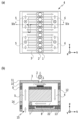
図1(a)及び(b)は、本実施例で使用可能な送液装置の模式図である。図1(a)は上面図、同図(b)は断面図である。送液室101、第1の流路105、第2の流路106は図のX方向に直列に接続されている。送液室101は、第1の接続流路103を介して第1の流路105に接続し、第2の接続流路102を介して第2の流路106に接続している。第1の流路105と第2の流路106は外部と接続し、外部から液体を供給したり排出したりすることが可能である。第1の接続流路103の流路抵抗は第2の接続流路102の流路抵抗よりも高く、送液室101、第1の流路105、第2の流路106の流路抵抗は、第1の接続流路103及び第2の接続流路102よりも十分に低い値になっている。
(Example 1)
FIGS. 1A and 1B are schematic diagrams of a liquid feeding device that can be used in this example. FIG. 1(a) is a top view, and FIG. 1(b) is a sectional view. The
送液室101の壁面には、駆動素子としてメンブレン構造のアクチュエータ104が設けられている。アクチュエータ104は、薄膜圧電体107と振動板108を有し、薄膜圧電体107には電力を供給するための配線(不図示)と共通電位(GND)を与えるための配線(不図示)が接続されている。これら配線を介して薄膜圧電体107に電圧が印加されると、振動板108は±Z方向に変位する。薄膜圧電体107に対しては、DC-BIASを印加した状態でACを印加するが、以下では、説明の簡略化のため、DC-BIASを省略しAC波形のみを表示する。図1(b)は、薄膜圧電体107にAC電圧が印加されていないデフォルト状態を示しており、振動板108は薄膜圧電体107に印加される電圧の程度に応じて、図に点線で示す位置まで変位可能となっている。
An
以下、上記構造の具体的な寸法について説明する。本実施例の送液装置において、送液室101の寸法は、X方向約250μm×Y方向約120μm×Z方向約250μmとする。第1の接続流路103の寸法は、X方向約200μm×Y方向約25μm×Z方向約25μmである。第2の接続流路102の寸法は、X方向約25μm×Y方向約15μm×Z方向約25μmである。
Hereinafter, specific dimensions of the above structure will be explained. In the liquid feeding device of this embodiment, the dimensions of the
以上説明した送液装置は、汎用のMEMS技術を用いて形成することが可能である。例えば送液装置は、Si基板を真空プラズマエッチング、若しくはアルカリ溶液を用いた異方性エッチング、若しくはその組み合わせによって形成することができる。また、複数のSi基板に送液室101を含む流路とアクチュエータ104を別々に形成し、その後、流路とアクチュエータ104とを接合または接着して貼り合わせることにより、送液装置を形成してもよい。
The liquid feeding device described above can be formed using general-purpose MEMS technology. For example, the liquid feeding device can be formed on a Si substrate by vacuum plasma etching, anisotropic etching using an alkaline solution, or a combination thereof. Alternatively, the flow path including the
アクチュエータ104としては、ユニモルフの圧電アクチュエータを用いる。ユニモルフの圧電アクチュエータとは、振動板108の片面側に圧電薄膜圧電体107が形成される構成を有する。このようなアクチュエータ104は、送液室101の開口を塞ぐように振動板108を接着し、更にその表面に薄膜圧電体107を接着することによって形成することができる。
As the
振動板108の材料については、必要な機械的特性や耐信頼性などの条件が満たされれば、特に限定されるものではない。例えば、シリコン窒化膜、シリコン、金属、耐熱ガラスなどを好適に用いることができる。
The material of the
薄膜圧電体107は、真空スパッタ成膜、ゾルゲル成膜、CVD成膜などの手法を用いて成膜することができ、多くの場合、成膜後に焼成される。焼成方法は特に限定されるものではないが、例えば、酸素雰囲気下にて最大650℃程度で焼成するランプアニール加熱法を採用することができる。また、プロセスフローとの整合に鑑みて、薄膜圧電体107は振動板108上に直接成膜して一体焼成してもよいし、振動板108とは別の基板上に成膜し、焼成してから振動板108に剥離転写してもよい。更に、振動板108とは別の基板上に成膜し、振動板108に剥離転写した後に一体焼成してもよい。
The thin film
電極は、焼成プロセスを経るならばPt系を選択することが好ましいが、焼成工程を分離できるならばAl系を選択することが可能である。本実施例では薄膜圧電体107としてPZT系の圧電材料を用い、電極には、薄膜圧電体107が印加電圧に対し線形性の高い状態即ち高い応答性で変位できるような材料を用いる。
It is preferable to select a Pt-based electrode if the electrode undergoes a firing process, but it is possible to select an Al- based electrode if the firing process can be separated. In this embodiment, a PZT-based piezoelectric material is used as the thin film
本実施例では、振動板108として、約1~2μmのSOI基板を用いる。薄膜圧電体107の-Z方向の面には、約1~3μmのTi/Pt、PZT層を形成し、これを振動板108に対向する電極とする。また、薄膜圧電体107の+Z方向の面には、Ti系合金の層を形成し、大気中に露出する最外層としてSiN系の保護膜を被覆し、アクチュエータ104全体を封止する。
In this embodiment, an SOI substrate with a thickness of about 1 to 2 μm is used as the
そして、送液装置と、信号配線を送液装置に伝えるための中継基板を、不図示の保持枠体に接着し、送液装置と中継基板とをワイヤーボンディングにて電気実装する。更に液体の流入口及び排出口となるマニホールドを第1の流路105及び第2の流路106に接続するように接着剤にて固定することにより、送液装置を完成させる。
Then, the liquid feeding device and a relay board for transmitting signal wiring to the liquid feeding device are adhered to a holding frame (not shown), and the liquid feeding device and the relay board are electrically mounted by wire bonding. Further, the manifold serving as the inlet and outlet of the liquid is fixed with an adhesive so as to be connected to the
次に、本発明者らが、送液装置を用いて実際に送液を行った場合の計測方法について説明する。本発明者らは、流れを評価する手法として一般に知られているPTV(Particle Tracking Velocimetry)を採用した。送液する液体は、クリーンルーム用純水と、粘度調整用のグリセリンと、表面張力調整用の1,2-ヘキサンジオールを混合し、粘度が約3cps、表面張力が約30mN/mとなるように調製した。液体中には直径が約1~3μmのトレーサー粒子を混合させて暫く攪拌し、減圧装置を用いて不要な気泡を除去した後に、チューブを通じて送液装置に充填した。この際、供給側と排出側の水頭圧差だけでなく、排出側から液体を強制的に吸引する作業も行い、送液室101を含む全ての液室と流路に液体を充填した。
Next, a measurement method when the present inventors actually perform liquid feeding using a liquid feeding device will be described. The present inventors adopted PTV (Particle Tracking Velocimetry), which is generally known as a method for evaluating flow. The liquid to be pumped is a mixture of pure water for clean rooms, glycerin for viscosity adjustment, and 1,2-hexanediol for surface tension adjustment, so that the viscosity is approximately 3 cps and the surface tension is approximately 30 mN/m. Prepared. Tracer particles having a diameter of about 1 to 3 μm were mixed into the liquid, stirred for a while, and unnecessary air bubbles were removed using a pressure reduction device, and then the liquid was filled into a liquid delivery device through a tube. At this time, in addition to the water head pressure difference between the supply side and the discharge side, a work was also carried out to forcibly suck the liquid from the discharge side, and all liquid chambers and channels including the
アクチュエータ104に対しては、周期が50μsecである単位波形電圧を繰り返し印加し、連続駆動を行った。単位波形は任意波形生成装置を用いて生成し、生成した波形をバイポーラ高速AMPで増幅し、BIAS電圧に重畳した形で配線を通じて薄膜圧電体107に供給した。
A unit waveform voltage having a cycle of 50 μsec was repeatedly applied to the
生成された流れの計測は、高速度カメラをマウント配置した顕微鏡下において、液体中のトレーサー粒子を観察することによって行った。アクチュエータ104の駆動信号のトリガーを高速度カメラの開始信号として取り込み、駆動前後でトレーサー粒子を撮像した。詳細には、トリガー信号の1msec前から撮像を開始し、時間に対応づけられた複数の画像夫々におけるトレーサー粒子の座標を解析し、単位時間当たりのトレーサー粒子の移動量から、流速などを取得した。
Measurements of the generated flow were performed by observing tracer particles in the liquid under a microscope mounted with a high-speed camera. The trigger of the drive signal of the
送液室101の容積変化については、振動板108の変位速度を、レーザードップラー変位計を用いることによって計測し、得られた速度を積分することによって算出した。
The change in volume of the
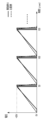
図2(a)及び(b)は、本実施例において、アクチュエータ104に印加する電圧と、当該電圧によって増減する送液室101の容積変化量を示す図である。どちらの図においても、本実施例は実線で比較例は破線で示している。図2(a)においては、例えば-30V以下のDC-BIASを印加しているが、図中では略する。
FIGS. 2A and 2B are diagrams showing the voltage applied to the
図2(a)は、アクチュエータ104に印加する本実施例の電圧波形を、比較例と比較しながら示す図である。ここでは、送液室101の容積が膨張する方向を電圧の正方向とし、最高電圧を30V、駆動周期を50.0μsec、駆動周波数を20KHzとしている。
FIG. 2A is a diagram showing the voltage waveform of this example applied to the
比較例において、電圧は、従来一般的に使用されている三角形状の電圧波形を呈している。電圧は、t=0.0μsecからt=2.5μsecの間で、0Vから30Vに一定の傾きで上昇し、t=2.5μsecからt=50.0μsecの間で、30Vから0Vに一定の傾きで下降している。そして、このような電圧の上昇と下降を50.0μsecの周期で繰り返している。 In the comparative example, the voltage has a triangular voltage waveform that is commonly used in the past. The voltage rises at a constant slope from 0V to 30V from t=0.0μsec to t=2.5μsec, and from 30V to 0V at a constant slope from t=2.5μsec to t=50.0μsec. It is descending at an inclination. Then, such rise and fall of the voltage is repeated at a cycle of 50.0 μsec.
一方、実施例1において、電圧は、t=0.0μsecからt≒1.35μsecの間で30Vを維持し、t=1.35μsecからt≒2.70μsecの間で0Vを維持する。そして、t=2.70μsecからt≒50.0μsecの間で、30Vから0Vに一定の傾きで下降する。以後、このような電圧の上昇と下降を50.0μsecの周期で繰り返している。 On the other hand, in Example 1, the voltage is maintained at 30V between t=0.0μsec and t≈1.35μsec, and maintained at 0V between t=1.35μsec and t≈2.70μsec. Then, from t=2.70 μsec to t≈50.0 μsec, the voltage decreases from 30 V to 0 V at a constant slope. Thereafter, such voltage rise and fall is repeated at a cycle of 50.0 μsec.
比較例にしても、実施例1にしても、相対的に短い時間に高い電圧が印加され、相対的に長い時間をかけて高い電圧から低い電圧に電圧を下降させている。このため、送液室101の容積は、急激な膨張と緩やかな収縮を繰り返すことになる。そして、この急激な膨張と緩やかな収縮の繰り返しが、一定の方向に向かう一定の流れを生み出している。
In both the comparative example and the first example, a high voltage is applied for a relatively short period of time, and the voltage is lowered from a high voltage to a low voltage over a relatively long period of time. Therefore, the volume of the
ここで、送液室101において、一定の流れが生み出される仕組みについて簡単に説明する。送液室101が急激に膨張するとき、流路抵抗の小さい第2の接続流路102の側では速い流速の下で渦が発生し、この渦が第2の流路106から送液室101へ流入しようとする液体を妨げる。これに対し、送液室101を緩やかに収縮するときは、遅い流速の下で渦は発生せず、液体は緩やかに送液室101から第2の流路106に流出する。一方、流路抵抗の大きい第1の接続流路103の側では、送液室101の膨張や収縮の速度によらず、液体は緩やかに送液室101に流入したり流出したりすることが可能である。つまり、第2の接続流路102からの流入が妨げられる膨張と、第2の接続流路102への流出が妨げられない収縮とを繰り返すことにより、図中X方向に向かう定量的な流れが形成されるのである。
Here, a mechanism for generating a constant flow in the
図2(b)は、図2(a)のような電圧を印加した場合の、送液室101のデフォルトに対する容積変化量を示す図である。実施例1においても比較例においても、駆動開始t=0.0μsecからt=5.0μsecの間で容積が大きく増大し、その後、電圧の下降とともに残留振動に伴う増減を繰り返しながら、徐々に振幅を縮小させ、元の値(容積変化量0)に戻っている。図では、送液室101の容積を平均的に膨張させている期間を「膨張用駆動」として示し、容積変化量を平均的に収縮させている期間を「収縮用駆動」として示している。
FIG. 2(b) is a diagram showing the amount of change in volume of the
比較例においても、実施例1においても、容積変化量の残留振動の周期は約8.0μsecである。これは本実施例で用いる送液装置に固有のヘルムホルツ振動の1次周期Thが約8.0μsecであり、ヘルムホルツ周波数が約125kHzであることを示す。そして、このような残留振動が、緩やかな収縮時の容積変化に重畳すると、結果として送液量が損失されてしまう。 In both Comparative Example and Example 1, the period of residual vibration of the volume change amount is approximately 8.0 μsec. This indicates that the primary period Th of the Helmholtz vibration specific to the liquid feeding device used in this example is about 8.0 μsec, and the Helmholtz frequency is about 125 kHz. If such residual vibration is superimposed on the volume change during gradual contraction, the amount of liquid sent will be lost as a result.
但し、比較例と実施例1を比べると、実施例1の振幅のほうが比較例よりも小さく抑えられていることが分かる。これは、実施例1のように、「膨張用駆動」の期間内に電圧を印加する期間と印加しない期間を交互に設けると、電圧を印加しない期間の存在が残留振動の振幅を抑える方向に作用するためと考えられる。本発明者らの観察によると、比較例における1周期分の送液量が約0.7pL、送液効率が約4.5%であったのに対し、実施例1における1周期分の送液量は約0.9pL、送液効率は約5.8%であった。つまり、実施例1では、比較例に対し概ね1.3倍の送液効率が得られることになる。 However, when Comparative Example and Example 1 are compared, it can be seen that the amplitude of Example 1 is suppressed smaller than that of Comparative Example. This is because, as in Example 1, if periods in which voltage is applied and periods in which voltage is not applied are provided alternately within the period of "expansion drive," the existence of periods in which voltage is not applied suppresses the amplitude of the residual vibration. This is thought to be due to the effect of According to the observations of the present inventors, the amount of liquid sent for one cycle in the comparative example was about 0.7 pL, and the liquid feeding efficiency was about 4.5%, whereas the amount of liquid sent for one cycle in Example 1 was The liquid volume was about 0.9 pL, and the liquid feeding efficiency was about 5.8%. In other words, in Example 1, the liquid feeding efficiency is approximately 1.3 times that of the comparative example.
以下、本発明者らが、図2(a)のような電圧波形を求めるに至った過程について説明する。本発明者らは、まず、アクチュエータ104に付与する電圧波形と、送液室101に形成される流れ場を対応づけるための作業を行った。図3は、本発明者らが市販のシミュレータを用いて作成した、上記電圧波形と流れ場との対応関係を表すシミュレーションの系を示す。
Hereinafter, the process by which the present inventors found the voltage waveform as shown in FIG. 2(a) will be explained. The present inventors first performed work to associate the voltage waveform applied to the
流体からの負荷を受けるアクチュエータ104に電圧を印加した場合の、電圧と振動板108の変位の関係については、市販の構造シミュレータ(振動板部の応答特性)を用いて対応づけを行った。また、振動板108の変位と、この変位によって生成される流れ場との関係は市販の流体シミュレータ(流れ特性)によって対応づけを行った。そして、「理想的な流れ場を実現するために、振動板108をどのように変位させればよいか」については、市販の流体シミュレータに入力する変位情報を調整しながら探求した。更に、「求めた変位を実現するための電圧波形」については、市販の構造シミュレータを用いて逆算する作業を行った。
The relationship between the voltage and the displacement of the
なお、厳密に言うと、サブミリサイズの構造において、振動板108の変位と送液室101の容積変化の間には、流体の圧縮性に起因する若干の位相差が発生する。しかしながら、このような位相差は本発明の趣旨において大きな影響はないため、本明細書では振動板108の変位と送液室の容積変化との間に線形関係が保たれるものとして示している。
Strictly speaking, in a submillimeter-sized structure, a slight phase difference occurs between the displacement of the
図4(a)及び(b)は、理想的な流れ場を実現するための、送液室101の容積変化量を示す図である。図4(a)は、送液室101の容積の急激な膨張と緩やかな収縮を繰り返す場合を示し、図1において+X方向に向かう定量的な流れが生成される。一方、図4(b)は、送液室101の容積の緩やかな膨張と急激な収縮を繰り返す場合を示し、図1において-X方向に向かう定量的な流れが形成される。どちらの場合も、一定量の液体を送液することができるが、以下では図4(a)に示す容積変化を実現するための制御について説明する。
FIGS. 4A and 4B are diagrams showing the amount of change in volume of the
図5(a)~(d)は、図4(a)に示す容積変化を実現するためにアクチュエータ104に印加する電圧の波形の例を、比較例と比較しながら説明するための図である。いずれの図においても、アクチュエータ104に印加する電圧を実線で、送液室101の容積変化量を破線で示している。図5(a)~(d)においては、例えば-30V以下のDC-BIASを印加しているが、図中では略する。
5(a) to 5(d) are diagrams for explaining examples of voltage waveforms applied to the
図5(a)は、比較例としての電圧の波形(実線)と、これに伴う送液室101の容積量変化(破線)を示している。比較例としては、従来一般的に使用されている三角型の電圧波形を用いている。具体的には、t=0.0μsecからt=4.0μsecの間で、電圧を0Vから30Vに一定の傾きで上昇させ、その後t=4.0μsecからt=50.0μsecの間で、電圧を30Vから0Vに一定の傾きで下降させる。 FIG. 5A shows a voltage waveform (solid line) and a corresponding change in volume of the liquid feeding chamber 101 (broken line) as a comparative example. As a comparative example, a conventionally commonly used triangular voltage waveform is used. Specifically, between t=0.0μsec and t=4.0μsec, the voltage is increased from 0V to 30V at a constant slope, and then between t=4.0μsec and t=50.0μsec, the voltage is increased. is lowered at a constant slope from 30V to 0V.
既に説明したように、図1の系において、ヘルムホルツ周波数Fhは、Fh=125KHzであり、ヘルムホルツ周期ThはTh=8.0μsecである。よって、図5(a)の例では、駆動開始からTh×1/2(=4.0μsec)の期間を、電圧を上昇させる期間に割り当て、残りの期間(約4.0μsec~50.0μsec)を、電圧を下降させる期間に割り当てていることになる。こうすることにより、送液室101の容積を効率的に膨張させることができる。但し、図5(a)に示す比較例においては、ヘルムホルツ周期(約8μse)の残留振動が、緩やかな収縮時の容積変化に重畳し、結果として送液量の損失を招いてしまっている。
As already explained, in the system of FIG. 1, the Helmholtz frequency Fh is Fh=125 KHz, and the Helmholtz period Th is Th=8.0 μsec. Therefore, in the example of FIG. 5(a), a period of Th×1/2 (=4.0 μsec) from the start of driving is assigned to the period for increasing the voltage, and the remaining period (approximately 4.0 μsec to 50.0 μsec) is assigned to the period during which the voltage is lowered. By doing so, the volume of the
図5(b)は、図4(a)に示す容積変化を実現するために求めた、アクチュエータ104に印加する電圧波形の一例と、当該電圧波形を印加した場合の容積変化を示している。本例において、Th×1/2の期間(0.0μsec~4.0μsec)が、膨張用駆動となり、残りの期間(4.0μsec~50.0μsec)が収縮用駆動となる。本例の場合、膨張用駆動においても収縮用駆動においても、電圧は単調に上昇したり下降したりせず、それぞれの期間で、上に凸の区間と下に凸の区間を繰り返すように増減している。そして、このような高精度の電圧の増減により、送液室101の容積変化においては、ヘルムホルツ周期を有する残留振動がほぼ完全に打ち消されている。
FIG. 5(b) shows an example of the voltage waveform applied to the
図5(c)は、図4(a)に示す容積変化を実現するために求めた、アクチュエータ104に印加する電圧波形の別の例と、当該電圧波形を印加した場合の容積変化を示している。本例においては、Th×3/4の期間(0.0μsec~6.0μsec)が、膨張用駆動に割り当てられ、残りの期間(6.0μsec~50.0μsec)が収縮用駆動に割り当てられている。本例においても、膨張用駆動及び収縮用駆動に対応するそれぞれの期間で、電圧は上に凸の区間と下に凸の区間を繰り返すように増減し、これによりヘルムホルツ周期を有する残留振動が、ほぼ完全に打ち消されている。
FIG. 5(c) shows another example of the voltage waveform applied to the
図5(d)は、図4(a)に示す容積変化を実現するために求めた、アクチュエータ104に印加する電圧波形の更に別の例と、当該電圧波形を印加した場合の容積変化を示している。本例においては、Th×1の期間(0.0μsec~8.0μsec)が、膨張用駆動に割り当てられ、残りの期間(8.0μsec~50.0μsec)が収縮用駆動に割り当てられている。本例においても、膨張用駆動及び収縮用駆動に対応するそれぞれの期間で、電圧は上に凸の区間と下に凸の区間を繰り返すように増減し、これによりヘルムホルツ周期を有する残留振動が、ほぼ完全に打ち消されている。
FIG. 5(d) shows yet another example of the voltage waveform to be applied to the
即ち、以上説明した図5(b)~(d)の実線で示すような波形電圧をアクチュエータ104に印加することができれば、送液室101の容積変化は破線で示すようになり、高い送液効率を実現することが可能となる。しかしながら、実際の駆動制御においては、図5(b)~(d)の実線で示すような複雑で高精度な波形制御を行うことは難しい。波形が複雑になるほど、用意するべき電圧値の種類が増え、回路が複雑になり、コストが増大するためである。
That is, if a waveform voltage as shown by the solid lines in FIGS. 5(b) to 5(d) described above can be applied to the
よって、本発明者らは、より単純な波形で残留振動を抑えるために、図5(b)~(d)に示される波形に共通する特徴の中から、残留振動を抑える効果があると思われる要素を探り、電圧波形の変曲点に着目した。そして、図5(b)~(d)に示される波形においては、膨張用動作の期間においてTh×1/2毎に変曲点が存在することを見出し、このことが残留振動を抑えるために効果的であるという知見に至った。ここで、上記変曲点の存在が残留振動を抑制する理由について説明する。 Therefore, in order to suppress residual vibration with a simpler waveform, the present inventors believe that the characteristics common to the waveforms shown in Figs. 5(b) to (d) are effective in suppressing residual vibration. We focused on the inflection point of the voltage waveform. In the waveforms shown in FIGS. 5(b) to 5(d), we found that there is an inflection point every Th x 1/2 during the expansion operation, and this indicates that in order to suppress residual vibration, We have come to the conclusion that it is effective. Here, the reason why the presence of the above-mentioned inflection point suppresses residual vibration will be explained.
ヘルムホルツ振動周期がThである系において、駆動開始からTh×1/4の期間に電圧を上昇させると、次のTh×1/4の期間には容積を収縮させる方向の戻り力が発生する。即ち、アクチュエータ104に作用する力は、送液室101を膨張させる方向の力から収縮させる方向の力に切り替わり、振動板108は、下に凸の運動から上に凸の運動に切り替わる。よって、このような切り替わりのタイミング(即ち変極点の時点)において、運動に対し逆向きの力を作用させることにより、戻り振動を効果的に抑制することができると考えられる。
In a system where the Helmholtz oscillation period is Th, if the voltage is increased during a period of Th x 1/4 from the start of driving, a return force in the direction of shrinking the volume is generated during the next Th x 1/4 period. That is, the force acting on the
以上の仮定が正しいとすれば、より単純な電圧波形であっても、戻り振動を抑制する効果を得ることはできる。具体的には、送液室101を膨張させるための膨張用駆動において、高い電圧を印加して送液室101の膨張を促す期間の後に、その膨張を抑える方向の力が働くような期間、即ち低い電圧を印加する或は電圧を印加しない期間を設けるようにすればよい。
If the above assumption is correct, it is possible to obtain the effect of suppressing return vibration even with a simpler voltage waveform. Specifically, in the expansion drive for expanding the
図6(a)及び(b)は、上記条件を満たす比較的単純な波形の例を示す図である。図6(a)及び(b)においては、例えば-30V以下のDC-BIASを印加しているが、図中では略する。どちらも、最高電圧30Vを印加する期間と最低電圧0Vを印加する期間が交互に配されている。図6(a)は、最高電圧(30V)を印加する期間(ON期間)と、非印加とする期間(OFF期間)の比を1:2とした場合を示している。この場合、実効電圧は10Vとなる。一方、図6(b)は、ON期間とOFF期間の比を1:1とした場合を示している。この場合、実効電圧は15Vとなる。ON期間とOFF期間の比は一般にDUTY比と呼ばれ、所定のDUTY比で電圧のONとOFFを繰り返す駆動を以下パルス駆動と称す。パルス駆動を行った場合、送液室101には、容積を膨張させる力を作用させつつ、その膨張がオーバーシュートする前に膨張を抑える方向の力を作用させることができる。図2(a)に示す実施例1では、DUTY比が1:1であるパルス駆動即ち図6(b)のパルス駆動を採用している。
FIGS. 6A and 6B are diagrams showing examples of relatively simple waveforms that satisfy the above conditions. In FIGS. 6A and 6B, for example, DC-BIAS of −30 V or less is applied, but this is omitted in the figures. In both cases, periods in which a maximum voltage of 30V is applied and periods in which a minimum voltage of 0V is applied are arranged alternately. FIG. 6A shows a case where the ratio of the period during which the highest voltage (30 V) is applied (ON period) to the period during which no voltage is applied (OFF period) is 1:2. In this case, the effective voltage will be 10V. On the other hand, FIG. 6(b) shows a case where the ratio of the ON period to the OFF period is 1:1. In this case, the effective voltage will be 15V. The ratio between the ON period and the OFF period is generally called the DUTY ratio, and driving in which the voltage is repeatedly turned ON and OFF at a predetermined DUTY ratio is hereinafter referred to as pulse driving. When pulse driving is performed, it is possible to apply a force to expand the volume of the
図7は、図5(b)に示す理想的な電圧波形と、実施例1の波形とを比較して示す図である。図7においては、例えば-30V以下のDC-BIASを印加しているが、図中では略する。理想的な波形については、図5(b)に示す実線と同じものであるが、ここでは説明を分かりやすくするため、時間軸を拡大して示している。理想的な波形に注目すると、t≒2.3μsec電圧が約16Vの辺りに変曲点が存在し、この変曲点を境にして、上に凸の波形が下に凸の波形に切り替わりっている。即ち、電圧は、極小値を通過した後再び上昇し、t≒4.0μsecにおいて20V程度まで上がっている。 FIG. 7 is a diagram showing a comparison between the ideal voltage waveform shown in FIG. 5(b) and the waveform of Example 1. In FIG. 7, for example, DC-BIAS of −30 V or lower is applied, but this is omitted in the figure. The ideal waveform is the same as the solid line shown in FIG. 5(b), but the time axis is shown enlarged here to make the explanation easier to understand. If we look at the ideal waveform, there is an inflection point around t≒2.3μsec and the voltage is about 16V, and at this inflection point, the upwardly convex waveform switches to the downwardly convex waveform. ing. That is, the voltage rises again after passing through the minimum value and reaches about 20V at t≈4.0 μsec.
次に、実施例1の波形に注目すると、膨張用駆動の期間において、パルス幅が1.35μsec、DUTY比が1:1のパルス駆動が含まれている。即ち、実施例1の波形を印加した場合、送液室101には、t≒0.0μsec~1.35μsecで容積を膨張させる強い力が作用し、t≒1.35μsec~2.70μsecでその膨張を抑える方向の力が作用する。このパルス駆動における実効電圧は15Vとなる。
Next, looking at the waveform of Example 1, the expansion drive period includes pulse drive with a pulse width of 1.35 μsec and a DUTY ratio of 1:1. That is, when the waveform of Example 1 is applied, a strong force that expands the volume acts on the
図8は、実施例1のパルス波形を採用した場合のシミュレーションの結果を示す図である。本図においても、図7と同様、理想的な波形を採用した場合の結果と比較して示している。実施例1の容積変化量は、理想的な例と比べると、収縮用駆動時の容積変化量において若干の残留振動が重畳されているものの、図5(a)に示す比較例に比べれば、振幅が大きく抑制されている。 FIG. 8 is a diagram showing the results of a simulation when the pulse waveform of Example 1 is adopted. Similar to FIG. 7, this figure also shows a comparison with the results obtained when an ideal waveform is adopted. Compared to the ideal example, the volume change amount of Example 1 has some residual vibration superimposed in the volume change amount during the contraction drive, but compared to the comparative example shown in FIG. 5(a), The amplitude is greatly suppressed.
ここで、ON期間とOFF期間の調整について説明する。ON期間とOFF期間の和(即ちパルス周期)は、ヘルムホルツ周期Thの2/8倍~3/8倍に含まれることが好ましい。よって、ヘルムホルツ周期Thが約8.0μsecである本実施例の系において、DUTY比を1:1とした場合、パルス周期は2.0μsec~3.0μsecの範囲に含まれることが好ましい。本発明者らが、ON期間とOFF期間の各幅を1.1μsec~1.6μsecの範囲で、即ちパルス周期を2.2μsec~3.2μsecの範囲で変化させたところ、膨張用駆動の容積変化量については大きな違いは見られなかった。しかし、収縮用駆動においてはパルス周期が3.0μsecを超えると、重畳される残留振動が目立つようになった。これは、ON期間で印加された電圧によるオーバーシュートが大きく、OFF期間による振動抑制の効果が不十分になるためと想定される。 Here, adjustment of the ON period and the OFF period will be explained. The sum of the ON period and the OFF period (ie, pulse period) is preferably included in 2/8 to 3/8 times the Helmholtz period Th. Therefore, in the system of this embodiment where the Helmholtz period Th is approximately 8.0 μsec, when the DUTY ratio is 1:1, the pulse period is preferably within the range of 2.0 μsec to 3.0 μsec. When the present inventors changed the width of each ON period and OFF period in the range of 1.1 μsec to 1.6 μsec, that is, the pulse period in the range of 2.2 μsec to 3.2 μsec, the volume of the expansion drive was No significant difference was observed in the amount of change. However, in the contraction drive, when the pulse period exceeded 3.0 μsec, the superimposed residual vibration became noticeable. This is assumed to be because the overshoot caused by the voltage applied during the ON period is large, and the vibration suppression effect during the OFF period becomes insufficient.
本実施例では、DUTY比を1:1に固定することにより、実効電圧を最高電圧の1/2(15V)とし、これにより膨張を抑える方向の力を効果的に作用させることができた。しかし、実効電圧の値は特に限定されるものではない。例えば、実効電圧を15Vよりも小さくすれば、残留振動の振幅を抑制する効果を更に向上させることができる。但し、実効電圧をあまり低くしてしまうと、用意した電圧(30V)が膨張用動作のために十分利用されないため、好ましい流速が得られず、結果として送液効率を低下させてしまうこともある。このため、実効電圧については、残留振動を抑制する目的と、流体バルブ機能を発揮させる目的の両方が、適切なバランスの上で達成されるように調整されることが求められる。本発明者らの検討によれば、実効電圧については、最高電圧の概ね0.40倍から0.95倍に設定されることが好ましいことが確認された。 In this example, by fixing the DUTY ratio to 1:1, the effective voltage was set to 1/2 (15V) of the maximum voltage, and thereby a force in the direction of suppressing expansion could be effectively applied. However, the value of the effective voltage is not particularly limited. For example, if the effective voltage is made smaller than 15V, the effect of suppressing the amplitude of residual vibration can be further improved. However, if the effective voltage is made too low, the prepared voltage (30V) will not be fully utilized for the expansion operation, making it impossible to obtain the desired flow rate, which may result in a decrease in liquid transfer efficiency. . Therefore, the effective voltage is required to be adjusted so that both the purpose of suppressing residual vibration and the purpose of exhibiting the fluid valve function are achieved with an appropriate balance. According to studies conducted by the present inventors, it has been confirmed that it is preferable to set the effective voltage to approximately 0.40 to 0.95 times the maximum voltage.
次に、膨張用駆動のための駆動波形時間と収縮用駆動のための駆動波形時間配分について説明する。膨張用駆動のための駆動波形時間については、流体バルブ機能が得られる程度の速い流速がある程度維持されることが求められる。このため、膨張用駆動の時間は、最高電圧値と生成すべき流速とに基づいて、適切に設定されればよい。収縮用駆動のための駆動波形時間については、振動の小さい低速流さえ得られれば、液体の流速を更に遅くするメリットはない。必要以上の低速化は駆動周期を延長させ、単位時間の送液効率をかえって低下させてしまう。一方、膨張用駆動のための駆動波形時間に対する収縮用駆動のための駆動波形時間が短すぎると、膨張時に発生した残留振動が収縮時に与える影響が大きくなり、送液効率を低下させてしまう。以上のことから、収縮用駆動のための駆動波形時間は膨張用駆動のための駆動波形時間の、3倍以上であり30倍以下であることが好ましい。更に、本発明者らの検討によれば、上記範囲の中でも、収縮用駆動のための駆動波形時間が膨張用駆動のための駆動波形時間の10倍程度であることが、最も好ましいことが確認された。 Next, the drive waveform time allocation for the expansion drive and the drive waveform time allocation for the contraction drive will be explained. Regarding the drive waveform time for the expansion drive, it is required that a high flow rate to obtain the fluid valve function be maintained to some extent. Therefore, the time for the expansion drive may be appropriately set based on the maximum voltage value and the flow rate to be generated. Regarding the drive waveform time for contraction drive, as long as a low-velocity flow with small vibrations can be obtained, there is no advantage in further slowing down the liquid flow rate. Slowing down the speed more than necessary will extend the driving cycle and will actually reduce the liquid feeding efficiency per unit time. On the other hand, if the drive waveform time for the contraction drive is too short relative to the drive waveform time for the expansion drive, the residual vibration generated during the expansion will have a greater influence on the contraction, resulting in a decrease in liquid feeding efficiency. From the above, it is preferable that the drive waveform time for the contraction drive is 3 times or more and 30 times or less the drive waveform time for the expansion drive. Further, according to the studies of the present inventors, it has been confirmed that, within the above range, it is most preferable that the drive waveform time for the contraction drive is about 10 times the drive waveform time for the expansion drive. It was done.
例えば、駆動周期を50μsecに固定した状態で、膨張用動作の時間を4μsec、収縮用動作の時間を46μsecとすると、
(収縮用動作の時間)/(膨張用動作の時間)≒11.5
となり、これは上記条件を満たすことになる。
For example, if the drive cycle is fixed at 50 μsec, and the expansion operation time is 4 μsec and the contraction operation time is 46 μsec, then
(Time for deflation operation) / (Time for expansion operation) ≒ 11.5
Therefore, this satisfies the above condition.
なお、本実施例のように、アクチュエータ104の駆動周期を50μsecとした状態で、収縮用駆動の時間を膨張用駆動の時間の3倍以上とするためには、送液装置として、ヘルムホルツ周期Thが25μsec以下であることが求められる。
Note that in order to make the contraction drive time three times or more the expansion drive time when the drive cycle of the
ここで、再び図2(a)を参照する。図2(a)の実線で示した実施例1の波形は、ヘルムホルツ周期Thが約8.0μsecである系において、膨張用駆動としてDUTY比が1:1、パルス周期が2.70μsecのパルス駆動を行っている。この際、実効電圧(15V)は最高電圧(30V)の0.5倍となり、この値は0.40倍から0.95倍の間に含まれている。このため、送液室101には、ON期間において容積が膨張する力が作用し、その膨張がオーバーシュートする前の好ましいタイミングで、OFF期間に移行し、残留振動が抑制される。その結果、ヘルムホルツ周波数を有する残留振動が発生しても、これに伴う送液室の容積変動を緩和し送液装置全体の送液効率を向上させることができる。
Here, refer to FIG. 2(a) again. The waveform of Example 1 shown by the solid line in FIG. 2(a) is a pulse drive with a DUTY ratio of 1:1 and a pulse period of 2.70 μsec as the expansion drive in a system where the Helmholtz period Th is about 8.0 μsec. It is carried out. At this time, the effective voltage (15V) is 0.5 times the maximum voltage (30V), and this value is included between 0.40 times and 0.95 times. Therefore, a force that expands the volume acts on the
既に説明したように、図5(b)~(c)に示すような電圧波形を実現しようとすると、用意するべき電圧値の種類が増え、回路が複雑になり、コストが増大になってしまう。これに対し、本実施例のようなパルス駆動においては、電圧のONとOFFの切り替えのみが行われればよいため、単純で省スペースの回路構成によって、低コストに実現することができる。更に、パルス周期やDUTY比についても、比較的単純なロジック回路を用いて調整することができる。 As already explained, when trying to realize the voltage waveforms shown in FIGS. 5(b) to 5(c), the number of voltage values that must be prepared increases, the circuit becomes complicated, and the cost increases. . On the other hand, in pulse driving as in this embodiment, it is only necessary to switch the voltage between ON and OFF, so it can be realized at low cost with a simple and space-saving circuit configuration. Furthermore, the pulse period and duty ratio can also be adjusted using a relatively simple logic circuit.
以上説明したように、本実施例によれば、最高電圧を印加する相対的に短い期間と、印加する電圧を最高電圧から基準電圧に変化させる相対的に長い期間とを繰り返すように、アクチュエータ104に印加する電圧を制御する。そして、最高電圧を印加する期間においては、最高電圧の印加と非印加とを所定の間隔で切り替える制御を行う。このような制御により、ヘルムホルツ周波数を有する残留振動が発生しても、これに伴う送液室の容積変動を緩和し送液装置全体の送液効率を向上させることができる。
As described above, according to this embodiment, the
(実施例2)
実施例2においても、図1(a)及び(b)で説明した送液装置を用いるものとする。図9(a)及び(b)は、実施例2において、アクチュエータ104に印加する電圧と、当該電圧によって増減する送液室101の容積変化量を、実施例1で説明した図2(a)及び(b)と同様に示す図である。図9(a)においては、例えば-30V以下のDC-BIASを印加しているが、図中では略する。比較例については、実施例1と同様である。
(Example 2)
In Example 2 as well, the liquid feeding device described in FIGS. 1(a) and 1(b) is used. 9A and 9B show the voltage applied to the
実施例2において、実施例1と異なる点は、「収縮用駆動」の間に「保持期間」を設けていることである。具体的には、図9(a)に示すように、t=0.0μsec~2.70μsecの間で実施例1と同様のパルス駆動を行う。その後、t=2.70μsec~9.45μsecの間では最高電圧を維持し、更にその後、電圧を一定の傾きで下降させてt=50.0μsecで元の電圧に戻している。本実施例において、「保持期間」は6.8μsecであり、この値は送液装置のヘルムホルツ周期Th=8.0μsecの約0.85倍に相当する。
図9(b)は、図9(a)のような電圧を印加した場合の、送液室101の容積変化量を示す図である。実施例2においても、駆動開始t=0.0μsecからt=5.0μsecの間で容積が大きく上昇し、その後、電圧の下降とともに残留振動に伴う僅かな増減を繰り返しながら、元の値(容積変化量0)に戻っている。
FIG. 9(b) is a diagram showing the amount of change in volume of the
実施例2においても、破線で示した比較例と比べると、振幅が小さく抑えられていることが分かる。本発明者らの検討によれば、比較例における1周期分の送液量が約0.7pL、送液効率が約4.5%であったのに対し、実施例2における1周期分の送液量は約1.0pL、送液効率は約6.5%であった。これは、実施例2のほうが比較例よりも送液量の損失が少なく、送液装置としての送液効率を1.5倍程度向上させることができることを意味する。そして、同じ送液装置を用いた場合でも、実施例2のほうが実施例1よりも送液効率を更に向上させている。 It can be seen that in Example 2 as well, the amplitude is kept small compared to the comparative example indicated by the broken line. According to the studies conducted by the present inventors, the amount of liquid sent for one cycle in the comparative example was about 0.7 pL, and the liquid feeding efficiency was about 4.5%, whereas the amount of liquid sent for one cycle in Example 2 was The amount of liquid fed was about 1.0 pL, and the liquid feeding efficiency was about 6.5%. This means that in Example 2, the loss in the amount of liquid fed is smaller than in the comparative example, and the liquid feeding efficiency as a liquid feeding device can be improved by about 1.5 times. Even when the same liquid feeding device is used, the liquid feeding efficiency of Example 2 is further improved than that of Example 1.
実施例2の送液効率を実施例1よりも更に向上させることができたのは、保持期間を設けることによって、膨張用駆動で発生した固有振動が収縮用駆動の容積変化量に重畳するのを抑えることができるためである。一方で、保持期間については、送液装置の構造設計や電圧条件にも影響を与えることが予想される。よって、この観点から考えると、保持期間は、系固有のヘルムホルツ振動周期をThとしたとき、概ね(1/4-1/8)×Th~(10+1/8)×Thの範囲であることが好ましい。実施例2の保持期間は、ヘルムホルツ振動周期の約0.85倍であり、上記条件を満たしている。 The reason why the liquid feeding efficiency of Example 2 was further improved than that of Example 1 was that by providing a holding period, the natural vibration generated in the expansion drive was superimposed on the volume change of the contraction drive. This is because it can suppress the On the other hand, it is expected that the retention period will also be affected by the structural design and voltage conditions of the liquid delivery device. Therefore, from this point of view, the retention period is approximately in the range of (1/4-1/8) x Th to (10 + 1/8) x Th, where Th is the Helmholtz oscillation period specific to the system. preferable. The retention period of Example 2 is about 0.85 times the Helmholtz oscillation period, which satisfies the above conditions.
なお、保持期間においては、必ずしも最高電圧が保持されなくてもよい。保持期間において多少電圧を下降させても、その時の傾きが、保持期間の後に電圧を下降させる際の傾きよりも小さければ、固有振動の重畳を抑制するという効果を得ることはできる。但し、傾きの絶対値は0.1V/μsecより小さいことが好ましい。 Note that the highest voltage does not necessarily have to be held during the holding period. Even if the voltage is lowered somewhat during the holding period, as long as the slope at that time is smaller than the slope when lowering the voltage after the holding period, it is possible to obtain the effect of suppressing the superposition of natural oscillations. However, the absolute value of the slope is preferably smaller than 0.1 V/μsec.
以上説明したように本実施例によれば、最高電圧を印加する相対的に短い期間と、印加する電圧を最高電圧から基準電圧に変化させる相対的に長い期間とを繰り返すように、 アクチュエータ104に印加する電圧を制御する。そして、最高電圧を印加する期間においては、最高電圧の印加と非印加とを所定の間隔で切り替える制御を行う。一方、最高電圧から基準電圧に電圧を変化させる期間においては、最高電圧を暫く保持した後、電圧を一定の傾きで基準電圧に変化させる。このような制御により、ヘルムホルツ周波数を有する残留振動が発生しても、これに伴う送液室の容積変動を緩和し送液装置全体の送液効率を向上させることができる。
As explained above, according to this embodiment, the
(実施例3)
図10は、本発明の送液装置として使用可能な液体吐出ヘッド1100(以下、インクジェット記録ヘッドとも言う)の斜視図である。インクジェット記録ヘッド1100は、複数の吐出素子がY方向に配列して成る素子基板4が、更にY方向に複数配列して構成されている。ここでは、素子基板4が、A4サイズの幅に対応する距離だけY方向に配列して構成されるフルライン型のインクジェット記録ヘッド1100を示している。
(Example 3)
FIG. 10 is a perspective view of a liquid ejection head 1100 (hereinafter also referred to as an inkjet recording head) that can be used as a liquid feeding device of the present invention. The
素子基板4の夫々は、フレキシブル配線基板1101を介して、同じ電気配線基板1102に接続している。電気配線基板1102には、電力を受容するための電力供給端子1103と吐出信号を受信するための信号入力端子1104が配備されている。一方、インク供給ユニット1105には、不図示のインクタンクより供給された色材を含有するインクを個々の素子基板4に供給したり、記録で消費されなかったインクを回収したりする循環流路が形成されている。
Each of the
以上の構成のもと、素子基板4に配された吐出素子のそれぞれは、信号入力端子1104より入力された記録データに基づき、電力供給端子1103から供給された電力を用い、インク供給ユニット1105より供給されたインクを図のZ方向に吐出する。
Based on the above configuration, each of the ejection elements arranged on the
図11(a)及び(b)は、素子基板4における1つの流路ブロックの流路構成を示す図である。1つの素子基板4には複数の流路ブロックが形成されており、図11(a)は、複数の流路ブロックのうちの1つを吐出口面と対向する側(+Z方向側)から見た透視図である。また、図11(b)は同図(a)のXIb-XIb断面図である。
FIGS. 11A and 11B are diagrams showing the flow path configuration of one flow path block on the
1つの流路ブロックには、図11(a)に示すように、Y方向に配列する8つの吐出口2と、これら吐出口のそれぞれに連通するように用意された8つの圧力室3と、2つの供給流路5と、2つの回収流路6とが含まれている。そして、2つの供給流路5のそれぞれは、4つずつの圧力室3に共通してインクを供給し、2つの回収流路6のそれぞれは、4つずつの圧力室3より共通してインクを回収する。後述する送液機構8は、1つの流路ブロックに対し1つ設けられている。
As shown in FIG. 11(a), one flow path block includes eight
図11(b)に示すように、本実施例の素子基板4は、第2の基板13、中間層14、第1の基板12、機能層9、流路形成部材10及び吐出口形成部材11が、この順にZ方向に積層して構成される。機能層9の表面には電気熱変換素子であるエネルギ発生素子1が配設され、吐出口形成部材11のエネルギ発生素子1に対応する位置には、吐出口2が形成されている。Y方向に配列する複数のエネルギ発生素子1の間には、機能層9と吐出口形成部材11の間を介在する流路形成部材10が隔壁となって配され、個々のエネルギ発生素子1及び吐出口2に対応する圧力室3を形成している。
As shown in FIG. 11(b), the
圧力室3に収容されているインクは、安定状態において、吐出口2でメニスカスを形成している。吐出信号に従ってエネルギ発生素子1に電圧パルスが印加されると、エネルギ発生素子1に接触するインクに膜沸騰が生じ、発生した泡の成長エネルギによって吐出口2からインクが滴としてZ方向に吐出される。液体の吐出口2から吐出される方向(ここではZ方向)を下方から上方に向かう方向とすると、インクは下方から上方に向けて吐出される。実際のインク吐出において、重力方向上方から下方に向けて吐出されることもあり、この場合は重力方向上方が下方、重力方向下方が上方ということになる。
The ink contained in the
吐出動作によって消費された圧力室3内のインクは、圧力室3及び吐出口2の毛管力によって新たに供給され、吐出口2においてメニスカスを再形成する。尚、本実施例では、吐出口2、エネルギ発生素子1、圧力室3を組み合わせたものを吐出素子と称する。
The ink in the
図11(b)に示すように、本実施例の素子基板4においては、第2の基板13、中間層14、第1の基板12、機能層9、流路形成部材10及び吐出口形成部材11のそれぞれが壁となって、循環流路が形成されている。そしてこの循環流路は、供給流路5、圧力室3、回収流路6、送液室22及び接続流路7に区分することができる。
As shown in FIG. 11(b), the
圧力室3は、吐出素子ごとに用意されている。供給流路5及び回収流路6は、ブロック内の4つの吐出素子ごとに用意され、供給流路5は4つの圧力室3に共通してインクを供給し、回収流路6は4つの圧力室3より共通してインクを回収する。
A
送液室22及び接続流路7は、8つの吐出素子即ち1つの流路ブロックごとに1つずつ用意されている。送液室22は、XY平面において8つのエネルギ発生素子1と重複する位置に配されている。送液室22には送液室22の容積を変更可能な送液機構8が配備されており、送液機構8は8つの圧力室3に共通してインクの循環を行う。接続流路7は、Y方向において、流路ブロックのほぼ中央に配置され、送液室22と供給流路とを接続している。接続流路7が接続する供給流路の位置は、2つの供給流路5に分岐されるよりも上流側の位置である。
One
以上の構成のもと、送液機構8を適切に駆動することにより、供給口15を介して供給されたインクを、供給流路5、圧力室3、回収流路6、送液室22、接続流路7の順に、循環させることができる。このような循環は、吐出動作の有無や頻度に係らずに安定的に行われ、吐出口2近傍には常に新鮮なインクを供給することが可能となる。なお、図には示していないが、圧力室3の手前の供給流路5の途中には、異物や気泡などの流入を防ぐためのフィルタを設けておくことが好ましい。フィルタとしては、柱状構造物などを採用することができる。
With the above configuration, by appropriately driving the
素子基板4は、第1の基板12と第2の基板13の夫々で構造物を予め形成しておき、その後、第1の基板12と第2の基板13を、後に接続流路7となる位置に溝が形成された中間層14を挟んで図のように貼り合わせることによって製造することができる。
In the
以下、上記構造の具体的な寸法例について説明する。本実施例において、個々の吐出素子、即ちエネルギ発生素子1、吐出口2及び圧力室3は、Y方向に1200npi(nozzles per inch)の密度で配列する。エネルギ発生素子1の大きさは20μm×20μm、吐出口2の直径は18μm、吐出口2の厚さ、即ち吐出口形成部材11の厚み、は5μmとする。圧力室3の大きさは、X方向100μm(長さ)×Y方向37μm(幅)×Z方向5μm(高さ)とする。なお、使用するインクの粘度は2cP、個々の吐出口からのインク吐出量は2pLとする。
Hereinafter, specific example dimensions of the above structure will be explained. In this embodiment, the individual ejection elements, that is, the
本実施形態において、個々のエネルギ発生素子1の駆動周波数は15KHzとする。このような駆動周波数は、個々の吐出素子において、エネルギ発生素子1に電圧を印加してから実際にインクが吐出され、更に新たなインクがリフィルされて次の吐出動作が可能になるまでに要される時間に基づいて設定される。
In this embodiment, the driving frequency of each
一方、本実施例の素子基板4において、送液室22の大きさは、X方向250μm×Y方向120μm×Z方向250μmとする。接続流路7の大きさは、X方向25μm×Y方向25μm×Z方向25μmとする。
On the other hand, in the
本実施例では以上のような寸法関係とすることで、接続流路7の流路抵抗及びイナータンスを、供給流路5、回収流路6、圧力室3を合わせた流路の流路抵抗及びイナータンスよりも低くしている。ここで、「供給流路5、回収流路6、圧力室3を合わせた流路の流路抵抗及びイナータンス」とは、2つの供給流路5、8つの圧力室3、2つの回収流路6それぞれの並列的な流路抵抗の和と、これらの直列的な流路抵抗の和とを総合したものを示す。なお、上記に示した各部の寸法値は一例に過ぎず、要求仕様に応じて、適宜変更してもよい。
In this embodiment, by setting the above-mentioned dimensional relationship, the flow path resistance and inertance of the
図12(a)~(c)は、送液機構8の構造及び動作を説明するための図である。本実施例では、送液機構8として、薄膜圧電体24とこれを表裏面から挟む2つの電極23及びダイヤフラム21を有する圧電アクチュエータを採用する。送液機構8(以後、アクチュエータ8とも称す)は、ダイヤフラム21が送液室22に露出するように第2の基板13上に配置されている。
FIGS. 12(a) to 12(c) are diagrams for explaining the structure and operation of the
ダイヤフラム21は、1~2μm程度の厚みを有するSiなどで構成される。薄膜圧電体24はPZT圧電薄膜であり、X方向220μm×Y方向90μm×Z方向2μm程度である。
The
2つの電極23を介し薄膜圧電体24に電圧を印加すると、ダイヤフラム21が薄膜圧電体24に対してたわみ、送液室22の容積が変動する。即ち、2つの電極23に印加する電圧を変動させることにより、ダイヤフラム21を±Z方向に変位させ、送液室22の容積を変化させることができる。
When a voltage is applied to the thin film
図12(b)は、薄膜圧電体24にDC-BIAS電圧を印加したデフォルト状態を示している。デフォルト状態において、ダイヤフラム21は送液室22の液室容積を収縮している。一方、図12(c)は、薄膜圧電体24に最大電圧30Vの過渡的な波形を印加した際の、デフォルト状態から液室容積が膨張した状態を示している。ダイヤフラム21は、薄膜圧電体24に印加する電圧の程度に応じて、図12(b)のデフォルト状態と図12(c)の膨張状態の間を変位する。
FIG. 12(b) shows a default state in which a DC-BIAS voltage is applied to the thin film
インクジェット記録ヘッド1100では、吐出動作が暫く行われない吐出口において揮発成分の蒸発が進み、インク(液体)が変質する場合がある。そしてこのような蒸発の程度が、吐出頻度に応じて複数の吐出口の間でばらつくと、吐出量及び吐出方向にもばらつき生じ、画像内に濃度むらやスジが確認されることがある。このようなことから、インクジェット記録ヘッド1100においては、吐出口の近傍に常に新鮮なインクを供給するために、高い送液効率を実現することが求められる。以下、本実施例のインクジェット記録ヘッド1100における送液制御について説明する。
In the
本実施例の流路ブロックにおけるヘルムホルツ共振周波数は約100kHz程度とする。本実施例ではこの共振周波数を利用してアクチュエータ8を駆動する。
The Helmholtz resonance frequency in the flow path block of this embodiment is approximately 100 kHz. In this embodiment, the
図13は、本実施例のアクチュエータ8を駆動するための電圧波形を示す図である。図13においては、例えば-30V以下のDC-BIASを印加しているが、図中では略する。図において、実線は本実施例、破線は比較例を示している。本実施例の電圧波形は実施例2の形状と類似している。即ち、パルス駆動を行った後、最高電圧を所定の保持期間だけ維持し、その後一定の傾きで電圧を下降させている。図では、送液室22の容積が膨張する方向を電圧の正方向とし、最高電圧を30V、駆動周期を50.0μsec、駆動周波数を20KHzとしている。この駆動周波数はエネルギ発生素子の駆動周波数15KHzよりも十分高い値である。アクチュエータ8の駆動周波数を吐出素子の駆動周波数よりも十分高くすることにより、吐出素子の個々の吐出動作がアクチュエータの駆動の影響でばらついてしまうのを抑えることができる。
FIG. 13 is a diagram showing a voltage waveform for driving the
このような本実施例においても、緩やかな収縮においてヘルムホルツ振動に伴う容積の増減を抑えることにより、送液効率を向上させることができる。その結果、供給流路5、圧力室3、回収流路6、送液室22及び接続流路7において、インクを好適な速度で循環させ、吐出口2の近傍に新鮮なインクを安定的に供給することができる。本発明者らの観察によると、粘度2cpsのインクを用いて上記駆動を行った場合、1周期分の送液量は約1.0pL、送液効率は約6.5%であることが確認された。
In this embodiment as well, the liquid feeding efficiency can be improved by suppressing the volume increase/decrease due to Helmholtz vibration during gentle contraction. As a result, ink is circulated at a suitable speed in the
そして、吐出動作が行われない期間が数sec~数10sec程度に及んでも、その後の吐出動作で不吐出となることはなく、正常な吐出動作が安定して行われることが確認された。 It was also confirmed that even if the period during which the ejection operation was not performed lasted for several seconds to several tens of seconds, no ejection failure occurred in the subsequent ejection operation, and the normal ejection operation was stably performed.
一方、図13の破線で示した比較例の下で電圧制御を行った場合は、緩やかな収縮においてヘルムホルツ振動が重畳され、高い送液効率が得られない。本発明者らが確認を行ったところ、吐出動作が行われない期間が数sec~数10sec程度に及ぶと、その後の吐出動作が不吐出となったり不安定になったりすることが確認された。 On the other hand, when voltage control is performed under the comparative example shown by the broken line in FIG. 13, Helmholtz oscillations are superimposed during gentle contraction, and high liquid feeding efficiency cannot be obtained. Upon confirmation by the present inventors, it was confirmed that if the period in which the ejection operation is not performed extends from several seconds to several tens of seconds, the subsequent ejection operation becomes non-ejection or becomes unstable. .
以上説明したように、本実施例によれば、複数の吐出口からインクを吐出するインクジェット記録ヘッドにおいて、吐出口の近傍にあるインクを循環させるための循環流路と、当該流路に配され循環ポンプとして機能するアクチュエータを用意する。そして、最高電圧を印加する相対的に短い期間と、印加する電圧を最高電圧から基準電圧に変化させる相対的に長い期間とを繰り返すように、アクチュエータ104に印加する電圧を制御する。この際、最高電圧を印加する期間においては、最高電圧の印加と非印加とを所定の間隔で切り替える制御を行う。一方、最高電圧から基準電圧に電圧を変化させる期間においては、最高電圧を暫く保持した後、電圧を一定の傾きで基準電圧に変化させる。
As described above, according to this embodiment, in an inkjet recording head that ejects ink from a plurality of ejection ports, there is a circulation channel for circulating ink near the ejection ports, and a circulation channel disposed in the flow channel. Prepare an actuator that functions as a circulation pump. Then, the voltage applied to the
本実施例では、このような制御により、ヘルムホルツ周波数を有する残留振動が発生しても、これに伴う送液室の容積変動を緩和し送液装置全体の送液効率を向上させることが可能となる。その結果、個々の吐出素子に対し新鮮なインクを定常的に供給することができ、吐出状態を安定させておくことが可能となる。 In this embodiment, even if a residual vibration having a Helmholtz frequency occurs, it is possible to alleviate the accompanying volume fluctuation of the liquid feeding chamber and improve the liquid feeding efficiency of the entire liquid feeding device through such control. Become. As a result, fresh ink can be constantly supplied to each ejection element, and the ejection state can be kept stable.
なお、本実施例において、流体ブロックは、図11(a)に示した形態に限定されるものではない。1つの送液機構8でインクを循環させる吐出素子(圧力室3)の数は、8より多くてもよいし少なくてもよい。また、1つの流体ブロックに設けられる供給流路5及び回収流路6の数は、2より多くてもよいし少なくてもよい。
Note that in this example, the fluid block is not limited to the form shown in FIG. 11(a). The number of ejection elements (pressure chambers 3) that circulate ink in one
また、図11(a)及び(b)では、吐出素子がY方向に1列に並ぶ形態の素子基板4を例に説明したが、素子基板4にはこのような吐出素子列がX方向に2列以上配置されていてもよい。
In addition, in FIGS. 11(a) and 11(b), the explanation has been given using the
更に、本実施例ではエネルギ発生素子1として電気熱変換素子を用い、ここで膜沸騰を生じさせ生成された泡の成長エネルギでインクを吐出する形態としたが、本発明はこのような吐出方法に限定されるものではない。例えば、圧電アクチュエータ、静電アクチュエータ、機械/衝撃駆動型アクチュエータ、音声コイルアクチュエータ、磁気歪み駆動型アクチュエータ等、様々な方式の素子をエネルギ発生素子として採用することができる。
Further, in this embodiment, an electrothermal conversion element is used as the
更にまた、以上では図10を参照し、素子基板4が、A4サイズの幅に対応する距離だけY方向に配列して構成されるフルライン型の記録ヘッドを例に説明したが、本実施例の液体吐出モジュールはシリアル型の記録ヘッドにも採用することはできる。但し、フルライン型のように長尺な記録ヘッドのほうが、インクの蒸発や変質という本発明の課題がより顕著に現れやすいことから、本発明の効果をより顕著に享受することができる。
次に、図4(b)に示す容積変化を実現する制御について実施例4~6を用いて説明する。
Furthermore, in the above description, referring to FIG. 10, a full-line type recording head in which the
Next, control for realizing the volume change shown in FIG. 4(b) will be explained using Examples 4 to 6.
(実施例4)
実施例4においても、図1(a)及び(b)で説明した送液装置を用いるものとする。
図14(a)及び(b)は、本実施例において、アクチュエータ104に印加する電圧と、当該電圧によって増減する送液室101の容積変化量を示す図である。どちらの図においても、本実施例は実線で比較例は破線で示している。図14(a)においては、例えば-30V以下のDC-BIASを印加しているが、図中では略する。
(Example 4)
In Example 4 as well, the liquid feeding device described in FIGS. 1(a) and 1(b) is used.
FIGS. 14A and 14B are diagrams showing the voltage applied to the
図14(a)は、アクチュエータ104に印加する本実施例の電圧波形を、比較例と比較しながら示す図である。ここでは、送液室101の容積が膨張する方向を電圧の正方向とし、最高電圧を30V、駆動周期を50.0μsec、駆動周波数を20KHzとしている。
FIG. 14A is a diagram showing a voltage waveform of this example applied to the
比較例において、電圧は、従来一般的に使用されている三角形状の電圧波形を呈している。電圧は、t=0.0μsecからt=47.5μsecの間で、0Vから30Vに一定の傾きで上昇し、t=47.5μsecからt=50.0μsecの間で、30Vから0Vに一定の傾きで下降している。そして、このような電圧の上昇と下降を50.0μsecの周期で繰り返している。 In the comparative example, the voltage has a triangular voltage waveform that is commonly used in the past. The voltage rises at a constant slope from 0V to 30V from t=0.0μsec to t=47.5μsec, and from 30V to 0V at a constant slope from t=47.5μsec to t=50.0μsec. It is descending at an angle. Then, such rise and fall of the voltage is repeated at a cycle of 50.0 μsec.
一方、実施例4において、電圧は、t=0.0μsecからt≒46.0μsecの間で電圧を0Vから30Vへ上昇させ、t=46.0μsecから47.35μsecの間で0Vを維持する。そして、t=47.3μsecから48.7μsecの間で30Vを維持し、その後t=48.7μsecから50.0μsecまで0Vを維持する。以後、このような電圧の上昇と下降を50.0μsecの周期で繰り返している。 On the other hand, in Example 4, the voltage is increased from 0V to 30V between t=0.0μsec and t≈46.0μsec, and maintained at 0V between t=46.0μsec and 47.35μsec. Then, 30V is maintained from t=47.3μsec to 48.7μsec, and then 0V is maintained from t=48.7μsec to 50.0μsec. Thereafter, such voltage rise and fall is repeated at a cycle of 50.0 μsec.
比較例にしても、実施例4にしても、相対的に長い時間に高い電圧が印加され、相対的に短い時間をかけて高い電圧から低い電圧に電圧を下降させている。このため、送液室101の容積は、緩やかな膨張と急激な収縮を繰り返すことになる。そして、この緩やかな膨張と急激な収縮の繰り返しが、一定の方向に向かう一定の流れを生み出している。
In both Comparative Example and Example 4, a high voltage is applied for a relatively long time, and the voltage is lowered from a high voltage to a low voltage over a relatively short time. Therefore, the volume of the
図15(b)~(d)は、図4(b)に示す容積変化を実現するためにアクチュエータ104に印加する電圧の波形の例を、比較例と比較しながら説明するための図である。いずれの図においても、アクチュエータ104に印加する電圧を実線で、送液室101の容積変化量を破線で示している。図15(a)~(d)においては、例えば-30V以下のDC-BIASを印加しているが、図中では略する。
15(b) to (d) are diagrams for explaining examples of voltage waveforms applied to the
図15(a)は、比較例としての電圧の波形(実線)と、これに伴う送液室101の容積量変化(破線)を示している。比較例としては、従来一般的に使用されている三角型の電圧波形を用いている。具体的には、t=0.0μsecからt=46.0μsecの間で、電圧を0Vから30Vに一定の傾きで上昇させ、その後t=46.0μsecからt=50.0μsecの間で、電圧を30Vから0Vに一定の傾きで下降させる。 FIG. 15A shows a voltage waveform (solid line) as a comparative example and a corresponding change in volume of the liquid feeding chamber 101 (broken line). As a comparative example, a conventionally commonly used triangular voltage waveform is used. Specifically, between t=0.0μsec and t=46.0μsec, the voltage is increased from 0V to 30V at a constant slope, and then between t=46.0μsec and t=50.0μsec, the voltage is increased. is lowered at a constant slope from 30V to 0V.
既に説明したように、図1の系において、ヘルムホルツ周波数Fhは、Fh=125KHzであり、ヘルムホルツ周期ThはTh=8.0μsecである。よって、図15(a)の例では、(約0.0μsec~46.0μsec)を、電圧を上昇させる期間に割り当て、Th×1/2(=4.0μsec)の期間において、電圧を下降させる期間に割り当てていることになる。こうすることにより、送液室101の容積を効率的に収縮させることができる。但し、図15(a)に示す比較例においては、ヘルムホルツ周期(約8μse)の残留振動が、緩やかな膨張時の容積変化に重畳し、結果として送液量の損失を招いてしまっている。
As already explained, in the system of FIG. 1, the Helmholtz frequency Fh is Fh=125 KHz, and the Helmholtz period Th is Th=8.0 μsec. Therefore, in the example of FIG. 15(a), (approximately 0.0 μsec to 46.0 μsec) is allocated to the period of increasing the voltage, and the voltage is decreased in the period of Th×1/2 (=4.0 μsec). It is assigned to a period. By doing so, the volume of the
図15(b)は、図4(b)に示す容積変化を実現するために求めた、アクチュエータ104に印加する電圧波形の一例と、当該電圧波形を印加した場合の容積変化を示している。本例において、期間(0.0μsec~46.0μsec)が膨張用駆動となり、Th×1/2の期間(46.0μsec~50.0μsec)が収縮用駆動となる。本例の場合、膨張用駆動においても収縮用駆動においても、電圧は単調に上昇したり下降したりせず、それぞれの期間で、上に凸の区間と下に凸の区間を繰り返すように増減している。そして、このような高精度の電圧の増減により、送液室101の容積変化においては、ヘルムホルツ周期を有する残留振動がほぼ完全に打ち消されている。
FIG. 15(b) shows an example of the voltage waveform applied to the
図15(c)は、図4(b)に示す容積変化を実現するために求めた、アクチュエータ104に印加する電圧波形の別の例と、当該電圧波形を印加した場合の容積変化を示している。本例において、期間(0.0μsec~44.0μsec)が膨張用駆動となり、Th×3/4の期間(44.0μsec~50.0μsec)が収縮用駆動となる。本例においても、膨張用駆動及び収縮用駆動に対応するそれぞれの期間で、電圧は上に凸の区間と下に凸の区間を繰り返すように増減し、これによりヘルムホルツ周期を有する残留振動が、ほぼ完全に打ち消されている。
FIG. 15(c) shows another example of the voltage waveform applied to the
図15(d)は、図4(b)に示す容積変化を実現するために求めた、アクチュエータ104に印加する電圧波形の更に別の例と、当該電圧波形を印加した場合の容積変化を示している。本例において、期間(0.0μsec~42.0μsec)が膨張用駆動となり、Th×1の期間(42.0μsec~50.0μsec)が収縮用駆動となる。本例においても、膨張用駆動及び収縮用駆動に対応するそれぞれの期間で、電圧は上に凸の区間と下に凸の区間を繰り返すように増減し、これによりヘルムホルツ周期を有する残留振動が、ほぼ完全に打ち消されている。
FIG. 15(d) shows yet another example of the voltage waveform to be applied to the
即ち、以上説明した図15(b)~(d)の実線で示すような波形電圧をアクチュエータ104に印加することができれば、送液室101の容積変化は破線で示すようになり、高い送液効率を実現することが可能となる。しかしながら、実際の駆動制御においては、図15(b)~(d)の実線で示すような複雑で高精度な波形制御を行うことは難しい。波形が複雑になるほど、用意するべき電圧値の種類が増え、回路が複雑になり、コストが増大するためである。
That is, if a waveform voltage as shown by the solid lines in FIGS. 15(b) to 15(d) described above can be applied to the
よって、本発明者らは、より単純な波形で残留振動を抑えるために、図15(b)~(d)に示される波形に共通する特徴の中から、残留振動を抑える効果があると思われる要素を探り、電圧波形の変曲点に着目した。そして、図15(b)~(d)に示される波形においては、図5(b)~(d)で説明したとの同じく、収縮用動作の期間においてもTh×1/2毎に変曲点が存在することを見出し、このことが残留振動を抑えるために効果的であるという知見に至った。 Therefore, in order to suppress residual vibration with a simpler waveform, the present inventors believe that the characteristics common to the waveforms shown in Figs. 15(b) to (d) are effective in suppressing residual vibration. We focused on the inflection point of the voltage waveform. In the waveforms shown in FIGS. 15(b) to 15(d), as explained in FIGS. They found that this point exists and found that this is effective for suppressing residual vibration.
即ち、実施例1と同様に、より単純な電圧波形であっても、戻り振動を抑制する効果を期待することはできる。具体的には、最大電圧から初期電圧まで下降させる立ち下がり期間において、まず、最大電圧から所定値まで下降させ、その後、駆動開始時の傾きの絶対値よりも小さな傾きの絶対値で電圧を印加し、その後更に目標電圧に到達させればよい。 That is, as in the first embodiment, even with a simpler voltage waveform, the effect of suppressing the return vibration can be expected. Specifically, during the falling period in which the maximum voltage is lowered to the initial voltage, the maximum voltage is first lowered to a predetermined value, and then the voltage is applied with an absolute value of the slope smaller than the absolute value of the slope at the start of driving. However, after that, it is sufficient to further reach the target voltage.
図16は、図15(b)に示す理想的な電圧波形と、実施例4の波形とを比較して示す図である。図16においては、例えば-30V以下のDC-BIASを印加しているが、図中では略する。理想的な波形については、図15(b)に示す実線と同じものである。但し、ここでは説明を分かりやすくするため、図15(b)において約45μsec~50μsecにおける波形を1周期(50μsec)シフトさせ-5μsec~0μsecの時間軸を拡大して示している。理想的な波形に注目すると、t≒-1.5μsec電圧が約14Vの辺りに変曲点が存在し、この変曲点を境にして、下に凸の波形が上に凸の波形に切り替わりっている。即ち、電圧は、極小値を通過した後再び上昇し、t≒-1.5μsecにおいて18V程度まで上がっている。 FIG. 16 is a diagram showing a comparison between the ideal voltage waveform shown in FIG. 15(b) and the waveform of Example 4. In FIG. 16, for example, DC-BIAS of −30 V or lower is applied, but this is omitted in the figure. The ideal waveform is the same as the solid line shown in FIG. 15(b). However, in order to make the explanation easier to understand, in FIG. 15(b), the waveform from about 45 μsec to 50 μsec is shifted by one period (50 μsec), and the time axis from −5 μsec to 0 μsec is shown enlarged. If we look at the ideal waveform, there is an inflection point around t≒-1.5μsec and the voltage is about 14V, and at this inflection point, the downwardly convex waveform switches to the upwardly convex waveform. ing. That is, the voltage rises again after passing through the minimum value and reaches about 18V at t≈−1.5 μsec.
次に、実施例4の波形に注目すると、収縮用駆動の期間において、パルス幅が1.35μsec、DUTY比が1:1のパルス駆動が含まれている。即ち、実施例4の波形を印加した場合、送液室101には、t≒-4.0μsec~-2.65μsecで容積を収縮させる強い力が作用し、t≒-2.65μsec~1.3μsecでその収縮を抑える方向の力が作用する。このパルス駆動における実効電圧は約15Vとなる。更にt≒-1.3μsec~0μsecで容積を収縮させる。
Next, looking at the waveform of Example 4, the contraction drive period includes pulse drive with a pulse width of 1.35 μsec and a DUTY ratio of 1:1. That is, when the waveform of Example 4 is applied, a strong force that contracts the volume acts on the
図17は、実施例4のパルス波形を採用した場合のシミュレーションの結果を示す図である。本図においても、図16と同様、理想的な波形を採用した場合の結果と比較して示している。実施例4の容積変化量は、理想的な例と比べると、収縮用駆動時の容積変化量において若干の残留振動が重畳されているものの、図15(a)に示す比較例に比べれば、振幅が大きく抑制されている。 FIG. 17 is a diagram showing the results of a simulation when the pulse waveform of Example 4 is adopted. Similarly to FIG. 16, this figure also shows a comparison with the results obtained when an ideal waveform is adopted. Compared to the ideal example, the volume change amount of Example 4 has some residual vibration superimposed in the volume change amount during the contraction drive, but compared to the comparative example shown in FIG. 15(a), The amplitude is greatly suppressed.
本実施例では、DUTY比を1:1に固定することにより、実効電圧を最高電圧の1/2(15V)とし、これにより収縮を抑える方向の力を効果的に作用させることができた。しかし、実効電圧の値は特に限定されるものではない。例えば、実効電圧を15Vよりも大きくすれば、残留振動の振幅を抑制する効果を更に向上させることができる。但し、実効電圧をあまり大きくしてしまうと、用意した電圧(30V)が収縮用動作のために十分利用されないため、好ましい流速が得られず、結果として送液効率を低下させてしまうこともある。このため、実効電圧については、残留振動を抑制する目的と、流体バルブ機能を発揮させる目的の両方が、適切なバランスの上で達成されるように調整されることが求められる。本発明者らの検討によれば、実効電圧については、最高電圧の概ね0.05倍から0.60倍に設定されることが好ましいことが確認された。 In this example, by fixing the DUTY ratio to 1:1, the effective voltage was set to 1/2 (15 V) of the maximum voltage, and thereby a force in the direction of suppressing contraction could be effectively applied. However, the value of the effective voltage is not particularly limited. For example, if the effective voltage is made larger than 15V, the effect of suppressing the amplitude of residual vibration can be further improved. However, if the effective voltage is made too large, the prepared voltage (30V) will not be fully utilized for the contraction operation, making it impossible to obtain the desired flow rate, which may result in a decrease in liquid transfer efficiency. . Therefore, the effective voltage is required to be adjusted so that both the purpose of suppressing residual vibration and the purpose of exhibiting the fluid valve function are achieved with an appropriate balance. According to studies conducted by the present inventors, it has been confirmed that it is preferable to set the effective voltage to approximately 0.05 to 0.60 times the maximum voltage.
以上説明したように、本実施例によれば、最高電圧を印加する相対的に短い期間と、印加する電圧を基準電圧から最高電圧に変化させる相対的に長い期間とを繰り返すように、アクチュエータ104に印加する電圧を制御する。そして、最高電圧を印加する期間においては、最高電圧の印加と非印加とを所定の間隔で切り替える制御を行う。このような制御により、ヘルムホルツ周波数を有する残留振動が発生しても、これに伴う送液室の容積変動を緩和し送液装置全体の送液効率を向上させることができる。
As described above, according to this embodiment, the
(実施例5)
実施例5においても、図1(a)及び(b)で説明した送液装置を用いるものとする。図18(a)及び(b)は、実施例5において、アクチュエータ104に印加する電圧と、当該電圧によって増減する送液室101の容積変化量を、実施例4で説明した図14(a)及び(b)と同様に示す図である。図18(a)においては、例えば-30V以下のDC-BIASを印加しているが、図中では略する。比較例については、実施例4と同様である。
(Example 5)
In Example 5 as well, the liquid feeding device described in FIGS. 1(a) and 1(b) is used. 18(a) and 18(b) show the voltage applied to the
実施例5において、実施例4と異なる点は、「膨張用駆動」の期間に「保持期間」を設けていることである。具体的には、図18(a)に示すように、t=0.0μsec~5.4μsecの間では基準電圧を維持し、t=5.4μsec~46.0μsecにかけて緩やかに最高電圧まで上昇させる。その後t=46.0μsec~50.0μsecの間で実施例4と同様のパルス駆動を行う。本実施例において、「保持期間」は約6μsecであり、この値は送液装置のヘルムホルツ周期Th=8.0μsecの約0.75倍に相当する。
図18(b)は、図18(a)のような電圧を印加した場合の、送液室101の容積変化量を示す図である。実施例5においても、収縮用駆動としてパルス駆動を開始したt=46.0μsecからt=50.0μsecの間で容積が大きく減少する。そして、その後、膨張用駆動に伴う電圧の上昇とともに、残留振動に伴う僅かな増減を繰り返しながら、最大の容積変化を実現していく。
FIG. 18(b) is a diagram showing the amount of change in volume of the
実施例5においても、破線で示した比較例と比べると、振幅が小さく抑えられていることが分かる。本発明者らの検討によれば、比較例における1周期分の送液量が約0.7pL、送液効率が約4.5%であったのに対し、実施例5における1周期分の送液量は約1.0pL、送液効率は約6.5%であった。これは、実施例5のほうが比較例よりも送液量の損失が少なく、送液装置としての送液効率を1.5倍程度向上させることができることを意味する。そして、同じ送液装置を用いた場合でも、実施例5のほうが実施例4よりも送液効率を更に向上させている。 It can be seen that in Example 5 as well, the amplitude is kept small compared to the comparative example indicated by the broken line. According to the studies conducted by the present inventors, the amount of liquid sent for one cycle in the comparative example was about 0.7 pL, and the liquid feeding efficiency was about 4.5%, whereas the amount of liquid sent for one cycle in the comparative example was about 4.5%. The amount of liquid fed was about 1.0 pL, and the liquid feeding efficiency was about 6.5%. This means that in Example 5, the loss in the amount of liquid fed is smaller than in the comparative example, and the liquid feeding efficiency as a liquid feeding device can be improved by about 1.5 times. Even when the same liquid feeding device is used, the liquid feeding efficiency of Example 5 is further improved than that of Example 4.
実施例5の送液効率を実施例4よりも更に向上させることができたのは、保持期間を設けることによって、収縮用駆動で発生した固有振動が膨張用駆動の容積変化量に重畳するのを抑えることができるためである。一方で、保持期間については、送液装置の構造設計や電圧条件にも影響を与えることが予想される。よって、この観点から考えると、保持期間は、系固有のヘルムホルツ振動周期をThとしたとき、概ね(1/4-1/8)×Th~(10+1/8)×Thの範囲であることが好ましい。実施例5の保持期間は、ヘルムホルツ振動周期の約0.85倍であり、上記条件を満たしている。 The reason why the liquid feeding efficiency of Example 5 was able to be further improved over that of Example 4 was that by providing a holding period, the natural vibration generated by the contraction drive was superimposed on the volume change of the expansion drive. This is because it can suppress the On the other hand, it is expected that the retention period will also be affected by the structural design and voltage conditions of the liquid delivery device. Therefore, from this point of view, the retention period is approximately in the range of (1/4-1/8) x Th to (10 + 1/8) x Th, where Th is the Helmholtz oscillation period specific to the system. preferable. The retention period of Example 5 is about 0.85 times the Helmholtz oscillation period, which satisfies the above conditions.
なお、保持期間においては、必ずしも基準電圧に保持されなくてもよい。保持期間において多少電圧を下降させても、その時の傾きが、保持期間の後に電圧を上昇させる際の傾きよりも小さければ、固有振動の重畳を抑制するという効果を得ることはできる。但し、傾きの絶対値は0.1V/μsecより小さいことが好ましい。 Note that the voltage does not necessarily have to be held at the reference voltage during the holding period. Even if the voltage is lowered somewhat during the holding period, as long as the slope at that time is smaller than the slope when increasing the voltage after the holding period, it is possible to obtain the effect of suppressing the superposition of natural oscillations. However, the absolute value of the slope is preferably smaller than 0.1 V/μsec.
以上説明したように本実施例によれば、最高電圧を印加する相対的に短い期間と、印加する電圧を基準電圧から最高電圧に変化させる相対的に短い期間とを繰り返すように、 アクチュエータ104に印加する電圧を制御する。そして、最高電圧を印加する期間においては、最高電圧の印加と非印加とを所定の間隔で切り替える制御を行う。一方、基準電圧から最高電圧に電圧を変化させる期間においては、基準電圧を暫く保持した後、電圧を一定の傾きで最高電圧に変化させる。このような制御により、ヘルムホルツ周波数を有する残留振動が発生しても、これに伴う送液室の容積変動を緩和し送液装置全体の送液効率を向上させることができる。
As explained above, according to this embodiment, the
(実施例6)
本実施例は、実施例3で実現したインクの流れ方向と逆方向へインクを循環させるものである。構造は実施例3と同じであり、駆動方法のみが異なる。実施例6における循環方向を実現することで、例えばノズル側から混入した気泡が、送液室22に流入することなく、供給口15の側へ回収できるメリットがある。
(Example 6)
In this embodiment, ink is circulated in the opposite direction to the ink flow direction realized in the third embodiment. The structure is the same as in Example 3, and only the driving method is different. By realizing the circulation direction in Example 6, there is an advantage that, for example, air bubbles mixed in from the nozzle side can be collected to the
図19(a)及び(b)は、素子基板4における1つの流路ブロックの流路構成を示す図である。図11(a)及び(b)と同じ符号は、第3の実施例と同じ機構であることを示す。重力方向は+Z方向であり、仮にノズル側から気泡が混入した場合、循環する流れに気泡をのせ、かつ浮力により共通液室側へ回収させることができる。
FIGS. 19A and 19B are diagrams showing the flow path configuration of one flow path block on the
図20は、本実施例のアクチュエータ8を駆動するための電圧波形を示す図である。図20においては、例えば-30V以下のDC-BIASを印加しているが、図中では略する。図において、実線は本実施例、破線は比較例を示している。本実施例の電圧波形は実施例5の形状と類似している。即ち、パルス駆動を行った後、基準電圧を所定の保持期間だけ維持し、その後一定の傾きで電圧を上昇させている。図では、送液室22の容積が膨張する方向を電圧の正方向とし、最高電圧を30V、駆動周期を50.0μsec、駆動周波数を20KHzとしている。この駆動周波数はエネルギ発生素子の駆動周波数15KHzよりも十分高い値である。アクチュエータ8の駆動周波数を吐出素子の駆動周波数よりも十分高くすることにより、吐出素子の個々の吐出動作がアクチュエータの駆動の影響でばらついてしまうのを抑えることができる。
FIG. 20 is a diagram showing a voltage waveform for driving the
このような本実施例においても、緩やかな膨張においてヘルムホルツ振動に伴う容積の増減を抑えることにより、送液効率を向上させることができる。その結果、供給流路5、圧力室3、回収流路6、送液室22及び接続流路7において、インクを好適な速度で循環させ、吐出口2の近傍に新鮮なインクを安定的に供給することができる。本発明者らの観察によると、粘度2cpsのインクを用いて上記駆動を行った場合、1周期分の送液量は約1.0pL、送液効率は約6.5%であることが確認された。そして、吐出動作が行われない期間が数sec~数10sec程度に及んでも、その後の吐出動作で不吐出となることはなく、正常な吐出動作が安定して行われることが確認された。
In this embodiment as well, the liquid feeding efficiency can be improved by suppressing the volume increase/decrease due to Helmholtz vibration during gentle expansion. As a result, ink is circulated at a suitable speed in the
一方、図20の破線で示した比較例の下で電圧制御を行った場合は、緩やかな収縮においてヘルムホルツ振動が重畳され、高い送液効率が得られない。本発明者らが確認を行ったところ、吐出動作が行われない期間が数sec~数10sec程度に及ぶと、その後の吐出動作が不吐出となったり不安定になったりすることが確認された。 On the other hand, when voltage control is performed under the comparative example shown by the broken line in FIG. 20, Helmholtz oscillations are superimposed during gentle contraction, and high liquid feeding efficiency cannot be obtained. Upon confirmation by the present inventors, it was confirmed that if the period in which the ejection operation is not performed extends from several seconds to several tens of seconds, the subsequent ejection operation becomes non-ejection or becomes unstable. .
以上説明したように、本実施例によれば、複数の吐出口からインクを吐出するインクジェット記録ヘッドにおいて、吐出口の近傍にあるインクを循環させるための循環流路と、当該流路に配され循環ポンプとして機能するアクチュエータを用意する。そして、最高電圧を印加する相対的に長い期間と、印加する電圧を最高電圧から基準電圧に変化させる相対的に短い期間とを繰り返すように、アクチュエータ104に印加する電圧を制御する。この際、基準電圧を印加する期間においては、基準電圧の印加と非印加とを所定の間隔で切り替える制御を行う。一方、基準電圧から最高電圧に電圧を変化させる期間においては、基準電圧を暫く保持した後、電圧を一定の傾きで基準電圧に変化させる。
As described above, according to this embodiment, in an inkjet recording head that ejects ink from a plurality of ejection ports, there is a circulation channel for circulating ink near the ejection ports, and a circulation channel disposed in the flow channel. Prepare an actuator that functions as a circulation pump. Then, the voltage applied to the
本実施例では、このような制御により、ヘルムホルツ周波数を有する残留振動が発生しても、これに伴う送液室の容積変動を緩和し送液装置全体の送液効率を向上させることが可能となる。その結果、個々の吐出素子に対し新鮮なインクを定常的に供給することができ、吐出状態を安定させておくことが可能となる。 In this embodiment, even if a residual vibration having a Helmholtz frequency occurs, it is possible to alleviate the accompanying volume fluctuation of the liquid feeding chamber and improve the liquid feeding efficiency of the entire liquid feeding device through such control. Become. As a result, fresh ink can be constantly supplied to each ejection element, and the ejection state can be kept stable.
本実施例においても、実施例3で説明したのと同様の実施形態を選択できる。 In this example as well, the same embodiment as that described in Example 3 can be selected.
(その他の実施例)
以上では、基準電圧を0V、最高電圧を30Vとし、電圧が高くなるほど送液室の容積が増大することを前提に説明してきたが、無論本発明はこのような形態に限定されるものではない。例えば、基準電圧は0Vで無くてもよいし、電圧が高くなるほど送液室の容積が縮小するようにアクチュエータを配置してもよい。
(Other examples)
The above description has been made on the assumption that the reference voltage is 0V, the maximum voltage is 30V, and the volume of the liquid feeding chamber increases as the voltage increases, but the present invention is of course not limited to this form. . For example, the reference voltage may not be 0V, or the actuator may be arranged so that the higher the voltage, the smaller the volume of the liquid feeding chamber.
また、以上の実施例では、ON期間とOFF期間のDUTY比を1:1としたパルス駆動を用いたが、無論、本発明はこのようなDUTY比に限定されるものではなく、図6(a)に示す1:2など、他のDUTY比とすることもできる。但し、DUTY比については、送液装置の駆動能力、配線能力、駆動負荷、に依存する部分も大きいので、適用時には、様々な要素を考慮して調整することが好ましい。 Further, in the above embodiment, pulse driving was used with a DUTY ratio of 1:1 between the ON period and the OFF period, but the present invention is of course not limited to such a DUTY ratio, and as shown in FIG. Other DUTY ratios can also be used, such as 1:2 shown in a). However, since the DUTY ratio largely depends on the driving ability, wiring ability, and driving load of the liquid delivery device, it is preferable to adjust the DUTY ratio in consideration of various factors at the time of application.
また、上記実施例では、膨張用駆動の期間をTh×1/2とする図5(b)や図15(b)に示した駆動を基準として、図2(a)や図9(a)、或いは図14(a)や図18(a)に示す電圧波形を作成したが。しかしながら、上記実施例では、図5(c)や図5(d)或いは図15(c)や図15(d)に示す駆動を基準とすることもできる。即ち、膨張用駆動の期間をTh×3/4やTh×1とした場合も、夫々の膨張用駆動の期間の中でパルス周期やDUTY比が調整されればよい。 Furthermore, in the above embodiment, the driving period shown in FIG. 2(a) and FIG. 9(a) is based on the drive shown in FIG. 5(b) and FIG. Alternatively, the voltage waveforms shown in FIG. 14(a) or FIG. 18(a) were created. However, in the above embodiments, the driving shown in FIGS. 5(c) and 5(d), or FIG. 15(c) and FIG. 15(d) may be used as a reference. That is, even when the period of the expansion drive is set to Th×3/4 or Th×1, the pulse period and the DUTY ratio may be adjusted within each period of the expansion drive.
いずれにせよ、アクチュエータに印加される電圧においては、i)第1の電圧を印加する第1の期間と、第1の期間よりも長い期間であって、第1の電圧と第1の電圧よりも低い第2の電圧との間を変化する第2の期間とが繰り返されるように制御されればよい。そして、ii)第1の期間においては、第1の電圧の印加と非印加とが切り替えられるように制御されればよい。 In any case, in the voltage applied to the actuator, i) a first period in which the first voltage is applied; and a period longer than the first period; It is sufficient if the control is performed such that a second period in which the voltage is lower than the second voltage is repeated. And ii) in the first period, the control may be performed so that application and non-application of the first voltage are switched.
本発明は、上述の実施例の1以上の機能を実現するプログラムを、ネットワーク又は記憶媒体を介してシステム又は装置に供給し、そのシステム又は装置のコンピュータにおける1つ以上のプロセッサーがプログラムを読出し実行する処理でも実現可能である。また、1以上の機能を実現する回路(例えば、ASIC)によっても実現可能である。 The present invention provides a system or device with a program that implements one or more of the functions of the above-described embodiments via a network or storage medium, and one or more processors in the computer of the system or device reads and executes the program. This can also be achieved by processing. It can also be realized by a circuit (for example, ASIC) that realizes one or more functions.
1 送液装置
101 送液室
104 アクチュエータ(駆動素子)
1
Claims (20)
前記液室に設けられ、電圧が印加されることによって前記液室の容積を膨張及び収縮させて、前記液室が収容する液体を外部との間で循環させる駆動素子と、
を備える送液装置の駆動方法であって、
前記駆動素子に印加する電圧を、
i)第1の電圧の印加と非印加を切り替えることで、電圧を印加する期間に続いて電圧を印加しない期間を有するように制御する第1の期間と、
ii)前記第1の期間に続く期間であって、前記第1の電圧を保持した後に前記第1の電圧から前記第1の電圧よりも低い第2の電圧に変化させる、または、前記第1の電圧を保持させずに前記第1の電圧から前記第2の電圧に変化させる第2の期間と、
を繰り返すように制御し、
前記第2の期間は、前記第1の期間よりも長いことを特徴とする駆動方法。 a liquid chamber containing a liquid;
a drive element that is provided in the liquid chamber and expands and contracts the volume of the liquid chamber by applying a voltage to circulate the liquid contained in the liquid chamber between the outside and the outside;
A method of driving a liquid feeding device comprising:
The voltage applied to the drive element is
i) a first period controlled by switching between application and non-application of the first voltage so as to have a period in which the voltage is not applied, followed by a period in which the voltage is not applied ;
ii) A period following the first period, in which the first voltage is held and then changed from the first voltage to a second voltage lower than the first voltage, or the first voltage is changed to a second voltage lower than the first voltage. a second period in which the voltage is changed from the first voltage to the second voltage without holding the voltage;
control to repeat,
The driving method, wherein the second period is longer than the first period.
前記液室に設けられ、電圧が印加されることによって前記液室の容積を膨張及び収縮させて、前記液室が収容する液体を外部との間で循環させる駆動素子と、
を備える送液装置の駆動方法であって、
前記駆動素子に印加する電圧を、
i)第1の電圧の印加と非印加を切り替えることで、電圧を印加する期間に続いて電圧を印加しない期間を有するように制御する第1の期間と、
ii)前記第1の期間に続く期間であって、前記第1の電圧よりも低い第2の電圧を保持した後に前記第2の電圧から前記第1の電圧に変化させる、または、前記第2の電圧を保持させずに前記第2の電圧から前記第1の電圧に変化させる第2の期間と、
を繰り返すように制御し、
前記第2の期間は、前記第1の期間よりも長いことを特徴とする駆動方法。 a liquid chamber containing a liquid;
a drive element that is provided in the liquid chamber and expands and contracts the volume of the liquid chamber by applying a voltage to circulate the liquid contained in the liquid chamber between the outside and the outside;
A method of driving a liquid feeding device comprising:
The voltage applied to the drive element is
i) a first period controlled by switching between application and non-application of the first voltage to have a period in which the voltage is not applied, followed by a period in which the voltage is not applied ;
ii) A period following the first period, in which a second voltage lower than the first voltage is held and then the second voltage is changed to the first voltage, or the second voltage is changed from the second voltage to the first voltage. a second period in which the second voltage is changed to the first voltage without holding the voltage;
control to repeat,
The driving method, wherein the second period is longer than the first period.
前記圧力室に設けられ、前記吐出口から液体を吐出させるためのエネルギを発生するエネルギ発生素子と、
前記圧力室に液体を供給する供給流路と、
前記圧力室より液体を回収する回収流路と、
前記回収流路に接続する送液室と、
前記送液室と前記供給流路とを接続する接続流路と、
前記送液室の容積を膨張及び収縮させることにより、前記供給流路、前記圧力室、前記回収流路、前記送液室、及び前記接続流路において液体を循環させる駆動素子と、
前記駆動素子に印加する電圧を制御する制御手段と
を備える液体吐出ヘッドであって、
前記制御手段は、前記駆動素子に印加する電圧を、
i)第1の電圧の印加と非印加を切り替えることで、電圧を印加する期間に続いて電圧を印加しない期間を有するように制御する第1の期間と、
ii)前記第1の期間に続く期間であって、前記第1の電圧を保持した後に前記第1の電圧から前記第1の電圧よりも低い第2の電圧に変化させる、または、前記第1の電圧を保持させずに前記第1の電圧から前記第2の電圧に変化させる第2の期間と、
を繰り返すように制御し、
前記第2の期間は、前記第1の期間よりも長いことを特徴とする液体吐出ヘッド。 a pressure chamber communicating with the discharge port and accommodating a liquid to be discharged from the discharge port;
an energy generating element that is provided in the pressure chamber and generates energy for discharging liquid from the discharge port;
a supply channel that supplies liquid to the pressure chamber;
a recovery channel for recovering liquid from the pressure chamber;
a liquid feeding chamber connected to the recovery channel;
a connection flow path connecting the liquid feeding chamber and the supply flow path;
a drive element that circulates the liquid in the supply channel, the pressure chamber, the recovery channel, the liquid supply chamber, and the connection channel by expanding and contracting the volume of the liquid supply chamber;
A liquid ejection head comprising a control means for controlling a voltage applied to the drive element,
The control means controls the voltage applied to the drive element,
i) a first period controlled by switching between application and non-application of the first voltage so as to have a period in which the voltage is not applied, followed by a period in which the voltage is not applied ;
ii) A period following the first period, in which the first voltage is held and then changed from the first voltage to a second voltage lower than the first voltage, or the first voltage is changed to a second voltage lower than the first voltage. a second period in which the voltage is changed from the first voltage to the second voltage without holding the voltage;
control to repeat,
A liquid ejection head, wherein the second period is longer than the first period.
前記圧力室に設けられ、前記吐出口から液体を吐出させるためのエネルギを発生するエネルギ発生素子と、
前記圧力室に液体を供給する供給流路と、
前記圧力室より液体を回収する回収流路と、
前記回収流路に接続する送液室と、
前記送液室と前記供給流路とを接続する接続流路と、
前記送液室の容積を膨張及び収縮させることにより、前記供給流路、前記圧力室、前記回収流路、前記送液室、及び前記接続流路において液体を循環させる駆動素子と、
前記駆動素子に印加する電圧を制御する制御手段と
を備える液体吐出ヘッドであって、
前記制御手段は、前記駆動素子に印加する電圧を、
i)第1の電圧の印加と非印加を切り替えることで、電圧を印加する期間に続いて電圧を印加しない期間を有するように制御する第1の期間と、
ii)前記第1の期間に続く期間であって、前記第1の電圧よりも低い第2の電圧を保持した後に前記第2の電圧から前記第1の電圧に変化させる、または、前記第2の電圧を保持させずに前記第2の電圧から前記第1の電圧に変化させる第2の期間と、
を繰り返すように制御し、
前記第2の期間は、前記第1の期間よりも長いことを特徴とする液体吐出ヘッド。 a pressure chamber communicating with the discharge port and accommodating a liquid to be discharged from the discharge port;
an energy generating element that is provided in the pressure chamber and generates energy for discharging liquid from the discharge port;
a supply channel that supplies liquid to the pressure chamber;
a recovery channel for recovering liquid from the pressure chamber;
a liquid feeding chamber connected to the recovery channel;
a connection flow path connecting the liquid feeding chamber and the supply flow path;
a drive element that circulates the liquid in the supply channel, the pressure chamber, the recovery channel, the liquid supply chamber, and the connection channel by expanding and contracting the volume of the liquid supply chamber;
A liquid ejection head comprising a control means for controlling a voltage applied to the drive element,
The control means controls the voltage applied to the drive element,
i) a first period controlled by switching between application and non-application of the first voltage so as to have a period in which the voltage is not applied, followed by a period in which the voltage is not applied ;
ii) A period following the first period, in which a second voltage lower than the first voltage is held and then the second voltage is changed to the first voltage, or the second voltage is changed from the second voltage to the first voltage. a second period in which the second voltage is changed to the first voltage without holding the voltage;
control to repeat,
A liquid ejection head, wherein the second period is longer than the first period.
Priority Applications (1)
| Application Number | Priority Date | Filing Date | Title |
|---|---|---|---|
| US16/727,541 US11097536B2 (en) | 2018-12-28 | 2019-12-26 | Driving method of liquid feeding apparatus |
Applications Claiming Priority (2)
| Application Number | Priority Date | Filing Date | Title |
|---|---|---|---|
| JP2018247871 | 2018-12-28 | ||
| JP2018247871 | 2018-12-28 |
Publications (3)
| Publication Number | Publication Date |
|---|---|
| JP2020108950A JP2020108950A (en) | 2020-07-16 |
| JP2020108950A5 JP2020108950A5 (en) | 2022-09-30 |
| JP7427401B2 true JP7427401B2 (en) | 2024-02-05 |
Family
ID=71569855
Family Applications (1)
| Application Number | Title | Priority Date | Filing Date |
|---|---|---|---|
| JP2019177333A Active JP7427401B2 (en) | 2018-12-28 | 2019-09-27 | How to drive the liquid transfer device |
Country Status (1)
| Country | Link |
|---|---|
| JP (1) | JP7427401B2 (en) |
Citations (3)
| Publication number | Priority date | Publication date | Assignee | Title |
|---|---|---|---|---|
| JP2004169706A (en) | 2004-02-02 | 2004-06-17 | Konica Minolta Holdings Inc | Fluid transport system |
| JP2007224837A (en) | 2006-02-24 | 2007-09-06 | Konica Minolta Holdings Inc | Micropump drive circuit, micropump array drive circuit, micropump and micropump array |
| US20170253032A1 (en) | 2016-03-01 | 2017-09-07 | Ricoh Company, Ltd. | Temperature uniformity across an inkjet head using piezoelectric actuation |
-
2019
- 2019-09-27 JP JP2019177333A patent/JP7427401B2/en active Active
Patent Citations (3)
| Publication number | Priority date | Publication date | Assignee | Title |
|---|---|---|---|---|
| JP2004169706A (en) | 2004-02-02 | 2004-06-17 | Konica Minolta Holdings Inc | Fluid transport system |
| JP2007224837A (en) | 2006-02-24 | 2007-09-06 | Konica Minolta Holdings Inc | Micropump drive circuit, micropump array drive circuit, micropump and micropump array |
| US20170253032A1 (en) | 2016-03-01 | 2017-09-07 | Ricoh Company, Ltd. | Temperature uniformity across an inkjet head using piezoelectric actuation |
Also Published As
| Publication number | Publication date |
|---|---|
| JP2020108950A (en) | 2020-07-16 |
Similar Documents
| Publication | Publication Date | Title |
|---|---|---|
| JP5364084B2 (en) | Inkjet device | |
| CN108602347B (en) | Ink jet driving device and ink jet driving method | |
| JP2010179651A (en) | Inkjet printer and method of driving the same | |
| JP6990877B2 (en) | Inkjet head and inkjet device using it and ink application method | |
| JP6307945B2 (en) | Liquid ejection apparatus and liquid ejection head driving method | |
| CN107107614B (en) | Method of driving droplet discharge head and droplet discharge apparatus | |
| JP5161986B2 (en) | Inkjet head and inkjet apparatus | |
| JP4739620B2 (en) | Fluid discharger | |
| US11097536B2 (en) | Driving method of liquid feeding apparatus | |
| JP7427401B2 (en) | How to drive the liquid transfer device | |
| JP7419006B2 (en) | How to drive the liquid transfer device | |
| JP2010105300A (en) | Liquid discharge apparatus | |
| JP4323197B2 (en) | Driving method of piezoelectric ink jet head | |
| WO2013165384A1 (en) | Selecting pulse to drive piezoelectric actuator | |
| US11453213B2 (en) | Driving method of liquid feeding apparatus | |
| JP7358153B2 (en) | liquid dispensing module | |
| JP5709554B2 (en) | Ink jet head and recording apparatus | |
| JP2001232798A (en) | Ink jet recorder and its recording method | |
| US20230150260A1 (en) | Liquid ejection apparatus and control method of liquid ejection apparatus | |
| CN113787829B (en) | Liquid ejection head and liquid ejection apparatus | |
| JP4541856B2 (en) | Driving method of piezoelectric ink jet head | |
| JP2006130782A (en) | Inkjet recording head and inkjet recorder | |
| JP2001191517A (en) | Ink jet head | |
| JP2002127428A (en) | Electrostatic ink jet recorder and recording method | |
| JP4052349B2 (en) | Inkjet recording device |
Legal Events
| Date | Code | Title | Description |
|---|---|---|---|
| A521 | Request for written amendment filed |
Free format text: JAPANESE INTERMEDIATE CODE: A523 Effective date: 20220921 |
|
| A621 | Written request for application examination |
Free format text: JAPANESE INTERMEDIATE CODE: A621 Effective date: 20220921 |
|
| A977 | Report on retrieval |
Free format text: JAPANESE INTERMEDIATE CODE: A971007 Effective date: 20230713 |
|
| A131 | Notification of reasons for refusal |
Free format text: JAPANESE INTERMEDIATE CODE: A131 Effective date: 20230822 |
|
| A521 | Request for written amendment filed |
Free format text: JAPANESE INTERMEDIATE CODE: A523 Effective date: 20231018 |
|
| TRDD | Decision of grant or rejection written | ||
| A01 | Written decision to grant a patent or to grant a registration (utility model) |
Free format text: JAPANESE INTERMEDIATE CODE: A01 Effective date: 20231226 |
|
| A61 | First payment of annual fees (during grant procedure) |
Free format text: JAPANESE INTERMEDIATE CODE: A61 Effective date: 20240124 |
|
| R151 | Written notification of patent or utility model registration |
Ref document number: 7427401 Country of ref document: JP Free format text: JAPANESE INTERMEDIATE CODE: R151 |