JP7422012B2 - Equipment condition monitoring device and method - Google Patents
Equipment condition monitoring device and method Download PDFInfo
- Publication number
- JP7422012B2 JP7422012B2 JP2020105129A JP2020105129A JP7422012B2 JP 7422012 B2 JP7422012 B2 JP 7422012B2 JP 2020105129 A JP2020105129 A JP 2020105129A JP 2020105129 A JP2020105129 A JP 2020105129A JP 7422012 B2 JP7422012 B2 JP 7422012B2
- Authority
- JP
- Japan
- Prior art keywords
- sensor
- measurement
- output
- equipment
- signal
- Prior art date
- Legal status (The legal status is an assumption and is not a legal conclusion. Google has not performed a legal analysis and makes no representation as to the accuracy of the status listed.)
- Active
Links
- 238000012806 monitoring device Methods 0.000 title claims description 36
- 238000000034 method Methods 0.000 title claims description 8
- 238000005259 measurement Methods 0.000 claims description 71
- 238000012544 monitoring process Methods 0.000 claims description 22
- 238000010248 power generation Methods 0.000 claims description 5
- 230000001133 acceleration Effects 0.000 claims description 4
- 238000006073 displacement reaction Methods 0.000 claims description 2
- 238000004891 communication Methods 0.000 description 10
- 238000005096 rolling process Methods 0.000 description 5
- 238000010586 diagram Methods 0.000 description 4
- 230000003287 optical effect Effects 0.000 description 2
- 238000001514 detection method Methods 0.000 description 1
- 238000007435 diagnostic evaluation Methods 0.000 description 1
- 238000005516 engineering process Methods 0.000 description 1
- 238000009434 installation Methods 0.000 description 1
- 230000007774 longterm Effects 0.000 description 1
- 238000012545 processing Methods 0.000 description 1
- 238000005070 sampling Methods 0.000 description 1
Images


Classifications
-
- Y—GENERAL TAGGING OF NEW TECHNOLOGICAL DEVELOPMENTS; GENERAL TAGGING OF CROSS-SECTIONAL TECHNOLOGIES SPANNING OVER SEVERAL SECTIONS OF THE IPC; TECHNICAL SUBJECTS COVERED BY FORMER USPC CROSS-REFERENCE ART COLLECTIONS [XRACs] AND DIGESTS
- Y02—TECHNOLOGIES OR APPLICATIONS FOR MITIGATION OR ADAPTATION AGAINST CLIMATE CHANGE
- Y02E—REDUCTION OF GREENHOUSE GAS [GHG] EMISSIONS, RELATED TO ENERGY GENERATION, TRANSMISSION OR DISTRIBUTION
- Y02E10/00—Energy generation through renewable energy sources
- Y02E10/70—Wind energy
- Y02E10/72—Wind turbines with rotation axis in wind direction
Description
本発明は、自動運転機器に適用される機器状態監視装置及び方法に関する。 TECHNICAL FIELD The present invention relates to an equipment condition monitoring device and method applied to automatic driving equipment.
自動で運転制御されるプラント機器のなかには、ほぼ無人状態で運用されるシステムも存在し、このような場合には、設備点検員に代わって機器の健全性を診断する計測装置の必要性が高い。 Among plant equipment that is automatically controlled, there are systems that are operated almost unattended, and in such cases, there is a strong need for measurement devices that can diagnose the health of equipment in place of equipment inspectors. .
例えば、一般的な風力発電システムにおいて、発電運転は自動制御されるため、運転員を兼ねた設備点検員が機械室内に留まって、機器の運転状態を確認することは少ない。このような場合、機器の健全性を評価する計測装置をシステムにあらかじめ組み込み、運転中の機器の状態を計測し、システムから離れた監視所に計測結果を伝送して、運転が正常に行われているかを評価することがある。 For example, in a typical wind power generation system, since the power generation operation is automatically controlled, it is rare for an equipment inspector who also serves as an operator to remain in the machine room to check the operating status of the equipment. In such cases, a measuring device to evaluate the health of the equipment is installed in the system in advance, measures the status of the equipment during operation, and transmits the measurement results to a monitoring station remote from the system to ensure normal operation. There are times when we evaluate whether the
この種の従来技術としては、例えば、特許文献1が知られている。特許文献1は、小規模で、人が介在することなく多数の遠隔地において状態監視が行える状態遠隔監視システムを提供することを目的とし、「回転機の運転状態を遠隔監視する状態遠隔監視システムであって、回転機に設置した部分放電センサ3、温度センサ4、振動センサ5、それらの各センサ信号を検出し検出した信号をA/D変換し監視データとして格納する信号検出/格納部6、通信のための通信モジュール7、を含む少なくとも1つの現場監視装置8と、この現場監視装置との通信のための通信モジュール7、通信を制御すると共に現場監視装置に監視を行わせその監視データを回収し監視データを管理するコンピュータで構成される監視サーバユニット10、を含む監視サーバ20と、この監視サーバと少なくとも1つの現場監視装置との間の通信を行う通信手段9と、を備えた。模で、人が介在することなく多数の遠隔地において状態監視が行える状態遠隔監視システムを提供する。」ものである。
As this type of conventional technology, for example,
特許文献1によれば、監視サーバと現場監視装置との間で通信手段を用いて部分放電、温度、振動の監視信号を遠隔収集し、機器の状態監視ができる。
According to
他方このように構成された計測装置は、測定対象となるシステムと密接に結合されるため、対象システムの導入に合わせて組み込まれることになる。これは、対象システムごとに計測装置が必要であることを意味しており、対象システムが複数存在する場合には、計測装置のコストが無視できなくなる。また、対象システムの導入時期が古く、この種の高精度な計測装置を持たない場合には、対象システムにインタフェースがなく、計測装置を結合することが困難な場合がある。 On the other hand, a measuring device configured in this manner is closely coupled to a system to be measured, and therefore is incorporated when the target system is introduced. This means that a measuring device is required for each target system, and if there are multiple target systems, the cost of the measuring device cannot be ignored. Furthermore, if the target system was introduced a long time ago and does not have this type of highly accurate measuring device, the target system may not have an interface and it may be difficult to connect the measuring device.
以上のことから本発明の目的とするところは、設置コストが低く、対象システムの設備構成と無関係に適用可能な機器状態監視装置及び方法を提供することにある。 In light of the above, an object of the present invention is to provide a device status monitoring device and method that have low installation costs and can be applied regardless of the equipment configuration of a target system.
上記課題を解決するため、本発明においては、「測定対象機器に設置された診断センサと稼働センサからの入力信号を取り込み、診断センサからの入力信号を記録する信号記録装置と、計測条件を記憶する計測条件記憶装置と、信号記録装置における記録を制御する計測制御器を備え、計測制御器は、稼働センサからの入力信号が計測条件を満たしているときに診断センサからの入力信号を信号記録装置に記録することを特徴とする機器状態監視装置」としたものである。 In order to solve the above problems, the present invention provides a signal recording device that captures input signals from a diagnostic sensor and an operation sensor installed in a device to be measured, and records the input signal from the diagnostic sensor, and a signal recording device that stores measurement conditions. and a measurement controller that controls recording in the signal recording device, and the measurement controller records the input signal from the diagnostic sensor as a signal when the input signal from the operating sensor satisfies the measurement condition. ``Equipment status monitoring device that records information on the device.''
また本発明においては、「測定対象機器に設置された診断センサと稼働センサからの入力信号を取り込み、稼働センサからの入力信号が計測条件を満たし、かつ設定された時刻であるときに診断センサからの入力信号を記録することを特徴とする機器状態監視方法」としたものである。 In addition, in the present invention, "input signals from the diagnostic sensor and operating sensor installed in the equipment to be measured are captured, and when the input signal from the operating sensor satisfies the measurement conditions and at the set time, the input signal from the diagnostic sensor is ``A method for monitoring equipment status, which is characterized by recording the input signal of the device.''
本発明によれば、計測が自動的になされるため、無人状態で運転される自動機器へ適用可能である。また、対象システムに対し、計測装置を容易に着脱可能であり、複数の対象システムで計測装置を共有することで、設備コストが抑制される。また、計測装置は対象システムから独立しているため、計測対象の設備構成と無関係に適用可能である。 According to the present invention, since measurement is performed automatically, it is applicable to automatic equipment operated in an unmanned state. Furthermore, the measurement device can be easily attached to and removed from the target system, and equipment costs can be suppressed by sharing the measurement device among a plurality of target systems. Furthermore, since the measurement device is independent from the target system, it can be applied regardless of the equipment configuration of the measurement target.
以下、本発明の具体的実施例を図面に基づいて説明する。各図において、同一符号を付した部分は同一或いは相当する部分を示している。 Hereinafter, specific embodiments of the present invention will be described based on the drawings. In each figure, parts given the same reference numerals indicate the same or corresponding parts.
本発明の実施例1に係る機器状態監視装置及び方法について図1ないし図3に基づいて説明する。図1は本実施例における機器状態監視装置の機器構成例、図2は測定対象機器に対する機器状態監視装置の実装例、図3は計測制御装置の機能実現例を示している。本実施例は、例えば風力発電システムのように自動運転されるプラント機械において、回転軸系に付随する軸受や歯車などの機械要素の状態監視用途に好適である。 EMBODIMENT OF THE INVENTION A device status monitoring apparatus and method according to a first embodiment of the present invention will be described based on FIGS. 1 to 3. FIG. 1 shows an example of the equipment configuration of the equipment status monitoring device in this embodiment, FIG. 2 shows an implementation example of the equipment status monitoring equipment for a device to be measured, and FIG. 3 shows an example of functional implementation of the measurement control device. This embodiment is suitable for use in monitoring the state of mechanical elements such as bearings and gears attached to a rotating shaft system in automatically operated plant machines such as wind power generation systems.
図1に示す機器状態監視装置の機器構成例によれば、測定対象機器20に設置された診断センサ1は、診断信号ケーブル6を介して信号記録装置3に接続されており、信号記録装置3は、記録制御ケーブル7によって計測制御器4と接続されている。計測制御器4は、計測条件通信ケーブル9によって計測条件記憶装置5と接続されている。また測定対象機器20に設置された稼働センサ2は、稼働信号ケーブル8によって計測制御器4に接続されている。ここで、計測制御器4、計測条件記憶装置5、計測条件通信ケーブル9により機器状態監視装置10を形成している。なお機器状態監視装置10は、さらに信号記録装置3を含んで構成されて、機器状態監視装置10Aとされていてもよい。
According to the device configuration example of the device condition monitoring device shown in FIG. is connected to the measurement controller 4 by a
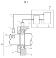
次に図2に示す測定対象機器に対する機器状態監視装置の実装例によれば、測定対象機器20は電動機などの回転機である。回転機の回転軸11は転がり軸受12によって、軸受ケーシング13に対して回転自在に支持され、軸方向には軸受カバー14によって固定されている。回転軸11上には反射シール15が設けられており、静止側の該当位置に稼働センサ2が設置されている。この場合の稼働センサ2としては、光学式の回転速度センサが好適である。また診断センサ1は、転がり軸受12近傍の軸受ケーシング13表面に設置されている。この場合の診断センサ1としては、振動加速度を検出する加速度センサが好適である。信号記録装置3、機器状態監視装置10の接続関係は、図1と同様である。診断センサ1や稼働センサ2、信号記録装置3、機器状態監視装置10は、測定対象機器20から独立して作動しており、容易に着脱可能である。なお、診断センサとは機器の診断評価に用いる信号のセンサであり、稼働センサとは機器の運転状態判断に用いる信号のセンサである。
Next, according to the implementation example of the device status monitoring device for the device to be measured shown in FIG. 2, the device to be measured 20 is a rotating machine such as an electric motor. A rotating
次に図3に示す機器状態監視装置10の機能実現例によれば、持ち運び可能な筐体として形成された機器状態監視装置10内には、トリガ装置31、論理演算器32、タイマ装置33で構成された計測制御器4と計測条件記憶装置5が収納されており、さらに筐体外の信号記録装置3により機器状態監視装置10Aが構成されており、論理演算器32に対し、入力信号としてトリガ装置31、タイマ装置33が接続され、出力信号として、信号記録装置3が接続されている。またトリガ装置31には、計測条件記憶装置5と稼働センサ2が接続されている。
Next, according to the functional implementation example of the equipment
また図3の機器状態監視装置10の機能実現例によれば、持ち運び可能な筐体として形成された機器状態監視装置10内には、さらに計測条件記憶装置5を含んで機器状態監視装置10Aのように構成されていてもよい。なおここで、計測条件記憶装置5とは、取り出し可能な記憶媒体と、記憶媒体への記憶制御を実行する記憶制御駆動部とを含むものであり、記憶制御駆動部を筐体内に収納して記憶媒体を取り出し可能とする。
Further, according to the functional implementation example of the equipment
以上のような構成において、回転軸11が回転すると、転がり軸受12は回転速度に応じた特徴的な周波数の振動(特徴振動)を発生し、これが軸受ケーシング13へ伝播し、診断センサ1に検出される。この特徴振動の経時変化を調べることにより、対象となる転がり軸受の健全性を評価する。また、回転軸11が回転することにより、反射シール15は周期的に稼働センサの受光部を通過するため、回転軸11の回転速度が検出される。
In the above configuration, when the
タイマ装置33は、あらかじめ設定された一定時間ごとに、論理演算器32の入力信号の一方をONにするが、これに加えて、回転軸11の回転速度が計測条件記憶装置5に記憶された値を超えた場合、トリガ装置31は、論理演算器32のもう一方の入力信号をONにする。論理演算器32は、2系統の入力信号に対して論理積演算をおこない、両者がONになったときのみ、出力信号をONとする。信号記録装置3は、論理演算器32の出力信号がONとなった場合に、一定時間分の信号を記録する。
The
以上のような構成とすることで、回転軸11の回転速度が一定値以上となった場合に、一定時間間隔で自動的に振動計測をおこなうことができる。例えばタイマ装置33が10分間隔で1分間だけON信号を与え、計測条件記憶装置5が定格回転数以上を設定している場合には、定格回転数超過となる状態が、10分間隔で継続的に記憶されることになる。この結果、信号記録装置3には回転機の状態が10分間隔でサンプリングされて記憶され、長時間の監視情報を少ない記憶容量で実現できる。
With the above configuration, when the rotational speed of the rotating
多くの場合、診断センサ1が検出する特徴振動の周波数は数十から数百Hzであり、これを記録する信号記録装置3は十分に高速である必要がある。本発明によれば、比較的高価な計測装置が測定対象機器20から容易に着脱可能であり、これを複数の測定対象機器20で共有することにより、設備費用の削減を実現する。
In many cases, the frequency of the characteristic vibration detected by the
なお筐体内に設置された計測条件記憶装置5は、例えばデジスイッチなどにより、動作閾値を設定可能な手段であり、ユーザにより任意に手動設定でき、あるいは携帯端末などの通信手段を介して適宜設定可能に構成されていてもよい。いずれであっても、可搬型の機器状態監視装置を持ち込んだ現場において、現場状況に合わせた設定がその場で行えることで、融通性を高くすることができる。
The measurement
以上の実施例において、診断センサ1は加速度センサとしているが、速度センサ、あるいは変位センサでもよい。また、稼働センサ2は光学式の回転速度センサとしているが、例えば電磁式など、他の方式の回転速度センサを用いてもよく、トルクセンサや電力センサを用いてもよい。
In the above embodiments, the
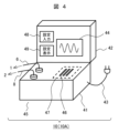
本発明における機器状態監視装置の実施例2を図4に基づいて説明する。図4は本実施例における機器状態監視装置の実装例を示している。本実施例は、例えば風力発電システムのように、風車タワー上部の機械室に監視対象機器が存在し、計測装置の搬入が容易でない場合に好適である。 A second embodiment of the device status monitoring device according to the present invention will be described based on FIG. 4. FIG. 4 shows an example of implementation of the device status monitoring device in this embodiment. This embodiment is suitable for a case where equipment to be monitored exists in a machine room at the top of a wind turbine tower, such as in a wind power generation system, and it is not easy to carry in a measuring device.
図4において、図示されない信号記録装置3と、計測制御器4と、計測条件記憶装置5と、信号記録装置3は一体的に形成され、キャリーケース41の内部に格納されている。なお信号記録装置3は、記録制御ケーブル7を介してキャリーケース41外に接続されて設けられていても、あるいはキャリーケース41内に設置されて設けられていてもよい。さらに信号記録装置3は、記録部自体が着脱可能に装着される形式のものであってもよい。
In FIG. 4, a signal recording device 3 (not shown), a measurement controller 4, a measurement
キャリーケース41には電源ケーブル43が接続されており、測定対象機器20側の電源から計測に要する電力の供給を受ける。また、診断信号ケーブル6と、稼働信号ケーブル8を介して、診断センサ1と、稼働センサ2が接続されている。本実施例においては、信号記録装置3は複数のメモリカードスロット46からなる記憶装置47を有しており、挿入される複数のメモリカードに計測波形データを保存する。キャリーケース41は、ケースカバー42を有しており、ケースカバー42には、計測した信号の波形を確認するための表示画面44を備えるのがよい。以上に記載したように、計測に係る主な機器は、計測パッケージ45として一体的に構成される。
A
計測パッケージ45はコンパクトなため、狭隘な計測対象システム内へも容易に持ち込むことができる。また、電源ケーブル43、診断信号ケーブル6、稼働信号ケーブル7などを接続すると、すぐに使用可能となる。実施例1に記載のように、あらかじめ計測条件記憶装置5に計測条件が記憶されており、これに基づき自動的に計測が行われる。複数設けられたメモリカードスロットには、複数枚のメモリカードが挿入されており、一枚が一杯になった場合には、次のメモリカードに記憶が計測される。設備点検員は定期的に計測対象システムを訪問し、表示画面44を用いて信号の記録状態を確認するとともに、一杯になったメモリカードを交換する。
Since the
またキャリーケース41は、そのケースカバー42を開いた場合に、その一部に各種設定のための設定入力部48及び設定表示部49を備えている。これにより例えば、タイマ装置33におけるサンプリングのための周期(先の例では10分)、および記録時間(先の例では1分間)、ならびに計測条件記憶装置5における計測条件(先の例では定格回転数以上)を設定入力部48から入力し、さらには入力の設定状態が設定表示部49により確認可能となる。
The carrying
以上のような構成とすることにより、計測装置は対象システムから容易に着脱可能となる。すなわち、隔地に存在する発電プラントに計測装置を容易に輸送するとともに、狭隘なプラント内に配置し、結線をおこなえばすぐに計測を開始できる。隣接する別の発電プラントへの計測器の移設も同様に容易である。 With the above configuration, the measuring device can be easily attached to and detached from the target system. In other words, the measurement device can be easily transported to a power plant located in a remote location, and can be placed inside a small plant and measurements can be started immediately after wiring. Relocation of measuring instruments to another adjacent power plant is also easy.
以上に述べたように、本実施例においては、計測信号の波形データはメモリカードに記憶されるが、計測対象システムでネットワークを利用できる場合には、LANケーブルを接続し、ネットワーク経由で計測信号を伝送してもよい。また、記憶あるいは伝送される計測データは、データ量を縮減するため、周波数分析などの信号処理をおこなったデータ、あるいは抽出された特徴振動の振幅データでもよい。 As described above, in this embodiment, the waveform data of the measurement signal is stored in the memory card, but if a network can be used in the measurement target system, a LAN cable can be connected and the measurement signal can be sent via the network. may be transmitted. Further, the measurement data to be stored or transmitted may be data subjected to signal processing such as frequency analysis or amplitude data of extracted characteristic vibrations in order to reduce the amount of data.
1:診断センサ
2:稼働センサ
3:信号記録装置
4:計測制御器
5:計測条件記憶装置
6:診断信号ケーブル
7:記録制御ケーブル
8:稼働信号ケーブル
9:計測条件通信ケーブル
10、10A:機器状態監視装置
11:回転軸
12:転がり軸受
13:軸受ケーシング
14:軸受カバー
15:反射シール
20:測定対象機器
31:トリガ装置
32:論理演算器
33:タイマ装置、
41:キャリーケース
42:ケースカバー
43:電源ケーブル
44:表示画面
45:計測パッケージ
46:メモリカードスロット
47:記憶装置。
1: Diagnostic sensor 2: Operating sensor 3: Signal recording device 4: Measurement controller 5: Measurement condition storage device 6: Diagnostic signal cable 7: Recording control cable 8: Operating signal cable 9: Measurement
41: Carry case 42: Case cover 43: Power cable 44: Display screen 45: Measurement package 46: Memory card slot 47: Storage device.
Claims (6)
前記計測制御器は、前記計測条件記憶装置に記憶する前記計測条件と前記稼働センサからの入力信号を比較して、前記稼働センサからの入力信号が前記計測条件を満たしているときに出力するトリガ装置と、あらかじめ設定された一定時間ごとに出力するタイマ装置と、前記トリガ装置と前記タイマ装置がともに出力するときに出力する論理積回路を備え、前記論理積回路の出力により、前記診断センサからの入力信号を前記信号記録装置に記録するとともに、
少なくとも前記計測条件記憶装置と前記計測制御器を持ち運び可能な筐体内に収納していることを特徴とする機器状態監視装置。 A signal recording device that captures input signals from a diagnostic sensor installed on a device to be measured , which is a rotating machine, and an operation sensor that detects the operating state of the device to be measured , and records the input signal from the diagnostic sensor, and measurement conditions. and a measurement controller that controls recording in the signal recording device,
The measurement controller compares the measurement condition stored in the measurement condition storage device with the input signal from the operation sensor, and outputs a trigger when the input signal from the operation sensor satisfies the measurement condition. a timer device that outputs an output at preset fixed time intervals; and an AND circuit that outputs when both the trigger device and the timer device output, and the output of the AND circuit causes the diagnostic sensor to output an output. recording the input signal of on the signal recording device , and
An equipment status monitoring device characterized in that at least the measurement condition storage device and the measurement controller are housed in a portable housing .
前記診断センサは、加速度センサ、速度センサ、あるいは、変位センサのいずれかであることを特徴とする機器状態監視装置。 The equipment condition monitoring device according to claim 1 ,
The device condition monitoring device is characterized in that the diagnostic sensor is any one of an acceleration sensor, a speed sensor, or a displacement sensor.
前記稼働センサは、回転速度センサ、トルクセンサ、あるいは、電力センサのいずれかであることを特徴とする機器状態監視装置。 The device status monitoring device according to claim 1 or 2 ,
The device status monitoring device is characterized in that the operation sensor is one of a rotational speed sensor, a torque sensor, or a power sensor.
前記信号記録装置は、複数のメモリカードスロットを備えていることを特徴とする機器状態監視装置。 The equipment condition monitoring device according to any one of claims 1 to 3 ,
A device status monitoring device characterized in that the signal recording device includes a plurality of memory card slots.
風力発電システムを計測対象とすることを特徴とする機器状態監視装置。 The equipment condition monitoring device according to any one of claims 1 to 4 ,
An equipment condition monitoring device characterized by measuring a wind power generation system.
前記計測制御器は、前記計測条件記憶装置に記憶する前記計測条件と前記稼働センサからの入力信号を比較して、前記稼働センサからの入力信号が前記計測条件を満たしているときに出力するトリガ装置と、あらかじめ設定された一定時間ごとに出力するタイマ装置と、前記トリガ装置と前記タイマ装置がともに出力するときに出力する論理積回路を備え、前記論理積回路の出力により、前記診断センサからの入力信号を前記信号記録装置に記録され、少なくとも前記計測条件記憶装置と前記計測制御器を持ち運び可能な筐体内に収納されているとともに、
機器状態監視にあたり前記測定対象機器に設置された診断センサと稼働センサが持ち運び可能な前記筐体にケーブルを用いて接続され、後日持ち運び可能な前記筐体内の前記信号記録装置の情報が外部に取り出されることを特徴とする機器状態監視方法。 A signal recording device that captures input signals from a diagnostic sensor installed on a device to be measured, which is a rotating machine, and an operation sensor that detects the operating state of the device to be measured, and records the input signal from the diagnostic sensor, and measurement conditions. An equipment condition monitoring method using a measurement condition storage device that stores a measurement condition storage device, and a measurement controller that controls recording in the signal recording device, the method comprising:
The measurement controller compares the measurement condition stored in the measurement condition storage device with the input signal from the operation sensor, and outputs a trigger when the input signal from the operation sensor satisfies the measurement condition. a timer device that outputs an output at preset fixed time intervals; and an AND circuit that outputs when both the trigger device and the timer device output, and the output of the AND circuit causes the diagnostic sensor to output an output. an input signal is recorded in the signal recording device, and at least the measurement condition storage device and the measurement controller are housed in a portable housing;
For device status monitoring, a diagnostic sensor and an operation sensor installed in the device to be measured are connected to the portable casing using a cable, and information from the signal recording device inside the portable casing is retrieved to the outside at a later date. A device condition monitoring method characterized in that :
Priority Applications (2)
| Application Number | Priority Date | Filing Date | Title |
|---|---|---|---|
| JP2020105129A JP7422012B2 (en) | 2020-06-18 | 2020-06-18 | Equipment condition monitoring device and method |
| TW110121404A TWI817138B (en) | 2020-06-18 | 2021-06-11 | Machine status monitoring device and method |
Applications Claiming Priority (1)
| Application Number | Priority Date | Filing Date | Title |
|---|---|---|---|
| JP2020105129A JP7422012B2 (en) | 2020-06-18 | 2020-06-18 | Equipment condition monitoring device and method |
Publications (2)
| Publication Number | Publication Date |
|---|---|
| JP2021197052A JP2021197052A (en) | 2021-12-27 |
| JP7422012B2 true JP7422012B2 (en) | 2024-01-25 |
Family
ID=79195703
Family Applications (1)
| Application Number | Title | Priority Date | Filing Date |
|---|---|---|---|
| JP2020105129A Active JP7422012B2 (en) | 2020-06-18 | 2020-06-18 | Equipment condition monitoring device and method |
Country Status (2)
| Country | Link |
|---|---|
| JP (1) | JP7422012B2 (en) |
| TW (1) | TWI817138B (en) |
Citations (1)
| Publication number | Priority date | Publication date | Assignee | Title |
|---|---|---|---|---|
| JP2011233108A (en) | 2010-04-30 | 2011-11-17 | Toshiba Corp | Monitoring system and monitoring method |
Family Cites Families (13)
| Publication number | Priority date | Publication date | Assignee | Title |
|---|---|---|---|---|
| SE510771C2 (en) * | 1996-07-05 | 1999-06-21 | Spm Instr Ab | Procedure for evaluating the condition of a machine as well as the analyzer and apparatus for cooperation with the analyzer |
| JP2003271234A (en) * | 2002-03-13 | 2003-09-26 | Mitsubishi Electric Corp | Condition remote monitor system |
| CN1738738A (en) * | 2002-11-18 | 2006-02-22 | 日本精工株式会社 | Axle unit with slip sensor and slip measurement method |
| CN1195358C (en) * | 2002-11-22 | 2005-03-30 | 天津大学 | Intelligent engineering machinery fault diagnosing system based on networked movable operation machines |
| CN100561158C (en) * | 2007-06-04 | 2009-11-18 | 西安交通大学 | Holographic spot dynamic balance method based on precession vector |
| EP3508827B1 (en) * | 2008-12-22 | 2021-11-24 | S.P.M. Instrument AB | Apparatus for analysing the condition of a machine having a rotating part |
| DE102011077129A1 (en) * | 2011-06-07 | 2012-12-13 | Aloys Wobben | Method for operating a wind energy plant |
| CN104121936A (en) * | 2013-04-29 | 2014-10-29 | 艾默生电气(美国)控股公司(智利)有限公司 | Dynamic transducer with digital output and method for use |
| US20190265015A1 (en) * | 2016-09-09 | 2019-08-29 | NejiLaw inc. | Sensor structure, component provided with sensor structure, and patterning method for sensor structure |
| CN209085657U (en) * | 2017-08-02 | 2019-07-09 | 强力物联网投资组合2016有限公司 | For data gathering system related or industrial environment with chemical production technology |
| GB2568783B (en) * | 2017-10-02 | 2023-06-28 | Fisher Rosemount Systems Inc | Method and apparatus for assessing the collective health of multiple process control systems |
| TWI644088B (en) * | 2018-01-18 | 2018-12-11 | 國立中興大學 | Tool machine spindle and tool yaw and vibration rapid measuring device and method |
| JP2019129604A (en) * | 2018-01-24 | 2019-08-01 | 株式会社東芝 | Apparatus state recording system and apparatus state recording device |
-
2020
- 2020-06-18 JP JP2020105129A patent/JP7422012B2/en active Active
-
2021
- 2021-06-11 TW TW110121404A patent/TWI817138B/en active
Patent Citations (1)
| Publication number | Priority date | Publication date | Assignee | Title |
|---|---|---|---|---|
| JP2011233108A (en) | 2010-04-30 | 2011-11-17 | Toshiba Corp | Monitoring system and monitoring method |
Also Published As
| Publication number | Publication date |
|---|---|
| JP2021197052A (en) | 2021-12-27 |
| TWI817138B (en) | 2023-10-01 |
| TW202201155A (en) | 2022-01-01 |
Similar Documents
| Publication | Publication Date | Title |
|---|---|---|
| JP4731782B2 (en) | Spindle with data storage element | |
| US6138078A (en) | Machine monitor with tethered sensors | |
| KR101652461B1 (en) | Prediction prognosis system for facilities using wireless sensor network | |
| US5917428A (en) | Integrated motor and diagnostic apparatus and method of operating same | |
| US20090284383A1 (en) | Data acquisition system for system monitoring | |
| TWI751170B (en) | Pump assembly, method of analysing data received from an accelerometer mounted on a pump and computer program | |
| JP2009505277A (en) | Data collection system for system monitoring | |
| DK2684262T3 (en) | DEVICE FOR MONITORING OF BRUSHES, SPECIFICALLY SLIPPING OR COMMUTOR BRUSHES, ON ELECTRIC MACHINES | |
| JP2008144973A (en) | Operating data collecting device for analyzing abnormality in air conditioner, and air conditioner | |
| JP4105692B2 (en) | Vibration information transmitting apparatus and vibration monitoring analysis system | |
| CN108226777A (en) | State monitoring apparatus and the method for monitoring motor | |
| JP2003271234A (en) | Condition remote monitor system | |
| KR20090001432A (en) | Internet base online conditioning monitoring system | |
| KR100751528B1 (en) | Mobile monitoring system for working status of a rotating machine | |
| JP7422012B2 (en) | Equipment condition monitoring device and method | |
| JP2002071742A (en) | Partial discharge detector and partial discharge monitoring system | |
| JP2008109806A (en) | Rotary electric machine attached with ic tag provided with sensor, abnormality detector for the rotary electric machine, and abnormality detection method for the rotary electric machine | |
| JP2006127425A (en) | Plant diagnosis support system and method | |
| JP2008140335A (en) | Multipoint measuring instrument | |
| WO2020184170A1 (en) | Data collection device, data management device, and state monitoring system | |
| FR2999326A1 (en) | System for monitoring operating parameter of e.g. electric motor, in industrial site, has calculation unit calculating operation parameter from measurement of electric current and from predetermined characteristics of electric device | |
| JP4105852B2 (en) | Remote damage diagnosis system for power generation facilities | |
| KR20020051322A (en) | Multi-channal vibration monitoring apparatus | |
| CN218156504U (en) | Portable fault diagnosis instrument based on sound vibration signal | |
| KR102500129B1 (en) | Ict . |
Legal Events
| Date | Code | Title | Description |
|---|---|---|---|
| A621 | Written request for application examination |
Free format text: JAPANESE INTERMEDIATE CODE: A621 Effective date: 20230208 |
|
| A977 | Report on retrieval |
Free format text: JAPANESE INTERMEDIATE CODE: A971007 Effective date: 20231026 |
|
| A131 | Notification of reasons for refusal |
Free format text: JAPANESE INTERMEDIATE CODE: A131 Effective date: 20231114 |
|
| A521 | Request for written amendment filed |
Free format text: JAPANESE INTERMEDIATE CODE: A523 Effective date: 20231130 |
|
| TRDD | Decision of grant or rejection written | ||
| A01 | Written decision to grant a patent or to grant a registration (utility model) |
Free format text: JAPANESE INTERMEDIATE CODE: A01 Effective date: 20240109 |
|
| A61 | First payment of annual fees (during grant procedure) |
Free format text: JAPANESE INTERMEDIATE CODE: A61 Effective date: 20240115 |
|
| R150 | Certificate of patent or registration of utility model |
Ref document number: 7422012 Country of ref document: JP Free format text: JAPANESE INTERMEDIATE CODE: R150 |