JP7421663B2 - Method for manufacturing parts with cooling pipe system - Google Patents
Method for manufacturing parts with cooling pipe system Download PDFInfo
- Publication number
- JP7421663B2 JP7421663B2 JP2022571200A JP2022571200A JP7421663B2 JP 7421663 B2 JP7421663 B2 JP 7421663B2 JP 2022571200 A JP2022571200 A JP 2022571200A JP 2022571200 A JP2022571200 A JP 2022571200A JP 7421663 B2 JP7421663 B2 JP 7421663B2
- Authority
- JP
- Japan
- Prior art keywords
- cavity
- covering
- introducing
- cooling
- building material
- Prior art date
- Legal status (The legal status is an assumption and is not a legal conclusion. Google has not performed a legal analysis and makes no representation as to the accuracy of the status listed.)
- Active
Links
Images
Classifications
-
- B—PERFORMING OPERATIONS; TRANSPORTING
- B22—CASTING; POWDER METALLURGY
- B22F—WORKING METALLIC POWDER; MANUFACTURE OF ARTICLES FROM METALLIC POWDER; MAKING METALLIC POWDER; APPARATUS OR DEVICES SPECIALLY ADAPTED FOR METALLIC POWDER
- B22F10/00—Additive manufacturing of workpieces or articles from metallic powder
- B22F10/20—Direct sintering or melting
- B22F10/25—Direct deposition of metal particles, e.g. direct metal deposition [DMD] or laser engineered net shaping [LENS]
-
- B—PERFORMING OPERATIONS; TRANSPORTING
- B22—CASTING; POWDER METALLURGY
- B22F—WORKING METALLIC POWDER; MANUFACTURE OF ARTICLES FROM METALLIC POWDER; MAKING METALLIC POWDER; APPARATUS OR DEVICES SPECIALLY ADAPTED FOR METALLIC POWDER
- B22F10/00—Additive manufacturing of workpieces or articles from metallic powder
- B22F10/20—Direct sintering or melting
-
- B—PERFORMING OPERATIONS; TRANSPORTING
- B22—CASTING; POWDER METALLURGY
- B22F—WORKING METALLIC POWDER; MANUFACTURE OF ARTICLES FROM METALLIC POWDER; MAKING METALLIC POWDER; APPARATUS OR DEVICES SPECIALLY ADAPTED FOR METALLIC POWDER
- B22F10/00—Additive manufacturing of workpieces or articles from metallic powder
- B22F10/50—Treatment of workpieces or articles during build-up, e.g. treatments applied to fused layers during build-up
-
- B—PERFORMING OPERATIONS; TRANSPORTING
- B22—CASTING; POWDER METALLURGY
- B22F—WORKING METALLIC POWDER; MANUFACTURE OF ARTICLES FROM METALLIC POWDER; MAKING METALLIC POWDER; APPARATUS OR DEVICES SPECIALLY ADAPTED FOR METALLIC POWDER
- B22F10/00—Additive manufacturing of workpieces or articles from metallic powder
- B22F10/60—Treatment of workpieces or articles after build-up
- B22F10/66—Treatment of workpieces or articles after build-up by mechanical means
-
- B—PERFORMING OPERATIONS; TRANSPORTING
- B22—CASTING; POWDER METALLURGY
- B22F—WORKING METALLIC POWDER; MANUFACTURE OF ARTICLES FROM METALLIC POWDER; MAKING METALLIC POWDER; APPARATUS OR DEVICES SPECIALLY ADAPTED FOR METALLIC POWDER
- B22F12/00—Apparatus or devices specially adapted for additive manufacturing; Auxiliary means for additive manufacturing; Combinations of additive manufacturing apparatus or devices with other processing apparatus or devices
- B22F12/80—Plants, production lines or modules
- B22F12/82—Combination of additive manufacturing apparatus or devices with other processing apparatus or devices
- B22F12/84—Parallel processing within single device
-
- B—PERFORMING OPERATIONS; TRANSPORTING
- B22—CASTING; POWDER METALLURGY
- B22F—WORKING METALLIC POWDER; MANUFACTURE OF ARTICLES FROM METALLIC POWDER; MAKING METALLIC POWDER; APPARATUS OR DEVICES SPECIALLY ADAPTED FOR METALLIC POWDER
- B22F5/00—Manufacture of workpieces or articles from metallic powder characterised by the special shape of the product
- B22F5/10—Manufacture of workpieces or articles from metallic powder characterised by the special shape of the product of articles with cavities or holes, not otherwise provided for in the preceding subgroups
-
- B—PERFORMING OPERATIONS; TRANSPORTING
- B23—MACHINE TOOLS; METAL-WORKING NOT OTHERWISE PROVIDED FOR
- B23K—SOLDERING OR UNSOLDERING; WELDING; CLADDING OR PLATING BY SOLDERING OR WELDING; CUTTING BY APPLYING HEAT LOCALLY, e.g. FLAME CUTTING; WORKING BY LASER BEAM
- B23K26/00—Working by laser beam, e.g. welding, cutting or boring
- B23K26/0006—Working by laser beam, e.g. welding, cutting or boring taking account of the properties of the material involved
-
- B—PERFORMING OPERATIONS; TRANSPORTING
- B23—MACHINE TOOLS; METAL-WORKING NOT OTHERWISE PROVIDED FOR
- B23K—SOLDERING OR UNSOLDERING; WELDING; CLADDING OR PLATING BY SOLDERING OR WELDING; CUTTING BY APPLYING HEAT LOCALLY, e.g. FLAME CUTTING; WORKING BY LASER BEAM
- B23K26/00—Working by laser beam, e.g. welding, cutting or boring
- B23K26/34—Laser welding for purposes other than joining
- B23K26/342—Build-up welding
-
- B—PERFORMING OPERATIONS; TRANSPORTING
- B23—MACHINE TOOLS; METAL-WORKING NOT OTHERWISE PROVIDED FOR
- B23P—METAL-WORKING NOT OTHERWISE PROVIDED FOR; COMBINED OPERATIONS; UNIVERSAL MACHINE TOOLS
- B23P15/00—Making specific metal objects by operations not covered by a single other subclass or a group in this subclass
- B23P15/007—Making specific metal objects by operations not covered by a single other subclass or a group in this subclass injection moulding tools
-
- B—PERFORMING OPERATIONS; TRANSPORTING
- B29—WORKING OF PLASTICS; WORKING OF SUBSTANCES IN A PLASTIC STATE IN GENERAL
- B29C—SHAPING OR JOINING OF PLASTICS; SHAPING OF MATERIAL IN A PLASTIC STATE, NOT OTHERWISE PROVIDED FOR; AFTER-TREATMENT OF THE SHAPED PRODUCTS, e.g. REPAIRING
- B29C33/00—Moulds or cores; Details thereof or accessories therefor
- B29C33/02—Moulds or cores; Details thereof or accessories therefor with incorporated heating or cooling means
- B29C33/04—Moulds or cores; Details thereof or accessories therefor with incorporated heating or cooling means using liquids, gas or steam
-
- B—PERFORMING OPERATIONS; TRANSPORTING
- B29—WORKING OF PLASTICS; WORKING OF SUBSTANCES IN A PLASTIC STATE IN GENERAL
- B29C—SHAPING OR JOINING OF PLASTICS; SHAPING OF MATERIAL IN A PLASTIC STATE, NOT OTHERWISE PROVIDED FOR; AFTER-TREATMENT OF THE SHAPED PRODUCTS, e.g. REPAIRING
- B29C33/00—Moulds or cores; Details thereof or accessories therefor
- B29C33/38—Moulds or cores; Details thereof or accessories therefor characterised by the material or the manufacturing process
- B29C33/3835—Designing moulds, e.g. using CAD-CAM
-
- B—PERFORMING OPERATIONS; TRANSPORTING
- B29—WORKING OF PLASTICS; WORKING OF SUBSTANCES IN A PLASTIC STATE IN GENERAL
- B29C—SHAPING OR JOINING OF PLASTICS; SHAPING OF MATERIAL IN A PLASTIC STATE, NOT OTHERWISE PROVIDED FOR; AFTER-TREATMENT OF THE SHAPED PRODUCTS, e.g. REPAIRING
- B29C33/00—Moulds or cores; Details thereof or accessories therefor
- B29C33/38—Moulds or cores; Details thereof or accessories therefor characterised by the material or the manufacturing process
- B29C33/3842—Manufacturing moulds, e.g. shaping the mould surface by machining
-
- B—PERFORMING OPERATIONS; TRANSPORTING
- B29—WORKING OF PLASTICS; WORKING OF SUBSTANCES IN A PLASTIC STATE IN GENERAL
- B29C—SHAPING OR JOINING OF PLASTICS; SHAPING OF MATERIAL IN A PLASTIC STATE, NOT OTHERWISE PROVIDED FOR; AFTER-TREATMENT OF THE SHAPED PRODUCTS, e.g. REPAIRING
- B29C45/00—Injection moulding, i.e. forcing the required volume of moulding material through a nozzle into a closed mould; Apparatus therefor
- B29C45/17—Component parts, details or accessories; Auxiliary operations
- B29C45/72—Heating or cooling
- B29C45/73—Heating or cooling of the mould
- B29C45/7312—Construction of heating or cooling fluid flow channels
-
- B—PERFORMING OPERATIONS; TRANSPORTING
- B33—ADDITIVE MANUFACTURING TECHNOLOGY
- B33Y—ADDITIVE MANUFACTURING, i.e. MANUFACTURING OF THREE-DIMENSIONAL [3D] OBJECTS BY ADDITIVE DEPOSITION, ADDITIVE AGGLOMERATION OR ADDITIVE LAYERING, e.g. BY 3D PRINTING, STEREOLITHOGRAPHY OR SELECTIVE LASER SINTERING
- B33Y10/00—Processes of additive manufacturing
-
- B—PERFORMING OPERATIONS; TRANSPORTING
- B33—ADDITIVE MANUFACTURING TECHNOLOGY
- B33Y—ADDITIVE MANUFACTURING, i.e. MANUFACTURING OF THREE-DIMENSIONAL [3D] OBJECTS BY ADDITIVE DEPOSITION, ADDITIVE AGGLOMERATION OR ADDITIVE LAYERING, e.g. BY 3D PRINTING, STEREOLITHOGRAPHY OR SELECTIVE LASER SINTERING
- B33Y80/00—Products made by additive manufacturing
-
- G—PHYSICS
- G05—CONTROLLING; REGULATING
- G05B—CONTROL OR REGULATING SYSTEMS IN GENERAL; FUNCTIONAL ELEMENTS OF SUCH SYSTEMS; MONITORING OR TESTING ARRANGEMENTS FOR SUCH SYSTEMS OR ELEMENTS
- G05B19/00—Program-control systems
- G05B19/02—Program-control systems electric
- G05B19/18—Numerical control [NC], i.e. automatically operating machines, in particular machine tools, e.g. in a manufacturing environment, so as to execute positioning, movement or co-ordinated operations by means of program data in numerical form
- G05B19/4097—Numerical control [NC], i.e. automatically operating machines, in particular machine tools, e.g. in a manufacturing environment, so as to execute positioning, movement or co-ordinated operations by means of program data in numerical form characterised by using design data to control NC machines, e.g. CAD/CAM
- G05B19/4099—Surface or curve machining, making three-dimensional [3D] objects, e.g. desktop manufacturing
-
- B—PERFORMING OPERATIONS; TRANSPORTING
- B22—CASTING; POWDER METALLURGY
- B22F—WORKING METALLIC POWDER; MANUFACTURE OF ARTICLES FROM METALLIC POWDER; MAKING METALLIC POWDER; APPARATUS OR DEVICES SPECIALLY ADAPTED FOR METALLIC POWDER
- B22F2998/00—Supplementary information concerning processes or compositions relating to powder metallurgy
- B22F2998/10—Processes characterised by the sequence of their steps
-
- B—PERFORMING OPERATIONS; TRANSPORTING
- B23—MACHINE TOOLS; METAL-WORKING NOT OTHERWISE PROVIDED FOR
- B23K—SOLDERING OR UNSOLDERING; WELDING; CLADDING OR PLATING BY SOLDERING OR WELDING; CUTTING BY APPLYING HEAT LOCALLY, e.g. FLAME CUTTING; WORKING BY LASER BEAM
- B23K2101/00—Articles made by soldering, welding or cutting
- B23K2101/04—Tubular or hollow articles
- B23K2101/14—Heat exchangers
-
- B—PERFORMING OPERATIONS; TRANSPORTING
- B23—MACHINE TOOLS; METAL-WORKING NOT OTHERWISE PROVIDED FOR
- B23K—SOLDERING OR UNSOLDERING; WELDING; CLADDING OR PLATING BY SOLDERING OR WELDING; CUTTING BY APPLYING HEAT LOCALLY, e.g. FLAME CUTTING; WORKING BY LASER BEAM
- B23K2103/00—Materials to be soldered, welded or cut
- B23K2103/08—Non-ferrous metals or alloys
- B23K2103/12—Copper or alloys thereof
-
- B—PERFORMING OPERATIONS; TRANSPORTING
- B29—WORKING OF PLASTICS; WORKING OF SUBSTANCES IN A PLASTIC STATE IN GENERAL
- B29C—SHAPING OR JOINING OF PLASTICS; SHAPING OF MATERIAL IN A PLASTIC STATE, NOT OTHERWISE PROVIDED FOR; AFTER-TREATMENT OF THE SHAPED PRODUCTS, e.g. REPAIRING
- B29C45/00—Injection moulding, i.e. forcing the required volume of moulding material through a nozzle into a closed mould; Apparatus therefor
- B29C45/17—Component parts, details or accessories; Auxiliary operations
- B29C45/72—Heating or cooling
- B29C45/73—Heating or cooling of the mould
- B29C45/7312—Construction of heating or cooling fluid flow channels
- B29C2045/7318—Construction of heating or cooling fluid flow channels multilayered fluid channel constructions
-
- G—PHYSICS
- G06—COMPUTING OR CALCULATING; COUNTING
- G06F—ELECTRIC DIGITAL DATA PROCESSING
- G06F2113/00—Details relating to the application field
- G06F2113/22—Moulding
-
- Y—GENERAL TAGGING OF NEW TECHNOLOGICAL DEVELOPMENTS; GENERAL TAGGING OF CROSS-SECTIONAL TECHNOLOGIES SPANNING OVER SEVERAL SECTIONS OF THE IPC; TECHNICAL SUBJECTS COVERED BY FORMER USPC CROSS-REFERENCE ART COLLECTIONS [XRACs] AND DIGESTS
- Y02—TECHNOLOGIES OR APPLICATIONS FOR MITIGATION OR ADAPTATION AGAINST CLIMATE CHANGE
- Y02P—CLIMATE CHANGE MITIGATION TECHNOLOGIES IN THE PRODUCTION OR PROCESSING OF GOODS
- Y02P10/00—Technologies related to metal processing
- Y02P10/25—Process efficiency
Landscapes
- Engineering & Computer Science (AREA)
- Manufacturing & Machinery (AREA)
- Mechanical Engineering (AREA)
- Chemical & Material Sciences (AREA)
- Materials Engineering (AREA)
- Physics & Mathematics (AREA)
- Optics & Photonics (AREA)
- Plasma & Fusion (AREA)
- Human Computer Interaction (AREA)
- General Physics & Mathematics (AREA)
- Automation & Control Theory (AREA)
- Fluid Mechanics (AREA)
- Turbine Rotor Nozzle Sealing (AREA)
- Metallurgy (AREA)
- Organic Chemistry (AREA)
- Laser Beam Processing (AREA)
- Moulds For Moulding Plastics Or The Like (AREA)
- Powder Metallurgy (AREA)
Description
本願発明は、冷却管システムを有する部品を製造するための方法に関する。 The present invention relates to a method for manufacturing a component with a cooling pipe system.
工業的製造で頻繁に用いられる方法には、例えば、射出成形加工方法がある。射出成形加工方法では、圧下で液状の材料が加成形用の金型インサート又は射出成形加工工具に注入され、そこで冷却され、固化した凝集状態に戻る。 Methods frequently used in industrial manufacturing include, for example, injection molding processing methods. In injection molding processing methods, a liquid material is injected under pressure into a forming mold insert or injection molding processing tool where it is cooled and returned to a solidified agglomerated state.
この一次的な形成処理は、塑性加工の分野で用いられることが多く、これにより製作される製品の複雑な成形を可能とする。材料を固化させるのに必要な冷却は、とりわけ、処理時間に対して決定的な影響を及ぼすので、そのような処理において特に重要である。 This primary forming process is often used in the field of plastic working and allows complex shaping of the manufactured product. The cooling required to solidify the material is particularly important in such processes, since it has a decisive influence on the processing time, among other things.
知られているのは、注入される材料のそのような冷却が、金型インサート又は射出成形加工工具を介して起こるのが有利であることである。通常、放熱のための冷却管が、金型インサート又は射出成形加工工具内に設けられる。適した冷却水がこれら冷却管を流れ、それにより、金型インサート又は射出成形加工工具を、したがって内部に位置する材料を冷却する。 It is known that such cooling of the injected material advantageously takes place via a mold insert or an injection molding processing tool. Typically, cooling channels for heat dissipation are provided within the mold insert or injection molding processing tool. Suitable cooling water flows through these cooling pipes, thereby cooling the mold insert or the injection molding processing tool and thus the material located inside.
原則的に、射出成形加工工具、形成工具、押出工具等、使用に際して高温に曝される工具の製作は複雑である。特に、工具内で延在する冷却管は通常、完成した工具内へ穿孔によってのみ導入できるので、冷却管を導入することは、工具の、通常非常に複雑である形状のために達成が容易ではないことが多い。 In principle, the manufacture of tools that are exposed to high temperatures during use, such as injection molding processing tools, forming tools, extrusion tools, etc., is complex. In particular, cooling channels extending within the tool can usually only be introduced by drilling into the finished tool, and the introduction of cooling channels is not easy to achieve due to the usually very complex geometry of the tool. Often there isn't.
従来技術文書DE 10 2004 040 929 A1には、例えば、付加的材料堆積製作処理により部品として、冷却水管を有する工具が製造される方法が記載されており、冷却水管は、付加的な構築の過程で工具内部に形成される。文書DE 10 2004 040 929 A1に示される方法は、高度に個別化された部品、又は複雑な形状を有する部品のために特に用いられる付加的製作が可能であることを利用し、よって、付加的な構築の間に部品内に、とりわけ、凹部を設けることを可能とする。
Prior
しかし、このやり方で製作される部品を効率よく冷却することが可能であることについては限界がある。 However, there are limits to the ability to efficiently cool parts made in this manner.
よって本願発明の目的は、向上した放熱性を有する部品を製造するための方法を提供することである。 It is therefore an object of the present invention to provide a method for manufacturing components with improved heat dissipation.
この目的を達成すべく、請求項1に係る冷却管システムを有する部品を製造するための方法が提案される。
To achieve this object, a method for manufacturing a component with a cooling pipe system according to
さらに、そのような部品の構築のために構成された、請求項20に係る、ソフトウェアでサポートされたコンピュータシステムが提案される。
Furthermore, a software-supported computer system according to
それぞれの独立請求項は、本願発明に係る方法の、又は本願発明に係るデータ処理システムの好ましい実施形態に関し、それらは個別に提供されてもよいし、又は組み合わせて提供されてもよい。 Each independent claim relates to a preferred embodiment of the method according to the invention or of the data processing system according to the invention, which may be provided individually or in combination.
本願発明の第1態様によると、冷却管システムを有する部品を製造するための方法は、-造形材料の付加的かつ一体接着的積層により部品の第1部分を造形することと、-部品の第1部分内へ開口部を有する第1キャビティを導入することとを備える。方法は、-被覆部により第1部分内の第1キャビティの開口部を被覆することと、-造形材料の付加的かつ一体接着的積層により部品の第2部分を造形することであって、造形材料は第1部分と被覆部とに積層されることと、-部品の第2部分内への第2キャビティを導入することと、-冷却管システムを形成するために、材料除去加工により部品内へ接続管を導入することであって、接続管は、第2部分の第2キャビティを、部品の第1部分の第1キャビティに接続することとをさらに備える。 According to a first aspect of the invention, a method for manufacturing a part having a cooling channel system comprises: - building a first part of the part by additive and integral adhesive lamination of a building material; introducing a first cavity having an opening into the portion. The method comprises: - covering an opening of a first cavity in a first part with a covering; - building a second part of the part by an additional and integrally adhesive lamination of a building material; a material is laminated to the first part and the cladding; - introducing a second cavity into the second part of the part; and - a material removal process within the part to form a cooling channel system. introducing a connecting tube into the component, the connecting tube connecting the second cavity of the second part to the first cavity of the first part of the component.
オプションで、被覆部は、例えば付加的ビルドアップ溶接トラックを積層することにより、挿入後に堅固に固定されてよい。このことは、例えば、重力とは異なる方向に5軸加工されることになる被処理物へ複数の被覆部が挿入されるときに、それら複数の被覆部が外れるのを防ぐために必要となり得る。代替的に、被覆板が、スポット溶接により固定されてもよい。 Optionally, the sheathing may be rigidly fixed after insertion, for example by laminating additional build-up welding tracks. This may be necessary, for example, to prevent the plurality of coverings from coming off when the plurality of coverings are inserted into a workpiece that is to be 5-axis machined in a direction different from gravity. Alternatively, the cover plate may be fixed by spot welding.
本願発明に係る方法は、複雑な形状を有し、冷却管システムが内部で延在する部品を特に有利な方式で製造することを可能とする。冷却管システムは、冷却水を搬送するよう構成され、また複雑な形状を有する。 The method according to the invention makes it possible to manufacture in a particularly advantageous manner parts with complex shapes and in which cooling pipe systems extend. Cooling pipe systems are configured to convey cooling water and have complex shapes.
部品内で延在する冷却管システムの形成は、部品の個々の部分が、造形材料の付加的かつ一体接着的積層により造形される(=付加的ビルドアップ)間に起こり、これにより、部品内のキャビティ及び接続管の位置により決定する冷却管システムの幾何学的配置が、製造されることになる部品の複雑な最終的な形状に有利に適応したものとなってよく、これにより冷却管システムは、少なくとも一部分で部品の外側輪郭表面に合うように延在し、つまり、冷却管システムは、少なくとも一部分でそれら外側輪郭表面に沿う。ここで、一部分において沿うとは、冷却管システムを流れる、又は搬送される冷却水の流れ方向が、部品の外側輪郭表面と本質的に平行に延びるような冷却管システムの配置を意味するものと理解される。 The formation of a cooling channel system extending within the part takes place while the individual parts of the part are built by additive and integrally adhesive lamination of the building material (=additive build-up), which results in The geometry of the cooling channel system, determined by the position of the cavities and the connecting tubes, may be advantageously adapted to the complex final shape of the part to be manufactured, so that the cooling channel system extends at least in part to fit the outer contour surfaces of the component, ie the cooling channel system follows at least in part along those outer contour surfaces. In this context, partially along shall mean an arrangement of the cooling channel system such that the direction of flow of the cooling water flowing or conveyed through the cooling channel system runs essentially parallel to the outer contour surface of the component. be understood.
複雑な部品形状の場合、そのような内部冷却管システムの導入は概して、一次的な成形処理後に穴の形態で導入するだけでは可能ではない。 In the case of complex part geometries, the introduction of such an internal cooling channel system is generally not possible by simply introducing it in the form of holes after the primary molding process.
これまで従来の方法においては、部品形状のため及び穿孔処理の可能性のために、穴の導入には限界があり、これにより、幾何学的配置が過度に単純な冷却管システムのみ導入が可能であった。 Until now, conventional methods have had limitations in the introduction of holes due to the component geometry and the possibility of drilling, which makes it possible to introduce only cooling pipe systems with overly simple geometry. Met.
本願発明に係る方法は、接続管を導入することも含め、内部で延在する冷却管システムを形成するのに、造形材料の付加的かつ一体接着的積層による造形(=付加的ビルドアップ)と材料除去加工との相乗効果を活用する。 The method according to the present invention involves the formation of an internally extending cooling pipe system, including the introduction of connecting pipes, by additionally and integrally adhesively laminating the building material (=additive build-up). Utilize synergistic effects with material removal processing.
したがって本願発明に係る方法は、一連の交互に行われる付加的造形工程と材料除去加工工程とを有するハイブリッド型の製作方法である。 The method according to the invention is therefore a hybrid fabrication method comprising a series of alternating additive building steps and material removal processing steps.
本願発明に係る方法は、特にニアネットコンターである冷却管システムを可能とし、その結果として、放熱性を、内部を流れる冷却水により大幅に向上させられる。 The method according to the invention allows a cooling pipe system which is in particular near-net contour, so that the heat dissipation is significantly improved by the cooling water flowing inside.
また、接続管より大きな断面をもつキャビティを導入することにより、部品の使用に際して特に熱的応力を受ける領域を、キャビティを流れる冷却水により効率よく冷却でき、有利である。 Further, by introducing a cavity having a larger cross section than the connecting pipe, it is advantageous that the region particularly subjected to thermal stress during use of the component can be efficiently cooled by the cooling water flowing through the cavity.
第1部分内の第1キャビティの開口部を、平らである、及び/又は平坦であるのが有利である被覆部で被覆することで、造形材料を積層することによる第2部分の付加的造形が可能となり、第1キャビティは、部品内部で全体的に閉じこめられ、第1キャビティは、第2部分に面した平らな境界面又は境界面形状を有する単純な形状を有する。 Additional building of the second part by layering building material by covering the opening of the first cavity in the first part with a covering that is flat and/or advantageously flat. is made possible, the first cavity being entirely enclosed within the part, the first cavity having a simple shape with a flat interface or interface shape facing the second part.
(被覆部なしで)造形材料の純粋に付加的な積層により全体的に完成部品内部に存在するキャビティの開口部を閉じることは、この目的のために構成されるある境界面形状に準拠した場合にのみ可能である。そのような境界面形状は通常平らではない。処理に関連した理由から、(被覆部なしで)平らな境界面の形態で境界面形状を造形することは可能ではない。このことが、付加的積層により、例えば屋根の形態でピラミッド型又は円錐形状の境界面形状が通常造形される理由である。 Closing the opening of a cavity present entirely inside the finished part by a purely additive layer of build material (without cladding) is possible in accordance with a certain interface geometry configured for this purpose. It is only possible to Such interface shapes are usually not flat. For processing-related reasons, it is not possible to print the interface shape in the form of a flat interface (without a covering). This is why pyramid-shaped or conical interface geometries, for example in the form of roofs, are usually produced by additional layering.
キャビティのそのような平らではない境界面形状は、多くの点で不利であることがわかっている。 It has been found that such an uneven interface shape of the cavity is disadvantageous in a number of respects.
一方で、そのような境界面形状は、冷却管システムを流れる冷却水にとって望ましくない滞留点を表しており、したがって、冷却水により作用が発揮される放熱性の低下も引き起こされる。 On the one hand, such an interface shape represents an undesirable stagnation point for the cooling water flowing through the cooling pipe system and therefore also causes a reduction in the heat dissipation exerted by the cooling water.
他方、そのような多くの場合、尖った境界面形状(ピラミッド型又は円錐形状)は、所定の破壊点(切欠係数)の意味で潜在的に弱い点を表しており、部品に対する力学的負荷が起こったときには部品内でそれらの点において過度な応力のピークが発生し得、その結果として、対応する点において部品が機能しなくなり得る(クラック、破砕、塑性変形等)。 On the other hand, in many such cases, the sharp interface shape (pyramidal or conical shape) represents a potential weak point in the sense of a given failure point (notch modulus), where the mechanical loads on the part are When this occurs, excessive stress peaks may occur within the part at those points, with the result that the part may fail (cracks, fractures, plastic deformations, etc.) at the corresponding points.
本願発明によれば、部分から部品が造形されるので、接続管は、部品の全体的な付加的ビルドアップ後では可能ではないであろう方式で導入され得る。 According to the invention, since the part is built from parts, connecting tubes can be introduced in a way that would not be possible after a total additive build-up of the part.
ここで、第2部分が造形された後に部品内に配置された第1キャビティへの接続を確立するために、したがって冷却管システムを形成するために、第1部分の第1キャビティの方向に、部品の第2部分内の第2キャビティから開始して接続管を導入するのが有利である。 Here, in the direction of the first cavity of the first part, in order to establish a connection to the first cavity arranged in the part after the second part has been printed, and thus to form a cooling channel system, It is advantageous to introduce the connecting tube starting from the second cavity in the second part of the part.
この目的のために、材料除去加工のために構成された工具のアクセスは、第2部分の第2キャビティの開口部を介して起こるのが有利である。例えば、チップ除去加工のために構成されたドリルヘッドが第2キャビティに損傷を加えることなく第2キャビティ内の開口部を通じて部品に入ることができるように、第2キャビティは、工具が接続管を導入するのを妨げない対応する形状を有するのが好ましい。 For this purpose, the access of a tool configured for material removal processing advantageously takes place via an opening of the second cavity of the second part. For example, the second cavity may have a connecting tube connected to it so that a drill head configured for chip removal machining can enter the part through an opening in the second cavity without damaging the second cavity. Preferably, it has a corresponding shape that does not impede its introduction.
材料除去加工に少なくとも部分的に基づく接続管の導入は、付加的ビルドアップにより製造される他の表面と比べて、接続管に隣接する部品の表面の、より表面構造が平滑な、より高い表面品質を生むことができるので有利である。 The introduction of a connecting tube based at least in part on a material removal process results in a higher surface with a smoother surface structure of the surface of the part adjacent to the connecting tube compared to other surfaces produced by additive build-up. This is advantageous because it can produce quality.
概して、造形材料の一体接着的な積層による付加的ビルドアップにより作成される表面は、材料除去加工、特にチップ除去加工によって作成される表面の場合よりも粗面度がより高く、表面品質がより低い表面構造又は表面品質を有する。 In general, surfaces created by additive build-up through integral adhesive lamination of build materials have higher roughness and better surface quality than surfaces created by material removal processes, especially chip removal processes. Has low surface structure or surface quality.
表面構造が平滑な、又は粗面度がより低い接続管の高い表面品質によって、その部分における流れ抵抗がより低くなるので、接続管を流れる冷却水の搬送が向上する。流動のための管又は流路が粗面である場合、それら表面の領域において乱流が発生し、したがって、流れ抵抗の上昇が発生し、このことはそれらに対応して流れを妨げる。 The high surface quality of the connecting pipe with a smooth or less rough surface structure improves the transport of the cooling water through the connecting pipe, since the flow resistance in that area is lower. If the tubes or channels for flow have rough surfaces, turbulence occurs in the area of these surfaces and therefore an increase in flow resistance occurs, which correspondingly impedes the flow.
付加的ビルドアップのみにより製造される接続管と比べて、材料除去加工に基づく接続管を導入することにより、内部を流れる冷却水の流れ抵抗を大幅に低減でき、このことは転じて、より低い流れ抵抗とその他の面では同じ境界条件(圧力差、管断面)とにより、内部を流れる冷却水のより多い流量又はより高い流速が達成することができるので、放熱性に対するプラスの影響を及ぼす。 Compared to connecting tubes produced only by additive build-up, by introducing connecting tubes based on material removal processing, the flow resistance of the cooling water flowing inside can be significantly reduced, which in turn translates into lower With flow resistance and otherwise identical boundary conditions (pressure difference, tube cross section), a higher flow rate or higher flow velocity of the cooling water flowing inside can be achieved, which has a positive influence on the heat dissipation.
しかし、原則的に、材料が積層されるときに対応する領域を省略することにより、付加的方法を用いて部分において接続管を導入することも可能である。 However, in principle it is also possible to introduce the connecting tube in the section using an additional method by omitting the corresponding area when the material is laminated.
本願発明に係る方法は、単なる第1部分内の第1キャビティ、及び/又は単なる第2部分内の第2キャビティに限定されるわけでは決してない。製造されることになる部品の形状に応じて、対応する数の接続管を介して部分を跨いで互いに接続されて冷却管システムを形成し得る複数のキャビティが、部品の個々の部分に導入され得る。よって、冷却管システムを形成するために、複数の接続管が単一のキャビティ内へと開口することも可能である。 The method according to the invention is in no way limited to a first cavity in a mere first part and/or a second cavity in a mere second part. Depending on the shape of the part to be manufactured, a plurality of cavities are introduced in the individual parts of the part, which can be connected to each other across the parts via a corresponding number of connecting tubes to form a cooling channel system. obtain. It is thus also possible for several connecting pipes to open into a single cavity to form a cooling pipe system.
したがって、例えば、第2部分が造形された後に2つの接続管を導入することにより、第2部分に導入されるキャビティに接続されることになる第1部分内へ2つの別個のキャビティを導入することが可能である。この場合、それら2つの接続管はいずれも第2部分のキャビティ内へと開口し、そのキャビティを第1部分内の2つのキャビティに接続する。 Thus, for example, by introducing two connecting tubes after the second part has been printed, two separate cavities are introduced into the first part which are to be connected to a cavity introduced into the second part. Is possible. In this case, the two connecting tubes both open into the cavity of the second part and connect it to the two cavities in the first part.
代替的に、例えば、第1部分内へキャビティを導入し2つの接続管を導入することにより、そのキャビティを第2部分に導入された2つのキャビティに接続することも可能である。 Alternatively, it is also possible to connect the cavity to two cavities introduced in the second part, for example by introducing a cavity into the first part and introducing two connecting tubes.
部品の放熱性の向上は、とりわけ、例えば製作処理における工具として、熱応力下で部品が使用されるときにおける部品の冷却率/冷却速度の上昇を意味し、これにより、より短い処理時間又はクロックタイムを達成することができる。熱は冷却管システムを流れる冷却水により放散され、冷却管システムは、部品を通じて伝導する熱を吸収し、外方へ、又はそこから離れるように熱を伝導させる。 Improving the heat dissipation of a part means, inter alia, an increase in the cooling rate/rate of the part when the part is used under thermal stress, for example as a tool in a fabrication process, thereby reducing processing times or clocks. can achieve the time. Heat is dissipated by cooling water flowing through the cooling tube system, which absorbs heat conducted through the components and conducts the heat outwardly or away from the components.
方法の好ましい実施形態において、それぞれの部分が造形された後に、少なくとも一部分で材料除去加工により第1及び/又は場合によっては更なるキャビティが導入される。 In a preferred embodiment of the method, after the respective part has been shaped, the first and/or optionally further cavities are introduced at least in part by material removal machining.
方法の特に好ましい実施形態において、第1及び/又は第2キャビティを導入するための材料除去加工はチップ除去加工である。 In a particularly preferred embodiment of the method, the material removal process for introducing the first and/or second cavity is a chip removal process.
チップ除去加工によるキャビティの導入は特に有益である。特に、造形材料の純粋に付加的な積層によって形成れる表面と比べて、キャビティに隣接する部品の表面が高い表面品質を有し、したがって、冷却管システム内の流れ抵抗を低減するからである。 The introduction of cavities by chip removal is particularly advantageous. In particular, this is because the surfaces of the parts adjacent to the cavity have a higher surface quality compared to the surfaces formed by purely additive layers of build material, thus reducing the flow resistance in the cooling channel system.
方法の別の好ましい実施形態において、第1及び/又は第2キャビティは、造形材料の付加的かつ一体接着的積層の間に対応する領域を省略することにより、それぞれの部分のビルドアップの過程で導入される。 In another preferred embodiment of the method, the first and/or second cavities are formed during the build-up of the respective part by omitting the corresponding areas during the additional and integral adhesive lamination of the building material. be introduced.
構築材料を積層するときの省略により、それぞれの部分のビルドアップの過程で既にキャビティが導入され有利となり得、したがって、製造コスト及び製造時間の削減と、造形材料の節約とにつながる。 Omissions when laminating the building materials can advantageously introduce cavities already in the course of the build-up of the respective parts, thus leading to a reduction in production costs and production times and a saving in building material.
方法の特に好ましい実施形態において、部分の構築の過程で導入されるキャビティに隣接する部分の表面は、チップ除去加工により再処理される。 In a particularly preferred embodiment of the method, the surface of the part adjacent to the cavity introduced during the construction of the part is reprocessed by a chip removal process.
表面のチップ除去再処理は、特に、造形材料の純粋に付加的な積層によって作成される表面と比べて、それらの表面品質を向上させ、その結果として、冷却管システム内の流れ抵抗を低減することができる。 Chip removal reprocessing of surfaces improves their surface quality and, as a result, reduces flow resistance in cooling channel systems, especially compared to surfaces created by purely additive layering of build materials. be able to.
付加的ビルドアップの間の事前の省略なしで材料除去加工のみでキャビティのうちの1つを導入することと対照的に、工具コストの削減もできる。1つの面のみが加工され、キャビティ自体の全体が材料除去加工により導入されるわけではないからである。 In contrast to introducing one of the cavities only by material removal machining without prior omission during additional build-up, tooling costs can also be reduced. This is because only one side is machined and the entire cavity itself is not introduced by the material removal process.
方法の特に好ましい実施形態において、このことはまた、被覆部により第2部分の第2キャビティの開口部を部分的に又は全体的に被覆することと、造形材料の付加的かつ一体接着的積層により部品の更なる部分を造形することであって、造形材料は、第2部分上、及び第2キャビティの開口部の被覆部上に積層されることとを含む。 In a particularly preferred embodiment of the method, this also includes partially or completely covering the opening of the second cavity of the second part with the covering and by additionally and integrally adhesively depositing the build material. Building a further portion of the part includes depositing a building material onto the second portion and onto the covering of the opening of the second cavity.
その結果、第2キャビティの開口部が造形材料により閉じられ、これにより部品は、全体がその内部に位置する冷却管システムを有することとなる。 As a result, the opening of the second cavity is closed by the building material, so that the part has a cooling channel system located entirely within it.
方法の特に好ましい実施形態において、方法は以下の工程をさらに備える。 In a particularly preferred embodiment of the method, the method further comprises the following steps.
ZS1:部品の予め造形された部分のうちの1つへ開口部を有する少なくとも1つの更なるキャビティを導入することであって、更なるキャビティは、予め造形された部分のビルドアップの後に材料除去加工により、又は、予め造形された部分のビルドアップの過程で造形材料の付加的かつ一体接着的積層の間に省略することにより導入されること。 ZS1: introducing at least one further cavity with an opening into one of the pre-shaped parts of the part, the further cavity being removed after material removal after build-up of the pre-shaped part Introduced by processing or by omission during additional and integral adhesive lamination of building material during the build-up of a pre-shaped part.
ZS2:材料除去加工により部品内へ1又は複数の接続管を導入して冷却管システムをさらに形成することであって、接続管は工程ZS1における更なるキャビティを、部品の予め造形された部分内の予め導入された1つのキャビティ又は複数のキャビティと接続すること。 ZS2: Introducing one or more connecting tubes into the part by material removal machining to further form a cooling channel system, the connecting tubes forming a further cavity in step ZS1 within a pre-shaped part of the part. connection with a pre-introduced cavity or cavities.
ZS3:被覆部により、工程ZS1における更なるキャビティの開口部を少なくとも部分的に被覆すること。 ZS3: At least partially covering the opening of the further cavity in step ZS1 with the covering part.
ZS4:造形材料の付加的かつ一体接着的積層により部品の1又は複数の更なる部分を造形することであって、造形材料は、予め造形された部分のうち1又は複数に、及び、1つ前の工程ZS3の被覆部に積層されること。 ZS4: Building one or more further parts of a part by additional and integral adhesive lamination of a building material, the building material being applied to one or more of the previously built parts and to one Laminated on the coating part of the previous step ZS3.
オプションで、工程ZS3における挿入の後、被覆部は、例えば付加的ビルドアップ溶接トラックを積層することにより、堅固に固定されてよい。このことは、例えば、重力とは異なる方向に5軸加工されることになる被処理物へ複数の被覆部が挿入されるときに、それら複数の被覆部が外れるのを防ぐために必要となり得る。代替的に、被覆板が、スポット溶接により固定されてもよい。 Optionally, after insertion in step ZS3, the sheathing may be rigidly fixed, for example by laminating additional build-up welding tracks. This may be necessary, for example, to prevent the plurality of coverings from coming off when the plurality of coverings are inserted into a workpiece that is to be 5-axis machined in a direction different from gravity. Alternatively, the cover plate may be fixed by spot welding.
方法の特に好ましい実施形態において、これら工程は幾度か繰り返すことができ、これにより方法工程の一連のZS1~ZS4の幾度かの繰り返しを通じて、複数のキャビティ及び複数のキャビティを接続するための複数の接続管を含む冷却管システムが内部に形成された、複数の部分を有する部品が製造される。 In a particularly preferred embodiment of the method, these steps can be repeated several times, whereby through several repetitions of the sequence of method steps ZS1 to ZS4, the cavities and the connections for connecting the cavities are formed. A multi-part component is manufactured having a cooling tube system formed therein that includes tubes.
その結果、複雑な形状、特に複雑な外形を有し、その複雑な形状に有利に適応した冷却管システムが内部で延在する部品を製造することができる。 As a result, it is possible to produce parts with a complex shape, in particular a complex external shape, in which a cooling channel system extends advantageously adapted to the complex shape.
ここで、部品の1つの部分あたりのキャビティの数は1つに限られず、これにより個々の部分が、冷却管システムの有利な形成に役立つ複数の導入されたキャビティを有してもよい。 Here, the number of cavities per part of the part is not limited to one, so that an individual part may have several introduced cavities which serve advantageously to form a cooling pipe system.
方法の特に好ましい実施形態において、接続管を導入するための材料除去加工は、チップ除去加工である。 In a particularly preferred embodiment of the method, the material removal process for introducing the connecting tube is a chip removal process.
特に造形材料の純粋に付加的な積層によって作成される表面と比べて、チップ除去加工は接続管に隣接する部品の作成された表面の高い表面品質を達成し得、したがって冷却管システム内の流れ抵抗を低減し得る。 Chip removal machining may achieve a high surface quality of the created surfaces of the parts adjacent to the connecting pipes, especially compared to surfaces created by purely additive layering of build materials, and thus the flow in the cooling pipe system. resistance can be reduced.
方法の特に好ましい実施形態において、造形材料の付加的かつ一体接着的積層は、レーザ又はアークビルドアップ溶接により実行される。 In a particularly preferred embodiment of the method, the additional integral adhesive lamination of the building material is carried out by laser or arc build-up welding.
方法の特に好ましい実施形態において、造形材料は、ビルドアップ溶接による積層の間に粉末及び/又はワイヤの形態で供給される。 In a particularly preferred embodiment of the method, the building material is supplied in the form of powder and/or wire during lamination by build-up welding.
方法の特に好ましい実施形態において、それぞれの部分内のキャビティのうち1又は複数の開口部付近の領域において、それぞれの開口部を被覆するためのそれぞれの被覆部が適切な位置でぴったり合った状態で保持されるように、それぞれの開口部を被覆するよう構成されたそれぞれの被覆部の形状に材料除去加工により適応した凹んだ肩部が形成される。 In a particularly preferred embodiment of the method, in a region near the opening or openings of the cavities in each portion, the respective covering for covering the respective opening is snugly in place. A concave shoulder adapted to the shape of the respective covering configured to cover the respective opening is formed by material removal so as to be retained.
このことにより、それぞれの被覆部が部品に対して適切な位置で保持され、所望されない振動などでずれないので、開口部を被覆する被覆部の挿入と、それぞれの被覆部上での後に続く付加的ビルドアップとが容易になる。 This ensures that the respective sheathing is held in position relative to the part and does not shift due to unwanted vibrations, etc., so that the insertion of the sheathing over the opening and the subsequent application on the respective sheathing Target build-up becomes easier.
方法の特に好ましい実施形態において、被覆部のうち1又は複数は、円形板金ブランク又は板金カバーである。 In a particularly preferred embodiment of the method, one or more of the covering parts is a circular sheet metal blank or a sheet metal cover.
方法の特に好ましい実施形態において、キャビティの形状は、キャビティの所定の標準形状の群から選択される。 In a particularly preferred embodiment of the method, the shape of the cavity is selected from a group of predetermined standard shapes of cavities.
その結果、随意的にキャビティの形状が選択されるのではなく、モジュール原理に従った所定の標準形状の群から選択がなされるので、格段に標準化された製造を可能とすることができる。このやり方で達成される標準化により、処理の特に好ましい実施形態においては同様にキャビティの標準形状に幾何学的に適応した事前作製された被覆部の群から選択される被覆部の構成に関して特に、更なる方法工程の最適化が可能となる。 As a result, the shape of the cavity is not selected arbitrarily, but rather from a group of predetermined standard shapes according to the modular principle, allowing a much more standardized production. The standardization achieved in this way makes it possible, in a particularly preferred embodiment of the process, to make further improvements in particular with regard to the configuration of the covering, which is also selected from a group of prefabricated coverings geometrically adapted to the standard shape of the cavity. Optimization of method steps becomes possible.
したがって、被覆部は大量に事前作製することができ、モジュールの原理にしたがって、標準形状を有するキャビティを被覆するよう直接使用することができる。 The coating can therefore be prefabricated in large quantities and used directly to cover cavities with standard shapes according to the modular principle.
このことは、製作コストの削減につながる。被覆部を個別に製作する必要がなく、さらには、部品を製作するための製作時間を、本願発明に係る方法により削減できるからである。 This leads to a reduction in manufacturing costs. This is because there is no need to separately manufacture the covering portion, and furthermore, the manufacturing time for manufacturing the parts can be reduced by the method according to the present invention.
特に好ましい実施形態において、キャビティの標準形状は略円筒形状である。 In particularly preferred embodiments, the standard shape of the cavity is generally cylindrical.
これら比較的単純な形状は、材料除去加工により、特にチップ除去加工により迅速かつ容易に導入することができ、これにより製造時間をさらに削減することができる。 These relatively simple geometries can be quickly and easily introduced by material removal machining, especially chip removal machining, which can further reduce manufacturing time.
本願発明に係る方法の特に好ましい実施形態において、方法は、材料除去加工により部品内に冷却管システムのための少なくとも1つの供給管及び少なくとも1つの吐出管を導入することであって、供給管及び吐出管は、冷却管システムが供給管から吐出管まで連続的に延在するよう導入されることをさらに備える。 In a particularly preferred embodiment of the method according to the invention, the method comprises introducing at least one supply pipe and at least one discharge pipe for a cooling pipe system into the component by material removal machining, the supply pipe and The discharge pipe further comprises being introduced such that a cooling pipe system extends continuously from the supply pipe to the discharge pipe.
このことにより、供給管を通じて部品外から供給される冷却水が部品内部で冷却管システムを通じて吐出管へと流れることができる連続的な冷却管システムが提供され、したがって、部品からの熱を冷却するための、又は放散するための冷却回路を設けることができる。 This provides a continuous cooling pipe system in which cooling water supplied from outside the part through the supply pipes can flow inside the part through the cooling pipe system to the discharge pipes, thus cooling heat from the part. A cooling circuit for cooling or dissipation can be provided.
方法の特に好ましい実施形態において、方法はまた、造形材料から造形された部品の外側輪郭表面のうちの一部に耐摩耗性外層の付加的かつ一体接着的積層をすることを備える。 In a particularly preferred embodiment of the method, the method also comprises additionally and integrally adhesively laminating a wear-resistant outer layer to a portion of the outer contour surface of the part built from the build material.
したがって、より大きな力学的応力に耐えることもできる耐摩耗性を有する(好ましくは、工具鋼製の)表面を、例えば、他の製作及び/又は製造方法における工具としての部品の後の使用に適応した方式で形成することができる。 Thus, a wear-resistant surface (preferably made of tool steel) that can also withstand greater mechanical stresses is adapted for later use of the part as a tool in other fabrication and/or manufacturing methods, for example. It can be formed using the following method.
方法の特に好ましい実施形態において、耐摩耗性外層の付加的かつ一体接着的積層は、レーザ又はアークビルドアップ溶接により実行され、耐摩耗性外層を造形するのに使用される材料は、粉末及び/又はワイヤの形態で供給される。 In a particularly preferred embodiment of the method, the additional and integral adhesive lamination of the wear-resistant outer layer is carried out by laser or arc build-up welding, and the material used to shape the wear-resistant outer layer is powder and/or Supplied in wire form.
方法の特に好ましい実施形態において、造形材料はまた、耐摩耗性外層の熱伝導率より高い熱伝導率を有する。 In particularly preferred embodiments of the method, the build material also has a thermal conductivity higher than that of the wear-resistant outer layer.
したがって、向上した放熱特性及び高い耐摩耗性を有する部品を、効率的な方式で提供することができる。高められた熱伝導率によって、外層を介して部品に入る熱エネルギーは、造形材料に隣接する外層の表面から冷却管システムへ迅速に伝導され、これにより部品内全体で向上した放熱性を達成することができる。 Therefore, components with improved heat dissipation properties and high wear resistance can be provided in an efficient manner. Due to the increased thermal conductivity, thermal energy entering the part through the outer layer is quickly conducted from the surface of the outer layer adjacent to the build material to the cooling channel system, thereby achieving improved heat dissipation throughout the part. be able to.
本願発明に係る方法により製造される部品の向上した放熱性は、冷却率を高めることのみが目的ではなく、例えば、特に大きな熱応力を受ける部品の領域において本願発明に係る方法の過程で設置されるキャビティに特に起因して、部品の冷却の局所的な均一性を達成することも目的としている。 The improved heat dissipation properties of the components produced by the method according to the invention are not only aimed at increasing the cooling rate, but also, for example, in areas of the component that are subject to particularly high thermal stresses, The aim is also to achieve local uniformity of the cooling of the component, in particular due to the cavities involved.
例えば、部品が例えば工具として使用されるとき、局所的に異なる冷却率により引き起こされる望ましくない変形を、信頼性高く回避できる。 For example, when the part is used, for example as a tool, undesired deformations caused by locally different cooling rates can be reliably avoided.
例えば、局所的な摩耗が増えるのを防ぐために、射出成形加工されたパーツのための冷却時間を削減することができ、高温の形成工具のための冷却を向上させることができる。 For example, cooling time for injection molded parts can be reduced and cooling for hot forming tools can be improved to prevent increased local wear.
本願発明の更なる態様によると、ソフトウェアでサポートされたコンピュータシステムが提案される。コンピュータシステムは、本願発明に係る方法を用いて製造されることになる部品の構築計画のために構成され、この目的のため、冷却管システムを有する部品の部品形状を規定するための少なくとも1つの手段を備える。 According to a further aspect of the invention, a software supported computer system is proposed. The computer system is configured for the construction planning of a component to be manufactured using the method according to the invention, and for this purpose at least one step for defining the component geometry of the component with the cooling pipe system. Have the means.
特に好ましい実施形態において、コンピュータシステムは、部品の製造のための数値制御工作機械及び/又は数値制御加工センターが実行できる連続的な加工工程を決定するための手段と、加工工程を実行するために数値制御工作機械及び/又は数値制御加工センターが使用する制御命令を導出するための手段と、部品を製造するための加工工程を実行するよう構成された、工作機械及び/又は加工センターへ制御命令を送信するための手段とをさらに備える。 In a particularly preferred embodiment, the computer system comprises means for determining consecutive machining steps that can be carried out by a numerically controlled machine tool and/or a numerically controlled machining center for the production of a part, and for carrying out the machining steps. means for deriving control instructions for use by a numerically controlled machine tool and/or a numerically controlled machining center; and control instructions for a machine tool and/or machining center configured to carry out a machining process for manufacturing a part. and means for transmitting.
特に好ましい実施形態において、コンピュータシステムはCAD及び/又はCAMシステムをさらに備える。 In particularly preferred embodiments, the computer system further comprises a CAD and/or CAM system.
更なる態様及びそれらの利点、並びに上述した態様及び特徴のより具体的な例示的な実施形態が、添付図面に示される図面を用いて以下に記載される。 Further aspects and advantages thereof, as well as more specific exemplary embodiments of the aspects and features described above, are described below with the aid of the drawings illustrated in the accompanying drawings.
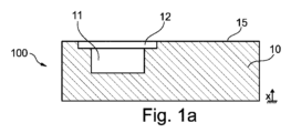
図1aは、造形材料の付加的かつ一体接着的積層により(=付加的ビルドアップ)本願発明に係る方法の過程で実行される、第1部分10のビルドアップの後の例示的な部品100を断面で示す。
FIG. 1a shows an
示されている例において、付加的ビルドアップは、造形方向xに沿って起こる。 In the example shown, additional buildup occurs along the build direction x.
第1キャビティ11が第1部分10の外側表面15に向かう開口部を有するように、第1キャビティ11が第1部分10に導入される。
The
第1キャビティ11の導入は、該当する点における凹部により、第1部分10の付加的ビルドアップの過程で実行され得る。表面品質を向上させ、したがって冷却管システム内の流れ抵抗を低減させるために、第1キャビティ11に隣接する第1部分の表面は、材料除去加工により、特にチップ除去加工により再処理される。
The introduction of the
代替的に、第1キャビティ11は、第1部分10の付加的ビルドアップに続いて中実材料内へ材料除去加工により、特にチップ除去加工により直接導入され得る。
Alternatively, the
さらに、外側表面15上の第1キャビティ11の開口部において、肩部12が、材料除去加工により第1部分10に導入される。肩部12は、後の被覆部13の挿入のために使用される(図1b参照)。
Furthermore, at the opening of the
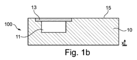
図1bは、被覆部13により第1キャビティ10の開口部を被覆する工程の後の部品を断面で示す。
FIG. 1 b shows the part in cross section after the step of covering the opening of the
被覆部13は、平坦かつ平らであり、他の寸法と比べて小さい厚さを有するのが有利である。被覆部は、第1キャビティの開口部を全体的に閉じる。 Advantageously, the covering 13 is flat and planar and has a small thickness compared to the other dimensions. The covering portion generally closes the opening of the first cavity.
平坦な被覆部12の表面が、第1部分の外側表面15と同一面に位置し、好ましくはそれらが一緒になって平坦表面を形成するよう、形状の観点から、第1キャビティ10において第1部分10に導入される肩部12と被覆部13とは互いに適応しているのが有利である。好ましくは、被覆部13は導入される肩部12により、ぴったりと合った状態で保持される。
In terms of shape, the first part in the
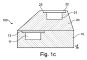
図1cは、第2部分20の付加的ビルドアップのための続く方法工程の後の部品100を断面で示す。
FIG. 1c shows the
第2部分20の付加的ビルドアップは、第1部分10の外側表面15から開始して第1部分10上で実行される。第1キャビティ11の被覆部13の表面は、ビルドアップ方向xに沿って外側表面15と同一面に位置する。
An additional build-up of the
第1キャビティ11の開口部を被覆することにより、第2部分20の付加的ビルドアップは被覆部13上で実行されてもよい。このことは、複雑なピラミッド型又は円錐形状を用いた純粋に付加的な積層によって第1キャビティ11を閉じることは省略することができ、したがって第1キャビティ11は、実質的に平行な対向し合う側面、又は頂面及び底面を有する形状を有することを意味する。
By coating the opening of the
第2部分20の付加的ビルドアップは、例示的な部品100に関して、第1部分10の外側表面全体15から、及び外側表面15と同一面に位置する被覆部13の表面から開始して図1cに示されるように実行される。このことは、本願発明に係る方法の限定と理解されるべきではない。概して第2部分は、部品100の第1部分10の外側表面15の(外側表面全体ではない)一部のみにビルドアップされてもよい。
The additional build-up of the
キャビティ、第2キャビティ21も、第1キャビティ11の導入の過程で既に記載した方法(付加的ビルドアップでの凹部及び材料除去後加工又は材料除去加工による全体的導入)のうち1つを用いた材料除去加工により部品100の第2部分20に導入される。
The cavity, the
図1cの描画は、第1キャビティ11及び第2キャビティ21が、寸法が同じか又は同様である同じか又は同様の形状を有することを示唆しているが、このことは、本願発明に係る方法の場合全般に関して必須というわけではない。
The drawing in FIG. 1c suggests that the
第2部分22内の第2キャビティ21は、第2部分20の外側表面25に向かって開口している。
The
さらに、第1キャビティ11の場合の手順と類似の方式で、肩部22が、材料除去加工により外側表面25上の第2キャビティ21の開口部に導入される。
Furthermore, in a similar manner to the procedure for the
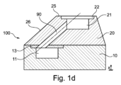
図1dは、接続管90を導入する続く方法工程の後の部品100を断面で示す。
FIG. 1d shows the
接続管90は、第1部分10の第1キャビティ11を第2部分20の第2キャビティ21へ接続するよう、材料除去加工により部品100に導入される。
The connecting
2つのキャビティ11及び21が接続管90で接続されて冷却管システムを形成するとき、材料も必ず、付加的ビルドアップの過程で部品内に閉じこめられた被覆部13から除去される。そうしなければ、キャビティ11とキャビティ21との間で接続を確立できないからである。
When the two
接続管90の導入のための材料除去加工は、特にレーザ加工又はチップ除去加工により、例えば、フライス工具又はドリルヘッドを用いて実行することができる。このやり方で導入された表面の高い表面品質のためにもチップ除去加工が好ましい。
The material removal machining for introducing the connecting
材料除去加工、例えばドリルヘッドの挿入は、第2キャビティ22から開始して実行される。第2キャビティ21の断面が接続管90の断面より大きいことによって、例えば第2キャビティ21付近の領域での第2部分20との衝突など望ましくない方式で部品100に損傷を加えることなく、部品100を通じて例示的なドリルヘッドを第1キャビティ11へ容易に導くことができる。
Material removal operations, such as insertion of a drill head, are performed starting from the
さらに、第2キャビティ22が比較的大きいことにより、例示的なドリルヘッドを、外側表面25の垂線に対してある角度で部品に導入することができる。(望ましくない方式で第2部分20に損傷を与えることなく)外側表面25の垂線に対して対応する傾斜角で接続管90を導入できることにより、結果として、部品100内の冷却管システムの形成により高い自由さが生まれる。
Additionally, the relatively large size of the
したがって、接続管90は、外側表面25の垂線に対して大きな傾斜角でも小さな傾斜角でも導入され得るので有利である。
The connecting
したがって、接続管90は、図1dにおける描画によると、部品100の部分領域内において部品100の更なる外側表面26と平行に(又はほぼ平行に)配置され得る。この結果、そのような部分的領域において、更なる外側表面26の異なる表面点同士が、同じ(又はほぼ同じ)接続管90からの距離を有する。外側輪郭の近くを通るように冷却管システムを配置でき、したがって、更なる外側表面26を通じて部品100に入る熱の、例えば冷却水が流れる冷却管システムによる放散を増やすことができるように、この距離はできる限り小さくなるよう選択されるべきであり、そうすることが有利である。冷却管システムの一部としての接続管90のそのような導入により、この部分領域において部品100は更なる外側表面26と接続管90との間で概ね一定の材料厚さを有し、このことはまた、該当する部分領域において局所間で均一な放熱性を達成することもできることを意味している。
The connecting
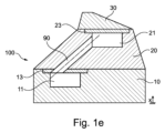
図1eは、例示的な部品100を完成させるための更なる(第3)部分30の付加的ビルドアップの後の部品100を断面で示す。
FIG. 1e shows the
本願発明に係る方法によると、第2部分20の外側表面25上の第2キャビティ21の開口部は、肩部22に適応した被覆部23により被覆され閉じられ、被覆部の一方の面が、ここでも外側表面25と同一面に位置して終端している。
According to the method according to the invention, the opening of the
第3部分30の付加的ビルドアップは、第2部分20の外側表面25から開始して第2部分20上で実行される。第2キャビティ21の被覆部23の表面は、構築方向xに沿って外側表面25と同一面に位置して延在する。
Additional build-up of the
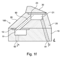
図1fは、冷却管システムが、供給管91及び吐出管92を導入することにより完成した後の部品100を断面で示す。
FIG. 1f shows the
供給管91及び吐出管92の導入は、材料除去加工により実行される。供給管91及び吐出管92は、入口Zから開始する、キャビティ21,22と接続管90と供給管91及び吐出管92とを含む冷却管システムを介した出口Aまでの冷却水の後段の通過が可能であるように、部品100に導入される。
The
冷却水のための入口Z及び出口Aの位置は概して固定されていないが、オプションで、入れ替えられてもよく、これにより冷却管システムを流れる冷却水の流れ方向は、図1fに示される流れ方向と反対となる。 The positions of the inlet Z and outlet A for the cooling water are generally not fixed, but may optionally be interchanged, so that the flow direction of the cooling water through the cooling pipe system is the flow direction shown in Figure 1f. The opposite is true.
供給管91及び吐出管92は、放熱性を向上させるために、少なくとも一部分で部品100の外側表面に沿うよう部品100内で配置されてもよい。
The
供給管91及び吐出管92は、部品100の冷却管システム内の冷却水のための入口Z及び出口Aが1つの外側表面又は複数の外側表面上に位置するように導入されるのが有利である(A及びZは、部品の同じ表面又は側面に必ずしも配置されない)。
The
完成した冷却管システムを有する図1fに示される部品100から明らかなのは、そのような複雑な幾何学構造を有する冷却管システムは、材料除去加工、例えばここでは3つの部分10,20及び30を有する部品100の全体的なビルドアップに続く穿孔では決して作ることができず、本願発明に係る方法によってのみ達成可能であるということである。
It is clear from the
さらに、内部冷却管システムに隣接する、部品100の表面は、材料除去加工により、特にチップ除去加工により導入される、又は少なくとも再処理されるのが有利である。このやり方で、特に純粋に付加的なビルドアップによって作成される表面と比較して低い粗面度をもつ高い表面品質を達成できる。このやり方で、そのような冷却管システムを流れる冷却水の流れ抵抗を大幅に低減することができ、これにより、特に純粋に付加的なビルドアップにより(すなわち、材料除去加工/再処理なしで)製造される、それ自体がより低い表面品質を有し、したがって冷却水に対するより高い流れ抵抗を有するであろう冷却管システムと比較して、より高い流速又はより多い流量を達成することができる。
Furthermore, the surfaces of the
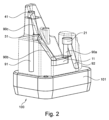
図2は、全体的に本願発明に係る方法により製造され、複数のキャビティ及び多数の複数の管を有する冷却管システムを備えた別の部品を斜視透視図で示す。 FIG. 2 shows in a perspective perspective view another part manufactured entirely by the method according to the invention and comprising a cooling pipe system having a plurality of cavities and a plurality of tubes.
図1a~1fでの描画と対照的に図2は、外形がより複雑であり、内部で延在する冷却管システムの形状がより複雑な部品100を示す。
In contrast to the depictions in FIGS. 1a to 1f, FIG. 2 shows a
部品100は、本願発明に係る方法を用いて製造される。交互に行われる付加的ビルドアップ工程と材料除去加工工程とを含む方法のハイブリッド的な性質によって部品100内の冷却管システムを形成することができ、このことにより、(冷却水が流れを有する)部品は、向上した放熱特性を有する。
部品は、部品101のベース本体101上への造形材料の付加的かつ一体接着的積層により造形される。
The part is built by additive and integral adhesive lamination of the building material onto the
本願発明に係る方法の過程で、第1キャビティ11と第2キャビティ21と2つの更なるキャビティ、第3キャビティ31及び第4キャビティ41とが、部品に導入されるのが有利である。これらキャビティのそれぞれは、チップ除去加工により導入される。また、キャビティ11,21,31及び41に隣接する表面は、表面品質を向上させるべく、例えば更なる材料除去加工により再処理され得る。
Advantageously, during the course of the method according to the invention, a
キャビティの形状は、標準形状の群から選択されるのが有利である。形状は、考えられる多様な寸法の単純な円筒形状、及び/又は略円筒形状を備えるのが好ましい。略円筒形状とは、任意の形状(例えば、円、楕円、多角形等)の基底面の、押出軸に沿った押し出しにより形成される形状と理解されるものとする。 Advantageously, the shape of the cavity is selected from a group of standard shapes. Preferably, the shape comprises a simple cylindrical shape and/or a substantially cylindrical shape of a wide variety of possible dimensions. A substantially cylindrical shape is understood to be a shape formed by extruding a base surface of an arbitrary shape (for example, a circle, an ellipse, a polygon, etc.) along an extrusion axis.
第2、第3及び第4キャビティ21,31及び41は、円状断面の円筒形状を有する。個々のキャビティの円筒形状の寸法は、円状断面の半径と円筒の高さの両方の点で異なる。
The second, third and
他方、第1キャビティ11は、非円状断面の略円筒形状を有する。
On the other hand, the
本願発明に係る方法を用いた部品の製造の過程で、キャビティ11,21,31及び41は互いに接続されて、材料除去加工により、特にチップ除去加工により部品100に導入される接続管90a,90b及び90cにより冷却管システムを形成する。
During the production of the component using the method according to the invention, the
接続管90aは第1キャビティ11を第2キャビティ21に接続し、接続管90bは第1キャビティ11を第3キャビティ31に接続し、接続管90cは第3キャビティ31を第4キャビティ41に接続する。
The connecting
よって、冷却管システムを流れる冷却水の流れ方向は、次の順序の何れかである。第2キャビティ21->接続管90a->第1キャビティ11->接続管90b->第3キャビティ31->接続管90c->第4キャビティ41
又は、これを逆にした順序である。
Therefore, the flow direction of the cooling water flowing through the cooling pipe system is in one of the following orders. Second cavity 21 -> connecting
Or the order is reversed.
部品100のベース本体101から開始して、冷却水のための供給管91及び吐出管92は、冷却管システムを完成させるために材料除去加工により部品101に導入される。
Starting from the
供給管91及び吐出管92の決定、したがって供給管91から吐出管92への流れ方向の決定は、冷却水がこの反対の流れ方向で冷却管システムを流れてもよいので、絶対的なものと理解されるものではない。
The determination of the
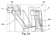
図3aは、図2における部品の中央部分領域の斜視部分を示す。 FIG. 3a shows a perspective section of the central partial area of the part in FIG. 2. FIG.
この部分は、キャビティ11,21及び31を接続するための接続管90a及び90bが少なくとも一部分で部品100の外側輪郭又は外側輪郭表面に沿うよう、すなわちこれらと平行に又は略平行に延在し、したがってニアネットコンター(ニアネット外形)となるよう形成されるよう、部品100に導入されることを示す。
In this part, the connecting
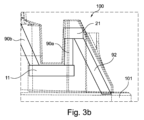
図3bは、図3aに中央部分領域が示される図2における部品の部分を側面図で示す。 FIG. 3b shows in side view a part of the part in FIG. 2, the central part area of which is shown in FIG. 3a.
この側面図は、キャビティ11,21及び31を接続するための接続管90a及び90bに加えて、冷却管システムの吐出管92も少なくとも一部分で部品100の外側輪郭又は外側輪郭表面に沿うよう、すなわちそれに平行に又は略平行に延在するよう、部品100に導入されることを示す。
This side view shows that in addition to the connecting
図3bに示される描画において、冷却管システムの吐出管92はベース本体101に向かって開口し、そこから冷却管システムが、冷却管システムに供給するよう構成された冷却水供給ユニットに接続する。
In the depiction shown in Figure 3b, the
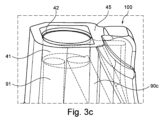
図3cは、部品を製造するための本願発明に係る方法の中間工程の後の、図2における部品の斜視部分の上側部分領域を示す。 FIG. 3c shows the upper partial region of the perspective part of the component in FIG. 2 after an intermediate step of the method according to the invention for manufacturing the component.
示される描画において、第4キャビティ41の導入に続く、被覆部43(ここでは図示せず。図3d参照)により外側表面45上の第4キャビティ41の開口部を被覆する方法工程、及び、外側表面45上の図2に示される部品100の最後の部分の付加的ビルドアップは、まだ実行されていない。
In the depiction shown, following the introduction of the
ここで、外側表面45は、前の方法工程の過程で形成される外側表面でしかなく、提示される場合において完成部品の外側表面ではない。
Here, the
ここで、部品の付加的ビルドアップは、外側表面45まで起こっている。
Here, additional build-up of the part has occurred up to the
さらに、外側表面45上の第4キャビティ41の開口部において、被覆部43(ここでは図示せず)を受けるよう構成された肩部42が、材料除去加工により、特にチップ除去加工により導入される。
Furthermore, at the opening of the
肩部42の形状は、第4キャビティの円筒形状に適応したものであり、続く方法工程の過程で設置される被覆部43がぴったりと合った状態で適切な位置で保持されるように構成される。
The shape of the
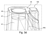
図3dは、部品を製造するための本願発明に係る方法の更なる中間工程の後の、図2における部品の斜視部分の上側部分領域を示す。 FIG. 3d shows the upper partial region of the perspective part of the component in FIG. 2 after a further intermediate step of the method according to the invention for manufacturing the component.
本願発明に係る製作方法の過程で図3cに示される部品の状態に続き、外側表面45上の第4キャビティ41の開口部は、肩部42に適応した被覆部43に被覆されている。
Following the state of the part shown in FIG. 3c during the manufacturing method according to the invention, the opening of the
被覆部43は、第4キャビティを被覆するよう肩部42に挿入することができ、ぴったりと合った状態でそこに位置するように(肩部42に合わせて)構成され、被覆部42の一方の面は、部品の外側表面45に対して僅かに凹んでいる。
The
したがって、続く方法工程の過程で図2に示される部品の最後の部分の付加的ビルドアップが起こり得る区画された終端が形成される。 Thus, a demarcated end is formed in which an additional build-up of the final part of the part shown in FIG. 2 can take place in the course of subsequent method steps.
本願発明に係る方法の過程で用いられる被覆部、ここでは被覆部43は好ましくは、キャビティの標準形状に幾何学的に適応した事前作製された被覆部の群から選択される。 The covering used in the course of the method according to the invention, here the covering 43, is preferably selected from the group of prefabricated coverings geometrically adapted to the standard shape of the cavity.
第4キャビティ41の円筒形状に対応して、被覆部43はそれに適応した円形平坦形状を有し、好ましくは薄い平坦な板金ブランクとして構成される。
Corresponding to the cylindrical shape of the
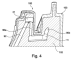
図4は、図2に示される部品の中央部分領域を斜視断面図で示す。 FIG. 4 shows a central partial region of the part shown in FIG. 2 in a perspective sectional view.
描画は、冷却管システムを有する部品100の異なる材料構造を示す。
The drawings show different material constructions of the
本願発明に係る方法の過程で製造される部品は、冷却管システムが内部に形成された造形材料から作られた芯体102を有する。
The part manufactured during the course of the method according to the invention has a
さらに、耐摩耗性外層103が、更なる材料の付加的かつ一体接着的積層により芯体102の外側輪郭表面上に形成される。更なる材料の耐摩耗性は、芯体102を形成するのに用いられる造形材料の耐摩耗性より高い。
Furthermore, an abrasion resistant
他方、芯体102を形成するのに用いられる造形材料の熱伝導率は、耐摩耗性外層103を形成するのに用いられる更なる材料の熱伝導率より高いことが好ましい。
On the other hand, the thermal conductivity of the building material used to form the
その結果得られる組み合わせは、冷却管システムが内部に形成された芯体102のより良好な熱伝導特性と、耐摩耗性外層103の高い耐摩耗性とを組み合わせた有利なものとなる。
The resulting combination advantageously combines better heat transfer properties of the
考えられる実施形態においては、熱伝導性造形材料は銅又は銅合金であり、耐摩耗性外層は工具鋼から形成される。 In a possible embodiment, the thermally conductive building material is copper or a copper alloy and the wear-resistant outer layer is formed from tool steel.
材料除去加工により、本願発明に係る方法の過程で冷却管システムが芯体102に導入されるので、加工の手間と加工のコストを削減することもできる。より熱伝導性の高い芯体102、例えば銅合金は通常、耐摩耗性外層103の更なる材料、例えば工具鋼より強度が低く、したがって芯体に対する材料除去加工が単純化されるからである。
Due to the material removal process, a cooling tube system is introduced into the
冷却管システムを有する部品を製造するための本願発明に係る方法の例示的な実施形態が、図5に概略的に示される。 An exemplary embodiment of the method according to the invention for manufacturing a component with a cooling pipe system is schematically shown in FIG.
工程S1において、部品の第1部分が、造形材料の付加的かつ一体接着的積層により造形される。 In step S1, a first part of the part is built by additional and integral adhesive lamination of building material.
工程S2において、開口部を有する第1キャビティが、部品の第1部分に導入される。 In step S2, a first cavity with an opening is introduced into the first part of the part.
工程S3において、第1部分における第1キャビティの開口部が、被覆部により部分的に又は全体的に被覆される。 In step S3, the opening of the first cavity in the first portion is partially or completely covered with the covering portion.
工程S4において、部品の第2部分が、造形材料の付加的かつ一体接着的積層により造形される。造形材料は、第1部分上、及び少なくとも被覆部上に、また適切であれば追加的に第1部分上に積層される。 In step S4, the second part of the part is built by additional and integral adhesive lamination of the building material. The building material is deposited on the first part and at least on the covering and if appropriate additionally on the first part.
工程S5において、第2キャビティが、部品の第2部分に導入される。 In step S5 a second cavity is introduced into the second part of the part.
工程S6において、冷却管システムを形成するために、接続管が、材料除去加工により少なくとも一部分で部品に導入される。接続管は、第2部分の第2キャビティを、部品の第1部分の第1キャビティに接続する。 In step S6, connecting tubes are introduced into the component at least in part by material removal machining to form a cooling tube system. A connecting tube connects the second cavity of the second part to the first cavity of the first part of the part.
この例示的な実施形態において、2つのキャビティが、材料の積層の間に対応する領域を省略することにより導入される。 In this exemplary embodiment, two cavities are introduced by omitting corresponding regions between the stacks of materials.
2つのキャビティを接続するための接続管は、チップ除去加工により導入される。 A connecting tube for connecting the two cavities is introduced by chip removal processing.
示される例示的な実施形態の特定の実施形態において、方法は工程S7も含み、対応する領域を省略することによって作成される第2部分の第2キャビティ内の開口部も、被覆部により部分的に又は全体的に被覆される。 In certain embodiments of the exemplary embodiments shown, the method also includes step S7, wherein the opening in the second cavity of the second part created by omitting the corresponding region is also partially covered by the covering. completely coated.
それから、工程S8において、部品の更なる部分が、造形材料の付加的かつ一体接着的積層により造形される。より良好な一体接着的な接続を達成し開口部の終端を確実に行うために、造形材料は、少なくとも第2キャビティの開口部の被覆部上に、また場合によっては第2部分上にも積層される。 Then, in step S8, further parts of the part are built by additional and integrally adhesively laminating the building material. In order to achieve a better cohesive connection and ensure the termination of the opening, the building material is deposited at least on the covering of the opening of the second cavity and optionally also on the second part. be done.
上記したように、これら工程は、このやり方でキャビティを有する更なる部分を連続的に造形するためにさらに繰り返され得、それから続いてそれらキャビティは、接続管を導入することにより接続され得る。本願発明によれば、接続管は少なくとも部分的に材料除去加工により製造され、他方、本願発明によれば、本願発明の範囲内で、キャビティは少なくとも部分的に造形材料の付加的かつ一体接着的積層により造形される。 As mentioned above, these steps can be further repeated in this way to successively build further parts with cavities, which cavities can then subsequently be connected by introducing connecting tubes. According to the invention, the connecting pipe is at least partially produced by a material removal process, while according to the invention, within the scope of the invention, the cavity is at least partially produced by an additional and integrally adhesive process of the building material. Modeled by layering.
本願発明の例示的な実施形態、及びそれらの利点を、上記にて添付図面を参照し詳細に説明してきた。 Exemplary embodiments of the present invention and their advantages have been described in detail above with reference to the accompanying drawings.
しかし、本願発明は、上記した例示的な実施形態、及びそれらの実装特徴には決して限定されず、述べられている例示的な実施形態の変形、特に独立請求項の範囲内での記載されている例示的な実施形態の1又は複数の特徴の変形及び/又は組み合わせの結果生じるものも含む。 However, the invention is in no way limited to the above-described exemplary embodiments and their implementation features, but rather extends to variations of the exemplary embodiments described, in particular within the scope of the independent claims. It also includes those that result from variations and/or combinations of one or more features of the exemplary embodiments.
10 第1部分
11 第1キャビティ
12 第1キャビティの開口部の肩部
13 第1キャビティを被覆するための被覆部
15 第1部分の外側表面
20 第2部分
21 第2キャビティ
22 第2キャビティの開口部の肩部
23 第2キャビティを被覆するための被覆部
25 第2部分の外側表面
26 第2部分の更なる外側表面
31 第3キャビティ
41 第4キャビティ
42 第4キャビティの開口部の肩部
43 第4キャビティを被覆するための被覆部
45 外側表面
90,90a,90b,90c 接続管
91 供給管
92 吐出管
100 部品
101 部品の本体
102 部品の芯体
103 耐摩耗性外層
Z 入口
A 出口
x 造形方向
10
Claims (22)
-造形材料の付加的かつ一体接着的積層により前記部品(100)の第1部分(10)を造形することと、
-前記部品(100)の前記第1部分(10)内へ開口部を有する第1キャビティ(11)を導入することと
を備え、
-被覆部(13)により前記第1部分(10)内の前記第1キャビティ(11)の前記開口部を部分的に又は全体的に被覆することと、
-前記造形材料の前記付加的かつ一体接着的積層により前記部品(100)の第2部分(20)を造形することであって、前記造形材料は少なくとも前記被覆部(13)に、かつ、積層可能であれば追加的に前記第1部分(10)に積層されることと、
-前記部品の前記第2部分(20)内へ第2キャビティ(21)を導入することと、
-材料除去加工により少なくとも一部分で前記部品(100)内へ接続管(90;90a)を導入して前記冷却管システムを形成することであって、前記接続管は前記第2部分(20)の前記第2キャビティ(21)を前記部品(100)の前記第1部分(10)の前記第1キャビティ(11)に接続することと
をさらに備える、方法。 A method for manufacturing a component (100) having a cooling pipe system, the method comprising:
- building a first part (10) of said part (100) by additional and integral adhesive lamination of building material;
- introducing into the first part (10) of the part (100) a first cavity (11) having an opening;
- partially or completely covering the opening of the first cavity (11) in the first part (10) with a covering (13);
- building a second part (20) of the part (100) by said additional and integrally adhesive lamination of said building material, said building material being applied at least to said covering (13) and in said lamination; additionally laminated to the first portion (10) if possible;
- introducing a second cavity (21) into the second part (20) of the part;
- introducing a connecting pipe (90; 90a) into said part (100) at least in part by material removal machining to form said cooling pipe system, said connecting pipe forming said second part (20); Connecting the second cavity (21) to the first cavity (11) of the first part (10) of the part (100).
前記第1キャビティ(11)及び/又は前記第2キャビティ(21)を導入すること、及び/又は、前記接続管を導入することは、それぞれの前記部分(10;20)を造形することに続いて少なくとも一部分で材料除去加工により実行される、方法。 The method according to claim 1,
The introduction of the first cavity (11) and/or the second cavity (21) and/or the introduction of the connecting tube follows the shaping of the respective part (10; 20). method, the method being carried out at least in part by a material removal process.
前記第1キャビティ(11)及び/又は前記第2キャビティ(21)及び/又は前記接続管を導入するための前記材料除去加工は、チップ除去加工である、方法。 3. The method according to claim 2,
The method, wherein the material removal process for introducing the first cavity (11) and/or the second cavity (21) and/or the connecting tube is a chip removal process.
前記第1キャビティ(11)及び/又は前記第2キャビティ(21)を導入すること、及び/又は、前記接続管を導入することは、前記造形材料の前記付加的かつ一体接着的積層の間における省略によりそれぞれの前記部分(10,20)を造形する過程で少なくとも一部分で実行される、方法。 The method according to claim 1,
Introducing the first cavity (11) and/or the second cavity (21) and/or introducing the connecting tube during the additional and integrally adhesive lamination of the building material A method which is by default carried out at least in part in the course of shaping each said part (10, 20).
前記部分(10;20)を造形する過程で導入される前記キャビティ(11;21)に隣接する前記部分(10;20)の表面は、チップ除去加工により再処理される、方法。 5. The method according to claim 4,
The method, wherein the surface of the part (10; 20) adjacent to the cavity (11; 21) introduced in the process of shaping the part (10; 20) is reprocessed by a chip removal process.
-被覆部(23)により前記第2部分(20)の前記第2キャビティ(21)の開口部を部分的に又は全体的に被覆することと、
-前記造形材料の前記付加的かつ一体接着的積層により前記部品(100)の更なる部分(30;40)を造形することであって、前記造形材料は少なくとも前記第2キャビティ(21)の前記開口部の前記被覆部(23)に、かつ、積層可能であれば前記第2部分(20)に積層されることと
をさらに備える、方法。 A method according to one of claims 1 to 5, comprising:
- partially or completely covering the opening of the second cavity (21) of the second part (20) with a covering part (23);
- building a further part (30; 40) of the part (100) by said additional and integrally adhesive lamination of said building material, said building material forming at least said part of said second cavity (21); The method further comprises: being laminated to the covering portion (23) of the opening and, if laminable, to the second portion (20).
ZS1:前記部品(100)の予め造形された前記部分(10;20)のうちの1つへ開口部を有する更なるキャビティ(31;41)を導入することであって、前記更なるキャビティ(31;41)を導入することは、前記予め造形された部分(10;20)を造形することに続く材料除去加工により、又は、前記予め造形された部分(10;20)を造形する過程で前記造形材料の前記付加的かつ一体接着的積層の間における省略により実行されることと、
ZS2:材料除去加工により前記部品(100)内へ1又は複数の接続管(90;90a;90b;90c)を導入して前記冷却管システムをさらに形成することであって、前記接続管(90;90a;90b;90c)は工程ZS1における前記更なるキャビティ(31;41)を、前記部品(100)の前記予め造形された部分(10;20)内の予め導入された前記キャビティ(11;21)のうち1又は複数と接続することと、
ZS3:被覆部(43)により、工程ZS1における前記更なるキャビティ(31;41)のうち1又は複数の前記開口部を部分的に又は全体的に被覆することと、
ZS4:前記造形材料の前記付加的かつ一体接着的積層により前記部品(100)の1又は複数の更なる部分を造形することであって、前記造形材料は、前記予め造形された部分のうち1又は複数に、及び、1つ前の工程ZS3の前記被覆部(43)に積層されることと
をさらに備える、方法。 7. The method according to claim 6,
ZS1: introducing a further cavity (31; 41) with an opening into one of said pre-shaped parts (10; 20) of said part (100), said further cavity ( 31; 41) can be introduced by a material removal process subsequent to modeling the pre-shaped part (10; 20) or during the process of modeling the pre-shaped part (10; 20). carried out by omission during the additional and integral adhesive lamination of the build material;
ZS2: further forming the cooling pipe system by introducing one or more connecting pipes (90; 90a; 90b; 90c) into the component (100) by material removal processing, the connecting pipes (90) ; 90a; 90b; 90c) in step ZS1 by adding said further cavity (31; 41) to said pre-introduced cavity (11; connecting with one or more of 21);
ZS3: Partially or completely covering one or more of the openings of the further cavities (31; 41) in step ZS1 with a covering part (43);
ZS4: Building one or more further parts of the part (100) by said additional and integrally adhesive lamination of said building material, said building material comprising one of said pre-built parts. or a plurality of layers, and being laminated on the covering portion (43) of the previous step ZS3.
-複数のキャビティ(11;21;31;41)及び前記複数のキャビティを接続するための複数の接続管(90;90a;90b;90c;90d)を含む冷却管システムが内部に形成された、複数の部分(10,20)を有する部品(100)を製造するための、一連の方法工程ZS1からZS4の複数回の繰り返しをさらに備える、方法。 8. The method according to claim 7,
- a cooling pipe system is formed inside, comprising a plurality of cavities (11; 21; 31; 41) and a plurality of connecting pipes (90; 90a; 90b; 90c; 90d) for connecting the plurality of cavities; A method for manufacturing a part (100) having a plurality of parts (10, 20), further comprising multiple repetitions of the series of method steps ZS1 to ZS4.
前記接続管(90;90a;90b;90c)を導入するための前記材料除去加工はチップ除去加工である、方法。 A method according to one of claims 1 to 8, comprising:
The method, wherein the material removal process for introducing the connecting pipe (90; 90a; 90b; 90c) is a chip removal process.
前記造形材料の前記付加的かつ一体接着的積層は、レーザ溶接又はアークビルドアップ溶接により実行される、方法。 The method according to one of claims 1 to 9,
The method, wherein the additional and integral adhesive lamination of the building material is performed by laser welding or arc build-up welding.
前記造形材料は、粉末及び/又はワイヤの形態で供給される、方法。 11. The method according to claim 10,
The method, wherein the building material is provided in the form of a powder and/or a wire.
それぞれの前記部分内の前記キャビティ(11;21;31;41)のうち1又は複数の前記開口部付近の領域において、それぞれの前記開口部を被覆するためのそれぞれの前記被覆部(13;23;43)が適切な位置でぴったり合った状態で保持されるように、それぞれの前記開口部を被覆するよう構成された前記被覆部(13;23;43)の形状に材料除去加工により適応した凹んだ肩部(12;22;42)が形成される、方法。 A method according to one of claims 1 to 11, comprising:
In a region near one or more of the openings of the cavities (11; 21; 31; 41) in each of the portions, each of the covering portions (13; 23 ;43) is adapted by material removal machining to the shape of said covering (13; 23; A method in which a recessed shoulder (12; 22; 42) is formed.
前記被覆部(13;23;43)のうち1又は複数は、円形板金ブランク又は板金カバーである、方法。 13. The method according to claim 12,
The method, wherein one or more of the covering parts (13; 23; 43) are circular sheet metal blanks or sheet metal covers.
前記キャビティ(11;21;31;41)の形状は、前記キャビティの所定の標準形状の群から選択される、方法。 A method according to one of claims 1 to 13, comprising:
The method, wherein the shape of the cavity (11; 21; 31; 41) is selected from a group of predetermined standard shapes of the cavity.
前記キャビティの前記標準形状は円筒形状を有する、方法。 15. The method according to claim 14,
The method, wherein the standard shape of the cavity has a cylindrical shape.
前記被覆部(13;23;43)は、前記キャビティの前記標準形状に幾何学的に適応した事前に作製された被覆部の群から選択される、方法。 16. The method according to one of claims 14 and 15,
The method, wherein said covering (13; 23; 43) is selected from a group of prefabricated coverings geometrically adapted to said standard shape of said cavity.
-材料除去加工により前記部品(100)内に前記冷却管システムのための少なくとも1つの供給管(91)及び少なくとも1つの吐出管(92)を導入することであって、前記供給管(91)及び前記吐出管(92)は、前記冷却管システムが前記供給管(91)から前記吐出管(92)まで連続的に延在するよう導入されることをさらに備える、方法。 17. A method according to one of claims 1 to 16, comprising:
- introducing at least one supply pipe (91) and at least one discharge pipe (92) for the cooling pipe system into the part (100) by material removal processing, the supply pipe (91) and said discharge pipe (92) is introduced such that said cooling pipe system extends continuously from said supply pipe (91) to said discharge pipe (92).
-前記部品(100)の前記造形材料とは異なる耐摩耗性を有する異なる材料の付加的かつ一体接着的積層をさらに備える、方法。 18. A method according to one of claims 1 to 17, comprising:
- a method further comprising an additional and integrally adhesive lamination of a different material having a different wear resistance than the building material of the part (100).
前記冷却管システムの周囲の前記造形材料は、耐摩耗性外層(103)の熱伝導率より高い熱伝導率を有する、方法。 19. The method according to claim 18 ,
The method, wherein the building material around the cooling tube system has a thermal conductivity higher than that of the wear- resistant outer layer (103).
-規定済みの幾何学的に所定のキャビティの群から冷却管部分の形状を特に選択することにより、冷却管システムを有する前記部品(100)の部品形状を規定するための手段を備える、コンピュータシステム。 A software-supported computer system, said computer system configured for the construction planning of a part (100) manufactured by the method according to one of claims 1 to 19, and for this purpose at least,
- a computer system comprising means for defining the part shape of said part (100) having a cooling pipe system by specifically selecting the shape of a cooling pipe section from a defined geometrically predetermined group of cavities; .
-前記部品(100)の前記製造のための数値制御工作機械及び/又は数値制御マシニングセンタが実行できる連続的な加工工程を決定するための手段と、
-前記加工工程を実行するために前記数値制御工作機械及び/又は前記数値制御マシニングセンタが使用する制御命令を導出するための手段と、
-前記部品(100)を製造するための前記加工工程を実行するよう構成された前記制御命令を前記工作機械及び/又は前記マシニングセンタへ送信するための手段と
をさらに備える、コンピュータシステム。 21. A software supported computer system according to claim 20, comprising:
- means for determining consecutive machining steps that can be carried out by a numerically controlled machine tool and/or a numerically controlled machining center for said production of said part (100);
- means for deriving control instructions used by the numerically controlled machine tool and/or the numerically controlled machining center to carry out the machining process;
- means for transmitting to the machine tool and/or the machining center the control instructions configured to carry out the machining steps for manufacturing the part (100).
Applications Claiming Priority (3)
| Application Number | Priority Date | Filing Date | Title |
|---|---|---|---|
| DE102020116037.2A DE102020116037A1 (en) | 2020-06-17 | 2020-06-17 | Manufacturing process for a component with a cooling channel system |
| DE102020116037.2 | 2020-06-17 | ||
| PCT/EP2021/066364 WO2021255154A1 (en) | 2020-06-17 | 2021-06-17 | Method for producing a component having a cooling channel system |
Publications (2)
| Publication Number | Publication Date |
|---|---|
| JP2023530074A JP2023530074A (en) | 2023-07-13 |
| JP7421663B2 true JP7421663B2 (en) | 2024-01-24 |
Family
ID=76744790
Family Applications (1)
| Application Number | Title | Priority Date | Filing Date |
|---|---|---|---|
| JP2022571200A Active JP7421663B2 (en) | 2020-06-17 | 2021-06-17 | Method for manufacturing parts with cooling pipe system |
Country Status (7)
| Country | Link |
|---|---|
| US (1) | US12397487B2 (en) |
| EP (1) | EP4168225B1 (en) |
| JP (1) | JP7421663B2 (en) |
| KR (1) | KR20230028752A (en) |
| CN (1) | CN115943029B (en) |
| DE (1) | DE102020116037A1 (en) |
| WO (1) | WO2021255154A1 (en) |
Families Citing this family (1)
| Publication number | Priority date | Publication date | Assignee | Title |
|---|---|---|---|---|
| DE102022125429A1 (en) | 2022-09-30 | 2024-04-04 | Dmg Mori Ultrasonic Lasertec Gmbh | METHOD FOR ADDITIVE MANUFACTURING OF A COMPONENT WITH A CORE MADE OF PURE COPPER OR A COPPER ALLOY |
Citations (4)
| Publication number | Priority date | Publication date | Assignee | Title |
|---|---|---|---|---|
| WO2010082331A1 (en) | 2009-01-15 | 2010-07-22 | 株式会社Opmラボラトリー | Sprue bush and method for producing the same |
| JP2014514162A (en) | 2011-04-28 | 2014-06-19 | インステク インコーポレイテッド | Metal product having internal space formed and method for manufacturing the same |
| JP2018122586A (en) | 2017-02-03 | 2018-08-09 | 株式会社ミマキエンジニアリング | Production method of molding and molding apparatus |
| JP2019110177A (en) | 2017-12-18 | 2019-07-04 | 株式会社アーレスティ | Manufacturing method of cooling structure |
Family Cites Families (13)
| Publication number | Priority date | Publication date | Assignee | Title |
|---|---|---|---|---|
| US5775402A (en) | 1995-10-31 | 1998-07-07 | Massachusetts Institute Of Technology | Enhancement of thermal properties of tooling made by solid free form fabrication techniques |
| DE19740502A1 (en) | 1997-09-15 | 1999-03-18 | Fraunhofer Ges Forschung | Method for producing a component with a surface-near flow channel system for liquids and/or gases |
| DE19834238A1 (en) | 1998-07-29 | 2000-02-10 | Juergen Roeders | Metal component with at least one tubular or channel-shaped recess in it, with base body having open recess in one side surface and carrier element partly covering recess |
| US20020165634A1 (en) * | 2000-03-16 | 2002-11-07 | Skszek Timothy W. | Fabrication of laminate tooling using closed-loop direct metal deposition |
| DE20221730U1 (en) | 2002-07-03 | 2007-04-26 | Cl Schutzrechtsverwaltungs Gmbh | Casting tool insert has lower section formed of machined metal section under upper section formed of sintered metal powder |
| JP4269923B2 (en) | 2003-12-10 | 2009-05-27 | 東レ株式会社 | FRP manufacturing method and manufacturing apparatus thereof |
| DE102004040929A1 (en) | 2004-08-24 | 2006-03-02 | Hachtel, Friedrich | injection mold |
| DE102006017808A1 (en) * | 2006-04-13 | 2007-10-18 | Impetus Plastics Engineering Gmbh | Temperable injection mold with mold nest(s), has insert with tempering fluid channels, formed by connecting plate-form segments with segment obtained by laser fusion of powder or wire |
| EP1980380A1 (en) * | 2007-04-13 | 2008-10-15 | LBC Laser Bearbeitungs Center GmbH | Device for warming or cooling, in particular as part of a mould for processing plastic masses, such as injection mould for plastic |
| JP6509038B2 (en) | 2015-05-25 | 2019-05-08 | 株式会社キャステム | Method of manufacturing metal powder injection molded body |
| JP6628024B2 (en) | 2015-07-31 | 2020-01-08 | パナソニックIpマネジメント株式会社 | Method for manufacturing three-dimensionally shaped object and three-dimensionally shaped object |
| CA2977757A1 (en) * | 2016-09-22 | 2018-03-22 | Sulzer Management Ag | Method for manufacturing or for repairing a component of a rotary machine as well as a component manufactured or repaired using such a method |
| US10617035B2 (en) | 2018-05-29 | 2020-04-07 | Raytheon Company | Additively manufactured structures for gradient thermal conductivity |
-
2020
- 2020-06-17 DE DE102020116037.2A patent/DE102020116037A1/en active Granted
-
2021
- 2021-06-17 US US17/927,067 patent/US12397487B2/en active Active
- 2021-06-17 KR KR1020237001264A patent/KR20230028752A/en active Pending
- 2021-06-17 CN CN202180043536.XA patent/CN115943029B/en active Active
- 2021-06-17 JP JP2022571200A patent/JP7421663B2/en active Active
- 2021-06-17 EP EP21736980.0A patent/EP4168225B1/en active Active
- 2021-06-17 WO PCT/EP2021/066364 patent/WO2021255154A1/en not_active Ceased
Patent Citations (4)
| Publication number | Priority date | Publication date | Assignee | Title |
|---|---|---|---|---|
| WO2010082331A1 (en) | 2009-01-15 | 2010-07-22 | 株式会社Opmラボラトリー | Sprue bush and method for producing the same |
| JP2014514162A (en) | 2011-04-28 | 2014-06-19 | インステク インコーポレイテッド | Metal product having internal space formed and method for manufacturing the same |
| JP2018122586A (en) | 2017-02-03 | 2018-08-09 | 株式会社ミマキエンジニアリング | Production method of molding and molding apparatus |
| JP2019110177A (en) | 2017-12-18 | 2019-07-04 | 株式会社アーレスティ | Manufacturing method of cooling structure |
Also Published As
| Publication number | Publication date |
|---|---|
| US12397487B2 (en) | 2025-08-26 |
| EP4168225B1 (en) | 2025-02-12 |
| WO2021255154A1 (en) | 2021-12-23 |
| US20230286197A1 (en) | 2023-09-14 |
| DE102020116037A1 (en) | 2021-12-23 |
| CN115943029B (en) | 2025-01-14 |
| CN115943029A (en) | 2023-04-07 |
| JP2023530074A (en) | 2023-07-13 |
| KR20230028752A (en) | 2023-03-02 |
| EP4168225A1 (en) | 2023-04-26 |
Similar Documents
| Publication | Publication Date | Title |
|---|---|---|
| US11898804B2 (en) | Fluid routing methods for a spiral heat exchanger with lattice cross section made via additive manufacturing | |
| US8946585B2 (en) | Method for the manufacture of a cutting tool | |
| JP5696867B2 (en) | Metal product having internal space formed and method for manufacturing the same | |
| US6656409B1 (en) | Manufacturable geometries for thermal management of complex three-dimensional shapes | |
| CA2930185C (en) | Tool for hot stamping and method for making the tool | |
| Shinde et al. | Direct rapid manufacturing of molds with conformal cooling channels | |
| US20080251243A1 (en) | Heat-exchange element and method of making same | |
| US20220016685A1 (en) | Production method for a shape-imparting tool part of a forming tool | |
| JP7421663B2 (en) | Method for manufacturing parts with cooling pipe system | |
| CN115194423B (en) | Heat exchanger and method for manufacturing the same | |
| US20130230616A1 (en) | Split thread insert | |
| Shinde et al. | On efficient electrode design and manufacturing techniques for hot die steel inserts | |
| JP2010194720A (en) | Cavity insert for mold, method for manufacturing insert for mold, and resin molding mold | |
| CN107414024A (en) | The method of valve body of the manufacture with one or more corrosion-resistant inner surfaces | |
| JP2010194719A (en) | Sprue bush and method for producing sprue bush | |
| US11878343B2 (en) | Housing and method of preparing same using a hybrid casting-additive manufacturing process | |
| CN110732595A (en) | Mould for hot forming and/or press hardening of sheet metal and method for producing cooling tool section | |
| CN115609804A (en) | Manufacturing method of die part with conformal waterway | |
| US7445746B2 (en) | Temperable member | |
| CN120170982B (en) | An optical mirror injection molding die and its manufacturing method | |
| US20250187073A1 (en) | Housing and method of preparing same using a hybrid casting-additive manufacturing process | |
| TWI684486B (en) | Mold and manufacturing method of mold | |
| JP2024132280A (en) | Manufacturing method of block joint | |
| JP6771678B2 (en) | Molds and mold manufacturing methods | |
| Karunakaran et al. | Manufacturing Letters |
Legal Events
| Date | Code | Title | Description |
|---|---|---|---|
| A521 | Request for written amendment filed |
Free format text: JAPANESE INTERMEDIATE CODE: A523 Effective date: 20230124 |
|
| A621 | Written request for application examination |
Free format text: JAPANESE INTERMEDIATE CODE: A621 Effective date: 20230125 |
|
| RD02 | Notification of acceptance of power of attorney |
Free format text: JAPANESE INTERMEDIATE CODE: A7422 Effective date: 20231109 |
|
| A521 | Request for written amendment filed |
Free format text: JAPANESE INTERMEDIATE CODE: A821 Effective date: 20231110 |
|
| A977 | Report on retrieval |
Free format text: JAPANESE INTERMEDIATE CODE: A971007 Effective date: 20231128 |
|
| TRDD | Decision of grant or rejection written | ||
| A01 | Written decision to grant a patent or to grant a registration (utility model) |
Free format text: JAPANESE INTERMEDIATE CODE: A01 Effective date: 20231219 |
|
| A61 | First payment of annual fees (during grant procedure) |
Free format text: JAPANESE INTERMEDIATE CODE: A61 Effective date: 20240112 |
|
| R150 | Certificate of patent or registration of utility model |
Ref document number: 7421663 Country of ref document: JP Free format text: JAPANESE INTERMEDIATE CODE: R150 |