JP7421237B2 - Data transmission method and reception method of wireless communication system, and device using the same - Google Patents
Data transmission method and reception method of wireless communication system, and device using the same Download PDFInfo
- Publication number
- JP7421237B2 JP7421237B2 JP2022142229A JP2022142229A JP7421237B2 JP 7421237 B2 JP7421237 B2 JP 7421237B2 JP 2022142229 A JP2022142229 A JP 2022142229A JP 2022142229 A JP2022142229 A JP 2022142229A JP 7421237 B2 JP7421237 B2 JP 7421237B2
- Authority
- JP
- Japan
- Prior art keywords
- time
- terminal
- physical data
- data channel
- resource
- Prior art date
- Legal status (The legal status is an assumption and is not a legal conclusion. Google has not performed a legal analysis and makes no representation as to the accuracy of the status listed.)
- Active
Links
Classifications
-
- H—ELECTRICITY
- H04—ELECTRIC COMMUNICATION TECHNIQUE
- H04L—TRANSMISSION OF DIGITAL INFORMATION, e.g. TELEGRAPHIC COMMUNICATION
- H04L5/00—Arrangements affording multiple use of the transmission path
- H04L5/0001—Arrangements for dividing the transmission path
- H04L5/0003—Two-dimensional division
- H04L5/0005—Time-frequency
-
- H—ELECTRICITY
- H04—ELECTRIC COMMUNICATION TECHNIQUE
- H04W—WIRELESS COMMUNICATION NETWORKS
- H04W72/00—Local resource management
- H04W72/20—Control channels or signalling for resource management
-
- H—ELECTRICITY
- H04—ELECTRIC COMMUNICATION TECHNIQUE
- H04L—TRANSMISSION OF DIGITAL INFORMATION, e.g. TELEGRAPHIC COMMUNICATION
- H04L1/00—Arrangements for detecting or preventing errors in the information received
- H04L1/0001—Systems modifying transmission characteristics according to link quality, e.g. power backoff
- H04L1/0009—Systems modifying transmission characteristics according to link quality, e.g. power backoff by adapting the channel coding
- H04L1/0013—Rate matching, e.g. puncturing or repetition of code symbols
-
- H—ELECTRICITY
- H04—ELECTRIC COMMUNICATION TECHNIQUE
- H04L—TRANSMISSION OF DIGITAL INFORMATION, e.g. TELEGRAPHIC COMMUNICATION
- H04L1/00—Arrangements for detecting or preventing errors in the information received
- H04L1/004—Arrangements for detecting or preventing errors in the information received by using forward error control
- H04L1/0056—Systems characterized by the type of code used
- H04L1/0067—Rate matching
-
- H—ELECTRICITY
- H04—ELECTRIC COMMUNICATION TECHNIQUE
- H04L—TRANSMISSION OF DIGITAL INFORMATION, e.g. TELEGRAPHIC COMMUNICATION
- H04L5/00—Arrangements affording multiple use of the transmission path
- H04L5/0001—Arrangements for dividing the transmission path
- H04L5/0003—Two-dimensional division
- H04L5/0005—Time-frequency
- H04L5/0007—Time-frequency the frequencies being orthogonal, e.g. OFDM(A) or DMT
- H04L5/001—Time-frequency the frequencies being orthogonal, e.g. OFDM(A) or DMT the frequencies being arranged in component carriers
-
- H—ELECTRICITY
- H04—ELECTRIC COMMUNICATION TECHNIQUE
- H04L—TRANSMISSION OF DIGITAL INFORMATION, e.g. TELEGRAPHIC COMMUNICATION
- H04L5/00—Arrangements affording multiple use of the transmission path
- H04L5/003—Arrangements for allocating sub-channels of the transmission path
- H04L5/0044—Allocation of payload; Allocation of data channels, e.g. PDSCH or PUSCH
-
- H—ELECTRICITY
- H04—ELECTRIC COMMUNICATION TECHNIQUE
- H04L—TRANSMISSION OF DIGITAL INFORMATION, e.g. TELEGRAPHIC COMMUNICATION
- H04L5/00—Arrangements affording multiple use of the transmission path
- H04L5/003—Arrangements for allocating sub-channels of the transmission path
- H04L5/0048—Allocation of pilot signals, i.e. of signals known to the receiver
- H04L5/005—Allocation of pilot signals, i.e. of signals known to the receiver of common pilots, i.e. pilots destined for multiple users or terminals
-
- H—ELECTRICITY
- H04—ELECTRIC COMMUNICATION TECHNIQUE
- H04L—TRANSMISSION OF DIGITAL INFORMATION, e.g. TELEGRAPHIC COMMUNICATION
- H04L5/00—Arrangements affording multiple use of the transmission path
- H04L5/003—Arrangements for allocating sub-channels of the transmission path
- H04L5/0048—Allocation of pilot signals, i.e. of signals known to the receiver
- H04L5/0051—Allocation of pilot signals, i.e. of signals known to the receiver of dedicated pilots, i.e. pilots destined for a single user or terminal
-
- H—ELECTRICITY
- H04—ELECTRIC COMMUNICATION TECHNIQUE
- H04L—TRANSMISSION OF DIGITAL INFORMATION, e.g. TELEGRAPHIC COMMUNICATION
- H04L5/00—Arrangements affording multiple use of the transmission path
- H04L5/003—Arrangements for allocating sub-channels of the transmission path
- H04L5/0053—Allocation of signalling, i.e. of overhead other than pilot signals
- H04L5/0055—Physical resource allocation for ACK/NACK
-
- H—ELECTRICITY
- H04—ELECTRIC COMMUNICATION TECHNIQUE
- H04L—TRANSMISSION OF DIGITAL INFORMATION, e.g. TELEGRAPHIC COMMUNICATION
- H04L5/00—Arrangements affording multiple use of the transmission path
- H04L5/003—Arrangements for allocating sub-channels of the transmission path
- H04L5/0053—Allocation of signalling, i.e. of overhead other than pilot signals
- H04L5/0057—Physical resource allocation for CQI
-
- H—ELECTRICITY
- H04—ELECTRIC COMMUNICATION TECHNIQUE
- H04L—TRANSMISSION OF DIGITAL INFORMATION, e.g. TELEGRAPHIC COMMUNICATION
- H04L5/00—Arrangements affording multiple use of the transmission path
- H04L5/0091—Signalling for the administration of the divided path, e.g. signalling of configuration information
- H04L5/0094—Indication of how sub-channels of the path are allocated
-
- H—ELECTRICITY
- H04—ELECTRIC COMMUNICATION TECHNIQUE
- H04W—WIRELESS COMMUNICATION NETWORKS
- H04W72/00—Local resource management
- H04W72/04—Wireless resource allocation
- H04W72/044—Wireless resource allocation based on the type of the allocated resource
-
- H—ELECTRICITY
- H04—ELECTRIC COMMUNICATION TECHNIQUE
- H04W—WIRELESS COMMUNICATION NETWORKS
- H04W72/00—Local resource management
- H04W72/04—Wireless resource allocation
- H04W72/044—Wireless resource allocation based on the type of the allocated resource
- H04W72/0446—Resources in time domain, e.g. slots or frames
-
- H—ELECTRICITY
- H04—ELECTRIC COMMUNICATION TECHNIQUE
- H04W—WIRELESS COMMUNICATION NETWORKS
- H04W72/00—Local resource management
- H04W72/04—Wireless resource allocation
- H04W72/044—Wireless resource allocation based on the type of the allocated resource
- H04W72/0453—Resources in frequency domain, e.g. a carrier in FDMA
-
- H—ELECTRICITY
- H04—ELECTRIC COMMUNICATION TECHNIQUE
- H04W—WIRELESS COMMUNICATION NETWORKS
- H04W72/00—Local resource management
- H04W72/12—Wireless traffic scheduling
- H04W72/1263—Mapping of traffic onto schedule, e.g. scheduled allocation or multiplexing of flows
-
- H—ELECTRICITY
- H04—ELECTRIC COMMUNICATION TECHNIQUE
- H04W—WIRELESS COMMUNICATION NETWORKS
- H04W72/00—Local resource management
- H04W72/12—Wireless traffic scheduling
- H04W72/1263—Mapping of traffic onto schedule, e.g. scheduled allocation or multiplexing of flows
- H04W72/1273—Mapping of traffic onto schedule, e.g. scheduled allocation or multiplexing of flows of downlink data flows
-
- H—ELECTRICITY
- H04—ELECTRIC COMMUNICATION TECHNIQUE
- H04W—WIRELESS COMMUNICATION NETWORKS
- H04W72/00—Local resource management
- H04W72/20—Control channels or signalling for resource management
- H04W72/23—Control channels or signalling for resource management in the downlink direction of a wireless link, i.e. towards a terminal
- H04W72/232—Control channels or signalling for resource management in the downlink direction of a wireless link, i.e. towards a terminal the control data signalling from the physical layer, e.g. DCI signalling
-
- H—ELECTRICITY
- H04—ELECTRIC COMMUNICATION TECHNIQUE
- H04W—WIRELESS COMMUNICATION NETWORKS
- H04W74/00—Wireless channel access
- H04W74/08—Non-scheduled access, e.g. ALOHA
- H04W74/0833—Random access procedures, e.g. with 4-step access
-
- H—ELECTRICITY
- H04—ELECTRIC COMMUNICATION TECHNIQUE
- H04W—WIRELESS COMMUNICATION NETWORKS
- H04W72/00—Local resource management
- H04W72/20—Control channels or signalling for resource management
- H04W72/23—Control channels or signalling for resource management in the downlink direction of a wireless link, i.e. towards a terminal
-
- Y—GENERAL TAGGING OF NEW TECHNOLOGICAL DEVELOPMENTS; GENERAL TAGGING OF CROSS-SECTIONAL TECHNOLOGIES SPANNING OVER SEVERAL SECTIONS OF THE IPC; TECHNICAL SUBJECTS COVERED BY FORMER USPC CROSS-REFERENCE ART COLLECTIONS [XRACs] AND DIGESTS
- Y02—TECHNOLOGIES OR APPLICATIONS FOR MITIGATION OR ADAPTATION AGAINST CLIMATE CHANGE
- Y02D—CLIMATE CHANGE MITIGATION TECHNOLOGIES IN INFORMATION AND COMMUNICATION TECHNOLOGIES [ICT], I.E. INFORMATION AND COMMUNICATION TECHNOLOGIES AIMING AT THE REDUCTION OF THEIR OWN ENERGY USE
- Y02D30/00—Reducing energy consumption in communication networks
- Y02D30/70—Reducing energy consumption in communication networks in wireless communication networks
Landscapes
- Engineering & Computer Science (AREA)
- Signal Processing (AREA)
- Computer Networks & Wireless Communication (AREA)
- Quality & Reliability (AREA)
- Mobile Radio Communication Systems (AREA)
- Radar Systems Or Details Thereof (AREA)
- Electroluminescent Light Sources (AREA)
- Communication Control (AREA)
Description
本発明は無線通信システムに関する。詳しくは、本発明は無線通信システムのデータ伝送方法、受信方法、及びそれを利用する装置に関する。 TECHNICAL FIELD The present invention relates to wireless communication systems. More specifically, the present invention relates to a data transmission method and reception method for a wireless communication system, and an apparatus using the same.
4G(4th generation)通信システムの商用化後、増加する無線データトラフィック需要を充足するために、新たな5G(5th generation)通信システムを開発するための努力が行われている。5G通信システムは、4Gネットワーク以降(beyond 4G network)の通信システム、LTEシステム以降(post LTE)のシステム、またはNR(new radio)システムと称されている。高いデータ伝送率を達成するために、5G通信システムは、6GHz以上の超高周波(mmWave)帯域を使用して運用されるシステムを含み、また、カバレッジを確保し得る側面から6GHz以下の周波数帯域を使用して運用される通信システムを含んで、基地局と端末における具現が考慮されている。 After the commercialization of 4G (4th generation) communication systems, efforts are being made to develop new 5G (5th generation) communication systems to meet the increasing demand for wireless data traffic. The 5G communication system is referred to as a beyond 4G network communication system, a post LTE system, or a NR (new radio) system. In order to achieve high data transmission rates, 5G communication systems include systems that operate using ultra-high frequency (mmWave) bands of 6 GHz or higher, and also include systems that operate using frequency bands of 6 GHz or lower to ensure coverage. Implementation in base stations and terminals is considered, including communication systems that are used and operated.
3GPP(登録商標、以下同様)(3rd generation partnership project) NRシステムは、ネットワークスペクトルの効率を向上させて、通信事業者が与えられた帯域幅でより多くのデータ及び音声サービスを提供し得るようにする。よって、3GPP NRシステムは、大容量音声支援以外にも、高速データ及びメディア伝送に対する要求を充足するように設計される。NRシステムの長所は、同じプラットフォームで高い処理量、低い待機時間、FDD(frequency division duplex)、及びTDD(time division duplex)支援、向上された最終ユーザ環境、及び簡単なアーキテクチャで低い運営コストを有するという点である。 3GPP (registered trademark) (3rd generation partnership project) NR system improves the efficiency of network spectrum so that carriers can offer more data and voice services in a given bandwidth. do. Thus, the 3GPP NR system is designed to meet the demands for high-speed data and media transmission in addition to high-capacity voice support. The advantages of the NR system are high throughput, low latency, FDD (frequency division duplex) and TDD (time division duplex) support on the same platform, improved end user environment, and low operating cost with simple architecture. That is the point.
より効率的なデータ処理のために、NRシステムのダイナミックTDDは、セルのユーザのデータトラフィック方向に応じて上りリンク及び下りリンクに使用し得るOFDM(orthogoal frequency division multiplexing)シンボルの数を可変する方式を使用する。例えば、セルの下りリンクトラフィックが上りリンクトラフィックより多ければ、基地局はスロット(またはサブフレーム)に多数の下りリンクOFDMシンボルを割り当てる。スロット構成に関する情報は端末に伝送されるべきである。 For more efficient data processing, dynamic TDD in the NR system is a method that varies the number of OFDM (orthogoal frequency division multiplexing) symbols that can be used for uplink and downlink depending on the data traffic direction of users in a cell. use. For example, if the downlink traffic of a cell is greater than the uplink traffic, the base station allocates multiple downlink OFDM symbols to a slot (or subframe). Information regarding slot configuration should be transmitted to the terminal.
超高周波帯域における電波の経路損失の緩和、及び電波の伝達距離の増加のために、5G通信システムではビームフォーミング(beamforming)、巨大配列体重入出力(massive MIMO)、全次元多重入出力(full dimension MIMO、FD-MIMO)、アレイアンテナ(array antenna)、アナログビームフォーミング(analog beam-forming)、アナログビームフォーミングとデジタルビームフォーミングを組み合わせるハイブリッドビームフォーミング、及び大規模アンテナ(large scale antenna)技術が論議されている。また、システムネットワークを改善するために、5G通信システムでは進化した小型セル、改善された小型セル(advanced small cell)、クラウド無線アクセスネットワーク(cloud radio access network:cloud RAN)、超高密度ネットワーク(ultra-dense network)、機器間通信(device to device communication:D2D)、車両を利用する通信(vehicle to everything communication:V2X)、無線バックホール(wireless backhaul)、非地上波ネットワーク通信(non-terrestrial network communication、NTN)、移動ネットワーク(moving network)、協力通信(cooperative communication)、CoMP(coordinated multi-points)、及び受信干渉除去(interference cancellation)などに関する技術開発が行われている。その他、5Gシステムでは進歩したコーディング変調(advanced coding modulation:ACM)方式のFQAM(hybrid FSK and QAM modulation)及びSWSC(sliding window superposition coding)と、進歩したアクセス技術であるFBMC(filter bank multi-carrier)、NOMA(non-orthogonal multiple access)、及びSCMA(sparse code multiple access)などが開発されている。 In order to alleviate the path loss of radio waves in the ultra-high frequency band and increase the transmission distance of radio waves, 5G communication systems use beamforming, massive MIMO, and full dimension multiple input/output. MIMO, FD-MIMO), array antennas, analog beam-forming, hybrid beam-forming that combines analog beam-forming and digital beam-forming, and large scale antenna technologies are being discussed. ing. In addition, to improve the system network, the 5G communication system will use advanced small cells, cloud radio access networks (cloud RAN), and ultra-dense networks ( -dense network), device to device communication (D2D), vehicle to everything communication (V2X), wireless backhaul l), non-terrestrial network communication , NTN), moving networks, cooperative communications, CoMP (coordinated multi-points), and reception interference cancellation. It is. In addition, the 5G system has advanced coding modulation (ACM) methods such as FQAM (hybrid FSK and QAM modulation) and SWSC (sliding window superposition coding). FBMC (filter bank multi-carrier) , NOMA (non-orthogonal multiple access), and SCMA (sparse code multiple access) have been developed.
一方、インターネットは人間が情報を生成し消費する人間中心の連結網において、物など分散された構成要素間に情報を交換し処理するIoT(Internet of Things、モノのインターネット)網に進化している。クラウドサーバなどとの連結を介したビックデータ(big data)処理技術などがIoT技術に結合されたIoE(Internet of Everything)技術も台頭している。IoTを具現するために、センシング技術、有無線通信及びネットワークインフラ、サービスインタフェース技術、及び保安技術などのような技術要素が要求されており、最近は物間の連結のためのセンサネットワーク、マシンツーマシン(machine to machine、M2M)、MTC(machine type communication)などの技術が研究されている。IoT環境では、連結された物から生成されたデータを収集、分析して、人間の生活に新たな価値を生み出す知能型IT(internet technology)サービスが提供される。IoTは、従来のIT技術と多様な産業間の融合及び複合を介し、スマートホーム、スマートビル、スマートシティ、スマートカーまたはコネクテッドカー、スマートグリッド、ヘルスケア、スマート家電、先端医療サービスなどの分野に応用される。 On the other hand, the Internet is a human-centered connected network in which humans generate and consume information, and is evolving into an IoT (Internet of Things) network that exchanges and processes information between distributed components such as objects. . Internet of Everything (IoE) technology, which combines big data processing technology and IoT technology through connection with cloud servers, is also on the rise. In order to realize IoT, technological elements such as sensing technology, wired/wireless communication and network infrastructure, service interface technology, and security technology are required.Recently, sensor networks and machine tools for connecting things are required. Technologies such as machine to machine (M2M) and MTC (machine type communication) are being researched. In the IoT environment, intelligent IT (internet technology) services are provided that collect and analyze data generated from connected objects to create new value in human life. IoT is expanding into fields such as smart homes, smart buildings, smart cities, smart cars or connected cars, smart grids, healthcare, smart home appliances, and advanced medical services through the fusion and combination of traditional IT technology and various industries. Applied.
そこで、5G通信システムをIoT網に適用するための様々な試みが行われている。例えば、センサネットワーク、マシンツーマシン、MTCなどの技術が、5G通信技術であるビームフォーミング、MIMO、及びアレイアンテナなどの技法によって具現されている。上述したビックデータ処理技術として、クラウド無線アクセスネットワーク(cloud RAN)の適用も5G技術とIoT技術の融合の一例といえる。一般に、移動通信システムは、ユーザの活動性を保障しながら音声サービスを提供するために開発された。 Therefore, various attempts are being made to apply 5G communication systems to IoT networks. For example, technologies such as sensor networks, machine-to-machine, and MTC are implemented using 5G communication technologies such as beamforming, MIMO, and array antennas. As the big data processing technology mentioned above, the application of cloud radio access network (cloud RAN) can also be said to be an example of the fusion of 5G technology and IoT technology. Generally, mobile communication systems have been developed to provide voice services while ensuring user activity.
しかし、移動通信システムは次第に音声だけでなくデータサービスまでサービス領域を拡張しており、現在は高速のデータサービスを提供する程度にまで発展している。しかし、現在サービス提供中の移動通信システムでは、資源不足現象及びユーザの高速サービスの要求のため、より発展した移動通信システムが要求されている。 However, mobile communication systems have gradually expanded their service range to include not only voice but also data services, and have now developed to the extent that they provide high-speed data services. However, in current mobile communication systems, more advanced mobile communication systems are required due to resource shortages and users' demands for high-speed services.
本発明の一実施例の目的は、無線通信システムにおいて効率的に信号を伝送する方法、及びそのための装置を提供することである。また、本発明の一実施例の目的は、無線通信システムのデータ伝送方法、受信方法、及びそれを利用する装置を提供することである。 An object of an embodiment of the present invention is to provide a method and apparatus for efficiently transmitting signals in a wireless communication system. Further, an object of an embodiment of the present invention is to provide a data transmission method and reception method for a wireless communication system, and an apparatus using the same.
本発明の一実施例による無線通信システムの端末は、通信モジュールと、前記通信モジュールを制御するプロセッサと、を含む。前記プロセッサは、前記無線通信システムの基地局から前記通信モジュールを介してRRC(radio resource control)信号を受信し、前記RRC信号が指示する少なくとも一つのリソース-セット(set)に当たる時間-周波数資源を判断し、前記通信モジュールを介して前記基地局から物理制御チャネルを受信し、前記物理制御チャネルによって前記端末の物理データチャネルの受信がスケジューリングされる時間-周波数資源領域を判断し、前記端末の物理データチャネルの受信がスケジューリングされる時間-周波数資源と前記少なくとも一つのリソース-セットがオーバーラップされる時間-周波数資源に基づいて物理データチャネルを受信する。この際、前記リソース-セットは時間-周波数資源のセットである。 A terminal of a wireless communication system according to an embodiment of the present invention includes a communication module and a processor that controls the communication module. The processor receives a radio resource control (RRC) signal from a base station of the wireless communication system via the communication module, and selects time-frequency resources corresponding to at least one resource set indicated by the RRC signal. determining a time-frequency resource region in which the terminal is scheduled to receive a physical data channel by the physical control channel; Receiving a physical data channel based on a time-frequency resource overlapping a time-frequency resource on which reception of the data channel is scheduled and the at least one resource-set. In this case, the resource set is a set of time-frequency resources.
前記オーバーラップされる時間-周波数資源は複数のサブ-リソース-セットに区分される。前記プロセッサは、前記物理制御チャネルから前記複数のサブ-リソース-セット別に前記物理データチャネル受信不可能可否を示すレートマッチング指示子を獲得し、前記レートマッチング指示子によって前記サブ-リソース-セット別にサブ-リソース-セットに当たる時間-周波数資源で前記物理データチャネル受信不可能可否を判断し、前記物理データチャネルを受信する。 The overlapping time-frequency resources are partitioned into multiple sub-resource sets. The processor obtains a rate matching indicator indicating whether or not the physical data channel is unreceivable for each of the plurality of sub-resource sets from the physical control channel, and uses the rate matching indicator to - Determine whether or not the physical data channel cannot be received using the time-frequency resources corresponding to the resource set, and receive the physical data channel.
前記サブ-リソース-セットは、前記オーバーラップされる時間-周波数資源のうち、時間領域で区分なしに、周波数領域を基準に分けられる。 The sub-resource set is divided based on the frequency domain without being divided in the time domain among the overlapping time-frequency resources.
前記少なくとも一つのリソース-セットそれぞれは互いに異なるインデックスによって識別される。前記レートマッチング指示子は複数のビットからなり、前記複数のビットそれぞれが指示するサブ-リソース-セットは前記インデックスに基づいて決定される。 Each of the at least one resource-set is identified by a different index. The rate matching indicator includes a plurality of bits, and a sub-resource set indicated by each of the plurality of bits is determined based on the index.
前記端末の前記物理データチャネル受信がスケジューリングされる時間-周波数資源と前記少なくとも一つのリソース-セットがいずれもオーバーラップされなければ、前記プロセッサは前記レートマッチング指示子とは関係なく、前記端末の前記物理データチャネルの受信がスケジューリングされる時間-周波数資源領域で前記物理データチャネルを受信する。 If neither the time-frequency resource on which the physical data channel reception of the terminal is scheduled and the at least one resource set overlap, the processor Receive physical data channels in a time-frequency resource domain in which reception of said physical data channels is scheduled.
前記物理制御チャネルは第1スロットで受信される。前記物理データチャネルが受信される第2スロットで物理データチャネルがスケジューリングされる時間-周波数資源と前記少なくとも一つのリソース-セットがオーバーラップされれば、前記プロセッサは前記第2スロットで物理データチャネルがスケジューリングされる時間-周波数資源から、前記物理データチャネルがスケジューリングされる時間-周波数資源と前記少なくとも一つのリソース-セットがオーバーラップされる時間-周波数資源を除いた時間-周波数資源で前記物理データチャネルを受信するためのレートマッチングを行う。この際、前記第1スロットと前記第2スロットは互いに異なるスロットである。 The physical control channel is received in a first slot. If the time-frequency resource on which the physical data channel is scheduled and the at least one resource set overlap in the second slot in which the physical data channel is received, the processor may receive the physical data channel in the second slot. Scheduled time - Frequency resource from which the physical data channel is scheduled - Frequency resource and said at least one resource - Time when the set overlaps - Time excluding frequency resource - Frequency resource and said physical data channel Perform rate matching to receive . At this time, the first slot and the second slot are different from each other.
本発明の一実施例による無線通信システムの端末は、通信モジュールと、前記通信モジュールを制御するプロセッサと、を含む。前記プロセッサは物理制御チャネルを受信し、前記物理制御チャネルによって前記端末の物理データチャネルの受信が複数のスロットにスケジューリングされれば、前記物理データチャネルが伝送される全てのスロットで同じOFDM(orthogonal frequency division multiplexing)シンボルの位置に基づいて前記物理データチャネルを受信する。 A terminal of a wireless communication system according to an embodiment of the present invention includes a communication module and a processor that controls the communication module. The processor receives a physical control channel, and if the physical control channel schedules reception of the physical data channel of the terminal into multiple slots, the processor uses the same orthogonal frequency (OFDM) in all slots in which the physical data channel is transmitted. division multiplexing) receives the physical data channel based on the position of the symbol.
前記物理制御チャネルは第1スロットで伝送される。前記プロセッサは前記無線通信システムの基地局から前記通信モジュールを介してRRC信号を受信し、前記RRC信号が指示する少なくとも一つのリソース-セットに当たる時間-周波数資源を判断し、前記複数のスロットに含まれた第2スロットで前記物理データチャネルがスケジューリングされる時間-周波数資源と前記少なくとも一つのリソース-セットがオーバーラップされれば、前記第2スロットで前記物理データチャネルがスケジューリングされる時間-周波数資源から、前記第2スロットで前記物理データチャネルがスケジューリングされる時間-周波数資源と前記少なくとも一つのリソース-セットがオーバーラップされる時間-周波数資源が除かれた時間-周波数資源で前記物理データチャネルを受信するためのレートマッチングを行う。前記第1スロットと前記第2スロットは互いに異なるスロットである。 The physical control channel is transmitted in a first slot. The processor receives an RRC signal from a base station of the wireless communication system via the communication module, and determines a time-frequency resource that corresponds to at least one resource-set indicated by the RRC signal and is included in the plurality of slots. If the time-frequency resource on which the physical data channel is scheduled in the second slot and the at least one resource set overlap, the time-frequency resource on which the physical data channel is scheduled in the second slot from which the physical data channel is scheduled in the second slot, the time-frequency resource and the at least one resource-set overlap, the time-frequency resource is removed, and the physical data channel is scheduled with the time-frequency resource. Perform rate matching for receiving. The first slot and the second slot are different slots.
前記複数のスロットそれぞれにおいて、物理データチャネル受信が不可能なリソースセットに当たる時間-周波数資源の位置は同じである。前記プロセッサは、前記複数のスロットそれぞれにスケジューリングされる前記物理データチャネルに当たる時間-周波数資源から前記位置に当たる時間-周波数資源が除かれた時間-周波数資源で物理データチャネルを受信するためのレートマッチングを行う。 In each of the plurality of slots, the positions of time-frequency resources corresponding to resource sets in which physical data channel reception is not possible are the same. The processor performs rate matching for receiving a physical data channel on a time-frequency resource from which a time-frequency resource corresponding to the location is removed from a time-frequency resource corresponding to the physical data channel scheduled in each of the plurality of slots. conduct.
前記OFDMシンボル位置は、前記物理制御チャネルによって指示される。 The OFDM symbol position is indicated by the physical control channel.
本発明の一実施例による無線通信システムの端末の動作方法は、前記無線通信システムの基地局から前記通信モジュールを介してRRC信号を受信するステップと、前記RRC信号が指示する少なくとも一つのリソース-セットに当たる時間-周波数資源を判断するステップと、前記通信モジュールを介して前記基地局から物理制御チャネルを受信するステップと、前記物理制御チャネルによって前記端末の物理データチャネルの受信がスケジューリングされる時間-周波数資源領域を判断するステップと、前記端末の物理データチャネルの受信がスケジューリングされる時間-周波数資源と前記少なくとも一つのリソース-セットがオーバーラップされる時間-周波数資源に基づいて物理データチャネルを受信するステップと、を含む。前記リソース-セットは時間-周波数資源のセットである。 A method of operating a terminal in a wireless communication system according to an embodiment of the present invention includes the steps of: receiving an RRC signal from a base station of the wireless communication system via the communication module; and at least one resource indicated by the RRC signal. - determining frequency resources, receiving a physical control channel from the base station via the communication module, and scheduling the terminal to receive a physical data channel via the physical control channel; determining a frequency resource region and a time at which said terminal is scheduled to receive a physical data channel; a time at which frequency resources and said at least one resource set overlap; receiving a physical data channel based on a frequency resource; The method includes the steps of: The resource set is a set of time-frequency resources.
前記オーバーラップされる時間-周波数資源は複数のサブ-リソース-セットに区分される。前記物理制御チャネルによって前記端末の物理データチャネルの受信がスケジューリングされる時間-周波数資源領域を判断するステップは、前記物理制御チャネルから前記複数のサブ-リソース-セット別に前記物理データチャネル受信不可能可否を示すレートマッチング指示子を獲得するステップを含む。前記物理データチャネルを受信するステップは、前記レートマッチング指示子によって前記サブ-リソース-セット別にサブ-リソース-セットに当たる時間-周波数資源で前記物理データチャネル受信不可能可否を判断し、前記物理データチャネルを受信するステップを含む。 The overlapping time-frequency resources are partitioned into multiple sub-resource sets. The step of determining a time-frequency resource region in which reception of a physical data channel of the terminal is scheduled by the physical control channel includes determining whether or not the physical data channel cannot be received from the physical control channel for each of the plurality of sub-resource sets. obtaining a rate matching indicator indicating. In the step of receiving the physical data channel, it is determined for each sub-resource set whether or not the physical data channel cannot be received with the time-frequency resource corresponding to the sub-resource set, based on the rate matching indicator; the step of receiving.
前記サブ-リソース-セットは、前記オーバーラップされる時間-周波数資源のうち、時間領域で区分なしに、周波数領域を基準に分けられる。 The sub-resource set is divided based on the frequency domain without being divided in the time domain among the overlapping time-frequency resources.
前記少なくとも一つのリソース-セットそれぞれは互いに異なるインデックスによって識別される。前記レートマッチング指示子は複数のビットからなり、前記複数のビットそれぞれが指示するサブ-リソース-セットは前記インデックスに基づいて決定される。 Each of the at least one resource-set is identified by a different index. The rate matching indicator includes a plurality of bits, and a sub-resource set indicated by each of the plurality of bits is determined based on the index.
前記物理データチャネルを受信するステップは、前記端末の前記物理データチャネル受信がスケジューリングされる時間-周波数資源と前記少なくとも一つのリソース-セットがいずれもオーバーラップされなければ、前記レートマッチング指示子とは関係なく、前記端末の前記物理データチャネルの受信がスケジューリングされる時間-周波数資源領域で前記物理データチャネルを受信するステップを含む。 The step of receiving the physical data channel comprises: if the time-frequency resources on which the terminal is scheduled to receive the physical data channel and the at least one resource set do not overlap, the rate matching indicator Regardless, receiving the physical data channel in a time-frequency resource domain in which the reception of the physical data channel of the terminal is scheduled.
前記物理制御チャネルは第1スロットで伝送される。前記物理データチャネルを受信するステップは、前記物理データチャネルが伝送れる第2スロットで物理データチャネルがスケジューリングされる時間-周波数資源と前記少なくとも一つのリソース-セットがオーバーラップされれば、前記第2スロットで物理データチャネルがスケジューリングされる時間-周波数資源から、前記物理データチャネルがスケジューリングされる時間-周波数資源と前記少なくとも一つのリソース-セットがオーバーラップされる時間-周波数資源を除いた時間-周波数資源で前記物理データチャネルを受信するためのレートマッチングを行うステップを含む。前記第1スロットと前記第2スロットは互いに異なるスロットである。 The physical control channel is transmitted in a first slot. The step of receiving the physical data channel may be performed when the at least one resource set overlaps the time-frequency resource on which the physical data channel is scheduled in the second slot in which the physical data channel is transmitted. from the time-frequency resource at which a physical data channel is scheduled in a slot, the time-frequency resource and the at least one resource-set overlap, excluding the time-frequency resource; performing rate matching for receiving the physical data channel on a resource. The first slot and the second slot are different slots.
本発明の一実施例による無線通信システムの端末の動作方法は、物理制御チャネルを受信するステップと、前記物理制御チャネルによって前記端末の物理データチャネルの受信が複数のスロットにスケジューリングされれば、前記物理データチャネルが伝送される全てのスロットで同じOFDMシンボルの位置に基づいて前記物理データチャネルを受信するステップと、を含む。 A method of operating a terminal in a wireless communication system according to an embodiment of the present invention includes the steps of: receiving a physical control channel; receiving the physical data channel based on the same OFDM symbol position in all slots in which the physical data channel is transmitted.
前記物理制御チャネルは第1スロットで伝送される。前記動作方法は、前記無線通信システムの基地局から前記通信モジュールを介してRRC信号を受信し、前記RRC信号が指示する少なくとも一つのリソース-セットに当たる時間-周波数資源を判断するステップを更に含む。 The physical control channel is transmitted in a first slot. The method of operation further includes receiving an RRC signal from a base station of the wireless communication system via the communication module, and determining time-frequency resources corresponding to at least one resource-set indicated by the RRC signal.
前記物理データチャネルを受信するステップは、前記複数のスロットに含まれた第2スロットで前記物理データチャネルがスケジューリングされる時間-周波数資源と前記少なくとも一つのリソース-セットがオーバーラップされれば、前記第2スロットで物理データチャネルがスケジューリングされる時間-周波数資源から、前記第2スロットで前記物理データチャネルがスケジューリングされる時間-周波数資源と前記少なくとも一つのリソース-セットがオーバーラップされる時間-周波数資源が除かれた時間-周波数資源で前記物理データチャネルを受信するためのレートマッチングを行うステップを含む。前記第1スロットと前記第2スロットは互いに異なるスロットである。 The step of receiving the physical data channel may include the step of receiving the physical data channel if the at least one resource set overlaps the time-frequency resource on which the physical data channel is scheduled in a second slot included in the plurality of slots. From the time-frequency resource at which the physical data channel is scheduled in the second slot, the time-frequency resource at which the physical data channel is scheduled in the second slot and the at least one resource set overlap. performing rate matching for receiving the physical data channel on the time-frequency resource from which the resource has been removed. The first slot and the second slot are different slots.
前記複数のスロットそれぞれにおいて、物理データチャネル受信が不可能なリソースセットに当たる時間-周波数資源の位置は同じである。前記物理データチャネルを受信するステップは、前記スロットそれぞれにスケジューリングされる前記物理データチャネルに当たる時間-周波数資源から前記位置に当たる時間-周波数資源が除かれた時間-周波数資源で物理データチャネルを受信するためのレートマッチングを行う。 In each of the plurality of slots, the positions of time-frequency resources corresponding to resource sets in which physical data channel reception is not possible are the same. The step of receiving the physical data channel includes receiving the physical data channel at the time-frequency resource from which the time-frequency resource corresponding to the physical data channel is scheduled in each of the slots is removed from the time-frequency resource corresponding to the location. rate matching.
前記OFDMシンボル位置は、前記物理制御チャネルによって指示される。 The OFDM symbol position is indicated by the physical control channel.
本発明の一実施例は、無線通信システムにおいて効率的に信号を伝送する方法、受信する方法、及びそれを利用する装置を提供する。 One embodiment of the present invention provides a method for efficiently transmitting and receiving signals in a wireless communication system, and an apparatus for utilizing the same.
本発明から得られる効果は以上で言及した効果に限らず、言及していない他の効果は、以下の記載から本発明が属する技術分野で通常の知識を有する者に明確に理解されるはずである。 The effects obtained from the present invention are not limited to those mentioned above, and other effects not mentioned should be clearly understood by a person having ordinary knowledge in the technical field to which the present invention pertains from the following description. be.
本明細書で使用される用語は本発明における機能を考慮してできるだけ現在広く使用されている一般的な用語を選択しているが、これは当分野に携わる技術者の意図、慣例、または新たな技術の出現などによって異なり得る。また、特定の場合は出願人が任意に選択したものもあるが、この場合、該当する発明の説明部分でその意味を記載する。よって、本明細書で使用される用語は、単なる用語の名称ではなく、その用語の有する実質的意味と本明細書全般にわたる内容に基づいて解析すべきであることを明らかにする。 The terminology used in this specification has been selected from common terms that are currently widely used as much as possible in consideration of the function of the present invention, but this may be due to the intention, custom, or newness of those skilled in the art. This may change depending on the emergence of new technology. In addition, in certain cases, the applicant may have arbitrarily selected the meaning, in which case the meaning will be stated in the description of the relevant invention. Therefore, it is clear that the terms used in this specification should be analyzed based on the substantive meaning of the term and the content of this specification as a whole, not just the name of the term.
明細書全体において、ある構成が他の構成を「連結」されているという際、これは「直接連結」されている場合だけでなく、その中間の他の構成要素を介在して「電気的に連結」されていることも含む。また、ある構成が特定構成要素を「含む」という際、これは特に反対する記載がない限り、他の構成要素を除くのではなく、他の構成要素を更に含むことを意味する。加えて、特定臨海を基準にする「以上」または「以下」という限定事項は、実施例によってそれぞれ「超過」または「未満」に適切に代替されてもよい。 Throughout the specification, when one structure is said to be "connected" to another, this refers not only to "direct connection" but also to "electrical connection" through other intermediate components. It also includes being connected. Further, when a certain configuration is said to "include" a specific component, unless there is a statement to the contrary, this does not mean that the other component is excluded, but that it further includes the other component. In addition, the limitations "more than" or "less than" based on a specific waterfront may be appropriately replaced with "more than" or "less than", respectively, depending on the embodiment.
以下の技術はCDMA(code division multiple access)、FDMA(frequency division multiple access)、TDMA(time division multiple access)、OFDMA(orthogonal frequency division multiple access)、SC-FDMA(single carrier frequency division multiple access)などのような多様な無線接続システムに使用される。CDMAは、UTRA(Universal Terrestrial Radio Access)やCDMA2000のような無線技術(radio technology)で具現される。TDMAは、GSM(登録商標)(Global System for Mobile communications)/GPRS(General Packet Radio Service)/EDGE(Enhanced Data Rates for GSM(登録商標) Evolution)のような無線技術で具現される。OFDMAは、IEEE802.11(Wi-Fi)、IEEE802.16(WiMAX)、IEEE802-20、E-UTRA(Evolved UTRA)などのような無線技術で具現される。UTRAは、UMTS(Universal Mobile Telecommunication System)の一部である。3GPP LTE(Long term evolution)はE-UTRAを使用するE-UMTS(Evolved UMTS)の一部であり、LTE-A(Advanced)は3GPP LTEの進化したバージョンである。3GPP NRはLTE/LTE-Aとは別途に設計されたシステムであって、IMT-2020の要求条件であるeMBB(enhanced Mobile BroadBand)、URLLC(Ultra-Reliable and Low Latency Communication)、及びmMTC(massive Machine Type Communication)サービスを支援するためのシステムである。説明を明確にするために3GPP NRを中心に説明するが、本発明の技術的思想はこれに限らない。 The following technologies are CDMA (code division multiple access), FDMA (frequency division multiple access), TDMA (time division multiple access), OFDMA (orthogonal frequency division multiple access), SC-FDMA (single carrier frequency division multiple access), etc. It is used in various wireless connection systems such as CDMA is implemented using radio technology such as Universal Terrestrial Radio Access (UTRA) and CDMA2000. TDMA is GSM (registered trademark) (Global System for Mobile communications) / GPRS (General Packet Radio Service) / EDGE (Enhanced Data Rates for GSM ( (registered trademark) Evolution). OFDMA is implemented using wireless technologies such as IEEE802.11 (Wi-Fi), IEEE802.16 (WiMAX), IEEE802-20, and E-UTRA (Evolved UTRA). UTRA is part of UMTS (Universal Mobile Telecommunication System). 3GPP LTE (Long term evolution) is part of E-UMTS (Evolved UMTS) that uses E-UTRA, and LTE-A (Advanced) is an evolved version of 3GPP LTE. 3GPP NR is a system designed separately from LTE/LTE-A, and meets the requirements of IMT-2020 such as eMBB (enhanced Mobile Broadband) and URLLC (Ultra-Reliable and Low Latency Communications). n), and mMTC (massive This is a system for supporting Machine Type Communication) services. Although 3GPP NR will be mainly described for clarity of explanation, the technical idea of the present invention is not limited to this.
図1は、無線通信システムで使用される無線フレーム構造の一例を示す図である。 FIG. 1 is a diagram showing an example of a wireless frame structure used in a wireless communication system.
図1を参照すると、3GPP NRシステムで使用される無線フレーム(またはラジオフレーム)は、10ms(ΔfmaxNf/100)*Tc)の長さを有する。また、無線フレームは10個の均等な大きさのサブフレーム(subfame、SF)からなる。ここで、Δfmax=480*103Hz、Nf=4096、Tc=1/(Δfref*Nf,ref)、Δfref=15*103Hz、Nf,ref=2048である。一つのフレーム内の10個のサブフレームにそれぞれ0から9までの番号が与えられる。それぞれのサブフレームは1msの長さを有し、サブキャリア間隔(subcarrier spacing)によって一つまたは複数のスロットからなる。より詳しくは、3GPP NRシステムで使用し得るサブキャリア間隔は15*2μkHzである。μはサブキャリア間隔構成因子(subcarrier spacing configuration)であって、μ=0~4の値を有する。つまり、15kHz、30kHz、60kHz、120kHz、または240kHzがサブキャリア間隔として使用される。1ms長さのサブフレームは2μ個のスロットからなる。この際、各スロットの長さは2-μmsである。一つのサブフレーム内の2μ個のスロットは、それぞれ0から2μ-1までの番号が与えられる。また、一つの無線フレーム内のスロットは、それぞれ0から10*2μ-1までの番号が与えられる。時間資源は、無線フレーム番号(または無線フレームインデックスともいう)、サブフレーム番号(またはサブフレームインデックスともいう)、スロット番号(またはスロットインデックス)のうち少なくともいずれか一つによって区分される。 Referring to FIG. 1, a radio frame (or radio frame) used in the 3GPP NR system has a length of 10 ms (Δf max N f /100)*T c ). Furthermore, a radio frame consists of 10 equally sized subframes (subframes, SF). Here, Δf max =480*10 3 Hz, N f =4096, T c =1/(Δf ref *N f,ref ), Δf ref =15*10 3 Hz, N f,ref =2048. Ten subframes within one frame are each given a number from 0 to 9. Each subframe has a length of 1 ms and consists of one or more slots depending on subcarrier spacing. More specifically, the subcarrier spacing that can be used in a 3GPP NR system is 15*2 μkHz . μ is a subcarrier spacing configuration factor and has a value of μ=0 to 4. That is, 15 kHz, 30 kHz, 60 kHz, 120 kHz, or 240 kHz is used as the subcarrier spacing. A 1 ms long subframe consists of 2 μ slots. At this time, the length of each slot is 2 −μ ms. The 2 μ slots in one subframe are each given a number from 0 to 2 μ −1. Further, each slot within one radio frame is given a number from 0 to 10*2 μ −1. Time resources are classified by at least one of a radio frame number (or radio frame index), a subframe number (or subframe index), and a slot number (or slot index).
図2は、無線通信システムにおける下りリンク(DL)/上りリンク(UL)スロット構造の一例を示す図である。特に、図2は3GPP NRシステムの資源格子(resource grid)構造を示す。 FIG. 2 is a diagram illustrating an example of a downlink (DL)/uplink (UL) slot structure in a wireless communication system. In particular, FIG. 2 shows a resource grid structure of a 3GPP NR system.
アンテナポート当たり一つの資源格子がある。図2を参照すると、スロットは時間ドメインで複数のOFDMシンボルを含み、周波数ドメインで複数の資源ブロック(resource block、RB)を含む。OFDMシンボルは、一つのシンボル区間も意味する。特別な説明がない限り、OFDMシンボルは簡単にシンボルと称される。一つのRBは周波数領域で連続した12個のサブキャリアを含む。図2を参照すると、各スロットから伝送される信号はNsize、μ grid、x*NRB SC個のサブキャリア(subcarrier)とNslot symb個のOFDMシンボルからなる資源格子で表現される。ここで、下りリンク資源格子であればx=DLであり、上りリンク資源格子であればx=ULである。Nsize、μ grid、xはサブキャリア間隔構成因子μによる資源ブロック(RB)の個数を示し(xはDLまたはUL)、Nslot symbはスロット内のOFDMシンボルの個数を示す。NRB SCは一つのRBを構成するサブキャリアの個数であって、NRB SC=12である。OFDMシンボルは、多重アクセス方式によってCP-OFDM(cyclic prefix OFDM)シンボル、またはDFT-S-OFDM(discrete Fourier transform spread OFDM)シンボルと称される。 There is one resource grid per antenna port. Referring to FIG. 2, a slot includes multiple OFDM symbols in the time domain and includes multiple resource blocks (RB) in the frequency domain. An OFDM symbol also means one symbol interval. Unless otherwise specified, OFDM symbols are simply referred to as symbols. One RB includes 12 consecutive subcarriers in the frequency domain. Referring to FIG. 2, a signal transmitted from each slot is represented by a resource grid consisting of N size, μ grid, x *N RB SC subcarriers and N slot sym OFDM symbols. Here, if it is a downlink resource grid, x=DL, and if it is an uplink resource grid, x=UL. N size, μ grid, x indicates the number of resource blocks (RB) according to the subcarrier spacing configuration factor μ (x is DL or UL), and N slot symb indicates the number of OFDM symbols in a slot. N RB SC is the number of subcarriers constituting one RB, and N RB SC =12. The OFDM symbol is called a CP-OFDM (cyclic prefix OFDM) symbol or a DFT-S-OFDM (discrete Fourier transform spread OFDM) symbol depending on the multiple access method.
一つのスロットに含まれるOFDMシンボルの数は、CP(cyclic prefix)の長さに応じて異なり得る。例えば、正規(normal)CPであれば一つのスロットが14個のOFDMシンボルを含むが、拡張(extended)CPであれば一つのスロットが12個のOFDMシンボルを含む。具体的な実施例において、拡張CPは60kHzのサブキャリア間隔でのみ使用される。図2では説明の便宜上、一つのスロットが14OFDMシンボルからなる場合を例示したが、本発明の実施例は他の個数のOFDMシンボルを有するスロットでも同じ方式で適用される。図2を参照すると、各OFDMシンボルは、周波数ドメインで、Nsize、μ grid、x*NRB SC個のサブキャリアを含む。サブキャリアの類型は、データを伝送するためのデータサブキャリア、参照信号(reference signal)を伝送するための参照信号サブキャリア、ガードバンド(guard band)に分けられる。キャリア周波数は中心周波数(center frequency、fc)ともいう。 The number of OFDM symbols included in one slot may vary depending on the length of a CP (cyclic prefix). For example, one slot includes 14 OFDM symbols in a normal CP, but one slot includes 12 OFDM symbols in an extended CP. In a specific embodiment, extended CP is used only with a subcarrier spacing of 60 kHz. Although FIG. 2 illustrates a case in which one slot includes 14 OFDM symbols for convenience of explanation, the embodiments of the present invention can be applied in the same manner to slots having other numbers of OFDM symbols. Referring to FIG. 2, each OFDM symbol includes N size, μ grid, x *N RB SC subcarriers in the frequency domain. Types of subcarriers are classified into data subcarriers for transmitting data, reference signal subcarriers for transmitting reference signals, and guard bands. The carrier frequency is also referred to as center frequency (fc).
一つのRBは、周波数ドメインでNRB SC個(例えば、12個)の連続するサブキャリアによって定義される。ちなみに、一つのOFDMシンボルと一つのサブキャリアからなる資源を資源要素(resource element、RE)またはトーン(tone)と称する。よって、一つのRBはNslot symb*NRB SC個の資源要素からなる。資源格子内の各資源要素は、一つのスロット内のインデックス対(k、l)によって固有に定義される。kは周波数ドメインで0からNsize、μ grid、x*NRB SC-1まで与えられるインデックスであり、lは時間ドメインで0からNslot symb-1まで与えられるインデックスである。 One RB is defined by N RB SC (eg, 12) consecutive subcarriers in the frequency domain. Incidentally, a resource consisting of one OFDM symbol and one subcarrier is called a resource element (RE) or tone. Therefore, one RB consists of N slot symb *N RB SC resource elements. Each resource element in the resource grid is uniquely defined by an index pair (k, l) within one slot. k is an index given from 0 to N size, μ grid, x *N RB SC -1 in the frequency domain, and l is an index given from 0 to N slot symb -1 in the time domain.
端末が基地局から信号を受信するか基地局信号を伝送するためには、端末の時間/周波数同期を基地局の時間/周波数同期と合わせるべきである。基地局と端末が同期化しなければ、端末がDL信号の復調及びUL信号の伝送を正確な時点に行うのに必要な時間及び周波数パラメータを決定できないためである。 In order for a terminal to receive a signal from a base station or transmit a base station signal, the time/frequency synchronization of the terminal should be aligned with the time/frequency synchronization of the base station. This is because unless the base station and the terminal are synchronized, the terminal cannot determine the time and frequency parameters necessary to demodulate the DL signal and transmit the UL signal at the correct time.
TDD(time division duplex)またはアンペアドスペクトル(unpaired spectrum)で動作する無線フレームの各シンボルは、下りリンクシンボル(DL symbol)、上りリンクシンボル(UL symbol)、またはフレキシブルシンボル(flexible symbol)のうち少なくともいずれか一つからなる。FDD(frequency division duplex)またはペアドスペクトル(paired spectrum)で下りリンクキャリアで動作する無線フレームは、下りリンクシンボルまたはフレキシブルシンボルからなり、上りリンクキャリアで動作する無線フレームは、上りリンクシンボルまたはフレキシブルシンボルからなる。下りリンクシンボルでは下りリンク伝送はできるが上りリンク伝送はできず、上りリンクシンボルでは上りリンク伝送はできるが下りリンク伝送はできない。フレキシブルシンボルは、信号に応じて下りリンクで使用されるか上りリンクで使用されるかが決定される。 Each symbol of a radio frame operating in TDD (time division duplex) or unpaired spectrum is at least one of a downlink symbol (DL symbol), an uplink symbol (UL symbol), or a flexible symbol (flexible symbol). Consists of one of these. A radio frame that operates on a downlink carrier in FDD (frequency division duplex) or paired spectrum consists of downlink symbols or flexible symbols, and a radio frame that operates on an uplink carrier consists of uplink symbols or flexible symbols. Consisting of Downlink symbols allow downlink transmission but not uplink transmission, and uplink symbols allow uplink transmission but not downlink transmission. Whether the flexible symbol is used in the downlink or uplink is determined depending on the signal.
各シンボルのタイプ(type)に関する情報、つまり、下りリンクシンボル、上りリンクシンボル、及びフレキシブルシンボルのうちいずれか一つを示す情報は、セル特定(cell-specificまたはcommon)RRC信号からなる。また、各シンボルのタイプに関する情報は、追加に特定端末(UE-specificまたはdedicated)RRC信号からなる。基地局は、セル特定RRC信号を使用し、i)セル特定スロット構成の周期、ii)セル特定スロット構成の周期の最初から下りリンクシンボルのみを有するスロットの数、iii)下りリンクシンボルのみを有するスロットの直後のスロットの最初のシンボルから下りリンクシンボルの数、iv)セル特定スロット構成の周期の最後から上りリンクシンボルのみを有するスロットの数、v)上りリンクシンボルのみを有するスロットの直前のスロットの最後のシンボルから上りリンクシンボルの数を知らせる。ここで、上りリンクシンボルと下りリンクシンボルのいずれにも構成されていないシンボルはフレキシブルシンボルである。 Information regarding the type of each symbol, that is, information indicating one of a downlink symbol, an uplink symbol, and a flexible symbol, is a cell-specific (cell-specific or common) RRC signal. Additionally, information regarding the type of each symbol additionally consists of a UE-specific or dedicated RRC signal. The base station uses a cell-specific RRC signal and determines i) the period of the cell-specific slot configuration, ii) the number of slots with only downlink symbols from the beginning of the period of the cell-specific slot configuration, and iii) the number of slots with only downlink symbols. the number of downlink symbols from the first symbol of the slot immediately after the slot; iv) the number of slots with only uplink symbols from the end of the period of the cell-specific slot configuration; v) the slot immediately before the slot with only uplink symbols. Indicates the number of uplink symbols starting from the last symbol. Here, a symbol that is not configured as either an uplink symbol or a downlink symbol is a flexible symbol.
シンボルタイプに関する情報が端末特定RRC信号からなれば、基地局はフレキシブルシンボルが下りリンクシンボルなのかまたは上りリンクシンボルなのかを、セル特定RRC信号でシグナリングする。この際、端末特定RRC信号は、セル特定RRC信号からなる下りリンクシンボルまたは上りリンクシンボルを他のシンボルタイプに変更することができない。特定端末RRC信号は、各スロットごとに該当スロットのNslot symbシンボルのうち下りリンクシンボルの数、該当スロットのNslot symbシンボルのうち上りリンクシンボルの数をシグナリングする。この際、スロットの下りリンクシンボルはスロットの最初のシンボルからi番目のシンボルまで連続的に構成される。また、スロットの上りリンクシンボルはスロットのj番目のシンボルから最後のシンボルまで連続的に構成される(ここで、i<j)。スロットにおいて、上りリンクシンボルと下りリンクシンボルのいずれにも構成されていないシンボルはフレキシブルシンボルである。 If the information regarding the symbol type consists of a terminal-specific RRC signal, the base station signals whether the flexible symbol is a downlink symbol or an uplink symbol using a cell-specific RRC signal. At this time, the terminal-specific RRC signal cannot change a downlink symbol or an uplink symbol consisting of a cell-specific RRC signal to another symbol type. The specific terminal RRC signal signals the number of downlink symbols among the N slot symb symbols of the corresponding slot and the number of uplink symbols among the N slot symb symbols of the corresponding slot for each slot. At this time, the downlink symbols of the slot are continuously configured from the first symbol to the i-th symbol of the slot. Further, the uplink symbols of the slot are constructed continuously from the j-th symbol to the last symbol of the slot (here, i<j). In a slot, a symbol that is not configured as either an uplink symbol or a downlink symbol is a flexible symbol.
前記のようなRRC信号からなるシンボルのタイプをセミ-スタティック(semi-static)DL/UL構成と称する。上述したRRC信号からなるセミ-スタティックDL/UL構成において、フレキシブルシンボルは物理下りリンク制御チャネル(PDCCH)で伝送されるダイナミックSFI(slot format information)を介して下りリンクシンボル、上りリンクシンボル、またはフレキシブルシンボルに指示される。この際、RRC信号からなる下りリンクシンボルまたは上りリンクシンボルは、他のシンボルタイプに変更されない。表1は、基地局が端末に指示するダイナミックSFIを例示する。 The type of symbol made up of the RRC signal as described above is referred to as a semi-static DL/UL configuration. In the semi-static DL/UL configuration consisting of the above-mentioned RRC signals, flexible symbols are converted into downlink symbols, uplink symbols, or flexible symbols via dynamic SFI (slot format information) transmitted on a physical downlink control channel (PDCCH). Directed by symbols. At this time, the downlink symbol or uplink symbol consisting of the RRC signal is not changed to another symbol type. Table 1 exemplifies the dynamic SFI that the base station instructs to the terminal.

表1において、Dは下りリンクシンボルを、Uは上りリンクシンボルを、Xはフレキシブルシンボルを示す。表1に示したように、一つのスロットで最大2回のDL/ULスイッチング(switching)が許容される。 In Table 1, D indicates a downlink symbol, U indicates an uplink symbol, and X indicates a flexible symbol. As shown in Table 1, DL/UL switching is allowed up to two times in one slot.
図3は、3GPPシステム(例えば、NR)に利用される物理チャネルと、該当物理チャンネルを利用した一般的な信号伝送方法を説明する図である。 FIG. 3 is a diagram illustrating physical channels used in the 3GPP system (for example, NR) and a general signal transmission method using the corresponding physical channels.
端末の電源がつくか端末が新しくセルに進入すれば、端末は初期セル探索作業を行うS101。詳しくは、端末は初期セル探索で基地局と同期を合わせる。このために、端末は基地局から主同期信号(primary synchronization signal、PSS)及び副同期信号(secondary synchronization signal、SSS)を受信して基地局と同期を合わせ、セルIDなどの情報を獲得する。次に、端末は基地局から物理放送チャネルを受信し、セル内の放送情報を獲得する。 When the terminal is powered on or enters a new cell, the terminal performs an initial cell search operation S101. Specifically, the terminal synchronizes with the base station during initial cell search. To this end, the terminal receives a primary synchronization signal (PSS) and a secondary synchronization signal (SSS) from the base station to synchronize with the base station and obtain information such as a cell ID. Next, the terminal receives the physical broadcast channel from the base station and obtains the broadcast information within the cell.
初期セル探索を終えた端末は、物理下りリンク制御チャネル(PDCCH)及び前記PDCCHに乗せられている情報によって物理下りリンク共有チャネル(physical downlink shared channel、PDSCH)を受信することで、初期セル探索を介して獲得したシステム情報より詳しいシステム情報を獲得するS102。ここで、端末が伝達されたシステム情報はRRCで物理階層(physical layer)で端末が正しく動作するためのセル-共通システム情報であり、リメイニングシステム情報(remaining system information)またはシステム情報ブロック(system information block、SIB)1と称される。 The terminal that has completed the initial cell search performs the initial cell search by receiving a physical downlink shared channel (PDSCH) based on a physical downlink control channel (PDCCH) and information carried on the PDCCH. S102 to acquire more detailed system information than the system information acquired through the system information. Here, the system information transmitted to the terminal is cell-common system information for the terminal to operate correctly at the physical layer in RRC, and is called remaining system information or system information block (system information). Information block (SIB) 1.
端末が基地局に最初にアクセスするか信号伝送のための無線資源がなければ(端末がRRC_IDLEモードであれば)、端末は基地局に対して任意のアクセス過程を行うS103乃至S106。まず、端末は物理任意アクセスチャネル(physical random access channel、PRACH)を介してプリアンブルを伝送しS103、基地局からPDCCH及び対応するPDSCHを介してプリアンブルに対する応答メッセージを受信するS104。端末に有効なランダムアクセス応答メッセージが受信されれば、端末は基地局からPDCCHを介して伝達された上りリンクグラントから指示した物理上りリンク共有チャネル(physical uplink shared channel、PUSCH)を介して自らの識別子などを含むデータを基地局に伝送するS105。次に、端末は衝突を解決するために基地局の指示としてPDCCHの受信を待つ。端末が自らの識別子を介してPDCCHの受信に成功すればS106、ランダムアクセス過程は終了される。端末はランダムアクセス過程の間、RRC階層で物理階層で端末が正しく動作するために必要な端末-特定システム情報を獲得する。端末がRRC階層から端末-特定システム情報を獲得すれば、端末はRRC連結モード(RRC_CONNECTED mode)に進入する。 When the terminal accesses the base station for the first time or there are no radio resources for signal transmission (if the terminal is in RRC_IDLE mode), the terminal performs an arbitrary access process to the base station in steps S103 to S106. First, the terminal transmits a preamble via a physical random access channel (PRACH) in step S103, and receives a response message for the preamble from the base station via a PDCCH and a corresponding PDSCH in step S104. If the terminal receives a valid random access response message, the terminal receives its own access via a physical uplink shared channel (PUSCH) indicated by the uplink grant transmitted via the PDCCH from the base station. S105 transmitting data including an identifier to the base station. Next, the terminal waits to receive a PDCCH as an instruction from the base station to resolve the conflict. If the terminal successfully receives the PDCCH through its own identifier, the random access process ends in step S106. During the random access process, the terminal acquires terminal-specific system information necessary for the terminal to operate properly at the RRC layer and the physical layer. When the terminal obtains terminal-specific system information from the RRC layer, the terminal enters an RRC connected mode (RRC_CONNECTED mode).
RRC階層は、端末と無線アクセスネットワーク(Raido Access Network、RAN)との間を制御するためのメッセージの生成及び管理に使用される。より詳しくは、基地局と端末はRRC階層でセル内の全ての端末に必要なセルシステム情報の放送(broadcasting)、ページング(paging)メッセージの伝達管理、移動性管理及びハンドオーバー、端末の測定報告とそれに対する制御、端末能力管理及び機管理を含む保管管理を行う。一般に、RRC階層で伝達する信号(以下、RRC信号)の更新(update)は、物理階層で送受信周期(つまり、transmission time interval、TTI)より長いため、RRC信号は長い周期の間変化せずに維持される。 The RRC layer is used to generate and manage messages for controlling between a terminal and a radio access network (RAN). More specifically, the base station and the terminal perform broadcasting of cell system information necessary for all terminals in the cell, transmission management of paging messages, mobility management and handover, and measurement reporting of the terminal at the RRC layer. and its storage management, including control, terminal capacity management, and machine management. In general, an update of a signal transmitted in the RRC layer (hereinafter referred to as an RRC signal) is longer than a transmission/reception cycle (that is, a transmission time interval, TTI) in the physical layer, so the RRC signal does not change for a long period. maintained.
上述した手順後、端末は一般的な上り/下りリンク信号伝送手順としてPDCCH/PDSCH受信S107、及び物理上りリンク共有チャネル(PUSCH)/物理上りリンク制御チャネル(physical uplink control channel、PUCCH)を伝送S108する。特に、端末は、PDCCHを介して下りリンク制御情報(downlink control information、DCI)を受信する。DCIは、端末に対する資源割当情報のような制御情報を含む。また、DCIは使用目的に応じてフォーマットが異なり得る。端末が上りリンクを介して基地局に伝送する上りリンク制御情報(uplink control information、UCI)は、下りリンク/上りリンクACK/NACK信号、CQI(channel quality indicator)、PMI(precoding matrix index)、RI(rank indicator)などを含む。ここで、CQI、PMI、及びRIは、CSI(channel state information)に含まれる。3GPP NRシステムの場合、端末はPUSCH及び/またはPUCCHを介して上述したHARQ-ACKとCSIなどの制御情報を伝送する。 After the above procedure, the terminal receives PDCCH/PDSCH S107 and transmits physical uplink shared channel (PUSCH)/physical uplink control channel (PUCCH) as a general uplink/downlink signal transmission procedure S108 do. In particular, the terminal receives downlink control information (DCI) via the PDCCH. The DCI includes control information such as resource allocation information for the terminal. Further, the format of the DCI may vary depending on the purpose of use. Uplink control information (UCI) that a terminal transmits to a base station via an uplink includes downlink/uplink ACK/NACK signals, CQI (channel quality indicator), and PMI (precoding matrix index). x), R.I. (rank indicator), etc. Here, CQI, PMI, and RI are included in CSI (channel state information). In the case of the 3GPP NR system, the terminal transmits control information such as the above-mentioned HARQ-ACK and CSI via the PUSCH and/or PUCCH.
図4は、3GPP NRシステムにおける初期セルアクセスのためのSS/PBCHブロックを示す図である。 FIG. 4 is a diagram illustrating SS/PBCH blocks for initial cell access in a 3GPP NR system.
端末は、電源が入るか新しくセルにアクセスしようとする際、セルとの時間及び周波数同期を獲得し、初期セル探索過程を行う。端末は、セル探索過程でセルの物理セル識別子(physical cell identity)Ncell IDを検出する。このために、端末は基地局から同期信号、例えば、主同期信号(PSS)及び副同期信号(SSS)を受信して基地局と同期を合わせる。この際、端末はセル識別子(identity、ID)などの情報を獲得する。 When a terminal is powered on or attempts to access a new cell, it acquires time and frequency synchronization with the cell and performs an initial cell search process. A terminal detects a physical cell identity (N cell ID ) of a cell during a cell search process. To this end, the terminal receives synchronization signals, such as a main synchronization signal (PSS) and a sub-synchronization signal (SSS), from the base station to synchronize with the base station. At this time, the terminal acquires information such as a cell identity (ID).
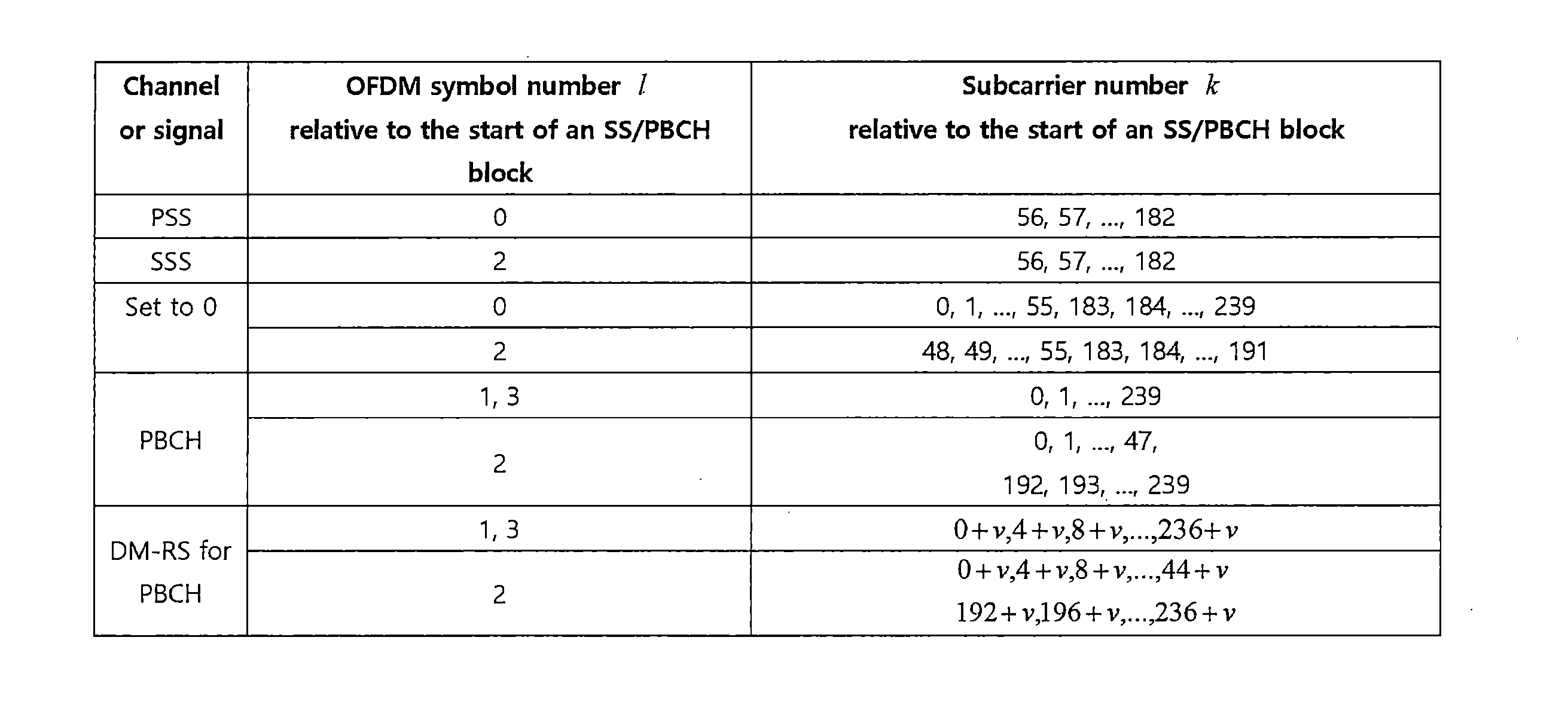
図4(a)を参照して、同期信号(synchronization signal、SS)をより詳しく説明する。同期信号はPSSとSSSに分けられる。PSSは、OFDMシンボル同期、スロット同期のような時間ドメイン同期及び/または周波数ドメイン同期を得るために使用される。SSSは、フレーム同期、セルグループIDを得るために使用される。図4(a)と表2を参照すると、SS/PBCHブロックは周波数軸に連続した20RBs(=240サブキャリア)からなり、時間軸に連続した4OFDMシンボルからなる。この際、SS/PBCHブロックにおいて、PSSは最初のOFDMシンボル、SSSは3番目のOFDMシンボルで56~182番目のサブキャリアを介して伝送される。ここで、SS/PBCHブロックの最も低いサブキャリアインデックスを0から付ける。PSSが伝送される最初のOFDMシンボルにおいて、残りのサブキャリア、つまり、0~55、183~239番目のサブキャリアを介しては基地局が信号を伝送しない。また、SSSが伝送される3番目のOFDMシンボルにおいて、48~55、183~191番目のサブキャリアを介しては基地局が信号を伝送しない。基地局は、SS/PBCHブロックにおいて、前記信号を除いた残りのREを介してPBCH(physical broadcast channel)を伝送する。 The synchronization signal (SS) will be explained in more detail with reference to FIG. 4(a). The synchronization signal is divided into PSS and SSS. PSS is used to obtain time domain synchronization and/or frequency domain synchronization such as OFDM symbol synchronization, slot synchronization. SSS is used to obtain frame synchronization, cell group ID. Referring to FIG. 4(a) and Table 2, the SS/PBCH block consists of 20 RBs (=240 subcarriers) continuous in the frequency axis and 4 OFDM symbols continuous in the time axis. At this time, in the SS/PBCH block, PSS is transmitted in the first OFDM symbol and SSS is transmitted in the third OFDM symbol via the 56th to 182nd subcarriers. Here, the lowest subcarrier index of the SS/PBCH block is assigned starting from 0. In the first OFDM symbol in which PSS is transmitted, the base station does not transmit signals through the remaining subcarriers, that is, the 0th to 55th and 183rd to 239th subcarriers. Furthermore, in the third OFDM symbol in which SSS is transmitted, the base station does not transmit signals via the 48th to 55th and 183rd to 191st subcarriers. The base station transmits a physical broadcast channel (PBCH) in the SS/PBCH block through the remaining REs excluding the signal.
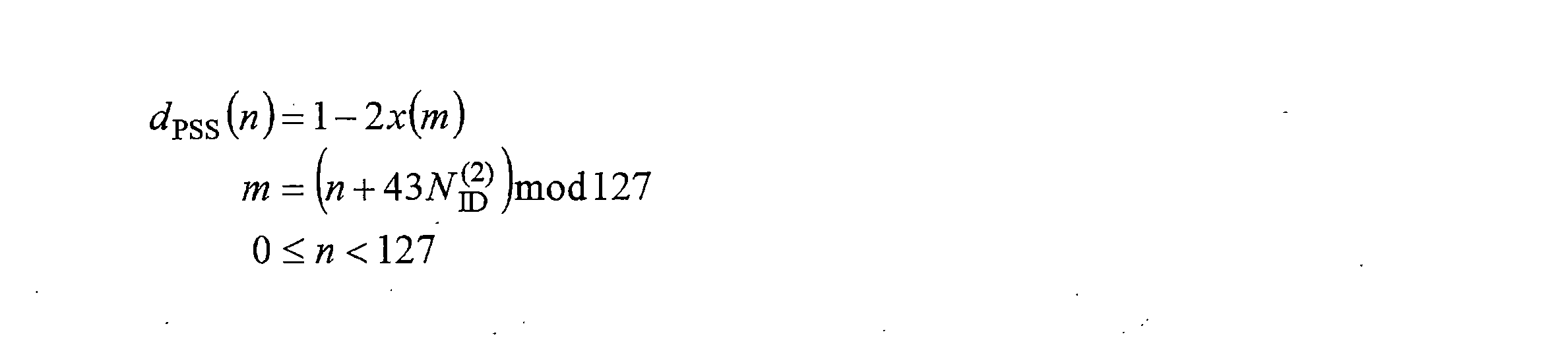
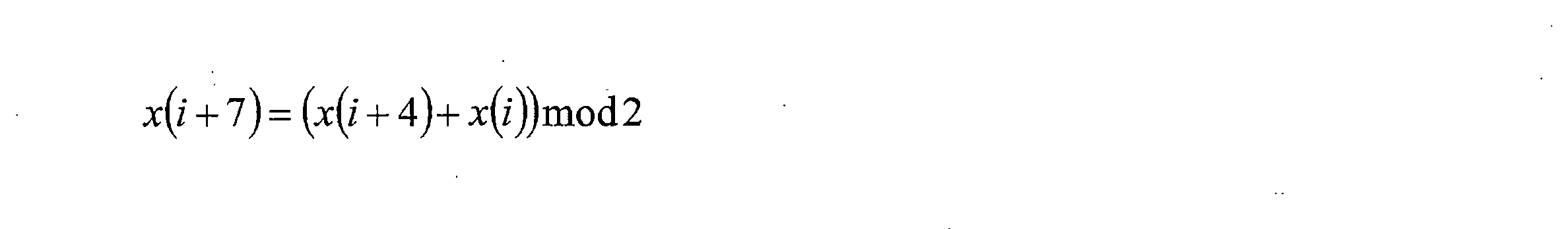
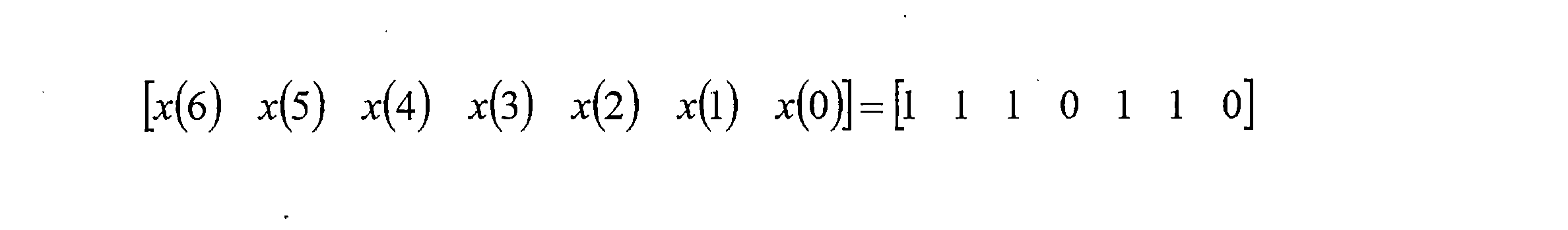
SSは3つのPSSとSSSの組み合わせを介して計1008個の固有の物理階層セル識別子(physical layer cell ID)を、詳しくは、それぞれの物理階層セルIDはたった一つの物理-階層セル-識別子グループの部分になるように、各グループが3つの固有の識別子を含む336個の物理-階層セル-識別子グループにグルーピングされる。よって、物理階層セルID Ncell ID=3N(1) ID+N(2) IDは、物理-階層セル-識別子グループを示す0から335までの範囲内のインデックスN(1) IDと、前記物理-階層セル-識別子グループ内の物理-階層識別子を示す0から2までのインデックスN(2) IDによって固有に定義される。端末はPSSを検出し、3つの固有の物理-階層識別子のうち一つを識別する。また、端末はSSSを検出し、前記物理-階層識別子に連関する336個の物理階層セルIDのうち一つを識別する。この際、PSSのシーケンスdPSS(n)は以下のようである。 The SS has a total of 1008 unique physical layer cell IDs through the combination of three PSSs and SSSs, in detail, each physical layer cell ID corresponds to only one physical layer cell ID group. are grouped into 336 physical-hierarchical cell-identifier groups, each group containing three unique identifiers, such that Therefore, the physical layer cell ID N cell ID =3N (1) ID +N (2) ID is an index N in the range from 0 to 335 indicating the physical layer cell identifier group (1) ID and the physical layer cell ID Uniquely defined by an index N (2) ID from 0 to 2 indicating the physical-hierarchy identifier within the hierarchy cell-identifier group. The terminal detects the PSS and identifies one of three unique physical-layer identifiers. The terminal also detects the SSS and identifies one of 336 physical layer cell IDs associated with the physical layer identifier. At this time, the PSS sequence d PSS (n) is as follows.
また、SSSのシーケンスdSSS(n)は以下のようである。 Further, the SSS sequence d SSS (n) is as follows.


10ms長さの無線フレームは、5ms長さの2つの半フレームに分けられる。図4(b)を参照して、各半フレーム内でSS/PBCHブロックが伝送されるスロットについて説明する。SS/PBCHブロックが伝送されるスロットは、ケースA、B、C、D、Eのうちいずれか一つである。ケースAにおいて、サブキャリア間隔は15kHzであり、SS/PBCHブロックの開始時点は{2、8}+14*n番目のシンボルである。この際、3GHz以下のキャリア周波数において、n=0、1である。また、3GHz超過6GHz以下のキャリア周波数において、n=0、1、2、3である。ケースBにおいて、サブキャリア間隔は30kHzであり、SS/PBCHブロックの開始時点は{4、8、16、20}+28*n番目のシンボルである。この際、3GHz以下のキャリア周波数において、n=0である。また、3GHz超過6GHz以下のキャリア周波数において、n=0、1である。ケースCにおいて、サブキャリア間隔は30kHzであり、SS/PBCHブロックの開始時点は{2、8}+14*n番目のシンボルである。この際、3GHz以下のキャリア周波数において、n=0、1である。また、3GHz超過6GHz以下のキャリア周波数において、n=0、1、2、3である。ケースDにおいて、サブキャリア間隔は120kHzであり、SS/PBCHブロックの開始時点は{4、8、16、20}+28*n番目のシンボルである。この際、6GHz以上のキャリア周波数において、n=0、1、2、3、5、6、7、8、10、11、12、13、15、16、17、18である。ケースEにおいて、サブキャリア間隔は240kHzであり、SS/PBCHブロックの開始時点は{8、12、16、20、32、36、40、44}+56*n番目のシンボルである。この際、6GHz以上のキャリア周波数において、n=0、1、2、3、5、6、7、8である。 A radio frame of 10 ms length is divided into two half-frames of 5 ms length. With reference to FIG. 4(b), slots in which SS/PBCH blocks are transmitted within each half frame will be described. The slot in which the SS/PBCH block is transmitted is one of cases A, B, C, D, and E. In case A, the subcarrier spacing is 15kHz and the start time of the SS/PBCH block is the {2,8}+14*nth symbol. At this time, n=0 and 1 at a carrier frequency of 3 GHz or less. Moreover, n=0, 1, 2, and 3 at carrier frequencies exceeding 3 GHz and below 6 GHz. In case B, the subcarrier spacing is 30kHz and the start time of the SS/PBCH block is the {4, 8, 16, 20}+28*nth symbol. At this time, n=0 at a carrier frequency of 3 GHz or less. Further, n=0 and 1 at carrier frequencies exceeding 3 GHz and below 6 GHz. In case C, the subcarrier spacing is 30kHz and the start time of the SS/PBCH block is the {2,8}+14*nth symbol. At this time, n=0 and 1 at a carrier frequency of 3 GHz or less. Moreover, n=0, 1, 2, and 3 at carrier frequencies exceeding 3 GHz and below 6 GHz. In case D, the subcarrier spacing is 120kHz and the start time of the SS/PBCH block is the {4, 8, 16, 20}+28*nth symbol. At this time, n=0, 1, 2, 3, 5, 6, 7, 8, 10, 11, 12, 13, 15, 16, 17, 18 at a carrier frequency of 6 GHz or higher. In case E, the subcarrier spacing is 240 kHz and the start time of the SS/PBCH block is the {8, 12, 16, 20, 32, 36, 40, 44}+56*nth symbol. At this time, n=0, 1, 2, 3, 5, 6, 7, and 8 at a carrier frequency of 6 GHz or higher.
図5は、3GPP NRシステムにおける制御情報及び制御チャネル伝送のための手順を示す図である。図5(a)を参照すると、基地局は制御情報(例えば、DCI)にRNTI(radio network temporary identifier)でマスク(例えば、XOR演算)されたCRC(cyclic redundancy check)を付加するS202。基地局は、各制御情報の目的/対象に応じて決定されるRNTI値でCRCをスクランブルする。一つ以上の端末が使用する共通RNTIは、SI-RNTI(system information RNTI)、P-RNTI(paging RNTI)、RA-RNTI(random access RNTI)、及びTPC-RNTI(transmit power control RNTI)のうち少なくともいずれか一つを含む。また、端末-特定RNTIは、C-RNTI(cell temporary RNTI)及びCS-RNTIのうち少なくともいずれか一つを含む。次に、基地局はチャネルエンコーディング(例えば、polar coding)を行ったS204後、PDCCH伝送のために使用された資源(ら)の量に合わせてレート-マッチング(rate-matching)をするS206。次に、基地局はCCE(control channel element)基盤のPDCCH構造に基づいて、DCI(ら)を多重化するS208。また、基地局は、多重化されたDCI(ら)に対してスクランブリング、モジュレーション(例えば、QPSK)、インターリービングなどの追加過程S210を適用した後、伝送しようとする資源にマッピングする。CCEはPDCCHのための基本資源単位であり、一つのCCEは複数(例えば、6つ)のREG(resource element group)からなる。一つのREGは複数(例えば、12個)のREからなる。一つのPDCCHのために使用されたCCEの個数を集成レベル(aggregation level)と定義する。3GPP NRシステムでは、1、2、4、8、または16の集成レベルを使用する。図5(b)はCCE集成レベルとPDCCHの多重化に関する図であり、一つのPDCCHのために使用されたCCE集成レベルの種類とそれによる制御領域で伝送されるCCE(ら)を示す。 FIG. 5 is a diagram illustrating a procedure for control information and control channel transmission in a 3GPP NR system. Referring to FIG. 5A, the base station adds a CRC (cyclic redundancy check) masked (for example, by XOR operation) using an RNTI (radio network temporary identifier) to control information (for example, DCI) in step S202. The base station scrambles the CRC with an RNTI value determined according to the purpose/object of each control information. Common RNTIs used by one or more terminals are SI-RNTI (system information RNTI), P-RNTI (paging RNTI), RA-RNTI (random access RNTI), and TPC-RNTI (transmit power con). Trol RNTI) Contains at least one of the following. Further, the terminal-specific RNTI includes at least one of a C-RNTI (cell temporary RNTI) and a CS-RNTI. Next, the base station performs channel encoding (eg, polar coding) in step S204, and then performs rate-matching in accordance with the amount of resources used for PDCCH transmission in step S206. Next, the base station multiplexes the DCI(s) based on a CCE (control channel element)-based PDCCH structure (S208). In addition, the base station applies additional processes S210 such as scrambling, modulation (eg, QPSK), and interleaving to the multiplexed DCI(s), and then maps the DCI(s) to resources to be transmitted. CCE is a basic resource unit for PDCCH, and one CCE consists of multiple (for example, six) REGs (resource element groups). One REG consists of a plurality of (for example, 12) REs. The number of CCEs used for one PDCCH is defined as an aggregation level. 3GPP NR systems use 1, 2, 4, 8, or 16 aggregation levels. FIG. 5B is a diagram regarding CCE aggregation levels and PDCCH multiplexing, and shows the types of CCE aggregation levels used for one PDCCH and the CCE(s) transmitted in the control area accordingly.
図6は、3GPP NRシステムにおけるPDCCHが伝送されるCORESETを示す図である。 FIG. 6 is a diagram illustrating a CORESET in which a PDCCH is transmitted in a 3GPP NR system.
CORESETは、端末のための制御信号であるPDCCHが伝送される時間-周波数資源である。また、後述する探索空間(search space)は一つのCORESETにマッピングされる。よって、端末はPDCCHを受信するために全ての周波数帯域をモニタリングするのではなく、CORESETと指定された時間-周波数領域をモニタリングして、CORESETにマッピングされたPDCCHをデコーディングする。基地局は、端末にセル別に一つまたは複数のCORESETを構成する。CORESETは、時間軸に最大3つまでの連続したシンボルからなる。また、CORESETは周波数軸に連続した6つのPRBの単位からなる。図5の実施例において、CORESET#1は連続的なPRBからなり、CORESET#2とCORESET#3は不連続的なPRBからなる。CORESETは、スロット内のいかなるシンボルにも位置し得る。例えば、図5の実施例において、CORESET#1はスロットの最初のシンボルから始まり、CORESET#2はスロットの5番目のシンボルから始まり、CORESET#9はスロットの9番目のシンボルから始まる。 CORESET is a time-frequency resource through which a PDCCH, which is a control signal for a terminal, is transmitted. Further, a search space (described later) is mapped to one CORESET. Therefore, the terminal does not monitor all frequency bands to receive the PDCCH, but rather monitors the time-frequency region designated as CORESET and decodes the PDCCH mapped to the CORESET. The base station configures one or more CORESETs for each cell in the terminal. CORESET consists of up to three consecutive symbols on the time axis. Further, the CORESET consists of six consecutive PRB units on the frequency axis. In the embodiment of FIG. 5, CORESET #1 consists of continuous PRBs, and CORESET #2 and CORESET #3 consist of discontinuous PRBs. CORESET may be located on any symbol within the slot. For example, in the example of FIG. 5, CORESET #1 begins with the first symbol of the slot, CORESET #2 begins with the fifth symbol of the slot, and CORESET #9 begins with the ninth symbol of the slot.
図7は、3GPP NRシステムにおけるPDCCH探索空間を設定する方法を示す図である。 FIG. 7 is a diagram illustrating a method of configuring a PDCCH search space in a 3GPP NR system.
端末にPDCCHを伝送するために、各CORESETには少なくとも一つ以上の探索空間が存在する。本発明の実施例において、探索空間は端末のPDCCHが伝送される全ての時間-周波数資源(以下、PDCCH候補)の集合である。探索空間は、3GPP NRの端末が共通に探索すべき共通探索空間(common search space)と、特定端末が探索すべき端末-特定探索空間(terminal-specific or UE-specific search space)を含む。共通探索空間では、同一基地局に属するセルにおける全ての端末が共通に探すように設定されているPDCCHをモニタリングする。また、端末-特定探索空間は、端末に応じて互いに異なる探索空間の位置で、各端末に割り当てられたPDCCHをモニタリングするように端末別に設定される。端末-特定探索空間の場合、PDCCHが割り当てられる制限された制御領域のため、端末間の探索空間が部分的に重なって割り当てられている可能性がある。PDCCHをモニタリングすることは、探索空間内のPDCCH候補をブラインドデコーディングすることを含む。ブラインドデコーディングに成功した場合をPDCCHが(成功的に)検出/受信されたと表現し、ブラインドデコーディングに失敗した場合をPDCCHが未検出/未受信されたと表現か、成功的に検出/受信されていないと表現する。 At least one search space exists in each CORESET to transmit the PDCCH to the terminal. In an embodiment of the present invention, the search space is a set of all time-frequency resources (hereinafter referred to as PDCCH candidates) on which a terminal's PDCCH is transmitted. The search space includes a common search space that 3GPP NR terminals should commonly search for, and a terminal-specific or UE-specific search space that a specific terminal should search for. In the common search space, a PDCCH that is commonly set to be searched by all terminals in cells belonging to the same base station is monitored. Further, the terminal-specific search space is set for each terminal so that the PDCCH assigned to each terminal is monitored at different search space positions depending on the terminal. In the case of a terminal-specific search space, due to the limited control area to which the PDCCH is allocated, the search spaces between the terminals may be allocated to partially overlap. Monitoring the PDCCH includes blind decoding PDCCH candidates within the search space. When blind decoding is successful, the PDCCH is expressed as (successfully) detected/received, and when blind decoding fails, it is expressed as the PDCCH is not detected/received. Express that it is not.
説明の便宜上、一つ以上の端末に下りリンク制御情報を伝送するために、一つ以上の端末が既に知っているグループ共通(group common、GC)RNTIでスクランブルされたPDCCHをグループ共通(GC)PDCCH、または共通PDCCHと称する。また、一つの特定端末に上りリンクスケジューリング情報または下りリンクスケジューリング情報を伝送するために、特定端末が既に知っている端末-特定RNTIでスクランブルされたPDCCHを端末-特定PDCCHと称する。前記共通PDCCHは共通探索空間に含まれ、端末-特定PDCCHは共通探索空間または端末-特定PDCCHに含まれる。 For convenience of explanation, in order to transmit downlink control information to one or more terminals, a PDCCH scrambled with a group common (GC) RNTI that is already known to one or more terminals is used as a group common (GC). It is called PDCCH or common PDCCH. In addition, a PDCCH scrambled with a terminal-specific RNTI that the specific terminal already knows in order to transmit uplink scheduling information or downlink scheduling information to one specific terminal is referred to as a terminal-specific PDCCH. The common PDCCH is included in a common search space, and the terminal-specific PDCCH is included in a common search space or terminal-specific PDCCH.
基地局は、PDCCHを介して伝送チャネルであるPCH(paging channel)及びDL-SCH(downlink-shared channel)の資源割当に関する情報(つまり、DL Grant)、またはUL-SCH(uplink-shared channel)の資源割当とHARQ(hybrid automatic repeat request)に関する情報(つまり、UL Grant)を各端末または端末グループに知らせる。基地局は、PCH伝送ブロック、及びDL-SCH伝送ブロックをPDSCHを介して伝送する。基地局は、特定制御情報または特定サービスデータを除いたデータをPDSCHを介して伝送する。また、端末は、特定制御情報または特定サービスデータを除いたデータをPDSCHを介して受信する。 The base station receives information regarding resource allocation (that is, DL Grant) for the transmission channels PCH (paging channel) and DL-SCH (downlink-shared channel) via the PDCCH, or information for the UL-SCH (uplink-shared channel). Information regarding resource allocation and HARQ (hybrid automatic repeat request) (ie, UL Grant) is notified to each terminal or terminal group. The base station transmits the PCH transport block and the DL-SCH transport block via the PDSCH. The base station transmits data excluding specific control information or specific service data via the PDSCH. Further, the terminal receives data excluding specific control information or specific service data via the PDSCH.
基地局は、PDSCHのデータがいかなる端末(一つまたは複数の端末)に伝送されるのか、該当端末がいかにPDSCHデータを受信しデコーディングすべきなのかに関する情報をPDCCHに含ませて伝送する。例えば、特定PDCCHを介して伝送されるDCIが「A」というRNTIでCRCマスキングされており、そのDCIが「B」という無線資源(例えば、周波数位置)にPDSCHが割り当てられていることを指示し、「C」という伝送形式情報(例えば、伝送ブロックのサイズ、変調方式、コーディング情報など)を指示すると仮定する。端末は、自らが有するRNTI情報を利用してPDCCHをモニタリングする。この場合、「A」RNTIを使用してPDCCHをブラインドデコーディングする端末があれば、該当端末はPDCCHを受信し、受信したPDCCHの情報を介して「B」と「C」によって指示されるPDSCHを受信する。 The base station transmits the PDCCH by including information regarding which terminal (one or more terminals) the PDSCH data is transmitted to and how the corresponding terminal should receive and decode the PDSCH data. For example, if the DCI transmitted via a specific PDCCH is CRC-masked with an RNTI of "A", that DCI indicates that the PDSCH is allocated to a radio resource (e.g., frequency location) of "B". , “C” (eg, transmission block size, modulation scheme, coding information, etc.). The terminal monitors the PDCCH using its own RNTI information. In this case, if there is a terminal that blind decodes the PDCCH using the "A" RNTI, the corresponding terminal receives the PDCCH and uses the received PDCCH information to decode the PDSCH indicated by "B" and "C". receive.
表3は、無線通信システムで使用されるPUCCHの一実施例を示す。 Table 3 shows one example of a PUCCH used in a wireless communication system.
PUCCHは、以下の上りリンク制御情報(UCI)を伝送するのに使用される。 PUCCH is used to transmit the following uplink control information (UCI).
-SR(Scheduling Request):上りリンクUL-SCH資源を要請するのに使用される情報である。 - SR (Scheduling Request): Information used to request uplink UL-SCH resources.
-HARQ-ACK:(DL SPS releaseを指示する)PDCCHに対する応答及び/またはPDSCH上の上りリンク伝送ブロック(transport block、TB)に対する応答である。HARQ-ACKは、PDCCHまたはPDSCHを介して伝送された情報の受信可否を示す。HARQ-ACK応答は、ポジティブACK(簡単に、ACK)、ネガティブACK(以下、NACK)、DTX(Discontinuous Transmission)、またはNACK/DTXを含む。ここで、HARQ-ACKという用語は、HARQ-ACK/NACK、ACK/NACKと混用される。一般に、ACKはビット値1で表され、NACKはビット値0で表される。 - HARQ-ACK: Response to PDCCH (indicating DL SPS release) and/or response to uplink transport block (TB) on PDSCH. HARQ-ACK indicates whether information transmitted via PDCCH or PDSCH can be received. HARQ-ACK responses include positive ACK (simply ACK), negative ACK (hereinafter NACK), DTX (Discontinuous Transmission), or NACK/DTX. Here, the term HARQ-ACK is used interchangeably with HARQ-ACK/NACK and ACK/NACK. Generally, an ACK is represented by a bit value of 1, and a NACK is represented by a bit value of 0.
-CSI:下りリンクチャネルに対するフィードバック情報である。基地局が伝送するCSI-RS(Reference Signal)に基づいて端末が生成する。MIMO(multiple input multiple output)-関連フィードバック情報は、RI及びPMIを含む。CSIは、CSIが示す情報に応じてCSIパート1とCSIパート2に分けられる。 - CSI: Feedback information for downlink channels. The terminal generates the CSI-RS based on the CSI-RS (Reference Signal) transmitted by the base station. MIMO (multiple input multiple output)-related feedback information includes RI and PMI. CSI is divided into CSI part 1 and CSI part 2 depending on the information indicated by the CSI.
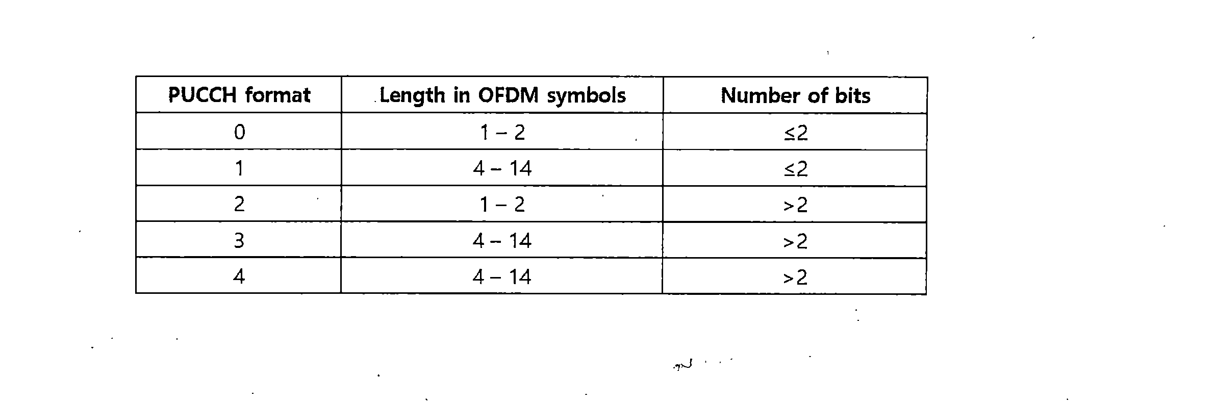
3GPP NRシステムでは、多様なサービスシナリオと多様なチャネル環境、及びフレーム構造を支援するために、5つのPUCCHフォーマットが使用される。 In the 3GPP NR system, five PUCCH formats are used to support various service scenarios and various channel environments and frame structures.
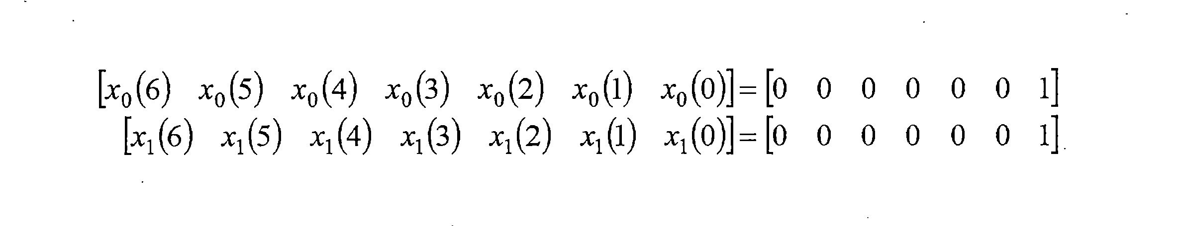
PUCCHフォーマット0は、1ビットまたは2ビットHARQ-ACK情報またはSRを伝達するフォーマットである。PUCCHフォーマット0は、時間軸に1つまたは2つのOFDMシンボルと、周波数軸に1つのPRBを介して伝送される。PUCCHフォーマット0が2つのOFDMシンボルで伝送されれば、2つのシンボルに同じシーケンスが互いに異なるRBで伝送される。この際、シーケンスはPUCCHフォマード0に使用されるベースシーケンス(base sequence)からサイクリックシフト(cyclic shift、CS)されたシーケンスである。これを介し、端末は周波数ダイバーシティゲイン(diversity gain)を得る。詳しくは、端末はMbitビットUCI(Mbit=1or2)によってサイクリックシフト(CS)値mcsを決定する。また、長さが12のベースシーケンスを決められたCS値mcsに基づいてサイクリックシフトしたシーケンスを1つのOFDMシンボル及び1つのRBの12個のREsにマッピングして伝送する。端末が使用可能なサイクリックシフトの数が12個で、Mbit=1であれば、1bit UCI0と1は、それぞれサイクリックシフト値の差が6である2つのサイクリックシフトされたシーケンスにマッピングされる。また、Mbit=2であれば、2bits UCI00、01、11、10は、それぞれサイクリックシフト値の差が3である4つのサイクリックシフトされたシーケンスにマッピングされる。 PUCCH format 0 is a format that conveys 1-bit or 2-bit HARQ-ACK information or SR. PUCCH format 0 is transmitted via one or two OFDM symbols in the time axis and one PRB in the frequency axis. If PUCCH format 0 is transmitted in two OFDM symbols, the same sequence is transmitted in two symbols in different RBs. At this time, the sequence is a sequence that is cyclically shifted (CS) from the base sequence used for PUCCH format 0. Through this, the terminal obtains frequency diversity gain. Specifically, the terminal determines the cyclic shift (CS) value m cs by M bit bit UCI (M bit = 1 or 2). In addition, a sequence obtained by cyclically shifting a base sequence having a length of 12 based on a determined CS value m cs is mapped onto 12 REs of one OFDM symbol and one RB, and then transmitted. If the number of cyclic shifts available to the terminal is 12 and M bit = 1, then 1 bit UCI 0 and 1 map to two cyclic shifted sequences, each with a difference in cyclic shift values of 6. be done. Furthermore, if M bit =2, 2 bits UCI00, 01, 11, and 10 are mapped to four cyclically shifted sequences, each of which has a cyclic shift value difference of 3.
PUCCHフォーマット1は、1ビットまたは2ビットHARQ-ACK情報またはSRを伝達する。PUCCHフォーマット1は、時間軸に連続的なOFDMシンボルと、周波数軸に1つのPRBを介して伝送される。ここで、PUCCHフォーマット1が占めるOFDMシンボルの数は4~14のうち一つである。より詳しくは、Mbit=1であるUCIはBPSKでモジュレーションされる。端末は、Mbit=2であるUCIをQPSK(quadrature phase shift keying)でモジュレーションされる。モジュレーションされた複素数シンボル(complex valued symbol)d(0)に長さ12のシーケンスをかけて信号を得る。この際、シーケンスはPUCCHフォマード0に使用されるベースシーケンスである。端末は、得られた信号をPUCCHフォーマット1が割り当てられた偶数番目のOFDMシンボルに、時間軸OCC(orthogonal cover code)でスプレディング(spreading)して伝送する。PUCCHフォーマット1は、使用するOCCの長さに応じて同じRBで多重化される互いに異なる端末の最大数が決められる。PUCCHフォーマット1の奇数番目OFDMシンボルには、DMRS(demodulation reference signal)がOCCでスプレディングされてマッピングされる。 PUCCH format 1 conveys 1-bit or 2-bit HARQ-ACK information or SR. PUCCH format 1 is transmitted via continuous OFDM symbols in the time axis and one PRB in the frequency axis. Here, the number of OFDM symbols occupied by PUCCH format 1 is one from 4 to 14. More specifically, the UCI with M bit =1 is modulated with BPSK. The terminal modulates the UCI with M bit = 2 using quadrature phase shift keying (QPSK). A signal is obtained by multiplying the modulated complex valued symbol d(0) by a sequence of length 12. At this time, the sequence is a base sequence used for PUCCH format 0. The terminal spreads the obtained signal on even-numbered OFDM symbols to which PUCCH format 1 is assigned using a time axis OCC (orthogonal cover code) and transmits the signal. In PUCCH format 1, the maximum number of different terminals that can be multiplexed in the same RB is determined depending on the length of the OCC used. A DMRS (demodulation reference signal) is spread and mapped to the odd-numbered OFDM symbol of PUCCH format 1 using OCC.
PUCCHフォーマット2は、2ビットを超過するUCIを伝達する。PUCCHフォーマット2は、時間軸に1つまたは2つのOFDMシンボルと、周波数軸に1つまたは複数個のRBを介して伝送される。PUCCHフォーマット2が2つのOFDMシンボルで伝送されれば、2つのOFDMシンボルを介して同じシーケンスが互いに異なるRBで伝送される。ここで、シーケンスは複数のモジュレーションされた複素数シンボルd(0)、…、d(Msymbol-1)である。ここで、MsymbolはMbit/2である。これを介し、端末は周波数ダイバーシティゲインを得る。より詳しくは、MbitビットUCI(Mbit>2)はビット-レベルスクランブリングされ、QPSKモジュレーションされて1つまたは2つのOFDMシンボル(ら)のRB(ら)にマッピングされる。ここで、RBの数は1~16のうち一つである。 PUCCH format 2 conveys UCI of more than 2 bits. PUCCH format 2 is transmitted via one or two OFDM symbols in the time axis and one or more RBs in the frequency axis. If PUCCH format 2 is transmitted using two OFDM symbols, the same sequence is transmitted in different RBs through two OFDM symbols. Here, the sequence is a plurality of modulated complex symbols d(0),...,d(M symbol -1). Here, M symbol is M bit /2. Through this, the terminal obtains frequency diversity gain. More specifically, the M bit bit UCI (M bit >2) is bit-level scrambled, QPSK modulated and mapped to the RB(s) of one or two OFDM symbol(s). Here, the number of RBs is one from 1 to 16.
PUCCHフォーマット3またはPUCCHフォーマット4は、2ビットを超過するUCIを伝達する。PUCCHフォーマット3またはPUCCHフォーマット4は、時間軸に連続的なOFDMシンボルと、周波数軸に1つのPRBを介して伝送される。PUCCHフォーマット3またはPUCCHフォーマット4が占めるOFDMシンボルの数は4~14のうち一つである。詳しくは、端末は、MbitビットUCI(Mbit>2)をπ/2-BPSK(Binary Phase Shift Keying)またはQPSKでモジュレーションし、複素数シンボルd(0)~d(Msymb-1)を生成する。ここで、π/2-BPSKを使用するとMsymb=Mbitであり、QPSKを使用するとMsymb=Mbit/2である。端末は、PUCCHフォーマット3にブロック-単位スプレディングを適用しない。但し、端末は、PUCCHフォーマット4が2つまたは4つの多重化容量(multiplexing capacity)を有するように、長さ-12のPreDFT-OCCを使用して1つのRB(つまり、12subcarriers)にブロック-単位スプレディングを適用してもよい。端末は、スプレディングされた信号を伝送プリコーディング(transmit precoding)(またはDFT-precoding)し、各REにマッピングして、スプレディングされた信号を伝送する。 PUCCH format 3 or PUCCH format 4 conveys a UCI of more than 2 bits. PUCCH format 3 or PUCCH format 4 is transmitted via continuous OFDM symbols in the time axis and one PRB in the frequency axis. The number of OFDM symbols occupied by PUCCH format 3 or PUCCH format 4 is one between 4 and 14. Specifically, the terminal modulates M bit UCI (M bit > 2) with π/2-BPSK (Binary Phase Shift Keying) or QPSK to generate complex symbols d(0) to d (M symb -1). do. Here, when using π/2-BPSK, M symb = M bit , and when using QPSK, M symb = M bit /2. The terminal does not apply block-wise spreading to PUCCH format 3. However, the terminal uses a PreDFT-OCC of length -12 to divide blocks into one RB (i.e., 12 subcarriers) so that PUCCH format 4 has a multiplexing capacity of 2 or 4. Spreading may also be applied. The terminal performs transmit precoding (or DFT-precoding) on the spread signal, maps it to each RE, and transmits the spread signal.
この際、PUCCHフォーマット2、PUCCHフォーマット3、またはPUCCHフォーマット4が占めるRBの数は、端末が伝送するUCIの長さと最大コードレート(code rate)に応じて決定される。端末がPUCCHフォーマット2を使用すれば、端末はPUCCHを介してHARQ-ACK情報及びCSI情報を共に伝送する。もし、端末が伝送し得るRBの数がPUCCHフォーマット2、PUCCHフォーマット3、またはPUCCHフォーマット4が使用し得る最大RBの数より大きければ、端末はUCI情報の優先順位に応じて一部のUCI情報は伝送せず、残りのUCI情報のみ伝送する。 At this time, the number of RBs occupied by PUCCH format 2, PUCCH format 3, or PUCCH format 4 is determined according to the length of UCI and the maximum code rate (code rate) transmitted by the terminal. If the terminal uses PUCCH format 2, the terminal transmits both HARQ-ACK information and CSI information via the PUCCH. If the number of RBs that the terminal can transmit is larger than the maximum number of RBs that can be used by PUCCH format 2, PUCCH format 3, or PUCCH format 4, the terminal transmits some UCI information according to the priority of the UCI information. is not transmitted, and only the remaining UCI information is transmitted.
PUCCHフォーマット1、PUCCHフォーマット3、またはPUCCHフォーマット4がスロット内で周波数ホッピング(frequency hopping)を指示するように、RRC信号を介して構成される。周波数ホッピングが構成される際、周波数ホッピングするRBのインデックスはRRC信号からなる。PUCCHフォーマット1、PUCCHフォーマット3、またはPUCCHフォーマット4が時間軸でN個のOFDMシンボルにわたって伝送されれば、最初のホップ(hop)はfloor(N/2)個のOFDMシンボルを有し、2番目のホップはceil(N/2)個のOFDMシンボルを有する。 PUCCH format 1, PUCCH format 3, or PUCCH format 4 is configured via an RRC signal to indicate frequency hopping within a slot. When frequency hopping is configured, the index of the frequency hopping RB consists of the RRC signal. If PUCCH format 1, PUCCH format 3, or PUCCH format 4 is transmitted over N OFDM symbols in the time axis, the first hop has floor(N/2) OFDM symbols, and the second hop has ceil(N/2) OFDM symbols.
PUCCHフォーマット1、PUCCHフォーマット3、またはPUCCHフォーマット4は、複数のスロットに繰り返し伝送さ得るように構成される。この際、PUCCHが繰り返し伝送されるスロットの個数KはRRC信号によって構成される。繰り返し伝送されるPUCCHは、各スロット内で同じ位置のOFDMシンボルから始まり、同じ長さを有するべきである。端末がPUCCHを伝送すべきスロットのOFDMシンボルのうちいずれか一つのOFDMシンボルでもRRC信号によってDLシンボルと指示されれば、端末はPUCCHを該当スロットから伝送せず、次のスロットに延期して伝送する。 PUCCH format 1, PUCCH format 3, or PUCCH format 4 is configured to be repeatedly transmitted in a plurality of slots. At this time, the number K of slots in which the PUCCH is repeatedly transmitted is configured by the RRC signal. Repeatedly transmitted PUCCHs should start from the OFDM symbol at the same position within each slot and have the same length. If any one of the OFDM symbols in the slot in which the terminal should transmit PUCCH is designated as a DL symbol by the RRC signal, the terminal does not transmit PUCCH from the corresponding slot, but postpones transmission to the next slot. do.
一方、3GPP NRシステムにおいて、端末はキャリア(またはセル)の帯域幅より小さいか同じ帯域幅を利用して送受信を行う。そのために、端末はキャリア帯域幅のうち一部の連続的な帯域幅からなるBWP(bandwidth part)を構成される。TDDに応じて動作するかまたはアンペアドスペクトルで動作する端末は、一つのキャリア(またはセル)に最大4つのDL/UL BWPペア(pairs)を構成される。また、端末は一つのDL/UL BWPペアを活性化する。FDDに応じて動作するかまたはペアドスペクトルで動作する端末は、下りリンクキャリア(またはセル)に最大4つのDL BWPを構成され、上りリンクキャリア(またはセル)に最大4つのUL BWPを構成される。端末は、各キャリア(またはセル)ごとに一つのDL BWPとUL BWPを活性化する。端末は、活性化されたBWP以外の時間-周波数資源から受信するか送信しなくてもよい。活性化されたBWPをアクティブBWPと称する。 On the other hand, in the 3GPP NR system, a terminal performs transmission and reception using a bandwidth that is smaller than or equal to the bandwidth of a carrier (or cell). To this end, the terminal is configured with a BWP (bandwidth part) consisting of a continuous bandwidth of a portion of the carrier bandwidth. A terminal operating according to TDD or operating in the unpaired spectrum is configured with up to four DL/UL BWP pairs in one carrier (or cell). The terminal also activates one DL/UL BWP pair. A terminal operating according to FDD or operating on a paired spectrum may be configured with up to four DL BWPs on the downlink carrier (or cell) and up to four UL BWPs on the uplink carrier (or cell). Ru. The terminal activates one DL BWP and one UL BWP for each carrier (or cell). A terminal may not receive or transmit from time-frequency resources other than the activated BWP. The activated BWP is referred to as an active BWP.
基地局は、端末が構成されたBWPのうち活性化されたBWPをDCIを介して指示する。DCIを介して指示したBWPは活性化され、他の構成されたBWP(ら)は非活性化される。TDDで動作するキャリア(またはセル)において、基地局は端末のDL/UL BWPペアを変えるために、PDSCHまたはPUSCHをスケジューリングするDCIに活性化されるBWPを指示するBPI(bandwidth part indicator)を含ませる。端末は、PDSCHまたはPUSCHをスケジューリングするDCIを受信し、BPIに基づいて活性化されるDL/UL BWPペアを識別する。FDDで動作する下りリンクキャリア(またはセル)の場合、基地局は端末のDL BWPを変えるために、PDSCHをスケジューリングするDCIに活性化されるBWPを知らせるBPIを含ませる。FDDで動作する上りリンクキャリア(またはセル)の場合、基地局は端末のUL BWPを変えるために、PUSCHをスケジューリングするDCIに活性化されるBWPを指示するBPIを含ませる。 The base station instructs the activated BWP among the BWPs in which the terminal is configured via the DCI. The BWP designated via the DCI is activated, and the other configured BWP(s) are deactivated. In a carrier (or cell) operating in TDD, the base station includes a BPI (bandwidth part indicator) that instructs the DCI that schedules PDSCH or PUSCH to activate BWP in order to change the DL/UL BWP pair of the terminal. let The terminal receives the DCI scheduling PDSCH or PUSCH and identifies the DL/UL BWP pair to be activated based on the BPI. In the case of a downlink carrier (or cell) operating in FDD, in order to change the DL BWP of the terminal, the base station includes a BPI that indicates the activated BWP in the DCI that schedules the PDSCH. In the case of an uplink carrier (or cell) operating in FDD, in order to change the UL BWP of the terminal, the base station includes a BPI indicating the activated BWP in the DCI that schedules the PUSCH.
図8は、キャリア集成を説明する概念図である。 FIG. 8 is a conceptual diagram illustrating carrier aggregation.
キャリア集成とは、無線通信システムがより広い周波数帯域を使用するために、端末が上りリンク資源(またはコンポーネントキャリア)及び/または下りリンク資源(またはコンポーネントキャリア)からなる周波数ブロック、または(論理的意味の)セルを複数個使用して一つの大きい論理周波数帯域で使用する方法を意味する。一つのコンポーネントキャリアは、PCell(Primary cell)またはSCell(Secondary Cell)、またはPSCell(Primary SCell)という用語で称される。但し、以下では説明の便宜上、コンポーネントキャリアという用語に統一する。 Carrier aggregation refers to a frequency block consisting of uplink resources (or component carriers) and/or downlink resources (or component carriers), or This refers to a method of using multiple cells in one large logical frequency band. One component carrier is referred to as a PCell (Primary cell), an SCell (Secondary Cell), or a PSCell (Primary SCell). However, for convenience of explanation, the term "component carrier" will be used hereinafter.
図8を参照すると、3GPP NRシステムの一例示として、全体システム帯域は最大16個のコンポーネントキャリアを含み、それぞれのコンポーネントキャリアは最大400MHzの帯域幅を有する。コンポーネントキャリアは、一つ以上の物理的に連続するサブキャリアを含む。図8ではそれぞれのコンポーネントキャリアがいずれも同じ帯域幅を有するように示したが、これは例示に過ぎず、それぞれのコンポーネントキャリアは互いに異なる帯域幅を有してもよい。また、それぞれのコンポーネントキャリアは周波数軸で互いに隣接しているように示したが、前記図面は論理的な概念で示したものであって、それぞれのコンポーネントキャリアは物理的に互いに隣接してもよく、離れていてもよい。 Referring to FIG. 8, as an example of a 3GPP NR system, the overall system band includes up to 16 component carriers, and each component carrier has a bandwidth of up to 400 MHz. A component carrier includes one or more physically contiguous subcarriers. Although each component carrier is shown to have the same bandwidth in FIG. 8, this is only an example, and each component carrier may have different bandwidths. Further, although the respective component carriers are shown as being adjacent to each other in the frequency axis, the drawings are shown based on a logical concept, and the respective component carriers may be physically adjacent to each other. , may be far apart.
それぞれのコンポーネントキャリアにおいて、互いに異なる中心周波数が使用される。また、物理的に隣接したコンポーネントキャリアにおいて、共通した一つの中心周波数が使用される。図8の実施例において、全てのコンポーネントキャリアが物理的に隣接していると仮定すれば、全てのコンポーネントキャリアで中心周波数Aが使用される。また、それぞれのコンポーネントキャリアが物理的に隣接していないと仮定すれば、コンポーネントキャリアそれぞれにおいて中心周波数A、中心周波数Bが使用される。 Different center frequencies are used in each component carrier. Further, one common center frequency is used in physically adjacent component carriers. In the example of FIG. 8, center frequency A is used for all component carriers, assuming that all component carriers are physically adjacent. Furthermore, assuming that the respective component carriers are not physically adjacent, center frequency A and center frequency B are used for each component carrier.
キャリア集成で全体のシステム帯域が拡張されれば、各端末との通信に使用される周波数帯域はコンポーネントキャリア単位に定義される。端末Aは全体のシステム帯域である100MHzを使用し、5つのコンポーネントキャリアをいずれも使用して通信を行う。端末B1~B5は20MHzの帯域幅のみを使用し、一つのコンポーネントキャリアを使用して通信を行う。端末C1及びC2は40MHzの帯域幅のみを使用し、それぞれ2つのコンポーネントキャリアを利用して通信を行う。2つのコンポーネントキャリアは、論理/物理的に隣接するか隣接しない。図8の実施例では、端末C1が隣接していない2つのコンポーネントキャリアを使用し、端末C2が隣接した2つのコンポーネントキャリアを使用する場合を示す。 If the overall system band is expanded by carrier aggregation, the frequency band used for communication with each terminal is defined for each component carrier. Terminal A uses the entire system band of 100 MHz and communicates using all five component carriers. Terminals B 1 to B 5 communicate using only a 20 MHz bandwidth and one component carrier. Terminals C 1 and C 2 use only a 40 MHz bandwidth and communicate using two component carriers each. Two component carriers may be logically/physically adjacent or non-adjacent. The example of FIG. 8 shows a case where terminal C 1 uses two non-adjacent component carriers and terminal C 2 uses two adjacent component carriers.
図9は、端末キャリア通信と多重キャリア通信を説明するための図である。特に、図9(a)は単一キャリアのサブフレーム構造を示し、図9(b)は多重キャリアのサブフレーム構造を示す。 FIG. 9 is a diagram for explaining terminal carrier communication and multicarrier communication. In particular, FIG. 9(a) shows a single carrier subframe structure, and FIG. 9(b) shows a multicarrier subframe structure.
図9(a)を参照すると、一般的な無線通信システムはFDDモードの場合一つのDL帯域とそれに対応する一つのUL帯域を介してデータ伝送または受信を行う。他の具体的な実施例において、無線通信システムはTDDモードの場合、無線フレームを時間ドメインで上りリンク時間ユニットと下りリンク時間ユニットに区分し、上り/下りリンク時間ユニットを介してデータ伝送または受信を行う。図9(b)を参照すると、UL及びDLにそれぞれ3つの20MHzコンポーネントキャリア(component carrier、CC)が集まって、60MHzの帯域幅が支援される。それぞれのCCは、周波数ドメインで互いに隣接するか非-隣接する。図9(b)は、便宜上UL CCの帯域幅とDL CCの帯域幅がいずれも同じで対称な場合を示したが、各CCの帯域幅は独立的に決められてもよい。また、UL CCの個数とDL CCの個数が異なる非対称のキャリア集成も可能である。RRCを介して特定端末に割当/構成されたDL/UL CCを特定端末のサービング(serving)DL/UL CCと称する。 Referring to FIG. 9A, a typical wireless communication system transmits or receives data through one DL band and one corresponding UL band in the FDD mode. In another specific embodiment, in the TDD mode, the wireless communication system divides the radio frame into an uplink time unit and a downlink time unit in the time domain, and transmits or receives data through the uplink/downlink time unit. I do. Referring to FIG. 9(b), three 20 MHz component carriers (CCs) are gathered in each of the UL and DL to support a 60 MHz bandwidth. Each CC is adjacent or non-adjacent to each other in the frequency domain. For convenience, FIG. 9B shows a case where the bandwidth of the UL CC and the bandwidth of the DL CC are both the same and symmetrical, but the bandwidth of each CC may be determined independently. It is also possible to have an asymmetric carrier assembly in which the number of UL CCs and the number of DL CCs are different. A DL/UL CC allocated/configured to a specific terminal via RRC is referred to as a serving DL/UL CC of the specific terminal.
基地局は、端末のサービングCCのうち一部または全部と活性化(activate)するか一部のCCを非活性化(deactivate)して、端末と通信を行う。基地局は、活性化/非活性化されるCCを変更してもよく、活性化/非活性化されるCCの個数を変更してもよい。基地局が端末に利用可能なCCをセル-特定または端末-特定に割り当てると、端末に対するCC割当が全面的に再構成されるか端末がハンドオーバー(handover)しない限り、一旦割り当てられたCCのうち少なくとも一つは非活性化されなくてもよい。端末に非活性化されない一つのCを主CC(primary CC、PCC)またはPCell(primary cell)と称し、基地局が自由に活性化/非活性化されるCCを副CC(secondary CC、SCC)またはSCell(secondary cell)と称する。 A base station communicates with a terminal by activating some or all of the serving CCs of the terminal, or by deactivating some CCs. The base station may change CCs to be activated/deactivated, or may change the number of CCs to be activated/deactivated. When a base station allocates available CCs to a terminal in a cell-specific or terminal-specific manner, the assigned CCs are At least one of them does not need to be deactivated. One C that is not deactivated by the terminal is called a primary CC (primary CC, PCC) or PCell (primary cell), and a CC that can be activated/deactivated freely by the base station is called a secondary CC (secondary CC, SCC). Or called SCell (secondary cell).
一方、3GPP NRは無線資源を管理するためにセル(cell)の概念を使用する。セルは、下りリンク資源と上りリンク資源の組み合わせ、つまり、DL CCとUL CCの組み合わせと定義される。セルは、DL資源単独、またはDL資源とUL資源の組み合わせからなる。キャリア集成が支援されれば、DL資源(または、DL CC)のキャリア周波数とUL資源(または、UL CC)のキャリア周波数との間のリンケージ(linkage)はシステム情報によって指示される。キャリア周波数とは、各セルまたはCCの中心周波数を意味する。PCCに対応するセルをPCellと称し、SCCに対応するセルをSCellと称する。下りリンクにおいてPCellに対応するキャリアはDL PCCであり、上りリンクにおいてPCellに対応するキャリアはUL PCCである。類似して、下りリンクにおいてSCellに対応するキャリアはDL SCCであり、上りリンクにおいてSCellに対応するキャリアはUL SCCである。端末性能(capacity)に応じて、サービングセル(ら)は一つのPCellと0以上のSCellからなる。RRC_CONNECTED状態にあるがキャリア集成が設定されていないか、キャリア集成を支援しないUEの場合、PCellのみからなるサービングセルがたった一つ存在する。 On the other hand, 3GPP NR uses the concept of a cell to manage radio resources. A cell is defined as a combination of downlink resources and uplink resources, that is, a combination of DL CC and UL CC. A cell consists of DL resources alone or a combination of DL resources and UL resources. If carrier aggregation is supported, the linkage between carrier frequencies of DL resources (or DL CCs) and carrier frequencies of UL resources (or UL CCs) is indicated by system information. Carrier frequency means the center frequency of each cell or CC. A cell corresponding to PCC is referred to as PCell, and a cell corresponding to SCC is referred to as SCell. The carrier corresponding to PCell in the downlink is DL PCC, and the carrier corresponding to PCell in uplink is UL PCC. Similarly, the carrier corresponding to the SCell in the downlink is the DL SCC, and the carrier corresponding to the SCell in the uplink is the UL SCC. Depending on the terminal capacity, the serving cell(s) consists of one PCell and zero or more SCells. For a UE in RRC_CONNECTED state but without carrier aggregation configured or not supporting carrier aggregation, there is only one serving cell consisting only of PCells.
上述したように、キャリア集成で使用されるセルという用語は、一つの基地局または一つのアンテナグループによって通信サービスが提供される一定の地理的領域を称するセルという用語とは区分される。つまり、一つのコンポーネントキャリアは、スケジューリングセル、スケジュールドセル、PCell、SCell、またはPSCellという用語で称される。但し、一定の地理的領域を称するセルとキャリア集成のセルを区分するために、本発明ではキャリア集成のセルをCCと称し、地理的領域のセルをセルと称する。 As mentioned above, the term cell as used in carrier aggregation is distinguished from the term cell, which refers to a certain geographic area served by one base station or one antenna group. That is, one component carrier is referred to as a scheduling cell, scheduled cell, PCell, SCell, or PSCell. However, in order to distinguish between a cell that refers to a certain geographical area and a cell that is a carrier aggregation, in the present invention, a carrier aggregation cell is called a CC, and a cell that is a geographical area is called a cell.
図10は、クロスキャリアスケジューリング技法が適用される例を示す図である。クロスキャリアスケジューリングが設定されれば、第1CCを介して伝送される制御チャネルはキャリア指示子フィールド(carrier indicator field、CIF)を利用して、第1CCまたは第2CCを介して伝送されるデータチャネルをスケジューリングする。CIFはDCI内に含まれる。言い換えると、スケジューリングセル(scheduling cell)が設定され、スケジューリングセルのPDCCH領域から伝送されるDLグラント/ULグラントは、被スケジューリングセル(scheduled cell)のPDSCH/PUSCHをスケジューリングする。つまり、複数のコンポーネントキャリアに対する検索領域がスケジューリングセルのPDCCH領域が存在する。PCellは基本的にスケジューリングセルであり、特定SCellが上位階層によってスケジューリングセルと指定される。 FIG. 10 is a diagram illustrating an example to which the cross-carrier scheduling technique is applied. When cross-carrier scheduling is configured, the control channel transmitted through the first CC uses a carrier indicator field (CIF) to determine the data channel transmitted through the first CC or the second CC. Schedule. CIF is contained within DCI. In other words, a scheduling cell is configured, and the DL grant/UL grant transmitted from the PDCCH region of the scheduling cell schedules the PDSCH/PUSCH of the scheduled cell. In other words, there is a PDCCH region where the search region for multiple component carriers is a scheduling cell. A PCell is basically a scheduling cell, and a specific SCell is designated as a scheduling cell by an upper layer.
図10の実施例では、3つのDL CCが併合されていると仮定する。ここで、DLコンポーネントキャリア#0はDL PCC(または、PCell)と仮定し、DLコンポーネントキャリア#1及びDLコンポーネントキャリア#2はDL SCC(または、SCell)と仮定する。また、DL PCCがPDCCHモニタリングCCと設定されていると仮定する。端末-特定(または端末-グループ-特定、またはセル-特定)上位階層シグナリングによってクロスキャリアスケジューリングを構成しなければCIFがディスエーブル(disable)となり、それぞれのDL CCはNR PDCCH規則に従ってCIFなしに自らのPDSCHをスケジューリングするPDCCHのみを伝送する(ノン-クロス-キャリアスケジューリング、セルフ-キャリアスケジューリング)。それに対し、端末-特定(または端末-グループ-特定、またはセル-特定)上位階層シグナリングによってクロスキャリアスケジューリングを構成すればCIFがイネーブル(ensable)となり、特定のCC(例えば、DL PCC)はCIFを利用してDL CC AのPDSCHをスケジューリングするPDCCHのみならず、他のCCのPDSCHをスケジューリングするPDCCHも伝送する(クロス-キャリアスケジューリング)。それに対し、他のDL CCではPDCCHが伝送されない。よって、端末は端末にクロスキャリアスケジューリングが構成されているのか否かに応じて、CIFを含まないPDCCHをモニタリングしてセルフキャリアスケジューリングされたPDSCHを受信するか、CIFを含むPDCCHをモニタリングしてクロスキャリアスケジューリングされたPDSCHを受信する。 In the example of FIG. 10, assume that three DL CCs are merged. Here, it is assumed that DL component carrier #0 is DL PCC (or PCell), and DL component carrier #1 and DL component carrier #2 are assumed to be DL SCC (or SCell). It is also assumed that the DL PCC is configured as the PDCCH monitoring CC. If cross-carrier scheduling is not configured through terminal-specific (or terminal-group-specific, or cell-specific) upper layer signaling, CIF will be disabled and each DL CC will self-configure without CIF according to the NR PDCCH rules. transmission of only the PDCCH that schedules the PDSCH (non-cross-carrier scheduling, self-carrier scheduling). On the other hand, if cross-carrier scheduling is configured using terminal-specific (or terminal-group-specific, or cell-specific) upper layer signaling, CIF is enabled, and a specific CC (for example, DL PCC) uses CIF. Not only the PDCCH used to schedule the PDSCH of DL CC A, but also the PDCCH used to schedule the PDSCH of other CCs is transmitted (cross-carrier scheduling). On the other hand, PDCCH is not transmitted in other DL CCs. Therefore, depending on whether cross-carrier scheduling is configured in the terminal, the terminal either monitors a PDCCH that does not include a CIF and receives a self-carrier scheduled PDSCH, or monitors a PDCCH that includes a CIF and receives a cross-carrier scheduled PDSCH. Receive carrier-scheduled PDSCH.
一方、図9及び図10は、3GPP LTE-Aシステムのサブフレーム構造を例示しているが、これと同じまたは類似した構成が3GPP NRシステムにも適用可能である。但し、3GPP NRシステムにおいて、図9及び図10のサブフレームはスロットに切り替えられる。 Meanwhile, although FIGS. 9 and 10 illustrate the subframe structure of a 3GPP LTE-A system, the same or similar configuration is also applicable to a 3GPP NR system. However, in the 3GPP NR system, the subframes in FIGS. 9 and 10 are switched to slots.
図11は、本開示の一実施例による端末と基地局の構成をそれぞれ示すブロック図である。本開示の実施例において、端末は携帯性と移動性が保障される多様な種類の無線通信装置、またはコンピューティング装置で具現される。端末はUE(User Equipment)、STA(Station)、MS(Mobile Subscriber)などと称される。また、本開示の実施例において、基地局はサービス地域に当たるセル(例えば、マクロセル、フェムトセル、ピコセルなど)を制御及び管掌し、信号の送り出し、チャネルの指定、チャネルの監視、自己診断、中継などの機能を行う。基地局は、gNB(next Generation NodeB)またはAP(Access Point)などと称される。 FIG. 11 is a block diagram showing the configurations of a terminal and a base station, respectively, according to an embodiment of the present disclosure. In embodiments of the present disclosure, the terminal may be implemented as various types of wireless communication devices or computing devices that ensure portability and mobility. A terminal is called a UE (User Equipment), an STA (Station), an MS (Mobile Subscriber), or the like. Furthermore, in the embodiments of the present disclosure, the base station controls and manages cells (e.g., macro cells, femto cells, pico cells, etc.) in its service area, and performs signal transmission, channel designation, channel monitoring, self-diagnosis, relaying, etc. perform the functions of The base station is called gNB (next Generation NodeB) or AP (Access Point).
図示したように、本開示の一実施例による端末100は、プロセッサ110、通信モジュール120、メモリ130、ユーザインタフェース140、及びディスプレイユニット150を含む。 As shown, a terminal 100 according to an embodiment of the present disclosure includes a processor 110, a communication module 120, a memory 130, a user interface 140, and a display unit 150.
まず、プロセッサ110は多様な命令またはプログラムを実行し、端末100内部のデータをプロセッシングする。また、プロセッサ110は端末100の各ユニットを含む全体動作を制御し、ユニット間のデータの送受信を制御する。ここで、プロセッサ110は、本開示で説明した実施例による動作を行うように構成される。例えば、プロセッサ110はスロット構成情報を受信し、それに基づいてスロットの構成を判断して、判断されたスロット構成に応じて通信を行ってもよい。 First, the processor 110 executes various instructions or programs to process data within the terminal 100. Further, the processor 110 controls the overall operation including each unit of the terminal 100, and controls the transmission and reception of data between the units. Here, processor 110 is configured to perform operations in accordance with the embodiments described in this disclosure. For example, processor 110 may receive slot configuration information, determine the slot configuration based on the slot configuration information, and perform communications according to the determined slot configuration.
次に、通信モジュール120は、無線通信網を利用した無線通信、及び無線LANを利用した無線LAN接続を行う統合モジュールである。そのために、通信モジュール120は、セルラー通信インターフェースカード121、122、及び非免許帯域通信インターフェースカード123のような複数のネットワークインターフェースカード(network interface card、NIC)を内蔵または外装の形に備える。図面において、通信モジュール120は一体型統合モジュールと図示されているが、それぞれのネットワークインターフェースカードは図面とは異なって、回路構成または用途に応じて独立して配置されてもよい。 Next, the communication module 120 is an integrated module that performs wireless communication using a wireless communication network and wireless LAN connection using a wireless LAN. To this end, the communication module 120 includes a plurality of network interface cards (NICs), such as cellular communication interface cards 121, 122 and an unlicensed band communication interface card 123, either internally or externally. Although the communication module 120 is illustrated as an integrated integrated module in the drawings, each network interface card may be arranged differently from the drawings depending on the circuit configuration or application.
セルラー通信インターフェースカード121は、移動通信網を介して基地局200、外部ディバイス、サーバのうち少なくとも一つと無線信号を送受信し、プロセッサ110の命令に基づいて第1周波数帯域によるセルラー通信サービスを提供する。一実施例によると、セルラー通信インターフェースカード121は、6GHz未満の周波数帯域を利用する少なくとも一つのNICモジュールを含む。セルラー通信インターフェースカード121の少なくとも一つのNICモジュールは、該当NICモジュールが支援する6GHz未満の周波数帯域のセルラー通信規格またはプロトコールに応じて、独立して基地局200、外部ディバイス、サーバのうち少なくとも一つとセルラー通信を行う。 The cellular communication interface card 121 transmits and receives wireless signals to and from at least one of the base station 200, an external device, and a server via a mobile communication network, and provides cellular communication services using the first frequency band based on instructions from the processor 110. . According to one embodiment, cellular communication interface card 121 includes at least one NIC module that utilizes a frequency band below 6 GHz. At least one NIC module of the cellular communication interface card 121 independently communicates with at least one of the base station 200, an external device, and a server according to the cellular communication standard or protocol in the frequency band below 6 GHz supported by the corresponding NIC module. Perform cellular communication.
セルラー通信インターフェースカード122は、移動通信網を介して基地局200、外部ディバイス、サーバのうち少なくとも一つと無線信号を送受信し、プロセッサ110の命令に基づいて第2周波数帯域によるセルラー通信サービスを提供する。一実施例によると、セルラー通信インターフェースカード122は、6GHz以上の周波数帯域を利用する少なくとも一つのNICモジュールを含む。セルラー通信インターフェースカード122の少なくとも一つのNICモジュールは、該当NICモジュールが支援する6GHz以上の周波数帯域のセルラー通信規格またはプロトコールに応じて、独立して基地局200、外部ディバイス、サーバのうち少なくとも一つとセルラー通信を行う。 The cellular communication interface card 122 transmits and receives wireless signals to and from at least one of the base station 200, an external device, and a server via a mobile communication network, and provides cellular communication services using the second frequency band based on instructions from the processor 110. . According to one embodiment, cellular communication interface card 122 includes at least one NIC module that utilizes a frequency band of 6 GHz or higher. At least one NIC module of the cellular communication interface card 122 independently communicates with at least one of the base station 200, an external device, and a server according to a cellular communication standard or protocol in a frequency band of 6 GHz or higher supported by the corresponding NIC module. Perform cellular communication.
非免許帯域通信インターフェースカード123は、非免許帯域である第3周波数帯域を介して基地局200、外部ディバイス、サーバのうち少なくとも一つと無線信号を送受信し、プロセッサ110の命令に基づいて非免許帯域の通信サービスを提供する。非免許帯域通信インターフェースカード123は、非免許帯域を利用する少なくとも一つのNICモジュールを含む。例えば、非免許帯域は2.4GHzまたは5GHzの帯域であってもよい。非免許帯域通信インターフェースカード123の少なくとも一つのNICモジュールは、該当NICモジュールが支援する周波数帯域の非免許帯域通信規格またはプロトコールに応じて、独立してまたは従属して基地局200、外部ディバイス、サーバのうち少なくとも一つと無線通信を行う。 The unlicensed band communication interface card 123 transmits and receives wireless signals to and from at least one of the base station 200, an external device, and a server via a third frequency band that is an unlicensed band, and transmits and receives wireless signals to and from at least one of the base station 200, an external device, and a server based on instructions from the processor 110. provide communication services. The unlicensed band communication interface card 123 includes at least one NIC module that utilizes an unlicensed band. For example, the unlicensed band may be a 2.4 GHz or 5 GHz band. At least one NIC module of the unlicensed band communication interface card 123 can be connected to the base station 200, an external device, or a server, independently or subordinately, depending on the unlicensed band communication standard or protocol of the frequency band supported by the corresponding NIC module. perform wireless communication with at least one of them.
次に、メモリ130は、端末100で使用される制御プログラム及びそれによる各種データを貯蔵する。このような制御プログラムには、端末100が基地局200、外部ディバイス、サーバのうち少なくとも一つと無線通信を行うのに必要な所定のプログラムが含まれる。 Next, the memory 130 stores a control program used in the terminal 100 and various data thereof. Such a control program includes a predetermined program necessary for the terminal 100 to perform wireless communication with at least one of the base station 200, an external device, and a server.
次に、ユーザインタフェース140は、端末100に備えられた多様な形態の入/出力手段を含む。つまり、ユーザインタフェース部140は多様な入力手段を利用してユーザの入力を受信し、プロセッサ110は受信されたユーザ入力に基づいて端末100を制御する。また、ユーザインタフェース140は、多様な出力手段を利用してプロセッサ110の命令に基づく出力を行う。 Next, the user interface 140 includes various types of input/output means provided in the terminal 100. That is, the user interface unit 140 receives user input using various input means, and the processor 110 controls the terminal 100 based on the received user input. Further, the user interface 140 performs output based on instructions from the processor 110 using various output means.
次に、ディスプレイユニット150は、ディスプレイ画面に多様なイメージを出力する。前記ディスプレイユニット150は、プロセッサ110によって実行されるコンテンツ、またはプロセッサ110の制御命令に基づいたユーザインタフェースなどの多様なディスプレイオブジェクトを出力する。 Next, the display unit 150 outputs various images on the display screen. The display unit 150 outputs various display objects such as content executed by the processor 110 or a user interface based on control instructions of the processor 110.
また、本開示の実施例による基地局200は、プロセッサ210、通信モジュール220、及びメモリ230を含む。 Base station 200 according to embodiments of the present disclosure also includes a processor 210, a communication module 220, and a memory 230.
まず、プロセッサ210は多様な命令またはプログラムを実行し、基地局200内部のデータをプロセッシングする。また、プロセッサ210は基地局200の各ユニットを含む全体動作を制御し、ユニット間のデータの送受信を制御する。ここで、プロセッサ210は、本開示で説明した実施例による動作を行うように構成される。例えば、プロセッサ210はスロット構成情報をシグナリングし、シグナリングしたスロット構成に応じて通信を行ってもよい。 First, the processor 210 executes various instructions or programs to process data within the base station 200. Further, the processor 210 controls the entire operation including each unit of the base station 200, and controls the transmission and reception of data between the units. Here, processor 210 is configured to perform operations in accordance with the embodiments described in this disclosure. For example, processor 210 may signal slot configuration information and perform communication according to the signaled slot configuration.
次に、通信モジュール220は、無線通信網を利用した無線通信、及び無線LANを利用した無線LANアクセスを行う統合モジュールである。そのために、通信モジュール120は、セルラー通信インターフェースカード221、222、及び非免許帯域通信インターフェースカード223のような複数のネットワークインターフェースカードを内蔵または外装の形に備える。図面において、通信モジュール220は一体型統合モジュールと図示されているが、それぞれのネットワークインターフェースカードは図面とは異なって、回路構成または用途に応じて独立して配置されてもよい。 Next, the communication module 220 is an integrated module that performs wireless communication using a wireless communication network and wireless LAN access using a wireless LAN. To this end, the communication module 120 includes a plurality of network interface cards, such as a cellular communication interface card 221, 222 and an unlicensed band communication interface card 223, in built-in or external form. Although the communication module 220 is illustrated as an integrated integrated module in the drawings, each network interface card may be arranged differently from the drawings depending on the circuit configuration or application.
セルラー通信インターフェースカード221は、移動通信網を介して上述した端末100、外部ディバイス、サーバのうち少なくとも一つと無線信号を送受信し、プロセッサ210の命令に基づいて第1周波数帯域によるセルラー通信サービスを提供する。一実施例によると、セルラー通信インターフェースカード221は、6GHz未満の周波数帯域を利用する少なくとも一つのNICモジュールを含む。セルラー通信インターフェースカード221の少なくとも一つのNICモジュールは、該当NICモジュールが支援する6GHz未満の周波数帯域のセルラー通信規格またはプロトコールに応じて、独立して端末100、外部ディバイス、サーバのうち少なくとも一つとセルラー通信を行う。 The cellular communication interface card 221 transmits and receives wireless signals to at least one of the above-mentioned terminal 100, an external device, and a server via the mobile communication network, and provides cellular communication services using the first frequency band based on instructions from the processor 210. do. According to one embodiment, cellular communication interface card 221 includes at least one NIC module that utilizes a frequency band below 6 GHz. At least one NIC module of the cellular communication interface card 221 independently communicates with at least one of the terminal 100, an external device, and a server according to a cellular communication standard or protocol in a frequency band below 6 GHz supported by the corresponding NIC module. communicate.
セルラー通信インターフェースカード222は、移動通信網を介してした端末100、外部ディバイス、サーバのうち少なくとも一つと無線信号を送受信し、プロセッサ210の命令に基づいて第2周波数帯域によるセルラー通信サービスを提供する。一実施例によると、セルラー通信インターフェースカード222は、6GHz以上の周波数帯域を利用する少なくとも一つのNICモジュールを含む。セルラー通信インターフェースカード222の少なくとも一つのNICモジュールは、該当NICモジュールが支援する6GHz以上の周波数帯域のセルラー通信規格またはプロトコールに応じて、独立して端末100、外部ディバイス、サーバのうち少なくとも一つとセルラー通信を行う。 The cellular communication interface card 222 transmits and receives wireless signals to at least one of the terminal 100, an external device, and a server via a mobile communication network, and provides cellular communication services using the second frequency band based on instructions from the processor 210. . According to one embodiment, cellular communication interface card 222 includes at least one NIC module that utilizes a frequency band of 6 GHz or higher. At least one NIC module of the cellular communication interface card 222 independently communicates with at least one of the terminal 100, an external device, and a server according to a cellular communication standard or protocol in a frequency band of 6 GHz or more supported by the corresponding NIC module. communicate.
非免許帯域通信インターフェースカード223は、非免許帯域である第3周波数帯域を介して端末100、外部ディバイス、サーバのうち少なくとも一つと無線信号を送受信し、プロセッサ210の命令に基づいて非免許帯域の通信サービスを提供する。非免許帯域通信インターフェースカード223は、非免許帯域を利用する少なくとも一つのNICモジュールを含む。例えば、非免許帯域は2.4GHzまたは5GHzの帯域であってもよい。非免許帯域通信インターフェースカード223の少なくとも一つのNICモジュールは、該当NICモジュールが支援する周波数帯域の非免許帯域通信規格またはプロトコールに応じて、独立してまたは従属して端末100、外部ディバイス、サーバのうち少なくとも一つと無線通信を行う。 The unlicensed band communication interface card 223 transmits and receives wireless signals to and from at least one of the terminal 100, an external device, and a server via a third frequency band that is an unlicensed band, and transmits and receives wireless signals to and from at least one of the terminal 100, an external device, and a server based on instructions from the processor 210. Provide communication services. The unlicensed band communication interface card 223 includes at least one NIC module that utilizes an unlicensed band. For example, the unlicensed band may be a 2.4 GHz or 5 GHz band. At least one NIC module of the unlicensed band communication interface card 223 can independently or dependently communicate with the terminal 100, an external device, or a server according to the unlicensed band communication standard or protocol of the frequency band supported by the corresponding NIC module. Communicate wirelessly with at least one of them.
図11に示した端末100及び基地局200は本開示の一実施例によるブロック図であって、分離して示したブロックはディバイスのエレメントを論理的に区別して図示したものである。よって、上述したディバイスのエレメントは、ディバイスの設計に応じて一つのチップまたは複数のチップで取り付けられる。また、端末100の一部の構成、例えば、ユーザインタフェース部140及びディスプレイユニット150などは端末100に選択的に備えられてもよい。また、ユーザインタフェース140及びディスプレイユニット150などは、基地局200に必要によって追加に備えられてもよい。 The terminal 100 and the base station 200 shown in FIG. 11 are block diagrams according to an embodiment of the present disclosure, and blocks shown separately are diagrams in which the elements of the device are logically distinguished. Thus, the elements of the device described above may be mounted in one chip or in multiple chips, depending on the design of the device. Furthermore, some components of the terminal 100, such as the user interface unit 140 and the display unit 150, may be selectively included in the terminal 100. Further, the user interface 140, display unit 150, etc. may be additionally provided in the base station 200 as necessary.
図12は、本発明の実施例による無線通信システムで使用されるリソース-セットを示す図である。 FIG. 12 is a diagram illustrating resource sets used in a wireless communication system according to an embodiment of the present invention.
基地局は、端末が物理データチャネルの受信に使用し得るのかを指示するための時間-周波数資源のセットであるリソース-セット(Resource Set、RESET)を使用する。詳しくは、基地局は、端末が物理データチャネルの受信に使用できない時間-周波数資源をシグナリングするためのリソース-セットを使用する。端末は、少なくとも初期セルアクセスのためのRRC信号を介し、少なくとも一つのRESETに当たる時間-周波数資源を判断する。具体的な実施例において、基地局はDCIのフィールドを使用してどのRESETで端末が物理データチャネルを受信できないのかを指示する。説明の便宜上、RESETが物理データチャネルの受信に使用可能であるのかを指示するDCIのフィールドをRESETフィールドと称する。物理データチャネルの受信にレートマッチングが使用されれば、RESETフィールドはレートマッチング指示子(rate-matching indicator)と称される。また、物理データチャネルの受信にパンクチュアリングが使用されれば、RESETフィールドはパンクチュアリング指示子(puncturing indicator)と称される。基地局はRRC信号を使用して一つまたは複数のRESETを指示する。詳しくは、基地局はRRC信号を使用してRESETに当たる時間-周波数資源を指示する。また、基地局はL1シグナリングまたは物理データチャネルをスケジューリングするDCIを使用し、一つまたは複数個のRESETが物理データチャネルの受信に使用不可能であるのかを指示する。この際、基地局は一つまたは複数個のRESETが物理データチャネルの受信に使用可能であるのかを指示するためのDCIのフィールドの長さをRRC信号を使用してシグナリングする。また、基地局のRESET設定に応じて、RESETは上述したCORESETの全体または一部を含む。詳しくは、RESETはCORESET単位で指定される。例えば、RESETは単一CORESETまたは複数のCORESET単位で指定されてもよい。 A base station uses a resource set (RESET), which is a set of time-frequency resources to indicate what a terminal may use to receive physical data channels. In particular, the base station uses a resource set to signal time-frequency resources that the terminal cannot use for receiving physical data channels. The terminal determines time-frequency resources corresponding to at least one RESET via an RRC signal for at least initial cell access. In a specific embodiment, the base station uses the field of the DCI to indicate at which RESETs the terminal cannot receive the physical data channel. For convenience of explanation, the field of the DCI that indicates whether RESET can be used to receive a physical data channel will be referred to as the RESET field. If rate matching is used for receiving the physical data channel, the RESET field is referred to as a rate-matching indicator. Additionally, if puncturing is used for receiving the physical data channel, the RESET field is referred to as a puncturing indicator. The base station uses RRC signals to indicate one or more RESETs. Specifically, the base station uses RRC signals to indicate time-frequency resources that are subject to RESET. The base station also uses L1 signaling or DCI to schedule physical data channels to indicate whether one or more RESETs are unavailable for receiving physical data channels. At this time, the base station uses an RRC signal to signal the length of a DCI field to indicate whether one or more RESETs can be used for receiving physical data channels. Further, depending on the RESET setting of the base station, RESET includes all or part of the above-mentioned CORESET. Specifically, RESET is specified in units of CORESET. For example, RESET may be specified in units of a single CORESET or multiple CORESETs.
端末は、端末の物理データチャネルの受信がスケジューリングされた時間-周波数資源と物理データチャネルの受信に使用不可能と指示されたRESETに当たる時間-周波数資源がオーバーラップされる時間-周波数資源に基づいて物理データチャネルを受信する。この際、端末が物理データチャネルの受信がスケジューリングされた時間-周波数資源は、物理制御チャネルのDCIによって端末の物理データチャネルの受信がスケジューリングされた時間-周波数資源を示す。詳しくは、物理データチャネルをスケジューリングするDCIは、物理データチャネルの受信がスケジューリングされる時間-周波数資源の時間領域情報と周波数領域情報を介し、端末に物理データチャネルの受信がスケジューリングされる時間-周波数資源を指示する。この際、時間領域情報は物理データチャネルの受信がスケジューリングされるスロットの開始OFDMシンボルのインデックスを含む。また、物理データチャネルをスケジューリングするDCIは、端末の物理データチャネルの受信がスケジューリングされる時間-周波数資源は端末の物理データチャネルの受信がスケジューリングされる周波数帯域を示す情報を使用して指示する。この際、物理データチャネルの受信がスケジューリングされる周波数帯域を示す情報は、PRBまたはPRBグループ(group)単位で指示される。詳しくは、端末は、物理データチャネルの受信がスケジューリングされた時間-周波数資源のうちチャネルの受信に使用不可能と指示されたRESETを除いた残りの時間-周波数資源を物理データチャネルを受信する資源として判断する。端末は、物理データチャネルをスケジューリングするDCIによって端末の物理データチャネルの受信がスケジューリングされた時間-周波数資源を判断する。これを介し、端末はRRC信号と設定されたRESETに当たる時間-周波数資源とDCIで指示した物理データチャネルの受信がスケジューリングされた時間-周波数資源がオーバーラップされた時間-周波数資源を判断する。説明の便宜上、端末に設定されたRESETに当たる時間-周波数資源と物理データチャネルの受信がスケジューリングされた時間-周波数資源がオーバーラップされた時間-周波数資源をオーバーラップ-リソース-セット(overlapped-resource set、overlapped-RESET)と称する。物理データチャネルの受信に使用可能なRESETに当たる時間-周波数資源と物理データチャネルの受信がスケジューリングされた時間-周波数資源がオーバーラップされなければ、端末は物理データチャネルの受信がスケジューリングされた時間-周波数資源全部で物理データチャネルの受信が可能であると判断する。詳しくは、物理データチャネルの受信に使用可能なRESETに当たる時間-周波数資源と物理データチャネルの受信がスケジューリングされた時間-周波数資源がオーバーラップされれば、端末は物理データチャネルをスケジューリングするDCIで伝送されるRESETフィールドに基づいてレートマッチング行い、物理データチャネルを受信する。この際、端末は、物理データチャネルがスケジューリングされる時間-周波数資源でRESETフィールドが物理データチャネルの受信が不可能であると指示するRESETに当たる時間-周波数資源を除いた時間-周波数資源でレートマッチングを行い、物理データチャネルを受信する。他の具体的な実施例において、物理データチャネルの受信に使用不可能なRESETに当たる時間-周波数資源と物理データチャネルの受信がスケジューリングされた時間-周波数資源がオーバーラップされれば、端末はRESETフィールドに基づいてパンクチュアリングを行う。この際、端末は、物理データチャネルがスケジューリングされる時間-周波数資源でRESETフィールドが物理データチャネルの受信が不可能であると指示するRESETに当たる時間-周波数資源をパンクチュアリングし、物理データチャネルを受信する。また、物理データチャネルの受信に使用不可能なRESETに当たる時間-周波数資源と物理データチャネルの受信がスケジューリングされた時間-周波数資源がオーバーラップされなければ、端末はRESETフィールドの値に関係なく物理データチャネルの受信がスケジューリングされた時間-周波数資源全部で物理データチャネルの受信が可能であると判断する。 The terminal determines based on the time when the terminal's reception of the physical data channel is scheduled - the time at which the frequency resource and the RESET are indicated as unavailable for reception of the physical data channel - the time at which the frequency resource overlaps - the frequency resource. Receive physical data channel. At this time, the time-frequency resource on which the terminal is scheduled to receive the physical data channel indicates the time-frequency resource on which the terminal is scheduled to receive the physical data channel based on the DCI of the physical control channel. Specifically, the DCI that schedules the physical data channel provides time-frequency information to the terminal through the time-domain information and frequency-domain information of the time-frequency resources on which the reception of the physical data channel is scheduled. Direct resources. At this time, the time domain information includes an index of a starting OFDM symbol of a slot in which reception of the physical data channel is scheduled. In addition, the DCI that schedules the physical data channel indicates the time-frequency resources in which the terminal is scheduled to receive the physical data channel using information indicating the frequency band in which the terminal is scheduled to receive the physical data channel. At this time, information indicating the frequency band in which reception of the physical data channel is scheduled is specified in units of PRBs or PRB groups. Specifically, the terminal uses the remaining time-frequency resources, excluding RESET, which are designated as unavailable for channel reception, among the time-frequency resources scheduled for reception of the physical data channel, as resources for receiving the physical data channel. Judging as. The terminal determines the time-frequency resources on which the terminal is scheduled to receive physical data channels by the DCI that schedules the physical data channels. Through this, the terminal determines the time-frequency resource corresponding to the RRC signal and the configured RESET and the time-frequency resource in which the time-frequency resource scheduled to receive the physical data channel indicated by the DCI overlaps. For convenience of explanation, the time corresponding to RESET set in the terminal - the time when the reception of the frequency resource and the physical data channel is scheduled - the time when the frequency resource is overlapped - the frequency resource is overlapped - the resource set (overlapped-resource set) , overlapped-RESET). If the frequency resources do not overlap, the terminal uses the RESET time available for reception of a physical data channel - the time when the reception of the physical data channel is scheduled - the time when the reception of the physical data channel is scheduled - the frequency It is determined that all resources are capable of receiving physical data channels. In detail, the time corresponding to RESET that can be used to receive the physical data channel - the time when the frequency resource and physical data channel reception are scheduled - if the frequency resources overlap, the terminal transmits on the DCI that schedules the physical data channel. rate matching is performed based on the RESET field, and the physical data channel is received. In this case, the terminal performs rate matching using the time-frequency resources excluding the time-frequency resources for which the RESET field for which the physical data channel is scheduled corresponds to the RESET that indicates that reception of the physical data channel is not possible. and receive the physical data channel. In another specific embodiment, if the RESET time-frequency resource that is unavailable for receiving the physical data channel and the time-frequency resource that is scheduled to receive the physical data channel overlap, the terminal may use the RESET field Perform puncturing based on. At this time, the terminal punctuates the time-frequency resource on which the physical data channel is scheduled and whose RESET field corresponds to the RESET indicating that reception of the physical data channel is not possible, and Receive. Also, the time corresponding to RESET that cannot be used for physical data channel reception - the time when frequency resources and physical data channel reception are scheduled - if the frequency resources do not overlap, the terminal receives physical data regardless of the value of the RESET field. It is determined that reception of the physical data channel is possible using all of the time-frequency resources scheduled for reception of the channel.
前記説明によって、端末にRRC信号に応じて物理データチャネルの受信に使用不可能な時間-周波数資源が設定され、端末はDCIで指示する該当時間-周波数のうち実際に物理データチャネルの受信に使用不可能な時間-周波数資源を判断する。もし、基地局がRRC信号のみで物理データチャネルの受信に使用不可能な時間-周波数資源を設定すれば、資源の使用可能可否は時間が過ぎると共に変更されるため、該当資源が実際に物理データチャネルの受信に使用可能な状況にあっても常にその資源を使用できない可能性がある。よって、周波数容量(special efficiency)が低下する恐れがある。もし、基地局がDCIのみで物理データチャネルの受信に使用してはいけない時間-周波数資源を指示すれば、基地局はDCIを介してその都度物理データチャネルの受信が不可能な時間-周波数資源に関する全ての情報をシグナリングしなければならないため、物理制御チャネルのオーバーヘッドが増加する恐れがある。よって、本発明の方式によって、基地局はRRC信号でDCIの組み合わせを介して周波数容量を増加するか、物理制御チャネルのオーバーヘッドを減少させる。 According to the above description, time-frequency resources that cannot be used for receiving physical data channels are set in the terminal according to the RRC signal, and the terminal selects the time-frequency resources that are actually used for receiving the physical data channel from among the corresponding time-frequency resources indicated by the DCI. Determine impossible time-frequency resources. If the base station configures a time-frequency resource that cannot be used to receive physical data channels using only RRC signals, the availability of the resource changes over time, so if the corresponding resource is actually used for physical data Even if a channel is available for reception, the resource may not be available at any time. Therefore, the frequency capacity (special efficiency) may be reduced. If the base station specifies time-frequency resources that cannot be used for receiving physical data channels using only DCI, the base station can use DCI to specify time-frequency resources that cannot be used to receive physical data channels. The overhead of the physical control channel may increase because all information regarding the network must be signaled. Therefore, according to the scheme of the present invention, the base station increases the frequency capacity or reduces the overhead of the physical control channel through the combination of DCI in the RRC signal.
図12の実施例において、RRC信号によってn番目のスロットに第1RESET(RESET#1)と第2RESET(RESET#2)が設定される。図12(a)の実施例において、DCIによって端末のPDSCH受信がスケジューリングされた時間-周波数資源と第1RESET(RESET#1)の一部がオーバーラップされる。よって、端末はDCIによって端末のPDSCH受信がスケジューリングされた時間-周波数資源と第1RESET(RESET#1)がオーバーラップされる時間-周波数資源をオーバーラップ-リソース-セットと判断する。図12(b)の実施例において、DCIによって端末のPDSCH受信がスケジューリングされた時間-周波数資源と第1RESET(RESET#1)の一部がオーバーラップされる。また、DCIによって端末のPDSCH受信がスケジューリングされた時間-周波数資源と第2RESET(RESET#2)の一部がオーバーラップされる。よって、端末はDCIによって端末のPDSCH受信がスケジューリングされた時間-周波数資源と第1RESET(RESET#1)及び第2RESET(RESET#2)がそれぞれオーバーラップされる時間-周波数資源をオーバーラップ-リソース-セットと判断する。 In the embodiment of FIG. 12, the first RESET (RESET #1) and the second RESET (RESET #2) are set in the nth slot by the RRC signal. In the example of FIG. 12A, the time-frequency resources scheduled for PDSCH reception by the terminal by the DCI and the first RESET (RESET #1) partially overlap. Therefore, the terminal determines that the time-frequency resource in which the terminal's PDSCH reception is scheduled by the DCI and the time-frequency resource in which the first RESET (RESET #1) overlaps is an overlapping resource set. In the example of FIG. 12(b), the time-frequency resources scheduled for PDSCH reception by the terminal by the DCI and the first RESET (RESET #1) partially overlap. Further, the time-frequency resource scheduled for PDSCH reception by the terminal by the DCI and a portion of the second RESET (RESET #2) overlap. Therefore, the terminal overlaps the time-frequency resource at which the terminal's PDSCH reception is scheduled by the DCI and the time-frequency resource at which the first RESET (RESET #1) and the second RESET (RESET #2) overlap, respectively. Judged as a set.
端末は、端末に設定(configure)されていないRESETが現在のスロットで占める時間-周波数資源を判断することができないか、別途のシグナリングを介してのみ判断することができる。また、端末は未来のスロットで端末に設定されたRESETが物理データチャネルを受信できるのかを判断することが難しい可能性がある。また、端末は未来のスロットで端末に設定されたRESETに含まれたCORESETに動的に(dymanically)割り当てられる物理制御チャネルが占める時間-周波数資源を判断することが難しい可能性がある。結局、端末は端末が物理データチャネルを受信すべき時間-周波数資源を判断することが難しい可能性がある。よって、端末は物理データチャネルの伝送が始まるOFDMシンボルの位置を示す開始シンボル情報を基地局から受信する。詳しくは、端末は物理データチャネルをスケジューリングするDCIを介して基地局から開始シンボル情報を受信する。物理データチャネルの伝送が始まる開始シンボルと指定可能なOFDMシンボルの位置がK個であれば、基地局はceil(log2K)ビットを使用して開始シンボル情報を伝送する。この際、ceil(x)はxと同じであるか大きい数のうち最も小さい整数を示す。この際、開始シンボルはスロット別に指定される。また、端末は開始シンボル情報に基づいて物理データチャネルの伝送が始まるOFDMシンボルの位置を判断する。例えば、開始シンボルと指定可能なOFDMシンボルがスロットの最初のOFDMシンボルから4番目のOFDMシンボルのうちいずれか一つであれば、基地局はDCIの2ビットを使用して開始シンボル情報を伝送する。この際、DCIの開始シンボル情報に当たる2ビットの値が00bであれば、端末は開始シンボルをスロットの最初のOFDMシンボルと判断する。また、DCIの開始シンボル情報に当たる2ビットの値が01bであれば、端末は開始シンボルをスロットの2番目のOFDMシンボルと判断する。また、DCIの開始シンボル情報に当たる2ビットの値が10bであれば、端末は開始シンボルをスロットの3番目のOFDMシンボルと判断する。また、DCIの開始シンボル情報に当たる2ビットの値が11bであれば、端末は開始シンボルをスロットの4番目のOFDMシンボルと判断する。端末は開始シンボル情報に基づいて物理データチャネルを受信する。詳しくは、端末は開始シンボル情報に基づいて物理データチャネルの受信を始める時間-周波数資源を決定する。図13乃至図24を介して、端末がデータチャネルを受信する方法について説明する。詳しくは、端末が物理データチャネルを受信する時間-周波数資源を判断する方法について説明する。 The terminal cannot determine the time-frequency resources occupied in the current slot by a RESET that is not configured in the terminal, or can determine only through separate signaling. Additionally, it may be difficult for the terminal to determine whether a RESET configured on the terminal can receive a physical data channel in a future slot. Additionally, it may be difficult for the terminal to determine the time-frequency resources occupied by the physical control channels that are dynamically allocated to the CORESET included in the RESET configured to the terminal in a future slot. Ultimately, it may be difficult for the terminal to determine the time-frequency resources on which the terminal should receive the physical data channel. Accordingly, the terminal receives starting symbol information from the base station indicating the position of the OFDM symbol at which transmission of the physical data channel begins. Specifically, the terminal receives starting symbol information from the base station via the DCI that schedules the physical data channel. If there are K positions of OFDM symbols that can be specified as a start symbol at which transmission of a physical data channel begins, the base station transmits start symbol information using ceil (log 2 K) bits. At this time, ceil(x) indicates the smallest integer that is the same as or larger than x. At this time, the starting symbol is specified for each slot. The terminal also determines the position of the OFDM symbol at which transmission of the physical data channel begins based on the start symbol information. For example, if the OFDM symbol that can be specified as the start symbol is one of the first to fourth OFDM symbols of the slot, the base station transmits the start symbol information using 2 bits of DCI. . At this time, if the value of the two bits corresponding to the starting symbol information of DCI is 00b , the terminal determines that the starting symbol is the first OFDM symbol of the slot. Furthermore, if the value of the two bits corresponding to the starting symbol information of DCI is 01b , the terminal determines that the starting symbol is the second OFDM symbol of the slot. Further, if the value of the 2 bits corresponding to the starting symbol information of DCI is 10 b , the terminal determines that the starting symbol is the third OFDM symbol of the slot. Further, if the value of the 2 bits corresponding to the starting symbol information of DCI is 11b , the terminal determines that the starting symbol is the fourth OFDM symbol of the slot. The terminal receives the physical data channel based on the starting symbol information. Specifically, the terminal determines the time-frequency resource from which to start receiving the physical data channel based on the starting symbol information. A method for a terminal to receive a data channel will be described with reference to FIGS. 13 to 24. In detail, a method for determining time-frequency resources on which a terminal receives a physical data channel will be described.
図13は、本発明の実施例による無線通信システムにおいてPDSCHが伝送される時間-周波数資源領域を示す図である。 FIG. 13 is a diagram illustrating time-frequency resource regions in which PDSCH is transmitted in a wireless communication system according to an embodiment of the present invention.
基地局は、端末にシグナリングされる開始シンボル情報を開始シンボル情報に当たるスロットで物理データチャネルがスケジューリングされた時間-周波数資源とオーバーラップされるRESET(s)に基づいて決定する。詳しくは、基地局は開始シンボル情報に当たるスロットで物理データチャネルがスケジューリングされた時間-周波数資源とオーバーラップされるRESET(s)に当たる時間-周波数資源のうち最も遅い時間資源(つまり、RESET(s)の最後のOFDMシンボル)に基づいて決定する。この際、基地局は、RRC設定(configuration)を介して端末に設定されたRESETの時間-周波数資源に基づいて端末に設定された物理データチャネルを受信不可能なRESETとオーバーラップしないように物理データチャネルの開始シンボル情報を決定する。物理データチャネルがスケジューリングされた周波数帯域に当たる時間-周波数資源とRESETがオーバーラップされなければ、基地局は該当周波数帯域の最初のOFDMシンボルから物理データチャネル伝送を始める。詳しくは、RESETが設定されていない周波数帯域がスロットにあれば、基地局は該当周波数帯域の最初のOFDMシンボルから物理データチャネル伝送を始める。図12は、n番目のスロットの7個のOFDMシンボルを示す。図12の実施例において、n番目のスロットには第1RESET(RESET#1)及び第2RESET(RESET#2)が設定される。周波数領域において、端末のPDSCH受信がスケジューリングされた時間-周波数資源と第1RESET(RESET#1)はオーバーラップされるが、第2RESET(RESET#2)はオーバーラップされない。また、第1RESET(RESET#1)はn番目のスロットの2番目のOFDMシンボルで終了するため、基地局はn番目のスロットの3番目のシンボルからPDSCH伝送を始める。この際、基地局はDCIの開始シンボル情報を示すフィールドの値を10bに設定する。 The base station determines the start symbol information to be signaled to the terminal based on RESET(s) in which the physical data channel overlaps the scheduled time-frequency resource in the slot corresponding to the start symbol information. In detail, the base station uses the time when the physical data channel was scheduled in the slot corresponding to the start symbol information - the time corresponding to RESET(s) overlapped with the frequency resource - the latest time resource among the frequency resources (i.e., RESET(s) (last OFDM symbol). At this time, the base station physically controls the physical data channel configured for the terminal based on the time-frequency resources of the RESET configured for the terminal via the RRC configuration so as not to overlap with the RESET that cannot be received. Determine starting symbol information for the data channel. If the RESET does not overlap with the time-frequency resources corresponding to the frequency band for which the physical data channel is scheduled, the base station starts transmitting the physical data channel from the first OFDM symbol of the corresponding frequency band. Specifically, if there is a frequency band in the slot in which RESET is not set, the base station starts physical data channel transmission from the first OFDM symbol of the corresponding frequency band. FIG. 12 shows seven OFDM symbols in the nth slot. In the embodiment of FIG. 12, a first RESET (RESET #1) and a second RESET (RESET #2) are set in the n-th slot. In the frequency domain, the time-frequency resources on which the terminal is scheduled to receive PDSCH and the first RESET (RESET #1) overlap, but the second RESET (RESET #2) does not overlap. Furthermore, since the first RESET (RESET #1) ends at the second OFDM symbol of the n-th slot, the base station starts PDSCH transmission from the third symbol of the n-th slot. At this time, the base station sets the value of the field indicating starting symbol information of DCI to 10b .
端末の物理データチャネル受信がスケジューリングされた時間-周波数資源のうち少なくとも一部がRESETとオーバーラップされれば、基地局は該当RESETの最後のOFDMシンボルの次のOFDMシンボルを開始シンボルと指定する。端末は、端末に設定された物理データチャネルを受信不可能なRESETに当たるOFDMシンボルでは物理データチャネルの受信を期待しない。また、端末は、端末に設定された物理データチャネルを受信不可能なRESETの最後のOFDMシンボルの次のOFDMシンボルから物理データチャネルの受信を期待する。詳しくは、端末は、端末に設定された物理データチャネルを受信不可能なRESETの最後のOFDMシンボルの次のOFDMシンボルから物理データチャネルを受信する。 If at least a portion of the time-frequency resources on which the terminal's physical data channel reception is scheduled overlaps with the RESET, the base station designates the OFDM symbol next to the last OFDM symbol of the corresponding RESET as a start symbol. The terminal does not expect to receive a physical data channel in an OFDM symbol that corresponds to a RESET in which the terminal cannot receive a physical data channel set to the terminal. Furthermore, the terminal expects to receive a physical data channel from the OFDM symbol next to the last OFDM symbol of RESET in which the terminal is unable to receive a physical data channel. Specifically, the terminal receives the physical data channel from the OFDM symbol next to the last OFDM symbol of RESET in which the terminal cannot receive the physical data channel set to the terminal.
このような実施例の場合、他の用途に使用されない時間-周波数資源であるにもかかわらず、物理データチャネルの伝送に使用できない可能性がある。時間-周波数資源を最大に活用するために、端末は、端末の物理データチャネルの受信がスケジューリングされた周波数帯域のうち端末に設定された物理データチャネルを受信不可能なRESETとオーバーラップされる周波数帯域と、端末に物理データチャネルを受信不可能な設定されたRESETとオーバーラップされない帯域を区分して、物理データチャネルの受信開始時点を判断する。また、基地局は、端末に設定されていないRESET(s)に当たるOFDMシンボルのうち最後のOFDMシンボルに基づいて開始シンボル情報を指定する。それについては図14を介して説明する。 In such embodiments, time-frequency resources that are not used for other purposes may not be available for transmission of physical data channels. In order to make maximum use of time-frequency resources, the terminal uses a frequency band in which the reception of the physical data channel of the terminal is scheduled that overlaps with a RESET in which the terminal is unable to receive the physical data channel set to the terminal. The time to start receiving the physical data channel is determined by classifying the band and the band that does not overlap with the RESET setting in which the terminal is unable to receive the physical data channel. Further, the base station specifies start symbol information based on the last OFDM symbol among the OFDM symbols corresponding to RESET(s) that are not set in the terminal. This will be explained with reference to FIG.
図14は、本発明の実施例による無線通信システムにおいてPDSCHが伝送される時間-周波数資源領域を示す図である。 FIG. 14 is a diagram illustrating time-frequency resource regions in which PDSCH is transmitted in a wireless communication system according to an embodiment of the present invention.
上述したように、端末は、端末の物理データチャネルの受信がスケジューリングされた周波数帯域のうち端末に設定された物理データチャネルを受信不可能なRESETとオーバーラップされる周波数帯域と、端末に設定されたRESETとオーバーラップされない周波数帯域を区分して、物理データチャネルの受信開始時点を判断する。また、基地局は、端末に設定されていないRESET(s)に当たるOFDMシンボルのうち最後のOFDMシンボルに基づいて開始シンボル情報を指定する。詳しくは、基地局は、端末に設定されていないRESET(s)に当たるOFDMシンボルのうち最後のOFDMシンボルの次のOFDMシンボルを開始シンボルと指示する。具体的な実施例において、端末の物理データチャネルの受信がスケジューリングされた周波数帯域のうち、端末に設定された物理データチャネルの受信が不可能なRESETとオーバーラップされる周波数帯域において、端末は端末に設定された物理データチャネルの受信が不可能なRESETの最後のOFDMシンボルの次のOFDMシンボルから物理データチャネルの受信を期待する。また、物理データチャネルの受信がスケジューリングされた周波数帯域のうち、端末に設定された物理データチャネルの受信が不可能なRESETとオーバーラップされない周波数帯域において、端末は開始シンボル情報が指示するOFDMシンボルから物理データチャネルの受信を期待する。物理データチャネルの開始シンボルを指示する理由は、端末は端末に設定された物理データチャネルの受信が不可能なRESETは判断できるが、他の端末に設定されたRESETを判断することはできないためである。 As described above, the terminal selects a frequency band that overlaps with a RESET in which the terminal is unable to receive the physical data channel configured for the terminal among the frequency bands in which reception of the physical data channel of the terminal is scheduled, and a frequency band configured for the terminal. The reception start point of the physical data channel is determined by dividing the frequency band that does not overlap with RESET. Further, the base station specifies start symbol information based on the last OFDM symbol among the OFDM symbols corresponding to RESET(s) that are not set in the terminal. Specifically, the base station designates the OFDM symbol next to the last OFDM symbol among the OFDM symbols corresponding to RESET(s) that are not set in the terminal as the start symbol. In a specific embodiment, in a frequency band in which the terminal is scheduled to receive a physical data channel, the terminal can receive The reception of the physical data channel is expected from the OFDM symbol next to the last OFDM symbol of RESET in which reception of the physical data channel is not possible. Furthermore, in a frequency band in which reception of a physical data channel is scheduled, in a frequency band that does not overlap with RESET in which reception of a physical data channel is not possible configured in the terminal, the terminal starts from the OFDM symbol indicated by the start symbol information. Expect to receive a physical data channel. The reason for specifying the start symbol of the physical data channel is that the terminal can determine RESETs that make it impossible to receive the physical data channel configured for the terminal, but cannot determine RESETs configured for other terminals. be.
図14は、n番目のスロットの7個のOFDMシンボルを示す。図14の実施例において、n番目のスロットには第1RESET(CORESET#1)及び第2RESET(CORESET#2)が設定される。この際、第1RESET(CORESET#1)は、端末に設定されたPDSCHの受信が不可能なRESETであり、第2RESET(RESET#2)は、他の端末に設定されたRESETである。端末のPDSCH受信がスケジューリングされた第1RESET(RESET#1)はオーバーラップされるが、第2RESET(RESET#2)はオーバーラップされない。この際、第1RESET(RESET#1)の最後のOFDMシンボルはn番目のスロットの2番目のOFDMシンボルである。また、第2RESET(RESET#2)の最後のOFDMシンボルはn番目のスロットの最初のOFDMシンボルである。図14(a)の実施例において、基地局は、端末に設定されていない第2RESET(RESET#2)の最後のシンボルの次のOFDMシンボルである2番目のOFDMシンボルを開始シンボルと指定する。この際、開始シンボル情報に当たるDCIフィールドの値は01bである。端末のPDSCH受信がスケジューリングされた周波数帯域のうち第1RESET(RESET#1)とオーバーラップされる周波数帯域において、端末は第1RESET(RESET#1)の最初のOFDMシンボルの次のOFDMシンボルからPDSCH受信を始める。また、端末のPDSCH受信がスケジューリングされた周波数帯域のうち第1RESET(RESET#1)とオーバーラップされない周波数帯域において、端末は開始シンボル情報が指示するOFDMシンボルである2番目のOFDMシンボルからPDSCH受信を始める。 FIG. 14 shows seven OFDM symbols in the nth slot. In the embodiment of FIG. 14, a first RESET (CORESET #1) and a second RESET (CORESET #2) are set in the n-th slot. At this time, the first RESET (CORESET #1) is a RESET configured in a terminal in which reception of the PDSCH is not possible, and the second RESET (RESET #2) is a RESET configured in another terminal. The first RESET (RESET #1) in which the terminal is scheduled to receive PDSCH is overlapped, but the second RESET (RESET #2) is not overlapped. At this time, the last OFDM symbol of the first RESET (RESET #1) is the second OFDM symbol of the nth slot. Further, the last OFDM symbol of the second RESET (RESET #2) is the first OFDM symbol of the nth slot. In the example of FIG. 14(a), the base station designates the second OFDM symbol, which is the next OFDM symbol after the last symbol of the second RESET (RESET #2) that is not configured in the terminal, as the start symbol. At this time, the value of the DCI field corresponding to start symbol information is 01b . In the frequency band overlapping with the first RESET (RESET #1) in the frequency band in which the terminal is scheduled to receive PDSCH, the terminal receives the PDSCH from the OFDM symbol following the first OFDM symbol of the first RESET (RESET #1). Start. In addition, in a frequency band that does not overlap with the first RESET (RESET #1) among the frequency bands in which the terminal is scheduled to receive PDSCH, the terminal starts PDSCH reception from the second OFDM symbol, which is the OFDM symbol indicated by the start symbol information. start.
他の具体的な実施例において、基地局は、端末の物理データチャネルの受信がスケジューリングされた時間-周波数資源と端末に設定されていないRESET(s)がオーバーラップされれば、端末に設定されていないRESET(s)の最後のOFDMシンボルの次のOFDMシンボルを開始シンボルと指示する。端末の物理データチャネル受信がスケジューリングされた時間-周波数資源とオーバーラップされる、端末に設定されていないRESETがなければ、基地局はスロットの最初のOFDMシンボルを開始シンボルと指定する。図14(b)の実施例において、端末のPDSCH受信がスケジューリングされたPRBとオーバーラップされ、端末に設定されていないRESETがないため、基地局は最初のOFDMシンボルを開始シンボルと指定する。この際、開始シンボルに当たるDCIフィールドの値は00bである。端末のPDSCH受信がスケジューリングされた周波数帯域のうち第1RESET(RESET#1)とオーバーラップされる周波数帯域において、端末は第1RESET(RESET#1)の最後のOFDMシンボルの次のOFDMシンボルからPDSCHモニタリングを始める。また、端末のPDSCH受信がスケジューリングされた周波数帯域のうち第1RESET(RESET#1)とオーバーラップされない周波数帯域において、端末は開始シンボル情報が指示するOFDMシンボルである最初のOFDMシンボルからPDSCH受信を始める。 In another specific embodiment, the base station configures the terminal if the time-frequency resources scheduled for reception of the physical data channel of the terminal and the RESET(s) not configured for the terminal overlap. The OFDM symbol next to the last OFDM symbol of RESET(s) that has not been set is designated as the start symbol. If the terminal's physical data channel reception overlaps with the scheduled time-frequency resource and there is no RESET configured for the terminal, the base station designates the first OFDM symbol of the slot as the starting symbol. In the example of FIG. 14(b), the base station designates the first OFDM symbol as the starting symbol because the terminal's PDSCH reception overlaps with the scheduled PRB and there is no RESET configured in the terminal. At this time, the value of the DCI field corresponding to the start symbol is 00b . In the frequency band in which the terminal's PDSCH reception is scheduled and overlaps with the first RESET (RESET #1), the terminal performs PDSCH monitoring from the OFDM symbol next to the last OFDM symbol of the first RESET (RESET #1). Start. In addition, in a frequency band that does not overlap with the first RESET (RESET #1) among the frequency bands in which the terminal PDSCH reception is scheduled, the terminal starts PDSCH reception from the first OFDM symbol, which is the OFDM symbol indicated by the start symbol information. .
RESETが含むCORESETに当たる時間-周波数資源のうち一部のみが物理データチャネルの伝送に使用される。また、端末は、端末に設定された物理データチャネルの受信が不可能なRESETに当たる時間-周波数資源のうち、端末の物理制御チャネルが伝送される時間-周波数資源を判断する。よって、RESETに当たる時間-周波数資源のうち、物理制御チャネルの伝送に使用されない周波数資源は物理データチャネルの伝送に使用される。この際、端末は、端末に設定された物理データチャネルの受信が不可能なRESETに当たる時間-周波数資源のうち、物理制御チャネルを受信した時間-周波数資源で物理データチャネルが伝送されないことを仮定する。端末は、該当時間-周波数資源を除いて残りの時間-周波数資源でレートマッチングを行うか、該当時間-周波数資源をパンクチュアリングして物理データチャネルを受信する。それについては、図15乃至図16を介して説明する。 Only a portion of the time-frequency resources corresponding to the CORESET included in the RESET are used for transmission of the physical data channel. Furthermore, the terminal determines the time-frequency resource on which the physical control channel of the terminal is transmitted, among the time-frequency resources corresponding to RESET where the terminal is unable to receive the physical data channel. Therefore, among the time-frequency resources corresponding to RESET, frequency resources that are not used for transmitting the physical control channel are used for transmitting the physical data channel. At this time, the terminal assumes that the physical data channel will not be transmitted on the time-frequency resource that receives the physical control channel among the time-frequency resources that correspond to the RESET in which the terminal cannot receive the physical data channel. . The terminal receives a physical data channel by performing rate matching on the remaining time-frequency resources after excluding the corresponding time-frequency resources, or by puncturing the corresponding time-frequency resources. This will be explained with reference to FIGS. 15 and 16.
図15乃至図16は、本発明の実施例による無線通信システムの端末が端末に設定されたRESETでPDSCHを受信することを示す図である。 15 and 16 are diagrams illustrating that a terminal in a wireless communication system according to an embodiment of the present invention receives a PDSCH with RESET set in the terminal.
端末に設定された物理データチャネルの受信が不可能なRESETとオーバーラップされるのか否かとは関係なく、端末は端末の物理データチャネルの受信がスケジューリングされた周波数帯域で開始シンボル情報が指示するOFDMシンボルから物理データチャネルを受信する。この際、端末は、端末に設定されたRESETがCORESETを含み、そのCORESETで物理制御チャネルを受信すれば、その物理制御チャネルの伝送に使用される時間-周波数資源をパンクチュアリングして物理データチャネルを受信する。また、端末に設定されたRESETがCORESETを含み、端末が該当CORESETで物理制御チャネルを受信すれば、端末は該当物理制御チャネルの伝送に使用される時間-周波数資源を除いた残りの時間-周波数資源でレートマッチングを行って物理データチャネルを受信する。 Regardless of whether the terminal is overlapped with a RESET in which reception of the physical data channel configured for the terminal is disabled, the terminal transmits the OFDM signal indicated by the start symbol information in the frequency band in which the reception of the physical data channel of the terminal is scheduled. Receive physical data channels from symbols. At this time, if the RESET set in the terminal includes a CORESET and the terminal receives a physical control channel in that CORESET, the terminal puncturing the time-frequency resources used for transmission of the physical control channel to transmit the physical data. Receive channels. In addition, if the RESET set in the terminal includes a CORESET and the terminal receives a physical control channel in the corresponding CORESET, the terminal receives the remaining time-frequency resources excluding the time-frequency resources used for transmission of the corresponding physical control channel. Rate matching is performed on the resource to receive the physical data channel.
図15乃至図16は、n番目のスロットの7個のOFDMシンボルを示す。図15乃至図16の実施例において、n番目のスロットには第1RESET(RESET#1)及び第2RESET(RESET#2)が設定される。この際、第1RESET(RESET#1)は、端末に設定されたPDSCHの受信が不可能なRESETであり、第2RESET(RESET#1)は、他の端末に設定されたRESETである。端末のPDSCH受信がスケジューリングされたPRBと第1RESET(RESET#1)はオーバーラップされるが、第2RESET(RESET#2)はオーバーラップされない。この際、第1RESET(RESET#1)の最後のOFDMシンボルはn番目のスロットの2番目のOFDMシンボルである。また、第2RESET(RESET#2)の最後のOFDMシンボルはn番目のスロットの最初のOFDMシンボルである。図15の実施例において、端末のPDSCH受信がスケジューリングされた周波数帯域で開始シンボル情報が指示する2番目のOFDMシンボルからPDSCHを受信する。この際、端末は、端末に設定されたRESETでPDCCHの伝送に使用されるPRBをパンクチュアリングしてPDSCHを受信する。 15-16 show seven OFDM symbols of the nth slot. In the embodiments of FIGS. 15 and 16, a first RESET (RESET #1) and a second RESET (RESET #2) are set in the n-th slot. At this time, the first RESET (RESET #1) is a RESET configured in a terminal that makes it impossible to receive a PDSCH, and the second RESET (RESET #1) is a RESET configured in another terminal. The PRB in which the terminal is scheduled to receive PDSCH and the first RESET (RESET #1) overlap, but the second RESET (RESET #2) does not overlap. At this time, the last OFDM symbol of the first RESET (RESET #1) is the second OFDM symbol of the nth slot. Further, the last OFDM symbol of the second RESET (RESET #2) is the first OFDM symbol of the nth slot. In the embodiment of FIG. 15, the terminal receives PDSCH from the second OFDM symbol indicated by the start symbol information in the scheduled frequency band. At this time, the terminal punctures the PRB used for PDCCH transmission using RESET set in the terminal and receives the PDSCH.
他の具体的な実施例において、端末は物理データチャネルの受信がスケジューリングされた周波数帯域のうち、端末に設定された物理データチャネルの受信が不可能なRESETとオーバーラップされる周波数帯域の最初のOFDMシンボルから物理データチャネルを受信する。この際、端末は、端末に設定されたRESETで物理制御チャネルの伝送に使用される時間-周波数資源をパンクチュアリングして物理データチャネルを受信する。また、端末は端末に設定されたRESETで物理制御チャネルの伝送に使用される時間-周波数資源を除いた残りの時間-周波数資源でレートマッチングを行って物理データチャネルを受信する。物理データチャネルの受信がスケジューリングされた周波数帯域のうち、端末に設定された物理データチャネルの受信が不可能なRESETとオーバーラップされない周波数帯域において、端末は開始シンボル情報が指示するOFDMシンボルから物理データチャネルを受信する。 In other specific embodiments, the terminal is configured to operate in the first frequency band of the frequency band in which the reception of the physical data channel is scheduled, which overlaps with the RESET in which the terminal is configured to receive the physical data channel. Receive a physical data channel from an OFDM symbol. At this time, the terminal receives the physical data channel by puncturing time-frequency resources used for transmitting the physical control channel using RESET set in the terminal. Further, the terminal performs rate matching using the remaining time-frequency resources excluding the time-frequency resources used for transmitting the physical control channel at RESET set in the terminal, and receives the physical data channel. Among the frequency bands scheduled to receive a physical data channel, in a frequency band that does not overlap with the RESET configured in the terminal in which physical data channel reception is impossible, the terminal receives physical data from the OFDM symbol indicated by the start symbol information. Receive channels.
図16の実施例において、端末は、端末のPDSCHの受信がスケジューリングされた周波数帯域のうち、端末に設定されたPDSCHの受信が不可能なRESETとオーバーラップされる周波数帯域の最初のOFDMシンボルからPDSCHを受信する。この際、端末は、端末に設定されたPDSCHの受信が不可能なRESETでPDCCHの伝送に使用されるPRBをパンクチュアリングしてPDSCHを受信する。また、端末は、端末に設定されたPDSCHの受信が不可能なRESETでPDCCHの伝送に使用されるPRBを除いた残りの時間-周波数資源でレートマッチングを行い、PDSCHを受信する。また、端末のPDSCH受信がスケジューリングされた周波数帯域のうち端末に設定されたPDSCHの受信が不可能なRESETとオーバーラップされない周波数帯域において、端末は開始シンボル情報が指示する2番目のOFDMシンボルからPDSCHをモニタリングする。 In the example of FIG. 16, the terminal starts from the first OFDM symbol of the frequency band in which the terminal is scheduled to receive a PDSCH, which overlaps with the RESET in which the terminal is configured to receive a PDSCH. Receive PDSCH. At this time, the terminal receives the PDSCH by puncturing the PRB used for transmitting the PDCCH in a RESET setting in which the terminal cannot receive the PDSCH. In addition, the terminal performs rate matching using the remaining time-frequency resources excluding the PRB used for PDCCH transmission in a RESET setting in which the terminal cannot receive PDSCH, and receives the PDSCH. In addition, in a frequency band in which the terminal is scheduled to receive PDSCH, in a frequency band that does not overlap with the RESET in which the terminal is configured to receive PDSCH, the terminal receives the PDSCH from the second OFDM symbol indicated by the start symbol information. Monitor.
このような実施例において、基地局は図13乃至図14を介して説明した実施例によって開始シンボルを設定する。 In such embodiments, the base station sets the starting symbol according to the embodiments described with reference to FIGS. 13-14.
基地局は一つのスロットを複数の周波数帯域に区分し、複数の周波数帯域それぞれに開始シンボルをシグナリングする。基地局は、複数の開始シンボルにそれぞれ当たる複数の開始シンボル情報をDCIを介してシグナリングする。この際、端末は複数の開始シンボル情報に基づいて物理データチャネルを受信する。一つのスロットにおいて、複数のRESET(s)が設定され、複数のRESET(s)が互いに異なるPRBとOFDMシンボルに設定されるためである。この際、基地局は、該当周波数帯域で端末の物理データチャネルの受信がスケジューリングされた時間-周波数資源とオーバーラップされる物理データチャネルの受信が不可能なRESET(s)の最後のOFDMシンボルのうち最も遅いOFDMシンボルに基づいて該当周波数帯域の開始シンボルを設定する。詳しくは、基地局は、該当周波数帯域で端末の物理データチャネルの受信がスケジューリングされた時間-周波数資源とオーバーラップされる物理データチャネルの受信が不可能なRESET(s)の最後のOFDMシンボルのうち最も遅いOFDMシンボルの次のOFDMシンボルを該当周波数帯域の開始シンボルと設定する。この際、該当周波数帯域で端末の物理データチャネルの受信がスケジューリングされた時間-周波数資源とオーバーラップされる物理データチャネルの受信が不可能なRESET(s)がなければ、基地局は最初のOFDMシンボルを該当周波数帯域の開始シンボルと設定する。 A base station divides one slot into multiple frequency bands and signals a start symbol to each of the multiple frequency bands. The base station signals a plurality of pieces of start symbol information corresponding to a plurality of start symbols via the DCI. At this time, the terminal receives the physical data channel based on the plurality of starting symbol information. This is because a plurality of RESET(s) are set in one slot, and the plurality of RESET(s) are set to different PRBs and OFDM symbols. At this time, the base station transmits the last OFDM symbol of RESET(s) in which it is not possible to receive a physical data channel that overlaps with the time-frequency resource on which the terminal is scheduled to receive a physical data channel in the corresponding frequency band. The starting symbol of the corresponding frequency band is set based on the latest OFDM symbol among them. Specifically, the base station determines whether the last OFDM symbol of RESET(s) in which reception of a physical data channel that overlaps with the time-frequency resource on which the terminal is scheduled to receive a physical data channel in the corresponding frequency band is not possible. The OFDM symbol following the slowest OFDM symbol among them is set as the starting symbol of the corresponding frequency band. At this time, if there is no RESET(s) that makes it impossible to receive a physical data channel that overlaps with the time-frequency resources scheduled for reception of the physical data channel of the terminal in the corresponding frequency band, the base station Set the symbol as the starting symbol of the corresponding frequency band.
また、端末は、該当周波数帯域において、端末に設定された物理データチャネルの受信が不可能なRESETまたは端末に伝送される物理データチャネルとオーバーラップされる端末の物理データチャネルの受信がスケジューリングされた時間-周波数資源に基づいて物理データチャネルの受信を始める。具体的な実施例において、端末は該当周波数帯域の開始シンボルとは関係なく、該当周波数帯域で端末の物理データチャネルの受信がスケジューリングされた時間-周波数資源とオーバーラップされる端末に設定された物理データチャネルの受信が不可能なRESETの最後のOFDMシンボルの次のOFDMシンボルから物理データチャネルを受信する。他の具体的な実施例において、端末は該当周波数帯域の開始シンボルとは関係なく、該当周波数帯域で端末の物理データチャネルの受信がスケジューリングされた時間-周波数資源とオーバーラップされる端末に伝送される物理制御チャネルの最後のOFDMシンボルの次のOFDMシンボルから物理データチャネルを受信する。 In addition, in the corresponding frequency band, the terminal receives a RESET in which it is not possible to receive the physical data channel configured for the terminal, or the terminal is scheduled to receive a physical data channel that overlaps with the physical data channel transmitted to the terminal. Begin receiving physical data channels based on time-frequency resources. In a specific embodiment, the terminal is configured to use a physical data channel configured for the terminal that overlaps the time-frequency resources scheduled for reception of the physical data channel of the terminal in the corresponding frequency band, regardless of the starting symbol of the corresponding frequency band. A physical data channel is received from the OFDM symbol following the last OFDM symbol of RESET in which data channel reception is not possible. In another specific embodiment, the terminal is transmitted to the terminal whose reception of the physical data channel in the corresponding frequency band overlaps with the scheduled time-frequency resources, regardless of the starting symbol of the corresponding frequency band. The physical data channel is received from the OFDM symbol following the last OFDM symbol of the physical control channel.
基地局は、物理制御チャネルと該当物理制御チャネルによってスケジューリングされた物理データチャネルを互いに異なるスロットを介して伝送する。このようなスケジューリング方式をクロス-スロット(cross-slot)スケジューリングと称する。例えば、基地局はn番目のスロットのCORESETで物理制御チャネルを伝送する。この際、物理制御チャネルはn+k番目のスロットの物理データチャネルをスケジューリングする。この際、nは自然数であり、kは1より大きい自然数である。端末に設定されたCORESETにマッピングされる物理制御チャネルが占める(occupy)時間-周波数資源の位置はスロットごとに異なり得る。基地局の物理制御チャネル割当によってCORESETが物理データチャネルに使用されるのか否かが決められるため、該当CORESETを含むRESETが物理データチャネルの受信が不可能であるのか否かはスロットごとに異なり得る。よって、クロス-スロットスケジューリングが行われる際、基地局または端末がクロス-スロットスケジューリングよってスケジューリングされる物理データチャネルが伝送されるスロットで物理データチャネルの伝送に使用される時間-周波数資源を判断することが難しい可能性がある。よって、クロス-スロットスケジューリングが使用される際、物理データチャネルに当たる開始シンボルの設定方法及びシグナリング方法が問題になる。それについては図17を介して説明する。 The base station transmits a physical control channel and a physical data channel scheduled by the corresponding physical control channel through different slots. This scheduling method is called cross-slot scheduling. For example, the base station transmits a physical control channel in the nth slot CORESET. At this time, the physical control channel schedules the physical data channel of the n+kth slot. At this time, n is a natural number, and k is a natural number larger than 1. The location of the time-frequency resource occupied by the physical control channel mapped to the CORESET configured in the terminal may vary from slot to slot. Since whether or not a CORESET is used for a physical data channel is determined by the base station's physical control channel allocation, whether or not a RESET including the corresponding CORESET is incapable of receiving a physical data channel may vary from slot to slot. . Therefore, when cross-slot scheduling is performed, a base station or a terminal determines the time-frequency resources to be used for transmitting a physical data channel in a slot in which a physical data channel scheduled by cross-slot scheduling is transmitted. may be difficult. Therefore, when cross-slot scheduling is used, how to set and signal a starting symbol corresponding to a physical data channel becomes an issue. This will be explained with reference to FIG.
図17は、本発明の実施例による無線通信システムにおいてクロス-スロットスケジューリングが行われる際、端末がPDSCHを受信することを示す図である。 FIG. 17 is a diagram illustrating a terminal receiving a PDSCH when cross-slot scheduling is performed in a wireless communication system according to an embodiment of the present invention.
クロス-スロットスケジューリングによって物理データチャネルがスケジューリングされれば、開始シンボルの位置は物理データチャネルが伝送されるスロットの特定OFDMシンボルと固定される。この際、特定OFDMシンボルは端末に設定されたRESETの最後のOFDMシンボルに基づいて設定される。詳しくは、特定OFDMシンボルは端末に設定されたRESETの最後のOFDMシンボルの次のOFDMシンボルである。例えば、端末に設定されたRESETの最後のシンボルが該当スロットの3番目のOFDMシンボルであれば、特定OFDMシンボルは4番目のOFDMシンボルである。基地局は、特定OFDMシンボルをRRC信号または周期的に伝送されるシステム情報を介してシグナリングする。この際、端末は、RRC信号またはシステム情報に基づいてクロス-スロットスケジューリングによってスケジューリングされた物理データチャネルに当たる開始シンボルを判断する。また、クロス-スロットスケジューリングによってスケジューリングされた物理データチャネルに当たる開始シンボルは、複数の周波数帯域別に設定される。詳しくは、クロス-スロットスケジューリングによってスケジューリングされた物理データチャネルに当たる開始シンボルは、PRB別にまたは連続した特定個数のPRBごとに設定される。他の具体的な実施例において、クロス-スロットスケジューリングによってスケジューリングされた物理データチャネルに当たる開始シンボルは、セルの全ての全ての周波数帯域に共通に設定される。また他の具体的な実施例において、基地局はクロス-スロットスケジューリングを行う物理制御チャネルのDCIを介して開始シンボルをシグナリングする。 When the physical data channel is scheduled by cross-slot scheduling, the position of the starting symbol is fixed with the specific OFDM symbol of the slot in which the physical data channel is transmitted. At this time, the specific OFDM symbol is set based on the last OFDM symbol of RESET set in the terminal. Specifically, the specific OFDM symbol is the OFDM symbol following the last OFDM symbol of RESET configured in the terminal. For example, if the last symbol of RESET set in the terminal is the third OFDM symbol of the corresponding slot, the specific OFDM symbol is the fourth OFDM symbol. The base station signals a specific OFDM symbol through an RRC signal or periodically transmitted system information. At this time, the terminal determines a starting symbol corresponding to a physical data channel scheduled by cross-slot scheduling based on the RRC signal or system information. Also, starting symbols corresponding to physical data channels scheduled by cross-slot scheduling are set for each of a plurality of frequency bands. Specifically, a starting symbol corresponding to a physical data channel scheduled by cross-slot scheduling is set for each PRB or for each specific number of consecutive PRBs. In another specific embodiment, the starting symbol corresponding to the physical data channel scheduled by cross-slot scheduling is set commonly for all all frequency bands of the cell. In yet another specific embodiment, the base station signals the start symbol via the DCI of a physical control channel that performs cross-slot scheduling.
端末は、クロス-スロットスケジューリングによって物理データチャネルがスケジューリングされる時間-周波数資源から、物理データチャネルがスケジューリングされる時間-周波数資源とRESETがオーバーラップされる時間-周波数資源が除かれた時間-周波数資源でレートマッチングを行って物理データチャネルを受信する。また、端末は、クロス-スロットスケジューリングによって物理データチャネルがスケジューリングされる時間-周波数資源で、物理データチャネルがスケジューリングされる時間-周波数資源とRESETがオーバーラップされる時間-周波数資源をパンクチュアリングして物理データチャネルを受信する。その他、端末が物理データチャネルを受信する動作は図17の以前に説明した実施例が適用される。 The terminal determines, from the time-frequency resource on which the physical data channel is scheduled by cross-slot scheduling, the time-frequency resource on which the physical data channel is scheduled and the time on which RESET overlaps and the time-frequency resource is removed. Rate matching is performed on the resource to receive the physical data channel. The terminal also punctuates the time-frequency resources on which the physical data channel is scheduled and the time-frequency resources on which the RESET overlaps with the time-frequency resources on which the physical data channel is scheduled by cross-slot scheduling. and receive the physical data channel. In addition, the previously described embodiment of FIG. 17 is applied to the operation of the terminal receiving the physical data channel.
上述したように、物理データチャネルをスケジューリングするDCIは、RESETフィールドを使用してRESETが物理データチャネルの受信に使用されるのか否かを指示する。この際、RESETフィールドは前記用途ではない他の用途で使用される。詳しくは、クロス-スロットスケジューリングによって物理データチャネルがスケジューリングされれば、RESETフィールドはどのスロットに物理データチャネルがスケジューリングされるのかを指示する。クロス-スロットスケジューリングによって未来のスロットに物理データチャネルがスケジューリングされれば、クローズスケジューリングの際に基地局が物理データチャンネルがスケジューリングされるスロットでどのRESETが使用できないのかを判断することが難しいためである。RESETフィールドが他の用途に使用されれば、端末は設定されたRESETに当たる時間-周波数資源が物理データチャネルに使用できないと仮定する。 As mentioned above, the DCI scheduling the physical data channel uses the RESET field to indicate whether the RESET is used for receiving the physical data channel. At this time, the RESET field is used for other purposes than the above-mentioned purpose. Specifically, if the physical data channel is scheduled by cross-slot scheduling, the RESET field indicates in which slot the physical data channel is scheduled. This is because if a physical data channel is scheduled in a future slot by cross-slot scheduling, it is difficult for the base station to determine which RESETs cannot be used in the slot in which the physical data channel is scheduled during close scheduling. . If the RESET field is used for other purposes, the terminal assumes that the time-frequency resources corresponding to the configured RESET are not available for physical data channels.
図17の実施例において、n番目のスロットで伝送されるPDCCHはn+1番目のスロットで伝送されるPDSCHをスケジューリングする。該当セル内の全ての周波数帯域でクロス-スロットスケジューリングによってスケジューリングされたPDSCHを受信する際に使用される開始シンボルの位置は、PDSCHと周波数帯域で重なるRESET#1の最後のシンボルの次のシンボルである3番目のOFDMシンボルである。よって、端末はn+1番目のスロットから3番目のスロットからPDSCHの受信を始める。また、RESETフィールドはPDSCHがn+1番目のスロットにスケジューリングされることを指示する。よって、端末はn+1番目のスロットから3番目のスロットからPDSCHの受信を始める。 In the embodiment of FIG. 17, the PDCCH transmitted in the nth slot schedules the PDSCH transmitted in the n+1th slot. The position of the start symbol used when receiving the PDSCH scheduled by cross-slot scheduling in all frequency bands in the corresponding cell is the symbol next to the last symbol of RESET #1 that overlaps with the PDSCH in the frequency band. This is a certain third OFDM symbol. Therefore, the terminal starts receiving the PDSCH from the (n+1)th slot to the third slot. Additionally, the RESET field indicates that the PDSCH is scheduled in the n+1th slot. Therefore, the terminal starts receiving the PDSCH from the (n+1)th slot to the third slot.
基地局は、一つの物理制御チャネルを使用して複数のスロットで伝送されるPDSCHをスケジューリングする。このようなスケジューリング方式をスロット-結合(slot-aggregation)基盤スケジューリングと称する。例えば、基地局はn番目のスロットのRESETで物理制御チャネルを伝送する。この際、物理制御チャネルはn番目のスロット、n+1番目のスロット、…、n+k番目のスロットの物理データチャネルをスケジューリングする。この際、nは自然数であり、kは1より大きい自然数である。端末に設定されたRESETにマッピングされる物理制御チャネルが占める時間-周波数資源の位置はスロットごとに異なり得る。よって、スロット-結合基盤スケジューリングが行われる際、基地局または端末がスロット-結合基盤スケジューリングよってスケジューリングされる物理データチャネルが伝送されるスロットで物理データチャネルが伝送に使用可能な時間-周波数資源を判断することが難しい可能性がある。よって、スロット-結合基盤スケジューリングが使用される際、物理制御チャネルに当たる開始シンボルの設定方法及びシグナリング方法が問題になる。それについては、図18乃至図19を介して説明する。 A base station schedules PDSCH to be transmitted in multiple slots using one physical control channel. This scheduling method is called slot-aggregation-based scheduling. For example, the base station transmits a physical control channel at RESET in the nth slot. At this time, the physical control channel schedules the physical data channels of the n-th slot, the n+1-th slot, . . . , the n+k-th slot. At this time, n is a natural number, and k is a natural number larger than 1. The position of the time-frequency resource occupied by the physical control channel mapped to the RESET configured in the terminal may vary from slot to slot. Therefore, when slot-combination-based scheduling is performed, the base station or terminal determines the time-frequency resources that can be used for transmission by the physical data channel in the slot in which the physical data channel scheduled by slot-combination-based scheduling is transmitted. It may be difficult to do so. Therefore, when slot-combination-based scheduling is used, a method of setting a starting symbol corresponding to a physical control channel and a method of signaling become a problem. This will be explained with reference to FIGS. 18 and 19.
図18乃至図19は、本発明の実施例による無線通信システムにおいてスロット-結合基盤スケジューリングが行われる際、端末がPDSCHを受信することを示す図である。 18 and 19 are diagrams illustrating a terminal receiving a PDSCH when slot-combination-based scheduling is performed in a wireless communication system according to an embodiment of the present invention.
物理データチャネルが複数の未来のスロットにスケジューリングされれば、端末は該当複数のスロットで同じOFDMシンボルの位置に基づいて物理データチャネルの受信を始める。詳しくは、スロット-結合基盤スケジューリングによって物理データチャネルがスケジューリングされれば、端末はスロット-結合基盤スケジューリングスケジューリングによってスケジューリングされる物理データチャネルが伝送される全てのスロットで同じOFDMシンボルの位置に基づいて物理データチャネルの受信を始める。詳しくは、スロット-結合基盤スケジューリングによって物理データチャネルがスケジューリングされれば、スロット-結合基盤スケジューリングスケジューリングによってスケジューリングされる物理データチャネルが伝送される全てのスロットに当たる開始シンボルの位置は、該当物理データチャネルが伝送されるスロットの同じ特定OFDMシンボルと設定される。この際、特定OFDMシンボルは各スロットでRESETが位置し得る最後のOFDMシンボルに基づいて設定される。詳しくは、特定OFDMシンボルは端末に設定されたRESETの最後のOFDMシンボルの次のOFDMシンボルである。例えば、設定されたRESETの最後のシンボルが該当スロットの3番目のOFDMシンボルであれば、特定OFDMシンボルは4番目のOFDMシンボルである。基地局は、特定OFDMシンボルをRRC信号または周期的に伝送されるシステム情報を介してシグナリングする。この際、端末は、RRC信号またはシステム情報に基づいてスロット-結合基盤スケジューリングによってスケジューリングされた物理データチャネルが伝送される全てのスロットに当たる開始シンボルを判断する。また、スロット-結合基盤スケジューリングによってスケジューリングされた物理データチャネルが伝送される全てのスロットに当たる開始シンボルは、複数の周波数帯域別に設定される。詳しくは、スロット-結合基盤スケジューリングによってスケジューリングされた物理データチャネルが伝送される全てのスロットに当たる開始シンボルは、PRB別にまたは連続した特定個数のPRBごとに設定される。他の具体的な実施例において、スロット-結合基盤スケジューリングによってスケジューリングされた物理データチャネルに伝送される全てのスロットに当たる開始シンボルは、セルの全ての周波数帯域に共通に設定される。また他の具体的な実施例において、基地局はスロット-結合基盤スケジューリングを行う物理制御チャネルのDCIを介して開始シンボルをシグナリングする。 If the physical data channel is scheduled in multiple future slots, the terminal starts receiving the physical data channel based on the position of the same OFDM symbol in the corresponding multiple slots. Specifically, if a physical data channel is scheduled by slot-combination-based scheduling, the terminal determines whether the physical Start receiving data channel. Specifically, if a physical data channel is scheduled by slot-combining based scheduling, the position of the start symbol corresponding to all slots in which the physical data channel scheduled by slot-combining based scheduling is transmitted is determined by the position of the start symbol corresponding to the corresponding physical data channel. It is set to the same specific OFDM symbol of the transmitted slot. At this time, the specific OFDM symbol is set based on the last OFDM symbol in which RESET can be located in each slot. Specifically, the specific OFDM symbol is the OFDM symbol following the last OFDM symbol of RESET configured in the terminal. For example, if the last symbol of the configured RESET is the third OFDM symbol of the slot, the specific OFDM symbol is the fourth OFDM symbol. The base station signals a specific OFDM symbol through an RRC signal or periodically transmitted system information. At this time, the terminal determines starting symbols corresponding to all slots in which physical data channels scheduled by slot-combination-based scheduling are transmitted based on the RRC signal or system information. In addition, starting symbols corresponding to all slots in which physical data channels scheduled by slot-combination-based scheduling are transmitted are set for each of a plurality of frequency bands. Specifically, starting symbols corresponding to all slots in which physical data channels scheduled by slot-combination-based scheduling are transmitted are set for each PRB or for each specific number of consecutive PRBs. In another specific embodiment, the starting symbols for all slots transmitted on the physical data channel scheduled by slot-combination-based scheduling are set commonly for all frequency bands of the cell. In yet another specific embodiment, the base station signals the start symbol via the DCI of a physical control channel that performs slot-combination based scheduling.
複数の未来のスロットに物理データチャネルがスケジューリングされれば、端末が複数の未来のスロットそれぞれで同じリセットで物理データチャネルを受信する。詳しくは、RESETフィールドはスロット-結合基盤スケジューリングスケジューリングによってスケジューリングされる物理データチャネルが伝送される全てのスロットに同じく適用される。他の具体的な実施例において、スロット-結合基盤スケジューリングをする物理制御チャネルのDCIはスロット-結合基盤スケジューリングによってスケジューリングされる物理データチャネルが伝送される全てのスロットのうちいずれか一つのスロットに当たる開始シンボルを指示する。RESETフィールドは、スロット-結合基盤スケジューリングによってスケジューリングされる物理データチャネルが伝送される複数のスロットのうちいずれか一つのスロットでRESETが物理データチャネルの受信に使用可能であるのか否かを指示する。この際、いずれか一つのスロットは物理データチャネルをスケジューリングするDCIを含む物理制御チャネルが伝送されるスロットである。スロット-結合基盤スケジューリングが使用されれば、端末はスロット-結合基盤スケジューリングによってスケジューリングされる物理データチャネルが伝送されるスロットのうち、RESETフィールドが指示しないスロットでRESETに当たる時間-周波数資源で物理データチャネルの受信に使用できないと仮定する。 If the physical data channel is scheduled in multiple future slots, the terminal receives the physical data channel with the same reset in each of the multiple future slots. Specifically, the RESET field is equally applied to all slots in which physical data channels scheduled by slot-combination-based scheduling are transmitted. In another specific embodiment, the DCI of the physical control channel with slot-combining based scheduling starts at any one slot among all the slots in which the physical data channel scheduled with slot-combining based scheduling is transmitted. Indicate a symbol. The RESET field indicates whether a RESET can be used to receive a physical data channel in any one of a plurality of slots in which physical data channels scheduled by slot-aggregation-based scheduling are transmitted. At this time, one of the slots is a slot through which a physical control channel including a DCI for scheduling a physical data channel is transmitted. If slot-combination-based scheduling is used, the terminal transmits the physical data channel using the time-frequency resource that corresponds to RESET in a slot where the RESET field does not indicate among the slots in which the physical data channel scheduled by slot-combination-based scheduling is transmitted. Assume that it cannot be used to receive .
図18の実施例において、n番目のスロットで伝送されるPDCCHはn番目のスロットで伝送されるPDSCHとn+1番目のスロットで伝送されるPDSCHをスケジューリングする。該当セル内の全ての周波数帯域でスロット-結合基盤スケジューリングによってスケジューリングされたPDSCHを受信する際に使用される開始シンボルの位置は3番目のOFDMシンボルである。よって、端末はn番目のスロットとn+1番目のスロットから3番目のスロットからPDSCHの受信を始める。 In the embodiment of FIG. 18, the PDCCH transmitted in the nth slot schedules the PDSCH transmitted in the nth slot and the PDSCH transmitted in the n+1th slot. The position of the start symbol used when receiving a PDSCH scheduled by slot-combination based scheduling in all frequency bands within a corresponding cell is the third OFDM symbol. Therefore, the terminal starts receiving the PDSCH from the third slot from the n-th slot and the (n+1)-th slot.
上述した実施例では、スロット-結合基盤スケジューリングによってスケジューリングされる物理データチャネルが伝送される全てのスロットに当たる開始シンボルの位置は同じである。他の具体的な実施例において、スロット-結合基盤スケジューリングをする物理制御チャネルのDCIはスロット-結合基盤スケジューリングによってスケジューリングされる物理データチャネルが伝送される全てのスロットのうちいずれか一つのスロットに当たる開始シンボルを指示する。詳しくは、スロット-結合基盤スケジューリングをする物理制御チャネルのDCIはスロット-結合基盤スケジューリングによってスケジューリングされる物理データチャネルが伝送される全てのスロットのうち最初のスロットに当たる開始シンボルを指示する。他の具体的な実施例において、スロット-結合基盤スケジューリングをする物理制御チャネルのDCIはスロット-結合基盤スケジューリングをする物理制御チャネルが伝送されるスロットの開始シンボルを指示する。このような実施例において、スロット-結合基盤スケジューリングをする物理制御チャネルのDCIによって開始シンボルの位置が指示されない物理データチャネルが伝送されるスロットの開始シンボルは、いずれも同じ特定OFDMシンボルと固定される。説明の便宜上、スロット-結合基盤スケジューリングをする物理制御チャネルのDCIによって開始シンボルの位置が指示されない物理データチャネルに当たる開始シンボルを残りの開始シンボルと称する。残りの開始シンボルの位置を設定する方法及びシグナリングする方法には、スロット-結合基盤スケジューリングによってスケジューリングされる物理データチャネルが伝送される全てのスロットに当たる開始シンボルの位置が同じ実施例で説明した実施例が同じく適用される。詳しくは、特定OFDMシンボルは設定されたRESETの最後のOFDMシンボルに基づいて設定される。詳しくは、特定OFDMシンボルは端末に設定されたRESETの最後のOFDMシンボルの次のOFDMシンボルである。基地局は、特定OFDMシンボルをRRC信号または周期的に伝送されるシステム情報を介してシグナリングする。この際、端末はRRC信号またはシステム情報に基づいて残りの開始シンボルの位置を判断する。また、残りの開始シンボルは複数の周波数帯域別に設定される。詳しくは、残りの開始シンボルはPRB別にまたは連続した特定個数のPRBごとに設定される。他の具体的な実施例において、残りの開始シンボルはセルの全ての全ての周波数帯域に共通に設定される。 In the embodiments described above, the positions of the starting symbols corresponding to all slots in which physical data channels scheduled by slot-combination-based scheduling are transmitted are the same. In another specific embodiment, the DCI of the physical control channel with slot-combining based scheduling starts at any one slot among all the slots in which the physical data channel scheduled with slot-combining based scheduling is transmitted. Indicate a symbol. Specifically, the DCI of a physical control channel that performs slot-combination-based scheduling indicates a starting symbol that corresponds to the first slot among all slots in which a physical data channel that is scheduled using slot-combination-based scheduling is transmitted. In another specific embodiment, the DCI of the physical control channel with slot-combining based scheduling indicates the starting symbol of the slot in which the physical control channel with slot-combining based scheduling is transmitted. In such embodiments, the starting symbols of slots in which physical data channels whose starting symbol positions are not indicated by the DCI of physical control channels that perform slot-combination-based scheduling are transmitted are all fixed to the same specific OFDM symbol. . For convenience of explanation, start symbols corresponding to physical data channels whose positions are not indicated by the DCI of the physical control channel that performs slot-combination-based scheduling are referred to as remaining start symbols. The method for setting and signaling the positions of the remaining starting symbols includes the embodiment described in the embodiment in which the positions of the starting symbols falling on all slots in which physical data channels scheduled by slot-combination-based scheduling are transmitted are the same. also applies. Specifically, the specific OFDM symbol is configured based on the last OFDM symbol of the configured RESET. Specifically, the specific OFDM symbol is the OFDM symbol following the last OFDM symbol of RESET configured in the terminal. The base station signals a specific OFDM symbol through an RRC signal or periodically transmitted system information. At this time, the terminal determines the position of the remaining starting symbols based on the RRC signal or system information. In addition, the remaining starting symbols are set for each of a plurality of frequency bands. Specifically, the remaining starting symbols are set for each PRB or for each specific number of consecutive PRBs. In other specific embodiments, the remaining starting symbols are set common to all frequency bands of the cell.
図19の実施例においてn番目のスロットで伝送されるPDCCHはn番目のスロットで伝送されるPDSCHとn+1番目のスロットで伝送されるPDSCHをスケジューリングする。この際、PDCCHはn番目のスロットの開始シンボルを最初のOFDMシンボルと指示する。また、PDCCHに開始シンボルが指示されていない残りのPDSCHを受信する際に使用される開始シンボルの位置は2番目のOFDMシンボルである。よって、端末はn番目のスロットで最初のOFDMシンボルからPDSCHのモニタリングを始め、n+1番目のスロットでは2番目のOFDMシンボルからPDSCHモニタリングを始める。 In the embodiment of FIG. 19, the PDCCH transmitted in the n-th slot is scheduled to be transmitted in the n-th slot and the PDSCH transmitted in the (n+1)-th slot. At this time, the PDCCH designates the starting symbol of the nth slot as the first OFDM symbol. Furthermore, the position of the start symbol used when receiving the remaining PDSCHs for which no start symbol is designated for the PDCCH is the second OFDM symbol. Therefore, the terminal starts monitoring the PDSCH from the first OFDM symbol in the nth slot, and starts monitoring the PDSCH from the second OFDM symbol in the n+1th slot.
スロット-結合基盤スケジューリングをする物理制御チャネルが伝送されたスロット以降のスロットにおいて、端末は、スロット-結合基盤スケジューリングによって物理データチャネルがスケジューリングされる時間-周波数資源から、物理データチャネルがスケジューリングされる時間-周波数資源とRESETがオーバーラップされる時間-周波数資源が除かれた時間-周波数資源でレートマッチングを行って物理データチャネルを受信する。上述したように、RESETフィールドの値がスロット-結合基盤スケジューリングをする物理制御チャネルが伝送されたスロットの以降のスロットにも適用される。この際、端末は、スロット-結合基盤スケジューリングによって物理データチャネルがスケジューリングされる時間-周波数資源から、物理データチャネルがスケジューリングされる時間-周波数資源と物理データチャネルの受信が不可能なRESETがオーバーラップされる時間-周波数資源が除かれた時間-周波数資源でレートマッチングを行う。また、スロット-結合基盤スケジューリングをする物理制御チャネルが伝送されたスロット以降のスロットにおいて、端末は、スロット-結合基盤スケジューリングによって物理データチャネルがスケジューリングされる時間-周波数資源で、物理データチャネルがスケジューリングされる時間-周波数資源とRESETがオーバーラップされ時間-周波数資源をパンクチュアリングして物理データチャネルを受信する。上述したように、RESETフィールドの値がスロット-結合基盤スケジューリングをする物理制御チャネルが伝送されたスロットの以降のスロットにも適用される。この際、端末は、スロット-結合基盤スケジューリングによって物理データチャネルがスケジューリングされる時間-周波数資源で、物理データチャネルがスケジューリングされる時間-周波数資源と物理データチャネルの受信が不可能なリセットがオーバーラップされる時間-周波数資源をパンクチュアリングする。その他、端末が物理データチャネルを受信する動作は図17の以前に説明した実施例が適用される。 In the slot after the slot in which the physical control channel that performs slot-combining-based scheduling is transmitted, the terminal calculates the time at which the physical data channel is scheduled from the time-frequency resources for which the physical data channel is scheduled by slot-combining-based scheduling. - Time when the frequency resource and RESET overlap - Time when the frequency resource is removed - Rate matching is performed on the frequency resource to receive the physical data channel. As described above, the value of the RESET field is also applied to slots subsequent to the slot in which the physical control channel for slot-aggregation-based scheduling is transmitted. At this time, the terminal determines that the time-frequency resource for which the physical data channel is scheduled by slot-combination-based scheduling and the RESET in which reception of the physical data channel is not possible overlap. Rate matching is performed using the time-frequency resources from which the time-frequency resources used are removed. In addition, in the slot after the slot in which the physical control channel that performs slot-combining-based scheduling is transmitted, the terminal uses the time-frequency resources for which the physical data channel is scheduled using slot-combining-based scheduling. The time-frequency resources and RESET overlap to puncture the time-frequency resources to receive the physical data channel. As described above, the value of the RESET field is also applied to slots subsequent to the slot in which the physical control channel for slot-aggregation-based scheduling is transmitted. At this time, the terminal uses the time-frequency resources for which the physical data channel is scheduled by slot-combination-based scheduling, and the time-frequency resources for which the physical data channel is scheduled and the reset that makes it impossible to receive the physical data channel overlap. puncturing the time-frequency resources to be used. In addition, the previously described embodiment of FIG. 17 is applied to the operation of the terminal receiving the physical data channel.
基地局は、オーバーラップ-リソース-セットを複数のサブ-リソース-セットに区分し、サブ-リソース-セットそれぞれが物理データチャネルの受信に使用不可能であるのかを指示する。また、端末は、サブ-リソース-セットそれぞれが物理データチャネルの受信に使用不可能であるのかを判断する。詳しくは、端末はN個のサブ-リソース-セットを指示するNビットのフィールドを含むDCIを基地局から受信する。この際、Nビットフィールドのビットそれぞれは、N個のサブ-リソース-セットそれぞれが物理データチャネルの受信に使用不可能であるのかを示す。それについては図20を介して説明する。 The base station partitions the overlapping resource set into multiple sub-resource sets and indicates whether each sub-resource set is unavailable for receiving physical data channels. The terminal also determines whether each sub-resource set is unavailable for receiving physical data channels. Specifically, the terminal receives a DCI from the base station that includes an N-bit field indicating N sub-resource sets. In this case, each bit of the N-bit field indicates whether each of the N sub-resource sets is unavailable for receiving a physical data channel. This will be explained with reference to FIG.
図20は、本発明の実施例による無線通信システムで使用されるサブ-リソース-セットの例を示す図である。 FIG. 20 is a diagram illustrating an example of sub-resource sets used in a wireless communication system according to an embodiment of the present invention.
上述したように、基地局は、Nビットフィールドを使用してサブ-リソース-セットが物理データチャネルの受信に使用されるのか否かを指示する。説明の便宜上、このフィールドをサブ-リソース-セットビットマップと称する。一つのオーバーラップ-リソース-セットが存在すれば、該当オーバーラップ-リソース-セットがN個のサブ-リソース-セットに区分される。この際、サブ-リソース-セットビットマップのビットそれぞれは、N個のサブ-リソース-セットそれぞれが物理データチャネルの受信に使用可能であるのかを指示する。オーバーラップ-リソース-セットの個数がNより小さければ、オーバーラップ-リソース-セットそれぞれは少なくとも一つのサブ-リソース-セットに設定される。オーバーラップ-リソース-セットの個数がNより大きければ、複数のオーバーラップ-リソース-セットが一つのサブ-リソース-セットに設定される。また、オーバーラップ-リソース-セットの個数がNであれば、N個のオーバーラップ-リソース-セットそれぞれは一つのサブ-リソース-セットに設定される。 As mentioned above, the base station uses the N-bit field to indicate whether the sub-resource set is used for receiving physical data channels. For convenience of explanation, this field will be referred to as a sub-resource-set bitmap. If one overlap resource set exists, the corresponding overlap resource set is divided into N sub-resource sets. At this time, each bit of the sub-resource set bitmap indicates whether each of the N sub-resource sets can be used for receiving a physical data channel. If the number of overlap resource sets is less than N, each overlap resource set is configured into at least one sub-resource set. If the number of overlapping resource sets is greater than N, multiple overlapping resource sets are configured into one sub-resource set. Also, if the number of overlap resource sets is N, each of the N overlap resource sets is configured as one sub-resource set.
一つのオーバーラップ-リソース-セットを複数のサブ-リソース-セットに設定する際、サブ-リソース-セットは周波数領域での区分なしに時間領域を基準に設定される。この際、サブ-リソース-セットはオーバーラップ-リソース-セットが占めるOFDMシンボルを基準に設定される。図20(a)は、時間領域を基準に設定されたサブ-リソース-セットの一例を示す。 When one overlapping resource set is configured into a plurality of sub-resource sets, the sub-resource sets are configured based on the time domain without distinction in the frequency domain. At this time, the sub-resource set is set based on the OFDM symbol occupied by the overlap resource set. FIG. 20(a) shows an example of a sub-resource set set based on the time domain.
また、一つのオーバーラップ-リソース-セットを複数のサブ-リソース-セットに設定する際、サブ-リソース-セットは時間領域での区分なしに周波数領域を基準に設定される。この際、サブ-リソース-セットはオーバーラップ-リソース-セットが占めるPRBを基準に設定される。この際、サブ-リソース-セットは連続したPRBのみを含む。他の具体的な実施例において、サブ-リソース-セットは不連続なPRBを含む。具体的な実施例において、オーバーラップ-リソース-セットをM個のサブ-リソース-セットに設定する。この際、オーバーラップ-リソース-セットがX個のPRBを占めれば、M-1個のサブ-リソース-セットはfloor(X/M)PRBを占めるように設定され、1つのサブ-リソース-セットはX-(M-1)*floor(X/M)PRBを占めるように設定される。この際、floor(x)はxと同じであるか小さい数のうち最も大きい自然数を示す。図20(b)、図20(d)は、周波数領域を基準に設定されたサブ-リソース-セットの一例を示す。 Furthermore, when one overlap resource set is configured as a plurality of sub-resource sets, the sub-resource sets are configured based on the frequency domain without being divided in the time domain. At this time, the sub-resource set is set based on the PRB occupied by the overlap resource set. At this time, the sub-resource set includes only consecutive PRBs. In other specific embodiments, the sub-resource-set includes non-contiguous PRBs. In a specific embodiment, the overlap-resource-set is configured into M sub-resource-sets. At this time, if the overlap resource set occupies X PRBs, M-1 sub-resource sets are set to occupy floor (X/M) PRBs, and one sub-resource The set is configured to occupy X-(M-1)*floor(X/M) PRBs. At this time, floor(x) indicates the largest natural number that is the same as or smaller than x. FIGS. 20(b) and 20(d) show examples of sub-resource sets set based on the frequency domain.
また、一つのオーバーラップ-リソース-セットを複数のサブ-リソース-セットに設定する際、サブ-リソース-セットは時間-周波数領域を基準に設定される。この際、サブ-リソース-セットはオーバーラップ-リソース-セットが占めるOFDMシンボル及びPRBを基準に設定される。この際、サブ-リソース-セットは連続したPRBのみを含む。他の具体的な実施例において、サブ-リソース-セットは不連続なPRBを含む。図20(c)、図20(e)は、時間-周波数領域を基準に設定されたサブ-リソース-セットの一例を示す。 Furthermore, when one overlapping resource set is configured as a plurality of sub-resource sets, the sub-resource sets are configured based on the time-frequency domain. At this time, the sub-resource set is set based on the OFDM symbol and PRB occupied by the overlap resource set. At this time, the sub-resource set includes only consecutive PRBs. In other specific embodiments, the sub-resource-set includes non-contiguous PRBs. FIGS. 20(c) and 20(e) show examples of sub-resource sets set based on the time-frequency domain.
オーバーラップ-リソース-セットの複数のRESETを含めば、複数のRESETが優先的にサブ-リソース-セットに設定される。詳しくは、複数のRESETに優先的にオーバーラップ-リソース-セットビットマップのビットを割り当てる。 If multiple RESETs are included in the overlapping resource set, the multiple RESETs are preferentially set in the sub-resource set. Specifically, bits of the overlap-resource-set bitmap are assigned preferentially to multiple RESETs.
他の具体的な実施例において、基地局はオーバーラップ-リソース-セットとは関係なく、端末の物理データチャネルの受信がスケジューリングされた時間-周波数資源を区分し、区分された資源が物理データチャネルの受信に使用可能であるのかをシグナリングする。詳しくは、端末の物理データチャネルの受信がスケジューリングされた時間-周波数資源を周波数領域を基準に均等に2N個に区分する。この際、基地局はL1シグナリングのNビットフィールドまたはDCIのNビットフィールドを使用し、端末の物理データチャネルの受信に使用可能であるのかをシグナリングする。端末は、L1シグナリングのNビットフィールドまたはDCIのNビットフィールドの値に基づいて物理データチャネルの受信に使用可能な時間-周波数資源を判断する。 In another specific embodiment, the base station partitions the time-frequency resources on which the reception of the physical data channels of the terminal is scheduled, regardless of the overlap-resource-set, and the partitioned resources are the physical data channels. signals whether it is available for reception. Specifically, the time-frequency resources scheduled for reception of the physical data channel of the terminal are equally divided into 2N pieces based on the frequency domain. At this time, the base station uses the N-bit field of L1 signaling or the N-bit field of DCI to signal whether it can be used to receive the physical data channel of the terminal. The terminal determines the time-frequency resources available for receiving the physical data channel based on the value of the L1 signaling N-bit field or the DCI N-bit field.
図21は、本発明の実施例による無線通信システムにおいて端末がオーバーラップ-リソース-セットに基づいてPDSCHを受信することを示す図である。 FIG. 21 is a diagram illustrating that a terminal receives PDSCH based on overlap-resource sets in a wireless communication system according to an embodiment of the present invention.
端末は、上述したように、物理データチャネルをスケジューリングするDCIが含むサブ-リソース-セットビットマップでサブ-リソース-セットでPDSCHが伝送されると指示されれば、端末はサブ-リソース-セットで物理データチャネルを受信する。サブ-リソース-セットに当たる時間-周波数領域でPDCCHが受信されれば、端末は物理制御チャネルが占める時間-周波数領域をパンクチュアリングして物理データチャネルを受信する。また、サブ-リソース-セットに当たる時間-周波数領域に物理制御チャネルが受信されれば、端末は物理制御チャネルが占める時間-周波数領域を除いた残りのサブ-リソース-セットでレートマッチングを行って物理データチャネルを受信する。図21の実施例において、RRC信号によってn番目のスロットに第1RESET(RESET#1)と第2RESET(RESET#2)が設定される。図21の実施例において、DCIによって端末のPDSCH受信がスケジューリングされた時間-周波数資源と第1RESET(RESET#1)の一部がオーバーラップされる。また、DCIは第1RESET(RESET#1)がPDSCHの受信が不可能であると指示しない。よって、端末はDCIによって端末のPDSCH受信がスケジューリングされた時間-周波数資源と第1RESET(RESET#1)がオーバーラップされる時間-周波数資源をオーバーラップ-リソース-セットと判断する。この際、オーバーラップ-リソース-セットに当たる時間-周波数資源を介してPDCCHが受信される。端末は、PDCCHが占める時間-周波数領域をパンクチュアリングしてPDSCHを受信する。また、端末は、PDCCHが占める時間-周波数領域を除いた残りのオーバーラップ-リソース-セットでレートマッチングを行ってPDSCHを受信する。 As described above, if the sub-resource set bitmap included in the DCI that schedules the physical data channel indicates that the PDSCH is transmitted in the sub-resource set, the terminal transmits the PDSCH in the sub-resource set. Receive physical data channel. When a PDCCH is received in the time-frequency domain corresponding to a sub-resource set, the terminal punctures the time-frequency domain occupied by a physical control channel and receives a physical data channel. In addition, if a physical control channel is received in the time-frequency domain corresponding to a sub-resource set, the terminal performs rate matching on the remaining sub-resource set excluding the time-frequency domain occupied by the physical control channel, and Receive data channel. In the embodiment of FIG. 21, the first RESET (RESET #1) and the second RESET (RESET #2) are set in the nth slot by the RRC signal. In the embodiment of FIG. 21, the time-frequency resources scheduled for PDSCH reception by the terminal by the DCI and the first RESET (RESET #1) partially overlap. Further, the DCI does not indicate that the first RESET (RESET #1) is unable to receive PDSCH. Therefore, the terminal determines that the time-frequency resource in which the terminal's PDSCH reception is scheduled by the DCI and the time-frequency resource in which the first RESET (RESET #1) overlaps is an overlapping resource set. At this time, the PDCCH is received through time-frequency resources corresponding to an overlap-resource set. The terminal receives the PDSCH by puncturing the time-frequency domain occupied by the PDCCH. Further, the terminal performs rate matching using the remaining overlap resource set excluding the time-frequency domain occupied by the PDCCH, and receives the PDSCH.
上述したように、基地局はRRC信号を使用してRESETを設定する。基地局がRRC信号を使用してRESETを設定する際、基地局が少なくとも一つのRESETに当たる時間-周波数資源を指示する方法が問題になる。それについては、図22乃至図24を介して説明する。 As mentioned above, the base station uses RRC signals to establish RESET. When a base station establishes a RESET using an RRC signal, a problem arises in how the base station indicates time-frequency resources that correspond to at least one RESET. This will be explained with reference to FIGS. 22 to 24.
基地局は、RESETが占めるPRBのインデックス、RESETが占めるOFDMシンボルインデックスをシグナリングして、RESETに当たる時間-周波数資源を指示する。RESETが連続した時間-周波数資源を占めれば、基地局は一つの指示値を使用して連続した時間-周波数資源を指示する。この際、指示値はRIV(resource indication value)と称し、このような指示方式をRIV方式と称する。詳しくは、基地局は連続した資源の開始位置と連続した資源の個数を組み合わせて一つのRIVを生成する。詳しくは、RESETが連続したOFDMシンボルを占めれば、基地局はOFDMシンボルの開始インデックスと最後のOFDMシンボルのインデックスを使用してRIVを生成する。また、RESETが連続したRPBと連続したOFDMシンボルを占めれば、基地局はPRBのインデックスに基づいて一つのRIVを生成し、OFDMシンボルのインデックスに基づいて一つのRIVを生成する。この際、基地局は2つのRIV値を伝送する。他の具体的な実施例において、2つのRIVをエンコーディングして一つの値を生成する。この際、基地局は生成した一つの値のみを伝送してRESETが占める時間-周波数資源をシグナリングする。RIVを生成する方法については、図27乃至図30を介して詳しく説明する。 The base station signals the index of the PRB occupied by the RESET and the OFDM symbol index occupied by the RESET to indicate the time-frequency resource that corresponds to the RESET. If the RESET occupies contiguous time-frequency resources, the base station uses one indication value to indicate the contiguous time-frequency resources. At this time, the instruction value is called RIV (resource indication value), and such an instruction method is called the RIV method. Specifically, the base station generates one RIV by combining the starting positions of consecutive resources and the number of consecutive resources. Specifically, if the RESET occupies consecutive OFDM symbols, the base station generates the RIV using the starting index of the OFDM symbol and the index of the last OFDM symbol. Also, if the RESET occupies consecutive RPBs and consecutive OFDM symbols, the base station generates one RIV based on the PRB index and one RIV based on the OFDM symbol index. At this time, the base station transmits two RIV values. In other specific embodiments, two RIVs are encoded to produce one value. At this time, the base station transmits only one generated value to signal time-frequency resources occupied by the RESET. The method of generating the RIV will be described in detail with reference to FIGS. 27 to 30.
RESETが占める時間-周波数資源が非連続であれば、基地局はビットマップを使用してRESETが占める時間-周波数資源をシグナリングする。また、基地局がRESETが占める時間-周波数資源をシグナリングする際、基地局はRESETに当たるモニタリング周期を共にシグナリングする。例えば、RESETのモニタリング周期が2スロットであれば、端末は2スロットごとに該当RESETが存在すると判断する。また、基地局がRESETが占める時間-周波数資源をシグナリングする際、基地局はRESETが含むCORESETに関する情報をシグナリングする。CORESETに関する情報は、REG(resource element group)バンドリング(bundling)に関する情報とCCE(control channel element)-to-REGマッピングに関する情報のうち少なくともいずれか一つを含む。 If the time-frequency resources occupied by the RESET are non-contiguous, the base station uses a bitmap to signal the time-frequency resources occupied by the RESET. Furthermore, when the base station signals the time-frequency resources occupied by the RESET, the base station also signals the monitoring period corresponding to the RESET. For example, if the RESET monitoring cycle is two slots, the terminal determines that a corresponding RESET exists every two slots. Additionally, when the base station signals the time-frequency resources that the RESET occupies, the base station also signals information about the CORESET that the RESET includes. The information regarding CORESET includes at least one of information regarding REG (resource element group) bundling and information regarding CCE (control channel element)-to-REG mapping.
基地局は、RESETとRESETを指示するL1-シグナリングのビットフィールドとの間の連結関係をシグナリングする必要がある。この際、ビットフィールドは上述したRESETフィールドである。基地局は、RESETに当たるL1-シグナリングのビットフィールドインデックスを指示し、RESETとRESETを指示するL1-シグナリングのビットフィールドとの間の連結関係をシグナリングする。L1-シグナリングは物理データチャネルをスケジューリングするDCIである。また、L1-シグナリングは物理データチャネルが伝送されるスロットで伝送されるグループ-共通DCIである。具体的な実施例において、基地局は、物理データチャネル割当情報とは関係なく、RESETとRESETを指示するL1-シグナリングのビットフィールドとの間の連結関係をシグナリングする。例えば、RESETフィールドがnビットである。基地局がRESETフィールドのi番目のビットがRESETが物理データの受信に使用不可能であるのかを指示することをシグナリングするために、基地局は該当RESETを設定するRRC信号を介してiをシグナリングする。RESETフィールドのi番目のビットの値が1であれば、端末は該当RESETに当たる時間-周波数資源が物理データチャネルの受信に使用不可能であると判断する。また、RESETフィールドのi番目のビットの値が0であれば、端末は該当RESETに当たる時間-周波数資源で物理データチャネルを受信すると判断する。物理データチャネルがスケジューリングされる時間-周波数資源とオーバーラップされないRESETに当たるRESETフィールドのビットは他の用途に使用される。この際、物理データチャネルがスケジューリングされる時間-周波数資源は、RA(Resource Allocation)フィールドによって指示される。詳しくは、他のRESETに当たる時間-周波数資源が物理データチャネルの受信に使用不可能であるのかを示す。例えば、RESETフィールドの最初のビットが第1RESET(RESET#1)と第2RESET(RESET#2)で物理データチャネルの受信可能可否を指示し、2番目のビットが第3RESET(RESET#3)と第4RESET(RESET#4)で物理データチャネルの受信可能可否を指示する。この際、第1RESET(RESET#1)と第2RESET(RESET#2)は物理データチャネルがスケジューリングされる時間-周波数資源とオーバーラップされる。第3RESET(RESET#3)と第4RESET(RESET#4)は物理データチャネルがスケジューリングされる時間-周波数資源とオーバーラップされない。この際、RESETフィールドの最初のビットは第1RESET(RESET#1)と第2RESET(RESET#2)で物理データチャネルの受信可能可否を指示せず、第1RESET(RESET#1)で物理データチャネルの受信可能可否を指示する。また、RESETフィールドの2番目のビットは第3RESET(RESET#3)と第4RESET(RESET#4)で物理データチャネルの受信可能可否を指示せず、第2RESET(RESET#2)で物理データチャネルの受信可能可否を指示する。RESETフィールドのいずれか一つのビットが指示する全てのRESETが物理データチャネルがスケジューリングされる時間-周波数資源とオーバーラップされなければ、該当ビットは特定CORESETまたはCORESETを含むRESETが物理データチャネルの受信に使用されるのかを示す。 The base station needs to signal the concatenation relationship between the RESET and the L1-signaling bit field indicating the RESET. At this time, the bit field is the above-mentioned RESET field. The base station indicates a bit field index of L1-signaling that corresponds to RESET, and signals a connection relationship between RESET and a bit field of L1-signaling that indicates RESET. L1-signaling is the DCI that schedules the physical data channels. Further, L1-signaling is a group-common DCI transmitted in a slot in which a physical data channel is transmitted. In a specific embodiment, the base station signals a concatenation relationship between RESET and a bit field of L1-signaling indicating RESET, regardless of physical data channel assignment information. For example, the RESET field is n bits. In order for the base station to signal that the i-th bit of the RESET field indicates whether the RESET is not usable for receiving physical data, the base station signals i via an RRC signal to set the corresponding RESET. do. If the value of the i-th bit of the RESET field is 1, the terminal determines that the time-frequency resource corresponding to the corresponding RESET cannot be used for receiving a physical data channel. Further, if the value of the i-th bit of the RESET field is 0, the terminal determines to receive the physical data channel using the time-frequency resource corresponding to the corresponding RESET. The bits of the RESET field that correspond to RESETs that do not overlap with the time-frequency resources on which the physical data channel is scheduled are used for other purposes. At this time, the time-frequency resource on which the physical data channel is scheduled is indicated by an RA (Resource Allocation) field. Specifically, it indicates whether the time-frequency resources corresponding to other RESETs are unavailable for receiving physical data channels. For example, the first bit of the RESET field indicates whether the physical data channel can be received in the first RESET (RESET #1) and the second RESET (RESET #2), and the second bit indicates whether the physical data channel can be received in the third RESET (RESET #3) and the second RESET (RESET #2). 4RESET (RESET #4) indicates whether or not the physical data channel can be received. At this time, the first RESET (RESET #1) and the second RESET (RESET #2) overlap with the time-frequency resources on which the physical data channel is scheduled. The third RESET (RESET #3) and the fourth RESET (RESET #4) do not overlap with the time-frequency resources on which physical data channels are scheduled. At this time, the first bit of the RESET field does not indicate whether the physical data channel can be received in the first RESET (RESET #1) and the second RESET (RESET #2), and the first bit in the RESET field does not indicate whether the physical data channel can be received in the first RESET (RESET #1) Indicates whether reception is possible or not. In addition, the second bit of the RESET field does not indicate whether or not the physical data channel can be received in the third RESET (RESET #3) and fourth RESET (RESET #4), and does not indicate whether or not the physical data channel can be received in the second RESET (RESET #2). Indicates whether reception is possible or not. If all the RESETs indicated by any one bit in the RESET field do not overlap with the time-frequency resources on which the physical data channel is scheduled, the corresponding bit indicates that the particular CORESET or RESETs containing the CORESET are used for receiving the physical data channel. Indicates what is used.
他の具体的な実施例において、基地局は、物理データチャネルがスケジューリングされる時間-周波数資源に基づき、RESETとRESETを指示するL1-シグナリングのビットフィールドとの間の連結関係をシグナリングする。例えば、基地局は端末にRESETに当たる時間-周波数資源情報をシグナリングする。この際、端末は、上述したオーバーラップ-リソース-セットとL1-シグナリングとの連結関係をRRC信号を使用してシグナリングする。または、基地局は、オーバーラップ-リソース-セットとL1-シグナリングとの連結関係を黙示的にシグナリングする。詳しくは、オーバーラップ-リソース-セットが複数のサブ-リソース-セットに区分されれば、RESET(s)それぞれは互いに異なるインデックスによって識別される。この際、レートマッチング指示子を構成する複数のビットのうちサブ-リソース-セットを指示するビットは、RESETを識別するインデックスに基づいて決定される。具体的な実施例において、端末はサブ-リソース-セットを順番にRESETフィールドのビットにマッピングする。例えば、j番目のサブ-リソース-セットはRESETフィールドの(j mod B)+1番目のビットにマッピングされる。この際、BはRESETフィールドのビット数を示す。また、X mod YはXをYで割ったときの余りの値を示す。 In another specific embodiment, the base station signals a concatenation relationship between the RESET and a bit field of L1-signaling indicating the RESET based on the time-frequency resources on which the physical data channel is scheduled. For example, the base station signals time-frequency resource information corresponding to RESET to the terminal. At this time, the terminal signals the connection relationship between the above-mentioned overlap resource set and L1 signaling using an RRC signal. Alternatively, the base station implicitly signals the connection relationship between the overlap-resource-set and L1-signaling. Specifically, if the overlapping resource set is divided into a plurality of sub-resource sets, each RESET(s) is identified by a different index. At this time, the bit that indicates the sub-resource set among the plurality of bits forming the rate matching indicator is determined based on the index that identifies RESET. In a specific embodiment, the terminal maps the sub-resource-sets to the bits of the RESET field in order. For example, the jth sub-resource-set is mapped to the (j mod B)+1th bit of the RESET field. At this time, B indicates the number of bits of the RESET field. Moreover, X mod Y indicates the value of the remainder when X is divided by Y.
互いに異なるRESETに当たる時間-周波数資源がオーバーラップされる。この際、端末がRESETに当たる時間-周波数資源で物理データチャネルを受信する方法が問題になる。それについては、図22乃至図24を介して説明する。 Time-frequency resources corresponding to different RESETs are overlapped. At this time, the problem is how the terminal receives the physical data channel using time-frequency resources corresponding to RESET. This will be explained with reference to FIGS. 22 to 24.
図22乃至図24は、互いに異なるRESETが占めると指示された時間-周波数資源がオーバーラップされる場合を示す図である。 FIGS. 22 to 24 are diagrams illustrating cases in which time-frequency resources designated to be occupied by different RESETs overlap.
基地局が端末にRESETを設定する際、端末はRESETが互いにオーバーラップされないと仮定する。詳しくは、互いに異なるRESETに当たる時間-周波数資源がオーバーラップされれば、端末は該当時間-周波数資源がいずれか一つのRESETに含まれ、残りのRESETには含まれないと判断する。詳しくは、端末はRESETの優先順位に応じてRESET(s)でオーバーラップされる時間-周波数資源がいずれか一つのRESETに含まれると判断する。この際、RESETの優先順位はRRC信号で明示的に指示される。他の具体的な実施例において、RESETの優先順位はRRC信号でRESETが設定される順に応じて決定される。他の具体的な実施例において、RESETの優先順位はRESETがマッピングされるRESETフィールドのビットインデックスによって決定される。また、端末が物理制御チャネルを受信するためにモニタリングするCORESETを含むRESETの優先順位は常に最も高い。また、端末がPDCCHを受信したCORESETを含むRESETの優先順位は常に最も高い。 When the base station configures RESETs to the terminal, the terminal assumes that the RESETs do not overlap with each other. Specifically, if time-frequency resources corresponding to different RESETs overlap, the terminal determines that the corresponding time-frequency resource is included in one of the RESETs and not included in the remaining RESETs. Specifically, the terminal determines that time-frequency resources overlapped by RESET(s) are included in any one RESET, depending on the priority of the RESETs. At this time, the priority of RESET is explicitly indicated by the RRC signal. In another specific embodiment, the priority of the RESETs is determined according to the order in which the RESETs are set in the RRC signal. In other specific embodiments, the priority of the RESET is determined by the bit index of the RESET field to which the RESET is mapped. Also, RESETs, including CORESETs, which the terminal monitors to receive physical control channels, always have the highest priority. Further, RESETs including CORESETs in which the terminal receives PDCCH always have the highest priority.
図22の実施例において、第1RESET(RESET#1)が占めると指示された時間-周波数資源と第2RESET(RESET#2)が占めると指示された時間-周波数資源がオーバーラップされる。図22(a)の実施例において、第2RESET(RESET#2)の優先順位が第1RESET(RESET#1)の優先順位より高い。よって、第1RESET(RESET#1)が占めると指示された時間-周波数資源と第2RESET(RESET#2)が占めると指示された時間-周波数資源がオーバーラップされる時間-周波数資源は第2RESET(RESET#2)に含まれ、第1RESET(RESET#1)には含まれない。図22(b)の実施例において、第1RESET(RESET#1)の優先順位が第2RESET(RESET#2)の優先順位より高い。よって、第1RESET(RESET#1)が占めると指示された時間-周波数資源と第2RESET(RESET#2)が占めると指示された時間-周波数資源がオーバーラップされる時間-周波数資源は第1RESET(RESET#1)に含まれ、第2RESET(RESET#2)には含まれない。 In the example of FIG. 22, the time-frequency resources that the first RESET (RESET #1) is designated to occupy and the time-frequency resources that the second RESET (RESET #2) is designated to occupy overlap. In the embodiment of FIG. 22(a), the priority of the second RESET (RESET #2) is higher than the priority of the first RESET (RESET #1). Thus, the time-frequency resources that the first RESET (RESET #1) is designated to occupy and the time-frequency resources that the second RESET (RESET #2) is designated to occupy overlap, and the time-frequency resources that the second RESET (RESET #2) is designated to occupy overlap. RESET #2) and not included in the first RESET (RESET #1). In the example of FIG. 22(b), the priority of the first RESET (RESET #1) is higher than the priority of the second RESET (RESET #2). Thus, the time-frequency resources that the first RESET (RESET #1) is designated to occupy and the time-frequency resources that the second RESET (RESET #2) is designated to occupy overlap the time-frequency resources that the first RESET (RESET #1) is designated to occupy. RESET #1) and not included in the second RESET (RESET #2).
他の具体的な実施例において、基地局が端末にRESETを設定する際、端末はRESETが互いにオーバーラップされると仮定する。この際、互いに異なるRESETに当たるRESETフィールドのビットが互いに異なる情報を指示すれば問題になる。例えば、第1RESETに当たるL1-シグナリングのビットフィールドのビットが第1RESETで物理データチャネルの受信に使用不可能であるのかを指示し、第2RESETに当たるL1-シグナリングのビットフィールドのビットのビットが第2RESETで物理データチャネルの受信に使用可能であると指示する。この際、端末はいずれか一つの情報を優先する。詳しくは、物理データチャネルの受信に使用可能であることを指示する情報を優先する。図23に乃至図24の実施例において、図23(a)で示したように、第1RESET(RESET#1)が占めると指示された時間-周波数資源と第2RESET(RESET#2)が占めると指示された時間-周波数資源がオーバーラップされる。図23(b)の実施例において、RESETフィールドは、第1RESET(RESET#1)がPDSCHの受信に使用不可能であることを指示し、第2RESET(RESET#2)でPDSCHの受信に使用不可能ではないことを指示する。よって、端末は、第1RESET(RESET#1)と第2RESET(RESET#2)がオーバーラップされる時間-周波数資源を含んで第2RESET(RESET#2)でPDSCHを受信する。図23(c)の実施例において、RESETフィールドは、第1RESET(RESET#1)がPDSCHの受信に使用不可能ではないことを指示し、第2RESET(RESET#2)でPDSCHの受信に使用不可能であることを指示する。よって、端末は、第1RESET(RESET#1)と第2RESET(RESET#2)がオーバーラップされる時間-周波数資源を含んで第1RESET(RESET#1)でPDSCHを受信する。 In another specific embodiment, when the base station configures the RESET to the terminal, the terminal assumes that the RESETs are overlapped with each other. At this time, a problem arises if the bits of the RESET fields corresponding to different RESETs indicate different information. For example, the bits in the L1-Signaling bit field corresponding to the first RESET indicate whether the bit field is unusable for receiving a physical data channel in the first RESET, and the bits in the L1-Signaling bit field corresponding to the second RESET specify whether the bits in the L1-Signaling bit field correspond to the second RESET. Indicates that the physical data channel is available for reception. At this time, the terminal gives priority to one of the pieces of information. Specifically, priority is given to information indicating that the physical data channel can be used for reception. In the embodiments of FIGS. 23 and 24, as shown in FIG. 23(a), the time-frequency resources designated to be occupied by the first RESET (RESET #1) and the time-frequency resources designated to be occupied by the second RESET (RESET #2) are The indicated time-frequency resources are overlapped. In the example of FIG. 23(b), the RESET field indicates that the first RESET (RESET #1) is unusable for receiving PDSCH, and the second RESET (RESET #2) is unusable for receiving PDSCH. indicate that it is not possible. Therefore, the terminal receives the PDSCH in the second RESET (RESET #2), including time-frequency resources in which the first RESET (RESET #1) and the second RESET (RESET #2) overlap. In the example of FIG. 23(c), the RESET field indicates that the first RESET (RESET #1) is not unusable for receiving PDSCH, and the second RESET (RESET #2) is unusable for receiving PDSCH. Indicate that it is possible. Therefore, the terminal receives the PDSCH in the first RESET (RESET #1), including time-frequency resources in which the first RESET (RESET #1) and the second RESET (RESET #2) overlap.
詳しくは、物理データチャネルの受信に使用不可能であることを指示する情報を優先する。図24(a)の実施例において、RESETフィールドは、第1RESET(RESET#1)がPDSCHの受信に使用不可能であることを指示し、第2RESET(RESET#2)でPDSCHの受信に使用不可能ではないことを指示する。よって、端末は、第1RESET(RESET#1)と第2RESET(RESET#2)がオーバーラップされる時間-周波数資源を除いて第2RESET(RESET#2)でPDSCHを受信する。図24(b)の実施例において、RESETフィールドは、第1RESET(RESET#1)がPDSCHの受信に使用不可能ではないことを指示し、第2RESET(RESET#2)でPDSCHの受信に使用不可能であることを指示する。よって、端末は、第1RESET(RESET#1)と第2RESET(RESET#2)がオーバーラップされる時間-周波数資源を除いて第1RESET(RESET#1)でPDSCHを受信する。 Specifically, priority is given to information indicating that the physical data channel cannot be used for reception. In the example of FIG. 24(a), the RESET field indicates that the first RESET (RESET #1) is unusable for receiving PDSCH, and the RESET field is unusable for receiving PDSCH in the second RESET (RESET #2). indicate that it is not possible. Therefore, the terminal receives the PDSCH in the second RESET (RESET #2) except for the time-frequency resources where the first RESET (RESET #1) and the second RESET (RESET #2) overlap. In the example of FIG. 24(b), the RESET field indicates that the first RESET (RESET #1) is not unusable for receiving PDSCH, and the second RESET (RESET #2) is unusable for receiving PDSCH. Indicate that it is possible. Therefore, the terminal receives the PDSCH in the first RESET (RESET #1) except for time-frequency resources where the first RESET (RESET #1) and the second RESET (RESET #2) overlap.
また、互いに異なるRESETがオーバーラップされ、互いに異なるRESETに当たるL1-シグナリングビットフィールドが互いに異なる情報を指示すれば、端末はRRC信号に基づいて物理データチャネルの受信が不可能であることを指示する情報を優先するのか、物理データチャネルの受信が可能であることを指示する情報を優先するのかを判断する。また、端末はRESET別にどの情報を優先するのかを独立的に判断する。端末は、第1RESETに当たる時間-周波数資源では物理データチャネルの受信が不可能であることを指示する情報を優先し、第2RESETに当たる時間-周波数資源では物理データチャネルの受信が可能であることを指示する情報を優先する。 Furthermore, if different RESETs overlap and the L1-signaling bit fields corresponding to the different RESETs indicate different information, the terminal receives information indicating that it is not possible to receive the physical data channel based on the RRC signal. It is determined whether to give priority to information indicating that reception of the physical data channel is possible. Further, the terminal independently determines which information should be prioritized for each RESET. The terminal gives priority to information indicating that reception of a physical data channel is not possible with the time-frequency resource corresponding to the first RESET, and indicates that reception of a physical data channel is possible with the time-frequency resource corresponding to the second RESET. Prioritize the information you want.
図25は、本発明の実施例による無線通信システムで使用されるスロット構成を示す図である。 FIG. 25 is a diagram showing a slot configuration used in a wireless communication system according to an embodiment of the present invention.
一つのスロットは7個のOFDMシンボルを含む。他の具体的な実施例において、一つのスロットは14個のOFDMシンボルを含む。スロットはDL伝送に使用されるDLシンボルを含む。また、スロットはUL伝送に使用されるULシンボルを含む。また、スロットはDL伝送からUL伝送に変更されるか、UL伝送からDL伝送に変更される際、DL伝送またはUL伝送に使用されないギャップ(GAP)シンボルを含む。基地局と端末が伝送モードから受信モードに、または受信モードから伝送モードに変更するための時間が必要であるためである。ギャップシンボルは一つのOFDMシンボルである。また、ギャップシンボルはDL制御情報を伝送する一つのOFDMシンボルを含む。 One slot includes 7 OFDM symbols. In another specific embodiment, one slot includes 14 OFDM symbols. A slot includes DL symbols used for DL transmission. Additionally, the slot includes UL symbols used for UL transmission. Also, when the slot is changed from DL transmission to UL transmission or from UL transmission to DL transmission, the slot includes a gap (GAP) symbol that is not used for DL transmission or UL transmission. This is because time is required for the base station and the terminal to change from transmission mode to reception mode or from reception mode to transmission mode. A gap symbol is one OFDM symbol. Furthermore, the gap symbol includes one OFDM symbol that transmits DL control information.
図25は、8つのスロット構成を示す。Format0において、スロットはDLシンボル(DL)のみを含む。Format1において、スロットは6つのDLシンボル(DL)と一つのギャップシンボル(GP)を含む。Format2において、スロットは5つのDLシンボル(DL)、一つのギャップシンボル(GP)、及び一つのULシンボル(UL)を含む。Format3において、スロットは4つのDLシンボル(DL)、一つのギャップシンボル(GP)、及び2つのULシンボル(UL)を含む。Format4において、スロットは3つのDLシンボル(DL)、一つのギャップシンボル(GP)、及び3つのULシンボル(UL)を含む。Format5において、スロットは2つのDLシンボル(DL)、一つのギャップシンボル(GP)、及び4つのULシンボル(UL)を含む。Format6において、スロットは一つのDLシンボル(DL)、一つのギャップシンボル(GP)、及び5つのULシンボル(UL)を含む。Format7において、スロットは6つのULシンボル(UL)と1つのギャップシンボル(GP)を含む。Format8において、スロットはULシンボル(UL)のみを含む。説明の便宜上、Format0のようにDLシンボルのみを含むスロットをDLオンリースロットと称し、Format7ようにULシンボルのみを含むスロットをULオンリースロットと称し、Format1乃至Format6のようにDLシンボルとULシンボル両方を含むスロットはハイブリッドスロットと称する。ULオンリースリットではないスロットでは、PDCCH伝送のためのCORESETが設定される。この際、CORESETでグループ-共通(group-common)PDCCHと端末-特定(UE-specific)PDCCHが伝送される。一つ以上の端末がグループ-共通PDCCHを受信する。また、グループ-共通PDCCHはスロット構成を示すスロット構成情報を含む。この際、グループ-共通PDCCHはPDCCHが伝送されるスロットのスロット構成情報を含む。また、グループ-共通PDCCHはPDCCHが伝送されるスロットのみならず、PDCCHが伝送されるスロットの次のスロット構成情報を含む。また、グループ-共通PDCCHはPDCCHが伝送されるスロットのみならず、N個の未来のスロットのスロット構成情報を含む。この際、未来のスロットはPDCCHが伝送されるスロットより遅い時間に当たるスロットである。また、Nは1以上の自然数である。Nは動的に変更される。また、NはRRC信号によって設定される。また、RRC信号に設定されたセット内で基地局が端末に動的に指示(indicate)される。 FIG. 25 shows an eight slot configuration. In Format0, the slot contains only DL symbols (DL). In Format1, a slot includes six DL symbols (DL) and one gap symbol (GP). In Format2, a slot includes five DL symbols (DL), one gap symbol (GP), and one UL symbol (UL). In Format 3, a slot includes four DL symbols (DL), one gap symbol (GP), and two UL symbols (UL). In Format 4, a slot includes three DL symbols (DL), one gap symbol (GP), and three UL symbols (UL). In Format 5, a slot includes two DL symbols (DL), one gap symbol (GP), and four UL symbols (UL). In Format6, a slot includes one DL symbol (DL), one gap symbol (GP), and five UL symbols (UL). In Format7, a slot includes six UL symbols (UL) and one gap symbol (GP). In Format 8, slots include only UL symbols (UL). For convenience of explanation, slots that include only DL symbols such as Format0 are referred to as DL-only slots, slots that include only UL symbols such as Format7 are referred to as UL-only slots, and slots that include only DL symbols and UL symbols such as Format1 to Format6 are referred to as DL-only slots. The slots that include this are called hybrid slots. In slots that are not UL-only slits, a CORESET for PDCCH transmission is set. At this time, a group-common PDCCH and a UE-specific PDCCH are transmitted using the CORESET. One or more terminals receive the group-common PDCCH. Furthermore, the group-common PDCCH includes slot configuration information indicating the slot configuration. At this time, the group-common PDCCH includes slot configuration information of slots in which the PDCCH is transmitted. Further, the group-common PDCCH includes not only the slot in which the PDCCH is transmitted, but also the configuration information of the slot next to the slot in which the PDCCH is transmitted. Further, the group-common PDCCH includes slot configuration information of not only the slot in which the PDCCH is transmitted but also N future slots. At this time, the future slot is a slot that is later than the slot in which the PDCCH is transmitted. Further, N is a natural number of 1 or more. N is dynamically changed. Further, N is set by the RRC signal. Further, the base station is dynamically indicated to the terminal within the set set in the RRC signal.
図26乃至図33を介して、スロット構成情報をシグナリングする方法について説明する。 A method of signaling slot configuration information will be described with reference to FIGS. 26 to 33.
図26は、本発明の実施例による無線通信システムにおいて端末特定PDCCHが端末にスケジューリングされた資源を指示することを示す図である。 FIG. 26 is a diagram illustrating that a terminal-specific PDCCH indicates scheduled resources to a terminal in a wireless communication system according to an embodiment of the present invention.
図26の実施例において、第1端末UE1のための端末特定PDCCHは第1端末UE1のPDSCHの受信がスケジューリングされた時間-周波数資源を指示する。また、第2端末UE2のための端末特定PDCCHは第2端末UE2のPUSCHの受信がスケジューリングされた時間-周波数資源を指示する。この際、基地局は一つの指示値を使用して連続した時間-周波数資源を指示する。詳しくは、LTEシステムにおいて、基地局は一つの指示値を使用して連続した時間-周波数資源を指示する。この際、指示値はRIVと称し、このような指示方式をRIV方式と称する。詳しくは、RIVは連続した資源の開始位置と連続した資源の個数を示す。端末は、RIVに基づいて端末に割り当てられた連続した資源の開始位置と該当資源の数を判断する。 In the embodiment of FIG. 26, the terminal-specific PDCCH for the first terminal UE1 indicates the time-frequency resource on which the reception of the PDSCH of the first terminal UE1 is scheduled. Also, the terminal-specific PDCCH for the second terminal UE2 indicates the time-frequency resource on which the reception of the PUSCH of the second terminal UE2 is scheduled. At this time, the base station indicates continuous time-frequency resources using one instruction value. Specifically, in the LTE system, a base station uses one indication value to indicate continuous time-frequency resources. At this time, the instruction value is called RIV, and this instruction method is called the RIV method. Specifically, RIV indicates the starting position of consecutive resources and the number of consecutive resources. The terminal determines the starting position of consecutive resources allocated to the terminal and the number of corresponding resources based on the RIV.
LTEシステムの第2タイプ(type-2)資源割当において、RIVは以下のように使用される。PDCCCHのDCIフォーマットが1A、1B、及び1Dのうちいずれか一つであるか、EPDCCHのDCIフォーマットが1A、1B、及び1Dのうちいずれか一つであるか、MPDCCHのDCIフォーマットが6-1Aであれば、DCIはRIVを含む。基地局は、RIVを使用して端末の物理データチャネルの受信がスケジューリングされた、周波数領域で連続した資源を指示する。この際、端末はDCIが含むRIVに基づいてDCIがスケジューリングする周波数領域で連続した資源の開始RBであるRBstartと連続した資源のRB個数であるLCRBsを獲得する。よって、基地局は以下の数式によってRIVの値を決定する。 In the second type (type-2) resource allocation of the LTE system, the RIV is used as follows. The DCI format of PDCCCH is one of 1A, 1B, and 1D, the DCI format of EPDCCH is one of 1A, 1B, and 1D, or the DCI format of MPDCCH is 6-1A. If so, DCI includes RIV. The base station uses the RIV to indicate contiguous resources in the frequency domain on which the terminal is scheduled to receive physical data channels. At this time, the terminal acquires RB start, which is a start RB of consecutive resources, and L CRBs , which is the number of RBs of consecutive resources, in the frequency domain scheduled by the DCI based on the RIV included in the DCI. Therefore, the base station determines the value of RIV using the following formula.
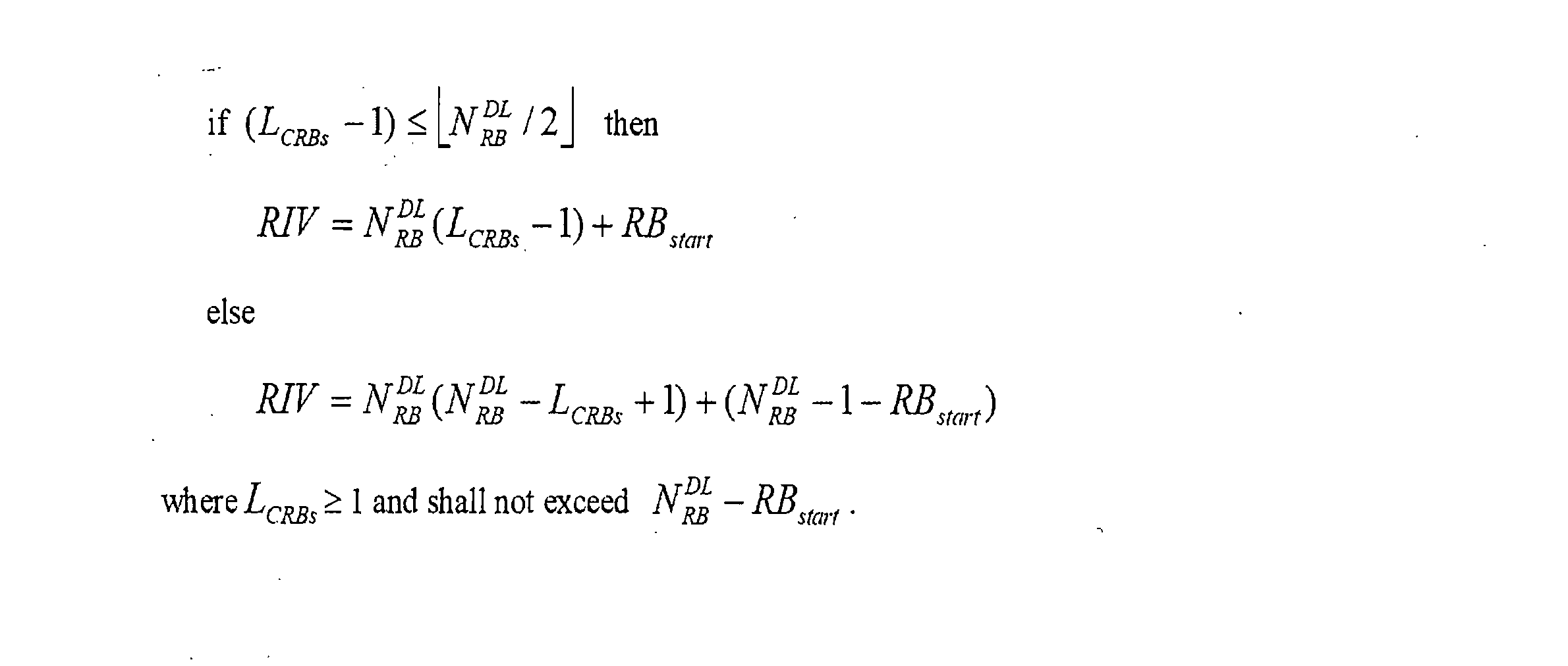
この際、NDL RBはDL伝送のための資源割当に使用される総RBの数である。UL伝送に第2タイプ(type-2)資源割当方式が使用されれば、NDL RBはUL伝送のための資源割当に使用される総RBの数であるNUL RBに置換される。 At this time, N DL RB is the total number of RBs used for resource allocation for DL transmission. If a type-2 resource allocation scheme is used for UL transmission, N DL RB is replaced with N UL RB , which is the total number of RBs used for resource allocation for UL transmission.
PDCCHのフォーマットが1Cであれば、基地局は第2タイプ(type-2)資源割当方式に従って複数のRB単位に端末にスケジューリングされた資源を指示する。


また、基地局が設定可能なRIVが示す連続した資源の連続したRBの個数は以下のようである。 Further, the number of consecutive RBs of consecutive resources indicated by the RIV that can be set by the base station is as follows.

この際、基地局は以下の数式によってRIVの値を決定する。 At this time, the base station determines the value of RIV using the following formula.
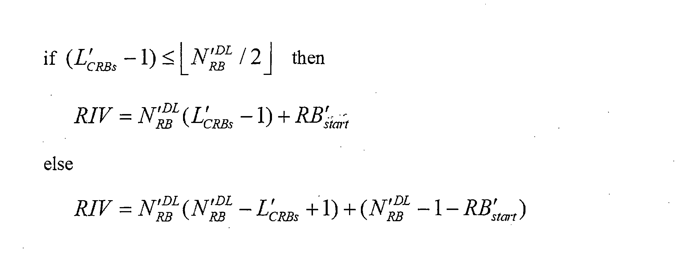
この際、NDL RBはDL伝送のための資源割当に使用される総RBの数である。UL伝送に第2タイプ(type-2)資源割当方式が使用されれば、NDL RBはUL伝送のための資源割当に使用される総RBの数であるNUL RBに置換される。 At this time, N DL RB is the total number of RBs used for resource allocation for DL transmission. If a type-2 resource allocation scheme is used for UL transmission, N DL RB is replaced with N UL RB , which is the total number of RBs used for resource allocation for UL transmission.
基地局は、RIVを使用して端末の物理データチャネルの受信がスケジューリングされた、時間領域で連続した資源を指示する。この際、端末はDCIが含むRIVに基づいてDCIがスケジューリングする周波数領域で連続した資源の開始OFDMシンボルであるSstartと連続した資源のOFDMシンボルの個数であるLsymbolsを獲得する。Sstartはスロット内の位置と解釈される。例えば、Sstart=0であれば、Sstartはスロットの最初のOFDMシンボルを示す。NsymbolがDCIがスケジューリングする端末の物理データチャネルの受信が割り当てられたシンボルの総数であれば、RIVの値は以下の数式によって決められる。 The base station uses the RIV to indicate the time-domain contiguous resources on which the terminal is scheduled to receive physical data channels. At this time, the terminal obtains S start , which is a start OFDM symbol of consecutive resources in the frequency domain scheduled by the DCI, and L symbols , which is the number of OFDM symbols of consecutive resources, in the frequency domain scheduled by the DCI based on the RIV included in the DCI. S start is interpreted as a position within the slot. For example, if S start =0, S start indicates the first OFDM symbol of the slot. If N symbol is the total number of symbols assigned to receive the physical data channel of the terminal scheduled by the DCI, the value of RIV is determined by the following formula.

基地局は、複数のOFDMシンボル単位で端末にスケジューリングされた資源を指示する。


また、基地局が設定可能なRIVが示す連続した資源の連続したOFDMシンボルの個数は以下のようである。 Further, the number of consecutive OFDM symbols of consecutive resources indicated by the RIV that can be set by the base station is as follows.

基地局は以下の数式によってRIVの値を設定する。 The base station sets the value of RIV using the following formula.
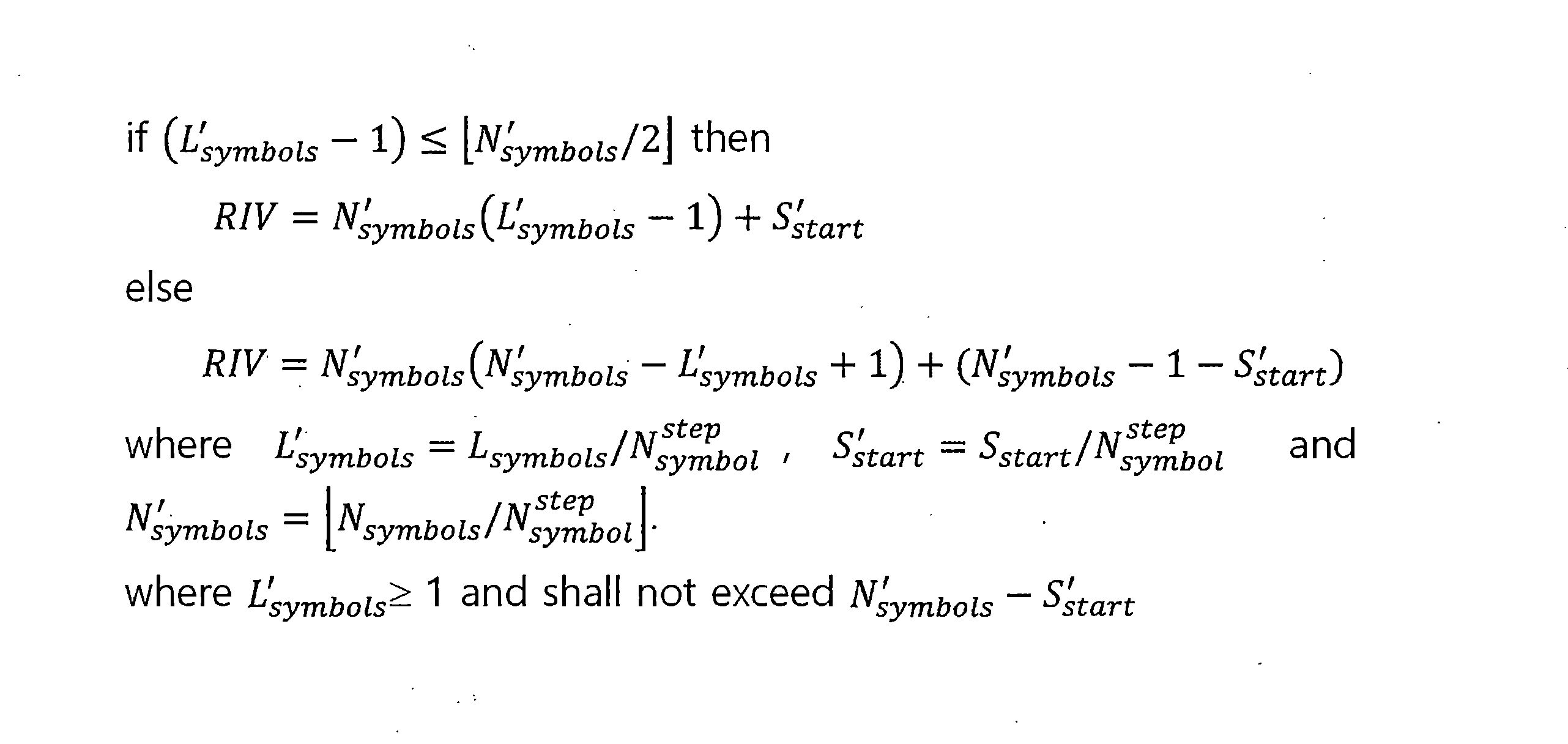
図27は、本発明の実施例による無線通信システムにおいて基地局が端末に2つのRIVを伝送して端末にスケジューリングされた時間-周波数資源領域を指示することを示す図である。 FIG. 27 is a diagram illustrating a base station transmitting two RIVs to a terminal to indicate a scheduled time-frequency resource region to the terminal in a wireless communication system according to an embodiment of the present invention.
基地局は、上述したように、RIVを利用して端末のPDSCHの受信がスケジューリングされた時間-周波数資源、または端末のPUSCH伝送がスケジューリングされた時間-周波数資源を指示する。この際、端末はRIVが指示する時間-周波数資源でPDSCHを受信するかPUSCHを伝送する。基地局は、周波数領域のRIVの値と時間領域のRIVの値を使用して端末にスケジューリングされた資源を指示する。詳しくは、基地局は、周波数領域のRIVの値と時間領域のRIVの値を独立的に指示し、端末にスケジューリングされた時間-周波数資源を指示する。説明の便宜上、周波数領域のRIVをRIVfreqと表し、時間領域のRIVをRIVtimeと表す。具体的な実施例において、基地局は、PDSCH受信のスケジューリングのためにRIVfreqとRIVtime、の2つのRIVを含むDCI伝送し、PDSCHが割り当てられた時間-周波数資源を指示する。 As described above, the base station uses the RIV to indicate the time-frequency resources on which the terminal is scheduled to receive a PDSCH or the time-frequency resources on which the terminal is scheduled to transmit PUSCH. At this time, the terminal receives PDSCH or transmits PUSCH using time-frequency resources indicated by the RIV. The base station indicates scheduled resources to the terminal using the frequency domain RIV value and the time domain RIV value. Specifically, the base station independently indicates the value of the RIV in the frequency domain and the value of the RIV in the time domain, and indicates the scheduled time-frequency resources to the terminal. For convenience of explanation, RIV in the frequency domain is expressed as RIV freq , and RIV in the time domain is expressed as RIV time . In a specific embodiment, the base station transmits a DCI including two RIVs, RIV freq and RIV time , for scheduling PDSCH reception and indicating the time-frequency resources to which the PDSCH is allocated.
図27の実施例において、基地局はDCIを介してRIVfreqとRIVtimeをそれぞれ伝送する。この際、端末は上述した実施例によってRIVfreqとRIVtimeが指示する時間周波数領域を判断する。詳しくは、端末は上述した実施例によって、RIVfreqからLCRB及びRBstartを獲得する。また、端末はRIVtimeからLsymbolsとSstartを獲得する。 In the embodiment of FIG. 27, the base station transmits RIV freq and RIV time through the DCI, respectively. At this time, the terminal determines the time frequency domain indicated by RIV freq and RIV time according to the above-described embodiment. Specifically, the terminal obtains the L CRB and RB start from the RIV freq according to the embodiments described above. The terminal also obtains L symbols and S start from RIV time .
RIVが示す最大値がQであれば、RIVを表現するためのビットの長さは
図28は、本発明の実施例による無線通信システムにおいて基地局が端末に2つのRIVを伝送して端末にスケジューリングされた時間-周波数資源領域を指示することを示す図である。 FIG. 28 is a diagram illustrating a base station transmitting two RIVs to a terminal to indicate a scheduled time-frequency resource region to the terminal in a wireless communication system according to an embodiment of the present invention.
基地局は、一つのRIVを伝送して端末にスケジューリングされた時間-周波数資源を指示する。この際、一つのRIVが2つのRIV(RIV1、RIV2)をエンコーディングして生成した値である。2つのRIVは、上述したRIVfreqとRIVtimeである。RIV1が有する最大値をRIV1 maxと表す。また、2つのRIVをエンコーディングして精製したRIVを最終RIV(RIVtotal)と称する。基地局は、以下の数式によって最終RIV(RIVtotal)の値を決定する。 The base station transmits one RIV to indicate scheduled time-frequency resources to the terminal. At this time, one RIV is a value generated by encoding two RIVs (RIV 1 , RIV 2 ). The two RIVs are the RIV freq and RIV time described above. The maximum value that RIV 1 has is expressed as RIV 1 max . Furthermore, RIV purified by encoding two RIVs is referred to as final RIV (RIV total ). The base station determines the final RIV (RIV total ) value using the following formula.

また、端末は最終RIV(RIVtotal)から以下の数式によってRIV1とRIV2を獲得する。 Also, the terminal obtains RIV 1 and RIV 2 from the final RIV (RIV total ) using the following formula.

この際、RIV1はRIVfreqである。また、RIV2はRIVtimeである。基地局が一つのRB単位で端末に時間-周波数資源をスケジューリングすれば、RIVfreqの最大値であるRIVfreq maxは以下の数式によって決定される。 At this time, RIV 1 is RIV freq . Further, RIV 2 is RIV time . If the base station schedules time-frequency resources to the terminal in units of one RB, the maximum value of RIV freq , RIV freq max , is determined by the following formula.

基地局が複数のRB単位で端末に時間-周波数資源をスケジューリングし、複数のRBの個数を


この際、
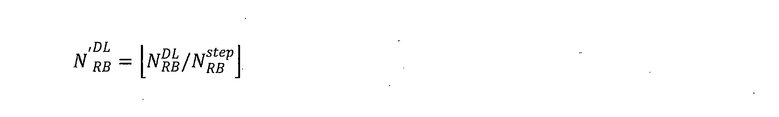
この際、RIV2はRIVtimeである。また、RIV1はRIVfreqである。基地局が一つのOFDM単位で端末に時間-周波数資源をスケジューリングすれば、RIVtimeの最大値であるRIVtime maxは以下の数式によって決定される。 At this time, RIV 2 is RIV time . Further, RIV 1 is RIV freq . When a base station schedules time-frequency resources to a terminal in one OFDM unit, the maximum value of RIV time , RIV time max , is determined by the following formula.

基地局が複数のOFDMシンボル単位で端末に時間-周波数資源をスケジューリングし、複数のRBの個数を


図28の実施例において、基地局は端末特定PDCCHのDCIを介して一つの最終RIV(RIVtotal)を伝送する。端末は、上述した実施例によって最終RIV(RIVtotal)からRIVtimeとRIVfreqを獲得する。端末は、IVfreqをからLCRB及びRBstartを獲得する。また、端末はRIVtimeからLsymbolsとSstartを獲得する。 In the embodiment of FIG. 28, the base station transmits one final RIV (RIV total ) via the DCI of the terminal-specific PDCCH. The terminal obtains RIV time and RIV freq from the final RIV (RIV total ) according to the embodiments described above. The terminal obtains the L CRB and RB start from the IV freq . The terminal also obtains L symbols and S start from RIV time .
他の具体的な実施例において、基地局は3つ以上のRIVをエンコーディングして一つの最終RIV(RIVtotal)を生成し、DCIを使用して最終RIV(RIVtotal)を伝送する。この際、基地局はRIVを2つずつ順次にエンコーディングして最終RIV(RIVtotal)を生成する。例えば、基地局が3つのRIV(RIV1、RIV2、RIV3)をエンコーディングして最終RIV(RIVtotal)を生成してもよい。この際、基地局は2つのRIV(RIV1、RIV2)を先にエンコーディングして中間RIVを生成する。次に、基地局は中間RIVと残りの一つのRIV(RIV3)をエンコーディングして最終RIV(RIVtotal)を生成する。 In other specific embodiments, the base station encodes three or more RIVs to generate one final RIV (RIV total ) and transmits the final RIV (RIV total ) using DCI. At this time, the base station sequentially encodes the RIV two by two to generate the final RIV (RIV total ). For example, the base station may encode three RIVs (RIV 1 , RIV 2 , RIV 3 ) to generate a final RIV (RIV total ). At this time, the base station first encodes two RIVs (RIV 1 , RIV 2 ) to generate an intermediate RIV. Next, the base station encodes the intermediate RIV and the remaining RIV (RIV 3 ) to generate a final RIV (RIV total ).
このような実施例を介して、基地局はRIV伝送に使用されるビット数を減らす。例えば、端末がスケジューリング可能なRBが6つで、端末がスケジューリング可能なOFDMシンボルが9つであるとする。この際、RIVfreqは0から20のうちいずれか一つの値を有する。また、RIVtimeは0から44のうちいずれか一つの値を有する。上述した実施例のように、RIVfreqとRIVtimeをエンコーディングして最終RIV(RIVtotal)を生成すれば、最終RIV(RIVtotal)は0から944のうち一つの値を有する。よって、最終RIV(RIVtotal)を伝送するために10ビットが必要となる。詳しくは、RIVこのような実施例によると、基地局がRIVfreqとRIVtimeをそれぞれ伝送する場合よりRIV伝送に使用されるDCIのビットを1ビットだけ減らすことができる。表4は、RIVfreqとRIVtimeをそれぞれ伝送する場合、端末がスケジューリング可能なRBの個数とOFDMシンボルの個数に応じてRIVに所要されるDCIのビット数を示す。また、表5は、RIVfreqとRIVtimeをエンコーディングして最終RIV(RIVtotal)を伝送する場合、端末がスケジューリング可能なRBの個数とOFDMシンボルの個数に応じてRIV伝送に所要されるDCIのビット数を示す。表4と表5を介し、複数のRIVをエンコーディングして最終RIV(RIVtotal)を伝送する場合、RIV伝送に所要されるDCIのビット数を減らすことができることが分かる。 Through such embodiments, the base station reduces the number of bits used for RIV transmission. For example, assume that there are six RBs that can be scheduled by the terminal and nine OFDM symbols that can be scheduled by the terminal. At this time, RIV freq has a value from 0 to 20. Also, RIV time has a value of 0 to 44. If the final RIV (RIV total ) is generated by encoding RIV freq and RIV time as in the above embodiment, the final RIV (RIV total ) has one value from 0 to 944. Therefore, 10 bits are required to transmit the final RIV (RIV total ). Specifically, according to this embodiment of RIV, the number of DCI bits used for RIV transmission can be reduced by one bit compared to when the base station transmits RIV freq and RIV time , respectively. Table 4 shows the number of DCI bits required for RIV according to the number of RBs and the number of OFDM symbols that can be scheduled by the terminal when transmitting RIV freq and RIV time , respectively. Table 5 also shows that when transmitting the final RIV (RIV total ) by encoding RIV freq and RIV time , the DCI required for RIV transmission is determined according to the number of RBs that can be scheduled by the terminal and the number of OFDM symbols. Indicates the number of bits. From Tables 4 and 5, it can be seen that when a plurality of RIVs are encoded and the final RIV (RIV total ) is transmitted, the number of DCI bits required for RIV transmission can be reduced.


上述した実施例において、最終RIV(RIVtotal)の生成及び最終RIV(RIVtotal)の伝送がDCIにスケジューリングされる時間-周波数資源を指示する場合に対してのみ説明した。しかし、上述した実施例はこれに対してのみ限らず、RIVを使用して時間-周波数資源を指示する場合にも適用可能である。例えば、基地局がRRC信号を介して時間-周波数資源をスケジューリングする際に上述した実施例が適用されてもよい。また、基地局が端末にプリエンプション(preemption)された時間-周波数資源を指示する際に上述した実施例が適用される。この際、プリエンプションされた時間-周波数資源は、端末に既にスケジューリングされる時間-周波数資源のうち一部の資源が前記端末にスケジューリングされていないことを示す。 In the embodiments described above, only the case where the generation of the final RIV (RIV total ) and the transmission of the final RIV (RIV total ) indicate time-frequency resources to be scheduled to the DCI has been described. However, the embodiments described above are not limited to this, and can also be applied to the case where RIV is used to indicate time-frequency resources. For example, the embodiments described above may be applied when a base station schedules time-frequency resources via RRC signals. Further, the above-described embodiments are applied when a base station instructs a terminal to use preempted time-frequency resources. At this time, the preempted time-frequency resources indicate that some of the time-frequency resources already scheduled to the terminal are not scheduled to the terminal.
基地局は、端末にスケジューリングする時間資源を以下の実施例によって指示する。詳しくは、基地局はRRC信号を使用して端末にスケジューリングされた物理データチャネルと時間資源のマッピングを示す時間資源マッピングテーブルを設定する。この際、RRC信号は端末-特定RRC信号である。また、基地局は、端末の物理データチャネルの受信または物理データチャネルの伝送をスケジューリングするDCIが含むいずれか一つのフィールドを使用してマッピングテーブルのステートをシグナリングする。端末は、RRC信号に基づいて基地局が設定する時間資源のマッピングテーブルを判断し、端末の物理データチャネルの受信または物理データチャネルの伝送をスケジューリングするDCIが含むいずれか一つのフィールドに基づいて該当データチャネルがスケジューリングされた時間資源領域を判断する。時間資源マッピングテーブルのステートの個数は16である。この際、DCIが含むいずれか一つのフィールドは4ビットである。時間資源マッピングテーブルはHARQ-ACK伝送スロットを指示するK1値、物理データチャネルが伝送されるスロット、物理データチャネルが伝送されるスロットで物理データチャネルがスケジューリングされる最初のOFDMシンボルと物理データチャネルがスケジューリングされるOFDMシンボルの個数、及び物理データチャネルのマッピングタイプを含む。この際、物理データチャネルのマッピングタイプは、DMRS(demodulation reference signal)の位置が物理データチャネルの位置とは関係なく決定されるのかを示す。具体的な実施例において、基地局はRRC信号の6ビットを使用して物理データチャネルが伝送されるスロット及び物理データチャネルが伝送されるスロットで、物理データチャネルがスケジューリング最初のOFDMシンボルと物理データチャネルがスケジューリングされるOFDMシンボルの個数を設定する。例えば、6ビットのうち2ビットは物理データチャネルが伝送されるスロットを示す。物理データチャネルが伝送されるスロットを示す2ビットはK0と称する。K0は、端末がDCIを受信したスロットと端末にスケジューリングされた物理データチャネルが伝送されるスロットとの間のインデックスの差を示す。K0が有する値は、00b、01b、10b、及び11bのうちいずれか一つである。K0の値が0であれば、端末がDCIを受信したスロットと端末にスケジューリングされた物理データチャネルが伝送されるスロットは同じである。また、6ビットのうち4ビットは、物理データチャネルが伝送されるスロットで物理データチャネルがスケジューリングされる最初のOFDMシンボルと物理データチャネルがスケジューリングされるOFDMシンボルの個数を示す。この際、物理データチャネルがスケジューリングされるOFDMシンボルの個数は2、4、7、及び14のうちいずれか一つである。詳しくは、4ビットは物理データチャネルがスケジューリングされる最初のOFDMシンボルと物理データチャネルがスケジューリングされるOFDMシンボルの個数に下記表6のようにマッピングされる。 The base station indicates the time resources to be scheduled to the terminal according to the following example. Specifically, the base station uses RRC signals to set up a time resource mapping table that indicates the mapping between physical data channels scheduled to the terminal and time resources. At this time, the RRC signal is a terminal-specific RRC signal. In addition, the base station signals the state of the mapping table using any one field included in the DCI that schedules reception of a physical data channel or transmission of a physical data channel of a terminal. The terminal determines the time resource mapping table set by the base station based on the RRC signal, and determines the corresponding time resource mapping table based on any one field included in the DCI that schedules the reception of the physical data channel or the transmission of the physical data channel of the terminal. Determine the time resource region in which the data channel is scheduled. The number of states in the time resource mapping table is 16. At this time, any one field included in the DCI is 4 bits. The time resource mapping table includes the K1 value indicating the HARQ-ACK transmission slot, the slot in which the physical data channel is transmitted, the first OFDM symbol in which the physical data channel is scheduled in the slot in which the physical data channel is transmitted, and the physical data channel. It includes the number of OFDM symbols to be scheduled and the mapping type of the physical data channel. At this time, the physical data channel mapping type indicates whether the location of a DMRS (demodulation reference signal) is determined regardless of the location of the physical data channel. In a specific embodiment, the base station uses 6 bits of the RRC signal to schedule the first OFDM symbol and the physical data in the slot in which the physical data channel is transmitted and in the slot in which the physical data channel is transmitted. Set the number of OFDM symbols on which the channel is scheduled. For example, 2 bits out of 6 bits indicate the slot in which the physical data channel is transmitted. The two bits indicating the slot in which the physical data channel is transmitted are called K0. K0 indicates the index difference between the slot in which the terminal received the DCI and the slot in which the physical data channel scheduled to the terminal is transmitted. The value of K0 is one of 00 b , 01 b , 10 b , and 11 b . If the value of K0 is 0, the slot in which the terminal receives the DCI is the same as the slot in which the physical data channel scheduled to the terminal is transmitted. Furthermore, 4 bits among the 6 bits indicate the first OFDM symbol in which the physical data channel is scheduled and the number of OFDM symbols in which the physical data channel is scheduled in the slot in which the physical data channel is transmitted. At this time, the number of OFDM symbols on which the physical data channel is scheduled is one of 2, 4, 7, and 14. Specifically, the 4 bits are mapped to the first OFDM symbol in which the physical data channel is scheduled and the number of OFDM symbols in which the physical data channel is scheduled, as shown in Table 6 below.
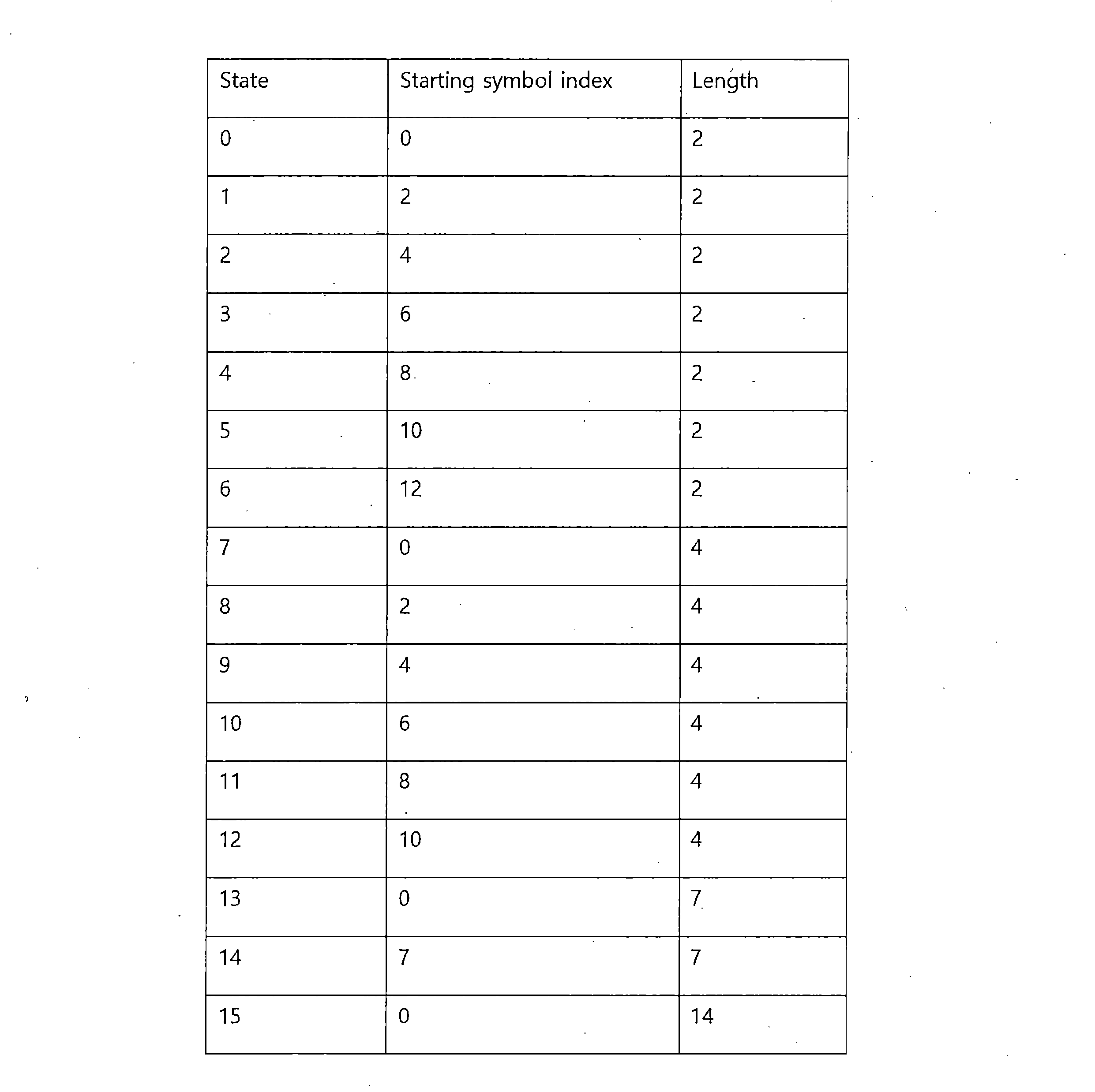
一つのスロットのOFDMシンボルインデックスを0から15に設定すると、各ステートは以下のようなOFDMシンボルを示す。ステートの値が示すOFDMシンボルは以下のようである。0:{0、1}、1:{2、3}、2:{4、5}、3:{6、7}、4:{8、9}、5:{10、11}、6:{12、13}、7:{0、1、2、3}、8:{2、3、4、5}、9:{4、5、6、7}、10:{6、7、8、9}、11:{8、9、10、11}、12:{10、11、12、13}、13:{0、1、2、3、4、5、6}、14:{7、8、9、10、11、12、13}、15:{0、1、2、3、4、5、6、7、8、9、10、11、12、13、14}。この際、X:{Y}においてXはステートの値を示し、YはXステートが指示するOFDMシンボルを示す。 When the OFDM symbol index of one slot is set from 0 to 15, each state indicates the following OFDM symbols. The OFDM symbols indicated by the state values are as follows. 0: {0, 1}, 1: {2, 3}, 2: {4, 5}, 3: {6, 7}, 4: {8, 9}, 5: {10, 11}, 6: {12, 13}, 7: {0, 1, 2, 3}, 8: {2, 3, 4, 5}, 9: {4, 5, 6, 7}, 10: {6, 7, 8 , 9}, 11: {8, 9, 10, 11}, 12: {10, 11, 12, 13}, 13: {0, 1, 2, 3, 4, 5, 6}, 14: {7 , 8, 9, 10, 11, 12, 13}, 15: {0, 1, 2, 3, 4, 5, 6, 7, 8, 9, 10, 11, 12, 13, 14}. At this time, in X:{Y}, X indicates the value of the state, and Y indicates the OFDM symbol indicated by the X state.
他の具体的な実施例において、6ビットのうち1ビットは物理データチャネルが伝送されるスロットを示す。物理データチャネルが伝送されるスロットを示す1ビットはK0と称する。K0は、端末がDCIを受信したスロットと端末にスケジューリングされた物理データチャネルが伝送されるスロットとの間のインデックスの差を示す。K0が有する値は、0及び1のうちいずれか一つである。K0の値が0であれば、端末がDCIを受信したスロットと端末にスケジューリングされた物理データチャネルが伝送されるスロットは同じである。K0の値が1であれば、端末がDCIを受信したスロットのインデックスと端末にスケジューリングされた物理データチャネルが伝送されるスロットのインデックスの差はEである。この際、Eは1とは異なる自然数に固定される。また、6ビットのうち5ビットは、物理データチャネルが伝送されるスロットで物理データチャネルがスケジューリングされる最初のOFDMシンボルと物理データチャネルがスケジューリングされるOFDMシンボルの個数を示す。この際、物理データチャネルがスケジューリングされるOFDMシンボルの個数は1、2、4、7、及び14のうちいずれか一つである。詳しくは、5ビットは物理データチャネルがスケジューリングされる最初のOFDMシンボルと物理データチャネルがスケジューリングされるOFDMシンボルの個数に下記表7のようにマッピングされる。 In other specific embodiments, one of the six bits indicates the slot in which the physical data channel is transmitted. One bit indicating the slot in which the physical data channel is transmitted is called K0. K0 indicates the index difference between the slot in which the terminal received the DCI and the slot in which the physical data channel scheduled to the terminal is transmitted. The value of K0 is either 0 or 1. If the value of K0 is 0, the slot in which the terminal receives the DCI is the same as the slot in which the physical data channel scheduled to the terminal is transmitted. If the value of K0 is 1, the difference between the index of the slot in which the terminal received the DCI and the index of the slot in which the physical data channel scheduled to the terminal is transmitted is E. At this time, E is fixed to a natural number different from 1. Further, 5 bits among the 6 bits indicate the first OFDM symbol in which the physical data channel is scheduled and the number of OFDM symbols in which the physical data channel is scheduled in the slot in which the physical data channel is transmitted. At this time, the number of OFDM symbols on which the physical data channel is scheduled is one of 1, 2, 4, 7, and 14. Specifically, the 5 bits are mapped to the first OFDM symbol in which the physical data channel is scheduled and the number of OFDM symbols in which the physical data channel is scheduled, as shown in Table 7 below.

0:{0、1}、1:{2、3}、2:{4、5}、3:{6、7}、4:{8、9}、5:{10、11}、6:{12、13}、7:{0、1、2、3}、8:{2、3、4、5}、9:{4、5、6、7}、10:{6、7、8、9}、11:{8、9、10、11}、12:{10、11、12、13}、13:{0、1、2、3、4、5、6}、14:{7、8、9、10、11、12、13}、15:{0、1、2、3、4、5、6、7、8、9、10、11、12、13、14}、16:{0}、17:{1}、18:{2}、19:{3}、20:{4}、21:{5}、22:{6}、23:{7}、24:{8}、25:{9}、26:{10}、27:{11}、28:{12}、29:{13}。この際、X:{Y}においてXはステートの値を示し、YはXステートが指示するOFDMシンボルを示す。また、ステートの値30と31はリザーブされる。ステートの値30と31は、それぞれセミ-スタティック(semi-static)に設定された全てのDLシンボルとセミ-スタティックに設定された全てのアンノウン(unknown)シンボルを示す。この際、アンノウンシンボルはULシンボルまたはDLシンボルと設定されていないシンボルを示す。また、ステートの値30と31は、それぞれセミ-スタティックに設定された全てのDLシンボルとセミ-スタティックに設定された全てのアンノウンシンボルのうち、スロット最後から指定された個数だけのOFDMシンボルを除いた全てのOFDMシンボルを示す。この際、指定された個数は固定された数である。例えば、指定された個数は1であってもよい。また、指定された個数は端末ごとに別途に指定される。詳しくは、指定された個数はRRC信号によって端末別に設定される。 0: {0, 1}, 1: {2, 3}, 2: {4, 5}, 3: {6, 7}, 4: {8, 9}, 5: {10, 11}, 6: {12, 13}, 7: {0, 1, 2, 3}, 8: {2, 3, 4, 5}, 9: {4, 5, 6, 7}, 10: {6, 7, 8 , 9}, 11: {8, 9, 10, 11}, 12: {10, 11, 12, 13}, 13: {0, 1, 2, 3, 4, 5, 6}, 14: {7 , 8, 9, 10, 11, 12, 13}, 15: {0, 1, 2, 3, 4, 5, 6, 7, 8, 9, 10, 11, 12, 13, 14}, 16: {0}, 17: {1}, 18: {2}, 19: {3}, 20: {4}, 21: {5}, 22: {6}, 23: {7}, 24: {8 }, 25: {9}, 26: {10}, 27: {11}, 28: {12}, 29: {13}. At this time, in X:{Y}, X indicates the state value, and Y indicates the OFDM symbol indicated by the X state. Additionally, state values 30 and 31 are reserved. State values 30 and 31 indicate all DL symbols set to semi-static and all unknown symbols set to semi-static, respectively. At this time, the unknown symbol indicates a symbol that is not set as a UL symbol or a DL symbol. Also, the state values 30 and 31 are for all semi-statically set DL symbols and semi-statically set unknown symbols, excluding the specified number of OFDM symbols from the end of the slot. shows all OFDM symbols. At this time, the specified number is a fixed number. For example, the specified number may be one. Further, the specified number is specified separately for each terminal. Specifically, the designated number is set for each terminal by an RRC signal.
他の具体的な実施例において、6ビットのうち1ビットは物理データチャネルが伝送されるスロットのリファレンス位置を示す。この際、1ビットは物理データチャネルが伝送されるスロットのリファレンス位置がスロットの最初のOFDMシンボルであるのか、またはCORESETのすぐ次のOFDMシンボルであるのかを示す。6ビットのうち5ビットは、物理データチャネルがスケジューリングされる物理データチャネルがスケジューリングされるOFDMシンボルの個数である。6ビットのうち1ビットがスロットの開始時点を示し、6ビットのうち5ビットが指示するOFDM開始シンボルのインデックスがAであれば、物理データチャネルはAから物理データチャネルが伝送されるOFDMシンボルの個数に当たるOFDMシンボルで伝送される。6ビットのうち1ビットCORESETのすぐ次のOFDMシンボルを示し、6ビットのうち5ビットが指示するOFDM開始シンボルのインデックスがAであれば、物理データチャネルはA+Bから物理データチャネルが伝送されるOFDMシンボルの個数に当たるOFDMシンボルで伝送される。この際、BはCORESETのすぐ次のOFDMシンボルに当たるOFDMシンボルのインデックスである。 In another specific embodiment, one of the six bits indicates the reference position of the slot in which the physical data channel is transmitted. At this time, one bit indicates whether the reference position of the slot in which the physical data channel is transmitted is the first OFDM symbol of the slot or the OFDM symbol immediately following CORESET. Five bits among the six bits are the number of OFDM symbols on which the physical data channel is scheduled. If 1 bit among the 6 bits indicates the start time of the slot, and the index of the OFDM start symbol indicated by 5 bits among the 6 bits is A, then the physical data channel is transmitted from A to the OFDM symbol where the physical data channel is transmitted. It is transmitted using the same number of OFDM symbols. If 1 bit out of 6 bits indicates the OFDM symbol immediately following CORESET, and the index of the OFDM start symbol indicated by 5 out of 6 bits is A, then the physical data channel is OFDM where the physical data channel is transmitted from A+B. It is transmitted using OFDM symbols corresponding to the number of symbols. At this time, B is the index of the OFDM symbol that immediately follows the CORESET.
図29乃至図33は、本発明の他の実施例による無線通信システムにおいてRRC信号の6ビットが示す端末にスケジューリングされた物理データチャネルに当たるOFDMシンボルを示す図である。 29 to 33 are diagrams illustrating OFDM symbols corresponding to physical data channels scheduled to a terminal indicated by 6 bits of an RRC signal in a wireless communication system according to another embodiment of the present invention.
具体的な実施例において、端末にスケジューリングされた物理データチャネルを示すために基地局が使用するRRC信号の6ビットは、物理データチャネルがスケジューリングされたOFDMシンボルの個数が1である14個のステート、物理データチャネルがスケジューリングされたOFDMシンボルの個数が7である2つのステート、物理データチャネルがスケジューリングされたOFDMシンボルの個数が2の倍数である28個のステートを指示する。この際、物理データチャネルがスケジューリングされたOFDMシンボルの個数が2の倍数であるステートは、14個のOFDMシンボルを2つずつ束ねて指示するRIV方式に従う。具体的な実施例によると、6ビットが示すOFDMシンボルは図29のようである。 In a specific embodiment, the 6 bits of the RRC signal used by the base station to indicate the physical data channel scheduled to the terminal are divided into 14 states in which the number of OFDM symbols on which the physical data channel is scheduled is 1. , two states in which the number of OFDM symbols on which the physical data channel is scheduled is 7, and 28 states in which the number of OFDM symbols on which the physical data channel is scheduled is a multiple of two. At this time, a state in which the number of OFDM symbols in which the physical data channel is scheduled is a multiple of 2 follows the RIV method in which 14 OFDM symbols are bundled and designated in pairs. According to a specific embodiment, the OFDM symbol indicated by 6 bits is as shown in FIG.
他の具体的な実施例において、端末にスケジューリングされた物理データチャネルを示すために基地局が使用するRRC信号の6ビットは、物理データチャネルがスケジューリングされたOFDMシンボルの個数が1である14個のステート、物理データチャネルがスケジューリングされたOFDMシンボルの個数が7である8つのステート、物理データチャネルがスケジューリングされたOFDMシンボルの個数が2の倍数である28個のステートを指示する。この際、物理データチャネルがスケジューリングされたOFDMシンボルの個数が2の倍数であるステートは、偶数のOFDMシンボルインデックスから始まることを示す。具体的な実施例によると、6ビットが示すOFDMシンボルは図30のようである。 In another specific embodiment, the 6 bits of the RRC signal used by the base station to indicate the scheduled physical data channel to the terminal are 14, where the number of OFDM symbols on which the physical data channel is scheduled is 1. , 8 states where the number of OFDM symbols on which the physical data channel is scheduled is 7, and 28 states where the number of OFDM symbols on which the physical data channel is scheduled is a multiple of 2. In this case, a state in which the number of OFDM symbols for which the physical data channel is scheduled is a multiple of 2 indicates that the state starts from an even numbered OFDM symbol index. According to a specific embodiment, the OFDM symbol indicated by 6 bits is as shown in FIG.
また他の具体的な実施例において、端末にスケジューリングされた物理データチャネルを示すために基地局が使用するRRC信号の6ビットは、物理データチャネルがスケジューリングされたOFDMシンボルの個数が1である14個のステート、物理データチャネルがスケジューリングされたOFDMシンボルの個数が2の倍数である49個のステートを指示する。この際、物理データチャネルがスケジューリングされたOFDMシンボルの個数が2の倍数であるステート49個のうち、28個のステートは偶数のOFDMシンボルインデックスから21個ステートは奇数のOFDMシンボルインデックスから始まることを示す。具体的な実施例によると、6ビットが示すOFDMシンボルは図31のようである。 In another specific embodiment, the 6 bits of the RRC signal used by the base station to indicate the physical data channel scheduled to the terminal are 14, when the number of OFDM symbols on which the physical data channel is scheduled is 1. states, the physical data channel indicates 49 states in which the number of scheduled OFDM symbols is a multiple of two. At this time, of the 49 states in which the number of OFDM symbols for which the physical data channel is scheduled is a multiple of 2, 28 states start from an even numbered OFDM symbol index, and 21 states start from an odd numbered OFDM symbol index. show. According to a specific embodiment, the OFDM symbol indicated by 6 bits is as shown in FIG.
更に他の具体的な実施例において、端末にスケジューリングされた物理データチャネルを示すために基地局が使用するRRC信号の6ビットは、物理データチャネルがスケジューリングされたOFDMシンボルの個数が1である14個のステート、物理データチャネルがスケジューリングされたOFDMシンボルの個数が2の倍数である48個のステートを指示する。この際、物理データチャネルがスケジューリングされたOFDMシンボルの個数が2の倍数であるステート48個のうち、28個のステートは偶数のOFDMシンボルインデックスから20個ステートは奇数のOFDMシンボルインデックスから始まることを示す。具体的な実施例によると、6ビットが示すOFDMシンボルは図32のようである。 In yet another specific embodiment, the 6 bits of the RRC signal used by the base station to indicate the physical data channel scheduled to the terminal are 14, where the number of OFDM symbols on which the physical data channel is scheduled is 1. states, the physical data channel indicates 48 states in which the number of scheduled OFDM symbols is a multiple of two. At this time, of the 48 states in which the number of OFDM symbols for which the physical data channel is scheduled is a multiple of 2, 28 states start from an even numbered OFDM symbol index, and 20 states start from an odd numbered OFDM symbol index. show. According to a specific embodiment, the OFDM symbol indicated by 6 bits is as shown in FIG.
他の具体的な実施例において、端末にスケジューリングされた物理データチャネルを示すために基地局が使用するRRC信号の6ビットは、物理データチャネルがスケジューリングされたOFDMシンボルの個数が1である14個のステート、物理データチャネルが物理データチャネルがスケジューリングされたOFDMシンボルの個数が7である8個のステート、物理データチャネルがスケジューリングされたOFDMシンボルの個数が2である13個のステート、物理データチャネルがスケジューリングされたOFDMシンボルの個数が4である11個のステート、物理データチャネルがスケジューリングされたOFDMシンボルの個数が14である一つのステート、物理データチャネルがスケジューリングされたOFDMシンボルの個数が3である4個のステート、物理データチャネルがスケジューリングされたOFDMシンボルの個数が5である2個のステート、物理データチャネルがスケジューリングされたOFDMシンボルの個数が6である2個のステート、物理データチャネルがスケジューリングされたOFDMシンボルの個数が8である一つのステート、物理データチャネルがスケジューリングされたOFDMシンボルの個数が9である一つのステート、物理データチャネルがスケジューリングされたOFDMシンボルの個数が10である一つのステート、物理データチャネルがスケジューリングされたOFDMシンボルの個数が11である一つのステート、物理データチャネルがスケジューリングされたOFDMシンボルの個数が12である一つのステート、及び物理データチャネルがスケジューリングされたOFDMシンボルの個数が13である一つのステートを指示する。この際、物理データチャネルがスケジューリングされたOFDMシンボルの個数が2であるステートは、いずれも3の倍数に当たるOFDMシンボルインデックスから始まる。具体的な実施例によると、6ビットが示すOFDMシンボルは図33のようである。 In another specific embodiment, the 6 bits of the RRC signal used by the base station to indicate the scheduled physical data channel to the terminal are 14, where the number of OFDM symbols on which the physical data channel is scheduled is 1. 8 states in which the number of OFDM symbols on which the physical data channel is scheduled is 7, 13 states in which the number of OFDM symbols in which the physical data channel is scheduled is 2, the physical data channel The number of OFDM symbols scheduled for the physical data channel is 14, the number of OFDM symbols scheduled for the physical data channel is 3, and the number of OFDM symbols scheduled for the physical data channel is 3. There are 4 states, 2 states where the number of OFDM symbols on which the physical data channel is scheduled is 5, 2 states where the number of OFDM symbols on which the physical data channel is scheduled is 6, and 2 states where the number of OFDM symbols on which the physical data channel is scheduled is 6. One state in which the number of OFDM symbols scheduled is 8, one state in which the number of OFDM symbols scheduled in the physical data channel is 9, and one state in which the number of OFDM symbols scheduled in the physical data channel is 10. one state where the number of OFDM symbols on which the physical data channel is scheduled is 11, one state where the number of OFDM symbols on which the physical data channel is scheduled is 12, and one state where the number of OFDM symbols on which the physical data channel is scheduled is 12; Indicates one state with 13 symbols. At this time, states in which the physical data channel is scheduled for two OFDM symbols start from an OFDM symbol index that is a multiple of three. According to a specific embodiment, the OFDM symbol indicated by 6 bits is as shown in FIG.
他の具体的な実施例において、端末にスケジューリングされた物理データチャネルを示すために基地局が使用するRRC信号の6ビットは、物理データチャネルがスケジューリングされたOFDMシンボルの個数が1である14個のステート、物理データチャネルがスケジューリングされたOFDMシンボルの個数が7である8個のステート、物理データチャネルがスケジューリングされたOFDMシンボルの個数が2である13個のステート、物理データチャネルがスケジューリングされたOFDMシンボルの個数が4である11個のステート、物理データチャネルがスケジューリングされたOFDMシンボルの個数が14である一つのステート、物理データチャネルがスケジューリングされたOFDMシンボルの個数が5である10個のステート、及び物理データチャネルがスケジューリングされたOFDMシンボルの個数が8である7個のステートを指示する。この際、物理データチャネルがスケジューリングされたOFDMシンボルの個数が1であるステートは、可能な全てのOFDMシンボルインデックスから始まることを示す。 In another specific embodiment, the 6 bits of the RRC signal used by the base station to indicate the scheduled physical data channel to the terminal are 14, where the number of OFDM symbols on which the physical data channel is scheduled is 1. states, 8 states where the number of OFDM symbols on which the physical data channel was scheduled is 7, 13 states where the number of OFDM symbols on which the physical data channel was scheduled is 2, and the physical data channel was scheduled. 11 states in which the number of OFDM symbols is 4, one state in which the number of OFDM symbols in which the physical data channel is scheduled is 14, and 10 states in which the number of OFDM symbols in which the physical data channel is scheduled is 5. state, and the physical data channel indicates 7 states in which the number of scheduled OFDM symbols is 8. At this time, a state in which the number of OFDM symbols scheduled for the physical data channel is 1 indicates that the physical data channel starts from all possible OFDM symbol indices.
また他の具体的な実施例において、端末にスケジューリングされた物理データチャネルを示すために基地局が使用するRRC信号の6ビットは、物理データチャネルがスケジューリングされたOFDMシンボルの個数が1である14個のステート、物理データチャネルがスケジューリングされたOFDMシンボルの個数が7である8個のステート、物理データチャネルがスケジューリングされたOFDMシンボルの個数が2である13個のステート、物理データチャネルがスケジューリングされたOFDMシンボルの個数が4である11個のステート、物理データチャネルがスケジューリングされたOFDMシンボルの個数が14である一つのステート、物理データチャネルがスケジューリングされたOFDMシンボルの個数が3である12個のステート、及び物理データチャネルがスケジューリングされたOFDMシンボルの個数が10である5個のステートを指示する。この際、物理データチャネルがスケジューリングされたOFDMシンボルの個数が1であるステートは、可能な全てのOFDMシンボルインデックスから始まることを示す。 In another specific embodiment, the 6 bits of the RRC signal used by the base station to indicate the physical data channel scheduled to the terminal are 14, when the number of OFDM symbols on which the physical data channel is scheduled is 1. 8 states where the number of OFDM symbols on which the physical data channel is scheduled is 7; 13 states where the number of OFDM symbols on which the physical data channel is scheduled is 2; 11 states where the number of OFDM symbols scheduled is 4; one state where the number of OFDM symbols scheduled with the physical data channel is 14; and 12 states where the number of OFDM symbols scheduled with the physical data channel is 3. and the physical data channel indicates 5 states in which the number of scheduled OFDM symbols is 10. At this time, a state in which the number of OFDM symbols scheduled for the physical data channel is 1 indicates that the physical data channel starts from all possible OFDM symbol indices.
更に他の具体的な実施例において、端末にスケジューリングされた物理データチャネルを示すために基地局が使用するRRC信号の6ビットは、物理データチャネルがスケジューリングされたOFDMシンボルの個数が1である14個のステート、物理データチャネルがスケジューリングされたOFDMシンボルの個数が7である8個のステート、物理データチャネルがスケジューリングされたOFDMシンボルの個数が2である13個のステート、物理データチャネルがスケジューリングされたOFDMシンボルの個数が4である11個のステート、物理データチャネルがスケジューリングされたOFDMシンボルの個数が14である一つのステート、物理データチャネルがスケジューリングされたOFDMシンボルの個数が6である9個のステート、物理データチャネルがスケジューリングされたOFDMシンボルの個数が9である6個のステート、及び物理データチャネルがスケジューリングされたOFDMシンボルの個数が11ある2個のステートを指示する。この際、物理データチャネルがスケジューリングされたOFDMシンボルの個数が1であるステートは、可能な全てのOFDMシンボルインデックスから始まることを示す。 In yet another specific embodiment, the 6 bits of the RRC signal used by the base station to indicate the physical data channel scheduled to the terminal are 14, where the number of OFDM symbols on which the physical data channel is scheduled is 1. 8 states where the number of OFDM symbols on which the physical data channel is scheduled is 7; 13 states where the number of OFDM symbols on which the physical data channel is scheduled is 2; 11 states in which the number of OFDM symbols scheduled is 4; one state in which the number of OFDM symbols scheduled for the physical data channel is 14; 9 states in which the number of OFDM symbols scheduled for the physical data channel is 6. , six states in which the number of OFDM symbols on which the physical data channel is scheduled is 9, and two states in which the number of OFDM symbols on which the physical data channel is scheduled is 11. At this time, a state in which the number of OFDM symbols scheduled for the physical data channel is 1 indicates that the physical data channel starts from all possible OFDM symbol indices.
前記でRIVを使用して端末にスケジューリングされた時間-周波数資源を示す方法を説明した。基地局は、RIVを使用して端末にスケジューリングされた、時間領域で連続した資源を指示する。この際、基地局は端末にスケジューリングされた連続した資源の開始シンボルの位置をリファレンスOFDMシンボルのインデックスを使用して指示する。RIVが指示する開始OFDMシンボルのインデックスは、端末にスケジューリングされた時間-周波数資源の開始OFDMシンボルからリファレンスOFDMシンボルのインデックスを引いた値である。詳しくは、基地局はRRC信号を使用してリファレンスOFDMシンボルのインデックスをシグナリングする。また、基地局は以下の数式によってRIVの値を決定する。 Above, a method for indicating scheduled time-frequency resources to a terminal using RIV has been described. The base station uses the RIV to indicate to the terminal the resources that are scheduled and contiguous in the time domain. At this time, the base station indicates to the terminal the position of the start symbol of the scheduled consecutive resources using the index of the reference OFDM symbol. The index of the starting OFDM symbol indicated by the RIV is the starting OFDM symbol of the time-frequency resource scheduled to the terminal minus the index of the reference OFDM symbol. Specifically, the base station uses RRC signals to signal the index of the reference OFDM symbol. Further, the base station determines the value of RIV using the following formula.
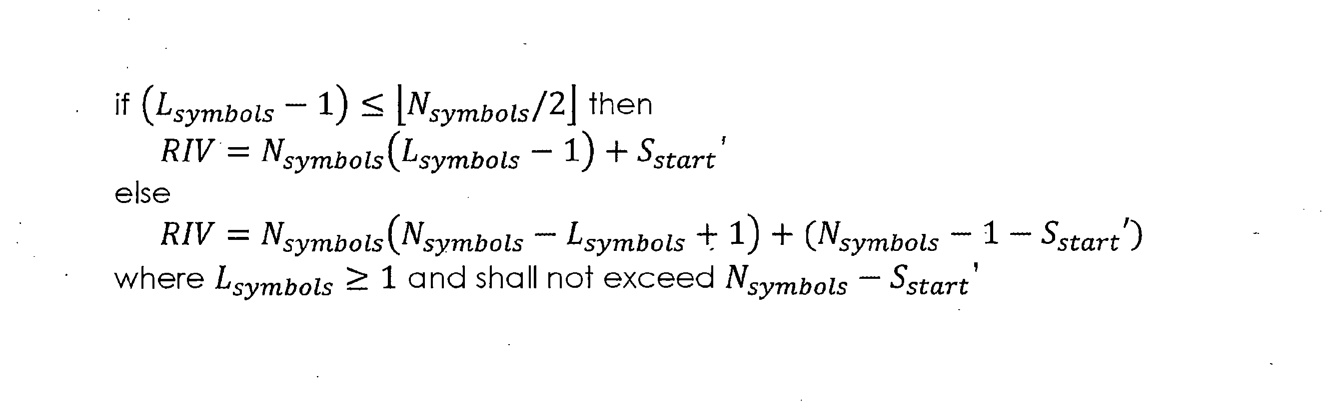
Lsymbolsは、端末にスケジューリングされた時間資源のOFDMシンボルの個数を示す。また、SstartはリファレンスOFDMシンボルのインデックスを基準に獲得した端末にスケジューリングされた時間資源の開始OFDMシンボルのインデックスである。よって、端末にスケジューリングされた時間資源のOFDMシンボルインデックスは以下の数式によって獲得される。 L symbols indicates the number of OFDM symbols of time resources scheduled to the terminal. Also, S start is the index of the start OFDM symbol of the time resource scheduled to the terminal, which is acquired based on the index of the reference OFDM symbol. Therefore, the OFDM symbol index of the time resource scheduled to the terminal is obtained by the following formula.
Sstart=Sstart’+R
S start = S start '+R
この際、RはリファレンスOFDMシンボルのインデックスである。このようにリファレンスOFDMシンボルを使用すれば、端末がデータチャネルを受信するために用意すべきメモリの大きさを減らすことができる。また、このような実施例はRIVを伝送するのに使用されるフィールドのビット数を減らすことができる。 At this time, R is the index of the reference OFDM symbol. By using the reference OFDM symbols in this way, it is possible to reduce the amount of memory that a terminal needs to prepare for receiving a data channel. Also, such embodiments can reduce the number of bits in the field used to transmit the RIV.
前記で基地局がRRC信号を使用してリファレンスOFDMシンボルのインデックスを設定するとした。他の具体的な実施例において、端末はリファレンスOFDMシンボルのインデックスをスロットの最初のOFDMシンボルと仮定する。また他の具体的な実施例において、端末は、端末の物理データチャネルの受信をスケジューリングするDCIが伝送されたCORESETに基づいてリファレンスOFDMシンボルのインデックスを判断する。例えば、端末は、端末の物理データチャネルの受信をスケジューリングするDCIが伝送されたCORESETの最初のOFDMシンボルインデックスをリファレンスOFDMシンボルのインデックスと判断する。更に他の具体的な実施例において、端末は、端末に時間資源をスケジューリングするDCIが伝送されたCORESETの最後のOFDMシンボルのすぐ次のOFDMシンボルのインデックスをリファレンスOFDMシンボルのインデックスと判断する。端末に端末の物理データチャネルの受信をスケジューリングするDCIが伝送されたCORESETの最初のOFDMシンボルのインデックスがKで、CORESETが占める時間資源に当たるOFDMシンボルの個数がAであるとすれば、リファレンスOFDMシンボルのインデックスはK+Aである。RRC信号を介し、リファレンスOFDMシンボルのインデックスがシグナリングされる際よりRRC信号の伝送に必要なビット数を減らすことができる。 In the above, it is assumed that the base station uses the RRC signal to set the index of the reference OFDM symbol. In another specific embodiment, the terminal assumes the index of the reference OFDM symbol is the first OFDM symbol of the slot. In yet another specific embodiment, the terminal determines the index of the reference OFDM symbol based on the CORESET in which the DCI that schedules reception of the terminal's physical data channel is transmitted. For example, the terminal determines the first OFDM symbol index of the CORESET in which the DCI that schedules reception of the terminal's physical data channel is transmitted as the index of the reference OFDM symbol. In yet another specific embodiment, the terminal determines the index of the OFDM symbol immediately following the last OFDM symbol of the CORESET in which the DCI for scheduling time resources to the terminal is transmitted as the index of the reference OFDM symbol. If the index of the first OFDM symbol of the CORESET in which the DCI for scheduling the reception of the terminal's physical data channel is transmitted to the terminal is K, and the number of OFDM symbols corresponding to the time resources occupied by the CORESET is A, then the reference OFDM symbol The index of is K+A. The number of bits required to transmit the RRC signal can be reduced compared to when the index of the reference OFDM symbol is signaled via the RRC signal.
更に他の具体的な実施例において、端末は、端末の物理データチャネルの受信をスケジューリングするDCIが伝送されたCORESETと上述したK0値によってリファレンスOFDMシンボルのインデックスを判断する。K0はPDSCHがスケジューリングされるスロットを示す。K0=0であれば、端末に端末の物理データチャネルの受信をスケジューリングするDCIと該当物理データチャネルが同じスロットで伝送されることを示す。また、K0=1であれば、端末に端末の物理データチャネルの受信をスケジューリングするDCIが伝送されるスロットのすぐ次のスロットに該当物理データチャネルが伝送されることを示す。具体的な実施例において、K0が0より大きければ、端末はリファレンスOFDMシンボルのインデックスを0と判断する。また、K0が0と同じであれば、端末はリファレンスOFDMシンボルのインデックスを端末の物理データチャネルの受信をスケジューリングするDCIが伝送されたCORESETの最初のOFDMシンボルと判断する。他の具体的な実施例において、K0が0と同じであれば、端末はリファレンスOFDMシンボルのインデックスを端末の物理データチャネルの受信をスケジューリングするDCIが伝送されたCORESETの最初のOFDMシンボルのインデックスにCORESETが占める時間資源に当たるOFDMシンボルの個数を足した値と判断する。このような実施例において、端末はクロス-スケジューリングが行われる際と行われない際に異なる動作を行って、RIV伝送に必要なビットの数を減らすことができる。また、RRC信号を介し、リファレンスOFDMシンボルのインデックスがシグナリングされる際よりRRC信号の伝送に必要なビット数を減らすことができる。 In yet another specific embodiment, the terminal determines the index of the reference OFDM symbol according to the above-mentioned K0 value and the CORESET in which the DCI that schedules reception of the physical data channel of the terminal is transmitted. K0 indicates the slot in which the PDSCH is scheduled. If K0=0, it indicates to the terminal that the DCI for scheduling reception of the physical data channel of the terminal and the corresponding physical data channel are transmitted in the same slot. Further, if K0=1, it indicates that the corresponding physical data channel is transmitted to the terminal in the slot immediately following the slot in which the DCI for scheduling reception of the physical data channel of the terminal is transmitted. In a specific embodiment, if K0 is greater than 0, the terminal determines the index of the reference OFDM symbol to be 0. Also, if K0 is equal to 0, the terminal determines the index of the reference OFDM symbol as the first OFDM symbol of the CORESET in which the DCI that schedules reception of the terminal's physical data channel is transmitted. In another specific embodiment, if K0 is equal to 0, the terminal sets the index of the reference OFDM symbol to the index of the first OFDM symbol of the CORESET in which the DCI that schedules reception of the terminal's physical data channel is transmitted. It is determined that the value is the sum of the number of OFDM symbols corresponding to the time resources occupied by CORESET. In such embodiments, the terminal may perform different operations when cross-scheduling is performed and when cross-scheduling is not performed to reduce the number of bits required for RIV transmission. Furthermore, the number of bits required for transmitting the RRC signal can be reduced compared to when the index of the reference OFDM symbol is signaled via the RRC signal.
更に他の具体的な実施例において、端末は、端末が受信する物理データチャネルのマッピングタイプに基づいてリファレンスOFDMシンボルのインデックスを判断する。この際、物理データチャネルのマッピングタイプは、DMRSの位置が物理データチャネルの位置とは関係なく決定されるのかを示す。また、端末が受信する物理チャネルはPDSCHである。詳しくは、物理データチャネルのマッピングタイプはタイプAとタイプBに区分される。タイプAは、DMRSの位置がスロット内でOFDMシンボルのインデックス2または3に固定されることを示す。この際、DMRSの位置はPBCHによって指示される。また、タイプBは最初のDMRSが物理データチャネルの最初のOFDMシンボルに位置することを示す。物理データチャネルのマッピングタイプがタイプAであれば、端末はリファレンスOFDMシンボルのインデックスを0と判断する。また、物理データチャネルのマッピングタイプがタイプBであれば、端末はリファレンスOFDMシンボルのインデックスを端末の物理データチャネルの受信をスケジューリングするDCIが伝送されたCORESETの最初のOFDMシンボルのインデックスと判断する。更に具体的な実施例において、物理データチャネルのマッピングタイプがタイプBであれば、端末はリファレンスOFDMシンボルのインデックスを端末の物理データチャネルの受信をスケジューリングするDCIが伝送されたCORESETの最初のOFDMシンボルのインデックスに該当CORESETが占める時間資源に当たるOFDMシンボルの個数を足した値と判断する。 In yet another specific embodiment, the terminal determines the index of the reference OFDM symbol based on a mapping type of a physical data channel that the terminal receives. At this time, the mapping type of the physical data channel indicates whether the location of the DMRS is determined regardless of the location of the physical data channel. Further, the physical channel that the terminal receives is PDSCH. Specifically, mapping types of physical data channels are classified into type A and type B. Type A indicates that the position of the DMRS is fixed at index 2 or 3 of the OFDM symbol within the slot. At this time, the location of the DMRS is indicated by the PBCH. Type B also indicates that the first DMRS is located at the first OFDM symbol of the physical data channel. If the mapping type of the physical data channel is type A, the terminal determines that the index of the reference OFDM symbol is 0. Furthermore, if the mapping type of the physical data channel is type B, the terminal determines the index of the reference OFDM symbol as the index of the first OFDM symbol of the CORESET in which the DCI that schedules reception of the physical data channel of the terminal is transmitted. In a more specific embodiment, if the mapping type of the physical data channel is type B, the terminal assigns the index of the reference OFDM symbol to the first OFDM symbol of the CORESET in which the DCI scheduling the reception of the physical data channel of the terminal is transmitted. The index is determined to be the sum of the number of OFDM symbols corresponding to the time resources occupied by the corresponding CORESET.
更に他の具体的な実施例において、端末は、端末の物理データチャネルの受信をスケジューリングするDCIの位置に基づいてリファレンスOFDMシンボルのインデックスを判断する。詳しくは、端末の物理データチャネルの受信をスケジューリングするDCIが予め指定されたOFDMシンボルの以前に位置すれば、端末はリファレンスOFDMシンボルのインデックスを0と判断する。また、端末の物理データチャネルの受信をスケジューリングするDCIが予め指定されたOFDMシンボルの以前に位置すれば、端末はリファレンスOFDMシンボルのインデックスを端末の物理データチャネルの受信をスケジューリングするDCIが伝送されたCORESETの最初のOFDMシンボルのインデックスと判断する。更に他の具体的な実施例において、端末の物理データチャネルの受信をスケジューリングするDCIが予め指定されたOFDMシンボルの以前に位置すれば、端末はリファレンスOFDMシンボルのインデックスを端末の物理データチャネルの受信をスケジューリングするDCIが伝送されたCORESETの最初のOFDMシンボルのインデックスに該当CORESETが占める時間資源に当たるOFDMシンボルの個数を足した値と判断する。予め指定されたOFDMシンボルの位置は、PBCHによって設定された端末が受信する物理データチャネルのマッピングタイプがタイプAである場合のDMRSの位置と同じである。詳しくは、物理データチャネルのマッピングタイプがタイプAで、PBCHがDMRSの位置として2番目のOFDMシンボルを指示すれば、予め指定されたOFDMシンボルの位置は2番目OFDMシンボルである。また、物理データチャネルのマッピングタイプがタイプAで、PBCHがDMRSの位置として3番目のOFDMシンボルを指示すれば、予め指定されたOFDMシンボルの位置は3番目OFDMシンボルである。 In yet another specific embodiment, the terminal determines the index of the reference OFDM symbol based on the location of the DCI that schedules reception of the terminal's physical data channel. Specifically, if the DCI that schedules reception of the physical data channel of the terminal is located before a predetermined OFDM symbol, the terminal determines that the index of the reference OFDM symbol is 0. In addition, if the DCI that schedules the reception of the physical data channel of the terminal is located before a pre-specified OFDM symbol, the terminal uses the index of the reference OFDM symbol as the DCI that schedules the reception of the physical data channel of the terminal. It is determined to be the index of the first OFDM symbol of CORESET. In yet another specific embodiment, if the DCI that schedules the reception of the physical data channel of the terminal is located before a pre-specified OFDM symbol, the terminal uses the index of the reference OFDM symbol to schedule the reception of the physical data channel of the terminal. The DCI for scheduling is determined to be the sum of the index of the first OFDM symbol of the transmitted CORESET and the number of OFDM symbols corresponding to the time resources occupied by the corresponding CORESET. The position of the pre-designated OFDM symbol is the same as the DMRS position when the mapping type of the physical data channel received by the terminal set by the PBCH is type A. Specifically, if the mapping type of the physical data channel is type A and the PBCH indicates the second OFDM symbol as the DMRS location, the pre-specified OFDM symbol location is the second OFDM symbol. Further, if the mapping type of the physical data channel is type A and the PBCH indicates the third OFDM symbol as the DMRS position, the pre-specified OFDM symbol position is the third OFDM symbol.
更に他の具体的な実施例において、端末は、端末の物理データチャネルの受信をスケジューリングするDCIが伝送されたCORESETと上述したK0値、及び端末の物理データチャネルの受信をスケジューリングするDCIが予め指定されたOFDMシンボルの以前に位置するのかに基づいてリファレンスOFDMシンボルのインデックスを判断する。K0はPDSCHがスケジューリングされるスロットを示す。具体的な実施例において、K0が0より大きいか、端末の物理データチャネルの受信をスケジューリングするDCIが予め指定されたOFDMシンボルの以前に位置すれば、端末はリファレンスOFDMシンボルのインデックスを0と判断する。また、K0が0と同じで、端末の物理データチャネルの受信をスケジューリングするDCIが予め指定されたOFDMシンボルの以前に位置しなければ、端末はリファレンスOFDMシンボルのインデックスを端末の物理データチャネルの受信をスケジューリングするDCIが伝送されたCORESETの最初のOFDMシンボルと判断する。更に他の具体的な実施例において、K0が0と同じで、端末の物理データチャネルの受信をスケジューリングするDCIが予め指定されたOFDMシンボルの以前に位置しなければ、端末はリファレンスOFDMシンボルのインデックスを端末の物理データチャネルの受信をスケジューリングするDCIが伝送されたCORESETの最初のOFDMシンボルのインデックスにCORESETが占める時間資源に当たるOFDMシンボルの個数を足した値と判断する。このような実施例において、端末はクロス-スケジューリングが行われる際と行われない際に異なる動作を行って、RIV伝送に必要なビットの数を減らすことができる。また、RRC信号を介し、リファレンスOFDMシンボルのインデックスがシグナリングされる際よりRRC信号の伝送に必要なビット数を減らすことができる。 In yet another specific embodiment, the terminal includes a CORESET in which a DCI for scheduling reception of a physical data channel of the terminal is transmitted and a K0 value as described above, and a DCI for scheduling reception of a physical data channel for the terminal is specified in advance. The index of the reference OFDM symbol is determined based on whether it is located before the reference OFDM symbol. K0 indicates the slot in which the PDSCH is scheduled. In a specific embodiment, if K0 is greater than 0 or the DCI that schedules reception of the physical data channel of the terminal is located before a pre-specified OFDM symbol, the terminal determines the index of the reference OFDM symbol to be 0. do. Also, if K0 is equal to 0 and the DCI that schedules reception of the physical data channel of the terminal is not located before a pre-specified OFDM symbol, the terminal uses the index of the reference OFDM symbol to It is determined that the DCI for scheduling is the first OFDM symbol of the transmitted CORESET. In yet another specific embodiment, if K0 is equal to 0 and the DCI that schedules reception of the physical data channel of the terminal is not located before the prespecified OFDM symbol, the terminal is determined to be the sum of the index of the first OFDM symbol of the CORESET in which the DCI for scheduling reception of the physical data channel of the terminal is transmitted and the number of OFDM symbols corresponding to the time resources occupied by the CORESET. In such embodiments, the terminal may perform different operations when cross-scheduling is performed and when cross-scheduling is not performed to reduce the number of bits required for RIV transmission. Furthermore, the number of bits required for transmitting the RRC signal can be reduced compared to when the index of the reference OFDM symbol is signaled via the RRC signal.
更に他の具体的な実施例において、端末は、端末がモニタリングするCORESETに基づいてリファレンスOFDMシンボルのインデックスを判断する。詳しくは、一つのスロットに端末がモニタリングするCORESETが複数で設定されれば、端末はリファレンスOFDMシンボルのインデックスを複数のCORESETが占めるOFDMシンボルのうち最も先のOFDMシンボルと判断する。端末が基地局が複数のCORESETのうちどのCORESETを介して物理制御チャネルを伝送するのかを判断することが難しいためである。このような実施例を介し、端末は複数のCORESETのうちどのCORESETで物理制御チャネルが伝送されても物理データチャネルを受信することができる。 In yet another specific embodiment, the terminal determines the index of the reference OFDM symbol based on the CORESET that the terminal monitors. Specifically, if a plurality of CORESETs to be monitored by the terminal are set in one slot, the terminal determines the index of the reference OFDM symbol to be the earliest OFDM symbol among the OFDM symbols occupied by the plurality of CORESETs. This is because it is difficult for the terminal to determine through which of the plurality of CORESETs the base station transmits the physical control channel. Through such an embodiment, a terminal can receive a physical data channel regardless of which of the plurality of CORESETs the physical control channel is transmitted in.
更に他の具体的な実施例において、端末の物理データチャネルの受信をスケジューリングDCIが伝送されるCORESETが該当物理データチャネルが伝送されるスロットとは異なるスロットに位置すれば、端末はリファレンスOFDMシンボルのインデックスを0と判断する。また、端末の物理データチャネルの受信をスケジューリングするDCIが伝送されるCORESETが該当物理データチャネルが伝送されるスロットと同じスロットに位置すれば、端末はリファレンスOFDMシンボルのインデックスを端末の物理データチャネルの受信をスケジューリングするDCIが伝送されたCORESETの最初のOFDMシンボルと判断する。更に他の具体的な実施例において、端末の物理データチャネルの受信をスケジューリングするDCIが伝送されるCORESETが該当物理データチャネルが伝送されるスロットと同じスロットに位置すれば、端末はリファレンスOFDMシンボルのインデックスを端末の物理データチャネルの受信をスケジューリングするDCIが伝送されたCORESETの最初のOFDMシンボルのインデックスにCORESETが占める時間資源に当たるOFDMシンボルの個数を足した値と判断する。 In yet another specific embodiment, if the CORESET for scheduling the reception of the physical data channel of the terminal is located in a slot different from the slot in which the corresponding physical data channel is transmitted, the terminal receives the reference OFDM symbol. Judge the index as 0. Furthermore, if the CORESET in which the DCI for scheduling the reception of the physical data channel of the terminal is transmitted is located in the same slot as the slot in which the corresponding physical data channel is transmitted, the terminal uses the index of the reference OFDM symbol as the The DCI for scheduling reception is determined to be the first OFDM symbol of the transmitted CORESET. In yet another specific embodiment, if the CORESET in which the DCI for scheduling reception of the physical data channel of the terminal is transmitted is located in the same slot as the slot in which the corresponding physical data channel is transmitted, the terminal receives the reference OFDM symbol. The index is determined to be the sum of the index of the first OFDM symbol of the CORESET in which the DCI for scheduling reception of the physical data channel of the terminal is transmitted, and the number of OFDM symbols corresponding to the time resources occupied by the CORESET.
また、DCIが端末の物理データチャネルの受信をスケジューリングする際、端末は、端末の物理データチャネルの受信がスケジューリングされる時間-周波数資源の最初のOFDMシンボルと最後のOFDMシンボルが互いに異なるスロットに位置することを期待しない。詳しくは、端末は、端末の物理データチャネルの受信がスケジューリングされる時間-周波数資源の最後のOFDMシンボルを、端末の物理データチャネルの受信がスケジューリングされる時間-周波数資源の開始OFDMシンボルが位置するスロットの最後のOFDMシンボルまたは最後のOFDMシンボルの以前のシンボルと判断する。例えば、スロットが含むOFDMシンボルの個数が14で、DCIが端末の物理データチャネルの受信がスケジューリングされる時間-周波数資源の最後のOFDMシンボルを7番目のOFDMシンボルと指示する。この際、DCIが指示する端末の物理データチャネルの受信がスケジューリングされる時間-周波数資源が占めるOFDMシンボルの個数が7であれば、端末は、端末の物理データチャネルの受信がスケジューリングされるOFDMシンボルを7番目のOFDMシンボルから14番目のOFDMシンボルまでと判断する。上述した実施例において、端末が受信する物理データチャネルはPDSCHである。 In addition, when the DCI schedules the reception of the physical data channel of the terminal, the terminal may locate the first OFDM symbol and the last OFDM symbol of the time-frequency resource in which the terminal is scheduled to receive the physical data channel in different slots. don't expect to. In particular, the terminal determines that the last OFDM symbol of the time-frequency resource on which the terminal is scheduled to receive a physical data channel is located, and the starting OFDM symbol of the time-frequency resource on which the terminal is scheduled to receive a physical data channel is located. Determine the last OFDM symbol of the slot or the symbol before the last OFDM symbol. For example, if the number of OFDM symbols included in the slot is 14, the DCI designates the seventh OFDM symbol as the last OFDM symbol of the time-frequency resource in which the reception of the physical data channel of the terminal is scheduled. At this time, if the number of OFDM symbols occupied by the time-frequency resource in which the terminal is scheduled to receive the physical data channel indicated by the DCI is 7, the terminal receives the OFDM symbols in which the terminal is scheduled to receive the physical data channel. is determined to be from the 7th OFDM symbol to the 14th OFDM symbol. In the embodiments described above, the physical data channel received by the terminal is the PDSCH.
上述した基地局が端末にスケジューリングされた連続した資源の開始シンボルの位置リファレンスOFDMシンボルのインデックスを使用して指示する実施例は、基地局が端末の物理チャネル伝送をスケジューリングする場合にも適用される。詳しくは、端末は、リファレンスOFDMシンボルのインデックスをスロットの最初のOFDMシンボルと判断する。端末の物理チャネル伝送に関して言及するOFDMシンボルはDFT-S-OFDMシンボルである。 The above-described embodiment in which the base station indicates to the terminal the position of the starting symbol of the scheduled consecutive resources using the index of the reference OFDM symbol also applies when the base station schedules the physical channel transmission of the terminal. . Specifically, the terminal determines the index of the reference OFDM symbol to be the first OFDM symbol of the slot. The OFDM symbol that refers to the physical channel transmission of the terminal is the DFT-S-OFDM symbol.
更に他の具体的な実施例において、端末は、端末が伝送する物理データチャネルのマッピングタイプに基づいてリファレンスOFDMシンボルのインデックスを判断する。この際、端末が伝送する物理データチャネルのマッピングタイプは、DMRSの位置が物理データチャネルの位置と関係なく決定されるのかを示す。また、端末が伝送する物理チャネルはPUSCHである。また、端末が伝送する物理データチャネルのマッピングタイプは、RRC信号で伝送されるUL-DMRS-config-typeを介して設定される。詳しくは、物理データチャネルのマッピングタイプはタイプAとタイプBに区分される。タイプAは、最初のDMRSの位置がスロット内で固定されることを示す。また、タイプBは最初のDMRSが物理データチャネルの最初のOFDMシンボルに位置することを示す。物理データチャネルのマッピングタイプがタイプAであれば、端末はリファレンスOFDMシンボルのインデックスを物理データチャネルに当たる最初のOFDMシンボルのインデックスと判断する。物理データチャネルのマッピングタイプがタイプBであれば、端末はリファレンスOFDMシンボルのインデックスを0と判断する。 In yet another specific embodiment, the terminal determines the index of the reference OFDM symbol based on the mapping type of the physical data channel that the terminal transmits. At this time, the mapping type of the physical data channel transmitted by the terminal indicates whether the location of the DMRS is determined regardless of the location of the physical data channel. Further, the physical channel transmitted by the terminal is PUSCH. Furthermore, the mapping type of the physical data channel transmitted by the terminal is configured via UL-DMRS-config-type transmitted in the RRC signal. Specifically, mapping types of physical data channels are classified into type A and type B. Type A indicates that the position of the first DMRS is fixed within the slot. Type B also indicates that the first DMRS is located at the first OFDM symbol of the physical data channel. If the mapping type of the physical data channel is type A, the terminal determines the index of the reference OFDM symbol as the index of the first OFDM symbol corresponding to the physical data channel. If the mapping type of the physical data channel is type B, the terminal determines that the index of the reference OFDM symbol is 0.
更に他の具体的な実施例において、端末は、端末が伝送する物理データチャネルのマッピングタイプとUL伝送のウェーブフォームに基づいてリファレンスOFDMシンボルのインデックスを判断する。端末は、CP-OFDM及びDFT-S-OFDMのうちいずれか一つを使用してUL伝送を行う。基地局はRRC信号を使用して、端末がCP-OFDM及びDFT-S-OFDMのうちいずれか一つを使用するのかを決定する。物理データチャネルのマッピングタイプがタイプBであれば、端末はリファレンスOFDMシンボルのインデックスを0と判断する。物理データチャネルのマッピングタイプがタイプAで、端末がDFT-S-OFDMウェーブフォームを使用するように設定されれば、端末はリファレンスOFDMシンボルのインデックスを最初のDMRSが位置するOFDMシンボルの次のOFDMシンボルのインデックスと判断する。UL DMRSで使用されるDFT-S-OFDMシンボルは物理データチャネルUL伝送に使用できない可能性があるためである。また、物理データチャネルのマッピングタイプがタイプAで、端末がCP-OFDMウェーブフォームを使用するように設定されれば、端末はリファレンスOFDMシンボルのインデックスを最初のDMRSが位置するOFDMシンボルのインデックスと判断する。 In yet another specific embodiment, the terminal determines the index of the reference OFDM symbol based on the mapping type of the physical data channel transmitted by the terminal and the waveform of the UL transmission. The terminal performs UL transmission using either CP-OFDM or DFT-S-OFDM. The base station uses the RRC signal to determine whether the terminal uses either CP-OFDM or DFT-S-OFDM. If the mapping type of the physical data channel is type B, the terminal determines that the index of the reference OFDM symbol is 0. If the mapping type of the physical data channel is type A and the terminal is configured to use the DFT-S-OFDM waveform, the terminal changes the index of the reference OFDM symbol to the OFDM symbol next to the OFDM symbol in which the first DMRS is located. Judged as the symbol index. This is because the DFT-S-OFDM symbols used in UL DMRS may not be used for physical data channel UL transmission. Also, if the mapping type of the physical data channel is type A and the terminal is configured to use the CP-OFDM waveform, the terminal determines the index of the reference OFDM symbol as the index of the OFDM symbol where the first DMRS is located. do.
更に他の具体的な実施例において、端末はセミ-スタティックに設定されたシンボル構成に基づいてリファレンスOFDMシンボルのインデックスを判断する。詳しくは、端末は、リファレンスOFDMシンボルのインデックスを端末の物理データチャネルがスケジューリングされたスロットでDLシンボルのすぐ次のアンノウンシンボルのインデックスと判断する。更に他の具体的な実施例において、端末は、リファレンスOFDMシンボルのインデックスを端末の物理データチャネルがスケジューリングされたスロットでDLシンボルのすぐ次のアンノウンシンボルのインデックスにギャップシンボルの数だけ足した値と判断する。ギャップシンボルの数は、TA(timing advance)値とOFDMシンボルの長さに基づいて決定される。更に他の具体的な実施例において、ギャップシンボルの数は基地局によって設定される。また、アンノウンシンボルにDLデータチャネルがスケジューリングされれば、端末はアンノウンシンボルをDLシンボルとみなす。また、アンノウンシンボルにULデータチャネルがスケジューリングされれば、端末はアンノウンシンボルをULシンボルとみなす。 In yet another specific embodiment, the terminal determines the index of the reference OFDM symbol based on a semi-statically configured symbol configuration. Specifically, the terminal determines the index of the reference OFDM symbol to be the index of the unknown symbol immediately following the DL symbol in the slot in which the terminal's physical data channel is scheduled. In yet another specific embodiment, the terminal determines that the index of the reference OFDM symbol is equal to the index of the unknown symbol immediately following the DL symbol in the slot in which the terminal's physical data channel is scheduled plus the number of gap symbols. to decide. The number of gap symbols is determined based on the TA (timing advance) value and the length of the OFDM symbol. In yet another specific embodiment, the number of gap symbols is configured by the base station. Also, if a DL data channel is scheduled on an unknown symbol, the terminal considers the unknown symbol as a DL symbol. Also, if a UL data channel is scheduled on an unknown symbol, the terminal considers the unknown symbol as a UL symbol.
また、DCIが端末の物理データチャネルの伝送をスケジューリングする際、端末は、端末の物理データチャネルの伝送がスケジューリングされる時間-周波数資源の最初のOFDMシンボルと最後のOFDMシンボルが互いに異なるスロットに位置することを期待しない。詳しくは、端末は、端末の物理データチャネルの伝送がスケジューリングされる時間-周波数資源の最後のOFDMシンボルを、端末の物理データチャネルの伝送がスケジューリングされる時間-周波数資源の開始OFDMシンボルが位置するスロットの最後のOFDMシンボルまたは最後のOFDMシンボルの以前のシンボルと判断する。例えば、スロットが含むOFDMシンボルの個数が14で、DCIが端末の物理データチャネルの伝送がスケジューリングされる時間-周波数資源の最後のOFDMシンボルを7番目のOFDMシンボルと指示する。この際、DCIが指示する端末の物理データチャネルの伝送がスケジューリングされる時間-周波数資源が占めるOFDMシンボルの個数が7であれば、端末は、端末の物理データチャネルの伝送がスケジューリングされるOFDMシンボルを7番目のOFDMシンボルから14番目のOFDMシンボルまでと判断する。上述した実施例において、端末が伝送する物理データチャネルはPUSCHである。 In addition, when the DCI schedules the transmission of the physical data channel of the terminal, the terminal may locate the first OFDM symbol and the last OFDM symbol of the time-frequency resource in which the transmission of the physical data channel of the terminal is scheduled in different slots. don't expect to. In particular, the terminal determines that the last OFDM symbol of the time-frequency resource on which the transmission of the physical data channel of the terminal is scheduled is located, and the starting OFDM symbol of the time-frequency resource on which the transmission of the physical data channel of the terminal is scheduled is located. Determine the last OFDM symbol of the slot or the symbol before the last OFDM symbol. For example, if the number of OFDM symbols included in the slot is 14, the DCI designates the seventh OFDM symbol as the last OFDM symbol of the time-frequency resource on which the transmission of the physical data channel of the terminal is scheduled. At this time, if the number of OFDM symbols occupied by the time-frequency resource designated by the DCI for which transmission of the physical data channel of the terminal is scheduled is 7, the terminal is determined to be from the 7th OFDM symbol to the 14th OFDM symbol. In the embodiments described above, the physical data channel transmitted by the terminal is PUSCH.
上述した実施例において、物理データチャネルはPDSCHまたはPUSCHを含む。また、物理制御チャネルはPDCCHまたはPUCCHを含む。また、PUSCH、PDCCH、PUCCH、及びPDCCHを例に挙げて説明した実施例において、他の種類のデータチャネル及び制御チャネルが適用されてもよい。 In the embodiments described above, the physical data channel includes PDSCH or PUSCH. Further, the physical control channel includes PDCCH or PUCCH. Further, in the embodiments described using PUSCH, PDCCH, PUCCH, and PDCCH as examples, other types of data channels and control channels may be applied.
本発明の方法及びシステムを特定実施例に関して説明したが、それらの構成要素または動作の一部または全部は、汎用ハードウェアアーキテクチャを有するコンピューティングシステムを使用して具現される。 Although the methods and systems of the present invention have been described with respect to particular embodiments, some or all of their components or operations may be implemented using a computing system having a general-purpose hardware architecture.
上述した本発明の説明は例示のためのものであって、本発明が属する技術分野における通常の知識を有する者は、本発明の技術的思想や必須的特徴を変更せずも他の具体的な形態に容易に変更可能であることを理解できるはずである。よって、上述した実施例は全ての面で例示的なものであり、限定的なものであると理解すべきである。例えば、単一型として説明されている各構成要素は分散されて実施されてもよく、同じく分散されていると説明されている構成要素も結合された形態で実施されてもよい。 The above description of the present invention is for illustrative purposes only, and those with ordinary knowledge in the technical field to which the present invention pertains will be able to make other specific explanations without changing the technical idea or essential features of the present invention. You should be able to understand that it can be easily changed to any other form. Therefore, the embodiments described above are illustrative in all respects and should be understood to be limited. For example, components described as unitary may be implemented in a distributed manner, and components also described as distributed may be implemented in a combined form.
本発明の範囲は、上述した詳細な説明よりは後述する特許請求の範囲によって示され、特許請求の範囲の意味及び範囲、そしてその均等概念から導き出される全ての変更または変形された形態が本発明の範囲に含まれると解釈すべきである。 The scope of the present invention is indicated by the claims set forth below rather than the detailed description given above, and the meaning and scope of the claims and all modifications or variations derived from the equivalent concept thereof are the present invention. should be interpreted as falling within the scope of
110 プロセッサ
121 セルラー通信インターフェースカード(第1周波数バンド)
122 セルラー通信インターフェースカード(第2周波数バンド)
123 無線LANインターフェースカード(第2周波数バンド)
130 メモリ
140 ユーザインタフェース
150 ディスプレイユニット
210 プロセッサ
221 セルラー通信インターフェースカード(第1周波数バンド)
222 セルラー通信インターフェースカード(第2周波数バンド)
223 無線LANインターフェースカード(第2周波数バンド)
230 メモリ
110 processor
121 Cellular communication interface card (1st frequency band)
122 Cellular communication interface card (second frequency band)
123 Wireless LAN interface card (second frequency band)
130 memory
140 User Interface
150 display unit
210 processor
221 Cellular communication interface card (1st frequency band)
222 Cellular communication interface card (second frequency band)
223 Wireless LAN interface card (second frequency band)
230 memory
Claims (8)
通信モジュールと、
前記通信モジュールを制御するように構成されたプロセッサと、を含み、
前記プロセッサは、
前記無線通信システムの基地局から前記通信モジュールを介してRRC(radio resource control)信号を受信し、
前記RRC信号が指示する少なくとも一つのリソース-セット(set)に当たる第1の時間-周波数資源を判断し、前記少なくとも一つのリソース-セットは、互いに異なるインデックスによってそれぞれ識別され、
前記通信モジュールを介して前記基地局から物理制御チャネルを受信し、前記物理制御チャネルは物理データチャネルを複数のスロットにスケジューリングし、
前記物理制御チャネルによって前記端末の物理データチャネルの受信がスケジューリングされる第2の時間-周波数資源を判断し、前記第1の時間-周波数資源は前記第2の時間-周波数資源とオーバーラップし、前記オーバーラップする時間-周波数資源は複数のサブ-リソース-セットを含み、
前記物理制御チャネルからレートマッチング指示子を獲得し、前記レートマッチング指示子は複数のビットを含み、前記複数のビットのそれぞれは前記複数のサブ-リソース-セット別に前記物理データチャネルの受信不可能可否を示し、前記レートマッチング指示子における特定のリソース-セットに含まれるサブ-リソース-セットを指示するビットは、前記特定のリソース-セットのインデックスに基づいて決定され、
前記レートマッチング指示子によって前記物理データチャネルを受信し、
前記リソース-セットは時間-周波数資源のセットである
ように構成される、端末。 A terminal for a wireless communication system, the terminal comprising:
a communication module;
a processor configured to control the communication module;
The processor includes:
receiving an RRC (radio resource control) signal from a base station of the wireless communication system via the communication module;
determining a first time-frequency resource corresponding to at least one resource set indicated by the RRC signal, each of the at least one resource set being identified by a different index;
receiving a physical control channel from the base station via the communication module, the physical control channel scheduling physical data channels into a plurality of slots;
determining a second time-frequency resource on which reception of a physical data channel of the terminal is scheduled by the physical control channel, the first time-frequency resource overlapping the second time-frequency resource; the overlapping time-frequency resources include a plurality of sub-resource sets;
A rate matching indicator is obtained from the physical control channel, and the rate matching indicator includes a plurality of bits, and each of the plurality of bits indicates whether or not the physical data channel is unreceivable for each of the plurality of sub-resource sets. and a bit indicating a sub - resource - set included in a specific resource - set in the rate matching indicator is determined based on an index of the specific resource - set,
receiving the physical data channel with the rate matching indicator;
A terminal configured such that the resource-set is a set of time-frequency resources.
前記物理データチャネルが受信される第2スロットで第2の時間-周波数と前記少なくとも一つのリソース-セットがオーバーラップすれば、前記プロセッサは前記第2スロットで物理データチャネルがスケジューリングされる時間-周波数資源から、前記物理データチャネルがスケジューリングされる時間-周波数と前記少なくとも一つのリソース-セットがオーバーラップする時間-周波数資源を除いた時間-周波数資源で前記物理データチャネルを受信するためのレートマッチングを行うように構成され、
前記第1スロットと前記第2スロットは互いに異なるスロットである
請求項1に記載の端末。 the physical control channel is received in a first slot;
If the second time-frequency and the at least one resource set overlap in the second slot in which the physical data channel is received, the processor determines the time-frequency in which the physical data channel is scheduled in the second slot. rate matching for receiving the physical data channel on a time-frequency resource excluding a time-frequency resource at which the at least one resource set overlaps the time-frequency resources at which the physical data channel is scheduled; configured to do
The terminal according to claim 1, wherein the first slot and the second slot are different slots.
前記無線通信システムの基地局からRRC(radio resource control)信号を受信するステップであって、前記少なくとも一つのリソース-セット
は、互いに異なるインデックスによってそれぞれ識別される、ステップと、
前記RRC信号が指示する少なくとも一つのリソース-セット(set)に当たる第1の時間-周波数資源を判断するステップと、
前記基地局から物理制御チャネルを受信するステップであって、前記物理制御チャネルは物理データチャネルを複数のスロットにスケジューリングする、ステップと、
前記物理制御チャネルによって前記端末の物理データチャネルの受信がスケジューリングされる第2の時間-周波数資源を判断するステップであって、前記第1の時間-周波数資源は前記第2の時間-周波数資源とオーバーラップし、前記オーバーラップする時間-周波数資源は複数のサブ-リソース-セットを含む、ステップと、
前記物理制御チャネルからレートマッチング指示子を獲得するステップであって、前記レートマッチング指示子は複数のビットを含み、前記複数のビットのそれぞれで前記物理データチャネルの受信は、前記複数のサブ-リソース-セット別に不可能可否を示し、前記レートマッチング指示子における特定のリソース-セットに含まれるサブ-リソース-セットを指示するビットは、前記特定のリソース-セットのインデックスに基づいて決定される、ステップと、
前記レートマッチング指示子によって前記物理データチャネルを受信するステップと
を含み、
前記リソース-セットは時間-周波数資源のセットである、動作方法。 A method of operating a terminal of a wireless communication system, the method comprising:
receiving a radio resource control (RRC) signal from a base station of the wireless communication system, wherein the at least one resource - set is each identified by a different index;
determining a first time-frequency resource that corresponds to at least one resource set indicated by the RRC signal;
receiving a physical control channel from the base station, the physical control channel scheduling physical data channels into a plurality of slots;
determining a second time-frequency resource on which the terminal is scheduled to receive a physical data channel by the physical control channel, the first time-frequency resource being the second time-frequency resource; overlapping, the overlapping time-frequency resources comprising a plurality of sub-resource sets;
obtaining a rate matching indicator from the physical control channel, wherein the rate matching indicator includes a plurality of bits, and in each of the plurality of bits, reception of the physical data channel determines whether the plurality of sub-resources - a bit indicating whether or not it is impossible for each set and indicating a sub - resource set included in a specific resource set in the rate matching indicator is determined based on an index of the specific resource set; and,
receiving the physical data channel according to the rate matching indicator;
The method of operation, wherein the resource-set is a set of time-frequency resources.
前記物理データチャネルを受信する前記ステップは、前記物理データチャネルが受信される第2スロットで第2の時間-周波数と前記少なくとも一つのリソース-セットがオーバーラップすれば、前記第2スロットで物理データチャネルがスケジューリングされる時間-周波数資源から、前記物理データチャネルがスケジューリングされる時間-周波数と前記少なくとも一つのリソース-セットがオーバーラップする時間-周波数資源を除いた時間-周波数資源で前記物理データチャネルを受信するためのレートマッチングを行うステップを含み、
前記第1スロットと前記第2スロットは互いに異なるスロットである
請求項5に記載の動作方法。 the physical control channel is received in a first slot;
The step of receiving the physical data channel may include receiving the physical data in the second slot if a second time-frequency and the at least one resource set overlap in the second slot in which the physical data channel is received. From the time-frequency resource at which the channel is scheduled, the time-frequency at which the physical data channel is scheduled and the at least one resource set overlaps the time-frequency resource excluding the time-frequency resource at which the physical data channel is scheduled. performing rate matching for receiving the
The operating method according to claim 5, wherein the first slot and the second slot are different slots.
Applications Claiming Priority (10)
| Application Number | Priority Date | Filing Date | Title |
|---|---|---|---|
| KR10-2017-0115232 | 2017-09-08 | ||
| KR1020170115232A KR20190028148A (en) | 2017-09-08 | 2017-09-08 | Method, apparatus, and system for transmitting or receiving data in wireless communication system |
| KR10-2017-0119178 | 2017-09-17 | ||
| KR20170119178 | 2017-09-17 | ||
| KR20170163637 | 2017-11-30 | ||
| KR10-2017-0163637 | 2017-11-30 | ||
| KR20180004324 | 2018-01-12 | ||
| KR10-2018-0004324 | 2018-01-12 | ||
| PCT/KR2018/010576 WO2019050371A1 (en) | 2017-09-08 | 2018-09-10 | Data transmission method and reception method for wireless communication system and device using same |
| JP2020513789A JP7142960B2 (en) | 2017-09-08 | 2018-09-10 | Data transmission method and reception method for wireless communication system, and device using the same |
Related Parent Applications (1)
| Application Number | Title | Priority Date | Filing Date |
|---|---|---|---|
| JP2020513789A Division JP7142960B2 (en) | 2017-09-08 | 2018-09-10 | Data transmission method and reception method for wireless communication system, and device using the same |
Publications (3)
| Publication Number | Publication Date |
|---|---|
| JP2022172323A JP2022172323A (en) | 2022-11-15 |
| JP2022172323A5 JP2022172323A5 (en) | 2022-12-15 |
| JP7421237B2 true JP7421237B2 (en) | 2024-01-24 |
Family
ID=65635084
Family Applications (5)
| Application Number | Title | Priority Date | Filing Date |
|---|---|---|---|
| JP2020513789A Active JP7142960B2 (en) | 2017-09-08 | 2018-09-10 | Data transmission method and reception method for wireless communication system, and device using the same |
| JP2022142230A Active JP7421238B2 (en) | 2017-09-08 | 2022-09-07 | Data transmission method and reception method of wireless communication system, and device using the same |
| JP2022142229A Active JP7421237B2 (en) | 2017-09-08 | 2022-09-07 | Data transmission method and reception method of wireless communication system, and device using the same |
| JP2024000224A Active JP7678617B2 (en) | 2017-09-08 | 2024-01-04 | Data transmission method and reception method for wireless communication system, and device using same |
| JP2025072423A Pending JP2025105814A (en) | 2017-09-08 | 2025-04-24 | Data transmission method and reception method for wireless communication system, and device using same |
Family Applications Before (2)
| Application Number | Title | Priority Date | Filing Date |
|---|---|---|---|
| JP2020513789A Active JP7142960B2 (en) | 2017-09-08 | 2018-09-10 | Data transmission method and reception method for wireless communication system, and device using the same |
| JP2022142230A Active JP7421238B2 (en) | 2017-09-08 | 2022-09-07 | Data transmission method and reception method of wireless communication system, and device using the same |
Family Applications After (2)
| Application Number | Title | Priority Date | Filing Date |
|---|---|---|---|
| JP2024000224A Active JP7678617B2 (en) | 2017-09-08 | 2024-01-04 | Data transmission method and reception method for wireless communication system, and device using same |
| JP2025072423A Pending JP2025105814A (en) | 2017-09-08 | 2025-04-24 | Data transmission method and reception method for wireless communication system, and device using same |
Country Status (9)
| Country | Link |
|---|---|
| US (5) | US11304181B2 (en) |
| EP (4) | EP4373191B1 (en) |
| JP (5) | JP7142960B2 (en) |
| KR (5) | KR102481201B1 (en) |
| CN (5) | CN119583026A (en) |
| ES (2) | ES3005312T3 (en) |
| FI (2) | FI3681079T3 (en) |
| PL (2) | PL3681079T3 (en) |
| WO (1) | WO2019050371A1 (en) |
Families Citing this family (30)
| Publication number | Priority date | Publication date | Assignee | Title |
|---|---|---|---|---|
| CN108430107B (en) * | 2017-02-11 | 2024-03-05 | 华为技术有限公司 | Data transmission method, device and system |
| PL4221057T3 (en) | 2017-06-16 | 2026-01-26 | Wilus Institute Of Standards And Technology Inc. | Method, apparatus, and system for transmitting or receiving control channel and data channel in wireless communication system |
| KR102481201B1 (en) * | 2017-09-08 | 2022-12-27 | 주식회사 윌러스표준기술연구소 | Data transmission method and reception method of wireless communication system and device using the same |
| CN113517952A (en) | 2017-09-30 | 2021-10-19 | 中兴通讯股份有限公司 | Method and device for determining time-frequency resources |
| CN111083794B (en) * | 2017-09-30 | 2021-01-26 | Oppo广东移动通信有限公司 | A channel resource indication method, terminal device and network device |
| CN109818895B (en) * | 2017-11-17 | 2022-04-29 | 中兴通讯股份有限公司 | Method and device for determining sequence group, method and device for determining cyclic shift |
| WO2019127551A1 (en) * | 2017-12-29 | 2019-07-04 | 北京小米移动软件有限公司 | Transmitting method and device and receiving method and device |
| WO2019157726A1 (en) * | 2018-02-14 | 2019-08-22 | Oppo广东移动通信有限公司 | Resource reporting method, terminal device and network device |
| CN110351839B (en) | 2018-04-04 | 2023-03-28 | 华为技术有限公司 | Communication method and device |
| US20190313385A1 (en) | 2018-04-05 | 2019-10-10 | Qualcomm Incorporated | Compact dci for urllc |
| US11405943B2 (en) * | 2018-09-28 | 2022-08-02 | Apple Inc. | Cross-slot scheduling for New Radio |
| CN113196846B (en) * | 2018-12-20 | 2024-10-15 | 索尼集团公司 | Communication device, infrastructure equipment and method |
| EP3949224A1 (en) * | 2019-03-26 | 2022-02-09 | Telefonaktiebolaget LM Ericsson (publ) | Systems and methods for radio operation with reduced bandwidth |
| GB2582662B (en) | 2019-03-29 | 2021-10-06 | Samsung Electronics Co Ltd | Improvements in and relating to non-terrestrial networks |
| CN110574401B (en) * | 2019-07-30 | 2022-11-22 | 北京小米移动软件有限公司 | Information configuration method and device, channel estimation method and device and sending equipment |
| WO2021029708A1 (en) * | 2019-08-15 | 2021-02-18 | 엘지전자 주식회사 | Method, transmission device, and recording medium for transmitting transport block in unlicensed band |
| WO2021062747A1 (en) * | 2019-09-30 | 2021-04-08 | 华为技术有限公司 | Scheduling method and apparatus |
| CN115802506A (en) * | 2019-12-06 | 2023-03-14 | 大唐移动通信设备有限公司 | A kind of uplink channel transmission method, terminal and base station |
| CN113271672B (en) * | 2020-02-14 | 2023-08-04 | 华为技术有限公司 | Method and device for determining DL SPS resources |
| US11671994B2 (en) * | 2020-04-10 | 2023-06-06 | Qualcomm Incorporated | Reusing PDSCH TCI and QCL for dynamic coresets |
| US11671995B2 (en) * | 2020-04-17 | 2023-06-06 | Qualcomm Incorporated | Time domain resource allocation-based HARQ-ACK feedback generation |
| WO2022006740A1 (en) * | 2020-07-07 | 2022-01-13 | Qualcomm Incorporated | Interlaced waveform for control resource set (coreset) |
| CN114071724B (en) * | 2020-07-30 | 2024-04-19 | 中国联合网络通信集团有限公司 | Communication method and device |
| CN112153625B (en) * | 2020-09-29 | 2021-10-26 | 上海豹云网络信息服务有限公司 | Insurance accident big data transmission method and system based on block chain system |
| CN115190593A (en) * | 2021-04-01 | 2022-10-14 | 华为技术有限公司 | Method and device for determining resources |
| CN117957801A (en) * | 2021-08-05 | 2024-04-30 | 北京小米移动软件有限公司 | Beam management using reference cells |
| CN114641075B (en) * | 2022-03-16 | 2025-02-28 | 深圳市科思科技股份有限公司 | Data transmission method, device, terminal equipment and storage medium |
| KR20240124012A (en) * | 2023-02-08 | 2024-08-16 | 삼성전자주식회사 | A method and apparatus for allocating resource in wireless communication system |
| US20240380559A1 (en) * | 2023-05-11 | 2024-11-14 | Cisco Technology, Inc. | Network with pilot tone overlap avoidance |
| CN121645522A (en) * | 2024-09-06 | 2026-03-10 | 华为技术有限公司 | A communication method and related apparatus |
Citations (1)
| Publication number | Priority date | Publication date | Assignee | Title |
|---|---|---|---|---|
| JP2015508956A (en) | 2012-01-27 | 2015-03-23 | インターデイジタル パテント ホールディングス インコーポレイテッド | System and / or method for providing EPDCCH in a multi-carrier based and / or pseudo matching network |
Family Cites Families (36)
| Publication number | Priority date | Publication date | Assignee | Title |
|---|---|---|---|---|
| KR101697596B1 (en) | 2009-01-29 | 2017-01-18 | 엘지전자 주식회사 | Method and apparatus of controlling transmission power |
| CN105450379B (en) * | 2010-01-26 | 2018-11-27 | Lg电子株式会社 | The method and apparatus of resource is distributed in a wireless communication system |
| KR20140004199A (en) * | 2011-01-30 | 2014-01-10 | 베이징 뉴프론트 모바일 멀티미디어 테크놀로지 씨오., 엘티디 | Method and device for realizing multi-input multi-output |
| CN103037520A (en) * | 2011-03-25 | 2013-04-10 | 北京新岸线无线技术有限公司 | Resource scheduling method and resource scheduling device |
| WO2012169744A2 (en) * | 2011-06-08 | 2012-12-13 | 엘지전자 주식회사 | Method and device for information transmission in wireless communication system |
| US8584393B2 (en) * | 2011-07-13 | 2013-11-19 | Laser Devices, Inc. | Accessory bracket for firearm mount |
| CN104012016B (en) * | 2011-10-20 | 2017-03-22 | 三星电子株式会社 | Method and device for sending and receiving control information in wireless communication system |
| US9113463B2 (en) * | 2011-11-04 | 2015-08-18 | Qualcomm Incorporated | Resource management for enhanced PDCCH |
| US9019921B2 (en) * | 2012-02-22 | 2015-04-28 | Lg Electronics Inc. | Method and apparatus for transmitting data between wireless devices in wireless communication system |
| EP3261400B1 (en) * | 2012-05-10 | 2018-10-24 | Sun Patent Trust | Dynamic allocation of ack/nack resources |
| CN103491637B (en) * | 2012-06-12 | 2017-03-29 | 电信科学技术研究院 | A kind of determination method and device of PDSCH transmission resource |
| US9456358B2 (en) * | 2012-08-13 | 2016-09-27 | Qualcomm Incorporated | Method and apparatus for indicating active channel state information reference signal (CSI-RS) configurations |
| EP2905915B1 (en) * | 2012-10-04 | 2018-09-12 | LG Electronics Inc. | Method and apparatus for receiving a pdsch |
| CN104782067B (en) * | 2012-11-06 | 2017-11-28 | Lg电子株式会社 | Method and apparatus for sending and receiving data in a wireless communication system |
| US9871636B2 (en) * | 2013-01-18 | 2018-01-16 | Qualcomm Incorporated | Enhanced control channel element (ECCE) based physical downlink shared channel (PDSCH) resource allocation for long-term evolution (LTE) |
| CN104852778B (en) * | 2014-02-18 | 2020-03-13 | 中兴通讯股份有限公司 | Overhead information transmission method, base station, terminal and system |
| WO2016018079A1 (en) * | 2014-08-01 | 2016-02-04 | 엘지전자 주식회사 | Downlink signal reception method and user equipment, and downlink signal transmission method and base station |
| CN107005960B (en) * | 2014-09-24 | 2020-07-07 | 交互数字专利控股公司 | Channel usage indication and synchronization for LTE operation in unlicensed frequency bands |
| US11818717B2 (en) * | 2014-12-31 | 2023-11-14 | Texas Instruments Incorporated | Method and apparatus for uplink control signaling with massive Carrier Aggregation |
| KR102070958B1 (en) * | 2014-12-31 | 2020-03-02 | 후아웨이 테크놀러지 컴퍼니 리미티드 | User equipment, access network device, and method for sending and receiving feedback information |
| WO2016114593A1 (en) * | 2015-01-13 | 2016-07-21 | 엘지전자 주식회사 | Method and user equipment for sending uplink signal, and method and base station for receiving uplink signal |
| US9775141B2 (en) * | 2015-07-14 | 2017-09-26 | Motorola Mobility Llc | Method and apparatus for reducing latency of LTE uplink transmissions |
| KR102412484B1 (en) * | 2015-08-06 | 2022-06-24 | 씨스코 시스템즈, 인코포레이티드 | Apparatus and method for dynamic resource allocation for uplink control channel |
| WO2017026159A1 (en) * | 2015-08-11 | 2017-02-16 | 三菱電機株式会社 | Communication system |
| EP3809781B1 (en) * | 2015-11-03 | 2023-10-18 | Telefonaktiebolaget LM Ericsson (publ) | Methods and apparatus for scheduling in uplink |
| US11129152B2 (en) * | 2016-02-04 | 2021-09-21 | Lg Electronics Inc. | Method and user equipment for receiving dowlink control information, and method and base station for transmitting dowlink control information |
| EP3433964B1 (en) | 2016-03-22 | 2020-08-12 | Telefonaktiebolaget LM Ericsson (PUBL) | Dynamic demodulation indication |
| US11477771B2 (en) * | 2016-04-05 | 2022-10-18 | Qualcomm Incorporated | Indicating start and stop symbols of PDSCH and PUSCH through PDCCH |
| CN106788931B (en) * | 2016-09-30 | 2019-01-04 | 展讯通信(上海)有限公司 | The method and base station, user equipment that information is transmitted in communication system |
| EP3565155B1 (en) * | 2017-01-23 | 2022-04-06 | Huawei Technologies Co., Ltd. | Data transmission method and apparatus |
| KR20190051730A (en) * | 2017-11-07 | 2019-05-15 | 주식회사 윌러스표준기술연구소 | METHOD, APPARATUS, AND SYSTEM FOR TRANSMITTING DATA BETWEEEN ENB (or GNB) AND UE, AND TRANSMITTING/RECEIVING CONTROL CHANNEL |
| WO2018164474A1 (en) * | 2017-03-08 | 2018-09-13 | 삼성전자 주식회사 | Method and apparatus for control and data information resource mapping in wireless cellular communication system |
| KR20180108342A (en) * | 2017-03-24 | 2018-10-04 | 주식회사 윌러스표준기술연구소 | Method, apparatus, and system for transmitting and receiving/decoding control channel in wireless communication system |
| CN108632005B (en) * | 2017-03-24 | 2023-12-15 | 华为技术有限公司 | Reference signal transmission method, device and system |
| KR20190027705A (en) * | 2017-09-07 | 2019-03-15 | 엘지전자 주식회사 | Apparatus and method for allocating resources in a wireless communication system |
| KR102481201B1 (en) * | 2017-09-08 | 2022-12-27 | 주식회사 윌러스표준기술연구소 | Data transmission method and reception method of wireless communication system and device using the same |
-
2018
- 2018-09-10 KR KR1020207007587A patent/KR102481201B1/en active Active
- 2018-09-10 KR KR1020237027767A patent/KR102650205B1/en active Active
- 2018-09-10 CN CN202411569514.9A patent/CN119583026A/en active Pending
- 2018-09-10 CN CN202211265886.3A patent/CN115720135B/en active Active
- 2018-09-10 CN CN201880064924.4A patent/CN111183608B/en active Active
- 2018-09-10 EP EP24167324.3A patent/EP4373191B1/en active Active
- 2018-09-10 FI FIEP18853967.0T patent/FI3681079T3/en active
- 2018-09-10 KR KR1020257033358A patent/KR20250153310A/en active Pending
- 2018-09-10 PL PL18853967.0T patent/PL3681079T3/en unknown
- 2018-09-10 FI FIEP22211093.4T patent/FI4164166T3/en active
- 2018-09-10 EP EP22211093.4A patent/EP4164166B1/en active Active
- 2018-09-10 CN CN202211265755.5A patent/CN115765946B/en active Active
- 2018-09-10 KR KR1020227044914A patent/KR102568599B1/en active Active
- 2018-09-10 PL PL22211093.4T patent/PL4164166T3/en unknown
- 2018-09-10 CN CN202211291221.XA patent/CN115765947B/en active Active
- 2018-09-10 ES ES22211093T patent/ES3005312T3/en active Active
- 2018-09-10 ES ES18853967T patent/ES2937950T3/en active Active
- 2018-09-10 EP EP25189585.0A patent/EP4608032A3/en active Pending
- 2018-09-10 EP EP18853967.0A patent/EP3681079B1/en active Active
- 2018-09-10 WO PCT/KR2018/010576 patent/WO2019050371A1/en not_active Ceased
- 2018-09-10 JP JP2020513789A patent/JP7142960B2/en active Active
- 2018-09-10 KR KR1020247009066A patent/KR20240042164A/en not_active Ceased
-
2020
- 2020-03-05 US US16/809,548 patent/US11304181B2/en active Active
-
2022
- 2022-03-04 US US17/686,643 patent/US11832255B2/en active Active
- 2022-03-04 US US17/686,592 patent/US12004161B2/en active Active
- 2022-09-07 JP JP2022142230A patent/JP7421238B2/en active Active
- 2022-09-07 JP JP2022142229A patent/JP7421237B2/en active Active
-
2024
- 2024-01-04 JP JP2024000224A patent/JP7678617B2/en active Active
- 2024-02-08 US US18/437,188 patent/US12418914B2/en active Active
-
2025
- 2025-04-24 JP JP2025072423A patent/JP2025105814A/en active Pending
- 2025-09-15 US US19/328,637 patent/US20260012948A1/en active Pending
Patent Citations (1)
| Publication number | Priority date | Publication date | Assignee | Title |
|---|---|---|---|---|
| JP2015508956A (en) | 2012-01-27 | 2015-03-23 | インターデイジタル パテント ホールディングス インコーポレイテッド | System and / or method for providing EPDCCH in a multi-carrier based and / or pseudo matching network |
Non-Patent Citations (2)
| Title |
|---|
| Nokia, Nokia Shanghai Bell, ZTE, Ericsson,Resource sharing between PDCCH and PDSCH in NR[online],3GPP TSG RAN WG1 #90 R1-1714098,Internet<URL:http://www.3gpp.org/ftp/tsg_ran/WG1_RL1/TSGR1_90/Docs/R1-1714098.zip>,2017年08月25日,1-4頁 |
| Samsung,Multiplexing NR-PDCCH and PDSCH[online],3GPP TSG RAN WG1 #90 R1-1713615,Internet<URL:http://www.3gpp.org/ftp/tsg_ran/WG1_RL1/TSGR1_90/Docs/R1-1713615.zip>,2017年08月25日,1-4頁 |
Also Published As
Similar Documents
| Publication | Publication Date | Title |
|---|---|---|
| JP7421237B2 (en) | Data transmission method and reception method of wireless communication system, and device using the same | |
| JP7761961B2 (en) | Method for generating HARQ-ACK codebook in wireless communication system and apparatus using same | |
| JP7754537B2 (en) | Method, device, and system for resource allocation in a wireless communication system | |
| KR102805041B1 (en) | Method for transmitting uplink control information in wireless communication system, and apparatus using same | |
| KR102903139B1 (en) | Method for multiplexing uplink control information in a wireless communication system and device using the same | |
| JP7701078B2 (en) | Method, device and system for cancelling uplink transmission in a wireless communication system | |
| KR20230006046A (en) | Channel multiplexing method and multiplexed channel transmission method for wireless communication system and device using same | |
| KR102864658B1 (en) | Method for receiving a physical control channel in a wireless communication system and a device using the same |
Legal Events
| Date | Code | Title | Description |
|---|---|---|---|
| A521 | Request for written amendment filed |
Free format text: JAPANESE INTERMEDIATE CODE: A523 Effective date: 20220907 |
|
| A621 | Written request for application examination |
Free format text: JAPANESE INTERMEDIATE CODE: A621 Effective date: 20220907 |
|
| A521 | Request for written amendment filed |
Free format text: JAPANESE INTERMEDIATE CODE: A523 Effective date: 20221207 |
|
| TRDD | Decision of grant or rejection written | ||
| A01 | Written decision to grant a patent or to grant a registration (utility model) |
Free format text: JAPANESE INTERMEDIATE CODE: A01 Effective date: 20231204 |
|
| A61 | First payment of annual fees (during grant procedure) |
Free format text: JAPANESE INTERMEDIATE CODE: A61 Effective date: 20240104 |
|
| R150 | Certificate of patent or registration of utility model |
Ref document number: 7421237 Country of ref document: JP Free format text: JAPANESE INTERMEDIATE CODE: R150 |