JP7421036B2 - lossless data compression - Google Patents
lossless data compression Download PDFInfo
- Publication number
- JP7421036B2 JP7421036B2 JP2019551920A JP2019551920A JP7421036B2 JP 7421036 B2 JP7421036 B2 JP 7421036B2 JP 2019551920 A JP2019551920 A JP 2019551920A JP 2019551920 A JP2019551920 A JP 2019551920A JP 7421036 B2 JP7421036 B2 JP 7421036B2
- Authority
- JP
- Japan
- Prior art keywords
- data
- compressed
- compression
- row
- value
- Prior art date
- Legal status (The legal status is an assumption and is not a legal conclusion. Google has not performed a legal analysis and makes no representation as to the accuracy of the status listed.)
- Active
Links
- 238000013144 data compression Methods 0.000 title claims description 17
- 238000007906 compression Methods 0.000 claims description 91
- 230000006835 compression Effects 0.000 claims description 89
- 238000000034 method Methods 0.000 claims description 52
- 238000012545 processing Methods 0.000 claims description 37
- 230000006837 decompression Effects 0.000 claims description 27
- 238000009694 cold isostatic pressing Methods 0.000 claims description 6
- 208000037584 hereditary sensory and autonomic neuropathy Diseases 0.000 claims description 6
- 239000004065 semiconductor Substances 0.000 claims description 4
- 238000012937 correction Methods 0.000 claims description 3
- 125000004122 cyclic group Chemical group 0.000 claims description 3
- 239000000758 substrate Substances 0.000 claims description 3
- 238000011084 recovery Methods 0.000 claims 1
- 230000008569 process Effects 0.000 description 8
- 238000004891 communication Methods 0.000 description 6
- 230000001186 cumulative effect Effects 0.000 description 6
- 238000013500 data storage Methods 0.000 description 5
- 238000003384 imaging method Methods 0.000 description 5
- 230000002093 peripheral effect Effects 0.000 description 5
- 238000004364 calculation method Methods 0.000 description 4
- 230000006870 function Effects 0.000 description 4
- 230000003044 adaptive effect Effects 0.000 description 3
- 230000008901 benefit Effects 0.000 description 3
- XUIMIQQOPSSXEZ-UHFFFAOYSA-N Silicon Chemical compound [Si] XUIMIQQOPSSXEZ-UHFFFAOYSA-N 0.000 description 2
- 230000015572 biosynthetic process Effects 0.000 description 2
- JJWKPURADFRFRB-UHFFFAOYSA-N carbonyl sulfide Chemical compound O=C=S JJWKPURADFRFRB-UHFFFAOYSA-N 0.000 description 2
- 230000008859 change Effects 0.000 description 2
- 238000006243 chemical reaction Methods 0.000 description 2
- 238000010586 diagram Methods 0.000 description 2
- 230000005055 memory storage Effects 0.000 description 2
- 230000004048 modification Effects 0.000 description 2
- 238000012986 modification Methods 0.000 description 2
- 239000002245 particle Substances 0.000 description 2
- 230000009467 reduction Effects 0.000 description 2
- 229910052710 silicon Inorganic materials 0.000 description 2
- 239000010703 silicon Substances 0.000 description 2
- 238000012546 transfer Methods 0.000 description 2
- 238000013519 translation Methods 0.000 description 2
- 230000008878 coupling Effects 0.000 description 1
- 238000010168 coupling process Methods 0.000 description 1
- 238000005859 coupling reaction Methods 0.000 description 1
- 230000007547 defect Effects 0.000 description 1
- 230000009977 dual effect Effects 0.000 description 1
- 230000006872 improvement Effects 0.000 description 1
- 238000010801 machine learning Methods 0.000 description 1
- 239000000463 material Substances 0.000 description 1
- 230000007246 mechanism Effects 0.000 description 1
- 230000007334 memory performance Effects 0.000 description 1
- 230000003071 parasitic effect Effects 0.000 description 1
- 230000004044 response Effects 0.000 description 1
- 230000003068 static effect Effects 0.000 description 1
Images


Classifications
-
- H—ELECTRICITY
- H03—ELECTRONIC CIRCUITRY
- H03M—CODING; DECODING; CODE CONVERSION IN GENERAL
- H03M7/00—Conversion of a code where information is represented by a given sequence or number of digits to a code where the same, similar or subset of information is represented by a different sequence or number of digits
- H03M7/30—Compression; Expansion; Suppression of unnecessary data, e.g. redundancy reduction
- H03M7/3059—Digital compression and data reduction techniques where the original information is represented by a subset or similar information, e.g. lossy compression
-
- H—ELECTRICITY
- H03—ELECTRONIC CIRCUITRY
- H03M—CODING; DECODING; CODE CONVERSION IN GENERAL
- H03M7/00—Conversion of a code where information is represented by a given sequence or number of digits to a code where the same, similar or subset of information is represented by a different sequence or number of digits
- H03M7/30—Compression; Expansion; Suppression of unnecessary data, e.g. redundancy reduction
- H03M7/60—General implementation details not specific to a particular type of compression
- H03M7/6005—Decoder aspects
-
- H—ELECTRICITY
- H03—ELECTRONIC CIRCUITRY
- H03M—CODING; DECODING; CODE CONVERSION IN GENERAL
- H03M7/00—Conversion of a code where information is represented by a given sequence or number of digits to a code where the same, similar or subset of information is represented by a different sequence or number of digits
- H03M7/30—Compression; Expansion; Suppression of unnecessary data, e.g. redundancy reduction
- H03M7/60—General implementation details not specific to a particular type of compression
- H03M7/6017—Methods or arrangements to increase the throughput
-
- H—ELECTRICITY
- H03—ELECTRONIC CIRCUITRY
- H03M—CODING; DECODING; CODE CONVERSION IN GENERAL
- H03M7/00—Conversion of a code where information is represented by a given sequence or number of digits to a code where the same, similar or subset of information is represented by a different sequence or number of digits
- H03M7/30—Compression; Expansion; Suppression of unnecessary data, e.g. redundancy reduction
- H03M7/60—General implementation details not specific to a particular type of compression
- H03M7/6064—Selection of Compressor
- H03M7/6076—Selection between compressors of the same type
Description
本発明は概して、メモリ内の画素情報の組織化を含む、デジタルデータを損失なく圧縮及びストアするための方法に関連する。 The present invention generally relates to a method for losslessly compressing and storing digital data, including organizing pixel information in memory.
データを圧縮するための手法は、通信及びコンピュータの分野において一般的である。通信において、受信の際に、それらのオリジナル形態に再構築され得るデータの圧縮されたストリングを送信することが望ましいことがしばしばある。圧縮されたデータを送信すると、同じデータを圧縮されていないフォーマットで送信するよりもかかる時間が短い。コンピュータの場合、圧縮されたデータは、圧縮されていないデータに対して、ストレージの利点を提供する。そのため、固定ストレージ容量を有するストレージデバイスでは、圧縮される場合、より多くのファイルがそこにストアされ得る。 Techniques for compressing data are common in the communications and computer fields. In communications, it is often desirable to transmit compressed strings of data that, upon receipt, can be reconstructed into their original form. Sending compressed data takes less time than sending the same data in uncompressed format. In computers, compressed data provides storage advantages over uncompressed data. Therefore, for a storage device with a fixed storage capacity, more files can be stored on it if compressed.
データ圧縮手法は、損失ありとロスレスとの2つの主要なカテゴリーに分けられ得る。ロスレスデータ圧縮手法は、圧縮/伸張プロセスにおいて情報が失われないことが要求されるときに用いられる。損失ありデータ手法は、ロスレス手法より正確性が低く、概してずっと速い。当然、ロスレス圧縮手法は、データが圧縮/伸張サイクルを介して渡された後のデータの正確な複製を補償する方法を用いる。ロスレス圧縮は、最も一般的には、コンピュータを使って用いられるデジタルデータのストレージに関連する。このような応用例は、データベース記録、スプレッドシート情報、及びワード処理ファイルのストレージを含む。その欠落が、データ内に符号化された情報を如何なる方式でも低減しないように、データメッセージにおける情報が冗長である場合、メッセージは、その中に符号化された情報のいかなるものも失うことなく短縮され得る。そのため、ロスレスデータ圧縮は、メッセージにより搬送される情報の完全性を脅かすことなくメッセージのサイズを低減する。 Data compression techniques can be divided into two main categories: lossy and lossless. Lossless data compression techniques are used when it is required that no information be lost during the compression/decompression process. Lossy data methods are less accurate and generally much faster than lossless methods. Naturally, lossless compression techniques employ methods that ensure exact duplication of data after it has been passed through a compression/decompression cycle. Lossless compression is most commonly associated with the storage of digital data used with computers. Such applications include storage of database records, spreadsheet information, and word processing files. If information in a data message is redundant such that its omission does not reduce in any way the information encoded within the data, the message may be shortened without losing any of the information encoded within it. can be done. Lossless data compression therefore reduces the size of messages without threatening the integrity of the information carried by the messages.
先進運転支援システム(ADAS)アルゴリズム及びゲーム、仮想現実、機械学習アルゴリズムはすべて、ダブルデータレート(DDR)メモリ性能及び帯域幅により制限されてきている。データストリーム(レーダーデータ、画像データなど)は典型的に強い局地性を示すが、ビットは「ほぼ等しい」だけである。より一層効率的にDDRメモリを用いるために、ラスターデータのためのオンラインデータ圧縮が必要とされる。 Advanced driver assistance system (ADAS) algorithms and gaming, virtual reality, and machine learning algorithms have all been limited by double data rate (DDR) memory performance and bandwidth. Data streams (radar data, image data, etc.) typically exhibit strong locality, but the bits are only "approximately equal." To use DDR memory more efficiently, online data compression for raster data is required.
データの圧縮は、概して、解決しやすい課題である。解決がより困難な課題は、圧縮されたデータストリームのデータのサイズが、ランダムデータサンプルに対しても制限されることを確実にすることである。別の問題は、速いデータ読み出しの間に、伸張方式を提供することである。他の問題は、異なるデータタイプ、及びこのような異なったデータタイプのためのメモリアクセス方式を扱うことが可能であるという要件を含む。例えば、キャッシュライン充填とダイレクトメモリアクセス(DMA)制御画像データアクセスとは、異なるアクセス方式を必要とし得る。最終的に、別の問題は、決定論的及び固定時間インタバル内で圧縮されたデータに対するランダムアクセスを提供することである。 Data compression is generally an easy problem to solve. A more difficult problem to solve is to ensure that the size of the data in the compressed data stream is limited even for random data samples. Another problem is providing a decompression scheme during fast data reads. Other issues include the requirement to be able to handle different data types and memory access schemes for such different data types. For example, cache line filling and direct memory access (DMA) controlled image data access may require different access schemes. Finally, another problem is to provide random access to compressed data within a deterministic and fixed time interval.
記載される例は、決定論的及び固定時間内にランダムデータアクセスを提供する画像センサ又はレーダーセンサからのデータなど、ラスター化されたセンサデータの動的に構成可能なオンラインロスレス圧縮及び伸張ための方法及びシステムを提供する。記載される例は、単一クロックサイクル伸張を備えるロスレスデータ圧縮のための方法及びシステムを含む。 The described example is for dynamically configurable online lossless compression and decompression of rasterized sensor data, such as data from image sensors or radar sensors, providing deterministic and random data access within a fixed time. Methods and systems are provided. The described examples include methods and systems for lossless data compression with single clock cycle expansion.
この方法は、複数のローを含むバイナリセンサデータを得ることを含み、各ローは、複数のマルチビットデータサンプルを含む。各ローは、各々が二つ又はそれ以上のサンプルを含む複数のデータグループに分割される。先行値(precedent value)が各ローに対して選択され、又はそれぞれの先行値がデータグループ(DGs)の各々に対して選択される。圧縮されるセンサデータの圧縮されたローは、各データサンプルとその関連するDGに対する先行値との間の差を計算することにより各ローから生成される。センサデータを損失なく戻す(即ち、伸張する)ため、情報を含む各ローに対して圧縮情報パケット(CIP(Compression Information Packet))が生成される。 The method includes obtaining binary sensor data that includes multiple rows, each row including multiple multi-bit data samples. Each row is divided into multiple data groups, each containing two or more samples. A preceding value is selected for each row, or a respective preceding value is selected for each of the data groups (DGs). A compressed row of sensor data is generated from each row by calculating the difference between each data sample and the previous value for its associated DG. To restore (i.e. decompress) the sensor data without loss, a Compression Information Packet (CIP) is generated for each row containing information.
CIP情報は、DGsの各々がストアされ圧縮されるか否かを示すデータ構造、ロー圧縮のために用いられるグループサイズをストアするマルチビット値であるフレキシブルなDGサイズ、及びロー圧縮のダイナミックレンジをストアするマルチビット値である圧縮されるワードサイズを含む、圧縮された述部を含む。例えば、DGサイズは、16、32、又は64ビットであり得る。また、CIP情報は、128ビットまでのマルチビット値である累積データサイズを含み得、これは、ストアされているフレームにおけるそのローまでのラスターデータの累積データサイズと、そのローに対するCIPの誤り補正符号(ECC)及び/又は巡回冗長検査(CRC)符号化表現を捕捉するシグネチャとを示す。 The CIP information includes a data structure that indicates whether each of the DGs is stored and compressed, a flexible DG size that is a multi-bit value that stores the group size used for row compression, and a dynamic range for row compression. Contains a compressed predicate that contains a compressed word size that is a multi-bit value to store. For example, the DG size may be 16, 32, or 64 bits. The CIP information may also include the cumulative data size, which is a multi-bit value of up to 128 bits, which is the cumulative data size of the raster data up to that row in the stored frame and the CIP error correction for that row. A signature capturing a code (ECC) and/or a cyclic redundancy check (CRC) encoded representation.
圧縮されたローは、CIPと共に、ストアされ圧縮されたデータとしてストアされる。また、この方法は、任意のランダムメモリ位置からセンサデータを損失なく回復させるため、ストアされ圧縮されたデータを伸張すること、及び、単一クロックサイクルにおいてセンサデータの全てを回復することを含み得る。 The compressed rows are stored with the CIP as stored compressed data. The method may also include decompressing the stored compressed data and recovering all of the sensor data in a single clock cycle to losslessly recover sensor data from any random memory location. .
図面は必ずしも一定の縮尺で描いてはいない。図面において、同様の参照数字は同様の又は等価の要素を示す。幾つかの図示した行為は、異なる順序で及び/又は他の行為/事象と同時に成されてもよい。また、幾つかの例示の行為又は事象は任意選択である。 Drawings are not necessarily drawn to scale. In the drawings, like reference numbers indicate similar or equivalent elements. Some illustrated acts may be performed in different orders and/or simultaneously with other acts/events. Also, some example acts or events are optional.
「に結合する」又は「と結合する」という用語は、更なる限定なしに用いられる場合、間接的又は直接的電気接続を説明する。そのため、第1のデバイスが第2のデバイスに「結合する」場合、この接続は、その経路に寄生成分のみ存在する直接的電気的接続を介し得、又は他のデバイス又は接続を含む介在要素を介する間接的電気的接続を介し得る。間接的結合では、介在要素は、概して、信号の情報を変更しないが、その電流レベル、電圧レベル、及び/又はパワーレベルを調整し得る。 The terms "coupled to" or "coupled with", when used without further limitation, describe an indirect or direct electrical connection. Thus, when a first device "couples" to a second device, this connection may be through a direct electrical connection with only parasitics present in its path, or through intervening elements that include other devices or connections. may be through an indirect electrical connection through. In indirect coupling, the intervening element generally does not change the information in the signal, but may adjust its current level, voltage level, and/or power level.
図1は、例示の一実施例に従って、感知されたデータストリームのロスレスデータ圧縮の例示の方法100のための工程のフローチャートである。感知されたデータストリームは、周波数変調連続波(FMCW)レーダーなどのレーダー応用例のためのレーダーデータ、又は先進運転支援システム(ADAS)応用例のためのなど、イメージングのための画素データを含み得る。
FIG. 1 is a flowchart of steps for an
工程101は、各ローが複数のマルチビット(例えば、16)データサンプルを含む、複数のローを含む感知されたデータ源から生じるバイナリセンサデータを取得することを含む。各ローはフレームに対応するか、又はチャネルとして対応し、フレームは、イメージング用途の場合の同じ又は異なる露光時間(例えば、3)において捕捉された各画像に対応する2D平面データレーダー、又はレーダードウェル毎のセンサチャープ反射に対応する2D平面データを含み得る。感知されたデータ源は、データストリームとしてリアルタイムデータを提供するセンサであってもよく、又は、データ源は、センサから得られたセンサデータをストアするメモリであってもよい。 Step 101 includes acquiring binary sensor data resulting from a sensed data source that includes multiple rows, each row including multiple multi-bit (eg, 16) data samples. Each row corresponds to a frame, or as a channel, where a frame corresponds to each image captured at the same or different exposure times (e.g., 3) for imaging applications, 2D planar data radar, or radar dwell. 2D planar data corresponding to each sensor chirp reflection. The sensed data source may be a sensor that provides real-time data as a data stream, or the data source may be a memory that stores sensor data obtained from the sensor.
工程102は、各ローを、それぞれが二つ又はそれ以上のデータサンプルを含む複数のDGに分割することを含む。本明細書において用いられるように「データグループ」(DG)は、データ局所性を示し、そのため比較的容易に圧縮される、ラスターデータ値(例えば、サンプル又は画素)の連続するグループである。ラスター化されたデータの各ローは、2つ又はそれ以上のDGを有し得る。後述する図2の例示的な圧縮において示されるように、4つのDGsの各々は、各ローに対して4つのサンプルを有する。 Step 102 includes dividing each row into multiple DGs, each row containing two or more data samples. As used herein, a "data group" (DG) is a contiguous group of raster data values (eg, samples or pixels) that exhibit data locality and are therefore relatively easily compressed. Each row of rasterized data may have two or more DGs. As shown in the exemplary compression of FIG. 2 below, each of the four DGs has four samples for each row.
工程103は、各ローに対して先行値を選択すること、又はローにおけるDGsの各々に対するそれぞれの先行値を選択することを含む。本明細書において用いられるように「先行値(precedent value)」は、「ドリフト」として本願において称されるものを最小化するように選択される値である。ドリフトは、現データ値と、圧縮されているDG内の先行値との間の符号付き差分として定義される。一実施例において、図2に示すように、先行値は、DGにおける第1のデータサンプル値である。 Step 103 includes selecting a predecessor value for each row, or selecting a respective predecessor value for each of the DGs in the row. As used herein, a "precedent value" is a value selected to minimize what is referred to herein as "drift." Drift is defined as the signed difference between the current data value and the previous value in the DG being compressed. In one embodiment, as shown in FIG. 2, the preceding value is the first data sample value in the DG.
先行値を動的に選択するための種々の方法が存在する。1つの方法は、最小の圧縮データ(最高の圧縮比)をもたらす。また、先行値は、DGにおけるすべてのサンプル(例えば画素)の予測される値に基づいて選択され得、その場合、予測される値の生成は、圧縮されているサンプルのより良好なに合致をもたらす、線形的、二次的、平均、中央値、又は任意の他の方法によって成され得る。先行値選択は、一般に専用ハードウェアで実施されるインテリジェントな方法である。先行値は、ローにおける任意のデータ値、すべてのデータ値の平均、データ値の中央値、又はユーザーにより構成される値とし得る。また、先行選択のための回路は、圧縮されているデータのための統計的ヒストグラム演算を含み得(後述する図3Bに示される統計的ヒストグラム演算ブロック(HIST)311を参照)、先行値は、このブロックの出力、及びオフラインで事前演算された発見的規則に基づいて選択され得る。 Various methods exist for dynamically selecting a predecessor value. One method results in the least compressed data (highest compression ratio). Also, the prior value may be selected based on the predicted value of every sample (e.g. pixel) in the DG, in which case the generation of the predicted value provides a better match to the sample being compressed. may be done linearly, quadratically, averaged, mediand, or by any other method. Advance value selection is an intelligent method that is typically implemented in dedicated hardware. The leading value may be any data value in the row, an average of all data values, a median of data values, or a value configured by the user. The circuit for advance selection may also include a statistical histogram operation for the data being compressed (see statistical histogram operation block (HIST) 311 shown in FIG. 3B, described below), and the advance value is The selection can be based on the output of this block and a heuristic rule pre-computed off-line.
工程104は、各データサンプルとその関連するDGに対する先行値との間の差を計算することによって、各ローから圧縮センサデータの圧縮されたローを生成することを含む。工程105は、センサデータをロスレスで返すための情報を有する各ローに対しCIPを生成することを含む。上述したように、CIPは、各DGが圧縮されてストアされているか否かを示すデータ構造を含む圧縮述部と、ロー圧縮に用いられるフレキシブルなデータグループサイズをストアするマルチビット値であるグループサイズと、ロー圧縮のダイナミックレンジをストアするマルチビット値である圧縮ワードサイズとを含む。(後述する図4に示される例示的なCIPsを参照のこと。)工程106は、圧縮されたローを、圧縮データとしてCIPsと共にストアされたストアすることを含む。例えば、図6A及び図6Bに関連してこれ以降に記載されるストレージオプションを参照のこと。 Step 104 includes generating a compressed row of compressed sensor data from each row by calculating the difference between each data sample and the previous value for its associated DG. Step 105 includes generating a CIP for each row that has information to return sensor data losslessly. As mentioned above, the CIP includes a compression predicate that contains a data structure indicating whether each DG is stored compressed, and a group predicate that is a multi-bit value that stores the flexible data group size used for row compression. and the compressed word size, which is a multi-bit value that stores the dynamic range of the row compression. (See the exemplary CIPs shown in FIG. 4 below.) Step 106 includes storing the compressed rows as compressed data stored with the CIPs. See, for example, the storage options described below in connection with FIGS. 6A and 6B.
方法100は、ストアされた圧縮データを伸張することを更に含み得る。図1に示される工程107は、ストアされた圧縮データをメモリ(例えば、DDR又はオンチップRAM)からリトリーブすることと、単一サイクル内でCIPsを用いてオリジナルの非圧縮データを回復するために伸張することとを含む。例えば、伸張については、図5A、図5B、及び図5Cに記載されている伸張回路オプションを参照されたい。
また、この方法は、全ての複数のDGsの並列単一クロックサイクル処理を含み得る。圧縮に必要とされる時間がDGグループ構成及び先行値選択等とは無関係であるように、後述する図3Aなどに示されているように、ローにおける全てのDGsに対して(線形にではなく)同時に圧縮された出力を計算するためのハードウェアが設けられている。また、この方法は、低圧縮比に反映される最良の圧縮出力を得るために、圧縮されたワードサイズを動的に選択することを含み得る。 The method may also include parallel single clock cycle processing of all multiple DGs. The time required for compression is independent of DG group configuration and prior value selection, etc., for all DGs in a row (not linearly ) hardware is provided to simultaneously compute the compressed output. The method may also include dynamically selecting the compressed word size to obtain the best compression output reflected in the lower compression ratio.
圧縮パラメータは、ドリフト、圧縮ワードサイズ、先行値、及びDGサイズを含む構成による制御によって動的に選択され得る。この方法は、固定時間内にランダム位置にアクセスすることを含みオリジナルセンサデータをロスレスに回復するために、ストアされた圧縮データを伸張することを更に含み得る。固定時間内にランダム位置にアクセスすることは、一定時間内に任意のデータ値(例えば、画素値)にアクセスすることを意味する。これは、そのデータ値の前に来るすべてのDGが任意のサイズ上に圧縮され得るので、自明(non-trivial)ではない。すべての前のDGsのサイズを順次加算しなければならない代わりに、CIPが定義される。累積データサイズ、述部、圧縮ワードサイズ、及びDGサイズを用いて、データ値がメモリ内のどこにあるかを判定することができる。伸張は、センサデータを回復するための単一サイクルを含み得る。本方法は、伸張のため、並列マップ縮小(map-reduce)関数及び単一サイクルアドレスポインタ計算を用いることを更に含み得る。 Compression parameters may be dynamically selected with configuration control including drift, compressed word size, predecessors, and DG size. The method may further include decompressing the stored compressed data to losslessly recover the original sensor data including accessing random locations within a fixed time period. Accessing a random location within a fixed time period means accessing any data value (eg, pixel value) within a fixed time period. This is non-trivial since all DGs that come before that data value can be compressed onto any size. Instead of having to add the sizes of all previous DGs sequentially, a CIP is defined. The cumulative data size, predicate, compressed word size, and DG size can be used to determine where a data value is in memory. Decompression may include a single cycle to recover sensor data. The method may further include using a parallel map-reduce function and single-cycle address pointer computation for decompression.
図2は、説明される圧縮オペレーションの一例を示し、この例では、圧縮されていないオリジナルデータ210の256ビットを含むローが、41ビットの圧縮述部を含んで示される圧縮述部225と共に157ビットを含むローを含む圧縮データ220に変換される。図示の圧縮された述部は、圧縮データ220内のDGが圧縮されているか否かを示す1ビットデータ構造である。
FIG. 2 shows an example of the described compression operation in which a row containing 256 bits of uncompressed
この例示のロー圧縮は、161/256=59%の圧縮比を提供する。4つのデータグループの各々に対する先行値が、DG内の第1のデータサンプル値として示されており、各サンプルは16ビットを有し、従って、DGsは各々64ビットを有する。第1のローでは、DGsがG1、G2、G3、及びG4として示されている。図示の圧縮方式では、各DGは4サンプルを有し、各データサンプルはオリジナルデータ210内の16ビットであり、用いられた圧縮ワードサイズは5ビットであった。本明細書において用いられる圧縮ワードサイズは、動的に選択可能な圧縮パラメータ(通常、16ビットデータに対して4~10)であり、DG内で圧縮され得るデータのドリフトのダイナミックレンジを定義する。
This example raw compression provides a compression ratio of 161/256=59%. The preceding value for each of the four data groups is shown as the first data sample value in the DG, with each sample having 16 bits, so the DGs each have 64 bits. In the first row, the DGs are shown as G 1 , G 2 , G 3 , and G 4 . In the illustrated compression scheme, each DG has 4 samples, each data sample being 16 bits in the
この例ではG1、G2、及びG4は圧縮されるが、G3のデータのドリフトの範囲が50(それぞれ、DGにおける最小及び最大データ値である100と150の間の差)であり、これは用いられる圧縮ワードサイズによって設定された5ビットで符号化され得る数より大きいので、G3は圧縮を有さない。G1では、2の先行値を用いて、先行値ではないオリジナルサンプルが、オリジナルデータサンプル値から2を減算することによって処理されて、圧縮データ値が提供される。第2のデータグループの第2のサンプルでは、この計算は10-2=8である。図示された圧縮データ述部は、圧縮を受けたG1、G2、及びG4のケースでは1が与えられ、圧縮を受けなかったG3については0が与えられる。記載される方法は、DGに対してデータ圧縮が実装されないとき、DGの処理の伸張を回避するために、0(又は1)の圧縮述部値を用いることによって、利点を達成する。 In this example, G 1 , G 2 , and G 4 are compressed, but the range of data drift in G 3 is 50 (the difference between the minimum and maximum data values in DG, 100 and 150, respectively). , which is larger than the number that can be coded with 5 bits set by the compressed word size used, so G3 has no compression. In G 1 , with a leading value of 2, original samples that are not leading values are processed by subtracting 2 from the original data sample value to provide a compressed data value. For the second sample of the second data group, this calculation is 10-2=8. The illustrated compressed data predicate is given a 1 for the cases of G 1 , G 2 , and G 4 that underwent compression, and a 0 for G 3 that did not undergo compression. The described method achieves advantages by using a compression predicate value of 0 (or 1) to avoid stretching the DG's processing when data compression is not implemented for the DG.
説明される圧縮の基本的な原理は、圧縮されたローのサイズに、オリジナルデータサイズにW/Nビットを加えたものによって決定される所定のサイズを超えてCIPのサイズを加えたものとして定義される如何なるローにおいても、圧縮されたデータサイズを決して増大させないことであり、ここで、Wはオリジナルデータ長(ビット単位)であり、NはDGのサイズ(ビット単位)である。例えば、オリジナルデータ長(ロー)は図2では256ビットであり、最終データ長は157ビットである。 The basic principle of compression described is defined as the size of the compressed row plus the size of the CIP over a predetermined size determined by the original data size plus the W/N bits. The compressed data size should never increase in any row that is processed, where W is the original data length (in bits) and N is the size of the DG (in bits). For example, the original data length (raw) is 256 bits in FIG. 2, and the final data length is 157 bits.
図3Aは、入力データ305として示されているように受信されて示されるオリジナルの入力バイナリセンサデータの各ローに対して最小圧縮比を提供する、ラスターデータ幅にわたって分散された各DGのための、単一クロックサイクル並列接続圧縮回路3101、3102、~310n(集合的に圧縮回路310)を用いる例示的のロスレスデータ圧縮を示す。圧縮回路3101、3102、~310nは、それぞれ、図3Aに示す先行選択信号を提供するための先行選択回路310aとして、図3Bでこれ以降に説明する2つの構成要素と、先行選択回路310aから受信したそれぞれの先行値を用いて圧縮データを生成するサンプル処理回路310bによって実装される差分によるサンプル処理とを含む。
FIG. 3A shows that for each DG distributed across the raster data width, providing a minimum compression ratio for each row of original input binary sensor data received and shown as
圧縮回路3101、3102、~310nからの圧縮データ出力は、ボーティング回路320に結合され、その後、DDRメモリ330に結合されて示されている。付加的な圧縮回路が、DGサイズ及びドリフトの異なる構成値を用いてローを圧縮するために用いられ得る。これに、図示のボーティング回路320が続き得、これは、これら全ての演算から得られた圧縮比を比較し、最良の圧縮比に対応する圧縮データをDDR330に転送する。
The compressed data output from
図3Bは、先行選択回路310a及びサンプル処理回路310bのための例示的な構成要素を示す。図3Bに示される先行選択回路310aは、例として、HISTブロック311によって計算された入力データの統計的分散に応じて、第1の画素312a、平均値(means)312bとして示される平均、及び中央値312cによって示される、複数の異なる先行選択オプションから選択し得る。HISTブロック311はMUX選択信号316をMUX317に出力し、MUX317は、これに応答して先行値を出力する。
FIG. 3B shows example components for
電気的に並列であるこれらの圧縮回路3101、3102、~310nは、入力データ305を介して、DGのサイズ、ドリフトのダイナミックレンジ、及び、提供されるリアルタイム計算に基づいて選択されるデータ先行値に対する種々の構成を用いて、単一クロックサイクルロスレス圧縮を実施する。これらの圧縮回路3101、3102、~310nからの出力は、各々により達成される異なる構成及び圧縮比に対して生成される圧縮出力データである。圧縮回路3101、3102、~310nの出力は、ボーティング回路320の入力に結合され、ボーティング回路320は、最良事例圧縮を実現した先行値、DGサイズ、及びドリフトを選択するためのボーティングを実装し、その選択肢に対応する圧縮データ及びCIPを、DDRメモリ330又はストレージのための別の内部メモリに転送する。
These electrically
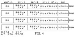
図4は、Row1~Row4として示される4つのローの各々に対するCIPの例示的な形成を示す。CIPsは、圧縮されたデータと共にメモリにストアされる(後述する図6A及び6Bを参照)。上述したように、CIPは、生成され、各ローと共にストアされるデータのパケットである。CIPのサイズは、概して、通常のローサイズのものより著しく小さいので、圧縮比を計算するときにはCIPは一般に考慮されない。例えば、2M画素のカメラでは、圧縮されないローサイズは6kバイトであり、一方、CIPのサイズは100バイト未満となり得る。CIP情報は、データを圧縮する一方で圧縮回路によってつくられ、オリジナルデータパケットを抽出(伸張)するために伸張回路によって用いられる。図4に示される例示のCIPのフィールドは、すべてのDGが圧縮されるか否かを示すように、1ビットである圧縮述部を含み(W/Nビットとして示されるが、回路は圧縮述部を固定ビットフィールド(例えば、512ビット)とし得、それにより、DGsの最大数に制限を設けることができ)、ここで、Wはラスターローサイズであり、Nがデータグループサイズである。 FIG. 4 shows an exemplary formation of a CIP for each of four rows, designated as Row1-Row4. CIPs are stored in memory along with compressed data (see Figures 6A and 6B below). As mentioned above, a CIP is a packet of data that is generated and stored with each row. Since the size of a CIP is generally significantly smaller than that of a normal raw size, the CIP is generally not considered when calculating the compression ratio. For example, for a 2M pixel camera, the uncompressed raw size is 6k bytes, while the CIP size can be less than 100 bytes. CIP information is created by the compression circuit while compressing data and is used by the decompression circuit to extract (decompress) the original data packet. The fields of the example CIP shown in FIG. may be a fixed bit field (eg, 512 bits), thereby placing a limit on the maximum number of DGs), where W is the raster row size and N is the data group size.
圧縮されたデータサイズは32ビットとして示されており、ここで、トータルの圧縮されたデータサイズは、図2の例では157ビットであるラスターデータの1つのローに対するものであり、64ビットとして示される累積データサイズは、そのローまでフレームのトータルの圧縮されたデータサイズである。また、CIPは、ローシグネチャのための圧縮方式のダイナミックレンジをストアする4ビット値である圧縮ワード(CW)サイズ、一つの特定のローを圧縮するために用いられるフレキシブルなDGサイズをストアする8ビット値であるDGサイズ、及び、圧縮の機能的安全及び正確さを保証するためにデータのローに順次対応するCIP毎に計算されたECC及び/又はCRCシグネチャを含む。また、シグネチャは、宇宙アルファ粒子、電磁干渉(EMI)、クロック又は電力欠陥などによりCIPが破損した場合でも、それがオンザフライで補正され得、したがって、全フレームのための伸張プロセスが正しく成されることを確実にする。 The compressed data size is shown as 32 bits, where the total compressed data size is for one row of raster data, which is 157 bits in the example of Figure 2, and is shown as 64 bits. The cumulative data size is the total compressed data size of the frame up to that row. CIP also stores the compressed word (CW) size, which is a 4-bit value that stores the dynamic range of the compression scheme for the row signature, and the flexible DG size used to compress one particular row. It includes a DG size, which is a bit value, and an ECC and/or CRC signature calculated for each CIP that sequentially corresponds to the rows of data to ensure functional safety and accuracy of the compression. The signature also ensures that even if the CIP is corrupted by cosmic alpha particles, electromagnetic interference (EMI), clock or power defects, etc., it can be corrected on the fly, thus ensuring that the decompression process for all frames is done correctly. make sure that.
図5Aは、圧縮データを圧縮されていないデータ出力(オリジナルデータ210)に変換するためにアドレス計算変換エンジンμ-アーキテクチャを用いる例示の伸張方式を示す。この例で示されている圧縮データは、それぞれのDGsの圧縮述部と共に図2の圧縮データ220が、受信された圧縮述部225から、示されている変換述部520を生成する並列マップ及び縮小ブロック510によって処理される。
FIG. 5A shows an example decompression scheme that uses the address calculation translation engine μ-architecture to convert compressed data to uncompressed data output (original data 210). The compressed data shown in this example includes the
一般に、1つの変換された述部がDG毎に計算される。シストリック(systolic)加算器に基づく並列マップ及び低減ブロック510の回路アーキテクチャの使用は、変換された述部値がデュアルデータ構造を表すことを確実にする。データ構造の第1の部分は、成功裏に圧縮されたDGの数についての情報を有し、これは、高速演算を確実にするためにlog2n複雑度を有する圧縮述部225入力から計算することができる。変換された述部520の第2の部分は、どのくらい多くのDGがローにおけるその点まで圧縮されずにストアされたかの累積情報を含み得る。この変換された述部520の後に、アドレスポインタ計算器525が続く。このアドレスポインタ計算器525は、DGに対する変換述部520の第1の部分を圧縮ワードサイズ(この例では31)で乗算し、変換述部520の第2の部分を圧縮ワードサイズ(この例では64)で乗算する。その後、これらの2つの値を加算して、リトリーブされた圧縮データ内の圧縮された先行値の位置ポインタを計算する。
Generally, one transformed predicate is computed per DG. The use of a parallel map and reduce
アドレスポインタ計算器525の出力は、先行値の位置をデコードするため、及び正しい非圧縮データ値を計算するためにデコーダ530に結合される。デコーダ530は、アドレスポインタ計算器525に基づいて、各データグループに対する圧縮されたローデータから先行値をフェッチする。また、デコーダ530は、圧縮されていないローに対する圧縮述部を別の入力として受け取る。デコーダ530の出力は、判定ブロック535にあるように、追加又は複写に結合される。DGが、圧縮された述部によって示されるように圧縮されてストアされた場合、そのDGの先行値は、圧縮されていないデータ値を計算するために、圧縮されたデータにおける受信された他の値と加算される。そうでない場合、圧縮データ内の値は、これらを先行値と共に追加することなく、判定ブロック535にあるようにオリジナルデータとしてそのまま(変更なしに)追加又はコピーによってメモリにコピーされる。判定ブロック535にあるような追加又は複写によるこの処理の結果、図2に示すオリジナルデータ210のローの256ビットが返される。
The output of
図5Bは、ここでは並列マップ及び縮小log2n層510’として示される並列マップ及び縮小回路510と共に525’として示されている図5Aに示されるアドレスポインタ計算器のための例示の回路実装を示す。アドレスポインタ計算器525’は、先行する2つの乗算器525b及び525cの出力を加算する加算器525aを含む。525bは、圧縮されたDGのサイズに等しい固定値を有する対応するDGに対する変換された述部520の第1の半分520aを乗算する。525cは、圧縮されていないDGのサイズに等しい固定値を有する対応するDGの第2の半分520bを乗算する。
FIG. 5B shows an example circuit implementation for the address pointer calculator shown in FIG. 5A, shown as 525', with a parallel map and reduce
アドレスポインタ計算器525’の出力はデコーダ530に結合される。変換された述部520のデータ構造は、マップ縮小回路5101及び5102の組み合わせによって計算される。これらの回路の両方に対する入力は、圧縮されていないデータローのための圧縮された述部225である。5101は、圧縮されていないデータローに対するDGの前の成功裏の圧縮後にストアされたデータグループの数をカウントする。5102は、圧縮されていないデータローに対するDGの前に圧縮できなかったDGの数をカウントする。
The output of address pointer calculator 525' is coupled to decoder 530. The data structure of the transformed
図5Cは、ブロック535にあるような例示の付加又は複製のオペレーションの一例を示す。この回路への入力は、圧縮述部225、圧縮データ、及び、デコーダ530によってデコードされたアドレス位置からフェッチされた先行値である。圧縮された述部が、DGが圧縮後にストアされたことを示す場合、受信された値は、加算器538a、b、及びcによって先行値に加算され、そうでない場合、これらの値は補償されていないデータ出力210aとして示されるように、そのままコピーされる(変化なし)。
FIG. 5C shows an example of an example append or duplicate operation, such as at
図6Aは、DDRメモリにおける圧縮データのデータストレージのための第1の例示的なオプションを示す。これは、概して、DDRメモリ密度を最適化しない、シンプルなインラインオプションである。この方法は、圧縮データをメモリに書き込むためのDDR帯域幅を改善する。CIPは、実際の圧縮データパケットの先頭に付加される(ヘッダーとして添付される)。圧縮されたデータは、すべてのラスター化されたローのCIPの第1のバイトが、それが圧縮されていなかった場合に実際のデータがあったであろう位置にあるように、メモリにストアされる。このデータストレージフォーマットにより、フレーム内のすべてのローからデータにアクセスするための一連のコマンドを発行し得るDMAエンジンを構成することが一層容易になる。DMA/ストリーミングエンジンは、CIPをプルインし、パケットを処理し、次いで、パケットを並列マップ及び縮小ブロック510、変換述部520、及びアドレスポインタ計算ブロック525に転送することができる。
FIG. 6A shows a first example option for data storage of compressed data in DDR memory. This is a simple inline option that generally does not optimize DDR memory density. This method improves DDR bandwidth for writing compressed data to memory. The CIP is added to the beginning of the actual compressed data packet (attached as a header). Compressed data is stored in memory such that the first byte of the CIP of every rasterized row is where the actual data would have been if it had not been compressed. Ru. This data storage format makes it easier to construct a DMA engine that can issue a series of commands to access data from all rows within a frame. The DMA/streaming engine may pull in the CIP, process the packet, and then forward the packet to parallel map and reduce
図6Bは、DDRメモリにおけるデータストレージのための第2の例示のオプションを示す。これは、DDRメモリストレージ密度を改善するデンスストレージオプションであり、すなわち、図6Aに示された第1の例示オプションと比較して、より多くのデータを同じDDRメモリサイズにストアすることができる。この場合、CIP構造は、次のCIPのアドレスも含む。あるいは、CIP構造の累積データサイズフィールドを用いて、データの次のローの開始アドレスを決定し得る。圧縮データフレームにアクセスするタスクを課されたDMAエンジンが、データフレーム内の第1のCIPを読み取り、それに続いて、圧縮されたローデータ及び次のローのCIPをストアするために、CIPによって示されるような厳密なバイトをフェッチし、その後、データを伸張回路に転送する。このプロセスを通して、DMAエンジンのメモリアクセスロジックは、次のアクセスのアドレスを計算し続ける。 FIG. 6B shows a second example option for data storage in DDR memory. This is a dense storage option that improves DDR memory storage density, i.e. more data can be stored in the same DDR memory size compared to the first example option shown in FIG. 6A. In this case, the CIP structure also includes the address of the next CIP. Alternatively, the cumulative data size field of the CIP structure may be used to determine the starting address of the next row of data. A DMA engine tasked with accessing a compressed data frame reads the first CIP in the data frame and subsequently reads the CIP indicated by the CIP in order to store the compressed raw data and the CIP of the next row. It fetches the exact bytes as shown and then transfers the data to the decompression circuit. Throughout this process, the DMA engine's memory access logic continues to calculate the address for the next access.
このように実施されるアドレス計算は、2つの固有のプロセスを介して、まず、次のCIPのアドレスをストアする任意選択のCIPフィールドを用いて、次に、圧縮されたデータサイズフィールドを用いてそれを現在のアドレスに付加することによって、行われる。このプロセスは、機能的に安全で信頼性の高いデータアクセスを確実にし、宇宙アルファ粒子、電磁波、クロック、又はランダム電圧ノイズによって引き起こされる故障から回路を守る。 The address calculations performed in this way are performed via two unique processes, first using the optional CIP field to store the address of the next CIP, and second using the compressed data size field. This is done by appending it to the current address. This process ensures functionally safe and reliable data access and protects the circuit from failures caused by cosmic alpha particles, electromagnetic waves, clocks, or random voltage noise.
また、説明される実施例は、適応性がありスケーラブルな圧縮方式アルゴリズムを含む。各データセットは異なる挙動を示し、最良の圧縮結果を保証するための圧縮パラメータの理想的なセットは存在しない。DGサイズ及び圧縮ワードサイズの、それらがいずれも柔軟なパラメータであるような範囲のための「有効パラメータ」の制約された範囲を定義することができる。例えば、DGサイズの有効値は、4、8、12、及び16であり得る。同様に、圧縮ワードサイズの有効値は、6~12とし得る。データのすべてのローについて、下記工程が実施され得る。
(a)並列に、N個のパラメータセット(N=DGサイズ値及び圧縮ワードサイズ値のすべての組み合わせ)を用いて全ローに対して圧縮を実行し、N個のCIPを生成する。
(b)関連するCIPフィールド(総圧縮サイズ)を比較することによって(a)における実行の各々からの圧縮データ(圧縮データサイズ)のサイズを比較する。
(c)全ての実施された構成オプションに対して達成された圧縮比のボーティング回路320比較に基づいて、最良の圧縮ワードサイズ及びDGチョイスを選択する。
The described embodiments also include an adaptive and scalable compression scheme algorithm. Each dataset behaves differently and there is no ideal set of compression parameters to guarantee the best compression results. A constrained range of "valid parameters" can be defined for the range of DG size and compressed word size, both of which are flexible parameters. For example, valid values for DG size may be 4, 8, 12, and 16. Similarly, valid values for compressed word size may be between 6 and 12. The following steps may be performed for every row of data.
(a) Perform compression on all rows in parallel using N parameter sets (N=all combinations of DG size values and compressed word size values) to generate N CIPs.
(b) Compare the size of the compressed data (compressed data size) from each of the runs in (a) by comparing the associated CIP fields (total compressed size).
(c) Select the best compressed word size and DG choice based on
この適応性がありスケーラブルな圧縮アルゴリズム及びロジックは、完全にスケーラブルであり、最適な圧縮データセットがデータの各ローに対してつくられることを保証する。圧縮方式の4倍の半導体(例えば、シリコン)エリアは、性能の4倍の改善を確実にする。いくらかのレイテンシーを犠牲にして、時間多重化方式で同じ回路要素を用いることによって、半導体エリアを制約することができる。 This adaptive and scalable compression algorithm and logic is fully scalable and ensures that an optimal compressed data set is created for each row of data. Four times the semiconductor (eg silicon) area of the compression scheme ensures a four times improvement in performance. Semiconductor area can be constrained by using the same circuit elements in a time multiplexed manner, at the expense of some latency.
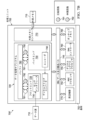
図7Aを参照すると、データ信号を圧縮するためのシステム700が、処理ユニット705を含んで示されている。処理ユニット705は、圧縮及び伸張回路の分散インスタンス化を備えるシステムオンチップ(SOC)アーキテクチャとして実装され得る半導体表面(例えば、シリコン基板)を有する基板702上に形成されて示される。処理ユニット705は、マイクロプロセッサ、デジタルシグナルプロセッサ(DSP)、又はマイクロコントローラユニットを含み得る。処理ユニット705は、感知されたデータ源710と電子的に通信している。データ源の例は、デジタルカメラ、カムコーダー、モバイルデバイス、又は、物理的な場面を示すビデオ信号を捕捉及び提供するデバイス、又はレーダーの場合、アナログフロントエンドと共にアンテナを含み得る。処理ユニット705は、外部メモリ715と電子的に通信する。外部メモリ715の一例には、DDRメモリがある。
Referring to FIG. 7A, a
処理ユニット705は、感知されたデータ信号を処理するための処理サブシステム720を含む。データ処理サブシステム720は、フロントエンド725と、バッファ780によって共に結合されるバックエンド730とを含む。フロントエンド725は、データ源710から、感知されたデータ信号を受信するセンサインタフェース735を含む。バックエンド730は、記載される圧縮方式に従ってデータ信号におけるフレームの圧縮バージョンを生成するためエンコーダ740を含む。幾つかの実施例において、エンコーダ740は、データ信号のフレームの圧縮バージョンを生成するための個別のユニットを含み得る。処理ユニット705は、ダイレクトメモリアクセス(DMA)データ及び構成バス745を含む。DMAデータ及び構成バス745は、処理ユニット705における構成要素間でデータ及び制御信号を伝達する。
処理ユニット705は、中央処理装置として機能する縮小命令セット演算(RISC)プロセッサ750を含む。RISCプロセッサ750は、入力又は出力機能、及びシステム制御機能を実施するように動作し得る。処理ユニット705は、デジタルシグナルプロセッサ(DSP)755を含む。DSP755は、リアルタイム信号処理ソフトウェアアルゴリズムを処理するように動作し得る。一実施例において、DSP755は、コーデックを処理するように動作し得る。コーデックは、符号化又は復号ソフトウェアとして定義され得る。
処理ユニット705は、ダイレクトメモリアクセスのためのDMAコントローラ760を含む。処理ユニット705は、データ信号のフレームをストアするオンチップメモリ765を含む。オンチップメモリ765の一例は、スタティックランダムアクセスメモリ(SRAM)である。処理ユニット705は、コーデックをストアするための他のメモリを含み得る。また、処理ユニット705は、外部メモリ715を制御するための外部メモリコントローラ770を含む。処理ユニット705は、データ信号の一つ又は複数のフレームを送信するための通信周辺機器など、一つ又は複数の周辺機器775を含む。通信周辺機器の例には、ポート及びソケットが含まれる。また、周辺機器775は、タイマーなどの周辺機器、及びRAMなどの一時的ストレージをシステムを含み得る。
図7Bは、データ信号を圧縮及び伸張するための例示のシステム700’を示す。システム700’は、バッファ780とセンサインタフェース735を含むフロントエンドとの間、及びバッファ780とバックエンド730との間に、説明される圧縮回路791及び伸張回路792を含む。システム700’の例示的なアーキテクチャは、種々のデータ処理の入力及び出力、及びシステムのデータ入力ブロックにおいて必要とされインスタンス化される、分散された圧縮及び伸張ブロックを保証する。
FIG. 7B shows an example system 700' for compressing and decompressing data signals. System 700' includes
図7Cは、説明される圧縮及び伸張を実装するために用いられ得る圧縮及び伸張ブロックの例示の4タイプを示す。示されたモジュールは、モジュール794、795、796、及び797として示されるモジュール1~4を含む。図示される各丸で囲まれた数字は、圧縮及び伸張のタイプに対応する。図示されたモジュール794によって処理され得る丸で囲まれた1は、ラスター線形(1D)データY平面画像又は線形レーダーデータに対応し、モジュール795によって処理され得る丸で囲まれた2は、ラスター線形データU、Vインターリーブされた平面画像データに対応して示され、モジュール796によって処理され得る丸で囲まれた3は、センサデータのためのブロック毎(2D)ランダムアクセスに対応して示され、モジュール797によって処理され得る丸で囲まれた4は、センサデータのためのブロック毎(2D)通常アクセスに対応して示される。また、示されたこの例は、線形レーダーデータを処理するための圧縮及び伸張ブロックをインスタンス化し得る。圧縮及び伸張のためのメカニズム、回路、及びのための方法は、固定及び決定論的時間での異なるデータトポロジー(1D、2D)及びアクセスパターン(規則的又はランダム)のためのデータ処理を可能にする。
FIG. 7C shows four example types of compression and decompression blocks that may be used to implement the described compression and decompression. The modules shown include modules 1-4, shown as
説明される実施例の利点には、シンプルなロスレスの及びダイナミックな適応性データ圧縮方式が含まれる。説明される圧縮は、ランダムデータアクセスを可能にする。説明される実施例は、説明されるCIP構造を備える、安全性が重要な応用例に特に適している。機能的安全性は、部品表(BOM:bill of materials)コストを潜在的に削減する。説明される実施例は、線形とブロック毎との両方で、種々の外部メモリストレージ方式を可能にする。また、説明される実施例は、固定密度、分離された制御及びデータパケット、ならびにレイテンシーを最小にするDGの並列処理を可能にする。 Advantages of the described embodiments include a simple lossless and dynamic adaptive data compression scheme. The compression described allows random data access. The described embodiments are particularly suitable for safety-critical applications with the described CIP structure. Functional safety potentially reduces bill of materials (BOM) costs. The described embodiments allow for a variety of external memory storage schemes, both linear and block-by-block. The described embodiments also enable fixed density, separated control and data packets, and parallel processing of DGs to minimize latency.
図8A及び図8Bは、説明された圧縮及び伸張を用いる例示のイメージング用途に対し、それぞれ、4及び6のDGサイズのための、圧縮比対圧縮ワードサイズデータを示す。この例では、データは、図8AのDGサイズ4及び図8BのDGサイズ6を変化させることによって生成された。図8A及び図8BのX軸は、圧縮のために用いられるCWサイズを記す。この特定の例において、最良の圧縮比は、ほぼ0.6に等しい、8のCWサイズ及び6のDGサイズに対して達成される。オリジナルデータサンプルは、16ビット画像データ(画素)であった。各フレームは、約300,000画素を含んでいた。ポスト圧縮帯域幅は、圧縮されないデータの60%まで低減されている。12ビット画像データ(図示せず)では、達成可能な圧縮比は約70%であることが分かった。
8A and 8B show compression ratio versus compressed word size data for DG sizes of 4 and 6, respectively, for an exemplary imaging application using the described compression and decompression. In this example, the data was generated by varying
本発明の特許請求の範囲内で、説明した例示の実施例に改変が成され得、他の実施例が可能である。 Modifications may be made to the exemplary embodiments described and other embodiments are possible within the scope of the claims of the invention.
Claims (19)
複数のローを含むバイナリセンサデータを得ることであって、前記ローの各々が複数のマルチビットデータサンプルを含む、前記バイナリセンサデータを得ることと、
各前記ローを複数のデータグループに分割することであって、前記複数のデータグループが、各々が前記マルチビットデータサンプルの2つ又はそれ以上を含む、前記複数のデータグループに分割することと、
各前記ローに対する先行値又は前記複数のデータグループの各々に対する先行値のそれぞれを選択することであって、各前記ロー又は各前記データグループにおけるデータサンプルの統計的分散に基づいて前記先行値が複数の異なる先行値から選択される、前記選択することと、
前記データグループのその関連するデータグループに対して各前記データサンプルと前記先行値との間の差を計算することにより、各前記ローから圧縮されたセンサデータの圧縮されたローを生成することと、
前記データグループの各々がストアされ圧縮されているか否かを示すデータ構造を含む圧縮された述部と、ロー圧縮のために用いられるグループサイズをストアするマルチビット値であるデータグループサイズと、前記ロー圧縮のダイナミックレンジをストアするマルチビット値である圧縮されたワードサイズとを含む、前記バイナリセンサデータを損失なく戻すための情報を有する各前記ローに対して圧縮情報パケット(CIP)を生成することと、
前記CIPと共にストアされ圧縮されたデータとして前記圧縮されたローをストアすることと、
を含む、方法。 A method of lossless data compression,
Obtaining binary sensor data including a plurality of rows, each of the rows including a plurality of multi-bit data samples;
dividing each said row into a plurality of data groups, each of said plurality of data groups including two or more of said multi-bit data samples;
selecting a respective preceding value for each said row or each of said plurality of data groups, wherein said plurality of preceding values is selected based on a statistical distribution of data samples in each said row or each said data group; said selecting from different preceding values of;
generating a compressed row of compressed sensor data from each said row by calculating a difference between each said data sample and said preceding value for its associated data group of said data groups; ,
a compressed predicate that includes a data structure indicating whether each of said data groups is stored and compressed; a data group size that is a multi-bit value that stores a group size used for row compression; generating a compressed information packet (CIP) for each said row having information for losslessly returning said binary sensor data, including a compressed word size that is a multi-bit value that stores the dynamic range of the row compression; And,
storing the compressed row as compressed data stored with the CIP;
including methods.
並列に前記ローのデータグループに対する単一クロックサイクル圧縮処理を実行することを更に含む、方法。 The method according to claim 1,
The method further comprising performing a single clock cycle compression process on the rows of data groups in parallel.
前記圧縮されたワードサイズを動的に選択するボーティング回路を用いることを更に含む、方法。 The method according to claim 1,
The method further comprising using voting circuitry to dynamically select the compressed word size.
構成によって制御される圧縮パラメータを動的に選択することであって、前記圧縮パラメータが、前記データグループ内の現在のデータ値と前記先行値との間の差であるドリフトと前記圧縮されたワードサイズと前記先行値と前記データグループサイズとを含む、前記圧縮パラメータを動的に選択することを更に含む、方法。 The method according to claim 1,
dynamically selecting a compression parameter controlled by a configuration, wherein the compression parameter is the difference between the current data value in the data group and the preceding value and the compressed word; The method further comprises dynamically selecting the compression parameters, including a size, the prior value, and the data group size.
固定時間にメモリのランダム位置にアクセスすることを含む、前記バイナリセンサデータを回復するために前記ストアされ圧縮されたデータを伸張することを更に含む、方法。 The method according to claim 1,
The method further comprises decompressing the stored compressed data to recover the binary sensor data, the method comprising accessing random locations in memory at fixed times.
前記伸張することが、単一サイクル内で前記バイナリセンサデータを回復することを含む、方法。 6. The method according to claim 5,
The method, wherein the decompressing includes recovering the binary sensor data within a single cycle.
前記伸張することが、
前記圧縮された述部から変換された述部を生成することであって、前記変換された述部が圧縮されたデータグループの数についての情報と圧縮されていないデータグループの数についての情報とを含む、前記変換された述部を生成することと、
前記変換された述部を用いて前記圧縮された先行値の位置ポインタを生成することと、
を含む、方法。 6. The method according to claim 5,
The stretching may include:
generating a transformed predicate from the compressed predicate, the transformed predicate comprising information about the number of compressed data groups and information about the number of uncompressed data groups; generating the transformed predicate comprising;
generating a position pointer for the compressed predecessor value using the transformed predicate;
including methods.
前記CIPが、少なくとも1つの誤り補正符号(ECC)又は巡回冗長検査(CRC)フィールドを含む、方法。 The method according to claim 1,
The method, wherein the CIP includes at least one error correction code (ECC) or cyclic redundancy check (CRC) field.
複数のローを含むバイナリセンサデータを受信するためのセンサインタフェースであって、前記ローの各々が複数のマルチビットデータサンプルを含む、前記センサインタフェースと、
前記センサインタフェースの出力に結合される入力を有するエンコーダを含むデータ処理サブシステムであって、前記データ処理サブシステムが、
各前記ローを、各々が前記マルチビットデータサンプルの2つ又はそれ以上を含む複数のデータグループに分割し、
各前記ローに対する先行値又は前記複数のデータグループの各々に対する先行値のそれぞれを各前記ロー又は各前記データグループにおけるデータサンプルの統計的分散に基づいて複数の異なる先行値から選択し、
各前記データサンプルとその関連する前記データグループに対する前記先行値との間の差を計算することによって各前記ローから圧縮されたセンサデータの圧縮されたローを生成し、
前記データグループの各々がストアされ圧縮されているか否かを示すデータ構造を含む圧縮された述部と、ロー圧縮のために用いられるグループサイズをストアするマルチビット値であるデータグループサイズと、前記ロー圧縮のダイナミックレンジをストアするマルチビット値である圧縮されたワードサイズとを含む、前記バイナリセンサデータを損失なく戻すための情報を有する各前記ローに対して圧縮情報パケット(CIP)を生成する、
ためのハードウェアとソフトウェアとを含む、前記データ処理サブシステムと、
を含む、システム。 A system for providing lossless data compression, the system comprising:
a sensor interface for receiving binary sensor data including a plurality of rows, each of the rows including a plurality of multi-bit data samples;
a data processing subsystem comprising an encoder having an input coupled to an output of the sensor interface, the data processing subsystem comprising:
dividing each said row into a plurality of data groups each including two or more of said multi-bit data samples;
selecting each of the preceding values for each said row or each of said plurality of data groups from a plurality of different preceding values based on the statistical distribution of data samples in each said row or each said data group;
generating a compressed row of compressed sensor data from each said row by calculating a difference between each said data sample and its associated preceding value for said data group;
a compressed predicate that includes a data structure indicating whether each of said data groups is stored and compressed; a data group size that is a multi-bit value that stores a group size used for row compression; generating a compressed information packet (CIP) for each said row having information for losslessly returning said binary sensor data, including a compressed word size that is a multi-bit value that stores the dynamic range of the row compression; ,
the data processing subsystem including hardware and software for;
system, including.
前記データ処理サブシステムが、前記CIPsと共にストアされ圧縮されたデータとして前記圧縮されたローをストアすることを更に提供する、システム。 10. The system according to claim 9,
The system further comprises: the data processing subsystem storing the compressed rows as compressed data stored with the CIPs.
前記データ処理サブシステムが、前記複数のデータグループの並列処理のための回路要素を含む、システム。 10. The system according to claim 9,
The system wherein the data processing subsystem includes circuitry for parallel processing of the plurality of data groups.
前記エンコーダが半導体表面を有する基板を含む、システム。 10. The system according to claim 9,
A system wherein the encoder includes a substrate having a semiconductor surface.
前記ロスレスデータ圧縮を実装するための単一クロックサイクル圧縮回路を更に含む、システム。 10. The system according to claim 9,
A system further comprising a single clock cycle compression circuit for implementing said lossless data compression.
前記圧縮されたワードサイズを動的に選択するためのボーティング回路を更に含む、システム。 11. The system according to claim 10,
The system further includes voting circuitry for dynamically selecting the compressed word size.
前記データグループ内の現在のデータ値と前記先行値との間の差の値であるドリフトと前記圧縮されたワードサイズと前記先行値と前記データグループサイズとを含む圧縮パラメータブロックを動的に選択するための動的選択圧縮パラメータブロックを更に含む、システム。 11. The system according to claim 10,
Dynamically selecting a compression parameter block that includes a drift that is a difference value between the current data value in the data group and the previous value, the compressed word size, the previous value and the data group size. The system further includes a dynamic selection compression parameter block for.
前記バイナリセンサデータを回復するために、前記ストアされ圧縮されたデータを伸張するためのデコーダを更に含む、システム。 11. The system according to claim 10,
The system further comprises a decoder for decompressing the stored compressed data to recover the binary sensor data.
前記デコーダが、前記バイナリセンサデータの前記回復のために単一サイクルにおいて動作する伸張回路を含む、システム。 17. The system of claim 16,
The system wherein the decoder includes a decompression circuit operating in a single cycle for the recovery of the binary sensor data.
前記伸張することが、
前記圧縮された述部から変換された述部を生成することであって、前記変換された述部が圧縮されたデータグループの数についての情報と圧縮されていないデータグループの数についての情報とを含む、前記変換された述部を生成することと、
前記変換された述部を用いて前記圧縮された先行値の位置ポインタを生成することと、
を含む、システム。 17. The system of claim 16,
said stretching;
generating a transformed predicate from the compressed predicate, the transformed predicate comprising information about the number of compressed data groups and information about the number of uncompressed data groups; generating the transformed predicate comprising;
generating a position pointer for the compressed predecessor value using the transformed predicate;
system, including.
前記CIPが、少なくとも1つの誤り補正符号(ECC)又は巡回冗長検査(CRC)フィールドを含む、システム。 11. The system according to claim 10,
The system, wherein the CIP includes at least one error correction code (ECC) or cyclic redundancy check (CRC) field.
Applications Claiming Priority (3)
| Application Number | Priority Date | Filing Date | Title |
|---|---|---|---|
| US15/376,170 | 2016-12-12 | ||
| US15/376,170 US10069511B2 (en) | 2016-12-12 | 2016-12-12 | Lossless data compression |
| PCT/US2017/065915 WO2018111942A1 (en) | 2016-12-12 | 2017-12-12 | Lossless data compression |
Publications (3)
| Publication Number | Publication Date |
|---|---|
| JP2020501475A JP2020501475A (en) | 2020-01-16 |
| JP2020501475A5 JP2020501475A5 (en) | 2021-01-28 |
| JP7421036B2 true JP7421036B2 (en) | 2024-01-24 |
Family
ID=62490497
Family Applications (1)
| Application Number | Title | Priority Date | Filing Date |
|---|---|---|---|
| JP2019551920A Active JP7421036B2 (en) | 2016-12-12 | 2017-12-12 | lossless data compression |
Country Status (5)
| Country | Link |
|---|---|
| US (1) | US10069511B2 (en) |
| EP (1) | EP3552312A4 (en) |
| JP (1) | JP7421036B2 (en) |
| CN (1) | CN109952708B (en) |
| WO (1) | WO2018111942A1 (en) |
Families Citing this family (17)
| Publication number | Priority date | Publication date | Assignee | Title |
|---|---|---|---|---|
| US10402111B1 (en) * | 2017-08-14 | 2019-09-03 | Xilinx, Inc. | Systems and methods for data storage compression |
| US10970080B2 (en) | 2018-02-08 | 2021-04-06 | Marvell Asia Pte, Ltd. | Systems and methods for programmable hardware architecture for machine learning |
| US10891136B1 (en) | 2018-05-22 | 2021-01-12 | Marvell Asia Pte, Ltd. | Data transmission between memory and on chip memory of inference engine for machine learning via a single data gathering instruction |
| US10929760B1 (en) | 2018-05-22 | 2021-02-23 | Marvell Asia Pte, Ltd. | Architecture for table-based mathematical operations for inference acceleration in machine learning |
| US11016801B1 (en) | 2018-05-22 | 2021-05-25 | Marvell Asia Pte, Ltd. | Architecture to support color scheme-based synchronization for machine learning |
| US10929778B1 (en) * | 2018-05-22 | 2021-02-23 | Marvell Asia Pte, Ltd. | Address interleaving for machine learning |
| US10997510B1 (en) | 2018-05-22 | 2021-05-04 | Marvell Asia Pte, Ltd. | Architecture to support tanh and sigmoid operations for inference acceleration in machine learning |
| US10929779B1 (en) | 2018-05-22 | 2021-02-23 | Marvell Asia Pte, Ltd. | Architecture to support synchronization between core and inference engine for machine learning |
| CN111697973B (en) * | 2019-05-16 | 2021-02-02 | 时擎智能科技(上海)有限公司 | Compression method and compression system |
| CN110247666B (en) * | 2019-05-22 | 2023-08-18 | 深圳大学 | System and method for hardware parallel compression |
| TWI745697B (en) | 2019-05-24 | 2021-11-11 | 創鑫智慧股份有限公司 | Computing system and compressing method thereof for neural network parameters |
| CN112241005A (en) * | 2019-07-19 | 2021-01-19 | 杭州海康威视数字技术股份有限公司 | Method and device for compressing radar detection data and storage medium |
| DE102019214587A1 (en) * | 2019-09-24 | 2021-03-25 | Conti Temic Microelectronic Gmbh | Processing of lossy compressed ADAS sensor data for driver assistance systems |
| DE112020006288T5 (en) * | 2019-12-23 | 2022-10-27 | ams AG | Lossless compression of data transmission |
| CN111307182B (en) * | 2020-03-06 | 2022-08-23 | 宁波飞芯电子科技有限公司 | Data processing method and array type sensor |
| US20230177730A1 (en) * | 2021-12-07 | 2023-06-08 | International Business Machines Corporation | Stochastic compression of raster data |
| CN114268323B (en) * | 2021-12-24 | 2023-07-07 | 成都索贝数码科技股份有限公司 | Data compression coding method, device and time sequence database supporting line memory |
Family Cites Families (15)
| Publication number | Priority date | Publication date | Assignee | Title |
|---|---|---|---|---|
| JPH04252569A (en) * | 1991-01-28 | 1992-09-08 | Nec Corp | Picture data compression system |
| JPH06319047A (en) * | 1993-05-07 | 1994-11-15 | Seiko Epson Corp | Information processor |
| JPH1132328A (en) * | 1997-07-10 | 1999-02-02 | Pfu Ltd | Method and device for compressing multilevel picture data and recording medium |
| US9204157B2 (en) | 2011-11-18 | 2015-12-01 | Texas Instruments Incorporated | Video compression searching reference frame in hybrid growing-window and sliding-window |
| CN201523455U (en) * | 2009-09-24 | 2010-07-07 | 信飞系统公司 | Signal compression device in base transceiver system |
| JP2012013657A (en) | 2010-07-05 | 2012-01-19 | Ihi Infrastructure Systems Co Ltd | Spectroscopy analyzer |
| JP5591080B2 (en) * | 2010-11-26 | 2014-09-17 | 三菱電機株式会社 | Data compression apparatus, data processing system, computer program, and data compression method |
| US20120239612A1 (en) | 2011-01-25 | 2012-09-20 | Muthian George | User defined functions for data loading |
| US8914545B2 (en) * | 2011-04-27 | 2014-12-16 | Iii Holdings 1, Llc | Systems and methods for lossless compression of data and high speed manipulation thereof |
| JP2014075687A (en) | 2012-10-04 | 2014-04-24 | Seiko Epson Corp | Image data compression apparatus, image data decompression apparatus, display device, image processing system, image data compression method, and image data decompression method |
| US9800886B2 (en) | 2014-03-07 | 2017-10-24 | Lattice Semiconductor Corporation | Compressed blanking period transfer over a multimedia link |
| CN104378118B (en) * | 2014-10-29 | 2017-08-11 | 中国科学院地质与地球物理研究所 | Efficient self-adapted geological data stream Lossless Compression and decompression method |
| US9748972B2 (en) * | 2015-09-14 | 2017-08-29 | Leco Corporation | Lossless data compression |
| US9496894B1 (en) * | 2015-10-21 | 2016-11-15 | GE Lighting Solutions, LLC | System and method for data compression over a communication network |
| US9923577B1 (en) * | 2016-09-04 | 2018-03-20 | ScaleFlux, Inc. | Hybrid software-hardware implementation of lossless data compression and decompression |
-
2016
- 2016-12-12 US US15/376,170 patent/US10069511B2/en active Active
-
2017
- 2017-12-12 CN CN201780068635.7A patent/CN109952708B/en active Active
- 2017-12-12 EP EP17880411.8A patent/EP3552312A4/en not_active Withdrawn
- 2017-12-12 WO PCT/US2017/065915 patent/WO2018111942A1/en unknown
- 2017-12-12 JP JP2019551920A patent/JP7421036B2/en active Active
Also Published As
| Publication number | Publication date |
|---|---|
| EP3552312A1 (en) | 2019-10-16 |
| WO2018111942A1 (en) | 2018-06-21 |
| US20180167083A1 (en) | 2018-06-14 |
| EP3552312A4 (en) | 2019-12-25 |
| CN109952708B (en) | 2023-06-30 |
| US10069511B2 (en) | 2018-09-04 |
| CN109952708A (en) | 2019-06-28 |
| JP2020501475A (en) | 2020-01-16 |
Similar Documents
| Publication | Publication Date | Title |
|---|---|---|
| JP7421036B2 (en) | lossless data compression | |
| US10599935B2 (en) | Processing artificial neural network weights | |
| US8847798B2 (en) | Systems and methods for data compression and parallel, pipelined decompression | |
| JP2020173782A (en) | Image encoding method and device, and image decoding method and device | |
| KR101725223B1 (en) | Data compressing method of storage device | |
| TWI500038B (en) | Fully parallel encoding method and fully parallel decoding method of memory system | |
| CN111641826B (en) | Method, device and system for encoding and decoding data | |
| US20180276873A1 (en) | Providing output surface data to a display in data processing systems | |
| CN112286714A (en) | Method and system for improving big data analysis throughput in NAND-based read source storage | |
| US11960986B2 (en) | Neural network accelerator and operating method thereof | |
| JP4443165B2 (en) | Image compression apparatus and image compression method | |
| US20210159913A1 (en) | Multiple Symbol Decoder | |
| US8594196B2 (en) | Spatial Wyner Ziv coding | |
| US11750825B2 (en) | Methods, apparatuses, computer programs and computer-readable media for processing configuration data | |
| WO2018068250A1 (en) | Method and device for data processing, chip and camera | |
| WO2023051335A1 (en) | Data encoding method, data decoding method, and data processing apparatus | |
| JPS6192073A (en) | Picture data compression system | |
| CN115250351A (en) | Compression method, decompression method and related products for image data | |
| JP2002519957A (en) | Method and apparatus for processing a sign function | |
| US20210385468A1 (en) | Methods, apparatuses, computer programs and computer-readable media for processing configuration data | |
| US11048413B2 (en) | Method for reducing read ports and accelerating decompression in memory systems | |
| US11855772B2 (en) | High throughput polar ECC decoding via compressed successive cancellation algorithm | |
| CN112083875B (en) | Method for reducing read ports and speeding up decompression in a storage system | |
| Kwon et al. | GPU-based ECC decode unit for efficient massive data reception acceleration | |
| WO2023187388A1 (en) | Frame buffer usage during a decoding process |
Legal Events
| Date | Code | Title | Description |
|---|---|---|---|
| A521 | Request for written amendment filed |
Free format text: JAPANESE INTERMEDIATE CODE: A821 Effective date: 20190613 |
|
| A521 | Request for written amendment filed |
Free format text: JAPANESE INTERMEDIATE CODE: A523 Effective date: 20201208 |
|
| A621 | Written request for application examination |
Free format text: JAPANESE INTERMEDIATE CODE: A621 Effective date: 20201208 |
|
| A711 | Notification of change in applicant |
Free format text: JAPANESE INTERMEDIATE CODE: A711 Effective date: 20210218 |
|
| A521 | Request for written amendment filed |
Free format text: JAPANESE INTERMEDIATE CODE: A523 Effective date: 20210323 |
|
| A521 | Request for written amendment filed |
Free format text: JAPANESE INTERMEDIATE CODE: A523 Effective date: 20210602 |
|
| A977 | Report on retrieval |
Free format text: JAPANESE INTERMEDIATE CODE: A971007 Effective date: 20220117 |
|
| A131 | Notification of reasons for refusal |
Free format text: JAPANESE INTERMEDIATE CODE: A131 Effective date: 20220209 |
|
| A601 | Written request for extension of time |
Free format text: JAPANESE INTERMEDIATE CODE: A601 Effective date: 20220509 |
|
| RD01 | Notification of change of attorney |
Free format text: JAPANESE INTERMEDIATE CODE: A7421 Effective date: 20220516 |
|
| A601 | Written request for extension of time |
Free format text: JAPANESE INTERMEDIATE CODE: A601 Effective date: 20220708 |
|
| A521 | Request for written amendment filed |
Free format text: JAPANESE INTERMEDIATE CODE: A523 Effective date: 20220805 |
|
| A131 | Notification of reasons for refusal |
Free format text: JAPANESE INTERMEDIATE CODE: A131 Effective date: 20221214 |
|
| A521 | Request for written amendment filed |
Free format text: JAPANESE INTERMEDIATE CODE: A523 Effective date: 20230313 |
|
| A131 | Notification of reasons for refusal |
Free format text: JAPANESE INTERMEDIATE CODE: A131 Effective date: 20230620 |
|
| A601 | Written request for extension of time |
Free format text: JAPANESE INTERMEDIATE CODE: A601 Effective date: 20230920 |
|
| A521 | Request for written amendment filed |
Free format text: JAPANESE INTERMEDIATE CODE: A523 Effective date: 20231019 |
|
| TRDD | Decision of grant or rejection written | ||
| A01 | Written decision to grant a patent or to grant a registration (utility model) |
Free format text: JAPANESE INTERMEDIATE CODE: A01 Effective date: 20231213 |
|
| A61 | First payment of annual fees (during grant procedure) |
Free format text: JAPANESE INTERMEDIATE CODE: A61 Effective date: 20231214 |
|
| R150 | Certificate of patent or registration of utility model |
Ref document number: 7421036 Country of ref document: JP Free format text: JAPANESE INTERMEDIATE CODE: R150 |