CN109952708B - Lossless data compression - Google Patents
Lossless data compression Download PDFInfo
- Publication number
- CN109952708B CN109952708B CN201780068635.7A CN201780068635A CN109952708B CN 109952708 B CN109952708 B CN 109952708B CN 201780068635 A CN201780068635 A CN 201780068635A CN 109952708 B CN109952708 B CN 109952708B
- Authority
- CN
- China
- Prior art keywords
- data
- compressed
- compression
- precedent
- rows
- Prior art date
- Legal status (The legal status is an assumption and is not a legal conclusion. Google has not performed a legal analysis and makes no representation as to the accuracy of the status listed.)
- Active
Links
Images


Classifications
-
- H—ELECTRICITY
- H03—ELECTRONIC CIRCUITRY
- H03M—CODING; DECODING; CODE CONVERSION IN GENERAL
- H03M7/00—Conversion of a code where information is represented by a given sequence or number of digits to a code where the same, similar or subset of information is represented by a different sequence or number of digits
- H03M7/30—Compression; Expansion; Suppression of unnecessary data, e.g. redundancy reduction
- H03M7/3059—Digital compression and data reduction techniques where the original information is represented by a subset or similar information, e.g. lossy compression
-
- H—ELECTRICITY
- H03—ELECTRONIC CIRCUITRY
- H03M—CODING; DECODING; CODE CONVERSION IN GENERAL
- H03M7/00—Conversion of a code where information is represented by a given sequence or number of digits to a code where the same, similar or subset of information is represented by a different sequence or number of digits
- H03M7/30—Compression; Expansion; Suppression of unnecessary data, e.g. redundancy reduction
- H03M7/60—General implementation details not specific to a particular type of compression
- H03M7/6005—Decoder aspects
-
- H—ELECTRICITY
- H03—ELECTRONIC CIRCUITRY
- H03M—CODING; DECODING; CODE CONVERSION IN GENERAL
- H03M7/00—Conversion of a code where information is represented by a given sequence or number of digits to a code where the same, similar or subset of information is represented by a different sequence or number of digits
- H03M7/30—Compression; Expansion; Suppression of unnecessary data, e.g. redundancy reduction
- H03M7/60—General implementation details not specific to a particular type of compression
- H03M7/6017—Methods or arrangements to increase the throughput
-
- H—ELECTRICITY
- H03—ELECTRONIC CIRCUITRY
- H03M—CODING; DECODING; CODE CONVERSION IN GENERAL
- H03M7/00—Conversion of a code where information is represented by a given sequence or number of digits to a code where the same, similar or subset of information is represented by a different sequence or number of digits
- H03M7/30—Compression; Expansion; Suppression of unnecessary data, e.g. redundancy reduction
- H03M7/60—General implementation details not specific to a particular type of compression
- H03M7/6064—Selection of Compressor
- H03M7/6076—Selection between compressors of the same type
Abstract
A method of data compression includes obtaining binary sensor data (210) having a multi-bit data sample row. The rows are divided into data groups (G1, G2, G3, G4) that each include two or more samples. A precedent value for the row is selected, or a corresponding precedent value for each data group is selected. Compressed rows of compressed sensor data (220) are generated from each row by calculating a difference between the data samples and the precedent values of their associated data groups. Generating a compressed packet, CIP, for each row, including information for returning the binary sensor data, the information including a compressed predicate (225) indicating whether each group of data is stored in compression; a data group size, which is a multi-bit value storing a group size for row compression; and a compressed word length storing a dynamic range of the line compression. The compressed line is stored with the CIP as stored compressed data.
Description
This generally relates to a method for lossless compression and storage of digital data that includes organizing pixel information within a memory.
Background
Techniques for compressing data are commonly used in the communications and computer arts. In communications, it is often desirable to transmit a compressed data string that is reconfigurable to its original form upon receipt. Transmitting compressed data takes less time than transmitting the same data in an uncompressed format. In a computer, compressed data provides storage advantages over uncompressed data. Thus, for a storage device with a fixed storage capacity, more compressed files may be stored therein.
Data compression techniques can be divided into two main categories: lossy and lossless. Lossless data compression techniques are employed when it is required that information cannot be lost during compression/decompression. Lossy data techniques are less accurate than lossless techniques but are typically much faster in speed. By definition, lossless compression techniques employ methods that guarantee accurate replication of data after passing through a compression/decompression cycle. Lossless compression is most commonly associated with the storage of digital data used in computers. Such applications include storing database records, spreadsheet information, and word processing files. If the information in the data message is redundant such that omitting it does not reduce the information encoded in the data in any way, the message may be shortened without losing any of the information encoded therein. Thus, lossless data compression reduces the size of the message without compromising the integrity of the information conveyed by the message.
Advanced Driving Assistance Systems (ADAS) algorithms and gambling (gambling), virtual reality, machine learning algorithms all become limited by Double Data Rate (DDR) memory performance and bandwidth. Data streams (radar data, image data, etc.) do typically exhibit strong locality, but the bits are only "substantially equal". On-line data compression for raster data requires more efficient use of DDR memory.
Compressing data is generally an easy to solve problem. The more difficult problem is to ensure that the data size of the compressed data stream is bounded, even for random data samples. Another problem is providing a decompression scheme during fast data reads. Other problems include the requirement to be able to handle different data types and memory access schemes for such disparate data types. For example, cache linefills and Direct Memory Access (DMA) controlled image data accesses would require different access schemes. Finally, another problem is providing random access to the compressed data within a deterministic fixed time interval.
Disclosure of Invention
The described examples provide methods and systems for dynamically configurable online lossless compression and decompression of rasterized sensor data, such as data from an image sensor or radar sensor that provides random data access for a deterministic fixed time. The described examples include methods and systems for lossless data compression that decompresses with a single clock cycle.
The method includes obtaining binary sensor data comprising a plurality of rows, wherein each row includes a plurality of multi-bit data samples. The rows are each divided into a plurality of data groups each including two or more samples. A precedent value for each row is selected or a corresponding precedent value for each of the Data Groups (DG) is selected. Compressed rows of compressed sensor data are generated from each row by calculating the difference between each data sample and the precedent value of its associated DG. A compressed packet of information (CIP) is generated for each line that contains information for lossless return (i.e., decompression) of the sensor data.
The CIP information includes a compressed predicate including a data structure indicating whether each of the DGs is stored compressed; flexible DG size, which is a multi-bit value storing a group size for row compression; and a compressed word length, which is a multi-bit value storing the dynamic range of the row compression. For example, the DG size may be 16, 32, or 64 bits. The CIP information may also include an accumulated data size, which is a multi-bit value up to 128 bits, indicating an accumulated data size of raster data up to the row in the frame being stored; and a signature that captures an Error Correction Code (ECC) and/or Cyclic Redundancy Check (CRC) encoded representation of the CIP of the line.
The compressed lines are stored with the CIP as stored compressed data. The method may also include decompressing the stored compressed data to recover sensor data from any random memory location without loss and recovering all sensor data within a single clock cycle.
Drawings
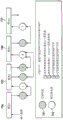
FIG. 1 is a flowchart of steps of an example method of lossless data compression, according to an example embodiment.
Fig. 2 shows an example of the described compression work, in which a line comprising 256 bits of raw data is converted into 157 bits of compressed data. The precedent for each DG in the row is shown as, for example, the first data sample value in DG.
FIG. 3A illustrates an example lossless data compression with a single clock cycle parallel compression block and voting circuitry for obtaining compression parameters for obtaining a minimum compression ratio and compressed data size.
Fig. 3B illustrates example components of the precedent selection circuit and the sample processing circuit.
Fig. 4 shows an example formation of CIP with compressed data for each row.
FIG. 5A shows an example decompression scheme that uses a 2/2 address computation transformation engine μ architecture to decompress by converting the described compressed data into uncompressed raw data output.
Fig. 5B shows an example circuit implementation of the address pointer calculator shown in fig. 5A.
Fig. 5C shows an example of the addition or copy-on-the-go circuit operation.
FIG. 6A illustrates a first example option including an internal line option for data storage in DDR memory.
FIG. 6B illustrates a second example option for data storage in DDR memory that includes a dense storage option.
FIG. 7A is a block diagram of an example system for lossless data compression of a sensed data stream (radar data or image data), according to an example embodiment.
Fig. 7B is a block diagram of an example system for lossless data compression and decompression of data signals.
FIG. 7C depicts 4 types of compression and decompression blocks that may be used to implement the described compression and decompression in an example system.
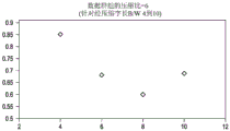
Fig. 8A and 8B illustrate experimentally determined compression ratio and compressed word length data for DG sizes of 4 and 6, respectively, for example imaging applications.
Detailed Description
The drawings are not necessarily to scale. In the drawings, like reference numerals designate similar or equivalent elements. Some of the illustrated acts or events may occur in different orders and/or concurrently with other acts or events. Moreover, some of the illustrated acts or events are optional.
The terms "coupled to" or "coupled with … …" (and the like) as used herein describe either an indirect or direct electrical connection without further limitation. Thus, if a first device "couples" to a second device, that connection may be through a direct electrical connection where only parasitics are present in the path, or through an indirect electrical connection via intermediaries including other devices and connections. For indirect coupling, the intermediate term typically does not modify the information of the signal, but may adjust its current level, voltage level, and/or power level.
FIG. 1 is a flowchart of steps of an example method 100 of lossless data compression of a sense data stream, according to an example embodiment. The sensing data stream may include radar data for radar applications, such as Frequency Modulated Continuous Wave (FMCW) radar, or pixel data for imaging, such as for advanced assisted driving system (ADAS) applications.
Step 101 includes obtaining binary sensor data from a sensed data source comprising a plurality of rows, wherein each row includes a plurality of multi-bit (e.g., 16) data samples. Each row corresponds to a frame or as a channel, where a frame may include 2D plane data corresponding to each image captured with the same or different exposure times (e.g., 3) in the case of an imaging application, or 2D plane data corresponding to radar sensor chirp (chirp) reflections of each radar dwell. The sensing data source may be a sensor that provides real-time data as a data stream, or the data source may be a memory that stores sensor data obtained from the sensor.
Step 102 includes dividing each row into a plurality of DG, each DG comprising two or more data samples. As used herein, a "data group" (DG) is a contiguous group of raster data values (e.g., samples or pixels) that display data locality and are therefore relatively easy to compress. Each row of rasterized data will have 2 or more DGs. As shown in the example compression of fig. 2 described below, 4 DGs each have 4 samples per row.
Step 103 includes selecting a precedent value for each row or a corresponding precedent value for each of the DG in the row. As used herein, a "precedent value" is a value selected to minimize an item referred to herein as "drift". Drift is defined as the difference in sign between the current data value and the precedent within the DG being compressed. In one embodiment, as shown in FIG. 2, the precedent is the first data sample value in DG.
Various methods exist for dynamically selecting precedent values. One approach is to produce the smallest compressed data (highest compression ratio). The precedent value may also be selected based on the predicted value of each sample (e.g., pixel) in DG, where the predicted value may be generated by yielding a better match of linearity, quadratic, mean, median, or any other method for the sample being compressed. Precedent selection is an intelligent method that is typically performed with dedicated hardware. A precedent may be any data value in a row, an average of all data values, a median of data values, or a user-configured value. The circuitry for precedent selection may also include a statistical histogram calculation block (his) 311 for the data being compressed (see fig. 3B described below), and precedents may be selected based on the output of this block and the heuristic rules of offline pre-calculation.
Step 104 includes generating compressed rows of compressed sensor data from each row by calculating a difference between each data sample and its associated precedent value of DG. Step 105 includes generating CIP for each line with information for non-destructive return of sensor data. As described above, CIP includes a compressed predicate that includes a data structure that indicates whether each DG is stored compressed; a group size, which is a multi-bit value storing a flexible data group size for row compression; and a compressed word length, which is a multi-bit value of the dynamic range of memory row compression. (see example CIP shown in FIG. 4 described below). Step 106 includes storing the compressed line with the CIP as stored compressed data. See, for example, the storage options described below with respect to fig. 6A and 6B.
The method 100 may also include decompressing the stored compressed data. Step 107 shown in fig. 1 includes retrieving stored compressed data from memory (e.g., DDR or on-chip RAM) and decompressing to recover the original uncompressed data using CIP in a single cycle. For decompression, for example, see decompression circuit options described in fig. 5A, 5B, and 5C.
The method may also include parallel single clock cycle processing of all multiple DGs. Hardware is provided for: for example, as shown in fig. 3A described below, the compressed outputs of all DG in a row are computed simultaneously (non-linearly) such that the time required for compression is independent of DG group configuration, and precedent selection, etc. The method may also include dynamically selecting the compressed word length to obtain an optimal compressed output reflected in a low compression ratio.
Compression parameters, including drift, compressed word length, precedent value, and DG size, may be dynamically selected under control by configuration. The method may additionally include decompressing the stored compressed data to recover the original sensor data losslessly, including accessing random locations at a fixed time. Accessing random locations at a fixed time means accessing any data value (e.g., pixel value) at a constant time. This is nontrivial as each DG that occurs prior to the data value can be compressed to any size. Instead of having to add up the sizes of all previous DG in sequence, CIP is defined. Using the accumulated data size, predicate, compressed word length, and DG size, it can be determined where the data value is in memory. Decompression may include a single cycle for recovering sensor data. The method may also include decompressing using a parallel map-reduce function and a single cycle address indicator calculation.
FIG. 2 shows an example of the described compression operation, where a row including uncompressed 256-bit raw data 210 is converted to compressed data 220 including a row having 157 bits, and compressed predicates 225, shown as including 4 1-bit compressed predicates. The compressed predicate shown is a one-bit data structure that indicates whether the DG in the compressed data 220 has been compressed.
This example row compression provides a compression ratio of 161/256=59%. The precedent for each of the 4 data groups is shown as the first data sample value in DG, where each sample has 16 bits, such that DG has 64 bits each. In the first row DG is shown as G 1 、G 2 、G 3 And G 4 . In the compression scheme shown, each DG has 4 samples, each data sample is 16 bits in the original data 210, and the compressed word length used is 5 bits. A compressed word length as used herein is a dynamically selectable compression parameter (typically from 4 to 10 for 16-bit data) that defines the dynamic range of drift of data that can be compressed inside a DG.
In this example, G 1 、G 2 And G 4 Compressed, but G 3 Not compressed because G 3 The drift range of the data in (1) is 50 (the difference between 100 and 150 of the minimum and maximum data values of DG, respectively) which is greater than the number that can be encoded in the 5 bits set by the compressed word length used. At G 1 In using precedent 2, the unprecedented raw samples are processed by subtracting 2 from the raw data sample values to provide compressed data values. For the second sample of the second data group, the calculation is 10-2=8. The compressed data predicate is shown at G 1 、G 2 And G 4 Given 1 in the case of receiving compression, for G not receiving compression 3 Given as 0. The described method achieves advantages by using a compressed predicate value of zero (or 1) to avoid decompressing the processing DG when data compression is not implemented for DG.
The basic principle of the described compression is to never increase the compressed data size of any row to a predetermined size above the original data size plus W/N bits, the compressed data size being defined as the size of the compressed row plus the size of CIP, where W is the original data length (in bits) and N is the size of DG (in bits). For example, the original data length (row) is 256 bits in fig. 2 and the final data length is 157 bits.
FIG. 3A illustrates an example lossless data compression using a single clock cycle parallel connection compression circuit 310 for each DG distributed across the raster data width 1 、310 2 To 310 n (collectively compression circuitry 310) that provides a minimum compression ratio for each row of raw input binary sensor data shown as received as input data 305 shown. Compression circuit 310 1 、310 2 To 310 n Each of the two components described below in fig. 3B are a precedent selection circuit 310a for providing the precedent selection signal shown in fig. 3A, and sample processing by differencing performed by a sample processing circuit 310B, the sample processing circuit 310B generating compressed data using the corresponding precedent values received from the precedent selection circuit 310 a.
The slave compression circuit 310 1 、310 2 To 310 n The output compressed data is shown coupled to voting circuit 320 and then to DDR memory 330. Additional compression circuitry may be used to compress the rows with different configuration values for DG size and drift. This may be followed by a voting circuit 320 shown that compares the compression ratios achieved from all of these calculations and forwards the compressed data corresponding to the best compression ratio to the DDR 330.
Fig. 3B illustrates example components of the precedent selection circuit 310a and the sample processing circuit 310B. The precedent selection circuit 310a shown in fig. 3B may select from a plurality of different precedent selection options shown by way of example for the first pixel 312a, an average value shown as mean 312B and median 312c depending on the statistical distribution of the input data calculated by the fast block 311. The HIST block 311 outputs a MUX select signal 316 to the MUX 317, which in response outputs the precedent value.
These electrically parallel compression circuits 310 1 、310 2 To 310n, single clock cycle lossless compression is performed on the input data 305 with DG size and dynamic range of drift, and various configurations of data precedents selected based on the provided real-time calculations. From these compression circuits 310 1 、310 2 To 310 n Is compressed output data generated for different configurations and the compression ratios achieved for each configuration. Compression circuit 310 1 、310 2 The outputs to 310n are coupled to inputs of voting circuit 320, which voting circuit 320 implements voting for selecting the precedents, DG sizes, and drifts that achieve best-case compression and forwards the compressed data and CIP corresponding to the options to DDR memory 330 or another internal memory for storage.
Fig. 4 shows an example formation of CIP shown for each of the 4 rows 1 through 4. CIP is stored in memory along with the compressed data (see FIGS. 6A and 6B described below). As described above, CIP is a data packet created and stored with each line. CIP is typically not considered when calculating the compression ratio, as the size of CIP is by far smaller than the usual line size. For example, in a 2M pixel camera, the uncompressed line size is 6 kilobytes, while the size of CIP would be <100 bytes. The compression circuit generates CIP information when compressing data, and the decompressor circuit extracts (decompresses) the original data packet using the CIP information. The fields in the example CIP shown in FIG. 4 include a 1-bit (shown as W/N bits, but the circuit may make the compressed predicates fixed bit fields (e.g., 512 bits), thereby limiting the maximum number of DGs) to indicate whether or not the compressed predicates are compressed, where W is the grid row size and N is the data group size.
The compressed data size is shown as 32 bits, with the entire compressed data size for the example in fig. 2 being a row of 157-bit raster data, and the accumulated data size shown as 64 bits being the entire compressed data size of the frame up to the row. CIP also includes a Compressed Word (CW) size, which is a 4-bit value that stores the dynamic range of the compression scheme for the row signature; DG size, which is an 8-bit value storing a flexible DG size to compress one specific row; and an ECC and/or CRC signature calculated for each CIP, which in turn corresponds to a line of data to ensure functional security and compression correctness. The signature also ensures that CIP is corrected in real time even if it is corrupted, for example, by cosmic alpha particles, electromagnetic interference (EMI), clock or power failure, and thus the decompression process for the full frame will occur correctly.
Fig. 5A shows an example decompression scheme that converts compressed data into uncompressed data output (raw data 210) using an address calculation transformation engine μ architecture. The compressed data shown in this example is the compressed data 220 in FIG. 2, and the compressed predicates of the respective DGs are processed by a parallel mapping and reduction block 510, which parallel mapping and reduction block 510 generates the illustrated transformed predicate 520 from the received compressed predicate 225.
In general, one transformed predicate is computed for each DG. The shrink-based adder uses the parallel mapping and reduction block 510 to ensure that the transformed predicate values represent a double data structure. The first part of the data structure has information about the number of DGs that were successfully compressed, and this may be done from having log 2 The compressed predicates 225 of n complexity input computations to ensure fast computations. The second portion of the transformed predicate 520 may contain accumulated information of how many uncompressed DG are stored up to the point in the row. This transformed predicate 520 is followed by an address pointer calculator 525. This address pointer calculator 525 multiplies the transformed predicate 520 first portion of DG by the compressed word length (31 in this example) and multiplies the transformed predicate 520 second portion by the compressed word length (64 in this example). These two values are then added together to calculate the location pointer of the compressed precedent in the retrieved compressed data.
The output of the address pointer calculator 525 is coupled to a decoder 530 for decoding the position of the precedent and calculating the correct uncompressed data value. The decoder 530 obtains precedent values from the compressed data of each data group based on the address pointer calculator 525. It also receives as another input the compressed predicate of an uncompressed row. The output of the decoder 530 is coupled to an add or copy as is decision block 535. If a DG is stored by compression as indicated by the compressed predicate, then the precedent value of the DG is added to other values received in the compressed data to calculate an uncompressed data value. Otherwise, the values in the compressed data are copied (unchanged) to memory as original data by the add or copy-as-original decision block 535 without adding the values to the precedents. This processing by the add or copy-as-is decision block 535 causes 256 bits of the line of original data 210 shown in fig. 2 to be returned.
FIG. 5B shows the address pointer calculator shown in FIG. 5A, now shown as 525' and now shown as parallel map and reduce log 2 An example circuit implementation of the parallel mapping and reduction circuit 510 of the n-layer 510'. The address pointer calculator 525' includes an adder 525a that outputs its previous two multipliers 525b and 525cAdded together. 525b multiply the first half 520a of the transformed predicate 520 of the corresponding DG by a fixed value equal to the size of the compressed DG. 525c multiply the second half 520b of the corresponding DG by a fixed value equal to the size of the uncompressed DG.
The output of the address pointer calculator 525' is coupled to a decoder 530. Through the map-reduce circuit 510 1 And 510 2 The data structure of the transformed predicate 520 is calculated by the combination of (a). The inputs to the two circuits are the compressed predicates 225 of the uncompressed data row. 510 1 The number of data groups stored after successful compression before DG of the data line is uncompressed is counted. 510 2 The number of DG that may be uncompressed before DG of the uncompressed data line is counted.
Fig. 5C shows an example of the operation of the instance add or copy as is 535. The inputs to this circuit are the precedents of the compressed predicate 225, the compressed data, and the address location extraction decoded from the decoder 530. If the compressed predicates indicate that DG is stored after compression, then adders 538a, 538b, and 538c add the received values to the precedent, otherwise copy (unchanged) the values as they were, which is shown as uncompensated data output 210a.
FIG. 6A illustrates a first example option for data storage of compressed data in DDR memory. This is a simple inline option that does not typically optimize DDR memory density. This approach improves DDR bandwidth for writing compressed data into memory. CIP is prepended (attached as a header) to the actual compressed data packet. The compressed data is stored in memory such that the first byte of CIP of each rasterized line is in the location where the actual data would be if not compressed. This data storage format is easier to configure a DMA engine that can issue a series of commands to access data from each row in a frame. The DMA/streaming engine may introduce CIP, process the packet, and then forward the packet to the parallel mapping and reduction block 510, the transformed predicate 520, and the address pointer computation block 525.
FIG. 6B illustrates a second example option for data storage in DDR memory. This is a dense storage option that improves DDR memory storage density, i.e., can store more data in the same DDR memory size as the first example option shown in fig. 6A. In this case, the CIP structure also contains the address of the next CIP. Alternatively, the cumulative data size field of the CIP structure may be used to determine the start address of the next line of data. The DMA engine responsible for accessing the compressed data frame reads the first CIP in the data frame, followed by extracting bytes as indicated by the CIP to store the compressed data and the CIP of the next line, after which the data is forwarded to the decompression circuit. Through this process, the memory access logic of the DMA engine keeps calculating the address of the next access.
The address calculation thus performed is done by two unique procedures, the first procedure is an optional CIP field storing the address of the next CIP, and the second procedure is to use the compressed data size field and add it to the current address. This process ensures functionally safe and reliable data access and prevents circuit failure from occurring due to cosmic alpha particles, EMI, clock, or random voltage noise.
The described embodiments also include adaptive and scalable compression scheme algorithms. Each data set behaves in a different way and there is no ideal set of compression parameters that ensure the best compression results. The "valid parameter" constrained range for the range of DG sizes and compressed word sizes may be defined such that both are flexible parameters. For example, the valid values for DG sizes may be 4, 8, 12, and 16. Similarly, the effective value of the compressed word length may be between 6 and 12, for each line of data, the following steps may be performed:
(a) In parallel, compression for the whole line is run using N parameter sets (all combinations of n=dg size values and compressed word length values), and N CIPs are generated;
(b) Comparing the size of the compressed data (compressed data size) from each of the runs in (a) by comparing the relevant CIP fields (entire compressed size); and
(c) The best compressed word length and DG selection are selected based on voting circuit 320 comparisons of compression ratios achieved for all of the executed configuration options.
This adaptive and scalable compression algorithm and logic is fully scalable and ensures that each row of data is proactively created an optimal compressed data set. The 4 x semiconductor (e.g., silicon) area of the compression scheme ensures a 4 x improvement in performance. Semiconductor area can be constrained by using the same circuit in a time multiplexed manner at the cost of a particular delay.
Referring to fig. 7A, a system 700 for compressing a data signal is shown that includes a processing unit 705. Shown is a processing unit 705 formed on a substrate 702 having a semiconductor surface (e.g., a silicon substrate), which may be implemented as a decentralized instantiated System On Chip (SOC) architecture with compression and decompression circuitry. The processing unit 705 may include a microprocessor, a Digital Signal Processor (DSP), or a microcontroller unit (MCU). The processing unit 705 is in electronic communication with a sensed data source 710. Examples of data sources may include digital cameras, camcorders, mobile devices or devices that capture and provide video signals indicative of a physical scene, or antennas in the case of radar, and analog front ends. The processing unit 705 is in electronic communication with an external memory 715. An example of the external memory 715 is a DDR memory.
The processing unit 705 comprises a processing subsystem 720 for processing the sensed date signal. Data processing subsystem 720 includes a front end 725 and a back end 730 coupled together by a buffer 780. Front end 725 includes a sensor interface 735 that receives sensed data signals from data source 710. The back end 730 includes an encoder 740 for generating a compressed version of a frame in the data signal according to the described compression scheme. In some embodiments, encoder 740 may include separate units for generating compressed versions of frames of the data signal. The processing unit 705 includes Direct Memory Access (DMA) data and a configuration bus 745. The DMA data and configuration bus 745 passes data and control signals between the components in the processing unit 705.
The processing unit 705 includes a Reduced Instruction Set Computing (RISC) processor 750 that acts as a central processing unit. RISC processor 750 is operative to perform input or output functions, as well as system control functions. The processing unit 705 includes a Digital Signal Processor (DSP) 755.DSP 755 is operable to process real-time signal processing software algorithms. In one embodiment, DSP 755 is operable to process the codec. A codec may be defined as a coding or decoding software.
The processing unit 705 includes a DMA controller 760 for directing memory accesses. The processing unit 705 comprises an on-chip memory 765 storing frames of data signals. An example of an on-chip memory 765 is Static Random Access Memory (SRAM). The processing unit 705 may include other memory for storing the codec. The processing unit 705 also includes an external memory controller 770 for controlling the external memory 715. The processing unit 705 includes one or more peripherals 775, such as a communication peripheral that transmits one or more frames of a data signal. Examples of communication peripherals include ports and sockets. Peripheral 775 may also include system peripherals such as a timer and temporary memory such as RAM.
Fig. 7B illustrates an example system 700' for compressing and decompressing data signals. The system 700' includes the described compression circuit 791 and decompression circuit 792 between the buffer 780 and the front end including the sensor interface 735, and between the buffer 780 and the back end 730. The example architecture of system 700' ensures the instantiated, decentralized compression and decompression blocks required at the input and output of the various data processing and data input blocks of the system.
FIG. 7C depicts an example 4 types of compression-decompression blocks that may be used to implement the described compression and decompression. The illustrated modules include modules 1-4, shown as modules 794, 795, 796 and 797. Each circle number shown corresponds to a type of compression and decompression. Circle 1, which may be processed by illustrated module 794, corresponds to raster linear (1D) data Y-plane image or linear radar data, circle 2, which may be processed by illustrated module 795, corresponds to raster linear data U, V interleaved plane image data, circle 3, which may be processed by illustrated module 796, corresponds to block-by-block (2D) random access of sensor data, and circle 4, which may be processed by illustrated module 797, corresponds to block-by-block (2D) regular access of sensor data. This example shown may also instantiate a compression and decompression block for handling linear radar data. The mechanisms, circuits and methods for compression and decompression allow for data handling of different data topologies (1D, 2D) and access patterns (regular or random) in fixed and deterministic times.
Advantages of the described embodiments include a simple lossless and dynamically adaptive data compression scheme. The compression described enables random data access. The described embodiments are particularly well suited for safety critical applications with the described CIP structure. Functional security has potential bill of materials (BOM) cost reduction. The described embodiments allow for a variety of external memory storage schemes, including both linear and block-by-block. The described embodiments also allow for fixed density, decoupled control and data packet, and DG parallel processing with minimized latency.
Fig. 8A and 8B illustrate DG-sized compression ratio and compressed word length data of 4 and 6, respectively, for example imaging applications using the compression and decompression described. For this example, data is generated by varying DG size 4 in fig. 8A and DG size 6 in fig. 8B. The X-axis in fig. 8A and 8B records the CW size for compression. In this particular example, an optimal compression ratio substantially equal to 0.6 for CW size 8 and DG size 6 is achieved. The original data samples are 16-bit image data (pixels). Each frame contains about 300,000 pixels. Post-compression bandwidth has been reduced to 60% of uncompressed data. For 12-bit image data (not shown), the achievable compression ratio was found to be about 70%.
Modifications to the described embodiments are possible, and other embodiments are possible, within the scope of the claims.
Claims (19)
1. A method of lossless data compression, comprising:
obtaining binary sensor data comprising a plurality of rows, wherein each of the rows comprises a plurality of multi-bit data samples;
dividing each of the rows into a plurality of groups of data each including two or more of the multi-bit data samples;
selecting a respective one of a precedent value for each of the rows or the precedent value for each of the plurality of data groups, the precedent value being selected from a plurality of different precedent values based on a statistical distribution of the data samples in each row or each data group;
generating compressed rows of compressed sensor data from each of the rows by calculating a difference between each of the data samples and the precedent value of its associated one of the data groups;
generating a compressed packet CIP for each of the rows having information for lossless return of the binary sensor data, the information comprising: a compressed predicate including a data structure indicating whether each of the data groups is stored compressed; a data group size, which is a multi-bit value storing a group size for row compression;
and a compressed word length that is a multi-bit value storing the dynamic range of the row compression, an
The compressed line is stored with the CIP as stored compressed data.
2. The method of claim 1, wherein the method comprises parallel single clock cycle processing of all of the plurality of data groups.
3. The method of claim 1, further comprising using voting circuitry that dynamically selects the compressed word length.
4. The method of claim 1, further comprising dynamically selecting a configuration controlled compression parameter that includes a drift that is a difference between a current data value and the precedent value within the data group, the compressed word length, the precedent value, and the data group size.
5. The method of claim 1, further comprising decompressing the stored compressed data to recover the binary sensor data, including accessing a random location within a fixed time.
6. The method of claim 5, wherein the decompressing comprises a single cycle for the recovering of the binary sensor data.
7. The method of claim 1, further comprising decompressing using a parallel map-reduce function and single cycle address indicator computation.
8. The method of claim 1, wherein the CIP includes at least one error correction code, ECC, or cyclic redundancy check, CRC, field.
9. A system for providing lossless data compression, comprising:
a sensor interface for receiving binary sensor data comprising a plurality of rows, wherein each of the rows includes a plurality of multi-bit data samples;
a data processing subsystem including an encoder having an input coupled to an output of the sensor interface, the data processing subsystem including hardware and software for:
dividing each of the rows into a plurality of groups of data each including two or more of the multi-bit data samples;
selecting, based on a statistical distribution of the data samples in each row or each data group, a precedent value for each of the rows or a respective one of the precedent values for each of the plurality of data groups from a plurality of different precedent values;
generating compressed rows of compressed sensor data from each of the rows by calculating a difference between each of the data samples and the precedent value of the data group associated therewith;
generating a compressed packet CIP for each of the rows having information for lossless return of the binary sensor data, the information comprising: a compressed predicate including a data structure indicating whether each of the data groups is stored compressed; a data group size, which is a multi-bit value storing a group size for row compression;
and a compressed word length that is a multi-bit value storing the dynamic range of the row compression.
10. The system of claim 9, wherein the data processing subsystem additionally provides for storing the compressed line with the CIP as stored compressed data.
11. The system of claim 9, wherein the data processing subsystem includes circuitry for parallel processing of the plurality of data groups.
12. The system of claim 9, wherein the encoder comprises a substrate having a semiconductor surface.
13. The system of claim 9, further comprising a single clock cycle compression circuit for implementing the lossless data compression.
14. The system of claim 10, further comprising voting circuitry for dynamically selecting the compressed word length.
15. The system of claim 10, further comprising a dynamically selected compression parameter block under configuration control that includes a drift that is a difference between a current data value and the precedent value within the data group, the compressed word length, the precedent value, and the data group size.
16. The system of claim 10, further comprising a decoder for decompressing the stored compressed data to recover the binary sensor data.
17. The system of claim 16, wherein the decoder comprises a decompression circuit that operates in a single cycle for the recovery of the binary sensor data.
18. The system of claim 16, further comprising identifying a location of the precedent value for the decompressing using a parallel map-reduce function and a single cycle address pointer calculator.
19. The system of claim 10, wherein the CIP includes at least one error correction code, ECC, or cyclic redundancy check, CRC, field.
Applications Claiming Priority (3)
| Application Number | Priority Date | Filing Date | Title |
|---|---|---|---|
| US15/376,170 | 2016-12-12 | ||
| US15/376,170 US10069511B2 (en) | 2016-12-12 | 2016-12-12 | Lossless data compression |
| PCT/US2017/065915 WO2018111942A1 (en) | 2016-12-12 | 2017-12-12 | Lossless data compression |
Publications (2)
| Publication Number | Publication Date |
|---|---|
| CN109952708A CN109952708A (en) | 2019-06-28 |
| CN109952708B true CN109952708B (en) | 2023-06-30 |
Family
ID=62490497
Family Applications (1)
| Application Number | Title | Priority Date | Filing Date |
|---|---|---|---|
| CN201780068635.7A Active CN109952708B (en) | 2016-12-12 | 2017-12-12 | Lossless data compression |
Country Status (5)
| Country | Link |
|---|---|
| US (1) | US10069511B2 (en) |
| EP (1) | EP3552312A4 (en) |
| JP (1) | JP7421036B2 (en) |
| CN (1) | CN109952708B (en) |
| WO (1) | WO2018111942A1 (en) |
Families Citing this family (17)
| Publication number | Priority date | Publication date | Assignee | Title |
|---|---|---|---|---|
| US10402111B1 (en) * | 2017-08-14 | 2019-09-03 | Xilinx, Inc. | Systems and methods for data storage compression |
| US10970080B2 (en) | 2018-02-08 | 2021-04-06 | Marvell Asia Pte, Ltd. | Systems and methods for programmable hardware architecture for machine learning |
| US11016801B1 (en) | 2018-05-22 | 2021-05-25 | Marvell Asia Pte, Ltd. | Architecture to support color scheme-based synchronization for machine learning |
| US10891136B1 (en) | 2018-05-22 | 2021-01-12 | Marvell Asia Pte, Ltd. | Data transmission between memory and on chip memory of inference engine for machine learning via a single data gathering instruction |
| US10929760B1 (en) | 2018-05-22 | 2021-02-23 | Marvell Asia Pte, Ltd. | Architecture for table-based mathematical operations for inference acceleration in machine learning |
| US10929779B1 (en) | 2018-05-22 | 2021-02-23 | Marvell Asia Pte, Ltd. | Architecture to support synchronization between core and inference engine for machine learning |
| US10929778B1 (en) * | 2018-05-22 | 2021-02-23 | Marvell Asia Pte, Ltd. | Address interleaving for machine learning |
| US10997510B1 (en) | 2018-05-22 | 2021-05-04 | Marvell Asia Pte, Ltd. | Architecture to support tanh and sigmoid operations for inference acceleration in machine learning |
| CN111697973B (en) * | 2019-05-16 | 2021-02-02 | 时擎智能科技(上海)有限公司 | Compression method and compression system |
| CN110247666B (en) * | 2019-05-22 | 2023-08-18 | 深圳大学 | System and method for hardware parallel compression |
| TWI745697B (en) | 2019-05-24 | 2021-11-11 | 創鑫智慧股份有限公司 | Computing system and compressing method thereof for neural network parameters |
| CN112241005A (en) * | 2019-07-19 | 2021-01-19 | 杭州海康威视数字技术股份有限公司 | Method and device for compressing radar detection data and storage medium |
| DE102019214587A1 (en) * | 2019-09-24 | 2021-03-25 | Conti Temic Microelectronic Gmbh | Processing of lossy compressed ADAS sensor data for driver assistance systems |
| US20230074041A1 (en) * | 2019-12-23 | 2023-03-09 | Ams Ag | Lossless data transfer compression |
| CN111307182B (en) * | 2020-03-06 | 2022-08-23 | 宁波飞芯电子科技有限公司 | Data processing method and array type sensor |
| US20230177730A1 (en) * | 2021-12-07 | 2023-06-08 | International Business Machines Corporation | Stochastic compression of raster data |
| CN114268323B (en) * | 2021-12-24 | 2023-07-07 | 成都索贝数码科技股份有限公司 | Data compression coding method, device and time sequence database supporting line memory |
Citations (5)
| Publication number | Priority date | Publication date | Assignee | Title |
|---|---|---|---|---|
| JPH04252569A (en) * | 1991-01-28 | 1992-09-08 | Nec Corp | Picture data compression system |
| JPH06319047A (en) * | 1993-05-07 | 1994-11-15 | Seiko Epson Corp | Information processor |
| JPH1132328A (en) * | 1997-07-10 | 1999-02-02 | Pfu Ltd | Method and device for compressing multilevel picture data and recording medium |
| CN201523455U (en) * | 2009-09-24 | 2010-07-07 | 信飞系统公司 | Signal compression device in base transceiver system |
| US9496894B1 (en) * | 2015-10-21 | 2016-11-15 | GE Lighting Solutions, LLC | System and method for data compression over a communication network |
Family Cites Families (10)
| Publication number | Priority date | Publication date | Assignee | Title |
|---|---|---|---|---|
| US9204157B2 (en) | 2011-11-18 | 2015-12-01 | Texas Instruments Incorporated | Video compression searching reference frame in hybrid growing-window and sliding-window |
| JP2012013657A (en) | 2010-07-05 | 2012-01-19 | Ihi Infrastructure Systems Co Ltd | Spectroscopy analyzer |
| JP5591080B2 (en) * | 2010-11-26 | 2014-09-17 | 三菱電機株式会社 | Data compression apparatus, data processing system, computer program, and data compression method |
| US20120239612A1 (en) | 2011-01-25 | 2012-09-20 | Muthian George | User defined functions for data loading |
| US8914545B2 (en) * | 2011-04-27 | 2014-12-16 | Iii Holdings 1, Llc | Systems and methods for lossless compression of data and high speed manipulation thereof |
| JP2014075687A (en) | 2012-10-04 | 2014-04-24 | Seiko Epson Corp | Image data compression apparatus, image data decompression apparatus, display device, image processing system, image data compression method, and image data decompression method |
| US9800886B2 (en) | 2014-03-07 | 2017-10-24 | Lattice Semiconductor Corporation | Compressed blanking period transfer over a multimedia link |
| CN104378118B (en) * | 2014-10-29 | 2017-08-11 | 中国科学院地质与地球物理研究所 | Efficient self-adapted geological data stream Lossless Compression and decompression method |
| US9748972B2 (en) * | 2015-09-14 | 2017-08-29 | Leco Corporation | Lossless data compression |
| US9923577B1 (en) * | 2016-09-04 | 2018-03-20 | ScaleFlux, Inc. | Hybrid software-hardware implementation of lossless data compression and decompression |
-
2016
- 2016-12-12 US US15/376,170 patent/US10069511B2/en active Active
-
2017
- 2017-12-12 JP JP2019551920A patent/JP7421036B2/en active Active
- 2017-12-12 WO PCT/US2017/065915 patent/WO2018111942A1/en unknown
- 2017-12-12 EP EP17880411.8A patent/EP3552312A4/en not_active Withdrawn
- 2017-12-12 CN CN201780068635.7A patent/CN109952708B/en active Active
Patent Citations (5)
| Publication number | Priority date | Publication date | Assignee | Title |
|---|---|---|---|---|
| JPH04252569A (en) * | 1991-01-28 | 1992-09-08 | Nec Corp | Picture data compression system |
| JPH06319047A (en) * | 1993-05-07 | 1994-11-15 | Seiko Epson Corp | Information processor |
| JPH1132328A (en) * | 1997-07-10 | 1999-02-02 | Pfu Ltd | Method and device for compressing multilevel picture data and recording medium |
| CN201523455U (en) * | 2009-09-24 | 2010-07-07 | 信飞系统公司 | Signal compression device in base transceiver system |
| US9496894B1 (en) * | 2015-10-21 | 2016-11-15 | GE Lighting Solutions, LLC | System and method for data compression over a communication network |
Also Published As
| Publication number | Publication date |
|---|---|
| JP2020501475A (en) | 2020-01-16 |
| WO2018111942A1 (en) | 2018-06-21 |
| EP3552312A4 (en) | 2019-12-25 |
| JP7421036B2 (en) | 2024-01-24 |
| EP3552312A1 (en) | 2019-10-16 |
| US10069511B2 (en) | 2018-09-04 |
| US20180167083A1 (en) | 2018-06-14 |
| CN109952708A (en) | 2019-06-28 |
Similar Documents
| Publication | Publication Date | Title |
|---|---|---|
| CN109952708B (en) | Lossless data compression | |
| US6597812B1 (en) | System and method for lossless data compression and decompression | |
| US9425828B2 (en) | Memory device and memory system | |
| US20210111741A1 (en) | Decompression apparatus and control method thereof | |
| Alarabeyyat et al. | Lossless image compression technique using combination methods | |
| CN111818346A (en) | Image encoding method and apparatus, image decoding method and apparatus | |
| US10515112B2 (en) | Method and device for searching images | |
| CN112953550B (en) | Data compression method, electronic device and storage medium | |
| TWI602212B (en) | System and method for compressed data transmission in an electron beam lithography system and system for electron beam lithography with data compression and transmission capabilities | |
| EP3968235A1 (en) | Artificial neural network processing methods and system | |
| DE102020133861A1 (en) | NORMALIZED LIKELIHOOD DETERMINATION FOR CHARACTER ENCODING | |
| CN114222129A (en) | Image compression encoding method, image compression encoding device, computer equipment and storage medium | |
| US11562241B2 (en) | Data output method, data acquisition method, device, and electronic apparatus | |
| EP4135200A1 (en) | Systems, methods, and apparatus for dividing and compressing data | |
| US7071854B1 (en) | Hardware-implemented LZW data decompression | |
| US11475285B2 (en) | Neural network accelerator and operating method thereof | |
| WO2022072802A1 (en) | Systems and methods for lossless compression of tabular numeric data | |
| Ahmed et al. | WSN application based on image compression using AHAAR wavelet transform | |
| CN115250351A (en) | Compression method, decompression method and related products for image data | |
| US7612692B2 (en) | Bidirectional context model for adaptive compression | |
| EP4134818A1 (en) | Systems, methods, and apparatus for dividing and encrypting data | |
| US11742875B1 (en) | Compression of floating-point numbers for neural networks | |
| US11048413B2 (en) | Method for reducing read ports and accelerating decompression in memory systems | |
| Beebe et al. | A Bibliography on Data Compression | |
| Jothin et al. | High performance static segment on-Chip memory for image processing applications |
Legal Events
| Date | Code | Title | Description |
|---|---|---|---|
| PB01 | Publication | ||
| PB01 | Publication | ||
| SE01 | Entry into force of request for substantive examination | ||
| SE01 | Entry into force of request for substantive examination | ||
| GR01 | Patent grant | ||
| GR01 | Patent grant |