JP7416632B2 - Fiber sheets, processed fiber bodies, cable shielding materials, and cables - Google Patents
Fiber sheets, processed fiber bodies, cable shielding materials, and cables Download PDFInfo
- Publication number
- JP7416632B2 JP7416632B2 JP2020006111A JP2020006111A JP7416632B2 JP 7416632 B2 JP7416632 B2 JP 7416632B2 JP 2020006111 A JP2020006111 A JP 2020006111A JP 2020006111 A JP2020006111 A JP 2020006111A JP 7416632 B2 JP7416632 B2 JP 7416632B2
- Authority
- JP
- Japan
- Prior art keywords
- fiber
- fiber sheet
- cable
- core wire
- fibrous
- Prior art date
- Legal status (The legal status is an assumption and is not a legal conclusion. Google has not performed a legal analysis and makes no representation as to the accuracy of the status listed.)
- Active
Links
Images
Landscapes
- Shielding Devices Or Components To Electric Or Magnetic Fields (AREA)
- Insulated Conductors (AREA)
- Woven Fabrics (AREA)
Description
本発明は、繊維シート、並びにこの繊維シートを加工して得られる繊維加工体およびケーブル用シールド材に関する。また、本発明は、ケーブル用シールド材を備えているケーブルに関する。 The present invention relates to a fiber sheet, a fiber processed body obtained by processing the fiber sheet, and a cable shielding material. The present invention also relates to a cable provided with a cable shielding material.
織物上に金属被膜を形成することにより、織物に導電性を付与し、電磁波シールド材、グランディング材などとして使用することが知られている。 BACKGROUND ART It is known that forming a metal coating on a textile fabric imparts conductivity to the textile fabric and uses it as an electromagnetic shielding material, a grounding material, etc.
例えば、特許文献1には、織物にメッキが施された金属被覆導電性織物が開示されている。この金属被覆導電性織物は、該織物を構成する経糸の織物表面占有率が90~110%、且つ、緯糸の織物表面占有率が40~80%であることを特徴としている。この金属被覆導電性織物は、電磁波シールド材、グランディング材などに用いられる。 For example, Patent Document 1 discloses a metal-coated conductive fabric in which a fabric is plated. This metal-coated conductive fabric is characterized in that the surface occupancy rate of the warp yarns constituting the fabric is 90 to 110%, and the surface occupancy rate of the weft yarns is 40 to 80%. This metal-coated conductive fabric is used for electromagnetic shielding materials, grounding materials, and the like.
特許文献1に開示された金属被覆導電性織物は、平織りで織られている。また、織物の織り方としては、平織りが一般的である。しかし、平織りは繊維の屈曲ピッチが狭く、織りに対する追従性が悪くなる。その結果、密に織ることが困難で、隣接する繊維間に隙間ができやすい。特に、金属メッキで被覆された繊維は、柔軟性が比較的小さく硬くなる傾向にある。このような繊維を用いて平織りの織物を作ると、隣接する繊維間の隙間が大きくなりやすく、結果として電磁波を遮断するシールド性(電磁シールドともいう)が低下する。 The metal-coated conductive fabric disclosed in Patent Document 1 is woven in a plain weave. Furthermore, plain weaving is a common method of weaving textiles. However, in the plain weave, the bending pitch of the fibers is narrow, and the followability to the weave is poor. As a result, it is difficult to weave tightly, and gaps are likely to form between adjacent fibers. In particular, fibers coated with metal plating tend to have relatively little flexibility and become hard. When a plain-woven fabric is made using such fibers, the gaps between adjacent fibers tend to become large, resulting in a decrease in shielding properties (also referred to as electromagnetic shielding) for blocking electromagnetic waves.
そこで、本発明では、金属メッキなどの金属被覆された繊維体を用いて、よりシールド性能の高い繊維シートを提供することを目的とする。 Therefore, an object of the present invention is to provide a fiber sheet with higher shielding performance by using a fiber body coated with metal such as metal plating.
本発明の一局面にかかる繊維シートは、金属被覆された複数の繊維体を有し、前記繊維体が綾織りされているものである。 A fiber sheet according to one aspect of the present invention has a plurality of metal-coated fiber bodies, and the fiber bodies are twilled.
綾織りで織られた繊維シートは、平織りで織られた繊維シートと比較して、より密な繊維組織構造を形成することが可能となる。換言すると、隣接する繊維体間の隙間をより小さくした繊維組織構造を形成することができる。したがって、上記の構成によれば、シールド性能のより高い繊維シートが得られる。 A fiber sheet woven in a twill weave can form a denser fiber structure compared to a fiber sheet woven in a plain weave. In other words, it is possible to form a fibrous tissue structure with smaller gaps between adjacent fibrous bodies. Therefore, according to the above configuration, a fiber sheet with higher shielding performance can be obtained.
上記の本発明の一局面にかかる繊維シートは、前記繊維体の繊度が2000dtex以上であってもよい。 In the fiber sheet according to one aspect of the present invention, the fiber body may have a fineness of 2000 dtex or more.
2000dtex以上の繊度を有する繊維体で形成された繊維シートは、電磁シールド効果を得るために十分な量の金属メッキが施されている。したがって、上記の構成によれば、より高い電磁シールド効果を得ることができる。 A fiber sheet formed of a fiber body having a fineness of 2000 dtex or more is plated with a sufficient amount of metal to obtain an electromagnetic shielding effect. Therefore, according to the above configuration, a higher electromagnetic shielding effect can be obtained.
上記の本発明の一局面にかかる繊維シートにおいて、前記繊維体は、複数の芯線を有しており、前記芯線の径は、10μm以上50μm以下であってもよい。 In the above-described fiber sheet according to one aspect of the present invention, the fiber body may have a plurality of core wires, and the diameter of the core wire may be 10 μm or more and 50 μm or less.
上記の構成によれば、芯線の径を10μm以上とすることで、芯線を被覆する金属被覆の厚さが芯線の径に対して大きくなることが抑制されるため、金属被覆を有する芯線の可撓性が低下することを抑えることができる。また、芯線の径を50μm以下とすることで、金属被覆を有する芯線の剛性が高くなり過ぎることを抑制することができる。さらに、芯線の径を50μm以下とすることで繊維体一本あたりのフィラメント本数が過少になることを防ぎ、金属メッキの相対量を確保することができ、シールド効果の低下を抑制することができる。このように、芯線の径を10μm以上50μm以下の範囲内とすることで、得られる繊維体に適度な可撓性を付与することができ、織物の材料により適した繊維体を得ることができる。 According to the above configuration, by setting the diameter of the core wire to 10 μm or more, the thickness of the metal coating covering the core wire is suppressed from increasing with respect to the diameter of the core wire, so that the core wire with the metal coating can be used. Decrease in flexibility can be suppressed. Further, by setting the diameter of the core wire to 50 μm or less, it is possible to prevent the rigidity of the core wire having a metal coating from becoming too high. Furthermore, by setting the diameter of the core wire to 50 μm or less, it is possible to prevent the number of filaments per fiber from becoming too small, ensure the relative amount of metal plating, and suppress the decline in shielding effectiveness. . In this way, by setting the diameter of the core wire within the range of 10 μm or more and 50 μm or less, it is possible to impart appropriate flexibility to the obtained fibrous body, and it is possible to obtain a fibrous body that is more suitable for textile materials. .
上記の本発明の一局面にかかる繊維シートは、複数の経糸と、複数の緯糸とを有しており、前記経糸の表面空隙率が20%以下であり、かつ、前記緯糸の表面空隙率が20%以下であってもよい。 The above-described fiber sheet according to one aspect of the present invention has a plurality of warps and a plurality of wefts, the warp has a surface porosity of 20% or less, and the weft has a surface porosity of 20% or less. It may be 20% or less.
上記の構成によれば、繊維シートの表面に形成された隙間からの電磁波の漏れ量を低減させることができる。これにより、繊維シートの電磁シールド性能をさらに向上させることができる。 According to the above configuration, it is possible to reduce the amount of electromagnetic waves leaking from the gap formed on the surface of the fiber sheet. Thereby, the electromagnetic shielding performance of the fiber sheet can be further improved.
上記の本発明の一局面にかかる繊維シートは、複数の経糸と、複数の緯糸とを有しており、隣接する前記経糸同士および隣接する前記緯糸同士の少なくとも何れか一方が部分的に重なっていてもよい。 The above-described fiber sheet according to one aspect of the present invention has a plurality of warps and a plurality of wefts, and at least one of the adjacent warps and the adjacent wefts partially overlap. You can.
上記の構成によれば、繊維シートの表面の空隙をほぼ無くすことができるため、電磁シールド性能をより向上させることができる。 According to the above configuration, since voids on the surface of the fiber sheet can be substantially eliminated, the electromagnetic shielding performance can be further improved.
また、上記の本発明の一局面にかかる繊維シートは、綾織りの構造を有しているため、0.1gf・cm2/yarn以上の剛性を有する繊維体を用いて繊維シートを形成する場合により適している。すなわち、上記の本発明の一局面にかかる繊維シートにおいて、前記繊維体の剛性は、0.1gf・cm2/yarn以上であってもよい。 Further, since the above-described fiber sheet according to one aspect of the present invention has a twill structure, when the fiber sheet is formed using a fiber body having a rigidity of 0.1 gf·cm 2 /yarn or more. more suitable. That is, in the fiber sheet according to one aspect of the present invention described above, the stiffness of the fiber body may be 0.1 gf·cm 2 /yarn or more.
また、本発明のもう一つの局面は、繊維加工体に関する。この繊維加工体は、上記の本発明の一局面にかかる繊維シートが、袋状またはチューブ状に形成されたものである。発明の一局面にかかる繊維シートから繊維加工体を形成することで、シールド性能のより高い繊維加工体を得ることができる。 Moreover, another aspect of the present invention relates to a processed fiber body. This processed fiber body is obtained by forming the above-described fiber sheet according to one aspect of the present invention into a bag shape or a tube shape. By forming a fiber processed body from the fiber sheet according to one aspect of the invention, a fiber processed body with higher shielding performance can be obtained.
また、本発明のさらにもう一つの局面は、上記のチューブ状の繊維加工体を有しているケーブル用シールド材に関する。このケーブル用シールド材によれば、シールド材の内部に配置された配線などから放射される電磁波が外部に漏れることを抑えることができる。 Yet another aspect of the present invention relates to a cable shielding material having the above-mentioned tubular processed fiber body. According to this cable shielding material, electromagnetic waves radiated from wiring arranged inside the shielding material can be suppressed from leaking to the outside.
また、本発明のさらにもう一つの局面は、ケーブルに関する。このケーブルは、導線と、前記導線を覆うように設けられている上記のケーブル用シールド材とを備えている。 Yet another aspect of the present invention relates to a cable. This cable includes a conducting wire and the above-mentioned cable shielding material provided so as to cover the conducting wire.
上記の構成によれば、シールド材の内部に配置された導線から電磁波が外部に漏れることを抑えることができるため、電磁シールド性に優れたケーブルを得ることができる。 According to the above configuration, leakage of electromagnetic waves to the outside from the conductive wire arranged inside the shielding material can be suppressed, so that a cable with excellent electromagnetic shielding properties can be obtained.
以上のように、本発明の一局面によれば、金属被覆された繊維体を用いて、よりシールド性能の高い繊維シートを得ることができる。 As described above, according to one aspect of the present invention, a fiber sheet with higher shielding performance can be obtained using a metal-coated fiber body.
以下、図面を参照しつつ、本発明の実施の形態について説明する。以下の説明では、同一の部材には同一の符号を付してある。それらの名称および機能も同じである。したがって、それらについての詳細な説明は繰り返さない。 Embodiments of the present invention will be described below with reference to the drawings. In the following description, the same members are given the same reference numerals. Their names and functions are also the same. Therefore, detailed descriptions thereof will not be repeated.
〔第1の実施形態〕
第1の実施形態では、本発明の繊維シートの一例である繊維シート1を例に挙げて説明する。本実施形態にかかる繊維シート1は、電子機器、ケーブル、モータ、インバータなどから発生する電磁波を遮蔽するための電磁シールド材などの材料として利用される。なお、ここでいう電磁波の遮断には、発生源から周囲に向けて放出される電磁波の遮断に限定されず、周囲からの電磁波の影響を遮断することも含まれる。
[First embodiment]
In the first embodiment, a fiber sheet 1, which is an example of the fiber sheet of the present invention, will be described as an example. The fiber sheet 1 according to this embodiment is used as a material such as an electromagnetic shielding material for shielding electromagnetic waves generated from electronic devices, cables, motors, inverters, and the like. Note that the blocking of electromagnetic waves here is not limited to blocking electromagnetic waves emitted from a source toward the surroundings, but also includes blocking the influence of electromagnetic waves from the surroundings.
(繊維シートの概略構成)
図1には、繊維シート1の構成を示す。図1の左側は、繊維シート1の一部分の繊維組織を示す平面図である。また、図1の右側は、左側の繊維シート1の破線枠の部分を拡大して示す図である。
(Schematic structure of fiber sheet)
FIG. 1 shows the structure of a fiber sheet 1. The left side of FIG. 1 is a plan view showing the fiber structure of a portion of the fiber sheet 1. As shown in FIG. Further, the right side of FIG. 1 is an enlarged view of the portion of the fiber sheet 1 on the left side surrounded by a broken line.
繊維シート1は、複数の繊維体10で形成されている。繊維体10は、複数本のフィラメント20の集合体である。すなわち、繊維体10は、例えば、2本以上1000本以下のフィラメント20を、束ねたり、撚り合わせたりして形成されている。なお、繊維体10は、20本以上500本以下のフィラメント20を、束ねたり、撚り合わせたりして形成されてもよい。
The fiber sheet 1 is formed of a plurality of fiber bodies 10. The fibrous body 10 is an aggregate of a plurality of
(フィラメントの構成および製造方法)
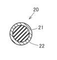
図2には、一実施形態にかかるフィラメント20の断面構成を示す。フィラメント20は、芯線21と、金属メッキ層(金属被覆)22とで構成されている。芯線21は、非金属材料で形成されている線状体である。芯線21は、繊維シート1を構成している最小単位の線状体である。
(Filament composition and manufacturing method)
FIG. 2 shows a cross-sectional configuration of a
芯線21の径は、特に限定はされないが、例えば、10μm以上50μm以下の範囲とすることができる。芯線21の径を10μm以上とすることで、芯線21に適度な強度を付与することができる。また、芯線21の径を10μm以上とすることで、芯線21を被覆する金属メッキ層22の厚さが芯線21の径に対して大きくなることが抑制され、フィラメント20の可撓性が低下することを抑えることができる。また、芯線21の径を50μm以下とすることで、メッキ処理後のフィラメント20の剛性が高くなり過ぎることを抑制することができる。これにより、フィラメント20に適度な可撓性を有し、織物の材料により適した繊維体10を得ることができる。また、芯線径が太すぎると、芯線径が細い場合と比較して繊維体一本あたりのフィラメント本数が減少するため、金属メッキの相対量(あるいは、金属メッキ層の総数)が減少して十分なシールド効果が得られない。そこで、芯線の径を50μm以下とすることで金属メッキの相対量を確保することができ、シールド効果の低下を抑制することができる。
The diameter of the
芯線21を形成している非金属材料としては、例えば、合成樹脂材料、セラミック材料、ガラス系材料などが挙げられる。合成樹脂材料としては、線状体への成形が容易なものが好適に利用される。合成樹脂材料として、具体的には、ナイロン、ビニロン、ポリエステル、オレフィン、アクリル、塩化ビニリデン、ポリウレタン、アラミド、エンジニアリングプラスチック、テフロン(登録商標)、芳香族ポリアミド、芳香族ポリエステル、液晶ポリマーなどが挙げられる。
Examples of the non-metallic material forming the
なお、ここでいう非金属材料には、例えば、アルミナを一成分として含有するセラミック繊維も含まれるものとする。すなわち、芯線21は、例えば、銅、鉄、アルミニウムなどの金属材料を主成分として形成される金属線以外の線状体であればよい。例えば、シリカおよびアルミナなどを主成分とするセラミック繊維、あるいは、チタン、ジルコニウムまたはアルミニウムなどの金属を含有するチラノ繊維(登録商標)も、芯線21の材料として利用することができる。
Note that the nonmetallic material herein includes, for example, ceramic fibers containing alumina as one component. That is, the
芯線21の材料として具体的には、液晶ポリマーから形成される合成繊維(例えば、ベクトラン(登録商標)、アラミド繊維(例えば、テクノ―ラ(登録商標))、ポリエステル(例えば、シベラス(登録商標)などの液晶ポリエステル繊維)、ナイロン(例えば、ナイロン66)などが挙げられる。
Specifically, the material of the
以上のように、芯線21を形成するための非金属材料としては種々のものが挙げられるが、繊維シート1の用途に応じて最適なものをそれぞれ選択すればよい。
As described above, there are various nonmetallic materials for forming the
金属メッキ層22は、芯線21の外周を覆うように設けられている。すなわち、芯線21の外周をコートする被覆層として金属メッキ層22が設けられている。金属メッキ層22の厚さは、特に限定はされないが、例えば、0.1μm以上5μm以下の範囲内とすることができる。
The
金属メッキ層22は、例えば、電解めっき、無電解めっきなどの従来公知のメッキ方法を用いて形成することができる。
The
一例のメッキ方法では、先ず、金属材料を含む塩化物、硫化物、水酸化物、あるいは、無機金属化合物などを溶液中に溶解させてめっき液を調製する。めっき液のpHを適宜調整することで、金属材料の溶解状態を調節することができる。このめっき液中に、芯線21を浸漬させる。その後、適切な還元剤または酸化剤を用いて芯線21の表面に金属の被膜を析出させる。このとき、めっき液の温度およびpH、並びに浸漬時間などを適宜調整することで、芯線21の表面に形成される被膜(すなわち、金属メッキ層22)の厚さを調整することができる。
In one example of a plating method, first, a plating solution is prepared by dissolving a chloride, sulfide, hydroxide, or an inorganic metal compound containing a metal material in a solution. By appropriately adjusting the pH of the plating solution, the state of dissolution of the metal material can be adjusted. The
その後、乾燥工程を経ることで金属メッキ層22が形成される。乾燥工程は、常温で行ってもよいし、加熱雰囲気下で行ってもよい。
Thereafter, the
金属メッキ層22の形成に用いられる金属材料としては、例えば、金(Au)、銀(Ag)、銅(Cu)、ニッケル(Ni)、アルミニウム(Al)、白金(Pt)、鉄(Fe)、スズ(Sn)、チタン(Ti)、およびコバルト(Co)などが挙げられる。金属材料には、これらの元素のうちの2つ以上が含まれていてもよい。すなわち、金属材料は合金であってもよい。
Examples of the metal materials used to form the
以上のようにして、フィラメント20を製造することができる。このようなフィラメント20は、長さ10cm当たり10~500mΩの抵抗値を有する。繊維体10は、このようなフィラメント20を複数本束ねたり、複数本撚り合わせたりして形成される。
The
なお、別の実施態様では、メッキ処理以外の方法で、芯線21を被覆する金属被覆を形成することもできる。このような金属被覆は、例えば、真空蒸着(CVDなど)、溶射加工、イオンプレーティングなどの従来公知の薄膜形成方法を用いて、上述の金属材料を芯線21の表面にコーティングすることで形成することができる。また、上述の金属材料を含有する溶液中に芯線21を浸漬させることによって、金属被覆を形成することもできる。
Note that in another embodiment, the metal coating covering the
また、芯線21を複数本束ねた状態で、上述したようなメッキ処理、薄膜形成処理などを行い、束状の芯線21の周囲に金属メッキ層22などの金属被覆を形成してもよい。これにより、複数本のフィラメント20で構成される繊維体10を得ることができる。
Alternatively, a metal coating such as a
また、金属メッキ層22などの金属被覆は、1層構造に限定はされず、2層以上の複数層構造とすることもできる。
Furthermore, the metal coating such as the
(繊維シートの詳細な構成)
続いて、繊維シート1のより詳細な構成について説明する。繊維シート1は、経糸11を構成する繊維体10と、緯糸12を構成する繊維体10とで形成されている。
(Detailed composition of fiber sheet)
Next, a more detailed configuration of the fiber sheet 1 will be described. The fibrous sheet 1 is formed of fibrous bodies 10 that constitute warp threads 11 and fibrous bodies 10 that constitute weft threads 12 .
繊維シート1は、複数の繊維体10を織り合わせて形成されている。具体的には、繊維シート1は、繊維体10を綾織りして形成されている。 The fiber sheet 1 is formed by interweaving a plurality of fiber bodies 10. Specifically, the fiber sheet 1 is formed by twilling the fiber bodies 10.
ここで綾織りとは、経糸11が、2本または3本の緯糸12の上を通過した後、1本または2本の緯糸12の下を通過することを繰り返す織り方である。綾織りは斜文織とも呼ばれ、経糸と緯糸との交差点(ウネと呼ばれる)が斜めに並ぶのが特徴である。綾織りの織物としては、例えば、サージ、デニムなどが挙げられる。 Here, the twill weave is a weaving method in which the warp 11 repeatedly passes over two or three wefts 12 and then under one or two wefts 12. Twill weave is also called oblique weave, and is characterized by the intersections (called une) of warp and weft threads arranged diagonally. Examples of twill fabrics include serge and denim.
経糸11が、2本の緯糸12の上を通過した後、1本の緯糸12の下を通過することを繰り返す織り方は、三つ綾(2/1)と呼ばれる。経糸11が、3本の緯糸12の上を通過した後、1本の緯糸12の下を通過することを繰り返す織り方は、四つ綾(3/1)と呼ばれる。経糸11が、2本の緯糸12の上を通過した後、2本の緯糸12の下を通過することを繰り返す織り方は、四つ綾(2/2)と呼ばれる。 A weaving method in which the warp threads 11 repeatedly pass over two weft threads 12 and then pass under one weft thread 12 is called triple twill (2/1). A weaving method in which the warp threads 11 repeatedly pass over three weft threads 12 and then pass under one weft thread 12 is called four-twill (3/1). A weaving method in which the warp yarns 11 repeatedly pass over two weft yarns 12 and then under two weft yarns 12 is called four-twill (2/2).
図1には、四つ綾(2/2)の綾織りで織られた繊維シート1を示す。図1の右側の拡大図に示すように、第1の経糸11aは、第1の緯糸12aの下を通過した後、第2の緯糸12bおよび第3の緯糸12cの上を通過している。また、第2の経糸11bは、第1の緯糸12aおよび第2の緯糸12bの下を通過した後、第3の緯糸12cの上を通過している。さらに、第3の経糸11cは、第1の緯糸12aの上を通過した後、第2の緯糸12bおよび第3の緯糸12cの下を通過している。 FIG. 1 shows a fiber sheet 1 woven with a four-twill (2/2) twill weave. As shown in the enlarged view on the right side of FIG. 1, the first warp 11a passes under the first weft 12a, and then passes over the second weft 12b and the third weft 12c. Further, the second warp 11b passes under the first weft 12a and the second weft 12b, and then passes over the third weft 12c. Further, the third warp 11c passes over the first weft 12a, and then passes under the second weft 12b and the third weft 12c.
このように、綾織りには、経糸11が、複数本(2本以上)の緯糸12の上を連続して通過する組織が含まれる。そのため、綾織りは、平織りと比較して、繊維の屈曲ピッチを広くすることができる。これにより、綾織りで織られた繊維シート1は、平織りで織られた繊維シートと比較して、より密に織ることが可能となり、隣接する繊維体間の隙間をより小さくすることができる。その結果、電磁シールド性の向上した繊維シート1が得られる。 In this way, the twill weave includes a structure in which the warp threads 11 continuously pass over a plurality of (two or more) weft threads 12. Therefore, the twill weave allows the fibers to have a wider bending pitch than the plain weave. As a result, the fiber sheet 1 woven in a twill weave can be woven more densely than the fiber sheet woven in a plain weave, and the gap between adjacent fiber bodies can be made smaller. As a result, a fiber sheet 1 with improved electromagnetic shielding properties is obtained.
また、繊維シート1を綾織りで形成することで、比較的剛性の高い繊維体10を用いて織物を形成することができる。すなわち、例えば、0.1gf・cm2/yarn以上の比較的剛性の高い繊維体10を用いた場合にも、繊維体間の隙間がより小さく、電磁シールド性能に優れた繊維シート1を得ることができる。 Further, by forming the fiber sheet 1 with a twill weave, a woven fabric can be formed using the relatively rigid fiber body 10. That is, for example, even when a relatively high rigidity fiber body 10 of 0.1 gf·cm 2 /yarn or more is used, the gap between the fiber bodies is smaller and a fiber sheet 1 having excellent electromagnetic shielding performance can be obtained. I can do it.
なお、0.1gf・cm2/yarn以上の剛性を有する繊維体10の芯線21の材料には、例えば、ベクトラン(登録商標)、テクノ―ラ(登録商標)、シベラス(登録商標)などが用いられる。これらの材料から成る芯線21に、金属メッキ層22を形成することで、0.1gf・cm2/yarn以上の剛性を有する繊維体10を得ることができる。
The material of the
また、繊維シート1を形成している各繊維体10(具体的には、経糸11および緯糸12)は、2000dtex以上の繊度を有していることが好ましい。ここで、繊度(dtex)とは、繊維の太さの単位であり、繊維10000m当たりのグラム数を意味する。 Moreover, it is preferable that each fibrous body 10 (specifically, the warp 11 and the weft 12) forming the fiber sheet 1 has a fineness of 2000 dtex or more. Here, the fineness (dtex) is a unit of fiber thickness, and means the number of grams per 10,000 m of fiber.
2000dtex以上の繊度を有する繊維体10は、上述したような適度な径の芯線21に適度な厚さの金属メッキ層22が被覆されたフィラメント20で構成される。このような繊維体10で形成された繊維シート1は、電磁シールド効果を得るために十分な量の金属メッキが施されているため、より高い電磁シールド効果を得ることができる。
The fibrous body 10 having a fineness of 2000 dtex or more is composed of a
また、繊維体10の繊度の上限は特に限定はされないが、例えば、10000dtexとすることができる。繊維体10の繊度を10000dtex以下とすることで、繊維体10に適度な柔軟性を付与することができる。これにより、繊維体10から織物への加工がより容易になる。 Further, the upper limit of the fineness of the fiber body 10 is not particularly limited, but may be, for example, 10,000 dtex. By setting the fineness of the fibrous body 10 to 10,000 dtex or less, it is possible to impart appropriate flexibility to the fibrous body 10. This makes it easier to process the fibrous body 10 into a woven fabric.
続いて、繊維シート1における繊維体10間に形成された隙間の割合について、図1を参照しながら説明する。ここでは、繊維シート1における繊維体10間に形成された隙間の割合を空隙率と呼ぶ。 Next, the ratio of gaps formed between the fibrous bodies 10 in the fibrous sheet 1 will be explained with reference to FIG. 1. Here, the ratio of the gaps formed between the fiber bodies 10 in the fiber sheet 1 is referred to as porosity.
そして、隣接する経糸11間の織物表面空隙率(%)、および、隣接する緯糸12間の織物表面空隙率(%)を以下のように定義する。
経糸の織物表面空隙率(%)=
隣接する経糸間の空隙の幅(A)/隣接する経糸間のピッチ(B)×100
緯糸の織物表面空隙率(%)=
隣接する緯糸間の空隙の幅(C)/隣接する緯糸間のピッチ(D)×100
The fabric surface porosity (%) between adjacent warp yarns 11 and the fabric surface porosity (%) between adjacent weft yarns 12 are defined as follows.
Warp fabric surface porosity (%) =
Width of gap between adjacent warps (A) / Pitch between adjacent warps (B) x 100
Weft fabric surface porosity (%) =
Width of gap between adjacent wefts (C) / Pitch between adjacent wefts (D) x 100
本実施形態にかかる繊維シート1では、経糸の織物表面空隙率(%)は20%以下であり、緯糸の織物表面空隙率(%)は20%以下であることが好ましい。繊維シート1の表面空隙率(%)をこのような数値範囲内に設定することで、繊維シート1の表面に形成された隙間からの電磁波の漏れ量を低減させることができる。なお、より好ましくは、経糸および緯糸の織物表面空隙率(%)は、0に限りなく近いのがよい。これにより、繊維シート1の電磁シールド性能をさらに向上させることができる。 In the fiber sheet 1 according to the present embodiment, the fabric surface porosity (%) of the warp is preferably 20% or less, and the fabric surface porosity (%) of the weft is preferably 20% or less. By setting the surface porosity (%) of the fiber sheet 1 within such a numerical range, the amount of electromagnetic waves leaking from the gaps formed on the surface of the fiber sheet 1 can be reduced. In addition, more preferably, the fabric surface porosity (%) of the warp and weft is as close to zero as possible. Thereby, the electromagnetic shielding performance of the fiber sheet 1 can be further improved.
また、別の例では、隣接する経糸同士および隣接する緯糸同士の少なくとも何れか一方が部分的に重なっていてもよい。この構成によれば、繊維シート1の表面の空隙をほぼ無くすことができるため、電磁シールド性能をより向上させることができる。 In another example, at least one of adjacent warp yarns and adjacent weft yarns may partially overlap. According to this configuration, since the voids on the surface of the fiber sheet 1 can be almost eliminated, the electromagnetic shielding performance can be further improved.
なお、本明細書では、隣接する経糸同士が部分的に重なっている状態の繊維シート1では、経糸の織物表面空隙率(%)は0%であるものとする。また、隣接する緯糸同士が部分的に重なっている状態の繊維シート1では、緯糸の織物表面空隙率(%)は0%であるものとする。 In this specification, it is assumed that in the fiber sheet 1 in which adjacent warp threads partially overlap each other, the fabric surface porosity (%) of the warp threads is 0%. Further, in the fiber sheet 1 in which adjacent wefts partially overlap each other, the fabric surface porosity (%) of the wefts is 0%.
図3の(a)には、経糸および緯糸の織物表面空隙率(%)が20%以下である繊維シート1の繊維組織の一例を示す。また、図3の(b)には、隣接する緯糸同士が部分的に重なっている繊維シート1の繊維組織の一例を示す。 FIG. 3A shows an example of the fiber structure of the fiber sheet 1 in which the warp and weft fabric surface porosity (%) is 20% or less. Further, FIG. 3(b) shows an example of the fiber structure of the fiber sheet 1 in which adjacent wefts partially overlap each other.
(第1の実施形態のまとめ)
以上のように、本実施形態にかかる繊維シート1は、複数の繊維体10を綾織りして得られる。すなわち、繊維シート1は、綾織りの繊維構造を有する。繊維体10は、金属メッキ層22などの金属被覆を有するフィラメント20の集合体で構成される。
(Summary of the first embodiment)
As described above, the fiber sheet 1 according to the present embodiment is obtained by twill weaving a plurality of fiber bodies 10. That is, the fiber sheet 1 has a twill weave fiber structure. The fibrous body 10 is composed of an aggregate of
このように、本実施形態にかかる繊維シート1は綾織りで織られているため、平織りで織られた繊維シートと比較して、より密な組織構造を形成することが可能となり、隣接する繊維体間の隙間をより小さくすることができる。したがって、繊維シート1は、平織りの繊維シートと比較して、より高い電磁シールド性能を有することができる。 As described above, since the fiber sheet 1 according to the present embodiment is woven with a twill weave, it is possible to form a denser tissue structure compared to a fiber sheet woven with a plain weave, and the adjacent fibers The gap between bodies can be made smaller. Therefore, the fiber sheet 1 can have higher electromagnetic shielding performance than a plain-woven fiber sheet.
また、布状の繊維シート1は、所望の形状に成形したり、加工したりすることが容易である。そのため、繊維シート1は、電磁シールド特性を有する衣服、かばん、袋などに加工することができる。 Further, the cloth-like fiber sheet 1 can be easily formed into a desired shape or processed. Therefore, the fiber sheet 1 can be processed into clothes, bags, bags, etc. that have electromagnetic shielding properties.
繊維シート1を袋状に加工することで、例えば、スマートフォン、携帯電話などの携帯情報端末を収容する収納ケースを得ることができる。このように、繊維シート1を用いて、携帯情報端末の寸法および形状に適合した形状および寸法の収納ケースを容易に加工することができる。この収納ケースを利用すれば、携帯情報端末から発せられる電磁波の外部への漏出量を低減させることができる。 By processing the fiber sheet 1 into a bag shape, it is possible to obtain, for example, a storage case that accommodates a mobile information terminal such as a smartphone or a mobile phone. In this way, using the fiber sheet 1, it is possible to easily fabricate a storage case having a shape and dimensions that match the dimensions and shape of a mobile information terminal. By using this storage case, it is possible to reduce the amount of electromagnetic waves emitted from the mobile information terminal leaking to the outside.
また、布状の繊維シートは、チューブ状(筒状)に加工することもできる。チューブ状に加工された繊維シートは、ケーブル用シールド材などとして好適に利用することができる。 Moreover, the cloth-like fiber sheet can also be processed into a tube shape (cylindrical shape). A fiber sheet processed into a tube shape can be suitably used as a cable shielding material.
このように、本実施形態にかかる繊維シート1を袋状またはチューブ状(筒状)に加工することで、電子機器および電線などから発生する電磁波の影響を低減させるための電磁シールド材として好適に利用することのできる繊維加工体を得ることができる。 As described above, by processing the fiber sheet 1 according to the present embodiment into a bag shape or a tube shape (cylindrical shape), it can be suitably used as an electromagnetic shielding material for reducing the influence of electromagnetic waves generated from electronic devices, electric wires, etc. A fiber processed body that can be used can be obtained.
〔第2の実施形態〕
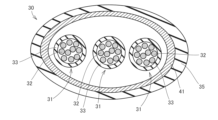
第2の実施形態では、本発明の繊維加工体の一例であるケーブル用シールド材、およびこのケーブル用シールド材有するケーブルを例に挙げて説明する。図4には、本実施形態にかかるケーブル30の断面構成を示す。ケーブル30は、例えば、各種電気機器および各種電気自動車などのパワーケーブル、インバータケーブル、充電ケーブルなどとして利用可能である。
[Second embodiment]
In the second embodiment, a cable shielding material which is an example of the fiber processed body of the present invention, and a cable having this cable shielding material will be described as an example. FIG. 4 shows a cross-sectional configuration of the
ケーブル30は、主として、導線集合体31、シース(外被材)35、およびケーブル用シールド材41などを有している。導線集合体31は、複数の導線32と、導線32を覆う絶縁体33とを有している。絶縁体33は、束状になった複数の導線32を覆うように設けられている。図4に示す例では、ケーブル30は3本の導線集合体31を有しているが、導線集合体31の本数はこれに限定されない。導線集合体31は、1本でもよいし複数本でもよい。
The
シース35は、ケーブル30の最外周に設けられている保護被覆である。シース35は、例えば、PVC(ポリ塩化ビニル)、PE(ポリエチレン)、FEP(テフロン(登録商標))などの絶縁材料で形成されている。
The
ケーブル用シールド材41は、本発明の一実施形態の繊維シート(例えば、繊維シート1)をチューブ状に加工して得られる。すなわち、ケーブル用シールド材41は、繊維シート1がチューブ状に形成されている繊維加工体の一例である。図4に示すように、ケーブル用シールド材41の内部には、導線集合体31が配置されている。すなわち、ケーブル用シールド材41は、束状の3本の導線集合体31の外周を覆うように設けられている。ケーブル用シールド材41の外側は、シース35で覆われている。
The
以上のように、本実施形態にかかるケーブル30には、導線集合体31を覆う電磁シールド材として、ケーブル用シールド材41が設けられている。ケーブル用シールド材41は、本発明の一実施形態の繊維シート(例えば、繊維シート1)を加工して得られる。したがって、本実施形態にかかるケーブル30によれば、導線集合体31から放射される電磁波が外部に漏れることを抑制することができる。また、本実施形態にかかるケーブル30では、電磁波の漏洩を抑制するためのケーブル用シールド材41として、銅などの金属製のメッシュ部材などの代わりに繊維シートを用いることで、ケーブル30の軽量化を実現することができる。
As described above, the
〔実施例〕
(実施例1:電磁シールド性能の評価)
実施例1では、本実施形態にかかる繊維シート1をチューブ状に形成したケーブル用シールド材について、電磁シールド性能の評価試験を行った。試験の手順は以下の通りである。
〔Example〕
(Example 1: Evaluation of electromagnetic shielding performance)
In Example 1, an evaluation test for electromagnetic shielding performance was conducted on a cable shielding material in which the fiber sheet 1 according to the present embodiment was formed into a tube shape. The test procedure is as follows.
先ず、同軸ケーブルの外被材を除去し、内部の導体を部分的に露出させた。この導体の露出部分の長さは、300mmとした。繊維シート1をチューブ状に形成したケーブル用シールド材の内部に、この導体の露出部分を挿入した。これにより、ケーブル用シールド材で導体が被覆されたサンプル(D)を得た。 First, the jacket material of the coaxial cable was removed to partially expose the internal conductor. The length of the exposed portion of this conductor was 300 mm. The exposed portion of this conductor was inserted into the inside of a cable shielding material made of the fiber sheet 1 formed into a tube shape. Thereby, a sample (D) in which the conductor was coated with the cable shielding material was obtained.
このサンプルを通電装置にセットし、電圧を印加した。このとき、サンプルから放射されるノイズを、アンテナによって計測した。計測周波数の範囲は、30MHz~1GHzとした。 This sample was set in a current supply device, and a voltage was applied. At this time, the noise radiated from the sample was measured using an antenna. The measurement frequency range was 30 MHz to 1 GHz.
なお、比較対象として、むき出し状態(シールドなし)の導体のサンプル(A)、銅パイプで形成されたシールド材で覆われた導体のサンプル(B)、および平織りの繊維シートで形成されたシールド材で覆われた導体のサンプル(C)を用いて、上記と同じ試験条件で電磁シールド性能の評価を行った。 For comparison, a sample (A) of an exposed conductor (no shield), a sample (B) of a conductor covered with a shielding material made of a copper pipe, and a shielding material made of a plain-woven fiber sheet are used for comparison. Electromagnetic shielding performance was evaluated under the same test conditions as above using the conductor sample (C) covered with .
図5には、サンプル(C)に用いられた平織りの繊維シートの繊維組織を示す。サンプル(C)に用いられた平織りの繊維シートは、繊維シート1と同じ繊維体10を平織りして形成されたものである。 FIG. 5 shows the fiber structure of the plain weave fiber sheet used in sample (C). The plain weave fiber sheet used in sample (C) was formed by plain weaving the same fiber bodies 10 as the fiber sheet 1.
図6には、その結果を示す。図6に示すように、綾織りの繊維シート1で形成されたシールド材で覆われたサンプル(D)は、銅パイプで形成されたシールド材で覆われた導線のサンプル(B)と、遜色のない程度の電磁シールド性能を有していることが確認された。これに対して、平織りの繊維シートで形成されたシールド材で覆われたサンプル(C)は、特定の周波数の電磁波の放射レベルが高くなっており、電磁シールド性能が不十分であることが確認された。 FIG. 6 shows the results. As shown in Figure 6, the sample (D) covered with a shielding material made of a twill weave fiber sheet 1 is inferior to the sample (B) of a conducting wire covered with a shielding material made of a copper pipe. It was confirmed that it has electromagnetic shielding performance to the extent that it does not. In contrast, sample (C) covered with a shielding material made of a plain-woven fiber sheet had a high radiation level of electromagnetic waves at a specific frequency, and it was confirmed that the electromagnetic shielding performance was insufficient. It was done.
以上の結果より、本実施形態にかかる綾織りの繊維シート1で形成されたケーブル用シールド材は、平織りの繊維シートで形成されたケーブル用シールド材よりも、電磁シールド性能が優れていることが確認された。 From the above results, it is concluded that the cable shielding material formed from the twill weave fiber sheet 1 according to the present embodiment has better electromagnetic shielding performance than the cable shielding material formed from the plain weave fiber sheet. confirmed.
(実施例2:繊維シートを構成する繊維体の剛性の測定)
実施例2では、繊維シートを構成する繊維体について、剛性の測定を行った。剛性の測定には、純曲げ試験機KES-FB2(カトーテック株式会社製)を用いた。
(Example 2: Measurement of rigidity of fibrous bodies constituting a fibrous sheet)
In Example 2, the rigidity of the fibrous bodies constituting the fibrous sheet was measured. A pure bending tester KES-FB2 (manufactured by Kato Tech Co., Ltd.) was used to measure the rigidity.
本実施例では、金属被覆を有していない繊維の一例として、ナイロン66(芯線a)、およびベクトラン(登録商標)(芯線b)を用いて、その剛性を測定した。また、金属被覆を有している繊維体の一例として、ベクトラン(繊維体A)、テクノ―ラ(登録商標)(繊維体B)、およびシベラス(登録商標)(繊維体C)を用いて、その剛性を測定した。この測定結果を図7に示す。図7では、複数本の繊維について剛性の測定を行った結果を×印で示し、これらの平均値を●印で示す。 In this example, nylon 66 (core wire a) and Vectran (registered trademark) (core wire b) were used as examples of fibers without metal coating, and their rigidities were measured. Further, as an example of a fibrous body having a metal coating, Vectran (fibrous body A), Technora (registered trademark) (fibrous body B), and Sciberus (registered trademark) (fibrous body C) were used. Its stiffness was measured. The measurement results are shown in FIG. In FIG. 7, the results of stiffness measurements for a plurality of fibers are indicated by x marks, and their average values are indicated by black marks.
また、本実施例では、芯線b(金属被覆を有していないベクトラン繊維)、繊維体A(金属被覆を有しているベクトラン繊維)、繊維体B(金属被覆を有しているテクノ―ラ繊維)、および繊維体C(金属被覆を有しているシラベス繊維)については、綾織りで一旦織布を形成した後、この織布を解いて得られる繊維についての剛性の測定も行った。この測定結果を図8に示す。図8では、複数本の繊維について剛性の測定を行った結果を×印で示し、これらの平均値を●印で示す。 In addition, in this example, core wire b (Vectran fiber without metal coating), fiber body A (Vectran fiber with metal coating), fiber body B (Technora fiber with metal coating) For fibers) and fibrous body C (silabeth fibers having a metal coating), a woven fabric was once formed using a twill weave, and then the woven fabric was unraveled and the resulting fibers were measured for their stiffness. The measurement results are shown in FIG. In FIG. 8, the results of stiffness measurements for a plurality of fibers are indicated by x marks, and the average values thereof are shown by black marks.
図7および図8を比較すると、織布前の繊維と織布を解いて得られる繊維との間で、剛性の値は大きく変わらないことが確認された。 Comparing FIGS. 7 and 8, it was confirmed that the stiffness values did not differ significantly between the fibers before woven fabric and the fibers obtained by unraveling the woven fabric.
また、芯線a、芯線b、繊維体A、繊維体B、および繊維体Cを用いて、綾織りの繊維シートを作成したところ、いずれも繊維間の隙間の小さな(すなわち、織物表面空隙率が20%以下の)繊維シートを得ることができた。 In addition, when twill weave fiber sheets were created using core wire a, core wire b, fiber body A, fiber body B, and fiber body C, all of them had small gaps between fibers (i.e., the fabric surface porosity was It was possible to obtain a fiber sheet with a fiber content of less than 20%.
一方、芯線a、芯線b、繊維体A、繊維体B、および繊維体Cを用いて、平織りの繊維シートを作成したところ、芯線a以外の芯線または繊維体では、繊維間の隙間が大きくなり、電磁シールド性能が不十分となることが確認された。なお、図7および図8に示すように、芯線a以外の芯線または繊維体の剛性は、0.1gf・cm2/yarn以上であった。 On the other hand, when a plain weave fiber sheet was created using core wire a, core wire b, fibrous body A, fibrous body B, and fibrous body C, the gaps between the fibers were large in core wires or fibrous bodies other than core wire a. It was confirmed that the electromagnetic shielding performance was insufficient. As shown in FIGS. 7 and 8, the rigidity of the core wires or fiber bodies other than core wire a was 0.1 gf·cm 2 /yarn or more.
この結果から、本実施形態にかかる綾織りの繊維シート1は、0.1gf・cm2/yarn以上の剛性を有する繊維体を用いて繊維シートを形成する場合に、より適しているといえる。 From this result, it can be said that the twill weave fiber sheet 1 according to the present embodiment is more suitable when a fiber sheet is formed using a fiber body having a rigidity of 0.1 gf·cm 2 /yarn or more.
今回開示された実施の形態はすべての点で例示であって制限的なものではないと考えられるべきである。本発明の範囲は上記した説明ではなくて特許請求の範囲によって示され、特許請求の範囲と均等の意味および範囲内でのすべての変更が含まれることが意図される。また、本明細書で説明した異なる実施形態の構成を互いに組み合わせて得られる構成についても、本発明の範疇に含まれる。 The embodiments disclosed this time should be considered to be illustrative in all respects and not restrictive. The scope of the present invention is indicated by the claims rather than the above description, and it is intended that all changes within the meaning and range equivalent to the claims are included. Furthermore, configurations obtained by combining configurations of different embodiments described in this specification are also included in the scope of the present invention.
1 :繊維シート
10 :繊維体
11 :経糸(繊維体)
12 :緯糸(繊維体)
20 :フィラメント
21 :芯線
22 :金属メッキ層
30 :ケーブル
31 :導線
41 :ケーブル用シールド材(繊維シート、繊維加工体)
1: Fiber sheet 10: Fibrous body 11: Warp (fibrous body)
12: Weft (fibrous body)
20 : Filament 21 : Core wire 22 : Metal plating layer 30 : Cable 31 : Conductor wire 41 : Cable shield material (fiber sheet, fiber processed body)
Claims (8)
前記繊維体が綾織りされており、
前記繊維体は、複数の経糸と、複数の緯糸とを有し、
隣接する前記経糸同士および隣接する前記緯糸同士の少なくとも何れか一方が部分的に重なっている、繊維シート。 It has a plurality of metal-coated fibrous bodies,
The fibrous body is twilled,
The fibrous body has a plurality of warps and a plurality of wefts,
A fiber sheet in which at least one of the adjacent warp yarns and the adjacent weft yarns partially overlap .
前記芯線の径は、10μm以上50μm以下である、
請求項1または2に記載の繊維シート。 The fibrous body has a plurality of core wires,
The diameter of the core wire is 10 μm or more and 50 μm or less,
The fiber sheet according to claim 1 or 2.
前記経糸の表面空隙率が20%以下であり、かつ、
前記緯糸の表面空隙率が20%以下である、
請求項1から3の何れか1項に記載の繊維シート。 It has multiple warps and multiple wefts,
The surface porosity of the warp is 20% or less, and
The surface porosity of the weft is 20% or less,
The fiber sheet according to any one of claims 1 to 3.
請求項1から4の何れか1項に記載の繊維シート。 The stiffness of the fibrous body is 0.1 gf cm / yarn or more,
The fiber sheet according to any one of claims 1 to 4.
前記導線を覆う、請求項7に記載のケーブル用シールド材と The cable shielding material according to claim 7, which covers the conductor wire.
を備えているケーブル。Equipped with a cable.
Priority Applications (1)
| Application Number | Priority Date | Filing Date | Title |
|---|---|---|---|
| JP2020006111A JP7416632B2 (en) | 2020-01-17 | 2020-01-17 | Fiber sheets, processed fiber bodies, cable shielding materials, and cables |
Applications Claiming Priority (1)
| Application Number | Priority Date | Filing Date | Title |
|---|---|---|---|
| JP2020006111A JP7416632B2 (en) | 2020-01-17 | 2020-01-17 | Fiber sheets, processed fiber bodies, cable shielding materials, and cables |
Publications (2)
| Publication Number | Publication Date |
|---|---|
| JP2021113367A JP2021113367A (en) | 2021-08-05 |
| JP7416632B2 true JP7416632B2 (en) | 2024-01-17 |
Family
ID=77076764
Family Applications (1)
| Application Number | Title | Priority Date | Filing Date |
|---|---|---|---|
| JP2020006111A Active JP7416632B2 (en) | 2020-01-17 | 2020-01-17 | Fiber sheets, processed fiber bodies, cable shielding materials, and cables |
Country Status (1)
| Country | Link |
|---|---|
| JP (1) | JP7416632B2 (en) |
Citations (4)
| Publication number | Priority date | Publication date | Assignee | Title |
|---|---|---|---|---|
| JP2000151182A (en) | 1998-11-05 | 2000-05-30 | Kanebo Ltd | Electromagnetic wave shield cloth |
| JP2004346349A (en) | 2003-05-20 | 2004-12-09 | Du Pont Toray Co Ltd | Plating cloth |
| JP2016213268A (en) | 2015-04-30 | 2016-12-15 | 帝人株式会社 | Fabric-like transducer and device including the same |
| JP2019183365A (en) | 2018-03-30 | 2019-10-24 | セーレン株式会社 | Conductive woven fabric, conductive member, and method for producing conductive woven fabric |
Family Cites Families (2)
| Publication number | Priority date | Publication date | Assignee | Title |
|---|---|---|---|---|
| JPH03287862A (en) * | 1990-03-30 | 1991-12-18 | Nitto Boseki Co Ltd | Conductive thermoplastic resin fiber yarn and fabric for reinforced thermoplastic |
| JPH0923085A (en) * | 1995-07-07 | 1997-01-21 | Daido Steel Co Ltd | Low frequency magnetic shield material |
-
2020
- 2020-01-17 JP JP2020006111A patent/JP7416632B2/en active Active
Patent Citations (4)
| Publication number | Priority date | Publication date | Assignee | Title |
|---|---|---|---|---|
| JP2000151182A (en) | 1998-11-05 | 2000-05-30 | Kanebo Ltd | Electromagnetic wave shield cloth |
| JP2004346349A (en) | 2003-05-20 | 2004-12-09 | Du Pont Toray Co Ltd | Plating cloth |
| JP2016213268A (en) | 2015-04-30 | 2016-12-15 | 帝人株式会社 | Fabric-like transducer and device including the same |
| JP2019183365A (en) | 2018-03-30 | 2019-10-24 | セーレン株式会社 | Conductive woven fabric, conductive member, and method for producing conductive woven fabric |
Also Published As
| Publication number | Publication date |
|---|---|
| JP2021113367A (en) | 2021-08-05 |
Similar Documents
| Publication | Publication Date | Title |
|---|---|---|
| Cheng et al. | Electromagnetic shielding effectiveness of the twill copper woven fabrics | |
| JP5323816B2 (en) | Cloth electromagnetic protective sheath | |
| Chen et al. | Comparison of electromagnetic shielding effectiveness properties of diverse conductive textiles via various measurement techniques | |
| Chen et al. | Fabrication of conductive woven fabric and analysis of electromagnetic shielding via measurement and empirical equation | |
| CN101828239B (en) | Electrical shielding material composed of metallized stainless steel monofilament yarns | |
| RU2715938C2 (en) | Electromagnetic interference protection sheath and method of its manufacturing | |
| SE439411B (en) | APPLICATION OF METALLIZED TEXTILE PAPERS FOR MICROVAGOR SHIELDING | |
| JP6293407B2 (en) | Magnetic field shielding material | |
| JP2001279575A (en) | Conductive fabric | |
| KR102539372B1 (en) | Fabric for electromagnetic shielding | |
| JP2000273762A (en) | Base cloth for electromagnetic wave shielding material and electromagnetic wave shielding material using the same | |
| JP6085162B2 (en) | Flat insulation sheath | |
| JP6592272B2 (en) | Shield sleeve | |
| JP7416632B2 (en) | Fiber sheets, processed fiber bodies, cable shielding materials, and cables | |
| CN108025527A (en) | Electroconductive component | |
| CN109610172B (en) | Yarn and fabric with electrostatic load characteristic | |
| WO2022270461A1 (en) | Conductive mesh fabric | |
| JPH06131916A (en) | Heat contraction conducting sheet | |
| CN206089958U (en) | Electromagnetic shield fabric with electric conductivity period structure | |
| US11013158B1 (en) | Electrical shielding material composed of metallized stainless steel or low carbon steel monofilament yarns | |
| JP2015183345A (en) | Electric conductive slit yarn and method for producing the same | |
| JP6168345B2 (en) | Metal stranded wire manufacturing method, and metal stranded wire and metal stranded wire fabric manufactured by the method | |
| JP6168340B2 (en) | Metal stranded wire manufacturing method, and metal stranded wire and metal stranded wire fabric manufactured by the method | |
| KR20070074057A (en) | Shielded cable | |
| KR102677186B1 (en) | Fabric for electromagnetic wave eliminating material, method for manufacturing thereof and electromagnetic wave eliminating material comprising the same |
Legal Events
| Date | Code | Title | Description |
|---|---|---|---|
| A621 | Written request for application examination |
Free format text: JAPANESE INTERMEDIATE CODE: A621 Effective date: 20221027 |
|
| A977 | Report on retrieval |
Free format text: JAPANESE INTERMEDIATE CODE: A971007 Effective date: 20230919 |
|
| A131 | Notification of reasons for refusal |
Free format text: JAPANESE INTERMEDIATE CODE: A131 Effective date: 20230926 |
|
| A521 | Request for written amendment filed |
Free format text: JAPANESE INTERMEDIATE CODE: A523 Effective date: 20231027 |
|
| TRDD | Decision of grant or rejection written | ||
| A01 | Written decision to grant a patent or to grant a registration (utility model) |
Free format text: JAPANESE INTERMEDIATE CODE: A01 Effective date: 20231226 |
|
| A61 | First payment of annual fees (during grant procedure) |
Free format text: JAPANESE INTERMEDIATE CODE: A61 Effective date: 20240104 |
|
| R150 | Certificate of patent or registration of utility model |
Ref document number: 7416632 Country of ref document: JP Free format text: JAPANESE INTERMEDIATE CODE: R150 |