JP7416488B2 - Relay diagnostic equipment, relay diagnostic method, battery system and electric vehicle - Google Patents
Relay diagnostic equipment, relay diagnostic method, battery system and electric vehicle Download PDFInfo
- Publication number
- JP7416488B2 JP7416488B2 JP2022544363A JP2022544363A JP7416488B2 JP 7416488 B2 JP7416488 B2 JP 7416488B2 JP 2022544363 A JP2022544363 A JP 2022544363A JP 2022544363 A JP2022544363 A JP 2022544363A JP 7416488 B2 JP7416488 B2 JP 7416488B2
- Authority
- JP
- Japan
- Prior art keywords
- relay
- insulation resistance
- voltage
- state
- resistance
- Prior art date
- Legal status (The legal status is an assumption and is not a legal conclusion. Google has not performed a legal analysis and makes no representation as to the accuracy of the status listed.)
- Active
Links
- 238000002405 diagnostic procedure Methods 0.000 title description 5
- 238000009413 insulation Methods 0.000 claims description 161
- 238000001514 detection method Methods 0.000 claims description 34
- 238000000034 method Methods 0.000 claims description 21
- 238000003745 diagnosis Methods 0.000 claims description 10
- 239000003990 capacitor Substances 0.000 description 12
- 238000009499 grossing Methods 0.000 description 12
- 230000008569 process Effects 0.000 description 8
- 230000006870 function Effects 0.000 description 7
- 238000012545 processing Methods 0.000 description 6
- 238000004891 communication Methods 0.000 description 4
- 238000005259 measurement Methods 0.000 description 4
- 238000012986 modification Methods 0.000 description 4
- 230000004048 modification Effects 0.000 description 4
- WHXSMMKQMYFTQS-UHFFFAOYSA-N Lithium Chemical compound [Li] WHXSMMKQMYFTQS-UHFFFAOYSA-N 0.000 description 2
- PXHVJJICTQNCMI-UHFFFAOYSA-N Nickel Chemical compound [Ni] PXHVJJICTQNCMI-UHFFFAOYSA-N 0.000 description 2
- XUIMIQQOPSSXEZ-UHFFFAOYSA-N Silicon Chemical compound [Si] XUIMIQQOPSSXEZ-UHFFFAOYSA-N 0.000 description 2
- 238000010586 diagram Methods 0.000 description 2
- 230000000694 effects Effects 0.000 description 2
- 229910052744 lithium Inorganic materials 0.000 description 2
- 229910052710 silicon Inorganic materials 0.000 description 2
- 239000010703 silicon Substances 0.000 description 2
- HBBGRARXTFLTSG-UHFFFAOYSA-N Lithium ion Chemical compound [Li+] HBBGRARXTFLTSG-UHFFFAOYSA-N 0.000 description 1
- 230000002159 abnormal effect Effects 0.000 description 1
- OJIJEKBXJYRIBZ-UHFFFAOYSA-N cadmium nickel Chemical compound [Ni].[Cd] OJIJEKBXJYRIBZ-UHFFFAOYSA-N 0.000 description 1
- 230000015556 catabolic process Effects 0.000 description 1
- 230000008859 change Effects 0.000 description 1
- 230000007423 decrease Effects 0.000 description 1
- 238000011161 development Methods 0.000 description 1
- 238000007599 discharging Methods 0.000 description 1
- 238000004146 energy storage Methods 0.000 description 1
- 229910001416 lithium ion Inorganic materials 0.000 description 1
- 230000007257 malfunction Effects 0.000 description 1
- 230000003446 memory effect Effects 0.000 description 1
- 229910052987 metal hydride Inorganic materials 0.000 description 1
- 229910052759 nickel Inorganic materials 0.000 description 1
- QELJHCBNGDEXLD-UHFFFAOYSA-N nickel zinc Chemical compound [Ni].[Zn] QELJHCBNGDEXLD-UHFFFAOYSA-N 0.000 description 1
- 230000001151 other effect Effects 0.000 description 1
- 238000011160 research Methods 0.000 description 1
- 230000004044 response Effects 0.000 description 1
- 239000007787 solid Substances 0.000 description 1
- 230000003068 static effect Effects 0.000 description 1
- 238000006467 substitution reaction Methods 0.000 description 1
Images


Classifications
-
- B—PERFORMING OPERATIONS; TRANSPORTING
- B60—VEHICLES IN GENERAL
- B60L—PROPULSION OF ELECTRICALLY-PROPELLED VEHICLES; SUPPLYING ELECTRIC POWER FOR AUXILIARY EQUIPMENT OF ELECTRICALLY-PROPELLED VEHICLES; ELECTRODYNAMIC BRAKE SYSTEMS FOR VEHICLES IN GENERAL; MAGNETIC SUSPENSION OR LEVITATION FOR VEHICLES; MONITORING OPERATING VARIABLES OF ELECTRICALLY-PROPELLED VEHICLES; ELECTRIC SAFETY DEVICES FOR ELECTRICALLY-PROPELLED VEHICLES
- B60L3/00—Electric devices on electrically-propelled vehicles for safety purposes; Monitoring operating variables, e.g. speed, deceleration or energy consumption
- B60L3/0023—Detecting, eliminating, remedying or compensating for drive train abnormalities, e.g. failures within the drive train
-
- G—PHYSICS
- G01—MEASURING; TESTING
- G01R—MEASURING ELECTRIC VARIABLES; MEASURING MAGNETIC VARIABLES
- G01R31/00—Arrangements for testing electric properties; Arrangements for locating electric faults; Arrangements for electrical testing characterised by what is being tested not provided for elsewhere
- G01R31/327—Testing of circuit interrupters, switches or circuit-breakers
- G01R31/3271—Testing of circuit interrupters, switches or circuit-breakers of high voltage or medium voltage devices
- G01R31/3272—Apparatus, systems or circuits therefor
-
- B—PERFORMING OPERATIONS; TRANSPORTING
- B60—VEHICLES IN GENERAL
- B60L—PROPULSION OF ELECTRICALLY-PROPELLED VEHICLES; SUPPLYING ELECTRIC POWER FOR AUXILIARY EQUIPMENT OF ELECTRICALLY-PROPELLED VEHICLES; ELECTRODYNAMIC BRAKE SYSTEMS FOR VEHICLES IN GENERAL; MAGNETIC SUSPENSION OR LEVITATION FOR VEHICLES; MONITORING OPERATING VARIABLES OF ELECTRICALLY-PROPELLED VEHICLES; ELECTRIC SAFETY DEVICES FOR ELECTRICALLY-PROPELLED VEHICLES
- B60L3/00—Electric devices on electrically-propelled vehicles for safety purposes; Monitoring operating variables, e.g. speed, deceleration or energy consumption
- B60L3/0023—Detecting, eliminating, remedying or compensating for drive train abnormalities, e.g. failures within the drive train
- B60L3/0046—Detecting, eliminating, remedying or compensating for drive train abnormalities, e.g. failures within the drive train relating to electric energy storage systems, e.g. batteries or capacitors
-
- B—PERFORMING OPERATIONS; TRANSPORTING
- B60—VEHICLES IN GENERAL
- B60L—PROPULSION OF ELECTRICALLY-PROPELLED VEHICLES; SUPPLYING ELECTRIC POWER FOR AUXILIARY EQUIPMENT OF ELECTRICALLY-PROPELLED VEHICLES; ELECTRODYNAMIC BRAKE SYSTEMS FOR VEHICLES IN GENERAL; MAGNETIC SUSPENSION OR LEVITATION FOR VEHICLES; MONITORING OPERATING VARIABLES OF ELECTRICALLY-PROPELLED VEHICLES; ELECTRIC SAFETY DEVICES FOR ELECTRICALLY-PROPELLED VEHICLES
- B60L58/00—Methods or circuit arrangements for monitoring or controlling batteries or fuel cells, specially adapted for electric vehicles
- B60L58/10—Methods or circuit arrangements for monitoring or controlling batteries or fuel cells, specially adapted for electric vehicles for monitoring or controlling batteries
- B60L58/18—Methods or circuit arrangements for monitoring or controlling batteries or fuel cells, specially adapted for electric vehicles for monitoring or controlling batteries of two or more battery modules
-
- G—PHYSICS
- G01—MEASURING; TESTING
- G01R—MEASURING ELECTRIC VARIABLES; MEASURING MAGNETIC VARIABLES
- G01R15/00—Details of measuring arrangements of the types provided for in groups G01R17/00 - G01R29/00, G01R33/00 - G01R33/26 or G01R35/00
- G01R15/04—Voltage dividers
-
- G—PHYSICS
- G01—MEASURING; TESTING
- G01R—MEASURING ELECTRIC VARIABLES; MEASURING MAGNETIC VARIABLES
- G01R27/00—Arrangements for measuring resistance, reactance, impedance, or electric characteristics derived therefrom
- G01R27/02—Measuring real or complex resistance, reactance, impedance, or other two-pole characteristics derived therefrom, e.g. time constant
- G01R27/025—Measuring very high resistances, e.g. isolation resistances, i.e. megohm-meters
-
- G—PHYSICS
- G01—MEASURING; TESTING
- G01R—MEASURING ELECTRIC VARIABLES; MEASURING MAGNETIC VARIABLES
- G01R31/00—Arrangements for testing electric properties; Arrangements for locating electric faults; Arrangements for electrical testing characterised by what is being tested not provided for elsewhere
- G01R31/12—Testing dielectric strength or breakdown voltage ; Testing or monitoring effectiveness or level of insulation, e.g. of a cable or of an apparatus, for example using partial discharge measurements; Electrostatic testing
- G01R31/1227—Testing dielectric strength or breakdown voltage ; Testing or monitoring effectiveness or level of insulation, e.g. of a cable or of an apparatus, for example using partial discharge measurements; Electrostatic testing of components, parts or materials
-
- G—PHYSICS
- G01—MEASURING; TESTING
- G01R—MEASURING ELECTRIC VARIABLES; MEASURING MAGNETIC VARIABLES
- G01R31/00—Arrangements for testing electric properties; Arrangements for locating electric faults; Arrangements for electrical testing characterised by what is being tested not provided for elsewhere
- G01R31/327—Testing of circuit interrupters, switches or circuit-breakers
- G01R31/3277—Testing of circuit interrupters, switches or circuit-breakers of low voltage devices, e.g. domestic or industrial devices, such as motor protections, relays, rotation switches
- G01R31/3278—Testing of circuit interrupters, switches or circuit-breakers of low voltage devices, e.g. domestic or industrial devices, such as motor protections, relays, rotation switches of relays, solenoids or reed switches
-
- G—PHYSICS
- G01—MEASURING; TESTING
- G01R—MEASURING ELECTRIC VARIABLES; MEASURING MAGNETIC VARIABLES
- G01R31/00—Arrangements for testing electric properties; Arrangements for locating electric faults; Arrangements for electrical testing characterised by what is being tested not provided for elsewhere
- G01R31/36—Arrangements for testing, measuring or monitoring the electrical condition of accumulators or electric batteries, e.g. capacity or state of charge [SoC]
- G01R31/392—Determining battery ageing or deterioration, e.g. state of health
-
- G—PHYSICS
- G01—MEASURING; TESTING
- G01R—MEASURING ELECTRIC VARIABLES; MEASURING MAGNETIC VARIABLES
- G01R31/00—Arrangements for testing electric properties; Arrangements for locating electric faults; Arrangements for electrical testing characterised by what is being tested not provided for elsewhere
- G01R31/50—Testing of electric apparatus, lines, cables or components for short-circuits, continuity, leakage current or incorrect line connections
- G01R31/66—Testing of connections, e.g. of plugs or non-disconnectable joints
-
- B—PERFORMING OPERATIONS; TRANSPORTING
- B60—VEHICLES IN GENERAL
- B60L—PROPULSION OF ELECTRICALLY-PROPELLED VEHICLES; SUPPLYING ELECTRIC POWER FOR AUXILIARY EQUIPMENT OF ELECTRICALLY-PROPELLED VEHICLES; ELECTRODYNAMIC BRAKE SYSTEMS FOR VEHICLES IN GENERAL; MAGNETIC SUSPENSION OR LEVITATION FOR VEHICLES; MONITORING OPERATING VARIABLES OF ELECTRICALLY-PROPELLED VEHICLES; ELECTRIC SAFETY DEVICES FOR ELECTRICALLY-PROPELLED VEHICLES
- B60L2240/00—Control parameters of input or output; Target parameters
- B60L2240/40—Drive Train control parameters
- B60L2240/52—Drive Train control parameters related to converters
- B60L2240/527—Voltage
-
- B—PERFORMING OPERATIONS; TRANSPORTING
- B60—VEHICLES IN GENERAL
- B60L—PROPULSION OF ELECTRICALLY-PROPELLED VEHICLES; SUPPLYING ELECTRIC POWER FOR AUXILIARY EQUIPMENT OF ELECTRICALLY-PROPELLED VEHICLES; ELECTRODYNAMIC BRAKE SYSTEMS FOR VEHICLES IN GENERAL; MAGNETIC SUSPENSION OR LEVITATION FOR VEHICLES; MONITORING OPERATING VARIABLES OF ELECTRICALLY-PROPELLED VEHICLES; ELECTRIC SAFETY DEVICES FOR ELECTRICALLY-PROPELLED VEHICLES
- B60L2240/00—Control parameters of input or output; Target parameters
- B60L2240/40—Drive Train control parameters
- B60L2240/54—Drive Train control parameters related to batteries
- B60L2240/547—Voltage
-
- B—PERFORMING OPERATIONS; TRANSPORTING
- B60—VEHICLES IN GENERAL
- B60Y—INDEXING SCHEME RELATING TO ASPECTS CROSS-CUTTING VEHICLE TECHNOLOGY
- B60Y2306/00—Other features of vehicle sub-units
- B60Y2306/15—Failure diagnostics
-
- G—PHYSICS
- G01—MEASURING; TESTING
- G01R—MEASURING ELECTRIC VARIABLES; MEASURING MAGNETIC VARIABLES
- G01R31/00—Arrangements for testing electric properties; Arrangements for locating electric faults; Arrangements for electrical testing characterised by what is being tested not provided for elsewhere
- G01R31/50—Testing of electric apparatus, lines, cables or components for short-circuits, continuity, leakage current or incorrect line connections
- G01R31/52—Testing for short-circuits, leakage current or ground faults
-
- Y—GENERAL TAGGING OF NEW TECHNOLOGICAL DEVELOPMENTS; GENERAL TAGGING OF CROSS-SECTIONAL TECHNOLOGIES SPANNING OVER SEVERAL SECTIONS OF THE IPC; TECHNICAL SUBJECTS COVERED BY FORMER USPC CROSS-REFERENCE ART COLLECTIONS [XRACs] AND DIGESTS
- Y02—TECHNOLOGIES OR APPLICATIONS FOR MITIGATION OR ADAPTATION AGAINST CLIMATE CHANGE
- Y02T—CLIMATE CHANGE MITIGATION TECHNOLOGIES RELATED TO TRANSPORTATION
- Y02T10/00—Road transport of goods or passengers
- Y02T10/60—Other road transportation technologies with climate change mitigation effect
- Y02T10/70—Energy storage systems for electromobility, e.g. batteries
Description
本発明は、バッテリーと負荷とを連結する電力ラインに設けられるリレーを診断する技術に関する。 The present invention relates to a technique for diagnosing a relay provided in a power line connecting a battery and a load.
本出願は、2020年10月15日出願の韓国特許出願第10-2020-0133688号に基づく優先権を主張し、該当出願の明細書及び図面に開示された内容は、すべて本出願に組み込まれる。 This application claims priority based on Korean Patent Application No. 10-2020-0133688 filed on October 15, 2020, and all contents disclosed in the specification and drawings of the corresponding application are incorporated into this application. .
最近、ノートブックPC、ビデオカメラ、携帯電話などのような携帯用電子製品の需要が急増し、電気自動車、エネルギー貯蔵用蓄電池、ロボット、衛星などの開発が本格化するにつれ、反復的な充放電の可能な高性能バッテリーについての研究が活発に進行しつつある。 Recently, the demand for portable electronic products such as notebook PCs, video cameras, mobile phones, etc. has rapidly increased, and as the development of electric vehicles, energy storage batteries, robots, satellites, etc. Research into high-performance batteries that are capable of
現在、商用化したバッテリーとしては、ニッケルカドミウム電池、ニッケル水素電池、ニッケル亜鉛電池、リチウムバッテリーなどがあり、このうち、リチウムバッテリーは、ニッケル系のバッテリーに比べてメモリー効果がほとんど起こらず、充放電が自由で、自己放電率が非常に低くてエネルギー密度が高いという長所から脚光を浴びている。 Currently, commercially available batteries include nickel-cadmium batteries, nickel-metal hydride batteries, nickel-zinc batteries, and lithium batteries. Among these, lithium batteries have almost no memory effect compared to nickel-based batteries, and they charge and discharge easily. It is attracting attention because of its advantages of free self-discharge, extremely low self-discharge rate, and high energy density.
電気車両など電気エネルギーを必要とする多様な電動装置は、通常、バッテリーアセンブリー、電気負荷及びバッテリーの正極側と負極側に各々設けられる二つのリレーを含む。バッテリーアセンブリーと電気負荷間の安定的な電力供給のためには、各リレーが外部からの命令に応じてオン状態とオフ状態の間で正常に切り換えられる必要がある。 BACKGROUND OF THE INVENTION Various electric devices that require electrical energy, such as electric vehicles, typically include a battery assembly, an electrical load, and two relays installed on the positive and negative sides of the battery, respectively. In order to provide a stable power supply between the battery assembly and the electrical load, each relay must be successfully switched between an on state and an off state in response to an external command.
リレーの代表的な二つの故障類型としては、短絡故障(「閉め固着故障」と称することがある。)及び開放故障(「開け固着故障」と称することがある。)が挙げられる。短絡故障とは、リレーがオン状態で溶着され、オン状態からオフ状態への切換えが不可能な状態を指す。逆に、開放故障とは、リレーがオフ状態で溶着され、オフ状態からオン状態への切換えが不可能な状態を指す。 Two typical failure types of relays include short-circuit failure (sometimes referred to as "stuck closed failure") and open failure (sometimes referred to as "stuck open failure"). A short-circuit failure refers to a state in which a relay is welded in the on state and cannot be switched from the on state to the off state. Conversely, an open failure refers to a state in which the relay is welded in the off state and cannot be switched from the off state to the on state.
因みに、リレーの両端部間の電圧差に基づいてリレーの故障を診断する方式が広く用いられている。 Incidentally, a method of diagnosing relay failure based on the voltage difference between both ends of the relay is widely used.
ところが、リレーがオン状態に一定時間以上に維持されると、電気負荷に備えられた平滑キャパシタ(「X-cap」と称することがある。)がバッテリーアセンブリーと同等の水準の電圧で充電される。したがって、リレーがオン状態からオフ状態へ正常に切り換えられたにもかかわらず、リレーの両端に十分な電圧差が発生せず、リレーが短絡故障していると誤診断される可能性が大きい。 However, if the relay is kept on for a certain period of time, the smoothing capacitor (sometimes referred to as an "X-cap") provided in the electrical load will be charged with the same level of voltage as the battery assembly. Ru. Therefore, even though the relay is normally switched from the on state to the off state, a sufficient voltage difference is not generated across the relay, and there is a high possibility that the relay will be misdiagnosed as having a short-circuit failure.
前述した問題を解決するために、平滑キャパシタに放電回路(放電スイッチ及び放電抵抗器の直列回路)を並列で接続し、リレー診断の前に平滑キャパシタを強制的に放電させる方案が考慮される。ところが、放電回路が故障する場合には、平滑キャパシタの放電が不可能であり、放電回路が正常であるとしても大容量である平滑キャパシタに対する強制放電に相当時間がかかるという制約がある。 In order to solve the above-mentioned problem, a method is being considered in which a discharge circuit (a series circuit of a discharge switch and a discharge resistor) is connected in parallel to the smoothing capacitor, and the smoothing capacitor is forcibly discharged before relay diagnosis. However, if the discharge circuit malfunctions, it is impossible to discharge the smoothing capacitor, and even if the discharge circuit is normal, there is a restriction that forced discharge of a large capacity smoothing capacitor takes a considerable amount of time.
本発明は、上記問題点に鑑みてなされたものであり、バッテリーアセンブリーと電気負荷とを連結する一対の電力ラインに各々設けられる二つのリレーのオン状態とオフ状態間の転換制御による、バッテリーアセンブリーと電気車両のシャーシ間の絶縁抵抗の変化に基づき、各リレーの故障を検出するための装置、方法及び前記装置を含む電気車両を提供することを目的とする。 The present invention has been made in view of the above-mentioned problems, and provides a battery control system that controls switching between an on state and an off state of two relays each provided in a pair of power lines that connect a battery assembly and an electric load. It is an object of the present invention to provide a device, a method, and an electric vehicle including said device for detecting failure of each relay based on changes in insulation resistance between the assembly and the chassis of the electric vehicle.
本発明の他の目的及び長所は、下記の説明によって理解でき、本発明の実施例によってより明らかに理解されるであろう。また、本発明の目的及び長所は、特許請求の範囲に示される手段及びその組合せによって実現することができる。 Other objects and advantages of the present invention can be understood from the following description and will be more clearly understood from the embodiments of the invention. Further, the objects and advantages of the present invention can be realized by means and combinations thereof shown in the claims.
本発明の一面によるリレー診断装置は、電気車両の電気負荷をバッテリーアセンブリーに接続する一対の電力ラインに各々設けられる第1リレー及び第2リレーのためのものである。前記リレー診断装置は、前記バッテリーアセンブリーの正極端子と前記電気車両のシャーシ間の電圧で第1診断電圧を生成するように構成される第1電圧検出回路と、前記バッテリーアセンブリーの負極端子と前記シャーシ間の電圧で第2診断電圧を生成するように構成される第2電圧検出回路と、前記第1リレー及び前記第2リレーがオフ状態に制御される間、第1時点における前記第1診断電圧及び第2時点における前記第2診断電圧に基づき、前記正極端子と前記シャーシ間の第1絶縁抵抗及び前記負極端子と前記シャーシ間の第2絶縁抵抗を決定するように構成されるコントローラと、を含む。前記コントローラは、前記第1リレー及び前記第2リレーがオン状態に制御される間、第3時点における前記第1診断電圧及び第4時点における前記第2診断電圧に基づき、前記正極端子と前記シャーシ間の第3絶縁抵抗及び前記負極端子と前記シャーシ間の第4絶縁抵抗を決定するように構成される。前記コントローラは、前記第1~前記第4絶縁抵抗に基づき、前記第1リレー及び前記第2リレーの少なくとも一つの故障を検出するように構成される。 A relay diagnostic device according to one aspect of the present invention is for a first relay and a second relay respectively provided in a pair of power lines connecting an electric load of an electric vehicle to a battery assembly. The relay diagnostic device includes a first voltage detection circuit configured to generate a first diagnostic voltage based on a voltage between a positive terminal of the battery assembly and a chassis of the electric vehicle, and a negative terminal of the battery assembly. a second voltage detection circuit configured to generate a second diagnostic voltage at the voltage across the chassis; and a second voltage detection circuit configured to generate a second diagnostic voltage at a voltage across the chassis; a controller configured to determine a first insulation resistance between the positive terminal and the chassis and a second insulation resistance between the negative terminal and the chassis based on a diagnostic voltage and the second diagnostic voltage at a second time point; ,including. The controller is configured to control the positive terminal and the chassis based on the first diagnostic voltage at a third time point and the second diagnostic voltage at a fourth time point while the first relay and the second relay are controlled to be in the on state. and a fourth insulation resistance between the negative terminal and the chassis. The controller is configured to detect a failure of at least one of the first relay and the second relay based on the first to fourth insulation resistances.
前記第1電圧検出回路は、前記正極端子と前記シャーシとの間に接続される、第1電圧分配器及び第1スイッチの直列回路であり得る。前記第2電圧検出回路は、前記負極端子と前記シャーシとの間に接続される、第2電圧分配器及び第2スイッチの直列回路であり得る。各電圧分配器は、二つの抵抗器の直列回路であり得る。 The first voltage detection circuit may be a series circuit of a first voltage divider and a first switch connected between the positive terminal and the chassis. The second voltage detection circuit may be a series circuit of a second voltage divider and a second switch connected between the negative terminal and the chassis. Each voltage divider may be a series circuit of two resistors.
前記第1時点は、前記コントローラによって前記第1スイッチ及び前記第2スイッチが各々オン状態及びオフ状態に制御される間における時点であり得る。前記第2時点は、前記コントローラによって前記第1スイッチ及び前記第2スイッチが各々オフ状態及びオン状態に制御される間における時点であり得る。 The first time point may be a time point during which the first switch and the second switch are controlled to be in an on state and an off state, respectively, by the controller. The second time point may be a time point during which the first switch and the second switch are controlled to be in an off state and an on state, respectively, by the controller.
前記第3時点は、前記コントローラによって前記第1スイッチ及び前記第2スイッチが各々オン状態及びオフ状態に制御される間における時点であり得る。前記第4時点は、前記コントローラによって前記第1スイッチ及び前記第2スイッチが各々オフ状態及びオン状態に制御される間における時点であり得る。 The third time point may be a time point during which the first switch and the second switch are controlled to be in an on state and an off state, respectively, by the controller. The fourth time point may be a time point during which the first switch and the second switch are controlled to be in an off state and an on state, respectively, by the controller.
前記コントローラは、前記第1絶縁抵抗と前記第3絶縁抵抗との抵抗差が臨界抵抗以下である場合、または前記第1絶縁抵抗に対する前記抵抗差の割合が臨界割合以下である場合に、前記第1リレーが故障していると判定するように構成され得る。 The controller controls the first insulation resistance when the resistance difference between the first insulation resistance and the third insulation resistance is less than or equal to a critical resistance, or when the ratio of the resistance difference to the first insulation resistance is less than or equal to a critical ratio. The relay may be configured to determine that one relay is faulty.
前記コントローラは、前記第3絶縁抵抗が第1基準抵抗以上である場合、前記第1リレーを開放故障と判定するように構成され得る。 The controller may be configured to determine that the first relay has an open failure when the third insulation resistance is greater than or equal to a first reference resistance.
前記コントローラは、前記第2絶縁抵抗と前記第4絶縁抵抗との抵抗差が臨界抵抗以下である場合、または前記第2絶縁抵抗に対する前記抵抗差の割合が臨界割合以下である場合に、前記第2リレーが故障している判定するように構成され得る。 The controller controls the resistance difference between the second insulation resistance and the fourth insulation resistance when the resistance difference between the second insulation resistance and the fourth insulation resistance is less than or equal to a critical resistance, or when the ratio of the resistance difference to the second insulation resistance is less than or equal to a critical ratio. The relay may be configured to determine that two relays are faulty.
前記コントローラは、前記第4絶縁抵抗が第2基準抵抗以上である場合、前記第2リレーを開放故障と判定するように構成され得る。 The controller may be configured to determine that the second relay has an open failure when the fourth insulation resistance is greater than or equal to a second reference resistance.
本発明の他面による電気車両は、前記リレー診断装置を含む。 An electric vehicle according to another aspect of the present invention includes the relay diagnostic device.
本発明のさらに他面によるリレー診断方法は、前記リレー診断装置によって実行可能である。前記リレー診断方法は、前記第1リレー及び前記第2リレーがオフ状態に制御される間、第1時点における前記第1診断電圧及び第2時点における前記第2診断電圧に基づき、前記正極端子と前記シャーシ間の第1絶縁抵抗及び前記負極端子と前記シャーシ間の第2絶縁抵抗を決定する段階と、前記第1リレー及び前記第2リレーがオン状態に制御される間、第3時点における前記第1診断電圧及び第4時点における前記第2診断電圧に基づき、前記正極端子と前記シャーシ間の第3絶縁抵抗及び前記負極端子と前記シャーシ間の第4絶縁抵抗を決定する段階と、前記第1絶縁抵抗、前記第2絶縁抵抗、前記第3絶縁抵抗または前記第4絶縁抵抗の少なくとも1つに基づき、前記第1リレー及び前記第2リレーの少なくとも一つの故障を検出する段階と、を含む。 A relay diagnostic method according to yet another aspect of the present invention can be performed by the relay diagnostic device. The relay diagnosis method includes, while the first relay and the second relay are controlled to be in the OFF state, the positive terminal and the determining a first insulation resistance between the chassis and a second insulation resistance between the negative terminal and the chassis; determining a third insulation resistance between the positive terminal and the chassis and a fourth insulation resistance between the negative terminal and the chassis based on the first diagnostic voltage and the second diagnostic voltage at a fourth time point; detecting a failure of at least one of the first relay and the second relay based on at least one of the first insulation resistance, the second insulation resistance, the third insulation resistance, or the fourth insulation resistance. .
本発明の実施例の少なくとも一つによると、バッテリーアセンブリーと電気負荷とを連結する一対の電力ラインに各々設けられる二つのリレーのオン状態とオフ状態間の切換え制御による、バッテリーアセンブリーと電気車両のシャーシ間の絶縁抵抗の変化に基づき、各リレーの故障が検出可能である。 According to at least one embodiment of the present invention, the battery assembly and the electrical load are controlled by switching between an on state and an off state of two relays each provided in a pair of power lines that connect the battery assembly and the electrical load. The failure of each relay can be detected based on the change in insulation resistance between the vehicle chassis.
また、本発明の実施例の少なくとも一つによると、平滑キャパシタを強制放電させるのに必要な構成(例えば、放電回路)及び制御過程を省略しても、各リレーの故障が検出可能である。 Further, according to at least one embodiment of the present invention, a failure in each relay can be detected even if the configuration (for example, a discharge circuit) and control process necessary for forcibly discharging the smoothing capacitor are omitted.
また、本発明の実施例の少なくとも一つによると、電気負荷側の電圧(即ち、平滑キャパシタの両端にかかった電圧)を測定するのに必要な構成(例えば、電圧センサー)及び過程を省略しても、各リレーの故障が検出可能である。 Also, according to at least one embodiment of the present invention, the configuration (e.g., voltage sensor) and process necessary to measure the voltage on the electrical load side (i.e., the voltage applied across the smoothing capacitor) can be omitted. However, failures in each relay can be detected.
本発明の効果は上述した効果に制限されず、言及されていない本発明の他の効果は請求範囲の記載から当業者により明らかに理解されるだろう。 The effects of the present invention are not limited to the above-mentioned effects, and other effects of the present invention not mentioned will be clearly understood by those skilled in the art from the description of the claims.
本明細書に添付される次の図面は、本発明の望ましい実施例を例示するものであり、発明の詳細な説明とともに本発明の技術的な思想をさらに理解させる役割をするため、本発明は図面に記載された事項だけに限定されて解釈されてはならない。 The following drawings attached to this specification illustrate preferred embodiments of the present invention, and together with the detailed description of the invention serve to further understand the technical idea of the invention, The interpretation shall not be limited to only the matters shown in the drawings.
以下、添付された図面を参照して本発明の望ましい実施例を詳しく説明する。これに先立ち、本明細書及び特許請求の範囲に使われた用語や単語は通常的や辞書的な意味に限定して解釈されてはならず、発明者自らは発明を最善の方法で説明するために用語の概念を適切に定義できるという原則に則して本発明の技術的な思想に応ずる意味及び概念で解釈されねばならない。 Hereinafter, preferred embodiments of the present invention will be described in detail with reference to the accompanying drawings. Prior to this, the terms and words used in this specification and claims should not be interpreted to be limited to their ordinary or dictionary meanings, and the inventors themselves have expressed their intention to explain the invention in the best way possible. Therefore, the meaning and concept of the term should be interpreted in accordance with the technical idea of the present invention, based on the principle that the concept of the term can be appropriately defined.
したがって、本明細書に記載された実施例及び図面に示された構成は、本発明のもっとも望ましい一実施例に過ぎず、本発明の技術的な思想のすべてを代弁するものではないため、本出願の時点においてこれらに代替できる多様な均等物及び変形例があり得ることを理解せねばならない。 Therefore, the embodiments described in this specification and the configurations shown in the drawings are only one of the most desirable embodiments of the present invention, and do not represent the entire technical idea of the present invention. It is to be understood that there may be various equivalents and modifications that may be substituted for these at the time of filing.
第1、第2などのように序数を含む用語は、多様な構成要素のうちいずれか一つを残りと区別する目的として使用され、このような用語によって構成要素が限定されることではない。 Terms including ordinal numbers, such as first, second, etc., are used to distinguish one of the various components from the rest, and the components are not limited by these terms.
なお、明細書の全体にかけて、ある部分が、ある構成要素を「含む」とするとき、これは特に反する記載がない限り、他の構成要素を除くことではなく、他の構成要素をさらに含み得ることを意味する。また、明細書に記載の「~部(unit)」のような用語は、少なくとも一つの機能や動作を処理する単位を示し、これはハードウェアやソフトウェア、またはハードウェアとソフトウェアとの結合せにより具現され得る。 Furthermore, throughout the specification, when a certain part is said to "include" a certain component, unless there is a statement to the contrary, this does not mean that other components are excluded, but it may further include other components. It means that. In addition, terms such as "unit" in the specification indicate a unit that processes at least one function or operation, and this is a unit that processes at least one function or operation, and this is a unit that processes at least one function or operation. It can be realized.
さらに、明細書の全体に亘って、ある部分が他の部分と「連結(接続)」されているとするとき、これは、「直接的に連結(接続)」されている場合のみならず、その中間に他の素子を介して「間接的に連結(接続)」されている場合も含む。 Furthermore, throughout the specification, when a certain part is "connected (connected)" to another part, this does not only mean that it is "directly connected (connected)"; This also includes cases in which they are "indirectly connected (connected)" through other elements in between.
図1は、本発明による電気車両1の構成を例示した図である。
FIG. 1 is a diagram illustrating the configuration of an
図1を参照すると、電気車両1は、シャーシ2、バッテリーアセンブリー10、電気負荷20、第1リレー31、第2リレー32及びリレー診断装置100を含む。
Referring to FIG. 1, an
バッテリーアセンブリー10は、直列で接続する複数のバッテリーセル11を含む。バッテリーセル11は、例えば、リチウムイオンバッテリーセル11であり得る。勿論、反復的な充放電が可能であれば、バッテリーセル11の種類は特に限定されない。
電気負荷20は、平滑キャパシタ21、インバーター22及び電気モーター42を含む。
平滑キャパシタ21は、バッテリーアセンブリー10、第1リレー31及び第2リレー32の直列回路に並列で接続され、バッテリーアセンブリー10とインバーター22間の直流電力の急激な変動を抑制する。
The smoothing
インバーター22は、第1リレー31及び第2リレー32がいずれもオン状態である間に、バッテリーアセンブリー10から平滑キャパシタ21を介して供給される直流電力を交流電力に変換して電気モーター42に供給する。
The
第1リレー31は、バッテリーアセンブリー10の正極端子BPと電気負荷20のプラス端子EPとを連結する電力ラインL1に設けられる。即ち、第1リレー31の第1端と第2端は、バッテリーアセンブリー10の正極端子BPと平滑キャパシタ21の一端に各々接続される。
The
第2リレー32は、バッテリーアセンブリー10の負極端子BNと電気負荷20のマイナス端子ENとを連結する電力ラインL2に設けられる。即ち、第2リレー32の第1端と第2端は、バッテリーアセンブリー10の負極端子BNと平滑キャパシタ21の他端に各々接続される。
The
一方、図1に示した、RA1、RA2、RB1及びRB2は、各々、電気車両1内に存在する4個の絶縁抵抗を示す。各絶縁抵抗は、物理的な抵抗器の抵抗ではなく、電気車両1の特定位置とシャーシ2との絶縁状態を示す仮想の抵抗成分である。
On the other hand, R A1 , R A2 , R B1 and R B2 shown in FIG. 1 each represent four insulation resistances present in the
絶縁抵抗RA1は、バッテリーアセンブリー10の正極端子BPとシャーシ2との第1絶縁状態を示し、絶縁抵抗RA2は、バッテリーアセンブリー10の負極端子BNとシャーシ2との第2絶縁状態を示し、絶縁抵抗RB1は、電気負荷20のプラス端子EPとシャーシ2との第3絶縁状態を示し、絶縁抵抗RB2は、電気負荷20のマイナス端子ENとシャーシ2との第4絶縁状態を各々示す。
Insulation resistance R A1 indicates a first insulation state between the positive terminal B P of the
絶縁状態が正常な場合、各絶縁抵抗は、例えば、10MΩ以上の非常に大きい値を有する。電気車両1の浸水などによって絶縁状態が非正常な場合(即ち、絶縁破壊が存在)、各絶縁抵抗は、例えば、10Ω以下の非常に小さい値に低下する。
When the insulation state is normal, each insulation resistance has a very large value of, for example, 10 MΩ or more. When the insulation state is abnormal (that is, dielectric breakdown exists) due to flooding of the
第1リレー31がオフ状態の場合には、絶縁抵抗RB1が絶縁抵抗RA1から電気的に分離するため、絶縁抵抗RA1のみが第1診断電圧V1に影響を与える。一方、第1リレー31がオン状態の場合には、絶縁抵抗RB1が絶縁抵抗RA1に並列で接続するため、絶縁抵抗RA1と絶縁抵抗RB1の合成抵抗が第1診断電圧V1に影響を与える。
When the
第2リレー32がオフ状態の場合には、絶縁抵抗RB2が絶縁抵抗RA2から電気的に分離されるため、絶縁抵抗RA2のみが第2診断電圧V2に影響を与える。
When the
一方、第2リレー32がオン状態の場合には、絶縁抵抗RB2が絶縁抵抗RA2に並列で接続されるため、絶縁抵抗RA2と絶縁抵抗RB2の合成抵抗が第2診断電圧V2に影響を与える。
On the other hand, when the
即ち、第1リレー31及び第2リレー32の各々のオフ状態とオン状態間の切換えによって、第1診断電圧V1及び第2診断電圧V2が変化できる。
That is, the first
リレー診断装置100は、第1電圧検出回路110、第2電圧検出回路120及びコントローラ130を含む。
Relay
第1電圧検出回路110は、正極端子BPとシャーシ2との間に接続可能に提供される。第1電圧検出回路110は、正極端子BPとシャーシ2との間の第1電流経路を選択的に提供し得る。第1電圧検出回路110は、第1電流経路が提供される場合、正極端子BPとシャーシ2と間の電圧を所定の割合で分圧して第1診断電圧V1を生成し得る。
The first
第1電圧検出回路110は、第1電圧分配器111及び第1スイッチSW1の直列回路であり得る。第1電圧分配器111は、直列で接続された、第1保護抵抗器113及び第1検出抵抗器115を含み得る。第1スイッチSW1がオン状態の場合、第1電流経路が提供される。第1診断電圧V1は、第1検出抵抗器115の両端にかかった電圧であり得る。
The first
第2電圧検出回路120は、負極端子BNとシャーシ2との間に接続可能に提供される。第2電圧検出回路120は、負極端子BNとシャーシ2との間の第2電流経路を選択的に提供し得る。第2電圧検出回路120は、第2電流経路が提供される場合、負極端子BNとシャーシ2間の電圧を所定の割合で分圧して第2診断電圧V2を生成し得る。
The second
第2電圧検出回路120は、第2電圧分配器121及び第2スイッチSW2の直列回路または定電圧源127、第2電圧分配器121及び第2スイッチSW2の直列回路であり得る。第2電圧分配器121は、直列で接続された、第2保護抵抗器123及び第2検出抵抗器125を含み得る。第2スイッチSW2がオン状態の場合、第2電流経路が提供される。第2診断電圧V2は、第2検出抵抗器125の両端にかかった電圧と定電圧源127の出力電圧との和であり得る。
The second
第1保護抵抗器113及び第2保護抵抗器123の抵抗は、同一であり得る。第1検出抵抗器115及び第2検出抵抗器125の抵抗は、同一であり得る。
The resistances of the
定電圧源127の出力電圧によって、0Vより大きい電圧が第2診断電圧V2としてコントローラ130に入力され得る。出力電圧の大きさは、バッテリーアセンブリー10の定格電圧と第2保護抵抗器123及び第2検出抵抗器125との抵抗比を考慮して予め決定され得る。
Depending on the output voltage of the
第1スイッチSW1及び第2スイッチSW2としては、MOSFETなどのような公知のスイチング素子が用いられ得る。 As the first switch SW 1 and the second switch SW 2 , known switching elements such as MOSFETs may be used.
コントローラ130は、第1電圧検出回路110及び第2電圧検出回路120に動作可能に結合する。コントローラ130は、第1リレー31及び第2リレー32に追加的に動作可能に結合し得る。二つの構成が動作可能に結合するということは、単方向または双方向に信号を送受信可能に二つの構成が直・間接的に接続していることを意味する。
コントローラ130は、データ処理部を含み得る。データ処理部は、ハードウェア的に、ASIC(application specific integrated circuit)、DSP(digital signal processor,デジタルシグナルプロセッサ)、DSPD(digital signal processing device,デジタル信号処理デバイス)、PLD(programmable logic device,プログラマブルロジックデバイス)、FPGA(field programmable gate array,フィールドプログラマブルゲートアレイ)、マイクロプロセッサ(microprocessor)、その他の機能遂行のための電気的ユニットの少なくとも一つを含んで具現され得る。データ処理部は、リレー診断のための各種演算処理及びリレー制御のための各種信号出力を担当する。
コントローラ130は、スイッチドライバーを含み得る。スイッチドライバーは、データ処理部の命令に応じて、第1リレー31、第2リレー32、第1スイッチSW1及び第2スイッチSW2の各々をオンオフ制御するためのスイチング信号を出力し得る。
コントローラ130は、アナログ-デジタルコンバータを含み得る。アナログ-デジタルコンバータは、アナログ信号である第1診断電圧V1及び第2診断電圧V2をデジタル値に変換し得る。
コントローラ130は、メモリーを含み得る。メモリーには、後述する方法を実行するのに必要なプログラム及び各種データが保存され得る。メモリーは、例えば、フラッシュメモリー(登録商標)タイプ(flash memory(登録商標) type)、ハードディスクタイプ(hard disk type)、SSDタイプ(Solid State Disk type,ソリッドステートディスクタイプ)、SDDタイプ(Silicon Disk Drive type,シリコンディスクドライブタイプ)、マルチメディアカードマイクロタイプ(multimedia card micro type)、RAM(random access memory,ランダムアクセスメモリー)、SRAM(static random access memory,スタティックランダムアクセスメモリー)、ROM(read‐only memory,リードオンリーメモリー)、EEPROM(electrically erasable programmable read‐only memory,エレクトリカリーイレーサブルプログラマブルリードオンリーメモリー)、PROM(programmable read‐only memory,プログラマブルリードオンリーメモリー)の少なくとも一つのタイプの保存媒体を含み得る。
コントローラ130は、第1リレー31、第2リレー32、第1スイッチSW1及び第2スイッチSW2のオンオフを個別的に制御し得る。
The
コントローラ130は、第1リレー31及び第2リレー32をオフ状態に制御中である第1時点で、第1スイッチSW1をオン状態、第2スイッチSW2はオフ状態に制御する。コントローラ130は、第1時点で第1電圧検出回路110によって生成された第1診断電圧V1の第1測定値をメモリーに記録し得る。コントローラ130は、第1リレー31及び第2リレー32をオフ状態に制御中である第2時点で、第1スイッチSW1をオフ状態、第2スイッチSW2はオン状態に制御する。コントローラ130は、第2時点で第2電圧検出回路120によって生成された第2診断電圧V2の第2測定値をメモリーに記録し得る。
At a first time point when the
コントローラ130は、第1リレー31及び第2リレー32をオン状態に制御中である第3時点で、第1スイッチSW1をオン状態、第2スイッチSW2はオフ状態に制御する。コントローラ130は、第3時点で第1電圧検出回路110によって生成された第1診断電圧V1の第3測定値をメモリーに記録し得る。コントローラ130は、第1リレー31及び第2リレー32をオン状態に御中である第4時点で、第1スイッチSW1をオフ状態、第2スイッチSW2はオン状態に制御する。コントローラ130は、第4時点で第2電圧検出回路120によって生成された第2診断電圧V2の第4測定値をメモリーに記録し得る。
At a third point in time when the
コントローラ130は、第1リレー31及び第2リレー32のオンオフを制御しながら、後述する第1~第4絶縁抵抗をモニター(推定)し得る。下記の数式は、コントローラ130が第1~第4絶縁抵抗を各々演算するのに用いられる関数の一例である。
The

前記数式で、RLeak(+)は、正極端子BPとシャーシ2間の絶縁抵抗、RLeak(-)は、負極端子BNとシャーシ2間の絶縁抵抗、VBatは、バッテリーアセンブリー10の両端にかかった電圧、V1は第1診断電圧、V2は第2診断電圧、R1は第1保護抵抗器113の抵抗、R2は第1検出抵抗器115の抵抗、VDCは定電圧源127の出力電圧を示す。
In the above formula, R Leak (+) is the insulation resistance between the positive terminal B P and the chassis 2 , R Leak (-) is the insulation resistance between the negative terminal B N and the
コントローラ130は、第1スイッチSW1及び第2スイッチSW2を両方ともオン状態に制御中である第1診断電圧V1と第2診断電圧V2との和に前記の割合を掛け算してVBatを決定し得る。または、VBatは、バッテリーアセンブリー10に並列で接続した追加的な電圧検出回路(図示せず)によって測定され得る。
The
コントローラ130は、第1時点における第1診断電圧V1及び第2時点における第2診断電圧V2を前記数式のV1及びV2に各々入力したときのRLeak(+)及びRLeak(-)を各々第1絶縁抵抗及び第2絶縁抵抗としてメモリーに記録し得る。第1絶縁抵抗及び第2絶縁抵抗は、第1リレー31及び第2リレー32をオフ状態に制御中である、正極端子BPとシャーシ2間の絶縁抵抗及び負極端子BNとシャーシ2間の絶縁抵抗を各々示す。
The controller 130 calculates R Leak (+) and R Leak (- ) may be recorded in memory as the first insulation resistance and the second insulation resistance, respectively. The first insulation resistance and the second insulation resistance are the insulation resistance between the positive terminal B P and the
第1リレー31が短絡故障なく第1時点でオフ状態である場合、第1絶縁抵抗は、絶縁抵抗RA1と同一であり得る。一方、第1リレー31が短絡故障によって第1時点でオン状態に維持された場合、第1絶縁抵抗は、絶縁抵抗RA1と絶縁抵抗RB1の合成抵抗と同一であり得る。絶縁抵抗RA1と絶縁抵抗RB1の合成抵抗は、(RA1×RB1)/(RA1+RB1)である。
If the
第2リレー32が短絡故障なく第2時点でオフ状態である場合、第2絶縁抵抗は、絶縁抵抗RA2と同一であり得る。一方、第2リレー32が短絡故障によって第2時点でオン状態に維持された場合、第2絶縁抵抗は、絶縁抵抗RA2と絶縁抵抗RB2の合成抵抗と同一であり得る。絶縁抵抗RA2と絶縁抵抗RB2の合成抵抗は、(RA2×RB2)/(RA2+RB2)である。
If the
コントローラ130は、第3時点における第1診断電圧V1及び第4時点における第2診断電圧V2を前記数式のV1及びV2に各々入力したときのRLeak(+)及びRLeak(-)を各々第3絶縁抵抗及び第4絶縁抵抗としてメモリーに記録し得る。第3絶縁抵抗及び第4絶縁抵抗は、第1リレー31及び第2リレー32をオン状態に制御中の、正極端子BPとシャーシ2間の絶縁抵抗及び負極端子BNとシャーシ2間の絶縁抵抗を各々示す。
The controller 130 calculates R Leak (+) and R Leak (- ) may be recorded in memory as the third insulation resistance and the fourth insulation resistance, respectively. The third insulation resistance and the fourth insulation resistance are the insulation resistance between the positive terminal B P and the
勿論、前記数式は、第1~第4絶縁抵抗を決定するのに用いられる一例にすぎず、前記数式の代わりに公知の他の関数の一つまたは二つ以上の組合せが用いられ得る。 Of course, the above formula is only an example used to determine the first to fourth insulation resistances, and one or a combination of other known functions may be used instead of the formula.
第1リレー31が開放故障なく第3時点でオン状態の場合、第3絶縁抵抗は、絶縁抵抗RA1と絶縁抵抗RB1の合成抵抗と同一であり得る。一方、第1リレー31が開放故障によって第3時点でオフ状態に維持された場合、第3絶縁抵抗は、絶縁抵抗RA1と同一であり得る。
If the
第2リレー32が開放故障なく第4時点でオン状態の場合、第4絶縁抵抗は、絶縁抵抗RA2と絶縁抵抗RB2の合成抵抗と同一であり得る。一方、第2リレー32が開放故障によって第4時点でオフ状態に維持された場合、第2絶縁抵抗は、絶縁抵抗RA2と同一であり得る。
If the
図2は、図1に示したリレー診断装置100によって実行可能な第1実施例によるリレー診断方法を例示したフローチャートである。
FIG. 2 is a flowchart illustrating a relay diagnosis method according to the first embodiment that can be executed by the
図1及び図2を参照すると、段階S210で、コントローラ130は、第1リレー31及び第2リレー32をオフ状態に制御する。
Referring to FIGS. 1 and 2, in step S210, the
段階S220で、コントローラ130は、第1スイッチSW1及び第2スイッチSW2が各々オン状態及びオフ状態に制御される間の第1診断電圧V1を示す第1検出値をメモリーに記録する。
In step S220, the
段階S230で、コントローラ130は、第1スイッチSW1及び第2スイッチSW2が各々オフ状態及びオン状態に制御される間の第2診断電圧V2を示す第2検出値をメモリーに記録する。
In step S230, the
段階S240で、コントローラ130は、第1検出値及び第2検出値に基づき、第1絶縁抵抗及び第2絶縁抵抗を決定する。
In step S240, the
段階S250で、コントローラ130は、第1リレー31及び第2リレー32をオン状態に制御する。
In step S250, the
段階S260で、コントローラ130は、第1スイッチSW1及び第2スイッチSW2が各々オン状態及びオフ状態に制御される間の第1診断電圧V1を示す第3検出値をメモリーに記録する。
In step S260, the
段階S270で、コントローラ130は、第1スイッチSW1及び第2スイッチSW2が各々オフ状態及びオン状態に制御される間の第2診断電圧V2を示す第4検出値をメモリーに記録する。
In step S270, the
段階S280で、コントローラ130は、第3検出値及び第4検出値に基づき、第3絶縁抵抗及び第4絶縁抵抗を決定する。
In step S280, the
段階S292で、コントローラ130は、第1絶縁抵抗と第3絶縁抵抗を比較して、第1リレー31の故障有無を判定する。コントローラ130は、(i)第1絶縁抵抗と第3絶縁抵抗との抵抗差が臨界抵抗以下の場合、または(ii)第1絶縁抵抗に対する抵抗差の割合が臨界の割合以下の場合、第1リレー31が故障していると判定し得る。段階S292の値が「はい」の場合、段階S294へ進む。
In step S292, the
段階S294で、コントローラ130は、第1リレー31が故障していることを示す第1診断信号を出力する。第1診断信号は、有/無線通信によって外部デバイスへ伝送され得る。
In step S294, the
段階S296で、コントローラ130は、第2絶縁抵抗と第4絶縁抵抗を比較して、第2リレー32の故障有無を判定する。コントローラ130は、(i)第2絶縁抵抗と第4絶縁抵抗との抵抗差が臨界抵抗以下の場合、または(ii)第2絶縁抵抗に対する抵抗差の割合が臨界の割合以下の場合、第2リレー32が故障していると判定し得る。段階S296の値が「はい」の場合、段階S298へ進み得る。
In step S296, the
段階S298で、コントローラ130は、第2リレー32が故障していることを示す第2診断信号を出力する。第2診断信号は、有/無線通信によって外部デバイスに伝送され得る。
At step S298, the
図3及び図4は、図1に示されたリレー診断装置100によって実行可能な第2実施例によるリレー診断方法を例示するフローチャートである。
3 and 4 are flowcharts illustrating a relay diagnosis method according to the second embodiment that can be executed by the
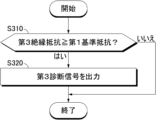
図3の方法は、図2の段階S292で第1リレー31が故障していると判定された場合にさらに行われ得る。図1及び図3を参照すると、段階S310で、コントローラ130は、第3絶縁抵抗が第1基準抵抗以上であるか否かを判定する。第1基準抵抗は、第1絶縁状態及び第3絶縁状態がいずれも正常の場合の絶縁抵抗RA1と絶縁抵抗RB1の合成抵抗を示す所定値であり得る。第3絶縁抵抗が第1基準抵抗以上であることは、(i)第1絶縁状態及び第3絶縁状態の少なくとも第1絶縁状態が正常であり、(ii)第1リレー31が開放故障であることを意味する。
The method of FIG. 3 may be further performed when it is determined in step S292 of FIG. 2 that the
段階S320で、コントローラ130は、第1絶縁状態が正常であり、第1リレー31が開放故障であることを示す第3診断信号を出力する。第3診断信号は、有/無線通信によって外部デバイスへ伝送され得る。
In step S320, the
図4の方法は、図2の段階S292で第1リレー31が故障していると判定された場合にさらに行われ得る。図1及び図4を参照すると、段階S410で、コントローラ130は、第4絶縁抵抗が第2基準抵抗以上であるか否かを判定する。第2基準抵抗は、第2絶縁状態及び第4絶縁状態がいずれも正常の場合の絶縁抵抗RA2と絶縁抵抗RB2の合成抵抗を示す所定値であり得る。第2基準抵抗は、第1基準抵抗と同一であり得る。第4絶縁抵抗が第2基準抵抗以上であることは、(i)第2絶縁状態及び第4絶縁状態の少なくとも第2絶縁状態が正常であり、(ii)第2リレー32が開放故障であることを意味する。
The method of FIG. 4 may be further performed when it is determined in step S292 of FIG. 2 that the
段階S420で、コントローラ130は、第2絶縁状態が正常であり、第2リレー32が開放故障であることを示す第4診断信号を出力する。第4診断信号は、有/無線通信によって外部デバイスに伝送され得る。
In step S420, the
以上で説明した本発明の実施例は、必ずしも装置及び方法を通じて具現されることではなく、本発明の実施例の構成に対応する機能を実現するプログラムまたはそのプログラムが記録された記録媒体を通じて具現され得、このような具現は、本発明が属する技術分野における専門家であれば、前述した実施例の記載から容易に具現できるはずである。 The embodiments of the present invention described above are not necessarily implemented through apparatuses and methods, but may be implemented through programs that implement functions corresponding to the configurations of the embodiments of the present invention or recording media on which the programs are recorded. In addition, such an embodiment should be easily realized by a person who is an expert in the technical field to which the present invention pertains from the description of the above-mentioned embodiments.
以上、本発明を限定された実施例と図面によって説明したが、本発明はこれに限定されず、本発明の属する技術分野で通常の知識を持つ者によって本発明の技術思想と特許請求の範囲の均等範囲内で多様な修正及び変形が可能であることは言うまでもない。 Although the present invention has been described above with reference to limited embodiments and drawings, the present invention is not limited thereto. It goes without saying that various modifications and variations are possible within the equivalent range.
また、上述の本発明は、本発明が属する技術分野における通常の知識を持つ者によって本発明の技術思想から脱しない範囲内で多様な置換、変形及び変更が可能であるため、上述の実施例及び添付された図面によって限定されず、多様な変形が行われるように各実施例の全部または一部を選択的に組み合わせて構成可能である。 Further, the present invention described above is capable of various substitutions, modifications, and changes by persons having ordinary knowledge in the technical field to which the present invention pertains without departing from the technical idea of the present invention. The embodiments are not limited by the accompanying drawings, and all or part of each embodiment can be selectively combined to make various modifications.
Claims (9)
前記バッテリーアセンブリーの正極端子と前記電気車両のシャーシ間の電圧で第1診断電圧を生成する第1電圧検出回路と、
前記バッテリーアセンブリーの負極端子と前記シャーシ間の電圧で第2診断電圧を生成する第2電圧検出回路と、
前記第1リレー及び前記第2リレーがオフ状態に制御される間、第1時点における前記第1診断電圧及び第2時点における前記第2診断電圧に基づき、前記正極端子と前記シャーシ間の第1絶縁抵抗及び前記負極端子と前記シャーシ間の第2絶縁抵抗を決定するコントローラと、を含み、
前記コントローラは、
前記第1リレー及び前記第2リレーがオン状態に制御される間、第3時点における前記第1診断電圧及び第4時点における前記第2診断電圧に基づき、前記正極端子と前記シャーシ間の第3絶縁抵抗、及び前記負極端子と前記シャーシ間の第4絶縁抵抗を決定し、
前記第1絶縁抵抗、前記第2絶縁抵抗、前記第3絶縁抵抗または前記第4絶縁抵抗の少なくとも1つに基づき、前記第1リレー及び前記第2リレーの少なくとも一つの故障を検出し、
前記第1絶縁抵抗と前記第3絶縁抵抗との抵抗差が臨界抵抗以下である場合、または前記第1絶縁抵抗に対する前記抵抗差の割合が臨界割合以下である場合に、前記第1リレーが故障していると判定する、リレー診断装置。 A relay diagnostic device for a first relay and a second relay each provided in a pair of power lines connecting an electric load of an electric vehicle to a battery assembly,
a first voltage detection circuit that generates a first diagnostic voltage from a voltage between a positive terminal of the battery assembly and a chassis of the electric vehicle;
a second voltage detection circuit that generates a second diagnostic voltage based on the voltage between the negative terminal of the battery assembly and the chassis;
While the first relay and the second relay are controlled to be in the OFF state, the first voltage between the positive terminal and the chassis is determined based on the first diagnostic voltage at the first time point and the second diagnostic voltage at the second time point. a controller that determines an insulation resistance and a second insulation resistance between the negative terminal and the chassis;
The controller includes:
While the first relay and the second relay are controlled to be in the ON state, a third voltage between the positive terminal and the chassis is determined based on the first diagnostic voltage at the third time point and the second diagnostic voltage at the fourth time point. determining insulation resistance and a fourth insulation resistance between the negative terminal and the chassis;
Detecting a failure in at least one of the first relay and the second relay based on at least one of the first insulation resistance, the second insulation resistance, the third insulation resistance, or the fourth insulation resistance,
When the resistance difference between the first insulation resistance and the third insulation resistance is less than or equal to a critical resistance, or when the ratio of the resistance difference to the first insulation resistance is less than or equal to a critical ratio, the first relay has failed. A relay diagnostic device that determines that
前記第2電圧検出回路が、前記負極端子と前記シャーシとの間に接続される、第2電圧分配器及び第2スイッチの直列回路であり、
各電圧分配器が、二つの抵抗器の直列回路である、請求項1に記載のリレー診断装置。 The first voltage detection circuit is a series circuit of a first voltage divider and a first switch connected between the positive terminal and the chassis,
The second voltage detection circuit is a series circuit of a second voltage divider and a second switch connected between the negative terminal and the chassis,
2. The relay diagnostic device of claim 1, wherein each voltage divider is a series circuit of two resistors.
前記第2時点は、前記コントローラによって前記第1スイッチ及び前記第2スイッチが各々オフ状態及びオン状態に制御される間における時点である、請求項2に記載のリレー診断装置。 The first time point is a time point during which the first switch and the second switch are controlled to be in an on state and an off state, respectively, by the controller,
The relay diagnostic device according to claim 2, wherein the second time point is a time point during which the first switch and the second switch are controlled to be in an off state and an on state, respectively, by the controller.
前記第3時点が、前記コントローラによって前記第1スイッチ及び前記第2スイッチが各々オン状態及びオフ状態に制御される間における時点であり、
前記第4時点が、前記コントローラによって前記第1スイッチ及び前記第2スイッチが各々オフ状態及びオン状態に制御される間における時点である、請求項2または3に記載のリレー診断装置。 The controller includes:
The third time point is a time point during which the first switch and the second switch are controlled to be in an on state and an off state, respectively, by the controller,
The relay diagnostic device according to claim 2 or 3, wherein the fourth time point is a time point during which the first switch and the second switch are controlled to be in an off state and an on state, respectively, by the controller.
前記第3絶縁抵抗が第1基準抵抗以上である場合、前記第1リレーを開放故障と判定する、請求項1から4のいずれか一項に記載のリレー診断装置。 The controller includes:
The relay diagnostic device according to any one of claims 1 to 4 , wherein the first relay is determined to have an open failure when the third insulation resistance is greater than or equal to the first reference resistance.
前記第2絶縁抵抗と前記第4絶縁抵抗との抵抗差が臨界抵抗以下である場合、または前記第2絶縁抵抗に対する前記抵抗差の割合が臨界割合以下である場合に、前記第2リレーが故障していると判定する、請求項1から5のいずれか一項に記載のリレー診断装置。 The controller includes:
When the resistance difference between the second insulation resistance and the fourth insulation resistance is less than or equal to the critical resistance, or when the ratio of the resistance difference to the second insulation resistance is less than or equal to the critical ratio, the second relay has failed. The relay diagnostic device according to any one of claims 1 to 5 , wherein the relay diagnostic device determines that
前記第4絶縁抵抗が第2基準抵抗以上である場合、前記第2リレーを開放故障と判定する、請求項1から6のいずれか一項に記載のリレー診断装置。 The controller includes:
The relay diagnostic device according to any one of claims 1 to 6 , wherein the second relay is determined to have an open failure when the fourth insulation resistance is greater than or equal to the second reference resistance.
前記第1リレー及び前記第2リレーがオフ状態に制御される間、第1時点における前記第1診断電圧及び第2時点における前記第2診断電圧に基づき、前記正極端子と前記シャーシ間の第1絶縁抵抗及び前記負極端子と前記シャーシ間の第2絶縁抵抗を決定する段階と、
前記第1リレー及び前記第2リレーがオン状態に制御される間、第3時点における前記第1診断電圧及び第4時点における前記第2診断電圧に基づき、前記正極端子と前記シャーシ間の第3絶縁抵抗、及び前記負極端子と前記シャーシ間の第4絶縁抵抗を決定する段階と、
前記第1絶縁抵抗、前記第2絶縁抵抗、前記第3絶縁抵抗または前記第4絶縁抵抗の少なくとも1つに基づき、前記第1リレー及び前記第2リレーの少なくとも一つの故障を検出する段階と、を含み、
前記第1リレー及び前記第2リレーの少なくとも一つの故障を検出する段階は、
前記第1絶縁抵抗と前記第3絶縁抵抗との抵抗差が臨界抵抗以下である場合、または前記第1絶縁抵抗に対する前記抵抗差の割合が臨界割合以下である場合に、前記第1リレーが故障していると判定する、リレー診断方法。 A relay diagnosis method executable by the relay diagnosis device according to any one of claims 1 to 7 ,
While the first relay and the second relay are controlled to be in the OFF state, the first voltage between the positive terminal and the chassis is determined based on the first diagnostic voltage at the first time point and the second diagnostic voltage at the second time point. determining an insulation resistance and a second insulation resistance between the negative terminal and the chassis;
While the first relay and the second relay are controlled to be in the ON state, a third voltage between the positive terminal and the chassis is determined based on the first diagnostic voltage at the third time point and the second diagnostic voltage at the fourth time point. determining an insulation resistance and a fourth insulation resistance between the negative terminal and the chassis;
detecting a failure of at least one of the first relay and the second relay based on at least one of the first insulation resistance, the second insulation resistance, the third insulation resistance, or the fourth insulation resistance; including ;
Detecting a failure of at least one of the first relay and the second relay includes:
When the resistance difference between the first insulation resistance and the third insulation resistance is less than or equal to a critical resistance, or when the ratio of the resistance difference to the first insulation resistance is less than or equal to a critical ratio, the first relay has failed. A relay diagnosis method that determines that
Applications Claiming Priority (3)
| Application Number | Priority Date | Filing Date | Title |
|---|---|---|---|
| KR10-2020-0133688 | 2020-10-15 | ||
| KR1020200133688A KR20220049950A (en) | 2020-10-15 | 2020-10-15 | Relay diagnosis apparatus, relay diagnosis method, and electric vehicle |
| PCT/KR2021/013269 WO2022080709A1 (en) | 2020-10-15 | 2021-09-28 | Relay diagnosis device, relay diagnosis method, battery system, and electric vehicle |
Publications (2)
| Publication Number | Publication Date |
|---|---|
| JP2023511169A JP2023511169A (en) | 2023-03-16 |
| JP7416488B2 true JP7416488B2 (en) | 2024-01-17 |
Family
ID=81209103
Family Applications (1)
| Application Number | Title | Priority Date | Filing Date |
|---|---|---|---|
| JP2022544363A Active JP7416488B2 (en) | 2020-10-15 | 2021-09-28 | Relay diagnostic equipment, relay diagnostic method, battery system and electric vehicle |
Country Status (6)
| Country | Link |
|---|---|
| US (1) | US11774499B2 (en) |
| EP (1) | EP4099034A4 (en) |
| JP (1) | JP7416488B2 (en) |
| KR (1) | KR20220049950A (en) |
| CN (1) | CN115136016A (en) |
| WO (1) | WO2022080709A1 (en) |
Families Citing this family (2)
| Publication number | Priority date | Publication date | Assignee | Title |
|---|---|---|---|---|
| FR3079305B1 (en) * | 2018-03-23 | 2020-05-01 | IFP Energies Nouvelles | METHOD FOR DETERMINING AT LEAST TWO EQUIVALENT INSULATION RESISTORS OF AN ELECTRICAL SYSTEM |
| KR20240006194A (en) | 2022-07-06 | 2024-01-15 | 씨앤지하이테크 주식회사 | Apparatus for detecting malfunction for power supply using a Zener diode |
Citations (7)
| Publication number | Priority date | Publication date | Assignee | Title |
|---|---|---|---|---|
| JP2016219229A (en) | 2015-05-20 | 2016-12-22 | 日産自動車株式会社 | Power supply device, and diagnostic method for diagnosing abnormality of power supply device |
| JP2017138278A (en) | 2016-02-05 | 2017-08-10 | 富士通テン株式会社 | Welding detection device and welding detection method |
| JP2017143662A (en) | 2016-02-10 | 2017-08-17 | 富士通テン株式会社 | Abnormality detection device and method for detection of abnormality |
| WO2018211933A1 (en) | 2017-05-19 | 2018-11-22 | パナソニックIpマネジメント株式会社 | Relay welding detection device, power supply control device including same, and welding detection method |
| JP2020521423A (en) | 2017-11-07 | 2020-07-16 | エルジー・ケム・リミテッド | Relay diagnostic circuit |
| JP2020523742A (en) | 2017-12-11 | 2020-08-06 | エルジー・ケム・リミテッド | Battery pack positive contactor diagnostic device and method |
| JP2020524263A (en) | 2017-12-12 | 2020-08-13 | エルジー・ケム・リミテッド | Negative contactor diagnostic device and method for battery pack |
Family Cites Families (13)
| Publication number | Priority date | Publication date | Assignee | Title |
|---|---|---|---|---|
| JP4265381B2 (en) * | 2003-11-13 | 2009-05-20 | 日産自動車株式会社 | Relay failure determination device and relay failure determination method |
| JP2007329045A (en) | 2006-06-08 | 2007-12-20 | Nissan Motor Co Ltd | Relay fault diagnostic system |
| KR101750073B1 (en) * | 2011-10-13 | 2017-07-03 | 에스케이이노베이션 주식회사 | Circuit for monitoring relay |
| KR20130119666A (en) * | 2012-04-24 | 2013-11-01 | 에스케이이노베이션 주식회사 | Circuit for monitoring relay |
| JP6146332B2 (en) | 2013-09-11 | 2017-06-14 | トヨタ自動車株式会社 | Relay sticking detection system |
| KR101771226B1 (en) * | 2014-10-02 | 2017-09-05 | 주식회사 엘지화학 | Isolation resistance measurement apparatus that can rapidly measure isolation resistance |
| US10126344B2 (en) * | 2015-12-18 | 2018-11-13 | Faraday&Future Inc. | Method for measuring electrical isolation of a vehicle chassis |
| JP6742191B2 (en) | 2016-08-08 | 2020-08-19 | 株式会社デンソーテン | Sticking detection device and battery system |
| KR101795319B1 (en) | 2016-12-13 | 2017-12-01 | 현대자동차주식회사 | System and method for detecting opening of fuse in high voltage system of vehicle |
| KR102432892B1 (en) | 2018-03-14 | 2022-08-12 | 주식회사 엘지에너지솔루션 | Apparatus and method for diagnosing a fault in a relay |
| KR102155207B1 (en) | 2019-07-05 | 2020-09-11 | 주식회사 라온텍 | Insulation resistance measuring apparatus, battery management system having the same and insulation resistance measuring method |
| US11592485B2 (en) * | 2019-10-04 | 2023-02-28 | Farasis Energy (Ganzhou) Co., Ltd. | Methods and apparatus for contactor weld detection in a vehicle |
| KR20200133688A (en) | 2020-11-10 | 2020-11-30 | (주) 대동이엔지 | Brio vibration ripper with multi-stage cylinder type stopper unit |
-
2020
- 2020-10-15 KR KR1020200133688A patent/KR20220049950A/en active Search and Examination
-
2021
- 2021-09-28 JP JP2022544363A patent/JP7416488B2/en active Active
- 2021-09-28 US US17/798,151 patent/US11774499B2/en active Active
- 2021-09-28 EP EP21880357.5A patent/EP4099034A4/en active Pending
- 2021-09-28 WO PCT/KR2021/013269 patent/WO2022080709A1/en unknown
- 2021-09-28 CN CN202180015610.7A patent/CN115136016A/en active Pending
Patent Citations (7)
| Publication number | Priority date | Publication date | Assignee | Title |
|---|---|---|---|---|
| JP2016219229A (en) | 2015-05-20 | 2016-12-22 | 日産自動車株式会社 | Power supply device, and diagnostic method for diagnosing abnormality of power supply device |
| JP2017138278A (en) | 2016-02-05 | 2017-08-10 | 富士通テン株式会社 | Welding detection device and welding detection method |
| JP2017143662A (en) | 2016-02-10 | 2017-08-17 | 富士通テン株式会社 | Abnormality detection device and method for detection of abnormality |
| WO2018211933A1 (en) | 2017-05-19 | 2018-11-22 | パナソニックIpマネジメント株式会社 | Relay welding detection device, power supply control device including same, and welding detection method |
| JP2020521423A (en) | 2017-11-07 | 2020-07-16 | エルジー・ケム・リミテッド | Relay diagnostic circuit |
| JP2020523742A (en) | 2017-12-11 | 2020-08-06 | エルジー・ケム・リミテッド | Battery pack positive contactor diagnostic device and method |
| JP2020524263A (en) | 2017-12-12 | 2020-08-13 | エルジー・ケム・リミテッド | Negative contactor diagnostic device and method for battery pack |
Also Published As
| Publication number | Publication date |
|---|---|
| WO2022080709A1 (en) | 2022-04-21 |
| US11774499B2 (en) | 2023-10-03 |
| EP4099034A4 (en) | 2023-10-11 |
| US20230099667A1 (en) | 2023-03-30 |
| EP4099034A1 (en) | 2022-12-07 |
| CN115136016A (en) | 2022-09-30 |
| JP2023511169A (en) | 2023-03-16 |
| KR20220049950A (en) | 2022-04-22 |
Similar Documents
| Publication | Publication Date | Title |
|---|---|---|
| CN107850643B (en) | Device and method for diagnosing a fault of a switching element | |
| KR101589198B1 (en) | Apparatus and method for diagnosis of cell balancing circuit | |
| EP2838152B1 (en) | Discharging device for electricity storage device | |
| JP7416488B2 (en) | Relay diagnostic equipment, relay diagnostic method, battery system and electric vehicle | |
| CN111630398B (en) | Battery management device, and battery pack and vehicle including the same | |
| JP7347770B2 (en) | Relay diagnostic equipment, relay diagnostic method, battery system and electric vehicle | |
| JP7248221B2 (en) | Earth leakage detection device, earth leakage detection method, and electric vehicle | |
| EP3624250B1 (en) | Battery pack | |
| US20220311065A1 (en) | Device and method for monitoring at least three battery cells of a battery | |
| KR20180026947A (en) | Power supply circuit, and battery pack including the same | |
| KR101858321B1 (en) | Apparatus and method for diagnosis of cell balancing circuit | |
| CN115343652A (en) | Storage battery abnormality detection device, storage battery abnormality detection method, and recording medium | |
| KR20200050865A (en) | Apparatus for diagnosing contactor | |
| KR20200087618A (en) | Apparatus for diagnosing battery pack | |
| CN113795762A (en) | Battery diagnosis device, battery diagnosis method and energy storage system | |
| US20230333170A1 (en) | Battery Management System, Battery Pack, Electric Vehicle and Battery Management Method | |
| JP7401058B2 (en) | Insulation resistance measurement circuit and diagnostic method | |
| CN115917336A (en) | Bus bar diagnosis apparatus, battery pack, energy storage system, and bus bar diagnosis method | |
| KR20220042794A (en) | Relay diagnosis apparatus, relay diagnosis method, battery system and electric vehicle | |
| KR20210051539A (en) | Apparatus for diagnosing isolation of battery | |
| KR20200076423A (en) | Appartus and method for diagnosing relay | |
| JP2023548898A (en) | Battery diagnosis device, battery management system, battery pack, electric vehicle and battery diagnosis method | |
| KR20210052195A (en) | Electric leakage detecting apparatus, electric leakage detecting method, and electric vehicle | |
| JP2024506146A (en) | Relay diagnosis device and relay diagnosis method | |
| KR20210074702A (en) | Apparatus and method for battery current measurement, and battery pack |
Legal Events
| Date | Code | Title | Description |
|---|---|---|---|
| A621 | Written request for application examination |
Free format text: JAPANESE INTERMEDIATE CODE: A621 Effective date: 20220725 |
|
| A131 | Notification of reasons for refusal |
Free format text: JAPANESE INTERMEDIATE CODE: A131 Effective date: 20230815 |
|
| A521 | Request for written amendment filed |
Free format text: JAPANESE INTERMEDIATE CODE: A523 Effective date: 20231114 |
|
| TRDD | Decision of grant or rejection written | ||
| A01 | Written decision to grant a patent or to grant a registration (utility model) |
Free format text: JAPANESE INTERMEDIATE CODE: A01 Effective date: 20231205 |
|
| A61 | First payment of annual fees (during grant procedure) |
Free format text: JAPANESE INTERMEDIATE CODE: A61 Effective date: 20231222 |
|
| R150 | Certificate of patent or registration of utility model |
Ref document number: 7416488 Country of ref document: JP Free format text: JAPANESE INTERMEDIATE CODE: R150 |