JP7415453B2 - Ophthalmology measuring device - Google Patents
Ophthalmology measuring device Download PDFInfo
- Publication number
- JP7415453B2 JP7415453B2 JP2019201814A JP2019201814A JP7415453B2 JP 7415453 B2 JP7415453 B2 JP 7415453B2 JP 2019201814 A JP2019201814 A JP 2019201814A JP 2019201814 A JP2019201814 A JP 2019201814A JP 7415453 B2 JP7415453 B2 JP 7415453B2
- Authority
- JP
- Japan
- Prior art keywords
- image
- purkinje
- optical system
- anterior segment
- eye
- Prior art date
- Legal status (The legal status is an assumption and is not a legal conclusion. Google has not performed a legal analysis and makes no representation as to the accuracy of the status listed.)
- Active
Links
- 230000003287 optical effect Effects 0.000 claims description 142
- 238000005259 measurement Methods 0.000 claims description 86
- 238000001514 detection method Methods 0.000 claims description 37
- 238000004364 calculation method Methods 0.000 claims description 28
- 238000000034 method Methods 0.000 claims description 21
- 238000012937 correction Methods 0.000 claims description 11
- 230000008569 process Effects 0.000 claims description 11
- 210000004087 cornea Anatomy 0.000 description 63
- 238000012545 processing Methods 0.000 description 16
- 210000000695 crystalline len Anatomy 0.000 description 13
- 238000003384 imaging method Methods 0.000 description 8
- 238000012876 topography Methods 0.000 description 5
- 230000004323 axial length Effects 0.000 description 4
- 238000010191 image analysis Methods 0.000 description 4
- 239000011159 matrix material Substances 0.000 description 4
- 230000007246 mechanism Effects 0.000 description 4
- 210000002294 anterior eye segment Anatomy 0.000 description 3
- 238000010586 diagram Methods 0.000 description 3
- 238000004458 analytical method Methods 0.000 description 2
- 201000009310 astigmatism Diseases 0.000 description 2
- 238000012790 confirmation Methods 0.000 description 2
- 238000000691 measurement method Methods 0.000 description 2
- 238000004088 simulation Methods 0.000 description 2
- 230000000007 visual effect Effects 0.000 description 2
- 230000005540 biological transmission Effects 0.000 description 1
- 238000009795 derivation Methods 0.000 description 1
- 238000011156 evaluation Methods 0.000 description 1
- 210000000720 eyelash Anatomy 0.000 description 1
- 239000012530 fluid Substances 0.000 description 1
- 230000006870 function Effects 0.000 description 1
- 230000005484 gravity Effects 0.000 description 1
- 238000005286 illumination Methods 0.000 description 1
- 201000000766 irregular astigmatism Diseases 0.000 description 1
- 238000012986 modification Methods 0.000 description 1
- 230000004048 modification Effects 0.000 description 1
- 230000002093 peripheral effect Effects 0.000 description 1
- 230000004044 response Effects 0.000 description 1
Images


Landscapes
- Eye Examination Apparatus (AREA)
Description
本開示は、被検眼を測定する眼科測定装置に関する。 The present disclosure relates to an ophthalmological measurement device that measures a subject's eye.
眼科測定装置として、例えば、複数の指標を前眼部に投影するとともに、前眼部を正面方向から撮影し、取得された前眼部画像(前眼部正面画像)に写った前眼部での指標の反射像を解析することで、被検眼の前眼部形状を測定する装置が知られている。このような装置では、例えば、角膜後面による指標の反射像(第2プルキンエ像)等を解析することによって、角膜後面形状(例えば、角膜後面曲率など)の測定を行うことができる。例えば、角膜後面曲率などは、眼内レンズの度数計算に用いられる。 As an ophthalmological measurement device, for example, a plurality of indicators are projected onto the anterior segment of the eye, and the anterior segment is photographed from the front direction, and the anterior segment captured in the obtained anterior segment image (frontal image of the anterior segment) is measured. A device is known that measures the shape of the anterior segment of the eye to be examined by analyzing the reflected image of the index. With such an apparatus, for example, the shape of the posterior corneal surface (for example, the posterior corneal curvature) can be measured by analyzing the reflected image of the index by the posterior corneal surface (second Purkinje image). For example, the posterior corneal curvature is used to calculate the power of an intraocular lens.
しかしながら、従来の装置において、プルキンエ像の反射光量が小さかった場合、前眼部画像から検出できなかったり、ノイズ光の影響で別の輝点と誤検出したりすることがあった。このため、被検眼の形状情報を取得することが困難な場合があった。 However, in conventional devices, if the amount of reflected light from the Purkinje image is small, it may not be detected from the anterior segment image or may be mistakenly detected as another bright spot due to the influence of noise light. For this reason, it may be difficult to obtain shape information of the eye to be examined.
本開示は、従来の問題点に鑑みてなされたものであり、被検眼の形状情報を容易に取得することを目的とする。 The present disclosure has been made in view of the conventional problems, and aims to easily obtain shape information of an eye to be examined.
上記課題を解決するために、本開示は以下のような構成を備えることを特徴とする。 In order to solve the above problems, the present disclosure is characterized by having the following configuration.
(1) 被検眼を測定する眼科測定装置であって、前記被検眼の前眼部に指標を投影する投影光学系と、前記指標が投影された前記前眼部を撮影することによって、前記被検眼の前眼部画像を取得する撮影手段と、前記前眼部画像において、前記指標によるプルキンエ像に関する位置を検者が指定したときの指定位置情報を取得する位置情報取得手段と、前記指定位置情報に基づいて前記前眼部の形状情報を取得する演算手段と、を備え、前記投影光学系は、前記前眼部に複数の指標を投影し、前記演算手段は、前記前眼部画像から検出された前記複数のプルキンエ像の検出位置に対してフィッティング処理を行うことで取得されたフィッティング結果の図形を、前記プルキンエ像に関する位置を修正するために表示手段に表示された修正画面に表示させることを特徴とする。
(1) An ophthalmological measurement device for measuring an eye to be examined, which includes a projection optical system that projects an index onto the anterior segment of the eye to be examined, and a projection optical system that projects an index onto the anterior segment of the eye to be examined, and a projection optical system that measures the anterior segment of the eye by photographing the anterior segment on which the index is projected. a photographing means for acquiring an anterior ocular segment image during optometry; a position information acquiring means for acquiring specified position information when an examiner specifies a position related to the Purkinje image according to the index in the anterior ocular image; and the specified position. calculation means for acquiring shape information of the anterior eye segment based on the information , the projection optical system projects a plurality of indicators on the anterior eye segment, and the calculation means is configured to calculate shape information from the anterior eye segment image. A fitting result figure obtained by performing a fitting process on the detected positions of the plurality of Purkinje images is displayed on a correction screen displayed on a display means in order to correct the position related to the Purkinje image. It is characterized by
本開示によれば、被検眼の形状情報を容易に取得できる。 According to the present disclosure, shape information of the eye to be examined can be easily acquired.
<実施形態>
以下、本開示に係る実施形態について説明する。本実施形態の眼科測定装置(例えば、眼科測定装置1)は、例えば、被検眼の前眼部形状を測定する。眼科測定装置は、投影光学系(例えば、投影光学系30)と、撮影部(例えば、撮影光学系20)と、位置情報取得部(例えば、制御部100)と、演算部(例えば、制御部100)を備える。投影光学系は、例えば、被検眼の前眼部に指標を投影する。撮影部は、例えば、指標の投影された前眼部を正面方向(ただし、真正面でなくてもよい)から撮影することによって、被検眼の前眼部画像を取得する。位置情報取得部は、前眼部画像において、指標によるプルキンエ像に関する位置を検者が指定したときの指定位置情報を取得する。指定位置情報は、例えば、前眼部画像においてプルキンエ像が存在する位置を検者が指定したときの位置情報であってもよいし、前眼部画像においてプルキンエ像が存在しない位置を検者が指定したときの位置情報であってもよい。なお、プルキンエ像は、前眼部画像上に輝点として現れる。演算部は、例えば、指定位置情報に基づいて前眼部の形状情報を取得する。
<Embodiment>
Embodiments according to the present disclosure will be described below. The ophthalmological measuring device (for example, the ophthalmological measuring device 1) of this embodiment measures, for example, the shape of the anterior segment of an eye to be examined. The ophthalmological measuring device includes a projection optical system (for example, the projection optical system 30), a photographing section (for example, the photographing optical system 20), a position information acquisition section (for example, the control section 100), and a calculation section (for example, the control section). 100). The projection optical system projects an index onto the anterior segment of the subject's eye, for example. The photographing unit acquires an anterior ocular segment image of the subject's eye by, for example, photographing the anterior ocular segment on which the index is projected from the front direction (however, it does not have to be directly in front). The position information acquisition unit acquires specified position information when the examiner specifies a position related to the Purkinje image using the index in the anterior segment image. The specified position information may be, for example, the position information when the examiner specifies the position where the Purkinje image exists in the anterior segment image, or the position information when the examiner specifies the position where the Purkinje image does not exist in the anterior segment image. It may also be location information at the time of designation. Note that the Purkinje image appears as a bright spot on the anterior segment image. The calculation unit obtains shape information of the anterior segment based on the specified position information, for example.
眼科測定装置は、上記構成を備えることによって、前眼部画像からプルキンエ像を自動で検出することができない場合であっても、検者が指定したプルキンエ像に関する位置に基づいて被検眼の形状情報(角膜曲率など)を取得することができる。このため、前眼部画像を撮り直す手間などを省くことでき、被検眼の形状情報を容易に取得できる。 By having the above-mentioned configuration, the ophthalmological measuring device can detect the shape information of the subject's eye based on the position related to the Purkinje image specified by the examiner even if the Purkinje image cannot be automatically detected from the anterior segment image. (Corneal curvature, etc.) can be obtained. Therefore, it is possible to save the effort of retaking the anterior segment image, and it is possible to easily obtain the shape information of the eye to be examined.
なお、位置情報取得部は、例えば、検者の操作に応じて操作部(例えば、操作部80)から出力された操作信号を受け付けてもよい。例えば、検者は、表示部(例えば、モニタ70)に表示された前眼部画像を確認しながら操作部を操作することでプルキンエ像に関する位置を指定し、位置情報取得部は、このときの操作信号に基づいて指定位置情報を取得してもよい。 Note that the position information acquisition unit may receive, for example, an operation signal output from an operation unit (for example, the operation unit 80) in response to an operation by the examiner. For example, the examiner specifies a position related to the Purkinje image by operating the operation unit while checking the anterior segment image displayed on the display unit (for example, the monitor 70), and the position information acquisition unit specifies the position related to the Purkinje image. The specified position information may be acquired based on the operation signal.
なお、演算部は、指定位置情報に基づいて前眼部画像からプルキンエ像を検出し、プルキンエ像の検出位置に基づいて形状情報を取得してもよい。眼科測定装置は、上記構成を備えることによって、例えば、前眼部画像の全体からプルキンエ像を検出することが困難な場合であっても、検者が指定した指定位置情報を用いて一部の領域で画像解析を行うことによって、プルキンエ像を検出できる可能性が高まる。例えば、演算部は、検者が指定した位置の周辺領域で画像解析を行うことでプルキンエ像を検出してもよいし、検者に指定された領域内で画像解析を行うことでプルキンエ像の検出を行ってもよい。また、プルキンエ像の存在しない位置を検者が指定した場合、演算部は、検者が指定した位置以外で画像解析を行うことでプルキンエ像の検出を行ってもよい。 Note that the calculation unit may detect the Purkinje image from the anterior segment image based on the specified position information, and may acquire the shape information based on the detected position of the Purkinje image. By having the above configuration, the ophthalmological measuring device can detect a part of the Purkinje image using specified position information specified by the examiner, for example, even when it is difficult to detect the Purkinje image from the entire anterior segment image. By performing image analysis in this region, the possibility of detecting a Purkinje image increases. For example, the calculation unit may detect the Purkinje image by performing image analysis in the area surrounding the position specified by the examiner, or may detect the Purkinje image by performing image analysis within the area specified by the examiner. Detection may also be performed. Further, when the examiner specifies a position where a Purkinje image does not exist, the calculation unit may detect the Purkinje image by performing image analysis at a position other than the position specified by the examiner.
なお、投影光学系は、複数の指標を被検眼に投影してもよい。この場合、前眼部画像上のそれぞれ異なる位置に複数のプルキンエ像が写り込む。位置情報取得部は、複数の指標のうち、いずれかに対応するプルキンエ像の1つに関する位置を検者が指定したときの指定位置情報を取得してもよいし、複数の指標の各々に対応するプルキンエ像に関する位置を検者が指定したときの複数の指定位置情報を取得してもよい。演算部は、複数の指定位置情報に基づいて被検眼の形状情報を取得してもよいし、前眼部画像から自動で検出したプルキンエ像の検出位置と、指定位置情報との両方に基づいて被検眼の形状情報を取得してもよい。 Note that the projection optical system may project a plurality of indices onto the eye to be examined. In this case, a plurality of Purkinje images appear at different positions on the anterior segment image. The position information acquisition unit may acquire specified position information when the examiner specifies a position related to one of the Purkinje images corresponding to one of the plurality of indicators, or may acquire specified position information corresponding to each of the plurality of indicators. A plurality of pieces of designated position information may be acquired when the examiner designates a position related to the Purkinje image. The calculation unit may acquire shape information of the eye to be examined based on a plurality of pieces of designated position information, or may acquire shape information of the eye to be examined based on both the detected position of the Purkinje image automatically detected from the anterior segment image and the designated position information. Shape information of the eye to be examined may also be acquired.
なお、プルキンエ像は、第2プルキンエ像であってもよい。例えば、第2プルキンエ像は、投影光学系によって投影された指標光束が角膜後面で反射して前眼部画像に写り込んだものである。この場合、演算部は、指定位置情報および第2プルキンエ像の少なくともいずれかに基づいて、角膜後面に関する形状情報を取得してもよい。第2プルキンエ像は、反射光量が小さいため、前眼部画像から検出しづらい。また、第2プルキンエ像は、他の指標による第4プルキンエ像(水晶体後面反射像)と誤検出される可能性がある。したがって、本装置のように、検者によって指定された指定位置情報を用いることによって、第2プルキンエ像を正確に検出できる可能性が高まる。 Note that the Purkinje image may be a second Purkinje image. For example, the second Purkinje image is an image in which the index light beam projected by the projection optical system is reflected on the posterior surface of the cornea and reflected in the anterior segment image. In this case, the calculation unit may acquire shape information regarding the posterior surface of the cornea based on at least one of the specified position information and the second Purkinje image. The second Purkinje image is difficult to detect from the anterior segment image because the amount of reflected light is small. Further, the second Purkinje image may be erroneously detected as the fourth Purkinje image (rear surface reflection image of the crystalline lens) based on another index. Therefore, by using designated position information designated by the examiner as in this device, the possibility of accurately detecting the second Purkinje image increases.
なお、演算部は、プルキンエ像の視認性を向上させる画像処理を前眼部画像に施してもよい。例えば、制御部は、局所的にコントラストを強調させる画像処理(例えば、CLAHEなど)を行ってもよいし、Hessian行列の固有値に基づいて構造により強調する画像処理(例えば、ブロブネスフィルタ)を行ってもよい。これによって、検者によるプルキンエ像に関する位置の指定が容易となる。 Note that the calculation unit may perform image processing on the anterior segment image to improve the visibility of the Purkinje image. For example, the control unit may perform image processing that locally enhances the contrast (for example, CLAHE, etc.), or may perform image processing that enhances the structure based on the eigenvalues of the Hessian matrix (for example, a blobness filter). You can. This makes it easier for the examiner to specify the position regarding the Purkinje image.
なお、投影光学系によって前眼部に複数の指標が投影される場合、演算部は、前眼部画像から検出された複数のプルキンエ像の検出位置に対してフィッティング処理を行うことで取得されたフィッティング結果およびフィッティング誤差の少なくともいずれかを表示部(例えば、モニタ70)に表示させてもよい。これによって、検者は、自動検出された点がどの程度確からしいか確認できるため、プルキンエ像に関する位置の指定または修正が行い易くなる。なお、フィッティング処理は、例えば、プルキンエ像の検出位置に対して楕円、またはその他の図形を合わせ込む処理である。なお、フィッティングする図形は、被検眼に投影される指標の配置に基づいて設定されてもよい。フィッティング結果は、例えば、フィッティングされた図形である。楕円フィッティングの場合、例えば、演算部は、現在検出しているプルキンエ像(輝点)の位置と、フィッティングさせた楕円を前眼部画像に重畳させて表示させる。また、フィッティング誤差は、例えば、検出したプルキンエ像とフィッティングさせた図形(の輪郭)との距離に基づく数値であってもよい。 Note that when multiple indices are projected onto the anterior segment by the projection optical system, the calculation unit performs fitting processing on the detection positions of multiple Purkinje images detected from the anterior segment image. At least one of the fitting result and the fitting error may be displayed on a display unit (for example, the monitor 70). This allows the examiner to confirm how likely the automatically detected points are, making it easier to designate or modify the position regarding the Purkinje image. Note that the fitting process is, for example, a process of fitting an ellipse or other figure to the detected position of the Purkinje image. Note that the figure to be fitted may be set based on the arrangement of indicators projected onto the subject's eye. The fitting result is, for example, a fitted figure. In the case of ellipse fitting, for example, the calculation unit displays the position of the currently detected Purkinje image (bright spot) and the fitted ellipse superimposed on the anterior segment image. Furthermore, the fitting error may be, for example, a numerical value based on the distance between the detected Purkinje image and (the contour of) the fitted figure.
なお、演算部は、フィッティング結果を表示部に複数表示させてもよいし、フィッティング誤差の小さい(評価値の高い)フィッティング結果を表示部に表示させてよい。 Note that the calculation section may display a plurality of fitting results on the display section, or may display a fitting result with a small fitting error (high evaluation value) on the display section.
なお、演算部は、プルキンエ像が所定数以上検出された場合にフィッティング処理を行ってもよい。例えば、第2プルキンエ像が6点以上検出できた場合、フィッティング処理を行ってもよい。もちろん、第2プルキンエ像が5点以下しか検出できなかった場合でも、第2プルキンエ像が所定配置に対して偏りなく検出されていれば、フィッティング処理を行ってもよい。例えば、検出された複数の第2プルキンエ像間の間隔に大きな偏りがなければ、フィッティング処理を行ってもよい。 Note that the calculation unit may perform fitting processing when a predetermined number or more of Purkinje images are detected. For example, if six or more second Purkinje images can be detected, fitting processing may be performed. Of course, even if only five or fewer second Purkinje images are detected, the fitting process may be performed as long as the second Purkinje images are detected without bias with respect to the predetermined arrangement. For example, if there is no significant deviation in the intervals between the plurality of detected second Purkinje images, fitting processing may be performed.
なお、演算部は、前眼部画像において、プルキンエ像である可能性のある候補点を表示部に表示させてもよい。これによって、検者は、候補点の中からプルキンエ像らしい点を指定するだけでよくなり、一からプルキンエ像を探す手間が省ける。 Note that the calculation unit may cause the display unit to display candidate points that may be Purkinje images in the anterior segment image. As a result, the examiner only needs to specify a point that seems to be a Purkinje image from among the candidate points, which saves him the trouble of searching for a Purkinje image from scratch.
なお、演算部は、検者に指定された検出位置または候補点を除外して形状情報を取得してもよい。これによって、プルキンエ像ではない他の輝点等の検出位置に基づいて角膜形状が算出されてしまうことを防止できる。 Note that the calculation unit may obtain the shape information by excluding the detection position or candidate point designated by the examiner. This can prevent the corneal shape from being calculated based on the detected position of a bright spot or the like other than the Purkinje image.
なお、演算部は、プルキンエ像の自動検出が成功したか否かを判定し、そのときの判定結果を報知部によって検者に報知してもよい。これによって、検者は、プルキンエ像に関する位置指定または検出位置の修正が必要であることを容易に把握することができる。なお、演算部は、自動検出が失敗した場合にのみ検者に報知し、プルキンエ像に関する位置指定または検出位置の修正を促してもよい。なお、報知部は、例えば、表示部、音声出力部などであってもよい。表示部は、ディスプレイや表示灯であってもよい。音声出力部は、例えば、スピーカーなどであってもよい。 Note that the calculation unit may determine whether the automatic detection of the Purkinje image has been successful or not, and the notification unit may notify the examiner of the determination result at that time. This allows the examiner to easily understand that it is necessary to specify the position or correct the detected position regarding the Purkinje image. Note that the arithmetic unit may notify the examiner only when the automatic detection fails, and prompt him to specify the position regarding the Purkinje image or correct the detected position. Note that the notification section may be, for example, a display section, an audio output section, or the like. The display section may be a display or an indicator light. The audio output unit may be, for example, a speaker.
なお、演算部は、例えば、検出されたプルキンエ像に対してフィッティング処理を行ったときのフィッティング誤差に基づいて、自動検出の成否を判定してもよい。例えば、演算部は、フィッティング誤差が小さい場合にプルキンエ像の自動検出が成功したと判定し、フィッティング誤差が大きい場合に自動検出が失敗したと判定してもよい。なお、被検眼に投影する指標の配置からフィッティングした図形の形状がある程度推測できるため、演算部は、フィッティングした図形の形状に基づいて自動検出の成否を判定してもよい。例えば、楕円フィッティングを行う場合、演算部は、長軸/短軸の比が大きいときに自動検出が失敗したと判定してもよい。 Note that the calculation unit may determine the success or failure of automatic detection, for example, based on a fitting error when fitting processing is performed on the detected Purkinje image. For example, the calculation unit may determine that the automatic detection of the Purkinje image has been successful when the fitting error is small, and may determine that the automatic detection has failed when the fitting error is large. Note that since the shape of the fitted figure can be estimated to some extent from the arrangement of the index projected onto the subject's eye, the calculation unit may determine the success or failure of automatic detection based on the shape of the fitted figure. For example, when performing ellipse fitting, the calculation unit may determine that automatic detection has failed when the ratio of major axis/minor axis is large.
また、演算部は、例えば、検出されたプルキンエ像が、フィッティングした図形の周辺領域に含まれるか否かに応じて成否判定を行ってもよい。例えば、演算部は、フィッティングした楕円に対して長径と短径の比が同じで、大きさの小さい小楕円と、大きさの大きい大楕円の2つの同心楕円の間にプルキンエ像があるか否かで成否判定を行ってもよい。つまり、小楕円の外側かつ大楕円の内側の領域にプルキンエ像の検出位置があるか否かで成否判定を行ってもよい。 Further, the arithmetic unit may determine success or failure depending on, for example, whether or not the detected Purkinje image is included in the peripheral area of the fitted figure. For example, the calculation unit determines whether or not there is a Purkinje image between two concentric ellipses, a small ellipse with the same length and breadth ratio and a small ellipse with a large size and a large ellipse with a large size, for the fitted ellipse. Success or failure may be determined based on the following. In other words, success or failure may be determined based on whether or not the Purkinje image detection position is located outside the small ellipse and inside the large ellipse.
また、演算部は、例えば、検出されたプルキンエ像の数によって自動検出の成否を判定してもよい。例えば、投影した指標の数の半数以上のプルキンエ像が検出された場合は自動検出が成功したと判定し、検出されなかった場合は自動検出が失敗したと判定してもよい。また、フィッティングに必要な最小数以上のプルキンエ像が検出された場合は自動検出が成功したと判定し、検出されたかった場合は自動検出が失敗したと判定してもよい。 Further, the calculation unit may determine whether automatic detection is successful or not, for example, based on the number of Purkinje images detected. For example, if Purkinje images equal to or more than half of the number of projected markers are detected, it may be determined that the automatic detection was successful, and if no Purkinje images are detected, it may be determined that the automatic detection has failed. Furthermore, if more than the minimum number of Purkinje images required for fitting are detected, it may be determined that the automatic detection was successful; if the Purkinje images were desired to be detected, it may be determined that the automatic detection has failed.
なお、演算部は、自動検出が失敗した場合に、フィッティング結果とフィッティング誤差を表示部に表示させることで、自動検出が失敗した可能性のあることを検者に報知してもよい。 Note that when the automatic detection fails, the calculation unit may notify the examiner that the automatic detection may have failed by displaying the fitting result and the fitting error on the display unit.
<実施例>
以下、図面を参照しつつ、本開示の例示的な実施例を説明する。
<装置の概略構成>
実施形態に係る眼科測定装置1の概略構成を、図1および図2を参照して説明する。なお、以下では、「眼科測定装置1」を、「本装置1」と省略する。
<Example>
Hereinafter, exemplary embodiments of the present disclosure will be described with reference to the drawings.
<Schematic configuration of the device>
A schematic configuration of an ophthalmological measuring device 1 according to an embodiment will be described with reference to FIGS. 1 and 2. Note that, hereinafter, "ophthalmological measurement device 1" will be abbreviated as "this device 1."
本装置1は、被検眼Eの角膜に関する測定を行う。少なくとも、正面方向から撮影された前眼部画像(前眼部正面画像)が取得され、その画像に含まれる(描画される)第2プルキンエ像に基づいて、被検眼Eの角膜後面に関する情報が取得される。 This device 1 measures the cornea of the eye E to be examined. At least, an anterior segment image photographed from the front direction (frontal anterior segment image) is acquired, and information regarding the posterior corneal surface of the eye E to be examined is obtained based on the second Purkinje image included (drawn) in the image. be obtained.
図1に示すように、本装置1は、少なくとも、投影光学系30、撮影光学系(「受光光学系」と称する場合がある)20、および、制御部100を、有する。更に、本装置1は、トポ投影光学系10(「第2投光光学系」の一例)、測定光学系40、および、固視光学系50を備えていてもよい。上記した光学系は、図示無き筐体に内蔵されている。その筐体は、周知のアライメント移動機構60の駆動によって、被検者眼に対して3次元的に移動される。例えば、操作部材(例えば、ジョイスティック)の操作に基づいて、筐体は移動されてもよい。
As shown in FIG. 1, the apparatus 1 includes at least a projection
<撮影光学系>
撮影光学系20は、被検眼Eの前眼部画像を撮影するための撮像素子27を有する。撮影光学系20では、前眼部からの反射光が撮像素子27で受光される。そして、撮像素子27からの受光信号に基づいて、前眼部画像が生成される。この場合において、反射光を生じさせるために前眼部へ照射される照明光の光源は、光源11、および、図示無き観察用光源の中から、適宜選択されてもよい。
<Photography optical system>
The photographing
図1では、撮影光学系20の撮影光軸を、光軸L1として図示する。便宜上、以下では、前眼部画像の画像中心と、光軸L1とは一致するものとして説明を行う。また、便宜上、光軸L1は、後述の角膜に関する測定をする際の測定光軸と共用される。
In FIG. 1, the photographing optical axis of the photographing
実施例として図1に示す撮影光学系20は、撮像素子27の他に、ダイクロイックミラー23、対物レンズ24、ミラー25、および、撮像レンズ26を含む。撮像素子27は、例えば、被検眼の前眼部と共役な位置に配置されてもよい。なお、ダイクロイックミラー(ビームスプリッタ)23は、撮影光学系20の光路を測定光学系40の光路と分岐させるための光路分岐部材である(詳しくは、後述する)。また、光軸L1(撮影光軸)は、固視灯51の投影光軸と兼用されている。
The photographing
<トポ投影光学系>
トポ投影光学系10は、角膜前面形状を測定するために利用される。本実施形態において、トポ投影光学系10は、角膜前面のトポグラフィー検査において、多重リング像(プラチドリング像または多重マイヤーリング像)を測定指標(本実施形態における「第3の測定指標」)として、角膜に投影する。
<Topo projection optical system>
The topo projection
実施例において、トポ投影光学系10は、光源11と、プラチド板12(図2参照)と、を有する。プラチド板12は、被検眼Eと光源11との間に配置される。プラチド板12に形成された同心円状の発光部から、光源11からの光が、リング状に角膜に投影される。光源11が発する光は、可視光であってもよいし、赤外光であってもよい。
In the embodiment, the topo projection
トポ投影光学系10によって投影された多重リング像は、撮影光学系20によって撮影される。そして、撮影された多重リング像が解析され、角膜トポグラフィーが演算される。角膜トポグラフィーのより詳細な導出方法については、例えば、本出願人による「特開平10-108837号公報」等を参照されたい。
The multiple ring images projected by the topo projection
なお、トポ投影光学系10によって投影される測定指標(第3の測定指標)の形状は、必ずしも多重リング像に限定されるものではない。測定指標は、線、又は、複数の点によって形成された、他の2次元的なパターンであってもよい。具体的な例としては、上記例示したリング状のパターンの他、点指標が格子状に配列されたドットマトリクスからなるパターン等が挙げられる。勿論、これら以外のパターンであってもよい。
Note that the shape of the measurement index (third measurement index) projected by the topo projection
なお、リング状のパターンは、途切れなく連続的なリングを形成するものであってもよいし、間欠的なリングパターンを形成するものであってもよい。間欠的なリングパターンは、破線状のリングを角膜へ投影してもよいし、円周上に配置される複数の点指標を角膜へ投影してもよいし、これらを組み合わせによるものであってもよい。 Note that the ring-shaped pattern may be one that forms a continuous ring without interruption, or may be one that forms an intermittent ring pattern. The intermittent ring pattern may be formed by projecting a broken line ring onto the cornea, projecting a plurality of point indicators arranged on the circumference onto the cornea, or by a combination of these. Good too.
また、プラチド板による測定方式に代えて、コーン方式が適用されてもよい。コーン方式では、プラチド板12の代わりに、コーンによって第3の測定指標におけるパターンが形成される。
Further, instead of the measurement method using a Placido plate, a cone method may be applied. In the cone method, the pattern in the third measurement index is formed by a cone instead of the
<投影光学系>
投影光学系30は、角膜後面に関する情報を測定するための指標(以下、便宜上「測定指標」と称する)を、角膜に投影する。測定指標は、光軸L1(撮影光軸)に対して斜め方向から投影される。本実施形態において、測定指標は、主に、適正アライメント状態において、角膜中心部の近傍領域に投影される。適正アライメント状態は、例えば、被検眼の光軸(視軸)が光軸L1と略一致した状態であってもよい。
<Projection optical system>
The projection
角膜後面に関する情報としては、例えば、角膜後面そのものの形状を示す情報であってもよい。角膜後面そのものの形状を示す情報としては、例えば、角膜後面の形状(トポグラフィまたはエベレーション等)、曲率(ケラトメトリ)、位置等が挙げられる。また、角膜後面に関する情報としては、例えば、角膜の前後面の両方によって特定される情報であってもよい。前後面の両方により特定される情報としては、例えば、角膜厚、屈折力、および、角膜における乱視軸角度等が挙げられる。 The information regarding the posterior surface of the cornea may be, for example, information indicating the shape of the posterior surface of the cornea itself. Information indicating the shape of the posterior corneal surface itself includes, for example, the shape (topography, elation, etc.), curvature (keratometry), position, etc. of the posterior corneal surface. Furthermore, the information regarding the posterior surface of the cornea may be, for example, information specified by both the anterior and posterior surfaces of the cornea. Examples of the information specified by both the anterior and posterior surfaces include corneal thickness, refractive power, and astigmatic axis angle in the cornea.
本実施形態において、投影光学系30が被検眼の角膜に向けて投影する測定指標は、第1測定指標と、第2測定指標と、に分けられる。第1測定指標は、光軸L1に対して、第2測定指標と対称に投影される。換言すれば、第1測定指標の投影光軸と、第2測定指標の投影光軸と、は、光軸L1に対し、対称に設けられている。
In this embodiment, the measurement index that the projection
第1測定指標および第2測定指標が角膜に投影された状態で得られる前眼部画像には、測定指標の第1プルキンエ像(角膜前面による反射像)、第2プルキンエ像(角膜後面による反射像)、第3プルキンエ像(水晶体前面による反射像)、および、第4プルキンエ像(水晶体後面による反射像)が生じ得る。この中で、第1プルキンエ像が最も明るく、光軸L1に対して最も離れた位置に形成される。第2プルキンエ像は、第1プルキンエ像と光軸L1との間に形成される。第3プルキンエ像は、各プルキンエ像の中で、光軸L1に対して最も近くに形成され、この点で他のプルキンエ像から容易に区別可能である。第4プルキンエ像は、第2プルキンエ像と、同程度の明るさで形成される。第4プルキンエ像は、倒立像であり、光軸L1を挟んで、第2プルキンエ像と略対称な位置に形成される。 The anterior segment image obtained when the first measurement index and the second measurement index are projected onto the cornea includes the first Purkinje image of the measurement index (reflected image by the anterior surface of the cornea) and the second Purkinje image (reflected image by the posterior surface of the cornea). A third Purkinje image (an image reflected by the anterior surface of the crystalline lens), and a fourth Purkinje image (an image reflected by the posterior surface of the crystalline lens) may be generated. Among these, the first Purkinje image is the brightest and is formed at the farthest position with respect to the optical axis L1. The second Purkinje image is formed between the first Purkinje image and the optical axis L1. The third Purkinje image is formed closest to the optical axis L1 among the Purkinje images, and is easily distinguishable from other Purkinje images in this respect. The fourth Purkinje image is formed with approximately the same brightness as the second Purkinje image. The fourth Purkinje image is an inverted image, and is formed at a position substantially symmetrical to the second Purkinje image with the optical axis L1 in between.
ここで、第1測定指標と、第2測定指標とは、光軸L1に対して対称に投影されるので、第1測定指標の第4プルキンエ像(水晶体後面による反射像)が、前眼部画像において、第2測定指標の第2プルキンエ像(角膜後面による反射像)の近傍に形成され、第2測定指標の第4プルキンエ像が、前眼部画像において、第1測定指標の第2プルキンエ像の近傍に形成される。なお、ここでいう近傍には、2つの輝点像が重なり合う場合も含まれる。 Here, since the first measurement index and the second measurement index are projected symmetrically with respect to the optical axis L1, the fourth Purkinje image (reflected image by the posterior surface of the crystalline lens) of the first measurement index is In the image, the fourth Purkinje image of the second measurement index is formed near the second Purkinje image (reflected image by the posterior surface of the cornea) of the second measurement index, and the fourth Purkinje image of the second measurement index is formed near the second Purkinje image of the first measurement index in the anterior segment image. Formed near the image. Note that the term "nearby" here includes a case where two bright spot images overlap.
投影光学系30は、光源31を有する。光源31が発する光は、赤外光であってもよいし、可視光であってもよい。投影光学系30は、光源31から出射される光を、測定指標として角膜に投影する構成であればよい。測定指標は、線、又は、複数の点によって形成された2次元的なパターンであることが好ましい。パターンのより具体的な例としては、リング状のパターン、点指標が格子状に配列されたドットマトリクスからなるパターン等が挙げられる。測定指標を点とすることで、輝度が小さい第2プルキンエ像なども検出し易くなる。勿論、これら以外のパターンで、測定指標が投影されてもよい。なお、リング状のパターンは、一つのリングを形成するパターンに限らず、多重リング(同心円状の複数のリング)を形成するパターンであってもよい。また、リング状のパターンとしては、途切れなく連続的なリングを形成するものであってもよいし、間欠的なリングパターンを形成するものであってもよい。間欠的なリングパターンは、破線状のリングを角膜へ投影してもよいし、円周上に配置される複数の点指標を角膜へ投影してもよいし、これらを組み合わせによるものであってもよい。
The projection
実施例において、投影光学系30は、8点の測定指標による間欠的なリングパターンを、角膜に投影する。投影光学系30には、8つの点光源31a~31hと、プラチド板12に形成された開口13a~13hと、によって、形成されるリング状光源を有する(図2参照)。
In the embodiment, the projection
図2では、被検眼Eから見て、プラチド板12の背面に、点光源31a~31hが配置されている。例えば、プラチド板12には、光軸L1を中心とする円周上に、8点の開口(13a~13h)が形成されており、各々の点光源31a~31hからの光は、開口13a~13hを介して投影される。各々の開口13a~13hは、円周を等分する経線上に形成される。図2では、円周を8等分する4本の経線上に、開口13a~13hが1つずつ形成されている。図2の実施例では、点光源31a~31hが、プラチド板12の背面に設けられている場合を説明するが、これに限らず、例えば、プラチド板12の前面に、点光源31a~31hが配置されていてもよい。つまり、リング状光源は、リング状に形成された光源であってもよいし、リング状に並べられた複数の点光源であってもよいし、リング状に並べられた複数の点光源と、点光源の前に配置されるリング状のパターン開口とを組み合せた構成であってもよい。
In FIG. 2, point
実施例では、一例として、点光源31a~31dから投影される指標が、第1測定指標として利用され、点光源31e~31hから投影される指標が、第2測定指標として利用されるものとして、以下説明する。
In the embodiment, as an example, the indicators projected from the point
図3は、前眼部画像において、各点光源31a~31hの点灯に基づいて形成される第1プルキンエ像、第2プルキンエ像、および、第4プルキンエ像を示している(図3において、第3プルキンエ像は省略する)。
FIG. 3 shows a first Purkinje image, a second Purkinje image, and a fourth Purkinje image formed based on the lighting of each point
図3では、点光源31aの点灯に基づいて形成される第1プルキンエ像、第2プルキンエ像、第4プルキンエ像に、Ia1、Ia2,Ia4の符号を付してそれぞれ示す。また、点光源31bの点灯に基づいて形成される第1プルキンエ像、第2プルキンエ像、第4プルキンエ像に、Ib1、Ib2,Ib4の符号を付し、同様に、・・・点光源31hの点灯に基づいて形成される第1プルキンエ像、第2プルキンエ像、第4プルキンエ像に、Ih1、Ih2,Ih4の符号を付してそれぞれ示す。
In FIG. 3, the first Purkinje image, the second Purkinje image, and the fourth Purkinje image formed based on the lighting of the point
<アライメント光学系>
投影光学系30から角膜に投影される指標は、アライメント指標として利用されてもよい。この場合、投影光学系30からの指標は、上下方向(Y方向)および左右方向(X方向)のアライメントに利用される。また、この場合、投影光学系30から角膜に投影可能な指標のうち一部が、アライメントに利用されてもよい。例えば、31b,31c,31f,31gの4つの点光源から出射される指標が、アライメント指標として利用されてもよい。この場合、投影光学系30および撮影光学系20が、X,Y方向に関するアライメント光学系を兼ねる。なお、本装置1は、前後方向(Z方向)のアライメントを行うために、更に、角膜に平行光(無限遠指標)を投影する光学系(図示せず)を有してもよい。平行光と投影光学系30による有限光との組合せによって、前後方向(Z方向)のアライメントが行われるようにしてもよい(詳細は、詳しくは、特開平6-46999号等を参照されたい)。この場合、投影光学系30および撮影光学系20が、Z方向に関するアライメント光学系に含まれる。
<Alignment optical system>
The index projected onto the cornea from the projection
勿論、各方向のアライメントにおいて利用されるアライメント光学系は、上記例示したものに必ずしも限定されるものではない。例えば、投影光学系30とは別に、アライメント指標の投影光学系が設けられていてもよい。
Of course, the alignment optical system used for alignment in each direction is not necessarily limited to those exemplified above. For example, a projection optical system for alignment indicators may be provided separately from the projection
<固視光学系>
固視光学系50は、測定時に、被検眼Eの視線方向を誘導し、被検眼Eを固視させるために用いられる。本実施形態において、固視光学系50は、装置本体内に設けられた内部固視標を有する。つまり、固視光学系50は、装置本体内(換言すれば、筐体内)から、固視標を投影する。本実施形態において、固視光学系50は、少なくとも被検眼Eの視線方向(視軸)を、光軸L1に沿う方向に誘導する。
<Fixation optical system>
The fixation
固視光学系50は、可視光源(固視灯)51、投光レンズ53、可視反射・赤外透過のダイクロイックミラー43、を有する。本実施例では、固視灯51が内部固視標として利用される。固視灯51から発せられる可視光は、投光レンズ53により平行光束に変換された後、ダイクロイックミラー43により反射され、被検眼Eの眼底に固視標として投影される。
The fixation
<測定光学系>
測定光学系40は、被検眼の角膜に関する情報とは異なる被検眼の眼特性を測定するために利用される。測定光学系40としては、例えば、測定光と参照光による干渉光を受光して眼軸長を測定する眼軸長測定光学系、被検者眼眼底に投影された反射光を受光して眼屈折力を測定する眼屈折力測定光学系等であってもよい。
<Measurement optical system>
The measurement
図1において、測定光学系40は、ダイクロイックミラー23の透過方向に設けられている。測定光学系40は、少なくとも測定光学ユニット41を含む。図1においては、更に、測定光学系40は、ダイクロイックミラー43を有している。また、図1に示す測定光学系40は、ダイクロイックミラー23を、撮影光学系20と共用する。測定光学ユニット41は、被検者眼に第2の測定光を投光し、その反射光を受光する構成を備える。測定光学ユニット41は、測定光を出射する光源42を有してもよい。
In FIG. 1, the measurement
<制御系>
次に、本装置1の制御系について説明する。
<Control system>
Next, the control system of this device 1 will be explained.
本装置1は、制御部(プロセッサ)100を備える。制御部100によって、装置全体の制御処理および各種演算処理が実行される。
This device 1 includes a control section (processor) 100. The
制御部100は、CPU、ROM、RAM等を含んでいてもよい。RAMには、例えば、撮影および測定に用いる一時データが格納される。
制御部100は、例えば、バス等を介して、光源11,31,51、撮像素子27、測定光学ユニット41、アライメント移動機構60,モニタ70、操作部80、記憶装置105等と接続される。
The
記憶装置105は、書き換え可能な不揮発性の記憶装置である。図1では、ハードディスクを記憶装置105として例示するが、必ずしもこれに限られるものではなく、フラッシュメモリ、USBメモリ等の他の記憶装置が適用されてもよい。記憶装置105には、例えば、各種の撮影処理、測定処理等を制御部100に実行させるためのプログラムが、少なくとも格納されていてもよい。また、記憶装置105には、眼科測定装置1によって撮像される前眼部画像が保存されてもよい。
The
モニタ70には、本装置1によって撮影された各種画像、および、本装置1によって測定された各種測定結果等が表示される。
The
操作部80は、本装置1における入力インターフェイスである。操作部80が検者によって操作されることによって、操作に応じた指示が、制御部100に入力される。操作部80としては、例えば、マウス、および、タッチパネル等のポインティングデバイスであってもよいし、キーボードであってもよいし、本装置1の筐体に設置された各種ボタンであってもよい。また、アライメントのために操作されるジョイスティックが操作部80の1つとして利用されてもよい。
The
<動作>
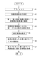
次に、図4に示すフローチャートを参照し、本装置1が角膜後面に関する情報を取得する際の測定動作を説明する。
<Operation>
Next, with reference to the flowchart shown in FIG. 4, a measurement operation when the present device 1 acquires information regarding the posterior surface of the cornea will be described.
まず、被検眼に対する光学系のアライメントが行われる(S1)。ここでは、制御部100が装置の各部を制御することによって、アライメントが自動的に行われる場合を示す。但し、アライメントは、手動で行われてもよい。また、手動によるアライメント(粗調整)と、自動的なアライメント(微調整)との組み合わせにより行われてもよい。
First, alignment of the optical system with respect to the eye to be examined is performed (S1). Here, a case is shown in which alignment is automatically performed by the
アライメントに際して、制御部100は、固視灯51aと、投影光学系30の光源31b,31c,31f,31gと、を点灯させる。また、制御部100は、光源31b,31c,31f,31gの点灯に伴って撮像素子27から出力される撮像信号に基づいて、被検眼Eの前眼部像のライブ画像(観察画像)をモニタ70に表示させる。また、制御部100は、アライメント基準位置(ここでは、光軸L1の位置)を示すレクチルを、モニタ70上に電子的に表示させてもよい。このとき、検者は、被検者に、固視標を固視するよう促す。
During alignment, the
その後、制御部100は、光源31b,31c,31f,31gによる指標を、撮像素子27からの撮像信号に基づいて検出する。制御部100は、アライメント移動機構60を、検出結果に基づいて駆動させることによって、4つの指標像Ib1,Ic1,If1,Ig1の中心が、アライメント基準位置(ここでは、光軸L1の位置)に配置されるように眼科測定装置1の光学系を移動させる。また、制御部100は、作動距離検出用の指標(図示せず)を投影すると共に、撮像素子27からの撮像信号に基づいてアライメント移動機構60を制御することで、装置から角膜頂点までの距離(つまり、作動距離)が、所定の距離となるように、前後方向のアライメントを行う。本実施例において、制御部100は、アライメント完了後に、光源31を消灯する。
Thereafter, the
次に、制御部100は、角膜前面形状を測定する(S2)。本実施形態における角膜前面形状の測定は、投影光学系30とは別に設けられたトポ投影光学系10から、角膜前面形状測定用の測定指標が角膜へ投影されることによって行われる。ここでは、多重リングによる測定指標がトポ投影光学系10から角膜へ投影される。そして、測定指標の角膜前面反射像である多重リング像、を含む前眼部画像が撮影光学系20を介して撮影される。前眼部画像に含まれる多重リング像に基づいて、制御部100は、角膜前面形状を示す情報を取得する。撮影または測定完了後、トポ投影光学系10の光源11は消灯される。
Next, the
次に、S3~S7の処理が制御部100によって実行され、これにより、本装置1によって角膜後面に関する測定が行われる。
Next, the processes of S3 to S7 are executed by the
まず、制御部100は、投影光学系30から被検眼Eの角膜に対し、第1測定指標と第2測定指標とを投影し、その状態で、前眼部画像を撮影する(S3)。例えば、投影光学系30の光源31a~光源31hが一斉に点灯される。そして、この状態において、撮影光学系20を介して、前眼部画像が撮影される。このようにして撮影された前眼部画像には、図3に示すように、第1測定指標および第2測定指標のそれぞれについての第1プルキンエ像Ia1~Ih1、第2プルキンエ像Ia2~Ih2、および第4プルキンエ像Ia4~Ih4のそれぞれが含まれる。
First, the
次に、制御部100は、前眼部画像における、第1プルキンエ像Ia1~Ih1、および、第2プルキンエ像Ia2~Ih2の位置を特定する(S4)。
Next, the
第1プルキンエ像Ia1~Ih1は他のプルキンエ像に対し、光軸L1からより離れた位置に形成されること、および、より明るく形成されること(但し、明るい箇所ほど暗く表現される画像では、より暗い像として形成される)、等の特性の違いを利用して、前眼部画像から第1プルキンエ像Ia1~Ih1は検出され、その位置が特定されてもよい。なお、本実施例では、検出されたプルキンエ像の中心位置、又は、重心位置が、そのプルキンエ像の位置として特定されてもよい。また、検出されたプルキンエ像における輝度値のピーク位置が、そのプルキンエ像の位置として特定されてもよい。 The first Purkinje images Ia1 to Ih1 are formed at a position farther from the optical axis L1 than the other Purkinje images, and are formed brighter (however, in an image where the brighter parts are darker, The first Purkinje images Ia1 to Ih1 may be detected from the anterior segment image and their positions may be specified by utilizing differences in characteristics such as (formed as darker images). Note that in this embodiment, the center position or center of gravity of the detected Purkinje image may be specified as the position of the Purkinje image. Further, the peak position of the luminance value in the detected Purkinje image may be specified as the position of the Purkinje image.
前眼部画像における第2プルキンエ像Ia2~Ih2は、光軸L1と第1プルキンエ像Ia1~Ih1との間に形成される。従って、制御部100は、前眼部画像において、例えば、光軸L1と第1プルキンエ像Ia1~Ih1との間で、輝度値が閾値よりも大きな(明るい箇所ほど暗く表現される画像では、閾値よりも小さな)領域を第2プルキンエ像として検出できる。
The second Purkinje images Ia2 to Ih2 in the anterior segment image are formed between the optical axis L1 and the first Purkinje images Ia1 to Ih1. Therefore, in the anterior segment image, for example, between the optical axis L1 and the first Purkinje images Ia1 to Ih1, the
続いて、制御部100は、図5に示すようにモニタ70に修正画面200を表示させる(S5)。修正画面200は、制御部100では検出できなかったプルキンエ像の位置を指定したり、制御部100によって検出されたプルキンエ像の位置を修正したりするための画面である。例えば、修正画面200には、前眼部画像と、前眼部画像上に重畳されるポインタPが表示される(図5(a))。ポインタPの形状は、例えば、範囲内にプルキンエ像があることを示すための閉曲線(円または四角形など)であってもよいし、一点を指定する矢印などであってもよい。もちろん、ポインタPの形状または大きさは変更できてもよい。検者は、操作部80の操作(マウスのクリック、画面タッチまたはキーボード入力など)によりポインタPの位置を移動させ、前眼部画像上のプルキンエ像の位置を指定する(図5(b))。検者は、複数のプルキンエ像の位置を指定してもよい。制御部100は、ポインタPによって指定された点または領域の位置情報(指定位置情報と称する)を取得し、メモリなどに記憶させる。
Subsequently, the
なお、S4において、制御部100は、図6に示すように、自動検出された輝点の検出位置201と、その位置に対するフィッティング結果202を修正画面200に表示してもよい。プルキンエ像は輝点でしかないため、輝点単体では涙液による反射、または他のプルキンエ像(例えば、第2プルキンエ像と第4プルキンエ像)との区別が困難である。不正乱視でない限り第1、第2プルキンエ像は楕円フィッティング可能であるため、制御部100は、現在検出している輝点がどれくらい楕円にフィットするかをリアルタイムで表示してもよい。これによって、検者は、フィッティングされた楕円を確認することで、検出位置201の修正などを好適に行うことができる。プルキンエ像の検出位置201を修正する場合、例えば、検者は、モニタ70に表示されたプルキンエ像の検出位置の一つを選択した状態で、前眼部画像上の他の位置をポインタPなどによって指定する。
Note that in S4, the
なお、制御部100は、修正画面200に楕円のパラメータ(長径、短径、中心座標、回転角など)、フィッティング誤差などを表示してもよい。フィッティング誤差は、例えば、輝点と楕円との距離に基づくパラメータであってもよい。フィッティングする図形は、角膜の形状に合っていれば楕円でなくてもよい。
Note that the
次いで、制御部100は、得られた指定位置情報に基づいて、プルキンエ像の検出を行う(S6)。例えば、制御部100は、ポインタPによって指定された点の周辺、または指定された領域内において、プルキンエ像の検出を行う。このように、ポインタPによってプルキンエ像の位置がある程度求められることによって、制御部100によるプルキンエ像の検出確率が高まる。また、検者が用いる操作部(入力デバイス等)によって位置指定の精度が限られるため、指定位置情報に基づいてさらに検出処理を行うことによって、より正確なプルキンエ像の位置を取得できる。
Next, the
制御部100は、プルキンエ像を検出すると、例えば、特定された第2プルキンエ像の検出位置に少なくとも基づいて、角膜後面に関する情報を取得する(S7)。
Upon detecting the Purkinje image, the
角膜後面に関する情報を求める場合、第2プルキンエ像に少なくとも基づいた光線追跡法(光線追跡シミュレーション)が利用されてもよい。この場合、所定の経線毎(なお、経線は、測定指標と光軸L1を含む面上の線)に角膜後面の曲率が求められる。 When obtaining information regarding the posterior corneal surface, a ray tracing method (ray tracing simulation) based at least on the second Purkinje image may be used. In this case, the curvature of the posterior corneal surface is determined for each predetermined meridian (the meridian is a line on the plane that includes the measurement index and the optical axis L1).
光線追跡法では、まず、角膜前面モデルを想定する。角膜前面モデルは、角膜前面における中心近傍の領域を球面近似したモデルであってもよい。この角膜前面モデルの形状は、例えば、S2の処理によって取得された、角膜前面形状を示す情報に基づく曲率または形状にて形成されてもよい。これに代えて、撮像面上における第1プルキンエ像の位置から、撮影光学系20の光路を逆に辿って角膜前面へ投影され、角膜前面で反射されることによって、光源31a~31hに到る光線を満足するような角膜前面の形状の条件(ここでは、角膜前面の曲率)を求めてもよい。
In the ray tracing method, first, a corneal anterior surface model is assumed. The corneal anterior surface model may be a model in which a region near the center of the corneal anterior surface is approximated to a spherical surface. The shape of this corneal anterior surface model may be formed, for example, with a curvature or shape based on information indicating the corneal anterior surface shape acquired by the process of S2. Instead, from the position of the first Purkinje image on the imaging plane, it is projected onto the front surface of the cornea by tracing the optical path of the photographing
次に、角膜前面モデルの形状と、第2プルキンエ像の位置情報とに基づいて、角膜後面の形状が導出される。例えば、第2プルキンエ像に基づく光線追跡シミュレーションによって、角膜後面の形状を求めてもよい。この場合、予め形状を求めた角膜前面モデルと、角膜後面における中心近傍の領域を球面近似した角膜後面モデルと、を想定する。角膜後面モデルは、角膜前面モデルに対し、角膜の基準位置(光軸L1が通過する位置、例えば、角膜頂点)において、角膜厚の分だけ眼底側に配置される。角膜厚には、例えば、超音波測定方式等のパキ測定等によって予め求めた値が適用されてもよい。なお、測定光学系40によって角膜厚が測定される場合、その測定結果が、角膜前面モデルと角膜後面モデルとの角膜厚として適用されてもよい。
Next, the shape of the posterior corneal surface is derived based on the shape of the anterior corneal model and the position information of the second Purkinje image. For example, the shape of the posterior corneal surface may be determined by ray tracing simulation based on the second Purkinje image. In this case, a corneal anterior surface model whose shape is determined in advance and a corneal posterior surface model in which a region near the center of the corneal posterior surface is approximated as a spherical surface are assumed. The posterior corneal model is placed closer to the fundus than the anterior corneal model by the thickness of the cornea at the reference position of the cornea (the position through which the optical axis L1 passes, for example, the corneal apex). For example, a value determined in advance by Paki measurement using an ultrasonic measurement method may be applied to the corneal thickness. Note that when the corneal thickness is measured by the measurement
そして、角膜後面モデルの曲率を変数とし、撮像面上における第2プルキンエ像の位置から、撮影光学系20の光路を逆に辿って角膜前面(より詳細には、第1プルキンエ像を生じさせる位置)を介して角膜後面で反射され、光源11に到る光線を満足するような角膜後面の形状の条件(ここでは、角膜後面の曲率)を求める。角膜の屈折率には、例えば、人眼の平均値等の既定値(n≒1.33等)が使用されてもよい。このようにして、角膜後面モデルの曲率を求めることで、被検眼における角膜後面の曲率を得ることができる。このとき、角膜後面の形状、および、位置についても得ることができる。
Then, using the curvature of the posterior corneal surface model as a variable, the optical path of the photographing
なお、第2プルキンエ像に少なくとも基づいて角膜の形状に関する情報を取得する手法は、上記の光線追跡法に限定されるものではなく、例えば、第2プルキンエ像の位置情報に基づく演算等の他の手法によって求められてもよい。 Note that the method of acquiring information regarding the shape of the cornea based at least on the second Purkinje image is not limited to the above-mentioned ray tracing method, but may also include other methods such as calculation based on the position information of the second Purkinje image. It may be determined by a method.
このようにして得た、角膜前面の形状と、角膜後面の形状とに基づいて、制御部100は、角膜厚の分布、角膜屈折力およびその分布、角膜における乱視軸、等の各種の角膜後面に関する情報を、求めることができる。これらの導出手法については、例えば、本出願人による「特開2015-104554号公報」等を参照されたい。
Based on the shape of the anterior surface of the cornea and the shape of the posterior surface of the cornea obtained in this way, the
以上のように、本装置1は、上記構成を備えることによって、前眼部画像からプルキンエ像を自動で検出することができない場合であっても、検者が指定した位置に基づいて被検眼の形状情報を取得することができるため、前眼部画像の撮り直しを省略できる。例えば、第2プルキンエ像と第4プルキンエ像が近傍に形成される場合、または睫の反射などによる輝点が発生した場合であっても、より好適に第2プルキンエ像を検出できる。 As described above, by having the above configuration, the present device 1 can detect the subject's eye based on the position specified by the examiner even when it is not possible to automatically detect the Purkinje image from the anterior segment image. Since the shape information can be acquired, retaking the anterior segment image can be omitted. For example, even if the second Purkinje image and the fourth Purkinje image are formed close to each other, or even if a bright spot is generated due to the reflection of the eyelashes, the second Purkinje image can be detected more preferably.
なお、制御部100は、修正画面200上の前眼部画像において、検者がプルキンエ像の位置を指定し易いように、輝点の視認性が向上するような画像処理を行ってもよい。例えば、制御部100は、局所的にコントラストを強調させる画像処理(例えば、CLAHEなど)を行ってもよいし、Hessian行列の固有値に基づいて構造により強調する画像処理(例えば、ブロブネスフィルタの適用)を行ってもよい。
Note that the
なお、制御部100は、S4において、プルキンエ像の検出に成功したか否かを判定してもよい。制御部100は、例えば、現在検出できている輝点に対して楕円フィッティングし、そのときのフィッティング誤差に基づいて検出の成否を判定してもよい。例えば、自動検出された各輝点に対して第2プルキンエ像らしさ(位置、輝度、形状、大きさなど)のスコア付けを行い、そのスコアの値に基づいて検出の成否を判定してもよい。例えば、スコアの値が所定値以上であれば第2プルキンエ像の検出に成功したと判定し、スコアの値が所定値未満であれば第2プルキンエ像の検出に失敗したと判定してもよい。例えば、制御部100は、検出成否の判定結果をモニタ70に表示させてもよい。これによって、制御部100は、プルキンエ像の位置指定または修正を検者に促すことができる。なお、制御部100は、プルキンエ像の検出に失敗したと判定したときにのみ、検出に失敗したことをモニタ70に表示するようにしてもよい。
Note that the
なお、制御部100は、図6に示すように、自動検出された輝点の位置の他に、プルキンエ像である可能性のある候補点203を修正画面200の前眼部画像上に表示させてもよい。これによって、検者は、主にプルキンエ像の候補点203を確認するだけでよくなり、プルキンエ像を探す手間が少なくて済む。例えば、検者は、いつくかの候補点203の中から最もプルキンエ像らしい候補点203を指定することによって、プルキンエ像の位置を指定してもよい。
Note that, as shown in FIG. 6, in addition to the automatically detected bright point position, the
なお、制御部100は、自動検出された輝点の検出位置201またはプルキンエ像の候補点203のうち、検者に指定されたものについて、形状情報の解析処理から除外するようにしてもよい。これによって、プルキンエ像ではない他の輝点等の検出位置201に基づいて角膜形状が算出されてしまうことを防止できる。例えば、検者は、前眼部画像上に表示されたプルキンエ像の検出位置201または候補点203のうち、明らかにプルキンエ像ではない輝点、または第1~4プルキンエ像のいずれであるか判別できない輝点などを、操作部80の操作によって角膜形状の解析に使用しないように指定する。この場合、制御部100は、指定された検出位置201または候補点203を除く位置に基づいて被検眼の形状情報を取得してもよい。
Note that the
なお、前眼部画像上にポインタP等を重畳表示させる場合、ポインタPによってプルキンエ像が隠れて位置が分からなくなる可能性がある。このような場合、制御部100は、前眼部画像上でポインタPを点滅表示させてもよい。これによって、前眼部画像上のプルキンエ像の位置を見失うことなく、ポインタPによってプルキンエ像の位置を指定することができる。また、確認用の前眼部画像と、操作用の前眼部画像をモニタ70に両方表示させ、確認用の前眼部画像でプルキンエ像の位置を確認しながら操作用の前眼部画像に表示されたポインタPを移動させてプルキンエ像の位置を指定するようにしてもよい。
Note that when a pointer P or the like is superimposed and displayed on the anterior segment image, the Purkinje image may be hidden by the pointer P and its position may not be known. In such a case, the
なお、S6において、検者の指定による指定位置情報に基づいてプルキンエ像を検出するものとしたが、これに限らない。例えば、S6の処理は行わず、S7において、指定位置情報そのものを用いて角膜形状に関する情報を取得してもよい。 Note that in S6, the Purkinje image is detected based on the specified position information specified by the examiner, but the present invention is not limited to this. For example, information regarding the corneal shape may be acquired using the designated position information itself in S7 without performing the process in S6.
なお、以上の実施例において、第2プルキンエ像を検出して角膜後面に関する角膜形状情報を取得することを主に説明したが、制御部100は、他の像に基づいて角膜形状情報を取得してもよい。例えば、角膜前面の反射光による輝点である第1プルキンエ像、水晶体前面の反射光による輝点である第3プルキンエ像、水晶体後面の反射光による輝点である第4プルキンエ像などの位置を検出し、角膜前面、水晶体前面、水晶体後面などの形状情報を取得してもよい。
Note that in the above embodiments, it has been mainly explained that corneal shape information regarding the posterior surface of the cornea is acquired by detecting the second Purkinje image, but the
上記実施例では、角膜前面形状を測定するために、投影光学系30とは別にトポ投影光学系10が設けられているが、必ずしもこれに限られるものではない。例えば、投影光学系30から角膜後面に関する情報を得るために投影される測定指標が、角膜前面形状を測定するための測定指標として、兼用されてもよい。この場合、投影光学系30からの測定指標による第1プルキンエ像に基づいて、制御部100は角膜前面形状を算出する。より詳細には、本出願人による「特開2003―111727号公報」を参考にされたい。なお、上記実施例では、投影光学系30が1重のリング指標を投影するのに対し、トポ投影光学系10は、多重リングを(「第3測定指標」として)投影する。つまり、投影光学系30からの測定指標と比べて、少なくとも経線方向に関する測定ポイントが、トポ投影光学系10から投影される指標のほうが多いので、詳細に角膜前面形状を測定することができる。また、トポ投影光学系10が、投影光学系30を兼用してもよい。
In the above embodiment, the topo projection
以上、実施例に基づいて本開示を説明したが、本開示は、上記実施例に限定されるものではなく、種々の変形が可能である。また、本開示は、以下の処理を実行することによっても実現される。即ち、上述した実施形態の機能を実現するソフトウェア(プログラム)を、ネットワーク又は各種記憶媒体を介してシステム或いは装置に供給し、そのシステム或いは装置のコンピュータ(またはCPUやMPU等)がプログラムを読み出して実行する処理である。 Although the present disclosure has been described above based on the embodiments, the present disclosure is not limited to the embodiments described above, and various modifications are possible. Further, the present disclosure is also realized by performing the following processing. That is, the software (program) that realizes the functions of the embodiments described above is supplied to a system or device via a network or various storage media, and the computer (or CPU, MPU, etc.) of the system or device reads the program. This is the process to be executed.
1 眼科測定装置
31a~31d 第1測定指標
31e~31h 第2測定指標
10 トポ投影光学系
20 撮影光学系
27 撮像素子
30 投影光学系
50 固視光学系
1
Claims (2)
前記被検眼の前眼部に指標を投影する投影光学系と、
前記指標が投影された前記前眼部を撮影することによって、前記被検眼の前眼部画像を取得する撮影手段と、
前記前眼部画像において、前記指標によるプルキンエ像に関する位置を検者が指定したときの指定位置情報を取得する位置情報取得手段と、
前記指定位置情報に基づいて前記前眼部の形状情報を取得する演算手段と、を備え、
前記投影光学系は、前記前眼部に複数の指標を投影し、
前記演算手段は、前記前眼部画像から検出された前記複数のプルキンエ像の検出位置に対してフィッティング処理を行うことで取得されたフィッティング結果の図形を、前記プルキンエ像に関する位置を修正するために表示手段に表示された修正画面に表示させることを特徴とする眼科測定装置。 An ophthalmological measuring device for measuring an eye to be examined,
a projection optical system that projects an index onto the anterior segment of the eye to be examined;
a photographing means for acquiring an anterior segment image of the eye to be examined by photographing the anterior segment on which the index is projected;
a position information acquisition means for acquiring specified position information when an examiner specifies a position related to the Purkinje image using the index in the anterior segment image;
a calculation means for acquiring shape information of the anterior segment based on the specified position information ,
The projection optical system projects a plurality of indicators onto the anterior segment of the eye,
The calculation means performs a fitting process on the detection positions of the plurality of Purkinje images detected from the anterior segment image, and uses the figure of the fitting result to correct the position related to the Purkinje image. An ophthalmological measurement device characterized in that the correction screen is displayed on a display means .
Priority Applications (1)
| Application Number | Priority Date | Filing Date | Title |
|---|---|---|---|
| JP2019201814A JP7415453B2 (en) | 2019-11-06 | 2019-11-06 | Ophthalmology measuring device |
Applications Claiming Priority (1)
| Application Number | Priority Date | Filing Date | Title |
|---|---|---|---|
| JP2019201814A JP7415453B2 (en) | 2019-11-06 | 2019-11-06 | Ophthalmology measuring device |
Publications (3)
| Publication Number | Publication Date |
|---|---|
| JP2021074101A JP2021074101A (en) | 2021-05-20 |
| JP2021074101A5 JP2021074101A5 (en) | 2022-10-11 |
| JP7415453B2 true JP7415453B2 (en) | 2024-01-17 |
Family
ID=75899111
Family Applications (1)
| Application Number | Title | Priority Date | Filing Date |
|---|---|---|---|
| JP2019201814A Active JP7415453B2 (en) | 2019-11-06 | 2019-11-06 | Ophthalmology measuring device |
Country Status (1)
| Country | Link |
|---|---|
| JP (1) | JP7415453B2 (en) |
Citations (4)
| Publication number | Priority date | Publication date | Assignee | Title |
|---|---|---|---|---|
| JP2015085081A (en) | 2013-11-01 | 2015-05-07 | 株式会社コーナン・メディカル | Ophthalmologic examination apparatus |
| JP2015104554A (en) | 2013-11-29 | 2015-06-08 | 株式会社ニデック | Ophthalmologic measuring device and ophthalmologic measuring program |
| JP2018029864A (en) | 2016-08-26 | 2018-03-01 | 株式会社トプコン | Ophthalmic apparatus and alignment method for ophthalmic apparatus |
| JP2018089082A (en) | 2016-12-01 | 2018-06-14 | 株式会社ニデック | Ophthalmologic measuring apparatus |
-
2019
- 2019-11-06 JP JP2019201814A patent/JP7415453B2/en active Active
Patent Citations (4)
| Publication number | Priority date | Publication date | Assignee | Title |
|---|---|---|---|---|
| JP2015085081A (en) | 2013-11-01 | 2015-05-07 | 株式会社コーナン・メディカル | Ophthalmologic examination apparatus |
| JP2015104554A (en) | 2013-11-29 | 2015-06-08 | 株式会社ニデック | Ophthalmologic measuring device and ophthalmologic measuring program |
| JP2018029864A (en) | 2016-08-26 | 2018-03-01 | 株式会社トプコン | Ophthalmic apparatus and alignment method for ophthalmic apparatus |
| JP2018089082A (en) | 2016-12-01 | 2018-06-14 | 株式会社ニデック | Ophthalmologic measuring apparatus |
Also Published As
| Publication number | Publication date |
|---|---|
| JP2021074101A (en) | 2021-05-20 |
Similar Documents
| Publication | Publication Date | Title |
|---|---|---|
| US5889576A (en) | Ophthalmic apparatus | |
| JP6444666B2 (en) | Ophthalmic photographing apparatus and ophthalmic information processing apparatus | |
| EP2415393B1 (en) | Ophthalmic apparatus | |
| JP2018149449A (en) | Ophthalmic photographing apparatus and ophthalmic information processing apparatus | |
| EP2382912B1 (en) | Ophthalmic apparatus | |
| JP2017080136A (en) | Ophthalmologic apparatus | |
| JP2013135837A (en) | Ophthalmic apparatus and ophthalmic program | |
| JP5767026B2 (en) | Anterior segment measurement device | |
| JP2022101653A (en) | Ophthalmologic measurement device | |
| JP6238552B2 (en) | Ophthalmic apparatus, control method for ophthalmic apparatus, and program | |
| JP6736356B2 (en) | Ophthalmic equipment | |
| JP2007215950A (en) | Ophthalmic apparatus | |
| JP7149519B2 (en) | Eye measurement device and method | |
| US11445903B2 (en) | Vision test device | |
| JP7415453B2 (en) | Ophthalmology measuring device | |
| JP2019058437A (en) | Ophthalmologic apparatus | |
| JP7367509B2 (en) | Ophthalmology measurement equipment, ophthalmology measurement system, and ophthalmology measurement program | |
| CN113456017A (en) | Ophthalmic device | |
| JP5460490B2 (en) | Ophthalmic equipment | |
| JP6823339B2 (en) | Ophthalmic equipment | |
| JP6480748B2 (en) | Ophthalmic equipment | |
| JP7248770B2 (en) | ophthalmic equipment | |
| JP6635638B1 (en) | Detection device, program, and detection method | |
| JP7459491B2 (en) | Ophthalmology measuring device | |
| US20230240526A1 (en) | Tomographic image processing device and program |
Legal Events
| Date | Code | Title | Description |
|---|---|---|---|
| A521 | Request for written amendment filed |
Free format text: JAPANESE INTERMEDIATE CODE: A523 Effective date: 20220930 |
|
| A621 | Written request for application examination |
Free format text: JAPANESE INTERMEDIATE CODE: A621 Effective date: 20220930 |
|
| A977 | Report on retrieval |
Free format text: JAPANESE INTERMEDIATE CODE: A971007 Effective date: 20230428 |
|
| A131 | Notification of reasons for refusal |
Free format text: JAPANESE INTERMEDIATE CODE: A131 Effective date: 20230516 |
|
| A601 | Written request for extension of time |
Free format text: JAPANESE INTERMEDIATE CODE: A601 Effective date: 20230713 |
|
| A521 | Request for written amendment filed |
Free format text: JAPANESE INTERMEDIATE CODE: A523 Effective date: 20230913 |
|
| TRDD | Decision of grant or rejection written | ||
| A01 | Written decision to grant a patent or to grant a registration (utility model) |
Free format text: JAPANESE INTERMEDIATE CODE: A01 Effective date: 20231205 |
|
| A61 | First payment of annual fees (during grant procedure) |
Free format text: JAPANESE INTERMEDIATE CODE: A61 Effective date: 20231218 |
|
| R150 | Certificate of patent or registration of utility model |
Ref document number: 7415453 Country of ref document: JP Free format text: JAPANESE INTERMEDIATE CODE: R150 |