JP7414552B2 - vehicle - Google Patents
vehicle Download PDFInfo
- Publication number
- JP7414552B2 JP7414552B2 JP2020010522A JP2020010522A JP7414552B2 JP 7414552 B2 JP7414552 B2 JP 7414552B2 JP 2020010522 A JP2020010522 A JP 2020010522A JP 2020010522 A JP2020010522 A JP 2020010522A JP 7414552 B2 JP7414552 B2 JP 7414552B2
- Authority
- JP
- Japan
- Prior art keywords
- music
- driver
- vehicle
- speed
- section
- Prior art date
- Legal status (The legal status is an assumption and is not a legal conclusion. Google has not performed a legal analysis and makes no representation as to the accuracy of the status listed.)
- Active
Links
- 230000036651 mood Effects 0.000 claims description 42
- 230000005540 biological transmission Effects 0.000 claims description 32
- 230000008921 facial expression Effects 0.000 claims description 5
- 230000033764 rhythmic process Effects 0.000 claims description 5
- 230000004397 blinking Effects 0.000 claims description 3
- 230000001815 facial effect Effects 0.000 claims description 3
- 238000000034 method Methods 0.000 description 21
- 238000010586 diagram Methods 0.000 description 10
- 239000012530 fluid Substances 0.000 description 4
- 230000001133 acceleration Effects 0.000 description 3
- 230000005281 excited state Effects 0.000 description 3
- 230000006870 function Effects 0.000 description 3
- 238000002485 combustion reaction Methods 0.000 description 1
- 238000004880 explosion Methods 0.000 description 1
- 230000014509 gene expression Effects 0.000 description 1
- 239000000463 material Substances 0.000 description 1
- 238000012986 modification Methods 0.000 description 1
- 230000004048 modification Effects 0.000 description 1
- 230000002093 peripheral effect Effects 0.000 description 1
- 230000035807 sensation Effects 0.000 description 1
Images


Landscapes
- Control Of Transmission Device (AREA)
- User Interface Of Digital Computer (AREA)
Description
本発明は、車両に関する。 The present invention relates to a vehicle.
従来、車両のエンジンから出力される動力を変速して出力する変速機がある。また、このような変速機において、複数の変速モードのいずれかに基づいて変速制御が実行するものがある(例えば、特許文献1を参照)。 2. Description of the Related Art Conventionally, there is a transmission that changes the speed of power output from a vehicle engine and outputs the same. Further, in some such transmissions, shift control is executed based on one of a plurality of shift modes (see, for example, Patent Document 1).
しかしながら、複数の変速モードを備えた場合、変速モードを切り替えることがドライバにとって煩わしく、ドライバが快適にドライブすることができないという問題があった。 However, when a plurality of speed change modes are provided, there is a problem in that switching between speed change modes is troublesome for the driver, and the driver cannot drive comfortably.
そこで、本発明は、このような課題に鑑み、ドライバが快適にドライブすることができる車両を提供することを目的とする。 SUMMARY OF THE INVENTION In view of these problems, an object of the present invention is to provide a vehicle that allows a driver to drive comfortably.
上記課題を解決するために、本発明の車両は、ドライバの生体情報を取得する生体情報取得部と、前記生体情報に基づいて、前記ドライバの状態を判定する状態判定部と、前記状態判定部の判定結果に基づいて、予め定められた複数の変速段を切り替え可能な変速機における変速制御を実行する変速制御部と、を備え、前記変速制御部は、前記状態判定部によって前記ドライバの気分が高揚していると判定された場合と、前記状態判定部によって前記ドライバの気分が高揚していないと判定された場合とで、前記変速機における使用可能な前記変速段を異ならして、前記変速制御を実行し、前記状態判定部は、前記ドライバの表情、瞬き、口の動き、顔面の温度の少なくともいずれかに基づいて、前記ドライバの気分が高揚しているかどうかを判定する。 In order to solve the above problems, the vehicle of the present invention includes a biometric information acquisition section that obtains biometric information of a driver, a state determination section that determines the state of the driver based on the biometric information, and a state determination section that determines the state of the driver based on the biometric information. a shift control section that executes shift control in a transmission capable of switching between a plurality of predetermined gear stages based on a determination result of The usable gears in the transmission are different depending on whether the driver is determined to be in a high mood or in a case where the state determination unit determines that the driver is not in a high mood. The state determination section executes the speed change control, and determines whether the driver is in a high mood based on at least one of the driver's facial expression, blinking, mouth movement, and facial temperature.
また、車両内で再生する楽曲の情報を取得する楽曲情報取得部と、前記楽曲の情報に基づいて、前記楽曲を判定する楽曲判定部と、を備え、前記変速制御部は、前記状態判定部の判定結果に加えて、前記楽曲判定部の判定結果に基づいて、前記変速制御を実行してもよい。 The gear change control unit further includes a music information acquisition unit that acquires information on music to be played in the vehicle, and a music determination unit that determines the music based on the information on the music, and the shift control unit includes the state determination unit In addition to the determination result of the music determining section, the speed change control may be performed based on the determination result of the music determining section.
また、前記変速制御部は、前記楽曲判定部の判定結果が特定結果である場合と、前記楽曲判定部の判定結果が前記特定結果ではない場合とで、使用可能な前記変速段を異ならして、前記変速制御を実行可能であってもよい。 Further, the shift control section may set the usable gears to be different depending on a case where the judgment result of the music judgment section is a specific result and a case where the judgment result of the music judgment section is not the specific result. , the speed change control may be executable.
また、前記楽曲判定部の判定結果が前記特定結果である場合は、前記楽曲判定部によって前記楽曲が、前記ドライバの気分を高揚させ得る楽曲であると判定された場合であってもよい。 Moreover, when the determination result of the music determination unit is the specific result, the music determination unit may determine that the music is a music that can lift the driver's mood.
また、前記楽曲判定部は、前記楽曲のテンポ、リズムの少なくともいずれかに基づいて、前記楽曲が、前記ドライバの気分を高揚させ得る楽曲であるどうかを判定してもよい。 Further, the music determining unit may determine whether the music is a music that can lift the driver's mood based on at least one of the tempo and rhythm of the music.
また、前記変速機は有段変速機であってもよい。 Further, the transmission may be a stepped transmission.
また、前記変速機は無段変速機であってもよい。 Further, the transmission may be a continuously variable transmission.
本発明によれば、ドライバが快適にドライブすることができる。 According to the present invention, a driver can drive comfortably.
以下に添付図面を参照しながら、本発明の好適な実施形態について詳細に説明する。かかる実施形態に示す寸法、材料、その他具体的な数値等は、発明の理解を容易にするための例示に過ぎず、特に断る場合を除き、本発明を限定するものではない。なお、本明細書および図面において、実質的に同一の機能、構成を有する要素については、同一の符号を付することにより重複説明を省略し、また本発明に直接関係のない要素は図示を省略する。 DESCRIPTION OF THE PREFERRED EMBODIMENTS Preferred embodiments of the present invention will be described in detail below with reference to the accompanying drawings. The dimensions, materials, and other specific numerical values shown in these embodiments are merely illustrative to facilitate understanding of the invention, and do not limit the invention unless otherwise specified. In this specification and the drawings, elements with substantially the same functions and configurations are given the same reference numerals to omit redundant explanation, and elements not directly related to the present invention are omitted from illustration. do.
図1は、車両100の駆動系の構成を示す図である。図1に示すように、車両100は、駆動源としてエンジン102およびモータ104を備える。
FIG. 1 is a diagram showing the configuration of a drive system of a
エンジン102は、内部を貫通するようにクランクシャフト102aが配置され、燃焼室における爆発圧力でピストンを往復動させてクランクシャフト102aを回転させる。
In the
モータ104は、例えば、U相、V相、W相を有する3相のブラシレスDCモータでなり、回転軸104aが回転子104bに固定される。モータ104は、後述するバッテリに接続され、当該バッテリから供給される電力により回転駆動し、また、回転軸104aが回転されることで電力を生成し、生成した電力でバッテリを充電する。
The
車両100は、エンジン102のクランクシャフト102aとモータ104の回転軸104aとの間に、エンジン102側から、トルクコンバータ106、油圧クラッチ108、および、変速機110が設けられる。
トルクコンバータ106は、クランクシャフト102aの他端に接続されたフロントカバー106aにポンプインペラ106bが固定され、フロントカバー106a内において、タービンシャフト106dに接続されたタービンランナ106cがポンプインペラ106bに対向配置される。また、トルクコンバータ106は、ポンプインペラ106bおよびタービンランナ106cの内周側の間にステータ106eが配置され、内部に作動流体が封入されている。なお、ステータ106eは、トルクコンバータ106、油圧クラッチ108、変速機110等を収容するハウジング112に固定される。
In the
ポンプインペラ106bおよびタービンランナ106cは、多数のブレードが設けられており、ポンプインペラ106bが回転することで作動流体が外周側に送出され、作動流体をタービンランナ106cに送ることでタービンランナ106cを回転させる。これにより、クランクシャフト102aからタービンランナ106cに動力が伝達される。
The
ステータ106eは、タービンランナ106cから送り出された作動流体の流動方向を変化させてポンプインペラ106bに還流させ、ポンプインペラ106bの回転を促進させる。そのため、トルクコンバータ106は伝達トルクを増幅することができる。
The
また、トルクコンバータ106は、タービンシャフト106dに固定されたクラッチプレート106fがフロントカバー106aの内面に対向配置される。クラッチプレート106fは、油圧によりフロントカバー106aに押し付けられることにより、クランクシャフト102aからタービンシャフト106dに動力が伝達される。また、油圧を制御することでクラッチプレート106fがフロントカバー106aに滑りながら当接することにより、クランクシャフト102aからタービンシャフト106dへ伝達される動力を調整することができる。
Further, in the
このような構成でなる車両100は、油圧クラッチ108の接続状態を切り替えることにより、エンジン102およびモータ104の一方または双方で走行する。油圧クラッチ108は、タービンシャフト106dと回転軸104aとの間の動力の伝達を遮断する遮断状態と、タービンシャフト106dと回転軸104aとの間で動力が伝達される連結状態とを切り替えることができる。そして、車両100は、油圧クラッチ108を遮断状態にすることでモータ104のみで走行するモータ走行と、油圧クラッチ108を連結状態にし、モータ104を空転させたり発電機として機能させたりすることで、エンジン102のみで走行するエンジン走行と、油圧クラッチ108を連結状態にし、エンジン102およびモータ104を駆動することで、エンジン102およびモータ104の双方で走行するハイブリッド走行とが切り替え可能である。
本実施形態において、変速機110は、9段変速式の有段変速機(有段AT)であり、回転軸104aに設けられた複数の第1ギヤ110a、および、回転軸104aに平行に配置された出力軸114aに設けられた複数の第2ギヤ110bを含んで構成される。出力軸114aには駆動輪114が連結されており、エンジン102やモータ104から回転軸104aに伝達された動力は、変速機110を介して変速されて駆動輪114に伝達される。
In this embodiment, the
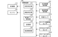
図2は、車両100の制御系の構成を示す図である。図2中、破線の矢印は制御信号の向きを示す。図2に示すように、車両100の制御系は、変速機110、エンジン102、制御装置150、生体情報取得部162、楽曲情報取得部164、車速センサ166a、エンジン回転数センサ166b、アクセルペダルセンサ166c、ブレーキペダルセンサ166dとを含んで構成される。
FIG. 2 is a diagram showing the configuration of the control system of
制御装置150は、中央処理装置(CPU)、プログラム等が格納されたROM、ワークエリアとしてのRAM等を含むマイクロコンピュータで構成され、車両100の各部を統括制御する。本実施形態において、制御装置150は、状態判定部152、楽曲判定部154、変速モード設定部156、記憶部158、変速制御部160としても機能する。
The
生体情報取得部162は、ドライバの生体情報を検出可能である。具体的には、例えば、生体情報取得部162は、ドライバの表情、瞬き、口の動きを検出可能な車載カメラや、ドライバの顔面の温度を検出可能な生体センサを用いることができる。本実施形態では、状態判定部152は、生体情報取得部162によって検出されたドライバの表情、瞬き、口の動き、顔面の温度の少なくともいずれかに基づいて、ドライバの状態(気分)が高揚状態であるかを判定する。
The biometric
具体的には、例えば、予め記憶部158に記憶されている気分が高揚している場合の表情パターンと、生体情報取得部162によって取得されたドライバの表情とが一致する場合に、ドライバの気分が高揚していると判定することができる。
Specifically, for example, if the expression pattern of the driver who is in a high mood, which is stored in advance in the
また、例えば、予め記憶部158に記憶されている気分が高揚している場合の瞬きパターンと、生体情報取得部162によって取得されたドライバの瞬きパターンとが一致する場合に、ドライバの気分が高揚していると判定することができる。
Further, for example, if the blink pattern of the driver who is in a high mood, which is stored in advance in the
また、例えば、予め記憶部158に記憶されている気分が高揚している場合の口の動きと、生体情報取得部162によって取得されたドライバの口の動きとが一致する場合に、ドライバの気分が高揚していると判定することができる。
Further, for example, if the mouth movement when the driver is in a high mood, which is stored in advance in the
また、例えば、予め記憶部158に記憶されている気分が高揚している場合の顔面の温度分布と、生体情報取得部162によって取得されたドライバの顔面の温度分布とが一致する場合に、ドライバの気分が高揚していると判定することができる。
Further, for example, if the temperature distribution of the face of the driver when the mood is high, which is stored in advance in the
楽曲情報取得部164は、車両100内で再生する楽曲の情報を取得可能である。具体的には、例えば、楽曲情報取得部164は、車両100内で再生中の楽曲を収音することができるマイクロフォンを用いることができる。本実施形態では、楽曲判定部154は、楽曲情報取得部164によって取得された車両100内で再生中の楽曲のテンポ、リズムの少なくともいずれかに基づいて、楽曲を判定する。具体的には、車両100内で再生中の楽曲がドライバの気分を高揚させ得る楽曲(所謂、ノリのいい楽曲)であるかを判定する。
The music
具体的には、例えば、予め記憶部158に記憶されている気分を高揚させ得る楽曲のテンポやリズムと、楽曲情報取得部164によって取得された車両100内で再生中の楽曲のテンポやリズムとが一致する場合に、ドライバの気分を高揚させ得る楽曲であると判定することができる。
Specifically, for example, the tempo and rhythm of a song that is pre-stored in the
変速モード設定部156は、上記の状態判定部152または楽曲判定部154の判定結果に基づいて、変速モードを設定する。本実施形態では、変速モードとして、通常変速モードと、通常変速モードと比較して変速段が多く設定されている特別変速モードのいずれかが設定可能である。
The shift
変速モード設定部156は、状態判定部152によってドライバの気分が高揚状態であると判定された場合(判定結果が所定結果であった場合)、変速モードとして特別変速モードに設定することを決定し、記憶部158に記憶された特別変速モードに対応した変速マップを選択する。また、変速モード設定部156は、状態判定部152によってドライバの気分が高揚状態ではないと判定された場合であって、楽曲判定部154によって車両100内で再生中の楽曲がドライバの気分を高揚させ得る楽曲であると判定された場合(判定結果が特定結果であった場合)にも、変速モードとして特別変速モードに設定することを決定し、記憶部158に記憶された特別変速モードに対応した変速マップを選択する。
When the state determining section 152 determines that the driver's mood is high (when the determination result is a predetermined result), the shift
一方、変速モード設定部156は、状態判定部152によってドライバの気分が高揚状態ではないと判定された場合、かつ、楽曲判定部154によって車両100内で再生中の楽曲がドライバの気分を高揚させ得る楽曲ではないと判定された場合には、変速モードとして特別変速モードに設定することを決定し、記憶部158に記憶された通常変速モードに対応した変速マップを選択する。
On the other hand, when the state determining section 152 determines that the driver's mood is not high, and the
変速マップには、有段変速における、各変速段間の変速条件が設定される。変速条件は、車速センサ166aが検出した車両100の車速、エンジン回転数センサ166bが検出したエンジン回転数、アクセルペダルセンサ166cが検出したアクセルペダルの踏込み量に基づいてアクセル開度およびアクセル開速度、ブレーキペダルセンサ166dが検出したブレーキ踏込み量によって規定される。
In the shift map, shift conditions between each gear stage in stepped transmission are set. The shift conditions include the accelerator opening degree and accelerator opening speed based on the vehicle speed of the
変速制御部160は、所定周期で取得した車速、エンジン回転数、アクセル開度およびアクセル開速度、ブレーキペダルの踏み込み量等に応じて、変速機110の変速制御を実行する。
The shift control unit 160 executes shift control of the
図3(a)は、通常変速モードが設定されている時のエンジンの回転数と車速の関係を示す説明図であり、図3(b)は、特別変速モードが設定されている時のエンジンの回転数と車速の関係を示す説明図である。 FIG. 3(a) is an explanatory diagram showing the relationship between the engine speed and vehicle speed when the normal shift mode is set, and FIG. 3(b) is an explanatory diagram showing the relationship between the engine speed and the vehicle speed when the special shift mode is set. FIG. 2 is an explanatory diagram showing the relationship between the rotation speed and the vehicle speed.
特別変速モードが設定されている時には、図3(a)に示すように、変速機110が有する多段の変速段のうちの全ての変速段の使用を許可した変速制御が実行される。すなわち、特別変速モードが設定されている時において使用が許可される変速段は、1速段(1st)、2速段(2nd)、3速段(3rd)、4速段(4th)、5速段(5th)、6速段(6th)、7速段(7th)、8速段(8th)および9速段(9th)となる。
When the special shift mode is set, as shown in FIG. 3(a), shift control is executed in which the use of all of the multiple gear stages of the
特別変速モードが設定されている場合の変速制御では、まず、車両100が発進した後、変速段は1速段(1st)になる。したがって、図3(a)に示すように、エンジン102の回転数は、加速に伴い1速段(1st)と対応する変速特性線に沿って上昇する。そして、車速が速度V1に到達したときにエンジン102の回転数が上限回転数Ntになり、変速段が1速段(1st)から2速段(2nd)へアップシフトされる。
In the shift control when the special shift mode is set, first, after the
次に、エンジン102の回転数は、加速に伴い2速段(2nd)と対応する変速特性線に沿って上昇する。そして、車速が速度V2に到達したときにエンジン102の回転数が上限回転数Ntになり、変速段が2速段(2nd)から3速段(3rd)へアップシフトされる。その後、加速に伴うエンジン102の回転数の上昇およびアップシフトが同様に繰り返される。具体的には、車速が速度V1、速度V2、速度V3、速度V4、速度V5、速度V6、速度V7、速度V8および速度V9にそれぞれ到達したときにエンジン102の回転数が上限回転数Ntになり、変速段が高速段側に隣り合う変速段へアップシフトされる。
Next, the rotational speed of the
一方、通常変速モードが設定されている場合の変速制御では、上述した特別変速モードが設定されている時に変速制御される多段の変速段のうちの一部の変速段を省略した変速制御が実行される。具体的には、図3(b)に示すように、図3(a)における2速段(2nd)、4速段(4th)、6速段(6th)、および8速段(8th)を省略した変速制御が実行される。したがって、通常変速モードが設定されている時において使用が許可される変速段は、1速段(1st)、3速段(3rd)、5速段(5th)、7速段(7th)および9速段(9th)となる。 On the other hand, in shift control when the normal shift mode is set, shift control is performed that omits some of the multiple gears that are controlled when the above-mentioned special shift mode is set. be done. Specifically, as shown in FIG. 3(b), the second gear (2nd), fourth gear (4th), sixth gear (6th), and eighth gear (8th) in FIG. 3(a) are The omitted shift control is executed. Therefore, the gears that are permitted to be used when the normal gear shift mode is set are 1st gear (1st), 3rd gear (3rd), 5th gear (5th), 7th gear (7th), and 9th gear. It becomes gear (9th).
通常変速モードが設定されている場合の変速制御では、まず、車両100が発進した後、変速段は1速段(1st)になる。したがって、図3(b)に示すように、エンジン102の回転数は、加速に伴い1速段(1st)と対応する変速特性線に沿って上昇する。そして、車速が速度V1に到達したときにエンジン102の回転数が上限回転数Ntになり、変速段が1速段(1st)から3速段(3rd)へアップシフトされる。次に、エンジン102の回転数は、加速に伴い3速段(3rd)と対応する変速特性線に沿って上昇する。そして、車速が速度V3に到達したときにエンジン102の回転数が上限回転数Ntになり、変速段が3速段(3rd)から5速段(5th)へアップシフトされる。その後、加速に伴うエンジン102の回転数の上昇およびアップシフトが同様に繰り返される。具体的には、車速が速度V1、速度V3、速度V5、速度V7および速度V9にそれぞれ到達したときにエンジン102の回転数が上限回転数Ntになり、変速段が高速段側に隣り合う変速段へアップシフトされる。
In the shift control when the normal shift mode is set, first, after the
本実施形態では、特別変速モードまたは通常変速モードが設定されている場合の両方において、アップシフトが行われる各車速間の間隔が、均一になるように設定されている。具体的には、特別変速モードが設定されている場合には、図3(a)に示すように、速度V1と速度V2との間隔と、速度V2と速度V3との間隔と、速度V3と速度V4との間隔と、速度V4と速度V5との間隔と、速度V5と速度V6との間隔と、速度V6と速度V7との間隔と、速度V7と速度V8との間隔と、速度V8と速度V9との間隔が、均一となっている。 In this embodiment, the intervals between vehicle speeds at which upshifts are performed are set to be uniform both when the special shift mode or the normal shift mode is set. Specifically, when the special shift mode is set, as shown in FIG. 3(a), the interval between speed V1 and speed V2, the interval between speed V2 and speed V3, and the interval between speed V3 and The interval between speed V4, the interval between speed V4 and speed V5, the interval between speed V5 and speed V6, the interval between speed V6 and speed V7, the interval between speed V7 and speed V8, and the interval between speed V8 and The distance from the speed V9 is uniform.
また、通常変速モードが設定されている場合には、図3(b)に示すように、速度V1と速度V3との間隔と、速度V3と速度V5との間隔と、速度V5と速度V7との間隔と、速度V7と速度V9との間隔が、均一となっている。 In addition, when the normal speed change mode is set, as shown in FIG. 3(b), the interval between speed V1 and speed V3, the interval between speed V3 and speed V5, and the interval between speed V5 and speed V7 are The interval between the speeds V7 and V9 is uniform.
このように、各変速モードにおいて、アップシフトが行われる各車速間の間隔が、均一になるように設定されているため、アップシフトが行われる際にドライバへ違和感を与えることを抑制することができる。 In this way, in each shift mode, the intervals between vehicle speeds at which upshifts are performed are set to be uniform, which prevents the driver from feeling uncomfortable when upshifting. can.
続いて、上述した制御処理の流れについて、フローチャートを用いて詳述する。 Next, the flow of the control processing described above will be explained in detail using a flowchart.
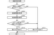
図4は、変速モード設定処理の流れを示すフローチャートである。変速モード設定処理では、ドライバの気分や、車両100内で再生中の音楽に基づいて、適切な変速モードを設定する。制御部120は、所定の割り込みタイミングにおいて、図4に示す一連の処理を実行する。なお、変速モード設定処理は、後述する変速制御処理と並行して遂行される。
FIG. 4 is a flowchart showing the flow of the speed change mode setting process. In the shift mode setting process, an appropriate shift mode is set based on the driver's mood and the music being played in the
まず、制御装置150は、ドライバの生体情報に基づいて、ドライバの気分を判定するドライバ状態判定処理(S100)を実行する。このドライバ状態判定処理については後述する。
First, the
次に、制御装置150は、ドライバの気分が高揚状態であることを示す第1フラグがオンであるか判定する(S10)。その結果、第1フラグがオンではなかった場合(S10のNO)には、制御装置150は、車両100内で再生中の楽曲の楽曲情報に基づいて、ドライバの気分を高揚させ得る楽曲が再生されているかを判定する楽曲判定処理(S200)を実行する。この楽曲判定処理については後述する。
Next, the
次に、制御装置150は、ドライバの気分を高揚させ得る楽曲が再生されていることを示す第2フラグがオンであるか判定する(S12)。その結果、第1フラグがオンである場合(S10のYES)、または、第2フラグがオンである場合(S12のYES)には、変速モード設定部156は、変速モードを特別変速モードに設定し、当該変速モード設定処理を終了する。
Next, the
一方、第2フラグがオフである場合(S12のNO)には、変速モード設定部156は、変速モードを通常変速モードに設定し、当該変速モード設定処理を終了する。なお、本実施形態では、変速制御において切り替えの対象となる変速段は段である。
On the other hand, if the second flag is off (NO in S12), the shift
図5は、ドライバ状態判定処理(S100)の流れを示すフローチャートである。ドライバ状態判定処理(S100)では、制御装置150は、ドライバの生体情報に基づいて、ドライバの気分を判定する。
FIG. 5 is a flowchart showing the flow of driver state determination processing (S100). In the driver state determination process (S100), the
まず、制御装置150は、生体情報取得部162からドライバの生体情報を取得する(S102)。状態判定部152は、生体情報取得部162から取得したドライバの生体情報を解析して、ドライバの気分を判定(推定)する(S104)。
First, the
そして、制御装置150(状態判定部152)は、ドライバの気分が高揚状態であるかを判定する(S106)。その結果、ドライバの気分が高揚状態である場合(S106のYES)には、制御装置150は、第1フラグをオンし(S108)、当該ドライバ状態判定処理を終了する。なお、第1フラグが既にオンであった場合には、制御装置150は第1フラグをオン状態で維持する。
Then, the control device 150 (state determining unit 152) determines whether the driver is in an excited state (S106). As a result, if the driver's mood is high (YES in S106), the
また、ドライバの気分が高揚状態ではない場合(S106のNO)、制御装置150は第1フラグをオフし(S110)、当該ドライバ状態判定処理を終了する。なお、第1フラグが既にオフであった場合には、制御装置150は第1フラグをオフ状態で維持する。
Furthermore, if the driver is not in an excited state (NO in S106), the
図6は、楽曲判定処理(S200)の流れを示すフローチャートである。楽曲判定処理(S200)では、制御装置150は、車両100内で再生中の楽曲の楽曲情報に基づいて、ドライバの気分を高揚させ得る楽曲が再生されているかを判定する。
FIG. 6 is a flowchart showing the flow of the music determination process (S200). In the song determination process (S200),
まず、制御装置150は、車両100内で楽曲が再生されているかを判定する。車両100内で楽曲が再生されている場合(S202のYES)、制御装置150は、楽曲情報取得部164から再生中の楽曲の楽曲情報を取得する(S204)。制御装置150(楽曲判定部154)は、楽曲情報取得部164が取得した楽曲情報を解析する(S206)。
First,
そして、制御装置150(楽曲判定部154)は、ドライバの気分を高揚させ得る楽曲が再生されているかを判定する(S208)。 Then, the control device 150 (music determining unit 154) determines whether a musical piece that can lift the driver's mood is being played (S208).
その結果、ドライバの気分を高揚させ得る楽曲が再生されている場合(S208のYES)には、制御装置150は、第2フラグをオンし(S210)、当該楽曲判定処理を終了する。なお、第2フラグが既にオンであった場合には、制御装置150は第2フラグをオン状態で維持する。
As a result, if a song that can lift the driver's mood is being played (YES in S208), the
また、そもそも車両100内で楽曲が再生されていなかった場合(S202のNO)、および、ドライバの気分を高揚させ得る楽曲が再生されていない場合(S208のNO)には、制御装置150は、第2フラグをオフし(S212)、当該楽曲判定処理を終了する。なお、第2フラグが既にオフであった場合には、制御装置150は第2フラグをオフ状態で維持する。
Further, if a song is not being played in the
図7は変速制御処理(S300)の流れを示すフローチャートである。変速制御処理では、変速制御部160は、設定中の変速モードに応じて変速モード設定部156が選択した変速マップを参照して、変速機110の変速制御を実行する。
FIG. 7 is a flowchart showing the flow of the shift control process (S300). In the shift control process, shift control section 160 executes shift control of
制御装置150(変速モード設定部156)は、上記S12またはS16で設定された、現在設定中の変速モードを取得する(S302)。そして、制御装置150(変速モード設定部156)は、現在の設定中の変速モードが特別変速モードであるか判定する(S304)。その結果、設定中の変速モードが特別変速モードである場合(S304のYES)には、制御装置150(変速モード設定部156)は、特別変速モードに対応した変速マップを記憶部158から読み込んで、使用する変速マップとして選択する(S306)。
The control device 150 (shift mode setting unit 156) obtains the currently set shift mode set in S12 or S16 (S302). Then, the control device 150 (shift mode setting unit 156) determines whether the currently set shift mode is a special shift mode (S304). As a result, if the shift mode being set is the special shift mode (YES in S304), the control device 150 (shift mode setting section 156) reads a shift map corresponding to the special shift mode from the
一方、設定中の変速モードが特別変速モードではない場合(S304のNO)には、制御装置150(変速モード設定部156)は、通常変速モードに対応した変速マップを記憶部158から読み込んで、使用する変速マップとして選択する(S308)。
On the other hand, if the shift mode being set is not the special shift mode (NO in S304), the control device 150 (shift mode setting section 156) reads a shift map corresponding to the normal shift mode from the
制御装置150(変速制御部160)は、上記S306またはS308において変速モード設定部156によって選択された変速マップを参照して、車速センサ166aが検出した車両100の車速、エンジン回転数センサ166bが検出したエンジン回転数、アクセルペダルセンサ166cが検出したアクセルペダルの踏込み量、ブレーキペダルセンサ166dが検出したブレーキペダルの踏み込み量等に応じて、変速機110の変速制御を実行する(S310)。
The control device 150 (shift control section 160) refers to the shift map selected by the shift
このように、本実施形態では、ドライバの気分や、車両内で再生されている楽曲に基づいて変速モードが自動的に切り替わるため、ドライバ自身が変速モードを切り替える必要性がない。これにより、変速モードを切り替える煩わしさを低減することが可能となるため、ドライバは、快適にドライブを行うことができる。特に、ドライバ自身の気分や、ドライバが聞いている楽曲に基づいて、変速モードを切り替えることができるため、ドライバ自身の状態または車内の環境に合わせるように、加速感や減速感を演出することが可能となることにより、運転する楽しさを向上させることが可能となる。 In this way, in this embodiment, the shift mode is automatically switched based on the driver's mood or the music being played in the vehicle, so there is no need for the driver himself to switch the shift mode. This makes it possible to reduce the hassle of switching between speed change modes, so that the driver can drive comfortably. In particular, it is possible to change the transmission mode based on the driver's own mood or the music the driver is listening to, so it is possible to create a sense of acceleration or deceleration to match the driver's own condition or the environment inside the car. This makes it possible to improve the enjoyment of driving.
以上、添付図面を参照しながら本発明の好適な実施形態について詳細に説明したが、本発明はかかる例に限定されない。本発明の属する技術の分野における通常の知識を有する者であれば、特許請求の範囲に記載された技術的思想の範疇内において、各種の変更例または修正例に想到し得ることは明らかであり、これらについても、当然に本発明の技術的範囲に属するものと了解される。 Although preferred embodiments of the present invention have been described above in detail with reference to the accompanying drawings, the present invention is not limited to such examples. It is clear that a person with ordinary knowledge in the technical field to which the present invention pertains can come up with various changes or modifications within the scope of the technical idea stated in the claims. It is understood that these also naturally fall within the technical scope of the present invention.
上記実施形態では、特別変速モードまたは通常変速モードが設定されている場合の両方において、アップシフトが行われる各車速間の間隔が、均一になるように設定されている場合を示したが、本発明はこれに限定されるものではない。また、上記実施形態では、通常変速モードにおいて、特別変速モードにおける偶数段(2速段(2nd)、4速段(4th)、6速段(6th)、および8速段(8th))を省略した変速制御が実行されることとしたが、本発明はこれに限定されるものではない。すなわち、使用可能な変速段が異なる変速モードを備えていればよい。 In the above embodiment, the intervals between vehicle speeds at which upshifts are performed are set to be uniform both when the special shift mode or the normal shift mode is set. The invention is not limited to this. Furthermore, in the above embodiment, in the normal shift mode, even-numbered gears (2nd gear (2nd), 4th gear (4th), 6th gear (6th), and 8th gear (8th)) in the special gear shift mode are omitted. However, the present invention is not limited to this. That is, it is only necessary to provide a shift mode in which the usable gear stages are different.
また、上記実施形態では、通常変速モードと特別変速モードの2つの変速モードが備えられている場合を示したが、本発明はこれに限定されるものではない。例えば、変速モードを3以上設けてもよい。 Further, in the above embodiment, a case has been described in which two shift modes, a normal shift mode and a special shift mode, are provided, but the present invention is not limited to this. For example, three or more speed change modes may be provided.
また、上記実施形態では、車両100内で再生中の楽曲をマイクロフォンで収音して解析する場合を示したが、本発明はこれに限定されるものではない。例えば、車両100内で再生する楽曲データを直接取り込んで、解析してもよい。
Further, in the embodiment described above, a case has been described in which the music being played back in the
また、上記実施形態では、ドライバの気分と、車両100内で再生中の楽曲とに基づいて、変速モードを設定する場合を示したが、本発明はこれに限定されるものではない。例えば、ドライバの気分および車両100内で再生中の楽曲のいずれか一方のみを変速モードを設定するために用いることとしてもよい。
Further, in the embodiment described above, a case has been shown in which the speed change mode is set based on the driver's mood and the music being played in the
また、上述した実施形態では、変速機110は有段変速機である場合について説明したが、無段変速機(Continuously Variable Transmission)であってもよい。無段変速機においてドライバに変速した感覚を体感させるなどの目的から段階的な(ステップ状の)変速が行われる場合に、本発明を適応することが可能である。
Further, in the above-described embodiment, the
また、上記実施形態では、ハイブリッド車両に対して本発明が適用されるとしたが、本発明はかかる例に限定されない。例えば、ガソリン車両または電気車両などの他の種類の車両に適用されてもよい。 Further, in the above embodiment, the present invention is applied to a hybrid vehicle, but the present invention is not limited to such an example. For example, it may be applied to other types of vehicles such as gasoline vehicles or electric vehicles.
本発明は、車両に利用できる。 INDUSTRIAL APPLICATION This invention can be utilized for a vehicle.
100 車両
102 エンジン
110 変速機
152 状態判定部
154 楽曲判定部
158 記憶部
160 変速制御部
162 生体情報取得部
164 楽曲情報取得部
Claims (7)
前記生体情報に基づいて、前記ドライバの状態を判定する状態判定部と、
前記状態判定部の判定結果に基づいて、予め定められた複数の変速段を切り替え可能な変速機における変速制御を実行する変速制御部と、
を備え、
前記変速制御部は、前記状態判定部によって前記ドライバの気分が高揚していると判定された場合と、前記状態判定部によって前記ドライバの気分が高揚していないと判定された場合とで、前記変速機における使用可能な前記変速段を異ならして、前記変速制御を実行し、
前記状態判定部は、前記ドライバの表情、瞬き、口の動き、顔面の温度の少なくともいずれかに基づいて、前記ドライバの気分が高揚しているかどうかを判定する車両。 a biometric information acquisition unit that obtains biometric information of the driver;
a state determining unit that determines the state of the driver based on the biological information;
a shift control section that executes shift control in a transmission capable of switching between a plurality of predetermined gear stages based on a determination result of the state determination section;
Equipped with
The speed change control section is configured to control the speed change control section according to the case where the state determining section determines that the driver's mood is high and the case where the state determining section determines that the driver's mood is not high. Executing the shift control by differentiating the available shift stages in the transmission;
In the vehicle, the state determination unit determines whether the driver is in a high mood based on at least one of the driver's facial expression, blinking, mouth movement, and facial temperature .
前記楽曲の情報に基づいて、前記楽曲を判定する楽曲判定部と、
を備え、
前記変速制御部は、前記状態判定部の判定結果に加えて、前記楽曲判定部の判定結果に基づいて、前記変速制御を実行する請求項1に記載の車両。 a music information acquisition unit that acquires information about music to be played in the vehicle;
a music determination unit that determines the music based on information about the music;
Equipped with
The vehicle according to claim 1 , wherein the shift control section executes the shift control based on the determination result of the music determining section in addition to the determination result of the state determining section .
Priority Applications (1)
| Application Number | Priority Date | Filing Date | Title |
|---|---|---|---|
| JP2020010522A JP7414552B2 (en) | 2020-01-27 | 2020-01-27 | vehicle |
Applications Claiming Priority (1)
| Application Number | Priority Date | Filing Date | Title |
|---|---|---|---|
| JP2020010522A JP7414552B2 (en) | 2020-01-27 | 2020-01-27 | vehicle |
Publications (2)
| Publication Number | Publication Date |
|---|---|
| JP2021116861A JP2021116861A (en) | 2021-08-10 |
| JP7414552B2 true JP7414552B2 (en) | 2024-01-16 |
Family
ID=77174494
Family Applications (1)
| Application Number | Title | Priority Date | Filing Date |
|---|---|---|---|
| JP2020010522A Active JP7414552B2 (en) | 2020-01-27 | 2020-01-27 | vehicle |
Country Status (1)
| Country | Link |
|---|---|
| JP (1) | JP7414552B2 (en) |
Citations (3)
| Publication number | Priority date | Publication date | Assignee | Title |
|---|---|---|---|---|
| JP2007261526A (en) | 2006-03-29 | 2007-10-11 | Toyota Motor Corp | VEHICLE CONTROL DEVICE AND INFORMATION COMMUNICATION SYSTEM |
| JP2017067209A (en) | 2015-09-30 | 2017-04-06 | ダイハツ工業株式会社 | Control device for continuously variable transmission |
| JP2019123327A (en) | 2018-01-15 | 2019-07-25 | 本田技研工業株式会社 | Vehicle control device and on-board device |
Family Cites Families (1)
| Publication number | Priority date | Publication date | Assignee | Title |
|---|---|---|---|---|
| JPS59214429A (en) * | 1983-05-23 | 1984-12-04 | 株式会社デンソー | Cardiac pulse detector for automobile |
-
2020
- 2020-01-27 JP JP2020010522A patent/JP7414552B2/en active Active
Patent Citations (3)
| Publication number | Priority date | Publication date | Assignee | Title |
|---|---|---|---|---|
| JP2007261526A (en) | 2006-03-29 | 2007-10-11 | Toyota Motor Corp | VEHICLE CONTROL DEVICE AND INFORMATION COMMUNICATION SYSTEM |
| JP2017067209A (en) | 2015-09-30 | 2017-04-06 | ダイハツ工業株式会社 | Control device for continuously variable transmission |
| JP2019123327A (en) | 2018-01-15 | 2019-07-25 | 本田技研工業株式会社 | Vehicle control device and on-board device |
Also Published As
| Publication number | Publication date |
|---|---|
| JP2021116861A (en) | 2021-08-10 |
Similar Documents
| Publication | Publication Date | Title |
|---|---|---|
| KR101376371B1 (en) | Method for operating a hybrid drive device having a torque converter | |
| JP3412352B2 (en) | Control device for vehicle drive unit | |
| EP1127730B1 (en) | Power output apparatus and control method thereof | |
| JP6799677B2 (en) | Adaptation method and equipment of automatic operation gear shift mechanism | |
| JP3754188B2 (en) | Vehicle driving force control device | |
| JP4840318B2 (en) | Control device for automatic transmission | |
| KR20040052465A (en) | System and method for the setting of an engine torque and a gearbox ratio in a vehicle with a continuously variable gearbox | |
| US20130184921A1 (en) | Driving mode control device, hybrid vehicle, driving mode control method, and computer program | |
| JP2009085328A (en) | Vehicle control device | |
| JP3716659B2 (en) | Vehicle travel control device | |
| CN113090754A (en) | Intelligent gear shifting prompting method and device for vehicle | |
| JP3601508B2 (en) | Hybrid vehicle with stepped transmission | |
| CN101134463B (en) | Shift and throttle management during cruise control | |
| JP7414552B2 (en) | vehicle | |
| JPH07174219A (en) | Transmission for vehicle | |
| US20050257976A1 (en) | Motor vehicle cruise control speed memory system | |
| JP5347584B2 (en) | Shift speed control device for automatic transmission for vehicle | |
| JPH0439461A (en) | Speed change control method for gas turbine vehicle | |
| JP2007016624A (en) | Engine output control device for acceleration when the vehicle is depressed | |
| JP7484666B2 (en) | Hybrid vehicle control device | |
| JP2006307702A (en) | Integrated control unit | |
| JP6200208B2 (en) | Transmission control device | |
| JP5974606B2 (en) | Shift control device | |
| WO2010050016A1 (en) | Control device for automatic transmission | |
| CN103459896A (en) | Method and device for influencing an automatic transmission |
Legal Events
| Date | Code | Title | Description |
|---|---|---|---|
| A621 | Written request for application examination |
Free format text: JAPANESE INTERMEDIATE CODE: A621 Effective date: 20221212 |
|
| A977 | Report on retrieval |
Free format text: JAPANESE INTERMEDIATE CODE: A971007 Effective date: 20230609 |
|
| A131 | Notification of reasons for refusal |
Free format text: JAPANESE INTERMEDIATE CODE: A131 Effective date: 20230711 |
|
| A521 | Request for written amendment filed |
Free format text: JAPANESE INTERMEDIATE CODE: A523 Effective date: 20230904 |
|
| TRDD | Decision of grant or rejection written | ||
| A01 | Written decision to grant a patent or to grant a registration (utility model) |
Free format text: JAPANESE INTERMEDIATE CODE: A01 Effective date: 20231205 |
|
| A61 | First payment of annual fees (during grant procedure) |
Free format text: JAPANESE INTERMEDIATE CODE: A61 Effective date: 20231228 |
|
| R150 | Certificate of patent or registration of utility model |
Ref document number: 7414552 Country of ref document: JP Free format text: JAPANESE INTERMEDIATE CODE: R150 |