JP7413672B2 - Antenna devices, radio transmitters, radio receivers, and radio communication systems - Google Patents
Antenna devices, radio transmitters, radio receivers, and radio communication systems Download PDFInfo
- Publication number
- JP7413672B2 JP7413672B2 JP2019137278A JP2019137278A JP7413672B2 JP 7413672 B2 JP7413672 B2 JP 7413672B2 JP 2019137278 A JP2019137278 A JP 2019137278A JP 2019137278 A JP2019137278 A JP 2019137278A JP 7413672 B2 JP7413672 B2 JP 7413672B2
- Authority
- JP
- Japan
- Prior art keywords
- antenna
- antenna element
- antenna elements
- radio
- signal
- Prior art date
- Legal status (The legal status is an assumption and is not a legal conclusion. Google has not performed a legal analysis and makes no representation as to the accuracy of the status listed.)
- Active
Links
- 238000004891 communication Methods 0.000 title claims description 39
- 230000010287 polarization Effects 0.000 claims description 119
- 230000005540 biological transmission Effects 0.000 claims description 77
- 238000012545 processing Methods 0.000 claims description 18
- 230000007274 generation of a signal involved in cell-cell signaling Effects 0.000 claims description 12
- 239000011159 matrix material Substances 0.000 description 15
- 230000007423 decrease Effects 0.000 description 8
- 238000010586 diagram Methods 0.000 description 7
- 238000005516 engineering process Methods 0.000 description 6
- 238000009434 installation Methods 0.000 description 6
- 238000010295 mobile communication Methods 0.000 description 5
- 238000004088 simulation Methods 0.000 description 5
- 238000010276 construction Methods 0.000 description 4
- 238000000034 method Methods 0.000 description 3
- 230000000694 effects Effects 0.000 description 2
- 230000001934 delay Effects 0.000 description 1
- 238000013461 design Methods 0.000 description 1
- 230000005684 electric field Effects 0.000 description 1
- 238000004519 manufacturing process Methods 0.000 description 1
- 238000012986 modification Methods 0.000 description 1
- 230000004048 modification Effects 0.000 description 1
- 230000005855 radiation Effects 0.000 description 1
- 238000000926 separation method Methods 0.000 description 1
Images


Classifications
-
- H—ELECTRICITY
- H01—ELECTRIC ELEMENTS
- H01Q—ANTENNAS, i.e. RADIO AERIALS
- H01Q21/00—Antenna arrays or systems
- H01Q21/24—Combinations of antenna units polarised in different directions for transmitting or receiving circularly and elliptically polarised waves or waves linearly polarised in any direction
- H01Q21/245—Combinations of antenna units polarised in different directions for transmitting or receiving circularly and elliptically polarised waves or waves linearly polarised in any direction provided with means for varying the polarisation
-
- H—ELECTRICITY
- H04—ELECTRIC COMMUNICATION TECHNIQUE
- H04B—TRANSMISSION
- H04B1/00—Details of transmission systems, not covered by a single one of groups H04B3/00 - H04B13/00; Details of transmission systems not characterised by the medium used for transmission
- H04B1/02—Transmitters
Landscapes
- Engineering & Computer Science (AREA)
- Computer Networks & Wireless Communication (AREA)
- Signal Processing (AREA)
- Variable-Direction Aerials And Aerial Arrays (AREA)
Description
本開示は、アンテナ装置、無線送信機、無線受信機、及び無線通信システムに関する。 The present disclosure relates to an antenna device, a wireless transmitter, a wireless receiver, and a wireless communication system.
近年、送受信局が物理的に固定された見通し内通信システムであるマイクロ波/ミリ波通信システムは、モバイル通信インフラストラクチャとしての需要が増加している。モバイル通信のトラフィックの増大に伴い、マイクロ波/ミリ波通信システムにおける伝送容量の更なる大容量化が求められている。このような要求に応じて、複数のアンテナ素子が配列されたアレーアンテナを用いた空間多重伝送技術が注目されている。 In recent years, microwave/millimeter wave communication systems, which are line-of-sight communication systems in which transmitting and receiving stations are physically fixed, have been in increasing demand as mobile communication infrastructure. With the increase in mobile communication traffic, there is a need for further increases in transmission capacity in microwave/millimeter wave communication systems. In response to such demands, spatial multiplexing transmission technology using an array antenna in which a plurality of antenna elements are arranged is attracting attention.
上記空間多重伝送技術として、複数の送信アンテナ及び複数の受信アンテナを使用したMIMO(multiple-input and multiple-output)伝送システムが知られている。MIMOは、これまで移動体通信システムなどの見通し外の移動体通信システムへの応用を中心に発展してきた。見通し外の移動体通信システムにおけるMIMO(以下、NLOS(Non Line Of Sight)-MIMOとも呼ぶ)では、電波の反射、回折、及び反射によって、多数の信号が重なり合って時間的に変動する多重伝送波が積極的かつ効果的に利用される。 As the spatial multiplexing transmission technology, a MIMO (multiple-input and multiple-output) transmission system using multiple transmitting antennas and multiple receiving antennas is known. MIMO has so far been developed mainly for application to non-line-of-sight mobile communication systems such as mobile communication systems. MIMO in non-line-of-sight mobile communication systems (hereinafter also referred to as NLOS (Non Line Of Sight) - MIMO) is a multiple transmission wave that fluctuates over time due to the overlapping of many signals due to reflection, diffraction, and reflection of radio waves. be used actively and effectively.
上記に対し、最近では、MIMOを、マイクロ波又はミリ波を用いた見通し内固定無線通信システムへ適用することが検討されている。見通し内固定無線通信におけるMIMO(以下、LOS(Line Of Sight)-MIMOとも呼ぶ)では、複数の送信アンテナと複数の受信アンテナとを適切に配置することで伝送遅延の差が調整される。LOS-MIMO伝送では、調整された伝送遅延の差に起因して生じるキャリアの位相回転量が信号対雑音比の向上に貢献し、通信容量の増大が可能となる。このようなLOS-MIMO伝送は、NLOS-MIMO伝送とは区別される。LOS-MIMO伝送は、トラフィックの増大に伴う伝送容量の更なる大容量化への要請に応える技術として注目されている。 In response to the above, recently, consideration has been given to applying MIMO to line-of-sight fixed wireless communication systems using microwaves or millimeter waves. In MIMO (hereinafter also referred to as LOS (Line Of Sight)-MIMO) in line-of-sight fixed wireless communication, the difference in transmission delay is adjusted by appropriately arranging multiple transmitting antennas and multiple receiving antennas. In LOS-MIMO transmission, the amount of carrier phase rotation caused by the adjusted difference in transmission delays contributes to improving the signal-to-noise ratio, making it possible to increase communication capacity. Such LOS-MIMO transmission is distinguished from NLOS-MIMO transmission. LOS-MIMO transmission is attracting attention as a technology that meets the demand for further increase in transmission capacity as traffic increases.
他の空間多重伝送技術として、電磁波の軌道角運動量(OAM:Orbital Angular Momentum)を利用して電磁波を多重させ、伝送容量を増大させる技術が知られている。OAMは、UCA(Uniform Circular Array)アンテナを用いて生成可能である。OAMでは、同一位相の電波の軌跡が進行方向に対してらせん状になる。電波が1波長進む間のらせんの回転数はOAMモードと呼ばれる。各OAMモードは互いに干渉することがない。このため、各OAMモードは、同一の周波数及び時間に重ね合わせて伝送し、分離することが可能である。OAMモード多重伝送技術は、そのような性質を利用して、同一系路上で電波の空間多重化を行う技術である。 As another spatial multiplexing transmission technique, a technique is known in which electromagnetic waves are multiplexed using orbital angular momentum (OAM) of electromagnetic waves to increase transmission capacity. OAM can be generated using a Uniform Circular Array (UCA) antenna. In OAM, the locus of radio waves having the same phase becomes a spiral in the direction of travel. The number of rotations of the helix while the radio wave travels by one wavelength is called the OAM mode. Each OAM mode does not interfere with each other. Therefore, each OAM mode can be transmitted overlappingly at the same frequency and time and separated. OAM mode multiplex transmission technology is a technology that utilizes such properties to spatially multiplex radio waves on the same path.
関連技術として、特許文献1は、LOS-MIMO伝送に用いられるアンテナ配置決定装置を開示する。特許文献1において、アンテナ装置は複数のアンテナを有し、複数のアンテナ間の距離が調整可能に構成される。アンテナ配置決定装置は、複数のアンテナのうちの任意の1つの設置高に応じた間隔で、複数のアンテナ間の距離の候補値を生成する。アンテナ配置決定装置は、複数のアンテナ間の距離を、生成した候補値に設定した場合の通信品質を算出する。アンテナ配置決定装置は、算出した通信品質に基づいて、複数の候補値の中から複数のアンテナ間の距離の設定値を決定する。アンテナ配置決定装置は、決定した設定値に従って、複数のアンテナ間の距離を調整する。 As a related technology, Patent Document 1 discloses an antenna placement determination device used for LOS-MIMO transmission. In Patent Document 1, an antenna device has a plurality of antennas, and the distance between the plurality of antennas is configured to be adjustable. The antenna placement determining device generates candidate values for distances between the plurality of antennas at intervals according to the installation height of any one of the plurality of antennas. The antenna placement determining device calculates communication quality when the distance between the plurality of antennas is set to the generated candidate value. The antenna placement determining device determines a setting value for the distance between the plurality of antennas from among the plurality of candidate values based on the calculated communication quality. The antenna placement determining device adjusts the distance between the plurality of antennas according to the determined setting value.
MIMOの空間伝搬では、複数のアンテナから放射された電磁波が複数のアンテナで受信されるため、波の重ね合わせの効果が生じる。波の重ね合わせの効果は、SISO(single-input and single-output)に対する受信品質の増減、つまり、利得として表現できる。ここでは、SISOに対する受信品質の増減をMIMO GAINと呼ぶ。MIMO GAINは、空間伝搬の条件に依存するので、無線信号の周波数(波長(λ)と等価)、対向するアンテナ間の距離(以下、リンク距離とも呼ぶ)、及びアンテナ素子の配置に依存する。MIMO GAINは、LOS-MIMO伝送及びOAMモード多重伝送のそれぞれに適用できる。一般に、無線信号の周波数は設計の段階で決まる固定要因であるため、変更できない。また、リンク距離は、送受信無線局の位置に応じて決まり、位置決定後は変更できない。LOS-MIMO伝送及びOAMモード多重伝送では、リンク距離に応じて、アンテナ素子の配置、例えばUCAアンテナの場合におけるアレイ半径を調整し、MIMO GAINが負とならないようにすることで、実質の多重伝送数を最大化することが求められる。 In MIMO spatial propagation, electromagnetic waves radiated from multiple antennas are received by multiple antennas, resulting in the effect of wave superposition. The effect of wave superposition can be expressed as an increase or decrease in reception quality with respect to SISO (single-input and single-output), that is, gain. Here, the increase/decrease in reception quality with respect to SISO is referred to as MIMO GAIN. Since MIMO GAIN depends on the spatial propagation conditions, it depends on the frequency of the radio signal (equivalent to the wavelength (λ)), the distance between opposing antennas (hereinafter also referred to as link distance), and the arrangement of antenna elements. MIMO GAIN can be applied to both LOS-MIMO transmission and OAM mode multiplex transmission. Generally, the frequency of a wireless signal is a fixed factor determined at the design stage and cannot be changed. Further, the link distance is determined depending on the location of the transmitting/receiving radio station, and cannot be changed after the location is determined. In LOS-MIMO transmission and OAM mode multiplex transmission, actual multiplex transmission can be achieved by adjusting the arrangement of antenna elements, for example, the array radius in the case of a UCA antenna, according to the link distance and ensuring that MIMO GAIN does not become negative. It is required to maximize the number.
上記に関し、特許文献1は、電動アクチュエータなどの駆動部を用いて、アンテナ間隔が物理的に調整される。しかしながら、特許文献1では、アンテナ装置が電動アクチュエータなどの駆動部を有している必要がある。このため、アンテナ装置のサイズ及び重量が増加するという問題がある。従って、アンテナ素子間の間隔を物理的に調整することは、アンテナ装置の製造及び設置の観点で課題がある。 Regarding the above, in Patent Document 1, the antenna spacing is physically adjusted using a drive unit such as an electric actuator. However, in Patent Document 1, the antenna device needs to have a drive unit such as an electric actuator. Therefore, there is a problem that the size and weight of the antenna device increase. Therefore, physically adjusting the spacing between antenna elements poses a problem from the viewpoint of manufacturing and installing the antenna device.
本開示は、上記事情に鑑み、リンク距離に応じてアンテナ素子の物理的な配置を変更しなくても、多重伝送数の低下を抑制できるアンテナ装置、無線送信機、無線受信機、及び無線通信システムを提供することを目的とする。 In view of the above circumstances, the present disclosure provides an antenna device, a wireless transmitter, a wireless receiver, and a wireless communication device that can suppress a decrease in the number of multiplexed transmissions without changing the physical arrangement of antenna elements according to the link distance. The purpose is to provide a system.
上記目的を達成するために、本開示は、第1の態様として、対向するアンテナ装置に向けて送信される無線信号を出力する複数のアンテナ素子を備え、前記複数のアンテナ素子の少なくとも一部は、前記無線信号の偏波方向が第1の方向と、該第1の方向に直交する第2の方向との間で切替可能に構成されるアンテナ装置を提供する。 In order to achieve the above object, the present disclosure, as a first aspect, includes a plurality of antenna elements that output wireless signals to be transmitted toward opposing antenna devices, and at least some of the plurality of antenna elements , provides an antenna device configured such that the polarization direction of the radio signal can be switched between a first direction and a second direction orthogonal to the first direction.
本開示は、第2の態様として、対向する無線受信機に向けて送信される無線信号を生成する無線信号生成部と、前記無線信号を対向する無線受信機に向けて出力する複数のアンテナ素子を有するアンテナ部とを備え、前記複数のアンテナ素子の少なくとも一部は、前記無線信号の偏波方向が第1の方向と、該第1の方向に直交する第2の方向との間で切替可能に構成される、無線送信機を提供する。 The present disclosure provides, as a second aspect, a wireless signal generation unit that generates a wireless signal to be transmitted toward an opposing wireless receiver, and a plurality of antenna elements that output the wireless signal toward the opposing wireless receiver. at least some of the plurality of antenna elements, wherein the polarization direction of the wireless signal is switched between a first direction and a second direction orthogonal to the first direction. A wireless transmitter is provided.
本開示は、第3の態様として、対向する無線送信機から無線信号を受信する複数のアンテナ素子を有するアンテナ部と、前記無線信号から送信信号を復調する無線信号処理部とを備え、前記複数のアンテナ素子の少なくとも一部は、前記無線信号の偏波方向が第1の方向と、該第1の方向に直交する第2の方向との間で切替可能に構成される、無線受信機を提供する。 The present disclosure, as a third aspect, includes an antenna section having a plurality of antenna elements that receive radio signals from opposing radio transmitters, and a radio signal processing section that demodulates a transmission signal from the radio signals, At least a part of the antenna element of the wireless receiver is configured such that the polarization direction of the wireless signal can be switched between a first direction and a second direction orthogonal to the first direction. provide.
本開示は、第4の態様として、無線信号を生成する無線信号生成部と、前記無線信号を出力する複数の送信アンテナ素子を有する送信アンテナ部とを含む無線送信機と、前記無線送信機から無線信号を受信する複数の受信アンテナ素子を有する受信アンテナ部と、前記無線信号から送信信号を復調する無線信号処理部とを含む無線受信機とを備え、前記複数の送信アンテナ素子の少なくとも一部は、前記無線信号の偏波方向が第1の方向と、該第1の方向に直交する第2の方向との間で切替可能に構成され、前記複数の受信アンテナ素子の少なくとも一部は、前記無線信号の偏波方向が第1の方向と、該第1の方向に直交する第2の方向との間で切替可能に構成され、無線通信システムを提供する。 The present disclosure provides, as a fourth aspect, a wireless transmitter including a wireless signal generating section that generates a wireless signal, a transmitting antenna section that has a plurality of transmitting antenna elements that outputs the wireless signal, and a radio receiver including a receiving antenna section having a plurality of receiving antenna elements for receiving a radio signal, and a radio signal processing section for demodulating a transmission signal from the radio signal, at least a portion of the plurality of transmitting antenna elements; is configured such that the polarization direction of the wireless signal is switchable between a first direction and a second direction orthogonal to the first direction, and at least some of the plurality of receiving antenna elements are configured to A wireless communication system is provided in which the polarization direction of the wireless signal is switchable between a first direction and a second direction orthogonal to the first direction.
本開示に係るアンテナ装置、無線送信機、無線受信機、及び無線通信システムは、リンク距離に応じてアンテナ素子の物理的な配置を変更しなくても、多重伝送数の低下を抑制することができる。 The antenna device, radio transmitter, radio receiver, and radio communication system according to the present disclosure can suppress a decrease in the number of multiplexed transmissions without changing the physical arrangement of antenna elements according to the link distance. can.
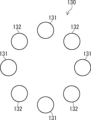
本開示の実施の形態の説明に先立って、本開示の概要を説明する。図1は、本発明に係るアンテナ装置を概略的に示す。アンテナ装置10は、複数のアンテナ素子11を有する。各アンテナ素子11は、対向するアンテナ装置に向けて送信される無線信号を出力する。複数のアンテナ素子11の少なくとも一部は、出力する無線信号の偏波方向が、第1の方向と、それに直交する第2の方向との間で切替可能に構成される。例えば、複数のアンテナ素子11の半分は、出力する無線信号の偏波方向が第1の方向と第2の方向との間で切替可能に構成されていてもよい。複数のアンテナ素子11の残りの半分は、偏波方向が第1の方向の無線信号を出力してもよい。
Prior to describing the embodiments of the present disclosure, an overview of the present disclosure will be explained. FIG. 1 schematically shows an antenna device according to the invention.
例えば、アンテナ装置10において、複数のアンテナ素子11は、図1に示されるように、円周上に等間隔で配列される。アンテナ素子11の配列は円形には限定されず、複数のアンテナ素子11は、所定方向に沿って直線状に配列されていてもよい。複数のアンテナ素子11の間隔は、例えば所定のリンク距離において、全てのアンテナ素子11から同一の偏波方向の無線信号が出力される場合に、MIMO GAINが所定の品質を確保できる間隔に設定されてもよい。
For example, in the
アンテナ装置10が、上記所定のリンク距離で使用される場合、各アンテナ素子11は、偏波方向が第1の方向の無線信号を出力してもよい。アンテナ装置が上記所定のリンク距離とは異なるリンク距離で使用される場合、複数のアンテナ素子11の一部は、偏波方向が第1の方向の無線信号を出力し、残りの少なくとも一部は偏波方向が第2の方向の無線信号を出力してもよい。例えば、アンテナ装置10において、偏波方向が第1の方向の無線信号を出力するアンテナ素子11と、偏波方向が第2の方向の無線信号を出力するアンテナ素子11とが、円周方向に沿って交互に並べられる。この場合、同じ偏波方向の無線信号を出力するアンテナ素子11の間隔は、全てのアンテナ素子11から同一の偏波方向の無線信号を出力する場合の2倍の間隔となる。第1の方向と第2の方向とは直交するため、偏波方向が第1の方向の無線信号と偏波方向が第2の方向の無線信号とは互いに干渉しない。
When the
前述のように、LOS-MIMO伝送及びOAMモード多重伝送において、MIMO GAINはアンテナ素子配置に依存する。本開示では、複数のアンテナ素子11の一部から偏波方向が第1の方向の無線信号を出力させ、残りのアンテナ素子11から偏波方向が第2の方向の無線信号を出力させることができる。各偏波において、無線信号の送信に用いられるアンテナ素子の数、及びアンテナ素子の間隔が変化することで、MIMO GAINが変化する。例えば、あるリンク距離では、全てのアンテナ素子11から同一偏波の無線信号が出力される場合に、MIMO GAINが劣化する場合がある。その場合でも、偏波方向ごとにアンテナ素子配置を変更することで、良好なMIMO GAINが得られる場合がある。
As described above, in LOS-MIMO transmission and OAM mode multiplex transmission, MIMO GAIN depends on the antenna element arrangement. In the present disclosure, it is possible to cause a portion of the plurality of
例えば、アンテナ装置10において、あるリンク距離では、例えば計8つのアンテナ素子11のうち、4つのアンテナ素子11は偏波方向が第1の方向の無線信号を出力する。また、残りの4つのアンテナ素子11は偏波方向が第2の方向の無線信号を出力する。LOS-MIMO伝送及びOAMモード多重伝送において、使用されるアンテナ素子の数が半分になると、空間多重できるデータストリームの数は半分になる。上記の場合、各偏波方向に対してアンテナ素子11の数が4つずつとなり、空間多重されるデータストリームの数は、8つのアンテナ素子から同一の偏波方向の無線信号が出力される場合と変わらない。このように、本開示では、リンク距離に応じてアンテナ素子11の物理的な配置を変更しなくても、多重伝送数の低下を抑制することができる。
For example, in the
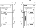
以下、図面を参照しつつ、本開示の実施の形態を説明する。図2は、本開示の第1実施形態に係る無線通信システムを示す。無線通信システム100は、無線送信機110、及び無線受信機120を有する。無線送信機110と無線受信機120とは、見通し内無線通信を行う。本実施形態では、空間多重伝送にOAMモード多重伝送が用いられる。無線通信システム100は、例えばモバイルバックホール回線における無線通信に利用され得る。
Embodiments of the present disclosure will be described below with reference to the drawings. FIG. 2 shows a wireless communication system according to the first embodiment of the present disclosure.
無線送信機110は、無線信号生成部115、及びアンテナ部113を有する。無線信号生成部115は、対向する無線受信機120に向けて送信される無線信号を生成する。無線信号生成部115は、複数の変調器111、及び線形プリコーダ112を有する。無線信号生成部115は、Mを2以上の整数として、M個の変調器111を有する。Mは、空間多重されるデータストリームの数に対応する。各変調器111は、所定の変調方式に従って送信信号を変調する。各変調器111は、変調信号を線形プリコーダ112に出力する。
アンテナ部113は、無線受信機120に向けて無線信号を送信する。アンテナ部113は、Nを2以上の整数として、N個のアンテナ素子(送信アンテナ素子)114を有する。線形プリコーダ112は、M個の変調信号に対して、N×Mウェイト行列を乗算し、各アンテナ素子114に対応するN個の信号を出力する。本実施形態において、線形プリコーダ112は、DFT(Discrete Fourier Transform)行列をウェイト行列として用いる。線形プリコーダ112は、複数のデータストリームを複数のOAMモードに多重化する。各アンテナ素子114は、無線信号(OAMモード無線信号)を送信する。なお、OAMモード信号の生成、及びその送信は公知であり、それら詳細な説明は省略する。
無線受信機120は、アンテナ部121、及び無線信号処理部125を有する。アンテナ部121は、対向する無線送信機110から無線信号を受信する。アンテナ部121は、N個のアンテナ素子(受信アンテナ素子)122を有する。各アンテナ素子122は、対向する無線送信機110の対応するアンテナ素子114から送信された無線信号(OAMモード無線信号)を受信する。
無線信号処理部125は、無線信号から送信信号を復調する。無線信号処理部125は、干渉補償器123、及び複数の復調器124を有する。干渉補償器123は、複数のOAMモードに多重化されたM個のデータストリーム(信号)を分離する。干渉補償器123は、N個の入力に対してM×Nのウェイト行列を乗算し、干渉を補償したM個の信号を出力する。無線信号処理部125は、M個の復調器124を有する。各復調器124は、干渉補償器123で分離された信号を復調し、送信側で変調された信号を復元する。OAMモード信号の受信、及びその分離は公知であり、それら詳細な説明は省略する。
The radio
なお、線形プリコーダ112及び干渉補償器123は、アナログ回路として実装されてもよいし、デジタル回路として実装されてもよい。アナログ回路として実装される場合、線形プリコーダ112及び干渉補償器123には例えばバトラーマトリックスが用いられる。
Note that the
また、図2では図示を省略しているが、無線信号生成部115は、ベースバンド信号をIF(Intermediate Frequency)信号に変換するIF信号処理部と、IF信号を例えばミリ波帯などのRF(Radio Frequency)信号(無線信号)にアップコンバートするアップコンバータを有していてもよい。また、無線信号処理部125は、RF信号をIF信号にダウンコンバートするダウンコンバータと、IF信号をベースバンド信号に変換するIF信号処理部とを有していてもよい。
Although not shown in FIG. 2, the radio
さらに、無線送信機110は、無線信号を送信するだけでなく、無線信号を受信してもよい。また、無線受信機120は、無線信号を受信するだけでなく、無線信号を送信してもよい。その場合、無線送信機110は、無線信号生成部115に加えて、無線信号処理部125を有していればよい。また、無線受信機120は、無線信号処理部125に加えて、無線信号生成部115を有していればよい。無線送信機110及び無線受信機120が、無線信号の送受信を行う場合、アンテナ部113及び121は、無線信号の送信と受信の双方に用いられ得る。
Furthermore, the
図3は、アンテナ装置の構成例を示す。図3は、アンテナ装置130を正面から見た正面図である。アンテナ装置130は、送信側のアンテナ部(送信アンテナ部)113及び受信側のアンテナ部(受信アンテナ部)121として用いることができる。なお、以下では主にアンテナ装置130が送信側のアンテナ部113として用いられる場合を説明する。アンテナ装置130が受信側のアンテナ部121として用いられる場合の説明は、無線信号の方向が反対になる点を除けば、アンテナ装置130が送信側のアンテナ部113として用いられる場合の説明と同様である。
FIG. 3 shows an example of the configuration of the antenna device. FIG. 3 is a front view of the
アンテナ装置130は、アンテナ素子(第1のアンテナ素子)131と、アンテナ素子(第2のアンテナ素子)132とを有する。本実施形態において、アンテナ装置130は、無線信号の放射点が円形状に配列された円形アレイアンテナとして構成される。アンテナ素子131及び132は、図2に示されるN個のアンテナ素子114に対応する。また、アンテナ素子131及び132は、N個のアンテナ素子122に対応する。図3の例では、アンテナ装置130は、4つのアンテナ素子131と、4つのアンテナ素子132を有する。つまり、N=8である。アンテナ装置130は、図1のアンテナ装置10に対応する。アンテナ素子131及び132は、図1のアンテナ素子11に対応する。
The
アンテナ素子131及び132は、円周上に、互い違いに等間隔で配列される。アンテナ素子131は、偏波方向が第1の方向の無線信号を出力する。アンテナ素子132は、出力する無線信号の偏波方向が、第1の方向とそれに直交する第2の方向とで切替可能に構成される。以下の説明では、第1の方向の偏波をH偏波とも呼ぶ。また、第2の方向の偏波をV偏波とも呼ぶ。アンテナ素子132は、例えば無線信号の給電点が変更されることで、H偏波とV偏波とが切替可能に構成される。給電点は、電気的又は物理的に変更可能に構成される。
The
図4(a)~(c)は、アンテナ素子132の構成例を示す。図4(a)~(c)において、アンテナ素子132の給電点は、切替部134を用いて切り替えられる。切替部134は、例えば電子的なスイッチとして構成される。切替部134は、図2には図示されない制御部から出力される制御信号(切替信号)に基づいて無線信号の出力先を切り替えることで、アンテナ素子132の給電点を変更してもよい。
FIGS. 4(a) to 4(c) show configuration examples of the
図4(a)の例では、アンテナ素子132はパッチアンテナとして構成される。切替部134は、パッチアンテナにおける給電点を、互いに直交する二辺の間で切り替える。このようにすることで、アンテナ素子132から出力される無線信号を、H偏波とV偏波との間で切り替えることができる。
In the example of FIG. 4(a), the
図4(b)及び(c)の例では、アンテナ素子132はホーンアンテナとして構成される。図4(b)の例では、ホーンアンテナであるアンテナ素子132には、円形導波路135を通じて無線信号が入力される。切替部134は、ホーンアンテナに接続される円形導波路135に無線信号を入力する位置を切り替える。このようにすることで、円形導波路135を導波される無線信号の電界の方向を、互いに直交する2つの方向の間で切り替えることができる。その結果、アンテナ素子132から出力される無線信号を、H偏波とV偏波との間で切り替えることができる。
In the examples of FIGS. 4(b) and 4(c), the
図4(c)の例では、ホーンアンテナであるアンテナ素子132は、方形導波路136及び方形導波路137に接続される。切替部134は、無線信号の出力先を、方形導波路136と方形導波路137との間で切り替える。アンテナ素子132は、例えば方形導波路136を通じて無線信号が入力された場合、V偏波の無線信号を出力する。アンテナ素子132は、方形導波路137を通じて無線信号が入力された場合、H偏波の無線信号を出力する。この例では、切替部134が無線信号を出力する方形導波路を切り替えることで、アンテナ素子132から出力される無線信号を、H偏波とV偏波との間で切り替えることができる。
In the example of FIG. 4C, the
図5(a)及び(b)は、アンテナ素子132の別の構成例を示す。この例において、アンテナ素子132はホーンアンテナとして構成される。この例では、ホーンアンテナの給電点が物理的に90°回転可能に構成される。図5(a)では、ホーンアンテナであるアンテナ素子132には、方形導波路138の長手方向に導波された無線信号が入力される。この場合、アンテナ素子132は、V偏波の無線信号を出力する。図5(b)に示すように、方形導波路138が90°回転された場合、アンテナ素子132には方形導波路の短手方向に導波された無線信号が入力される。この場合、アンテナ素子132は、H偏波の無線信号を出力する。
FIGS. 5A and 5B show another example of the structure of the
ここで、無線通信システム100において、無線局である無線送信機110及び無線受信機120は所定の位置に固定される。このため、送信側のアンテナ部113から受信側のアンテナ部121までの距離、すなわちリンク距離は、無線局の位置が決まれば一定である。通常、アンテナ部113及び121におけるアンテナ素子配置(アンテナ素子の数、及びアンテナ径)は、リンク距離に応じて適宜決定される。例えば、アンテナ部113及び121に、アンテナ素子の数が8つのUCAアンテナが用いられる場合、アンテナ素子が配列される円の半径(アンテナ径)は、あるリンク距離Lに対して各OAMモードにおいてMIMO GAINが所望の特性となる半径rに設定される。
Here, in the
しかしながら、上記半径rの円周上に8つのアンテナ素子が配列されたUCAアンテナが、例えばリンク距離がLとは異なる環境に用いられる場合、いくつかのOAMモードではMIMO GAINが劣化し、そのOAMモードが利用できない場合がある。特に、高次のOAMモードは、リンク距離の増加に伴ってMIMO GAINが劣化する傾向がある。いくつかのOAMモードが利用できない場合、その分だけ空間多重数が減少し、通信容量が低下する。 However, when a UCA antenna in which eight antenna elements are arranged on the circumference of the radius r is used in an environment where the link distance is different from L, for example, MIMO GAIN deteriorates in some OAM modes, and the OAM mode may not be available. In particular, in high-order OAM modes, MIMO GAIN tends to deteriorate as the link distance increases. If some OAM modes are not available, the number of spatial multiplexing decreases accordingly, and the communication capacity decreases.
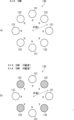
上記問題に対し、本実施形態では、リンク距離に応じて、アンテナ素子132から出力される無線信号の偏波を、H偏波とV偏波との間で切り替える。図6(a)及び(b)は、各アンテナ素子から出力される無線信号の偏波を示す。図6(a)は、アンテナ素子132からH偏波の無線信号を出力させる場合の各アンテナ素子から出力される無線信号の偏波を示す。図6(a)に示されるように、アンテナ素子131及び132の双方からH偏波の無線信号が出力される。この場合、半径rの円周上に8つのアンテナ素子が配列されたアンテナ装置が送信側と受信側とにおいて用いられる8×8OAMモード多重伝送が実現される。8×8OAMモード多重伝送では、モード0、モード±1、モード±2、モード±3、及びモード+4を用いることができ、空間多重数は最大で8となる。
To solve the above problem, in this embodiment, the polarization of the wireless signal output from the
一方、図6(b)は、アンテナ素子132からV偏波の無線信号を出力させる場合の各アンテナ素子から出力される無線信号の偏波を示す。この場合、アンテナ素子131はH偏波の無線信号を出力し、アンテナ素子132はV偏波の無線信号を出力する。前述のように、H偏波の無線信号とV偏波の無線信号とは互いに干渉しない。このため、図6(b)の場合、各偏波において、半径rの円周上に4つのアンテナ素子が配列されたアンテナ装置が送信側と受信側とにおいて用いられる4×4OAMモード多重伝送が実現される。4×4OAMモード多重伝送では、モード0、モード±1、モード+2が利用可能である。図6(b)の場合、偏波ごとにこれら4つのモードが利用でき、空間多重数は、8×8OAMモード多重伝送の場合と同様に最大で8となる。
On the other hand, FIG. 6(b) shows the polarization of the radio signal output from each antenna element when the
図7(a)及び(b)は、150GHz帯におけるOAMモード無線信号のMIMO GAINとリンク距離との関係を示す。図7(a)及び(b)に示されるグラフにおいて、縦軸はMIMO GAIN(dB)を示し、横軸はリンク距離(m)を示す。図7(a)は、8×8OAMモード多重伝送(8OAMモード多重)の場合のMIMO GAINとリンク距離との関係を示す。アンテナ径が0.3[m]であり、アンテナ素子の数が8つのUCAアンテナが用いられる場合に、各リンク距離における各OAMモードのMIMO GAINをシミュレーションを用いて求めると、図7(a)に示す結果が得られた。 FIGS. 7A and 7B show the relationship between MIMO GAIN and link distance of OAM mode radio signals in the 150 GHz band. In the graphs shown in FIGS. 7A and 7B, the vertical axis represents MIMO GAIN (dB), and the horizontal axis represents link distance (m). FIG. 7A shows the relationship between MIMO GAIN and link distance in the case of 8×8 OAM mode multiplex transmission (8 OAM mode multiplex). When the antenna diameter is 0.3 [m] and a UCA antenna with eight antenna elements is used, the MIMO GAIN of each OAM mode at each link distance is calculated using simulation, as shown in Fig. 7 (a) The results shown are obtained.
ここでは、MIMO GAINが、基準である0[dB]以上のモードは通信に利用可能であるとする。図7(a)に示されるように、リンク距離が80[m]程度の場合、各モードのMIMO GAINは基準である0[dB]を超えており、かつその差が少ない。このため、アンテナ径0.3[m]のUCAアンテナは、リンク距離80[m]の場合の8OAMモード多重に適していると言える。一方、特にモード+4ではリンク距離が延びるにつれてMIMO GAINが劣化し、リンク距離120[m]程度でMIMO GAINが基準である0[dB]を下回る。このため、アンテナ径0.3[m]のUCAアンテナは、リンク距離が120[m]を超える場合の8OAMモード多重には適していないといえる。 Here, it is assumed that modes in which MIMO GAIN is equal to or higher than the standard 0 [dB] can be used for communication. As shown in FIG. 7A, when the link distance is about 80 [m], the MIMO GAIN of each mode exceeds the standard 0 [dB], and the difference is small. Therefore, it can be said that the UCA antenna with an antenna diameter of 0.3 [m] is suitable for 8OAM mode multiplexing when the link distance is 80 [m]. On the other hand, especially in mode +4, MIMO GAIN deteriorates as the link distance increases, and MIMO GAIN falls below the standard 0 [dB] at a link distance of about 120 [m]. Therefore, it can be said that the UCA antenna with an antenna diameter of 0.3 [m] is not suitable for 8OAM mode multiplexing when the link distance exceeds 120 [m].
図7(b)は、4×4OAMモード多重伝送(4OAMモード多重)の場合のMIMO GAINとリンク距離との関係を示す。アンテナ径が0.3[m]であり、アンテナ素子の数が4つのUCAアンテナが用いられる場合に、各リンク距離における各OAMモードのMIMO GAINをシミュレーションを用いて求めると、図7(b)に示す結果が得られた。 FIG. 7(b) shows the relationship between MIMO GAIN and link distance in the case of 4×4 OAM mode multiplex transmission (4 OAM mode multiplex). When a UCA antenna with an antenna diameter of 0.3 [m] and four antenna elements is used, the MIMO GAIN of each OAM mode at each link distance is calculated using simulation as shown in Figure 7(b). The results shown are obtained.
図7(b)に示されるように、リンク距離が180[m]程度の場合、各モードのMIMO GAINは基準である0[dB]を超えており、かつその差が少ない。このため、アンテナ径0.3[m]のUCAアンテナは、リンク距離180[m]の場合の4OAMモード多重に適していると言える。一方、リンク距離が短い範囲では、特にモード0及びモード±1のMIMO GAINが基準である0[dB]を下回る。このため、アンテナ径0.3のUCAアンテナは、リンク距離が短い場合の4OAMモード多重には適していないといえる。
As shown in FIG. 7B, when the link distance is about 180 [m], the MIMO GAIN of each mode exceeds the standard 0 [dB], and the difference is small. Therefore, it can be said that the UCA antenna with an antenna diameter of 0.3 [m] is suitable for 4OAM mode multiplexing when the link distance is 180 [m]. On the other hand, in a range where the link distance is short, especially the MIMO GAIN of
設計者は、例えばアンテナ工事に先立って、見通し内通信を行う無線送信機110(図2を参照)の設置場所と無線受信機120の設置場所との位置関係から、リンク距離を取得する。設計者は、シミュレーションを行い、アンテナ素子131及び132から同一偏波の無線信号が出力される場合(図6(a)を参照)の、取得したリンク距離における受信品質を計算する。また、設計者は、アンテナ素子131及び132から偏波方向が互いに直交する無線信号が出力される場合(図6(b)を参照)の、取得したリンク距離における受信品質を計算する。設計者は、計算した受信品質を比較し、取得したリンク距離の場合にどちらの受信品質が良好であるかを判断する。
For example, prior to antenna construction, the designer obtains the link distance from the positional relationship between the installation location of the wireless transmitter 110 (see FIG. 2) that performs line-of-sight communication and the installation location of the
設計者は、アンテナ素子131及び132から同一偏波の無線信号が出力される場合の受信品質が良好であると判断したとする。その場合、無線送信機110及び無線受信機120内の図示しない制御部は、アンテナ素子132からH偏波の無線信号を出力させるための制御信号を切替部134(図4(a)~(c)を参照)に対して出力する。設計者は、アンテナ素子132の給電点が物理的に変更可能な場合は、アンテナ工事の作業者に、方形導波路138(図5(a)及び(b)を参照)の向きを、アンテナ素子132からH偏波の無線信号を出力させる向きに回転させるように指示してもよい。以後、方形導波路138の向きはその向きに固定される。無線通信システム100の運用中、アンテナ素子132は、H偏波の無線信号を出力する。
It is assumed that the designer has determined that the reception quality is good when radio signals of the same polarization are output from the
上記とは逆に、設計者は、アンテナ素子131及び132から互いに直交する偏波方向の無線信号が出力される場合の受信品質が良好であると判断したとする。その場合、無線送信機110及び無線受信機120内の図示しない制御部は、アンテナ素子132からV偏波の無線信号を出力させるための制御信号を切替部134に対して出力する。設計者は、アンテナ素子132の給電点が物理的に変更可能な場合は、アンテナ工事の作業者に、方形導波路138の向きを、アンテナ素子132からV偏波の無線信号を出力させる向きに回転させるように指示してもよい。以後、方形導波路138の向きはその向きに固定される。無線通信システム100の運用中、アンテナ素子132は、H偏波の無線信号を出力する。
Assume that, contrary to the above, the designer has determined that the reception quality is good when radio signals in mutually orthogonal polarization directions are output from the
設計者は、無線送信機110及び無線受信機120において、アンテナ素子132から出力される無線信号がH偏波であるか、又はV偏波であるかに応じて、線形プリコーダ112及び干渉補償器123で使用されるウェイト行列の設定を行う。無線通信システム100の運用中、線形プリコーダ112は、設定されたウェイト行列を用いて、複数の変調信号を複数のOAMモードに多重化する。また、無線通信システム100の運用中、干渉補償器123は、設定されたウェイト行列を用いて、複数のOAMモードに多重化された信号を分離する。
In the
図8(a)及び(b)は、線形プリコーダ112及び干渉補償器123で使用されるウェイト行列を示す。ここでは、M=N=8であるとする。線形プリコーダ112及び干渉補償器123は、アンテナ素子132から出力される無線信号がH偏波である場合、8×8DFT行列を使用する(図8(a)を参照)。つまり、線形プリコーダ112及び干渉補償器123は、8×8OAMモード多重伝送が実施される場合、8×8DFT行列を使用する。一方、線形プリコーダ112及び干渉補償器123は、アンテナ素子132から出力される無線信号がV偏波である場合、4×4DFT行列を2つ配置したウェイト行列を使用する(図8(b)を参照)。つまり、線形プリコーダ112及び干渉補償器123は、各偏波において4×4OAMモード多重伝送が実施される場合、4×4DFT行列を2つ配置したウェイト行列を使用する。この場合、ウェイト行列において、4×4DFT行列が配置されない要素は0で埋められる。このように、8×8OAMモード多重伝送が実施される場合と、各偏波において4×4OAMモード多重伝送が実施される場合とで、ウェイト行列を切り替えることで、双方のOAMモード多重伝送に応じた処理を切り替えることができる。
FIGS. 8A and 8B show weight matrices used in the
本実施形態では、アンテナ装置130は、出力する無線信号の偏波方向が切替可能なアンテナ素子132を有する。アンテナ装置130は、アンテナ素子131及び132のそれぞれから同一の偏波方向の無線信号を出力できる。その場合、無線通信システム100において、例えば8×8OAMモード多重伝送が実施される。また、アンテナ装置130は、アンテナ素子131及び132から、互いに直交する偏波方向の無線信号を出力できる。その場合、無線通信システム100において、各偏波方向に対して、例えば4×4OAMモード多重伝送が実施される。
In this embodiment, the
アンテナ素子131及び132から同一の偏波方向の無線信号を出力する場合と、互いに直交する偏波方向の無線信号を出力する場合とで、リンク距離に対する受信品質特性は異なる。例えば、あるリンク距離において、アンテナ素子131及び132から同一の偏波方向の無線信号を出力する場合に受信品質が劣化する場合、アンテナ素子132が出力する無線信号の偏波方向を変更する。その場合でも、偏波ごとに4×4OAMモード多重伝送が実施されるため、8×8OAMモード多重伝送の場合と同じ空間多重数を実現できる。本実施形態では、アンテナ素子132から出力される無線信号の偏波方向が切り替えられるだけで、アンテナ素子131及び132の物理的な配置は変更されない。従って、本実施形態では、さまざまなリンク距離において、物理的なアンテナ素子の配置を変更することなく、空間多重されるデータストリームの数を確保することができる。
The reception quality characteristics with respect to the link distance are different depending on whether the
ここで、アンテナ装置において、アンテナ素子が移動可能に構成される場合、設置時のリンク距離に応じてアレイ半径などを調整することができる。しかしながら、アレイ半径が変更された場合、アンテナ素子とRF部の機器とを接続するケーブルなどのインタフェースを交換する必要が生じる場合があるという問題が生じる。また、アンテナ装置が可動部分を有することで、その部分の耐久性が低下するという問題もある。これに対し、本実施形態では、物理的なアンテナ素子の配置を変更する必要がないため、上記した問題は生じない。 Here, in the antenna device, when the antenna element is configured to be movable, the array radius and the like can be adjusted depending on the link distance at the time of installation. However, when the array radius is changed, a problem arises in that it may be necessary to replace an interface such as a cable that connects the antenna element and equipment in the RF section. Furthermore, since the antenna device has a movable part, there is also a problem in that the durability of that part decreases. In contrast, in this embodiment, there is no need to change the physical arrangement of the antenna elements, so the above-mentioned problem does not occur.
次いで、本開示の第2実施形態を説明する。図9は、本開示の第2実施形態に係る無線通信システムを示す。無線通信システム100aは、無線送信機110a、及び無線受信機120aを有する。本実施形態では、空間多重伝送にLOS-MIMO伝送が用いられる。本実施形態において、無線送信機110aは、複数の変調器111、及びアンテナ部113を有する。本実施形態における無線送信機110aは、図2に示される線形プリコーダ112を有していない点で、第1実施形態における無線送信機110と相違する。他の点は、第1実施形態と同様でよい。
Next, a second embodiment of the present disclosure will be described. FIG. 9 shows a wireless communication system according to a second embodiment of the present disclosure. The
本実施形態において、アンテナ部113及び121には、例えば図3に示すアンテナ装置130が用いられる。アンテナ素子131及び132から同一偏波の無線信号が出力される場合(図6(a)を参照)、8つのアンテナ素子が配列されたアンテナ装置が送信側と受信側とにおいて用いられる8×8LOS-MIMO伝送が実現される。8×8LOS-MIMO伝送が実施される場合、空間多重されるデータストリームの数は8となる。
In this embodiment, the
一方、アンテナ素子131及び132から偏波方向が互いに直交する無線信号が出力される場合(図6(b)を参照)、各偏波において、4つのアンテナ素子が配列されたアンテナ装置が送信側と受信側とにおいて用いられる4×4OAMモード多重伝送が実現される。4×4LOS-MIMO伝送が各偏波において実施される場合、空間多重されるデータストリームの数は、8×8LOS-MIMO伝送の場合と同様に、8となる。
On the other hand, when radio signals whose polarization directions are orthogonal to each other are output from the
図10(a)及び(b)は、150GHz帯におけるLOS-MIMO伝送におけるMIMO GAINとリンク距離との関係を示す。図10(a)及び(b)に示されるグラフにおいて、縦軸はMIMO GAIN(dB)を示し、横軸はリンク距離(m)を示す。図10(a)は、8×8LOS-MIMO伝送(8多重LOS-MIMO)の場合のMIMO GAINとリンク距離との関係を示す。アンテナ径が0.3[m]であり、アンテナ素子の数が8つのUCAアンテナが用いられる場合に、各リンク距離におけるMIMO GAINをシミュレーションを用いて求めると、図10(a)に示す結果が得られた。 FIGS. 10A and 10B show the relationship between MIMO GAIN and link distance in LOS-MIMO transmission in the 150 GHz band. In the graphs shown in FIGS. 10(a) and 10(b), the vertical axis represents MIMO GAIN (dB), and the horizontal axis represents link distance (m). FIG. 10(a) shows the relationship between MIMO GAIN and link distance in the case of 8×8 LOS-MIMO transmission (8 multiplexed LOS-MIMO). When a UCA antenna with an antenna diameter of 0.3 [m] and eight antenna elements is used, the MIMO GAIN at each link distance is calculated using simulation, and the results shown in Figure 10(a) are obtained. Obtained.
ここでは、MIMO GAINが、基準である0[dB]以上の場合に、通信が可能であるとする。図10(a)に示されるように、リンク距離が80[m]程度の場合、MIMO GAINは基準である0[dB]を超えており、かつ極大値をとる。このため、アンテナ径0.3[m]のUCAアンテナは、リンク距離80[m]の場合の8多重LOS-MIMOに適していると言える。一方、MIMO GAINはリンク距離が延びるにつれて劣化し、リンク距離150[m]程度でMIMO GAINが基準である0[dB]を下回る。このため、アンテナ径0.3[m]のUCAアンテナは、リンク距離が150[m]を超える場合の8多重LOS-MIMO伝送には適していないといえる。 Here, it is assumed that communication is possible when MIMO GAIN is equal to or greater than the standard 0 [dB]. As shown in FIG. 10(a), when the link distance is about 80 [m], MIMO GAIN exceeds the standard 0 [dB] and takes a maximum value. Therefore, it can be said that the UCA antenna with an antenna diameter of 0.3 [m] is suitable for 8-multiplex LOS-MIMO when the link distance is 80 [m]. On the other hand, MIMO GAIN deteriorates as the link distance increases, and MIMO GAIN falls below the standard 0 [dB] at a link distance of about 150 [m]. Therefore, it can be said that the UCA antenna with an antenna diameter of 0.3 [m] is not suitable for 8-multiplex LOS-MIMO transmission when the link distance exceeds 150 [m].
図10(b)は、4×4LOS-MIMO伝送(4多重LOS-MIMO)の場合のMIMO GAINとリンク距離との関係を示す。アンテナ径が0.3[m]であり、アンテナ素子の数が4つのUCAアンテナが用いられる場合に、各リンク距離におけるMIMO GAINをシミュレーションを用いて求めると、図10(b)に示す結果が得られた。 FIG. 10(b) shows the relationship between MIMO GAIN and link distance in the case of 4×4 LOS-MIMO transmission (4 multiplexed LOS-MIMO). When a UCA antenna with an antenna diameter of 0.3 [m] and four antenna elements is used, the MIMO GAIN at each link distance is calculated using simulation, and the result shown in Fig. 10(b) is obtained. Obtained.
図10(b)に示されるように、リンク距離が180[m]程度の場合、各モードのMIMO GAINは基準である0[dB]を超えており、かつ極大値をとる。このため、アンテナ径0.3[m]のUCAアンテナは、リンク距離180[m]の場合の4多重LOS-MIMOに適していると言える。一方、リンク距離が70[m]から120「m」程度の範囲では、MIMO GAINが基準である0[dB]を下回る。このため、アンテナ径0.3のUCAアンテナは、それらのリンク距離における4多重LOS-MIMOには適していないといえる。 As shown in FIG. 10(b), when the link distance is about 180 [m], the MIMO GAIN of each mode exceeds the standard 0 [dB] and takes a local maximum value. Therefore, it can be said that the UCA antenna with an antenna diameter of 0.3 [m] is suitable for 4-multiplex LOS-MIMO when the link distance is 180 [m]. On the other hand, in a range where the link distance is about 70 [m] to 120 "m", MIMO GAIN falls below the standard 0 [dB]. Therefore, it can be said that the UCA antenna with an antenna diameter of 0.3 is not suitable for 4-multiplex LOS-MIMO at these link distances.
リンク距離に応じた、8多重LOS-MIMO又は偏波ごとの4多重LOS-MIMOとの選択は、第1実施形態と同様でよい。設計者は、例えばアンテナ工事に先立って、見通し内通信を行う無線送信機110a(図9を参照)の設置場所と無線受信機120の設置場所との位置関係から、リンク距離を取得する。設計者は、取得したリンク距離における、8多重LOS-MIMOの場合の受信品質と、偏波ごとの4多重LOS-MIMOの場合の受信品質を比較し、どちらの受信品質が良好であるかを判断する。設計者は、その判断結果に基づいて、8多重LOS-MIMO又は偏波ごとの4多重LOS-MIMOを選択する。
The selection of 8-multiplex LOS-MIMO or 4-multiplex LOS-MIMO for each polarization depending on the link distance may be the same as in the first embodiment. For example, prior to antenna construction, the designer obtains the link distance from the positional relationship between the installation location of the
本実施形態では、無線通信システム100aにおいて、リンク距離に応じて、8多重LOS-MIMO又は偏波ごとの4多重LOS-MIMOが実施される。LOS-MIMO伝送の場合も、OAMモード多重伝送の場合と同様に、さまざまなリンク距離において、物理的なアンテナ素子の配置を変更することなく、空間多重されるデータストリームの数を確保することができる。
In this embodiment, in the
なお、上記各実施形態では、アンテナ装置130がアンテナ素子131とアンテナ素子132とを有する例を説明したが、本開示はこれには限定されない。アンテナ装置130において、全てのアンテナ素子がアンテナ素子132で構成されてもよい。別の言い方をすると、アンテナ装置130において、全てのアンテナ素子が、H偏波の無線信号とV偏波の無線信号とを切り替えて出力可能であってもよい。その場合でも、全てのアンテナ素子からH偏波の無線信号を出力させることができ、図6(a)の場合と同様に、8×8OAMモード多重伝送を実現できる。また、円周方向に沿って、アンテナ素子からH偏波の無線信号とV偏波の無線信号とを交互に出力させることができる。その場合、図6(b)の場合と同様に、偏波ごとに、4×4OAMモード多重伝送を実現できる。
Note that in each of the embodiments described above, an example has been described in which the
上記第2実施形態では、LOS-MIMO伝送にUCAアンテナが用いられる例を説明したが、本開示はこれには限定されない。図11は、アンテナ装置の別の構成例を示す。この構成例において、アンテナ装置130aは、直線状に配列された複数のアンテナ素子131及び132を有する。アンテナ装置130aにおいて、アンテナ素子131とアンテナ素子132とは交互に配列される。アンテナ素子131とアンテナ素子132との間隔はdであるとする。アンテナ素子131及び132からH偏波の無線信号が出力される場合、H偏波の無線信号が出力されるアンテナ素子の間隔はdとなる。
Although the second embodiment described above describes an example in which the UCA antenna is used for LOS-MIMO transmission, the present disclosure is not limited thereto. FIG. 11 shows another configuration example of the antenna device. In this configuration example, the
図12は、アンテナ素子131がH偏波の無線信号を出力し、アンテナ素子132がV偏波の無線信号を出力する場合の各アンテナ素子から出力される無線信号の偏波を示す。この場合、H偏波の無線信号を出力するアンテナ素子の間隔は2dとなる。また、V偏波の無線信号を出力するアンテナ素子の間隔も2dとなる。このように、アンテナ素子が直線状に配列される場合でも、物理的なアンテナ素子配置を変更せずに、偏波方向ごとにアンテナ素子配置を変更することができる。従って、UCAアンテナが用いられる場合と同様に、さまざまなリンク距離において、物理的なアンテナ素子の配置を変更することなく、空間多重されるデータストリームの数を確保することができる。
FIG. 12 shows the polarization of the radio signal output from each antenna element when the
以上、本開示の実施形態を詳細に説明したが、本開示は、上記した実施形態に限定されるものではなく、本開示の趣旨を逸脱しない範囲で上記実施形態に対して変更や修正を加えたものも、本開示に含まれる。 Although the embodiments of the present disclosure have been described in detail above, the present disclosure is not limited to the embodiments described above, and changes and modifications may be made to the embodiments described above without departing from the spirit of the present disclosure. are also included in this disclosure.
10:アンテナ装置
11:アンテナ素子
100:無線通信システム
110:無線送信機
111:変調器
112:線形プリコーダ
113、121:アンテナ部
114、122:アンテナ素子
115:無線信号生成部
120:無線受信機
123:干渉補償器
124:復調器
125:無線信号処理部
130:アンテナ装置
131、132:アンテナ素子
134:切替部
135:円形導波路
136~138:方形導波路
10: Antenna device 11: Antenna element 100: Wireless communication system 110: Radio transmitter 111: Modulator 112: Linear precoder 113, 121:
Claims (16)
前記複数のアンテナ素子の少なくとも一部は、前記無線信号の偏波方向が第1の方向と、該第1の方向に直交する第2の方向との間で切替可能に構成され、
前記複数のアンテナ素子は、偏波方向が前記第1の方向の無線信号を出力する第1のアンテナ素子と、出力する無線信号の偏波方向が前記第1の方向と前記第2の方向とで切替可能な第2のアンテナ素子とを含み、
前記複数のアンテナ素子は、円周上に等間隔で配列され、
前記円周上で、前記第1のアンテナ素子と前記第2のアンテナ素子とが交互に配列される、アンテナ装置。 Equipped with multiple antenna elements that output wireless signals transmitted toward opposing antenna devices,
At least some of the plurality of antenna elements are configured such that the polarization direction of the wireless signal can be switched between a first direction and a second direction orthogonal to the first direction ,
The plurality of antenna elements include a first antenna element that outputs a radio signal having a polarization direction in the first direction, and a polarization direction of the output radio signal in the first direction and the second direction. and a second antenna element switchable with
The plurality of antenna elements are arranged at equal intervals on a circumference,
The antenna device , wherein the first antenna element and the second antenna element are alternately arranged on the circumference .
前記複数のアンテナ素子の少なくとも一部は、前記無線信号の偏波方向が第1の方向と、該第1の方向に直交する第2の方向との間で切替可能に構成され、 At least some of the plurality of antenna elements are configured such that the polarization direction of the wireless signal can be switched between a first direction and a second direction orthogonal to the first direction,
前記複数のアンテナ素子は、偏波方向が前記第1の方向の無線信号を出力する第1のアンテナ素子と、出力する無線信号の偏波方向が前記第1の方向と前記第2の方向とで切替可能な第2のアンテナ素子とを含み、 The plurality of antenna elements include a first antenna element that outputs a radio signal having a polarization direction in the first direction, and a polarization direction of the output radio signal in the first direction and the second direction. and a second antenna element switchable with
前記複数のアンテナ素子は、直線上に等間隔で配列され、 The plurality of antenna elements are arranged at equal intervals on a straight line,
前記直線上で、前記第1のアンテナ素子と前記第2のアンテナ素子とが交互に配列される、アンテナ装置。 An antenna device, wherein the first antenna element and the second antenna element are alternately arranged on the straight line.
前記複数のアンテナ素子の少なくとも一部は、前記無線信号の偏波方向が第1の方向と、該第1の方向に直交する第2の方向との間で切替可能に構成され、
前記複数のアンテナ素子は、偏波方向が前記第1の方向の無線信号を受信する第1のアンテナ素子と、受信する無線信号の偏波方向が前記第1の方向と前記第2の方向とで切替可能な第2のアンテナ素子とを含み、
前記複数のアンテナ素子は、円周上に等間隔で配列され、
前記円周上で、前記第1のアンテナ素子と前記第2のアンテナ素子とが交互に配列される、アンテナ装置。 Comprising a plurality of antenna elements that receive wireless signals transmitted from opposing antenna devices,
At least some of the plurality of antenna elements are configured such that the polarization direction of the wireless signal can be switched between a first direction and a second direction orthogonal to the first direction ,
The plurality of antenna elements include a first antenna element that receives a radio signal having a polarization direction in the first direction, and a polarization direction of the received radio signal in the first direction and the second direction. and a second antenna element switchable with
The plurality of antenna elements are arranged at equal intervals on a circumference,
The antenna device , wherein the first antenna element and the second antenna element are alternately arranged on the circumference .
前記複数のアンテナ素子の少なくとも一部は、前記無線信号の偏波方向が第1の方向と、該第1の方向に直交する第2の方向との間で切替可能に構成され、 At least some of the plurality of antenna elements are configured such that the polarization direction of the wireless signal can be switched between a first direction and a second direction orthogonal to the first direction,
前記複数のアンテナ素子は、偏波方向が前記第1の方向の無線信号を受信する第1のアンテナ素子と、受信する無線信号の偏波方向が前記第1の方向と前記第2の方向とで切替可能な第2のアンテナ素子とを含み、 The plurality of antenna elements include a first antenna element that receives a radio signal having a polarization direction in the first direction, and a polarization direction of the received radio signal in the first direction and the second direction. and a second antenna element switchable with
前記複数のアンテナ素子は、直線上に等間隔で配列され、 The plurality of antenna elements are arranged at equal intervals on a straight line,
前記直線上で、前記第1のアンテナ素子と前記第2のアンテナ素子とが交互に配列される、アンテナ装置。 An antenna device, wherein the first antenna element and the second antenna element are alternately arranged on the straight line.
前記無線信号を対向する無線受信機に向けて出力する複数のアンテナ素子を有するアンテナ部とを備え、
前記複数のアンテナ素子の少なくとも一部は、前記無線信号の偏波方向が第1の方向と、該第1の方向に直交する第2の方向との間で切替可能に構成され、
前記複数のアンテナ素子は、偏波方向が前記第1の方向の無線信号を出力する第1のアンテナ素子と、出力する無線信号の偏波方向が前記第1の方向と前記第2の方向とで切替可能な第2のアンテナ素子とを含み、
前記複数のアンテナ素子は、円周上に等間隔で配列され、
前記円周上で、前記第1のアンテナ素子と前記第2のアンテナ素子とが交互に配列される、無線送信機。 a wireless signal generation unit that generates a wireless signal to be transmitted to an opposing wireless receiver;
an antenna section having a plurality of antenna elements that output the wireless signal toward an opposing wireless receiver;
At least some of the plurality of antenna elements are configured such that the polarization direction of the wireless signal can be switched between a first direction and a second direction orthogonal to the first direction ,
The plurality of antenna elements include a first antenna element that outputs a radio signal having a polarization direction in the first direction, and a polarization direction of the output radio signal in the first direction and the second direction. and a second antenna element switchable with
The plurality of antenna elements are arranged at equal intervals on a circumference,
A radio transmitter , wherein the first antenna element and the second antenna element are arranged alternately on the circumference .
前記無線信号を対向する無線受信機に向けて出力する複数のアンテナ素子を有するアンテナ部とを備え、 an antenna section having a plurality of antenna elements that output the wireless signal toward an opposing wireless receiver;
前記複数のアンテナ素子の少なくとも一部は、前記無線信号の偏波方向が第1の方向と、該第1の方向に直交する第2の方向との間で切替可能に構成され、 At least some of the plurality of antenna elements are configured such that the polarization direction of the wireless signal can be switched between a first direction and a second direction orthogonal to the first direction,
前記複数のアンテナ素子は、偏波方向が前記第1の方向の無線信号を出力する第1のアンテナ素子と、出力する無線信号の偏波方向が前記第1の方向と前記第2の方向とで切替可能な第2のアンテナ素子とを含み、 The plurality of antenna elements include a first antenna element that outputs a radio signal having a polarization direction in the first direction, and a polarization direction of the output radio signal in the first direction and the second direction. and a second antenna element switchable with
前記複数のアンテナ素子は、直線上に等間隔で配列され、 The plurality of antenna elements are arranged at equal intervals on a straight line,
前記直線上で、前記第1のアンテナ素子と前記第2のアンテナ素子とが交互に配列される、無線送信機。 A radio transmitter, wherein the first antenna element and the second antenna element are alternately arranged on the straight line.
前記無線信号から送信信号を復調する無線信号処理部とを備え、
前記複数のアンテナ素子の少なくとも一部は、前記無線信号の偏波方向が第1の方向と、該第1の方向に直交する第2の方向との間で切替可能に構成され、
前記複数のアンテナ素子は、偏波方向が前記第1の方向の無線信号を受信する第1のアンテナ素子と、受信する無線信号の偏波方向が前記第1の方向と前記第2の方向とで切替可能な第2のアンテナ素子とを含み、
前記複数のアンテナ素子は、円周上に等間隔で配列され、
前記円周上で、前記第1のアンテナ素子と前記第2のアンテナ素子とが交互に配列される、無線受信機。 an antenna section having a plurality of antenna elements that receive radio signals from opposing radio transmitters;
a wireless signal processing unit that demodulates a transmission signal from the wireless signal,
At least some of the plurality of antenna elements are configured such that the polarization direction of the wireless signal can be switched between a first direction and a second direction orthogonal to the first direction ,
The plurality of antenna elements include a first antenna element that receives a radio signal having a polarization direction in the first direction, and a polarization direction of the received radio signal in the first direction and the second direction. and a second antenna element switchable with
The plurality of antenna elements are arranged at equal intervals on a circumference,
A radio receiver , wherein the first antenna element and the second antenna element are arranged alternately on the circumference .
前記無線信号から送信信号を復調する無線信号処理部とを備え、 a wireless signal processing unit that demodulates a transmission signal from the wireless signal,
前記複数のアンテナ素子の少なくとも一部は、前記無線信号の偏波方向が第1の方向と、該第1の方向に直交する第2の方向との間で切替可能に構成され、 At least some of the plurality of antenna elements are configured such that the polarization direction of the wireless signal can be switched between a first direction and a second direction orthogonal to the first direction,
前記複数のアンテナ素子は、偏波方向が前記第1の方向の無線信号を受信する第1のアンテナ素子と、受信する無線信号の偏波方向が前記第1の方向と前記第2の方向とで切替可能な第2のアンテナ素子とを含み、 The plurality of antenna elements include a first antenna element that receives a radio signal having a polarization direction in the first direction, and a polarization direction of the received radio signal in the first direction and the second direction. and a second antenna element switchable with
前記複数のアンテナ素子は、直線上に等間隔で配列され、 The plurality of antenna elements are arranged at equal intervals on a straight line,
前記直線上で、前記第1のアンテナ素子と前記第2のアンテナ素子とが交互に配列される、無線受信機。 A radio receiver, wherein the first antenna element and the second antenna element are arranged alternately on the straight line.
前記無線送信機から無線信号を受信する複数の受信アンテナ素子を有する受信アンテナ部と、前記無線信号から送信信号を復調する無線信号処理部とを含む無線受信機とを備え、
前記複数の送信アンテナ素子の少なくとも一部は、前記無線信号の偏波方向が第1の方向と、該第1の方向に直交する第2の方向との間で切替可能に構成され、
前記複数の受信アンテナ素子の少なくとも一部は、前記無線信号の偏波方向が第1の方向と、該第1の方向に直交する第2の方向との間で切替可能に構成され、
前記複数の送信アンテナ素子は、それぞれ、偏波方向が前記第1の方向の無線信号を出力する第1の送信アンテナ素子と、出力する無線信号の偏波方向が前記第1の方向と前記第2の方向とで切替可能な第2の送信アンテナ素子とを含み、
前記複数の送信アンテナ素子は、円周上に等間隔で配列され、
前記円周上で、前記第1の送信アンテナ素子と前記第2の送信アンテナ素子とが交互に配列され
前記複数の受信アンテナ素子は、それぞれ、偏波方向が前記第1の方向の無線信号を受信する第1の受信アンテナ素子と、受信する無線信号の偏波方向が前記第1の方向と前記第2の方向とで切替可能な第2の受信アンテナ素子とを含み、
前記複数の受信アンテナ素子は、円周上に等間隔で配列され、
前記円周上で、前記第1の受信アンテナ素子と前記第2の受信アンテナ素子とが交互に配列される、無線通信システム。 a radio transmitter including a radio signal generation unit that generates a radio signal; and a transmission antenna unit that has a plurality of transmission antenna elements that output the radio signal;
A radio receiver including a receiving antenna section having a plurality of receiving antenna elements that receives a radio signal from the radio transmitter, and a radio signal processing section that demodulates a transmission signal from the radio signal,
At least some of the plurality of transmitting antenna elements are configured such that the polarization direction of the wireless signal can be switched between a first direction and a second direction orthogonal to the first direction,
At least some of the plurality of receiving antenna elements are configured such that the polarization direction of the radio signal can be switched between a first direction and a second direction orthogonal to the first direction,
Each of the plurality of transmitting antenna elements includes a first transmitting antenna element that outputs a wireless signal having a polarization direction in the first direction, and a first transmitting antenna element that outputs a wireless signal whose polarization direction is in the first direction and the first transmitting antenna element. a second transmitting antenna element switchable in two directions;
The plurality of transmitting antenna elements are arranged at equal intervals on a circumference,
The first transmitting antenna element and the second transmitting antenna element are arranged alternately on the circumference.
Each of the plurality of receiving antenna elements includes a first receiving antenna element that receives a radio signal having a polarization direction in the first direction, and a first receiving antenna element that receives a radio signal having a polarization direction in the first direction, and a first receiving antenna element that receives a radio signal having a polarization direction in the first direction. and a second receiving antenna element switchable in two directions;
The plurality of receiving antenna elements are arranged at equal intervals on a circumference,
A wireless communication system , wherein the first receiving antenna element and the second receiving antenna element are arranged alternately on the circumference .
前記無線送信機から無線信号を受信する複数の受信アンテナ素子を有する受信アンテナ部と、前記無線信号から送信信号を復調する無線信号処理部とを含む無線受信機とを備え、 A radio receiver including a receiving antenna section having a plurality of receiving antenna elements that receives a radio signal from the radio transmitter, and a radio signal processing section that demodulates a transmission signal from the radio signal,
前記複数の送信アンテナ素子の少なくとも一部は、前記無線信号の偏波方向が第1の方向と、該第1の方向に直交する第2の方向との間で切替可能に構成され、 At least some of the plurality of transmitting antenna elements are configured such that the polarization direction of the wireless signal can be switched between a first direction and a second direction orthogonal to the first direction,
前記複数の受信アンテナ素子の少なくとも一部は、前記無線信号の偏波方向が第1の方向と、該第1の方向に直交する第2の方向との間で切替可能に構成され、 At least some of the plurality of receiving antenna elements are configured such that the polarization direction of the radio signal can be switched between a first direction and a second direction orthogonal to the first direction,
前記複数の送信アンテナ素子は、それぞれ、偏波方向が前記第1の方向の無線信号を出力する第1の送信アンテナ素子と、出力する無線信号の偏波方向が前記第1の方向と前記第2の方向とで切替可能な第2の送信アンテナ素子とを含み、 Each of the plurality of transmitting antenna elements includes a first transmitting antenna element that outputs a wireless signal having a polarization direction in the first direction, and a first transmitting antenna element that outputs a wireless signal whose polarization direction is in the first direction and the first transmitting antenna element. a second transmitting antenna element switchable in two directions;
前記複数の送信アンテナ素子は、直線上に等間隔で配列され、 The plurality of transmitting antenna elements are arranged at equal intervals on a straight line,
前記直線上で、前記第1の送信アンテナ素子と前記第2の送信アンテナ素子とが交互に配列され The first transmitting antenna element and the second transmitting antenna element are arranged alternately on the straight line.
前記複数の受信アンテナ素子は、それぞれ、偏波方向が前記第1の方向の無線信号を受信する第1の受信アンテナ素子と、受信する無線信号の偏波方向が前記第1の方向と前記第2の方向とで切替可能な第2の受信アンテナ素子とを含み、 Each of the plurality of receiving antenna elements includes a first receiving antenna element that receives a radio signal having a polarization direction in the first direction, and a first receiving antenna element that receives a radio signal having a polarization direction in the first direction, and a first receiving antenna element that receives a radio signal having a polarization direction in the first direction. and a second receiving antenna element switchable in two directions;
前記複数の受信アンテナ素子は、直線上に等間隔で配列され、 The plurality of receiving antenna elements are arranged at equal intervals on a straight line,
前記直線上で、前記第1の受信アンテナ素子と前記第2の受信アンテナ素子とが交互に配列される、無線通信システム。 A wireless communication system, wherein the first receiving antenna element and the second receiving antenna element are arranged alternately on the straight line.
前記複数の受信アンテナ素子の少なくとも一部は、前記無線信号の給電点が変更されることで、前記無線信号の偏波方向が前記第1の方向と前記第2の方向との間で切替可能に構成される請求項14又は15に記載の無線通信システム。 At least some of the plurality of transmitting antenna elements can switch the polarization direction of the wireless signal between the first direction and the second direction by changing the feeding point of the wireless signal. consists of
At least some of the plurality of receiving antenna elements can switch the polarization direction of the wireless signal between the first direction and the second direction by changing the feeding point of the wireless signal. The wireless communication system according to claim 14 or 15 , configured to.
Priority Applications (2)
| Application Number | Priority Date | Filing Date | Title |
|---|---|---|---|
| JP2019137278A JP7413672B2 (en) | 2019-07-25 | 2019-07-25 | Antenna devices, radio transmitters, radio receivers, and radio communication systems |
| US16/937,040 US11362440B2 (en) | 2019-07-25 | 2020-07-23 | Antenna device, wireless transmitter, wireless receiver, and wireless communication system |
Applications Claiming Priority (1)
| Application Number | Priority Date | Filing Date | Title |
|---|---|---|---|
| JP2019137278A JP7413672B2 (en) | 2019-07-25 | 2019-07-25 | Antenna devices, radio transmitters, radio receivers, and radio communication systems |
Publications (2)
| Publication Number | Publication Date |
|---|---|
| JP2021022791A JP2021022791A (en) | 2021-02-18 |
| JP7413672B2 true JP7413672B2 (en) | 2024-01-16 |
Family
ID=74189233
Family Applications (1)
| Application Number | Title | Priority Date | Filing Date |
|---|---|---|---|
| JP2019137278A Active JP7413672B2 (en) | 2019-07-25 | 2019-07-25 | Antenna devices, radio transmitters, radio receivers, and radio communication systems |
Country Status (2)
| Country | Link |
|---|---|
| US (1) | US11362440B2 (en) |
| JP (1) | JP7413672B2 (en) |
Families Citing this family (5)
| Publication number | Priority date | Publication date | Assignee | Title |
|---|---|---|---|---|
| FR3062523B1 (en) * | 2017-02-01 | 2019-03-29 | Thales | ELEMENTARY ANTENNA WITH A PLANAR RADIANT DEVICE |
| JP6988903B2 (en) * | 2017-09-25 | 2022-01-05 | 日本電信電話株式会社 | OAM multiplex communication system and OAM multiplex communication method |
| US11336008B2 (en) * | 2018-08-02 | 2022-05-17 | Nec Corporation | Control apparatus, OAM transmission apparatus, OAM reception apparatus, control method, non-transitory computer-readable medium, and control system |
| WO2020255594A1 (en) * | 2019-06-17 | 2020-12-24 | 日本電気株式会社 | Antenna device, radio transmitter, radio receiver, radio communication system, and antenna diameter adjustment method |
| US20240243884A1 (en) * | 2021-07-17 | 2024-07-18 | Qualcomm Incorporated | Control channel design in orbital angular momentum (oam) based communication system |
Citations (6)
| Publication number | Priority date | Publication date | Assignee | Title |
|---|---|---|---|---|
| JP2004147154A (en) | 2002-10-25 | 2004-05-20 | Taiyo Yuden Co Ltd | Diversity antenna circuit |
| JP2004364262A (en) | 2003-05-12 | 2004-12-24 | Kobe Steel Ltd | Wireless lan antenna, method for controlling wireless lan antenna, antenna for wireless lan base station, antenna for wireless lan mobile station terminal, wireless lan card for terminal and wireless lan system |
| JP2007221242A (en) | 2006-02-14 | 2007-08-30 | Nippon Telegr & Teleph Corp <Ntt> | Wireless communication device |
| US20130229262A1 (en) | 2012-03-05 | 2013-09-05 | Symbol Technologies, Inc. | Radio frequency identification reader antenna arrangement with multiple linearly-polarized elements |
| JP2016213927A (en) | 2015-04-30 | 2016-12-15 | パナソニックIpマネジメント株式会社 | Array antenna for power transmission / reception |
| JP2018056696A (en) | 2016-09-27 | 2018-04-05 | ソニーセミコンダクタソリューションズ株式会社 | Communication device, communication method, and electronic apparatus |
Family Cites Families (43)
| Publication number | Priority date | Publication date | Assignee | Title |
|---|---|---|---|---|
| JPH1039997A (en) * | 1996-07-18 | 1998-02-13 | Saifasha:Yugen | Three-dimensional image data/command input system |
| US6137996A (en) * | 1998-07-20 | 2000-10-24 | Motorola, Inc. | Apparatus and method for overcoming the effects of signal loss due to a multipath environment in a mobile wireless telephony system |
| EP2139068B1 (en) * | 1999-12-15 | 2011-04-13 | Nippon Telegraph And Telephone Corporation | Adaptive array antenna transceiver apparatus |
| JP4169709B2 (en) * | 2004-02-16 | 2008-10-22 | 株式会社国際電気通信基礎技術研究所 | Array antenna device |
| US10133888B2 (en) * | 2005-10-06 | 2018-11-20 | Universal Entertainment Corporation | Data reader and positioning system |
| EP1808710A1 (en) * | 2006-01-11 | 2007-07-18 | International University Bremen Gmbh | Method and device for determining the speed of a moving entity |
| US7813709B2 (en) * | 2006-08-16 | 2010-10-12 | Panasonic Corporation | MIMO antenna apparatus provided with variable impedance load element connected to parasitic element |
| JP4345800B2 (en) * | 2006-10-19 | 2009-10-14 | ソニー株式会社 | Wireless communication device |
| JP5231435B2 (en) * | 2006-10-26 | 2013-07-10 | クゥアルコム・インコーポレイテッド | Progressive information beacon symbol |
| US20080261539A1 (en) * | 2007-04-17 | 2008-10-23 | Chien-Ming Chen | Wireless transmission system having architecture based on three internal antennas and method thereof |
| US7869533B2 (en) * | 2007-08-27 | 2011-01-11 | Delphi Technologies, Inc. | Communication system and method for receiving high priority and low priority signals |
| KR100922001B1 (en) * | 2007-09-10 | 2009-10-14 | 한국전자통신연구원 | Cross Dipole, Cross Dipole Module, Array Antenna and Multiple Input Multiple Output Antenna |
| JP5040549B2 (en) * | 2007-09-20 | 2012-10-03 | 日本電気株式会社 | Synthetic aperture radar, compact polarimetry SAR processing method, program |
| JP4716195B2 (en) * | 2007-10-17 | 2011-07-06 | ブラザー工業株式会社 | Wireless tag communication device |
| CN101884135A (en) * | 2007-12-04 | 2010-11-10 | 松下电器产业株式会社 | Antenna devices and communication devices |
| US8306473B2 (en) * | 2008-02-15 | 2012-11-06 | Qualcomm Incorporated | Methods and apparatus for using multiple antennas having different polarization |
| US20110150118A1 (en) * | 2008-08-28 | 2011-06-23 | Henrik Asplund | Antenna arrangement for interference reduction and mimo communication |
| US7832770B2 (en) * | 2008-10-01 | 2010-11-16 | Intertek Industrial Corporation | Vehicle passenger restraint system |
| US8878718B2 (en) * | 2010-02-18 | 2014-11-04 | Mitsubishi Electric Corporation | Intruding object discrimination apparatus for discriminating intruding object based on multiple-dimensional feature |
| JP5619168B2 (en) * | 2010-08-30 | 2014-11-05 | シャープ株式会社 | Antenna device |
| US8818457B2 (en) * | 2011-09-21 | 2014-08-26 | Broadcom Corporation | Antenna having polarization diversity |
| CN102833768A (en) * | 2012-08-01 | 2012-12-19 | 华为终端有限公司 | Antenna spatial correlation measuring method and device and terminal device |
| JP2015073260A (en) * | 2013-09-04 | 2015-04-16 | 富士通株式会社 | Radio communication system and radio communication method |
| WO2015163033A1 (en) * | 2014-04-24 | 2015-10-29 | 日本電気株式会社 | Radio system |
| WO2015182002A1 (en) * | 2014-05-29 | 2015-12-03 | トヨタ自動車株式会社 | Array antenna device |
| JP6643799B2 (en) * | 2014-11-28 | 2020-02-12 | キヤノン株式会社 | Sensor and information acquisition device using the same |
| JP6502764B2 (en) * | 2015-02-10 | 2019-04-17 | 日本放送協会 | Transmitter, receiver, and semiconductor chip |
| JP2016163078A (en) * | 2015-02-26 | 2016-09-05 | 富士通株式会社 | Demodulator and demodulation method |
| TWI563731B (en) * | 2015-06-29 | 2016-12-21 | Wistron Neweb Corp | Antenna device |
| CN108352917B (en) * | 2016-07-07 | 2019-09-06 | 株式会社日立制作所 | Wireless systems, elevator control systems using them, and substation equipment monitoring systems |
| US10270185B2 (en) * | 2016-12-19 | 2019-04-23 | Huawei Technologies Co., Ltd. | Switchable dual band antenna array with three orthogonal polarizations |
| CN114285447B (en) * | 2017-01-09 | 2022-11-08 | 中兴通讯股份有限公司 | Method and device for feeding back and determining channel state information |
| US10965035B2 (en) * | 2017-05-18 | 2021-03-30 | Skyworks Solutions, Inc. | Reconfigurable antenna systems with ground tuning pads |
| JP6930859B2 (en) | 2017-05-30 | 2021-09-01 | 株式会社東芝 | Antenna placement determination device, antenna placement determination method, wireless communication device and communication system |
| US10164325B1 (en) * | 2017-06-16 | 2018-12-25 | Wistron Neweb Corp. | Communication device |
| TWI639275B (en) * | 2017-06-16 | 2018-10-21 | 啓碁科技股份有限公司 | Communication device |
| JP2019083427A (en) * | 2017-10-31 | 2019-05-30 | 株式会社日立製作所 | Radio communication system and radio monitoring control system |
| CN109755745B (en) * | 2017-11-02 | 2020-10-09 | 台达电子工业股份有限公司 | Antenna system |
| TWI671951B (en) * | 2018-03-09 | 2019-09-11 | 啟碁科技股份有限公司 | Smart antenna device |
| KR102519079B1 (en) * | 2018-06-19 | 2023-04-07 | 삼성전자주식회사 | Electronic device including a plurality of switches selectively connecting antenna having a plurality of feeding terminal with communication circuit, and its driving method |
| US10651565B1 (en) * | 2019-04-29 | 2020-05-12 | Microsoft Technology Licensing, Llc | Antenna polarization diversity |
| US10840609B1 (en) * | 2019-04-30 | 2020-11-17 | The Boeing Company | Low-profile rectangular to circular transition |
| US11303042B2 (en) * | 2019-05-23 | 2022-04-12 | Htc Corporation | Communication device |
-
2019
- 2019-07-25 JP JP2019137278A patent/JP7413672B2/en active Active
-
2020
- 2020-07-23 US US16/937,040 patent/US11362440B2/en active Active
Patent Citations (6)
| Publication number | Priority date | Publication date | Assignee | Title |
|---|---|---|---|---|
| JP2004147154A (en) | 2002-10-25 | 2004-05-20 | Taiyo Yuden Co Ltd | Diversity antenna circuit |
| JP2004364262A (en) | 2003-05-12 | 2004-12-24 | Kobe Steel Ltd | Wireless lan antenna, method for controlling wireless lan antenna, antenna for wireless lan base station, antenna for wireless lan mobile station terminal, wireless lan card for terminal and wireless lan system |
| JP2007221242A (en) | 2006-02-14 | 2007-08-30 | Nippon Telegr & Teleph Corp <Ntt> | Wireless communication device |
| US20130229262A1 (en) | 2012-03-05 | 2013-09-05 | Symbol Technologies, Inc. | Radio frequency identification reader antenna arrangement with multiple linearly-polarized elements |
| JP2016213927A (en) | 2015-04-30 | 2016-12-15 | パナソニックIpマネジメント株式会社 | Array antenna for power transmission / reception |
| JP2018056696A (en) | 2016-09-27 | 2018-04-05 | ソニーセミコンダクタソリューションズ株式会社 | Communication device, communication method, and electronic apparatus |
Also Published As
| Publication number | Publication date |
|---|---|
| JP2021022791A (en) | 2021-02-18 |
| US20210028560A1 (en) | 2021-01-28 |
| US11362440B2 (en) | 2022-06-14 |
Similar Documents
| Publication | Publication Date | Title |
|---|---|---|
| JP7413672B2 (en) | Antenna devices, radio transmitters, radio receivers, and radio communication systems | |
| US10050681B2 (en) | Apparatus and method for performing beamforming by using antenna array in wireless communication system | |
| EP3488489B1 (en) | Base station antenna system with enhanced array spacing | |
| US10381736B2 (en) | Method and device for extending beam area in wireless communication system | |
| US8279132B2 (en) | Multi-mode antenna and method of controlling mode of the antenna | |
| US5504937A (en) | Local traffic capacity control in a cellular radio network | |
| US7180447B1 (en) | Shared phased array beamformer | |
| US8676214B2 (en) | Backfire distributed antenna system (DAS) with delayed transport | |
| US20100046421A1 (en) | Multibeam Antenna System | |
| JP5272004B2 (en) | Multi-antenna system power feeding device and radio link terminal comprising such device | |
| US12166564B2 (en) | Adjusting polarization states for wireless transmission | |
| US20040077379A1 (en) | Wireless transmitter, transceiver and method | |
| US20110199992A1 (en) | Method and apparatus for antenna radiation pattern sweeping | |
| EP4052334B1 (en) | Apparatus and method for phase shifting | |
| HK1010808B (en) | A cellular radio network, a base station and a method for controlling local traffic capacity in the cellular radio network | |
| US20200245412A1 (en) | Remote radio head, beamforming method and storage medium | |
| EP1169875B1 (en) | Adaptive sectorization | |
| EP1966908A1 (en) | A wireless communication mimo system with repeaters | |
| WO2015067152A1 (en) | Antenna system, antenna, and base station | |
| EP2396907B1 (en) | Backfire distributed antenna system (das) with delayed transport | |
| KR101859867B1 (en) | Antenna apparatus for millimeter wave and beam generating method using lens | |
| US20190109696A1 (en) | Method and Apparatus for Millimeter-Wave Hybrid Beamforming to Form Subsectors | |
| WO2017167532A1 (en) | Beamforming device for forming different beams for control and data signal | |
| US9137749B2 (en) | Node in a wireless communication system, the node having different functional modes | |
| KR102428139B1 (en) | Uniform circular array antenna for milimeter wave |
Legal Events
| Date | Code | Title | Description |
|---|---|---|---|
| A621 | Written request for application examination |
Free format text: JAPANESE INTERMEDIATE CODE: A621 Effective date: 20220603 |
|
| A977 | Report on retrieval |
Free format text: JAPANESE INTERMEDIATE CODE: A971007 Effective date: 20230720 |
|
| A131 | Notification of reasons for refusal |
Free format text: JAPANESE INTERMEDIATE CODE: A131 Effective date: 20230822 |
|
| A521 | Request for written amendment filed |
Free format text: JAPANESE INTERMEDIATE CODE: A523 Effective date: 20231013 |
|
| TRDD | Decision of grant or rejection written | ||
| A01 | Written decision to grant a patent or to grant a registration (utility model) |
Free format text: JAPANESE INTERMEDIATE CODE: A01 Effective date: 20231128 |
|
| A61 | First payment of annual fees (during grant procedure) |
Free format text: JAPANESE INTERMEDIATE CODE: A61 Effective date: 20231211 |
|
| R151 | Written notification of patent or utility model registration |
Ref document number: 7413672 Country of ref document: JP Free format text: JAPANESE INTERMEDIATE CODE: R151 |