JP6930859B2 - Antenna placement determination device, antenna placement determination method, wireless communication device and communication system - Google Patents
Antenna placement determination device, antenna placement determination method, wireless communication device and communication system Download PDFInfo
- Publication number
- JP6930859B2 JP6930859B2 JP2017107009A JP2017107009A JP6930859B2 JP 6930859 B2 JP6930859 B2 JP 6930859B2 JP 2017107009 A JP2017107009 A JP 2017107009A JP 2017107009 A JP2017107009 A JP 2017107009A JP 6930859 B2 JP6930859 B2 JP 6930859B2
- Authority
- JP
- Japan
- Prior art keywords
- antenna
- antennas
- value
- distance
- candidate
- Prior art date
- Legal status (The legal status is an assumption and is not a legal conclusion. Google has not performed a legal analysis and makes no representation as to the accuracy of the status listed.)
- Active
Links
Images


Classifications
-
- H—ELECTRICITY
- H04—ELECTRIC COMMUNICATION TECHNIQUE
- H04B—TRANSMISSION
- H04B7/00—Radio transmission systems, i.e. using radiation field
- H04B7/02—Diversity systems; Multi-antenna system, i.e. transmission or reception using multiple antennas
- H04B7/04—Diversity systems; Multi-antenna system, i.e. transmission or reception using multiple antennas using two or more spaced independent antennas
- H04B7/0413—MIMO systems
- H04B7/0456—Selection of precoding matrices or codebooks, e.g. using matrices antenna weighting
- H04B7/046—Selection of precoding matrices or codebooks, e.g. using matrices antenna weighting taking physical layer constraints into account
-
- H—ELECTRICITY
- H04—ELECTRIC COMMUNICATION TECHNIQUE
- H04B—TRANSMISSION
- H04B7/00—Radio transmission systems, i.e. using radiation field
- H04B7/02—Diversity systems; Multi-antenna system, i.e. transmission or reception using multiple antennas
- H04B7/04—Diversity systems; Multi-antenna system, i.e. transmission or reception using multiple antennas using two or more spaced independent antennas
- H04B7/0413—MIMO systems
- H04B7/0417—Feedback systems
-
- H—ELECTRICITY
- H04—ELECTRIC COMMUNICATION TECHNIQUE
- H04B—TRANSMISSION
- H04B7/00—Radio transmission systems, i.e. using radiation field
- H04B7/02—Diversity systems; Multi-antenna system, i.e. transmission or reception using multiple antennas
- H04B7/04—Diversity systems; Multi-antenna system, i.e. transmission or reception using multiple antennas using two or more spaced independent antennas
- H04B7/06—Diversity systems; Multi-antenna system, i.e. transmission or reception using multiple antennas using two or more spaced independent antennas at the transmitting station
- H04B7/0613—Diversity systems; Multi-antenna system, i.e. transmission or reception using multiple antennas using two or more spaced independent antennas at the transmitting station using simultaneous transmission
- H04B7/0615—Diversity systems; Multi-antenna system, i.e. transmission or reception using multiple antennas using two or more spaced independent antennas at the transmitting station using simultaneous transmission of weighted versions of same signal
- H04B7/0617—Diversity systems; Multi-antenna system, i.e. transmission or reception using multiple antennas using two or more spaced independent antennas at the transmitting station using simultaneous transmission of weighted versions of same signal for beam forming
-
- H—ELECTRICITY
- H04—ELECTRIC COMMUNICATION TECHNIQUE
- H04B—TRANSMISSION
- H04B7/00—Radio transmission systems, i.e. using radiation field
- H04B7/02—Diversity systems; Multi-antenna system, i.e. transmission or reception using multiple antennas
- H04B7/04—Diversity systems; Multi-antenna system, i.e. transmission or reception using multiple antennas using two or more spaced independent antennas
- H04B7/06—Diversity systems; Multi-antenna system, i.e. transmission or reception using multiple antennas using two or more spaced independent antennas at the transmitting station
- H04B7/0613—Diversity systems; Multi-antenna system, i.e. transmission or reception using multiple antennas using two or more spaced independent antennas at the transmitting station using simultaneous transmission
- H04B7/0615—Diversity systems; Multi-antenna system, i.e. transmission or reception using multiple antennas using two or more spaced independent antennas at the transmitting station using simultaneous transmission of weighted versions of same signal
- H04B7/0619—Diversity systems; Multi-antenna system, i.e. transmission or reception using multiple antennas using two or more spaced independent antennas at the transmitting station using simultaneous transmission of weighted versions of same signal using feedback from receiving side
- H04B7/0621—Feedback content
- H04B7/0626—Channel coefficients, e.g. channel state information [CSI]
-
- H—ELECTRICITY
- H04—ELECTRIC COMMUNICATION TECHNIQUE
- H04B—TRANSMISSION
- H04B7/00—Radio transmission systems, i.e. using radiation field
- H04B7/02—Diversity systems; Multi-antenna system, i.e. transmission or reception using multiple antennas
- H04B7/04—Diversity systems; Multi-antenna system, i.e. transmission or reception using multiple antennas using two or more spaced independent antennas
- H04B7/06—Diversity systems; Multi-antenna system, i.e. transmission or reception using multiple antennas using two or more spaced independent antennas at the transmitting station
- H04B7/0613—Diversity systems; Multi-antenna system, i.e. transmission or reception using multiple antennas using two or more spaced independent antennas at the transmitting station using simultaneous transmission
- H04B7/0615—Diversity systems; Multi-antenna system, i.e. transmission or reception using multiple antennas using two or more spaced independent antennas at the transmitting station using simultaneous transmission of weighted versions of same signal
- H04B7/0619—Diversity systems; Multi-antenna system, i.e. transmission or reception using multiple antennas using two or more spaced independent antennas at the transmitting station using simultaneous transmission of weighted versions of same signal using feedback from receiving side
- H04B7/0621—Feedback content
- H04B7/0632—Channel quality parameters, e.g. channel quality indicator [CQI]
-
- H—ELECTRICITY
- H04—ELECTRIC COMMUNICATION TECHNIQUE
- H04L—TRANSMISSION OF DIGITAL INFORMATION, e.g. TELEGRAPHIC COMMUNICATION
- H04L25/00—Baseband systems
- H04L25/02—Details ; arrangements for supplying electrical power along data transmission lines
- H04L25/0202—Channel estimation
- H04L25/0204—Channel estimation of multiple channels
Description
本発明の実施形態はアンテナ配置決定装置、アンテナ配置決定方法および無線通信装置に関する。 Embodiments of the present invention relate to an antenna arrangement determination device, an antenna arrangement determination method, and a wireless communication device.
MIMO(Multiple Input,Multiple Output:MIMO)は、送信側及び受信側の双方で複数のアンテナを同時に用いて、同一の周波数帯で無線通信を行うことで、伝送容量を増やすマルチストリーム伝送を実現する。MIMOにおいては、送信側のアンテナ(送信アンテナ)より送信された電波は複数の通信路を経由して、受信側のアンテナ(受信アンテナ)に到達するため、それぞれの受信アンテナの受信信号は複数の送信アンテナの送信信号の合成波となる。従ってMIMOにおいては受信側で送信信号の分離・検出処理を行うことが必要となる。 MIMO (Multiple Input, Multiple Output: MIMO) realizes multi-stream transmission that increases the transmission capacity by simultaneously using multiple antennas on both the transmitting side and the receiving side to perform wireless communication in the same frequency band. .. In MIMO, radio waves transmitted from the transmitting side antenna (transmitting antenna) reach the receiving side antenna (receiving antenna) via a plurality of communication paths, so that each receiving antenna has a plurality of received signals. It is a composite wave of the transmission signal of the transmission antenna. Therefore, in MIMO, it is necessary to perform separation / detection processing of the transmission signal on the receiving side.
これまで移動体通信用のMIMO通信システムでは、散乱電波伝搬環境が存在する見通し外(Non−line−of−sight:NLOS)の通信が想定されていた。すなわち、送信された電波は通信路に存在する障害物等の存在により反射や散乱を受け、電波は互いに相関のない一群の素波として受信機に到達するとされていた。このため、確率論的なモデルを用いて受信信号の分離・検出を行っていた。 Until now, in MIMO communication systems for mobile communication, non-line-of-sight (NLOS) communication in which a scattered radio wave propagation environment exists has been assumed. That is, it was said that the transmitted radio waves are reflected or scattered by the presence of obstacles or the like existing in the communication path, and the radio waves reach the receiver as a group of uncorrelated elementary waves. Therefore, the received signal is separated and detected using a stochastic model.
一方、固定マイクロ波通信システムのような見通し内の固定地点間通信でも相関を低く保つようにMIMOを行うことで、伝送容量の増大をはかるLOS(Line−of−Sight)−MIMOが知られている。LOS−MIMOでは送信アンテナ及び受信アンテナの幾何学的配置を調整することにより、伝送容量の増大をはかることができる。 On the other hand, LOS (Line-of-Sigma) -MIMO, which aims to increase the transmission capacity by performing MIMO so as to keep the correlation low even in line-of-sight fixed-point communication such as a fixed microwave communication system, is known. There is. In LOS-MIMO, the transmission capacity can be increased by adjusting the geometric arrangement of the transmitting antenna and the receiving antenna.
例えば、送信アンテナ及び受信アンテナがそれぞれ2つずつ存在する2×2のMIMOを行うLOS−MIMO通信システムにおいては、受信アンテナには複数の通信路をたどった電波が到達する。ある通信路を経由した電波と、もう一方の通信路を経由した電波の位相差が90度(π/2ラジアン)であれば、伝送容量が最大となることが知られている。このような直交性もしくは低い空間相関を得るためのアンテナ配置(アンテナ間の距離など)の条件式が知られているが、この条件式から特定されるアンテナ配置では、設置高が高いなどの理由で、設置環境等の制約により、必ずしもその位置にアンテナを配置できない場合もある。想定される全てのアンテナ配置について空間相関を算出することで、低い空間相関でなおかつ実際の設置も可能なアンテナ配置を見つけることも考えられるが、演算量が膨大になるため現実的ではない。また、実際の通信環境では、条件式を満たしても、空間相関はゼロにはならず、より空間相関が低いアンテナ配置が存在する場合もある。 For example, in a 2 × 2 MIMO LOS-MIMO communication system in which two transmitting antennas and two receiving antennas are present, radio waves following a plurality of communication paths reach the receiving antenna. It is known that if the phase difference between the radio wave passing through one communication path and the radio wave passing through the other communication path is 90 degrees (π / 2 radians), the transmission capacity is maximized. A conditional expression of antenna arrangement (distance between antennas, etc.) for obtaining such orthogonality or low spatial correlation is known, but the antenna arrangement specified from this conditional expression has a reason such as a high installation height. Therefore, due to restrictions such as the installation environment, it may not always be possible to place the antenna at that position. By calculating the spatial correlation for all the assumed antenna arrangements, it is possible to find an antenna arrangement that has a low spatial correlation and can be actually installed, but this is not realistic because the amount of calculation is enormous. Further, in an actual communication environment, even if the conditional expression is satisfied, the spatial correlation does not become zero, and there may be an antenna arrangement having a lower spatial correlation.
本発明の実施形態は、高品質な通信が可能なアンテナ配置を効率的に特定することを可能としたアンテナ配置決定装置、通信局、アンテナ配置決定方法および無線通信装置を提供する。 An embodiment of the present invention provides an antenna arrangement determination device, a communication station, an antenna arrangement determination method, and a wireless communication device that can efficiently specify an antenna arrangement capable of high-quality communication.
本発明の実施形態としてのアンテナ配置決定装置は、アンテナ間の距離を調整可能な複数のアンテナのうちの任意の1つの設置高に応じた間隔で、前記アンテナ間の前記距離の候補値を生成する候補値生成部と、前記アンテナ間の前記距離を前記候補値に設定した場合の通信品質を算出する算出部と、前記通信品質に基づき、前記候補値の中から前記アンテナ間の前記距離の設定値を決定するアンテナ配置決定部と、を備える。 The antenna arrangement determining device as an embodiment of the present invention generates candidate values for the distance between the antennas at intervals according to the installation height of any one of a plurality of antennas whose distances between the antennas can be adjusted. The candidate value generation unit, the calculation unit that calculates the communication quality when the distance between the antennas is set to the candidate value, and the distance between the antennas from the candidate values based on the communication quality. It is provided with an antenna arrangement determination unit for determining a set value.
以下、図面を参照しながら、本発明の実施形態について説明する。また、図面において同一の構成要素は、同じ番号を付し、説明は、適宜省略する。
(第1の実施形態)
Hereinafter, embodiments of the present invention will be described with reference to the drawings. Further, in the drawings, the same components are given the same number, and the description thereof will be omitted as appropriate.
(First Embodiment)
図1は、第1の実施形態に係るLOS(Line−of−Sight)−MIMO(Multiple Input,Multiple Output:MIMO)システムの全体構成を模式的に示す図である。このMIMO通信システムは、通信局である送信局と、通信局である受信局とを備えている。送信局は、アレイアンテナ装置(以下、アンテナ装置)100とアンテナ配置決定装置1とを備えている。受信局は、アンテナ装置200とアンテナ配置決定装置2とを備えている。送信局は、任意の設置ベース3上に設置され、受信局は任意の設置ベース4上に設置されている。設置ベース3、4の例として、ビルの屋上、丘の頂上又は山脈の稜線などの大地7よりも高い位置がある。ただし、設置ベース3、4が大地であってもかまわない。高い位置に配置することで、アンテナ装置100及び200は互いに見通しが確保され、周囲の構造物又は大地の凹凸等により、電波が遮られることを防止する。
FIG. 1 is a diagram schematically showing an overall configuration of a LOS (Line-of-Sight) -MIMO (Multiple Input, Multiple Output: MIMO) system according to the first embodiment. This MIMO communication system includes a transmitting station which is a communication station and a receiving station which is a communication station. The transmitting station includes an array antenna device (hereinafter referred to as an antenna device) 100 and an antenna
アンテナ装置100とアンテナ装置200は、見通し内環境において互いに対向するように配置されている。送信側のアンテナ装置100は、電波を送受信する2つのアンテナ101、102を含み、アンテナ101、102は、大地に対し、垂直方向に、互いに間隔を開けて並べられたアレーアンテナである。アンテナ101、102はそれぞれ大地に対し垂直方向に、それぞれ予め定められた範囲で移動可能に構成される。これによりアンテナ101、102の相対位置は移動可能である。受信側のアンテナ装置200は、電波を送受信する2つのアンテナ201、202を含み、アンテナ201、202は、大地に対し、垂直方向に、互いに間隔を開けて並べられたアレーアンテナである。アンテナ201、202はそれぞれ大地に対し垂直方向に、それぞれ予め定められた範囲で移動可能に構成される。これによりアンテナ101、102の相対位置は移動可能である。図では、アンテナとしてパラボラアンテナが示されているが、これは一例に過ぎず、例えばホーンアンテナなどその他の種類のアンテナであってもよい。更に異なる種類のアンテナを複数組み合わせた構成も排除されない。
The
送信側のアンテナ装置100及び受信側のアンテナ装置200間の距離はDである。この距離を送受信距離Dと呼ぶ。送信側のアンテナ101、102及び受信側のアンテナ201、201はデータ送受信時には、大地に対して垂直な対称軸について、互いに線対称の関係をなすよう配置される。ただし、このような線対称の配置は必須の要件ではない。
The distance between the transmitting
アンテナ102は大地に対し高さL2で配置されている。アンテナ102と対向するアンテナ202も大地に対する高さはL2である。以降では、この高さL2を特にアンテナ設置高L2と呼ぶ。アンテナ101は大地に対し高さL1に配置されている。アンテナ101と対向するアンテナ201も大地に対し高さL1で配置される。以降では、この高さL1を特にアンテナ設置高L1と呼ぶ。アンテナ101とアンテナ102との距離(間隔)はsである。アンテナ101と102は大地に対して垂直に配置されているため、距離(間隔)sは、|L2−L1|である。以下、距離(間隔)sをアンテナ間隔sと呼ぶ。ここでは線対称な配置のため、アンテナ201とアンテナ202とのアンテナ間隔も、送信側と同じアンテナ間隔sである。ここでは大地が平坦であるとみなしているが、これに限られない。送信局と受信局が大地の異なる高さに配置されている場合に、それぞれが設置されている大地の高さの平均の高さを、アンテナの設置高の基準にしてもよい。
The
アンテナ101及びアンテナ102はアンテナ配置決定装置1と電気的に接続されている。本発明の実施形態に係るアンテナ配置決定装置1は無線によるデータ通信を行う機能も備えているため、アンテナ配置決定装置1はMIMO送信用に生成した2つの送信信号の一方を、アンテナ101に、他方をアンテナ2に送り、アンテナ101とアンテナ102から同一の波長λ、すなわち同一の周波数の電波が放射される。なお、波長λ及び周波数fは、cを光速度とすると、c=λfの関係がある。
The
送信局は、アンテナ101及びアンテナ102のそれぞれに対して配置された駆動部11A、11Bを有する。駆動部11A、11Bは、アンテナ101及びアンテナ102のうち対応するアンテナを、大地に対して垂直方向に一定の範囲で移動させる。駆動部11A、11Bによる移動機構の実現方法としては、電動アクチュエータ、空圧アクチュエータ、油圧アクチュエータ又はワイヤ・ベルト・チェーン・ギア・車輪及びレール等と動力機械を組み合わせたものが想定されるが、直進運動が可能であれば用いる方法については特に問わない。図1では駆動部11A、11Bがアンテナ101とアンテナ102の後背部に配置されているが、駆動部11A、11Bの位置及び構成についてはこれに限定されない。例えば、駆動部11A、11Bがアンテナ装置100の基部に配置される構成であってもよい。また、図1ではアンテナ101、102の両方の位置を移動可能であるが、いずれか一方のみが移動可能でも良い。その場合、駆動部11A、11Bの一方は不要である。
The transmitting station has
受信側でもアンテナ201及びアンテナ202のそれぞれに対して駆動部21A、21Bが配置されている。駆動部21A、21Bは、アンテナ201及びアンテナ202のうち対応するアンテナを一定の範囲で移動させる。駆動部21A、21Bの位置及び構成例は、駆動部11A、11Bと同様である。
On the receiving side as well, drive
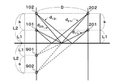
図2はアンテナ装置100が送信し、アンテナ装置200が受信する直接波の決定論的通信路を示す。図3はアンテナ装置100が送信し、アンテナ装置200が受信する大地反射波の決定論的通信路を示す。図3では、大地反射波の経路を算出するために、アンテナ101、102に関して大地に対して対称な位置に配置した仮想的なアンテナ901、902も示されている。図2及び図3に示した通信路は、アンテナ装置100及びアンテナ装置200の送信側・受信側の関係が入れ替わった場合にも成立する。これらの決定論的な通信路を想定した場合、アンテナ装置100及び200のそれぞれにおけるアンテナ間隔sが、一例として、√(λD/2)に設定されると、通信路の直交性を確保して空間相関を抑制できることが関連技術として知られている。以下では、まずこのことについて詳細に説明する。
FIG. 2 shows a deterministic communication path of a direct wave transmitted by the
図2のように、直接波の決定論的に決まるパスを考慮し、パス長をそれぞれ dijと置く。dijは、送信側のアンテナjから受信側のアンテナiへの直接波のパスの長さを表す。また、図3のように、大地反射波の決定論的に決まるパスを考慮し、パス長をそれぞれdijrと置く。dijrは、送信側のアンテナjから受信側のアンテナiへの大地反射波のパスの長さを表す。なお、アンテナ装置100及び200のそれぞれにおけるアンテナ間隔sが送受信距離Dに比べて十分に小さい場合、受信側のアンテナ間で受信信号の振幅の違いは無視することができる。
As shown in Fig. 2, considering the deterministic paths of direct waves, the path lengths are set to dig , respectively. dij represents the length of the path of the direct wave from the antenna j on the transmitting side to the antenna i on the receiving side. Further, as shown in FIG. 3, the path length is set to djr in consideration of the deterministic path of the ground reflected wave. d ijr represents the length of the path of the ground reflected wave from the antenna j on the transmitting side to the antenna i on the receiving side. When the antenna interval s in each of the
ここで、送信側のアンテナ(送信アンテナ)の本数をNtx、受信側のアンテナ(受信アンテナ)の本数をNrxとしたMIMOシステムモデルを考える。j番目の送信アンテナからi番目の受信アンテナへの伝送路応答(チャネル情報)をhijにより表すと

要素hijからなるNrx×Ntx次元の行列をチャネル行列Hとすると式(1)は下記のように定式化される。
Assuming that the N rx × N tx dimension matrix consisting of the elements h ij is the channel matrix H, the equation (1) is formulated as follows.
本実施形態では、送信側及び受信側とも2本のアンテナを有するため、2×2MIMOシステムモデルが適用される。このため、チャネル行列Hは2×2次元となる。チャネル行列Hの各要素は、下記のような直接波と大地反射波の位相成分の足し合わせで表現される。
式(3)の空間相関行列を用いて
![]()
![]()
式(5)が直接波の直交条件、式(8)が大地反射波の直交条件、式(6)、(7)、式(9)−(12)が直接波と反射波間の直交条件となる。
Using the spatial correlation matrix of equation (3)
![]()
![]()
Equation (5) is the orthogonal condition of the direct wave, equation (8) is the orthogonal condition of the ground reflected wave, and equations (6), (7) and (9)-(12) are the orthogonal conditions between the direct wave and the reflected wave. Become.
図3に示した位置関係よりdijrはアンテナ設置高L1、L2及び送受信距離Dを用いて下記の式(13)乃至(15)のように書き表すことができる。
式(13)においては、送受信距離DがL1と比べて十分に長いと仮定すると1≫(2×L1/D)2であるから次の近似式が成り立つ。
大地反射波の直交条件である式(8)に上記式(16)乃至(18)を代入すると、
また、送受信距離Dがアンテナ間隔sに比べ十分に長いと仮定すると、直接波の通信路について、下記の式(21)が得られる。
次に直接波及び大地反射波間の直交条件を含む式(9)に、近似式(16)、(18)及び(21)を代入すると、次の式(23)が得られる。
また、式(24)と、s=√(λD/2)と、L2=L1+sとから、以下の式が得られる。
Further, the following equation can be obtained from the equation (24), s = √ (λD / 2), and L2 = L1 + s.
図4は、本発明者らがシミュレーションにより作成したアンテナ設置高L1と空間相関(Spatial Correlation)ρとの関係を示す。なお、空間相関ρの定義については後述する。D=5000m、f=80GHzとし、フリスの伝搬公式に基づいて直接波と反射波との2波により構成されるチャネルを生成した。s=√(λD/2)とした。実線のグラフは、予め定めた範囲内の各アンテナ設置高L2についてシミュレーションで算出した空間相関を表す点を結合したグラフである。図の各丸は、式(25)を満たす場合のアンテナ設置高(最適化された高さ)L2とそのときの空間相関を表す。0より大きいL2について、空間相関ρの値が小さく抑えられている(ただし、シミュレーションでは反射波の反射係数による影響などにより、式(25)を満たす場合も空間相関は0にはならない)。グラフにより示されるように、式(25)が満たされていないアンテナ設置高L2では、空間相関ρの値が0.0と1.0の間で安定していない。一方、式(25)を満たすアンテナ設置高L2では、空間相関を小さく抑制できる。ただし、そのような設置高L2の間隔は大きい。このことは、アンテナ装置を設置するビルの高さや、設置後の設置高L2の調整に制約を与えることになる。式(25)を満たすアンテナ設置高L2以外でも、空間相関を低減することが要求される。また、式(25)を満たすアンテナ設置高L2の設置が可能な場合であっても、実際の通信ではこれと異なるアンテナ設置高L2(式(25)を満たすアンテナ設置高L2よりよりも若干低いアンテナ設置高)で、より低い空間相関が得られる場合もある。 FIG. 4 shows the relationship between the antenna installation height L1 created by the present inventors by simulation and the spatial correlation ρ. The definition of spatial correlation ρ will be described later. With D = 5000 m and f = 80 GHz, a channel composed of two waves, a direct wave and a reflected wave, was generated based on the Fris propagation formula. It was set as s = √ (λD / 2). The solid line graph is a graph in which points representing the spatial correlation calculated by simulation for each antenna installation height L2 within a predetermined range are combined. Each circle in the figure represents the antenna installation height (optimized height) L2 when the equation (25) is satisfied and the spatial correlation at that time. For L2 larger than 0, the value of the spatial correlation ρ is kept small (however, in the simulation, the spatial correlation does not become 0 even when the equation (25) is satisfied due to the influence of the reflection coefficient of the reflected wave). As shown by the graph, at the antenna installation height L2 in which the equation (25) is not satisfied, the value of the spatial correlation ρ is not stable between 0.0 and 1.0. On the other hand, at the antenna installation height L2 satisfying the equation (25), the spatial correlation can be suppressed to be small. However, the interval between such installation heights L2 is large. This imposes restrictions on the height of the building where the antenna device is installed and the adjustment of the installation height L2 after installation. It is required to reduce the spatial correlation other than the antenna installation height L2 satisfying the equation (25). Further, even if the antenna installation height L2 satisfying the equation (25) can be installed, it is slightly lower than the antenna installation height L2 (the antenna installation height L2 satisfying the equation (25)) which is different from this in actual communication. Lower spatial correlation may be obtained with antenna installation height).
そこで、本実施形態では、式(25)を満たすアンテナ設置高L2又はL1以外でも、空間相関を低減可能なアンテナ設置高L2又はL1を効率的に見つける。 Therefore, in the present embodiment, an antenna installation height L2 or L1 capable of reducing the spatial correlation can be efficiently found other than the antenna installation height L2 or L1 satisfying the equation (25).
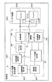
以下、図1の送信局(アンテナ配置決定装置1及びアンテナ装置100)並びに受信局(アンテナ配置決定装置2及びアンテナ装置200)についてさらに詳細に説明する。図5は第1の実施形態に係る送信局の詳細ブロック図である。図6は第1の実施形態に係る受信局の詳細ブロック図である。
Hereinafter, the transmitting station (antenna
図5の送信局は、アンテナ配置決定装置1とアンテナ装置100とを備える。アンテナ配置決定装置1は、アンテナ位置調整部11と、送受調整同期部12と、環境値設定部13と、空間相関算出部14と、空間相関記憶部15と、チャネル推定部16と、アンテナ配置決定部17と、送受信部18と、候補値生成部19とを備える。アンテナ装置100は、アンテナ101、102と、アンテナ101、102を移動させる駆動部11A、11Bとを備える。各部11〜14、16〜19の全部又は一部は、CPU等のプロセッサにプログラムを実行させることによりソフトウェアで実現してもよいし、専用のハードウェア回路又はプログラム可能な回路によって実現してもよいし、これらの両方によって実現してもよい。
The transmitting station of FIG. 5 includes an antenna
図6の受信局は、アンテナ配置決定装置2とアンテナ装置200とを備える。アンテナ配置決定装置2は、アンテナ位置調整部21と、送受調整同期部22と、環境値設定部23と、空間相関算出部24と、空間相関記憶部25と、チャネル推定部26と、アンテナ配置決定部27と、送受信部28と、候補値生成部29とを備える。アンテナ装置200は、アンテナ201、202と、アンテナ201、202を移動させる駆動部21A、21Bとを備える。各部21〜24、26〜29の全部又は一部は、CPU等のプロセッサにプログラムを実行させることによりソフトウェアで実現してもよいし、専用のハードウェア回路又はプログラム可能な回路によって実現してもよいし、これらの両方によって実現してもよい。
The receiving station of FIG. 6 includes an antenna
本発明の実施形態に係るアンテナ位置決定装置の構成は一例であり、これとは異なる構成を用いることができる。アンテナ配置決定装置は、少なくとも空間相関算出部など通信品質の算出を行う構成要素と、候補値生成部と、アンテナ配置決定部を含むものとする。従ってアンテナ配置決定装置は無線通信装置とは独立した計算機などの情報処理装置により実現されていてもよい。アンテナ配置決定装置は、更にアンテナ位置調整部などアンテナ位置を決定した配置に変更する機能を備えることもできる。このような場合は、アンテナ配置決定装置を、既存の無線通信装置及びアンテナ装置と組み合わせて、高品質な通信が可能なMIMO通信システムを構築することが可能となる。また、本発明の実施形態のように、アンテナ配置決定装置はチャネル推定部、送受信部など無線データ通信のための構成要素も含むことで、無線通信装置と一体化した構成をとってもよい。この場合、無線通信装置が、アンテナ配置決定装置を兼ねるといえる。送信局と受信局に係るアンテナ位置決定装置の構成が同一である必要はなく、それぞれ異なった構成であってもよい。 The configuration of the antenna position determining device according to the embodiment of the present invention is an example, and a configuration different from this can be used. The antenna arrangement determination device includes at least a component for calculating communication quality such as a spatial correlation calculation unit, a candidate value generation unit, and an antenna arrangement determination unit. Therefore, the antenna arrangement determining device may be realized by an information processing device such as a computer independent of the wireless communication device. The antenna arrangement determining device can also be provided with a function of changing the antenna position to a determined arrangement such as an antenna position adjusting unit. In such a case, it is possible to construct a MIMO communication system capable of high-quality communication by combining the antenna arrangement determination device with the existing wireless communication device and antenna device. Further, as in the embodiment of the present invention, the antenna arrangement determining device may be integrated with the wireless communication device by including components for wireless data communication such as a channel estimation unit and a transmission / reception unit. In this case, it can be said that the wireless communication device also serves as the antenna arrangement determining device. The configurations of the antenna position-fixing devices related to the transmitting station and the receiving station do not have to be the same, and they may have different configurations.
送受信部18及び送受信部28は互いに無線通信を行う。送受信部18及び送受信部28は、送信時においては、MIMO変調等の変調、DA変換、無線周波数へのアップコンバート、増幅等を行う。送受信部18及び送受信部28は、受信時においては、増幅、ダウンコンバート、AD変換、MIMO復調等の復調を行う。使用する通信方式は、任意でよい。
The transmission /
送信局1の送受信部18は、送信用の信号に基づき搬送波を変調することにより、変調信号を生成する。変調信号をDA変換、無線周波数へのアップコンバート、増幅等し、1つ又は複数のアンテナを介して送信する。なお、変調方式はASK(amplitude shift keying)、PSK(phase shift keying)、FSK(frequency shift keying)又はQAM(quadrature amplitude modulation)のような任意のディジタル変調方式を用いればよい。なお、ディジタル変調方式ではなく、振幅変調(AM)、周波数変調(FM)又は位相変調(PM)などのアナログ変調方式を用いることも可能である。また、送受信部18は、MIMOを実行する機能を有する。送受信部18は、MIMOを行う場合は、データを分割して複数のストリームを生成し、複数のストリームにMIMO変調を行った後、変調後のストリームを、複数のアンテナから送信する。
The transmission /
更に必要に応じて、送受信部18は2次変調を行ってもよい。2次変調方式としてはDS(direct sequence)、FH(frequency hopping)、TDMA(time division multiple access)、FDMA(frequency division multiple access)、CDMA(code division multiple access)又はOFDM(orthogonal frequency−division multiplexing)など、いずれの方式を用いてもよい。また、送受信部18は、時分割多重、周波数分割多重、符号分割多重又はこれらの組み合わせなど、任意の多重方式で通信を行ってもよい。
Further, if necessary, the transmission /
受信局2の送受信部28は、1つ又は複数のアンテナを介して、送信局から送信された電波を受信し、受信した電波の信号に低雑音増幅、ダウンコンバート、AD変換、復調を行う。MIMOの場合、送受信部28は、送信局1から送信された電波を複数のアンテナで受信し、複数のアンテナで受信された信号をMIMO復調することにより複数のストリームに分離する。MIMO復調処理における信号分離アルゴリズムには、ZF法(Zero−Forcing method)、MMSE法(Minimum Mean Square Error method)、BLAST法(Bell laboratories Layered Space−Time method)、MLD法(Maximum Likelihood Detection method)又はMLD法の派生形など複数の方式があるが、それらのいずれの方式を用いてもよい。
The transmitting / receiving
送信局と受信局の役割を互いに入れ替えることが可能である。この場合、送信局1の送受信部18は、前述の受信局2の送受信部28と同様の処理を実行する。一方、受信局2の送受信部28は前述の送信局1の送受信部18と同様の処理を実行する。送信局1及び受信局2はいずれも送信と受信の双方の機能を兼ね備えた送受信局として機能することができる。
It is possible to switch the roles of the transmitting station and the receiving station. In this case, the transmission /
アンテナ位置調整部11は、駆動部11A、11Bを制御することで、アンテナ101、102の位置を調整する。アンテナ位置調整部11は、調整後の位置にアンテナを固定する。固定することで、屋外使用時に発生する風・気温の変動・振動などがあっても、アンテナ101及びアンテナ102の位置ずれが抑制される。アンテナ位置調整部11は、一例として、アンテナ101及びアンテナ102の位置調整を、アンテナ間隔s、アンテナ設置高L1及びL2の少なくとも1つに基づいて行う。これらの値は、アンテナ配置決定部17から提供される。
The antenna
受信局2のアンテナ位置調整部21も、同様にアンテナ間隔s、アンテナ設置高L1及びL2の少なくとも1つに基づいて、アンテナ201及びアンテナ202を制御することで、アンテナ201及びアンテナ202の位置を調整する。アンテナ位置調整部21は、調整後の位置にアンテナを固定する。
Similarly, the antenna
送受調整同期部12は、受信側の送受調整同期部22との間で、アンテナ間隔sの設定及びアンテナ設置高L1、L2の設定の同期処理を行う。この同期処理は、受信局2のアンテナ位置調整部21によって用いられるアンテナ間隔s及びアンテナ設置高L1、L2が、送信局1のアンテナ位置調整部11によって用いられている値と同一になるよう設定を行うものである。受信局2の送受調整同期部22についても、送信側の送受調整同期部12との間で同期処理を行うことで、送信側で用いられるアンテナ間隔s及びアンテナ設置高L1、L2を、受信側で用いられている値と同一になるよう設定できる。
The transmission / reception
送受調整同期部12、22は、同期処理を、送受信部18、28を介した無線通信により行ってもよいし、送信局1と受信局2の間を接続する有線ネットワークが存在する場合は、当該有線ネットワークを用いた有線通信により行ってもよい。
The transmission / reception
環境値設定部13は、パラメータを保持する。パラメータには、送受信距離D、電波の波長λ又は周波数f、アンテナ101の設置高L1の範囲[Ll,Lh]、アンテナ102の設置高L2の範囲[Nl,Nh]、アンテナ間隔の範囲[sl,sh]の全部又は一部が含まれる。環境値設定部13は、これらのパラメータを内部に保持するためのバッファを有していてもよい。バッファは、例えばNANDフラッシュメモリ、NORフラッシュメモリ、MRAM、ReRAM、ハードディスク、光ディスクなどの不揮発記憶デバイス又はDRAMなどの記憶デバイスのいずれか又はそれらの組み合わせから構成される。
The environment
パラメータを取得する方法については特に限定しない。事前に外部から環境値設定部13に静的にパラメータを登録してもよいし、環境値設定部13が計測によりパラメータを算出し、算出したパラメータを内部に保持してもよい。
The method of acquiring the parameters is not particularly limited. Parameters may be statically registered in the environment
計測によりパラメータを算出する例を説明する。送受信距離Dについては送信局と受信局間で計測を行い、送受信距離Dの値を求める方法がある。例えば、GPS(Global Positioning System)のような測位方法を用いて送信局及び受信局の位置を求め、その間の距離を算出し、送受信距離Dとして用いることができる。Time−of−Flight(TOF)のように光が送信局及び受信局の間を往復する時間を計測し、計測した時間と光速とから距離を算出し、それを送受信距離Dとして用いてもよい。 An example of calculating parameters by measurement will be described. Regarding the transmission / reception distance D, there is a method of measuring between the transmitting station and the receiving station and obtaining the value of the transmission / reception distance D. For example, the positions of the transmitting station and the receiving station can be obtained by using a positioning method such as GPS (Global Positioning System), the distance between them can be calculated, and the transmission / reception distance D can be used. Like Time-of-Flight (TOF), the time for light to reciprocate between a transmitting station and a receiving station may be measured, the distance may be calculated from the measured time and the speed of light, and this may be used as the transmission / reception distance D. ..
アンテナ設置高L1又はL2については、気圧センサから設置高度を求める方法、アンテナ装置の設置されるビルの高さに関する情報から求める方法、高度が既知である地点との間でTime−of−Flight(TOF)による計測を行い、その差分からアンテナ設置高を算出する方法などがある。 Regarding the antenna installation height L1 or L2, the method of obtaining the installation altitude from the barometric pressure sensor, the method of obtaining from the information on the height of the building where the antenna device is installed, and the Time-of-Fright ( There is a method of measuring by TOF) and calculating the antenna installation height from the difference.
外部からパラメータを設定する方法としては、作業員等のユーザが入力した値を環境値設定部23に登録してもよい。または、図示しない管理サーバから配信された値を取得し、パラメータとして環境値設定部23に登録してもよい。これらの場合にアンテナ配置決定装置1、2に値又は指示を入力するために用いられるインタフェースは、入力キー又はタッチパネル付のコンソール等の物理的な端末であっても、ブラウザから操作可能なウェブインタフェースであっても、ソフトウェアにより実現されるAPI(Application Programming Interface)であってもよい。また、実際の入力操作が行われる場所については、送信局1又は受信局2の所在地でも、送信局1又は受信局2の設置場所から離れたリモート環境でもよい。リモート環境からの入力が行われる場合には、端末と送信局又は受信局との間に電気通信回線及び管理サーバ等を介して伝達がされる形態でもよい。
As a method of setting parameters from the outside, a value input by a user such as a worker may be registered in the environment
受信局のチャネル推定部24は、式(2)のチャネル行列Hを求める(チャネル推定)。チャネル推定部24は、送信局から受信された信号に基づきチャネル推定を行う。ただし、送信局1及び受信局2間で通信路の対称性を仮定することで、送信局のチャネル推定部14が、受信局から受信した信号に基づき、チャネル推定を行ってもよい。送信局が受信局として動作し、受信局が送信局として動作する場合も同様にしてチャネル推定を行うことが可能である。
The
ここで、チャネル推定部24の動作について説明する。まず送信局の送受信部18はアンテナ装置100のアンテナ101及び102を用いて、チャネル推定用の信号であるパイロット信号をアンテナ装置200に向けて送信する。パイロット信号は、時間と周波数に対して離散的に配置された信号を含み、パイロット信号のパターンは予め送信局1及び受信局2との間で共有されている。パイロット信号の送信は、受信局がパイロット信号の送信指示信号を送信局に送信することで行ってもよい。受信局は、この動作を、一例としてアンテナ調整処理の開始を決定した場合に行う。アンテナ調整処理は、外部からユーザの指示情報を受信したときに行ってもよいし、定期的に行ってもよいし、通信品質の低下を検知した場合(たとえば受信エラー率が一定値以上になった場合など)に行ってもよい。
Here, the operation of the
送信局から送信されたパイロット信号は、アンテナ装置200のアンテナ201及び202を介して、受信局の送受信部28により受信される。受信された信号は送受信部28からチャネル推定部24に渡される。チャネル推定部24は受信された信号に対し、2次元線形補間、又は2次元離散フーリエ変換を用いた補間などを適用し、チャネル行列Hの推定を行う。ここで述べたチャネル推定時の補間方法は例示であり、高速フーリエ変換など他の方法を用いてもよい。
The pilot signal transmitted from the transmitting station is received by the transmitting / receiving
受信局の空間相関算出部24は、チャネル推定部24で求められたチャネル行列Hを使って空間相関を計算する。MIMO通信においては、大地の凹凸や建築物等障害物が存在しているため、電波の散乱が発生する。このため各々のチャネルは互いに独立しておらず、ある程度相関が生じる。このようなチャネル間の相関を空間相関と呼ぶ。ここでは、下記の式(26)及び(27)で定義される受信空間相関
![]()
![]()
以下の説明で、空間相関ρは、受信空間相関ρrを指す場合を想定するが、送信空間相関ρtを指してもよい。空間相関ρは、範囲[0,1]の実数値をとる。空間相関ρの値が小さいほど空間相関が少なく、符号誤り率も低くなる。このため、伝送容量の確保の観点から、空間相関ρの値は小さいことが望ましい。空間相関算出部14が計算した空間相関の値は、空間相関記憶部15に格納される。
In the following description, it is assumed that the spatial correlation ρ refers to the receiving spatial correlation ρ r , but it may also refer to the transmitting spatial correlation ρ t. The spatial correlation ρ takes a real value in the range [0,1]. The smaller the value of the spatial correlation ρ, the smaller the spatial correlation and the lower the bit error rate. Therefore, from the viewpoint of securing the transmission capacity, it is desirable that the value of the spatial correlation ρ is small. The spatial correlation value calculated by the spatial
空間相関記憶部15は空間相関算出部14より書き込み可能で、アンテナ配置決定部17より参照可能である。空間相関記憶部16は、例えばNANDフラッシュメモリ、NORフラッシュメモリ、MRAM、ReRAM、ハードディスク、光ディスクなどの不揮発記憶デバイス又はDRAMなどの記憶デバイスのいずれか又はそれらの組み合わせから構成される。
The spatial
送信局の空間相関算出部14及び空間相関記憶部15については、それぞれ受信局の空間相関算出部24及び空間相関記憶部25と同様の構成を有する。なお、受信局で推定したチャネル行列Hを、送信局にフィードバックし、送信局の空間相関算出部14で空間相関を計算してもよい。この場合、計算した空間相関を表す情報を、空間相関記憶部25に格納してもよい。
The spatial
アンテナ配置決定部17は、それぞれアンテナ配置決定装置1内の他のブロックの制御を行うとともに、MIMO通信の空間相関を低く抑えるもしくは直交性を担保するアンテナ装置100のアンテナ101及びアンテナ102の配置(アンテナ101、102の間の間隔、及びアンテナ101又は102の位置)を求める。アンテナ配置決定部17は、アンテナ101又は102の設置高に応じた間隔で、アンテナ間隔の候補値を生成する候補値生成部19を備えている。アンテナ配置決定部17は、候補値の中から、各候補値にアンテナ間隔を設定した場合の通信品質(空間相関等)に基づき、アンテナ間隔の設定値を決定する。一例として、空間相関が最小又は閾値以下のアンテナ間隔を決定する。アンテナ配置決定部27も、アンテナ配置決定部17と同様の構成を有する。すなわち、アンテナ配置決定部27は、それぞれアンテナ配置決定装置2内の他のブロックの制御を行うとともに、MIMO通信の空間相関を低く抑えるもしくは直交性を担保するアンテナ装置200のアンテナ201及びアンテナ202の配置を求める(アンテナ201、202の間の間隔、及びアンテナ101又は102の位置)。アンテナ配置決定部27は、アンテナ201又は202の設置高に応じた間隔で、アンテナ間隔の候補値を生成する候補値生成部29を備えている。候補値生成部29の動作は、候補値生成部19と同様である。
The antenna
関連技術においては通信路の直交性を確保するためにアンテナの配置が式(25)の要件を満たす必要があり、このことがアンテナ設置に対する制約となっていた。本発明の実施形態では式(25)の要件を満たさなくても、MIMO通信路の空間相関を低く抑えるもしくは直交性を確保できるアンテナ配置が存在する(詳細は後述)ことを利用し、設置の制約を満たすようなアンテナ配置を効率的に求める。これにより、式(25)の要件の元で算出されたアンテナ配置では設置できなかった場所にも、アンテナ装置を設置できる。例えば、式(25)の要件で要求される位置よりも低い位置に、アンテナ装置を設置できる。 In the related technology, the antenna arrangement must satisfy the requirement of the equation (25) in order to ensure the orthogonality of the communication path, which has been a restriction on the antenna installation. In the embodiment of the present invention, even if the requirement of the equation (25) is not satisfied, there is an antenna arrangement that can suppress the spatial correlation of the MIMO communication path low or ensure the orthogonality (details will be described later). Efficiently find an antenna arrangement that meets the constraints. As a result, the antenna device can be installed even in a place where the antenna arrangement calculated based on the requirement of the equation (25) could not be installed. For example, the antenna device can be installed at a position lower than the position required by the requirement of the equation (25).
次に式(25)の要件が満たされていなくても、MIMO通信の空間相関を低く抑えることができるもしくは直交性を確保できるアンテナ配置の存在について詳しく説明する。
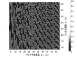
図7は直接波と大地反射波を含む2波の電波伝搬モデルを用いて、一定範囲のアンテナ設置高L1及びアンテナ間隔sについてシミュレーションを行い、空間相関ρの値を計算した結果を示している。送受信距離Dは5000m、周波数fは80×109Hzとしている。アンテナ設置高L1及びアンテナ間隔sの範囲についてみると、アンテナ設置高L2の範囲が概ね3mから59m、アンテナ間隔sの範囲が概ね1.575mから3.25mである。図8は、図7の分布の一部を拡大表示したものであり、アンテナ設置高L1の範囲が概ね50〜50.1、アンテナ間隔sの範囲が概ね1.5mから3.25mとなっている。空間相関が低いほど、濃い色になっている。
Next, the existence of an antenna arrangement capable of suppressing the spatial correlation of MIMO communication to a low level or ensuring orthogonality even if the requirement of the equation (25) is not satisfied will be described in detail.
FIG. 7 shows the result of calculating the value of the spatial correlation ρ by simulating the antenna installation height L1 and the antenna interval s in a certain range using a two-wave radio wave propagation model including a direct wave and a ground reflected wave. .. Receiving distance D 5000 m, frequency f is set to 80 × 10 9 Hz. Looking at the range of the antenna installation height L1 and the antenna interval s, the range of the antenna installation height L2 is approximately 3 m to 59 m, and the range of the antenna interval s is approximately 1.575 m to 3.25 m. FIG. 8 is an enlarged display of a part of the distribution of FIG. 7, in which the range of the antenna installation height L1 is approximately 50 to 50.1 and the range of the antenna interval s is approximately 1.5 m to 3.25 m. There is. The lower the spatial correlation, the darker the color.
前述した図4で説明したように式(25)を満たすアンテナ設置高L1の位置は離散的であり、これに対応するアンテナ間隔も1つに決まる。図7及び図8の空間相関シミュレーション結果から分かるように、空間相関が低い(たとえば0.1付近である)アンテナ設置高L1とアンテナ間隔sの組み合わせは多数存在する。このように、アンテナ配置が式(25)の条件を満たさなくても、空間相関を低く抑えることができるアンテナ設置高L1及びアンテナ間隔sの組み合わせが多数存在する。 As described with reference to FIG. 4 described above, the positions of the antenna installation height L1 satisfying the equation (25) are discrete, and the corresponding antenna spacing is also determined to be one. As can be seen from the spatial correlation simulation results of FIGS. 7 and 8, there are many combinations of the antenna installation height L1 having a low spatial correlation (for example, around 0.1) and the antenna spacing s. As described above, there are many combinations of the antenna installation height L1 and the antenna spacing s that can suppress the spatial correlation low even if the antenna arrangement does not satisfy the condition of the equation (25).
一例として、図7及び図8のシミュレーション結果において、空間相関ρが0.1以下となる範囲501の分布を取り出して示したものを図9及び図10にそれぞれ概略的に示す。ここでは空間相関ρが0.1以下の範囲を対象としているが、これは一例に過ぎず、0.1より大きい値を基準として、これより小さい範囲を対象としてもよいし、0.1より小さい値を基準として、これより小さい範囲を対象としてもよい。図9及び図10から、アンテナ設置高L1の値を固定し、アンテナ間隔sの値を変更すると、空間相関ρが0.1以下となる範囲が概ね一定の間隔ごとに繰り返されることがわかる。例えば、図10の破線502で示すアンテナ設置高L1に着目すると、この傾向が確認できる。以降この傾向を「低空間相関部分の周期性」と呼ぶことにする。更に、図7をみると、アンテナ設置高L1が大きくなるほど、低空間相関部分の周期(低空間相関部分の出現間隔)が短くなる傾向にあることがわかる。
As an example, in the simulation results of FIGS. 7 and 8, the distribution of the range 501 in which the spatial correlation ρ is 0.1 or less is taken out and shown, which are schematically shown in FIGS. 9 and 10, respectively. Here, the range in which the spatial correlation ρ is 0.1 or less is targeted, but this is only an example, and a range smaller than this may be targeted based on a value larger than 0.1, or more than 0.1. A smaller value may be used as a reference, and a range smaller than this may be targeted. From FIGS. 9 and 10, it can be seen that when the value of the antenna installation height L1 is fixed and the value of the antenna interval s is changed, the range in which the spatial correlation ρ is 0.1 or less is repeated at substantially constant intervals. For example, this tendency can be confirmed by paying attention to the antenna installation height L1 shown by the
アンテナ配置決定部17は、環境値設定部13で設定された条件の下でアンテナ間隔の候補値scを複数生成する。ここでいう設定された条件には、一例として、送受信距離D、波長λ又は周波数f、アンテナ設置高L2の範囲[Nl,Nh]が含まれる。アンテナ設置高L1の範囲[Ll,Lh]が含まれてもよい。
Antenna
アンテナ間隔の候補値scを生成する方法の一例について、図11を用いて説明する。ここでは、アンテナ設置高がある値L1s(図では50.5)である場合を想定する。 An example of a method of generating a candidate value s c of the antenna interval is described with reference to FIG. 11. Here, it is assumed that the antenna installation height is a certain value L1 s (50.5 in the figure).
この例では、√(λD/2)を初期の候補値(初期値)とし、アンテナ間隔sが小さくなる方向に、設置高L1sに応じた間隔で、アンテナ間隔の候補値を生成(サンプリング)する。初期値は、何でもよく、√(λD/2)は一例である。初期値を上限値とすることで、アンテナ102の設置高L2がL1+初期値より大きくならないように、設定するアンテナ間隔を探索することができる。また、前述したように、アンテナ間隔が√(λD/2)の場合も空間相関は0にはならず、これより良い空間相関が得られるアンテナ間隔が存在する場合もある。アンテナ装置の所望の設置高に応じて初期値を決めてもよい。初期値は外部から指定してもよいし、予め設定しておいてもよい。
In this example, √ (λD / 2) is set as the initial candidate value (initial value), and the candidate value of the antenna interval is generated (sampling) at the interval corresponding to the installation height L1 s in the direction in which the antenna interval s becomes smaller. do. The initial value may be anything, and √ (λD / 2) is an example. By setting the initial value as the upper limit value, it is possible to search for the antenna interval to be set so that the installation height L2 of the
図の二重丸が、サンプリングされた箇所を模式的に示している。この例では、λD/2L1sの2つ分の長さの区間を探索範囲(候補範囲)とし、探索範囲からn個の候補値(サンプル)を一定の間隔で選択している。前述したように、アンテナ設置高L1(又はL2)が大きくなるほど、アンテナ間隔s方向における低空間相関部分の周期(出現間隔)が短くなる傾向がある。そこで、この傾向に合わせてアンテナ設置高L1(又はL2)が大きくなるほど、探索範囲を小さくなるように、分母にL1sを含めている。これによりアンテナ設置高L1(又はL2)に応じた、効率的な探索が可能となる。つまり、探索範囲の大きさが狭すぎると、空間相関ρの値が最も小さい部分が選択対象から漏れる可能性が高くなり、大きすぎると、演算量が多くなる。そこで、上記の傾向に合わせて設置高L1が大きいほど探索範囲を小さくすることで、このような問題を防止しつつ、効率的な探索を行う。なお、n値は、正の整数値であれば任意でよい。例えば、5、10、又は20などがある。nの値が大きいほど、サンプルの間隔が小さくなる。設置高が大きいと探索範囲が小さくなることから、設置高が大きいほど、サンプルの間隔は小さくなる。nの値を複数用意し、nの複数の値を対象に処理を行ってもよい。 The double circles in the figure schematically show the sampled parts. In this example, a section having a length of two λD / 2L1 s is set as a search range (candidate range), and n candidate values (samples) are selected from the search range at regular intervals. As described above, as the antenna installation height L1 (or L2) increases, the period (appearance interval) of the low-spatial correlation portion in the antenna interval s direction tends to become shorter. Therefore, L1 s is included in the denominator so that the search range becomes smaller as the antenna installation height L1 (or L2) increases in line with this tendency. This enables efficient search according to the antenna installation height L1 (or L2). That is, if the size of the search range is too narrow, there is a high possibility that the portion having the smallest value of the spatial correlation ρ will be leaked from the selection target, and if it is too large, the amount of calculation will increase. Therefore, in line with the above tendency, the larger the installation height L1, the smaller the search range, thereby preventing such a problem and performing an efficient search. The n value may be any value as long as it is a positive integer value. For example, there are 5, 10, or 20. The larger the value of n, the smaller the sample spacing. The larger the installation height, the smaller the search range. Therefore, the larger the installation height, the smaller the sample spacing. A plurality of values of n may be prepared, and processing may be performed on a plurality of values of n.
探索範囲の大きさは、A/L1s又はこの倍数の範囲としてよいし(Aは任意の実数である)、分母にL1sのべき乗を用いるなど、別の方法で決めてもよい。探索範囲を一定の大きさあるいは別の任意の方法で決定し、設置高が大きいほどサンプルの間隔を小さくしてもよい。 The size of the search range may be A / L1 s or a range of multiples thereof (A is an arbitrary real number), or may be determined by another method such as using the power of L1 s as the denominator. The search range may be determined by a certain size or another arbitrary method, and the larger the installation height, the smaller the sample spacing may be.
図11に示した方法においては、アンテナ102及び202の高さがLs+√(λD/2)以下の範囲に収まり、それより高くならないよう、アンテナ間隔の候補値scをsc<=√(λD/2)の範囲内で生成している。ただし、アンテナ装置102及び202の高さL1をL+√(λD/2)より高くしてもよい場合は、アンテナ間隔の候補値scとして、√(λD/2)より大きい値をとってもよい。
In the method shown in FIG. 11, the height of the
アンテナ設置高L1の範囲[Ll,Lh]の複数のLsについて、同様にして、アンテナ間隔scの選択(サンプリング)を行ってもよい。ただし、アンテナ設置高L1が事前に決まっている場合などは、その値のアンテナ設置高のみを対象に、アンテナ間隔scのサンプリングを行ってもよい。 The antenna spacing s c may be selected (sampling) in the same manner for a plurality of L s in the range [L l , L h] of the antenna installation height L1. However, such as when the antenna installation height L1 is determined in advance, targeting only the antenna installation height of that value, may be performed sampling antenna spacing s c.
アンテナ間隔の候補値scはアンテナ位置調整部11及び送受調整同期部12に渡され、アンテナ装置100及び200のアンテナ間隔の大きさが、候補値scになるよう調整される。調整後のアンテナ間隔scで、送信局からパイロット信号を送信し、受信局でチャネル行列の推定及び空間相関の計算を行い、空間相関記憶部15に格納する。なお、空間相関の計算を、電波伝搬モデルを用いたシミュレーションにより行うことも可能であり、その場合は、アンテナ装置100、200でアンテナ間隔の調整、及びパイロット信号の送信等を実際に行う必要はない。アンテナ配置決定部17は、設置高L1の範囲内で、複数のアンテナ間隔候補値scのうち、空間相関が最も低い又は閾値以下のアンテナ間隔候補scとアンテナ設置高L1を決定する。決定された候補値scと設置高Lを、アンテナ設置高L1の設定値及びアンテナ間隔の設定値sとする。アンテナ設置高L1が特定の値に決まっているときは、空間相関が最も低い又は閾値以下のアンテナ間隔候補scを、設定値sとする。
Candidate value s c of the antenna interval is passed to
図12はシミュレーションを繰り返し行い、nをn=5、n=10、n=20及びn=40とした場合に、アンテナ設置高L1の各値について得られる最小の空間相関ρの値を丸でプロットしたグラフである。なお、nの値が大きいほど、グラフが手前側に表示されている。このため、例えばn=5のグラフのうち、n=10、n=20、n=40のグラフと重なる部分は後ろに隠れて見えないことに注意する。図13は、図12の各nの値に対する空間相関値の累積確率分布と、関連技術の累積確率分布(LOS−MIMOのグラフ)を表す。 In FIG. 12, the simulation is repeated, and when n is set to n = 5, n = 10, n = 20 and n = 40, the value of the minimum spatial correlation ρ obtained for each value of the antenna installation height L1 is circled. It is a plotted graph. The larger the value of n, the closer the graph is displayed. Therefore, it should be noted that, for example, in the graph of n = 5, the portion overlapping with the graphs of n = 10, n = 20, and n = 40 is hidden behind and cannot be seen. FIG. 13 shows the cumulative probability distribution of the spatial correlation value for each n value of FIG. 12 and the cumulative probability distribution (LOS-MIMO graph) of the related technology.
この結果をみると、nの値を大きくするほどアンテナ設置高L1の各値について低い空間相関ρを抽出しやすくなっていることがわかる。n=40の場合、サンプリング間隔が小さいため、多くのアンテナ設置高で、低い空間相関ρを抽出できているが、n=5又はn=10だと、サンプリング間隔が広くなるため、抽出される空間相関ρが高くなるケースも多くなる。 From this result, it can be seen that the larger the value of n, the easier it is to extract the low spatial correlation ρ for each value of the antenna installation height L1. When n = 40, the sampling interval is small, so low spatial correlation ρ can be extracted at many antenna installation heights, but when n = 5 or n = 10, the sampling interval becomes wide, so it is extracted. In many cases, the spatial correlation ρ becomes high.
図14は第1の実施形態に係る処理を表したフローチャートである。 FIG. 14 is a flowchart showing the process according to the first embodiment.
ステップS101では、波長λ、アンテナ設置高L1(又はアンテナ設置高L2の範囲)及び送受信距離D等のパラメータを、送信局及び受信局のそれぞれのアンテナ配置決定装置に設定する。波長λの代わりに周波数fを設定してもよい。一方の通信局に設定したパラメータを、他方の通信局に通知することで両局に同じパラメータを設定してもよい。 In step S101, parameters such as the wavelength λ, the antenna installation height L1 (or the range of the antenna installation height L2), and the transmission / reception distance D are set in the antenna arrangement determination devices of the transmitting station and the receiving station, respectively. The frequency f may be set instead of the wavelength λ. The same parameter may be set for both stations by notifying the other communication station of the parameter set for one communication station.
ステップS102では、アンテナ装置100及び200のアンテナ設置高L1及びアンテナ間隔sを初期値に設定する。アンテナ間隔sの初期値は任意でよいが、一例として、√(λD/2)とする。具体的な動作として、受信局2側のアンテナ配置決定部27は、環境値設定部23からパラメータである波長λ、アンテナ設置高L1及び送受信距離Dを取得し、アンテナ間隔の初期値(候補値)√(λD/2)を算出する。アンテナ設置高L1を調整対象としない場合はステップS101で設定されたアンテナ設置高L1の値を初期値として設定する。アンテナ設置高L1も調整対象とする場合は、アンテナ設置高L1の範囲内で、設置高L1の候補値を任意の順番で選択し、選択したそれぞれの候補値について、以下のステップS103以降の処理を繰り返し実行する。ステップS102において実行される具体的な処理を下記に説明する。
In step S102, the antenna installation height L1 and the antenna interval s of the
アンテナ配置決定部27は、アンテナ位置調整部21及び送受調整同期部22に、アンテナ間隔の初期値及びアンテナ設置高L1の値を渡す。アンテナ位置調整部21は、これらの値を元にアンテナ装置200に係るアンテナ201及び202の位置を調整する。送受調整同期部22は、送信局側の送受調整同期部12にアンテナ間隔の初期値及びアンテナ設置高を表す情報を送信する。送受調整同期部12は、アンテナ位置調整部11にアンテナ間隔の初期値及びアンテナ設置高の値を渡す。アンテナ位置調整部11はこれらの値を元に、アンテナ装置100に係るアンテナ101及び102の位置を調整する。ここではパラメータの提供を受信局から送信局に行ったが、送信局から受信局へ行ってもよい。
The antenna
ステップS103では、アンテナ間隔sの初期値及びアンテナ設置高L1の初期値にアンテナ配置を調整し、チャネル推定を行い、空間相関を計算する。ステップS103において実行される具体的な処理を下記に説明する。 In step S103, the antenna arrangement is adjusted to the initial value of the antenna interval s and the initial value of the antenna installation height L1, channel estimation is performed, and the spatial correlation is calculated. The specific processing executed in step S103 will be described below.
まず、チャネル推定については、チャネル推定部24の動作の説明で述べたように、一例として、受信局が送信局にパイロット信号を送信することを指示する指示信号を送信し、送信局は、指示信号に従って、パイロット信号を送信する。受信局のチャネル推定部24は、各アンテナを介して、パイロット信号を受信して、チャネル推定を行い、チャネル行列Hを求める。続いて、空間相関算出部25が、空間相関(受信空間相関ρr又は送信空間相関ρt)を計算し、計算された空間相関を、アンテナ間隔の現在の候補値(アンテナ設置高も調整の対象とする場合は、アンテナ設置高の現在の値も)とともに、空間相関記憶部26に保存する。一例として、空間相関と候補値とを対応づけた空間相関テーブルの形式、又は空間相関と候補値と設置高L1とを対応づけた空間相関テーブルの形式で保存する。
First, regarding channel estimation, as described in the description of the operation of the
次のステップS104でアンテナ間隔のすべての候補値について空間相関を計算したかを判断し、まだ空間相関を計算していない候補値が存在するときは、ステップS105に進み、すべての候補値について空間相関を計算したときは、ステップS106に進む。 In the next step S104, it is determined whether the spatial correlation has been calculated for all the candidate values of the antenna interval, and if there is a candidate value for which the spatial correlation has not been calculated yet, the process proceeds to step S105, and the space for all the candidate values. When the correlation is calculated, the process proceeds to step S106.
ステップS105においてはアンテナ間隔の次の候補値を選択し、アンテナ装置100及び200のアンテナ位置を再調整する。アンテナ設置高L1は固定し、上側のアンテナを移動させることで、アンテナ間隔を調整する(この結果として、アンテナ設置高L2が調整される)。次のアンテナ間隔の候補値は、前述したように、アンテナ設置高L1が大きいほど、サンプル間隔(候補値の間隔)が小さくなる。ある特定のアンテナ設置高L1に対して、すべての候補値について空間相関を格納した空間相関テーブル160の例を図16に示す。この例では、アンテナ間隔の初期値が3.16mでありサンプル間隔が0.09mの場合を示している。空間相関の値は、記号“XXXXX”により模式的に表しているが、実際には値が入る。この例では、λD/2L1の2つ分の長さ内に等間隔にn個のサンプルを候補値として配置し、初期値である起点(上限値)から順次候補値を選択するとする。候補値を順次選択する様子を模式的に図15に示す。図の一番上の矩形が初期の候補値を表す。ステップS105を経るごとに、sが小さくなる方向に候補値を選択する。
In step S105, the next candidate value of the antenna spacing is selected, and the antenna positions of the
ステップS106では、アンテナ配置決定部27は、空間相関記憶部26から最小の空間相関が得られた候補値を特定し、特定した候補値をアンテナ間隔の設定値として決定する。特定した候補値を、閾値と比較し、閾値以上である場合は、閾値未満の空間相関が得られるまで、サンプル数nを段階的に大きくして、より粒度の高い探索を行うようにしてもよい。nの一定の値まで大きくしても空間相関が閾値未満となるアンテナ間隔を検出できない場合は、アンテナ設置高L1を別の値に設定し、再びアンテナ間隔の探索を行ってもよい。以降、閾値未満の空間相関が得られるまで、nの値の変更とアンテナ設置高の変更を繰り返してもよい。nの値は固定し、アンテナ設置高L1の値のみ変更していってもよい。アンテナ設置高L1の複数の値について、ステップS106までの処理を行った場合に得られる空間相関テーブル150の例を図17に示す。図16と異なり、アンテナ設置高L1の項目が追加されている。アンテナ設置高L1の値をX1、X2・・として記号によって表しているが実際には値が入る。アンテナ設置高L1の変更に加えて、nの値を変更する場合は、nの値ごとに、図17のようなテーブルが得られる。このテーブルをユーザにインタフェースを介して提供して、ユーザがアンテナ設置高L1の設定値、及びアンテナ間隔の設定値を決定してもよい。
In step S106, the antenna
アンテナ配置決定部27は、決定したアンテナ間隔の設定値及びアンテナ設置高L1の設定値を、送信局に通知する。これにより受信局及び送信局双方においてアンテナ配置が確定する。この後、受信局のアンテナ位置調整部21は当該設定値に基づきアンテナ201、202の位置を調整し、送信局のアンテナ位置調整部もアンテナ101、102の位置を調整する。調整後、送信局及び受信局間で、MIMO通信を行う。あるいは、ユーザが空間相関テーブル又は空間相関マップに基づき、ビル等に設置するアンテナ装置のアンテナ設置高L1及びアンテナ間隔を決定し、決定した内容に基づきアンテナ装置の設計を行ってもよい。
The antenna
図14のフローチャートの変形例として、ステップS103で計算された空間相関を閾値と比較し、閾値未満であるときは、当該空間相関が得られたときのアンテナ間隔の候補値を、アンテナ間隔の設定値として決定してもよい。これにより、他の候補値に対する探索処理を省略できるため、演算時間を短縮できる。 As a modification of the flowchart of FIG. 14, the spatial correlation calculated in step S103 is compared with the threshold value, and if it is less than the threshold value, the candidate value of the antenna interval when the spatial correlation is obtained is set as the antenna interval. It may be determined as a value. As a result, the search process for other candidate values can be omitted, so that the calculation time can be shortened.
本実施形態では、チャネル推定を実測により行ったが、シミュレーションにより行うことも可能である。例えば、直接波と大地反射波の2波が支配的なチャネルの場合、送信局側の各アンテナの設置高と、受信局側の各アンテナの設置高と、送受信間距離よりフリスの伝搬公式を用いて伝搬路応答(チャネル情報)を計算しても良い。あるいは、送受信間のチャネルを模擬したシミュレータを用いて、伝搬路応答を計算しても良い。シミュレーションでは、送受信局の間の地形、土地の利用状況及び存在する構造物など、周囲の地理情報を考慮して、現実環境の再現性の高いモデリングができれば、空間相関マップ又は空間相関テーブルの信頼性も高くなる。 In the present embodiment, the channel estimation is performed by actual measurement, but it can also be performed by simulation. For example, in the case of a channel in which two waves, a direct wave and a ground reflected wave, dominate, the fris propagation formula is calculated from the installation height of each antenna on the transmitting station side, the installation height of each antenna on the receiving station side, and the distance between transmission and reception. It may be used to calculate the propagation path response (channel information). Alternatively, the propagation path response may be calculated using a simulator that simulates the channel between transmission and reception. In the simulation, if the real environment can be modeled with high reproducibility in consideration of the surrounding geographic information such as the topography between the transmitting and receiving stations, the land use situation, and the existing structures, the reliability of the spatial correlation map or the spatial correlation table can be trusted. The sex is also high.
また、本実施形態では、アンテナ設置高L1に応じた間隔で複数の候補値を設定し、最小又は閾値以下の空間相関を得られる候補値を、アンテナ間隔の設定値として決定した。別の方法として、探索範囲内のデータに対して最急降下法を適用して、空間相関が最小又は閾値以下のアンテナ間隔を見つけてもよい。前述した探索範囲内において低空間相関部分の周期性を利用することで、最急降下法により、最小の空間相関値とアンテナ間隔との組を見つけることができる。 Further, in the present embodiment, a plurality of candidate values are set at intervals according to the antenna installation height L1, and a candidate value at which a spatial correlation equal to or less than the minimum value can be obtained is determined as a set value of the antenna interval. Alternatively, the steepest descent method may be applied to the data within the search range to find antenna spacing with minimal or less spatial correlation. By utilizing the periodicity of the low spatial correlation portion within the search range described above, the pair of the minimum spatial correlation value and the antenna spacing can be found by the steepest descent method.
また、本実施形態では、下側のアンテナ101、201の位置を固定し、上側のアンテナ102、202を移動する場合を示したが、上側のアンテナの位置を固定し、下側のアンテナを移動することで、アンテナ間隔を調整してもよい。この場合、上側のアンテナの設置高を変えずに、高い通信品質が得られるアンテナ間隔を効率良く見つけることができる。
Further, in the present embodiment, the case where the positions of the
以上、本実施形態によれば、上側のアンテナ102、202の設置高が所望の範囲に収まるように、高い通信品質が得られるアンテナ間隔を決定できる。
As described above, according to the present embodiment, it is possible to determine the antenna spacing at which high communication quality can be obtained so that the installation heights of the
(第2の実施形態)
第2の実施形態は、第1の実施形態で行ったチャネル推定及び空間相関計算に代えて、伝送レートを計算し、計算した伝送レートが最も高い又は閾値以上のアンテナ間隔を決定することを特徴とする。空間相関の代わりに伝送レートを用いることができるのは、高い伝送レートが得られているのであれば、チャネル干渉の発生が抑制されており、MIMO通信路の低相関が確保されていると推測できるからである。伝送レートの代わりに、ビット誤り率などの別の通信性能を表す指標を用いてもよい。空間相関、及び通信性能を表す指標(伝送レート、ビット誤り率等)は、送信局及び受信局間の通信品質を表す指標の一例である。以降、第2の実施形態について、伝送レートの場合を例に説明を行う。
(Second Embodiment)
The second embodiment is characterized in that, instead of the channel estimation and the spatial correlation calculation performed in the first embodiment, the transmission rate is calculated to determine the antenna interval having the highest calculated transmission rate or greater than or equal to the threshold value. And. It is presumed that the transmission rate can be used instead of the spatial correlation because the occurrence of channel interference is suppressed and the low correlation of the MIMO communication path is secured if a high transmission rate is obtained. Because it can be done. Instead of the transmission rate, another index indicating communication performance such as a bit error rate may be used. An index showing spatial correlation and communication performance (transmission rate, bit error rate, etc.) is an example of an index showing communication quality between a transmitting station and a receiving station. Hereinafter, the second embodiment will be described by taking the case of a transmission rate as an example.
図18は第2の実施形態に係る受信局のアンテナ配置決定装置のブロック図を示している。図6の空間相関算出部24及び空間相関記憶部25が、伝送レート算出部241及び伝送レート記憶部251に変更されている。送信局も同様に、空間相関算出部14及び空間相関記憶部15が、伝送レート算出部及び伝送レート記憶部に置き換わってもよい(図示せず)。伝送レート算出部241は、複数のアンテナ間隔の候補値ごとに、送信局及び受信局間の伝送レートを測定する。伝送レート記憶部15は、候補値と、伝送レートの測定値とを対応づけて記憶する。図19のように、アンテナ間隔の候補値と、伝送レートの測定値とを対応づけた伝送レートテーブル170を生成してもよい。アンテナ設置高を調整の対象とする場合は、図17の空間相関テーブルと同様に、アンテナ設置高の項目を追加すればよい。
FIG. 18 shows a block diagram of the antenna arrangement determining device of the receiving station according to the second embodiment. The spatial
図20は第2の実施形態に係る処理を表したフローチャートである。ステップS201及びステップS202は第1の実施形態におけるステップS101及びステップS102と同じである。ステップS203では送信局から受信局への伝送レートを測定する。伝送レートの測定は、例えば、複数回の伝送レート測定を行い、その平均、最大又は最小の伝送レートを決定してもよい。 FIG. 20 is a flowchart showing the process according to the second embodiment. Step S201 and step S202 are the same as steps S101 and S102 in the first embodiment. In step S203, the transmission rate from the transmitting station to the receiving station is measured. The transmission rate may be measured, for example, by performing a plurality of transmission rate measurements and determining the average, maximum or minimum transmission rate.
ステップS204、ステップS205は、第1の実施形態におけるステップS104、S105と同じである。ステップS206では、最大の伝送レートが得られた候補値を特定し、特定した候補値をアンテナ間隔の設定値として決定する。特定した候補値を、閾値と比較し、閾値未満である場合は、閾値以上の伝送レートが得られるまで、サンプル数nを段階的に大きくして、より粒度の高い探索を行うようにしてもよい。nの一定の値まで大きくしても伝送レートが閾値以上となるアンテナ間隔を検出できない場合は、アンテナ設置高L1を現在値より大きい値又は小さい値に設定し、再びアンテナ間隔の探索を行ってもよい。以降、閾値以上の伝送レートが得られるまで、nの値の変更とアンテナ設置高の変更を繰り返してもよい。nの値は固定し、アンテナ設置高のみ変更していってもよい。または、複数の候補値を生成する区間を変更してもよい。例えば候補値の生成区間が最初、3.16〜2.80であった場合に、0.13だけずらして、3.03〜2.67などにしてもよい。 Steps S204 and S205 are the same as steps S104 and S105 in the first embodiment. In step S206, the candidate value for which the maximum transmission rate is obtained is specified, and the specified candidate value is determined as the setting value of the antenna interval. The specified candidate value is compared with the threshold value, and if it is less than the threshold value, the number of samples n is gradually increased until a transmission rate equal to or higher than the threshold value is obtained, and a search with higher particle size is performed. good. If the antenna interval at which the transmission rate exceeds the threshold value cannot be detected even if the value of n is increased to a certain value, the antenna installation height L1 is set to a value larger or smaller than the current value, and the antenna interval is searched again. May be good. After that, the change of the value of n and the change of the antenna installation height may be repeated until a transmission rate equal to or higher than the threshold value is obtained. The value of n may be fixed and only the antenna installation height may be changed. Alternatively, the interval for generating a plurality of candidate values may be changed. For example, when the generation section of the candidate value is initially 3.16 to 2.80, it may be shifted by 0.13 to 3.03 to 2.67 or the like.
本実施形態では伝送レートを例に述べたが、ビット誤り率など通信性能に関する別の指標を用いる場合も同様にして実施できる。 In the present embodiment, the transmission rate has been described as an example, but it can be implemented in the same manner when another index related to communication performance such as a bit error rate is used.
(第3の実施形態)
第3の実施形態では、送信側及び受信側の双方のアンテナ装置に係るアンテナをそれぞれ大地に対して垂直方向ではなく、斜め又は水平方向に配置する。
(Third Embodiment)
In the third embodiment, the antennas related to the antenna devices on both the transmitting side and the receiving side are arranged not in the vertical direction but in the oblique or horizontal direction with respect to the ground, respectively.
図21は、第3の実施形態に係る送信局及び受信局の概略斜視図である。送信側であるアンテナ701及びアンテナ702、並びに受信側であるアンテナ801及びアンテナ802が、ビル等の建物上に配置されている。なお、アンテナ701の高さはアンテナ801と同じであり、アンテナ702の高さは、アンテナ802と同じである。またアンテナ701及びアンテナ702の相対位置関係と、アンテナ801及びアンテナ802の相対位置関係は同じである。
FIG. 21 is a schematic perspective view of a transmitting station and a receiving station according to the third embodiment. The transmitting
図22は、本実施形態に係る反射波の通信路を説明するための図である。鏡像711は、アンテナ701の大地に対する鏡像、鏡像712はアンテナ702の大地に対する鏡像、鏡像811はアンテナ801の大地に対する鏡像、鏡像812はアンテナ802の大地に対する鏡像をそれぞれ表す。
FIG. 22 is a diagram for explaining a communication path of the reflected wave according to the present embodiment. The
式(6)と式(7)の左辺及び右辺同士を足し、式(5)の左辺及び右辺を引くと、以下の大地反射波の直交条件の式が得られる。
図22を用いて、式(30)に含まれている大地反射波に係る通信路について説明をする。d11rはアンテナ701とアンテナ801間の大地反射波の経路を表す。d11rの長さは、アンテナ701と鏡像811間を結ぶ直線の長さ又はアンテナ801と鏡像711間を結ぶ直線の長さに等しい。従って、d11rは下記の式(31)のように表せる。
d22rは、アンテナ702とアンテナ802間の大地反射波の経路を表す。d22rの長さは、アンテナ702と鏡像812を結ぶ直線の長さ又はアンテナ802と鏡像712を結ぶ直線の長さに等しい。従って、d22rの長さは、下記の式(32)のように表せる。
d12rはアンテナ802とアンテナ701間の大地反射波の経路を表す。d21rはアンテナ801とアンテナ702の大地反射波の経路を表す。d12rとd21rの長さは等しい。d12r及びd21rの長さは、アンテナ701と鏡像812を結ぶ直線の長さ又はアンテナ802と鏡像711を結ぶ直線の長さに等しくなる。また、図22における線分Mの長さは下記のように表される。
式(31)、(32)及び(35)を式(30)に代入すると下記の式が得られる。
更に、式(36)でp1=0,p2=0及びp3=0と置くと、下記の式(38)が得られる。
(第4の実施形態)
第4の実施形態は、アンテナ位置調整処理を、使用する周波数帯域内において周波数選択性フェージングの影響が軽減される周波数(又は波長)で行うことを特徴とする。
(Fourth Embodiment)
A fourth embodiment is characterized in that the antenna position adjusting process is performed at a frequency (or wavelength) in which the influence of frequency selective fading is reduced within the frequency band to be used.
無線通信装置の使用する周波数帯域内に周波数選択性フェージングが発生すると、通信品質に影響を及ぼす。 If frequency selective fading occurs within the frequency band used by the wireless communication device, it affects the communication quality.
このため、周波数フェージングの影響が相対的に少ない周波数を用いることで、アンテナ位置調整処理を効果的に行うことができる。 Therefore, the antenna position adjustment process can be effectively performed by using a frequency that is relatively less affected by frequency fading.
第4の実施形態に係る処理においては、図14のステップS101又は図20のステップS201で、周波数選択性フェージングの影響が少ない周波数又は波長λを選択する。 In the process according to the fourth embodiment, in step S101 of FIG. 14 or step S201 of FIG. 20, a frequency or wavelength λ that is less affected by the frequency selective fading is selected.
例えば、使用周波数帯域で試験用の信号を送信局から受信局に送信し、受信信号を解析する。これにより図23に示すように、周波数ごとの振幅を表すデータを取得する。データに基づき、信号強度が最も高い又は閾値以上の周波数(又は波長)を選択する。信号の送信を複数回行い、信号強度の時間変動が少なく、信号強度の時間平均値が閾値以上の周波数を選択してもよい。選択した周波数を用いて位置調整のための通信(チャネル推定のための通信等)を行う。この通信では、選択した周波数を中心とする狭い帯域を使用する。位置調整後の通常の通信では、選択した周波数を含む周波数帯域全体を使えばよい。 For example, a test signal is transmitted from a transmitting station to a receiving station in the frequency band used, and the received signal is analyzed. As a result, as shown in FIG. 23, data representing the amplitude for each frequency is acquired. Based on the data, select the frequency (or wavelength) with the highest signal strength or above the threshold. A frequency may be selected in which the signal is transmitted a plurality of times, the time variation of the signal strength is small, and the time average value of the signal strength is equal to or higher than the threshold value. Communication for position adjustment (communication for channel estimation, etc.) is performed using the selected frequency. This communication uses a narrow band centered on the selected frequency. In normal communication after position adjustment, the entire frequency band including the selected frequency may be used.
本実施形態により、アンテナ位置調整をより効果的に行うことができる。 According to this embodiment, the antenna position can be adjusted more effectively.
(第5の実施形態)
第5の実施形態は、送信側及び受信側のアンテナ装置にそれぞれ3つ以上のアンテナがある構成において、2つのアンテナを送信側及び受信側のアンテナ装置のそれぞれにおいて選択し、選択した2つのアンテナを対象に、これまで述べた実施形態のアンテナ位置調整処理を行う。
(Fifth Embodiment)
In the fifth embodiment, in a configuration in which the transmitting side and the receiving side antenna devices each have three or more antennas, two antennas are selected in each of the transmitting side and the receiving side antenna devices, and the two selected antennas are selected. The antenna position adjustment process of the above-described embodiment is performed on the subject.
図24に、3つのアンテナ101、102、103を備えた送信局と、3つのアンテナ201、202、203を備えた受信局を模式的に示す。送信局のアンテナは、大地に近い側から、アンテナ101、102、103の順に大地に垂直に配置されている。受信局のアンテナは、大地に近い側から、アンテナ201、202、203の順に大地に垂直に配置されている。一例として、アンテナ101、201は同じ高さ、アンテナ102、202は同じ高さ、アンテナ103、203は同じ高さに配置されている。
FIG. 24 schematically shows a transmitting station having three
位置調整を行う2つのアンテナを選択する際、一例として、送信局及び受信局の双方で同じ相対位置関係にあるアンテナを選択する。例えば送信局からアンテナ102、103を選択し、受信局からアンテナ202、203を選択する。あるいは、送信局からアンテナ101、103を選択し、受信局からアンテナ201、203を選択してもよい。その他の組み合わせのアンテナを選択してもよい。
When selecting two antennas for position adjustment, as an example, antennas having the same relative positional relationship at both the transmitting station and the receiving station are selected. For example,
位置調整を行った後は、送信局及び受信局でそれぞれ3つのアンテナを用いて、3×3のMIMO通信を行えばよい。 After adjusting the position, the transmitting station and the receiving station may each use three antennas to perform 3 × 3 MIMO communication.
図24では、送信局及び受信局がそれぞれ3つのアンテナの場合を示したが、4つ以上のアンテナを備える場合も同様にして、アンテナ選択及び位置調整を行えばよい。 In FIG. 24, the case where the transmitting station and the receiving station each have three antennas is shown, but when four or more antennas are provided, the antenna selection and the position adjustment may be performed in the same manner.
(第6の実施形態)
第6の実施形態では、送信局及び受信局間で、FDD(Frequency Division Duplex)を用いて双方向のMIMO通信を行う場合を想定する。FDDは、送信用と受信用にそれぞれ別々の周波数を割り当てることにより全二重通信を実現する。具体的には、送信局から受信局への送信と、受信局から送信局への送信(送信局による受信局からの受信)とで別々の周波数帯域(使用する周波数帯域がオーバーラップしない)用いて同時に通信を行う。なお、送信用の周波数帯域と、受信用の周波数帯域間には、ガードバンドが設けられる。
(Sixth Embodiment)
In the sixth embodiment, it is assumed that bidirectional MIMO communication is performed between a transmitting station and a receiving station using FDD (Frequency Division Duplex). The FDD realizes full-duplex communication by assigning different frequencies for transmission and reception. Specifically, different frequency bands (the frequency bands used do not overlap) are used for transmission from the transmitting station to the receiving station and transmission from the receiving station to the transmitting station (reception from the receiving station by the transmitting station). And communicate at the same time. A guard band is provided between the transmission frequency band and the reception frequency band.
第6の実施形態においては、FDDにおいて、送信及び受信の双方に共通して空間相関を抑制できるアンテナ間隔及びアンテナ設置位置L1又はL2を決定する。具体的な動作例として、送信局から受信局への送信について、第1の実施形態と同様にして、空間相関テーブル(図16、図17参照)を作成する。同様にして、受信局から送信局への送信についても同様に空間相関テーブルを生成する。空間相関テーブルは、アンテナ設置高の範囲内の各設置高に対して作成してもよいし、特定のアンテナ設置高に対してのみ作成してもよい。これらの空間相関テーブルの双方で、空間相関が最小もしくは閾値未満のアンテナ間隔とアンテナ設置高L1(又はアンテナ間隔とアンテナ設置高L2の組)を特定する。特定したアンテナ間隔及びアンテナ設置高L1(又はL2)の値を設定値に決定する。 In the sixth embodiment, in the FDD, the antenna spacing and the antenna installation position L1 or L2 that can suppress the spatial correlation in common for both transmission and reception are determined. As a specific operation example, a spatial correlation table (see FIGS. 16 and 17) is created for transmission from the transmitting station to the receiving station in the same manner as in the first embodiment. Similarly, a spatial correlation table is generated for transmission from the receiving station to the transmitting station. The spatial correlation table may be created for each installation height within the range of the antenna installation height, or may be created only for a specific antenna installation height. In both of these spatial correlation tables, the antenna interval and the antenna installation height L1 (or the set of the antenna interval and the antenna installation height L2) whose spatial correlation is the minimum or less than the threshold value are specified. The specified antenna spacing and antenna installation height L1 (or L2) values are determined as set values.
(第7の実施形態)
図25は、シミュレーションによりアンテナ設置高L1の複数の値に対して、アンテナ間隔をs−s/2からsまで変化させ、その中で空間相関が最小となるアンテナ間隔をプロットし、グラフで結んだものである。sの値は、任意の方法で決定する。一例として、第1の実施形態と同様、s=√(λD/2)とする。分布はs−s/2以上に集中している。このことから、アンテナ間隔の候補値を設定する範囲(候補値の探索範囲)は、s−s/2からsとしても良い。シミュレーションと同じモデルを適用する場合は、シミュレーションの結果を記憶しておき、このシミュレーションの結果から、適用するアンテナ設置高L1に対応するアンテナ間隔を1つ特定してもよい。シミュレーションの結果は図25のようにグラフ形式でもよいし、第1の実施形態における空間相関テーブルの形式でもよい。この場合、第1の実施形態のようにアンテナ間隔の候補値の探索を行わなくてもよい。
(7th Embodiment)
In FIG. 25, the antenna spacing is changed from s−s / 2 to s for a plurality of values of the antenna installation height L1 by simulation, and the antenna spacing that minimizes the spatial correlation is plotted and connected in a graph. It is. The value of s is determined by any method. As an example, as in the first embodiment, s = √ (λD / 2). The distribution is concentrated over s-s / 2. From this, the range for setting the candidate value of the antenna interval (search range of the candidate value) may be s−s / 2 to s. When applying the same model as the simulation, the result of the simulation may be stored, and one antenna interval corresponding to the applied antenna installation height L1 may be specified from the result of this simulation. The result of the simulation may be in the form of a graph as shown in FIG. 25, or may be in the form of a spatial correlation table in the first embodiment. In this case, it is not necessary to search for the candidate value of the antenna interval as in the first embodiment.
図25における空間相関が最小になる近似グラフを算出し、図25のシミュレーション結果を記憶する代わりに、近似グラフを記憶してもよい。シミュレーションと同じモデルを適用する場合は、適用するアンテナ設置高L1に対応するアンテナ間隔を近似グラフから特定してもよい。この場合、第1の実施形態のようにアンテナ間隔の候補値の探索を行う必要はない。近似グラフの算出例として、
なお、本発明は上記各実施形態そのままに限定されるものではなく、実施段階ではその要旨を逸脱しない範囲で構成要素を変形して具体化できる。また、上記各実施形態に開示されている複数の構成要素を適宜組み合わせることによって種々の発明を形成できる。また例えば、各実施形態に示される全構成要素からいくつかの構成要素を削除した構成も考えられる。さらに、異なる実施形態に記載した構成要素を適宜組み合わせてもよい。 The present invention is not limited to each of the above embodiments as it is, and at the implementation stage, the components can be modified and embodied within a range that does not deviate from the gist thereof. In addition, various inventions can be formed by appropriately combining a plurality of components disclosed in each of the above embodiments. Further, for example, a configuration in which some components are deleted from all the components shown in each embodiment can be considered. Furthermore, the components described in different embodiments may be combined as appropriate.
1:アンテナ配置決定装置
2:アンテナ配置決定装置
11:アンテナ位置調整部
12:送受調整同期部
13:環境値設定部
14:チャネル推定部
15:空間相関算出部
16:空間相関記憶部
17:アンテナ配置決定部
18:送受信部
19:候補値生成部
21:アンテナ位置調整部
22:送受調整同期部
23:環境値設定部
24:チャネル推定部
25:空間相関算出部
26:空間相関記憶部
27:アンテナ配置決定部
28:送受信部
29:候補値生成部
100:アンテナ装置
101:アンテナ
102:アンテナ
150:空間相関テーブル
160:空間相関テーブル
170:伝送レートテーブル
200:アンテナ装置
201:アンテナ
202:アンテナ
701:アンテナ
702:アンテナ
711:アンテナの鏡像
712:アンテナの鏡像
801:アンテナ
802:アンテナ
811:アンテナの鏡像
812:アンテナの鏡像
1: Antenna arrangement determination device 2: Antenna arrangement determination device 11: Antenna position adjustment unit 12: Transmission / reception adjustment synchronization unit 13: Environment value setting unit 14: Channel estimation unit 15: Spatial correlation calculation unit 16: Spatial correlation storage unit 17: Antenna Arrangement determination unit 18: Transmission / reception unit 19: Candidate value generation unit 21: Antenna position adjustment unit 22: Transmission / reception adjustment synchronization unit 23: Environment value setting unit 24: Channel estimation unit 25: Spatial correlation calculation unit 26: Spatial correlation storage unit 27: Antenna arrangement determination unit 28: Transmission / reception unit 29: Candidate value generation unit 100: Antenna device 101: Antenna 102: Antenna 150: Spatial correlation table 160: Spatial correlation table 170: Transmission rate table 200: Antenna device 201: Antenna 202: Antenna 701 : Antenna 702: Antenna 711: Mirror image of antenna 712: Mirror image of antenna 801: Antenna 802: Antenna 811: Mirror image of antenna 812: Mirror image of antenna
Claims (16)
前記アンテナ間の前記距離を前記候補値に設定した場合の通信品質を算出する算出部と、
前記通信品質に基づき、前記候補値の中から前記アンテナ間の前記距離の設定値を決定するアンテナ配置決定部と、
を備え、
前記複数の候補値の前記間隔は、前記設置高が大きいほど小さい
アンテナ配置決定装置。 A candidate value generator that generates a candidate value for the distance between the antennas at an interval corresponding to the installation height of any one of a plurality of antennas whose distances between the antennas can be adjusted.
A calculation unit that calculates the communication quality when the distance between the antennas is set to the candidate value, and
An antenna arrangement determination unit that determines a set value of the distance between the antennas from the candidate values based on the communication quality.
Equipped with a,
An antenna arrangement determining device in which the interval between the plurality of candidate values is smaller as the installation height is larger.
請求項1に記載のアンテナ配置決定装置。 Wherein the spacing of the plurality of candidate values, the antenna arrangement determination apparatus according to claim 1 which depends on the operating wavelength.
請求項1又は2に記載のアンテナ配置決定装置。 The antenna arrangement determining device according to claim 1 or 2, wherein the candidate value generation unit generates the candidate value within a size range corresponding to the installation height.
請求項3に記載のアンテナ配置決定装置。 The antenna arrangement determining device according to claim 3, wherein the size of the range is smaller as the installation height is larger.
請求項1ないし4のいずれか一項に記載のアンテナ配置決定装置。 The calculation unit estimates the channel state between the plurality of antennas and another wireless communication device when the distance between the antennas is set to the candidate value, and the communication is based on the estimated channel state. The antenna arrangement determining device according to any one of claims 1 to 4, which calculates the spatial correlation which is the quality.
請求項1ないし4のいずれか一項に記載のアンテナ配置決定装置。 Any one of claims 1 to 4 in which the calculation unit calculates the data transmission rate or error rate with another wireless communication device when the distance between the antennas is set to the candidate value as the communication quality. The antenna arrangement determination device according to item 1.
前記算出部は、前記アンテナ間の前記距離が前記候補値に調整された前記複数のアンテナを用いて、前記通信品質を実測により算出する
請求項1ないし6のいずれか一項に記載のアンテナ配置決定装置。 Further, an adjusting unit for adjusting the distance between the antennas based on the candidate value is provided.
The antenna arrangement according to any one of claims 1 to 6, wherein the calculation unit calculates the communication quality by actual measurement using the plurality of antennas in which the distance between the antennas is adjusted to the candidate value. Decision device.
請求項1ないし7のいずれか一項に記載のアンテナ配置決定装置。 The antenna arrangement determining device according to any one of claims 1 to 7, wherein the calculation unit calculates the communication quality by simulation.
をさらに備えた請求項1ないし8のいずれか一項に記載のアンテナ配置決定装置。 The antenna arrangement determining device according to any one of claims 1 to 8, further comprising an adjusting unit for adjusting the distance between the plurality of antennas according to the set value of the distance between the plurality of antennas.
をさらに備えた請求項1ないし9のいずれか一項に記載のアンテナ配置決定装置。 The antenna arrangement determining device according to any one of claims 1 to 9, further comprising a transmitting / receiving unit that performs MIMO communication via the antenna whose distance between the antennas is set to the set value.
を備えたアンテナ配置決定装置。 The candidate range of the distance between the antennas is determined according to the installation height of any one of the plurality of antennas whose distances between the antennas can be adjusted, and the set value of the distance between the antennas is set within the candidate range. An antenna arrangement determination device having an antenna arrangement determination unit for determining.
前記複数のアンテナと
を備えた無線通信装置。 The antenna arrangement determining device according to any one of claims 1 to 11 and
Wireless communication device that includes a plurality of antennas.
前記アンテナ間の前記距離を前記候補値に設定した場合の通信品質を算出し、
前記通信品質に基づき、前記候補値の中から前記アンテナ間の前記距離の設定値を決定する
アンテナ配置決定方法。 Candidate values for the distance between the antennas are generated at intervals according to the installation height of any one of the plurality of antennas whose distances between the antennas can be adjusted.
The communication quality when the distance between the antennas is set to the candidate value is calculated.
An antenna arrangement determining method for determining a set value of the distance between the antennas from the candidate values based on the communication quality.
前記複数のアンテナのうちの任意の1つの設置高に応じた間隔で、前記アンテナ間の前記距離の候補値を生成する候補値生成部と、 A candidate value generation unit that generates candidate values for the distance between the antennas at intervals according to the installation height of any one of the plurality of antennas.
前記アンテナ間の前記距離を前記候補値に設定した場合の通信品質を算出する算出部と、 A calculation unit that calculates the communication quality when the distance between the antennas is set to the candidate value, and
前記通信品質に基づき、前記候補値の中から前記アンテナ間の前記距離の設定値を決定するアンテナ配置決定部と、 An antenna arrangement determination unit that determines a set value of the distance between the antennas from the candidate values based on the communication quality.
を備え、 With
前記複数の候補値の前記間隔は、前記設置高が大きいほど小さい The interval between the plurality of candidate values becomes smaller as the installation height increases.
通信システム。Communications system.
前記アンテナ間の前記距離を前記候補値に設定した場合の通信品質を算出する算出部と、 A calculation unit that calculates the communication quality when the distance between the antennas is set to the candidate value, and
前記通信品質に基づき、前記候補値の中から前記アンテナ間の前記距離の設定値を決定するアンテナ配置決定部と、 An antenna arrangement determination unit that determines a set value of the distance between the antennas from the candidate values based on the communication quality.
を備え、 With
前記複数の候補値の前記間隔は、使用波長に依存する The interval between the plurality of candidate values depends on the wavelength used.
アンテナ配置決定装置。 Antenna placement determination device.
Priority Applications (2)
| Application Number | Priority Date | Filing Date | Title |
|---|---|---|---|
| JP2017107009A JP6930859B2 (en) | 2017-05-30 | 2017-05-30 | Antenna placement determination device, antenna placement determination method, wireless communication device and communication system |
| US15/918,254 US20180351606A1 (en) | 2017-05-30 | 2018-03-12 | Antenna arrangement determination device, antenna arrangement determination method and wireless communication device |
Applications Claiming Priority (1)
| Application Number | Priority Date | Filing Date | Title |
|---|---|---|---|
| JP2017107009A JP6930859B2 (en) | 2017-05-30 | 2017-05-30 | Antenna placement determination device, antenna placement determination method, wireless communication device and communication system |
Publications (2)
| Publication Number | Publication Date |
|---|---|
| JP2018207172A JP2018207172A (en) | 2018-12-27 |
| JP6930859B2 true JP6930859B2 (en) | 2021-09-01 |
Family
ID=64460411
Family Applications (1)
| Application Number | Title | Priority Date | Filing Date |
|---|---|---|---|
| JP2017107009A Active JP6930859B2 (en) | 2017-05-30 | 2017-05-30 | Antenna placement determination device, antenna placement determination method, wireless communication device and communication system |
Country Status (2)
| Country | Link |
|---|---|
| US (1) | US20180351606A1 (en) |
| JP (1) | JP6930859B2 (en) |
Families Citing this family (5)
| Publication number | Priority date | Publication date | Assignee | Title |
|---|---|---|---|---|
| EP3402102A4 (en) * | 2016-01-04 | 2018-12-26 | Nec Corporation | Wireless device, wireless communication system, and antenna position adjustment method |
| EP3349372B1 (en) * | 2017-01-11 | 2019-12-04 | Volkswagen Aktiengesellschaft | Method for adjusting the interference level for a wireless communication from a first mobile station to a second mobile station and adapted mobile station for the use in the method and adapted vehicle |
| JP7201075B2 (en) * | 2019-04-25 | 2023-01-10 | 日本電気株式会社 | demodulator |
| JP7413672B2 (en) | 2019-07-25 | 2024-01-16 | 日本電気株式会社 | Antenna devices, radio transmitters, radio receivers, and radio communication systems |
| JP7468215B2 (en) | 2020-07-21 | 2024-04-16 | 日本電信電話株式会社 | Wireless communication system and wireless communication method |
Family Cites Families (4)
| Publication number | Priority date | Publication date | Assignee | Title |
|---|---|---|---|---|
| CN101772904B (en) * | 2007-08-02 | 2014-11-19 | 日本电气株式会社 | MIMO communication system having deterministic communication path and antenna arrangement method therefor |
| JP5961139B2 (en) * | 2013-05-22 | 2016-08-02 | 日本電信電話株式会社 | Wireless communication system, transmitter, and receiver |
| CN103475609B (en) * | 2013-09-02 | 2016-11-09 | 华为技术有限公司 | Communication equipment, Base Band Unit and communication means |
| JP2017536025A (en) * | 2014-10-17 | 2017-11-30 | 華為技術有限公司Huawei Technologies Co.,Ltd. | Wireless communication method and system |
-
2017
- 2017-05-30 JP JP2017107009A patent/JP6930859B2/en active Active
-
2018
- 2018-03-12 US US15/918,254 patent/US20180351606A1/en not_active Abandoned
Also Published As
| Publication number | Publication date |
|---|---|
| JP2018207172A (en) | 2018-12-27 |
| US20180351606A1 (en) | 2018-12-06 |
Similar Documents
| Publication | Publication Date | Title |
|---|---|---|
| JP6930859B2 (en) | Antenna placement determination device, antenna placement determination method, wireless communication device and communication system | |
| Müller et al. | Flexible multi-node simulation of cellular mobile communications: the Vienna 5G System Level Simulator | |
| US20190253900A1 (en) | Method and device for communications in millimeter-wave networks | |
| KR102042105B1 (en) | Apparatus and Method for Analyzing Interference between Heterogeneous Wireless System considering Geographical Features | |
| CN105191236A (en) | Channel estimation in wireless communications | |
| Wang et al. | An extension of spatial channel model with spatial consistency | |
| CN115085839B (en) | Unmanned aerial vehicle mountain terahertz channel modeling method based on ray tracing | |
| Mazgula et al. | Ultra reliable low latency communications in mmWave for factory floor automation | |
| CN102195690A (en) | Method for estimating/optimizing capacity gain and coverage range generated by multi-antenna configuration in honeycomb wireless network | |
| KR20190036171A (en) | Method and apparatus of analyzing for network design based on distributed processing in wireless communication system | |
| Kokkoniemi et al. | Stochastic geometry based interference analysis of multiuser mmWave networks with RIS | |
| KR102584996B1 (en) | Method, storage medium and electronic device for radio network design | |
| CN115053498A (en) | Method and device for predicting channel state information | |
| Hrovat et al. | GRASS-RaPlaT-Radio planning tool for GRASS GIS system | |
| JP7142326B2 (en) | Communication control device, program to be executed by computer, computer-readable recording medium and data structure recording program | |
| JP6209073B2 (en) | Information communication terminal device and information communication method | |
| Michailidis et al. | Wideband HAP-MIMO channels: A 3-D modeling and simulation approach | |
| US20220248340A1 (en) | Interference wave calculation method, interference wave calculation apparatus, computer program | |
| KR102424104B1 (en) | Apparatus and method for estimating radiation characteristics in wireless communication system | |
| Moon et al. | Line-of-Sight Communications with Antenna Misalignments | |
| Figueiredo et al. | On the real experimentation and simulation models for millimeter-wave | |
| Singh et al. | Rotational motion-aware beam refinement for high-throughput mmWave communications | |
| Yamada et al. | Plane-wave and vector-rotation approximation technique for reducing computational complexity to simulate MIMO propagation channel using ray-tracing | |
| Abdulwahid et al. | Implementation of 2D Ray SBR Modeling for different MIMO Antenna Array placement in Outdoor communication using Wireless InSite software | |
| JP2005303472A (en) | Fading simulator |
Legal Events
| Date | Code | Title | Description |
|---|---|---|---|
| A621 | Written request for application examination |
Free format text: JAPANESE INTERMEDIATE CODE: A621 Effective date: 20190823 |
|
| A977 | Report on retrieval |
Free format text: JAPANESE INTERMEDIATE CODE: A971007 Effective date: 20200911 |
|
| A131 | Notification of reasons for refusal |
Free format text: JAPANESE INTERMEDIATE CODE: A131 Effective date: 20201110 |
|
| A521 | Written amendment |
Free format text: JAPANESE INTERMEDIATE CODE: A523 Effective date: 20210112 |
|
| TRDD | Decision of grant or rejection written | ||
| A01 | Written decision to grant a patent or to grant a registration (utility model) |
Free format text: JAPANESE INTERMEDIATE CODE: A01 Effective date: 20210716 |
|
| A61 | First payment of annual fees (during grant procedure) |
Free format text: JAPANESE INTERMEDIATE CODE: A61 Effective date: 20210812 |
|
| R151 | Written notification of patent or utility model registration |
Ref document number: 6930859 Country of ref document: JP Free format text: JAPANESE INTERMEDIATE CODE: R151 |