JP7413640B2 - Printing system and method with efficient memory usage - Google Patents
Printing system and method with efficient memory usage Download PDFInfo
- Publication number
- JP7413640B2 JP7413640B2 JP2020548954A JP2020548954A JP7413640B2 JP 7413640 B2 JP7413640 B2 JP 7413640B2 JP 2020548954 A JP2020548954 A JP 2020548954A JP 2020548954 A JP2020548954 A JP 2020548954A JP 7413640 B2 JP7413640 B2 JP 7413640B2
- Authority
- JP
- Japan
- Prior art keywords
- memory
- bundle
- bundles
- pixels
- scan line
- Prior art date
- Legal status (The legal status is an assumption and is not a legal conclusion. Google has not performed a legal analysis and makes no representation as to the accuracy of the status listed.)
- Active
Links
- 238000000034 method Methods 0.000 title claims description 37
- 238000010304 firing Methods 0.000 claims description 15
- 230000004044 response Effects 0.000 claims description 2
- 239000000758 substrate Substances 0.000 description 11
- 102100028423 MAP6 domain-containing protein 1 Human genes 0.000 description 2
- 101710163760 MAP6 domain-containing protein 1 Proteins 0.000 description 2
- 102100025297 Mannose-P-dolichol utilization defect 1 protein Human genes 0.000 description 2
- 101710089919 Mannose-P-dolichol utilization defect 1 protein Proteins 0.000 description 2
- 230000001419 dependent effect Effects 0.000 description 2
- 238000002347 injection Methods 0.000 description 2
- 239000007924 injection Substances 0.000 description 2
- 239000000463 material Substances 0.000 description 2
- 230000001360 synchronised effect Effects 0.000 description 2
- 238000003491 array Methods 0.000 description 1
- 238000010586 diagram Methods 0.000 description 1
- 239000011888 foil Substances 0.000 description 1
- 238000013507 mapping Methods 0.000 description 1
- 239000000243 solution Substances 0.000 description 1
Images

Classifications
-
- B—PERFORMING OPERATIONS; TRANSPORTING
- B41—PRINTING; LINING MACHINES; TYPEWRITERS; STAMPS
- B41J—TYPEWRITERS; SELECTIVE PRINTING MECHANISMS, i.e. MECHANISMS PRINTING OTHERWISE THAN FROM A FORME; CORRECTION OF TYPOGRAPHICAL ERRORS
- B41J2/00—Typewriters or selective printing mechanisms characterised by the printing or marking process for which they are designed
- B41J2/005—Typewriters or selective printing mechanisms characterised by the printing or marking process for which they are designed characterised by bringing liquid or particles selectively into contact with a printing material
- B41J2/01—Ink jet
- B41J2/21—Ink jet for multi-colour printing
- B41J2/2132—Print quality control characterised by dot disposition, e.g. for reducing white stripes or banding
- B41J2/2146—Print quality control characterised by dot disposition, e.g. for reducing white stripes or banding for line print heads
-
- B—PERFORMING OPERATIONS; TRANSPORTING
- B41—PRINTING; LINING MACHINES; TYPEWRITERS; STAMPS
- B41J—TYPEWRITERS; SELECTIVE PRINTING MECHANISMS, i.e. MECHANISMS PRINTING OTHERWISE THAN FROM A FORME; CORRECTION OF TYPOGRAPHICAL ERRORS
- B41J2/00—Typewriters or selective printing mechanisms characterised by the printing or marking process for which they are designed
- B41J2/005—Typewriters or selective printing mechanisms characterised by the printing or marking process for which they are designed characterised by bringing liquid or particles selectively into contact with a printing material
- B41J2/01—Ink jet
- B41J2/135—Nozzles
- B41J2/145—Arrangement thereof
- B41J2/155—Arrangement thereof for line printing
-
- B—PERFORMING OPERATIONS; TRANSPORTING
- B41—PRINTING; LINING MACHINES; TYPEWRITERS; STAMPS
- B41J—TYPEWRITERS; SELECTIVE PRINTING MECHANISMS, i.e. MECHANISMS PRINTING OTHERWISE THAN FROM A FORME; CORRECTION OF TYPOGRAPHICAL ERRORS
- B41J2/00—Typewriters or selective printing mechanisms characterised by the printing or marking process for which they are designed
- B41J2/005—Typewriters or selective printing mechanisms characterised by the printing or marking process for which they are designed characterised by bringing liquid or particles selectively into contact with a printing material
- B41J2/01—Ink jet
- B41J2/21—Ink jet for multi-colour printing
- B41J2/2103—Features not dealing with the colouring process per se, e.g. construction of printers or heads, driving circuit adaptations
Landscapes
- Engineering & Computer Science (AREA)
- Quality & Reliability (AREA)
- Ink Jet (AREA)
- Record Information Processing For Printing (AREA)
Description
本発明の分野は、1つまたは複数のインクジェットヘッドを使用する印刷システムおよび方法に関し、特に、改善されたメモリ使用を伴う印刷方法および装置に関する。 The field of the invention relates to printing systems and methods using one or more inkjet heads, and particularly to printing methods and apparatus with improved memory usage.
インクジェットプリンタは、1つまたは複数のインクジェットヘッドに形成されたノズルからインクを吐出することにより、記録媒体に画像を記録する。基材は、1つまたは複数のインクジェットヘッドの下で所定の速度で搬送される。 An inkjet printer records an image on a recording medium by ejecting ink from nozzles formed in one or more inkjet heads. The substrate is transported under one or more inkjet heads at a predetermined speed.
印刷方向全体に必要なノズルの数は、主に、使用するインクジェット印刷ヘッドの所与の印刷解像度に対する望ましい印刷解像度によって規定される。ノズルは最小の寸法を有するので、2つの隣り合うノズル間の距離を無限に小さくすることはできない。そのため、インクジェットヘッドは、印刷解像度を高めるために、互いに対してシフトされた複数のノズル行を備えることが好ましい。 The number of nozzles required across the print direction is primarily defined by the desired print resolution for a given print resolution of the inkjet printhead used. Since the nozzles have minimum dimensions, the distance between two adjacent nozzles cannot be made infinitely small. Therefore, the inkjet head preferably comprises a plurality of nozzle rows shifted with respect to each other in order to increase printing resolution.
既知のインクジェットヘッドの例は、複数の行n、例えば16行を備え、それぞれが複数のノズルm、例えば100~200個のノズルを有し、行は、印刷方向に垂直な方向、すなわち、基材がインクジェットヘッドに対して移動する方向に向けられている。1つのインクジェットヘッドは、複数の行を形成するために一緒にされる複数のチップまたはダイを含み得ることに留意されたい。また、各行のノズル数は同じであってもよいし、いくつかの行ではノズル数が異なっていてもよい。物理的な制限により、通常、行は2つ以上のスキャンライン、例えばk本のスキャンラインで分離され、kは例えば10~30本のスキャンラインであってもよい。典型的な既知の実施形態では、インクジェットヘッドのノズルは、実質的に同時に噴射され得る。噴射周波数は、基材が1つの行から次の行に移動するごとに、インクジェットヘッドのすべてのノズルの噴射がk回実行されるようなものである。行は、印刷プロセスの後続のステップ中に印刷されるドットの組み合わせが規則的なパターンを形成するように、互いに対してシフトされる。より具体的には、基材がインクジェットヘッドの下を移動している間にインクジェットヘッドがすべての(n×m)ノズルをk回噴射すると、印刷方向に垂直に延在するn本のラインのうちの1本のラインが完了し、(n×m)個のドットを備えることができる。他の実施態様では、インクジェットヘッドのノズルは、出願人の名前でオランダ国特許出願第2020081号に開示されているように、異なる瞬間に噴射されてもよい。 An example of a known inkjet head comprises a plurality of rows n, for example 16, each having a plurality of nozzles m, for example 100 to 200 nozzles, the rows being arranged in the direction perpendicular to the printing direction, i.e. The material is oriented in the direction of movement relative to the inkjet head. Note that one inkjet head may include multiple chips or dies that are grouped together to form multiple rows. Further, the number of nozzles in each row may be the same, or the number of nozzles may be different in some rows. Due to physical limitations, rows are typically separated by two or more scan lines, eg k scan lines, where k may be eg 10 to 30 scan lines. In typical known embodiments, the nozzles of an inkjet head may be fired substantially simultaneously. The firing frequency is such that every time the substrate moves from one row to the next, firing of all nozzles of the inkjet head is performed k times. The rows are shifted relative to each other so that the combination of dots printed during subsequent steps of the printing process forms a regular pattern. More specifically, if the inkjet head fires all (n×m) nozzles k times while the substrate moves under the inkjet head, then the number of n lines extending perpendicular to the printing direction One of the lines is complete and can contain (n×m) dots. In other embodiments, the nozzles of the inkjet head may be fired at different moments, as disclosed in Dutch Patent Application No. 2020081 in the name of the applicant.
既知のインクジェットヘッドの別の例は、複数の行(n)および列(m)のアレイを備え、例えば32行(n=32)で、それぞれが複数のノズル、例えば64個のノズル(m=64)を有し、行は印刷方向に垂直な方向に対して小さな角度に向けられ、列は印刷方向に対して小さな角度に向けられる。印刷方向に垂直な方向から見ると、複数のそのようなヘッドを互いに隣接して設けることができる。印刷中、すべての(n×m)ノズルは、少なくとも基材が次の行に移動するたびにノズルが噴射するような噴射周波数で実質的に同時に噴射される。また、そのようなインクジェットヘッドを使用すると、印刷方向に見られる隣り合う印刷されたドット間の距離は、隣り合うノズル行間の距離よりも小さい係数になり得る。行と列の数を増やすことにより、印刷方向の解像度を上げることができる。 Another example of a known inkjet head comprises an array of a plurality of rows (n) and columns (m), e.g. 32 rows (n=32), each with a plurality of nozzles, e.g. 64 nozzles (m= 64), the rows are oriented at a small angle to the direction perpendicular to the printing direction, and the columns are oriented at a small angle to the printing direction. A plurality of such heads can be provided adjacent to each other when viewed perpendicular to the printing direction. During printing, all (n×m) nozzles fire substantially simultaneously at a firing frequency such that a nozzle fires at least every time the substrate moves to the next row. Also, when using such an inkjet head, the distance between adjacent printed dots as seen in the printing direction can be a smaller factor than the distance between adjacent nozzle rows. By increasing the number of rows and columns, the resolution in the printing direction can be increased.
既知のインクジェットヘッドの問題は、何千ものスキャンラインに対応する大量のデータを格納する必要があることである。これは通常、ソフトウェアと大容量メモリを組み合わせて実装されるため、システムが比較的高価になる。 A problem with known inkjet heads is the need to store large amounts of data corresponding to thousands of scan lines. This is typically implemented using a combination of software and large amounts of memory, making the system relatively expensive.
本発明の実施形態の目的は、メモリ使用の改善を可能にし、より費用効果の高い印刷方法およびシステムをもたらす、1つまたは複数のインクジェットヘッドで複数のスキャンラインを印刷する方法およびシステムを提供することである。 An object of embodiments of the present invention is to provide a method and system for printing multiple scan lines with one or more inkjet heads that allows for improved memory usage and results in a more cost-effective printing method and system. That's true.
本発明の第1の態様によれば、1つまたは複数のインクジェットヘッドを使用して複数のスキャンラインを印刷するための方法が、
a.複数のスキャンラインのうちの少なくとも1つのスキャンラインを受け取るステップと、
b.前記少なくとも1つのスキャンラインのピクセルから、所定のサイズの複数のバンドル(bundle;束)を作成して、前記複数のバンドルが第1のバンドルおよび連続するバンドルを含むようにし、前記第1のバンドルおよび前記連続するバンドルが、1つまたは複数のインクジェットヘッドのノズルがそれぞれ第1の期間内および連続する期間内に噴射されなければならないピクセルを含み、前記複数のバンドルを第1のメモリに格納し、複数のバンドルのうちの1つのバンドルの所定のサイズが、第2のメモリに応じて選択される、ステップと、
c.前記複数のバンドルを第1のメモリから第2のメモリに転送するステップと、
d.1つまたは複数のインクジェットヘッドのノズルが第1の期間内に噴射されなければならないすべてのピクセルが第1のバンドルとして第2のメモリにおいて利用可能になるまで、ステップa~cを繰り返すステップと、
e.第1の期間内に第1のバンドルに従って1つまたは複数のインクジェットヘッドのノズルを噴射するステップと、
f.連続するバンドルおよび関連するそれぞれの連続する期間についてステップdおよびeを繰り返すステップと、を含む。
According to a first aspect of the invention, a method for printing a plurality of scan lines using one or more inkjet heads comprises:
a. receiving at least one scanline of the plurality of scanlines;
b. creating a plurality of bundles of a predetermined size from pixels of the at least one scan line, the plurality of bundles including a first bundle and successive bundles; and storing the plurality of bundles in a first memory, wherein the successive bundles include pixels that a nozzle of one or more inkjet heads must fire within a first time period and within successive time periods, respectively. , a predetermined size of one of the plurality of bundles is selected in response to a second memory;
c. transferring the plurality of bundles from a first memory to a second memory;
d. repeating steps a to c until all pixels that the nozzles of the one or more inkjet heads have to fire within the first period are available in the second memory as the first bundle;
e. firing the nozzles of one or more inkjet heads according to a first bundle within a first time period;
f. repeating steps d and e for successive bundles and associated respective successive time periods.
上記のステップを使用すると、比較的小さな第1のメモリと大きな第2のメモリを使用することが可能である。さらに、バンドルのサイズを第2のメモリに適するように、特に高速の読み出し/書き込みデータ速度を得るのに適するように選択することにより、ストレージの高速かつ効率的な使用が実現される。さらに、同じ期間内に噴射されるピクセルを適切なサイズのバンドルにグループ化することにより、特定の期間内に噴射されるバンドルのグループを第2のメモリから高速に読み出すことができ、その結果、メモリを効率的に使用する高速な印刷プロセスが得られる。 Using the above steps, it is possible to use a relatively small first memory and a large second memory. Furthermore, by selecting the size of the bundle to be suitable for the second memory, particularly to obtain fast read/write data rates, fast and efficient use of storage is achieved. Furthermore, by grouping pixels that are fired within the same time period into appropriately sized bundles, groups of bundles that are fired within a particular time period can be read quickly from the second memory, resulting in A fast printing process that uses memory efficiently is obtained.
好ましくは、第2のメモリは、ダイナミックランダムアクセスメモリ、より好ましくは同期ダイナミックランダムアクセスメモリ(SDRAM)、より好ましくはDDR3を含む。このようなメモリは、必要な量のバンドルを格納するのに適しており、適切なサイズのバンドルを使用すると、十分に高速に読み書きすることができる。 Preferably, the second memory comprises dynamic random access memory, more preferably synchronous dynamic random access memory (SDRAM), more preferably DDR3. Such memory is suitable for storing the required amount of bundles, and with suitably sized bundles it can be read and written fast enough.
好ましくは、複数のバンドルのうちの1つのバンドルの所定のサイズは、第2のメモリを読み書きするための最適サイズの50%~100%である。例えば、DDR3の場合、最適なパケットサイズは512ビットであり、これは、各ピクセルが4ビットで表される場合、128ピクセルに対応する。そのような実施形態では、各バンドルは、好ましくは、64~128ピクセルを含む。しかし、バンドルごとの適切なピクセル数は、1つまたは複数のインクジェットヘッドのノズルの配置と数にも依存し、通常は128ピクセル未満の値が使用される。他の実施形態では、各ピクセルは2ビットまたは1ビットで表すことができ、128個を超えるピクセルをバンドルにグループ化されてもよい。 Preferably, the predetermined size of one of the plurality of bundles is between 50% and 100% of the optimal size for reading and writing the second memory. For example, for DDR3, the optimal packet size is 512 bits, which corresponds to 128 pixels if each pixel is represented by 4 bits. In such embodiments, each bundle preferably includes 64-128 pixels. However, the appropriate number of pixels per bundle also depends on the arrangement and number of nozzles in the inkjet head or heads, and values of less than 128 pixels are typically used. In other embodiments, each pixel may be represented by two bits or one bit, and more than 128 pixels may be grouped into bundles.
好ましくは、第1のメモリは、第2のメモリの少なくとも1/10よりも小さく、より好ましくは、第2のメモリの少なくとも1/100よりも小さい。好ましくは、第1のメモリは10本未満のスキャンライン、より好ましくは5本未満のスキャンラインを格納し、第2のメモリは少なくとも1000本のスキャンライン、好ましくは少なくとも2000本のスキャンラインを格納する。スキャンラインは、スキャンラインごとにファイルまたはデータストリームからスキャンラインで受け取られてもよく、次にバンドルにグループ化されて第2のメモリに転送されるので、第1のメモリを小さくすることができる。しかし、2本のスキャンラインを並行して受け取ることも可能であるが、そのような構成でも、第1のメモリは10本未満のスキャンラインを格納することができる。 Preferably, the first memory is at least 1/10 times smaller than the second memory, more preferably at least 1/100 times smaller than the second memory. Preferably, the first memory stores less than 10 scan lines, more preferably less than 5 scan lines, and the second memory stores at least 1000 scan lines, preferably at least 2000 scan lines. do. Scanlines may be received in scanlines from a file or data stream, scanline by scanline, and then grouped into bundles and transferred to a second memory, so that the first memory can be made smaller. . However, it is also possible to receive two scan lines in parallel; however, even in such a configuration, the first memory can store fewer than ten scan lines.
可能な実施形態によれば、第1のメモリは、プログラム可能なハードウェア構成要素、好ましくはフィールドプログラマブルゲートアレイ(FPGA)に含まれる。第1のメモリはまた、特定用途向け集積回路(ASIC)に含まれてもよい。別の可能な実施形態によれば、第1のメモリは、中央処理装置(CPU)のキャッシュメモリである。 According to a possible embodiment, the first memory is included in a programmable hardware component, preferably a field programmable gate array (FPGA). The first memory may also be included in an application specific integrated circuit (ASIC). According to another possible embodiment, the first memory is a central processing unit (CPU) cache memory.
他の好ましい実施形態は、添付の従属請求項に開示されている。 Other preferred embodiments are disclosed in the accompanying dependent claims.
本発明の第2の態様によれば、複数のスキャンラインを印刷するための印刷システムが提供され、前記システムは、1つまたは複数のインクジェットヘッドと、第1のメモリおよび第2のメモリを有する論理ユニットと、を備える。論理ユニットは、少なくとも1つのスキャンラインを受け取り、前記少なくとも1つのスキャンラインのピクセルから、所定のサイズの複数のバンドルを作成して、前記複数のバンドルが第1のバンドルおよび連続するバンドルを含むようにし、前記第1のバンドルおよび前記連続するバンドルが、1つまたは複数のインクジェットヘッドのノズルがそれぞれ第1の期間内および連続する期間内に噴射されなければならないピクセルを含み、前記複数のバンドルを第1のメモリに格納して、前記複数のバンドルを第1のメモリから第2のメモリに転送するように構成される。第2のメモリが、第1の期間内に1つまたは複数のインクジェットヘッドのノズルが噴射されなければならない少なくともすべてのピクセルが第2のメモリにおいて利用可能になるまで、連続するスキャンラインのバンドルを格納するように構成される。複数のバンドルのうちの1つのバンドルの所定のサイズは、第2のメモリに適切であるように選択される。印刷システムは、第2のメモリから第1のバンドルを読み出すことにより、第1の期間内に第1のバンドルに従って、かつ第2のメモリから連続するバンドルを読み出すことにより、関連する連続する期間内に連続するバンドルに従って、1つまたは複数のインクジェットヘッドのノズルを噴射するように構成される。 According to a second aspect of the invention, there is provided a printing system for printing a plurality of scan lines, the system comprising one or more inkjet heads, a first memory and a second memory. A logical unit. A logic unit receives at least one scan line and creates a plurality of bundles of a predetermined size from pixels of the at least one scan line, such that the plurality of bundles includes a first bundle and a successive bundle. and wherein the first bundle and the successive bundles include pixels that a nozzle of one or more inkjet heads must fire within a first time period and within successive time periods, respectively; and configured to store the plurality of bundles in a first memory and transfer the plurality of bundles from the first memory to a second memory. A second memory stores successive bundles of scan lines until at least all pixels that must be fired by the nozzles of the one or more inkjet heads within the first time period are available in the second memory. configured to store. A predetermined size of one of the plurality of bundles is selected to be appropriate for the second memory. The printing system is configured to perform operations according to the first bundle within a first time period by reading the first bundle from the second memory, and within associated successive time periods by reading successive bundles from the second memory. The nozzles of one or more inkjet heads are configured to fire according to consecutive bundles.
印刷システムの好ましい実施形態は、従属請求項に開示されている。 Preferred embodiments of the printing system are disclosed in the dependent claims.
本方法の実施形態について上で述べた特徴および利点は、必要な変更を加えて印刷システムの実施形態に当てはまる。 The features and advantages described above for the embodiments of the method apply mutatis mutandis to the embodiments of the printing system.
添付の図面は、本発明の装置の現在好ましい非限定的な例示的実施形態を示すために使用される。本発明の特徴および目的の上記および他の利点は、添付の図面と併せて読まれるとき、以下の詳細な説明からより明らかになり、本発明はよりよく理解されるであろう。 The accompanying drawings are used to illustrate presently preferred non-limiting exemplary embodiments of the apparatus of the invention. These and other advantages of the features and objects of the present invention will become more apparent and the invention will be better understood from the following detailed description when read in conjunction with the accompanying drawings.
図1は、複数のスキャンラインSLを印刷するための印刷システム1000の例示的な実施形態を示している。印刷システム1000は、第1のメモリ110を備えた論理ユニット100、DRAMの形態の第2のメモリ200、および3つのインクジェットヘッド310、320、330からなるインクジェット装置300を含む。
FIG. 1 shows an exemplary embodiment of a
論理ユニット100は、少なくとも1つのスキャンラインSLを受け取るように構成される。可能な実施形態では、一度に1つのスキャンラインが受け取られるか、または別の言い方をすれば、連続するスキャンラインが論理ユニット100によってシリアル方式で受け取られる。しかしながら、他の実施形態では、論理ユニット100で2つまたは3つの連続するスキャンラインを並列に受け取ることが想定され得る。論理ユニット100は、少なくとも1つの受け取られたスキャンラインSLのピクセルから、所定のサイズの複数のバンドルBを作成するようにさらに構成される。バンドルBのサイズは、第2のメモリ200に、より具体的には、第2のメモリの高い書き込み/読み出しデータレートを得るのに適するように選択される。例えば、第2のメモリは、ダイナミックランダムアクセスメモリ(DRAM)、好ましくは同期ダイナミックランダムアクセスメモリ(SDRAM)、より好ましくはDDR3メモリであってもよい。例えば、DDR3(320MHzのクロックと16ビットのデータバス)で10240メガビット/秒のデータレートを取得するには、バンドルのサイズを512ビットにする必要があり、これは、各ピクセルが4ビットで表される場合に128ピクセルに対応する。好ましくは、バンドルBの所定のサイズは、第2のメモリ200を読み書きするための最適サイズの50%~100%になるように選択される。したがって、例えばDDR3の場合、バンドルのサイズは64~128ピクセルであることが好ましい。
論理ユニット100は、少なくとも1つのスキャンラインSLのピクセルから、複数のバンドルBを作成するように構成され、それにより、前記複数のバンドルBは第1のバンドルおよび連続するバンドルを含む。第1のバンドルは、インクジェット装置300のノズル350が第1の期間内に噴射されなければならないピクセルを含む。連続するバンドルは、インクジェット装置300のノズル350が前記第1の期間の後の連続する期間内に噴射されなければならないピクセルを含む。複数のバンドルBは、第2のメモリ200に転送される前に、第1のメモリ110に一時的に格納される。例えば、8000ピクセルの1つのスキャンラインが受け取られると、それぞれ80ピクセルの100個のバンドルが作成される。それぞれが時刻t1で噴射されるピクセルを含む80ピクセルの4つの第1のバンドル、時刻t1+k.Δtの連続する瞬間に噴射されるピクセルを含む4つの連続するバンドル、時刻t1+2k.Δtの連続した瞬間に発射されるピクセルを含む4つの連続したバンドル、・・・であり、ここでkは2つの行の間のスキャンラインの数に対応する整数であり、Δtは2つの連続する噴射の瞬間の間の時間である。これは簡略化された例であり、例えば特定の瞬間に噴射されるピクセルを含むバンドルの数は、異なる瞬間によって異なり得る。例えば、図1に示すように3つのインクジェットヘッド310、320、330を使用する場合、第1のスキャンラインでは、インクジェットヘッド310、330に関連付けられたピクセルについては、インクジェットヘッド310、330に対してシフトされたインクジェットヘッド320よりも多くのバンドルを作成する必要がある。より一般的には、バンドルへのマッピングは、以下により詳細に説明するように、1つまたは複数のインクジェットヘッドにおけるノズルの配置に依存する。
The
第2のメモリ200は、インクジェット装置300のノズル350が第1の期間内に噴射されなければならない少なくともすべてのピクセルが第2のメモリ200において利用可能になるまで、連続するスキャンラインの第1のおよび連続するバンドルを格納するように構成される。例えば、各プリントヘッド310、320、330にn行があり、行がk本のスキャンラインで分離されている場合には、およびインクジェットヘッド320が図1のようにインクジェットヘッド310、330に対してシフトされている場合には、約(2×(n×k))本のスキャンラインは、第1の期間内に噴射されるピクセルを有するすべてのバンドルが第2のメモリで使用可能になるように、第2のメモリ200に格納される必要がある。
The
印刷システムは、第2のメモリ200から第1のバンドルを読み出すことによって、第1の期間内に第1のバンドルに従ってインクジェットヘッド310、320、330のノズル350を噴射するようにさらに構成される。次に、第2のバンドルを第2のメモリ200から読み出すことなどにより、第2の期間内に第2のバンドルに従ってノズルが噴射される。
The printing system is further configured to fire the
好ましくは、第1のメモリ100は、第2のメモリ200の少なくとも1/10よりも小さく、より好ましくは、第2のメモリ200の少なくとも1/100よりも小さい。例えば、第1のメモリは、10本未満のスキャンラインを格納するように構成されたメモリであってもよく、一方で第2のメモリは、少なくとも2000本のスキャンラインを格納するように構成されてもよい。
Preferably, the
論理ユニット100は、ハードウェアまたはソフトウェアで実装されてもよい。例えば、論理ユニット100は、プログラム可能なハードウェア構成要素、好ましくはフィールドプログラマブルゲートアレイ(FPGA)またはASICとして実装されてもよい。別の実施形態では、論理ユニット100は、小さなキャッシュメモリ110を備えたCPUであってもよい。
好ましい実施形態では、バンドルのすべてのピクセルは、同じ時点で噴射されなければならないピクセルである。しかし、特定のインクジェットヘッドの場合、同じ期間内の、通常は100マイクロ秒未満、好ましくは70マイクロ秒未満、より好ましくはより短い5~65マイクロ秒の期間内の、様々な瞬間に噴射する必要があるピクセルをグループ化することが有効であり得る。実際、いくつかの印刷方法によれば、すべてのノズルを同時に噴射するのではなく、ノズルの噴射の間に小さな時間差がある場合があり、このような場合、同じバンドル内の同じ短い期間内に噴射する必要があるピクセルをグループ化することが有効であり得る。 In a preferred embodiment, all pixels of the bundle are pixels that must be fired at the same time. However, certain inkjet heads require firing at different instants within the same time period, typically less than 100 microseconds, preferably less than 70 microseconds, and more preferably shorter, from 5 to 65 microseconds. It may be useful to group pixels that have a In fact, according to some printing methods, instead of firing all nozzles at the same time, there may be a small time difference between the firing of nozzles, and in such cases, within the same short period of time in the same bundle It may be useful to group pixels that need to be fired.
k本のスキャンラインで区切られたn行のインクジェットヘッドの場合、第1のバンドルは、第1のスキャンラインのピクセルのサブセット、第(k+1)のスキャンラインのピクセルのサブセット、第(2k+1)のスキャンラインのピクセルのサブセット、・・・、および第((n-1)k+1)のスキャンラインのピクセルのサブセットを含む。同様に、第2のバンドルは、第2のスキャンラインのピクセルの異なるサブセット、第(k+2)のスキャンラインのピクセルの異なるサブセット、第(2k+2)のスキャンラインのピクセルの異なるサブセット、・・・、および第((n-1)k+2)のスキャンラインのピクセルの異なるサブセットを含む。好ましくは、バンドルは、異なるスキャンラインからのピクセルを含まない。しかしながら、特定の実施形態では、隣り合うスキャンラインのピクセルを同じバンドルにグループ化することが有効であり得る。 For an inkjet head with n rows separated by k scanlines, the first bundle consists of a subset of pixels of the first scanline, a subset of pixels of the (k+1)th scanline, a subset of pixels of the (2k+1)th scanline, and a subset of the pixels of the (k+1)th scanline. , and a subset of pixels of the ((n-1)k+1)th scan line. Similarly, the second bundle includes different subsets of pixels of the second scan line, different subsets of pixels of the (k+2)th scan line, different subsets of pixels of the (2k+2)th scan line, etc. and different subsets of pixels of the ((n-1)k+2)th scan line. Preferably, the bundle does not include pixels from different scanlines. However, in certain embodiments it may be advantageous to group pixels of adjacent scan lines into the same bundle.
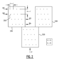
図2は、3つのインクジェットヘッド310、320、330を含むインクジェット装置300の例を示す。各インクジェットヘッド310、320、330は、複数の行N1、N2などを含み、ここでは4つの行(n=4)を含む。各行N1、N2などは、複数のm個のノズル350、ここでは4個のノズル(m=4)を有する。インクジェットヘッドの現実的な実施形態では、行および行あたりのノズルの量は、通常、はるかに多いことに留意されたい、例えば16~32行であり、行当たり100~400個のノズルである。しかしながら、本発明の実施形態を説明するために、説明を過度に複雑にしないように、ノズルの数を減らした。行N1、N2などは、印刷方向Pに垂直な方向、すなわち、基材がインクジェットヘッド310、320、330の下を移動する方向に向けられる。同じ行の隣り合う2つのノズル350の中心間の距離は、解像度rのn倍である(ノズル間の距離=n×r)。隣り合うノズル行の間の距離は、解像度rのk倍である(ノズル行間の距離=k×r)。
FIG. 2 shows an example of an
ノズル行N1、N2などは平行であり、複数のノズル行の隣り合うノズル行は、印刷方向Pに垂直な方向に互いに対してシフトされる。図示の実施形態では、行N2は行N1に対して距離rにわたって右にシフトされ、行N3は行N2に対して距離rにわたって右にシフトされ、行N4は行N3に対して距離rにわたって右にシフトされている。他の図示されていない実施形態では、シフトは異なってもよく、例えば行N2は行N1に対して距離2*rにわたってシフトされ、行N3は行N1に対して距離rにわたってシフトされ、行N4は行N3に対して距離3*rにわたって右にシフトされる。当業者は、他の変形が可能であることを理解する。印刷方向Pに垂直な線上に投影すると、ノズルの中心は、rに対応する互いに等しい距離に配置される。 The nozzle rows N1, N2, etc. are parallel and adjacent nozzle rows of the plurality of nozzle rows are shifted relative to each other in a direction perpendicular to the printing direction P. In the illustrated embodiment, row N2 is shifted to the right by a distance r relative to row N1, row N3 is shifted right by a distance r relative to row N2, and row N4 is shifted right by a distance r relative to row N3. has been shifted to. In other not-illustrated embodiments, the shifts may be different, for example row N2 is shifted a distance 2*r with respect to row N1, row N3 is shifted a distance r with respect to row N1, and row N4 is shifted a distance r with respect to row N1. is shifted to the right by a distance 3*r with respect to row N3. Those skilled in the art will appreciate that other variations are possible. Projected onto a line perpendicular to the printing direction P, the centers of the nozzles are placed at equal distances from each other corresponding to r.
典型的な印刷プロセス中、基材は印刷速度vで移動し、3つのインクジェットヘッド310、320、330のすべての(m×n×3)ノズルは、噴射周波数f=v/rで実質的に同時に噴射される。大きな電力ピークを回避するために小さな差(ナノ秒のオーダ)が存在する場合があるが、そのような小さな差は印刷された画像では目に見えない。言い換えると、噴射周波数は、基材が距離rにわたって移動するたびに、インクジェットヘッド310、320、330のすべてのノズルの噴射が実行されるようなものである。行は、印刷プロセスの後続のステップ中に印刷されるドットの組み合わせが規則的なパターンを形成するように、互いに対してシフトされる。より具体的には、インクジェットヘッド310、320、330がすべての(n×m×3)ノズルを、行数(n×k×2)の2k倍に対応する回数噴射した場合、基材がインクジェットヘッド310、320、330の下を移動する間に、印刷方向に垂直に延びる1つのスキャンラインが完成し、(n×m×3)ピクセルを含むことができる。
During a typical printing process, the substrate moves at a printing speed v, and all (m x n x 3) nozzles of the three inkjet heads 310, 320, 330 are fired substantially at a firing frequency f = v/r. sprayed at the same time. Small differences (on the order of nanoseconds) may exist to avoid large power peaks, but such small differences are not visible in the printed image. In other words, the firing frequency is such that firing of all nozzles of the inkjet heads 310, 320, 330 is performed each time the substrate is moved over a distance r. The rows are shifted relative to each other so that the combination of dots printed during subsequent steps of the printing process forms a regular pattern. More specifically, when the inkjet heads 310, 320, and 330 eject all (n×m×3) nozzles a number of times corresponding to 2k times the number of lines (n×k×2), the base material is inkjet. While moving under the
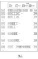
次に、図3を参照して、1つまたは複数のインクジェットヘッドで複数のスキャンラインSLを印刷する方法の例示的な実施形態を説明する。図3は、図2に示した3つのインクジェットヘッド310、320、330に対応する例であり、各ヘッドの行数は4(n=4)で、行当たりのノズル数はヘッド当たり4(m=4)であり、隣り合う行は6本のスキャンライン(k=6)で分離されている。各スキャンラインSLは(n×m×3)ピクセル、つまり、図3にP1、P2、P3、・・・、P48として示されている48ピクセルを含む。図2では、基材は、矢印Pで示されるように底部から上部に延在すると想定される。さらに、基材は、t1において、行N1のノズルが第1のスキャンラインSL1を印刷する位置にあると想定される。 An exemplary embodiment of a method for printing multiple scan lines SL with one or more inkjet heads will now be described with reference to FIG. FIG. 3 is an example corresponding to the three inkjet heads 310, 320, and 330 shown in FIG. =4), and adjacent rows are separated by six scan lines (k=6). Each scan line SL includes (n×m×3) pixels, ie 48 pixels shown as P1, P2, P3, . . . , P48 in FIG. In FIG. 2, the substrate is assumed to extend from the bottom to the top as indicated by arrow P. Furthermore, it is assumed that the substrate is in a position at t1 where the nozzles of row N1 print the first scan line SL1.
第1のスキャンラインSL1の場合、第1のピクセルP1は第1の時点t1で行N1の第1のノズルによって噴射され、第2のピクセルP2は行N2の第1のノズルによって6スキャンライン早く(t1-6Δt)噴射され、第3のピクセルP3は、行N3の第1のノズルによって12スキャンライン早く(t1-12Δt)噴射され、第4のピクセルP4は、行N4の第1のノズルによって18スキャンライン早く(t1-18Δt)噴射され、第5のピクセルP5は、第1の時点t1で再び噴射される、等々であり、ここで、Δtは2つの連続する噴射の瞬間の間の時間である。 For the first scan line SL1, the first pixel P1 is fired by the first nozzle of row N1 at a first time t1, and the second pixel P2 is fired six scan lines earlier by the first nozzle of row N2. (t1-6Δt), the third pixel P3 is fired 12 scan lines early (t1-12Δt) by the first nozzle of row N3, and the fourth pixel P4 is fired by the first nozzle of row N4. The fifth pixel P5 is fired 18 scan lines earlier (t1 - 18Δt), the fifth pixel P5 is fired again at the first time t1, and so on, where Δt is the time between two consecutive firing instants. It is.
第2のスキャンラインSL2の場合、第1のピクセルP1は第2の時点t2(=t1+Δt)で第1の行N1の第1のノズルによって噴射され、第2のピクセルP2は第2の行N2の第1のノズルによってt2より6スキャンライン早く(t2-6Δt)噴射された、等々。
For the second scan line SL2, the first pixel P1 is fired by the first nozzle of the first row N1 at the second time t2 (=t1+Δt), and the second pixel P2 is fired by the first nozzle of the first row N2 is injected by the
第(k+1)のスキャンラインSL7の場合、第1のピクセルP1はt1の6スキャンライン後に(t7=t1+6Δt)噴射する必要があり、第2のピクセルP2は、第2のノズル行N2の第1のノズルによって、第1の時点t1で噴射される必要があり、第3のピクセルP3は、6スキャンライン早く(t1-6Δt)噴射された、等々。 For the (k+1)th scan line SL7, the first pixel P1 needs to be fired after 6 scan lines of t1 (t7=t1+6Δt), and the second pixel P2 needs to be fired at the first pixel P2 of the second nozzle row N2. , the third pixel P3 was fired six scan lines earlier (t1-6Δt), and so on.
さらに、第2のインクジェットヘッド320は、第1および第3のインクジェットヘッド310、33に対してシフトされているので、スキャンラインSL25~SL48も、時刻t1、t2、t3などで印刷されるピクセルを含む。より具体的には、スキャンラインSL25の場合、第17のピクセルP17は時刻t1で噴射する必要があり、第18のピクセルP18はt1-6Δtなどで噴射する必要がある。
Furthermore, since the
言い換えると、以下のスキャンラインは、以下のように印刷されるピクセルで構成される。
時刻t1では:SL1、SL7、SL13、SL19、SL25、SL31、SL37、SL43;
時刻t2では:SL2、SL8、SL14、SL20、SL26、SL32、SL38、SL44;
時刻t3では:SL3、SL9、SL15、SL21、SL27、SL33、SL39、SL45;
時刻t4では:SL4、SL10、SL16、SL22、SL28、SL34、SL40、SL46;
時刻t5では:SL5、SL11、SL17、SL23、SL29、SL35、SL41、SL47;
時刻t6では:SL6、SL12、SL18、SL24、SL30、SL36、SL42、SL48;
時刻t7では:SL7、SL13、SL19、SL25、SL31、SL37、SL43;
時刻t8では:SL8、SL14、SL20、SL26、SL32、SL38、SL44;
時刻t9では:SL9、SL15、SL21、SL27、SL33、SL39、SL45;
時刻t10では:SL10、SL16、SL22、SL28、SL34、SL40、SL46;
時刻t11では:SL11、SL17、SL23、SL29、SL35、SL41、SL47;
時刻t12では:SL12、SL18、SL24、SL30、SL36、SL42、SL48;
等々であり、
ここで、t2=t1+Δt、t3=t1+2Δt、t4=t1+3Δtなどであり、Δtは2つの連続する噴射の瞬間の間の時間である。
In other words, the following scan lines are composed of pixels that are printed as follows.
At time t1: SL1, SL7, SL13, SL19, SL25, SL31, SL37, SL43;
At time t2: SL2, SL8, SL14, SL20, SL26, SL32, SL38, SL44;
At time t3: SL3, SL9, SL15, SL21, SL27, SL33, SL39, SL45;
At time t4: SL4, SL10, SL16, SL22, SL28, SL34, SL40, SL46;
At time t5: SL5, SL11, SL17, SL23, SL29, SL35, SL41, SL47;
At time t6: SL6, SL12, SL18, SL24, SL30, SL36, SL42, SL48;
At time t7: SL7, SL13, SL19, SL25, SL31, SL37, SL43;
At time t8: SL8, SL14, SL20, SL26, SL32, SL38, SL44;
At time t9: SL9, SL15, SL21, SL27, SL33, SL39, SL45;
At time t10: SL10, SL16, SL22, SL28, SL34, SL40, SL46;
At time t11: SL11, SL17, SL23, SL29, SL35, SL41, SL47;
At time t12: SL12, SL18, SL24, SL30, SL36, SL42, SL48;
etc.,
where t2=t1+Δt, t3=t1+2Δt, t4=t1+3Δt, etc., where Δt is the time between two consecutive injection moments.
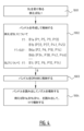
図4は、方法の例示的な実施形態に従って、図3のスキャンラインのピクセルがどのようにバンドルされ得るかを示す。第1のステップ1001では、少なくとも1つのスキャンラインが受け取られる。この例では、一度に受け取られるスキャンラインは1つだけであると想定されているが、当業者は、例えば2つまたは3つのスキャンラインを並列に受け取ることも可能であることを理解するであろう。最初に、第1のスキャンラインSL1が受け取られる。第1のスキャンラインSL1のピクセルP1~P48から、所定のサイズの複数のバンドルが作成される。この例では、簡単にするために、4つのピクセルのバンドルが作成されると想定している。しかし、現実的な解決策では、通常、例えば70~128ピクセルを含む、より大きなバンドルが作成される。
FIG. 4 shows how the pixels of the scan lines of FIG. 3 may be bundled, according to an exemplary embodiment of the method. In a
スキャンラインSL1の場合、以下のバンドルが作成される。
t1で噴射されるバンドル:B1a(P1、P5、P9、P13);B1b(P33、P37、P41、P45)
(t1-6Δt)で噴射されるバンドル:B6’a(P2、P6、P10、P14)。B6’b(P34、P38、P42、P46)
(t1-12Δt)で噴射されるバンドル:B12’a(P3、P7、P11、P15)。B12’b(P35、P39、P43、P47)
(t1-18Δt)で噴射されるバンドル:B18’a(P4、P8、P12、P16);B18’b(P36、P40、P44、P48)
当業者には理解されるように、ピクセルP17~P32は、第2のインクジェットヘッド320のノズルによってさらに早期に印刷されなければならない。簡単にするために、これらのピクセルに対応するバンドルについては、ここではさらに詳しく説明しない。
In the case of scan line SL1, the following bundles are created.
Bundle injected at t1: B1a (P1, P5, P9, P13); B1b (P33, P37, P41, P45)
Bundle injected at (t1-6Δt): B6'a (P2, P6, P10, P14). B6'b (P34, P38, P42, P46)
Bundle injected at (t1-12Δt): B12'a (P3, P7, P11, P15). B12'b (P35, P39, P43, P47)
Bundle injected at (t1-18Δt): B18'a (P4, P8, P12, P16); B18'b (P36, P40, P44, P48)
As will be understood by those skilled in the art, pixels P17-P32 must be printed even earlier by the nozzles of the
第2のスキャンラインSL2の場合、以下のバンドルが作成される。
t2(=t1+Δt)で噴射されるバンドル:B2a(P1、P5、P9、P13);B2b(P33、P37、P41、P45)
(t2-6Δt=t1-5Δt)で噴射されるバンドル:B5’a(P2、P6、P10、P14)。B5’b(P34、P38、P42、P46)
(t2-12Δt)で噴射されるバンドル:B11’a(P3、P7、P11、P15)。B11’b(P35、P39、P43、P47)
(t2-18Δt)で噴射されるバンドル:B17’a(P4、P8、P12、P16)。B17’b(P36、P40、P44、P48)
当業者には理解されるように、ピクセルP17~P32は、第2のインクジェットヘッド320のノズルによってさらに早期に印刷されなければならない。簡単にするために、これらのピクセルに対応するバンドルについては、ここではさらに詳しく説明しない。
For the second scanline SL2, the following bundles are created:
Bundle injected at t2 (=t1+Δt): B2a (P1, P5, P9, P13); B2b (P33, P37, P41, P45)
Bundle injected at (t2-6Δt=t1-5Δt): B5'a (P2, P6, P10, P14). B5'b (P34, P38, P42, P46)
Bundle injected at (t2-12Δt): B11'a (P3, P7, P11, P15). B11'b (P35, P39, P43, P47)
Bundle injected at (t2-18Δt): B17'a (P4, P8, P12, P16). B17'b (P36, P40, P44, P48)
As will be understood by those skilled in the art, pixels P17-P32 must be printed even earlier by the nozzles of the
第(k+1)のスキャンラインSL7の場合、以下のバンドルが形成される。
t7で噴射されるバンドル(t7=t1+6Δt):B7a(P1、P5、P9、P13);B7b(P33、P37、P41、P45)
t1で噴射されるバンドル:B1c(P2、P6、P10、P14);B1d(P34、P38、P42、P46)
(t1-6Δt)で噴射されるバンドル:B6’c(P3、P7、P11、P15);B6’d(P35、P39、P43、P47)
等々である。
For the (k+1)th scan line SL7, the following bundle is formed.
Bundle injected at t7 (t7=t1+6Δt): B7a (P1, P5, P9, P13); B7b (P33, P37, P41, P45)
Bundle injected at t1: B1c (P2, P6, P10, P14); B1d (P34, P38, P42, P46)
Bundle injected at (t1-6Δt): B6'c (P3, P7, P11, P15); B6'd (P35, P39, P43, P47)
etc.
論理ユニットのメモリ110は、通常、1つまたは2つだけのスキャンラインを格納できる小さなメモリであるため、バンドルは、第1のメモリがいっぱいになる前に、かつ好ましくは次のスキャンラインが到着する前に、第2のメモリ200に書き込まれる。したがって、第1のスキャンラインSL1のバンドルを作成した後に、バンドルB1a、B1b、B6’a、B6’b、B12’a、B12’bなどが第2のメモリ200に書き込まれ、次に第2のスキャンラインSL2がバンドルB2a、B2b、B5’a、B5’bなどにグループ化され、バンドルB2a、B2b、B5’a、B5’bなどが第2のメモリ200に書き込まれる。これらのステップは、インクジェットヘッド310、320、330のノズルが第1の時点t1で噴射されなければならないすべてのピクセルが第2のメモリにおいて利用可能になるまで繰り返される。スキャンラインSL43は、時点t1で噴射されるピクセルを収容する最後のスキャンラインであるから、スキャンラインSL43のバンドルを第2のメモリ200に格納した後に、インクジェットヘッド310、320、330のノズルは、時点t1で第1のバンドルに従って噴射され得る。スキャンラインSL44が受け取られ、バンドルにグループ化され、第2のメモリ200に格納された後に、インクジェットヘッド310、320、330のノズルは、第2の時点t2で第2のバンドルB2a、B2bなどに従って噴射され得る。
Since the logical unit's
図4では、ステップ1002は、論理ユニット100で実行されるバンドルの作成および格納を示し、ステップ1003は、第2のメモリ200への作成されたバンドルの格納を示す。次のステップ1004では、特定の時点で噴射されるバンドルが第2のメモリ200から読み出され、それに応じてインクジェットヘッド310、320、330のノズルが噴射される。
In FIG. 4,
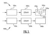
図5は、本発明の2つの印刷システムを単一のプリンタに組み合わせることが可能であることを示している。インクジェット装置300a、300bは、直列に配置されてもよく、それぞれ、印刷されるスキャンラインのピクセルの半分を印刷してもよい。この例示的な実施形態では、インクジェット装置300a、300bごとに別個の論理ユニット100a、100bおよび別個の第2のメモリ200a、200bが設けられている。
FIG. 5 shows that it is possible to combine the two printing systems of the invention into a single printer.
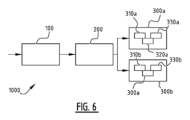
図6に示す別の例示的な実施形態では、単一の論理ユニット100および単一の第2のメモリ200を使用して、2つのインクジェット装置300a、300bを制御することができ、例えばそれぞれが3つのインクジェットヘッド310a、320a、330a;310b、320b、330bを含む。
In another exemplary embodiment shown in FIG. 6, a
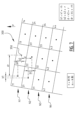
本発明の実施形態は、他のタイプのインクジェットヘッドにも適用可能である。インクジェットヘッドの別の例が図7に示されており、複数の行N1、N2など、例えば32行(n=32)を含む。各行N1、N2などは、m個のノズル、例えば64個のノズル(m=64)を含む。ノズル行は平行であり、印刷方向に対して60°~89°の角度に向けられている。印刷方向Pに垂直な線に投影した場合、同じ行の隣り合う2つのノズルの中心間の距離はdrである。drは、印刷方向に垂直な水平方向に見られる望ましい解像度rhの倍数である(dr=k4*rh、ここでk4は整数である)。複数のノズル行の隣り合うノズル行は、距離b1にわたって印刷方向Pに垂直な方向に互いに対してシフトされている。図示の実施形態では、行N2は行N1に対して距離b1だけ左にシフトされ、行N3は行N2に対して距離b1だけ左にシフトされる、等々。当業者は、図2について上で説明されたものと同様に、他の変形が可能であることを理解する。印刷方向Pに垂直な線上に投影すると、ノズルの中心は、b1に対応する互いに等距離に配置される。印刷方向に投影された、同じ行の隣り合うノズルの中心間の距離はb2である。b1は、印刷方向に垂直な方向の解像度rhの倍数である、つまり、b1=k1*rhであり、k1は整数である。b2は、印刷方向の解像度rの倍数である、つまり、b2=k2*rであり、k2は整数である。印刷方向Pに見た隣り合うノズル行間の距離はdである。また、dは印刷方向に見られる望ましい解像度rの倍数である(d=k3*r、k3は整数である)。基材は、印刷速度vで移動することができ、すべてのm×n個のノズルは、噴射周波数f=k*v/dで実質的に同時に噴射することができ、ここで、kは整数である。言い換えれば、噴射周波数は、基材が距離d/kにわたって移動するたびに、インクジェットヘッドのすべてのノズルの噴射が実行されるようなものである。行は、印刷プロセスの後続のステップ中に印刷されるドットの組み合わせが規則的なパターンを形成するように、互いに対してシフトされる。 Embodiments of the invention are also applicable to other types of inkjet heads. Another example of an inkjet head is shown in FIG. 7 and includes a plurality of rows N1, N2, etc., for example 32 rows (n=32). Each row N1, N2, etc. contains m nozzles, for example 64 nozzles (m=64). The nozzle rows are parallel and oriented at an angle of 60° to 89° to the printing direction. When projected onto a line perpendicular to the printing direction P, the distance between the centers of two adjacent nozzles in the same row is dr. dr is a multiple of the desired resolution rh seen in the horizontal direction perpendicular to the printing direction (dr=k4*rh, where k4 is an integer). Adjacent nozzle rows of the plurality of nozzle rows are shifted relative to each other in a direction perpendicular to the printing direction P over a distance b1. In the illustrated embodiment, row N2 is shifted left by a distance b1 relative to row N1, row N3 is shifted left by a distance b1 relative to row N2, and so on. Those skilled in the art will appreciate that other variations are possible, similar to those described above with respect to FIG. Projected onto a line perpendicular to the printing direction P, the centers of the nozzles are placed equidistant from each other corresponding to b1. The distance between the centers of adjacent nozzles in the same row, projected in the printing direction, is b2. b1 is a multiple of the resolution rh in the direction perpendicular to the printing direction, that is, b1=k1*rh, where k1 is an integer. b2 is a multiple of the resolution r in the print direction, that is, b2=k2*r, where k2 is an integer. The distance between adjacent nozzle rows in the printing direction P is d. Also, d is a multiple of the desired resolution r as seen in the print direction (d=k3*r, k3 being an integer). The substrate can be moved at a printing speed v and all m×n nozzles can fire substantially simultaneously with a firing frequency f=k*v/d, where k is an integer It is. In other words, the firing frequency is such that firing of all nozzles of the inkjet head is performed each time the substrate moves over a distance d/k. The rows are shifted relative to each other so that the combination of dots printed during subsequent steps of the printing process forms a regular pattern.
また、そのようなインクジェットヘッドについて、図4に関連して上で説明したようなバンドルの作成を実行することができる。そのような実施形態では、バンドルのサイズが十分に大きいことを確認するために、同じバンドル内の隣り合うスキャンラインのピクセルを組み合わせることが有効であり得る。 Also, for such inkjet heads, bundle creation as described above in connection with FIG. 4 may be performed. In such embodiments, it may be useful to combine pixels of adjacent scanlines within the same bundle to ensure that the size of the bundle is large enough.
本発明の特定の実施形態は、特に、同じ画像の多数のコピー、あるいは一連の画像、または大量の組の個別に変化する画像を印刷するために、いわゆる「連続」ウェブ、すなわち、基材(例えば、紙、プラスチックホイル、またはそれらの多層の組み合わせ)の連続ロールが一定の速度で印刷ステーションを通過する印刷システムのデジタル印刷システムおよび方法の分野に関する。 Certain embodiments of the present invention are particularly useful for printing multiple copies of the same image, or a series of images, or a large set of individually varying images. The present invention relates to the field of digital printing systems and methods of printing systems in which a continuous roll of paper, plastic foil, or a multilayer combination thereof) passes through a printing station at a constant speed.
「論理ユニット」とラベル付けされた任意の機能ブロックを含む、図に示す様々な要素の機能は、専用ハードウェアならびに適切なソフトウェアに関連してソフトウェアを実行できるハードウェアの使用を通じて提供され得る。プロセッサによって提供される場合、機能は、単一の専用プロセッサ、単一の共有プロセッサ、またはいくつかが共有され得る複数の個々のプロセッサによって提供されてもよい。さらに、「論理ユニット」という用語の明示的な使用は、ソフトウェアを実行できるハードウェアのみを指すと解釈されるべきではなく、デジタル信号プロセッサ(DSP)ハードウェア、ネットワークプロセッサ、特定用途向け集積回路(ASIC)、フィールドプログラマブルゲートアレイ(FPGA)、ソフトウェアを格納するための読み取り専用メモリ(ROM)、ランダムアクセスメモリ(RAM)、および不揮発性ストレージを暗黙的に含むことができるが、これらに限定されない。従来型および/またはカスタムのその他のハードウェアも含めることができる。 The functionality of the various elements shown in the figures, including any functional blocks labeled "logical units," may be provided through the use of dedicated hardware as well as hardware capable of executing software in conjunction with appropriate software. If provided by a processor, the functionality may be provided by a single dedicated processor, a single shared processor, or multiple individual processors, some of which may be shared. Additionally, explicit use of the term "logical unit" should not be construed to refer only to hardware capable of executing software, but rather digital signal processor (DSP) hardware, network processors, application-specific integrated circuits ( ASICs), field programmable gate arrays (FPGAs), read-only memory (ROM) for storing software, random access memory (RAM), and non-volatile storage. Other hardware, conventional and/or custom, may also be included.
本発明の原理は特定の実施形態に関連して上に述べられているが、この説明は単なる例としてなされたものであり、添付の特許請求の範囲によって定められる保護範囲の限定としてなされていないことを理解されたい。 Although the principles of the invention have been described above in connection with specific embodiments, this description is made by way of example only and not as a limitation of the scope of protection defined by the appended claims. I hope you understand that.
Claims (15)
a.前記複数のスキャンラインのうちの少なくとも1つのスキャンラインを受け取るステップと、
b.前記少なくとも1つのスキャンラインのピクセルから所定のサイズの複数のバンドル(B)を作成し、前記複数のバンドルを第1のメモリ(110)に格納するステップであって、前記複数のバンドルが、第1のバンドルおよび連続するバンドルを含み、前記第1のバンドルおよび前記連続するバンドルが、前記1つまたは複数のインクジェットヘッドのノズルがそれぞれ第1の期間内および連続する期間内に噴射されなければならないピクセルを含み、前記複数のバンドルのうちの1つのバンドルの前記所定のサイズが、第2のメモリ(200)に応じて選択される、ステップと、
c.前記複数のバンドルを前記第1のメモリ(110)から前記第2のメモリ(200)に転送するステップと、
d.前記1つまたは複数のインクジェットヘッドのノズルが前記第1の期間内に噴射されなければならないすべてのピクセルが前記第1のバンドルとして前記第2のメモリにおいて利用可能になるまで、ステップa~cを繰り返すステップと、
e.前記第1の期間内に前記第1のバンドルに従って前記1つまたは複数のインクジェットヘッドのノズルを噴射するステップと、
f.連続するバンドルおよび関連するそれぞれの連続する期間についてステップdおよびeを繰り返すステップと、
を含む方法。 A method for printing multiple scan lines (SL) using one or more inkjet heads (310, 320, 330; 310a, 320a, 330a), the method comprising:
a. receiving at least one scan line of the plurality of scan lines;
b. creating a plurality of bundles (B) of a predetermined size from pixels of the at least one scan line and storing the plurality of bundles in a first memory (110), the plurality of bundles 1 bundle and successive bundles, the first bundle and the successive bundles being ejected by the nozzles of the one or more inkjet heads within a first time period and within successive time periods, respectively. the predetermined size of one bundle of the plurality of bundles comprising pixels is selected in response to a second memory (200);
c. transferring the plurality of bundles from the first memory (110) to the second memory (200);
d. performing steps a to c until all pixels that the nozzles of the one or more inkjet heads have to fire within the first period are available in the second memory as the first bundle; repeating steps and
e. firing nozzles of the one or more inkjet heads according to the first bundle within the first time period;
f. repeating steps d and e for successive bundles and associated respective successive time periods;
method including.
Applications Claiming Priority (3)
| Application Number | Priority Date | Filing Date | Title |
|---|---|---|---|
| NL2020646 | 2018-03-22 | ||
| NL2020646A NL2020646B1 (en) | 2018-03-22 | 2018-03-22 | Printing system and method with efficient memory usage |
| PCT/EP2019/056972 WO2019180086A1 (en) | 2018-03-22 | 2019-03-20 | Printing system and method with efficient memory usage |
Publications (2)
| Publication Number | Publication Date |
|---|---|
| JP2021518280A JP2021518280A (en) | 2021-08-02 |
| JP7413640B2 true JP7413640B2 (en) | 2024-01-16 |
Family
ID=63013070
Family Applications (1)
| Application Number | Title | Priority Date | Filing Date |
|---|---|---|---|
| JP2020548954A Active JP7413640B2 (en) | 2018-03-22 | 2019-03-20 | Printing system and method with efficient memory usage |
Country Status (5)
| Country | Link |
|---|---|
| US (1) | US11648781B2 (en) |
| EP (1) | EP3768516B1 (en) |
| JP (1) | JP7413640B2 (en) |
| NL (1) | NL2020646B1 (en) |
| WO (1) | WO2019180086A1 (en) |
Citations (9)
| Publication number | Priority date | Publication date | Assignee | Title |
|---|---|---|---|---|
| US20030072036A1 (en) | 2000-05-23 | 2003-04-17 | Kia Silverbrook | Print engine controller for a multi-segment printhead |
| JP2004237599A (en) | 2003-02-06 | 2004-08-26 | Noritsu Koki Co Ltd | Image data transmission control device |
| JP2008183884A (en) | 2007-01-31 | 2008-08-14 | Fujifilm Corp | Image forming apparatus and print data transfer method |
| JP2010006066A (en) | 2008-06-27 | 2010-01-14 | Toshiba Corp | Image processing device and image processing method |
| US20110254889A1 (en) | 2010-04-16 | 2011-10-20 | Xerox Corporation | Fifo methods, systems and apparatus for electronically registering image data |
| JP2013082208A (en) | 2011-09-30 | 2013-05-09 | Fujifilm Corp | Image forming apparatus and image forming method |
| JP2014019046A (en) | 2012-07-18 | 2014-02-03 | Kyocera Document Solutions Inc | Image forming device |
| JP2014144590A (en) | 2013-01-29 | 2014-08-14 | Kyocera Document Solutions Inc | Image forming apparatus |
| JP2016068462A (en) | 2014-09-30 | 2016-05-09 | セイコーエプソン株式会社 | Printing apparatus and image processing apparatus |
Family Cites Families (2)
| Publication number | Priority date | Publication date | Assignee | Title |
|---|---|---|---|---|
| US5619622A (en) * | 1994-12-16 | 1997-04-08 | Xerox Corporation | Raster output interface for a printbar |
| JP2008220353A (en) * | 2007-03-14 | 2008-09-25 | Noboru Uehara | Capture net |
-
2018
- 2018-03-22 NL NL2020646A patent/NL2020646B1/en not_active IP Right Cessation
-
2019
- 2019-03-20 WO PCT/EP2019/056972 patent/WO2019180086A1/en not_active Ceased
- 2019-03-20 EP EP19710722.0A patent/EP3768516B1/en active Active
- 2019-03-20 JP JP2020548954A patent/JP7413640B2/en active Active
- 2019-03-20 US US16/979,680 patent/US11648781B2/en active Active
Patent Citations (9)
| Publication number | Priority date | Publication date | Assignee | Title |
|---|---|---|---|---|
| US20030072036A1 (en) | 2000-05-23 | 2003-04-17 | Kia Silverbrook | Print engine controller for a multi-segment printhead |
| JP2004237599A (en) | 2003-02-06 | 2004-08-26 | Noritsu Koki Co Ltd | Image data transmission control device |
| JP2008183884A (en) | 2007-01-31 | 2008-08-14 | Fujifilm Corp | Image forming apparatus and print data transfer method |
| JP2010006066A (en) | 2008-06-27 | 2010-01-14 | Toshiba Corp | Image processing device and image processing method |
| US20110254889A1 (en) | 2010-04-16 | 2011-10-20 | Xerox Corporation | Fifo methods, systems and apparatus for electronically registering image data |
| JP2013082208A (en) | 2011-09-30 | 2013-05-09 | Fujifilm Corp | Image forming apparatus and image forming method |
| JP2014019046A (en) | 2012-07-18 | 2014-02-03 | Kyocera Document Solutions Inc | Image forming device |
| JP2014144590A (en) | 2013-01-29 | 2014-08-14 | Kyocera Document Solutions Inc | Image forming apparatus |
| JP2016068462A (en) | 2014-09-30 | 2016-05-09 | セイコーエプソン株式会社 | Printing apparatus and image processing apparatus |
Also Published As
| Publication number | Publication date |
|---|---|
| WO2019180086A1 (en) | 2019-09-26 |
| US11648781B2 (en) | 2023-05-16 |
| EP3768516B1 (en) | 2023-05-03 |
| US20210046765A1 (en) | 2021-02-18 |
| EP3768516A1 (en) | 2021-01-27 |
| JP2021518280A (en) | 2021-08-02 |
| NL2020646B1 (en) | 2019-10-02 |
Similar Documents
| Publication | Publication Date | Title |
|---|---|---|
| JP3884498B2 (en) | Printer and method for printing raster images | |
| US12130280B2 (en) | Identifying random bits in control data packets | |
| CN103171279B (en) | Digital jet printing device and control method | |
| JP6352943B2 (en) | Data processing method, apparatus, program, and ink jet printer | |
| JP7413640B2 (en) | Printing system and method with efficient memory usage | |
| EP2584499B1 (en) | Image forming apparatus and image forming method | |
| JP2010120291A5 (en) | ||
| JP2011131385A5 (en) | Data generating apparatus and data generating method | |
| JP2012056312A (en) | Method and apparatus for sorting pixel data present in printing-data flow | |
| AU644637B2 (en) | Control system for ion projection printing and the like | |
| US20090219316A1 (en) | Printing method and apparatus | |
| JP5975894B2 (en) | Image forming apparatus | |
| US10286650B2 (en) | Image processing apparatus and image processing method | |
| AU2017202225B2 (en) | Information processing device, image forming device, and program | |
| JP5736826B2 (en) | Image data processing apparatus, recording apparatus, and image data processing method | |
| JP4720486B2 (en) | Data processing apparatus, data processing method, data processing program, and droplet discharge apparatus | |
| JP2016132167A (en) | Printer, control device and control method | |
| JP2008265161A (en) | Ink jet recorder and method for forming recording data | |
| JPH08252946A (en) | Dot printer |
Legal Events
| Date | Code | Title | Description |
|---|---|---|---|
| A621 | Written request for application examination |
Free format text: JAPANESE INTERMEDIATE CODE: A621 Effective date: 20220216 |
|
| A977 | Report on retrieval |
Free format text: JAPANESE INTERMEDIATE CODE: A971007 Effective date: 20220831 |
|
| A131 | Notification of reasons for refusal |
Free format text: JAPANESE INTERMEDIATE CODE: A131 Effective date: 20220906 |
|
| A601 | Written request for extension of time |
Free format text: JAPANESE INTERMEDIATE CODE: A601 Effective date: 20221206 |
|
| A521 | Request for written amendment filed |
Free format text: JAPANESE INTERMEDIATE CODE: A523 Effective date: 20230113 |
|
| A131 | Notification of reasons for refusal |
Free format text: JAPANESE INTERMEDIATE CODE: A131 Effective date: 20230221 |
|
| A601 | Written request for extension of time |
Free format text: JAPANESE INTERMEDIATE CODE: A601 Effective date: 20230517 |
|
| A521 | Request for written amendment filed |
Free format text: JAPANESE INTERMEDIATE CODE: A523 Effective date: 20230718 |
|
| A02 | Decision of refusal |
Free format text: JAPANESE INTERMEDIATE CODE: A02 Effective date: 20230801 |
|
| A521 | Request for written amendment filed |
Free format text: JAPANESE INTERMEDIATE CODE: A523 Effective date: 20230914 |
|
| A521 | Request for written amendment filed |
Free format text: JAPANESE INTERMEDIATE CODE: A523 Effective date: 20231006 |
|
| A911 | Transfer to examiner for re-examination before appeal (zenchi) |
Free format text: JAPANESE INTERMEDIATE CODE: A911 Effective date: 20231030 |
|
| TRDD | Decision of grant or rejection written | ||
| A01 | Written decision to grant a patent or to grant a registration (utility model) |
Free format text: JAPANESE INTERMEDIATE CODE: A01 Effective date: 20231128 |
|
| A61 | First payment of annual fees (during grant procedure) |
Free format text: JAPANESE INTERMEDIATE CODE: A61 Effective date: 20231206 |
|
| R150 | Certificate of patent or registration of utility model |
Ref document number: 7413640 Country of ref document: JP Free format text: JAPANESE INTERMEDIATE CODE: R150 |