JP7409492B2 - gas chromatograph mass spectrometer - Google Patents
gas chromatograph mass spectrometer Download PDFInfo
- Publication number
- JP7409492B2 JP7409492B2 JP2022519866A JP2022519866A JP7409492B2 JP 7409492 B2 JP7409492 B2 JP 7409492B2 JP 2022519866 A JP2022519866 A JP 2022519866A JP 2022519866 A JP2022519866 A JP 2022519866A JP 7409492 B2 JP7409492 B2 JP 7409492B2
- Authority
- JP
- Japan
- Prior art keywords
- opening
- ionization chamber
- sample
- section
- mass spectrometer
- Prior art date
- Legal status (The legal status is an assumption and is not a legal conclusion. Google has not performed a legal analysis and makes no representation as to the accuracy of the status listed.)
- Active
Links
- 239000007789 gas Substances 0.000 claims description 50
- 238000000926 separation method Methods 0.000 claims description 32
- IJGRMHOSHXDMSA-UHFFFAOYSA-N Atomic nitrogen Chemical compound N#N IJGRMHOSHXDMSA-UHFFFAOYSA-N 0.000 claims description 29
- 239000012159 carrier gas Substances 0.000 claims description 28
- 229910001873 dinitrogen Inorganic materials 0.000 claims description 19
- 238000004458 analytical method Methods 0.000 claims description 14
- 238000004949 mass spectrometry Methods 0.000 claims description 13
- 230000001737 promoting effect Effects 0.000 claims description 3
- 150000002500 ions Chemical class 0.000 description 35
- 238000010586 diagram Methods 0.000 description 14
- 238000001514 detection method Methods 0.000 description 13
- 230000010365 information processing Effects 0.000 description 13
- 230000035945 sensitivity Effects 0.000 description 13
- 238000005259 measurement Methods 0.000 description 11
- 230000004048 modification Effects 0.000 description 10
- 238000012986 modification Methods 0.000 description 10
- 239000001307 helium Substances 0.000 description 9
- 229910052734 helium Inorganic materials 0.000 description 9
- SWQJXJOGLNCZEY-UHFFFAOYSA-N helium atom Chemical compound [He] SWQJXJOGLNCZEY-UHFFFAOYSA-N 0.000 description 9
- 230000007246 mechanism Effects 0.000 description 8
- 238000012545 processing Methods 0.000 description 8
- 230000000875 corresponding effect Effects 0.000 description 6
- 230000003287 optical effect Effects 0.000 description 6
- JDCMOHAFGDQQJX-UHFFFAOYSA-N 1,2,3,4,5,6,7,8-octafluoronaphthalene Chemical compound FC1=C(F)C(F)=C(F)C2=C(F)C(F)=C(F)C(F)=C21 JDCMOHAFGDQQJX-UHFFFAOYSA-N 0.000 description 5
- 230000000052 comparative effect Effects 0.000 description 5
- 229910052757 nitrogen Inorganic materials 0.000 description 5
- 230000006870 function Effects 0.000 description 4
- 150000001793 charged compounds Chemical class 0.000 description 3
- 238000004817 gas chromatography Methods 0.000 description 3
- 238000002290 gas chromatography-mass spectrometry Methods 0.000 description 3
- 230000014759 maintenance of location Effects 0.000 description 3
- -1 nitrogen gas Chemical compound 0.000 description 3
- 208000033962 Fontaine progeroid syndrome Diseases 0.000 description 2
- 230000009471 action Effects 0.000 description 2
- 230000001276 controlling effect Effects 0.000 description 2
- 238000007599 discharging Methods 0.000 description 2
- 230000000694 effects Effects 0.000 description 2
- 230000005684 electric field Effects 0.000 description 2
- 239000012634 fragment Substances 0.000 description 2
- 238000002347 injection Methods 0.000 description 2
- 239000007924 injection Substances 0.000 description 2
- 238000000034 method Methods 0.000 description 2
- RVZRBWKZFJCCIB-UHFFFAOYSA-N perfluorotributylamine Chemical compound FC(F)(F)C(F)(F)C(F)(F)C(F)(F)N(C(F)(F)C(F)(F)C(F)(F)C(F)(F)F)C(F)(F)C(F)(F)C(F)(F)C(F)(F)F RVZRBWKZFJCCIB-UHFFFAOYSA-N 0.000 description 2
- 238000003860 storage Methods 0.000 description 2
- 238000009834 vaporization Methods 0.000 description 2
- 230000008016 vaporization Effects 0.000 description 2
- 230000002411 adverse Effects 0.000 description 1
- 238000004364 calculation method Methods 0.000 description 1
- 238000004891 communication Methods 0.000 description 1
- 230000002596 correlated effect Effects 0.000 description 1
- 238000009792 diffusion process Methods 0.000 description 1
- 238000000605 extraction Methods 0.000 description 1
- 238000001125 extrusion Methods 0.000 description 1
- 230000004907 flux Effects 0.000 description 1
- 230000037427 ion transport Effects 0.000 description 1
- 238000000752 ionisation method Methods 0.000 description 1
- 239000007788 liquid Substances 0.000 description 1
- 238000004519 manufacturing process Methods 0.000 description 1
- 239000002184 metal Substances 0.000 description 1
- 239000000203 mixture Substances 0.000 description 1
- 238000010926 purge Methods 0.000 description 1
- 229910001220 stainless steel Inorganic materials 0.000 description 1
- 239000010935 stainless steel Substances 0.000 description 1
Images


Classifications
-
- G—PHYSICS
- G01—MEASURING; TESTING
- G01N—INVESTIGATING OR ANALYSING MATERIALS BY DETERMINING THEIR CHEMICAL OR PHYSICAL PROPERTIES
- G01N27/00—Investigating or analysing materials by the use of electric, electrochemical, or magnetic means
- G01N27/62—Investigating or analysing materials by the use of electric, electrochemical, or magnetic means by investigating the ionisation of gases, e.g. aerosols; by investigating electric discharges, e.g. emission of cathode
Landscapes
- Chemical & Material Sciences (AREA)
- Chemical Kinetics & Catalysis (AREA)
- Electrochemistry (AREA)
- Physics & Mathematics (AREA)
- Health & Medical Sciences (AREA)
- Life Sciences & Earth Sciences (AREA)
- Analytical Chemistry (AREA)
- Biochemistry (AREA)
- General Health & Medical Sciences (AREA)
- General Physics & Mathematics (AREA)
- Immunology (AREA)
- Pathology (AREA)
- Other Investigation Or Analysis Of Materials By Electrical Means (AREA)
Description
本発明は、ガスクロマトグラフ質量分析計に関する。 The present invention relates to gas chromatograph mass spectrometers.
ガスクロマトグラフ-質量分析計(Gas Chromatograph-Mass spectrometer; GC-MS)による分析では、ガスクロマトグラフ(Gas Chromatograph; GC)で分離された試料を効率よくイオン化することで、感度を高めることができる。GCでは、ヘリウムガスまたは窒素ガス等がキャリアガスとして用いられ(特許文献1参照)、試料と共にイオン化室に導入される。電子衝撃イオン化法(Electron Ionizaion; EI)では、イオン化室に導入された試料に、イオン化室の外部に配置されたフィラメントから出射した熱電子が照射され、熱電子との反応により試料がイオン化される。 In analysis using a gas chromatograph-mass spectrometer (GC-MS), sensitivity can be increased by efficiently ionizing a sample separated by the gas chromatograph (GC). In GC, helium gas, nitrogen gas, or the like is used as a carrier gas (see Patent Document 1), and is introduced into the ionization chamber together with the sample. In the electron impact ionization method (EI), a sample introduced into an ionization chamber is irradiated with thermionic electrons emitted from a filament placed outside the ionization chamber, and the sample is ionized by reaction with the thermionic electrons. .
窒素ガス等の分子量がヘリウムよりも大きい分子または原子を含むガスは、ヘリウムガス等と比較して、分子の大きさが大きく熱電子と衝突しやすい等の理由により、キャリアガスとして用いたときに分析の感度が低下する場合がある。 Gases containing molecules or atoms with a larger molecular weight than helium, such as nitrogen gas, have a larger molecular size and are more likely to collide with thermoelectrons than helium gas, so when used as a carrier gas, The sensitivity of the analysis may be reduced.
本発明の第1の態様は、試料を分離する分離部と、キャリアガスとして窒素ガスを前記分離部に供給するガス供給部と、前記分離部から導入される前記試料を質量分析する質量分析部とを備えるガスクロマトグラフ質量分析計であって、前記質量分析部は、フィラメントと、前記フィラメントからの熱電子および前記分離部からの前記試料が導入され、前記試料の電子衝撃イオン化が行われるイオン化室とを備え、単位を立方ミリメートル(mm3)とした前記イオン化室の内側の体積に対する、単位を平方ミリメートルとした前記イオン化室の側壁における開口部の面積(mm2)の合計の比率が、30分の1以上であり、前記イオン化室の前記側壁には、前記フィラメントからの前記熱電子が前記イオン化室に入射する際に通過する第1開口部と、前記熱電子が前記イオン化室から出射する際に通過する第2開口部と、前記分離部から前記試料が導入される際に通過する第3開口部と、イオン化された前記試料が前記イオン化室から出射する際に通過する第4開口部と、較正用試料が導入される際に通過する第5開口部との他に、少なくとも一つの第6開口部が形成され、前記第6開口部は、キャリアガスの前記イオン化室からの排出を促進するための開口部であるガスクロマトグラフ質量分析計に関する。 A first aspect of the present invention includes a separation section that separates a sample, a gas supply section that supplies nitrogen gas as a carrier gas to the separation section, and a mass spectrometer section that performs mass analysis of the sample introduced from the separation section. A gas chromatograph mass spectrometer comprising: a filament; and an ionization chamber into which thermionic electrons from the filament and the sample from the separation section are introduced, and electron impact ionization of the sample is performed. and the ratio of the total area (mm 2 ) of the openings in the side wall of the ionization chamber in square millimeters to the inner volume of the ionization chamber in cubic millimeters (mm 3 ) is 30. The side wall of the ionization chamber includes a first opening through which the thermoelectrons from the filament pass when entering the ionization chamber, and a first opening through which the thermoelectrons exit from the ionization chamber. a second opening through which the sample is introduced from the separation section; a fourth opening through which the ionized sample passes when exiting from the ionization chamber; and a fifth opening through which the calibration sample is introduced, at least one sixth opening is formed, said sixth opening being configured to discharge carrier gas from said ionization chamber. This invention relates to a gas chromatograph mass spectrometer that is an opening for promoting
本発明によれば、窒素ガス等の分子量がヘリウムよりも大きい分子または原子を含むガスをキャリアガスとして用いたときに、分析の感度の低下を抑制することができる。 According to the present invention, when a gas containing molecules or atoms having a molecular weight larger than that of helium, such as nitrogen gas, is used as a carrier gas, a decrease in analysis sensitivity can be suppressed.
以下、図を参照して本発明を実施するための形態について説明する。 Hereinafter, embodiments for carrying out the present invention will be described with reference to the drawings.
-実施形態-
図1は、本実施形態のガスクロマトグラフ-質量分析計(GC-MS)1の構成を示す概念図である。GC-MS1は、測定部100と情報処理部40とを備える。測定部100は、ガスクロマトグラフ(GC)10と、試料ガス導入管20と、質量分析部30とを備える。GC10は、キャリアガス流路11と、試料導入部12とを備える。質量分析部30は、真空容器31と、排気口32と、真空排気系33と、試料Sをイオン化してイオンInを生成するイオン化部300と、イオン調整部34と、質量分離部35と、検出部36とを備える。イオン化部300は、イオン化室310と、フィラメント320と、トラップ電極330とを備える。-Embodiment-
FIG. 1 is a conceptual diagram showing the configuration of a gas chromatograph-mass spectrometer (GC-MS) 1 of this embodiment. The GC-
測定部100は、ガスクロマトグラフィおよび質量分離を含む2工程以上の分離操作により、試料の各成分を分離して検出する。
The
GC10は、GC10に導入された試料Sを、ガスクロマトグラフィにより分離する分離部として機能する。
The
キャリアガス流路11は、キャリアガスの流路であり、キャリアガスを試料導入部12に導入する(矢印A1)。キャリアガスの組成は特に限定されないが、GC-MS1は、キャリアガスとして少なくとも窒素を使用可能である。以下で、窒素とは窒素分子を指す。試料導入部12は、試料気化室等の試料を導入する室を備え、不図示のシリンジまたはオートサンプラー等の注入器により注入された試料を一時的に収容し、試料が液体の場合は気化させて、試料ガスを不図示の分離カラムに導入する(矢印A2)。
The carrier
GC10は、分離カラムが取り付けられ、分離カラムにおいて試料Sを分離する。分離カラムに導入される際に、試料Sはガスまたはガス状となっているが、これを適宜試料ガスと呼ぶ。分離カラムの種類は特に限定されず、キャピラリーカラム等の任意のカラムを用いることができる。GC10において分離された試料ガスの各成分は異なる時間に分離カラムから溶出し、試料ガス導入管20を通って質量分析部30のイオン化部300に導入される。試料ガス導入管20は、分離カラムと一体化していてもよい。
The
質量分析部30は、質量分析計を備え、イオン化部300に導入された試料Sをイオン化し、質量分離して検出する。イオン化部300で生成された試料Sに由来するイオンInは、イオン光軸Ax1に沿って移動する。
なお、試料Sに由来するイオンInを所望の精度で質量分離して検出することができれば、質量分析部30を構成する質量分析計の種類は特に限定されず、任意の種類の1以上の質量分析器を含むものを用いることができる。The
Note that the type of mass spectrometer constituting the
質量分析部30の真空容器31は、排気口32を備える。排気口32は、真空排気系33と排気可能に接続されている。真空排気系33は、ターボ分子ポンプ等の、10-2Pa以下等の低圧力が実現可能なポンプおよびその補助ポンプを含む。図1では、真空容器31の内部の気体が排出される点を矢印A10で模式的に示した。The
質量分析部30のイオン化部300は、イオン化部300に導入された試料Sを電子衝撃イオン化(Electron Ionization;EI)によりイオン化する。イオン化室310には、試料ガス導入管20が、試料ガスをイオン化室内に導入可能に接続されている。イオン化室310に導入された試料Sに、フィラメント320から出射された熱電子が照射される。図1では、当該熱電子の流れを矢印A20で模式的に示した。照射される熱電子の量は、イオン化室310を挟んでフィラメント320と反対側に配置されたトラップ電極330により検出される。
The
試料Sに含まれる分子と熱電子とが接触すると、試料Sに含まれる分子がイオン化され分子イオンが生成する。熱電子のエネルギーにより、分子イオンが開裂しフラグメントイオンが生成する場合もある。分子イオンまたはフラグメントイオンを含む、試料Sに由来するイオンInは、イオン化室310の外部に配置された電極に印加された電圧に基づく電磁気学的作用によりイオン化室310から出射される。例えば、イオン調整部34に、検出するイオンInと反対の極性の電圧が印加され、当該電圧に基づく引き出し用電場によりイオンInが加速される。または、イオン化室内に配置された電極にイオンInと同じ極性の電圧を印加することで、当該電圧に基づく押し出し用電場によりイオンInが加速されても良い。
When the molecules contained in the sample S come into contact with the thermoelectrons, the molecules contained in the sample S are ionized and molecular ions are generated. In some cases, molecular ions are cleaved and fragment ions are generated due to the energy of thermal electrons. Ions In originating from the sample S, including molecular ions or fragment ions, are ejected from the
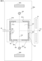
図2は、イオン化部300の構成を示す概念図である。イオン化部300は、イオン化室310、フィラメント320およびトラップ電極330の他、磁石340aおよび340bを備える。イオン化室310は、第1側壁311と、第2側壁312と、第3側壁313と、第4側壁314と、第5側壁315とを備える。イオン化室310は、この他に第5側壁315と向かい合う位置に配置された不図示の側壁である第6側壁を備える。以下では、単に側壁と述べた場合には、第1側壁311、第2側壁312、第3側壁313、第4側壁314、第5側壁315および第6側壁を区別せずに指す。
FIG. 2 is a conceptual diagram showing the configuration of the
図2では、Z軸をフィラメント320とトラップ電極330とを結ぶ方向に設定し、X軸をイオン光軸Ax1に沿った方向に設定し、Z軸およびX軸に垂直にY軸を設定している(座標系9参照)。第1側壁311および第2側壁312は、XY平面に沿って配置されている。第3側壁313および第4側壁314はYZ平面に沿って配置されている。第5側壁315および第6側壁は、ZX平面に沿って配置されている。
In FIG. 2, the Z-axis is set in the direction connecting the
イオン化室310の第1側壁311には、第1開口部301と第6開口部306とが形成されている。第2側壁312には、第2開口部302と第5開口部305が形成されている。第2側壁312は、第1側壁311と、イオン光軸Ax1を挟んで向かい合う位置に形成されている。第3側壁313には、第3開口部303が形成されている。第4側壁314には、第4開口部304が形成されている。
A
イオン化室310の側壁はステンレス等の金属により構成されている。イオン化室310の側壁の厚さは製造および分析において支障が無ければ特に限定されず、例えば数mm等にすることができる。熱電子を加速するため、第1側壁311を含むイオン化室310は、フィラメント320に対して+数十V~数百Vの電圧が印加されている。この電圧は、イオン化の効率を上げる観点から適宜設定される。
The side wall of the
イオン化室310は例えば直方体状または円筒状等とすることができる。しかし、フィラメント320から出射された熱電子を第1開口部301を通過させて試料Sに照射でき、当該照射により得られたイオンInをイオン化室から出射できれば、イオン化室310の形状は特に限定されない。
The
第1開口部301は、フィラメント320から出射された熱電子がイオン化室310の内部へと進入する際に通過する開口部である。第2開口部302は、フィラメント320から出射された熱電子がイオン化室310から出射される際に通過する開口部である。第1開口部301および第2開口部302は、軸Ax2を中心軸として形成されている。軸Ax2は、試料ガス導入管20からの試料ガスの流れおよびイオン光軸Ax1と略直交することが好ましい。また、試料ガス導入管20から排出された試料Sの流れが、軸Ax2とイオン光軸Ax1との交点を通るように試料ガス導入管20が配置されることが好ましい。第1開口部301および第2開口部302の形状は、所望の効率でイオン化を行うことができれば特に限定されない。例えば、第1開口部301および第2開口部302は、円状、楕円状、正方形状または長方形状とすることができる。
The
第3開口部303を通って、試料ガス導入管20が配置されている。第3開口部303は、GC10から試料ガスがイオン化室310に導入される際に通過する開口部である。第4開口部304をイオン光軸Ax1が通過している。第4開口部304は、イオン化室310でイオン化された試料がイオン化室310から出射する際に通過する開口部である。
The sample
第5開口部305は、較正用試料がイオン化室310に導入される際に通過する開口部である。第5開口部305を通って、較正用試料導入管60が配置される。第5開口部305に較正用試料導入管60は配置されず、イオン化室310の外部から拡散により較正用試料がイオン化室310の内部に導入される構成にしてもよい。較正用試料の種類は特に限定されないが、感度が高くなるように質量分析部30の各部を調節する際に用いるPFTBA(Perfluorotributylamine)等とすることができる。
The
第6開口部306は、キャリアガスのイオン化室310からの排出を促進するための開口部である。第6開口部306は、窒素ガスを排出するための窒素ガス排出口として機能する。窒素ガスのようにキャリアガスの分子の大きさがヘリウムと比較して大きいと、当該分子に熱電子が衝突してしまい、イオン化に寄与する熱電子の割合が減少するため、イオン化効率が減少する。この点は、窒素ガスのようにキャリアガスの分子量がヘリウムと比較して大きいことによりイオン化室310における滞留時間が長いことでより顕著となる。窒素ガス由来のイオンがノイズとして検出される場合もある。このような理由で、キャリアガスにおいて窒素ガスが使用されると、感度が低下する場合がある。第6開口部306から窒素ガスが排出されることで、感度の低下を抑制することができる。
The
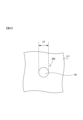
図3は、第1側壁311に垂直な方向で、図2のZ軸プラス側からマイナス側の向きに第6開口部306を見た場合の図である。この例では、第6開口部306は、第1側壁311において円形の開口部となっている。第6開口部306の面積S6は、単位を立方ミリメートル(mm3)としたイオン化室310の内側の体積に対する、単位を平方ミリメートル(mm2)としたイオン化室310の側壁における開口部の面積の合計の比率が、30分の1以上となるように設定される。ここで、本実施形態では、イオン化室310の側壁における開口部の面積の合計は、第1開口部301、第2開口部302、第3開口部303、第4開口部304、第5開口部305および第6開口部306の面積の合計である。開口部の面積とは、例えば、開口部が形成された側壁に平行な面と当該開口部とが重なる面積の最小値とすることができる。
なお、第6開口部306は、イオン化室310の側壁の任意の位置に形成することができる。また、第6開口部306の形状は特に限定されない。FIG. 3 is a diagram when the
Note that the
第6開口部306の最大径L6は、20mm未満であることが好ましく、2mm以上4mm未満がより好ましく、2.5mm以上3.5mm未満がさらに好ましく、3mmがより一層好ましい。ここで、第6開口部306の最大径L6は、第6開口部306が形成された側壁に平行で第6開口部306の内壁の2点を結ぶ線分のうち、最も長い線分の長さとすることができる。第6開口部306はイオン化室310の側壁に複数配置してもよい。第6開口部306の最大径L6の下限は特に限定されず、例えば0.1mm以上とすることができる。
The maximum diameter L6 of the
図2に戻って、トラップ電極330は、熱電子を検出可能な任意の電極とすることができるが、フィラメントを含むことが好ましい。トラップ電極330は、不図示の電流計等と電気的に接続されており、トラップ電極330に到達した熱電子の量を測定可能に構成されている。トラップ電極330をフィラメントとすると、当該フィラメントを熱電子源とし、フィラメント320をトラップ電極としてEIを行うこともできる。この場合、フィラメント320およびトラップ電極330は同一形状であることがより好ましい。
Returning to FIG. 2,
イオン化部300に配置された磁石340aおよび340bにより生成される磁場により、フィラメント320から出射された熱電子は、螺旋状の軌道に沿って移動する。これにより、熱電子と試料Sとが反応しやすくすることができ、イオン化の効率が高められる。
Due to the magnetic field generated by
図1に戻って、質量分析部30のイオン調整部34は、イオンガイド等のイオン輸送系を備え、電磁気学的作用により、イオンInの流束を収束させる等して調整する。イオン調整部34から出射されたイオンInは質量分離部35に導入される。
Returning to FIG. 1, the
質量分析部30の質量分離部35は、四重極マスフィルタを備え、導入されたイオンInを質量分離する。質量分離部35は、四重極マスフィルタに印加された電圧により、質量電荷比の値に基づいてイオンInを選択的に通過させる。質量分離部35の質量分離で得られたイオンInは検出部36に入射する。
The
質量分析部30の検出部36は、イオン検出器を備え、入射したイオンInを検出する。検出部36は、入射したイオンInの検出により得られた検出信号を、不図示のアナログ/デジタル(Analog/Digital;A/D)変換器によりA/D変換し、デジタル化された検出信号を情報処理部40に出力する(矢印A20)。以下では、検出部36がイオンInを検出して得た検出信号に基づくデータを測定データと呼ぶ。
The
情報処理部40は、電子計算機等の情報処理装置を備え、GC-MS1のユーザー(以下、単に「ユーザー」と呼ぶ)とのインターフェースとなる他、様々なデータに関する通信、記憶および演算等の処理を行う。情報処理部40は、マウス、キーボードまたはタッチパネル等の入力装置を介してユーザーから分析条件等に関する情報を取得する。情報処理部40は、CPU(Central Processing Unit)等の処理装置ならびにメモリおよびハードディスク等の記憶媒体からなる制御部を備える。当該処理装置は、ハードディスク等に記憶されたプログラムをメモリに読み込んで実行し、測定部100を制御したり、測定データを処理する等、GC―MS1の動作の主体となる。測定データの処理の方法は特に限定されず、検出部36が検出したイオンInの保持時間と検出信号の強度が対応付けられたクロマトグラムに対応するデータを作成したり、試料Sに含まれる分子の同定または定量等を行うことができる。情報処理部40は、表示モニタ等の表示装置を備え、処理装置による処理で得られた情報を表示する。
なお、測定部100と情報処理部40とを一体の装置として構成してもよい。The
Note that the measuring
本実施形態の質量分析装置1は、単位を立方ミリメートルとしたイオン化室310の内側の体積に対する、単位を平方ミリメートルとした前記イオン化室の側壁における開口部の面積の合計の比率が、30分の1以上である。これにより、窒素ガスをキャリアガスとして用いたときに、イオン化室310における、窒素ガスの分圧を低くしたり、窒素の滞留時間を短くすることができ、窒素ガスによる感度の低下を抑制することができる。また、本実施形態の質量分析装置1は、第1~第5開口部の他に、第6開口部306を備える。第6開口部306は容易に加工することができ、感度の低下を抑制した質量分析装置1を実現することができる。
In the
次のような変形も本発明の範囲内であり、上述の実施形態と組み合わせることが可能である。以下の変形例において、上述の実施形態と同様の構造、機能を示す部位等に関しては、同一の符号で参照し、適宜説明を省略する。 The following modifications are also within the scope of the invention and can be combined with the embodiments described above. In the following modified examples, parts having the same structures and functions as those in the above-described embodiment will be referred to with the same reference numerals, and descriptions thereof will be omitted as appropriate.
(変形例1)
上述の実施形態では、第6開口部306をイオン化室310の側壁に形成する構成とした。しかし、第6開口部をイオン化室に形成せず、第1開口部、第2開口部、第3開口部、第4開口部および第5開口部の少なくとも一つの面積を広げる構成にしてもよい。(Modification 1)
In the embodiment described above, the
図4は、本変形例のイオン化部300aの構成を示す概念図である。イオン化部300aは、イオン化室310の代わりにイオン化室310aを備える点が上述のイオン化部300とは異なっている。イオン化室310aは、第6開口部306を備えず、第1側壁311の代わりに第1側壁311aを備え、第1開口部301の代わりに第1開口部301aを備える点で上述のイオン化部300とは異なっている。
FIG. 4 is a conceptual diagram showing the configuration of the
第1開口部301aは、第1側壁311aに垂直な方向から見て円状、楕円状、正方形状または長方形状の開口部となっている。第1開口部301aの面積は、単位を立方ミリメートル(mm3)としたイオン化室310aの内側の体積に対する、単位を平方ミリメートル(mm2)としたイオン化室310aの側壁における開口部の面積の合計の比率が、30分の1以上となるように設定される。本変形例のGC-MSでも、窒素ガスをキャリアガスとして用いた場合における感度の低下を抑制することができる。The first opening 301a has a circular, elliptical, square, or rectangular shape when viewed from a direction perpendicular to the
なお、トラップ電極330をフィラメントとして、フィラメント320をトラップ電極として用いることもできる構成とする場合には、第2開口部302の大きさも第1開口部301aと同等になるように構成することが好ましい。また、単位を立方ミリメートル(mm3)としたイオン化室310aの内側の体積に対する、単位を平方ミリメートル(mm2)としたイオン化室310aの側壁における開口部の面積の合計の比率が、30分の1以上となれば、いずれの1以上の開口部の大きさを変更してもよい。本変形例のように第1開口部301aの大きさを変更する他、第2開口部302、第3開口部303、第4開口部304および第5開口部305の少なくとも一つの大きさを変更してもよい。Note that in the case of a configuration in which the
(変形例2)
上述の実施形態において、イオン化室の側壁に形成された開口部の面積が変更可能に制御される構成としてもよい。(Modification 2)
In the embodiment described above, the area of the opening formed in the side wall of the ionization chamber may be controlled to be changeable.
図5は、本変形例のGC-MSの構成を示す概念図である。GC-MS1は、測定部100aと情報処理部40aとを備える。測定部100aは、イオン化部300の代わりにイオン化部300bを備える点で上述の測定部100とは異なっている。イオン化部300bは、イオン化室310の代わりにイオン化室310bを備える点で上述のイオン化部300とは異なっている。情報処理部40aは、開口制御部400を備える点で上述の情報処理部400とは異なっている。
FIG. 5 is a conceptual diagram showing the configuration of the GC-MS of this modification. GC-MS1 includes a
図6は、イオン化部300bの構成を示す概念図である。イオン化室310bは、第1側壁311の代わりに、開閉機構360が設置された第1側壁311bを備える点で上述のイオン化室310とは異なっている。開閉機構360は、アクチュエータとして構成され、蓋360aと駆動装置360bとを備える。開閉機構360は、第6開口部306を開閉する開閉部として機能する。開閉機構は、開口制御部400(図5)により制御される。開口制御部400は、情報処理部40aの制御部に含まれる。例えば、ユーザーが第6開口部306の開閉を入力すると、開口制御部400から制御信号が開閉機構360に送られる。駆動装置360bは、蓋360aを移動させることにより第6開口部306の開閉を行う。このようにイオン化室310bの開口部の面積を制御することにより、ヘリウムおよび窒素等、分子量の異なるキャリアガスのそれぞれに適した条件で分析を行うことができる。
FIG. 6 is a conceptual diagram showing the configuration of the
なお、開閉機構360の構成は、第6開口部306の面積を変化させることができれば特に限定されない。また、イオン化室310bに形成されている開口部の少なくとも一つは、その面積を変更可能に制御する構成にすることができる。第1開口部301、第2開口部302、第3開口部303、第4開口部304、第5開口部305および第6開口部306の少なくとも一つについて、開閉機構が設置され、開口部の面積を変化させるようにすることができる。
Note that the configuration of the opening/
(変形例3)
上述の実施形態ではキャリアガスとして窒素ガスを使用可能に構成した。しかし、GC-MSがヘリウムと比較して分子量の大きい分子または原子をキャリアガスとして用いる場合にも、上記と同様の効果を得ることができる。(Modification 3)
In the embodiment described above, nitrogen gas can be used as the carrier gas. However, even when GC-MS uses molecules or atoms with a larger molecular weight than helium as a carrier gas, the same effect as described above can be obtained.
(態様)
上述した複数の例示的な実施形態または変形例は、以下の態様の具体例であることが当業者により理解される。(mode)
It will be appreciated by those skilled in the art that the exemplary embodiments or variations described above are specific examples of the following aspects.
(第1項)一態様に係るガスクロマトグラフ質量分析計は、試料を分離する分離部と、前記分離部から導入される前記試料を質量分析する質量分析部とを備えるガスクロマトグラフ質量分析計であって、前記質量分析部は、フィラメントと、前記フィラメントからの熱電子および前記分離部からの前記試料が導入されるイオン化室とを備え、単位を立方ミリメートル(mm3)とした前記イオン化室の内側の体積に対する、単位を平方ミリメートルとした前記イオン化室の側壁における開口部の面積 (mm2)の合計の比率が、30分の1以上である。これにより、窒素ガス等の分子量がヘリウムよりも大きい分子または原子を含むガスをキャリアガスとして用いたときに、分析の感度の低下を抑制することができる。(Section 1) A gas chromatograph mass spectrometer according to one aspect is a gas chromatograph mass spectrometer that includes a separation section that separates a sample, and a mass spectrometry section that performs mass spectrometry on the sample introduced from the separation section. The mass spectrometry section includes a filament and an ionization chamber into which the thermoelectrons from the filament and the sample from the separation section are introduced, and the inside of the ionization chamber is expressed in cubic millimeters (mm 3 ). The ratio of the total area (mm 2 ) of the openings in the side wall of the ionization chamber in units of square millimeters to the volume of is 1/30 or more. Thereby, when a gas containing molecules or atoms having a molecular weight larger than that of helium, such as nitrogen gas, is used as a carrier gas, a decrease in analysis sensitivity can be suppressed.
(第2項)他の一態様に係るガスクロマトグラフ質量分析計では、第1項に記載のガスクロマトグラフ質量分析計において、前記イオン化室の前記側壁には、前記フィラメントからの熱電子が前記イオン化室に入射する際に通過する第1開口部と、前記熱電子が前記イオン化室から出射する際に通過する第2開口部と、前記分離部から前記試料が導入される際に通過する第3開口部と、イオン化された前記試料が前記イオン化室から出射する際に通過する第4開口部と、較正用試料が導入される際に通過する第5開口部との他に、少なくとも一つの第6開口部が形成され得る。これにより、分析の感度の低下を抑制することができるイオン化室を容易に加工することができる。
(Section 2) In the gas chromatograph mass spectrometer according to another aspect, in the gas chromatograph mass spectrometer according to
(第3項)他の一態様に係るガスクロマトグラフ質量分析計では、第2項に記載のガスクロマトグラフ質量分析計において、前記第6開口部の最大径は20mm未満とすることができる。これにより、分析の感度の低下を抑制しつつ、開口部による悪影響を防ぐことができる。
(Section 3) In the gas chromatograph mass spectrometer according to another aspect, in the gas chromatograph mass spectrometer according to
(第4項)他の一態様に係るガスクロマトグラフ質量分析計では、第2項または第3項に記載のガスクロマトグラフ質量分析計において、第6開口部を開閉する開閉部を備えることができる。これにより、分子量の異なるキャリアガスのそれぞれに適した条件で分析を行うことができる。
(Section 4) In the gas chromatograph mass spectrometer according to another aspect, the gas chromatograph mass spectrometer according to
(第5項)他の一態様に係るガスクロマトグラフ質量分析計では、第1項から第3項までのいずれかに記載のガスクロマトグラフ質量分析計において、前記イオン化室に形成されている開口部の少なくとも一つを開閉する開閉部を備えることができる。これにより、分子量の異なるキャリアガスのそれぞれにさらに適した条件で分析を行うことができる。
(Section 5) In the gas chromatograph mass spectrometer according to another aspect, in the gas chromatograph mass spectrometer according to any one of
(第6項)他の一態様に係るガスクロマトグラフ質量分析計では、第1項から第5項までのいずれかに記載のガスクロマトグラフ質量分析計において、前記イオン化室は、電子衝撃イオン化が可能であり、キャリアガスとして窒素ガスを使用可能とすることができる。これにより、より確実に分析の感度の低下を抑制することができる。
(Section 6) In a gas chromatograph mass spectrometer according to another aspect, in the gas chromatograph mass spectrometer according to any one of
本発明は上記実施形態の内容に限定されるものではない。本発明の技術的思想の範囲内で考えられるその他の態様も本発明の範囲内に含まれる。 The present invention is not limited to the contents of the above embodiments. Other embodiments considered within the technical spirit of the present invention are also included within the scope of the present invention.
以下に実施例を示すが、本発明は下記の実施例に限定されることを意図したものではない。 Examples are shown below, but the present invention is not intended to be limited to the following examples.
(比較例)
GCとしてGC-2010Plus(島津製作所)が搭載されたGC-MSであるGCMS-TQ8040(島津製作所)を用い、オクタフルオロナフタレンを含む試料をガスクロマトグラフィ/質量分析(Gas Chromatography/Mass Spectrometry;GC/MS)に供した。(Comparative example)
Using GCMS-TQ8040 (Shimadzu Corporation), which is a GC-MS equipped with GC-2010Plus (Shimadzu Corporation) as a GC, a sample containing octafluoronaphthalene was subjected to gas chromatography/mass spectrometry (GC/MS). ).
ガスクロマトグラフィの条件
カラム: SH-Rxi-5Sil MS(長さ:30.0m、内径:0.25mm、膜厚:0.25μm)(島津ジーエルシー)
試料気化室の温度: 250℃
キャリアガスの制御モード: 試料の注入口の圧力が設定値となるよう制御
キャリアガスの圧力: 21.8kPa
全流量: 50mL/min.
パージ流量: 6mL/min.
注入モード: スプリットレス
カラムオーブン温度: 最初の1分を50℃に保ち、40℃/min.の割合で200℃まで上昇させ、15℃/min.の割合で250℃まで上昇させ、3分間250℃に保った。Conditions for gas chromatography Column: SH-Rxi-5Sil MS (length: 30.0 m, inner diameter: 0.25 mm, film thickness: 0.25 μm) (Shimadzu GLC)
Temperature of sample vaporization chamber: 250℃
Carrier gas control mode: Control the sample injection port pressure to the set value Carrier gas pressure: 21.8kPa
Total flow rate: 50mL/min.
Purge flow rate: 6mL/min.
Injection mode: Splitless column oven temperature: 50°C for the first minute, 40°C/min. The temperature was increased to 200°C at a rate of 15°C/min. The temperature was increased to 250°C at a rate of 250°C, and the temperature was kept at 250°C for 3 minutes.
質量分析の条件
インターフェース温度: 250℃
イオン源温度: 200℃
測定モード: スキャン
スキャン範囲: m/z 200 - 300
イベント時間: 0.2sec.
スキャンスピード: 555u/sec.Mass spectrometry conditions Interface temperature: 250℃
Ion source temperature: 200℃
Measurement mode: Scan Scan range: m/z 200 - 300
Event time: 0.2sec.
Scan speed: 555u/sec.
図7は、本比較例で得られたクロマトグラムを示す図である。クロマトグラムは、横軸に保持時間、縦軸に当該保持時間に溶出した試料の質量分析での検出信号の強度を示すグラフである。ピークP1は、オクタフルオロナフタレンに対応するピークである。オクタフルオロナフタレンに対応するピークを用い、ルートミーンスクエア(RMS)法によりノイズを定量して算出した信号対雑音比(Signal/Noise ratio;S/N比)は、78.18となった。 FIG. 7 is a diagram showing a chromatogram obtained in this comparative example. The chromatogram is a graph in which the horizontal axis shows the retention time and the vertical axis shows the intensity of the detection signal in mass spectrometry of the sample eluted during the retention time. Peak P1 is a peak corresponding to octafluoronaphthalene. The signal/noise ratio (S/N ratio) calculated by quantifying noise using the root mean square (RMS) method using the peak corresponding to octafluoronaphthalene was 78.18.
(実施例)
GC-2010Plusが搭載されたGC-MSであるGCMS-TQ8040のイオン化室の側壁に3mmの円形の穴をあけ、上述の第6開口部に対応する開口部を作成した。その他は、上記比較例と同様の条件でGC/MSを行った。S/N比を上記比較例と同様の方法で算出した。(Example)
A 3 mm circular hole was made in the side wall of the ionization chamber of GCMS-TQ8040, which is a GC-MS equipped with GC-2010Plus, to create an opening corresponding to the sixth opening described above. Other than that, GC/MS was performed under the same conditions as in the above comparative example. The S/N ratio was calculated in the same manner as in the above comparative example.
図8は、本実施例で得られたクロマトグラムを示す図である。ピークP2は、オクタフルオロナフタレンに対応するピークである。S/N比は、693.34となった。 FIG. 8 is a diagram showing a chromatogram obtained in this example. Peak P2 is a peak corresponding to octafluoronaphthalene. The S/N ratio was 693.34.
1,2…GC-MS、9…座標系、10…GC、20…試料ガス導入管、30…質量分析部、31…真空容器、33…真空排気系、35…質量分離部、36…検出部、40,40a…情報処理部、100,100a…測定部、300,300a,300b…イオン化部、301,301a…第1開口部、302…第2開口部、303…第3開口部、304…第4開口部、305…第5開口部、306…第6開口部、310,310a,310b…イオン化室、311,311a,311b…第1側壁、312…第2側壁、313…第3側壁、314…第4側壁、315…第5側壁、320…フィラメント、330…トラップ電極、360…開閉機構、400…開口制御部、In…イオン、L6…第6開口部の最大径、P1,P2…オクタフルオロナフタレンに対応するピーク、S…試料、S6…第6開口部の面積。
1, 2...GC-MS, 9...Coordinate system, 10...GC, 20...Sample gas introduction tube, 30...Mass spectrometry section, 31...Vacuum container, 33...Evacuation system, 35...Mass separation section, 36...
Claims (4)
前記質量分析部は、フィラメントと、前記フィラメントからの熱電子および前記分離部からの前記試料が導入され、前記試料の電子衝撃イオン化が行われるイオン化室とを備え、
単位を立方ミリメートル(mm3)とした前記イオン化室の内側の体積に対する、単位を平方ミリメートルとした前記イオン化室の側壁における開口部の面積(mm2)の合計の比率が、30分の1以上であり、
前記イオン化室の前記側壁には、前記フィラメントからの前記熱電子が前記イオン化室に入射する際に通過する第1開口部と、前記熱電子が前記イオン化室から出射する際に通過する第2開口部と、前記分離部から前記試料が導入される際に通過する第3開口部と、イオン化された前記試料が前記イオン化室から出射する際に通過する第4開口部と、較正用試料が導入される際に通過する第5開口部との他に、少なくとも一つの第6開口部が形成され、
前記第6開口部は、キャリアガスの前記イオン化室からの排出を促進するための開口部である、ガスクロマトグラフ質量分析計。 A gas chromatograph mass spectrometer comprising a separation section that separates a sample, a gas supply section that supplies nitrogen gas as a carrier gas to the separation section, and a mass spectrometry section that performs mass analysis of the sample introduced from the separation section. There it is,
The mass spectrometry section includes a filament and an ionization chamber into which the thermoelectrons from the filament and the sample from the separation section are introduced and electron impact ionization of the sample is performed,
The ratio of the total area (mm 2 ) of the openings in the side wall of the ionization chamber in square millimeters to the inner volume of the ionization chamber in cubic millimeters (mm 3 ) is 1/30 or more. and
The side wall of the ionization chamber includes a first opening through which the thermoelectrons from the filament pass when entering the ionization chamber, and a second opening through which the thermoelectrons pass when exiting from the ionization chamber. a third opening through which the sample is introduced from the separation section; a fourth opening through which the ionized sample passes when exiting from the ionization chamber; and a calibration sample through which the sample is introduced. At least one sixth opening is formed in addition to the fifth opening through which the second opening passes when
The sixth opening is an opening for promoting discharge of carrier gas from the ionization chamber .
前記第6開口部の最大径は20mm未満である、ガスクロマトグラフ質量分析計。 The gas chromatograph mass spectrometer according to claim 1 ,
The gas chromatograph mass spectrometer, wherein the sixth opening has a maximum diameter of less than 20 mm.
前記第6開口部を開閉する開閉部を備える、ガスクロマトグラフ質量分析計。 The gas chromatograph mass spectrometer according to claim 1 or 2 ,
A gas chromatograph mass spectrometer comprising an opening/closing section that opens and closes the sixth opening.
前記イオン化室に形成されている開口部の少なくとも一つを開閉する開閉部を備える、ガスクロマトグラフ質量分析計。 The gas chromatograph mass spectrometer according to claim 1 or 2 ,
A gas chromatograph mass spectrometer, comprising an opening/closing section that opens and closes at least one of the openings formed in the ionization chamber.
Applications Claiming Priority (1)
| Application Number | Priority Date | Filing Date | Title |
|---|---|---|---|
| PCT/JP2020/018600 WO2021224973A1 (en) | 2020-05-08 | 2020-05-08 | Gas chromatograph mass spectrometer |
Publications (3)
| Publication Number | Publication Date |
|---|---|
| JPWO2021224973A1 JPWO2021224973A1 (en) | 2021-11-11 |
| JPWO2021224973A5 JPWO2021224973A5 (en) | 2022-12-22 |
| JP7409492B2 true JP7409492B2 (en) | 2024-01-09 |
Family
ID=78467986
Family Applications (1)
| Application Number | Title | Priority Date | Filing Date |
|---|---|---|---|
| JP2022519866A Active JP7409492B2 (en) | 2020-05-08 | 2020-05-08 | gas chromatograph mass spectrometer |
Country Status (2)
| Country | Link |
|---|---|
| JP (1) | JP7409492B2 (en) |
| WO (1) | WO2021224973A1 (en) |
Citations (7)
| Publication number | Priority date | Publication date | Assignee | Title |
|---|---|---|---|---|
| JP2001126658A (en) | 1999-10-29 | 2001-05-11 | Jeol Ltd | Mass spectrometer |
| JP2003270207A (en) | 2002-03-12 | 2003-09-25 | Jeol Ltd | Mass spectrograph and ionizing apparatus therefor |
| WO2007102204A1 (en) | 2006-03-07 | 2007-09-13 | Shimadzu Corporation | Mass analyzer |
| US20090194681A1 (en) | 2008-02-05 | 2009-08-06 | Mccauley Edward B | Method and Apparatus for Response and Tune Locking of a Mass Spectrometer |
| JP2010504504A (en) | 2006-09-25 | 2010-02-12 | エムディーエス アナリティカル テクノロジーズ, ア ビジネス ユニット オブ エムディーエス インコーポレイテッド, ドゥーイング ビジネス スルー イッツ サイエックス ディビジョン | Multiple sample sources for use with a mass spectrometer and apparatus, devices and methods therefor |
| JP2013539590A (en) | 2010-08-19 | 2013-10-24 | レコ コーポレイション | Time-of-flight mass spectrometer with storage electron impact ion source |
| WO2018100621A1 (en) | 2016-11-29 | 2018-06-07 | 株式会社島津製作所 | Ionizer and mass spectrometer |
Family Cites Families (2)
| Publication number | Priority date | Publication date | Assignee | Title |
|---|---|---|---|---|
| US6037179A (en) * | 1998-04-30 | 2000-03-14 | Hewlett-Packard Company | Method and apparatus for suppression of analyte diffusion in an ionization detector |
| CN107301945B (en) * | 2016-04-14 | 2024-02-13 | 广州禾信仪器股份有限公司 | Electron bombardment source and mass spectrometer |
-
2020
- 2020-05-08 WO PCT/JP2020/018600 patent/WO2021224973A1/en active Application Filing
- 2020-05-08 JP JP2022519866A patent/JP7409492B2/en active Active
Patent Citations (7)
| Publication number | Priority date | Publication date | Assignee | Title |
|---|---|---|---|---|
| JP2001126658A (en) | 1999-10-29 | 2001-05-11 | Jeol Ltd | Mass spectrometer |
| JP2003270207A (en) | 2002-03-12 | 2003-09-25 | Jeol Ltd | Mass spectrograph and ionizing apparatus therefor |
| WO2007102204A1 (en) | 2006-03-07 | 2007-09-13 | Shimadzu Corporation | Mass analyzer |
| JP2010504504A (en) | 2006-09-25 | 2010-02-12 | エムディーエス アナリティカル テクノロジーズ, ア ビジネス ユニット オブ エムディーエス インコーポレイテッド, ドゥーイング ビジネス スルー イッツ サイエックス ディビジョン | Multiple sample sources for use with a mass spectrometer and apparatus, devices and methods therefor |
| US20090194681A1 (en) | 2008-02-05 | 2009-08-06 | Mccauley Edward B | Method and Apparatus for Response and Tune Locking of a Mass Spectrometer |
| JP2013539590A (en) | 2010-08-19 | 2013-10-24 | レコ コーポレイション | Time-of-flight mass spectrometer with storage electron impact ion source |
| WO2018100621A1 (en) | 2016-11-29 | 2018-06-07 | 株式会社島津製作所 | Ionizer and mass spectrometer |
Also Published As
| Publication number | Publication date |
|---|---|
| WO2021224973A1 (en) | 2021-11-11 |
| JPWO2021224973A1 (en) | 2021-11-11 |
Similar Documents
| Publication | Publication Date | Title |
|---|---|---|
| JP5268634B2 (en) | Method and apparatus for controlling ion instability in an electron impact ion source | |
| JP5793207B2 (en) | System and method for performing charge monitoring mass spectrometry of analyte bioparticles | |
| WO2007108211A1 (en) | Gas analyzer | |
| JP6301907B2 (en) | Method and apparatus for acquiring mass spectrometry / mass spectrometry data in parallel | |
| CA2738053C (en) | Photoemission induced electron ionization | |
| US8344317B2 (en) | Molecular ion accelerator | |
| JP2009129868A (en) | Mass spectroscope and its method for adjustment | |
| US20230207301A1 (en) | Multi-modal ionization for mass spectrometry | |
| JP7409492B2 (en) | gas chromatograph mass spectrometer | |
| JP2011171009A (en) | Focused ion beam device | |
| JP5989959B2 (en) | Focused ion beam device | |
| JP5142273B2 (en) | Neutral particle mass spectrometer and analysis method | |
| CN112424902B (en) | Ionization source and system and method for using the same | |
| WO2021033318A1 (en) | Gas chromatograph mass spectrometer and mass spectrometry method | |
| US10262852B2 (en) | Atmospheric pressure ionization method | |
| JP2015502645A (en) | Improvements in or related to mass spectrometry | |
| JP7107378B2 (en) | Quadrupole mass spectrometer | |
| CN111971778B (en) | Off-axis ionization device and system | |
| Park et al. | Effect of magnetic field in electron-impact ion sources and simulation of electron trajectories | |
| Kolomiets et al. | Vortex focusing of ions produced in corona discharge | |
| US11217437B2 (en) | Electron capture dissociation (ECD) utilizing electron beam generated low energy electrons | |
| Brinkmalm et al. | DIPLOMA: An experimental system to study MeV and keV particle‐and photon‐induced desorption of molecules | |
| CN112313774A (en) | Mass analyzers including ion sources and reaction cells and systems and methods for using the same | |
| Houk et al. | Mass spectrometer with electron source for reducing space charge effects in sample beam | |
| Irvine et al. | Ultra-compact 180° magnetic spectrometer for intermediate energy electron measurement |
Legal Events
| Date | Code | Title | Description |
|---|---|---|---|
| A521 | Request for written amendment filed |
Free format text: JAPANESE INTERMEDIATE CODE: A523 Effective date: 20221006 |
|
| A621 | Written request for application examination |
Free format text: JAPANESE INTERMEDIATE CODE: A621 Effective date: 20221006 |
|
| A131 | Notification of reasons for refusal |
Free format text: JAPANESE INTERMEDIATE CODE: A131 Effective date: 20230725 |
|
| A601 | Written request for extension of time |
Free format text: JAPANESE INTERMEDIATE CODE: A601 Effective date: 20230921 |
|
| A521 | Request for written amendment filed |
Free format text: JAPANESE INTERMEDIATE CODE: A523 Effective date: 20231011 |
|
| TRDD | Decision of grant or rejection written | ||
| A01 | Written decision to grant a patent or to grant a registration (utility model) |
Free format text: JAPANESE INTERMEDIATE CODE: A01 Effective date: 20231121 |
|
| A61 | First payment of annual fees (during grant procedure) |
Free format text: JAPANESE INTERMEDIATE CODE: A61 Effective date: 20231204 |
|
| R151 | Written notification of patent or utility model registration |
Ref document number: 7409492 Country of ref document: JP Free format text: JAPANESE INTERMEDIATE CODE: R151 |