JP7403077B2 - Laser light source device and image forming device using the same - Google Patents
Laser light source device and image forming device using the same Download PDFInfo
- Publication number
- JP7403077B2 JP7403077B2 JP2019165647A JP2019165647A JP7403077B2 JP 7403077 B2 JP7403077 B2 JP 7403077B2 JP 2019165647 A JP2019165647 A JP 2019165647A JP 2019165647 A JP2019165647 A JP 2019165647A JP 7403077 B2 JP7403077 B2 JP 7403077B2
- Authority
- JP
- Japan
- Prior art keywords
- laser
- light source
- source device
- collimating lens
- diffraction
- Prior art date
- Legal status (The legal status is an assumption and is not a legal conclusion. Google has not performed a legal analysis and makes no representation as to the accuracy of the status listed.)
- Active
Links
- 230000003287 optical effect Effects 0.000 claims description 142
- 238000010586 diagram Methods 0.000 description 31
- 230000004075 alteration Effects 0.000 description 27
- 239000000463 material Substances 0.000 description 8
- 230000000694 effects Effects 0.000 description 7
- 239000000203 mixture Substances 0.000 description 7
- 239000003086 colorant Substances 0.000 description 6
- 238000005516 engineering process Methods 0.000 description 5
- 239000004065 semiconductor Substances 0.000 description 3
- 238000007792 addition Methods 0.000 description 2
- 238000004364 calculation method Methods 0.000 description 2
- 230000006870 function Effects 0.000 description 2
- 206010010071 Coma Diseases 0.000 description 1
- 238000004458 analytical method Methods 0.000 description 1
- 230000015572 biosynthetic process Effects 0.000 description 1
- 230000007613 environmental effect Effects 0.000 description 1
- 239000011521 glass Substances 0.000 description 1
- 238000012423 maintenance Methods 0.000 description 1
- 238000000034 method Methods 0.000 description 1
- 230000000630 rising effect Effects 0.000 description 1
- 238000006467 substitution reaction Methods 0.000 description 1
- 238000003786 synthesis reaction Methods 0.000 description 1
Images


Description
本開示は、複数の波長のレーザ光を出射するレーザ光源装置及びそれを用いた像形成装置に関する。 The present disclosure relates to a laser light source device that emits laser light of a plurality of wavelengths and an image forming apparatus using the same.
従来、複数の波長のレーザ光を出射するレーザ光源装置は、ダイクロイックミラーを用いてそれぞれの波長のレーザ光を合成していた。また、ダイクロイックミラーに入射する前にそれぞれの波長のレーザ光は平行光にされていた。 Conventionally, a laser light source device that emits laser beams of multiple wavelengths has combined the laser beams of each wavelength using a dichroic mirror. Furthermore, the laser beams of each wavelength were made into parallel beams before entering the dichroic mirror.
特許文献1は、R(赤色)、G(緑色)、B(青色)の3色のレーザ光を合波して出力する3色光光源が記載されている。赤色、緑色、青色それぞれのレーザダイオードに対してコリメートレンズを配置し、2つの波長フィルタを配置している。
しかしながら、ダイクロイックミラーを用いる場合、各色のレーザ光源ごとにコリメートレンズと反射用の波長フィルタを必要とする。これにより、部品点数が多くなり、コスト高となってしまう。 However, when using a dichroic mirror, a collimating lens and a reflection wavelength filter are required for each color laser light source. This increases the number of parts and increases costs.
本開示は、部品点数を低減し、コストを低減した、複数の波長レーザを出射するレーザ光源装置を提供する。 The present disclosure provides a laser light source device that emits a plurality of wavelength lasers, which has a reduced number of parts and a reduced cost.
本開示のレーザ光源装置は、複数のレーザ素子と、
それぞれの前記レーザ素子から出射したレーザ光を回折する回折光学素子と、
それぞれの前記レーザ光を平行光にするコリメートレンズと、を備え、
それぞれの前記レーザ素子は、互いに波長の異なるレーザ光を出射し、
前記回折光学素子は、複数の直線状の溝がそれぞれ平行に形成された鋸歯形状部を有し、
それぞれの前記レーザ素子は、前記コリメートレンズの光軸を含む断面視において、前記コリメートレンズの光軸よりも一方側に、前記光軸との距離が異なる位置に配置され、
それぞれのレーザ素子から出射されたそれぞれのレーザ光が前記回折光学素子で互いに異なる回折次数で、回折されて合成される。
A laser light source device of the present disclosure includes a plurality of laser elements,
a diffractive optical element that diffracts the laser light emitted from each of the laser elements;
a collimating lens that converts each of the laser beams into parallel light;
Each of the laser elements emits laser beams having different wavelengths from each other,
The diffractive optical element has a sawtooth-shaped portion in which a plurality of linear grooves are respectively formed in parallel,
Each of the laser elements is arranged at a position different from the optical axis on one side of the optical axis of the collimating lens in a cross-sectional view including the optical axis of the collimating lens,
The respective laser beams emitted from the respective laser elements are diffracted and combined by the diffraction optical element at different orders of diffraction.
また、本開示の像形成装置は、前記レーザ光源装置と、
前記レーザ光源装置から出射する複数の波長を有するレーザ光を第1方向に走査する第1走査素子と、
前記第1走査素子から出射するレーザ光を前記第1方向と直交する第2方向に走査する第2走査素子と、を備える。
Further, the image forming apparatus of the present disclosure includes the laser light source device;
a first scanning element that scans laser light having a plurality of wavelengths emitted from the laser light source device in a first direction;
A second scanning element that scans a laser beam emitted from the first scanning element in a second direction perpendicular to the first direction.
本開示におけるレーザ光源装置及び像形成装置は、部品点数を低減し、コストを低減して複数の波長レーザを出射することが可能である。 A laser light source device and an image forming device according to the present disclosure can reduce the number of parts and reduce costs, and can emit lasers of multiple wavelengths.
以下、適宜図面を参照しながら、実施の形態を詳細に説明する。但し、必要以上に詳細な説明は省略する場合がある。例えば、既によく知られた事項の詳細説明や実質的に同一の構成に対する重複説明を省略する場合がある。これは、以下の説明が不必要に冗長になるのを避け、当業者の理解を容易にするためである。
なお、発明者(ら)は、当業者が本開示を十分に理解するために添付図面および以下の説明を提供するのであって、これらによって特許請求の範囲に記載の主題を限定することを意図するものではない。
Hereinafter, embodiments will be described in detail with reference to the drawings as appropriate. However, more detailed explanation than necessary may be omitted. For example, detailed explanations of well-known matters or redundant explanations of substantially the same configurations may be omitted. This is to avoid unnecessary redundancy in the following description and to facilitate understanding by those skilled in the art.
The inventor(s) provide the accompanying drawings and the following description to enable those skilled in the art to fully understand the present disclosure, and are intended to limit the subject matter recited in the claims. It's not something you do.
まず、図1~図3を参照して本開示の概略的な説明をする。図1は、本開示の光源装置の構成の一例を示す断面図である。図2Aは、コリメートレンズ15の光源側に形成された直線状の回折格子13を示し、(a)は直線状の回折格子13の背面図であり、(b)は、直線状の回折格子13の部分断面図である。図2Bは、コリメートレンズの斜視図である。図3は、赤色レーザ素子、緑色レーザ素子、青色レ-ザ素子のそれぞれの回折次数とそれぞれの回折効率との関係を示すグラフである。なお、図1においてコリメートレンズ15の光軸Lsの方向をZ軸方向とし、コリメートレンズの光軸Lsに垂直で紙面内の方向をY軸方向とし、Z軸方向及び紙面に垂直な方向をX軸方向とする。
First, a general description of the present disclosure will be given with reference to FIGS. 1 to 3. FIG. 1 is a cross-sectional view showing an example of the configuration of a light source device of the present disclosure. 2A shows a linear diffraction grating 13 formed on the light source side of the
光源装置1は、複数の波長のレーザ光を出射するレーザ光源2と、レーザ光源2から出射された複数の波長のレーザ光を回折する回折格子13と、回折格子13により回折されたそれぞれのレーザ光を平行光にするコリメートレンズ15とを備える。なお、この例では、コリメートレンズ15の一面に回折光学素子としての回折格子13が形成されているが、回折格子13とコリメートレンズ15とが別体でもいい。コリメートレンズ15の凸面16は非球面形状である。
The
レーザ光源2は、波長の異なるレーザ光をそれぞれ出射する少なくとも2つ以上のレーザ素子を有する。図1の例では、レーザ光源2は、赤色レーザ素子3、緑色レーザ素子5、及び青色レ-ザ素子7を備える。各レーザ素子は、例えば、レーザチップ型の半導体レーザである。赤色レーザ素子3、緑色レーザ素子5、及び青色レ-ザ素子7の光源は、コリメートレンズ15の光軸Ls上に存在せず、コリメートレンズ15の光軸Lsを含むYZ平面による断面視において、コリメートレンズ15の光軸Lsの一方側に光軸Lsとの距離が異なる位置に配置されている。おおよそ各レーザ素子から出射されるレーザの強度がもっとも強い方向をコリメートレンズ15の中心方向に向けられる。
The
レーザ光源2から出射した、各波長のレーザ光は回折格子13により回折する。回折格子13は複数の直線状の溝13bがそれぞれ平行に形成された鋸歯形状部としての複数のブレーズ13aを有する。ブレーズ13aは、例えば、光軸Lsを含むYZ平面の断面視で直角三角形の形状であり、溝13bと、溝13bからコリメートレンズ15の光軸Ls方向に起立した斜辺13cと、を有する。なお、鋸歯形状とは、断面視で斜辺13cが直線形状に限らず、円弧形状であるものも含む。直線状の溝13bは、光軸Lsの垂直方向(X軸方向)に延びる。各溝13bは平行に形成されている。例えば、回折格子13のブレーズ13aの溝13bが延びる方向(X軸方向)と、コリメートレンズ15の光軸Lsを含むYZ平面とは直交する。回折格子13の鋸歯形状のブレーズ13aの高さdにより各波長の回折効率は変化する。
Laser light of each wavelength emitted from the
図3はブレーズ高さ(横軸)によって、各波長の最も高い回折効率をもつ回折次数における回折効率の変化を示したものである。なお、回折効率の計算はスカラー解析で行っている。計算条件は、青色レーザ光BLの波長を0.467μm、緑色レーザ光GLの波長を0.532μm、赤色レーザ光RLの波長を0.630μmとし、材質は住田光学ガラス(株)のK-SFLD8を使用した。各グラフのピークに示した数字は、それぞれの波長の最も高い回折効率を示す。例えば、緑色レーザ光GLの1次回折光が回折効率100%のブレーズの高さでは、赤色及び青色のそれぞれレーザ光RL、BLの1次回折光は、回折効率が約90%となり、平行光とした場合のそれぞれの色のレーザ光の光量は、出射光の光量よりも10%減る。減った光量は、迷光となるので、ノイズの原因にもなる。 FIG. 3 shows the change in diffraction efficiency in the diffraction order having the highest diffraction efficiency for each wavelength depending on the blaze height (horizontal axis). Note that the diffraction efficiency is calculated using scalar analysis. The calculation conditions are that the wavelength of the blue laser light BL is 0.467 μm, the wavelength of the green laser light GL is 0.532 μm, the wavelength of the red laser light RL is 0.630 μm, and the material is K-SFLD8 manufactured by Sumita Optical Glass Co., Ltd. It was used. The number shown at the peak of each graph indicates the highest diffraction efficiency for each wavelength. For example, at a blaze height where the first-order diffracted light of the green laser beam GL has a diffraction efficiency of 100%, the first-order diffracted light of the red and blue laser beams RL and BL, respectively, have a diffraction efficiency of approximately 90% and are converted into parallel lights. In this case, the amount of laser light of each color is reduced by 10% than the amount of emitted light. The reduced amount of light becomes stray light, which also causes noise.
一方、ブレーズの高さdが4.6μmの場合、赤色レーザ光RLの5次回折光と、緑色レーザ光GLの6次回折光と、青色レーザ光BLの7次回折光とが、ほぼ回折効率100%となる。したがって、赤色レーザ光RLの5次回折光と、緑色レーザ光GLの6次回折光と、青色レーザ光BLの7次回折光を平行光にすることで、異なる波長のレーザ光を効率よく平行光にして合成することが可能となる条件があることが分かる。 On the other hand, when the blaze height d is 4.6 μm, the diffraction efficiency of the fifth-order diffracted light of the red laser beam RL, the sixth-order diffracted light of the green laser beam GL, and the seventh-order diffracted light of the blue laser beam BL is almost 100%. becomes. Therefore, by collimating the fifth-order diffracted light of the red laser beam RL, the sixth-order diffracted light of the green laser beam GL, and the seventh-order diffracted light of the blue laser beam BL, laser beams of different wavelengths can be efficiently converted into parallel beams. It can be seen that there are conditions that make synthesis possible.
光源装置1において、それぞれのレーザ素子の各波長をλpとし、それぞれの前記波長における回折光学素子の屈折率をnpとし、回折光学素子の鋸歯形状部であるブレーズの高さをdとし、それぞれの前記波長における最大の回折効率を有する回折次数をmpとしたとき、mpは0でない整数であり、以下の(1)式を満たすことが望ましい。
-0.175<d(np-1)/λp-mp<0.175・・・(1)式
In the
-0.175<d(np-1)/λp-mp<0.175...Equation (1)
(1)式を満たす光源装置1であれば、回折効率が高い平行光を得ることができる。
If the
また、(1)式の代わりに以下の(2)式を満たすと、なお回折効率が向上する。
-0.1<d(np-1)/λp-mp<0.1・・・(2)式
Further, if the following formula (2) is satisfied instead of formula (1), the diffraction efficiency will still be improved.
-0.1<d(np-1)/λp-mp<0.1...Equation (2)
(2)式を満たす光源装置1であれば、さらに回折効率が高い平行光を得ることができる。
If the
なお、レンズ面の非球面を表す式として下式を用いる。

(実施形態1)
以下、図4~図7を参照して、より具体的に例示した実施形態1を説明する。
[1-1.構成]
図4は、実施形態1に係る光源装置1Aの構成を示す説明図である。図5は、緑色レーザ素子の位置を基準に赤色レーザ素子及び青色レーザ素子の相対位置を示す説明図である。図6は、光源装置1Aの光学系の諸条件を示す表である。図7は、光源装置1Aの光学系の球面収差を示す図である。
(Embodiment 1)
[1-1. composition]
FIG. 4 is an explanatory diagram showing the configuration of the
光源装置1Aは、光源2と、回折レンズ19Aと、コリメートレンズ15Aとを備える。コリメートレンズ15Aは、非球面形状のS1面及びS2面を有する。平板状の回折レンズ19Aは平面のS3面および直線状の回折格子13が形成されたS4面を有する。
The
実施形態1における光源装置1Aは、レーザ光源2からの光路の順に、回折レンズ19Aの回折格子S4面と、回折レンズ19AのS3面と、コリメートレンズ15AのS2面と、コリメートレンズ15のS1面が配置されている。
The
図4では、コリメートレンズ15Aの光軸Ls上の回折しない光の焦点位置Fcを示し、回折する光源2の位置は光軸Lsから垂直方向(Y軸方向)に距離Ly1離れて位置する。なお、ここでは緑色レーザ素子5の位置を基準として示している。図5は、緑色レーザ素子5を基準に赤色レーザ素子3及び青色レーザ素子7のフォーカス方向(Z軸方向)及び光軸に垂直方向(Y軸方向)の位置関係を示している。
FIG. 4 shows the focal position Fc of non-diffracted light on the optical axis Ls of the
実施形態1において、緑色レーザ素子5は、光軸Lsの垂直方向(Y軸方向)に-3.025mm(Ly1)の位置に配置されている。図5に示すように、赤色レーザ素子3は、緑色レーザ素子5からフォーカス方向(Z軸方向)に約90μm、光軸Lsの垂直方向(Y軸方向)に約70μmの位置に配置されている。青色レーザ素子7は、緑色レーザ素子5からフォーカス方向(Z軸方向)に約-90μm、光軸Lsの垂直方向(Y軸方向)に約-120μmの位置に配置されている。
In the first embodiment, the
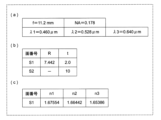
実施形態1の光源装置1Aにおける光学系の具体的な数値構成が図6に示される。図6(a)において、コリメートレンズ15Aの焦点距離f、コリメートレンズ15Aの開口数NA、青色レーザ光BLの波長λ1、緑色レーザ光GLの波長λ2、赤色レーザ光RLの波長λ3を示す。
A specific numerical configuration of the optical system in the
図6(b)において、面番号S1~S3それぞれの曲率R、面番号S1~S3それぞれの次の面までの間隔(距離)t及び面番号S4のバックフォーカスtを示す。また、図6(c)において、屈折率n1は面番号S1、S3それぞれの波長λ1に対する値であり、屈折率n2は面番号S1、S3それぞれの波長λ2に対する値であり、屈折率n3は面番号S1、S3それぞれの波長λ3に対する値である。 In FIG. 6(b), the curvature R of each of the surface numbers S1 to S3, the interval (distance) t from each of the surface numbers S1 to S3 to the next surface, and the back focus t of the surface number S4 are shown. In addition, in FIG. 6(c), the refractive index n1 is the value for the wavelength λ1 of each of the surface numbers S1 and S3, the refractive index n2 is the value for the wavelength λ2 of each of the surface numbers S1 and S3, and the refractive index n3 is the value for the wavelength λ2 of each of the surface numbers S1 and S3. This is the value for each wavelength λ3 of numbers S1 and S3.
コリメートレンズ15Aにおける面番号S1は非球面であり、(3)式における円錐係数k=-0.92456であり、4次の非球面係数A4=1.47679×10⁻⁴である。また、コリメートレンズ15Aにおける面番号S2も非球面であり、(3)式における4次の非球面係数A4=4.14290×10⁻⁵である。
The surface number S1 in the
回折格子13のブレーズ13aの高さd=3.121μmであり、ピッチ幅Pbは8μmである。回折格子13により、青色レーザ光BLの回折次数m1=6であり、緑色レーザ光GLの回折次数m2=5であり、赤色レーザ光RLの回折次数m3=4のそれぞれの回折光が回折格子13から出射される。
The height d of the
したがって、
d(n1-1)/λ1-m1= 0.06691、
d(n2-1)/λ2-m2= 0.03501、
d(n3-1)/λ3-m3= 0.05339、
となり、(1)式および(2)式の両方の条件を満たす。
therefore,
d(n1-1)/λ1-m1=0.06691,
d(n2-1)/λ2-m2=0.03501,
d(n3-1)/λ3-m3=0.05339,
Therefore, the conditions of both equations (1) and (2) are satisfied.
これらの構成により、回折効率は、青色レーザ光BLが98.5%、緑色レーザ光GLが99.6%、赤色レーザ光RLが99.1%となり、高効率な回折効率を得ることができる。 With these configurations, the diffraction efficiency is 98.5% for the blue laser beam BL, 99.6% for the green laser beam GL, and 99.1% for the red laser beam RL, making it possible to obtain highly efficient diffraction efficiency. .
図7を参照すると、各レーザ光の色収差が±0.1mm程度である。この色収差を補正するように、各色のレーザ素子はフォーカス方向(Z軸方向)にずらして配置される。 Referring to FIG. 7, the chromatic aberration of each laser beam is approximately ±0.1 mm. In order to correct this chromatic aberration, the laser elements of each color are arranged so as to be shifted in the focus direction (Z-axis direction).
[1-2.効果等]
実施形態1に係る光源装置1Aは、複数のレーザ素子3、5、7と、それぞれのレーザ素子3、5、7から出射したレーザ光を回折する回折格子13と、回折格子13により回折されたそれぞれのレーザ光を平行光にするコリメートレンズ15Aと、を備える。それぞれのレーザ素子3、5、7は、互いに波長の異なるレーザ光BL、GL、RLを出射し、回折格子13は、複数の直線状の溝13bがそれぞれ平行に形成されたブレーズ13aを有する。それぞれのレーザ素子3、5、7は、コリメートレンズ15Aの光軸Lsを含むYZ平面の断面視において、コリメートレンズ15Aの光軸Lsよりも一方側に光軸Lsとの距離が異なる位置に配置されている。それぞれのレーザ素子3、5、7から出射されたそれぞれのレーザ光BL、GL、RLが回折格子13で互いに異なる回折次数で、回折されて合成される。これにより、各波長で回折次数の異なるそれぞれの回折光を生成し、これらの回折光を平行光にすることで、回折効率を向上させた平行ビームを生成することができる。また、回折格子13を用いることで、部品点数を低減し、コストを低減して複数の波長レーザを出射することが可能である。また、回折効率を向上させることで、迷光の発生を低減することができる。さらに、レーザ素子3、5、7から出射されるレーザ光を回折するので、環境温度が変化してそれぞれのレーザ光の波長が変化しても、それぞれのレーザ光は同方向に回折ズレが発生するので、一部のレーザ光だけを回折する構成に比べて温度変化による影響を低減することができる。また、実施形態1では、コリメートレンズ15Aと回折格子13とが別体であるので、それぞれ別の材質で形成することでき、それぞれに最適な材質を選択することができる。
[1-2. Effects, etc.]
A
さらに、それぞれのレーザ素子BL、GL、RLの各波長をλ1、λ2、λ3とし、それぞれの波長における回折格子13の屈折率をn1、n2、n3とし、回折格子13の鋸歯形状部であるブレーズ13aの高さをdとし、それぞれの波長における最大の回折効率の組み合わせとなる回折次数m1、m2、m3としたとき、m1、m2、m3は0でない整数であり、
-0.175<d(n1-1)/λ1-m1<0.175、
-0.175<d(n2-1)/λ2-m2<0.175、
-0.175<d(n3-1)/λ3-m3<0.175、
を満たす。これにより、回折効率を向上させた平行ビームを生成することができる。
Furthermore, the wavelengths of the respective laser elements BL, GL, and RL are λ1, λ2, and λ3, the refractive indices of the
-0.175<d(n1-1)/λ1-m1<0.175,
-0.175<d(n2-1)/λ2-m2<0.175,
-0.175<d(n3-1)/λ3-m3<0.175,
satisfy. Thereby, a parallel beam with improved diffraction efficiency can be generated.
(実施形態2)
次に、図8~図11を参照して、実施形態2を説明する。図8は、実施形態2に係る光源装置1Bの構成を示す断面図である。図9は、緑色レーザ素子の位置を基準に赤色レーザ素子及び青色レーザ素子の相対位置を示す説明図である。図10は、光源装置1Bの光学系の諸条件を示す表である。図11は、光源装置1Bの光学系の球面収差を示す図である。
[2-1.構成]
図8に示すように、実施形態2の光源装置1Bは、コリメートレンズ15Bが実施形態1の光源装置1Aのコリメートレンズ15Aと回折格子13とを一体化した形状となっている。コリメートレンズ15Bの片側が平面形状でも、軸外コマ収差を抑制し、かつガラス成形が可能なレンズ材料を選択している。これらの相違点及び下記に説明する点以外の構成について、実施形態1の光源装置1Aと実施形態2の光源装置1Bとは共通である。
(Embodiment 2)
Next, a second embodiment will be described with reference to FIGS. 8 to 11. FIG. 8 is a sectional view showing the configuration of a
[2-1. composition]
As shown in FIG. 8, in the
光源装置1Bは、光源2と、回折格子13が一面に形成されたコリメートレンズ15Bとを備える。コリメートレンズ15Bは、非球面形状のS1面及び直線状の回折格子13が形成されたS2面を有する。実施形態2における光源装置1Bは、レーザ光源2からの光路の順に、回折格子13の回折面S2と、凸形状のS1面が配置されている。
The
図8では、コリメートレンズ15Bの光軸Ls上の回折しない光の焦点位置Fcを示し、回折する光源2の位置は光軸Lsから垂直方向(Y軸方向)に距離Ly2離れて位置する。なお、ここでは緑色レーザ素子5の位置を基準として示している。図9は、緑色レーザ素子5を基準に赤色レーザ素子3及び青色レーザ素子7のフォーカス方向(Z軸方向)及び光軸に垂直方向(Y軸方向)の位置関係を示している。
FIG. 8 shows the focal position Fc of non-diffracted light on the optical axis Ls of the
実施形態2において、緑色レーザ素子5は、光軸Lsの垂直方向(Y軸方向)に-2.737mm(Ly2)の位置に配置されている。図9に示すように、赤色レーザ素子3は、緑色レーザ素子5からフォーカス方向(Z軸方向)に約170μm、光軸Lsの垂直方向(X軸方向)に約40μmの位置に配置されている。青色レーザ素子7は、緑色レーザ素子5からフォーカス方向(Z軸方向)に約-170μm、光軸Lsの垂直方向(Y軸方向)に約-80μmの位置に配置されている。
In the second embodiment, the
実施形態2の光源装置1Bにおける光学系の具体的な数値構成が図10に示される。コリメートレンズ15Bにおける面番号S1は非球面であり、(3)式における円錐係数k=-0.9466であり、4次の非球面係数A4=1.01201×10⁻⁴であり、6次の非球面係数A6=1.00260×10⁻⁷である。また、コリメートレンズ15Bにおける面番号S2は平面である。
A specific numerical configuration of the optical system in the
回折格子13のブレーズ13aの高さd=4.013μmである。回折格子13により、青色レーザ光BLの回折次数m1=6であり、緑色レーザ光GLの回折次数m2=5であり、赤色レーザ光RLの回折次数m3=4のそれぞれの回折光が回折格子13から出射される。
The height d of the
したがって、
d(n1-1)/λ1-m1=-0.10660、
d(n2-1)/λ2-m2= 0.04984、
d(n3-1)/λ3-m3= 0.09988、
となり、(1)式の条件を満たす。
therefore,
d(n1-1)/λ1-m1=-0.10660,
d(n2-1)/λ2-m2=0.04984,
d(n3-1)/λ3-m3=0.09988,
Therefore, the condition of equation (1) is satisfied.
これらの構成により、回折効率は、青色レーザ光BLが96.2%、緑色レーザ光GLが99.2%、赤色レーザ光RLが96.8%となり、高効率な回折効率を得ることができる。 With these configurations, the diffraction efficiency is 96.2% for the blue laser beam BL, 99.2% for the green laser beam GL, and 96.8% for the red laser beam RL, making it possible to obtain highly efficient diffraction efficiency. .
また、図11を参照すると、各レーザ光の色収差が±0.18mm程度である。この色収差を補正するように、各色のレーザ素子がコリメートレンズ15の光軸Ls方向(Z軸方向)にずらして配置される。コリメートレンズ15の光軸Ls方向はフォーカス方向ともいえる。
Further, referring to FIG. 11, the chromatic aberration of each laser beam is about ±0.18 mm. In order to correct this chromatic aberration, the laser elements of each color are arranged so as to be shifted in the optical axis Ls direction (Z-axis direction) of the collimating
[2-2.効果等]
実施形態2の構成によれば、各波長で回折次数の異なるそれぞれの回折光を生成し、これらの回折光を平行光にすることで、回折効率を向上させた平行ビームを生成することができる。また、実施形態2では、コリメートレンズ15Bと回折格子13とが一体になっているので、省スペース化を実現することができる。また、コリメートレンズ15Bの片側が平面のS2面であるので、S2面に回折格子13を容易に形成することができる。
[2-2. Effects, etc.]
According to the configuration of the second embodiment, by generating diffracted lights with different orders of diffraction at each wavelength and converting these diffracted lights into parallel lights, a parallel beam with improved diffraction efficiency can be generated. . Furthermore, in the second embodiment, since the
(実施形態3)
以下、図12~図16を参照して、実施形態3を説明する。図12は、実施形態3に係る光源装置1Cの構成を示す説明図である。図13は、コリメートレンズ15CのS1面に形成された同心円状の回折格子19を示し、図13(a)は同心円状の回折格子19の断面図であり、図13(b)は、同心円状の回折格子19の正面図である。図14は、緑色レーザ素子の位置を基準に赤色レーザ素子及び青色レーザ素子の相対位置を示す説明図である。図15は、光源装置1Cの光学系の諸条件を示す表である。図16は、光源装置1Cの光学系の球面収差を示す図である。
(Embodiment 3)
[3-1.構成]
図12に示すように、実施形態3の光源装置1Cは、実施形態2の光源装置1Bのコリメートレンズ15CのS1面に同心円状の回折格子19を有する。これらの相違点及び下記に説明する点以外の構成について、実施形態3の光源装置1Cと実施形態2の光源装置1Bとは共通である。
[3-1. composition]
As shown in FIG. 12, the
光源装置1Cは、光源2と、回折格子13が一面に形成されたコリメートレンズ15Cとを備える。コリメートレンズ15Cは、非球面形状かつ凸形状のS1面と、直線状の回折格子13が形成された平面のS2面とを有する。
The
実施形態3における光源装置1Cは、レーザ光源2からの光路の順に、直線状の回折格子13が形成された回折面S2面と、非球面形状のS1面とが配置されている。非球面形状のS1面には、同心円状の回折格子19が形成されている。したがって、コリメートレンズ15Cは、同心円状の回折レンズを含むコリメートレンズである。
In the
図12では、コリメートレンズ15Cの光軸Ls上の回折しない光の焦点位置Fcを示し、回折する光源2の位置は光軸Lsから垂直方向(Y軸方向)に距離Ly3離れて位置する。なお、ここでは緑色レーザ素子5の位置を基準として示している。図14は、緑色レーザ素子5を基準に赤色レーザ素子3及び青色レーザ素子7のフォーカス方向(Z軸方向)及び光軸に垂直方向(X方向)の位置関係を示している。
FIG. 12 shows the focal position Fc of non-diffracted light on the optical axis Ls of the
実施形態3において、緑色レーザ素子5は、光軸Lsの垂直方向(Z軸方向)に-2.737mm(Ly3)の位置に配置されている。そして、図14に示すように赤色レーザ素子3は、緑色レーザ素子5からフォーカス方向(Z軸方向)に約-42μm、光軸Lsの垂直方向(X軸方向)に約100μmの位置に配置されている。青色レーザ素子7は、緑色レーザ素子5からフォーカス方向(Z軸方向)に約-45μm、光軸Lsの垂直方向(X軸方向)に約-120μmの位置に配置されている。
In the third embodiment, the
実施形態3の光源装置1Cにおける光学系の具体的な数値構成が図15に示される。コリメートレンズ15Cにおける面番号S1は非球面であり、(3)式における円錐係数k=1.32542であり、4次の非球面係数A4=-4.41926×10⁻⁴であり、6次の非球面係数A6=-1.10591×10⁻⁵である。コリメートレンズ15Cにおける面番号S2は平面であり、このS2面に鋸歯状の回折格子13が形成されている。
A specific numerical configuration of the optical system in the
S2面の回折格子13のブレーズ13aの高さd=4.013μmであり、ピッチ幅Pbは10μmである。また、同心円状の回折格子19のブレーズ19aの高さhも、直線状の回折格子13のブレーズ13aの高さdと同じ高さである。これにより、赤色、緑色、青色のいずれの波長に対しても高い回折効率を得ることができる。
The height d of the
回折格子13により、青色レーザ光BLの回折次数m1=6であり、緑色レーザ光GLの回折次数m2=5であり、赤色レーザ光RLの回折次数m3=4のそれぞれの回折光が回折格子13から出射される。
By the
したがって、
d(n1-1)/λ1-m1=-0.10664、
d(n2-1)/λ2-m2= 0.04984、
d(n3-1)/λ3-m3= 0.09987、
となり、(1)式の条件を満たす。
therefore,
d(n1-1)/λ1-m1=-0.10664,
d(n2-1)/λ2-m2=0.04984,
d(n3-1)/λ3-m3=0.09987,
Therefore, the condition of equation (1) is satisfied.
これらの構成により、回折効率は、青色レーザ光BLが96.2%、緑色レーザ光GLが99.2%、赤色レーザ光RLが96.8%となり、高効率な回折効率を得ることができる。 With these configurations, the diffraction efficiency is 96.2% for the blue laser beam BL, 99.2% for the green laser beam GL, and 96.8% for the red laser beam RL, making it possible to obtain highly efficient diffraction efficiency. .
図16を参照すると、各レーザ光の色収差が0.05mm以内に収束しており、実施形態1及び2よりも色収差が小さくなっており、各レーザ光源をほぼ同一平面上に配置することができる。
Referring to FIG. 16, the chromatic aberration of each laser beam is converged to within 0.05 mm, which is smaller than in
[3-2.効果等]
実施形態3の構成によれば、各波長で回折次数の異なるそれぞれの回折光を生成し、これらの回折光を平行光にすることで、回折効率を向上させた平行ビームを生成することができる。また、実施形態3では、コリメートレンズ15CのS1面に同心円状の回折格子が形成されているので、色収差を低減することができる。
[3-2. Effects, etc.]
According to the configuration of
(実施形態4)
以下、図17~図20を参照して、実施形態4を説明する。図17は、実施形態4に係る光源装置1Dの構成を示す説明図である。図18は、緑色レーザ素子の位置を基準に赤色レーザ素子及び青色レーザ素子の相対位置を示す説明図である。図19は、光源装置1Dの光学系の諸条件を示す表である。図20は、光源装置1Dの光学系の球面収差を示す図である。
(Embodiment 4)
[4-1.構成]
図17に示すように、実施形態4の光源装置1Dは、実施形態2の光源装置1Bと異なり、コリメートレンズ15DのS1面とS3面との間に球面形状のS2面を有する。この相違点及び下記に説明する点以外の構成について、実施形態4の光源装置1Dと実施形態2の光源装置1Bとは共通である。
[4-1. composition]
As shown in FIG. 17, unlike the
光源装置1Dは、光源2と、回折格子13が一面に形成されたコリメートレンズ15Dとを備える。コリメートレンズ15Dは第1レンズ15Daと第2レンズ15Dbとを張り合わせたレンズである。第1レンズ15Daは、凸形状で非球面形状のS1面を有する。第2レンズ15Dbは、直線状の回折格子13が形成された平面のS3面を有する。そして、コリメートレンズ15Dは、第1レンズ15DaのS1面の反対側と第2レンズ15DbのS3面の反対側との張り合わせ面である、球面形状のS2面とを有する。
The
実施形態4における光源装置1Dは、レーザ光源2からの光路の順に、直線状の回折格子13が形成された回折面S3面と、球面形状のS2面と、非球面形状のS1面とが配置されている。
In the
図17では、コリメートレンズ15Dの光軸Ls上の回折しない光の焦点位置Fcを示し、回折する光源2の位置は光軸Lsから垂直方向(Y軸方向)に距離Ly4離れて位置する。なお、ここでは緑色レーザ素子5の位置を基準として示している。図18は、緑色レーザ素子5を基準に赤色レーザ素子3及び青色レーザ素子7のフォーカス方向(Z軸方向)及び光軸に垂直方向(Y軸方向)の位置関係を示している。
FIG. 17 shows the focal position Fc of non-diffracted light on the optical axis Ls of the
実施形態4において、緑色レーザ素子5は、光軸Lsの垂直方向(Y軸方向)に-2.737mm(Ly4)の位置に配置されている。そして、図18に示すように赤色レーザ素子3は、緑色レーザ素子5からフォーカス方向(Z軸方向)に約20μm、光軸Lsの垂直方向(X軸方向)に約80μmの位置に配置されている。青色レーザ素子7は、緑色レーザ素子5からフォーカス方向(Z軸方向)に約10μm、光軸Lsの垂直方向(X軸方向)に約-140μmの位置に配置されている。
In the fourth embodiment, the
実施形態4の光源装置1Dにおける光学系の具体的な数値構成が図19に示される。コリメートレンズ15Dにおける面番号S1は非球面であり、(3)式における円錐係数k=0.26004であり、4次の非球面係数A4=-1.64830×10⁻⁴であり、6次の非球面係数A6=-1.55915×10⁻⁶である。コリメートレンズ15Dにおける面番号S2は球面形状である。コリメートレンズ15Dにおける面番号S3は平面であり、このS3面に鋸歯状の回折格子13が形成されている。
A specific numerical configuration of the optical system in the
S3面の回折格子13のブレーズ13aの高さd=4.013μmであり、ピッチ幅Pbは10μmである。
The height d of the
回折格子13により、青色レーザ光BLの回折次数m1=6であり、緑色レーザ光GLの回折次数m2=5であり、赤色レーザ光RLの回折次数m3=4のそれぞれの回折光が回折格子13から出射される。
By the
したがって、
d(n1-1)/λ1-m1=-0.10664、
d(n2-1)/λ2-m2= 0.04984、
d(n3-1)/λ3-m3= 0.09987、
となり、(1)式の条件を満たす。
therefore,
d(n1-1)/λ1-m1=-0.10664,
d(n2-1)/λ2-m2=0.04984,
d(n3-1)/λ3-m3=0.09987,
Therefore, the condition of equation (1) is satisfied.
これらの構成により、回折効率は、青色レーザ光BLが96.2%、緑色レーザ光GLが99.2%、赤色レーザ光RLが96.8%となり、高効率な回折効率を得ることができる。 With these configurations, the diffraction efficiency is 96.2% for the blue laser beam BL, 99.2% for the green laser beam GL, and 96.8% for the red laser beam RL, making it possible to obtain highly efficient diffraction efficiency. .
図20を参照すると、球面形状のS2面により各レーザ光の色収差が0.04mm以内に収束しており、実施形態2及び3よりも色収差が小さくなっている。 Referring to FIG. 20, the chromatic aberration of each laser beam is converged to within 0.04 mm due to the spherical S2 surface, and the chromatic aberration is smaller than in the second and third embodiments.
[4-2.効果等]
実施形態4の構成によれば、各波長で回折次数の異なるそれぞれの回折光を生成し、これらの回折光を平行光にすることで、回折効率を向上させた平行ビームを生成することができる。また、実施形態4では、コリメートレンズ15Dが第1レンズ15Daと第2レンズ15Dbとの張り合わせレンズであり、色収差を低減することができ、レーザ素子3、5、7のそれぞれのフォーカス方向(Z方向)の位置を近づけて配置することができる。
[4-2. Effects, etc.]
According to the configuration of
(実施形態5)
以下、図21~図24を参照して、実施形態5を説明する。図21は、実施形態5に係る光源装置1Eの構成を示す説明図である。図22は、緑色レーザ素子の位置を基準に赤色レーザ素子及び青色レーザ素子の相対位置を示す説明図である。図23は、光源装置1Eの光学系の諸条件を示す表である。図24は、光源装置1Eの光学系の球面収差を示す図である。
(Embodiment 5)
[5-1.構成]
図21に示すように、実施形態5の光源装置1Eは、実施形態4の光源装置1Dと異なり、コリメートレンズ15Eと直線状の回折格子13が形成されている回折レンズ19Eとが別体で構成されている。また、実施形態5では、実施形態1~4と異なるレーザ光の波長の組み合わせを用いている。この相違点及び下記に説明する点以外の構成について、実施形態5の光源装置1Eと実施形態4の光源装置1Dとは共通である。
[5-1. composition]
As shown in FIG. 21, the
光源装置1Eは、光源2と、コリメートレンズ15Eと、回折レンズ19Eと、を備える。コリメートレンズ15Eは第1レンズ15Eaと第2レンズ15Ebとを張り合わせたレンズである。第1レンズ15Eaは、凸形状で非球面形状のS1面を有する。第2レンズ15Ebは、非球面のS3面とを有する。そして、コリメートレンズ15Eは、第1レンズ15EaのS1面の反対側と第2レンズ15EbのS3面の反対側との張り合わせ面である、球面形状のS2面とを有する。
The
回折レンズ19Eは、平板形状を有し、第2レンズ15EbのS3面と対向して平面のS4面と、光源2側に直線状の回折格子13が形成されたS5面とを有する。
The
実施形態5における光源装置1Eは、レーザ光源2からの光路の順に、鋸歯状の回折格子13が形成された回折面S5面と、平面形状のS4面及びS3面と、球面形状のS2面と、非球面形状のS1面とが配置されている。
The
図21では、コリメートレンズ15Eの光軸Ls上の回折しない光の焦点位置Fcを示し、回折する光源2の位置は光軸Lsから垂直方向(Y軸方向)に距離Ly5離れて位置する。図22は、緑色レーザ素子5を基準に赤色レーザ素子3及び青色レーザ素子7のフォーカス方向(Z軸方向)及び光軸に垂直方向(Y軸方向)の位置関係を示している。
FIG. 21 shows the focal position Fc of non-diffracted light on the optical axis Ls of the
実施形態5において、緑色レーザ素子5は、光軸Lsの垂直方向(X方向)に-4.352mm(Ly5)の位置に配置されている。そして、図22に示すように赤色レーザ素子3は、緑色レーザ素子5からフォーカス方向(Z軸方向)に約20μm、光軸Lsの垂直方向(X軸方向)に約60μmの位置に配置されている。青色レーザ素子7は、緑色レーザ素子5からフォーカス方向(Z軸方向)に約10μm、光軸Lsの垂直方向(X軸方向)に約-130μmの位置に配置されている。
In the fifth embodiment, the
実施形態5の光源装置1Eにおける光学系の具体的な数値構成が図23に示される。コリメートレンズ15Eにおける面番号S1は非球面であり、(3)式における円錐係数k=0.26173であり、4次の非球面係数A4=-1.87896×10⁻⁴であり、6次の非球面係数A6=-5.91751×10⁻⁶である。また面番号S3も非球面であり、(3)式における円錐係数k=-1091.926であり、4次の非球面係数A4=-6.87462×10⁻⁴であり、6次の非球面係数A6=6.47266×10⁻⁵である。
A specific numerical configuration of the optical system in the
S5面の回折格子13のブレーズ13aの高さd=4.382μmであり、ピッチ幅Pbは8μmである。
The height d of the
回折格子13により、青色レーザ光BLの回折次数m1=7であり、緑色レーザ光GLの回折次数m2=6であり、赤色レーザ光RLの回折次数m3=5のそれぞれの回折光が回折格子13から出射される。
By the
したがって、
d(n1-1)/λ1-m1=-0.00931、
d(n2-1)/λ2-m2= 0.01843、
d(n3-1)/λ3-m3= 0.00740、
となり、(1)式および(2)式の両方の条件を満たす。
therefore,
d(n1-1)/λ1-m1=-0.00931,
d(n2-1)/λ2-m2=0.01843,
d(n3-1)/λ3-m3=0.00740,
Therefore, the conditions of both equations (1) and (2) are satisfied.
これらの構成により、回折効率は、青色レーザ光BLが99.9%、緑色レーザ光GLが99.9%、赤色レーザ光RLが99.9%となり、高効率な回折効率を得ることができる。 With these configurations, the diffraction efficiency is 99.9% for the blue laser beam BL, 99.9% for the green laser beam GL, and 99.9% for the red laser beam RL, making it possible to obtain highly efficient diffraction efficiency. .
図24を参照すると、各レーザ光の色収差は0.02mm以下であり、実施形態2~4よりも色収差が低減されている。
Referring to FIG. 24, the chromatic aberration of each laser beam is 0.02 mm or less, which is lower than in
[5-2.効果等]
実施形態5の構成によれば、各波長で回折次数の異なるそれぞれの回折光を生成し、これらの回折光を平行光にすることで、回折効率を向上させた平行ビームを生成することができる。また、実施形態5では、コリメートレンズ15Eが第1レンズ15Eaと第2レンズ15Ebとの張り合わせレンズであり、色収差を低減することができ、レーザ素子3、5、7のそれぞれのフォーカス方向(Z方向)の位置を近づけて配置することができる。また、コリメートレンズ15Eと回折レンズ19Eとそれぞれ別体に構成されているので、それぞれ別の材質で形成することでき、それぞれに最適な材質を選択することができる。
[5-2. Effects, etc.]
According to the configuration of the fifth embodiment, by generating diffracted lights with different orders of diffraction at each wavelength and converting these diffracted lights into parallel lights, a parallel beam with improved diffraction efficiency can be generated. . In addition, in the fifth embodiment, the
(実施形態6)
以下、図25~図28を参照して、実施形態6を説明する。図25は、実施形態6に係る光源装置1Fの構成を示す説明図である。図26は、緑色レーザ素子の位置を基準に赤色レーザ素子及び青色レーザ素子の相対位置を示す説明図である。図27は、光源装置1Fの光学系の諸条件を示す表である。図28は、光源装置1Fの光学系の球面収差を示す図である。
(Embodiment 6)
[6-1.構成]
図25に示すように、実施形態6の光源装置1Fは、実施形態2の光源装置1Bのコリメートレンズ15Bの材質を変更し、焦点距離を長くしている。また、実施形態6では、実施形態1~4と異なるレーザ光の波長の組み合わせを用いている。これらの相違点及び下記に説明する点以外の構成について、実施形態6の光源装置1Fと実施形態2の光源装置1Bとは共通である。
[6-1. composition]
As shown in FIG. 25, in the
光源装置1Fは、光源2と、コリメートレンズ15Fとを備える。コリメートレンズ15Fは、非球面形状のS1面と、直線回折格子13が形成された平面のS2面を有する。
The
実施形態6における光源装置1Fは、レーザ光源2からの光路の順に、直線回折格子13が形成された回折面S2面と、非球面形状のS1面とが配置されている。
In the
図25では、コリメートレンズ15Fの光軸Ls上の回折しない光の焦点位置Fcを示し、回折する光源2の位置は光軸Lsから垂直方向(Y軸方向)に距離Ly6離れて位置する。図26は、緑色レーザ素子5を基準に赤色レーザ素子3及び青色レーザ素子7のフォーカス方向(Z軸方向)及び光軸に垂直方向(Y軸方向)の位置関係を示している。
FIG. 25 shows the focal position Fc of non-diffracted light on the optical axis Ls of the
実施形態6において、緑色レーザ素子5は、光軸Lsの垂直方向(Y軸方向)に-6.38mm(Ly6)の位置に配置されている。そして、図26に示すように赤色レーザ素子3は、緑色レーザ素子5からフォーカス方向(Z軸方向)に約420μm、光軸Lsの垂直方向(Y軸方向)に約20μmの位置に配置されている。青色レーザ素子7は、緑色レーザ素子5からフォーカス方向(Z軸方向)に約-380μm、光軸Lsの垂直方向(Y軸方向)に約-130μmの位置に配置されている。
In the sixth embodiment, the
実施形態6の光源装置1Fにおける光学系の具体的な数値構成が図27に示される。コリメートレンズ15Fにおける面番号S1は非球面であり、(3)式における円錐係数k=-2.58130であり、4次の非球面係数A4=-1.96836×10⁻⁵であり、6次の非球面係数A6=-2.95251×10⁻⁸である。コリメートレンズ15Fにおける面番号S2は平面であり、このS2面に鋸歯状の回折格子が形成されている。
A specific numerical configuration of the optical system in the
実施形態6では、実施形態1~4と異なる、レーザ光の波長の組み合わせを用いている。また、実施形態6では、高い屈折率の材料を選択したので、S2面の回折格子13のブレーズ13aの高さd=2.93μmと低い。また、ピッチ幅Pbは20μmである。回折格子のピッチ幅Pbを実施形態1~5よりも拡げているが、コリメートレンズの焦点距離を長くすることで、半導体レーザの間隔が充分に確保することができる。
回折格子13により、青色レーザ光BLの回折次数m1=6であり、緑色レーザ光GLの回折次数m2=5であり、赤色レーザ光RLの回折次数m3=4のそれぞれの回折光が回折格子13から出射される。
By the
したがって、
d(n1-1)/λ1-m1=-0.16212、
d(n2-1)/λ2-m2= 0.07974、
d(n3-1)/λ3-m3= 0.09466、
となり、(1)式の条件を満たす。
therefore,
d(n1-1)/λ1-m1=-0.16212,
d(n2-1)/λ2-m2=0.07974,
d(n3-1)/λ3-m3=0.09466,
Therefore, the condition of equation (1) is satisfied.
これらの構成により、回折効率は、青色レーザ光BLが91.7%、緑色レーザ光GLが97.9%、赤色レーザ光RLが97.1%となり、高効率な回折効率を得ることができる。 With these configurations, the diffraction efficiency is 91.7% for the blue laser beam BL, 97.9% for the green laser beam GL, and 97.1% for the red laser beam RL, making it possible to obtain highly efficient diffraction efficiency. .
図28を参照すると、緑色レーザ素子5と赤色レーザ素子3との色収差が約0.42mmあり、緑色レーザ素子5と赤色レーザ素子3との色収差が約-0.37mmある。各レーザ素子3、5、7をこの程度離して配置することで色収差を解消することができる。各レーザ素子の間隔を広くすることができるので、メンテナンスが容易になる。
Referring to FIG. 28, the chromatic aberration between the
[6-2.効果等]
実施形態6の構成によれば、各波長で回折次数の異なるそれぞれの回折光を生成し、これらの回折光を平行光にすることで、回折効率を向上させた平行ビームを生成することができる。また、回折格子13のブレーズ13aの高さdを他の実施形態に比べて低くし、ピッチ幅Pbを拡げることで、回折効率の向上に効果がある。
[6-2. Effects, etc.]
According to the configuration of the sixth embodiment, by generating diffracted lights with different orders of diffraction at each wavelength and converting these diffracted lights into parallel lights, a parallel beam with improved diffraction efficiency can be generated. . Further, by making the height d of the
(実施形態7)
以下、図29を参照して、実施形態7を説明する。図29は、実施形態7に係る像形成装置の構成を示す説明図である。
(Embodiment 7)
[7-1.構成]
像形成装置21は、レーザ光源装置1と、集光レンズ23と、第1走査素子25と、第2走査素子27と、制御部29とを備える。なお、像形成装置21は、レーザ光源装置1の代わりに、実施形態1~6のレーザ光源装置1A~1Fのいずれかを用いてもよい。
[7-1. composition]
The
集光レンズ23は、レーザ光源装置1のコリメートレンズ15から出射される平行光を第1走査素子25に集光する。
The
第1走査素子25は、例えば、圧電駆動により回転駆動される回転ミラーである。レーザ光源装置1から出射する複数の波長を有するレーザ光を第1方向に走査する。走査されたレーザ光は、第2走査素子に入射する。これにより、平行光がスクリーン31の垂直方向に拡散される。
The
第2走査素子27は、例えば、圧電駆動により回転駆動される回転ミラーである。第1走査素子25から出射するレーザ光を第1方向と直交する第2方向に走査する。走査されたレーザ光はスクリーン31の水平方向に拡散される。これにより、二次元画像をスクリーン31に投影することが出来る。
The
制御部29は、第1走査素子25と第2走査素子27の走査と同期して、それぞれの波長の発光タイミングを制御する。制御部29は、半導体素子などで実現可能である。制御部29は、例えば、マイコン、CPU、MPU、GPU、DSP、FPGA、ASICで構成することができる。制御部29の機能は、ハードウェアのみで構成してもよいし、ハードウェアとソフトウェアとを組み合わせることにより実現してもよい。制御部29は、ハードディスク(HDD)、SSD、メモリ等の記憶部を有しており、記憶部に格納されたデータやプログラムを読み出して種々の演算処理を行うことで、所定の機能を実現する。
The
[7-2.効果等]
実施形態7の像形成装置21は、レーザ光源装置1~1Fのいずれか1つと、レーザ光源装置から出射する複数の波長を有するレーザ光を第1方向に走査する第1走査素子25と、第1走査素子25から出射するレーザ光を第1方向と直交する第2方向に走査する第2走査素子27と、を備えている。レーザ光源装置から出射されるレーザ光の回折効率が高いので、スクリーン31上に投影されるレーザ光の輝度を高く保つことができ、迷光が低減される。なお、像形成装置21は、二次元画像に限らず、立体像を投影してもよい。
[7-2. Effects, etc.]
The
以上、例示した実施形態1~6における光源2の(1)式と回折効率との関係を図30に示す。図30において、実施形態1において(1)式の青色レーザ光BLの値をB1、緑色レーザ光GLの値をG1、赤色レーザ光RLの値をR1とする。同様に、実施形態2から6における、(1)式の青色レーザ光BLの値をそれぞれB2~B6、緑色レーザ光GLの値をそれぞれG2~G6、赤色レーザ光RLの値をそれぞれR2~R6とする。いずれの実施形態の青色レーザ光BL、緑色レーザ光GL、赤色レーザ光RLの回折効率は91%以上である。
FIG. 30 shows the relationship between equation (1) of the
(他の実施形態)
以上のように、本出願において開示する技術の例示として、実施形態1~7を説明した。しかしながら、本開示における技術は、これに限定されず、変更、置き換え、付加、省略などを行った実施の形態にも適用できる。また、上記実施形態1~7で説明した各構成要素を組み合わせて、新たな実施形態とすることも可能である。
(Other embodiments)
As described above,
(1)本開示の光源装置1は、3色のレーザ光を出射しているがこれに限らない。例えば、2色でもよいし、4色以上でもよい。例えば、レーザ植物工場に用いられる光源として、赤色レーザ光RLと青色レーザ光BLの2色を出射する光源装置1を構成してもよい。また、例えば、二次元画像や立体像の生成に用いられる光源として、赤色レーザ光RLと緑色レーザ光GLと青色レーザ光BLと黄色レーザ光YLとの4色を出射する光源装置1を構成してもよい。
(1) Although the
(2)本開示の光源装置1は、コリメートレンズ15と光源2との間に回折格子13が配置されていたが、これに限らない。コリメートレンズ15を回折格子13よりも光源2側に配置して、回折格子13と光源2との間にコリメートレンズ15を配置してもよい。
(2) Although the
以上のように、本開示における技術の例示として、実施の形態を説明した。そのために、添付図面および詳細な説明を提供した。したがって、添付図面および詳細な説明に記載された構成要素の中には、課題解決のために必須な構成要素だけでなく、上記技術を例示するために、課題解決のためには必須でない構成要素も含まれ得る。そのため、それらの必須ではない構成要素が添付図面や詳細な説明に記載されていることをもって、直ちに、それらの必須ではない構成要素が必須であるとの認定をするべきではない。 As described above, the embodiments have been described as examples of the technology in the present disclosure. To that end, the accompanying drawings and detailed description have been provided. Therefore, among the components described in the attached drawings and detailed description, there are not only components that are essential for solving the problem, but also components that are not essential for solving the problem, in order to exemplify the above technology. may also be included. Therefore, just because these non-essential components are described in the accompanying drawings or detailed description, it should not be immediately determined that those non-essential components are essential.
また、上述の実施の形態は、本開示における技術を例示するためのものであるから、特許請求の範囲またはその均等の範囲において種々の変更、置き換え、付加、省略などを行うことができる。 Moreover, since the above-described embodiments are for illustrating the technology of the present disclosure, various changes, substitutions, additions, omissions, etc. can be made within the scope of the claims or equivalents thereof.
(実施形態の概要)
(1)本開示のレーザ光源装置は、複数のレーザ素子と、それぞれのレーザ素子から出射したレーザ光を回折する回折光学素子と、それぞれのレーザ光を平行光にするコリメートレンズ15と、を備え、それぞれのレーザ素子は、互いに波長の異なるレーザ光を出射し、回折光学素子は、複数の直線状の溝がそれぞれ平行に形成された鋸歯形状部を有し、それぞれのレーザ素子は、コリメートレンズの光軸を含む断面視において、コリメートレンズの光軸よりも一方側に、光軸との距離が異なる位置に配置され、それぞれのレーザ素子から出射されたそれぞれのレーザ光が回折光学素子で互いに異なる回折次数で、回折されて合成される。
(Summary of embodiment)
(1) The laser light source device of the present disclosure includes a plurality of laser elements, a diffraction optical element that diffracts laser light emitted from each laser element, and a
このように、各波長でそれぞれの回折光を生成し、これらの回折光を平行光にすることで、回折効率を向上させた平行ビームを生成することができる。 In this way, by generating diffracted lights at each wavelength and converting these diffracted lights into parallel lights, a parallel beam with improved diffraction efficiency can be generated.
(2)(1)のレーザ光源装置において、鋸歯形状部の溝の延びる方向は、コリメートレンズの光軸を含む断面と直交する。 (2) In the laser light source device of (1), the direction in which the groove of the sawtooth-shaped portion extends is orthogonal to the cross section of the collimating lens that includes the optical axis.
(3)(1)または(2)のレーザ光源装置において、それぞれのレーザ素子から出射されたそれぞれのレーザ光は回折効率が91%以上で回折されて合成されるように、回折光学素子の鋸歯形状部の高さが予め定められた範囲の値である。それぞれのレーザ素子から出射されたそれぞれのレーザ光は回折効率が91%以上で回折されて合成されるように、前記回折光学素子の前記鋸歯形状部の高さが定められていてもよい。 (3) In the laser light source device of (1) or (2), the sawtooth of the diffractive optical element is configured such that each laser beam emitted from each laser element is diffracted and combined with a diffraction efficiency of 91% or more. The height of the shaped portion is within a predetermined range. The height of the sawtooth-shaped portion of the diffractive optical element may be determined so that each laser beam emitted from each laser element is diffracted and combined with a diffraction efficiency of 91% or more.
(4)(1)から(3)のいずれか1つのレーザ光源装置において、それぞれのレーザ素子から出射されるそれぞれのレーザ光の波長をλpとし、それぞれの波長における回折光学素子の屈折率をnpとし、回折光学素子の鋸歯形状部であるブレーズ13aの高さをdとし、最大の回折効率の組み合わせとなるそれぞれの波長における回折次数をmpとしたとき、mpは0でない整数であり、
-0.175<d(np-1)/λp-mp<0.175 を満たす。
(4) In any one of the laser light source devices (1) to (3), the wavelength of each laser beam emitted from each laser element is λp, and the refractive index of the diffractive optical element at each wavelength is np. When the height of the
-0.175<d(np-1)/λp-mp<0.175 is satisfied.
(5)(4)のレーザ光源装置において、
-0.1<d(np-1)/λp-mp<0.1 を満たす。これにより、より回折効率を向上することができる。
(5) In the laser light source device of (4),
-0.1<d(np-1)/λp-mp<0.1 is satisfied. Thereby, the diffraction efficiency can be further improved.
(6)(1)から(5)のいずれか1つのレーザ光源装置において、レーザ素子のうち1つは、青色の波長を有するレーザ光を出射し、レーザ素子のうち1つは、緑色の波長を有するレーザ光を出射し、レーザ素子のうち1つは、赤色の波長を有するレーザ光を出射する。 (6) In any one of the laser light source devices (1) to (5), one of the laser elements emits a laser beam with a blue wavelength, and one of the laser elements emits a laser beam with a green wavelength. One of the laser elements emits a laser beam having a red wavelength.
(7)(6)のレーザ光源装置において、回折光学素子において、異なる波長のレーザ光が少なくとも4次以上の回折次数のレーザ光に生成されて合成される。 (7) In the laser light source device of (6), in the diffractive optical element, laser beams of different wavelengths are generated and combined into laser beams of at least a fourth or higher diffraction order.
(8)(6)または(7)のレーザ光源装置において、青色、緑色、赤色の波長をもつ3つのレーザ素子の波長をλ1、λ2、λ3としたとき、
450nm<λ1<475nm、
500nm<λ2<540nm、
625nm<λ3<650nm、
を満たす。
(8) In the laser light source device of (6) or (7), when the wavelengths of the three laser elements having blue, green, and red wavelengths are λ1, λ2, and λ3,
450nm<λ1<475nm,
500nm<λ2<540nm,
625nm<λ3<650nm,
satisfy.
(9)(1)から(8)のいずれか1つのレーザ光源装置において、それぞれのレーザ素子は、コリメートレンズの光軸方向に異なる位置に配置されている。 (9) In any one of the laser light source devices (1) to (8), the respective laser elements are arranged at different positions in the optical axis direction of the collimating lens.
(10)(1)から(9)のいずれか1つのレーザ光源装置において、回折光学素子とコリメートレンズとが一体化されている。これにより、レーザ光源装置の省スペース化をすることができる。 (10) In any one of the laser light source devices (1) to (9), the diffractive optical element and the collimating lens are integrated. Thereby, the space of the laser light source device can be saved.
(11)(1)から(10)のいずれか1つのレーザ光源装置と、レーザ光源装置から出射する複数の波長を有するレーザ光を第1方向に走査する第1回転ミラーと、第1回転ミラーから出射するレーザ光を第1方向と直交する第2方向に走査する第2回転ミラーと、を備えた、像形成装置。 (11) Any one of the laser light source devices (1) to (10), a first rotating mirror that scans laser light having a plurality of wavelengths emitted from the laser light source device in a first direction, and a first rotating mirror. An image forming apparatus comprising: a second rotating mirror that scans laser light emitted from the mirror in a second direction perpendicular to the first direction.
本開示は、複数の波長を有するレーザ光を出射するレーザ光源装置に適用可能である。 The present disclosure is applicable to a laser light source device that emits laser light having multiple wavelengths.
1 光源装置
2 レーザ光源
3 赤色レーザ素子
5 緑色レーザ素子
7 青色レーザ素子
13 回折格子
13a ブレーズ
15、15A、15B、15C、15D、15E、15F コリメートレンズ
16 非球面
19A、19E 回折レンズ
21 像形成装置
23 集光レンズ
25 第1走査素子
27 第2走査素子
29 制御部
31 スクリーン
Pb 格子ピッチ
Hb 格子高さ
BL 青色レーザ光
GL 緑色レーザ光
RL 赤色レーザ光
1
Claims (11)
それぞれの前記レーザ素子から出射したレーザ光を回折する回折光学素子と、
前記回折光学素子で回折されたそれぞれの前記レーザ光を平行光にするコリメートレンズと、を備え、
それぞれの前記レーザ素子は、互いに波長の異なるレーザ光を出射し、
前記回折光学素子は、複数の直線状の溝がそれぞれ平行に形成された鋸歯形状部が外側に形成された回折面を有し、
それぞれの前記レーザ素子は、前記コリメートレンズの光軸を含む断面視において、前記コリメートレンズの光軸よりも一方側に、前記光軸との距離が異なる位置に配置され、
それぞれの前記レーザ素子から出射されたそれぞれのレーザ光が前記回折光学素子で互いに異なる回折次数で、回折されて合成され、
それぞれの前記レーザ素子から出射されたそれぞれのレーザ光は回折効率が91%以上で回折されて合成されるように、前記回折光学素子の前記鋸歯形状部の高さが予め定められた範囲の値である、
レーザ光源装置。 multiple laser elements;
a diffractive optical element that diffracts the laser light emitted from each of the laser elements;
a collimating lens that converts each of the laser beams diffracted by the diffractive optical element into parallel light;
Each of the laser elements emits laser beams having different wavelengths from each other,
The diffractive optical element has a diffractive surface having a sawtooth-shaped portion formed on the outside in which a plurality of linear grooves are respectively formed in parallel;
Each of the laser elements is arranged at a position different from the optical axis on one side of the optical axis of the collimating lens in a cross-sectional view including the optical axis of the collimating lens,
Each of the laser beams emitted from each of the laser elements is diffracted and synthesized by the diffraction optical element at different orders of diffraction,
The height of the sawtooth-shaped portion of the diffractive optical element falls within a predetermined range so that each laser beam emitted from each of the laser elements is diffracted and combined with a diffraction efficiency of 91% or more. is,
Laser light source device.
それぞれの前記レーザ素子から出射したレーザ光を回折する回折光学素子と、
前記回折光学素子で回折されたそれぞれの前記レーザ光を平行光にするコリメートレンズと、を備え、
それぞれの前記レーザ素子は、互いに波長の異なるレーザ光を出射し、
前記回折光学素子は、複数の直線状の溝がそれぞれ平行に形成された鋸歯形状部が外側に形成された回折面を有し、
それぞれの前記レーザ素子は、前記コリメートレンズの光軸を含む断面視において、前記コリメートレンズの光軸よりも一方側に、前記光軸との距離が異なる位置に配置され、
それぞれの前記レーザ素子から出射されたそれぞれのレーザ光が前記回折光学素子で互いに異なる回折次数で、回折されて合成され、
それぞれの前記レーザ素子から出射されるそれぞれのレーザ光の波長をλpとし、
それぞれの前記波長における前記回折光学素子の屈折率をnpとし、
前記回折光学素子の鋸歯形状部の高さをdとし、
最大の回折効率の組み合わせとなるそれぞれの前記波長における回折次数をmpとしたとき、
mpは0でない整数であり、
-0.175<d(np-1)/λp-mp<0.175
を満たす、
レーザ光源装置。 multiple laser elements;
a diffractive optical element that diffracts the laser light emitted from each of the laser elements;
a collimating lens that converts each of the laser beams diffracted by the diffractive optical element into parallel light;
Each of the laser elements emits laser beams having different wavelengths from each other,
The diffractive optical element has a diffractive surface having a sawtooth-shaped portion formed on the outside in which a plurality of linear grooves are respectively formed in parallel;
Each of the laser elements is arranged at a position different from the optical axis on one side of the optical axis of the collimating lens in a cross-sectional view including the optical axis of the collimating lens,
Each of the laser beams emitted from each of the laser elements is diffracted and synthesized by the diffraction optical element at different orders of diffraction,
Let the wavelength of each laser beam emitted from each of the laser elements be λp,
The refractive index of the diffractive optical element at each of the wavelengths is np,
The height of the sawtooth-shaped portion of the diffractive optical element is d,
When the diffraction order at each of the wavelengths that results in the combination of maximum diffraction efficiency is mp,
mp is a non-zero integer,
-0.175<d(np-1)/λp-mp<0.175
satisfy,
Laser light source device.
を満たす、請求項2に記載のレーザ光源装置。 -0.1<d(np-1)/λp-mp<0.1
The laser light source device according to claim 2, which satisfies the following.
それぞれの前記レーザ素子から出射したレーザ光を回折する回折光学素子と、
前記回折光学素子で回折されたそれぞれの前記レーザ光を平行光にするコリメートレンズと、を備え、
それぞれの前記レーザ素子は、互いに波長の異なるレーザ光を出射し、
前記回折光学素子は、複数の直線状の溝がそれぞれ平行に形成された鋸歯形状部が外側に形成された回折面を有し、
それぞれの前記レーザ素子は、前記コリメートレンズの光軸を含む断面視において、前記コリメートレンズの光軸よりも一方側に、前記光軸との距離が異なる位置に配置され、
それぞれの前記レーザ素子から出射されたそれぞれのレーザ光が前記回折光学素子で互いに異なる回折次数で、回折されて合成され、
前記レーザ素子のうち1つは、青色の波長を有するレーザ光を出射し、
前記レーザ素子のうち1つは、緑色の波長を有するレーザ光を出射し、
前記レーザ素子のうち1つは、赤色の波長を有するレーザ光を出射する、
レーザ光源装置。 multiple laser elements;
a diffractive optical element that diffracts the laser light emitted from each of the laser elements;
a collimating lens that converts each of the laser beams diffracted by the diffractive optical element into parallel light;
Each of the laser elements emits laser beams having different wavelengths from each other,
The diffractive optical element has a diffractive surface having a sawtooth-shaped portion formed on the outside in which a plurality of linear grooves are respectively formed in parallel;
Each of the laser elements is arranged at a position different from the optical axis on one side of the optical axis of the collimating lens in a cross-sectional view including the optical axis of the collimating lens,
Each of the laser beams emitted from each of the laser elements is diffracted and synthesized by the diffraction optical element at different orders of diffraction,
One of the laser elements emits a laser beam having a blue wavelength,
One of the laser elements emits a laser beam having a green wavelength,
one of the laser elements emits a laser beam having a red wavelength;
Laser light source device.
請求項4に記載のレーザ光源装置。 In the diffractive optical element, the laser beams of different wavelengths are generated and combined into laser beams of at least a fourth or higher diffraction order.
The laser light source device according to claim 4.
450nm<λ1<475nm、
500nm<λ2<540nm、
625nm<λ3<650nm、
を満たす、
請求項4または5に記載のレーザ光源装置。 When the wavelengths of the three laser elements having wavelengths of blue, green, and red are λ1, λ2, and λ3,
450nm<λ1<475nm,
500nm<λ2<540nm,
625nm<λ3<650nm,
satisfy,
The laser light source device according to claim 4 or 5.
それぞれの前記レーザ素子から出射したレーザ光を回折する回折光学素子と、
前記回折光学素子で回折されたそれぞれの前記レーザ光を平行光にするコリメートレンズと、を備え、
それぞれの前記レーザ素子は、互いに波長の異なるレーザ光を出射し、
前記回折光学素子は、複数の直線状の溝がそれぞれ平行に形成された鋸歯形状部が外側に形成された回折面を有し、
全ての前記レーザ素子は、前記コリメートレンズの光軸を含む断面視において、前記コリメートレンズの光軸よりも一方側に、前記光軸との距離が異なる位置に配置され、
それぞれの前記レーザ素子から出射された前記互いに波長の異なるレーザ光の全てが前記回折光学素子で互いに異なる回折次数で、回折されて合成される、
レーザ光源装置。 multiple laser elements;
a diffractive optical element that diffracts the laser light emitted from each of the laser elements;
a collimating lens that converts each of the laser beams diffracted by the diffractive optical element into parallel light;
Each of the laser elements emits laser beams having different wavelengths from each other,
The diffractive optical element has a diffractive surface having a sawtooth-shaped portion formed on the outside in which a plurality of linear grooves are respectively formed in parallel;
All of the laser elements are arranged on one side of the optical axis of the collimating lens at different distances from the optical axis in a cross-sectional view including the optical axis of the collimating lens,
All of the laser beams having different wavelengths emitted from each of the laser elements are diffracted and combined by the diffraction optical element at different orders of diffraction.
Laser light source device.
請求項1から7のいずれか1つに記載のレーザ光源装置。 The direction in which the groove of the sawtooth-shaped portion extends is orthogonal to a cross section including the optical axis of the collimating lens.
A laser light source device according to any one of claims 1 to 7.
請求項1から8のいずれか1つに記載のレーザ光源装置。 Each of the laser elements is arranged at a different distance from the collimating lens in the optical axis direction of the collimating lens in the cross-sectional view ,
A laser light source device according to any one of claims 1 to 8.
請求項1から9のいずれか1つに記載のレーザ光源装置。 the diffractive optical element and the collimating lens are integrated;
A laser light source device according to any one of claims 1 to 9.
前記レーザ光源装置から出射する複数の波長を有するレーザ光を第1方向に走査する第1走査素子と、
前記第1走査素子から出射するレーザ光を前記第1方向と直交する第2方向に走査する第2走査素子と、
を備えた、像形成装置。 A laser light source device according to any one of claims 1 to 10,
a first scanning element that scans laser light having a plurality of wavelengths emitted from the laser light source device in a first direction;
a second scanning element that scans a laser beam emitted from the first scanning element in a second direction orthogonal to the first direction;
An image forming device equipped with
Priority Applications (1)
| Application Number | Priority Date | Filing Date | Title |
|---|---|---|---|
| JP2019165647A JP7403077B2 (en) | 2019-09-11 | 2019-09-11 | Laser light source device and image forming device using the same |
Applications Claiming Priority (1)
| Application Number | Priority Date | Filing Date | Title |
|---|---|---|---|
| JP2019165647A JP7403077B2 (en) | 2019-09-11 | 2019-09-11 | Laser light source device and image forming device using the same |
Publications (3)
| Publication Number | Publication Date |
|---|---|
| JP2021043352A JP2021043352A (en) | 2021-03-18 |
| JP2021043352A5 JP2021043352A5 (en) | 2022-09-14 |
| JP7403077B2 true JP7403077B2 (en) | 2023-12-22 |
Family
ID=74863968
Family Applications (1)
| Application Number | Title | Priority Date | Filing Date |
|---|---|---|---|
| JP2019165647A Active JP7403077B2 (en) | 2019-09-11 | 2019-09-11 | Laser light source device and image forming device using the same |
Country Status (1)
| Country | Link |
|---|---|
| JP (1) | JP7403077B2 (en) |
Citations (3)
| Publication number | Priority date | Publication date | Assignee | Title |
|---|---|---|---|---|
| JP2011186175A (en) | 2010-03-09 | 2011-09-22 | Konica Minolta Opto Inc | Laser optical element and image projector using the same |
| CN102931585A (en) | 2012-10-31 | 2013-02-13 | 中国科学院长春光学精密机械与物理研究所 | External-cavity-beam-combination semiconductor laser fiber coupling module |
| US20170235151A1 (en) | 2016-02-16 | 2017-08-17 | Gerald Ho Kim | Two-Dimensional Coherent Beam Combination Using Circular Or Spiral Diffraction Grating |
-
2019
- 2019-09-11 JP JP2019165647A patent/JP7403077B2/en active Active
Patent Citations (3)
| Publication number | Priority date | Publication date | Assignee | Title |
|---|---|---|---|---|
| JP2011186175A (en) | 2010-03-09 | 2011-09-22 | Konica Minolta Opto Inc | Laser optical element and image projector using the same |
| CN102931585A (en) | 2012-10-31 | 2013-02-13 | 中国科学院长春光学精密机械与物理研究所 | External-cavity-beam-combination semiconductor laser fiber coupling module |
| US20170235151A1 (en) | 2016-02-16 | 2017-08-17 | Gerald Ho Kim | Two-Dimensional Coherent Beam Combination Using Circular Or Spiral Diffraction Grating |
Also Published As
| Publication number | Publication date |
|---|---|
| JP2021043352A (en) | 2021-03-18 |
Similar Documents
| Publication | Publication Date | Title |
|---|---|---|
| JP6992251B2 (en) | Video display device and light guide device | |
| JP4587418B2 (en) | Diffractive optical element and optical system having the diffractive optical element | |
| JP6297932B2 (en) | Optical device | |
| US10830409B2 (en) | Light source module and projection device | |
| US8116187B2 (en) | Design method of optical element and optical element through which a plurality of light beams having different design wavelengths pass | |
| JP4562645B2 (en) | Optical element design method and optical information recording / reproducing apparatus | |
| JP5049508B2 (en) | Diffractive optical element, objective optical system including the same, and optical pickup device including the same | |
| US20130315047A1 (en) | Optical information recording/reproducing apparatus and objective optical system for the same | |
| EP1923877A1 (en) | Optical pickup device | |
| JP7403077B2 (en) | Laser light source device and image forming device using the same | |
| CN111487841B (en) | Light source device and projection equipment | |
| JP5667712B2 (en) | Objective optical system for optical information recording / reproducing apparatus, and optical information recording / reproducing apparatus | |
| JP2000260056A (en) | Composite objective lens, spherical aberration correction element, and optical information recording/reproducing device | |
| JP2007328082A (en) | Scanning optical system, image forming apparatus equipped with the same and imaging optical system used for this scanning optical system | |
| EP1923876A1 (en) | Optical pickup device | |
| EP1930890A1 (en) | Optical pickup device | |
| JP2011186175A (en) | Laser optical element and image projector using the same | |
| WO2022196313A1 (en) | Optical multiplexer | |
| EP1930892A1 (en) | Optical pickup device | |
| JPH1195145A (en) | Scanning optical system | |
| JP5581700B2 (en) | Coupling lens and projection type image display apparatus having the coupling lens | |
| JP7270219B2 (en) | Optical multiplexer and image projection device using the same | |
| JP5425893B2 (en) | Collimating lens | |
| JP2009205032A (en) | Projection optical system and projection device | |
| JP2021043352A5 (en) |
Legal Events
| Date | Code | Title | Description |
|---|---|---|---|
| A521 | Request for written amendment filed |
Free format text: JAPANESE INTERMEDIATE CODE: A523 Effective date: 20220906 |
|
| A621 | Written request for application examination |
Free format text: JAPANESE INTERMEDIATE CODE: A621 Effective date: 20220906 |
|
| A977 | Report on retrieval |
Free format text: JAPANESE INTERMEDIATE CODE: A971007 Effective date: 20230512 |
|
| A131 | Notification of reasons for refusal |
Free format text: JAPANESE INTERMEDIATE CODE: A131 Effective date: 20230523 |
|
| A521 | Request for written amendment filed |
Free format text: JAPANESE INTERMEDIATE CODE: A523 Effective date: 20230720 |
|
| A131 | Notification of reasons for refusal |
Free format text: JAPANESE INTERMEDIATE CODE: A131 Effective date: 20230905 |
|
| A521 | Request for written amendment filed |
Free format text: JAPANESE INTERMEDIATE CODE: A523 Effective date: 20231101 |
|
| TRDD | Decision of grant or rejection written | ||
| A01 | Written decision to grant a patent or to grant a registration (utility model) |
Free format text: JAPANESE INTERMEDIATE CODE: A01 Effective date: 20231114 |
|
| A61 | First payment of annual fees (during grant procedure) |
Free format text: JAPANESE INTERMEDIATE CODE: A61 Effective date: 20231129 |
|
| R151 | Written notification of patent or utility model registration |
Ref document number: 7403077 Country of ref document: JP Free format text: JAPANESE INTERMEDIATE CODE: R151 |